Embed Size (px)
Citation preview
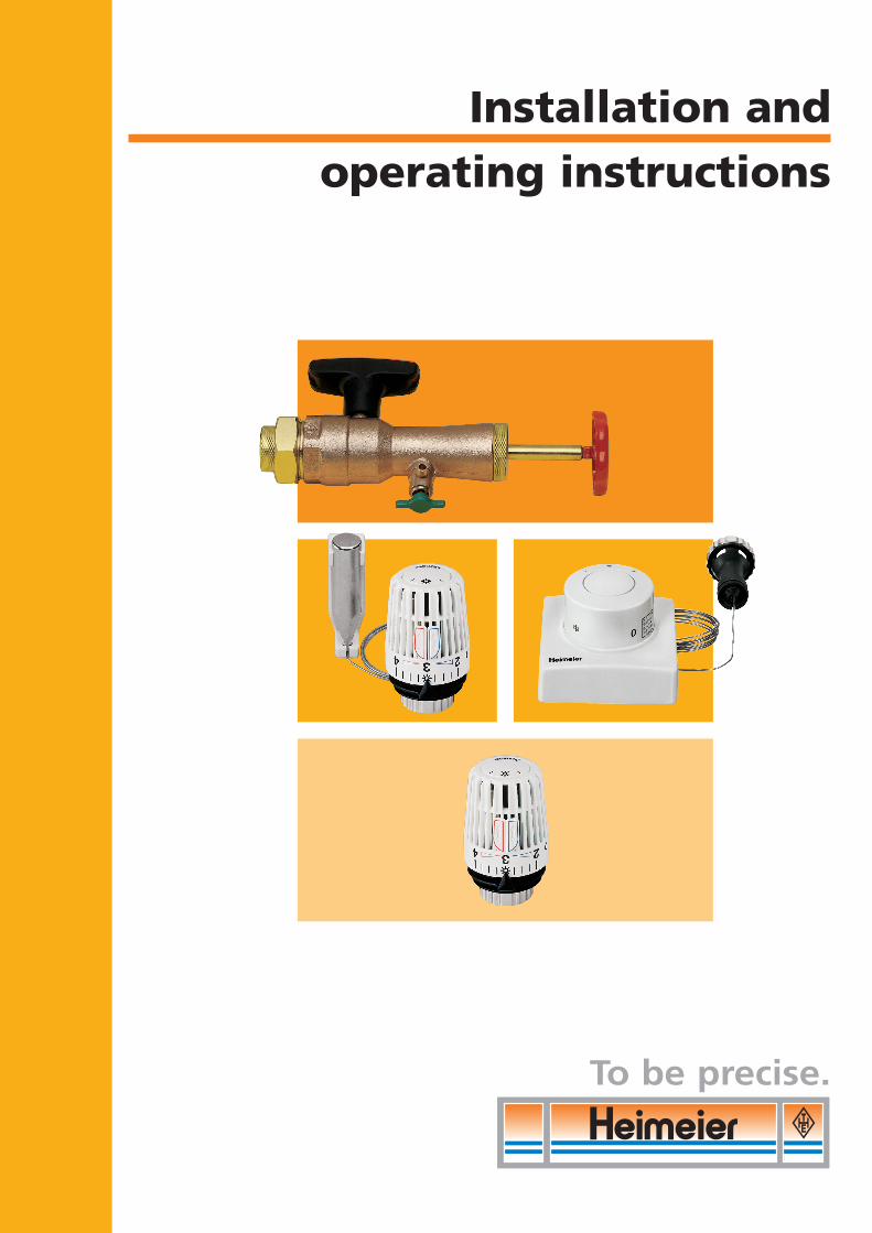
Installation and operating instructions
To be precise.
DV1800-18-483-01-0407.qxd 31.05.2007 9:29 Uhr Seite 1
2
Installation and operating instructions
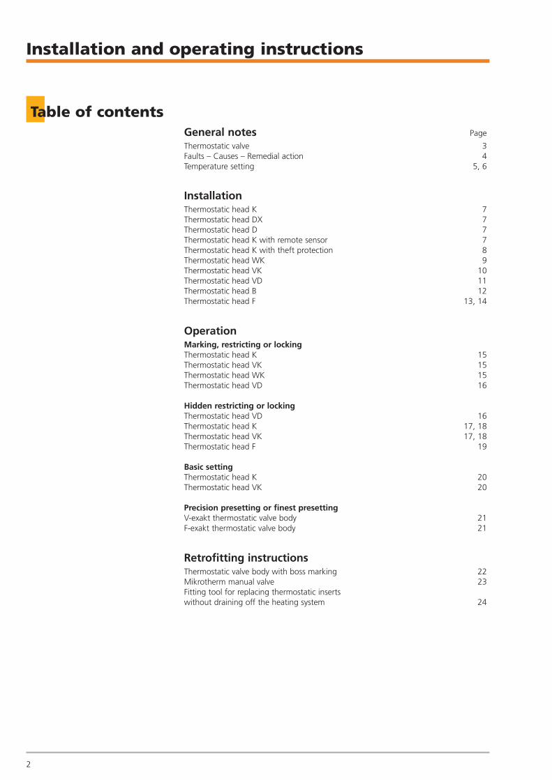
Table of contentsGeneral notes Page
Thermostatic valve 3Faults – Causes – Remedial action 4Temperature setting 5, 6
InstallationThermostatic head K 7Thermostatic head DX 7Thermostatic head D 7Thermostatic head K with remote sensor 7Thermostatic head K with theft protection 8Thermostatic head WK 9Thermostatic head VK 10Thermostatic head VD 11Thermostatic head B 12Thermostatic head F 13, 14
OperationMarking, restricting or locking Thermostatic head K 15Thermostatic head VK 15Thermostatic head WK 15Thermostatic head VD 16
Hidden restricting or locking Thermostatic head VD 16Thermostatic head K 17, 18Thermostatic head VK 17, 18Thermostatic head F 19
Basic settingThermostatic head K 20Thermostatic head VK 20
Precision presetting or finest presettingV-exakt thermostatic valve body 21F-exakt thermostatic valve body 21
Retrofitting instructionsThermostatic valve body with boss marking 22Mikrotherm manual valve 23Fitting tool for replacing thermostatic inserts without draining off the heating system 24
DV1800-18-483-01-0407.qxd 31.05.2007 9:29 Uhr Seite 2
General notes
3
Thermostatic valve
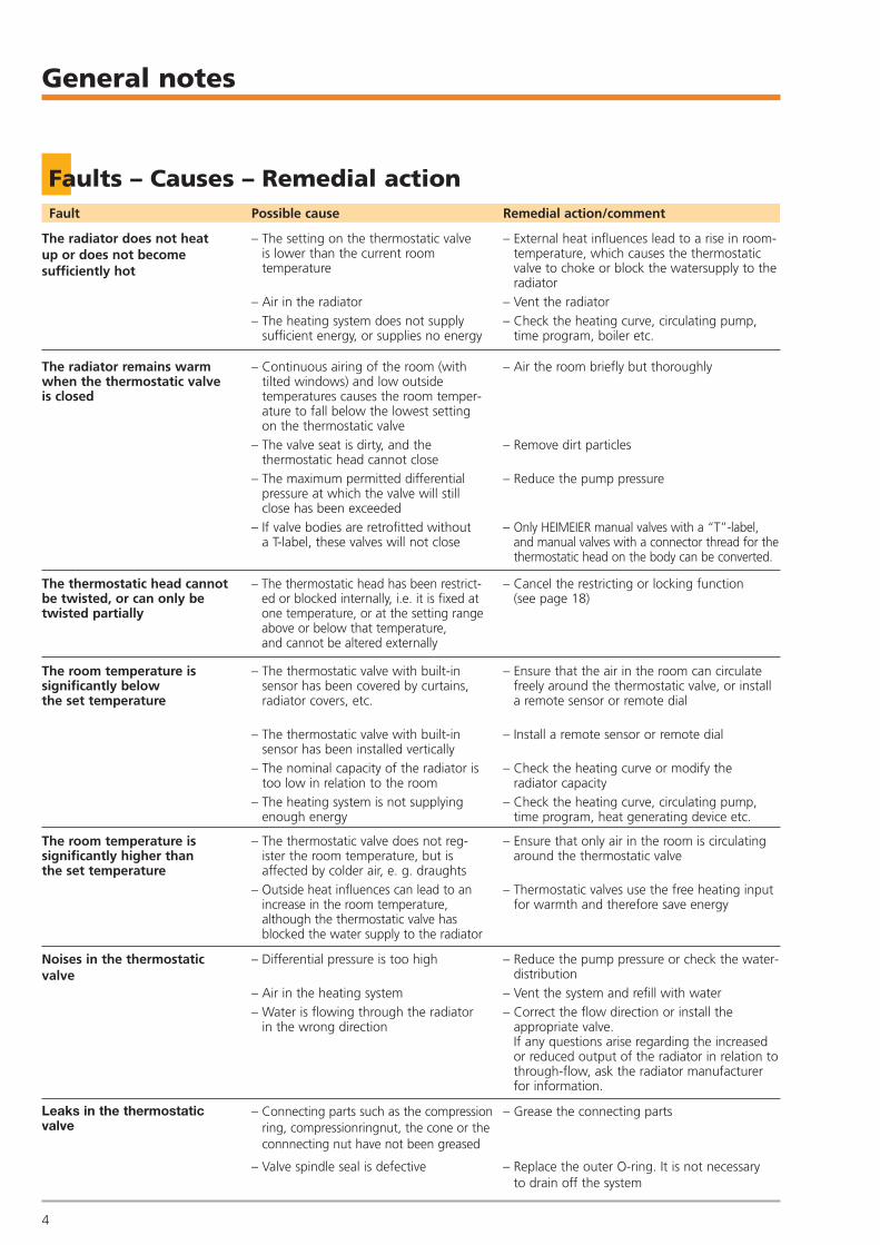
Underfloorconvector
Built-incabinet
IncorrectThe thermostatichead with built-insensor should notbe installed vertically.
CorrectThe remote sensormakes it possibleto read the airtemperature in theroom unhindered.
CorrectAir in the roomcan circulate freely around the thermostatichead.
IncorrectThe thermostatichead with built-insensor should notbe covered by curtains.
Notes on installation
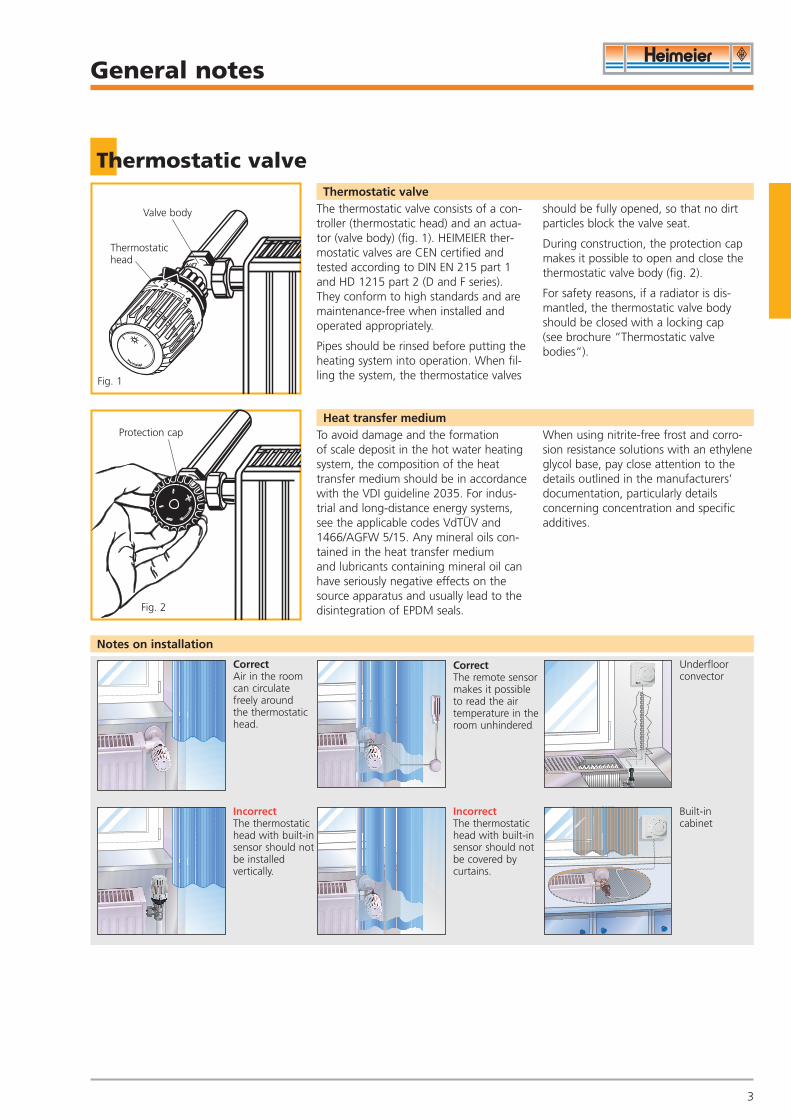
The thermostatic valve consists of a con-troller (thermostatic head) and an actua-tor (valve body) (fig. 1). HEIMEIER ther-mostatic valves are CEN certified andtested according to DIN EN 215 part 1and HD 1215 part 2 (D and F series).They conform to high standards and aremaintenance-free when installed andoperated appropriately.
Pipes should be rinsed before putting theheating system into operation. When fil-ling the system, the thermostatice valves
should be fully opened, so that no dirtparticles block the valve seat.
During construction, the protection capmakes it possible to open and close thethermostatic valve body (fig. 2).
For safety reasons, if a radiator is dis-mantled, the thermostatic valve bodyshould be closed with a locking cap (see brochure “Thermostatic valvebodies“).
Thermostatic valve
To avoid damage and the formation of scale deposit in the hot water heatingsystem, the composition of the heattransfer medium should be in accordancewith the VDI guideline 2035. For indus-trial and long-distance energy systems,see the applicable codes VdTÜV and1466/AGFW 5/15. Any mineral oils con-tained in the heat transfer medium and lubricants containing mineral oil canhave seriously negative effects on thesource apparatus and usually lead to thedisintegration of EPDM seals.
When using nitrite-free frost and corro-sion resistance solutions with an ethyleneglycol base, pay close attention to thedetails outlined in the manufacturers’documentation, particularly details concerning concentration and specificadditives.
Heat transfer medium
3
Valve body
Thermostatichead
Protection cap
Fig. 1
Fig. 2
DV1800-18-483-01-0407.qxd 31.05.2007 9:29 Uhr Seite 3
General notes
4
Faults – Causes – Remedial actionFault Possible cause Remedial action/comment
The radiator does not heatup or does not become sufficiently hot
– The setting on the thermostatic valve is lower than the current room temperature
– Air in the radiator– The heating system does not supply
sufficient energy, or supplies no energy
– External heat influences lead to a rise in room-temperature, which causes the thermostaticvalve to choke or block the watersupply to theradiator
– Vent the radiator– Check the heating curve, circulating pump,
time program, boiler etc.
– Continuous airing of the room (with tilted windows) and low outside temperatures causes the room temper-ature to fall below the lowest settingon the thermostatic valve
– The valve seat is dirty, and the thermostatic head cannot close
– The maximum permitted differentialpressure at which the valve will stillclose has been exceeded
– If valve bodies are retrofitted without a T-label, these valves will not close
– Air the room briefly but thoroughly
– Remove dirt particles
– Reduce the pump pressure
– Only HEIMEIER manual valves with a “T”-label,and manual valves with a connector thread for the thermostatic head on the body can be converted.
The radiator remains warmwhen the thermostatic valve is closed
The room temperature is significantly below the set temperature
– The thermostatic head has been restrict-ed or blocked internally, i.e. it is fixed atone temperature, or at the setting rangeabove or below that temperature, and cannot be altered externally
– Cancel the restricting or locking function (see page 18)
The thermostatic head cannotbe twisted, or can only be twisted partially
– The thermostatic valve with built-insensor has been covered by curtains,radiator covers, etc.
– The thermostatic valve with built-insensor has been installed vertically
– The nominal capacity of the radiator istoo low in relation to the room
– The heating system is not supplyingenough energy
– Ensure that the air in the room can circulatefreely around the thermostatic valve, or installa remote sensor or remote dial
– Install a remote sensor or remote dial
– Check the heating curve or modify the radiator capacity
– Check the heating curve, circulating pump,time program, heat generating device etc.
– The thermostatic valve does not reg-ister the room temperature, but isaffected by colder air, e. g. draughts
– Outside heat influences can lead to anincrease in the room temperature, although the thermostatic valve hasblocked the water supply to the radiator
– Ensure that only air in the room is circulatingaround the thermostatic valve
– Thermostatic valves use the free heating inputfor warmth and therefore save energy
The room temperature is significantly higher than the set temperature
– Differential pressure is too high
– Air in the heating system– Water is flowing through the radiator
in the wrong direction
– Reduce the pump pressure or check the water-distribution
– Vent the system and refill with water– Correct the flow direction or install the
appropriate valve.If any questions arise regarding the increasedor reduced output of the radiator in relation tothrough-flow, ask the radiator manufacturerfor information.
Noises in the thermostatic valve
– Connecting parts such as the compressionring, compressionringnut, the cone or theconnnecting nut have not been greased
– Valve spindle seal is defective
– Grease the connecting parts
– Replace the outer O-ring. It is not necessary to drain off the system
Leaks in the thermostaticvalve
DV1800-18-483-01-0407.qxd 31.05.2007 9:29 Uhr Seite 4
General notes
5
Setting the temperatureRecommended room temperatures
Setting the temperature
The following temperature settings are recommended for the corresponding rooms, with cost-efficient heating in mind:
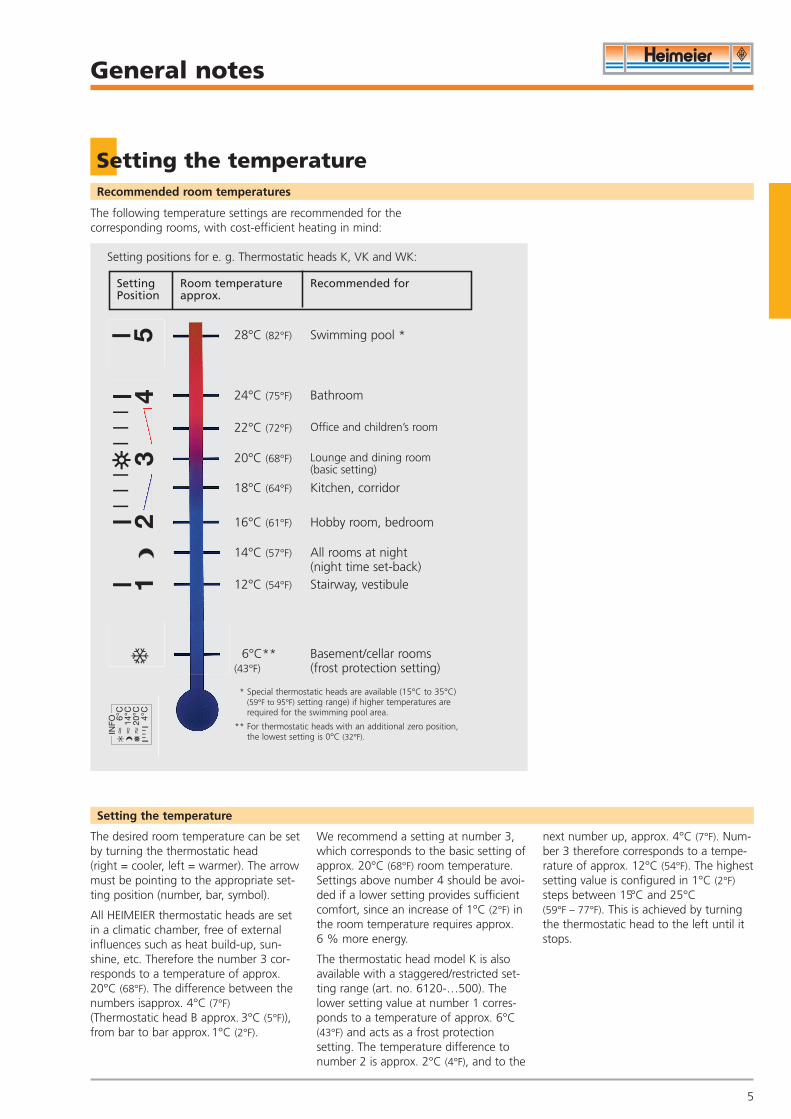
Setting positions for e. g. Thermostatic heads K, VK and WK:
The desired room temperature can be setby turning the thermostatic head (right = cooler, left = warmer). The arrowmust be pointing to the appropriate set-ting position (number, bar, symbol).
All HEIMEIER thermostatic heads are setin a climatic chamber, free of externalinfluences such as heat build-up, sun-shine, etc. Therefore the number 3 cor-responds to a temperature of approx. 20°C (68°F). The difference between thenumbers isapprox. 4°C (7°F)(Thermostatic head B approx. 3°C (5°F)),from bar to bar approx.1°C (2°F).
We recommend a setting at number 3,which corresponds to the basic setting ofapprox. 20°C (68°F) room temperature.Settings above number 4 should be avoi-ded if a lower setting provides sufficientcomfort, since an increase of 1°C (2°F) inthe room temperature requires approx.6 % more energy.
The thermostatic head model K is alsoavailable with a staggered/restricted set-ting range (art. no. 6120-…500). Thelower setting value at number 1 corres-ponds to a temperature of approx. 6°C(43°F) and acts as a frost protectionsetting. The temperature difference tonumber 2 is approx. 2°C (4°F), and to the
next number up, approx. 4°C (7°F). Num-ber 3 therefore corresponds to a tempe-rature of approx. 12°C (54°F). The highestsetting value is configured in 1°C (2°F)steps between 15°C and 25°C (59°F – 77°F). This is achieved by turningthe thermostatic head to the left until itstops.
53
42
1IN
FO�
6°C
�14
°C�
20°C 4°C
Swimming pool *
Bathroom
Office and children’s room
Lounge and dining room(basic setting)
Hobby room, bedroom
All rooms at night(night time set-back)Stairway, vestibule
Basement/cellar rooms(frost protection setting)
Kitchen, corridor
28°C (82°F)
24°C (75°F)
22°C (72°F)
20°C (68°F)
18°C (64°F)
16°C (61°F)
14°C (57°F)
12°C (54°F)
6°C**(43°F)
* Special thermostatic heads are available (15°C to 35°C) (59°F to 95°F) setting range) if higher temperatures are required for the swimming pool area.
** For thermostatic heads with an additional zero position,the lowest setting is 0°C (32°F).
Setting Room temperature Recommended for Position approx.
DV1800-18-483-01-0407.qxd 31.05.2007 9:30 Uhr Seite 5
General notes
6
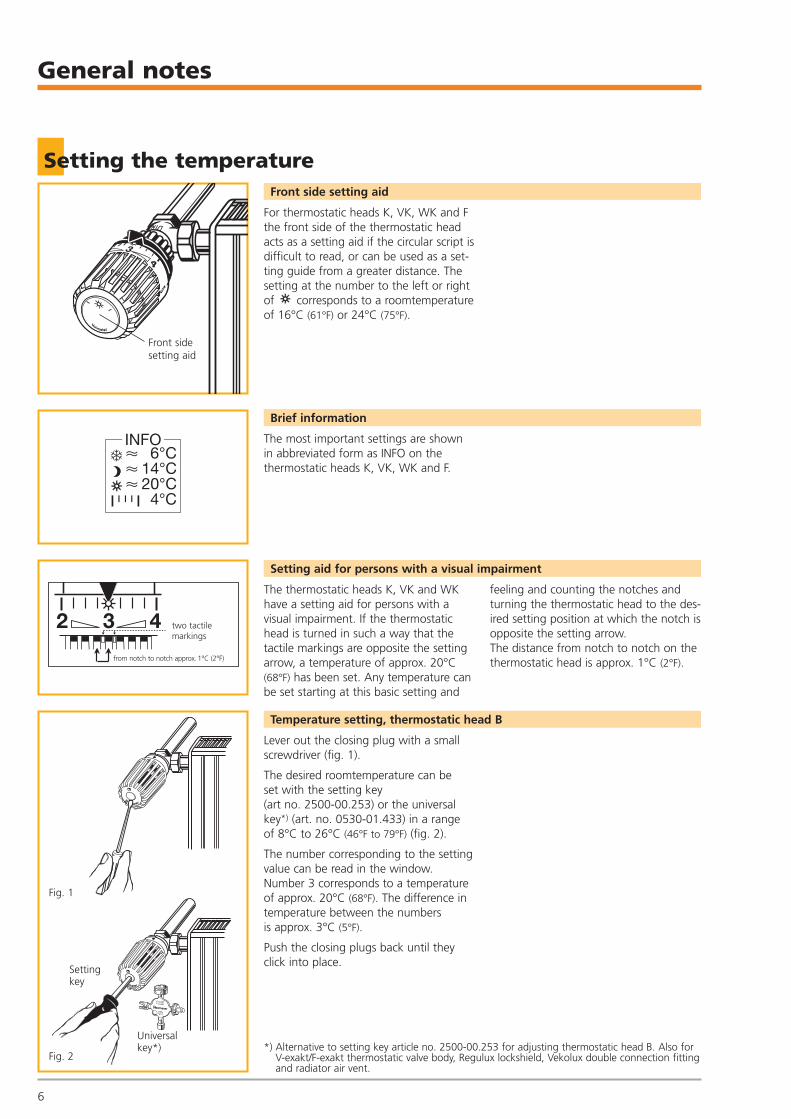
Front side setting aid
For thermostatic heads K, VK, WK and Fthe front side of the thermostatic headacts as a setting aid if the circular script isdifficult to read, or can be used as a set-ting guide from a greater distance. Thesetting at the number to the left or rightof corresponds to a roomtemperatureof 16°C (61°F) or 24°C (75°F).
Brief information
The most important settings are shownin abbreviated form as INFO on the thermostatic heads K, VK, WK and F.
Setting aid for persons with a visual impairment
The thermostatic heads K, VK and WKhave a setting aid for persons with avisual impairment. If the thermostatichead is turned in such a way that thetactile markings are opposite the settingarrow, a temperature of approx. 20°C(68°F) has been set. Any temperature canbe set starting at this basic setting and
feeling and counting the notches andturning the thermostatic head to the des-ired setting position at which the notch isopposite the setting arrow. The distance from notch to notch on thethermostatic head is approx. 1°C (2°F).
Temperature setting, thermostatic head B
Lever out the closing plug with a smallscrewdriver (fig. 1).
The desired roomtemperature can be set with the setting key (art no. 2500-00.253) or the universalkey*) (art. no. 0530-01.433) in a range of 8°C to 26°C (46°F to 79°F) (fig. 2).
The number corresponding to the settingvalue can be read in the window. Number 3 corresponds to a temperatureof approx. 20°C (68°F). The difference intemperature between the numbers is approx. 3°C (5°F).
Push the closing plugs back until theyclick into place.
*) Alternative to setting key article no. 2500-00.253 for adjusting thermostatic head B. Also forV-exakt/F-exakt thermostatic valve body, Regulux lockshield, Vekolux double connection fittingand radiator air vent.
Setting the temperature
3
Front side setting aid
INFO� 6°C� 14°C� 20°C
4°C
2 3 4
from notch to notch approx. 1°C (2°F)
two tactile markings
Settingkey
Universalkey*)
V-exaktF-exakt
hahnLuft-
Fig. 1
Fig. 2
DV1800-18-483-01-0407.qxd 31.05.2007 9:30 Uhr Seite 6
Installation
7
Thermostatic heads K, DX and D, remote sensor
Installation of thermostatic heads K, DX and D
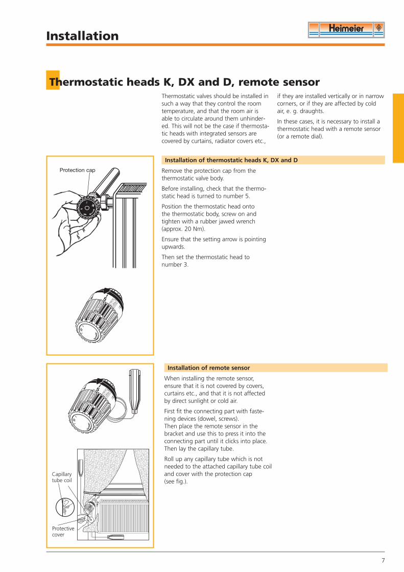
Thermostatic valves should be installed insuch a way that they control the roomtemperature, and that the room air isable to circulate around them unhinder-ed. This will not be the case if thermosta-tic heads with integrated sensors arecovered by curtains, radiator covers etc.,
if they are installed vertically or in narrowcorners, or if they are affected by coldair, e. g. draughts.
In these cases, it is necessary to install athermostatic head with a remote sensor(or a remote dial).
Remove the protection cap from thethermostatic valve body.
Before installing, check that the thermo-static head is turned to number 5.
Position the thermostatic head onto the thermostatic body, screw on andtighten with a rubber jawed wrench(approx. 20 Nm).
Ensure that the setting arrow is pointingupwards.
Then set the thermostatic head to number 3.
Installation of remote sensor
When installing the remote sensor,ensure that it is not covered by covers,curtains etc., and that it is not affectedby direct sunlight or cold air.
First fit the connecting part with faste-ning devices (dowel, screws). Then place the remote sensor in thebracket and use this to press it into theconnecting part until it clicks into place.Then lay the capillary tube.
Roll up any capillary tube which is notneeded to the attached capillary tube coiland cover with the protection cap (see fig.).
Protection cap
Protectivecover
Capillarytube coil
DV1800-18-483-01-0407.qxd 31.05.2007 9:30 Uhr Seite 7
Installation
8
Thermostatic head K with theft protection
Collar
Screwdriver
Fig. 1
Fig. 2
Safety screwon the locking ring
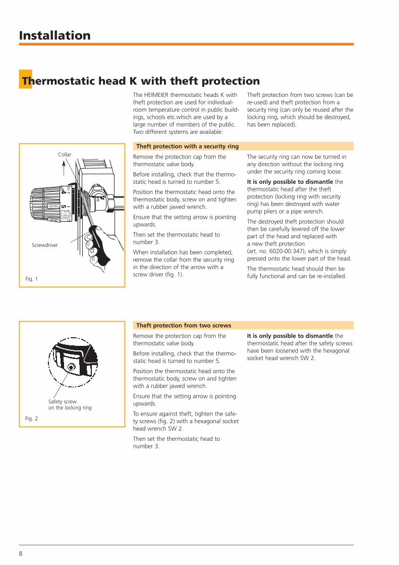
The HEIMEIER thermostatic heads K withtheft protection are used for individual-room temperature control in public build-ings, schools etc.which are used by alarge number of members of the public.Two different systems are available:
Theft protection from two screws (can bere-used) and theft protection from asecurity ring (can only be reused after thelocking ring, which should be destroyed,has been replaced).
Theft protection with a security ring
Remove the protection cap from thethermostatic valve body.
Before installing, check that the thermo-static head is turned to number 5.
Position the thermostatic head onto thethermostatic body, screw on and tightenwith a rubber jawed wrench.
Ensure that the setting arrow is pointingupwards.
Then set the thermostatic head to number 3.
When installation has been completed,remove the collar from the security ringin the direction of the arrow with ascrew driver (fig. 1).
The security ring can now be turned inany direction without the locking ringunder the security ring coming loose.
It is only possible to dismantle thethermostatic head after the theftprotection (locking ring with securityring) has been destroyed with waterpump pliers or a pipe wrench.
The destroyed theft protection shouldthen be carefully levered off the lowerpart of the head and replaced with a new theft protection (art. no. 6020-00.347), which is simplypressed onto the lower part of the head.
The thermostatic head should then befully functional and can be re-installed.
Theft protection from two screws
Remove the protection cap from thethermostatic valve body.
Before installing, check that the thermo-static head is turned to number 5.
Position the thermostatic head onto thethermostatic body, screw on and tightenwith a rubber jawed wrench.
Ensure that the setting arrow is pointingupwards.
To ensure against theft, tighten the safe-ty screws (fig. 2) with a hexagonal sockethead wrench SW 2.
Then set the thermostatic head to number 3.
It is only possible to dismantle thethermostatic head after the safety screwshave been loosened with the hexagonalsocket head wrench SW 2.
DV1800-18-483-01-0407.qxd 31.05.2007 9:30 Uhr Seite 8
Installation
9
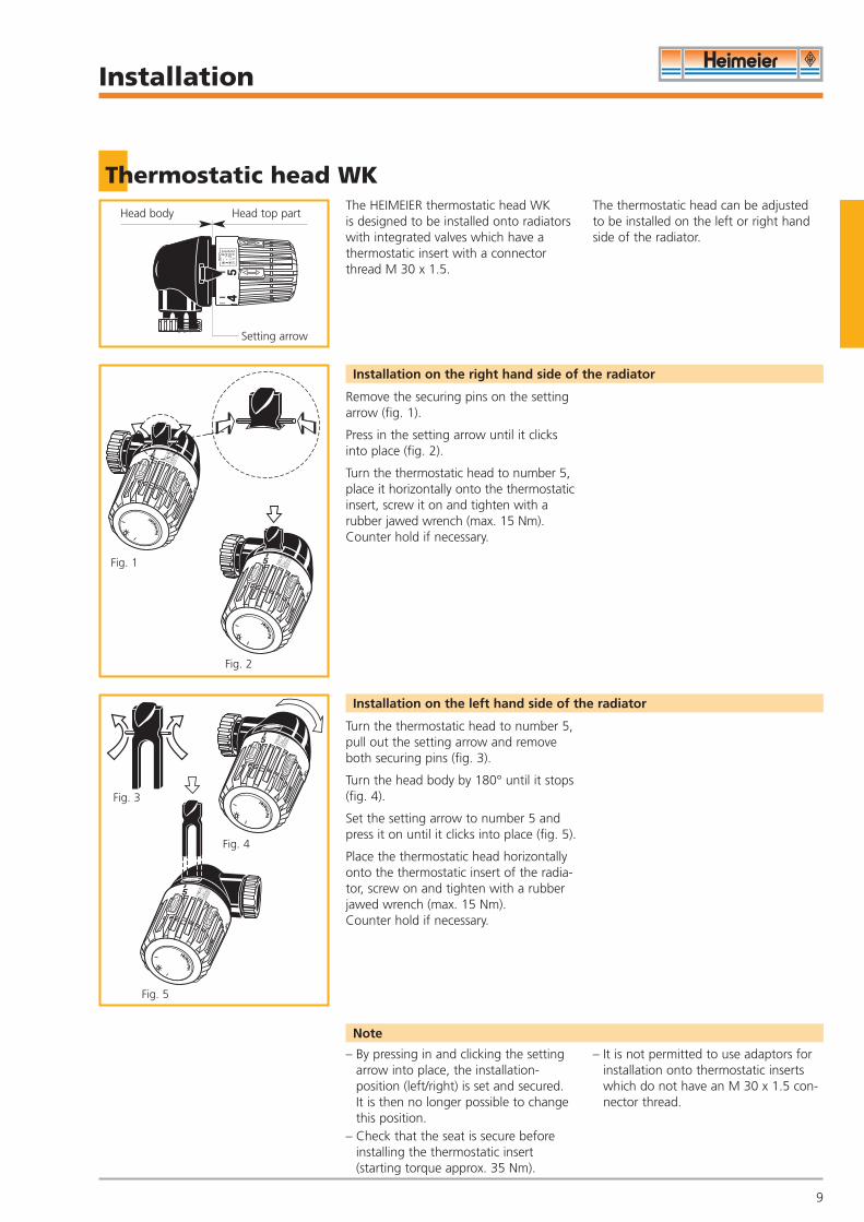
Thermostatic head WKThe HEIMEIER thermostatic head WK is designed to be installed onto radiatorswith integrated valves which have a thermostatic insert with a connectorthread M 30 x 1.5.
The thermostatic head can be adjustedto be installed on the left or right handside of the radiator.
Installation on the right hand side of the radiator
Remove the securing pins on the settingarrow (fig. 1).
Press in the setting arrow until it clicksinto place (fig. 2).
Turn the thermostatic head to number 5,place it horizontally onto the thermostaticinsert, screw it on and tighten with a rubber jawed wrench (max. 15 Nm).Counter hold if necessary.
Installation on the left hand side of the radiator
Turn the thermostatic head to number 5,pull out the setting arrow and removeboth securing pins (fig. 3).
Turn the head body by 180° until it stops(fig. 4).
Set the setting arrow to number 5 andpress it on until it clicks into place (fig. 5).
Place the thermostatic head horizontallyonto the thermostatic insert of the radia-tor, screw on and tighten with a rubberjawed wrench (max. 15 Nm). Counter hold if necessary.
Note
– By pressing in and clicking the settingarrow into place, the installation-position (left/right) is set and secured. It is then no longer possible to changethis position.
– Check that the seat is secure beforeinstalling the thermostatic insert(starting torque approx. 35 Nm).
– It is not permitted to use adaptors forinstallation onto thermostatic inserts which do not have an M 30 x 1.5 con-nector thread.
Setting arrow
Head body Head top part
Fig. 1
Fig. 2
Fig. 3
Fig. 4
Fig. 5
DV1800-18-483-01-0407.qxd 31.05.2007 9:30 Uhr Seite 9
Installation
10
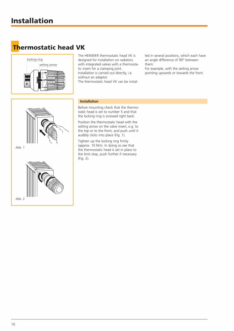
Thermostatic head VKThe HEIMEIER thermostatic head VK isdesigned for installation on radiatorswith integrated valves with a thermosta-tic insert for a clamping joint.Installation is carried out directly, i.e.without an adaptor.The thermostatic head VK can be instal-
led in several positions, which each havean angle difference of 90° betweenthem:For example, with the setting arrowpointing upwards or towards the front.
Installation
3
locking ring
•
setting arrow
Abb. 1
Abb. 2
Before mounting check that the thermo-static head is set to number 5 and thatthe locking ring is screwed right back.
Position the thermostatic head with thesetting arrow on the valve insert, e.g. tothe top or to the front, and push until itaudibly clicks into place (Fig. 1).
Tighten up the locking ring firmly(approx. 10 Nm). In doing so see that the thermostatic head is set in place tothe limit stop, push further if necessary(Fig. 2).
DV1800-18-483-01-0407.qxd 31.05.2007 9:30 Uhr Seite 10
Installation
11
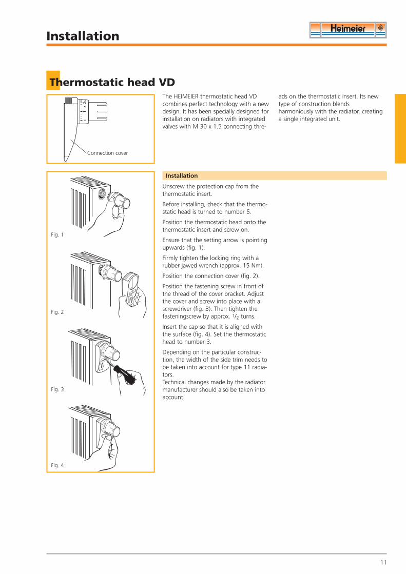
Thermostatic head VDThe HEIMEIER thermostatic head VDcombines perfect technology with a newdesign. It has been specially designed forinstallation on radiators with integratedvalves with M 30 x 1.5 connecting thre-
ads on the thermostatic insert. Its newtype of construction blends harmoniously with the radiator, creatinga single integrated unit.
Unscrew the protection cap from thethermostatic insert.
Before installing, check that the thermo-static head is turned to number 5.
Position the thermostatic head onto thethermostatic insert and screw on.
Ensure that the setting arrow is pointingupwards (fig. 1).
Firmly tighten the locking ring with arubber jawed wrench (approx. 15 Nm).
Position the connection cover (fig. 2).
Position the fastening screw in front ofthe thread of the cover bracket. Adjustthe cover and screw into place with ascrewdriver (fig. 3). Then tighten thefasteningscrew by approx. 1/2 turns.
Insert the cap so that it is aligned withthe surface (fig. 4). Set the thermostatichead to number 3.
Depending on the particular construc-tion, the width of the side trim needs tobe taken into account for type 11 radia-tors. Technical changes made by the radiatormanufacturer should also be taken intoaccount.
Installation
Connection cover
Fig. 1
Fig. 2
Fig. 3
Fig. 4
DV1800-18-483-01-0407.qxd 31.05.2007 9:30 Uhr Seite 11

Installation
12
Thermostatic head B
Marking notches
Hexagonalkey SW 2
Hexagonalkey SW 2
Closingplugs
Settingkey
Universalkey*)
Bore hole
V-exaktF-exakt
hahnLuft-
Window
The HEIMEIER thermostatic head B isused for individual room temperaturecontrol in public buildings, schools etc.which are used by a large number ofmembers of the public. The protection
cap of this theft protected thermostatichead can be turned continuously, andthe set setting value cannot be changedto lower or higher temperatures withouta special tool.
Remove the protection cap from thethermostatic valve body. Leverout the closing plugs with a small screwdriver(fig. 1).
Open the thermostatic head throughopening which is now available withsettingkey art. no. 2500-00.253) or theuniversal key*) art. no. 0530-01.433 byturning to the left until it stops (fig. 2).
Screw on the thermostatic head by turn-ing to the right on the valve body. Continue to turn the hand wheel capbeyond the point where resistance is feltuntil the bore hole at the side is alignedwith one of the two marking notches onthe fasteningnut. The location of the lok-king screws in the fastening nut is identi-cal to the marking notches (fig. 3).
Tighten the thermostatic head by insert-ing the hexagonal socket head wrenchSW 2 Art.no. 6040-02.256 (fig. 4).
Tighten the safety screw in the fasteningnut with the hexagonal key SW 2 until itstops. The hand wheel cap can now beturned in any direction without changingthe set setting value (fig. 5).
To read the setting value more clearly,turn the hand wheel cap so that thewindow points upwards (fig. 6).
*) As an alternative to the setting key art. no. 2500-00.253 for adjustingthermostatic head B. Also for the V-exakt/F-exakt thermostatic valve body, Regeluxlockshield, Vekolux double connection fitting and radiator air vent.
Installation
If it is necessary to dismantle the ther-mostatic head, turn the handwheel until the bore hole on the side is aligned with one of the two markingnotches on the fasteningnut (fig. 3).
Loosen the safety screw with the hexagonal key SW 2 (art. no. 6040-02.256) (fig. 5).
Unscrew the thermostatic head by inserting the hexagonal key and turning to the left (fig. 4).
Dismantling the thermostatic head
Fig. 1
Fig. 2
Fig. 3
Fig. 4
Fig. 5
Fig. 6
DV1800-18-483-01-0407.qxd 31.05.2007 9:30 Uhr Seite 12
Installation
13
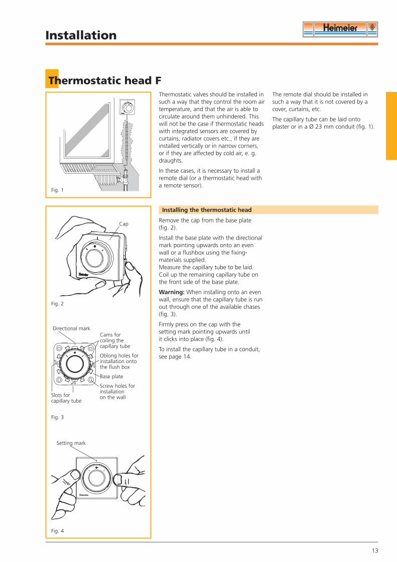
Thermostatic head FThermostatic valves should be installed insuch a way that they control the room airtemperature, and that the air is able tocirculate around them unhindered. Thiswill not be the case if thermostatic headswith integrated sensors are covered bycurtains, radiator covers etc., if they areinstalled vertically or in narrow corners,or if they are affected by cold air, e. g.draughts.
In these cases, it is necessary to install aremote dial (or a thermostatic head witha remote sensor).
The remote dial should be installed insuch a way that it is not covered by acover, curtains, etc.
The capillary tube can be laid onto plaster or in a Ø 23 mm conduit (fig. 1).
Remove the cap from the base plate (fig. 2).
Install the base plate with the directionalmark pointing upwards onto an evenwall or a flushbox using the fixing-materials supplied. Measure the capillary tube to be laid.Coil up the remaining capillary tube onthe front side of the base plate.
Warning: When installing onto an evenwall, ensure that the capillary tube is runout through one of the available chases(fig. 3).
Firmly press on the cap with the setting mark pointing upwards until it clicks into place (fig. 4).
To install the capillary tube in a conduit,see page 14.
Installing the thermostatic head
Cap
Directional mark
Slots for capillary tube
Setting mark
Cams forcoiling thecapillary tube
Oblong holes forinstallation ontothe flush box
Base plate
Screw holes forinstallation on the wall
Fig. 1
Fig. 2
Fig. 3
Fig. 4
DV1800-18-483-01-0407.qxd 31.05.2007 9:30 Uhr Seite 13

Installation
14
Thermostatic head F
Here, a flush box with Ø 60 mm and a conduit with Ø 23 mmshould be used (fig. 1).
Installation onto a flush box with a conduit
Unscrew the closing screw(fig. 2).
Remove the capillary tube with the thermostatic transmitter (fig. 3).
Push the spiral through the conduit andconnect to the thermostatic transmitter.Pull the transmitter and the capillary tubewith the spiral through the conduit (fig. 4).
Then put the individual parts back toget-her again. Remove the protection capfrom the thermostatic valve body.Turn the thermostatic head F to number 5. Position the connecting piece and tighten the locking ring with a rubber jawed wrench.
Installing the capillary tube in the conduit
Flush box Ø 60 mm
Threadedbore holesto fixthebaseplate
Closing screw
Thermostatic trans-mitterBore hole forfastening thespiral
Connecting piece
Spiral
ConduitØ 23 mm
Fig. 1
Fig. 2
Fig. 3
Fig. 4
DV1800-18-483-01-0407.qxd 31.05.2007 9:30 Uhr Seite 14
OperationMarking, restricting or locking
15
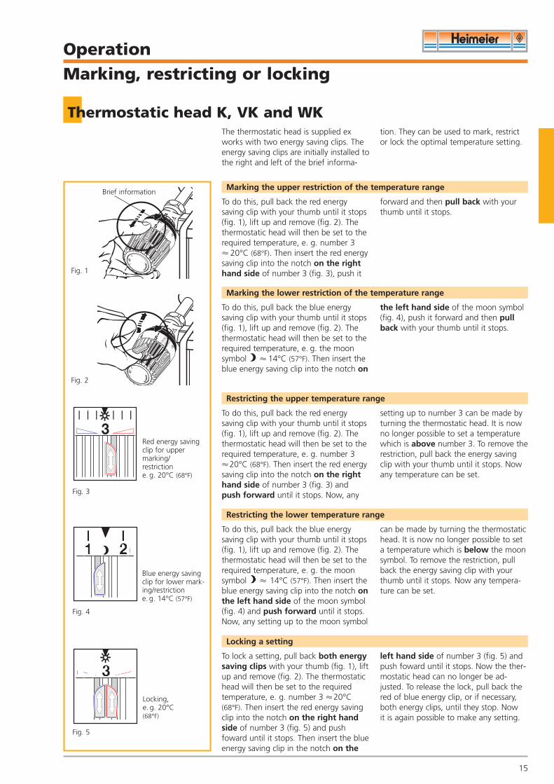
Thermostatic head K, VK and WKThe thermostatic head is supplied exworks with two energy saving clips. Theenergy saving clips are initially installed tothe right and left of the brief informa-
tion. They can be used to mark, restrictor lock the optimal temperature setting.
To do this, pull back the red energysaving clip with your thumb until it stops(fig. 1), lift up and remove (fig. 2). Thethermostatic head will then be set to therequired temperature, e. g. number 3 � 20°C (68°F). Then insert the red energysaving clip into the notch on the righthand side of number 3 (fig. 3), push it
forward and then pull back with yourthumb until it stops.
Marking the upper restriction of the temperature range
To do this, pull back the blue energysaving clip with your thumb until it stops(fig. 1), lift up and remove (fig. 2). Thethermostatic head will then be set to therequired temperature, e. g. the moonsymbol � 14°C (57°F). Then insert theblue energy saving clip into the notch on
the left hand side of the moon symbol(fig. 4), push it forward and then pullback with your thumb until it stops.
Marking the lower restriction of the temperature range
Restricting the upper temperature range
To do this, pull back the blue energysaving clip with your thumb until it stops(fig. 1), lift up and remove (fig. 2). Thethermostatic head will then be set to therequired temperature, e. g. the moonsymbol � 14°C (57°F). Then insert theblue energy saving clip into the notch onthe left hand side of the moon symbol(fig. 4) and push forward until it stops.Now, any setting up to the moon symbol
can be made by turning the thermostatichead. It is now no longer possible to seta temperature which is below the moonsymbol. To remove the restriction, pullback the energy saving clip with yourthumb until it stops. Now any tempera-ture can be set.
Restricting the lower temperature range
To lock a setting, pull back both energysaving clips with your thumb (fig. 1), liftup and remove (fig. 2). The thermostatichead will then be set to the requiredtemperature, e. g. number 3 �20°C(68°F). Then insert the red energy savingclip into the notch on the right handside of number 3 (fig. 5) and pushfoward until it stops. Then insert the blueenergy saving clip in the notch on the
left hand side of number 3 (fig. 5) andpush foward until it stops. Now the ther-mostatic head can no longer be ad-justed. To release the lock, pull back thered of blue energy clip, or if necessary,both energy clips, until they stop. Now it is again possible to make any setting.
Locking a setting
Brief information
Fig. 1
Fig. 2
Fig. 3
Fig. 4
Fig. 5
3
Red energy savingclip for uppermarking/restriction e. g. 20°C (68°F)
Blue energy savingclip for lower mark-ing/restrictione. g. 14°C (57°F)
Locking,e. g. 20°C(68°F)
21
3To do this, pull back the red energysaving clip with your thumb until it stops(fig. 1), lift up and remove (fig. 2). Thethermostatic head will then be set to therequired temperature, e. g. number 3 �20°C (68°F). Then insert the red energysaving clip into the notch on the righthand side of number 3 (fig. 3) andpush forward until it stops. Now, any
setting up to number 3 can be made byturning the thermostatic head. It is nowno longer possible to set a temperaturewhich is above number 3. To remove therestriction, pull back the energy savingclip with your thumb until it stops. Nowany temperature can be set.
DV1800-18-483-01-0407.qxd 31.05.2007 9:30 Uhr Seite 15
OperationMarking, restricting or locking
16
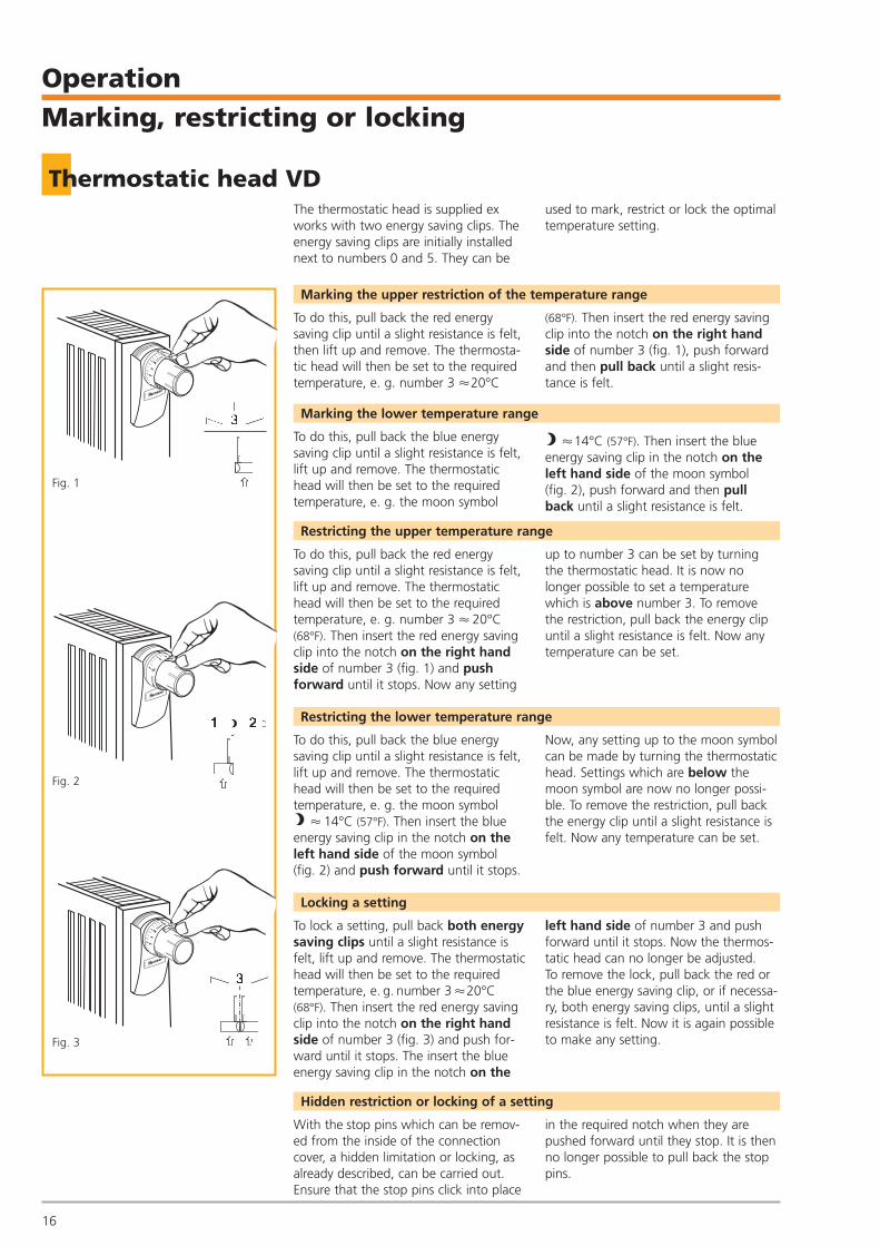
Thermostatic head VD
Fig. 1
Fig. 2
Fig. 3
To do this, pull back the red energysaving clip until a slight resistance is felt,then lift up and remove. The thermosta-tic head will then be set to the requiredtemperature, e. g. number 3 �20°C
(68°F). Then insert the red energy savingclip into the notch on the right handside of number 3 (fig. 1), push forwardand then pull back until a slight resis-tance is felt.
The thermostatic head is supplied exworks with two energy saving clips. Theenergy saving clips are initially installednext to numbers 0 and 5. They can be
used to mark, restrict or lock the optimaltemperature setting.
Marking the upper restriction of the temperature range
To do this, pull back the blue energysaving clip until a slight resistance is felt,lift up and remove. The thermostatichead will then be set to the requiredtemperature, e. g. the moon symbol
�14°C (57°F). Then insert the blueenergy saving clip in the notch on theleft hand side of the moon symbol(fig. 2), push forward and then pull back until a slight resistance is felt.
Marking the lower temperature range
To do this, pull back the red energysaving clip until a slight resistance is felt,lift up and remove. The thermostatichead will then be set to the requiredtemperature, e. g. number 3 � 20°C(68°F). Then insert the red energy savingclip into the notch on the right handside of number 3 (fig. 1) and push forward until it stops. Now any setting
up to number 3 can be set by turningthe thermostatic head. It is now no longer possible to set a temperaturewhich is above number 3. To remove the restriction, pull back the energy clipuntil a slight resistance is felt. Now anytemperature can be set.
Restricting the upper temperature range
To do this, pull back the blue energysaving clip until a slight resistance is felt,lift up and remove. The thermostatichead will then be set to the requiredtemperature, e. g. the moon symbol
� 14°C (57°F). Then insert the blueenergy saving clip in the notch on theleft hand side of the moon symbol(fig. 2) and push forward until it stops.
Now, any setting up to the moon symbolcan be made by turning the thermostatichead. Settings which are below themoon symbol are now no longer possi-ble. To remove the restriction, pull backthe energy clip until a slight resistance isfelt. Now any temperature can be set.
Restricting the lower temperature range
To lock a setting, pull back both energysaving clips until a slight resistance isfelt, lift up and remove. The thermostatichead will then be set to the requiredtemperature, e. g. number 3 �20°C(68°F). Then insert the red energy savingclip into the notch on the right handside of number 3 (fig. 3) and push for-ward until it stops. The insert the blueenergy saving clip in the notch on the
left hand side of number 3 and pushforward until it stops. Now the thermos-tatic head can no longer be adjusted. To remove the lock, pull back the red orthe blue energy saving clip, or if necessa-ry, both energy saving clips, until a slightresistance is felt. Now it is again possibleto make any setting.
Locking a setting
With the stop pins which can be remov-ed from the inside of the connectioncover, a hidden limitation or locking, asalready described, can be carried out.Ensure that the stop pins click into place
in the required notch when they arepushed forward until they stop. It is thenno longer possible to pull back the stoppins.
Hidden restriction or locking of a setting
3
�
21
�
3
��
DV1800-18-483-01-0407.qxd 31.05.2007 9:30 Uhr Seite 16
17
OperationHidden restriction or locking
Thermostatic heads K and VK
Restricting the upper temperature range
It is possible to combine the upper andlower restriction in one operation. To dothis, the thermostatic head should be setat the required upper or lower tempera-ture before the cap with graduation is
removed. When the restriction has beenset, position the cap with graduation atthe same setting.
Combined upper and lower restriction of the temperature range
Restricting the lower temperature range
To reset the basic position if the regulating head has been adjusted, see page 20.
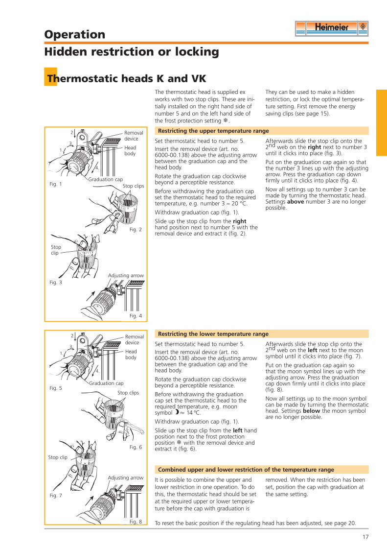
The thermostatic head is supplied exworks with two stop clips. These are ini-tially installed on the right hand side ofnumber 5 and on the left hand side ofthe frost protection setting .
They can be used to make a hiddenrestriction, or lock the optimal tempera-ture setting. First remove the energysaving clips (see page 15).
Set thermostatic head to number 5.Insert the removal device (art. no. 6000-00.138) above the adjusting arrowbetween the graduation cap and thehead body.
Rotate the graduation cap clockwisebeyond a perceptible resistance.
Before withdrawing the graduation capset the thermostatic head to the requiredtemperature, e.g. number 3 ≈ 20 °C.
Withdraw graduation cap (fig. 1).
Slide up the stop clip from the righthand position next to number 5 with theremoval device and extract it (fig. 2).
Afterwards slide the stop clip onto the2nd web on the right next to number 3until it clicks into place (fig. 3).
Put on the graduation cap again so thatthe number 3 lines up with the adjustingarrow. Press the graduation cap downfirmly until it clicks into place (fig. 4).
Now all settings up to number 3 can bemade by turning the thermostatic head.Settings above number 3 are no longerpossible.
Set thermostatic head to number 5.Insert the removal device (art. no. 6000-00.138) above the adjusting arrowbetween the graduation cap and thehead body.
Rotate the graduation cap clockwisebeyond a perceptible resistance.
Before withdrawing the graduation cap set the thermostatic head to therequired temperature, e.g. moon symbol � 14 °C.
Withdraw graduation cap (fig. 1).
Slide up the stop clip from the left handposition next to the frost protectionposition with the removal device andextract it (fig. 6).
Afterwards slide the stop clip onto the2nd web on the left next to the moonsymbol until it clicks into place (fig. 7).
Put on the graduation cap again so that the moon symbol lines up with theadjusting arrow. Press the graduationcap down firmly until it clicks into place(fig. 8).
Now all settings up to the moon symbolcan be made by turning the thermostatichead. Settings below the moon symbolare no longer possible.
3.
1.
2.
4.
5
3
1 2
Fig. 1
Fig. 3
Fig. 5
Fig. 2
Fig. 7
Graduation capStop clips
Stop clip
Adjusting arrow
5
Fig. 6
Stop clips
Stop clip
Adjusting arrow
Fig. 4
Fig. 8
Removaldevice
Headbody
3.
1.
2.
4.
Graduation cap
Removaldevice
Headbody
DV1800-18-483-01-0407.qxd 31.05.2007 9:30 Uhr Seite 17
18
OperationHidden restriction or locking
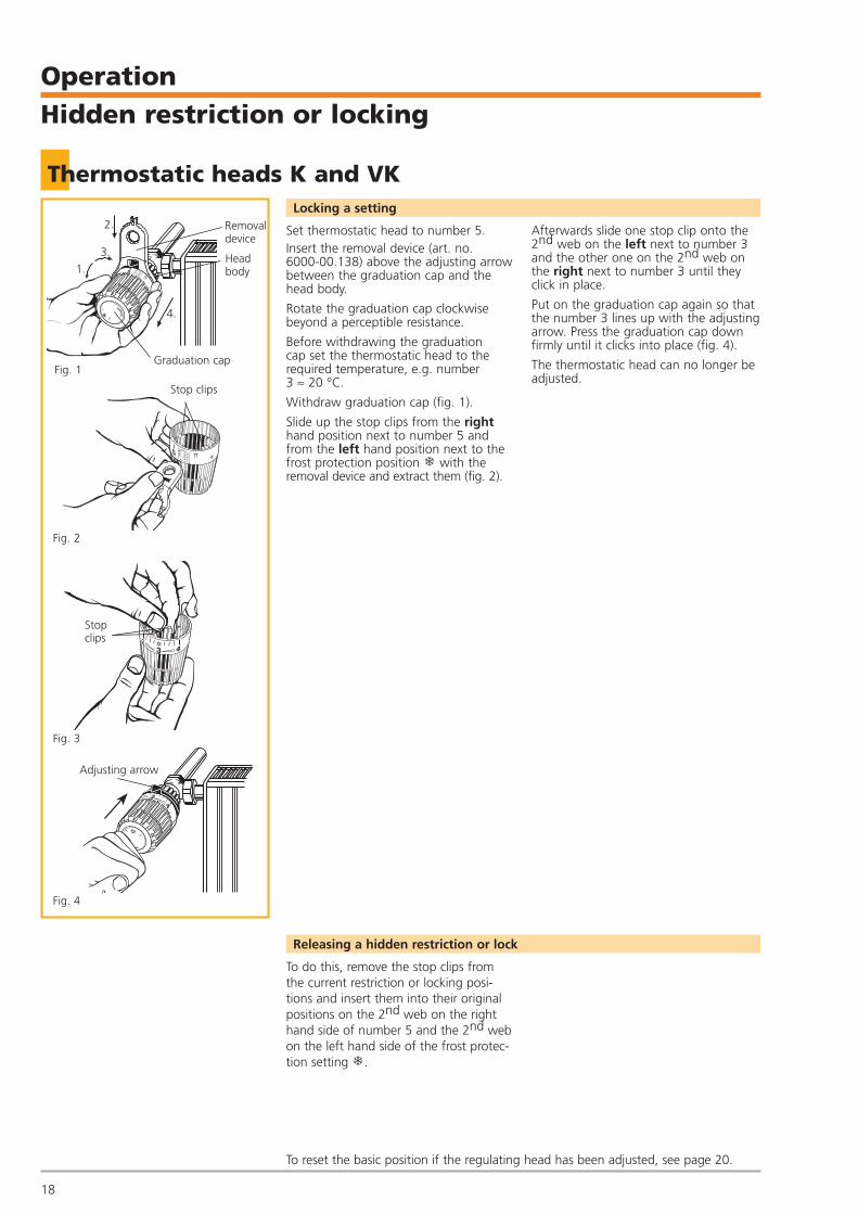
Thermostatic heads K and VKLocking a setting
To do this, remove the stop clips fromthe current restriction or locking posi-tions and insert them into their originalpositions on the 2nd web on the righthand side of number 5 and the 2nd webon the left hand side of the frost protec-tion setting .
Releasing a hidden restriction or lock
To reset the basic position if the regulating head has been adjusted, see page 20.
Set thermostatic head to number 5.Insert the removal device (art. no. 6000-00.138) above the adjusting arrowbetween the graduation cap and thehead body.
Rotate the graduation cap clockwisebeyond a perceptible resistance.
Before withdrawing the graduation cap set the thermostatic head to therequired temperature, e.g. number 3 ≈ 20 °C.
Withdraw graduation cap (fig. 1).
Slide up the stop clips from the righthand position next to number 5 andfrom the left hand position next to thefrost protection position with theremoval device and extract them (fig. 2).
Afterwards slide one stop clip onto the2nd web on the left next to number 3and the other one on the 2nd web onthe right next to number 3 until theyclick in place.
Put on the graduation cap again so thatthe number 3 lines up with the adjustingarrow. Press the graduation cap downfirmly until it clicks into place (fig. 4).
The thermostatic head can no longer beadjusted.
5
Fig. 2
Fig. 3
Stop clips
Stop clips
3
Fig. 4
Adjusting arrow
3.
1.
2.
4.
Graduation cap
Removaldevice
Headbody
Fig. 1
DV1800-18-483-01-0407.qxd 31.05.2007 9:30 Uhr Seite 18
19
OperationHidden restriction or locking
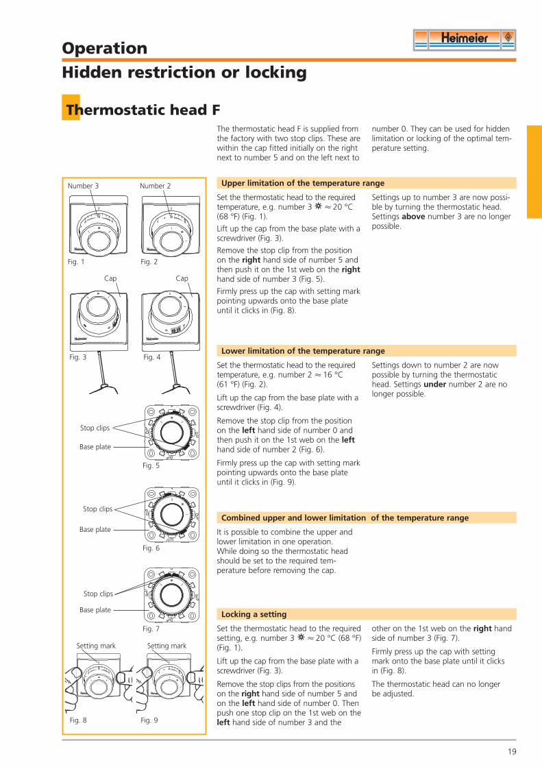
Thermostatic head FThe thermostatic head F is supplied fromthe factory with two stop clips. These arewithin the cap fitted initially on the rightnext to number 5 and on the left next to
number 0. They can be used for hiddenlimitation or locking of the optimal tem-perature setting.
Set the thermostatic head to the requiredtemperature, e.g. number 3 � 20 °C(68 °F) (Fig. 1).
Lift up the cap from the base plate with ascrewdriver (Fig. 3).
Remove the stop clip from the positionon the right hand side of number 5 andthen push it on the 1st web on the righthand side of number 3 (Fig. 5).
Firmly press up the cap with setting markpointing upwards onto the base plateuntil it clicks in (Fig. 8).
Settings up to number 3 are now possi-ble by turning the thermostatic head.Settings above number 3 are no longerpossible.
Upper limitation of the temperature range
Set the thermostatic head to the requiredtemperature, e.g. number 2 � 16 °C (61 °F) (Fig. 2).
Lift up the cap from the base plate with ascrewdriver (Fig. 4).
Remove the stop clip from the positionon the left hand side of number 0 andthen push it on the 1st web on the lefthand side of number 2 (Fig. 6).
Firmly press up the cap with setting markpointing upwards onto the base plateuntil it clicks in (Fig. 9).
Settings down to number 2 are nowpossible by turning the thermostatichead. Settings under number 2 are nolonger possible.
Lower limitation of the temperature range
It is possible to combine the upper andlower limitation in one operation. While doing so the thermostatic headshould be set to the required tem-perature before removing the cap.
Combined upper and lower limitation of the temperature range
Set the thermostatic head to the requiredsetting, e.g. number 3 � 20 °C (68 °F)(Fig. 1).
Lift up the cap from the base plate with ascrewdriver (Fig. 3).
Remove the stop clips from the positionson the right hand side of number 5 andon the left hand side of number 0. Thenpush one stop clip on the 1st web on theleft hand side of number 3 and the
other on the 1st web on the right handside of number 3 (Fig. 7).
Firmly press up the cap with setting mark onto the base plate until it clicks in (Fig. 8).
The thermostatic head can no longer be adjusted.
Locking a setting
Number 3
Cap
Stop clips
Stop clips
Setting mark
Fig. 1
Number 2
Fig. 2
Fig. 3 Fig. 4
Fig. 6
Fig. 7
Fig. 8
Setting mark
Fig. 9
Stop clips
Fig. 5
Base plate
Base plate
Base plate
Cap
DV1800-18-483-01-0407.qxd 31.05.2007 9:30 Uhr Seite 19
20
OperationBasic setting
Thermostatic heads K and VK
3
Graduation cap
Adjustmentnotch
Adjustingarrow
Regulatinghead
Adjustmentnotch
Arrowmarking
Fig. 2
Fig. 3
Fig. 4
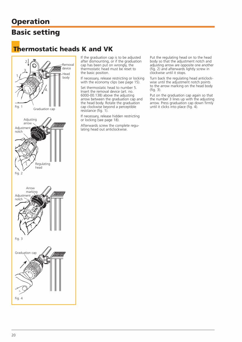
If the graduation cap is to be adjustedafter dismounting, or if the graduationcap has been put on wrongly, the thermostatic head must be reset to the basic position.
If necessary, release restricting or lockingwith the economy clips (see page 15).
Set thermostatic head to number 5.Insert the removal device (art. no. 6000-00.138) above the adjusting arrow between the graduation cap andthe head body. Rotate the graduationcap clockwise beyond a perceptible resistance (fig. 1).
If necessary, release hidden restricting or locking (see page 18).
Afterwards screw the complete regu-lating head out anticlockwise.
Put the regulating head on to the headbody so that the adjustment notch andadjusting arrow are opposite one another(fig. 2) and afterwards lightly screw inclockwise until it stops.
Turn back the regulating head anticlock-wise until the adjustment notch pointsto the arrow marking on the head body(fig. 3).
Put on the graduation cap again so thatthe number 3 lines up with the adjustingarrow. Press graduation cap down firmlyuntil it clicks into place (fig. 4).
3.
1.
2.
4.
Graduation cap
Removaldevice
Headbody
Fig. 1
DV1800-18-483-01-0407.qxd 31.05.2007 9:30 Uhr Seite 20

21
Operation Precision presetting or finest presetting
V-exakt /F-exakt thermostatic valve bodyTo guarantee even hot water distributionand warming of the radiators, a hydraulic balance within the heatingsystem is necessary.
HEIMEIER offers several possibilities, e. g.:1. V-exakt thermostatic valve bodies with
precision presetting
2. F-exakt thermostatic valve bodies withfinest presetting
3. Regulux lockshield4. Balancing valves
Directional marking
Index
Setting key
Index
V-exaktF-exakt
hahnLuft-
The precision presetting/finest presettingof the V-exakt/F-exakt thermostatic valvebodies can be selected from 1; 2; 3; 4; 5and 6. Setting 6 corresponds to the normal setting (manufacturer’s setting).
There is a flow range hidden behindevery setting value, which has a gap-freeconnection to the next range. It is there-fore not necessary, and not permitted, tomake intermediary settings.
With the key, only a specialist can createor change the setting. It is not possiblefor an unqualified person to tamper withthe settings without a tool.
• Position the setting key onto the valveinsert and turn until it clicks into place.
• Turn the index of the required setting value to the directional marking of the valve body.
• Remove the key. The setting can beread on the valve insert from theadjustment direction.
Operation of the presetting or finest presetting
for precision presetting and finest presetting
Art. no. 3501-02.142
Setting key
as an alternative to the setting key foradjusting V-exakt/F-exakt. Also for thermostatic head B (temperature set-ting), thermostatic head K (for pushingout the stop clips), Regulux lockshield,
Vekolux double connection fitting andradiator air vent.Art. no. 0530-01.433
Universal key
DV1800-18-483-01-0407.qxd 31.05.2007 9:30 Uhr Seite 21
22
Retrofitting instructions
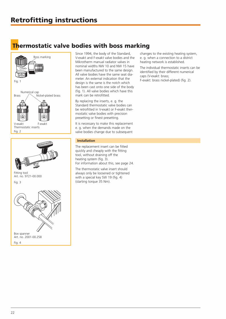
Thermostatic valve bodies with boss marking
Boss marking
Numerical capBrass Nickel-plated brass
V-exakt F-exaktThermostatic inserts
Fitting toolArt. no. 9721-00.000
Box spannerArt. no. 2001-00.258
Fig. 1
Fig. 2
Fig. 3
Fig. 4
Since 1994, the body of the Standard, V-exakt and F-exakt valve bodies and theMikrotherm manual radiator valves innominal widths NW 10 and NW 15 havebeen manufactured to the same design.All valve bodies have the same seat dia-meter. An external indication that thedesign is the same is the notch whichhas been cast onto one side of the body(fig. 1). All valve bodies which have thismark can be retrofitted.
By replacing the inserts, e. g. the Standard thermostatic valve bodies canbe retrofitted in V-exakt or F-exakt ther-mostatic valve bodies with precisionpresetting or finest presetting.
It is necessary to make this replacemente. g. when the demands made on thevalve bodies change due to subsequent
changes to the existing heating system,e. g. when a connection to a district heating network is established.
The individual thermostatic inserts can beidentified by their different numericalcaps (V-exakt: brass; F-exakt: brass nickel-plated) (fig. 2).
The replacement insert can be fittedquickly and cheaply with the fitting tool, without draining off the heating system (fig. 3). For information about this, see page 24.
The thermostatic valve insert shouldalways only be loosened or tightenedwith a special key SW 19 (fig. 4) (starting torque 35 Nm).
Installation
DV1800-18-483-01-0407.qxd 31.05.2007 9:30 Uhr Seite 22
23
Retrofitting instructions
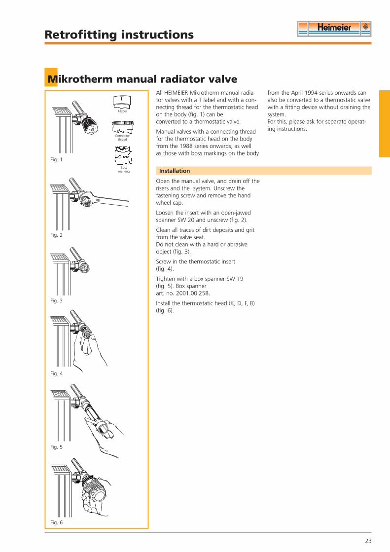
Mikrotherm manual radiator valveAll HEIMEIER Mikrotherm manual radia-tor valves with a T label and with a con-necting thread for the thermostatic headon the body (fig. 1) can be converted to a thermostatic valve.
Manual valves with a connecting threadfor the thermostatic head on the bodyfrom the 1988 series onwards, as well as those with boss markings on the body
from the April 1994 series onwards canalso be converted to a thermostatic valvewith a fitting device without draining thesystem.For this, please ask for separate operat-ing instructions.
Open the manual valve, and drain off therisers and the system. Unscrew thefastening screw and remove the handwheel cap.
Loosen the insert with an open-jawedspanner SW 20 and unscrew (fig. 2).
Clean all traces of dirt deposits and gritfrom the valve seat.Do not clean with a hard or abrasiveobject (fig. 3).
Screw in the thermostatic insert (fig. 4).
Tighten with a box spanner SW 19 (fig. 5). Box spanner art. no. 2001.00.258.
Install the thermostatic head (K, D, F, B)(fig. 6).
Installation
T-label
Connectorthread
3
Fig. 2
Fig. 3
Fig. 4
Fig. 5
Fig. 6
Boss marking
Fig. 1
DV1800-18-483-01-0407.qxd 31.05.2007 9:30 Uhr Seite 23
Retrofitting instructions
Fitting tool
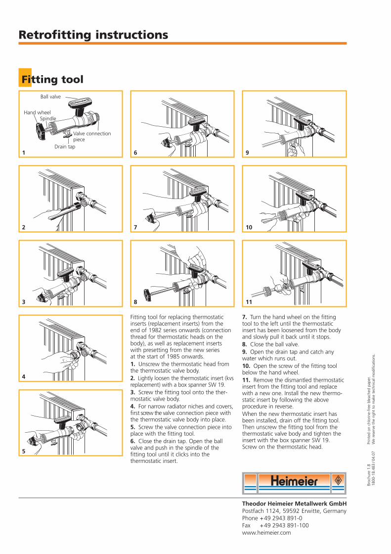
Hand wheel
Drain tap
Ball valve
Spindle
Valve connectionpiece
Fitting tool for replacing thermostaticinserts (replacement inserts) from the end of 1982 series onwards (connectionthread for thermostatic heads on thebody), as well as replacement insertswith presetting from the new series at the start of 1985 onwards.1. Unscrew the thermostatic head fromthe thermostatic valve body.2. Lightly loosen the thermostatic insert (kvsreplacement) with a box spanner SW 19.3. Screw the fitting tool onto the ther-mostatic valve body.4. For narrow radiator niches and covers,first screw the valve connection piece withthe thermostatic valve body into place.5. Screw the valve connection piece intoplace with the fitting tool.6. Close the drain tap. Open the ballvalve and push in the spindle of the fitting tool until it clicks into the thermostatic insert.
7. Turn the hand wheel on the fittingtool to the left until the thermostatic insert has been loosened from the bodyand slowly pull it back until it stops.8. Close the ball valve.9. Open the drain tap and catch anywater which runs out.10. Open the screw of the fitting toolbelow the hand wheel.11. Remove the dismantled thermostaticinsert from the fitting tool and replacewith a new one. Install the new thermo-static insert by following the aboveprocedure in reverse.When the new thermostatic insert hasbeen installed, drain off the fitting tool.Then unscrew the fitting tool from thethermostatic valve body and tighten theinsert with the box spanner SW 19.Screw on the thermostatic head.
1
2
6
7
8
9
10
113
4
5
Broc
hure
1.8
Prin
ted
on c
hlor
ine-
free
ble
ache
d pa
per.
1800
-18.
483
/04.
07W
e re
serv
e th
e rig
ht t
o m
ake
tech
nica
l mod
ifica
tions
.
Theodor Heimeier Metallwerk GmbHPostfach 1124, 59592 Erwitte, GermanyPhone +49 2943 891-0Fax +49 2943 891-100www.heimeier.com
DV1800-18-483-01-0407.qxd 31.05.2007 9:30 Uhr Seite 24