Embed Size (px)
Citation preview
DFPC is powered by
Dutch Fluid Power Conference 2016
Electrical, mechanical and integration aspectsof Hydraulic System Design
Marten Fluks
DFPC is powered by
Topics
Background of speaker
System Architecture
building systems – hydraulic systems
speaker’s perspective
Electrical aspects
hydraulic and electric motors characteristics
efficiency aspects
hydraulic system choice and electric motor for HPUoperating cycle
hydraulic system alternatives
E-motor size
overload prevention
overall efficiency of variable speed drives
1

DFPC is powered by
Topics
Mechanical aspects
mechanical energy transformation
mechanical-hydraulic drive instead of full-hydraulic
optimizing hydraulic system by changing cylinder position
enhancing vehicle hydraulic drive performance by addition of mechanical direct-drive
hydraulic system with mechanical energy storage in fly-wheels
Integration aspects
overall system and next higher system level
snow-ball effect of drive system choice
clear communication functional system description
modes of operation and transitions
document change management2

DFPC is powered by
Speaker’s background
Education: Mechanical Engineering – Hydraulic Drive System Technology; TU Eindhoven; 1968
Royal Netherlands Navy (mil. service): technical staff at MoD
Engineering, Technical Development and Management functions at:
IHC
Stork Group
Hydraudyne
Bosch Rexroth
Design of simple or complex equipment and systems, including hydraulic, electric or hybrid drive technology
Engineering and Consulting activities since 2008: Conseon
3
DFPC is powered by
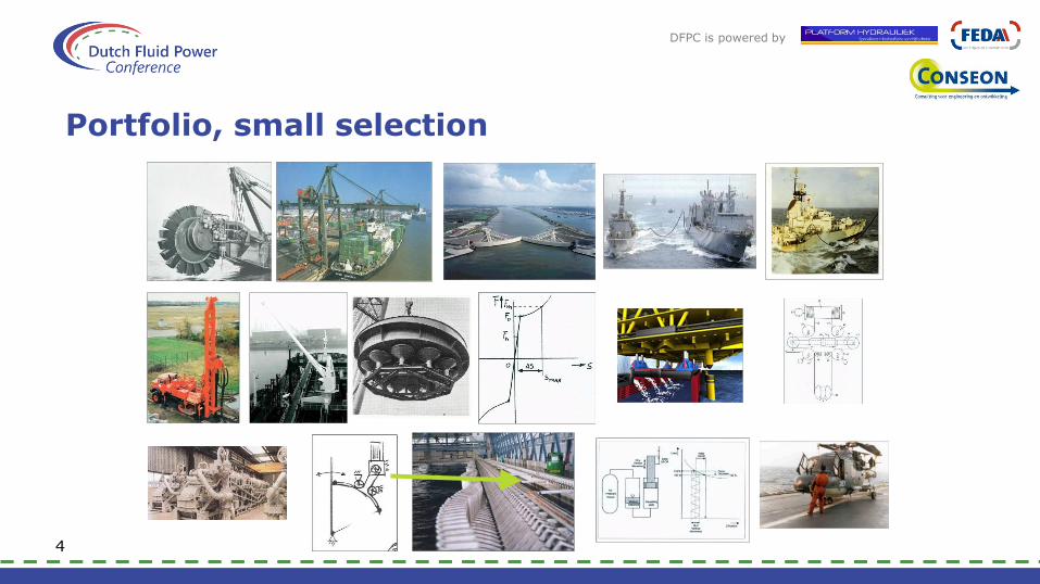
Portfolio, small selection
4

DFPC is powered by
DFPC is powered by
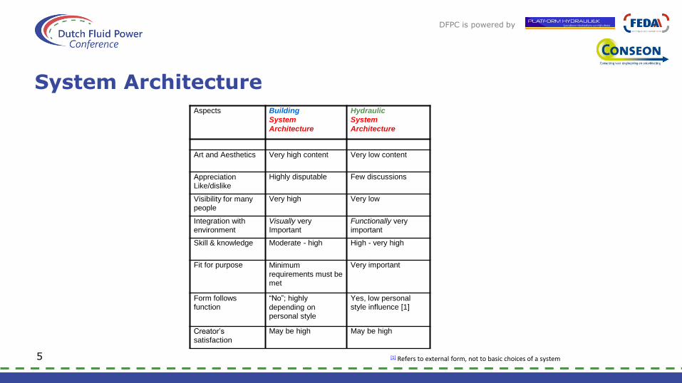
System Architecture
5 [1] Refers to external form, not to basic choices of a system
Aspects Building
System
Architecture
Hydraulic
System
Architecture
Art and Aesthetics Very high content Very low content
Appreciation Like/dislike
Highly disputable Few discussions
Visibility for many people
Very high Very low
Integration with environment
Visually very Important
Functionally very important
Skill & knowledge Moderate - high High - very high
Fit for purpose Minimum
requirements must be met
Very important
Form follows function
“No”; highly
depending on personal style
Yes, low personal style influence [1]
Creator’s satisfaction
May be high May be high

DFPC is powered by
Architecture examples
6
Dutch Embassy Residence in Ljubljana (Bevk, Peroviand Kanduk Architects)
Lou Ruvo Center for Brain Health in Las Vegas (Architect Frank
Gehry)
Hydraulic Power Unit (Direct Industry)
Hydraulic Power Unit (Rosso Hydraulic)

DFPC is powered by
System Architecture
Speaker’s perspective:
7
DriveSystem
Architecture
HydraulicSystem Design
HydraulicDetailDesign
Pro
gres
s o
f D
esig
n P
roce
ss

DFPC is powered by
Focus of presentation
Aspects of hydraulic system design 18 items identified in Vademecum Hydrauliek 2014
now 3 more issues are treated:
electrical
mechanical
integration
Awareness of these 3 aspects may contribute to better and cheaper overall system solutions
8

DFPC is powered by

DFPC is powered by
Electrical aspects
Increasing tendency to use variable speed motors instead of constant speed squirrel cage motors
Many hydraulic applications: preference still exists for constant speed E-motors
Smaller size motors and electrical installations are often possible, compared to “conventional” selection
This presentation is restricted to squirrel cage motors
9
DFPC is powered by
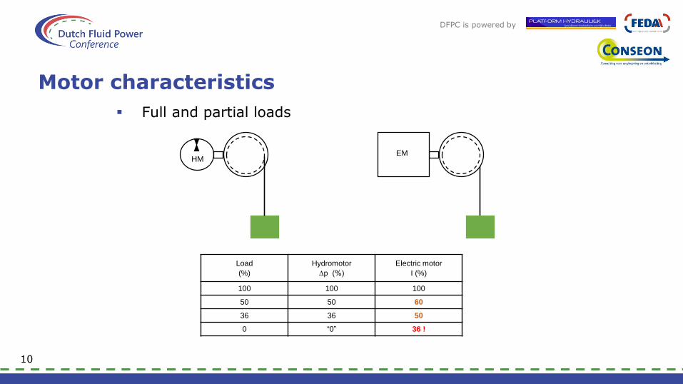
Motor characteristics
Full and partial loads
10
HMEM
Load
(%)
Hydromotor
∆p (%)
Electric motor
I (%)
100 100 100
50 50 60
36 36 50
0 “0” 36 !
DFPC is powered by
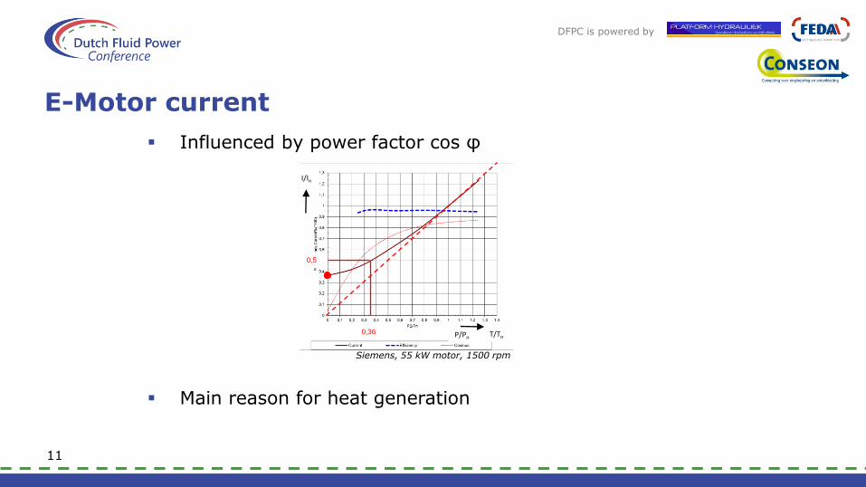
E-Motor current
Influenced by power factor cos φ
Siemens, 55 kW motor, 1500 rpm
Main reason for heat generation
11
I/In
0,5
0,36 T/Tn P/Pn

DFPC is powered by
Motor Efficiency
Hydromotor Electric motor
Calzoni MRD 300; 54 kW Report IEA 2011; 55 kW
E-motors exist in different efficiency classes
IE1; IE2, IE3; IE4
E-motor efficiency decreases at lower nominal power
12
DFPC is powered by
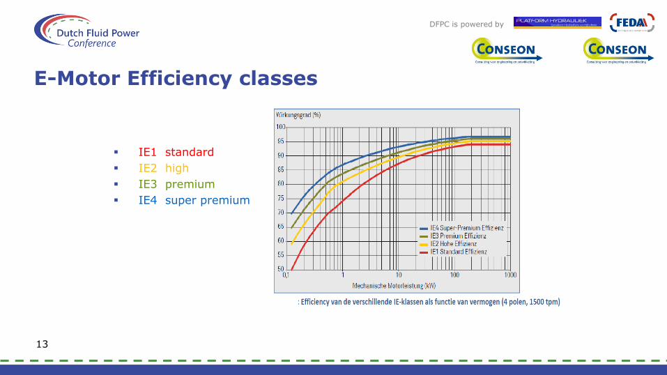
E-Motor Efficiency classes
IE1 standard
IE2 high
IE3 premium
IE4 super premium
13

DFPC is powered by
Energy cost reduction
Replacement of E-motor may be cost-effective
Calculation example:
motor power 22 kW
2-shift operation => approx. 4000 hrs per year
running at nominal load
efficiency IE1: 90,0 %; IE4: 94,5 %
energy cost: € 0,12/kWh
energy cost savings over 5 years:5 x 4000 x 22 x (0,945 – 0,900) x 0,12 = € 2.376,--
this equals twice the purchase price of a new motor !
14

DFPC is powered by
Load conditions and E-motor size
Motors seldom run at nominal load all the time
Some applications comprise extreme low (average load)/(maximum load) ratio:escalators must be capable of transporting more than 1 person at every step over the full length; most of the time only a couple of people are simultaneously transported
Hydraulic power units normally have varying load conditions and thus varying (average load)/(maximum load) ratios
From energy cost and installation price point of view: choose smallest E-motor and let it regularly run in overload conditions
15

DFPC is powered by
Example E-motor selection for HPU
Hydraulic system, 3 consumers (A,B and C), HPU with 1 E-motor driving the pump(s)
Operating conditions : working cycle of 145 seconds, and load profile per consumer according table in next slide
Compare 4 different hydraulic system lay-outs:
a. open circuit; prop. valve control (VC); constant pressure pump (CP) and accumulator (AC)
b. open circuit; prop. valve control (VC) ; load sensing pump (LS)
c. consumer A and B: according b); consumer C: closed circuit, pump control (PC); motor with fixed displacement
d. open circuit; motor control (MC) (secondary control);constant pressure pump (CP) and accumulator (AC)
16

DFPC is powered by
Operating conditions of consumers
In table:
load profile: transferred to pressure (difference) at the consumer
speed profile: transferred to oil flow at the consumer (for fixed displacement motor)
theoretical nett peak power 30 + 25 + 90 = 145 kW
17
Consumer A Consumer B Consumer C
pressure flow time power pressure flow time power pressure flow time power
(bar) (lpm) (s) (kW) (bar) (lpm) (s) (kW) (bar) (lpm) (s) (kW)
250 50 25 20,8 10 5 70 0,1 270 200 40 90,0
180 100 40 30,0 300 40 20 20,0 250 -200 40 -83,3
50 10 80 0,8 100 150 55 25,0 40 400 30 26,7
35 -400 35 -23,3

DFPC is powered by
Operating conditions of consumers
In diagram:
18
DFPC is powered by
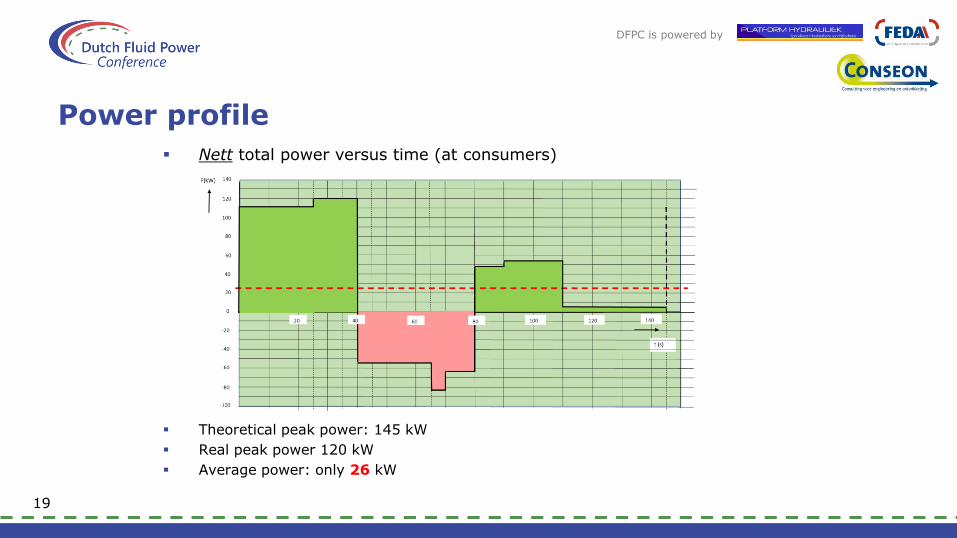
Power profile
Nett total power versus time (at consumers)
Theoretical peak power: 145 kW
Real peak power 120 kW
Average power: only 26 kW
19

DFPC is powered by
Power profile
Gross total power versus time (at pump)
Case b; LS pump
Maximum pump power: 233 kW => 250 kW standard E-motor ??
Average power: 117 kW => 132 kW standard E-motor ??
Req’d cooling power: approx. 100 kW
20

DFPC is powered by
Output power of pump(s)
For 4 hydraulic system lay-outs
Large differences in maximum power and average power
Ratio between average and maximum power:94 %; 50 %; 24 % and 93 % respectively
21
pm
ax
Q
max
Pm
ax
Pav
bar
lpm
kW
kW
a) CP (+accu)
340
396
225
211
b) LS 310
560
233
117
c) PC + LS
310
400160
123
30
d) MC (+accu)
340
53 30 28

DFPC is powered by
Size of electric motor
Two important issues:
Maximum torque at nominal speed, not larger than 1,6 – 1,8 x nominal torque
Effective current (or RMS current), not larger than 1,0 x nominal current at rated speed
22
T max
T nom
I nom

DFPC is powered by
E-motor choice
Case b); standard type (S1; isolation class B)
23

DFPC is powered by
Motor size and energy cost
Comparison table for different hydraulic systems
Same functionality => different system solutions => quite different motor sizes and energy cost
Maximum required hydraulic pump power is often not determining for electric motor size
Average required hydraulic pump power is not always determiningfor electric motor size !
So: careful analysis recommended
Savings in energy cost and lower electric system cost may overcompensate for more expensive hydraulic system !24
Pmax Pav E price PEM
kW kW € / a kW
a) CP (+accu) 225 211 57.101 250
b) LS 233 117 31.753 132
c) PC + LS 123 30 8.167 75
d) MC (+accu) 30 28 7.468 30

DFPC is powered by
Overload prevention
Considerations:
Customer already has some spare capacity in specification?
Standard E-motor mostly larger than necessary (case b: Ieff/Inom = 0,94; so 6 % spare)
Sensitivity analysis recommended
Use isolation class F motors instead of class B
Integrate power limiter with hydraulic pump (hydraulic/mechanical or electronic)
Power limiter to be adjusted at nominal motor power ?!
More ideal: use temperature sensor in motor windings- to gradually limit the power, also based on learning curve
- temporary maximum power can be much higher than withconventional power limiter
25
DFPC is powered by
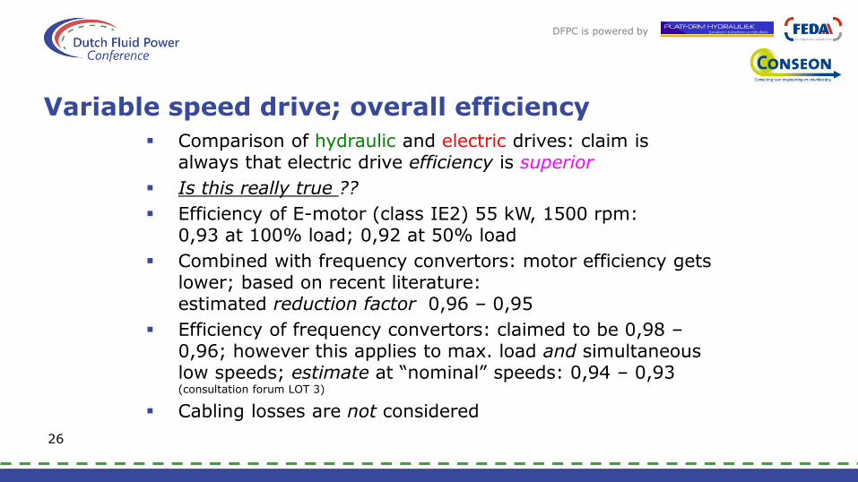
Variable speed drive; overall efficiency
Comparison of hydraulic and electric drives: claim is always that electric drive efficiency is superior
Is this really true ??
Efficiency of E-motor (class IE2) 55 kW, 1500 rpm: 0,93 at 100% load; 0,92 at 50% load
Combined with frequency convertors: motor efficiency gets lower; based on recent literature: estimated reduction factor 0,96 – 0,95
Efficiency of frequency convertors: claimed to be 0,98 –0,96; however this applies to max. load and simultaneous low speeds; estimate at “nominal” speeds: 0,94 – 0,93 (consultation forum LOT 3)
Cabling losses are not considered
26

DFPC is powered by
Electric VSD; overall efficiency
Result:
Claim for superior efficiency of electric drive over hydraulic drive needs reconsideration !!
Proposal: execute test program to verify this; important for position of hydraulics in comparison with electrics. Role for FEDA?
27
Electric motor plus frequency convertor, nominal
55 kW @ 1500 rpm
Efficiency
at 100% load
Efficiency
at 50% load
Motor (IE2 class) 0,93 0,92
Reduction factor for motor 0,96 0,95
Frequency convertor 0,94 0,93
Overall efficiency 0,84 0,81

DFPC is powered by

DFPC is powered by
Mechanical aspects
Mechanical energy transformers are very often used in combination with hydraulics systems:- gear transmissions- lever mechanisms
Gear transmissions at primary (pump)-or at secondary (actuator/motor) side of the hydraulic system or at both sides
Lever mechanisms at actuator side
“Clever” mechanisms may simplify hydraulic system: e.g.only 1 cylinder for 180 deg. arm rotation instead of 2 cylinders and intermediate arm
28

DFPC is powered by
Mechanical-hydraulic system
Ore separation equipment (jig with multiple cells) originally comprised eccentric drive with sine curve
For optimal performance: use saw-tooth curve
In “pre-electronic” era: full-hydraulic solution realized, with complicated and vulnerable system; difficult to adjust
Too much down-time, so new approach required
29
DFPC is powered by
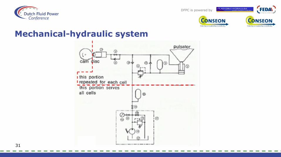
Mechanical-hydraulic system
Solution: Mechanical-hydraulic system replacesfull-hydraulic system
Cam disc with ideal curve drives a number of single piston pumps around perimeter of cam housing
Hydro-pneumatic accumulator stores energy for power peak during fast upward stroke
Combination of mechanics and hydraulics:extremely simple system, and very reliable
Also understood and maintained by low skilled personnel
30
DFPC is powered by
Mechanical-hydraulic system
31

DFPC is powered by
Change of cylinder arrangement
Passive part of Drill String Heave Compensator (1250 kN)
Almost flat force-stroke characteristic necessary (3 % dev.)
So: hydro-pneumatic accumulator with large gas volume
Alternative geometry of cylinder arrangement: inclined position
Kinematic force characteristic compensates gas curve
Result: gas volume reduction 5700 dm3 => 2800 dm3
Combination of mechanical and hydraulic design can save money32

DFPC is powered by
Adding direct mechanical drive
Wheel Drive transmission systems of e.g. agricultural tractors, shovels etc: often use combination of hydraulic and mechanical subsystems.
Examples:
serial power flow parallel power flow (power splitting)
Even more sophisticated and complicated systems are nowadays “common practice”
33

DFPC is powered by
Adding direct mechanical drive
Alternative solution: Simpler system reduces cost and additionally enhances the driving performance
full hydraulic drive mode full mechanical drive mode
Note: this applies for road driving conditions; for “working conditions” (e.g. ploughing) some gear stages remain necessary
34

DFPC is powered by
Road drive characteristic
Low speeds: full hydraulic drive mode
Then fast and smooth transition to next mode
“High” speeds: full mechanical drive mode
35

DFPC is powered by
Energy storage in fly-wheels
Hydro-pneumatic accumulators most widely used in hydraulic systems
Mechanical accumulators (e.g. weight and spring types) rarely are attractive
Fly-wheels may be considered, when low weight and high power density are no main criteria
36
DFPC is powered by
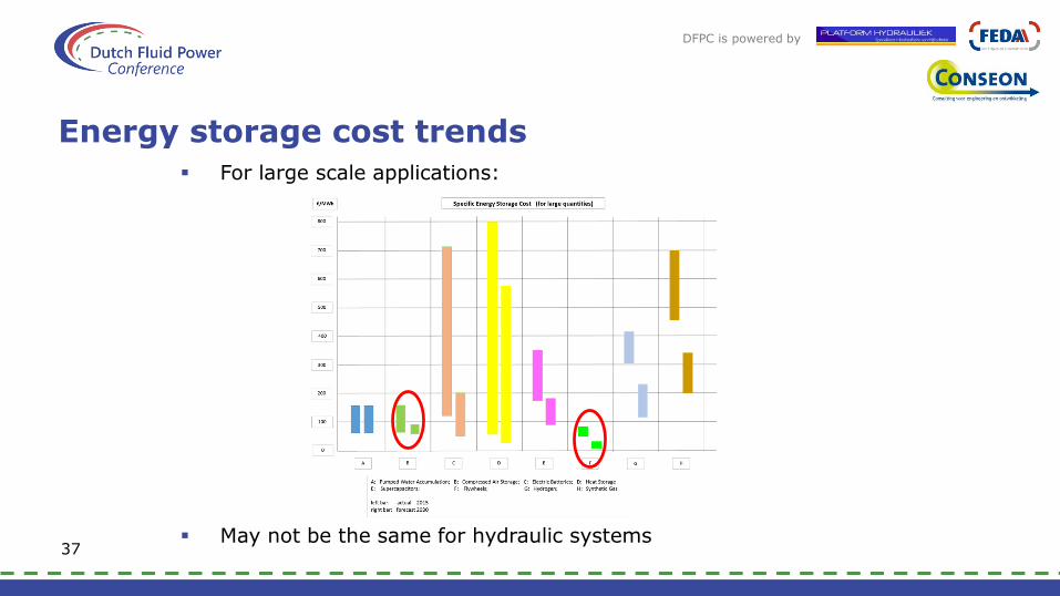
Energy storage cost trends For large scale applications:
May not be the same for hydraulic systems37

DFPC is powered by
Hydraulic system with fly-wheel
Test installation
Simple, reliable and proven long life-time
So: for stationary systems: conventional fly-wheel is interesting alternative as energy storage device
38

DFPC is powered by

DFPC is powered by
Integration aspects
Good system solution is based on proper design process
It involves comparison of alternative solutions
Simplified block diagram (and without drawing feed-back loops):
39
problem definition
different concept solutions
contact with
customer
requirements
selection criteria choice of concept
further design process

DFPC is powered by
Integration aspects
Chance to obtain “best” system solution requires alsolooking at next higher or overall system level:
40
problem definition
different concept solutions
contact with
customer
requirements
selection criteria choice of concept
further design process
relation withoverall system
DFPC is powered by
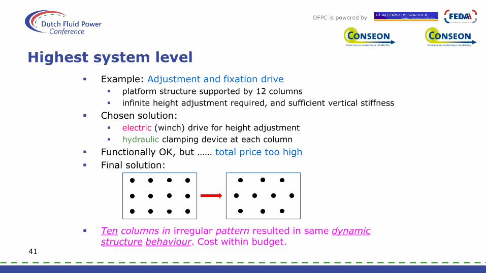
Highest system level
Example: Adjustment and fixation drive
platform structure supported by 12 columns
infinite height adjustment required, and sufficient vertical stiffness
Chosen solution:
electric (winch) drive for height adjustment
hydraulic clamping device at each column
Functionally OK, but …… total price too high
Final solution:
Ten columns in irregular pattern resulted in same dynamicstructure behaviour. Cost within budget.
41

DFPC is powered by
Snow ball effect
Example: Truck mounted concrete pump with different hydraulic drives “on board”
Mass of hydraulic cylinders in top boom sections may have substantial influence on:
- mass of boom section(s)
- luffing cylinder dimension (at lower boom)
- slewing bearing size and mass
- overall weight of slewing and luffing parts
- slewing drive size; slewing and luffing power
- outrigger arm size and mass
- reaction forces on ground and jacking cylinder dimensions
- overall vehicle weight, and possibly one (extra or less) axle and set of wheels
- power for hydraulic system and vehicle propulsion
Solution: use aluminium or carbon fibre cylinders42
DFPC is powered by
Clear communication
Operational description of the intended system
in early stage of engineering phase important for:- review by the customer to check mutual understanding- lead system engineer to verify all functionality is included- explanation of the operation to other engineers
should include different modes of operation and transitionsbetween them
“State diagram” with conditions and restrictions for transition between modes of operation is very useful tool for everyone
Change management of documents
if this is not done properly it can lead to dramatic consequences
advice: maintain document register system43
DFPC is powered by
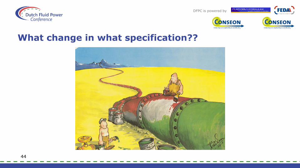
What change in what specification??
44

DFPC is powered by

DFPC is powered by
Summarizing my “message”
Before starting hydraulic system design: what can mechanicscontribute?
Compare different hydraulic system options, including
“smallest” electric motor
cost of associated electric system
energy cost prediction
Reconsider overall efficiency of electric VSD versus hydraulic drive
Stationary applications: use fly-wheel for energy storage?!
For best end-result: always look atnext higher or overall system level aspects
Be aware of snow ball effects
Make operational system description in early engineering stage
Always take care of clear communication
45
DFPC is powered by
Thank you for yourattention !