Embed Size (px)
DESCRIPTION
fust
Citation preview
Aeroqual Dust Sentry User Guide V1.1
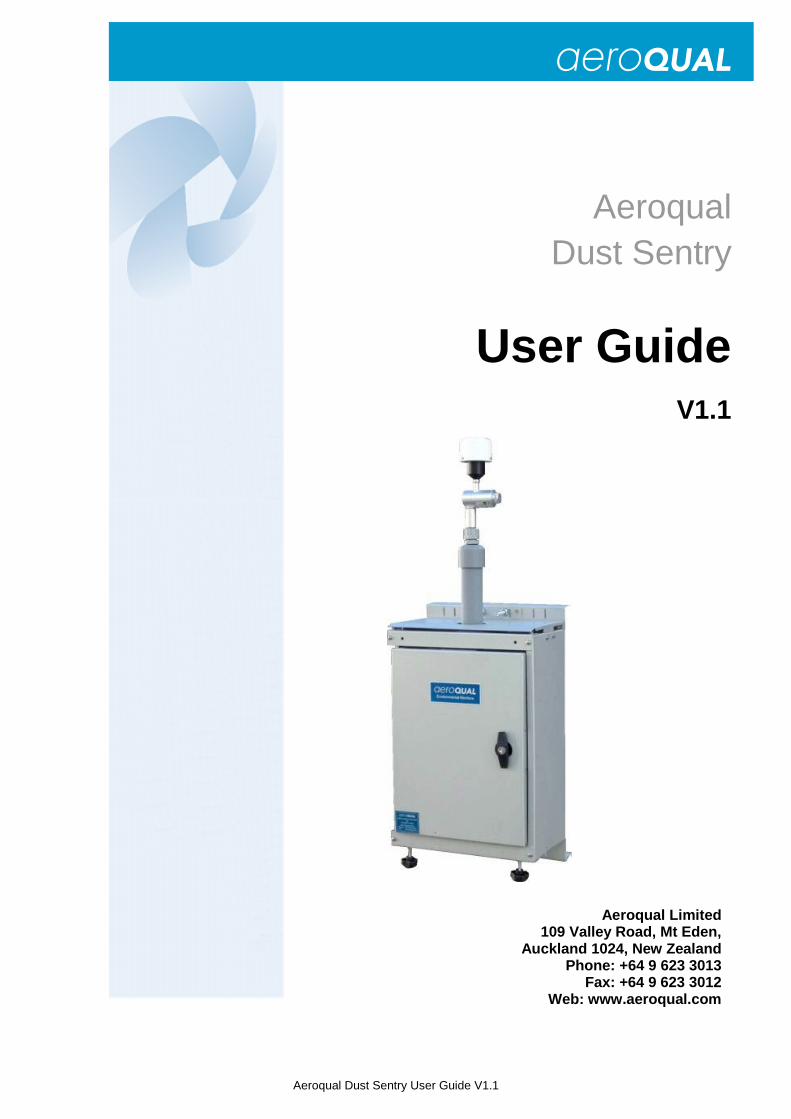
Aeroqual Dust Sentry
User Guide V1.1
Aeroqual Limited 109 Valley Road, Mt Eden,
Auckland 1024, New Zealand Phone: +64 9 623 3013
Fax: +64 9 623 3012 Web: www.aeroqual.com
Page | 2 Aeroqual Dust Sentry User Guide V1.1
Table of Contents
User Guide Revision History ....................... ......................................................................................................... 3 1. Description ....................................... ............................................................................................................. 4
1.1. Internal View .......................................................................................................................................... 4 1.2. Control Module ...................................................................................................................................... 5 1.3. Power Module ........................................................................................................................................ 6 1.4. Electrical Connections ........................................................................................................................... 6 1.5. Alarm Relay ........................................................................................................................................... 6 1.6. Optional Sensors ................................................................................................................................... 7
1.6.1. Vaisala Weather Transmitter WXT520 .......................................................................................... 7 1.6.2. Gill MetPak II Weather Station ...................................................................................................... 8 1.6.3. Sensirion T/RH Sensor SHT75 ..................................................................................................... 8
2. Specifications ..................................... .......................................................................................................... 9 3. Installation ...................................... ............................................................................................................ 10
3.1. Site Positioning Guidelines .................................................................................................................. 10 3.1.1. Inlet height .................................................................................................................................. 10 3.1.2. Measurement Interference .......................................................................................................... 10 3.1.3. Safety .......................................................................................................................................... 10
3.2. Assembly of heated inlet ...................................................................................................................... 10 3.3. Connect Mains Power.......................................................................................................................... 12
4. Start up ........................................... ............................................................................................................. 12 4.1. Set up and PC Software ...................................................................................................................... 12 4.2. IP Modem (Optional)............................................................................................................................ 14
4.2.1. TCP/IP connection ...................................................................................................................... 14 4.2.2. SMS Messaging .......................................................................................................................... 15
4.3. Setting Alarm Function ........................................................................................................................ 16 4.4. Gravimetric Reference Filter ................................................................................................................ 17 4.5. Commissioning Procedures ................................................................................................................. 17
4.5.1. Controller display correct ............................................................................................................ 17 4.5.2. RS232/USB communication OK ................................................................................................. 17 4.5.3. SD card logging correct .............................................................................................................. 17 4.5.4. Configuration correct ................................................................................................................... 17 4.5.5. Sensors all logging ...................................................................................................................... 17 4.5.6. Modem Communication OK - Optional ....................................................................................... 17
5. Maintenance ....................................... ......................................................................................................... 18 5.1. Maintenance Schedule ........................................................................................................................ 18 5.2. Maintenance Procedures ..................................................................................................................... 18
5.2.1. Sample Flow Check and Adjustment .......................................................................................... 18 5.2.2. Purge Flow Check ....................................................................................................................... 19 5.2.3. Manual Zero Air Check ............................................................................................................... 19 5.2.4. Fibre Span Check ....................................................................................................................... 20 5.2.5. Filter Changes............................................................................................................................. 20 5.2.6. Cyclone Cleaning ........................................................................................................................ 20
5.3. Troubleshooting ................................................................................................................................... 21 6. Schematic Diagrams ................................. ................................................................................................. 22
6.1. Pneumatics .......................................................................................................................................... 22 6.1.1. Sample Mode .............................................................................................................................. 22 6.1.2. Zero Mode .................................................................................................................................. 22
6.2. Electrical .............................................................................................................................................. 23 6.3. Communication .................................................................................................................................... 23
7. Appendix .......................................... ........................................................................................................... 24 7.1. Software Menu Descriptions ................................................................................................................ 24 7.2. IP address solutions using GPRS Systems ......................................................................................... 25 7.3. Declarations ......................................................................................................................................... 26 7.4. Technical Support ................................................................................................................................ 27
Page | 3 Aeroqual Dust Sentry User Guide V1.1
User Guide Revision History
Current version: 1.1 Date released: August 2012 Description: User guide for Dust Sentry This user guide is a newly created document for the use of the Aeroqual Dust Sentry.
Date Revision number Description of change Affected pages
Page | 4 Aeroqual Dust Sentry User Guide V1.1
1. Description
Aeroqual’s Dust Sentry is a user friendly device designed to provide reliable real time indicative particulate measurement of TSP, PM10, PM2.5 or PM1 using a well proven near forward light scattering nephelometer and high precision sharp cut cyclone. The basic unit is fitted with the following components:
� Forward Scattering Nephelometer � Weatherproof lockable GRP enclosure � Pole mounting brackets � BLDC pump sampling module � Heated sampling tube with TSP inlet � Sharp cut cyclone (PM10/PM2.5/PM1)
� GF reference filter 25mm � 100-250V AC power supply and 12V DC
input � Alarm relay output � Control Module � PC software
The instrument includes an integrated internal data logger, alarm relay outputs and a backup SD card as standard. There are also numerous additional options available, including, wireless communications, SMS and email notifications, weather sensors and mounting equipment. The instrument is packaged in a robust, lockable enclosure and is light enough for one person site installations. The ease of installation, as well as the extensive range of possible add-ons, enables the unit to be used in a wide range of applications. The most common of these include:
• Roadside/ Urban PM measurement
• Nuisance dust detection and alerts
• Industrial site compliance monitoring
• Construction, quarries and mining sites
• PM monitoring networks
• Community exposure studies: residential, schools, hospitals, epidemiological
• Workplace monitoring
• Smoke / biomass burn-off detection
• Automatic dust control system
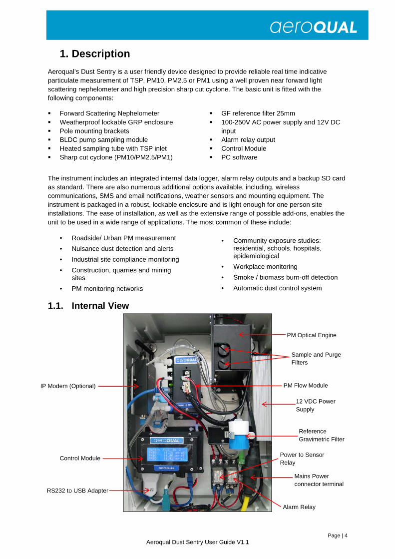
1.1. Internal View
Sample and Purge Filters
Mains Power connector terminal
RS232 to USB Adapter
Power to Sensor Relay
Alarm Relay
IP Modem (Optional)
Reference Gravimetric Filter
12 VDC Power Supply
PM Flow Module
PM Optical Engine
Control Module
Page | 5 Aeroqual Dust Sentry User Guide V1.1
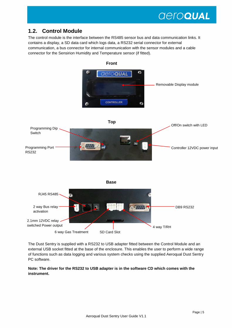
1.2. Control Module The control module is the interface between the RS485 sensor bus and data communication links. It contains a display, a SD data card which logs data, a RS232 serial connector for external communication, a bus connector for internal communication with the sensor modules and a cable connector for the Sensirion Humidity and Temperature sensor (if fitted).
The Dust Sentry is supplied with a RS232 to USB adapter fitted between the Control Module and an external USB socket fitted at the base of the enclosure. This enables the user to perform a wide range of functions such as data logging and various system checks using the supplied Aeroqual Dust Sentry PC software.
Note: The driver for the RS232 to USB adapter is in the software CD which comes with the instrument.
Top Off/On switch with LED
Controller 12VDC power input Programming Port RS232
Programming Dip Switch
6 way Gas Treatment SD Card Slot
DB9 RS232
4 way T/RH
2 way Bus relay activation
RJ45 RS485
2.1mm 12VDC relay switched Power output
Base
Removable Display module
Front

Page | 6 Aeroqual Dust Sentry User Guide V1.1
1.3. Power Module The Meanwell HLG240-12A 192W 12V Single Output Class 2 with PFC Power Unit is mounted on the right hand side of the enclosure. It has a universal AC input (90-280VAC) and IP67/IP65 rating.
1.4. Electrical Connections The Dust Sentry internal power is 12 VDC. An external mains to 12 VDC power supply may be fitted (if ordered) and this will allow connection to mains supply. Otherwise connect 12 VDC via the gland.
RS485 Bus The two wire RS485 bus connections are made using 20 cm CAT5 cables between the sensor modules. The last module on the bus also has a blue termination dongle fitted.
Note: The termination dongle should not be removed.
12 VDC Power Bus All modules inside the Dust Sentry operate from the 12VDC power. The power is supplied by a daisy chain of black and red cables. A relay is activated by the Control Module on/off button to allow the sensor bus to be powered.
12 VDC Power in 12 VDC power is connected into the instrument at the Din Rail power connector.
Safety Conformity: This product, when properly installed and operated is considered a Class I laser product. Class I laser products are not considered to be hazardous.
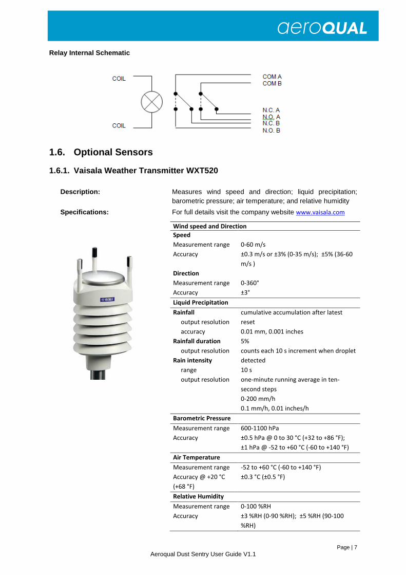
1.5. Alarm Relay The Alarm relay coil is activated by the Control Module in response to the Alarm set point. The Set point is programmed into the Control Module via the Operation menu in the PC Software. The Alarm Relay is a double pole, double throw type (see diagrams below). This allows the connection of two different alarm signals – e.g. siren and strobe - that may have different power requirements.
The relay contacts rating: 10A @ 24VDC 220VAC.
Page | 7 Aeroqual Dust Sentry User Guide V1.1
Relay Internal Schematic
1.6. Optional Sensors
1.6.1. Vaisala Weather Transmitter WXT520
Description: Measures wind speed and direction; liquid precipitation; barometric pressure; air temperature; and relative humidity
Specifications: For full details visit the company website www.vaisala.com
Wind speed and Direction
Speed
Measurement range
Accuracy
Direction
Measurement range
Accuracy
0-60 m/s
±0.3 m/s or ±3% (0-35 m/s); ±5% (36-60
m/s )
0-360°
±3°
Liquid Precipitation
Rainfall
output resolution
accuracy
Rainfall duration
output resolution
Rain intensity
range
output resolution
cumulative accumulation after latest
reset
0.01 mm, 0.001 inches
5%
counts each 10 s increment when droplet
detected
10 s
one-minute running average in ten-
second steps
0-200 mm/h
0.1 mm/h, 0.01 inches/h
Barometric Pressure
Measurement range
Accuracy
600-1100 hPa
±0.5 hPa @ 0 to 30 °C (+32 to +86 °F);
±1 hPa @ -52 to +60 °C (-60 to +140 °F)
Air Temperature
Measurement range
Accuracy @ +20 °C
(+68 °F)
-52 to +60 °C (-60 to +140 °F)
±0.3 °C (±0.5 °F)
Relative Humidity
Measurement range
Accuracy
0-100 %RH
±3 %RH (0-90 %RH); ±5 %RH (90-100
%RH)
Page | 8 Aeroqual Dust Sentry User Guide V1.1
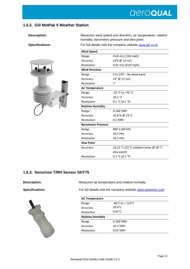
1.6.2. Gill MetPak II Weather Station
Description: Measures wind speed and direction; air temperature; relative humidity; barometric pressure and dew point
Specifications: For full details visit the company website www.gill.co.uk
1.6.3. Sensirion T/RH Sensor SHT75
Description: Measures air temperature and relative humidity
Specifications For full details visit the company website www.sensirion.com
Wind Speed
Range
Accuracy
Resolution
0-60 m/s (134 mph)
±2% @ 12 m/s
0.01 m/s (0.02 mph)
Wind Direction
Range
Accuracy
Resolution
0 to 359° - No dead band
±3° @ 12 m/s
1°
Air Temperature
Range
Accuracy
Resolution
-35 °C to +70 °C
±0.1 °C
0.1 °C (0.1 °F)
Relative Humidity
Range
Accuracy
Resolution
0-100 %RH
±0.8 % @ 23 °C
0.1 %RH
Barometric Pressure
Range
Accuracy
Resolution
800-1100 hPa
±0.5 hPa
±0.1 hPa
Dew Point
Accuracy
Resolution
±0.15 °C (23 °C ambient temp @ 20 °C
dew point)
0.1 °C (0.1 °F)
Air Temperature
Range
Accuracy
Resolution
-40°C to + 123°C
±0.4°C
0.01°C
Relative Humidity
Range
Accuracy
Resolution
0-100 %RH
±0.3 %RH
0.05 %RH
Page | 9 Aeroqual Dust Sentry User Guide V1.1
2. Specifications
The Particle Monitor uses a Met One Instruments Inc. 80180 OEM Mass Detector which operates on the principle of light scatter from suspended particulates to provide a continuous real time measurement of airborne particulate.
More detailed specifications are in the table below. The Particle Monitor is supplied with a 1 µm, 2.5 µm or 10 µm sharp cut cyclone to measure PM1, PM2.5 or PM10, respectively.
Measurement technology Near forward light scattering nephelometer
Range 0-2000µg/m3
Accuracy +/- 8%
Precision 3 ug/m3 (or 2% reading)
Cut points available PM1, PM2.5, PM10, TSP
Inlet 36cm heated inlet with TSP Head and sharp cut cyclone
Flow rate 2 LPM
Alarm Relay, SMS, Email
Data logging 2GB SD card (>15 years data storage)
Display 4 Line Alphanumeric
Output data units µg/m3 / PPM
Averaging Period 1-60 minutes
Reference filter 25mm GFA circular filter
Software Data logging & alarm configuration software included
Outputs RS232 (38400 Baud) & wireless IP Gateway
Mounting Pole or wall mounting hardware included
Wireless communication options GPRS TCP/IP enabled modem
Meteorological sensor options Temperature & RH, Gill WindSonic, Vaisala WXT520
Environmental operating range -10°C to +55°C; 10 to 95% RH (NC)
Power requirements Mains (100 to 260VAC) or 12VDC (10W)
Enclosure Lockable & weatherproof GRP cabinet IP65; 420 x 315 x 180mm (excluding solar shield armour & mounting brackets)
Weight <12kg
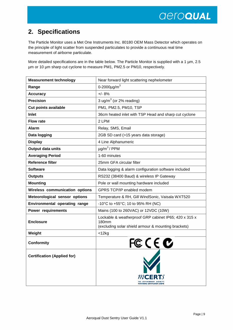
Conformity
Certification (Applied for)

Page | 10 Aeroqual Dust Sentry User Guide V1.1
3. Installation
3.1. Site Positioning Guidelines It is important that the positioning of the Dust Sentry is suitable so as to yield data which is representative of that specific location.
3.1.1. Inlet height • If PM monitoring is related to human exposure, the sampling inlet height should be positioned
in the “breathing zone”. This is located between 2 and 15 meters above ground level. • If PM monitoring is related to specific emission sources, the position of the sampling inlet can
be more flexible. It is more important that there is no obstruction between the approaching air from the emission source and the sampling inlet.
• If more than one Dust Sentry, or any other particulate instrument, is being used at the site, the height of the inlets should be uniform.
• If the Dust Sentry inlet is the highest point at the site, a lightning rod must be installed to prevent damage to the unit during electrical storms.
3.1.2. Measurement Interference • The meteorological conditions of the site should be taken into consideration when positioning
the Dust Sentry. For example, there should be no obstruction to the air flow in the predominant wind direction. A minimum clear sky angle of 120 degrees is recommended.
• The inlet should be at least 1 meter away from any objects that could potentially influence the airflow characteristics e.g. trees, vertical surfaces or walls.
• Avoid overhead high-voltage cables which may cause electrical interference with the sampling equipment.
• Demolition/construction activities and change to normal transport patterns due to road works etc. can significantly affect the data. Ensure a record of such events is kept to account for unexpected peaks in concentration.
3.1.3. Safety • The intended data capture rate should be considered when positioning the Dust Sentry. If
data capture above 90% is essential, the unit should be located in an area which has 24 hour access available.
• The positioning should allow for routine maintenance checks to be performed safely by personnel.
• If using a tripod, ensure the tripod legs are bolted to the ground to prevent the unit from falling.
• Ensure the Dust Sentry is in a secure location to avoid vandalism or theft.
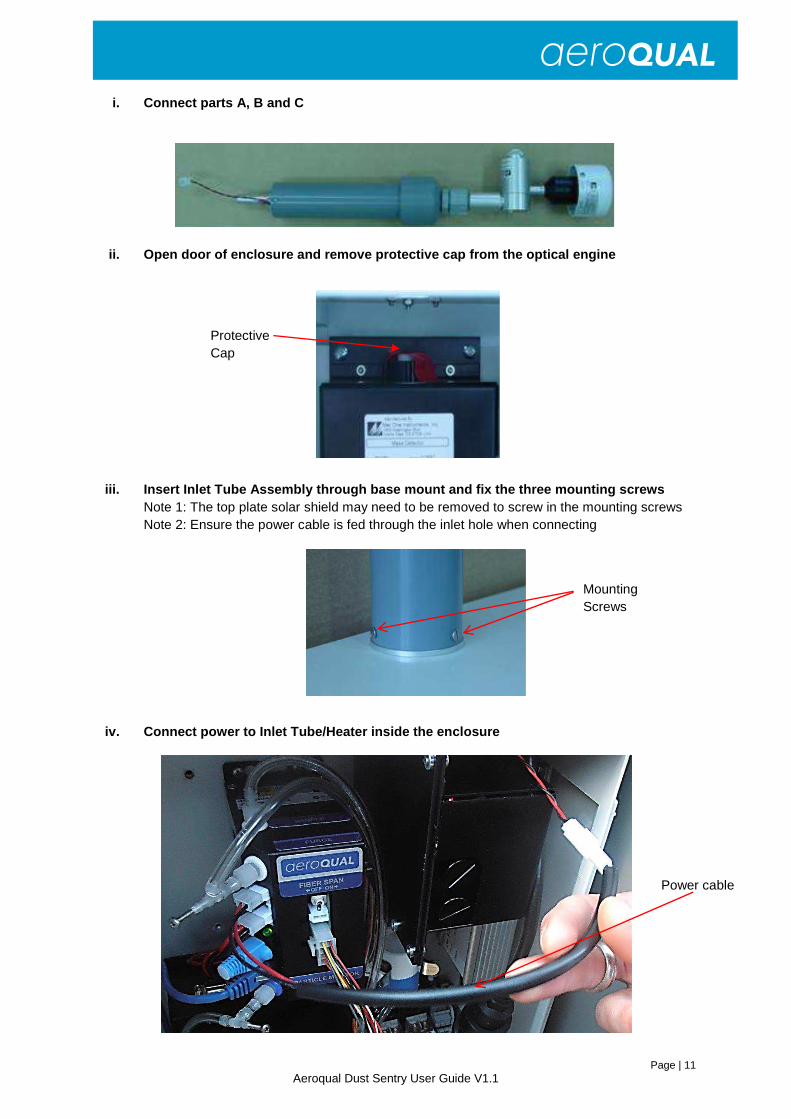
3.2. Assembly of heated inlet Parts List:
A. Inlet Tube/Heater including power cable B. Sharp Cut Cyclone (if fitted) C. TSP Inlet
A B C
Page | 11 Aeroqual Dust Sentry User Guide V1.1
Power cable
i. Connect parts A, B and C
ii. Open door of enclosure and remove protective ca p from the optical engine
iii. Insert Inlet Tube Assembly through base mount and fix the three mounting screws Note 1: The top plate solar shield may need to be removed to screw in the mounting screws Note 2: Ensure the power cable is fed through the inlet hole when connecting
iv. Connect power to Inlet Tube/Heater inside the enclosure
Protective Cap
Mounting Screws
Page | 12 Aeroqual Dust Sentry User Guide V1.1
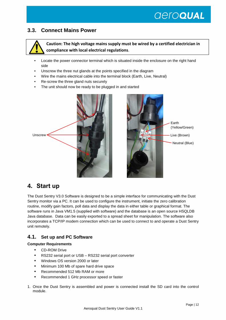
3.3. Connect Mains Power
• Locate the power connector terminal which is situated inside the enclosure on the right hand
side • Unscrew the three nut glands at the points specified in the diagram • Wire the mains electrical cable into the terminal block (Earth, Live, Neutral) • Re-screw the three gland nuts securely • The unit should now be ready to be plugged in and started
4. Start up
The Dust Sentry V3.0 Software is designed to be a simple interface for communicating with the Dust Sentry monitor via a PC. It can be used to configure the instrument, initiate the zero calibration routine, modify gain factors, poll data and display the data in either table or graphical format. The software runs in Java VM1.5 (supplied with software) and the database is an open source HSQLDB Java database. Data can be easily exported to a spread sheet for manipulation. The software also incorporates a TCP/IP modem connection which can be used to connect to and operate a Dust Sentry unit remotely.
4.1. Set up and PC Software
Computer Requirements
• CD-ROM Drive • RS232 serial port or USB – RS232 serial port converter • Windows OS version 2000 or later • Minimum 100 Mb of spare hard drive space • Recommended 512 Mb RAM or more • Recommended 1 GHz processor speed or faster
1. Once the Dust Sentry is assembled and power is connected install the SD card into the control
module.
Caution: The high voltage mains supply must be wired by a certified electrician in
compliance with local electrical regulations.
Unscrew
Neutral (Blue)
Earth (Yellow/Green)
Live (Brown)
Page | 13 Aeroqual Dust Sentry User Guide V1.1
2. Start the Dust Sentry by pushing the on/off switch on the control module
3. Connect the instrument using a computer via the USB cable to the outside of the enclosure 4. Configure:
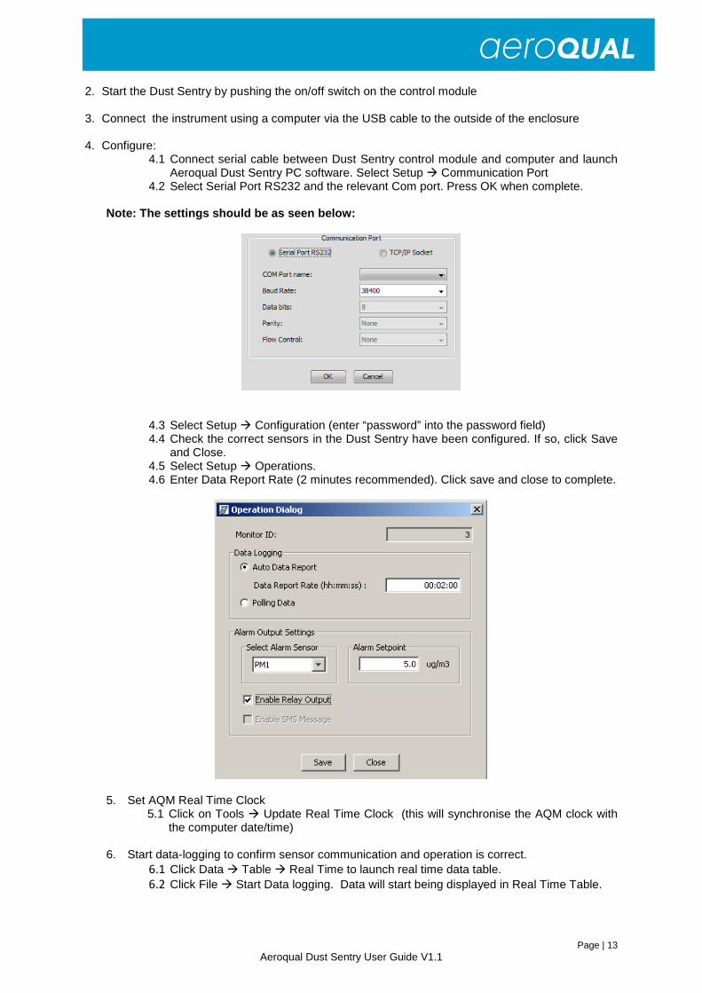
4.1 Connect serial cable between Dust Sentry control module and computer and launch Aeroqual Dust Sentry PC software. Select Setup � Communication Port
4.2 Select Serial Port RS232 and the relevant Com port. Press OK when complete. Note: The settings should be as seen below:
4.3 Select Setup � Configuration (enter “password” into the password field) 4.4 Check the correct sensors in the Dust Sentry have been configured. If so, click Save
and Close. 4.5 Select Setup � Operations. 4.6 Enter Data Report Rate (2 minutes recommended). Click save and close to complete.
5. Set AQM Real Time Clock 5.1 Click on Tools � Update Real Time Clock (this will synchronise the AQM clock with
the computer date/time)
6. Start data-logging to confirm sensor communication and operation is correct. 6.1 Click Data � Table � Real Time to launch real time data table. 6.2 Click File � Start Data logging. Data will start being displayed in Real Time Table.
Page | 14 Aeroqual Dust Sentry User Guide V1.1
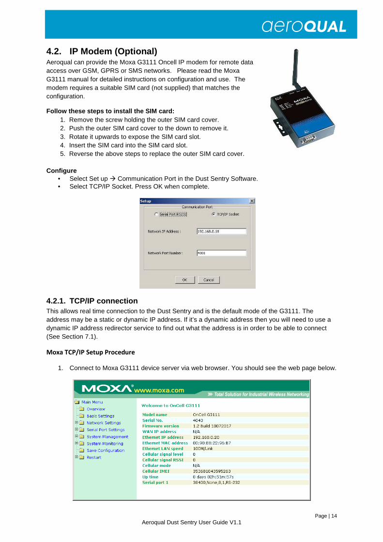
4.2. IP Modem (Optional)
Aeroqual can provide the Moxa G3111 Oncell IP modem for remote data access over GSM, GPRS or SMS networks. Please read the Moxa G3111 manual for detailed instructions on configuration and use. The modem requires a suitable SIM card (not supplied) that matches the configuration.
Follow these steps to install the SIM card: 1. Remove the screw holding the outer SIM card cover. 2. Push the outer SIM card cover to the down to remove it. 3. Rotate it upwards to expose the SIM card slot. 4. Insert the SIM card into the SIM card slot. 5. Reverse the above steps to replace the outer SIM card cover.
Configure
• Select Set up � Communication Port in the Dust Sentry Software. • Select TCP/IP Socket. Press OK when complete.
4.2.1. TCP/IP connection This allows real time connection to the Dust Sentry and is the default mode of the G3111. The address may be a static or dynamic IP address. If it’s a dynamic address then you will need to use a dynamic IP address redirector service to find out what the address is in order to be able to connect (See Section 7.1).
Moxa TCP/IP Setup Procedure
1. Connect to Moxa G3111 device server via web browser. You should see the web page below.
Page | 15 Aeroqual Dust Sentry User Guide V1.1
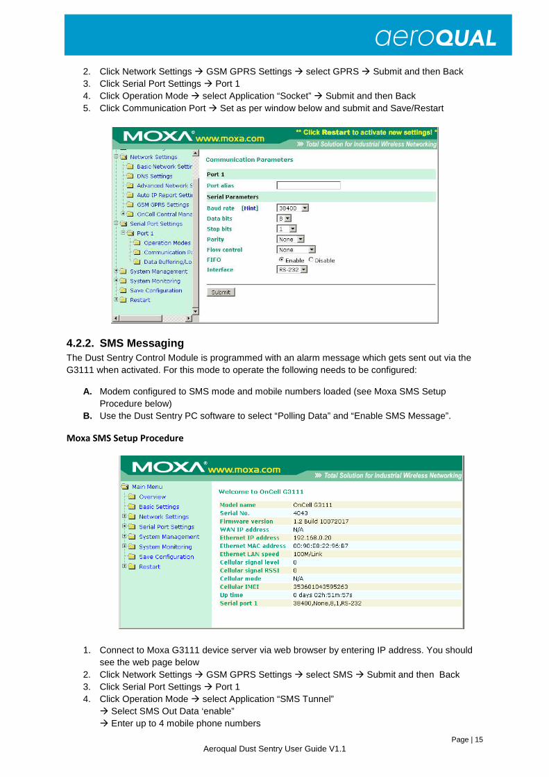
2. Click Network Settings � GSM GPRS Settings � select GPRS � Submit and then Back 3. Click Serial Port Settings � Port 1 4. Click Operation Mode � select Application “Socket” � Submit and then Back 5. Click Communication Port � Set as per window below and submit and Save/Restart
4.2.2. SMS Messaging The Dust Sentry Control Module is programmed with an alarm message which gets sent out via the G3111 when activated. For this mode to operate the following needs to be configured:
A. Modem configured to SMS mode and mobile numbers loaded (see Moxa SMS Setup Procedure below)
B. Use the Dust Sentry PC software to select “Polling Data” and “Enable SMS Message”.
Moxa SMS Setup Procedure
1. Connect to Moxa G3111 device server via web browser by entering IP address. You should see the web page below
2. Click Network Settings � GSM GPRS Settings � select SMS � Submit and then Back 3. Click Serial Port Settings � Port 1 4. Click Operation Mode � select Application “SMS Tunnel”
� Select SMS Out Data ‘enable” � Enter up to 4 mobile phone numbers
Page | 16 Aeroqual Dust Sentry User Guide V1.1
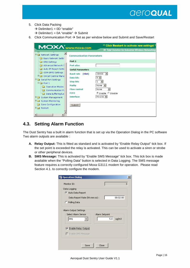
5. Click Data Packing � Delimiter1 = 0D “enable”
� Delimiter1 = 0A “enable” � Submit 6. Click Communication Port � Set as per window below and Submit and Save/Restart
4.3. Setting Alarm Function
The Dust Sentry has a built in alarm function that is set up via the Operation Dialog in the PC software Two alarm outputs are available :
A. Relay Output: This is fitted as standard and is activated by “Enable Relay Output” tick box. If the set point is exceeded the relay is activated. This can be used to activate a siren or strobe or other peripheral devices.
B. SMS Message: This is activated by “Enable SMS Message” tick box. This tick box is made available when the “Polling Data” button is selected in Data Logging. The SMS message feature requires a correctly configured Moxa G3111 modem for operation. Please read Section 4.1. to correctly configure the modem.
Page | 17 Aeroqual Dust Sentry User Guide V1.1
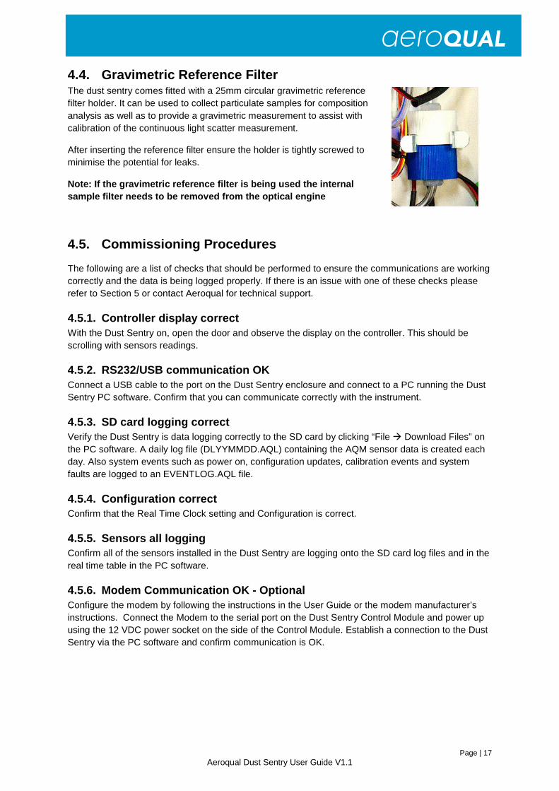
4.4. Gravimetric Reference Filter The dust sentry comes fitted with a 25mm circular gravimetric reference filter holder. It can be used to collect particulate samples for composition analysis as well as to provide a gravimetric measurement to assist with calibration of the continuous light scatter measurement.
After inserting the reference filter ensure the holder is tightly screwed to minimise the potential for leaks.
Note: If the gravimetric reference filter is being used the internal sample filter needs to be removed from the optical engine
4.5. Commissioning Procedures
The following are a list of checks that should be performed to ensure the communications are working correctly and the data is being logged properly. If there is an issue with one of these checks please refer to Section 5 or contact Aeroqual for technical support.
4.5.1. Controller display correct With the Dust Sentry on, open the door and observe the display on the controller. This should be scrolling with sensors readings.
4.5.2. RS232/USB communication OK Connect a USB cable to the port on the Dust Sentry enclosure and connect to a PC running the Dust Sentry PC software. Confirm that you can communicate correctly with the instrument.
4.5.3. SD card logging correct Verify the Dust Sentry is data logging correctly to the SD card by clicking “File � Download Files” on the PC software. A daily log file (DLYYMMDD.AQL) containing the AQM sensor data is created each day. Also system events such as power on, configuration updates, calibration events and system faults are logged to an EVENTLOG.AQL file.
4.5.4. Configuration correct Confirm that the Real Time Clock setting and Configuration is correct.
4.5.5. Sensors all logging Confirm all of the sensors installed in the Dust Sentry are logging onto the SD card log files and in the real time table in the PC software.
4.5.6. Modem Communication OK - Optional Configure the modem by following the instructions in the User Guide or the modem manufacturer’s instructions. Connect the Modem to the serial port on the Dust Sentry Control Module and power up using the 12 VDC power socket on the side of the Control Module. Establish a connection to the Dust Sentry via the PC software and confirm communication is OK.

Page | 18 Aeroqual Dust Sentry User Guide V1.1
5. Maintenance
5.1. Maintenance Schedule
Procedure Section Frequency
Sample Flow Check 5.2.1. Monthly
Purge Flow Check 5.2.2. Monthly
Manual Zero Air Check 5.2.3. Monthly
Fibre Span Check 5.2.4. Monthly
Filter Changes 5.2.5. Yearly
Cyclone Cleaning 5.2.6. Monthly
Note: Suggested intervals for maintenance procedure s may vary with sampling intensity and environmental conditions
Note: All checks should be carried out during the c ommissioning of the Dust Sentry
5.2. Maintenance Procedures
5.2.1. Sample Flow Check and Adjustment A constant flow is essential to ensure the sharp cut cyclone is separating out the correct particle size to be measured e.g. PM10 or PM2.5. To measure the flow, remove the TSP head from the inlet and connect the volumetric flow meter to the top of the sharp cut cyclone using the adaptor supplied with the instrument. Ensure the flow meter is on a steady surface before reading the flow rate.
Note: The flow should be 2.0 LPM
The PM inlet flow can be adjusted via the flow adjuster on the exhaust and sample line.
• If the flow is less than 2.0 LPM then close the purge flow screw (turn clockwise) until 2.0 LPM is achieved.
• If the flow is greater than 2.0 LPM then open the purge flow screw (turn anticlockwise) until the flow is 2.0 LPM.
• If you can’t adjust the flow to 2 LPM using the purge flow screw then close (clockwise) the exhaust flow screw until 2.0 LPM is achieved.
Afterwards replace the inlet components with care making sure there is no leak.
Page | 19 Aeroqual Dust Sentry User Guide V1.1
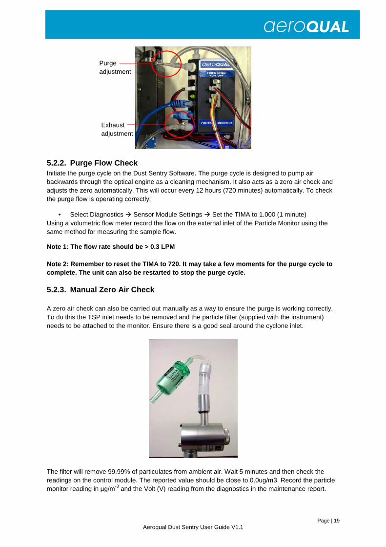
Exhaust adjustment
Purge adjustment
5.2.2. Purge Flow Check Initiate the purge cycle on the Dust Sentry Software. The purge cycle is designed to pump air backwards through the optical engine as a cleaning mechanism. It also acts as a zero air check and adjusts the zero automatically. This will occur every 12 hours (720 minutes) automatically. To check the purge flow is operating correctly:
• Select Diagnostics � Sensor Module Settings � Set the TIMA to 1.000 (1 minute) Using a volumetric flow meter record the flow on the external inlet of the Particle Monitor using the same method for measuring the sample flow.
Note 1: The flow rate should be > 0.3 LPM Note 2: Remember to reset the TIMA to 720. It may t ake a few moments for the purge cycle to complete. The unit can also be restarted to stop th e purge cycle.
5.2.3. Manual Zero Air Check A zero air check can also be carried out manually as a way to ensure the purge is working correctly. To do this the TSP inlet needs to be removed and the particle filter (supplied with the instrument) needs to be attached to the monitor. Ensure there is a good seal around the cyclone inlet.
The filter will remove 99.99% of particulates from ambient air. Wait 5 minutes and then check the readings on the control module. The reported value should be close to 0.0ug/m3. Record the particle monitor reading in µg/m-3 and the Volt (V) reading from the diagnostics in the maintenance report.
Page | 20 Aeroqual Dust Sentry User Guide V1.1
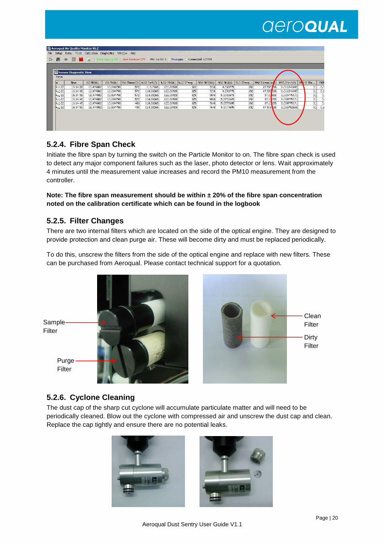
5.2.4. Fibre Span Check Initiate the fibre span by turning the switch on the Particle Monitor to on. The fibre span check is used to detect any major component failures such as the laser, photo detector or lens. Wait approximately 4 minutes until the measurement value increases and record the PM10 measurement from the controller.
Note: The fibre span measurement should be within ± 20% of the fibre span concentration noted on the calibration certificate which can be f ound in the logbook
5.2.5. Filter Changes There are two internal filters which are located on the side of the optical engine. They are designed to provide protection and clean purge air. These will become dirty and must be replaced periodically.
To do this, unscrew the filters from the side of the optical engine and replace with new filters. These can be purchased from Aeroqual. Please contact technical support for a quotation.
5.2.6. Cyclone Cleaning The dust cap of the sharp cut cyclone will accumulate particulate matter and will need to be periodically cleaned. Blow out the cyclone with compressed air and unscrew the dust cap and clean. Replace the cap tightly and ensure there are no potential leaks.
Dirty Filter
Purge Filter
Sample Filter
Clean Filter
Page | 21 Aeroqual Dust Sentry User Guide V1.1
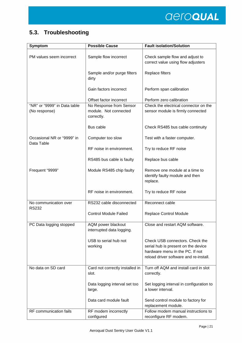
5.3. Troubleshooting
Symptom Possible Cause Fault isolation/Solution PM values seem incorrect
Sample flow incorrect Sample and/or purge filters dirty Gain factors incorrect Offset factor incorrect
Check sample flow and adjust to correct value using flow adjusters Replace filters Perform span calibration Perform zero calibration
“NR” or “9999” in Data table (No response) Occasional NR or “9999” in Data Table Frequent “9999”
No Response from Sensor module. Not connected correctly. Bus cable Computer too slow RF noise in environment. RS485 bus cable is faulty Module RS485 chip faulty RF noise in environment.
Check the electrical connector on the sensor module is firmly connected Check RS485 bus cable continuity Test with a faster computer. Try to reduce RF noise Replace bus cable Remove one module at a time to identify faulty module and then replace. Try to reduce RF noise
No communication over RS232
RS232 cable disconnected Control Module Failed
Reconnect cable Replace Control Module
PC Data logging stopped AQM power blackout interrupted data logging. USB to serial hub not working
Close and restart AQM software. Check USB connectors. Check the serial hub is present on the device hardware menu in the PC. If not reload driver software and re-install.
No data on SD card
Card not correctly installed in slot. Data logging interval set too large. Data card module fault
Turn off AQM and install card in slot correctly. Set logging interval in configuration to a lower interval. Send control module to factory for replacement module.
RF communication fails RF modem incorrectly configured
Follow modem manual instructions to reconfigure RF modem.
Page | 22 Aeroqual Dust Sentry User Guide V1.1
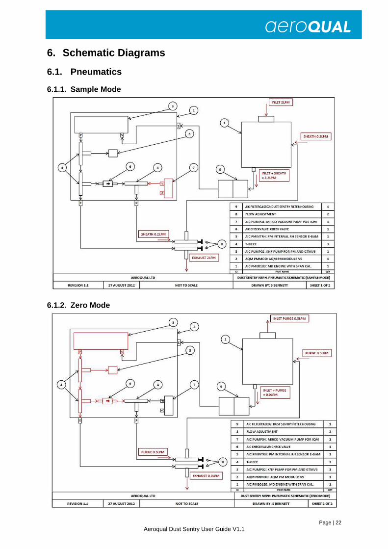
6. Schematic Diagrams
6.1. Pneumatics
6.1.1. Sample Mode
6.1.2. Zero Mode
Page | 23 Aeroqual Dust Sentry User Guide V1.1
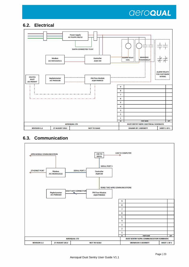
6.2. Electrical
6.3. Communication
Page | 24 Aeroqual Dust Sentry User Guide V1.1
7. Appendix
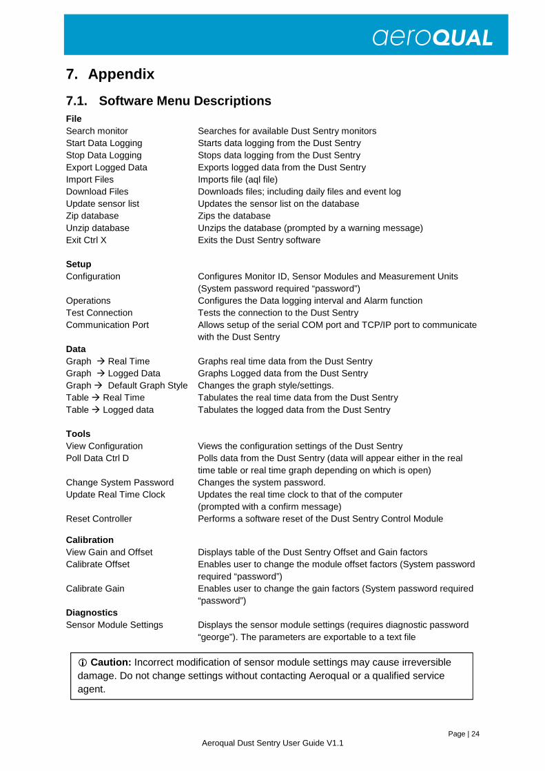
7.1. Software Menu Descriptions
File Search monitor Searches for available Dust Sentry monitors Start Data Logging Starts data logging from the Dust Sentry Stop Data Logging Stops data logging from the Dust Sentry Export Logged Data Exports logged data from the Dust Sentry Import Files Imports file (aql file) Download Files Downloads files; including daily files and event log Update sensor list Updates the sensor list on the database Zip database Zips the database Unzip database Unzips the database (prompted by a warning message) Exit Ctrl X Exits the Dust Sentry software Setup Configuration Configures Monitor ID, Sensor Modules and Measurement Units (System password required “password”) Operations Configures the Data logging interval and Alarm function Test Connection Tests the connection to the Dust Sentry Communication Port Allows setup of the serial COM port and TCP/IP port to communicate
with the Dust Sentry Data Graph � Real Time Graphs real time data from the Dust Sentry Graph � Logged Data Graphs Logged data from the Dust Sentry Graph � Default Graph Style Changes the graph style/settings. Table � Real Time Tabulates the real time data from the Dust Sentry Table � Logged data Tabulates the logged data from the Dust Sentry Tools View Configuration Views the configuration settings of the Dust Sentry Poll Data Ctrl D Polls data from the Dust Sentry (data will appear either in the real
time table or real time graph depending on which is open) Change System Password Changes the system password. Update Real Time Clock Updates the real time clock to that of the computer (prompted with a confirm message) Reset Controller Performs a software reset of the Dust Sentry Control Module
Calibration View Gain and Offset Displays table of the Dust Sentry Offset and Gain factors Calibrate Offset Enables user to change the module offset factors (System password
required “password”) Calibrate Gain Enables user to change the gain factors (System password required
“password”) Diagnostics Sensor Module Settings Displays the sensor module settings (requires diagnostic password
“george”). The parameters are exportable to a text file
� Caution: Incorrect modification of sensor module settings may cause irreversible damage. Do not change settings without contacting Aeroqual or a qualified service agent.

Page | 25 Aeroqual Dust Sentry User Guide V1.1
Sensor Diagnostics View Displays the sensor module diagnostic view (exportable to text file)
Window Full Screen Display Toggles between full screen display and other open windows Help About Displays version information
7.2. IP address solutions using GPRS Systems GPRS is a communication technology that allows data acquisition systems to overcome the difficulty of cabling for wide area remote sites. GPRS applications are becoming more prevalent, but the dynamic IP address issues associated with GPRS networking continue to frustrate system integrators.
The trouble with I/O devices with GPRS capability is that they receive a different IP address every time they connect to the GPRS network.
Three distinct solutions have been developed to overcome this challenge:
Solution 1: Public Static IP Address
The first choice is to obtain a public static IP address; some carriers (telecom service providers) can assign a static IP address to a specific SIM card. This way, all the I/O devices will have their own static IP address. The main benefit of this solution is that it behaves like a wired solution. However, not all carriers offer this kind of service.
Solution 2: VPN Service Provided by Carrier/MVNO
A VPN (Virtual Private Network) is a secure LAN solution that groups specific devices together. The VPN grouping concept solves the dynamic IP address issues and prevents unauthorized persons from accessing the data. For this VPN solution, customers are required to buy one of a number of different GPRS on-line services to be able to access a Virtual Private Network (VPN). When the GPRS device dials up, the carrier will assign a private IP address which is on the same network segment as the host and can maintain bi-directional communication using a polling architecture. Many enterprise clients turn to mobile virtual network operators (MVNO). These MVNO’s acquire numerous GPRS services and then rents them out to customers who are looking for a small number of IP addresses.
Unfortunately, some countries do not have MVNOs, and some carriers do not provide VPN services. For this reason, this solution may be unfeasible for some users.
Aeroqual has used www.wyless.com successfully to communicate with AQM instruments.
Solution 3: DDNS
Using dynamic IP addresses is often necessary since many ISPs do not provide static IP addresses. The Dynamic Domain Name System (DDNS) is used to convert a device’s name into a dynamic IP address so that remote devices can communicate with the control center using a fixed domain name. DDNS takes care of the Dynamic IP address of a device, and DNS the static IP address of a device.
With most remote GPRS devices, you need to apply for a hostname for each of the devices handled by the DDNS server. When GPRS devices get an IP from the carrier, they will automatically connect to the GPRS network. Each time a GPRS device’s built-in DDNS client gets a new IP address, it will send the IP address to the DDNS sever.
Aeroqual has used www.dyndns.com successfully to communicate with AQM instruments.
For further details visit the Moxa company website www.moxa.com

Page | 26 Aeroqual Dust Sentry User Guide V1.1
7.3. Declarations Copyright Aeroqual Limited. All rights reserved. Reproduction, transfer, distribution or storage of part or all of the contents of this document in any form without the prior written permission of Aeroqual Limited is prohibited.
“Aeroqual” and “Aeroqual Limited – Making the Invisible Visible” are registered trademarks of Aeroqual Limited. Other product and company names mentioned herein may also be trademarks or trade names.
Aeroqual operates a policy of continuous development. Aeroqual reserves the right to make changes and improvements to any of the products described in this document without prior notice.
Under no circumstances shall Aeroqual be responsible for any loss of data or income or any special, incidental, consequential or indirect damages howsoever caused.
The contents of this document are provided "as is". Except as required by applicable law, no warranties of any kind, either express or implied, including, but not limited to, the implied warranties of merchantability and fitness for a particular purpose, are made in relation to the accuracy, reliability or contents of this document.
Aeroqual reserves the right to revise this document or withdraw it at any time without prior notice. The availability of particular products may vary by region. Please check with the Aeroqual dealer nearest to you. © Aeroqual Limited 2010. All rights reserved.
1. The Aeroqual Dust Sentry complies with EN 61000-6-1:2001 2. The Aeroqual Dust Sentry complies with EN 61000-6-3:2001 3. The Aeroqual Dust Sentry complies with Part 15 of the FCC Rules. Operation is subject to the
following two conditions: (1) these devices may not cause harmful interference, and (2) these devices must accept any interference received, including interference that may cause undesired operation.
� USE SENSIBLY Use the Aeroqual AQM10 instrument only as per this user guide.
� USE AEROQUAL APPROVED SERVICE Only approved service personnel must work on this product.
� ACCESSORIES Use only approved accessories. Do not connect incompatible products.
� CONNECTING TO OTHER DEVICES When connecting to any other device, read the appropriate user guide for detailed safety instructions. Do not connect incompatible products.
� HAZARDOUS ENVIRONMENTS Do not use the monitor in or near volatile fuel or chemicals.

Page | 27 Aeroqual Dust Sentry User Guide V1.1
7.4. Technical Support Technical information, service and spare parts are available through your distributor. In addition, worldwide technical support is available from Aeroqual Ltd.
Please contact:
Aeroqual Limited 109 Valley Road, Mt Eden, Auckland 1024, New Zealand Phone: +64 9 623 3013 Fax: +64 9 623 3012 Email: [email protected]