Embed Size (px)
Citation preview

'1 ^ '
fédération internationale de l’automobile
NON VAIABLE/NON VALID FI
annuaire , * dusport
automobile86
year book of . automobile
sport19® éditlon/19th edition
A n n e x e " J "au Code Sportif International, 1986 (classification, définition et spécifications des voitures)En cas de divergence d’interprétation entre les termes des diverses traductions des règlements officiels de la FISA, le texte français fera seul fol. Toute modification paraîtra dans le Bulletin Soortlf mensuel de la FISA.
A p p e n d ix “ j "to the International Sporting Code, 1986 (classification, definition and specifications of cars)In the case of differences of Interpretation as regards the terms used In the various translations of official FISA regulations, only the French text w ill be considered authentic. Any amendments wilt be published In the monthly FISA Motor Sport Bulletin.
1986 Fédération Internationale de l’Automobile
123

Appendix "J" to the international Sportinp Code
CONTENTS
Art 251 - Classification and defin itions.................................... 124Art 252 - General prescriptions for Production Cars (Or. N),
Touring Cars (Or. A), Sports Cars (Or. B).................... 136Arf 2 5 3 -Safety equipment (Category 1 ) .................................. 146Art 254 - Specific regulations for Production Cars (Gr. N ) 168Art 255 - Specific reguiations for Touring Cars(Gr. A ) 174Art 256 - Specific regulations for Sports Cars(Gr. B ). ! .......... 192Art 257 ■ Group C l Prototype reguiations...................... 194Art 258 - Group C2 Prototype reguiations ............................ 216Art 274 - Formula 3000 Technical Reguiations........................ 216Art 275 ■ International Formula N® 2/N” 3 ................................ 244Arf 2 7 7 - International Formulae racing c a r s .......................... 272Title 5 - National Form ulae....................................................... 274
Art. 251 - Claseiffication and detinitions1) CLASSIFICATION
1.1) CATEGORIES AND GROUPSThe cars used In competition shall be divided up Into the foiiowing catego
ries and groups:Category I : Production Cars (Gr. N)
Touring Cars (Gr. A)Sports Cars (Gr. B)
Category II: Sports Prototype Cars (Gr. C)Group D : International Formula racing cars.Group E : Formula libre racing cars.
1.2) CUBIC CAPACITY CLASSESThe cars will be divided up into following 15 classes according to their
cubic capacity.1. Cylinder-capacity lower than or equal to 500 cc2. Cylinder-capacity exceed. 500 cc and lower than/equal to 600 cc3. 600 cc 700 cc
125

Appendix " J ” - D efin itions.850 cc
1.000 cc 1,150 cc 1,300 cc 1,600 cc2.000 cc 2,500 cc3.000 cc4.000 cc5.000 cc6.000 cc
4. 700 cc5. 850 cc6. 1,000 cc7. 1,150 cc8. 1,300 cc9. 1,600 cc
10. 2,000 cc11. 2,500 cc12. 3,000 cc13. 4,000 cc14. 5,000 cc15. ” ” over 6,000 ccUnless otherwise specified In special provisions imposed by the FIA for a
certain category of events, the organisers are not bound to include all the above-mentioned classes in the Supplementary Regulations and, furthermore, they are free to group two or more consecutive classes, according to the particular circumstances of their events.
No class tie subdivised.
2) DEFINITIONS2.1) GENERAL CONDITIONS2.1.1) Series Production cars (Category I):Cars of which the production of a certain number of identical exam ples
(see definition of this word hereinafter) within a certain period of tim e has been verified at the request of the m anufacturer, and which are destined for normal sale to the public (see this expression).
Cars must be sold in accordance with the homologation form.2.1.2) Competitions cars (Category II):Cars built as single examples and destined solely for competition.2.1.3) Identical cars:Cars t^longing to the same production series and which have the same
bodyvyork (outside and inside), same mechanical components and same chassis (even though this chassis may be an integral part of the bodywork in case of a monocoque construction).
2.1.4) Model of car;Car belonging to a production-series distinguishable by specific concep
tion and external general lines of the bodywork and by an identical mechanical construction of the engine and the transmission to the wheels.
2.1.5) Normal sale:Means the distribution of cars to individual purchasers through the normal
commercial channels of the manufacturer.2.1.6) Homologation:Is the official certification made by the FIA/FISA that a minimum numbers
Of cars a specifjc model has been made on serles-productlon terms to ustlfv classification in Production Cars (Gr. N), Touring Cars (Gr. A), or Sports Cars In Vk Cl A ^PPllcsliOh for homologation shall t>e submittedto the FIA/FISA by the ASN of the country In which the véhiculé is manufactured and shall entail the drawing up of a homologation form (see below) It must be established In accordance with the special regulations called Regulations for homologation” , laid down by the FIA/FISA. Homologation
of a series-produced car will become null and void 5 years after the date

A p p en d ix " J " - D e fin it io n s
which the series-production of the said model has been stopped (serles- production under 10 % of the minimum production of the group considered).
The Homologation of a model can only be valid in one group, Production Cars/Touring Cars, or Sports Cars. If a model already homologated in Group Sports Cars (Gr. B) passes into Group Production Cars (Gr. N)/Touring Cars (Gr. A), the first homologation is cancelled.
2.1.7) Homologation forms:All cars recognised by the FIA/FISA shall be the subject of descriptive
form called homologation form on which shall be entered all data enabling identification of the said model.
This homologation form defines the series as Indicated by the manufacturer. According to the group in which the competitors race, the modification lim its allowed in international competition for the series are stated in Appe- dix J.
The presentation of the forms at scrutineering and/or at the start may be required by the organisers who w ill be entitled to refuse the participation of the entrant in the event in case of non-presentation.
With regard to Group Production Cars {Gr. N), apart from the specific form for this group, the Group Touring Cars {Gr. A) form must also be submitted {or the FISA transfer to Group A).
In case of any doubt remaining after the checking of a model of car against its homologation form, the scrutineers should refer either to the maintenance booklet published for the use of the make’s distributors or to the general catalogue in which are listed all spare parts.
In case of lack of enough accurate documentation, scrutineers may carry out direct scrutineering by comparaison with an identical part available from a concessionnaire, tt w ill be up to the competitor to obtain the homologation concerning his car from the ASN of the manufacturing country of the véhiculé, or from the FIA/FISA.
Description. A form breaks down in the following way:1) A basic form giving a description of the basic model.2) At a later stage, a certain number of additional sheets describing
“ homologation extensions” , which can be “ variants” , or "errata” or “ evolutions” .
a) Variants (VF, VO)These are either supply variants (VF) {two suppliers providing the same
part for the manufacturer and the client does not have the possibility of choice), or options (VO) {supplied on request and available at the concessionnaires).
b) Erratum (ER)Replaces and cancels an incorrect piece of information previously sup
plied by the constructor on a form.c) Evolution (ET-ES)Characterises modifications made on a permanent basis to the basic
model {complete cessation ot the production of the car In Its original form in the case of the evolution of the type ET), or sporting evolution (ES) intended to render a model more competitive.
Use1) Variants (VF, VO)The competitor may use any variant as he wishes, only on condition that
129

A p p en d ix “ J ” ■ D é f in it jons
all the technical data of the vehicle, so designed, conforms to that described on the homologation form applicable to the car, or expressly allowed byAppendix J. , . X X •
For example, the fitting of a brake calliper as defined on a variant form is only possible if the braking surface, the dimensions of the brake linings, etc. obtained In this way, are indicated on a form applicable to the car In question. (For Group Production Cars (Gr. N), see also Art. 254.2).
2) Evolution of the type (ET) (For Group Production Cars (Gr. N), see also Art. 254.2). ^ ^
The car must comply with a given stage of evolution (independent of the date when It left the factory), and thus an evolution must be wholly applicable or not at all. , .
Besides, from the moment a competitor has chosen a particular evolution, all the previous evolutions should be applied, except where they are Incompatible : for example, If two brake evolutions happen one after another, only that corresponding to the date of the stage of evolution of the car w ill be used.
This homologation form defines the series as Indicated by the manufacturer. According to the group, in which the competitors race, the modification lim its allowed in International competition for this series are stated in Appendix J.
3) Sporting evolution ESSince the bS form refers to a previous extension, or to the basic form, the
car must correspond to the stage of evolution corresponding to this reference ; moreover, the Sporting Evolution must be applied In full.
2.1.8) Mechanical componentsAll those necessary for the propulsion, suspension, steering and braking
as well as all accessories whether moving or not which are necessary for their normal working.
2.2) DIMENSIONS Perimeter of the car seen from above:The car as presented on the starting grid for the event In question.
2.3) ENGINE2.3.^) Cylinder capacity: Volume generated in cylinder (or cylinders) by the
upward or downward of the pistons. For all calculations relating to cylinder capacity the symbol n w ill be regarded as equivalent to 3.1416.
2.3.2) Supercharging :Increasing the weight of the charge of the fuel-air mixture in the combus
tion chamber (over the weight Induced by normal atmospheric pressure, ram effect and dynamic effects in the Intake and/or exhaust systems) by any means whatsoever.
The Injection of fuel under pressure is not considered to be supercharging (See Article 3.1 of the General Prescriptions for Groups N, A, B).
2.3.3) Cylinder block:The crankcase and the cylinders.2.3.4) intake manifold:
— Part collecting the alr-fuel mixture from the carburettor(s), and extending131

A p p en d ix “ J " • D e fin it io n s
to the entrance ports of the cylinder head, in tne case of the carburettor Induction system. . . .— Part situated between the valve of the device regulating the air intake and extending to the ports on the cylinder head, in the case of an Injection Intake system. .. ^— Part collecting the air at the air filter outlet and extending to the cylinder head entrance ports in the case of a diesel engine.
2.3.5) Exhaust manifold :Part collecting together the gases from the cylinder head and extending to
the first gasket separating it from the rest of the exhaust system.
2.4) RUNNING GEAR2.4.1) Wheel:Flange and rim: by complete wheel is meant flange, rim and tyre.2.4.2) Friction surface of the brakes:Surface swept by the linings on the drum, or the pads on both side of the
disc when the wheel achieves a complete revolution.2.4.3) Mac Pherson suspension:Any suspension system In which a telescopic strut, not necessarily provi
ding the springing and/or damping action, but incorporating the stub axle, is anchored on tne Body or chassis through single attachment point at its top end. and Is pivoted at Its bottom and either on a transversal link located longitudinally by an anti-roll bar, or by a tie rod.
2.5) CHASSIS-BODYWORK2.5.1) Chassis: .The overall structure of the car around which are assembled the mechani
cal components and the bodywork including any structural part of the said structure.
2.5.2) Bodywork: .— externally: all the entirely suspended parts of the car licked by the.
alrstream.— internally : cockpit and boot.Bodywork is differentiated as follows;1) completely closed bodywork2) completely open bodywork .3) convertible bodywork with a hood In either supple (drop-head) or rigid
(hard-top) material.2.5.3) Seat: ,The two surfaces making up the seat cushion and seatback or backrest.Seatback or backrest:Surface measured upwards from the bottom of a normally seated person s
spine.Seat cushion: , , .Surface measured from the bottom of the same person’s spine towards the
front.2.5.4) Luggage compartent(s):All volumes) d istinct from the cockpit and the engine compartment inside
the véhiculé.133

Appendix “ J ” - D e fin itions
This (these) volunne(s) Is (are) limited in length by the fixed structure(s) provided for by the manufacturer and/or by the rear of the seats and/or, if this is possible reclined at a maximum angle of 15°,
This (these) voiume(s) is (are) limited in height by the fixed structure(s) and/or by the detachable partitlon(s) provided for by the manufacturer, or In the absence of these by the horizontal plane passing through the lowest point of the windscreen.
2.5.5) Cockpit:Inner volume which accommodates the driver and the passenger(s).2.5.6) Bonnet:Outer part of the bodywork which opens to give access to the engine.2.5.7) Mudguard:A mudguard will be considered to be the area defined as follows, provided
that It Is riveted, screwed or bolted on to the bodywork:
B2
A
■ B2
1A1
{ bolt (
o ( or screw (( or rlvec
rCl
1Cl 02
'1VC2
Front mudguard: the area defined by the Inner of the complete wheel of the standard car 01/01 and the lower edge of the side wlndow(s) A/A and the front edge of the front door (81/81).
Rear mudguard: the area defined by the inner face of the complete wheel of the standard car (02/02) and the lower edge of the side window(s) (A/A) and the rear edge of the rear door (82/82).
In the case of two-door cars (81/81) and (82/82) will de defined by the front and rear of the same door.
2.6) ELECTRICAL SYSTEMHeadlight: any signal the focus of which creates an in-depth luminous
beam directed towards the front.2.7) FUELFuel tank: any container holding fuel likely to flow by any means whatsoe
ver towards the main tank or the engine.135

Art. 252 - General prescriptions for Production ears (Cr. N), Touring Cars (Gr. A), Sports Cars (Gr. B)
1) GENERAL REMARKS u,1.1) All modifications are forbidden unless expressly authorised by the
regulations specific to the group in which the car is entered or by the general prescriptions below or imposed under the chapter “ safety eguipement .
1.2) Application of the general prescriptionsThe general prescriptions must be oberserved in the event that the specifi
cations of Productions Cars (Gr. N), Touring Cars (Gr. A), or Sports Cars (Gr.- B) do not lay down a more strict prescription.
1.3) Conditions for changes of groups and authorized regroupingsCars originally belonging to Production Cars (Gr. N) but having been sub
ject to modifications or additions duly declared and which exceed the lim its provided for this group may pass into Touring Cars (Gr. A) if it is laid down in the event’s supplementary regulations and if they conform to the prescriptions of this group.
2) DIMENSIONS AND WEIGHT ^ ^2.1) Ground clearance: no part of the car must touch the ground when all
the tyres on one side are deflated.2 2) Ballast: it is permitted to complete the weight of the car by one or
several ballasts provided that they are strong and unitary blocks, fixed by means of tools with the possibility to fix seals, placed on the floor of the cockpit, visible and sealed by the scrutineers.
Application : Touring Cars (Gr. A) Sports Cars (Gr. B) ; no kind of ballast Is authorised on Production Cars (Gr. N). In rallies, however.-the carryina of tools and spare parts for the car w ill be allowed under the conditions laid down in Art. 253 a. Any object of a dangerous nature (battery, inflammable products, etc.) must be carried outside the cockpit.
31) Supercharching : in case of supercharging, the nominal cylinder- capacity will be multiplied by 1.4 and the car w ill pass into the class corresponding to the fictive volume thus obtained. The car will be treated in all respects as if its cylinder-capacity thus increased were its real capacity. This shall particularly be the case for assigning the car to its cylinder-capacity class, its interior dimensions, its minimum number of places, etc.
N.B.: The FISA reserves the right to change, the supercharging coefficient as from January 1st 1987.
3.2) Equivalence formula, between reciprocating piston and rotary engines (of the type covered by the NSU Wankel patents)
The cubic capacity equivalent is 1.8 times the volume determined between the maximum capacity of the combustion chamber.
137

Appendix " J " G eneral p rescrip tions
3.3) Equivalence formula between reciprocating piston and turbine engines
This formula Is the following:
C = S(3.10 X R) - 7.63 0,09625
S = High pressure nozzle area — expressed In square centimetres by which Is meant the area of the alr-flow at the exit from the stator blades (or at the exit form the first stage If the stator has several stages), fyieasurement Is done by taking the minimum area. In cases where the first stage turbine stator blades are adjustable, the w ill open to their greatest extent to present the greatest area for the determination of area S.
The area of the high pressure nozzle Is thus the product of the height (expressed In cm) by the width (expressed in cm) and by the number of vane spaces.
R = The pressure ratio Is the ratio of the compressor of the turbine engine. It Is obtained by multiplying together the value for each stage of the compressor, as indicated hereafter:
Subsonic axial compressor : 1.15 per stage.Trans-sonic axial compressor : 1.5 per stage.Radial compressor : 4.25 per stage.Thus a compressor with one radial and six axial subsonic stages will be
designated to have a pressure of:4.25 X 1.15 X 1.15 X 1.15 X 1.15 x 1.15 x 1.15 or 4.25 x 1,15»
C = Equivalent cubic capacity for reciprocating piston engines In cm’ .
3.4) All engines into which fuel Is Injected or In which fuel Is burned after an exhaust port are prohibited for the time being.
3.5) Equivalences between reciprocating piston engines and new types of engines
The FISA reserves the right to make medications on the basis of comparisons established between classic engines and new types of engines, by giving a two year notice from the 1st January following the decision taken.
3.6) Exhaust system and silencerEven when the specific provisions for a group allow the replacement of the
original silencer, the cars competing In an open-road event shall always tie equipped with an exhaust silencer complying with the traffic regulations of the country(les) through which the event is run.
The orifices of the exhaust pipes shall be placed at a maximum of 45 cm and a minimum of 10 cm from the ground. The exit must be located aft of a vertical plane passing through the wheelbase centre and may not project at any point beyond the side of the bodywork. Moreover, adequate protection must be provided In order to prevent heated pipes from causing burns.
The exhaust system must not be provisional. Exhaust gas may only exit at
139
Appendix " J " ■ General Prescrip tions
the end of the system. Parts of the chassis must not be used to evacuate exhaust gasses. , . . .
Catalytic exhausts ; Should two possible versions of one car rnodei be homologated (catalytic and other exhaust), the differences characterizing the catalytic model shall be included under « additional information » on the basic form. The cars must comply with one or other version, all combinations of the two versions being prohibited.
3.7) Starting on board the vehicle: starter with electric or other source at energy on board operable by the driver when seated in the seat.
4) TRANSMISSION ^Ail cars must be fitted with a gearbox including a reverse gear which must
be in working order when the car starts the event, and be able to be operated by ttie driver when he is normally seated.
5) WHEELS . . ^ ^ ,Mesuring wheel width : the wheel width is to be measured with the wheel
mounted on the car, or the ground, the vehicle in race condition, driver aboard, at any point along the circumference of the tyre, except in the area in contact with the ground. When multiple tyres are fitted as part of a complete wheel, the latter must comply with the maximum dimensions for the Group in which tyres are used (See Article 255.5.4 and Article 256.5).
Application : Touring Cars (Gr. A), Sports Cars (Gr. B).
6) COACHWORK6.1) Convertible vehicles must comply in ail respects with the specifica
tions applying to open cars.6.2) Minimum inside dimensions . . . ^If a modification authorised by Appendix J affects a dimension stated on
the homologation form this dimension may not be retained as an eligibility criterion for the car. j
6 3) Cockpit: only the following accessories may be installed in the cockpit - spare wheei(s), spare parts, safety equipment, communication équipement ballast (if permitted), windscreen washer water container (Touring Cars (Gr. A), Sports Cars (Gr. 8) only). The passenger compartment and seat of an open car must in no way be covered.
Containers for helmets and tools situated in the cockpit must be made of non-inflammable material.
7) LIGHTINGA fog light may be changed for another provided that the original mounting
remains the same.

Appendix " J " ■ General Prescriptions
B) FUEL-COMBUSTIVE8 1) The use of "commercial fuel" Is obligatory, that Is to say the use of
motor fuel produced by an oil company and currently distributed at road refuelling stations throughout one same country. .u
May therefore be used, all commercial fuels of the country In which the even takes place, with no other additive except that of a lubricant of current sale which cannot increase the octane number, or water. , , .,M ay also be used, under the same conditions, any commercial fuel(s)
which — in France, Germany, Great Britain and Italy — is (are) of the highest octane rating, according to the Research Method.
If the atx)ve-mentioned fuel cannot be easily imported Into the country where the event is taking place. It may be replaced by another one of similar quality and with the same octane number (RON) — with a tolerance of + 1 — specially made by an oil company.
Whenever, In France, Great Britain, German arid Italy, a new commercial fuel Is made available which has higher octane rating than those sold so far, the oil company producing the said fuel shall give notice to the FiA by a registered letter and this new commercial fuel (or Its equivalent as specified hereabove) may be used for racing 30 days after the registered letter has been m ailed.* , . „
The oil companies who supply fuel directly to the entrants of a race shall have to send to the promoters the characteristics and a sample of the fuel delivered in such quantity as is sufficient to carry out the necessary analyses, and also a declaration stating that the fuel compiles with the present specifications.
8.2) Only air may be mixed with the fuel as an oxidant.
8.3) Refuelling procedure
Standardised coupling
— In case of a centralised system provided by the circuit or a system provided by the competitors, the refuelling hose shall be provided with a leak- proof coupling to fit the standardised fitting mounted on the car. The dimensions of this fitting are given in the diagram on page 252.
— All cars must be provided with a fuel fitting complying with this diagram. This leak-proof fitting must comply with the dead man principe and must not therefore incorporate any retaining device when in a open position (spring-loaded, bayonet, etc.).
— The air vent(s) must be equipped with non return valves and valves having the same closing system as that of the standard fitting and having the same diameter. During refuelling the outlet of the air-vent must be connected with the appropriate coupling either to the main supply-tank or to a transparent portable container with a minimum capacity of 20 litres provided with a closing system rendering it completely leak-proof. The venting catch tanks must be empty at the beginning of the refuelling operation. In cases where the circuits are unable to provide the entrants with a centralised system, they w ill have to refuel the above procedure. The level of the reserve tank may in no case be more than 3 metres above the level of the track where the refuelling is effected. This appftes to the wrfiole duration of the event.
Appendix " J " ■ G eneral Prescrip tions
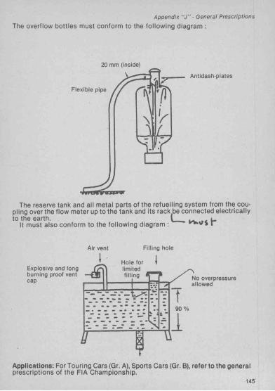
The overflow bottles must conform to the following diagram :
20 mm (inside)
Flexible pipe
Antidash-plates
The reserve tank and all metal parts of the refuelling system from the coupling over the flow meter up to the tank and its rack be connected electrically to the earth. 1 ,e
It must also conform to the following diagram : r
Air vent Filling hole
Hole forlimitedfilling
Explosive and long burning proof vent cap No overpressure
allowed
90 Vo
Applications: For Touring Cars (Qr. A), Sports Cars (Gr. B), refer to the generalApplications: For Touring .. prescriptions of the FIA Championship.
For Cars
145

Art. 253 - Safety equipment (catesory IISAFETY DEVICES FOR ALL CARS OF CATEGORY I COMPETING IN EVENTS ENTERED ON THE FIA INTERNATIONAL CALENDAR;
1) A car, the construction of which is deemed to be dangerous, may be excluded by the Stewards of the meeting.
2) if a device is optional, it must be fitted in a way that compiles with regulations.3) CABLES, LINES AND ELECTRICAL EQUIPMENT
Fuel, oil lines and brake cables must be protected externally against any risk of deterioration (stones, corrosion, mechanical breakages, etc.) and internally against all risks of fire.
if the series production fitting is retained, no additional protection is necessary.
Application: obligatory for Touring Cars (Gr. A), Sports Cars (Gr. B).4) BRAKING SAFETY SYSTEM
Double circuit operated by the same pedal: the pedal shall normally control ail the wheels ; in case of a leakage at any point of the brake system pipes or of any kind of failure in the brake transmission system, the pedal shall still control at least two wheels.
Application: compulsory fitting on all cars Touring Cars (Gr. A), Sports Cars (Gr. B). If this system is fitted in series production, no modifications are necessary.5) ADDITIONAL FASTENERS
At least two additional fasteners for the front and rear bonnet and boot lid, the original fasteners having been rendered inoperative.
Large objects carried on board the véhiculé (such as the spare wheel, toolkit, etc.) must be firmly fixed.
Appiication: obligatory for Touring Cars (Gr. A), Sports Cars (Gr. 8). Optional for Production Cars (Gr. N).6) SAFETY BELTS
Wearing of a diagonal strap and one abdominal strap: fixation points on the shell: 3.
Appiication: Compulsory for ail Production Cars (Gr. N) together with Touring Cars (Gr. A), Sports Cars (Gr. B) participating in rallies.
Wearing of two shoulder straps and one abdominal strap: fixation points on the shell: two for the abdominal strap - two or possibly one symetrical in relation to the seat for the shoulder straps.
Application : compulsory for all Touring Cars (Gr. A), Sports Cars (Gr. B) (except in rallies).
A hole may be made in a series production seat to allow the passage of a safety belt.7) EXTINGHISHERS • EXTINGUISHING SYSTEMS
They must have the following characteristics:P A i i v ('(Dr'iMT c i A i ^ n (minimum quantities) 4 kg Halon 1211 or 1301ÜH I X’l rJ.Do ’ s l a l o m , powder or equivalent*HILL C LIM B S (In 2 txjttles maximum)
'équivaient : a product having a efficiency and non-toxicity at least equal tothat of Halon 1211.

Appendix ” J ” • Safety
N.B. : Installed systems are allowed in Group Touring Cars (Or. A) Sports Cars (Gr. B) as replacements for the systems laid down in this article. In this case please refer to the Sport Prototype Cars regulations (Article 4.4).
7.1.1) InstallationEach extinguisher bottle must be installed in such a way that It Is capable
of withstanding accelerations of up to 25 g no matter how these are applied. Only rapid release metal mountings will be accepted.
7.1.2) Operation ■ TriggeringThe extinguisher(s) must be easily accessible to the driver and co-driver.7.1.3) CheckingThe type of extlngulshant, Its quantity, and the total weight of the bottle
must be specified on the bottle(s).7.2.1) Circuits, Rallies, Slaloms, HlllcllmbsThe cars must be equipped with one or two t>ottles containing a minimum
of 4 kg of Halon 1211 or 1301 (BCF-BTM) powder or equivalent.7.2.2) Autocross or RallycrossCars must be equipped with a single bottle containing 2 kg minimum
Halon 1211 or 1301 (BCF-BTM) power or equivalent.
8) ROLLBAR8.1) DEFINITIONS
8.1.1) RollcageA structural framework made up of tubes, connections and fixation points.
It Is designed to prevent serious deformation In the case of a collision or a car turning over.
8.1.2) RollbarStructural framework made up of a main rollbar, a front rollbar, connec
tions and fixation points.8.1.3) Safety cageStructural framework made up of a main rollbar, a front rollbar, connec
tions and fixation points.8.1.4) Main rollbarA structure which should be made out of a vertical frame situated In trans
versal plane In relation to the car's axis, near the back of the front seats.8.1.5) Front rollbarIdentical to the main rollbar but Its shape follows the windscreen moun
tings and the front part of the roof.8.1.6) Lateral rollbarA rollcage made up of a vertical framework situated In a longitudinal plane
or In relation to the car’s axis placed on the right or the left. The rear pillar must be placed against or behind the back of the driver’s seat or that of his co-driver. (Drawing 6). In cases where the rear pillar Is used as the main rollbar, the connection must be near the roof (Drawing 4a). The front bar must be near the windscreen and dashboard. The driver and his co-driver must be able to gel in and out of the vehicle without any Inconvenient difficulty.
8.1.7) Longitudinal strutLongitudinal tubes belong neither to the main rollbar nor to the front roll
bar.

A p p e n d ix " J ” -S a fe ty
8.1.8) Diagonal strutTube crossing the car from one of the corners of the main rollbar to any
fixation point o f the other side of the rollbar or of the near longitudinal strut.8.1.9) Framework reinforcementTube fixed to the rollcage improving its efficiency.8.1.10) Reinforcement platesMetal plates, fixed to the chassis structure of the cars on which the rollbar
rests.8.1.11) Fixing platesPlates which are attached to the tubes and allow their fixation to the chas
sis.8.1.12) Removable connectionsOptional connection of lateral or diagonal struts to the main rollbar or the
front rollbar. It must be possible to dismantle these pieces of equipment.
8.2) SPECIFICATIONS
8.2.1) General comments
8.2.1.1) Safety cages should be designed and constructed In such a fashion that after they have been properly bu ilt in, they prevent the bodywork from deforming and thus reduce the risks o f injury to people on board the véhiculé.
The essential characteristics of safety cages come from a fine ly detailed construction, suitable adaptation and fixa tion to the car plus snug fitting against the bodywork. The rollbars must never be used as pipes for liquids.
The bar or bars must be constructed in such a way that It (they do) not obstruc t access to the front seats and do not encroach on the space provided for the driver an co-driver. However parts of the rollcage may encroach upon the front passenger space by passing through the lateral upholstery of the rear seats. The rear seat may be folded down.
Any m odification to the homologated rollbars (see Art. 8.8) is forbidden, even with regard to the fixations and welds.
8.2.1.2) Basic rollcage (drawings 1 & 2)Rollbar : Production Cars (Or. N) and Touring Cars (Gr. A), Sports Cars (Gr.
B) up to 2 000 cm®.Rollcage : Touring Cars (Gr. A), Sports Cars (Gr. B) more than 2,000 cm®
(optional for Production Cars (Gr. N) and Touring Cars (Gr. A), sports Cars (Gr. B) up to 2,000 cm®) (drawings 3 & 4).
8.2.1.3) Different possib ilities of Installing the obligatory strut (with the exception of rallies).
The obligatory strut can be fixed as illustrated In all basic rollcages (draw ings 1-4).
The combination of several struts (drawings 5-8) is permitted.
8.2.1.4) D ifferent possib ilities o f insta lling the optional reinforcements of the rollcage (drawings 9 to 12).
Each type o f reinforcement (drawings 9-11) may t^e used separately or combined with one or.several others.
These reinforcements can be Installed In each of the basic rollcages (drawings 1-4).
151

Annexe "J ” - Sécurité
OMaln/drawIng No 1 □•M ln/drawlng No 2
OaMln/drawIng No 3DMSin/drawIng No 4
Daaaln/drawing No 4a
Daaaln/drawing No 5 Daaaln/drawtng No 6
152

Appendix "J " -S a fe ty
\
DMSln/drtiwing No 7(d « 30 cm)
DoMln/draviring No 9 Dotsln/drawing No 10
1 — Plancher de la voiture/Car floor 2— Plaque de rerrfort/Reinforcement plate 3 — P la ^ cTattache/Attachment plate Deealn/drawing No 11
Dassln/drawlng n* 12153

Appendix "J " -S a fe ly
8.2.2) Technical specifications8.2.2.1) Main and front and iaterai roiibarsThe roiibars must be in a single piece. Their construction must be Impec
cable without unevenness or cracks. The fitting must be done In such a way it marries the Interior shape of the car, or straight If It cannot be directed upwards. If-lt Is necessary for the lower parts of the roilbar to be rounded, these parts must be strengthened and follow the Interior shape exactly.
Minimum bending r„, = 3 x tube diameter.In order to get an efficient Installation of the roll-cage. It Is allowed to
locally modify the original upholstery, directly on the legs of the roli-cage, for example by cutting or embedding (deformation).
This Is only valid for the vertical pillars A and B and for the longitudinal upright at the front door level.
However, this modification can In no case allow the removal of entire parts of the upholstery.
8.2.2.2) Fixation of the roiibars to the bodyMinimum fixations for the safety rollcage:1 for each pillar of the main or lateral roilbar.1 for each pillar of the front roilbar.1 for each pillar of the rear longitudinal strut.1 for each pillar of the main roilbar, and each rear pillar of the lateral roilbar
at the fixation point for the front seat belt, or In the approximate area of this position.
The fixation of the roilbar pillars must be done with at least 3 bolts.The attachment points of the roiibars on the body must be reinforced with
a steel plate of a least 3 mm thick and with a surface area of 120 cm= welded to the body.
The various possibilities are given In drawings 12 to 18.Hexagonal bolts or similar, of a minimum diameter of 8 mm (minimum qua
lity 8-8 as per the ISO specifications) shall be used.The nuts shall be self-tapping, self-locking or fitted with washers.These fixations represent a minimum. It Is possible to Increase the number
of bolts, to weld the steel roilbar to the bodyshell.
8.2.2.3) Longitudinal StrutsThey must be fixed to the left and to the right above and outside the main
roilbar, then going directly backwards and as near as possible to the Interior side contour.
A rounded construction (with a large bend) Is allowed if It Is placed a near the roof as possible.
The diameter, the thickness and the material of the longitudinal struts should correspond to the norms fixed for the rollcages.
The forces must be efficiently divided and absorbed. The attachment points must be strengthened by plates If their location does not allow them to absorb forces. (See drawing 19).
8.2.2.4) Diagonal StrutsWith the exception of rallies, the Installation of at least one diagonal strut
Is obligatory.Their construction must be carried out in accordance with drawings 5 to 8
without bends.The attachment points of the diagonal struts must be so located that they
cannot cause Injuries.
155

Annexe “ J " ■ Sécurité
je u .
TOMaln/drawtng No 12
SESl.
DOMln/drawIng No 13
□•Min/drawing No 13a
Ecrous rivetés ou soudés/Rivetted or welded nuts
Dosaln/drawlng No 14
156

A ppendix "J " -S a fe ly
1/2 vertical
Dessin/drawing n° 15
1/2 vertical
Dessin/drawing n° 16
Dessin/drawing n” 17 Dessin/drawing n" 18
157

A ppendix "J " -S a fe ly
DMtln/drawIng No 17
stm ctur^^® ’ Pi’sfefably have the same diameter as the tubes of the main
8.2.2.S) Optional reinforcements of the rollcageThe diameter the thickness and the material of the reinforcements must
correspond to the norms fixed for the rollcages.welded into position or Installed by means of a deta
chable connection (obligatory for the front transversal reinforcements)The reinforcement tubes should never be attached to the actual bodywork
OT me car.8.2.2.5.1) Transversal struts
^ transversal struts as shown In Illustrations 9 and 10 Is permitted. The transversal strut fixed to the front bar must not, however
*Pe occupant(s). It must be placed as high as possible under the dashboard and must bie detachable.
8.2.2.5.2) Longitudinal struts (lateral protection)n strut at the side(s) of the vehicle at door level Is
'faking up this reinforcement must be built Into the fano lo /n and Its arigle with the horizontal tube must not exceed 15’ rfa h . I f . ^ '° ft) ' poInt of the side protection shouldoM^e d^or^ ** height of the door measured from the base
8.2.2.5.3) Roof reinforcement
in S a t lS n ‘=?o'is"pe^t1ed".‘’ "8.2.2.5.4) Angle reinforcementThe reinforcement of the upper angles between the main rollbar and the
longitudinal connections with the front rollbar Is permitted, as Is the reinforcements of the upper rear angles of the lateral rollbars, as shown in Illustration 11.
The upper fixation of these reinforcements shall, under no circumstances be situated to the fore of the middle of the longitudinal linking tube, and their lower fixation shall, under no circumstances, be situated lower than the middle of the vertical pillar of the rollbar.
8.2.2.6) Padding for protectionThe padding of the dangerous points on the rollbars Is recommended in
order to orevent injurv.

A nnexe " J " 'S é c u r i té
ZZZDessin/drawing 22
5mm'3/16
t)essin/drawlng 23 En dehors de l’arceau principale/ Outside the main roll-bar.
fT-jl ]_________ 1____i i j i 1.
H l m
Dessin/drawing 24
160
0 = 14 mm (tube â 40 mm < 50 mm dima. ext.) 16 mm (tube â 50 mm diam. ext.)

A p p en d ix " J " ’ S a fe ty
7 7
Dessin/drawing n** 25 En dehors de l'arceau principale/ Outsider the main roll-bar.
1er seulement ^ Steel onlyCEI
SoudureWelding
L X J Dessin/drawing n*’ 26
- 4 ^ '
161

A p p en d ix 'J " S a fe ty
The rollbar may be covered with a detachable protective casing.8.2.2.T) Removable connectionsShould removable connections be used In the construction of the rollbar
they must comply with or be sim ilar to a type approved by the FIA (see drawings 22-26).
The screws and bolts must be of a sufficient minimum diameter, and of the best possible quality (preferably aircraft type).
8.2.2.8) Welding InstructionsAll welding should be of the highest quality possible with full penetration
(preferably arc welding and in particular hellarc).Although good outside appearance of a weld does not necessarily guaran
tee its quality, poor looking welds are never a sign of good workmanship.When using heat treated stell the special Instructions of the manufactu
rers must be followed (special electrodes, helium protected welding).It must be pointed out above ail else that the manufacture of heat treated
steel, and high carbon steels may cause certain problems and that bad construction may result In a decrease In strength (crinking) and an absence of flexibility.8.3) MATERIAL PRESCRIPTIONS
Specifications of the tubes used:Minimum material: Minimum tensile strength: Minimum dimensions:Cold drawn seamless 360 N/m* 38x2 .5 orcarbon steel 4 0 x 2
In mmThese dimensions represent the minima allowed.In choosing the quality of the steel, attention must be paid to the elonga
tion properties and the weldability.8.4) REGULATIONS FOR CARS
8.4.1) Production Cars (Gr. N)The fitting of a rollbar Is compulsory for all events.8.4.2) Touring Cars (Gr. A) and Sports Cars (Gr. B) ,The fitting of a safety cage is obligatofy for all events. The diagonal strut
although not obligatory for rallies, is desirable.Rules of application are as follows:— up to 2,000 cm*; rollbar obligatory, rollcage optional.— More than 2,000 cm*: rollcage obligatory.
8.5) EXCEPTIONSHowever manufacturers of safety rollcage may also propose a rollbar of
free conception to an ASN for approval as regards the material used, the dimensions of the tubes and the Implantation or the braces provided that the construction is certified to withstand stress minima given hereafter (and applied simultaneously):
— 1,5 w lateral*;— 5,5 w fore and aft;— 7,5 w vertical.*w = weight of the c a r- I-75 kg.It must be possible to submit a certificate on a form approved by the ASN
to the event's scrutineers. It must be accompagnied by a drawing or photo of the rollbar In question declaring that this rollbar can resist the forces mentioned above.
Rolfbars must not be modified.163

Appendix "J " ■ Safety
8.6) HOMOLOGATIONThe FISA being aware of the problem of habitability being raised by the
use of safety rollcages proposes that each car manufacturer recommends a type of safety rollcage complying with FISA standards.
This rolibar must tie described on an homologation extension form presented to the FISA for approval and must not be modified (see Article 8.2.1.1).9) REARVIEW
This shall be provided by a inside mirror commanding a rear window with a least a 10 cm vertical opening, maintained along a width of at least 50 cm. However, if the straight line connecting the upper and lower edges of the rear' window opening maxes an angle Inferior to 20° with the horizontal, the rear view must be efficiently obtained by other means (two outside mirrors or any other system of equivalent efficiency). Furthermore, all these cars should tie equipped with two outside mirrors for circuit events.
Application : obligatory for all Groups.10) TOWING-EYE
All cars will be equipped with a rear and front towlng-eye for all events. This towing-eye will only tie used If the carcan move freeTy and It must not be used to lift the car. It will be clearly visible and painted in yellow, red or orange.
Application : All Groups.11) WINDSHIELD
A w/inHchiBid m ade of lam inated glass is compulsory.Application : All Grouos.
12) SAFETY FIXING DEVICES FOR WINDSHIELDSSuch devices mav be used freeiv.Application : ootional for all Groiio.s
13) GENERAL CIRCUIT BREAKERThe general circuit breaker must cut all electrical circuits, battery, alterna
tor or dynamo, lights, hooters, ignition, electrical controls, etc.). It must be a spark-proof model, and will be accessible from Inside and outside the car. As for the outside, the triggering system of the circuit breaker will compulsorily be situated at the lower part of the windscreen mouting of driver’s side for closed cars. It w ill be marked by a red spark in a white-edged blue triangle with a base of at lea.st 12 cm.
Application: compulsory fitting for all Touring Cars (Gr. A) and Sports Cars (Gr. B) cars taking part in speed events on circufts or hill-climbs. The fitting is recommended for other events. Obligatory for Production Cars (Gr. N) in c ircuit events, optional In the other cases.14) FIA APPROVED SAFETY FUEL TANKS
Whenever a competitor uses a safety fuel tank, it must come from a manufacturer approved by FIA.
In order to obtain the FIA’s agreement, a manufacturer must have proved the constant quality of Its products and its compliance with the specifications approvea by the FIA.
Safety tank manufacturers recognised by the FIA must undertake to deli ver to their customers exclusively tanks complying with the norms approved To this end, on each tank delivered the name of the manufacturer, the model the exact specifications according to which this tank has been manufact'u red, the date of the manufacturing, and the series number, shall be printed,
165

A ppendix "J " -S a fe ty
14.1) Technical specifications:The FIA reserves the right to approve any other set of technical specifica
tions after study of the dossier submitted by the manufacturers concerned.14.2) Specifications FiA/SpecfFT3:The technical specifications for these tanks are avaiiable, on request, from
the FiSA Secretariat.14.3) Ageing of tanks:The ageing of safety tanks entaiis a considérai reduction in the strength
characteristics after approximately five years.Therefore, all fuel ceils must be replaced by new ones at the latest five
years after the fabrication date indicated on the celi.14.4) List of agreed manufacturers:
Federal Republic of Gennany:Uniroyal Englebert GmbH, Westerbachstr. 122, 6230 Frankfurt/Main 80.
United States: „Don W Alien inc, 401 Agee Road, Grants Pass, Oregon 97526.Aero Tecs Labs, Hewson Avenue, Warcick, NJ 07463.Fuel Safe Corporation, 15545 Computer Lane, Huntington Beach, Califor
nia 92649.
^"^Wébêr Colombes, Division Tissus Enduits et Applications, 4, rue Lesage- Maiile, 76320 Caudebec-les-Elbœuf.
E t s J . RiCHE-BP 14-14690 Pont-D’Oullly. t u v c m vSociété Lyonnaise des Réservoirs Souples, 18 rue Guiilaume-Teli, 75017
Paris.Superflexit SA, 45, rue des Minimes, 92405 Courbevoie.
*^"^Ma*rston*Pâimer Ltd, Wobaston Road, Fordhouses Wolverhampton, WV10
^*^PrenMe^Fuel Systems Ltd, Willow Road, Trent Lane Industrial Estate, Castle Donlngton, Derby DE7 2NP.Italy:
Gipl, Via Abruzzi 7, 20090 Opera, Miiano.Pirelli, Viale Rodi 15, Miiano.
Japan:Fujikura Rubber Works Ltd., N° 20,2-chome, Nishigotandu, Shinagawa-ku,
Tokyo. _Kojima Press Ltd, 3-30 Shimoichibacho Toytrta, Aichiken.Sakura Rubber Co Ltd, 48-14-1 Chôme Sasazuka, Shibuya Ku, Tokyo. Sumitomo Electric Industries Ltd, 15-5 Chôme Katahama, Migashi Ku,
Osaka.
14.5) Applications of these specifications:Touring Cars (Gr. A) and Sports Cars (Qr. B) cars may be equipped with a
safety fuel tank if the modifications necessary do not exceed those allowed by the regulations.
IS) PROTECTION AGAINST FIREAn efficient protective screen must be placed between the engine and the
occupants’ seat, in order to prevent the direct passage of flames. In case of fire.
167

Art. 254 - Specific reaulocions for Production Cars (Gr. N)
1) DEFINITIONLarge scale series production touring cars.
2) HOMOLOGATIONAt least 5000 identical units must have been produced in 12 consecutive
months and homologated by the FISA In Touring Cars (Gr. A).The Optional Variants (VO) of the Touring Cars (Gr. A) form shall not be
valid in Production Cars (Gr. N), unless they refer to:— fly-wheel for autom atic gearboxes;— fuel tank;— autom atic gearboxes;— sun roof;— 2/4 doors versions;— safety roll cage.Likewise evolutions o f the type (ET) homologated in Touring Cars (Gr. A)
are not valid in Production Cars (Gr. N).Production Cars (Gr. N) cars must derive from cars homologated In Touring
Cars (Gr. A) In a stage of evolution after 1.1.1979 or from cars homologated in Group 1 1981 on the basis of their autom atic transfer by the FISA into Group A.
The FISA shall only grant its homologation to a model which does not present any differences compared w ith the basic form of the country of construction which would affect the basis characteristics.
3) NUMBER OF SEATSCars must have at least 4 seats, In accordance with the dimensions de fi
ned for Touring Cars (Gr. A).
4) MODIFICATIONS AND ADJUNCTIONS ALLOWED OR OBLIGATORYAll the m odifications which are not allowed are expressly forbidden.The only work which may be carried out on the car Is that necessary for its
normal servicing; or for the replacements o f parts worn through use or accident. The lim its of the m odifications and fittings allowed are specified hereinafter. Apart from these, any part worn through use or accident can only be replaced by an original part identical to the damaged one.
The cars must be stric tly series production models identifiable by the homologation form data.
5) MINIMUM WEIGHT . ^Cars must have at least the weight appearing on the homologation form
plus the weight of the safety devices.This is the real weight of the empty car (without persons or luggage
aboard) w ithout tools, jack. All the liquid tanks (lubrication, cooling, braking, heating where applicable) must be at the normal level foreseen by the manufacturer, w ith the exception of the windscreen wiper or headlight wiper, brake, cooling system, fuel and water in jection tanks, which shall be empty. Additional headlights which do not appear on the homologation form must be removed t>efore weighing.
169
Appendix " J " - P roduction Cars N
6)
6.1) ENGINEThe accelerator cable may be replaced or doubled by another one regard
less of whether It comes from the manufacturer or not. ^ ^— ignition; make and type of plugs are free as are rev-limiters and high
tension cables. , . ...— Cooling system: the thermostat Is free as Is the control system and the
temperature at which the fan cuts in.Locking system for the radiator cap Is free.— Fuel feed; Carburettor(s) parts or fuel Injection system parts regulating
the quantity of fuel reaching the engine may be changed, provided that they have no influence on air admission. The original Injection system must be maintained.
The engine mountings are free, but not their number.
6.2) TRANSMISSION . . . .— Clutch; linings are free as well as their fixing method.
6.3) SUSPENSION
lo il'sV rlngs ; The length is free, as is the number of coiis, the wire diameter and the external diameter. ^
Leaf springs ; The length, width, thickness and vertical curvature are tree. Torsion bars ; The diameter is free.— Shock absorbers; free, provided that their number, their type, their
working principle, their attachment points and the spring trim position remain unchanged. . , .
Gas filled dampers, regarding their working principle, w ill be considered as hydraulic dampers.
if In order to change the damping element of a MacPherson suspension, or a suspension operating in a identical manner, it is necessary to replace the entire MacPherson strut, the replacement parts must be mechanically equivalent to the original ones and have the same mounting points and the same spring position.
6.4) RUNNING GEARThe rims must be those homologated by the manufacturer. The tyres shall
be free provided that they may be fitted to these rims.
6.5) BRAKING SYSTEMBrake linings are free, as well as their mountings (riveted, bonded, etc.) pro
vided that the contact surface of the brakes is not increased.Protection plates may be dismantled or bent.in the case of a car fitted with servo-assisted brakes, this device may be
disconnected.
6.6) BODYWORK6.6.1) Exterior; hubcaps must be removed. ^ _Protective headlight covers may be fitted provided that ttieir only function
is to cover the glass, and that have no influence on the car s aerodynamics... ■_ .1____ I.. _ r . x ___ /4iirlr\/i ra ll lAf iUoderbody protection may be fitted during rallies. . . . . Any locking system may be used for the cap of the petrol tank.
171

A p p en d ix ” J ” ■ P ro du c tio n Cars-N
If the spare wheel is fixed underneath the bodywork, (i.e. the airflow), it may be brought inside the cockpit, on condition that J] s secured and that is is not installed in the space reserved for the driver and the front-seat passenger.
6.6.2) Passenger space . . . .All accessories which have no effect on the vehicles behaviour are
allowed without restrictions, such as those concerning the aesthetics or interior comfort (lighting, heating, radio, etc.). on the express condition that they do not influence, even in a secondary manner, the efficiency of the engine, steering, strength, transmission, braking, or road-holding.
All the passenger seats must be fitted with a headrest.All the controls must tie those provided by the manufacturer and they must
retain their original function but they can be worked on to make them more accessible or more easily useable ; for example, the addition of an extension to the handbrake lever, of an additional flange to the brake pedal, etc.
The following is allowed in particular: , . * ,1) Additional measuring instruments, counters, etc. may be freely instal
led. provided that their fitting is not likely to create any dangers.2) The horn may be changed or an additional on for the passengers use
added.3) A f ly -o ff handbrake is a llow ed . . , . u4) Seat supports may be modified, and all kinds of seat-covers may be
added including those creating bucket seats.5) Bucket seats are allowed provided that they have at least the same
minimum weight as the original seats or provided that they are ballasted to bring them up to the weight of the original seat.
6) Additional compartments m ^ be added to the glove compartment as well as additional pockets to the doors.
7) Steering wheel is free.
ft1s% errn? tte ï^o '? im the front reinforcement bars between the suspension mounting points to the body-shell to prevent separation and (?r) convergence, on condition that they are removable and fixed exclusively by bolts on to the suspension or spring mounting points. . . * , *
A hole may also be bored in the upper suspension trim to fit these rods.These bars may also be fitted at the rear, In the same coriditions.
Strengthening of the suspended part is allowed provided that the material used follows the original shape and is In contact with it.
6.7) ELECTRICAL SYSTEM . -ru .— Battery: the make, capacity, and battery cables are free. The tension
and the site of the battery must be retained.— Generator, may be replaced by a more powerful one (watts). A dynamo
may not be replaced by an alternator and vice-versa.
Addhfona^^ieadllg^^ including the corresponding relays are allowed, prc> vided that the total does not exceed eight (tail and parking lights not included provided that this is accepted by the laws of the country). They may not be housed within the bodywork. . . .
Headlights and other exterior lights must always exist in pairs. A reversing173

Appendix " J " ■ Production N/Touring Cars-A
light may be fitted provided It can only be used when police regulations on this subject are obsenred.
Fuses may be added to the electrical system.
Art. 255 - Spaclffic Reaulacions for Touring Coro iGr. A)
1) DEFINITION , , ,Large scale series production touring cars.
W?east'’ ^ ld e n t lc a l examples of these cars must have been manufactured In 12 consecutive months.3) NUMBER OF SEATS
The touring cars must have 4 seats minimum.
(^rs^ate^subject to the following scale of minimum weights In relation to their cubic capacity, up to: 1,000 cm’ : 620 kg
1,300 cm’ : 720 kg1,600 cm’ : 800 kg2.000 cm’ : 880 kg2,500 cm’ : 960 kg3.000 cm’ : 1,035 kg4.000 cm’ : 1,185 kg5.000 cm’ : 1,325 kg
°'*Ttils Is^th^real minimum^weight of the car, without driver or C0|drlver or additional equipment. At no time during the event may a car weigh less than the minimum stated In this Article. ^ Ar>i,.io
The use of ballast Is permitted In the conditions provided for und^ Article 2.3 of the “ general prescriptions for Production Cars (Gr. N), Touring Cars (Gr.A), Sports Cars (Gr. 8)".5) MODIFICATIONS AND ADJUNCTIONS ALLOWED
°^rres"pect?ve of°thi°parts for which the presem article l ^ s down freedom of modification, the original mechanical parts having undergone the r or ^ ^ machining operations laid down by the manufacturer for series p ro d u c t if may be subjected to all tuning operations through finishing, replacement. In other words provided that the origin of the P^'^uct °npart may always be established. Its shape may be ground, balanced, adjus-ted reduced or modified through machining.
However, the modifications defined by the above paragraph are allow^ed on condition that the weights and dimensions mentioned on the homologation form are respected.
175

A pp en d ix " J ” * Touring Cars-A
Nuts and bolts: throughout the car, any nut, boit, screw may be replaced by another nut, t>olt, screw and may have any kind of locking device.
Adjunction of material: any adjunction of material or parts Is forbidden unless it is specifically allowed by an Article in these regulations. Any material removed may not be reused.
5.1) ENGINE5.1.1) Cyllnder-block - Cylinder-headA rebore of 0.6 mm maximum is allowed in relation to the original bore
without this leading to the capacity class lim it * being exceeded. The resleeving of the engine is allowed within the same conditions as for rebo- ring, and the sleeve material may be modified.
Planing of the cylinderblock is allowed.Cylinder head: planing authorized.5.1.2) Volumetric ratio: free.5.1.3) Cylinder head gasket: free.5.1.4) Pistons: free as welt as the piston-rings, gudgeon pins and their
securing mechanism.5.1.5) Connecting rods, crankshaft: besides the modifications laid down in
the paragraph "General Conditions” above, the original crankshaft and con- nectina rods may receive chemical or heat treatment different to the laid down for series production parts.
5.1.6) Bearings: make and material are free; they must however retain their original type and dimensions.
5.1.7) Flywheel: It may be modified In accordance with the above paragraph "Genera! Conditions” provided that the original flywheel may still be identified.
5.1.8) Fuel feed:The orloinal system, as specified on the homologation form (such as
K-Jetronic) must be retained.Carburettor(s) parts or fuel injection system parts regulating the quantity
of fuel reaching the engine may be changed, but not the diameter of the venturi.
Anti-pollution elements may be removed provided that this does not lead to an Increase in the quantity of air admitted.
The filter and the original air filter box may be removed; the air intake may be fitted with a grill. An additional air fitter may be fitted. The air ducting devices situated in front of the air filter are free Jn the engine compartment.
In the case of injection, it is possible to select a different air measuring device, provided that this still compiles with Article 324 c on the homologation form, Articles C l to C5 belno able to be modified In this way.
Fuel pump(s) are free provided that they are not installed in tne cockpit. Should this be an original fitting, the pump may remain in place, but must be well protected.
The accelerator linkage may be replaced or doubled by another whether or not it is supplied by the manufacturer.
The number, the characteristics and the principle of operation of the heat exchangers are free, as are the lines connecting them to the engine provided that the original model was fitted with at least one exchanger. The inlet and outlet air ducts/pipes may be changed.
177

Aooendix " J " ■ Touring Cars A
5.1.9) Camshaft(s) : free (except the number and number ot bearings). Timing is tree.
With regard to the cylinder head orifices (inner side ot the engine), In the case ot rotary engine, only those dimensions which have been entered on the Homologation Form have to be respected.
5.1.10) Valves: the material and the shape ot the valves are tree, but their characteristic dimensions (mentioned on the homologation form) must be retained (including the respective angles ot the valves axis). Maximum valvelift must not be exceeded^ith a tolerance ot +0.3 mm. . ^
The cups, cotter»1ind guidbs (even it they do not exist as original parts) are ^ - ^ not subject to anfnydrauiic. à>iims may be added under the springs.
Competitors ustrtf-eafe-wfth any hydraulic valve lift system whatsoever must be able to supply the scrutineers with a mechanical valve litter to enable them to measure the valve lift.
5.1.11) Rocker arms and tappets: they may only be modified in accordance with Art. 5 “ General Conditions” atx)ve.
5.1.12) ignition: the ignition coii(s), condenser, distributor, interrupter and plugs are tree subject to the ignition system (battery/coii or magneto), remai- nitig the same as provided by the manufacturer tor the model concerned.
The fitting ot an electronic ignition system, even without a mechanical interrupter, is allowed provided no mechanical part other than those mentioned hereatxjve is modified or replaced, in the same conditions, it shall t>e possible to change an electronic ignition tor a mechanical ignition. The number ot plugs may not be modified; that ot the coils is tree.
5.1.13) Cooling: Provided the original fitting on the car is retained, the radiator and its fixation are tree, as are the lines linking it it to the engine. A radiator screen may be fitted.
A tan may be added, the original one reduced in accordance with Article 5 «General Conditions», or it may tie disconnected, but the original drive system must be maintained.
Thermostat is tree. Dimensions and material ot the tan/turbine are tree, as are their number.
The fitting ot a water catch tank is allowed. The radiator cap may be locked.
The water injection devices may be disconnected, but not removed.5.1.14) Lubrication: radiator, oil/water exchanger, lines, sump and filter,
are tree. However, the fitting ot an oil radiator outside the bodywork is only allowed below the horizontal plane passing through the hub in such a way that it does not protrude beyond the general perimeter ot the car seen from above as it stands on the starting line.
Fitting an oil radiator in this manner does not allow the addition ot an enveloping aerodynamic structure. Ail air vents must have the sole ot inducing the necessary air tor the cooling ot the radiator, and must not have any aerodynamic effect.
Oil pressure may tie increased by changing the discharge valve spring.it the lubrification system includes an open type sump breather it must be
equipped in such a way that the oil flows into a catch tank.This must have a capacity ot 2 litres tor cars with a cubic capacity equal to
or below 2,000 cc, and 3 litres tor cars with a cubic capacity of over 2,000 cc.This container shall be made either out ot plastic or shall include a transparent window.
179

Appendix “ J " ■ Tourina Cars-A
5.1.15) Engine ■ Suspension • Angle and positionSupports are free (but not their number) provided that the angle and posi
tion o f the engine within its compartment are not modified, and that Articles5.7.1 et 5 - General Conditions are respected.
5.1.16) Exhaust: below the exhaust manifold exit the exhaust Is free provided that the sound levels In the country(les) crossed are not exceeded if It Is an event on open roads. The exhaust exit must tie Inside the car’s perimeter. (See General Prescriptions, Article 3.5).
For cars with turbocharged engines the exhaust can only be modified after the turtxjcharger.
5.1.17) Driving pulleys and belts for anclllarles situated outside the engine: may not be removed but their material and dimensions are free.
5.1.18) Gaskets: free.5.1.19) Engine: springs: In the event of supercharging the sprlng(s) lim iting
the pressure In the Inlet must remain unchanged.Other springs are not subject to any restrictions but they must keep their
original functioning principle.5.1.20) Starter. It must be conserved, but Its make and type are free.5.1.21) Supercharging pressure: this pressure Is free.
5.2) TRANSMISSION5.2.1) Clutch: the clutch and Its mechanism are free provided that Is has
the same number of plates as the series production Item, that the original bell housing Is retained, and the type of clutch operation (hydraulic or mechanical) as fitted In series production Is not changed In any way.
The operation lever of a mechanical clutch may t)e changed from "push" to "p u ll” and vice-versa.
5.2.2) Geart)oxAn additional lubrication and oil cooling device Is allowed (circulation
pump, radiator, and air Intakes situated under the car) In the same conditions as for Article 5.1.14, but the original lubrication principle must be retained.
The gears of the additional gear box on the homologation form may be changed, provided that they respect the Information given on this form.
Gearbox supports are free, but not their number.5.2.3) Final drive and differentialA llmlted-sllp differential Is allowed provided that It can be fitted Into the
original housing without arty modification other than those laid down In the above paragraph "General Conditions". The original differential may also be locked.
The original lubricating principle for the rear axle must be retained. However, an additional lubricating and oil cooling device Is allowed (circulation pump, radiator, and air Intakes situated under the car) under the same conditions as for Article 5.1.14.
5.3) SUSPENSIONThe position of the mounting points of the suspension to the wheel
uprights and to the shell (or chassis) must remain unchanged.
181

Appendix " J " ■ Touring Cars-A
5.3.1) Reinforcement bars between the suspension mounting points to the body shell (or chassis) may be instailed.
Apart from these two points, this bar must not be mounted on the bodyshell or the mechanical parts.
5.3.2) Strengthening by the adjunction of material, of the mounting points and existing suspension parts, the running gear and all the suspension parts is allowed.
5.3.3) Anti-roll bar. The anti-roll bars homologated by the manufacturer may t>e replaced or removed, provided that their mounting points on the chassis remain unchanged.
5.3.4) The jo ints may be of a different material from the original ones. Rut> ber articulations may therefore be replaced by “ Uniball” joints, if this modification is possible without adding any material other than that which is necessary for the fitting of the joints.
5.3.5) The material and main spring dimensions are free (but not the type). The spring seats may be made adjustable even if this includes the adjunction of material.
A coll spring may t>e replaced with two or more springs of the same type, concentric or In series, provided that they are fully interchangeable with the original and can be fitted without any modifications other than those specified in this article.
5.3.6) Shock Absorbers ; Make is free, but not the number, the type (telescopic, arm, etc.), the system of operation (hydraulic, friction, mixed, etc.) nor the supports.
With regard to their principle of operation, gas-filled shock-absorbers will be considered as hydraulic shock-absorbers. If in order to change the damping element of a Mac Pherson suspension, or suspension working on an identical principle, it is necessary to replace the entire Mac Pherson strut, the replacement part must be mechanically equivalent to the original one, except for the damping element, and the spring cup.
5.4) WHEELS AND TYRES
Complete wheels (complete wheel = flange + rim + tyre) are free provided that they can be housed within the original bodywork ; this means the upper part of the wheel (rim flange and tyre flank), located vertically over the wheel hub centre, must be covered by the bodywork, when measured vertically.
In no case should the width of the rim-tyre assembly In relation to the cubic capacity of the car, exceed the following:up to: 1,000 cm’ : 7"
1,300 cm’ : 7.5"1,600 cm’ : 8.0”2.000 cm’ : 9,0"3.000 cm’ : 10.0"4.000 cm’ : 11.0"5.000 cm’ : 12.0”
over: 5,000 cm’ : 13.0"183

A p p en d ix V ” - Touring C ars A
The rim diameter may be increased or reduced by up to 2 inches in relation to the original dimensions.
The wheels do not necessarily have to be of the same diameter.
5.5) BRAKING SYSTEM5.5.1) Brake linings , ^ .Material and mounting method (riveted or bonded) are free provided that
the dimensions of the linings are retained.
5.5.2) Sen/o brakes and braking force adjusters (pressure limiters)ThAv rrw y be disconnected but not removed. The adjusting device free.
5.5.3) Cooiing of brakes ^ ^Protection shields of homologated may be modified or removed, but mate
rial may not be added. ^ ^A single circular flexible pipe to channel air to the brakes of each wheel is
allowed, but its interior diameter must not exceed 10 cm.The air pipes must not go beyond the perimeter of the car, seen from
above.5.5.4) Brake discs: the only operation allowed is rectification.5.5.5) The handbrake device may be disconected but only for closed
course races (circuit, hillclimbs).
5.5.6.) Hydraulic pipes : Hydraulic pipes may be replaced by lines of aircraft quality.
5.6) STEERINGPower steering may be disconnected but not removed.
5.7) BODYWORK - CHASSISb.7.1) Lightening and reinforcementsStrengthening oT the suspended part Is allowed provided that the material
used follows the original shape and is in contact with it.Insulating material may be removed from under the car floor, from the
engine compartment, the luggage boot, and the wheel arches.5.7.2) Exterior5.7.2.1) Bumpers: Overriders may be removed.5.7.2.2) Hub-caps and wheel embellishers: hub-caps may be removed.
Wheels embellishers must be removed.5.7.2.5) Windscreen wipers : motor position, blades and mechanism are
free but there should be at least one windscreen wiper provided for the windscreen. The windscreen washer device may be disconnected.
5.7.2.4) External decorative strips may be removed. Any parts following the external contour of the bodywork and less than 25 mm wide w ill be considered as decorative strips.
5.7.2.5) Jacking points may be strengthened, moved, and Increased in number.
165

A p p e n d ix " J ” • T o u rin g C a rs n
5.7.2.6) Headlight covers may be fitted provided their sole aim is to protect the headlight glass and that they have no effect on the car’s aerodynamics.
5.7.2.T) Taking into account the d ifferent police regulations In each country registration plate locations are free.
5.7.2.8) The registration plate mountings may be disconnected but not the ir lighting system.
5.7.2.9) Additional safety fastenings fo r the v/indscreen and the side w indows may be fitted provided they do not improve the aerodynamic qualities of the car.
5.7.2.10) The fitting of underboby protection is allowed in rallies only.5.7.2.11) The edges of the wing panels may be folded back If they protrude
inside the wheel housing.5.7.2.12) Removable pneumatic jacks are permitted, but w ithout the com
pressed air bottle on board (circuits only).
5.7.3) Cockpit
5.7.3.1) Seats : seats and the ir mountings are free, but they must include a headrest. The front seats may be moved backwards but not t>eyond the vertical plane defined by the front edge of the original rear seat.
The front seats may be moved backwards but not beyond the vertical plane defined by the front edge of the original rear seat.
The passenger’s seat may be removed as well as the rear seats (including their backrests).
5.7.3.2) Should the fuel tank be installed in the boot and the rear seats removed, a fireproof and liquid-proof bulkhead must separate the cockpit from the fuel tank.
5.7.3.3) Dash board: standard, however the trim m ings situated below this and which are not a part of it may be removed.
5.7.3.4) Doors : The follow ing is allowed:— the removal of soundproofing material provided that th is does not
m odify the shape of the doors.— the replacement of e lectric winders by manual ones.5.7.3.5) Roof: all padding, Insulating material and roof lin ing may be remo
ved from the underside of the roof.5.7.3.6) Floor: insultating and padding materials may be removed. Carpets
are free and may thus be removed.5.7.3.T) Other padding and soundproofing materials may be removed.5.7.3.B) Heating system : The original heatino equipment may however, be
replaced by another also provided by the manufacturer, and mentioned in his catalogue as supplied on demand.
5.7.3.9) A ir conditioning: may be added or removed but heating must be assured.
5.7.3.10) Steering wheel: free, the anti-theft device may be removed.The steering can be on either the right or left provided that It Is a question
of a simple inversion of the driving wheels control, laid down and supplied by the manufacturer w ithout any other mechanical m odifications except those made necessary by the inversion.
187
Appendix " J " ■ Touring Cars A
5.7.3.11) A rollcage may be fitted. (See Art. 253.9).5.7.3.12) Ttie rear removable window shelf In two-volume cars may t)e
removed.5.7.3.13) Fluid pipes: liquid pipes may pass through the cockpit, but these
pipes should not have any connections In the cockpit.Air pipes may only pass through the cockpit If these are Intended for the
ventilation of ttie cockpit.
5.7.4) Additional accessoriesAll those which have no Influence on the car’s behaviour are allowed, for
example equipment which Improves the aesthetics or comfort of the car Interior (lighting, heating, radio, etc.). In no case can these accessories Increase the engine power or Influence the steering, transmission, brakes, or roadhol- dlng even In a Indirect fashion. All controls must retain the role laid down for them by the manufacturer. The may be adapted to facilitate their use and accessibility, for example a longer handbrake lever, an additional flange on the brake pedal, etc.
The following Is allowed:1) The original windscreen may be replaced by a laminated windscreen
with defrosting equipment Incorporated.2) Instruments such as speedometers, etc. may be Installed or replaced
without this causing any risks.3) The horn may be changed or an additional one added, within reach of
the passenger.4) Circuit breakers may be freely changed vIs-a-vIs their use, position, or
number In the case of additional accessories.5) A "fly-off" hand brake may be Installed.6) Spare wheel(s) Is/are not compulsory. However If there Is/are any. It/they
must tie securely fixed, and not Installed In the space reserved for the driver and front passenger (If he Is on board). No exterior modification of the bodywork must result from Its/their Installation.
7) Additional compartments may be added to the glove compartment and additional pockets In the doors provided they use the original panels.
8) Insultating material may be added to the existing bulkheads to protect the passengers from fire.
9) It Is permitted to change the joints of gear-box change systems.
5.8) ELECTRICAL SYSTEM
5.8.1) The nominal voltage of the electrical system Including that of the supply circuit of the Ignition must tie retained.
5.8.2) The addition of relays and fuses to the electrical circuit Is allowed as Is ttie lengthening or addition of electric cables.
Electric cables and their sleeves are free.5.8.3) Battery: the make and capacity of the battery(les) are free. Each bat
tery must be securely fixed and covered to avoid any short circuiting or leaks. Their location Is free, however It (they) must not tie placed In the cockpit. The number of batteries laid down by the manufacturer must be retalnecl.

A p p e n d ix “ J ” ■ T o u rin g C ars-A
5.8.4) Generator and voltage regulator: free, but neither the position nor the drivina system of the generator may be modified. The position of the voltage regulator may be changed but may not be placed in the cockpit unless It was placed there originally.
5.8.5) Lighting - IndicatingAll lighting and signalling devices must comply w ith the legal require
ments of the country of the event or w ith the Convention on international road traffic.
Taking this com m ent into account th e location of the ind icators and parking Tights m ay be m odified, but the o rig ina l orifices must be sealed . The m ake of the lighting devices is free.
Lighting devices which are part of the standard équipement must be those forseen by the manufacturer and must com ply where the ir functioning is concerned with what the manufacturer has foreseen for the model in question.
However, the operating system of the retractable headlights, as well as Its energy source, may be modified.
Freedom is granted with regard to the frontal glass, the reflector and the bulbs. The mounting of additional headlights is authorised provided that a to ta l of 8 is not exceeded (parking lights and side lights not included) and provided that the total is an even one.
They may. If necessary, be fitted into the front part o f the coachwork or into the radiator grille, but such openings as needed In th is case must be completely filled by the headlights. The replacement of a rectangular headlight by two c ircu lar ones, or vice-versa, fitted on a support corresponding to the dimensions of the aperture and sealing it completely is allowed. The fitting o f a reverse-light is authorised, if necessary by embedding it in to the coachwork, but provided It w ill only sw itch on when the reverse-gear is engaged and provided the police regulations are respected.
The Supplementary Regulations of an event may give waivers to the above mentioned prescriptions.
5.9) FUEL TANKS
5.9.1) The to ta l capacity o f the fuel tanks must not exceed the follow ing lim its.Cars up to 700 ccCars from 700 cc to 1,000 cc
” ” 1,000 cc to 1,300 cc” ■’ 1,300 cc to 1,600 cc’’ ” 1,600 cc to 2,000 0 0’ ’ ” 2,000 cc to 2,500 cc
Cars over 2,500 cc
701 801 901
100 1 1101 1201
5.9.2) The fuel tank may be replaced by a safety fuel tank homologated by the FIA (specification FT3) or by another tank homologated by the car manufacturer. In th is case, the number of tanks is free and the tank may be placed Inside the luggage compartment but provision should be made for a collector hole to collect any petrol which may have leaked in th is compartiment. The various homologated tanks and the FT3 tanks may also be combined (including the standard tank), insofar as a tota l of their capacities does not exceed the lim its determined by A rtic le 5.9.1.
191

Appendix " J ” ’ Tourlng-A/Sports Cars-B
The position o f the original tank may only be m odified in cars of w hich the tank had been piaced by the manufacturer inside the cockp it arid close to the occupants. In th is case it shall be perm issible either to Instali a protective device between the tank compartment, and, if need be, to m odify its supplementary accessories {refuelling orifice, petrol pump, overflow pipe), n any case, the changes of the position of the tanks should not give rise to any liQhtenings or reinforcements other than those provided for under Article57.1 but the opening remaining a he rthe removal of the original tank may be closed by the instalTation of a panel.
The position and the dim ension of the f ille r hole as well as that of the cap may be changed as long as the new insta lla tion does not protrude beyond the bobywork and guarantees that no fuel shall leak Into one of the in terio r com-
^^^.olai^The^use of an increased-capacity fuel tank may be authorised by the ASN w ith the agreement of the FiA lo r events organised under specil geographic conditions {crossing desert or trop ica l country for example).
Art. 256 - Specific regulations for Sports Cars (Gr. B)
1) DEFINITIONSports Grand Touring Cars.
2) HOMOLOGATIONAt least 200 Identical un its {minimum 2 seats) o f these cars m ust have
been bu ilt in 12 consecutive months.
3) FITTINGS AND MODIFICATIONS ALLOWEDAll those allowed for Touring Cars {Gr. A) w ith the fo llow ing m odifications.
4) WEIGHTTouring Cars {Gr. A) Cars are subjected to the fo llow ing m inimum weight
scale in relation to the ir cubic capacity, up to 1,000 cm ’ : 580 kg
1,300 cm ’ : 675 kg1,600 cm ’ : 750 kg2.000 cm ’ : 820 kg2,500 cm ’ : 890 kg3.000 cm ’ : 960 kg4.000 cm ’ : 1,100 kg5.000 cm ’ : 1,235 kg
over 5,000 cm ’ : 1,300 kg193

Appendix " J ’>- Groupe C l Prototype Regulations
5) WHEELS AND TYRESSame text as for Touring Cars (Gr. A), (Art. 5.4) except for the rim diameter
(In rallies only) and the maximum widths.The total of the widths of two rim-tyre assemblies on the same side ot the
car must t>e less than or equal to: up to 1,000 cm’ ; 16”
1,300 cm’ : 17”1,600 cm’ : 18"2.000 cm’ : 20"3,000.cm’ : 22"4.000 cm’ : 24"5.000 cm’ : 26"
over 5,000 cm’ : 28"in rallies: the rim diameter cannot exceed 16" (or 415 mm for metric dimen
sions).
Art. 257 - Group Ct *port*-Proto*ype regulations
Two seater competition automobiles built specially for races on closed circuits.
2) SPECIFICATIONS
By^eng^e Is understood the whole made up by the block, cylinders and cyllnderhead(s). All modifications are allowed.
The maximum amount of fuel which may be carried The maximum total quantity of fuel allocated for the whole distance or for
the whole duration of the event Is limited to:180 km : 1001360 km : 1901800 km-500 miles : 425 I1 000 km : 510 I9 hours 830 I12 hours ■ !24 hours : 2 550 I
2.2) WeightThe minimum weight Is 850 kg.This Is the real weight of the empty car (with no persons or baggage on
board, the car being fully equipped). All the safey parts normally prescribed are Included In this weight.
195
A p p e n d ix ’ ‘J ' ' - G r o u p C l S p o rts -P ro to ty p e R e g u la tio n s
The weight may be checked at any tim e during an event w ith the quantity o f liquid remaining in the tanks (on the understanding that it is forbidden to add oil, water or any other liqu id before the weighing) and after emptying the car of all the fuel.
The weight of the car may be completed by means of one or several ballasts incorporated In the material of the car provided that these are solid and unitary blocks, fixed by means o f tools and offering the possib ility for seals to be affixed if the scrutineers deem it necessary.
2.3) Main StructureThe fu lly sprung structure of the vehicle to which the suspension and/or
spring loads are transmitted, extending longitudinally from the foremost front suspension mounting on the chassis to the rearmost one at the rear.
3) OTHER PRESCRIPTIONS Valid at all tim es during the event.
3.1) Exterior dimensionsMaximum w idth: 200 cm ;Maximum length: 480 cm ; ,Height: The height measured vertically from the lowest point of the fla t sur
face of 100 x 80 cm as defined under A rtic le 3.7 to the highest point of the glazed part o f the windscreen must be at least 920 mm.
The height measured vertically from th is same point o f the fla t surface to the highest point o f the car must not exceed 1 030 mm.
— Front plus rear overhangs must not exceed 80 % o f the wheelbase.— Difference between front and rear overhangs must not exceed 15 % of
the wheelbase.
3.2) DoorsTwo doors are obligatory. The word door should be taken as meaning that
part o f the bodywork which opens to give access to the seats. The doors, when open, must afford free access to the seats. (No mechanical part should obstruct access to the seats).
The outside door handle on closed cars must be clearly Indicated.The dimensions of the lower door panel (the part which is normally opaque)
m ust be such as to allow a rectangle or a parallelogram of at least 50 cm w ide and 30 cm high, measured vertically, to be inserted In it. The corners of the rectangle or parallelogramm may be rounded to a maximum radius of 15 cm.
Cars with slid ing doors w ill not be allowed unless they include a safety system enabling a quick and easy evacuation of the car’s occupants in case of accident. . . . ^ ,
The doors should have a window of transparent material Into which a parallelogram should be able to be inscribed, the horizontal sides of which shall measure at least 40 cm. The height measured on the surface of the window perpendicularly to the horizontal sides, shall be at least 25 cm. The angles may be rounded in accordance with a maximum radius of 5 cm. The measurements shall be taken across the chord o f the arc. The doors should be designed In such a way as to never restrict the lateral vision of the driver.
197
Appenaix " J " - Group C1 Sports-Proto lype Regulations
3.3) WindscreenA windscreen of singie piece, made of laminated glass, is compulsory.Tfie stiape of the windscreen must be such that at a distance of 5 cm mea
sured vertically downwards from the highest point of the transparent part, the width of the glazed surface is at least 25 cm measured across the chord of the arc on either side of the longitudinal axis of the car.
The shape of the screen must be such that its upper edge forms a regular, continuous convex line. ^
it must tie possible to fit on the windscreen a band 10 cm high (measured vertically) by 95 cm measured horizontally across the chord ot the arc between the inner faces of the pillars of the windscreen (and/or of the front roli- bar) the centre of which will be 30 cm from the highest point of the car.
3.4) CockpitDefinition of the cockpit: inner volume in which the driver and the passen
ger sit. No component may be fitted in this space, apart front a communication system, fire extinguisher(s) and the roiibar, and a tool kit.
Definition of the term “seat”: the two surfaces constituting the seating cushion and the seat-back or back rest.
Seat-back or back rest: surface measured upwards from the bottom of the spine of a person normally seated.
Seat cushion: surface measured forwards from the bottom of the spine of the same person.
Minimum elbow width above the front seats : 130 cm (51 in), measured horj- zontaiiy between the padding or inner surface of the doors, it must be possible to occupy simultaneously the driver’s and passenger's seats which must be identical and shall be located symetricaiiy on either side of the centreline of the car. ,
The seats must be firmly fixed to the car, but may provide for ad]ustment for the size of the occupant.
Two footweiis must be provided, disposed symmetrically about the longitudinal centreline of the car. These footweiis must be identical dimensio- naiiy. The only components allowed to intrude into the footweiis w ill be the steering column and its joints.
The size of the footweiis w ill be defined by the following dimensions:The section perpendicular to the longitudinal axis of the car, which must
have a minimum cross section of 750 cm® and a minimum width of 25 cm, and the length from the foot pedals to the vertical projection of the centre of the steering wheel. , . . . .
An efficient ventilation system with a fresh air miet and a used air outlet must be provided for.
3.5) Wheels and tyresThe number of wheels is fixed at 4. The use of wheels with a device to hold
on the tyres is recommended. Should “ knockoff” nuts be used these should never protrude beyond the rims.
The maximum width of the complete wheel is limited to 16 .The width shall be measured with the tyre at normal running pressure, and
199

A p p e n d ix " J ” ■ G ro u p C l- S p o rts -P ro to ty p e R e g u la tio n s
the complete wheel mounted on the car resting on the ground in running order w ith the driver aboard. This measurement of the width w ill only be taken at the w idest point of the tyre, above the hub-level. In no case can the w idth measured where the beads jo in the rim exceed the width of the tyre.
The fitting o f m ultip le tyres on one and the same rim Is authorized.
3.6) TransmissionFree, but a reverse gear which the driver may operate from his seat is obli
gatory.
3.7) BodyworkAll elements o f the bodywork shall be completely and neatly designed and
finished, w ith to temporary or makeshift elements.The body shall cover all mechanical components.A ir Intakes must not be any higher than the highest points of the roof or
windscreen.In the case of open cars, the opening above the seats must be symmetrical
in relation to the lonaltudinal axis of the car.An open car is defined by the fo llow ing prescriptions:— The shape o f the bodywork seen from one side m ust be Identical to the
shape seen from the other side.— Seen from above, a central part separating the driver from the passen-
ger, even if th is part is not connected to the bodywork at the seat-back, can e accepted, as long as the opening is o f the same size for the driver and for the passenger.
^ The bodywork can be made with transparent material, but the rules concerning the windscreen must be respected.
The bodywork shall project over the wheels so as to provide e ffic ient covering of at least 1/3 of their circumference, and at least the whole w idth of the tyre. Behind the rear wheels, the bodywork should term inate below the axis o f the rear wheels.
Cooling holes directed to the rear must be fitted with louvres or any other device to always prevent the tyre being visib le from the rear.
Any part having an aerodynamic influence and any part of the bodywork must t>e rigidly secured to the entirely sprung part o f the car (chassis-body unit), must not have any degree of freedom, must be securely fixed and remain immobile In relation to th is part w hile the car is In motion.
On the bottom of any car, rearward o f the vertical plane tangent to the rear of the complete front wheels, and fore of the vertical plane tanaent to the fore of the complete rear wheels, a solid, fla t, hard, rigid and continuous surface must be provided in which a rectangle o f 100 cm (measured along the trans-
, verse axis o f the car) and 80 cm (measured along the longitudinal axis o f the car) can t>e Inscribed. This plate, the entire surface of which must be an integral part of the chassls-body unit, must not have any degree of freedom nor any provision for adjustment in relation to th is unit. No space may exist between the fla t bottom defined as above and the chassls-body unit.
No part having an aerodvnamic influence and no part of the bodywork may, under any circumstances, be locateo below the geometrical plane produced by the surface as defined above.
Any transverse, longitudinal or other flexib le, retractable, pivoting or s liding device bridging the gap between the body and the road surface is forbidden.
201
A p p tn à lx " J " ■ Qm up C l Sporta P ro to lyp * R egu le tlon t
3.8) Lighting «qulpmtntAt the rear, the cars will be equipped with at least 2 "s*°P"
as 2 rear red lights. They w ill be situated symmetrically on either side o the car’s longitudinal axis In a visible position. The cars shall be equipped with a rear red “ raln/fog” light (of 25 watts minimum) which shall be clearly visible
''^°Moreov'^Br ' ihe cars must be equipped with at \ e a s \ ^ opowerful as those with which touring cars are usually fitted plus directionindicators (with side indicators mounted to the rear of the axis of the hub ofthe front wheels) mounted at the front and rear. .
The lighting equipment must be in working order throughout the whole duration of the race, even If the entire race is run in daylight.
3.9) Battery - BatteriesIt must be fitted outside the cokpit and be firmly fixed and completely pro
tected by a box in Insulating material.
3.10) Windscreen wiperts)At least one windscreen wiper. In working order. Is obligatory.
3.11) Oil tanksThe quantity of oil carried on board may not exceed 20 litres. All oil tanks
must be efficiently protected.All oil storage tanks situated outside the mam structure of the car must be
surrounded by 10 mm thick crushable structure. , ,No part of the car containing oil may be situated aft of the gearbox or tm ^
drive casing on any rear wheel driven car. In case of front wheel drive, no part containing oil may be situated behind the complete rear vvheels.
All oil lines external to the cockpit, with the exception of lines permanently mounted on the engine, must be capable of withstanding a pressure ot 70 kg/cm’ (1 000 psi) and a temperature of 230° C.
3.12) StartingOnly the on board source ot energy may be used to start the engine, opera
ted by the driver from his seat.
3.13) FuelFor petrol engines, the only fuel permitted Is petrol having the following
characteristics : . . ^— a maximum of 102 RON, the measurement being made according to the
standard ASTfVI D 2699, the fuel being accepted or rejected according to ASTM D 3244 with a confidence lim it of 95 %, and ^ .
— a maximum of 2 % oxygen and 1 % nitrogen by weight, the remainder of the fuel consisting exclusively of hydrocarbons and not containing any alcohols, nitro-compounds or other power boosting additives.
For all events, each competitor may use either a fuel complying with the above mentioned definition or the fuel which the organisers must supply, and whose technical characteristics have been sent out 60 days before the race.

Appendix " J " ■ Group C l Sporls P ro lo lype Regulations
For diesel engines:The fuel must correspond to the following specifications:— Hydro-carbon content, % w 99,0 mln.— Density, kg/l 0,860 max.— Cetane n° (ASTM D613) or___________— Calculated Cetane Index (ASTM D976/80) 60 max.
3.14) Only air may be mjxed with the fuel as an oxydant.
4) SAFETY EQUIPMENT
4.1) Cables, lines and electrical equipment „iExcept If the cables, lines and electrical equipment such as battery, fuel
pump, ect. are In compliance with the requirements of the aircraft industry as regards their location, material and connections, they must be placed or fitted In such a way that any leakage cannot result In:
— accumulation of liquid;— entry of liquid Into the cockpit; .— contact between liquid and any electrical line or equipment.Should the cables, lines or electrical equipment pass througti or be fitted
In the cockpit, they must be fully enclosed In a cover of a liquid-tight and fire-
All fuel lines external to the cockpit, with theexceptlori of fuel lines perioa- nently mounted on the engine, should be ofched by screw-on connectors. They must withstand a 70 kg/cm (1,000 psi) pressure and a 230° C temperature. , . .
All electrical circuits should be enclosed in a fire-proof material.
4.2) Additional protection of the pipesAn additional protection of fuel pipes and brake lines outside the coach-
work against any risk of damage (stones, corrosion, breaking of mechanical pieces, etc.) and inside the cockpit against any risk of fire (fuel pipes only) is compulsory.
4.3) Safety harnessesWearing of two shoulder straps, one abdominal strap and two straps bet
ween the legs Is obligatory; fixation points on the bodyshell: two for the abdominal strap, two, or else one symmetrical in relation to the seat for the shoulder straps, two for the straps between the legs.
4.4) Extinguishing systemsInstallation: Each extinguisher bottle must be installed in such a way that
It Is capable of withstanding accelerations of up to 25 g no matter how these are applied.
Operation ■ Triggering:The two systems must be triggered simultaneously.Any triggering system Is allowed. However a source of energy not coming
from the main source must be provided in the case of a triggering system which Is not exclusively mechanical.
The driver seated normally at his steering wheel with his satefy harness attached must be able to trigger the system manually; the same applies to
205

A p p e n d ix “ J " • G roup C l S p o rts -P ro to ty p e R e g u la tio n s
any person outside the car. The means of triggering from the exterior must positioned close to the c ircu it breaker or combined w ith it, and must be marked by the letter “ E" in red inside a white circle of a least 10 cm diameter with a red edge.
Automatic triggering by heat sensors is recommended.The system must work in any position, even when the car is upside down.
Checking: the type of extinguishant, its quantity, and the total weight of the bottle must be specified on the bottle(s).
Minimum capacities of extinguisher systems:Closed cars: cockpit: 2.5 kg
engine: 5 kgOpen cars: cockpit: 5 kg
engine: 2.5 kg.The extinguishant must be Halon 1211 or 1301 (BCF-BTM) only.Extinguishing equipment must w ithstand fire and be protected against
impacts. ^ . . . . .The extinghisher system nozzles must be installed in such a way that they
are not directly pointed at the driver (danger of burns caused by cold).Discharge time:Cockpit: 30 secs for Halon 1211.
60 secs for Halon 1301.Engine: 10 secs.
4.5) Safety roll-bars
4.5.1) Two roll-bars, to the front and to the rear of the chest of the driver and the passenger must be provided. They shall correspond in shape to the inner profile of the upper part of the cockpit, shall be connected at their base by the chassis of the car and linked at the top by a least one tubular strut or box-member. In addition, the rear roll-bar shall comprise a diagonal reinforcement bar and two braces directed rearwards (see drawing 1).
The roll-bars must be covered w ith non-combustible shock-absorber foam. This structure shall be built w ith tubes having at least the following cha
racteristics:Gold-drawn seamless Diam. 48,3Carbon steel - E30 daN x 2.6A lloy steel Diam. 42.4Type25CD4 x 2.6SAE 4125 etc E-SOdaNSteel tubes of diam. 1 3/4 inch x0.90 are also accepted.
General considerations1) The basic purpose of such devices is to protect the driver if the car turns
over or is involved in a serious accident. This purpose should always beborne in mind. ^ • *
2) Whenever bolts and nuts are used, the bolts should be of a suffic ient m inimum diameter according to the number used. They should be of the highest possible quality (preferably aircraft). Square head bolts and nuts should not be used.
207

A p p e n d ix “ J ” • G roup C l S p o rts -P ro to ty p e R e g u la d o n s
3) One continuous length o f tubing should be used for the main structure w ith smooth continous bends and no evidence of crim ping or wall failure.
4) All welding should be o f the highest quality possible w ith fu ll penetration (preferably arc welding and in particular herliarc). A lthough good outside appearance of a weld does not necessarily guarantee its quality poor looking welds are never a sign of good workmanship.
5) Braces should preferably be of the same size tubing as used for the main structure. Their fixation points should be as close as possible to the top of the roll-bar, and in any case at least 3/4 way up the to ta l height o f the roll- bar.
6) For space-frame constructions it is important that the safety roll-bar is attached to the car In such a way as to spread the loads over a wide area. It is not suffic ient to sim ply attach the roll-bar to a single tube or junction of tuties. The roll-bar should be designed In such a way as to be an extension of the frame itse lf, not simply an attachment to it.
Considerable care should be attached to the necessary strenghtening of the basic structure, for Instance by adding reinforcement bars or plates so as to properly d is tribute the loads.
7) For monocoque constructions It is preferable to use a roll-bar hoop of 360 degrees completely around the inside o f the car, and attached w ith suitable mounting plates. This type of roll-bar then becomes an integral part of the chassis.
Attachment of the roll-bars to the bodyIt Is specified that roll-bars must make use of two plates:— a steel plate, welded, riveted, or bolted on to the chassis body shell, at
least 2 mm th ick w ith an extension along a vertical component of the body (for intance, a door p illar see drawing 20).
This plate must have a to ta l surface of at least 35 cm ^ a third of which at least constitutes the link w ith the vertical body component.
— a plate attached to the tube, having the same thickness as the metal of the tube to which It Is fixed.
These two plates shall be joined together by a least three hexagonal headed bolts and nuts, at least 8 mm In diameter or by at least three high- resistance Allen screws and bolts of a m inimum diameter of 8 mm. In no case may the roll-over bar be welded directly on to the body shell/chassis.
When the roll-bar rests on a box-member, the latter must be locally reinforced by a structure constituted of either welded bolts or welded tubing ends (see cfrawing 21).
Should the roll-bar be supported on a rear shelf which is not rigid enough, the roll-bar must be strengthened by adding struts, which must conform to roll-bar specifations (material, connections, fixation) between this rear shelf and the car’s monocoque.
Removable connectionsShould removable connections be used in the roll-bar construction, they
must comply w ith a type approved by the FIA. Are approved up to now: a tape- red connection and a tw in lug connection with axis working under double shearing conditions and a muff-connectlon complying w ith drawings 22, 23 and 24.
209

Appendix " J " - Group C1 Sports-Prototype Regulations
The twin lug connection may however be used only for longitudinal brace- rods and not for the basic frame of the roii-bar(s).
The connection in accordance with drawing 25 may be used outside the main structure.
4.5.2) However, recognised and traditional manufacturers may also present a roil-bar of free design with regard to the dimensions of the tubes and the attachment of the bracerods providing that the construction is certified to withstand stress minima given hereafter, "w " being the weight of the car in starting order (driver aboard, full tanks), the roil-bar must be able to withstand three simultaneously applied loads:
— 1.5 w lateral— 5.5 w fore and aft— 7.5 w vertical, these loads being carried over into the primary structure
of the chassisA certificate signed by a qualified technician must be submitted to the
Scrutineers of an event, and state that this roli-bar can withstand the above mentioned loads.
4.6) General Circuit breakerThe general circuit breaker must cut ail electrical circuits (battery, alterna
tor or dynamo, lights, hooters, ignition, electrical controls, etc.). It must be of a spark-proof model, and will be accessible from inside and outside the car. As for the outside, the triggering system of the circuit breaker must be situated at the lower part of the windscreen pillar on the driver's side for closed cars, at the lower part of the main hoop of the roli-bar, indifferently on the right or the left, for open cars. It will be marked by a red spark in a white- edged blue triangle with a base of at least 12 cm.
4.7) Oil catch-tankWhen cars have a lubrication system which includes an open type sump
breather, they must be equipped in such a way as to prevent oil spillage. For ail cars the oil catching device shall have a minimum capacity of 3 litres. The container shall either be made out of transiuscent platic or include a transparent panel.
4.8) Towlng-eyeA towing-eye (minimum inner diameter: 80 mm) must be securely fitted to
the front and the rear of the cars for ail events.This towing-eye will only be used if the car can move freely and it must not
be used to lift the car.This towing-eye shall be clearly visible and painted in yellow, red or
orange.
4.9) Tank fillers and alr-ventsCompetitors are reminded that the tank fillers and theirs caps must not
protrude beyond the coachwork.The caps must be designed in such a way as to ensure an efficient locking
action which reduces the risks of an accidental opening following a crash impact or incomplete locking after closing.
The fillers must be placed away from points which are vulnerable in case of an accident. The air-vents must be located at places which present no danger.
211

Appendix " J " - Group C l Sports-Prototype Regulations
4.10) Standardised couplingIn all cases, the refuelling hose must be provided with a leak-proof cou
pling to fit the standardized filler mounted on the car. The dimensions of this filler are given in the diagram.
All cars must be provided with a fuel filler complying with the diagram shown. The leak-proof filler must comply with the dead-man principle and must not therefore incorporate any retaining device when In a open position (spring loaded, bayonet, etc.).
The air-vent(s) must be equipped with non return valve or valves having the same closing system as that of the standard filler, and of the same diameter.
During refuelling the outlet of the air-vent must be connected with the appropriate coupling, either to the main supply-tank or to a transparent portable container with a minimum capacity of 20 litres provided with a ciosing system rendering It completely leak-proof.
In the case where the circuits are unabie to provide the entrants with a centralised system, these will have to refuel according to the above procedure. In no case the level of the reserve tank may exceed two metres atrove the track where refuelling takes place, for all the duration of the event.
The overflow-botties and storage independent tanks must comply with the diagrams which shall be published in the FISA Official Bulletin.
All metal parts of the refuelling system from the coupling over the flow meter up to the tank and its rack must be connected conducting electricaliy.
4.11) Petrol tanks
All the cars must be equipped with safety fuel tanks conforming to the specifications FIA/Spec/FT3 or FTA and supplied by an approved manufacturer.
The total capacity of the tank(s), including the collector tank, may not exceed 99 litres.
The maximum outer diameter of the lines going from the engine to the tanks must be 20 mm and their path as direct as possible.
The tank(s) may not be placed more than 65 cm from the longitudinal axis of the car and must tie located within the lim its defined by the front and rear axes of the wheels.
They shall be isolated by means of bulkheads so that in case of spillage, leakage or accident happening to the tank, the fuel w ill not pass into the driver or engine compartment or come into contact with any part of the exhaust system.
The fuel tanks must tie efficiently protected.The competitors must provide an illustration of the entire fuel circuit of the
vehicle.Low points must be provided for In the circuit enabling all the fuel to be
speedily drained when the vehicle is positioned on a horizontal surface.
4.12) Headrest
A headrest must be fitted covered with non-combustible shock-absorber foam.
It must designed In such a way that the driver's head may not tiecome trapped between the safety structure and the headrest.
213

Annexe " J " ■ Règlement Groupe C1 Sport-Prototype
4.13) Firewall and floorCars shall have an adequate firewall to prevent the passage of flame from
the engine compartment or under the car to the cockpit. Openings In the firewall for the passage of engine controls, wires and lines shall be of the minimum size necessary. The cockpit floor shall be constructed to protect the driver by preventing the entry of gravel, oil, water and debris from the road or from the engine. Bottom panels or belly panels shall be adequately vented to prevent the accumulation of liquid.
4.14) Crushable structuresThe bottom of the tanks licked by the airflow shall be protected by a crus
hable structure, the entire surface of which shall tie 1 cm thick.All the petrol tanks less than 20 cm from the lateral flanks must be protec-,
ted by a crushable structure, the entire surface of which shall be 10 cm thick.The crushable structure should be a sandwich construction based on fire-
resistant core of a minimum crushing strength of 25 lb/square Inch (18 N/cm“). Water pipes may be passed through this core, but not fuel, oil or electrical lines.
The sandwich construction must Include two sheets of 1.5 mm thickness, one of which shall be aluminium alloy sheet having a tensile strength of 14 tons/square Inch (225 N/mm“) and minimum elongation of 5 per cent.
4.15) Frontal protectionThe chassis shall Include an Impact absorbing structure (which may be
attached) ahead of the driver’s feet.It shall be an extension of all the skins of the main chassis construction to
a point at least 30 cm ahead of the soles of the driver's feet when normally resting on the pedals In the Inoperative position.
At this point 30 cm ahead of the driver’s feet It shall have a cross section of a least 2()0 cm’ .
Material and thickness will be the same as the corresponding skins of the main chassis structure. The cross section of the material will be at least 3 cm ' In non-stablllsed material and 1.5 cm' In stabilised material.
Holes or cutouts must be strongly reinforced to maintain the cross section of any wall of this base over more than 50 %.
This structure may not be an Integral part of the chassis, but must be securely fixed to It.
An Identical structure will be provided, symmetrically, for the passenger. In case of a multl-tubular chassis, the structure of the frorttal protection shall afford the same resistance as that offered by the chassis tubes.
4.16) Rear-vlewRear-vlew mirrors giving an efficient view towards the rear must be fitted
on both sides (Minimum surface 100 cm' for each one).
4.17) Brake ^ ,The braking system must be designed In such a way that the brake pedal
controls all wheels normally. In case of any kind of failure In the brake transmission, the pedal shall still control at least two wheels.
215

Appendix " J " ■ Qroup C1 Sports-PrototYpe/F3000 Regula tions
4.18) Exhaust systemIt shall be directed either rearwards or sideways. If the outlet pipes are
pointing rearwards, their orifices shall be placed at a height neither superior to 45 cm nor below 10 cm in relation to the ground. If the exhaust pipes are directed sideways, their orifices must be located aft of a vertical line passing through the wheelbase centre and may not project In any way beyond the bodywork.
4.19) Position of the oedalsThe axis of the pedals must never be situated to the fore of the axis of the
front wheels.N.B. : The prescriptions under articles 4.5 and 4.19 are compulsory for any
new car built as from 1st January 1985. Those cars which were built before this date following the 1984 regulations are provisionally admitted until 31st December 1986 provided that proof of the date of construction is supplied.
Art. 258 ■ Group C2 SporCS-ProCoCype regu- lacions
The Group C2 Sports-Prototype cars must be in conformity with the Group Cl Sports-Prototype Technical Regulations (Article 257 of Appendix J) apart from with regard to the following points:
1) Weight;The minimum weight Is set at 700 kg.2) Maximum global fuel allowanceMaximum total quantity of fuei ailocated for each car for the whole dis
tance or the whole duration of the race :180 km 65 litres360 km 120 litres500 Miies/800 km 275 litres 1 000 km 330 litres9 hours 495 litres12 hours 715 litres24 hours 1.650 litres
Artic le 274 ■ Pormula 3000 tecnnlcal regulocionsSUMMARYArticle 1: Definitions 7) Event
1) Formula 3000 car 8) Weight2) Automobile 9) Racing Weight3) Land vehicle 10) Cubic Capacity4) Coachwork 11) Supercharging5) Wheel 12) Sprung suspension6) “ Automobile Make” 13) Main structure
217

Article 2: Regulations1) Role ot the FiA2) Publication date for modifica
tions3) Dangerous construction4) Permanent compliance with
regulations5) Measurements6) Duty of Competitor
Article 3: Coachwork and dimensions1) Overall width2) Width ahead of front wheels3) Width and shape between the
front wheels and the rear wheels
4) Width behind the centre-line of the rear wheels
5) Overhang6) Height7) Aerodynamic devices
Article 4: Weight1) Minimum weight2) Ballast
Article 5: Engine1) Types of engine eligible2) Limitation of the engine rev
speed3) Water injection
Article 6: Piping, fuel tanks, cables1) Fuel tank location2) FTA/FT3 rubber bladders3) Rubber bladder manufacturers4) Printing code on rubber blad
ders5) Rubber bladder limited period
of use6) Other sets of technical specifi
cations7) Fuel fittings8) Connections with the chassis9) Fuel lines
10) Cables, fuel lines and electrical équipement
11) Reinforced piping12) Crushable structures13) Tank fillers and caps14) Refuelling during the race
Appendix ” J " - Formula 3000
Article 7: Oil1) Location - Crushable structure2) Oil lines3) Catch tank4) Part of the car containing oil:
Location5) Oil replenishment
Article 8; Starting1) Compulsory starter2) Start of the engine
Article 9: Transmission to the wheels1) Ban on 4-wheel drive cars2) Gear ratios3) Reverse gear
Article 10: Brakes1) Double circuit2) Prohibition of carbon fibre bra
kes
Article 11: Wheels and tyres1) Location2) Dimensions3) Maximum number of wheels
Article 12: Cockpit1) Architecture, access, dimen
sions2) Rear view mirrors3) Safety belts
Article 13: Safety1) Fire extinghlshers2) Life support system3) Master switch4) Red light5) Suspension: Chromium plating6) Magnesium sheet7) Titanium8) Safety structures
Article 14: Fuel1) Commercial fuel2) Air
Article 15: Final text
219

Appendix " J " - Formula 3000
ARTICLE 1: DEFINITIONS
1) Formula 3000 car: An automobile designed solely for speed races on circuits or closed courses.
2) Automobile: A land vetiicie running on at least four non-aligned complete wtieeis, of whicti at least two are for steering and at least two for propulsion.
3) Land vehicle: A locomotive device, propelled by its own means moving by constantly taking real support on the earth’s surface, of which the propuf- sion and steering are under the control of a driver aboard the vehicle.
4) Coachwork: Ail entirely sprung parts of the car licked by the external air stream, e x c e p t the safety roll-over structures and the parts definitely associated with the mechanical functioning of the engine, transmission and running gear. The air-box(es) and ail radiators shall be considered to be part of the coachwork. ^
5) Wheel: Flange and rim. Complete wheel : Flange, rim and tyre.
6) “ Automobile Mark” : In the case of Formula racing cars, an automobile make is a complete car. When the car manufacturer fits an engine which it does not manufacture, the car shall be considered a hybrid and the name of the engine manufacturer shall be associated with that of the car manufacturer. The name of the car manufacturer must always precede that of the engine manufacturer. Should a hybrid car win a Championship Title, Cup or Trophy, this w ill tie granted to the manufacturer of the car.
7) Event: An event shall consist of official practice and the race.
B) Weight: Is the weight of the car without the fuel and the driver at all times durrng the event.
9) Racing weight: Is the weight of the car in running order with the driver aboard and all fuel tanks full.
10) Cubic capacity: Means the volume swept in tne cyimder(s) of the engine by the movement of the piston(s). This volume shall be expressed In cubic centimetres. In calculating engine cubic capacity, the number n shall be 3.1416.
11) Surpercharglng: Increasing the weight of the charge of the fuel-air mixture in the combustion chamber (over the weight induced by normal atmospheric pressure, ram effect and dynamic effects in the intake and/or exhaust systems) by any means whatsoever. The Injection of fuel under pressure is not considered to t>e supercharging.
12) Sprung suspension: All road wheels/axies must be suspended from the chassis/body unit by springing mediums (I.e. axles or wheels must not be connected directly to the chassis/body unit). The springing medium must not be comprised of tK)lts located through flexible bushes or flexible mountings.
There must be independant movement of the axles/wheei uprights/stub axles giving suspension travel from “ bump” to “ droop” In excess of the flexibility of the mounting location attachments.
221

A p p e n d ix “ J " ■ F o rm u la 3000
13) Main structure: The fu lly sprung structure o f the vehicle to which the suspension and/or spring loads are transm itted, extending longitudinally from the foremost front suspension on the chassis to the rearmost one at the rear and w ith in the lateral protection structures.
ARTICLE 2: REGULATIONS
1) The follow ing regulations governing the construction o f Formula 3000 cars listed below are issued by the FIA.
2) Each year, in October, the FIA w ill publish all changes made to these regulations. All changes affecting the manufacturing o f engines w ill become effective as from the fourth 1st January fo llow ing the announcement. All other changes w ill becomes effective as from the th ird 1 st January following the announcement. Changes made for safety reasons may come into force w ithout notice.
3) If an automobile is deemed to be dangerous, it may be excluded by the Stewards of the Meeting.
4) Automobiles must comply w ith these regulations In their entirety at all times during an event.
5) All measurements must be made while the car is stationary on a fla t horizontal metalled surface.
6) It Is the duty of each com petitor to satisfy the Scrutineers and the Stewards of the Meeting that his automobile compiles with these regulations in their entirety at all tim es during the event.
ARTICLE 3: COACHWORK AND DIMENSIONS
1) Overall w idth o f the car, including complete wheels shall not exceed 200 cm, w ith the steered wheels In the straight ahead position.
2) The coachwork ahead of the front wheels may be extended to an overall maximum w idth of 150 cm. Nevertheless, any part o f the coachwork ahead of the front wheels exceeding an overall w idth o f 110 cm shall not extend above the height o f the front wheel rims w ith the driver aboard seated normally, and irrespective o f the fuel load.
3) The overall maximum width o f the coachwork behind the rearmost edge o f the complete front wheels and In front o f the centre-line o f the rear wheels shall not exceed 130 cm. The crushable structure Is Included in th is width. Between the rear edge of the complete front wheels and the front edge of the complete rear wheels all sprung parts o f the car visible from d irectly beneath the car must lie on one plane w ithin a toierance o f ± 5 mm.
Ail these parts must produce a uniform, solid, hard, rigid (no degree of freedom In relation to the body/chassis unit), impervious surface, under all c ircumstances.
The periphery of the surface formed by these parts may be curved upwards w ith a maximum radius of 5 cm.
No parts o f the bodywork in front o f the centre-line o f the rear wheels and extending above the height of the rear complete wheels may project beyond 45 cm each side of the iongitudinai axis o f the car.
223

Appendix " J " ■ Form ula 3000
4) Coachwork behind the centre-line of the rear wheels shall not exceed 90 cm In width.
5) Except In the case of front-wheel drive when the measurement will be taken from the centre-line of the rearmost substantial load-carrying wheels, no part of the car shall be more than 60 cm behind the centre-line of the rearmost driving wheels. No part of the car shall be more than 120 cm In front of the centre-line of the foremost front wheels. The centre-line of any wheel shall be deemed to be half way between two straight edges, perpendicular to the surface on which the car Is standing, placed against opposite sides of the complete wheel at the centre of the tyre-tread.
Drawing N° 1: Article 3.5 - Wheel centre-line determination.
6) Height: Except for the safety roll-over structures, no part of the car shall be higher than 90 cm from the ground with the car In normal racing trim with the driver aboard seated normally.
Any part of any safety roll-over structure higher than 90 cm trom the ground must not be shaped to have a significant aerodynamic Influence on the performance of the car.
7) Any specific part of the car Influencing Its aerodynamic performance:— must comply with the rules relating to coachwork;— must be rigidly secured to the entirely sprung part of the car (rigidly
secured means not having any degree of freedom);— must remain Immobile In relation to the sprung part of the car.Any device or construction that Is designed to bridge the gap between the
sprung part of the car and the ground Is prohibited under all circumstances.
No part having an aerodynamic Influence and no part of the coachwork may under any circumstances be located below the geometrical plane generated by the plane surface provided for by Article 3.3.
225
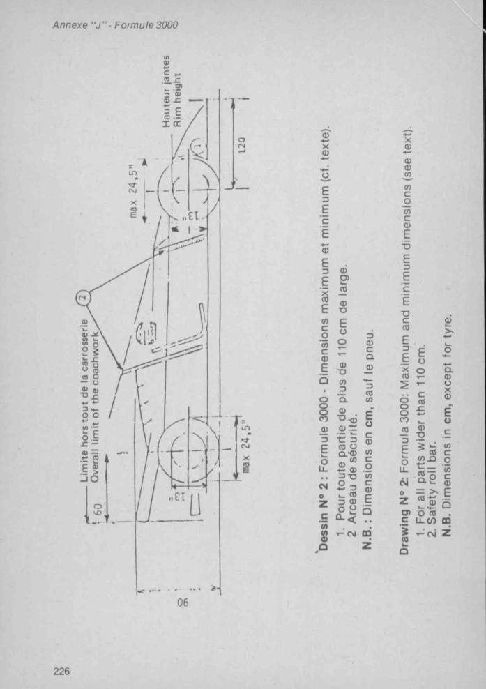
Annexe " J ” • Formule 3000
tfta>c
•2 .-C a>
I ce
fN
LO
CM
Ss(D 0
CM
Q)X<D
E3EEEa>
E3
£
EcocotoC<DE
3
Eo
e
M(0d)
û
0)o>
3 <0
0)•O
Eoo
0)T3(03
3a>cQ01
8o ®co© Q ) . r
c 3 <0 ^ Q .*® W(0 c
Euc®
3 © . 23 - 0 WO -1 ^k_ <0 c3 © t
f-^CM od
X
®3coco(0C
E■BE3
EcE
T3CCO
E3
EXco
Eoo
®•o
o s8 ^ cojO 3
Eo u.Cd oz
®>>
û . ® uX ®
E uc
% W ©CO C
O •—
O - w ©
E
5o> o co .E U-(0 ODi ^(Q
06
226
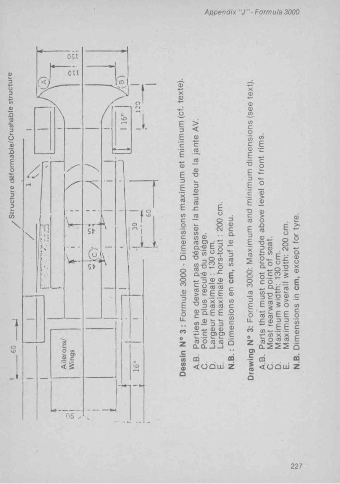
Append ix “ J " - Formula 3000
on3
oC4
nto£V)3o
<0Eo
3
X -» r>
oVO
0 6
<DX0)
u
1 5E 0)cEQ>EDE'xCO
COcoCOc0}E
CO0)DEou.• t
eoe
COCOoO
cCO
jO
0>"OD©3CO
JCCO
Eo
8CNJ0)
CO « "2.-9 E g•CD « « °
Q.KU • • • C ♦ - 3 _ Q 0)
5 <0 2 E e e 0)■OCDc
CO 3Q.E E
X X CO CO
^ ‘-3 î •*- ® ® ^ c 0 ) o )k . — w wCO O CO CO
Q . C L ^ - J
CO
< o d L i i
30>cQ.o
3COCO
Eoc0)COcoCÔc0}E
CD
X0)(DO
(OcoCÔcCDEbE3
EcE■DCCOE3
_EXCO
COE
co
(D>Q)CD>O.oCO
T3 {0? ^ Wé
EÜ
8eg
oooCO33
Eo
U -
cieZo>c5CO
^ CO r- ..o — h - c
o . E ? iC O
0 . £ CO
£ § 5 o
« « E E^ « 3 3
CO — — t - CO X X « o CO CO^ 5 5 5
CO
< C J G u i
o>>.♦-o
Û.<DÜX0)
Eo
COcgCOcCDE
0Û
z
227

Appendix "J ” -Formula 3000ARTICLE 4: WEIGHT
1) The weight of the car must not be less than 540 kg.2) Ballast can be used provided it is secured in such a way that tools are
required for its removal and/or its fixation. The com petitor is otillged to declare to the Scrutineers the presence o f ballast in his car. It must be possible to fix seals if deemed necessary by the Scrutineers.
The weight may be checked at any tim e during an event w ithout the driver on board and w ith the quantity of liquid remaining In the tanks and after the tanks have been emptied o f all fuel.
No solid, liquid, gas or other substance or matter of whatsoever nature may be added to placed on or removed from the car prior to or during the weighing.
No solid, liquid, gas or other substance or m atter o f whatsoever nature may be added to placed on or removed from the car or the driver or his apparel durino the race.
The adding to the car during the race o f any liquid or other material whatsoever or the replacement during the race of any part of the car w ith another materially heavier is forbidden.
ARTICLE 5: ENGINE1) Types o f engine e lig ib le4-stroke engines with reciprocating pistons :— engine cubic-capacity w ithout supercharging : lower than or equal to
3 000 cc ;Number o f cylinders: maximum 12.The Wankel, Diesel, 2-stroke engines and turbines are forbidden.Supercharging is forbidden.2) Lim itation o f the engine rev speedMaximum crankshaft r.p.m. authorized: 9000.In order to ensure that all the com petitors respect the maximum lim it of
9000 revs per minute, an electronic lim iter, approved by the FISA, must be f itted to each car and used throughout the entire duration of the race and also during timed practice. The scrutineers may inspect the electronic lim iter at any time during the event.
Any element discovered, enabling its functioning to be tampered with, shall be used to cancel all the tinies obtained in practice oi^to exclude the car from the classification of the race. These penalties are not exhaustive.
3) Water Injection : it is not authorised.
ARTICLE 6: PIPING AND PETROL TANKS, CABLES AND ELECTRICAL EQUIPMENT
1) All fuel tanks must be situated w ith in the main structure o f the car. The stocking of petrol at more than 40 cm from the longitudinal axis of the car and in the longitudinal box members, defined by artic le 13-8-g, is forbidden.
2) All fuel tanks must be rubber bladders conform ing to or exceeding the specifications o f FTA/Spec/FT3.
3) All rubber bladders must be made by manufacturers recognised by the FIA. (In order to obtain the FlA’s agreement, a manufacturer must prove the compliance o f his product w ith the specifications approved by the FIA. These manufacturers must undertake to deliver to the ir customers exclusively tanks complying with the norms approved).
229

A p p e n d ix “ J " - F o rm u la 3000
List of recognised manufacturers:
Federal Republic of GermanyUnlroyal Englebert GmbH, Westerbachstr. 122, 6230 FRANKFURT/MAIN
80.
United StatesDon Allen Inc., 401 Agee Road, Grants Has., OREGON 97526;Aero Tec Labs, Hewson Avenue, WARCICK, NJ 07463;Fuel Safe Corporation, 15545 Computer Lane, HUNTINGDON BEACH, Cali
fornia 92649:
FranceKléber-Colombes, Division Tissus Enduits et Applications, 4, rue Lesage-
Maille, 76230 CAUDELEC-LES-ELBEUF;Ets J. RICHE, BP 14, 14690 PONT-D’OUILLY;Société Lyonnaise des Réservoirs Souples, 18, rue Guillaume-Tell, 75017
Paris;Superflexit SA, 45, rue des Minimes, 92000 COURBEVOIE;
Great BritainMarston Palmer Ltd, Wobaston Road, Fordhouses, Wolverhampton, WV10
6QJ Staffs.Premier Fuel Systems Ltd, W illow Road, Trent Lane Industrial Estate,
Castle Donington, Derby DE7 2NP.
ItalyPirelli, V iale Rod! 15, MILANO;Gipi, Via Abruzzi 7, 20090 OPERA, MILANO.
JapanFujikura Rubber Works Ltd. N* 20, 2-chome, N ishigotanda Shlnagawa-ku,
Tokyo.Kojima Press Ltd, 3-30 Shimolchibacho Toyota, AlCHIKEN;Sakura Rubber Co Ltd, 48-14-1 Chôme Sasazuka, SHIBUYA KU, TOKYO ; Sumitomo Electric Industries Ltd, 15-5 Chôme Katahama, MIGASHI KU,
OSAKA.
4) All rubber bladders shall have a printed code indicating the name-of the manufacturer, the specifications to which the tank has been manufactured and the date o f manufacture.
5) No rubber bladders shall be used more than five years after the date of manufacture.
6) The FIA reserves the right to approve any other set of technical specifications after study of the dossier submitted by the manufacturers concerned.
7) All fuel fittings (including air vents, inlets, outlets, tank fillers, inter tank connectors and access openings) must be metal fittings bonded in to the fuel tank.
8) All connections between any fuel tank and the chassis (Including tank fillers, air vents, access openings, in lets and outlets) must be frangible. By
231

Appendix " J " - Formula 3000
frangible is meant ttiat stiould ttie fuel tank move relative to the chassis during an accident, the connection between the fuel tank and the chassis will fall at a load which is less than 50 per cent of the load required to pull the bonded metal fitting out of the tank.
9) All fuel lines between any fuel tank and the engine must have a selfsealing breakaway valve. This valve must separate at less than 50 per cent of the load required to fail the fuel line fitting out of the fuel tank.
10) Cables, lines and electrical equipment: Except if the cables, lines and electrical equipment are in compliance with the requirements of the aircraft industry as regards their location, material and connections, they must be placed or fitted in such a way ttiat any leakage cannot result in:
— accumulation of liquid;— entry of liquid in the cockpit;— contact between liquid and any electrical line or equipment.Should the cables, lines or electrical equipment pass through or be fitted
in the cockpit, they must be fully enclosed in a cover of a liquid-tight and fire- resistant material.
11) All fuel lines external to the cockpit, with the exception of lines permanently mounted on the engine, must be capable of withstanding a pressure of 70 kg/cm’ (1 000 psi) and a temperature of 230“ C (446“ F).
12) Crushable structure: The entire fuel tank area of the car in direct contact with the open air stream must incorporate a crushable structure which is an integral part of the car conforming to the specifications hereafter.
This area includes the complete external area of the iDody/monocoque construction irrespective of such added items as water radiators, inlet ducts, windscreens, etc.
a-The crushable structure should be a sandwich construction based on fire-resistant core of a minimum crushing strength of 25 lb/square inch (18 N/cm'). It shall be permitted to pass water pipes through this core, but not fuel, oil or electrical lines.
The sandwich construction must include two sheets of 1.5 mm thickness, one of which shall be aluminium alloy sheet having a tensile strength of 14 tons/square inch (225 N/mm^) and minimum elongation of 5 per cent. Alternatively, the sandwich construction must include two sheets of 1.5 mm thickness having a tensile strength of 14 tons/square inch (225 N/mmh.
b - The minimum thickness of the sandwich construction must be 1 cm.
13) Tank fillers and caps: The tank fillers and their caps shall not protrude beyond the coachwork. The filler shall have a sufficient diameter to allow for the air exhausted at the time of quick refuelling (in particular those done under pressure). Any breather pipe connecting the tank with the atmosphere shall be designed to avoid liquid leakage when the car Is running and its outlet must not be less than 25 cm to the rear of the cockpit. All filler caps must be designed to ensure an efficient locking action which reduces the risks of an accidental opening following a crash impact or incomplete locking after refuelling.
233

Appendix " J " ■ Formula 3000
14) Refuelling during ftie race : Refuelling during ttie race Is forbidden.
*^1 ) 'AM^II storage tanks situated outside the main structure of the car must be surrounded by 1 cm thick crushable structure _ ,_______ ______
No part of the car containing oil may be situated aft of the geartiox or fm ^ drive casing on any rear-wheel-driven car. In case of front-wheel-drive, no part containing oil may be situated behind the complete rear wheels.
2) All oil lines external to the cockpit, with the exception of lines nently mounted on the engihe, must be capable of withstanding a pressure of 70 kg/cm= (1 000 psi) and a temperature of 230 C (44b h).
31 Oil catch tank: When a car’s lubrication system Includes an open type sump tireather this le a th e r must vent Into a catch tank of at least 3 litres capacity. u , ■
4) No part of the car containing oil may be more than 65 cm from the longitudinal centre-line of the car.
5) No oil replenishment Is allowed during a race.
**ll*Com pulsory starter with electrical or other source of energy carried aboard the car, and able to be controlled by the driver when normally in his
2) A supplementary external source of energy temporarily ttie car may be used to start the engine both on the starting grid and in the pits.
ARTICLE 9: TRANSMISSION TO THE WHEELS1) Four-wheel drive cars are forbidden.2) Five gearbox ratios, not Including the reverse gear, as maximum.3) All automobiles must have a reverse gear which must b e jn working
order when the car starts the event and which can be operated by the driver when seated normally In the car.
AH^cars must have a brake system which has at least two separate circuits operated by the same pedal. This system rnust lie designed so that it leakage or failure occurs In one circuit, the pedal shall still operate the brakes on at least two wheels.
2) Carbon fibre brakes are forbidden.
ARTICLE 11: WHEELS AND TYRES .1) Complete wheels shall be external to the coachwork with the car viewed
In plan with the rear aerodynamic device removed.235

A p p en d ix " J ” ■ Fo rm u la 3000
2) a - The maximum width of any rim and tyre assembly shall not exceed 16 inches
C o m pu lso ry d ia m e te r o f th e w h ee ls : 13 in ches.Maximum compulsory diameter of the complete wheels. 24,5 inches.
b-The width shall be measured with the tyre at normal running pressure, and the complete wheel mounted on the car resting on the ground, in running order, with the driver aboard.
These measurements w ill be taken horizontally at axle height.3) The number of wheels is fixed at four.
ARTICLE 12: COCKPIT1) The opening giving to the cockpit must have following minimum dimen
sions:— length: 60 cm; . .— width: 45 cm, maintained over 30 cm from the most rearward point of
the seat-back-rest towards the front. . ^ .The driver must be able to enter and get out of his seat without it being
necessary to open a door or move any part of the car. Sitting at his steering wheel, the driver must be facing forward.
The cockpit must be so conceived that the maximum time necessary for the driver to get out does not exceed 5 seconds with steering wheel in place.
2) All cars must have at least two mirrors mounted so that the driver has visibility to the rear on both sides of the car (minimum reflective surface of each one: 55 cm*).
3) Safety belts: The wearing of two shoulder straps, one abdominal strap and two straps between the legs is mandatory. These straps must be securely fixed to the car.
ARTICLE 13: SAFETY1) Fire extinguishers. ___ __ ^ ^ ,a. Extinguishing product: BCF (CF^ CIBr) - BTM (CBrFj) - TDE (Cj Br2 F ).b. Minimum capacity:— driver’s compartment: 5 kg ;— engine compartment: 2.5 kg.c. Location • Mounting method: The extinguisher tx)ttle must be adequa
tely protected and the bottle for the driver’s compartment must be mounted within the main structure of the car. In all cases, the bottle mountings must be able to withstand a 25 g acceleration, no matter how these are applied.
d. Discharge time:— engine compartment: 10 seconds minimum;— driver’s compartment: 30 ± 5 seconds for BCF and TDE. 60 ± 5
seconds for BTM.Both bottles should be released simultaneously.E. Drive system: Any triggering system having its own source of energy Is
permitted, provided it Is possible to operate all extinguishers in case the main electric circuits of the car fall.
Automatic triggering by heat sensors is recommended. The driver must be able to trigger all extinguishers manually when seated normally In the car with his belts fastened and steering wheel in place. The same applies to any
237

A p p e n d ix “ J " ■ F o rm u la 3000
person outside the car. The means of triggering from the exterior must be Dositioned close to the c ircu it breaker or combined with it, and n^ust be clearly marked by a red le tter "E " in a white circle w ith a red edge, of at least 10 cm diameter.
f Checking of bottles; The following weights shall be Indicated on each bottle: weight of the empty bottle; w eight of the extinguising agent; total charged weight.
a. Operation; The two systems must be triggered simultaneously.Anv triaaering system is allowed. However, a source o f energy not corning
from the main source must be provided in the case o f a triggering system which is not exclusively mechanical. a
Concerning triggering iri the interior, and to avoid accidental triggering awarning symbol must be fitted.
The system must work in any position even when the car is upside down.
2) Life support system; A life-support system consisting o f a f^edical air bottle and flame resistant pipe for connections to the driver s h ^ e l ^ sha be fitted to the car and available for connection to the driver s helmet at alltimes.
3) Master-switch; The driver, seated normally w ith safety belt fastened and the steering wheel in place, must be able to cut o ff all e lectrical circuits by means of a spark proof c ircu it breaker which w ill be also accessibles from outside the car. There must also be a clearly indicated external handle rescue personnel can operate at a distance by a hook. This handl^e must be located near the base of the main roll-over bar sUucture, and he niarked by a symbol showing a red spark In a white-edged blue triangle with a base of at least 10 cm.
4) All cars must have a red warning light of at least 25 watts in working order at the start of a race which: faces rearward; is clearly visib le from the rear; is mounted not more than 10 cm from the car centre line; has a minimum surface of 20 cm=; a maximum surface o f 40 cm '; can be switched on by the driver when seated normally in the car.
5) Chromium plating o f steel suspension members of over 45 tons/inch' (725 N/mm') tensile strength is forbidden.
6) The use of magnesium sheet less than 3 mm th ick is forbidden.
7) The use o f titanium is forbidden, except for the engine.
S) Safety structures;a. The basic purpose o f safety structures Is to protect the driver. This pur-
DOse Is the primary design consideration.b A ll cars must have at least two roll-over structures.i) The firs t roll-over structure must be in front of the
more than 25 cm forward o f the steering wheel rim and at least as high as the top of the steering wheel rim.
239

Appendix " J " - Formula3000
ii) The second roll-over structure m ust not be less than 50 cm behind the first and high enough for a line extended from the top of the first structure to the top of the second to pass over the driver’s helm et when he Is seated norm ally in the car with his helm et on and seat belts fastened. If the second structure is not located behind the driver, there m ust be a structure behind him which Is high enough so that a line extended from Its top to the top of e ither structure in front of him will pass over the top o f his helm et when he Is seated norm ally w ith his helm et on and seat belts fastened.
c. All sa fety structures required by paragraph b m ust, when attached to the car, be capab le of w ithstanding three loads applied s im ultaneously to the top of the structure which are 1.5 w la tera lly , 5.5 w longitud inally, and 7.5 w vertically, w being the racing w eight o f the car.
d. The design concept of the safety structures required by paragraph b shall be free. Forward fac ing stays w h ich restrict the d im ensions of cockpit access required by A rtic le 12, paragraph 1, are perm itted provided the driver can exit the cockpit In the tim e required in that paragraph.
e. G eneral Considerations:— W henever bolts and nuts are used, the bolts should be o f a sufficient
m inim um diam eter, according to the num ber used. They should be.of the highest possible quality (preferably aircraft). Square head bolts and nuts should not be used.
— All w elding should be o f the h ighest quality possible w ith full penetration (preferably arc w elding and in particu lar heliarc).
— C onsiderable care should be a ttached to the necessary strengthening of the basic structure, for instance by adding reinforcem ent bars or p lates so as to properly d istribute the loads.
C onsideration should be given to using a roll-bar hoop o f 360 degrees com plete ly around the inside of the car, and attached with su itab le mounting plates. Th is type o f roll-bar then becom es a substitu te for the fram e.
f. All cars m ust have a structure im m edia te ly behind the driver's seat w hich Is w ider than and extends above his shoulders when he is seated norm ally in the car with his seat belts fastened . This structure m ust be capable of w ithstanding a sustained lateral load of 1.5 w applied to its top, w being the racing weight of the car.
g. Survival cell :
1. The chassis structure shall include tw o continuous box m em bers, one on each side o f the driver.
The chassis m ust incorporate at least one transversal hoop at the main rollbar level, one In front o f the pedal box and a further hoop betw een these two.
2. Each box m em ber shall extend from behind the driver to a point at least 50 cm in front of the soles o f his feet w ith the driver seated norm ally and with his feet on the pedals and the pedals In the inoperative position. The forem ost 40 cm o f each box m em ber need not be an integral part o f the chassis, but must be solidly fixed to it.
241

Xppendix " J ” - Formula 3000
3. Throughout its length, the structural material In the cross section of each tiox member shall have a minimum area of 10 cm’ , a minimum tensile strength of 31 kg/mm’ and a minimum panel thickness of 1 mm on unstabilised skins or 5 cm’ area and 0.5 mm thickness on stabilised skins.
4. Throughout its length from behind the driver to the soles of his feet, each tx3x must have a minimum cross sectional area of 150 cm’ . Forward of this, the boxes may taper to a minimum cross section of 100 cm’ and a minimal structural material cross section of 5 cm’ for unstablllsed skins or 2.5 cm’ with stabilised skins.
5. All holes and cutouts In the boxes shall be strongly reinforced and all material sections through these holes shall comply with minimum area requirement of 10 cm’ for unstabilised and 5 cm’ for stabilised skins.
6. The Internal cross sectional area of the cockpit from the soles of the driver’s feet to behind his seat shall nowhere be less bhan 700 cm’ and the minimum width must tie 25 cm over the whole length of the cockpit.
7. The minimum height of the tiox between the front and rear roll-over bar structures shall be no less than 30 cm.
h. All cars must have a headrest which does not deflect more than 5 cm rearwards when a rearward force of 85 kg Is applied. It must be designed so that the driver's head cannot tie trapped between the roll-over structure and the headrest.
I. Panels which, projected on a vertical plane parallel to the longitudinal axis of the car, are at least 20 cm high and of a total length of at least 50 % of the wheel-base, shall be situated tietween the front and rear complete wheels on either side and at least 55 cm from the car's longitudinal centre line and shall be the outermost extremities of the coachwork. These panels shall be made from a composite material at least 10 mm thick with a honeycomb core in metal or nomex with expanding foam giving adequate resistance to compression. The external covering shall be In aluminium alloy, plastic, or carbon fibre of minimum thickness of 0.5 mm or In another assembly of materials of equivalent efficiency. The panels must be fixed in such a manner as not to move relative to the main structure of the car and to ensure absorbtion of a lateral impact. The radiators may play the role of the protective panels or of the transversal struts.
ARTICLE 14: FUEL
1) The only fuel permitted Is petrol having the following characteristics:— a maximum of 102 RON, the measurement being made accoromg to tne
standard ASTM D 2699, the fuel being accepted or rejected according to ASTM D 3244 with a confidence lim it of 95 % and
— a maximum of 2 % oxygen and 1 % nitrogen by weight, the remainder of the fuel consisting excluslveiy of hydrocarbons and not containing any alcohols, nitrocompounds or other power-boosting additives.

Appendix " J " ■ In te rna tiona l Form ula n ’ 2 n ° 3
In countries wtiere no fuel suitable for use In current F 3000 engines is commercially available, and wtiere the laws of the country prohibit Importation of such fuel, the ASN must obtain a dispensation from the FISA for the use of aviation fuel which will then be suppled by the organiser and must be used by all competitors.
2) Only air may be mixed with the fuel as an oxidant.
ARTICLE 15: FINAL TEXTThe final text for these regulations shall tie the French version which will
be used should any dispute arise over their Interpretation.
Article 275 - incernacional formula n* Sfn* 3
SUMMARY Art. 1; Definitions
1) Formula 2 and 32) Automobile3) Land vehicle4) Coachwork5) Aerodynamic device6) Wheel7) “ Automobile make”8) Event9) Weight
10) Racing weight11) Cylinder capacity12) Supercharging13) Induction system14) Main structure
Art. 2: Regulations1) Role of the FIA2) Publication date for modifica
tions3) Previous notice for change in
the throttling flange (F3)4) Dangerous construction5) Permanent compliance with
regulations6) Measurements
Art. 3: Coachwork and regulations1) Overall width2) Width ahead of front wheels3) Width and shape between the
front wheels and the rear wheels
4) Width of the rear wing5) Overhang6) Height7) Wheel base and track (F3)8) Aerodynamic devices
Art. 4: Weight1) Minimum weight2) Ballast
Art. 5: Engine1) Engine with reciprocating pis
tons2) Wankei engines (F3)3) Engine modifications4) Induction system control (F3)5) Exhaust pipes
Art. 6: Transmission1) Number of gearbox ratios2) Number of driving wheels
Article 7: Fuel lines and tanks, cables and electrical equipment
1) Cables, fuel lines and electrical equipment
2) Reinforced piping3) FTA/FT3 rubtxer bladders4) Crushable structures5) Tank fillers and caps6) Refuelling during the race
245
Appendix ” J ” ■ International Formula/n " 2-n* 3
\rt. 8: Oil Art. 13: Cockpit1) Location • crushable structure 1) A rch itectura l access, dimen-2) Oil lines sions3) Catch tank 2) Rear view mirrors4) Oil replenishment 3) Safety belts
Art. 14: Safetya. “•) F'f’e extinguishers
1)’ Itarle? 2) Life support system (F2)2) External energy source Red'lîght*'*'^^
5) Safety structures6) Headrest
^rt. 10: Reverse gear Chromium plating o f suspension
8) Magnesium sheet \r t. 11: Brakes 9) Titanium use
Art. 15: Fuel^rt. 12: Wheels and tyres 1) Commercial fuel
1) Number o f wheels 2) Air2) Location3) Dimensions Art. 16: Final text
ARTICLE 1; DEFINITIONS
1) Formula 2 and 3 cars: A four-wheel automobile designed solely tor speed races on circuits or closed courses.
2) Automobile : A land vehicle running on at least four non-aligned wheels, of which at least two are used for steering, and at least two fo r propulsion.
3) Land vehicle: A locomotive device, propelled Dy Its own means, moving' by constantly taking real support on the earth’s surface, of which the propuF- sion and steering are under the control o f a driver aboard the vehicle.
4) Coachwork: All entirely sprung parts of the car licked by the external air stream, except the safety roll-over structures and the parts defin ite ly associated with the mechanical functioning o f the engine, transmission and running gear. The radiators shall be considered to be part o f the coachwork.
5) Aerodynamic device: Any part o f the car whose primary function is to influence aerodynamic performance.
6) Wheel: Flange and rim. Complete wheel: Flange, rim and tyre.
7) “ Automobile make” : in the case o f Formula racing cars, an "autom obile make" is a complete car. When the car manufacturer Tits an engine which it does not manufacture, the car shall be considered a hydrld and the name of the engine manufacturer shall be associated with that of the car manufacturer. The name o f the car manufacturer must always precede that of the engine manufacturer. Should a hybrid car w in a Championship Title, Cup or Trophy, th is w ill be granted to the manufacturer o f the car.
247

Appendix " J " ■ In te rna tiona l Formula n ‘ 2-n° 3
8) Event: An event shall consist of official practice, timed and untlmed, and the race.
9) Weight: Is the weight of the car at any time during the event, with neither fuel nor driver on board.
10) Racing weight: is the weight of the car in running order with the driver aboard and aii fuel tanks full.
11) Cylinder capacity: l^eans the volume swept in the cylinder(s) of the engine by the movement of the piston(s). In calculating engine cylinder capacity, the number n shall be 3.1416.
12) Surpercharging: Increasing the weight of the charge of the fuei-air mixture in the combustion chamber (over the weight induced by normal atmospheric pressure, ram effect and dynamic effects in the intake and/or exhaust systems) by any means whatsoever. The injection of fuel under pressure is not considered to tie supercharging.
13) Inlet system: All the elements of the Inlet system included between the head and external side of the throttling flange.
14) Main structure: The fully sprung structure of the véhiculé to which the suspension and/or spring loads are transmitted, extending longitudinaiiy from the foremost front suspension on the chassis to the rearmost one at the rear.
ARTICLE 2: REGULATIONS1) The following regulations governing the construction of F2 and F3 cars
listed below are issued by the FiA.2) Each year, the FiA w ill publish all changes made to these regulations.
All such changes w ill take effect on the third 1st January following their publication.
Changes made in consideration of safety matters may come under validity immediately.
3) The FISA reserves Its right in F3 to modify the dimensions of the throttling flange with a one year notice.
4) If an automobile Is deemed to be dangerous. It may t>e excluded by the Stewards of the Meeting.
5) Automobiles must comply with these regulations in their entirety at all times during an event.
6) All measurements must t>e made while the car is stationary on a fiat horizontal metalled surface.
ARTICLE 3: COACHWORK AND DIMENSIONS1) Overall width of the car, including complete wheels with the steered
wheels in the straight ahead position, shall not exceed: F2-200cm; F3-185 cm.
2) The coachwork ahead of the front wheels may be extended to an overall maximum width of: F2-150 cm; F3-135 cm.
Nevertheless, any part of the coachwork ahead of the front wheels exceeding an overall width of: F2-110cm; F3-95cm, shall not extend above the height of the front wheels rims, with the driver aboard seated normally, and irrespective of the fuel load.
3) The overall maximum width of the coachwork behind the forward edge of the front wheels and in front of the centre-line of the rear wheels shall not exceed 130 cm.
The crushabie structure is included in this width.F3 : No Dart of the bodywork in front of the centre-line of the rear wheels
249

A p p e n d ix " J ” - In te rn a tio n a l F o rm u la 2 -n * ."î
F3 : No part of the bodywork in front of the centre-line of the rear wheels ind extending above the height of the rear complete wheels may project teyond 47.5 cm each side of the longitudinal axis of the car.
4) Coachwork behind the centre-line of the rear wheels shall not exceed in vidth: F2-110cm; F3-95cm.
5) Except in the case of front-wheel drive when the measurement w ill be aken from the centre-line of the rearmost substantial load carrylna wheels,10 part of the car shall be more than 80 cm behind the centre-line o f the fore- nost front wheels.
The centre-line of any wheel shall be deemed to be half way between two itra ight edges, perpendicular to the surface on which the car Is standing, placed against opposite sides of the complete wheel at the centre of the tyre read.
6) Height ; Except for the safety roll-over bars, no part of the car shall be ligher than 90 cm from the ground w ith the car in normal racing trim w ith the Jriver aboard seated normally.
Any part of any safety roll-over bar higher than 90 cm from the ground must lo t be shaped to have a significant aerodynamic influence on the perfor- nance of the car.
7) For F3:Minimum wheelbase: 200 cmMinimum track: 120 cm.8) Between the rear edge of the complete front wheels and the front edge
)f the complete rear wheels, all sprung parts of the car visible from directly beneath the car must lie on one plane w ith in a tolerance of ± 5 mm. All these 3arts must produce an uniform, solid, hard, rigid (no degree of freedom in •elation to the body/chassis unit), impervious surface, under all circumstan- :es. The periphery of the surface formed by these parts may be curved jpwards w ith a maximum radius of 5 cm.
Any specific part of the car influencing its aerodynamic performance:— must comply with the rules relating to coachwork;— must be rigidly secured to the entirely sprung part of the car (rigidly
secured means not having any degree of freedom);— must remain immobile in relation to the sprung part of the car.Any device or construction that is designed to bridge the gap between the
sprung part o f the car and the ground is prohibited under all circumstances.No part having an aerodynamic influence and no part of the coachwork
may under any circumstances be located below the geometrical plane generated by the plane surface provided for by th is article.
ARTICLE 4: WEIGHT1) The weight of the car must not be less than: F2-515 kg; F3-455 kg.2) Ballast can be used provided it is secured in such way that tools are
required for its removal. It must be possible to fix seals if deemed necessary by the scrutineers.
The weight may be checked at any tim e during an event w ithout the driver on board and with the quantity of liquid remaining in the tanks (on the understanding that it is forbidden to add oil, any other liquid or extinguishants before the weighing) and after the tanks have been emptied of all fuel.
N.B.: Formula 2 cars taking part in the European F3000 Championship must have a minimum weight of 540 kg.
251

Annexe " J " ■ Form ule In te rna tiona le 2 -n^3
Euca>(0Soüôiz
0>c
E ®
1 ^ c oc ££ • 0
E E
Ë c
• i sÛ ... . CM ^ A3 " 3
ilo u . u. ••.. (O
lo CM 04 O O Z 2 o> C ç ■« J(/) go> S Q Û
- E S
a3 .-S
ü ^ E
o î?
o =£ (Q
E O
c<Q£
0)TJ
<0
r(0a
î 2w «c E a ÿ
«•o(/>3ao>■o9t<0o.
3O
3OCL
OEoom«O)«tf)3•D«5«EV■o«3CTOUAi
</>•- <9 ^fO C ^^ C «= 2 «9 ^ C^ 3 2ü) ç
co33U3«V3A0>
U . < (0
I I Iesi to ^
252

Appendix " J " ■ In te rna tipna l Formula n ’ 2 n ‘ 3
& Î■p 5 «• 5 £I 1 I5 g6 Io o
il3 C U ■s ?
m Ea, c1 io ^ IL to
I I IO O z
253

A p p e n d ix “ J ” • In te rn a tio n a l F o rm u la n ° 2 -n “ 3
ARTICLE 5: ENGINE1) Engines w ith reciprocating pistonsa) Engine cylinder capacity: less than or equal to 2,000 cm^b) Maximum number of cylinders: F2-6; F3-4.c) Supercharging forbidden.
2) For F3 only:Rotary piston engines: Cars with rotary piston engines covered by NSU-
Wankel patents w ill be admitted on the basis of a piston displacement equivalence. This equivalence is tw ice the volume determined by the difference between the maximum and minimum capacity of the working chamber.
3) For F3 only:
The engine block and engine head castings, machining completed, mus be those of an engine equipping a car model of which the FIA has ascertai ned the series-production of a least 5.000 units in 12 consecutive months The original engine block and cylinder head may be modified freely by remo val of material to the exclusion of any addition of material. However, it is per mitted to sleeve an engine block that orig inally is not fitted w ith sleeves.
The type of crankshaft bearings may not be modified (the replacement of a plain bearing by a roller bearing is therefore forbidden).
It is pointed out that whatever the type o f the engine used, it Is not compulsory that the different mechanical components of the engine should proceed from the original engine.
The Induction system is free but it must be fitted w ith a throttling flange of 3 mm in length having a circular section, and with a parallel hole o f 24 mm diameter maximum. All the air feeding the engine must pass through this throttling flange, which must be made o f metal or metal alloy.
The material of the air box is free, provided that it is not porous. It Is prescribed that the entire inlet system including manifolds, injectors, alr-box and restrlctor must fit into a box of 1 m long, 50 cm wide and 50 cm high. It w ill also t>e prescribed that the inlet system may be removed from the engine as one unit w ith the cylinder head(s).
The maximum cylinder-capacity may be obtained by increasing or reducing either the bore or stroke or both dimensions.
The other original parts of the engine may be replaced or modified without restriction. It is permitted to weld the sleeves to the block for the conventional engine.
Water in jection: it shall only be authorised if it is effected upstream of the air restrictor.
For F2: Free.
4) For F3 only:
Vacuum tightness control apparatus o f the Induction system for F3 engines:
The control apparatus described hereafter represents the ultim ate method o f verification of the vacuum tightness o f F3 induction systems, w ithout the possib ility of appeal. A ll F3 event organisers w ill have to put such an appara-
255

Appendix " J " ■ In te rna tiona l Formula n ’ 2 n ‘ 3
tus at ttie disposal of the scrutineers tor verification purposes, both before and after the race. , ^
The apparatus alms to create artific ially a vacuum In the induction system and Includes: , , . , . -c .
— A membrane suctlon-pump, with the nominal output of 25 to 28 lltres/mlnute, and capable of obtaining a vacuum of 55 to 65 cm Hg for zero air flow. ^ „
— A rubber tubular stop perfectly adjusted to the flange.— A vacuum-gauge connected to the piping between the rubber stop and
the suctlon-pump. . ^ .The procedure to be respected for the checking is the following:a) Rotate the engine Into such a position that, In each cylinder, at least
one of the valves Is closed.b) Open the Injection slide or the carburettor butterflies.c) Check on the vacuum-gauge that the suctlon-pump creates In the Induc
tion system a depression more than or equal to 15 cm Hg.d) If condition a) cannot be met, disconnect the rocker-arms or remove the
camshaft. In order to shut all Inlet valves. If one or several valves have been damaged during the event, the entrant may repair them under the steward s control before undergoing the testing procedure. In these last cases, the minimum vacuum to be obtained shall be 20 cm Hg Instead of 15.
5) Exhaust pipes: The outlet orifices of the exhaust pipes, when directed to the rear, must tie placed at a height of less than 60 cm above the ground.
ARTICLE 6; TRANSMISSION1) F2 only: Five gearbox ratios, not Including the reverse gear, as maxi
mum.2) The car must be driven by two wheels only.
ARTICLE 7: FUEL LINES AND TANKS, CABLES AND ELECTRICAL EQUIPMENT
1) Except If the cables, lines and electrical equipment are In compliance with the requirements of the aircraft Industry as regards their location, material and connections, they must t>e placed or fitted in such a way that any leakage cannot result In:
— Accumulation of liquid In the cockpit.— Entry of liquids Into the cockpit.— Contact tietween liquid and any electrical line or equipment.Should the cables, lines or electrical equipment pass through or be fitted
In the cockpit, they must be fully enclosed In a cover of a llquld-tlght and fire- resistant material.
2) All fuel lines external to the cockpit, with the exception of lines permanently mounted on the engine, must be capable of withstanding a temperature of 230° C and a pressure of:
— 70 kg/cm’ for those lines working under pressure.— 7 kgrcm' for others.
257

A p p en d ix " J ” ■ In te rn a tio n a l Fo rm u la n * 2 -n “ 3
3) AM fuel tanks, except for a collector tank not exceeding 5 litres capacity, must be rubber bladders conforming to or exceeding tfie specifications of FIA/Spec/FT3.
a) Safety fuel tanks approved by ttie FIA; * . u iThe FIA reserves Its right to approve any other set of technical specifica
tions after study of the dossier submitted by the manufacturers concerned.
b) Safety tank manufacturers recognised by the FIA:Entrants must use safety fuel tanks made by a manufacturer recognised
by the FIA. In order to obtain the FIA’s agreement, a manufacturer must prove the compliance of Its product with the specifications approved by the FIA.
These manufacturers must undertake to deliver to their customers exclusively tanks complying with the norms approved. To this end, on each tank delivered there shall be printed a code Indicating the name of the manufacture^ the exact specification according to which the tank has been manufactured and the date of the manufacturing.
c) Ageing of safety fuel tanks:The ageing of safety fuel tanks entails a considerable reduction in the
strength characteristics after approximately five years. Therefore, all fuel cells must be replaced at the latest five years after the date o f manufacture indicated on the cell.
d) List of recognised manufacturers Federal Republic of Germany:
Uniroyal Englebert GmbH, Westerbachstr. 122, 6230 Frankfurt/Mam 80.United States: ^ ^
Don W Allen Inc, 401 Agee Road, Grants Pass, Oregon 97526.Aero Tec Labs. Hewson Avenue, Warcick, NJ 07463.Fuel Safe Corporation, 15545 Computer Lane, Huntington Beach, Califor
nia 92649.hrance*
Klébêr Colombes, Division Tissus Enduits et Applications, 4, rue Lesage- Maille, 76320 Caudelec-les-Elbœuf.
Ets J. RICHE, BP 14, 14690 Pont-d’Ouilly.Société Lyonnaise des Réservoirs Souples, 18, rue Guillaume-Tell, 75017
Paris.Superflexit SA, 45, rue des Minimes, 92405 Courbevoie.
^^STarstorf Palmer Ltd, Wobaston Road, Fordhouses Wolverhampton, WV10
^^Pren^er^ Fuel Systems Ltd, Willow Road, Trent Lane Industrial Estate, Castle Donington, Derby DE7 2NP.
Italy:Gipi, Via Abruzzi 7, Opera, Milano.Pirelli, Viale Rodi 15, Milapo.
259

Appendix " J " ■ In le rna lion a l Formula n ° 2 n ° 3
"^^Puj^kura Rubber Works Ltd. N° 20, 2-chome, Nishigotanda, Shlnagawa-ku, Tokyo.
Koiima Press Ltd, 3-30 Shimoichibacho Toyota, Aichiken.Sakura Rubber Co Ltd, 48-14-1 Chôme Sasazuka, Shibuya Ku, Tokyo.Sumitomo Electric Industries Ltd, 15-5 Chôme Katahama, Migashi-ku,
Osaka.4) Crushable structures (Compulsory for F2, optional for F3) : The entire
fuel tank area of the car in direct contact with the open air stream must Incorporate a crushable structure which Is an Integral part of the car conforming to the specification hereafter.
This area includes the complete external area of the body/monocoque construction irrespective of such added items as water radiators, inlet ducts, wiodscr66ris Gto
a) The crushable structure should be a sandwich construction based on fire resistant core of a minimum crushing strength of 25 ib/square inch (18 N/cm"). It shall be permitted to pass water pipes through this core, but not fuel, oil or electrical lines.
The sandwich construction must Include two sheets of 1.5 mm thickness, one of which shall be aluminium, alloy sheet having a minimum tensile strength of 14 tons/square inch (225 N/mm’) and minimum elongation of 5 per
Alternatively the sandwich construction may include two sheets of 1.5 mm thickness having a tensile strength of 14 tons/square Inch (225 Ijl/mm*).
b) The minimum thickness o f the sandwich construction must be 1 cm. The side of the fore and aft fuel tank area, however, must contain a crushabie structure of at ieast 10 cm thickness at such crushable structure’s thickest point, the position of this widest point to be at the constructor's discretion, over a length of at least 35 cm after which It may be gradually reduced to 1 cm.
5) Tank fillers and caps : The tank fillers and their caps shall not protrude beyond the coachwork. . ^ ^ ^ »
The filler shall have a sufficient diameter to allow for the air exhausted at the time of quick refuelling (in particular those done under pressure). Any breather pipe connecting the tank with the atmosphere shall be designed to avoid liquid leakage when the car is running, and its outlet must not tie less than 25 cm to the rear of the cockpit. ............................. .
All filler caps must be designed to ensure an efficient locking action which reduces the risk of an accidental opening following a crash impact or incomplete locking and refuelling.
6) Refuelling during the race: In the event that any fuel Is added after the race starts, the container from which fuel Is being added must have a ieak- oroof coupfing which connects it to the tank filler on the car. The air vent of ihe container must be fitted with a non-return valve.
ARTICLE 8: OIL
1) An oil storage tank situated outside the main structure of the car must be surrounded by 1 cm thick crushable structure.
No part of the car containing oil may be situated aft of the gearbox, or final
261

Appendix “J " ■ In te rna tiona l Formula n ° 2 -n ' 3
drive casing on any rear wheei driven car. In case ot front wheel drive, no pan containing oil may be situated behind the complete rear vvheels.
2) Oil lines external to the cockpit with the exception of lines permanently mounted on the engine, must be a reinforced construction. They must withstand a pressure of:
— 70 kg/cm’ for those lines working under pressure;— 7 kg/cm“ for others. . . ^3) Oil catch tank: When a car lubrication system includes an open type
sump breather, this breather must vent into a catch tank of at least 2 litrecâpâcity. • I j
The container shall either be made out of translucent plastic, or include atransparent panel. ,
4) No oil replenishment is allowed during a race.
ARTICLE 9: STARTING1) Compulsory starter with electrical or other source of energy carried
aboard the car, and able to be controlled by the driver when normally in his
*^2) A supplementary external source of energy temporarily connected to the car may be used to start the engine both on the starting grid and in the pits.
ARTICLE 10: REVERSE GEARAil vehicles must have a reverse gear which must be in working order when
the car starts the event, and which can be operated by the driver when seated normally In the car.ARTICLE 11: BRAKES
All cars must have a brake system which has at least two separate circuits ooerated by the same pedal. This system must be designed so that if leakage or failure occurs In one circuit, the pedal shall still operate the brakes on a least two wheels.ARTICLE 12: WHEELS AND TYRES
1) Number of wheels: 4. j2) Complete wheels shall be external to the coachwork with the car viewed
in plan, with the rear aerodynamic device removed.3) a) For F2, the maximum width of any rim and tyre assembly shall not
exceed 16 inches. ,Compulsory diameter of the rear wheels: 13 inches.For f=3: The width of the complete wheels is lim ited to 11.5 inches. Compulsory diameter of the rear wheels : 13 inches,b) The width shall be measured with the tyre at normal running pressure,
and the complete wheel mounted on the car resting on the ground, in running order, with the driver aboard.
This measurement of the width will only be taken at the widest point of the tyre, above the hub-level. In no case can the interior width measured where the tjeads join the rim exceed the width of the tyre.
4) The fitting of multiple tyres on one and the same rim is authorised.
ARTICLE 13: COCKPIT1) The opening giving access to the cockpit must have the following mini
mum dimensions:263

Appendix " J " - In te rna tiona l Form ula n * 3
— Lenoth: 60 cm ; . • .— Width: 45 cm, maintained over 30 cm from the most rearward point ot
the seat backrest towards the front.The driver must be able to enter and get out of his seat without it bemg
necessary to open a door or move any part of the car. Sitting at his steering wheel, the driver must be facing forward.
The cockpit must be so conceived that the maximum time necessary tor the driver to get out does not exceed five seconds with steering wheel in
'’ ' 21^X11 cars must have at least two mirrors mounted so that the driver has visibility to the rear on both sides of the car (minimum surface of each one : 55 cm^.
3) Safety belts: The wearing of two straps, one abdominal strap and two straps between the legs Is mandatory. These straps must be securely fixed to the car an must be in conformity with the 1985-FISA norma (obtainable from FISA).
ARTICLE 14: SAFETY
1) Fire Extinguishers ■ Extinguisher systemsa) Extingulshant: Halon 1211 ou 1301 (BCF-BTM).b) Minimum capacity:Cockpit 5 kg ;Engine compartment: 2.5 kg.c) Location: Mounting method: The extinguisher bottle must be adequa
tely protected, and the bottle for the driver’s compartment must be mounted within the main structure of the car. In all cases, the bottle mountings must be able to withstand 25 g accelerations, no matter how these are applied.
d) Discharge Time:Engine compartment: 10 seconds ;Driver’s compartment: 30±/5 seconds for Halon 1211;
60 ± /5 seconds for Halon 1301.e) Drive System: j ■Any triggering system having Its own source of energy Is permitted, provi
ded It Is possible to operate all extinguishers In case the main electric circuits of the car fall. ^ ^ .
Automatic triggering by heat sensors Is recommended. The driver must be able to trigger all extinguishers manually when seated normally in the car with his belts fastened and steering wheel In place. The same applies to any person outside the car. The means of triggering from the exterior must be positioned close to the circuit breaker or combined with It, and must be clearly marked by a red letter “ E” In a white circle with a red edge.
f) Checking of bottles: ... ,The type of extlnghlshant, the total weight of the bottle and the quantity of
extingulshant must be specified on each bottle. ------ ____g) Working:The two systems must be triggered simultaneously.Any triggering system is allowed. However, a source of energy not coming
from the main source must be provided In the case o/ a triggering system which Is not exclusively mechanical.
265

Appendix “ J " ■ In te rna tiona l Formula n ' 2 n ' 3
Z wiSth'"'45°cm"!'Àiaintained over 30 cm from the most rearward point of
‘ ' ^ T h T d V w e î S r a b t get out of his seat without it beingne le lsa iV Io open Tdoor or move any part of the car. Sitting at his steering
T lt^ i ' fo c M r r ^ u ^ s r b e ^ V S l^ e d ^ the maximum time necessa^fo r the driver to geTout does not exceed five seconds with steering wheel in
2^^Ali cars must have at least two mirrors mounted so that visibility to thTm ar on both sides of the car (minimum surface of each one . 55 cm*).
nt Safetv Ijelts; The wearing of two straps, one abdorn^inal strap ®nd tvvo
fhe®Mr“ ust‘b l !^con® ormity with Ih l® ll5 -F llA "n o rm l (®o®btainlbl'e from FISA).
ARTICLE 14 : SAFETY1) Fire Extinguishers • Extinguisher systemsa) Extinguishant; Halon 1211 ou 1301 (BOr-BTM).b) Minimum capacity:Cockpit 5 kg ;Engine compartment: 2.5 kg.c) Location: Mounting method: The extinguisher bottle
telv protected and the bottle for the driver's compartment must be mounted withPn the main structure of the car, In allbe able to withstand 25 g accelerations, no matter how these are applied.
d) Discharge Time:Engine compartment: 10 seconds ; uDriver’s compartment: 30±/5 seconds for Ha on 1211,
60 ±15 seconds for Haion 1301.
Any*trlggering system having its own source of energy is permitted, provided it is possible to operate all extinguishers in case the mam electric cir-
‘""‘AmomatlcTriggering by heat sensors is recommended. The driver rnust be able to trioaer all extinguishers manually when seated normally In the carwilh M t s fasiened fnd steering wheel in P'®®t„^^;^h^ex,e?^or mi°st'Ee person outside the car. The means of ‘ f '9gering <rom the exterior must be positioned close to the circuit breaker or combined with a™ clearly marked by a red letter “ E” in a white circle with a red edge.
The type of^exti^hlshant, the total weight of the bottle and the quantity ofextinguishant must be Specified on each bottle. ^ —
?he two systems must be triggered simultaneously. .Anv trioaering system is allowed. However, a source of energy not corning
from the main source must be provided in the case Oi a triggering system which is not exclusively mechanical.
265

Appendix " J " ■ In ternationa l Formula n ‘ 2 n ° 3
Concerning triggering in the interior, and to avoid accidental triggering a warning symbol must be fitted.
The system must work in any position even when the car is upside down.
2) For F2 only: , . l. jLife support system: A ilfe-support consisting of a medical air bottle and
flame resistant pipe for connection to the driver’s helmet, shall be fitted to the car and available for connection to the driver's helmet at all times.
3) Master-swltch: The driver seated normally with his safety belt fastened and the steering wheel in place must be able to cut off ail electrical circuits by means of a spark proof circuit breaker, which w ill be also accessible from outside the car. There must also be a clearly Indicated external control switch which may be operated at a distance by the safety personnel, by means of a hook. This switch must be situated near the base of the main safety structure (Art. 13.5.C). It will be marked by a red spark in a white-edged blue triangle with a base of a least 10 cm.
4) All cars must have a red warning light of a least 15 watts in working order at the start of a race which faces rearward, is clearly visible from the rear, is mounted not more than 10 cm from the car centre-line, has a minimum surface of 20 cm^ a maximum surface of 40 cm^ and can be switched on by the driver.
5) Safety Structures:а) Survival cell1) The chassis structure shall include two continuous box members, one
each side of the driver.2) Each box members shall extend from behind the driver to a point In front
of the fully depressed pedal position and terminate in transverse bulkheads.3) Throughout its length the structural material in the cross section of
each box member shall have a minimum area of 10 cm^ a minimum tensi e strength of 30 kg/mm’ and a minimum panel thickness of 1 mm on unstabili- sed skins or 5 cm" area and 0.5 mm thickness on stabilised skins.
4) Throughout its length each box must have a minimum cross sectional area of 150 cm".
5) All holes and cutouts in the boxes shall be strongly reinforced and all material sections through these holes shall still comply vvlth rninimum area reQuirement of 10 cm^ for unstabilised and 5 cm* for stabilised skins.
б) The internal cross sectional area of the cockpit from the soles of the driver’s feet to behind his seat shall nowhere be less than 700 cm" and the minimum width must tie 25 cm over the whole length of the cockpit.
7) I he minimum height ot the box between the front and rear roll-over bai structures shall be no less than 30 cm.
8.1) The chassis shall Include an impact absorbing structure (which may be detachable) ahead of the front transverse bulkhead.
Radiators may be incorporated in this structure. If detachable this structure must be securely fixed.
267

Appenxiix " J " - In te rn a tio n a l Fo rm u la n ' 2 -n* 3
8.2) At a point 30 cm ahead of the front transverse bulkhead it shall have a cross section of a least 200 cm*.
8.3) Material w ill be the same as the skins of the main chassis structure. The cross section of the material w ill be at least 3 cm* with mirilmum thickness of 1 mm in non-stabllised material and 1.5 cm* In stabilised m a te ria l^ minimum thickness 0.5 mm. A securely mounted radiator will be considered to meet these requirements. , . ^ • i i
Holes or cutouts must be strongly reinforced to maintain the originalstrength.
b) Lateral protection structuresThey w ill be 10 cm high minimum. .These shall be of minimum length 60 % of the wheel base on either side
and at least 55 cm from the car’s longitudinal centre line. E ^ h to consist of a structure with minimum cross sectional area of 20 cm and a minimum ten-
The'?tructu?e^hai^^^ transversally to the tub to ensure the absorption of lateral impact. Radiators may be incorporated into these structures.
c) Roll-over barsl j The basic purpose of safety structures is to protect the driver. This pur
pose is the primary design consideration.2) All cars must have at least two roll-over structures, but the use of tlta-
The first'^roil-over structure must be in front of the steering wheel, r^ot more than 25 cm forward of the steering wheel rim and at least as high as the top
The second^ri^ll^^^ structure must be not less than 50 cm behind the first^ It must be high enough for a line extending from the top of the first structure to the top of the second, to pass over the driver’s helmet when he is seated normally in the car with his helmet on and seat belts fastened.
This second structure behind the seat must be symmetrical about the lengthwise centre-line o f the car and comply with the ^o"owmg f gures.
— The minimum height must be at least 90 cm measured vertically from
*^^^^he°tolTofThTr(S°ba^ also be at least 5 cm above the driver's helmet when the driver Is sitting in a normal driving position.
Furthermore, the top of this second structure must have a passage enabling the use of a hook for lifting the car.
Th*e mM-bar, of entirely free conception, must be capable of thf» stress minima indicated as follows, applied simultaneously to the top of h i I l r l l fu æ , w h icH ^^ w laterally, 5 .^w longitudinally in both directions
and 7.5 w vertically, w being the racing weight of the car, the Induced loads being carried over into the primary syucture of the . ... ^ .
A certificate signed by a qualified technician must be submitted to the scrljtileers o ^ niust be accompanied by a d ra ^n g or a photo^graph of said roli-bar, and state that this roli-bar can withstand the above mentioned loads.
269

Appendix “ J " - In le rna lion a l Formula n ' 2 -n ’ 3
*"'^1 ^henever*bcms”a^d^^ are used, the bolts should ® minimum diameter, according to the number used. They must be of the hig hest possible quality (preferably aircraft). Square head bolts and nuts should
" ° 2) 'o n lco n tln u ou s lenoth of tubing should be used for the main f j u c t ^ with smooth continuous bends and no evidence of crimping or «a I failure.
3) All welding should be of the highest quality pop ib le with full pénétrat io n (oreferablv arc welding and in particular heliarc).
4) ^or space-frame constructions, It is important that m lj^^e r structures aro attarhfid to cars in such a way as to spread the loads over a wide area. It is not sufficient to simply attach the roll-bar to a single t i^ e ortubes. The roll-bar should be designed In such a way as to be an extension of the frame Itself, not simply an attachment to the frame.
Considerable care should be attached to the the basic structure, for Instance by adding reinforcement bars or plates
^j^F^oTmo'nocoque constructions, consideration shouW t ^ ^roll-bar hoop of 360 degrees completely around the inside of ‘be car and atta ched with suitable mounting plates. This type of roll-bar then becomes a
*^6)**AM*ca*rs'^rnust have a headrest which does c ° ' ‘^.f^ect rnore than 5 crn rearwards, when a rearward force of 85 kg is ®PPb®8_'t must te des^^^^ that the driver's head cannot be trapped between the roll-over structure ana
7)*^Chromliim plating of steel suspension members of over 45 tons/squareinch (725 N /m m 4 tensile strength Is forbidden. , . k ih h ...,
8) The use of magnesium sheet less than 3 mrn *bi ck is forbidden.9) The use of titanium In suspension and steering parts, or In the roll-over
structures is forbidden.
ARTICLE 15; FUEL „1) In piston engines, the only fuel permitted Is petrol having the following
characterj^sticS|^ of 102 RON, the measurement being made according to the standard ASTM D 2699, the fuel being accepted or reiected according to ASTM D 3244 with a confidence lim it of 95 %, and
bl A maximum of 2 % oxygen and 1 % nitrogen by weight, the remainder of the fuel consisting exclusively of hydrocarbons and not containing any alcohols nitro-compounds or other power boosting adddlves.
In countries where no fuel suitable for use in current ^^/F^ fngmes is commercially available, and where the laws of the ° !such fuel, the ASN must obtain a dispensation from he f A foMhe use of aviation fuel which w ill then be supplied by the organisers and must be used
air may be mixed with the fuel as an oxydant.
ARTICLE 16: FINAL TEXTThe final text for these regulations shall be the French version which will
be used should any dispute arise over their interpretation.271

Appendix " J " ■ in te rna tio na l Form uia cars (Group El
Artic le 277 - intemcicional formulae racing cars (Group E)
It Is permitted to organise sporting competitions open to other racing cars than those defined in one of the previous Groups of Appendix J.
All specihcatlons concerning the vehicles and particularly the lim itations of the cylinder-capacity are in this case at the discretion of promoters and it rests with them to list these specifications as clearly as possible in the Sup- l^ernentary Regulations of the event, which anyway have to t)e approved bv the National Sporting Authority answerable to the FIA.
However, racing cars, which do not comply with any of the International Racing Formulae, must for security reasons be in conformity with the Gene-
Art. 257.4.1, 257.4.2, 257.4.3, 253.15, 253.14 lo n i A rf' I 275.13.4 et de l ’Art. 274.3.5 (1st paragraph, see1981 Appendix J - FI Regulations): k a k .
The dimensions of the roll-bars must be as follows: the minimum height must be at least 36 inches (92 cm) measured along the line followina the dri- ver s spine, from the seat's metal shell to the top of the roll-bar. The top of the roll-bar must also be at least at 5 cm above the driver's helmet when the driver is sitting in normai driving position. The width must be at least 38 cm measured inside the roll-bar tietween the two vertical pillars of the sides It must be measured at 60 cm above the seat's metal shell on the perpendicular to the line following the driver’s spine.
to obtain a sufficient strength for the roli-bar, two possibilities are left to the manufacturers:
a) The roli-bar, of entirely free structural conception, must be capable of withstanding the stress minima Indicated in Art. 257.4.5., , ^^® tyoes and brace(s) must have a diameter of at least 1 3/8 Inch(3.5 cm) and at least 0.090 inch (2 mm) wail thickness. The material should tie m^ybdenum chronlum SAE 4130 or 4125 (or equivalent In DIN, NF etc.).
There must be at least one brace from the top of the tiar rearwards at an angle not exceeding 60“ with the horizontal. The diameter and material of the brace must be the same as those of the roll-bar Itself.
case of two braces, the diameter of each of them may be reduced to 20/26 mm. Removable connections between the main hoop and the brace must comply with drawings listed In Art. 253.9.2.2.7.
Forward fitted stays are allowed.,2) The extinguisher system Is left up to the ASNs. However the directives
laid down in Art. 257.4.4. are strongly recommended.
Title 5) NaMonal formulaeRegistration of National Racing Formulae
•'’® registration of "national" formulae. In order to have their technical prescriptions known at an international level
273

Appendix “J " - National Formulae and to ensure a certain stability and a standardisation of the regulations which rule them.
1) In persuance of Art. 251, any ASN has the right to define regulations applying to given types of “ Formula libre” racing cars denominated hereafter: "National Formulae” .
2) A ree llg ib le fo r registration only the applications presented by at least 2 National Sporting Authorities and concerning a National Formula used in at least 2 countries.
3) The FIA w ill accept, in compliance with the preceding Art. 2 to register on an voluntary basis any set of prescriptions defining such National Formulae.
The regulations thus registered by the FIA will be applicable in countries, the ASNs of which have declared to abide by them. The declaration made by the National Sporting Authority to adopt the regulations o f a determined National Formula is exclusively valid for the regulations such as they were originally deposited at the FIA, and this National Sporting Authority is entitled to withdraw this declaration if the regulations are altered afterwards.
The withdrawal of a declaration for another reason than the one hereabove mentioned, must compusorily be communicated to the FIA before December 31 St in order to be valid as from the following year.
4) From the time when such a f^atlonal Formula is registered, its appellation can be used in those countries where the ASNs have adopted the registered regulations, only for cars entirely complying with the regulations deposited at the FIA.
5) Any application for the registration of regulations for a National Formula should be addressed to the FIA at the latest on October 1st, to be valid as from January 1st of the following year. The National Formulae can (but it Is not compulsory) form the subject of restrictions as regards the engine or other manufacturing elements, in order to allow exclusively the use of castings of a given make. Such a one-make Formula may have a d istinct commercial name related to the Imposed desion restrictions.
6) The National Sporting Authorities which have adopted a determined National Formula may file an application at the FIA in view of the organisation of a award including several countries.
Any application of that kind will be submitted to the appreciation of the FISA whose decision w ill depend on the number of countries interested by the organisation of an event included In that award and on the advisability or .the necessity, for the general Interest of Automobile Sport, to introduce such a form of competition.
7) The organisation of any other type of international award without the FIA’s agreement, as prescribed in the above Art. 6 w ill entail the application of penalties.
275