Embed Size (px)
Citation preview
Durs tL a b o r a t o r138 S
- I - G 1 3 9
• •
Durst Laborator 138 SDurs t Labora tor G 139 Servicing instructions
L 1 3 8 SG 139 -
Replacing the counterweight spring
The special tool required for this purpose is supplied to order and charged by Durst.
Important: The counterweight spring (1) must always be replaced together with thecolumn head (2).
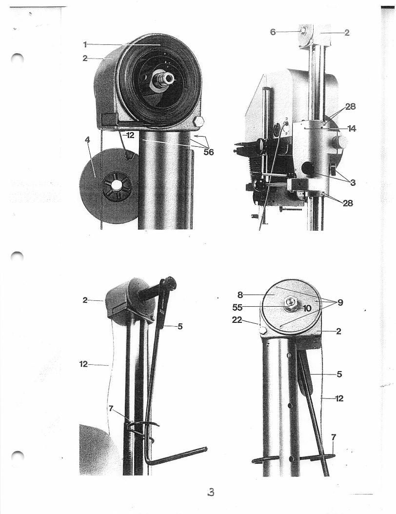
1.) Move the enlarger head to the bottom of the column and lock it in position withthe two knobs (3) on the carriage (14).
2,1 The column head (2) contains the counterweight spring (1) and the steel cable
T d
X
L 1 3 8 S - 1G 1 3 9 - 1sheet 2
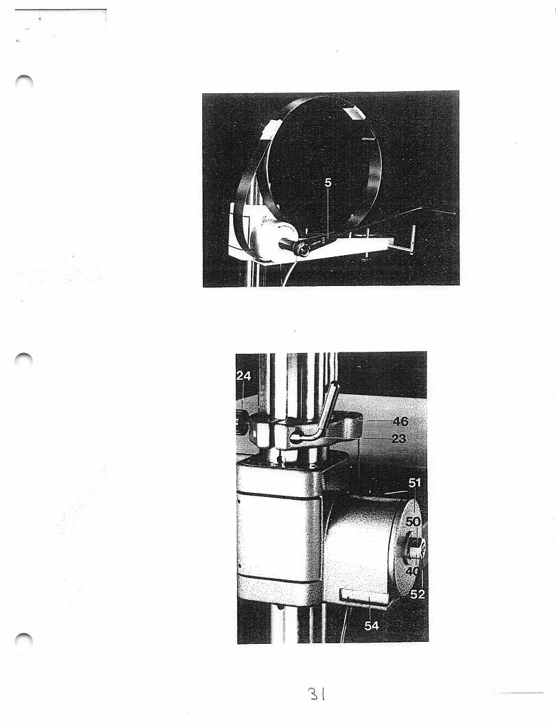
drum (4). Mount the special spanner (5) for tensioning the counten/veight springon the nut (6) at the right-hand side of the column head, slightly tension, andsecure the spanner (5) by engaging the hook (7).
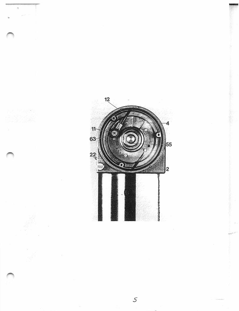
3.) Unscrew the three cross-head screws (9) and remove the left-hand cover plate (8)of the column head (2). Tap out the locking pin (10) of the hexagonal nut (55)with a punch, and unscrew the nut. Then take out the cable drum (4).
4.) Remove the retaining hook (7) and carefully relax the spring (1) fully. Thenremove the tensioning spanner (5).
5.) Unscrew the cross-head screw (11) and remove the retaining washer (63), then pullthe steel cable (12) out of the column head (2).
6.) Unscrew the three screws (56) securing the column head on the column, and^ remove the column head (2). Mount the new column head with the new counterweight spring in the same way. Again attach the tensioning spanner (5) to theright-hand side of the column head and tension the counterweight spring (1) bytuming the spanner (5) anti-clockwise through 4 - 6 tums. Then secure the spanner(5) with the hook (7).
7.) Draw the steel cable (12) into the new column head (2), attach to the cable daim(4) with the cross-head screw (11) and the retaining washer (63) and refit the cabledrum (4). Screw in the left-hand hexagonal nut (55) and secure with the lockingpin (10). Fit the left-hand cover panel (8) and ti^ten the three screws (9).
8.) Now remove the retaining hook (7) and the spanner (5).
Durst Laborator 138 SDurst Laborator G 139 Servicing instructions
10.734
1 2
5
Durst Laborator 138 SDurst Laborator G 139 Servicing instructions
L 1 3 8 S - 2G 1 3 9 - 2
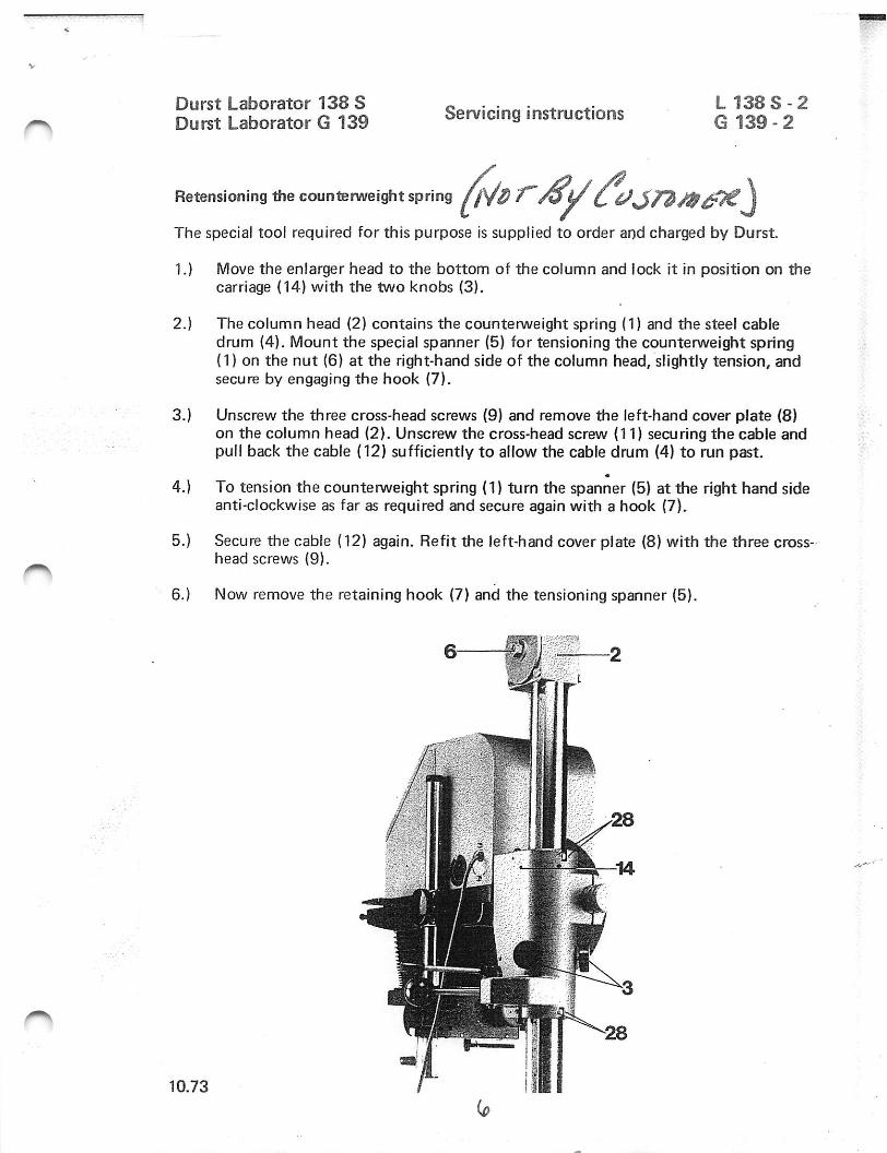
Retensioning the counterweight spring
The special tool required for this purpose is supplied to order and charged by Durst.
1.) Move the enlarger head to the bottom of the column and lock it in position on thecarriage (14) with the two knobs (3).
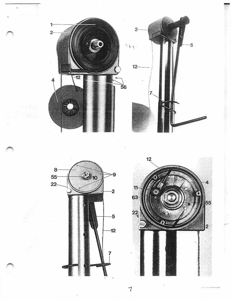
2.) The column head (2) contains the counterweight spring (1) and the steel cabledrum (4). Mount the special spanner (5) for tensioning the counterweight spring(1) on the nut (6) at the right-hand side of the column head, slightly tension, andsecure by engaging the hook (7).
3.) Unscrew the three cross-head screws (9) and remove the left-hand cover plate (8)on the column head (2). Unscrew the cross-head screw {11) securing the cable andpull back the cable (12) sufficiently to allow the cable drum (4) to run past.
4.) To tension the countenrt/eight spring (1) turn the spanner (5) at the right hand sideanti-clockwise as far as required and secure again with a hook (7).
5.) Secure the cable (12) again. Refit the left-hand cover plate (8) with the three cross-head screws (9).
6.) Now remove the retaining hook (7) and the tensioning spanner (5).
6 2
1 0 . 7 3
Durst Laborator 138 SDurst Laborator G 139 Servicing instructions
L 1 3 8 S - 3G 139 - 3
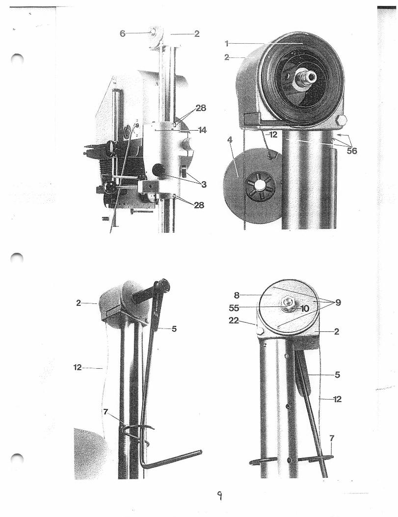
Replacing the steel cable
The special tool required for this purpose is supplied to order and charged by Durst.
1.) Move the enlarger head to the bottom of the column and lock it in position withthe two knobs (3) on the carriage.
2.) The column head (2) contains the countenveight spring (1) and the steel cabledrum (4). Mount the special spanner (5) for tensioning the countenA^eight springon the nut (6) at the right-hand side of the column head, slightly tension andsecure the spanner (5) by engaging the hook (7).
Unscrew the three cross-head screws (9) and remove the left-hand cover plate (8) of
%
V
D u r s t L a b o r a t o r 1 3 8 S L 1 3 8 S - 3Durst Laborator G 139 Servicing instructions g ^gg 3
sheet 2
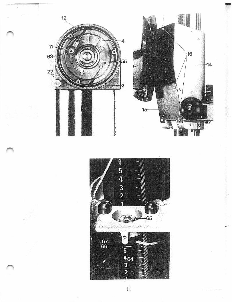
the column head (2). Unscrew the cross-head screw (11) and remove together withthe retaining washer (63).
4 . ) Unscrew the cross-head screws (16) and remove the cover plate (15).
5.) Hold the screw (64) and unscrew the nut (66).
6.) Release the bottom end of the cable from the screw (64) and pull out of thecarriage (14) and the column head (2) from above.
7.) Pull a new cable (12) first through the column head (2) and then through thecarriage (14).
8 . ) Place the upper end of the cable into the slot of the cable drum (4) and secure withthe cross-head screw (11) and the retaining washer (63).
9 . ) Place the washer (66) over the screw (64), fit the lower end of the cable into theslot of the screw (64), form a loop over one half of the screw and fit the secondwasher (67). Push the whole assembly inside the carnage (14) and secure fromabove with the nut (65).
10.) Refit the cover plate (15), fit the left-hand cover plate (8) and gently release thespecial spanner (5) until the cable takes up the spring tension. Then unscrew thespecial spanner (5) and remove.
1 0 . 7 310
D u r s t L a b o r a t o r 1 3 8 SDurst Laborator G 139 Servicing instructions
L 1 3 8 S - 4G 1 3 9 - 4
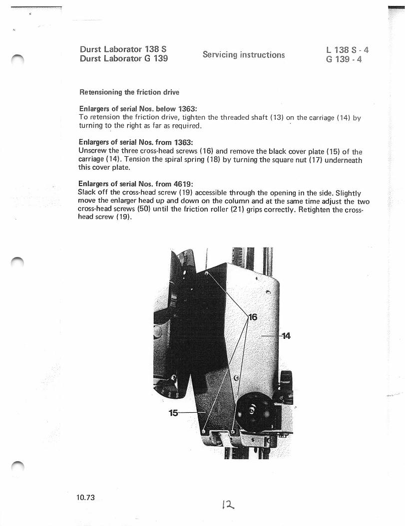
Retensioning the friction drive
Eniargers of serial IMos. below 1363:To retension the friction drive, tighten the threaded shaft (13) on the carriage (14) byturning to the right as far as required.
Eniargers of serial Nos. from 1363:Unscrew the three cross-head screws (16) and remove the black cover plate (15) of thecarriage (14). Tension the spiral spring (18) by turning the square nut (17) underneaththis cover plate.
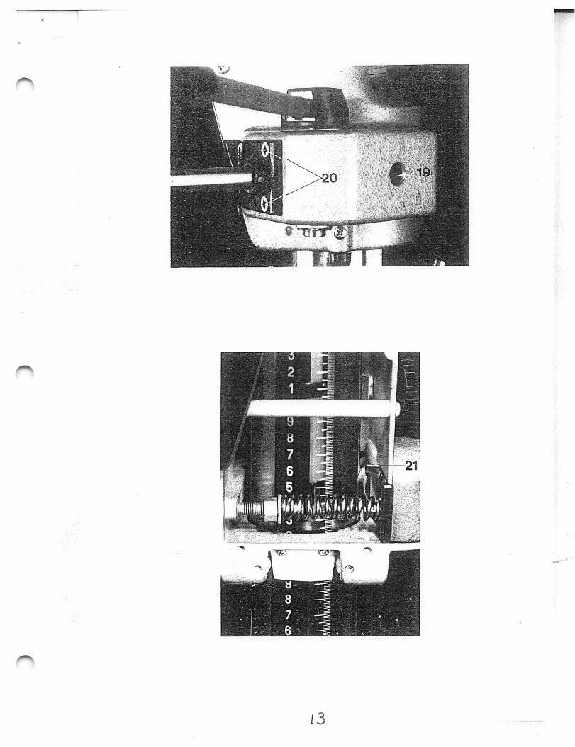
Eniargers of serial Nos. from 4619:Slack off the cross-head screw (19) accessible through the opening in the side. Slightlymove the enlarger head up and down on the column and at the same time adjust the twocross-head screws (50) until the friction roller (21) grips correctly. Retighten the cross-head screw (19).
1 0 . 7 3I X
13
Durst Laborator 138 SDurst Laborator G 139 Servicing instructions
Exchange of the guide rollers in the guide sleeve of the enlarger head
instead of the two back rollers (upper and lower one), all Laborators 138 S and G 139 asof unit number 202478 will have two ball bearings which guarantee a snDOOthermovement of the enlarger head. These ball bearings can also be mounted as follows intounits as of number 137621:
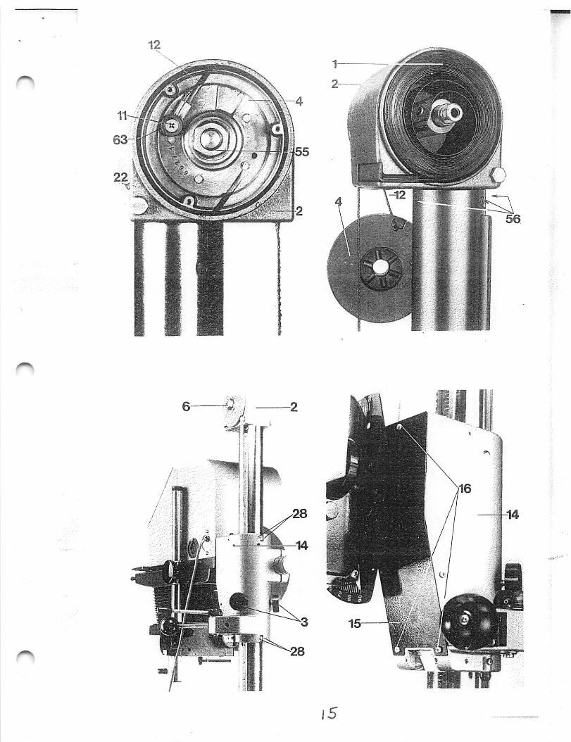
1.) Block the counterweight spring (1) by tightening the threaded pin (22) on the backof the counterweight-spring housing (right-hand down).
2.) Mark the position of the enlarger head on the column and lift somewhat the headuntil the steel cable (12) becomes rather slack, then block the head by tighteningthe two set grips (3) on the sides of the guide sleeve (14) of the enlarger head.
3.) Swivel the enlarger head to the left through 90° and remove the black cover plate(15) of the sleeve (14) after loosening the three crosshead screws (16).
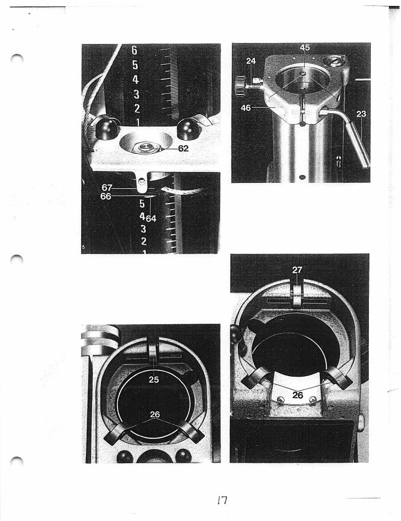
4.) Loosen the hexagonal nut (62) in the round cut-out on the front top side of thesleeve (14) with a spanner (18 mm) and draw out the steel cable (12).
5.) After loosening clamping lever (23) and screw (24), draw the complete upper partof the enlarger out of the lower column, place it on a table, and now, afterloosening the three screws (56), draw the counterweight-spring housing out of thec o l u m n -
6.) Loosen the two set grips (3) on the sleeve (14) of the enlarger head and pull out' the enlarger head upwards until the upper back roller (25) can be removed easily
and exchanged for ball bearings with pressed-in shaft. Take care that both rollers(26) and ball bearing (25) do not fall out of their mounting support. Then reinsertthe enlarger head.
7.) Pull out the enlarger head just as far downwards and exchange here back roller (27)(like described under 6) for ball bearings. Then reinsert the enlarger head.
8.) Block again the enlarger head by tightening the two set grips (3) at the abovedesigned position. Reinsert the enlarger head with column into the lower columnand fix it by means of clamping lever (23) and screw (24). Mount counterweight-spring housing (2), reinsert steel cable (12) into the sleeve (14) of the enlarger headand fix it. Remount black cover plate (15).
1 0 . 7 3 - 2 -
i 5
D u r s t L a b o r a t o r 1 3 8 SDurs t Labora tor G 139 Servicing instructions
9.) First loosen cautiously the two set grips (3) of sleeve (14} (holding the enlargerhead fast by hand) and then loosen threaded pin (22) on the back of thecounterweight-spring housing. Move the enlarger head up and down, taking carethat all roller respect, ball bearings do rotate. If during moving it up and down thehead should jam, or if one or more rollers don't rotate, the two ball bearings (25)and 27) should be adjusted by means of the two threaded pins (28) on the backof the sleeve (14), i. e. that they have to be tightened or loosened.
1 0 . 7 3
I (o
11
Durst Laborator 138 S Servicing instructions L 1 3 8 S - 6
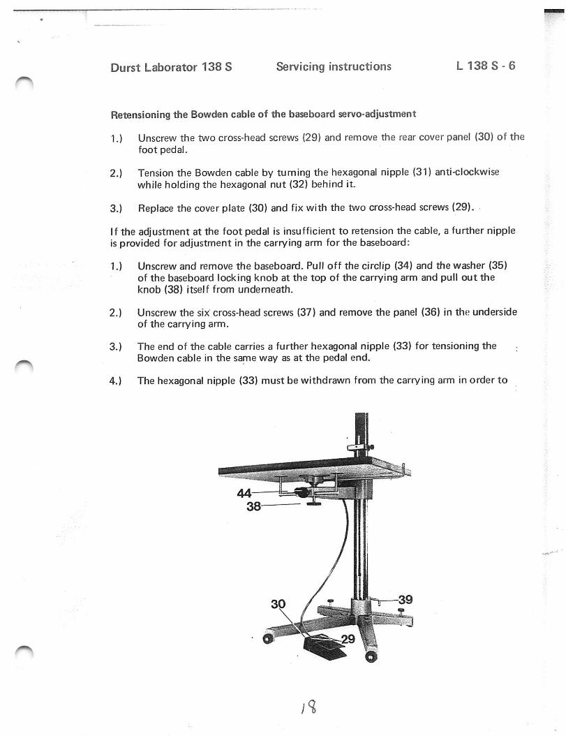
Retensioning the Bowden cable of the baseboard servo-adjustment
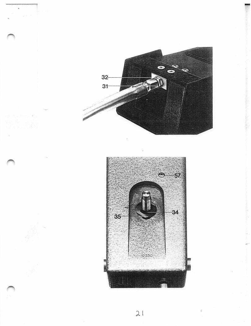
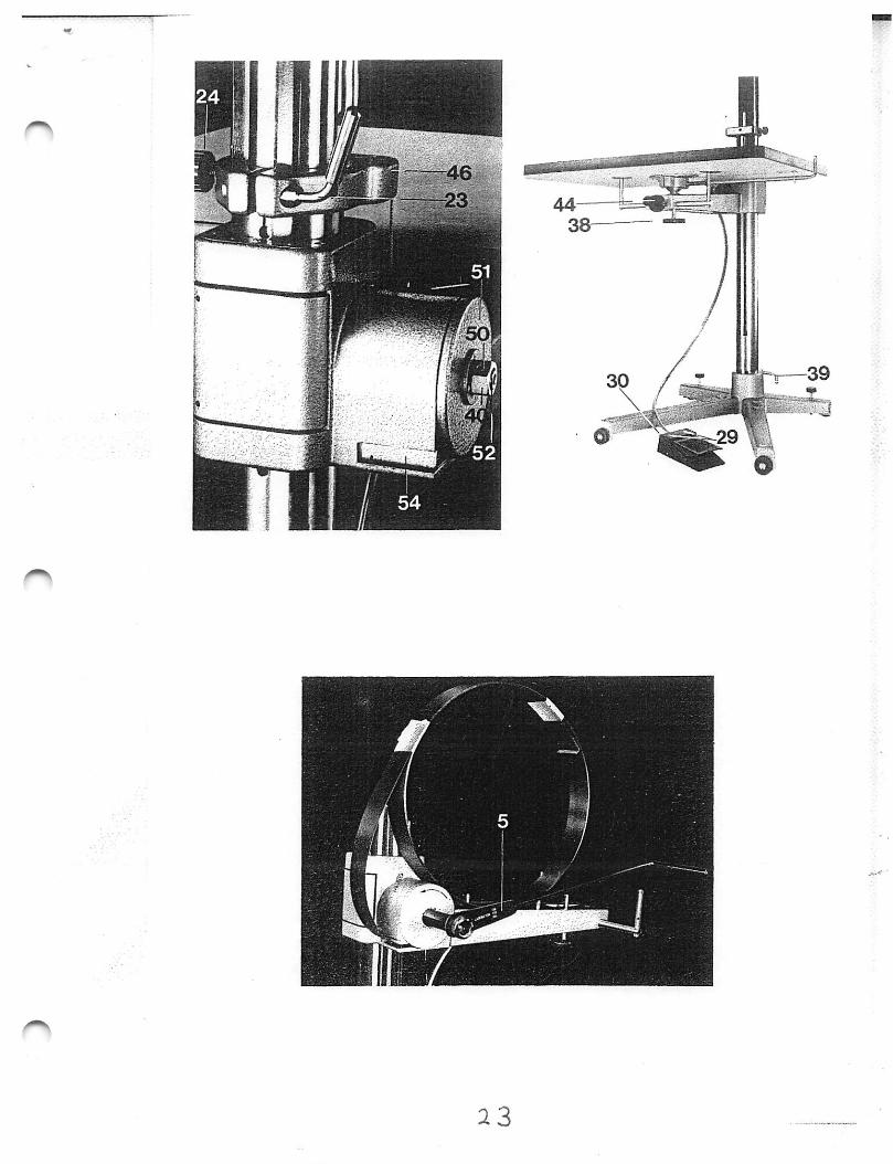
1.) Unscrew the two cross-head screws (29) and remove the rear cover panel (30) of thefoot peda!.
2.) Tension the Bowden cable by turning the hexagonal nipple (31) anti-clockwisewhile holding the hexagonal nut (32) behind it.
3.) Replace the cover plate (30) and fix with the two cross-head screws (29).
If the adjustment at the foot pedal is insufficient to retension the cable, a further nippleis provided for adjustment in the carrying arm for the baseboard:
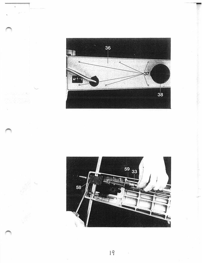
1.) Unscrew and remove the baseboard. Pull off the circlip (34) and the washer (35)of the baseboard locking knob at the top of the carrying arm and pull out theknob (38) itself from underneath.
2.) Unscrew the six cross-head screws (37) and remove the panel (36) in the undersideof the carrying arm.
3.) The end of the cable carries a further hexagonal nipple (33) for tensioning theBowden cable in the same way as at the pedal end.
4.) The hexagonal nipple (33) must be withdrawn from the carrying arm in order to
19
Durst Laborator 138 S Servicing instructions L 1 3 8 S - 7
Retensioning the counterweight spring of the baseboard servo adjustment
The special tool required for this purpose is supplied to order and charged by Durst.
1.) Release the clamping lever (23) and the milled knob (24) and lift the enlarger headwith the top column out of the lower column. Unscrew the knob (38) and removethe baseboard. Place the lower half of the stand (base, lower column and baseboardcarrying arm) on the work bench. Release the clamping lever (39) of the base andturn the lower column with the baseboard carrying arm clockwise through 90®.Lock it in this position with the clamping lever (39). Move the carrying arm to itsbottom position and lock it there by tightening the clamping knob (44).
2.) Mount the special spanner (5) for tensioning the counterweight spring on thehexagonal nut (40). Tighten the spanner (5) to allow the three grub screws (41) of
Durst Laborator 138 S Servicing instructions L 1 3 8 S - 6sheet 2
get at it with a spanner. To do this, unscrew the screw (57), clamp the cable witha screwdriver at the point (58) to release its tension and pull out the nipple (33)with its fitting (59).
5.) Now reassemble ail parts as described under 1. and 2. in the reverse sequence.
1 0 . 7 3
a s
Durst Laborator 138 S Servicing instructions L 1 3 8 S - 7sheet 2
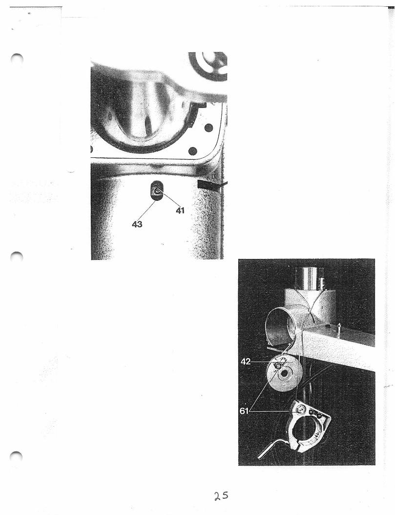
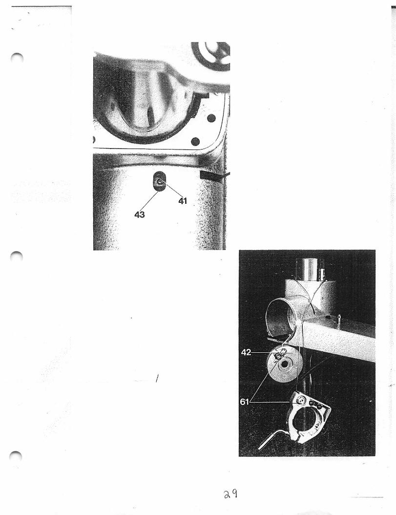
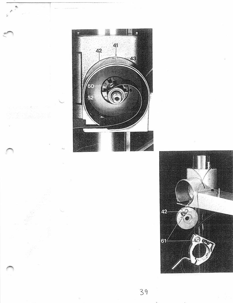
the steel cable dmm (42) to be slacked off in turn. These screws are accessiblethrough the oblong opening (43) in the top of the countenA/eight spring housing.These grub screws (41) secure the cable drum (42) on the shaft of the counterweight spring.
3.) To tension the counterweight spring, turn the spanner (5) anti-clockwise as far asrequired.
4.) To screw the grub screws (41) of the steel cable dmrn (42) into their grooves, turnthe tensioning spanner (5) — in either direction as required — while screwing in thefirst grub screw, until this engages in the groove. On turning the tensioning spanner(5) the two other grub screws are then easily screwed in.
5.) Remove the tensioning gpanner (5) and release the clamping knob (44) to free themovement of the carrying arm.
10.73
^ 5
Durst Laborator 138 S Servicing instructions L 138 S - 8
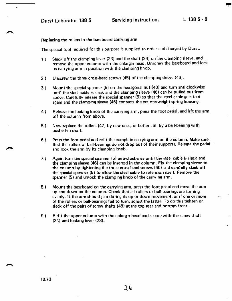
Replacing the rollers in the baseboard carrying arm
The special tool required for this purpose is supplied to order and charged by Durst.
1.) Slack off the clamping lever (23) and the shaft (24) on the clamping sleeve, andremove the upper column with the enlarger head. Unscrew the baseboard and lockits carrying arm in position with the clamping knob.
2.) Unscrew the three cross-head screws (45) of the clamping sleeve (46).
3.) Mount the special spanner (5) on the hexagonal nut (40) and tum anti-clockwiseuntil the steel cable is slack and the clamping sleeve (46) can be pulled out fromabove. Carefully release the special spanner (5) so that the steel cable gets tautagain and the clamping sleeve (46) contacts the counten^^eight spring housing.
4.) Release the locking knob of the carrying arm, press the foot pedal, and lift the amioff the column from above.
5.) Now replace the rollers (47) by new ones, or better still by a ball-bearing withpushed-in shaft.
6.) Press the foot pedal and refit the complete carrying arm on the column. Make surethat the rollers or ball-bearings do not drop out of their supports. Release the pedaland lock the arm by its clamping knob.
7.) Again tum the special spanner (5) anti-clockwise until the steel cable is slack andthe clamping sleeve (46) can be inserted in the column. Fix the clamping sleeve tothe column by tightening the three cross-head screws (45) and carefully slack offthe special spanner (5) to allow the steel cable to retension itself. Remove thespanner (5) and unlock the clamping knob of the carrying arm.
8.) Mount the baseboard on the carrying arm, press the foot pedal and move the armup and down on the column. Check that all rollers or ball-bearings are turningevenly. If the arm should jam during its up or down movement, or if one or moreof the rollers or ball-bearings fail to turn, adjust the latter. To do this tighten orslack off the pairs of screw shafts (48) at the top rear and bottom front.
9.) Refit the upper column with the enlarger head and secure with the screw shaft(24) and locking lever (23).
1 0 . 7 3
^(o
X I
Durst Laborator 138 S Servicing instructions L 1 3 8 S - 9
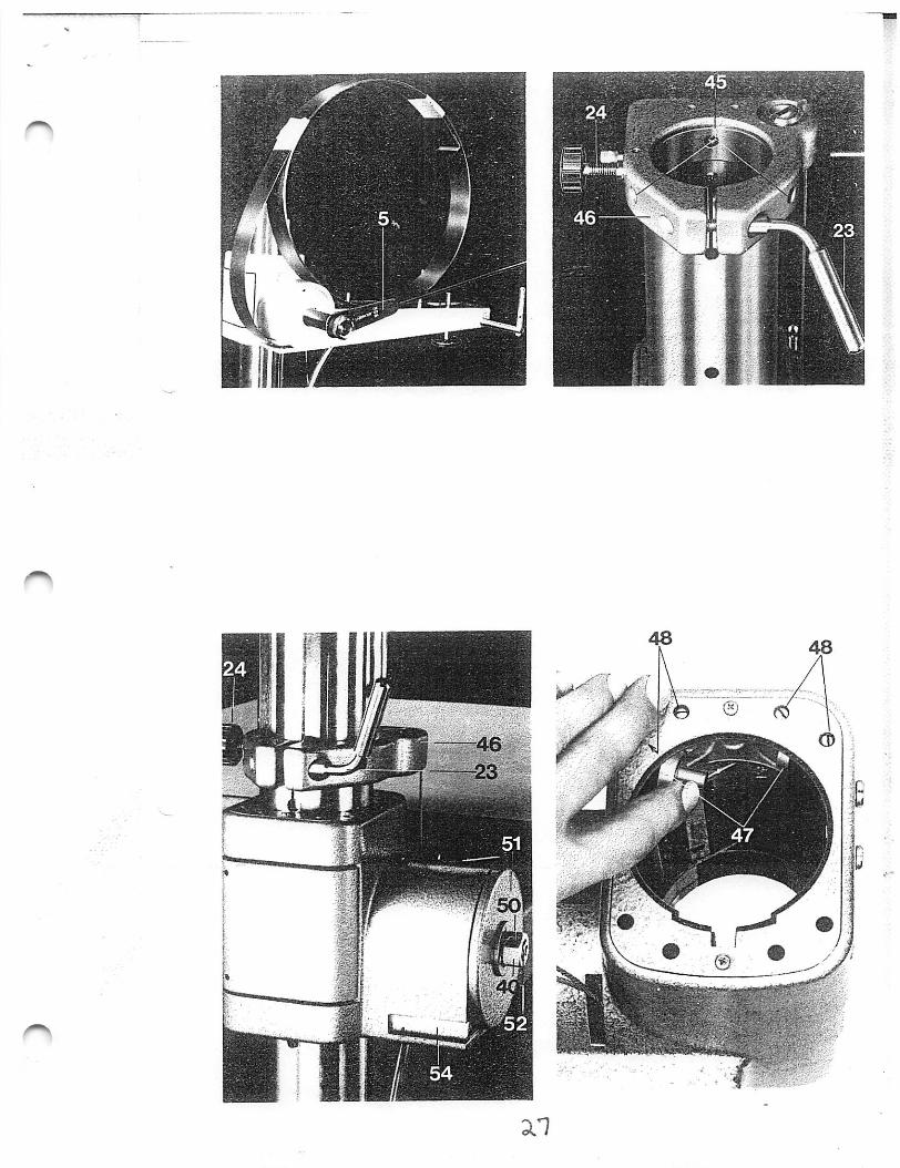
Changing the counterweight spring of the baseboard servo-adjustment
The special tool required for this purpose is supplied to order and charged by Durst.
1.) Remove the upper column with the enlarger head and also the baseboard.
2.) Lock the carrying arm In position with its locking knob. Mount the special spanner(5) for tensioning the counterweight spring on the hexagonal nut (40). Tum thespanner anticlockwise to allow the three grub screws (41) of the steel cable drum(42) to be slacked off in tum. These grub screws are accessible through the oblongopening (43) In the top of the counterweight spring housing. Now carefuliy releasethe spanner (5) until the spring is fully relaxed. Then remove the spanner (5).
3.) Unscrew the three cross-head screws (45) and pull the clamping sleeve out of the
Durst Laborator 138 S Servicing instructions L 1 3 8 S - 9sheet -2-
7.) Clean the entire spring housing and regrease. Remove the old spring from the coreand the shaft (52) by unscrewing the two screws (60). Mount the new spring in thesame way on the spring core and shaft (52). Do not screw the screws (60) tight;the spring must be able to move on the core. Lock the spring about 4 inches or10 cm from the spring core in a vice. Mount the nut (40) and locking pin (50) onthe shaft (52) and screw the special spanner (5) onto the nut (40). Turn thespanner (5) onto the nut (40). Turn the spanner (5) anti-dockwise to bend thespring and to allow it to be introduced into the housing.
Push the spring with the core into the housing. Remove the carrying arm from thecolumn to allow the shaft (52) to be fixed inside the arm with the securing cap(49).
8.) Press the foot pedal and fit the carrying arm in the column. Mount the clampingsleeve on the upper end of the column and secure with the three cross-head screws(45) .
Remove the nut (40) and locking pin (50), refit the cover plate (51) on the side ofthe spring housing, screw on the hexagonal nut (40) again and secure with thelocking pin (50). Mount the special spanner (5) on the nut and slowly turn anticlockwise until the spring is fully folded up and tensioned. Thoroughly oil the springduring this operation. Hold the spanner (5) in this position and secure the anglebracket (54) at the end of the spring underneath the spring housing with the twocross-head screws (53). Turn the spanner clockwise until the spring is fully slack.
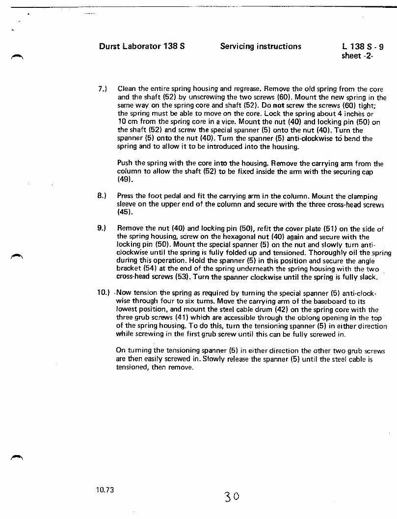
10.) Now tension the spring as required by tuming the special spanner (5) anti-clockwise through four to six turns. Move the carrying arm of the baseboard to itslowest position, and mount the steel cable drum (42) on the spring core with thethree grub screws (41) which are accessible through the oblong opening in the topof the spring housing. To do this, turn the tensioning spanner (5) in either directionwhile screwing in the first grub screw until this can be fully screwed in.
On tuming the tensioning spanner (5) in either direction the other two grub screwsare then easily screwed in. Slowly release the spanner (5) until the steel cable istensioned, then remove.
9.)
1 0 . 7 3
3 0
D u r s t L a b o r a t o r 1 3 8 S Servicing instructions L 1 3 8 S - 9sheet 2
upper end of the column. Slack off the locking knob (44) of the carrying arm, pressthe foot pedal, and lift the arm off the column from above. Remove the securingcap (49) of the counterweight spring shaft inside the arm.
4.) Refit the carrying arm on the column. Tap out the locking pin (50) of thehexagonal nut (40) with a punch and unscrew the nut (40) with a 24 mm spanner.Remove the cover plate (51) of the spring housing.
Important: From this point on ail steps require two people. For safety both should wearthick leather gloves or wind thick rags round their hands for protection.
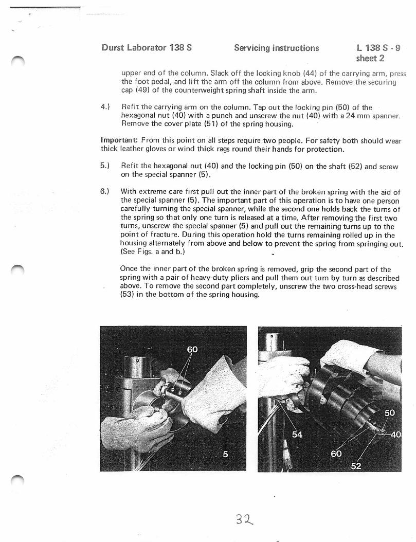
5.) Refit the hexagonal nut (40) and the locking pin (50) on the shaft (52) and screwon the special spanner (5).
6.) With extreme care first pull out the inner part of the broken spring with the aid ofthe special spanner (5). The important part of this operation is to have one personcarefully turning the special spanner, while the second one holds back the turns ofthe spring so that only one turn is released at a time. After removing the first twoturns, unscrew the special spanner (5) and pull out the remaining turns up to thepoint of fracture. During this operation hold the turns remaining rolled up in thehousing alternately from above and below to prevent the spring from springing out.(See Figs, a and b.)
Once the inner part of the broken spring is removed, grip the second part of thespring with a pair of heavy-duty pliers and pull them out turn by turn as describedabove. To remove the second part completely, unscrew the two cross-head screws(53) in the bottom of the spring housing.
30 .
D u r s t L a b o r a t o r 1 3 8 S Servicing instructions L 1 3 8 S - 1 1
Replacing the steei cable of the baseboard servo-adjustment
The special tool required for this purpose is supplied to order and charged by Durst.
1.) Remove the upper column of the enlarger head and also the baseboard.
2.) Relax the spring as described in the servicing instruction sheet 138 S - 9, step 2.
3.) Remove the spring from the housing.
Remove an intact spring as follows:
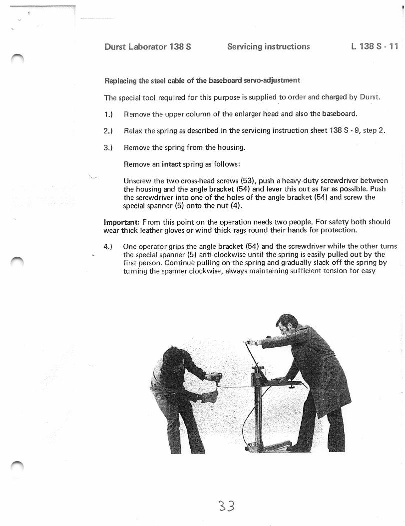
Unscrew the two cross-head screws (53), push a heavy-duty screwdriver betweenthe housing and the angle bracket (54) and lever this out as far as possible. Pushthe screwdriver into one of the holes of the angle bracket (54) and screw thespecial spanner (5) onto the nut (4),
Important: From this point on the operation needs two people. For safety both shouldwear thick leather gloves or wind thick rags round their hands for protection.
4.) One operator grips the angle bracket (54) and the screwdriver while the other turnsthe special spanner (5) anti-clockwise until the spring is easily pulled out by thefirst person. Continue pulling on the spring and gradually slack off the spring bytuming the spanner clockwise, always maintaining sufficient tension for easy
1 0 . 7 3
1.H
Durst Laborator 138 S Servicing instructions L 1 3 8 S - 11s h e e t 2
withdrawal of the spring. While the spring is being pulled, hold down the base ofthe enlargerwith one hand and one foot. Once the spring is fully pulled out to itsstop, roll it up carefully and tie it together, placing it on the baseboard carryinga r m .
5.1
Note: Never let go of the spring during rolling up and keep the spring itselfalways taut. (See Figs, c and d.)
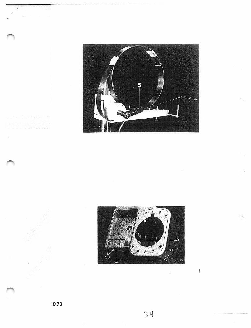
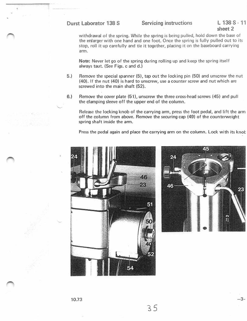
Remove the special spanner (5), tap out the locking pin (50) and unscrew the nut(40). If the nut (40) is hard to unscrew, use a counter screw and nut which arescrewed into the main shaft (52).
6,) Remove the cover plate (51), unscrew the three cross-head screws (45) and pullthe clamping sleeve off the upper end of the column.
Release the locking knob of the carrying arm, press the foot pedal, and lift the armoff the column from above. Remove the securing cap (49) of the counterweightspring shaft inside the arm.
Press the pedal again and place the carrying arm on the column. Lock with its knot
1 0 . 7 3
1 5- 3 -
Durst Laborator 138 S Servicing instructions L 1 3 8 S - 1 1shee t - 2 -
7.) Pull the last part of the spring with the core and shaft (52) out of the housing andtie securely. Until it is secured, do not let go of this end Of the spring, either.
Pull the cable drum (42) out of the housing and release both ends (61) of the cable.Replace the old cable by a new one and push the cable drum (42) back into thehousing.
Push the end part of the spring with the core and shaft (52) into the housing,checking that the shaft is correctly seated in the cable drum (42) and the bearing.
8.) Pull the carrying arm off the column as described before, and mount the securing cap(49) on the spring shaft (52) inside the arm. Replace the arm on the column andl o c k .
Refit the clamping sleeve on the upper end of the column and secure with the threecross-head screws (45).
Remount the cover plate (51) on the spring housing, screw in the nut (40) and tapin the locking pin (50).
9.) Mount the tensioning spanner (5), fully unroll the spring and push a heavy-dutyscrewdriver through one of the holes of the angle bracket (54) for an easier grip.Thoroughly oil the spring.
10.) Turn the tensioning spanner (5) anti-clockwise and wind the spring back into thehousing. While one operator winds the spring, the other one holds the spring tautat the other end for easier winding up.
Secure the angle bracket (54) with the two cross-head screws (53).
11.) The remaining steps of reassembly are identical with those of servicing instructionsheet L 138 S - 9, steps 10, 11 and 12.
1 0 . 7 3
31-
Durst Laborator 138 S Servicing instructions L 1 3 8 S - 9sheet 3
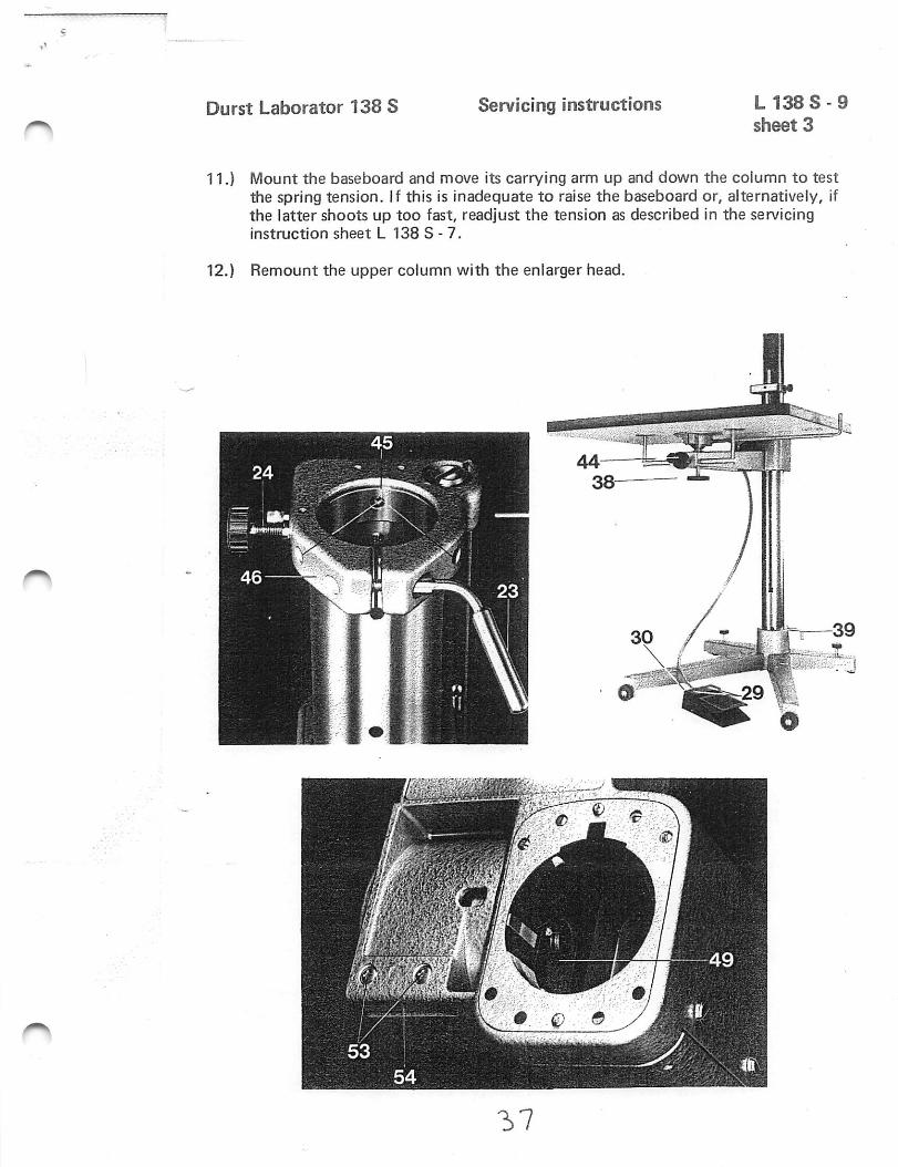
11.) Mount the baseboard and move its carrying arm up and down the column to testthe spring tension. If this is inadequate to raise the baseboard or, alternatively, ifthe latter shoots up too fast, readjust the tension as described in the servicinginstruct ion sheet L 138 S - 7.
12.) Remount the upper column with the enlarger head.
-^7
Durst Laborator 138 SDurst Laborator G 139 Servicing instructions
L 138 S -10G 1 3 9 - 9
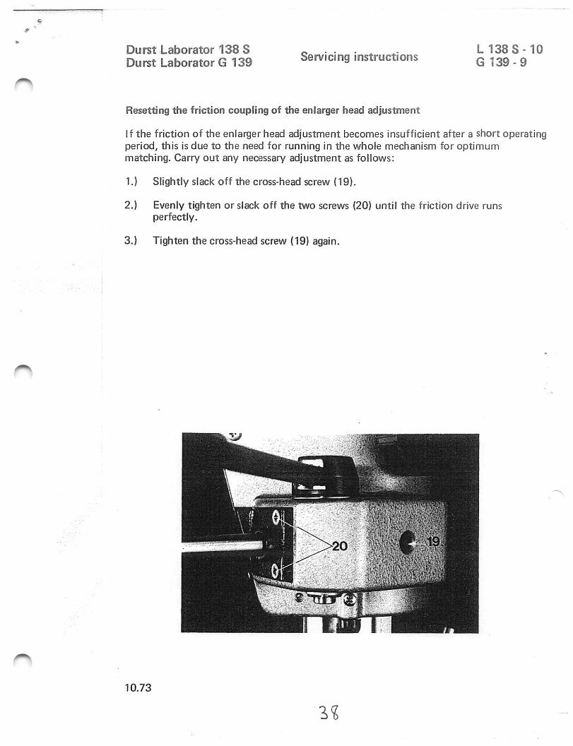
Resetting the friction coupling of the enlarger head adjustment
If the friction of the enlarger head adjustment becomes insufficient after a short operatingperiod, this is due to the need for running In the whole mechanism for optimummatching. Carry out any necessary adjustment as follows:
1.) Slightly slack off the cross-head screw (19).
2.) Evenly tighten or slack off the two screws (20) until the friction drive runsperfectly.
3.) Tighten the cross-head screw (19) again.
1 0 . 7 3
1%
3 9