Embed Size (px)
Citation preview
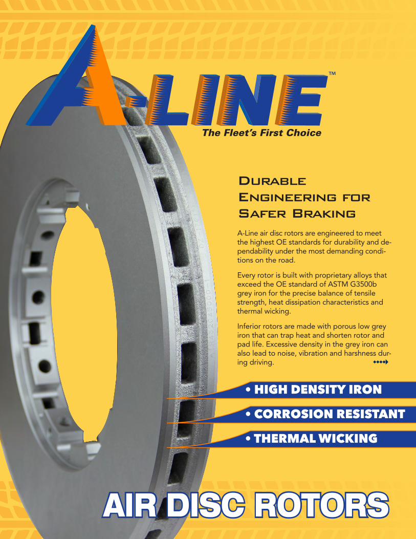
AIR DISC ROTORS
The Fleet’s First Choice
• HIGH DENSITY IRON
• CORROSION RESISTANT
• THERMAL WICKING
Durable Engineering for Safer BrakingA-Line air disc rotors are engineered to meet the highest OE standards for durability and de-pendability under the most demanding condi-tions on the road.
Every rotor is built with proprietary alloys that exceed the OE standard of ASTM G3500b grey iron for the precise balance of tensile strength, heat dissipation characteristics and thermal wicking.
Inferior rotors are made with porous low grey iron that can trap heat and shorten rotor and pad life. Excessive density in the grey iron can also lead to noise, vibration and harshness dur-ing driving. wwww}
The Fleet’s First Choice
0
1
2
3
44.17%
A-LINE OE-1 OE-2 AM-1
4.18% 4.25%
3.35%
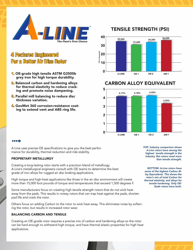
5CARBON ALLOY EQUIVALENT
0
10
20
30
4035,060
PSI i
n th
ousa
nds
A-LINE OE-1 OE-2 AM-1
31,60034,200
36,000
TENSILE STRENGTH (PSI)
wwww}
1. OE-grade high tensile ASTM G3500b grey iron for high torque durability.
2. Balanced carbon and hardening alloys for thermal elasticity to reduce crack-ing and promote noise dampening.
3. Parallel mill balancing to reduce disc thickness variation.
4. GeoMet 360 corrosion-resistance coat-ing to extend vent and ABS ring life.
4 Features Engineered For a Better Air Disc Rotor
A-Line uses precise OE specifications to give you the best perfor-mance for durability, thermal reduction and ride stability.
PROPRETARY METALLURGY
Creating a long-lasting rotor starts with a precision blend of metallurgy. A-Line’s metallurgical engineers consult with OE teams to determine the best grade of iron alloys for rugged air disc braking applications.
High torque and high-heat applications like those in the air disc environment will create more than 15,000 foot pounds of torque and temperatures that exceed 1,500 degrees F.
Some manufacturers focus on creating high tensile strength rotors that do not wick heat away from the pads. This results in noisey rotors that can trap heat against the pads, shorten pad life and crack the rotor.
Others focus on adding Carbon to the rotor to wick heat away. This eliminates noise by soften-ing the rotor, but results in increased rotor wear.
BALANCING CARBON AND TENSILE
Creating an OE-grade rotor requires a precise mix of carbon and hardening alloys so the rotor can be hard enough to withstand high torque, and have thermal elastic properties for high heat applications.
TOP: Industry comparison shows A-Line rotors have among the
highest tensile strength in the industry. But rotors need more
than tensile strength.
BOTTOM: A-Line rotors have some of the highest Carbon Al-loy Equivalents. This shows the rotor’s mix of total Carbon for
thermal elasticity, and alloys for tensile hardening. Only OE-
Gade rotors have both.
PARALLEL MILLING AND BALANCING
Every A-Line rotor is finished with computer controlled parallel milling and balancing. Parallel milling cuts both faces of the rotor simultaneously to a tolerance of 20 microns or .00078”. This precision milling eliminates disc thickness variation (DTV) that can cause brake judder.
ISO 1940/1 balancing standards are used to ensure that A-Line rotors are balanced to OE specifcations.
GEOMET CORROSION PROTECTION
To extend rotor life and prevent corrosion, A-Line rotors are coated with GeoMet® 360 protection.
This blend of zinc and aluminum oxides interlace and bind to the metal surface so that they are four times more corrosion resistant than zinc-only coatings.
Applied in layers of eight to 10 microns thick, the coating resists more than 30 natural and synthetic corrosives, including:
A.
C.
B.
D.
• Acid Wash
• Alcohol
• Ammonia
• Antifreeze
• Brake Clean
• Brake Fluid
• Calcium Chloride
• Diesel
• Gasoline
• Kerosene
• Magnesium Chloride
• Road Salt
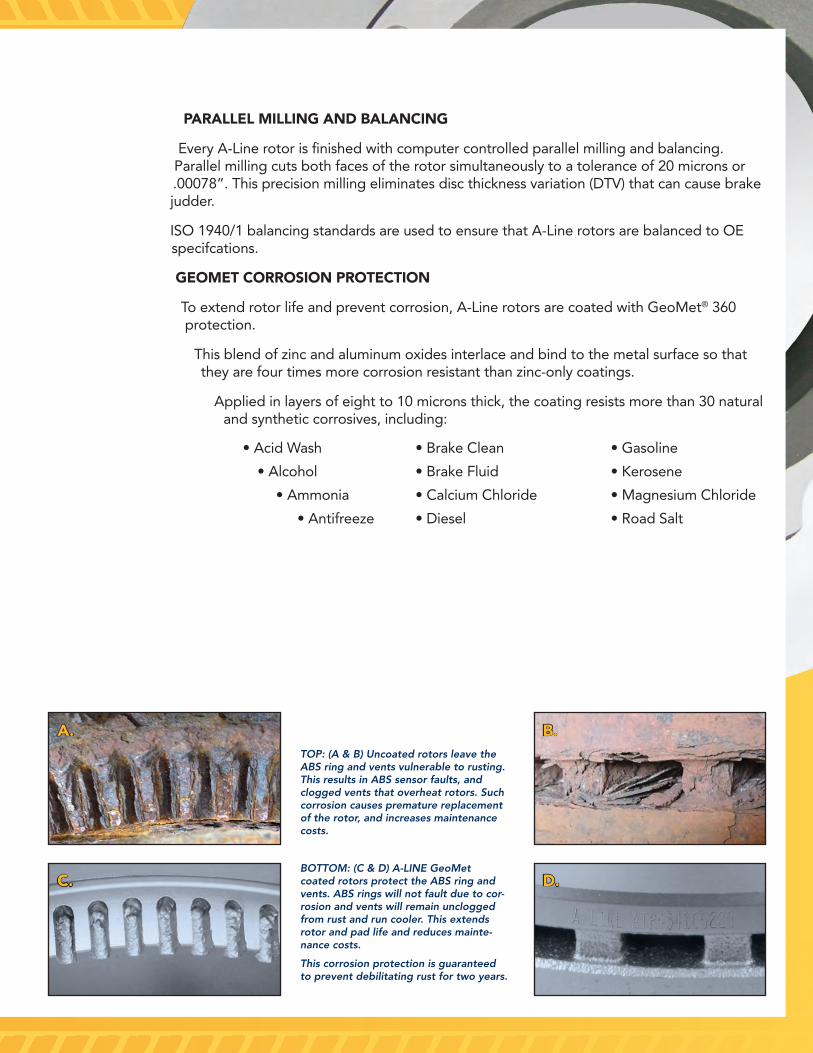
TOP: (A & B) Uncoated rotors leave the ABS ring and vents vulnerable to rusting. This results in ABS sensor faults, and clogged vents that overheat rotors. Such corrosion causes premature replacement of the rotor, and increases maintenance costs.
BOTTOM: (C & D) A-LINE GeoMet coated rotors protect the ABS ring and vents. ABS rings will not fault due to cor-rosion and vents will remain unclogged from rust and run cooler. This extends rotor and pad life and reduces mainte-nance costs.
This corrosion protection is guaranteed to prevent debilitating rust for two years.
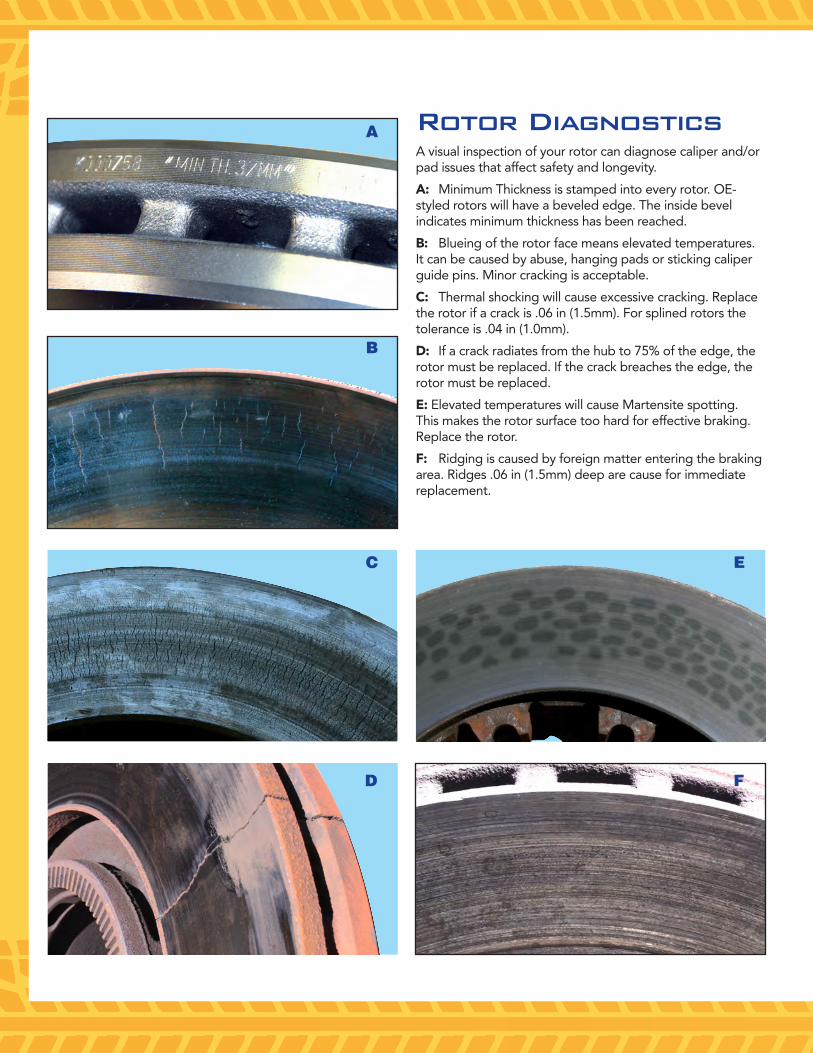
Rotor DiagnosticsA visual inspection of your rotor can diagnose caliper and/or pad issues that affect safety and longevity.
A: Minimum Thickness is stamped into every rotor. OE-styled rotors will have a beveled edge. The inside bevel indicates minimum thickness has been reached.
B: Blueing of the rotor face means elevated temperatures. It can be caused by abuse, hanging pads or sticking caliper guide pins. Minor cracking is acceptable.
C: Thermal shocking will cause excessive cracking. Replace the rotor if a crack is .06 in (1.5mm). For splined rotors the tolerance is .04 in (1.0mm).
D: If a crack radiates from the hub to 75% of the edge, the rotor must be replaced. If the crack breaches the edge, the rotor must be replaced.
E: Elevated temperatures will cause Martensite spotting. This makes the rotor surface too hard for effective braking. Replace the rotor.
F: Ridging is caused by foreign matter entering the braking area. Ridges .06 in (1.5mm) deep are cause for immediate replacement.
A
B
C E
FD
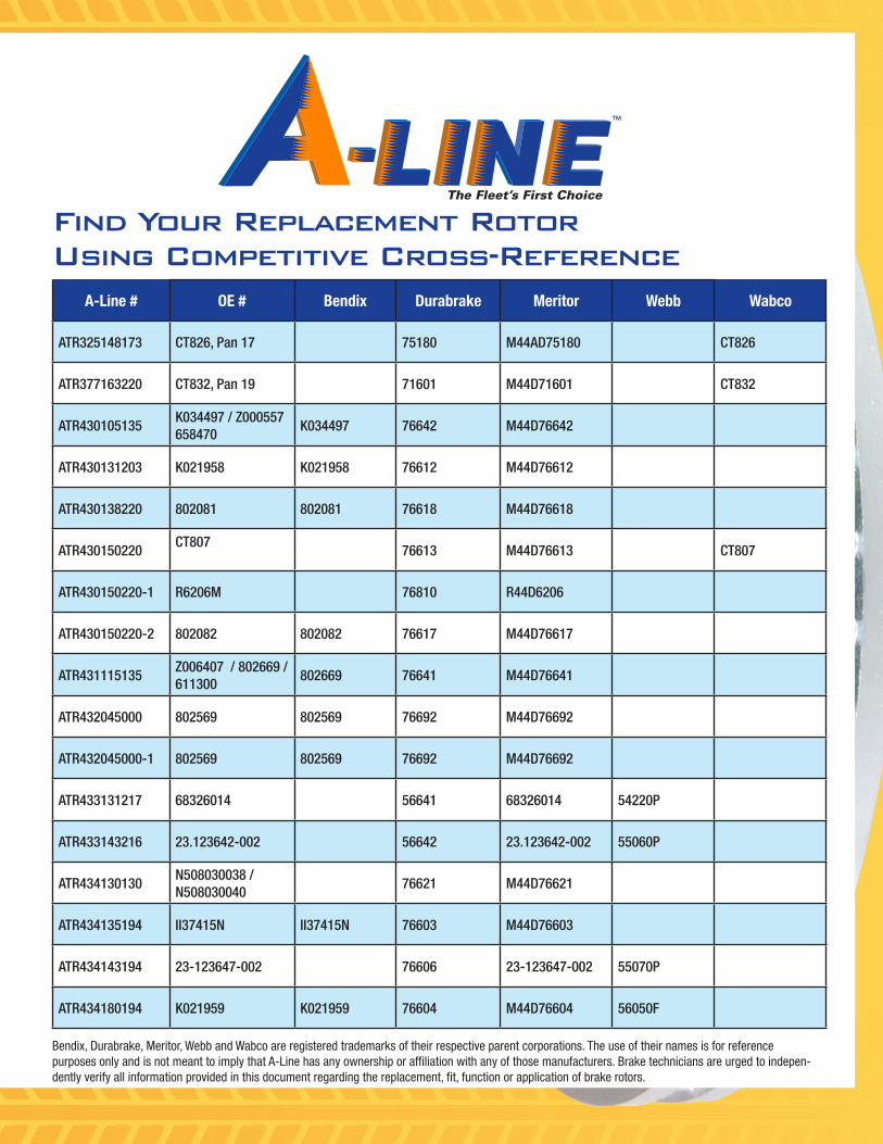
A-Line # OE # Bendix Durabrake Meritor Webb Wabco
ATR325148173 CT826, Pan 17 75180 M44AD75180 CT826
ATR377163220 CT832, Pan 19 71601 M44D71601 CT832
ATR430105135K034497 / Z000557 658470
K034497 76642 M44D76642
ATR430131203 K021958 K021958 76612 M44D76612
ATR430138220 802081 802081 76618 M44D76618
ATR430150220CT807
76613 M44D76613 CT807
ATR430150220-1 R6206M 76810 R44D6206
ATR430150220-2 802082 802082 76617 M44D76617
ATR431115135Z006407 / 802669 / 611300
802669 76641 M44D76641
ATR432045000 802569 802569 76692 M44D76692
ATR432045000-1 802569 802569 76692 M44D76692
ATR433131217 68326014 56641 68326014 54220P
ATR433143216 23.123642-002 56642 23.123642-002 55060P
ATR434130130N508030038 / N508030040
76621 M44D76621
ATR434135194 II37415N II37415N 76603 M44D76603
ATR434143194 23-123647-002 76606 23-123647-002 55070P
ATR434180194 K021959 K021959 76604 M44D76604 56050F
The Fleet’s First Choice
Bendix, Durabrake, Meritor, Webb and Wabco are registered trademarks of their respective parent corporations. The use of their names is for reference purposes only and is not meant to imply that A-Line has any ownership or affiliation with any of those manufacturers. Brake technicians are urged to indepen-dently verify all information provided in this document regarding the replacement, fit, function or application of brake rotors.
Find Your Replacement RotorUsing Competitive Cross-Reference
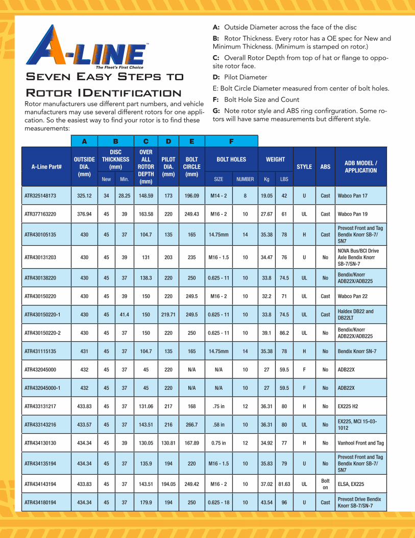
Seven Easy Steps to Rotor IDentificationRotor manufacturers use different part numbers, and vehicle manufacturers may use several different rotors for one appli-cation. So the easiest way to find your rotor is to find these measurements:
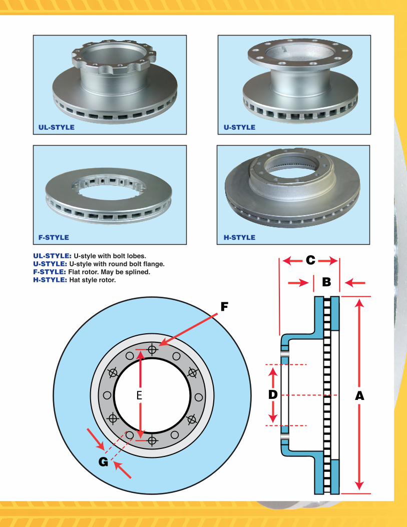
A: Outside Diameter across the face of the disc
B: Rotor Thickness. Every rotor has a OE spec for New and Minimum Thickness. (Minimum is stamped on rotor.)
C: Overall Rotor Depth from top of hat or flange to oppo-site rotor face.
D: Pilot Diameter
E: Bolt Circle Diameter measured from center of bolt holes.
F: Bolt Hole Size and Count
G: Note rotor style and ABS ring confirguration. Some ro-tors will have same measurements but different style.
A B C D E F
A-Line Part#OUTSIDE
DIA. (mm)
DISC THICKNESS
(mm)
OVER ALL
ROTOR DEPTH (mm)
PILOT DIA.
(mm)
BOLT CIRCLE (mm)
BOLT HOLES WEIGHTSTYLE ABS
ADB MODEL / APPLICATION
New Min. SIZE NUMBER Kg LBS
ATR325148173 325.12 34 28.25 148.59 173 196.09 M14 - 2 8 19.05 42 U Cast Wabco Pan 17
ATR377163220 376.94 45 39 163.58 220 249.43 M16 - 2 10 27.67 61 UL Cast Wabco Pan 19
ATR430105135 430 45 37 104.7 135 165 14.75mm 14 35.38 78 H CastPrevost Front and Tag Bendix Knorr SB-7/SN7
ATR430131203 430 45 39 131 203 235 M16 - 1.5 10 34.47 76 U NoNOVA Bus/BCI Drive Axle Bendix Knorr SB-7/SN-7
ATR430138220 430 45 37 138.3 220 250 0.625 - 11 10 33.8 74.5 UL NoBendix/Knorr ADB22X/ADB225
ATR430150220 430 45 39 150 220 249.5 M16 - 2 10 32.2 71 UL Cast Wabco Pan 22
ATR430150220-1 430 45 41.4 150 219.71 249.5 0.625 - 11 10 33.8 74.5 UL CastHaldex DB22 and DB22LT
ATR430150220-2 430 45 37 150 220 250 0.625 - 11 10 39.1 86.2 UL NoBendix/Knorr ADB22X/ADB225
ATR431115135 431 45 37 104.7 135 165 14.75mm 14 35.38 78 H No Bendix Knorr SN-7
ATR432045000 432 45 37 45 220 N/A N/A 10 27 59.5 F No ADB22X
ATR432045000-1 432 45 37 45 220 N/A N/A 10 27 59.5 F No ADB22X
ATR433131217 433.83 45 37 131.06 217 168 .75 in 12 36.31 80 H No EX225 H2
ATR433143216 433.57 45 37 143.51 216 266.7 .58 in 10 36.31 80 UL NoEX225, MCI 15-03-1012
ATR434130130 434.34 45 39 130.05 130.81 167.89 0.75 in 12 34.92 77 H No Vanhool Front and Tag
ATR434135194 434.34 45 37 135.9 194 220 M16 - 1.5 10 35.83 79 U NoPrevost Front and Tag Bendix Knorr SB-7/SN7
ATR434143194 433.83 45 37 143.51 194.05 249.42 M16 - 2 10 37.02 81.63 ULBolt on
ELSA, EX225
ATR434180194 434.34 45 37 179.9 194 250 0.625 - 18 10 43.54 96 U CastPrevost Drive Bendix Knorr SB-7/SN-7
The Fleet’s First Choice
Seven Easy Steps to Rotor IDentificationRotor manufacturers use different part numbers, and vehicle manufacturers may use several different rotors for one appli-cation. So the easiest way to find your rotor is to find these measurements:
A: Outside Diameter across the face of the disc
B: Rotor Thickness. Every rotor has a OE spec for New and Minimum Thickness. (Minimum is stamped on rotor.)
C: Overall Rotor Depth from top of hat or flange to oppo-site rotor face.
D: Pilot Diameter
E: Bolt Circle Diameter measured from center of bolt holes.
F: Bolt Hole Size and Count
G: Note rotor style and ABS ring confirguration. Some ro-tors will have same measurements but different style.
A
C
F
E D
B
G
U-STYLE
H-STYLE
UL-STYLE
F-STYLE
UL-STYLE: U-style with bolt lobes.U-STYLE: U-style with round bolt flange.F-STYLE: Flat rotor. May be splined.H-STYLE: Hat style rotor.
AIR DISC ROTORS
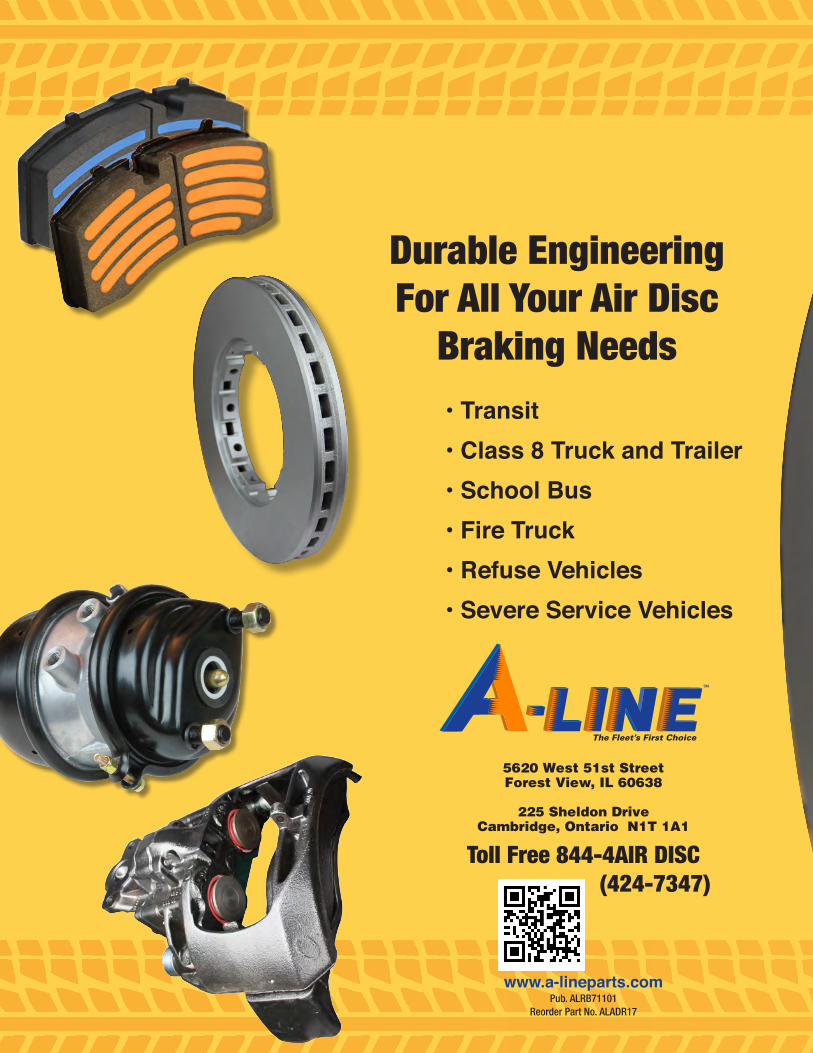
Durable EngineeringFor All Your Air Disc
Braking Needs• Transit• Class 8 Truck and Trailer• School Bus• Fire Truck• Refuse Vehicles• Severe Service Vehicles
The Fleet’s First Choice
5620 West 51st StreetForest View, IL 60638
225 Sheldon DriveCambridge, Ontario N1T 1A1
Toll Free 844-4AIR DISC (424-7347)
www.a-lineparts.comPub. ALRB71101
Reorder Part No. ALADR17


![1 Rotor service On car brake lathe. 2 Rotor runout Rotor runout [wobble] causes pedal pulsation and vibration during braking. Beside irritating customers](https://img.pdfslide.us/doc/110x75/56649e535503460f94b48dc2/1-rotor-service-on-car-brake-lathe-2-rotor-runout-rotor-runout-wobble-causes.jpg)