Embed Size (px)
Citation preview

Y.Belopolsky. 1
Durability of Connecting Hardware under Electrical Load for
Power-over-Ethernet Applications
This presentation is intended for information only It is NOT an IEC or TIA liaison document
Presentation to IEEE Meeting , Seoul 2007
Presenter: Yakov [email protected] 1-717-227-7837

Y.Belopolsky. 2
Durability of Connecting Hardware under Electrical Load for Power-over-Ethernet Applications
Information Presented in this Report was provided by
Yakov BelopolskyManager, Research and Development Bel Stewart ConnectorUSA
Matthias GerberManager, Innovation and TechnologyReichle & De-Massari AGSwitzerland
Erik BechSenior Specialist DELTA European CablingDenmark
Additional information
International Electrotechnical Commission TECHNICAL COMMITTEE No. 48: ELECTROMECHANICAL COMPONENTS AND MECHANICAL STRUCTURES FOR ELECTRONIC EQUIPMENT
EC Cabling News Technical Note April 2007
Y.Belopolsky. 3
PoE = POWER – over –ETHERNETPoE enables network devices to receive power over the same cable that supplies data and eliminates the need in additional power cables and transformers and AC outlets.
As the result: the network connecting hardware (RJ45 and ARJ45) are exposed to effects of the power discontinuation

Y.Belopolsky. 4
ISO/IEC 11801
Connectorcategory
Freq. max. Character.
Application ConnectingHardwareInterface
Class C 3 16 MHz IEEE 802.5 TokenRing
RJ 45
Class D 5e 100 MHz 10 to 1000baseT Ethernet
RJ45
Class E 6 250 MHz 100-1000 baseT RJ45
Class Eaaugmented
6a 500 MHz 10 Gigabit RJ45, ARJ45
Class F 7 600 MHz 1G over single pair10 Gigabit
GG45, ARJ45
Class Faaugmented
7a 1000 MHz 10 Gigabit over 2 pairs
ARJ45, Tera
NA NA 5000 MHz ARJ45
Transmission classes, Connector categories and Interfaces

Y.Belopolsky. 5
STANDARD CONNECTOR INTERFACES for NETWORKING
Tera ConnectorAlternative interface
GG45 or ARJ45 HD 12-CONTACTS
RJ45 8-CONTACTS, Up to 500 MHz Cat. 3 to 6A
ARJ45 HS 8-CONTACTS, 1000 MHz + Category 7A

Y.Belopolsky. 6
PHYSICAL PHENOMENA due to
ELECTRICAL CONTACT SEPARATION
•Effects caused by mechanical abrasion and environmental exposure •Effects caused by electrical discharge
Fast, single event,Time independentLarge distinct crater
Relatively slow, time dependent Multiple events, shallow craters or pitted surface, erosion
Combination of all
SPARK CORONA DISCHARGE

Y.Belopolsky. 7
EFFECTSShort term
Physical/mechanical damageElectrical Interface Degradation
Long termPhysical/mechanical damageCorrosionElectrical Interface Degradation
MAJOR ACCEPTANCE CRITERIONLOW LEVEL CONTACT Resistance
LLCR (bulk)
Effects and Acceptance criteria

Y.Belopolsky. 8
Low Level Contact Resistance (LLCR-bulk ) consists of four components
Plug Conductor ResistancePlug Blade/Conductor Contact ResistancePlug Blade/Jack Wire Contact ResistanceJack Wire Resistance
Overview of IEC TR: Connector Durability under Electrical Load

Y.Belopolsky. 9
Table 1. Some factors affecting the connecting hardware durability
Test Matrix Variable Options. Variable Item
Connector type IEC 60603 interface Connector manufacturer Various Speed of separation Cycle/Hour Cable length m Cable type Shielded or unshielded Number of contacts energized simultaneously 0, 1 or 8 Test circuit A, B, C Polarity +/- Plug Plating and finish Thickness and porosity
Connector Durability under Electrical Load
Y.Belopolsky. 10
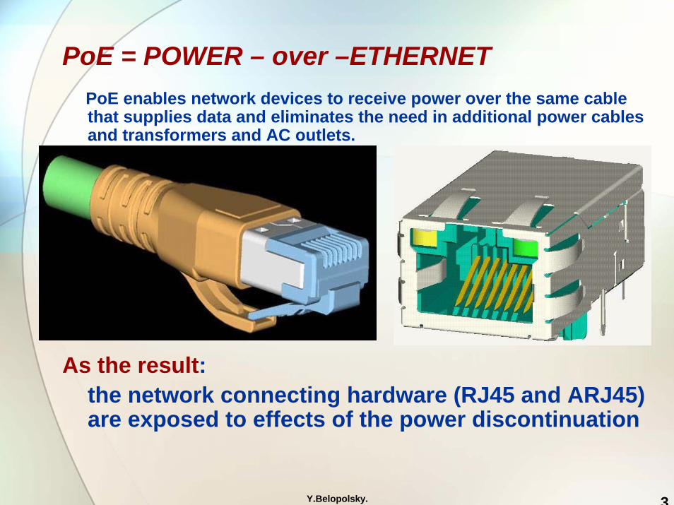
Bel Stewart Connectors
Power Cycling of ConnectorsPOWER
OFF
ON
ON
ON/OFFDischarge !!
Y.Belopolsky. 11
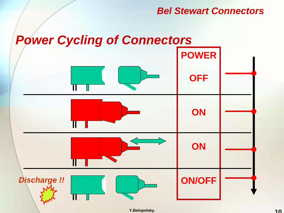
Twisted Pair Cables used in this study
Category 5e (100 MHz) unshieldedtwisted pair , stranded
Category 7 and 6A shieldedtwisted pair cables, strandedwith pairs shielded

Y.Belopolsky. 12
EXAMPLE of JACK Contacts
Bel Stewart Connectors

Y.Belopolsky. 13
NOMINAL CONTACT AREA in RJ45 and ARJ45 CONNECTORS
Jack-Plug prior to mating
Jack-PlugInitial contact
Jack-PlugFinal mating position
Final mating position typically within 0.024’ (0.6 mm) +/- 0.012” (0.3 mm) from a nominal position and 0.030” (0.75 mm) from the the initial contact.
Nominal contact area is a final contact position in reference to nominal position

Y.Belopolsky. 14
Contact B
Wiping Zone
Connect-/ disconnect area
Nominal contactarea
Contact A
NOMINAL CONTACT AREA in RJ45 and ARJ45 CONNECTORS
Connector Durability under Electrical Load
Typical damage location

Y.Belopolsky. 15
Connecting Hardware Contacts
A) Fresh unusedB) After mechanical cycling without electrical loadC) Crater caused by a sparkD) Multiple craters due to discharges
A) B) C) D)

Y.Belopolsky. 16
SPARK CRATER located outside of nominal contact zone
Connector Wiping Zone
Typical effect of Electrical Discharge in connectors

Y.Belopolsky. 17
Table 2. Selected parameters of the test set up and procedures Test No Connector
type Speed of
separation, cycle/hour
Cable length,
m
Patch cord cable type
Contacts energized
simultaneously
Power contact,
W
Test Circuit
Cycle Polarity
Test 1A RJ45 300 2 5e unsh 0 NA NA NA NA Test 2A 60603-7-7 300 2 7 shielded 0 NA NA NA NA Test 3A RJ45 300 2 5e unsh 1 20 A Un-
mate +PLUG
Test 4A RJ45 5e unsh 2 12.6 B both Test 5A RJ45 5e unsh 4 12 C both Test 6A RJ45 5e unsh 8 12 D Un-
mate
Test 7A RJ45 450 2 5e unsh 1 20 A Un-mate
-PLUG
Test 8A RJ45 720 2 5e unsh 8 20 A Un-mate
-PLUG
Test 9A RJ45 450 10 5e unsh 8 20 E Un-mate
-PLUG
Test 10A
RJ45 450 10 6 unsh 8 20 C Un-mate
-PLUG
Test 11A
60603-7-7 450 10 7 shielded 8 20 E Un-mate
-PLUG
Test 12A
RJ45 720 10 5e unsh 8 20 F Un-mate
+PLUG
Test 13A
60603-7-7 450 10 7 shielded 8 20 F Un-mate
-PLUG
Test 14A
60603-7-7 720 100 7 shielded 8 20 F Un-mate
-PLUG
Test 15A
RJ45 720 100 6 unsh 8 20 F Un-mate
-PLUG
Connector Durability under Electrical Load

Y.Belopolsky. 18
RJ45 fresh After 750 mechanical Contact Cycles no el. load
ARJ45 fresh contact
ARJ45 after 750 cycles no el.load
Tests 1A and 2A
Connector Durability under Electrical Load
Identify the effects of mechanical operations

Y.Belopolsky. 19
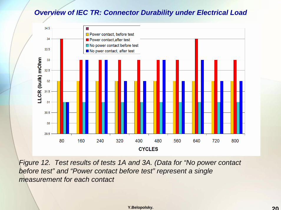
Tests 3A Objective of this test was to identify parameters of the expected LLCR changes and variations in the LLCR during the unmating cycles only. The power was 20 W per contact. The LLCR was measured initially and after each 80 cycles, using a separate measuring plug. A total of 800 cycles were performed.
Test Circuit A
Overview of IEC TR: Connector Durability under Electrical Load
Y.Belopolsky. 20
Figure 12. Test results of tests 1A and 3A. (Data for “No power contact before test” and “Power contact before test” represent a single measurement for each contact
Overview of IEC TR: Connector Durability under Electrical Load
Y.Belopolsky. 21
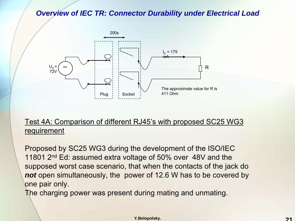
Test 4A: Comparison of different RJ45’s with proposed SC25 WG3 requirement
Proposed by SC25 WG3 during the development of the ISO/IEC 11801 2nd Ed: assumed extra voltage of 50% over 48V and the supposed worst case scenario, that when the contacts of the jack do not open simultaneously, the power of 12.6 W has to be covered by one pair only.The charging power was present during mating and unmating.
==U0 = 72V
Plug Socket
R
The approximate value for R is 411 Ohm
200x
I0 = 175 mA
Overview of IEC TR: Connector Durability under Electrical Load

Y.Belopolsky. 22
Disconnect zone
Nominal contact area
Wiping area
Test 4A. 23 test specimens manufactured by Chinese, European and US suppliers, Shielded and Unshielded
Max electrical resistance rise after 200 mating cycles with electrical load {smallest value = best result}
1.2 1.2
4.2
0.82.0
0.4 0.5
14.0
1.2 2.2
16.8
0.52.0
4.5
19.2
7.0
2.42.6
0.01.8
0.0
5.0
10.0
15.0
20.0
25.0
30.0
V1
V3
V17
V18
V12
V15
V19 V
8V
21 V7
V14
I≡≡≡≡I V2
V23
V22 V
4V
20V
16V
11 V5
V10 V
6
Vendors [left unshielded, right shielded]
Elec
tric
al re
sist
ance
rise
[mO
hm]
Overview of IEC TR: Connector Durability under Electrical Load

Y.Belopolsky. 23
Bel Stewart ConnectorsPoE PLUS. CONNECTOR DURABILITY UNDER ELECTRICAL LOAD
JACK CONTACT
PLUG and UNPLUG MOVEMENT
Nominal Contact AreaTypical Erosion Location
LOCATION of EROSION TYPICALLY OUTSIDEOF NOMINAL CONTACT ZONE (WIPING ZONE)
PLUG CONTACT

Y.Belopolsky. 24
Test 5A: Resistive test setup simulating PoE power stress
This test is to imitate the conditions of IEEE PoE . The feeding power is split up to both wires of a pair (e.g. to 4,5 and 7,8). 48V, power 12W, resulting in a current of 250mA. Power was present during mating and unmating.
==U0 = 48V
Plug Socket
R
200x
I0 = 250 mA
The approximate value for R is 184 Ohm
3 test samples: representing 3 manufacturers (Swiss, US and Asian)
Overview of IEC TR: Connector Durability under Electrical Load

Y.Belopolsky. 25
Test 5A results:
Electrical resistance change after 200 mating cycles with resistive electrical load
0
5
10
15
20
25
30
V1,4 V1,5 V1,6 V1,7 V1,8 V2,4 V2,5 V2,6 V2,7 V2,8 V3,4 V3,5 V3,6 V3,7 V3,8
Test sample contact number
Ele
ctric
al re
sist
ance
cha
nge
[mO
hm]
Test with resistive load resulted in very littledamage to contacts and negligiblechange in LLCR- irrespective of the connector manufacturer
Overview of IEC TR: Connector Durability under Electrical Load

Y.Belopolsky. 26
Overview of IEC TR: Connector Durability under Electrical Load
Test 6A: Mating and unmating with PoE hardware An actual IEEE 802.3af PoE hardware was used in this test supporting the complete functionality of IEEE 802.3af. A resistive load was attached to the 12V output to generate 12W (R ~12 Ohm).
R
POE Out48V
POE In 48V
DC Out 12V
Load 12W
POE Injector POE Splitter
230V
200x
Electrical resistance change after 200 mating cycles with PoE load
0
5
10
15
20
25
30
V1,4 V1,5 V1,7 V1,8 V2,4 V2,5 V2,7 V2,8 V3,4 V3,5 V3,7 V3,8Test sample contact number
Ele
ctri
cal r
esis
tanc
e ch
ange
[m
Ohm
]Test 6A results:Power interruption using PoE equipment did not cause any failures or significant damage

Y.Belopolsky. 27
Overview of IEC TR: Connector Durability under Electrical Load
Test 7A and 8A. Effect of Speed of Contact Separation
-25
-20
-15
-10
-5
0
5
10
15
20
25
Contact position
LLC
R c
hang
e (m
Ohm
)
Results: no failures, no effects attributable to difference in contact separation speed

Y.Belopolsky. 28
Overview of IEC TR: Connector Durability under Electrical Load
Tests 9A, 10A and 11A. Effect of the patch cord length
The tests were conducted with shielded and unshielded patch cords: 2m, 10 m and 100 m long (see table 2) . No differences in discharge effects were observed.No failures

Y.Belopolsky. 29
PLUG CONTACT
Typical Erosion LocationOutside nominal contact area
NOMINAL WIPE
Damage was small in comparison to jacks. Two possible factors:a) jack contact experiences simultaneously a mechanical stress (bending) and
electrical discharge leading to greater observed damageb) that the thermal mass of plug contact is greater in the discharge area
Overview of IEC TR: Connector Durability under Electrical Load
Test 12A: effects of polarity

Y.Belopolsky. 30
ARJ45
Category 7 and 7A connecting hardware 1000 MHz
Y.Belopolsky. 31
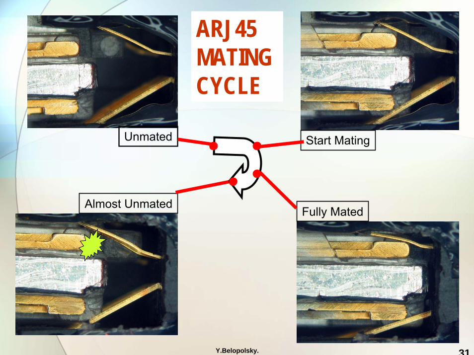
Almost Unmated
Start Mating
Fully Mated
Unmated
ARJ45MATING CYCLE

Y.Belopolsky. 32
ARJ45 Category 7Bottom contacts
ARJ45 Category 7Top contacts
Very little or no visible discharge effects
Discharge effects in the areaperipheral to contact area
Overview of IEC TR: Connector Durability under Electrical Load

Y.Belopolsky. 33
-25
-20
-15
-10
-5
0
5
10
15
20
25
Contact Position
LLC
R (
mill
iohm
s )
Change in Bulk Low Level Contact Resistance combined for all groups for ARJ45 HD connectors
Top contacts1 2 7 8
Bottom contacts9 10 11 12
top
bottom
Overview of IEC TR: Connector Durability under Electrical Load
Y.Belopolsky. 34
Overview of IEC TR: Connector Durability under Electrical Load
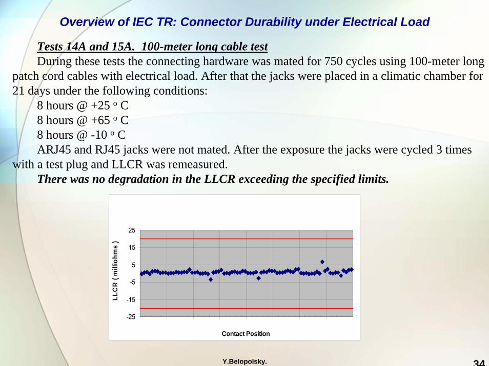
Tests 14A and 15A. 100-meter long cable testDuring these tests the connecting hardware was mated for 750 cycles using 100-meter long
patch cord cables with electrical load. After that the jacks were placed in a climatic chamber for 21 days under the following conditions:
8 hours @ +25 o C8 hours @ +65 o C8 hours @ -10 o C ARJ45 and RJ45 jacks were not mated. After the exposure the jacks were cycled 3 times
with a test plug and LLCR was remeasured.There was no degradation in the LLCR exceeding the specified limits.
-25
-15
-5
5
15
25
Contact Position
LLC
R (
mill
iohm
s )

Y.Belopolsky. 35
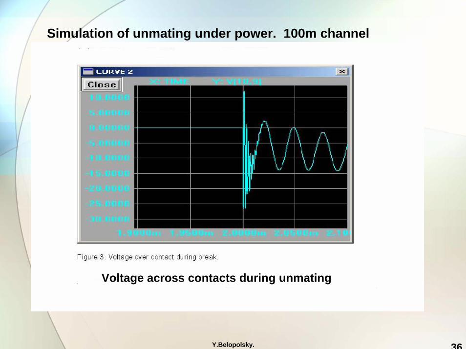
Simulation of unmating under power. 100m channel
Y.Belopolsky. 36
Simulation of unmating under power. 100m channel
Voltage across contacts during unmating

Y.Belopolsky. 37
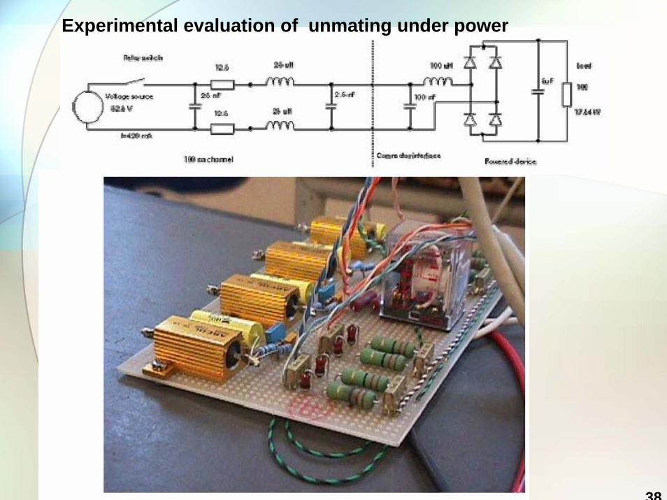
Experimental evaluation of unmating under power
Mechanism for mating-unmating of connecting hardware
Y.Belopolsky. 38
Experimental evaluation of unmating under power
Y.Belopolsky. 39
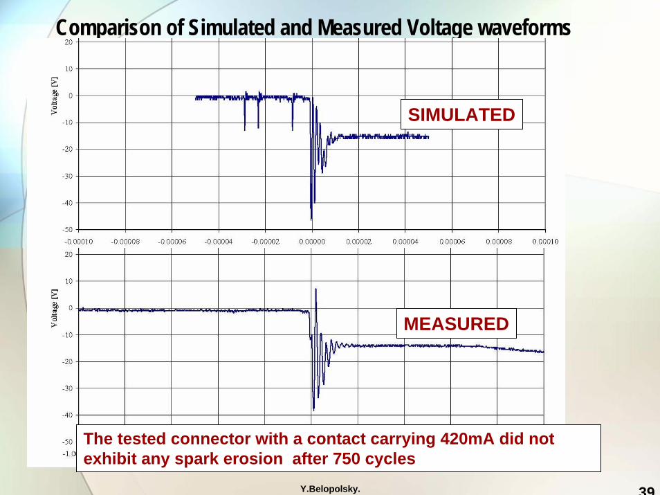
Comparison of Simulated and Measured Voltage waveforms
SIMULATED
MEASURED
The tested connector with a contact carrying 420mA did not exhibit any spark erosion after 750 cycles

Y.Belopolsky. 40
Observations and Conclusions
• Unmating a connection while transmitting power can cause damage to contacts
• Proper design of the modular connectors should assure that the zone of breaking contact is separate from the zone where contact between plug and jack is made during normal operation. This results in certain immunity to the effects of unmating under the electrical load.
• The reduction in the separation between a nominal contact zone and a disconnect zone, could lead to an upper limit of breaking power for modular connectors.
• The voltage waveforms across contacts obtained by simulation andthe experiments were very similar
Y.Belopolsky. 41
Thank you for your time and attention
ANY QUESTIONS ?