Embed Size (px)
Citation preview
Durability of composite cements
Paweł DurdzińskiEPFL
Lausanne, 01.07.2015
LC3 1st International Conference on Calcined Clays for Sustainable Concrete
IMPLICATIONS FOR DURABILITY
We are and will be using more and more SCMs.
What are therefore the..
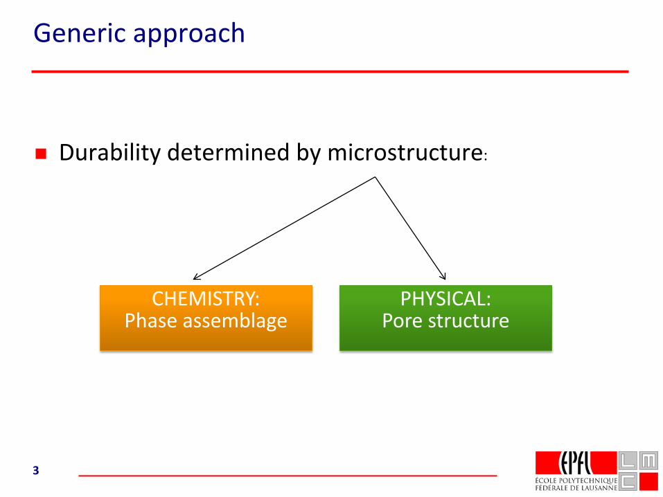
Generic approach
Durability determined by microstructure:
3
CHEMISTRY:Phase assemblage
PHYSICAL:Pore structure
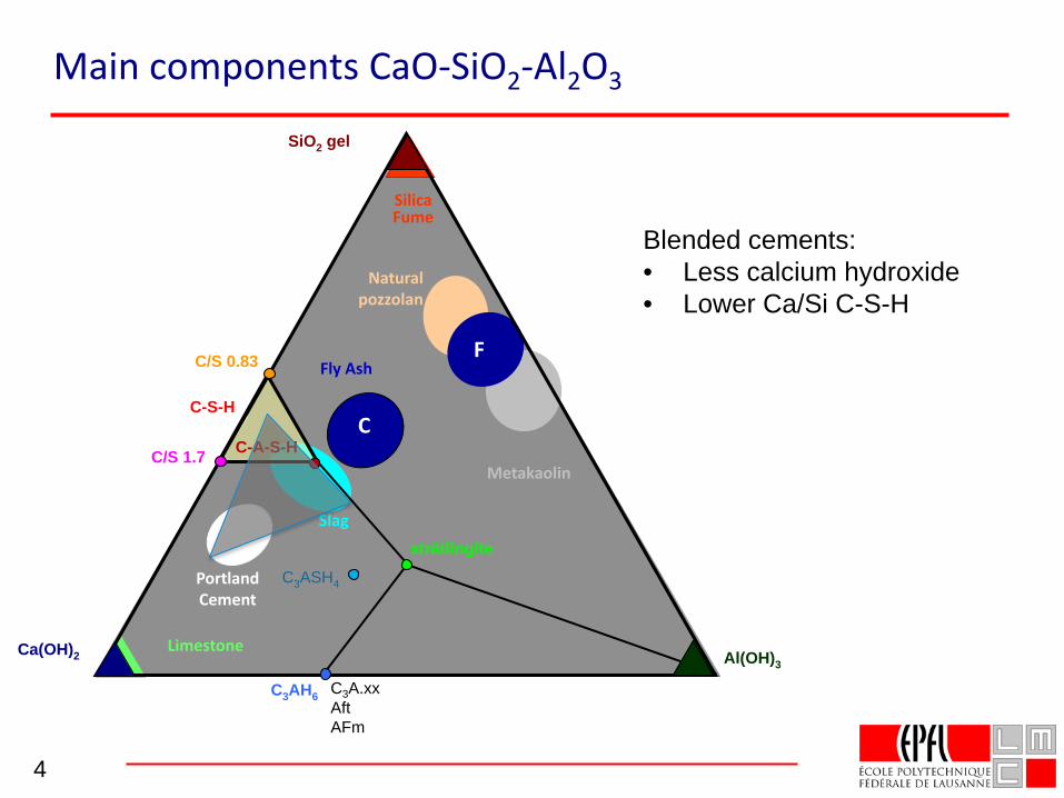
Main components CaO-SiO2-Al2O3
4
C3A.xxAftAFm
Portland Cement
Slag
Fly Ash
C
Natural pozzolan
SilicaFume
Limestone
Metakaolin
F
C3ASH4
Ca(OH)2 Al(OH)3
SiO2 gel
C3AH6
strätlingite
C/S 1.7
C-S-H
C/S 0.83
C-A-S-H
Blended cements:• Less calcium hydroxide• Lower Ca/Si C-S-H
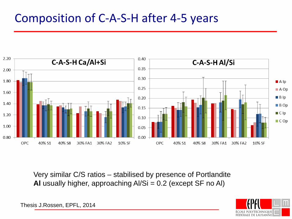
Composition of C-A-S-H after 4-5 years
Very similar C/S ratios – stabilised by presence of PortlanditeAl usually higher, approaching Al/Si = 0.2 (except SF no Al)
Thesis J.Rossen, EPFL, 2014
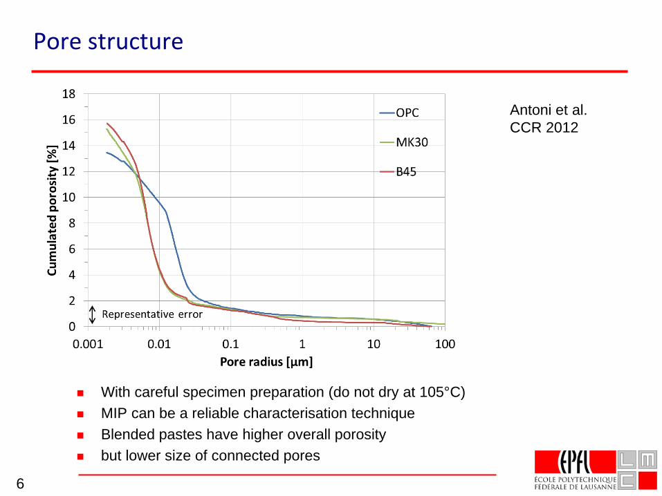
Pore structure
With careful specimen preparation (do not dry at 105°C) MIP can be a reliable characterisation technique Blended pastes have higher overall porosity but lower size of connected pores
6
Antoni et al.CCR 2012
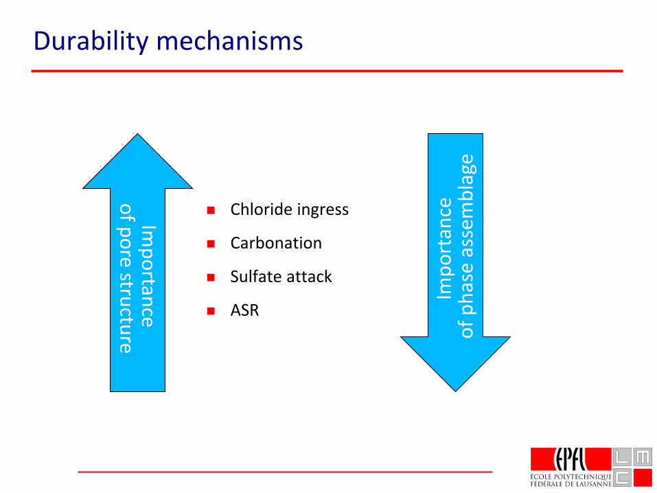
Durability mechanisms
Chloride ingress
Carbonation
Sulfate attack
ASR
Impo
rtan
ceof
pha
se a
ssem
blag
e
Importance
of pore structure
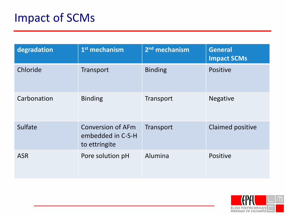
Impact of SCMs
degradation 1st mechanism 2nd mechanism GeneralImpact SCMs
Chloride Transport Binding Positive
Carbonation Binding Transport Negative
Sulfate Conversion of AFm embedded in C-S-H to ettringite
Transport Claimed positive
ASR Pore solution pH Alumina Positive
Effect of SCMs on durabilityagainst chloride
Slides from:Mathieu Antoni
PhD thesisEPFL
Professor Mike ThomasUniversity of New Brunswick
Canada
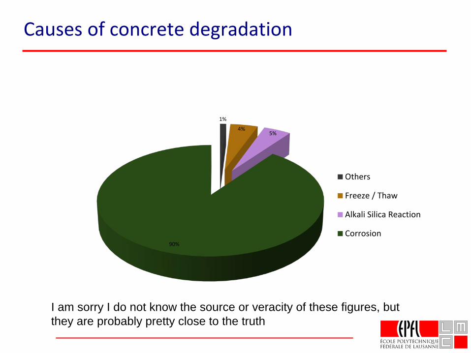
Causes of concrete degradation
1%
4%5%
90%
Others
Freeze / Thaw
Alkali Silica Reaction
Corrosion
I am sorry I do not know the source or veracity of these figures, but they are probably pretty close to the truth
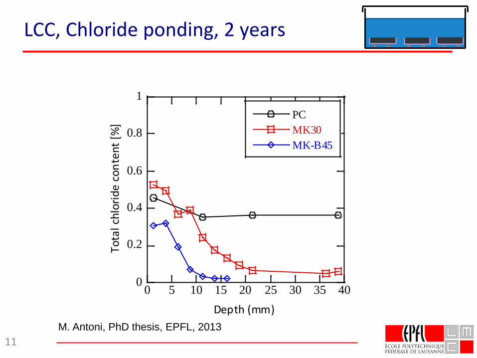
LCC, Chloride ponding, 2 years
11
0
0.2
0.4
0.6
0.8
1
0 5 10 15 20 25 30 35 40
PC MK30MK-B45
Tota
l chl
orid
e co
nten
t [%
]
Depth (mm)M. Antoni, PhD thesis, EPFL, 2013
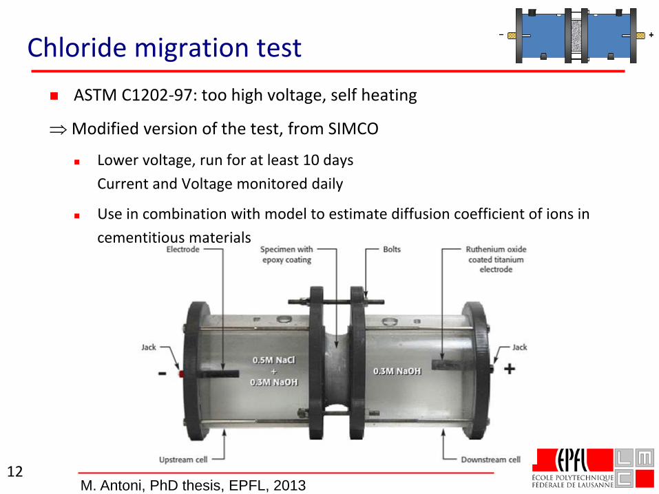
Chloride migration test ASTM C1202-97: too high voltage, self heating
⇒ Modified version of the test, from SIMCO
Lower voltage, run for at least 10 daysCurrent and Voltage monitored daily
Use in combination with model to estimate diffusion coefficient of ions in cementitious materials
12M. Antoni, PhD thesis, EPFL, 2013
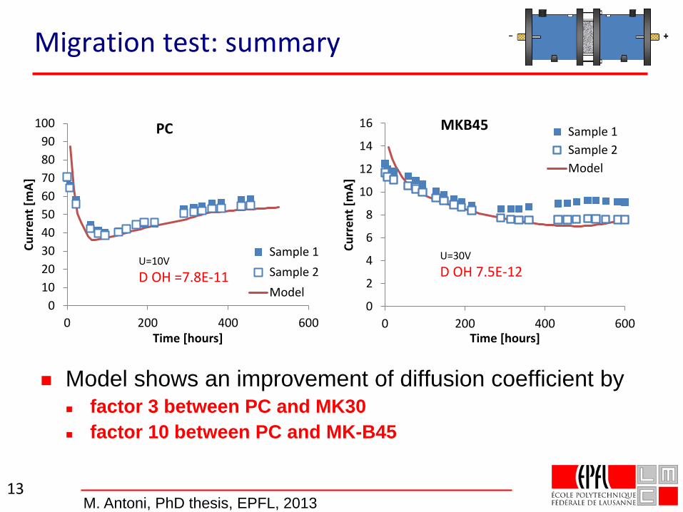
Migration test: summary
13
0
2
4
6
8
10
12
14
16
0 200 400 600
Curr
ent [
mA]
Time [hours]
MKB45 Sample 1Sample 2Model
U=30VD OH 7.5E-12
0102030405060708090
100
0 200 400 600
Curr
ent [
mA]
Time [hours]
PC
Sample 1Sample 2Model
U=10VD OH =7.8E-11
Model shows an improvement of diffusion coefficient by factor 3 between PC and MK30 factor 10 between PC and MK-B45
M. Antoni, PhD thesis, EPFL, 2013
Effect of SCMs on chloride transport
• Transport is dominant
• Binding is secondary, but important
• C-S-H (a lot which binds a little)
• Freidel’s salt (a little which binds a lot)
overall play roughly equal roles in binding.
• SCMs with high available alumina content will give significant increase in binding capacity
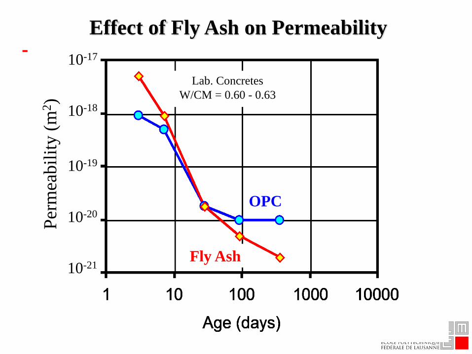
Effect of Fly Ash on Permeability
Lab. ConcretesW/CM = 0.60 - 0.63
OPC
Fly Ash
10-17
10-18
10-19
10-20
10-21
Perm
eabi
lity
(m2 )
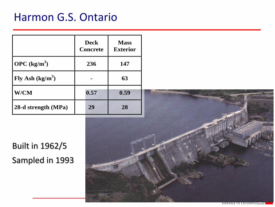
DeckConcrete
MassExterior
OPC (kg/m3) 236 147
Fly Ash (kg/m3) - 63
W/CM 0.57 0.59
28-d strength (MPa) 29 28
Built in 1962/5Sampled in 1993
Harmon G.S. Ontario
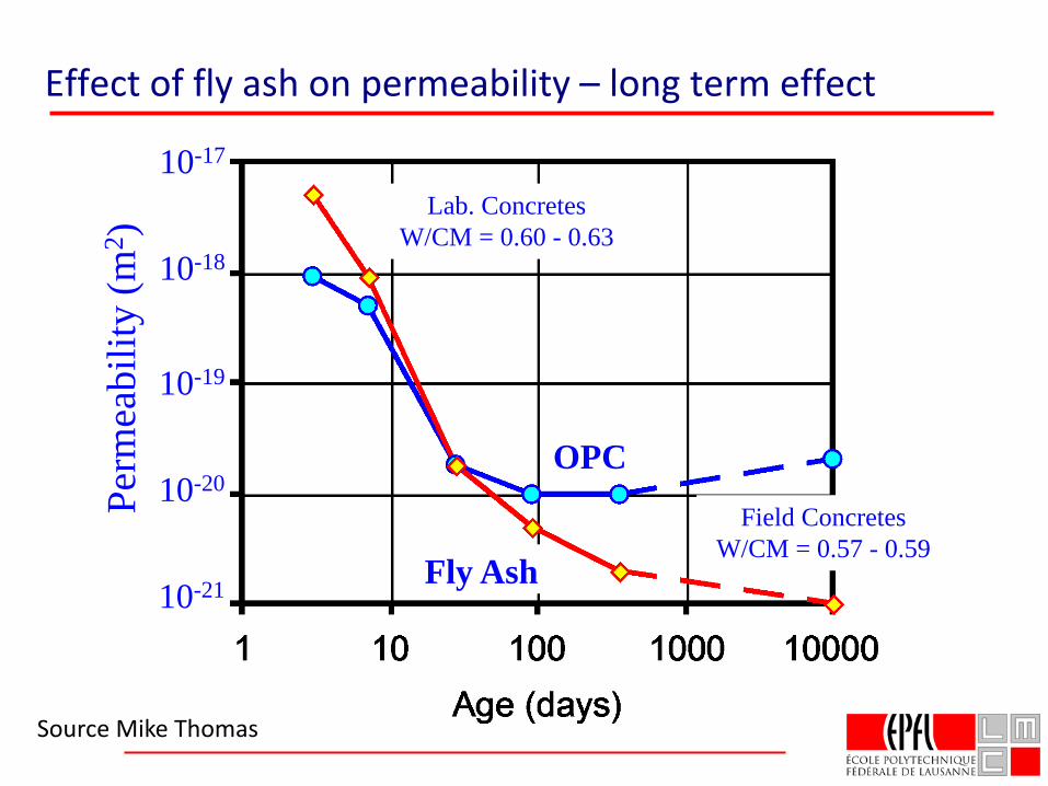
Lab. ConcretesW/CM = 0.60 - 0.63
Field ConcretesW/CM = 0.57 - 0.59
OPC
Fly Ash
10-17
10-18
10-19
10-20
10-21
Perm
eabi
lity
(m2 )
Effect of fly ash on permeability – long term effect
Source Mike Thomas
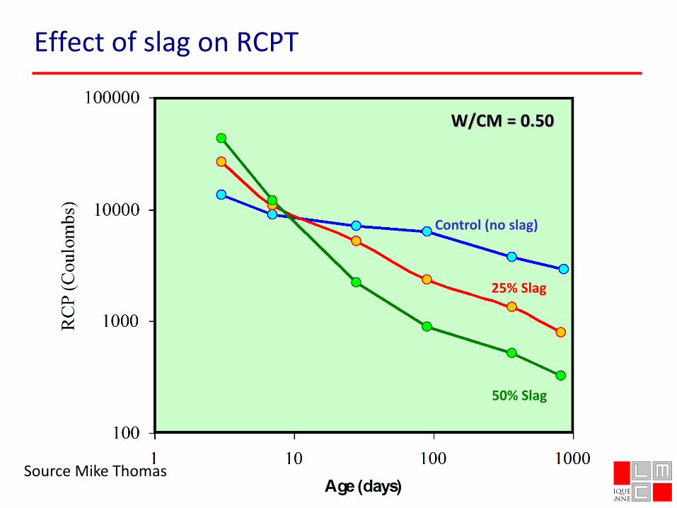
W/CM = 0.50
Control (no slag)
25% Slag
50% Slag
Effect of slag on RCPT
Source Mike Thomas
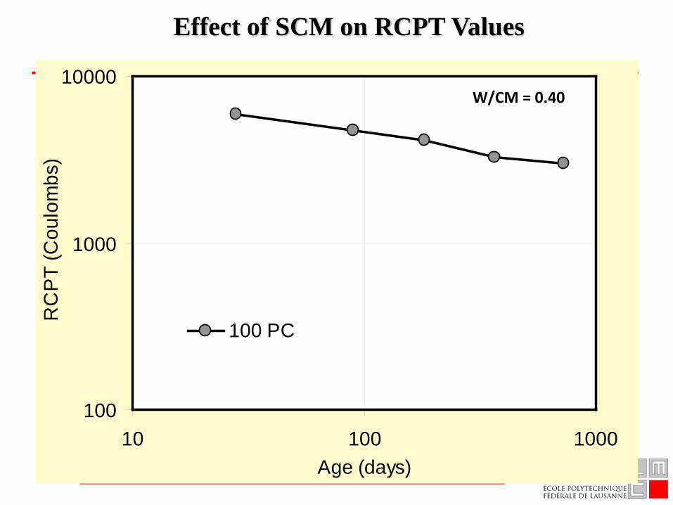
Effect of SCM on RCPT Values
100
1000
10000
10 100 1000Age (days)
RC
PT
(Cou
lom
bs)
100 PC
W/CM = 0.40
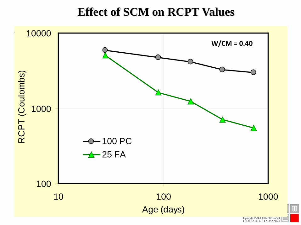
Effect of SCM on RCPT Values
100
1000
10000
10 100 1000Age (days)
RC
PT
(Cou
lom
bs)
100 PC25 FA
W/CM = 0.40
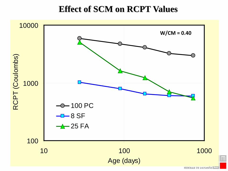
100
1000
10000
10 100 1000Age (days)
RC
PT
(Cou
lom
bs)
100 PC8 SF25 FA
Effect of SCM on RCPT Values
W/CM = 0.40
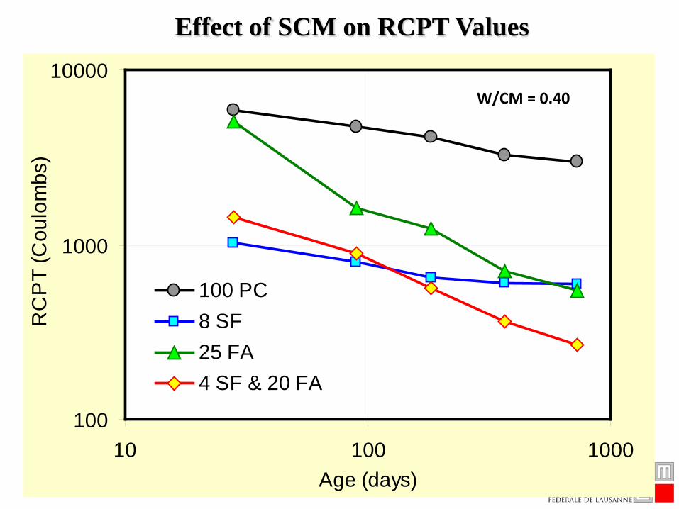
Effect of SCM on RCPT Values
100
1000
10000
10 100 1000Age (days)
RC
PT
(Cou
lom
bs)
100 PC8 SF25 FA4 SF & 20 FA
W/CM = 0.40
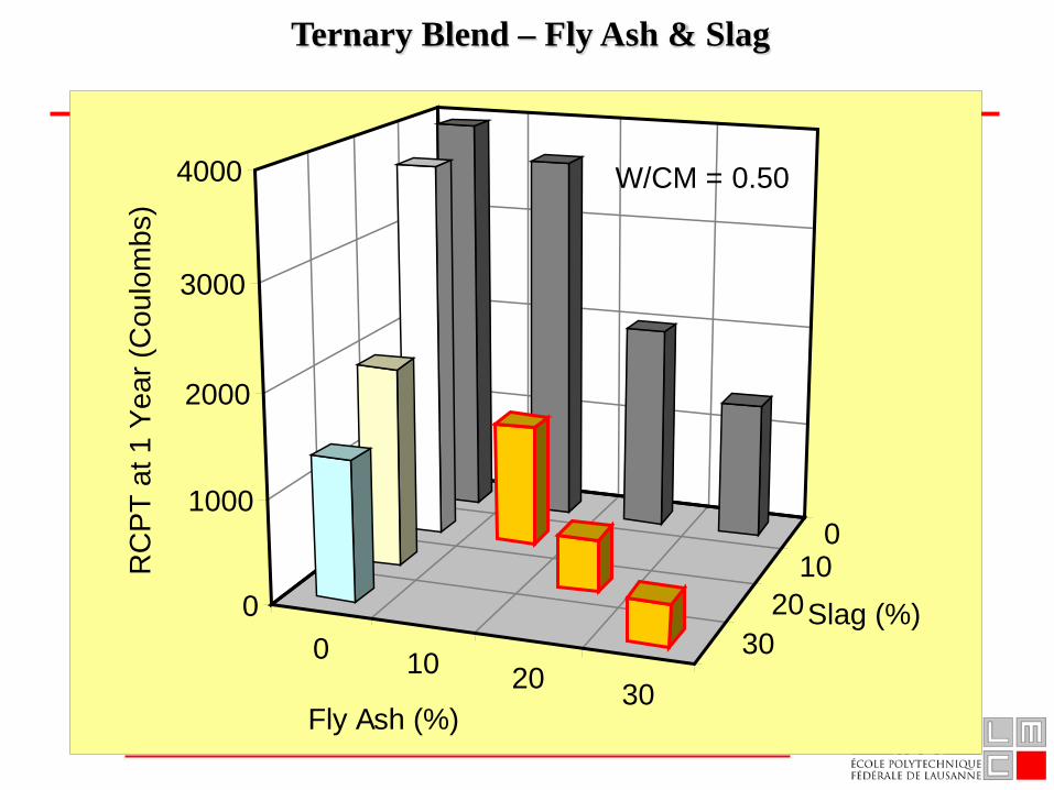
0 10 20 30
010
2030
0
1000
2000
3000
4000R
CP
T at
1 Y
ear (
Cou
lom
bs)
Fly Ash (%)
Slag (%)
W/CM = 0.50
Ternary Blend – Fly Ash & Slag
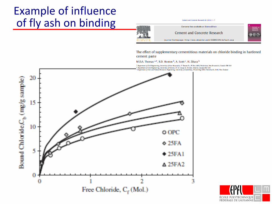
Example of influenceof fly ash on binding
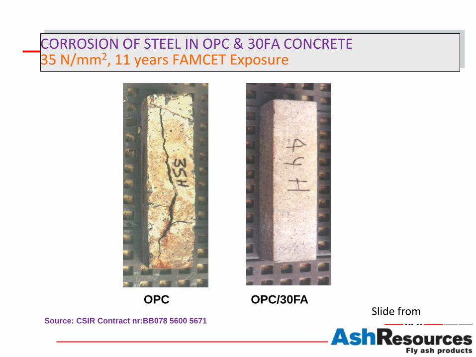
CORROSION OF STEEL IN OPC & 30FA CONCRETE35 N/mm2, 11 years FAMCET Exposure
OPC OPC/30FASource: CSIR Contract nr:BB078 5600 5671
Slide from
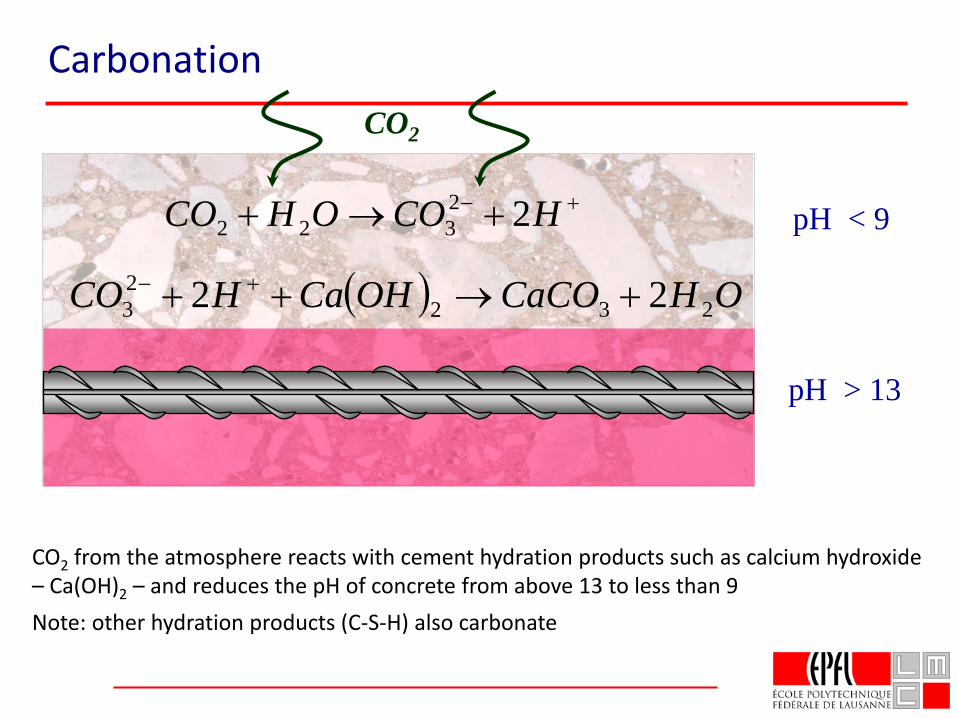
Carbonation
Slides from Professor Mike Thomasand from Mathieu Antoni
CO2
CO2 from the atmosphere reacts with cement hydration products such as calcium hydroxide – Ca(OH)2 – and reduces the pH of concrete from above 13 to less than 9Note: other hydration products (C-S-H) also carbonate
pH > 13
pH < 9+− +→+ HCOOHCO 22322
( ) OHCaCOOHCaHCO 23223 22 +→++ +−
Carbonation
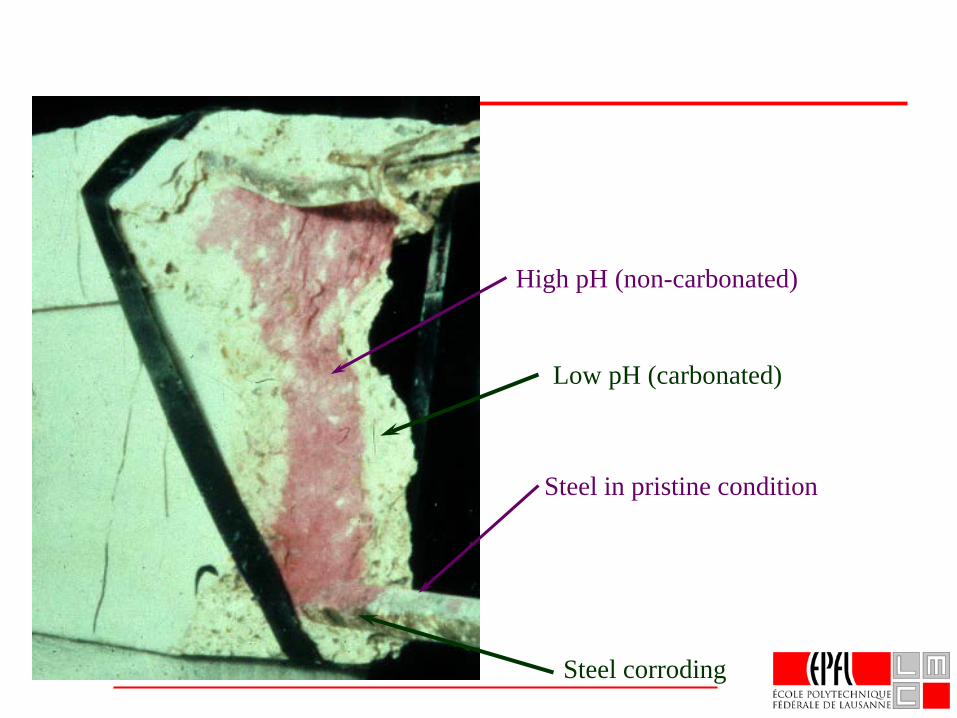
High pH (non-carbonated)
Steel in pristine condition
Low pH (carbonated)
Steel corroding
Courtesy P. Harwood
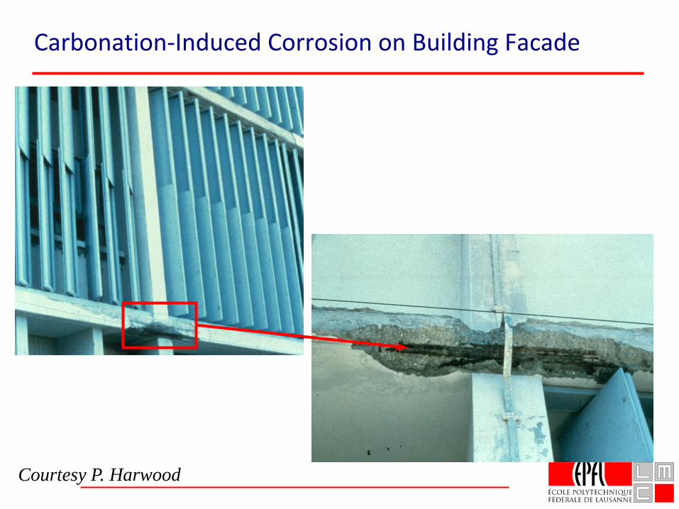
Carbonation-Induced Corrosion on Building Facade
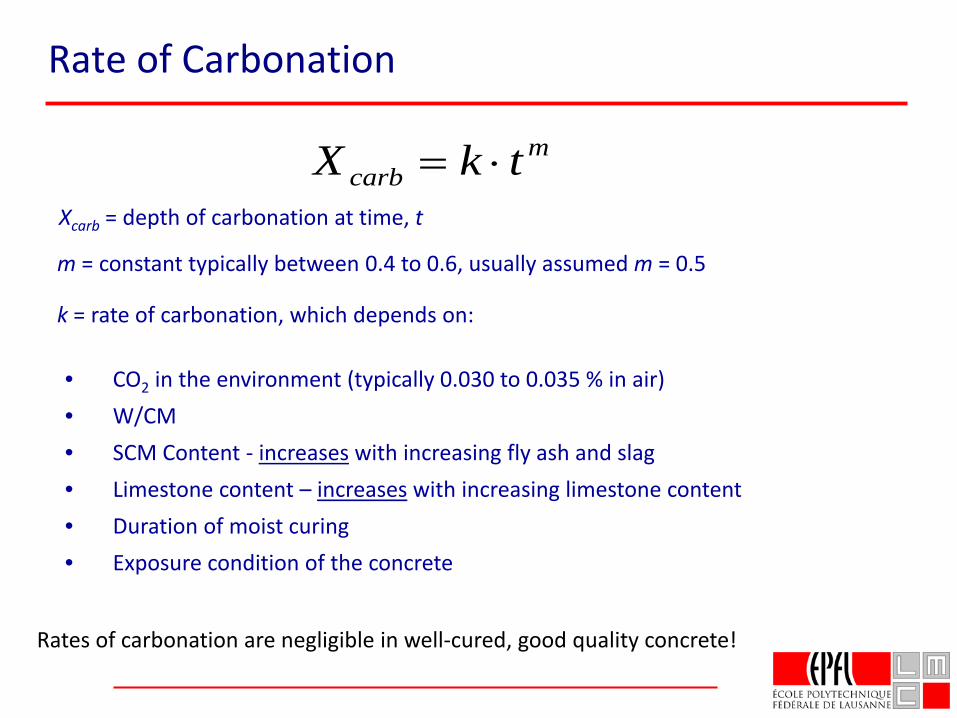
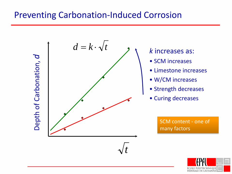
k = rate of carbonation, which depends on:
• CO2 in the environment (typically 0.030 to 0.035 % in air)• W/CM• SCM Content - increases with increasing fly ash and slag• Limestone content – increases with increasing limestone content• Duration of moist curing• Exposure condition of the concrete
Rates of carbonation are negligible in well-cured, good quality concrete!
mcarb tkX ⋅=
Xcarb = depth of carbonation at time, t
m = constant typically between 0.4 to 0.6, usually assumed m = 0.5
Rate of Carbonation
t
Dept
h of
Car
bona
tion,
dtkd ⋅= k increases as:
• SCM increases• Limestone increases• W/CM increases• Strength decreases• Curing decreases
Preventing Carbonation-Induced Corrosion
SCM content - one of many factors
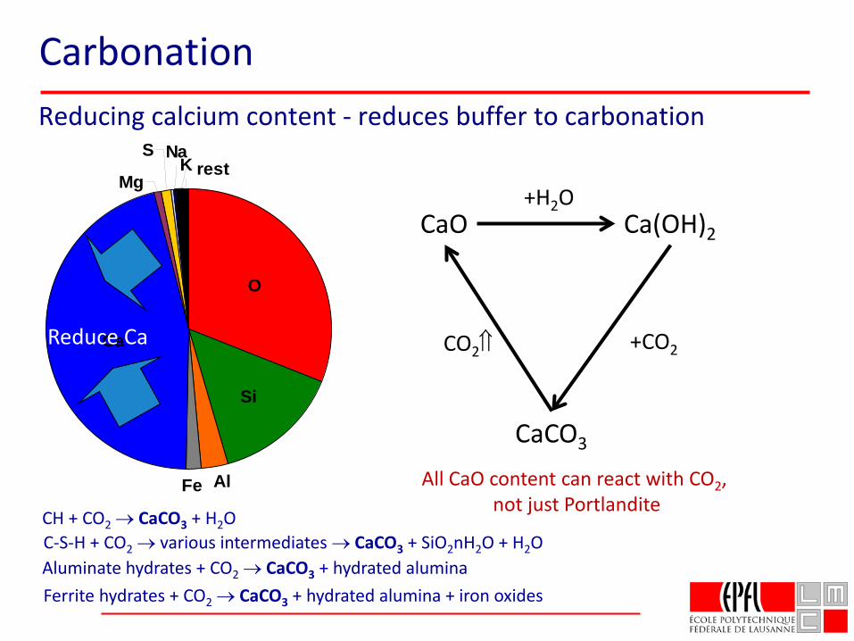
Reducing calcium content - reduces buffer to carbonation
Mg
S
AlFe
KNa
rest
Ca
Si
O
Reduce Ca
CaCO3
CaO Ca(OH)2
+H2O
CO2⇑ +CO2
C-S-H + CO2 → various intermediates → CaCO3 + SiO2nH2O + H2OCH + CO2 → CaCO3 + H2O
Aluminate hydrates + CO2 → CaCO3 + hydrated aluminaFerrite hydrates + CO2 → CaCO3 + hydrated alumina + iron oxides
All CaO content can react with CO2, not just Portlandite
Carbonation
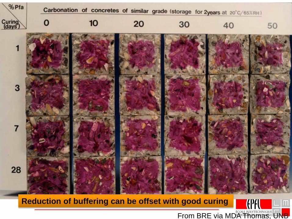
Reduction of buffering can be offset with good curing
From BRE via MDA Thomas, UNB
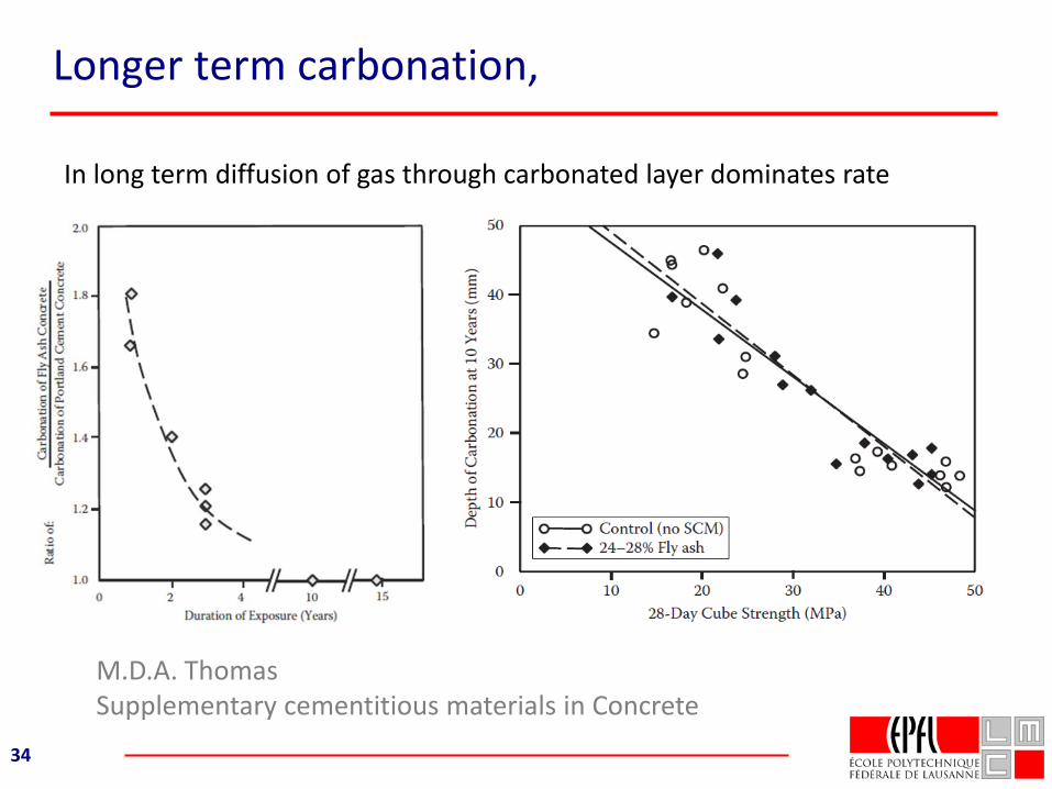
Longer term carbonation,
34
M.D.A. Thomas Supplementary cementitious materials in Concrete
In long term diffusion of gas through carbonated layer dominates rate
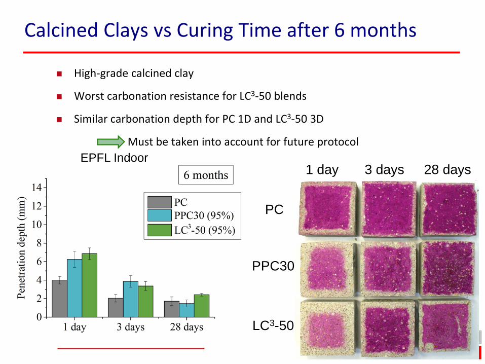
Calcined Clays vs Curing Time after 6 months
High-grade calcined clay
Worst carbonation resistance for LC3-50 blends
Similar carbonation depth for PC 1D and LC3-50 3D
Must be taken into account for future protocol
1 day 3 days 28 days
PC
PPC30
LC3-50
EPFL Indoor
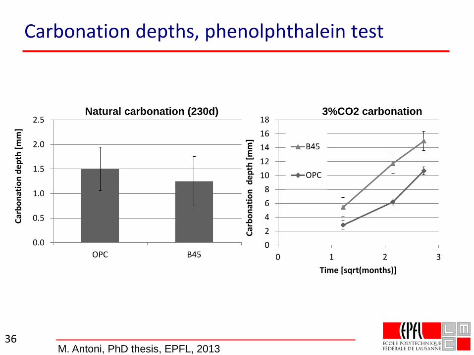
Carbonation depths, phenolphthalein test
36
Natural carbonation (230d) 3%CO2 carbonation
0.0
0.5
1.0
1.5
2.0
2.5
OPC B45
Carb
onat
ion
dept
h [m
m]
02468
1012141618
0 1 2 3Ca
rbon
atio
n d
epth
[mm
]
Time [sqrt(months)]
B45
OPC
M. Antoni, PhD thesis, EPFL, 2013
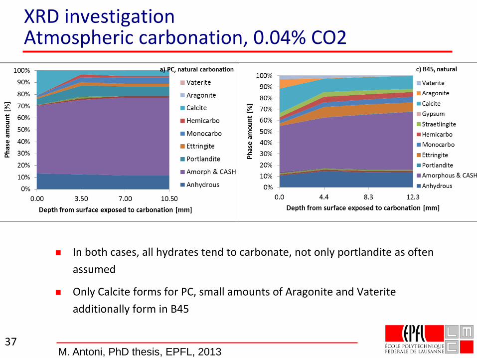
XRD investigationAtmospheric carbonation, 0.04% CO2
In both cases, all hydrates tend to carbonate, not only portlandite as often assumed
Only Calcite forms for PC, small amounts of Aragonite and Vaterite additionally form in B45
37M. Antoni, PhD thesis, EPFL, 2013
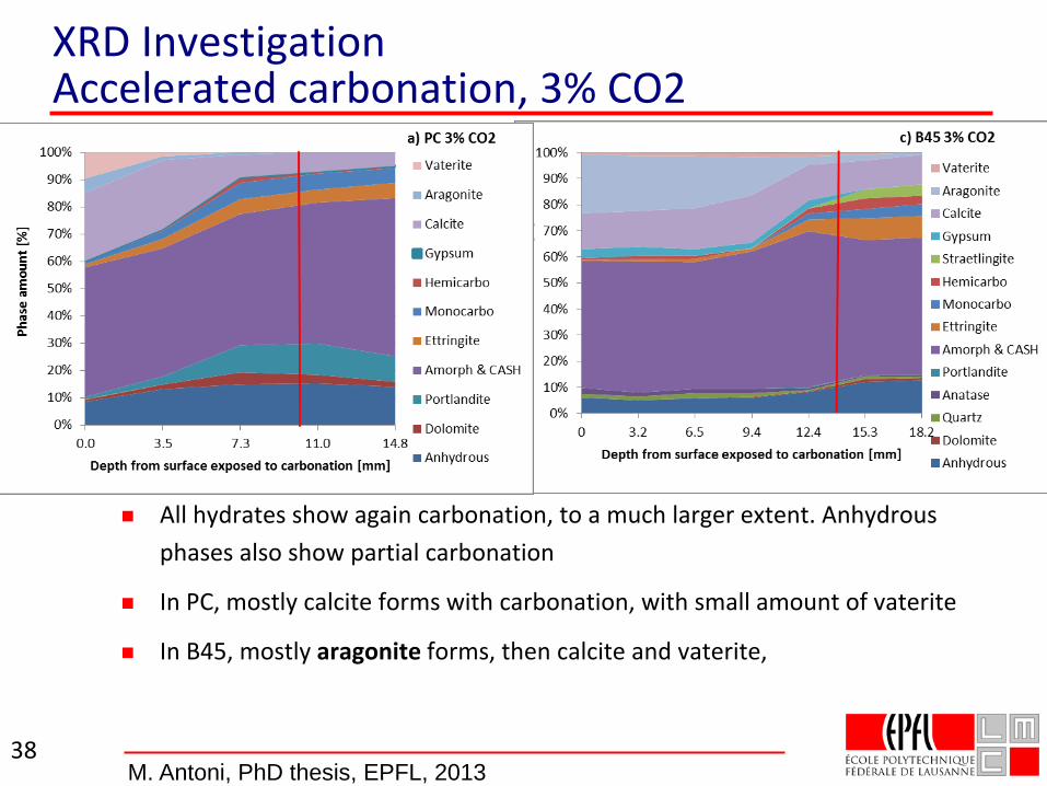
XRD InvestigationAccelerated carbonation, 3% CO2
All hydrates show again carbonation, to a much larger extent. Anhydrous phases also show partial carbonation
In PC, mostly calcite forms with carbonation, with small amount of vaterite
In B45, mostly aragonite forms, then calcite and vaterite,
38M. Antoni, PhD thesis, EPFL, 2013
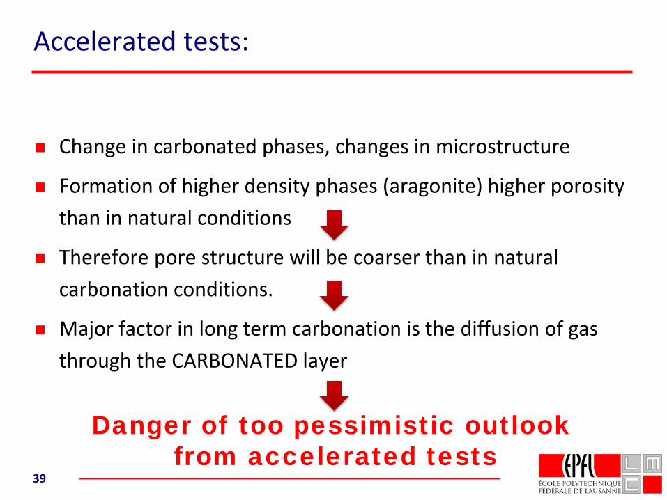
Accelerated tests:
Change in carbonated phases, changes in microstructure
Formation of higher density phases (aragonite) higher porosity than in natural conditions
Therefore pore structure will be coarser than in natural carbonation conditions.
Major factor in long term carbonation is the diffusion of gas through the CARBONATED layer
39
Danger of too pessimistic outlookfrom accelerated tests
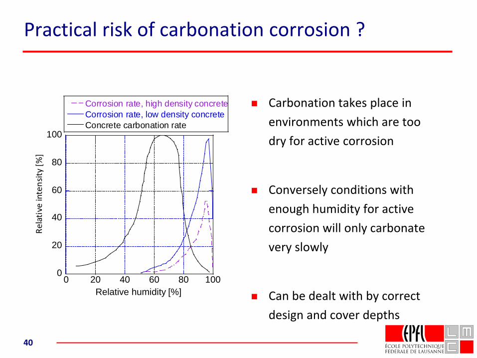
Practical risk of carbonation corrosion ?
0
20
40
60
80
100
0 20 40 60 80 100
Corrosion rate, high density concreteCorrosion rate, low density concreteConcrete carbonation rate
Rela
tive
inte
nsity
[%]
Relative humidity [%]
Carbonation takes place in environments which are too dry for active corrosion
Conversely conditions with enough humidity for active corrosion will only carbonate very slowly
Can be dealt with by correct design and cover depths
40
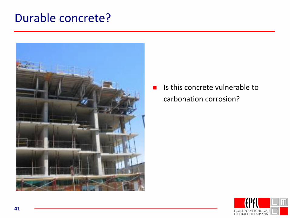
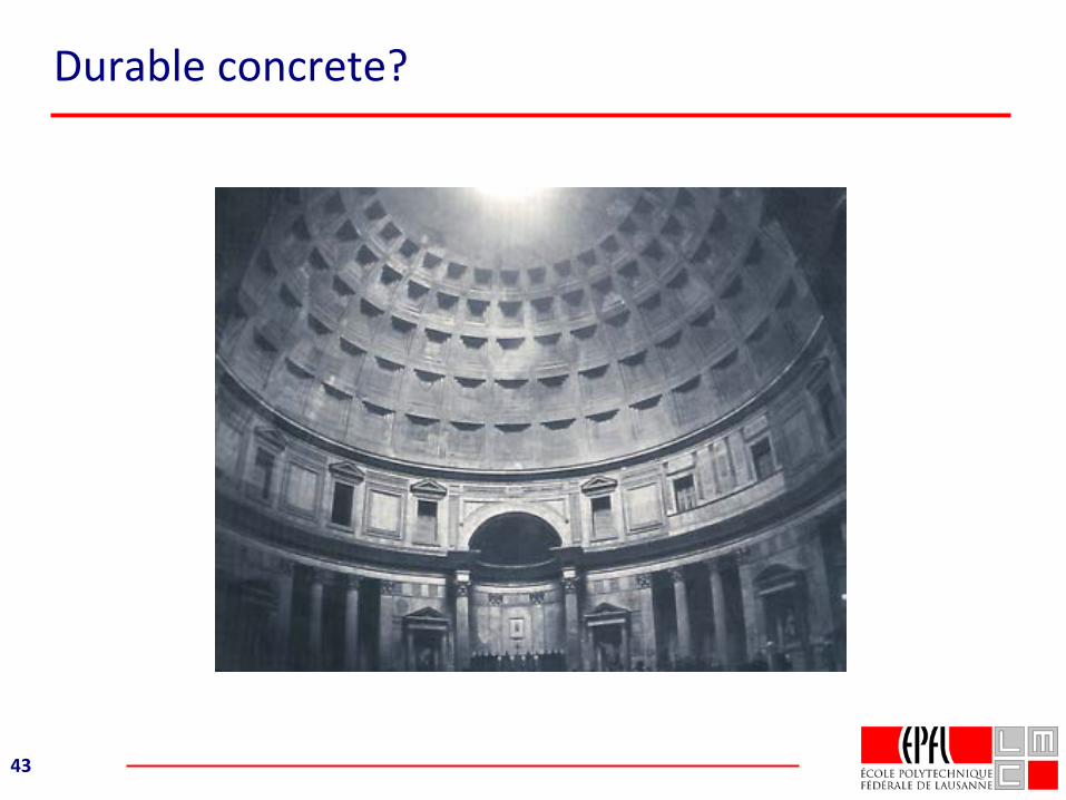
Durable concrete?
41
Is this concrete vulnerable to carbonation corrosion?
Effect of SCMs on carbonation
#1 - Capacity to bind CO2 is most important.
Cement with less chemical CO2 inevitably has less capacity to bind CO2
#2 - Transport (through carbonated layer) is secondary.
Good curing can partially offset effects of lower binding capacity
The balance between these effects needs to be further explored
Important for reinforced concrete, but there is no obstacle to using
low CaO binders in non reinforced applications: blocks, bricks, pavers roof tiles
Durable concrete?
43
Sulfate Attack
Slides from Cheng YuPhD thesis
South East University, China and EPFL
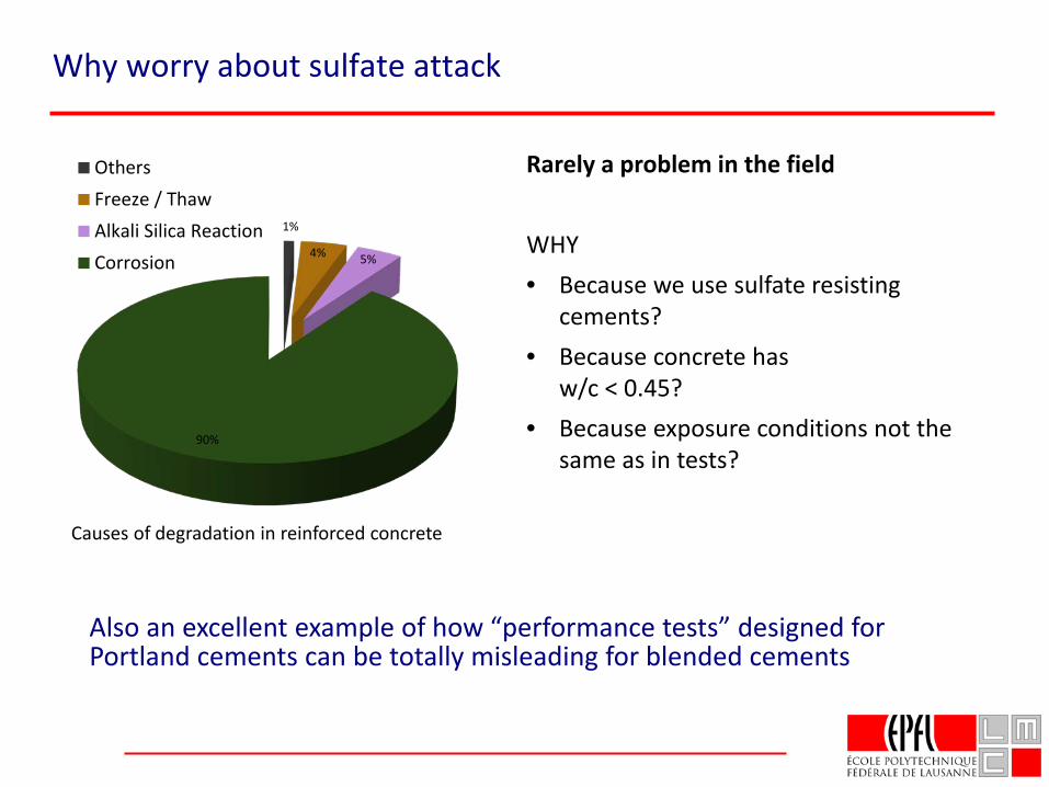
Why worry about sulfate attack
1%
4% 5%
90%
OthersFreeze / ThawAlkali Silica ReactionCorrosion
Causes of degradation in reinforced concrete
Rarely a problem in the field
WHY• Because we use sulfate resisting
cements?• Because concrete has
w/c < 0.45?• Because exposure conditions not the
same as in tests?
Also an excellent example of how “performance tests” designed for Portland cements can be totally misleading for blended cements
First a word about DEF (delayed ettringite formation)
In this talk I will not speak about DEF –Heat induced internal sulfate attack
Only occurs due to high temperatures (>70°C during curing)
If you have problems due to DEF, you almost certainly have problems due to temperature gradients
If you apply good engineering practice to avoid thermal cracking, you should not have DEF.
What was the motivation for these studies
1. Conventionally “sulfate resisting” cements are those with a low content of C3A
2. To improve sustainability we now see an increasing amount of cements containing supplementary cementitious materials (SCMs).
Can such cements be qualified as “sulfate resisting”?
Wide diversity of prescriptive approaches throughout Europe.
CEN TC 51 charged with finding a performance test
>10 years of round robin testing failed to find a reproducible test
2004 approach to NANOCEM to help on understanding fundamentals.
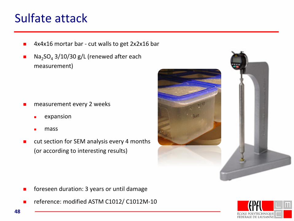
Sulfate attack
4x4x16 mortar bar - cut walls to get 2x2x16 bar
Na2SO4 3/10/30 g/L (renewed after each measurement)
measurement every 2 weeks
expansion
mass
cut section for SEM analysis every 4 months(or according to interesting results)
foreseen duration: 3 years or until damage
reference: modified ASTM C1012/ C1012M-1048
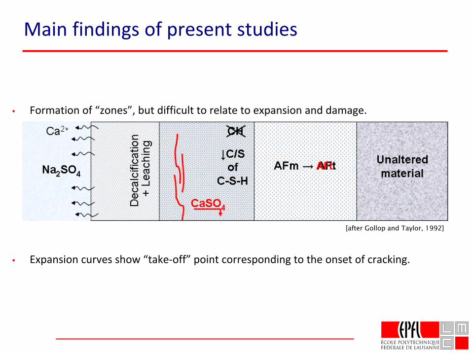
Main findings of present studies
• Formation of “zones”, but difficult to relate to expansion and damage.
• Expansion curves show “take-off” point corresponding to the onset of cracking.
[after Gollop and Taylor, 1992]
AFt
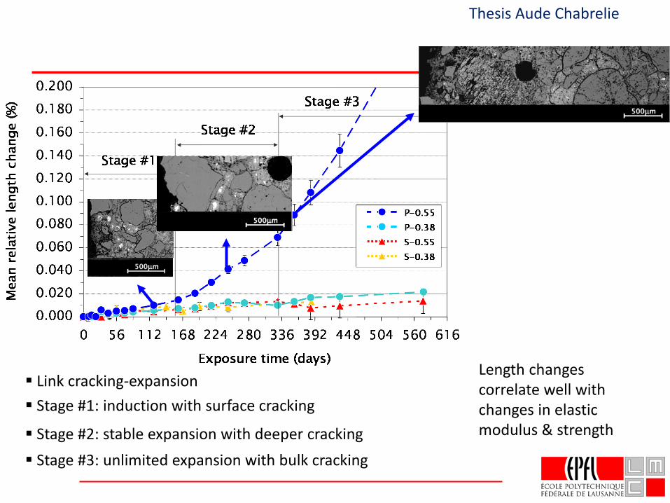
Link cracking-expansion Stage #1: induction with surface cracking
Stage #2: stable expansion with deeper cracking Stage #3: unlimited expansion with bulk cracking
Thesis Aude Chabrelie
Length changes correlate well with changes in elastic modulus & strength
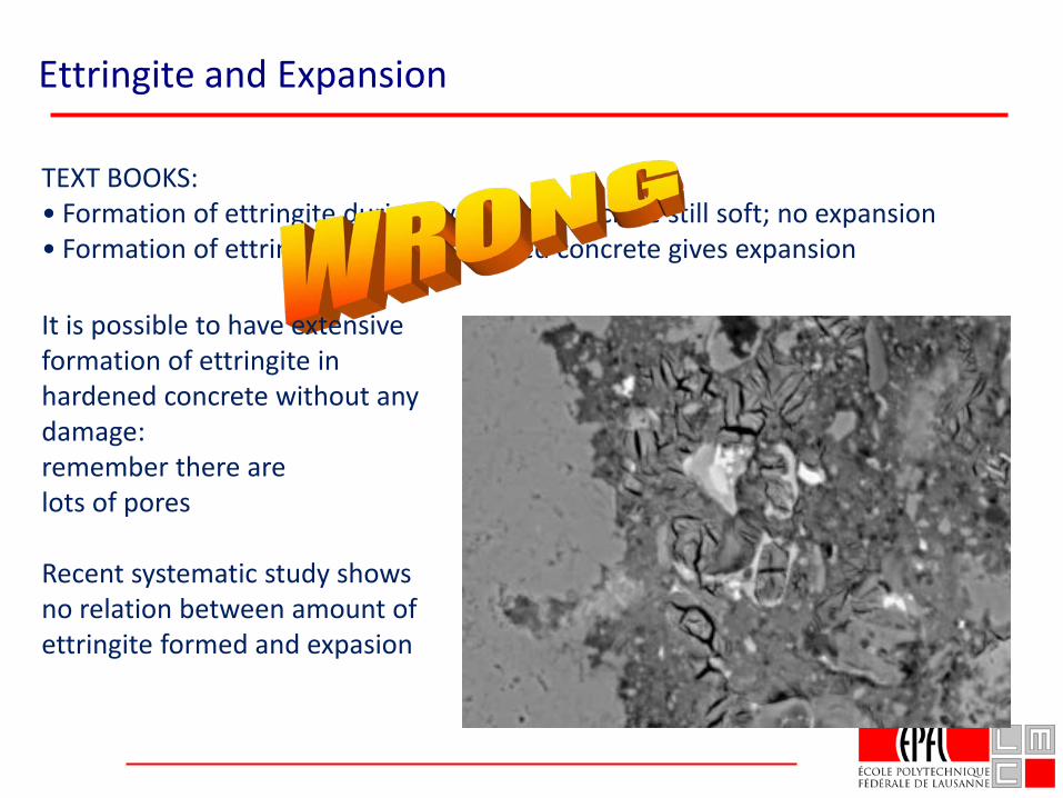
Ettringite and Expansion
TEXT BOOKS:• Formation of ettringite during hydration, concrete still soft; no expansion• Formation of ettringite later in hardened concrete gives expansion
It is possible to have extensive formation of ettringite in hardened concrete without any damage: remember there are lots of pores
Recent systematic study shows no relation between amount of ettringite formed and expasion
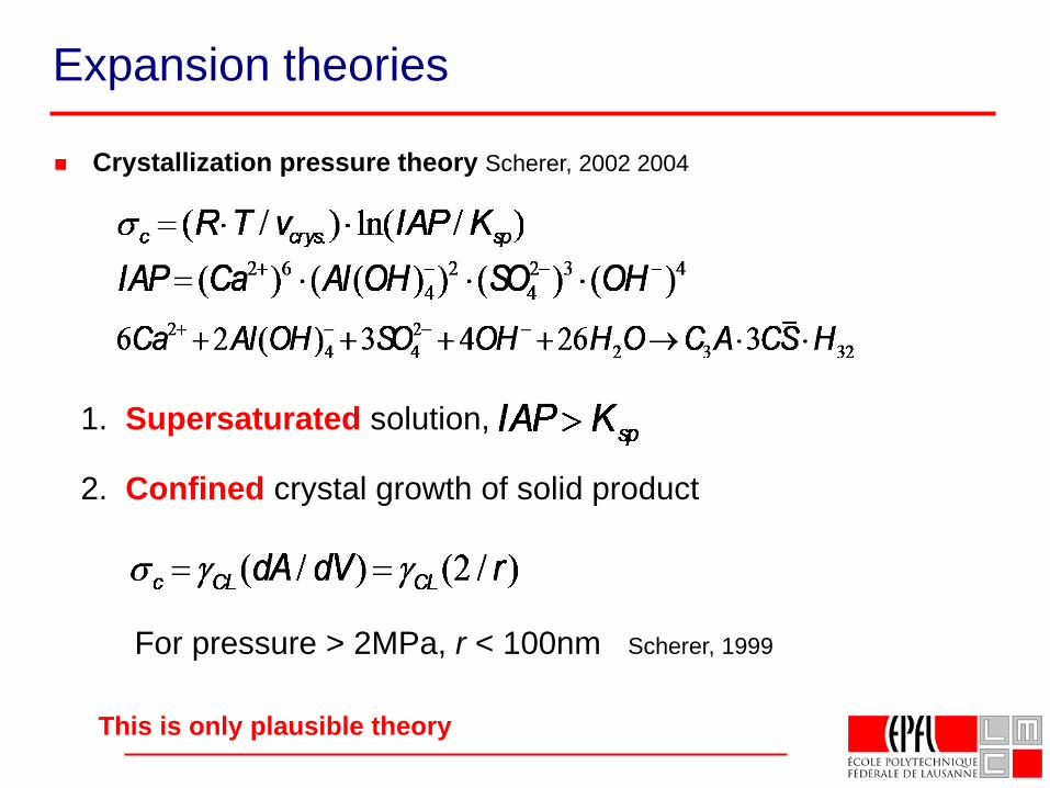
Crystallization pressure theory Scherer, 2002 2004
1. Supersaturated solution,
2. Confined crystal growth of solid product
For pressure > 2MPa, r < 100nm Scherer, 1999
Expansion theories
This is only plausible theory
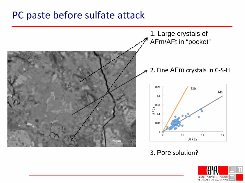
1. Large crystals of AFm/AFt in “pocket”
3. Pore solution?
2. Fine AFm crystals in C-S-H
PC paste before sulfate attack
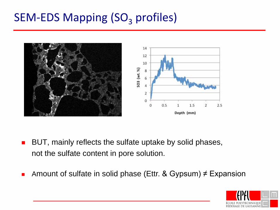
SEM-EDS Mapping (SO3 profiles)
BUT, mainly reflects the sulfate uptake by solid phases, not the sulfate content in pore solution.
Amount of sulfate in solid phase (Ettr. & Gypsum) ≠ Expansion
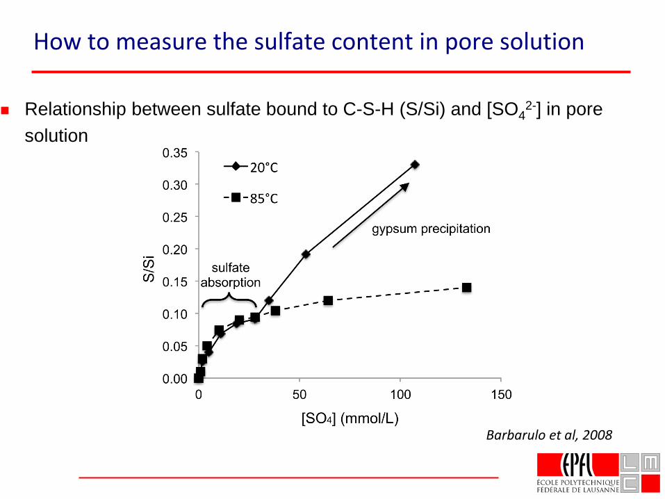
How to measure the sulfate content in pore solution
Relationship between sulfate bound to C-S-H (S/Si) and [SO42-] in pore
solution
Barbarulo et al, 2008
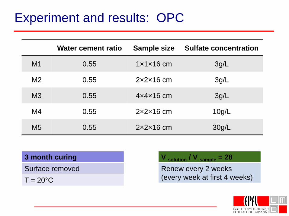
Experiment and results: OPC
Water cement ratio Sample size Sulfate concentration
M1 0.55 1×1×16 cm 3g/L
M2 0.55 2×2×16 cm 3g/L
M3 0.55 4×4×16 cm 3g/L
M4 0.55 2×2×16 cm 10g/L
M5 0.55 2×2×16 cm 30g/L
V solution / V sample = 28Renew every 2 weeks (every week at first 4 weeks)
3 month curing Surface removedT = 20°C
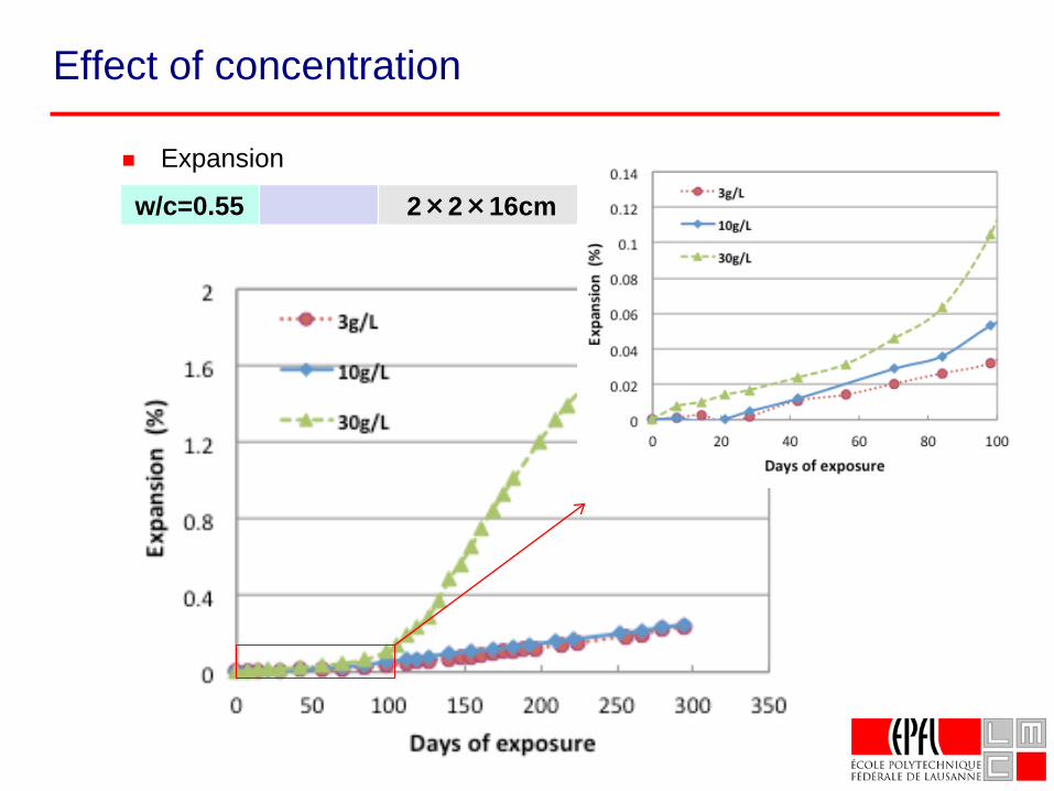
Effect of concentration
Expansion
w/c=0.55 2×2×16cm
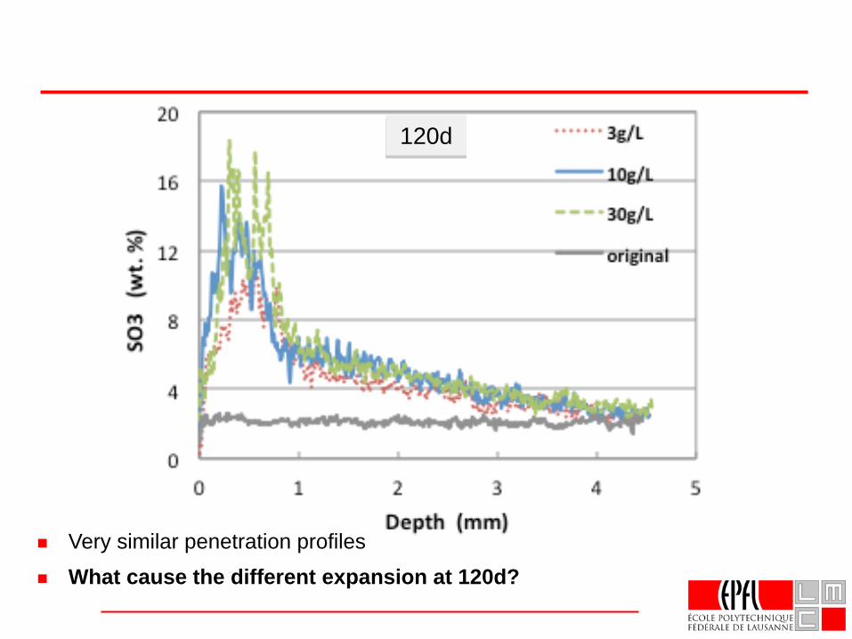
Very similar penetration profiles
120d
What cause the different expansion at 120d?
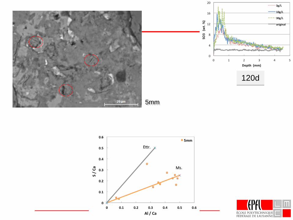
5mm
120d
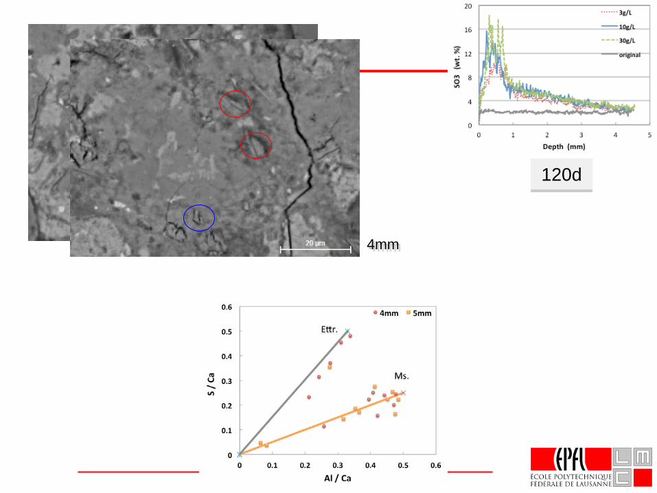
4mm
120d
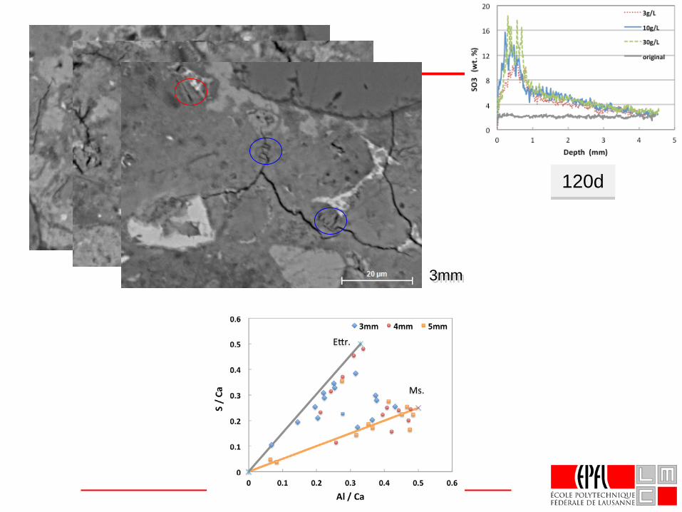
3mm
120d
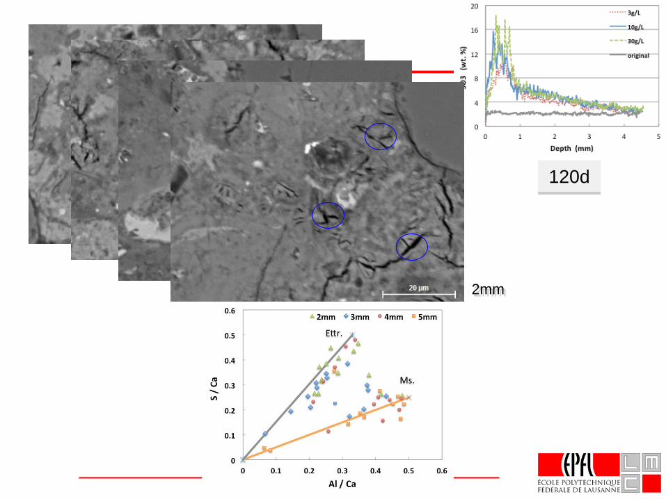
2mm
120d
4mm2mm 3mm
120d
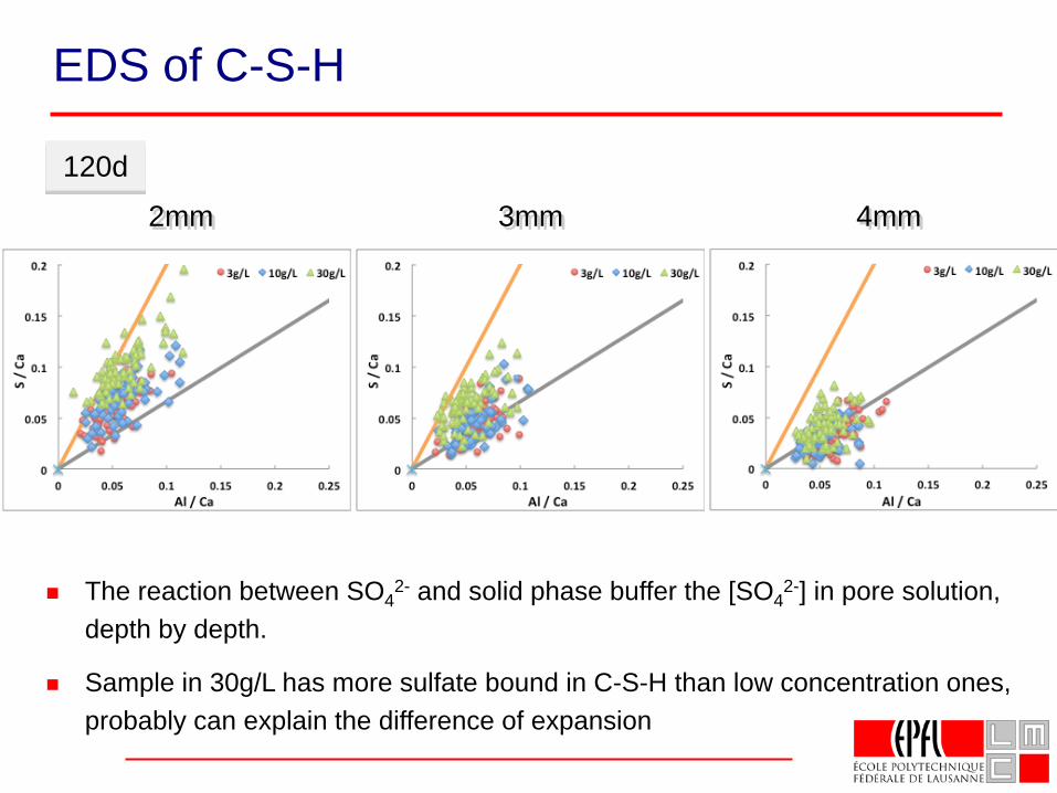
The reaction between SO42- and solid phase buffer the [SO4
2-] in pore solution, depth by depth.
Sample in 30g/L has more sulfate bound in C-S-H than low concentration ones, probably can explain the difference of expansion
EDS of C-S-H
As sulfate ions penetrate in the cement paste, they react with unconstrained aluminate phases, mainly AFm in the pockets, this buffers the increase of [SO4
2-] in pore solution.
When all freely transformable Al2O3 has reacted, the [SO4
2-] in solution will increase,constrained AFm within C-S-H can then react to ettringiteand exert expansion force.
Once cracking occurs, SO42- can entry freely and,
react even with Ca2+ to form gypsum in cracks.
Explanation of expansion
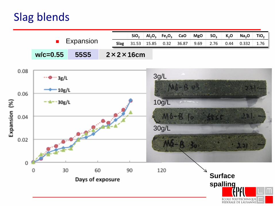
w/c=0.55 55S5 2×2×16cm
Slag blends
Expansion
3g/L
10g/L
30g/L
Surface spalling
SiO2 Al2O3 Fe2O3 CaO MgO SO3 K2O Na2O TiO2
Slag 31.53 15.85 0.32 36.87 9.69 2.76 0.44 0.332 1.76
Effect of SCMs on sulfate resistance
• Complicated
• Interaction of:
• buffering effects,
• amount of constrained AFm and
• perhaps transport effects
• Cannot say that blended cements have “chemical” resistance to sulfate attack if they contain alumina.
• Need for test methods more representative of reality where surface loss is more important than macroscopic expansion
Alkali - Silica Reaction
Slides from Theodore ChappexPhD thesis
EPFL
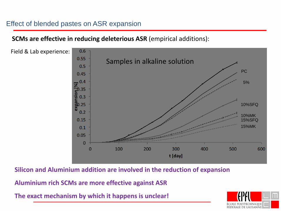
Effect of blended pastes on ASR expansion
SCMs are effective in reducing deleterious ASR (empirical additions):
Field & Lab experience:
Silicon and Aluminium addition are involved in the reduction of expansion
Aluminium rich SCMs are more effective against ASR
The exact mechanism by which it happens is unclear!
5%
15%SFQ15%MK
10%SFQ
10%MK
PC
Samples in alkaline solution
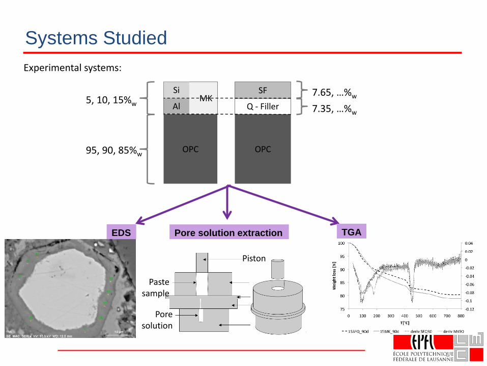
Systems StudiedExperimental systems:
MK
OPC
Q - Filler
SF
OPC
Si
Al
95, 90, 85%w
5, 10, 15%w7.65, …%w
7.35, …%w
Paste sample
Pore solution
Piston
EDS Pore solution extraction TGA
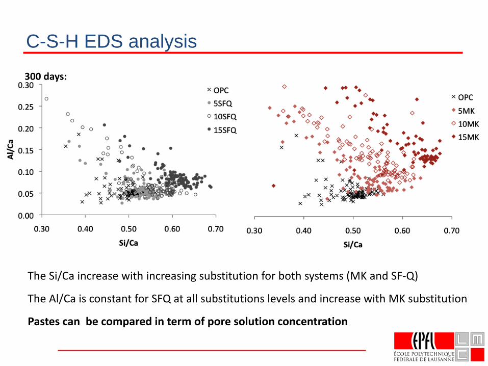
C-S-H EDS analysis
The Si/Ca increase with increasing substitution for both systems (MK and SF-Q)
The Al/Ca is constant for SFQ at all substitutions levels and increase with MK substitution
Pastes can be compared in term of pore solution concentration
300 days:
5MK
5SFQ
10MK
10SSFQ
15SFQ15MK
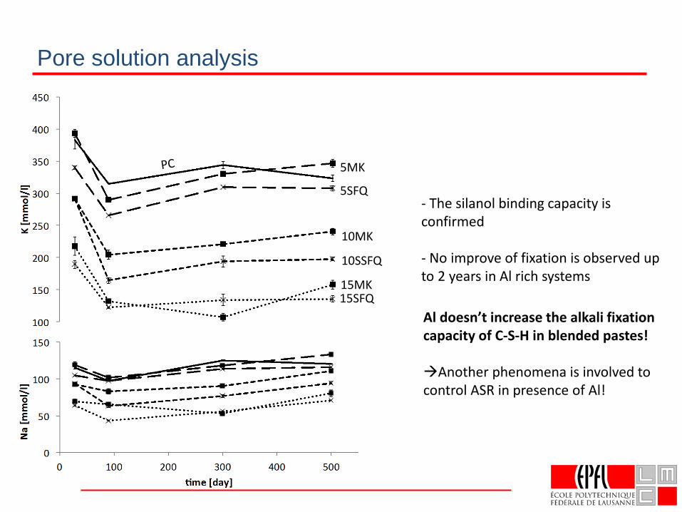
Pore solution analysis
- The silanol binding capacity is confirmed
- No improve of fixation is observed up to 2 years in Al rich systems
Al doesn’t increase the alkali fixation capacity of C-S-H in blended pastes!
Another phenomena is involved to control ASR in presence of Al!
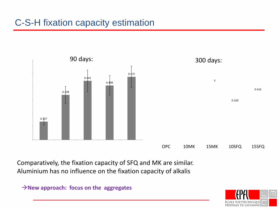
Comparatively, the fixation capacity of SFQ and MK are similar. Aluminium has no influence on the fixation capacity of alkalis
C-S-H fixation capacity estimation
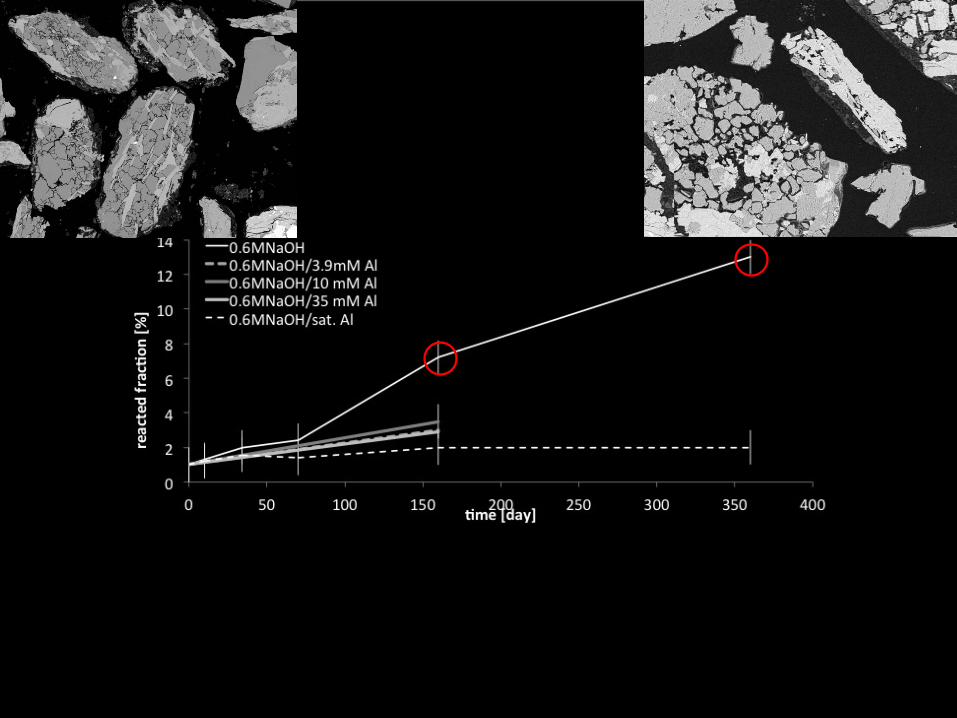
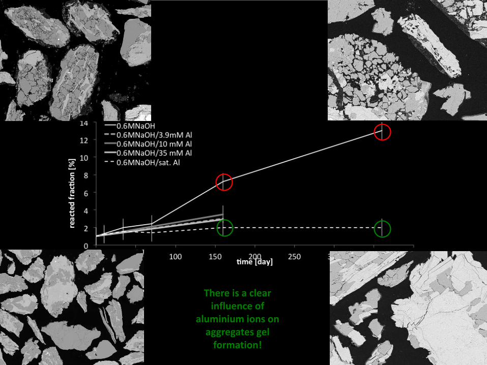
New approach: focus on the aggregates
90 days: 300 days:
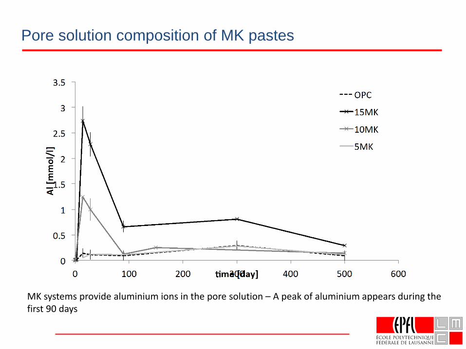
Pore solution composition of MK pastes
MK systems provide aluminium ions in the pore solution – A peak of aluminium appears during the first 90 days
74
75
76
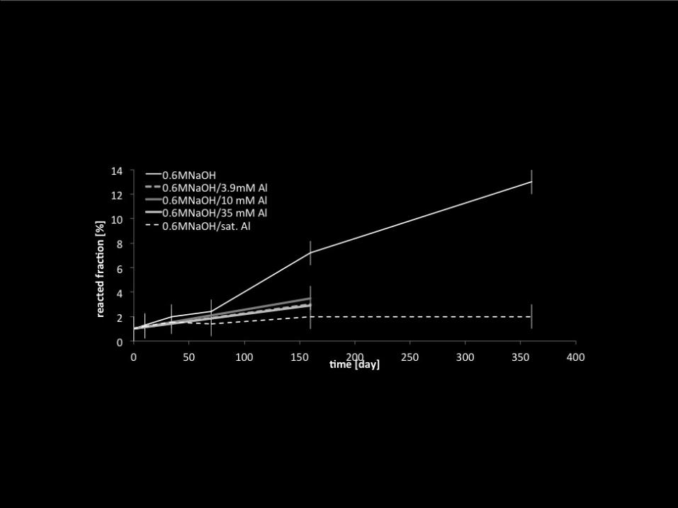
There is a clear influence of
aluminium ions on aggregates gel
formation!
Effect of SCMs on ASR
• First effect is lowering of pH of pore solution
• Lower C/S C-S-H absorbs more alkalis
• SCM high in alumina also inhibit directly dissolution of amorphous silica
Concluding remarks
Future cements will be based on Portland cement clinker with increasing amounts of SCMs
Need to be able to use divers range of materials, generic approach to understanding durability
Durability is not an intrinsic materials property, but a result of interaction of material with its environment
Effect of SCMs of durability:
Mostly positive: Chloride, ASR
Sulfate attack is colmpex and has to be better understood
Faster carbonation? Yes, but low risk of carbonation corrosion in most concrete.
If we are serious about more sustainable concrete we need to use cements with lower CO2 emissions
e.g. LC3 clinker/ calcined clay / limestone blends
79
“No concrete is sustainable without being durable”
“Sustainable use of concrete should adapt the composition to
the application”
“Use only what you need”
THANK YOUQuestions?
80