Embed Size (px)
Citation preview
Zeszyty Naukowe 35(107) 125
Scientific Journals Zeszyty Naukowe Maritime University of Szczecin Akademia Morska w Szczecinie
2013, 35(107) pp. 125–131 2013, 35(107) s. 125–131 ISSN 1733-8670
Durability and wear of engine parts – new methods of testing of alloys and composites
Zbigniew Ranachowski1, Andrzej Pawełek2, Zdzisław Jasieński2, Andrzej Piątkowski2
Stanislav Kudela Jr.3, Marcin Lewandowski1, Paweł Mazuruk4 1 PAS, Institute of Fundamental Technological Problems
02-106 Warszawa, ul. Pawińskiego 5 B, e-mail: [email protected]
2 PAS, Institute of Metalurgy and Materials Engineerig
30-059 Kraków, ul. Reymonta 25
3 Slovak Academy of Sciences, Institute of Materials and Machine Mechanics
830-08 Bratislava, Račianska 75, P.O. box 95, Slovakia
4 BU Power Systems Polska
02-293 Warszawa, ul. Krótka 6
Key words: Diesel engines diagnostics, light alloys and composites, Common Rail fuel system, Acoustic
Emission method
Abstract The paper deals with the problems related to the diagnostics of selected parts of modern Diesel engines. The
evolution of mechanical properties of four alloys of Mg-Li-Al system and four composites made on the base
of the alloys mentioned above, caused by variation of its composition was presented. The Acoustic Emission
(AE) method applied to monitoring of degradation of mechanical properties of the alloys and composites was
described. Moreover, the results of the investigation of failures occurring in the injectors of Common Rail
Diesel engines performed with the application of AE method were also reported.
Introduction
Diesel engines serving as the main and auxiliary
propulsion of different vessels and vehicles are
objects of permanent improvements. The engines
with Common Rail (CR) fuel system were introduced
to comply with new strict environmental regulations
dealing with limits of emissions of: carbon oxide,
hydrocarbons, nitrogen oxides and particulate pollut-
ants. The CR Diesel engines controlled by sophisti-
cated electronic systems and sensors are character-
ised by high (> 50%) efficiency and increased
reliability. Operating with different way than those
of mechanical fuel supply controlling, the CR
system engines suffer from specific fault types. The
novel method of non-invasion method of diagnostic
of the faults mentioned above will be described
below. The other important problem of develop-
ment of engines is the choice of the light and dura-
ble materials to construct them. As far as now,
Diesel engines suffer from the relative high (0.5–2
kg/kW) mass related to power unit. Gravity reduc-
tion causing no negative impact on reliability would
create economic gains and cause the further techno-
logical progress. As an example of the importance
of the matter the results achieved by the engineers
of the Cassidian Company being a corporate of
EADS can be recalled here. Cassidian has intro-
duced a sort of Unmanned Aerial Vehicle (UAV)
designed to be a surveillance and imaginary plat-
form for naval and rescue purposes. Having 300 kg
of weight UAV, called Tanan 300, is able to carry
a 50 kg payload, including an AIS (Automatic Iden-
tification System), an IFF (Identification Friend
or Foe) system, maritime radar, an electronic HD
surveillance system, and a direction finder. The
aircraft’s endurance is quoted at eight hours at the
flight speed of 100 km/h. To meet these difficult
requirements the designers have chosen a light-
weight Diesel engine to drive it as the optimal
solution. It is highly probable that other autono-
mous boats / vehicles would be soon in service.
Z. Ranachowski, A. Pawełek, Z. Jasieński, A. Piątkowski, S. Kudela Jr., M. Lewandowski, P. Mazuruk
126 Scientific Journals 35(107)
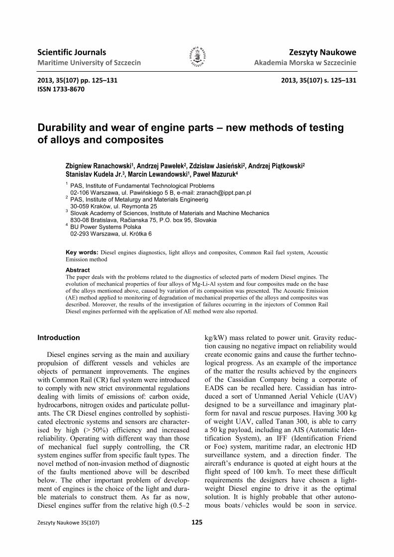
The image of the Tanan 300 helicopter on the basis
of the data taken from the website of Cassidian
company is shown in the figure 1.
Fig. 1. The image of the remote-controlled Tanan 300 helicop-
ter. The lightweight Diesel engine is applied to drive the ma-
chine [the advertisement of the Cassidian company at www.
miltechmag.com/2012/08/cassidians-tanan-300-vtol-uas.html]
Testing of lightweight alloys and composites
The comparison of the mechanical properties of
the engineering materials can be done by recalling
of their parameters – yield strength (YS) and tensile
strength (TS). These parameters can be applied in
the assessment of the sustained load possible to
withstand for the element made of the considered
material. The low grain and properly tempered steel
of good quality achieves ca. 400 MPa of TS. Its
specific gravity is remarkable and equals ca. 7900
kg/m3. Therefore, nowadays lightweight alloys of
system of Mg-Al or Mg-Al-Li, are applied as parts
of engines. After the proper processing these alloys
have TS close to 200 MPa, but they are considera-
bly lighter than steel with the specific gravity of
2000 kg/m3. The alternate way of improving of the
mechanical strength of the engine part is to replace
the alloy with the composite. The example of the
composite can be the material which base material
(matrix) is a lightweight alloy and it is reinforced
by immersion of high strength ceramic fibres acting
as the skeleton.
The authors of the paper have compared the me-
chanical properties of four lightweight Mg-Li-Al
system alloys and of four composites made on their
base. The authors have used relatively small speci-
mens for testing (i.e. the 101010 mm cubes) and
therefore application of the tensile stress was of no
use. Instead the specimens were compressed what
enabled for the determination of the yield strength
changes caused by the modification of material
composition. The Mg9Li, Mg9Li1Al, Mg9Li3AL
and Mg9Li5Al alloys are build of two material
phases. The mechanical properties of the α phase
are worse than these of the β phase compensated by
considerably higher plasticity, very good machine
and weld abilities. Adding of aluminium causes
additional expansion / compression strengthening
but in practical applications the excess of Al may
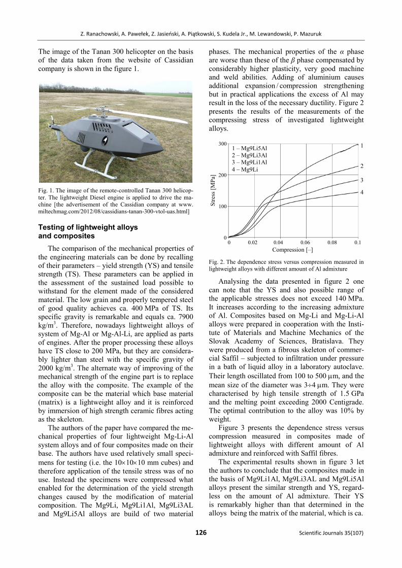
result in the loss of the necessary ductility. Figure 2
presents the results of the measurements of the
compressing stress of investigated lightweight
alloys.
Fig. 2. The dependence stress versus compression measured in
lightweight alloys with different amount of Al admixture
Analysing the data presented in figure 2 one
can note that the YS and also possible range of
the applicable stresses does not exceed 140 MPa.
It increases according to the increasing admixture
of Al. Composites based on Mg-Li and Mg-Li-Al
alloys were prepared in cooperation with the Insti-
tute of Materials and Machine Mechanics of the
Slovak Academy of Sciences, Bratislava. They
were produced from a fibrous skeleton of commer-
cial Saffil – subjected to infiltration under pressure
in a bath of liquid alloy in a laboratory autoclave.
Their length oscillated from 100 to 500 m, and the
mean size of the diameter was 34 m. They were
characterised by high tensile strength of 1.5 GPa
and the melting point exceeding 2000 Centigrade.
The optimal contribution to the alloy was 10% by
weight.
Figure 3 presents the dependence stress versus
compression measured in composites made of
lightweight alloys with different amount of Al
admixture and reinforced with Saffil fibres.
The experimental results shown in figure 3 let
the authors to conclude that the composites made in
the basis of Mg9Li1Al, Mg9Li3AL and Mg9Li5Al
alloys present the similar strength and YS, regard-
less on the amount of Al admixture. Their YS
is remarkably higher than that determined in the
alloys being the matrix of the material, which is ca.
Compression [–]
1 – Mg9Li5Al
2 – Mg9Li3Al
3 – Mg9Li1Al
4 – Mg9Li
1
2
3
4
0 0.02 0.04 0.06 0.08 0.1
300
200
100
0
Str
ess
[MP
a]
Durability and wear of engine parts – new methods of testing of alloys and composites
Zeszyty Naukowe 35(107) 127
Fig. 3. The dependence stress versus compression measured in
composites made of lightweight alloys with different amount of
Al admixture and reinforced with Saffil fibres, 10% by weight
200 MPa. Therefore, there is possibility of applica-
tion of the investigated composites to become parts
of lightweight engines. It should be noted that the
development of destruction mechanisms in over-
loaded composites is different than that appearing
in alloys. In the latter materials the plastic deforma-
tion is related with the onset of the evolution of
large dislocation systems and also with the crack
growth initiated by the presence of voids and struc-
tural defects. In the composites being the object of
present investigation the mechanical stress is taken
over by the fibrous skeleton rather than by the duc-
tile alloy. The collapse of the system appears when
the majority of the fibres is broken or pulled out of
the matrix. That process is undergoing with com-
plex, partly fragile and partly plastic stages. This is
a reason that for the research during the mechanical
loading of composite elements the Acoustic Emis-
sion (AE) signal is registered [1]. The origin of this
signal is a structural degradation of the tested ob-
ject. The authors of the paper have registered the
AE signal during compression tests of the speci-
mens described above. A standard instrumentation,
schematically shown in figure 4 was used in this
purpose.
Fig. 4. Block – diagram of the instrumentation for registration
of AE signal generated during compression tests of alloys of
Mg-Li-Al system and composites made on their base
During the compression of the alloys of Mg-Li-
Al system the maximum energy of AE signal is
evoked by the activated dislocation systems when
a yield limit of the material is reached. In the com-
posites the AE activity is registered in wider range
of compression and it is caused by the local break-
ing of the mechanical durability by the rigid fibrous
skeleton. At this moment the fibres are breaking or
pulling out of the matrix. Later there appears the
relaxation of the alloy and this causes the stress
redistribution among the next parts of the skeleton.
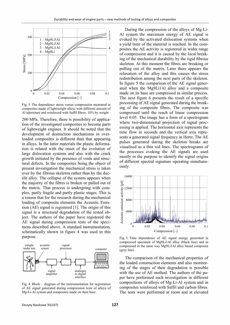
In figure 5 the comparison of the AE signal gener-
ated when the Mg9Li1Al alloy and a composite
made on its base are compressed in similar process.
The next figure 6 presents the result of a specific
processing of AE signal generated during the break-
ing of the composite fibres. The composite was
compressed until the reach of linear compression
level 0.05. The image has a form of a spectrogram
where two-dimensional projection of signal proc-
essing is applied. The horizontal axis represents the
time flow in seconds and the vertical axis repre-
sents a generated signal frequency in Hertz. The AE
pulses generated during the skeleton breaks are
visualised as a thin red lines. The spectrograms of
the processes evoking the AE signals are used
mostly in the purpose to identify the signal origins
of different spectral signature operating simultane-
ously.
Fig. 5. Time dependence of AE signal energy generated in
compressed specimen of Mg9Li1Al alloy (black line) and in
compressed in the same way Mg9Li1Al alloy based composite
(grey line)
The comparison of the mechanical properties of
the loaded construction elements and also monitor-
ing of the stages of their degradation is possible
with the use of AE method. The authors of the pa-
per have performed such investigation in different
compositions of alloys of Mg-Li-Al system and in
composites reinforced with Saffil and carbon fibres.
The tests were performed at room and at elevated
Compression [–]
0 0.02 0.04 0.06 0.08 0.1
12000
8000
4000
0 Aco
ust
ic e
mis
sio
n a
ctiv
ity
[p
J]
16000
sample under test
acoustic sensor
signal processor
signal amplifier
analogue to digital interface
computer
1 – Mg9Li5Al
2 – Mg9Li3Al
3 – Mg9Li1Al
4 – Mg9Li
1
4
Compression [–]
0 0.02 0.04 0.06 0.08 0.1
300
200
100
0
Str
ess
[MP
a]
2 3
Z. Ranachowski, A. Pawełek, Z. Jasieński, A. Piątkowski, S. Kudela Jr., M. Lewandowski, P. Mazuruk
128 Scientific Journals 35(107)
temperature (150C). The results were published in
[2, 3, 4, 5].
Investigation of Common Rail fuel system faults
After the longer period of servicing Diesel
engines with Common Rail fuel system – what was
his professional occupation – one of the authors of
the paper has created the ranking of faults affecting
these engines. To the most frequent one can in-
clude: fuel system faults (70%), faults of controllers
(11%), crankshaft faults (4%). The superiority of
the first enlisted damage type results from the
circumstance that the proper operation of the fuel
system relies on the quality of precise collaborating
parts working at high pressures and under high
capacity impacts of short duration. Small mechani-
cal impairments appearing in collaborating parts of
the fuel dosage sections of CR injectors result in
pressure drop in high-pressure supply rail what
causes the start up of the engine unworkable. The
common fault of the CR fuel system is the damage
of the electromagnetic injector dosage control
valve. This fault results in excess fuel outflow to
the outlet line and therefore the pressure drop in
high-pressure supply rail. There is no confirmation
that the fault is caused by natural wear of the injec-
tor elements because the faults were recognised
either after several hundreds or after several tens of
engine operation hours. To solve the problem
a special diagnostic procedure was developed to
identify the damaged injector during its operation in
running engine [6, 7]. The authors of the paper have
performed their investigation on industrial four-
lined cylinder Perkins engine of 102 kW power at
2200 rev/min.
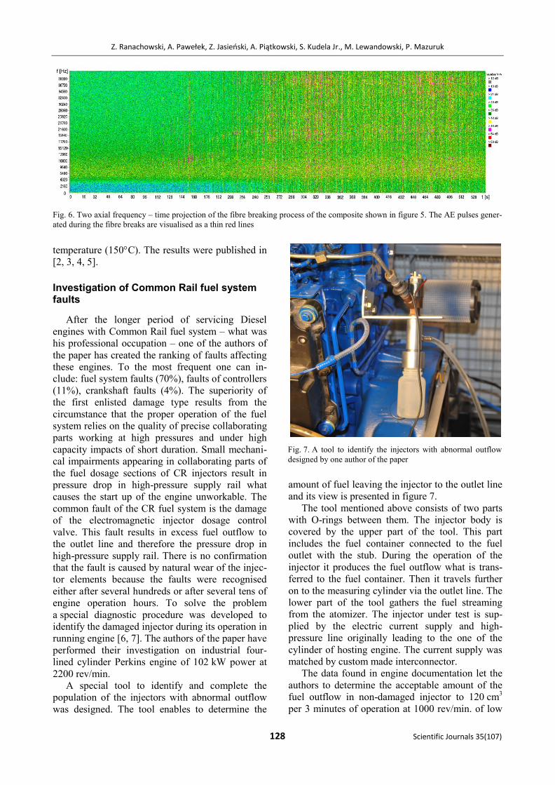
A special tool to identify and complete the
population of the injectors with abnormal outflow
was designed. The tool enables to determine the
amount of fuel leaving the injector to the outlet line
and its view is presented in figure 7.
The tool mentioned above consists of two parts
with O-rings between them. The injector body is
covered by the upper part of the tool. This part
includes the fuel container connected to the fuel
outlet with the stub. During the operation of the
injector it produces the fuel outflow what is trans-
ferred to the fuel container. Then it travels further
on to the measuring cylinder via the outlet line. The
lower part of the tool gathers the fuel streaming
from the atomizer. The injector under test is sup-
plied by the electric current supply and high-
pressure line originally leading to the one of the
cylinder of hosting engine. The current supply was
matched by custom made interconnector.
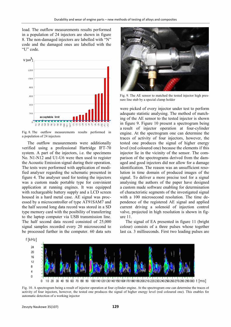
The data found in engine documentation let the
authors to determine the acceptable amount of the
fuel outflow in non-damaged injector to 120 cm3
per 3 minutes of operation at 1000 rev/min. of low
Fig. 6. Two axial frequency – time projection of the fibre breaking process of the composite shown in figure 5. The AE pulses gener-
ated during the fibre breaks are visualised as a thin red lines
Fig. 7. A tool to identify the injectors with abnormal outflow
designed by one author of the paper
Durability and wear of engine parts – new methods of testing of alloys and composites
Zeszyty Naukowe 35(107) 129
load. The outflow measurements results performed
in a population of 24 injectors are shown in figure
8. The non-damaged injectors are labelled with “N”
code and the damaged ones are labelled with the
“U” code.
Fig. 8. The outflow measurements results performed in
a population of 24 injectors
The outflow measurements were additionally
verified using a professional Hartridge IFT-70
system. A part of the injectors, i.e. the specimens
No. N1-N12 and U1-U6 were then used to register
the Acoustic Emission signal during their operation.
The tests were performed with application of modi-
fied analyser regarding the schematic presented in
figure 4. The analyser used for testing the injectors
was a custom made portable type for convinient
application at running engines. It was equipped
with rechargeable battery supply and a LCD screen
housed in a hard metal case. AE signal was proc-
essed by a microcontroller of type AT91SAM7 and
the half second long data record was stored in a SD
type memory card with the posibility of transferring
to the laptop computer via USB transmission line.
The half second data record consisted of 25,000
signal samples recorded every 20 microsecond to
be processed further in the computer. 60 data sets
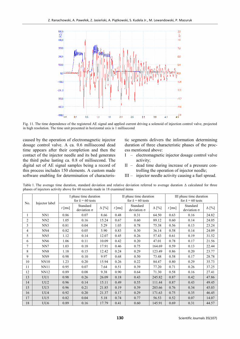
were picked of every injector under test to perform
adequate statistic analysing. The method of match-
ing of the AE sensor to the tested injector is shown
in figure 9. Figure 10 present a spectrogram being
a result of injector operation at four-cylinder
engine. At the spectrogram one can determine the
traces of activity of four injectors, however, the
tested one produces the signal of higher energy
level (red coloured one) because the elements if this
injector lie in the vicinity of the sensor. The com-
parison of the spectrograms derived from the dam-
aged and good injectors did nor allow for a damage
identification. The reason was an unsufficient reso-
lution in time domain of produced images of the
signal. To deliver a more precise tool for a signal
analysing the authors of the paper have designed
a custom made software enabling for determination
of characteristic segments of the investigated signal
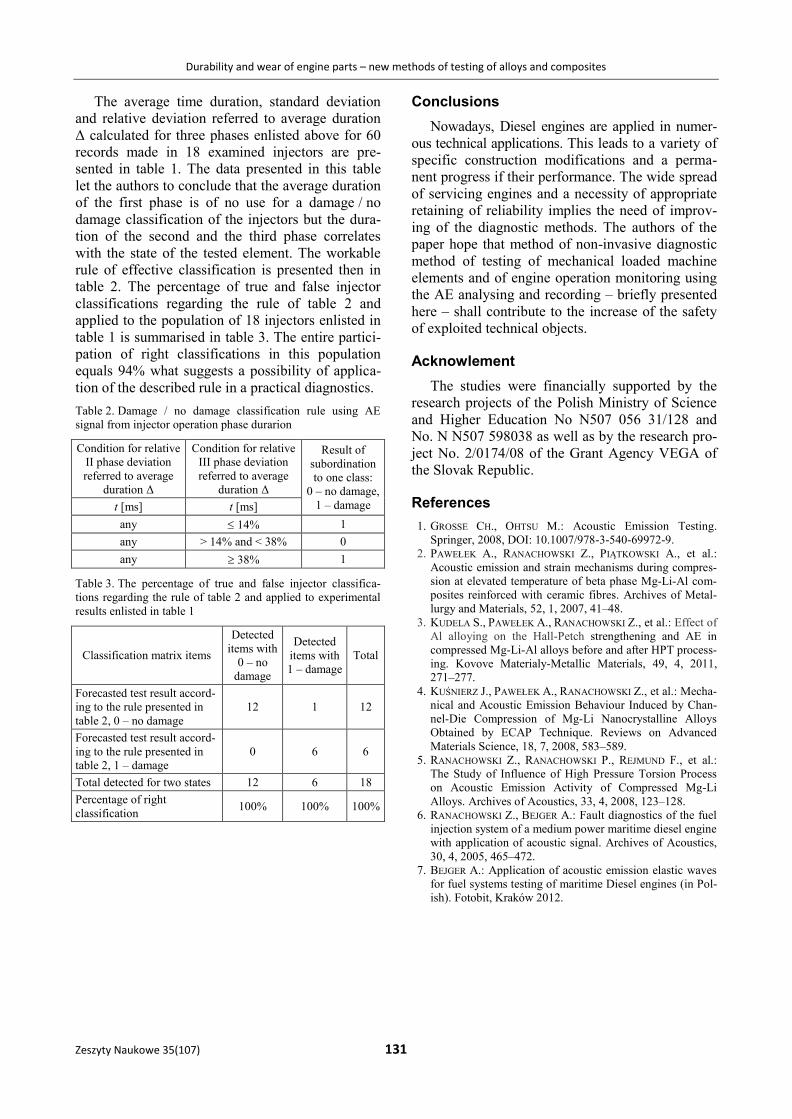
with a 100 microsecond resolution. The time de-
pendence of the registered AE signal and applied
current driving a solenoid of injection control
valve, projected in high resolution is shown in fig-
ure 11.
The signal of EA presented in figure 11 (bright
colour) consists of a three pulses whose together
last ca. 3 milliseconds. First two leading pulses are
Fig. 10. A spectrogram being a result of injector operation at four cylinder engine. At the spectrogram one can determine the traces of
activity of four injectors, however, the tested one produces the signal of higher energy level (red coloured one). This enables for
automatic detection of a working injector
Fig. 9. The AE sensor to matched the tested injector high pres-
sure line stub by a special clamp holder
Z. Ranachowski, A. Pawełek, Z. Jasieński, A. Piątkowski, S. Kudela Jr., M. Lewandowski, P. Mazuruk
130 Scientific Journals 35(107)
caused by the operation of electromagnetic injector
dosage control valve. A ca. 0.6 millisecond dead
time appears after their completion and then the
contact of the injector needle and its bed generates
the third pulse lasting ca. 0.8 of millisecond. The
digital set of AE signal samples being a record of
this process includes 150 elements. A custom made
software enabling for determination of characteris-
tic segments delivers the information determining
duration of three characteristic phases of the proc-
ess mentioned above:
I – electromagnetic injector dosage control valve
activity;
II – dead time during increase of a pressure con-
trolling the operation of injector needle;
III – injector needle activity causing a fuel spread.
Fig. 11. The time dependence of the registered AE signal and applied current driving a solenoid of injection control valve, projected
in high resolution. The time unit presented in horizontal axis is 1 millisecond
Table 1. The average time duration, standard deviation and relative deviation referred to average duration Δ calculated for three
phases of injectors activity above for 60 records made in 18 examined items
No. Injector label
I phase time duration
for k = 60 tests
II phase time duration
for k = 60 tests
III phase time duration
for k = 60 tests
t [ms] Standard
deviation σ Δ [%] t [ms]
Standard
deviation σ Δ [%] t [ms]
Standard
deviation σ Δ [%]
1 NN1 0.86 0.07 8.66 0.48 0.31 64.50 0.63 0.16 24.82
2 NN2 1.05 0.16 15.24 0.67 0.60 89.12 0.60 0.14 24.05
3 NN3 0.81 0.04 5.29 1.03 0.78 75.38 0.56 0.13 23.24
4 NN4 0.82 0.05 5.90 0.83 0.30 36.14 0.58 0.14 24.09
5 NN5 1.12 0.14 12.07 0.45 0.26 57.43 0.61 0.19 31.52
6 NN6 1.06 0.11 10.09 0.42 0.20 47.01 0.78 0.17 21.56
7 NN7 1.03 0.18 17.91 0.46 0.75 164.69 0.59 0.13 22.44
8 NN8 1.18 0.15 12.42 0.24 0.29 123.49 0.86 0.20 23.77
9 NN9 0.98 0.10 9.97 0.68 0.50 73.48 0.58 0.17 28.78
10 NN10 1.23 0.20 15.94 0.26 0.22 84.47 0.80 0.29 35.73
11 NN11 0.95 0.07 7.64 0.51 0.39 77.20 0.71 0.26 37.25
12 NN12 0.89 0.08 9.38 0.90 0.64 71.30 0.58 0.16 27.41
13 UU1 0.98 0.26 26.09 0.18 0.43 245.82 0.87 0.42 47.86
14 UU2 0.96 0.14 15.11 0.49 0.55 111.44 0.87 0.43 49.45
15 UU3 0.96 0.21 21.85 0.19 0.39 203.66 0.76 0.34 45.03
16 UU4 0.92 0.20 21.37 0.17 0.29 171.63 0.75 0.35 46.45
17 UU5 0.82 0.04 5.18 0.74 0.77 56.53 0.52 0.07 14.07
18 UU6 0.89 0.16 17.79 0.41 0.60 145.91 0.69 0.31 44.57
Durability and wear of engine parts – new methods of testing of alloys and composites
Zeszyty Naukowe 35(107) 131
The average time duration, standard deviation
and relative deviation referred to average duration
Δ calculated for three phases enlisted above for 60
records made in 18 examined injectors are pre-
sented in table 1. The data presented in this table
let the authors to conclude that the average duration
of the first phase is of no use for a damage / no
damage classification of the injectors but the dura-
tion of the second and the third phase correlates
with the state of the tested element. The workable
rule of effective classification is presented then in
table 2. The percentage of true and false injector
classifications regarding the rule of table 2 and
applied to the population of 18 injectors enlisted in
table 1 is summarised in table 3. The entire partici-
pation of right classifications in this population
equals 94% what suggests a possibility of applica-
tion of the described rule in a practical diagnostics.
Table 2. Damage / no damage classification rule using AE
signal from injector operation phase durarion
Condition for relative
II phase deviation
referred to average
duration Δ
Condition for relative
III phase deviation
referred to average
duration Δ
Result of
subordination
to one class:
0 – no damage,
1 – damage t [ms] t [ms]
any 14% 1
any > 14% and < 38% 0
any 38% 1
Table 3. The percentage of true and false injector classifica-
tions regarding the rule of table 2 and applied to experimental
results enlisted in table 1
Classification matrix items
Detected
items with
0 – no
damage
Detected
items with
1 – damage
Total
Forecasted test result accord-
ing to the rule presented in
table 2, 0 – no damage
12 1 12
Forecasted test result accord-
ing to the rule presented in
table 2, 1 – damage
0 6 6
Total detected for two states 12 6 18
Percentage of right
classification 100% 100% 100%
Conclusions
Nowadays, Diesel engines are applied in numer-
ous technical applications. This leads to a variety of
specific construction modifications and a perma-
nent progress if their performance. The wide spread
of servicing engines and a necessity of appropriate
retaining of reliability implies the need of improv-
ing of the diagnostic methods. The authors of the
paper hope that method of non-invasive diagnostic
method of testing of mechanical loaded machine
elements and of engine operation monitoring using
the AE analysing and recording – briefly presented
here – shall contribute to the increase of the safety
of exploited technical objects.
Acknowlement
The studies were financially supported by the
research projects of the Polish Ministry of Science
and Higher Education No N507 056 31/128 and
No. N N507 598038 as well as by the research pro-
ject No. 2/0174/08 of the Grant Agency VEGA of
the Slovak Republic.
References
1. GROSSE CH., OHTSU M.: Acoustic Emission Testing.
Springer, 2008, DOI: 10.1007/978-3-540-69972-9.
2. PAWEŁEK A., RANACHOWSKI Z., PIĄTKOWSKI A., et al.:
Acoustic emission and strain mechanisms during compres-
sion at elevated temperature of beta phase Mg-Li-Al com-
posites reinforced with ceramic fibres. Archives of Metal-
lurgy and Materials, 52, 1, 2007, 41–48.
3. KUDELA S., PAWEŁEK A., RANACHOWSKI Z., et al.: Effect of
Al alloying on the Hall-Petch strengthening and AE in
compressed Mg-Li-Al alloys before and after HPT process-
ing. Kovove Materialy-Metallic Materials, 49, 4, 2011,
271–277.
4. KUŚNIERZ J., PAWEŁEK A., RANACHOWSKI Z., et al.: Mecha-
nical and Acoustic Emission Behaviour Induced by Chan-
nel-Die Compression of Mg-Li Nanocrystalline Alloys
Obtained by ECAP Technique. Reviews on Advanced
Materials Science, 18, 7, 2008, 583–589. 5. RANACHOWSKI Z., RANACHOWSKI P., REJMUND F., et al.:
The Study of Influence of High Pressure Torsion Process
on Acoustic Emission Activity of Compressed Mg-Li
Alloys. Archives of Acoustics, 33, 4, 2008, 123–128.
6. RANACHOWSKI Z., BEJGER A.: Fault diagnostics of the fuel
injection system of a medium power maritime diesel engine
with application of acoustic signal. Archives of Acoustics,
30, 4, 2005, 465–472.
7. BEJGER A.: Application of acoustic emission elastic waves
for fuel systems testing of maritime Diesel engines (in Pol-
ish). Fotobit, Kraków 2012.