Embed Size (px)
Citation preview

AQUA~FLOPAC
INSTALLATION, OPERATION & MAINTENANCE FOR
DUPLEX VARIABLE SPEED SYSTEMS
PO Box 790 . 9201 Ayersville Road Toccoa, Georgia 30577 Phone: 706-886-2101
www.pattersonpumps.com
TM

TABLE OF CONTENTS
SECTION 1 MECHANICAL & ELECTRICAL DATA
Installation and Storage Requirements System Installation, Operation & Maintenance Manual Maintenance Schedule for Packaged Pump Systems Sequence of Operation Electrical Schematics Duplex Amperage Chart
Assembly Section for DAP 1 series, B05-83429 Assembly Section for DAP 2 series, B05-82811 Assembly Section for DAP 3 series, A05-83474 Assembly Section for DAP 4 series, B05-83431
SECTION 2 PUMP


INSTALLATION AND STORAGE REQUIREMENTS FOR
PUMP SKID UNIT
INSTALLATION:
1. The skid mounting surface can be a pad, but preferably a footing to support the entireperimeter of each of the skid unit(s). This footing should be designed in accordance withlocal building codes for the support of similar steel structures.
2. Typically the skid will be fabricated WITHOUT anchor bolt holes. Anchoring of the skid isdone by placing anchor bolt plates over the bottom of the skid framing member andsecuring to the footing with expansion or epoxy anchor bolts. The skid is leveled, pipingand electrical installation are complete before anchoring. For most installations, a total ofeight (8) such anchors are recommended (local authorities may dictate otherwise) foreach unit. This would include two (2) anchors down each long side (evenly spaced), withone (2) at each end (evenly spaced). For suggested anchor detail, see sketch attached.
3. After the skid is installed and leveled, but before anchoring, check the doors for fit andease of movement. The entire package is assembled on a level surface at the factoryand checked for proper operation before shipment. Occasionally, when the building isset, the doors do not line- up as they should. This can usually be corrected by shimmingto level the skid on the foundation. Some experimenting may be required as each footingwill vary slightly and the shim may need to be shifted until satisfactory door alignment isachieved. Once proper alignment is achieved the skid should be anchored down and theinterior of the skid filled with concrete over a packed granular fill (gravel). The concreteshould be 4"-6" thick and finished with some surface texture. For deckplated skids, theperimeter members of the skid should be grouted.
4. For skids with poured concrete floors, once the floor has cured the baseplate is to begrouted with a non-shrink grout.
5. The field electrician will need to connect the building heater. The field electrician isresponsible for grounding the building per local codes.
6. All bolts need to be tightened after shipment. Bolts can become loose due to vibrationfrom traveling and loading and unloading.
7. All valves are to be in the closed position prior to filling the system.
8. All drains in system that are to be field connected need to be routed appropriately by theinstalling contractor.
9. It is the installing contractor’s responsibility to inspect the entire package before receivingthe unit. Any damage must be noted in writing on the bill of lading. Pictures should betaken when possible. Failure to do so could result in a denial of a warranty claim.
10. All flexible coupled pumps shall be field aligned once the building has been anchored.Pumps are factory aligned, but vibrations in shipping and flexing of the station duringloading and unloading may change the alignment. This shall be done by the installingcontractor.

STORAGE:
1. Place on a dry, hard, level surface.
2. Protect from weather and airborne contamination (if not enclosed).
3. Protect from effects of temperature extremes and humidity, to prevent condensation.
4. Protect from physical damage.
5. Maintain corrosion protection on exposed bare metal surfaces.
6. Rotate pump shaft by hand at least once per week. Rotate two revolutions stopping at apoint 90 degrees from the initial shaft position.

SKID UNLOADING GUIDELIFT ARM POSITIONING:
The skid lifting arms consist of two pipes inserted through two larger Sch 40pipes that are an integral part of the skid structure. The smaller pipes areapproximately 4 FT longer than the skid width and when properly positionedwill expand beyond the skid on each side. It is recommended that the liftercables not be located farther than 6" form the skid structure.
On larger units, the lifting arms are welded in place and are approximately 8inches wider than the skid width, 4 inches on each side.
On small units, four 5/8” eyebolts are used instead of lifting arms.RIGGING:
The lower cables attach between the four lift points on the skid and thespreader bar (see sketch). The cables (supplied by the crane operator)should be long enough so that the angle between the cables does not exceedthe recommendation of the cable supplier. We have found that an includedangle of 40-45 degrees between cables allows for good stabili ty. The longerthe cables, the more stable the load.
The spreader bar (supplied by the crane operator), should be about two feetwider than the skid base. The upper cables should be somewhat longer thanthe lower cables (approximately 20%). Again, the cable manufacturer'srecommendation should be followed.
Proper rigging of the skid for lifting is the responsibility of the customer. Theabove rigging suggestions are meant only as a guide and are not to beconstrued as complete instructions, consequently Patterson Pump Companyshall not be responsible for the use or misuse of these suggestions. Thecustomer is encouraged to retain the services of a qualified contractorexperienced in the rigging of similar structures.


1
P.O. BOX 790Toccoa, Georgia 30577
Telephone: 706-886-2101Fax: 706-886-0023
www.flo-pak.com
INSTALLATION, OPERATION & MAINTENANCE MANUAL
Read this entire manual before proceeding.
SECTION I – INTRODUCTION
1-1 This manual provides general instructions for the installation andmaintenance of the package pumping unit manufactured by Flo-Pak, Inc. /A Business Unit of Patterson Pump Company, Toccoa, Georgia.
1-2 After carefully uncrating or unpacking, check the equipment against theshipping papers, and inspect for any damage incurred during shipment.Immediately notify the carrier of any damage or shortage found.
1-3 The type and sizing of the unit was built to meet requirements provided bythe purchaser. Among the more important requirements are the following:
Liquid pumped Flow in gallons-per-minute Temperature of liquid pumped degree Fahrenheit Suction condition, pressure or lift Discharge pressure Power supply characteristics Location
1-4 If any of the requirements change after the order was placed, we suggestthat each change be reviewed with the factory.
CAUTION: Operation of the package under conditions different from the
design requirements may void the warranty!SECTION II – INSTALLATION

2
2-1 Location
Select a location for the package which will be clean, well ventilated,properly drained, and provide accessibility for inspection andmaintenance. Outdoor installation may require protection from theelements, particularly freezing.
PACKAGE PUMPING SYSTEMS
*** Installation*** Operation*** Maintenance
Read the entire manual before attempting to install, operate or repair thisequipment.
Properly installed your Flo-Pak package will give you satisfactory anddependable service. We urge that you carefully read these step-by-stepinstructions to simplify any problems of installation, operation or repair.
Failure to read and comply with installation and operation instruction willvoid the responsibility of the manufacturer and may also result in bodilyinjury, as well as property damage.
This manual is intended to be a permanent part of your packageinstallation and should be preserved in a convenient location for readyreference. If these instructions should be come soiled, obtain a new copyfrom Flo-Pak. Be sure to include the package serial number you request.
2-2 Foundation
Concrete (reinforcement as necessary or required) is most widely used forthe foundation. In sufficient mass it provides rigid support whichminimizes deflection and vibration. It may be located on soil, structuralsteel or building floors, provided the combined weight of the package,grout and foundation does not exceed the allowable bearing load of thesupport. Allowable bearing loads of structural steel and floors can beobtained form engineering handbooks, building codes or localcommunities which give the recommended allowable bearing loads fordifferent types of soil.
2-3 Before pouring, roughen the top surface to provide a good bond.Ordinarily the proportions used are 1 part cement to 3 parts sand and 4parts medium aggregate.

3
2-4 If vibration or noise will be objectionable, as in office building, it may beadvisable to use vibration dampeners between the package unit andfoundation in conjunction with suction and discharge piping vibrationsuppressor.
2-5 Mounting
Set the package unit on the foundation base. Level the unit and check thealignment on the bearing frame units; tighten the foundation bolts.
2-6 Alignment Bearing Frame Units Only
Reliable, trouble-free and efficient operation of the unit depends on thecorrect alignment of the pumps and driver shafts. Misalignment may bethe cause of:
a. Noisy pump operationb. Vibrationc. Premature bearing failured. Excessive coupling wear
Note: Complete units are aligned at the factory. Experience has shownthat all bases, no matter how rugged or deep in section, will twist
during shipment. At the very least, the alignment must be checkedafter mounting.
Factors which may change the alignment of the unit after the initialinstallation:
a. Settling of the foundationb. Springing of the basec. Piping straind. Settling of the buildinge. Shift of pump driver on the foundation
2-7 Grouting
Grouting compensates for unevenness in the foundation and the base, aswell as distributes the weight of the unit uniformly over the foundation. Italso helps to prevent the unit from shifting after mounting. It is essentialthat the unit be expertly grouted by use of non-shrinking grout. Grout theunit as follows:
a. Build a form of plywood or thin planking around the foundation tocontain the grout. Support adequately to prevent deformation.

4
b. Soak the top of the concrete pad thoroughly with water beforegrouting. Remove all surface water before pouring.
c. A recommended mix of grout satisfactory for most applications is asfollows:
1. One part of normal Portland Cement – 94#2. One part of Embeco Cement – 100#3. One part of coarse clean sand – 100#4. One and one-half parts of ¼” pea gravel (1½ cu. Ft.)5. approximately 5 ½ gallons water
d. Pour the grout into the base and, while pouring, tamp liberally inorder to fill cavities and prevent air pockets. In order to prevent thebase from shifting, grout 4” out from all sides of the base. Slantoutside edges of the grout to prevent chipping.
e. Approximately fourteen days after the grout has been poured orwhen the grout is thoroughly dried, apply an oil base paint to allexposed surfaces of the grout to prevent air and moisture fromcoming in contact with the grout.
2-8 Piping
The suction and discharge piping should be arranged for the mostsimple, direct layout and be of sufficient size and internally free offoreign material. The piping must never be pulled into position by theflange bolts. It must be be independently supported and arranged inorder to not induce any strain on the package.
Note: Piping should be cleaned and flushed prior to installing thepackage. A large number of packing, mechanical seals and
seizure troubles of the pumps are due to improperly cleanedsystem.
2-9 Electricity
Connect the power supply to the package conforming to the NationalElectrical and local codes. Line voltage and wire capacity must matchthe rating stamped on the control panel nameplate.
a. Only when the coupling halves are disconnected (framemounted pumps) and the water supply is to the suction of thepumps, momentarily energize the panel and check that rotationof the pumps is correct by setting the hand-off-auto switch intothe hand position.

5
b. If the rotation is inaccurate, correct by changing any two of thethree power leads.
SECTION III – LUBRICATION
3-1 Couplings
Couplings with rubber drive parts do not require lubrication; however, mostcouplings do require some form of lubrication. After completion ofinstallation and alignment, and before operating the unit, lubricatecouplings in accordance with the manufacturer’s specific instructioncontained in the package installation manual.
3-2 Ball Bearings
Reasonable care and proper lubrication of bearings will result in manyyears of service. The lubricant provides a film between the balls,separator and races, giving low friction and preventing excessivetemperature rise and corrosion.
3-3 The normal life of ball bearings is terminated only by fatigue. Improperlubrication practices are the primary cause of failure. Good practiceincludes the following:
a. Keep lubricant clean; provide and use a dust-tight cover on thestorage container.
b. Use the oldest lubricant first.
c. Clean lubrication fittings before re-lubrication.
d. Use clean dispensing equipment.
e. Use the proper amount of lubricant. Too much grease results inchurning and unnecessary power consumption, rapid heating tohigh temperatures which break down the grease.
f. Use the correct lubricant. Grease Lithium Soap Base, meetingNational Lubricating Grease Institute Grade 2 specifications. Thishas a safe operating temperature higher than 300 degreesFahrenheit.

6
3-4 Operating Temperature
Use of the lubricants and procedures given in this manual will allow safeoperation at bearing temperatures to 250 degrees Fahrenheit. Pastexperience, however, indicates the normal temperature will not exceed250 degrees if the pumped fluid is well below that temperature.
3-5 A high normal operating temperature is not a sign of bearing failure.Normal temperatures vary with the seasons and the environment and mayrange from 0 to approximately 200 degrees Fahrenheit. A continuous risefrom established normal operating temperature indicates trouble andprobable failure of the bearings. Shut down the unit immediately.Disassemble, clean and inspect the bearings. Replace if required.
3-6 Re-Lubrication
Grease that has been in service does not “wear away.” It needs replacingonly because of contamination by dust, metal particles, moisture or hightemperature breakdown.
a. Thoroughly clean greased fitting.b. Remove grease drain plug on equipment so equipped.c. Inject clean new grease.
SECTION IV – OPERATION
4-1 When making an initial start, after installation or major maintenance, checkthe following:
a. Coupling alignment (if frame mounted).b. Bearing lubricant on pumps and drives.
4-2 Start the package as follows:
1. When possible, turn the pump shaft by hand to make sure parts donot bind.
2. Open suction valves.3. Start drive in “hand” and check rotation. (Correct as necessary.)4. With pump running in “hand” regulate system pressure by adjusting
the pressure regulating valve. (See data sheet in manual.) Repeatthis for all pumps on package.

7
SECTION V – MAINTENANCE
WARNING – DISCONNECT THE POWER TO ANY ROTATING ORELECTRICAL COMPONENTS BEFORE STARTING ANY
REPAIRS!
5-1 Regular consistent maintenance is the best way to avoid serious troublewhich may require taking the unit out of service for extensive repair.
5-2 Bearings
It is essential to provide proper lubrication and keep bearings clean.Frequency of lubrication must be determined by experience as it dependsupon bearing size, speed, operating conditions and location(environment). Table 1 should be used as a guide for grease re-lubrication.
TABLE 1Operating Conditions Lubricate
Normal, 8-hour day operation.Area free of dust and damaging atmosphere.
Every six (6)months.
Severe, 24-hour day operation.Area with moderate dust and/or damaging atmosphere oroutdoor service.
Every month.
Light, approximately 10-hour week.Area relatively free of dust and damaging atmosphere. Every year.
5-3 Alignment – (Bearing frame unit only) – Check alignment yearly.

8
TABLE 2Problems Probable Cause Remedy
Failure to deliverliquid or sufficientpressure.
Control valve notadjusted correctly.
Adjust control valve. (See valvemanual.)
Incorrect pump rotation. Change rotation.
Discharge head toohigh.
Check that all discharge valves are openand discharge line is free formobstructions. In some cases theinstallation needs to be altered or pumpof suitable rating supplied.
Impeller passagesrestricted.
Disassemble the pump and clean theimpeller.
Pump not up to speed. Check for low motor voltage or motoroverload.
Worn wearing rings. Replace worn parts.
Damaged impeller. Replace or repair impeller.
Overload of driver. Total head lower thanrating
Check suction and discharge pressureand determine the total dynamic head.If TDH is lower than rated, throttledischarge valve to rated TDH.
Mechanical problem inpump or driver.
See if unit turns freely.
Vibration or noise. Misalignment bearing(frame units only).
Realign unit.
Worn ball bearing. Replace bearings.
Cracked foundation. Replace foundation.
All pumps runninglag units cycle offand back on again.
Control valve settingand start pressureswitch not adjustedcorrectly in relation toone another.
Readjust.
Too low setting on startdelay timer.
Readjust.

9
TABLE 2(Continued)
All pumps runninglag units cycle offand back on again.
Package undersized forload.
Verify operating flow and head.
Low suction alarmtripping.
Low suction switchadjusted incorrectly orpoorly.
Check adjustment.
Actual low suctioncondition.
Check suction pressure with test gauge.
All other alarms. Switches adjustedincorrectly.
Readjust.
Actual alarm condition. Verify and correct.
Delay timer set too low. Increase time delay.
5-4 Spare Parts
To keep delay to a minimum when package repairs are required, wesuggest that the following spare parts be stocked:
Panel
a. Spare set of fuses.b. Spare timer.c. Spare relay.d. Spare system pressure switch and suction pressure switch.
Pumps
a. Spare mechanical seal for each size pump.b. Spare casing gasket for each size pump.c. Spare shaft sleeve for each size pump.d. Spare impeller for each size pump.
5-5 To obtain quick and accurate service when ordering spare parts, providethe following information:
1. Package serial number.2. The name and number of parts shown on the data provided for the
individual component.3. Quantity required on each item.

10
Aid may be obtained from the Flo-Pak representative in your area or from thefactory.
Flo-Pak, Inc.P.O. Box 790
Toccoa, Georgia 30577Telephone: 706-886-2101
Fax: 706-886-0023www.flo-pak.com
A Business Unit of Patterson Pump Company
5/28/04

PUMP COMPANY / A Subsidiary of The Gorman Rupp Co. P.O. Box 790 / Toccoa, Georgia 30577 / (706) 886-2101 / FAX (706) 886-0023
www.pattersonpumps.com
General Pump Inspection and Maintenance Schedule Packaged Pump Systems
Any additional inspections, maintenance, or tests required by NFPA- Standards for fire pumps are excluded. Refer to NFPA Standards for additional requirements for fire pumps.
Actions required only for specific pump types are so noted. The symbol ( ) used in the table below indicates that the action indicated may not be applicable to a specific pump of a particular type. For more information regarding inspection and maintenance requirements refer to the Patterson O & M manual supplied with the pump.
Contact Patterson Pump Company if assistance is needed to determine the inspection and service requirements for a specific pump.
Inspect ( ) or service ( ) at the indicated calendar time or run time interval whichever comes first 4 hours Routinely Monthly
2000 hours or 3 months
4000 hours or 6 months
8000 hours or 12 months
Replenish grease lubricated sleeve bearing grease per the O & M manual using the manual grease lubricator. Perform every 3 months while idle. (vertical wet pit pumps so equipped)
Unusual noise
Unusual vibration
Unusual temperature
Leaks in pump or piping
Pressure gauge readings
Visual inspection of equipment general condition
Anytime a pump is opened, inspect the running clearances and restore them to original specifications if the running clearances have doubled (adjust ring clearances if so supplied or install new wear rings)
Anytime a pump is opened, inspect the impeller for corrosion or excessive wear.
Packing box verify slight leakage (if excessive, adjust gland or seal water valve; replace packing if required)
Mechanical seal (should be no leakage)
Drain lines are working properly
Coupling integrity
Drive shaft integrity
Verify proper operation of oil drip lubricator (vertical wet pit pumps so equipped)
Verify proper operation of automatic grease lubricator (vertical wet pit pumps so equipped)
Operate the pump (note for vertical wet pit pumps first verify proper lubrication )
Tightness of foundation and hold-down bolts
Check coupling alignment and integrity (maintain records)
Add grease to pump anti-friction bearings (maintain records)
Add grease to universal joint shafting u-joint bearings, anti-friction steady bearings (maintain records)
Add grease to coupling (maintain records)
Change anti-friction bearing oil (maintain records)
Replace packing (all packing; not just the outermost ring)
Clean and oil gland bolts (packed pumps)
Verify free movement of packing glands (packed pumps)
Universal joint shafting and steady bearings wear check (replace bearings if required)
Clean packing box
Check and flush seal water and drain piping
Perform a comparative field test (flow, pressures, and power) with calibrated instruments. Restore internal running clearances if results are unsatisfactory (install new wear rings).
Perform a comparative vibration test
Remove packing and inspect sleeve(s). Replace if worn. (packed pumps)
Realign coupled pumps (maintain records)
Remove pump handhole covers and inspect impeller for corrosion and excessive wear (sewage pumps)
Remove handhole covers to inspect the wear ring clearances. When the wear ring clearances have doubled, adjust the ring clearances to original specifications if so supplied or install new wear rings (sewage pumps).
Examine running clearance between propeller and propeller housing. When the running clearance has doubled, repair or replace the housing, housing liner, or propeller as appropriate. (model AFV axial flow pumps)
Inspect the impeller running clearance. Inspect the impeller housing for excessive wear. If the wear is not excessive, perform impeller adjustment. If the wear is excessive, repair or replace the impeller housing. (open impeller mixed flow pumps, such as models SAF, SAFV, SAFH, or TMF)
Inspect batteries & battery charger for proper charge.
Observe operation of fans & dampers such that the fans & dampers operate at set temperature, and damper opens upon operation of the diesel engine.
Jockey Pump See manual for specific jockey maintenance requirements.
Engine Maintenance (Belts / Filters / Oil / Fuel Strainer) [See O&M manual for Engine]
Replace any worn caulk around pipe exits on buildings.
Building Heater - Inspect for proper operation.
Inspect operation of all valves in system.
Lights (Outside, Inside, Emergency) Inspect for proper operation.
Issue 020907

1
Sequence of Operation
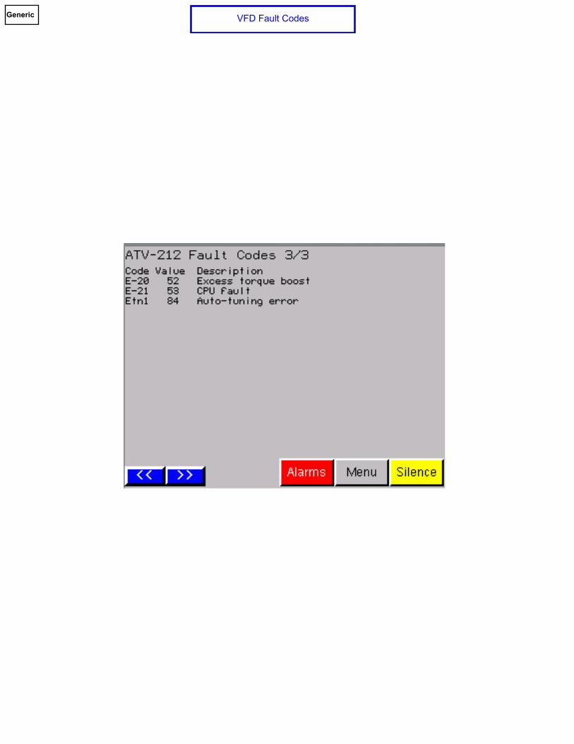
Rev. 3 03/03/17 Basic Operation The pumps are started and stopped according to discharge pressure and kw (power). The “PID Set-point” is the set-point pressure desired to be maintained at the discharge header. The start and stop pressure set-points for the lead and lag pumps are “deviations” below the “PID Set-point”. The kw start and stop set-points are based on the horsepower and number of pumps running. The operator can adjust the speed of the VFDs manually by placing the speed command to manual in the operator interface and altering the pump(s) speed by using the increase and decrease (up and down arrow) buttons. The lead pump will start after an adjustable time delay when the discharge pressure drops to the start lead pressure set-point. The lag pump will start after an adjustable time delay when the discharge pressure drops to the start lag pump pressure set-point or when the lead kw meets or exceeds the start lag pump set-point or if the optional flow sensor is supplied, when the flow rate meets or exceeds the start lag pump set-point. Once a pump has started, it will run for an adjustable minimum run time. The factory default minimum run time is set to 10 minutes. Shutdown will occur in reverse order according to the starting sequence. The lag pump will stop when the discharge pressure has risen to the stop lag pump set-point, its minimum run timer has expired, the total kw drops to or below the stop lag pump set-point and if the optional flow sensor is supplied, when the flow rate drops to or below the stop lag pump set-point. The lead pump will stop when the discharge pressure has risen to the stop lead pump set-point, its minimum run timer has expired, the lag pump has stopped and there is no flow as determined by the “Stop Test” routine. Stop Test Routine The “Stop Test” routine occurs every time a single pump (the lead pump) is running and its minimum run timer is within 4 seconds of expiration. When the “Stop Test” is engaged, the speed of the pump is reduced by an adjustable amount (factory default of 1 Hz) and the discharge pressure is then compared to the Goal PID pressure set-point. If the discharge pressure has fallen below the Goal PID pressure set-point during the test period of 5 seconds, then the minimum run timers are reset, the pump continues to run, the Stop Test is terminated and the system returns to normal operation. If the discharge pressure has not fallen below the Goal PID pressure set-point during the test period of 5 seconds, then the (lead) pump is allowed to stop. Equal sized pumps are alternated every time all equal pumps have stopped (duty cycle alternation) or after 24 hours whichever occurs first. The hour for which the 24 hour alternation change occurs can be selected by the operator. Once the system piping has been filled, the operator simply performs the following: Set the HOA switches in the automatic position. Set the desired PID pressure set-point.
Duplex Variable Speed Booster

2
Set the starting and stopping set-point pressure deviations of the lead and lag pumps. Set the starting and stopping kw set-points of the lag pumps. Set the starting and stopping flow rate set-points of the lag pumps if optional flow sensing is provided. Set the speed control mode to “Auto” Ramp Control Mode Ramp Control Mode is a routine which helps to prevent large discharge header pressure overshoot when a pump that is driven by a variable speed drive starts and ramps up to speed. Once the pump is up to speed, the Ramp Control Mode is no longer effective for that pump and its speed is controlled by the PID algorithm. When successive pumps are started, they are controlled by the Ramp Control Mode until they are up to speed while previous pump(s) continue to be controlled by the PID. When a pump is up to speed, the “@” symbol is present in the bottom right portion of the associated pump HOA switch. The operator can, if necessary, modify the parameters of the Ramp Control Mode to better fit the application. If the operator decides that the application does not require the Ramp Control Mode, it can be disabled. Safety Startup Mode In the automatic mode of operation, if the pumps are stopped for certain conditions such as a shutdown alarm or if the system is disabled, the controller contains a routine which will take the system into a safety startup mode once the shutdown alarm condition has been reset or the system has been re-enabled. Once a shutdown condition has been reset or the system has been re-enabled, the controller compares the current discharge pressure to the goal (final) PID set-point pressure. If the current discharge pressure is not more than 5 PSI (adjustable) below the goal PID set-point, then the goal set-point is moved into the set-point register and normal operation is resumed. If the current discharge pressure is more than 5 PSI (adjustable) below the goal PID set-point, then the current discharge pressure is used as the initial startup set-point. When the discharge pressure reaches the initial set-point, then 5 psi (adjustable) is added to the set-point after a 10 second (adjustable) time delay. This routine continues until the discharge pressure is within 5 psi (adjustable) of the goal set-point. Once the discharge pressure is within 5 psi (adjustable) of the goal set-point, the goal set-point is moved into the set-point register and normal operation is resumed. During the startup mode, if the system fails to maintain any set-point pressure for an adjustable time (default of 5 minutes), the pump is stopped and the system is locked out, requiring a manual reset. The conditions are as follows:
- Power loss - Low suction shutdown - High suction shutdown - Low discharge shutdown - High discharge shutdown - Discharge pressure transducer failure - All pumps have failed - All pump HOA switches are turned off - System has been disabled (via timeclock enable/disable) - Goal set-point has been set to “0” - Irregular Power (Optional)
Low Suction Shutdown In the event of low suction (supply) pressure, the pumps will be stopped and the Low Suction Pressure alarm will be initiated after an adjustable time delay. The alarm will automatically reset after 10 seconds (adjustable) if configured for auto reset or will require a manual reset if the alarm is configured for manual reset when the pressure rises above the alarm set-point. Once reset, the pumps will be re-enabled. High Suction Shutdown In the event of the optional high suction (supply) pressure, the pumps will be stopped and the High Suction Pressure alarm will be initiated after an adjustable time delay. The alarm will automatically reset after 10 seconds (adjustable) if configured for auto reset or will require a manual reset if the alarm is configured for manual reset when the pressure drops below the alarm set-point. Once reset, the pumps will be re-enabled.

3
Low Discharge Alarm or Shutdown In the event of a low discharge pressure condition, the Low Discharge Pressure alarm will be initiated after an adjustable time delay. The alarm will automatically reset after 10 seconds (adjustable) if configured for auto reset or will require a manual reset if the alarm is configured for manual reset when the discharge pressure rises above the alarm set-point. The operator can enable the Low Discharge Alarm to shut down the pumps when the low discharge condition occurs. The low discharge pressure shutdown requires a manual reset. High Discharge Shutdown In the event of a high discharge pressure condition, the pumps will be stopped and the High Discharge Pressure alarm will be initiated after an adjustable time delay. The alarm will automatically reset after 10 seconds (adjustable) if configured for auto reset or will require a manual reset if the alarm is configured for manual reset when the discharge pressure drops below the alarm set-point. Once the alarm is reset, the pumps will be re-enabled. Irregular Power (Optional) In the event of an irregular power condition as sensed by a phase monitor, the pumps will be stopped and the Irregular Power alarm will be initiated. Once the irregular power condition has been corrected, the pumps will be automatically re-enabled and the alarm will be reset. Discharge Pressure Transducer Failure In the event of discharge pressure transducer failure, the pumps will be stopped and the PLC will remove this failed sensor from operation. The operator will be able to start the pumps manually in an emergency only using the LOC/REM key on each VFD and adjust the speed(s) manually at each VFD keypad by use of the up and down arrow keys. When the pumps are started in this manner, there are no pump or system shutdown safeties. The operator must monitor the system continuously when operating pumps in the backup start mode to prevent damage to the system, the pumps or other devices connected to the system. Suction Pressure Transducer Failure In the event of suction pressure transducer failure, the pumps will be stopped and the PLC will remove this failed sensor from operation. The operator will be able to start the pumps manually in an emergency only using the LOC/REM key on each VFD and adjust the speed(s) manually at each VFD keypad by use of the up and down arrow keys. When the pumps are started in this manner, there are no pump or system shutdown safeties. The operator must monitor the system continuously when operating pumps in the backup start mode to prevent damage to the system, the pumps or other devices connected to the system. PLC Failure In the event of programmable logic controller (PLC) failure, the pumps will stop. The operator will be able to start the pumps manually in an emergency only using the LOC/REM key on each VFD and adjust the speed(s) manually at each VFD keypad by use of the up and down arrow keys. When the pumps are started in this manner, there are no pump or system shutdown safeties. The operator must monitor the system continuously when operating pumps in the backup start mode to prevent damage to the system, the pumps or other devices connected to the system. HMI (Operator Interface) Failure In the event that the HMI should fail, the PLC will continue to operate the system based on the last states for which the PLC was adjusted via the HMI. For example, if the HOA switches and speed control mode were left in the “auto” position, the PLC will continue to start, stop and regulate the pumps speed as if the HMI had never failed. Should the operator be required to stop the pumps, each VFD can be stopped at the VFD keypad by (1) pressing the LOC/REM key in order to place the VFD in local mode and then to press the “Stop” key, (2) the individual pump MSPs can be opened or (3) the main power disconnect can be opened to de-energize the system. Pump/VFD Failure In the event of a VFD fault or if the pump fails to run when called to start, the PLC will ignore the failed pump in the starting/running sequence and will start the remaining pump in its place. The PLC will put the failed pump back into the starting/running sequence once the VFD fault or call to run failure has been cleared. Operator Interface The HMI is menu button driven for ease of navigation. Following are some of the main screens.

4
“Menu” is the starting point for all screens. “Main” displays the normal operating data screen which includes HOA switches, running lights, pressure, etc. “Setup Menu” allows the operator adjust start/stop set-points, timers, etc. “Alarms” displays the alarms screen. The operator can touch an alarm lamp to bring up information about a specific alarm. Alarms that require a manual reset are reset via the “Manual Reset” button located on the alarms screen. Communication
The control panel provides one dry normally open contact for system common alarm. The control panel provides as a standard, Modbus RTU data in RS485, two-wire form on “TB Serial 2” (serial port 2) on the PLC for system monitoring. As an option, the control panel provides Modbus TCP/IP communications for system monitoring. As an option, the control panel provides Bacnet IP communications for system monitoring. As an option, the control panel provides Bacnet MS/TP communications for system monitoring. As an option, the control panel provides Lonworks communications for system monitoring.

Initial Startup ScreenGeneric

Main ScreenMain ScreenGeneric

Menu
Generic

Large Pressure DisplayGeneric

Pump Run TimeGenericGeneric

Speed ControlGeneric

Sequence SelectionGeneric

Alarms
Generic

Alarms HistoryGeneric

I/O MonitoringGeneric

Pressure Trend ScreenGeneric

KW Trending
Generic

Date / TimeGeneric

P1 StatusGeneric

P1 StatusGeneric

P1 StatusGeneric

P1 StatusGeneric

VFD Fault CodesGeneric

VFD Fault CodesGeneric
VFD Fault CodesGeneric

Login Screen(Logged in)
Generic

Menu(Logged in)
Generic

Setup Menu(Logged In)
Generic

Setup (PID)Generic

Setup (Lead Pump)
Generic
Setup (Stop Test)
Generic

Setup (Lag Pump)Generic

Setup (Ramp Control Mode)Generic

Setup (Pump Minimum Run Time)Generic

Setup (Pump Call to Run Failure)Generic

Setup (Pump Elapsed Time Reset)Generic
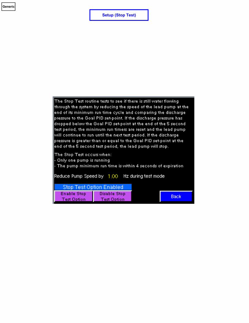
Setup (Date and Time)Generic

Setup (System Enable)Generic

Setup (Pump Exerciser)Generic

Setup (Analog Input 0)Generic

Setup (Analog Input 1)Generic

Setup (Safety Startup Mode)Generic

Setup (Safety Startup Mode Help)Generic

Setup (Pressure Alarm Setup Menu)Generic

Setup (High Discharge Alarm Setup)Generic

Setup (Low Discharge Alarm Setup)
Generic

Setup (High Suction Alarm Setup)Generic

Setup (Low Suction Alarm Setup)Generic

Setup (24 Hour Alternation Override)Generic

Setup (Pump VFD Amps & Volts Scaling)
Generic

Setup (Set-point Recipes)Generic

Dwg No.
Drawn By: Date:
Rev:
A business unit of Patterson Pump Company
INC.
TM
HPFLAMSP
HPFLAMSP
V / Ph / Hz
MCA -
DUPLEX VARIABLE SPEED SCHEMATIC Page 1
XXXXXX A
XXXXXX A
PUMP 1 PUMP 2
XX
XXX
Power Feed
0A85-146683
WRW 09/06/2017
THROUGH-DOOROPERATOR
DSM
GROUND
POWERFEED
PDB
L1
L2
L3
BLK
BLK
BLK
GB1
BLK
BLK
BLK
(to 54)
L1
L2
L3
(to 55)
(to 56)
MSP1
GB2
1L3
1L2
1L1
1T3
1T2
1T1
VFD1
VARIABLE SPEED DRIVE
PUMP 1MOTOR
GB2
2L3
2L2
2L1
VARIABLE SPEED DRIVE
PUMP 2MOTOR
XXX VXPH
HZXX
XXXVAC
XXXVAC
XXXVAC
HP VACXX XXXXX A
XX A
XX A
XXX
XXX
VAC
VAC
XX
XX
HPFLA XX
HPFLA XX
ATV212XXXXXX
ATV212XXXXXX
8
9
7
6
5
2
4
3
1
50
49
48
47
46
45
44
43
42
41
40
39
38
37
36
35
34
33
32
31
30
29
28
27
26
25
24
23
22
21
20
19
18
17
16
15
14
13
12
11
10
2T3
2T2
2T1
HP VACXX XXXXX A
VFD2
L1
L2
L3
T1
T2
T3
L1
L2
L3
T1
T2
T3
(3) #XX
(3) #XX
(1) #XX
(3) #XX
(1) #XX
(1) #XX
(1) #XX
(3) #XX
(3) #XX
All 200 to 600 vac power wiring to be THHNunless otherwise indicated.
NOTE
OVERCURRENT PROTECTIONPROVIDED AND INSTALLEDIN ACCORDANCE WITH NFPA70(NEC) BY OTHERS
MSP2
NOTE
GND
XXX X

Dwg No.
Drawn By: Date:
Rev:
A business unit of Patterson Pump Company
INC.
TM
DUPLEX VARIABLE SPEED SCHEMATIC
OPTIONAL
OPTIONAL
FU2
FU1
(from 4)
(from 5)
(from 6)
L1
L2
L3
BLK
BLK
BLK
L1
L2
L3
4L2
4L3
4L1
GB2
PROTECTIONSURGE
SPD
BLK
BLK
BLK
L1
L2
L3
5L25L1
24VDC+ 24VDC-
24VDC
PS1
POWER SUPPLY
HV
+
WH
ITE
/ B
LU
E
BL
UE
GB2
HMIUSB1 + - FG
COM1 ETHERNET
XXXVAC
XXXVAC
XXXVAC
2A 2A
2A
2A
2A
(to 114)
TO PLC ETHERNET PORTETHERNET CABLE
CBL4
100
99
98
97
96
95
94
93
92
91
90
89
88
87
86
85
84
83
82
81
80
79
78
77
76
75
74
73
72
71
70
69
68
67
66
65
64
63
62
61
60
59
58
57
56
55
54
53
52
51
PM
DEVICE
PHASEMONITOR
GB3
C LV
+ - -
L1
L2
L3
L1
L2
L3
RS485
24VDC+ 24VDC-
(from 6)
L3
BLKXXXVAC
(2) #12
(2) #12
All Grounds to GB2 are to be #14 greenTHHN unless otherwise indicated.
All 24VDC- control power wiring to be #16white with blue stripe TFFN or MTW unlessotherwise indicated.
All 24VDC+ control power wiring to be #16blue TFFN or MTW unless otherwiseindicated.
All 200 to 600 vac power wiring to be THHNunless otherwise indicated.
NOTE
NOTES
99
24VDC+(to 104)
24VDC-(to 105)
T-STAT 1
FAN 1
+ -24VDC+ 24VDC--15GB2
(to 123)
TO TM4ES4 ETHERNET SWITCHETHERNET CABLECBL5
(If Modbus TCP/IP Option)
+ -
GB2
FAN 2 NOTE:The number of fans are
dependent upon theconfiguration
0A85-146683
WRW 09/06/2017
Page 2

Dwg No.
Drawn By: Date:
Rev:
A business unit of Patterson Pump Company
INC.
TM
DUPLEX VARIABLE SPEED SCHEMATIC
(from 100)24VDC+
(from 100)24VDC-
24VDC+
24VDC-
(to 154)24VDC+
(to 155)24VDC-
101
102
103
104
105
106
107
108
109
110
111
112
113
114
115
116
117
118
119
120
121
122
123
124
125
126
127
128
129
130
131
132
133
134
135
136
137
138
139
140
142
141
143
144
145
146
147
148
149
150
TM241CE24TCOMM PORTS
PLCL+
N-
RJ45 Serial 1
24VDC+
24VDC-
MH
MODBUS HUB
TRTERMINATINGRESISTOR
CBL0
0V
IN
OUT
CBL2
CBL1(to 538)
TO VFD1MODBUS CABLE
(to 588)
TO VFD2MODBUS CABLE
GB2
WARNINGMODBUS HUB ISRS485 SERIAL
COMMUNICATIONSONLY!
DO NOT CONNECTETHERNET!
CBL0
GB2
COM
Shield
D0
D1
TB Serial 2
TM4ES4ETHERNET SWITCH
CBL4
(from 85)
TO HMI ETHERNET PORTETHERNET CABLE
CBL5
GB2
ETHERNET
CUSTOMER MODBUS TCP/IPETHERNET CONNECTION(by others)
BLACK
RED
SHIELD
To Communications OptionModbus RTU RS485
128
129
130
OPTIONAL
OPTIONAL
(from 86)
TO HMI ETHERNET PORTETHERNET CABLE
CBL4
Modbus TCP/IP
Modbus RTU
0A85-146683
WRW 09/06/2017
Page 3

Dwg No.
Drawn By: Date:
Rev:
A business unit of Patterson Pump Company
INC.
TM
DUPLEX VARIABLE SPEED SCHEMATIC
(from 104)24VDC+
(from 105)24VDC-
(to 204)24VDC+
(to 205)24VDC-
24VDC+
24VDC-
TM241CE24TDIGITAL INPUTS
PLC
I0
I1
I2
I3
I4
I5
I6
COM 2
101
102
OPTIONALPHASE MONITOR
PM11 1
2+
+
151
152
153
154
155
156
157
158
159
160
161
162
163
164
165
166
167
168
169
170
171
172
173
174
175
176
177
178
179
180
181
182
183
184
185
186
187
188
189
190
192
191
193
194
195
196
197
198
199
200
1424VDC+
24VDC+
COM 1
COM 024VDC-
I7
I8
I9
I10
I11
I12
I13
- 24VDC-
- 24VDC-
+24VDC+
+24VDC+
0A85-146683
WRW 09/06/2017
Page 4

Dwg No.
Drawn By: Date:
Rev:
A business unit of Patterson Pump Company
INC.
TM
DUPLEX VARIABLE SPEED SCHEMATIC
(to 254)24VDC+
(to 255)24VDC-
24VDC+
24VDC-
(from 154)24VDC+
(from 155)24VDC-
PLC
TM241CE24TDIGITAL OUTPUTS
125AH
ALARM HORN
1
24V 0
250
248
249
247
246
245
242
244
243
241
240
239
238
236
237
201
202
203
204
205
206
207
208
209
210
211
212
213
214
215
216
217
218
219
220
221
222
223
224
225
226
227
228
229
230
231
232
233
234
235
24VDC-
24VDC+
V0+
Q0
Q1
Q2
Q3
V1+
V1-
Q4
Q5
Q6
Q7
V2+
V2-
Q8
Q9
V0-
24VDC-
119R1
24VDC-
120R2
24VDC-
R1-1
24VDC+
24VDC+
2012619
240VAC 5 AMPS MAXCOMMON ALARM (DRY CONTACT)
127YEL YEL
R2-1
0A85-146683
WRW 09/06/2017
Page 5
Dwg No.
Drawn By: Date:
Rev:
A business unit of Patterson Pump Company
INC.
TM
DUPLEX VARIABLE SPEED SCHEMATIC
(from 204)24VDC+
(from 205)24VDC-
(to 304)24VDC+
(to 305)24VDC-
24VDC+
24VDC-
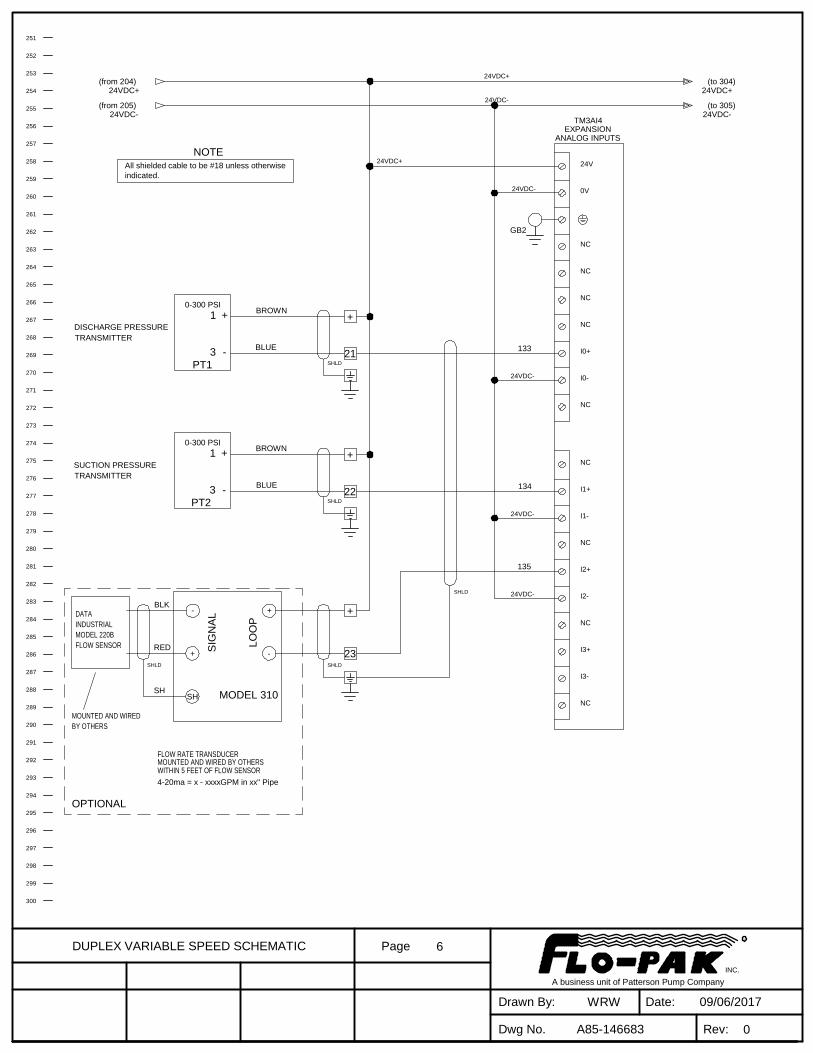
TM3AI4EXPANSION
+
21
BROWN
BLUE
PT1
DISCHARGE PRESSURETRANSMITTER
+
133
135
0-300 PSI
273
282
281
279
280
278
277
276
275
274
272
271
270
269
267
268
266
265
264
254
261
263
262
260
259
258
257
256
255
253
252
251
300
299
298
297
295
296
294
293
292
289
291
290
288
287
286
285
283
284
1
-3
All shielded cable to be #18 unless otherwiseindicated.
NOTE
SHLD
SHLD
ANALOG INPUTS
0V
24V
NC
NC
NC
NC
I0+
I0-
NC
I1+
NC
NC
I2+
I2-
NC
I3+
I3-
NC
I1-
SIG
NA
L
LO
OP
OPTIONAL
RED
BLK
SH
FLOW RATE TRANSDUCERMOUNTED AND WIRED BY OTHERSWITHIN 5 FEET OF FLOW SENSOR
MOUNTED AND WIREDBY OTHERS
MODEL 310
DATAINDUSTRIALMODEL 220BFLOW SENSOR
SHLD
+
23SHLD
- +
-+
SH
4-20ma = x - xxxxGPM in xx" Pipe
24VDC-
24VDC-
24VDC-
24VDC-
+
22SHLD
BLUE
BROWN
PT2
134
0-300 PSI
SUCTION PRESSURETRANSMITTER
+1
-3
GB2
24VDC+
0A85-146683
WRW 09/06/2017
Page 6

Dwg No.
Drawn By: Date:
Rev:
A business unit of Patterson Pump Company
INC.
TM
DUPLEX VARIABLE SPEED SCHEMATIC
(to 354)24VDC+
(to 355)24VDC-
24VDC+
24VDC-
(from 254)24VDC+
(from 255)24VDC-
320
329
328
326
327
325
324
323
322
321
319
318
317
316
314
315
313
312
311
348
301
308
310
309
307
306
305
304
303
302
350
349
347
346
345
344
342
343
341
340
339
336
338
337
335
334
333
332
330
331
FROM PLC TB SERIAL 2
Bacnet IP To Customer
NE
T +
NE
T -
PO
WE
R
GN
D
GN
D
MODBUS RTU RS485
Babel BusterBacnet IP Gateway
BB2-7010(IP / XM)
BLACK
RED
24VDC+
24VDC-
OPTIONAL
128
129
0A85-146683
WRW 09/06/2017
Page 7

Dwg No.
Drawn By: Date:
Rev:
A business unit of Patterson Pump Company
INC.
TM
DUPLEX VARIABLE SPEED SCHEMATIC
(to 404)24VDC+
(to 405)24VDC-
24VDC+
24VDC-
(from 304)24VDC+
(from 305)24VDC-
367
376
375
373
374
372
371
370
369
368
366
365
364
363
361
362
360
359
358
355
357
356
354
353
352
351
395
400
399
398
397
396
394
393
392
391
389
390
388
387
386
383
385
384
382
381
380
379
377
378
Bacnet MS/TP To Customer
Babel Buster
BB2-3010Bacnet Gateway
NE
T+
NE
T-
PO
WE
R
GN
D
GN
D
Wired By Others
24VDC+
24VDC-
+ (B)
- (A)RS485
Modbus RTUFROM PLC TB SERIAL 2
MODBUS RTU RS485BLACK
RED
OPTIONAL
128
129
0A85-146683
WRW 09/06/2017
Page 8

Dwg No.
Drawn By: Date:
Rev:
A business unit of Patterson Pump Company
INC.
TM
DUPLEX VARIABLE SPEED SCHEMATIC
(from 354)24VDC+
(from 355)24VDC-
414
423
422
420
421
419
418
417
416
415
413
412
411
410
408
409
407
406
405
402
404
403
401
437
450
447
448
449
442
445
446
443
444
440
441
438
439
435
436
433
434
431
432
430
428
429
425
426
427
424
Lonworks To Customer
Babel Buster
485Lonworks Gateway
LON
LON
PO
WE
R
AC
CO
M
GN
DWired By Others
+ (B)
- (A)RS485
Modbus RTU
24VDC+
24VDC-
FROM PLC TB SERIAL 2
MODBUS RTU RS485BLACK
RED
OPTIONAL
128
129
24VDC+
24VDC-
0A85-146683
WRW 09/06/2017
Page 9

Dwg No.
Drawn By: Date:
Rev:
A business unit of Patterson Pump Company
INC.
TM
DUPLEX VARIABLE SPEED SCHEMATIC
466
469
470
468
467
464
465
462
463
459
460
461
457
458
454
456
455
452
453
451
500
499
498
497
496
495
489
493
494
492
491
490
488
487
485
486
484
483
481
482
480
479
478
477
476
474
475
473
472
471
INSTALLED OPTIONSPHASE MONITOR
SURGE PROTECTION DEVICE
FLOW SENSOR AND TRANSMITTER
CONNECTION TO PLC VIA BACNET MS/TP
CONNECTION TO PLC VIA BACNET IP
CONNECTION TO PLC VIA MODBUS TCP/IP
CONNECTION TO PLC VIA MODBUS RTU
CONNECTION TO PLC VIA LONWORKS
0A85-146683
WRW 09/06/2017
Page 10

Dwg No.
Drawn By: Date:
Rev:
A business unit of Patterson Pump Company
INC.
TM
DUPLEX VARIABLE SPEED SCHEMATIC
517
515
516
514
512
513
511
508
510
509
507
506
504
505
503
502
501
550
549
547
548
546
545
543
544
542
536
540
541
539
538
537
535
534
532
533
531
530
528
529
527
526
525
524
523
521
522
520
519
518
VFD1
PUMP 1VARIABLE SPEED DRIVE
HP VACXX XXXXX A
ATV212XXXXXX
RUNNING
LOGICINPUTS
BRAKEOUTPUT
ANALOGOUTPUT
FAULT
ANALOGINPUTS
SW102
SW101
FM
VIA
SK
SW100
VIB
B I U
SC
U
U I
PTC
PLC
PO
PA+
PB
PC-
FLA
FLC
FLB
RYA
RYC
FM
P24
PLC
RES
R
F
A GND SCR
CC
CC
VIA
PP
VIB
RJ45
CBL1(from 125)MODBUS CABLEFROM MODBUS HUB
SW103
TERM
YES NO
0A85-146683
WRW 09/06/2017
Page 11

Dwg No.
Drawn By: Date:
Rev:
A business unit of Patterson Pump Company
INC.
TM
DUPLEX VARIABLE SPEED SCHEMATIC
564
562
563
561
559
560
558
555
557
556
554
553
551
552
600
598
599
597
596
594
595
593
592
590
591
589
583
587
588
586
585
584
582
581
579
580
578
577
575
576
574
573
572
571
570
568
569
567
566
565
PUMP 2VARIABLE SPEED DRIVE
HP VACXX XXXXX A
ATV212XXXXXX
RUNNING
LOGICINPUTS
BRAKEOUTPUT
ANALOGOUTPUT
FAULT
ANALOGINPUTS
SW102
SW101
FM
VIA
SK
SW100
VIB
I U
SC
U
U I
PTC
PLC
PO
PA+
PB
PC-
FLA
FLC
FLB
RYA
RYC
P24
PLC
RES
R
F
B A GND SCR
FM
CC
CC
VIA
PP
VIB
VFD2
RJ45
CBL2(from 126)MODBUS CABLEFROM MODBUS HUB
SW103
TERM
YES NO
0A85-146683
WRW 09/06/2017
Page 12

A business unit of Patterson Pump Company
INC.
TM
Dwg No.
Drawn By: Date:
Rev:
HPFLAMSP
HPFLAMSP
V / Ph / Hz
MCA -
THROUGH-DOOROPERATOR
DSM
GROUND
POWERFEED
L1
L2
L3
GB1
XXX VXPH
HZXX
1T3
1T2
1T1
VFD1
PUMP 1MOTOR
PUMP 2MOTOR
XXX XXXVAC VACXX XXHP
FLA XXHPFLA XX
2T3
2T2
2T1
VFD2
T1
T2
T3
T1
T2
T3
(1) #XX (1) #XX
(3) #XX (3) #XX
2012619
240VAC 5 AMPS MAXCOMMON ALARM (DRY CONTACT)
127YEL YEL
SIG
NA
L
LO
OP
OPTIONAL
RED
BLK
SH
FLOW RATE TRANSDUCERMOUNTED AND WIRED BY OTHERSWITHIN 5 FEET OF FLOW SENSOR
MOUNTED AND WIREDBY OTHERS
MODEL 310
DATAINDUSTRIALMODEL 220BFLOW SENSOR
SHLD
+
23SHLD
- +
-+
SH
4-20ma = x - xxxxGPM in xx" Pipe
+
21
+
22SHLD
BROWN
BLUE
BLUE
BROWN
PT1
DISCHARGE PRESSURE
PT2
TRANSMITTER
+0-300 PSI
0-300 PSI
SUCTION PRESSURETRANSMITTER
1
-3
+1
-3
SHLD
OVERCURRENT PROTECTIONPROVIDED AND INSTALLEDIN ACCORDANCE WITH NFPA70(NEC) BY OTHERS
NOTE
R2-1
GND
DUPLEX VARIABLE SPEED SCHEMATIC
XXXXXX A
XXXXXX A
PUMP 1 PUMP 2
XX
XXX 0A85-146683
WRW 09/06/2017XXX X
Power Feed
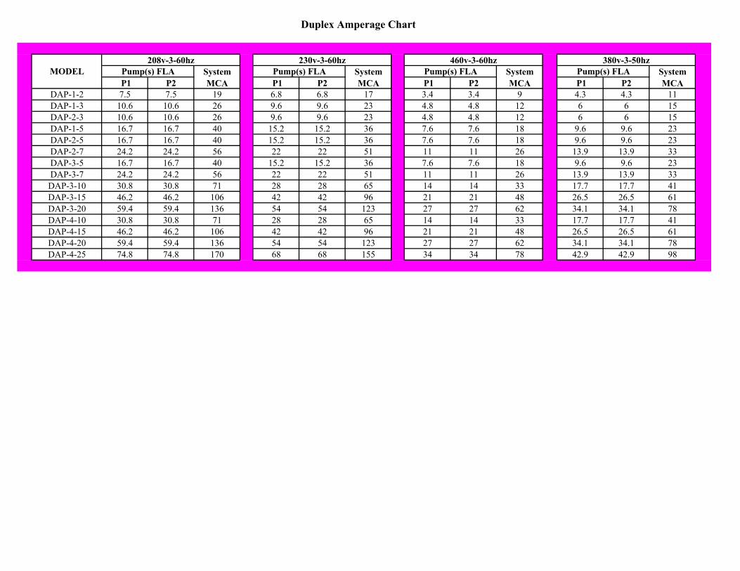
Duplex Amperage Chart
MODEL P1 P2 P1 P2 P1 P2 P1 P2
DAP-1-2 7.5 7.5 19 6.8 6.8 17 3.4 3.4 9 4.3 4.3 11DAP-1-3 10.6 10.6 26 9.6 9.6 23 4.8 4.8 12 6 6 15DAP-2-3 10.6 10.6 26 9.6 9.6 23 4.8 4.8 12 6 6 15DAP-1-5 16.7 16.7 40 15.2 15.2 36 7.6 7.6 18 9.6 9.6 23DAP-2-5 16.7 16.7 40 15.2 15.2 36 7.6 7.6 18 9.6 9.6 23DAP-2-7 24.2 24.2 56 22 22 51 11 11 26 13.9 13.9 33DAP-3-5 16.7 16.7 40 15.2 15.2 36 7.6 7.6 18 9.6 9.6 23DAP-3-7 24.2 24.2 56 22 22 51 11 11 26 13.9 13.9 33DAP-3-10 30.8 30.8 71 28 28 65 14 14 33 17.7 17.7 41DAP-3-15 46.2 46.2 106 42 42 96 21 21 48 26.5 26.5 61DAP-3-20 59.4 59.4 136 54 54 123 27 27 62 34.1 34.1 78DAP-4-10 30.8 30.8 71 28 28 65 14 14 33 17.7 17.7 41DAP-4-15 46.2 46.2 106 42 42 96 21 21 48 26.5 26.5 61DAP-4-20 59.4 59.4 136 54 54 123 27 27 62 34.1 34.1 78DAP-4-25 74.8 74.8 170 68 68 155 34 34 78 42.9 42.9 98
Pump(s) FLA208v-3-60hz
System MCA
230v-3-60hzPump(s) FLA System
MCA
460v-3-60hzPump(s) FLA System
MCA
380v-3-50hzPump(s) FLA System
MCA

-1
Pump Emergency Backup (Local) Operation
Duplex Variable Speed Controller With Internal VFDs
CAUTION THE BACKUP (LOCAL) VFD STARTING MODE IS FOR EMERGENCY USE ONLY IN THE EVENT OF PLC FAILURE. WHILE IN THE BACKUP (LOCAL) VFD STARTING MODE, THERE ARE NO PUMP OR SYSTEM SHUTDOWN SAFETIES. THE SYSTEM MUST BE MONITORED BY THE OPERATOR AT ALL TIMES WHILE OPERATING IN THE BACKUP (LOCAL) VFD STARTING MODE. TO CHANGE VFD TO BACKUP (LOCAL) MODE, THE FOLLOWING IS PERFORMED AT THE VFD KEYPAD:
- PRESS THE “LOC/REM” BUTTON - THE LIGHT ABOVE THE “LOC/REM” BUTTON WILL TURN ON ALONG
WITH THE LIGHT BETWEEN THE UP AND DOWN ARROWS AND THE LIGHT ABOVE THE “RUN” BUTTON
TO START/STOP VFD WHILE OPERATING IN BACKUP MODE:
- PRESS THE “RUN” BUTTON TO START VFD - PRESS THE “STOP” BUTTON TO STOP VFD
TO CHANGE VFD SPEED WHILE OPERATING IN BACKUP MODE:
- PRESS THE UP OR DOWN ARROW BUTTONS FOLLOWED BY THE “ENT” KEY
TO RETURN PUMP VFD TO AUTO (PLC) CONTROL MODE THE FOLLOWING IS PERFORMED AT THE VFD KEYPAD:
- PRESS THE “LOC/REM” BUTTON - THE LIGHT ABOVE THE “LOC/REM” BUTTON WILL TURN OFF ALONG
WITH THE LIGHT BETWEEN THE UP AND DOWN ARROWS AND THE LIGHT ABOVE THE “RUN” BUTTON
- THE RESET BUTTON MUST BE PRESSED THREE TIMES.

-2
IN THE EVENT OF COMUNICATIONS LOSS OR PLC FAILURE:
- THE VFD WILL DISPLAY AN ERROR (ERR8) - THE RESET BUTTON MUST BE PRESSED TWICE - THE LIGHT BETWEEN THE UP AND DOWN ARROWS AND THE LIGHT
ABOVE THE “RUN” BUTTON WILL TURN ON (THE LIGHT ABOVE THE “LOC/REM” BUTTON WILL NOT TURN ON)
TO START/STOP VFD WHILE OPERATING IN BACKUP MODE:
- PRESS THE “RUN” BUTTON TO START VFD - PRESS THE “STOP” BUTTON TO STOP VFD
TO CHANGE VFD SPEED WHILE OPERATING IN BACKUP MODE:
- PRESS THE UP OR DOWN ARROW BUTTONS FOLLOWED BY THE “ENT” KEY
WHEN COMMUNICATIONS HAVE BEEN RE-ESTABLISHED:
- THE PLC WILL RETURN THE VFD TO REMOTE (AUTO) CONTROL. - THE LIGHT BETWEEN THE UP AND DOWN ARROWS AND THE LIGHT
ABOVE THE “RUN” BUTTON WILL TURN OFF - THE RESET BUTTON MUST BE PRESSED THREE TIMES.
THE OPERATOR CAN VERIFY THE COMM FAULT STATUS FOR A VFD IN THE HMI (P1 STATUS, P2 STATUS, ETC)


Altivar 212Variable speed drives for synchronous and asynchronous motors
Programming Manual
11/2014
S1A
5383
8
www.schneider-electric.com

The information provided in this documentation contains general descriptions and/or technical characteristics
of the performance of the products contained herein. This documentation is not intended as a substitute for and is not to be used for determining suitability or reliability of these products for specific user applications. It is the duty of any such user or integrator to perform the appropriate and complete risk analysis, evaluation and testing of the products with respect to the relevant specific application or use thereof. Neither Schneider Electric nor any of its affiliates or subsidiaries shall be responsible or liable for misuse of the information contained herein. If you have any suggestions for improvements or amendments or have found errors in this publication, please notify us.
No part of this document may be reproduced in any form or by any means, electronic or mechanical, including photocopying, without express written permission of Schneider Electric.
All pertinent state, regional, and local safety regulations must be observed when installing and using this product. For reasons of safety and to help ensure compliance with documented system data, only the manufacturer should perform repairs to components.
When devices are used for applications with technical safety requirements, the relevant instructions must be followed.
Failure to use Schneider Electric software or approved software with our hardware products may result in injury, harm, or improper operating results.
Failure to observe this information can result in injury or equipment damage.
© 2014 Schneider Electric. All rights reserved.
2 S1A53838 11/2014

Table of Contents
Table of Contents
Safety Information . . . . . . . . . . . . . . . . . . . . . . . . . . . . . . . . . . . . . . . . . . . . . . . . . . . . 7
About the Book. . . . . . . . . . . . . . . . . . . . . . . . . . . . . . . . . . . . . . . . . . . . . . . . . . . . . . . 8
General Overview . . . . . . . . . . . . . . . . . . . . . . . . . . . . . . . . . . . . . . . . . . . . . . . . . . . . . 11
Chapter 1 Setup . . . . . . . . . . . . . . . . . . . . . . . . . . . . . . . . . . . . . . . . . . . . . . . . . . . . . . . . . . . . . . . 13Steps for setting-up the drive . . . . . . . . . . . . . . . . . . . . . . . . . . . . . . . . . . . . . . . . . . . . 14
Chapter 2 Overview . . . . . . . . . . . . . . . . . . . . . . . . . . . . . . . . . . . . . . . . . . . . . . . . . . . . . . . . . . . . 15Factory configuration . . . . . . . . . . . . . . . . . . . . . . . . . . . . . . . . . . . . . . . . . . . . . . . . . . 16Preliminary recommendations . . . . . . . . . . . . . . . . . . . . . . . . . . . . . . . . . . . . . . . . . . . 17Embedded display terminal . . . . . . . . . . . . . . . . . . . . . . . . . . . . . . . . . . . . . . . . . . . . . 18Monitoring Mode. . . . . . . . . . . . . . . . . . . . . . . . . . . . . . . . . . . . . . . . . . . . . . . . . . . . . . 20Run Mode . . . . . . . . . . . . . . . . . . . . . . . . . . . . . . . . . . . . . . . . . . . . . . . . . . . . . . . . . . . 23Programming Mode . . . . . . . . . . . . . . . . . . . . . . . . . . . . . . . . . . . . . . . . . . . . . . . . . . . 23Menu Navigation. . . . . . . . . . . . . . . . . . . . . . . . . . . . . . . . . . . . . . . . . . . . . . . . . . . . . . 24Submenus . . . . . . . . . . . . . . . . . . . . . . . . . . . . . . . . . . . . . . . . . . . . . . . . . . . . . . . . . . 34Graphic display option . . . . . . . . . . . . . . . . . . . . . . . . . . . . . . . . . . . . . . . . . . . . . . . . . 35Finding a parameter in this document . . . . . . . . . . . . . . . . . . . . . . . . . . . . . . . . . . . . . 37Detected fault screens . . . . . . . . . . . . . . . . . . . . . . . . . . . . . . . . . . . . . . . . . . . . . . . . . 37Pre-alarms screens . . . . . . . . . . . . . . . . . . . . . . . . . . . . . . . . . . . . . . . . . . . . . . . . . . . 38Modbus communication status . . . . . . . . . . . . . . . . . . . . . . . . . . . . . . . . . . . . . . . . . . . 38SoMove software . . . . . . . . . . . . . . . . . . . . . . . . . . . . . . . . . . . . . . . . . . . . . . . . . . . . . 39Structure of the parameter tables . . . . . . . . . . . . . . . . . . . . . . . . . . . . . . . . . . . . . . . . . 40Parameters that cannot be changed while the drive is running . . . . . . . . . . . . . . . . . . 41Common control schemes . . . . . . . . . . . . . . . . . . . . . . . . . . . . . . . . . . . . . . . . . . . . . . 42Drive Operation . . . . . . . . . . . . . . . . . . . . . . . . . . . . . . . . . . . . . . . . . . . . . . . . . . . . . . 49
Programming . . . . . . . . . . . . . . . . . . . . . . . . . . . . . . . . . . . . . . . . . . . . . . . . . . . . . . . . 57
Chapter 3 Quick Menu . . . . . . . . . . . . . . . . . . . . . . . . . . . . . . . . . . . . . . . . . . . . . . . . . . . . . . . . . . 59Quick menu . . . . . . . . . . . . . . . . . . . . . . . . . . . . . . . . . . . . . . . . . . . . . . . . . . . . . . . . . 60
Chapter 4 Programming Parameters . . . . . . . . . . . . . . . . . . . . . . . . . . . . . . . . . . . . . . . . . . . . . . 65Parameter Reset . . . . . . . . . . . . . . . . . . . . . . . . . . . . . . . . . . . . . . . . . . . . . . . . . . . . . 66Macro Programming (AU4). . . . . . . . . . . . . . . . . . . . . . . . . . . . . . . . . . . . . . . . . . . . . . 67Parameter Lock . . . . . . . . . . . . . . . . . . . . . . . . . . . . . . . . . . . . . . . . . . . . . . . . . . . . . . 68Display of Submenu AUF (F738) . . . . . . . . . . . . . . . . . . . . . . . . . . . . . . . . . . . . . . . . . 68
Chapter 5 Motor Control Parameters . . . . . . . . . . . . . . . . . . . . . . . . . . . . . . . . . . . . . . . . . . . . . . 69Motor Control Mode . . . . . . . . . . . . . . . . . . . . . . . . . . . . . . . . . . . . . . . . . . . . . . . . . . . 70Other Motor Control Mode Parameters . . . . . . . . . . . . . . . . . . . . . . . . . . . . . . . . . . . . 72Motor Tuning . . . . . . . . . . . . . . . . . . . . . . . . . . . . . . . . . . . . . . . . . . . . . . . . . . . . . . . . 74Auto-tuning . . . . . . . . . . . . . . . . . . . . . . . . . . . . . . . . . . . . . . . . . . . . . . . . . . . . . . . . . . 75Expert parameters . . . . . . . . . . . . . . . . . . . . . . . . . . . . . . . . . . . . . . . . . . . . . . . . . . . . 77Supply Voltage Correction and Motor Voltage Limitation . . . . . . . . . . . . . . . . . . . . . . . 78
S1A53838 11/2014 3

Table of Contents
Motor 2 Control Parameters . . . . . . . . . . . . . . . . . . . . . . . . . . . . . . . . . . . . . . . . . . . . . 79Permanent Magnet Motor Control Law ([PM Control] (PM)) . . . . . . . . . . . . . . . . . . . . . . 81
Chapter 6 Drive Control Parameters . . . . . . . . . . . . . . . . . . . . . . . . . . . . . . . . . . . . . . . . . . . . . . 87
Chapter 7 Application Parameters . . . . . . . . . . . . . . . . . . . . . . . . . . . . . . . . . . . . . . . . . . . . . . . . 91Application parameters. . . . . . . . . . . . . . . . . . . . . . . . . . . . . . . . . . . . . . . . . . . . . . . . . 92Skip Frequencies . . . . . . . . . . . . . . . . . . . . . . . . . . . . . . . . . . . . . . . . . . . . . . . . . . . . . 97DC Injection Braking Parameters . . . . . . . . . . . . . . . . . . . . . . . . . . . . . . . . . . . . . . . . . 98
Chapter 8 I/O Control Parameters . . . . . . . . . . . . . . . . . . . . . . . . . . . . . . . . . . . . . . . . . . . . . . . . 99Logic Inputs Functions . . . . . . . . . . . . . . . . . . . . . . . . . . . . . . . . . . . . . . . . . . . . . . . . 100Logic Input Function Compatibility . . . . . . . . . . . . . . . . . . . . . . . . . . . . . . . . . . . . . . . 107Relay Output Functions . . . . . . . . . . . . . . . . . . . . . . . . . . . . . . . . . . . . . . . . . . . . . . . 108Analog Input Functions. . . . . . . . . . . . . . . . . . . . . . . . . . . . . . . . . . . . . . . . . . . . . . . . 114Analog Output Functions . . . . . . . . . . . . . . . . . . . . . . . . . . . . . . . . . . . . . . . . . . . . . . 115Analog Input Adjustments. . . . . . . . . . . . . . . . . . . . . . . . . . . . . . . . . . . . . . . . . . . . . . 116Active Logic Function . . . . . . . . . . . . . . . . . . . . . . . . . . . . . . . . . . . . . . . . . . . . . . . . . 122Preset Speeds . . . . . . . . . . . . . . . . . . . . . . . . . . . . . . . . . . . . . . . . . . . . . . . . . . . . . . 123+/- Speed Control Parameters . . . . . . . . . . . . . . . . . . . . . . . . . . . . . . . . . . . . . . . . . . 124Damper control . . . . . . . . . . . . . . . . . . . . . . . . . . . . . . . . . . . . . . . . . . . . . . . . . . . . . . 127
Chapter 9 Display Parameters . . . . . . . . . . . . . . . . . . . . . . . . . . . . . . . . . . . . . . . . . . . . . . . . . . 129Display parameters. . . . . . . . . . . . . . . . . . . . . . . . . . . . . . . . . . . . . . . . . . . . . . . . . . . 130
Chapter 10 Detected Fault Management Parameters . . . . . . . . . . . . . . . . . . . . . . . . . . . . . . . . . 133Time delay . . . . . . . . . . . . . . . . . . . . . . . . . . . . . . . . . . . . . . . . . . . . . . . . . . . . . . . . . 136Catch On The Fly (F301) . . . . . . . . . . . . . . . . . . . . . . . . . . . . . . . . . . . . . . . . . . . . . . 137Overtorque Detection . . . . . . . . . . . . . . . . . . . . . . . . . . . . . . . . . . . . . . . . . . . . . . . . . 143Nuisance Overvoltage And Input Phase Detected Fault Avoidance . . . . . . . . . . . . . 144Motor Overload Characteristics . . . . . . . . . . . . . . . . . . . . . . . . . . . . . . . . . . . . . . . . . 145
Chapter 11 Serial Communication Parameters . . . . . . . . . . . . . . . . . . . . . . . . . . . . . . . . . . . . . . 147Network communication between the ATV212 drive and a master controller . . . . . . 148Data structure parameters . . . . . . . . . . . . . . . . . . . . . . . . . . . . . . . . . . . . . . . . . . . . . 150
Chapter 12 Start/Stop Control By Speed Reference Level. . . . . . . . . . . . . . . . . . . . . . . . . . . . . 153Overview. . . . . . . . . . . . . . . . . . . . . . . . . . . . . . . . . . . . . . . . . . . . . . . . . . . . . . . . . . . 154
Chapter 13 Droop Control . . . . . . . . . . . . . . . . . . . . . . . . . . . . . . . . . . . . . . . . . . . . . . . . . . . . . . . 155Droop control principle . . . . . . . . . . . . . . . . . . . . . . . . . . . . . . . . . . . . . . . . . . . . . . . . 156
Chapter 14 Functions for Scroll . . . . . . . . . . . . . . . . . . . . . . . . . . . . . . . . . . . . . . . . . . . . . . . . . . 157Driving Scroll (F324) . . . . . . . . . . . . . . . . . . . . . . . . . . . . . . . . . . . . . . . . . . . . . . . . . . 160Pre-start Scroll (F325) . . . . . . . . . . . . . . . . . . . . . . . . . . . . . . . . . . . . . . . . . . . . . . . . 170Std Oiling Cycle (F330) . . . . . . . . . . . . . . . . . . . . . . . . . . . . . . . . . . . . . . . . . . . . . . . 172Low Speed Oiling (F334) . . . . . . . . . . . . . . . . . . . . . . . . . . . . . . . . . . . . . . . . . . . . . . 173Scroll Protection (F338) . . . . . . . . . . . . . . . . . . . . . . . . . . . . . . . . . . . . . . . . . . . . . . . 174Discharge gas (F349) . . . . . . . . . . . . . . . . . . . . . . . . . . . . . . . . . . . . . . . . . . . . . . . . . 175Crankcase heating (F355) . . . . . . . . . . . . . . . . . . . . . . . . . . . . . . . . . . . . . . . . . . . . . 176
Diagnostics and troubleshooting . . . . . . . . . . . . . . . . . . . . . . . . . . . . . . . . . . . . . . . 177
Chapter 15 Diagnostics and troubleshooting . . . . . . . . . . . . . . . . . . . . . . . . . . . . . . . . . . . . . . . 179Detected fault conditions . . . . . . . . . . . . . . . . . . . . . . . . . . . . . . . . . . . . . . . . . . . . . . 180Alarm Conditions . . . . . . . . . . . . . . . . . . . . . . . . . . . . . . . . . . . . . . . . . . . . . . . . . . . . 184Pre-alarm Conditions . . . . . . . . . . . . . . . . . . . . . . . . . . . . . . . . . . . . . . . . . . . . . . . . . 186Clearing the detected fault . . . . . . . . . . . . . . . . . . . . . . . . . . . . . . . . . . . . . . . . . . . . . 187
4 S1A53838 11/2014

Table of Contents
Annex. . . . . . . . . . . . . . . . . . . . . . . . . . . . . . . . . . . . . . . . . . . . . . . . . . . . . . . . . . . . . . 189
Chapter 16 Migration . . . . . . . . . . . . . . . . . . . . . . . . . . . . . . . . . . . . . . . . . . . . . . . . . . . . . . . . . . . 191Migration ATV21 - ATV212. . . . . . . . . . . . . . . . . . . . . . . . . . . . . . . . . . . . . . . . . . . . . 192
Chapter 17 Parameters Reset Tables. . . . . . . . . . . . . . . . . . . . . . . . . . . . . . . . . . . . . . . . . . . . . . 193Parameter values that do not vary by reset type . . . . . . . . . . . . . . . . . . . . . . . . . . . . 194Parameter values that vary according to reset type . . . . . . . . . . . . . . . . . . . . . . . . . . 198Parameter values that vary According to drive rating, but not reset type . . . . . . . . . . 199Parameter values that vary According to drive rating and reset type . . . . . . . . . . . . . 200Parameter values that do not change if reset . . . . . . . . . . . . . . . . . . . . . . . . . . . . . . . 201
Chapter 18 User Settings Tables . . . . . . . . . . . . . . . . . . . . . . . . . . . . . . . . . . . . . . . . . . . . . . . . . 203
S1A53838 11/2014 5

Table of Contents
6 S1A53838 11/2014

§
Safety Information
Safety Information
Important Information
NOTICE
Please read these instructions carefully and examine the equipment in order to familiarize yourself with the device before installing, operating or carrying out any maintenance work on it.
The following special messages that you will come across in this document or on the device are designed to
warn you about potential risks or draw your attention to information that will clarify or simplify a procedure.
PLEASE NOTE
The word "drive" as used in this manual refers to the controller portion of the adjustable speed drive as defined
by NEC.
Electrical equipment should be installed, operated, serviced, and maintained only by qualified personnel. No
responsibility is assumed by Schneider Electric for any consequences arising out of the use of this product.
© 2014 Schneider Electric. All Rights Reserved.
The addition of this symbol to a Danger or Warning safety label indicates that an electrical hazard exists, which will result in personal injury if the instructions are not followed.
This is the safety alert symbol. It is used to alert you to potential personal injury hazards. Obey all safety messages that follow this symbol to avoid possible injury or death.
DANGERDANGER indicates an imminently hazardous situation, which, if not avoided, will result in death or serious injury.
WARNINGWARNING indicates a potentially hazardous situation, which, if not avoided, can result in death, serious injury, or equipment damage.
CAUTIONCAUTION indicates a potentially hazardous situation, which, if not avoided, can result in injury or equipment damage.
NOTICENOTICE, used without the safety alert symbol, indicates a potentially hazardous situation which, if not avoided, can result in equipment damage.
S1A53838 11/2014 7
About the Book
About the Book
At a Glance
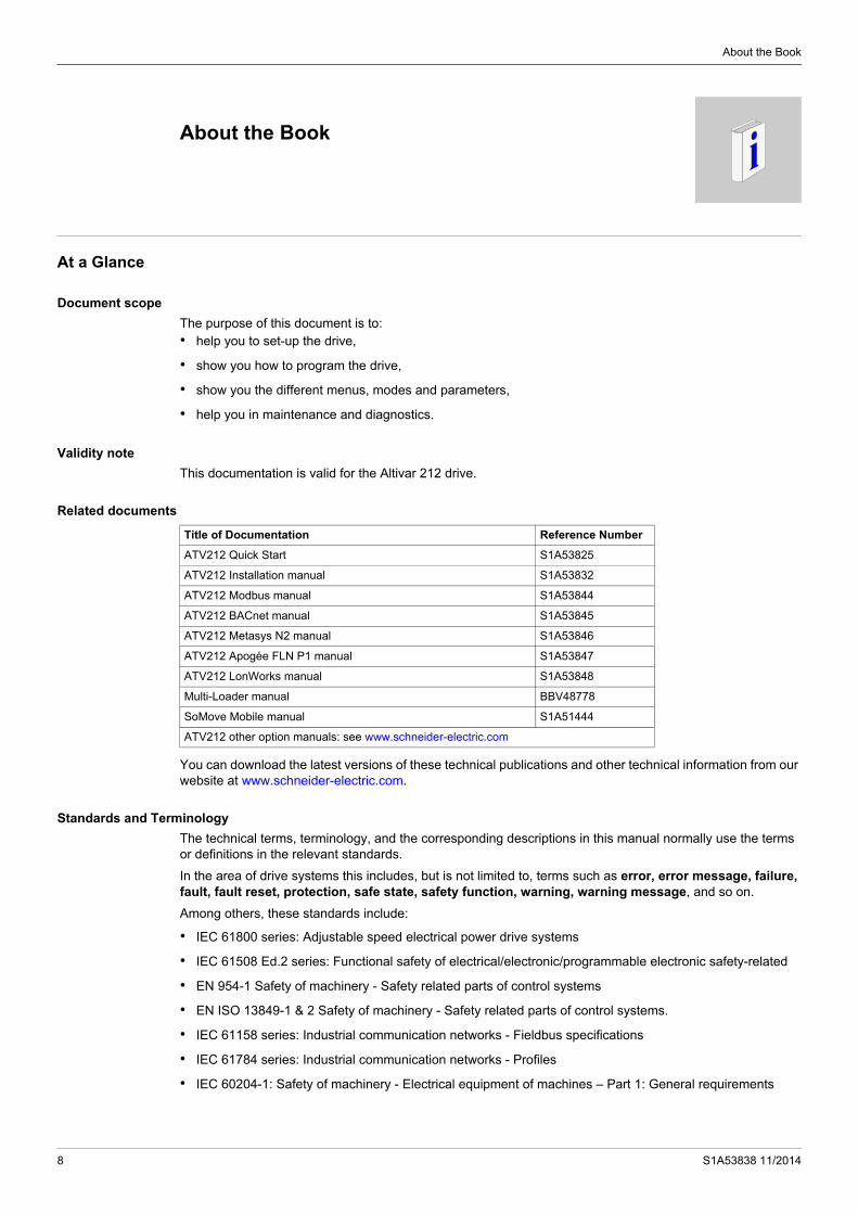
Document scope
The purpose of this document is to:• help you to set-up the drive,
• show you how to program the drive,
• show you the different menus, modes and parameters,
• help you in maintenance and diagnostics.
Validity note
This documentation is valid for the Altivar 212 drive.
Related documents
You can download the latest versions of these technical publications and other technical information from our website at www.schneider-electric.com.
Standards and Terminology
The technical terms, terminology, and the corresponding descriptions in this manual normally use the terms or definitions in the relevant standards.
In the area of drive systems this includes, but is not limited to, terms such as error, error message, failure, fault, fault reset, protection, safe state, safety function, warning, warning message, and so on.
Among others, these standards include:
• IEC 61800 series: Adjustable speed electrical power drive systems
• IEC 61508 Ed.2 series: Functional safety of electrical/electronic/programmable electronic safety-related
• EN 954-1 Safety of machinery - Safety related parts of control systems
• EN ISO 13849-1 & 2 Safety of machinery - Safety related parts of control systems.
• IEC 61158 series: Industrial communication networks - Fieldbus specifications
• IEC 61784 series: Industrial communication networks - Profiles
• IEC 60204-1: Safety of machinery - Electrical equipment of machines – Part 1: General requirements
Title of Documentation Reference Number
ATV212 Quick Start S1A53825
ATV212 Installation manual S1A53832
ATV212 Modbus manual S1A53844
ATV212 BACnet manual S1A53845
ATV212 Metasys N2 manual S1A53846
ATV212 Apogée FLN P1 manual S1A53847
ATV212 LonWorks manual S1A53848
Multi-Loader manual BBV48778
SoMove Mobile manual S1A51444
ATV212 other option manuals: see www.schneider-electric.com
8 S1A53838 11/2014

About the Book
Product related information
(1) For USA: Additional information, refer to NEMA ICS 1.1 (latest edition), “Safety Guidelines for the Application, Installation, and Maintenance of Solid State Control” and to NEMA ICS 7.1 (latest edition), “Safety Standards for Construction and Guide for Selection, Installation and Operation of Adjustable Speed Drive Systems.”
DANGERHAZARD OF ELECTRIC SHOCK, EXPLOSION OR ARC FLASH• Only appropriately trained persons who are familiar with and understand the contents of this manual and all
other pertinent product documentation and who have received safety training to recognize and avoid hazards involved are authorized to work on and with this drive system. Installation, adjustment, repair and maintenance must be performed by qualified personnel.
• The system integrator is responsible for compliance with all local and national electrical code requirements as well as all other applicable regulations with respect to grounding of all equipment.
• Many components of the product, including the printed circuit boards, operate with mains voltage. Do not touch. Use only electrically insulated tools.
• Do not touch unshielded components or terminals with voltage present.
• Motors can generate voltage when the shaft is rotated. Prior to performing any type of work on the drive system, block the motor shaft to prevent rotation.
• AC voltage can couple voltage to unused conductors in the motor cable. Insulate both ends of unused conductors of the motor cable.
• Do not short across the DC bus terminals or the DC bus capacitors or the braking resistor terminals.
• Before performing work on the drive system:- Disconnect all power, including external control power that may be present.- Place a "Do Not Turn On" label on all power switches.- Lock all power switches in the open position.- Wait 15 minutes to allow the DC bus capacitors to discharge. The DC bus LED is not an indicator of the
absence of DC bus voltage that can exceed 800 Vdc.- Measure the voltage on the DC bus between the DC bus terminals (PA/+ and PC/-) using a properly rated
voltmeter to verify that the voltage is < 42 Vdc.- If the DC bus capacitors do not discharge properly, contact your local Schneider Electric representative.
• Install and close all covers before applying voltage.Failure to follow these instructions will result in death or serious injury.
DANGERUNINTENDED EQUIPMENT OPERATION• Prevent accidental grounding of logic inputs configured for sink logic. Accidental grounding can result in
unintended activation of drive functions.• Protect the signal conductors against damage that could result in unintentional conductor grounding.Failure to follow these instructions will result in death or serious injury.
WARNINGLOSS OF CONTROL • The designer of any control scheme must consider the potential failure modes of control paths and, for
critical control functions, provide a means to achieve a safe state during and after a path failure. Examples of critical control functions are emergency stop, overtravel stop, power outage, and restart.
• Separate or redundant control paths must be provided for critical control functions.
• System control paths may include communication links. Consideration must be given to the implications of unanticipated transmission delays or failures of the link.
• Observe all accident prevention regulations and local safety guidelines (1).
• Each implementation of the product must be individually and thoroughly tested for proper operation before being placed into service.
Failure to follow these instructions can result in death, serious injury, or equipment damage.
S1A53838 11/2014 9

About the Book
10 S1A53838 11/2014

S1A53838 11/2014
General Overview
I
General OverviewWhat's in this Part?
This part contains the following chapters:
Chapter Chapter Name Page
1 Setup 13
2 Overview 15
11

General Overview
12 S1A53838 11/2014
S1A53838 11/2014
Setup
1
SetupWhat's in this Chapter?
This chapter contains the following topics:
Topic Page
Steps for setting-up the drive 14
13

Setup
Steps for setting-up the drive
2. Apply input power to the drive, but do not give a run command.
3. Configure
v the nominal frequency of the motor[Parameter reset] (tYP) = [50 Hz reset] (1)if this is not 50Hz,
v the motor parameters, page 70, only if thefactory configuration of the drive is notsuitable,
v the application functions in the Drive ControlParameters section, page 87 and the I/OControl Parameters section, page 99, only ifthe factory configuration of the drive is notsuitable.
1. Please, refer to the installation manual..
PROGRAMMING
INSTALLATION
Tips:
Before beginning programming, complete the customer setting tables, page 203.
Perform an auto-tuning operation to optimize performance, page 75.
If you get lost, return to the factory settings, page 66.
4. Adjust the application parameters
v [Acceleration time 1] (ACC), page 93 and [Deceleration time 1] (dEC), page 93.
v [Low limit frequency] (LL), page 92 and [Upper limit freq] (UL), page 92.
v [Motor thermal prot.] (tHr), page 74.
5. Start the drive
14 S1A53838 11/2014

S1A53838 11/2014
Overview
2
OverviewWhat's in this Chapter?
This chapter contains the following topics:
Topic Page
Factory configuration 16
Preliminary recommendations 17
Embedded display terminal 18
Monitoring Mode 20
Run Mode 23
Programming Mode 23
Menu Navigation 24
Submenus 34
Graphic display option 35
Finding a parameter in this document 37
Detected fault screens 37
Pre-alarms screens 38
Modbus communication status 38
SoMove software 39
Structure of the parameter tables 40
Parameters that cannot be changed while the drive is running 41
Common control schemes 42
Drive Operation 49
15

Overview
Factory configuration
Drive factory settings
The Altivar 212 is factory-set for the most common operating conditions:
[Mot cont. mode sel.] (Pt): [Variable torque] (Pt = 1). See page 71. [Upper limit freq] (UL) = 50.0 Hz. See page 92. [Low limit frequency] (LL) = 0.0 Hz. See page 92. [Switch. freq. level] (F300): depending on drive rating (see page 95) [Auto ramp] (AU1) = [Enable] (AU1 =1). See page 95.
Parameter which depends on Macro Programming [Auto set function] (AU4) = 0 (see page 67):
Command reference: logic inputs ([Command mode sel] (CMOd) = 0). See page 87. Speed reference: analog input VIA = 0–10 V or 0–20 mA ([Frequency mode sel] (FMOd) = 1, (F201)= 0).
See [Frequency mode sel] (FMOd) page 87 and Analog Input Speed Reference page 116.
F: run forward (F111= 2). See [LI F selection] page 100.
R: preset speed 1 (F112= 6). See [LI R selection] page 100.
RES: clear detected fault (F113= 10). See [LI RES selection] page 100.
Drive ready for operation (F110= 1). See [Logic Funct 2 active] page 122.
If the above values are compatible with the application, the drive can be used without changing the settings.
16 S1A53838 11/2014

Overview
Preliminary recommendations
Power switching via line contactor
User adjustment and extension of functions
The display unit and buttons can be used to modify the settings and to extend the functions described in the following pages.
Return to factory settings is made easy by the [Parameter reset] (tYP) (see page 66).
Test on a low power motor or without a motor
In factory settings mode, [Output phase loss] (F605) (page 140) is active F605 = 3. To check the drive in a test or maintenance environment without having to switch to a motor with the same rating as the drive (particularly useful in the case of high power drives), set F605 to 0.
Set [Mot cont. mode sel.] (Pt) = [Constant V/Hz] (0) (see page 71).
Using motors in parallel
Set [Mot cont. mode sel.] (Pt) = [Constant V/Hz] (0) (see page 71).
Using in single phase supply
Set [Input phase loss] (F608) to Disabled 0 (see page 138).
NOTICEINCOMPATIBLE LINE VOLTAGEBefore turning on and configuring the drive, ensure that the line voltage is compatible with the supply voltage range shown on the drive nameplate. The drive may be damaged if the line voltage is not compatible.Failure to follow these instructions can result in equipment damage.
NOTICERISK OF DAMAGE TO THE DRIVE Avoid operating the contactor frequently. Power cycling must be MORE than 60 seconds.Failure to follow these instructions can result in equipment damage.
DANGERUNINTENDED EQUIPMENT OPERATIONCheck that changes made to the settings during operation do not present any danger.We recommend stopping the drive before making any changes.Failure to follow these instructions will result in death or serious injury.
NOTICEUNINTENDED EQUIPMENT OPERATIONMotor thermal protection will not be provided by the drive if the motor 's nominal current is 20% lower than that of the drive. Find an alternative source of thermal protection.Failure to follow these instructions can result in equipment damage.
NOTICERISK OF DAMAGE TO THE MOTORMotor thermal protection is no longer provided by the drive. Provide an alternative means of thermal protection.Failure to follow these instructions can result in equipment damage.
NOTICERISK OF DAMAGE TO THE DRIVEUsing ATV212 in single phase supply is only allowed in training mode with motor and without load.Failure to follow these instructions can result in equipment damage.
S1A53838 11/2014 17
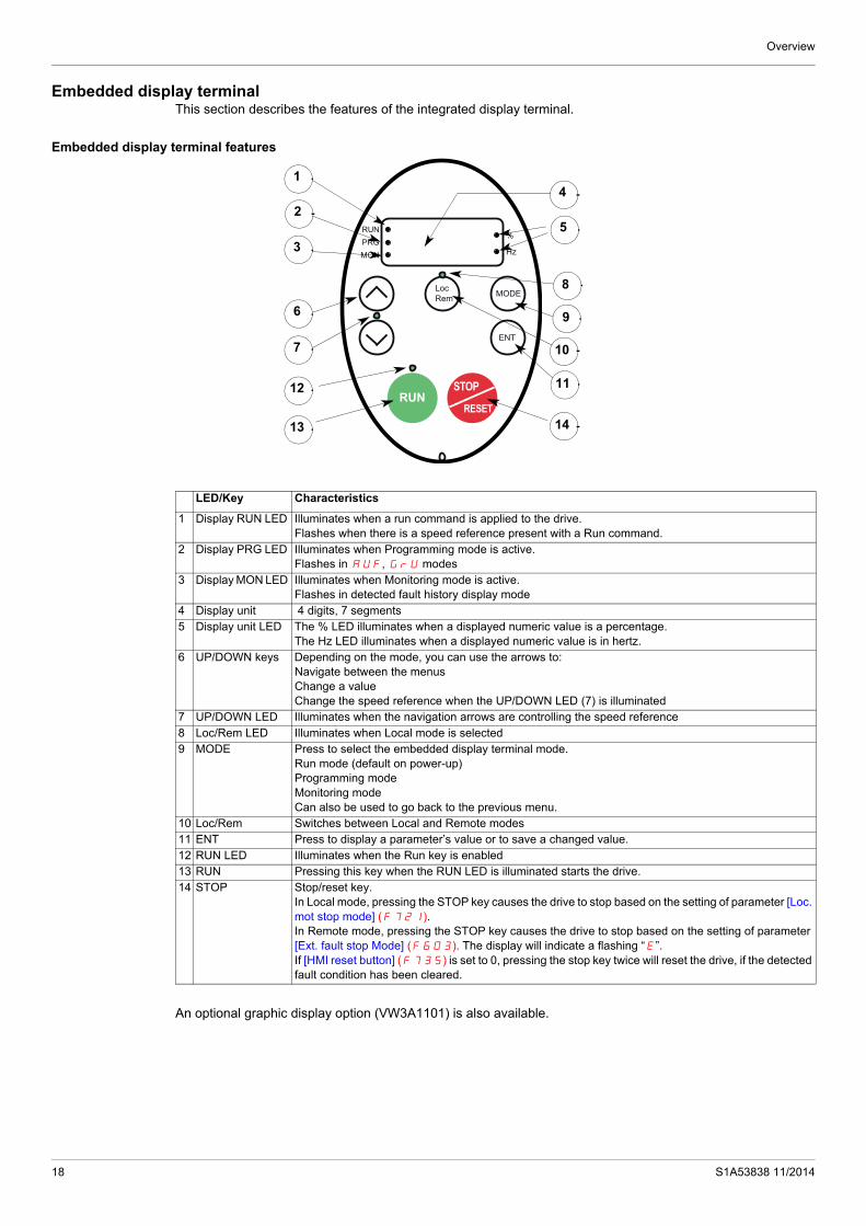
Overview
Embedded display terminalThis section describes the features of the integrated display terminal.
Embedded display terminal features
An optional graphic display option (VW3A1101) is also available.
RUNPRGMON
%
Hz
LocRem
RUNSTOP
RESET
MODE
ENT
13
1
2
3
6
7
4
5
9
10
11
14
12
8
LED/Key Characteristics
1 Display RUN LED Illuminates when a run command is applied to the drive.Flashes when there is a speed reference present with a Run command.
2 Display PRG LED Illuminates when Programming mode is active. Flashes in AUF, GrU modes
3 Display MON LED Illuminates when Monitoring mode is active. Flashes in detected fault history display mode
4 Display unit 4 digits, 7 segments5 Display unit LED The % LED illuminates when a displayed numeric value is a percentage.
The Hz LED illuminates when a displayed numeric value is in hertz.6 UP/DOWN keys Depending on the mode, you can use the arrows to:
Navigate between the menus Change a value Change the speed reference when the UP/DOWN LED (7) is illuminated
7 UP/DOWN LED Illuminates when the navigation arrows are controlling the speed reference8 Loc/Rem LED Illuminates when Local mode is selected9 MODE Press to select the embedded display terminal mode.
Run mode (default on power-up) Programming mode Monitoring mode Can also be used to go back to the previous menu.
10 Loc/Rem Switches between Local and Remote modes11 ENT Press to display a parameter’s value or to save a changed value.12 RUN LED Illuminates when the Run key is enabled13 RUN Pressing this key when the RUN LED is illuminated starts the drive.14 STOP Stop/reset key.
In Local mode, pressing the STOP key causes the drive to stop based on the setting of parameter [Loc. mot stop mode] (F721). In Remote mode, pressing the STOP key causes the drive to stop based on the setting of parameter [Ext. fault stop Mode] (F603). The display will indicate a flashing “E”. If [HMI reset button] (F735) is set to 0, pressing the stop key twice will reset the drive, if the detected fault condition has been cleared.
18 S1A53838 11/2014

Overview
Embedded display terminal modes
The Altivar 212 embedded display terminal has three modes of operation: Monitoring, Run and Programming.
The drive powers up in the Run mode. To select a different mode, use the MODE key as illustrated below.
The red LED in left side of the display indicates the current mode selected, RUN for Run mode, PRG for Programming mode and MON for Monitoring mode.
MODE
ENT
RUNPRGMON
%
Hz
LocRem
RUNSTOP
RESET
ENT
RUNPRGMON
%
Hz
LocRem
RUNSTOP
RESET
MODE
PRGMON
RUN
Runmode
Programmingmode
Monitoringmode
0.0 AUF Fr-F
Hz
ATV212 drive
Power UpMODE MODE
S1A53838 11/2014 19

Overview
Monitoring ModeThe Monitoring mode displays drive operational data in real time. To access the Monitoring mode, press the MODE key until the MON LED is illuminated. Then use the UP and DOWN keys to view up to 30 different types of data.
Monitoring Mode Displays
ENT
RUNPRGMON
%
Hz
LocRem
RUNSTOP
RESET
ENT
RUNPRGMON
%
Hz
LocRem
RUNSTOP
RESET
MODE
Fr-F
AUF
0.0
MON
C80
t0.
n---
F60.
25 other parameters
PRG
RUN
MODE
MODE
MODE
0
10
Display example
Display on graphic terminal Description
Fr-F [Direction] Fr-F = [Forward] Fr-r = [Reverse]
F60.0 [Speed reference] Command frequency to drive, displayed either as Hz or in custom unit set by parameter [Customized freq val] (F702)
C 80 [Motor current] The average of the 3 phases of motor current displayed either as amperes or as a percentage of the drive's nameplate-rated output current. Select % or A with parameter [Unit value selection] (F701).
Y 100 [Line voltage] The average of the 3 phases of line to line input voltages displayed either in volts or as a percentage of the drive's rated input voltage (200 V for 208/240 V models - 400 V for 480 V models). Select % or volts with param-eter [Unit value selection] (F701).
P 100 [Motor voltage] The average of the 3 phases of line to line output voltages displayed either in volts or as a percentage of the drive's rated output voltage (200 V for 208/240 V models - 400 V for 480 V models). Select % or volts with param-eter [Unit value selection] (F701).
q 60 [Motor torque %] Estimated motor torque as a percentage of the motor's rated torque
c 90 [Torque current] The average of the 3 phases of torque-producing motor current displayed either as amperes or as a percentage of the motor's rated torque-producing current. Select % or A with parameter [Unit value selection] (F701).
L 70 [Drive load %] The motor current as a percentage of the drive's rated output current, which may be reduced from the drive’s nameplate current rating by adjustments in switching frequency.
h 80 [Input power KW] drive input power displayed in accordance with parameter [Power cons. unit] (F749).
H 75 [Output power KW] drive output power displayed in accordance with parameter [Power cons. unit] (F749).
o60.0 [Motor frequency] Motor operating frequency, displayed either as Hz or in custom unit set by parameter [Customized freq val] (F702)
..11 [Logic input map]The bar representing VIA is dis-played only if F109 = 1 or 2
ON:OFF:
VIA FRRES
20 S1A53838 11/2014

Overview
Detected fault display and history
When the drive detected faults, the graphic terminal displays a code. To review data about drive operation at the time of the detected fault, press the MODE key to enter the Monitoring mode. Then use the Up/Down keys to scroll through the data listed in table page 20.
Up to five detected faults can be displayed on the graphic terminal in Monitoring mode: the present detected fault (if the drive is in a detected fault state) and the previous four detected fault codes. To review drive operation data recorded at the time of detected fault for a previous detected fault, press ENT when the code for the detected fault is displayed. See table below for the available information.
When a detected fault is cleared or power is cycled to the drive, the present detected fault becomes Past detected fault 1.
0.1 [Relay map]
u101 [CPU CTRL ver.] CTRL version 101
uc01 [CPU MMI ver.] MMI version 1.0
uE01 [Memory ver.] Version of memory
d50.0 [PID feedback] Level of PID feedback, displayed either as Hz or in custom unit set by pa-rameter [Customized freq val] (F702)
b70.0 [PID computed ref.] speed reference
Speed reference command to drive as computed by the PID function, dis-played either as Hz or in custom unit set by parameter [Customized freq val] (F702)
h85 [Total input power] Accumulated input power consumed by the drive displayed in kWh
H75 [Total motor power] Accumulated output power supplied by the drive displayed in kWh
A16.5 [Drive out. rat. cur. A] Drive nameplate rated output current in amperes
1500 [Motor speed rpm] Motor speed in rpm
N50 [Comm. counter 2] Displays the counter numbers of communication through the network
n50 [Comm. counter 1] Displays the counter numbers of communication only at normal state in ev-ery communication through the network
nErr [Past fault]Examples:- 1 blink Err5- 2 blink Err5- 3 blink CFI2- 4 blink nErr
The most recent detected fault stored in the detected fault history. If the drive is in a detected fault state, this is not the active detected fault. A de-tected fault is stored in the detected fault history after it is cleared by clear detected fault action. Press ENT to review drive state at time of detected fault. See “Detected fault Display and History” on page 21 and “Diagnostics and troubleshooting” on page 179 for more detail. There are 4 detected faults recorded. The detected fault 4 is cleared when a new detected fault appears.
N...1 [Drive service alarm]
Mb [Mdb com stat]
t0.10 [Drive run time 100h] Cumulative drive run time. 0.01 = 1 hour. 1.00 = 100 hours
Display example
Display on graphic terminal Description
ON:OFF:
RYA-RYCFL
ON:OFF:
Cooling fanMain Control boardDC Bus capacitor
CumulativeOperation
Time
ON:OFF:
OpenStyle TxOpenStyle RxRJ45 Tx
RJ45 Rx
S1A53838 11/2014 21

Overview
Detected fault History
I/O Map
In both the monitoring mode and the detected fault history, it is possible to view the state of the logic inputs and the relay outputs. See previous tables on pages 20 and 21.
Logic Input Map
The ON or OFF status of each logic input is displayed in bits. VIA is included in this display if parameter F109 is set to either 1 or 2.
Relay Output Map
The ON or OFF status of each relay output is displayed in bits.
Display Display on graphic terminal Description
n 2 [Comm. counter 1] Number of times in succession that this particular detected fault has oc-curred
o60.0 [Motor frequency] Motor operating frequency, displayed either as Hz or in custom unit set by parameter [Customized freq val] (F702)
Fr-F [Direction] Fr-F = [Forward]Fr-r = [Reverse]
F60.0 [Speed reference] Command frequency to drive, displayed either as Hz or in custom unit set by parameter [Customized freq val] (F702)
C80 [Motor current] The average of the 3 phases of motor current displayed either as A or as a percentage of the drive's nameplate-rated output current. Select % or A with parameter [Unit value selection] (F701).
Y100 [Line voltage] The average of the 3 phases of line to line input voltages displayed either in volts or as a percentage of the drive's rated input voltage (200 V for 208/240 V models - 400 V for 480V models). Select % or volts with param-eter [Unit value selection] (F701).
P100 [Motor voltage] The average of the 3 phases of line to line output voltages displayed either in volts or as a percentage of the drive's rated output voltage (200 V for 208/240 V models - 400 V for 480 V models). Select % or volts with param-eter [Unit value selection] (F701).
..11 [LOGIC INPUT MAP]Logic input map The bar representing VIA is
displayed only if F109 = 1 or 2
0.1 [Relay map]
t0.10 [Drive run time 100h] Cumulative drive run time. 0.01 = 1 hour. 1.00 = 100 hours
ON:OFF:
VIA FRRES
ON:OFF:
RYA-RYCFL
ON:OFF:
VIA FRRES
ON:OFF:
RYA-RYCFL
22 S1A53838 11/2014

Overview
Run ModeTo access the Run mode, press the MODE key until the drive operating frequency, a detected fault code, or a pre-alarm code is displayed.
See Diagnostics and troubleshooting beginning on page 179 for the detected fault and pre-alarm codes.
Changing the Display in Run Mode
Motor operating frequency is the default value displayed on the graphic terminal in Run mode. This displayed value can be changed by setting parameter [Displayed param.] (F710). See page 130 for a list of the display choices.
The displayed value can be expressed as a percentage of the drive rating, or in amperes or volts, as appropriate for the value displayed. The units can be changed by setting parameter [Unit value selection] (F701) (see page 130).
In addition, the resolution of the speed reference and output frequency displays can be adjusted by setting parameters [Loc. speed ref. step] (F707) and [Display ref. resol.] (F708) (see pages 87 and 130).
Programming ModeUse this mode to program the drive.
To access the Programming mode, use the MODE key until the PRG indicator LED on the display is illuminated.
See Menu Navigation page 24.
S1A53838 11/2014 23
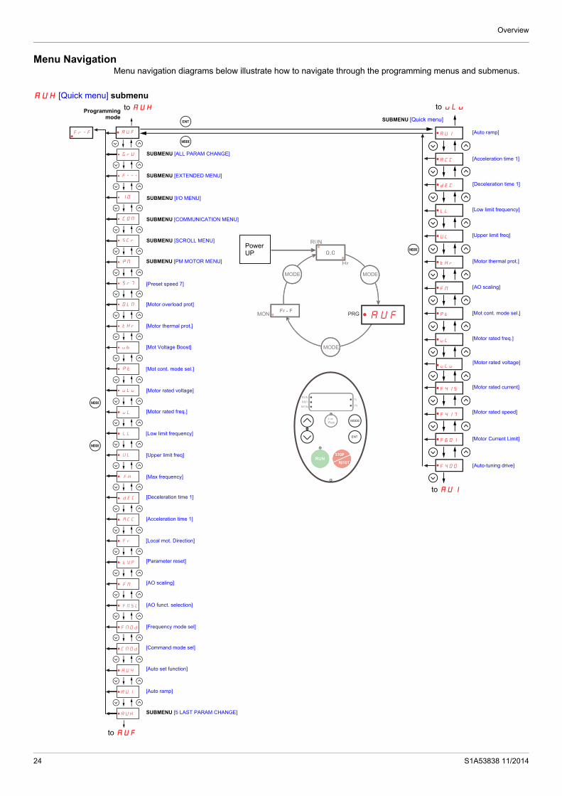
Overview
Menu NavigationMenu navigation diagrams below illustrate how to navigate through the programming menus and submenus.
AUH [Quick menu] submenu
AU1
ACC
dEC
LL
UL
tHr
FM
Pt
uL
uLu
F415
F417
F601
F400
ENT
MODE
MODE0.0
MODE MODE
MODE
Fr - FMON
RUN
Hz
0.0
MODE MODE
MODE
Fr - FMON
RUN
Hz
AUFPRG
RUN
PRG
MON
%
Hz
LocRem
RUNSTOP
RESET
RUN
PRG
MON
%
Hz
LocRem
RUNSTOP
RESET
MODE
ENT
Sr7
OLM
tHr
ub
Pt�
uLu
FM
tYP
Fr
dEC
ACC
FH
UL
uL
LL
FMSL
FMOd
CMOd
AU4
AU1
AUH
MODE
AUF
GrU
F---
IO�
COM
MODE
Fr-F
SCr
PM�
to AUHProgrammingmode SUBMENU [Quick menu]
SUBMENU [ALL PARAM CHANGE]
SUBMENU [EXTENDED MENU]
SUBMENU [I/O MENU]
SUBMENU [COMMUNICATION MENU]
to uLu
SUBMENU [SCROLL MENU]
SUBMENU [PM MOTOR MENU]
[Preset speed 7]
[Motor overload prot]
[Motor thermal prot.]
[Mot Voltage Boost]
[Mot cont. mode sel.]
[Motor rated voltage]
[Motor rated freq.]
[Low limit frequency]
[Upper limit freq]
[Max frequency]
[Deceleration time 1]
[Acceleration time 1]
[Local mot. Direction]
[Parameter reset]
[AO scaling]
[AO funct. selection]
[Frequency mode sel]
[Command mode sel]
[Auto set function]
[Auto ramp]
SUBMENU [5 LAST PARAM CHANGE]
to AUF
to AUI
[Auto ramp]
[Acceleration time 1]
[Deceleration time 1]
[Low limit frequency]
[Upper limit freq]
[Motor thermal prot.]
[AO scaling]
[Mot cont. mode sel.]
[Motor rated freq.]
[Motor rated voltage]
[Motor rated current]
[Motor rated speed]
[Motor Current Limit]
[Auto-tuning drive]
PowerUP
24 S1A53838 11/2014

Overview
AUF [5 LAST PARAM CHANGE] submenu
Note: If no parameter has been changed, AU1 is selected.
(1) Flashes three times then displays previous parameter.
0.0
MODE MODE
MODE
Fr - FMON
RUN
Hz
0.0
MODE MODE
MODE
Fr - FMON
RUN
Hz
AUFPRG
RUN
PRG
MON
%
Hz
LocRem
RUNSTOP
RESET
RUN
PRG
MON
%
Hz
LocRem
RUNSTOP
RESET
MODE
ENT
MODE
ENT
MODE
HEAd
End
(xxx)
(xxx)
(xxx)
(xxx)
(xxx)
Sr7
OLM
tHr
ub
Pt�
uLu
FM
tYP
Fr
dEC
ACC
FH
UL
uL
LL
FMSL
FMOd
CMOd
AU4
AU1
AUH
MODE
AUF
GrU
F---
IO�
COM
MODE
Fr-F
SCr
PM�
Code of 5 lastparameters
(xxx) to AUF
(1)
(1)
SUBMENU [ALL PARAM CHANGE]
SUBMENU [EXTENDED MENU]
SUBMENU [I/O MENU]
SUBMENU [COMMUNICATION MENU]
SUBMENU [SCROLL MENU]
SUBMENU [PM MOTOR MENU]
[Preset speed 7]
[Motor overload prot]
[Motor thermal prot.]
[Mot Voltage Boost]
[Mot cont. mode sel.]
[Motor rated voltage]
[Motor rated freq.]
[Low limit frequency]
[Upper limit freq]
[Max frequency]
[Deceleration time 1]
[Acceleration time 1]
[Local mot. Direction]
[Parameter reset]
[AO scaling]
[AO funct. selection]
[Frequency mode sel]
[Command mode sel]
[Auto set function]
[Auto ramp]
to AUHProgrammingmode
SUBMENU [Quick menu]
PowerUP
SUBMENU [5 LAST PARAM CHANGE]
S1A53838 11/2014 25

Overview
GrU [ALL PARAM CHANGE] submenu
0.0
MODE MODE
MODE
Fr - FMON
RUN
Hz
0.0
MODE MODE
MODE
Fr - FMON
RUN
Hz
AUFPRG
RUN
PRG
MON
%
Hz
LocRem
RUNSTOP
RESET
RUN
PRG
MON
%
Hz
LocRem
RUNSTOP
RESET
MODE
ENT
ENT
MODE
U---
U--r
U--F
Sr7
OLM
tHr
ub
Pt�
uLu
FM
tYP
Fr
dEC
ACC
FH
UL
uL
LL
FMSL
FMOd
CMOd
AU4
AU1
AUH
MODE
AUF
GrU
F---
IO�
COM
MODE
Fr-F
SCr
PM�
to AUF
(1) Pressing the UP key searches the parameter list starting with the first one changed.
(2) Pressing the DOWN key searches the parameter list starting with the last one changed.
(3) The number of parameters displayed within the GrU menu depends upon how many have been altered from their factory settings.
(4) When all the changed parameters have been displayed,the display returns to GrU.
to AUHProgrammingmode SUBMENU
SUBMENU [EXTENDED MENU]
SUBMENU [I/O MENU]
SUBMENU [COMMUNICATION MENU]
SUBMENU [SCROLL MENU]
SUBMENU [PM MOTOR MENU]
[Preset speed 7]
[Motor overload prot]
[Motor thermal prot.]
[Mot Voltage Boost]
[Mot cont. mode sel.]
[Motor rated voltage]
[Motor rated freq.]
[Low limit frequency]
[Upper limit freq]
[Max frequency]
[Deceleration time 1]
[Acceleration time 1]
[Local mot. Direction]
[Parameter reset]
[AO scaling]
[AO funct. selection]
[Frequency mode sel]
[Command mode sel]
[Auto set function]
[Auto ramp]
SUBMENU [Quick menu]
PowerUP
SUBMENU [5 LAST PARAM CHANGE]
[ALL PARMCHANGE]
(4)
(1)
(3)
(2)
(4)
[Forward search]
[Waiting search]
[Reverse search]
to GrU
26 S1A53838 11/2014

Overview
F--- [EXTENDED MENU] submenu
ENT
MODE
MODE
MODE
0.0
MODE MODE
MODE
Fr - FMON
RUN
Hz
0.0
MODE MODE
MODE
Fr - FMON
RUN
Hz
AUFPRG
RUN
PRG
MON
%
Hz
LocRem
RUNSTOP
RESET
RUN
PRG
MON
%
Hz
LocRem
RUNSTOP
RESET
MODE
ENT
F912
F...
F102
F101
F100
Sr7
OLM
tHr
ub
Pt�
uLu
FM
tYP
Fr
dEC
ACC
FH
UL
uL
LL
FMSL
FMOd
CMOd
AU4
AU1
AUH
MODE
AUF
GrU
F---
IO�
COM
MODE
Fr-F
SCr
PM�
to AUF
SUBMENU [ALL PARAM CHANGE]
SUBMENU
SUBMENU [I/O MENU]
SUBMENU [COMMUNICATION MENU]
SUBMENU [SCROLL MENU]
SUBMENU [PM MOTOR MENU]
[Preset speed 7]
[Motor overload prot]
[Motor thermal prot.]
[Mot Voltage Boost]
[Mot cont. mode sel.]
[Motor rated voltage]
[Motor rated freq.]
[Low limit frequency]
[Upper limit freq]
[Max frequency]
[Deceleration time 1]
[Acceleration time 1]
[Local mot. Direction]
[Parameter reset]
[AO scaling]
[AO funct. selection]
[Frequency mode sel]
[Command mode sel]
[Auto set function]
[Auto ramp]
Programmingmode
to AUH
SUBMENU [Quick menu]
PowerUP
SUBMENU [5 LAST PARAM CHANGE]
to F--- [EXTENDE ENU]
[Reserved]
[Freq.2 bandw.]
[Freq. 2 reached]
[Freq. 1 reached]
S1A53838 11/2014 27

Overview
IO [I/O MENU] submenu
0.0
MODE MODE
MODE
Fr - FMON
RUN
Hz
0.0
MODE MODE
MODE
Fr - FMON
RUN
Hz
AUFPRG
RUN
PRG
MON
%
Hz
LocRem
RUNSTOP
RESET
RUN
PRG
MON
%
Hz
LocRem
RUNSTOP
RESET
MODE
ENT
FMSL
F147
F146
F139
F137
F132
F130
F118
F113
F108
F112
F111
F110
F109
ENT
MODE
MODE
Sr7
OLM
tHr
ub
Pt�
uLu
FM
tYP
Fr
dEC
ACC
FH
UL
uL
LL
FMSL
FMOd
CMOd
AU4
AU1
AUH
MODE
AUF
GrU
F---
IO�
COM
MODE
Fr-F
SCr
PM�
to AUHProgrammingmode
SUBMENU [ALL PARAM CHANGE]
SUBMENU [EXTENDED MENU]
SUBMENU [COMMUNICATION MENU]
SUBMENU [SCROLL MENU]
SUBMENU [PM MOTOR MENU]
[Preset speed 7]
[Motor overload prot]
[Motor thermal prot.]
[Mot Voltage Boost]
[Mot cont. mode sel.]
[Motor rated voltage]
[Motor rated freq.]
[Low limit frequency]
[Upper limit freq]
[Max frequency]
[Deceleration time 1]
[Acceleration time 1]
[Local mot. Direction]
[Parameter reset]
[AO scaling]
[AO funct. selection]
[Frequency mode sel]
[Command mode sel]
[Auto set function]
[Auto ramp]
SUBMENU [Quick menu]
PowerUP
SUBMENU [5 LAST PARAM CHANGE]
to F108 SUBMENU [I/O MN]
[AO funct. selection]
[FL Relay delay]
[RY relay]
[RY logic select.]
[RY Relay Function 2]
[FL Relay Function]
[RY Relay Function 1]
[VIA LI selection]
[LI RES selection]
[LI R selection]
[LI F selection]
[Logic Funct 2 active]
[VIA selection]
[Logic Funct 1 active]
to FMSL
to AUF
28 S1A53838 11/2014

Overview
COM [COMMUNICATION MENU] submenu
F851
ENT
MODE
F896
F89.
F890
F829
F821
F820
F803
F80.
F800
0.0
MODE MODE
MODE
Fr - FMON
RUN
Hz
0.0
MODE MODE
MODE
Fr - FMON
RUN
Hz
AUFPRG
RUN
PRG
MON
%
Hz
LocRem
RUNSTOP
RESET
RUN
PRG
MON
%
Hz
LocRem
RUNSTOP
RESET
MODE
ENT
MODE
MODE
Sr7
OLM
tHr
ub
Pt�
uLu
FM
tYP
Fr
dEC
ACC
FH
UL
uL
LL
FMSL
FMOd
CMOd
AU4
AU1
AUH
MODE
AUF
GrU
F---
IO�
COM
MODE
Fr-F
SCr
PM�
to AUH
to AUF
SUBMENU [ALL PARAM CHANGE]
SUBMENU [EXTENDED MENU]
SUBMENU [I/O MENU]
SUBMENU
SUBMENU
SUBMENU
[Preset speed 7]
[Motor overload prot]
[Motor thermal prot.]
[Mot Voltage Boost]
[Mot cont. mode sel.]
[Motor rated voltage]
[Motor rated freq.]
[Low limit frequency]
[Upper limit freq]
[Max frequency]
[Deceleration time 1]
[Acceleration time 1]
[Local mot. Direction]
[Parameter reset]
[AO scaling]
[AO funct. selection]
[Frequency mode sel]
[Command mode sel]
[Auto set function]
[Auto ramp]
SUBMENU [Quick menu]
PowerUP
SUBMENU [5 LAST PARAM CHANGE]
to F800to COM
[COMMUNCTION MENU]
[SCROLL MENU]
[PM MOTOR MENU]
[Com. fault setting]
[Max info frames]
[Network adress]
[Network protocol]
[Mdb network parity]
[Mdb network baud]
[Comm. time out]
[Mdb RJ45 baud]
to F851
S1A53838 11/2014 29
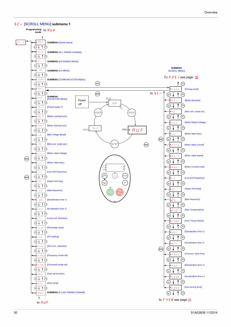
Overview
SCr [SCROLL MENU] submenu 1
F324
ENT
MODE
F311
uLu
uL
F415
F601
LL
UL
FH
pt
F417
F401
0.0
MODE MODE
MODE
Fr - FMON
RUN
Hz
0.0
MODE MODE
MODE
Fr - FMON
RUN
Hz
AUFPRG
RUNPRGMON
%
Hz
LocRem
RUNSTOP
RESET
RUNPRGMON
%
Hz
LocRem
RUNSTOP
RESET
MODE
ENT
MODE
MODE
F402
dEC
ACC
F505
F501
F500
F400
MODE
Sr7
OLM
tHr
ub
Pt
uLu
FM
tYP
Fr
dEC
ACC
FH
UL
uL
LL
FMSL
FMOd
CMOd
AU4
AU1
AUH
MODE
AUF
GrU
F---
IO
COM
MODE
Fr-F
SCr
PM
Programmingmode
to AUH
SUBMENU [Quick menu]
SUBMENU [ALL PARAM CHANGE]
SUBMENU [EXTENDED MENU]
SUBMENU [I/O MENU]
Power
UP
SUBMENU [COMMUNICATION MENU]
[Preset speed 7]
[Motor overload prot]
[Motor thermal prot.]
[Mot Voltage Boost]
[Mot cont. mode sel.]
[Motor rated voltage]
[Motor rated freq.]
[Low limit frequency]
[Upper limit freq]
[Max frequency]
[Deceleration time 1]
[Acceleration time 1]
[Local mot. Direction]
[Parameter reset]
[AO scaling]
[AO funct. selection]
[Frequency mode sel]
[Command mode sel]
[Auto set function]
[Auto ramp]
SUBMENU [5 LAST PARAM CHANGE]
to AUF
To F251 see page
to F458 see page 31
[Driving scroll]
[Mot cont. mode sel.]
[Motor Rated Voltage]
[Motor rated freq.]
[Motor rated current]
[Motor rated speed]
[Low limit frequency]
[Upper limit freq]]
[Slip Compensation]
[Auto Torque Boost]
[Deceleration time 1]
[Acceleration time 1]
[Auto-tuning drive]
SUBMENU[SCROLL MENU]
32
[Motor direction]
[Motor Current Limit]
[Max frequency]
SUBMENU [PM MOTOR MENU]
[Commut. ramp freq.]
[Deceleration time 1]
[Acceleration time 2 ]
to SCr
30 S1A53838 11/2014

Overview
SCr [SCROLL MENU] submenu 2
ENT
MODE
0.0
MODE MODE
MODE
Fr - FMON
RUN
Hz
0.0
MODE MODE
MODE
Fr - FMON
RUN
Hz
AUFPRG
RUNPRGMON
%
Hz
LocRem
RUNSTOP
RESET
RUNPRGMON
%
Hz
LocRem
RUNSTOP
RESET
MODE
ENT
MODE
F912
F913
F921
F325
F326
F327
F328
F329
F102
F113
F132
F101
F130
MODE
MODE
F495
F915
F418
F419
F458
F303
F420
F916
Sr7
OLM
tHr
ub
Pt
uLu
FM
tYP
Fr
dEC
ACC
FH
UL
uL
LL
FMSL
FMOd
CMOd
AU4
AU1
AUH
MODE
AUF
GrU
F---
IO
COM
MODE
Fr-F
SCr
PM
to AUF
Programmingmode
to AUH
SUBMENU [Quick menu]
SUBMENU [ALL PARAM CHANGE]
SUBMENU [EXTENDED MENU]
SUBMENU [I/O MENU]
SUBMENU [COMMUNICATION MENU]
[Preset speed 7]
[Motor overload prot]
[Motor thermal prot.]
[Mot Voltage Boost]
[Mot cont. mode sel.]
[Motor rated voltage]
[Motor rated freq.]
[Low limit frequency]
[Upper limit freq]
[Max frequency]
[Deceleration time 1]
[Acceleration time 1]
[Local mot. Direction]
[Parameter reset]
[AO scaling]
[AO funct. selection]
[Frequency mode sel]
[Command mode sel]
[Auto set function]
[Auto ramp]
SUBMENU [5 LAST PARAM CHANGE]
[Autotune L d-axis]
[Pre-start Scroll]
[Pre-Start time]
[Pre-Start speed]
[LL speed time]
[Pre-Start delay]
to F400 see page
to F330 see page 32
to SCr
30
[Motor voltage coef.]
[LI RES selection]
[Freq.2 bandw.]
[Freq. 2 reached]
[FL Relay Function]
[RY Relay Function 1]
[PM mode selection]
[Autotune L q-axis]
[Init. Pos. Current]
PowerUP
SUBMENU [PM MOTOR MENU]
SUBMENU[SCROLL MENU]
[Number auto reset]
[Torque Boost Coef]
[Frequency loop gain]
[Freq. loop stability]]
[Current loop gain]
[PM Align cur. Level]
S1A53838 11/2014 31

Overview
SCr [SCROLL MENU] submenu 3
ENT
MODE
F333
F334
F335
F336
F337
F338
F339
F330
F332
F331
0.0
MODE MODE
MODE
Fr - FMON
RUN
Hz
0.0
MODE MODE
MODE
Fr - FMON
RUN
Hz
AUFPRG
RUNPRGMON
%
Hz
LocRem
RUNSTOP
RESET
RUNPRGMON
%
Hz
LocRem
RUNSTOP
RESET
MODE
ENT
MODE
F349
MODE
F350
F351
F352
F353
F354
F355
F250
F251
MODE
Sr7
OLM
tHr
ub
Pt
uLu
FM
tYP
Fr
dEC
ACC
FH
UL
uL
LL
FMSL
FMOd
CMOd
AU4
AU1
AUH
MODE
AUF
GrU
F---
IO
COM
MODE
Fr-F
SCr
PM
Programmingmode
to AUH
SUBMENU [Quick menu]
SUBMENU [ALL PARAM CHANGE]
SUBMENU [EXTENDED MENU]
SUBMENU [I/O MENU]
SUBMENU [COMMUNICATION MENU]
[Preset speed 7]
[Motor overload prot]
[Motor thermal prot.]
[Mot Voltage Boost]
[Mot cont. mode sel.]
[Motor rated voltage]
[Motor rated freq.]
[Low limit frequency]
[Upper limit freq]
[Max frequency]
[Deceleration time 1]
[Acceleration time 1]
[Local mot. Direction]
[Parameter reset]
[AO scaling]
[AO funct. selection]
[Frequency mode sel]
[Command mode sel]
[Auto set function]
[Auto ramp]
SUBMENU [5 LAST PARAM CHANGE]
to AUF
[Discharge Gas]
[Hight Tresh.]
[Cooling Frq.]
[Cooling Time]
[Hight hight Tresh.]
[Re-Start Delay]
[Crankcase Heating]
[DC brake start freq.]
[DC braking current]
30
to F329 see page
to SCr
SUBMENU[SCROLL MENU]
31
[Low Speed Oiling]
[LL Speed for Oiling]
[LL Time for Oiling]
[Oiling Time at LLS]
[Scroll Protection]
[Cavitation Frq.]
To F324 see page
PowerUP
SUBMENU [PM MOTOR MENU]
[Std Oil. Cycle Frq.]
[Std Oiling Speed]
[Std Oiling Time]
[Std Oiling Cycle]
32 S1A53838 11/2014

Overview
PM [PM MOTOR MENU] submenu
ENT
MODE
Pt
uLu
uL
F415
F405
F417
F400
F458
F418
F419
F495
F915
F936
F912
F913
F916�
F402
F921
F420
0.0
MODE MODE
MODE
Fr - FMON
RUN
Hz
0.0
MODE MODE
MODE
Fr - FMON
RUN
Hz
AUFPRG
RUN
PRG
MON
%
Hz
LocRem
RUNSTOP
RESET
RUN
PRG
MON
%
Hz
LocRem
RUNSTOP
RESET
MODE
ENT
MODE
Sr7
OLM
tHr
ub
Pt�
uLu
FM
tYP
Fr
dEC
ACC
FH
UL
uL
LL
FMSL
FMOd
CMOd
AU4
AU1
AUH
MODE
AUF
GrU
F---
IO�
COM
Fr-F
SCr
PM�
to AUH
SUBMENU [ALL PARAM CHANGE]
SUBMENU [EXTENDED MENU]
SUBMENU [I/O MENU]
SUBMENU [COMMUNICATION MENU]
SUBMENU [SCROLL MENU]
SUBMENU
[Preset speed 7]
[Motor overload prot]
[Motor thermal prot.]
[Mot Voltage Boost]
[Mot cont. mode sel.]
[Motor rated voltage]
[Motor rated freq.]
[Low limit frequency]
[Upper limit freq]
[Max frequency]
[Deceleration time 1]
[Acceleration time 1]
[Local mot. Direction]
[Parameter reset]
[AO scaling]
[AO funct. selection]
[Frequency mode sel]
[Command mode sel]
[Auto set function]
[Auto ramp]
SUBMENU [Quick menu]
SUBMENU [5 LAST PARAM CHANGE]
PowerUP
[Motor thermal prot.]
[PM MOTOR MENU]
to PM
to F420
[Motor rated voltage]
[Motor rated freq.]
[Motor rated cap.]
[Motor rated current]
[Motor rated speed]
[Auto-tuning drive]]
[Current loop gain]
[Frequency loop gain]
[Freq. loop stability]
[Motor voltage coef.]
[PM mode selection]
[Autotune L q-axis]
[Autotune L d-axis]
[Init. Pos. Current]
[Torque Boost Coef]
[Saliency Level]
[Auto Torque Boost]
to Pt
[PM Align cur. Level]
to AUF
S1A53838 11/2014 33

Overview
SubmenusThe ATV212 drive features 6 submenus (see diagrams starting on page 24) that are designed to reduce the time andeffort required to program application parameters. Parameters can be modified within these submenus.
AUH [5 LAST PARAM CHANGE]
The AUH submenu displays, in reverse chronological order, the last 5 parameters that have been changed from theirfactory settings. Each time the AUH submenu is accessed, it searches for the latest parameters changed from theirfactory settings. If every parameter is at its factory settings, no display is generated. Parameter Lock F700 is not displayed in the AUH menu, even if its value has been changed (see page 68).
AUF [QUICK MENU]
The AUF submenu provides ready access to the ten basic parameters commonly used in programming the drive. Inmany cases, programming the ATV212 drive is complete when these 10 parameters have been properly set (seechapter Quick Menu page 59).
GrU [ALL PARAM CHANGE]
The GrU submenu displays every parameter that has been changed from its factory settings. Each time the GrU
submenu is accessed, its content is refreshed with the latest list of parameters changed from their factory settings. Ifevery parameter is at its factory setting, no display is generated. Parameters Fn and F470 – F473 are not displayed in the GrU menu, even if their values have been changed.
F– – – [EXTENDED MENU]
The extended parameter submenu provides access to parameters used for special settings and applications.
10 [I/O MENU]
The IO submenu provides access to parameters used for input/output setting.
COM [COMMUNICATION MENU]
The COM submenu provides access to parameters used for the communication setting.
SCr [SCROLL MENU]
The SCr submenu provides access to parameters used for the Synchronous scroll motors setting.
PM [PM CONTROL MENU]
The PM submenu provides access to parameters used for the Synchronous motor setting.
34 S1A53838 11/2014

Overview
Graphic display option
Description of the graphic display option
With the graphic display option, which works with FLASH V1.1IE29 or higher, it is possible to display more text information than can be shown on the integrated display terminal.
Note: Keys 3, 4, 5 and 6 can be used to control the drive directly, if control via the graphic display option is activated.
WARNINGLOSS OF CONTROL Do not use the ATV21 and ATV12 terminal display (VW3A21101 and VW3A1006). Only VW3A1101 is compatible with ATV212.Failure to follow these instructions can result in death, serious injury, or equipment damage.
1 Graphic display
2 Function keysF1, F2 and F3: not assignedF4: Loc/Rem
3 STOP/RESET key
4 RUN key
5 Jog dial:
• Press (ENT): - To save the current value- To enter the selected menu or parameter
• Turn +/-:- To increment or decrement a value- To go to the next or previous line- To increase or decrease the reference if control via the graphic
display option is activated
7 ESC key: Press to select the graphic display mode.- Run mode (default on power-up)- Programming mode- Monitoring modeCan also be used to go back to the previous menu.Also corresponds to the MODE button of the embedded HMI
6 FWD/REV key: Press to reverse the direction of rotation of the motor
S1A53838 11/2014 35

Overview
Powering up the drive with graphic display option for the first time
When powering up the graphic display option for the first time, the user has to select the required language.
Display after the graphic display option has been powered up for the first time.Select the language and press ENT.
ENT
ENT
The graphic display option to drive synchronization screen will now ap-pear.
Moveup/down keys
2 s or ENT
LANGUAGE
English
Français
Deutsch
Italiano
Español
Chinese
Русский
Türkçe
Connection in Progress
V1.2IE12
MAIN MENU
DRIVE MENU
LANGUAGE
LANGUAGE
English French
Spanish
German
Chinese
ATV212H075M3X0.75kW/1HP 200 / 240 V
MAIN MENU
DRIVE MENU
LANGUAGE
OPERATIONAL VALUE
0 Hz
Rem Loc/Rem
36 S1A53838 11/2014

Overview
Finding a parameter in this documentThe following assistance with finding explanations on a parameter is provided:
• With the integrated display terminal and the optional graphic display terminal : Direct use of the parameter code index, page 203, to find the page giving details of the displayed parameter.
• With the graphic display option: The parameter code and the name are displayed.
Example: ACC
Then use the parameter code index, page 203, to find the page giving details of the displayed parameter.
Detected fault screensExample: Output phase loss fault
This screen is displayed the detected fault type and diagnostic information related to the detected fault. Then use the alarm code table page 180 for more information.
AUF: QUICK MENU
vLv: Motor rated voltage
AU1: Auto ramp
ACC: Acceleration time 1
DEC:Deceleration time 1
LL: Low limit frequency
Rem Loc/Rem
Line undervoltage
EPHO: Output phase loss fault
Loss of one or more output phases. Determine the cause of the missing output phase and rectify the problem.Set parameter F605 to 0.
Rem Loc/Rem
OPERATIONAL VALUE
MOFF: Line Undervolt fault
Rem Loc/Rem
S1A53838 11/2014 37

Overview
Pre-alarms screensHere some type of screens:
Modbus communication status
[Mdb com stat] (Mb ) parameter display
This parameter is able to check the modbus communication on RJ45 and OpenStyle port.
Current Limit pre-alarm DC bus overvoltage pre-alarm
Motor overload pre-alarm Drive overheating pre-alarm
Current Limit and DC bus overvoltage pre-alarm
Motor overload and drive overheatingpre-alarm
Alarm C Alarm P
OPERATIONAL VALUE
29.0 Hz
Rem Loc/Rem
Alarm P
OPERATIONAL VALUE
29.0 Hz
Rem Loc/Rem
Alarm L
OPERATIONAL VALUE
29.0 Hz
Rem Loc/Rem
Alarm H
OPERATIONAL VALUE
29.0 Hz
Rem Loc/Rem
Alarm C Alarm P
OPERATIONAL VALUE
29.0 Hz
Rem Loc/Rem
Alarm L Alarm H
OPERATIONAL VALUE
29.0 Hz
Rem Loc/Rem
Without Communication
Example : With Communication on RJ45 port
Mdb com stat
RJ45 B - A - COM
Rx Tx Rx Tx
Rem Loc/RemRJ45:
Mb activity on RJ45 port
When Rx and/or Tx aredisplayed in this rowtheir state is inactive
B-A-COM:Mb activityon OpenStyle port
Mdb com stat
RJ45 B - A - COM
Tx Rx Tx
Rx
Rem Loc/Rem
Mdb com stat
RJ45 B - A - COM
Rx Rx Tx
Tx
Rem Loc/Rem
38 S1A53838 11/2014

Overview
SoMove software
Description
SoMove is user-friendly setup software PC for setting up Altivar 212 drives.
SoMove software incorporates various functions for the device setup phases, such as:
Configuration preparation Start-up Maintenance
It can be downloaded free of charge from the internet at www.schneider-electric.com.
Connection
SoMove software can use a direct USB/RJ45 cable link or a Bluetooth® wireless link. See catalog on www.schneider-electric.com.
S1A53838 11/2014 39

Overview
Structure of the parameter tablesThe parameter tables contained in the descriptions of the various menus are organized as follows.
Example:
Value of parameter on graphic display option
Parameter value on embedded display
Name of parameter on graphic display option and description if needed.
Parameter code on 4-digit 7-segment display
Note: The text in square brackets [ ] indicates what you will see on the graphic display option.
Code Name / Description Adjustment range Factory setting
F400 [Auto-tuning drive] Auto tuning enable - 0
0
1
2
[Disabled][Initialize constant]: Application of individual settings of Auto Torque Boost [Auto Torque Boost] (F402) [Complete tune]: complete auto tuning. Parameter F400 is reset to “0” after the auto tuning is performed.
40 S1A53838 11/2014

Overview
Parameters that cannot be changed while the drive is runningThe table below lists the parameters that cannot be changed unless the drive is stopped.
Code Description Code DescriptionAU1 [Auto ramp] F338 [Scroll Protection]AU4 [Auto set function] F349 [Discharge gas]
CMOd [Command mode sel] F355 [Crankcase heating]FMOd [Frequency mode sel] F400 [Auto-tuning drive]tYp [Parameter reset] F405 [Motor rated cap.]FH [Max frequency] F415 [Motor rated current]UL [Upper limit freq] F416 [Mot no-load current]
uLu [Motor rated voltage] F417 [Motor rated speed]Pt [Mot cont. mode sel.] F418 [Frequency loop gain]
F108 [Logic Funct 1 active] F419 [Freq. loop stability]F109 [VIA selection] F458 [Current loop gain]F110 [Logic Funct 2 active] F480 [No load cur. coef]F111 [LI F selection] F481 [In noise comp. filter]F112 [LI R selection] F482 [In noise Inhibit filter]F113 [LI RES selection] F483 [In noise inhibit gain]F118 [VIA LI selection] F484 [Pwr supply adj. gain]F130 [RY Relay Function 1] F485 [Stall control coef. 1]F132 [FL Relay Function] F492 [Stall control coef. 2]F137 [RY Relay Function 2] F494 [Mot. adj coefficient]F139 [RY logic select.] F495 [Motor voltage coef.]F170 [Mot 2 rated Freq.] F496 [PWM adj. coef.]F171 [Motor 2 rated Volt] F601 [Motor Current Limit]F300 [Switch. freq. level] F603 [fault stop Mode]F301 [Catch on fly] F605 [Output phase loss]F302 [Supply loss behav.] F608 [Input phase loss]F303 [Number auto reset] F613 [Short circuit det.]F305 [Overvoltage fault] F626 [Overvoltage level]F307 [Mot volt limitation] F627 [Undervolt detect.]F311 [Motor direction] F732 [Loc/rem key]F316 [Switch. freq. mode] F915 [PM mode selection]F324 [Driving Scroll] F916 [PM Align cur. Level]F325 [Pre-start Scroll] F920 [Position Adjust]F330 [Std Oiling Cycle] F921 [Init. Pos. Current]F334 [Low Speed Oiling]
S1A53838 11/2014 41

Overview
Common control schemes
2-wire control
1. Wire the logic inputs as indicated in the above figure.
2. Set switch SW102 to source.
3. Program common parameters of ATV212 (see Quick Menu page 59).
4. Program specific parameters for 2-wire control as indicated in the following table:
Note: If F111 and F112 are switched simultaneously, the drive will go at 0 speed.
DANGERHAZARD OF ELECTRIC SHOCK, EXPLOSION OR ARC FLASHRead and understand the instructions in "before you begin" chapter, before performing the procedure in thissection.Failure to follow these instructions will result in death or serious injury.
DANGERUNINTENDED EQUIPMENT OPERATION To modify the setting of the switches, the product must be switched off. Do not change the setting of switch SW102 unless your system is properly wired.Failure to follow these instructions will result in death or serious injury.
R/L1S/L2T/L3
U/T1V/T2W/T3
FLC
FLBFLA
PP
PA/+PO PC/-
SCRA GNDB
RUNPRGMON
%
Hz
MODELocRem
ENT
RUN STOP
M
RYARYC
FM
F
R
RES
PLC
P24
CCSink
PLCFM
Source
SW102
I U
SW101
Term
SW103
VIA UVIB U
IPTC
SW100
CCVIA VIB
Run forward
Run reverse
Parameter Page Setting Factory valueCMOd [Command mode sel] 87 0 [Logic inputs] 0 F111 [LI F selection] 100 2 [forward] 2 F112 [LI R selection] 100 3 [reverse] 6
42 S1A53838 11/2014

Overview
3-wire control
1. Wire the logic inputs as indicated in the above figure.
2. Set switch SW102 to source.
3. Program common parameters of ATV212 (see Quick Menu page 59).
4. Program specific parameters for 3-wire control as indicated in the following table:
3 wire control timing diagram
R/L1S/L2T/L3
U/T1V/T2W/T3
FLC
FLBFLA
PP
PA/+PO PC/-
SCRA GNDB
RUNPRGMON
%
Hz
MODELocRem
ENT
RUN STOP
M
RYARYC
FM
F
R
RES
PLC
P24
CCSink
PLCFM
Source
SW102
I U
SW101
Term
SW103
VIA UVIB U
IPTC
SW100
CCVIA VIB
Start forward
Start reverse
Stop
Parameter Page Setting Factory valueCMOd [Command mode sel] 87 0 [Logic inputs] 0 F111 [LI F selection] 100 2 [forward] 2 F112 [LI R selection] 100 49 [3-wire] 6
F113 [LI RES selection] 100 3 [reverse] 10
ONOFF
ON
OFF
ON
OFF
ON
OFF
0
Output frequency
Line power
RES - Reverse start
F - Forward start
R - Stop
Reverse run
Forward run
S1A53838 11/2014 43

Overview
External speed control potentiometer
1. Wire the analog input as indicated in the above figure.
2. Set switch SW100 to V (voltage).
3. Program common parameters of ATV212 (see Quick Menu page 59).
4. Program specific parameters for external speed control potentiometer as indicated in the following table:
R/L1S/L2T/L3
U/T1V/T2W/T3
FLC
FLBFLA
PP
PA/+PO PC/-
SCRA GNDB
RUNPRGMON
%
Hz
MODELocRem
ENT
RUN STOP
M
RYARYC
FM
F
R
RES
PLC
P24
CCSink
PLCFM
Source
SW102
I U
SW101
Term
SW103
VIA UVIB U
IPTC
SW100
CCVIA VIB
2.2 to 10 kOhms1/4 Watt
Parameter Page Setting Factory value
FMOd [Frequency mode sel] 87 1 [Ref source VIA] 1
F109 [VIA selection] 100 0 [AI] 0
F200 [Auto/man speed ref] 118 0 [Enable] 0
44 S1A53838 11/2014

Overview
4-20 mA speed control
1. Wire the analog input as indicated in the above figure.
2. Set switch SW100 to I (current).
3. Program common parameters of ATV212 (see Quick Menu page 59).
4. Program specific parameters for 4-20 mA speed control as indicated in the following table:
R/L1S/L2T/L3
U/T1V/T2W/T3
FLC
FLBFLA
PP
PA/+PO PC/-
SCRA GNDB
RUNPRGMON
%
Hz
MODELocRem
ENT
RUN STOP
M
RYARYC
FM
F
R
RES
PLC
P24
CCSink
PLCFM
Source
SW102
I U
SW101
Term
SW103
VIA UVIB U
IPTC
SW100
CCVIA VIB
4-20 mAcurrent signal
Parameter Page Setting Factory value
FMOd [Frequency mode sel] 87 1 [Ref source VIA] 1
F109 [VIA selection] 100 0 [AI] 0
F200 [Auto/man speed ref] 118 0 [Enable] 0
F201 [VIA ref point 1] 116 20 % 0 %
S1A53838 11/2014 45

Overview
Preset speeds (up to seven)
1. Wire the logic and analog inputs as indicated in the above figure.
2. Set switch SW102 to source.
3. Program common parameters of ATV212 (see Quick Menu page 59).
4. Program specific parameters for preset speed as indicated in the following table:
Example of 7-step preset speed operation:
See page 123 for additionnal information.
R/L1S/L2T/L3
U/T1V/T2W/T3
FLC
FLBFLA
PP
PA/+PO PC/-
SCRA GNDB
RUNPRGMON
%
Hz
MODELocRem
ENT
RUN STOP
M
RYARYC
FM
F
R
RES
PLC
P24
CCSink
PLCFM
Source
SW102
I U
SW101
Term
SW103
VIA UVIB U
IPTC
SW100
CCVIA VIB
Parameter Page Setting Factory valueF109 [VIA selection] 100 2 [LI source] 0
F111 [LI F selection] 100 2 [forward] 2 F112 [LI R selection] 100 6 [PS1] 6
F113 [LI RES selection] 100 7 [PS2] 10F118 [VIA LI selection] 100 8 [PS3] 7
Sr1 [Preset speed 1] 123 - 15.0Sr2 [Preset speed 2] 123 - 20.0Sr3 [Preset speed 3] 123 - 25.0Sr4 [Preset speed 4] 123 - 30.0Sr5 [Preset speed 5] 123 - 35.0Sr6 [Preset speed 6] 123 - 40.0Sr7 [Preset speed 7] 123 - 45.0
ONOFF
F
R
RES
ONOFF
ONOFF
ONOFF
0
VIA
Outputfrequency(Hz)
Time (sec)
46 S1A53838 11/2014

Overview
Serial communication
1. For Modbus serial communication, plug the network cable into RJ45 connector on the main control board. Connection can also be carried out using the «open style» port.
2. Program common parameters of ATV212 (see Quick Menu page 59).
3. Program specific parameters for serial communication as indicated in the following table:
Forced local
1. Wire the logic input as indicated in the above figure.
2. Set switch SW102 to source.
3. Program common parameters of ATV212 (see Quick Menu page 59).
4. Program specific parameter for forced local as indicated in the following table:
RJ45 connection Port open style connection
Contact SignalBAGNDSCR
+-GNDScreen
• Cable sheath should be peeled off by about 10 mm.
• For wiring work, use a fat blade screwdriver with a 0.6 mm thick and 3.5 mm width blade.
• Tightening torque for the terminal block is 0.5 to 0.6 Nm.
R/L1S/L2T/L3
U/T1V/T2W/T3
FLC
FLBFLA
PP
PA/+PO PC/-
SCRA GNDB
RUNPRGMON
%
Hz
MODELocRem
ENT
RUN STOP
M
RYARYC
FM
F
R
RES
PLC
P24
CCSink
PLCFM
Source
SW102
I U
SW101
Term
SW103
VIA UVIB U
IPTC
SW100
CCVIA VIB
Parameter Page Setting Factory valueCMOd [Command mode sel] 87 2 [Communication] 0 FMOd [Frequency mode sel] 87 4 [Serial com ref.] 1
F807 [Com channel choice] 149 1
R/L1S/L2T/L3
U/T1V/T2W/T3
FLC
FLBFLA
PP
PA/+PO PC/-
SCRA GNDB
RUNPRGMON
%
Hz
MODELocRem
ENT
RUN STOP
M
RYARYC
FM
F
R
RES
PLC
P24
CCSink
PLCFM
Source
SW102
I U
SW101
Term
SW103
VIA UVIB U
IPTC
SW100
CCVIA VIB
Forcedlocal
Parameter Page Setting Factory value
F113 [LI RES selection] 100 48 [forced local] 10
S1A53838 11/2014 47

Overview
PID control
1. Wire analog inputs as indicated in the above figure.
2. Set switch SW102 to source.
3. If the feedback is a milliamp signal, set switch SW100 to the I (current) position. If the feedback is a voltage signal, set switch SW100 to the V (voltage) position.
4. Program common parameters of ATV212 (see Quick Menu page 59).
5. Program specific parameters for PID control as indicated in the following table:
P
R/L1S/L2T/L3
U/T1V/T2W/T3
FLC
FLBFLA
PP
PA/+PO PC/-
SCRA GNDB
RUNPRGMON
%
Hz
MODELocRem
ENT
RUN STOP
M
RYARYC
FM
F
R
RES
PLC
P24
CCSink
PLCFM
Source
SW102
I U
SW101
Term
SW103
VIA UVIB U
IPTC
SW100
CCVIA VIB
Feedbacktransmitter
Feedback mA or voltage signal
Setpoint 0 - 10 V
Parameter Page Setting Factory valueFMOd [Frequency mode sel] 87 2 [Communication] 1
F109 [VIA selection] 100 0 [AI] 0
F200 [Auto/man speed ref] 118 0 [Enable] 0
F360 [PID control enable] 120 1 [PID by VIA] 0
F359 [PID ctrl wait time] 121
In accordance with theapplication
0 s
F362 [PID Prop Gain] 120 0.30 %
F363 [PID Integral Gain] 120 0.20
F366 [PID Derivative Gain] 121 0.00
F380 [PID reverse error] 121 0
F391 [Stop on LL hyst] 122 0.2 Hz
F392 [PID wake up (thres)] 122 0.0 Hz
F393 [PID wake up, feedb] 122 0.0 Hz
48 S1A53838 11/2014

Overview
Drive Operation
Local and Remote Modes of Operation
Overview
The ATV212 drive has two modes of operation, local and remote.
In local mode, the ATV212 drive can be operated only from the embedded display terminal or graphic display option:
Use the RUN and STOP keys for command control Use the UP and DOWN keys for speed control
In remote mode, the ATV212 drive is operated from a combination of the command and speed reference sources defined by programming parameters [Frequency mode sel] (FMOd) and [Command mode sel] (CMOd) (see page 87).
Command Sources
The command source [Command mode sel] (CMOd) choices are:
External signals to the control terminal logic inputs F, R, RES and VIA Serial communication control (Modbus®, Metasys® N2, Apogee® FLN P1, BACnet, or LonWorks®) Embedded display terminal RUN and STOP keys or graphic display option
Speed Reference Sources
The speed reference source [Frequency mode sel] (FMOd) choices are:
External signals to the control terminal analog inputs VIA or VIB (4–20 mA, 0–10 Vdc), External signals to the control terminal logic inputs assigned to +/- Speed
Serial communication control (Modbus®, Metasys® N2, Apogee FLN P1®, BACnet, or LonWorks®) Embedded display terminal UP and DOWN keys or graphic display option
S1A53838 11/2014 49

Overview
Command Mode Selection and Priorities
The diagram below illustrates the control inputs and selection logic which determine the source of the drive's start/stop and speed reference commands.
Command and Reference Switching
Parameters [Command mode sel] (CMOd) and [Frequency mode sel] (FMOd) are the first layers of logic used by the drive to determine its command CMOd and speed reference FMOd source.
[Remote spd ref 2] (F207) is a secondary speed reference source that may override the source selected by FMOd (see page 87).
The speed reference source identified by F207 takes control if either:
A logic input assigned to function 38 (frequency reference source switching) is enabled, or Parameter [Auto/man speed ref] (F200) is set to 1 and the drive's output frequency is equal to or less than
1 Hz (see page 118).
If a serial communication link is established, it can take control of the ATV212 drive, overriding inputs identified by CMOd, FMOd, and F207. Control is restored to CMOd, FMOd, and F207 only if:
The serial communication link relinquishes control, or A logic input assigned to function 48 (forced local) is enabled.
The final layer of logic used by the drive to determine its command source is the LOC/REM key on the graphic display option.
When the drive and embedded HMI is set to local mode (by pressing the LOC/REM key, lighting the local mode LED), the drive responds only to commands from the embedded and graphic display option.
LOCREM
VIA
VIB
VIA
VIB
0
1
2
1
2
3
4
5
1
2
3
4
5
Communication
Forced Local{LIx = 48}
SpeedSetPoint
Terminal LocalGraphic display
option
Logic inputs
CommandsCMOd
References FMOd Switching
FMOd / F207
{LIx = 38 or F200}
Up/Down speed
F207
ON
OFF
Terminal LocalGraphic display
option
REM
LOCCmdSetPoint
Terminal LocalGraphic display option
REM
LOC
Communication
Communication
Terminal LocalGraphic display
option
Up/Down speed
Communication
Terminal LocalGraphic display
option
F807
CommunicationRJ45 channel: Modbus
Network channel:Paremeter F829
ON
OFFCommunication
active
inactive
Default value
50 S1A53838 11/2014

Overview
Selecting Local or Remote mode
Switching between local and remote mode is achieved with the LOC/REM key on the drive’s embedded display terminal or with F4 key on the graphic display option.
The LOC/REM key can be disabled by setting parameter [Loc/rem key] (F732) to 1 (see page 90).
When parameter [Switch rem/Local] (F295) is set to 1 (factory setting), a bumpless tranfer of motor operation is achieved when switching from remote to local mode (see page 88).
For example, if the bumpless transfert feature is active and if the motor is running at full speed with the drive in remote mode, the motor will still run at full speed after the drive is transferred to local mode.
Conversely, when switching from local to remote mode, the run and speed command is not transferred to the remote mode. Upon entering the remote mode, the drive will operate on the run and speed command set by the remote source even if it was received before entering or while in the local mode.
The diagram below is an example timing diagram.
Switching Between Local and Remote Mode
DANGERUNINTENDED EQUIPMENT OPERATION Know the state of the frequency and run commands from the remote source before exiting the local mode. Upon entering the remote mode, the drive will respond to the most recent command from the remote source,
even if it was received before entering or while in the local mode.Failure to follow these instructions will result in death or serious injury.
Remote mode Local mode
ONOFF
LOCREM
Key
Output Frequency
Local Run Command
Remote Run Command
Run Status
ONOFF
The remote run command and frequency command are transferred to the local mode when the LOC/REM key is pressed.
In this example, the run command and frequency command from the remote mode are copied to the local mode, and the motor continues to run.
Local mode Remote mode
ONOFF
LOCREM
Key
Output Frequency
Local Run Command
Remote Run CommandRun Status
ONOFF
When switching from the local mode to the remote mode, the run command and frequency command are determined by the setting in the remote mode.
In this example, when the LOC/REM button is pressed, the motor in started.This is due to the application of a remote run command when the drive exits the local mode and enters the remote mode.
Set frequency at remote mode
S1A53838 11/2014 51

Overview
Local Mode
When the ATV212 drive is in local mode, the LED above the LOC/REM key is illuminated.
On the graphic display option:
Starting and Stopping the Motor in Local Mode
Start and stop the motor with the RUN and STOP keys on the graphic/embeded display terminals.
The setting of parameter [Loc. mot stop mode] (F721) determines how the motor stops when the drive is in local mode (see page 88):
If F721 is set to 0 (factory setting), the motor will stop on a ramp, based on the time value set in parameter [Deceleration time 1] (dEC) or parameter [Deceleration time 2] (F501).
If F721 is set to 1, power will be removed from the motor when the STOP key is pressed, allowing the motor to coast to a stop with the ramp-down time determined by inertia and friction.
Use of the RUN and STOP keys in local mode can be disabled using parameter [Run/stop key] (F733) (see page 90).
Adjusting Motor Speed in Local Mode
Set the motor speed using the UP and DOWN keys on the graphic/embeded display terminals. Motor speed can be adjusted while the drive is operating.
Normally, motor frequency changes by 0.1 Hz each time the UP or DOWN key is pressed. This rate of speed change can be altered by entering a new frequency step change into parameter [Loc. speed ref. step] (F707) (see page 87).
If the ENT key is pressed after the motor speed has been adjusted, that speed setpoint value will be entered into parameter FC. The next time the drive is Power ON in local mode, it will accelerate the motor directly to the speed setpoint memorized by [Local speed ref.] (FC) (see page 87).
Selecting Motor Rotation Direction in Local Mode
Motor rotation direction is set by parameter [Local mot. direction] (Fr) (see page 87). The four selections are:
0: Forward only (factory setting) 1: Reverse only 2: Forward, with reverse selectable from the graphic/embeded display terminals (1) 3: Reverse, with forward selectable from the graphic/embeded display terminals (1)(1)If Fr is set to either 2 or 3, motor rotation can be set to forward by pressing the UP key while holding the
ENT key. Reverse can be set by pressing the DOWN key while holding the ENT key.
Motor rotation is indicated on the embedded display terminal as Fr-F for forward and as Fr-r for reverse.
The ability to run in the Forward or Reverse direction can be set with parameter [Motor direction] (F311) (see page 96).
AUF: QUICK MENU
LL: Low Limit frequency
DEC: Deceleration time 1
ACC: Acceleration time 1
AU1: Auto ramp
vLv: Motor rated voltage
Loc Ref loc Cmd loc Loc/Rem
52 S1A53838 11/2014

Overview
Resetting drive detected fault in Local Mode
It is not possible to clear a drive detected fault if the cause of the detected fault persists. Be certain to diagnose and rectify the cause of the detected fault before attempting a drive reset.
With the STOP Key
To clear a drive detected fault in local mode:
1. Press the STOP key. See Fault detection codes that can be cleared with the automatic restart function after the cause has disappeared on page 135 for a list of detected faults that can be cleared with the STOP key. If it is possible to reset the drive, the embedded display terminal will display CLr.
2. To clear the detected fault, press the STOP key a second time.
3. If the cause of the detected fault is still present, the CLr display will not appear. Diagnose and clear the detected fault before attempting to reset the drive.
Use of the STOP key as a clear detected fault can be set with parameter [HMI reset button] (F735) (see page 90).
In the event of an OL1 or OL2 detected fault, the following time periods are necessary before a clear detected fault is possible:
OL1 (drive overload)—about 30 seconds after the detected fault has occured OL2 (motor overload)—about 120 seconds after the detected fault has occured
By Cycling Line Power
A drive detected fault can also be cleared by removing and restoring line power. Be certain that the cause of the detected fault is no longer present and leave power removed long enough for all of the LEDs on the face of the drive to extinguish.
Cycling power to clear a detected fault can cause the detected fault history to be lost. Refer to parameter [Drive Fault Memory] (F602) on page 138.
Logic Input Functions Active in Local Mode
The logic input functions listed in the table below are active, even if [Command mode sel] (CMOd) is set to 1 (embedded display terminal control). See table on page 100 for logic input function settings.
Logic InputFunction No.
Description
1 [Run permissive]54 [Inverse Run permissive]10 [Fault reset]55 [Inv fault reset]11 [Ext Fault]45 [Inv Ext. fault]16 [Run reset]38 [Frequency source]41 [(+) speed]42 [(-) speed]43 [+/- clear]44 [+/- SPD, FLT CLR]46 [Ext. Th fault]47 [Inv Ext. Th fault]51 [Reset kWh]52 [Forced mode]53 [Fire mode]62 [RY on]64 [Cancel HMI cmd]
S1A53838 11/2014 53

Overview
Remote Mode
When the ATV212 drive is in the remote mode, the LOC/REM LED is off.
Starting and Stopping the Motor in Remote Mode
The diagram on page 50 illustrates the start/stop command source when the drive is in remote mode.
With Logic Input Terminals
Use the logic input terminals F, R, RES, or VIA to start the drive if parameter [Command mode sel] (CMOd) is set to [Logic Inputs] (0) (factory setting).
With the display terminals
The drive responds to commands from the embedded display terminal or graphic display option, just as in local mode, if parameter [Command mode sel] (CMOd) is set to [HMI] (1).
With Serial Communication
The drive responds to commands sent over the serial communication link (Modbus®, Metasys® N2, Apogee®
FLN, BACnet or LonWorks®) if parameter [Command mode sel] (CMOd) is set to [Communication] (2).
The drive responds to commands sent over the RJ45 communication port if parameter [Com channel choice] (F807) is set to 0. Other protocols are available when F807 is set to 1 on open style port.
With the graphic/embeded display terminals STOP Key
The graphic/embeded display terminals STOP key is active when the drive is in remote mode. Pressing the STOP key causes the drive to stop according to the setting of parameters [Ext. fault stop Mode] (F603), [DC brk time ext flt] (F604), and [DC braking current] (F251) (see page 126 and page 98) . After the drive has come to a stop, the graphic/embeded display terminals display E and the fault relay is activated.
Adjusting the Motor Speed in Remote Mode
The diagram on page 50 illustrates the speed reference source when the drive is in remote mode.
By Analog Input VIA
A 0–10 Vdc or 4–20 mA signal connected to VIA and CC can be used to adjust the motor speed if:
Parameter [Frequency mode sel] (FMOd) is set to 1 (factory setting). Alternate speed reference source parameter [Remote spd ref 2] (F207) has not been enabled (see page
88).
The analog signal type depends on the setting of switch SW100 and parameters F109, F201–F204, and F470–F471.
By Analog Input VIB
A 0–10 Vdc signal connected to VIB and CC can be used to adjust the motor speed if:
Parameter [Frequency mode sel] (FMOd) is set to 2. Alternate speed reference source parameter [Remote spd ref 2] (F207) has not been enabled.
The control that VIB has over motor speed depends on the setting of switch SW100 and parameters F210–F213, F472–F473, and F645.
54 S1A53838 11/2014

Overview
By display terminal Control
Control of the motor speed is enabled, if:
Parameter [Frequency mode sel] (FMOd) is set to 3. Alternate speed reference source parameter [Remote spd ref 2] (F207) has not been enabled.
By Serial communication control
Serial communication control (Modbus, Metasys N2, Apogee FLN, BACnet or LonWorks) of the motor speed is enabled, if:
Parameter [Com channel choice] (F807) is set to 0 (only for Modbus on RJ45 port), Parameter [Com channel choice] (F807) is set to 1, Parameter [Frequency mode sel] (FMOd) is set to 4. Alternate speed reference source parameter [Remote spd ref 2] (F207) has not been enabled.
By +/- Motor Speed Control
+/- Motor speed control is enabled, if:
Parameter [Frequency mode sel] (FMOd) is set to 5, Alternate speed reference source parameter [Remote spd ref 2] (F207) has not been enabled.
Selecting Motor Rotation Direction in Remote Mode
The diagram on page 50 illustrates the motor rotation command source when the drive is in remote mode.
With Logic Input Terminals
Use the logic input terminals F, R, RES, or VIA to select motor rotation direction if parameter [Command mode sel] (CMOd) is set to 0 (factory setting).
With the embedded display terminal or graphic display option
Motor rotation direction can be set by pressing the display terminal UP and ENT keys if:
Parameter [Command mode sel] (CMOd) is set to 1, Serial communication control has not been established. Parameter [Local mot. direction] (Fr) is set to either 2 or 3.
With Serial Communication
The drive responds to commands sent over the serial communication link (Modbus, Metasys N2, Apogee FLN, BACnet or LonWorks) if Parameter [Command mode sel] (CMOd) is set to 2.
Resetting drive detected faults in Remote Mode
The diagram on page 50 illustrates the clear detected fault command source when the drive is in remote mode.
It is not possible to clear a drive detected fault if the cause of the detected fault persists. Be certain to diagnose and rectify the cause of the detected fault before attempting to reset the drive.
See Automatically Resettable detected faults on page 135 for a list of detected faults that can be cleared in remote mode.
With the Logic Input Terminals
Use the logic input terminals F, R, RES, or VIA to clear a drive detected fault if parameter [Command mode sel] (CMOd) is set to 0 (factory setting).
With the graphic/embeded display terminals
The STOP key can be used to clear a drive detected fault if parameter [Command mode sel] (CMOd) is set to 1.
To clear a drive detected fault, press the STOP key. If it is possible to reset the drive, it will display CLr. To clear the detected fault, press the STOP key a second time.
If the cause of the interruption is still present, the CLr display will not appear. Diagnose and clear the detected fault before attempting to reset the drive.
The use of the STOP key as a clear detected fault can be managed by parameter [HMI reset button] (F735).
S1A53838 11/2014 55

Overview
With Serial Communication
A drive detected fault can be cleared over the serial communication link (Modbus, Metasys N2, Apogee FLN, BACnet or LonWorks) if parameter [Command mode sel] (CMOd) is set to 2.
In the event of an OL1 or OL2 detected fault, the following time periods needs to pass before a clear detected fault is possible:
OL1 (drive overload) - about 30 seconds after the occurrence of the event. OL2 (motor overload) - about 120 seconds after the occurrence of the event.
By Cycling Line Power
A drive detected fault can also be cleared by removing and restoring line power. Be certain that the cause of the detected fault is no longer present and leave power removed long enough for all of the LEDs on the face of the drive to go out.
Cycling power to clear a detected fault can cause the detected fault history to be lost. Refer to parameter F602 on page 138 for drive fault memory options.
56 S1A53838 11/2014

S1A53838 11/2014
Programming
II
ProgrammingWhat's in this Part?
This part contains the following chapters:
Chapter Chapter Name Page
3 Quick Menu 59
4 Programming Parameters 65
5 Motor Control Parameters 69
6 Drive Control Parameters 87
7 Application Parameters 91
8 I/O Control Parameters 99
9 Display Parameters 129
10 Detected Fault Management Parameters 133
11 Serial Communication Parameters 147
12 Start/Stop Control By Speed Reference Level 153
13 Droop Control 155
57

Programming
58 S1A53838 11/2014

S1A53838 11/2014
Quick Menu
3
Quick MenuWhat's in this Chapter?
This chapter contains the following topics:
Topic Page
Quick menu 60
59

Quick Menu
Quick menuThe AUF submenu provides ready access to the ten basic parameters commonly used in programming the drive.
In many cases, programming the ATV212 drive is complete when these 10 parameters and motor parameters have been properly set. .
Code Name / Description Adjustment range Factory setting
AU1 [Auto ramp] Automatic ramp adaptation - 1
0
1
2
[Disabled][Enable]: [Acceleration time 1] (ACC) and [Deceleration time 1] (dEC)[ACC only]: [Acceleration time 1] (ACC) only
If parameter AU1 is set to 1 or 2, the drive will monitor its own loading level and optimize the acceleration and deceleration ramps. The acceleration and deceleration AU1 = 1 only rates will be automatically adjusted between 1/8 to 8 times the settings of ACC and dEC, depending on the drive’s current rating and the load level on the motor. ACC and dEC should be appro-priately set for an average load in the application. If the load on the motor increases rapidly during ramp up or ramp down, the auto ramp adaptation feature may not help to prevent the drive from experiencing an overcurrent or overvoltage.
If the application requires a consistent acceleration and deceleration time, set AU1 to 0, and set ACC and dEC manually as needed. The manual acceleration and deceleration times can still be overridden by the [Motor Current Limit] (F601) (see page 73) and [Overvoltage fault] (F305) (see page 139) and [Overvoltage level] (F626) (see page 139) functions.
ACC [Acceleration time 1] 0.0 to 3200 s According to drive rating (1)
The setting of parameter ACC determines the slope of the acceleration ramp and the time it takes for the output frequency of the drive to increase from 0 Hz to the setting of [Max frequency] (FH) (see page 92).If parameter [Auto ramp] (AU1) is set to 1 or 2, the acceleration ramp may be increased or decreased from the setting of ACC, depending on the amount of load on the motor during ramp up.
If two different acceleration rates are needed, see parameter [Acceleration time 2] (F500) on page 93.
dEC [Deceleration time 1] 0.0 to 3200 s According to drive rating (1)
The setting of parameter dEC determines the slope of the deceleration ramp and the time it takes for the output frequency of the drive to decrease from the setting of [Max frequency] (FH) to 0 Hz.
If parameter [Auto ramp] (AU1) is set to 1 or 2, the deceleration ramp may be increased or decreased from the setting of dEC, depending on the amount of load on the motor during ramp down. See diagram above.
If two different deceleration rates are needed, see parameter [Deceleration time 2] (F501) on page 93.
LL [Low limit frequency] 0.0 to [Upper limit freq] (UL) Hz
0.0 Hz
If [Driving Scroll] (F324) page 160 is set to [yes] (1) the setting is replaced by 30%.
Parameter LL sets the minimum frequency that can be commanded to the drive by the local or remote speed reference source.
UL [Upper limit freq] 0.5 to [Max fre-quency] (FH) Hz
50.0 Hz
If [Driving Scroll] (F324) page 160 is set to [yes] (1) the setting is replaced by 90%.
Parameter UL sets the maximum frequency that can be commanded to the drive by the local or remote speed reference source. The top end of its range is limited by the setting of [Max frequency] (FH).
(1) See table page 199
0
Output frequency (Hz)
Time (s)
60 S1A53838 11/2014

Quick Menu
tHr [Motor thermal prot.] Motor Rated Current Overload Setting 10 to 100% of the drive’s output cur-rent rating
100%
Set parameter tHr to the motor’s rated current as indicated on the motor nameplate for the selected operating voltage.If parameter [Unit value selection] (F701) is set to 1 (see page 130), parameter tHr will be adjusted in amperes.If parameter F701 is set to 0, parameter tHr will be adjusted in percentage. In this case, divide the motor rated current by the drive rated current (as listed on its nameplate) and set parameter tHr to the resulting percentage.The setting of parameter [Switch. freq. level] (F300) does not change the drive’s rated current for the sake of this calculation (see page 95).
FM [AO scaling] Analog output scaling -
Parameter FM is used to match the FM terminal output signal with the input requirements of the attached panel meter by adjusting the slope and bias of the analog output signal. Before adjusting FM, set FMSL to either 15 or 17. As you adjust the value of FM, monitor the display on the attached panel meter. When the meter display reaches 100%, press the ENT key on the drive display terminal. The drive will flash between FM and the adjusted value, indicating that the adjustment has been saved.
Pt [Mot cont. mode sel.] Motor control mode 1
0
1
2
3
4
5
6
If [Driving Scroll] (F324) page 160 is set to [yes] (1) the setting is replaced by [SVC] (3).
[Constant V/Hz]: Constant V/HzUse constant V/Hz mode for loads that require the same torque at low speeds as at rated speeds. Low speed torque can be ad-justed manually by setting parameter [Motor Voltage Boost] (ub) (see page 73).
[Variable Torque]: Variable torqueUse variable torque mode for loads such as centrifugal fans and pumps whose torque requirements increase as a square of the increase in motor speed. Low speed torque can be adjusted manually by setting parameter ub.
[Cst V/Hz+Boost]: Constant V/Hz with automatic torque boostSee the diagram on page 70.This mode is similar to the constant V/Hz mode (for loads that require the same torque at low speeds as at rated speeds), except it automatically increases motor voltage and torque to compensate for increases in load.
[SVC]: Sensorless vector controlUse sensorless vector control mode to increase torque at motor speeds below 3 Hz or to improve speed regulation (0.5 to 1%).See diagram on page 70.
[Economy]: Energy savingIn energy savings mode, the ATV212 drive monitors motor loading and automatically modulates the voltage applied to the motor to optimize energy consumption.If the ATV212 drive and the connected motor have the same power rating, and if the motor has a nominal 1500 rpm rating, no motor auto-tuning is required to use this motor control mode. Otherwise, follow the steps outlined in “Motor Tuning” on page 74.
[Do not use]: Reserved[PM Control]: Permanent magnet
Code Name / Description Adjustment range Factory setting
0
Motor rated voltage
Motor Voltage Boost
Motor Rated Frequency
Output Frequency (Hz)
Ou
tput
Vo
ltage
(%
)
0
Motor rated voltage
Motor Voltage Boost
Motor Rated FrequencyOutput Frequency (Hz)
Out
put
Vol
tag
e (
%)
S1A53838 11/2014 61

Quick Menu
uL [Motor rated freq.] Motor rated frequency 25.0 to 400.0 Hz 50.0 Hz
Set parameter uL (vL) to the motor’s rated frequency as indicated on the motor nameplate.Note: It is possible to set the drive’s various motor control frequencies to 50 Hz by setting [Parameter reset] (tYP) to 1, the 50 Hz reset. For more information, see page 66.
uLu [Motor rated voltage] According to drive rating
According to drive rating (1)
Set parameter uLu (vLv) to the motor’s rated voltage as indicated on the motor nameplate.ATV212pppM3X: 50 to 330 V.ATV212pppN4: 50 to 660 VNote: Drive output voltage cannot be set to exceed the input line voltage level.
(1) See table page 199
Code Name / Description Adjustment range Factory setting
62 S1A53838 11/2014

Quick Menu
Motor parameters
Configure the motor parameters and perform an auto-tuning ([Auto-tuning drive] (F400) = 2, see page 75 for
auto-tuning).
Code Name / Description Adjustment range Factory setting
F415 [Motor rated current] Motor rated full load current 0.1 to 200.0 A According to drive rating (1)
Set parameter F415 to the motor rated full load current in amperes as indicated on the motor’s nameplate.
F417 [Motor rated speed] 100 to 15000 rpm According to drive rating (1)
Set parameter F417 to the motor rated speed in rpm as indicated on the motor’s nameplate.
F601 [Motor Current Limit] 10 to 110% of the drive’s output cur-rent rating
110%
NOTICERISK OF DAMAGE TO THE MOTOR AND THE DRIVE Check that the motor will withstand this current. Check that the profile mission complies with the derating curve given in the installation manual
Failure to follow this instruction can result in equipment damage.
Parameter F601 can be adjusted to limit current during motoring or braking.
Display in Current Limit Mode:When the drive goes into current limit mode, it will:Adjust the output frequency to limit the flow of motor current (down when motoring, up when braking).
Display the letter C and the output frequency flashing on the embedded software terminal, ex:
If parameter [Unit value selection] (F701) is set to 1 (see page 130), parameter F601 will be adjusted in amperes. If param-eter F701 is set to 0, parameter F601 will be adjusted as a percentage of the drive’s output rated current as listed on its nameplate.
The setting of parameter [Switch. freq. level] (F300) (see page 95) does not change the drive’s rated current for the sake of this calculation.
Do not set parameter F601 below the no-load current rating of the motor.
(1) See table page 200.
S1A53838 11/2014 63

Quick Menu
Code Name / Description Adjustment range Factory setting
F400 [Auto-tuning drive] Auto tuning enable - 0
DANGERHAZARD OF ELECTRIC SHOCK OR ARC FLASH During auto-tuning, the motor operates at rated current. Do not service the motor during auto-tuning.Failure to follow these instructions will result in death or serious injury.
WARNINGLOSS OF CONTROL It is essential that the following parameters uLu, uL, F415 and F417 are correctly configured before starting auto-
tuning. When one or more of these parameters have been changed after auto-tuning has been performed, F400 will return 0
and the procedure will have to be repeated.Failure to follow these instructions can result in death or serious injury.
NOTICERISK OF DAMAGE TO THE MOTOR Conduct auto-tuning only after the motor has been connected and operation completely stopped. If auto-tuning is conducted immediately after operation stops, the presence of a residual voltage may result in abnormal
tuning. Failure to follow these instructions can result in equipment damage.
0
1
2
3
4
5
[Disabled]: Disabled
[Initialize constant]: Factory setting of [Auto Torque Boost] (F402) for asynchronous motor. Factory setting of [Auto Torque Boost] (F402) , [Autotune L q-axis] (F912), and [Autotune L d-axis] (F913), and [Motor Rated Voltage] (vlv) for synchronous motor.
[Tun Dyn. 1]:Tune Dynamic, with driving run after the tuning.Application settings of [Auto Torque Boost] (F402) for asynchronous motor.Application settings of [Auto Torque Boost] (F402) , [Autotune L q-axis] (F912), and [Autotune L d-axis] (F913) for synchronous motor.
[Tun Dyn. 2]: Complete tune Dynamic, with driving run after the tuning. Application settings of [Auto Torque Boost] (F402) , [Autotune L q-axis] (F912), [Autotune L d-axis] (F913), and [Motor Rated Voltage] (vlv) for synchronous motor.
[Tun Static 1]: Tune Static, without driving run after the tuning.Application settings of [Auto Torque Boost] (F402) for asynchronous motor.Application settings of [Auto Torque Boost] (F402) , [Autotune L q-axis] (F912), and [Autotune L d-axis] (F913) for synchronous motor.
[Tun Static 2]: Complete tune Static, without driving run after the tuning. Application settings of [Auto Torque Boost] (F402) , [Autotune L q-axis] (F912), and [Autotune L d-axis] (F913), and [Motor Rated Voltage] (vlv) for synchronous motor.
Parameter F400 is reset to “0” after the auto tuning is performed.
64 S1A53838 11/2014

S1A53838 11/2014
Programming Parameters
4
Programming ParametersWhat's in this Chapter?
This chapter contains the following topics:
Topic Page
Parameter Reset 66
Macro Programming (AU4) 67
Parameter Lock 68
Display of Submenu AUF (F738) 68
65

Programming Parameters
Parameter Reset
Parameter Reset Options
The ATV212 drive offers three options to return parameters to their factory default settings:
Factory reset: set parameter [Parameter reset] (tYP) to 3 50 Hz reset: set parameter [Parameter reset] (tYP) to 1 60 Hz reset: set parameter [Parameter reset] (tYP) to 2
Code Name / Description Factory setting
tYP [Parameter reset] 0
DANGERUNINTENDED EQUIPMENT OPERATIONWhen tYP is set to 3 or 8:- Check that the modification of the current configuration is compatible with the wiring diagram used.- All logic inputs must be deactivated to avoid unintended restart.Failure to follow these instructions will result in death or serious injury.
0
1
2
3
4
5
6
7
8
9
[No action][50 Hz reset]: 50 Hz parameter reset Setting parameter tYP to a value of 1 will set specific parameters to values suitable for many 50 Hz (motor base frequency) ap-plications.See Parameters whose values after a reset vary by reset type table on page 198 and table on page 200 for a list of parameters that are affected by this reset action and their resultant values.[60 Hz reset]: 60 Hz parameter resetSetting parameter tYP to 2 sets specific parameters to values suitable for many 60 Hz (motor base frequency) applications. See table "Parameters whose values after a reset vary by reset type" on page 198 and table "Parameters whose values after a reset are drive model dependant but do not vary by reset type" on page 199 for a list of parameters that are affected by this reset action and their resultant values.[Factory set]: Factory reset Setting parameter tYP to 3 resets most parameters to their factory settings. See tables listed below for a listing of the values that will be copied into the drive by this factory reset action:Parameters whose values after a reset do not vary by reset type (on page 194).Parameters whose values after a reset vary by reset type (on page 198).Parameters whose values after a reset are drive model dependant but do not vary reset type (on page 199).Parameters whose values after a reset are drive model and reset type dependant (on page 200).Parameters whose values do not change if a reset is performed (on page 201).
A factory reset will also clear the detected fault history.[Trip cleared]: detected fault history cleared Setting parameter tYP to 4 clears the detected fault history. As soon as the detected fault history is reset, parameter tYP re-sumes its default value of 0.[Cumul time clear]: Elapsed Motor Run Time Reset Setting parameter tYP to 5 resets the elapsed motor run time clock. As soon as the elapsed motor run time clock is reset, pa-rameter tYP resumes its default value of 0.[EtYP fault reset]: Clear EtYP detected fault Setting parameter tYP to 6 clears a EtYP detected fault. As soon as the EtYP detected fault is cleared, parameter tYP resumes its default value of 0.[Save parameters]: Save user-defined settingsThe drive parameter settings can be stored into memory into the drive as a custom parameter set.Set parameter tYP to 7 to save the current drive parameter settings to memory[Recall parameters]: Recalls user-defined settingsThe drive parameter settings can be reloaded into the drive as a custom parameter set.Set parameter tYP to 8 to reload into the drive the parameter settings last saved by setting tYP to 7.[Elapse time reset]: Elapsed drive run time resetSetting parameter tYP to 9 resets the elapsed drive run time clock. As soon as the elapsed motor run time clock is reset, param-eter tYP resumes its default value of 0.
66 S1A53838 11/2014

Programming Parameters
Macro Programming (AU4)The ATV212 drive can be configured for four common control schemes by setting parameter AU4:
(1) When programming parameter AU4, the embedded display terminal will display two numbers. The left number is the value last entered into AU4. The right number will be 0. Use the UP/DOWN keys to change the right number to the desired value and press ENT. Entering 0 into AU4 has no effect on the drive. Programming 0 into AU4 will not return the seven parameters to their factory default values.
Code Name / Description Factory setting
AU4 [Auto set function] Macro Programming (1) 0
DANGERUNINTENDED EQUIPMENT OPERATIONCheck that the selected macro configuration is compatible with the wiring diagram used.Failure to follow these instructions will result in death or serious injury.
0
1
2
3
4
[Factory set]Command reference: logic inputs (CMOd = 0). See page 87.Speed reference: analog input VIA = 0–10 V or 0–20 mA (FMOd = 1, F201 = 0). See [Frequency mode sel] (FMOd) page 87 and Analog Input Speed Reference page 116.F: run forward (F111 = 2). See F Logic Input Function page 100.R: preset speed 1 (F112 = 6). See R Logic Input Function page 100.RES: clear detected fault (F113 = 10). See RES Logic Input Function page 100.Drive ready for operation (F110 = 1). See Active Logic Function 2 page 122.
[Run permissive]Command reference: logic inputs (CMOd = 0). See page 87.Speed reference: analog input VIA = 0–10 V or 0–20 mA (FMOd = 1). See [Frequency mode sel] (FMOd) page 87.F: run forward (F111 = 2). See F Logic Input Function page 100.R: run permissive (F112 = 1). See R Logic Input Function page 100.RES: clear detected fault (F113 = 10). See RES Logic Input Function page 100.
[3-wire]Command reference: logic inputs (CMOd = 0). See page 87.Speed reference: analog input VIA = 0–10 V or 0–20 mA (FMOd = 1). See See [Frequency mode sel] (FMOd) page 87.F: run forward (F111 = 2). See F Logic Input Function page 100.R: stop ramp (F112 = 49). See R Logic Input Function page 100.RES: clear detected fault (F113 = 10). See RES Logic Input Function page 100.
[+/- Speed]Command reference: logic inputs (CMOd = 0). See page 87.Speed reference: +/- Speed (FMOd = 5). See See [Frequency mode sel] (FMOd) page 87F: run forward (F111 = 2). See F Logic Input Function page 100.R: + Speed (F112 = 41). See R Logic Input Function page 100.RES: - Speed (F113 = 42). See RES Logic Input Function page 100.
[4-20 mA speed ref]Command reference: logic inputs (CMOd = 0). See page 87.Speed reference: analog input VIA = 4–20 mA (FMOd = 1, F201 = 20). SeeSee [Frequency mode sel] (FMOd) page 87 and Analog Input Speed Reference page 116.F: run forward (F111 = 2). See F Logic Input Function page 100.R: preset speed 1 (F112 = 6). See R Logic Input Function page 100.RES: clear detected fault (F113 = 10). See RES Logic Input Function page 100.
S1A53838 11/2014 67
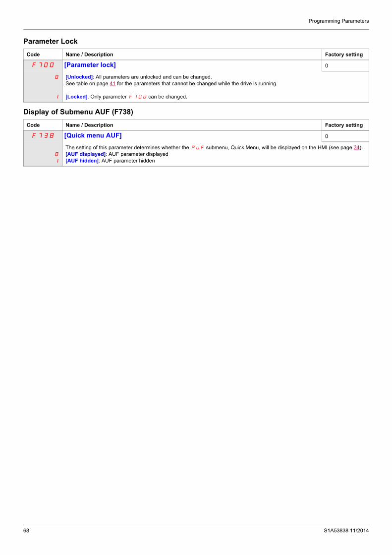
Programming Parameters
Parameter Lock
Display of Submenu AUF (F738)
Code Name / Description Factory setting
F700 [Parameter lock] 0
0
1
[Unlocked]: All parameters are unlocked and can be changed. See table on page 41 for the parameters that cannot be changed while the drive is running.
[Locked]: Only parameter F700 can be changed.
Code Name / Description Factory setting
F738 [Quick menu AUF] 0
0
1
The setting of this parameter determines whether the AUF submenu, Quick Menu, will be displayed on the HMI (see page 34).[AUF displayed]: AUF parameter displayed[AUF hidden]: AUF parameter hidden
68 S1A53838 11/2014

S1A53838 11/2014
Motor Control Parameters
5
Motor Control ParametersWhat's in this Chapter?
This chapter contains the following topics:
Topic Page
Motor Control Mode 70
Other Motor Control Mode Parameters 72
Motor Tuning 74
Auto-tuning 75
Expert parameters 77
Supply Voltage Correction and Motor Voltage Limitation 78
Motor 2 Control Parameters 79
Permanent Magnet Motor Control Law ([PM Control] (PM)) 81
69

Motor Control Parameters
Motor Control Mode
Constant V/Hz Mode with AutomaticTorque Boost ([Mot cont. mode sel.] (Pt) = 2 [Cst V/Hz+Boost])
Use parameter [Auto Torque Boost] (F402) to adjust the amount of automatic torque boost (see page 79).
If the ATV212 drive and the connected motor have the same power rating, and if the motor has a nominal 1500 rpm rating, no motor auto-tuning is required to use this motor control mode. Otherwise, follow the steps outlined in “Motor Tuning” on page 74.
Due to the feedback circuit used in this mode, it is possible for motor speed to oscillate. If this occurs, select the Constant V/Hz mode ([Mot cont. mode sel.] (Pt) = 0) and adjust torque boost manually with parameter [Motor Voltage Boost] (ub).
Sensorless Vector Control Mode ([Mot cont. mode sel.] (Pt) = 3 [SVC])
Sensorless vector control mode is only for use in applications where:
Each motor is powered by its own ATV212 drive (not for multi-motor applications). The motor has a power rating equal to that of the ATV212 drive, or no lower than one hp rating less. The motor has between two and eight poles (750...3000 rpm).
Sensorless vector control will not improve motor control above the motor’s rated speed.
Sensorless vector control is more effective if the motor leads are less than 30 m (100 ft) in length. If motor leads longer than 30 m (100 ft) are required, perform an auto-tuning with the long motor leads included in the circuit. Motor torque may not be maximized at the motor’s rated frequency due to voltage drop in the motor leads.
Connecting a load reactor or a motor filter on the output of the ATV212 drive may reduce the torque generated by the motor in sensorless vector control mode. Auto-tuning will most likely not be possible with a reactor or filter attached to the drive. Manual tuning will be required
Permanent Magnet motors Mode ([Mot cont. mode sel.] (Pt) = 6 [PM control])
Permanent magnet motors that are light, small in size, and highly efficient, as compared to induction motors, can be operated in sensor-less operation mode.
This feature can be used only for specific permanent magnet motors:
- IPM, Interior-buried Permanent Magnet motor.
- SPM, Surface-mounted Permanent Magnet motor.
0
Motor rated voltage
Motor Rated Frequency
: Automatically adjusts the amount of
torque boost.O
utp
ut
Vol
tag
e (
%)
Output Frequency (Hz)
70 S1A53838 11/2014

Motor Control Parameters
Code Name / Description Factory setting
Pt [Mot cont. mode sel.] Motor control mode 1
0
1
2
3
4
5
6
If [Driving Scroll] (F324) page 160 is set to [yes] (1) the setting is replaced by [SVC] (3).
[Constant V/Hz]: Constant V/HzUse constant V/Hz mode for loads that require the same torque at low speeds as at rated speeds. Low speed torque can be ad-justed manually by setting parameter [Motor Voltage Boost] (ub) (see page 73).
[Variable Torque]: Variable torqueUse variable torque mode for loads such as centrifugal fans and pumps whose torque requirements increase as a square of the increase in motor speed. Low speed torque can be adjusted manually by setting parameter ub.
[Cst V/Hz+Boost]: Constant V/Hz with automatic torque boostSee the diagram on page 70.This mode is similar to the constant V/Hz mode (for loads that require the same torque at low speeds as at rated speeds), except it automatically increases motor voltage and torque to compensate for increases in load.
[SVC]: Sensorless vector controlSee the diagram on page 70.Use sensorless vector control mode to increase torque at motor speeds below 3 Hz or to improve speed regulation (0.5 to 1%).
[Economy]: Energy savingIn energy savings mode, the ATV212 drive monitors motor loading and automatically modulates the voltage applied to the motor to optimize energy consumption.If the ATV212 drive and the connected motor have the same power rating, and if the motor has a nominal 1500 rpm rating, no motor auto-tuning is required to use this motor control mode. Otherwise, follow the steps outlined in “Motor Tuning” on page 74.
[Do not use]: Reserved
[PM Control]: Permanent Magnet Motor Control Law
0
Motor rated voltage
Motor Voltage Boost
Motor Rated Frequency
Output Frequency (Hz)
Ou
tpu
t Vo
ltag
e (%
)
0
Motor rated voltage
Motor Voltage Boost
Motor Rated FrequencyOutput Frequency (Hz)
Out
put
Vo
ltage
(%
)
DANGERHAZARD OF ELECTRIC SHOCK, EXPLOSION OR ARC FLASHIf [Mot cont. mode sel.] (Pt) is set to (6) (Permanent Magnet Motor Control Law), output phase loss monitoring, while the motor is running, is disabled. Phase loss and, by implication, accidental disconnection of cables, are not detected. Verify that this behavior does not result in unsafe conditions and implement alternative monitoring function if required.Failure to follow these instructions will result in death or serious injury.
S1A53838 11/2014 71

Motor Control Parameters
Other Motor Control Mode ParametersThe table below lists other parameters that may need to be adjusted, depending on the setting of parameter [Mot cont. mode sel.] (Pt).
Relationship between [Mot cont. mode sel.] (Pt) setting and Other Motor Parameters
X: Not applicable for the [Mot cont. mode sel.] (Pt) setting: Adjustment of this parameter is required.O: Adjust this parameter if necessary.
Parameter Function
Parameter [Mot cont. mode sel.] (Pt) setting
0 1 2 3 4 6
Constant V/Hz
Control
Variable Torque Control
ConstantV/Hz withAutomatic
Torque BoostControl
SensorlessVectorControl
EnergySavingControl
Permanent magnet Control
uL (vL) [Motor rated freq.]
uLu [Motor rated voltage]
ub [Mot Voltage Boost] X X X X
F170 [Mot 2 rated Freq.] O X X X X X
F171 [Motor 2 rated Volt] O X X X X X
F172 [Motor 2 Volt Boost] O X X X X X
F400 [Auto-tuning drive] X X O O O
F401 [Slip Compensation] X X X O X X
F402 [Auto Torque Boost] X X
F415 [Motor rated current] O O
F416 [Mot no-load current] X X O O O X
F417 [Motor rated speed] O O
F418 [Frequency loop gain] X X O O O O
F458 [Current loop gain] X X O O O O
F419 [Freq. loop stability] X X O O O O
F480 [No load cur. coef] X X O O X X
F485 [Stall control coef. 1] O O O O O O
F492 [Stall control coef. 2] O O O O O O
F494 [Mot. adj coefficient] O O O O O O
F495 [Motor voltage coef.] O O O O O O
F496 [PWM adj. coef.] O O O O O O
F912 [Autotune L q-axis] X X X X X
F913 [Autotune L d-axis] X X X X X
F921 [Init. Pos. Current] X X X X X O
F914 [N-S direction] X X X X X O
F915 [PM mode selection] X X X X X
F916 [PM Align cur. Level] X X X X X O
72 S1A53838 11/2014

Motor Control Parameters
(1) See table page 199.
Code Name / Description Adjustment range
Factory setting
ub [Motor Voltage Boost] 0.0 to 30.0% According to drive rating (1)
Low speed motor torque can be adjusted with parameter ub when parameter [Mot cont. mode sel.] (Pt) (see page 71) is set to 0 (Constant V/Hz) or 1 (Variable Torque). See curves on page 70 for more information.If nuisance overcurrent faults occur during starting, reducing the setting of parameter ub may help.
F601 [Motor Current Limit] 0.0 to 30.0% 10 to 110% of the drive’s output current rating 110%
Parameter F601 can be adjusted to limit current during motoring or braking.
Display in Current Limit Mode:When the drive goes into current limit mode, it will:Adjust the output frequency to limit the flow of motor current (down when motoring, up when braking).
Display the letter C and the output frequency flashing on the embedded software terminal, ex:
If parameter [Unit value selection] (F701) is set to 1 (see page 130), parameter F601 will be adjusted in amperes. If param-eter F701 is set to 0, parameter F601 will be adjusted as a percentage of the drive’s output rated current as listed on its nameplate.
The setting of parameter [Switch. freq. level] (F300) (see page 95) does not change the drive’s rated current for the sake of this calculation.
Do not set parameter F601 below the no-load current rating of the motor.
NOTICERISK OF DAMAGE TO THE MOTOR AND THE DRIVE Check that the motor will withstand this current. Check that the profile mission complies with the derating curve given in the installation manual
Failure to follow this instruction can result in equipment damage.
S1A53838 11/2014 73

Motor Control Parameters
Motor Tuning Tuning the drive to specific motor values will optimize motor performance if parameter [Mot cont. mode sel.] (Pt) (see page 71) is set to:
2 (constant V/Hz with automatic boost), 3 (sensorless vector control), or 4 (energy savings)
At a minimum, manually set parameters uL (vL), uLu (vLv), F415, F416, and F417.
Parameters [Slip Compensation] (F401), [Auto Torque Boost] (F402), [Frequency loop gain] (F418) and [Freq. loop stability] (F419) can be set manually or they can be set automatically using the auto tuning function, parameter [Auto-tuning drive] (F400).
More precise motor control adjustments can be made with parameters F307, F480, F485, F492, and F494 – F496.
(1) See table page 199.
Code Name / Description Adjustment range Factory setting
uLu [Motor Rated Voltage] According to drive rating (1)
According to drive rating (1)
Set parameter uLu (vLv) to the motor’s rated voltage as indicated on the motor nameplate.ATV212pppM3X: 50...330 V.ATV212pppN4: 50...660 VNote: Drive output voltage cannot be set to exceed the input line voltage level.
uL [Motor rated freq.] 25.0 to 400.0 Hz 50.0 Hz
If [Driving Scroll] (F324) page 160 is set to [yes] (1) the setting is replaced by 50.0 Hz.
Set parameter uL(vL) to the motor’s rated frequency as indicated on the motor nameplate.Note: It is possible to set the drive’s various motor control frequencies to 50 Hz by setting [Parameter reset] (tYP) to 1, the 50 Hz reset. For more information, see page 66.
tHr [Motor thermal prot.] Motor rated current overload setting 10 to 100% of the drive’s output cur-rent rating
100%
Set parameter tHr to the motor’s rated current as indicated on the motor nameplate for the selected operating voltage.If parameter [Unit value selection] (F701) is set to 1 (see page 130), parameter tHr will be adjusted in amperes.If parameter F701 is set to 0, parameter [Motor thermal prot.] (tHr) will be adjusted in percentage. In this case, divide the motor rated current by the drive rated current (as listed on its nameplate) and set parameter tHr to the resulting percentage.
The setting of parameter [Switch. freq. level] (F300) does not change the drive’s rated current for the sake of this calcu-lation (see page 95).
F607 [Mot overload time] Motor overload time 10...2400 s 300 s
NOTICERISK OF DAMAGE TO THE MOTORCheck that the motor will withstand this time without overheatingFailure to follow this instruction can result in equipment damage.
Parameter F607 determines how long the drive will support a 150% motor overload before a fault detection occurs.
F415 [Motor rated current] 0.1 to 200.0 A According to drive rating (1)
Set parameter F415 to the motor rated current in amperes as indicated on the motor’s nameplate.
F416 [Mot no-load current] Motor no-load current 10.0 to 100.0% According to drive rating (1)
Set parameter F416 to the ratio of the motor’s no load current to its rated current.
F417 [Motor rated speed] Motor rated speed 100.0 to 15000 rpm According to drive rating (1)
Set parameter F417 to the motor rated speed in rpm as indicated on the motor’s nameplate.
74 S1A53838 11/2014

Motor Control Parameters
Auto-tuning Before performing an auto-tune, verify that:
A motor is connected and any load-side disconnect is closed. The motor is completely stopped and de-energized. The motor should be cool (room temperature). There is only one motor connected to the drive. All of the motor leads that will be used in the final installation are included in the output circuit during the auto-
tuning process. Motor leads are no longer than 30 m (100 ft). Motor leads longer than 30 m (100 ft) may result in reduced
motor torque and less than optimal motor control. No load reactors or filters are included in the motor circuit. Output reactors and filters may cause an auto-
tuning detected fault Etn1 and reduce effectiveness of sensorless vector control. The motor is not more than 1 hp size smaller than the drive. The motor has at least 2 and not more than 8 poles (750...3000 rpm). The motor does not have a high slip rating.
Auto tuning is performed upon the first start command after parameter [Auto-tuning drive] (F400) below is set to 1, 2 and 3 and is normally completed within 3 seconds. During the auto-tuning process, the graphic display option displays Atn1.
During the auto-tuning process voltage is applied to the motor, although it barely rotates and produces very little torque.
During the auto-tuning process, the drive checks for an output phase loss detection regardless of the setting of parameter F605. An output phase loss detection EPH0 will abort the auto-tuning process.
If the auto-tuning process is unsuccessful, the drive will display Etn1. In this event, no results of the aborted auto-tuning 1 will be saved in the drive, and a manual tuning of parameters [Slip Compensation] (F401), [Auto Torque Boost] (F402), [Frequency loop gain] (F418) and [Freq. loop stability] (F419) will be required.
S1A53838 11/2014 75

Motor Control Parameters
Code Name / Description Adjustment range Factory setting
F400 [Auto-tuning drive] - 0
DANGERHAZARD OF ELECTRIC SHOCK OR ARC FLASH During auto-tuning, the motor operates at rated current. Do not service the motor during auto-tuning.Failure to follow these instructions will result in death or serious injury.
WARNINGLOSS OF CONTROL It is essential that the following parameters uLu, uL, F415 and F417 are correctly configured before starting auto-
tuning. When one or more of these parameters have been changed after auto-tuning has been performed, F400 will return 0
and the procedure will have to be repeated.Failure to follow these instructions can result in death or serious injury.
NOTICERISK OF DAMAGE TO THE MOTOR Conduct auto-tuning only after the motor has been connected and operation completely stopped. If auto-tuning is conducted immediately after operation stops, the presence of a residual voltage may result in abnormal
tuning. Failure to follow these instructions can result in equipment damage.
0
1
2
3
4
5
Auto tuning enable[Disabled]
[Initialize constant]: Factory setting of [Auto Torque Boost] (F402) for asynchronous motor. Factory setting of [Auto Torque Boost] (F402) , [Autotune L q-axis] (F912), and [Autotune L d-axis] (F913), and [Motor Rated Voltage] (vlv) for synchronous motor.
[Tun Dyn. 1]:Tune Dynamic, with driving run after the tuning.Application settings of [Auto Torque Boost] (F402) for asynchronous motor.Application settings of [Auto Torque Boost] (F402) , [Autotune L q-axis] (F912), and [Autotune L d-axis] (F913) for synchronous motor.
[Tun Dyn. 2]: Complete tune Dynamic, with driving run after the tuning. Application settings of [Auto Torque Boost] (F402) , [Autotune L q-axis] (F912), [Autotune L d-axis] (F913), and [Motor Rated Voltage] (vlv) for synchronous motor.
[Tun Static 1]: Tune Static, without driving run after the tuning.Application settings of [Auto Torque Boost] (F402) for asynchronous motor.Application settings of [Auto Torque Boost] (F402) , [Autotune L q-axis] (F912), and [Autotune L d-axis] (F913) for synchronous motor.
[Tun Static 2]: Complete tune Static, without driving run after the tuning. Application settings of [Auto Torque Boost] (F402) , [Autotune L q-axis] (F912), and [Autotune L d-axis] (F913), and [Motor Rated Voltage] (vlv) for synchronous motor.
Parameter F400 is reset to “0” after the auto tuning is performed.
76 S1A53838 11/2014

Motor Control Parameters
Expert parameters
Code Name / Description Adjustment range Factory setting
F390 [LL for ov.cur. prev.] Lower Limit function for Over Current Prevention 0.0 - UL 0.0
In the present software, motor speed is decreased to 0 Hz in case the stall prevention state is continued.When motor speed is lower than F390 during stall prevention, motor speed is kept to F390 to increase motor current.In this situation, motor current is beyond stall prevention level (F601 or F185), therefore over current or over load detected fault may occur in some case.
F480 [No load cur. coef] Magnetizing current coefficient 100 to 130% 100%
Use parameter F480 to fine-tune motor torque during low-speed operation. To increase motor torque in the low-speed operating range, increase the setting of parameter F480. However, only adjust parameter F480 if an auto tune does not yield sufficient low-speed torque. Increasing the setting of parameter F480 may increase the motor’s no-load current during low-speed operation. Do not set this parameter so that the motor’s no-load current exceeds its rated operating current.
F485 [Stall control coef. 1] Stall prevention control coefficient 1 10 to 250 100
Use parameter F485 to adjust the drive’s response to large, sudden changes in load when the motor is operated above its rated frequency. If a sudden change in load causes the motor to stall before the drive goes into current limit, gradually reduce the setting of F485.
F492 [Stall control coef. 2] Stall prevention control coefficient 2 50 to 150 100
Use parameter F492 to adjust the drive’s response to a drop in the line supply voltage when the motor is operated above its rated frequency. Such a drop in voltage often causes fluctuations in motor current or vibration in the motor. To reduce these dis-turbances, set parameter F492 to a value from 80 to 90. Note: Reducing the F492 setting increases the motor running current level.
F494 [Mot. adj coefficient] Motor adjustment coefficient - -
DO NOT ADJUST.
F495 [Motor voltage coef.] Maximum voltage adjustment coefficient 90 to 120% 104%
Use parameter F495 to limit the drive’s maximum output voltage. Increasing this setting increases torque when the motor is operated above its rated frequency, but may also cause motor vibration. Do not increase the value of F495 if motor vibrations occur.
F496 [PWM adj. coef.] Waveform switching adjustment coefficient 0.1 to 14.0 kHz 14.0 kHz
Adjusting the value of parameter F496 may reduce motor noise and vibration during PWM waveform frequency shifts in the mid-speed operating range.
Frequency command
RUN command (F or R)
Output Frequency (Hz)
F390
0 Time
Over current alarm status
ON
OFF
ON
OFF
S1A53838 11/2014 77

Motor Control Parameters
Supply Voltage Correction and Motor Voltage LimitationThe setting of parameter F307 determines:
If the drive’s voltage output will be corrected for fluctuations in the line supply voltage, or If the drive’s voltage output will be limited, despite increases in the line supply voltage.
The drive’s output voltage will not exceed the input supply voltage.
If parameter F307 is set to 0 or 2, no corrections are made in the motor voltage gating process in response to fluctuations in supply voltage. As a result, the V/Hz value of the output waveform to the motor will change in proportion to the input voltage. Conversely, if F307 is set to 1 or 3, the V/Hz value of the output waveform will be held constant, despite changes in the supply voltage level.
If parameter F307 is set to 0 or 1, output motor voltage will be limited to the value set by parameter [Motor rated voltage] (uLu) (see page 74), even if the input supply voltage rises. If F307 is set to 2 or 3, output motor voltage can rise above the level set by uLu if the input supply voltage rises above the motor rated voltage.
If parameter [Mot cont. mode sel.] (Pt) is set to a value of 2, 3, 4, 5, or 6, the supply voltage is corrected, regardless of the setting of parameter F307.
The diagrams below illustrate the impact of each setting of parameter F307.
0
F307 = 1
0
F307 = 0
0
F307 = 2
0
F307 = 3
Supply Voltage uncorrected, Motor Voltage Limited
uLu
Rated Voltage
Mo
tor
Vo
ltage
(V
)
OutputFrequency
Input Voltagex Input Voltage
High
Low
Supply Voltage corrected, Motor Voltage Limited
OutputFrequency
Supply Voltage uncorrected, Motor Voltage Unlimited Supply Voltage corrected, Motor Voltage Unlimited
Input Voltage High
Low
Input Voltage High
Low
Input Voltage High
Low
OutputFrequency
OutputFrequency
uLu
Rated Voltage
Mo
tor
Vol
tag
e (
V)
x Input Voltage
Mo
tor
Vo
ltage
(V
)M
oto
r V
olta
ge
(V
)
Code Name / Description Factory setting
F307 [Mot volt limitation] Supply Voltage Correction and Motor Voltage Limitation 3
0
1
2
3
[Motor volt limit]: Supply voltage uncorrected – motor voltage limited[Line&mot correct.]: Supply voltage corrected – motor voltage limited[No action]: Supply voltage uncorrected – motor voltage unlimited[U Line correction]: Supply voltage corrected – motor voltage unlimited
78 S1A53838 11/2014
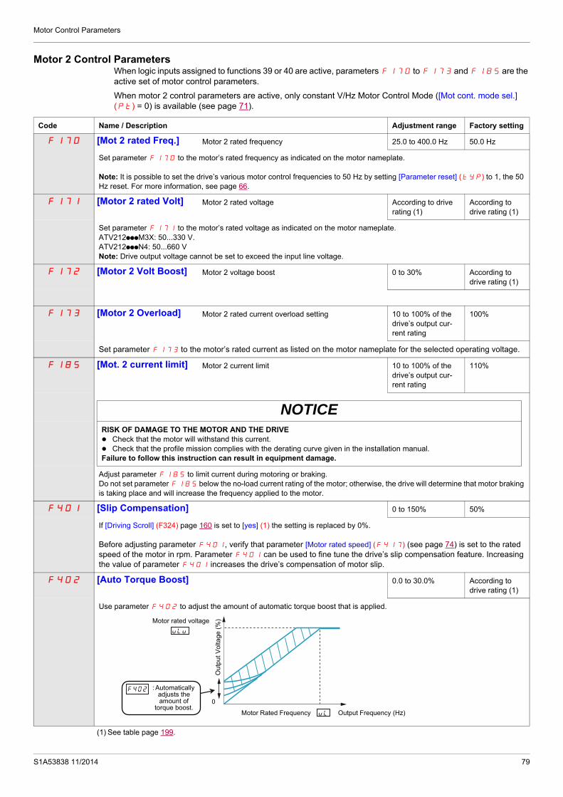
Motor Control Parameters
Motor 2 Control ParametersWhen logic inputs assigned to functions 39 or 40 are active, parameters F170 to F173 and F185 are the active set of motor control parameters.
When motor 2 control parameters are active, only constant V/Hz Motor Control Mode ([Mot cont. mode sel.] (Pt) = 0) is available (see page 71).
Code Name / Description Adjustment range Factory setting
F170 [Mot 2 rated Freq.] Motor 2 rated frequency 25.0 to 400.0 Hz 50.0 Hz
Set parameter F170 to the motor’s rated frequency as indicated on the motor nameplate.
Note: It is possible to set the drive’s various motor control frequencies to 50 Hz by setting [Parameter reset] (tYP) to 1, the 50 Hz reset. For more information, see page 66.
F171 [Motor 2 rated Volt] Motor 2 rated voltage According to drive rating (1)
According to drive rating (1)
Set parameter F171 to the motor’s rated voltage as indicated on the motor nameplate.ATV212pppM3X: 50...330 V.ATV212pppN4: 50...660 VNote: Drive output voltage cannot be set to exceed the input line voltage.
F172 [Motor 2 Volt Boost] Motor 2 voltage boost 0 to 30% According to drive rating (1)
F173 [Motor 2 Overload] Motor 2 rated current overload setting 10 to 100% of the drive’s output cur-rent rating
100%
Set parameter F173 to the motor’s rated current as listed on the motor nameplate for the selected operating voltage.
F185 [Mot. 2 current limit] Motor 2 current limit 10 to 100% of the drive’s output cur-rent rating
110%
NOTICERISK OF DAMAGE TO THE MOTOR AND THE DRIVE Check that the motor will withstand this current. Check that the profile mission complies with the derating curve given in the installation manual.Failure to follow this instruction can result in equipment damage.
Adjust parameter F185 to limit current during motoring or braking.Do not set parameter F185 below the no-load current rating of the motor; otherwise, the drive will determine that motor braking is taking place and will increase the frequency applied to the motor.
F401 [Slip Compensation] 0 to 150% 50%
If [Driving Scroll] (F324) page 160 is set to [yes] (1) the setting is replaced by 0%.
Before adjusting parameter F401, verify that parameter [Motor rated speed] (F417) (see page 74) is set to the rated speed of the motor in rpm. Parameter F401 can be used to fine tune the drive’s slip compensation feature. Increasing the value of parameter F401 increases the drive’s compensation of motor slip.
F402 [Auto Torque Boost] 0.0 to 30.0% According to drive rating (1)
Use parameter F402 to adjust the amount of automatic torque boost that is applied.
(1) See table page 199.
0
Motor rated voltage
Motor Rated Frequency
: Automatically adjusts the amount of
torque boost.
Ou
tput
Vo
ltage
(%
)
Output Frequency (Hz)
S1A53838 11/2014 79

Motor Control Parameters
F418 [Frequency loop gain] 1 to 150 40
Parameters F418 and [Freq. loop stability] (F419) reduce the speed of the drive’s response to a change in speed command. The factory setting of these two parameters assumes that the inertia of the load is three times as large as that of the motor shaft. Adjust these two parameters if the factory setting is not appropriate for the application.Note: It is possible for the drive’s output frequency to exceed its upper limit (parameter [Max frequency] (FH)) if the acceleration parameter (ACC or F507) is set to its minimum value.Increasing the setting of parameter F418 reduces the drive’s response time to changes in the speed reference.
F419 [Freq. loop stability] Frequency loop stability 1 to 100 20
Increasing the setting of parameter F419 further reduces the drive’s response to changes in the speed reference.
Code Name / Description Adjustment range Factory setting
80 S1A53838 11/2014

Motor Control Parameters
Permanent Magnet Motor Control Law ([PM Control] (PM)) Drive may be set to control synchronous motor. When [PM control] is activated, motor parameters are set to new default value. You can access to additional settings to optimize the motor control.
Motor parameters setting.
These motor parameters below are needed to set:
1 - Set (Pt) [Mot cont. mode sel.] to [PM Control] (6) see page 82.
2 - Set [Motor rated freq.] (uL), see page 74:
Note: Motor rated freq.] (uL) = [Motor rated speed] (F417) / (60 / np)[Motor rated speed] (F417), see page 74, indicated on the motor nameplate or follow the procedure step 4 above.np = Number of pole pairs, indicated on the motor nameplate.
3 - Set the Motor rated power (unit is kW) by [Motor rated cap.] (F405), see page 82
Note: P = C x ωP = Power in WC = N.m, indicated on the motor nameplate.
ω = rad s-1
ω = 2π x (FRS/np)FRS = [Motor rated freq.] (uL) see page 74, indicated on the motor nameplate.np = Number of pole pairs, indicated on the motor nameplate.
4 - Motor rated current (unit is A) is set by [Motor rated current] (F415), see page 74.
5 - Set [Motor rated speed] (F417), see page 74, without information:
Set the motor rated speed by FRS x (60 / np)FRS = [Motor rated freq.] (uL) see page 74, indicated on the motor nameplate.np = Number of pole pairs, indicated on the motor nameplate.
6 - Configure [Auto-tuning drive] (F400) to [Tun Static 2] (5), see page 83. Make the TUN (Run order is needed to start the TUN.)
- Motor’s rated voltage is set by [Motor Rated Voltage] (uLu)a, see page 82.
- Stator resistance is set by [Auto Torque Boost] (F402)a, see page 84.
- Axis "q" stator inductance in mH is set by [Autotune L q-axis] (F912)a, see page 85.
- Axis "d" stator inductance in mH is set by [Autotune L d-axis] (F913)a, see page 85.
7 - Check the value of [Saliency Level] (F936), see page 84.
8 - Set [PM mode selection] (F915) according to the [Saliency Level] (F936) value (see page 84).
9 - If (F936) is u 0.2, increase [Init. Pos. Current] (F921) see page 85 .
Configure [Auto-tuning drive] (F400) to [Tun Static 2] (5), see page 83. Make the TUN (Run order is needed to start the TUN.)
10 - Start the motor,
- if there is current limitation on starting, increase the [PM Align cur. Level] (F916) value (See page 85). - if its behavior is not optimal, reduce by 20% [Motor Rated Voltage] (uLu) value (see page 82). - After this procedure, if you need further assistance, contact your Schneider Electric Product Support.
(a) Auto Torque Boost] (F402) , [Autotune L q-axis] (F912), [Autotune L d-axis] (F913), and [Motor Rated Voltage] (uLu) may be defined automatically after activation of [Auto-tuning drive] (F400) = [Tun Dyn. 2] (3) or [Tun Static 2] (5)
S1A53838 11/2014 81

Motor Control Parameters
Code Name / Description Adjustment range Factory setting
Pt [Mot cont. mode sel.] Motor control mode selection - 1
0
1
2
3
4
5
6
If [Driving Scroll] (F324) page 160 is set to [yes] (1) the setting is replaced by [SVC] (3)
[Constant V/Hz]: Constant V/Hz[Variable Torque]: Variable torque[Cst V/Hz+Boost]: Constant V/Hz with automatic torque boost[SVC]: Sensorless vector control[Economy]: Energy saving[Do not use]: Reserved[PM Control]: Permanent Magnet Motor Control Law
uLu [Motor Rated Voltage] According to drive rating (1)
According to drive rating (1)
Set parameter uLu (vLv) to the motor’s rated voltage as indicated on the motor nameplate.ATV212pppM3X: 50...330 VATV212pppN4: 50...660 VNote: Drive output voltage cannot be set to exceed the input line voltage level.
uLu (vLv) may be defined automatically after activation of F400 = [Tun Dyn. 2] (3) or [Tun Static. 2] (5) if [Mot cont. mode sel.] (Pt) = (6)
uL [Motor rated freq.] 25.0 to 400 Hz 50.0 Hz
Set parameter uL(vL) to the motor’s rated frequency as indicated on the motor nameplate.Note: It is possible to set the drive’s various motor control frequencies to 50 Hz by setting [Parameter reset] (tYP) to 1, the 50 Hz reset. For more information, see page 66.
F405 [Motor rated cap.] Motor rated capacity 0.01 to 75 kW According to drive rating (1)
Set parameter F405 to the motor rated capacity in kilowatt. It permite to calculate automatically [Motor Rated Voltage] (uLu) after TUN F400 [Auto-tuning drive]
F415 [Motor rated current] 0.1 to 200.0 A According to drive rating (1)
Set parameter F415 to the motor rated current in amperes as indicated on the motor’s nameplate.
F417 [Motor rated speed] Motor rated speed 100.0 to 15000 rpm According to drive rating (1)
Set parameter F417 to the motor rated speed in rpm as indicated on the motor’s nameplate.
(1) See table page 199.
DANGERHAZARD OF ELECTRIC SHOCK, EXPLOSION OR ARC FLASHIf [Mot cont. mode sel.] (Pt) is set to (6) (Permanent Magnet Motor Control Law), output phase loss monitoring, while the motor is running, is disabled. Phase loss and, by implication, accidental disconnection of cables, are not detected.Verify that this behavior does not result in unsafe conditions and implement alternative monitoring function if required.Failure to follow these instructions will result in death or serious injury.
82 S1A53838 11/2014

Motor Control Parameters
F400 [Auto-tuning drive] - 0
0
1
2
3
4
5
Auto tuning enable[Disabled]
[Initialize constant]: Factory setting of [Auto Torque Boost] (F402) for asynchronous motor. Factory setting of [Auto Torque Boost] (F402) , [Autotune L q-axis] (F912), and [Autotune L d-axis] (F913), and [Motor Rated Voltage] (vlv) for synchronous motor.
[Tun Dyn. 1]:Tune Dynamic, with driving run after the tuning.Application settings of [Auto Torque Boost] (F402) for asynchronous motor.Application settings of [Auto Torque Boost] (F402) , [Autotune L q-axis] (F912), and [Autotune L d-axis] (F913) for synchronous motor.
[Tun Dyn. 2]: Complete tune Dynamic, with driving run after the tuning. Application settings of [Auto Torque Boost] (F402) , [Autotune L q-axis] (F912), [Autotune L d-axis] (F913), and [Motor Rated Voltage] (vlv) for synchronous motor.
[Tun Static 1]: Tune Static, without driving run after the tuning.Application settings of [Auto Torque Boost] (F402) for asynchronous motor.Application settings of [Auto Torque Boost] (F402) , [Autotune L q-axis] (F912), and [Autotune L d-axis] (F913) for synchronous motor.
[Tun Static 2]: Complete tune Static, without driving run after the tuning. Application settings of [Auto Torque Boost] (F402) , [Autotune L q-axis] (F912), and [Autotune L d-axis] (F913), and [Motor Rated Voltage] (vlv) for synchronous motor.
Parameter F400 is reset to “0” after the auto tuning is performed.
F458 [Current loop gain] Current loop gain 0...100 Hz 0 Hz
Parameter F458 is set to the response gain of current loop.If [Mot cont. mode sel.] (Pt) page 82 is set to [PM control] (6) the setting is replaced by 25 Hz.
Note: Contact Schneider electric product support to confirm the modification of this parameter.
(1) See table page 199.
DANGERHAZARD OF ELECTRIC SHOCK OR ARC FLASH During auto-tuning, the motor operates at rated current. Do not service the motor during auto-tuning.Failure to follow these instructions will result in death or serious injury.
WARNINGLOSS OF CONTROL It is essential that the following parameters uLu, uL, F415 and F417 are correctly configured before starting auto-
tuning. When one or more of these parameters have been changed after auto-tuning has been performed, F400 will return 0
and the procedure will have to be repeated.Failure to follow these instructions can result in death or serious injury.
NOTICERISK OF DAMAGE TO THE MOTOR Conduct auto-tuning only after the motor has been connected and operation completely stopped. If auto-tuning is conducted immediately after operation stops, the presence of a residual voltage may result in abnormal
tuning. Failure to follow these instructions can result in equipment damage.
S1A53838 11/2014 83

Motor Control Parameters
Refer to the following tables to select the setting of the parameter F915, F915 is selected by the saliency level F936
(1) There is some motor electrical magnetic noise at start and low speed area.(2) There is some motor electrical magnetic noise at start. It can not be started in case of high start-up torque.(3) It goes opposite direction at start sometimes. It cannot be started in case rotor saliency is high.
F418 [Frequency loop gain] 1 to 150 40
Parameters F418 and [Freq. loop stability] (F419) reduce the speed of the drive’s response to a change in speed command. The factory setting of these two parameters assumes that the inertia of the load is three times as large as that of the motor shaft. Adjust these two parameters if the factory setting is not appropriate for the application.Note: It is possible for the drive’s output frequency to exceed its upper limit (parameter [Max frequency] (FH)) if the acceleration parameter (ACC or F507) is set to its minimum value.Increasing the setting of parameter F418 reduces the drive’s response time to changes in the speed reference.
F419 [Freq. loop stability] Frequency loop stability 1 to 100 20
Increasing the setting of parameter F419 further reduces the drive’s response to changes in the speed reference.
F495 [Motor voltage coef.] Maximum voltage adjustment coefficient 90 to 120% 104%
Use parameter F495 to limit the drive’s maximum output voltage. Increasing this setting increases torque when the motor is operated above its rated frequency, but may also cause motor vibration. Do not increase the value of F495 if motor vibrations occur.
F936 [Saliency Level] Saliency coefficient for PM motor 0 to 2.55 0
PM type [PM mode selection] (F915) is selected by the saliency level [Saliency Level] (F936)
F936 u 0.2 = high saliency F936 < 0.2 = low saliency.
Note: This parameter is automatically computed with the setting of [Autotune L q-axis] (F912) and [Autotune L d-axis] (F913)
F915 [PM mode selection] PM control mode selection - 3
0
1
2
3
4
[Basic Ctrl]: basic control[Ctrl Type1]: control type 1 (for IPM, interior-buried Permanent Magnet motor)[Ctrl Type2]: control type 2 (for IPM, interior-buried Permanent Magnet motor)[Ctrl Type3]: control type 3 (for IPM / SPM, interior-buried Permanent Magnet motor / Surface-mounted Permanent Magnet motor)[Ctrl Type4]: control type 4 (for IPM / SPM, interior-buried Permanent Magnet motor / Surface-mounted Permanent Magnet motor)
- big starting torque is needed.- for constant torque application.(1)
- big starting torque is not needed.- for variable torque application (2)
- big starting torque is not needed- for variable torque application- motor electrical magnetic noise is forbidden (3)
The saliency level is high (F936 u 0.2)
F915 = 4 or 2 F915 =1 or 3 F915 =0
The saliency level is low (F936 < 0.2)
F915 =3
Code Name / Description Adjustment range Factory setting
F402 [Auto Torque Boost] 0.0 to 30.0% According to drive rating
Use parameter F402 to adjust the amount of automatic torque boost that is applied.
0
Motor rated voltage
Motor Rated Frequency
: Automatically adjusts the amount of
torque boost.
Out
put
Vol
tag
e (
%)
Output Frequency (Hz)
84 S1A53838 11/2014

Motor Control Parameters
F912 [Autotune L q-axis] q-axis self-inductance 0.01 to 650 mH 10
Axis "q" stator inductance in mHThe setting is replaced by the result of the auto-tuning operation, if it has been performed.
Measured between the neutral and the phase, its value could be differente than the datasheet of the motor.[Autotune L q-axis] (F912) is defined automatically after activation of [Auto-tuning drive] (F400) = [Tun Dyn. 2] (3)
F913 [Autotune L d-axis] d-axis self-inductance 0.01 to 650 mH 10
Axis "d" stator inductance in mHThe setting is replaced by the result of the auto-tuning operation, if it has been performed.
Measured between the neutral and the phase, its value could be differente than the datasheet of the motor.[Autotune L q-axis] (F913) is defined automatically after activation of [Auto-tuning drive] (F400) = [Tun Dyn. 2] (3)
F916 [PM Align cur. Level] Stabilization at the starting and low speed(for PM) 0 to 100 % 25 %
It might be able to stabilize the motor rotation behavior by the current in D axis at no load when starting or low-speed
If you have a torque jolt, when starting / stopping or low-speed, it is recommended to increased the setting of 916.If E-20 [Excess torque boost flt] trip occurs at the start, it is recommended to increased the setting of 916.
In the case of F915=0, 1, 2, 3
In the case of F915=4
Starting current F916 is set 25% as the default setting, Limit it to the value of about 75% in the maximum with consideration of copper loss and iron loss of the motor.If the loss of motor at no load is made decreased, please decrease the value of F916 confirming the stability when starting.
F921 [Init. Pos. Current] Current for initial position estimation 10 to 150 % 100 %
In case of position detection 3, the current level can be set by this parameter, during the auto-tuning for d axis / q axis inductance,the maximum current level can be adjusted by this parameter setting.
F420 [Torque Boost Coef] Compensation coefficient of torque boost 0 to 200% 90 %
If synchronous or asynchronous motor is used, F420 [Torque Boost Coef] is set to 90%.If you have a torque jolt, when starting / stopping or low-speed, increase the value of F420
Note:If E-20 [Excess torque boost flt] trip occurs at the start, it is recommended to be decreased the setting of F420
K*Fn (K*vL) Rotor speed
0
Stabilization current in D axis F916 to 25 %
Current Level (%)
F916 to 25 %
Current Level (%)
K*Fn (K*vL)
0
Rotor speed
Stabilization current in D axis
S1A53838 11/2014 85

Motor Control Parameters
Parameters described in this page can be accessed by the extended menu
Code Name / Description Adjustment range Factory setting
F914 [N-S direction] Method of detection 0 - 1 0
0
1
N-S Method of detection.
If F914 = 0, the N-S direction of rotor position is judged by the method of DC offset for position detection.If F914 = 1, the N-S direction of rotor position is judged by the method of AC offset for position detection.
Note : N-S method of detection is available if [PM mode selection] (F915) is set to [Ctrl Type1] (1) or [Ctrl Type2] (2)
F917 [PM Max torq. Ctrl] Max torque control activation (for IPM) 0 - 1 1
0
1
[0] : Deactivation[1] : Activation
F918 [Cur. phase adjt] - 45.0 to 45.0 0
It is possible to aim the higher efficiency in the case of IPM (Interior Permanent Magnet), by activation of [PM Max torq. Ctrl] (F917) which makes required current the minimum, the loss of m otor and driver may be reduced and the efficiency may be attained higher level.
F920 [Position Adjust] 0 - 150 % 0 = Auto
In case of heavy load, the estimated position can be adjusted by setting this parameter.
Adjustment for position estimation, available if [PM mode selection] (F915) is set to [Ctrl Type2] (2) or |Ctrl Type4] (4).
86 S1A53838 11/2014

S1A53838 11/2014
Drive Control Parameters
6
Drive Control ParametersCode Name / Description Adjustment range Factory setting
CMOd [Command mode sel] Remote Mode Start/Stop Control - 0
0
1
2
The setting of parameter CMOd determines the source of start, stop, forward, and reverse operation commands when the drive is in remote mode.The drive needs to be stopped to make changes to parameter CMOd.See diagram on page 50 and description page 54 for more information on the source of the drive’s operation commands.[Logic inputs]: Control terminal logic inputs[HMI]: Graphic display option[Communication]: Serial communication
FMOd [Frequency mode sel] Remote Mode Primary Speed Reference Source - 1
1
2
3
4
5
The setting of parameter FMOd determines the source of the drive’s speed reference when the drive is in remote mode.The drive needs to be stopped to make changes to parameter FMOd.See diagram on page 50 and description page 54 for more information on the source of the drive’s speed reference.[Ref source VIA]: VIA[Ref source VIB]: VIB[HMI reference]: Graphic display option[Serial com ref.]: Serial communication[+/- Speed]: +/- Speed
FC [Local speed ref.] Local Mode Speed Reference LL - UL 0.0 Hz
The speed reference set by the UP/DOWN keys in local mode will be stored in parameter FC when the ENT key is pressed. The next time the drive is Power ON in local mode, it will accelerate the motor directly to the speed setpoint memorized by FC.
Fr [Local mot. direction] Local Mode Motor Rotation Direction Command - 0
0
1
2
3
[Run FW]: Run forward only.[Run rev.]: Run reverse only.[Run FW+rev]: Run forward with reverse selectable.[Run rev+FW]: Run reverse with forward selectable.
If Fr is set to 2 or 3:The motor direction can be changed in local mode to forward by pressing the UP key while holding the ENT key and to reverse by pressing the DOWN key while holding the ENT key. The new motor direction will be displayed (forward = Fr-F, reverse = Fr-r) before the motor direction is reversed.
The motor’s last operating direction in local mode will be stored before a power removal or loss detection. When power is restored to the drive, the local mode motor rotation direction will be the same as before the power loss detection.
If [Switch rem/Local] F295 (see page 88) is enabled and control is transferred from remote to local mode, the local mode operation will assume the same motor rotation direction as in remote mode, regardless of the setting of Fr.
F707 [Loc. speed ref. step] Local Mode Speed Reference Step Changes - 0.0 Hz
0
1
[Disable]: Disabled (0.00).[Enable]: Enabled (0.01 to Maximum Frequency [Max frequency] (FH) in Hz).If parameter F707 is disabled in local mode, the drive’s speed reference will change in steps of 0.1 Hz each time the UP or DOWN key is pressed.
If parameter F707 is enabled in local mode, the drive’s speed reference will change in steps equal to the setting of F707 each time the UP or DOWN key is pressed.
Enabling parameter F707 only affects drive operation if parameter [Customized freq val] (F702) is set to 0.00. See page 131.
If the display flashes “HI” or “LO”, it indicates that repeated usage of the UP or DOWN keys has caused to drive’s speed reference to reach either the [Low limit frequency] (LL) (see page 92) or the [Upper limit freq] (UL) (see page 92). This may happen if param-eter F707 is set to a value larger than 0.00 Hz.
87

Drive Control Parameters
F721 [Loc. mot stop mode] Local Mode Motor Stop Type - 0
0
1
The setting of parameter F721 determines the type of motor stop that will be executed when then embedded display terminal STOP key is pressed.
The RUN and STOP keys needs to be enabled be setting parameter [Run/stop key] (F733) (see page 90) to 0 for the motor to stop when the embedded display terminal STOP key is pressed.
[Ramp stop]: Ramp stop[Freewheel]: Freewheel stop
F295 [Switch rem/Local] Bumpless transfer from remote to local control - 1
0
1
If parameter F295 is enabled, the speed reference, run and direction commands will be transferred from remote to local mode when the LOC/REM key is pressed. Operation of the drive is not affected by a remote to local control mode transition.
If parameter F295 is disabled, a remote to local control mode transition will cause the drive to remove power from the motor. A new run command and speed reference will need to be entered in the local mode.
Regardless of the setting of parameter F295, a local to remote transition will cause the drive to immediately respond to the remote commands present at the moment of the transition.
[No bumpless]: Bumpless disabled[Bumpless]: Bumpless enabled
F256 [Time limit low spd] 0.0 to 600 s 0.0 s
0
1
[Disable]: (0.0)[Enable]: (0.01 to 600 seconds)If parameter F256 is enabled and if the drive operates continuously at [Low limit frequency] (LL) (see page 92) for a time period equal to the setting of F256, the drive will ramp the motor to a stop. While the motor is stopped, “LStP” will flash on the drive embedded display terminal.
When the speed reference to the drive exceeds the low speed level LL+F391, the drive will accelerate the motor to the new speed reference.
If parameter F256 is enabled, drive operation at or below the low speed level is also monitored during startup or during reversing of the motor. See diagram below.
F207 [Remote spd ref 2] - 2
1
2
3
4
5
VIAVIBHMICommunication+/- Speed
Parameter [Remote spd ref 2] (F207) defines the remote mode secondary speed reference source. The setting of parameter [Au-to/man speed ref] (F200) (see page 118) determines whether this source is used for the speed reference. If F200 is set to 0, a logic input terminal set to function 38 (see page 118) determines if [Remote spd ref 2] (F207) identifies the speed reference source. If F200 is set to 1, [Remote spd ref 2] (F207) is the speed reference source when the drive’s output frequency is 1 Hz or below. See diagram on page 50 for more detail.
Code Name / Description Adjustment range Factory setting
+
Outputfrequency (Hz)
RunCommand
Time (s)ONOFF
88 S1A53838 11/2014

Drive Control Parameters
F650 [Forced fire control] - 0
WARNINGLOSS OF CONTROLThe value of F650 will impact the direction of the motor.- Check wiring motor power UVW is correct.- Verify that the value of F650 is convenient for this application.Failure to follow these instructions can result in death, serious injury, or equipment damage.
0
1
2
[Disable][Enable forward][Enable Reverse]To enable Forced fire control, set parameter F650 to1 or 2 and assign a logic input to function 52 or 53 (see page 104). When parameter F650 is set to1 or 2, the embedded display will briefly flash the code FIrE.If parameter F650 is set to1 or 2 and a logic input assigned to function 52 or 53 is activated, the drive will run at the frequency set by parameter [Forced speed freq.] (F294) (see below).
Note: • First set [Motor direction] (F311) page 96 to allow forward or reverse operation.• Push the ENT button for 2 sec to complete the setting.• See F659 for more information of the behavior.
F659 [Forced fire function] - 0
0 [Enable transition]When parameter F659 is set to 0, the function is enabling on transition 0 -->1 of the logic input. The transition 1 -->0 will not disable the function.
WARNINGLOSS OF CONTROLIf the Forced fire mode on logic input (function 52) has been enabled and F659 is set to 0, the drive will run and only removing power from the drive will stop it.If the Fire mode on logic input (function 53) has been enabled and F659 is set to 0, the drive will run and only removing power from the drive or a fault detection or a pressing on the STOP key on the display terminal will stop the drive.Check that this value of F659 is convenient for the application.Failure to follow these instructions can result in death, serious injury, or equipment damage.
1 [Enable level 1]When parameter F659 is set to 1, if the logic input is set to 0 the function is disabled.If the logic input is set to 1 the function is enable
WARNINGRISK OF APPLICATION MALFUNCTIONWhen F659 is set to 1 for safety reason, the forced mode will be inhibited if the logic input is inactivated for any reason (order removed, input broken, wiring contact lost).- Check that this value of F659 is conveniant for the application.- If you need to continue to run if forced mode in any circonstance, select an other value of F659.Failure to follow these instructions can result in death, serious injury, or equipment damage.
2 [Enable level 0]When parameter F659 is set to 2, if the logic input is set to 1 the function is disabled.If the logic input is set to 0 the function is enable.
DANGERUNINTENDED EQUIPMENT OPERATIONWhen F659 is set to 2 for safety reason, the motor will run at Forced speed F294 in case of intempestive wire disconnection.- Check and control the wiring connection periodically.- Protect the signal conductors against damage that could result in unintentional conductor grounding.Failure to follow these instructions will result in death or serious injury.
F294 [Forced speed freq.] LL - UL 50.0 Hz
The F294 parameter is used to set the fixed frequency command for the drive when it is in Forced or Fire mode.
Code Name / Description Adjustment range Factory setting
S1A53838 11/2014 89

Drive Control Parameters
F730 [Up/down key ref] 0
0
1
The setting of parameter F730 determines whether it is possible to set the drive’s speed by means of the embedded display ter-minal in local mode.[Enable][Disable]
F732 [Loc/rem key] 0
0
1
2
Use parameter F732 to enable or disable the LOC/REM key on the drive embedded display terminal.If the LOC/REM key is disabled, switching between local and remote mode can be achieved with parameters [Frequency mode sel] (FMOd) and [Command mode sel] (CMOd). See page 87.
[Permitted memo]: still retained with the power off.[Prohibited][Permitted no memo]: cancelled with the power off.
F733 [Run/stop key] 0
0
1
[Enable][Disable]
The setting of parameter F733 determines whether it is possible to start and stop the drive by the Run/Stop keys located on the drive and graphic display option.
F734 [Priority stop] 0
WARNINGLOSS OF CONTROLYou are going to disable the stop button located on the drive and graphic display optionDo not select 1 unless exterior stopping methods exist.Failure to follow these instructions can result in death, serious injury, or equipment damage.
0
1
The setting of parameter F734 determines whether it is possible to stop the drive by the Stop key located on the drive and graphic display option.
[Enable][Disable]
F735 [HMI reset button] 1
0
1
The setting of parameter [HMI reset button] (F735) determines whether it is possible to clear a drive detected fault by means of the embedded display terminal STOP key (see page 55 for more detail).
[Enable][Disable]
Code Name / Description Adjustment range Factory setting
90 S1A53838 11/2014

S1A53838 11/2014
Application Parameters
7
Application ParametersWhat's in this Chapter?
This chapter contains the following topics:
Topic Page
Skip Frequencies 97
DC Injection Braking Parameters 98
91

Application Parameters
Application parameters
Code Name / Description Adjustment range Factory setting
FH [Max frequency] Maximum Frequency 30.0 Hz to 400.0 Hz 50.0 Hz
If [Driving Scroll] (F324) page 160 is set to [yes] (1) the setting is replaced by 90%.
The setting of parameter FH determines the maximum output frequency of the drive.
FH limits the setting of parameter [Upper limit freq] (UL) (see page 92), which can be adjusted while the drive is operating.Acceleration and deceleration rates are also affected by the setting of FH, as the definition of [Acceleration time 1] (ACC) or [Deceleration time 1] (dEC) (see page 93) is the time it takes for the drive to ramp the motor up or down between zero speed and the setting of FH.FH can only be adjusted while the drive is stopped.
UL [Upper limit freq] High speed 0.5 to [Max frequency] (FH) 50.0 Hz
If [Driving Scroll] (F324) page 160 is set to [yes] (1) the setting is replaced by 90%.
Parameter UL sets the maximum frequency that can be commanded to the drive by the local or remote speed reference source. The top end of its range is limited by the setting of Maximum frequency [Max frequency] (FH). See diagram above.
LL [Low limit frequency] Low speed 0.0 to [Upper limit freq] (UL) 0.0 Hz
If [Driving Scroll] (F324) page 160 is set to [yes] (1) the setting is replaced by 30%.
Parameter LL sets the minimum frequency that can be commanded to the drive by the local or remote speed reference source.See diagram above.
F240 [Mot start freq.] Output Starting Frequency 0.5 to 10.0 Hz 0.5 Hz
The setting of parameter F240 determines the drive’s output frequency at the moment it receives a start command. There is no acceleration time to reach the parameter F240 level.
Parameter F240 is typically set for the rated slip frequency of the motor. This allows motor torque to be generated as soon as a start command is given. Adjust parameter F240 when a delay in the motor’s response to a start command adversely affects the application.
To determine the motor’s slip frequency:1) Subtract the motor’s rated speed at full load from it’s no-load speed (in rpm). 2) Divide the result by the no-load speed. 3) Multiply this result by the motor’s rated frequency in Hz.
Example: Motor no-load speed = 1500 rpmMotor rated speed at full load = 1450 rpmMotor rated frequency = 50 Hz
1500 rpm – 1450 rpm = 50 rpm50 rpm / 1500 rpm = 3.33%50 Hz x 0.0333 = 1.7 Hz (motor slip frequency)
0 100% 0 100%
Output frequency (Hz) Output frequency (Hz)
Speed Reference Speed Reference
92 S1A53838 11/2014

Application Parameters
ACC [Acceleration time 1] 0.0 to 3200 s According to drive rating (5)
If [Driving Scroll] (F324) page 160 is set to [yes] (1) the setting is replaced by 0.9 s.
The setting of parameter ACC determines the slope of the acceleration ramp and the time it takes for the output frequency of the drive to increase from 0 Hz to the setting of [Max frequency] (FH) (see page 92).
If parameter [Auto ramp] (AU1) (see page 95) is set to 1 or 2, the acceleration ramp may be increased or decreased from the setting of ACC, depending on the amount of load on the motor during ramp up.
If two different acceleration rates are needed, see parameter [Acceleration time 2] (F500) on page 93.
dEC [Deceleration time 1] 0.0 to 3200 s According to drive rating (5)
If [Driving Scroll] (F324) page 160 is set to [yes] (1) the setting is replaced by 0.9 s.
The setting of parameter dEC determines the slope of the deceleration ramp and the time it takes for the output frequency of the drive to decrease from the setting of [Max frequency] (FH) to 0 Hz.
If parameter [Auto ramp] (AU1) is set to 1, the deceleration ramp may be increased or decreased from the setting of dEC, depending on the amount of load on the motor during ramp down. See diagram above.
If two different deceleration rates are needed, see parameter [Deceleration time 2] (F501) on page 93.
F500 [Acceleration time 2] 0.0 to 3200 s 20.0 s
Parameter F500 sets the second acceleration time. Switching between acceleration rates 1 and 2 is accomplished by means of:
Parameter [Ramp switching] (F504) (see page 95),
A particular operating frequency (see parameter [Commut. ramp freq.] (F505) on page 95), orA logic input assigned to functions 5, 20, 21, 30, 31 – 35, or 40 (see table beginning on page 101)
F501 [Deceleration time 2] 0.0 to 3200 s 20.0 s
Parameter F501 sets the second deceleration time. Switching between deceleration rates 1 and 2 is accomplished by means of:- Parameter [Ramp switching] (F504) (see page 95),- A particular operating frequency (see parameter [Commut. ramp freq.] (F505) on page 95), or- A logic input assigned to functions 5, 20, 21, 30, 31 – 35, or 40 (see table beginning on page 101).
(5) See table page 199.
Code Name / Description Adjustment range Factory setting
0
Output frequency (Hz)
Time (Sec)
0(1) (2) (3) (4)
Output Frequency (Hz)
Speed Reference
(1) ACC Acceleration Slope(2) F500 Acceleration Slope(3) F501 Deceleration Slope(4) dEC Deceleration Slope
Acceleration/Deceleration SwitchingLogic Input
Time (S)
S1A53838 11/2014 93

Application Parameters
F502 [Acc/dec 1 pattern] 0
0
1
2
[Linear][S-ramp 1] (see diagram below)[S-ramp 2] (see diagram below for [Acc/dec 2 pattern] (F503) parameter).The linear acceleration and deceleration pattern is illustrated in diagram on page 93 and is used in most applications.S-pattern 1 (see diagram below) is for use in applications that need the shortest ramp time possible while minimizing jerks during speed changes. See below for more information about parameters [Acc/Dec S-pat start] (F506) and [Acc/Dec S-pat end] (F507).
F503 [Acc/dec 2 pattern] 0
0
1
2
[Linear][S-ramp 1] See diagram below.[S-ramp 2] See previous diagram for parameter Acc/Dec Pattern 1 [Acc/dec 1 pattern] (F502).S-pattern 2 (diagram below) is for use in high-speed spindle applications where acceleration and deceleration rates need to be reduced as the motor operates above its rated operating frequency—a constant hp region where motor torque is reduced.Use parameter F503 to select the second Acc/Dec pattern. Switching between Acc/Dec patterns 1 and 2 is accomplished by means of:
Parameter [Ramp switching] (F504) (see page 95),
A particular operating frequency (see parameter [Commut. ramp freq.] (F505) on page 95), orA logic input assigned to functions 5, 20, 21, 30, 31 – 35, or 40 (see table beginning on page 101).
For more information on Acc/Dec patterns, see parameter [Acc/dec 1 pattern] (F502) above.
F506 [Acc/Dec S-pat start] Acc/Dec S-pattern lower limit 0 to 50% of acceleration time 10%
Use parameter F506 to adjust the lower portion of S-pattern 1. See diagram on page 95.
F507 [Acc/Dec S-pat end] Acc/Dec S-pattern Upper Limit 0 to 50% of acceleration time 10%
Use parameter F507 to adjust the upper portion of the S-pattern 1. See diagram on page 95.
Code Name / Description Adjustment range Factory setting
0
xx
Output Frequency (Hz)Maximum Frequency
Actual Acceleration Time
Time (S)
Set Frequency
0
Output Frequency (Hz)Maximum Frequency
Actual Acceleration Time
Time (S)
Set Frequency
Motor RatedFrequency
Constant hpRegion
94 S1A53838 11/2014

Application Parameters
F504 [Ramp switching] Acc/Dec Pattern Selection - 1
1
2
[Ramp 1][Ramp 2]Parameter F504 determines the Acc/Dec pattern.
F505 [Commut. ramp freq.] Acc/Dec pattern switching frequency 0.0 to [Upper limit freq] (UL) (Hz)
0.0 Hz
If parameter F505 is set to a frequency greater than 0.0, the drive will use Acc/Dec pattern 1 above that frequency and Acc/Dec pattern 2 above.
AU1 [Auto ramp] Auto ramp adaptation 1
0
1
2
[Disabled][Enable] - [Acceleration time 1] (ACC) and [Deceleration time 1] (dEC) (see page 93)[ACC only] - [Acceleration time 1] (ACC) only
If parameter AU1 is set to 1 or 2, the drive will monitor its own loading level and optimize the acceleration and deceleration ramps. The acceleration and deceleration (AU1 = 1 only) rates will be automatically adjusted between 1/8 to 8 times the settings of [Acceleration time 1] (ACC) and [Deceleration time 1] (dEC), depending on the drive’s current rating and the load level on the motor. ACC and dEC should be appropriately set for an average load in the application. If the load on the motor increases rapidly during ramp up or ramp down, the auto ramp adaptation feature may not help prevent the drive from experiencing an over-current or overvoltage.
If the application requires a consistent acceleration and deceleration time, set AU1 to 0, and set ACC and dEC manually as needed. The manual acceleration and deceleration times can still be overridden by the [Motor Current Limit] (F601) (see page 73) and [Overvoltage fault] (F305) (see page 139) and [Overvoltage level] (F626) (see page 139) functions.
F300 [Switch. freq. level] Switching Frequency Level 6.0 to 16.0 kHz in 0.1 kHz steps According to drive rating (1)
Increasing the switching frequency may reduce audible motor noise. Increasing the switching frequency will increase the heat dissipated by the drive. The capacity of the drive may need to be derated accordingly if the switching frequency is increased. See the derating curves in the ATV212 Installation Manual.
(5) See table page 199.
Code Name / Description Adjustment range Factory setting
0
Output Frequency (Hz)
Time (S)
0(1) (2) (3) (4)
Output Frequency (Hz)
Speed Reference
(1) ACC Acceleration Slope(2) F500 Acceleration Slope(3) F501 Deceleration Slope(4) dEC Deceleration Slope
Acceleration/Deceleration SwitchingLogic Input
Time (S)
S1A53838 11/2014 95

Application Parameters
(1) See table page 200.(2) For 400 V applications with motor leads longer than 30 m (100 ft).
F311 [Motor direction] - 1
0
1
2
Use parameter F311 to permit only forward or reverse operation.
If [Driving Scroll] (F324) page 90 is set to [yes] (1) the setting is replaced by [FW only] (1).
[Fw & Rev.][Fw only][Rev. only]
F312 [Noise reduction] Switching Frequency Random Mode 0
0
1
Random control of the switching frequency may reduce audible motor noise.Random control of the switching frequency will not be performed if the switching frequency is set above 7.1 kHz, regardless of the setting of F312.[Disable][Enable]
F316 [Switch. freq. mode] Switching frequency control mode 1
0
1
2
3
[Fixed] - ATV212pppM3X and ATV212pppN4: switching frequency NOT automatically reduced[Auto] - ATV212pppM3X and ATV212pppN4: switching frequency automatically reduced[460 V fixed] - ATV212pppN4 (2): switching frequency NOT automatically reduced[460 V Auto] - ATV212pppN4 (2): switching frequency automatically reduced
If parameter F316 is set to 1 or 3, the switching frequency level will be automatically controlled to help prevent a drive over-heating. If the drive senses an impending overheating, it will reduce the switching frequency, thus reducing heat produced by the controller. As the temperature approaches normal, the switching frequency will return to the level selected by parameter [Switch. freq. level] (F300).
If F316 is set to 1 or 3, motor control performance is optimized if parameter F300 is set to 6 kHz or 8 kHz.
Code Name / Description Adjustment range Factory setting
96 S1A53838 11/2014

Application Parameters
Skip FrequenciesDo not set the skip frequency bands so that they overlap.
While the drive will not operate within these skip frequency bands during steady state operation, skip frequency bands are ignored by the drive during motor acceleration and deceleration.
Code Name / Description Adjustment range Factory setting
F270 [Jump frequency 1] Skip frequency 1 midpoint 0.0 to [Max frequency] (FH) 0.0 Hz
F271 [Jump bandwidth 1] Skip frequency 1 bandwidth 0.0 to 30.0 Hz 0.0 Hz
F272 [Jump frequency 2] Skip frequency 2 midpoint 0.0 to [Max frequency] (FH) 0.0 Hz
F273 [Jump bandwidth 2] Skip frequency 2 bandwidth 0.0 to 30.0 Hz 0.0 Hz
F274 [Jump frequency 3] Skip frequency 3 midpoint 0.0 to [Max frequency] (FH) 0.0 Hz
F275 [Jump bandwidth 3] Skip frequency 3 bandwidth 0.0 to 30.0 Hz 0.0 Hz
S1A53838 11/2014 97

Application Parameters
DC Injection Braking Parameters
The drive can inject DC current into the motor to apply braking torque to the load. Parameters [DC brake start freq.] (F250), [DC braking current] (F251) and [DC braking time] (F252) determine the Output Starting Frequency, current level, and braking time.
During DC injection braking, the drive’s switching frequency is 6 kHz regardless of the setting of parameter [Switch. freq. level] (F300) (see page 95).
0
0
DC brake start freq.
ONOFF
Time (s)
Speed Reference
Run Command
DC Braking
Output Frequency (Hz)
DC Braking Current
DC braking time
Output Current(A)
Code Name / Description Adjustment range Factory setting
F250 [DC brake start freq.] 0.0 to [Max frequency] (FH) 0.0 Hz
WARNINGNO HOLDING TORQUE DC injection braking does not provide holding torque at zero speed. DC injection braking does not work when there is a loss of power or when the drive detects a fault. When necessary, use a separate brake to maintain torque levels.Failure to follow these instructions can result in death, serious injury, or equipment damage.
When stopping the motor, the drive will apply DC injection braking once the output frequency drops below the level set by parameter F250.
F251 [DC braking current] DC braking current level 0 to 100% 50% (1)
NOTICERISK OF DAMAGE TO THE MOTORCheck that the motor will withstand this current without overheating.Failure to follow this instruction can result in equipment damage.
Parameter F251 sets the level of current applied to the motor during DC injection braking. The displayed value, percent or amperes, is set by parameter [Unit value selection] (F701) (see page 130).During DC injection braking, the drive’s overload protection sensitivity increases. The drive automatically lowers the applied DC current to avoid an overload detected fault.
F252 [DC braking time] 0.0 to 20.0 s 1.0 s
NOTICERISK OF DAMAGE TO THE MOTOR Long periods of DC injection braking can cause overheating and damage the motor. Protect the motor by avoiding long periods of DC injection braking.Failure to follow this instruction can result in equipment damage.
Parameter F252 determines how long DC injection braking is applied to the motor.
(1) Percentage of the drive's rated current or ampere range. This will vary according to drive power rating.
98 S1A53838 11/2014

S1A53838 11/2014
I/O Control Parameters
8
I/O Control ParametersWhat's in this Chapter?
This chapter contains the following topics:
Topic Page
Logic Inputs Functions 100
Logic Input Function Compatibility 107
Relay Output Functions 108
Analog Input Functions 114
Analog Output Functions 115
Analog Input Adjustments 116
Active Logic Function 122
Preset Speeds 123
+/- Speed Control Parameters 124
Damper control 127
99

I/O Control Parameters
Logic Inputs FunctionsSee table on page 101 for a complete list of F, R and RES logic inputs assignments
Code Name / Description Adjustment range Factory setting
F111 [LI F selection] F Logic Input Function 0 to 73 2
The setting of parameter F111 determines the control function of logic input terminal F.
F112 [LI R selection] R Logic Input Function 0 to 73 6
The setting of parameter F112 determines the control function of logic input terminal R.
F113 [LI RES selection] RES Logic Input Function 0 to 73 10
If [Driving Scroll] (F324) page 160 is set to [yes] (1) the setting is replaced by [Inverse Run permis.] (54).
The setting of parameter F113 determines the control function of logic input terminal RES.
F109 [VIA selection] VIA Input Function (Analog or Logic Selection) - 0
DANGERUNINTENDED EQUIPMENT OPERATIONPrevent accidental grounding of logic inputs configured for sink logic. Accidental grounding can result in unin-tended activation of drive functions.Protect the signal conductors against damage that could result in unintentional conductor grounding.Failure to follow these instructions will result in death or serious injury.
0
1
2
[AI]: Analog input[LI sink]: Logic input - sink (negative logic)[LI source]: Logic input - source (positive logic)
The setting of parameter F109 determines whether control input terminal VIA will serve as an analog input (0-10 Vdc or 0–20 mA) or as a logic input (either sink or source).
When configuring VIA as a logic input, be certain to slide switch SW100 on the main control board to the V (voltage) position. When configuring VIA as a logic input using sink (negative) logic, be certain to connect a 4.7 k (1/2 W) resistor between control terminals P24 and VIA.For more information on the use of control input terminal VIA, see ATV212 Installation manual.
F118 [VIA LI selection] VIA Logic Input Function 0 to 73 7
Set first parameter [VIA selection] (F109) before setting parameter F118. The setting of parameter F118 determines the control function of logic input terminal VIA.See page 101 for a complete list of VIA logic input assignments.
100 S1A53838 11/2014

I/O Control Parameters
Logic inputs F, R, RES, and VIA (if parameter [VIA selection] (F109) is set to 1 or 2) can be set to the functions described in the table below. See table on page 107 for logic input function compatibility.
Function Action
No. Description
0 [No assigned] No function assigned
Logic input disabled
1 [Run permissive](see also input function 54, page 105)
OFF: drive motor output disabled, motor coasts to stop ON: drive ready for operationIf [Logic Funct 2 active] (F110) is not set to 1 [Run permissive], a logic input should be assigned to the [Run permissive] logic function to enable the motor to start.
2 [Forward]
(2-wire control: inputfunction 49 NOT used) or (3-wire control: inputfunction 49 USED)
Mode Logic Input Action
2-wire control OFF: Motor ramps down to a stopON: Motor runs forward
Mode Stop Input State
Logic Input Action
3-wire control OFF OFF: no functionON: no function
3-wire control ON OFF to ON transition starts the drive, motor runs forward
3 [Reverse]
(2-wire control: input func-tion 49 NOT used) or (3-wire control: inputfunction 49 USED)
Mode Logic Input Action
2-wire control OFF: Motor ramps down to a stopON: Motor runs reverse
Mode Stop Input State
Logic Input Action
3-wire control OFF OFF: no functionON: no function
3-wire control ON OFF to ON transition starts the drive, motor runs in reverse
5 [Acc / Dec] OFF: Acceleration/deceleration pattern 1ON: Acceleration/deceleration pattern 2
6 [PS1]Preset speed command input 1
Input 3 Input 2 Input 1 Motor Speed
0 0 0 minimum speed or speed refer-ence per [Frequency mode sel] (FMOd)
0 0 1 Sr1: preset speed 1
7 [PS2]Preset speed command input 2
0 1 0 Sr2: preset speed 2
0 1 1 Sr3: preset speed 3
1 0 0 Sr4: preset speed 4
8 [PS3]Preset speed command input 3
1 0 1 Sr5: preset speed 5
1 1 0 Sr6: preset speed 6
1 1 1 Sr7: preset speed 7
10 [Fault reset] (see alsoinput function 55, page 105)
DANGERUNINTENDED EQUIPMENT OPERATIONThis configuration enables to reset the drive. Check this action will not endanger per-sonnel or equipment in any wayFailure to follow these instructions will result in death or serious injury.
ON to OFF transition clears a detected fault (if cause of detected fault has been cleared)
11 [Ext Fault] (see alsoinput function 45, page 104)
OFF: No external detected fault ON: Motor stops according to method set by parameter [Ext. fault stop Mode] (F603) Embedded display terminal displays E detected fault, detected fault relay activated
S1A53838 11/2014 101

I/O Control Parameters
13 [DC braking]
WARNINGNO HOLDING TORQUE DC injection braking does not provide any holding torque at zero speed. DC injection braking does not work when there is a loss of power or when the drive
detects a fault. Where necessary, use a separate brake to maintain torque levels.Failure to follow these instructions can result in death, serious injury, or equip-ment damage.
OFF: No DC braking command ON: DC braking applied to motor, Level and time set by parameters [DC braking current] (F251) and [DC braking time] (F252)
14 [PID disable] OFF: PID control permitted ON: PID control prohibitedPID control prohibited input terminal function is available to switch PID control and open-loop control.Also Clear PID integral value input terminal function (function 65) is available.Note: For software version lower than V1.7IE04, when Clear PID integral value (function 65) and PID Control Prohibited (function 14) are used, it is necessary to set [Command mode sel] (CMOd) to [Logic inputs] (O) Control terminal logic inputs.
15 [Param Edit] Functional only when pa-rameter [Parameter lock] (F700) = 1
OFF: Parameters locked (if parameter F700 = 1) ON: Programming changes permitted
16 [Run reset] OFF: drive motor output disabled, motor coasts to stop ON: drive ready for operation ON to OFF transition clears a detected fault (if cause of detected fault has cleared)
20 [FW-RMP2]Combination of forward run command and accel-eration/deceleration pat-tern 2 selection
OFF: Motor stops, ramping down per ACC/dEC pattern 2 ON: Motor runs forward,ramping up per ACC/dEC pattern 2
21 [Rev- RMP2]Combination of reverse run command and accel-eration/deceleration pat-tern2 selection
OFF: Motor stops, ramping down per ACC/dEC pattern 2 ON: Motor runs in reverse, ramping up per ACC/dEC pattern 2
22 [FW, PS1]Combination of forward run command and preset speed 1 command
OFF: Motor ramps down to a stop ON: Motor runs forward, at speed set by Sr1, preset speed 1
23 [RV, PS1]Combination of reverse run command and preset speed 1 command
OFF: Motor ramps down to a stopON: Motor runs in reverse, at speed set by Sr1, preset speed 1
24 [FW, PS2]Combination of forward run command and preset speed 2 command
OFF: Motor ramps down to a stop ON: Motor runs forward, at speed set by Sr2, preset speed 2
25 [RV, PS2]Combination of reverse run command and preset speed 2 command
OFF: Motor ramps down to a stop ON: Motor runs in reverse, at speed set by Sr2, preset speed 2
26 [FW, PS3]Combination of forward run command and preset speed 3 command
OFF: Motor ramps down to a stop ON: Motor runs forward, at speed set by Sr3, preset speed 3
Function Action
No. Description
102 S1A53838 11/2014

I/O Control Parameters
27 [RV, PS3]Combination of reverse run command and preset speed 3 command
OFF: Motor ramps down to a stop ON: Motor runs in reverse, at speed set by Sr3, preset speed 3
30 [FW-RMP2-SP1]Combination of forward run command, preset speed 1 command, and acceleration/deceleration pattern 2 selection
OFF: Motor stops, ramping down per ACC/dEC pattern 2 ON: Motor runs forward, at speed set by Sr1, preset speed 1, ramping up per ACC/dEC pattern 2
31 [Rev-RMP2-SP1]Combination of reverse run command, preset speed 1 command, and acceleration/deceleration pattern 2 selection
OFF: Motor stops, ramping down per ACC/dEC pattern 2 ON: Motor runs in reverse, at speed set by Sr1, preset speed 1, ramping up per ACC/dEC pattern 2
32 [FW-RMP2-SP2]Combination of forward run command, preset speed 2 command, and acceleration/deceleration pattern 2 selection
OFF: Motor stops, ramping down per ACC/dEC pattern 2 ON: Motor runs forward, at speed set by Sr2, preset speed 2, ramping up per ACC/dEC pattern 2
33 [Rev-RMP2-SP2]Combination of reverse run command, preset speed 2 command, and acceleration/deceleration pattern 2 selection
OFF: Motor stops, ramping down per ACC/dEC pattern 2 ON: Motor runs in reverse, at speed set by Sr2, preset speed 2, ramping up per ACC/dEC pattern 2
34 [FW-RMP2-SP3]Combination of forward run command, preset speed 3 command, and acceleration/deceleration pattern 2 selection
OFF: Motor stops, ramping down per ACC/dEC pattern 2 ON: Motor runs forward, at speed set by Sr3, preset speed 3, ramping up per ACC/dEC pattern 2
35 [Rev-RMP2-SP3]Combination of reverse run command, preset speed 3 command, and acceleration/deceleration pattern 2 selection
OFF: Motor stops, ramping down per ACC/dEC pattern 2 ON: Motor runs in reverse, at speed set by Sr3, preset speed 3, ramping up per ACC/dEC pattern 2
38 [Frequency source]Frequency reference source switching
OFF: drive follows speed reference set by parameter [Frequency mode sel] (FMOd)ON: drive follows speed reference set by parameter [Remote spd ref 2] (F207) >(if [Auto/man speed ref] (F200) = 1)
39 [Motor switch]
NOTICERISK OF DAMAGE TO THE MOTOR The motor switching function disables motor thermal protection. The use of external overload protection is required when using motor switching.Failure to follow these instructions can result in death, serious injury, or equip-ment damage.
OFF: 1st motor V/Hz parameter set active: ([Mot cont. mode sel.] (Pt), [Motor rated freq.] (uL), [Motor rated voltage] (uLu), [Mot Voltage Boost] (ub), [Motor thermal prot.] (tHr))
ON: 2nd motor V/Hz parameter set active: (Pt = 0, F170, F171, F172, F173)
Function Action
No. Description
S1A53838 11/2014 103

I/O Control Parameters
40 [Mot param. switch]Motor control parameter switching V/Hz, current limit, acceleration/decel-eration pattern
NOTICERISK OF DAMAGE TO THE MOTOR The parameter switching function disables motor thermal protection. The use of external overload protection is required when using motor switching.Failure to follow these instructions can result in death, serious injury, or equip-ment damage.
OFF: 1st motor control parameter set active: ([Mot cont. mode sel.] (Pt), [Motor rated freq.] (uL), [Motor rated voltage] (uLu), [Mot Voltage Boost] (ub), [Motor thermal prot.] (tHr), [Acceleration time 1] (ACC), [Decel-eration time 1] (dEC), [Acc/dec 1 pattern] (F502), [Motor Current Limit] (F601))
ON: 2nd motor control parameter set active: (Pt = 0, F170, F171, F172, F173, F185, F500, F501, F503)
41 [(+) speed] OFF: No motor speed increase ON: Motor accelerates
42 [(-) speed] OFF: No motor speed reduction ON: Motor decelerates
43 [+/- clear] OFF to ON transition clears frequency level set by +/- speed inputs
44 [+/- SPD, FLT CLR] OFF to ON transition clears frequency level set by +/- speed inputs ON to OFF transition clears a detected fault (if cause of detected fault has been cleared)
45 [Inv Ext. fault]Inversion of external de-tected fault signal (see also input function 11, page 101)
OFF: Motor stops according to method set by parameter [Ext. fault stop Mode] (F603) Embedded display terminal displays E detected fault ON: No external detected fault
46 [Ext. Th fault]External overheating in-put (see also input func-tion 47)
OFF: No external overheating ON: Motor stops, embedded display terminal displays OH2
47 [Inv Ext. Th fault]Inversion of external over-heating input (see also in-put function 46)
OFF: Motor stops, embedded display terminal displays OH2
ON: No external overheating
48 [Forced local] OFF: No forced local function ON: Control of the drive is forced to mode set by [Frequency mode sel] (FMOd), [Com-mand mode sel] (CMOd), and [Remote spd ref 2] (F207).
49 [3-wire] OFF: Motor ramps down to a stop ON: drive ready for operation
51 [Reset kWh]Clear accumulated power consumption kWh display
OFF: No function ON: Clears kWh memory
52 [Forced mode]
DANGERLOSS OF PERSONNEL AND EQUIPMENT PROTECTIONWhen F650 is set to 1 or 2 and a logic input set to function "52" is activated, all the drive controller protection will be disable.• Logic input should not be enable on function 52 for typical applications...• Logic input should be enable on function 52 only in extraordinary situations where a thorough risk analysis demonstrates that the presence of adjustable speed drive protection poses a greater risk than personnel injury or equipment damage.Failure to follow these instructions will result in death or serious injury.
This function enables the "Forced fire" mode.In this mode, all the detected fault will be ignored or if it is a hardware trip, the drive will be reset to try to restart.OFF: No function ON: Motor runs at speed set by F294 Note: F650, F659 and F294 must be configured to activate this function.
Function Action
No. Description
104 S1A53838 11/2014

I/O Control Parameters
53 [Fire mode] This function enables the "Fire" modeOFF: No function ON: Motor runs at speed set by F294 Note: F650, F659 and F294 must be configured to activate this function.
54 [Inverse Run permis.]Inversion of run permis-sive (see also input func-tion 1 page 101)
OFF: drive ready for operation ON: drive motor output disabled, motor coasts to stopThis mode allows to have a freewheel stop using a terminal command.
55 [Inv fault reset]Inversion of clear detect-ed fault (see also input function 10 page 101)
DANGERUNINTENDED EQUIPMENT OPERATIONThis configuration enables to reset the drive. Check this action will not endanger per-sonnel or equipment in any wayFailure to follow these instructions will result in death or serious injury.
OFF to ON transition clears a detected fault (if cause of detected fault has been cleared)
56 [Run, FW]Combination of run per-missive and run forward command (2-wire control only)
OFF: drive motor output disabled, motor coasts to stop ON: Motor runs forward
57 [Run, RV]Combination of run per-missive and run reverse command (2-wire control only)
OFF: drive motor output disabled, motor coasts to stop ON: Motor runs reverse
61 [I limit 1/2]Current limit level selec-tion
OFF: Current limit level 1 [Motor Current Limit] (F601) selected ON: Current limit level 2 [Mot. 2 current limit] (F185) selected
62 [RY on]Holding of RYA-RYC relay output
OFF: Normal real-time relay operation ON: RYA-RYC is held on once activated
64 [Cancel HMI cmd]Cancellation of last graphic display option command
OFF: Last graphic display option command cancelled ON: Last graphic display option command retained
65 [PID integral]Clear PID integral value
OFF: No action ON: PID integral value held at zero
66 [Run-fw-sp1]Combination of run per-missive, run forward com-mand, and preset speed 1 command
OFF: drive motor output disabled, motor coasts to stop ON: Motor runs forward at speed set by Sr1, preset speed 1
67 [Run-rev-sp1]Combination of run per-missive, run reverse com-mand, and preset speed 1 command
OFF: drive motor output disabled, motor coasts to stop ON: Motor runs reverse at speed set by Sr1, preset speed 1
68 [Run-fw-sp2]Combination of run per-missive, run forward com-mand, and preset speed 2 command
OFF: drive motor output disabled, motor coasts to stop ON: Motor runs forward at speed set by Sr2, preset speed 2
69 [Run-rev-sp2]Combination of run per-missive, run reverse com-mand, and preset speed 2 command
OFF: drive motor output disabled, motor coasts to stop ON: Motor runs reverse at speed set by Sr2, preset speed 2
Function Action
No. Description
S1A53838 11/2014 105

I/O Control Parameters
70 [Run-fw-sp4]Combination of run per-missive, run forward com-mand, and preset speed 4 command
OFF: drive motor output disabled, motor coasts to stop ON: Motor runs forward at speed set by Sr4, preset speed 4
71 [Run-rev-sp4]Combination of run per-missive, run reverse com-mand, and preset speed 4 command
OFF: drive motor output disabled, motor coasts to stop ON: Motor runs reverse at speed set by Sr4, preset speed 4
72 [PID rev]PID error signal reversed
OFF: if F111 = 72 and F terminal is OFF, PI error input = reference - feedbackON: if F111 = 72 and F terminal is ON, PI error input = feedback - reference
73 [Damper feedBack] OFF: if F111 or F112 or F113 is not set to 73 the damper has no effect.ON: if F111 or F112 or F113 = 73 the damper is ON.The damper feedback has not effect if not configured to an output.
Function Action
No. Description
106 S1A53838 11/2014

I/O Control Parameters
Logic Input Function Compatibility
O = Compatible
X = Incompatible
+ = Compatible under some conditions
@ = Priority
The following logic input functions are active, regardless of the [Frequency mode sel] (FMOd) and [Command mode sel] (CMOd) setting.
(1) Run permissive (10) Clear detected fault (11) External detected fault
When determining function compatibility using the table above, the function listed horizontally is activated first and the function listed vertically is activated second.
Function No. / Function 1/54 2 3 5 6-9 10/55 11/45 13 14 15 46/47 48 41-43 49 38 39 40 52/53
1/54[No assigned] / [Inverse Run
permissive]@ @ @ @ O O @ O O O O O @ O O O X
2 [Forward] + X O O O X X O O X O O X O O O X
3 [Reverse] + + O O O X X O O X O O X O O O X
5 [Acc / Dec] + O O O O X X O O X O O O O O X O
6~8 [PS1]~[PS3] + O O O O X X O O X O O O O O O X
10/55 [Fault reset] / [Inv fault reset] O O O O O X O O O X O O O O O O X
11/45 [Ext. fault] / [Inv. Ext. fault] + @ @ @ @ @ @ @ O + O @ @ O O O X
13 [DC braking] + @ @ @ @ O X @ O X O @ @ O O O X
14 [PID disable] O O O O O O X X O X O O O O O O X
15 [Param Edit] O O O O O O O O O O O O O O O O O
46/47[Ext. Th fault] / [Inv Ext. Th
fault]@ @ @ @ @ @ + @ @ O O O @ O O O X
48 [Forced local] O O O O O O O O O O O O O O O O X
41-43[(+) speed]
[(-) speed] [+/- clear]O O O O O O O O O O O O O O O O X
49 [3-wire] + @ @ O O O X X O O X O O O O O X
38 [Frequency source] O O O O O O O O O O O O O O O O X
39 [Motor switch] O O O O O O O O O O O O O O O X O
40 [Mot param. switch] O O O @ O O O O O O O O O O O @ O
52/53 [Forced mode] / [Fire mode] @ @ @ O @ @ @ @ @ O @ @ @ @ @ O O
S1A53838 11/2014 107

I/O Control Parameters
Relay Output FunctionsThe two relay outputs (FL and RYA-RYC) can be set to the functions described in the table below.
Function No. / Description Action
0 [Low speed reach]Low speed reached
OFF: output frequency is low speed setting [Low limit frequency] (LL)ON: output frequency is > low speed setting LL
1 [Inv low spd reach]Inversion of low speed reached
OFF: output frequency is > low speed setting [Low limit frequency] (LL)ON: output frequency is low speed setting LL
2 [High speed reach]High speed reached
OFF: output frequency is < high speed setting [Upper limit freq] (UL)ON: output frequency is high speed setting UL
3 [Inv Hi spd reach]Inversion of high speed reached
OFF: output frequency is high speed setting [Upper limit freq] (UL)ON: output frequency is < high speed setting UL
4 [F100 speed reach]F100 speed reached (See page 125 for more details on parameter F100)
OFF: output frequency is < [Freq. 1 reached] (F100) speed settingON: output frequency is F100 speed setting
5 [Inv F100 sp reach]Inversion of F100 speed reached
OFF: output frequency is [Freq. 1 reached] (F100) speed settingON: output frequency is < F100 speed setting
6 [Speed reach]Commended speed reached
OFF: output frequency is commanded speed +/- [Freq.2 bandw.] (F102) hysteresis bandON: output frequency is > commanded speed +/- F102 hysteresis band
7 [Inv speed reach]Inversion of commanded speed reached
OFF: output frequency is > commanded speed +/- [Freq.2 bandw.] (F102) hysteresis bandON: output frequency is commanded speed +/- F102 hysteresis band
8 [F101 speed reach]F101 speed reached (See page 125 for more details on parameters F101 and F102.)
OFF: output frequency is [Freq. 2 reached] (F101) speed +/- [Freq.2 bandw.] (F102) hysteresis bandON: output frequency is > F101 speed +/- F102 hysteresis band
9 [Inv F101 sp reach]Inversion of F101 speed reached
OFF: output frequency is > [Freq. 2 reached] (F101) speed +/- [Freq.2 bandw.] (F102) hysteresis bandON: output frequency is F101 speed +/- F102 hysteresis band
10 [Drive fault]Fault relay. The drive is not in a fault state during auto fault reset attempts. See also function 36 page 112.
OFF: No drive detected faultON: drive detected fault
WARNINGLOSS OF CONTROL When F130, F132, F137 is set to 10, the output will be active
when the drive will detect a fault. The drive status will not be detected if the wiring is damaged for any
reason. Do not select10 unless you are sure that your signal will be present
in any case.Failure to follow these instructions can result in death, serious inju-ry, or equipment damage.
11 [No drive fault]Inversion of Drive fault function.
OFF: drive detected faultON: No drive detected fault
12 [Overload flt]Overtorque faultOvertorque fault detection is active only if parameter F615 = 1. See page 143 for more detail on an overtorque detected fault and parameters F616 and F618.)
OFF: Estimated motor torque has NOT been at [Overtorque level] (F616) level for a time period longer than that set by [Ovtorque det time] (F618)ON: Estimated motor torque has been at F616 level for a time period longer than that set by F618. drive stopped, displaying Ot
13 [Inv overload flt]Inversion of Overload flt function
OFF: Estimated motor torque has been at [Overtorque level] (F616) level for a time period longer than that set by [Ovtorque det time] (F618). drive stopped, displaying Ot ON: Estimated motor torque has NOT been at F616 level for a time period longer than that set by F618
108 S1A53838 11/2014
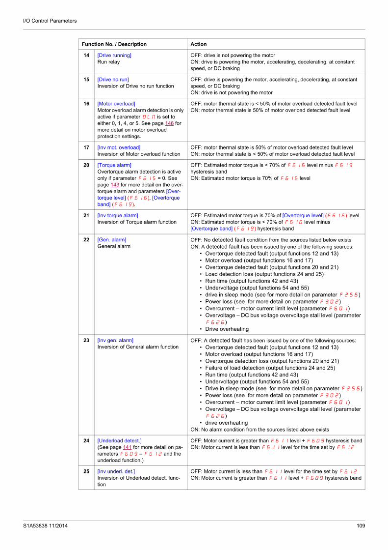
I/O Control Parameters
14 [Drive running]Run relay
OFF: drive is not powering the motorON: drive is powering the motor, accelerating, decelerating, at constant speed, or DC braking
15 [Drive no run]Inversion of Drive no run function
OFF: drive is powering the motor, accelerating, decelerating, at constant speed, or DC brakingON: drive is not powering the motor
16 [Motor overload]Motor overload alarm detection is only active if parameter OLM is set to either 0, 1, 4, or 5. See page 146 for more detail on motor overload protection settings.
OFF: motor thermal state is < 50% of motor overload detected fault levelON: motor thermal state is 50% of motor overload detected fault level
17 [Inv mot. overload]Inversion of Motor overload function
OFF: motor thermal state is 50% of motor overload detected fault levelON: motor thermal state is < 50% of motor overload detected fault level
20 [Torque alarm]Overtorque alarm detection is active only if parameter F615 = 0. See page 143 for more detail on the over-torque alarm and parameters [Over-torque level] (F616), [Overtorque band] (F619).
OFF: Estimated motor torque is < 70% of F616 level minus F619 hysteresis bandON: Estimated motor torque is 70% of F616 level
21 [Inv torque alarm]Inversion of Torque alarm function
OFF: Estimated motor torque is 70% of [Overtorque level] (F616) levelON: Estimated motor torque is < 70% of F616 level minus [Overtorque band] (F619) hysteresis band
22 [Gen. alarm]General alarm
OFF: No detected fault condition from the sources listed below exists ON: A detected fault has been issued by one of the following sources:
• Overtorque detected fault (output functions 12 and 13)• Motor overload (output functions 16 and 17)• Overtorque detected fault (output functions 20 and 21)• Load detection loss (output functions 24 and 25)• Run time (output functions 42 and 43)• Undervoltage (output functions 54 and 55)• drive in sleep mode (see for more detail on parameter F256)• Power loss (see for more detail on parameter F302)• Overcurrent – motor current limit level (parameter F601)• Overvoltage – DC bus voltage overvoltage stall level (parameter F626)
• Drive overheating
23 [Inv gen. alarm]Inversion of General alarm function
OFF: A detected fault has been issued by one of the following sources:• Overtorque detected fault (output functions 12 and 13)• Motor overload (output functions 16 and 17)• Overtorque detection loss (output functions 20 and 21)• Failure of load detection (output functions 24 and 25)• Run time (output functions 42 and 43)• Undervoltage (output functions 54 and 55)• Drive in sleep mode (see for more detail on parameter F256)• Power loss (see for more detail on parameter F302)• Overcurrent – motor current limit level (parameter F601)• Overvoltage – DC bus voltage overvoltage stall level (parameter F626)
• drive overheatingON: No alarm condition from the sources listed above exists
24 [Underload detect.](See page 141 for more detail on pa-rameters F609 – F612 and the underload function.)
OFF: Motor current is greater than F611 level + F609 hysteresis bandON: Motor current is less than F611 level for the time set by F612
25 [Inv underl. det.]Inversion of Underload detect. func-tion
OFF: Motor current is less than F611 level for the time set by F612
ON: Motor current is greater than F611 level + F609 hysteresis band
Function No. / Description Action
S1A53838 11/2014 109

I/O Control Parameters
26 [Manu reset flt.]Non-autoresettable detected fault
OFF: None of the detected fault conditions listed below existON: One (or more) of the following detected fault conditions exists and has stopped the drive:
• E – external detected fault• E-18 – VIA analog input signal detected fault• E-19 – main control board CPU communication• E-20 – excessive torque boost• E-21 – main control board CPU detected fault 2• EEP1 – main control board EEPROM detected fault 1• EEP2 – main control board EEPROM detected fault 2• EEP3 – main control board EEPROM detected fault 3• EF2 – ground detected fault• EPH0 – output phase detected fault detection• EPH1 – input phase detected fault detection• Err1 – speed reference• Err2 – main control board RAM• Err3 – main control board ROM• Err4 – main control board CPU detected fault 1• Err5 – serial communication control• Err7 – motor current sensor• Err8 – serial communication network• Err9 – graphic display option communication interruption• Etn1 – auto-tuning• EtYP – drive ratings• OCA – short-circuit detected in drive output inverter stage
during motor startup• OCL – short-circuit detected in motor or output wiring during
motor startup• OH2 - external overheating• Ot – overtorque• Uc – underload• UP1 - Undervoltage
27 [Inv manu reset flt.]Inversion of Manu reset flt. function
OFF: One (or more) of the following fault conditions exists and has stopped the drive:
• E – external detected fault• E-18 – VIA analog input signal• E-19 – main control board CPU communication• E-20 – excessive torque boost• E-21 – main control board CPU detected fault 2• EEP1 – main control board EEPROM detected fault 1• EEP2 – main control board EEPROM detected fault 2• EEP3 – main control board EEPROM detected fault 3• EF2 – ground fault• EPH0 – output phase loss detection• EPH1 – input phase loss detection• Err1 – speed reference• Err2 – main control board RAM• Err3 – main control board ROM• Err4 – main control board CPU detected fault 1• Err5 – serial communication control• Err7 – motor current sensor• Err8 – serial communication network• Err9 – graphic display option communication interruption• Etn1 – auto-tuning• EtYP – drive ratings• OCA – short-circuit detected in drive output inverter stage
during motor startup• OCL – short-circuit detected in motor or output wiring during
motor startup• OH2 - external overheating• Ot – overtorque• Uc – underload• UP1 - Undervoltage
ON: None of the detected fault conditions listed above exist
Function No. / Description Action
110 S1A53838 11/2014
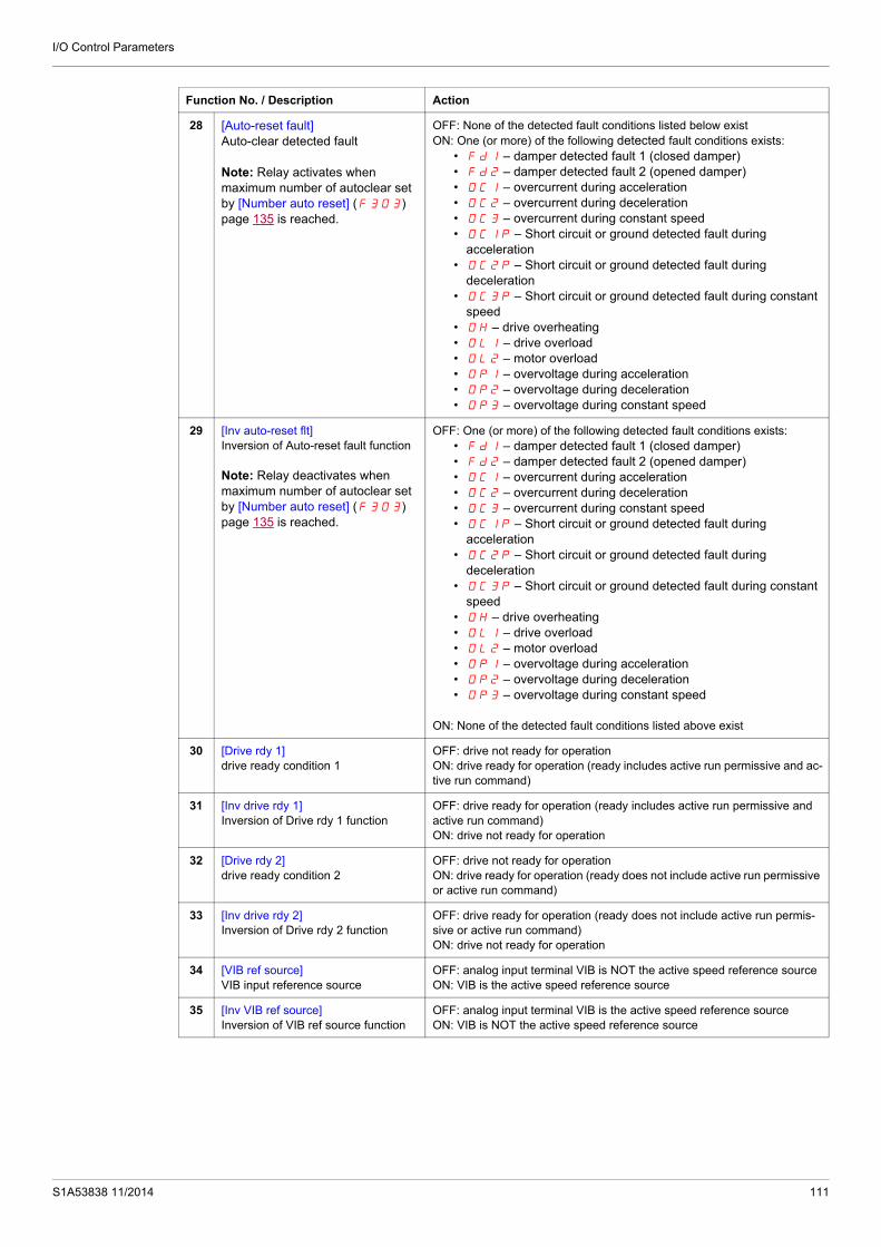
I/O Control Parameters
28 [Auto-reset fault]Auto-clear detected fault
Note: Relay activates when maximum number of autoclear set by [Number auto reset] (F303) page 135 is reached.
OFF: None of the detected fault conditions listed below existON: One (or more) of the following detected fault conditions exists:
• Fd1 – damper detected fault 1 (closed damper)• Fd2 – damper detected fault 2 (opened damper)• OC1 – overcurrent during acceleration • OC2 – overcurrent during deceleration• OC3 – overcurrent during constant speed• OC1P – Short circuit or ground detected fault during
acceleration• OC2P – Short circuit or ground detected fault during
deceleration• OC3P – Short circuit or ground detected fault during constant
speed• OH – drive overheating• OL1 – drive overload• OL2 – motor overload• OP1 – overvoltage during acceleration• OP2 – overvoltage during deceleration• OP3 – overvoltage during constant speed
29 [Inv auto-reset flt]Inversion of Auto-reset fault function
Note: Relay deactivates when maximum number of autoclear set by [Number auto reset] (F303) page 135 is reached.
OFF: One (or more) of the following detected fault conditions exists:• Fd1 – damper detected fault 1 (closed damper)• Fd2 – damper detected fault 2 (opened damper)• OC1 – overcurrent during acceleration • OC2 – overcurrent during deceleration• OC3 – overcurrent during constant speed• OC1P – Short circuit or ground detected fault during
acceleration• OC2P – Short circuit or ground detected fault during
deceleration• OC3P – Short circuit or ground detected fault during constant
speed• OH – drive overheating• OL1 – drive overload• OL2 – motor overload• OP1 – overvoltage during acceleration• OP2 – overvoltage during deceleration• OP3 – overvoltage during constant speed
ON: None of the detected fault conditions listed above exist
30 [Drive rdy 1]drive ready condition 1
OFF: drive not ready for operationON: drive ready for operation (ready includes active run permissive and ac-tive run command)
31 [Inv drive rdy 1]Inversion of Drive rdy 1 function
OFF: drive ready for operation (ready includes active run permissive and active run command)ON: drive not ready for operation
32 [Drive rdy 2]drive ready condition 2
OFF: drive not ready for operationON: drive ready for operation (ready does not include active run permissive or active run command)
33 [Inv drive rdy 2]Inversion of Drive rdy 2 function
OFF: drive ready for operation (ready does not include active run permis-sive or active run command)ON: drive not ready for operation
34 [VIB ref source]VIB input reference source
OFF: analog input terminal VIB is NOT the active speed reference sourceON: VIB is the active speed reference source
35 [Inv VIB ref source]Inversion of VIB ref source function
OFF: analog input terminal VIB is the active speed reference sourceON: VIB is NOT the active speed reference source
Function No. / Description Action
S1A53838 11/2014 111

I/O Control Parameters
36 [Fault relay] (The drive is not in a fault state during auto clear detected fault attempts. See also function 10 page 108)
WARNINGLOSS OF CONTROL When F130, F132, F137 is set to 36, the output will be active
when the drive will detect a fault. The drive status will not be detected if the wiring is damaged for any
reason. Do not select 36 unless you are sure that your signal will be present
in any case.Failure to follow these instructions can result in death, serious inju-ry, or equipment damage.
OFF: No drive detected faultON: drive detected fault.Relay activates when a clearable fault occurs and the drive attempts to re-start. Relay deactivates when drive is restarting.
37 [Inv fault relay]Inversion of Fault relay function 36
OFF: drive detected faultON: No drive detected faultRelay deactivates when a clearable fault occurs and the drive attempts to restart. Relay activates when drive is restarting.
38 [Ser. data relay FL]Serial communication data
OFF: Serial communication word FA50 bit 0 = 0ON: Serial communication word FA50 bit 0 = 1
39 [Inv ser. dat rel. FL]Inversion of ser. dat rel. FL function
OFF: Serial communication word FA50 bit 0 = 1ON: Serial communication word FA50 bit 0 = 0
40 [Ser. data relay RY]Serial communication data
OFF: Serial communication word FA50 bit 1 = 0ON: Serial communication word FA50 bit 1 = 1
41 [Inv ser. dat rel RY]Inversion of ser. dat rel. RY function
OFF: Serial communication word FA50 bit 1 = 1ON: Serial communication word FA50 bit 1 = 0
42 [Drive run time al]Drive operational run time alarm(see page 130 for more detail on parameter F621).
OFF: Run time is < F621 time settingON: Run time is F621 time setting
43 [Inv.drive run time al] Inversion of Drive run time al function
OFF: Run time is F621 time settingON: Run time is < F621 time setting
44 [Drive serv. alarm]Drive service alarm (see page 144 for more detail on parameter F634).
OFF: drive maintenance detected fault not activeON: drive maintenance detected fault active
45 [Inv. drive serv. alarm] Inversion of Drive serv. alarm function
OFF: drive maintenance detected fault activeON: drive maintenance detected fault not active
48 [LI F state]Logic input F state
OFF: Logic input F is not activeON: Logic input F is active
49 [Inv. LI F state] Inversion of LI F state function
OFF: Logic input F is activeON: Logic input F is not active
50 [LI R state]Logic input R state
OFF: Logic input R is not activeON: Logic input R is active
51 [Inv. LI R state] Inversion of LI R state function
OFF: Logic input R is activeON: Logic input R is not active
52 [Speed ref = VIA]Drive speed reference equals VIA sig-nal
OFF: Speed reference from the source identified by [Frequency mode sel] (FMOd) or the source identified by [Remote spd ref 2] (F207) VIA signalON: Speed reference from the source identified by FMOd or the source identified by F207 = VIA signal
53 [Inv. speed ref = VIA] Inversion of Speed ref = VIA function
OFF: Speed reference from the source identified by [Frequency mode sel] (FMOd) or the source identified by [Remote spd ref 2] (F207) = VIA signalON: Speed reference from the source identified by FMOd or the source identified by F207 VIA signal
Function No. / Description Action
112 S1A53838 11/2014

I/O Control Parameters
54 [Undervolt. alarm]Undervoltage alarm
OFF: Undervoltage detected fault is not activeON: Undervoltage detected fault is active
55 [Inv. undervolt. alarm] Inversion of Un-dervolt. al. function
OFF: Undervoltage detected fault is activeON: Undervoltage detected fault is not active
56 [Loc / remote]Local/remote switching
OFF: drive is in remote modeON: drive is in local mode
57 [Inv. loc / remote] Inversion of Loc / re-mote function
OFF: drive is in local modeON: drive is in remote mode
58 [PTC alarm]PTC thermal alarm
OFF: Motor temperature as indicated by PTC thermal probes is < 60% of the detected fault levelON: Motor temperature as indicated by PTC thermal probes is 60% of the detected fault level
59 [Inv. PTC alarm] Inversion of PTC alarm function
OFF: Motor temperature as indicated by PTC thermal probes is 60% of the detected fault levelON: Motor temperature as indicated by PTC thermal probes is < 60% of the detected fault level
60 [Speed ref = VIB]Drive speed reference equals VIB sig-nal
OFF: Speed reference from the source identified by [Frequency mode sel] (FMOd) or the source identified [Remote spd ref 2] (F207) VIB signalON: Speed reference from source identified by FMOd or the source iden-tified F207 = VIB signal
61 [Inv. speed ref = VIB] Inversion of Speed ref = VIB function
OFF: Speed reference from source identified by [Frequency mode sel] (FMOd) or the source identified [Remote spd ref 2] (F207) = VIB signalON: Speed reference from the source identified by FMOd or the source identified F207 VIB signal
62 [VIA detection]Analog VIA detection
ON: The value of VIA is equal to or higher than F160 + F161
OFF: The value of VIA is equal to or lower than F160 - F161
63 [Inv. VIA detection] Inversion of VIA detection function
ON: The value of VIA is equal to or lower than F160 - F161
OFF: The value of VIA is equal to or higher than F160 + F161
64 [VIB detection]Analog VIB detection
ON: The value of VIB is equal to or higher than F162 + F163
OFF: The value of VIB is equal to or lower than F162 - F163
65 [Inv. VIB detection] Inversion of VIB detection function
ON: The value of VIB is equal to or lower than F162 - F163
OFF: The value of VIB is equal to or higher than F162 + F163
66 [Freq. reach hyst]Set frequency attainment signal withhysteresis
ON: The ouptput frequency is equal to or higher than F101 + F102
OFF: The ouptput frequency is equal to or lower than F101 - F102
(See page 125 for more detail on parameters F101 and F102.)
67 [Inv. freq. reach hyst] Inversion of Freq. reach hyst function
ON: The ouptput frequency is equal to or lower than F101 - F102
OFF: The ouptput frequency is equal to or higher than F101 + F102
(See page 125 for more detail on parameters F101 and F102.)
68 [Damper]Damper control
ON: The damper is ON.OFF: The damper is OFF (see page 127)
69 [Inv. damper] Inversion of Damper function
ON: The damper is OFF.OFF: The damper is ON (see page 127)
70 [DisOil Inj PL] Disable oil injection in high speed positive logic
Positive logic
71 [DisOil Inj NL] Disable oil injection in high speed negative logic
Negative logic
254 [Relay OFF]Relay output is OFF
OFF
255 [Relay ON]Relay output is ON
ON
Function No. / Description Action
S1A53838 11/2014 113

I/O Control Parameters
Analog Input FunctionsTwo analog inputs are supplied with the ATV212 drive. The terminals are designated VIA and VIB.
Analog Input VIA
VIA can accept the following signal types:- Voltage (V): 0–10 V, voltage or potentiometer input- Current (I): 0–20 mA or 4–20 mA
The signal type (V or I) is selected by setting SW100 on the main control board.For information on wiring, consult the ATV212 Installation manual.
The slope and bias of the input signal are adjusted with parameters F201–F204 and F470–F471. For more information, see page 116.
VIA is configured as the speed reference input in the following macro-configurations: - Run permissive- 3-wire- 4-20 mA.
Relay output functions 34 and 35 can signal when VIA is being used as the speed reference source. For more information, see table on page 111 and consult “I/O Control Parameters” on page 100.
Relay output functions 52 and 53 can be used to signal the results of a comparison between the signal at VIA and the speed reference commanded by [Frequency mode sel] (FMOd) or [Remote spd ref 2] (F207). This function can also be used to send out a signal indicating whether the amount of processing and the amount of feedback agree with each other. For more information, see table on page 108. Also, consult “I/O Control Parameters” on page 100 and review information about parameter F167 on page 126.
The drive can enter a detected fault state if the VIA signal drops below a specified level for more than 300 mS. For more information, see parameter F633 on page 141 and code E-18 on page 180.
VIA can serve as an analog or a logic input, depending on setting of parameter F109 (set to 0 for analog input). Analog input is the factory setting. See page 100 for more information about parameter F109.
Analog Input VIB
VIB can accept the following signal types: Voltage (V): 0–10V, voltage or potentiometer input PTC motor thermal sensor input. For more information, see parameters F645 and F646 on page 122. Adjust the slope and bias of the input signal with parameters F210 - F213 and F472 - F473. For
more information, see page 116. Relay output functions 52 and 53 can signal when VIA is being used as the speed reference source. For more
information, see table on page 112 and consult “I/O Control Parameters” on page 100. Relay output functions 60 and 61 can be used to signal the results of a comparison between the signal at VIB
and the speed reference commanded by [Frequency mode sel] (FMOd) or [Remote spd ref 2] (F207). This function can also be used to send out a signal indicating whether the amount of processing and the amount of feedback agree with each other. For more information, see table on page 108. Also, consult “I/O Control Parameters” on page 100 and review information about parameter F167 on page 126.
General
The selection of VIA or VIB as the speed reference input in remote mode is made through parameters [Frequency mode sel] (FMOd) and [Remote spd ref 2] (F207). FMOd is the primary speed reference source, while F207 is the secondary source. Switching between the two is determined by the setting of parameter [Auto/man speed ref] F200. For more information, see page 118.
Analog output terminal FM can be configured to provide a signal in proportion to the VIA or VIB signal levels. See parameter FMSL, selections 13 and 14, on page 118.
When PID control is enabled, VIA or VIB can serve as the setpoint input. Either VIA or VIB needs to be selected as the feedback input. See page 120 for more information on parameter F360 and PID control.
Information can be transferred between the serial communication network and the analog inputs via read and write functions F870, F871, and F875-F879. For more information, see pages 150 to 151.
114 S1A53838 11/2014

I/O Control Parameters
Analog Output FunctionsOne analog output is supplied with the ATV212 drive. The terminal is designated FM.
FM is a multifunctional programmable analog output supplying an output frequency signal as the factory default.
The FM terminal can output a voltage or current signal.
When switch SW101 is set to V (voltage), FM outputs a 0–10 Vdc signal at 1 mA. When switch SW101 is set to I (current), FM outputs a 0–20 mA signal up to 24 Vdc. For detail on proper
wiring, consult the ATV212 Installation manual.
The drive value represented by the FM analog output signal is determined by the setting of parameter [AO funct. selection] (FMSL) (see page 118).
Calibrating the FM signal output to provide full scale deflection on an analog meter is achieved by adjusting parameter [AO scaling] (FM) (see page 118).
The slope and bias of the FM analog output signal can be adjusted using parameters F691 and F692. For more information, see page 119.
S1A53838 11/2014 115

I/O Control Parameters
Analog Input Adjustments
Analog Input Speed Reference and Output Frequency
Do not set the same frequency values for both output frequency levels 1 and 2. This will cause an Err1 detected fault.
When using a 4–20 mA signal, set speed reference level 1 value to 20% (4 ÷ 20 = 20%).
A further refinement of the bias and slope of the analog input signals can be made with parameters F470 – F473.
Output Frequency Hz
20 mAor
10 V
Speed Reference %F203F201
F202
F204
Code Name / Description Adjustment range Factory setting
F201 [VIA ref point 1] VIA speed reference level 1 0 to 100% 0%
F202 [VIA freq. point 1] VIA output frequency level 1 0.0 to 200.0 Hz 0.0 Hz
F203 [VIA ref point 2] VIA speed reference level 2 0 to 100% 100%
F204 [VIA freq. point 2] VIA output frequency level 2 0.0 to 200.0 Hz 50.0 Hz
F160 [VIA rel thresh. logic] Threshold logic for relay link to VIA 0 to 100% 0%
F161 [VIA threshold hyst.] Hysteresis threshold for logic relay link to VIA 0 to 20% 3%
F210 [VIB ref. point 1] VIB speed reference level 1 0 to 100% 0%
F211 [VIB freq. point 1] VIB output frequency level 1 0.0 to 200.0 Hz 0.0 Hz
F212 [VIB ref. point 2] VIB speed reference level 2 0 to 100% 100%
F213 [VIB freq. point 2] VIB output frequency level 2 0.0 to 200.0 Hz 50.0 Hz
F162 [VIB rel thresh. logic] Threshold logic for relay link to VIB 0 to 100% 0%
F163 [VIB threshold hyst.] Hysteresis threshold for logic relay link to VIB 0 to 20% 3%
116 S1A53838 11/2014

I/O Control Parameters
Parameters [VIA bias] (F470) and [VIB bias] (F472) are factory set so that a minimal signal needs to be applied to VIA or VIB before the drive starts the motor.
To increase the signal level required to start the motor, decrease the input bias level. To reduce the signal level required to start the motor, increase the input bias level.
Parameters [VIA gain] (F471) and [VIB gain] (F473) are factory set so that the drive output reaches rated voltage and frequency just before the signal to VIA or VIB reaches its maximum level.
To decrease the signal level required before the drive output reaches rated voltage and frequency, increase the input gain level.
To increase the signal level required before the drive output reaches rated voltage and frequency, decrease the input gain level.
Note: If the input gain level is set too low, the drive output may never reach rated voltage and frequency.
F470 [VIA bias] VIA analog input bias 0 to 255 128
DANGERUNINTENDED EQUIPMENT OPERATIONIf the input bias level is set too high, the drive will start the motor without a signal present at VIA or VIB.Failure to follow these instructions will result in death or serious injury.
F471 [VIA gain] VIA analog input gain 0 to 255 148
F472 [VIB bias] VIB analog input bias 0 to 255 128
DANGERUNINTENDED EQUIPMENT OPERATIONIf the input bias level is set too high, the drive will start the motor without a signal present at VIA or VIB.Failure to follow these instructions will result in death or serious injury.
F473 [VIB gain] VIB analog input gain 0 to 255 148
Code Name / Description Adjustment range Factory setting
DANGERUNINTENDED EQUIPMENT OPERATIONIf the input bias level is set too high, the drive will start the motor without a signal present at VIA or VIB.Failure to follow these instructions will result in death or serious injury.
0
100%%
Hz
0%
,
,
10 Vdc0 V20 mAdc0(4) mA
Output frequency
Maximum frequency
Speed Reference Signal (VIA, VIB Input Value)
Default Setting
Smaller
Large
Smaller
Large
S1A53838 11/2014 117

I/O Control Parameters
Code Name / Description Factory setting
F200 [Auto/man speed ref] Auto/Manual Speed Reference Switching 0
0
1
[Enable][Disable]Switching between two speed reference sources by means of a logic input is enabled if parameter F200 is set to 0. To use this function, you need to assign a logic input to function 38, Auto/Man speed ref.
When the assigned logic input is off, the drive will follow the speed reference source defined by parameter [Frequency mode sel] (FMOd) (see page 87).When the assigned logic input is on, the drive will follow the speed reference source defined by parameter [Remote spd ref 2] (F207) (see page 88).When parameter F200 is set to 1, the drive will follow the FMOd speed reference source when it is operating above 1 Hz. Below 1 Hz, it will follow the F207 speed reference source.
FMSL [AO funct. selection] Analog Output Function Selection 0
FM [AO scaling] Analog Output Scaling -
Parameter FM is used to match the FM terminal output signal with the input requirements of the attached panel meter by adjust-ing the slope and bias of the analog output signal. Before adjusting FM, set [AO funct. selection] (FMSL) to either 15 or 17. As you adjust the value of FM, monitor the display on the attached panel meter. When the meter display reaches 100%, press the ENT key on the drive embedded display terminal. The drive will flash between FM and the adjusted value, indicating that the adjustment has been saved.
Value Function Maximum Signal
0 [Motor frequency]: Output frequency [Max frequency] (FH)
1 [Motor current]: Output current 150 % of [Motor current]
2 [Speed ref]: Speed reference [Max frequency] (FH)
3 [DC bus U]: DC bus voltage 150 % of [DC bus U]
4 [Motor U]: Output motor voltage 150 % of [Motor U]
5 [Input power]: Input power 185 % of [Input power]
6 [Output power]: Output power 185 % of [Output power]
7 [motor torque]: Estimated motor torque 250 % of rated motor torque
8 [Torque I]: Motor torque current Current at 250 % of rated motor torque
9 [Motor thermal]: Motor thermal state 100 % of motor’s rating
10 [Drive thermal]: drive thermal state 100 %
11 [Do not use]: DO NOT USE -
12[Internal reference]: Internal speed reference (after PID)
[Max frequency] (FH)
13 [VIA]: VIA input value Maximum input value
14 [VIB]: VIB input value Maximum input value
15[Fixed 100%]: Fixed output – 100% signal (Selection 1 – output current)
-
16[Fixed 50%]: Fixed output – 50% signal (Selection 1 – output current)
-
17
[Fixed 100%]: Fixed output – 100% signal (Selections 0, 2, 3, 4, 5, 6, 7, 8, 9,10, 12, 13, 14, 18)
-
18 [Com data]: Serial communication data FA51 = 1000
19 [Do not use]: DO NOT USE -
118 S1A53838 11/2014

I/O Control Parameters
Code Name / Description Adjustment rangeFactory set-ting
F691 [AO slope] Analog Output Slope - 1
0
1
[Negative slope][Positive slope]
F692 [Analog output bias] 0 to 100% 0%
Refer to the diagram below for examples of adjusting parameters [AO scaling] (FM), [AO slope] (F691), and F692.
F694 [Freq. for AO = 0V] Low frequency when analog output equal 0 V 0 Hz to [Max frequency] (FH)
0 Hz
Refer to the diagram below for adjusting parameters F694, and [Freq. for AO = 10V] (F695).
F695 [Freq. for AO = 10V] High frequency when analog output equal 10 V 0 Hz to [Max frequency] (FH)
0 Hz
Refer to the diagram above for adjusting parameters [Freq. for AO = 0V] (F694), and F695.
F130 [RY Relay Function 1] RYA-RYC Relay Function 0 to 69, 254, 255 4
If [Driving Scroll] (F324) page 160 is set to [yes] (1) the setting is replaced by [disable oil injection in high speed positive logic] (70)
For a complete description of the various functions assignable to the RYA-RYC relay, see page 108.The RYA-RYC relay can have a secondary assignment with programmed selection logic. See parameters
[RY Relay Function 2] (F137) and [RY logic select.] (F139) on page 124 for more detail.
F146 [RY delay] Delay for RYA-RYC Relay 0.0 to 60.0 s 0.0 s
This parameter introduce a delay on RYA-RYC output signal relay.
= , =(mA)
20
00 100%
= , =(mA)
20
4
0 100%
= , =(mA)
20
00 100%
= , =(mA)
20
4
0 100%
FMSL signal value
Out
put
Cu
rre
nt
:Large Gain :Small Gain
Ou
tput
Cu
rren
t
Ou
tpu
tC
urr
ent
FMSL signal value
FMSL signal valueFMSL signal value
Ou
tpu
tC
urr
ent
10 V
0 VF694 F695
10 V
0 VF695 F694
Speed referenceMotor frequencyInternal reference (after PID)
Speed referenceMotor frequencyInternal reference (after PID)
S1A53838 11/2014 119

I/O Control Parameters
F132 [FL Relay Function] Function for FL Relay 0 to 69, 254, 255 11
If [Driving Scroll] (F324) page 160 is set to [yes] (1) the setting is replaced by [Inv F101 sp reach] (9)
For a complete description of the various functions assignable to the FL relay, see page 108.
F147 [FL Relay delay] Delay for FL Relay 0.0 to 60.0 s 0.0 s
This parameter introduce a delay on FL output signal relay.
F360 [PID control enable] - 0
0
1
2
[No PID]: PID disabled[PID by VIA]: Enabled (feedback source is VIA)[PID by VIB]: Enabled (feedback source is VIB)Parameter F360 is used to enable PID control and define the source of the feedback signal.The PID source is defined by the setting of parameter [Frequency mode sel] (FMOd) (see page 87).Parameter [Freq band det range] (F167) can be adjusted to command a drive relay to signal when the PID setpoint and feedback are in agreement (see page 126).
F362 [PID Prop Gain] PID Proportionnal Gain 0.01 to 100.0% 0.30%
Parameter F362 adjusts the proportional gain applied during PID control. The speed change applied to the motor is a correc-tional value proportional to the product of this parameter’s setting and the process error (deviation between the setpoint and the feedback value).A higher setting of F362 provides a fast response to a process error but may also result in instability such as hunting. The diagram below illustrates the effect produced by adjusting F362.
F363 [PID Integral Gain] 0.01 to 100.0 0.20
Parameter F363 adjusts the integral gain applied during PID control. Any residual process errors that remain after correction by the proportional gain are cleared to zero over time by the integral gain function.
A higher setting of F363 provides a fast response to a process error but may also result in instability such as hunting. The diagram below illustrates the effect produced by adjusting F363.
The integral gain value can be set to zero by setting a logic input to function 65. For more information, see table on page 101 and parameters [LI F selection] (F111), [LI R selection] (F112), [LI RES selection] (F113), page 100, and [VIA LI selection] (F118), page 100.
Code Name / Description Adjustment rangeFactory set-ting
FeedbackAmount
Fast Response(F362 = Large Gain)
Motor Speed Change
Slow Response (F362= Small Gain)
Time
Feedback Amount
Motor Speed Change
(F363= Small Gain)
Time
(F363 = Large Gain)
Residual Deviation
120 S1A53838 11/2014

I/O Control Parameters
F366 [PID Derivative Gain] 0.00 to 2.55 0.00
Parameter F366 adjusts the derivative gain applied during PID control. This gain adjusts the response time of the drive to rapid changes in the process.Increasing the setting of F366 more than necessary may cause great fluctuations in motor speed resulting in system instability. The diagram below illustrates the effect produced by adjusting F366.
F359 [PID ctrl wait time] PID Control Waiting Time 0 to 2400 s 0
If parameter F359 is set to a value greater than 0 seconds, the drive will not immediately enter PID control upon startup. For the time set by F359, the drive will ignore the feedback signal, accelerating the motor to the speed set by the reference input. This function can be used to help prevent the drive from entering PID control mode before the system approaches the final op-erating level.
F380 [PID reverse error] PI regulator reversal direction correction 0
0
1
[No][Yes]
This function is used to reverse the error PI for Water Pump.If F380 = 0 or No, PI error input = reference - feedback. The motor speed increases when the error is positive.If F380 = 1 or Yes, PI error input = feedback - reference. The motor speed decreases when the error is positive.
F256 [Time limit low spd] 0.0 to 600 s 0.0 s
0
1
[Disable]: (0.0)[Enable]: (0.01 to 600 seconds)If parameter F256 is enabled and if the drive operates continuously at [Low limit frequency] (LL) (see page 92) for a time period equal to the setting of F256, the drive will ramp the motor to a stop. While the motor is stopped, “LStP” will flash on the drive embedded display terminal.
When the speed reference to the drive exceeds the low speed level LL+F391, the drive will accelerate the motor to the new speed reference.
If parameter F256 is enabled, drive operation at or below the low speed level is also monitored during startup or during revers-ing of the motor. See diagram below.
Code Name / Description Adjustment rangeFactory set-ting
Current Error
PreviousError
FeedbackAmount
Small Derivative Gain
Large Derivative Gain
Motor Speed Change
Time
+
Outputfrequency (Hz)
RunCommand
Time (s)ONOFF
S1A53838 11/2014 121

I/O Control Parameters
Active Logic Function
Two logic input functions can be configured to be active. The logic input functions assigned to parameters [Logic Funct 1 active] (F108) and [Logic Funct 2 active] (F110) will continuously affect drive operation. See table beginning on page 101 for a list of available logic input functions.
If F110 is not set to 1 (logic function [Run permissive]), a logic input should be assigned to the [Run permissive] logic function to enable the motor to start.
F391 [Stop on LL hyst] Stop on LL hysteresis 0.0 to [Max frequency] (FH)
0.2 Hz
Activated if [Time limit low spd] (256) is not set to [Disable] (0)
F392 [PID wake up (thres)] PI wake up threshold on PI error 0.0 to [Max frequency] (FH)
0.0 Hz
DANGERUNINTENDED EQUIPMENT OPERATIONCheck that unintended restarts will not endanger personnel or equipment in any way.Failure to follow these instructions will result in death or serious injury.
Activated if [Time limit low spd] (256) is not set to [Disable] (0)
F393 [PID wake up, feedb] PI wake up threshold on PI feedback error 0.0 to [Max frequency] (FH)
0.0 Hz
DANGERUNINTENDED EQUIPMENT OPERATIONCheck that unintended restarts will not endanger personnel or equipment in any way.Failure to follow these instructions will result in death or serious injury.
Activated if [Time limit low spd] (256) is not set to [Disable] (0)
F645 [Mot PTC selection] PTC Motor Thermal Protection Enable - 0
0
1
2
[Disabled][Enabled fault] (detected fault mode). If F645 is set to 1 and the PTC probe exceeds a given, threshold, the drive will trip and display an [PTC overheating] (OH2) code.[Enabled alarm] (alarm mode). If F645 is set to 2 and the PTC probe exceeds a given, threshold, the drive will signal a de-tected fault and continue operating.Setting parameter F645 to 1 or 2 converts control terminal VIB into a PTC motor thermal probe input. See the ATV212 Instal-lation manual, for wiring details.
F646 [PTC resistor value] 100 to 9999 3000
Code Name / Description Adjustment rangeFactory set-ting
Code Name / Description Adjustment range Factory setting
F108 [Logic Funct 1 active] Active Logic Function 1 0 to 73 0
F110 [Logic Funct 2 active] Active Logic Function 2 0 to 73 1
122 S1A53838 11/2014

I/O Control Parameters
Preset SpeedsA maximum of seven preset speeds can be selected by 4 logic inputs (F, R, RES, or VIA). Preset speed control is only active when the drive is in logic input control ([Command mode sel] (CMOd) = 0).
For one preset speed, assign a logic input to function 6.
For up to three preset speeds, use two logic inputs for functions 6 and 7.
For up to seven preset speeds, use three logic inputs for functions 6, 7, and 8.
Preset speed commands take priority over speed commands from any other source. For more information on preset speeds, see page 101. See page 46, for wiring instructions and timing diagram.
Code Name / Description Adjustment range Factory setting
Sr1 [Preset speed 1] LL to UL Hz 15 Hz
Sr2 [Preset speed 2] LL to UL Hz 20 Hz
Sr3 [Preset speed 3] LL toUL Hz 25 Hz
Sr4 [Preset speed 4] LL to UL Hz 30 Hz
Sr5 [Preset speed 5] LL to UL Hz 35 Hz
Sr6 [Preset speed 6] LL to UL Hz 40 Hz
Sr7 [Preset speed 7] LL to UL Hz 45 Hz
S1A53838 11/2014 123
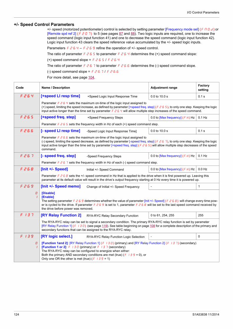
I/O Control Parameters
+/- Speed Control Parameters+/- speed (motorized potentiometer) control is selected by setting parameter [Frequency mode sel] (FMOd) or [Remote spd ref 2] (F207) to 5 (see pages 87 and 88). Two logic inputs are required, one to increase the speed command (logic input function 41) and one to decrease the speed command (logic input function 42). Logic input function 43 clears the speed reference value accumulated by the +/- speed logic inputs.
Parameters F264 – F269 refine the operation of +/- speed control.
The ratio of parameter F265 to parameter F264 determines the (+) speed command slope:
(+) speed command slope = F265 / F264
The ratio of parameter F267 to parameter F266 determines the (-) speed command slope.
(-) speed command slope = F267 / F266
For more detail, see page 104.
Code Name / Description Adjustment rangeFactorysetting
F264 [+speed LI resp time] +Speed Logic Input Response Time 0.0 to 10.0 s 0.1 s
Parameter F264 sets the maximum on-time of the logic input assigned to (+) speed, limiting the speed increase, as defined by parameter [+speed freq. step] (F265), to only one step. Keeping the logic input active longer than the time set by parameter F264 will allow multiple step increases of the speed command.
F265 [+speed freq. step] +Speed Frequency Steps 0.0 to [Max frequency] (FH) Hz 0.1 Hz
Parameter F265 sets the frequency width in Hz of each (+) speed command step.
F266 [- speed LI resp time] -Speed Logic Input Response Time] 0.0 to 10.0 s 0.1 s
Parameter F266 sets the maximum on-time of the logic input assigned to (-) speed, limiting the speed decrease, as defined by parameter [-speed freq. step] (F267), to only one step. Keeping the logic input active longer than the time set by parameter [+speed freq. step] (F265) will allow multiple step decreases of the speed command.
F267 [- speed freq. step] -Speed Frequency Steps 0.0 to [Max frequency] (FH) Hz 0.1 Hz
Parameter F267 sets the frequency width in Hz of each (-) speed command step.
F268 [Init +/- Speed] Initial +/- Speed Command 0.0 to [Max frequency] (FH) Hz 0.0 Hz
Parameter F268 sets the +/- speed command in Hz that is applied to the drive when it is first powered up. Leaving this parameter at its default value will result in the drive’s output frequency starting at 0 Hz every time it is powered up.
F269 [Init +/- Speed memo] Change of Initial +/- Speed Frequency - 1
0
1
[Disable][Enable]The setting parameter F269 determines whether the value of parameter [Init +/- Speed] (F268) will change every time pow-er is cycled to the drive. If parameter F269 is set to 1, parameter F268 will be set to the last speed command received by the drive before power was removed.
F137 [RY Relay Function 2] RYA-RYC Relay Secondary Function 0 to 61, 254, 255 255
The RYA-RYC relay can be set to signal a secondary condition. The primary RYA-RYC relay function is set by parameter [RY Relay Function 1] (F130) (see page 119). See table beginning on page 108 for a complete description of the primary and secondary functions that can be assigned to the RYA-RYC relay.
F139 [RY logic select.] RYA-RYC Relay Function Logic Selection - 0
0
1
[Function 1and 2]: [RY Relay Function 1] (F130) (primary) and [RY Relay Function 2] (F137) (secondary)[Function 1 or 2]: F130 (primary) or F137 (secondary)The RYA-RYC relay can be configured to energize when either:Both the primary AND secondary conditions are met (true) (F139 = 0), orOnly one OR the other is met (true) (F139 = 1)
124 S1A53838 11/2014

I/O Control Parameters
F100 [Freq. 1 reached] Relay Output – Frequency Level 1 Attained 0.0 to [Max frequency] (FH) Hz 0.0 Hz
The frequency set by parameter F100 is the threshold level for relay output functions 4 and 5 (see page 108).
F101 [Freq. 2 reached] Relay Output – Frequency Level 2 Attained 0.0 to [Max frequency] (FH) Hz 0.0 Hz
If [Driving Scroll] (F324) page 160 is set to [yes] (1) the setting is replaced by 65 Hz.
The frequency set by parameter F101 +/- the [Freq.2 bandw.] (F102) detection band is the threshold level for relay output functions 8 and 9 and the hysteresis for relay output functions 66 and 67 (see page 113).
F102 [Freq.2 bandw.] Frequency Attained Detection Band 0.0 to [Max frequency] (FH) Hz 2.5 Hz
If [Driving Scroll] (F324) page 160 is set to [yes] (1) the setting is replaced by 0.65 Hz.
Parameter F102 determines the bandwidth around the [Freq.2 reached] (F101) frequency (see diagram above) and the commanded frequency (see diagram below) driving relay output functions 6 through 9 (see page 108).
Code Name / Description Adjustment rangeFactorysetting
0
Output Frequency (Hz)
CommandedFrequency
Relay Output Function 4
Relay Output Function 5
Time (S)
ONOFF
ONOFF
0
+
-
Output Frequency (Hz)
Relay Output Function 8
Relay Output Function 9
Time (S)
ONOFF
ONOFF
ONOFF
ONOFF
Relay Output Function 66
Relay Output Function 67
0
+
-
Output Frequency (Hz)
Commanded Frequency
Relay Output Function 6
Relay Output Function 7
Time (S)
ONOFF
ONOFF
S1A53838 11/2014 125

I/O Control Parameters
F167 [Freq band det range] Frequency bandwidth detection range 0.0 to [Max frequency] (FH) Hz 2.5 Hz
Parameter F167 determines the bandwidth around the VIA or VIB speed reference (see below) driving relay output functions 52, 53, 60, and 61 (see page 112). This function can be used to signal whether the amount of processing and the amount of feedback agree when the PID function is in use.
F603 [Ext. fault stop Mode] External detected fault stop mode - 0
0
1
2
[Freewheel]: Freewheel stop[Ramp stop][DC braking]: DC injection brakingThe setting of parameter F603 determines how the drive will stop if a logic input assigned to function 11 or 46 is activated (see table on pages 101 and 104).
F604 [DC brk time ext flt] External Fault DC braking time 0.0 to 20.0 s 1.0 s
If parameter [Ext. fault stop Mode] (F603) is set to 2, parameter F604 will determine how long DC current will be injected into the motor while the external fault logic input is active.
Code Name / Description Adjustment rangeFactorysetting
+
-
VIA
Relay Output Function 52 + 60
Relay Output Function 53 + 61
Time (S)
ONOFF
ONOFF
or
126 S1A53838 11/2014

I/O Control Parameters
Damper controlThis function applies to the ventilation ducts. The aim is to control the opening of the duct (shutter device called a "damper") when the fan starts up.
Damper opening command
The opening command can be assigned to a relay via the F130 or F132 parameters to the function [Damper] 68 or [Inv. damper] 69 page 113. The damper is closed automatically when there is no longer an opening command.
Damper opening feedback
Opening is controlled by a bit or a logic input that can be assigned via the F111 or F112 or F113 parameters to the function [Damper feedBack] 73 page 106. The corresponding logic input or bit can be configured via the parameter [Damper fdb type] F580.
When there is an inconsistency, the drive goes on a [Damper fault 1] Fd1 if the damper does not open and on a [Damper fault 2] Fd2 if it does not close.
The parameter [Time open damper] F581 can be used to delay tripping on an opening fault when a run command is sent and the parameter [Time close damper] F582 delays the closing fault when a stop command is sent.
U
M 3
V W 0 Rp P24 LIp
Control FeedbackATV 212
Damper
Damper opening
FanFlow of air
Damper open contact
F581
1
1
1
1
1
0t
t
t
t
t
0
0
0
0
F582
Fan speed
Run command
Opening commandRx
OpenPosition of damper
Closed
Damper open contact
S1A53838 11/2014 127

I/O Control Parameters
Code Name / Description Adjustment range Factory setting
F580 [Damper fdb type] 0
0
1
2
3
4
[No feedback]: No feedback used (Default value)[LI L set]: Logical input and active at level 0 (shunt). When setting F580 to 1, first assign logic inputs.[LIH set]: Logical input and active at level 1 (open). When setting F580 to 2, first assign logic inputs.[Com. LIL set]: Serial link to communication bit selected by [Com channel choice] (F807) and active at level 0 (shunt). Please refer to communcation manual.[Com. LIH set]: Serial link to communication bit selected by F807 and active at level 1 (open). Please refer to communcation manual.
Setting of F580 parameter is independent of the type of command mode.The F807 parameter allows selecting the communication channel used for communication damper feedback
F581 [Time open Damper] 0.05 s to 300.00 s 60.00
Opening fault monitoring time delay. If the damper is not open at the end of the set time, the drive will lock in [Damper fault 1] Fd1 detected fault mode. The timer is launch after the run command.The time delay needs to be greater than the normal opening time of the damper.
F582 [Time close Damper] 0.05 s to 300.00 s 60.00
Closing fault monitoring time delay. If the damper is not close at the end of the set time, the drive will lock in [Damper fault 2] Fd2 detected fault mode. The timer is launch when the motor is stopped.The time delay needs to be greater that the normal closing time of the damper
F583 [Damper flt behavior] 1
0
1
2
[No fault][Freewheel stop][Ramp stop]The F583 parameter allows defining the behavior when [Damper fault 1] (Fd1) occurs.
128 S1A53838 11/2014

S1A53838 11/2014
Display Parameters
9
Display ParametersWhat's in this Chapter?
This chapter contains the following topics:
Topic Page
Display parameters 130
129
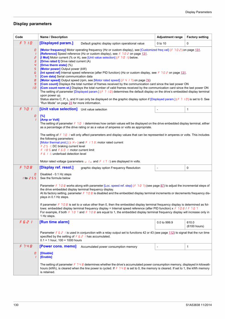
Display Parameters
Display parameters
Code Name / Description Adjustment range Factory setting
F710 [Displayed param.] Default graphic display option operational value 0 to 10 0
0
1
2
3
4
5
6
7
8
9
10
[Motor frequency] Motor operating frequency (Hz or custom display), see [Customized freq val] (F702) on page 131.[Reference] Speed reference (Hz or custom display), see F702 on page 131.[I Mot] Motor current (% or A), see [Unit value selection] (F701) below.[Drive rated I] Drive rated current (A)[Drive therm state] (%)[Motor power] Output power (kW)[Int speed ref] Internal speed reference (after PID function) (Hz or custom display, see F702 on page 131.[Com data] Serial communication data[Motor speed] Output speed (rpm, see [Motor rated speed] (F417) on page 74)[Com count] Displays the total number of frames received by the communication card since the last power ON[Com count norm st.] Displays the total number of valid frames received by the communication card since the last power ONThe setting of parameter [Displayed param.] (F710) determines the default display on the drive’s embedded display terminal upon power up.Status alarms C, P, L, and H can only be displayed on the graphic display option if [Displayed param.] (F710) is set to 0. See “Run Mode” on page 23 for more information.
F701 [Unit value selection] Unit value selection - 1
0
1
[%][Amp or Volt]The setting of parameter F701 determines how certain values will be displayed on the drive embedded display terminal, either as a percentage of the drive rating or as a value of amperes or volts as appropriate.
The setting of F701 will only affect parameters and display values that can be represented in amperes or volts. This includes the following parameters:[Motor thermal prot.] (tHr) and F173: motor rated currentF251: DC braking current levelF185 and F601: motor current limitF611: underload detection level
Motor rated voltage (parameters ulu and F171) are displayed in volts.
F708 [Display ref. resol.] graphic display option Frequency Resolution - 0
0
1 to 255
Disabled - 0.1 Hz stepsSee the formula below
Parameter F708 works along with parameter [Loc. speed ref. step] (F707) (see page 87) to adjust the incremental steps of the drive embedded display terminal frequency display.At its factory setting, parameter F708 is disabled and the embedded display terminal increments or decrements frequency dis-plays in 0.1 Hz steps.
If parameter F708 is set to a value other than 0, then the embedded display terminal frequency display is determined as fol-lows: embedded display terminal frequency display = Internal speed reference (after PID function) x F708 / F707
For example, if both F707 and F708 are equal to 1, the embedded display terminal frequency display will increase only in 1 Hz steps.
F621 [Run time alarm] 0.0 to 999.9 610.0 (6100 hours)
Parameter F621 is used in conjunction with a relay output set to functions 42 or 43 (see page 112) to signal that the run time specified by the setting of F621 has accumulated.0.1 = 1 hour, 100 = 1000 hours
F748 [Power cons. memo] Accumulated power consumption memory - 1
0
1
[Disable][Enable]
The setting of parameter F748 determines whether the drive’s accumulated power consumption memory, displayed in kilowatt-hours (kWh), is cleared when the line power is cycled. If F748 is set to 0, the memory is cleared. If set to 1, the kWh memory is retained.
130 S1A53838 11/2014

Display Parameters
F749 [Power cons. unit] - According todrive rating (1)
0
1
2
3
[1 kWh][0.1 = 1 kWh][0.01 = 1 kWh][0.001 = 1 kWh]The setting of parameter F749 determines the scaling of the kWh display on the embedded display terminal.
F702 [Customized freq val] Customized freq val 0.00 to 200.00 0.00
Parameters F702, F705, and F706 can be used to customize a speed display on the drive embedded display terminal to match the application’s operational speed, for example, feet per minute or units per hour.0.00: Frequency displayed in Hz0.0 If parameter F702 is set to a value other than 0.00, the frequency value displayed will be calculated as follows:Value displayed = display or parameter frequency x F702. See example below.1 to 200.0: Conversion factor
F703 [Frequency convert.] Frequency free unit conversion selection] 0
0
1
[All] Frequencies display free unit[PID only] PID frequencies free unit conversion
F705 [Custom freq. slope] Custom Frequency Display Conversion Slope] - 1
0
1
[Negative slope][Positive slope]Parameter F705 sets the slope of the custom frequency display conversion. See the diagrams below for examples of the op-eration of this function.
F706 [Customize unit bias] Custom Frequency Display Conversion Bias 0.00 to FH Hz 0.00 Hz
Parameter F706 adds a bias to the custom frequency display conversion process.
(1) See table page 199.
Code Name / Description Adjustment range Factory setting
=
=
=
=
X =
X =
Hz
Hz
= , =
800
00 80 (Hz)
= , =
800
00 80 (Hz)
= , =
1000
00 80 (Hz)
200
graphic display option
Output Frequency
graphic display option
graphic display option
Output Frequency
Output Frequency
S1A53838 11/2014 131

Display Parameters
132 S1A53838 11/2014

S1A53838 11/2014
Detected Fault Management Parameters
10
Detected Fault Management ParametersWhat's in this Chapter?
This chapter contains the following topics:
Topic Page
Time delay 136
Catch On The Fly (F301) 137
Overtorque Detection 143
Nuisance Overvoltage And Input Phase Detected Fault Avoidance 144
Motor Overload Characteristics 145
133

Detected Fault Management Parameters
F400 [Auto-tuning drive] - 0
DANGERHAZARD OF ELECTRIC SHOCK OR ARC FLASH During auto-tuning, the motor operates at rated current. Do not service the motor during auto-tuning.Failure to follow these instructions will result in death or serious injury.
WARNINGLOSS OF CONTROL It is essential that the following parameters uLu, uL, F415 and F417 are correctly configured before starting auto-
tuning. When one or more of these parameters have been changed after auto-tuning has been performed, F400 will return 0
and the procedure will have to be repeated.Failure to follow these instructions can result in death or serious injury.
NOTICERISK OF DAMAGE TO THE MOTOR Conduct auto-tuning only after the motor has been connected and operation completely stopped. If auto-tuning is conducted immediately after operation stops, the presence of a residual voltage may result in abnormal
tuning. Failure to follow these instructions can result in equipment damage.
0
1
2
3
4
5
Auto tuning enable[Disabled]
[Initialize constant]: Factory setting of [Auto Torque Boost] (F402) for asynchronous motor. Factory setting of [Auto Torque Boost] (F402) , [Autotune L q-axis] (F912), and [Autotune L q-axis] (F913), and [Motor Rated Voltage] (vlv) for synchronous motor.
[Tun Dyn. 1]:Tune Dynamic, with driving run after the tuning.Application settings of [Auto Torque Boost] (F402) for asynchronous motor.Application settings of [Auto Torque Boost] (F402) , [Autotune L q-axis] (F912), and [Autotune L q-axis] (F913) for synchronous motor.
[Tun Dyn. 2]: Complete tune Dynamic, with driving run after the tuning. Application settings of [Auto Torque Boost] (F402) , [Autotune L q-axis] (F912), [Autotune L q-axis] (F913), and [Motor Rated Voltage] (vlv) for synchronous motor.
[Tun Static 1]: Tune Static, without driving run after the tuning.Application settings of [Auto Torque Boost] (F402) for asynchronous motor.Application settings of [Auto Torque Boost] (F402) , [Autotune L q-axis] (F912), and [Autotune L q-axis] (F913) for synchronous motor.
[Tun Static 2]: Complete tune Static, without driving run after the tuning. Application settings of [Auto Torque Boost] (F402) , [Autotune L q-axis] (F912), and [Autotune L q-axis] (F913), and [Motor Rated Voltage] (vlv) for synchronous motor.
Parameter F400 is reset to “0” after the auto tuning is performed.
134 S1A53838 11/2014

Detected Fault Management Parameters
Description
The table below lists the detected faults that can be cleared with Auto clear. If parameter F303 is set to a value greater than0 and one of these detected faults occurs, the drive will attempt to automatically clear the detected fault, allowing it to be re-started:
Fault detection codes that can be cleared with the automatic restart function after the cause has disappeared
Auto clear attempts will continue until the number of attempts set by parameter F303 has been exhausted.
If these attempts do not clear the detected fault condition, the drive will stop and a manual clear will be required.
If another type of detected fault occurs during the auto clear process, the drive will stop and a manual clear will be required.
A successful auto clear means that the drive accelerates the motor to the commanded speed without another detected fault occurring.
If an unspecified period of time elapses after a successful auto clear attempt without another detected fault occurring, the reset attempt counter will clear allowing another full set of reset attempts to be made during a future detected fault occurrence.
During the auto clear process, the drive embedded display terminal alternately displays rtrY and the display value selected by parameter [Displayed param.] (F710), page 130.
Conditions permitting auto clear
An auto clear attempt will not be made if the cause of the detected fault persists.
In the case of an OL1 or OL2 overload detected fault, the drive will calculate the cooling time necessary to clear the detected fault.
In the event of an OH detected fault, the heatsink temperature probe will indicate when the detected fault can be cleared.
DC bus voltage measurements will indicate when an OP1, OP2, or OP3 detected fault can be cleared.
Code Name / Description Factory setting
F303 [Number auto reset] 0
DANGERUNINTENDED EQUIPMENT OPERATION The automatic restart can only be used on machines or installations which do not pose any danger to either personnel or
equipment. If the automatic restart is activated, the fault relay will only indicate a fault has been detected once the time-out period for the
restart sequence has expired. The equipment must be used in compliance with national and regional safety regulationsFailure to follow these instructions will result in death or serious injury.
0
1 to 10
Disabled.Number of clear attempts.
Code Description Code Description
EPtF External Process Threshold error detected OH Drive overheating
Fd1 Damper detected fault 1 (closed damper)OH2 External overheatingOL1 Drive overload
OC1 Overcurrent during acceleration OL2 Motor overloadOC2 Overcurrent during deceleration OP1 Overvoltage during accelerationOC3 Overcurrent during constant speed OP2 Overvoltage during deceleration
OC1PShort-circuit or ground detected fault during acceleration
OP3 Overvoltage during constant state operation
OC2PShort-circuit or ground detected fault during deceleration
PSrF Prestart Speed not reached error detected
OC3PShort-circuit or ground detected fault during constant speed operation
SOUt Permanent magnet motor step-out
S1A53838 11/2014 135

Detected Fault Management Parameters
Time delayThe first clear is attempted 1 second after the detected fault occurs. Each subsequent clear attempt adds 1 second to the time interval, as illustrated in the table below.
Clear detected fault attempts
Fault relay action
An output relay set to functions 10 and 11 (see table on page 108) will not indicate a detected fault until all clear attempts have been exhausted.
Output relay functions 28 and 29 can be used to indicate that an auto-resetable detected fault has occurred.
Output relay functions 36 and 37 can be used to signal any kind of drive detected fault, even during auto clear attempts.
Drive fault memory
If parameter [Drive fault memory] (F602) is set to 1 and power to the drive is cycled while an auto-resetable detected fault is active, the auto clear action will be cancelled (see page 138).
Attempt number Time delay between detected fault reset attempt and most recent fault
1 1 second
2 2 seconds
3 3 seconds
4 4 seconds
5 5 seconds
6 6 seconds
7 7 seconds
8 8 seconds
9 9 seconds
10 10 seconds
136 S1A53838 11/2014

Detected Fault Management Parameters
Catch On The Fly (F301)
If catch-on-the-fly motor starting is enabled (parameter F301 is not set to 0), the drive will detect the motor’s rotating direction and speed before applying power. This will result in a smooth reapplication of power to a coasting motor without high current or torque pulses.
If F301 is disabled and the drive is started into a spinning motor, it will apply a low starting frequency to the motor, operating in current limit until the motor almost stops. Then, the drive will accelerate the motor to the commanded speed.
Catch-on-the-fly motor starting will be applied if F301 is set to 1 or 3 and:
There is a brief power loss (the embedded display terminal does not go blank) that results in the drive removing power from the motor,
and, there is a continuous run command to the drive (2-wire control)
F301 Set to 1 or 3
Catch-on-the-fly motor starting will be applied if F301 is set to 2 or 3 and:
The run permissive (logic input assigned to functions 1 or 54) is removed and restored, and, there is a continuous run command to the drive (2-wire control)
F301 Set to 2 or 3
If F301 is set to 4, the drive will perform a motor speed and direction search each time it receives a run command.
Note: Enabling catch-on-the-fly adds about 300 milliseconds to implementation of each start command to the drive.
Do not use catch-on-the-fly if there is more than one motor supplied by the drive.
Inout Voltage
Motor Speed
Run Command ONOFF
Motor Speed
Run CommandONOFF
Run Permissive
ONOFF
Code Name / Description Factory setting
F301 [Catch on fly] 3 (1)
0
1
2
3
4
[Disable][Brief power loss] After brief power loss[Run restored] After run permissive is restored[Power loss, run] After brief power loss or run permissive is restored[Each start] During every startup
F632 [Mot overload memo] Motor Overload Memory 0
0
1
[Disabled] ClearedIf parameter F632 is set to 0, the drive’s memory of the motor’s thermal state (used for overload calculation) is cleared when-ever the power is cycled.[Enabled] RetainedIf parameter F632 is set to 1, the drive’s memory of the motor’s thermal state is retained even when power is removed. If the drive is tripped on an Motor Overload detected fault OL2, a cooling time (as calculated by the drive) needs to expire before the motor can be restarted.
(1) Catch-on-the-fly motor starting after a drive detected fault is active if auto clear is enabled (parameter [Number auto reset] (F303) is not set to 0, see page 135)
S1A53838 11/2014 137

Detected Fault Management Parameters
F602 [Drive fault memory] 0
0
1
[Cleared]If parameter F602 is set to 0 and the drive is powered after a detected fault:If the cause of the detected fault has been removed, the drive will reset and can be started. Information about the detected fault just cleared will be transferred to the detected fault history.If the cause of the detected fault has not been removed, the detected fault will be displayed again but the drive’s memory of the operational information associated with the detected fault will be transferred to the detected fault history.Information about the 4th most recent detected fault will be removed from the detected fault history.[Retained]If parameter F602 is set to 1 and the drive is powered after a detected fault:If the cause of the detected fault has been removed, the drive will reset and can be started. Information about the detected fault just cleared will be transferred to the detected fault history. If the cause of the detected fault has not been removed, the original detected fault and all of its operational data will be available for viewing as the current detected fault in the monitoring mode.Information about the 4th most recent detected fault will be retained in the detected fault history.Auto clear will be disabled.
F608 [Input phase loss] Input phase loss detection mode 1
0
1
[Disable]: DisabledIf parameter F608 is set to 0, input phase loss detection is disabled. Loss of one input phase will not cause the drive to trip.[Enable]: EnabledIf parameter F608 is set to 1, the loss of one input phase will cause an EPH1 detected fault.
F302 [Supply loss behav.] 0
0
1
2
[Disabled]If parameter F302 is set to 0 and the drive briefly loses input power, it may not trip but may instead experience a momentary reduction of motor voltage and/or current and then resume normal operation once nominal input power is restored.[Do not use]: DO NOT SELECT[Freewheel]If parameter F302 is set to 2 and the drive briefly loses input power, the drive will remove power from the motor and allow it to coast to a stop. The embedded display terminal will flash StOP. The drive can only be restarted by providing a new run com-mand.
F627 [Undervolt detect.] Undervoltage Fault Operation Mode - 0
0
1
2
[Alarm (0.6U)]: Alarm only (detection level below 60 %)If parameter F627 is set to 0 and the supply voltage drops below 60% of its rated value, the drive will stop and indicate a de-tected fault code on the embedded display terminal, but it will not activate a fault relay. If the supply voltage rises above 60% of its rated value, the detected fault code on the embedded display terminal will be cleared without a clear action and the drive will be ready to operate.[Fault (0.6U)]: Fault (detection level below 60 %)If parameter F627 is set to 1 and the supply voltage drops below 60% of its rated value, the drive will trip and will require a reset action to clear the detected fault before it can be restarted.[Alarm (0.5U)]: Alarm only (detection level below 50 %)If parameter F627 is set to 2 and the supply voltage drops below 50% of its rated value, the drive will stop and indicate a de-tected fault code on the embedded display terminal, but it will not activate a fault relay. If the supply voltage rises above 50% of its rated value, the detected fault code on the embedded display terminal will be cleared without a clear action and the drive will be ready to operate.
NOTICERISK OF DAMAGE TO DRIVEWhen F627 = 2 , use a line choke.Failure to follow these instructions can result in death, serious injury, or equipment damage.
Code Name / Description Factory setting
Input Voltage
Motor Speed
138 S1A53838 11/2014

Detected Fault Management Parameters
.
F305 [Overvoltage fault] Overvoltage protection - 2
0
1
2
3
[Enable]If parameter F305 is set to 0, and the drive detects an impending DC bus overvoltage, it will automatically take one of the fol-lowing actions:Increase the deceleration timeKeep the motor at a steady speedIncrease the motor speed
[Disabled]If parameter F305 is set to 1, the drive will take no action to avoid a DC bus overvoltage.[Quick deceleration]: Enabled (quick deceleration mode)If parameter F305 is set to 2, and the drive detects an impending DC bus overvoltage, it will increase the V/Hz ratio of the power applied to the motor. Motor over-excitation is used to dissipate regenerative energy into the motor instead of the drive.[Dyn. deceleration]: Enabled (dynamic quick deceleration mode)If parameter F305 is set to 3, the drive will increase the V/Hz ratio of the power applied to the motor as soon as slow down begins instead of waiting for the DC bus voltage to approach the detected fault level.
When motor speed is being reduced, a DC bus overvoltage can often be caused by regenerated energy being absorbed by the drive from the load and motor.
F626 [Overvoltage level] 100 to 150 % of nominal DC bus voltage
140%
Parameter F626 sets the DC bus voltage level at which the actions defined by parameter F305 take place. See diagram above for more details.
OutputFrequency
DC Bus Voltage : Over-Voltage detected fault Operation Leve
S1A53838 11/2014 139

Detected Fault Management Parameters
Code Name / Description Factory setting
F605 [Output phase loss] Output phase loss detection Mode 3
DANGERHAZARD OF ELECTRIC SHOCK, EXPLOSION OR ARC FLASH If F605 = 0, loss of cable is not detected If F605 =1 or 2, loss of cable is only detected at the startup of the motor Check this action will not endanger personnel or equipment in any wayFailure to follow these instructions will result in death or serious injury.
Note: If [Mot cont. mode sel.] (Pt) is set to 6 (Permanent Magnet Motor Control Law) and [Output phase loss] (F605) is set to 1, 3, 4 and 5, the output phase loss check is done every time the motor is started.
DANGERHAZARD OF ELECTRIC SHOCK, EXPLOSION OR ARC FLASH If [Mot cont. mode sel.] (Pt) is set to 6 (Permanent Magnet Motor Control Law), output phase loss monitoring, while the motor is running, is disabled. Phase loss and, by implication, accidental disconnection of cables, are not detected.Verify that this behavior does not result in unsafe conditions and implement alternative monitoring function if required.Failure to follow these instructions will result in death or serious injury.
0
1
2
3
4
5
If output phase loss detection is enabled and an output phase loss persists for more than 1 second, the drive will trip and display the EPH0 code.
[Disabled]If parameter F605 is set to 0, output phase loss detection is disabled.[First start]: At the first start-up,If parameter F605 is set to 1, an output phase loss check is made only during the first motor start-up after power is applied to the drive.[Each start]: At every start-up.If parameter F605 is set to 2, an output phase loss check is made every time the motor is started.[During run]: During operation,If parameter F605 is set to 3, continuous output phase loss monitoring is performed while the motor is running.[Permanent]: At start-up and during operation,If parameter F605 is set to 4, monitoring for an output phase loss is performed at motor start-up and continuously during op-eration.[Output contactor]: Load side disconnect mode,Setting 5 for parameter F605 is for applications with a load side disconnect. The drive will automatically restart the motor if the following are true:
- An all-phase loss has been detected (an output contactor or a load side disconnect has opened)- The drive detects that a 3-phase connection has been reestablished (the output contactor or load side disconnect has
closed). It is necessary to wait 1 s between disconnection and connection. See following scheme to have an example of loss of output contactor.
- A valid run command exists.An output phase loss detection sweep is made as part of the auto-tuning process, regardless of the setting of parameter F605. High-speed motors and other special motors may cause nuisance output phase losss.
t
t
Speed
Ouput contactor t1 t2
1
0
t1: deceleration without ramp (freewheel)
t2: acceleration with ramp
140 S1A53838 11/2014

Detected Fault Management Parameters
Code Name / Description Adjustment range Factory setting
F610 [Underload det.] Underload / alarm selection - 0
0
1
[Alarm]If parameter F610 is set to 0, relay output functions 24 or 25 (see page 141) can be used to signal an underload condition without the drive faulting.[Fault]If parameter F610 is set to 1 and the loading level drops below the setting of F611 for a period of time longer than that set by F612, the drive will trip, displaying code UC. The fault relay will be set if one has been defined (relay output functions 10 or 11, see page 108). A relay assigned to signal an underloaded condition (functions 24 or 25, see page 109) will also be set.
The drive’s response to an underload condition is set by parameters F609, F610, F611, and F612.The setting of parameter F610 determines whether an underload condition signals an alarm with an output relay or faults the drive.The sum of parameters F609 and F611 determines the drive loading level that will clear an underload alarm/detected fault.Parameter F612 determines how long the drive can be under load before an alarm or detected fault is signaled.See parameters F609, F610, F611 and F612 diagram below for more details.
F611 [Underload level] Underload Detection Level 0 to 100% (1) 0%
Parameter F611 sets the underload detection level.
F609 [Underload band] Underload Detection Level Bandwidth 1 to 20% (2) 10%
F612 [Underload det. time] Underload Detection Time 0 to 255 s 0 s
F633 [Loss of VIA] Loss of VIA Analog Signal 0 to 100% (3) 0%
0
1 to 100
[Disabled] Disabled.If parameter F633 is set to 0, the drive will not monitor for loss of signal at analog input terminal VIA[Fault detection level]If parameter F633 is set to a value greater than 0 and:The signal at VIA drops below the detection level selected, and, the low signal level persists for 300 milliseconds or longer, the drive will trip and the embedded display terminal will display the code E-18.
(1) Percentage of the drive’s current rating. Display can also be in amperes, depending on setting of parameter [Unit value selection] (F701) (see page 130).
(2) Percentage of [Underload level] (F611) setting.(3) Percentage of maximum VIA signal level
+
F610 = 0 (Alarm Only)
Low CurrentSignal Output
Output Current (%)
ON
F612 or Less
Time [Sec]
OFFOFF
S1A53838 11/2014 141

Detected Fault Management Parameters
F644 [4-20 mA loss] Drive behavior on 4-20 event 0
0
1
2
3
4
[No]: No[Freewheel] Freewheel.Freewheel stop and alarm.[Set speed] Fallback speed.Switch to fallback speed. Maintained as long as the trip cause is present and the run command is not disabled. See parameter[4-20mA fallback sp] (F649) for fallback speed.[Keep speed] Speed maintain.The drive maintains the speed being applied when the trip occurred, as long as the trip cause is present and the run command is not disabled.[Ramp stop] Ramp stop.
F649 [4-20mA fallback sp] Fallback speed 0.0 to [Max frequency] (FH) 0.0 Hz
See parameter [4-20 mA loss] (F644).
F613 [Short circuit det.] Output short-circuit detection mode - 0
0
1
2
3
[Each time (std)]: Each time a RUN command is given (standard pulse)[One time (std)]: Only one time after power is turned on (standard pulse)[Each time (short)]: Each time a RUN command is given (short-time pulse)[One time (short)]: Only one time after power is turned on (short-time pulse)
The setting of parameter F613 determines how the drive determines an output short-circuit during start-up.Select the short-time pulse if the drive is powering a low impedance motor.
Code Name / Description Adjustment range Factory setting
142 S1A53838 11/2014

Detected Fault Management Parameters
Overtorque DetectionThe drive’s response to a particular motor torque level is determined by the setting of parameters F615 – F619.
OvertorqueSignal Output
Torque Current (%)
Time (Sec)
OFF
ON
OFF
Less Than F618
Code Name / Description Adjustment range Factory setting
F615 [Overtorque det.] Overtorque detected fault/Alarm Selection - 0
0
1
[Alarm]If parameter F633 is set to 0, the drive will not monitor for loss of signal at analog input terminal VIA.[Fault]If parameter F615 is set to 1 and the drive faults, the overtorque signal output will remain latched on until the detected fault is cleared.Depending on the setting of parameter F615, the drive can use output relay function 12 or 13 (see table on pages 108) to signal an overtorque alarm or detected fault (Ot code).
F616 [Overtorque level] Overtorque Detection Level 0 to 250 % of nominal rated motor torque
130%
The setting of parameter F616 determines the level at which the drive will act upon a motor overtorque condition (see diagrams above and below).
Output relay functions 20 or 21 can be used to signal a overtorque pre-alarm when the calculated motor torque reaches 70% of the value set by parameter F616.
F618 [OvTorque det time] Overtorque Detection Time 0.0 to 10 s 0.5 s
The setting of parameter F618 determines how long the drive needs to detect a motor overtorque condition before it signals an alarm or detected fault (see above diagram).
F619 [Overtorque band] Overtorque Detection Level Bandwidth 0 to 100 % of F616 level
10%
While the setting of parameter F616 determines the level at which a motor overtorque alarm or detected fault will be signaled, the setting of parameter F619 determines how far the calculated motor torque needs to drop before the alarm or detected fault is cleared (see above diagram).
x 0.7x 0.7
Overtorque Pre-AlarmSignal Output
Torque Current (%)
Time (Sec)
ON OFF ONOFF
Output Frequencylevel 2
S1A53838 11/2014 143

Detected Fault Management Parameters
Nuisance Overvoltage And Input Phase Detected Fault Avoidance
Parameters F481 to F483 can be used to avoid nuisance overvoltage and input phase faults caused by:
High input impedance: line reactor Low input impedance: high kVA distribution network Voltage instability: generator power source
If nuisance faults occur, increase the value of parameter F481. If increasing the value of F481 over 1000 does not remove nuisance faults, increase the values of parameters F482 and F483 as needed.
When the using machine has specific resonance, the following phenomena are happened:
the machine occurs vibration, unusual noise of machine or peripheral.
If these phenomena are occurred, the following parameters should be adjusted:
at first, set [Pwr supply adj. gain] (F484) to 0.5, next, set F484 as another value when no effect by setting F484 to 0.5, if [Motor rated freq.] (uL) = 50 Hz, set F481 to the following value 531, if uL= 60 Hz, set F481 to the following value 442.
Note: F481 and F483 are invalid when F484 has a value excluding 0.0.
Code Name / Description Factory setting
F634 [Amb. temp. alarm] Ambient Temperature For drive Service Alarm 3
1
2
3
4
5
6
[- 10 to 10 °C][11 to 20 °C][21 to 30 °C][31 to 40 °C][41 to 50 °C][51 to 60 °C]The drive can be programmed to signal a service alarm using output relay functions 44 or 45 (see page 112). The status of the service alarm can be displayed on the embedded display terminal (see page 21).
At initial start-up, set parameter F634 to the drive’s average ambient operating temperature. Setting F634 to the highest annual temperature or changing the value after drive operation has begun may result in an early drive service alarm.
Code Name / Description Adjustment range Factory setting
F481 [In noise comp. filter] Line noise compensation filter 0 to 9999 s 0 s
F482 [In noise Inhibit filter] Line noise Inhibitor filter 0 to 9999 s 442 s
F483 [In noise inhibit gain] Line noise Inhibitor gain 0 to 300 % 100%
F484 [Pwr supply adj. gain] Power supply adjustment gain 0.0 to 2.0 s 0.0
144 S1A53838 11/2014

Detected Fault Management Parameters
Motor Overload Characteristics
Motor Type
Set OLM to 0, 1, 2, or 3 if a self-cooled motor is being powered by the drive. The diagram below illustrates the overload protection level for the self-cooled motor as a function of motor frequency.
Overload Protection for a Self-Cooled Motor
Set OLM to 4, 5, 6, or 7 if a forced-cooled motor is being powered by the drive. The diagram below illustrates the overload protection level for the forced-cooled motor as a function of motor frequency.
Overload Protection for a Forced-Cooled Motor
Overload Protection
To enable motor overload protection, set OLM to 0, 1, 4, or 5.
To disable motor overload protection, set OLM to 2, 3, 6, or 7. In this case, a separate overload protective device, external to the ATV212 drive, needs to be wired between the drive and the motor.
Overload Stall
The overload stall function is only compatible with variable torque loads where the load on the motor and drive is dependent on the operating frequency and where the load can be reduced by slowing the motor.
If overload stall is enabled, the drive will reduce its output frequency if it detects an impending overload. As the overload condition of the motor is dissipated, the drive will return its output frequency to the commanded value.
To enable overload stall, set OLM to 1, 3, 5, or 7.
To disable overload stall, set OLM to 0, 2, 4, or 6.
0
x 0.55
x 01.0
30 Hz
Output Current Reduction Factor [%] / [A]
Output Frequency (Hz)
0
x 0.6
x 01.0
6 Hz
Output Current Reduction Factor [%] / [A]
Output Frequency (Hz)
NOTICERISK OF DAMAGE TO THE MOTORWhen OLM is set to 2, 3, 6 or 7 motor thermal protection is no longuer provided by the drive. Provide an alternative means of thermal protection.Failure to follow these instructions can result in equipment damage.
S1A53838 11/2014 145

Detected Fault Management Parameters
(1) If the speed is lower than the fallback speed, the drive will keep the same speed.
Code Name / Description Factory setting
OLM [Motor overload prot] Motor Overload Characteristics 0
NOTICERISK OF DAMAGE TO THE MOTORWhen OLM is set to 2, 3, 6 or 7 motor thermal protection is no longuer provided by the drive. Provide an alternative means of thermal protection.Failure to follow these instructions can result in equipment damage.
This parameter value depends on:
- the motor type (self cool or forced cooled),- and the protection.
Motor type
ProtectionOLM value
Description BehaviorOverload protection
Overload stall
Selfcooled
enabled disabled 0 [Std mot. protect.] In case of overload defined by [Motor thermal prot.] (tHr) parameter, the drive trips in OL2 and the letter L is flashing.
enabled enabled 1 [Std & stall mot. prot] In case of overload defined by [Motor thermal prot.] (tHr) parameter, the drive reduces automatically the speed and follows a fallback speed (80 % of Motor rated frequency uL) (1).If the overload remains during the fallbackspeed, the drive trips in OL2 and the letter Lis flashing.
disabled disabled 2 [Self cool] -
disabled enabled 3 [Slf cool stall ov.load] In case of overload defined by [Motor thermal prot.] (tHr) parameter, the drive reduces automatically the speed and follows a fallback speed (80 % of Motor rated frequency uL) (1).The drive will not trip in OL2.
Forced cooled
enabled disabled 4 [Forced cool prot] In case of overload defined by [Motor thermal prot.] (tHr) parameter, the drive trips in OL2 and the letter L is flashing.
enabled enabled 5 [Forc cool stall prot] In case of overload defined by [Motor thermal prot.] (tHr) parameter, the drive reduces automatically the speed and follows a fallback speed (80 % of Motor rated frequency uL) (1).If the overload remains during the fallbackspeed, the drive trips in OL2 and the letter Lis flashing.
disabled disabled 6 [Forced cool] -
disabled enabled 7 [F cool & stall ov load] In case of overload defined by [Motor thermal prot.] (tHr) parameter, the drive reduces automatically the speed and follows a fallback speed (80 % of Motor rated frequency uL) (1).The drive will not trip in OL2.
146 S1A53838 11/2014

S1A53838 11/2014
Serial Communication Parameters
11
Serial Communication ParametersWhat's in this Chapter?
This chapter contains the following topics:
Topic Page
Network communication between the ATV212 drive and a master controller 148
Data structure parameters 150
147

Serial Communication Parameters
Network communication between the ATV212 drive and a master controller
(1) For additional information, refer to NEMA ICS 1.1 (latest edition), “Safety Guidelines for the Application, Installation, and Maintenance of Solid State Control” and to NEMA ICS 7.1 (latest edition), “Safety Standards for Construction and Guide for Selection, Installation and Operation of Adjustable-Speed Drive Systems.”
Network communication between the ATV212 drive and a master controller is possible through five protocols selectable through the embedded display terminal:
Modbus® RTU
Metasys® N2
Apogee® P1 FLN
BACnet
LonWorks®
Three types of data exchange are possible:
Monitoring: monitoring values such as output frequency, voltage, and current Programming: reading, editing, and writing drive parameters Control: starting and stopping the drive and controlling the frequency reference
For operation on a network containing multiple drives, each ATV212 drive needs to be assigned a unique address using parameter F802.
For operation on a network where all drives are slaves responding to a central control system:
Parameters [Command mode sel] (CNOd) (see page 87) and [Frequency mode sel] (FMOd) (see page 87) needs to be set correctly:
- Setting CMOd to 2 enables start/stop control of the drive via network communication- Setting FMOd to 4 enables the frequency reference to be controlled by network communication- Setting either CMOd to 2 or FMOd to 4 enables serial communication error detection. The setting of
parameter F851 determines the drive’s response in case of a loss of communication.
Control of the ATV212 drive can be established by a master controller over a serial communication network regardless of the setting of CMOd or FMOd (see diagram on page 50). Control can be restored to the source defined by CMOd and FMOd if the serial communication network relinquishes control or a logic input assigned to function 48 (forced local) is enabled.
WARNINGLOSS OF CONTROL • The designer of any control scheme must consider the potential failure modes of control paths and, for
certain critical control functions, provide a means to achieve a safe state during and after a path failure.Examples of critical control functions are emergency stop and overtravel stop.
• Separate or redundant control paths must be provided for critical control functions.
• System control paths may include communication links. Consideration must be given to the implications of unanticipated transmission delays or failures of the link (1).
Failure to follow these instructions can result in death, serious injury, or equipment damage.
Code Name / Description Adjustment range
Factorysetting
F800 [Mdb RJ45 baud] Modbus RJ45 baud rate - 1
0
1
[9600 bps][19200 bps]
F801 [Mdb RJ45 parity] Modbus RJ45 parity - 1
0
1
2
[No]: No parity[Even]: Even parity[Odd]: Odd parity
F802 [Modbus address] 0 to 247 1
This address is used whatever the port used.
148 S1A53838 11/2014

Serial Communication Parameters
F803 [Com. time out] - 3
WARNINGLOSS OF CONTROL If F803 is set to 0, communication control will be inhibited. For safety reasons, inhibiting the communication interruption detection should be restricted to the debug phase or to special
applications.Failure to follow these instructions can result in death, serious injury, or equipment damage.
0
1 to 100
Communication error detection disabled1 to 100 seconds
F820 [Mdb network baud] Modbus network baud rate - 1
0
1
[9600][19200]
F821 [Mdb network parity] Modbus network parity - 1
0
1
2
[No]: No parity[Even]: Even parity[Odd]: Odd parity
F829 [Network protocol] Network protocol selection - 1
1
2
3
4
5
[Mdb RTU][Metasys N2][Apogee P1][BACnet][LonWorks]
F829 is enable if F807 is set to 1 previously.
Note: On the ATV21, Lonworks configuration corresponded to value 1.
F851 [Com. fault setting] Communication fault setting - 4
WARNINGLOSS OF CONTROLIf F851 is set to 1, communication control will be inhibited.For safety reasons, inhibiting the communication interruption detection should be restricted to the debugphase or to special application.Failure to follow these instructions can result in death, serious injury, or equipment damage.
WARNINGLOSS OF CONTROLKnow and understand the setting of parameter F851. This parameter controls the behavior of the drive in the event of a network communication loss. If the value of F851 is 0, 1, 2, or 3, the drive will not trip on an Err8.Failure to follow these instructions can result in death, serious injury, or equipment damage.
0
1
2
3
4
Ramp stp (F/Cmod): Drive ramps to a stop. Serial control is relinquished to the sources defined by [Frequency mode sel] (FMOd) and [Command mode sel] (CMOd). This function is only used with the Lonworks terminal board.
[No active]: Last commanded operation continues.[Ramp stop]: Drive ramps to a stop. Serial control is maintained.[Freewheel]: Drive removes power from the motor which coasts to a stop. Serial control is maintained.[Err5 or Err8]: Drive faults with either a communication detected fault Err5 or a network detected fault Err8.
Note: For Modbus connection, only the function 1 is taken into account. The other function make drive trip in Err8 or Err5.
F807 [Com channel choice] Communication channel choice - 1
0
1
[RJ45]: command Modbus via RJ45 port.[Open style]: Modbus, BACnet, Apogee P1, Metasys N2 and Lonworks defined by [Network protocol] F829 via open style port.F807 can only be adjusted while the drive is stopped.
Code Name / Description Adjustment range
Factorysetting
S1A53838 11/2014 149

Serial Communication Parameters
Data structure parametersParameters F856– F880 define the structure of data transmitted between the drive and the data communication network
Code Name / Description Factory setting
F856 [Mot. poles (comm.)] Number of motor poles for communication 2
1
2
3
4
5
6
7
8
[2 poles][4 poles][6 poles][8 poles][10 poles][12 poles][14 poles][16 poles]
F870 [Block write data 1] 0
0
1
2
3
4
5
6
[No select]: No selection[Command word 1][Command word 2][Frequency Setpoint][Relay command]: Ouput data on the terminal board[FM command]: Analog output for communication[Speed Setpoint]
F871 [Block write data 2] 0
0
1
2
3
4
5
6
[No select]: No selection[Command word 1][Command word 2][Frequency Setpoint][Relay command]: Ouput data on the terminal board[FM command]: Analog output for communication[Speed Setpoint]
F875 [Block read data 1] 0
0
1
2
3
4
5
6
7
8
9
10
11
[No select]: No selection[Status info][Freq. out]: Output frequency[Motor current]: Ouput current[Ouput volt]: Ouput voltage[Alarm info]: Alarm information[PID feedback value][Input term. mon]: Input terminal board monitor[Out term. mon]: Output terminal board monitor[VIA monitor]: VIA terminal board monitor[VIB monitor]: VIB terminal board monitor[Mot speed mon.]: Ouput motor speed monitor
F876 [Block read data 2] 0
0
1
2
3
4
5
6
7
8
9
10
11
[No select]: No selection[Status info][Freq. out]: Output frequency[Motor current]: Ouput current[Ouput volt]: Ouput voltage[Alarm info]: Alarm information[PID feedback value][Input term. mon]: Input terminal board monitor[Out term. mon]: Output terminal board monitor[VIA monitor]: VIA terminal board monitor[VIB monitor]: VIB terminal board monitor[Mot speed mon.]: Ouput motor speed monitor
150 S1A53838 11/2014

Serial Communication Parameters
F877 [Block read data 3] 0
0
1
2
3
4
5
6
7
8
9
10
11
[No select]: No selection[Status info][Freq. out]: Output frequency[Motor current]: Ouput current[Ouput volt]: Ouput voltage[Alarm info]: Alarm information[PID feedback value][Input term. mon]: Input terminal board monitor[Out term. mon]: Output terminal board monitor[VIA monitor]: VIA terminal board monitor[VIB monitor]: VIB terminal board monitor[Mot speed mon.]: Ouput motor speed monitor
F878 [Block read data 4] 0
0
1
2
3
4
5
6
7
8
9
10
11
[No select]: No selection[Status info][Freq. out]: Output frequency[Motor current]: Ouput current[Ouput volt]: Ouput voltage[Alarm info]: Alarm information[PID feedback value][Input term. mon]: Input terminal board monitor[Out term. mon]: Output terminal board monitor[VIA monitor]: VIA terminal board monitor[VIB monitor]: VIB terminal board monitor[Mot speed mon.]: Ouput motor speed monitor
F879 [Block read data 5] 0
0
1
2
3
4
5
6
7
8
9
10
11
[No select]: No selection[Status info][Freq. out]: Output frequency[Motor current]: Ouput current[Ouput volt]: Ouput voltage[Alarm info]: Alarm information[PID feedback value][Input term. mon]: Input terminal board monitor[Out term. mon]: Output terminal board monitor[VIA monitor]: VIA terminal board monitor[VIB monitor]: VIB terminal board monitor[Mot speed mon.]: Ouput motor speed monitor
Code Name / Description Factory setting
Code Name / Description Adjustmentrange
Factorysetting
F880 [Free ID parameter] Free Notes 0 to 65535 0
The free notes parameter can be used to set a unique value to identify the drive on a network.
S1A53838 11/2014 151

Serial Communication Parameters
Parameters F890 – F896 should be adjusted only if the corresponding optional equipment has been installed. See the ATV212 catalog for more detail.
When the value of F829 parameter is changed, the adjustment range and factory setting of F890 to F896 are automatically setted.
There are 2 connection port witch support different communication protocol, embedded or using option board.
The two channels could communicate simultaneously with the product, but only one could send the logical or frequency command to the drive:
The two channel used for monitoring One channel used for command (run order and speed) and the second for monitoring.
The configuration parameters of communication are taking account at next power up of the product.
(1) Time out disconnection board, internal default value (3s)
Code Name / Description
F890 [Network adress]
F891 [Network baud rate]
F892 [Network time out]
F893 [Instance number H]
F894 [Instance number L]
F895 [Max master]
F896 [Max info frames]
Modbus APOGEE FLN P1 METASYS N2 BACNET
Setting Range
Factorysetting
Setting Range
Factorysetting
Setting Range
Factory set-ting
Setting Range
Factorysetting
F829 - 1 3 3 2 2 4 4
F890 0 to 65535 0 1 to 99 99 1 to 255 1 0 to 127 0
F891 0 to 6 0 1 to 5 5 1 to 5 5
F892 20 to 600 100 20 to 600 100 20 to 600 100
F893 0 to 4194 0 0 to 4194 0 0 to 4194 0
F894 0 to 999 0 0 to 999 0 0 to 999 0
F895 0 to 127 0 0 to 127 0 0 to 127 127
F896 0 to 100 0 0 to 100 0 1 to 100 1
Description RJ45Modbus
NetworkModbus
NetworkApogee P1
Network Metasys N2
NetworkBACnet
NetworkLonWorks
F829 Network selection - p p p p p
F800 Modbus RJ45 Baud rate p - - - - -
F801 Modbus RJ45 Parity p - - - - -
F802 Modbus address p p - - - -
F803 Modbus time out p p - - - (1)
F851 Com fault behavior p p p p p p
F820 Modbus Net Baud rate - p - - - -
F821 Modbus Net Parity - p - - - -
F890 Network parameter - - p p p -
F891 Network parameter - - p - p -
F892 Network parameter - - p p p -
F893 Network parameter - - - - p -
F894 Network parameter - - - - p -
F895 Network parameter - - - - p -
F896 Network parameter - - - - p -
152 S1A53838 11/2014

S1A53838 11/2014
Start/Stop Control By Speed Reference Level
12
Start/Stop Control By Speed Reference LevelWhat's in this Chapter?
This chapter contains the following topics:
Topic Page
Overview 154
153

Start/Stop Control By Speed Reference Level
OverviewUse parameters [Freq. pedestal] (F241) and [Freq. pedestal hyst.] (F242) to enable start/stop control of the drive based on the speed reference level.
If the drive operates normally and has a run permissive signal, it will start powering the motor as soon as the speed reference level exceeds the frequency set by F241 + F242 (point B in diagram below). It will remove power from the motor as soon as the output frequency drops below the level set by F241 – F242 (point A in diagram below).
0 A B 100%
-
+
Output Frequency (Hz)
Speed Reference
Code Name / Description Adjustment range Factory setting
F241 [Freq. pedestal] Operating starting frequency] 0.0 to [Max frequency] (FH) Hz 0.0 Hz
F242 [Freq. pedestal hyst.] Operating starting frequency hysteresis 0.0 to [Max frequency] (FH) Hz 0.0 Hz
154 S1A53838 11/2014

S1A53838 11/2014
Droop Control
13
Droop ControlWhat's in this Chapter?
This chapter contains the following topics:
Topic Page
Droop control principle 156
155

Droop Control
Droop control principle
The use of droop control (or negative slip compensation) can help balance the load between multiple motors in a load sharing application. The amount of slip or speed droop allowed in the motor powering the load is determined by the load current level and the setting of parameters F320 and F323.
During motoring, droop control decreases the drive output frequency. During regenerative braking, droop control increases the drive output frequency.
When enabled, droop control is active when:
The load current exceeds the level set by parameter F323. The drive output frequency is between the [Mot start freq.] F240 (see page 92) and [Max frequency] (FH)
(see page 92).
The amount of speed droop allowed (f) can be calculated by this equation:f = uL(1) x F320 x (load current – F323)(2)
Example: uL = 60 HzF320 = 10%F323 = 30% (of drive’s rated current)Load current = 100% of drive’s rating
f = 60 x 0.1 x (1 – 0.3)f = 60 x 0.07 f = 4.2
Assuming the speed reference is set to 60 Hz, the output frequency will be: f1 = f0 – f = 60 – 4.2 = 55.8 (Hz).
(1) Parameter [Motor Rated freq] (uL) (see page 74). The value entered for uL in this formula should not exceed 100, regardless of the actual setting of parameter uL.
(2) Speed droop is zero if (load current – F323 = 0).(3) Percent of the drive’s rated current.
0 100%T1
Output frequency (Hz)
Command frequency: f0Power running
Torque current (%)
Operation frequency: f1
Code Name / Description Adjustment range Factory setting
F320 [Load gain] 0 to 100% 0%
F323 [Load gain offset] 0 to 100% (3) 10%
156 S1A53838 11/2014

S1A53838 11/2014
Functions for Scroll
14
Functions for ScrollWhat's in this Chapter?
This chapter contains the following topics:
Topic Page
Driving Scroll (F324) 160
Pre-start Scroll (F325) 170
Std Oiling Cycle (F330) 172
Low Speed Oiling (F334) 173
Scroll Protection (F338) 174
Discharge gas (F349) 175
Crankcase heating (F355) 176
157

Functions for Scroll
Scroll sub menu ([SCROLL MENU] (SCr))
ATV212 have 7 specific functions dedicated to the management of a scroll compressor with variable speed operation integrated into an HVAC production system. The main purpose of these functions is to help protect the compressor, the engine, and the system against the risk of mechanical damage inherent to the operating conditions.
General setting of the motor control of a Scroll compressor:- [Driving Scroll] (F324) Driving a Scroll Compressor. (See page 160)
When this function is activated, default value of some parameters change (see the table page 159).This function also allows taking into account the characteristics of the motor for optimum control.
Scroll Compressor Operating Functions:- [Pre-start Scroll] (F325) Scroll Compressor Pre-start Management. (See page 170)
On each run order, the variable speed drive ensures that the scroll compressor starts under good conditions.
- [Std Oiling Cycle] (F330) Periodic Oiling Cycle Management. (See page 172)The variable speed drive manages the lubrication cycle of the Scroll Compressor during normal operation.
- [Low Speed Oiling] (F334) Oiling management for Low Speed Running. (See page 173)The variable speed drive initiates a cycle of the scroll compressor lubrication after a continuous period of operation below a threshold speed.
Scroll compressor and refrigerant loop protection functions:
- [Scroll Protection] (F338) Avoid Overloading or Cavitations Effects. (See page 174)By monitoring thresholds of current and output frequency, the variable speed drive stops the motor in case of overcharging or cavitations.
- [Discharge Gas] (F349) Avoid high temperature or high pressure through sensor input. (See page 175)By monitoring an analog threshold (pressure sensor and temperature on the refrigerant circuit), the drive stops the motor.
- [Crankcase Heating] (F355) Keep the system warm after motor sopped. (See page 176)To avoid internal condensation effects, the variable speed drive maintains the temperature of the compressor by injecting current into the motor. This replaces an external heating system for compressors with built-in motor.
M
CompressorCondenser
Expansion valve
Evaporator
Refrigerant
Coolant
158 S1A53838 11/2014

Functions for Scroll
Activation of functions
[Driving Scroll] (F324) must be set to (1) to activate the 7 specific functions. (See below)Example: (F325) [Pre-start Scroll] can be set (0) to (1), if F324 = (0) then F325 is deactivated.
Automatic values of parameters
These parameters will be changed automatically when [Driving Scroll] (F324) changes from [No] (0) to (1) [Yes].
(1) see table page 199 Note: When (F324) changes from [Yes] (1) to [No] (0), linked parameters values are not changed.
Code Name Adjustment range Automatic valuesF325 [Pre-start Scroll] 0 - 1 0F330 [Std Oiling Cycle] 0 - 1 0F334 [Low Speed Oiling] 0 - 1 0F338 [Scroll Protection] 0 - 1 0F349 [Discharge Gas] 0 - 1 0F355 [Crankcase Heating] 0 - 1 0
Code Name Factory setting Automatic valuesF311 [Motor direction] 1 [FW only] 1 [FW only]Pt [Mot cont. mode sel.] 1 [Variable Torque] 3 [SVC]uL [Motor rated freq.] 50 Hz 50 HzF601 [Motor Current Limit] 110 % 110 %LL [Low limit frequency] 0.0 Hz 30 HzUL [Upper limit freq] 50 Hz 90 HZFH [Max frequency] 50 Hz 90 HzF401 [Slip Compensation] 50 % 0 %dEC [Deceleration time 1] According to drive rating (1) 0.9 sACC [Acceleration time 1] According to drive rating (1) 0.9 sF130 [RY Relay Function 1] 4 [F100 speed reach] 70 [DisOil Inj PL]F132 [FL Relay Function] 11 [No drive fault] 9 [Inv F101 sp reach]F101 [Freq. 2 reached] 0.0 [0.0 Hz] 65 [65 Hz]F102 [Freq.2 bandw.] 2.5 [2.5 Hz] 0.65 [0.65 Hz]F113 [LI RES selection] 10 [Fault reset] 54 [Inverse Run permis.]F250 [DC brake start freq.] 0 Hz 0 HzF251 [DC braking current] 50 % 10 %F301 [Catch on fly] 3 [Power loss, run] 0 [Disable]
S1A53838 11/2014 159

Functions for Scroll
Driving Scroll (F324) This section will regroup basics parameters to ensure a good control and performance for the [Driving Scroll] (F324).
DANGERUNINTENDED EQUIPMENT OPERATIONEnabling Driving Scroll parameter (F324) will modify the setting of some parameters (see page 159). All previous setting ofthese parameters will be lost.
• Modify only these parameters after activation of Driving Scroll parameter (F324).Failure to follow these instructions will result in death or serious injury.
Code Name / Description Adjustment range Factory setting
F324 [Driving Scroll] Driving a Scroll Compressor - 0
0
1
Motor characteristics and control parameters.[No][Yes]
Automatic values of parameters changes when F324 changes from 0 to 1, see the table page 159
F311 [Motor direction] - 1 [FW only]
(1)
0
1
2
If [Driving Scroll] (F324) page 160 is set to [yes] (1) the setting is replaced by [FW only] (1).
Use parameter F311 to permit only forward or reverse operation.
[Fw & Rev.][Fw only][Rev. only]
Pt [Mot cont. mode sel.] Motor control mode - 1
(1)
0
1
2
3
4
5
6
If [Driving Scroll] (F324) page 160 is set to [yes] (1) the setting is replaced by [SVC] (3).
[Constant V/Hz]: Constant V/Hz[Variable Torque]: Variable torque[Cst V/Hz+Boost]: Constant V/Hz with automatic torque boost[SVC]: Sensorless vector control[Economy]: Energy saving[Do not use]: Reserved [PM Control]: Permanent Magnet Motor Control Law
uLu [Motor Rated Voltage] According to drive rating (2)
According to drive rating (2)
Set parameter uLu (vLv) to the motor’s rated voltage as indicated on the motor nameplate.ATV212pppM3X: 50...330 V.ATV212pppN4: 50...660 VNote: Drive output voltage cannot be set to exceed the input line voltage level.
(1) When (F324) changes from [No] (0) to [Yes] (1), some of linked parameters are set to a new value. When (F324) changes from [Yes] (1) to [No] (0), linked parameters value are not changed.
(2) See table page 199
DANGERHAZARD OF ELECTRIC SHOCK, EXPLOSION OR ARC FLASHIf [Mot cont. mode sel.] (Pt) is set to (6) (Permanent Magnet Motor Control Law), output phase loss monitoring, while the motor is running, is disabled. Phase loss and, by implication, accidental disconnection of cables, are not detected. Verify that this behavior does not result in unsafe conditions and implement alternative monitoring function if required.Failure to follow these instructions will result in death or serious injury.
160 S1A53838 11/2014

Functions for Scroll
(1) When (F324) changes from [No] (0) to [Yes] (1), some of linked parameters are set to a new value. When (F324) changes from [Yes] (1) to [No] (0), linked parameters value are not changed.
(2) See table page 199
uL [Motor rated freq.] 25...400 Hz 50.0 Hz
(1) If [Driving Scroll] (F324) page 160 is set to [yes] (1) the setting is replaced by 50.0 Hz.
Set parameter uL(vL) to the motor’s rated frequency as indicated on the motor nameplate.Note: It is possible to set the drive’s various motor control frequencies to 50 Hz by setting [Parameter reset] (tYP) to 1, the 50 Hz reset. For more information, see page 66.
F415 [Motor rated current] 0.1 to 200.0 A According to drive rating (2)
Set parameter F415 to the motor rated current in amperes as indicated on the motor’s nameplate.
F417 [Motor rated speed] 100.0 to 15000 rpm According to drive rating (2)
Set parameter F417 to the motor rated speed in rpm as indicated on the motor’s nameplate.
F601 [Motor Current Limit] 10 to 110% of the drive’s output cur-rent rating
110%
(1) If [Driving Scroll] (F324) page 160 is set to [yes] (1) the setting is replaced by 110%.
Parameter F601 can be adjusted to limit current during motoring or braking.
Display in Current Limit Mode:When the drive goes into current limit mode, it will:Adjust the output frequency to limit the flow of motor current (down when motoring, up when braking).
Display the letter C and the output frequency flashing on the embedded software terminal, ex:
If parameter [Unit value selection] (F701) is set to 1 (see page 130), parameter F601 will be adjusted in amperes. If param-eter F701 is set to 0, parameter F601 will be adjusted as a percentage of the drive’s output rated current as listed on its nameplate.
The setting of parameter [Switch. freq. level] (F300) (see page 95) does not change the drive’s rated current for the sake of this calculation.
Do not set parameter F601 below the no-load current rating of the motor.
LL [Low limit frequency] Low speed0.0 to [Upper limit freq] (UL) Hz
0.0 Hz
(1) If [Driving Scroll] (F324) page 160 is set to [yes] (1) the setting is replaced by 30%.
Parameter LL sets the minimum frequency that can be commanded to the drive by the local or remote speed reference source.See diagram above.
UL [Upper limit freq] High speed0.5 to [Max fre-quency] (FH) Hz
50 Hz
(1) If [Driving Scroll] (F324) page 160 is set to [yes] (1) the setting is replaced by 90%.
Parameter UL sets the maximum frequency that can be commanded to the drive by the local or remote speed reference source. The top end of its range is limited by the setting of Maximum frequency [Max frequency] (FH). See diagram above.
NOTICERISK OF DAMAGE TO THE MOTOR AND THE DRIVE Check that the motor will withstand this current. Check that the profile mission complies with the derating curve given in the installation manual
Failure to follow this instruction can result in equipment damage.
S1A53838 11/2014 161

Functions for Scroll
(1) When (F324) changes from [No] (0) to [Yes] (1), some of linked parameters are set to a new value. When (F324) changes from [Yes] (1) to [No] (0), linked parameters value are not changed.
(2) See table page 199
Code Name / Description Adjustment range Factory setting
FH [Max frequency] Maximum Frequency 30.0 Hz to 400.0 Hz 50.0 Hz
(1) If [Driving Scroll] (F324) page 160 is set to [yes] (1) the setting is replaced by 90%.
The setting of parameter FH determines the maximum output frequency of the drive.
FH limits the setting of parameter [Upper limit freq] (UL) (see page 92), which can be adjusted while the drive is operating.Acceleration and deceleration rates are also affected by the setting of FH, as the definition of [Acceleration time 1] (ACC) or [Deceleration time 1] (dEC) (see page 162) is the time it takes for the drive to ramp the motor up or down between zero speed and the setting of FH.FH can only be adjusted while the drive is stopped.
F401 [Slip Compensation] 0 to 150% 50 %
(1) If [Driving Scroll] (F324) page 160 is set to [yes] (1) the setting is replaced by 0%.
Before adjusting parameter F401, verify that parameter [Motor rated speed] (F417) (see page 161) is set to the rated speed of the motor in rpm. Parameter F401 can be used to fine-tune the drive’s slip compensation feature. Increasing the value of parameter F401 increases the drive’s compensation of motor slip.
F402 [Auto Torque Boost] 0.0 to 30.0% According to drive rating (2)
Use parameter F402 to adjust the amount of automatic torque boost that is applied.
dEC [Deceleration time 1] 0.0 to 3200 s According to drive rating (2)
(1) If [Driving Scroll] (F324) page 160 is set to [yes] (1) the setting is replaced by 0.9 s.
The setting of parameter dEC determines the slope of the deceleration ramp and the time it takes for the output frequency of the drive to decrease from the setting of [Max frequency] (FH) to 0 Hz.
If parameter [Auto ramp] (AU1) is set to 1, the deceleration ramp may be increased or decreased from the setting of dEC, depending on the amount of load on the motor during ramp down. See diagram above.
If two different deceleration rates are needed, see parameter [Deceleration time 2] (F501) on page 93.
0 100% 0 100%
Output frequency (Hz) Output frequency (Hz)
Speed reference Speed reference
0
Motor rated voltage
Motor Rated Frequency
: Automatically adjusts the amount of
torque boost.
Ou
tpu
t Vo
ltag
e (%
)
Output Frequency (Hz)
162 S1A53838 11/2014

Functions for Scroll
(1) When (F324) changes from [No] (0) to [Yes] (1), some of linked parameters are set to a new value. When (F324) changes from [Yes] (1) to [No] (0), linked parameters value are not changed.
(2) See table page 199
Code Name / Description Adjustment range Factory setting
ACC [Acceleration time 1] 0.0 to 3200 s According to drive rating (2)
(1) If [Driving Scroll] (F324) page 160 is set to [yes] (1) the setting is replaced by 0.9 s.
The setting of parameter ACC determines the slope of the acceleration ramp and the time it takes for the output frequency of the drive to increase from 0 Hz to the setting of [Max frequency] (FH) (see page 162).
If parameter [Auto ramp] (AU1) (see page 95) is set to 1 or 2, the acceleration ramp may be increased or decreased from the setting of ACC, depending on the amount of load on the motor during ramp up.
If two different acceleration rates are needed, see parameter [Acceleration time 2] (F500) on page 93.
F505 [Commut. ramp freq.] Acc/Dec pattern switching frequency 0.0 to [Upper limit freq] (UL) (Hz)
0.0 Hz
If parameter F505 is set to a frequency greater than 0.0, the drive will use Acc/Dec pattern 1 above that frequency and Acc/Dec pattern 2 above.
F501 [Deceleration time 2] 0.0 to 3200 s 20.0 s
Parameter F501 sets the second deceleration time. Switching between deceleration rates 1 and 2 is accomplished by means of:- Parameter [Ramp switching] (F504) (see page 95),- A particular operating frequency (see parameter [Commut. ramp freq.] (F505) above), or- A logic input assigned to functions 5, 20, 21, 30, 31 – 35, or 40 (see table beginning on page 101).
0
Output frequency (Hz)
Time (S)
0(1) (2) (3) (4)
Output Frequency (Hz)
Speed Reference
(1) ACC Acceleration Slope(2) F500 Acceleration Slope(3) F501 Deceleration Slope(4) dEC Deceleration Slope
Acceleration/Deceleration SwitchingLogic Input
Time (S)
S1A53838 11/2014 163

Functions for Scroll
F500 [Acceleration time 2] 0.0 to 3200 s 20.0 s
Parameter F500 sets the second acceleration time. Switching between acceleration rates 1 and 2 is accomplished by means of:
Parameter [Ramp switching] (F504) (see page 95),
A particular operating frequency (see parameter [Commut. ramp freq.] (F505) above), orA logic input assigned to functions 5, 20, 21, 30, 31 – 35, or 40 (see table beginning on page 101)
0(1) (2) (3) (4)
Output Frequency (Hz)
Speed Reference
(1) ACC Acceleration Slope(2) F500 Acceleration Slope(3) F501 Deceleration Slope(4) dEC Deceleration Slope
Acceleration/Deceleration SwitchingLogic Input
Time (S)
164 S1A53838 11/2014
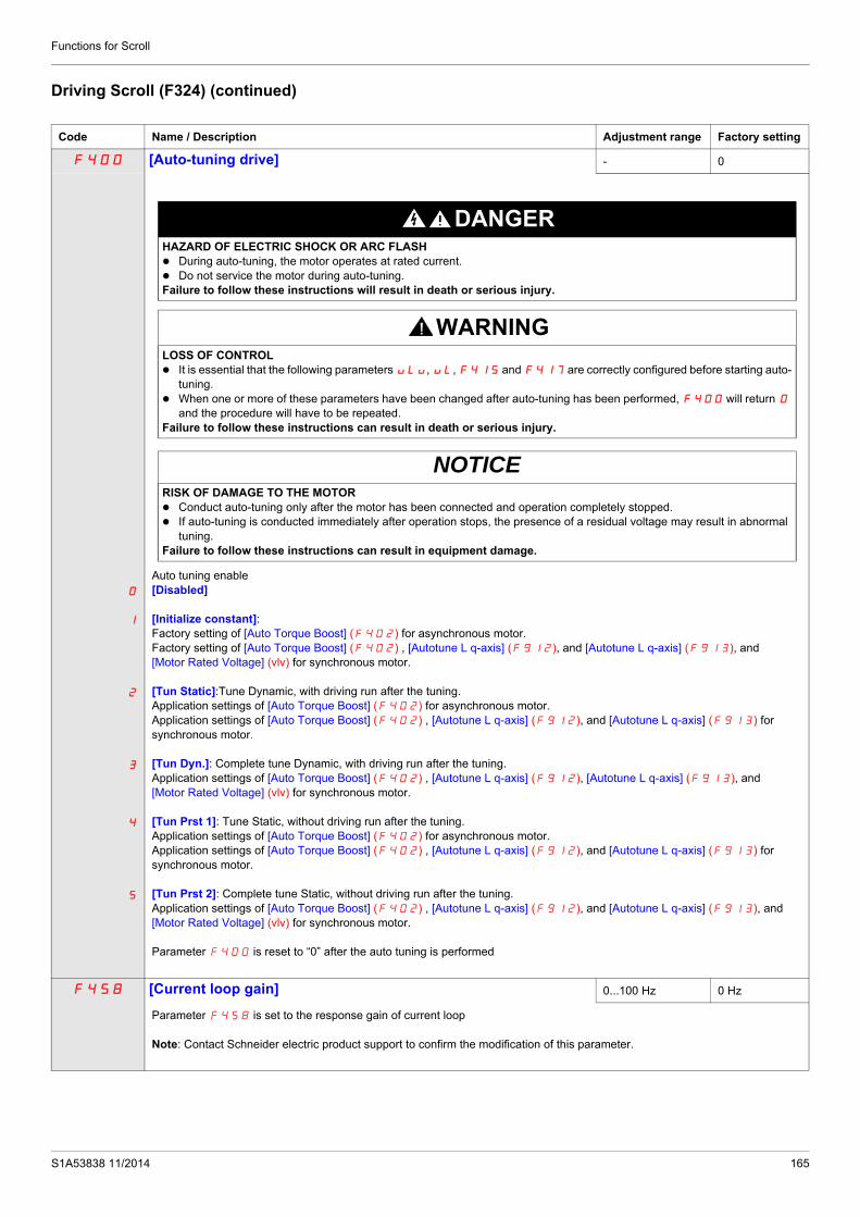
Functions for Scroll
Driving Scroll (F324) (continued)
Code Name / Description Adjustment range Factory setting
F400 [Auto-tuning drive] - 0
0
1
2
3
4
5
Auto tuning enable[Disabled]
[Initialize constant]: Factory setting of [Auto Torque Boost] (F402) for asynchronous motor. Factory setting of [Auto Torque Boost] (F402) , [Autotune L q-axis] (F912), and [Autotune L q-axis] (F913), and [Motor Rated Voltage] (vlv) for synchronous motor.
[Tun Static]:Tune Dynamic, with driving run after the tuning.Application settings of [Auto Torque Boost] (F402) for asynchronous motor.Application settings of [Auto Torque Boost] (F402) , [Autotune L q-axis] (F912), and [Autotune L q-axis] (F913) for synchronous motor.
[Tun Dyn.]: Complete tune Dynamic, with driving run after the tuning. Application settings of [Auto Torque Boost] (F402) , [Autotune L q-axis] (F912), [Autotune L q-axis] (F913), and [Motor Rated Voltage] (vlv) for synchronous motor.
[Tun Prst 1]: Tune Static, without driving run after the tuning.Application settings of [Auto Torque Boost] (F402) for asynchronous motor.Application settings of [Auto Torque Boost] (F402) , [Autotune L q-axis] (F912), and [Autotune L q-axis] (F913) for synchronous motor.
[Tun Prst 2]: Complete tune Static, without driving run after the tuning. Application settings of [Auto Torque Boost] (F402) , [Autotune L q-axis] (F912), and [Autotune L q-axis] (F913), and [Motor Rated Voltage] (vlv) for synchronous motor.
Parameter F400 is reset to “0” after the auto tuning is performed
F458 [Current loop gain] 0...100 Hz 0 Hz
Parameter F458 is set to the response gain of current loop
Note: Contact Schneider electric product support to confirm the modification of this parameter.
DANGERHAZARD OF ELECTRIC SHOCK OR ARC FLASH During auto-tuning, the motor operates at rated current. Do not service the motor during auto-tuning.Failure to follow these instructions will result in death or serious injury.
WARNINGLOSS OF CONTROL It is essential that the following parameters uLu, uL, F415 and F417 are correctly configured before starting auto-
tuning. When one or more of these parameters have been changed after auto-tuning has been performed, F400 will return 0
and the procedure will have to be repeated.Failure to follow these instructions can result in death or serious injury.
NOTICERISK OF DAMAGE TO THE MOTOR Conduct auto-tuning only after the motor has been connected and operation completely stopped. If auto-tuning is conducted immediately after operation stops, the presence of a residual voltage may result in abnormal
tuning. Failure to follow these instructions can result in equipment damage.
S1A53838 11/2014 165

Functions for Scroll
F418 [Frequency loop gain] 1 to 150 40
Parameters F418 and [Freq. loop stability] (F419) reduce the speed of the drive’s response to a change in speed command. The factory setting of these two parameters assumes that the inertia of the load is three times as large as that of the motor shaft. Adjust these two parameters if the factory setting is not appropriate for the application.Note: It is possible for the drive’s output frequency to exceed its upper limit (parameter [Max frequency] (FH)) if the acceleration parameter (ACC or F507) is set to its minimum value.Increasing the setting of parameter F418 reduces the drive’s response time to changes in the speed reference.
F419 [Freq. loop stability] Frequency loop stability 1 to 100 20
Increasing the setting of parameter F419 further reduces the drive’s response to changes in the speed reference.
F495 [Motor voltage coef.] Maximum voltage adjustment coefficient 90 to 120% 104%
Use parameter F495 to limit the drive’s maximum output voltage. Increasing this setting increases torque when the motor is operated above its rated frequency, but may also cause motor vibration. Do not increase the value of F495 if motor vibrations occur.
F915 [PM mode selection] PM control mode selection - 3
0
1
2
3
4
[0]: basic control[1]: control type 1 (for IPM)[2]: control type 2 (for IPM)[3]: control type 3 (for IPM / SPM)|4]: control type 4 (for IPM / SPM)
For more details see the chapter Motor Control Parameters “F915” on page 84
F912 [Autotune L q-axis] Q-axis self-inductance 0.01 to 650 mH 10
Axis "q" stator inductance in mHThe setting is replaced by the result of the auto-tuning operation, if it has been performed.
F913 [Autotune L d-axis] D-axis self-inductance 0.01 to 650 mH 10
Axis "d" stator inductance in mHThe setting is replaced by the result of the auto-tuning operation, if it has been performed.
F916 [PM Align cur. Level] Stabilization at the starting and low speed (for PM) 0 to 100 % 25 %
It might be able to stabilize the motor rotation behavior by the current in D axis at no load when starting or low-speed
For a complete description, see page 85.
F921 [Init. Pos. Current] Current for initial position estimation 10 to 150 100 %
During the auto-tuning for d-axis / q-axis inductance, the maximum current level can be adjusted by this parameter setting.
F420 [Torque Boost Coef] Compensation coefficient of torque boost 0 to 200% 90 %
If synchronous or asynchronous motor is used F420 [Torque Boost Coef] is set to 90%.
Note: If E-20 [Excess torque boost flt] trip occurs at the start, it is recommended to be decreased the setting of F420
166 S1A53838 11/2014

Functions for Scroll
F130 [RY Relay Function 1] RYA-RYC Relay Function 0 to 69, 254, 255 4
(1)
If [Driving Scroll] (F324) page 160 is set to [yes] (1) the setting is replaced by [disable oil injection in high-speed positive logic] (70)
For a complete description of the various functions assignable to the RYA-RYC relay, see page 108.The RYA-RYC relay can have a secondary assignment with programmed selection logic. See parameters
[RY Relay Function 2] (F137) and [RY logic select.] (F139) on page 124 for more detail.
F132 [FL Relay Function] Delay for RYA-RYC Relay 0 to 69, 254, 255 11
(1)
If [Driving Scroll] (F324) page 160 is set to [yes] (1) the setting is replaced by [Inv F101 sp reach] (9)
This parameter introduces a delay on RYA-RYC output signal relay see page 108.
0
+
-
0
1
F130 - RY Behaviour
Electrovalves
0
+
-
0
1
F132 - FL Behaviour
Electrovalves
S1A53838 11/2014 167

Functions for Scroll
F101 [Freq. 2 reached] Relay Output – Frequency Level 2 Attained0.0 to [Max frequen-cy] (FH) Hz 0.0 Hz
(1)
If [Driving Scroll] (F324) page 160 is set to [yes] (1) the setting is replaced by 65 Hz.
The frequency set by parameter F101 +/- the [Freq.2 bandw.] (F102) detection band is the threshold level for relay output functions 8 and 9 and the hysteresis for relay output functions 66 and 67 (see page 113).
F102 [Freq.2 bandw.] Frequency Attained Detection Band0.0 to [Max frequen-cy] (FH) Hz 2.5 Hz
(1)
If [Driving Scroll] (F324) page 160 is set to [yes] (1) the setting is replaced by 0.65 Hz.
Parameter F102 determines the bandwidth around the [Freq.2 reached] (F101) frequency (see diagram above) and the commanded frequency (see diagram below) driving relay output functions 6 through 9 (see page 101).
F113 [LI RES selection] RES Logic Input Function (2) 0 to 73 10
(1)If [Driving Scroll] (F324) page 160 is set to [yes] (1) the setting is replaced by [Inverse Run permis.] (54).
The setting of parameter F113 determines the control function of logic input terminal RES.
(1) When (F324) changes from [No] (0) to [Yes] (1), some of linked parameters are set to a new value. When (F324) changes from [Yes] (1) to [No] (0), linked parameters value are not changed
(2) See table on 101 for a complete list of RES logic inputs assignment
0
+
-
Output Frequency (Hz)
Relay Output Function 8
Relay Output Function 9
Time (S)
ONOFF
ONOFF
ONOFF
ONOFF
Relay Output Function 66
Relay Output Function 67
0
+
-
Output Frequency (Hz)
Commanded Frequency
Relay Output Function 6
Relay Output Function 7
Time (S)
ONOFF
ONOFF
168 S1A53838 11/2014

Functions for Scroll
F303 [Number auto reset] 0
0
1 to 10
Disabled.Number of clear attempts.
F303 is common and single for all functionsThe fault detection codes, which permit this function, are listed on page 135.
DANGERUNINTENDED EQUIPMENT OPERATION The automatic restart can only be used on machines or installations which do not pose any danger to either personnel or
equipment. If the automatic restart is activated, the fault relay will only indicate a fault has been detected once the time-out period for
the restart sequence has expired. The equipment must be used in compliance with national and regional safety regulationsFailure to follow these instructions will result in death or serious injury.
S1A53838 11/2014 169

Functions for Scroll
Pre-start Scroll (F325)This function is to help protect the compressor. The Drive must reach [Low limit Freq] (LL) within 2 s max. If not, FreeWheel stop the drive and do an automatic restart after a preset delay [Pre-start delay] (F329). Once [Low limit Freq] (LL) speed is reached in less than 2 s [LL speed time] (F328) the motor should run at [Pre-Start speed] (F327) for a [Pre-Start time] (F326) before taking into account the reference frequency.
If the [Pre-Start speed] (F327) is never reach, the amount of attempt should be limited at 10, and the alarm code [Autoreset] (rtrY) should be raised (see alarm codes page 184). After activating this function, [Pre-start Scroll] (F235) mustbe achieved at every run order.
Speed frequency (Hz)
Reference frequency
[Pre-start speed](F327)
[Low limit frequency](LL)
[LL speed time] [Pre-Start time] (F326)(F328)
Times (s)
Times (s)
(F328) (F328) (F326) (F329) and (F303) < x cycles
(F329) and (F303) < x cycles
Speed frequency (Hz)
[Pre-start speed](F327)
[Low limit frequency](LL)
Freewheel Stop
Freewheel Stop
Code Name / Description Adjustment range Factory setting
F325 [Pre-start Scroll] Scroll Compressor Pre-start Management - 0
0
1
At every Run Order the Drive must reach a preset Low Limit Frequency within a preset time and a limited number of attempts in order to avoid mechanical issues.[No][Yes]
F326 [Pre-Start time] Time to reach the pre-start speed 0...6000 s 10 s
Time during the motor turn to the pre-start speed
170 S1A53838 11/2014

Functions for Scroll
F327 [Pre-Start speed] 0.0 Hz to [Upper limit freq] (UL)
50 Hz
Speed to reach within the pre-start cycle
F328 [LL speed time] Time to reach LL Freq on pre-start order 0...10 s 2 s
Time which needs to be respected for reaching the low limit frequency.If the motor does not reach the [Low limit frequency] (LL) during this time the motor must stop.
F329 [Pre-start delay] 0...120 s 3 s
Delay between two pre-start cycles
S1A53838 11/2014 171

Functions for Scroll
Std Oiling Cycle (F330)This function helps to prevent the damage to the installation by lubricating it after a period of running. The drivemanages to re-oil the Scroll pump by running the (F330 = [Yes] (1)) motor at the optimal [Std Oiling Speed] (F331)for a settable [Std Oiling Time] (F332).The [Std Oiling Speed] (F331) must be reached at least one time within the [Std Oil. Cycle Frq.] (F333) of run order.
Time (s)
0
Drive speedreference
[Std Oiling Speed](F331)
Speed (Hz)
[Std Oil. Cycle Frq.] (F333)
[Std Oiling Time] (F332)
Code Name / Description Adjustment range Factory setting
F330 [Std Oiling Cycle] Periodic Oiling Cycle management - 0
0
1
After a preset period of service and/or a preset time of running at a low speed, the drive must manage an oiling boost cycle by running at a preset oiling speed during a preset oiling time.
[No][Yes]
F331 [Std Oiling Speed] Oiling Speed for Std Oiling Cycle 0 Hz to (UL)[Upper limit freq]
70 Hz
Oiling is done at this frequency.
F332 [Std Oiling Time] Time to maintain Oiling Speed in Std Cycle 0 s to 6000 s 30 s
Time to maintain oiling speed in standard cycle
F333 [Std Oil. Cycle Frq.] Frequency (time) of Standard Oiling Cycle 0 to 24 Hours (of run oder)
24 hrs
Time during the motor which turn without lubrication since the first Run order.
172 S1A53838 11/2014

Functions for Scroll
Low Speed Oiling (F334)This function helps to protect the installation of low lubrification that occurs at low speed. The [Std Oiling Speed](F331) must be reach during a time [Oiling Time at LLS] (F337) if the motor speed stayed under a [LL Speed forOiling] (F335) during a cycle limit [LLS Time for Oiling] (F336).
Time (s)
0
[LL Speed for Oiling](F335)
[Std Oiling Speed](F331)
[LLS Time for Oiling]
Speed (Hz)
[Oiling Time at LLS] (F336) ( F337)
Code Name / Description Adjustment range Factory setting
F334 [Low Speed Oiling] Oiling management for low speed running - 0
0
1
A preset oiling speed must be reached during a preset time every time the motor stayed under a preset speed during a preset time to compensate a too low lubrication due to low speed.
[No][Yes]
F331 [Std Oiling Speed] Oiling Speed for Std Oiling Cycle 0 Hz to (UL)[Upper limit freq]
70 Hz
Oiling Speed for Standard Oiling Cycle.
F335 [LL Speed for Oiling] 0 Hz to (UL)[Upper limit freq]
50 Hz
Low speed threshold to start Oiling control.
If the system never reach it after time [LLS Time for Oiling] (F336) the system will go in lubrification.
F336 [LLS Time for Oiling] 0...360 minutes 60 minutes
Time during the motor turn under the threshold of [LL Speed for Oiling] (F335).
F337 [Oiling Time at LLS] 0...6000 s 30 s
Time to maintain oiling injection in the installation.
S1A53838 11/2014 173

Functions for Scroll
Scroll Protection (F338)This function is active only out of the acceleration phase to helps protect the Scroll pump about overloading andcavitations effect, if the motor current limit is over passed and if the speed is under the [Cavitation Frq.] (F339) thedrive will stop in Freewheel and the alarm signal will be displayed [Cavitation Error] (CAPF).
Code Name / Description Adjustment range Factory setting
F338 [Scroll Protection] Avoid overloading or cavitation effects - 0
0
1
Scroll compressor protection against the effects of overload and cavitation
If Fire function mode (53) is activated and F338 = (1), [Cavitation Error] (CAPF) alarm signal is inhibited, see Logic input Functions page 53
[No][Yes]
F339 [Cavitation Frq.] [Low limit frequency] (LL) to [Upper limit freq] (uL)
30 Hz
Cavitation Frequency Threshold.
174 S1A53838 11/2014

Functions for Scroll
Discharge gas (F349)This function enables to helps to protect the installation avoiding high temperature or high pressure, the speed will automatically reduced the speed or stop the Scroll pump depending on temperature level [High Thd] (F350) and [High high Thd] (F353).
The time [Re-Start Delay] (F354) before automatic restart (see [Number auto reset] (F303) page 169) is settable and the number of maximum attempt is limited to 10. The restart will come [Re-Start Delay] (F354) after the temperature gets under y [High high Thd] (F353).
Code Name / Description Adjustment range Factory setting
F349 [Discharge gas] Avoid high temp. or pressure on sensor input - 0
0
1
2
This function helps to protect the installation avoiding high temperature or high pressure in the refrigerant loop.[No] Function unactive[VIA] Function is active and uses analog input VIA [Ref source VIA][VIB] Function is active and uses analog input VIB: [Ref source VIB]
F350 [High Thd] 0 - 100 65 %
High Process ThresholdNote: 100% means analog input ports VIA or VIB applied full scale value.
F351 [Cooling Frq.] [Low limit frequency] (LL) to [Upper limit freq] (UL)
50 Hz
Cooling system Frequency.
F352 [Cooling Time] 0 - 30 3 minutes
Time to maintain cooling system frequency.
F353 [High high Thd] 0 - 100 70 %
High high Process Threshold.Note: 100% means analog input ports VIA or VIB applied full scale value.
F354 [Re-Start Delay] 0...30 minutes 5 minutes
Delay before restart after emergency stop.
[Cooling Time] (F352)
[Re-Start Delay] (F354)
T (s)
T (s)
T (s)
Stop freewheelsand default trig.
Temperature (%)
[High high Thd] (F353)
[High Thd](F350)
Speed reference
Speed (Hz)
[Cooling Frq.] (F351)
RUN Order
1
0
S1A53838 11/2014 175

Functions for Scroll
Crankcase heating (F355)Replace crankcase heaters by using a current injection in motor to generate resistance heating.
Note: Before using the Function [Crankcase heating] (F355), to stop the current injection you should assign a logic input to Freewheel stop, you can also stop the injection by a power off.
(1) When (F324) changes from [No] (0) to [Yes] (1), some of linked parameters are set to a new value. When (F324) changes from [Yes] (1) to [No] (0), linked parameters value are not changed.
Code Name / Description Adjustment range Factory setting
F355 [Crankcase heating] Keep the system warm after motor stopped - 0
0
1
Heating by current injection in the motor in order to prevent the emission of gas due to the condensation of the refrigerant into the compressor.
[No][Yes]
F250 [DC brake start freq.] 0.0 Hz to [Max frequency](FH)
0.0 Hz
(1) If [Driving Scroll] (F324) page 160 is set to [yes] (1) the setting is replaced by 0.0 Hz.
When stopping the motor, the drive will apply DC injection braking once the output frequency drops below the level set by parameter F250.
F251 [DC braking current] 0 to 100 % 50%
(1) If [Driving Scroll] (F324) page 160 is set to [yes] (1) the setting is replaced by 10%.
Parameter F251 sets the level of current applied to the motor during DC injection braking. The displayed value, percent or am-peres, is set by parameter [Unit value selection] (F701) (see page 130).During DC injection braking, the drive’s overload protection sensitivity increases. The drive automatically lowers the applied DC cur-rent to avoid an overload detected fault.
WARNINGNO HOLDING TORQUE DC injection braking does not provide holding torque at zero speed. DC injection braking does not work when there is a loss of power or when the drive detects a fault. When necessary, use a separate brake to maintain torque levels.Failure to follow these instructions can result in death, serious injury, or equipment damage.
NOTICERISK OF DAMAGE TO THE MOTORCheck that the motor will withstand this current without overheating.Failure to follow this instruction can result in equipment damage.
176 S1A53838 11/2014

S1A53838 11/2014
Diagnostics and troubleshooting
III
Diagnostics and troubleshootingWhat's in this Part?
This part contains the following chapters:
Chapter Chapter Name Page
14 Diagnostics and troubleshooting 179
177

Diagnostics and troubleshooting
178 S1A53838 11/2014

S1A53838 11/2014
Diagnostics and troubleshooting
15
Diagnostics and troubleshootingWhat's in this Chapter?
This chapter contains the following topics:
Topic Page
Detected fault conditions 180
Alarm Conditions 184
Pre-alarm Conditions 186
Clearing the detected fault 187
179
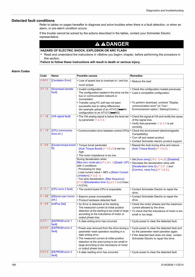
Diagnostics and troubleshooting
Detected fault conditionsRefer to tables on pages hereafter to diagnose and solve troubles when there is a fault detection, or when an alarm, or pre-alarm condition occurs.
If the trouble cannot be solved by the actions described in the tables, contact your Schneider Electric representative.
Alarm Codes
DANGERHAZARD OF ELECTRIC SHOCK, EXPLOSION OR ARC FLASH• Read and understand the instructions in «Before you begin» chapter, before performing the procedure in
this section.Failure to follow these instructions will result in death or serious injury.
Code Name Possible causes Remedies
CApF [Cavitation Error] • Loss of speed due to overload or / and too
much torque. • Reduce the load
CFI2 [Download transfer fault]
• Invalid configuration.The configuration loaded in the drive via the bus or communication network is inconsistent.
• Transfer using PC soft has not been successful due to rating differences (for example upload of an ATV212pppN4 configuration to an ATV212pppM3)
• Check the configuration loaded previously.• Load a compatible configuration.
• To perform download, uncheck "Display communication error" (in Tool / Environnement option / Startup/Comm.)
E-18 [VIA signal fault] • The VIA analog signal is below the level set by parameter F633.
• Check the signal at VIA and rectify the cause of the signal loss.
• Verify that parameter F633 is set correctly.
E-19 [CPU communica-tions err.]
• Communication error between control CPUs • Check the environment (electromagnetic Compatibility)
• Turn off and restart product.• Contact Schneider electric product support.
E-20 [Excess torque boost flt]
• Torque boost parameter [Auto Torque Boost] (F402) is set too high.
• The motor impedance is too low.
• Repeat the Auto-tuning drive and reduce [Auto Torque Boost] (F402).
During deceleration when [Mot cont. mode sel.] (Pt) = (1) [Quadr. U/F] with 3 conditions:- Processing for stop- Load current value > 88% x [Motor Current Limitation] (F601)- Too slow deceleration, [Max frequency] (FH) /[Deceleration time 1] (dEC) x 2 msec < 0.01Hz
• Set [Auto ramp] (AU1) = (0) [Disabled]• Decrease the deceleration ramp with
[Deceleration time 2] (F501) and [Commut. ramp freq.] (F505).
E-21 [CPU error 2 fault] • The control board CPU is inoperable. • Contact Schneider Electric to repair the drive.
E-38 [EEprom pwr incom-pat.]
• Eeprom power incompatible.• Product hardware detected fault.
• Contact Schneider Electric to repair the drive.
E-39 [InitPos Det] • An Error is detected at the starting:The measured current at initial position detection at the starting is too small or large according to the inductance of motor or output phase loss.
• Check the motor phases and the maximum current allowed by the drive.
• To check that the inductance of motor is too small or too large.
EEP1 [EEPROM error 1 fault]
• A data writing error has occurred. • Cycle power to clear the detected fault.
EEP2 [EEPROM error 2 fault]
• Power was removed from the drive during a parameter reset operation resulting in a data writing error.
• The measured current at initial position detection at the auto-tuning is too small or large according to the inductance of motor or output phase loss
• Cycle power to clear the detected fault and try the parameter reset operation again.
• If the detected fault does not clear, contact Schneider Electric to repair the drive.
EEP3 [EEPROM error 3 fault]
• A data reading error has occurred. • Cycle power to clear the detected fault.
180 S1A53838 11/2014

Diagnostics and troubleshooting
EF2 [Ground fault] • Ground fault in motor or motor cables • Check the motor and motor cables for ground faults.
EPHO [Output phase loss fault]
• Loss of one or more output phases • Determine the cause of the missing output phase (such as a bad connection, an output disconnect, or an open winding in the motor) and clear it.
• Check parameter F605.EPHI [Input phase loss
fault]• Loss of one input phase • Determine the cause of the missing input
phase and clear it.• Check parameter F608.
EPtF [Threshold Error] • Condition for overheating reached, exceeded Treshold F353
• Check the system.
Err1 [Speed ref. error fault]
• Parameters F202, F203, F210, or F212 are set improperly.
• Set the parameters to the correct settings.
Err2 [RAM fault] • The control board RAM is inoperable. • Contact Schneider Electric to repair the drive.
Err3 [ROM fault] • The control board ROM is inoperable. • Contact Schneider Electric to repair the drive.
Err4 [CPU fault 1] • The control board CPU is inoperable. • Contact Schneider Electric to repair the drive.
Err5 [Com RJ45 fault] • Serial communication error • Check network control devices and cables.• Check the setting of the communication
timeout parameter, F803.• Check the remote graphic display option
cable.• Check the setting of F829 parameters.
Err7 [Current sensor fault] • A motor current sensor is inoperable. • Replace the drive.Err8 [Network error fault] • Network communication error • Check the network control devices and
cables.Err9 [Remote keypad
fault]• Graphic display option cable disconnected • Check the RJ45 cable.
Etn1 [Auto-tuning fault] • Parameters F401 to F494 are incorrectly set.
• The motor is too large for the drive.• The motor cable gauge is too small.• The motor is still rotating at the start of the
auto-tune.• The drive is not powering a 3-phase
induction motor.• The measured current at initial position
detection at the auto-tuning is too small or large according to the inductance of motor or output phase loss
• Set parameters F401–F494 correctly.• Use a larger drive.• Use a larger gauge motor cable.• Verify that the motor is stopped before
starting an auto-tune.• Use the drive to power only a 3-phase
induction motor.
EtYP [Drive fault] • The main control board is inoperable. • Set parameter [Parameter reset] (tYP) to 6.
• If this does not clear the detected error, replace the drive.
Fd1 [Closed damper 1 fault]
• Damper is locked in closed position. • Set [Damper flt behavior] (F583) to 0.• Check the FL relay connection (FLA/FLB).• Check the relay configuration
(F130/F132).Fd2 [Closed damper 2
fault]• Damper blocked open or soldered. • Set [Damper fdb type] (F580) to 0 or
1.Check the FL relay connection (FLA/FLB).
• Check the relay configuration (F130/F132).
M020 [Total input power] • The accumulated input power value is more than 999.999 kWh.
• Clear the accumulated input power value using logic input function 51, or parameter F748.
Code Name Possible causes Remedies
S1A53838 11/2014 181

Diagnostics and troubleshooting
OC1 [Overcurrentacceleration]
• The acceleration time is too short.• The setting of parameter [Mot cont. mode
sel.] (Pt) is incorrect.• The drive is starting into a rotating load.• The drive is powering a low impedance
motor.• Ground fault
• Increase the acceleration time parameters (ACC or F500).
• Select the correct setting for parameter [Mot cont. mode sel.] (Pt).
• Enable catch on the fly, parameter F301.• Adjust the switching frequency parameter F300.
• Set parameter F316 to 1 or 3.OC1P [SC or ground fault
acc.]• Short circuit or ground fault during
acceleration• Using a 1000 V testing tool megger, check
the motor and motor cables for ground faults.OC2 [Overcurrent
deceleration]• The deceleration time is too short.• Ground fault
• Increase the deceleration time parameters (dEC or F501).
• Set parameter F316 to 1 or 3.OC2P [SC or ground fault
dec.]• Short circuit or ground fault during
deceleration• Using a 1000 V megger, check the motor and
motor cables for ground faults.OC3 [Overcurrent cont.
speed]• Abrupt fluctuations in load• Abnormal load condition
• Reduce the load fluctuations.• Check the load.• Set parameter F316 to 1 or 3.
OC3P [SC/ground flt cont. spd]
• Short circuit or ground fault during constant speed operation
• The drive cooling fan is not working.
• Using a 1000 V megger, check the motor and motor cables for ground faults.
• Check the fan operationOCA [SC inverter at start] • Ground fault • Using a 1000 V megger, check the motor and
motor cables for ground faults.OCL [SC mot. cable at
start]• Phase to phase output short circuit• The motor impedance is too low.
• Using a 1000 V megger, check the motor and motor cables for ground faults.
OH [Driveovertemperature]
• The drive cooling fan is not working.• The ambient temperature is too high.• An enclosure air vent is blocked.• A heat source is too close to the drive.• The drive heatsink temperature sensor is
malfunctioning.
• Restart operation by resetting the drive detected fault after cool-off.
• Decrease the ambient temperature by increasing the free space around the drive and removing any heat generating source from the proximity of the drive.
• Check the fan operationOH2 [PTC overheating] • The external PTC embedded in the motor
windings indicates a motor overtemperature condition.
• Correct the motor overload condition.• Check the PTC for correct operation.
OL1 [Drive overload] • The acceleration time is too short.• The DC injection current level is too high.• The setting of parameter [Mot cont. mode
sel.] (Pt) is incorrect.• The drive is starting into a rotating load.• The load is too large.
• Increase the acceleration time parameters (ACC or F500).
• Reduce the setting of parameters F251 and/or F252.
• Select the correct setting for parameter [Mot cont. mode sel.] (Pt).
• Enable catch on the fly, parameter F301.• Set parameter F302 to 2.• Use a drive with a higher power rating.
OL2 [Motor overload] • The setting of parameter [Mot cont. mode sel.] (Pt) is incorrect.
• The motor is jammed.• Low-speed operation is performed
continuously• Excessive load is applied to the motor.
• Select the correct setting for parameter [Mot cont. mode sel.] (Pt).
• Check the load.• Adjust parameter OLM to the overload level
that the motor can withstand during low speed operation.
OP1 [Overvoltageacceleration]
• The input voltage is fluctuating abnormally.• Power network is greater than 200 kVA.• Power factor capacitor switching• SCR switching on power network• The drive is starting into a rotating load.• Intermittent output phase fault
• Install a line reactor.• Enable catch on the fly, parameter F301.• Set parameter F302 to 2.• Determine the cause of the missing output
phase (such as a bad connection, an output disconnect, or an open winding in the motor) and rectify the trouble.
OP2 [Overvolt.deceleration]
• The deceleration time is too short.• Overhauling load• The input voltage is fluctuating abnormally.• Power network is greater than 200 kVA• Power factor capacitor switching• SCR switching on power network• The drive is starting into a rotating load.• Intermittent output phase fault
• Increase the deceleration time parameters (DEC or F501).
• Enable parameter F305.• Install a line reactor.• Check the input and output circuits for phase
loss detection and rectify.• Enable catch on the fly, parameter F301.
Code Name Possible causes Remedies
182 S1A53838 11/2014

Diagnostics and troubleshooting
OP3 [Overvoltage cont. speed]
• The input voltage is fluctuating abnormally.• Power network is greater than 200 kVA• Power factor capacitor switching• SCR switching on power network• The drive is regenerating - the load causes
the motor to run at a frequency higher than drive output frequency.
• Intermittent output phase fault
• Install a line reactor.• Check the input and output circuits for phase
loss detection and rectify.
Ot [Overtorque] • The calculated motor torque has reached the level set by parameter F616.
• Adjust the settings of parameters F615 and F616 as needed.
• Verify machine operation.pSrF [Prst Spd Error] • Prestart speed not reached.
• The load is too high.• Reduce the load
SOUt [PM motor step-out](permanent magnet motor pulls out of synchronism)
• The motor is jammed.• Output phase loss• Impact load
• Check the load and correct the jammed condition.
• Check the condition of the motor and load wiring.
UC [Underload] • The measured motor current has dropped below the level set by parameter F611.
• Check parameters F610–612 for the correct settings.
UPI [Undervoltage] • The input voltage is too low. • Check the input voltage and rectify the trouble.
• Select the correct setting for parameter F627.
• Enable catch on the fly, parameter F301.• Set parameter F302 to 2.
Code Name Possible causes Remedies
S1A53838 11/2014 183
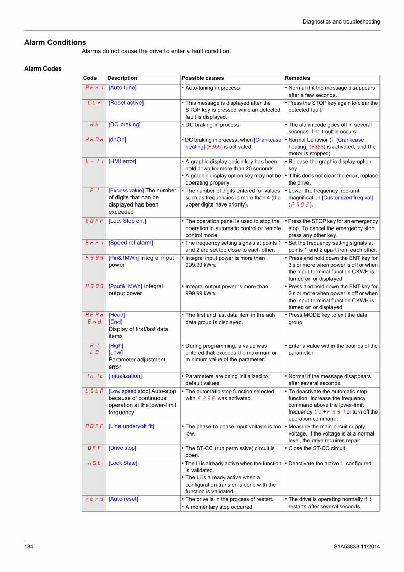
Diagnostics and troubleshooting
Alarm ConditionsAlarms do not cause the drive to enter a fault condition.
Alarm Codes
Code Description Possible causes Remedies
Atn1 [Auto tune] • Auto-tuning in process • Normal if it the message disappears after a few seconds.
CLr [Reset active] • This message is displayed after the STOP key is pressed while an detected fault is displayed.
• Press the STOP key again to clear the detected fault.
db [DC braking] • DC braking in process • The alarm code goes off in several seconds if no trouble occurs.
dbOn [dbOn] • DC braking in process, when [Crankcase heating] (F355) is activated.
• Normal behavior (if [Crankcase heating] (F355) is activated, and the motor is stopped)
E-17 [HMI error] • A graphic display option key has been held down for more than 20 seconds.
• A graphic display option key may not be operating properly.
• Release the graphic display option key.
• If this does not clear the error, replace the drive.
EI [Excess value] The number of digits that can be displayed has been exceeded
• The number of digits entered for values such as frequencies is more than 4 (the upper digits have priority).
• Lower the frequency free-unit magnification [Customized freq val] (F702).
EOFF [Loc. Stop en.] • The operation panel is used to stop the operation in automatic control or remote control mode.
• Press the STOP key for an emergency stop. To cancel the emergency stop, press any other key.
Err1 [Speed ref alarm] • The frequency setting signals at points 1 and 2 are set too close to each other.
• Set the frequency setting signals at points 1 and 2 apart from each other.
h999 [Pin&1MWh] Integral input power
• Integral input power is more than 999.99 kWh.
• Press and hold down the ENT key for 3 s or more when power is off or when the input terminal function CKWH is turned on or displayed.
H999 [Pout&1MWh] Integral output power
• Integral output power is more than 999.99 kWh.
• Press and hold down the ENT key for 3 s or more when power is off or when the input terminal function CKWH is turned on or displayed.
HEAd
End
[Head][End]Display of first/last data items
• The first and last data item in the auh data group is displayed.
• Press MODE key to exit the data group.
H1
LO
[High][Low]Parameter adjustment error
• During programming, a value was entered that exceeds the maximum or minimum value of the parameter.
• Enter a value within the bounds of the parameter
InIt [Initialization] • Parameters are being initialized to default values.
• Normal if the message disappears after several seconds.
LStp [Low speed stop] Auto-stop because of continuous operation at the lower-limit frequency
• The automatic stop function selected with F256 was activated.
• To deactivate the automatic stop function, increase the frequency command above the lower-limit frequency LL+F391 or turn off the operation command.
NOFF [Line undervolt flt] • The phase-to-phase input voltage is too low.
• Measure the main circuit supply voltage. If the voltage is at a normal level, the drive requires repair.
OFF [Drive stop] • The ST-CC (run permissive) circuit is open.
• Close the ST-CC circuit.
nSt [Lock State] • The Li is already active when the function is validated.
• The Li is already active when a configuration transfer is done with the function is validated.
• Deactivate the active Li configured.
rtrY [Auto reset] • The drive is in the process of restart.• A momentary stop occurred.
• The drive is operating normally if it restarts after several seconds.
184 S1A53838 11/2014

Diagnostics and troubleshooting
StOp [Stop supply] Momentary power loss slowdown stop prohibition function activated.
• The slowdown stop prohibition function set with F302 (momentary power loss ride-through operation) is activated.
• To restart operation, reset the drive or input an operation signal again.
S1A53838 11/2014 185

Diagnostics and troubleshooting
Pre-alarm Conditions
Pre-alarm Codes
The pre-alarm codes are displayed, flashing on the embedded HMI, in the following order from left to right: C, P, L, H.
If two or more troubles arise simultaneously, one of the following pre-alarm codes appears and flashes: CP, PL, CPL.
Code Pre-alarm Description
C [Current alarm] • The drive is at current limit. • For more information, refer to parameter F601 (see page 73) and F185 (see page 79).
P [DC bus alarm] • The drive is approaching an overvoltage detected fault due to a high supply line, regenerative motor braking, or a combination of these. For more information, refer to parameters F305 (see page 139) and F626 (see page 139).
L [Motor overload al] • The motor overload timer has reached or exceeded 50% of its detected fault level.H [Drv overheat alrm] • The drive is approaching an overheating fault detection.
186 S1A53838 11/2014

Diagnostics and troubleshooting
Clearing the detected fault
In the event of a non resettable detected fault:
1 Disconnect all power, including external control power that may be present.2 Lock all power disconnects in the open position.3 Wait 15 minutes to allow the DC bus capacitors to discharge (the drive LEDs are not indicators of the absence
of DC bus voltage).4 Measure the voltage of the DC bus between the PA/+ and PC/– terminals to ensure that the voltage is less
than 42 Vdc.5 If the DC bus capacitors do not discharge completely, contact your local Schneider Electric representative.
Do not repair or operate the drive.- Find and correct the detected fault.- Restore power to the drive to confirm the detected fault has been rectified.
When any overload function (OL1 or OL2) is active, the drive cannot be reset by inputting a reset signal from an external device or with the Stop key on the display terminal if the calculated cooling time has not expired. Calculated cooling time:
- OL1: 30 seconds after the detected fault has occurred- OL2: 120 seconds after the detected fault has occurred
NOTICERISK OF DAMAGE TO THE MOTOR Repeated reset of the thermal state after a thermal overload can result in thermal stress to the motor. When trips occur, promptly inspect the motor and driven equipment for problems (such as a locked shaft or
mechanical overload) before restarting. Also check the power supplied to the motor for abnormal conditions (such as a phase loss or phase imbalance).
Failure to follow these instructions can result in equipment damage.
S1A53838 11/2014 187

Diagnostics and troubleshooting
188 S1A53838 11/2014

S1A53838 11/2014
Annex
IV
AnnexWhat's in this Part?
This part contains the following chapters:
Chapter Chapter Name Page
15 Migration 191
17 Parameters Reset Tables 193
18 User Settings Tables 203
189

Annex
190 S1A53838 11/2014

S1A53838 11/2014
Migration
16
MigrationWhat's in this Chapter?
This chapter contains the following topics:
Topic Page
Migration ATV21 - ATV212 192
191

Migration
Migration ATV21 - ATV212
General
The ATV212 is compatible with the ATV21
Migration Modbus ATV21 to ATV212: When controlling ATV21 using Modbus RJ45, parameter [Network protocol] (F829) should be set to 1.
With ATV212, parameter F829 should also be set to 1 and parameter [Com channel choice] (F807) set to [RJ45] (0). Factory setting is [Open style] (1).
Settings of other communication parameters described from page 148 remain the same as on ATV21.
Note: For LonWorks, parameter F829 needs to be set to 1 for ATV21 and needs to be set to 5 for ATV212.
A configuration transfer from ATV21 to ATV212 is possible.
For example:
You can upload a configuration from an ATV21 via PC Soft (and selected the inverter Type : ATV21) and download it into ATV212.
After a transfer from ATV21 to ATV212, the new parameters stay at their factory setting:
[Damper fdb type] (F580), [Time open Damper] (F581), [Time close Damper] (F582) ,[Damper flt behavior] (F583),[Forced fire control] (F650), [Forced fire function] (F659), [Com channel choice] (F807), [Mdb network baud] (F820), [Mdb network parity] (F821) and [LL for ov.cur. prev.] (F390).
The download configuration is not allowed if the drive is running.
In case of an interruption of download configuration transfer to the drive and detected fault, the CFI2 is set. This detected fault code keeps also present even after power off of the drive.
To reset the download transfer detected fault code CFI2:
Make a new successful transfer Make a factory setting on the drive (using tYP parameter)
At the end of download transfer, the drive cannot run if a logic input configured to a function is active. To use the function and run the motor, it's necessary to disable and enable the logic input.
Commissioning
Compatible loader tools with ATV212:
SoMove V1.7.1.1 and higher, Multi-Loader V3.2 and higher,
SoMoveMobile V2.2.7 and higher,
PC soft is not compliant, since the software version V5.2 of the products ATV212.
WARNINGLOSS OF CONTROL Since the software version V5.2 of the products ATV212, PC soft is not compliant. Do not use PC soft with the products ATV212 V5.2 and at and above.Failure to follow these instructions can result in death, serious injury, or equipment damage.
192 S1A53838 11/2014

S1A53838 11/2014
Parameters Reset Tables
17
Parameters Reset TablesParameter Reset
Refer to Menu navigation diagram page 66 to know how to reach [Parameter reset] (tYP) parameter.
The Altivar 212 drive offers three parameter reset options:
Factory reset: [Parameter reset] (tYP) = 3 50 Hz reset: [Parameter reset] (tYP) = 1 60 Hz reset: [Parameter reset] (tYP) = 2
This appendix describes parameter values after these reset operations.
The following tables identify:
Parameters whose values after a reset do not vary by reset type, see page 194. Parameters whose values after a reset vary by reset type, see page 198. Parameters whose values after a reset are drive model dependant but do not vary by reset type, see page
199. Parameters whose values after a reset are drive model and reset type dependant, see page 200. Parameters whose values do not change if a reset is performed, see page 201.
193

Parameters Reset Tables
Parameter values that do not vary by reset typeThe table below lists the parameters whose values, after a reset, do not vary by the reset type.
To determine the value of a parameter after a reset, locate the parameter in the first column and read across the row to the default value column. The number that appears at the intersection of the parameter and the default value is the parameter’s value after a reset of any type ([Parameter reset] (tYP) = 1, [Parameter reset] (tYP) = 2, or [Parameter reset] (tYP) = 3).
Parameters whose values after a reset do not vary by reset type
Parameter Description Unit Default Value
AU1 [Auto ramp] – 1
AU4 [Auto set function] – 0
FMSL [AO funct. selection] – 0
FM [AO scaling] – –
tYp [Parameter reset] – 0
Fr [Local mot. direction] – 0
FC [Local speed ref.] Hz 0.0
LL [Low limit frequency] Hz 0.0
Pt [Mot cont. mode sel.] – 1
OLM [Motor overload prot] – 0
Sr1 [Preset speed 1] Hz 15
Sr2 [Preset speed 2] Hz 20
Sr3 [Preset speed 3] Hz 25
Sr4 [Preset speed 4] Hz 30
Sr5 [Preset speed 5] Hz 35
Sr6 [Preset speed 6] Hz 40
Sr7 [Preset speed 7] Hz 45
F100 [Freq. 1 reached] Hz 0.0
F101 [Freq. 2 reached] Hz 0.0
F102 [Freq.2 bandw.] Hz 2.5
F108 [Logic Funct 1 active] – 0
F109 [VIA selection] – 0
F110 [Logic Funct 2 active] – 1
F111 [LI F selection] – 2
F112 [LI R selection] – 6
F113 [LI RES selection] – 10
F118 [VIA LI selection] – 7
F130 [RY Relay Function 1] – 4
F132 [FL Relay Function] – 11
F137 [RY Relay Function 2] – 255
F139 [RY logic select.] – 0
F167 [Freq band det range] Hz 2.5
F200 [Auto/man speed ref]f – 0
F201 [VIB ref. point 1] % 0
F202 [VIA freq. point 1] Hz 0.0
F203 [VIA freq. point 2] % 100
F207 [Remote spd ref 2] – 2
F210 [VIB ref. point 1] % 0
194 S1A53838 11/2014

Parameters Reset Tables
F211 [VIB freq. point 1] Hz 0.0
F212 [VIB ref. point 2] % 100
F240 [Mot start freq.] Hz 0.5
F241 [Freq. pedestal] Hz 0.0
F242 [Freq. pedestal hyst.] Hz 0.0
F250 [DC brake start freq.] Hz 0.0
F251 [DC braking current] A 50
F252 [DC braking time] s 1.0
F256 [Time limit low spd] s 0.0
F264 [+speed LI resp time] s 0.1
F265 [+speed freq. step] Hz 0.1
F266 [- speed LI resp time] s 0.1
F267 [- speed freq. step] Hz 0.1
F268 [Init +/- Speed] Hz 0.0
F269 [Init +/- Speed memo] – 1
F270 [Jump frequency 1] Hz 0.0
F271 [Jump bandwidth 1] Hz 0.0
F272 [Jump frequency 2] Hz 0.0
F273 [Jump bandwidth 2] Hz 0.0
F274 [Jump frequency 3] Hz 0.0
F275 [Jump bandwidth 3] Hz 0.0
F294 [Forced speed freq.] Hz 50
F295 [Switch rem/Local] – 1
F301 [Catch on fly] – 3
F302 [Supply loss behav.] – 0
F305 [Overvoltage fault] – 2
F307 [Mot volt limitation] – 3
F311 [Motor direction] – 1
F312 [Noise reduction] – 0
F316 [Switch. freq. mode] – 1
F320 [Load gain] % 0
F323 [Load gain offset] % 10
F359 [PID ctrl wait time] s 0
F360 [PID control enable] – 0
F362 [PID Prop Gain] – 0.30
F363 [PID Integral Gain] – 0.20
F366 [PID Derivative Gain] – 0.00
F400 [Auto-tuning drive] – 0
F401 [Slip Compensation] % 50
F418 [Frequency loop gain] – 40
F419 [Freq. loop stability] – 20
F470 [VIA bias] – 128
F471 [VIA gain] – 148
F472 [VIB bias] – 128
F473 [VIB gain] – 148
F482 [In noise Inhibit filter] s 442
Parameter Description Unit Default Value
S1A53838 11/2014 195

Parameters Reset Tables
F483 [In noise inhibit gain] – 100
F484 [Pwr supply adj. gain] – 0.0
F485 [Stall control coef. 1] – 100
F492 [Stall control coef. 2] – 100
F495 [Motor voltage coef.] % 104
F496 [PWM adj. coef.] kHz 14.0
F502 [Acc/dec 1 pattern] – 0
F503 [Acc/dec 2 pattern] – 0
F504 [Ramp switching] – 1
F505 [Commut. ramp freq.] Hz 0.0
F506 [Acc/Dec S-pat start] % 10
F507 [Acc/Dec S-pat end] % 10
F602 [Drive fault memory] – 0
F603 [Ext. fault stop Mode] – 0
F604 [DC brk time ext flt] s 1.0
F605 [Output phase loss] – 3
F607 [Mot overload time] s 300
F608 [Input phase loss] – 1
F609 [Underload band] % 10
F610 [Underload det.] – 0
F611 [Underload level] % / A 0
F612 [Underload det. time] s 0
F613 [Short circuit det.] – 0
F615 [Overtorque det.] – 0
F616 [Overtorque level] % 130
F618 [OvTorque det time] s 0.5
F619 [Overtorque band] % 10
F621 [Run time alarm] h 610.0 (6100 h)
F627 [Undervolt detect.] – 0
F632 [Mot overload memo] – 0
F633 [Loss of VIA] % 0
F634 [Amb. temp. alarm] – 3
F645 [Mot PTC selection] – 0
F646 [PTC resistor value] 3000
F650 [Forced fire control] – 0
F691 [AO slope] – 1
F692 [Analog output bias] % 0
F700 [Parameter lock] – 0
F701 [Unit value selection] – 1
F702 [Customized freq val] – 0
F703 [Frequency convert.] – 0
F706 [Customize unit bias] Hz 0.0
F707 [Loc. speed ref. step] Hz 0.0
F708 [Display ref. resol.] – 0
F710 [Displayed param.] – 0
F721 [Loc. mot stop mode] – 0
Parameter Description Unit Default Value
196 S1A53838 11/2014

Parameters Reset Tables
(1) See table page 199.
F730 [Up/down key ref] – 0
F732 [Loc/rem key] – 0
F733 [Run/stop key] – 0
F734 [Priority stop] – 0
F735 [HMI reset button] – 1
F738 [Quick menu AUF] – 0
F748 [Power cons. memo] – 1
F800 [Mdb RJ45 baud] – 1
F801 [Mdb RJ45 parity] – 1
F802 [Modbus address] – 1
F803 [Com. time out] s 3
F829 [Network protocol] – 1
F851 [Com. fault setting] – 4
F856 [Mot. poles (comm.)] – 2
F870 [Block write data 1] – 0
F871 [Block write data 2] – 0
F875 [Block read data 1] – 0
F876 [Block read data 2] – 0
F877 [Block read data 3] – 0
F878 [Block read data 4] – 0
F879 [Block read data 5] – 0
F880 [Free ID parameter] – 0
F890 [Network adress] – (1)
F891 [Network baud rate] – (1)
F892 [Network time out] – (1)
F893 [Instance number H] – (1)
F894 [Instance number L] – (1)
F895 [Max master] – (1)
F896 [Max info frames] – (1)
Parameter Description Unit Default Value
S1A53838 11/2014 197

Parameters Reset Tables
Parameter values that vary according to reset typeThe table below lists the parameters whose values, after a reset, depend on the reset type ([Parameter reset] (tYP) = 1, [Parameter reset] (tYP) = 2, or [Parameter reset] (tYP) = 3).
To determine the value of a parameter after a reset, locate the parameter in the first column and read across the row to the column that corresponds to the reset type. The number that appears at the intersection of the parameter and the reset type is the parameter’s value after a reset of the corresponding type.
Parameters whose values after a reset vary by reset type
Parameter Description UnitFactory Reset
tYP = 3
50 Hz Reset
tYP = 1
60 Hz Reset
tYP = 2
CMOd [Command mode sel] – 0 0 0
FMOd [Frequency mode sel] – 1 1 1
FH [Max frequency] Hz 50 50 60
UL [Upper limit freq] Hz 50 50 60
uL [Motor rated freq.] Hz 50 50 60
F170 [Mot 2 rated Freq.] Hz 50 50 60
F204 [VIA freq. point 2] Hz 50 50 60
F213 [VIB freq. point 2] Hz 50 50 60
F303 [Number auto reset] – 0 0 0
F480 [No load cur. coef] % 100 0 100
F481 [In noise comp. filter] micro-seconds 0 100 0
198 S1A53838 11/2014

Parameters Reset Tables
Parameter values that vary According to drive rating, but not reset typeThe table below lists the parameters whose values, after a reset, depend on the drive model.
To determine the value of a parameter after a reset, locate the drive model number in first column and read across the row to the column that corresponds to the parameter code. The number that appears at the intersection of the model number and the parameter code is the parameter’s value after a reset. These values are the same for every reset types ([Parameter reset] (tYP) = 1, [Parameter reset] (tYP) = 2, or [Parameter reset] (tYP) = 3).
Parameters whose values after a reset are drive model dependant but do not vary by reset type
Reference
Parameter
ACC dEC vLv ub F171 F172 F300 F402 F494 F626 F749
s s V % V % kHz % - % -
ATV212H075M3X 10 10 200 6 200 6 12 5.8 80 140 0
ATV212HU15M3X 10 10 200 6 200 6 12 4.3 70 140 0
ATV212HU22M3X 10 10 200 5 200 5 12 4.1 70 140 0
ATV212HU30M3X 10 10 200 5 200 5 12 3.7 70 140 0
ATV212HU40M3X 10 10 200 5 200 5 12 3.4 70 140 1
ATV212HU55M3X 10 10 200 4 200 4 12 3.0 70 140 1
ATV212HU75M3X 10 10 200 3 200 3 12 2.5 70 140 1
ATV212HD11M3X 10 10 200 2 200 2 12 2.3 60 140 1
ATV212HD15M3X 10 10 200 2 200 2 12 2.0 50 140 1
ATV212HD18M3X 30 30 200 2 200 2 8 2.0 50 140 1
ATV212HD22M3X 30 30 200 2 200 2 8 1.8 50 140 1
ATV212HD30M3X 30 30 200 2 200 2 8 1.8 50 140 1
ATV212H075N4 10 10 400 6 400 6 12 5.8 80 140 0
ATV212HU15N4 10 10 400 6 400 6 12 4.3 70 140 0
ATV212HU22N4 10 10 400 5 400 5 12 4.1 70 140 0
ATV212HU30N4 10 10 400 5 400 5 12 3.7 70 140 0
ATV212HU40N4 10 10 400 5 400 5 12 3.4 70 140 1
ATV212HU55N4 10 10 400 4 400 4 12 2.6 70 140 1
ATV212HU75N4 10 10 400 3 400 3 12 2.3 70 140 1
ATV212HD11N4 10 10 400 2 400 2 12 2.2 60 140 1
ATV212HD15N4 10 10 400 2 400 2 12 1.9 50 140 1
ATV212HD18N4 30 30 400 2 400 2 8 1.9 50 140 1
ATV212HD22N4S 30 30 400 2 400 2 6 1.8 50 140 1
ATV212HD22N4 30 30 400 2 400 2 8 1.8 50 140 1
ATV212HD30N4 30 30 400 2 400 2 8 1.8 50 140 1
ATV212HD37N4 30 30 400 2 400 2 8 1.8 50 140 2
ATV212HD45N4 30 30 400 2 400 2 8 1.7 50 140 2
ATV212HD55N4 30 30 400 2 400 2 8 1.6 40 140 2
ATV212HD75N4 30 30 400 2 400 2 8 1.5 40 140 2
S1A53838 11/2014 199

Parameters Reset Tables
Parameter values that vary According to drive rating and reset typeThe table below lists lists the parameters whose values, after a reset, depend on the drive model and the reset type ([Parameter reset] (tYP) = 1, [Parameter reset] (tYP) = 2, or [Parameter reset] (tYP) = 3). To determine the value of a parameter after a reset:
1. Locate the drive model number in the first column.
2. Read across the row to the group of columns that corresponds to the reset type ([Parameter reset] (tYP) = 1, [Parameter reset] (tYP) = 2, or [Parameter reset] (tYP) = 3).
3. Locate the parameter code in the columns corresponding to the reset type.
The number that appears at the intersection of the drive model number and the parameter code is the parameter’s value after a reset of the specified type.
Parameters whose values after a reset are drive model and reset type dependant
Reference
Factory reset tYP = 3 50 Hz reset tYP = 1 60 Hz reset tYP = 2
tHr F173 F185 F601 tHr F173 F185 F415 F416 F417 F601 tHr F173 F185 F415 F416 F417 F601
% % % % % % % A % rpm % % % % A % rpm %
ATV212H075M3X 100 100 110 110 100 100 110 3.5 64 1400 110 100 100 110 3.0 60 1700 110
ATV212HU15M3X 100 100 110 110 100 100 110 6.1 61 1420 110 100 100 110 5.8 59 1715 110
ATV212HU22M3X 100 100 110 110 100 100 110 8.8 59 1430 110 100 100 110 8.0 61 1715 110
ATV212HU30M3X 100 100 110 110 100 100 110 12.5 63 1420 110 100 100 110 12.4 48 1760 110
ATV212HU40M3X 100 100 110 110 100 100 110 15.8 61 1425 110 100 100 110 15.2 51 1769 110
ATV212HU55M3X 100 100 110 110 100 100 110 20.6 57 1430 110 100 100 110 22.0 53 1780 110
ATV212HU75M3X 100 100 110 110 100 100 110 26.3 54 1450 110 100 100 110 28.0 42 1780 110
ATV212HD11M3X 100 100 110 110 100 100 110 36.9 53 1450 110 100 100 110 36.0 39 1766 110
ATV212HD15M3X 100 100 110 110 100 100 110 49.5 53 1455 110 100 100 110 48.0 36 1771 110
ATV212HD18M3X 100 100 110 110 100 100 110 61.0 53 1455 110 100 100 110 61.0 39 1771 110
ATV212HD22M3X 100 100 110 110 100 100 110 68.0 53 1460 110 100 100 110 68.0 36 1771 110
ATV212HD30M3X 100 100 110 110 100 100 110 93.0 50 1460 110 100 100 110 93.0 33 1771 110
ATV212H075N4 100 100 110 110 100 100 110 2.0 64 1400 110 100 100 110 1.5 60 1720 110
ATV212HU15N4 100 100 110 110 100 100 110 3.5 61 1420 110 100 100 110 2.9 59 1700 110
ATV212HU22N4 100 100 110 110 100 100 110 5.1 59 1430 110 100 100 110 4.0 61 1715 110
ATV212HU30N4 100 100 110 110 100 100 110 7.2 63 1420 110 100 100 110 6.2 48 1715 110
ATV212HU40N4 100 100 110 110 100 100 110 9.1 61 1425 110 100 100 110 7.6 51 1760 110
ATV212HU55N4 100 100 110 110 100 100 110 11.9 57 1430 110 100 100 110 11.0 53 1769 110
ATV212HU75N4 100 100 110 110 100 100 110 15.2 54 1450 110 100 100 110 14.0 42 1780 110
ATV212HD11N4 100 100 110 110 100 100 110 21.3 53 1450 110 100 100 110 21.0 39 1780 110
ATV212HD15N4 100 100 110 110 100 100 110 28.6 53 1455 110 100 100 110 27.0 36 1766 110
ATV212HD18N4 100 100 110 110 100 100 110 35.1 53 1455 110 100 100 110 35.1 39 1771 110
ATV212HD22N4S 100 100 110 110 100 100 110 41.7 53 1460 110 100 100 110 41.7 36 1780 110
ATV212HD22N4 100 100 110 110 100 100 110 41.7 53 1460 110 100 100 110 41.7 36 1771 110
ATV212HD30N4 100 100 110 110 100 100 110 55.0 50 1460 110 100 100 110 55.0 33 1771 110
ATV212HD37N4 100 100 110 110 100 100 110 67 51 1475 110 100 100 110 67 31 1771 110
ATV212HD45N4 100 100 110 110 100 100 110 81 51 1475 110 100 100 110 71 34 1771 110
ATV212HD55N4 100 100 110 110 100 100 110 99 53 1480 110 100 100 110 86 31 1771 110
ATV212HD75N4 100 100 110 110 100 100 110 135 53 1480 110 100 100 110 114 31 1771 110
200 S1A53838 11/2014

Parameters Reset Tables
Parameter values that do not change if resetThe parameters listed in the table below cannot be reset. The table lists the default settings of these parameters.
Parameters whose values do not change if a reset is performed
Parameter Description Default Value
FM [AO scaling] –
FMSL [AO funct. selection] 0
F109 [VIA selection] 0
F470 [VIA bias] 128
F471 [VIA gain] 148
F472 [VIB bias] 128
F473 [VIB gain] 148
F880 [Free ID parameter] 0
S1A53838 11/2014 201

Parameters Reset Tables
202 S1A53838 11/2014

S1A53838 11/2014
User Settings Tables
18
User Settings TablesUse the Configuration Setting Table to look up parameter default settings, to record customized parameter settings, and to look up sections of the manual, by page number, that contain detailed parameter descriptions.
Configuration Setting Table
Code Page Name Unit Adjustment Range / FunctionFactory Setting
UserSetting
FC 87 [Local speed ref.] Hz – [Low limit frequency] (LL) to [Upper limit freq] (UL) 0.0
AU1 95 [Auto ramp] -
0 [Disabled]11 [Enable]
2 [ACC only]
AU4 67 [Auto set function] -
0 [Factory set]
0
1 [Run permissive]2 [3-wire]3 [+/- Speed]4 [4-20mA speed ref]
CMOd 87 [Command mode sel] -
0 [Logic inputs]01 [HMI]
2 [Communication]
FMOd 87 [Frequency mode sel] -
1 [Ref source VIA]
1
2 [Ref source VIB]3 [HMI reference]4 [Serial com ref.]5 [+/- Speed]
FMSL 118 [AO funct. selection] -
0 [Motor frequency]
0
1 [Motor current]2 [Speed ref]3 [DC bus U]4 [Motor U]5 [Input power]6 [Output power]7 [motor torque]8 [Torque I]9 [Motor thermal]10 [Drive thermal]11 [Do not use]12 [Internal reference]13 [VIA]14 [VIB]15 [Fixed 100%]16 [Fixed 50%]17 [Fixed 100%]18 [Com data]19 [Do not use]
FM 118 [AO scaling] - – – –
203

User Settings Tables
tYP 66 [Parameter reset] -
0 [No action]
0 –
1 [50 Hz reset]2 [60 Hz reset]3 [Factory set]4 [Trip cleared]5 [Cumul time clear]6 [EtYP fault reset]7 [Save parameters]8 [Recall parameters]9 [Elapse time reset]
Fr 87 [Local mot. direction] -
0 [Run FW]
01 [Run rev.]2 [Run FW+rev]3 [Run rev+FW]
ACC93
163[Acceleration time 1] s – 0.0 – 3200
Model depen-
dent
dEC93
162[Deceleration time 1] s – 0.0 – 3200
Model depen-
dent
FH92
162[Max frequency] Hz – 30.0 – 400.0 50.0
UL92
161[Upper limit freq] Hz – 0.5 – [Max frequency] (FH) 50.0
LL92
161[Low limit frequency] Hz – 0.0 – [Upper limit freq] (UL) 0.0
uL74
161[Motor rated freq.] Hz – 25.0 – 200.00 50.0
uLu74
160[Motor Rated Voltage] V
230 V models
50 – 330 230
460 V models
50 – 660 400
Pt7182
[Mot cont. mode sel.] -
0 [Constant V/Hz]
1
1 [Variable Torque]2 [Cst V/Hz+Boost]3 [SVC]4 [Economy]5 [Do not use]6 [PM control]
ub 73 [Motor Voltage Boost] % – 0.0 – 30.0
Model depen-
dent
tHr 74 [Motor thermal prot.] %/A – 10 – 100% of drive’s output current rating 100%
OLM 146 [Motor overload prot] -
0 [Std mot. protect.]
0
1 [Std & stall mot. prot]2 [Self cool]3 [Slf cool stall ov.load]4 [Forced cool prot]5 [Forc cool stall prot]6 [Forced cool]7 [F cool & stall ov load]
Sr1 123 [Preset speed 1] Hz 1 [Low limit frequency] (LL) to [Upper limit freq] (UL) 15
Sr2 123 [Preset speed 2] Hz 1 [Low limit frequency] (LL) to [Upper limit freq] (UL) 20
Sr3 123 [Preset speed 3] Hz 1 [Low limit frequency] (LL) to [Upper limit freq] (UL) 25
Sr4 123 [Preset speed 4] Hz 1 [Low limit frequency] (LL) to [Upper limit freq] (UL) 30
Sr5 123 [Preset speed 5] Hz 1 [Low limit frequency] (LL) to [Upper limit freq] (UL) 35
Sr6 123 [Preset speed 6] Hz 1 [Low limit frequency] (LL) to [Upper limit freq] (UL) 40
Sr7 123 [Preset speed 7] Hz 1 [Low limit frequency] (LL) to [Upper limit freq] (UL) 45
F100 125 [Freq. 1 reached] Hz - 0.0 to [Max frequency] (FH) 0.0
Code Page Name Unit Adjustment Range / FunctionFactory Setting
UserSetting
204 S1A53838 11/2014

User Settings Tables
F101 125 [Freq. 2 reached] Hz - 0.0 to [Max frequency] (FH) 0.0
F102 125 [Freq.2 bandw.] Hz - 0.0 to [Max frequency] (FH) 2.5
F108 122 [Logic Funct 1 active] - 0 – 73 See table on page 101 0
F109 100 [VIA selection] -
0 AI
01 LI sink
2 LI source
F110 122 [Logic Funct 2 active] - 0 – 73 See table page 194 1
F111 100 [LI F selection] - 0 – 72 See table page 194 2
F112 100 [LI R selection] - 0 – 72 See table page 194 6
F113 100 [LI RES selection] - 0 – 72 See table page 194 10
F118 100 [VIA LI selection] - 0 – 73 See table page 194 7
F130 119 [RY Relay Function 1] -0 – 61,
254, 255See table page 194 4
F132 120 [FL Relay Function] -0 – 61,
254, 255See table page 194 11
F137 124 [RY Relay Function 2] -0 – 61,
254, 255See table page 194 255
F139 124 [RY logic select.] -0 Function 1and 2
01 Function 1 or 2
F146 119 [RY delay] s - 0.0 – 60.0 s 0.0
F147 120 [FL Relay delay] s - 0.0 – 60.0 s 0.0
F160 116 [VIA rel thresh. logic] % - 0 – 100 0
F161 116 [VIA threshold hyst.] % - 0 – 20 3
F162 116 [VIB rel thresh. logic] % - 0 – 100 0
F163 116 [VIB threshold hyst.] % - 0 – 20 3
F167 126 [Freq band det range] Hz - 0.0 to [Max frequency] (FH) 2.5
F170 79 [Mot 2 rated Freq.] Hz - 25.0 to 200.0 50.0
F171 79 [Motor 2 rated Volt] V
230V model
50 to 330 230
460V model
50 to 660 400
F172 79 [Motor 2 Volt Boost] % - 0 – 30
Model depen-
dant
F173 79 [Motor 2 Overload] %/A - 10 – 100% of drive rating 100
F185 79 [Mot. 2 current limit] %/A - 10 – 110% 110
F200 118 [Auto/man speed ref] -0 [Enable] 0
1 [Disable]
F201 116 [VIA ref point 1] % - 0 – 100 0
F202 116 [VIA freq. point 1] Hz - 0.0 – 200.0 0.0
F203 116 [VIA freq. point 2] % 0 – 100 100
F204 116 [VIA freq. point 2] Hz 0.0 – 200.0 50.0
F207 88 [Remote spd ref 2] -
1 [VIA]
2
2 [VIB]3 [HMI]4 [Communication]5 [+/– Speed]
F210 116 [VIB ref. point 1] % 0 – 100 0
F211 116 [VIB freq. point 1] Hz 0.0 – 200.0 0.0
F212 116 [VIB ref. point 2] % 0 – 100 100
F213 116 [VIB freq. point 2] Hz 0.0 – 200.0 50.0
F240 92 [Mot start freq.] Hz - 0.5 – 10.0 0.5
F241 154 [Freq. pedestal] Hz - 0.0 – [Max frequency] (FH) 0.0
Code Page Name Unit Adjustment Range / FunctionFactory Setting
UserSetting
S1A53838 11/2014 205

User Settings Tables
F242 154 [Freq. pedestal hyst.] Hz - 0.0 – [Max frequency] (FH) 0.0
F250 98 [DC brake start freq.] Hz - 0.0 – [Max frequency] (FH) 0.0
F251 98 [DC braking current] %/A - 0 – 100% 50
F252 98 [DC braking time] s - 0.0 – 20.0 1.0
F256 88 [Time limit low spd] s0 [Disable]
0.01 [Enable]
F264 124 [+speed LI resp time] s - 0.0 – 10.0 0.1
F265 124 [+speed freq. step] Hz - 0.0 – [Max frequency] (FH) 0.1
F266 124 [- speed LI resp time] s - 0.0 – 10.0 0.1
F267 124 [- speed freq. step] Hz - 0.0 – [Max frequency] (FH) 0.1
F268 124 [Init +/- Speed] Hz - 0.0 – [Max frequency] (FH) 0.0
F269 124 [Init +/- Speed memo] -0 [Disable]
11 [Enable]
F270 97 [Jump frequency 1] Hz - 0.0 – [Max frequency] (FH) 0.0
F271 97 [Jump bandwidth 1] Hz - 0.0 – 30.0 0.0
F272 97 [Jump frequency 2] Hz - 0.0 – [Max frequency] (FH) 0.0
F273 97 [Jump bandwidth 2] Hz - 0.0 – 30.0 0.0
F274 97 [Jump frequency 3] Hz - 0.0 – [Max frequency] (FH) 0.0
F275 97 [Jump bandwidth 3] Hz - 0.0 – 30.0 0.0
F294 89 [Forced speed freq.] Hz - [Low limit frequency] (LL) – [Upper limit freq] (UL) 50.0
F295 88 [Switch rem/Local] -0 [No bumpless] 1
1 [Bumpless]
F300 95 [Switch. freq. level] kHz - 6.0 – 16.0
Model depen-
dent
F301 137 [Catch on fly] -
0 [Disable]
3
1 [Brief power loss]2 [Run restored]3 [Power loss, run]4 [Each start]
F302 138 [Supply loss behav.] -
0 [Disabled]01 [Do not use]
2 [Freewheel]
F303135169
[Number auto reset] -0 [Disabled]
01-10 [Number of fault reset attempts]
F305 139 [Overvoltage fault] -
0 [Enable]
21 [Disabled]2 [Quick deceleration]3 [Dyn. deceleration]
F307 78 [Mot volt limitation] -
0 [Motor volt limit]
31 [Line & mot correct.]2 [No action]3 [U Line correction]
F31196
160[Motor direction] -
0 [Fw & Rev.]11 [Fw only]
2 [Rev. only]
F312 96 [Noise reduction] -0 [Disable]
01 [Enable]
F316 96 [Switch. freq. mode] -
0 [Fixed]
11 [Auto]2 [460 V fixed]3 [460 V Auto]
F320 156 [Load gain] % - 0 – 100 0
F323 156 [Load gain offset] % - 0 – 100 10
F324 160 [Driving Scroll] -0 [No]
01 [Yes]
Code Page Name Unit Adjustment Range / FunctionFactory Setting
UserSetting
206 S1A53838 11/2014

User Settings Tables
F325 170 [Pre-start Scroll] -0 [No]
01 [Yes]
F326 170 [Pre-Start time] s - 0 – 6000 10
F327 171 [Pre-Start speed] Hz - 0.0 – [Upper limit freq] (UL) 50
F328 171 [LL speed time] s - 0 – 10 2
F329 171 [Pre-start delay] s - 0 – 120 3
F330 172 [Std Oiling Cycle] -0 [No]
01 [Yes]
F331172173
[Std Oiling Speed] Hz - 0.0 – [Upper limit freq] (UL) 70
F332 172 [Std Oiling Time] s 0 – 6000 30
F333 172 [Std Oil. Cycle Frq.] Hours 0 – 24 24
F334 173 [Low Speed Oiling] -0 [No]
01 [Yes]
F335 173 [LL Speed for Oiling] Hz - 0.0 – [Upper limit freq] (UL) 50
F336 173 [LLS Time for Oiling] mn - 0.0 – 360 60
F337 173 [Oiling Time at LLS] s - 0.0 – 6000 30
F338 174 [Scroll Protection] -0 [No]
01 [Yes]
F339 174 [Cavitation Frq.] Hz - [Low limit frequency] (LL) – [Upper limit freq] (UL) 30
F349 175 [Discharge gas] -
0 [No]
01 [VIA]
2 [VIB]
F350 175 [High Thd] % - 0 – 100 65
F351 175 [Cooling Frq.] Hz - [Low limit frequency] (LL) – [Upper limit freq] (UL) 50
F352 175 [Cooling Time] mn - 0 – 30 3
F353 175 [High high Thd] % - 0 – 100 70
F354 175 [Re-Start Delay] mn - 0 – 30 5
F355 176 [Crankcase heating] -0 [No]
01 [Yes]
F359 121 [PID ctrl wait time] s - 0 – 2400 0
F360 120 [PID control enable] -
0 [No PID]01 [PID by VIA]
2 [PID by VIB]
F362 120 [PID Prop Gain] - - 0.01 – 100.0 0.30
F363 120 [PID Integral Gain] - - 0.01 – 100.0 0.20
F366 121 [PID Derivative Gain] - - 0.00 – 2.55 0.00
F380 121 [PID reverse error] -0 [No]
01 [Yes]
F391 122 [Stop on LL hyst] Hz - 0.0 – [Max frequency] (FH) 0.2
F392 122 [PID wake up (thres)] Hz - 0.0 – [Max frequency] (FH) 0.0
F393 122 [PID wake up, feedb] Hz - 0.0 – [Max frequency] (FH) 0.0
F40076
165[Auto-tuning drive] -
0 [Disabled]
0
1 [Initialize constant]2 [Tun Static]3 [Tun Dyn.]4 [Tun Prst 1]5 [Tun Prst 2]
F40179
162[Slip Compensation] % - 0 – 150 50
F40279
162[Auto Torque Boost] % - 0.0 – 30.0
Model depen-
dent
Code Page Name Unit Adjustment Range / FunctionFactory Setting
UserSetting
S1A53838 11/2014 207

User Settings Tables
F405 82 [Motor rated freq.] kW - 0.01 – 75
Model depen-
dent
F41574
161[Motor rated current] A - 0.1 – 200.0
Model depen-
dent
F416 74 [Mot no-load current] % - 10.0 – 100.0
Model depen-
dent
F41774
161[Motor rated speed] rpm - 100 – 15000
Model depen-
dent
F41880
166[Frequency loop gain] - - 1 – 150 40
F41980
166[Freq. loop stability] - - 1 – 100 20
F42085
166[Torque Boost Coef] % - 0 – 200
Model depen-
dent
F458 165 [Current loop gain] Hz - 0 – 100 0
F470 117 [VIA bias] - - 0 – 255 128
F471 117 [VIA gain] - - 0 – 255 148
F472 117 [VIB bias] - - 0 – 255 128
F473 117 [VIB gain] - - 0 – 255 148
F480 77 [No load cur. coef] - - 100 – 130 100
F481 144 [In noise comp. filter] s - 0 – 9999 0
F482 144 [In noise Inhibit filter] s - 0 – 9999 442
F483 144 [In noise inhibit gain] - - 0.0 – 300.0 100.0
F484 144 [Pwr supply adj. gain] - - 0.0 to 2.0 0.0
F485 77 [Stall control coef. 1] - - 10 – 250 100
F492 77 [Stall control coef. 2] - - 50 – 150 100
F494 77 [Mot. adj coefficient] - - DO NOT ADJUST
Model depen-
dant
F49577
166[Motor voltage coef.] % - 90 – 120 104
F496 77 [PWM adj. coef.] kHz - 0.1 – 14.0 14.0
F500 93 [Acceleration time 2] s 1 0.0 – 3200 20.0
F501 93 [Deceleration time 2] s 1 0.0 – 3200 20.0
F502 94 [Acc/dec 1 pattern] -
0 [Linear]01 [S-ramp 1]
2 [S-ramp 2]
F503 94 [Acc/dec 2 pattern] -
0 [Linear]01 [S-pattern 1]
2 [S-pattern 2]
F504 95 [Ramp switching] -1 [Ramp 1]
12 [Ramp 2]
F505 95 [Commut. ramp freq.] Hz - 0.0 – [Upper limit freq] (UL) 0.0
F506 94 [Acc/Dec S-pat start] % - 0 – 50 10
F507 94 [Acc/Dec S-pat end] - - 0 – 50 10
F580 128 [Damper fdb type] -
0 [No feedback]
0
1 [LIH set]
2 [LIL set]
3 [Com. LIH set]
4 [Com. LIL set]
Code Page Name Unit Adjustment Range / FunctionFactory Setting
UserSetting
208 S1A53838 11/2014

User Settings Tables
F581 128 [Time open Damper] - - 0.05 to 300.00 s 60.00
F582 128 [Time close Damper] - - 0.05 to 300.00 s 60.00
F583 128 [Damper flt behavior] -
0 [No fault]
11 [Freewheel stop]
2 [Ramp stop]
F60173
161[Motor Current Limit] %/A - 10 – 110% 110%
F602 138 [Drive fault memory] -0 [Cleared]
01 [Retained]
F603 126 [Ext. fault stop Mode] -
0 [Freewheel]01 [Ramp stop]
2 [DC braking]
F604 126 [DC brk time ext flt] s - 0.0 – 20.0 1.0
F605 140 [Output phase loss] -
0 [Disabled]
3
1 [First start]2 [Each start]3 [During run]4 [Permanent]5 [Catch on fly]
F607 74 [Mot overload time] s - 10 – 2400 300
F608 138 [Input phase loss] -0 [Disable]
11 [Enable]
F609 141 [Underload band] % - 1 – 20 10
F610 141 [Underload det.] -0 [Alarm]
01 [Fault]
F611 141 [Underload level] %/A - 0 – 100% 0
F612 141 [Underload det. time] s - 0 – 255 0
F613 142 [Short circuit det.] -
0 [Each time (std)]
01 [One time (std)]2 [Each time (short)]3 [One time (short)]
F615 143 [Overtorque det.] -0 [Alarm]
01 [Fault]
F616 143 [Overtorque level] % - 0 – 250 130
F618 143 [OvTorque det time] s - 0.0 – 10.0 0.5
F619 143 [Overtorque band] % - 0 – 100% 10
F621 130 [Run time alarm] h - 0.0 – 999.9 (0.1 = 1 hour, 100 = 1000 hours) 610.0
F626 139 [Overvoltage level] % 1 [100 – 150% of nominal DC bus voltage] 140
F627 138 [Undervolt detect.] -
0 [Alarm (0.6U)]01 [Fault (0.6U)]
2 [Alarm (0.5U)]
F632 137 [Mot overload memo] -0 [Disabled]
01 [Enabled]
F633 141 [Loss of VIA] %0 [Disabled]
01-100 [Fault detection level]
F634 144 [Amb. temp. alarm] -
1 [-10 to 10°C]
3
2 [11 to 20°C]3 [21 to 30°C]4 [31 to 40°C]5 [41 to 50°C]6 [51 to 60°C]
F644 142 [4-20 mA loss] -
0 [No]
0
1 [Freewheel]2 [Set speed]3 [Keep speed]4 [Ramp stop]
F645 122 [Mot PTC selection] -
0 [Disabled]01 [Enabled fault]
2 [Enabled alarm]
Code Page Name Unit Adjustment Range / FunctionFactory Setting
UserSetting
S1A53838 11/2014 209

User Settings Tables
F646 122 [PTC resistor value] - 100 – 9999 3000
F649 142 [4-20mA fallback sp] Hz - 0 – [Max frequency] (FH) Hz 0
F650 89 [Forced fire control] -
0 [Disable]01 [Enable forward]
2 [Enable Reverse]
F659 89 [Forced fire function] -
0 [Enable transition ’’0->1’’]01 [Enable level 1]
2 [Enable level 0]
F691 119 [AO slope] -0 [Negative slope]
11 [Positive slope]
F692 119 [Analog output bias] % - 0 – 100% 0
F694 119 [Freq. for AO = 0V] Hz - 0 – [Max frequency] (FH) Hz 0
F695 119 [Freq. for AO = 10V] Hz - 0 – [Max frequency] (FH) Hz 0
F700 68 [Parameter lock] -0 [Unlocked]
01 [Locked]
F701 130 [Unit value selection] -0 [%]
11 [Amp or Volt]
F702 131 [Customized freq val] -
0 Frequency displayed in Hz00.01 –
200.0Conversion factor
F703 131 [Frequency convert.] -0 [All]
01 [PID only]
F705 131 [Custom freq. slope] -0 [Negative slope]
11 [Positive slope]
F706 131 [Customize unit bias] Hz - 0.00 – [Max frequency] (FH) 0.00
F707 87 [Loc. speed ref. step] Hz0 [Disable]
0.001 [Enable]
F708 130 [Display ref. resol.] -0 Disabled – 0.1 Hz steps
01 – 255 See formula on page 130
F710 130 [Displayed param.] -
0 [Motor frequency]
0
1 [Reference]2 [I Mot]3 [Drive rated I]4 [Drive therm state]5 [Motor power]6 [Int speed ref]7 [Com data]8 [Motor speed]9 [Com count]10 [Com count norm st.]
F721 88 [Loc. mot stop mode] -0 [Ramp stop]
01 [Freewheel]
F730 90 [Up/down key ref] -0 [Enable]
01 [Disable]
F732 90 [Loc/rem key] -
0 [Permitted memo]01 [Prohibited]
2 [Permitted no memo]
F733 90 [Run/stop key] -0 [Enable]
01 [Disable]
F734 90 [Priority stop] -0 [Enable]
01 [Disable]
F735 90 [HMI reset button] -0 [Disable]
11 [Enable]
F738 68 [Quick menu AUF] -0 [AUF displayed]
01 [AUF hidden]
F748 130 [Power cons. memo] -0 [Disable] Model
depen-dant1 [Enable]
Code Page Name Unit Adjustment Range / FunctionFactory Setting
UserSetting
210 S1A53838 11/2014

User Settings Tables
F749 131 [Power cons. unit] kWh
0 [1 kWh]Model depen-
dant
1 [0.1 kWh]2 [0.01 kWh]3 [0.001 kWh]
F800 148 [Mdb RJ45 baud] -0 [9600 bps]
11 [19200 bps]
F801 148 [Mdb RJ45 parity] -
0 [No]11 [Even]
2 [Odd]
F802 148 [Modbus address] - - 0 – 247 1
F803 149 [Com. time out] s0 Communication error detection disabled
31-100 1 to 100 seconds
F807 149 [Com channel choice] -0 [RJ45]
11 [Open style]
F820 149 [Mdb network baud] -0 [9600]
11 [19200]
F821 149 [Mdb network parity] s
0 [No]11 [Even]
2 [Odd]
F829 149 [Network protocol] -
1 [Mdb RTU]2 [Metasys N2]3 [Apogee P1]4 [BACnet]5 [LonWorks]
F851 149 [Com. fault setting] -
0 [Ramp stp (F/Cmod)]
4
1 [No active]2 [Ramp stop]3 [Freewheel]4 [Err5 or Err8]
F856 150 [Mot. poles (comm.)] -
1 [2 poles]
2
2 [4 poles]3 [6 poles]4 [8 poles]5 [10 poles]6 [12 poles]7 [14 poles]8 [16 poles]
F870 150 [Block write data 1] -
0 [No select]
0
1 [Command word 1]2 [Command word 2]3 [Frequency Setpoint]4 [Relay command]5 [FM command]6 [Speed Setpoint]
F871 150 [Block write data 2] -
0 [No select]
0
1 [Command word 1]2 [Command word 2]3 [Frequency Setpoint]4 [Relay command]5 [FM command]6 [Speed Setpoint]
F875 150 [Block read data 1] -
0 [No select]
0
1 [Command 1]2 [Freq. out]3 [Motor current]4 [Output volt]5 [Alarm info]6 [PID feedback value]7 [Input term. mon]8 [Out term. mon]9 [VIA monitor]10 [VIB monitor]11 [Mot speed mon.]
Code Page Name Unit Adjustment Range / FunctionFactory Setting
UserSetting
S1A53838 11/2014 211

User Settings Tables
F876 150 [Block read data 2] -
0 [No select]
0
1 [Command 1]2 [Freq. out]3 [Motor current]4 [Output volt]5 [Alarm info]6 [PID feedback value]7 [Input term. mon]8 [Out term. mon]9 [VIA monitor]10 [VIB monitor]11 [Mot speed mon.]
F877 151 [Block read data 3] -
0 [No select]
0
1 [Status info]2 [Freq. out]3 [Motor current]4 [Output volt]5 [Alarm info]6 [PID feedback value]7 [Input term. mon]8 [Out term. mon]9 [VIA monitor]10 [VIB monitor]11 [Mot speed mon.]
F878 151 [Block read data 4] -
0 [No select]
0
1 [Status info]2 [Freq. out]3 [Motor current]4 [Output volt]5 [Alarm info]6 [PID feedback value]7 [Input term. mon]8 [Out term. mon]9 [VIA monitor]10 [VIB monitor]11 [Mot speed mon.]
F879 151 [Block read data 5] -
0 [No select]
0
1 [Status info]2 [Freq. out]3 [Motor current]4 [Output volt]5 [Alarm info]6 [PID feedback value]7 [Input term. mon]8 [Out term. mon]9 [VIA monitor]10 [VIB monitor]11 Mot speed mon.
F880 151 [Free ID parameter] - - 0 – 65535 0
F890 152 [Network adress] - - 0 – 65535 (1)
F891 152 [Network baud rate] - - 0 – 65535 (1)
F892 152 [Network time out] - - 20 - 600 (1)
F893 152 [Instance number H] - - 0 – 4194 (1)
F894 152 [Instance number L] - - 0 – 999 (1)
F895 152 [Max master] - - 0 – 127 (1)
F896 152 [Max info frames] - - 0 – 100 (1)
F912 85 [Autotune L q-axis] - - 0 – 650 10
F913 85 [Autotune L d-axis] - - 0 – 650 10
F914 86 [N-S direction] -0 [0]
01 [1]
Code Page Name Unit Adjustment Range / FunctionFactory Setting
UserSetting
212 S1A53838 11/2014

User Settings Tables
F915 166 [PM mode selection] -
0 [0]
3
1 [1]
2 [2]
3 [3]
4 [4]
F916 85 [PM Align cur. Level] % - 0 – 100 25
F917 86 [PM Max torq. Ctrl] -0 [0]
11 [1]
F918 86 [Cur. phase adjt] - - -45 – 45.0 0.0
F920 86 [Position Adjust] % - 0 – 150 0
F921 85 [Init. Pos. Current] % - 10 – 150 0.0
F936 84 [Saliency Level] - - 0 – 2.55 0
(1) See table page 152.
Code Page Name Unit Adjustment Range / FunctionFactory Setting
UserSetting
S1A53838 11/2014 213

User Settings Tables
214 S1A53838 11/2014

ATV212_programming_manual_EN_S1A53838_03
11/2014


![Dual Variable Gain Duplex Filter[1]](https://img.pdfslide.us/doc/110x75/552df772550346231a8b4832/dual-variable-gain-duplex-filter1.jpg)