Embed Size (px)
Citation preview
HAL Id: hal-02910100https://hal.univ-lorraine.fr/hal-02910100
Submitted on 31 Jul 2020
HAL is a multi-disciplinary open accessarchive for the deposit and dissemination of sci-entific research documents, whether they are pub-lished or not. The documents may come fromteaching and research institutions in France orabroad, or from public or private research centers.
L’archive ouverte pluridisciplinaire HAL, estdestinée au dépôt et à la diffusion de documentsscientifiques de niveau recherche, publiés ou non,émanant des établissements d’enseignement et derecherche français ou étrangers, des laboratoirespublics ou privés.
Duplex surface treatment of metallic alloys combiningcold-spray and plasma electrolytic oxidation technologiesJ. Martin, K. Akoda, V. Ntomprougkidis, O. Ferry, A. Maizeray, A. Bastien,
P. Brenot, G Ezo’O, G. Henrion
To cite this version:J. Martin, K. Akoda, V. Ntomprougkidis, O. Ferry, A. Maizeray, et al.. Duplex surface treatmentof metallic alloys combining cold-spray and plasma electrolytic oxidation technologies. Surface andCoatings Technology, Elsevier, 2020, 392, pp.125756. �10.1016/j.surfcoat.2020.125756�. �hal-02910100�
1
Duplex surface treatment of metallic alloys combining cold-spray and plasma
electrolytic oxidation technologies
J. Martin1,2*, K. Akoda1,2, V. Ntomprougkidis1,2, O. Ferry1, A. Maizeray1,2,3,
A. Bastien3, P. Brenot3, G. Ezo’o3, G. Henrion1,2
1 Université de Lorraine, CNRS, IJL, F-54000 Nancy, France
2 Université de Lorraine, Laboratoire d'Excellence Design of Alloy Metals for low-mAss
Structures ('LabEx DAMAS'), F-57045 Metz, France
3 CRITT METALL 2/ICAR, Campus ARTEM, 2 allée André Guinier, 54000 Nancy, France
*Corresponding author: +33 (0)3.72.74.24.97, [email protected]
2
Highlights
Duplex treatments combining cold-spray deposition and PEO is investigated
Al coating is deposited on Mg and steel and then successfully PEO processed
Duplex treatment strongly enhances the PEO oxide coating growth kinetics
Duplex treatment offers new opportunities to protect surface of metallic alloys
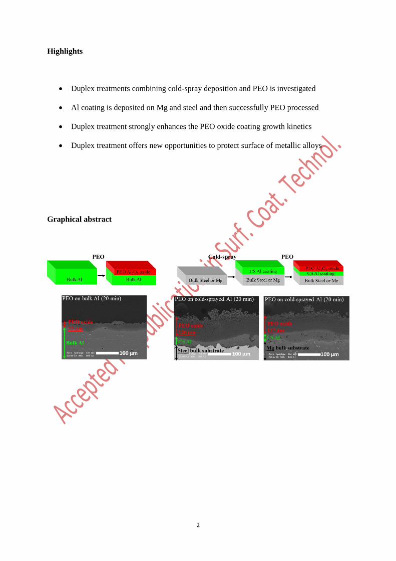
Graphical abstract
3
Abstract
Plasma electrolytic oxidation (PEO) is widely used to improve the corrosion and wear
resistance of lightweight metals such as aluminium alloys by the formation of a ceramic oxide
coating. However, the PEO process remains ineffective for ferrous metals and, when applied to
magnesium alloys, oxide coatings are usually thin and porous. To overcome these limitations,
the feasibility of applying a duplex treatment combining cold-spray deposition (CS) and PEO
is investigated. Cold-sprayed aluminium coatings are deposited on magnesium (EV31) and
steel (S235) substrates prior to PEO. Investigation of this duplex process evidences the
efficiency of such a two-steps process to form thick, dense and crystalline alumina coatings on
both magnesium and steel substrates. The growth kinetic of the duplex CS-PEO oxide layer is
enhanced by a factor of 3 compared to single-step PEO processing of bulk aluminium
substrates. Results are discussed by considering the effect of the porosity through the cold-
sprayed aluminium coating on the mechanism of oxidation during the subsequent PEO
treatment.
Keywords: Duplex treatment; Cold-spray deposition; Plasma Electrolytic Oxidation (PEO);
Aluminium; Magnesium; Ferrous metals
4
1. Introduction
Plasma electrolytic oxidation (PEO), also referred to as micro-arc oxidation (MAO), is a
plasma-assisted electrochemical technology to synthesize protective ceramic-like oxide
coatings on lightweight metals like aluminium, titanium and magnesium alloys [1-4]. PEO
process is gaining a growing interest in various industrial domains (transport, energy, medicine)
to replace conventional chromic acid anodizing (CAA) or hard acid anodizing (HAA) [5, 6].
Indeed, PEO results in improved wear and corrosion resistance together with enhanced thermal
stability and biocompatibility properties. The use of environmentally friendly alkaline
electrolytes is an asset as well [6-8]. PEO process is carried out at a voltage slightly higher than
the breakdown voltage of the growing oxide layer. Consequently, PEO coatings grow under a
sparking regime leading to the gradual conversion of the processed metal to a crystalline oxide
layer [9-12]. The growth mechanisms of the protective PEO coatings remain complex due to
the combination of both electrochemical, thermal and plasma phase reactions that
simultaneously occur in a small affected volume (few tens of µm3) [13-17].
In the case of aluminium alloys, PEO process parameters are well controlled to form thick
and compact oxide achieving a long-term protection. Numerous studies were devoted to the
electrolyte composition according the requested coating properties [5, 6, 18]. Especially, the
addition of (micro-) particles in the electrolyte aims at forming composite oxide layers
(metal/oxide, oxide/oxide), that endows the protective layer with new functionalities [19-22].
In parallel, other studies sought the optimization of the electrical conditions, such as the applied
supplying mode (AC, DC, bipolar, etc.), the current and/or voltage amplitude, or the frequency
and duty cycle of the applied voltage or current [23-26]. Using a pulsed bipolar current to supply
the electrodes promotes the appearance of a particular “soft” regime that occurs after a certain
period of processing time [27-29] provided the current waveform parameters are suitably set.
The occurrence of this “soft” regime is associated with the gradual decrease in the voltage
5
response, the gradual disappearance of visible discharges as well as an increase in the growth
rate and a lowering of the oxide coating porosity [30].
Although the PEO process of aluminium alloys is now well controlled, PEO processing of
magnesium alloys faces some issues and PEO layers grown on magnesium are generally thin
and porous, poorly adherent to the substrate and often need additional post-treatments [31-32].
Sealing method based on cerium and phosphate appears to be the most effective way to
significantly improve the corrosion properties of PEO coatings on magnesium [33-35]. In
addition, the PEO process is strictly limited to aluminium, titanium, magnesium and zirconium
alloys and it remains ineffective on other metals [5, 6]. For example, it does not allow surface
protection of ferrous metals for which electrodeposition of Zn- and Ni-based alloys are still
widely used at the industrial scale. However, electrodeposition technologies use concentrated
acids (e.g. boric acid) or alkaline electrolytes containing toxic cyanides compounds [36].
In this context, duplex treatments can address these issues and widen the use of the PEO
process. In this paper, it is proposed to investigate the feasibility of a duplex surface treatment
combining cold-spray deposition and PEO technology. Studies reporting on the combination of
cold-spray and PEO are scarce in the literature, and to the knowledge of the authors, only two
recently published works mentioned its use on an AZ91 magnesium alloy [37, 38]. Although,
improvements in the corrosion and wear resistance were observed, the effect of this duplex
treatment on the growth mechanisms of the PEO coatings has not been considered as well as
the feasibility to apply such duplex treatment on another magnesium alloy and also on a steel
substrate.
2. Experimental procedure
6
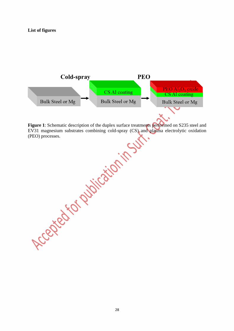
As illustrated in Fig. 1, the process consists in first cold-spraying an aluminium coating on a
metallic substrate that will be converted into aluminium oxide by the use of the PEO process in
a second step. For comparison reasons, bulk aluminium substrates were also processed using
the same PEO conditions.
2.1 Materials
A commercial EV31 grade magnesium alloy and a commercial S235 steel were used as
substrates. The chemical composition of Mg EV31 and S235 steel is given in Tables 1 and 2,
respectively. All samples have a rectangular shape of 45 25 6 mm3. Prior to be processed,
the surface of the samples is shot blasted with corundum particles under 5 bars pressure. It
allows cleaning the surfaces (e.g. removal of organic contaminations or oxidation residues) as
well as providing a sufficient roughness level to ensure adhesion of the aluminium sprayed
coating. The resulting surface roughness Ra of the prepared samples is Ra = 25 5 µm and Ra
= 17 5 µm for the magnesium and for the steel substrates, respectively. PEO coatings on pre-
deposited aluminium were compared with PEO layers achieved on pure aluminium (Al 1050)
bulk substrate using the same PEO conditions. The composition of Al 1050 grade material is
given in Table 3. Table 4 summarizes the different samples that were processed for this study.
2.2 Cold-spray conditions
In the cold-spray (CS) process, also known as cold gas-dynamic spraying (CGDS), coatings
are applied in the solid state by spraying metal powder at a high velocity on a substrate at greatly
reduced temperatures compared to thermal spray techniques [39-41]. A carrier gas, usually
nitrogen or helium, at pressure as high as 6 MPa and temperature ranging from 100 to 1100 °C,
is expanded to supersonic speed through a converging-diverging De Laval nozzle. Particles are
introduced in this gas flow at the inlet of the nozzle. Depending of the processing conditions
applied, as well as on the morphology and the density of the sprayed particles, the metallic
7
particles are accelerated through the nozzle at speeds exceeding up to 1600 m.s-1. The particles
impact the substrate located approximately between 20 and 100 mm from the exit of the nozzle
and form a more or less dense metal coating depending on the velocity of the particles.
Thickness of the sprayed coating is also adjusted by repeated scans over the same area. Table
5 gives the main parameters of the cold-spray process that were used in the present study. The
sprayed metallic powder consisted in a commercial 1050 grade aluminium for which the
chemical composition is given in Table 3. Two different ranges of pre-coating thickness were
prepared on both magnesium and steel substrates. For magnesium substrates, thicknesses of the
aluminium layer deposited by cold-spray were 66 15 µm and 220 25 µm (see Table 4). For
the steel substrate, thicknesses were 80 15 µm and 190 25 µm.
2.3 Plasma electrolytic oxidation conditions
PEO treatments were run in a solution of potassium hydroxide ([KOH] = 1 g.L-1 0.018
mol.L-1) and anhydrous sodium silicate ([Na2SiO3] = 1.65 g.L-1 0.014 mol.L-1) diluted in
deionised water. The measured pH and conductivity of the fresh electrolyte is 12.5 and 2.8
mS.cm-1, respectively. In order to limit the ageing effect of the electrolyte, a fresh electrolyte is
renewed for each substrate. Two titanium plates 200 200 1 mm3 in size were used as
counter-electrodes. They were systematically located at 90 mm apart from the working
electrode (Al1050, Mg EV31 and Steel S235). All the PEO treatments were performed using a
pulsed bipolar current generator within the “soft” regime conditions [30]. The anodic to
cathodic charge quantity ratio, RCQ = Qp/Qn, was set at a value of 0.9. The current pulse
frequency (f) and the anodic current density (ja) were set at 100 Hz and 48 A.dm-2 respectively.
As reported in Table 4, the duration of the PEO treatments was set at 8, 20 and 35 min. After
the PEO treatment, the processed sample was rinsed with ethanol, dried and stored in a dry
environment before ex-situ characterization. The voltage-time response was recorded using a 1
GHz bandwidth oscilloscope (Agilent 54832B).
8
2.4 Ex-situ characterization of the coatings
Cross-sections of the treated samples were examined by SEM (FEG-SEM Philips XL 30S)
working in backscattered electron mode (25 kV accelerating voltage). Prior to SEM
observations, samples were cut, mounted in resin and finely polished with 1 µm diamond paste.
SEM investigations were systematically done at the centre of the sample in order to avoid
possible artefact due to edge effect. The coating thickness was determined as an average value
of 10 measures taken on cross-section over 10 different positions (every 100 µm). Chemical
composition and distribution of elements in the synthesized duplex coatings were determined
by EDX analyses. The phase composition of the coatings was determined by X-ray diffraction
(XRD) measurements in Bragg-Brentano geometry using the Cu-K1 radiation at = 0.1542
nm (Bruker D8 ADVANCE diffractometer). Finally, some X-ray micro-computed tomography
(µCT) measurements were carried out to characterized porosities through the cold-sprayed
aluminium coatings as well as through the PEO oxide layers. A Phoenix Nanotom X-ray µCT
facility was used to characterize the morphology and the space distribution of pores in both the
cold-sprayed and PEO coatings. Rectangular specimens with 2 2 2 mm3 in size were
characterized by µCT. The µCT procedure was based on the acquisition of a series of X-ray
radiographs of a sample that rotated step by step around a vertical axis perpendicular to the
incident X-ray beam. Images were recorded over a period of 6 s. A total of 1440 images were
recorded for a scan duration of 144 min. A mathematical algorithm was used to reconstruct the
internal 3D volume structure of the samples. The final resolution of the 3D-images was voxels
of dimensions 1.5 1.5 1.5 µm3. Below these dimensions, porosities were not detected.
3. Results
3.1 Establishment of the “soft” sparking regime
9
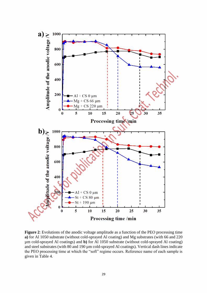
Fig. 2 shows the evolution of the anodic voltage amplitude as a function of the PEO
processing time for the different duplex treatments summarized in Table 4. As previously
reported, the “arc” to “soft” regime switching time is usually detected by the gradual drop in
the anodic voltage amplitude during the PEO process [12, 22, 26]. During the first minutes of
treatment, i.e. in the “arc” sparking regime, Fig. 2 shows that the presence of a cold-sprayed
aluminium coating on magnesium and steel substrates has a significant influence on the voltage
amplitude compared to the reference PEO treatment performed on the bulk aluminium
substrate. For instance, at t = 5 min, the anodic voltage amplitude is higher than 900 V for the
duplex treatments while it is lower than 760 V for the reference PEO treatment performed on
the bulk aluminium. Moreover, for this reference treatment, transition from the “arc” to the
“soft” regime appears at about 28 min. In contrast, Fig. 2 evidences that all the duplex
treatments performed on magnesium and steel substrates result in an earlier appearance of the
“soft” sparking regime. This is particularly obvious for the thicker cold-sprayed aluminium
coatings for which transition occurs before 18 min. For the thinner pre-deposited aluminium
coatings, it is also apparent that the establishment of the “soft” regime is accompanied with a
sharp drop in the anodic voltage amplitude (more than 300 V).
3.2 Morphology and growth kinetic of the coatings
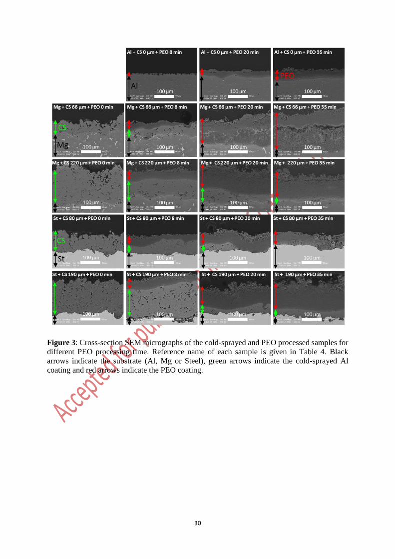
Fig. 3 shows the cross-sectional SEM micrographs of the PEO oxide layers grown within
the different conditions as defined in Table 4. Cross-sectional views of the pre-deposited
aluminium coatings on the magnesium and steel substrates are also presented in Fig. 3 (left-
hand side column). The latter show that all the cold-sprayed aluminium coatings studied here
are porous. For the bulk aluminium substrate, the cross-sectional SEM micrographs show the
typical morphology of PEO coatings produced on aluminium alloys during the “arc” regime (at
8 and 20 min) and the “soft” regime (at 35 min). The pancake-like structure is the usual feature
of PEO layers grown under the “arc” regime while a sponge-like structure known to incorporate
10
elements from the electrolyte (e.g. Si, Na and K) is more developed over the top-surface under
the “soft” regime. It is also apparent that with the transition from the “arc” to the “soft” sparking
regime that occurs at about 28 min for the bulk aluminium substrate, the morphology gradually
transforms into a more compact and a thicker oxide layer.
Interestingly, Fig. 3 clearly demonstrates the possibility to grow a PEO oxide layer through
a cold-sprayed aluminium coating previously applied on magnesium and steel substrates.
Whatever the nature of the metallic substrate (i. e. magnesium or steel), the thickness of the
cold-sprayed aluminium coating and the PEO processing time, the duplex treatments result in
thicker and more compact PEO oxide layers than those grown by PEO on pure aluminium
substrate. Additionally, the top-surface of the PEO oxide layers grown for 20 min or more
already exhibits the particular sponge-like structure achieved under the “soft” sparking regime.
This agrees well with the voltage-time responses (Fig. 2) that show an earlier transition to the
“soft” regime by using duplex treatments.
Concerning the cold-sprayed aluminium coatings less than 80 µm in thickness, growth of
the PEO oxide layers is different depending on the processed substrate. In the case of the
magnesium substrate, after 20 min processing time, the thickness of the PEO oxide layer
reaches and then exceeds the thickness of the pre-deposited aluminium coating (samples
Mg+CS66µm+PEO20min and Mg+CS66µm+PEO35min in Fig. 3). This suggests that the
magnesium substrate is PEO converted in magnesium oxide beyond the total conversion of the
sprayed Al layer. This is particularly obvious at 35 min where signs of delamination can be
observed exactly at the location of the former aluminium / magnesium interface. In contrast,
for the steel substrate, the PEO oxide layer reaches the aluminium / steel interface at about 20
min after which growth of the oxide layer seems to stop (samples St+CS80µm+PEO20min and
St+CS80µm+PEO35min in Fig. 3). Interestingly, after 35 min, no delamination is observed at
the interface between the elaborated PEO coating and the steel substrate. This can be explained
11
by the initial high level of roughness over the steel surface that ensures an efficient anchor of
the coating.
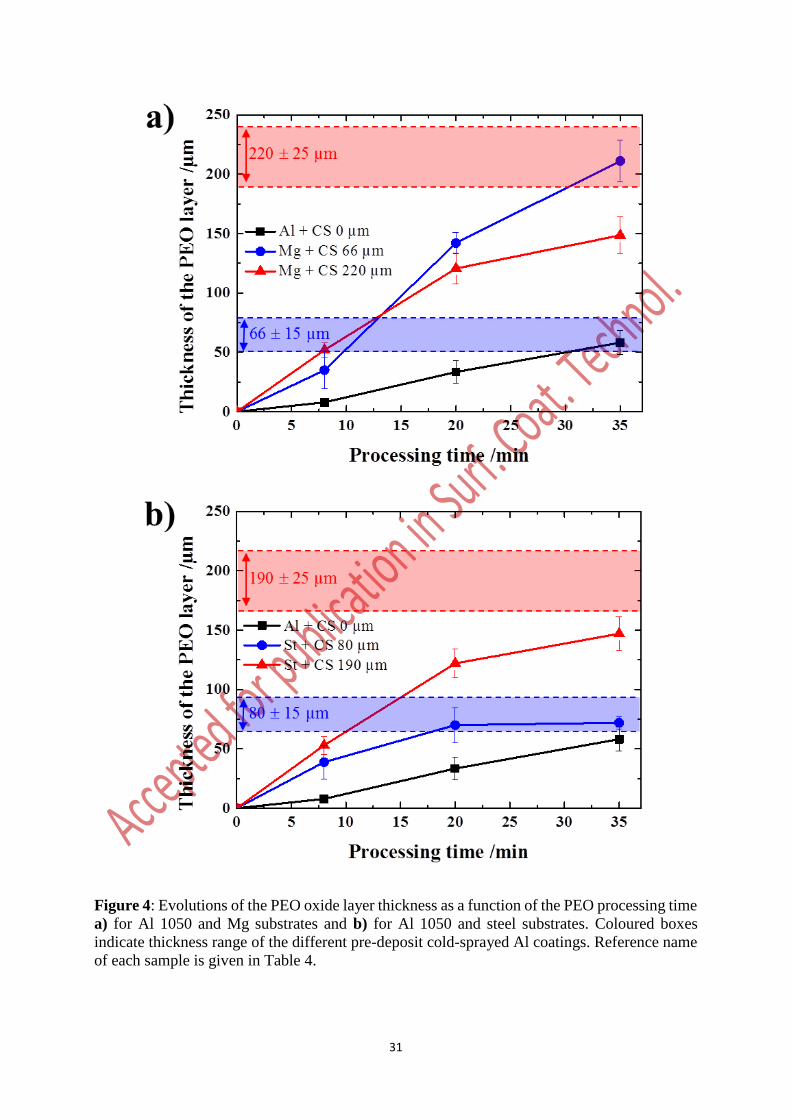
Fig. 4 depicts the evolution of the average thickness of the overall PEO oxide layer with the
processing time for the different treatments summarized in Table 4. Fig. 4 evidences an
enhancement of the growth kinetic of the PEO oxide layer, by a factor 3 or more, when applying
duplex treatments (~ 6 µm.min-1) than using one-step PEO process (~ 1.5 µm.min-1). For
thinner cold-sprayed aluminium coatings (down to 80 µm in thickness), and as previously
observed in Fig. 3, a difference in the growth kinetic is pointed out between the magnesium and
the steel substrates. Indeed, for the magnesium substrate, the final thickness of the PEO oxide
layer (215 20 µm at 35 min) clearly exceeds the thickness of the sprayed aluminium coating
(66 15 µm). This confirms that the magnesium substrate is PEO converted in magnesium
oxide beyond the total conversion of the cold-spray deposited Al layer. Oppositely, for the steel
substrate, once the sprayed aluminium coating is PEO converted, at about 20 min, growth of
the PEO oxide layer stops. Finally, for the thicker cold-sprayed aluminium coatings (up to 190
µm in thickness), and whatever the processed substrate (Mg or steel), a slight decrease in the
growth kinetic is observed after about 20 min (~ 4 µm.min-1).
3.3 Chemical and crystallographic compositions of the coatings
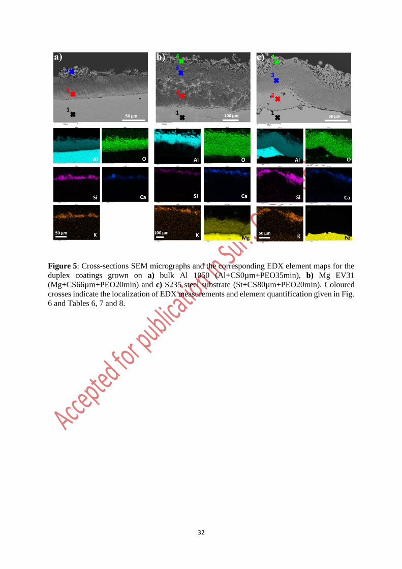
Fig. 5 shows specific cross-sectional SEM views and the associated EDX elemental map
distributions (Al, O, Si, Ca, K, Mg and Fe elements) throughout the coatings synthesised using
a single 35 minutes PEO process on a bulk aluminium substrate (sample
Al+CS0µm+PEO35min), and using the duplex treatments on magnesium and steel alloys
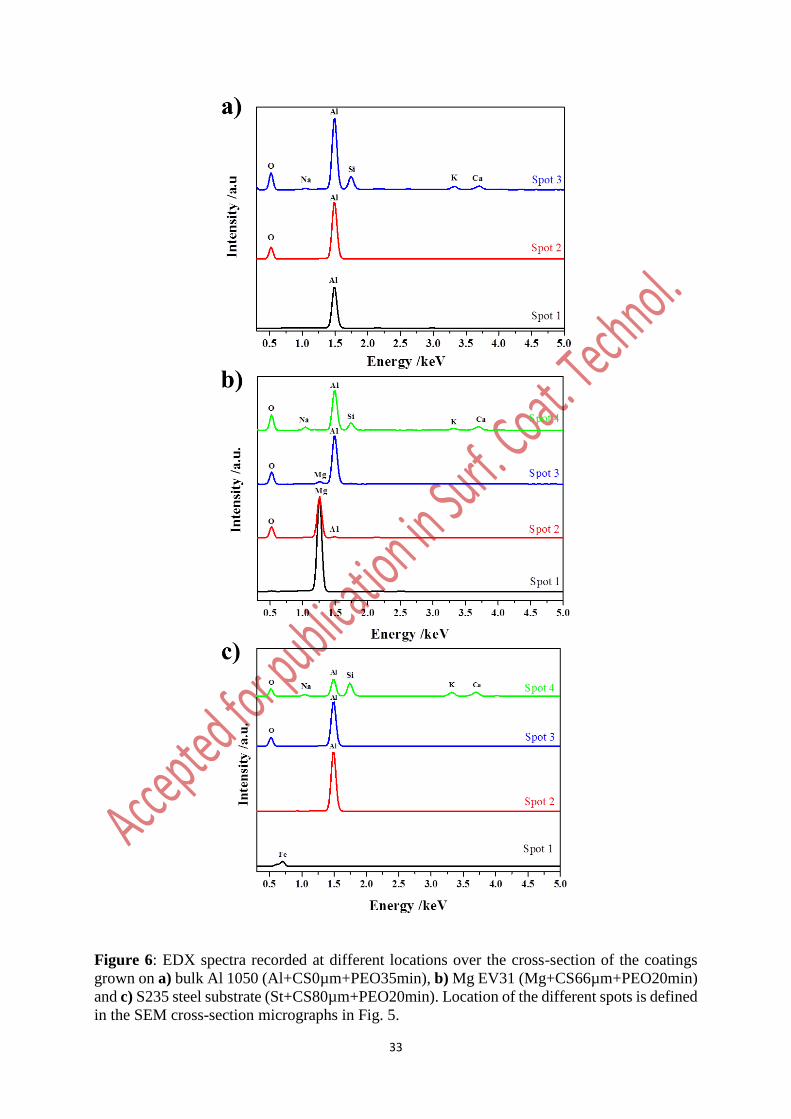
(samples Mg+CS66µm+PEO20min and St+CS80µm+PEO20min). In complement, Fig. 6
shows EDX spectra recorded at different locations over the sample cross-sections (indicated by
coloured crosses in Fig. 5). The corresponding quantifications in elements are given in Tables
6, 7 and 8. First of all, whatever the processed substrate (Al, Mg or steel), these element maps
12
evidence an outer sponge-like structure that incorporates elements from the electrolyte e.g. O,
Si, Ca and K. This is usually encountered for PEO treatments conducted on aluminium under
the “soft” sparking regime. In addition, for the bulk aluminium substrate, Fig. 5a shows that the
inner sublayer exclusively consists of Al and O (Table 6). For the magnesium substrate with a
thin aluminium pre-coating (Mg+CS66µm+PEO20min), the synthesized PEO coatings consist
of (i) a sponge-like outer sublayer enriched in Si, Ca and K, (ii) a denser intermediate sublayer
rich in Al and O, and (iii) an inner sublayer rich in Mg and O close to the magnesium substrate
(Fig. 5b). This inner sublayer exhibits cracks that mainly develop parallel to the metal / oxide
interface. The element quantification performed in this inner sublayer clearly suggests the
presence of a magnesium oxide and the absence of an aluminium oxide (Table 7). In the case
of the steel substrate (St+CS80µm+PEO20min) (Fig. 5c), the PEO coating shows a thick
sponge-like outer sublayer and a compact inner sublayer rich in Al and O (Table 8). It is also
worth mentioning that the EDX measurements do not show the presence of oxidized iron even
close to the steel interface.
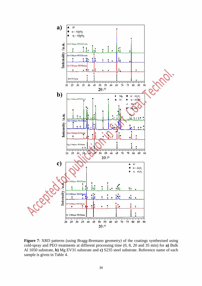
XRD analyses of the processed samples point out the presence of Al as well as crystalline
- and -alumina peaks (Fig. 7). The Al peaks originate from the aluminium substrate or from
the cold-sprayed aluminium coating. The presence of - and -alumina is usual for PEO oxide
layers grown on aluminium. The transition from the “arc” to the “soft” sparking regime is
known to be concomitant with an increase in the -alumina proportion in the PEO layer. This
is confirmed by the relative increase in the intensity of the -alumina peaks with the processing
time compared to the intensity of the -alumina peaks. For the magnesium substrate with a pre-
deposited aluminium coating (Fig. 7b), XRD patterns also show the presence of magnesium
oxide (MgO) and forsterite (Mg2SiO4) peaks after 20 min processing time. It definitively
confirms that the oxidation of the magnesium substrate takes place after the complete oxidation
of the pre-deposited aluminium coating. Their low peak intensity is due to the fact that the
13
MgO- and Mg2SiO4-containing sublayer is located beneath the thick aluminium oxide outer
sublayer as observed in Fig. 5b. Interestingly, by using a duplex treatment involving cold-spray
and PEO processes on a magnesium substrate, this result also demonstrates the possibility to
produce a composite ceramic-based multilayer on a lightweight metal. Finally, for the steel
substrate on which an aluminium pre-coating was sprayed, XRD patterns in Fig. 7c only show
the presence of Al peaks as well as crystalline - and -alumina peaks. For longer PEO
processing time, although growth of the PEO coating stops, the relative intensity of the -
alumina peaks seems to increase compared to the intensity of the -alumina peaks. This
suggests the gradual transformation of the -alumina into -alumina for longer PEO processing
time. This point needs however further detailed investigations. In addition, Fig. 7c also confirms
the absence of oxidized iron through the PEO coating.
4. Discussion
The discussion hereafter focuses on the influence of the porosity on the PEO process of
aluminium. Particularly, a descriptive mechanism is proposed to explain the role played by the
porosities through a pre-deposited aluminium coating on the subsequent growth of a PEO oxide
layer. Indeed, results have shown that growth kinetic of PEO oxide layers is greatly enhanced
(by a factor up to 3) when applied to cold-sprayed aluminium coatings compared with a bulk
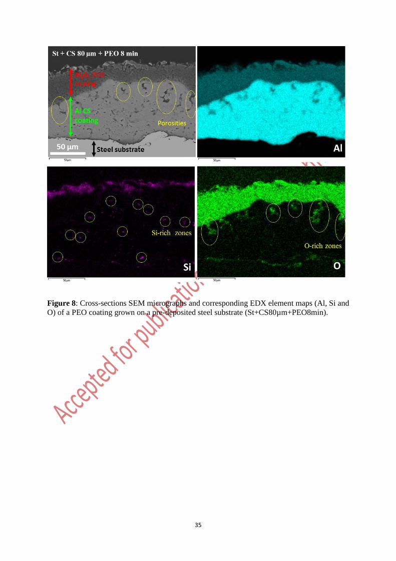
aluminium substrate. At the same time, results also show that the cold-sprayed aluminium
coatings exhibit a high level of porosity throughout their thickness (see Fig. 3). This is
particularly obvious in the cross-sectional SEM view of a steel substrate covered with a cold-
sprayed aluminium coating (80 15 µm in thickness) that was then shortly PEO processed (for
8 min processing time) (Fig. 8). Large and extended pores up to 50 µm in length are observed
through the pre-deposited aluminium coating.
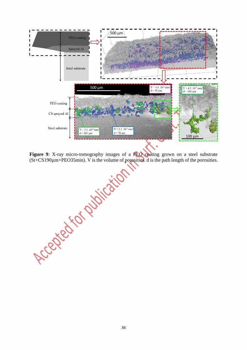
In complement to these SEM observations, X-ray micro-computed tomography (µCT)
measurements were also carried out to characterize these porosities in both the cold-sprayed
14
aluminium coatings and the grown PEO oxide layers. Fig. 9 shows the µCT visualizations of
pores into the PEO coating elaborated on a cold-spray coated steel substrate
(St+CS190µm+PEO35min). The associated schema in Fig. 9 allows localizing the µCT probed
volume. The PEO outer sublayer consists in small numerous pores while the cold-sprayed
aluminium coating exhibits fewer but larger pores. The size of pores into the PEO oxide layer
is less than 1.5 µm in length, which is the detection limit of the µCT equipment (< 3.3810-9
mm3 in volume). For the cold-sprayed coating, the length path of the detected porosities varies
between 10s and 100s of µm while the average volume ranges between 10-8 and 10-5 mm3.
Interestingly, and contrary to observations performed on cross-sectional SEM micrographs, the
µCT visualizations in Fig. 9 evidence the presence of interconnected pores through the cold-
sprayed aluminium coating forming a network of large porosities. At the beginning of the PEO
process, when the sample is immersed into the electrolyte, it would be reasonable to expect that
the presence of such open porosities allow the electrolyte to fill in the porosities and deeply
penetrate into the cold-sprayed aluminium coating.
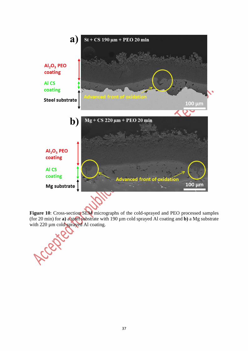
The EDX element maps in Fig. 8 confirm this statement since elements from the electrolyte,
especially Si and O, are detected into the porosities of the pre-deposited aluminium coating.
These elements are found far advanced from the front line of the aluminium oxidation. For these
advanced sites, it suggests that conversion of aluminium into alumina has already started. This
is confirmed in Fig. 10 where oxidized regions ahead from the PEO oxidation front line are
observed. Interestingly, these oxidized regions clearly exhibit the same shape and size than the
porosities detected by µCT through the cold-sprayed aluminium coatings.
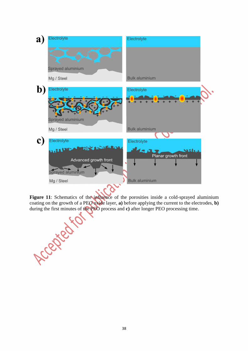
Based on these observations, a growth mechanism of PEO coating in porous aluminium is
schematically depicted in Fig. 11 and described hereafter. Before applying the current to the
electrodes, the sample is immersed in the electrolyte. This electrolyte penetrates into the
connected porosities of the cold-sprayed aluminium layer. When applying the current, and
15
during the first seconds of treatment, the voltage increases rapidly due to the growth a thin
insulating oxide layer over the processed surface. In the case of the sprayed coatings that exhibit
open porosities, breakdown value appears at higher voltage than for the bulk aluminium
substrate (see Fig. 2) due to higher specific surface. Indeed, accumulated charges throughout
the insulating layer that are needed to reach the dielectric breakdown voltage remain higher
with a higher specific surface. As the PEO process continues, the “arc” regime takes place first
and arcs appear over the processed surface. Strong arcs ignite but, in the case of the sprayed
aluminium coatings, they turn earlier into tiny or even not visible micro-discharges whose
behaviour is comparable to the inner D-type micro-discharges appearing inside the PEO coating
during the “soft” regime [2, 12, 30]. On this point, although the high level of porosity through
the cold-sprayed aluminium coating seems to be responsible, it remains that further
investigations are required to better understand the earlier occurrence of the “soft” regime in
the case of a duplex treatment (see Fig. 2). Once the “soft” regime is established, a sponge-like
phase enriched in elements from the electrolyte grows at the top-surface of the PEO coatings.
This can explain that, after just ten minutes of PEO treatment, a well-developed sponge-like
structure is observed at the top surface of the duplex coating. In contrast, for the bulk
aluminium, this sponge like structure grows later, after about 20 minutes (see Fig. 3). Inner
micro-discharges that appear inside porosities of the pre-deposited aluminium coating gradually
convert the surrounding aluminium into alumina. Thus, the growth front of the PEO oxide layer
extends not only vertically as observed for the bulk aluminium but also laterally. With the
processing time, the porosities are gradually filled with aluminium oxide trapping elements
from the electrolyte inside the inner dense PEO oxide sublayer. This explains the presence of
such elements, mainly Si, throughout the overall PEO coatings (see Fig. 8). In contrast, for the
PEO process of the bulk aluminium, the inner oxide sublayer is depleted in such elements.
Finally, for the duplex treatments, the oxidized areas that consist in advanced fronts of oxidation
16
overlap with the adjacent ones forming a thicker PEO coating compared to those observed for
the PEO process of bulk aluminium.
5. Conclusions
The feasibility of duplex surface treatments involving cold-spray (CS) and plasma
electrolytic oxidation (PEO) techniques was investigated. For this purpose, cold-sprayed
aluminium coatings with various thicknesses were pre-deposited on magnesium and steel
substrates and they were then PEO processed during various processing time. Results clearly
demonstrated the possibility to grow an alumina PEO coating on magnesium and steel
substrates cold-sprayed with porous aluminium. Compared to conventional PEO treatments
performed on bulk aluminium substrates, growth kinetic of the PEO oxide layer is greatly
enhanced by using a duplex treatment. While porosities in the cold-sprayed coatings are
generally undesired, they seem here to have a very positive effect on the PEO growth kinetic.
A descriptive mechanism of growth was proposed. Such a duplex treatment offers new
opportunities to protect surface of magnesium alloys and ferrous metals for which direct PEO
process remains tricky and even not possible. Further investigations should be devoted to study
the properties of such duplex coatings such as wear resistance and corrosion resistance.
17
Acknowledgments
This work was supported by the French Government through the programme
"Investissements d’avenir" operated by the French National Research Agency (ANR)
and referenced to as ANR-11-LABX-0008-01 (‘LabEx DAMAS’).
This work was also partly supported by ICÉEL Carnot institute through the project
“SOPRODSYSE”
The authors would like to acknowledge contributions of the following:
- Mr. P. Boulet and the competence cluster on X-ray diffraction (CC-X) at Institut
Jean Lamour for providing advices in XRD measurements and analyses.
- Mrs. S. Mathieu and the competence cluster on electron microscopy (CC 3M) at
Institut Jean Lamour for providing advices in SEM observations and EDX analyses.
18
Data availability
The data that support the findings of this study are available from the corresponding author,
J. Martin, upon reasonable request.
Contribution of each author
J. Martin, G. Henrion, P. Brenot and G. Ezo’o conceptualized the goal of this research work.
A. Bastien elaborated the cold-spray coatings.
O. Ferry performed and analysed the X-ray micro-computed tomography measurements.
G. Henrion, J. Martin and V. Ntomprougkidis conceived the PEO experimental rigs.
J. Martin and K. Akoda performed most of the PEO experiments.
J. Martin and K. Akoda performed all the SEM, XRD and EDX analysis.
All the authors analysed the results and reviewed the manuscript.
J. Martin, V. Ntomprougkidis and A. Maizeray prepared the manuscript
J. Martin, G. Henrion , P. Brenot and G. Ezo’o supervised the whole work.
Additional information
The authors declare no competing financial interests.
19
List of references
[1] Gh. Barati Darband, M. Aliofkhazraei, P. Hamghalam, N. Valizade, Plasma electrolytic
oxidation of magnesium and its alloys: Mechanism, properties and applications, J. Magnesium
Alloy. 5 (2017) 74-132.
[2] Y. L. Cheng, J. Cao, M. Mao, H. Xie, P. Skeldon, Key factors determining the development
of two morphologies of plasma electrolytic coatings on an Al-Cu-Li alloy in aluminate
electrolytes. Surf. Coat. Technol. 291 (2016) 239-249.
[3] Y.L. Cheng, J. Cao, Z. Peng, Q. Wang, E. Matykina, P. Skeldon, G.E. Thompson. Wear
resistant coatings formed on Zircaloy-2 by plasma electrolytic oxidation in sodium aluminate
electrolytes. Electrochim. Acta 116 (2014) 453-466.
[4] A. Mathis, E. Rocca, D. Veys-Renaux, J. Tardelli, Electrochemical behaviour of titanium
in KOH at high potential, Electrochim. Acta 202 (2016) 253-261.
[5] A.L. Yerokhin, X. Nie, A. Leyland, A. Matthews, S.J. Dowey, Plasma electrolysis for
surface engineering, Surf. Coat. Technol. 122 (1999) 73–93.
[6] P. Gupta, G. Tenhundfeld, E.O. Daigle, D. Ryabkov, Electrolytic plasma technology:
Science and engineering - An overview, Surf. Coat. Technol. 201 (2007) 8746-8760.
[7] J.A. Curran, T.W. Clyne, Thermo-physical properties of plasma electrolytic oxide coatings
on aluminium, Surf. Coat. Technol. 199 (2005) 168-176.
[8] J.A. Curran, H. Kalkanci, Y. Magurova, T.W. Clyne, Mullite-rich plasma electrolytic oxide
caotings for thermal barrier applications, Surf. Coat. Technol. 201 (2007) 8683-8687.
[9] E. Matykina, A. Berkani, P. Skeldon, G.E. Thompson, Real-time imaging of coating growth
during plasma electrolytic oxidation of titanium, Electrochim. Acta 53 (2007) 1987-1994.
20
[10] F. Monfort, A. Berkani, E. Matykina, P. Skeldon, G.E. Thompson, H. Habazaki, K.
Shimizu, Development of anodic coatings on aluminium under sparking conditions in silicate
electrolyte, Corros. Sci. 49 (2007) 672-693.
[11] V. Dehnavi, X.Y. Liu, B.L. Luan, D.W. Shoesmith, S. Rohani, Phase transformation in
plasma electrolytic oxidation on 6061 aluminium alloy, Surf. Coat. Technol. 251 (2014) 106-
114.
[12] J. Martin, A. Nominé, V. Ntomprougkidis, S. Migot, S. Bruyère, F. Soldera, T. Belmonte,
G. Henrion, Formation of a mestastable nanostructured mullite during Plasma Electrolytic
Oxidation of aluminium in “soft” regime condition, Mater. Design 180 (2019) 107977.
[13] A.L. Yerokhin, L.O. Snizhko, N.L. Gurevina, A. Leyland, A. Pilkington, A. Matthews,
Discharge characterization in plasma electrolytic oxidation of aluminium, J. Phys. D: Appl.
Phys. 36 (2003) 2110–2120.
[14] R.O. Hussein, X. Nie, D.O. Northwood, A. Yerokhin, A. Matthews, Spectroscopic study
of electrolytic plasma and discharging behaviour during the plasma electrolytic oxidation
(PEO) process, J. Phys. D: Appl. Phys. 43 (2010) 105203.
[15] J. Jovović, S. Stojadinović, N.M. Šišović, N. Konjević, Spectroscopic study of plasma
during electrolytic oxidation of magnesium- and aluminium-alloy, J. Quant. Spectrosc. Rad.
Trans. 113 (2012) 1928‑1937.
[16] S. Stojadinović, J. Jovović, M. Petković, R. Vasilić, N. Konjević, Investigation of plasma
electrolytic oxidation on valve metals by means of molecular spectroscopy – a review, RSC
Advances 4 (2014) 25759-25789.
[17] T.W. Clyne, S.C. Troughton, A review of recent work on discharge characteristics during
plasma electrolytic oxidation of various metals, Int. Mater. Rev. 64 (2019) 127-162.
21
[18] F. Simchen, M. Sieber, T. Lampke, Electrolyte influence on ignition of plasma electrolytic
oxidation processes on light metals, Surf. Coat. Technol. 315 (2017) 205-213.
[19] E. Matykina, R. Arrabal, F. Monfort, P. Skeldon, G.E. Thompson, Incorporation of
zirconia into coatings formed by DC plasma electrolytic oxidation of aluminium in nanoparticle
suspensions, Appl. Surf. Sci. 255 (2008) 2830-2839.
[20] X. Lu, M. Mohedano, C. Blawert, E. Matykina, R. Arrabal, K.U. Kainer, M.L.
Zheludkevich, Plasma electrolytic oxidation coatings with particle additions – A review, Surf.
Coat. Technol. 307 (2016) 1165-1182.
[21] B.S. Lou, Y.Y. Lin, C.M. Tseng, Y.C. Lu, J.G. Duh, J.W. Lee, Plasma electrolytic
oxidation coatings on AZ31 magnesium alloys with Si3N4 nanoparticles additives, Surf. Coat.
Technol. 332 (2017) 358-367.
[22] X. Tu, C. Miao, Y. Zhang, Y. Xu, J. Li, Plasma electrolytic oxidation of magnesium alloy
AZ31B in electrolyte containing Al2O3 sol as additives, Materials 11 (2018) 1618-1629.
[23] J. Martin, A. Melhem, I. Shchedrina, T. Duchanoy, A. Nominé, G. Henrion, T. Czerwiec,
T. Belmonte, Effects of electrical parameters on plasma electrolytic oxidation of aluminium,
Surf. Coat. Technol. 221 (2013) 70-76.
[24] V. Dehnavi, B.L. Luan, D.W. Shoesmith, X.Y. Liu, S. Rohani, Effect of duty cycle and
applied current frequency on plasma electrolytic oxidation (PEO) coating growth behaviour,
Surf. Coat. Technol. 226 (2013) 100-107.
[25] V. Dehnavi, B.L. Luan, X.Y. Liu, D.W. Shoesmith, S. Rohani, Correlation between
plasma electrolytic oxidation treatment stages and coating microstructure on aluminium under
unipolar pulsed DC mode, Surf. Coat. Technol. 269 (2015) 91-99.
[26] V. Ntomprougkidis, J. Martin, A. Nominé, G. Henrion, Sequential run of the PEO process
with various pulsed bipolar current waveforms, Surf. Coat. Technol. 374 (2019) 713-724.
22
[27] F. Jaspard-Mecuson, T. Czerwiec, G. Henrion, T. Belmonte, L. Dujardin, A. Viola, J.
Beauvir, Tailored aluminium oxide layers by bipolar current adjustment in the Plasma
Electrolytic Oxidation (PEO) process, Surf. Coat. Technol. 201 (2007) 8677–8682.
[28] A.B. Rogov, A. Yerokhin, A. Matthews, The role of cathodic current in Plasma Electrolytic
Oxidation of aluminium: phenomenological concepts of the “soft sparking” mode, Langmuir
33 (2017) 11059-11069.
[29] D. S. Tsai, G. W. Chen, C. C. Chou, Probe the micro arc softening phenomenon with pulse
transient analysis in plasma electrolytic oxidation, Surf. Coat. Technol. 357 (2019) 235-243.
[30] J. Martin, A. Nominé, F. Brochard, J.L. Briançon, C. Noël, T. Belmonte, T. Czerwiec, G.
Henrion, Delay in micro-discharges appearance during PEO of Al: Evidence of a mechanism
of charge accumulation at the electrolyte /oxide interface, Appl. Surf. Sci. 410 (2017) 29-41.
[31] J. Dou, Y. Chen, H. Yu, C. Chen, Research status, of magnesium alloys by micro-arc
oxidation : A review, Surf. Eng. 33 (2017) 731-738.
[32] M. Toorani, M. Aliofkhazraei, Review of electrochemical properties of hybrid coating
systems on Mg with plasma electrolytic oxidation process as pretreatment, Surf. Interface 14
(2019) 262-295.
[33] U. Malayoglu, K.C. Tekin, S. Shrestha, Influence of post-treatment on the corrosion
resistance of PEO coated AM50B and AM60B Mg alloys, Surf. Coat. Technol. 205 (2010)
1793-1798.
[34] M. Sun, A. Matthews, A. Yerokhin, Plasma electrolytic oxidation coatings on cp-Mg with
cerium nitrate and benzotriazole immersion post-treatments, Surf. Coat. Technol. 344 (2018)
330-341.
[35] M. Mohedano, C. Blawert, M.L. Zheludkevich, Cerium-based sealing of PEO coated
AM50 magnesium alloy, Surf. Coat. Technol. 269 (2015), 145-154.
23
[36] M. Paunovic, M. Schlesinger, Fundamentals of Electro-chemical Deposition, Wiley, New-
York, 1998.
[37] L. Rama Krishna, G. Poshal, A. Jyothirmayi, G. Sundararajan, Compositionaly modulated
CGDS + MAO duplex coatings for corrosion protection of AZ91 magnesium alloy, J. Alloys
Comp. 578 (2013) 355-361.
[38] O. Tazegul, F. Muhaffel, O. Meydanoglu, M. Baydogan, E. Sabri Kayali, H. Cimenoglu,
Wear and corrosion characteristics of novel alumina coatings produced by micro arc oxidation
on AZ91D magnesium alloy, Surf. Coat. Technol. 258 (2014) 168-173.
[39] V. Champagne, D. Helfritch, The unique abilities of cold spray deposition, Int. Mater. Rev.
61 (2016) 437-455.
[40] A. Moridi, S.M. Hassani-Gangaraj, M. Guagliano, M. Dao, Cold spray coating : review of
material systems and future perspectives, Surf. Eng. 30 (2014) 369-395.
[41] M.R. Rokni, S.R. Nutt, C.A. Widener, V.K. Champagne, R.H. Hrabe, Review of
relationship between particle deformation coating microstructure, and properties in high
pressure cold spray, J. Therm. Spray Technol. 26 (2017) 1308-1355.
24
List of tables
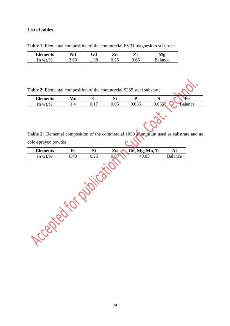
Table 1: Elemental composition of the commercial EV31 magnesium substrate
Elements Nd Gd Zn Zr Mg
in wt.% 2.60 1.38 0.25 0.66 Balance
Table 2: Elemental composition of the commercial S235 steel substrate
Elements Mn C Si P S Fe
in wt.% 1.4 0.17 0.05 0.035 0.035 Balance
Table 3: Elemental composition of the commercial 1050 aluminium used as substrate and as
cold-sprayed powder.
Elements Fe Si Zn Cu, Mg, Mn, Ti Al
in wt.% 0.40 0.25 0.07 <0.05 Balance
25
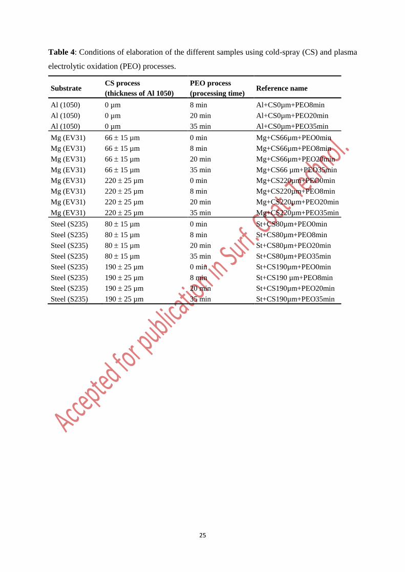
Table 4: Conditions of elaboration of the different samples using cold-spray (CS) and plasma
electrolytic oxidation (PEO) processes.
Substrate CS process
(thickness of Al 1050)
PEO process
(processing time) Reference name
Al (1050) 0 µm 8 min Al+CS0µm+PEO8min
Al (1050) 0 µm 20 min Al+CS0µm+PEO20min
Al (1050) 0 µm 35 min Al+CS0µm+PEO35min
Mg (EV31) 66 15 µm 0 min Mg+CS66µm+PEO0min
Mg (EV31) 66 15 µm 8 min Mg+CS66µm+PEO8min
Mg (EV31) 66 15 µm 20 min Mg+CS66µm+PEO20min
Mg (EV31) 66 15 µm 35 min Mg+CS66 µm+PEO35min
Mg (EV31) 220 25 µm 0 min Mg+CS220µm+PEO0min
Mg (EV31) 220 25 µm 8 min Mg+CS220µm+PEO8min
Mg (EV31) 220 25 µm 20 min Mg+CS220µm+PEO20min
Mg (EV31) 220 25 µm 35 min Mg+CS220µm+PEO35min
Steel (S235) 80 15 µm 0 min St+CS80µm+PEO0min
Steel (S235) 80 15 µm 8 min St+CS80µm+PEO8min
Steel (S235) 80 15 µm 20 min St+CS80µm+PEO20min
Steel (S235) 80 15 µm 35 min St+CS80µm+PEO35min
Steel (S235) 190 25 µm 0 min St+CS190µm+PEO0min
Steel (S235) 190 25 µm 8 min St+CS190 µm+PEO8min
Steel (S235) 190 25 µm 20 min St+CS190µm+PEO20min
Steel (S235) 190 25 µm 35 min St+CS190µm+PEO35min
26
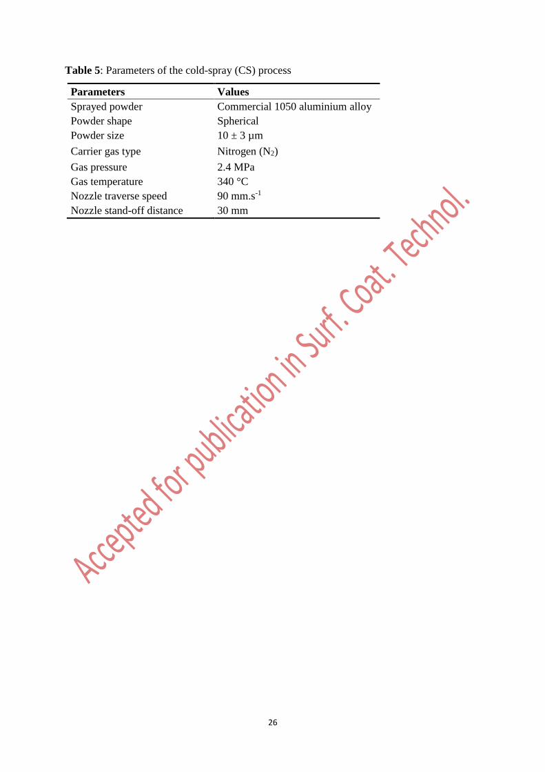
Table 5: Parameters of the cold-spray (CS) process
Parameters Values
Sprayed powder Commercial 1050 aluminium alloy
Powder shape Spherical
Powder size 10 ± 3 µm
Carrier gas type Nitrogen (N2)
Gas pressure 2.4 MPa
Gas temperature 340 °C
Nozzle traverse speed 90 mm.s-1
Nozzle stand-off distance 30 mm
27
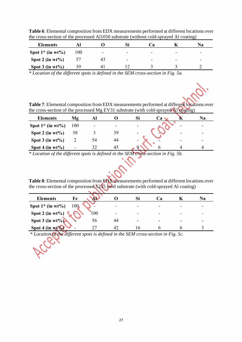
Table 6: Elemental composition from EDX measurements performed at different locations over
the cross-section of the processed Al1050 substrate (without cold-sprayed Al coating)
Elements Al O Si Ca K Na Spot 1* (in wt%) 100 - - - - - Spot 2 (in wt%) 57 43 - - - - Spot 3 (in wt%) 39 41 12 3 3 2
* Location of the different spots is defined in the SEM cross-section in Fig. 5a.
Table 7: Elemental composition from EDX measurements performed at different locations over
the cross-section of the processed Mg EV31 substrate (with cold-sprayed Al coating)
Elements Mg Al O Si Ca K Na Spot 1* (in wt%) 100 - - - - - - Spot 2 (in wt%) 58 3 39 - - - - Spot 3 (in wt%) 2 54 44 - - - - Spot 4 (in wt%) - 32 45 9 6 4 4
* Location of the different spots is defined in the SEM cross-section in Fig. 5b.
Table 8: Elemental composition from EDX measurements performed at different locations over
the cross-section of the processed S235 steel substrate (with cold-sprayed Al coating)
Elements Fe Al O Si Ca K Na Spot 1* (in wt%) 100 - - - - - - Spot 2 (in wt%) - 100 - - - - - Spot 3 (in wt%) - 56 44 - - - - Spot 4 (in wt%) - 27 42 16 6 6 3
* Location of the different spots is defined in the SEM cross-section in Fig. 5c.
28
List of figures
Figure 1: Schematic description of the duplex surface treatments performed on S235 steel and
EV31 magnesium substrates combining cold-spray (CS) and plasma electrolytic oxidation
(PEO) processes.
29
Figure 2: Evolutions of the anodic voltage amplitude as a function of the PEO processing time
a) for Al 1050 substrate (without cold-sprayed Al coating) and Mg substrates (with 66 and 220
µm cold-sprayed Al coatings) and b) for Al 1050 substrate (without cold-sprayed Al coating)
and steel substrates (with 80 and 190 µm cold-sprayed Al coatings). Vertical dash lines indicate
the PEO processing time at which the “soft” regime occurs. Reference name of each sample is
given in Table 4.
30
Figure 3: Cross-section SEM micrographs of the cold-sprayed and PEO processed samples for
different PEO processing time. Reference name of each sample is given in Table 4. Black
arrows indicate the substrate (Al, Mg or Steel), green arrows indicate the cold-sprayed Al
coating and red arrows indicate the PEO coating.
31
Figure 4: Evolutions of the PEO oxide layer thickness as a function of the PEO processing time
a) for Al 1050 and Mg substrates and b) for Al 1050 and steel substrates. Coloured boxes
indicate thickness range of the different pre-deposit cold-sprayed Al coatings. Reference name
of each sample is given in Table 4.
32
Figure 5: Cross-sections SEM micrographs and the corresponding EDX element maps for the
duplex coatings grown on a) bulk Al 1050 (Al+CS0µm+PEO35min), b) Mg EV31
(Mg+CS66µm+PEO20min) and c) S235 steel substrate (St+CS80µm+PEO20min). Coloured
crosses indicate the localization of EDX measurements and element quantification given in Fig.
6 and Tables 6, 7 and 8.
33
Figure 6: EDX spectra recorded at different locations over the cross-section of the coatings
grown on a) bulk Al 1050 (Al+CS0µm+PEO35min), b) Mg EV31 (Mg+CS66µm+PEO20min)
and c) S235 steel substrate (St+CS80µm+PEO20min). Location of the different spots is defined
in the SEM cross-section micrographs in Fig. 5.
34
Figure 7: XRD patterns (using Bragg-Brentano geometry) of the coatings synthesised using
cold-spray and PEO treatments at different processing time (0, 8, 20 and 35 min) for a) Bulk
Al 1050 substrate, b) Mg EV31 substrate and c) S235 steel substrate. Reference name of each
sample is given in Table 4.
35
Figure 8: Cross-sections SEM micrographs and corresponding EDX element maps (Al, Si and
O) of a PEO coating grown on a pre-deposited steel substrate (St+CS80µm+PEO8min).
36
Figure 9: X-ray micro-tomography images of a PEO coating grown on a steel substrate
(St+CS190µm+PEO35min). V is the volume of porosities. d is the path length of the porosities.
37
Figure 10: Cross-section SEM micrographs of the cold-sprayed and PEO processed samples
(for 20 min) for a) a steel substrate with 190 µm cold sprayed Al coating and b) a Mg substrate
with 220 µm cold-sprayed Al coating.
38
Figure 11: Schematics of the influence of the porosities inside a cold-sprayed aluminium
coating on the growth of a PEO oxide layer, a) before applying the current to the electrodes, b)
during the first minutes of the PEO process and c) after longer PEO processing time.


![1 Introduction to the Science of Complex Metallic Alloys · Complex metallic alloys (or CMA for short), also called SCAPs (for structurally complex alloy phases) for some time [1]](https://img.pdfslide.us/doc/110x75/5f217b2c32e27a58f3493217/1-introduction-to-the-science-of-complex-metallic-complex-metallic-alloys-or-cma.jpg)