Embed Size (px)
Citation preview

Users, Installation & Servicing
Instructions
MUST BE LEFT WITH THE USER
DUO POWER 2
Models: RV – Rear Venting
Fuel Effect Options:
Coal Effect Pebble Effect
Both available on NG & LPG
Control Options: Manual Control
Installation Options:
Installation using Freedom Surround
For use on Natural Gas (G20) at a supply pressure of 20mbar or Propane (G31) at a supply pressure of 37mbar in GB and IE
(Dependent upon model)
Manufacturer Contact Details: Burley Appliances Ltd. Lands End Way Oakham, Rutland, LE15 6RB
Tel: +44 (0)1572 725570 Fax: +44 (0)1572 724390
General E-Mail: [email protected] Web Site: www.magiglo.co.uk Technical Support: Direct Dial on (01572) 725570 or email: [email protected]
Magiglo Document Number: MF388.51 CAS
Revision Date: 22 October 2009
Copyright: This documentation is copyrighted by Burley Magiglo. ©2009. No part of this document may be copied, photocopied or reproduced in any form or by any means without permission in writing from Burley Magiglo. Magiglo is a registered trademark of Burley Appliances Ltd.
Service Warranty: In the unlikely event of a defect in materials or workmanship occurring within one year of purchase, Burley Magiglo will arrange to repair or replace the item free of charge. Any claims under this warranty must be made through the retailer from whom the product was purchased. As the purchaser’s contract of sale is with the retailer, Burley Magiglo are unable to enter into discussions with the purchaser until the retailer has inspected any claim and deemed it to be valid. Burley Magiglo reserve the right to refuse service or make a charge for any service call, when a defect is due to installation error or misuse. Extended warranty (if purchased) commences after the first year; please see separate registration for further information.
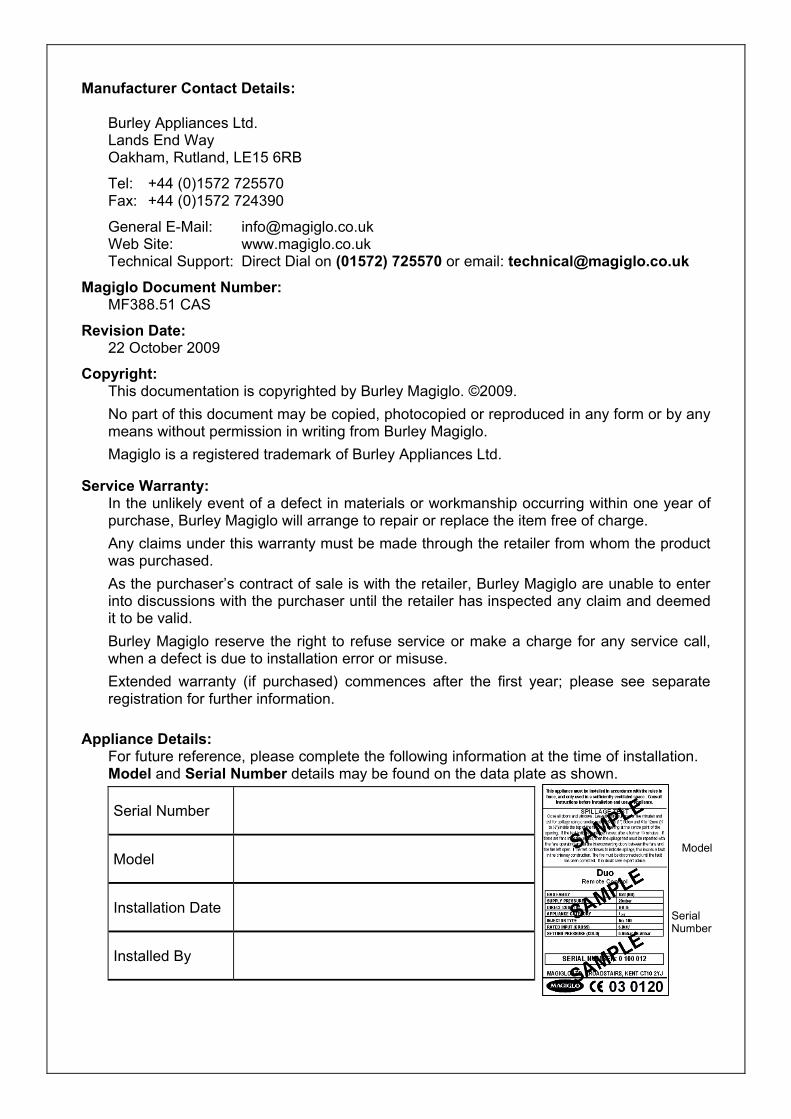
Appliance Details:
For future reference, please complete the following information at the time of installation. Model and Serial Number details may be found on the data plate as shown.
Serial Number
Model
Installation Date
Installed By
Model
Serial Number

Page i
Contents
1. General Information ........................................................................................................... 1 1.1. Important Note About ODS Pilot ................................................................................ 3 1.2. Fire Fret Dimensions .................................................................................................. 4
2. User Instructions ............................................................................................................... 5 2.1. Lighting the Pilot ......................................................................................................... 5 2.2. Lighting the Main Burner ............................................................................................ 6 2.3. Turning the Fan Off .................................................................................................... 6 2.4. Fuel Effect Layout ...................................................................................................... 7
2.4.1. Coal Effect Layout ................................................................................................ 8 2.4.2. Pebble Effect Layout ............................................................................................ 9
2.5. Fitting the Trim (Optional) ......................................................................................... 10 2.6. Fitting Ioss Fascia (if supplied) ................................................................................. 10 2.7. Home Improvements ................................................................................................ 11 2.8. Cleaning and Care Instructions ................................................................................ 12
2.8.1. Cleaning the Fire-Bed and the Imitation Coals/Pebbles .................................... 12 2.8.2. Cleaning the Pilot ............................................................................................... 13 2.8.3. Cleaning the Fire Back ....................................................................................... 13 2.8.4. Black Painted Metal Surfaces ............................................................................ 13 2.8.5. Brass or Chrome Surfaces ................................................................................. 14 2.8.6. Stainless Steel ................................................................................................... 14 2.8.7. Care of Ceramic Backs ...................................................................................... 14
3. Installation Instructions .................................................................................................. 15 3.1. General Safety Requirements .................................................................................. 15 3.2. General Dimensions ................................................................................................. 15
3.2.1. Dimensions for Duo Power 2 (excluding Freedom Surround) ........................... 15 3.2.2. Dimensions for Duo Power 2 with Freedom Surround ...................................... 16
3.3. Appliance Location ................................................................................................... 17 3.3.1. Floor Level and Raised Fireplace Openings ...................................................... 18 3.3.2. Flue Terminal Location ...................................................................................... 19 3.3.3. Physical Barrier .................................................................................................. 20
3.4. Ventilation ................................................................................................................. 22 3.5. Technical Data ......................................................................................................... 22 3.6. Contents Checklist ................................................................................................... 23 3.7. Installation Procedure (Examples) ........................................................................... 24
3.7.1. Examples of Installation into Cavity/Solid Masonry Wall ................................... 24 3.7.2. Examples of Protecting Combustible Materials (e.g. Timber Framed Dwelling Installation) ..................................................................................................................... 26 3.7.3. Preparing the Installation ................................................................................... 27 3.7.4. Installation using Freedom Surround (If applicable) .......................................... 27 3.7.5. Freedom Surround Installation (if applicable) .................................................... 28 3.7.6. Installation Using a Spacer Frame (if applicable) .............................................. 29 3.7.7. Dimension Templates ........................................................................................ 30 3.7.8. Firebox Preparation ........................................................................................... 30 3.7.9. Recessed Firebox Preparation .......................................................................... 31 3.7.10. Surface Mounted Firebox Preparation ............................................................... 32 3.7.11. Installation into timber framed buildings............................................................. 33 3.7.12. The Gas Supply ................................................................................................. 34 3.7.13. Fitting the Firebox (without Freedom Surround) ................................................ 35 3.7.14. Fitting the Firebox (with Freedom Surround) ..................................................... 36 3.7.15. Electrical Wiring ................................................................................................. 37

Page ii
3.7.16. Fan Unit Installation ........................................................................................... 38 3.7.17. Commissioning the Installation .......................................................................... 40 3.7.18. Checking for Spillage ......................................................................................... 41 3.7.19. Terminal Guard .................................................................................................. 41 3.7.20. Instructing the User ............................................................................................ 41
4. Servicing Instructions ..................................................................................................... 43 4.1. General Requirements ............................................................................................. 43 4.2. Servicing Instructions ............................................................................................... 43
4.2.1. Fan and Flue Servicing ...................................................................................... 43 4.2.2. Servicing the Fire ............................................................................................... 43
4.3. Replacing Parts ........................................................................................................ 44 4.3.1. Pilot Assembly Replacement ............................................................................. 44 4.3.2. Injector Replacement ......................................................................................... 44 4.3.3. Control Valve Replacement ............................................................................... 44 4.3.4. Control Box Replacement .................................................................................. 45 4.3.5. Replacing the Solenoid Valve ............................................................................ 45 4.3.6. Replacing the Air Pressure Switch ..................................................................... 45
4.4. Installation and Operational Troubleshooting ........................................................... 46 4.4.1. Electrical Fault Finding Chart ............................................................................. 48
4.5. Wiring in Fan Box Schematic ................................................................................... 49 4.6. Wiring inside Control Box ......................................................................................... 49
Page 1
1. GENERAL INFORMATION Introduction
1. This appliance is suitable for installation in GB and IE and should be installed in accordance with the rules in force.
In GB, the installation must be carried out by a Gas Safe Registered Installer registered for working on this type of appliance. It must be carried out in accordance with the relevant requirements of the:
• Gas Safety (Installation and Use) Regulations. • The appropriate Building Regulations either The Building Regulations, The
Building Regulations (Scotland), Building Regulations (Northern Ireland). • The Current I.E.E. Wiring Regulations.
Where no specific instructions are given, reference should be made to the relevant British Standard Code of Practice (see item 2).
In IE, the installation must be carried out by a Competent Person and installed in accordance with the current edition of I.S.813 “Domestic Gas Installations”, the current Building Regulations and reference should be made to the current ETCI rules for electrical installation.
On completion of an installation in IE, it is necessary to complete a “Declaration of Conformity” to indicate compliance to I.S.813.
2. The installation of the fire in GB should follow the recommendations of the following current British Standards: BS 5871: Pt 2 Installation of ILFE Gas Fires BS 5871: Pt 3 Installation and Code of Practice for DFE Gas Fires BS 6891 Pipe work Installation BS 5440: Pts 1 & 2 Flues and Ventilation IGE/UP/7 IGE document for gas installations in Timber Frame Buildings (Available from CORGI or Institute of Gas Engineers)
3. In other EC countries equivalent rules in force must be used.
4. It is important for correct combustion of this fire that the imitation fuel is placed in accordance with the instructions given in this and associated booklets. Only approved imitation fuel, available from Burley Magiglo., should be used with this appliance.
5. It is recommended that a fire guard complying with BS 8423 be fitted for the protection of young children, the elderly or infirm.
6. This fire is intended for decorative purposes only.
7. The user is warned not to throw any rubbish onto the fire or to disturb the fuel bed.
8. The user is advised that the ceramics used within this appliance require extra care whilst cleaning. Please refer to the Cleaning Instructions.
9. It is important for the fire to be serviced regularly. An annual service is recommended.
Ventilation Requirements
1. For models with heat inputs not exceeding 6.9kW, normal adventitious ventilation is usually sufficient to satisfy the ventilation requirements of these appliances. In GB

Page 2
reference should be made to BS 5871 Part 2, and in IE reference should be made to the current edition of I.S.813 which makes clear the conditions that must be met to demonstrate that sufficient ventilation is available.
2. If provided, any purpose provided ventilation must be checked periodically to ensure it is free from obstructions.
3. When fitting the fire in Northern Ireland (NI), purpose provided ventilation must be provided in accordance with the rules in force.
4. In other EC countries equivalent rules in force must be used.
Flue Requirements
This product is supplied as a complete system, including all necessary flue components.
Gas Supply
1. This range of decorative gas fires are suitable for use with either Natural Gas (G20) at 20mbar supply pressure, or LPG (G31) at 37mbar supply pressure (please check appliance data plate for compatibility).
2. A separate means of isolating the gas supply should be provided near to the appliance to facilitate servicing. For this an isolating valve has been supplied.
Electrical Supply
Connection can be made using one of the following methods:
a) A fused spur providing 230v 50Hz AC, protected with 3A fuse, located adjacent to the appliance.
b) A BS1363/A approved (three pin) plug with a 3 Amp rated fuse, can be fitted to the power supply cable on the appliance and plugging into a suitable wall socket nearby.
The wires in the mains power supply lead on the appliance must be connected to the plug in accordance with the diagram below.
Connect BLUEto N(neutral)
Outer Sleevefirmly clamped
Cable grip
Connect BROWNto L (live)
3Amp fuse approvedto BS1362
Connect GREEN/YELLOWto E or (earth)
Figure 1
In case the appliance needs to be isolated from the power supply (e.g. during servicing) switch off at the wall socket and REMOVE THE PLUG from the socket.
The electrical Installation must be carried out in accordance with The Current I.E.E. Wiring Regulations.

Page 3
1.1. Important Note About ODS Pilot This fire is fitted with an ODS pilot which causes the appliance to shut down in the event of a reduction of oxygen (e.g. caused by poor ventilation) in the room. Should this happen, follow the lighting instructions to re-light the fire. In the event that the fire should shut down again, do NOT attempt to re-light it but contact your gas installer for remedial action to be taken.
Under no circumstances should it be adjusted or put out of action by the installer or the user. In case the pilot needs replacing, only the approved part (available from your supplier or Burley Magiglo.) should be fitted. Note: if any part of the pilot assembly becomes faulty the complete assembly will need replacing.
Page 4
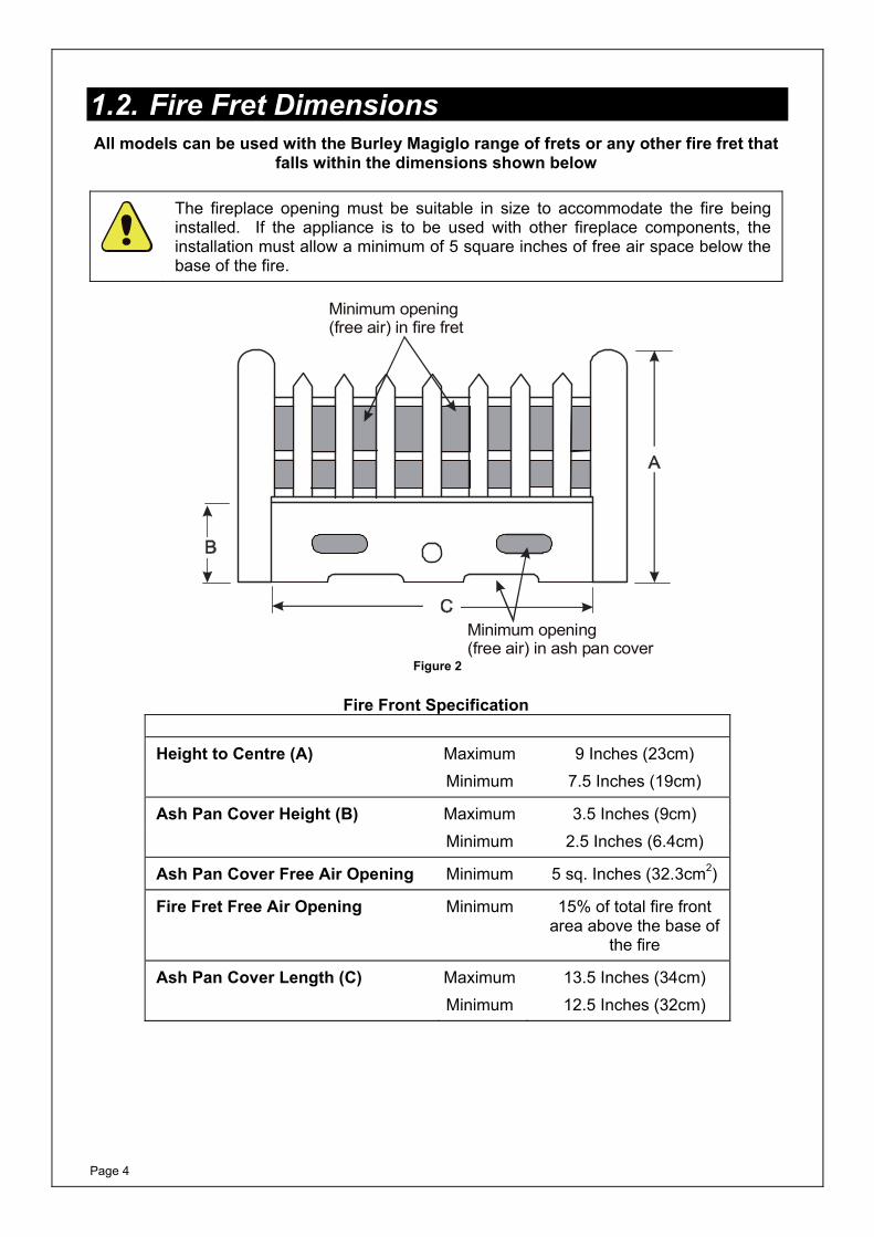
1.2. Fire Fret Dimensions All models can be used with the Burley Magiglo range of frets or any other fire fret that
falls within the dimensions shown below
The fireplace opening must be suitable in size to accommodate the fire being installed. If the appliance is to be used with other fireplace components, the installation must allow a minimum of 5 square inches of free air space below the base of the fire.
Minimum opening (free air) in fire fret
Minimum opening (free air) in ash pan cover
Figure 2
Fire Front Specification Height to Centre (A) Maximum 9 Inches (23cm) Minimum 7.5 Inches (19cm)
Ash Pan Cover Height (B) Maximum 3.5 Inches (9cm) Minimum 2.5 Inches (6.4cm)
Ash Pan Cover Free Air Opening Minimum 5 sq. Inches (32.3cm2)
Fire Fret Free Air Opening Minimum 15% of total fire front area above the base of
the fire
Ash Pan Cover Length (C) Maximum 13.5 Inches (34cm) Minimum 12.5 Inches (32cm)
Page 5
2. USER INSTRUCTIONS
2.1. Lighting the Pilot1. Confirm that the fused spur serving this
appliance is switched on, and power is available.
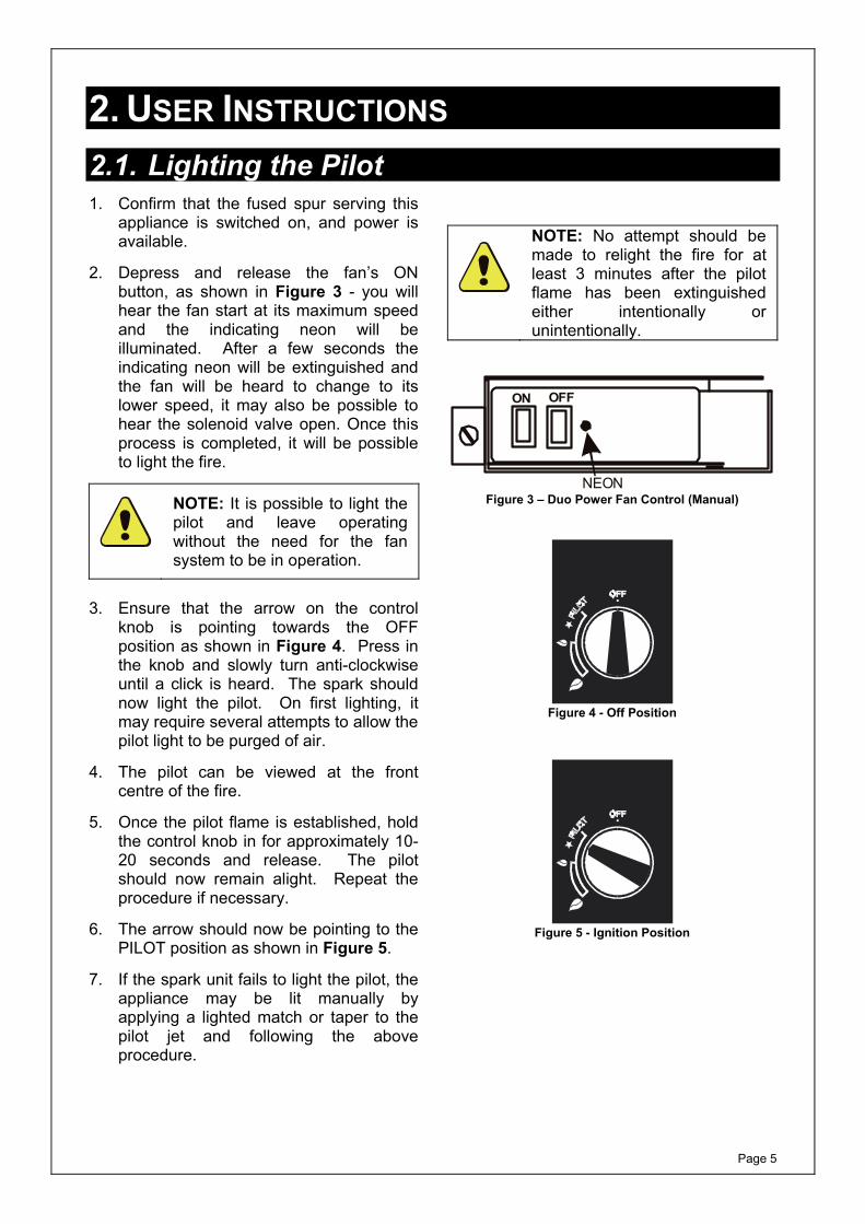
2. Depress and release the fan’s ON button, as shown in Figure 3 - you will hear the fan start at its maximum speed and the indicating neon will be illuminated. After a few seconds the indicating neon will be extinguished and the fan will be heard to change to its lower speed, it may also be possible to hear the solenoid valve open. Once this process is completed, it will be possible to light the fire.
NOTE: It is possible to light the pilot and leave operating without the need for the fan system to be in operation.
3. Ensure that the arrow on the control
knob is pointing towards the OFF position as shown in Figure 4. Press in the knob and slowly turn anti-clockwise until a click is heard. The spark should now light the pilot. On first lighting, it may require several attempts to allow the pilot light to be purged of air.
4. The pilot can be viewed at the front centre of the fire.
5. Once the pilot flame is established, hold the control knob in for approximately 10-20 seconds and release. The pilot should now remain alight. Repeat the procedure if necessary.
6. The arrow should now be pointing to the PILOT position as shown in Figure 5.
7. If the spark unit fails to light the pilot, the appliance may be lit manually by applying a lighted match or taper to the pilot jet and following the above procedure.
NOTE: No attempt should be made to relight the fire for at least 3 minutes after the pilot flame has been extinguished either intentionally or unintentionally.
ON OFF
NEON Figure 3 – Duo Power Fan Control (Manual)
Figure 4 - Off Position
Figure 5 - Ignition Position

Page 6
2.2. Lighting the Main Burner 1. Once the pilot is established, the main
burner can be operated by turning the control knob anti-clockwise. The preset minimum is found with the arrow in the 9 o’clock position as shown in Figure 6.
2. The preset maximum (as shown in Figure 7 is found by turning the control knob fully anti-clockwise. The control is infinitely variable between the two preset limits.
3. To extinguish the main burner, push the control knob in and turn clockwise until the arrow is in the PILOT position, then release.
4. To extinguish the pilot, push the control knob in and turn it clockwise until the arrow is in the OFF position, then release.
NOTE: The main burner will not light unless the fan is switched on.
Figure 6 - Minimum Position
Figure 7 - Maximum Position
WARNING: Always turn on/off the main burner using the control valve and NOT by means of any power supply switches.
2.3. Turning the Fan Off Once the main burner has been extinguished, the fan can be switched off.
NOTE: If the fire has been operating for a long period, it may prove desirable to leave the fan operating for 5 minutes after turning the burner off.
Page 7
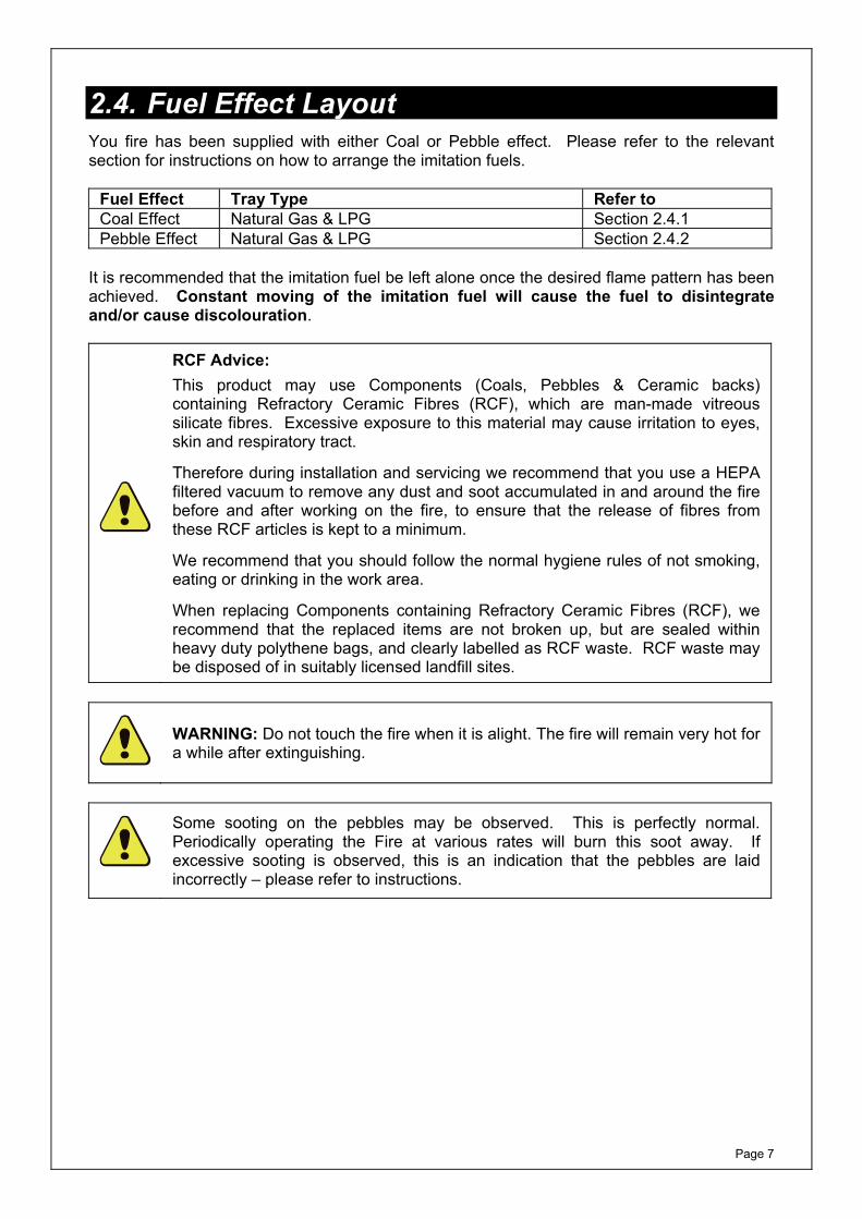
2.4. Fuel Effect Layout You fire has been supplied with either Coal or Pebble effect. Please refer to the relevant section for instructions on how to arrange the imitation fuels.
Fuel Effect Tray Type Refer to Coal Effect Natural Gas & LPG Section 2.4.1 Pebble Effect Natural Gas & LPG Section 2.4.2
It is recommended that the imitation fuel be left alone once the desired flame pattern has been achieved. Constant moving of the imitation fuel will cause the fuel to disintegrate and/or cause discolouration.
RCF Advice: This product may use Components (Coals, Pebbles & Ceramic backs) containing Refractory Ceramic Fibres (RCF), which are man-made vitreous silicate fibres. Excessive exposure to this material may cause irritation to eyes, skin and respiratory tract.
Therefore during installation and servicing we recommend that you use a HEPA filtered vacuum to remove any dust and soot accumulated in and around the fire before and after working on the fire, to ensure that the release of fibres from these RCF articles is kept to a minimum.
We recommend that you should follow the normal hygiene rules of not smoking, eating or drinking in the work area.
When replacing Components containing Refractory Ceramic Fibres (RCF), we recommend that the replaced items are not broken up, but are sealed within heavy duty polythene bags, and clearly labelled as RCF waste. RCF waste may be disposed of in suitably licensed landfill sites.
WARNING: Do not touch the fire when it is alight. The fire will remain very hot for a while after extinguishing.
Some sooting on the pebbles may be observed. This is perfectly normal. Periodically operating the Fire at various rates will burn this soot away. If excessive sooting is observed, this is an indication that the pebbles are laid incorrectly – please refer to instructions.

Page 8
2.4.1. Coal Effect Layout This fire is supplied with different sizes of ceramic coal as follows:
Qty Small Square Coals 8 Medium Square Coals 4 Random Coals 8 Small Random Coals 9 Aeration Tubes 2 ½ Aeration Tubes 1
Proceed with the coal layout as follows: - 1. Following the appropriate set of
drawings, form the first layer, using the Small square and Medium square coals, placing the aeration tubes as shown.
2. Unpack the Random and small Random coals and form the second layer, ensuring that none of these coals come into contact with the burner board.
3. Using more of the small random coals, form the final layer.
4. Packing the coals too tightly together will result in a poor flame picture. The best results come from a ‘loose’ fuel build.
5. Do not place any coals immediately over the pilot assembly.
6. After the appliance has been allowed to warm up, small adjustments (using a small pair of tongs) may be made to the top layer to achieve the desired flame picture.
7. It is recommended that the coals be left alone once the desired flame picture has been achieved. Constant moving of the coals causes the coals to disintegrate and/or cause discolouration.
WARNING: Do not touch the fire when it is alight. The fire will remain very hot for a while after extinguishing.
Medium Square Coalsequally spaced
Aeration Tubes
Small Square Coalsequally spaced Cross lighting slot Pilot
Gas outletports
Figure 8
4 Random coals
6 Small Random coals
GapsGaps
Figure 9
3 Small Random coals
4 Random Coals Figure 10
Page 9
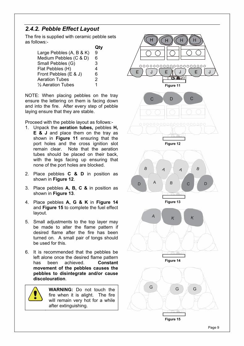
2.4.2. Pebble Effect LayoutThe fire is supplied with ceramic pebble sets as follows:-
Qty Large Pebbles (A, B & K) 9 Medium Pebbles (C & D) 6 Small Pebbles (G) 3 Flat Pebbles (H) 4 Front Pebbles (E & J) 6 Aeration Tubes 2 ½ Aeration Tubes 1
NOTE: When placing pebbles on the tray ensure the lettering on them is facing down and into the fire. After every step of pebble laying ensure that they are stable. Proceed with the pebble layout as follows:- 1. Unpack the aeration tubes, pebbles H,
E & J and place them on the tray as shown in Figure 11 ensuring that the port holes and the cross ignition slot remain clear. Note that the aeration tubes should be placed on their back, with the legs facing up ensuring that none of the port holes are blocked.
2. Place pebbles C & D in position as shown in Figure 12.
3. Place pebbles A, B, C & in position as shown in Figure 13.
4. Place pebbles A, G & K in Figure 14 and Figure 15 to complete the fuel effect layout.
5. Small adjustments to the top layer may be made to alter the flame pattern if desired flame after the fire has been turned on. A small pair of tongs should be used for this.
6. It is recommended that the pebbles be left alone once the desired flame pattern has been achieved. Constant movement of the pebbles causes the pebbles to disintegrate and/or cause discolouration.
WARNING: Do not touch the fire when it is alight. The fire will remain very hot for a while after extinguishing.
Figure 11
H H HC D C
Figure 12
H H H
B BA A
AD B DC
Figure 13
H H HK KA
Figure 14
H H H
G GG
Figure 15

Page 10
2.5. Fitting the Trim (Optional)1. Most trims are coated with a protective
film. This must be removed by peeling off before fitting the trim.
2. The trim is held on by four magnets. These will either be attached to the trim or supplied loose in a separate envelope. Space them as shown in Figure 16.
3. Offer the trim onto the flange of the firebox. The magnets will hold the trim in position.
4. Centralise the trim as necessary.
Magnets
Figure 16
2.6. Fitting Ioss Fascia (if supplied)1. The Fascia is coated with a protective
film. This must be removed by peeling off before fitting the fascia.
2. The fascia is held on by four magnets. These will either be attached to the trim or supplied loose in a separate envelope. Position them as shown in Figure 17.
3. Offer the fascia onto the flange of the firebox. The magnets will hold the fascia in position.
4. Centralise the trim as necessary.
5. The removable cover can be lifted off to access the controls.
MAGNETS
Removablecover to accesscontrols
MAGNETS
Figure 17
Page 11
2.7. Home Improvements
WARNING: If after installation of this fire any home improvements (e.g. double glazing, secondary double glazing, draught proofing, fitting extractor fans, laminate flooring etc.) are carried out to the property it is essential to carry out a spillage test on the fire to ensure that the flue is still operating satisfactorily.
NOTICE: Discolouration of wall surfaces
Generally, heating appliances will create warm air convection currents that will transfer heat to any wall surface against which they are located.
Some soft furnishings (including blown vinyl wallpapers) may not be suitable for use where they are likely to encounter temperatures above the normal room level. For this reason, the manufacturer’s advice should be sought before using this type of wall covering adjacent to any heating appliance.
The likelihood of wall staining caused from convected air currents will be increased in areas where high levels of tobacco smoke or other contaminants exist.
Page 12
2.8. Cleaning and Care Instructions
CAUTION: Ensure that the appliance is off (including the pilot light) and has completely cooled (off for at least 2 hours) before carrying out any cleaning or maintenance.
RCF Advice: This product may use Components (Coals, Pebbles & Ceramic backs) containing Refractory Ceramic Fibres (RCF), which are man-made vitreous silicate fibres. Excessive exposure to this material may cause irritation to eyes, skin and respiratory tract.
Therefore during installation and servicing we recommend that you use a HEPA filtered vacuum to remove any dust and soot accumulated in and around the fire before and after working on the fire, to ensure that the release of fibres from these RCF articles is kept to a minimum.
We recommend that you should follow the normal hygiene rules of not smoking, eating or drinking in the work area.
When replacing Components containing Refractory Ceramic Fibres (RCF), we recommend that the replaced items are not broken up, but are sealed within heavy duty polythene bags, and clearly labelled as RCF waste. RCF waste may be disposed of in suitably licensed landfill sites.
2.8.1. Cleaning the Fire-Bed and the Imitation Coals/Pebbles1. If excessive debris is observed on the
imitation fuels or fire-bed, this must be removed before further using the fire.
2. Carefully remove all the imitation fuel from the fire-bed. Any soot or debris on the fuel can be gently brushed away with a soft brush - DO NOT use a vacuum cleaner.
3. Use a low powered HEPA filtered vacuum cleaner with a small nozzle to clean the burner board by gently sweeping the nozzle above the surface of the board. Clean the ports (small holes on the board) in a similar fashion.
4. Relay the imitation fuel after cleaning, in accordance with the layout instructions in this booklet.
5. When satisfactory flame appearance has been achieved after positioning the coals, they should not be moved unnecessarily. Constant moving of the imitation fuels will damage and/or cause discolouration.
Page 13
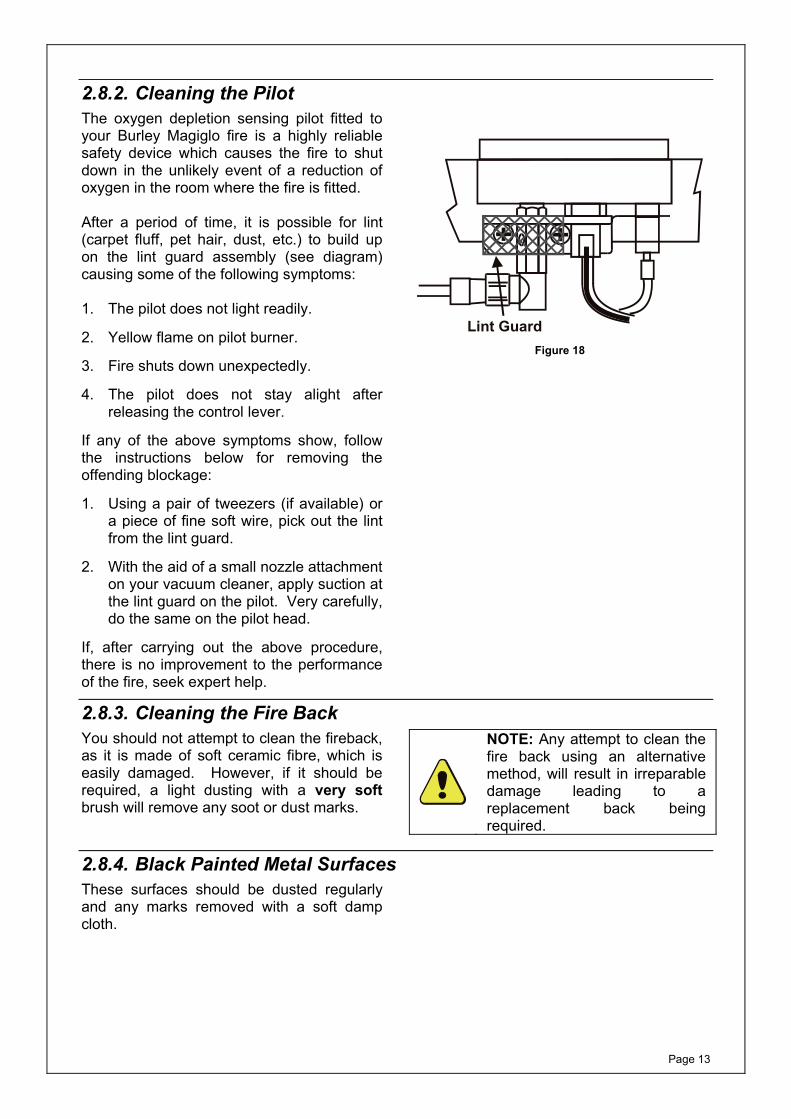
2.8.2. Cleaning the Pilot The oxygen depletion sensing pilot fitted to your Burley Magiglo fire is a highly reliable safety device which causes the fire to shut down in the unlikely event of a reduction of oxygen in the room where the fire is fitted. After a period of time, it is possible for lint (carpet fluff, pet hair, dust, etc.) to build up on the lint guard assembly (see diagram) causing some of the following symptoms: 1. The pilot does not light readily.
2. Yellow flame on pilot burner.
3. Fire shuts down unexpectedly.
4. The pilot does not stay alight after releasing the control lever.
If any of the above symptoms show, follow the instructions below for removing the offending blockage:
1. Using a pair of tweezers (if available) or a piece of fine soft wire, pick out the lint from the lint guard.
2. With the aid of a small nozzle attachment on your vacuum cleaner, apply suction at the lint guard on the pilot. Very carefully, do the same on the pilot head.
If, after carrying out the above procedure, there is no improvement to the performance of the fire, seek expert help.
Lint Guard Figure 18
2.8.3. Cleaning the Fire BackYou should not attempt to clean the fireback, as it is made of soft ceramic fibre, which is easily damaged. However, if it should be required, a light dusting with a very soft brush will remove any soot or dust marks.
NOTE: Any attempt to clean the fire back using an alternative method, will result in irreparable damage leading to a replacement back being required.
2.8.4. Black Painted Metal SurfacesThese surfaces should be dusted regularly and any marks removed with a soft damp cloth.
Page 14
2.8.5. Brass or Chrome Surfaces These surfaces should be cleaned with a proprietary non-abrasive metal cleaner. Remove the trim (if fitted), the fret and the ash-pan cover before cleaning. The trim is held in place by means of four magnets at the rear of the trim. The fret and the ash-pan cover are free standing in front of the fire. 2.8.6. Stainless Steel Stainless steels need to be cleaned for aesthetic considerations and to preserve corrosion resistance. Oil and finger marks can be removed using a glass cleaner or preferably a mild solution of warm water and detergent. Scratches can be removed by gently rubbing in the direction of the grain with a 240 grit emery cloth (or similar). Once the scratch has been completely removed the surface can then be re-polished using 3M Scotchbrite pads - Fine Grade. Periodically it may be necessary to coat the entire surface in order to achieve a uniform finish. This can be achieved by applying a light coat of oil (baby oil) using a soft lint free cloth, then buffing in line with the grain until the excess is removed.
NOTE: After any cleaning process the surface must be thoroughly dried.
2.8.7. Care of Ceramic Backs The ceramic fireback on this appliance must NOT be sprayed with any type of solvent-based high temperature paint. The very high temperatures produced within the appliance will cause the paint to bubble and/or burn off rendering the fireback looking unsightly. Minor surface scuffs may be treated using a water based touch up stain available at Burley Magiglo retailers.
Extreme care should be taken when handling and installing products containing ceramic interiors, so as not to cause damage.
Page 15
3. INSTALLATION INSTRUCTIONS Before installation, ensure that the local distribution conditions (identification of the type of gas and pressure) and the adjustment of the appliance are compatible
3.1. General Safety Requirements
Before commencing installation, ensure that the intended installation will comply with details in General Information on Page 1.
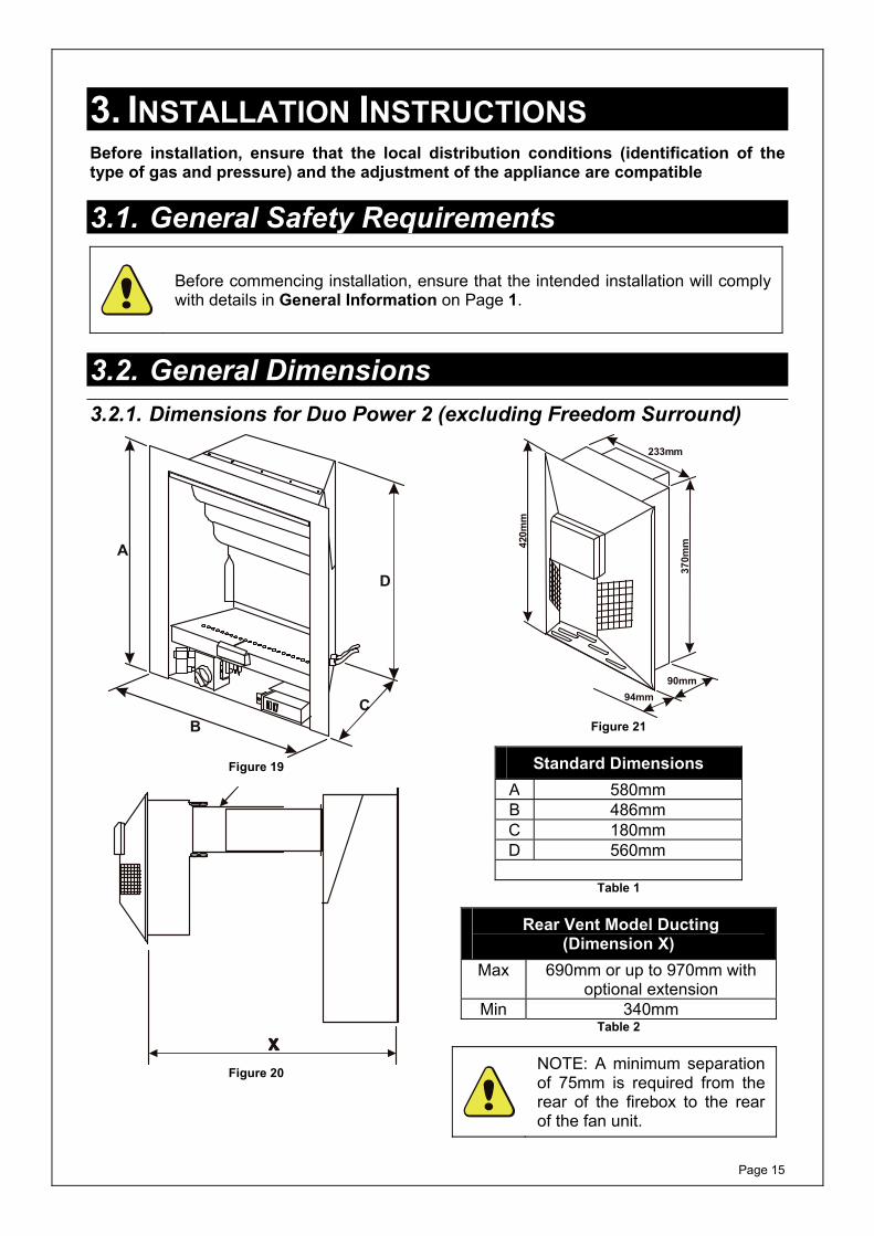
3.2. General Dimensions 3.2.1. Dimensions for Duo Power 2 (excluding Freedom Surround)
A
BC
D
Figure 19
Figure 20
90mm94mm
420m
m
233mm
370m
m
Figure 21
Standard Dimensions A 580mm B 486mm C 180mm D 560mm
Table 1
Rear Vent Model Ducting (Dimension X)
Max 690mm or up to 970mm with optional extension
Min 340mm Table 2
NOTE: A minimum separation of 75mm is required from the rear of the firebox to the rear of the fan unit.
Page 16
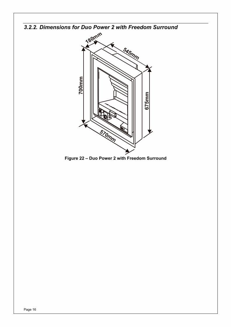
3.2.2. Dimensions for Duo Power 2 with Freedom Surround
675m
m700 m
m
545mm
570mm
180mm
Figure 22 – Duo Power 2 with Freedom Surround
Page 17
3.3. Appliance Location The fire must be fitted on a flat non-combustible base. In addition a non-combustible hearth or physical barrier with minimum dimensions shown in figures below should be provided in front of the fireplace opening where relevant. However, with hole in the wall fire installations, where it may be desirable not to include a hearth with the appliance installation, Building Regulation Approved Document J paragraph 3.40 currently states:- Appliance should be placed on hearths unless:
a) they are installed so that every part of any flame or incandescent material will be at least 225mm above the floor; or
b) the manufacturer’s instructions state that a hearth is not required.
Burley Magiglo would recommend that a hearth or physical barrier be installed with this appliance. However, should you decide not to follow our recommendation and do not fit a hearth or subsequently decide to remove the hearth / physical barrier, then consideration as to the protection of the occupants of the room should be given. In BS 5871 Pt3, section 11.2 states: The user, or other persons in the room in which the appliance is fitted, shall be protected as far is reasonably possible, from the risks of burns or ignition of their clothing from the heat from the flames and incandescent parts of the appliance.
Page 18
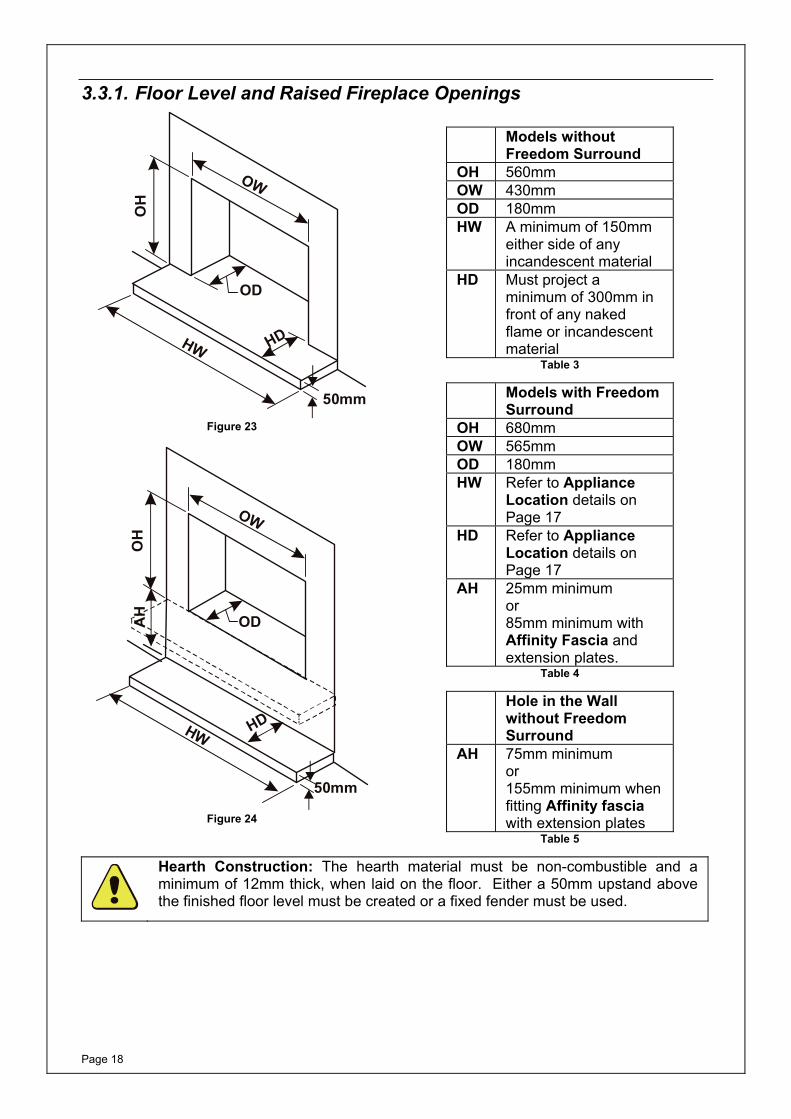
3.3.1. Floor Level and Raised Fireplace Openings
OW
OH
OD
HW HD
50mm
Figure 23
OW
OH
OD
HW HD
50mm
AH
Figure 24
Models without
Freedom Surround OH 560mm OW 430mmOD 180mmHW A minimum of 150mm
either side of any incandescent material
HD Must project a minimum of 300mm in front of any naked flame or incandescent material
Table 3
Models with Freedom Surround
OH 680mmOW 565mmOD 180mm HW Refer to Appliance
Location details on Page 17
HD Refer to Appliance Location details on Page 17
AH 25mm minimum or 85mm minimum with Affinity Fascia and extension plates.
Table 4
Hole in the Wall without Freedom Surround
AH 75mm minimum or 155mm minimum when fitting Affinity fascia with extension plates
Table 5
Hearth Construction: The hearth material must be non-combustible and a minimum of 12mm thick, when laid on the floor. Either a 50mm upstand above the finished floor level must be created or a fixed fender must be used.
Page 19
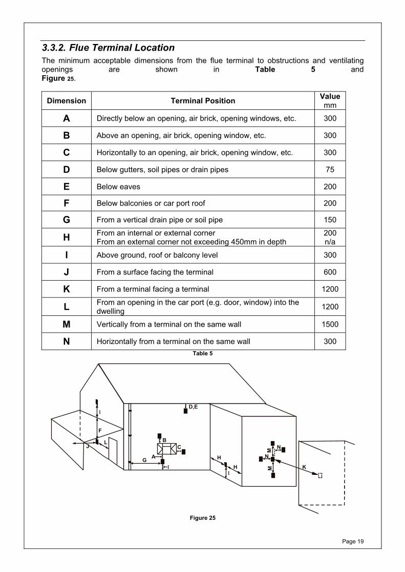
3.3.2. Flue Terminal Location The minimum acceptable dimensions from the flue terminal to obstructions and ventilating openings are shown in Table 5 and Figure 25.
Dimension Terminal Position Value mm
A Directly below an opening, air brick, opening windows, etc. 300
B Above an opening, air brick, opening window, etc. 300
C Horizontally to an opening, air brick, opening window, etc. 300
D Below gutters, soil pipes or drain pipes 75
E Below eaves 200
F Below balconies or car port roof 200
G From a vertical drain pipe or soil pipe 150
H From an internal or external corner From an external corner not exceeding 450mm in depth
200 n/a
I Above ground, roof or balcony level 300
J From a surface facing the terminal 600
K From a terminal facing a terminal 1200
L From an opening in the car port (e.g. door, window) into the dwelling 1200
M Vertically from a terminal on the same wall 1500
N Horizontally from a terminal on the same wall 300 Table 5
II
AG
BC
H
H
D,EI
F
LJ
MM
NN
K
Figure 25

Page 20
3.3.3. Physical BarrierAny physical barrier should meet the following requirements:
1. Provide at least the equivalent level of warning to the approach of an open fire, to that of a hearth.
2. Define a clear zone where occupants must exercise additional caution.
3. Should be constructed of non-combustible material, of robust design and fixed in such a way so as to provide a secure boundary and be mechanically fixed to prevent accidental and/or unintentional removal.
Such a device could take the form of a fender, a shelf, a wall mounted decorative bar, etc.
All Duo Models W Must project a minimum of
150mm either side of any naked flame or incandescent material
D Must project a minimum of 300mm in front of any naked flame or incandescent material
The height of any physical barrier must be a minimum of 50mm above the finished floor level.
Table 6 – Protected Area
Figure 26 and Figure 27 show examples of area to be protected by the physical barrier.
Figure 28, Figure 29 and Figure 30 show methods for calculating the barrier width, but must remain at least the width of the fireplace opening.
W
D
Fire bed
Figure 26
D
Fire bed
Figure 27
Fire Bed
X XY
X=150mm, less dimension Y Figure 28
Fire Bed
X XY
X=150mm, less dimension Y Figure 29
Fire Bed
X X
X=150mm Figure 30

Page 21
Figure 31, Figure 32, Figure 33 and Figure 34 show examples of how the requirements for the physical barrier may be met.
D
W
Figure 31 – Example of physical barrier
(dimensions as stated in Table 6 – Protected Area)
D
W
Figure 32 – Example of physical barrier
(dimensions as stated in Table 6 – Protected Area)
D
W
50mmMin
Figure 33 – Example of physical barrier
(dimensions as stated in Table 6 – Protected Area)
W
D
Figure 34– Example of physical barrier
(dimensions as stated in Table 6 – Protected Area)
Page 22
3.4. Ventilation For models with heat inputs not exceeding 6.9kW, normal adventitious ventilation is usually sufficient to satisfy the ventilation requirements of these appliances. In GB reference should be made to BS 5871 Part 3, and in IE reference should be made to the current edition of I.S.813 which makes clear the conditions that must be met to demonstrate that sufficient ventilation is available. If provided, any purpose provided ventilation must be checked periodically to ensure it is free from obstructions. When fitting the fire in Northern Ireland (NI), purpose provided ventilation must be provided in accordance with the rules in force. In other EC countries equivalent rules in force must be used.
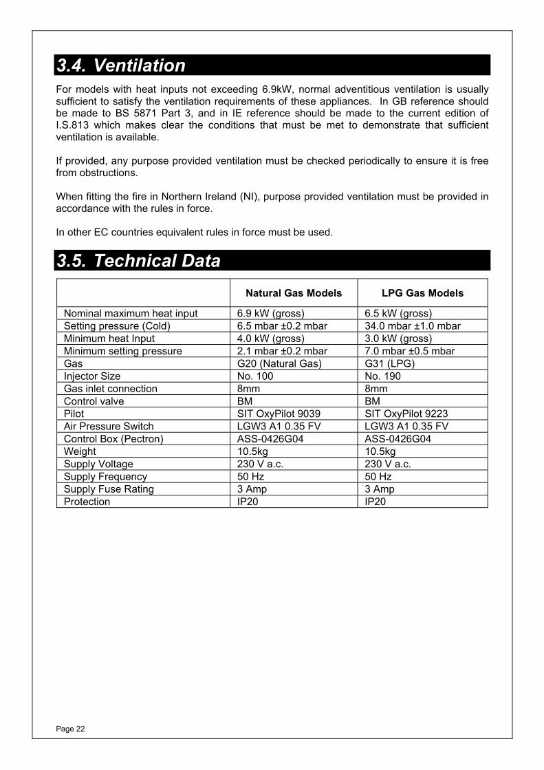
3.5. Technical Data
Natural Gas Models LPG Gas Models
Nominal maximum heat input 6.9 kW (gross) 6.5 kW (gross) Setting pressure (Cold) 6.5 mbar ±0.2 mbar 34.0 mbar ±1.0 mbarMinimum heat Input 4.0 kW (gross) 3.0 kW (gross) Minimum setting pressure 2.1 mbar ±0.2 mbar 7.0 mbar ±0.5 mbar Gas G20 (Natural Gas) G31 (LPG) Injector Size No. 100 No. 190 Gas inlet connection 8mm 8mm Control valve BM BMPilot SIT OxyPilot 9039 SIT OxyPilot 9223 Air Pressure Switch LGW3 A1 0.35 FV LGW3 A1 0.35 FV Control Box (Pectron) ASS-0426G04 ASS-0426G04 Weight 10.5kg 10.5kg Supply Voltage 230 V a.c. 230 V a.c. Supply Frequency 50 Hz 50 Hz Supply Fuse Rating 3 Amp 3 Amp Protection IP20 IP20
Page 23
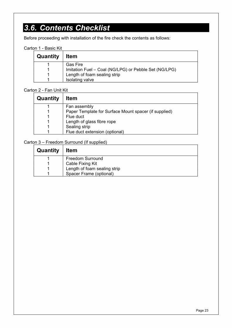
3.6. Contents Checklist Before proceeding with installation of the fire check the contents as follows: Carton 1 - Basic Kit
Quantity Item 1 Gas Fire 1 Imitation Fuel – Coal (NG/LPG) or Pebble Set (NG/LPG) 1 Length of foam sealing strip 1 Isolating valve
Carton 2 - Fan Unit Kit
Quantity Item 1 Fan assembly 1 Paper Template for Surface Mount spacer (if supplied) 1 Flue duct 1 Length of glass fibre rope 1 Sealing strip 1 Flue duct extension (optional)
Carton 3 – Freedom Surround (If supplied)
Quantity Item 1 Freedom Surround1 Cable Fixing Kit 1 Length of foam sealing strip1 Spacer Frame (optional)

Page 24
3.7. Installation Procedure (Examples)
Before commencing installation, ensure that the intended installation will comply with details in General Information on Page 1.
The Burley Magiglo Duo Power 2 is designed to be inset into a 16” opening. Any surround that is to be installed with the Burley Magiglo Duo Power 2 must be rated at 150oC.
Carefully unpack the contents of the carton and check them against the checklist given on the previous page. Make sure that the fireplace opening is suitable for the installation of the fire and prepare the fireplace to suit the dimensional requirements given in Sections 3.2, and 3.3 (i.e. fitting the fire surround, the hearth, etc.).
3.7.1. Examples of Installation into Cavity/Solid Masonry Wall
FLUEDUCT
TERMINAL/FAN BOX
PROPRIETARYFIRE SURROUND
HEARTH
FLOOR
DPC
20mmMin
Figure 35 – Example Installation inside cavity of a cavity
wall
PROPRIETARYFIRE SURROUND
HEARTH
FLOOR
300m
m
MIN
NON-COMBUSTIBLESURFACE
TERMINAL/FAN BOX
Figure 36 – Surface mounted installation example
CABLEFIXING
LINTEL
Figure 37 - Installation of Freedom Surround into a
Cavity Wall
FLUEDUCT
TERMINALFAN BOX
/
Figure 38 - Installation of Appliance in Freedom
Surround
Page 25
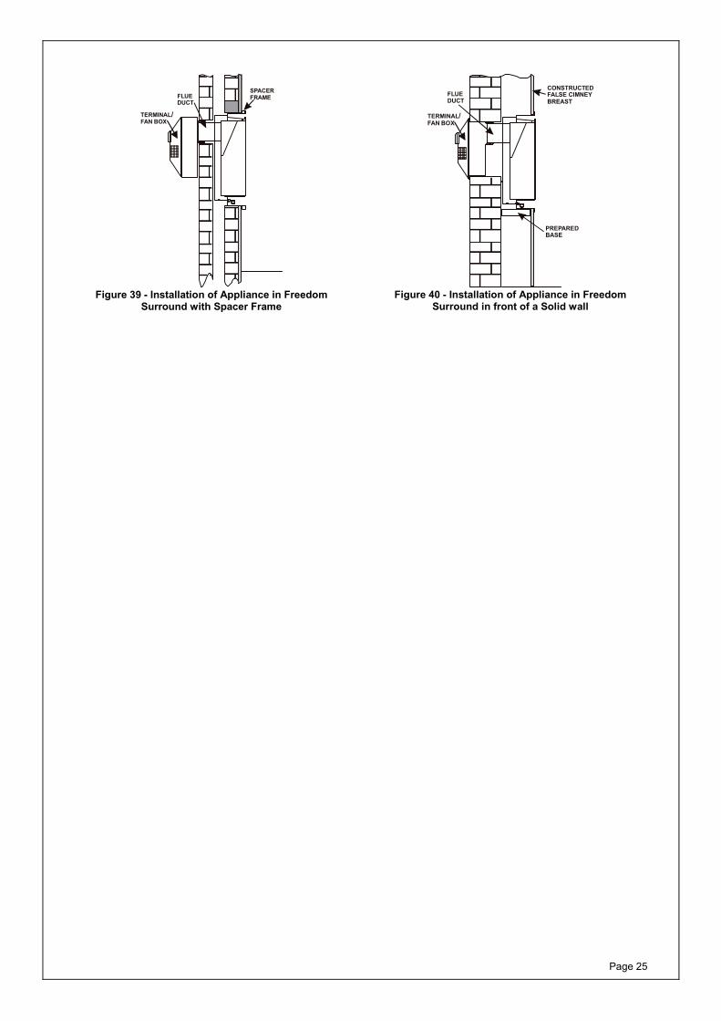
FLUEDUCT
TERMINALFAN BOX
/
SPACERFRAME
Figure 39 - Installation of Appliance in Freedom
Surround with Spacer Frame
FLUEDUCT
TERMINALFAN BOX
/
CONSTRUCTEDFALSE CIMNEYBREAST
PREPAREDBASE
Figure 40 - Installation of Appliance in Freedom
Surround in front of a Solid wall
Page 26
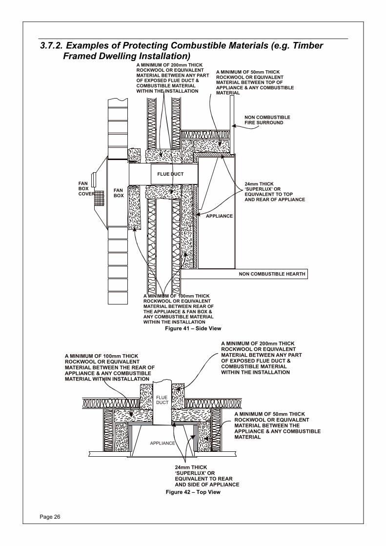
3.7.2. Examples of Protecting Combustible Materials (e.g. Timber Framed Dwelling Installation)
A MINIMUM OF 50mm THICKROCKWOOL OR EQUIVALENTMATERIAL BETWEEN TOP OFAPPLIANCE & ANY COMBUSTIBLEMATERIAL
NON COMBUSTIBLEFIRE SURROUND
24mm THICK‘SUPERLUX’ OREQUIVALENT TO TOPAND REAR OF APPLIANCE
A MINIMUM OF 200mm THICKROCKWOOL OR EQUIVALENTMATERIAL BETWEEN ANY PARTOF EXPOSED FLUE DUCT &COMBUSTIBLE MATERIALWITHIN THE INSTALLATION
A MINIMUM OF 100mm THICKROCKWOOL OR EQUIVALENTMATERIAL BETWEEN REAR OFTHE APPLIANCE & FAN BOX &ANY COMBUSTIBLE MATERIALWITHIN THE INSTALLATION
FLUE DUCT
FANBOX
FANBOXCOVER
NON COMBUSTIBLE HEARTH
APPLIANCE
Figure 41 – Side View
A MINIMUM OF 200mm THICKROCKWOOL OR EQUIVALENTMATERIAL BETWEEN ANY PARTOF EXPOSED FLUE DUCT &COMBUSTIBLE MATERIALWITHIN THE INSTALLATION
A MINIMUM OF 50mm THICKROCKWOOL OR EQUIVALENTMATERIAL BETWEEN THEAPPLIANCE & ANY COMBUSTIBLEMATERIAL
24mm THICK‘SUPERLUX’ OREQUIVALENT TO REARAND SIDE OF APPLIANCE
A MINIMUM OF 100mm THICKROCKWOOL OR EQUIVALENTMATERIAL BETWEEN THE REAR OFAPPLIANCE & ANY COMBUSTIBLEMATERIAL WITHIN INSTALLATION
APPLIANCE
FLUEDUCT
Figure 42 – Top View

Page 27
3.7.3. Preparing the InstallationGeneral Notes
1. Attempt to keep the recess and any hole sizes as close as possible to the minimum dimensions. This will keep the installation tidy without the need for excessive sealing afterwards.
2. Ensure any damp course, electrical wiring and any pipework within the wall is not going to be affected by the installation.
3. Any gas pipe concealed in the wall, floor or cavity must be continuous and enclosed within a gas tight sleeve. (Gas Safety (Installation & Use) Regulations: 1998).
4. Ensure that the chosen position for the appliance will comply with the requirements detailed in Section 3.3.2.
5. Having decided the appropriate installation type, e.g. recessed or surface mount, proceed to the appropriate following section.
For installation using a Freedom Surround follow Sections 3.7.4 to 3.7.6 before proceeding to one of the usual installation sections below:
For recessed firebox installations proceed to Section 3.7.9
For surface mounted firebox installations proceed to Section 3.7.10
For Installation into timber framed buildings, proceed to Section 3.7.11
3.7.4. Installation using Freedom Surround (If applicable)The Freedom Surround is designed to provide an alternative installation method giving it a contemporary hole-in-the-wall appearance whilst reducing heat transfer to the fabric of the building. The Freedom Surround greatly reduces the risk of cracking caused by excessive heat being transferred from the appliance to the wall. If there is insufficient depth to accommodate the chosen appliance, a 30mm spacer is available – see the Installation Using a Spacer Frame section within this document. When installed in a timber framed building, the Freedom Surround greatly reduces the amount of insulation required around the appliance, however, the rear of the appliance and any flue will still require the same level of protection. Figure 38, Figure 39 and Figure 40 show some typical examples of installation

Page 28
3.7.5. Freedom Surround Installation (if applicable) 1. Using Figure 44, mark out and create
the appropriate opening in the wall at the desired height above the floor to accommodate the Freedom Surround. Figure 44 also includes details of the cut out in the outer wall for the flue duct and the hole for cable entry.
2. With reference to Figure 44, mark out, drill, plug and fit the four vine eyes.
3. Remove the base plate (see Figure 47), then fit the sealing strip to the rear of the flange, as shown in Figure 45.
4. Thread the two cables through the two holes at the top rear of the surround.
5. Place the Freedom Surround into the prepared opening, threading the cables through the vine eyes, and through the holes in the base of the surround, as shown in Figure 46.
6. Tighten the cables using the cable tensioning screws, ensuring that the surround remains square and true, and an effective seal is obtained between the flange and the finished wall.
7. Refit the base plate, using screws provided. This will be used to secure the base of the appliance.
8. The top fixing screws of the appliance will secure it against the upper edge of the Freedom Surround.
9. Proceed to appropriate Sections 3.7.8 to 3.7.11 to prepare the duct length depending on the type of installation of fan box (surface mount or inset).
FLANGE 25mm ALL ROUND
125mm
675m
m
545mm
Figure 43 - General Dimensions
230
80
30 DIA
160 X 160
LINTEL
150 150
30
635
685
565
550
150 150
Figure 44
SEALINGSTRIP
Figure 45

Page 29
VINEEYES
CABLE
CABLETENSIONERS
VINEEYES
Figure 46
BASE PLATE
FIXINGSCREWS
WING NUT FIXING
(ON UNDERSIDE)
BASE PLATE(TRIM SWITCH MODELS)
Figure 47
3.7.6. Installation Using a Spacer Frame (if applicable)In order to reduce the installation depth required, the Freedom Surround may be installed using a spacer frame (30mm deep). The spacer frame is slipped over the Freedom Surround, as shown, and secured in place when the Freedom Surround is fixed into the opening.
Freedom Surround
Spacer Frame
Figure 48

Page 30
3.7.7. Dimension TemplatesThere are numerous ways of installing the firebox and fan combination, dependant upon dwelling construction and fireplace design. Detailed below are dimensional templates for creating the appropriate openings, which will be referred to in the appropriate section.
560
mm
430 mm
CL
LINTEL
HEARTH
Figure 49 – Recessed Firebox Template
CL
HEARTH
240mm
200m
m
575m
m
Figure 50 – Recessed Fan Unit Template
CL
HEARTH
480
160 X160mm
240
mm
80mm
30mm OHOLE
Figure 51 – Flue Duct Template
3.7.8. Firebox Preparation 1. Remove the two burner fixing screws
from under the burner tray and withdraw the tray carefully from the firebox.
2. Unplug the power supply to the solenoid by first removing the plug securing screw. Place the fire tray safely away for later installation.
3. Apply the sealing strip around the rear edge of the firebox flange. See Figure 52. (Do Not apply this sealing strip if installing the fire with Freedom Surround)
Rubber Seal
Figure 52
Page 31
3.7.9. Recessed Firebox PreparationOn the inside wall: 1. Measure the height of the hearth and
mark a horizontal line on the wall at the same height.
2. Above the hearth level draw a rectangle to the dimensions of the recess as detailed in Figure 49. Note that a lintel may be required above the recess of the fire to support the inner wall. If in doubt seek expert building advice.
3. Cut the recess in the inner wall ensuring that the depth of the firebox can be accommodated.
4. Screed the floor of the recess to the level of the hearth to allow for accurate fitting of the firebox and flue duct.
5. If surface mounting the fan box assembly, cut through the outer wall as detailed in Figure 51.
6. If recessing the fan box assembly, cut through the outer wall as detailed in Figure 50.
7. Ensure that any cavity wall insulation or other combustible materials within the installation are removed and replaced with rockwool or equivalent material to the dimensions and depths as detailed in Figure 41and Figure 42.
8. Provision in the installation for the routing of the electrical supply to the fire and from the fire to the fan box shall be made with consideration to keeping wires and cables as far away from the flue duct as possible.
9. Temporarily, position the firebox complete with flue duct attached centrally into the fire opening. Engage the flue though the inner wall and to the outside.
10. Ensure the firebox is flat against the fire surround.
11. From the outside, mark the flue duct flush with the outer face of the wall.
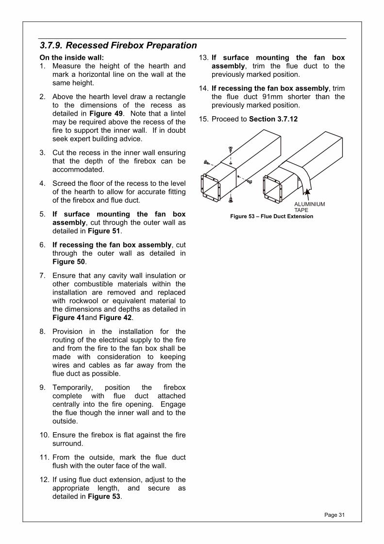
12. If using flue duct extension, adjust to the appropriate length, and secure as detailed in Figure 53.
13. If surface mounting the fan box assembly, trim the flue duct to the previously marked position.
14. If recessing the fan box assembly, trim the flue duct 91mm shorter than the previously marked position.
15. Proceed to Section 3.7.12
ALUMINIUMTAPE
Figure 53 – Flue Duct Extension

Page 32
3.7.10. Surface Mounted Firebox PreparationOn the inside wall: 1. Measure the height of the hearth and
mark a horizontal line on the wall at the same height.
2. Using the template shown in Figure 51, mark the position of the flue above the hearth. Drill a pilot hole in the centre through to the outside wall.
3. From inside the building cut a hole in the inside wall to accept the flue duct.
4. A separate hole shall be made through the inside wall towards the bottom right hand corner of the fire box location, as shown in Figure 51, to accept the electric cable for connecting the fire box to the fan box assembly.
5. Provision in the installation for the routing of the electrical supply to the fire and from the fire to the fan box shall be made with consideration to keeping wires and cables as far away from the flue duct as possible.
6. Ensure that any cavity wall insulation or other combustible materials within the installation are removed and replaced with rockwool or equivalent material to the dimensions and depths as detailed in Figure 41 and Figure 42.
7. The false chimney breast / fire surround, if made of combustible materials shall be suitably protected with 24mm thick ‘Superlux’ or equivalent material and the correct thickness of rockwool or equivalent material as detailed in Figure 41 and Figure 42.
8. Any combustible material to the rear of the firebox, on the inside wall and within the false surround shall be removed.
9. If surface mounting the fan box assembly, cut an opening in the outer wall as detailed in Figure 51.
10. If recessing the fan box assembly, cut an opening in the outer wall as detailed in Figure 50.
11. Temporarily, position the firebox complete with flue duct attached,
centrally into the fire opening. Engage the flue though the inner wall and to the outside.
12. Ensure the firebox is flat against the fire surround.
13. From outside, mark the flue duct flush with the outer face of the wall.
14. If using flue duct extension, adjust to the appropriate length, and secure as detailed in Figure 53.
15. If surface mounting the fan box assembly, trim the flue duct to the previously marked position.
16. If recessing the fan box assembly, trim the flue duct 91mm shorter than the previously marked position.
17. Proceed to Section 3.7.12

Page 33
3.7.11. Installation into timber framed buildings
Note: Installation must be in accordance with the current edition of Gas Engineers Publication IGE/UP/7 (Gas installations in Timber Framed Housing).
Note: Prior to cutting any holes within the inner wall for the firebox or the flue duct (plus clearance dimensions), ensure that no supporting timbers will be cut.
On the inside wall: 1. Measure the height of the hearth and
mark a horizontal line on the wall at the same height.
2. Using the template shown in Figure 51, mark the position of the flue above the hearth. Drill a pilot hole in the centre through to the outside wall.
3. From inside the building cut a hole in the inside wall to accept the flue duct. Consideration should be given to the clearances required around the flue duct in relation to combustible materials within the installation. Combustible materials shall be removed and suitably protected with rockwool or equivalent material as specified in Figure 41 and Figure 42.
4. A separate hole shall be made through the inside wall towards the bottom right hand corner of the fire box location to accept the electric cable for connecting the fire box to the fan box assembly.
5. Ensure that any cavity wall insulation or other combustible materials within the installation are removed and replaced with rockwool or equivalent material to the dimensions and depths as detailed in Figure 41 and Figure 42.
6. The false chimney breast / fire surround, if made of combustible materials shall be suitably protected with 24mm thick 'Superlux' or equivalent material and the correct thickness of rockwool or equivalent material as detailed in Figure 41 and Figure 42.
7. Any combustible material to the rear of the firebox shall be suitably protected with 24mm thick non-combustible material and a minimum of 100mm rockwool. The non-combustible material can consist of the 13 mm plasterboard wall lining plus 12mm thick 'Superlux' or equivalent material.
8. If surface mounting the fan box assembly, cut an opening in the outer wall as detailed in Figure 51. Ensure that the vapour barrier is cut carefully and made good to maintain its integrity.
9. If recessing the fan box assembly, cut an opening in the outer wall as detailed in Figure 50. Ensure that the vapour barrier is cut carefully and made good to maintain its integrity.
10. A suitable flashing should be positioned above the flue duct, extending 150mm either side, in accordance with the Institute of Gas Engineers Publication IGE/UP/7.
11. To prevent water tracking across to the inner wall surface, a drip collar should be fitted around the flue duct e.g. a bead of high temperature silicon.
12. Temporarily, position the firebox complete with flue duct attached centrally into the fire opening. Engage the flue though the inner wall and to the outside.
13. Ensure the firebox is flat against the fire surround.
14. From outside, mark the flue duct flush with the outer face of the wall.
18. If using flue duct extension, adjust to the appropriate length, and secure as detailed in Figure 53.
19. If surface mounting the fan box assembly, trim the flue duct to the previously marked position.
20. If recessing the fan box assembly, trim the flue duct 91mm shorter than the previously marked position.
21. Proceed to Section 3.7.12
Page 34
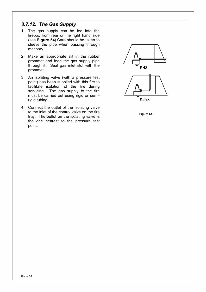
3.7.12. The Gas Supply1. The gas supply can be fed into the
firebox from rear or the right hand side (see Figure 54).Care should be taken to sleeve the pipe when passing through masonry.
2. Make an appropriate slit in the rubber grommet and feed the gas supply pipe through it. Seal gas inlet slot with the grommet.
3. An isolating valve (with a pressure test point) has been supplied with this fire to facilitate isolation of the fire during servicing. The gas supply to the fire must be carried out using rigid or semi-rigid tubing.
4. Connect the outlet of the isolating valve to the inlet of the control valve on the fire tray. The outlet on the isolating valve is the one nearest to the pressure test point.
Figure 54
Page 35
3.7.13. Fitting the Firebox (without Freedom Surround)
Before fitting the firebox it is necessary to install any fire surround that may be required.
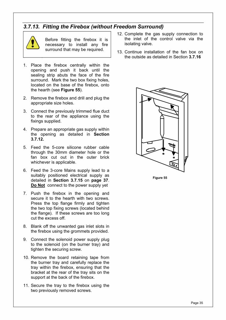
1. Place the firebox centrally within the
opening and push it back until the sealing strip abuts the face of the fire surround. Mark the two box fixing holes, located on the base of the firebox, onto the hearth (see Figure 55).
2. Remove the firebox and drill and plug the appropriate size holes.
3. Connect the previously trimmed flue duct to the rear of the appliance using the fixings supplied.
4. Prepare an appropriate gas supply within the opening as detailed in Section 3.7.12.
5. Feed the 5-core silicone rubber cable through the 30mm diameter hole or the fan box cut out in the outer brick whichever is applicable.
6. Feed the 3-core Mains supply lead to a suitably positioned electrical supply as detailed in Section 3.7.15 on page 37. Do Not connect to the power supply yet
7. Push the firebox in the opening and secure it to the hearth with two screws. Press the top flange firmly and tighten the two top fixing screws (located behind the flange). If these screws are too long cut the excess off.
8. Blank off the unwanted gas inlet slots in the firebox using the grommets provided.
9. Connect the solenoid power supply plug to the solenoid (on the burner tray) and tighten the securing screw.
10. Remove the board retaining tape from the burner tray and carefully replace the tray within the firebox, ensuring that the bracket at the rear of the tray sits on the support at the back of the firebox.
11. Secure the tray to the firebox using the two previously removed screws.
12. Complete the gas supply connection to the inlet of the control valve via the isolating valve.
13. Continue installation of the fan box on the outside as detailed in Section 3.7.16
Figure 55
Page 36
3.7.14. Fitting the Firebox (with Freedom Surround)1. Select the required gas entry point
(choice of two). After creating a slit in the grommet, route the gas supply through, leaving the remaining two intact.
2. Feed the 5-core silicone rubber cable through the 30mm diameter hole in the outer brick if applicable.
3. Feed the 3-core Mains supply lead to a suitably positioned electrical supply as detailed in Section 3.7.15 on page 37. Do Not connect to the power supply yet.
4. Place the box centrally within the Freedom Surround and push it back until the sealing foam abuts the rear.
5. Secure the base of the firebox to the base plate of the Freedom Surround using the two fixing screws supplied.
6. Secure the top of the firebox by tightening the two screws on the roof of the firebox against the Freedom Surround. (See Figure 55).
7. Connect the solenoid power supply plug to the solenoid (on the burner tray) and tighten the securing screw.
8. Remove the board retaining tape from the burner tray and carefully place the tray in the firebox ensuring that the bracket at the rear of the tray sits on the support at the back of the firebox. Secure the tray to the firebox using the two previously removed screws.
9. Connect the gas supply to the inlet of the of the control valve via the isolation valve supplied.
10. Continue installation of the fan box on the outside as detailed in Section 3.7.16
Page 37
3.7.15. Electrical WiringConnection can be made using one of the following methods:
a) A fused spur providing 230v 50Hz AC, protected with 3A fuse, located adjacent to the appliance.
b) A BS1363/A approved (three pin) plug with a 3 Amp rated fuse, can be fitted to the power supply cable on the appliance and plugging into a suitable wall socket nearby.
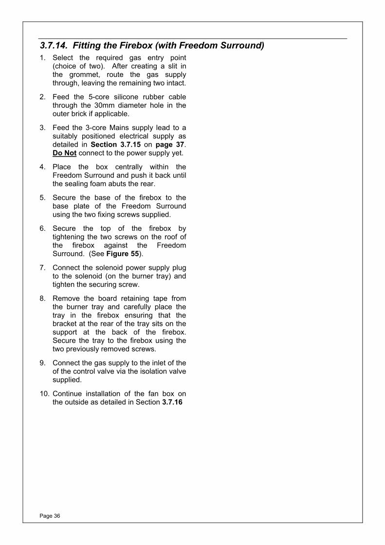
The wires in the mains power supply lead on the appliance must be connected to the plug in accordance with Figure 56.
In case the appliance needs to be isolated from the power supply (e.g. during servicing) switch off at the wall socket and REMOVE THE PLUG from the socket.
The electrical Installation must be carried out in accordance with The Current I.E.E. Wiring Regulations.
Connect BLUEto N(neutral)
Outer Sleevefirmly clamped
Cable grip
Connect BROWNto L (live)
3Amp fuse approvedto BS1362
Connect GREEN/YELLOWto E or (earth)
Figure 56
Page 38
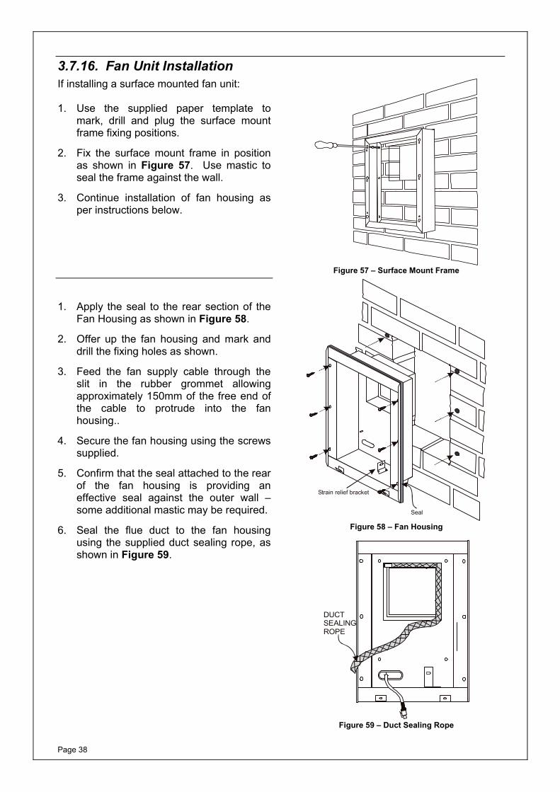
3.7.16. Fan Unit InstallationIf installing a surface mounted fan unit: 1. Use the supplied paper template to
mark, drill and plug the surface mount frame fixing positions.
2. Fix the surface mount frame in position as shown in Figure 57. Use mastic to seal the frame against the wall.
3. Continue installation of fan housing as per instructions below.
Figure 57 – Surface Mount Frame
1. Apply the seal to the rear section of the Fan Housing as shown in Figure 58.
2. Offer up the fan housing and mark and drill the fixing holes as shown.
3. Feed the fan supply cable through the slit in the rubber grommet allowing approximately 150mm of the free end of the cable to protrude into the fan housing..
4. Secure the fan housing using the screws supplied.
5. Confirm that the seal attached to the rear of the fan housing is providing an effective seal against the outer wall – some additional mastic may be required.
6. Seal the flue duct to the fan housing using the supplied duct sealing rope, as shown in Figure 59.
Seal
Strain relief bracket
Figure 58 – Fan Housing
DUCTSEALINGROPE
Figure 59 – Duct Sealing Rope
Page 39
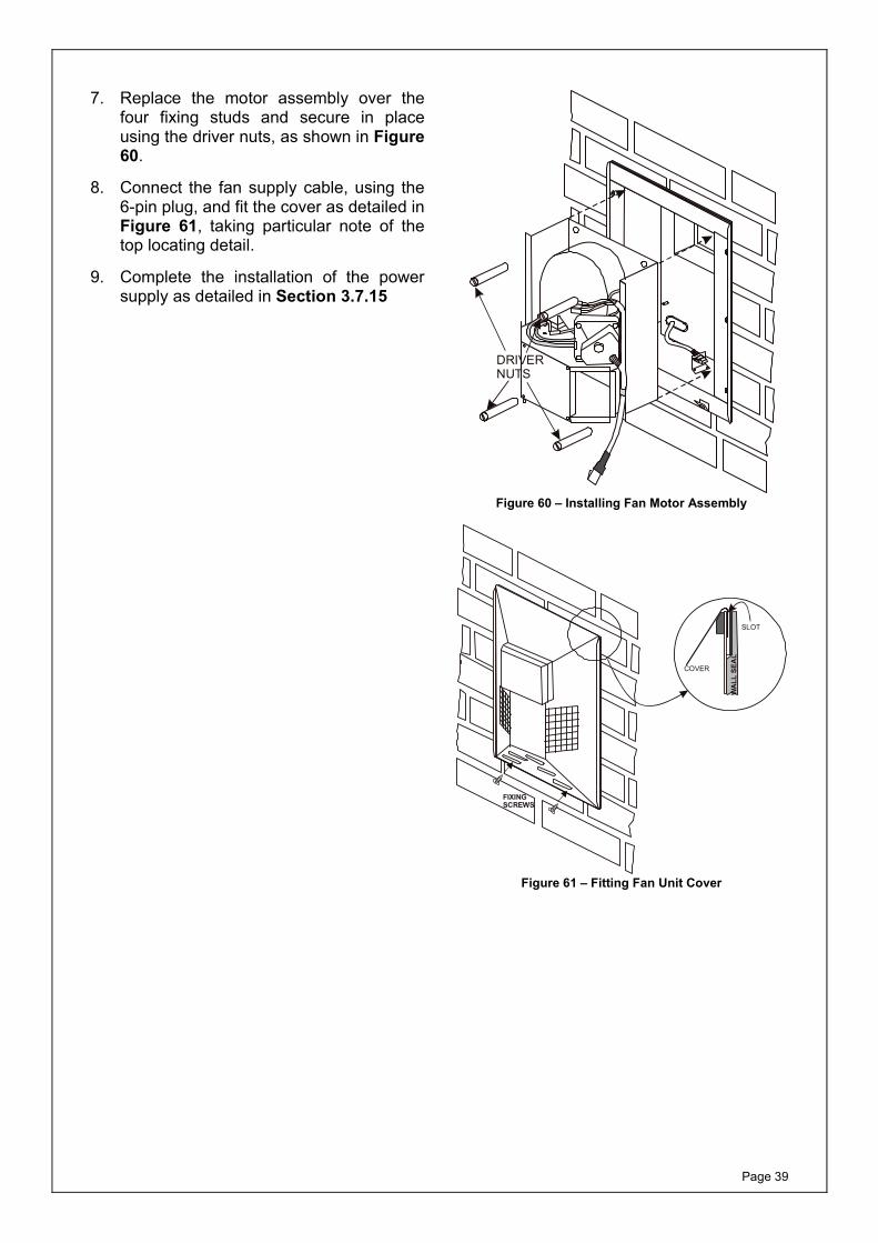
7. Replace the motor assembly over the four fixing studs and secure in place using the driver nuts, as shown in Figure 60.
8. Connect the fan supply cable, using the 6-pin plug, and fit the cover as detailed in Figure 61, taking particular note of the top locating detail.
9. Complete the installation of the power supply as detailed in Section 3.7.15
DRIVERNUTS
Figure 60 – Installing Fan Motor Assembly
COVER
SLOT
WA
LL S
EAL
FIXINGSCREWS
Figure 61 – Fitting Fan Unit Cover
Page 40
3.7.17. Commissioning the Installation1. Turn on the service cock and purge the
gas line up to the gas valve. Check all gas joints (up to solenoid valve) for gas soundness.
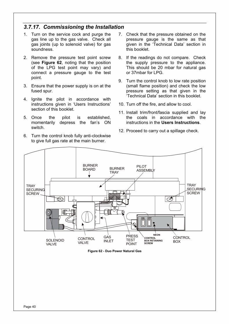
2. Remove the pressure test point screw (see Figure 62, noting that the position of the LPG test point may vary) and connect a pressure gauge to the test point.
3. Ensure that the power supply is on at the fused spur.
4. Ignite the pilot in accordance with instructions given in ‘Users Instructions’ section of this booklet.
5. Once the pilot is established, momentarily depress the fan’s ON switch.
6. Turn the control knob fully anti-clockwise to give full gas rate at the main burner.
7. Check that the pressure obtained on the pressure gauge is the same as that given in the ‘Technical Data’ section in this booklet.
8. If the readings do not compare. Check the supply pressure to the appliance. This should be 20 mbar for natural gas or 37mbar for LPG.
9. Turn the control knob to low rate position (small flame position) and check the low pressure setting as that given in the ‘Technical Data’ section in this booklet.
10. Turn off the fire, and allow to cool.
11. Install trim/front/fascia supplied and lay the coals in accordance with the instructions in the Users Instructions.
12. Proceed to carry out a spillage check.
TRAYSECURINGSCREW
TRAYSECURINGSCREW
PRESSTESTPOINT
CONTROLVALVE
BURNERBOARD
PILOTASSEMBLYBURNER
TRAY
GASINLET
ON OFF
NEONCONTROLBOX
CONTROLBOX RETAININGSCREW
SOLENOIDVALVE
Figure 62 - Duo Power Natural Gas
Page 41
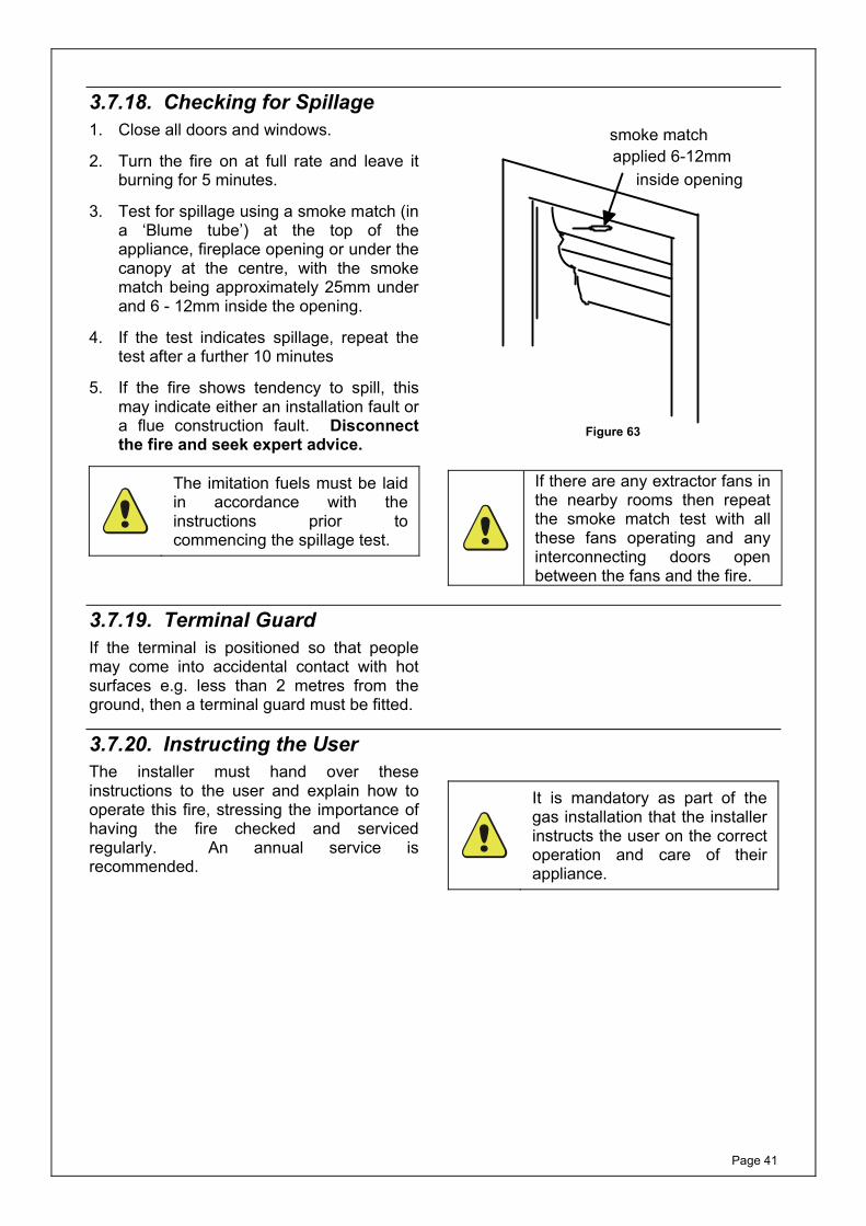
3.7.18. Checking for Spillage1. Close all doors and windows.
2. Turn the fire on at full rate and leave it burning for 5 minutes.
3. Test for spillage using a smoke match (in a ‘Blume tube’) at the top of the appliance, fireplace opening or under the canopy at the centre, with the smoke match being approximately 25mm under and 6 - 12mm inside the opening.
4. If the test indicates spillage, repeat the test after a further 10 minutes
5. If the fire shows tendency to spill, this may indicate either an installation fault or a flue construction fault. Disconnect the fire and seek expert advice.
The imitation fuels must be laid in accordance with the instructions prior to commencing the spillage test.
smoke matchapplied 6-12mm
inside opening
Figure 63
If there are any extractor fans in the nearby rooms then repeat the smoke match test with all these fans operating and any interconnecting doors open between the fans and the fire.
3.7.19. Terminal GuardIf the terminal is positioned so that people may come into accidental contact with hot surfaces e.g. less than 2 metres from the ground, then a terminal guard must be fitted.
3.7.20. Instructing the UserThe installer must hand over these instructions to the user and explain how to operate this fire, stressing the importance of having the fire checked and serviced regularly. An annual service is recommended.
It is mandatory as part of the gas installation that the installer instructs the user on the correct operation and care of their appliance.

Page 42
This page is left intentionally blank

Page 43
4. SERVICING INSTRUCTIONS
4.1. General Requirements All repairs and servicing must be carried out by a qualified registered gas installer (e.g. member of Gas Safe in GB) in accordance with the current Gas Safety (Installation and Use) Regulations and these instructions. Before any servicing is carried out ensure that the gas and electrical supply (where applicable) have been isolated. After any servicing or replacement of any parts, the appliance should be re-commissioned.
4.2. Servicing Instructions 4.2.1. Fan and Flue Servicing 1. From the outside (at the fan box) remove
the fan box cover and remove motor assembly.
2. Access to the fan impeller for cleaning is at the back of the assembly. Check for excessive soot or debris and clean as necessary.
3. With the motor assembly removed inspect the flue duct and clear any soot or debris. Refit the motor assembly and the fan box cover.
4. Ensure flue outlet terminal is not damaged and is free of obstructions.
5. With the gas and electricity supply on, and the fan on, check the ignition of the pilot. Check that the main burner cross lights satisfactorily from the pilot.
4.2.2. Servicing the Fire Refer to the section:
2.8.1 - Cleaning the Fire-Bed and the Imitation Coals/Pebbles on Page 12
then section:
2.8.2 - Cleaning the Pilot on Page 13.
On completion of the servicing, a spillage test must be carried out.

Page 44
4.3. Replacing Parts For any spare parts that are required, please contact either your supplier or the manufacturer directly. You will need the model name i.e. model number, the gas type, the type of control and serial number. Only approved parts should be used. 4.3.1. Pilot Assembly Replacement
NOTE: If any part of the pilot assembly becomes faulty then the whole pilot assembly will need changing.
1. Remove the HT lead from the end of the electrode.
2. Cut the cable tie wrap.
3. Using M9 spanner undo the thermocouple connection from behind the control valve
4. Using M10 spanner undo the pilot feed pipe nut at the pilot assembly.
5. Remove the pilot lint guard and undo the pilot assembly securing screws and withdraw the pilot assembly.
6. Refit in reverse order ensuring that the lint guard is fitted.
4.3.2. Injector Replacement1. Undo the two compression nuts on the
gas feed pipe to the injector elbow/s and remove the pipe.
2. Loosen the M5 grub screw/s securing the injector elbow/s into the venturi boss and withdraw the injector elbow/s.
3. Replace in reverse order ensuring that the replacement jet size (marked on the jet) is as given on the data badge.
4.3.3. Control Valve Replacement1. Disconnect the pilot feed pipe, the main
gas feed pipe and the thermocouple connection from the back of the valve.
2. Pull out the HT lead connection from under the electrode and cut the cable tie wrap.
3. Remove the two valve securing screw/s and withdraw the valve.
4. Refit the new valve in reverse order.
5. Roll up the excess length of HT lead and secure it to the rolled up thermocouple cable with a new tie wrap.

Page 45
4.3.4. Control Box Replacement1. With reference to Figure 62, unscrew
the control box retaining screw, until almost free.
2. By pulling the screw forward, this will release the control box from its mounting bracket.
3. The control box may now be drawn forward revealing a 12-pin plug, which can be removed to allow a replacement control box to be fitted.
4. Locate the control box back over its mounting bracket and tighten the retaining screw, locking the control box back into place.
4.3.5. Replacing the Solenoid Valve 1. Disconnect the gas to the burner tray
and disconnect the solenoid supply lead.
2. Whilst holding the main body of the valve, carefully undo the solenoid and replace with the new unit.
3. Tighten the connection.
4. Reconnect the plug and socket.
5. Test all joints for gas soundness.
4.3.6. Replacing the Air Pressure Switch 1. Remove the fan box cover.
2. Disconnect the air pressure tubes, noting that the red tube is connected to the positive outlet, and the blue tube to the negative outlet.
3. Remove the triangular cover from the air pressure switch, and disconnect the 3 spade terminals, noting their configuration, see Figure 64.
4. Remove the air pressure switch by undoing 2 Philips screws and fitting the replacement in reverse order.
WARNING: Replacement air pressure switch must originate from the manufacturer of the appliance, and setting pressures confirmed.

Page 46
4.4. Installation and Operational Troubleshooting The table below is intended for problems related to the fire and its gas controls. It is a guide only and does not take into account every eventuality. The fan system is dealt with in later sections. Servicing must be carried out in accordance with the current Gas Safety (Installation and Use) Regulations, by a competent person.
It is recommended that the purchaser seek the advice of the original installer in case of encountering any problems.
Symptom Cause Remedy
No spark appears at the electrode
a) Electrode cracked or broken Replace pilot assembly
b) HT lead shorting out on burner body
Establish where spark is occurring and insulate or re-route lead accordingly.
c) Faulty spark generator Replace valve
Piezo operates normally but pilot will not light
a) No gas supply Check isolation valve/supply
b) Pilot jet blocked Replace pilot assembly
Pilot lights, but goes out when control is released
a) Loose thermocouple connection at control valve end
Remake thermocouple ensuring the connection is firm
b) Faulty Thermocouple Replace complete pilot assembly
Pilot and main burner go out when control is set to high position
a) Gas supply partially blocked Locate restrict and remove faulty section
b) Too many bends on gas inlet pipe
Increase diameter and/or reduce the number of bends
c) Pilot jet partially blocked Replace complete pilot assembly
d) Restriction at Isolation valve Ensure valve is fully open and that internal diameter is sufficient and free from grease
Fire burns with flames only on one side
a) Imitation fuel layout incorrect Re-lay imitation fuel in accordance with instructions
b) Excessive draught Establish cause and rectify
Warning: If you are in any doubt about the clearance of fumes, you must stop using the appliance immediately and seek expert advice. Do not use appliance until the fault has been rectified.
NOTE: If any part of the pilot assembly (i.e. thermocouple, electrode, jet or burner) becomes faulty the whole pilot assembly will need changing.

Page 47
NOTE: For any spare parts that are required, please contact either your supplier or the manufacturer directly. You will need the model name i.e. Model Number, the gas type, the type of control and serial number. Only approved parts should be used.
Page 48
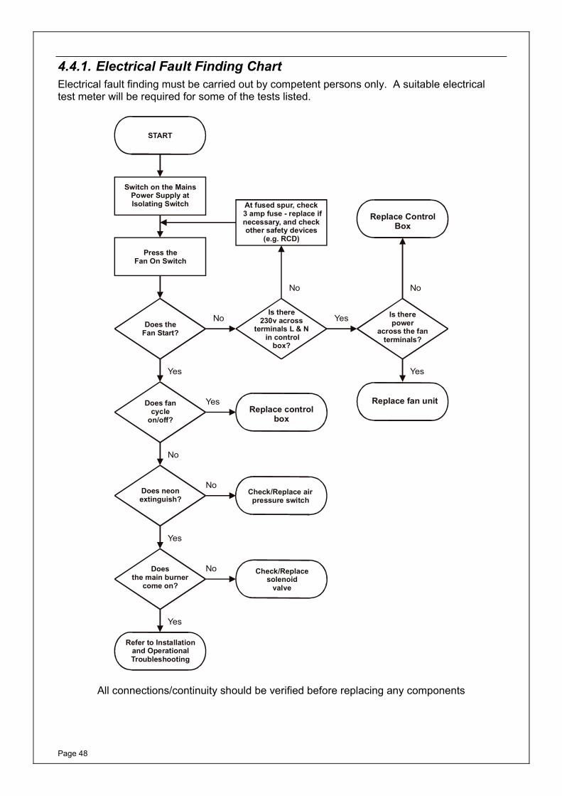
4.4.1. Electrical Fault Finding Chart Electrical fault finding must be carried out by competent persons only. A suitable electrical test meter will be required for some of the tests listed.
Switch on the Mains Power Supply at Isolating Switch
START
At fused spur, check 3 amp fuse - replace if necessary, and check other safety devices
(e.g. RCD)
Replace ControlBox
Replace controlbox
Replace fan unit
Check/Replace air pressure switch
Check/Replace solenoid
valve
Refer to Installation and Operational Troubleshooting
Does neon extinguish?
Does the main burner
come on?
Is there power
across the fan terminals?
Is there 230v across
terminals L & N in control
box?
Does fan cycle
on/off?
Does the Fan Start?
Press the Fan On Switch
Yes
Yes
Yes
Yes
Yes
Yes
No
No
No
No
No No
All connections/continuity should be verified before replacing any components
Page 49
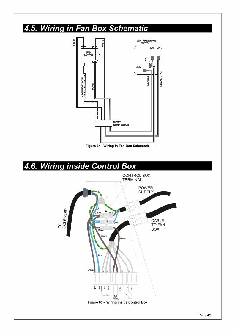
4.5. Wiring in Fan Box Schematic
Figure 64 - Wiring in Fan Box Schematic
4.6. Wiring inside Control Box
COM
MO
N
LOW
Blue
Blu
e
Blue
Brown
HIG
H
FANGASVALVE
CO
M
NO
NC
POWERSUPPLY
CONTROL BOXTERMINAL
CABLETO FANBOXTO
SO
LEN
OID
124 356
Brown
Brown
Brown Brown
Brown
Figure 65 – Wiring inside Control Box

Page 50
This page is left intentionally blank

Page 51
This page is left intentionally blank

MF388.5
Burley Magiglo fires are protected by UK patents 2193802, 2240620 and 2256920
Other Patents Pending
Magiglo is a registered trademark of Burley Appliances Ltd
Burley Appliances Ltd, Lands End Way Oakham, Rutland, LE15 6RB
Tel: 01572 725570 Fax: 01572 724390
www.magiglo.co.uk Email: [email protected]


![[MTX and NITRO 2] "Power Duo"](https://img.pdfslide.us/doc/110x75/577cc9b91a28aba711a47100/mtx-and-nitro-2-power-duo.jpg)