Embed Size (px)
Citation preview
lightweight composite panels
DuFLEX ®
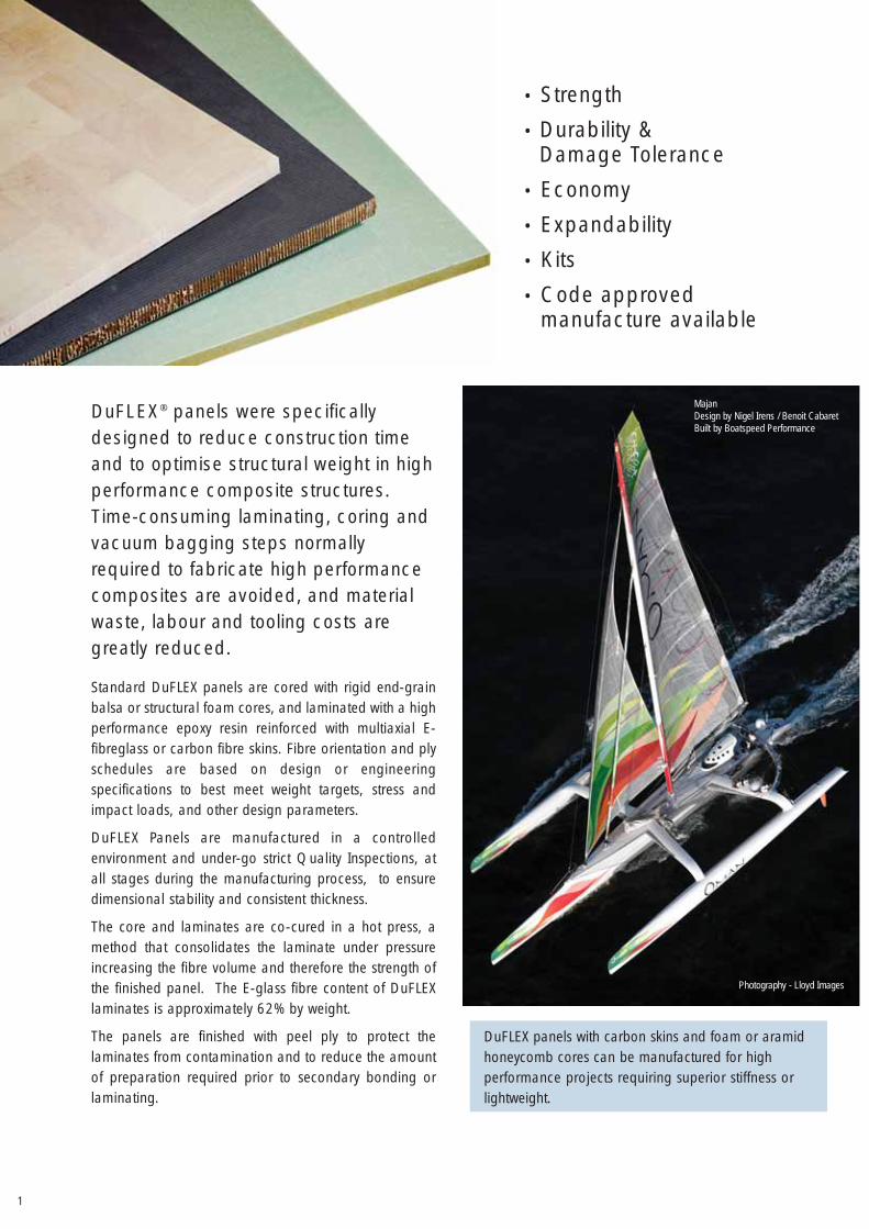
DuFLEX® panels were specificallydesigned to reduce construction timeand to optimise structural weight in highperformance composite structures.Time-consuming laminating, coring andvacuum bagging steps normallyrequired to fabricate high performancecomposites are avoided, and materialwaste, labour and tooling costs aregreatly reduced.
Standard DuFLEX panels are cored with rigid end-grainbalsa or structural foam cores, and laminated with a highperformance epoxy resin reinforced with multiaxial E-fibreglass or carbon fibre skins. Fibre orientation and plyschedules are based on design or engineeringspecifications to best meet weight targets, stress andimpact loads, and other design parameters.
DuFLEX Panels are manufactured in a controlledenvironment and under-go strict Quality Inspections, atall stages during the manufacturing process, to ensuredimensional stability and consistent thickness.
The core and laminates are co-cured in a hot press, amethod that consolidates the laminate under pressureincreasing the fibre volume and therefore the strength ofthe finished panel. The E-glass fibre content of DuFLEXlaminates is approximately 62% by weight.
The panels are finished with peel ply to protect thelaminates from contamination and to reduce the amountof preparation required prior to secondary bonding orlaminating.
DuFLEX panels with carbon skins and foam or aramidhoneycomb cores can be manufactured for highperformance projects requiring superior stiffness orlightweight.
• Strength
• Durability &Damage Tolerance
• Economy
• Expandability
• Kits
• Code approvedmanufacture available
1
Photography - Lloyd Images
MajanDesign by Nigel Irens / Benoit CabaretBuilt by Boatspeed Performance
2
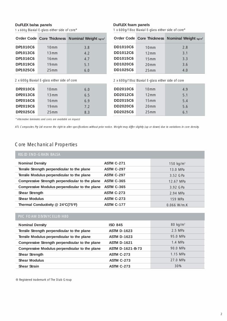
ATL Composites Pty Ltd reserve the right to alter specifications without prior notice. Weight may differ slightly (up or down) due to variations in core density.
* Alternative laminates and cores are available on request
Nominal Weight kg/m2Order Code
DP1010C6
DP1013C6
DP1016C6
DP1019C6
DP1025C6
Core Thickness
10mm
13mm
16mm
19mm
25mm
3.8
4.2
4.7
5.1
6.0
Nominal Weight kg/m2Order Code
DD1010C6
DD1012C6
DD1015C6
DD1020C6
DD1025C6
Core Thickness
10mm
12mm
15mm
20mm
25mm
2.8
3.1
3.3
3.6
4.0
DuFLEX balsa panels 1 x 600g Biaxial E-glass either side of core*
DuFLEX foam panels 1 x 600g/18oz Biaxial E-glass either side of core*
DP2010C6
DP2013C6
DP2016C6
DP2019C6
DP2025C6
10mm
13mm
16mm
19mm
25mm
6.0
6.5
6.9
7.2
8.3
2 x 600g/18oz Biaxial E-glass either side of core
DD2010C6
DD2012C6
DD2015C6
DD2020C6
DD2025C6
10mm
12mm
15mm
20mm
25mm
4.9
5.1
5.4
5.6
6.1
2 x 600g Biaxial E-glass either side of core
Core Mechanical Properties
PVC FOAM DIVINYCELL® H80
80 kg/m3
2.5 MPa
95.0 MPa
1.4 MPa
90.0 MPa
1.15 MPa
27.0 MPa
30%
Nominal Density ASTM C-271
Tensile Strength perpendicular to the plane ASTM C-297
Tensile Modulus perpendicular to the plane ASTM C-297
Compressive Strength perpendicular to the plane ASTM C-365
Compressive Modulus perpendicular to the plane ASTM C-365
Shear Strength ASTM C-273
Shear Modulus ASTM C-273
Thermal Conductivity @ 24oC(75oF) ASTM C-177
Nominal Density ISO 845
Tensile Strength perpendicular to the plane ASTM D-1623
Tensile Modulus perpendicular to the plane ASTM D-1623
Compressive Strength perpendicular to the plane ASTM D-1621
Compressive Modulus perpendicular to the plane ASTM D-1621-B-73
Shear Strength ASTM C-273
Shear Modulus ASTM C-273
Shear Strain ASTM C-273
RIGID END-GRAIN BALSA
150 kg/m3
13.0 MPa
3.52 GPa
12.67 MPa
3.92 GPa
2.94 MPa
159 MPa
0.066 W/m.K
® Registered trademark of The Diab Group
3
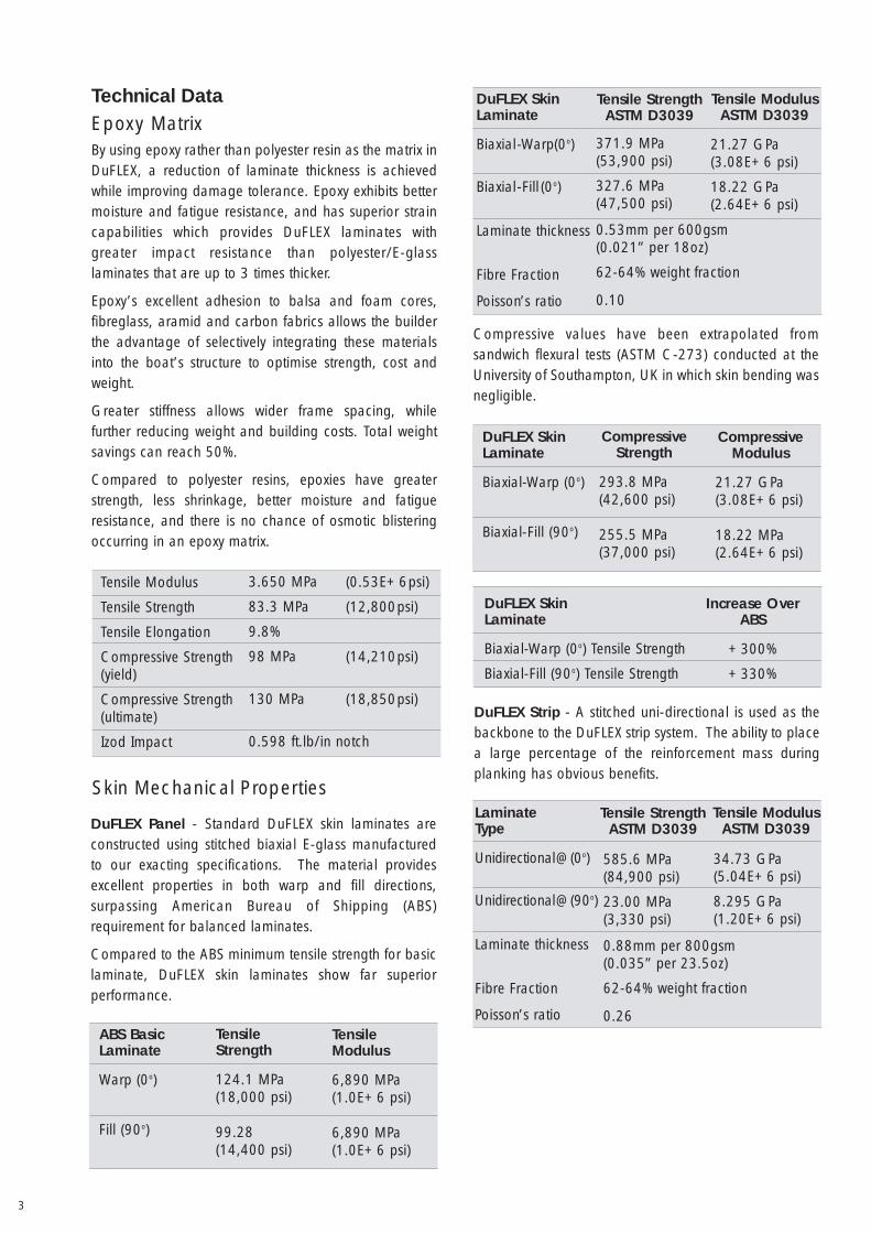
Technical DataEpoxy MatrixBy using epoxy rather than polyester resin as the matrix inDuFLEX, a reduction of laminate thickness is achievedwhile improving damage tolerance. Epoxy exhibits bettermoisture and fatigue resistance, and has superior straincapabilities which provides DuFLEX laminates withgreater impact resistance than polyester/E-glasslaminates that are up to 3 times thicker.
Epoxy’s excellent adhesion to balsa and foam cores,fibreglass, aramid and carbon fabrics allows the builderthe advantage of selectively integrating these materialsinto the boat’s structure to optimise strength, cost andweight.
Greater stiffness allows wider frame spacing, whilefurther reducing weight and building costs. Total weightsavings can reach 50%.
Compared to polyester resins, epoxies have greaterstrength, less shrinkage, better moisture and fatigueresistance, and there is no chance of osmotic blisteringoccurring in an epoxy matrix.
Tensile Modulus
Tensile Strength
Tensile Elongation
Compressive Strength(yield)
Compressive Strength(ultimate)
Izod Impact
3.650 MPa
83.3 MPa
9.8%
98 MPa
130 MPa
0.598 ft.lb/in notch
(0.53E+6psi)
(12,800psi)
(14,210psi)
(18,850psi)
Skin Mechanical Properties
ABS BasicLaminate
Warp (0o)
Fill (90o)
TensileStrength
124.1 MPa(18,000 psi)
99.28(14,400 psi)
TensileModulus
6,890 MPa(1.0E+6 psi)
6,890 MPa(1.0E+6 psi)
DuFLEX Panel - Standard DuFLEX skin laminates areconstructed using stitched biaxial E-glass manufacturedto our exacting specifications. The material providesexcellent properties in both warp and fill directions,surpassing American Bureau of Shipping (ABS)requirement for balanced laminates.
Compared to the ABS minimum tensile strength for basiclaminate, DuFLEX skin laminates show far superiorperformance.
DuFLEX SkinLaminate
Biaxial-Warp (0o)
Biaxial-Fill (90o)
CompressiveStrength
293.8 MPa(42,600 psi)
255.5 MPa(37,000 psi)
CompressiveModulus
21.27 GPa(3.08E+6 psi)
18.22 MPa(2.64E+6 psi)
DuFLEX SkinLaminate
Biaxial-Warp (0o) Tensile Strength
Biaxial-Fill (90o) Tensile Strength
Increase OverABS
+300%
+330%
DuFLEX SkinLaminate
Biaxial-Warp(0o)
Biaxial-Fill (0o)
Laminate thickness
Fibre Fraction
Poisson’s ratio
371.9 MPa(53,900 psi)
327.6 MPa(47,500 psi)
0.53mm per 600gsm(0.021” per 18oz)
62-64% weight fraction
0.10
Tensile ModulusASTM D3039
21.27 GPa(3.08E+6 psi)
18.22 GPa(2.64E+6 psi)
Compressive values have been extrapolated fromsandwich flexural tests (ASTM C-273) conducted at theUniversity of Southampton, UK in which skin bending wasnegligible.
DuFLEX Strip - A stitched uni-directional is used as thebackbone to the DuFLEX strip system. The ability to placea large percentage of the reinforcement mass duringplanking has obvious benefits.
LaminateType
Unidirectional@(0o)
Unidirectional@(90o)
Laminate thickness
Fibre Fraction
Poisson’s ratio
585.6 MPa(84,900 psi)
23.00 MPa(3,330 psi)
0.88mm per 800gsm(0.035” per 23.5oz)
62-64% weight fraction
0.26
34.73 GPa(5.04E+6 psi)
8.295 GPa(1.20E+6 psi)
Tensile StrengthASTM D3039
Tensile StrengthASTM D3039
Tensile ModulusASTM D3039
4
4
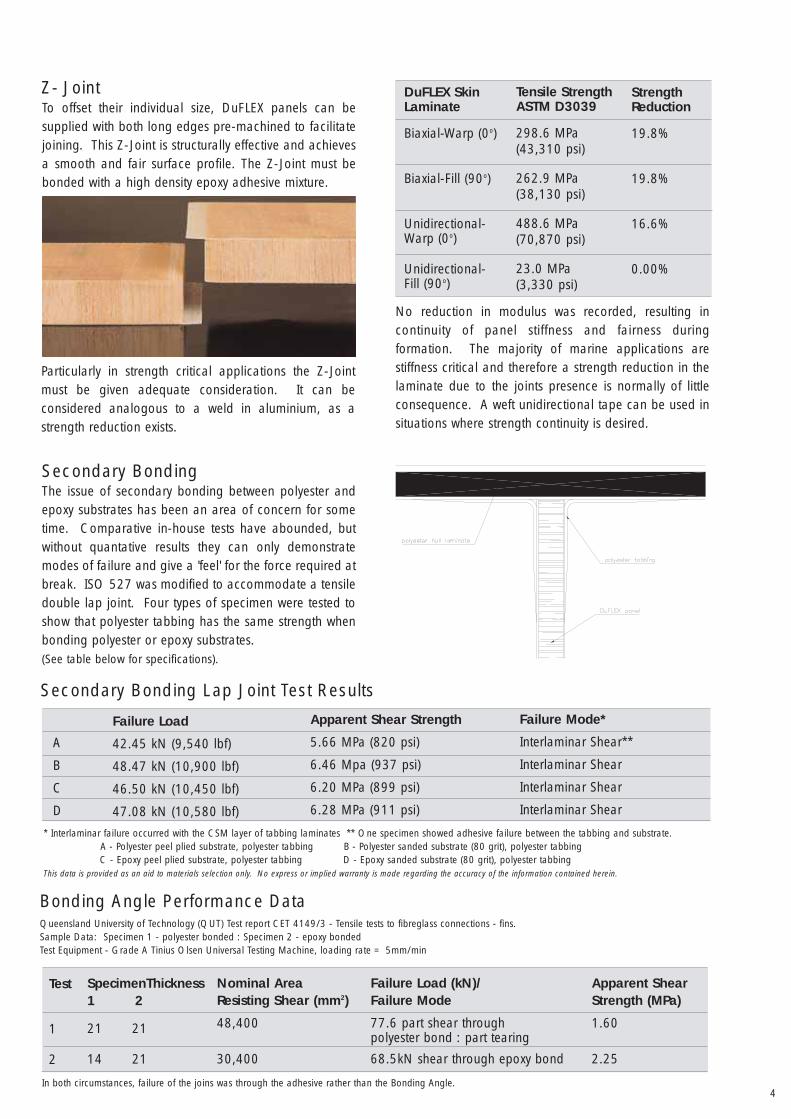
Z- Joint
Particularly in strength critical applications the Z-Jointmust be given adequate consideration. It can beconsidered analogous to a weld in aluminium, as astrength reduction exists.
To offset their individual size, DuFLEX panels can besupplied with both long edges pre-machined to facilitatejoining. This Z-Joint is structurally effective and achievesa smooth and fair surface profile. The Z-Joint must bebonded with a high density epoxy adhesive mixture.
DuFLEX SkinLaminate
Biaxial-Warp (0o)
Biaxial-Fill (90o)
Unidirectional-Warp (0o)
Unidirectional-Fill (90o)
Tensile StrengthASTM D3039
298.6 MPa(43,310 psi)
262.9 MPa(38,130 psi)
488.6 MPa(70,870 psi)
23.0 MPa(3,330 psi)
StrengthReduction
19.8%
19.8%
16.6%
0.00%
No reduction in modulus was recorded, resulting incontinuity of panel stiffness and fairness duringformation. The majority of marine applications arestiffness critical and therefore a strength reduction in thelaminate due to the joints presence is normally of littleconsequence. A weft unidirectional tape can be used insituations where strength continuity is desired.
Secondary BondingThe issue of secondary bonding between polyester andepoxy substrates has been an area of concern for sometime. Comparative in-house tests have abounded, butwithout quantative results they can only demonstratemodes of failure and give a 'feel' for the force required atbreak. ISO 527 was modified to accommodate a tensiledouble lap joint. Four types of specimen were tested toshow that polyester tabbing has the same strength whenbonding polyester or epoxy substrates. (See table below for specifications).
Secondary Bonding Lap Joint Test Results
Failure Load
42.45 kN (9,540 lbf)
48.47 kN (10,900 lbf)
46.50 kN (10,450 lbf)
47.08 kN (10,580 lbf)
Apparent Shear Strength
5.66 MPa (820 psi)
6.46 Mpa (937 psi)
6.20 MPa (899 psi)
6.28 MPa (911 psi)
Failure Mode*
Interlaminar Shear**
Interlaminar Shear
Interlaminar Shear
Interlaminar Shear
A
B
C
D
* Interlaminar failure occurred with the CSM layer of tabbing laminates ** One specimen showed adhesive failure between the tabbing and substrate.A - Polyester peel plied substrate, polyester tabbing B - Polyester sanded substrate (80 grit), polyester tabbingC - Epoxy peel plied substrate, polyester tabbing D - Epoxy sanded substrate (80 grit), polyester tabbing
This data is provided as an aid to materials selection only. No express or implied warranty is made regarding the accuracy of the information contained herein.
Test
1
2
SpecimenThickness1 2
21 21
14 21
Nominal AreaResisting Shear (mm2)
48,400
30,400
Failure Load (kN)/Failure Mode
77.6 part shear throughpolyester bond : part tearing
68.5kN shear through epoxy bond
Apparent ShearStrength (MPa)
1.60
2.25
Bonding Angle Performance DataQueensland University of Technology (QUT) Test report CET 4149/3 - Tensile tests to fibreglass connections - fins.Sample Data: Specimen 1 - polyester bonded : Specimen 2 - epoxy bondedTest Equipment - Grade A Tinius Olsen Universal Testing Machine, loading rate = 5mm/min
In both circumstances, failure of the joins was through the adhesive rather than the Bonding Angle.
5
Technology vs Cost - KitsWhether in computers, airplanes or boats, high tech isoften associated with high cost.
Time is valuable and there is no doubt that DuFLEX,especially in kit form, speeds up construction of the basichull and deck. Hours saved in construction time will goa long way to pay the extra cost of the materials.
With the DuFLEX system, boatbuilders can usewidely spaced temporary female frames, or place hullpanels over bulkheads which are aligned upside downover strongbacks. Large parts, for example a topsidepanel, may extend through two or more panels, so thepanels are joined before the tabs are cut. Flat surfacessuch as floors, walls and bulkheads are used as-cut, andcurved surfaces are created by bending the flat panelsinto the required shape.
A strong, lightweight monocoque structure is achievedafter adjacent parts and internal support structures arebonded together. On the hull interior, the joints areepoxy/fibreglass taped at points where differently angledpanels meet; typically the keel, gunnels and chines.
The panels are designed to provide a fair surface on thehull exterior, and while the builder may choose to addlaminate for aesthetic or other reasons, it's not requiredstructurally.
Computer aided design and manufacture (CAD/CAM)processes combined with computer numeric control(CNC) equipment allows the production of pre-fabricatedDuFLEX Kits. The kit form process is practical even forone-off kit sets if the part files are available from a navalarchitect or designer. Parts to be formed into curvedsurfaces can be translated by design software into thecorrect flat panel shapes, and this electronic informationis supplied to vdL's engineers, by your Naval Architect ordesigner. All parts required for the project are nestedtogether within the panels to reduce wastage.
Once the panels are manufactured, the CAD informationis used by a CNC router to machine the programmedshapes into the panels.
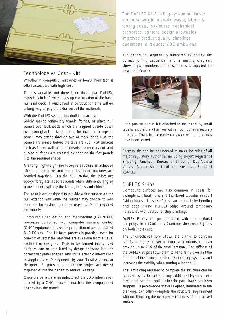
The panels are sequentially numbered to indicate thecorrect joining sequence, and a nesting diagram,showing part numbers and descriptions is supplied foreasy identification.
Each pre-cut part is left attached to the panel by smalltabs to ensure the kit arrives with all components securelyin place. The tabs are easily cut away, when the panelshave been joined.
Custom kits can be engineered to meet the rules of allmajor regulatory authorities including Lloyd's Register ofShipping, American Bureau of Shipping, Det NorskeVeritas, Germanishcer Lloyd and Australian StandardAS4132.
The DuFLEX Kit-Building system minimisesstructural weight, material waste, labour &tooling costs, maximises mechanicalproperties, tightens design allowables,improves product quality, simplifiesquotations, & reduces VOC emissions.
DuFLEX StripsCompound surfaces are also common in boats, forexample sail boat hulls and the flared topsides in sportfishing boats. These surfaces can be made by bendingand edge gluing DuFLEX Strips around temporaryframes, as with traditional strip planking.
DuFLEX Panels are pre-laminated with unidirectionalpre-pregs, in a 1200mm x 2400mm sheet with Z-Jointson both short ends.
The unidirectional fibre allows the planks to conformreadily to highly convex or concave contours and canprovide up to 50% of the total laminate. The stiffness ofthe DuFLEX Strips allows them to bend fairly over half thenumber of the frames required by other strip systems, andincreases the stability when turning a boat hull.
The laminating required to complete the structure can bereduced by up to half and any additional layers of rein-forcement can be applied after the part shape has beenstripped. Tapered-edge triaxial E-glass, laminated to theplanking, can often complete the structural requirementwithout disturbing the near-perfect fairness of the plankedsurface.
6
To compliment the DuFLEX® SystemCNC-routed temporary frames
CNC-routed plywood or MDF (medium density fibre-board) temporary frames can also be supplied to providethe builder with accurate sections, cut exactly to drawingspecifications.
CNC-routed plywood, or MDF jigs can be supplied by ATL Composites
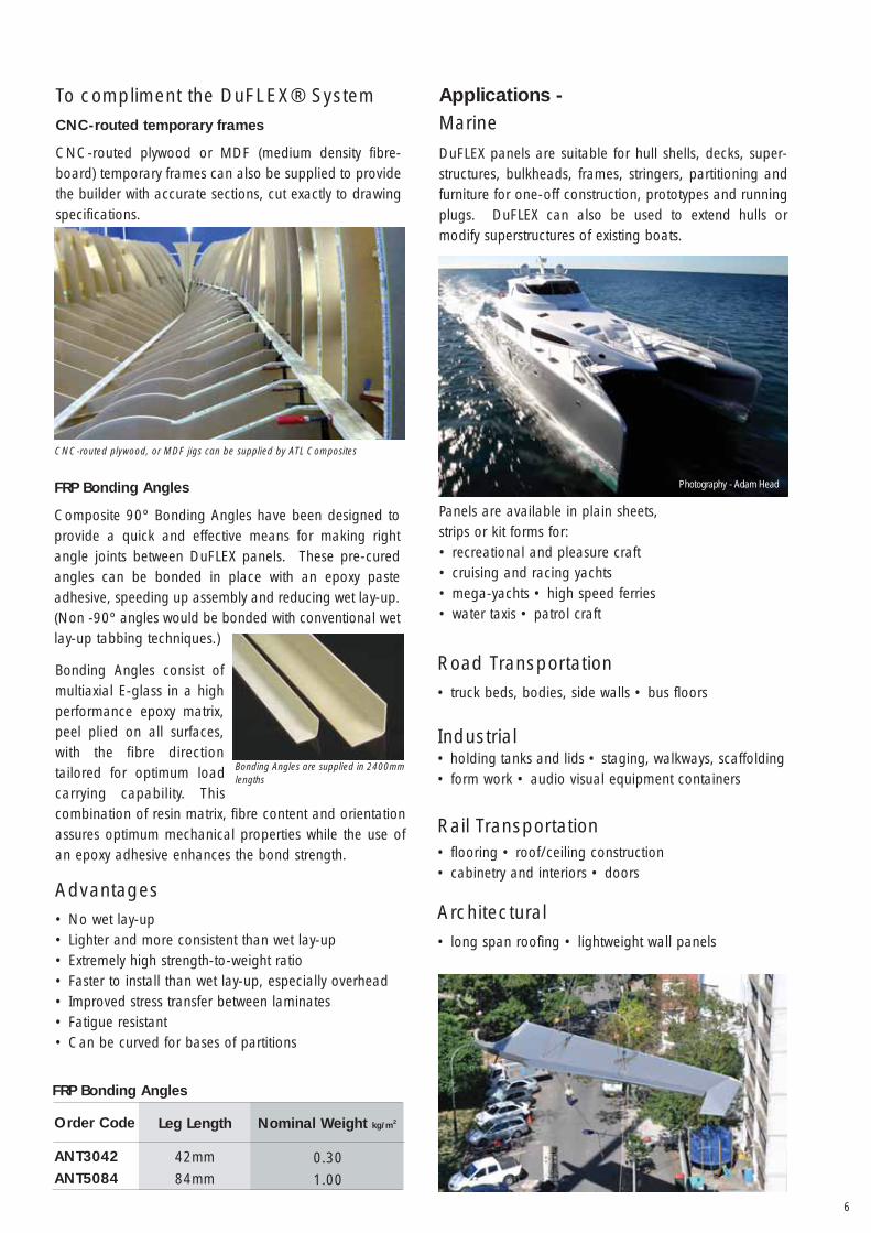
Applications -Marine
Road Transportation• truck beds, bodies, side walls • bus floors
Industrial• holding tanks and lids • staging, walkways, scaffolding• form work • audio visual equipment containers
Rail Transportation• flooring • roof/ceiling construction• cabinetry and interiors • doors
Architectural• long span roofing • lightweight wall panels
DuFLEX panels are suitable for hull shells, decks, super-structures, bulkheads, frames, stringers, partitioning andfurniture for one-off construction, prototypes and runningplugs. DuFLEX can also be used to extend hulls ormodify superstructures of existing boats.
Panels are available in plain sheets,strips or kit forms for:• recreational and pleasure craft• cruising and racing yachts• mega-yachts • high speed ferries• water taxis • patrol craft
Bonding Angles consist ofmultiaxial E-glass in a highperformance epoxy matrix,peel plied on all surfaces,with the fibre directiontailored for optimum loadcarrying capability. Thiscombination of resin matrix, fibre content and orientationassures optimum mechanical properties while the use ofan epoxy adhesive enhances the bond strength.
Advantages• No wet lay-up• Lighter and more consistent than wet lay-up• Extremely high strength-to-weight ratio• Faster to install than wet lay-up, especially overhead• Improved stress transfer between laminates• Fatigue resistant• Can be curved for bases of partitions
FRP Bonding Angles
Composite 90º Bonding Angles have been designed toprovide a quick and effective means for making rightangle joints between DuFLEX panels. These pre-curedangles can be bonded in place with an epoxy pasteadhesive, speeding up assembly and reducing wet lay-up.(Non -90º angles would be bonded with conventional wetlay-up tabbing techniques.)
Bonding Angles are supplied in 2400mmlengths
Nominal Weight kg/m2Order Code
ANT3042
ANT5084
Leg Length
42mm
84mm0.30
1.00
FRP Bonding Angles
Photography - Adam Head
7
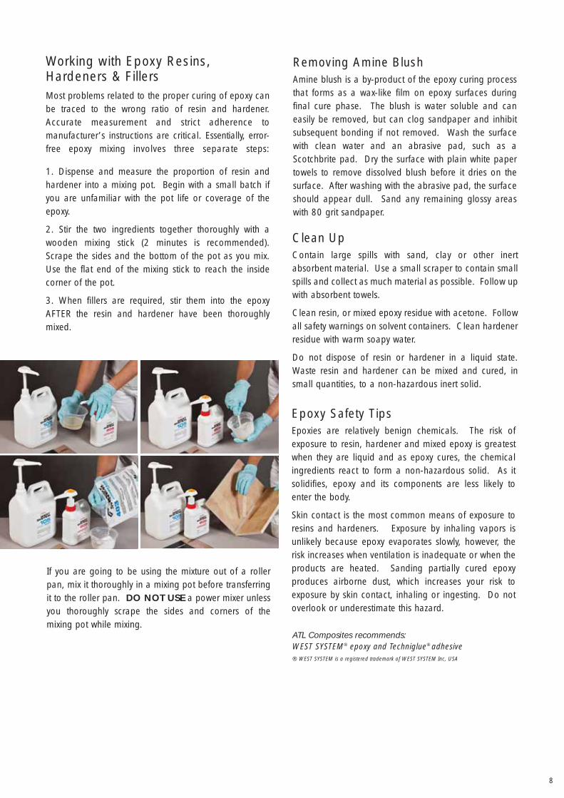
Applying Adhesive to the Z-JointPrior to applying adhesiveto the Z-Joint, carefullyremove approximately25mm of peelply from theoutside edge of the malescarf, taking care not todamage the laminate.Scarfs should be brushedwith a clean brush toremove dust and any con-tamination that wouldinhibit adhesion.
It is important to apply enough high-density adhesive tocover both Z-joints and exposed core, and to allowadequate squeeze out when the joints are pushedtogether.
The panels should be pushed together by sliding themback and forth to make a tight join of no more than1mm, prior to applying pressure with the Z-Press ormanual joining strips.
Basic Techniques
Step1
Take two strips of 100mm wide, 19mm MDF (fibreboard)the length of the long side of the composite panel(2400mm). Cover one side of each strip with plastic tapeas shown. Drill pairs of 3mm (approx.) screw holes,30mm each side ofcentre, throughone strip at 100mmcentres.
Step2
Apply a high-density epoxy adhesive to both Z-Joints,making sure there is adequate adhesive to cover allcore and scarfjoint areas, andpush jointstogether with amaximum gap of1mm.
Step 3
Lay the strip with no holes, plasticside up, underneaththe glue joint;lay the holed strip,plastic side down,on top of the gluejoint.
Step 4
Screw through theholed top strip intothe bottom strip,ensuring faces aresqueezed together firmly.Leave to cure overnight.
Manual Edge Joining Instructions
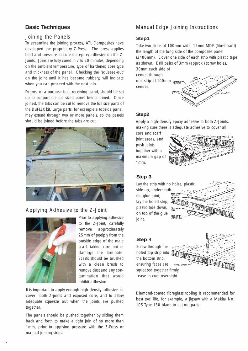
Joining the PanelsTo streamline the joining process, ATL Composites havedeveloped the proprietary Z-Press. The press appliesheat and pressure to cure the epoxy adhesive on the Z-Joints. Joins are fully cured in 7 to 20 minutes, dependingon the ambient temperature, type of hardener, core typeand thickness of the panel. Checking the "squeeze-out"on the joint until it has become rubbery, will indicatewhen you can proceed with the next join.
Drums, or a purpose-built receiving stand, should be setup to support the full sized panel being joined. Oncejoined, the tabs can be cut to remove the full size parts ofthe DuFLEX kit. Large parts, for example a topside panel,may extend through two or more panels, so the panelsshould be joined before the tabs are cut.
Diamond-coated fibreglass tooling is recommended forbest tool life, for example, a jigsaw with a Makita No.10S Type 150 blade to cut out parts.
8
Working with Epoxy Resins,Hardeners & FillersMost problems related to the proper curing of epoxy canbe traced to the wrong ratio of resin and hardener.Accurate measurement and strict adherence tomanufacturer’s instructions are critical. Essentially, error-free epoxy mixing involves three separate steps:
1. Dispense and measure the proportion of resin andhardener into a mixing pot. Begin with a small batch ifyou are unfamiliar with the pot life or coverage of theepoxy.
2. Stir the two ingredients together thoroughly with awooden mixing stick (2 minutes is recommended).Scrape the sides and the bottom of the pot as you mix.Use the flat end of the mixing stick to reach the insidecorner of the pot.
3. When fillers are required, stir them into the epoxyAFTER the resin and hardener have been thoroughlymixed.
If you are going to be using the mixture out of a rollerpan, mix it thoroughly in a mixing pot before transferringit to the roller pan. DO NOT USE a power mixer unlessyou thoroughly scrape the sides and corners of themixing pot while mixing.
Removing Amine BlushAmine blush is a by-product of the epoxy curing processthat forms as a wax-like film on epoxy surfaces duringfinal cure phase. The blush is water soluble and caneasily be removed, but can clog sandpaper and inhibitsubsequent bonding if not removed. Wash the surfacewith clean water and an abrasive pad, such as aScotchbrite pad. Dry the surface with plain white papertowels to remove dissolved blush before it dries on thesurface. After washing with the abrasive pad, the surfaceshould appear dull. Sand any remaining glossy areaswith 80 grit sandpaper.
Epoxy Safety TipsEpoxies are relatively benign chemicals. The risk ofexposure to resin, hardener and mixed epoxy is greatestwhen they are liquid and as epoxy cures, the chemicalingredients react to form a non-hazardous solid. As itsolidifies, epoxy and its components are less likely toenter the body.
Skin contact is the most common means of exposure toresins and hardeners. Exposure by inhaling vapors isunlikely because epoxy evaporates slowly, however, therisk increases when ventilation is inadequate or when theproducts are heated. Sanding partially cured epoxyproduces airborne dust, which increases your risk toexposure by skin contact, inhaling or ingesting. Do notoverlook or underestimate this hazard.
Clean UpContain large spills with sand, clay or other inertabsorbent material. Use a small scraper to contain smallspills and collect as much material as possible. Follow upwith absorbent towels.
Clean resin, or mixed epoxy residue with acetone. Followall safety warnings on solvent containers. Clean hardenerresidue with warm soapy water.
Do not dispose of resin or hardener in a liquid state.Waste resin and hardener can be mixed and cured, insmall quantities, to a non-hazardous inert solid.
ATL Composites recommends:WEST SYSTEM® epoxy and Techniglue® adhesive ® WEST SYSTEM is a registered trademark of WEST SYSTEM Inc, USA
9
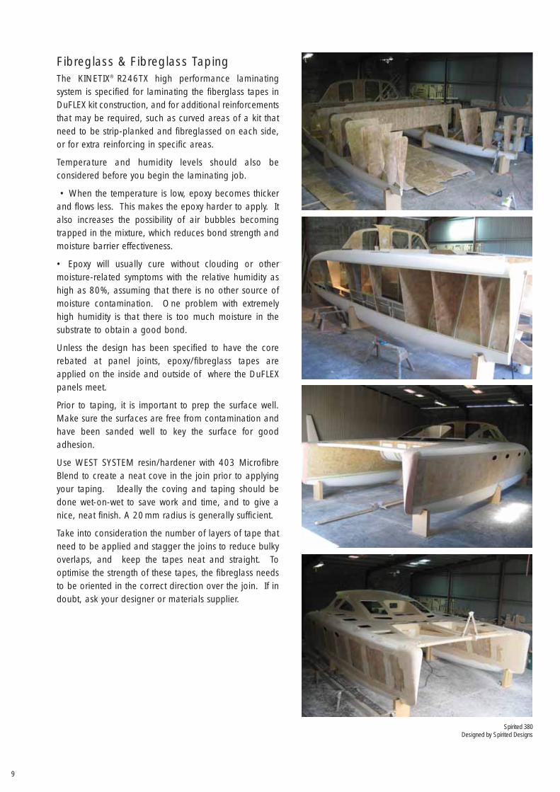
Fibreglass & Fibreglass TapingThe KINETIX® R246TX high performance laminatingsystem is specified for laminating the fiberglass tapes inDuFLEX kit construction, and for additional reinforcementsthat may be required, such as curved areas of a kit thatneed to be strip-planked and fibreglassed on each side,or for extra reinforcing in specific areas.
Temperature and humidity levels should also beconsidered before you begin the laminating job.
• When the temperature is low, epoxy becomes thickerand flows less. This makes the epoxy harder to apply. Italso increases the possibility of air bubbles becomingtrapped in the mixture, which reduces bond strength andmoisture barrier effectiveness.
• Epoxy will usually cure without clouding or othermoisture-related symptoms with the relative humidity ashigh as 80%, assuming that there is no other source ofmoisture contamination. One problem with extremelyhigh humidity is that there is too much moisture in thesubstrate to obtain a good bond.
Unless the design has been specified to have the corerebated at panel joints, epoxy/fibreglass tapes areapplied on the inside and outside of where the DuFLEXpanels meet.
Prior to taping, it is important to prep the surface well.Make sure the surfaces are free from contamination andhave been sanded well to key the surface for goodadhesion.
Use WEST SYSTEM resin/hardener with 403 MicrofibreBlend to create a neat cove in the join prior to applyingyour taping. Ideally the coving and taping should bedone wet-on-wet to save work and time, and to give anice, neat finish. A 20mm radius is generally sufficient.
Take into consideration the number of layers of tape thatneed to be applied and stagger the joins to reduce bulkyoverlaps, and keep the tapes neat and straight. Tooptimise the strength of these tapes, the fibreglass needsto be oriented in the correct direction over the join. If indoubt, ask your designer or materials supplier.
Spirited 380Designed by Spirited Designs
10
Applying the Fibreglass Tapes1. Unroll the reinforcement and pre-fit it over the joint,cut it so that several excess inches extend beyond thetaping surface. After pre-fitting, roll up each segment ofreinforcement neatly and set it aside while you cove thejoint. Roll a neat coat of resin/hardener onto the surfaceto be taped.
2. Unroll your tape and position it carefully over the wetepoxy and cove, and in most cases the surface tensionwill hold it in place. If the area is too vertical, you maywant to wait until the epoxy becomes tacky. Work out anywrinkles by lifting the edge of the tape and smoothingfrom the centre with your gloved hand or a squeegee.
3. Apply a second coat of epoxy with a foam roller tothoroughly wet-out the fabric.
4. Squeegee away any excess epoxy before the first batchbegins to gel. Drag the squeegee over the fabric, usingeven-pressured, overlapping strokes. The object is toremove excess epoxy that could cause the fabric to floatoff the surface, while avoiding the creation of dry spotscaused by squeegeeing too hard.
5. Finally, run a brush down the centre of the cove tomake sure you have good adhesion.
Repeat steps 2 thru 5 until you have applied the correctnumber of tapes to the joint.
If tapes cannot be applied wet-on-wet, it is wise to applya layer of peel-ply tape to the last layer to avoid havingto prep and sand the surface prior to applying the nextlayer of tape the following day.
Alternately, you can use the fibreglass tapes on the paneljoints as a guideline to apply the fairing compound, andscreed horizontally the full length of the boat in twoapplications. Allow to cure and do initial fairing. Followwith another full length run to cover the join. Allow tocure and then sand. Apply a final vertical screed tomake sure all low spots are filled, prior to final fairing.
In all cases, the key is to screed carefully in the beginningto avoid extra work.
Once you have the hull faired, you will need to apply 2coats of neat WEST SYSTEM resin/hardener above thewaterline and 4 coats below the waterline, to seal thefairing compound prior to applying primer/undercoat.
Screed fairing compound in between the battens with atrowel, then take a 5mm * aluminium batten 50mm wide,the length of the space + the vertical batten width, witha fine edge on one side, press firmly on thebattens and drag the horizontal batten down the side ofthe hull. This takes off the high spots and levels the panelto the height of the temporary battens.
* Curved areas will require a more flexible batten, similarto the ones taped on the hull.
Remove the temporary battens and allow the compoundto cure. Sand the batten space to a bevel edge and fillthat space with compound to the same level as the mainhull. Let it cure - nice and smooth, and then do your finalfairing.
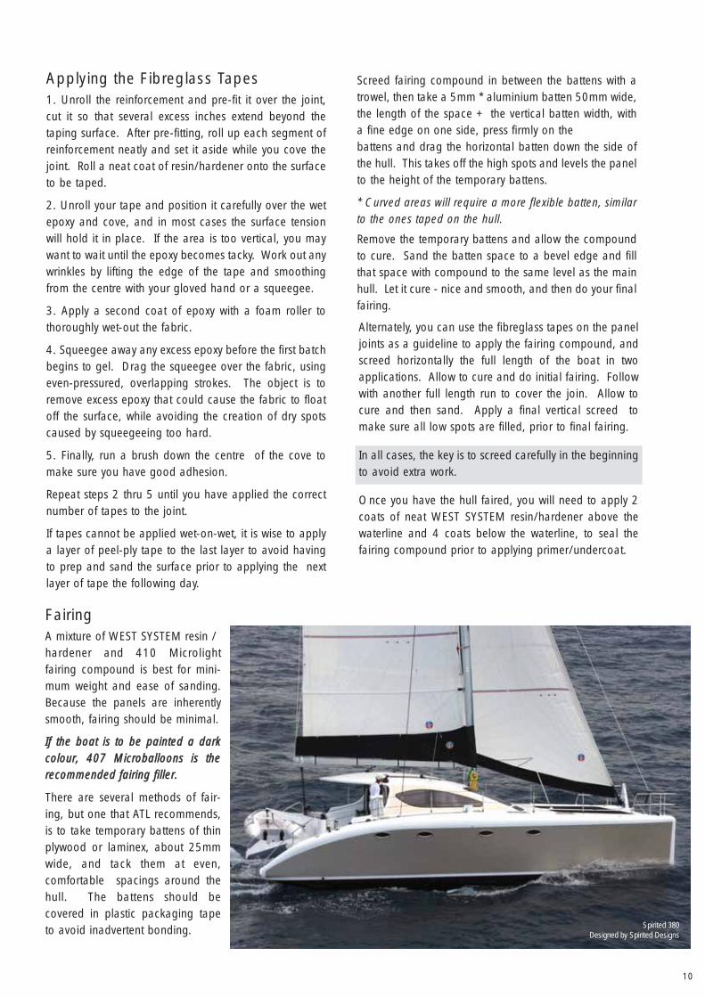
FairingA mixture of WEST SYSTEM resin /hardener and 410 Microlightfairing compound is best for mini-mum weight and ease of sanding.Because the panels are inherentlysmooth, fairing should be minimal.
If the boat is to be painted a darkcolour, 407 Microballoons is therecommended fairing filler.
There are several methods of fair-ing, but one that ATL recommends,is to take temporary battens of thinplywood or laminex, about 25mmwide, and tack them at even,comfortable spacings around thehull. The battens should becovered in plastic packaging tapeto avoid inadvertent bonding. Spirited 380
Designed by Spirited Designs
11
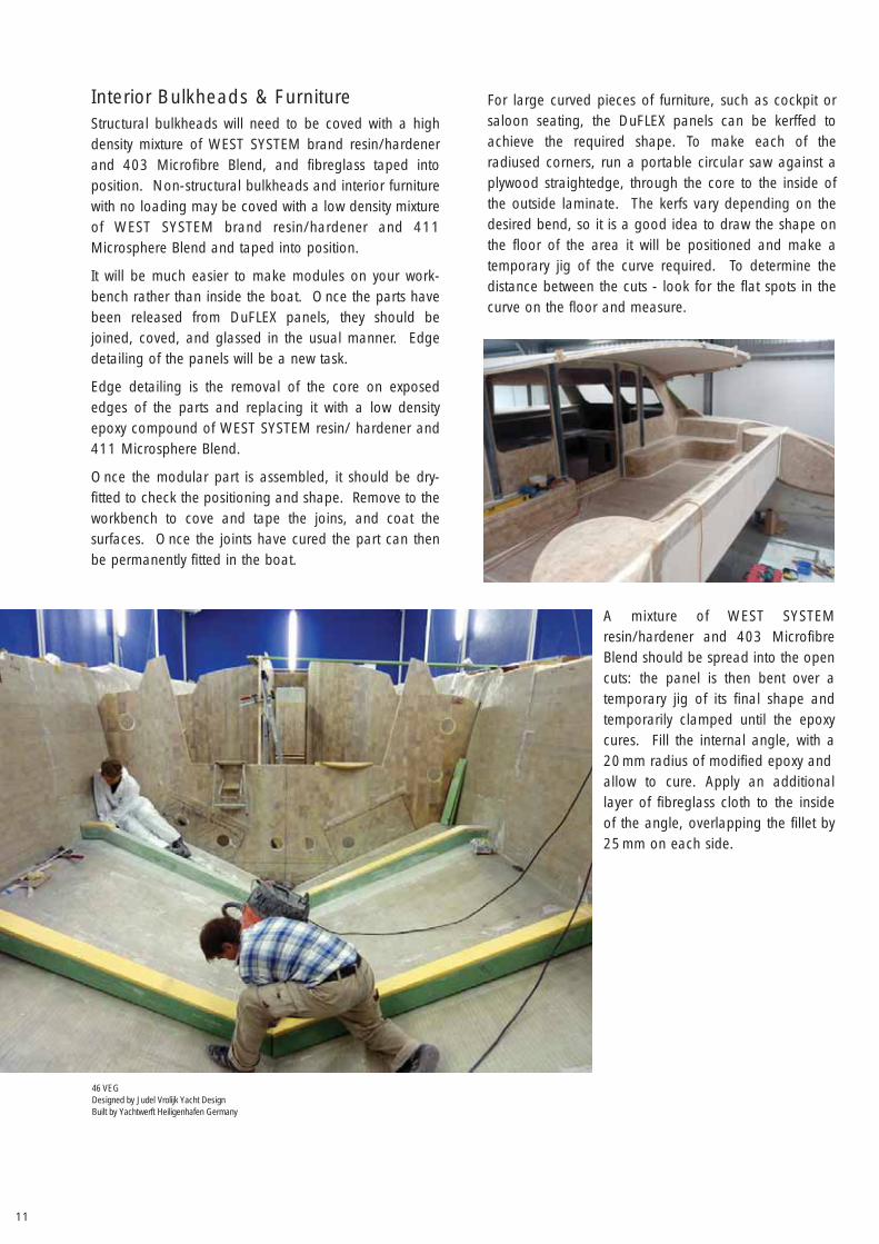
For large curved pieces of furniture, such as cockpit orsaloon seating, the DuFLEX panels can be kerffed toachieve the required shape. To make each of theradiused corners, run a portable circular saw against aplywood straightedge, through the core to the inside ofthe outside laminate. The kerfs vary depending on thedesired bend, so it is a good idea to draw the shape onthe floor of the area it will be positioned and make atemporary jig of the curve required. To determine the distance between the cuts - look for the flat spots in thecurve on the floor and measure.
Interior Bulkheads & FurnitureStructural bulkheads will need to be coved with a highdensity mixture of WEST SYSTEM brand resin/hardenerand 403 Microfibre Blend, and fibreglass taped intoposition. Non-structural bulkheads and interior furniturewith no loading may be coved with a low density mixtureof WEST SYSTEM brand resin/hardener and 411Microsphere Blend and taped into position.
It will be much easier to make modules on your work-bench rather than inside the boat. Once the parts havebeen released from DuFLEX panels, they should bejoined, coved, and glassed in the usual manner. Edgedetailing of the panels will be a new task.
Edge detailing is the removal of the core on exposededges of the parts and replacing it with a low densityepoxy compound of WEST SYSTEM resin/ hardener and411 Microsphere Blend.
Once the modular part is assembled, it should be dry-fitted to check the positioning and shape. Remove to theworkbench to cove and tape the joins, and coat thesurfaces. Once the joints have cured the part can thenbe permanently fitted in the boat.
A mixture of WEST SYSTEMresin/hardener and 403 MicrofibreBlend should be spread into the opencuts: the panel is then bent over atemporary jig of its final shape andtemporarily clamped until the epoxycures. Fill the internal angle, with a20mm radius of modified epoxy andallow to cure. Apply an additionallayer of fibreglass cloth to the insideof the angle, overlapping the fillet by25mm on each side.
46 VEGDesigned by Judel Vrolijk Yacht DesignBuilt by Yachtwerft Heiligenhafen Germany
12
Hardware bondingHardware bolted through a balsa or foam cored panelcan be over-tightened or loaded enough to crush skinsand core material. Proper hardware bonding techniquescan dramatically improve the load-carrying capacity andbonded hardware becomes an integral part of a deck orhull and can perform long term without leak-causingmovement.
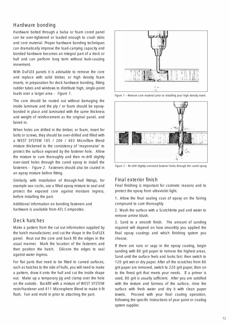
With DuFLEX panels it is advisable to remove the coreand replace with solid timber, or high density foaminserts, in preparation for deck hardware bonding, fittingrudder tubes and windows to distribute high, single-pointloads over a larger area - Figure 1.
The core should be routed out without damaging theinside laminate and the ply / or foam should be epoxy-bonded in place and laminated with the same thicknessand weight of reinforcement as the original panel, andfaired in.
When holes are drilled in the timber, or foam, insert forbolts or screws, they should be over-drilled and filled witha WEST SYSTEM 105 / 206 / 403 Microfibre Blend mixture thickened to the consistency of ‘mayonnaise’ toprotect the surface exposed by the fastener hole. Allowthe mixture to cure thoroughly and then re-drill slightlyover-sized holes through the cured epoxy to install thefasteners - Figure 2. Fasteners should also be coated inan epoxy mixture before fitting.
Similarly, with installation of through-hull fittings, forexample sea-cocks, use a filled epoxy mixture to seal andprotect the exposed core against moisture ingress,before installing the part.
Additional information on bonding fasteners andhardware is available from ATL Composites.
Deck hatchesMake a pattern from the cut out information supplied bythe hatch manufacturer, and cut the shape in the DuFLEXpanel. Rout out the core and back fill the edges in theusual manner. Mark the location of the fasteners andthen position the hatch. Silicone the edges to sealagainst water ingress.
For flat parts that need to be fitted to curved surfaces,such as hatches to the side of hulls, you will need to makea pattern, draw it onto the hull and cut the inside shapeout. Make up a temporary jig and clamp over the holeon the outside. Backfill with a mixture of WEST SYSTEMresin/hardener and 411 Microsphere Blend to make it fitflush. Fair and mold in prior to attaching the part.
Final exterior finishFinal finishing is important for cosmetic reasons and toprotect the epoxy from ultraviolet light.
1. Allow the final sealing coat of epoxy on the fairingcompound to cure thoroughly.
2. Wash the surface with a Scotchbrite pad and water toremove amine blush.
3. Sand to a smooth finish. The amount of sandingrequired will depend on how smoothly you applied thefinal epoxy coatings and which finishing system youchoose.
If there are runs or sags in the epoxy coating, beginsanding with 80 grit paper to remove the highest areas.Sand until the surface feels and looks fair; then switch to120 grit wet or dry paper. After all the scratches from 80grit paper are removed, switch to 220 grit paper, then onto the finest grit that meets your needs. If a primer isused, 80 grit is usually sufficient. After you are satisfiedwith the texture and fairness of the surface, rinse thesurface with fresh water and dry it with clean papertowels. Proceed with your final coating operation, following the specific instructions of your paint or coatingsystem supplier.
Figure 1 - Remove core material prior to installing your high density insert.
Figure 2 - Re-drill slightly oversized fastener holes through the cured epoxy.
13
For the Amateur Builder
Planning the ShopSpend as much time planning your workshop as you doevery other aspect of the boat. After all, you will bespending a large part of your time working there.Working in a cramped shop or one with bad lightingturns, what should be pleasurable hours, into puretorture. Even small things like the placement of electricaloutlets can become major frustrations. Like everything inboatbuilding, careful preparation pays dividends.
Even in the sunny tropics, a DuFLEX boat must be builtunder shelter and kept dry and clean. Peel ply should beleft on the panels as long as possible to reduce the riskof surface contamination. From a practical standpoint,the best way to build your boat is inside a conventionalbuilding with a roof, side walls and a solid floor.
The first consideration in choosing a building shedshould be, ’How am I going to get the boat out of here?’If the doorway is not wide enough to just pull the boatout, you may be able to tilt it on its side to takeadvantage of the diagonal of the door, which is longerthan its height or width. The other option is to removethe door/wall completely to provide the necessary exit.
Build your boat so that either the bow or stern is pointedstraight at the opening to the outside world. This makesthings a lot easier on moving, or turning, day. Outside,there must be enough driveway space for the boathauler's truck to pick-up the completed vessel. Extra out-door space will be necessary if cranes are needed to turnthe boat over or to hoist it onto the truck.
Working space inside the shop is the next majorconsideration. The building should be high, as you willnot only need clearance for the boat, but also to allowyou to stand and work on the cabin top and roof. It willalso keep the factory cooler and allows for storage spaceunderneath the boat if the shed is narrow. A wide shedwill give you space so that the boat can be walkedaround and accessed from all sides, and helps to keepparts and equipment away from the main structure.Searching for a factory to rent is the most realisticsolution for the majority of amateur builders, buttemporary shelters are another option. Environmentalvariables need to be considered when building in partiallyenclosed shelters, as extremely low or high temperatures,and high humidity will affect the working characteristicsof epoxy resin and hardeners and the long termperformance of the products.
Work StationsSeparate, free-standing work stations, for each worker,should be set up around the perimeter of the boat. Youshould be able to walk completely around theworkstation, so they should be positioned away fromwalls or corners.
A sheet of 1200mm x 2400mm 17mm ply wood sittingon 2 x empty 200 ltr drums, with a frame to stop it fromsliding, makes an excellent work bench. It provides agood working height, is easily moved around theworkshop, and is a versatile space for large or smallmodular construction.
Build a separate workbench for the epoxy resin,hardener and powder modifiers. Mixing epoxy can be abit messy, so it pays to separate this operation from therest of the shop. The resin pumps should be at acomfortable height and have a drip pan. Be sure there isan adequate supply of mixing containers, mixing sticks,and gloves stored on, or near, the bench for easy access.
Power, Light & VentilationFor efficiency, it is best to position the workstations closeto power outlets, and for each station to have a portablepower-board and a set of 2 power leads. A short leadfor power tool operation at the bench and a long leadthat will allow access to any location on the boat. Extrapower-boards should be on hand so they can be taken todifferent locations on the boat.
A well-lit factory will also make working on your boatmore efficient and pleasant. Most rental factories willhave adequate overhead lighting, and portablefluorescent lights provide shadow-less light for workinginside the boat without generating too much heat.
Ventilation is also important even when working withchemicals as benign as epoxy resins. While the bulk ofthe air in the shop is fresh, the same can't be said for thedeep recesses of the hulls. Portable fans should beincluded in your tool kit.
14
The Tool Kit -General Hand Tools• Screwdrivers - both straight and Phillips in a variety
of sizes• Hammers - a standard carpenters claw hammer
is always handy. Other handy hammers includes one with soft rubber head and a dead blow mallet
• Pliers - include a pair of standard 200mm slip-jointpliers. Diagonal cutters and needlenose pliers will come in handy if you decide to install your electrical wiring
• Wrenches - full sets of socket and combination wrenches are indispensable when installing an engines and associated gear
• Knives - a couple of different types of knives. The standard shop utility knife with replaceable blades does most of the work, but a pocketknife and a single edge razor blade scraper are also needed
• Hand saws, planes, chisels and rasps & wood files, and tape measures
Power Tools• Pistol drills • Sanders
• Router with tungsten bits
• Circular saw - with a diamond tipped blade forcutting through the DuFLEX laminate
• Power plane • Sander/polisher
• 4" grinder • Jigsaw • Power drill
Other Useful Items• Coving knives can be made up by machining 25mmpaint scrapers to 20mm wide radiused ends. • Step ladders and simple scaffolding to put beside theboat to access higher areas of hulls for strip planking incurved areas, positioning of panel parts and fairing• An industrial wet & dry vacuum cleaner is a handyaddition to keep your work space clean & tidy, especiallyif it can be attached to your tools to act as a dustextraction device• Heavy duty gardening gloves will prevent injury whenhandling fibreglassed parts, as the fibreglass edges canbe quite sharp.
Composite ToolsDiamond-coated fibreglass tooling is recommended forbest tool life, for example, a jigsaw with a Makita No.10S Type 150 blade to cut out parts.
Cutting glass cloth requires sharp tools, and a large,good quality pair of scissors will make life easier. Batteryoperated fibreglass shears are available.
Epoxy Application:
• WEST SYSTEM 800 Foam roller covers
• roller frames • plastic roller trays
• metal laminate rollers • rubber squeegees
• disposable brushes • plastic mixing containers
• mixing sticks • disposable gloves
• scotch-brite scouring pads
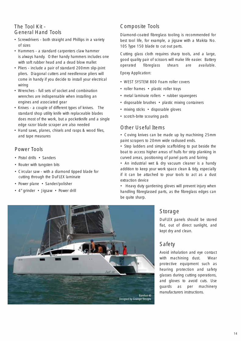
StorageDuFLEX panels should be storedflat, out of direct sunlight, andkept dry and clean.
SafetyAvoid inhalation and eye contactwith machining dust. Wearprotective equipment such ashearing protection and safetyglasses during cutting operations,and gloves to avoid cuts. Useguards as per machinerymanufacturers instructions.
Barefoot 40Designed by Grainger Designs

ATL Composites Pty LtdPO Box 2349 Southport Qld 4215
T (+61) 7 5563 1222F (+61) 7 5563 1585
www.duflex.com.au
ATL composites