Embed Size (px)
Citation preview

DUET
™
ExTErnal DrainagE anD moniToring sysTEm
Quick Reference Guide
Refer to product package insert for instructions, warnings, precautions and complications.
Attach DUET™ System to IV Pole
refer to product package insert for instructions, warnings, precautions and complications.
- 2 -
Attach pole clamp to I.V. pole
Hang system from IV. pole using cord
OR
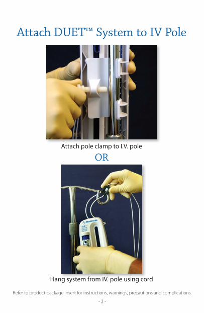
Attach here for lumbar drainage
Attach here for ventricular drainage
Attach Main System Stopcock
refer to product package insert for instructions, warnings, precautions and complications.
- 3 -
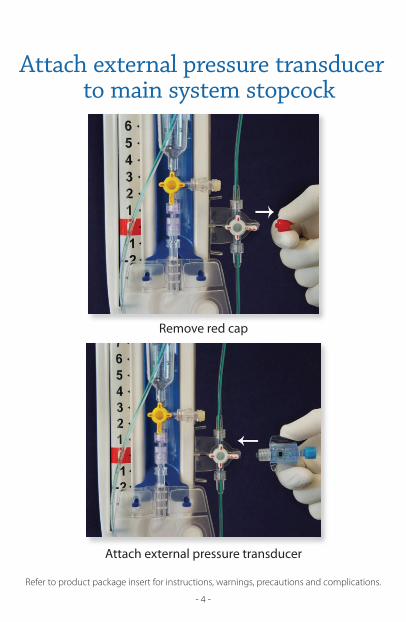
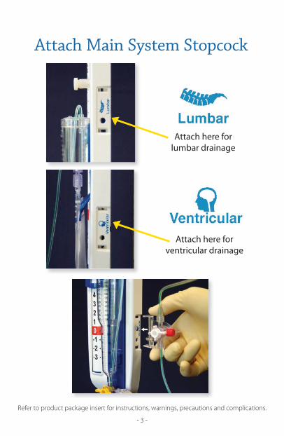
Remove red cap
Attach external pressure transducer
Attach external pressure transducer to main system stopcock
refer to product package insert for instructions, warnings, precautions and complications.
- 4 -
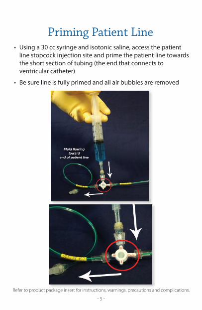
• Using a 30 cc syringe and isotonic saline, access the patient line stopcock injection site and prime the patient line towards the short section of tubing (the end that connects to ventricular catheter)
• Be sure line is fully primed and all air bubbles are removed
Priming Patient Line
refer to product package insert for instructions, warnings, precautions and complications.
- 5 -
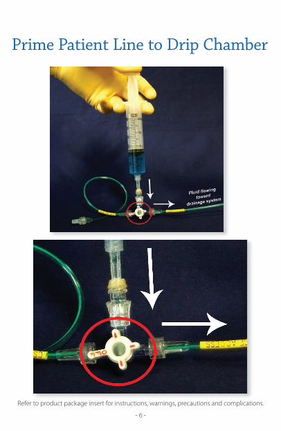
Prime Patient Line to Drip Chamber
refer to product package insert for instructions, warnings, precautions and complications.
- 6 -
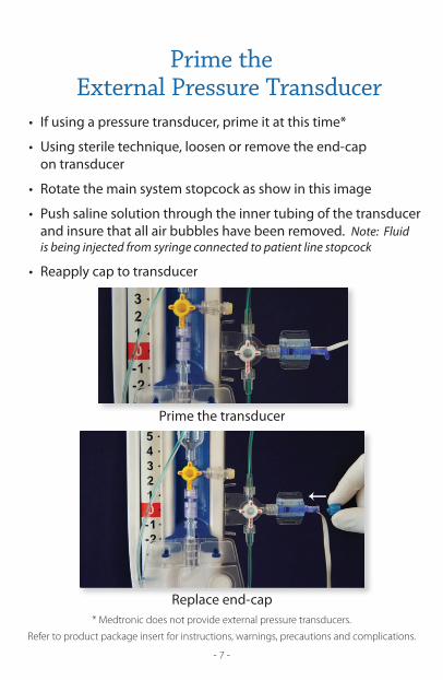
Prime the transducer
Replace end-cap
Prime the External Pressure Transducer
refer to product package insert for instructions, warnings, precautions and complications.
- 7 -
• If using a pressure transducer, prime it at this time*
• Using sterile technique, loosen or remove the end-cap on transducer
• Rotate the main system stopcock as show in this image
• Push saline solution through the inner tubing of the transducer and insure that all air bubbles have been removed. Note: Fluid is being injected from syringe connected to patient line stopcock
• Reapply cap to transducer
* medtronic does not provide external pressure transducers.
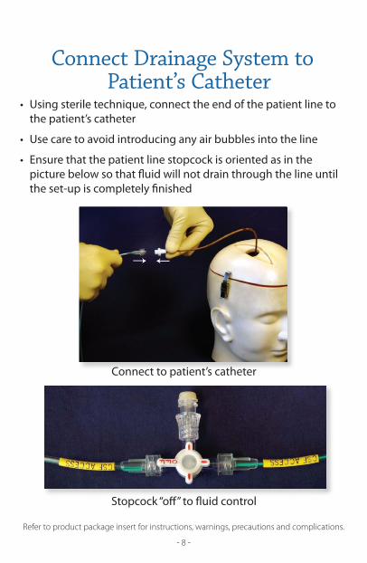
Connect to patient’s catheter
Stopcock “off” to fluid control
Connect Drainage System to Patient’s Catheter
refer to product package insert for instructions, warnings, precautions and complications.
- 8 -
• Using sterile technique, connect the end of the patient line to the patient’s catheter
• Use care to avoid introducing any air bubbles into the line
• Ensure that the patient line stopcock is oriented as in the picture below so that fluid will not drain through the line until the set-up is completely finished
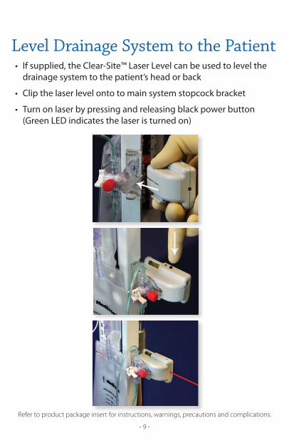
Level Drainage System to the Patient
refer to product package insert for instructions, warnings, precautions and complications.
- 9 -
• If supplied, the Clear-Site™ Laser Level can be used to level the drainage system to the patient’s head or back
• Clip the laser level onto to main system stopcock bracket
• Turn on laser by pressing and releasing black power button (Green LED indicates the laser is turned on)
Level Drainage System to the Patient
refer to product package insert for instructions, warnings, precautions and complications.
- 10 -
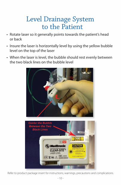
• Rotate laser so it generally points towards the patient’s head or back
• Insure the laser is horizontally level by using the yellow bubble level on the top of the laser • When the laser is level, the bubble should rest evenly between the two black lines on the bubble level
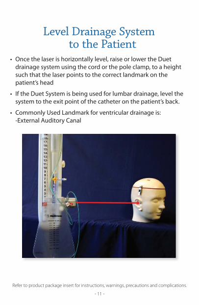
Level Drainage System to the Patient
refer to product package insert for instructions, warnings, precautions and complications.
- 11 -
• Once the laser is horizontally level, raise or lower the Duet drainage system using the cord or the pole clamp, to a height such that the laser points to the correct landmark on the patient’s head
• If the Duet System is being used for lumbar drainage, level the system to the exit point of the catheter on the patient’s back.
• Commonly Used Landmark for ventricular drainage is: -External Auditory Canal
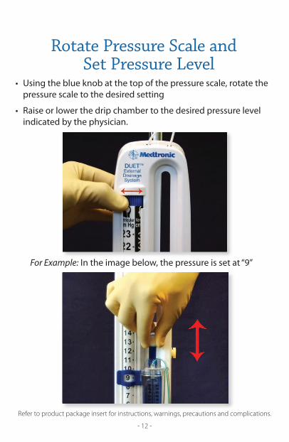
For Example: In the image below, the pressure is set at “9”
Rotate Pressure Scale and Set Pressure Level
refer to product package insert for instructions, warnings, precautions and complications.
- 12 -
• Using the blue knob at the top of the pressure scale, rotate the pressure scale to the desired setting
• Raise or lower the drip chamber to the desired pressure level indicated by the physician.
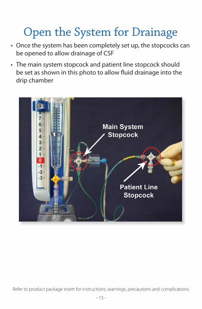
Open the System for Drainage
refer to product package insert for instructions, warnings, precautions and complications.
- 13 -
• Once the system has been completely set up, the stopcocks can be opened to allow drainage of CSF
• The main system stopcock and patient line stopcock should be set as shown in this photo to allow fluid drainage into the drip chamber
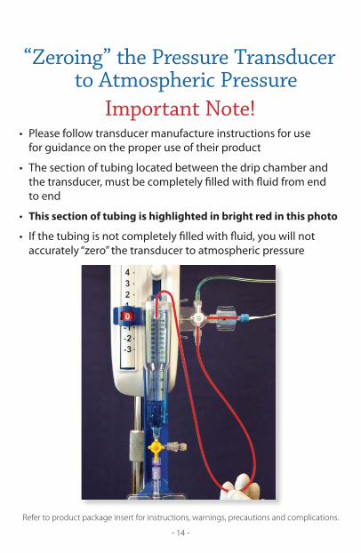
“Zeroing” the Pressure Transducer to Atmospheric Pressure
refer to product package insert for instructions, warnings, precautions and complications.
- 14 -
• Please follow transducer manufacture instructions for use for guidance on the proper use of their product
• The section of tubing located between the drip chamber and the transducer, must be completely filled with fluid from end to end
• This section of tubing is highlighted in bright red in this photo
• If the tubing is not completely filled with fluid, you will not accurately “zero” the transducer to atmospheric pressure
Important Note!
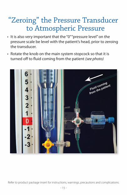
“Zeroing” the Pressure Transducer to Atmospheric Pressure
refer to product package insert for instructions, warnings, precautions and complications.
- 15 -
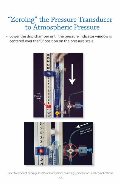
• It is also very important that the “0” “pressure level” on the pressure scale be level with the patient’s head, prior to zeroing the transducer.
• Rotate the knob on the main system stopcock so that it is turned off to fluid coming from the patient (see photo)
“Zeroing” the Pressure Transducer to Atmospheric Pressure
refer to product package insert for instructions, warnings, precautions and complications.
- 16 -
• Lower the drip chamber until the pressure indicator window is centered over the “0” position on the pressure scale.

“Zeroing” the Pressure Transducer to Atmospheric Pressure
refer to product package insert for instructions, warnings, precautions and complications.
- 17 -
• The Clinician then pushes the zero button on the bedside monitor and the transducer is now “zeroed” to atmospheric pressure
“Zeroing” the Pressure Transducer to Atmospheric Pressure
refer to product package insert for instructions, warnings, precautions and complications.
- 18 -
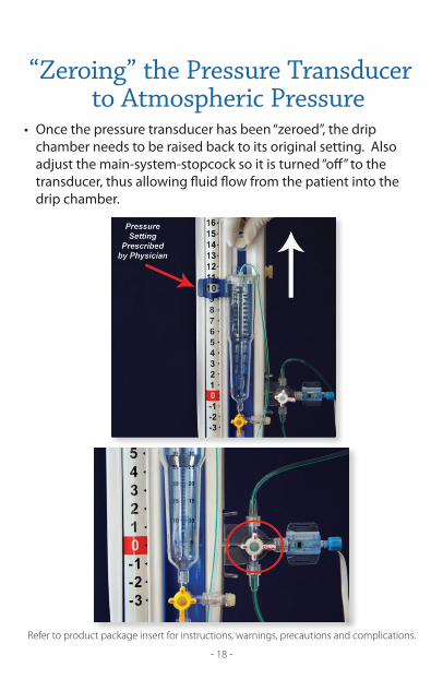
• Once the pressure transducer has been “zeroed”, the drip chamber needs to be raised back to its original setting. Also adjust the main-system-stopcock so it is turned “off” to the transducer, thus allowing fluid flow from the patient into the drip chamber.
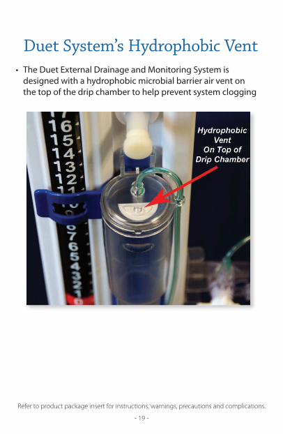
Duet System’s Hydrophobic Vent
refer to product package insert for instructions, warnings, precautions and complications.
- 19 -
• The Duet External Drainage and Monitoring System is designed with a hydrophobic microbial barrier air vent on the top of the drip chamber to help prevent system clogging

all r
ight
s res
erve
d. P
rinte
d in
Usa
.©
2009
, med
tron
ic, i
nc.
™ T
rade
mar
ks o
f med
tron
ic, i
nc.
liT5
9583
1
.09
2
009-
113
For further information, please contact your Neurologic Technologies representative, or refer to www.Medtronic.com.
Medtronic Neurologic Technologiesmedtronic Usa, inc.123 Cremona Drivegoleta, Ca 93117-550 UsaUsa/Canada: (800) 468-9710international: (901) 344-0645Fax: (800) 468-9713Fax international: (901) 396-2698
Caution: Federal (USA) law restricts this device to sale by or on the order of a physician. Refer to product package insert for instructions, warnings, precautions and complications.