Embed Size (px)
Citation preview

I n s t r u c t o r W o r k b o o k Masonry Design Example Module M5/S4
i
Instructor Workbook
Module M5/S4
Masonry Design Example: ETABS Analysis
OBJECTIVES As a result of this session, you should be able to:
•• DDeetteerrmmiinnee tthhee mmeecchhaanniiccaall pprrooppeerrttiieess ooff bbrriicckk mmaassoonnrryy eexxaammppllee bbuuiillddiinngg ttyyppee
• IIddeennttiiffyy hhooww mmaassoonnrryy wwaallllss aarree mmooddeelleedd iinn EETTAABBSS,,SSAAPP tthhee ssttrruuccttuurraall aannaallyyssiiss aanndd ddeessiiggnn ssooffttwwaarree
• OObbsseerrvvee sshheellll eelleemmeenntt iinntteerrnnaall ssttrreesssseess aanndd ffoorrcceess
•• CChheecckk sshheeaarr aanndd ccoommpprreessssiivvee ssttrreessss iinn wwaallllss
•• DDeessiiggnn vveerrttiiccaall rreeiinnffoorrcceemmeenntt bbaarr ffoorr iinn--ppllaannee bbeennddiinngg ooff bbrriicckk ppiieerr

I n s t r u c t o r W o r k b o o k Masonry Design Example Module M5/S4
ii
CONTENTS
1. INTRODUCTION ......................................................................................1 2. Building Description ..................................................................................1
2.1 General ................................................................................................1
2.2 Design Loads ......................................................................................1
2.3 Material Properties ..............................................................................2
2.4 Calculation of Earthquake Load .........................................................2
3. Building Model and Analysis ....................................................................4 4. Numerical Study .........................................................................................6
4.1 Modal Outputs ....................................................................................6
4.2 Analysis results ...................................................................................7
4.3 ETABS Output Convention for Shell Element Internal Stresses .....11
4.4 ETABS Output Convention for Shell Element Internal Forces ........13
4.5 Stress Checks Examples in Shell elements of Brick Masonry Walls .................................................................................................15
4.6 Sample Design of Vertical Bar due to In-plane Loading in Pier 3 ...17
I n s t r u c t o r W o r k b o o k Masonry Design Example Module M5/S4
M5/S4-1
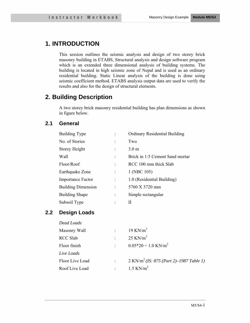
1. INTRODUCTION This session outlines the seismic analysis and design of two storey brick masonry building in ETABS, Structural analysis and design software program which is an extended three dimensional analysis of building systems. The building is located in high seismic zone of Nepal and is used as an ordinary residential building. Static Linear analysis of the building is done using seismic coefficient method. ETABS analysis output data are used to verify the results and also for the design of structural elements.
2. Building Description A two storey brick masonry residential building has plan dimensions as shown in figure below.
2.1 General
Building Type : Ordinary Residential Building
No. of Stories : Two
Storey Height : 3.0 m
Wall : Brick in 1:5 Cement Sand mortar
Floor/Roof : RCC 100 mm thick Slab
Earthquake Zone : 1 (NBC 105)
Importance Factor : 1.0 (Residential Building)
Building Dimension : 5760 X 3720 mm
Building Shape : Simple rectangular
Subsoil Type : II
2.2 Design Loads
Dead Loads
Masonry Wall : 19 KN/m3
RCC Slab : 25 KN/m3
Floor finish : 0.05*20 = 1.0 KN/m2
Live Loads
Floor Live Load : 2 KN/m2 (IS: 875 (Part 2)–1987 Table 1)
Roof Live Load : 1.5 KN/m2
I n s t r u c t o r W o r k b o o k Masonry Design Example Module M5/S4
M5/S4-2
2.3 Material Properties
Concrete
Concrete grade for floor/roof slab : M15
Young’s modulus for slab Ec = 5000 √fck N/mm2 = 5000 √15 = 19365 N/mm2
Poisson’s ratio for concrete : 0.2
Brick Masonry
Compressive strength of brick : 10 N/mm2
Mortar Type : M1 (Cement sand ratio 1:5)
Basic compressive stresses for masonry
after 28 days (IS 1905-1987) : 0.96 N/mm2
Compressive strength of masonry fm’ : 0.96/0.25 = 3.84 N/mm2
Young’s modulus of brick masonry Em : 550*3.84 = 2112 N/mm2
Poisson’s ratio for brick masonry : 0.3
Steel
Reinforcement of grade Fe 415 is used for slab and other reinforcement to be designed for masonry to take shear and tensile stresses.
2.4 Calculation of Earthquake Load
Linear static method (Referring NBC 105)
Seismic Coefficient Method
The design horizontal seismic force coefficient, Cd
for seismic coefficient method is taken as C
d = CZIK
Where,
C is the basic seismic coefficient for the fundamental translational period in the direction under consideration.
Z = Seismic zoning factor= 1 (For the location of the building in Kathmandu)
I =Importance factor = 1.0 Residential building
K = Structural Performance factor =2.5
T = (0.09 X H) / (D^0.5) = (0.09 * 6)/(5.76^0.5) = 0.225 Longitudinal direction
= (0.09 * 6)/(3.72^0.5) = 0.28 Transverse direction
C = 0.08 for Subsoil Type II

I n
Cd
= C
Using
Desig
Wher
Z
I
S
S
Rb
A
s t r u c t
CZIK = 0.08
g IS Code,
gn Seismic C
re,
Z = 0.36 (Zon
= 1.0 (Resid
a/g = functio
a/g = 2.5
R = 3.0 ( Forands and ver
Ah = ZISa/2R
Hence use
o r W o r
8 X 1.0 X 1
Coefficient A
ne V)
dential Build
on of Time P
r Load bearinrtical bars at
Rg = (0.36X
e base shear
k b o o k
X 2.5 = 0.2
Ah = ZISa/2R
ding)
Period T
ng masonryt corners of r
1.0X2.5)/ (2
coefficient
Fig
Rg
wall buildinrooms and ja
2X3) = 0.15
equal to 0.2
1: Floor Pl
Masonry D
ngs reinforceambs of open
lan
Design Exampl
ed with horizning)
e Module M
3
zontal RC
5/S4

I n
3. B
s t r u c t
BuildingThe spaceLoad bearigid slab dead loaddistributeLinear Anin both analysis, degrees oand all thrare restrai
The followthe worki
1) DL+L2) 0.7 DL
o r W o r
Model ae frame is m
aring brick mof reinforce
d of floor fid load in donalysis of theorthogonal the floor sla
of freedom cree rotationained in all si
wing load cong stress me
LL+E L + E
k b o o k
Fig
and Anamodelled usmasonry waed concrete ifinish and livownward diree building isdirection wabs are assu
considered inal degrees ofix degrees of
ombination aethod:
g 2:Elevatio
alysis sing a standaalls are modis modelled ve load on ection of gras carried usinwith user deumed to act n the analysif freedom. Bf freedom.
as given in N
Masonry D
on
ard softwaredelled as waas slab shellfloor/roof i
avity to slab ng Auto laterefined coefas rigid dia
is are six, i.eBut all the no
NBC 105:19
Design Exampl
e ETABS, Vall shell eleml elements. Ais taken as ushell elemeral load of e
fficient of 0aphragms. Te. all three todes at the pl
994 are cons
e Module M
4
Version 9. ments and Additional uniformly nts. Static
earthquake 0.2.In the
The no. of translation linth level
sidered for
5/S4

I n
F
s t r u c t
Activity 1
Discuss L
Participan
Check and
3D View
Fig 3: 3 Dime
o r W o r
1
Limitation of
nts are asked
d Compare t
of the ETAB
ensional Mat
k b o o k
f Structural A
d to prepare m
the model ou
BS model is
thematical M
Analysis and
model
utcomes
shown in th
Model of the B
Masonry D
d Design Sof
he figure belo
Building usin
Design Exampl
ftware
ow.
ng ETABS V
e Module M
5
Version 9
5/S4

I n s t r u c t o r W o r k b o o k Masonry Design Example Module M5/S4
M5/S4-6
4. Numerical Study The building model is run and the analysis results are verified using the resulted base shear to check the reliability of the computer model. The induced base shear from the auto lateral load with user coefficient of 0.2 is 98 KN, while the manually calculated base shear is 100 KN. The building is also checked for the induced compression and tension with earthquake loading in opposite directions. The stresses shown are reversed with reverse earthquake load. The parameters investigated are the time period, inter-storey drift, base shear and induced element stresses in masonry walls. Stresses induced are compared with their respective permissible values. The results are evaluated and discussed below.
4.1 Modal Outputs
The following is the output of the analysis result of the building modal.
Time Period of various modes of the building and its modal mass participation ratio is given in the tabular form below
Table 1: Time Period and Modal Mass Participation Ratio of Various Modes of the Building
Mode Period Modal mass
participation ratioSum UX
Modal mass participation ratio
Sum UY 1 0.126 0.188 90.298
2 0.097 91.490 90.562
3 0.067 94.199 90.801
4 0.049 94.199 99.845
5 0.036 99.895 99.848
6 0.026 99.985 99.896
7 0.014 99.985 99.993
8 0.012 99.985 99.997
9 0.011 99.985 99.997
10 0.011 99.989 99.998
11 0.009 99.996 99.998
12 0.009 99.996 99.998
Inter-storey drift
Maximum inter-storey drift of the building in longitudinal X and transverse Y direction as obtained from ETABS model is shown below in the table.

I n
4.2
s t r u c t
Table 2: I
STORY
STORY
Permissib
(The storforce, witheight)
Hence, co
Analys
Analysis verified wexpected shear stre
Fi
o r W o r
Inter-storey
Y2 Max
Y2 Max
ble value of s
ey drift in ath partial lo
omplies the d
is results
results andwith the achorizontal shsses obtaine
ig 4: Pier ID
P
P
k b o o k
y Drift of th
x DriftX
x DriftY
storey drift =
any storey doad factor of
drift limitatio
s
d numerical ctual capacihaking. Sam
ed from the p
D for In-plan
he Building
DL+
DL+
= 0.004
due to the mf 1, shall no
on.
data obtainity of the s
mple analysisprogram are
ne lateral lo
Masonry D
+LL+EQX
+LL+EQY
minimum spot exceed 0
ned as an ostructural els results in thshown in fig
oading along
Design Exampl
0
0
pecified desi.004 times t
output is stulements resihe form of ngures below.
g Y-Directio
P
P
e Module M
7
.000171
0.00029
ign lateral the storey
udied and isting the ormal and .
on
5/S4
I n
C
s t r u c t
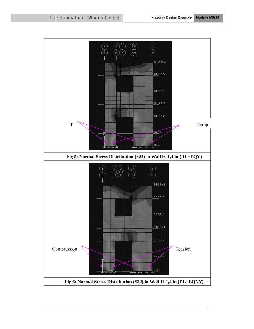
Fig 5:
Fig 6: N
T
ompression
o r W o r
Normal Str
Normal Str
k b o o k
ress Distrib
ress Distribu
bution (S22)
ution (S22) i
Masonry D
in Wall H-
in Wall H-1
Design Exampl
1,4 in (DL+
1,4 in (DL+E
Tension
e Module M
8
+EQY)
EQNY)
Comp
n
5/S4

I n s t r u c t
Fig 7
Fig 8:
o r W o r
7: Shear Str
Shear Stre
k b o o k
ess Distribu
ess Distribut
ution (S12) i
tion (S12) in
Masonry D
in Wall H-1
n Wall H-1,
Design Exampl
1,4 in (DL+E
4 in (DL+E
e Module M
9
EQY)
QNY)
5/S4

I n s t r u c t
Fig 9: Str
Fig 10: S
o r W o r
ress SMax D
tress SMax
k b o o k
Diagram Shin
Diagram Sin
howing Stren (DL+EQX
howing Stren (DL+EQY
Masonry D
ss ConcentrX)
ess ConcentY)
Design Exampl
ration in W
tration in W
e Module M
10
all 1-A,H
Wall A-1,4
5/S4

I n s t r u c t o r W o r k b o o k Masonry Design Example Module M5/S4
M5/S4-11
4.3 ETABS Output Convention for Shell Element Internal Stresses
The basic shell element stresses are identified as S11, S22, S12, S13, and S23. The stresses S21 is always equal to S12. Sij stresses (where i can be equal to 1 or 2 and j can be equal to 1, 2 or 3) are stresses that occur on face i of an element in direction j. Direction j refers to the local axis direction of the shell element. Thus S11 stresses occur on face 1 of the element (perpendicular to the local 1 axis) and are acting in the direction parallel to the local 1 axis (that is, the stresses act normal to face 1). As another example, S12 stresses occur on face 1 of the element (perpendicular to the local 1 axis) and are acting in the direction parallel to the local 2 axis (that is, the stresses act parallel to face 1, like shearing stresses). The figure below shows examples of each of these basic types of shell stresses. ETABS reports internal stresses for shell elements at the four corner points of the appropriate face of the element.
Fig 11: Examples of Membrane Direct Stresses, S11
Fig 12: Examples of Membrane Shear Stresses, S12 (S21 Stresses Similar)

I n s t r u c t o r W o r k b o o k Masonry Design Example Module M5/S4
M5/S4-12
Fig 13: Examples of Plate Transverse Shear Stresses, S13
Fig 14: Membrane Direct Stresses
S22 Fig 15: Transverse Shear Stresses S23

I n s t r u c t o r W o r k b o o k Masonry Design Example Module M5/S4
M5/S4-13
The transverse shear stresses calculated by ETABS (S13 and S23) are average values. The actual transverse shear stress distribution is approximately parabolic; it is zero at the top and bottom surfaces and has its maximum or minimum value at the mid-surface of the element. ETABS reports the average transverse shear value. An approximation to the maximum (or minimum) transverse shear stress would be 1.5 times the average shear stress.
4.4 ETABS Output Convention for Shell Element Internal Forces
The shell element internal forces, like stresses, act throughout the element. They are present at every point on the mid-surface of the shell element. ETABS reports values for the shell internal forces at the element nodes. It is important to note that the internal forces are reported as forces and moments per unit of in-plane length.
The basic shell element forces and moments are identified as F11, F22, F12, M11, M22, M12, V13 and V23. However, F21 is always equal to F12 and M21 is always equal to M12, so it is not actually necessary to report F21 and M21.
The figure below illustrates the positive directions for shell element internal forces F11, F22, F12, V13 and V23. Note that these shell element internal forces are forces per unit length acting on the mid-surface of the shell element. ETABS only reports the value of these forces at the shell element corner points.

I n s t r u c t
The figurmoments are momeETABS oelement cmoments
o r W o r
Fig 16
re below illuM11, M22 a
ents per unionly reports corner pointshown in th
k b o o k
6: Shell Ele
ustrates the and M12. Noit length act
the value os. Use the r
he figure abo
ment Intern
positive direte that theseing on the m
of these momright hand ruve.
Masonry D
nal Forces
ections for se shell elemmid-surface ments per unule to determ
Design Exampl
shell elemenment internal
of the shellnit length atmine the sen
e Module M
14
nt internal moments
l element. t the shell nse of the
5/S4

I n s t r u c t o r W o r k b o o k Masonry Design Example Module M5/S4
M5/S4-15
Fig 17: Shell Element Internal Moments
4.5 Stress Checks Examples in Shell elements of Brick Masonry Walls
Following is the sample of stress check in masonry walls.
Check for Compressive Stress
Compressive strength of masonry unit = 10 N/mm2
Mortar type M1 corresponding to cement sand ratio of 1:5
Permissible compressive stress (fc) in masonry shall be based on the value of basic compressive stress (fb) and multiplying this value by factor known as stress reduction factor (ks), Area reduction factor (ka) and shape modification factor (kp).
Basic compressive strength of wall fb = 0.96 N/mm2 (From Table 8, IS 1905-1987)
Stress reduction factor ks = 0.51 for slenderness ratio of 24 (From Table 9, IS 1905-1987)

I n s t r u c t o r W o r k b o o k Masonry Design Example Module M5/S4
M5/S4-16
Area reduction factor Ka takes into consideration smallness of the sectional area of the element and is applicable when sectional area of the element is less than 0.2 m2.
The factor, Ka = 0.7 + 1.5 A, A being the area of section in m2.
Sectional Area A = 0.11 * 0.075 = 0.00825 m2
Area reduction factor Ka = 0.7 + 1.5 A = 0.7 + 1.5*0.00825 = 0.71
Shape modification ratio = Kp = 1.0 (For H/W = 0.075/0.11=0.68, Table 10 IS 1905-1987)
Hence, Permissible compressive stress in masonry (fc) = 0.96* 0.51 * 0.71 * 1 = 0.35 N/mm2
Compressive Stress S22 demand in load bearing brick masonry due to site specific earthquake loading is well within permissible value except in very small locations of stress concentration at corners.
Check for Shear Stress
Check for shear stress in wall H-1,4
Shear stress, S12, demand from ETABS model is 0.12 N/mm2 which is the greater value for earthquake loading in transverse direction i.e. load combination of (DL+EQY) and (DL+EQNY)
Compressive stress, S22, due to DL is 0.18 N/mm2 (Obtained from ETABS Model)
Permissible Shear Stress ح c= 0.1+0.18/6 = 0.13 N/mm2
Hence safe in shear

I n
4.6
T
s t r u c t
SamplePier 3
Let x be t
0.7/0.45 =
x = 610 m
Total tens
Area of st
Provide 1
Tension
o r W o r
e Design
the length of
= (1560-x)/x
mm
sile force T =
teel required
No. of 12 m
k b o o k
of Vertic
f tension zon
x
= ½ * 610 *
d = 31567.5 /
mm dia. verti
cal Bar du
ne
0.45 * 230 =
/ 0.56/ 415/
ical bar
P
Masonry D
ue to In-p
= 31567.5 N
1.25 = 108.6
Design Exampl
plane Loa
N
67 mm2
Compress
e Module M
17
ading in
sion
5/S4

EEEE
EEaarrtthhEEnngghhqquu
VVoo
giinneeeeuuaakkee
BB
oolluummee
GovMinDepBuiEarRePro
eerrss'' ee RReesBBuuiill
IIII :: CCoomm
MMa
vernment nistry of partmenilding Corthquacoveryogram
TTrraassiissttalddiinngg
mmppuutteerr
ay 22001111
of Nepal Physicalnt of Urbonstructiake Risy Prepame for
aaiinniinnaanntt ggss
rr AAiiddeedd
11
l Planninan Deveion sk Reduaredner Nepal
nngg oo DDeess
dd DDeessiigg
ng and Welopmen
uction ess l
oonn ssiiggnn
ggnn
Works t and
and
nn ooff

Acknowledgement
Earthquake Risk Reduction and Recovery Preparedness Programme for Nepal (ERRRP Project) with the financial support of Government of Japan and UNDP- Nepal is assigned in carrying out various activities related to Earthquake safety and recovery preparedness in five identified municipalities located in 5 different development region of Nepal. This program has helped to strengthen the institutional and community level capacity to plan and implement earthquake risk reduction and disaster recovery preparedness in the country through capacity building, public education and awareness, retrofitting demonstration and preparation of study reports on building safety against seismic risk. To ensure earthquake resistant construction, appropriate knowledge needs to be disseminated to a broad spectrum of professional engineers and designers. This manual is therefore expected to be useful to designers & engineering professionals in general and to those involved in analysis, design and construction of buildings in particular. Broader use of this training manual will definitely raise earthquake safety awareness and will be useful in achieving highly important objective of the government to reduce urban risks including earthquakes.
I appreciate and acknowledge the efforts of the project officials and professionals' team in preparing this manual. I encourage the users of this manual for providing creative comments and suggestions to further improve the content and context to make this book more user-friendly.
Purna Kadariya Secretary, Ministry of Physical Panning and Works

Preface
Technology in earthquake resistant building construction has advanced tremendously in last years and has demonstrated good practices in reducing impact of earthquakes. There are number of earthquake codes and guidelines aimed towards safe building construction. But many earthquake prone countries are still struggling with appropriate building construction practices. The main reason behind this is the lack of proper knowledge in earthquake resistant building design and construction.
Designers and supervisors play a vital role for the effective implementation of Building Codes. Capacity building of all stakeholders thus is the key factor for earthquake risk reduction. They need to take responsibility for motivating and convincing house owners and constructors to apply earthquake resistant techniques by utilizing their technical knowledge and skill. These trainings should focus more on practical basis. Engineers should learn actual condition of construction sites and elaborate proposal based on actual conditions.
Though earthquake engineering must be introduced in the regular course of civil engineering, this manual is an exercise towards availing standard training curriculum that covers major aspects of seismicity. I hope the contribution of this manual towards achieving the national goal of reduced disaster risk will be considerable and be very much useful in proper implementation of National Building Code of Nepal.
Ashok Nath Uprety Director General Department of Urban Development and Building Construction

Foreword
Nepal is a country that stands at 11th rank in the world with respect to vulnerability to earthquake hazards. In this context UNDP/BCPR (Bureau of Crisis Prevention and Recovery) with the support of Government of Japan initiated an Earthquake Risk Reduction and Recovery Preparedness (ERRRP) program in five high risk South Asian countries: Nepal, Bhutan, Bangladesh, India and Pakistan. ERRRP Project is being implemented by the Ministry of Physical Planning and Works (MPPW) in close coordination with other line ministries and Programme Municipalities. ERRRP project is engaged in carrying out various activities related to Earthquake safe constructions, Earthquake preparedness and recovery planning in five municipalities of Nepal located in different development regions. They are Biratnagar, Hetauda, Pokhara, Birendranagar and Dhangadhi.
The ultimate aim of the project is sustainable earthquake disaster mitigation in Nepal by better training and capacity building of professional engineers in earthquake engineering. As we all know, earthquakes do not kill people but poorly designed or constructed buildings do. A properly designed, detailed and constructed structure can resist an earthquake of high intensity. But in Nepal, due to lack of manpower and technical competence, regulatory agencies are lagging behind to properly enforce seismic design Codes and standards.
The Department of Urban Development and Building construction is the main agency responsible for the implementation of the Building Act. National Building Codes including the NBC 105: Seismic Design of Buildings in Nepal are developed as provisioned by the Act. This manual is therefore expected to be useful for the department in future conduction of training programs on "Structural Analysis and Earthquake Resistant Design of Buildings Using SAP 2000 and Nepal National Building Code" for Municipal and other professional engineers, designers, architects etc.
This manual has been developed by the ERRRP project with professional input from the National Society for Earthquake Technology-Nepal (NSET) and is based on the experiences gained by the project during conduction of similar trainings in its 5 project municipalities. This document is assumed to serve as a standard training curriculum and ready-to-use training material that covers a wide range of seismicity, its design, assessment and will considerably help in implementation of Building Codes.
This manual is being prepared in two separate volumes to ensure easiness of its use. Volume I covers the theoretical aspects of seismicity, earthquake resistant design and assessment and general provisions of National Building Code whereas the Volume II covers its practical aspects including computer based applications.

We are thankful to the project officials and professionals' team including NSET in preparing this manual.
Sagar Krishna Joshi Suresh Prakash Acharya
National Project Manager, ERRRP National Project Director, ERRRP and
Joint Secretary Ministry of Physical Planning and Works
OBJECTIVES As a result of this session, you should be able to:
•• lleessssoonnss lleeaarrnntt ffrroomm ppaasstt eeaarrtthhqquuaakkee ddaammaaggeess
• PPhhiilloossoopphhyy ooff eeaarrtthh--qquuaakkee rreessiissttaanntt ddeessiiggnn aass aapppplliieedd ttoo RRCC FFrraammee
• SSppeecciiaall ffaaiilluurree ttyyppeess iinn RRCC ffrraammeess dduuee ttoo sseeiissmmiicc llooaadd aanndd rreemmeeddiieess..
•• DDuuccttiillee ddeettaaiilliinngg ffoorr bbeeaammss,, ccoolluummnnss && bbeeaamm ccoolluummnn jjooiinntt ..
Instructor Workbook Module M3/S1
A Seismic Design And Concept and Construction of RC Building

I n s t r u c t o r W o r k b o o k A seismic Design Concept and Construction of RC Building
Module M3/S1
ii
CONTENTS
1. Introduction ................................................................................................1 2. Lessons learnt from past earthquake damages .......................................1 3. Philosophy of earth-quake resistant design as applied to RC Frame ....6 4. Special failure types in RC frames due to seismic load and remedies ...8
4.1 Strong-Column weak beam ................................................................8
4.2 Torsion in building ..............................................................................9
4.3 Soft storey .........................................................................................12
4.4 Short Column ....................................................................................15
4.5 Infill walls .........................................................................................17
4.6 Hammering .......................................................................................20
4.7 Cold joint ..........................................................................................21
5. Our Practice for Ductile Detailing ..........................................................23 6. Ductile Detailing for Beam, Column and Beam-Column Joint ...........28

I n s t r u c t o r W o r k b o o k A Seismic Design Concept and Construction of RC Building
Module M3/S1
M3/S1-1
1. Introduction
The conceptual design and the detailing of the structural elements (walls, columns, slabs) and the non-structural elements (partition walls, façades) play a central role in determining the structural behavior (before failure) and the. Errors and defects in the conceptual design cannot be compensated for in the following calculations and detailed design of the engineer. A seismically correct conceptual design is furthermore necessary in order to achieve a good earthquake resistance without incurring significant additional costs. A typical Reinforcement Concrete (RC) building is made of horizontal members (beams and slabs) and vertical members (columns and walls), and supported by foundations that rest on ground. The system comprising of RC columns and connecting beams is called a RC Frame. The RC frame participates in resisting the earthquake forces. Earthquake shaking generates inertia forces in the building, which are proportional to the building mass. Since most of the building mass is present at floor levels, earthquake-induced inertia forces primarily develop at the floor levels. These forces travel downwards -through slab and beams to columns and walls, and then to the foundations from where they are dispersed to the ground. As inertia forces accumulate downwards from the top of the building, the columns and walls at lower storey experience higher earthquake-induced forces.
2. Lessons learnt from past earthquake damages
First of all we will discuss about global damage to the RC framed construction and then move to local damage. After that we will discuss why these damages occurred, what was the problem. Hope, it will help us to learn many lessons.

I n s t r u c t o r W o r k b o o k A seismic Design Concept and Construction of RC Building
Module M3/S1
M3/S1-2
This picture shows pancake damage of a RC framed hotel building. This building collapsed during Philippine earthquake. It shows RC framed construction are not immune to earthquake damage unless designed and constructed properly.
These photographs are from Bhuj Earthquake. Though, RC framed construction is excellent construction system, faulty design and construction has made it more risky than masonry construction because of more number of stories and higher occupancy.

I n s t r u c t o r W o r k b o o k A seismic Design Concept and Construction of RC Building
Module M3/S1
M3/S1-3
Both the photographs show “Soft storey” collapse of the buildings. Though the upper stories are still intact, the bottom storey collapsed. Soft storey effect happens when lower stories are weaker/less stiffer than upper stories. Examples could be open bottom storey such as shops and more compact upper stories (constructed for residential or office space). More walls in upper stories make it stiffer than lower storey.
This picture shows general brittle damage in a RC framed construction. This building has interestingly suffered all types of brittle damages. The red circle shows cold joint/ shear failure of column. Beams could be seen falling apart. The infill walls have already fallen down.

I n s t r u c t o r W o r k b o o k A seismic Design Concept and Construction of RC Building
Module M3/S1
M3/S1-4
The picture of this slide shows damage due to eccentric beam column joint. In the picture, interior beam does not frame into column; transverse beam is eccentric with column.
The picture here shows indirect support for framing beams. The spandrel beam does not frame directly into column - connected on one face only.

I n s t r u c t o r W o r k b o o k A seismic Design Concept and Construction of RC Building
Module M3/S1
M3/S1-5
The picture on the left side shows column failure because of lack of stirrups. Because of very little stirrups, the column burst. The picture in right side shows too much cover on one side where as almost no cover on the other. Though there are a lot of steel bars in both the columns, the column failed because of lack of stirrups. It shows that vertical bars are not only enough for strength of column. Furthermore, in right side picture, all the bars are lapped in one location and at the bottom of the column.
Deformability (ductility) of reinforced concrete members is a necessity. Note the obvious differences of capability of concrete columns to take load after earthquake damage. The reinforced column with more stirrups (ductile reinforcing) has an obvious capacity to carry much more load than the column with fewer stirrups. This picture shows front column without many stirrups failed where as central column survived because of more stirrups. The stirrups provide shear strength and confinement to the concrete and protect longitudinal bars against buckling. This photo proves this fact. Further, because of adequate stirrups only cover concrete has spalled without much harm to the column.

I n s t r u c t o r W o r k b o o k A seismic Design Concept and Construction of RC Building
Module M3/S1
M3/S1-6
3. Philosophy of earth-quake resistant design as applied to RC Frame
Ground vibrations during earthquakes cause forces and deformations in structures. Structures need to be designed to withstand such forces and deformations and must withstand the earthquake effects without significant loss of life and property. An earthquake-resistant building has four virtues in it, namely: (a) Good Structural Configuration: Its size, shape and structural system carrying loads
are such that they ensure a direct and smooth flow of inertia forces to the ground. (b) Lateral Strength: The maximum lateral (horizontal) force that it can resist is such
that the damage induced in it does not result in collapse. (c) Adequate Stiffness: Its lateral load resisting system is such that the earthquake-
induced deformations in it do not damage its contents under low-to moderate shaking.
(d) Good Ductility: Its capacity to undergo large deformations under severe earthquake shaking even after yielding is improved by favorable design and detailing strategies.
Ductility for good seismic performance Concrete is used in buildings along with steel reinforcement bars. This composite material is called reinforced cement concrete or simply reinforced concrete (RC). The amount and location of steel in a member should be such that the failure of the member is by steel reaching its strength in tension before concrete reaches its strength in compression. This type of failure is ductile failure, and hence is preferred over a failure where concrete fails first in compression. Therefore, contrary to common thinking, providing too much steel in RC buildings can be harmful even.

I n s t r u c t o r W o r k b o o k A seismic Design Concept and Construction of RC Building
Module M3/S1
M3/S1-7
Left side shows that, When we pull two bars of same length and cross-sectional area -one made of a ductile material and another of a brittle material, until they break. We will notice that the ductile bar elongates by a large amount before it breaks, while the brittle bar breaks suddenly on reaching its maximum strength at a relatively small elongation. Amongst the materials used in building construction, steel is ductile, while masonry and concrete are brittle. A right side figure shows that, chain with links made of brittle and ductile materials. Now, a force F is applied either end of the chain. Since the same force F is being transferred through all the links, the force in each link is the same, i.e., F. As more and more force is applied, eventually the chain will break when the weakest link in it breaks. If the ductile link is the weak one (i.e., its capacity to take load is less), then the chain will show large final elongation. Instead, if the brittle link is the weak one, then the chain will fail suddenly and show small final elongation. Therefore, if we want to have such a ductile chain, we have to make the ductile link to be the weakest link.

I n s t r u c t o r W o r k b o o k A seismic Design Concept and Construction of RC Building
Module M3/S1
M3/S1-8
4. Special failure types in RC frames due to seismic load and remedies
4.1 Strong-Column weak beam
Buildings should be designed like the ductile chain. For example, consider the common urban residential apartment construction -the multi-storey building made of reinforced concrete. It consists of horizontal and vertical members, namely beams and columns. The seismic inertia forces generated at its floor levels are transferred through the various beams and columns to the ground. The correct building components need to be made ductile. The failure of a column can affect the stability of the whole building, but the failure of a beam causes localized effect. Therefore, it is better to make beams to be the ductile weak links than columns. This method of designing RC buildings is called the strong-column weak-beam design method

I n s t r u c t o r W o r k b o o k A seismic Design Concept and Construction of RC Building
Module M3/S1
M3/S1-9
4.2 Torsion in building
When a building is hit by an earthquake, it is subjected to horizontal force at the floor levels and the whole building is deflected. If the building is regular shaped the deflection is uniform in all the parts of the building. But if it is irregular then the deflection is not uniform, some parts deflect much and some parts less. Due to this difference in deflection the building as a whole tends to rotate leaving the corners and ends at more stress. This rotation of a building is called the torsion Torsion irregularity shall be considered when floor diaphragms are rigid in their own plan in relation to the vertical structural elements that resist the lateral forces. Torsion irregularity is considered to exist when the maximum storey drift, computed with design eccentricity, at one end of the structure transverse to axis is more than 1.2 times of the average of the storey drifts at the two ends of the structures.
The lateral force resisting elements should be a well balanced system that is not subjected to significant torsion. Significant torsion will be taken as the condition where the distance between the storey’s center of rigidity and storey’s centre of mass

I n s t r u c t o r W o r k b o o k A seismic Design Concept and Construction of RC Building
Module M3/S1
M3/S1-10
is greater than 20% of the width of the structure in either major plan dimension. Torsion or excessive lateral deflection is generated in asymmetrical buildings, or eccentric and asymmetrical layout of the bracing system that may result in permanent set or even partial collapse
A simple example of this rotation can be seen in the swing. In a swing of the ropes are not equal or the person sitting is not at the center, in both the cases it does not swing in straight direction, but it rotates. Likewise, if the mass on the floor of a building is more on one side (for instance, one side of a building may have a storage or a library), then that side of the building moves more underground movement. This building moves such that its floors displace horizontally as well as rotate.
Let the two ropes with which the cradle is tied to the branch of the tree is different in length. Such a swing also twists even we sit in the middle. Similarly, in buildings with unequal vertical members (i.e. columns and/or walls) also the floors twist about a vertical axis and displace horizontally.

I n s t r u c t o r W o r k b o o k A seismic Design Concept and Construction of RC Building
Module M3/S1
M3/S1-11
Likewise, buildings, which have walls only on two sides (or one side) and thin columns along the other, twist when shaken at the ground level. Buildings that are irregular shapes in plan tend to twist under earthquake shaking. For example, in a propped overhanging building, the overhanging portion swings on the relatively slender columns under it. The floors twist and displace horizontally.
Twist in buildings, called torsion by engineers, makes different portions at the same floor level to move horizontally by different amounts. This induces more damage in the columns and walls on the side that moves more. Many buildings have been severely affected by this excessive torsional behavior during past earthquakes. It is best to minimize (if not completely avoid) this twist by ensuring that buildings have symmetry in plan (i.e., uniformly distributed mass and uniformly placed vertical members). If this twist cannot be avoided, special calculations need to be done to account for this additional shear forces in the design of buildings; the Indian seismic code (IS 1893, 2002) has provisions for such calculations. But, for sure, buildings with twist will perform poorly during strong earthquake shaking.

I n s t r u c t o r W o r k b o o k A seismic Design Concept and Construction of RC Building
Module M3/S1
M3/S1-12
Some buildings may look symmetrical and regular but actually they may be unsymmetrical and irregular. Buildings with heavy shear walls in staircase or lift wells, buildings with walls in some sides and open in some sides are common examples of such false symmetry and false regularity. This should be avoided as far as possible and care should be taken to make them actually regular both in terms of shape as well as weight and distribution of walls or columns.
4.3 Soft storey
Reinforced concrete (RC) frame buildings are becoming increasingly common in urban area. Many such buildings constructed in recent times have a special feature – the ground storey is left open for the purpose of parking, i.e., columns in the ground storey do not have any partition walls (of either masonry or RC) between them. Such buildings are often called open ground storey buildings or buildings on stilts.
Both the photographs show “Soft storey” collapse of the buildings. Though the upper

I n s t r u c t o r W o r k b o o k A seismic Design Concept and Construction of RC Building
Module M3/S1
M3/S1-13
stories are still intact, the bottom storey collapsed. Basic Features An open ground storey building, having only columns in the ground storey and both partition walls and columns in upper stories, have two distinct characteristics, namely: (a) It is relatively flexible in the ground storey, i.e., the relative horizontal displacement it undergoes in the ground storey is much larger than what each of the stories above it does. This flexible ground storey is also called soft storey. (b) It is relatively weak in ground storey, i.e., the total horizontal earthquake force it can carry in the ground storey is significantly smaller than what each of the stories above it can carry. Thus, the open ground storey may also be a weak storey. Often, open ground storey buildings are called soft storey buildings, even though their ground storey may be soft and weak. Generally, the soft or weak storey usually exists at the ground storey level, but it could be at any other storey level too.
Earthquake Behavior The presence of walls in upper stories makes them much stiffer than the open ground storey. Thus, the upper stories move almost together as a single block, and most of the horizontal displacement of the building occurs in the soft ground storey itself. In common language, this type of buildings can be explained as a building on chopsticks. Thus, such buildings swing back-and-forth like inverted pendulums during earthquake shaking, and the columns in the open ground storey are severely stressed. If the columns are weak (do not have the required strength to resist these high stresses) or if they do not have adequate ductility, they may be severely damaged which may even lead to collapse of the building.

I n s t r u c t o r W o r k b o o k A seismic Design Concept and Construction of RC Building
Module M3/S1
M3/S1-14
The Problem Open ground storey buildings are inherently poor systems with sudden drop in stiffness and strength in the ground storey. In the current practice, stiff masonry walls are neglected and only bare frames are considered in design calculations. Thus, the inverted pendulum effect is not captured in design. Improved design strategies The Indian Seismic Code IS:1893 (Part 1) - 2002 has included special design provisions related to soft storey buildings. Firstly, it specifies when a building should be considered as a soft and a weak storey building. Secondly, it specifies higher design forces for the soft storey as compared to the rest of the structure. The Code suggests that the forces in the columns, beams and shear walls (if any) under the action of seismic loads specified in the code, may be obtained by considering the bare frame building (without any infills). However, beams and columns in the open ground storey are required to be designed for 2.5 times the forces obtained from this bare frame analysis. For all new RC frame buildings, the best option is to avoid such sudden and large decrease in stiffness and/or strength in any storey; it would be ideal to build walls (either masonry or RC walls) in the ground storey also. Designers can avoid dangerous effects of flexible and weak ground stories by ensuring that too many walls are not discontinued in the ground storey, i.e., the drop in stiffness and strength in the ground storey level is not abrupt due to the absence of infill walls. The existing open ground storey buildings need to be strengthened suitably so as to prevent them from collapsing during strong earthquake shaking. The owners should seek the services of qualified structural engineers who are able to suggest appropriate solutions to increase seismic safety of these buildings.

I n s t r u c t o r W o r k b o o k A seismic Design Concept and Construction of RC Building
Module M3/S1
M3/S1-15
4.4 Short Column
During past earthquakes, reinforced concrete (RC) frame buildings that have columns of different heights within one storey, suffered more damage in the shorter columns as compared to taller columns in the same storey. Two examples of buildings with short columns are shown above Figure – buildings on a sloping ground and buildings with a mezzanine floor.
Poor behavior of short columns is due to the fact that in an earthquake, a tall column and a short column of same cross-section move horizontally by same amount ∆. However, the short column is stiffer as compared to the tall column, and it attracts larger earthquake force. Stiffness of a column means resistance to deformation – the larger is the stiffness, larger is the force required to deform it. If a short column is not adequately designed for such a large force, it can suffer significant damage during an earthquake. This behavior is called Short Column Effect. The damage in these short columns is often in the form of X-shaped cracking – this type of damage of columns is due to shear failure. Many situations with short column effect arise in buildings. When a building is rested on sloped ground, during earthquake shaking all columns move horizontally by the

I n s t r u c t o r W o r k b o o k A seismic Design Concept and Construction of RC Building
Module M3/S1
M3/S1-16
same amount along with the floor slab at a particular level. If short and tall columns exist within the same storey level, then the short columns attract several times larger earthquake force and suffer more damage as compared to taller ones. The short column effect also occurs in columns that support mezzanine floors or loft slabs that are added in between two regular floors. There is another special situation in buildings when short-column effect occurs. Consider a wall (masonry or RC) of partial height built to fit a window over the remaining height. The adjacent columns behave as short columns due to presence of these walls. In many cases, other columns in the same storey are of regular height, as there are no walls adjoining them. When the floor slab moves horizontally during an earthquake, the upper ends of these columns undergo the same displacement. However, the stiff walls restrict horizontal movement of the lower portion of a short column, and it deforms by the full amount over the short height adjacent to the window opening. On the other hand, regular columns deform over the full height. Since the effective height over which a short column can freely bend is small, it offers more resistance to horizontal motion and thereby attracts a larger force as compared to the regular column. As a result, short column sustains more damage.
In new buildings, short column effect should be avoided to the extent possible during architectural design stage itself. When it is not possible to avoid short columns, this effect must be addressed in structural design. The Indian Standard IS: 13920-1993 for ductile detailing of RC structures requires special confining reinforcement to be provided over the full height of columns that are likely to sustain short column effect. The special confining reinforcement (i.e., closely spaced closed ties) must extend beyond the short column into the columns vertically above and below by a certain distance. In existing buildings with short columns, different retrofit solutions can be employed to avoid damage in future earthquakes. Where walls of partial height are present, the simplest solution is to close the openings by building a wall of full height – this will eliminate the short column effect. If that is not possible, short columns need to be strengthened using one of the well established retrofit techniques. The retrofit solution should be designed by a qualified structural engineer with requisite background.

I n s t r u c t o r W o r k b o o k A seismic Design Concept and Construction of RC Building
Module M3/S1
M3/S1-17
4.5 Infill walls
After the columns and floors of RC building are cast and the concrete hardens, vertical spaces between columns and floors are usually filled-in with masonry walls to demarcate a floor area into functional spaces (rooms). Normally, these masonry walls, also called infill walls, are not connected to surrounding RC columns and beams.
When columns receive horizontal forces at floor levels, they try to move in the horizontal direction, but masonry walls tend to resist this movement. Due to their heavy weight and thickness, these walls attract rather large horizontal forces. However, since masonry is a brittle material, these walls develop cracks once their ability to carry horizontal load is exceeded. Thus, infill walls act like sacrificial fuses in buildings; they develop cracks under severe ground shaking but help share the load of the beams and columns until cracking. Earthquake performance of infill walls is enhanced by mortars of good strength, making proper masonry courses, and proper packing gaps between RC frame and masonry infill walls. However, an infill wall that is unduly tall or long in comparison to its thickness can fall out of plane (i.e. along its thin direction), which can be life threatening. Also, Placing infill irregularly in the building causes ill effects.

I n s t r u c t o r W o r k b o o k A seismic Design Concept and Construction of RC Building
Module M3/S1
M3/S1-18
Untied infill walls (masonry units of brick, concrete blocks, adobe, or other similar material placed within the confines of a structural frame) usually collapse during earthquake shaking. Though the building may survive, it may cause casualty and loss of property.

I n s t r u c t o r W o r k b o o k A seismic Design Concept and Construction of RC Building
Module M3/S1
M3/S1-19
The infill walls usually create structural problems. As shown in the pictures these may cause shear failure of the framing elements. Since they create a rigid non-flexible element, they attract seismic forces; but being structurally weak, they fail when subjected to these forces. When they fail, they tend to cause a failure in the structural frame as well - often causing collapse of the structure.
All the infill walls should be tied up with the frame. Walls could be tied up in different ways. One of the methods could be to tie-up walls with Reinforced concrete band.

I n s t r u c t o r W o r k b o o k A seismic Design Concept and Construction of RC Building
Module M3/S1
M3/S1-20
4.6 Hammering
When two buildings are attached with each other, during earthquake vibration both the buildings vibrate and they may hammer to each other. Different buildings behave differently in an earthquake. There may be different amount of deflections in each building. In case the floor levels of adjacent buildings are at the same level, the effect of hammering may be less, but if the floors are at different levels then floor level of one building may hit at the middle of the other building. This may be severe
Therefore, buildings should be sufficiently apart. If it is not possible to make them sufficiently apart, then at least making their floors at the same level can reduce the problem.

I n s t r u c t o r W o r k b o o k A seismic Design Concept and Construction of RC Building
Module M3/S1
M3/S1-21
4.7 Cold joint
I n s t r u c t o r W o r k b o o k A seismic Design Concept and Construction of RC Building
Module M3/S1
M3/S1-22
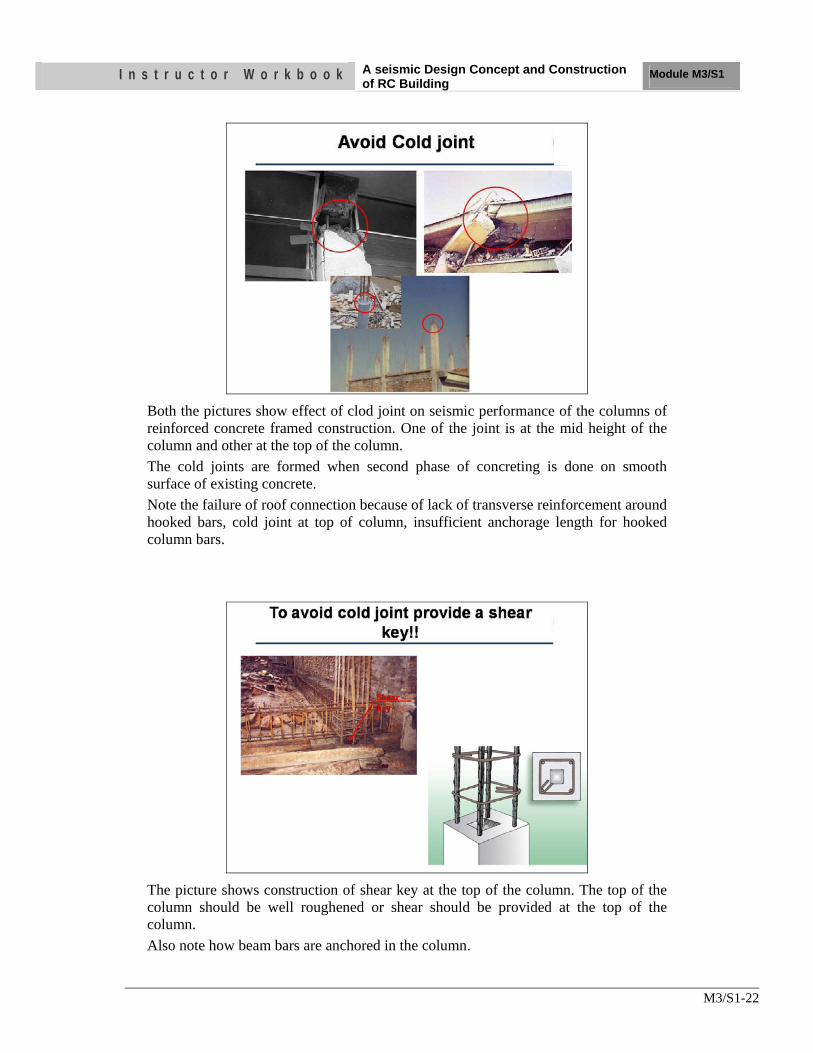
Both the pictures show effect of clod joint on seismic performance of the columns of reinforced concrete framed construction. One of the joint is at the mid height of the column and other at the top of the column. The cold joints are formed when second phase of concreting is done on smooth surface of existing concrete. Note the failure of roof connection because of lack of transverse reinforcement around hooked bars, cold joint at top of column, insufficient anchorage length for hooked column bars.
The picture shows construction of shear key at the top of the column. The top of the column should be well roughened or shear should be provided at the top of the column. Also note how beam bars are anchored in the column.

I n s t r u c t o r W o r k b o o k A seismic Design Concept and Construction of RC Building
Module M3/S1
M3/S1-23
5. Our Practice for Ductile Detailing
The slides shown earlier clearly show shear confinement failure and buckling of longitudinal bars. These problems are result of lack of stirrups, unanchored end of stirrups in the core of concrete as shown in the above pictures. Use of even open stirrups has been observed as shown in first photograph which is a worst possible case.
The picture exposes the lack of anchorage of column bars, lack of stirrups. Beam, column ends suffer higher interaction of loads than rest of the member so these need special attention.

I n s t r u c t o r W o r k b o o k A seismic Design Concept and Construction of RC Building
Module M3/S1
M3/S1-24
These pictures reveals what our practice is and what should we expect if an earthquake strikes. In the first picture overlap is less than 200 mm and spacing of stirrups is more than 400 mm far less than what is required. In the second picture, column bars are left for future extension at the floor level. At one end lap length in too little and other hand this is not a good location to lap bas. Furthermore all the bars should not be lapped at the same location.
This picture reveals one more weakness of reinforcement detailing. Besides weaknesses discussed in earlier slide, this column has only three bars to be lapped. These shall not be less than four bas in a column.

I n s t r u c t o r W o r k b o o k A seismic Design Concept and Construction of RC Building
Module M3/S1
M3/S1-25
The pictures show damage concentration in the region of bar lapping. Because of interaction between overlapped bars and concrete for load transfer the overlapping section suffers higher level of damage. This interaction is further coupled with lack of stirrups which has led to buckling of bars, loss of concrete.

I n s t r u c t o r W o r k b o o k A seismic Design Concept and Construction of RC Building
Module M3/S1
M3/S1-26
The pictures presents both the interior and exterior beam-column joint damage because longitudinal beam bars of the beams were not confined within column longitudinal bars and stirrups. In the second picture, the corner joint failure, the beam bars are not well anchored inside the column, beam bars are not confined by transverse reinforcement through joint.

I n s t r u c t o r W o r k b o o k A seismic Design Concept and Construction of RC Building
Module M3/S1
M3/S1-27
It is common practice not to provide any stirrup in the beam-column joint region. In addition to it, it is also common to keep one face of beam bars outside the column bars. Furthermore, very short L-bend is provided at the end of beam bar which is not enough for anchorage.

I n s t r u c t o r W o r k b o o k A seismic Design Concept and Construction of RC Building
Module M3/S1
M3/S1-28
6. Ductile Detailing for Beam, Column and Beam-Column Joint
Beams sustain two basic types of failures, namely: Flexural (or bending) Failure: As the beam sags under increase loading, it can fail in two possible ways. If relatively more steel is present on the tension face, concrete crushes in compression; this is a brittle failure and is therefore undesirable. If relatively less steel is present on the tension face, the steel yields first and redistribution occurs in the beam until eventually the concrete crushes in compression; this is a ductile failure and hence is desirable. Thus, more steel on tension face is not necessarily desirable. The ductile failure is characterized with many vertical cracks starting from the stretched beam face, and going towards its mid depth. Shear failure: A beam may also fail due to shearing action. A shear crack is inclined at 45˚ to the horizontal; it develops at mid depth near the support and grows towards the top and bottom faces. Closed loop stirrups are provided to avoid such shearing action. Shear damage occurs when the area of these stirrups is insufficient. Shear failure is brittle, and therefore, shear failure must be avoided in the design of RC beams. Design Strategy Designing a beam involves the selection of its material properties (i.e., grades of steel bars and concrete) and shape and size; these are usually selected as a part of an overall design strategy of the whole building. And, the amount and distribution of steel to be provided in the beam be determined by performing design calculation as per IS 456-2000 and IS 13920 The IS 13920 prescribe that:
• At least two bars go through the full length of the beam at the top as well as the bottom of the beam.
• At the ends of beams, the amount of steel provided at the bottom is at least half that at top.

I n s t r u c t o r W o r k b o o k A seismic Design Concept and Construction of RC Building
Module M3/S1
M3/S1-29
The following requirements related to stirrups in RC beams:
• The diameter of stirrups must be at least 6mm; in beams more than 5m long, it must be at least 8mm.
• Both ends of the vertical stirrups should be bent into 135˚ hook and extended sufficiently beyond this hook to ensure that the stirrup does not open out in an earthquake. The maximum spacing of stirrups is less than half the depth of the beam.
Stirrups in RC beams help in three ways, namely
• They carry vertical shear force and thereby resist diagonal shear cracks. • They protect the concrete from bulging outwards due to flexure, and • They prevent the buckling of the compressed longitudinal bars due to flexure.
At the location of the lap, the bars transfer large forces from one to another. Thus, such laps of longitudinal bar are (a) made away from the face the column, and (b) not made at locations where they are likely to stretch by large amounts and yield. Moreover, at the location of laps, vertical stirrups should be provided at a closer spacing.

I n s t r u c t o r W o r k b o o k A seismic Design Concept and Construction of RC Building
Module M3/S1
M3/S1-30
Columns can sustain two types of damage, namely axial-flexural (or combined compression bending) failure and shear failure. Shear damage is brittle and must be avoided in columns by providing transverse ties at close spacing. Design Strategy Designing a column involves selection of materials to be used (i.e., grades of concrete and steel bars), choosing shape and size of the cross-section, and calculating amount and distribution of steel reinforcement. The first two aspects are part of the overall design strategy of the whole building. The Indian Ductile Detailing Code IS:13920-1993 requires columns to be at least 300mm wide. A column width of up to 200mm is allowed if unsupported length is less than 4m and beam length is less than 5m. Columns that are required to resist earthquake forces must be designed to prevent shear failure by a skillful selection of reinforcement. Vertical Bars tied together with Closed Ties Closely spaced horizontal closed ties help in three ways, namely i) they carry the horizontal shear forces induced by earthquakes, and thereby resist diagonal shear cracks, ii) they hold together the vertical bars and prevent them from excessively bending outwards (this bending phenomenon is called buckling), and (iii) they contain the concrete in the column within the closed loops. The ends of the ties must be bent as 135° hooks Such hook ends prevent opening of loops and consequently buckling of concrete and buckling of vertical bars. The Indian Standard IS13920-1993 prescribes following details for earthquake-resistant columns: (a) Closely spaced ties must be provided at the two ends of the column over a length not less than larger dimension of the column, one-sixth the column height or 450mm. (b) Over the distance specified in item (a) above and below a beam-column junction, the vertical spacing of ties in columns should not exceed D/4 for where D is the smallest dimension of the column (e.g., in a rectangular column, D is the length of the small side). This spacing need not be less than 75mm nor more than 100mm. At other

I n s t r u c t o r W o r k b o o k A seismic Design Concept and Construction of RC Building
Module M3/S1
M3/S1-31
locations, ties are spaced as per calculations but not more than D/2. (c) The length of tie beyond the 135° bends must be at least 10 times diameter of steel bar used to make the closed tie; this extension beyond the bend should not be less than 75mm. In columns where the spacing between the corner bars exceeds 300mm, the Indian Standard prescribes additional links with 180° hook ends for ties to be effective in holding the concrete in its place and to prevent the buckling of vertical bars. These links need to go around both vertical bars and horizontal closed ties; special care is required to implement this properly at site.
Lapping Vertical Bars In the construction of RC buildings, due to the limitations in available length of bars and due to constraints in construction, there are numerous occasions when column bars have to be joined. A simple way of achieving this is by overlapping the two bars over at least a minimum specified length, called lap length. The lap length depends on types of reinforcement and concrete. For ordinary situations, it is about 50 times bar diameter. Further, IS:13920-1993 prescribes that the lap length be provided ONLY in the middle half of column and not near its top or bottom ends. Also, only half the vertical bars in the column are to be lapped at a time in any storey. Further, when laps are provided, ties must be provided along the length of the lap at a spacing not more than 150mm.

I n s t r u c t o r W o r k b o o k A seismic Design Concept and Construction of RC Building
Module M3/S1
M3/S1-32
In RC buildings, portions of columns that are common to beams at their intersections are called beam-column joints. When forces larger than these are applied during earthquakes, joints are severely damaged. Repairing damaged joints is difficult, and so damage must be avoided. Thus, beam-column joints must be designed to resist earthquake effects.
Under earthquake shaking, the beams adjoining a joint are subjected to moments in the same direction. Under these moments, the top bars in the beam-column joint are pulled in one direction and the bottom ones in the opposite direction. These forces are balanced by bond stress developed between concrete and steel in the joint region. If the column is not wide enough or if the strength of concrete in the joint is low, there is insufficient grip of concrete on the steel bars. In such circumstances, the bar slips inside the joint region and beams lose their capacity to carry load. Further, under the action of the above pull-push forces at top and bottom ends, joints undergo geometric distortion; one diagonal length of the joint elongates and the other compresses. If the column cross-sectional size is insufficient, the concrete in the joint develops diagonal cracks.

I n s t r u c t o r W o r k b o o k A seismic Design Concept and Construction of RC Building
Module M3/S1
M3/S1-33
Problems of diagonal cracking and crushing of concrete in the joint region can be controlled by two means, namely providing large column sizes and providing closely spaced closed-loop steel ties around column bar in the joint region. The ties hold together the concrete in the joint and also resist shear force, thereby reducing the cracking and crushing of concrete.
In exterior joints where beams terminate at columns, longitudinal beam bars need to be anchored into the column to ensure proper gripping of bar in joint. The length of anchorage for a bar of grade Fe415 is about 50 times its diameter. This length is measured from the face of the column to the end of the bar anchored in the column. In columns of small widths and when beam bars are of large diameter a portion of beam top bar is embedded in the column that is cast up to the soffit of the beam, and a part of it overhangs. It is difficult to hold such an overhanging beam top bar in position while casting the column up to the soffit of the beam. On the other hand, if column width is large, the beam bars may not extend below the soffit of the beam. Thus, it is preferable to have columns with sufficient width. In interior joints, the beam bars (both top and bottom) need to go through the joint without any cut in the joint region. Also, these bars must be placed within the column bars and with no bends.

I n s t r u c t o r W o r k b o o k A seismic Design Concept and Construction of RC Building
Module M3/S1
M3/S1-34
This picture shows how a well detailed beam and columns look like. Furthermore, the stirrup ends should be well anchored inside the column or beam core as shown in the right hand picture.
Beam-column joint should be concentric as shown in the pictures. An eccentric beam-column joint creates additional stress in the joint region forcing it to fail.

I n s t r u c t o r W o r k b o o k A seismic Design Concept and Construction of RC Building
Module M3/S1
M3/S1-35
This slide shows how long the beam bar should be anchored in the column or beyond.
The picture shows how the beam bars can be anchored in the column.

I n s t r u c t o r W o r k b o o k A seismic Design Concept and Construction of RC Building
Module M3/S1
M3/S1-36
This picture shows few of the good practices of the beam-column joint, column, beam construction.
Stirrups in beam and column should be closely spaced. At the end of the column and beams stirrup spacing shall not be more than 100 mm till first 600 mm from their ends. In the rest of the mid section the spacing can be increased to half the depth of the section.

I n s t r u c t o r W o r k b o o k A seismic Design Concept and Construction of RC Building
Module M3/S1
M3/S1-37
UNIT TEST 1) The conceptual design and the detailing of the structural elements plays
a. central role in determining the structural behavior b. earthquake vulnerability of buildings c. to achieve a good earthquake resistance without incurring significant
additional cost d. all of above
2) Describe four virtues of earthquake-resistant building.
a. .………………………………………………………………………………… b. ……………………………………………………………………………… c. ……………………………………………………………………………… d. …………………………………………………………………………………
3) The failure of a column can affect the stability of the whole building, but the failure of a beam causes localized effect. Therefore, it is better to make beams to be the ductile weak links than columns. This method of designing RC buildings is called the ……………………………. design method
4) Torsion or excessive lateral deflection is generated in …………………buildings, that may result in permanent set or even partial collapse
5) Beams and columns in the open ground storey are required to be designed for ………… times the forces obtained from this bare frame analysis.
6) In new buildings, short column effect should be avoided during i)………………. stage or must be addressed in ii)………………………..
7) Above and below a beam-column junction, the vertical spacing of ties in columns should not exceed i)…………. for where D is the smallest dimension of the column (e.g., in a rectangular column, D is the length of the small side). This spacing need not be less than 75mm nor more than 100mm. At other locations, ties are spaced as per calculations but not more than ii)…………….
8) Put tick mark on correct practice of following figure of interior beam column joints.
A) B)

Nk on it
OBJECTIVES As a result of this session, you should be able to:
•• OOrrggaanniizzee tthhee iirrrreegguullaarr ggrriidd ppllaannss
•• KKnnooww aabboouutt tthhee ccoonnffiigguurraattiioonn ooff ppllaann aanndd eelleevvaattiioonn ooff SSeelleecctteedd BBuuiillddiinngg ffoorr SSttuuddyy
Instructor Workbook Module M4/S1
Description of Building Plan and Elevation of selected building for Analysis

I n s t r u c t o r W o r k b o o k Description of Floor plans and elevation/
Discussion of prevailing Practices Module M4/S1
M4/S1-1
CONTENTS
1. Introduction ...................................................................................................... 2 2. The Project ........................................................................................................ 2 3. The Selected Plan of the Building (Prevailing Practices) ............................. 2 4. Structural Problem with the Selected Plan .................................................... 5 5. Modification of plan to make it regular ......................................................... 6 6. Structural Benefits after modification of Plan ............................................ 10

I n s t r u c t o r W o r k b o o k Description of Floor plans and elevation/
Discussion of prevailing Practices Module M4/S1
M4/S1-2
1. Introduction This chapter provides you the details of the selected building under study. The building initially selected was with improper configuration and it was made proper with least change in its utilities.
2. The Project The tutorial project is a four and half storey building with three bays in both direction, Shorter and longer dimension of the building in plan are 9.6m and 11.475m.The supports are fixed at plinth level. The dimensions of beams are 230X375 for the first trial and Columns are 300X300. The slab will be a concrete slab 125mm thick. 3. The Selected Plan of the Building (Prevailing
Practices) The plan of the building selected is show below. Due to its improper location of column it is named as improper configuration building
Fig1; Ground floor plan

I n s t r u c t o r W o r k b o o k Description of Floor plans and elevation/
Discussion of prevailing Practices Module M4/S1
M4/S1-3
Fig2; 1st, 2nd, 3rd floor plan

I n s t r u c t o r W o r k b o o k Description of Floor plans and elevation/
Discussion of prevailing Practices Module M4/S1
M4/S1-4

I n s t r u c t o r W o r k b o o k Description of Floor plans and elevation/
Discussion of prevailing Practices Module M4/S1
M4/S1-5
4. Structural Problem with the Selected Plan
Grid plan
• There are 4 major discontinuities in frame along grid C, D, E and 2
• Since the frames along those grids are incomplete, the beam has to resist the expected lateral load resulting from the absence of column there.
• The beam has to resist biaxial bending moment.

I n s t r u c t o r W o r k b o o k Description of Floor plans and elevation/
Discussion of prevailing Practices Module M4/S1
M4/S1-6
• The ductility in this region cannot be expected and it must be designed for the R(response reduction factor) times the incoming forces.
• Such joint must be in elastic for extreme lateral loading.
• Overall ductility of the structure will be reduced which causes to decrease the overall performance of structure.
5. Modification of plan to make it regular

I n s t r u c t o r W o r k b o o k Description of Floor plans and elevation/
Discussion of prevailing Practices Module M4/S1
M4/S1-7

I n s t r u c t o r W o r k b o o k Description of Floor plans and elevation/
Discussion of prevailing Practices Module M4/S1
M4/S1-8

I n s t r u c t o r W o r k b o o k Description of Floor plans and elevation/
Discussion of prevailing Practices Module M4/S1
M4/S1-9

I n s t r u c t o r W o r k b o o k Description of Floor plans and elevation/
Discussion of prevailing Practices Module M4/S1
M4/S1-10
6. Structural Benefits after modification of Plan
• There are no any discontinuities in frame.
• The overall ductility of the structure can be insured.
• The span is not regular so there will be some torsion in the structure and must be checked for the safety.

I n s t r u c t o r W o r k b o o k Description of Floor plans and elevation/
Discussion of prevailing Practices Module M4/S1
M4/S1-11
Questions
1) The Ductility of the structure for the irregular building is
a) Greater b) Lesser c) No change
2) The Configuration of the building should be ……………. For best performance during Earthquake.
3) Regular b) irregular

Nk on it
OBJECTIVES As a result of this session, you should be able to:
•• OOrrggaanniizzee tthhee iirrrreegguullaarr ggrriidd ppllaannss
•• KKnnooww aabboouutt tthhee ccoonnffiigguurraattiioonn ooff ppllaann aanndd eelleevvaattiioonn ooff SSeelleecctteedd BBuuiillddiinngg ffoorr SSttuuddyy
Instructor Workbook Module M4/S2
Preliminary Design, Dl, LL Calculation

I n s t r u c t o r W o r k b o o k Preliminary Design, Dl, LL Calculation
Module M4/S2
M4/S2-1
CONTENTS
1. Introduction ...................................................................................................... 2 2. Grid plans of the building, Identification of critical elements ..................... 2 3. Preliminary design of Beam ............................................................................ 3
3.1 Deflection Criterion .................................................................................. 3
3.2 Ductile Detailing criteria .......................................................................... 3
4. Design of critical Slab panel C, D-1,2 ............................................................. 4 5. Preliminary Design of Column ........................................................................ 4 6. Load Calculation .............................................................................................. 5

I n s t r u c t o r W o r k b o o k Preliminary Design, Dl, LL Calculation
Module M4/S2
M4/S2-2
1. Introduction This chapter will provides you the details of the procedure for preliminary design of structural elements and process of evaluation of DL and LL. Building with proper configuration is selected for further investigation 2. Grid plans of the building, Identification of critical
elements
I n s t r u c t o r W o r k b o o k Preliminary Design, Dl, LL Calculation
Module M4/S2
M4/S2-3
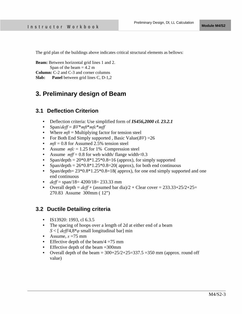
The grid plan of the buildings above indicates critical structural elements as bellows: Beam: Between horizontal grid lines 1 and 2. Span of the beam = 4.2 m Column: C-2 and C-3 and corner columns Slab: Panel between grid lines C, D-1,2 3. Preliminary design of Beam
3.1 Deflection Criterion
• Deflection criteria: Use simplified form of IS456,2000 cl. 23.2.1 • Span/deff = BV*mft*mfc*mff • Where mft = Multiplying factor for tension steel • For Both End Simply supported , Basic Value(BV) =26 • mft = 0.8 for Assumed 2.5% tension steel • Assume mfc = 1.25 for 1% Compression steel • Assume mff = 0.8 for web width/ flange width<0.3 • Span/depth = 20*0.8*1.25*0.8=16 (approx), for simply supported • Span/depth = 26*0.8*1.25*0.8=20( approx), for both end continuous • Span/depth= 23*0.8*1.25*0.8=18( approx), for one end simply supported and one
end continuous • deff = span/18= 4200/18= 233.33 mm • Overall depth = deff + (assumed bar dia)/2 + Clear cover = 233.33+25/2+25=
270.83 Assume 300mm ( 12”)
3.2 Ductile Detailing criteria
• IS13920: 1993, cl 6.3.5 • The spacing of hoops over a length of 2d at either end of a beam
S < [ deff/4,8*φ small longitudinal bar] min • Assume, s =75 mm • Effective depth of the beam/4 =75 mm • Effective depth of the beam =300mm • Overall depth of the beam = 300+25/2+25=337.5 =350 mm (approx. round off
value)

I n s t r u c t o r W o r k b o o k Preliminary Design, Dl, LL Calculation
Module M4/S2
M4/S2-4
4. Design of critical Slab panel C, D-1,2
• Ref IS456:2000, cl. 24.4,ANNEX D • Slab Boundary Condition: Two adjacent edge discontinuous • Aspect ratio, ly/lx = 4200/3900=1.08 • Short Span Coefficient for continuous edge=0.0518 • Short Span Coefficient for Mid span= 0.039 • Long Span Coefficients for continuous edge = 0.047 • Long span Coefficients for mid span =0.035 • Critical moment coefficient at support αx = 0.0518(at support) and at mid span αx
= 0.039 • Critical slab Moment = αx*w*lx2 • Assume trial Slab depth =125mm • DL Intensity = 0.125*25 = 3.125 KN/m2 • LL Intensity =2 KN/m2 ( for residential Building) • Finishing load intensity =1.0KN/m2 • Max BM for Unit strip for 1.5DL + 1.5LL Combination =
0.0518*(1.5*(3.125+2+1))*3.92 =7.24 KN-m • Depth of the slab for Balanced section = d = 59 mm • Deflection Criteria IS456,2000 cl. 23.2.1 • Assume depth of the slab =125 mm, deff =125-15-4 =104mm • Actual mid span moment = 0.039*1.5(3.125+2+1)*3.92 =5.45KN-m • Required Ast =0.14% from chart 4 of SP16 for deff =100 and Mu = 4.56 • For fs = 240, pt = 0.14% fig 4 of IS 456; 2000, mft = span/(BV*deff) =
3900/(23*104) =1.65 • Check for deflection: Span/deff = BV*mft = 23*1.65 = 37.9 • Deff = span/37.9 = 3900/37.9 = 102.9mm • D =102.9+15+4 = 121.9 < 125mm • Hence Overall Depth of 125mm is ok with slab
5. Preliminary Design of Column
• According to the new draft code of IS 13920 the minimum dimension of column should be 15 times the largest bar diameter => Minimum dimension for 20 mm dia. bar = 20*15 = 300mm
• Use your experience to select column size starting from 300X300 in multiple of 25 • Select column size 300X300

I n s t r u c t o r W o r k b o o k Preliminary Design, Dl, LL Calculation
Module M4/S2
M4/S2-5
6. Load Calculation
• SAP 2000 considers self load of the assigned member, so no need to calculate Load from beam, column.
• Calculate tributary DL and LL from slab to beam by 45 degree angle distribution.
• NBC 102 and NBC 103 Recommends Use of IS 875, Part1 for DL and part 2 for LL Respectively.
• From IS 875 part 1 – Unit wt of RCC =25 KN/m3 ( Table 1, No 20) – Unit wt of Cement plaster = 20.4 KN/m3 ( Table 1, No 25) – Unit wt of brick masonry =18.85 KN/m3 ( Table 1, No 36) – Mortar screed = 0.21 KN/m2 ( Table 2, No 8) – Unit wt of Marble finishing = 26.7 KN/m2 ( Table 1, No 47)
• From IS 875 part 2 For residential building – Imposed load for Dwelling residential building All rooms , kitchen, toilet
and bath rooms =2 KN/m2 ( Table 1, 1,a1) – For Corridors, passages and stair case =3 KN/m2 ( Table 1, 1,a2) – For balconies =3 KN/m2 – For roof with Access =1.5KN/m2 (Table2,1,1)
• DL from slab =0.125m*25 KN/m2= 3.125 KN/m2 • DL from Mortar screed = 0.21 KN/m2 • DL from ½ inch cement plaster= 0.0125*20.4=0.225 KN/m2 • DL from 1” marble finishing =0.0254*26.7 = 0.68 KN/m2
• Total DL = 4.24 KN/m2 • LL =2 KN/m2
• Partition wall load =1.2 KN/m2 (IS 875-part2, cl. 3.1.2) • Parapet wall of height 900mm, DL = 0.25*0.9*19.6 = 4.41KN/m

I n s t r u c t o r W o r k b o o k Preliminary Design, Dl, LL Calculation
Module M4/S2
M4/S2-6

I n s t r u c t o r W o r k b o o k Preliminary Design, Dl, LL Calculation
Module M4/S2
M4/S2-7

I n s t r u c t o r W o r k b o o k Preliminary Design, Dl, LL Calculation
Module M4/S2
M4/S2-8

I n s t r u c t o r W o r k b o o k Preliminary Design, Dl, LL Calculation
Module M4/S2
M4/S2-9

I n s t r u c t o r W o r k b o o k Preliminary Design, Dl, LL Calculation
Module M4/S2
M4/S2-10

I n s t r u c t o r W o r k b o o k Preliminary Design, Dl, LL Calculation
Module M4/S2
M4/S2-11
Questions
1) The critical beam for deflection criterion is
a) Largest span beam b) Shortest span beam
2) The critical slab panel for design check has
a) Largest shorter span b) largest longer span
3) The simplified load distribution from slab to beam is tributary area bounded by line with inclination with beam
a) 45o b) 30o c) 75o

OBJECTIVES As a result of this session, you should be able to:
•• KKnnooww aabboouutt tthhee MMooddeelliinngg ffeeaattuurree iinn SSaapp 22000000..
• Know about object oriented modeling and element oriented method.
•• FFaammiilliiaarr aabboouutt aannaallyyssiiss mmeetthhooddss ffoorr ssttrruuccttuurree bbrriieeffllyy..
•• FFaammiilliiaarr wwiitthh llooaadd ccoommbbiinnaattiioonn mmeetthhooddss •• DDeessiiggnn sstteeppss iinn SSAAPP •• GGrraapphhiiccaall uusseerr iinntteerrffaaccee SSccrreeeenn ooff SSAAPP
Instructor Workbook Module M4/S3
Analysis procedures with SAP2000

I n s t r u c t o r W o r k b o o k Analysis Procedures with SAP2000 Module M4/S3
M4/S3-1
CONTENTS
1. INTRODUCTION ............................................................................................ 2 2. THE STRUCTURAL MODEL ....................................................................... 2 3. THE SAP SCREEN .......................................................................................... 7

I n s t r u c t o r W o r k b o o k Analysis Procedures with SAP2000 Module M4/S3
M4/S3-2
1. INTRODUCTION There are different software available for 3 Dimensional finite element modeling of RC Buildings like SAP2000, ETAB 9, STAAD 2010, RISA 3D. In this course we are using SAP2000 developed by CSI Berkeley. SAP 2000 is the popular 3 dimensional nonlinear finite element modeling software for structural analysis of building bridges and gas pipe lines.
2. THE STRUCTURAL MODEL The structural model defined in graphical user interface consists primarily of the following types of components.
• Units • Objects and elements • Groups • Coordinate systems and grids • Properties • Functions • Load patterns • Load cases • Load Combinations • Design settings • Output and display definitions
Units: SAP2000 works with four basics units: force, length, temperature, and time. Choose different combinations of Force, displacement and temperature units as per requirement. For modeling of 3D building it is better to start with the combination (KN, m, C) When a new model is started, SAP2000 will ask the user to specify a set of units. Those units become the “base units” for the model. Although input data may be provided and output data can be viewed in any set of units, those values are always converted to and from the base units of the model. An important distinction is made between mass and weight. Mass is used only for calculating dynamic inertia and for loads resulting from ground acceleration. Weight is a force that can be applied like any other force load. Be sure to use force units when specifying weight values, and mass units (force-sec2/length) when specifying mass values.
Object and elements:

I n s t r u c t o r W o r k b o o k Analysis Procedures with SAP2000 Module M4/S3
M4/S3-3
The physical structural members in the model are represented by objects. Use the Graphical User Interface to “draw” the geometry of an object, and then “assign “properties and loads to the object to completely define a model of the physical member. The following objects are available in SAP Point Objects: Joint objects; automatically created at the end of all types of objects Grounded (one-joint) link objects: Are used to model special support behavior such as isolators, dampers, gaps, multi-linear springs, and more. Line Objects: Frame/cable/tendon objects: Are used to model beams, columns, braces, trusses, cable, and tendon members. Area objects: Are used to model walls, floors, and other thin walled members, as well as two-dimensional solids. (plane stress, plane strain, and axi-symmetric solids). Solid objects: Are used to model three-dimensional solids. As a general rule, the geometry of the object should correspond to that of the physical member. This simplifies the visualization of the model and helps with the design process. Groups: A group is a named collection of objects. It may contain any number of Objects of any number of types. Its main uses are for the quick selection of objects. Coordinate Systems and Grids: All locations in the model are ultimately defined with respect to a single global coordinate system. This is a three-dimensional, right-handed, Cartesian (rectangular) coordinate system. The three axes denoted X, Y, and Z, are mutually perpendicular, and satisfy the right-hand rule.SAP2000 always considers the global +Z direction as upward. By default, gravity acts in the –Z direction. For each coordinate system (the global and all additional systems), you can define a three-dimensional grid system consisting of intersecting “construction” lines used for locating objects in the model. Each grid may be of Cartesian (rectangular), cylindrical, or general type. Properties: Geometrical properties: such as section of beam and column Material properties: steel or concrete of different grades Support conditions: Hinged, fixed or free. Frame end releases: moment release, shear release, axial force release etc.

I n s t r u c t o r W o r k b o o k Analysis Procedures with SAP2000 Module M4/S3
M4/S3-4
Functions: Options are available to define functions to describe how load varies, as a function of period or time. The functions are needed for certain types of analysis only; they are not used for static analysis. A function is a series of digitized abscissa-ordinate data pairs. Four types of functions are available:
• Response-spectrum functions: Pseudo-spectral acceleration vs. period for use in response-spectrum analysis.
• Time-history functions: Loading magnitude vs. time for use in time-history analysis.
• Steady-state functions: Loading magnitude vs. frequency for use in steady-state analysis.
• Power-spectral-density functions: Loading magnitude squared per frequency vs. frequency for use in power-spectral-density analysis.
As many named functions as needed can be defined. Functions are not assigned to objects, but are used in the definition of load cases. Load patterns: Loads represent actions upon the structure, such as force, pressure, support displacement, thermal effects, ground acceleration, and others. A spatial distribution of loads upon the structure is called a load pattern. As many named load patterns as needed can be defined. Typically separate load patterns would be defined for dead load, live load, wind load, snow load, thermal load, and so on. Loads that need to vary independently, either for design purposes or because of how they are applied to the structure, should be defined as separate load patterns. After defining a load pattern name, assign specific load values to the objects as part of that load pattern. The load values assigned to an object specify the type of load (e.g., force, displacement), its magnitude, and direction (if applicable). Different loads can be assigned to different objects as part of a single load pattern. Each object can be subjected to multiple load patterns. Load cases: A load case defines how loads are to be applied to the structure, and how the structural response is to be calculated. Many types of load cases are available. Most broadly, load cases are classified as linear or nonlinear, depending on how the structure responds to the loading. The results of near analyses may be superposed, i.e., added together, after analysis. The following types of load cases are available: Static: The most common type of analysis. Loads are applied without dynamical effects

I n s t r u c t o r W o r k b o o k Analysis Procedures with SAP2000 Module M4/S3
M4/S3-5
Modal: Calculation of dynamic modes of the structure using eigenvector or Ritz-vector method. Loads are not actually applied, although they can be used to generate Ritz vectors.
Response-Spectrum: Statistical calculation of the response caused by acceleration loads. It requires response-spectrum functions.
Time-History: Time-varying loads are applied. It requires time history functions. The solution may be by modal superposition or direct integration methods.
Buckling: Calculation of buckling modes under the application of loads.
Hyperstatic: Calculation of the secondary forces due to pre-stress forces and other self-equilibrating loads. Moving Load: Calculation of the most severe response caused by vehicle loads moving along lanes on the structure. Uses defined vehicle loads and defined lanes rather than the load patterns used by other analysis types. Steady State: Harmonically varying loads are applied at one or more frequencies. It requires steady-state functions. Power Spectral Density: Harmonically varying loads are applied according to a probabilistic specification of loading over a range of frequencies, and the expected value of the response is determined. It requires power-spectral-density functions.
The results of nonlinear load cases normally should not be superposed. Instead, all loads acting together on the structure should be combined directly within the specific nonlinear load case. Nonlinear load cases may be chained together to represent complex loading sequences. The following types of nonlinear load cases are available: Nonlinear Static: Loads are applied without dynamical effects. It may be used for pushover analysis. Nonlinear Staged Construction: Loads are applied without dynamical effects, with portions of the structure being added or removed. Time-dependent effects can be included, such as creep, Shrinkage and aging. Nonlinear Time-History: Time-varying loads are applied. It requires time-history functions. The solution may be by modal superposition or direct integration methods. Any number of named load cases of any type may be defined. When the model is analyzed, the load cases to be run must be selected. Results for any load case may be selectively deleted. Load Combinations:

I n s t r u c t o r W o r k b o o k Analysis Procedures with SAP2000 Module M4/S3
M4/S3-6
A SAP2000 combination, also called a “combo,” is a named combination of the results from one or more load cases or other combinations. When a combination is defined, it applies to the results for every object in the model. Five types of combinations are available:
• Linear type: Results from the included load cases and combos are added linearly.
• Absolute type: The absolute values of the results from the included load cases and combos are added.
• SRSS type: The square root of the sum of the squares of the results from the included load cases and combos is computed.
• Envelope type: Results from the included load cases and combos are enveloped to find the maximum and minimum values.
• Range Add type: Positive values are added to the maximum and negative values are added to the minimum for the included load cases and combos, efficiently generating maximum and minimum responses for pattern loading.
Except for the envelope type, combinations should usually be applied only to linear load cases, since nonlinear results are not generally super-posable. Design is always based on combinations, not directly on load cases. A combination that contains only a single load case can be created. Each design algorithm creates its own default combinations. Additional user defined combinations can be created for design or other purposes. Design may be performed for any arrangement of user-defined and program generated combinations. Design settings: The design features of the program can be used on frame objects whose section properties use materials of concrete, steel, cold-formed steel, or aluminum. Several settings can be made that affect the design of a particular model:
• The specific design code to be used for each type of material, e.g. IS800 for steel, IS456;2000 for concrete. Preference settings of how those codes should be applied to a model.
• Combinations for which the design should be checked. • Groups of objects that should share the same design. • Optional “overwrite” values for each object that specify coefficients and
parameters to change the default values in the design-code formulas. • An “analysis section” used in the previous analysis, and a “design section”
resulting from the current design. The design section becomes the analysis section for the next analysis, and the iterative analysis and design cycle should be continued until the two sections become the same. Although there are no explicit design settings for concrete shells, the program will display design stresses and the reinforcing contours necessary to carry the tensile

I n s t r u c t o r W o r k b o o k Analysis Procedures with SAP2000 Module M4/S3
M4/S3-7
force component of the resolved tension compression couple. This information is accessed under the Display menu for shells. The required reinforcing area is calculated using the rebar material type specified by the user under the Define menu. Design results for the design section, when available, as well as all of the settings described herein, can be considered to be part of the model. Output and display definitions: The definition of the SAP2000 model and the results of analysis and design can be viewed and saved in many different ways, including:
• Two- and three-dimensional views of the model. • Tables of values in plain text, spreadsheet, or database format. • Formatted documents containing tables of values in rich text and HTML
format. • Function plots of analysis results. • Single button report creation. • Advanced report writer. • Export to other drafting and design programs.
Options are available to save named definitions of display views, sets of output tables, document formats, and function plots as part of a model. Combined with the use of groups, this can significantly speed up the process of getting results while developing the model. 3. THE SAP SCREEN After starting the program, the SAP2000 graphical user interface appears on your screen and looks similar to the figure2-1. The various parts of the interface are labeled in the figure and are described as follows. Main Window Figure 4-1 shows the main window for the graphical user interface. This window may be moved, resized, maximized, minimized, or closed using standard Windows operations. The main title bar, at the top of the main window, gives the program name and the name of the model file.

I n s t r u c t o r W o r k b o o k Analysis Procedures with SAP2000 Module M4/S3
M4/S3-8
Figure 2-1 The Graphical User Interface Main Window Menu Bar The menus on the Menu Bar contain almost all of the operations that can be performed using SAP2000. Those operations are called menu commands, or simply commands. Each menu corresponds to a basic type of operation. The operations are described later in this chapter. Menu commands are indicated as Menu > Command, where “Menu” is the menu name, and “Command” is an item you can select from the menu. In some cases, commands are on sub-menus of the main menu, in which case they are indicated as Menu > Sub-menu > Command. Toolbars The buttons on the toolbars provide quick access to many commonly used operations. Move the mouse cursor over one of these buttons and the name of the button will display, indicating the associated command, as shown in Figure 2-2.

I n s t r u c t o r W o r k b o o k Analysis Procedures with SAP2000 Module M4/S3
M4/S3-9
Figure 2-2: Roll over tool tip, indicating the Snap to Intersections command Most buttons correspond to menu commands. If a menu command has a corresponding button, it will be displayed next to the command on the menu, as shown in Figure 2-3. Figure 2-3 Menu Commands with Corresponding Buttons Display Windows Display windows show the geometry of the model, and may also include properties, loading, analysis or design results. From one to four display windows may be displayed at any time. Each window may have its own view orientation, type of display, and display options. For example, an unreformed shape could be displayed in one window, applied loads in another, an animated deformed shape in a third, and design stress ratios in the fourth window. Alternatively, four different views of an unreformed shape or other type of display can be shown: a plan view, two elevations, and a perspective view. Only one display window is “active” at a time. Viewing and display operations only affect the currently active window. Make any display window active by clicking on its title bar or within the window. Status Bar

I n s t r u c t o r W o r k b o o k Analysis Procedures with SAP2000 Module M4/S3
M4/S3-10
The status bar contains the following items:
• Status information about what the program is currently doing, or the number of objects currently selected.
• The coordinates of the mouse cursor. • A drop-down list to show or change the current units. • A drop-down list to show or change the current coordinate system. • Scrolling controls when displaying analysis results for multi-step cases. • Animation controls when displaying deformed shapes.
UNIT TEST
1) What is the deference between object and element? make list of the objects available in SAP2000
…..
2) What is the Base Unit?
…..
3) Describe load patterns and Load cases
…..
4) List the deferent load cases available for numerical modeling
……
Nk on it
OBJECTIVES As a result of this session, you should be able to:
•• MMaakkee 33--DD wwiirree ffrraammee mmooddeell ooff aa BBuuiillddiinngg IInn SSaapp 22000000
•• AAppppllyy DDeeaadd LLooaaddss aanndd LLiivvee llooaaddss ttoo bbeeaamm •• DDeetteerrmmiinnee aanndd aappppllyy EEaarrtthhqquuaakkee llooaadd ffrroomm
mmooddeell •• IImmpprroovvee mmooddeell ttoo rreemmoovvee sshhoorrtt ccoolluummnn eeffffeecctt • DDiissppllaayy ffoorrccee ddiiaaggrraammss
Instructor Workbook Module M4/ S4,S5,S6
Preparation of Model in SAP 2000/Check for input and output

I n s t r u c t o r W o r k b o o k Preparation of Model in SAP2000 Module M4/ S4-S6
M4/S4, S6-1
1. Introduction This chapter provides step-by-step instructions for building a basic SAP2000 model. Each step of the model creation process is identified, and various model construction techniques are introduced. At the completion of this chapter, you will have built the model shown in Figure 1.
Figure 1 The Final Model of selected Building
2. The Project The tutorial project is a four and half storey building with three bays in both directions. Shorter and longer dimension of the building in plan are 9.6 m and 11.475 m. The supports are fixed at plinth level. The dimensions of beams are 230X375 for the first trial and Columns are 300X300.

I n s t r u c t o r W o r k b o o k Preparation of Model in SAP2000 Module M4/ S4-S6
M4/S4, S6-2
The slab will be a concrete slab 125mm thick. The Structure will be analyzed for static loads only, and the Slab will be loaded with a Dead Load corresponding to slab and finishing 4.24KN/m2 and live load of 2 KN/m2 and seismic load for the fifth zone as per IS 1893;2000. The grid plan of the building is shown below. The frame in XZ plane and YZ planes are named by “Frame (vertical plane) Plane @ Plane ID”
Figure 2 General grid plan of selected Building
3. Step 1 Begin a New Model In this Step, the basic grid that will serve as a template for developing the model will be defined. Then a material will be defined and a list of double angle sections will be selected for the truss Auto Select Section list.

I n s t r u c t o r W o r k b o o k Preparation of Model in SAP2000 Module M4/ S4-S6
M4/S4, S6-3
A) Click the File menu > New Model command or the New Model button. The form shown in Figure 3 will display.
Figure 3 New Model form B) The New Model form allows for the quick generation of numerous model types using parametric generation techniques. However, in this tutorial the model will be started using only the grid generation. When laying out the grid, it is important that the geometry defined accurately represents the major geometrical aspects of the model, so it is advisable to spend time carefully planning the number and spacing of the grid lines. Select the Grid Only button, and the form Shown in Figure 4 will display. Verify that the default units are set to KN-mm as in fig 4.

I n s t r u c t o r W o r k b o o k Preparation of Model in SAP2000 Module M4/ S4-S6
M4/S4, S6-4
Figure 4 New Model form; chose unit as a KN-mm and grid only option C) The Quick Grid Lines form is used to specify the grids and spacing in the X, Y, and Z directions. Set the number of grid lines to 4 for the X direction, and to 4 for the Y and 6 for the Z directions. Type 6000 mm into the X and Y direction spacing edit box and press the Enter key on your keyboard. Enter 3000 or 12 ft or 144 for both the Y and Z direction spacing. The values specified in the First Grid Line Location area locate the origin of the grid lines; make sure that these values are all set to zero for this tutorial.
Figure 5 Quick grid Line form

I n s t r u c t o r W o r k b o o k Preparation of Model in SAP2000 Module M4/ S4-S6
M4/S4, S6-5
D) Click the OK button to accept the changes, and the program will appear as shown in Figure 6. Note that the grids appear in two view windows tiled vertically, an X-Y “Plan” View on the left and a 3-D View on the right. The number of view windows may be changed using the Options menu > Windows command. The “Plan” view is active in Figure 6. When the window is active, the display title bar is highlighted. Set a view active by clicking anywhere in the view window. Note that the Global Axes are displayed as well, and that the Z positive is in the “up” direction. When SAP2000 refers to the direction of gravity, this is in the negative Z direction, or “down.” The grid spacing along X and Y directions are equal and needs modification.
Figure 6 The SAP2000 windows
E) Right click in the left active window and click Edit grid Data. Select Display grid as: Spacing Modify X grid spacing as: 2100, 3300, 3900, 0 Modify Y grid spacing as 4200, 3075, 3900, 0 Modify Z grid spacing as 2850, 2850, 2850, 2850, 2850, 0
Figure 7 Edit grid data

I n s t r u c t o r W o r k b o o k Preparation of Model in SAP2000 Module M4/ S4-S6
M4/S4, S6-6
Figure 8 Edit grid data
F) Selecting Deferent plan and elevation for the active 2D window Simply click button and watch for the plan or elevation ID

I n s t r u c t o r W o r k b o o k Preparation of Model in SAP2000 Module M4/ S4-S6
M4/S4, S6-7
4. Step2 Define a Material Specify material properties of concrete (fc’ = 27.579N/mm2) as shown in the figure below. A) Click the Define menu > Materials command to display the Define Materials form shown in Figure 9.
Figure 9 Define Materials form

I n s t r u c t o r W o r k b o o k Preparation of Model in SAP2000 Module M4/ S4-S6
M4/S4, S6-8
5. Step3- Define Sectional Properties
A) Define Frame Section for Beam 230X375 Go to Define >> Section Properties >>Frame Sections select on Add New Properties. Select Concrete from second drop down menu then Select Rectangular. In third drop-down menu enter beam section properties for BM230X375 as shown in figure below. Figure 10 Define Materials form
B) Define Frame Section for Column 300X300

I n s t r u c t o r W o r k b o o k Preparation of Model in SAP2000 Module M4/ S4-S6
M4/S4, S6-9
Figure 11 Define Materials form
6. Step4- Add Frame Objects Draw Frame Objects Make sure that the X-Y Plane @ Z=2850 view is active. This view should be in the left window. Also check that the Snap to Points and Grid Intersections command is active. This will assist in accurately positioning the frame objects. Alternatively, use the Draw menu > Snap to > Points and Grid Intersections command. By default, this command is active. A) Click button till status show X-Y Plane @ Z=2850, i.e. select first floor plan. B) Click the Draw Frame/Cable/Tendon button or use the Draw menu > Draw Frame/Cable/Tendon command. If you accessed the Draw Frame/Cable/Tendon command via the Draw menu, the Draw Frame/Cable/Tendon button will depress

I n s t r u c t o r W o r k b o o k Preparation of Model in SAP2000 Module M4/ S4-S6
M4/S4, S6-10
verifying your command selection. The Properties of Object pop-up form for frames will appear as shown in Figure 12. Select the BM 230X375 from the Pop-up window. Now plotting frame section is corresponding to plotting of beam section 230X375.
Properties of Object Line Object Type Straight Frame Section BM 230X375 Moment Released Continuous XY Plane Offset Normal 0 Drawing Control Type None <space bar>
Figure 12Properties of Object form C) Click in the Section drop-down list on the Properties of Object form and scroll down to BM 230X375. Single click on it to assign the beam section 230X375 to the members you will draw. D) To draw the first frame object, left click once in the X-Y Plane view at the X-Y origin, and then click again at the far right end along the same horizontal grid line (x=9300, y=0). The cursor location is indicated in the lower right-hand corner of the interface. A frame line should appear in both views (plan and 3D). After clicking to define the end point of the frame object, a right click will “lift the pen” so you will no longer be actively drawing, but will leave the Draw Frame/Cable/Tendon command active so that you may add additional objects. If you have made a mistake while drawing this object, click the Select Object button, to leave the Draw mode and go to the Select mode. Then click the Edit menu > Undo Frame Add command, and repeat Items B-D. E) Repeat Item D, drawing a frame object along X axis grid from left to right. Right click to stop drawing and start drawing to next grid parallel to X axis grid. Similarly repeat for the frame object along Y axis grid and for grids parallel to Y axis F) Click the Select Object button, or press the Esc key on the keyboard to exit the Draw Frame/Cable/Tendon command. 7. Step5- Replicate Objects With Replicate Command you can copy all the plotted beams in first storey to the next storeys

I n s t r u c t o r W o r k b o o k Preparation of Model in SAP2000 Module M4/ S4-S6
M4/S4, S6-11
A) Select the first floor beams by left clicking directly on the member, or left clicking to the right of the object, holding the left mouse button down, and dragging the mouse across the member. See Figure 13 for selection options.
Figure 13Graphical Selection Options
B) Click the Edit menu > Replicate command to access the form shown in Figure
14. C) On the Linear tab,
type 2850 into the dz edit box.
D) Type 3 into the Number edit box.
E) Click the OK button Note that first storey beam members have been generated up to fourth storey
F) go to fifth floor plan and plot beams for the pent house roof
Figure 14Replicate form

I n s t r u c t o r W o r k b o o k Preparation of Model in SAP2000 Module M4/ S4-S6
M4/S4, S6-12
Figure 15 Replication of first floor beam to upper floors Similarly make all columns in vertical plane and then replicate it to other vertical planes. Save the Model Save the model often during the development. Although typically you will save it with the same name, on occasion you may want to save it with a different name to record your work at various stages of development. 8. Step5- Assigning Boundary Condition Assigning Boundary Condition
• Go to X-Y Plane @Z=0. • Select all Nodes. • Go to Assign-joints- Restraints.

I n s t r u c t o r W o r k b o o k Preparation of Model in SAP2000 Module M4/ S4-S6
M4/S4, S6-13
• Select (fixed Boundary Condition)
9. Step5- Plotting Z Beam for Stair Case
• There are three Z-Beams in
– XZ Plane @Y=11175,
– YZ Plane @Y= 9300,
– XZ Plane @Y=7275
• The length of the three segment of Z beam is almost equal and equal to 1300 mm. Stair case divides each storey column in almost three equal parts(950mm)
Figure 16 Location of Z-Beams for Stair case

I n s t r u c t o r W o r k b o o k Preparation of Model in SAP2000 Module M4/ S4-S6
M4/S4, S6-14
• Right click on the sap Window
• Click on Edit Grid Data
• Add extra grids at X=6700 ,X=8000,Y=8575 ,Y=9875,Z=950 and Z=1900
Figure 17Additional grid lines for plotting Z-Beams

I n s t r u c t o r W o r k b o o k Preparation of Model in SAP2000 Module M4/ S4-S6
M4/S4, S6-15
9-1. Plotting Z Beam1 • Go to X-Z Plane @Y=11175
• Plot frame sections for Z Beam
• Select Z beam
• Use replicate command to copy to upper floors
Figure 17 plotting Z-Beams in frame X-Z Plane @Y=11175mm

I n s t r u c t o r W o r k b o o k Preparation of Model in SAP2000 Module M4/ S4-S6
M4/S4, S6-16
9.2 Plotting Z-Beam2 • Go to Y-Z Plane @X=9300
• Plot Z-Beam in ground floor
• Replicate the Z-Beam to Upper Storey
Figure 18 Plotting Z-Beams in frame, Y-Z Plane @X=9300mm

I n s t r u c t o r W o r k b o o k Preparation of Model in SAP2000 Module M4/ S4-S6
M4/S4, S6-17
9.3 Plotting Z-Beam3 • Go to Y-Z Plane @X=7275.
• Plot Z-Beam in ground floor.
• Replicate the Z-Beam to Upper Storey.
Figure 19Plotting Z-Beams in frame, Y-Z Plane @X=7275 mm

I n s t r u c t o r W o r k b o o k Preparation of Model in SAP2000 Module M4/ S4-S6
M4/S4, S6-18
9.4 Dividing frames • Go to Select-Select-All
• This will select all the elements
• Go to Edit-Edit Lines-Divide Frames
• Select Second options (Break at intersections with……..)
• Click OK
• This will divide the column and beam intersected by Z-Beams
10. Complete wire frame model
Figure20 Complete wire frame model
11. Possible Modelling Error Up to this stage Before applying loads the check for the connectivity of frame element and free nodes should be done to correct model.
Simply click Run on the tool bar. The model will run for the self loading of the members.
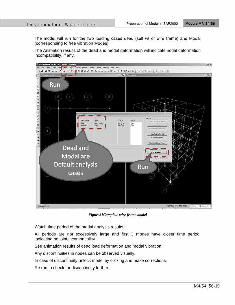
I n s t r u c t o r W o r k b o o k Preparation of Model in SAP2000 Module M4/ S4-S6
M4/S4, S6-19
The model will run for the two loading cases dead (self wt of wire frame) and Modal (corresponding to free vibration Modes)
The Animation results of the dead and modal deformation will indicate nodal deformation incompatibility, if any.
Figure21Complete wire frame model
Watch time period of the modal analysis results
All periods are not excessively large and first 3 modes have closer time period, indicating no joint incompatibility
See animation results of dead load deformation and modal vibration.
Any discontinuities in nodes can be observed visually.
In case of discontinuity unlock model by clicking and make corrections.
Re run to check for discontinuity further.

I n s t r u c t o r W o r k b o o k Preparation of Model in SAP2000 Module M4/ S4-S6
M4/S4, S6-20
12. Step 6- Define Load Patterns The loads used in this tutorial consist of dead and live static load patterns acting in the gravity direction and Earthquake load along horizontal direction.
For this example, assume that the dead load pattern consists of the self weight of the beam column and additional load from slab.
The live load pattern is taken to be 2 KN/m2
The dead load and live load is converted to the tributary triangular and trapezoidal member load for beam.
Unlock the model
Go to define-load patterns-add new Live load pattern with self load multiplying factor =0
Similarly define Wall Load and Wall Load1 Load pattern
Wall Load is the load pattern considering walls
Wall load1 is the load pattern to adjust Wall mass at roof level and just below the roof level
A) Click the Define menu > Load Patterns command to access the Define Load Patterns form shown in Figure 27. Note there is only a single default load pattern defined, which is a dead load pattern with self-weight (DEAD).
Figure 22Define Load Patterns form
Note that the self-weight multiplier is set to 1 for the default pattern. This indicates that this load pattern will automatically include 1.0 times the self-weight of all members. In SAP2000, both Load Patterns and Load Cases exist, and they may be different. However, the program automatically creates a corresponding load case when a load pattern is defined, and the load cases are available for review at the time the analysis is run.
B) Click in the edit box for the Load Pattern Name column. Type the name of the
new pattern, LIVE. Select a Type of load pattern from the drop-down list; in this case, select LIVE. Make sure that the Self Weight Multiplier is set to zero. Click the Add New Load Pattern button to add the LIVE load pattern to the load list.

I n s t r u c t o r W o r k b o o k Preparation of Model in SAP2000 Module M4/ S4-S6
M4/S4, S6-21
The Define Load Patterns form should now appear as shown in Figure 23. Click the OK button in that form to accept the newly defined static load pattern.
Figure 23The Define Load Patterns form after the live load pattern has been defined
C) Similarly Add Wall Load and assign it with dead load type
D) Add another Wall Load1 pattern; Wall load 1 pattern is simply for the balancing
mass in the roof storey, Simply apply 50% of wall load from the storey below roof to the roof level
13. Define Mass source
• Go to Define‐ Mass Source • Select Radio button from loads • Select
– Dead with scale factor 1 – Live with scale factor 0.25 – Wall Load with SF =1 – Wall Load1 with SF=1

I n s t r u c t o r W o r k b o o k Preparation of Model in SAP2000 Module M4/ S4-S6
M4/S4, S6-22

I n s t r u c t o r W o r k b o o k Preparation of Model in SAP2000 Module M4/ S4-S6
M4/S4, S6-23
Determining total seismic mass of the storey
• Run the Model • Watch for time
periods not excessively large.
• Select first storey joints
• Go to Display-Show tables
• Select joint mass and Base reactions

I n s t r u c t o r W o r k b o o k Preparation of Model in SAP2000 Module M4/ S4-S6
M4/S4, S6-24

I n s t r u c t o r W o r k b o o k Preparation of Model in SAP2000 Module M4/ S4-S6
M4/S4, S6-25
• Similarly determine lump mass of each storey and make summary table as below
14. Determining seismic load based on NBC 105

I n s t r u c t o r W o r k b o o k Preparation of Model in SAP2000 Module M4/ S4-S6
M4/S4, S6-26
15. Determining seismic load based on IS1893 Part1

I n s t r u c t o r W o r k b o o k Preparation of Model in SAP2000 Module M4/ S4-S6
M4/S4, S6-27
16. Assign Joint Constraints
• Un lock model again • Select all first floor joints • Go to Assign-Joint-Constraint-Select Diaphragm • Add New Diaphragm • Repeat same for all other storey
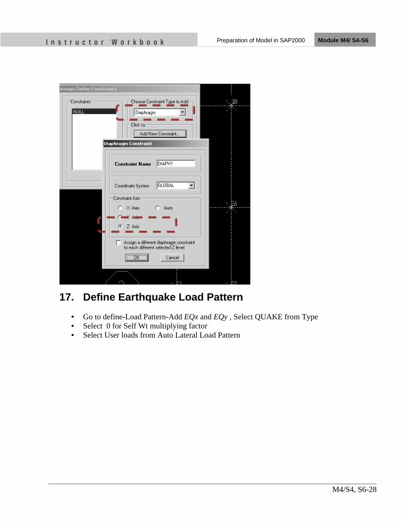
I n s t r u c t o r W o r k b o o k Preparation of Model in SAP2000 Module M4/ S4-S6
M4/S4, S6-28
17. Define Earthquake Load Pattern
• Go to define-Load Pattern-Add EQx and EQy , Select QUAKE from Type • Select 0 for Self Wt multiplying factor • Select User loads from Auto Lateral Load Pattern

I n s t r u c t o r W o r k b o o k Preparation of Model in SAP2000 Module M4/ S4-S6
M4/S4, S6-29
18. Assign Earthquake Loads
• Select Eqx load pattern and click Modify Lateral Load Patterns • Type Storey forces in column FX in Corresponding Diaphragm • Select Apply at Center of mass • Additional Ecc Ratio 0.5 • Click OK • Similarly repeat for Eqy load case
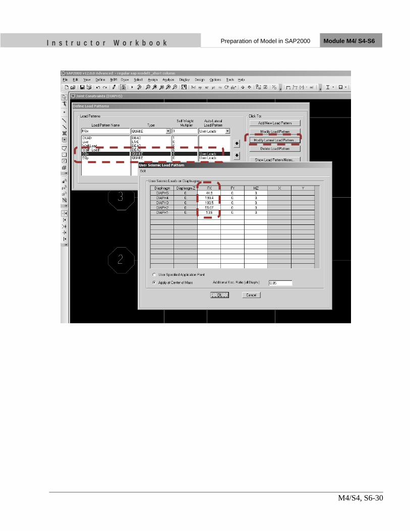
I n s t r u c t o r W o r k b o o k Preparation of Model in SAP2000 Module M4/ S4-S6
M4/S4, S6-30

I n s t r u c t o r W o r k b o o k Preparation of Model in SAP2000 Module M4/ S4-S6
M4/S4, S6-31
19. Load Combinations
A) NBC 105
B) IS 1893;2002
C) IS456;2000

I n s t r u c t o r W o r k b o o k Preparation of Model in SAP2000 Module M4/ S4-S6
M4/S4, S6-32
D) Defining Load Combinations a. IS1893-2002 is latest and refers load combination critical than NBC
105-1994 b. For this Example Earthquake Loading is Considered from IS1893-
2002 c. Go to Design -Concrete Frame Design -View/Revise Preferences d. Select Design Code as IS 456-2000 e. This step will add all the design combinations defined by IS 456-
2000 Automatically
E) Rename Load Combinations a. Go to Define-Load combinations-select any Load combination.
Click Modify Show Combo b. Watch the load cases and their Scale factor, in this case
• DL 1.2
• LL 1.2
• Eqx 1.2 c. Rename This Combination to 1.2(DL+LL+Eqx) - Click Modify and
then click OK d. Choose another combo for renaming.

I n s t r u c t o r W o r k b o o k Preparation of Model in SAP2000 Module M4/ S4-S6
M4/S4, S6-33
After Renaming the List of Load Combination Will be as below

I n s t r u c t o r W o r k b o o k Preparation of Model in SAP2000 Module M4/ S4-S6
M4/S4, S6-34
20. Analyze Structure A) Click RUN and Check For Any Warnings and Errors
B) Check For Bracing Action of Z-Beam
• Frame X‐Z Plane @Y=7.275 m
• See Axial Force Diagram for 1.2(DL+LL+Eqx) Combinations
• Axial Compression in Stair case Z beam can be observed
• Max Axial Compression=317.2KN

I n s t r u c t o r W o r k b o o k Preparation of Model in SAP2000 Module M4/ S4-S6
M4/S4, S6-35
• Axial Force Diagram for 1.2(DL+LL‐Eqx)
• MaxAxial Tension for reversal Loading =312KN
• These Axial Force can produce additional Shear Force in column in addition to increased shear from Short Column Effect

I n s t r u c t o r W o r k b o o k Preparation of Model in SAP2000 Module M4/ S4-S6
M4/S4, S6-36
C) Short Column Effect
• Again For Frame X‐Z Plane @Y=7.275 m
• Shear force along X direction(V2), For 1.2(DL+LL‐Eqx)
• Shear force in Short Column =154KN
• SF in nearest regular Column =65 KN
• The change in the direction of shear is due to z Beam Bracing action

I n s t r u c t o r W o r k b o o k Preparation of Model in SAP2000 Module M4/ S4-S6
M4/S4, S6-37
21. Stair case arrangement for Solving Short Column Effect

I n s t r u c t o r W o r k b o o k Preparation of Model in SAP2000 Module M4/ S4-S6
M4/S4, S6-38
22. Modelling Stair Case
• Go to X-Z Plane Y=11175 • Select two upper segment of Z Beam • Go to Edit-Move • Type dy = -300mm, Number =1 • Click OK • Delete upper floor Z Beams
• Top view of Stair case portion, modeled with Shell element

I n s t r u c t o r W o r k b o o k Preparation of Model in SAP2000 Module M4/ S4-S6
M4/S4, S6-39

I n s t r u c t o r W o r k b o o k Preparation of Model in SAP2000 Module M4/ S4-S6
M4/S4, S6-40
23. Check for Short Column Effects
• Run the Model again • Go to X-Z Plane @Y=11175 mm • Display Shear Force diagram for 1.2 (DL+LL+Eqx) • There is no Short Column Effects

I n s t r u c t o r W o r k b o o k Preparation of Model in SAP2000 Module M4/ S4-S6
M4/S4, S6-41
24. Viewing Force diagrams of defferent frames
• Bending Moment Diagram of frame XZ-Plane @Y=11175

I n s t r u c t o r W o r k b o o k Preparation of Model in SAP2000 Module M4/ S4-S6
M4/S4, S6-42
• Shear Force Diagram of frame XZ-Plane @Y=11175

I n s t r u c t o r W o r k b o o k Preparation of Model in SAP2000 Module M4/ S4-S6
M4/S4, S6-43
UNIT TEST
1) The modeling of staircase should be done to capture a) Short column effect b) Bracing action of staircase beam c) Both a and b d) Not necessary to model
2) Is Codes predicts ……….. Base shear than NBC for the same building
a) Greater b) Lesser c) Same
3) List all the Load Combinations to be considered for the Analysis of the building …
4) Why diaphragm Constraints are defined to the joints at slab level.
…

Nk on it
OBJECTIVES As a result of this session, you should be able to:
•• DDeevveelloopp eennvveellooppee BBeennddiinngg mmoommeenntt aanndd sshheeaarr ffoorrccee ddiiaaggrraammss aanndd ttaabblleess
•• DDuuccttiillee ddeessiiggnn pprroocceedduurree ooff bbeeaamm aass ppeerr IISS1133992200;;11999933 aanndd iittss ddrraafftt rreevviissiioonn
•• TTaacckkllee tthhee pprraaccttiiccaall pprroobblleemmss wwiitthh bbeeaamm ddeessiiggnn aanndd ddeettaaiilliinngg
Instructor Workbook Module M4/ S7,S8
Developing Envelope Diagram of Beam and its Sample Design

I n s t r u c t o r W o r k b o o k Developing Envelope Diagram of
Beam and its Sample design Module M4/ S7,S8
M4/S7, S8-1
CONTENTS
1. Sorting data for the design of beam (Beam Data Management) .................. 3 2. General Checks for Beam (Applicable for all beams) .................................. 8 3. Design of Beam (General data) ....................................................................... 9 4. Design of Beam ID 34 ....................................................................................... 9 5. Design of Beam ID 35 ..................................................................................... 12 6. Design of Beam ID 237 and 60 ...................................................................... 14 7. Design Summary ............................................................................................ 16 8. Adopted Reinforcement ................................................................................. 16 9. Moment Curvature diagram for beam ends ................................................ 17 10. Moment capacities of beam ........................................................................... 22 11. Shear Design of beam ..................................................................................... 23 12. Design for Shear Forces (Beam 34 End Shear) ........................................... 26 13. UNIT TEST ..................................................................................................... 27

I n s t r u c t o r W o r k b o o k Developing Envelope Diagram of
Beam and its Sample design Module M4/ S7,S8
M4/S7, S8-2
Introduction This chapter provides step-by-step instructions for Development of design input data for beam and ductile design procedures of the beam. IS 13920; 1993, IS 456 2000, SP16 and SP34 will be used for the design process. IS 13920; 1993 will govern among all the similar procedures given by another codes. The sample beam taken for the design is shown in below.
Figure 1; Beams 34, 35, 237, 68 and column 179,180 are selected from Frame X-Z Plane @Y=11175

I n s t r u c t o r W o r k b o o k Developing Envelope Diagram of
Beam and its Sample design Module M4/ S7,S8
M4/S7, S8-3
1. Sorting data for the design of beam (Beam Data Management)
A) End Length Offset
• Unlock the model • Select all Beams • Go to Assign-Frame sections-Frame End offsets • Click Automatic from Connectivity • This step will records output forces data from the face of the
column B) Frame Output Station Format
• Again select all beams • Go to Assign-Frame sections-Output stations • Type No of minimum Output station as 5 • The above step will records beam data at 5 station points only
2.

I n s t r u c t o r W o r k b o o k Developing Envelope Diagram of
Beam and its Sample design Module M4/ S7,S8
M4/S7, S8-4
C) Force Envelope Options • Go to Define-Load Combinations-Click Add New
Combo(COMBO1) • Select all 13 load combinations with scale factor 1 in all • Select Load Combination type as a Envelope • These steps will short maximum –ve and +ve force data at
every section
3.
D) RUN Model and Extracting Envelope Beam Data
• RUN The Model again • Select beam 34,35,237,60 • Go to Display-Show tables-select Frame output • Select Combo1 from Select load cases • Select ok • This option will display Envelope force data for beam
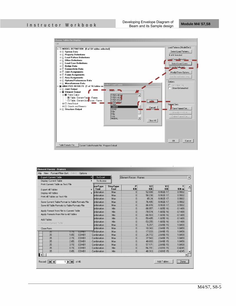
I n s t r u c t o r W o r k b o o k Developing Envelope Diagram of
Beam and its Sample design Module M4/ S7,S8
M4/S7, S8-5

I n s t r u c t o r W o r k b o o k Developing Envelope Diagram of
Beam and its Sample design Module M4/ S7,S8
M4/S7, S8-6
Beam Envelop data after organising,

I n s t r u c t o r W o r k b o o k Developing Envelope Diagram of
Beam and its Sample design Module M4/ S7,S8
M4/S7, S8-7

I n s t r u c t o r W o r k b o o k Developing Envelope Diagram of
Beam and its Sample design Module M4/ S7,S8
M4/S7, S8-8
4. General Checks for Beam (Applicable for all beams)
• Check for Axial Stress – Factored axial force =0 – Factored axial stress=0.0<0.1fck – Hence the beam comes under flexural member
(Cl6.1.1;IS13920:1993) • Check for member size
– Width of the Beam, B =230mm>200mm (Cl 6.1.3;IS13920:1993) – B/Depth of the beam=230/375=0.613>0.3 (Cl 6.1.2;IS13920:1993) – Span/Depth of the beam=4200/375=11.2>4 (Cl
6.1.4;IS13920:1993) • Check for limiting longitudinal reinforcement
– Minimum reinforcement=0.24√fck/fy=0.26% (Cl 6.2.1b;IS13920:1993)
– Maximum reinforcement=2.5% (Cl 6.2.2;IS13920:1993)

I n s t r u c t o r W o r k b o o k Developing Envelope Diagram of
Beam and its Sample design Module M4/ S7,S8
M4/S7, S8-9
5. Design of Beam (General data)
6. Design of Beam ID 34

I n s t r u c t o r W o r k b o o k Developing Envelope Diagram of
Beam and its Sample design Module M4/ S7,S8
M4/S7, S8-10

I n s t r u c t o r W o r k b o o k Developing Envelope Diagram of
Beam and its Sample design Module M4/ S7,S8
M4/S7, S8-11

I n s t r u c t o r W o r k b o o k Developing Envelope Diagram of
Beam and its Sample design Module M4/ S7,S8
M4/S7, S8-12
7. Design of Beam ID 35

I n s t r u c t o r W o r k b o o k Developing Envelope Diagram of
Beam and its Sample design Module M4/ S7,S8
M4/S7, S8-13

I n s t r u c t o r W o r k b o o k Developing Envelope Diagram of
Beam and its Sample design Module M4/ S7,S8
M4/S7, S8-14
8. Design of Beam ID 237 and 60
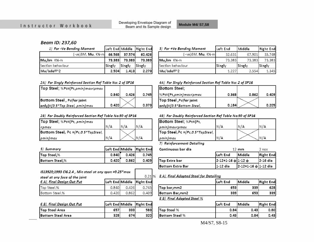
I n s t r u c t o r W o r k b o o k Developing Envelope Diagram of
Beam and its Sample design Module M4/ S7,S8
M4/S7, S8-15

I n s t r u c t o r W o r k b o o k Developing Envelope Diagram of
Beam and its Sample design Module M4/ S7,S8
M4/S7, S8-16
9. Design Summary
10. Note: All Beams are detailed with 2-12 dia Continuous bar at top and
bottom Faces
11. Adopted Reinforcement

I n s t r u c t o r W o r k b o o k Developing Envelope Diagram of
Beam and its Sample design Module M4/ S7,S8
M4/S7, S8-17
12. Moment Curvature diagram for beam ends

I n s t r u c t o r W o r k b o o k Developing Envelope Diagram of
Beam and its Sample design Module M4/ S7,S8
M4/S7, S8-18
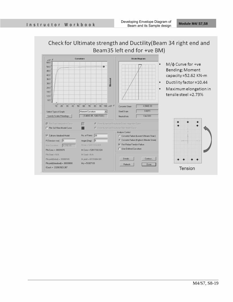
I n s t r u c t o r W o r k b o o k Developing Envelope Diagram of
Beam and its Sample design Module M4/ S7,S8
M4/S7, S8-19
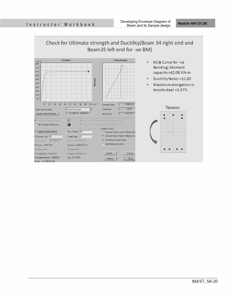
I n s t r u c t o r W o r k b o o k Developing Envelope Diagram of
Beam and its Sample design Module M4/ S7,S8
M4/S7, S8-20

I n s t r u c t o r W o r k b o o k Developing Envelope Diagram of
Beam and its Sample design Module M4/ S7,S8
M4/S7, S8-21

I n s t r u c t o r W o r k b o o k Developing Envelope Diagram of
Beam and its Sample design Module M4/ S7,S8
M4/S7, S8-22
13. Moment capacities of beam

I n s t r u c t o r W o r k b o o k Developing Envelope Diagram of
Beam and its Sample design Module M4/ S7,S8
M4/S7, S8-23
14. Shear Design of beam

I n s t r u c t o r W o r k b o o k Developing Envelope Diagram of
Beam and its Sample design Module M4/ S7,S8
M4/S7, S8-24

I n s t r u c t o r W o r k b o o k Developing Envelope Diagram of
Beam and its Sample design Module M4/ S7,S8
M4/S7, S8-25

I n s t r u c t o r W o r k b o o k Developing Envelope Diagram of
Beam and its Sample design Module M4/ S7,S8
M4/S7, S8-26
15. Design for Shear Forces (Beam 34 End Shear)
• DSF for left End of the Beam ID 35, Vu = 124.92 KN • Governing pt = 0.8 % • Shear Capacity of Concrete without stirrups,τc = 0.57 N/mm2 • Nominal Shear Stress, τv = Vu/bd = 124.92*1000/(230*342)= 1.59 N/mm2 • Shear Force to be resisted by stirrups, Vus = Vu-τc*bd = 125.07 KN • Assume 8 mm dia 2 legged STRPS with shearing area, Asv= 100.5 • Spacing of Shear Stirrups, S = 0.87*fy*Asv*d/Vus = 99.22 mm • Spacing of the special confining reinforcement ={S,342/4,8*φsmall}min =
{99.22,85.5,96} =85.5 • Provide 8mm dia 2-legged Stirrups @85 mm c/c

I n s t r u c t o r W o r k b o o k Developing Envelope Diagram of
Beam and its Sample design Module M4/ S7,S8
M4/S7, S8-27
16. UNIT TEST
1) Ductile design detailing is govern by IS Code.
a) IS 456:2000 b) IS 1893:2000 c) IS13920:1983
2) Describe the use of End (length) offset Command available in SAP2000. ......
3) What is the use of Envelope Load Combination? ......
4) Describe the methods to extract envelope Bending moment, shear force data from analysis output and organising it for using it for input design data.
• ....... • ......
5) Write down the design steps for the longitudinal reinforcement in beam.
• .... • ....
6) Describe the process of evaluating design shear for the beam considering the
formation of plastic hinge. • ... • ....
7) What are the steps of shear design of the beam?
• .... • .....

Nk on it
OBJECTIVES As a result of this session, you should be able to:
• Organize column design data from SAP2000
• Approximate Design of Column
• Check for column reinforcement for flexural and column action
• Determine column shear due to plastic hinge formation
• Design of column for shear
• Check for joint shear
Instructor Workbook Module M4/ S9
Sample Column Design

I n s t r u c t o r W o r k b o o k Sample Column Design Module M4/S9
M4/S9-1
CONTENTS
Developing Envelope Diagram of Beam and its Sample design .................. Error! Bookmark not defined.
1. Sorting data for the design of Column (Column Data Management) .................................. 3
2. Column General Calculations ................................................................................................. 6
3. Column Design Data ................................................................................................................ 6
4. Column Design Data Summary ............................................................................................... 7
5. Design of Column (179, Top) Approximate design (Considering Uni-axial bending only) ........................................................................................................................................... 7
6. Design of Column (180, Bottom) Approximate design (Considering Uni-axial bending only) ............................................................................................................................ 8
7. Check for column dimension for flexural action ................................................................... 9
8. Summary of Approximate design ......................................................................................... 10
9. Final Design Check for Column 179 top .............................................................................. 10
10. Final Design Check for Column 180 bottom ........................................................................ 11
11. Summary of Column Design Check ...................................................................................... 12
12. Shear Capacity of Column without Stirrups ....................................................................... 13
13. SF Force Due to Plastic Hinge Formation in Beams ........................................................... 14
14. Design for Shear ..................................................................................................................... 15
15. Design for Confining Links (IS13920; 1993 Cl7.3) .............................................................. 15
16. Confining Links arrangement ............................................................................................... 16
17. Column Moment capacity ...................................................................................................... 18
18. Check for strong column weak beam ................................................................................... 19
19. Joint Shear .............................................................................................................................. 19
20. Design for Joint Shear ............................................................................................................ 20
21. UNIT TEST ............................................................................................................................. 21

I n s t r u c t o r W o r k b o o k Sample Column Design Module M4/S9
M4/S9-2
1. Introduction This chapter provides step-by-step instructions for Development of design input data for Column ductile design procedures of the column. IS 13920; 1993, IS 456 2000, SP16 and SP34 will be used for the design process. IS 13920; 1993 will govern among all the similar procedures given by another codes. The sample Column considered for the design is shown in below.
Figure 1; Column 179,180 are selected from Frame X-Z Plane @Y=11175

I n s t r u c t o r W o r k b o o k Sample Column Design Module M4/S9
M4/S9-3
2. Sorting data for the design of Column (Column Data Management)
The force data of column 179 top and column 180 bottoms is required for the design of reinforcement crossing joint common to the column 179 and 180. Select Column 179 and Column 180 - Go to Display -Show Tables -
3.

I n s t r u c t o r W o r k b o o k Sample Column Design Module M4/S9
M4/S9-4

I n s t r u c t o r W o r k b o o k Sample Column Design Module M4/S9
M4/S9-5

I n s t r u c t o r W o r k b o o k Sample Column Design Module M4/S9
M4/S9-6
Select Data corresponding to End station of Column 179 and initial station of column 180 delete all others
4. Column General Calculations
5. Column Design Data

I n s t r u c t o r W o r k b o o k Sample Column Design Module M4/S9
M4/S9-7
6. Column Design Data Summary
7. Design of Column (179, Top) Approximate design (Considering Uni-axial bending only)

I n s t r u c t o r W o r k b o o k Sample Column Design Module M4/S9
M4/S9-8
8. Design of Column (180, Bottom) Approximate design (Considering Uni-axial bending only)
However, Code requires a minimum percentage of steel at 0.8% Hence, adopt 0.8%
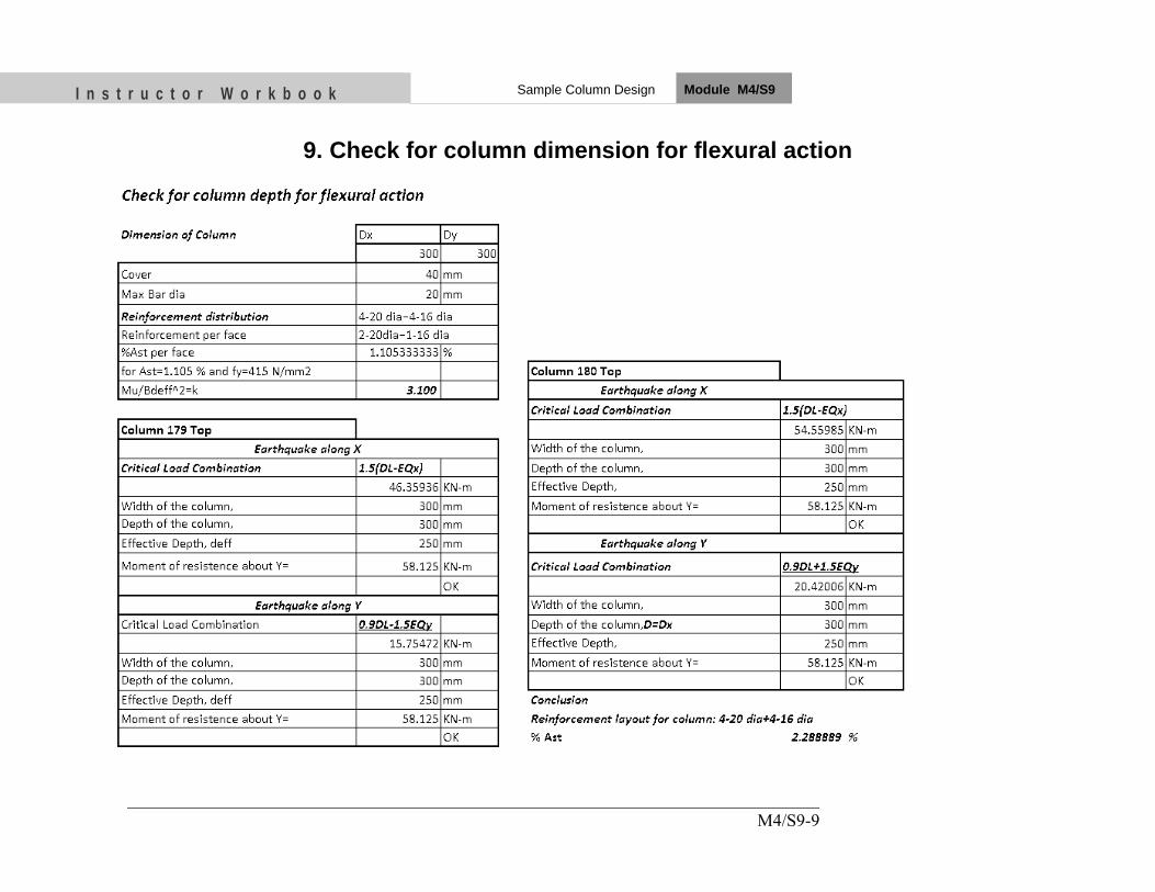
I n s t r u c t o r W o r k b o o k Sample Column Design Module M4/S9
M4/S9-9
9. Check for column dimension for flexural action
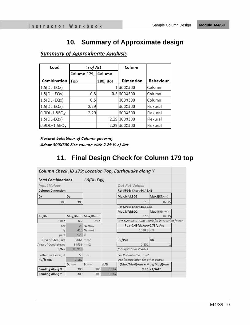
I n s t r u c t o r W o r k b o o k Sample Column Design Module M4/S9
M4/S9-10
10. Summary of Approximate design
11. Final Design Check for Column 179 top

I n s t r u c t o r W o r k b o o k Sample Column Design Module M4/S9
M4/S9-11
12. Final Design Check for Column 180 bottom

I n s t r u c t o r W o r k b o o k Sample Column Design Module M4/S9
M4/S9-12
13. Summary of Column Design Check

I n s t r u c t o r W o r k b o o k Sample Column Design Module M4/S9
M4/S9-13
14. Shear Capacity of Column without Stirrups

I n s t r u c t o r W o r k b o o k Sample Column Design Module M4/S9
M4/S9-14
15. SF Force Due to Plastic Hinge Formation in Beams
• Shear force due to plastic hinge formation in end beams
=1.4* (117.2+117.2)/2.85 = 115.14 KN
• Maximum Shear Force From Analysis = 82.4 KN
• Hence ; Formation of plastic hinge governs shear design of column
• Design Shear force for Column 179 top half and 180 bottom half
= 115.14 KN

I n s t r u c t o r W o r k b o o k Sample Column Design Module M4/S9
M4/S9-15
16. Design for Shear
17. Design for Confining Links (IS13920; 1993 Cl7.3)
• H= longer dimension of the rectangular confining hoop measured to its outer face. • The dimension ‘h’ of the hoop could be reduced by introducing cross ties. • Ak =Area of confined concrete core in the rectangular hoop measured to its
outside dimensions. • Ag= Gross area of column • Ash= Area of shear stirrups used
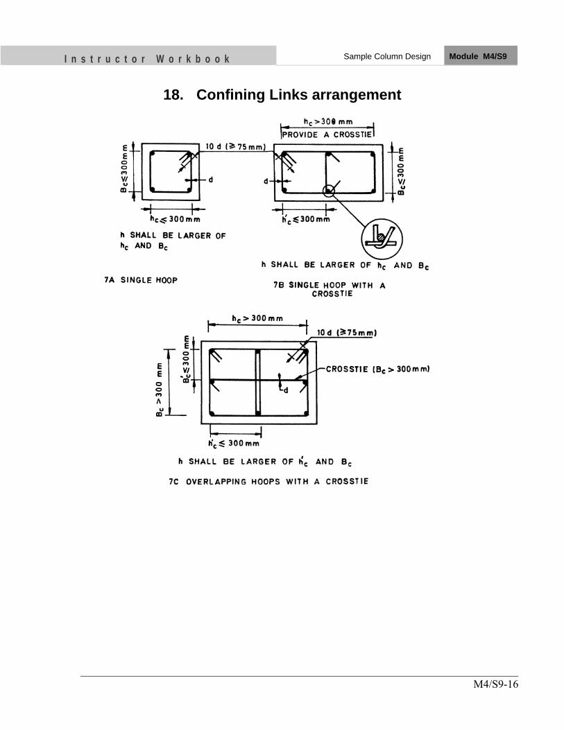
I n s t r u c t o r W o r k b o o k Sample Column Design Module M4/S9
M4/S9-16
18. Confining Links arrangement

I n s t r u c t o r W o r k b o o k Sample Column Design Module M4/S9
M4/S9-17

I n s t r u c t o r W o r k b o o k Sample Column Design Module M4/S9
M4/S9-18
19. Column Moment capacity

I n s t r u c t o r W o r k b o o k Sample Column Design Module M4/S9
M4/S9-19
20. Check for strong column weak beam
• Sum of the beam Moment Capacity =117.2+117.2= 234.4KN-m
• Sum of column Moment capacity=175+175=350 KN-m
• Capacity ratio=350/234.4=1.49>1.1, Safe in Strong column Weak Beam
21. Joint Shear

I n s t r u c t o r W o r k b o o k Sample Column Design Module M4/S9
M4/S9-20
22. Design for Joint Shear
• Joint Shear force, Vjx = 534.31+534.31-115.14= 953.48 KN
• Joint width, bj = {350,230+0.5*400}min=350mm
• Joint Depth, hj = 400 mm • Effective shear area of the joint, Ac =4
00*350 = 140000 mm2 • Joint shear strength=1.2*√fck*Ac = 840
KN< 953.48 KN=> Not safe • Shear to be resisted by links = 953.48 -840
=113.48 KN • Assuming 8 mm dia two legged stirrups,
spacing = 0.87*415*100*400/(113.48*1000) = 127mm
• Provide 8 mm dia @125mm c/c within the joint

I n s t r u c t o r W o r k b o o k Sample Column Design Module M4/S9
M4/S9-21
23. UNIT TEST
1) Describe Design steps for the Column.
...
2) Area of Special Confining link, Ash=.....................
.....
. 3) For the check of strong column weak beam,
Sum of the column moment =..........*Sum of the Column Moment
.... 4) For Column behaviour, axial load/gross area must be greater than.............
.....
5) If Axial load/gross area of column <0.1*fck, Column element should be designed as a ..................... ....
6) Additional cross tie is necessary if the outer distance between longitudinal bars exceeds................. .....

Nk on it
OBJECTIVES As a result of this session, you should be able to:
•• DDeevveelloopp eennvveellooppee BBeennddiinngg mmoommeenntt aanndd sshheeaarr ffoorrccee ddiiaaggrraammss aanndd ttaabblleess
•• SSeeiissmmiicc ddeessiiggnn pprroocceedduurree ooff bbeeaamm aanndd CCoolluummnn aass ppeerr IISS1133992200;;11999933 aanndd iittss ddrraafftt rreevviissiioonn
•• TTaacckkllee tthhee pprraaccttiiccaall pprroobblleemmss wwiitthh bbeeaamm aanndd CCoolluummnn ddeessiiggnn aanndd ddeettaaiilliinngg
Instructor Workbook Module M4/ S10, S11
Beam & Column Design Exercise

I n s t r u c t o r W o r k b o o k Beam and Column Design Exercise Module M4/S10, S11
M4/S10, S11-1
CONTENTS
1. Introduction ...................................................................................................... 2 2. Envelope bending moment and shear force data for beam .......................... 3 3. General Checks for Beam (Applicable for all beams) .................................. 4 4. Design of Beam (General data) ....................................................................... 4 5. Design data of Beam ID 25 .............................................................................. 5 6. Design form for Beam ID 25, Fill the form to complete design of Beam
25 ........................................................................................................................ 6 7. Design data of Beam ID 26 .............................................................................. 7 8. Design form for Beam ID 26, Fill the form to complete design of Beam
26 ........................................................................................................................ 8 9. Design data of Beam ID 27 .............................................................................. 9 10. Design form for Beam ID 26, Fill the form to complete design of Beam
27 ...................................................................................................................... 10 11. Prepare Design Summary similar to the table below .................................. 11 12. Determine Moment Curvature diagram for beam ends Similar to the
sample below ................................................................................................... 12 13. Shear Design of beam ..................................................................................... 15 14. Column section 129top and, 130 bottom .......... Error! Bookmark not defined.

I n s t r u c t o r W o r k b o o k Beam and Column Design Exercise Module M4/S10, S11
M4/S10, S11-2
1. Introduction
This is the design exercise session for the participants, follow all the design instructions described in the session S7,S8 and S9
Figure 1; Design Beams 25,26, 27 and column section 129top and,130 bottom Frame X-Z Plane @Y=0

I n s t r u c t o r W o r k b o o k Beam and Column Design Exercise Module M4/S10, S11
M4/S10, S11-3
2. Envelope bending moment and shear force data for beam
Plot envelope diagram similar to sample on left
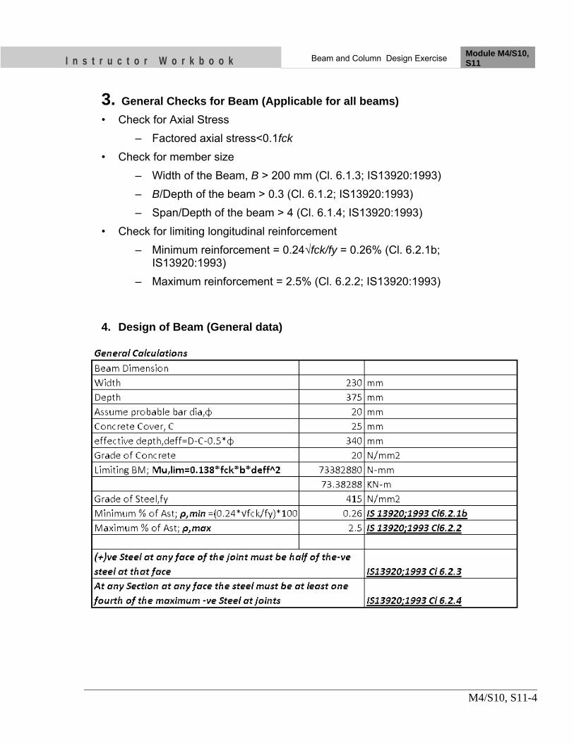
I n s t r u c t o r W o r k b o o k Beam and Column Design Exercise Module M4/S10, S11
M4/S10, S11-4
3. General Checks for Beam (Applicable for all beams) • Check for Axial Stress
– Factored axial stress<0.1fck • Check for member size
– Width of the Beam, B > 200 mm (Cl. 6.1.3; IS13920:1993) – B/Depth of the beam > 0.3 (Cl. 6.1.2; IS13920:1993) – Span/Depth of the beam > 4 (Cl. 6.1.4; IS13920:1993)
• Check for limiting longitudinal reinforcement – Minimum reinforcement = 0.24√fck/fy = 0.26% (Cl. 6.2.1b;
IS13920:1993) – Maximum reinforcement = 2.5% (Cl. 6.2.2; IS13920:1993)
4. Design of Beam (General data)

I n s t r u c t o r W o r k b o o k Beam and Column Design Exercise Module M4/S10, S11
M4/S10, S11-5
5. Design data of Beam ID 25 Envelope Bending Moment and Shear Force Table
Frame Station P V2(+),KN V2(‐),KN M3(+),KNM3(‐),KN
25
Plot Envelope diagram similar to the sample below

I n s t r u c t o r W o r k b o o k Beam and Column Design Exercise Module M4/S10, S11
M4/S10, S11-6
6. Design form for Beam ID 25, Fill the form to complete design of Beam 25

I n s t r u c t o r W o r k b o o k Beam and Column Design Exercise Module M4/S10, S11
M4/S10, S11-7
7. Design data of Beam ID 26 Envelope Bending Moment and Shear Force Table
Frame Station P V2(+),KN V2(‐),KN M3(+),KNM3(‐),KN
26
Plot Envelope diagram similar to the sample below

I n s t r u c t o r W o r k b o o k Beam and Column Design Exercise Module M4/S10, S11
M4/S10, S11-8
8. Design form for Beam ID 26, Fill the form to complete design of Beam 26

I n s t r u c t o r W o r k b o o k Beam and Column Design Exercise Module M4/S10, S11
M4/S10, S11-9
9. Design data of Beam ID 27 Envelope Bending Moment and Shear Force Table
Frame Station P V2(+),KN V2(‐),KN M3(+),KNM3(‐),KN
27
Plot Envelope diagram similar to the sample below

I n s t r u c t o r W o r k b o o k Beam and Column Design Exercise Module M4/S10, S11
M4/S10, S11-10
10. Design form for Beam ID 26, Fill the form to complete design of Beam 27
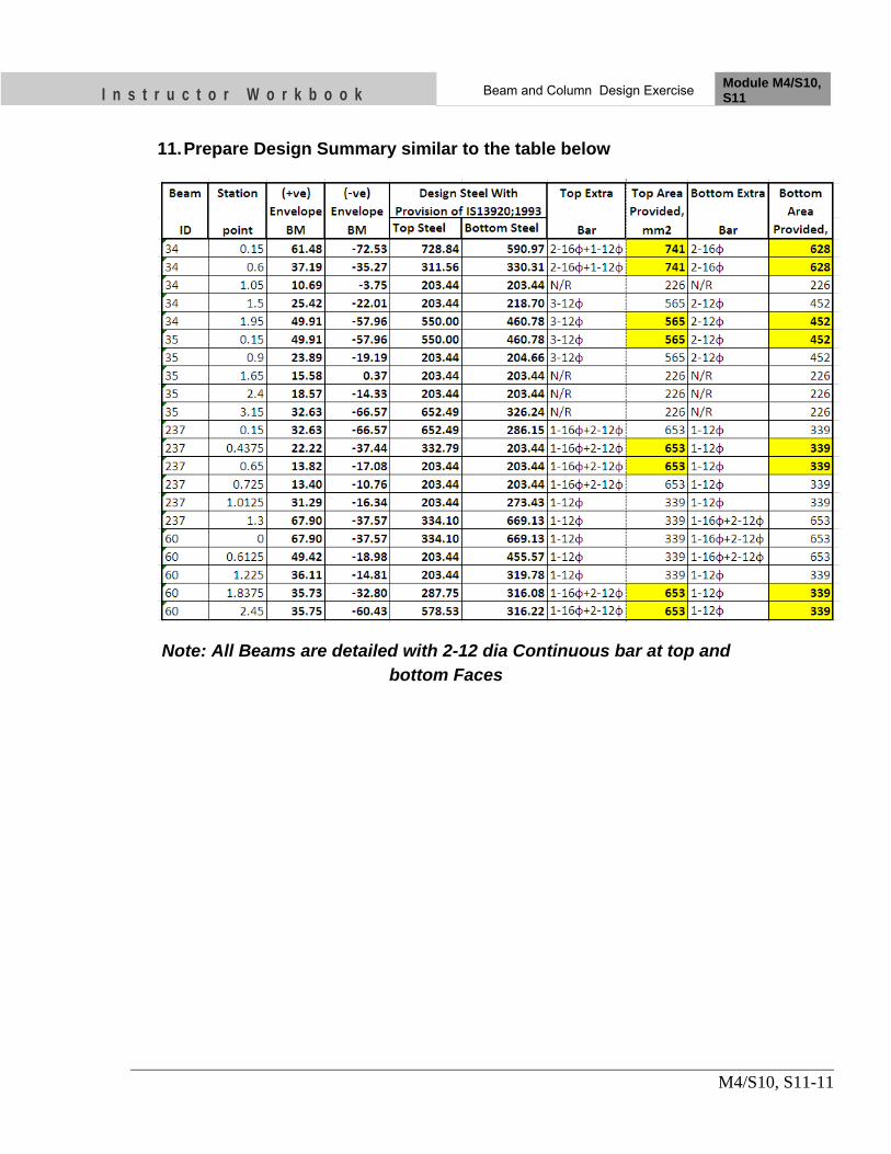
I n s t r u c t o r W o r k b o o k Beam and Column Design Exercise Module M4/S10, S11
M4/S10, S11-11
11. Prepare Design Summary similar to the table below
Note: All Beams are detailed with 2-12 dia Continuous bar at top and bottom Faces

I n s t r u c t o r W o r k b o o k Beam and Column Design Exercise Module M4/S10, S11
M4/S10, S11-12
Write down Adopted Reinforcement for beam end sections similar to below
12. Determine Moment Curvature diagram for beam ends Similar to the
sample below
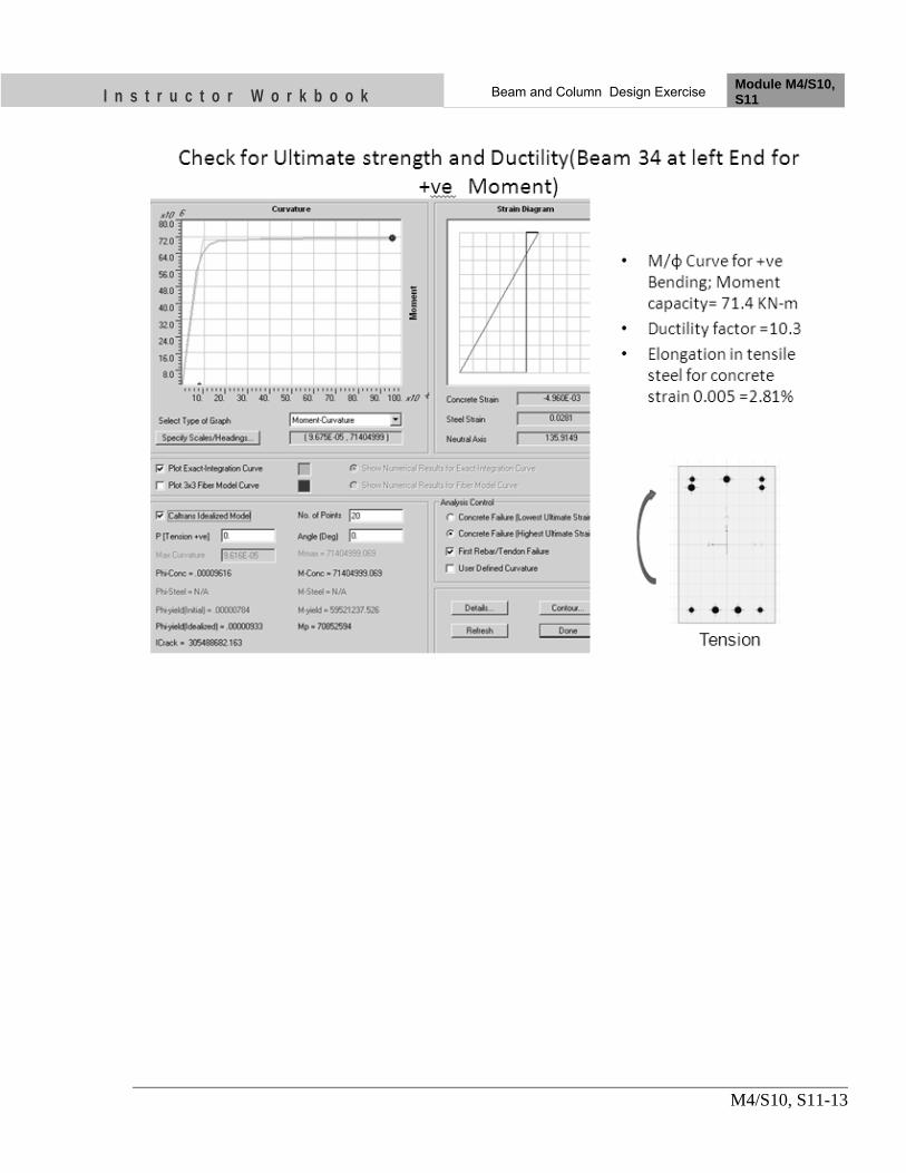
I n s t r u c t o r W o r k b o o k Beam and Column Design Exercise Module M4/S10, S11
M4/S10, S11-13

I n s t r u c t o r W o r k b o o k Beam and Column Design Exercise Module M4/S10, S11
M4/S10, S11-14
Write down Moment capacities of beam similar to sample below

I n s t r u c t o r W o r k b o o k Beam and Column Design Exercise Module M4/S10, S11
M4/S10, S11-15
13. Shear Design of beam
Determine the shear due to plastic hinge formation similar to the sample below

I n s t r u c t o r W o r k b o o k Beam and Column Design Exercise Module M4/S10, S11
M4/S10, S11-16
Note down the SF due to 1.2(DL+LL) Combination from SAP output, similar to sample below

I n s t r u c t o r W o r k b o o k Beam and Column Design Exercise Module M4/S10, S11
M4/S10, S11-17
Determine SF due to plastic Hinge formation similar to sample below
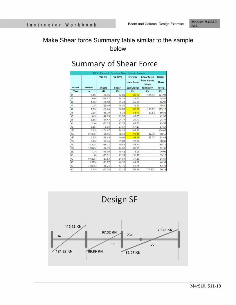
I n s t r u c t o r W o r k b o o k Beam and Column Design Exercise Module M4/S10, S11
M4/S10, S11-18
Make Shear force Summary table similar to the sample below

I n s t r u c t o r W o r k b o o k Beam and Column Design Exercise Module M4/S10, S11
M4/S10, S11-19
Design for Shear Forces for critical shear force
• DSF for left End of the Beam ID …… , Vu= ………… KN
• Governing pt = …….. %
• Shear Capacity of Concrete without stirrups, τc =………. N/mm2
• Nominal Shear Stress, τv = Vu/bd = ……….. N/mm2
• Shear Force to be resisted by stirrups, Vus = Vu-τc*bd =……… KN
• Assume 8 mm dia 2 legged STRPS with shearing area, Asv = …..
• Spacing of Shear Stirrups, S = 0.87*fy*Asv*d/Vus = ……… mm
• Spacing of the special confining reinforcement ={S, deff/4, 8*φsmall}min ={…….,………,……..}=……..mm
• Provide … mm dia … - legged STRPS @.........mm c/c

Nk on it
OBJECTIVES As a result of this session, you should be able to:
• Know about available design check provision in SAP2000.
• Display Design reinforcement in beam and columns
• Check for Strong Column Weak Beam ratios
• Check for Joint shear
• Check for required shear reinforcement
• Updating model for capacity check
Instructor Workbook Module M4/ S12
Sap2000 Design Features

I n s t r u c t o r W o r k b o o k Sap2000 Design Features Module M4/S12
M4/S12-1
CONTENTS
1. Introduction ...................................................................................................... 2 2. Sap 2000 Design ................................................................................................ 2 3. Design output display options ......................................................................... 2 4. Override Command ......................................................................................... 4 5. Check for Reinforcement details .................................................................... 4 6. Column/ Beam Capacity Check ...................................................................... 5 7. Don’t Use Sap Output directly ........................................................................ 6 8. Beam Reinforcement output ........................................................................... 7 9. Grouping of Beam of first to third floor with similar detailing ................. 11 10. Column grouping ............................................................................................ 13 11. Define Beam and Column Sections ............................................................... 14 12. Re Run the Model again and check for capacity ratio ................................ 16
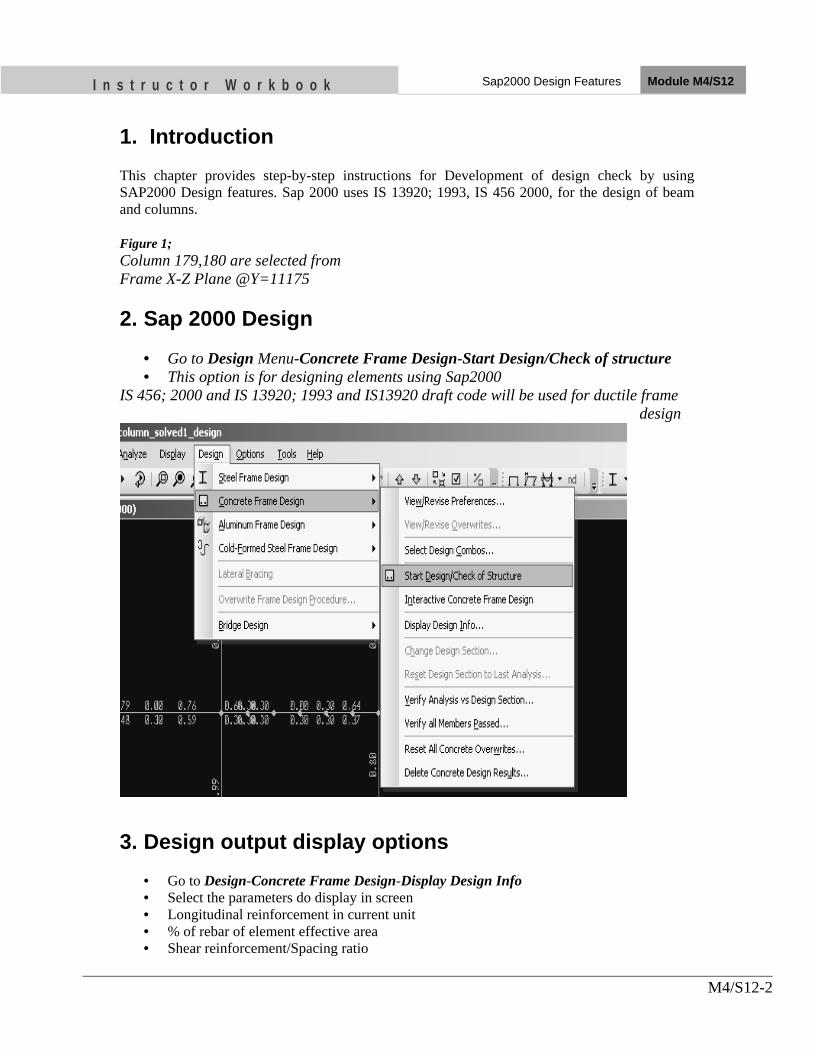
I n s t r u c t o r W o r k b o o k Sap2000 Design Features Module M4/S12
M4/S12-2
1. Introduction This chapter provides step-by-step instructions for Development of design check by using SAP2000 Design features. Sap 2000 uses IS 13920; 1993, IS 456 2000, for the design of beam and columns. Figure 1; Column 179,180 are selected from Frame X-Z Plane @Y=11175 2. Sap 2000 Design
• Go to Design Menu-Concrete Frame Design-Start Design/Check of structure • This option is for designing elements using Sap2000
IS 456; 2000 and IS 13920; 1993 and IS13920 draft code will be used for ductile frame design
3. Design output display options
• Go to Design-Concrete Frame Design-Display Design Info • Select the parameters do display in screen • Longitudinal reinforcement in current unit • % of rebar of element effective area • Shear reinforcement/Spacing ratio

I n s t r u c t o r W o r k b o o k Sap2000 Design Features Module M4/S12
M4/S12-3
• Column P-M-M Interaction ratio • 1.1*Column/Beam capacity<1 {Strong Column Weak Beam} • Column/Beam Capacity ratio>1.1 {Strong Column Weak Beam} • Joint shear capacity ratio<1
• This option will display the selected output information • Right click frame element for detail information

I n s t r u c t o r W o r k b o o k Sap2000 Design Features Module M4/S12
M4/S12-4
4. Override Command
• sap displays deferent beam reinforcement left and right to the same joint • Such detailing is practically impossible • Override command available in sap is useful to adjust such difficulties • Make groups of the beam with similar proposed detailing • Assign the section and reanalyze and redesign
5. Check for Reinforcement details
• Go to Design-Concrete Frame Design-Display Design Info • Select Longitudinal reinforcement in current unit

I n s t r u c t o r W o r k b o o k Sap2000 Design Features Module M4/S12
M4/S12-5
XZ-Plane @Y=11175 Color of Column indicates P-M-M interaction values qualitatively. Red color indicates overstressing of column. All other colors indicates safe in P-M-M interaction 6. Column/ Beam Capacity Check
• Column /Beam capacity ratio must be >1.1 • Otherwise either section or reinforcement should be revised. • The fig below shows most of the beam column failed in capacity check

I n s t r u c t o r W o r k b o o k Sap2000 Design Features Module M4/S12
M4/S12-6
XZ-Plane @Y=11175 7. Don’t Use SAP Output directly
• The design reinforcement indicates area of steel for the critical load combinations with consideration for amplification of shear based up on the capacity of section
• Always check the Beam column capacity and joint shear capacity and column P-M-M interaction
• If the member passed capacity check and P-M-M check then we can use the reinforcement output of sap
• If the member failed for the capacity, revise the section properties or use override command to upgrade steel

I n s t r u c t o r W o r k b o o k Sap2000 Design Features Module M4/S12
M4/S12-7
8. Beam Reinforcement output First floor beam reinforcement

I n s t r u c t o r W o r k b o o k Sap2000 Design Features Module M4/S12
M4/S12-8
Second floor Beam reinforcement

I n s t r u c t o r W o r k b o o k Sap2000 Design Features Module M4/S12
M4/S12-9
Third floor Beam Reinforcement

I n s t r u c t o r W o r k b o o k Sap2000 Design Features Module M4/S12
M4/S12-10
Fourth floor Beam Reinforcement
Pent house roof Beam Reinforcement

I n s t r u c t o r W o r k b o o k Sap2000 Design Features Module M4/S12
M4/S12-11
9. Grouping of Beam of first to third floor with similar detailing
Observing beam reinforcement output and practical difficulties in beam detailing, 8 groups of the Beam with same sectional properties
• Grouping of Beam of first to third floor with similar detailing Beam Section 230X375 all but with deferent end sectional details

I n s t r u c t o r W o r k b o o k Sap2000 Design Features Module M4/S12
M4/S12-12
• Grouping of Beam of fourth floor with similar detailing Beam 230X300 all
• Beam Sectional Reinforcement – S1
• Top: 2-16 Cont+(2-16+1-12) Extra • Bottom: 2-16 Cont+2-16 Extra
– S2 • Top: 2-16 Cont+2-16 Extra • Bottom: 2-16 Cont+2-16 Extra
– S3 • Top: 2-16 Cont+2-16 Extra • Bottom: 2-16 Cont+1-16 Extra
– S4 • Top: 2-16 Cont+1-16 Extra • Bottom: 2-16 Cont+1-16 Extra

I n s t r u c t o r W o r k b o o k Sap2000 Design Features Module M4/S12
M4/S12-13
10. Column grouping
• Column C1: 300X300 with 8-25 dia bar top to bottom • ColumnC2: 350X350,8-20dia bar top to bottom • Column C3: 350X350, bottom two storey 8-25 dia other storey 8-20dia

I n s t r u c t o r W o r k b o o k Sap2000 Design Features Module M4/S12
M4/S12-14
11. Define Beam and Column Sections
• Define Beam section B1 to B8 with Reinforcement override for ductile detailing option
• Assign to Corresponding Beam • Define All Column Section C1 to C3

I n s t r u c t o r W o r k b o o k Sap2000 Design Features Module M4/S12
M4/S12-15

I n s t r u c t o r W o r k b o o k Sap2000 Design Features Module M4/S12
M4/S12-16
12. Re Run the Model again and check for capacity ratio

I n s t r u c t o r W o r k b o o k Sap2000 Design Features Module M4/S12
M4/S12-17

I n s t r u c t o r W o r k b o o k Sap2000 Design Features Module M4/S12
M4/S12-18
13. UNIT TEST
1) Make list of Design checks available in SAP2000 …
2) Can we use the reinforcement output given by sap 2000 directly for detailing? …
3) The reinforcement output from sap 2000 must pass another check. Make list of that checks ….
4) Reinforcement detailing of beam on either side of beam is unequal. How to correct it? ….

Nk on it
OBJECTIVES As a result of this session, you should be able to:
• Evaluate Inter‐storey drift in building and to compare with its limiting values
Instructor Workbook Module M4/ S13
Drift limitations

I n s t r u c t o r W o r k b o o k Drift limitations Module M4/S13
M4/S13-1
CONTENTS
1. Introduction ...................................................................................................... 2 2. Storey Drift and Drift ratio ............................................................................. 2 3. IS 1893,2002 Provision for Storey Drift ......................................................... 2 4. Sap 2000 Deflection outputs along X direction .............................................. 2 5. Sap 2000 Deflection outputs along Y direction .............................................. 5

I n s t r u c t o r W o r k b o o k Drift limitations Module M4/S13
M4/S13-2
1. Introduction This chapter provides step-by-step instructions for evaluation of drift ratio of Column along X and Y direction. 2. Storey Drift and Drift ratio Storey drift is the deflection of one level relative to other level above and below. Drift ratio is the ratio of storey drift and storey height 3. IS 1893,2002 Provision for Storey Drift
4. Sap 2000 Deflection outputs along X direction
• Select any intermediate frame in XZ Plane • Go to Display-Shaw deformed shape-Select EQx Load Case • This option is for displaying deformed shape for XZ-frame

I n s t r u c t o r W o r k b o o k Drift limitations Module M4/S13
M4/S13-3
Deflected shape of XZ frame and storey deflection

I n s t r u c t o r W o r k b o o k Drift limitations Module M4/S13
M4/S13-4
Deflected shape of XZ-Frame and storey drift ratio, all drift ratios are within permissible value of 0.004

I n s t r u c t o r W o r k b o o k Drift limitations Module M4/S13
M4/S13-5
5. SAP 2000 Deflection outputs along Y direction
• Select any intermediate frame in YZ Plane • Go to Display-Shaw deformed shape-Select EQy Load Case • This option is for displaying deformed shape for YZ-frame
Deflected shape of YZ frame and storey deflection

I n s t r u c t o r W o r k b o o k Drift limitations Module M4/S13
M4/S13-6
Deflected shape of YZ-Frame and storey drift ratio, all drift ratios are within permissible value of 0.004 6. What if the Drift limitation does not satisfy? Increase the dimensions of column to increase the stiffness and re analyze the structure again. Repeat the process till the condition satisfied.
I n s t r u c t o r W o r k b o o k Drift limitations Module M4/S13
M4/S13-7
UNIT TEST
1) The partial load factor considered for the check of drift limitation ….
2) Storey drift limitations as per IS 1893; 2000 is……………
….
3) If the drift limit is not satisfied then the next step will be………….
......

Nk on it
OBJECTIVES As a result of this session, you should be able to:
• Know the concept of ductility of beam
• Use section designer option available is sap2000
• Know the Moment hinge of the beam
Instructor Workbook Module M4/ S14
Ductility of Beam and Pushover hinge

I n s t r u c t o r W o r k b o o k Ductility of beam and pushover hinge Module M4/ S14
M4/S14-1
CONTENTS
1. Introduction ...................................................................................................... 2 2. Ductility ............................................................................................................. 2 3. Section Designer ............................................................................................... 3 4. Push over Hinge ................................................................................................ 4 5. Pushover Hinge (Beam Moment) .................................................................... 5

I n s t r u c t o r W o r k b o o k Ductility of beam and pushover hinge Module M4/ S14
M4/S14-2
1. Introduction This chapter provides definition of ductility of beam and important points of its pushover moment hinge. 2. Ductility Ductility may be defined as the ability to undergo deformations without a significant reduction in the flexural capacity of the member.
• The ductility of reinforced concrete section could be expressed in the form of the curvature ductility (µф):
• Where φu is the curvature at ultimate when the concrete compression strain
reaches a specified limiting value • φy is the curvature when the tension reinforcement first reaches the yield strength.

I n s t r u c t o r W o r k b o o k Ductility of beam and pushover hinge Module M4/ S14
M4/S14-3
3. Section Designer
• Go to Define- Frame Sections

I n s t r u c t o r W o r k b o o k Ductility of beam and pushover hinge Module M4/ S14
M4/S14-4
4. Push over Hinge
• Hinge defines force deformation from elastic to collapse of the elements • Structural element may have coupled(P-M2-M3) or Uncoupled
Hinges(P,M,V2,V3) • 5 points labeled A, B,C,D,E are used to define the force deformation behavior of
hinge • Three points labeled IO,LS,CP are used to define acceptance criteria for
hinge(Plastic hinge rotation angles) • IO: Immediate occupancy=0.005 • LS: Life safety=0.01 • CP: Collapse prevention=0.02

I n s t r u c t o r W o r k b o o k Ductility of beam and pushover hinge Module M4/ S14
M4/S14-5
5. Pushover Hinge (Beam Moment) • For Moment M2 and Moment M3 hinge properties,
– the force is input as M/MSF , MSF= Yield moment corresponding to point B
– the displacement is input as θ/θSF, θSF =1 • The load values at B is important, but not the deformation values (they may be
zero). only the plastic deformation should be defined. Elastic deformation is determined by the frame element containing the hinge.
• The path A to B is elastic and can be defined easily • Point B is the point corresponding to yield strength of steel with partial factor of safety=1 • Point C is corresponding to the 1.25 times yield strength and partial FOS=1
Point E is corresponding to residual strength=20% of yield strength

I n s t r u c t o r W o r k b o o k Ductility of beam and pushover hinge Module M4/ S14
M4/S14-6
UNIT TEST:
1) What are the plastic hinge rotation limits for IO, LS and CP.? ….
2) Sketch the curve representing the pushover hinge of the beam qualitatively. Mark
different points corresponding to IO,LS and CP ….
3) Define Point A, B,C,D,E on pushover curve ….
4) What is the ductility of the beam? …

Nk on it
OBJECTIVES As a result of this session, you should be able to:
• Know about Basic Concept of Pushover analysis
• Familiar with process of Pushover Analysis using SAP 2000
Instructor Workbook
Module M4/S15
Pushover Analysis Basic Concepts

I n s t r u c t o r W o r k b o o k Pushover Analysis Basic Concepts Module M4/S15
M4/S15-1
CONTENTS
1. Introduction ...................................................................................................... 2 2. Pushover Analysis ............................................................................................ 2 3. Pushover lateral load ....................................................................................... 2 4. Pushover target displacement ......................................................................... 2

I n s t r u c t o r W o r k b o o k Pushover Analysis Basic Concepts Module M4/S15
M4/S15-2
1. Introduction This chapter provides Basic Concepts of pushover analysis and SAP 2000 modeling features. 2. Pushover Analysis A Pushover Analysis is a nonlinear static procedure wherein monotonically increasing lateral loads are applied to the structure till a target displacement is achieved or the structure is unable to resist further loads 3. Pushover lateral load
• It plays an important role due to the fact that it is supposed to deform the structure in a similar manner experienced in earthquake occurrence.
• Lateral load proportional to the Codal seismic load distribution is sufficient when the response is dominated by first mode shape.
The importance of the loading shape increases when the response is not dominated by the single mode (Multi mode Pushover analysis) 4. Pushover target displacement
• The target displacement is the maximum displacement likely to be expected during the design earthquake

Nk on it
OBJECTIVES As a result of this session, you should be able to:
• Determine Pushover hinge of beam
• Determine Pushover hinge of Column
Instructor Workbook Module M 4/S16
Determining Pushover hinges for Beam and Column

I n s t r u c t o r W o r k b o o k Determining Pushover hinges for Beam
and Column Module M4/S16
M4/S16-1
CONTENTS
Introduction .................................................................................................................. 2 1. Beam Grouping & Beam hinge ID .................................................................. 2 2. Beam Sectional Reinforcement and Hinge ID ............................................... 3 3. Column grouping and Hinge ID ..................................................................... 4 4. Beam Hinge:BH4 .............................................................................................. 4 5. Material Properties .......................................................................................... 5 6. Section S1 (BH1) ............................................................................................... 6 7. Section S2; Hinge BH2 ..................................................................................... 8 8. Section S3; Beam Hinge BH3 .......................................................................... 9 9. Section S4,-Ve and +ve Bending (BH4) ........................................................ 11 10. Using Section Designer for Column Hinge .................................................. 12 11. Column Hinge, Confined Concrete Model ................................................... 12 12. Column Hinge: CH1 ....................................................................................... 13 13. Column Hinge: CH2 ....................................................................................... 13 14. Column Hinge: CH3 ....................................................................................... 14

I n s t r u c t o r W o r k b o o k Determining Pushover hinges for Beam
and Column Module M4/S16
M4/S16-2
Introduction This chapter provides the process of determining pushover hinges for beam and columns 1. Beam Grouping & Beam hinge ID Make grouping of beam end with similar detailing as shown below.
First floor to third floor Beam Beam Size: 230X375

I n s t r u c t o r W o r k b o o k Determining Pushover hinges for Beam
and Column Module M4/S16
M4/S16-3
Fourth floor Beam Beam Size: 230X300 2. Beam Sectional Reinforcement and Hinge ID
• S1 : Hinge ID BH1 – Top: 2-16 Cont+(2-16+1-12) Extra – Bottom: 2-16 Cont+2-16 Extra
• S2 : Hinge ID BH2 – Top: 2-16 Cont+2-16 Extra – Bottom: 2-16 Cont+2-16 Extra
• S3 : Hinge ID BH3 – Top: 2-16 Cont+2-16 Extra – Bottom: 2-16 Cont+1-16 Extra
• S4 : Hinge ID BH4 – Top: 2-16 Cont+1-16 Extra – Bottom: 2-16 Cont+1-16 Extra

I n s t r u c t o r W o r k b o o k Determining Pushover hinges for Beam
and Column Module M4/S16
M4/S16-4
3. Column grouping and Hinge ID
4. Beam Hinge: BH4
• Column C1: 300X300 with 8-25 dia bar top to bottom; Column Hinge:CH1 • ColumnC2: 350X350,8-20dia bar top to bottom Column Hinge:CH2 • Column C3: 350X350, bottom two storey 8-25 dia other storey 8-20dia Column
Hinge:CH3, CH2

I n s t r u c t o r W o r k b o o k Determining Pushover hinges for Beam
and Column Module M4/S16
M4/S16-5
5. Material Properties
Un-Confined Concrete Stress-Strain Model
Rebar Stress-Strain Model

I n s t r u c t o r W o r k b o o k Determining Pushover hinges for Beam
and Column Module M4/S16
M4/S16-6
6. Section S1 (BH1)
-ve Bending
+ve Bending

I n s t r u c t o r W o r k b o o k Determining Pushover hinges for Beam
and Column Module M4/S16
M4/S16-7
Hinge Summary

I n s t r u c t o r W o r k b o o k Determining Pushover hinges for Beam
and Column Module M4/S16
M4/S16-8
7. Section S2; Hinge BH2
-ve and +ve Bending Both

I n s t r u c t o r W o r k b o o k Determining Pushover hinges for Beam
and Column Module M4/S16
M4/S16-9
8. Section S3; Beam Hinge BH3
-ve Bending

I n s t r u c t o r W o r k b o o k Determining Pushover hinges for Beam
and Column Module M4/S16
M4/S16-10

I n s t r u c t o r W o r k b o o k Determining Pushover hinges for Beam
and Column Module M4/S16
M4/S16-11
9. Section S4,-Ve and +ve Bending (BH4)
+ve and –ve Bending

I n s t r u c t o r W o r k b o o k Determining Pushover hinges for Beam
and Column Module M4/S16
M4/S16-12
10. Using Section Designer for Column Hinge
• Section Designer gives Interaction curve data for design purpose • Upgrade Concrete strength to 2.25 times Characteristic Strength • Upgrade Steel yield stress to 1.15 times characteristic yield strength
11. Column Hinge, Confined Concrete Model

I n s t r u c t o r W o r k b o o k Determining Pushover hinges for Beam
and Column Module M4/S16
M4/S16-13
12. Column Hinge: CH1
13. Column Hinge: CH2

I n s t r u c t o r W o r k b o o k Determining Pushover hinges for Beam
and Column Module M4/S16
M4/S16-14
14. Column Hinge: CH3

Nk on it
OBJECTIVES As a result of this session, you should be able to:
• Assign Pushover Hinges for Beam
• Assign Pushover Hinges for Column
• Defining Gravity Pushover Cases
• Defining Lateral Pushover Cases
• Pushover analysis nonlinear parameters
• Viewing Analysis Results
• Interpreting Analysis Results
Instructor Workbook Module M 4/S17
Pushover Analysis in SAP2000

I n s t r u c t o r W o r k b o o k Push over Analysis in SAP2000 Module M4/S17
M4/S17-1
CONTENTS
1. Introduction ...................................................................................................... 2 2. Define Frame Hinge ......................................................................................... 2 3. Define Column Hinge ....................................................................................... 3 4. Assign Beam and Column Hinge .................................................................... 4 5. Define Gravity Pushover Load Case .............................................................. 4 6. Define Lateral PushX Load Case .................................................................... 5 7. Viewing Pushover analysis outputs ................................................................ 5 8. Base shear Vs Roof displacement curve ......................................................... 7 9. ATC40 Capacity Spectrum ............................................................................. 7 10. Displaying Data Data Table ............................................................................ 8 11. Elastic Vs Pushover Response ......................................................................... 8

I n s t r u c t o r W o r k b o o k Push over Analysis in SAP2000 Module M4/S17
M4/S17-2
1. Introduction This chapter provides the Steps of Pushover analysis in SAP 2000. 2. Define Frame Hinge

I n s t r u c t o r W o r k b o o k Push over Analysis in SAP2000 Module M4/S17
M4/S17-3
3. Define Column Hinge
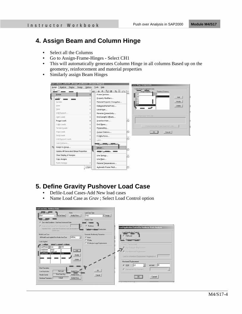
I n s t r u c t o r W o r k b o o k Push over Analysis in SAP2000 Module M4/S17
M4/S17-4
4. Assign Beam and Column Hinge
• Select all the Columns • Go to Assign-Frame-Hinges - Select CH1 • This will automatically generates Column Hinge in all columns Based up on the
geometry, reinforcement and material properties • Similarly assign Beam Hinges
5. Define Gravity Pushover Load Case • Defile-Load Cases-Add New load cases • Name Load Case as Grav ; Select Load Control option
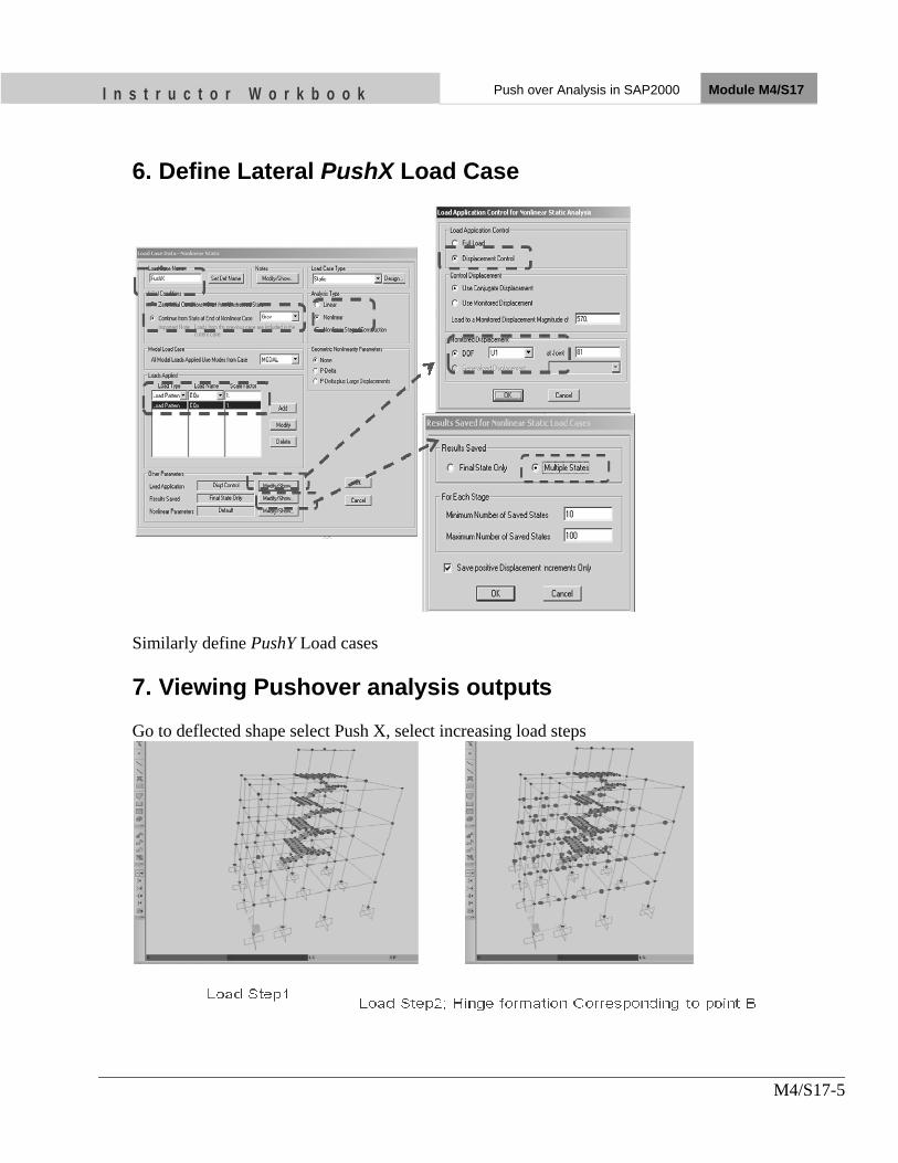
I n s t r u c t o r W o r k b o o k Push over Analysis in SAP2000 Module M4/S17
M4/S17-5
6. Define Lateral PushX Load Case
Similarly define PushY Load cases 7. Viewing Pushover analysis outputs Go to deflected shape select Push X, select increasing load steps

I n s t r u c t o r W o r k b o o k Push over Analysis in SAP2000 Module M4/S17
M4/S17-6

I n s t r u c t o r W o r k b o o k Push over Analysis in SAP2000 Module M4/S17
M4/S17-7
8. Base shear Vs Roof displacement curve
9. ATC40 Capacity Spectrum

I n s t r u c t o r W o r k b o o k Push over Analysis in SAP2000 Module M4/S17
M4/S17-8
10. Displaying Data Table
11. Elastic Vs Pushover Response
Slope of the elastic curve, m = 28204.7 KN/m Area under the pushover curve, A = 345.57 KN-m Design Base shear, V = 421 KN Seismic wt of the building, W = 4677.778 KN Ultimate demand = 0.9*seismic wt = 4210 KN

I n s t r u c t o r W o r k b o o k Push over Analysis in SAP2000 Module M4/S17
M4/S17-9
Actual Base shear corresponding to first yield = 616.7 KN Ultimate base shear demand = 2374 KN Corresponding Elastic Demand = sqrt(2*A*m) = 4415 KN 2*Response reduction factor, 2*R = 4415/421 = 10.5 R = 5.25 > 5 OK

Nk on it
OBJECTIVES As a result of this session, you should be able to:
• Develop confidence in pushover analysis and interpretation of the analysis results.
Instructor Workbook Module M 4/S18
Group Discussion for Pushover Analysis

I n s t r u c t o r W o r k b o o k Group Discussion on Pushover Analysis Module M4/S18
M4/S18-1
CONTENTS
1. Introduction ...................................................................................................... 2 2. Group division and group exercise ................................................................. 2 3. Push over Hinge ................................................................................................ 3 4. Pushover Hinge (Beam Moment) .................................................................... 4

I n s t r u c t o r W o r k b o o k Group Discussion on Pushover Analysis Module M4/S18
M4/S18-2
1. Introduction This Session is for the group discussion for pushover analysis. 2. Group division and group exercise Divide whole participant in four groups and let them to practice pushover analysis by group discussion.

I n s t r u c t o r W o r k b o o k Group Discussion on Pushover Analysis Module M4/S18
M4/S18-3
3. Push over Hinge
• Hinge defines force deformation from elastic to collapse of the elements • Structural element may have coupled (P-M2-M3) or Uncoupled Hinges
(P,M,V2,V3) • 5 points labeled A, B,C,D,E are used to define the force deformation behavior of
hinge • Three points labeled IO,LS,CP are used to define acceptance criteria for hinge
– IO: Immediate occupancy – LS: Life safety – CP: Collapse prevention

I n s t r u c t o r W o r k b o o k Group Discussion on Pushover Analysis Module M4/S18
M4/S18-4
4. Pushover Hinge (Beam Moment)
• For Moment M2 and Moment M3 hinge properties, – the force is input as M/MSF , MSF = Yield moment corresponding to point B – the displacement is input as θ/θSF, θSF = 1
• The load values at B is important, but not the deformation values (they may be zero).
only the plastic deformation should be defined. Elastic deformation is determined by the frame element containing the hinge.
• The path A to B is elastic and can be defined easily • Point B is the point corresponding to yield strength of steel with partial factor of safety=1 • Point C is corresponding to the 1.25 times yield strength and partial FOS=1 • Point E is corresponding to residual strength=20% of yield strength

OBJECTIVES As a result of this session, you should be able to:
•• IIddeennttiiffyy tthhee mmooddeess ooff ffaaiilluurree ooff mmaassoonnrryy bbuuiillddiinnggss
• UUnnddeerrssttaanndd tthhee mmaajjoorr wweeaakknneesssseess ooff oouurr bbuuiillddiinngg ttyyppeess
• UUnnddeerrssttaanndd tthhee rreemmeeddiiaall mmeeaassuurreess ttoo iimmpprroovvee tthhee rreessppoonnssee ooff tthhee bbuuiillddiinngg iinn llaarrggee eeaarrtthhqquuaakkee
Instructor Workbook Module M5/S1
Failure of Masonry Buildings

I n s t r u c t o r W o r k b o o k Failure of Masonry Buildings Module M5/S1
ii
CONTENTS
1. INTRODUCTION ......................................................................................1 2. MODES OF FAILURE OF MASONRY BUILDINGS ..........................1
2.1 Failure of In-Plane Walls ....................................................................1
2.2 Failure of Out-plane Wall ...................................................................3
2.3 Corner Separation ...............................................................................5
2.4 Delamination of Walls ........................................................................6
3. MAJOR DEFICIENCIES OF MASONRY BUILDING TYPES ..........7
3.1 Lack of Strength and Stiffness ............................................................7
3.2 Lack of Integrity between Walls Roof and Floor ...............................8
3.3 Absence of Vertical bar, Horizontal Bands at Plinth, Sill, Lintel and Floor/Roof Level ........................................................................10
3.4 Lack of Cross Walls ..........................................................................11
3.5 Asymmetric Configuration ...............................................................12
3.6 Inadequate Gap between Adjacent Buildings ...................................13
3.7 Construction Deficiency ...................................................................13

I n s t r u c t o r W o r k b o o k Failure of Masonry Buildings Module M5/ S1
M5/S1-1
1. INTRODUCTION Masonry buildings refer to those with load bearing walls made of fired clay bricks, stone or concrete masonry units. In the event of an earthquake, apart from the existing gravity loads, horizontal racking loads are imposed on walls. However, the unreinforced masonry behaves as a brittle material. Hence if the stress state within the wall exceeds masonry strength, brittle failure occurs, followed by possible collapse of the wall and the building. Therefore, unreinforced masonry walls are vulnerable to earthquakes and should be confined and/or reinforced whenever possible.
2. MODES OF FAILURE OF MASONRY BUILDINGS Unreinforced masonry buildings suffer the following modes of failure.
2.1 Failure of In-Plane Walls
Masonry walls resisting in-plane loads usually exhibit three modes of failure. The mechanisms depend on the geometry of the wall (Height/Width ratio), quality of materials and on boundary restraints and loads acting on the wall. These are:
1) Sliding Shear
2) Shear
3) Bending
• Sliding shear- In case of low vertical load and poor quality mortar, seismic loads frequently cause shearing of the wall in two parts and sliding of the upper part of the wall on one of the horizontal mortar joints.
• Shear- A wall loaded with significant vertical load as well as horizontal forces can fail in shear with diagonal cracking. This is the most common mode of failure of masonry walls subjected to seismic loads. This type of failure takes place where the principal tensile stresses developed in the wall under a combination of vertical and horizontal loads exceed the tensile strength of masonry materials. Diagonal cracking of piers either start from corners of openings or in solid walls, from the wall ends.
• Bending- this type of failure can occur if walls are with improved shear resistance. Crushing of compression zones at the ends of the wall usually takes place indicating the flexural mode of failure.
Failure modes for masonry walls subject to in-plane loads are shown in Figure 1-3 below. Photos 1-3 show diagonal cracking of masonry walls which is the most common type of failure of masonry buildings.

I n s t r u c t o r W o r k b o o k Failure of Masonry Buildings Module M5/S1
M5-S1-2
Fig. 1: Failure Modes for Masonry Walls Subject to In-Plane Loads
Fig. 2: Illustration on In-plane Flexural Failure of Masonry Wall (Flexural Cracking/Toe Crushing/Bed Joint Sliding Case)
Fig 3: Illustrations on In-plane Flexural Failure of Masonry Wall (Flexural Cracking/Toe Crushing)

I n s t r u c t o r W o r k b o o k Failure of Masonry Buildings Module M5/S1
M5-S1-3
Photo1: Diagonal Cracking of Solid Wall (Bed Joint Sliding Mode)
Photo 2: Diagonal Cracking of Solid Wall
Photo 3: Diagonal Cracking of Masonry Piers Starting from Corner of Opening
2.2 Failure of Out-plane Wall
Masonry walls resisting out-of-plane loads usually exhibit the following two modes of failure:
1) Vertical orientation of failure plane when bending in longitudinal direction and tension developed is parallel to bed joint
2) Horizontal orientation of failure plane when bending in vertical direction and tension developed normal to bed joint

I n s t r u c t o r W o r k b o o k Failure of Masonry Buildings Module M5/S1
M5-S1-4
Fig 2: Vertical Orientation of Failure Plane
Fig 3: Horizontal Orientation of failure plane
Out-of-plane failures are common in URM buildings. Usually they occur due to the lack of adequate wall ties, bands or cross walls. When ties are adequate,

I n s t r u c t o r W o r k b o o k Failure of Masonry Buildings Module M5/S1
M5-S1-5
the wall may fail due to out-of- plane bending between floor levels. In case of long walls, without cross walls, the failure mode is out of plane bending horizontally. Important variables are the vertical stress on the wall and the height-to-thickness ratio of the wall. Thus, walls at the top of buildings and slender walls are more likely to suffer damage.
Photos 4 and 5 show the out of plane failure of masonry walls.
Photo 4: Out of Plane Failure of Stone Wall
Photo 5: Out of Plane Failure of Block Wall
2.3 Corner Separation
Separation of orthogonal walls due to in-plane and out-of-plane stresses at corners is one of the most common damage patterns in masonry buildings. Separations in both sides of a wall result to an unstable condition leading to out-of-plane failure. The failure is due to lack of lateral support at two ends of the wall during out of plane loading.
This type of failure significantly reduces the lateral load carrying capacity of the building if all the corners are separated. The decision for restoration/ retrofitting and demolition depends on extent of such damage. If only limited numbers or portion of the walls is separated, the buildings can be restored and retrofitted. If all/most of the corners are separated it is difficult to restore the original capacity by restoration and retrofitting.

I n s t r u c t o r W o r k b o o k Failure of Masonry Buildings Module M5/S1
M5-S1-6
Photo 6: Heavy Corner Separation
Photo 7: Wall Failure at Joint
2.4 Delamination of Walls
Delamination of two wyths of masonry walls is another type of damage. The extent of this type of damage can be examined by sounding test. Wall delamination is caused by lack of integrity of two wyths of the wall. Photo 8 and 9 show the delamination of walls during earthquakes.
Photo 8: Delamination of Outer Stone Masonry Wall Photo 9: Delamination of Outer and Inner
Stone Masonry Walls

I n s t r u c t o r W o r k b o o k Failure of Masonry Buildings Module M5/S1
M5-S1-7
3. MAJOR DEFICIENCIES OF MASONRY BUILDING TYPES Observation of structural performance of buildings during an earthquake can clearly identify the strong and weak aspects of the building construction. Most of the structural failures that we observed in past earthquakes were associated with deficiencies in the structure as built, whether caused by lack of strength and ductility, integrity or by improper construction practices (poor materials, poor workmanship).
As evident from past earthquakes, the typical damages to non-engineered masonry buildings are as follows:
3.1 Lack of Strength and Stiffness
These arise from large openings and inadequate thickness of walls usually in ground floor resulting in reduced wall strength and storey stiffness. In load bearing masonry, walls are the main lateral load resisting elements. Doors and windows are the voids in walls that make walls weaker. Therefore, their sizes and locations are carefully decided and constructed. There are some rules for size and location of doors and window openings and wall thickness in masonry buildings.
Thickness requirement as per National Building Code
Floor Min. Wall Thickness (mm) Max. Height (m)
Brick masonry in Cement
mortar
Second 230 2.8
First 230 3.0
Ground 350 3.2
Stone Masonry in Cement
mortar
First 380 3.0
Ground 380 3.2

I n s t r u c t o r W o r k b o o k Failure of Masonry Buildings Module M5/S1
M5-S1-8
Openings requirements in walls as NBC Nepal
Any opening in the wall should be small in size and centrally located. The following is the guideline for the size and position of openings.
i) Openings are to be located away from inside corners by a clear distance equal to at least 1/4 of the height of the opening, but not less than 600 mm.
ii) The total length of openings in a wall are not to exceed 50 % of the length of the wall between consecutive cross-walls in single-storey construction, 42 % in two-storey construction, and 33 % in three-storey buildings.
iii) The horizontal distance (pier width) between two openings is to be not less than one half of the height of the shorter opening but not less than 600 mm.
iv) The vertical distance from one opening to another opening directly above it shall not be less than 600 mm, nor less than one half the width of the smaller opening
v) When an opening does not comply with requirements (i) to (iv), it shall be boxed in reinforced jambs through the masonry.
vi) If the vertical opening of the wall is more than 50 % of the wall height, vertical bars shall be provided in the jambs.
3.2 Lack of Integrity between Walls Roof and Floor
Non-existent or improper connections between walls, roof and floor is another major deficiency of our masonry buildings. As envisaged by past earthquake most of the non-engineered masonry buildings collapsed due to lack of bonding and anchorage between wall to wall, wall to roof/floor and between elements of roof/floor. This arise mainly due to
i) The practice of providing toothed joint between two consecutive walls.
ii) Roof/Floor simply rests on wall without any anchorage
iii) Elements of roof/slab are not tied properly
iv) Poor connection between masonry units leading to vertical joint in the wall.
Integrity can be improved by enduring a proper connection between these elements so that the building acts as a single unit enhancing the lateral load resisting capacity of the building.
Some examples of improving the integrity of the building are illustrated below.

I n s t r u c t o r W o r k b o o k Failure of Masonry Buildings Module M5/S1
M5-S1-9
Step Joint at Corners
The weakness due to toothed joints can be improved easily by providing stepped joints in place of toothed joint whenever necessary. Steps are easy to construct as well as when another wall is to be joined mortar can be placed at all necessary surfaces. Also the joint will not be at the same vertical line. This option does not cost additional money but would significantly improve the joint strength.
L Shaped Stitch
The inherent weakness of wall joints can be improved by providing stepped joints but for ensuring earthquake safety, we need to employ some extra strengthening elements which are called stitches. Stitches are L or T shaped elements which joins two orthogonal walls properly. The stitches work as nails in wooden box where planks are nailed together to make a box. RCC stitches are suitable for masonry buildings with cement sand mortar and timber or bamboo stitches are suitable for masonry buildings with mud mortar. However, RCC stitch can also be provided in the building with mud mortar. The photographs show L and T stitches reinforcement details used to connect walls at L and T junctions.
T Shaped Stitch

I n s t r u c t o r W o r k b o o k Failure of Masonry Buildings Module M5/S1
M5-S1-10
Anchorage of Roof to Wall
Floor/roof slab or truss should have a sufficient bearing to wall and tied properly to prevent relative displacement between the wall and roof element at joint ensuring stability of the structure. Use of metal ties is common as an anchoring element. Many buildings in past earthquakes have collapsed due to inadequate connection between roof/floor and wall system.
Door/Window openings attached to wall junctions also increases weakness of the building. Openings shall be provided either at a distance such that
P1 > 0.25h1
P2 > 0.25h2
P3 > 0.50h2 or at least 600 mm from the wall junction.
3.3 Absence of Vertical bar, Horizontal Bands at Plinth, Sill, Lintel and Floor/Roof Level
Masonry is a brittle material and the flexural strength of masonry wall is almost negligible. Therefore during earthquake shaking, masonry walls get damaged due to out of plane and in-plane bending. To prevent such damage, masonry wall is tied by providing horizontal bands at plinth, sill, lintel and roof/floor level and vertical bars at wall junctions and at jambs of door/window openings. The bandages are designed for out-of-plane bending and vertical reinforcement bars are designed for in-plane bending. The band may be of RCC, timber, bamboo depending upon the material available and type of the building construction. For a building with cement mortar, RC band is preferable. A timber band could be used for building with mud mortar. However, RCC band can also be used in the buildings with mud mortar.
The problem with two sided sloped roof buildings is failure of gable walls. Gable wall in a building is at the highest level and the displacement of wall at the top is more than that at the bottom. Usually these gable walls are untied at the top. Also the height becomes more in gable walls so this wall can fall more easily. To mitigate the problem of gable wall failure, bandages similar to other
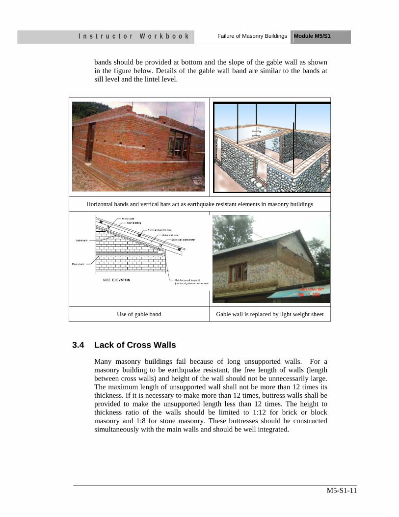
I n s t r u c t o r W o r k b o o k Failure of Masonry Buildings Module M5/S1
M5-S1-11
bands should be provided at bottom and the slope of the gable wall as shown in the figure below. Details of the gable wall band are similar to the bands at sill level and the lintel level.
Horizontal bands and vertical bars act as earthquake resistant elements in masonry buildings
Use of gable band Gable wall is replaced by light weight sheet
3.4 Lack of Cross Walls
Many masonry buildings fail because of long unsupported walls. For a masonry building to be earthquake resistant, the free length of walls (length between cross walls) and height of the wall should not be unnecessarily large. The maximum length of unsupported wall shall not be more than 12 times its thickness. If it is necessary to make more than 12 times, buttress walls shall be provided to make the unsupported length less than 12 times. The height to thickness ratio of the walls should be limited to 1:12 for brick or block masonry and 1:8 for stone masonry. These buttresses should be constructed simultaneously with the main walls and should be well integrated.

I n s t r u c t o r W o r k b o o k Failure of Masonry Buildings Module M5/S1
M5-S1-12
These buttresses are used to provide lateral support to the masonry wall in the horizontal direction.
3.5 Asymmetric Configuration
Irregular buildings (both horizontally and vertically as well) suffer more damage than regular buildings due to concentration of stresses in limited structural members. To avoid the damage due to irregular configuration mass-center of the building should be as close to stiffness-center of the building as possible. For this, square shaped building is most preferable. Otherwise, rectangular shaped building is also good as long as the length of the building does not exceed three times its width. Similarly, height of the building should not exceed three times the width of the building. Building code of Nepal allows projection of up to one fourth the building width, if desired. If L, T or U shaped building is desired, different wings of the building need separation using seismic gap as shown in the figure below.
Not preferable shapes of the building from seismic consideration

I n s t r u c t o r W o r k b o o k Failure of Masonry Buildings Module M5/S1
M5-S1-13
Preferable shapes of the building from seismic consideration
The building should also exhibit vertical regularity. Sudden change in storey stiffness is not desired from seismic point of view. Similarly, to avoid any kind of eccentricity, mass in the building should be uniformly distributed.
3.6 Inadequate Gap between Adjacent Buildings
Buildings attached to each other are likely to get damaged due to pounding. Two adjacent buildings or two adjacent units of the same building with separation joint in between shall be separated by a distance equal to R times the sum of the calculated storey displacements to avoid damaging contact when the two units deflect towards each other. When floor levels of two similar adjacent units or buildings are at the same elevation levels, factor R in this requirement may be replaced by R/2.
3.7 Construction Deficiency
Buildings behave as they are actually constructed and not as they are designed or planned. No matter how well a building is planned and designed, if they are poorly constructed, it performs poorly. Therefore, quality and workmanship during each stage of the construction play a vital role in making a building of good quality, strong and earthquake resistant. Besides good planning and design, quality control should also be given high attention during the construction of a building. First factor to affect the quality of a building is the quality of its planning and design. If a building is not properly planned and designed, the building could never be of good quality even if it is constructed with greater care and quality control. For a building to be an earthquake resistant, a good quality planning and design means the one which follows the basic rules such as appropriate site selection, good configuration and layout, appropriate size and detailing of different structural elements etc. Another factor affecting the quality of a building is quality of materials used in the construction. Inferior quality materials can not make a good quality building. Therefore, materials used in the construction should be of good quality as

I n s t r u c t o r W o r k b o o k Failure of Masonry Buildings Module M5/S1
M5-S1-14
mentioned in the specifications. Next major factor to contribute in the quality of a building is the quality of construction process and quality of workmanship. This is the ultimate factor to make a good quality building. Each and every stage of the construction should be in accordance with the provisions and steps mentioned in the standard construction manuals and guidelines. Resources and time available are the indirect factors to make a good quality building. Experiences have shown that if the project period is prolonged due to the resource constraints, the quality of construction goes on decreasing.
I n s t r u c t o r W o r k b o o k Failure of Masonry Buildings Module M5/S1
M5-S1-15
UNIT TEST 1) Describe three modes of failure of masonry walls resisting in in-plane
loads
• ……
2) Describe five major deficiencies of masonry buildings
• ……

OBJECTIVES As a result of this session, you should be able to:
•• DDeetteerrmmiinnee tthhee mmeecchhaanniiccaall pprrooppeerrttiieess ooff tthhee bbuuiillddiinngg
• CCaallccuullaattee tthhee eeaarrtthhqquuaakkee llooaadd iinn tthhee bbuuiillddiinngg
Instructor Workbook Module M5/S2
Masonry Design Example Engineers’ Training on Earthquake-Resistant Design of Buildings

I n s t r u c t o r W o r k b o o k Masonry Design Example Module M5/ S2
ii
CONTENTS
1 INTRODUCTION ................................................................................. 1
2 BUILDING DESCRIPTION ................................................................. 1
2.1 General ........................................................................................................1 2.2 Design Loads ...............................................................................................1 2.3 Material Properties ....................................................................................2
3 PRELIMINARY DESIGN OF STRUCTURAL ELEMENTS ............. 3
3.1 General Design Consideration ..................................................................3 3.2 Determine the Wall Thickness ..................................................................4
3.2.1 Slenderness ratio .................................................................................4
3.2.2 Effective length of wall .......................................................................4
3.2.3 Effective Length for our Case .............................................................6
4 CALCULATION OF PERMISSIBLE COMPRESSIVE STRESS IN WALL 7
5 EARTHQUAKE LOAD CALCULATION ........................................... 9
Using NBC 105 ...........................................................................................9
5.1 Lump Mass Calculation .............................................................................9

I n s t r u c t o r W o r k b o o k Masonry Design Example Module M5/ S2
M5/S2-1
1 INTRODUCTION
This session outlines the problem statement of two storey brick masonry residential building which is the most common masonry building type in Nepal. It discusses the general design requirements of the building including determination of various design parameters and material properties for seismic analysis and design of the building. This session also describes the selection of various factors for determination of earthquake load in the building.
The analysis and design presented here is approximate and is in very simplified version because of time limitation. The goal of this exercise is just to give an overview of basic principles of analysis and design of masonry load bearing elements.
2 BUILDING DESCRIPTION
A two storey brick masonry residential building has plan dimensions as shown in figure below.
2.1 General
Building Type : Ordinary Residential Building
No. of Stories : Two
Storey Height : 3.0 m
Wall : Brick in 1:5 Cement Sand mortar
Floor/Roof : RCC 100 mm thick Slab
Earthquake Zone : 1 (NBC 105)
Importance Factor : 1.0 (Residential Building)
Building Dimension : 5760 X 3720 mm
Building Shape : Simple rectangular
Subsoil Type : II
2.2 Design Loads
Dead Loads
Masonry Wall : 19 KN/m3
RCC Slab : 25 KN/m3
Floor finish : 0.05*20 = 1.0 KN/m2
Live Loads

I n s t r u c t o r W o r k b o o k Masonry Design Example Module M5/ S2
M5/S2-2
Floor Live Load : 2 KN/m2 (IS: 875(Part 2)–1987 Table 1)
Roof Live Load : 1.5 KN/m2
2.3 Material Properties
Brick Masonry
Compressive strength of brick : 10 N/mm2
Mortar Type : M1 (Cement sand ratio 1:5)
Steel
Reinforcement of grade Fe 415 is used for slab and other reinforcement to be designed for masonry to take shear and tensile stresses.
765 900 2430 900 765
5760
765 900 765 900 765
5760
765 900
1560
1200
960
1410
3720
900
1410
3720
D1
D
W W
W W
W
Fig.1:Floor Plan

I n s t r u c t o r W o r k b o o k Masonry Design Example Module M5/ S2
M5/S2-3
900
1200
900
1004
1200
796
3000
3000
450
450
6450
Fig 2:Elevation
3 PRELIMINARY DESIGN OF STRUCTURAL ELEMENTS
3.1 General Design Consideration
Masonry structures gain stability from the support offered by cross walls, floors, roof and other elements such as piers and buttresses Load bearing walls are structurally more efficient when the load is uniformly distributed and the structure is so planned that eccentricity of loading on the members is as small as possible. Avoidance of eccentric loading by providing adequate bearing of floor/roof on the walls providing adequate stiffness in slabs and avoiding fixity at the supports, etc, is especially important in load bearing wall structures. These matters should receive careful consideration during the planning stage of masonry structures. Similarly it is always essential to meet the basic criteria of earthquake resistant masonry buildings such as door/window opening ratio, height to thickness ratio, maximum length of unsupported walls etc. prior to detail analysis and design of structural elements to avoid unnecessary time loss in re-determining and analysing the structure again with revised sections of structural elements.

I n s t r u c t o r W o r k b o o k Masonry Design Example Module M5/ S2
M5/S2-4
3.2 Determine the Wall Thickness
Determine the preliminary size of the load bearing walls maintaining the basic criteria of height to thickness ratio or length to thickness ratio whichever is critical as per the prevalent building code or standard norms.
3.2.1 Slenderness ratio
For a wall, slenderness ratio shall be effective height divided by effective thickness or effective length divided by the effective thickness, whichever is less. In case of a load bearing wall, slenderness ratio shall not exceed that given in Table 1 below.
Table 1: Maximum Slenderness Ratio for a Load Bearing Wall
NNuummbbeerr ooff SSttoorriieess
UUssiinngg PPoorrttllaanndd cceemmeenntt mmoorrttaarr
UUssiinngg LLiimmee mmoorrttaarr
UUpp ttoo 22 2277 2200
EExxcceeeeddiinngg 22 2277 1133
3.2.2 Effective length of wall
Effective length of a wall shall be as given in Table below.
Table 2: Effective Length of Wall S.N. Conditions of Support (See figure below) Effective
Length
1 Where a wall is continuous and is supported by cross wall, and there is no opening within a distance of H/8 from the face of cross wall or where a wall is continuous and is supported by piers/buttresses.
0.8 L
2 Where a wall is supported by a cross wall at one end and continuous with cross wall at other end or where a wall is supported by a pier/ buttress at one end and continuous with pier/buttress at other end.
0.9L
3 Where a wall is supported at each end by cross wall or where a wall is supported at each end by a pier/buttress.
1.0L
4 Where a wall is free at one end and continuous with a cross wall at the other end or where a wall is free at one end and continuous with a pier/buttress at the other end
1.5L
5 Where a wall is free at one end and supported at the other end by a cross wall or where a wall is free at one end and supported at the other end by a pier/ buttress.
2.0L

I n
s t r u c t o
In case thopening s
o r W o r
here is an opshall be cons
x
k b o o k
pening tallersidered as fre
xx ≥≥ HH//88,, yy
xx ≥≥ HH//88,, yy ≥≥
xx ≥≥ HH//88,, yy
r than 0.5 Hee.
≥≥ HH//66
≥≥ HH//66
≥≥ HH//66,,
Masonry
in a wall, e
ll == 00..88 LL
ll == 00..99 LL
ll == LL
Design Examp
ends of the w
ple Module M
wall at the
M5/ S2

I n
3.2.3
3720
s t r u c t o
3 Effective
765 900
765 900
1410
900
1410
W
W
W
o r W o r
xx ≥≥
xFi
e Length fo
2430 9
5760
765 9
5760
765 900
D1
PLAN
k b o o k
≥ HH//88,, yy ≥≥ HH//
xx << HH//88,, yy ≥≥ig 3: Effectiv
or our Cas
900 765
900 765
1560
1200
960
3720
D
W
W
x ≥ H/8, y
//66,, ll
≥≥ HH//66,, ll ==ve Length o
se
y ≥ H/6, l =
Masonry
ll == 11..55 LL
== 22 LL of Wall
= L
Design Examp
ple Module M
M5/ S2

I n s t r u c t o r W o r k b o o k Masonry Design Example Module M5/ S2
M5/S2-7
Fig 4: Effective Length of the Building
Effective length = 5.76-0.23 m =5.53 m
Trial thickness of wall using slenderness criteria, 5.53/27 = 0.2 m
Use the thickness of wall 0.23m or 230 mm
4 CALCULATION OF PERMISSIBLE COMPRESSIVE STRESS IN WALL
Permissible compressive stress in masonry shall be based on the value of basic compressive stress (fb) and multiplying this value by factor known as stress reduction factor (ks). Area reduction factor (ka) and shape modification factor (kp) as per IS 1905-1987.
Basic Compressive Stress: Values of basic compressive stress given in Table 3 that .take into consideration crushing strength of masonry unit and grades of mortar, and hold good for values of slenderness ration not exceeding 6, zero eccentricity and masonry unit having height to width ratio ( as laid ) equal to 0.75 or less. Alternatively, basic compressive stress may be based on results of prism test on masonry made from masonry units and mortar to be actually used in a particular job.
Table 3: Basic Compressive Stress
S. No.
Mortar Type
BASIC COMPRESSIVE STRENGTH IN N/mm2 CORRESPONDING TO MASONRY UNITS OF WHICH HEIGHT TO WIDTH RATIO DOES NOT EXCEED 0.75 AND
CRUSHING STRENGTH IN N/mm2 IS NOT LESS THAN 3.5 5.0 7.5 10.0 12.5 15.0 17.5 20.0 25.0 30.0 35.0 40.0
1 2 3 4 5 6 7 8 9 10 11 12 13 14 1 H1 8.35 0.50 0.75 1.00 1.16 1.31 1.45 1.59 1.91 2.21 2.50 3.052 H2 8.35 0.50 0.74 0.96 1.09 1.19 1.30 1.41 1.62 1.85 2.10 2.50 3 M1 8.35 0.50 0.74 0.96 1.06 1.13 1.20 1.27 1.47 1.69 1.90 2.20 4 M2 0.35 0.44 0.59 0.81 0.94 1.03 1.10 1.17 1.34 1.51 1.65 1.90 5 M3 0.25 0.41 0.56 0.75 0.87 0.95 1.02 1.10 1.25 1.41 1.55 1.78 6 L1 0.25 0.36 0.53 0.67 0.76 0.83 0.90 0.97 1.11 1.26 1.40 1.06 7 L2 0.25 0.31 0.42 0.53 0.58 0.61 0.65 0.69 0.73 0.78 0.85 0.95
Stress Reduction Factor - This factor Ks, as given in Table 4, takes into consideration the slenderness ratio of the element and also the eccentricity of loading.

I n s t r u c t o r W o r k b o o k Masonry Design Example Module M5/ S2
M5/S2-8
Table 4: Stress Reduction Factor
Slenderness Ratio
ECCENTRICITY OF LOADING DIVIDED BY THE THICKNESS OF THE MEMBER
0.00 0.04 0.08 0.17 0.25 0.33 1 2 3 4 5 6 7
6 1.00 1.00 1.00 1.00 1.00 1.00 8 0.95 0.15 0.94 0.93 0.92 0.91 10 0.89 0.88 0.87 0.85 0.83 0.81 12 0.84 0.83 0.81 0.78 0.75 0.72 14 0.78 0.76 0.74 0.70 0.66 0.66 16 0.73 0.71 0.68 0.63 0.58 0.53 18 0.67 0.64 0.61 0.55 0.49 0.43 20 0.62 0.59 0.55 0.48 0.41 0.34 22 0.56 0.52 0.48 0.40 0.32 0.24 24 0.51 0.47 0.42 0.33 0.24 --- 26 0.45 0.40 0.35 0.25 --- --- 28 0.43 0.38 0.33 0.22 --- ---
Area Reduction Factor - This factor takes into consideration smallness of the sectional area of the element and is applicable when sectional area of the element is less than 0.2 m2. The factor, Ka, = 0.7 + 1.5 A, A being the area of section in m2.
Shape Modification Factor – This factor takes into consideration the shape of the unit, that is, height to width ratio (as laid) and is given in Table 5. This factor is applicable for units of crushing strength up to 15 N/mm2.
Table 5: Shape Modification Factor
Height to Width ratio of units (as laid)
SHAPE MODIFICATION FACTOR (kp) FOR UNITS HAVING CRUSHING STRENGTH IN N/mm2
5.00 7.50 10.00 15.00 1 2 3 4 5
Upto 0.75 1.0 1.0 1.0 1.0 1.0 1.2 1.1 1.1 1.0 1.5 1.5 1.3 1.2 1.1 2.0 to 4.0 1.8 1.5 1.3 1.2
For our case,
Compressive strength of masonry unit = 10 N/mm2
Mortar type M1 corresponding to cement sand ratio of 1:5
Basic compressive strength of wall fb = 0.96 N/mm2 (From Table 3)
Stress reduction factor ks = 0.51 for slenderness ratio of 24 (From Table 4)
Area reduction factor Ka = 0.7 + 1.5 A,
Sectional Area A = 0.11 * 0.075 = 0.00825 m2
Area reduction factor Ka = 0.7 + 1.5 A = 0.7 + 1.5*0.00825 = 0.71
Shape modification ratio = Kp = 1.0 (For H/W = 0.075/0.11=0.68, Table 5)

I n s t r u c t o r W o r k b o o k Masonry Design Example Module M5/ S2
M5/S2-9
Hence, Permissible compressive stress in masonry (fc) = 0.96* 0.51 * 0.71 * 1 = 0.35 N/mm2
5 EARTHQUAKE LOAD CALCULATION Using NBC 105
Seismic Coefficient Method
The design horizontal seismic force coefficient, Cd
for seismic coefficient method is taken as C
d = CZIK
Where,
C is the basic seismic coefficient for the fundamental translational period in the direction under consideration.
Z = Seismic zoning factor = 1 (For the location of the building in Kathmandu)
I = Importance factor = 1.0 Residential building
K = Structural Performance factor = 2.5
T = (0.09 X H) / (D^0.5) = (0.09 * 6)/(5.76^0.5) = 0.225 Longitudinal direction
= (0.09 * 6)/(3.72^0.5) = 0.28 Transverse direction
C = 0.08 for Subsoil Type II
Cd = CZIK = 0.08 X 1.0 X 1 X 2.5 = 0.2
Using IS Code,
Design Seismic Coefficient Ah = ZISa/2Rg
Where,
Z = 0.36 (Zone V)
I = 1.0 (Residential Building)
Sa/g = function of Time Period T
Sa/g = 2.5
R = 3.0 (For Load bearing masonry wall buildings reinforced with horizontal RC bands and vertical bars at corners of rooms and jambs of opening)
Ah = ZISa/2Rg = (0.36X1.0X2.5)/ (2X3) = 0.15
Hence use base shear coefficient equal to 0.2
5.1 Lump Mass Calculation
The seismic weight or the lump mass at each floor level, Wi, shall be taken as the sum of the dead loads and the seismic live loads between the mid-heights

I n s t r u c t o
of adjacendesign liv
Table 6: Calculati
D
U
Av
F
Effect of
Weight of
Table 7: L
o r W o r
nt storeys. Tve load as giv
Percentageion
Design Live
Up to 3 KPa
Above 3 Kvehicle garag
For Roofs
openings ne
f slab = (0.1
Stru
Lump Load
k b o o k
The seismic lven in Table
e of Imposed
Load
KPa and foges
Fig 5:L
glected (just
1*25) + (0.05
ucture fini
ds and Distr
live load shae 6 below
d Load to b
P
2
or 5
N
Lumping th
t for simplic
5*20) = 3.5
ishing
ribution of S
Masonry
all be taken
be considere
Percentage o
25
50
NIL
he Mass
ity)
5 KN/m2
Shear Force
Design Examp
as a percent
ed in Seismi
of Design Li
e
ple Module M
age of the
ic Weight
ive Load
M5/ S2

I n s t r u c t o r W o r k b o o k Masonry Design Example Module M5/ S2
M5/S2-11
Storey Wall Slab Total Wi (KN)
hi Wihi Qi
1
(2*5.76 + 2*3.26) *2.9*19*0.23 =229
5.76*3.72*(3.5+0.5) =86
315 3.0 945 46
2 (2*5.76 + 2*3.26) *1.4*19*.23 =110
5.76*3.72*3.5 =75
185 6.0 1110 54
500 2055 100
Total Base Shear, Vb = 500KN* 0.2 = 100KN
Distribution of Base Shear,
Qi = Vb * Wihi/ΣWihi (cl. 7.7 Commentary IS 1893 for T ≤ 0.5 sec)
3000
3000
W2 = 185 KN
W1 = 315 KN
LUMPEDWEIGHTS
54 KN
46 KN
FLOOR LEVELFORCE
54 KN
100 KN
BASE SHEAR
0.29
0.146
Lateral Coefficient in 2nd storey, C = 54/185 =0.29 >0.2 Design bandage, stitches for C = 0.29 Lateral Coefficient in 1st storey, C = 46/315 = 0.146 <0.2 Design bandage, stitches for C = 0.29 in 2nd storey
“TAKE SPECIAL CARE FOR UPPER STOREY WALLS, PARTICULARLY THE TOP ONE”

I n s t r u c t o r W o r k b o o k Masonry Design Example Module M5/ S3
i
Instructor Workbook Module M5/ S3
Masonry Design Example
OBJECTIVES As a result of this session, you should be able to:
• DDeessiiggnn lliinntteell bbaanndd ffoorr oouutt ooff ppllaannee bbeennddiinngg ooff bbrriicckk ppiieerr
• DDeessiiggnn ccoorrnneerr ssttiittcchheess
• CCaallccuullaattee tthhee iinndduucceedd bbeennddiinngg,, oovveerrttuurrnniinngg aanndd vveerrttiiccaall ssttrreesssseess iinn iinnddiivviidduuaall bbrriicckk ppiieerr ooff tthhee bbuuiillddiinngg
•• DDeessiiggnn vveerrttiiccaall rreeiinnffoorrcceemmeenntt bbaarr ffoorr iinn--ppllaannee bbeennddiinngg ooff bbrriicckk ppiieerr

I n s t r u c t o r W o r k b o o k Masonry Design Example Module M5/ S3
ii
CONTENTS
1. INTRODUCTION ......................................................................................1 2. OUT-PLANE ANALYSIS .........................................................................2
2.1 Design Bandage at Lintel Level ..........................................................2
2.2 Check for Vertical Bending below Lintel Bandage ............................4
2.3 Design of Stitches ...............................................................................5
3. IN-PLANE ANALYSIS .............................................................................5
3.1 Distribution of Load in In-plane Direction of the Building ................5
4. SAMPLE DESIGN OF VERTICAL BAR ...............................................8 5. CHECK FOR SHEAR STRESS .............................................................10 6. CHECK FOR COMPRESSIVE STRESS..............................................10

I n s t r u c t o r W o r k b o o k Masonry Design Example Module M5/ S3
M5/S3-1
1. INTRODUCTION This session outlines the seismic analysis and design of two storey brick masonry building by pier analysis. The seismic analysis of the building consists of the analysis of individual piers for a) in-plane and b) out-of-plane analysis. For in-plane analysis, the building model comprises of vertical wall piers resisting the seismic forces along a direction of earthquake. For the wall piers, only the resistance to in-plane lateral loads is considered. The portions of the walls above the doors, windows, and arch openings are neglected in in-plane analysis. For simplicity in manual calculation torsion in the building is neglected
The analysis and design presented here is approximate and is in very simplified version because of time limitation. The goal of this exercise is just to give an overview of basic principles of analysis and design of masonry load bearing elements.
765 900 2430 900 765
5760
765 900 765 900 765
5760
765 900
1560
1200
960
1410
3720
900
1410
3720
D1
D
W W
W W
W
Fig.1:Floor Plan

I n s t r u c t o r W o r k b o o k Masonry Design Example Module M5/ S3
M5/S3-2
900
1200
900
1004
1200
796
3000
3000
450
450
6450
Fig 2:Elevation
2. OUT-PLANE ANALYSIS
The walls exhibit local vibrations in an orthogonal direction to their plane due to out-of-plane forces. Forces acting in the direction orthogonal to the plane of the walls are proportional to the distributed mass of the walls and accelerations induced in the building by seismic ground motion. As has been observed after earthquakes, out-of-plane bending results into cracking at the most stressed zones of the walls and ultimately, out-of-plane collapse of the wall orthogonal to the direction of seismic motion. More severe consequences of out-of-plane behaviour of masonry walls have been observed in the upper than in the lower storeys of buildings.
Out-plane analysis of the building is carried for the design of bandages and corner stitches.
2.1 Design Bandage at Lintel Level
The bandage is designed for horizontal banding neglecting effect of openings for 2nd storey
Span of bandage = 5.53m

I n s t r u c t
Load carr
M = 1.84*
o r W o r
Fig 3:Load
ried by the b
*5.532/10
230
178
k b o o k
d Carried b
andage, q =
= 5.63 KNm
DL
by Bandage
= (1.05 + 0.4
= 1.84 KN/
m (At Suppor
Design bandLever arm = Ast = 5.63* = 109 m Use 2 nu
Masonry De
at Lintel Le
4)*(19*0.23)
/m
rt)
dage as steel = 230-2*20-1
106/(178*(4mm2 umbers 12 m
esign Example
evel
)*0.29
I Beam 12 = 178 mm
415*0.56*1.2
mm Ф bars
e Module M5
3
m
25)
5/ S3

I n
2.2
s t r u c t
Check
57
7
Combine
Permissib
Combined
If tensile
o r W o r
for Vertic
760
7.25m²
3.46m
ed Vertical S
ble Bending
d Vertical St
stress exceed
k b o o k
cal Bendi
La
M Be
3720
m²
Ve = ( = 3 Co = 0
Stress on W
Stress for M
tress f = fa ±
= 0.
= 0
ds the permi
ing below
ateral load =
= 1.26*2.12
ending Stres
ertical load a
(2.1/2+0.8)*
33.5 kN
ompressive s
0.025 MPa
Wall
M1 = 0.07 N/m
± fb
025 ± 0.053
0.078 (C)
issible value
Masonry De
w Lintel B
1*19*0.23*2/12 = 0.47 k
s, fb = M/Z
= .47*106/( = 0.053 M
at mid heigh
*0.23*19+7.
stress fa = 3
mm2 (IS 190
= 0.028 (T)
e, provide a s
esign Example
Bandage
*0.29 = 1.27
kNm/m strip
(2302/6*100MPa
ht of wall bel
25*3.5 (wal
33.5*1000/(5
05)
) < 0.07 MPa
sill level ban
e Module M5
4
KN/m
p
00)
low bandage
l+slab)
5760*230)
a O.K.,
ndage.
5/ S3
e
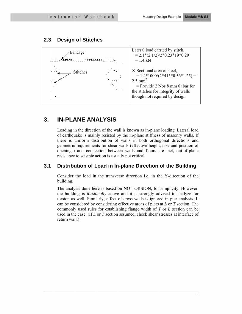
I n
2.3
3.
3.1
s t r u c t
Ba
Design
IN-PLALoading iof earthquthere is geometricopenings)resistance
Distribu
Consider building.
The analythe builditorsion ascan be cocommonlyused in threturn wa
S
o r W o r
andage
n of Stitch
ANE ANAin the directiuake is mainuniform dis
c requiremen) and connee to seismic a
ution of L
the load in
ysis done heing is torsios well. Siminsidered by y used rules
he case. (If Lall.)
Stitches
k b o o k
hes
ALYSISion of the wnly resisted bstribution onts for shearection betweaction is usu
Load in In
n the transv
ere is based onally activlarly, effect considering
s for establiL or T section
Late = = X-S =2.5 =the thou
wall is knownby the in-plaf walls in r walls (effeeen walls a
ually not crit
n-plane D
erse directio
on NO TORve and it is
of cross wag effective arshing flangen assumed, c
Masonry De
eral load car2.1*(2.1/2)/1.4 kN
Sectional are= 1.4*1000/(
mm2 = Provide 2 Nstitches for ugh not requ
n as in-planeane stiffnessboth orthog
ective heightand floors aical.
Direction
on i.e. in th
RSION, for strongly ad
alls is ignorreas of piers e width of Tcheck shear s
esign Example
rried by stitc/2*0.23*19*
ea of steel, (2*415*0.56
Nos 8 mm Фintegrity of w
uired by desi
e loading. Las of masonrygonal direct, size and pare met, ou
of the Bu
he Y-directi
simplicity. dvised to aned in pier aat L or T sec
T or L sectiostresses at in
e Module M5
5
ch, *0.29
*1.25) =
Ф bar for walls ign
ateral load y walls. If tions and
position of ut-of-plane
uilding
on of the
However, nalyze for nalysis. It ction. The on can be nterface of
5/ S3

I n s t r u c t o r W o r k b o o k Masonry Design Example Module M5/ S3
M5/S3-6
1560
1200
960
1410
3720
900
1410
3720
DW
1 2
P1
P2
P3
P4
Fig 4: Piers for In-Plane Analysis
Base shear in the building = 100 KN
As torsion is not taken into account, both the transverse wall will carry equal lateral load.
Lateral load on each wall = 100/2 =50 KN
Analysis is done for 1st storey pier along Grid # 2 only.
Pier Analysis:
Table 1: Stiffness of Piers
Pier
Hei
ght
h (m
)
b * d (m)
A (m2) I (m4)
Proportion of lateral load carried by
pier
P3 2.1 0.23*1.56 0.3588 0.0727 0.0405 0.74
P4 2.1 0.23*0.96 0.2208 0.0169 0.0146 0.26
0.0551

I n s t r u c t o r W o r k b o o k Masonry Design Example Module M5/ S3
M5/S3-7
Bending Moment
Lateral Load Carried by P3= (54/2+46/2)*0.74 = 37 kN Lateral Load Carried by P4= (54/2+46/2)*0.23 = 13 kN
Table 2: Bending Stress in Piers Pier M (KNm) Z Fb = M/Z
P3 38.8 230 * 15602 /6 = 93288000
0.416
P4 13.6 230 * 9602 /6 = 35328000
0.385
Overturning Moment
At the bottom of pier, Mo = 54/2 * 6 + 46/2 * 3
= 231 KNm
Calculation of I of the wall in plan,
ŷA = . . . . .
. . .
= 2.0 m
I = . . + . . +[0.96*0.23*(2-0.48)2] + [1.56*0.23*(2.94-2)2]
= 0.9169 m4
Overturning Stresses:
(fo)A = = .
2000 = 2.519*10-4*2000= 0.504 MPa (T)
(fo)B= = .
2000 960 = 2.519*10-4*1040= 0.262 MPa (T)
960 1200 1560P3P4
13.6 KNm 38.8 KNm
37 KN13 KN
A B C D
46/2
54/2
3000
3000
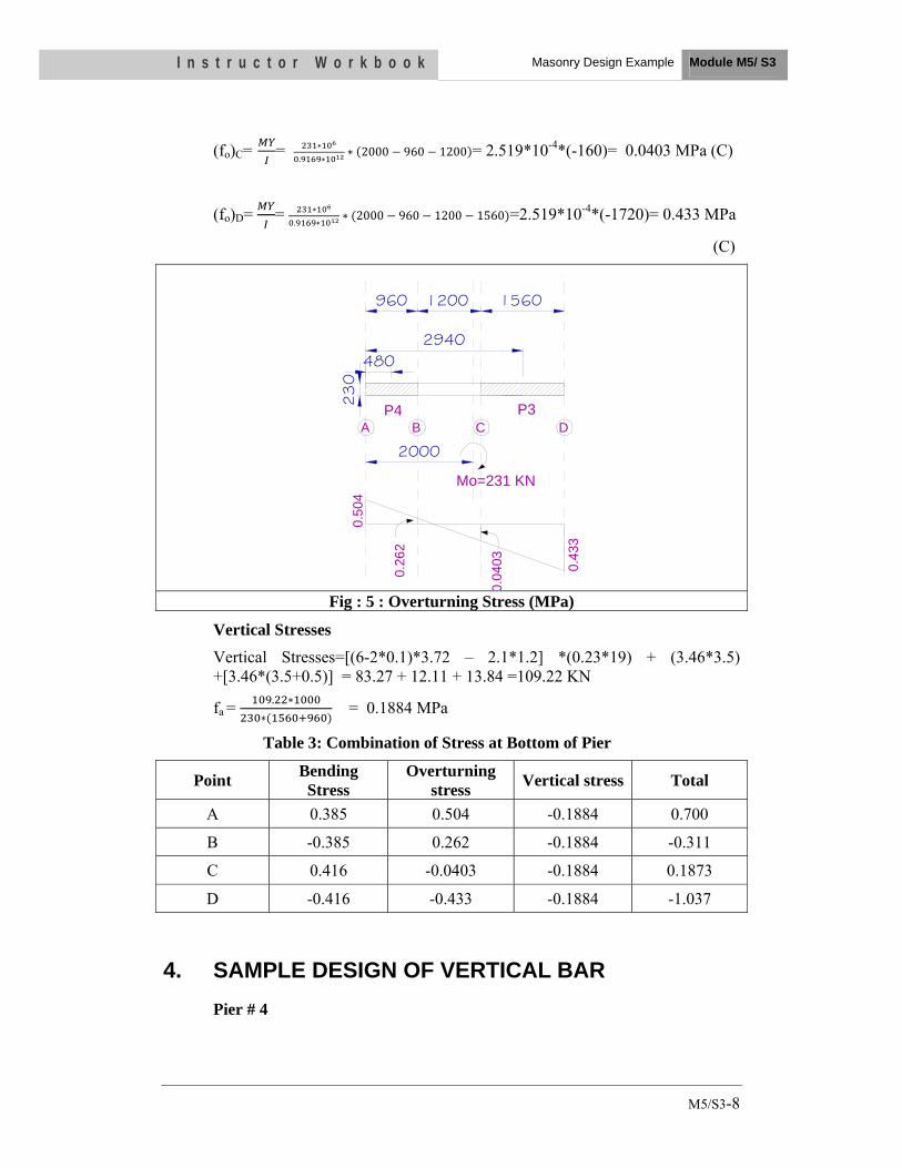
I n s t r u c t o r W o r k b o o k Masonry Design Example Module M5/ S3
M5/S3-8
(fo)C= = .
2000 960 1200 = 2.519*10-4*(-160)= 0.0403 MPa (C)
(fo)D= = .
2000 960 1200 1560 =2.519*10-4*(-1720)= 0.433 MPa
(C)
1560
P3P4 A B C D
1200960
4802940
2000
Mo=231 KN
0.50
4
0.43
3
0.04
03
0.26
2
230
Fig : 5 : Overturning Stress (MPa)
Vertical Stresses
Vertical Stresses=[(6-2*0.1)*3.72 – 2.1*1.2] *(0.23*19) + (3.46*3.5) +[3.46*(3.5+0.5)] = 83.27 + 12.11 + 13.84 =109.22 KN
fa = . = 0.1884 MPa
Table 3: Combination of Stress at Bottom of Pier
Point Bending Stress
Overturning stress Vertical stress Total
A 0.385 0.504 -0.1884 0.700
B -0.385 0.262 -0.1884 -0.311
C 0.416 -0.0403 -0.1884 0.1873
D -0.416 -0.433 -0.1884 -1.037
4. SAMPLE DESIGN OF VERTICAL BAR Pier # 4

I n s t r u c t o r W o r k b o o k Masonry Design Example Module M5/ S3
M5/S3-9
960
230
P4 0.700 = 0.311 x (960-x)or, 0.311x = 672-0.7xor, 1.011x = 672or, x = 665
x=665 295
Tension Zone Comp. Zone
0.70
0 M
Pa
0.31
1 M
Pa
Total Tensile force = . 230
= 53532 N
Steel required = . .
= 184 mm2
Provide 1 no of 16mm Ø bar.
230
Bar for New Construction
16mm Ø bar

I n s t r u c t o r W o r k b o o k Masonry Design Example Module M5/ S3
M5/S3-10
5. CHECK FOR SHEAR STRESS Shear stress in Pier # P3
Shear force, V = 37 KN
Shear stress =
=
= 0.103 MPa
Compressive stress due to DL= 0.1884 N/mm2
Permissible shear stress = 0.1 + 0.1884/6
= 0.13 N/mm2
Hence safe in shear stress
6. CHECK FOR COMPRESSIVE STRESS Unit load
Slab= 0.1*25+0.05*20 = 3.5 kN/m2
Wall=0.23*19=4.37 kN/m2
Total dead load in building due to wall and slab DL
= 2*5.76*3.72*3.5+2*2*(5.53+3.49)*3*4.37 = 623 KN
Total live load on both the floors LL=5.76*3.72*2+5.76*3.72*0.75 = 58.9 kN
Total Load= DL+LL = 682 kN
Compressive Stress=682/((5.53+3.49)*2*0.23) kN/m2
=0.164 N/mm2
Permissible value of compressive stress = 0.35 N/mm2
Hence safe