Embed Size (px)
Citation preview
CommunicationDuctile-Phase Toughening inTiBw/Ti-Ti3Al Metallic-IntermetallicLaminate Composites
HAO WU, BO CHENG JIN, LIN GENG,GUOHUA FAN, XIPING CUI, MENG HUANG,RODRIGO MIER HICKS, and STEVEN NUTT
The concept of ductile-phase toughening was exploredin a metallic-intermetallic laminate (MIL) compositecomprising alternating layers of Ti3Al and TiBw/Ti. Thelaminates, in which the TiBw/Ti layers were intended toimpart toughness to the brittle Ti3Al, were fabricatedin situ by hot pressing and reaction annealing. Com-pared with monolithic Ti3Al, the MIL compositeexhibited marked increases in both fracture toughnessand tensile elongation because of stress redistributionand strain delocalization by in situ interfaces.
DOI: 10.1007/s11661-015-3025-y� The Minerals, Metals & Materials Society and ASMInternational 2015
The intermetallic compound a2-Ti3Al has potential asa lightweight material for high-temperature structuralapplications, exhibiting both high strength, and resis-tance to oxidation and creep. However, poor ductilityand toughness at room temperature prohibit the poten-tial applications in most fields.[1,2] Various approacheshave been employed in attempts to improve the tough-ness of intermetallic compounds, including introducingparticles, fibers, or layers of ductile inclusions.[3–7]
However, for a given volume fraction, ductile phaseinclusions in the laminate form provide the maximumtoughening efficiency, followed by fiber and particulateinclusions.[4,6]
Metallic-intermetallic laminate (MIL) composites canbe fabricated by deposition or bonding the components.Deposition techniques, involving atomic scale transportof the componentmaterials, are relatively costly and slow,
and thus are not practical for production of large-scalecomponents.[8,9] In contrast, reaction bonding of metallicfoils afford multiple advantages, in particular the gener-ation of well-bonded interfaces between themetal and theintermetallic components.[10,11] Furthermore, the lami-nated structure of the composite allows for variations inlayer thickness and volume fractions of the componentssimply through the selection of initial foil thickness.[4,11,12]
In the present work, we explore the concept of ductile-phase toughening of Ti3Al by fabrication of MILcomposites. In particular, we prepare MIL compositescomprising alternating layers of TiBw/Ti and Ti3Al byreaction annealing TiBw/Ti foils and Al foils. Comparedwith pure Ti, TiBw/Ti has a greater yield strength withlittle sacrifice of ductility, an important attribute tosatisfy the service requirements of high-temperaturematerials.[13] We also assess both the synthesis processand deformation behavior of the resulting TiBw/Ti-Ti3Al MIL composites.The MIL composites were fabricated by an in situ
method, in which alternating Al foils (100 lm thick) and5 vol pct TiBw/Ti composite foils (500 lm thick) werestacked, followed by hot pressing at 788 K (515 �C)under 75 MPa for 1.5 hours and reaction annealingunder controlled temperature and pressure (Figure 1).Typical processing parameters for reaction annealingconsisted of (i) an initial annealing at 943 K (670 �C) for3 hours to consume all of Al, and (ii) a densificationtreatment at 1473 K (1200 �C) for 5 hours under40 MPa to produce a fully dense TiBw/Ti-Ti3Al MILcomposite. The dimensions of the processed sampleswere 30 mm9 50 mm9 4 mm. The microstructure ofthe MIL composite was characterized by electronchanneling contrast (ECC), electron backscatter diffrac-tion (EBSD), energy dispersive X-ray spectroscopy(EDX), and X-ray diffraction (XRD).Single-edge notched bend (SENB) specimens
(29 49 20 mm3, ASTM E1820) with a notched depthof 2 mm parallel to the loading direction were employedto measure the fracture toughness. The load-displace-ment curve was acquired automatically by using anInstron-5500 Universal Testing Machine at room tem-perature (RT) with a crosshead rate of 0.2 mm/min. Onthe basis of the maximum force, Fmax, we can calculatethe value of fracture toughness by the Eqs. [1] and [2]
KIC ¼ FmaxS
B1=2W3=2� fða=WÞ; ½1�
fða=WÞ ¼ 3ða=WÞ1=2
� 1:99� ða=WÞð1� a=WÞ½2:15� 3:93ða=WÞ þ 2:70ða=WÞ2�2ð1þ 2a=WÞð1� a=WÞ3=2
;
½2�
where S, B, W are the span, thickness, and width ofthe specimen, respectively (cm), a is the length of a
HAO WU, Ph.D. Student, LIN GENG, Professor, GUOHUAFAN, Associate Professor, XIPING CUI, Researcher, and MENGHUANG, Master Student, are with the School of Materials Scienceand Engineering, Harbin Institute of Technology, Harbin 150001, P.R.China. Contact e-mail: [email protected] BO CHENG JIN, Ph.D.Student, RODRIGO MIER HICKS, Master Student, and STEVENNUTT, Professor, are with the Department of Chemical Engineeringand Materials Science, M.C. Gill Composites Center, University ofSouthern California, Los Angeles, CA 90089-0241.
Manuscript submitted March 22, 2015Article published online June 24, 2015
METALLURGICAL AND MATERIALS TRANSACTIONS A VOLUME 46A, SEPTEMBER 2015—3803
pre-crack (cm), and f(a/W) is a geometry factor basedon the dimension of specimens. In this work,S = 16 mm, B = 2 mm, W = 4 mm, a = 2 mm.
The tensile tests were performed at 873 K and 973 K(600 �C and 700 �C) using an Instron-1186 UniversalTesting Machine with a constant strain rate of 1910�4 s�1. Samples were ground before testing, from 400to 2000 grit, and then final polished by 0.5 lm diamond.
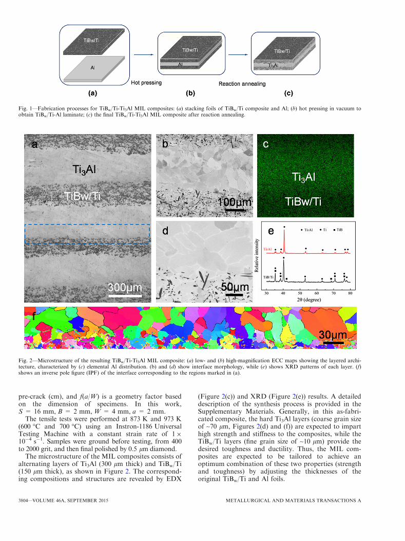
The microstructure of the MIL composites consists ofalternating layers of Ti3Al (300 lm thick) and TiBw/Ti(150 lm thick), as shown in Figure 2. The correspond-ing compositions and structures are revealed by EDX
(Figure 2(c)) and XRD (Figure 2(e)) results. A detaileddescription of the synthesis process is provided in theSupplementary Materials. Generally, in this as-fabri-cated composite, the hard Ti3Al layers (coarse grain sizeof ~70 lm, Figures 2(d) and (f)) are expected to imparthigh strength and stiffness to the composites, while theTiBw/Ti layers (fine grain size of ~10 lm) provide thedesired toughness and ductility. Thus, the MIL com-posites are expected to be tailored to achieve anoptimum combination of these two properties (strengthand toughness) by adjusting the thicknesses of theoriginal TiBw/Ti and Al foils.
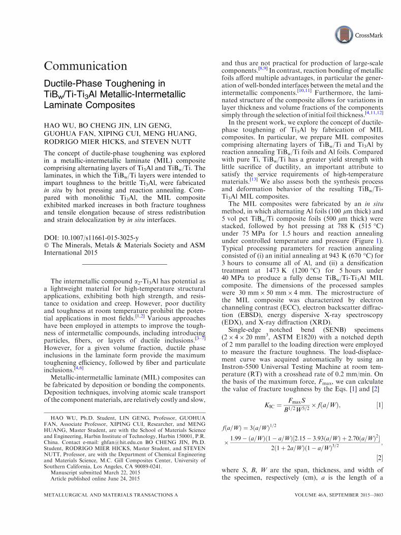
Fig. 1—Fabrication processes for TiBw/Ti-Ti3Al MIL composites: (a) stacking foils of TiBw/Ti composite and Al; (b) hot pressing in vacuum toobtain TiBw/Ti-Al laminate; (c) the final TiBw/Ti-Ti3Al MIL composite after reaction annealing.
Fig. 2—Microstructure of the resulting TiBw/Ti-Ti3Al MIL composite: (a) low- and (b) high-magnification ECC maps showing the layered archi-tecture, characterized by (c) elemental Al distribution. (b) and (d) show interface morphology, while (e) shows XRD patterns of each layer. (f)shows an inverse pole figure (IPF) of the interface corresponding to the regions marked in (a).
3804—VOLUME 46A, SEPTEMBER 2015 METALLURGICAL AND MATERIALS TRANSACTIONS A
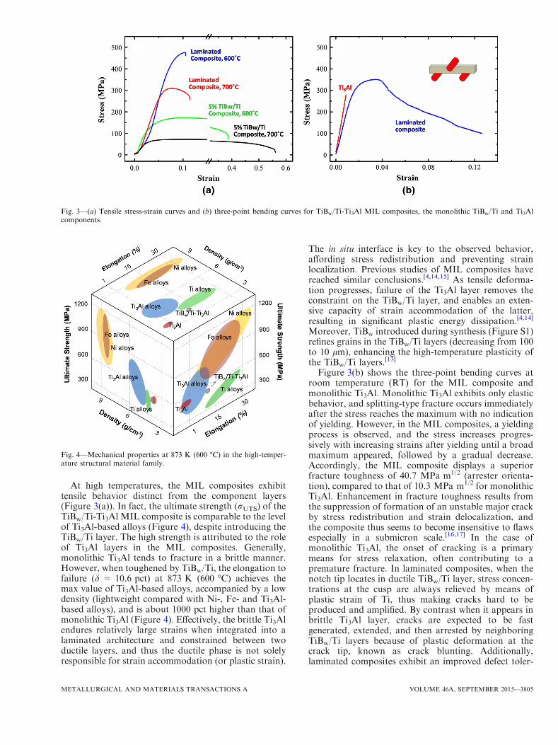
At high temperatures, the MIL composites exhibittensile behavior distinct from the component layers(Figure 3(a)). In fact, the ultimate strength (rUTS) of theTiBw/Ti-Ti3Al MIL composite is comparable to the levelof Ti3Al-based alloys (Figure 4), despite introducing theTiBw/Ti layer. The high strength is attributed to the roleof Ti3Al layers in the MIL composites. Generally,monolithic Ti3Al tends to fracture in a brittle manner.However, when toughened by TiBw/Ti, the elongation tofailure (d = 10.6 pct) at 873 K (600 �C) achieves themax value of Ti3Al-based alloys, accompanied by a lowdensity (lightweight compared with Ni-, Fe- and Ti3Al-based alloys), and is about 1000 pct higher than that ofmonolithic Ti3Al (Figure 4). Effectively, the brittle Ti3Alendures relatively large strains when integrated into alaminated architecture and constrained between twoductile layers, and thus the ductile phase is not solelyresponsible for strain accommodation (or plastic strain).
The in situ interface is key to the observed behavior,affording stress redistribution and preventing strainlocalization. Previous studies of MIL composites havereached similar conclusions.[4,14,15] As tensile deforma-tion progresses, failure of the Ti3Al layer removes theconstraint on the TiBw/Ti layer, and enables an exten-sive capacity of strain accommodation of the latter,resulting in significant plastic energy dissipation.[4,14]
Moreover, TiBw introduced during synthesis (Figure S1)refines grains in the TiBw/Ti layers (decreasing from 100to 10 lm), enhancing the high-temperature plasticity ofthe TiBw/Ti layers.
[13]
Figure 3(b) shows the three-point bending curves atroom temperature (RT) for the MIL composite andmonolithic Ti3Al. Monolithic Ti3Al exhibits only elasticbehavior, and splitting-type fracture occurs immediatelyafter the stress reaches the maximum with no indicationof yielding. However, in the MIL composites, a yieldingprocess is observed, and the stress increases progres-sively with increasing strains after yielding until a broadmaximum appeared, followed by a gradual decrease.Accordingly, the MIL composite displays a superiorfracture toughness of 40.7 MPa m1/2 (arrester orienta-tion), compared to that of 10.3 MPa m1/2 for monolithicTi3Al. Enhancement in fracture toughness results fromthe suppression of formation of an unstable major crackby stress redistribution and strain delocalization, andthe composite thus seems to become insensitive to flawsespecially in a submicron scale.[16,17] In the case ofmonolithic Ti3Al, the onset of cracking is a primarymeans for stress relaxation, often contributing to apremature fracture. In laminated composites, when thenotch tip locates in ductile TiBw/Ti layer, stress concen-trations at the cusp are always relieved by means ofplastic strain of Ti, thus making cracks hard to beproduced and amplified. By contrast when it appears inbrittle Ti3Al layer, cracks are expected to be fastgenerated, extended, and then arrested by neighboringTiBw/Ti layers because of plastic deformation at thecrack tip, known as crack blunting. Additionally,laminated composites exhibit an improved defect toler-
Fig. 3—(a) Tensile stress-strain curves and (b) three-point bending curves for TiBw/Ti-Ti3Al MIL composites, the monolithic TiBw/Ti and Ti3Alcomponents.
Fig. 4—Mechanical properties at 873 K (600 �C) in the high-temper-ature structural material family.
METALLURGICAL AND MATERIALS TRANSACTIONS A VOLUME 46A, SEPTEMBER 2015—3805
ance, evidenced by an increasing critical crack length, l,as a result of strain absorption (ductile layers) and stressredistribution (laminated architecture). Kumar et al.[18]
defined the parameter as an intrinsic attribute ofcomposites by
l ¼ aCE=S2; ½3�
below which the fracture strength of pre-cracked mate-rials is identical to that of a perfect crystal in spite ofthe presence of defects. In Eq. [3], a equals to 1.9 forGriffith-Irwin models, S is the ultimate strength, C isthe fracture energy and qualitatively expressed as thearea beneath the stress-strain curve
C ¼Z
rde: ½4�
Apparently, an increased fracture energy in laminatedcomposites, as shown in Figure 3(b), contributes to alarge magnitude of critical crack length, implying anenhanced flaws endurance compared to monolithiccounterparts.
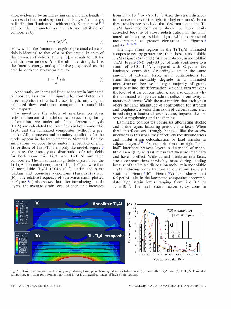
To investigate the effects of interfaces on stressredistribution and strain delocalization occurring duringdeformation, we undertook finite element analysis(FEA) and calculated the strain fields in both monolithicTi3Al and the laminated composites (without a pre-crack). All parameters and boundary conditions for themodel appear in the Supplementary Materials. For thesimulations, we substituted material properties of pureTi for those of TiBw/Ti to simplify the model. Figure 5compares the intensity and distribution of strain fieldsfor both monolithic Ti3Al and Ti-Ti3Al laminatedcomposites. The maximum magnitude of strain for theTi-Ti3Al laminated composite (4.129 10�3) is twice thatof monolithic Ti3Al (2.049 10�3) under the sameloading and boundary conditions (Figures 5(a) and(b)). The relative frequency of von Mises strain plottedin Figure 5(c) also shows that after introducing ductilelayers, the average strain level of each unit increases
from 3.59 10�4 to 7.89 10�4. Also, the strain distribu-tion curve moves to the right (to higher strains). Fromthese results, we conclude that deformation in the Ti-Ti3Al laminated composite should be more easilyactivated because of stress redistribution in the lami-nated architecture, which aligns with experimentalmeasurements (a greater elongation in Figures 3and 4).[16,17,19]
The high strain regions in the Ti-Ti3Al laminatedcomposite occupy greater area than those in monolithicTi3Al (Figures 5(a) and (b)). For instance, in monolithicTi3Al (Figure 5(c)), only 33 pct of units contribute to astrain of >3.39 10�4, compared with 82 pct in thelaminated composite. Accordingly, under the sameamount of external force, grain contributions forstrain-sharing inevitably degrade in a laminatedmicrostructure because a larger majority of grainsparticipate into the deformation, which in turn weakensthe level of stress concentrations, and also explains whythe laminated composites exhibit defect insensitivity asmentioned above. With the assumption that each grainoffers the same magnitude of contribution for strengthand toughness, a wider dimension of deformation, afterintroducing a laminated architecture, imparts the ob-served strengthening and toughening.Laminated composites comprises alternating ductile
and brittle layers featuring periodic interfaces. Whenthese interfaces are strongly bonded, like the in situinterfaces in this work, they effectively redistribute stressand inhibit strain delocalization by load transfer toadjacent layers.[20] For example, there are eight ‘‘nom-inal’’ interfaces between layers in the model of mono-lithic Ti3Al (Figure 5(a)), but in fact they are imaginaryand have no effect. Without real interlayer interfaces,stress concentrations inevitably arise during loadingbecause of the limited dislocation mobility in monolithicTi3Al, inducing brittle fracture at low strains (~0.7 pctstrain in Figure 3(b)). Figure 5(c) also shows that6.5 pct of units in the laminated composites accommo-date high strain levels ranging from 29 10�3 to4.19 10�3. The high strain region (gray zone in
Fig. 5—Strain contour and partitioning maps during three-point bending: strain distribution of (a) monolithic Ti3Al and (b) Ti-Ti3Al laminatedcomposites; (c) strain partitioning map. Inset in (c) is a magnified image of high strain regions.
3806—VOLUME 46A, SEPTEMBER 2015 METALLURGICAL AND MATERIALS TRANSACTIONS A
Figure 5(b)) includes both a brittle Ti3Al layer and aductile Ti layer, implying that the laminated compositecould withstand a relatively large strain when the brittleTi3Al was constrained between ductile layers.
In summary, laminated composites comprising alter-nating layers of Ti3Al and TiBw/Ti have been producedin situ by hot pressing and reaction annealing. Theapproach of using ductile TiBw/Ti layers to imparttoughness to inherently brittle Ti3Al has been employedand explored in this work. Compared with monolithicTi3Al, the MIL composites exhibited superior elonga-tion (10.6 pct) at 873 K (600 �C) and RT fracturetoughness (40.7 MPa m1/2). Tensile tests and simula-tions demonstrated that the laminated architecture ofthe microstructure imparted an ability to endure rela-tively large strains, and appeared to be linked to the factthat the Ti3Al is integrated into the composite andconstrained between ductile layers.
The work presented here establishes a framework fordesigning and producing MIL based on a wide variety ofmultiple-component systems (e.g., Ni-Al, Fe-Al, Nb-Al,etc.). The approach allows designers to sufficientlyleverage the intrinsic attributes of the componentphases. Such MILs and similar derivative microstruc-tures have potential as future lightweight high-perfor-mance materials for high-temperature structuralapplications.
This work was financially supported by (i) theNational Natural Science Foundation of China (GrantNo. 51071058, 51401068), (ii) China PostdoctoralScience Foundation Funded Project (Grant No.2013M541370), (iii) Heilongjiang Postdoctoral Fund(Grant No. LBH-Z13098), and (iv) FundamentalResearch Funds for the Central University (Grant No.HIT. NSRIF. 2014001).
ELECTRONIC SUPPLEMENTARY MATERIAL
The online version of this article (doi:10.1007/s11661-015-3025-y) contains supplementary material, which isavailable to authorized users.
REFERENCES1. K.L. Yang, J.C. Huang, and Y.N. Wang:Metall. Mater. Trans. A,
2004, vol. 35A, pp. 3803–15.2. Y. Koizumi, T. Nakano, and Y. Umakoshi: Acta Mater., 1999,
vol. 47, pp. 2019–29.3. H.M. Chan: Annu. Rev. Mater. Sci., 1997, vol. 27, pp. 249–82.4. A. Rohatgi, D.J. Harach, K.S. Vecchio, and K.P. Harvey: Acta
Mater., 2003, vol. 51, pp. 2933–57.5. M.E. Launey and R.O. Ritchie: Adv. Mater., 2009, vol. 21,
pp. 2103–10.6. M.E. Launey, E. Munch, D.H. Alsem, E. Saiz, A.P. Tomsia, and
R.O. Ritchie: J. R. Soc. Interface, 2010, vol. 7, pp. 741–53.7. K. Lu: Science, 2010, vol. 328, pp. 319–20.8. Y. Kaneko, H. Sakakibara, and S. Hashimoto: J. Mater. Sci.,
2008, vol. 43, pp. 3931–37.9. P.M. Anderson, J.F. Bingert, A. Misra, and J.P. Hirth: Acta
Mater., 2003, vol. 51, pp. 6059–75.10. Q.W. Wang, G.H. Fan, L. Geng, J. Zhang, X.P. Cui, J.C. Pang,
S.H. Qin, and Y. Du: Intermetallics, 2013, vol. 37, pp. 46–51.11. X.P. Cui, G.H. Fan, L. Geng, Y. Wang, H.W. Zhang, and H.X.
Peng: Scripta Mater., 2012, vol. 66, pp. 276–79.12. K. Kishida, J. Yoshikawa, H. Inui, and M. Yamaguchi: Acta
Mater., 1999, vol. 47, pp. 3405–10.13. L.J. Huang, L. Geng, H.X. Peng, and J. Zhang: Scripta Mater.,
2011, vol. 64, pp. 844–47.14. D.E. Alman, J.C. Rawers, and J.A. Hawk: Metall. Mater. Trans.
A, 1995, vol. 26A, pp. 589–99.15. P. Lhuissier, J. Inoue, and T. Koseki: Scripta Mater., 2011, vol. 64,
pp. 970–73.16. T.H. Fang, W.L. Li, N.R. Tao, and K. Lu: Science, 2011, vol. 331,
pp. 1587–90.17. H. Kou, J. Lu, and Y. Li: Adv. Mater., 2014, vol. 26, pp. 5518–24.18. S. Kumar, M.A. Haque, and H. Gao: Appl. Phys. Lett., 2009, vol.
94, p. 253104.19. L. Lu, X. Chen, X. Huang, and K. Lu: Science, 2009, vol. 323,
pp. 607–10.20. J.C. Pang, G.H. Fan, X.P. Cui, A.B. Li, L. Geng, Z.Z. Zheng, and
Q.W. Wang: Mater. Sci. Eng. A, 2013, vol. 582, pp. 294–98.
METALLURGICAL AND MATERIALS TRANSACTIONS A VOLUME 46A, SEPTEMBER 2015—3807