Embed Size (px)
Citation preview
Dual Vertical Phased Array
DXE-DVA
DXE-DVA-160-P - Dual Vertical Array system for 160 meters
DXE-DVA-80-P - Dual Vertical Array system for 80 meters
DXE-DVA-40-P - Dual Vertical Array system for 40 meters
DXE-DVA-INS Revision 0a
© DX Engineering 2014
1200 Southeast Ave. - Tallmadge, OH 44278 USA
Phone: (800) 777-0703 ∙ Tech Support and International: (330) 572-3200
Fax: (330) 572-3279 ∙ E-mail: [email protected]
- 2 -
Introduction and General Information
Congratulations on your purchase of the DX Engineering Dual Vertical Phased Array System,
custom designed and tested to offer the best directional transmitting and receiving performance in
proportion to the space required. Advanced design, with a stable, clean and low-angle pattern makes
the DX Engineering Dual Vertical Phased Array (DVA) the finest dual element quarter-wave
monoband phased antenna system available. The DX Engineering Dual Vertical Phased Arrays are
advanced vertical antenna phasing systems that set new standards in two vertical element array
performance. DX Engineering Dual Vertical Phased Array system design eliminates the waste load
port of previous hybrid-type two-element systems, thus increasing array efficiency. Each mono-
band Dual Vertical Array system includes a sleek new Phasing Relay Unit and a new Control
Console. The model number of your system corresponds to the band for which it was manufactured.
There are 3 system models available that cover the 160, 80, or 40 meter bands:
DXE-DVA-160-P - Dual Vertical Array - 160 meters - Phasing Relay Unit and Control Console
DXE-DVA-80-P - Dual Vertical Array - 80 meters - Phasing Relay Unit and Control Console
DXE-DVA-40-P - Dual Vertical Array - 40 meters - Phasing Relay Unit and Control Console
The Phasing Relay Unit can be ordered without the DVA Control Console:
DXE-DVA-160 - Dual Vertical Array - 160 meters - Phasing Relay Unit Only
DXE-DVA-80 - Dual Vertical Array - 80 meters - Phasing Relay Unit Only
DXE-DVA-40 - Dual Vertical Array - 40 meters - Phasing Relay Unit Only
The Dual Vertical Array Control Console can be ordered without the DVA Phasing Relay Unit:
DXE-EC-DVA - Control Console only for the Dual Vertical Array System
DX Engineering Dual Vertical Phased Array (DVA) systems produce two enhanced End-Fire
Cardioid patterns and one Broadside-Omni pattern. New heavy-duty components handle 2 kW
continuous RF power with array performance at low SWR over a wide bandwidth. The Dual
Vertical Array end-fire directional patterns achieve a real front-to-back over 20 dB with typical
array forward gain up to 3 dB over a single vertical.
Each DX Engineering Dual Vertical Phased Array’s mono-band weatherproof DVA Phasing Relay
Unit includes a clamp for mounting on a mounting pipe that is positioned directly between two
ground-mounted, full-size, quarter-wave resonant verticals. The antennas must be located as
described in the installation section to provide switchable patterns in desired directions. The
forward lobes are reasonably wide eliminating the need for precise aiming while also providing
coverage of in-between directions.
The proper spacing between these user-supplied antennas is one-quarter wavelength free space, and
each should be installed with 40 or more ground radials; all antenna system parts are also available
from DX Engineering.
The two vertical antennas must be resonant in the desired band of operation. Each vertical element
must be directly fed through 1/4-wave long 75Ω transmission lines. No additional matching
components or decoupling devices may be used, like baluns or coils, between the centrally located
Dual Vertical Phasing Relay Unit and the verticals, as additional transmission line lengths can
reduce array performance.
- 3 -
DVA systems require the 75-ohm antenna feed cables to be electrically tuned to one-quarter
wavelength. Offered by DX Engineering as an option, these custom built PL-259 terminated cable
assemblies use the highest quality waterproof polyethylene jacket direct-burial DXE-11U low-loss
foam coax. These custom length coaxial cables are frequency specific, electronically tuned and
connect the DVA Phasing Relay Unit directly to each mono-band vertical antenna feed point and
radial system.
The vertical antennas must be series-fed at the base, 1/4-wave long and must be resonant. DX
Engineering offers vertical antennas that are well suited for this application. Above all, a properly
designed and installed radial system is necessary for maximum system performance.
The included companion DXE-EC-DVA Control Console is a three-position directional pattern
selector that operates on 13.8 Vdc and features a 3-position rotary switch, directional LED
indicators and scratch pads on the console for the user to write in their array end fire directions. The
DXE-EC-DVA Control Consoles require only a 3-conductor 20 AWG cable for connection to the
DVA Phasing Relay Unit.
DXE-DVA - Dual Vertical Array System Features
The Dual Vertical Array System is a monoband two element, three direction-switchable array
based on a two element end-fire/broadside combination of identical vertical elements. This antenna
array system is capable of delivering pattern directional performance superior to other systems in its
class.
Custom design with stable and clean low-angle patterns
No dump power as on other types of phased arrays so all your power goes to the antenna
elements
Power Handling: 2 kW continuous
Directional performance - Two End Fire and one Broadside directions
Forward Gain (approximate as compared to a single vertical): 3 dB End-Fire, 1 dB
Broadside (Omni)
Can be built with monoband verticals to cover any single band
RF Connectors: Three SO-239 (UHF Female): Transmitter, Antenna 1, Antenna 2
Excellent signal-to-noise ratio
Directivity over a very wide frequency range in the band selected
Excellent relay contact reliability
DC powered control console allows system operation without AC power mains
Control Cable: 3 conductors, minimum 20 AWG
Control Wire Connections: Set screw connectors internal at the Control Console and a
removable external connector at the DVA Phasing Relay Unit
Cover on the DVA Phasing Relay Unit made from tough UV protected plastic
Stainless steel chassis and mounting plate on Phasing Relay Unit
DVA Control Console uses +13.8 Vdc input has three LEDs and three position rotary
direction switch (Position 1, Broadside, Position 2)
Designed, manufactured and tested in the USA by DX Engineering
- 4 -
Parts Included
DXE-DVA Dual Vertical Array Phasing Relay Unit for band specified.
DXE-SSVC-2P Stainless Steel V-Clamp for mounting the DXE-DVA Phasing Relay Unit
to a mounting post between 1" and 2" OD
DXE-EC-DVA Dual Vertical Array Control Console
2.1 mm Power Plug with wires to connect to the station +12 to +13.8 Vdc filtered power
supply
Additional Parts Required, Not Supplied with the DXE-DVA Systems See the Optional Items at the back of this manual for details
Two identical Full Size Quarter-wave Monoband Vertical Antenna Elements
DXE-P8A - Penetrox A Anti-Oxidant for the vertical antenna elements
DXE-RG-11U Phasing Cables, 75-ohm, cut to the proper electrical length for the applicable
dual vertical array system center frequency
DXE-RADP-3 Radial Plates - one for each vertical element
DXE-363-SST Bulkhead Connectors for a clean and quality feedline connections, one for
each Radial Plate
DXE-FP-WIRE-P Feedpoint Wire & Connector Assemblies, one for each vertical element
DXE- RADW Radial Wire for the required vertical antenna radials
GCL-1120-050 Copper Radial Cross Bonding Strap, 2” wide
COM-CW4 - Four Wire Control Cable - Three wires are used with this system. COM-CW-
4 is 4-wire, 20 AWG, stranded copper with a grey PVC jacket
Galvanized Mounting Pipe, 1 inch minimum to 2 inches OD maximum, for mounting the
Dual Vertical Array Phasing Relay Unit at the center of the array using the supplied DXE-
SSVC-2P Stainless Steel V-Clamp (see text for details)
UMI-81343 Never-Seez®
or DXE-NSBT8 Anti-Seize for stainless steel hardware
DXE-3M2155 3M Temflex Tape and TRM-06132 Scotch Super 33 Tape for
Weatherproofing the coaxial cable connections
DXE-400MAX or DXE-213U or equivalent, 50-ohm coaxial cable for the array main
feedline from the transceiver to the Phasing Relay Unit
Manual Updates
Every effort is made to supply the latest manual revision with each product. Occasionally a manual
will be updated between the time your DX Engineering product is shipped and when you receive it.
Please check the DX Engineering web site (www.dxengineering.com) for the latest revision manual.
- 5 -
Tools Required
1/2” nut driver or wrench (for the DXE-SSVC-2P V-Clamp
Wire stripper for control lines
Small flat blade screwdriver for control line connections
Soldering Iron and Solder to join the two radial fields together where they meet
General Installation Information
The DXE-DVA Dual Vertical Array Phasing Relay Unit should be mounted to a customer supplied
mounting pipe at the center of the array, halfway between the two monoband verticals.
The DXE-DVA Dual Vertical Array Phasing Relay Unit has a built-in, stainless steel, pre-drilled
mounting flange to accommodate up to a 2 inch OD mounting pipe. The included DXE-SSVC-2P
Stainless Steel V-Bolt Saddle Clamp is for attaching the Phasing Relay Unit to the customer
supplied 1" to 2" OD mounting pipe. An optional DXE-CAVS-1P V-Bolt Saddle clamp can be
used for pipe from 3/4" to 1-3/4" inches OD. The Phasing Relay Unit can also be mounted on a
sturdy wooden post.
Note: UMI-81343 Never-Seez®
or DXE-NSBT8 Anti-Seize should be used on all clamps, bolts and
stainless steel threaded hardware to prevent galling and to ensure proper tightening.
The Array Phasing Relay Unit must be mounted with cover upward and the control and coaxial
cable connections downward to prevent water from entering the box. The stainless steel base of the
Array Phasing Relay Unit has weep holes to allow condensation that may build up inside the unit to
leave. Additional weatherproofing protection may be used on the coaxial connections.
WARNING!
INSTALLATION OF ANY ANTENNAS NEAR POWER LINES IS DANGEROUS
Warning: Do not locate the antennas near overhead power lines or other electric light or power
circuits, or where they can come into contact with such circuits. When installing the antennas, take
extreme care not to come into contact with such circuits, because they may cause serious injury or
death. Make sure when you are digging, you are not near any buried utility lines.
- 6 -
Overhead Power Line Safety
Before you begin working, check carefully for overhead power lines in the area you will be
working. Don't assume that wires are telephone or cable lines: check with your electric utility for
advice. Although overhead power lines may appear to be insulated, often these coverings are
intended only to protect metal wires from weather conditions and may not protect you from electric
shock
Keep your distance! Remember the 10-foot rule: When carrying and using ladders and other long
tools, keep them at least 10 feet away from all overhead lines - including any lines from the power
pole to your home.
Installation
Site Selection
Select mounting locations clear from power lines and structures by a minimum of height of the
monoband antennas used plus 10 feet (for the 10 foot safety rule). Consider overhead power lines,
utility cables and wires. The monoband verticals should be mounted away from local noise sources
or other metallic objects which can re-radiate noise and affect the tuning, radiation pattern and
SWR. Determine the direction you want the array positioned. There should also be a clear diameter
from the monoband antennas for the guying and radial systems that will extend away from the
antennas.
Topographical Considerations
Flat or gradually sloped land is best. Erecting the transmitting array on steeply sloped land or
uneven terrain might degrade performance. To avoid pattern degradation, antenna elements should
have reasonably similar elevations. It's recommended the maximum ground height difference
between any of the vertical antennas in the array should be less than 20% of the array diameter. For
example, two 80 meter verticals 66 feet apart should be within 13 feet of level. Every effort should
be taken to make the elements symmetrical. Elements must be similar or identical in construction
and grounding. Elements should be mounted above any standing water, but as close to the ground as
possible. In general, the system will not be affected by trees or foliage so long as the foliage is not
near an element. The open ends or tips of the elements are particularly sensitive to close branches or
foliage. There should be a reasonably clear electrical path for at least 1 wavelength in important
receiving directions. The site should allow a radial system to be as evenly distributed around each of
the vertical elements as possible, although perfect symmetry isn’t important so long as the radial
connections are good.
Most amateur radio operators in the continental United States will want the system to point toward
Europe (NE) as a default (position 1). Therefore the system described in this manual will be laid out
with vertical antenna elements 1 to the Northeast in a line going to antenna 2 toward the Southwest.
- 7 -
Note: This array, like all dual phased vertical set ups, has a fairly wide flat forward lobe. This
means exact direction headings are generally not critical. We should still remember there is a
difference between True North and Magnetic or Compass North. Without going into all of the
details, you want your system aligned to True North. Depending on your location you can check
your position using various geological, topographical or aviation maps to determine True North.
If your location has more than 10 degrees magnetic declination, you may want to correct for it.
Declinations below ten degrees can be safely ignored.
If you know your longitude and latitude, you can then pinpoint yourself on an aircraft navigation or
geological map. If you don't know your longitude and latitude, you can find that information on
many of the map services available on the internet, or use a GPS.
Site Selection in Relation to Noise Sources
Since the array is generally used for both transmitting and receiving, you should listen to desired
bands and identify any sources of unwanted noise. Elimination of noise sources is required for
optimal receiving results. If noise sources cannot be eliminated, then locate the antenna array as far
away from noise sources as possible.
Since this array is directional, locate the array so the rear of the array is pointing towards the
dominant noise source. This ensures the array has maximum suppression of noise when beaming in
the primary listening direction. For example, if you primarily want to work Europeans from the
eastern USA (Northeast direction), try to position the array so the dominant local noise is Southwest
of the array. There is no advantage at all when an array points into the noise, no matter what the
array gain is.
Gain does not generally matter, only the ratio of signal response to noise response changes S/N
ratio. The only way S/N ratio improves at HF is if the array nulls the noise more than it nulls the
desired signal.
The second-best location for the array is when the noise source is as far as possible to either side of
the array. If you look at patterns, the ideal receiving location for the array is one that places
undesired noise in a deep null area.
If your location doesn’t have the usual noise sources (power lines, electric fences, etc.), locate the
array so that your other transmitting antennas and buildings are off the back or side of the primary
array direction.
Consider these things about noise sources:
If noise is not evenly distributed, performance will depend on the gain difference between
the desired signal direction (azimuth and elevation) and average gain in the direction of
noise.
- 8 -
If noise predominantly arrives from the direction and angle of desired signals (assuming
polarization of signals and noise are the same) there will be no improvement in the signal-to-
noise ratio.
If the noise originates in the near-field of the antenna, everything becomes unpredictable. This is a
good case for the use of separate receiving antennas placed as far from noise sources (such as power
lines) as possible.
Monoband Antennas for a Dual Vertical Array System
The following are some suggested DX Engineering and COMTEK full size quarter-wave monoband
vertical antennas are an ideal match for top performance in a dual vertical array system. You’ll need
2 verticals. The COM-40VA-2P is a package of two antennas. The other listed antennas are single.
DXE-40VE-1 COM-40VA-2P DXE-7580FS-VA2 DXE-7580FS-VA3 DXE-ATK65
and DXE-VE BASE
Band 40 40 80 or 75 80 or 75 80 or 75
Element Size
Range 2" to 1/2" 2" to 1-3/8" 3” to 1/4” 4” to 1/2” 2" to 7/8"
Height 33-35' 35' 68’ 68’ 64'
Guying Suggested Suggested Suggested Suggested Required
Please visit www.DXEngineering.com for details on these vertical antennas
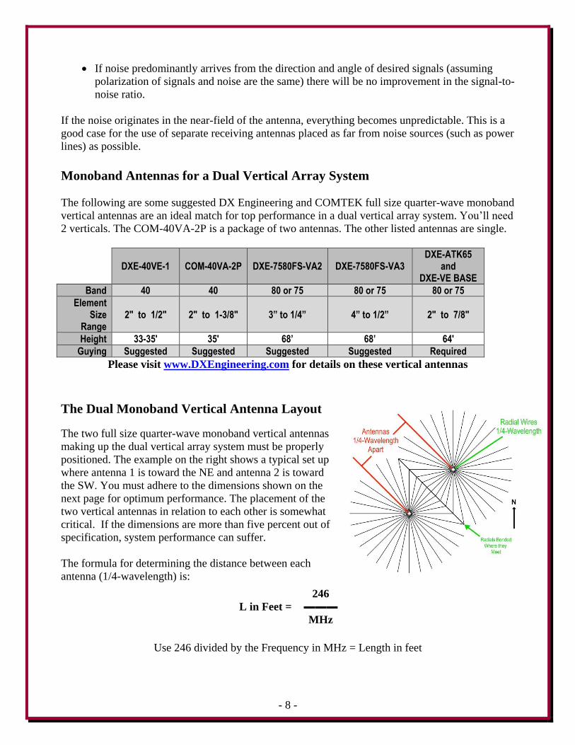
The Dual Monoband Vertical Antenna Layout
The two full size quarter-wave monoband vertical antennas
making up the dual vertical array system must be properly
positioned. The example on the right shows a typical set up
where antenna 1 is toward the NE and antenna 2 is toward
the SW. You must adhere to the dimensions shown on the
next page for optimum performance. The placement of the
two vertical antennas in relation to each other is somewhat
critical. If the dimensions are more than five percent out of
specification, system performance can suffer.
The formula for determining the distance between each
antenna (1/4-wavelength) is:
246
L in Feet =
MHz
Use 246 divided by the Frequency in MHz = Length in feet
- 9 -
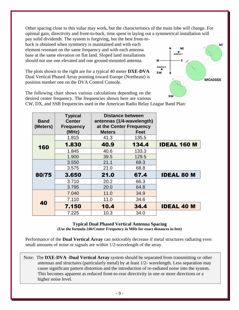
Other spacing close to this value may work, but the characteristics of the main lobe will change. For
optimal gain, directivity and front-to-back, time spent in laying out a symmetrical installation will
pay solid dividends. The system is forgiving, but the best front-to-
back is obtained when symmetry is maintained and with each
element resonant on the same frequency and with each antenna
base at the same elevation on flat land. Sloped land installations
should not use one elevated and one ground-mounted antenna.
The plots shown to the right are for a typical 40 meter DXE-DVA
Dual Vertical Phased Array pointing toward Europe (Northeast) is
position number one on the DVA Control Console.
The following chart shows various calculations depending on the
desired center frequency. The frequencies shown here are various
CW, DX, and SSB frequencies used in the American Radio Relay League Band Plan:
Band (Meters)
Typical Center
Frequency (MHz)
Distance between antennas (1/4-wavelength) at the Center Frequency
Meters Feet
160
1.815 41.3 135.5
1.830 40.9 134.4 IDEAL 160 M
1.845 40.6 133.3
1.900 39.5 129.5
80/75
3.550 21.1 69.3
3.575 21.0 68.8
3.650 21.0 67.4 IDEAL 80 M
3.710 20.2 66.3
3.795 20.0 64.8
40
7.040 11.0 34.9
7.110 11.0 34.6
7.150 10.4 34.4 IDEAL 40 M
7.225 10.3 34.0
Typical Dual Phased Vertical Antenna Spacing (Use the formula 246/Center Frequency in MHz for exact distances in feet)
Performance of the Dual Vertical Array can noticeably decrease if metal structures radiating even
small amounts of noise or signals are within 1/2-wavelength of the array.
Note: The DXE-DVA -Dual Vertical Array system should be separated from transmitting or other
antennas and structures (particularly metal) by at least 1/2- wavelength. Less separation may
cause significant pattern distortion and the introduction of re-radiated noise into the system.
This becomes apparent as reduced front-to-rear directivity in one or more directions or a
higher noise level.
- 10 -
With so many variables involved, there is no optimum or minimum spacing for effects on pattern.
The best practice is to install the array as far as possible from tall conductors or noise sources, or
place potential problems in less frequently used directions. For best pattern, space the system as far
as possible from conductors that might be noise sources or re-radiate unwanted signals. One
wavelength or more is generally ideal, although adequate performance generally occurring at closer
spacing, with one-half wavelength minimum recommended.
Radial System Information
The use of a radial system is a key requirement for a high performance dual phased monoband
vertical antenna system. With any vertical antenna, the radials are the second half of the antenna.
The radials contribute to the radiation efficiency of the entire phased vertical antenna system.
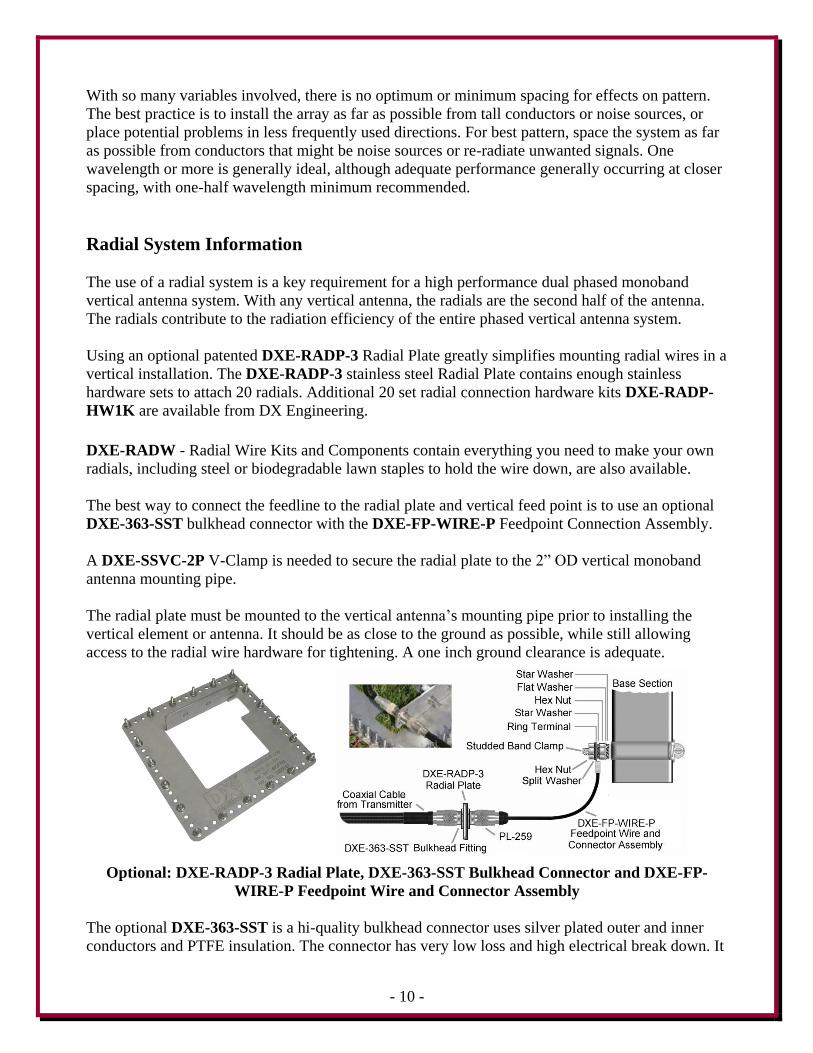
Using an optional patented DXE-RADP-3 Radial Plate greatly simplifies mounting radial wires in a
vertical installation. The DXE-RADP-3 stainless steel Radial Plate contains enough stainless
hardware sets to attach 20 radials. Additional 20 set radial connection hardware kits DXE-RADP-
HW1K are available from DX Engineering.
DXE-RADW - Radial Wire Kits and Components contain everything you need to make your own
radials, including steel or biodegradable lawn staples to hold the wire down, are also available.
The best way to connect the feedline to the radial plate and vertical feed point is to use an optional
DXE-363-SST bulkhead connector with the DXE-FP-WIRE-P Feedpoint Connection Assembly.
A DXE-SSVC-2P V-Clamp is needed to secure the radial plate to the 2” OD vertical monoband
antenna mounting pipe.
The radial plate must be mounted to the vertical antenna’s mounting pipe prior to installing the
vertical element or antenna. It should be as close to the ground as possible, while still allowing
access to the radial wire hardware for tightening. A one inch ground clearance is adequate.
Optional: DXE-RADP-3 Radial Plate, DXE-363-SST Bulkhead Connector and DXE-FP-
WIRE-P Feedpoint Wire and Connector Assembly
The optional DXE-363-SST is a hi-quality bulkhead connector uses silver plated outer and inner
conductors and PTFE insulation. The connector has very low loss and high electrical break down. It
- 11 -
comes with two nuts to secure it to the DX Engineering Radial Plate and ensures the radial ground
system, antenna ground and the feedline shield are common. The optional DXE-FP-WIRE-P
Feedpoint Wire Connector Assembly is a perfect solution to connect the feedline to the vertical
element. Don't forget to weatherproof the PL-259 coaxial connections.
At a minimum, 30 radials, each 1/4-wavelength long on the array frequency should be used. Arrays
using 40 to 60 radials are preferred and highly recommended. If you have very rocky or mostly
sandy soil, using more longer radials may help the performance of your phased antenna system.
Extra radials help overcome unknown poor-soil conditions, improve efficiency, and ensure the best
performance. DXE-RADW Radial Wire, a stranded 14 gauge PVC insulated copper wire is
suggested for the best results.
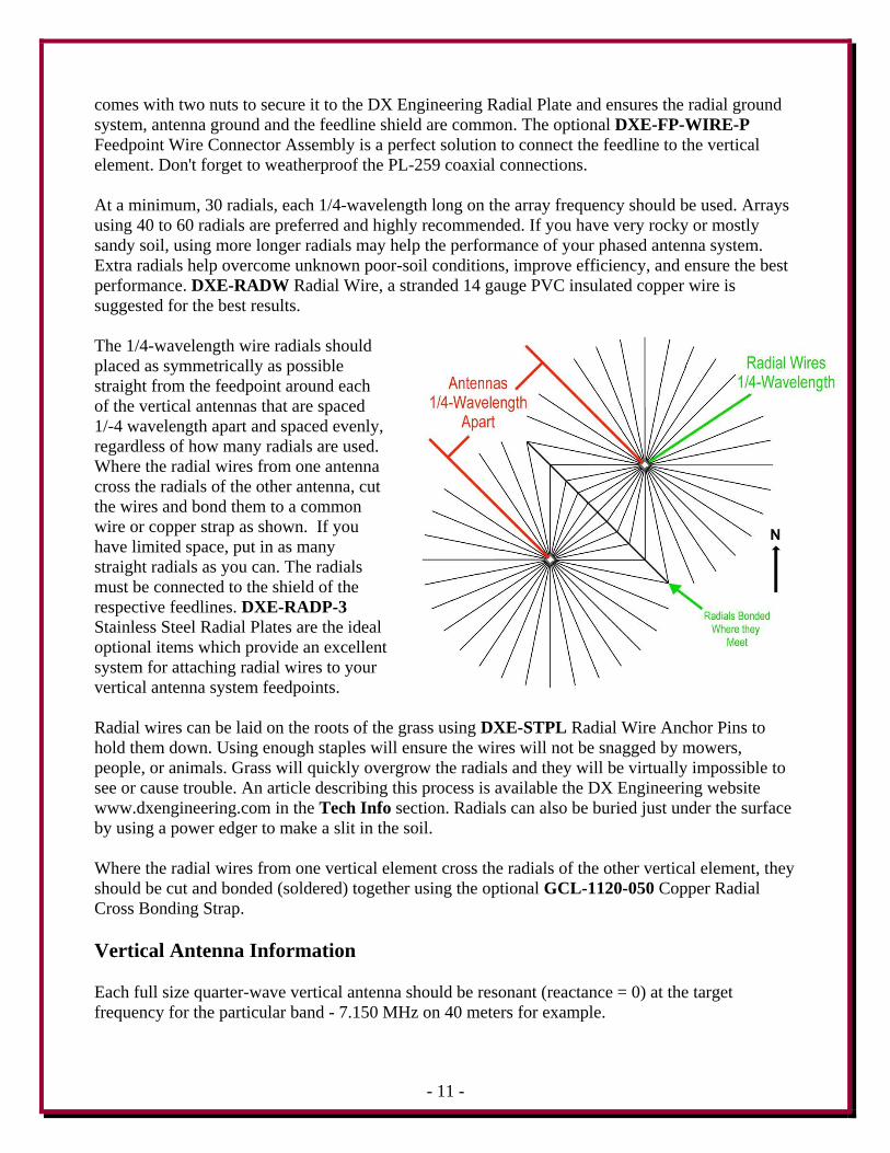
The 1/4-wavelength wire radials should
placed as symmetrically as possible
straight from the feedpoint around each
of the vertical antennas that are spaced
1/-4 wavelength apart and spaced evenly,
regardless of how many radials are used.
Where the radial wires from one antenna
cross the radials of the other antenna, cut
the wires and bond them to a common
wire or copper strap as shown. If you
have limited space, put in as many
straight radials as you can. The radials
must be connected to the shield of the
respective feedlines. DXE-RADP-3
Stainless Steel Radial Plates are the ideal
optional items which provide an excellent
system for attaching radial wires to your
vertical antenna system feedpoints.
Radial wires can be laid on the roots of the grass using DXE-STPL Radial Wire Anchor Pins to
hold them down. Using enough staples will ensure the wires will not be snagged by mowers,
people, or animals. Grass will quickly overgrow the radials and they will be virtually impossible to
see or cause trouble. An article describing this process is available the DX Engineering website
www.dxengineering.com in the Tech Info section. Radials can also be buried just under the surface
by using a power edger to make a slit in the soil.
Where the radial wires from one vertical element cross the radials of the other vertical element, they
should be cut and bonded (soldered) together using the optional GCL-1120-050 Copper Radial
Cross Bonding Strap.
Vertical Antenna Information
Each full size quarter-wave vertical antenna should be resonant (reactance = 0) at the target
frequency for the particular band - 7.150 MHz on 40 meters for example.
- 12 -
When the measurement is being done on one vertical antenna, the other vertical antenna should be
floating (not connected to anything).
It is also expected that the impedance of a single full size quarter-wave vertical antenna should be
close to 39 ohms at resonance, as in 39 + j 0 ohms. That represents the 36 ohms of a "textbook"
quarter-wave vertical antenna, and a few ohms of ground loss, assuming a good ground.
When measured, one vertical with the other one floating, and the results are approximately 39 + j 0
ohms of impedance and then go to the second vertical with the first antenna now floating and again
measure 39 + j 0 ohms, that's a good indication of being ready to go.
Phasing Relay Unit Mounting Pipe
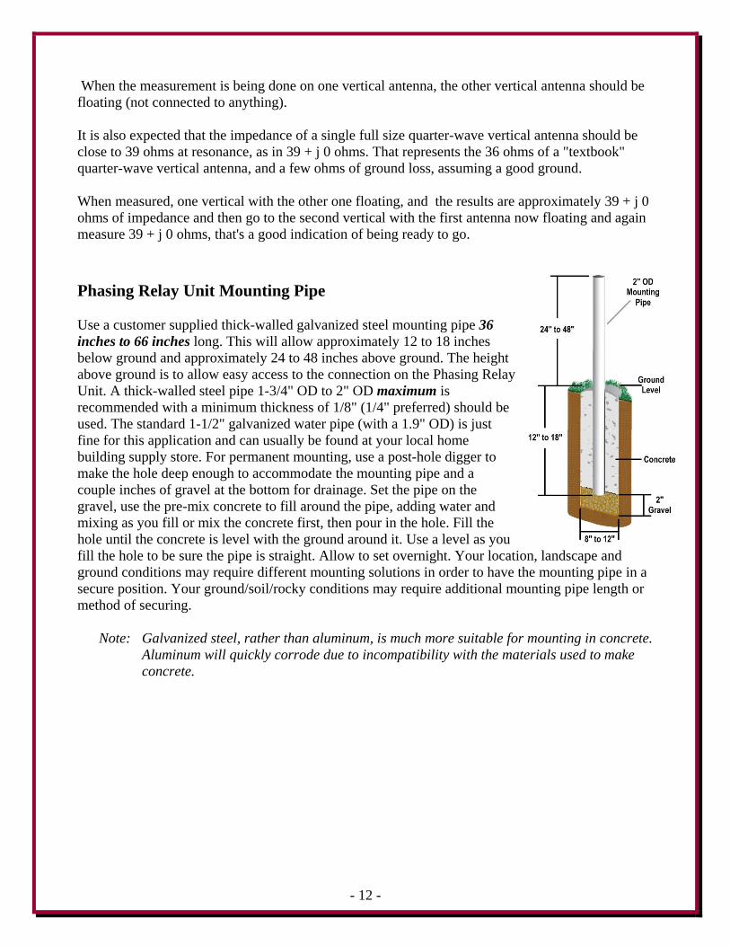
Use a customer supplied thick-walled galvanized steel mounting pipe 36
inches to 66 inches long. This will allow approximately 12 to 18 inches
below ground and approximately 24 to 48 inches above ground. The height
above ground is to allow easy access to the connection on the Phasing Relay
Unit. A thick-walled steel pipe 1-3/4" OD to 2" OD maximum is
recommended with a minimum thickness of 1/8" (1/4" preferred) should be
used. The standard 1-1/2" galvanized water pipe (with a 1.9" OD) is just
fine for this application and can usually be found at your local home
building supply store. For permanent mounting, use a post-hole digger to
make the hole deep enough to accommodate the mounting pipe and a
couple inches of gravel at the bottom for drainage. Set the pipe on the
gravel, use the pre-mix concrete to fill around the pipe, adding water and
mixing as you fill or mix the concrete first, then pour in the hole. Fill the
hole until the concrete is level with the ground around it. Use a level as you
fill the hole to be sure the pipe is straight. Allow to set overnight. Your location, landscape and
ground conditions may require different mounting solutions in order to have the mounting pipe in a
secure position. Your ground/soil/rocky conditions may require additional mounting pipe length or
method of securing.
Note: Galvanized steel, rather than aluminum, is much more suitable for mounting in concrete.
Aluminum will quickly corrode due to incompatibility with the materials used to make
concrete.
- 13 -
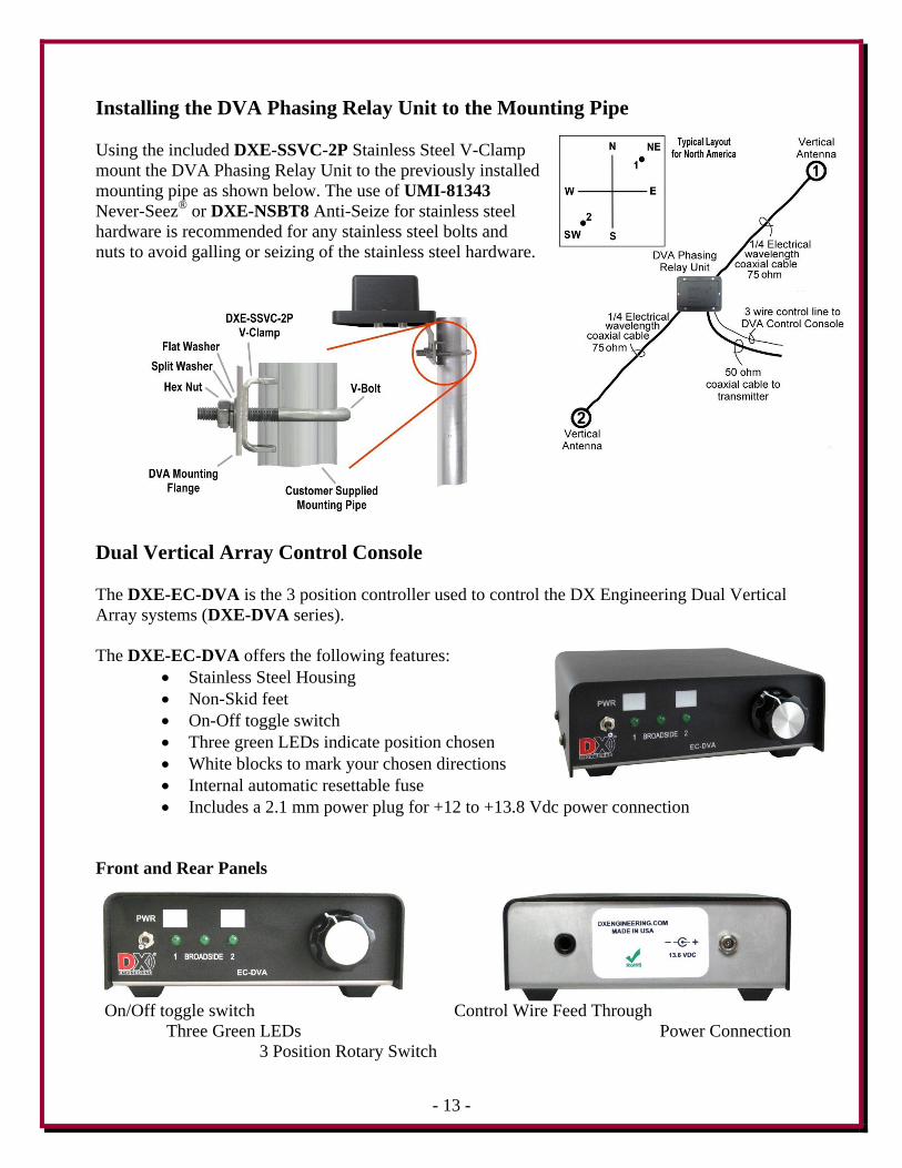
Installing the DVA Phasing Relay Unit to the Mounting Pipe
Using the included DXE-SSVC-2P Stainless Steel V-Clamp
mount the DVA Phasing Relay Unit to the previously installed
mounting pipe as shown below. The use of UMI-81343
Never-Seez®
or DXE-NSBT8 Anti-Seize for stainless steel
hardware is recommended for any stainless steel bolts and
nuts to avoid galling or seizing of the stainless steel hardware.
Dual Vertical Array Control Console
The DXE-EC-DVA is the 3 position controller used to control the DX Engineering Dual Vertical
Array systems (DXE-DVA series).
The DXE-EC-DVA offers the following features:
Stainless Steel Housing
Non-Skid feet
On-Off toggle switch
Three green LEDs indicate position chosen
White blocks to mark your chosen directions
Internal automatic resettable fuse
Includes a 2.1 mm power plug for +12 to +13.8 Vdc power connection
Front and Rear Panels
On/Off toggle switch Control Wire Feed Through
Three Green LEDs Power Connection
3 Position Rotary Switch
- 14 -
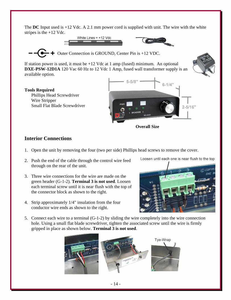
The DC Input used is +12 Vdc. A 2.1 mm power cord is supplied with unit. The wire with the white
stripes is the +12 Vdc.
Outer Connection is GROUND, Center Pin is +12 VDC.
If station power is used, it must be +12 Vdc at 1 amp (fused) minimum. An optional
DXE-PSW-12D1A 120 Vac 60 Hz to 12 Vdc 1 Amp, fused wall transformer supply is an
available option.
Tools Required
Phillips Head Screwdriver
Wire Stripper
Small Flat Blade Screwdriver
Overall Size Interior Connections
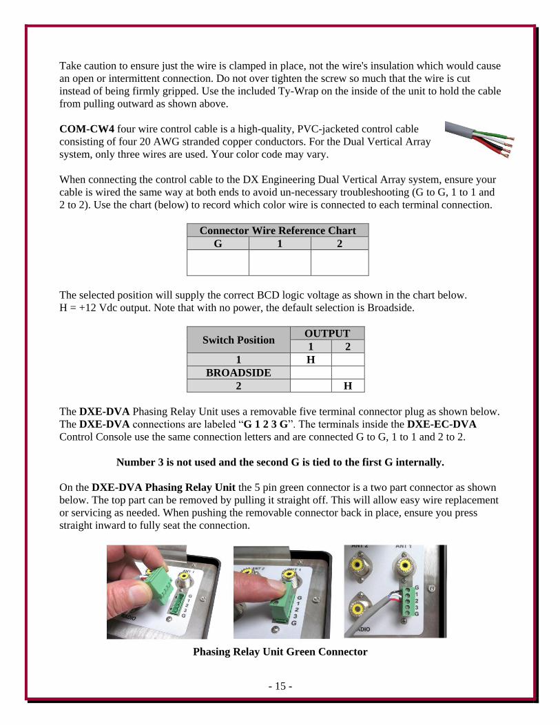
1. Open the unit by removing the four (two per side) Phillips head screws to remove the cover.
2. Push the end of the cable through the control wire feed
through on the rear of the unit.
3. Three wire connections for the wire are made on the
green header (G-1-2). Terminal 3 is not used. Loosen
each terminal screw until it is near flush with the top of
the connector block as shown to the right.
4. Strip approximately 1/4" insulation from the four
conductor wire ends as shown to the right.
5. Connect each wire to a terminal (G-1-2) by sliding the wire completely into the wire connection
hole. Using a small flat blade screwdriver, tighten the associated screw until the wire is firmly
gripped in place as shown below. Terminal 3 is not used.
- 15 -
Take caution to ensure just the wire is clamped in place, not the wire's insulation which would cause
an open or intermittent connection. Do not over tighten the screw so much that the wire is cut
instead of being firmly gripped. Use the included Ty-Wrap on the inside of the unit to hold the cable
from pulling outward as shown above.
COM-CW4 four wire control cable is a high-quality, PVC-jacketed control cable
consisting of four 20 AWG stranded copper conductors. For the Dual Vertical Array
system, only three wires are used. Your color code may vary.
When connecting the control cable to the DX Engineering Dual Vertical Array system, ensure your
cable is wired the same way at both ends to avoid un-necessary troubleshooting (G to G, 1 to 1 and
2 to 2). Use the chart (below) to record which color wire is connected to each terminal connection.
Connector Wire Reference Chart
G 1 2
The selected position will supply the correct BCD logic voltage as shown in the chart below.
H = +12 Vdc output. Note that with no power, the default selection is Broadside.
Switch Position OUTPUT
1 2
1 H
BROADSIDE
2 H
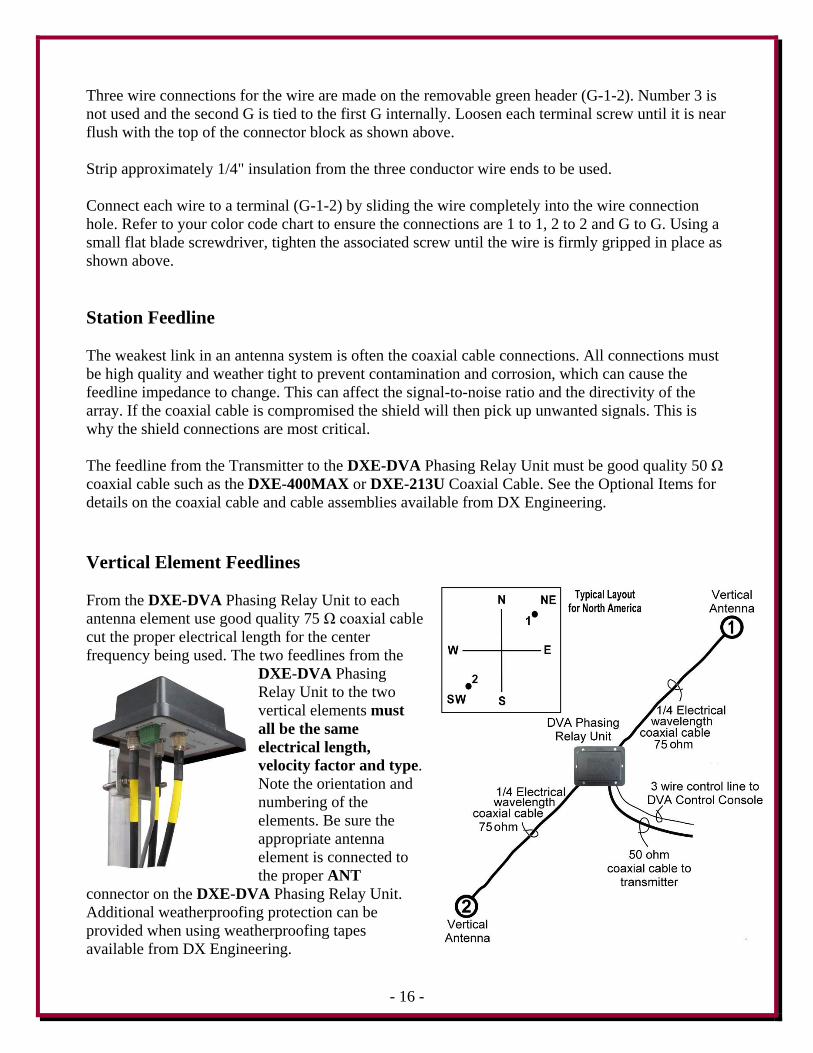
The DXE-DVA Phasing Relay Unit uses a removable five terminal connector plug as shown below.
The DXE-DVA connections are labeled “G 1 2 3 G”. The terminals inside the DXE-EC-DVA
Control Console use the same connection letters and are connected G to G, 1 to 1 and 2 to 2.
Number 3 is not used and the second G is tied to the first G internally.
On the DXE-DVA Phasing Relay Unit the 5 pin green connector is a two part connector as shown
below. The top part can be removed by pulling it straight off. This will allow easy wire replacement
or servicing as needed. When pushing the removable connector back in place, ensure you press
straight inward to fully seat the connection.
Phasing Relay Unit Green Connector
- 16 -
Three wire connections for the wire are made on the removable green header (G-1-2). Number 3 is
not used and the second G is tied to the first G internally. Loosen each terminal screw until it is near
flush with the top of the connector block as shown above.
Strip approximately 1/4" insulation from the three conductor wire ends to be used.
Connect each wire to a terminal (G-1-2) by sliding the wire completely into the wire connection
hole. Refer to your color code chart to ensure the connections are 1 to 1, 2 to 2 and G to G. Using a
small flat blade screwdriver, tighten the associated screw until the wire is firmly gripped in place as
shown above.
Station Feedline
The weakest link in an antenna system is often the coaxial cable connections. All connections must
be high quality and weather tight to prevent contamination and corrosion, which can cause the
feedline impedance to change. This can affect the signal-to-noise ratio and the directivity of the
array. If the coaxial cable is compromised the shield will then pick up unwanted signals. This is
why the shield connections are most critical.
The feedline from the Transmitter to the DXE-DVA Phasing Relay Unit must be good quality 50 Ω
coaxial cable such as the DXE-400MAX or DXE-213U Coaxial Cable. See the Optional Items for
details on the coaxial cable and cable assemblies available from DX Engineering.
Vertical Element Feedlines
From the DXE-DVA Phasing Relay Unit to each
antenna element use good quality 75 Ω coaxial cable
cut the proper electrical length for the center
frequency being used. The two feedlines from the
DXE-DVA Phasing
Relay Unit to the two
vertical elements must
all be the same
electrical length,
velocity factor and type.
Note the orientation and
numbering of the
elements. Be sure the
appropriate antenna
element is connected to
the proper ANT
connector on the DXE-DVA Phasing Relay Unit.
Additional weatherproofing protection can be
provided when using weatherproofing tapes
available from DX Engineering.
- 17 -
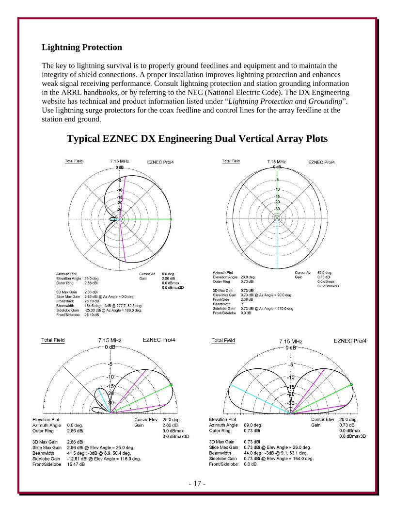
Lightning Protection
The key to lightning survival is to properly ground feedlines and equipment and to maintain the
integrity of shield connections. A proper installation improves lightning protection and enhances
weak signal receiving performance. Consult lightning protection and station grounding information
in the ARRL handbooks, or by referring to the NEC (National Electric Code). The DX Engineering
website has technical and product information listed under “Lightning Protection and Grounding”.
Use lightning surge protectors for the coax feedline and control lines for the array feedline at the
station end ground.
Typical EZNEC DX Engineering Dual Vertical Array Plots
- 18 -
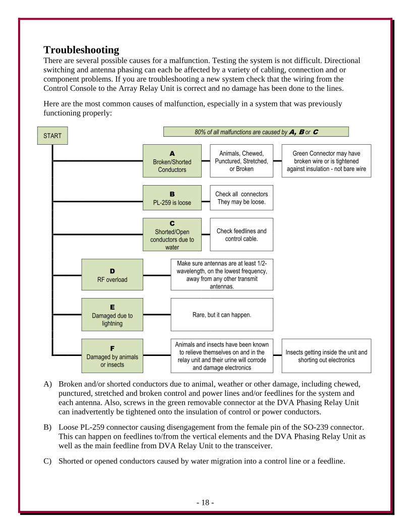
Troubleshooting There are several possible causes for a malfunction. Testing the system is not difficult. Directional
switching and antenna phasing can each be affected by a variety of cabling, connection and or
component problems. If you are troubleshooting a new system check that the wiring from the
Control Console to the Array Relay Unit is correct and no damage has been done to the lines.
Here are the most common causes of malfunction, especially in a system that was previously
functioning properly:
START 80% of all malfunctions are caused by A, B or C
A
Broken/Shorted Conductors
Animals, Chewed, Punctured, Stretched,
or Broken
Green Connector may have broken wire or is tightened
against insulation - not bare wire
B
PL-259 is loose
Check all connectors
They may be loose.
C
Shorted/Open conductors due to
water
Check feedlines and
control cable.
D
RF overload
Make sure antennas are at least 1/2-wavelength, on the lowest frequency,
away from any other transmit antennas.
E
Damaged due to lightning
Rare, but it can happen.
F
Damaged by animals or insects
Animals and insects have been known to relieve themselves on and in the
relay unit and their urine will corrode and damage electronics
Insects getting inside the unit and
shorting out electronics
A) Broken and/or shorted conductors due to animal, weather or other damage, including chewed,
punctured, stretched and broken control and power lines and/or feedlines for the system and
each antenna. Also, screws in the green removable connector at the DVA Phasing Relay Unit
can inadvertently be tightened onto the insulation of control or power conductors.
B) Loose PL-259 connector causing disengagement from the female pin of the SO-239 connector.
This can happen on feedlines to/from the vertical elements and the DVA Phasing Relay Unit as
well as the main feedline from DVA Relay Unit to the transceiver.
C) Shorted or opened conductors caused by water migration into a control line or a feedline.
- 19 -
Over 80% of all phased array malfunctions have been caused by the above system problems. A
thorough inspection and subsequent testing of each control cable, RF cable, and their respective
connections, will uncover the cause of most phased array system troubles. Here are a few other
causes for malfunction:
1) Damaged Dual Vertical Array Relay unit due to lightning. This has been reported
only a couple of times and is not very likely.
2) Dual Vertical Array Relay units that were damaged by animals or insects.
If necessary, the following further troubleshooting procedure may assist in finding the malfunction.
Advanced Troubleshooting Procedure
1) Test the DXE-EC-DVA Dual Vertical Array (DVA) Control Console unit, which should be
connected only to the control lines of the Dual Vertical Relay Unit. When the DVA Control
Console is connected to the control cable, do all three of the selected switch position LEDs
light normally when rotating the directional control knob?
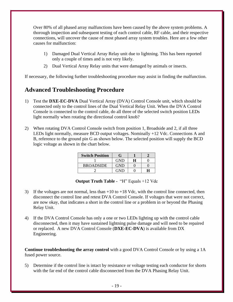
2) When rotating DVA Control Console switch from position 1, Broadside and 2, if all three
LEDs light normally, measure BCD output voltages. Nominally +12 Vdc. Connections A and
B, reference to the ground pin G as shown below. The selected position will supply the BCD
logic voltage as shown in the chart below.
Switch Position G 1 2
1 GND H 0
BROADSIDE GND 0 0
2 GND 0 H
Output Truth Table - “H” Equals +12 Vdc
3) If the voltages are not normal, less than +10 to +18 Vdc, with the control line connected, then
disconnect the control line and retest DVA Control Console. If voltages that were not correct,
are now okay, that indicates a short in the control line or a problem in or beyond the Phasing
Relay Unit.
4) If the DVA Control Console has only a one or two LEDs lighting up with the control cable
disconnected, then it may have sustained lightning pulse damage and will need to be repaired
or replaced. A new DVA Control Console (DXE-EC-DVA) is available from DX
Engineering.
Continue troubleshooting the array control with a good DVA Control Console or by using a 1A
fused power source.
5) Determine if the control line is intact by resistance or voltage testing each conductor for shorts
with the far end of the control cable disconnected from the DVA Phasing Relay Unit.
- 20 -
6) With a good DVA Control Console or other power source connected, measure 1 and 2 control
conductor voltages at the Phasing Relay Unit with the control cable connected, and again at the
end of the control cable that is disconnected from the Phasing Relay Unit. If measured voltages
are not between +10 to 18 Vdc on the selected line, a resistive, short or open circuit problem
exists in the control line or in the Phasing Relay Unit. Normal voltages on the connected
control line will cause relays to switch inside the Phasing Relay Unit. If switching voltages are
correct, lack of system directivity may be due to antenna feedline(s) or the vertical elements.
7) Test reception of each Vertical Antenna by connecting each antenna feedline, one at a time, to
an activated port on the Phasing Relay Unit. This assumes that a good port has been identified
and is functioning properly. Normal reception must be confirmed from each antenna. If one or
both monoband verticals produce a low or no signal, then vertical elements, connections or
feedlines may need to be serviced or replaced.
8) If both vertical elements tested provide the same signal level in one port, then change switching
to select the other port and try each antenna on that port one at a time, testing for the same level
of reception. If one or two of the antenna ports are dead or has diminished reception, there may
be a problem in the Phasing Relay Unit.
At this point, the problem in your system should have been identified.
If you need additional assistance from DX Engineering, feel free to call or write. Detailed
discussions of system function, connections, and troubleshooting is best handled by telephone,
Monday through Friday, 8:30 am to 4:30 pm Eastern Time, at 330-572-3200.
Testing the Vertical Antennas without the DVA connected This test will determine if the vertical antenna system needs to be adjusted.
If the test results are not correct as described, one or both of the vertical antennas (or feedlines)
may need to be adjusted accordingly.
If the test results are correct as described, there may be a problem with the Dual Vertical Array
Relay Unit.
It is assumed that the full size quarter-wave vertical antennas are resonant (at the chosen
frequency), are identical and properly installed. The radial system for both antennas must be
complete and the quarter-wave feedline coaxial cables are electrically cut to the proper length
for the frequency desired.
Parts needed:
DXE-533 - UHF-T Adapter
Antenna Analyzer or VNA: MFJ-259C, Rig Expert REU-AA-54, or equivalent
- 21 -
Testing the Vertical Antennas without the DXE-DVA connected.
Each full size quarter-wave vertical antenna should be resonant (reactance = 0) at the target
frequency for the particular band - 7.150 MHz on 40 meters for example.
When the measurement is being done on one vertical antenna, the other vertical antenna should be
floating (not connected to anything).
It is also expected that the impedance of a single full size quarter-wave vertical antenna should be
close to 39 ohms at resonance, as in 39 + j 0 ohms. That represents the 36 ohms of a "textbook"
quarter-wave vertical antenna, and a few ohms of ground loss, assuming a good ground.
When measured, one vertical with the other one floating, and the results are approximately 39 + j 0
ohms of impedance and then go to the second vertical with the first antenna now floating and again
measure 39 + j 0 ohms, that's a good indication of being ready to go.
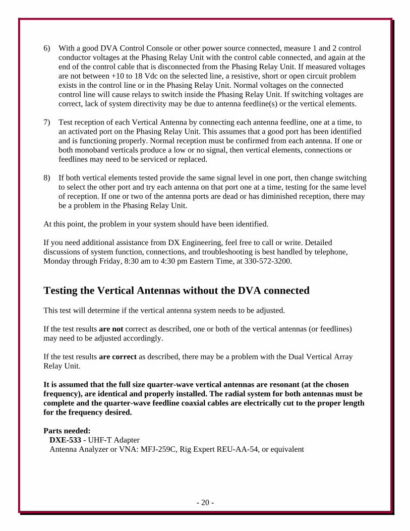
Now the pair of vertical can be tested together.
The 75 ohm 1/4-wavelength feedlines from the two vertical antennas are connected to a UHF-T
(DXE-533) which is connected directly to an Antenna Analyzer or VNA.
Do not use any extra coaxial cables since we are trying to measure the impedance right at the
junction.
The measured impedance at the target frequency should be very close to: 46 + j 12 ohms (in this
example, the target frequency is 7.150 MHz). The values should be within a few ohms. Values that
are far off may indicate a problem with one or both of the vertical antennas, cables or installation. If
this occurs, then each antenna and cable should be carefully measured by themselves and
adjustments made accordingly.
- 22 -
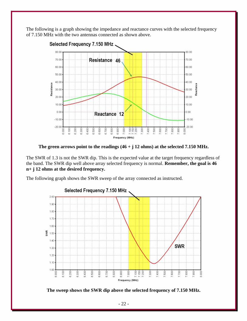
The following is a graph showing the impedance and reactance curves with the selected frequency
of 7.150 MHz with the two antennas connected as shown above.
The green arrows point to the readings (46 + j 12 ohms) at the selected 7.150 MHz.
The SWR of 1.3 is not the SWR dip. This is the expected value at the target frequency regardless of
the band. The SWR dip well above array selected frequency is normal. Remember, the goal is 46
n+ j 12 ohms at the desired frequency.
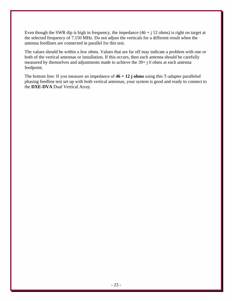
The following graph shows the SWR sweep of the array connected as instructed.
The sweep shows the SWR dip above the selected frequency of 7.150 MHz.
- 23 -
Even though the SWR dip is high in frequency, the impedance (46 + j 12 ohms) is right on target at
the selected frequency of 7.150 MHz. Do not adjust the verticals for a different result when the
antenna feedlines are connected in parallel for this test.
The values should be within a few ohms. Values that are far off may indicate a problem with one or
both of the vertical antennas or installation. If this occurs, then each antenna should be carefully
measured by themselves and adjustments made to achieve the 39+ j 0 ohms at each antenna
feedpoint.
The bottom line: If you measure an impedance of 46 + 12 j ohms using this T-adapter paralleled
phasing feedline test set up with both vertical antennas, your system is good and ready to connect to
the DXE-DVA Dual Vertical Array.
- 24 -
Optional Items
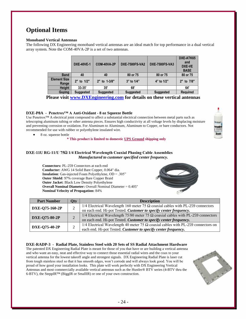
Monoband Vertical Antennas
The following DX Engineering monoband vertical antennas are an ideal match for top performance in a dual vertical
array system. Note the COM-40VA-2P is a set of two antennas.
Please visit www.DXEngineering.com for details on these vertical antennas
DXE-P8A - Penetrox™ A Anti-Oxidant - 8 oz Squeeze Bottle Use Penetrox™ A electrical joint compound to affect a substantial electrical connection between metal parts such as
telescoping aluminum tubing or other antenna pieces. Ensures high conductivity at all voltage levels by displacing moisture
and preventing corrosion or oxidation. For Aluminum to Aluminum, Aluminum to Copper, or bare conductors. Not
recommended for use with rubber or polyethylene insulated wire.
8 oz. squeeze bottle
* This product is limited to domestic UPS Ground shipping only
DXE-11U RG-11/U 75Ω 1/4 Electrical Wavelength Coaxial Phasing Cable Assemblies
Manufactured to customer specified center frequency.
Connectors: PL-259 Connectors at each end
Conductor: AWG 14 Solid Bare Copper, 0.064" dia.
Insulation: Gas-injected Foam Polyethylene, OD = .305”
Outer Shield: 97% coverage Bare Copper Braid
Outer Jacket: Black Low Density Polyethylene
Overall Nominal Diameter: Overall Nominal Diameter = 0.405"
Nominal Velocity of Propagation: 84%
Part Number Qty Description
DXE-Q75-160-2P 2 1/4 Electrical Wavelength 160 meter 75 Ω coaxial cables with PL-259 connectors
on each end. Hi-pot Tested. Customer to specify center frequency.
DXE-Q75-80-2P 2 1/4 Electrical Wavelength 75/80 meter 75 Ω coaxial cables with PL-259 connectors
on each end. Hi-pot Tested. Customer to specify center frequency.
DXE-Q75-40-2P 2 1/4 Electrical Wavelength 40 meter 75 Ω coaxial cables with PL-259 connectors on
each end. Hi-pot Tested. Customer to specify center frequency.
DXE-RADP-3 - Radial Plate, Stainless Steel with 20 Sets of SS Radial Attachment Hardware The patented DX Engineering Radial Plate is meant for those of you that have or are building a vertical antenna
and who want an easy, neat and effective way to connect those essential radial wires and the coax to your
vertical antenna for the lowest takeoff angle and strongest signals. DX Engineering Radial Plate is laser cut
from tough stainless steel so that it has smooth edges, won’t corrode and will always look good. You will be
proud of how good your installation looks. This plate will work perfectly with DX Engineering Vertical
Antennas and most commercially available vertical antennas such as the Hustler® BTV series (4-BTV thru the
6-BTV), the SteppIR™ (BiggIR or SmallIR) or one of your own construction.
DXE-40VE-1 COM-40VA-2P DXE-7580FS-VA2 DXE-7580FS-VA3
DXE-ATK65 and
DXE-VE BASE
Band 40 40 80 or 75 80 or 75 80 or 75
Element Size Range
2" to 1/2" 2" to 1-3/8" 3” to 1/4” 4” to 1/2” 2" to 7/8"
Height 33-35' 35' 68’ 64'
Guying Suggested Suggested Suggested Suggested Required
- 25 -
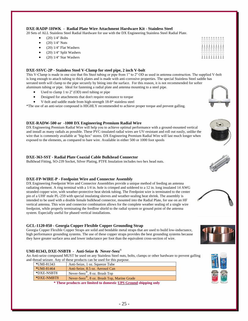
DXE-RADP-1HWK - Radial Plate Wire Attachment Hardware Kit - Stainless Steel 20 Sets of ALL Stainless Steel Radial Hardware for use with the DX Engineering Stainless Steel Radial Plate.
(20) 1/4'' Bolts
(20) 1/4'' Nuts
(20) 1/4'' Flat Washers
(20) 1/4'' Split Washers
(20) 1/4'' Star Washers
DXE-SSVC-2P - Stainless Steel V-Clamp for steel pipe, 2 inch V-bolt This V-Clamp is made in one size that fits Steel tubing or pipe from 1” to 2'' OD as used in antenna construction. The supplied V-bolt
is long enough to attach tubing to thick plates and is made with anti-corrosive properties. The special Stainless Steel saddle has
serrated teeth will clamp to the pipe securely by biting into the surface. For this reason, it is not recommended for softer
aluminum tubing or pipe. Ideal for fastening a radial plate and antenna mounting to a steel pipe.
Used to clamp 1 to 2'' (OD) steel tubing or pipe
Designed for attachments that don't require resistance to torque
V-bolt and saddle made from high-strength 18-8* stainless steel
*The use of an anti-seize compound is HIGHLY recommended to achieve proper torque and prevent galling.
DXE-RADW-500 or -1000 DX Engineering Premium Radial Wire DX Engineering Premium Radial Wire will help you to achieve optimal performance with a ground-mounted vertical
and install as many radials as possible. These PVC-insulated radial wires are UV-resistant and roll out easily, unlike the
wire that is commonly available at "big-box" stores. DX Engineering Premium Radial Wire will last much longer when
exposed to the elements, as compared to bare wire. Available in either 500 or 1000 foot spools
DXE-363-SST - Radial Plate Coaxial Cable Bulkhead Connector Bulkhead Fitting, SO-239 Socket, Silver Plating, PTFE Insulation includes two hex head nuts.
DXE-FP-WIRE-P - Feedpoint Wire and Connector Assembly DX Engineering Feedpoint Wire and Connector Assemblies provide a unique method of feeding an antenna
radiating element. A ring terminal with a 1/4 in. hole is crimped and soldered to a 12 in. long insulated 14 AWG
stranded copper wire, with weather-protective heat shrink tubing. The Feedpoint wire is terminated to the center
pin of a UHF male PL-259 with special insulating sleeves and weather-sealing heat shrink. The assembly is
intended to be used with a double female bulkhead connector, mounted into the Radial Plate, for use on an HF
vertical antenna. This wire and connector combination allows for the complete weather sealing of a single wire
feedpoint, while properly terminating the feedline shield to the radial system or ground point of the antenna
system. Especially useful for phased vertical installations.
GCL-1120-050 - Georgia Copper Flexible Copper Grounding Strap Georgia Copper Flexible Copper Straps are solid and bendable metal straps that are used to build low-inductance,
high performance grounding systems. The use of these copper straps provides the best grounding systems because
they have greater surface area and lower inductance per foot than the equivalent cross-section of wire.
UMI-81343, DXE-NSBT8 - Anti-Seize & Never-Seez®
An Anti-seize compound MUST be used on any Stainless Steel nuts, bolts, clamps or other hardware to prevent galling
and thread seizure. Any of these products can be used for this purpose.
*UMI-81343 Anti-Seize, 1 oz. Squeeze Tube
*UMI-81464 Anti-Seize, 8.5 oz. Aerosol Can
*DXE-NSBT8 Never-Seez®
, 8 oz. Brush Top
*DXE-NMBT8 Never-Seez®
, 8 oz. Brush Top, Marine Grade
* These products are limited to domestic UPS Ground shipping only
- 26 -
COM-CW4 - Four Conductor Cable, Sold per Foot or COM-CW4-500 in a 500 Foot Spool A high quality, PVC jacketed 4-wire control cable, COM-CW4 consists of 4 #20 AWG stranded copper conductors. It
may be used in a multitude of control cable applications, such as remote switching and antenna rotators. Sold by the foot
and also in a 500 foot spool.
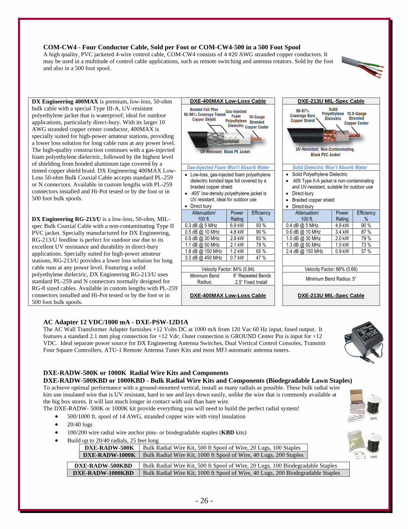
DX Engineering 400MAX is premium, low-loss, 50-ohm
bulk cable with a special Type III-A, UV-resistant
polyethylene jacket that is waterproof; ideal for outdoor
applications, particularly direct-bury. With its larger 10
AWG stranded copper center conductor, 400MAX is
specially suited for high-power amateur stations, providing
a lower loss solution for long cable runs at any power level.
The high-quality construction continues with a gas-injected
foam polyethylene dielectric, followed by the highest level
of shielding from bonded aluminum tape covered by a
tinned copper shield braid. DX Engineering 400MAX Low-
Loss 50-ohm Bulk Coaxial Cable accepts standard PL-259
or N connectors. Available in custom lengths with PL-259
connectors installed and Hi-Pot tested or by the foot or in
500 foot bulk spools.
DX Engineering RG-213/U is a low-loss, 50-ohm, MIL-
spec Bulk Coaxial Cable with a non-contaminating Type II
PVC jacket. Specially manufactured for DX Engineering,
RG-213/U feedline is perfect for outdoor use due to its
excellent UV resistance and durability in direct-bury
applications. Specially suited for high-power amateur
stations, RG-213/U provides a lower loss solution for long
cable runs at any power level. Featuring a solid
polyethylene dielectric, DX Engineering RG-213/U uses
standard PL-259 and N connectors normally designed for
RG-8 sized cables. Available in custom lengths with PL-259
connectors installed and Hi-Pot tested or by the foot or in
500 foot bulk spools.
DXE-400MAX Low-Loss Cable DXE-213U MIL-Spec Cable
Gas-Injected Foam Won’t Absorb Water Solid Dielectric Won’t Absorb Water
Low-loss, gas-injected foam polyethylene dielectric bonded tape foil covered by a braided copper shield
.405” low-density polyethylene jacket is UV resistant, ideal for outdoor use
Direct bury
Solid Polyethylene Dielectric
.405 Type II-A jacket is non-contaminating and UV-resistant, suitable for outdoor use
Direct-bury
Braided copper shield
Direct-bury
Attenuation/ 100 ft.
Power Rating
Efficiency %
Attenuation/
100 ft. Power Rating
Efficiency %
0.3 dB @ 5 MHz 6.9 kW 93 % 0.4 dB @ 5 MHz 4.9 kW 90 %
0.5 dB @ 10 MHz 4.8 kW 90 % 0.6 dB @ 10 MHz 3.4 kW 87 %
0.8 dB @ 30 MHz 2.8 kW 83 % 1.0 dB @ 30 MHz 2.0 kW 79 %
1.1 dB @ 50 MHz 2.1 kW 79 % 1.3 dB @ 50 MHz 1.5 kW 73 %
1.8 dB @ 150 MHz 1.2 kW 65 % 2.4 dB @ 150 MHz 0.9 kW 57 %
3.3 dB @ 450 MHz 0.7 kW 47 %
Velocity Factor: 84% (0.84) Velocity Factor: 66% (0.66)
Minimum Bend Radius:
6” Repeated Bends Minimum Bend Radius: 5”
2.5” Fixed Install
DXE-400MAX Low-Loss Cable DXE-213U MIL-Spec Cable
AC Adapter 12 VDC/1000 mA - DXE-PSW-12D1A The AC Wall Transformer Adapter furnishes +12 Volts DC at 1000 mA from 120 Vac 60 Hz input, fused output. It
features a standard 2.1 mm plug connection for +12 Vdc. Outer connection is GROUND Center Pin is input for +12
VDC. Ideal separate power source for DX Engineering Antenna Switches, Dual Vertical Control Consoles, Transmit
Four Square Controllers, ATU-1 Remote Antenna Tuner Kits and most MFJ automatic antenna tuners.
DXE-RADW-500K or 1000K Radial Wire Kits and Components
DXE-RADW-500KBD or 1000KBD - Bulk Radial Wire Kits and Components (Biodegradable Lawn Staples) To achieve optimal performance with a ground-mounted vertical, install as many radials as possible. These bulk radial wire
kits use insulated wire that is UV resistant, hard to see and lays down easily, unlike the wire that is commonly available at
the big box stores. It will last much longer in contact with soil than bare wire.
The DXE-RADW- 500K or 1000K kit provide everything you will need to build the perfect radial system!
500/1000 ft. spool of 14 AWG, stranded copper wire with vinyl insulation
20/40 lugs
100/200 wire radial wire anchor pins- or biodegradable staples (KBD kits)
Build up to 20/40 radials, 25 feet long
DXE-RADW-500K Bulk Radial Wire Kit, 500 ft Spool of Wire, 20 Lugs, 100 Staples
DXE-RADW-1000K Bulk Radial Wire Kit, 1000 ft Spool of Wire, 40 Lugs, 200 Staples
DXE-RADW-500KBD Bulk Radial Wire Kit, 500 ft Spool of Wire, 20 Lugs, 100 Biodegradable Staples
DXE-RADW-1000KBD Bulk Radial Wire Kit, 1000 ft Spool of Wire, 40 Lugs, 200 Biodegradable Staples
- 27 -
DXE-225RT-20 - Ring terminal 16-14 Wire Gauge, 1/4" hole/20 Pack \his is a set of 20 ring terminals for AWG #14 to 16 wire with a clearance hole for a 1/4" bolt. These are the same crimp
terminals supplied with the DXE Radial Wire Kits for #14 Radial and Antenna Wire.
DXE-STPL-100P - Radial Wire Metal Anchor Pins, 100/pack
DXE-STPL-300P - Radial Wire Metal Anchor Pins, 300/pack DX Engineering Radial Steel Wire Anchor Pins are perfect for fastening radials below the grass line to eliminate the
risk of damaging your radials during lawn maintenance.
100 & 300 count - 6'' Pins
11-Gauge
DXE-STPL-100BD - Radial Wire Staple, Biodegradable, 3", 100 pack DX Engineering DXE-STPL-100BD is a 100-pack of 3” biodegradable anchors that are produced from recycled PLA
(Polylactide Resin). Depending on the weather conditions, they will degrade in about a year. They are easily installed and
will hold radial wires in place until lawn roots overtake them - and then disappear. Ecologically friendly!
SUM-900031 - Automatic Wire Stripper/Crimper/Cutter, 24-10 Ga. Our DX Engineering wire stripper uses a spring-loaded design to make quick work of wires ranging from 24 to 10 gauge. Just insert
the wire, squeeze the handle, and listen for the click. That’s the sound of another perfect wire stripping job performed in about 2
seconds- a fraction of the time it takes your pocket knife to do the same job. An adjustable wire length guide helps you make uniform
strips, and a built-in wire cutter and crimper helps you complete your wiring job.
Spring-loaded design
Strips wires ranging from 24 to 10 gauge
built-in wire cutter and crimper
DXE-3M2155 - 3M Temflex™ 2155 Rubber Splicing Tape. Conformable self-fusing rubber electrical insulating tape. It is designed for low voltage electrical insulating and
moisture sealing applications. For outdoor use, it should be protected from UV deterioration with an overwrap of
TRM-06132
TRM-06132 - Scotch® Super 33+.
Highly conformable super stretchy tape for all weather applications. This tape provides flexibility and easy handling for
all around performance. It also combines PVC backing with excellent electrical insulating properties to provide primary
electrical insulation for splices up to 600V and protective jacketing.
- 28 -
Technical Support
If you have questions about this product, or if you experience difficulties during the installation,
contact DX Engineering at (330) 572-3200. You can also e-mail us at:
For best service, please take a few minutes to review this manual before you call.
Warranty
All products manufactured by DX Engineering are warranted to be free from defects in material and workmanship for a
period of one (1) year from date of shipment. DX Engineering’s sole obligation under these warranties shall be to issue
credit, repair or replace any item or part thereof which is proved to be other than as warranted; no allowance shall be
made for any labor charges of Buyer for replacement of parts, adjustment or repairs, or any other work, unless such
charges are authorized in advance by DX Engineering. If DX Engineering’s products are claimed to be defective in
material or workmanship, DX Engineering shall, upon prompt notice thereof, issue shipping instructions for return to
DX Engineering (transportation-charges prepaid by Buyer). Every such claim for breach of these warranties shall be
deemed to be waived by Buyer unless made in writing. The above warranties shall not extend to any products or parts
thereof which have been subjected to any misuse or neglect, damaged by accident, rendered defective by reason of
improper installation, damaged from severe weather including floods, or abnormal environmental conditions such as
prolonged exposure to corrosives or power surges, or by the performance of repairs or alterations outside of our plant,
and shall not apply to any goods or parts thereof furnished by Buyer or acquired from others at Buyer’s specifications.
In addition, DX Engineering’s warranties do not extend to other equipment and parts manufactured by others except to
the extent of the original manufacturer’s warranty to DX Engineering. The obligations under the foregoing warranties
are limited to the precise terms thereof. These warranties provide exclusive remedies, expressly in lieu of all other
remedies including claims for special or consequential damages. SELLER NEITHER MAKES NOR ASSUMES ANY
OTHER WARRANTY WHATSOEVER, WHETHER EXPRESS, STATUTORY, OR IMPLIED, INCLUDING
WARRANTIES OF MERCHANTABILITY AND FITNESS, AND NO PERSON IS AUTHORIZED TO ASSUME
FOR DX ENGINEERING ANY OBLIGATION OR LIABILITY NOT STRICTLY IN ACCORDANCE WITH THE
FOREGOING.
©DX Engineering 2014
DX Engineering®, DXE®, Hot Rodz®, Maxi-Core®, THUNDERBOLT®, Antenna Designer®, Yagi Mechanical®, and
Gorilla Grip® Stainless Steel Boom Clamps, are trademarks of PDS Electronics, Inc. No license to use or reproduce any
of these trademarks or other trademarks is given or implied. All other brands and product names are the trademarks of
their respective owners.
Specifications subject to change without notice.