Embed Size (px)
Citation preview

AUTHORS
Matthew J. Pranter � Department ofGeological Sciences, University of Coloradoat Boulder, Boulder, Colorado 80309;[email protected]
Matt Pranter is an assistant professor of geologicalsciences at the University of Colorado at Boulder. Hereceived a B.S. degree in geology from Oklahoma StateUniversity (1987), an M.S. degree in geology fromBaylor University (1989), a B.S. degree in geologicalengineering from the Colorado School of Mines (1996),and a Ph.D. in geology from the Colorado School ofMines (1999). He currently serves as an AAPG associateeditor, is a member of the AAPG Distinguished LectureCommittee and is a past member of the AAPG Foun-dation Grants-in-Aid Committee. He was previously asenior research geologist with ExxonMobil UpstreamResearch Company and a geologist with Conoco Inc. Hisresearch interests are in reservoir geology and geo-physics, sedimentary geology, and reservoir modeling.He is a member of AAPG, SEPM, Society of ExplorationGeophysicists, Society of Petroleum Engineers, Geolo-gical Society of America, European Association of Geo-scientists and Engineers, and Society of Petrophysicistsand Well Log Analysts.
Neil F. Hurley � Department of Geology andGeological Engineering, Colorado School of Mines,Golden, Colorado 80401; [email protected]
Neil Hurley is a professor of geology at the ColoradoSchool of Mines. He received B.S. degrees in geologyand petroleum engineering from the University ofSouthern California (1976), an M.S. degree in geologyfrom the University of Wisconsin, Madison (1978), and aPh.D. in geology from the University of Michigan (1986).He is a past editor of AAPG and has been an AAPGdistinguished lecturer. Specialties include carbonategeology and reservoir characterization. He is a memberof AAPG, Society of Petroleum Engineers, Society ofExploration Geophysicists, SEPM, European Associationof Geoscientists and Engineers, and Society of Petro-physicists and Well Log Analysts.
Thomas L. Davis � Department of Geophysics,Colorado School of Mines, Golden, Colorado 80401;[email protected]
Tom Davis is currently a professor of geophysics at theColorado School of Mines and has 29 years of teachingand research experience. He is the founder and co-director of the Reservoir Characterization Project, anindustry-funded consortium in its 18th year of applyingmulticomponent seismic data to improve hydrocarbonrecovery. He holds a Ph.D. in geophysical engineeringfrom the Colorado School of Mines, an M.Sc. degreein geophysics from the University of Calgary, and a B.E.degree in geological engineering (geophysics option) fromthe University of Saskatchewan. Memberships includeAAPG, Canadian Society of Exploration Geophysicists,Denver Geophysical Society, European Association ofGeoscientists and Engineers, Rocky Mountain Associationof Geologists, and Society of Exploration Geophysicists.
Dual-lateral horizontal wellssuccessfully target bypassed payin the San Andres Formation,Vacuum field, New MexicoMatthew J. Pranter, Neil F. Hurley, Thomas L. Davis,Michael A. Raines, and Scott C. Wehner
ABSTRACT
This case study of the San Andres Formation in the mature Vacuum
field, New Mexico, shows how seismic data can be used to target
bypassed pay with horizontal wells. These dual-lateral wells were
the first attempt at horizontal development in the Vacuum San
Andres field and in the San Andres Formation in New Mexico. The
primary reservoir facies consist of ramp crest and outer ramp do-
lomitized peloidal packstones, skeletal and ooid grainstones, and
fusulinid packstones. Vertical facies successions form numerous high-
frequency carbonate depositional cycles and cycle sets that create
distinct reservoir zones. Structural blocks created by small-scale
faults (�25 ft [8 m] vertical displacement) and bypassed pay located
in thin depositional cycles were identified with three-dimensional
compressional-wave seismic amplitude and coherency volumes and
well data and targeted using medium-radius horizontal wells. Hor-
izontal wells penetrated fault blocks and depositional cycles that
were not adequately drained by existing vertical wells.
Production curves show a significant increase in production from
the horizontal wells and no interference with production from off-
set vertical wells. This suggests that the faults are partially sealing.
INTRODUCTION
Vacuum field is located in southeast New Mexico on the northwest
shelf of the Permian basin (Figure 1). Stratigraphic, structural, and
diagenetic variability in the shelf-margin carbonates of the Per-
mian San Andres Formation (Guadalupian) forms a heterogeneous
and compartmentalized reservoir. Detailed characterization and
AAPG Bulletin, v. 88, no. 1 (January 2004), pp. 99–113 99
Copyright #2004. The American Association of Petroleum Geologists. All rights reserved.
Manuscript received September 4, 2002; provisional acceptance December 5, 2002; revised manuscriptreceived July 28, 2003; final acceptance September 5, 2003.

modeling of reservoir heterogeneity are used to identify areas with
bypassed pay potential. Supplemental recovery techniques, includ-
ing horizontal wells, could access the bypassed pay. The study area
(Figure 2) includes a portion of the Central Vacuum Unit. This area
is under waterflood operations and was converted to a partial-field
CO2 flood and monitored to evaluate the effect of CO2 injection
on reservoir performance and recovery.
Vacuum field, one of the larger oil fields in the Permian basin,
produces oil and gas from several formations, including the San
Andres Formation. The field is part of a major productive trend
along the northwest shelf. Vacuum field was discovered in 1929 by
the Vacuum-Socony Company, predecessor of Magnolia Petroleum
and Mobil Oil (now ExxonMobil). By 1941, 327 wells were com-
pleted with 40-ac (0.16-km2) spacing (Purves, 1990; Wehner and
Prieditis, 1996). In the Central Vacuum Unit, scattered develop-
ment drilling associated with primary recovery operations continued
until a water-injection program began in 1978 when Texaco (now
ChevronTexaco) became the unit operator. At that time, infill wells
were drilled on 20-ac (0.08-km2) spacing, and in the mid-1990s,
more wells were added in the heart of the field, resulting in 10-ac
(0.04-km2) spacing.
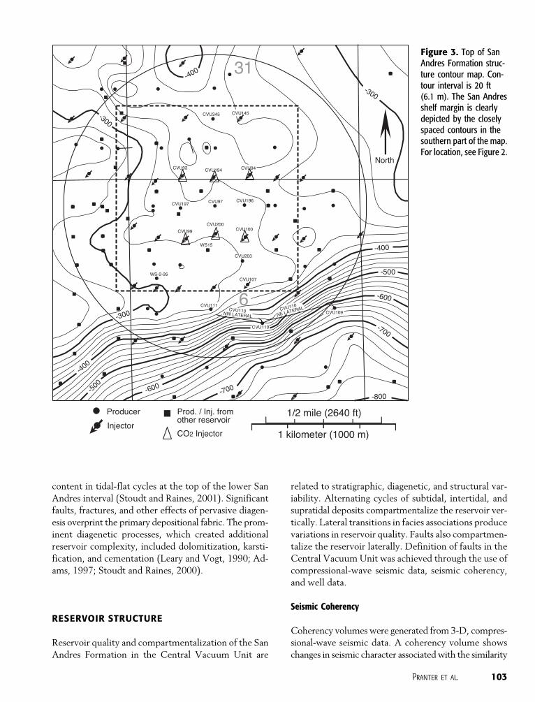
In 1995, a pilot CO2-injection program with one well, Central
Vacuum Unit 97 (Figure 3), was initiated in the area. The pilot was a
CO2 injection, soak, and production process (Benson and Davis,
2000). The Central Vacuum Unit CO2 project was expanded suc-
cessfully through the late 1990s, until the gas-handling facilities
were fully used. The project continues to be expanded in the tar-
geted acreage to maintain the full efficiency of the surface facilities.
The unit was brought up to a peak of and is maintained at ap-
proximately 7300 BOPD.
Time-lapse, multicomponent (four-dimensional, nine-compo-
nent) seismic data were acquired during the CO2 pilot program to
determine the use of these data for reservoir characterization and to
detect and monitor changes in rock and fluid properties associated
with the CO2 pilot (Roche et al., 2001). In addition, a larger P-wave
three-dimensional (3-D) seismic survey was acquired in 1995. The
CO2 flood was expanded in April 1998 to six injectors (Figure 3).
With the expansion, additional time-lapse, multicomponent seismic
data were acquired in 1997 and 1998, before and after CO2 in-
jection. The time-lapse, multicomponent seismic data were used to
characterize static reservoir properties such as lithology, porosity,
and fracture-related permeability (Pranter, 1999) and to monitor
changes in fluid saturation (Benson and Davis, 2000).
Other data include conventional logs from 120 wells, one
borehole image log in well WS-2-26 (Figure 3), and log data from
the medium-radius, dual-lateral horizontal well, Central Vacuum
Unit 110 (CVU-110). Six cores are available, and neural-network–
estimated permeability curves were provided by the unit operator
for most of the wells in the study area. Injection and production
data, primarily consisting of monthly cumulative volumes of fluids
injected or produced, were also provided by the unit operator. In
Michael A. Raines � Kinder Morgan CO2 Company,L.P., Midland, Texas 79701;[email protected]
Michael Raines is a geologist with Kinder Morgan CO2
Company, L.P. He has a B.S. degree in geology fromWest Texas State University and an M.S. degree in geol-ogy from the University of Oklahoma. His professionalinterests include reservoir characterization, tertiary recov-ery, horizontal drilling, earth science education, multi-component seismic, time-lapse seismic monitoring, andcarbonate systems. He is involved with AAPG, West TexasGeological Society, and Permian Basin Section-SEPM.
Scott C. Wehner � Kinder Morgan CO2 Company,L.P., Midland, Texas 79701;[email protected]
Scott Wehner is a senior engineer with Kinder MorganCO2 Company, L.P. located in Midland, Texas. He waspreviously with Texaco. His 22-year career has been inthe Permian basin of west Texas and southeast NewMexico. His past 18 years have been devoted to thedesign, implementation, and/or management of CO2
projects. He has published various CO2-related papersand has one CO2 process patent. He is a past directorof the Society of Petroleum Engineers and is a pastDepartment of Energy Program Manager. He gradu-ated from the University of Missouri, Rolla in 1980 witha B.Sc. degree in geological engineering.
ACKNOWLEDGEMENTS
We thank the industry sponsors of the Colorado School ofMines Reservoir Characterization Project for funding andinput to this study. The consortium members includeAGIP, Amoco Production Company (now BP), AnadarkoPetroleum Corporation, ARCO (now BP), ChevronPetroleum Technology Company (now ChevronTexaco),China National Petroleum Corporation, CompagnieGenerale de Geophysique, Conoco Inc. (now Conoco-Phillips), Dawson Geophysical Company, Exxon Produc-tion Research Company (now ExxonMobil UpstreamResearch Company), Gas Research Institute (now GasTechnology Institute), GeoQuest/Schlumberger/Geco,Golden Geophysical/Fairfield Industries, Grant Geophys-ical, Inc., Input/Output, Inc., INTEVEP, S.A., Japan NationalOil Corporation, Landmark Graphics Corporation, Mara-thon Oil Company, Maxus Energy Corporation, NambeGeophysical, Inc., Occidental Oil and Gas Corporation,Oyo Geospace Corporation, PanCanadian PetroleumLimited (now EnCana), Phillips Petroleum Company (nowConocoPhillips), Paradigm Geophysical (formerly Cogni-Seis), Shell E&P Technology Company, Discovery BayCompany (now Rock Solid Images), Silicon GraphicsCorporation, Solid State Geophysical, Texaco Group, Inc.(now ChevronTexaco), Union Pacific Resources Company(now Anadarko Petroleum Corporation), UNOCAL/SprintEnergy, Western Geophysical, and Veritas DGC, Inc.The study was also supported through research grantsand funding from AAPG, Geological Society of America,Society of Professional Well Log Analysts (now Societyof Petrophysicists and Well Log Analysts), and theDepartment of Geology and Geological Engineering atthe Colorado School of Mines.
100 Dual-Lateral Horizontal Wells Target Bypassed Pay in the San Andres Formation

addition, several wells have single or multiple produc-
tion and injection profiles. These profiles show which
intervals in a well are producing or taking injected fluid.
GEOLOGIC SETTING
Vacuum field is associated with an anticline that de-
veloped through a combination of sediment drape, dif-
ferential compaction, and faulting (Purves, 1990). Shelf-
margin depositional relief (Figure 3) and faults bound
the reservoir on the south. The structural features, com-
bined with the high-frequency cycles that are character-
istic of the San Andres Formation, create a stratigraphic
and structural trap for hydrocarbons at Vacuum field.
Evaporites, supratidal carbonates, and low-perme-
ability siltstones provide updip and top seals for the
reservoir.
In the Vacuum field, the San Andres Formation
consists of approximately 1500 ft (457 m) of dolo-
mites interbedded with a few thin dolomitic siltstones
(Figure 4). The average depth to the top of the San
Andres Formation is approximately 4400 ft (1341 m).
The upper 400–450 ft (122–137 m) of the San An-
dres Formation is the main hydrocarbon-bearing in-
terval (Stoudt and Raines, 2000). The typical rock and
fluid properties of the San Andres Formation are shown
in Table 1.
Gross pay maximum of 500 ft (150 m)
Net-to-gross ratio average of 40%
Porosity 0–24%, average of 11.6%
Permeability 0–530 md, average of 22.3 md
Initial reservoir pressure 1628 psia (1.12�107 Pa)
at 4500 ft (1372 m)
Producing interval 4200–4800 ft (1280–1463 m)
Reservoir temperature 105jF (40.6jC)
Stock tank oil gravity 38j API
Bubble-point pressure 764 psia (5.27�106 Pa)
Initial solution
gas-oil ratio
400 SCF/STB (differential data)
Reservoir oil viscosity 0.96 cp at the bubble-
point pressure
Reservoir drive
mechanism
water and solution-gas
drive in the southern
and southeastern parts
of the field; solution-gas
drive in the northern part
of the field
Figure 1. Location map of Vacuum fieldon the northwest shelf of the Permianbasin. Modified from Hills (1984).
Table 1. Typical Rock and Fluid Properties of the San Andres
Formation
Pranter et al. 101
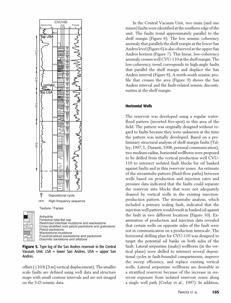
The reservoir interval consists of four high-
frequency sequences (Figure 5). These four sequences
include the upper two high-frequency sequences of
the lower San Andres Formation and the upper two
high-frequency sequences of the upper San Andres
Formation. High-frequency sequences are bounded lo-
cally by unconformities and consist of retrogradational,
aggradational, and progradational sets of high-frequency
cycles (Mitchum and Van Wagoner, 1991; Kerans and
Tinker, 1997; Tinker, 1998, Kerans and Kempter,
2002). Individual high-frequency cycles in the San
Andres Formation (Figure 5) consist of vertical litho-
facies successions that commonly include bryozoan/
sponge/pelmatozoan wackestones and boundstones,
fusulinid and peloidal wackestones and packstones,
skeletal, ooid, and peloidal packstones and grainstones,
and tidal-flat caps with abundant fenestrae (Pranter,
1999; Stoudt and Raines, 2001).
The San Andres Formation in this area represents
an overall shallowing-upward interval composed of nu-
merous high-frequency depositional cycles that subdi-
vide the reservoir into alternating zones of high and low
reservoir quality. Depositional cycles range in thickness
from several feet to more than 10 ft (3 m). The primary
reservoir rocks consist of dolomitized peloidal pack-
stones, skeletal and ooid grainstones, and fusulinid
packstones (Adams, 1997; Scuta, 1997; Pranter, 1999,
Stoudt and Raines, 2001). Porosity of these lithofacies
ranges from 5 to 20%, and permeability ranges from 5
to 100 md. These rocks alternate with dolomite cycles
of lower reservoir quality that exhibit variable degrees
of anhydrite cementation. The Lovington siltstone strat-
igraphically separates the upper and lower San Andres
Formation in the northwest part of the study area and is
characterized by very low matrix permeability. The
Lovington siltstone represents eolian silts and sands
that were deposited on the platform or that infiltrated
shallow karst features in the tidal-flat–capped lower
San Andres interval. The high gamma-ray response in
the sandstones, however, is enhanced by high uranium
Figure 2. Base map of the western part of the Vacuum field and the location of the Central Vacuum Unit. Detailed map of area incircle is shown in Figure 3.
102 Dual-Lateral Horizontal Wells Target Bypassed Pay in the San Andres Formation
content in tidal-flat cycles at the top of the lower San
Andres interval (Stoudt and Raines, 2001). Significant
faults, fractures, and other effects of pervasive diagen-
esis overprint the primary depositional fabric. The prom-
inent diagenetic processes, which created additional
reservoir complexity, included dolomitization, karsti-
fication, and cementation (Leary and Vogt, 1990; Ad-
ams, 1997; Stoudt and Raines, 2000).
RESERVOIR STRUCTURE
Reservoir quality and compartmentalization of the San
Andres Formation in the Central Vacuum Unit are
related to stratigraphic, diagenetic, and structural var-
iability. Alternating cycles of subtidal, intertidal, and
supratidal deposits compartmentalize the reservoir ver-
tically. Lateral transitions in facies associations produce
variations in reservoir quality. Faults also compartmen-
talize the reservoir laterally. Definition of faults in the
Central Vacuum Unit was achieved through the use of
compressional-wave seismic data, seismic coherency,
and well data.
Seismic Coherency
Coherency volumes were generated from 3-D, compres-
sional-wave seismic data. A coherency volume shows
changes in seismic character associated with the similarity
Figure 3. Top of SanAndres Formation struc-ture contour map. Con-tour interval is 20 ft(6.1 m). The San Andresshelf margin is clearlydepicted by the closelyspaced contours in thesouthern part of the map.For location, see Figure 2.
Pranter et al. 103

(continuity) or lack of similarity (discontinuity) among
neighboring seismic traces. To compute coherency at-
tributes, each seismic trace was compared with eight
surrounding traces, and correlation coefficients or sem-
blance values were calculated for each trace pair (com-
parison of the central trace with each of the eight
surrounding traces) through cross correlation. The cor-
relation coefficients of each pair were then used to de-
termine a single continuity attribute value for the cen-
tral trace in the comparison pattern. In general, high
coherency is typical for a relatively flat and continuous
seismic event.
A regional seismic coherency map of the lower San
Andres horizon (Figure 6) shows east-west trending
discontinuities associated with interpreted normal
faults along the Leonardian-Guadalupian shelf margin
in the Central Vacuum Unit (Talley, 1997). Faults iden-
tified on regional 3-D seismic amplitude and coherency
volumes (Talley, 1997) appear to compartmentalize
the reservoir and affect production.
Vertical throw of the main faults is estimated from
seismic and well data to range from 0 to 70 ft (0 to 21
m), but is generally less than 25 ft (8 m). The main
faults are intersected by smaller scale faults with minor
Figure 4. Stratigraphiccolumn of the maingeologic formations ator near Vacuum field.
104 Dual-Lateral Horizontal Wells Target Bypassed Pay in the San Andres Formation
offset (�10 ft [3 m] vertical displacement). The smaller
scale faults are defined using well data and structure
maps with small contour intervals and are not imaged
on the 3-D seismic data.
In the Central Vacuum Unit, two main (and one
minor) faults were identified at the southern edge of the
unit. The faults trend approximately parallel to the
shelf margin (Figure 6). The low seismic coherency
anomaly that parallels the shelf margin at the lower San
Andres level (Figure 6) is also observed at the upper San
Andres horizon (Figure 7). This linear, low-coherency
anomaly crosses well CVU-110 at the shelf margin. The
low-coherency trend corresponds to high-angle faults
that parallel the shelf margin and displace the San
Andres interval (Figure 8). A north-south seismic pro-
file that crosses the area (Figure 9) shows the San
Andres interval and the fault-related seismic disconti-
nuities at the shelf margin.
Horizontal Wells
The reservoir was developed using a regular water-
flood pattern (inverted five-spot) in this area of the
field. The pattern was originally designed without re-
gard to faults because they were unknown at the time
the pattern was initially developed. Based on a pre-
liminary structural analysis of shelf-margin faults (Tal-
ley, 1997; L. Duranti, 1998, personal communication),
two medium-radius, horizontal wellbores were proposed
to be drilled from the vertical production well CVU-
110 to intersect isolated fault blocks for oil banked
against faults and in thin reservoir zones. An estimate
of the streamtube pattern (fluid-flow paths) between
wells based on production and injection rates and
pressure data indicated that the faults could separate
the reservoir into blocks that were not adequately
drained by vertical wells in the existing injection-
production pattern. The streamtube analysis, which
included a primary sealing fault, indicated that the
injection well pattern would result in banked oil against
the fault in two different locations (Figure 10). Ex-
amination of production and injection data revealed
that certain wells on opposite sides of the fault were
not in communication on a production timescale. The
horizontal drilling plan for CVU-110 was designed to
target the potential oil banks on both sides of the
fault. Lateral serpentine (snaky) wellbores (in the ver-
tical plane) were drilled to intersect several deposi-
tional cycles in fault-bounded compartments, improve
the sweep efficiency, and replace existing vertical
wells. Lateral serpentine wellbores are desirable in
a stratified reservoir because of the increase in res-
ervoir exposure from isolated reservoir zones along
a single well path (Corlay et al., 1997). In addition,
Figure 5. Type log of the San Andres reservoir in the CentralVacuum Unit. LSA = lower San Andres, USA = upper SanAndres.
Pranter et al. 105

with higher horizontal permeability/vertical permeabil-
ity ratios, the productivity of a serpentine wellbore is
generally higher than that of a slanted wellbore of
similar length (Corlay et al., 1997). The northwestern
lateral well, CVU-110-NW, was terminated 150 ft (50
m) from the offset vertical well, CVU-111 (Figure 11),
and has not affected production from the well. The
northeastern lateral well, CVU-110-NE, passed within
75 ft (25 m) of CVU-109 (Figure 12) and terminated
330 ft (100 m) from the leaseline (the legal setback
distance).
The lateral wells were deviated after exiting milled
sections in the vertical wellbore. While drilling well
CVU-110-NW, the steering was difficult to control
initially. In this interval, the anhydrite content was
high. Dogleg severity, a relative measure of the rate of
change in borehole deviation, was also anomalous in
this interval. These characteristics occurred in an area
where a fault was expected, and were attributed to
drilling through the fault at a highly oblique angle.
To identify the faults encountered by the horizon-
tal wells, the horizontal well logs were converted to
true vertical depth for direct correlation to adjacent
vertical wells. In general, correlation of reservoir zones
was based on gamma-ray and neutron porosity log sig-
natures. Fault cuts were identified in wells as zones of
10–25 ft (3–8 m) of missing section on the logs (Pran-
ter, 1999). Intervals above and below these zones of
missing section are correlative between the horizontal
and vertical wells. Although the observed fault throw is
generally less than 25 ft (8 m), it is sufficient to offset
relatively thin depositional cycles, reduce lateral fluid
flow across the fault, and limit the efficiency of vertical
production wells.
Cross sections through wells CVU-110-NW and
CVU-110-NE show fault locations along the well paths
Figure 6. Top of the lower San Andres Formation seismic coherency map. Lighter shades indicate areas of low seismic continuity,and darker shades indicate areas of high seismic continuity. Well CVU-110 is the vertical well that was used to drill the two horizontalwells.
106 Dual-Lateral Horizontal Wells Target Bypassed Pay in the San Andres Formation

Figure 7. Top of the upperSan Andres Formation seismiccoherency maps. Darker shadesindicate areas of low seismiccontinuity, and lighter shadesindicate areas of high seismiccontinuity. The time-lapse seis-mic area is shown by the largeopen circle. (A) Map generatedfrom coherency data (unfil-tered), and (B) map generatedfrom coherency data with fre-quency-wavenumber (f-k) fanfilter applied to eliminate minordiscontinuities and emphasizethe more significant disconti-nuities (modified from Talley,1997).
Pranter et al. 107

(Figures 11, 12). As much as 25 ft (8 m) of vertical
displacement can be inferred at the wellbore from the
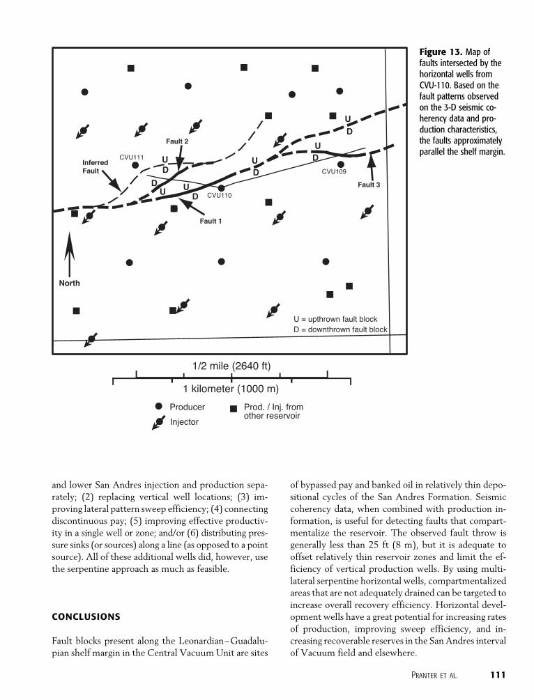
given data. Based on the fault patterns observed on the
3-D seismic coherency data and production character-
istics, the faults approximately parallel the shelf margin
(Figure 13) and separate nearby vertical wells to form
undrained fault blocks.
Production data from CVU-110 and nearby pro-
ducers, CVU-109 and CVU-111, illustrate the signif-
icance of the fault blocks. The CVU-110 horizontal
wellbores were completed open hole for 273 bbl oil/
day, 53,000 ft3 of gas per day, and 279 bbl of water per
day (previous production from the CVU-110 vertical
well was 10–15 bbl per day and had been declining for
many years). A graph of monthly oil production for the
wells clearly shows a significant increase in oil produc-
tion in CVU-110 associated with the dual-lateral devel-
opment. However, there was no change in production
in the offset wells (Figure 14), presumably because of
compartmentalization by faults.
Based in part on the results of CVU-110, several
additional horizontal wells were drilled in the San An-
dres interval at Central Vacuum Unit. However, none
of these wells specifically targeted oil banks stranded
against sealing faults. Instead, they were individually de-
signed to address issues such as (1) controlling upper
Figure 8. Map of faulttraces interpreted from3-D seismic amplitudeand coherency data. Thefault patterns representthe projection onto themap of all fault traces thatwere interpreted for eachtime slice or stratigraphicinterval through the SanAndres Formation (pro-vided by L. Duranti). Thefault trace patterns spreadout because the faultsare not vertical. The loca-tion of the seismic profileof Figure 9 is shown.
108 Dual-Lateral Horizontal Wells Target Bypassed Pay in the San Andres Formation
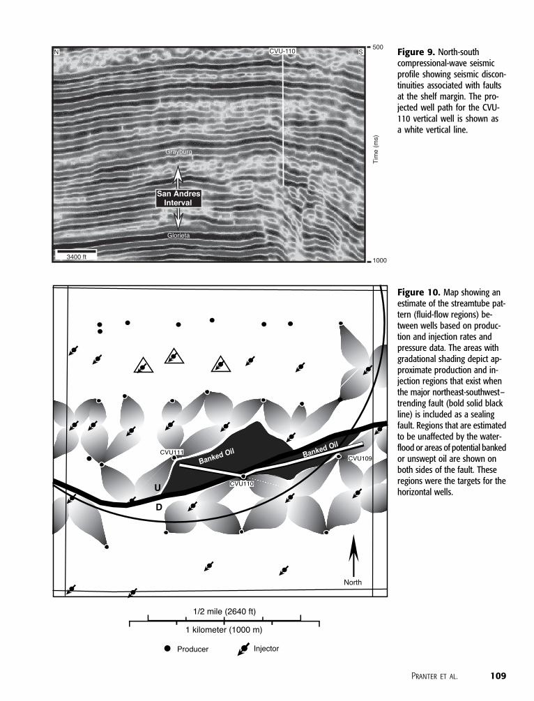
Figure 9. North-southcompressional-wave seismicprofile showing seismic discon-tinuities associated with faultsat the shelf margin. The pro-jected well path for the CVU-110 vertical well is shown asa white vertical line.
Figure 10. Map showing anestimate of the streamtube pat-tern (fluid-flow regions) be-tween wells based on produc-tion and injection rates andpressure data. The areas withgradational shading depict ap-proximate production and in-jection regions that exist whenthe major northeast-southwest–trending fault (bold solid blackline) is included as a sealingfault. Regions that are estimatedto be unaffected by the water-flood or areas of potential bankedor unswept oil are shown onboth sides of the fault. Theseregions were the targets for thehorizontal wells.
Pranter et al. 109
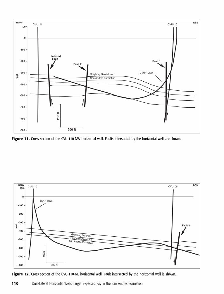
Figure 11. Cross section of the CVU-110-NW horizontal well. Faults intersected by the horizontal well are shown.
Figure 12. Cross section of the CVU-110-NE horizontal well. Fault intersected by the horizontal well is shown.
110 Dual-Lateral Horizontal Wells Target Bypassed Pay in the San Andres Formation
and lower San Andres injection and production sepa-
rately; (2) replacing vertical well locations; (3) im-
proving lateral pattern sweep efficiency; (4) connecting
discontinuous pay; (5) improving effective productiv-
ity in a single well or zone; and/or (6) distributing pres-
sure sinks (or sources) along a line (as opposed to a point
source). All of these additional wells did, however, use
the serpentine approach as much as feasible.
CONCLUSIONS
Fault blocks present along the Leonardian–Guadalu-
pian shelf margin in the Central Vacuum Unit are sites
of bypassed pay and banked oil in relatively thin depo-
sitional cycles of the San Andres Formation. Seismic
coherency data, when combined with production in-
formation, is useful for detecting faults that compart-
mentalize the reservoir. The observed fault throw is
generally less than 25 ft (8 m), but it is adequate to
offset relatively thin reservoir zones and limit the ef-
ficiency of vertical production wells. By using multi-
lateral serpentine horizontal wells, compartmentalized
areas that are not adequately drained can be targeted to
increase overall recovery efficiency. Horizontal devel-
opment wells have a great potential for increasing rates
of production, improving sweep efficiency, and in-
creasing recoverable reserves in the San Andres interval
of Vacuum field and elsewhere.
Figure 13. Map offaults intersected by thehorizontal wells fromCVU-110. Based on thefault patterns observedon the 3-D seismic co-herency data and pro-duction characteristics,the faults approximatelyparallel the shelf margin.
Pranter et al. 111

REFERENCES CITED
Adams, S. D., 1997, Sedimentology and diagenesis of the San AndresFormation, Vacuum field, New Mexico: M.S. thesis, T-5060,Colorado School of Mines, Golden, Colorado, 158 p.
Benson, R. D., and T. L. Davis, 2000, Time-lapse seismic monitoringand dynamic reservoir characterization, Central Vacuum Unit,Lea County, New Mexico: Society of Petroleum EngineersReservoir Evaluation & Engineering, SPE Paper 60890, p. 88–97.
Corlay, P., D. Bossie-Codreanu, J. C. Sabathier, and E. R. Delamaide,1997, Improving reservoir management with complex well ar-chitectures: World Oil, v. 218, p. 45–50.
Hills, J. M., 1984, Sedimentation, tectonism and hydrocarbongeneration in Delaware basin, west Texas and southeasternNew Mexico: AAPG Bulletin, v. 68, p. 250–267.
Kerans, C., and K. Kempter, 2002, Hierarchical stratigraphic analysisof a carbonate platform, Permian of the Guadalupe Mountains:AAPG/Datapages Discovery Series No. 5, CD-ROM.
Kerans, C., and S. W. Tinker, 1997, Sequence stratigraphy and char-acterization of carbonate reservoirs: SEPM Short Course Notes40, 130 p.
Leary, D. A., and J. N. Vogt, 1990, Diagenesis of the San AndresFormation (Guadalupian), Central Basin platform, Permianbasin, in D. G. Bebout and P. M. Harris, eds., Geologic andengineering approaches in evaluation of San Andres/Grayburg
hydrocarbon reservoirs— Permian basin: Texas Bureau ofEconomic Geology, p. 21–48.
Mitchum, R. M., Jr., and J. C. Van Wagoner, 1991, High-frequencysequences and their stacking patterns: sequence stratigraphicevidence of high-frequency eustatic cycles, in K. T. Biddle andW. Schlager, eds., The record of sea-level fluctuations:Sedimentary Geology, v. 70, p. 131–160.
Pranter, M. J., 1999, Use of a petrophysical-based reservoir zonationand multicomponent seismic attributes for improved geologicmodeling, Vacuum field, New Mexico: Ph.D. dissertation, Col-orado School of Mines, Golden, Colorado, 366 p.
Purves, W. J., 1990, Reservoir description of the Mobil oil bridgesstate leases (upper San Andres reservoir), Vacuum field, LeaCounty, New Mexico, in D. G. Bebout and P. M. Harris, eds.,Geologic and engineering approaches in evaluation of SanAndres/Grayburg hydrocarbon reservoirs— Permian basin:Texas Bureau of Economic Geology, p. 87–112.
Roche, S. L., T. L. Davis, R. D. Benson, and L. Duranti, 2001,Dynamic reservoir characterization; application of time-lapse(4-D), multicomponent seismic to a CO2 EOR project,Vacuum field, New Mexico (abs.): AAPG Bulletin, v. 85,p. 389.
Scuta, M. S., 1997, 3-D reservoir characterization of the CentralVacuum Unit, Lea County, New Mexico: Ph.D. dissertation,Colorado School of Mines, Golden, Colorado, 274 p.
Stoudt, E. L., and M. A. Raines, 2000, Karst features in the SanAndres Formation on the northwest shelf of the Permian
Figure 14. Plot of monthly oilproduction vs. time for CVU-109(solid gray line), CVU-110 (solidblack line), and CVU-111 (dashedgray line). The significant in-crease in production from CVU-110 corresponds to the comple-tion of the dual-lateral horizontalwells in early 1998. The com-pletion of the two horizontalwells did not affect productionfrom the offset vertical wells.These data also support thesealing capacity of the faults.
112 Dual-Lateral Horizontal Wells Target Bypassed Pay in the San Andres Formation
basin; they’re not just at Yates field anymore!, in S. T. Reid, ed.,Transactions, Southwest Section AAPG, 2000 Convention:SWS Publication 2000-107, p. 181–211.
Stoudt, E. L., and M. A. Raines, 2001, Reservoir compartmentali-zation in the San Andres Formation of Vacuum field, LeaCounty, New Mexico; peritidal deposits and karst overprintscreate vertical and lateral barriers to fluid flow in carbonateplatform dolopackstones and dolograinstones (abs.): AAPGBulletin, v. 85, p. 390.
Talley, D. J., 1997, Characterization of a San Andres carbonatereservoir using four dimensional multicomponent attribute
analysis: M.S. thesis, Colorado School of Mines, Golden, Col-orado, 75 p.
Tinker, S. W., 1998, Shelf-to-basin facies distributions and sequencestratigraphy of a steep-rimmed carbonate margin: Capitandepositional system, McKittrick Canyon, New Mexico andTexas: Journal of Sedimentary Research, v. 68, no. 6, p. 1146–1174.
Wehner, S. C., and J. Prieditis, 1996, CO2 huff-n-puff: initial resultsfrom a waterflooded ssc reservoir: Proceedings of the Societyof Petroleum Engineers Permian Basin Oil and Gas RecoveryConference, SPE Paper 35223, p. 1–10.
Pranter et al. 113


![ENVIRONMENTAL PROTECTION COMMISSION[567] · 2014-06-25 · wells, recreational-use wells, monitoring wells, heat pump supply wells or GHEX loop boreholes, industrial wells, and dewatering](https://img.pdfslide.us/doc/110x75/5f3f728939b254613866ae00/environmental-protection-commission567-2014-06-25-wells-recreational-use-wells.jpg)