Embed Size (px)
Citation preview
08/16/2011 HI210B
WARMFLO®
Dual Heat System
Universal Furnace Interface Module Specially Equipped for 2-Speed HP
Controller Portion of Electro-Mate
Also accompanying each system is a specific control program “chip”. This is typically part of ordering information and should be listed on packing slip. A listing of these “chip codes” is in the controller setup or programming sections of this document.
WarmFlo/Electro-Mate EM-WU*****/EM-WD***** mechanical information – companion manual EI703/EI707. Also the WarmFlo control board must be the latest version with 10-pin connector, chip code version 2.30 or higher, and the latest sensors with “E” identification band. Model WF-HP2 – B Must use chip 2.02 or higher. This universal interface module is equipped to handle two types of room thermostats. The installation and setup information is significantly different, the page shown can assist in locating the information relating to the type of thermostat you intend to use.
Manufacturer multi-wire HP room thermostat 6 - 8
Conventional heat/cool, 2H/2C room thermostat 9 - 11
NOTE 1: With the upgraded revision B product, the conventional 2H/2C roomstat may now be the best choice – see pages 5, 9, 12, and 19.
NOTE 2: Also review page 19, Blower Speed Operation. Factory default is now set at “B”.
NOTE 3: This interface does not apply to Bryant Evolution or Carrier Infinity.
NOTE 4: If there is a less than ideal combination of WF+/EZ-Mate with WF-HP2, see page 20 for setup procedure. Drawings: HH210 HH211B HD320 XX017
08/16/2011 HI210B
TABLE OF CONTENTS
Page
INTRODUCTION 1
INSTALLATION REQUIREMENTS 2
MECHANICAL INSTALLATION 2
EM-WU***** Electro-Mate Upflow Application 2
EM-WU***** EM-WD***** Electro-Mate Horizontal Application 2
EM-WD***** Electro-Mate Downflow Application 3
WIRING INSTALLATION 4
High Voltage 4
WarmFlo Sensors 4
Outdoor Sensor (OT) 4
Warm Air Supply Sensor (ST) 4
HP Manufacturers’ Multi-Wire Stat 6
WF-HP2 Setup 8
Conventional 2H/2C Thermostat 9
WF-HP2 Setup 11
Standard Heat/Cool (4-Wire) Thermostat 12
WarmFlo Controller Setup or Programming 13
HPDH, HPDF, HPEL Chip Code Selection 13
OPERATION INDICATORS 16
HANDHELD ANALYZER/LAPTOP SOFTWARE 18
SPECIAL APPLICATION/INSTALLATION 18
Heating, Blower Speed Control 18
1 HEAT/2 HEAT 19
WARMFLO – STAT OVERRIDE TIMER (SOT) 20
USING EZ-MATE OR WF+ BOARD 20
TROUBLESHOOTING 22
OPERATIONAL INFORMATION 23
HOOKUP DRAWING HH210 HH211B
WARMFLO INFORMATION HD320
WARRANTY XX017
08/16/2011 1 HI210B
INTRODUCTION
Prior to installation we recommend that the installer verify the system application represents air source heat pump (probably 2-speed)/Electro-Mate plenum heater/standby or gas furnace. The program code chip for the Electro-Mate WarmFlo controller will be either HPDH or HPDF. If your application does not include this combination, do not use this WF-HP2 interface module or this installation manual. Consult factory for other models relating to total electric or air handlers (EM-WE series, WF-DH*** kits, etc.).
EM-WU***** – WarmFlo/Electro-Mate upflow ranging from 10 kW to 25 kW. Can be installed in upflow applications only.
EM-WD***** – WarmFlo/Electro-Mate downflow ranging from 10 kW to 25 kW. Can be installed in downflow and horizontal applications.
Caution, Heat Pump Application: Depending upon mechanical positioning and airflow, in all cases the electric element, Electro-Mate, unit must be on the supply or warm side of the HP refrigerant coil.
First-time or non-routine user – before attempting installation or setup, suggest studying the last section of this manual, operational information and terminology definitions. Also if you have not attended a WarmFlo training session, it is strongly advised. With this package is a WarmFlo information document, HD320, which we strongly recommend you take time to read and call factory for questions and further information. This WF-HP2 interface module basically ties together all the low voltage control wiring and interfaces directly with the Electro-Mate/WarmFlo plenum heater and utility load control receiver. It is a universal controller in the sense that it has provisions for all known 2-speed heat pump manufacturers’ products (except Bryant/Carrier Evolution/Infinity), can use various room thermostats, and can actually be a replacement for the WF-LGR4 or for single speed HP interface module. The control board has several setup peg jumpers, if these are not correctly set in relationship to the components within the system, malfunction and unsatisfactory operation will result. In some cases there’s a built-in detection from this wiring and the controller pulses the EL mode LED to indicate incorrect setup (pulsing amber LED). Installer must carefully work through the hookup, also see page 22. The heat pump manufacturers’ “fossil fuel kit” or any other controllers relating to manufacturers’ instructions for “dual fuel” are not needed and should not be used. This controller works directly with the basic outdoor HP unit and gas furnace wiring terminal block. As stated on the cover, there are major instruction sections relating to either multi-wire heat pump stat or conventional heat/cool stat.
The basic and very generic heat/cool 4-wire stat can actually be used for all functions of this system including 2-speed heat pump. With a basic H/C stat (1H/1C), the high speed cooling within the heat pump is activated from three setup options, refer to page 12 emergency switch or emergency timeout (SOT).
**Installation Notice - Upon installation it is necessary that all the components of the heating system are in place and functional. This controller is designed to operate the complete heating system - heat pump, backup furnace (gas or oil), Electro-Mate, room thermostat, WF outdoor sensor, etc. If one of these components is missing or not initially installed, improper performance of WarmFlo and the system may be experienced. In other words, if the gas furnace doesn’t exist, LP tank not yet installed or filled, and the WarmFlo is operating on a cold day; do not be disappointed if there is no heat.
Warranty/Checkout – with the Electro-Mate is a warranty certification and checkout procedure. This must be completed and returned for warranty coverage.
08/16/2011 2 HI210B
INSTALLATION REQUIREMENTS
1. All installation work must be performed by trained, qualified contractors or technicians. Electro Industries, Inc., sponsors installation and service schools to assist the installer. Visit our web site at electromn.com for upcoming service schools.
2. All electrical wiring must be in accordance with National Electric Code and local electric codes, ordinances, and regulations.
3. Observe electric polarity and wiring colors. Failure to observe could cause electric shock and/or damage to the equipment.
4. This unit can only be used for its intended design as described in this manual. Any internal wiring changes, modifications to the circuit board, modifications or bypass of any controls, or installation practices not according to the details of this manual will void the product warranty, the ARL certification label, and manufacturer product liability. Electro Industries, Inc., cannot be held responsible for field modifications, incorrect installations, and conditions which may bypass or compromise the built-in safety features and controls.
5. The only approved installation for this Electro-Mate series is upflow and horizontal furnace and above or downstream from the air conditioning or heat pump A-coil. Any other configuration or furnace plenum/ducting installation voids warranty and manufacturers product liability.
MECHANICAL INSTALLATION
WF Furnace Interface, WF-HP2 The mounting location of this enclosure is flexible to any convenient location were the thermostat connection is easily accessible. The distance between this unit and WF unit limited only by the 4’ cable provided within.
EM-WU***** Electro-Mate Upflow Application Electro-Mate nameplate or companion installation manual EI703 is required for correct mechanical installation. If you do not have manual #EI703 do not attempt to do the mechanical installation, contact the factory for a replacement manual. The primary installation concerns focusing on the existing furnace and ducting system’s airflow capacity and necessary plenum baffling required by the specific Electro-Mate for correct installation. It is true that the WarmFlo modulating control and the supply sensor adjust the electric heat or element capacity based upon temperature. But if you do not have the required CFM airflow (example 20 kW, 1400 CFM), you could have a situation where you cannot heat the house. Another even more serious situation (because of improper airflow) is when all stages are on at colder temperatures and the unit is cycling on mechanical safety hi-limit. When cycling on the hi-limit probe, the WarmFlo supply sensor basically gets confused because at one point it is way up in temperature and then the elements simply disappear and it dips down, the net result probably is switching over to standby at premature intervals. There is no substitute for adequate airflow capacity and plenum baffling.
EM-WD***** Electro-Mate Horizontal Application NOTE: It is not permissible to rotate the WarmFlo/Electro-Mate 180°. These instructions apply to only rotating the Electro-Mate unit 90°.
With WarmFlo, IT IS permissible (and authorized by the manufacturer) to turn the Electro-Mate unit 90° for horizontal application. However, you must follow the instructions below relating to temperature sensor positioning, etc.
The reason this practice is acceptable is because the element power and temperature is controllable by the WarmFlo sensor. When placing the sensor at the top of the duct as stated below, heat rise will keep the elements off even without the blower.
08/16/2011 3 HI210B
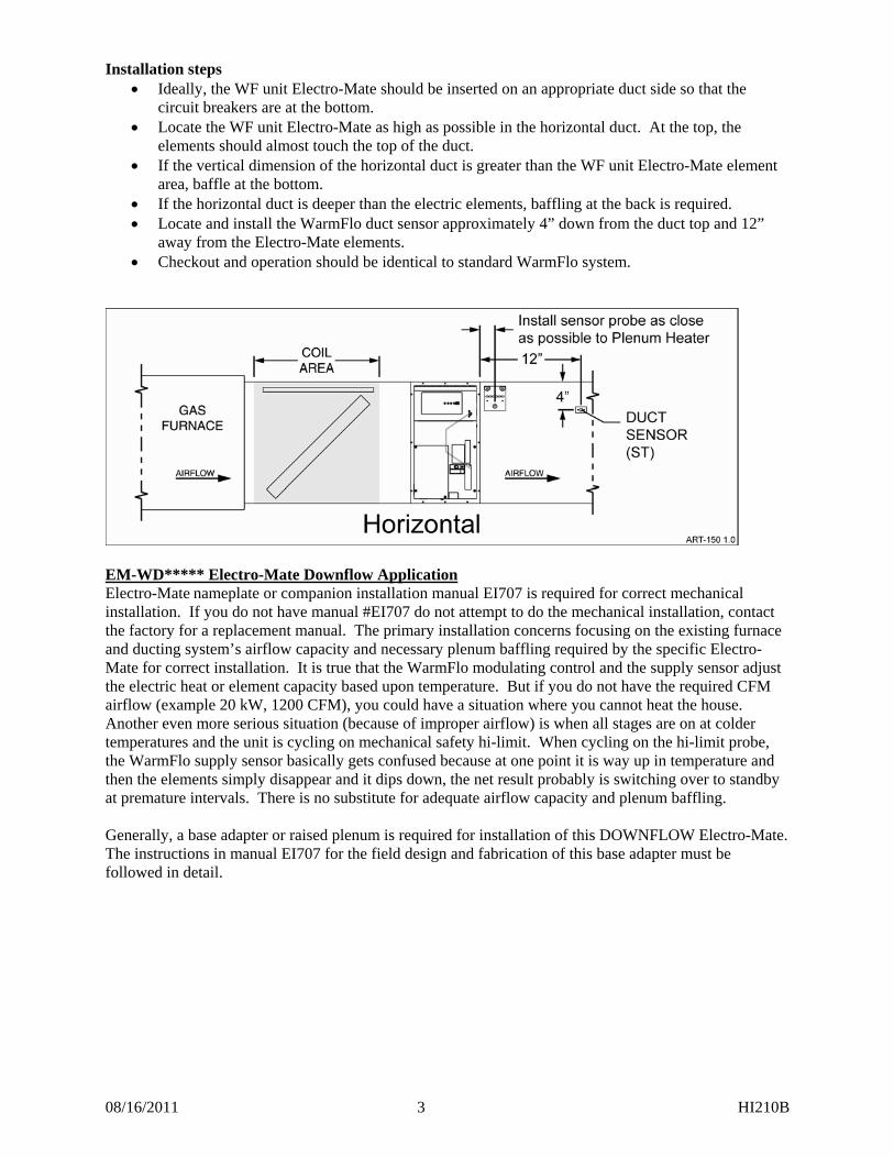
Installation steps Ideally, the WF unit Electro-Mate should be inserted on an appropriate duct side so that the
circuit breakers are at the bottom. Locate the WF unit Electro-Mate as high as possible in the horizontal duct. At the top, the
elements should almost touch the top of the duct. If the vertical dimension of the horizontal duct is greater than the WF unit Electro-Mate element
area, baffle at the bottom. If the horizontal duct is deeper than the electric elements, baffling at the back is required. Locate and install the WarmFlo duct sensor approximately 4” down from the duct top and 12”
away from the Electro-Mate elements. Checkout and operation should be identical to standard WarmFlo system.
EM-WD***** Electro-Mate Downflow Application Electro-Mate nameplate or companion installation manual EI707 is required for correct mechanical installation. If you do not have manual #EI707 do not attempt to do the mechanical installation, contact the factory for a replacement manual. The primary installation concerns focusing on the existing furnace and ducting system’s airflow capacity and necessary plenum baffling required by the specific Electro-Mate for correct installation. It is true that the WarmFlo modulating control and the supply sensor adjust the electric heat or element capacity based upon temperature. But if you do not have the required CFM airflow (example 20 kW, 1200 CFM), you could have a situation where you cannot heat the house. Another even more serious situation (because of improper airflow) is when all stages are on at colder temperatures and the unit is cycling on mechanical safety hi-limit. When cycling on the hi-limit probe, the WarmFlo supply sensor basically gets confused because at one point it is way up in temperature and then the elements simply disappear and it dips down, the net result probably is switching over to standby at premature intervals. There is no substitute for adequate airflow capacity and plenum baffling. Generally, a base adapter or raised plenum is required for installation of this DOWNFLOW Electro-Mate. The instructions in manual EI707 for the field design and fabrication of this base adapter must be followed in detail.
08/16/2011 4 HI210B
WIRING INSTALLATION High Voltage Please reference Electro-Mate manual EI707 or EI703, pages 2 and 3.
Low Voltage
WarmFlo Sensors Located within the WarmFlo control (with Electro-Mate) are two sensing probes, OT (outdoor sensing) and ST (supply sensing) necessary for proper operation and installation of the WarmFlo systems. Without proper installation of these probes the WarmFlo system will not operate correctly. Outdoor Sensor (OT) is identified by the longer cable and the metal mounting bracket.
1. Determine best location for the OT sensor using the following ground rules. a. Locate on the outside of the house to sample outside temperature least affected by sun. b. Locate sensor away from other objects that produce a heat or cool effect such as heat
pump freon line sets, drier vents, direct sunlight, steel siding, or other miscellaneous objects that affect the air temperature.
c. Do not install sensor in an enclosure which may have a “heat build up” or insulation effect.
2. Disconnect OT and ST sensor cable from Warmflo Controller noting the screw locations for future re-hookup.
3. The factory supplied OT cable is approximately 25’. Determine necessary length of cable to route to the predetermined outside location. If the sensor wire cable is too short, you must use the following rules for extending the cable.
a. Use unshielded (low capacitance, prefer twisted) 3 or 4 wire low voltage cable, 50 foot maximum.
b. Do not under any circumstances use leftover wires within the thermostat cable going to the outdoor unit.
4. Mount OT sensor. 5. Routing the cable along the Freon tubing often makes the easiest installation (sensor must be
mounted away from hot gas pipe). 6. Route wire from outside making sure not to crimp, cut, staple, or damage cable in any way. 7. Keep the sensor cables at least 12” away from any line voltage wiring, Romex, etc. Do not,
under any circumstances, use part of existing thermostat cable, leftover wires, for the sensor cable.
8. Do not reconnect sensor wires to the 4-screw terminal block until both sensors are properly installed.
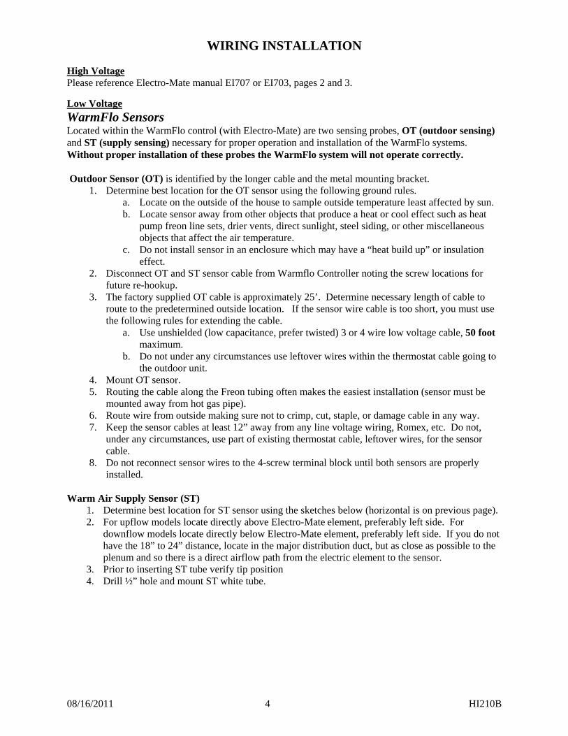
Warm Air Supply Sensor (ST)
1. Determine best location for ST sensor using the sketches below (horizontal is on previous page). 2. For upflow models locate directly above Electro-Mate element, preferably left side. For
downflow models locate directly below Electro-Mate element, preferably left side. If you do not have the 18” to 24” distance, locate in the major distribution duct, but as close as possible to the plenum and so there is a direct airflow path from the electric element to the sensor.
3. Prior to inserting ST tube verify tip position 4. Drill ½” hole and mount ST white tube.
08/16/2011 5 HI210B
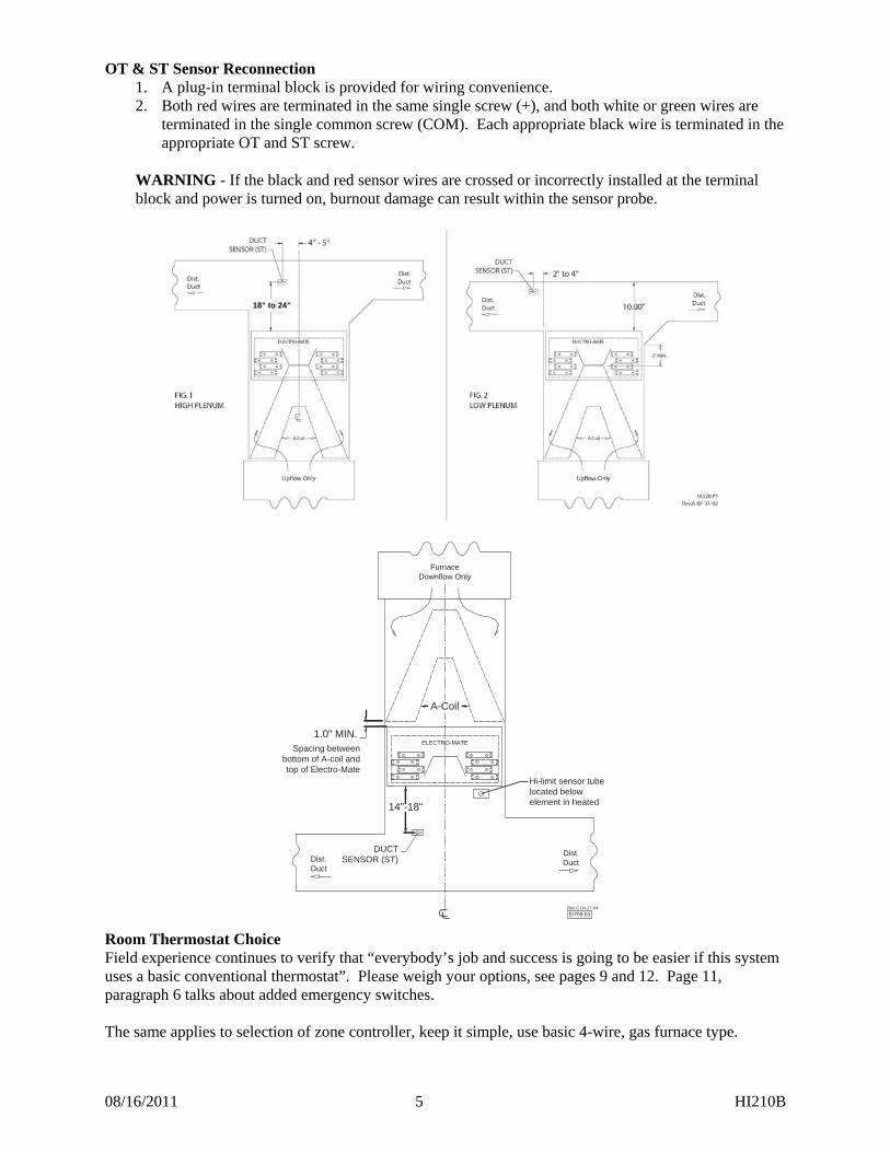
OT & ST Sensor Reconnection 1. A plug-in terminal block is provided for wiring convenience. 2. Both red wires are terminated in the same single screw (+), and both white or green wires are
terminated in the single common screw (COM). Each appropriate black wire is terminated in the appropriate OT and ST screw.
WARNING - If the black and red sensor wires are crossed or incorrectly installed at the terminal block and power is turned on, burnout damage can result within the sensor probe.
Room Thermostat Choice Field experience continues to verify that “everybody’s job and success is going to be easier if this system uses a basic conventional thermostat”. Please weigh your options, see pages 9 and 12. Page 11, paragraph 6 talks about added emergency switches. The same applies to selection of zone controller, keep it simple, use basic 4-wire, gas furnace type.
18” to 24”
ELECTRO-MATE
Dist.Duct
Dist.Duct
FurnaceDownflow Only
EI708-03Rev.C 04-27-04
DUCTSENSOR (ST)
Hi-limit sensor tube located below element in heated 14"-18"
1.0" MIN. Spacing between
bottom of A-coil andtop of Electro-Mate
A-Coil
08/16/2011 6 HI210B
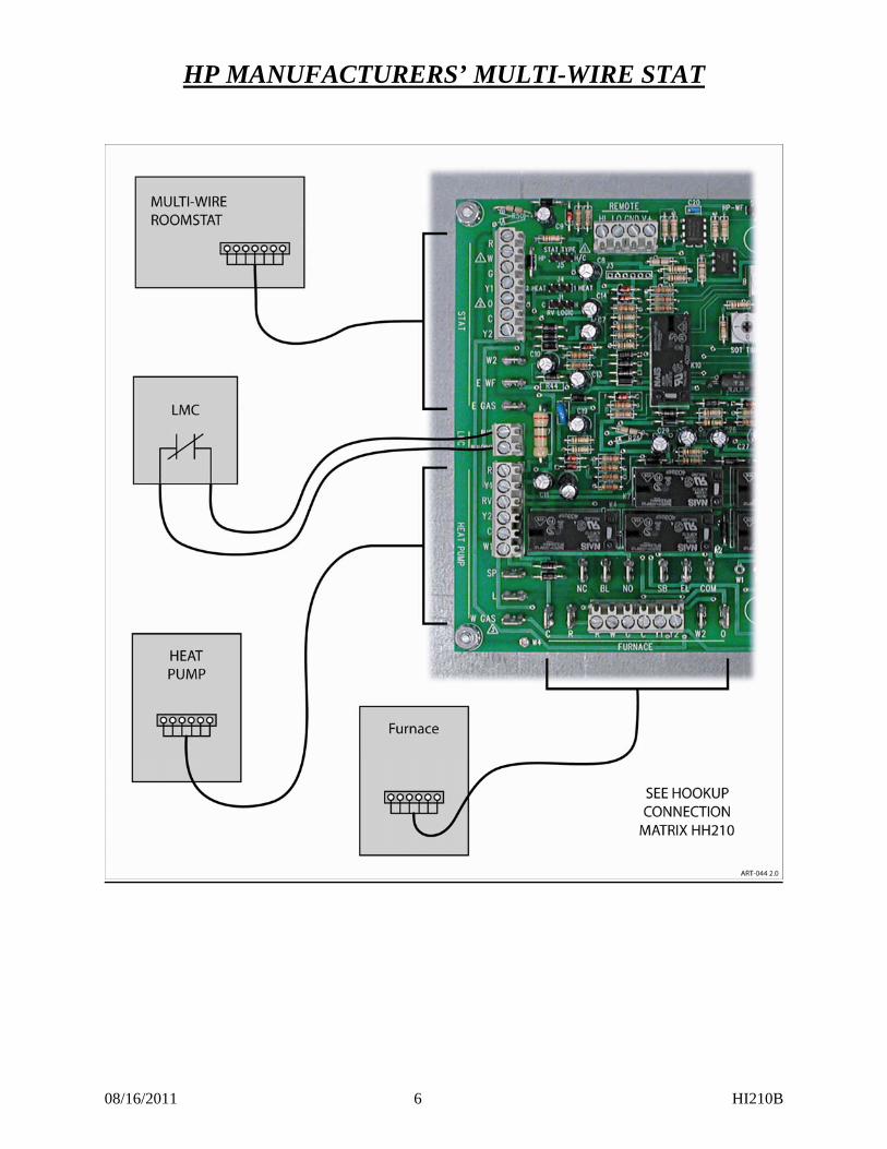
HP MANUFACTURERS’ MULTI-WIRE STAT
08/16/2011 7 HI210B
HP MULTI-WIRE STAT - HOOKUP
Note: The installer must be familiar with the manufacturer’s low voltage wiring terminology, screw terminal terminology/colors, etc. This manufacturer’s terminology must be related to Electro Industries’ screw terminal identification within this controller. The intent of this instruction manual is not to train each installer on the terminology related to the specific product you are installing.
1. Install this unit within the 4-foot cable length of the Electro-Mate/WarmFlo plenum heater. 2. Requirements:
a. Thermostat connection 6 to 8-wire cable b. Gas furnace wiring board 6-wire cable, 40VA or larger transformer c. Outdoor heat pump 6 to 8-wire cable
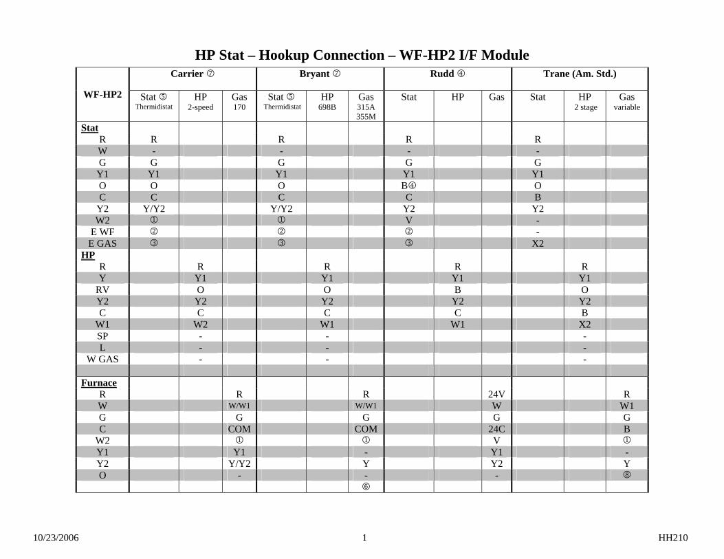
3. Manufacturers’ terminology and low voltage connection points – locate the enclosed Hookup Connection matrix chart, HH210, and the appropriate room thermostat/outdoor unit/gas furnace columns. The terminology in these columns should relate directly to the terminology within the manufacturer’s instruction sheets and information packed with the heat pump/room thermostat/gas furnace.
4. Specific wire to wire hookup – the terminology for this controller is in the left column of the hookup matrix. Simply move, wire by wire, from the appropriate WF-HP2 terminology to a right column representing your product.
a. There should be a screw terminal or a tab point for each necessary wire. There is no need for splicing or wire nutting within this controller. If you feel that it is necessary, call factory for further interpretation and assistance.
5. Room thermostat connections – at the appropriately marked terminal block section connect wire by wire to the room thermostat terminology shown on the hookup matrix. W is not used and must be open.
6. Gas furnace wiring block – at the appropriately marked terminal block section connect wire by wire to the furnace terminology shown on the hookup matrix. Stat W2 can be used for furnace W2 if it is so arranged. However, Electro recommends using a timeout for gas furnace second stage.
7. Outdoor HP unit – use the terminology and connection point specified on HH210. Six connection points are required, the HP2-W1 represents a defrost signal and is required for proper HP2 operation (must go high during the outdoor unit defrost cycle).
8. Utility load control – center left is a 2-screw terminal block marked blue and blu/wht. Remove the jumper and extend the two wires to the utility furnished control device. For electric energy operation (off-peak) the two blue wires represent contact closure as shipped. Do not apply external voltage or external power to the blue wires, they are simply looking for a closed contact during off-peak. - Optional – where load management interrupt does not apply, simply leave the blue wires jumpered. - If load control reverse logic is required, consult factory for interposing relay.
9. Defrost Warning – several heat pump manufacturers are now energizing reversing valve O terminal during heat pump defrost. It is imperative O terminal does not go to 24VAC before W1 input (relay race). This will cause WF-HP2 to enter a cooling mode operation. Same conditions exist with RV high = heating (with logic reversed). Call factory for further details.
WarmFlo Controller Connection Note: The WarmFlo control board must be the latest version with 10-pin connector and chip code version 2.30 or higher. If replacement is needed, call wholesaler.
1. WF unit controller is located on the cabinet right door. 2. Sensor connection – see page 4 “WarmFlo Sensors”. 3. Plug the 10-pin cable from this unit to the appropriate male pin connector on the WarmFlo board
(you may need to remove a “dummy” block). Do not force on the connector, the connector only plugs in one way and should slide on easily (red wire will be on top).
4. Caution – 24 volts common grounding – the installer must determine whether the furnace wiring block COM screw terminal has a good ground bond (not simply furnace skin). If the furnace COM is not adequately grounded, use the pigtail green wire (WarmFlo board, upper, C
08/16/2011 8 HI210B
tab) for a ground bond to the Electro-Mate cabinet power source ground lug. The upper right circuit board mounting screw is a static ground protection point.
If your installation has special application and hookup conditions please see section located in this manual called “Special Application/Installation Instructions”.
WF-HP2 SETUP (HP STAT)
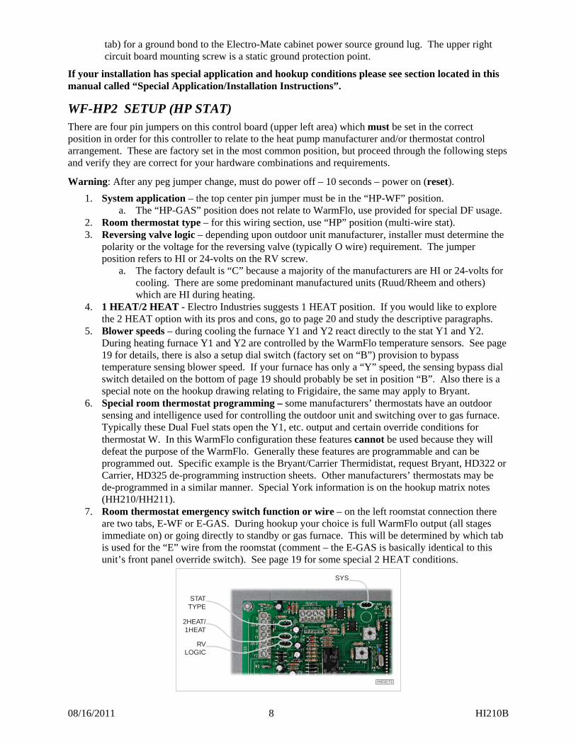
There are four pin jumpers on this control board (upper left area) which must be set in the correct position in order for this controller to relate to the heat pump manufacturer and/or thermostat control arrangement. These are factory set in the most common position, but proceed through the following steps and verify they are correct for your hardware combinations and requirements.
Warning: After any peg jumper change, must do power off – 10 seconds – power on (reset).
1. System application – the top center pin jumper must be in the “HP-WF” position. a. The “HP-GAS” position does not relate to WarmFlo, use provided for special DF usage.
2. Room thermostat type – for this wiring section, use “HP” position (multi-wire stat). 3. Reversing valve logic – depending upon outdoor unit manufacturer, installer must determine the
polarity or the voltage for the reversing valve (typically O wire) requirement. The jumper position refers to HI or 24-volts on the RV screw.
a. The factory default is “C” because a majority of the manufacturers are HI or 24-volts for cooling. There are some predominant manufactured units (Ruud/Rheem and others) which are HI during heating.
4. 1 HEAT/2 HEAT - Electro Industries suggests 1 HEAT position. If you would like to explore the 2 HEAT option with its pros and cons, go to page 20 and study the descriptive paragraphs.
5. Blower speeds – during cooling the furnace Y1 and Y2 react directly to the stat Y1 and Y2. During heating furnace Y1 and Y2 are controlled by the WarmFlo temperature sensors. See page 19 for details, there is also a setup dial switch (factory set on “B”) provision to bypass temperature sensing blower speed. If your furnace has only a “Y” speed, the sensing bypass dial switch detailed on the bottom of page 19 should probably be set in position “B”. Also there is a special note on the hookup drawing relating to Frigidaire, the same may apply to Bryant.
6. Special room thermostat programming – some manufacturers’ thermostats have an outdoor sensing and intelligence used for controlling the outdoor unit and switching over to gas furnace. Typically these Dual Fuel stats open the Y1, etc. output and certain override conditions for thermostat W. In this WarmFlo configuration these features cannot be used because they will defeat the purpose of the WarmFlo. Generally these features are programmable and can be programmed out. Specific example is the Bryant/Carrier Thermidistat, request Bryant, HD322 or Carrier, HD325 de-programming instruction sheets. Other manufacturers’ thermostats may be de-programmed in a similar manner. Special York information is on the hookup matrix notes (HH210/HH211).
7. Room thermostat emergency switch function or wire – on the left roomstat connection there are two tabs, E-WF or E-GAS. During hookup your choice is full WarmFlo output (all stages immediate on) or going directly to standby or gas furnace. This will be determined by which tab is used for the “E” wire from the roomstat (comment – the E-GAS is basically identical to this unit’s front panel override switch). See page 19 for some special 2 HEAT conditions.
SYS
2HEAT/1HEAT
STATTYPE
RVLOGIC
HH210 F2
08/16/2011 9 HI210B
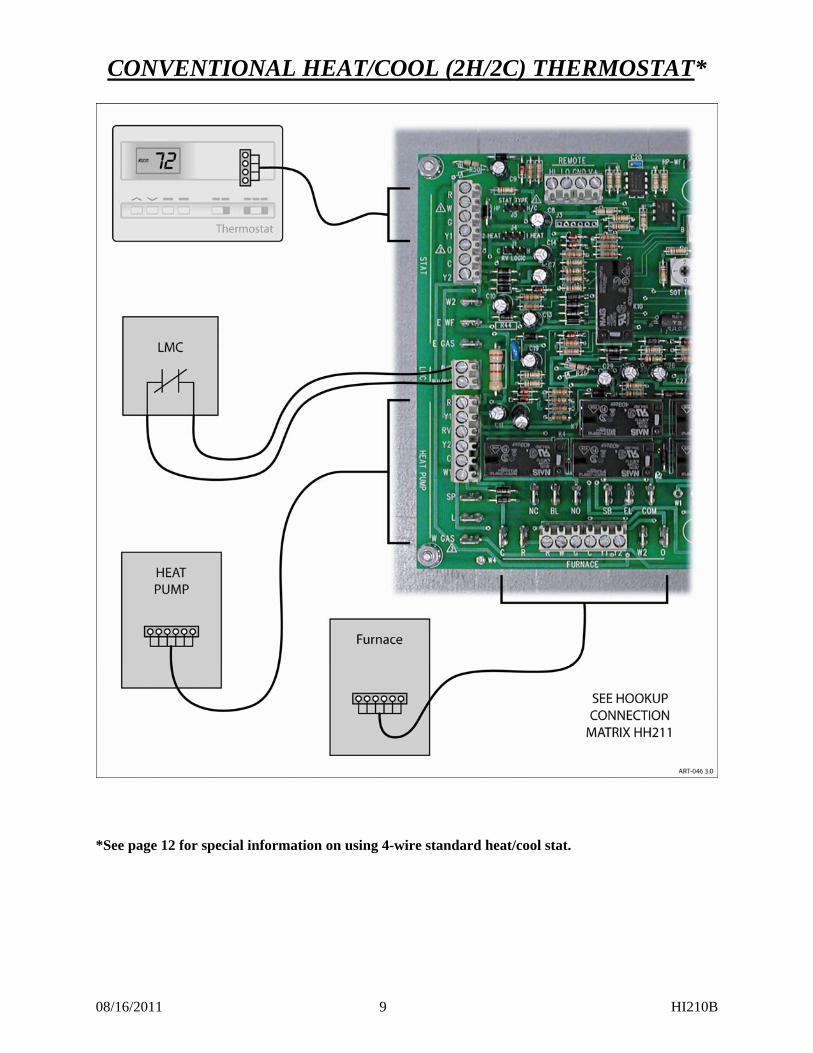
CONVENTIONAL HEAT/COOL (2H/2C) THERMOSTAT* *See page 12 for special information on using 4-wire standard heat/cool stat.
08/16/2011 10 HI210B
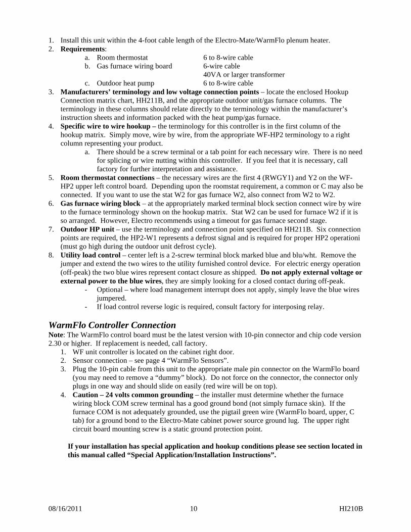
1. Install this unit within the 4-foot cable length of the Electro-Mate/WarmFlo plenum heater. 2. Requirements:
a. Room thermostat 6 to 8-wire cable b. Gas furnace wiring board 6-wire cable
40VA or larger transformer c. Outdoor heat pump 6 to 8-wire cable
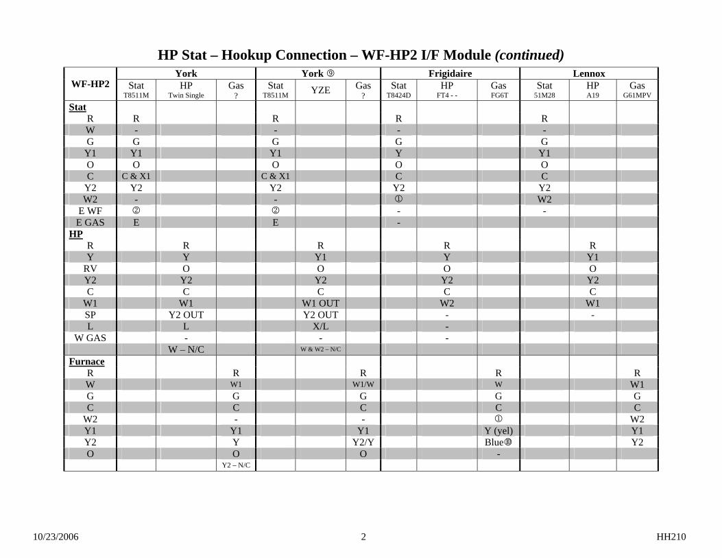
3. Manufacturers’ terminology and low voltage connection points – locate the enclosed Hookup Connection matrix chart, HH211B, and the appropriate outdoor unit/gas furnace columns. The terminology in these columns should relate directly to the terminology within the manufacturer’s instruction sheets and information packed with the heat pump/gas furnace.
4. Specific wire to wire hookup – the terminology for this controller is in the first column of the hookup matrix. Simply move, wire by wire, from the appropriate WF-HP2 terminology to a right column representing your product.
a. There should be a screw terminal or a tab point for each necessary wire. There is no need for splicing or wire nutting within this controller. If you feel that it is necessary, call factory for further interpretation and assistance.
5. Room thermostat connections – the necessary wires are the first 4 (RWGY1) and Y2 on the WF-HP2 upper left control board. Depending upon the roomstat requirement, a common or C may also be connected. If you want to use the stat W2 for gas furnace W2, also connect from W2 to W2.
6. Gas furnace wiring block – at the appropriately marked terminal block section connect wire by wire to the furnace terminology shown on the hookup matrix. Stat W2 can be used for furnace W2 if it is so arranged. However, Electro recommends using a timeout for gas furnace second stage.
7. Outdoor HP unit – use the terminology and connection point specified on HH211B. Six connection points are required, the HP2-W1 represents a defrost signal and is required for proper HP2 operationi (must go high during the outdoor unit defrost cycle).
8. Utility load control – center left is a 2-screw terminal block marked blue and blu/wht. Remove the jumper and extend the two wires to the utility furnished control device. For electric energy operation (off-peak) the two blue wires represent contact closure as shipped. Do not apply external voltage or external power to the blue wires, they are simply looking for a closed contact during off-peak.
- Optional – where load management interrupt does not apply, simply leave the blue wires jumpered.
- If load control reverse logic is required, consult factory for interposing relay.
WarmFlo Controller Connection Note: The WarmFlo control board must be the latest version with 10-pin connector and chip code version 2.30 or higher. If replacement is needed, call factory.
1. WF unit controller is located on the cabinet right door. 2. Sensor connection – see page 4 “WarmFlo Sensors”. 3. Plug the 10-pin cable from this unit to the appropriate male pin connector on the WarmFlo board
(you may need to remove a “dummy” block). Do not force on the connector, the connector only plugs in one way and should slide on easily (red wire will be on top).
4. Caution – 24 volts common grounding – the installer must determine whether the furnace wiring block COM screw terminal has a good ground bond (not simply furnace skin). If the furnace COM is not adequately grounded, use the pigtail green wire (WarmFlo board, upper, C tab) for a ground bond to the Electro-Mate cabinet power source ground lug. The upper right circuit board mounting screw is a static ground protection point.
If your installation has special application and hookup conditions please see section located in this manual called “Special Application/Installation Instructions”.
08/16/2011 11 HI210B
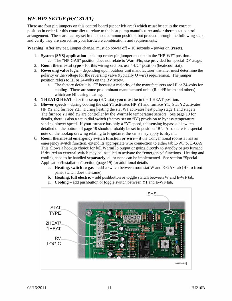
WF-HP2 SETUP (H/C STAT)
There are four pin jumpers on this control board (upper left area) which must be set in the correct position in order for this controller to relate to the heat pump manufacturer and/or thermostat control arrangement. These are factory set in the most common position, but proceed through the following steps and verify they are correct for your hardware combinations and requirements.
Warning: After any peg jumper change, must do power off – 10 seconds – power on (reset).
1. System (SYS) application – the top center pin jumper must be in the “HP-WF” position. a. The “HP-GAS” position does not relate to WarmFlo, use provided for special DF usage.
2. Room thermostat type – for this wiring section, use “H/C” position (heat/cool stat). 3. Reversing valve logic – depending upon outdoor unit manufacturer, installer must determine the
polarity or the voltage for the reversing valve (typically O wire) requirement. The jumper position refers to HI or 24-volts on the RV screw.
a. The factory default is “C” because a majority of the manufacturers are HI or 24-volts for cooling. There are some predominant manufactured units (Ruud/Rheem and others) which are HI during heating.
4. 1 HEAT/2 HEAT – for this setup (H/C stat) you must be in the 1 HEAT position. 5. Blower speeds – during cooling the stat Y1 activates HP Y1 and furnace Y1. Stat Y2 activates
HP Y2 and furnace Y2.. During heating the stat W1 activates heat pump stage 1 and stage 2. The furnace Y1 and Y2 are controller by the WarmFlo temperature sensors. See page 19 for details, there is also a setup dial switch (factory set on “B”) provision to bypass temperature sensing blower speed. If your furnace has only a “Y” speed, the sensing bypass dial switch detailed on the bottom of page 19 should probably be set in position “B”. Also there is a special note on the hookup drawing relating to Frigidaire, the same may apply to Bryant.
6. Room thermostat emergency switch function or wire – if the Conventional roomstat has an emergency switch function, extend its appropriate wire connection to either tab E-WF or E-GAS. This allows a hookup choice for full WarmFlo output or going directly to standby or gas furnace. If desired an external switch may be installed to activate the “emergency” functions. Heating and cooling need to be handled separately, all or none can be implemented. See section “Special Application/Installation” section (page 19) for additional details
a. Heating, switch to gas – add a switch between roomstat W and E-GAS tab (HP to front panel switch does the same).
b. Heating, full electric – add pushbutton or toggle switch between W and E-WF tab. c. Cooling – add pushbutton or toggle switch between Y1 and E-WF tab.
SYS
2HEAT/1HEAT
STATTYPE
RVLOGIC
HH210 F2

08/16/2011 12 HI210B
OPTIONAL, CONVENTIONAL H/C, BASIC 4-WIRE, THERMOSTAT Relating back to the previous three pages and connection matrix HH211B, there is a method of using the basic 1H/1C 4-wire stat for this controller and the total heat pump/Electro-Mate/gas furnace system. The only shortcomings in using this approach:
Emergency heat or standby is operated from the switch on this controller (however, a remote pushbutton or toggle switch can be used with E-WF tab as mentioned on page 19).
High speed cooling is accomplished by an SOT timeout delay or an external pushbutton/toggle switch, see below.
Gas furnace second stage must be programmed as a timeout on the gas furnace.
When using this basic 4-wire stat approach, getting high cooling is the primary concern. Review the following three built-in functions and select one to best meet your needs.
1. Do nothing – 60 minutes after the basic stat Y call (cool) this HP2 controller will automatically bring on high cooling to finish out the thermostat cycle. This 60 minutes is a factory default, on the control board approximate center towards the top there is a dial switch “SOT TIME”. This delay time to activate high speed cooling can be field changed:
0 = 30 minutes 1 = 45 minutes 2 = 60 minutes 3 = 90 minutes Factory default = 2
2. Add a pushbutton at a convenient location – connect the pushbutton between Y1 (stat TB) and E-WF. Whenever the pushbutton is activated for 10 seconds or more, the system automatically activates high cool for 30 minutes.
3. Add a toggle switch – connect the toggle switch between Y1 (stat TB) and E-WF. Whenever the switch is in a full closed position, the compressor is always in high cool whenever thermostat Y call is active.
Emergency Heat Activated by SOT Dial (4-wire stat only) When setting the “SOT TIME” dial, be aware that this setting directly relates to emergency heat when using a 4-wire stat. Once this times out in heating, the WarmFlo plenum heater goes to full output while keeping both Y1 and Y2 terminals energized at the heat pump until the thermostat call is satisfied.
08/16/2011 13 HI210B
WARMFLO CONTROLLER SETUP OR PROGRAMMING
Important - Located on the WF unit board is a firmware chip that determines a specific set of defaults (see table below). However, this can be programmed (altered) with optional PC software (ET-SOFT-WF) or a plug-in WarmFlo analyzer (WF-ANZ*). As part of the WF unit system this chip represents critical defaults and settings that make your system operate correctly. It is a critical portion of the installation to verify that the chip code sent with your WF unit is correct for your intended application.
The table below represents the typical WF unit chip codes and defaults for use with a WF-LGR4. Please use this table as a reference as you setup your WF unit. See Operational Information and last section of this manual for further information on these defaults.
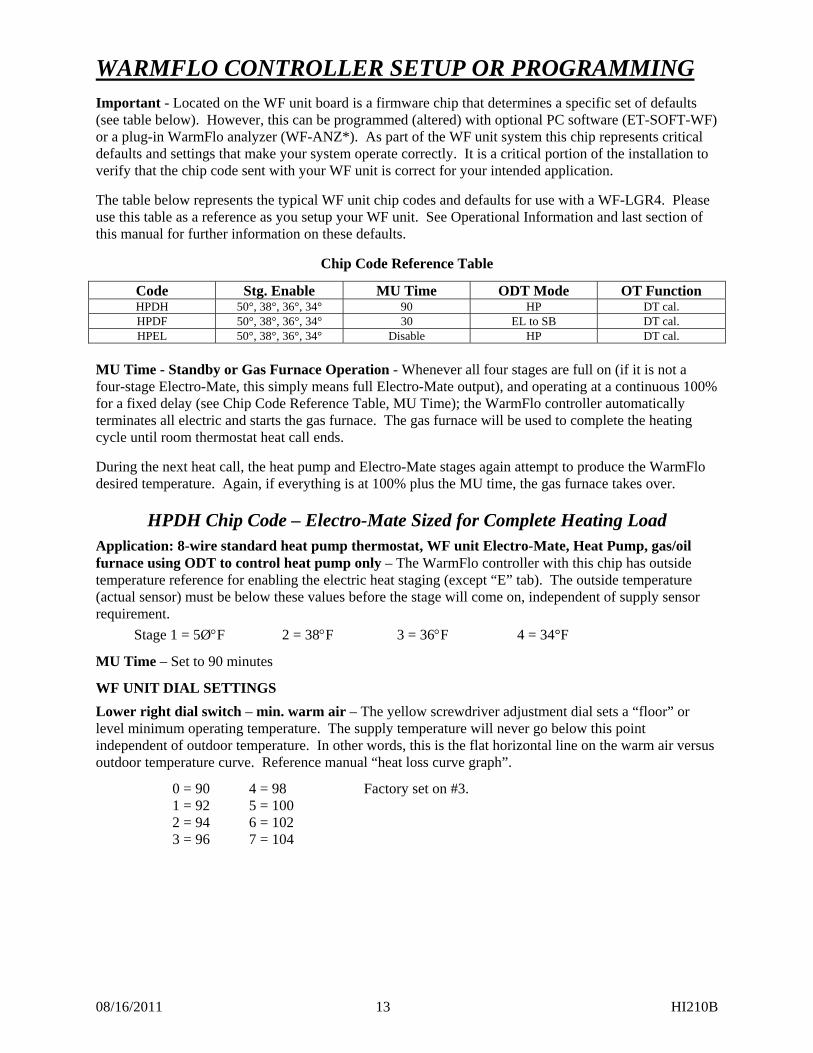
Chip Code Reference Table
Code Stg. Enable MU Time ODT Mode OT Function HPDH 50°, 38°, 36°, 34° 90 HP DT cal. HPDF 50°, 38°, 36°, 34° 30 EL to SB DT cal. HPEL 50°, 38°, 36°, 34° Disable HP DT cal.
MU Time - Standby or Gas Furnace Operation - Whenever all four stages are full on (if it is not a four-stage Electro-Mate, this simply means full Electro-Mate output), and operating at a continuous 100% for a fixed delay (see Chip Code Reference Table, MU Time); the WarmFlo controller automatically terminates all electric and starts the gas furnace. The gas furnace will be used to complete the heating cycle until room thermostat heat call ends.
During the next heat call, the heat pump and Electro-Mate stages again attempt to produce the WarmFlo desired temperature. Again, if everything is at 100% plus the MU time, the gas furnace takes over.
HPDH Chip Code – Electro-Mate Sized for Complete Heating Load
Application: 8-wire standard heat pump thermostat, WF unit Electro-Mate, Heat Pump, gas/oil furnace using ODT to control heat pump only – The WarmFlo controller with this chip has outside temperature reference for enabling the electric heat staging (except “E” tab). The outside temperature (actual sensor) must be below these values before the stage will come on, independent of supply sensor requirement.
Stage 1 = 5ØF 2 = 38F 3 = 36F 4 = 34°F
MU Time – Set to 90 minutes
WF UNIT DIAL SETTINGS
Lower right dial switch – min. warm air – The yellow screwdriver adjustment dial sets a “floor” or level minimum operating temperature. The supply temperature will never go below this point independent of outdoor temperature. In other words, this is the flat horizontal line on the warm air versus outdoor temperature curve. Reference manual “heat loss curve graph”.
0 = 90 4 = 98 Factory set on #3. 1 = 92 5 = 100 2 = 94 6 = 102 3 = 96 7 = 104
08/16/2011 14 HI210B
Top right dial switch - Built-in ODT or Low Temperature Switch-Over – The yellow screwdriver adjustment dial can be set to terminate the heat pump or via special programming can terminate heat pump and electric to allow total gas operation below ODT temp. (reference manual WF-ANZ*).
The temperature settings related to the “ODT dial” are:
Ø = Disabled, no ODT switch-over Factory set on #3. 1 = -15F 5 = 10°F 2 = -10F 6 = 20F 3 = 0F 7 = 30°F 4 = 5F
COMMENT: If you are using outdoor compressor built-in ODT, set the dial to “0”.
Temperature (Efficiency Dial) – Located on the front cover of the WF unit Electro-Mate, the red center screwdriver adjustment dial has a selection of A through G. These A through G selections represent a supply temperature point at 0° outdoor (also see page 22). The closer the user or installer selection is to A, the flatter the heat loss curve or the higher the operating efficiency. The closer a selected setting is to G, the steeper the heat loss curve or the lower overall heat pump system efficiency. If knob is turned to “full” the WF unit will automatically put all stages of electric to full capacity.
HPDF Chip Code – Electro-Mate Undersized
Application: 8-wire standard heat pump thermostat, WF unit Electro-Mate, Heat Pump, and gas/oil furnace using ODT setting as full electric control – The WarmFlo controller with this chip has outside temperature reference for enabling the electric heat staging (except “E” tab). The outside temperature (actual sensor) must be below these values before the stage will come on, independent of supply sensor requirement.
Stage 1 = 5ØF 2 = 38F 3 = 36F 4 = 34°F
Electro-Mate or strip heat undersizing – there are provisions within WarmFlo and within Electro’s various heating products to add partial resistance heating section to heat pumps. To provide optimum operation and comfort, the setup functions need to be activated accordingly. Default program code chip “HPDF” has been designed for this application. As a field setup, you probably want MU to be relatively short (30 minutes), the ODT mode will be “EL to SB” with a dial switch temperature selection at about the combination heat pump and Electro-Mate output energy (probably 0°) or position #3.
MU Time – Set to 30 minutes
WF UNIT DIAL SETTINGS
Lower right dial switch – min. warm air – The yellow screwdriver adjustment dial sets a “floor” or level minimum operating temperature. The supply temperature will never go below this point independent of outdoor temperature. In other words, this is the flat horizontal line on the warm air versus outdoor temperature curve. Reference manual “heat loss curve graph”.
0 = 90 4 = 98 Factory set on #3. 1 = 92 5 = 100 2 = 94 6 = 102 3 = 96 7 = 104
08/16/2011 15 HI210B
Top right dial switch - Built-in ODT or Low Temperature Switch-Over – The yellow screwdriver adjustment dial can be set to terminate all electric to allow total gas operation below ODT temp. Electric will stay on until thermostat is satisfied. The only time gas will be used is in utility control (reference manual WF-ANZ* for special programming).
The temperature settings related to the “ODT dial” are: Ø = Disabled, no ODT switch-over 1 = -15F 5 = 10°F Factory set on #3. 2 = -10F 6 = 20F 3 = 0F 7 = 30°F 4 = 5F
This arrangement provides low temperature interrupt of both the heat pump and the Electro-Mate elements. If you desire to interrupt only the heat pump, this is the wrong chip code or can be altered with Handheld.
Temperature (Efficiency Dial) – Located on the front cover of the WF unit Electro-Mate, the red center screwdriver adjustment dial has a selection of A through G. These A through G selections represent a supply temperature point at 0° outdoor (also see page 22). The closer the user or installer selection is to A, the flatter the heat loss curve or the higher the operating efficiency. The closer a selected setting is to G, the steeper the heat loss curve or the lower overall heat pump system efficiency. If knob is turned to “full” the WF unit will automatically put all stages of electric to full capacity.
HPEL Chip Code – Non-Standby Automatic Functions
Basically this is the same as HPDH without an MU function. This is typically used for total electric (non-standby furnace) application, but it can be used where the user does not want to have the WarmFlo automatically turn on the standby. The load control receiver interrupt and the front panel switch are still active and functional unrelated to this chip code.
08/16/2011 16 HI210B
OPERATION INDICATORS
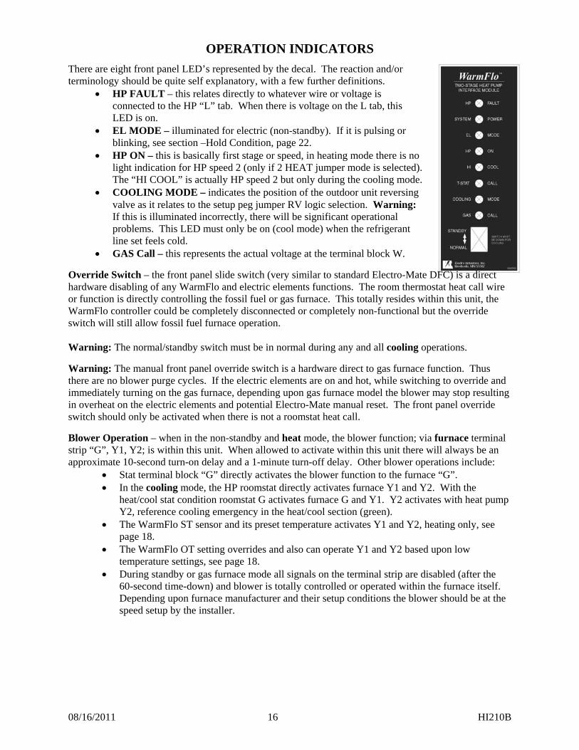
There are eight front panel LED’s represented by the decal. The reaction and/or terminology should be quite self explanatory, with a few further definitions.
HP FAULT – this relates directly to whatever wire or voltage is connected to the HP “L” tab. When there is voltage on the L tab, this LED is on.
EL MODE – illuminated for electric (non-standby). If it is pulsing or blinking, see section –Hold Condition, page 22.
HP ON – this is basically first stage or speed, in heating mode there is no light indication for HP speed 2 (only if 2 HEAT jumper mode is selected). The “HI COOL” is actually HP speed 2 but only during the cooling mode.
COOLING MODE – indicates the position of the outdoor unit reversing valve as it relates to the setup peg jumper RV logic selection. Warning: If this is illuminated incorrectly, there will be significant operational problems. This LED must only be on (cool mode) when the refrigerant line set feels cold.
GAS Call – this represents the actual voltage at the terminal block W.
Override Switch – the front panel slide switch (very similar to standard Electro-Mate DFC) is a direct hardware disabling of any WarmFlo and electric elements functions. The room thermostat heat call wire or function is directly controlling the fossil fuel or gas furnace. This totally resides within this unit, the WarmFlo controller could be completely disconnected or completely non-functional but the override switch will still allow fossil fuel furnace operation. Warning: The normal/standby switch must be in normal during any and all cooling operations.
Warning: The manual front panel override switch is a hardware direct to gas furnace function. Thus there are no blower purge cycles. If the electric elements are on and hot, while switching to override and immediately turning on the gas furnace, depending upon gas furnace model the blower may stop resulting in overheat on the electric elements and potential Electro-Mate manual reset. The front panel override switch should only be activated when there is not a roomstat heat call.
Blower Operation – when in the non-standby and heat mode, the blower function; via furnace terminal strip “G”, Y1, Y2; is within this unit. When allowed to activate within this unit there will always be an approximate 10-second turn-on delay and a 1-minute turn-off delay. Other blower operations include:
Stat terminal block “G” directly activates the blower function to the furnace “G”. In the cooling mode, the HP roomstat directly activates furnace Y1 and Y2. With the
heat/cool stat condition roomstat G activates furnace G and Y1. Y2 activates with heat pump Y2, reference cooling emergency in the heat/cool section (green).
The WarmFlo ST sensor and its preset temperature activates Y1 and Y2, heating only, see page 18.
The WarmFlo OT setting overrides and also can operate Y1 and Y2 based upon low temperature settings, see page 18.
During standby or gas furnace mode all signals on the terminal strip are disabled (after the 60-second time-down) and blower is totally controlled or operated within the furnace itself. Depending upon furnace manufacturer and their setup conditions the blower should be at the speed setup by the installer.
08/16/2011 17 HI210B
WarmFlo Controller
Strip Heat Disable – To maximize heat pump system energy efficiency and preventing “accidental” unnecessary resistant strip heat when it is not required, this WarmFlo controller disables or locks out strip heat elements based upon outdoor temperature.
Depending upon program code chip and information in the colored sections, the strip heat may not activate or operate unless the WF outdoor sensor is below the ODT dial setting. Typically for a heat pump, factory settings are:
Stage 1 - 5ØF Stage 2 - 38F Stage 3 - 36F Stage 4 - 34°
Monitor LED’s on WF Unit Controller Green LED - When illuminated the WarmFlo controller is receiving 24v power. Under all normal operating modes, this should be solid green.
As a secondary function this green LED provides status of the two remote sensors. If a sensor is inoperative, incorrectly wired, or malfunctioning; this monitor light is in a blinking or pulsing mode. By checking the pulsing pattern, the appropriate sensor can be identified.
OT sensor - 1ØØ ms blink every second. ST sensor - two, 1ØØ ms blinks every second. Both bad - ½ second on, ½ second off, alternating.
Amber LED – When illuminated the WarmFlo controller is in the electric heat operating mode. Inside WarmFlo Board, Red LED’s - The four red LED’s next to the output connector, indicate Stage 1, 2, 3, and 4 operation (Stage 1 is on the bottom).
EM-WU*****/EM-WD***** Inside Relay Board Monitor Light
COMMENT: The relay board activates from the WarmFlo controller as the WarmFlo controller interprets the “Y” input voltage in relationship to both temperature sensor requirements. However, the “Y” input also directly controls the Stage 1 triac and the staging relays. Whenever the “Y” input goes to 0 volts (at the end of the cycle) the relay output immediately goes off and strip heat is turned off and not necessarily stepped down as shown by the WarmFlo monitor Red LED’s. This is a safety feature; strip heat cannot be accidentally kept on by the WarmFlo controller internal logic if there is no “Y” input.
Inside Red LED - Illuminates when the low voltage hi-limit sensor probe opens. This applies only after thermostat heat call and WarmFlo controller is activating the various element stages. If there is a hi-limit condition, red LED is illuminated. As soon as the hi-limit cools and snaps back in, red LED extinguishes.
Triac Relay Module (under inside relay board) This module has its own built-in LED. When the LED is on, the triac switch is closed, elements will be heating. This LED shall operate coincident with Stage 1 on the WarmFlo board.
08/16/2011 18 HI210B
HANDHELD ANALYZER/LAPTOP SOFTWARE This test tool and/or software is available for temperature offset, field altering the program chip parameters and setup, and general assistance for troubleshooting. See the enclosed “WarmFlo Information” document (HD320) for functional details.
SPECIAL APPLICATION/INSTALLATION
For Various Heat Pump, Multi-Speed, Multi-Stage Furnaces, Blower Options, Oil Furnace, etc.
Thermostat Emergency, Heating Only (this wire function must always be low during cooling) Based upon thermostat type and brand, there may be an “emergency” function, but it also has to have an appropriate output terminal (we call “E”). If this is the case, this “E” can either be wired to E WF or E GAS tab. When activated (tab raised to 24 volts) the WarmFlo either goes to 100% electric resistance (bypasses all temperature sensing and modulation) or directly to standby/gas furnace.
Note: Do not confuse this with a heating W2 and the gas furnace second stage W2. If your specific thermostat has a true W2 with an additional emergency wire (we’re calling E) then it is okay to connect to either E-WF or E-GAS tab. If they are using the W2 for both a heating second stage and an emergency, do not connect this terminal to the upper left tab W2 as it relates to the W2 for the gas furnace connection.
If using Conventional H/C stat and it has an emergency function, it is okay to wire and activate as described above. Again, make sure this wire has no association with cooling and not W2 Active E-WF also opens both Y terminals to the heat pump. If using the option for a basic heat/cool, 4-wire, room thermostat; see page 12 for information on activating standby and high cooling. Heating Mode, Blower Speed Temperature Control
Via factory defaults (changeable via WF-ANZ* or software downloads) there is a supply temperature setting for blower speed Y1 and Y2, plus an OT temperature setting for blower speed Y1 and Y2. Factory defaults:
ST, 95° and above – Y1 ST, 105° and above – Y2 OT, 30° and less – Y1 OT, 20° and less – Y2
In case of the ST, if the temperature rises above this preset value, the blower speed will increase by adding Y2. In the case of the OT, if the outdoor is below this temperature at the initial call for heat, the blower speed will increase by adding Y2. Once this condition is crossed, it remains for the completion of the heat call cycle. This technique allows for maximum heat pump usage with minimum Electro-Mate/WarmFlo resistance.
Note: If your furnace only has a Y1 or Y, WF-HP2 Y2 will not be used.
Setup or installer temperature sensing bypass – provisions are included for the installer to bypass the above temperature sensing/blower speed provision for direct heat call blower speed up condition. Approximately top center on the circuit board are two dial switches, the bottom dial switch is marked “SOT TIME”. Above the “SOT TIME” switch is a dial switch marked A, B, C, D. Position A sets up the temperature sensing/blower speed arrangement detailed above. Position “B” is the factory default setting. This setting immediately turns both Y1 and Y2 blower speeds on. Or set the dial switch to position “C”
08/16/2011 19 HI210B
for immediate blower speed Y1. Y2 blower speed will still be controlled by the temperature sensor. Note: Position “D” is not used. 1 HEAT/2 HEAT – one of the first functional decisions and somewhat controversial issue is whether or not the Electro-Mate/WarmFlo should be activated with roomstat/heat pump stage 1. The first reaction may be that stage 1 should be heat pump only to use higher efficient section of the heat pump. However, since the first stage is approximately one-half heat pump capacity there is an almost 100% possibility of heat pump blowing cool air every time the room thermostat is “waiting” for stage 2 to kick in (room temperature will also be reduced). This certainly is not what WarmFlo comfort is all about. On the other side of the coin, if WarmFlo is activated on stage 1, WarmFlo temperature sensing will simply take over and the heat pump may never be used as stage 2 heating. This is not good because the full benefit of the HP heating is not used. Electro Industries suggests the heating be one stage (full heat pump at all times, maximum heat pump comfort heat) and standard manufacturer supplied 2-stage cooling. In this case, use 1 HEAT. This seems to be the best of both worlds, the WFHP2 interface controller has a setup jumper technique for field selection. Also the 2 HEAT selection requires some additional compromise conditions.
1. The HP roomstat must provide a G signal during heating. 2. If furnace G airflow is not adequate, set A, B, C, D dial to B for Y1 airflow. 3. There is no WarmFlo assisted defrost heating when in stage 1 or roomstat Y1 only. This is
because in the 2 HEAT mode the WarmFlo is only active when there is a Y2. 4. Do not use or connect the HP stat emergency wire to E-WF tab. Using roomstat emergency wire
for E-GAS is okay. Outdoor Unit Defrost With this interface module defrost is initiated by the W1 terminal on the heat pump wiring strip. If the outdoor unit provides a 24-volt signal when its internal defrost controller is in operation, the HP-W1 picks up that signal and immediately forces all Electro-Mate stages on and furnace receives an immediate Y1 and Y2 for top blower speed.
Comment: If using 2 HEAT mode, Electro-Mate reaction to defrost only happens during a Y2 call. As described above, Electro-Mate is disabled (not active) during the Y1 call. Fossil Fuel Furnace Comment Furnace interface modules (WF-EZ3, LGR4, EM3, HP2, etc.) are designed to interface directly with a furnace fan center containing 24-volt transformer (40VA or larger), blower relay, and a “W” function to operate the fossil fuel furnace. If this installation is for an oil furnace with only oil control “T and T” terminals, a fan center will need to be added plus an isolation relay at the “W” terminal so only isolated contacts are connected to the oil burner master control “T and T”. Another choice is to use a standard fan center and order EE-5053 relay with accompanying HD001 instruction sheet.
Load Control Interrupt, Blower Function Internal to this unit, the control logic applies a "G" function to the furnace fan center whenever there is a call for heat (electric mode only). In the heating mode this is independent of the thermostat “G”. In the cooling mode only the thermostat “G” gets to the fan center “G”. Some thermostats (especially multi-stage HP manufacturer’s stat) provide the “G” function for both heat and cool. In this case the green wire coming from the thermostat will take precedence and be in direct control of the furnace blower.
During cooling Load Control (SB), the blower is on (if Y1 is calling).
08/16/2011 20 HI210B
WarmFlo – Stat Override Timer (SOT) Activated with T-stat call and can be programmed for switchover to standby or full electric.
- SOT S – this is the longer set timer which allows transfer to standby if something might have happened to the electric system unmonitored. To prevent Electro-Mate manual reset possibility of house freeze-ups, SOT S is set at 90 minutes.
- SOT E – this must be shorter time than above, is typically used to overcome morning setback pickup issues. In other words, if you would field download 30 minutes and you program the setback stat to begin bringing up the temperature 30 minutes prior to the wakeup time; and the system is not at the new higher temperature at the 30-minute point it will automatically jump to all stages full on (DT flat) in order to more rapidly raise the building temperature. However, this also means you will be “short cycling” the HP compressor during other heat calls. The maximum run time for the compressor is then about 30 minutes at any time of the day or at any particular heat call. Factory default setting is disabled.
Note: Beginning approximately 7-04 the SOT S has been factory default at 90 minutes for all dual heat chip codes.
This controller used in a less than ideal combination with WF+ board (Electro-EZ-Mate, new upgrade WarmFlo+, etc.) – the WF+ board has the same standard WarmFlo controller features plus much more. When using this arrangement all control wiring connections are at the HP2 and all monitor observations are at the HP2. The following are key items that represent exceptions to the normal function and operation of this Electro-EZ-Mate built-in controller board.
- HP2 special blower speed switch should be set in position “C”. Do not use “A”, but “B” is still an option
- By definition, this will apply to HP, mode switch must be in either “Dual” or “No Gas” with the
OT sensor installed.
- By definition and normal thermostat operation, the Y2 input must never be high without a Y1 input.
- EZ-Mate front panel lights – because of the combination, the WarmFlo+ board lights will be
slightly modified as follows: o Normal operation – hi-limit, POWER ON, ELECTRIC MODE o Misleading, ignore – HP OR A/C, THERMOSTAT, and GAS
The J2 cable plugs into the WF+ board J2 header.
WF+ board must have BLUE screw and BLU/WHT screw jumpered.
There are no WarmFlo+ board STAT connection, HP connection, AC connection, or Furnace terminal block connections.
The EZ-Mate or WarmFlo+ board must either be a revision B or a revision A board with a solder-on jumper. This added jumper wire is close to the dial switch. These have factory update modification after 12/14/2006.
Load Control, other products or Peak Interrupter – this control board includes an isolated relay contact which can be connected to another electric product’s blue wires to “pass on” the utility load control function. Above the furnace terminal block there are three tabs, SB/EL/COM. Connect the next product’s blue wires to EL and COM. Comment: Typically there is a 1 or 2-minute delay between the action of this relay contact and actual load control receiver. This relay contact is involved with certain blower purge cycles.
08/16/2011 21 HI210B
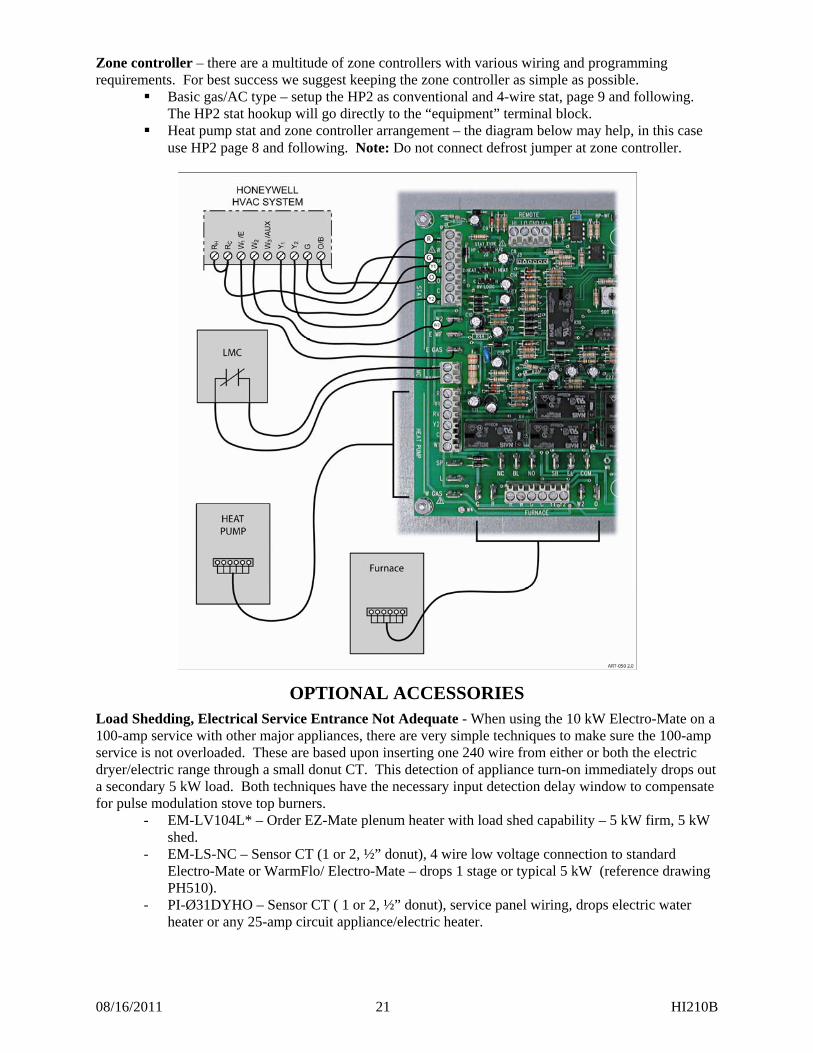
Zone controller – there are a multitude of zone controllers with various wiring and programming requirements. For best success we suggest keeping the zone controller as simple as possible.
Basic gas/AC type – setup the HP2 as conventional and 4-wire stat, page 9 and following. The HP2 stat hookup will go directly to the “equipment” terminal block.
Heat pump stat and zone controller arrangement – the diagram below may help, in this case use HP2 page 8 and following. Note: Do not connect defrost jumper at zone controller.
OPTIONAL ACCESSORIES
Load Shedding, Electrical Service Entrance Not Adequate - When using the 10 kW Electro-Mate on a 100-amp service with other major appliances, there are very simple techniques to make sure the 100-amp service is not overloaded. These are based upon inserting one 240 wire from either or both the electric dryer/electric range through a small donut CT. This detection of appliance turn-on immediately drops out a secondary 5 kW load. Both techniques have the necessary input detection delay window to compensate for pulse modulation stove top burners.
- EM-LV104L* – Order EZ-Mate plenum heater with load shed capability – 5 kW firm, 5 kW shed.
- EM-LS-NC – Sensor CT (1 or 2, ½” donut), 4 wire low voltage connection to standard Electro-Mate or WarmFlo/ Electro-Mate – drops 1 stage or typical 5 kW (reference drawing PH510).
- PI-Ø31DYHO – Sensor CT ( 1 or 2, ½” donut), service panel wiring, drops electric water heater or any 25-amp circuit appliance/electric heater.
08/16/2011 22 HI210B
TROUBLESHOOTING
Comment: Also see the “WarmFlo Information” document (HD320) included with this manual.
EL Mode LED Pulsing – an error in thermostat type, thermostat hookup, or peg setup jumpers has been detected. Recheck pages 7, 8, 10, and 11.
Typical examples causing EL mode LED pulsing condition (lock-up): Stat type peg jumper in HP position
o Stat W has a wire connected and is at 24 volts o In cooling either the stat W or E-WF or E-GAS somehow got activated o During defrost, heat pump energizes reversing valve O terminal before W1 to WF-HP2.
WF-HP2 will see a cooling call then defrost which “confuses” the WF-HP2 and causes lockout. See page 7 or request Field Service Bulletin 1100 for further details.
Stat type peg jumper in H/C position o Peg jumper must be in 1HEAT (2HEAT not allowed for this arrangement) o Stat W and Y1 inputs are high or energized the same time. There must be at least a
5-second delay where both W and Y1 are at 0 volts during thermostat switchover. This may or may not be a problem with certain automatic switchover thermostats.
Sensor Temperature Calibration - Both remote sensors are digital electronic and factory calibrated. Normally these do not require field calibration or verification. However, if sensor temperature error is determined, there are two field calibration techniques. Proceed with extreme caution.
1. The outdoor sensor can be calibrated with ice (32F). Notice a small push button next to the sensor terminal block, with the sensor at 32°F, push and hold for approximately ten seconds. When green LED “blinks” at you, release and now the outdoor sensor is set at 32°F.
Caution: This is not a temperature checking situation. If you proceed with this function, the sensor automatically goes to 32°F.
2. Use WarmFlo Analyzer test set or purchase special PC software disc and PC serial port cable. These plug-in devices allow direct readout of both temperatures, allows a visual determination of WarmFlo internal temperature settings, and can be used to offset either temperature sensor for troubleshooting and demonstration purposes. This is especially valuable during summer installation. Call factory and order test set device.
Outdoor Sensor (OT) Location – direct sunlight has a definite affect on sensor temperature reading. The sensor white tube must be “shadowed” from direct sun rays.
Troubleshooting/Repair Helps 1. This WarmFlo controller contains several interference suppression components, but as an electronic
logic product, unpredictable and unusual transients or interferences may sometimes cause strange results. If the WarmFlo controller is “acting strange”, one immediate step would be power down reset. Simply turn off the 24-volt source power (probably furnace or air handler circuit breaker), when the green LED goes out, count to 10, and re-energize power supply.
2. The terminal blocks for control wire hook-up are designed for a wire insertion and screw clamp down. If there is no wire connected and the screw is loose, the screw may not necessarily make a good electrical contact to the inside components. Example – if you are jumpering the thermostat terminals without thermostat wire connection or if you are attempting to measure voltage on the screw head, you may get erroneous or unpredictable results if the screw is not tightened down.
3. Use general heating system logic information and basic understanding of the terminal block wiring functions when measuring voltage to determine proper operation of this module.
4. The outdoor sensor must be located outdoors for this controller to correctly operate. Do not leave the outdoor sensor “hang in conditioned space” and attempt to run this system.
08/16/2011 23 HI210B
5. Acquiring the WarmFlo Analyzer test set or the PC software and serial port hook-up cable (see previous page) is a positive tool for understanding and troubleshooting the WarmFlo controller. Either test set device can display all temperatures, real time evaluation of WarmFlo functions, provide temperature offsets for assimilating winter conditions, and reprogram the control chip (program stays with the actual controller board).
Bad sensor, safety – if the internal logic detects open sensor wire, incorrectly wired sensor, or some bad sensor transmitted value conditions; the green LED reverts to a pulsing mode. Basically the appropriate sensor is set internally to a 0° value and there will be an attempt to cause the electric heat output to go “DT flat”.
- OT sensor – approximately 1/10 second blip every ½ second - ST sensor – two, 1/10 second blips every ½ second - Both bad – ½ second on and ½ second off, alternating
Analyzer readout, sensor temperature constant 32° or 0° – these two values represent digital bit patterns that are hard to predict an error function. A blinking green light may or may not be experienced. Typically the cable is too long, wrong type of sensor wire, or some electrical interference on the sensor cable. WarmFlo Furnace Interface Internal Fuse – the internal fuse is between the fan center “R” and all other WarmFlo functions, including the “R” going to the outdoor unit. Use only two amp, fast blow. WarmFlo Controller Fuse – the WarmFlo board itself does not contain a traditional fuse. At the “R” input terminal is a automatic reset, short current protection device. If there has been a short circuit condition, and the green LED is off, at least 2 to 3 minutes “cool off time” is required for this “fuse” to reset.
OPERATIONAL INFORMATION
In order for the installer to completely understand the WF unit functions and operational sequence it is recommended to thoroughly read and understand the information below. This knowledge can help in determining settings that can be set according to the end customers needs. Normal Heating Operation – Whenever the WarmFlo receives a heat demand, the WarmFlo controller begins turning on the Electro-Mate elements (assume outdoor temperature is below disable value) and automatically controls the warm air temperature as sampled by the warm air sensor (ST). However, if added heat is not required, no element power is used.
Depending upon Electro-Mate model, the heating section may have one, two, three, or four stages. Stage one is pulse modulated (approximate 10-second cycle) based upon the WarmFlo controller automatic requirement. Stages 2, 3, and 4 are turned on and off with a relay. However, Stage 2 is only used when needed by the WarmFlo supply air temperature calculations. When the warm air sensor is calling for more than the heat pump and Stage 1 100% output, Stage 2 turns on. Stage 1 may not necessarily remain at 100%, but is modulated downward to meet the requirements of the warm air sensor. Also on the next call for heat, the WarmFlo controller remembers what stages were on and starts at that point. A clamp-on amp meter at the service input can be used to “visualize” the Stage 1 modulation and/or Stages 2, 3, and 4 functions.
Efficiency* – the characteristic of a heat pump dual heat system is the heat pump’s ability to deliver warm air at efficiencies greater than 100%. Gas and oil systems are always less than 100% (60% through 90%), resistance electric (Electro-Mate) is always exactly 100%, but the heat pump is always at least 100% (-20°F) or greater, up to about 200% for air source.
The user needs to realize it is to his advantage to run the heat pump either continuously or at the longest possible thermostat call cycles. This is contrary to the basic understanding of most users. However, realizing again the heat pump is a device that delivers greater than 100%, this system can only deliver
08/16/2011 24 HI210B
greater than 100% if it’s running, let it run. Because of WarmFlo’s design concept and its internal “brain” the heat loss curve (diagonal lines, above) allows the compressor to operate with a minimal amount of electric resistance supplement or temperature boost.
Where should I set the efficiency dial? – As you can visualize from the curves above, the lower the setting, the flatter the curve, the less electric resistance is added to the heat pump compressor warm air. Therefore, the efficiency knob setting is based upon comfort and efficiency. The lower the setting the higher the overall operating annual efficiency, the higher the setting the warmer the air at the register.
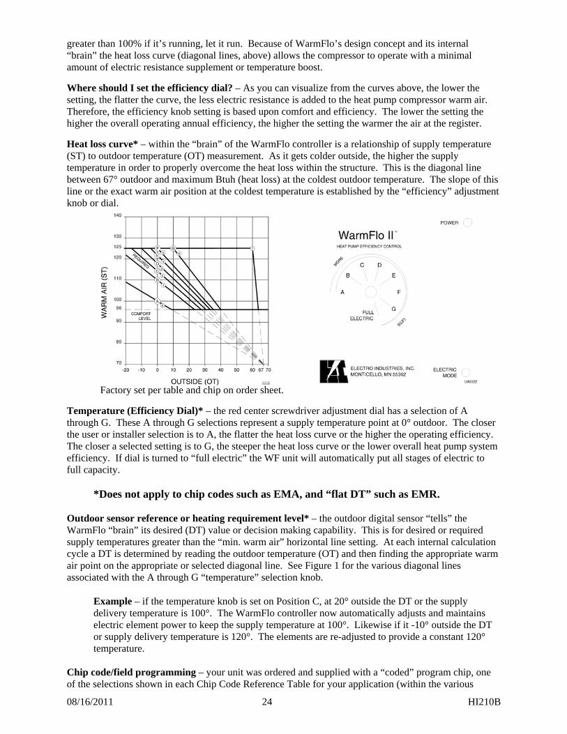
Heat loss curve* – within the “brain” of the WarmFlo controller is a relationship of supply temperature (ST) to outdoor temperature (OT) measurement. As it gets colder outside, the higher the supply temperature in order to properly overcome the heat loss within the structure. This is the diagonal line between 67° outdoor and maximum Btuh (heat loss) at the coldest outdoor temperature. The slope of this line or the exact warm air position at the coldest temperature is established by the “efficiency” adjustment knob or dial.
Factory set per table and chip on order sheet.
Temperature (Efficiency Dial)* – the red center screwdriver adjustment dial has a selection of A through G. These A through G selections represent a supply temperature point at 0° outdoor. The closer the user or installer selection is to A, the flatter the heat loss curve or the higher the operating efficiency. The closer a selected setting is to G, the steeper the heat loss curve or the lower overall heat pump system efficiency. If dial is turned to “full electric” the WF unit will automatically put all stages of electric to full capacity.
*Does not apply to chip codes such as EMA, and “flat DT” such as EMR. Outdoor sensor reference or heating requirement level* – the outdoor digital sensor “tells” the WarmFlo “brain” its desired (DT) value or decision making capability. This is for desired or required supply temperatures greater than the “min. warm air” horizontal line setting. At each internal calculation cycle a DT is determined by reading the outdoor temperature (OT) and then finding the appropriate warm air point on the appropriate or selected diagonal line. See Figure 1 for the various diagonal lines associated with the A through G “temperature” selection knob.
Example – if the temperature knob is set on Position C, at 20° outside the DT or the supply delivery temperature is 100°. The WarmFlo controller now automatically adjusts and maintains electric element power to keep the supply temperature at 100°. Likewise if it -10° outside the DT or supply delivery temperature is 120°. The elements are re-adjusted to provide a constant 120° temperature.
Chip code/field programming – your unit was ordered and supplied with a “coded” program chip, one of the selections shown in each Chip Code Reference Table for your application (within the various
08/16/2011 25 HI210B
colored page sections). These tables show the various defaults associated with that particular code. With WarmFlo a number of field re-programming possibilities and options exist using either PC software or WarmFlo analyzer, reference “WarmFlo Handheld Analyzer/Laptop Software” section. Chip code is located on the WarmFlo controller board white label.
Note: There are certain things such as SOT’s, MU time, etc. which are only field programmable. If the item is not shown in the chip code table, that feature or item is default set as disable.
Delay, transfer from standby to electric – if the unit was operating in SB for more than 1 minute, the follow-up transfer back to electric engages a 4-minute delay before the HP compressor relay is activated and any of the electric stages are activated. The blower will react to the call for heat, but the elements will stay off for 4 minutes in order for the blower to cool down the furnace heat exchanger. SB (Gas) 5-Minute Safety – when in the standby mode (see previous section) there is now a 5-minute timer which begins at each heat call. If after the 5 minutes the ST sensor is less than 85°, the logic board itself goes into an automatic reset and restart. This simply means it attempts to begin the heat cycle using electric in case the furnace did not ignite or “out of gas”. However, if it is in the SB mode because of Load Control it will still remain SB and try the gas furnace again. The system will never go back to electric if you have a Load Control on-peak or A1 tab high. Note: Handheld can disable (must have latest firmware chips).
10/23/2006 1 HH210
HP Stat – Hookup Connection – WF-HP2 I/F Module
Carrier 7
Bryant 7 Rudd 4 Trane (Am. Std.)
WF-HP2 Stat 5 Thermidistat
HP 2-speed
Gas 170
Stat 5 Thermidistat
HP 698B
Gas 315A 355M
Stat
HP
Gas
Stat
HP 2 stage
Gas variable
Stat R R R R R W - - - - G G G G G
Y1 Y1 Y1 Y1 Y1 O O O B4 O C C C C B
Y2 Y/Y2 Y/Y2 Y2 Y2 W2 1 1 V -
E WF 2 2 2 - E GAS 3 3 3 X2
HP R R R R R Y Y1 Y1 Y1 Y1
RV O O B O Y2 Y2 Y2 Y2 Y2 C C C C B
W1 W2 W1 W1 X2 SP - - - L - - -
W GAS - - -
Furnace R R R 24V R W W/W1 W/W1 W W1 G G G G G C COM COM 24C B
W2 1 1 V 1 Y1 Y1 - Y1 - Y2 Y/Y2 Y Y2 Y O - - - 8
10/23/2006 2 HH210
HP Stat – Hookup Connection – WF-HP2 I/F Module (continued)
York York Frigidaire Lennox WF-HP2 Stat
T8511M HP
Twin Single Gas
? Stat
T8511M YZE Gas ?
Stat T8424D
HP FT4 - -
Gas FG6T
Stat 51M28
HP A19
Gas G61MPV
Stat R R R R R W - - - - G G G G G
Y1 Y1 Y1 Y Y1 O O O O O C C & X1 C & X1 C C
Y2 Y2 Y2 Y2 Y2 W2 - - 1 W2
E WF 2 2 - - E GAS E E -
HP R R R R R Y Y Y1 Y Y1
RV O O O O Y2 Y2 Y2 Y2 Y2 C C C C C
W1 W1 W1 OUT W2 W1 SP Y2 OUT Y2 OUT - - L L X/L -
W GAS - - - W – N/C W & W2 – N/C
Furnace R R R R R W W1 W1/W W W1 G G G G G C C C C C
W2 - - 1 W2 Y1 Y1 Y1 Y (yel) Y1 Y2 Y Y2/Y Blue Y2 O O O - Y2 – N/C
10/23/2006 3 HH210
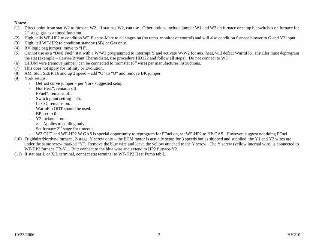
Notes: (1) Direct point from stat W2 to furnace W2. If stat has W2, can use. Other options include jumper W1 and W2 on furnace or setup bit switches on furnace for
2nd stage gas as a timed function. (2) High, tells WF-HP2 to condition WF Electro-Mate to all stages on (no temp. monitor or control) and will also condition furnace blower to G and Y2 input. (3) High, tell WF-HP2 to condition standby (SB) or Gas only. (4) RV logic peg jumper, move to “H”. (5) Cannot use as a “Dual Fuel” stat with a W/W2 programmed to interrupt Y and activate W/W2 for aux. heat, will defeat WarmFlo. Installer must deprogram
the stat (example – Carrier/Bryant Thermidistat, use procedure HD322 and follow all steps). Do not connect to W3. (6) DHUM wire (remove jumper) can be connected to roomstat (6th wire) per manufacturer instructions. (7) This does not apply for Infinity or Evolution. (8) AM. Std., SEER 16 and up 2 speed – add “O” to “O” and remove BK jumper. (9) York setups:
- Defrost curve jumper – per York suggested setup. - Hot Heat*, remains off. - FFuel*, remains off. - Switch point setting – 35. - LTCO, remains on. - WarmFlo ODT should be used. - BP, set to 0. - Y2 lockout – on.
o Applies to cooling only. - Set furnace 2nd stage for timeout. - W2 OUT and WF-HP2 W GAS is special opportunity to reprogram for FFuel on, set WF-HP2 to HP-GAS. However, suggest not doing FFuel.
(10) Frigidaire/Nordyne furnace, 2-stage, Y screw only – the ECM motor is actually setup for 3 speeds but as shipped and supplied, the Y1 and Y2 wires are under the same screw marked “Y”. Remove the blue wire and leave the yellow attached to the Y screw. The Y screw (yellow internal wire) is connected to WF-HP2 furnace TB-Y1. Butt connect to the blue wire and extend to HP2 furnace-Y2.
(11) If stat has L or X/L terminal, connect stat terminal to WF-HP2 Heat Pump tab L.
10/23/2006 4 HH210
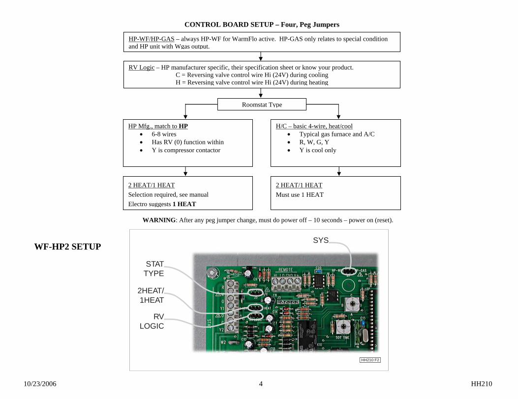
HP-WF/HP-GAS – always HP-WF for WarmFlo active. HP-GAS only relates to special condition and HP unit with Wgas output.
Roomstat Type
H/C – basic 4-wire, heat/cool • Typical gas furnace and A/C • R, W, G, Y • Y is cool only
HP Mfg., match to HP • 6-8 wires • Has RV (0) function within • Y is compressor contactor
2 HEAT/1 HEAT Must use 1 HEAT
2 HEAT/1 HEAT Selection required, see manual Electro suggests 1 HEAT
WARNING: After any peg jumper change, must do power off – 10 seconds – power on (reset).
RV Logic – HP manufacturer specific, their specification sheet or know your product. C = Reversing valve control wire Hi (24V) during cooling H = Reversing valve control wire Hi (24V) during heating
CONTROL BOARD SETUP – Four, Peg Jumpers
SYS
2HEAT/1HEAT
STATTYPE
RVLOGIC
HH210 F2
WF-HP2 SETUP
10/23/2006 5 HH210
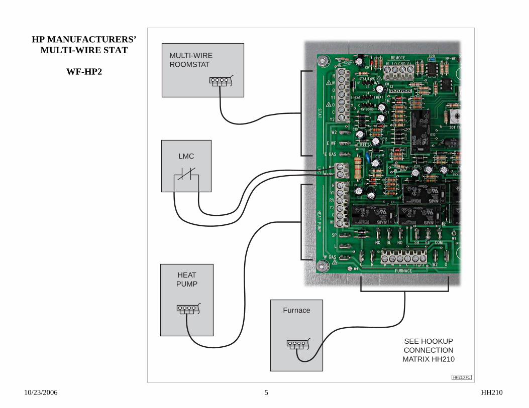
HP MANUFACTURERS’ MULTI-WIRE STAT
WF-HP2
Furnace
HH210 F1
HEATPUMP
LMC
MULTI-WIREROOMSTAT
SEE HOOKUPCONNECTIONMATRIX HH210
10/23/2006 1 HH211B
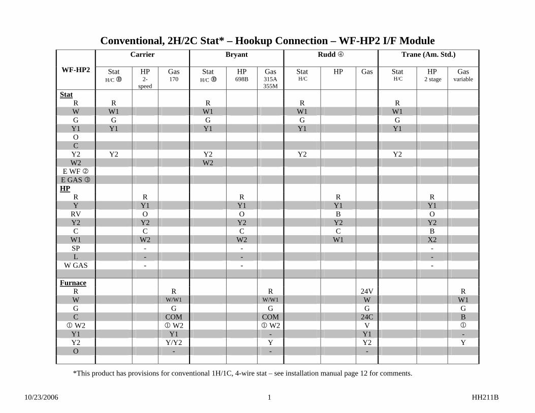
Conventional, 2H/2C Stat* – Hookup Connection – WF-HP2 I/F Module
Carrier
Bryant Rudd 4 Trane (Am. Std.)
WF-HP2 Stat H/C
HP 2-
speed
Gas 170
Stat H/C
HP 698B
Gas 315A 355M
Stat H/C
HP
Gas
Stat H/C
HP 2 stage
Gas variable
Stat R R R R R W W1 W1 W1 W1 G G G G G
Y1 Y1 Y1 Y1 Y1 O C
Y2 Y2 Y2 Y2 Y2 W2 W2
E WF E GAS HP
R R R R R Y Y1 Y1 Y1 Y1
RV O O B O Y2 Y2 Y2 Y2 Y2 C C C C B
W1 W2 W2 W1 X2 SP - - - L - - -
W GAS - - -
Furnace R R R 24V R W W/W1 W/W1 W W1 G G G G G C COM COM 24C B
1 W2 1 W2 1 W2 V 1 Y1 Y1 - Y1 - Y2 Y/Y2 Y Y2 Y O - - -
*This product has provisions for conventional 1H/1C, 4-wire stat – see installation manual page 12 for comments.
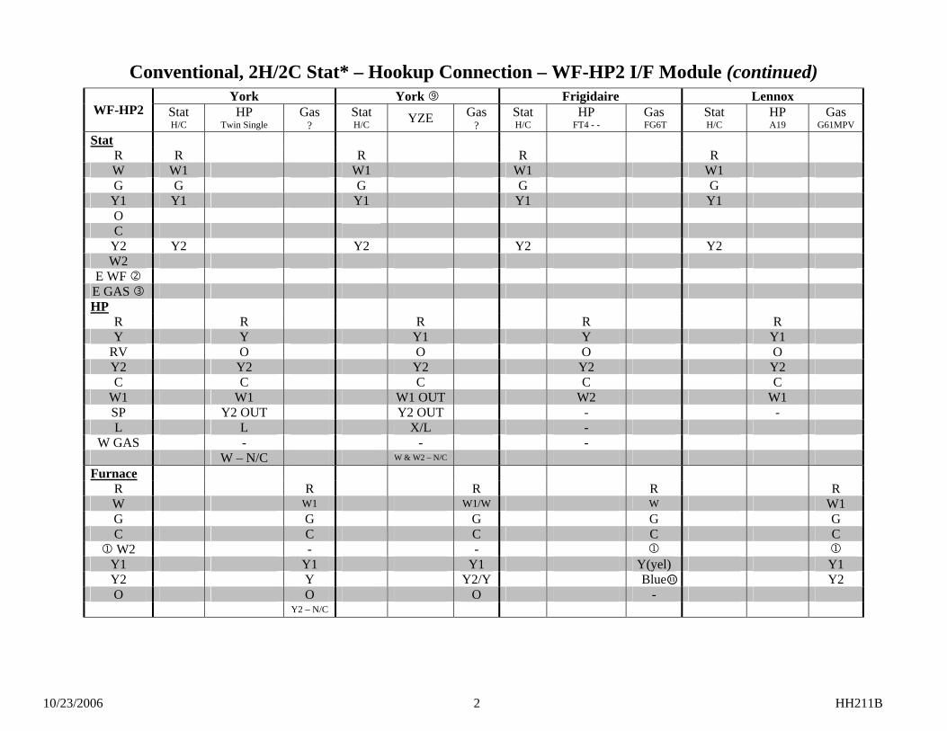
10/23/2006 2 HH211B
Conventional, 2H/2C Stat* – Hookup Connection – WF-HP2 I/F Module (continued)
York York Frigidaire Lennox WF-HP2 Stat
H/C HP
Twin Single Gas
? Stat H/C YZE Gas
? Stat H/C
HP FT4 - -
Gas FG6T
Stat H/C
HP A19
Gas G61MPV
Stat R R R R R W W1 W1 W1 W1 G G G G G
Y1 Y1 Y1 Y1 Y1 O C
Y2 Y2 Y2 Y2 Y2 W2
E WF E GAS HP
R R R R R Y Y Y1 Y Y1
RV O O O O Y2 Y2 Y2 Y2 Y2 C C C C C
W1 W1 W1 OUT W2 W1 SP Y2 OUT Y2 OUT - - L L X/L -
W GAS - - - W – N/C W & W2 – N/C
Furnace R R R R R W W1 W1/W W W1 G G G G G C C C C C
1 W2 - - 1 1 Y1 Y1 Y1 Y(yel) Y1 Y2 Y Y2/Y Blue Y2 O O O - Y2 – N/C
11
10/23/2006 3 HH211B
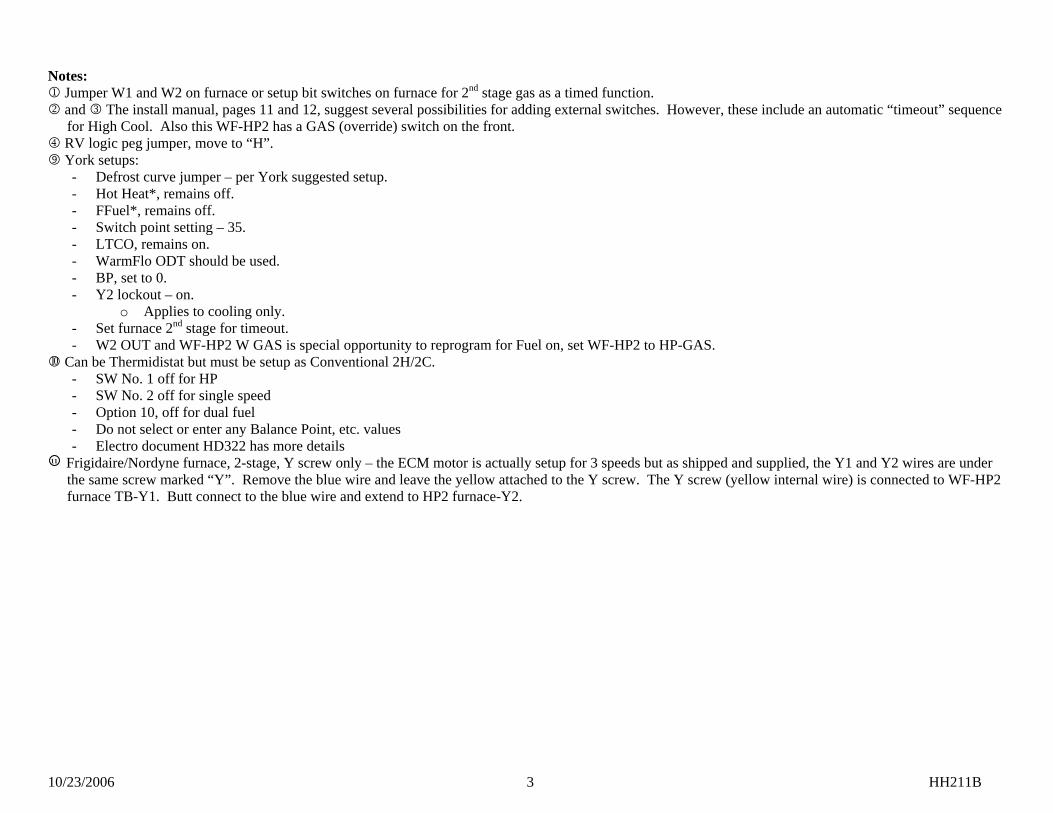
Notes: 1 Jumper W1 and W2 on furnace or setup bit switches on furnace for 2nd stage gas as a timed function. 2 and 3 The install manual, pages 11 and 12, suggest several possibilities for adding external switches. However, these include an automatic “timeout” sequence
for High Cool. Also this WF-HP2 has a GAS (override) switch on the front. 4 RV logic peg jumper, move to “H”.
York setups: - Defrost curve jumper – per York suggested setup. - Hot Heat*, remains off. - FFuel*, remains off. - Switch point setting – 35. - LTCO, remains on. - WarmFlo ODT should be used. - BP, set to 0. - Y2 lockout – on.
o Applies to cooling only. - Set furnace 2nd stage for timeout. - W2 OUT and WF-HP2 W GAS is special opportunity to reprogram for Fuel on, set WF-HP2 to HP-GAS.
Can be Thermidistat but must be setup as Conventional 2H/2C. - SW No. 1 off for HP - SW No. 2 off for single speed - Option 10, off for dual fuel - Do not select or enter any Balance Point, etc. values - Electro document HD322 has more details
Frigidaire/Nordyne furnace, 2-stage, Y screw only – the ECM motor is actually setup for 3 speeds but as shipped and supplied, the Y1 and Y2 wires are under the same screw marked “Y”. Remove the blue wire and leave the yellow attached to the Y screw. The Y screw (yellow internal wire) is connected to WF-HP2 furnace TB-Y1. Butt connect to the blue wire and extend to HP2 furnace-Y2.
11
10/23/2006 4 HH211B
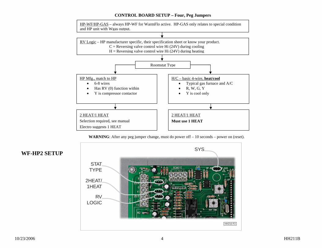
HP-WF/HP-GAS – always HP-WF for WarmFlo active. HP-GAS only relates to special condition and HP unit with Wgas output.
Roomstat Type
H/C – basic 4-wire, heat/cool • Typical gas furnace and A/C • R, W, G, Y • Y is cool only
HP Mfg., match to HP • 6-8 wires • Has RV (0) function within • Y is compressor contactor
2 HEAT/1 HEAT Must use 1 HEAT
2 HEAT/1 HEAT Selection required, see manual Electro suggests 1 HEAT
WARNING: After any peg jumper change, must do power off – 10 seconds – power on (reset).
RV Logic – HP manufacturer specific, their specification sheet or know your product. C = Reversing valve control wire Hi (24V) during cooling H = Reversing valve control wire Hi (24V) during heating
CONTROL BOARD SETUP – Four, Peg Jumpers
SYS
2HEAT/1HEAT
STATTYPE
RVLOGIC
HH210 F2
WF-HP2 SETUP
10/23/2006 5 HH211B
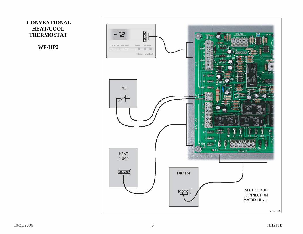
CONVENTIONAL HEAT/COOL
THERMOSTAT
WF-HP2
11/05/2008 1 HD320
EElleeccttrroo--HHEELLPPSS IIVV
WarmFlo Terminology, Key Terms ST – supply temperature sensor. This is the warm air or duct sensor (boiler – supply outlet water). OT – outdoor temperature sensor. Provides the WarmFlo board with outdoor temperature information. DT – desired temperature to overcome building heat loss, the diagonal line on heat loss curve. The front panel efficiency knob selects one of 8 curves to determine DT at specific real time OT. DT Flat – this is an internal reference point, as WarmFlo establishes this mode it in essence sets the operating point at 125° F. (Analyzer or software may have any value from 123 to 125). Electric element modulation and staging are still in effect. The staging will be based upon the ST sensor detecting and operating around the 125° point.
Note: All four stages do not automatically go to full on. HL – actually this is the same as “DT Flat”. This perceived hi-limit temperature value (130°) within the control logic, measured by the ST. This is over and above the 155° probe or 170° mechanical hi-limits. Full electric (or Full EL) – this setting causes the modulation and staging to operate at “DT Flat”. When first selected or turned on, the WarmFlo logic may first go through a process of building up to the “DT Flat” value. Do not expect the outlet temperature to immediately jump up to this highest value. However, on consecutive thermostat calls it will immediately step to the “DT Flat” temperature value.
Note: This is essentially the same as DT Flat and again all four stages do not automatically go to full on.
Staging Disable Temperature – in all OT active sensor applications (DT cal) there is a setup program temperature to "hold off" each stage for warmer heating conditions. In other words, the OT sensor must be reporting a temperature below these values before the stage is allowed to come on. In WarmFlo Analyzer or PC software terminology this is called – STG1 DIS, etc. The stage-up situation relating to all of the above "DT Flat" operation is controlled by these stage enable temperature set points. This statement must be carefully related to all of the above.
- In other words, if the OT is reading 42° and the front panel is set to "full electric" the ST is looking to operate at 125°, but only stage 1 will be on.
If for heat pump applications Stg 1 is set at 50°, there will be no electric element or standby furnace above 50° OT.
Note: For HP roomstat multi-wire thermostat application, the OT temp. set point must be below normal desired cooling.
E tab (board top center) – in most WarmFlo products and TS Series boiler products there is a troubleshooting tab marked "E". When applying 24-volt (or jumpered to "W" tab) this input function immediately forces all four stages on and bypasses all temperature sensing or element modulation sequences. If used verify blower also functions properly.
11/05/2008 2 HD320
- New 2008 – version 2.38, 10.03, 12.04, 15.03, etc. – once activated, it remains for the completion of the heat call. Thus it only needs to be a temporary jumper (5 seconds or more) to step on all stages. User needs to remember to cycle the roomstat to cancel this E tab function.
- A potential convenience or secondary usage for this upgraded E tab function is to provide an easy manual means for rapidly bringing up the building or room temperature if the system has been set for non-occupancy. By installing a pushbutton between W and E tab, the homeowner can easily activate all stages on to the end of the thermostat cycle. Warning: This is all stages on, no temperature monitor. This should only be used in this manner when it is a very cold building from non-occupancy, the outdoor temperature is quite low with low temperature rise coming from the heat pump.
Stat override timer (SOT) – this is an option WarmFlo internal timer which can be programmed with WF analyzer to select a roomstat run time. If this downloaded run time (typically 90 minutes) is exceeded before the thermostat is satisfied, the system automatically switches to either full electric elements or standby.
- SOT S – this is the longer set timer which allows transfer to standby if something might have happened to the electric system.
- SOT E – this must be shorter time, is typically used to overcome morning setback pickup issues. In other words, if you would field download 30 minutes and you program the setback stat to begin bringing up the temperature 30 minutes prior to the wakeup time; and the system is not at the new higher temperature at the 30-minute point it will automatically jump to DT Flat in order to more rapidly raise the building temperature. However, this also means you will be “short cycling” the HP compressor during other heat calls. The maximum run time for the compressor is then about 30 minutes at any time of the day or at any particular heat call.
Note: Beginning approximately 7-04 the SOT S has been factory default at 90 minutes for all dual heat chip codes.
MU – this is an internal timeout function which begins when all stages are on at 100%. Anytime the electric section is operating with all stages on at 100% for a continuous operating time greater than the programmed MU (3 initial minutes), the system automatically switches to standby. MU = 00 is a disable setting. The amber LED on the main WarmFlo board will correctly follow electric or standby. On the Interface module (EZ3, etc.) the “gas call” LED also will be on, but the “utility off-peak” LED remains on. Electro-Mate or strip heat undersizing – there are provisions within WarmFlo and within Electro’s various heating products to add partial resistance heating section to heat pumps. To provide optimum operation and comfort, the setup functions need to be activated accordingly. Default program code chip “HPDF” has been designed for this application. As a field setup, you probably want MU to be relatively short (30 minutes), the ODT mode will be “EL to SB” with an ODT dial switch temperature selection at about the combination heat pump and Electro-Mate output energy (probably 0°) or position #3. Electro-Mate only, no heat pump – there are two default chip codes, EMW or EMA.
- EMW – all normal WarmFlo functions and modulation, front dial, etc. - Must be auto standby, no wood furnace.
- EMA – does not use an OT sensor, at each thermostat call outlet temperature goes to a preset value (commonly called electronic aquastat). This value is the “min. warm air” adjustment (inside main board).
- The decal table shows the outlet temperature at the various “temperature” settings.
- The plug-in Analyzer OT Function must be “disable” (no OT sensor).
11/05/2008 3 HD320
Note: With an Electro-Mate it is assumed there is always standby or gas furnace. For non-automatic or wood, suggest using EMA and select the desired outlet temperature.
ODT dial switch mode – within the program chip default and Analyzer/software programming this function defines the use of the dial switch on the circuit board labeled “ODT”. The dial switch selects the temperature, the setup function selects what the temperature does.
- EL to SB – interrupts all electric elements and the heat pump - HP – interrupts only the outdoor compressor unit, electric energy continues without
an OT temperature shut down reference Note: "0" position does not disable outdoor sensor. This only disables the built-in heat pump ODT function. With the dial switch "0" position the heat pump becomes a direct function of the room thermostat and/or standby mode.
Standby (SB) – the WarmFlo control system has transferred the thermostat or heat active function to the standby furnace via the appropriate Furnace Interface module (WF-EZ3, etc.). These actions cause SB.
- SOT-S timeout – thermostat continuous run time. - MU timeout. - ODT dial switch value – EL to SB mode. - A1 tab at 24 volts – any switching device which raises A1 tab to 24VAC.
In addition the Furnace Interface module (EZ3, EM3, etc.) sends a signal via J2-4 (blue, high DC)
- Load Control interrupt (open blues) - Front panel switch - Added remote switch, “SB” tab to common
Note: Electro-Helps V has additional troubleshooting conditions that will help evaluate standby.
SB (Gas) 5-Minute Safety – when in the standby mode (see previous section) there is a 5-minute timer which begins at each heat call. If after the 5 minutes the ST sensor is less than 80°, the logic board itself goes into an automatic reset and restart. This simply means it attempts to begin the heat cycle using electric in case the furnace did not ignite or “out of gas”. However, if it is in the SB mode because of Load Control it will still remain SB and try the gas furnace again. The system will never go back to electric if Load Control is set for on-peak or A1 tab high.
- Typically this is disabled for boiler control applications. - Analyzer or PC software can disable this function. - As an added non-freeze safety feature, the program counts these 5-minute resets. If
the count reaches 40 (200 minutes) and each time the ST is still less than 80°, the system will revert back to electric to bring up the temperature of the building, one thermostat cycle only.
Delay, transfer from electric to standby – because there are a multitude of gas furnaces which turn off the blower during their internal heat exchanger warm-up, there is a 1-minute delay before the gas furnace receives the W input. During this 1-minute the gas furnace G function remains high allowing the blower to purge out the heat on the Electro-Mate elements. After the 1-minute the G function drops and the gas furnace W function goes high. Delay, transfer from standby to electric – if the unit was operating in SB for more than 1 minute, the follow-up transfer back to electric engages a 2-minute delay before the HP compressor relay is activated and any of the electric stages are activated. The blower will react to the call for heat, but the elements will stay off for 2 minutes in order for the blower to cool down the furnace heat exchanger. In addition the WarmFlo logic stages up from stage 1 through the various temperature/delay staging sequences.
11/05/2008 4 HD320
Blower operation – the air handler or fossil fuel furnace blower is operated from its own fan center (G screw). The activation of this “G” input is either directly from a heat pump (total electric system) roomstat “G” screw or in the case of dual heat from the Furnace Interface module (WF-EZ3, LGR4, EM3, etc.). The Interface module and its wiring or association with the room thermostat completely controls the blower. There is nothing on or within the WarmFlo control board itself which has anything to do with the blower function.
- Delay on/delay off – within all Interface modules there is an approximate 10 to 15 second blower on delay and a 1-minute blower off delay. In the case of a heat pump stat, this can be bypassed by taking the stat “G” screw directly to the interface module tab “G1” (multi-wire stat only).
- Multi-speed blower – newer furnaces having multi-speed blower functions can be stepped up to the proper high speed with an appropriate (special relay contact) jumper between the furnace fan center “G” and “Y”. See the installation manual sketch and paragraph for adding the necessary wiring jumpers associated with the Interface module special terminals (BL, NO, NC). Also Electro-Helps VIII provides details on all the various wiring arrangements for ECM variable speed blower.
- Using E tab with HP stat emergency output – see previous “E-tab” section for blower operation caution.
Bad sensor, safety – if the internal logic detects open sensor wire, incorrectly wired sensor, or some bad sensor transmitted value conditions; the green LED reverts to a pulsing mode. Basically the appropriate sensor is set internally to a default value and there will be an attempt to cause the electric heat output to go “DT Flat”.
- OT sensor – approximately 1/10 second blip every ½ second - ST sensor – two, 1/10 second blips every ½ second - Both bad – ½ second on and ½ second off, alternating
Bad sensor default heating – when above condition is detected electric unit has limited staging output. WarmFlo Analyzer or Software Bad Sensor Indicators
255 or NA - OT function is disabled, EMA/EBA type operation 254 or BAD - controller cannot read a value from the temperature sensor 31° (assuming it is not 31°) - new software (2.3* and up chip) with previous sensor,
"D" ring (DS2434) 0° (assuming it is not 0° F) - previous software (2.2* chip) with new sensor, "E" ring
(DS18B20), green LED should also blink Cal. pushbutton, on board upper right – function is unchanged, holding for 10 seconds forces the OT sensor to 32° value. Power-Down Reset – there are some data entry or setup modes which require power-down reset - WF+ board configuration selection, cancelling pulsing bad sensor green LED, etc. If in doubt do a complete 24-volt system power-down reset after WarmFlo Analyzer save operations. Reset always verifies the proper handling of a software modification.
11/05/2008 5 HD320
HANDHELD ANALYZER/LAPTOP SOFTWARE PC software (ET-SOFT-WF) or Handheld (WF-ANZ*) – now has provisions for the following setup or reprogramming functions. Caution – do not attempt to reprogram a forced air (Electro-Mate) chip for boiler application.
- Select proper product application – dial switch on the back - MU time, or disable - SB RESET – disable/enable - SOT S time, or disable – switches to standby - SOT E time, or disable – all stages on - Stage disable temperature – 1, 2, 3, 4 - OT sensor function
· DT cal. · Flat DT or HL (suggest not using) · Disable
- ODT dial switch mode · EL to SB – interrupt all electric energy (Electro-Mate and HP) · HP – Outdoor compressor interrupt only
- OT SPD A/B and ST SPD A/B – special temperature sensing speed settings, relates only to variable speed motor interface arrangements (WF-ANZ5 and up)
- WF-ANZ7 adds a EB-WO or EB-MO function for establishing the baseline or beginning point for modulation temperature ramp-on
Warning, field reprogramming – within WarmFlo II internal logic and non-volatile memory, it can detect whether it is operating from a pre-programmed chip (see table, following pages) or if it has been modified (reprogrammed) with PC software or Handheld. Once the user or field technician has downloaded (save), the WarmFlo II physical control board is no longer governed by the chip code written on the plug-in chip, etc. In other words, power up/power down or reset does not affect any altered reprogrammed functions. It is smart enough to know it is no longer the original chip and that specific physical board, from this time forward, must be under the control of the PC software/Handheld. However, a new totally different coded chip with the same or different revision date will automatically wipe out any of the previous setups and can restart the same physical board based on the defaults within this newly added or different coded chip. After power-up reset the internal program reads the chip code and the version number. If either changes it begins new with the defaults and revision code of the specific replaced chip.
OPERATIONAL INFORMATION
In order for the installer to completely understand the WF II functions and operational sequence it is recommended to thoroughly read and understand the information below. This knowledge can help in determining settings that can be set according to the end customers needs.
Normal Heating Operation – Whenever the WarmFlo II Y tab is at 24 volt (with reference to “C”), the WarmFlo II controller begins turning on the Electro-Mate elements (assume outdoor temperature is below disable value) and automatically controls the warm air temperature as sampled by the warm air sensor (ST). However, if added heat is not required, no element power is used. Depending upon Electro-Mate model, the heating section may have one, two, three, or four stages. Stage one is pulse modulated (approximate 10-second cycle) based upon the WarmFlo II controller automatic requirement. Stages 2, 3, and 4 are turned on and off with a relay. However, Stage 2, etc. is only used when needed by the WarmFlo II supply air temperature calculations.
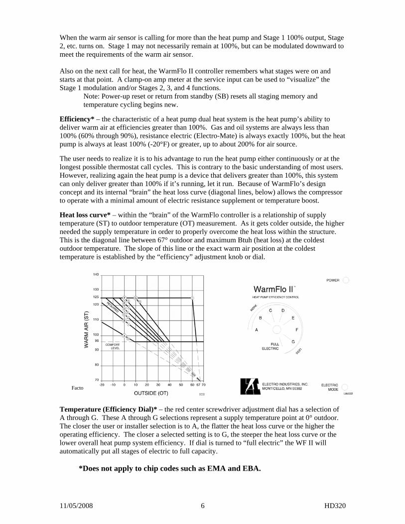
11/05/2008 6 HD320
When the warm air sensor is calling for more than the heat pump and Stage 1 100% output, Stage 2, etc. turns on. Stage 1 may not necessarily remain at 100%, but can be modulated downward to meet the requirements of the warm air sensor. Also on the next call for heat, the WarmFlo II controller remembers what stages were on and starts at that point. A clamp-on amp meter at the service input can be used to “visualize” the Stage 1 modulation and/or Stages 2, 3, and 4 functions.
Note: Power-up reset or return from standby (SB) resets all staging memory and temperature cycling begins new.
Efficiency* – the characteristic of a heat pump dual heat system is the heat pump’s ability to deliver warm air at efficiencies greater than 100%. Gas and oil systems are always less than 100% (60% through 90%), resistance electric (Electro-Mate) is always exactly 100%, but the heat pump is always at least 100% (-20°F) or greater, up to about 200% for air source. The user needs to realize it is to his advantage to run the heat pump either continuously or at the longest possible thermostat call cycles. This is contrary to the basic understanding of most users. However, realizing again the heat pump is a device that delivers greater than 100%, this system can only deliver greater than 100% if it’s running, let it run. Because of WarmFlo’s design concept and its internal “brain” the heat loss curve (diagonal lines, below) allows the compressor to operate with a minimal amount of electric resistance supplement or temperature boost. Heat loss curve* – within the “brain” of the WarmFlo controller is a relationship of supply temperature (ST) to outdoor temperature (OT) measurement. As it gets colder outside, the higher needed the supply temperature in order to properly overcome the heat loss within the structure. This is the diagonal line between 67° outdoor and maximum Btuh (heat loss) at the coldest outdoor temperature. The slope of this line or the exact warm air position at the coldest temperature is established by the “efficiency” adjustment knob or dial.
Factory set per table and chip on order sheet.
Temperature (Efficiency Dial)* – the red center screwdriver adjustment dial has a selection of A through G. These A through G selections represent a supply temperature point at 0° outdoor. The closer the user or installer selection is to A, the flatter the heat loss curve or the higher the operating efficiency. The closer a selected setting is to G, the steeper the heat loss curve or the lower overall heat pump system efficiency. If dial is turned to “full electric” the WF II will automatically put all stages of electric to full capacity.
*Does not apply to chip codes such as EMA and EBA.
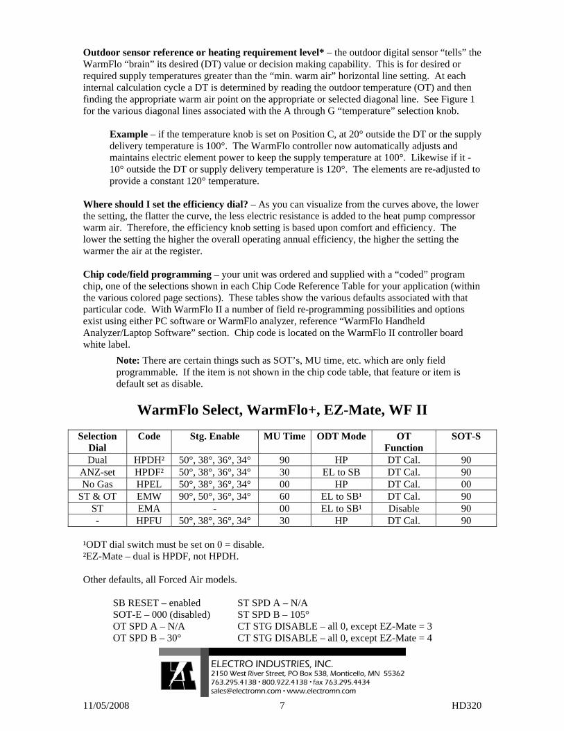
11/05/2008 7 HD320
Outdoor sensor reference or heating requirement level* – the outdoor digital sensor “tells” the WarmFlo “brain” its desired (DT) value or decision making capability. This is for desired or required supply temperatures greater than the “min. warm air” horizontal line setting. At each internal calculation cycle a DT is determined by reading the outdoor temperature (OT) and then finding the appropriate warm air point on the appropriate or selected diagonal line. See Figure 1 for the various diagonal lines associated with the A through G “temperature” selection knob.
Example – if the temperature knob is set on Position C, at 20° outside the DT or the supply delivery temperature is 100°. The WarmFlo controller now automatically adjusts and maintains electric element power to keep the supply temperature at 100°. Likewise if it -10° outside the DT or supply delivery temperature is 120°. The elements are re-adjusted to provide a constant 120° temperature.
Where should I set the efficiency dial? – As you can visualize from the curves above, the lower the setting, the flatter the curve, the less electric resistance is added to the heat pump compressor warm air. Therefore, the efficiency knob setting is based upon comfort and efficiency. The lower the setting the higher the overall operating annual efficiency, the higher the setting the warmer the air at the register. Chip code/field programming – your unit was ordered and supplied with a “coded” program chip, one of the selections shown in each Chip Code Reference Table for your application (within the various colored page sections). These tables show the various defaults associated with that particular code. With WarmFlo II a number of field re-programming possibilities and options exist using either PC software or WarmFlo analyzer, reference “WarmFlo Handheld Analyzer/Laptop Software” section. Chip code is located on the WarmFlo II controller board white label.
Note: There are certain things such as SOT’s, MU time, etc. which are only field programmable. If the item is not shown in the chip code table, that feature or item is default set as disable.
WarmFlo Select, WarmFlo+, EZ-Mate, WF II
Selection
Dial Code Stg. Enable MU Time ODT Mode OT
Function SOT-S
Dual HPDH² 50°, 38°, 36°, 34° 90 HP DT Cal. 90 ANZ-set HPDF² 50°, 38°, 36°, 34° 30 EL to SB DT Cal. 90 No Gas HPEL 50°, 38°, 36°, 34° 00 HP DT Cal. 00
ST & OT EMW 90°, 50°, 36°, 34° 60 EL to SB¹ DT Cal. 90 ST EMA - 00 EL to SB¹ Disable 90 - HPFU 50°, 38°, 36°, 34° 30 HP DT Cal. 90
¹ODT dial switch must be set on 0 = disable. ²EZ-Mate – dual is HPDF, not HPDH. Other defaults, all Forced Air models.
SB RESET – enabled ST SPD A – N/A SOT-E – 000 (disabled) ST SPD B – 105° OT SPD A – N/A CT STG DISABLE – all 0, except EZ-Mate = 3 OT SPD B – 30° CT STG DISABLE – all 0, except EZ-Mate = 4
Page 1 of 2 XX017
Electro Industries, Inc.
Limited Product Warranty Effective February 5, 2009
Electro Industries, Inc. warrants to the original owner, at the original installation site, for a period of two (2) years from date of installation, that the product and product parts manufactured by Electro Industries are free from manufacturing defects in materials and workmanship, when used under normal conditions and when such product has not been modified or changed in any manner after leaving the plant of Electro Industries. If any product or product parts manufactured by Electro Industries are found to have manufacturing defects in materials or workmanship, such will be repaired or replaced by Electro Industries. Electro Industries shall have the opportunity to directly, or through its authorized representative, examine and inspect the alleged defective product or product parts. Electro Industries may request that the materials be returned to Electro Industries at the owner’s expense for factory inspection. The determination as to whether product or product parts shall be repaired, or in the alternative replaced, shall be made by Electro Industries or its authorized representative. Electro Industries will cover reasonable labor costs to repair defective product or product parts for ninety (90) days after installation. TWENTY YEAR (20) LIMITED WARRANTY ON BOILER ELEMENTS AND VESSELS Electro Industries, Inc. warrants that the boiler elements and vessels of its products are free from defects in materials and workmanship through the twentieth year following date of installation. If any boiler elements or vessels are found to have a manufacturing defect in materials or workmanship, Electro Industries will replace them.
TWENTY YEAR (20) LIMITED WARRANTY ON SPIN FIN ELEMENTS Electro Industries, Inc. warrants that the spin fin elements of its products are free from defects in materials and workmanship through the twentieth year following date of installation. If any spin fin elements are found to have a manufacturing defect in materials or workmanship, Electro Industries will replace them.
FIVE YEAR (5) LIMITED WARRANTY ON OPEN WIRE ELEMENTS Electro Industries, Inc. warrants that the open wire elements of its products are free from defects in materials and workmanship through the fifth year following date of installation. If any open wire elements are found to have a manufacturing defect in materials or workmanship, Electro Industries will replace them.
Page 2 of 2 XX017
THESE WARRANTIES DO NOT COVER: 1. Costs for labor for removal and reinstallation of an alleged defective product or product parts,
transportation to Electro Industries, and any other materials necessary to perform the exchange, except as stated in this warranty. Replacement material will be invoiced to the distributor in the usual manner and will be subject to adjustment upon verification of defect.
2. Any product that has been damaged as a result of being improperly serviced or operated, including, but not limited to, the following: operated with insufficient water or airflow, allowed to freeze, subjected to flood conditions, subjected to improper voltages or power supplies, operated with airflow or water conditions and/or fuels or additives which cause unusual deposits or corrosion in or on the product, chemical or galvanic erosion, improper maintenance or subject to any other abuse or negligence.
3. Any product that has been damaged as a result of natural disasters, including, but not limited to, the following: lightning, fire, earthquake, hurricanes, tornadoes or floods.
4. Any product that has been damaged as a result of shipment or handling by the freight carrier. It is the receiver’s responsibility to claim and process freight damage with the carrier.
5. Any product that has been defaced, abused, or suffered unusual wear and tear as determined by Electro Industries or its authorized representative.
6. Workmanship of any installer of the product. This warranty does not assume any liability of any nature for unsatisfactory performance caused by improper installation.
7. Transportation charges for any replacement part or component, service calls, normal maintenance; replacement of fuses, filters, refrigerant, etc.
CONDITIONS AND LIMITATIONS: 1. If at the time of a request for service the original owner cannot provide an original sales receipt or a
warranty card registration then the warranty period for the product will have deemed to begin thirty (30) days after the date of manufacture and NOT the date of installation.
2. The product must have been sold and installed by a licensed electrical contractor, a licensed plumbing contractor, or a licensed heating contractor.
3. The application and installation of the product must be in compliance with Electro Industries’ specifications as stated in the installation and instruction manual, and all state and federal codes and statutes. If not, the warranty will be null and void.
4. The purchaser shall have maintained the product in accordance with the manual that accompanies the unit. Annually, a qualified and licensed contractor must inspect the product to assure it is in proper working condition.
5. All related heating components must be maintained in good operating condition. 6. All lines must be checked to confirm that all condensation drains properly from the unit. 7. Replacement of a product or product part under this limited warranty does not extend the warranty
term or period. 8. Replacement product parts are warranted to be free from defects in material and workmanship for
ninety (90) days from the date of installation. All exclusions, conditions, and limitations expressed in this warranty apply.
9. Before warranty claims will be honored, Electro Industries shall have the opportunity to directly, or through its authorized representative, examine and inspect the alleged defective product or product parts. Remedies under this warranty are limited to repairing or replacing alleged defective product or product parts. The decision whether to repair or, in the alternative replace, products or product parts shall be made by Electro Industries or its authorized representative.
THESE WARRANTIES DO NOT EXTEND TO ANYONE EXCEPT THE ORIGINAL PURCHASER AT RETAIL AND ONLY WHEN THE PRODUCT IS IN THE ORIGINAL INSTALLATION SITE. THE REMEDIES SET FORTH HEREIN ARE EXCLUSIVE.
ALL IMPLIED WARRANTIES, INCLUDING WARRANTIES OF MERCHANTABILITY AND FITNESS FOR A PARTICULAR PURPOSE, ARE HEREBY DISCLAIMED WITH RESPECT TO ALL PURCHASERS OR OWNERS. ELECTRO INDUSTRIES, INC. IS NOT BOUND BY PROMISES MADE BY OTHERS BEYOND THE TERMS OF THESE WARRANTIES. FAILURE TO RETURN THE WARRANTY CARD SHALL HAVE NO EFFECT ON THE DISCLAIMER OF THESE IMPLIED WARRANTIES.
ALL EXPRESS WARRANTIES SHALL BE LIMITED TO THE DURATION OF THIS EXPRESS LIMITED WARRANTIES SET FORTH HEREIN AND EXCLUDE ANY LIABILITY FOR CONSEQUENTIAL OR INCIDENTAL DAMAGES RESULTING FROM THE BREACH THEREOF. SOME STATES DO NOT ALLOW THE EXCLUSION OR LIMITATION OF INCIDENTAL OR CONSEQUENTIAL DAMAGES, SO THE ABOVE LIMITATIONS OR EXCLUSIONS MAY NOT APPLY. PRODUCTS OR PARTS OF OTHER MANUFACTURERS ATTACHED ARE SPECIFICALLY EXCLUDED FROM THE WARRANTY.
THIS WARRANTY GIVES YOU SPECIFIC LEGAL RIGHTS, AND YOU MAY HAVE OTHER RIGHTS WHICH VARY UNDER THE LAWS OF EACH STATE. IF ANY PROVISION OF THIS WARRANTY IS PROHIBITED OR INVALID UNDER APPLICABLE STATE LAW, THAT PROVISION SHALL BE INEFFECTIVE TO THE EXTENT OF THE PROHIBITION OR INVALIDITY WITHOUT INVALIDATING THE REMAINDER OF THE AFFECTED PROVISION OR THE OTHER PROVISIONS OF THIS WARRANTY.