Embed Size (px)
Citation preview

Dual H&D Cavity for the PAX Target Polarimeter
M. Capiluppia, V. Carassitia , G. Ciulloa, P. Lenisaa , A. Nassb, and E. Steffensc
aINFN Ferrara, ItalybIKP, Research Center Jülich, Germany cUniv. of Erlangen-Nürnberg, Gemany
Supported in part by BMBF under Contract 006ER90661
• PAX polarimeter - requirements
• Tuned twin lines - principle of operation
• Technical realization and test
• Conclusions

Overview of the PAX target
Spin2012 - Dubna - Sept. 17, 2012 E. Steffens: Dual H&D Cavity 2
beam

Principle of the Breit-Rabi Polarimeter
• SFT, MFT = RF-transitions
• Sextupoles for state selection
• QMA with chopper and
single-ion counting
Spin2012 - Dubna - Sept. 17, 2012 E. Steffens: Dual H&D Cavity 3
By measuring many combinations of hf states one can
extract all four hydrogen occupation numbers N1 – N4
→ nuclear polarization

Required:
• RF field with appropriate orientation of oscillating B field
• Static B field (usually transverse to atomic beam, AB) with adjustable gradient
→ adiabatic passage through resonance enables 100% efficiency [for
the exchange of hf states (Abragam & Winter 1958)]
“Adiabatic” Rf transitions
Spin2012 - Dubna - Sept. 17, 2012 E. Steffens: Dual H&D Cavity 4
Semi-classical picture of theadiabatic rf-transition: themagnetization M is reversedduring passage of the reso-nance (taken from Haeberli1967), resulting in mF ↔ -mF
z‘ = z, y’:
rotating
system

Low frequency [≤ 50 MHz]:
solenoid coil with axis ǁ to AB axis (field longitudinal)
Implies BRF + Bstat , i.e. ∆mF = ± 1, and ∆F = 0 (± 1 not possible at low frequency).
→ Used for WFT = weak field transition mF ↔ -mF , MFT = medium
field transition = incomplete WFT.
Generation of RF fields
Spin2012 - Dubna - Sept. 17, 2012 E. Steffens: Dual H&D Cavity 5
High frequency [e.g. ≈ 330 MHz for deuterium (D), 1430 MHz for
hydrogen (H)]:
tuned twin lines!

∆∆∆∆W 2-4
Two-level transitions (∆F = 1):
Species ∆∆∆∆W / h [MHz]
Bcritical[ mT ]
Hydrogen 1421.4 50.7
Deuterium 327.4 11.7
Example of a “strong field” transition SFTNote: “Strong field” purely historical!
Better: “Two-level transition”
Spin2012 - Dubna - Sept. 17, 2012 E. Steffens: Dual H&D Cavity 6
Two-level transitions (∆F = 1): level spacing is of the order ∆W
• RF fields in the range 100 MHz to few GHz are produced by means of resonating structures. Most flexible: a resonator, e.g. a λλλλ/4 rod, in a conducting Cu box. Results in Q ≈ few 100.
• The length of a λλλλ/4 rod is 5.3 cm for hydrogen (H) and 23 cm for deuterium (D). While for H such a rod fits to the length of a rf transition, it has to be reduced for D.

� In the early days: standard method for atomic beam resonance machines
� Improved version: tuned twin lines in a conducting box, e.g. silver plated for higher Q (used at ORNL, ANAC/Glavish, PSI/Basel group)
Tuned Twin Lines
Example: 300 MHz resonator of the polarized Lithium source at MPI Heidelberg [Steffens et al., 1977]
Spin2012 - Dubna - Sept. 17, 2012 E. Steffens: Dual H&D Cavity 7
Two λ/2 strip lines, excited by coupling
loop; rf field monitored by pick-up loop at the center.
Two “open ends”: λ/2 resonator with
maximum voltage amplitude at the ends, and current maximum in the center (virtual ground).
One end grounded: λ/4 resonator;
works as well.
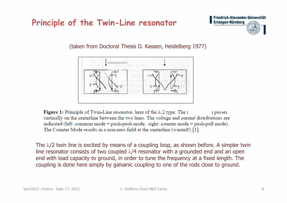
Principle of the Twin-Line resonator
(taken from Doctoral Thesis D. Kassen, Heidelberg 1977)
Spin2012 - Dubna - Sept. 17, 2012 E. Steffens: Dual H&D Cavity 8
The λ/2 twin line is excited by means of a coupling loop, as shown before. A simpler twin line resonator consists of two coupled λ/4 resonator with a grounded end and an open end with load capacity to ground, in order to tune the frequency at a fixed length. The coupling is done here simply by galvanic coupling to one of the rods close to ground.

Tunable λλλλ/4 resonator
Conducting rod of length a grounded at the left corner.
The voltage and current distribution of a ficticious rod of
length λ/4 = a + ∆ is shown. The difference ∆ is
Spin2012 - Dubna - Sept. 17, 2012 E. Steffens: Dual H&D Cavity 9
length λ/4 = a + ∆ is shown. The difference ∆ is
accounted for by a load capacity between the end of the
rod and the ground to the right.
The quantity ∆ is given by: ∆∆∆∆ = (λλλλR / 2ππππ) arctan(ωωωω C ZL)
with λR = wavelength on the line resonator (in good approximation equal to lfree-space )
ω = resonance angular velocity
C = capacity between end of rod and ground
ZL = impedance of rod resonator
This expression can be used for estimating the load capacity C.
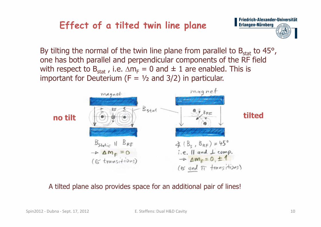
By tilting the normal of the twin line plane from parallel to Bstat to 45°, one has both parallel and perpendicular components of the RF field with respect to Bstat , i.e. ∆mF = 0 and ± 1 are enabled. This is important for Deuterium (F = ½ and 3/2) in particular.
Effect of a tilted twin line plane
no tilt tilted
Spin2012 - Dubna - Sept. 17, 2012 E. Steffens: Dual H&D Cavity 10
no tilt tilted
A tilted plane also provides space for an additional pair of lines!
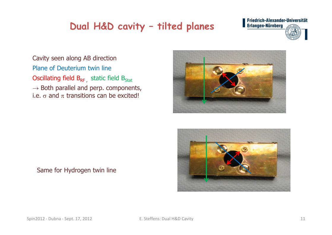
Cavity seen along AB direction
Plane of Deuterium twin line
Oscillating field BRF , static field BStat
→ Both parallel and perp. components,
i.e. σ and π transitions can be excited!
Dual H&D cavity – tilted planes
Spin2012 - Dubna - Sept. 17, 2012 E. Steffens: Dual H&D Cavity 11
Same for Hydrogen twin line
Spin2012 - Dubna - Sept. 17, 2012 E. Steffens: Dual H&D Cavity 12
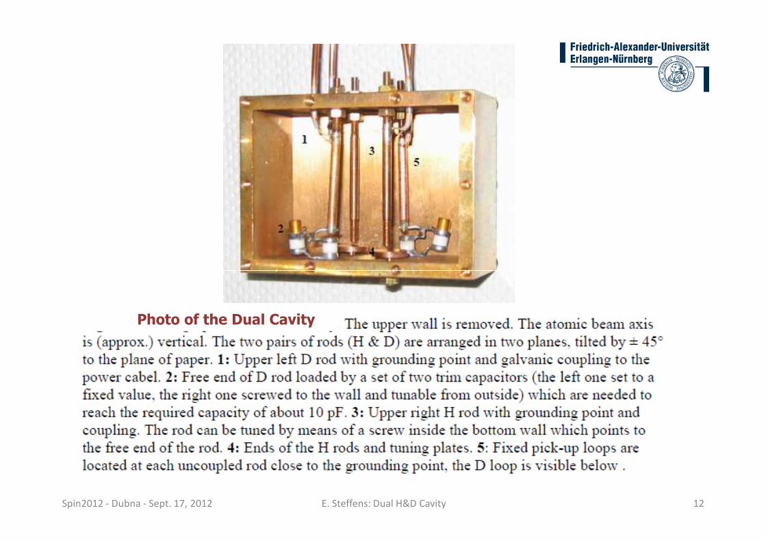
Photo of the Dual Cavity

LEFT
top: grounded ends of the rods with galvanic coupling and pick-up loops;
bottom: tuning capacitors
Dual H&D cavity – different views
Spin2012 - Dubna - Sept. 17, 2012 E. Steffens: Dual H&D Cavity 13
RIGHT
top: open ends of the rods with tuning capacitors
bottom: micro coax lines
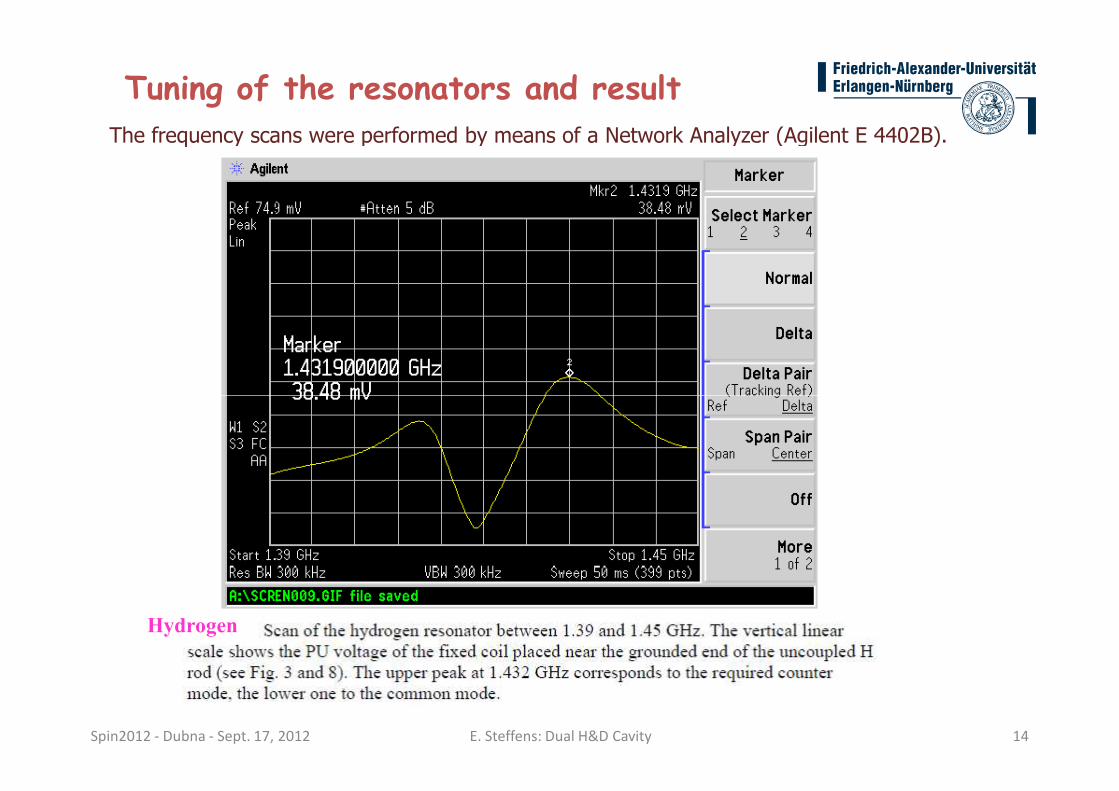
The frequency scans were performed by means of a Network Analyzer (Agilent E 4402B).
Tuning of the resonators and result
Spin2012 - Dubna - Sept. 17, 2012 E. Steffens: Dual H&D Cavity 14
Hydrogen

Tuning of the resonators and result
Spin2012 - Dubna - Sept. 17, 2012 E. Steffens: Dual H&D Cavity 15
Deuterium
Hydrogen twin line
With 3 – 5 W of RF power, a field amplitude of 0.06 – 0.1 mThas been obtained. This results in 30 – 60 precessions of F around the RF field component which ensures adiabatic passage conditions.
Deuterium twin line
Up to now, tuning only of the twin line has been performed.
Test results for the Dual cavity
Spin2012 - Dubna - Sept. 17, 2012 E. Steffens: Dual H&D Cavity 16
Up to now, tuning only of the twin line has been performed. The full test requires a power amplifier for the 350 MHz-range, which were not available at the time of the test.

� A tuned twin line dual cavity has been developed which works both on Deuterium and Hydrogen frequencies in the “tilted“ mode, i.e. all possible two-level transitions can be excited.
� The cavity has been tested electronically using a Network Analyzer. For hydrogen a sufficient RF field strength has been demonstrated. The deuterium twin line is still to be tested, but no problems are to be expected.
Conclusions
Spin2012 - Dubna - Sept. 17, 2012 E. Steffens: Dual H&D Cavity 17
expected.
� The cavity will be installed soon at the Jülich PAX target and tested with atomic H&D beams.
Thank you!