Embed Size (px)
Citation preview
materials
Article
Dual Function Behavior of Carbon Fiber-ReinforcedPolymer in Simulated Pore Solution
Ji-Hua Zhu, Guanping Guo, Liangliang Wei, Miaochang Zhu and Xianchuan Chen *
Guangdong Province Key Laboratory of Durability for Marine Civil Engineering, School of Civil Engineering,Shenzhen University, Shenzhen 518060, Guangdong, China; [email protected] (J.-H.Z.);[email protected] (G.G.); [email protected] (L.W.);[email protected] (M.Z.)* Correspondence: [email protected]; Tel.: +86-755-2653-4021
Academic Editor: Naozumi TeramotoReceived: 11 January 2016; Accepted: 29 January 2016; Published: 6 February 2016
Abstract: The mechanical and electrochemical performance of carbon fiber-reinforced polymer (CFRP)were investigated regarding a novel improvement in the load-carrying capacity and durability ofreinforced concrete structures by adopting CFRP as both a structural strengthener and an anode ofthe impressed current cathodic protection (ICCP) system. The mechanical and anode performanceof CFRP were investigated in an aqueous pore solution in which the electrolytes were available tothe anode in a cured concrete structure. Accelerated polarization tests were designed with differenttest durations and various levels of applied currents in accordance with the international standard.The CFRP specimens were mechanically characterized after polarization. The measured feedingvoltage and potential during the test period indicates CFRP have stable anode performance in asimulated pore solution. Two failure modes were observed through tensile testing. The tensileproperties of the post-polarization CFRP specimens declined with an increased charge density.The CFRP demonstrated success as a structural strengthener and ICCP anode. We propose amathematic model predicting the tensile strengths of CFRP with varied impressed charge densities.
Keywords: polymer-matrix composites (PMCs); corrosion; electrical properties; mechanicalproperties; anode
1. Introduction
It is well known that the corrosion of steel is the major cause of damage of reinforced concretestructures exposed to de-icing salts or marine environments [1,2]. Traditional techniques for localrepair are not only laborious and interferential with operational service, but are also not effectivein reducing the corrosion rate [3]. The impressed current cathodic protection (ICCP) technique iscurrently well accepted as a suitable technique for the protection of reinforced concrete structures thathave been damaged by chloride-induced corrosion [4]. The Federal Highway Administration evensuggested that the only effective corrosion prevention method for a contaminated reinforced concretemember is the ICCP method [5].
Due to concrete’s high resistivity and the complex geometry of reinforcing bars, an importantconsideration in the ICCP system is the selection of a suitable anode material [1,6]. A number ofanode systems have currently been investigated in the impressed cathodic protection, includingactivated titanium mesh [7], metalized zinc [8], conductive organic paints [9], and coating-overlayanodes [10]. However, these anode systems are either highly expensive or suffer from durabilityproblems. Furthermore, they are not compatible with concrete materials. For instance, conductivepaints are cheaper, but they cannot supply current densities higher than 20 mA/m2 for long periods of
Materials 2016, 9, 103; doi:10.3390/ma9020103 www.mdpi.com/journal/materials
Materials 2016, 9, 103 2 of 12
time [10]. The development of new types of anodes for the protection of reinforced concrete structuresis a subject of great technological interest.
A successful ICCP system should keep the anode material electrochemically stable while reducingits corrosion rate to a low level [6,11]. The accelerated testing of anodes for use in concrete is commonlyadopted, with the purpose of indicating the anode’s ability to perform satisfactorily for a specificnumber of years. Unfortunately, accelerated life testing cannot be conducted in concrete, becausetesting at high current levels causes premature failure through electrolysis of the concrete. Therefore,accelerated life testing must be conducted in an aqueous solution, as specified in NACE StandardTM0294-2007 [12].
Carbon fiber-reinforced polymers (CFRP) consist of strong and light carbon fibers embedded ina polymer matrix. The remarkable mechanical properties suggest that CFRP is an ideal material forstructurally strengthening reinforced concrete structures [13]. Structural strengthening is generallyachieved by warping or adhering CFRP to the surface of reinforced structures using contact materials,thereby improving the load-carrying capacity of degraded structures [14,15]. CFRP is conductive witha polarization potential close to that of noble metals, which may induce galvanic corrosion in steelwhen CFRP is used to structurally strengthen steel structures [16]. Therefore, the feasibility of CFRP asan anode material in ICCP systems is an interesting problem. Moreover, the excellent conductivity,high mechanical strength, and lower cost of CFRP would present a novel and affordable method toimprove the durability of reinforced concrete structures with CFRP simultaneously acting as the ICCPanode and structural strengthening material.
Studies have been performed on the dual-functional behavior of CFRP on reinforced concrete.Lee-Orantes et al. [17] experimentally investigated the use of CFRP anodes in the ICCP systems ofreinforced concrete prisms. Nguyen et al. [18] studied the electrochemical performance of CFRP fabricand rods in both a calcium solution and in concrete. In addition, CFRP was employed in pre-corrodedreinforced concrete beams for both structural strengthening and ICCP; the results showed that theultimate strength of CFRP for dual functions was slightly lower than it was for a control specimen, inwhich CFRP was used for structural strengthening only [6].
The above works investigated the corrosion and mechanical behavior of steel and concrete inICCP systems with CFRP anodes. However, extensive study on the electrochemical performance ofCFRP itself is also important. According to the NACE Standard TM0294-2007 [12], accelerated anodetesting should be conducted in three specified aqueous solutions of NaCl, NaOH, and a pore solutionto characterize the resistance of the anode material to tolerate chloride evolution, oxygen evolution, aswell as the actual concentrations of the pore water components and any possible synergistic effectsimposed by these components, respectively. In the previous study [19,20], Zhu et al. investigatedCFRP’s mechanical and electrochemical performance during accelerated polarization in NaCl andNaOH solution environment. It was shown that CFRP can be successfully used as the anode in anICCP system without significant degradation of mechanical properties in NaCl and NaOH solutionenvironment [21]. Following these studies, this work presents a systematic investigation, including theelectrochemical behavior, mechanical strength, and failure modes of CFRP during anodic polarizationin a simulated pore solution environment. CFRP’s electrochemical performance during anodicpolarization with the pore solution was investigated using a simulated ICCP system. The mechanicalstrengths and failure modes of the CFRP specimens were obtained after the polarization tests and therelationship between the tensile strengths and impressed charge densities was elucidated.
2. Experimental Details
2.1. Materials
The CFRP strips (CA.BEN Composite Co., Ltd., Hong Kong) were made from multi-layer carbonfibers (Toray T700, supplied by CA.BEN Composite Co., Ltd., Hong Kong) with a volume fractionof 60% embedded in LAM-125/LAM-226 epoxy (Pro-Set Inc., Bay City, MI, USA). The chemical
Materials 2016, 9, 103 3 of 12
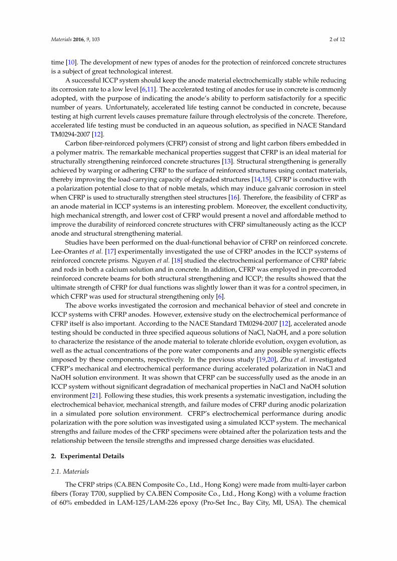
composition of the epoxy used in the CFRP is shown in Table 1. CFRP specimens were machinedinto dumbbell shapes for mechanical testing according to the ASTM Standard D638-10 [22], as shownin Figure 1a. Specimens were protected by Kafuter K-5704RTV sealant (Guangdong Hengda NewMaterials Technology Co., Ltd., Guangdong, China), except for the front surface of the test regionin the center, as shown in Figure 1b, with a nominal anodic surface area of 650 mm2 for the anodicpolarization tests. The geometric dimensions of the CFRP specimens are detailed in Figure 1.
Materials 2016, 9, 103 3 of 12
the center, as shown in Figure 1b, with a nominal anodic surface area of 650 mm2 for the anodic
polarization tests. The geometric dimensions of the CFRP specimens are detailed in Figure 1.
(a) (b)
Figure 1. Geometric dimensions of carbon fiber‐reinforced polymer (CFRP) specimens. (a) Front view;
(b) Sectional view (unit: mm).
Table 1. Chemical composition of epoxy in CFRP.
Ingredients Concentration (%)
Bisphenol‐A type epoxy resin 37–38
Novolac epoxy resin 19–20
Dicyandiamide 5–6
Methyl ethyl ketone (MEK) 36–37
2.2. Testing Methods
2.2.1. Accelerated Polarization Test
Accelerated polarization tests were conducted to investigate CFRP’s galvanostatic anodic
polarization behavior in a simulated ICCP system (as shown in Figure 2)—including an impressed
current anode of CFRP, a cathode of a stainless steel strip, an aqueous pore electrolyte solution, a
power source, and a saturated calomel electrode (SCE). The composition of the simulated pore
solution is shown in Table 2. The anodic polarization of CFRP was achieved by connecting the CFRP
specimen to the positive terminal of the power source. The exposed area of the stainless steel cathode
was equal to the CFRP test area (As) to obtain a uniform electric field distribution between the anode
and cathode.
Figure 2. Schematic view of the simulated impressed current cathodic protection (ICCP) system.
Figure 1. Geometric dimensions of carbon fiber-reinforced polymer (CFRP) specimens. (a) Front view;(b) Sectional view (unit: mm).
Table 1. Chemical composition of epoxy in CFRP.
Ingredients Concentration (%)
Bisphenol-A type epoxy resin 37–38Novolac epoxy resin 19–20
Dicyandiamide 5–6Methyl ethyl ketone (MEK) 36–37
2.2. Testing Methods
2.2.1. Accelerated Polarization Test
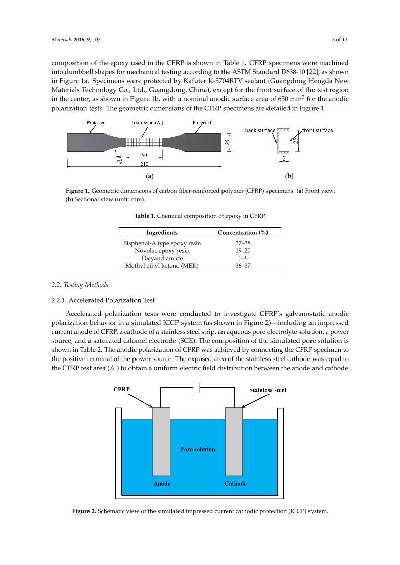
Accelerated polarization tests were conducted to investigate CFRP’s galvanostatic anodicpolarization behavior in a simulated ICCP system (as shown in Figure 2)—including an impressedcurrent anode of CFRP, a cathode of a stainless steel strip, an aqueous pore electrolyte solution, a powersource, and a saturated calomel electrode (SCE). The composition of the simulated pore solution isshown in Table 2. The anodic polarization of CFRP was achieved by connecting the CFRP specimen tothe positive terminal of the power source. The exposed area of the stainless steel cathode was equal tothe CFRP test area (As) to obtain a uniform electric field distribution between the anode and cathode.
Materials 2016, 9, 103 3 of 12
the center, as shown in Figure 1b, with a nominal anodic surface area of 650 mm2 for the anodic
polarization tests. The geometric dimensions of the CFRP specimens are detailed in Figure 1.
(a) (b)
Figure 1. Geometric dimensions of carbon fiber‐reinforced polymer (CFRP) specimens. (a) Front view;
(b) Sectional view (unit: mm).
Table 1. Chemical composition of epoxy in CFRP.
Ingredients Concentration (%)
Bisphenol‐A type epoxy resin 37–38
Novolac epoxy resin 19–20
Dicyandiamide 5–6
Methyl ethyl ketone (MEK) 36–37
2.2. Testing Methods
2.2.1. Accelerated Polarization Test
Accelerated polarization tests were conducted to investigate CFRP’s galvanostatic anodic
polarization behavior in a simulated ICCP system (as shown in Figure 2)—including an impressed
current anode of CFRP, a cathode of a stainless steel strip, an aqueous pore electrolyte solution, a
power source, and a saturated calomel electrode (SCE). The composition of the simulated pore
solution is shown in Table 2. The anodic polarization of CFRP was achieved by connecting the CFRP
specimen to the positive terminal of the power source. The exposed area of the stainless steel cathode
was equal to the CFRP test area (As) to obtain a uniform electric field distribution between the anode
and cathode.
Figure 2. Schematic view of the simulated impressed current cathodic protection (ICCP) system.
Figure 2. Schematic view of the simulated impressed current cathodic protection (ICCP) system.
Materials 2016, 9, 103 4 of 12
Table 2. The composition of the simulated pore solution.
Ingredients Concentration (%)
Ca(OH)2 0.2KCl 3.2
NaOH 2.45KOH 1
Distilled water 93.15
A constant current supply was used to achieve galvanostatic anodic polarization. Currents of 0,0.5, 1, 2, and 4 mA were applied, with corresponding nominal current densities of 0, 0.77, 1.54, 3.08,and 6.15 A/m2, respectively. Each current was tested for two distinct anodic polarization durations of25 and 50 days. Hence, a total of ten conditions were investigated.
The specimens were labeled according to the applied currents and the anodic polarizationdurations for ease of identification, as shown in Table 3. For example, the label I0.5D25# indicatesthat the specimen was exposed to the nominal applied current, I, of 0.5 A for a test duration, D,of 25 days. Two duplicate specimens were tested for each condition; the # symbol indicates thesecond specimen. Table 3 also shows the critical parameters used for the post-polarization tensile tests.The I0.5D50# specimen is not shown in Table 3 because the extensometer demonstrated problemsduring the test process.
Table 3. Parameters and test results for specimens used for tensile tests after polarization.
Specimen As (mm2) Ac (mm2) i (A/m2) q (107 C/m2) f u (MPa) Failure Modes KExp KCal/KExp
I0D25 670.40 25.56 0 0 774.79 L – –I0D25# 669.63 25.66 0 0 649.71 L – –I0.5D25 642.64 25.19 0.889 0.192 675.58 L 0.99 0.92
I0.5D25# 616.17 25.30 0.926 0.200 699.42 L 1.02 0.89I1D25 578.82 26.18 1.888 0.408 559.89 L 0.82 1.00
I1D25# 657.50 25.97 1.637 0.354 549.92 L 0.80 1.05I2D25 646.07 25.71 3.085 0.666 513.21 D 0.75 0.96
I2D25# 656.75 26.27 3.024 0.653 477.16 D 0.70 1.04I4D25 656.25 25.27 6.066 1.310 474.00 D 0.69 0.76
I4D25# 630.48 26.07 6.355 1.373 466.77 D 0.68 0.75I0D50 671.16 25.23 0 0 682.09 L – –
I0D50# 668.61 25.79 0 0 627.16 L – –I0.5D50 644.60 25.45 0.887 0.383 653.59 L 0.96 0.87I1D50 657.25 25.70 1.611 0.696 318.15 D 0.47 1.53
I1D50# 643.62 24.83 1.666 0.720 340.22 D 0.50 1.41I2D50 656.75 25.09 2.981 1.288 329.08 D 0.48 1.11
I2D50# 630.72 25.69 3.110 1.344 303.17 D 0.44 1.17I4D50 632.64 26.23 6.354 2.745 193.49 D 0.28 0.93
I4D50# 618.76 26.00 6.424 2.775 181.88 D 0.27 0.97Mean – – – – – – – 1.02COV – – – – – – – 0.211
Notes: # = duplicate specimen. As = measured anodic surface area, Ac = measured cross-sectional area, i = actualcurrent densities, q = charge density, f u = ultimate tensile strength, L= lateral failure type, D= edge delaminationfailure type, KExp = experimental deterioration factor, KCal = calculated deterioration factor.
The anodic performance of CFRP was evaluated by recording the feeding voltage betweenthe CFRP and stainless steel. The potential of CFRP versus the SCE was also measured during thegalvanostatic anodic polarization. The feeding voltage between CFRP and stainless steel, together withthe potential of CFRP, were monitored every 10 min throughout the test period with a multi-channeldata logger.
Materials 2016, 9, 103 5 of 12
2.2.2. Tensile Test
Uniaxial tensile tests were conducted on the CFRP specimens after the galvanostatic anodicpolarization. Tensile tests were performed on a universal test machine (E45, MTS, Eden Prairie,MN, USA) at a constant loading rate of 0.2 mm/min. The applied load and displacement betweenthe machine grips for each test were recorded using a data acquisition system. The strains of thespecimens were not measured, as it was not possible to attach strain gauges to the heavily corrodedspecimen surfaces.
3. Results and Discussion
3.1. Anode Performance
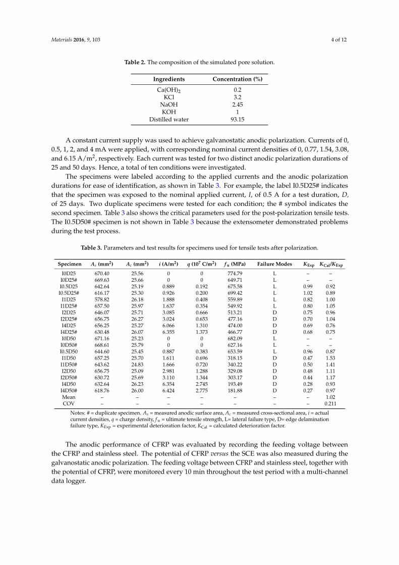
The feeding voltages between the CFRP anode and the steel cathode were used to demonstratethe variation of resistance in the electrical circuit, as a constant current was applied throughout the testvia the pore solution. Figure 3 depicts the recorded feeding voltages between the CFRP and stainlesssteel during galvanostatic anodic polarization for 50 days. At all given currents, the feeding voltagesgradually stabilized at values between 1.7 and 2.4 V with increased galvanostatic anodic polarizationtime. This trend indicates the stable and serviceable performance of CFRP as the impressed currentanode in an ICCP system.
Materials 2016, 9, 103 5 of 12
with the potential of CFRP, were monitored every 10 min throughout the test period with a multi‐
channel data logger.
2.2.2.Tensile Test
Uniaxial tensile tests were conducted on the CFRP specimens after the galvanostatic anodic
polarization. Tensile tests were performed on a universal test machine (E45, MTS, Eden Prairie, MN,
USA) at a constant loading rate of 0.2 mm/min. The applied load and displacement between the
machine grips for each test were recorded using a data acquisition system. The strains of the
specimens were not measured, as it was not possible to attach strain gauges to the heavily corroded
specimen surfaces.
3. Results and Discussion
3.1. Anode Performance
The feeding voltages between the CFRP anode and the steel cathode were used to demonstrate
the variation of resistance in the electrical circuit, as a constant current was applied throughout the
test via the pore solution. Figure 3 depicts the recorded feeding voltages between the CFRP and
stainless steel during galvanostatic anodic polarization for 50 days. At all given currents, the feeding
voltages gradually stabilized at values between 1.7 and 2.4 V with increased galvanostatic anodic
polarization time. This trend indicates the stable and serviceable performance of CFRP as the
impressed current anode in an ICCP system.
Figure 3. The feeding voltage between CFRP and stainless steel during galvanostatic anodic
polarization process.
The potentials of the CFRP anode reflect the anodic performance during the galvanostatic anodic
polarization process. The potential of CFRP with respect to the SCE during the tests are presented in
Figure 4. Specimen I0‐D50, which was immersed in the electrolyte solution for 50 days without an
applied current, is shown in Figure 4 for reference. The potential of CFRP shows a trend similar to
that of the feeding voltage between CFRP and stainless steel. The potential of anodically polarized
CFRP is within the range of 0.4–1.2 V (vs. SCE), while the potential of specimen I0‐D50 (without
external current) is approximately −0.135 V (vs. SCE). The stabilizing potential curve demonstrates
the stable anodic performance of CFRP during anodic polarization in the pore solution. Figures 3 and
4 show a drop in both the feeding voltage and potential at around the 40th day. This drop is caused
by an accidental interruption of supplied power. However, the feeding voltage and potential were
recovered once the power supply was restored.
0 10 20 30 40 50
Time (Day)
1
1.5
2
2.5
3
Fee
din
g vo
ltag
e (V
)
I0.5-D50I1-D50I2-D50I4-D50
Figure 3. The feeding voltage between CFRP and stainless steel during galvanostatic anodicpolarization process.
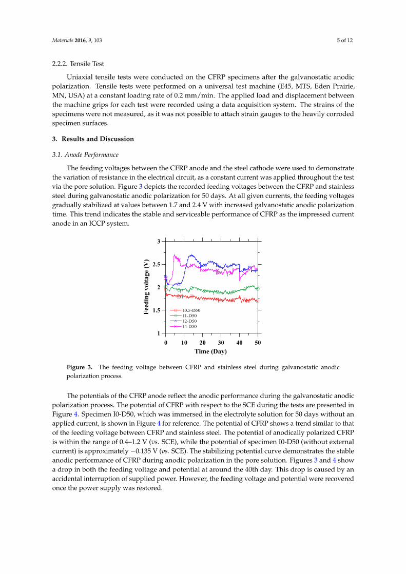
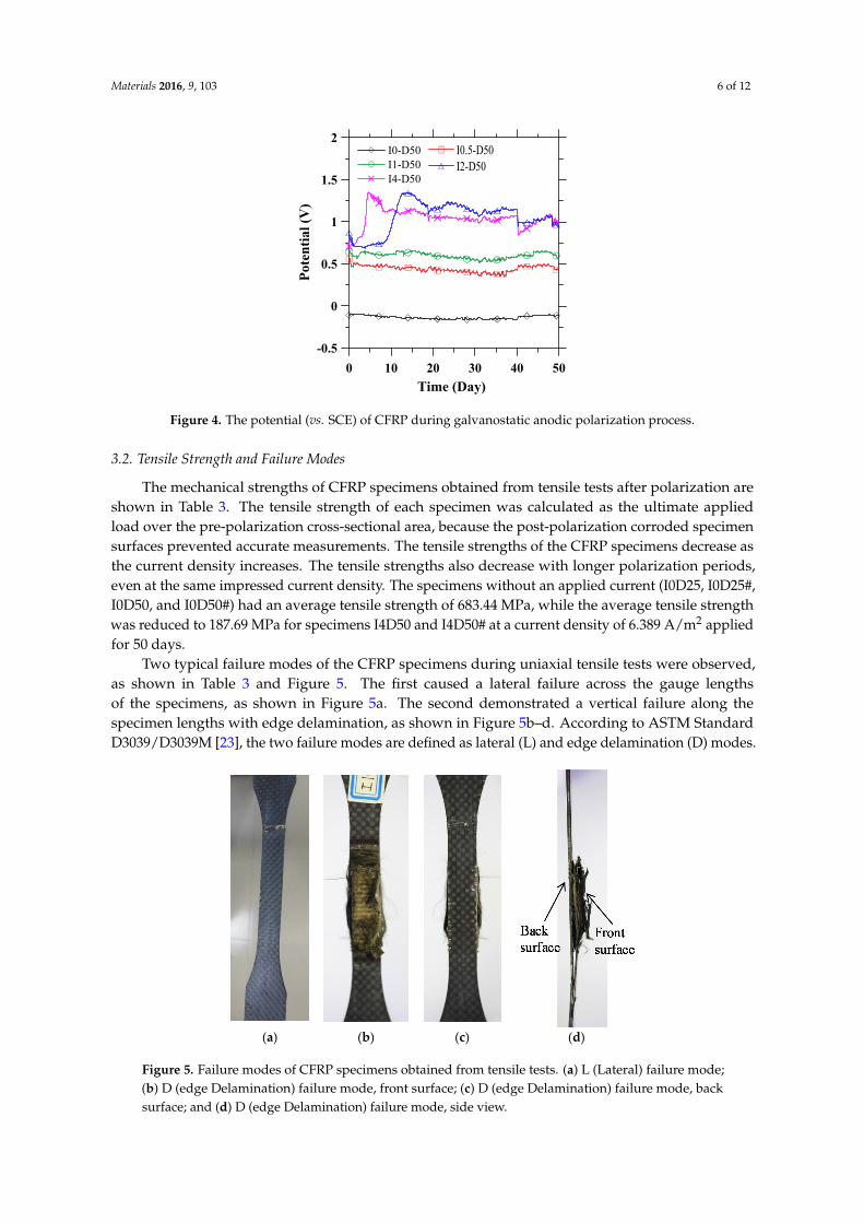
The potentials of the CFRP anode reflect the anodic performance during the galvanostatic anodicpolarization process. The potential of CFRP with respect to the SCE during the tests are presented inFigure 4. Specimen I0-D50, which was immersed in the electrolyte solution for 50 days without anapplied current, is shown in Figure 4 for reference. The potential of CFRP shows a trend similar to thatof the feeding voltage between CFRP and stainless steel. The potential of anodically polarized CFRPis within the range of 0.4–1.2 V (vs. SCE), while the potential of specimen I0-D50 (without externalcurrent) is approximately ´0.135 V (vs. SCE). The stabilizing potential curve demonstrates the stableanodic performance of CFRP during anodic polarization in the pore solution. Figures 3 and 4 showa drop in both the feeding voltage and potential at around the 40th day. This drop is caused by anaccidental interruption of supplied power. However, the feeding voltage and potential were recoveredonce the power supply was restored.
Materials 2016, 9, 103 6 of 12Materials 2016, 9, 103 6 of 12
Figure 4. The potential (vs. SCE) of CFRP during galvanostatic anodic polarization process.
3.2. Tensile Strength and Failure Modes
The mechanical strengths of CFRP specimens obtained from tensile tests after polarization are
shown in Table 3. The tensile strength of each specimen was calculated as the ultimate applied load
over the pre‐polarization cross‐sectional area, because the post‐polarization corroded specimen
surfaces prevented accurate measurements. The tensile strengths of the CFRP specimens decrease as
the current density increases. The tensile strengths also decrease with longer polarization periods,
even at the same impressed current density. The specimens without an applied current (I0D25,
I0D25#, I0D50, and I0D50#) had an average tensile strength of 683.44 MPa, while the average tensile
strength was reduced to 187.69 MPa for specimens I4D50 and I4D50# at a current density of
6.389 A/m2 applied for 50 days.
Two typical failure modes of the CFRP specimens during uniaxial tensile tests were observed,
as shown in Table 3 and Figure 5. The first caused a lateral failure across the gauge lengths of the
specimens, as shown in Figure 5a. The second demonstrated a vertical failure along the specimen
lengths with edge delamination, as shown in Figures 5b–d. According to ASTM Standard
D3039/D3039M [23], the two failure modes are defined as lateral (L) and edge delamination (D) modes.
(a) (b) (c) (d)
Figure 5. Failure modes of CFRP specimens obtained from tensile tests. (a) L (Lateral) failure mode;
(b) D (edge Delamination) failure mode, front surface; (c) D (edge Delamination) failure mode, back
surface; and (d) D (edge Delamination) failure mode, side view.
0 10 20 30 40 50
Time (Day)
-0.5
0
0.5
1
1.5
2
Pot
enti
al (
V)
I0-D50I1-D50I4-D50
I0.5-D50I2-D50
Figure 4. The potential (vs. SCE) of CFRP during galvanostatic anodic polarization process.
3.2. Tensile Strength and Failure Modes
The mechanical strengths of CFRP specimens obtained from tensile tests after polarization areshown in Table 3. The tensile strength of each specimen was calculated as the ultimate appliedload over the pre-polarization cross-sectional area, because the post-polarization corroded specimensurfaces prevented accurate measurements. The tensile strengths of the CFRP specimens decrease asthe current density increases. The tensile strengths also decrease with longer polarization periods,even at the same impressed current density. The specimens without an applied current (I0D25, I0D25#,I0D50, and I0D50#) had an average tensile strength of 683.44 MPa, while the average tensile strengthwas reduced to 187.69 MPa for specimens I4D50 and I4D50# at a current density of 6.389 A/m2 appliedfor 50 days.
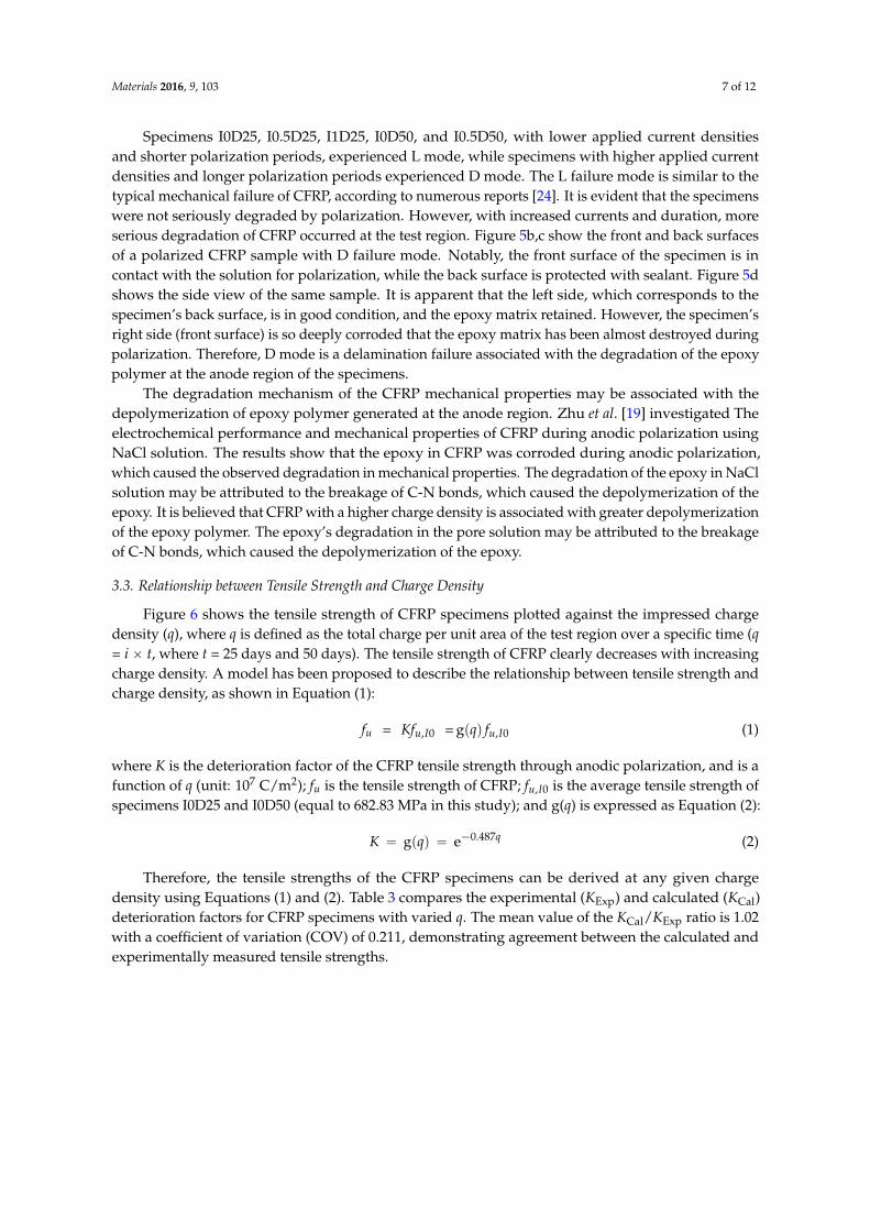
Two typical failure modes of the CFRP specimens during uniaxial tensile tests were observed,as shown in Table 3 and Figure 5. The first caused a lateral failure across the gauge lengthsof the specimens, as shown in Figure 5a. The second demonstrated a vertical failure along thespecimen lengths with edge delamination, as shown in Figure 5b–d. According to ASTM StandardD3039/D3039M [23], the two failure modes are defined as lateral (L) and edge delamination (D) modes.
Materials 2016, 9, 103 6 of 12
Figure 4. The potential (vs. SCE) of CFRP during galvanostatic anodic polarization process.
3.2. Tensile Strength and Failure Modes
The mechanical strengths of CFRP specimens obtained from tensile tests after polarization are
shown in Table 3. The tensile strength of each specimen was calculated as the ultimate applied load
over the pre‐polarization cross‐sectional area, because the post‐polarization corroded specimen
surfaces prevented accurate measurements. The tensile strengths of the CFRP specimens decrease as
the current density increases. The tensile strengths also decrease with longer polarization periods,
even at the same impressed current density. The specimens without an applied current (I0D25,
I0D25#, I0D50, and I0D50#) had an average tensile strength of 683.44 MPa, while the average tensile
strength was reduced to 187.69 MPa for specimens I4D50 and I4D50# at a current density of
6.389 A/m2 applied for 50 days.
Two typical failure modes of the CFRP specimens during uniaxial tensile tests were observed,
as shown in Table 3 and Figure 5. The first caused a lateral failure across the gauge lengths of the
specimens, as shown in Figure 5a. The second demonstrated a vertical failure along the specimen
lengths with edge delamination, as shown in Figures 5b–d. According to ASTM Standard
D3039/D3039M [23], the two failure modes are defined as lateral (L) and edge delamination (D) modes.
(a) (b) (c) (d)
Figure 5. Failure modes of CFRP specimens obtained from tensile tests. (a) L (Lateral) failure mode;
(b) D (edge Delamination) failure mode, front surface; (c) D (edge Delamination) failure mode, back
surface; and (d) D (edge Delamination) failure mode, side view.
0 10 20 30 40 50
Time (Day)
-0.5
0
0.5
1
1.5
2
Pot
enti
al (
V)
I0-D50I1-D50I4-D50
I0.5-D50I2-D50
Figure 5. Failure modes of CFRP specimens obtained from tensile tests. (a) L (Lateral) failure mode;(b) D (edge Delamination) failure mode, front surface; (c) D (edge Delamination) failure mode, backsurface; and (d) D (edge Delamination) failure mode, side view.
Materials 2016, 9, 103 7 of 12
Specimens I0D25, I0.5D25, I1D25, I0D50, and I0.5D50, with lower applied current densitiesand shorter polarization periods, experienced L mode, while specimens with higher applied currentdensities and longer polarization periods experienced D mode. The L failure mode is similar to thetypical mechanical failure of CFRP, according to numerous reports [24]. It is evident that the specimenswere not seriously degraded by polarization. However, with increased currents and duration, moreserious degradation of CFRP occurred at the test region. Figure 5b,c show the front and back surfacesof a polarized CFRP sample with D failure mode. Notably, the front surface of the specimen is incontact with the solution for polarization, while the back surface is protected with sealant. Figure 5dshows the side view of the same sample. It is apparent that the left side, which corresponds to thespecimen’s back surface, is in good condition, and the epoxy matrix retained. However, the specimen’sright side (front surface) is so deeply corroded that the epoxy matrix has been almost destroyed duringpolarization. Therefore, D mode is a delamination failure associated with the degradation of the epoxypolymer at the anode region of the specimens.
The degradation mechanism of the CFRP mechanical properties may be associated with thedepolymerization of epoxy polymer generated at the anode region. Zhu et al. [19] investigated Theelectrochemical performance and mechanical properties of CFRP during anodic polarization usingNaCl solution. The results show that the epoxy in CFRP was corroded during anodic polarization,which caused the observed degradation in mechanical properties. The degradation of the epoxy in NaClsolution may be attributed to the breakage of C-N bonds, which caused the depolymerization of theepoxy. It is believed that CFRP with a higher charge density is associated with greater depolymerizationof the epoxy polymer. The epoxy’s degradation in the pore solution may be attributed to the breakageof C-N bonds, which caused the depolymerization of the epoxy.
3.3. Relationship between Tensile Strength and Charge Density
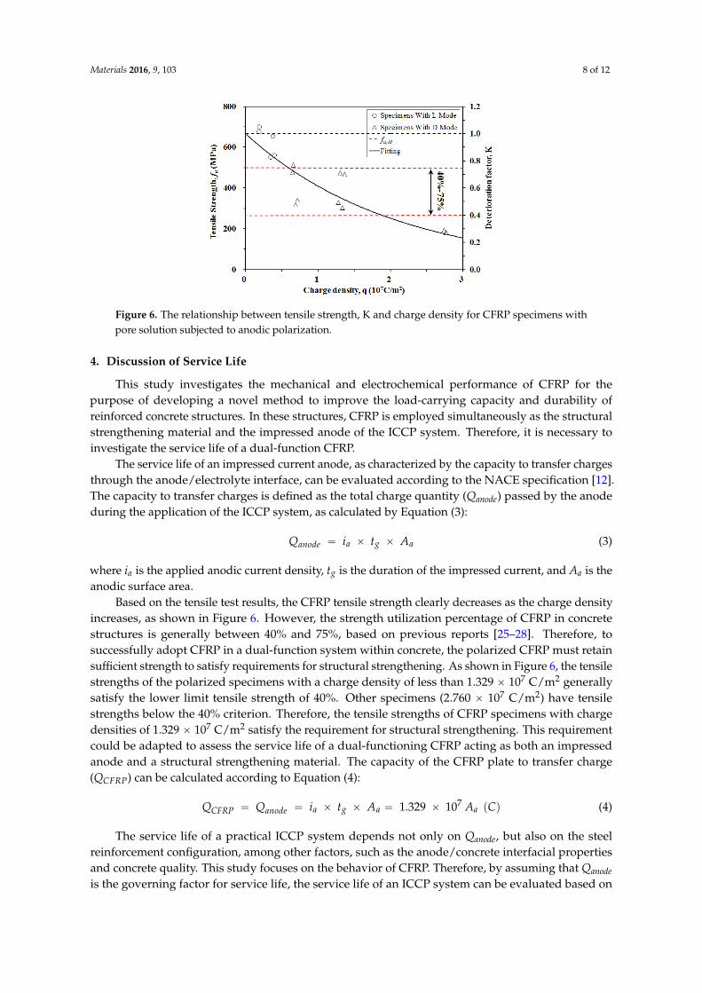
Figure 6 shows the tensile strength of CFRP specimens plotted against the impressed chargedensity (q), where q is defined as the total charge per unit area of the test region over a specific time (q= i ˆ t, where t = 25 days and 50 days). The tensile strength of CFRP clearly decreases with increasingcharge density. A model has been proposed to describe the relationship between tensile strength andcharge density, as shown in Equation (1):
fu = Kfu,I0 = gpqq fu,I0 (1)
where K is the deterioration factor of the CFRP tensile strength through anodic polarization, and is afunction of q (unit: 107 C/m2); fu is the tensile strength of CFRP; fu,I0 is the average tensile strength ofspecimens I0D25 and I0D50 (equal to 682.83 MPa in this study); and g(q) is expressed as Equation (2):
K “ gpqq “ e´0.487q (2)
Therefore, the tensile strengths of the CFRP specimens can be derived at any given chargedensity using Equations (1) and (2). Table 3 compares the experimental (KExp) and calculated (KCal)deterioration factors for CFRP specimens with varied q. The mean value of the KCal/KExp ratio is 1.02with a coefficient of variation (COV) of 0.211, demonstrating agreement between the calculated andexperimentally measured tensile strengths.
Materials 2016, 9, 103 8 of 12Materials 2016, 9, 103 8 of 12
Figure 6. The relationship between tensile strength, K and charge density for CFRP specimens with
pore solution subjected to anodic polarization.
4. Discussion of Service Life
This study investigates the mechanical and electrochemical performance of CFRP for the
purpose of developing a novel method to improve the load‐carrying capacity and durability of
reinforced concrete structures. In these structures, CFRP is employed simultaneously as the structural
strengthening material and the impressed anode of the ICCP system. Therefore, it is necessary to
investigate the service life of a dual‐function CFRP.
The service life of an impressed current anode, as characterized by the capacity to transfer
charges through the anode/electrolyte interface, can be evaluated according to the NACE
specification [12]. The capacity to transfer charges is defined as the total charge quantity (Qanode)
passed by the anode during the application of the ICCP system, as calculated by Equation (3):
(3)
where ia is the applied anodic current density, tg is the duration of the impressed current, and Aa is
the anodic surface area.
Based on the tensile test results, the CFRP tensile strength clearly decreases as the charge density
increases, as shown in Figure 6. However, the strength utilization percentage of CFRP in concrete
structures is generally between 40% and 75%, based on previous reports [25–28]. Therefore, to
successfully adopt CFRP in a dual‐function system within concrete, the polarized CFRP must retain
sufficient strength to satisfy requirements for structural strengthening. As shown in Figure 6, the
tensile strengths of the polarized specimens with a charge density of less than 1.329 × 10⁷ C/m2
generally satisfy the lower limit tensile strength of 40%. Other specimens (2.760 × 10⁷ C/m2) have
tensile strengths below the 40% criterion. Therefore, the tensile strengths of CFRP specimens with
charge densities of 1.329 × 10⁷ C/m2 satisfy the requirement for structural strengthening. This
requirement could be adapted to assess the service life of a dual‐functioning CFRP acting as both an
impressed anode and a structural strengthening material. The capacity of the CFRP plate to transfer
charge (QCFRP) can be calculated according to Equation (4):
Q Q i t A 1.329 107 A (4)
The service life of a practical ICCP system depends not only on Qanode, but also on the steel
reinforcement configuration, among other factors, such as the anode/concrete interfacial properties
and concrete quality. This study focuses on the behavior of CFRP. Therefore, by assuming that Qanode
is the governing factor for service life, the service life of an ICCP system can be evaluated based on
the equilibrium of the charge quantity between the cathode (Qcathode) and anode (Qanode), as shown in
Equation (5).
Q Q (5)
Figure 6. The relationship between tensile strength, K and charge density for CFRP specimens withpore solution subjected to anodic polarization.
4. Discussion of Service Life
This study investigates the mechanical and electrochemical performance of CFRP for thepurpose of developing a novel method to improve the load-carrying capacity and durability ofreinforced concrete structures. In these structures, CFRP is employed simultaneously as the structuralstrengthening material and the impressed anode of the ICCP system. Therefore, it is necessary toinvestigate the service life of a dual-function CFRP.
The service life of an impressed current anode, as characterized by the capacity to transfer chargesthrough the anode/electrolyte interface, can be evaluated according to the NACE specification [12].The capacity to transfer charges is defined as the total charge quantity (Qanode) passed by the anodeduring the application of the ICCP system, as calculated by Equation (3):
Qanode “ ia ˆ tg ˆ Aa (3)
where ia is the applied anodic current density, tg is the duration of the impressed current, and Aa is theanodic surface area.
Based on the tensile test results, the CFRP tensile strength clearly decreases as the charge densityincreases, as shown in Figure 6. However, the strength utilization percentage of CFRP in concretestructures is generally between 40% and 75%, based on previous reports [25–28]. Therefore, tosuccessfully adopt CFRP in a dual-function system within concrete, the polarized CFRP must retainsufficient strength to satisfy requirements for structural strengthening. As shown in Figure 6, the tensilestrengths of the polarized specimens with a charge density of less than 1.329 ˆ 107 C/m2 generallysatisfy the lower limit tensile strength of 40%. Other specimens (2.760 ˆ 107 C/m2) have tensilestrengths below the 40% criterion. Therefore, the tensile strengths of CFRP specimens with chargedensities of 1.329 ˆ 107 C/m2 satisfy the requirement for structural strengthening. This requirementcould be adapted to assess the service life of a dual-functioning CFRP acting as both an impressedanode and a structural strengthening material. The capacity of the CFRP plate to transfer charge(QCFRP) can be calculated according to Equation (4):
QCFRP “ Qanode “ ia ˆ tg ˆ Aa “ 1.329 ˆ 107 Aa pCq (4)
The service life of a practical ICCP system depends not only on Qanode, but also on the steelreinforcement configuration, among other factors, such as the anode/concrete interfacial propertiesand concrete quality. This study focuses on the behavior of CFRP. Therefore, by assuming that Qanodeis the governing factor for service life, the service life of an ICCP system can be evaluated based on
Materials 2016, 9, 103 9 of 12
the equilibrium of the charge quantity between the cathode (Qcathode) and anode (Qanode), as shown inEquation (5).
Qcathode “ Qanode (5)
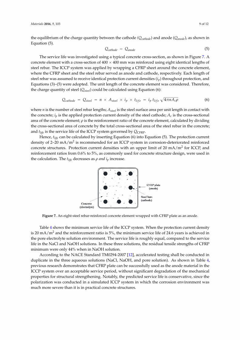
The service life was investigated using a typical concrete cross-section, as shown in Figure 7. Aconcrete element with a cross-section of 400 ˆ 400 mm was reinforced using eight identical lengths ofsteel rebar. The ICCP system was applied by wrapping a CFRP sheet around the concrete element,where the CFRP sheet and the steel rebar served as anode and cathode, respectively. Each length ofsteel rebar was assumed to receive identical protection current densities (ip) throughout protection, andEquations (3)–(5) were adopted. The unit length of the concrete element was considered. Therefore,the charge quantity of steel (Qsteel) could be calculated using Equation (6):
Qcathode “ Qsteel “ n ˆ Asteel ˆ ip ˆ tli f e “ ip tli f ea
4πnAcρ (6)
where n is the number of steel rebar lengths; Asteel is the steel surface area per unit length in contact withthe concrete; ip is the applied protection current density of the steel cathode; Ac is the cross-sectionalarea of the concrete element; ρ is the reinforcement ratio of the concrete element, calculated by dividingthe cross-sectional area of concrete by the total cross-sectional area of the steel rebar in the concrete;and tlife is the service life of the ICCP system governed by QCFRP.
Hence, tlife can be calculated by inserting Equation (6) into Equation (5). The protection currentdensity of 2–20 mA/m2 is recommended for an ICCP system in corrosion-deteriorated reinforcedconcrete structures. Protection current densities with an upper limit of 20 mA/m2 for ICCP, andreinforcement ratios from 0.6% to 5%, as commonly used for concrete structure design, were used inthe calculation. The tlife decreases as ρ and ip increase.
Materials 2016, 9, 103 9 of 12
The service life was investigated using a typical concrete cross‐section, as shown in Figure 7. A
concrete element with a cross‐section of 400 × 400 mm was reinforced using eight identical lengths of
steel rebar. The ICCP system was applied by wrapping a CFRP sheet around the concrete element,
where the CFRP sheet and the steel rebar served as anode and cathode, respectively. Each length of
steel rebar was assumed to receive identical protection current densities (ip) throughout protection,
and Equations (3)–(5) were adopted. The unit length of the concrete element was considered.
Therefore, the charge quantity of steel (Qsteel) could be calculated using Equation (6):
4 (6)
where n is the number of steel rebar lengths; Asteel is the steel surface area per unit length in contact
with the concrete; ip is the applied protection current density of the steel cathode; Ac is the cross‐
sectional area of the concrete element; ρ is the reinforcement ratio of the concrete element, calculated
by dividing the cross‐sectional area of concrete by the total cross‐sectional area of the steel rebar in
the concrete; and tlife is the service life of the ICCP system governed by QCFRP.
Hence, tlife can be calculated by inserting Equation (6) into Equation (5). The protection current
density of 2–20 mA/m2 is recommended for an ICCP system in corrosion‐deteriorated reinforced
concrete structures. Protection current densities with an upper limit of 20 mA/m2 for ICCP, and
reinforcement ratios from 0.6% to 5%, as commonly used for concrete structure design, were used in
the calculation. The tlife decreases as ρ and ip increase.
Figure 7. An eight‐steel rebar‐reinforced concrete element wrapped with CFRP plate as an anode.
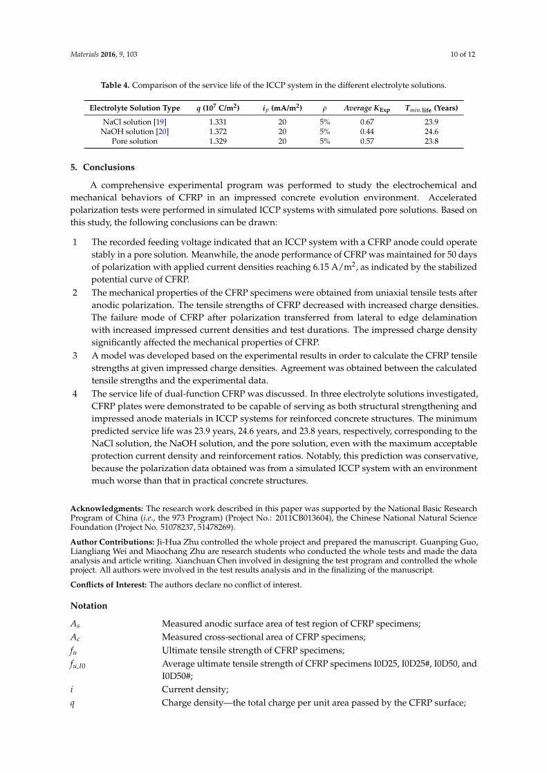
Table 4 shows the minimum service life of the ICCP system. When the protection current density
is 20 mA/m2 and the reinforcement ratio is 5%, the minimum service life of 24.6 years is achieved in
the pore electrolyte solution environment. The service life is roughly equal, compared to the service
life in the NaCl and NaOH solutions. In these three solutions, the residual tensile strengths of CFRP
minimum were only 44% when in NaOH solution. According to the NACE Standard TM0294‐2007 [12], accelerated testing shall be conducted in
duplicate in the three aqueous solutions (NaCl, NaOH, and pore solution). As shown in Table 4,
previous research demonstrates that CFRP plate can be successfully used as the anode material in the
ICCP system over an acceptable service period, without significant degradation of the mechanical
properties for structural strengthening. Notably, the predicted service life is conservative, since the
polarization was conducted in a simulated ICCP system in which the corrosion environment was
much more severe than it is in practical concrete structures.
Table 4. Comparison of the service life of the ICCP system in the different electrolyte solutions.
Electrolyte Solution Type q (107 C/m2) ip (mA/m2) ρ Average KExp Tmin.life (Years)
NaCl solution [19] 1.331 20 5% 0.67 23.9
NaOH solution [20] 1.372 20 5% 0.44 24.6
Pore solution 1.329 20 5% 0.57 23.8
Figure 7. An eight-steel rebar-reinforced concrete element wrapped with CFRP plate as an anode.
Table 4 shows the minimum service life of the ICCP system. When the protection current densityis 20 mA/m2 and the reinforcement ratio is 5%, the minimum service life of 24.6 years is achieved inthe pore electrolyte solution environment. The service life is roughly equal, compared to the servicelife in the NaCl and NaOH solutions. In these three solutions, the residual tensile strengths of CFRPminimum were only 44% when in NaOH solution.
According to the NACE Standard TM0294-2007 [12], accelerated testing shall be conducted induplicate in the three aqueous solutions (NaCl, NaOH, and pore solution). As shown in Table 4,previous research demonstrates that CFRP plate can be successfully used as the anode material in theICCP system over an acceptable service period, without significant degradation of the mechanicalproperties for structural strengthening. Notably, the predicted service life is conservative, since thepolarization was conducted in a simulated ICCP system in which the corrosion environment wasmuch more severe than it is in practical concrete structures.
Materials 2016, 9, 103 10 of 12
Table 4. Comparison of the service life of the ICCP system in the different electrolyte solutions.
Electrolyte Solution Type q (107 C/m2) ip (mA/m2) ρ Average KExp Tmin.life (Years)
NaCl solution [19] 1.331 20 5% 0.67 23.9NaOH solution [20] 1.372 20 5% 0.44 24.6
Pore solution 1.329 20 5% 0.57 23.8
5. Conclusions
A comprehensive experimental program was performed to study the electrochemical andmechanical behaviors of CFRP in an impressed concrete evolution environment. Acceleratedpolarization tests were performed in simulated ICCP systems with simulated pore solutions. Based onthis study, the following conclusions can be drawn:
1 The recorded feeding voltage indicated that an ICCP system with a CFRP anode could operatestably in a pore solution. Meanwhile, the anode performance of CFRP was maintained for 50 daysof polarization with applied current densities reaching 6.15 A/m2, as indicated by the stabilizedpotential curve of CFRP.
2 The mechanical properties of the CFRP specimens were obtained from uniaxial tensile tests afteranodic polarization. The tensile strengths of CFRP decreased with increased charge densities.The failure mode of CFRP after polarization transferred from lateral to edge delaminationwith increased impressed current densities and test durations. The impressed charge densitysignificantly affected the mechanical properties of CFRP.
3 A model was developed based on the experimental results in order to calculate the CFRP tensilestrengths at given impressed charge densities. Agreement was obtained between the calculatedtensile strengths and the experimental data.
4 The service life of dual-function CFRP was discussed. In three electrolyte solutions investigated,CFRP plates were demonstrated to be capable of serving as both structural strengthening andimpressed anode materials in ICCP systems for reinforced concrete structures. The minimumpredicted service life was 23.9 years, 24.6 years, and 23.8 years, respectively, corresponding to theNaCl solution, the NaOH solution, and the pore solution, even with the maximum acceptableprotection current density and reinforcement ratios. Notably, this prediction was conservative,because the polarization data obtained was from a simulated ICCP system with an environmentmuch worse than that in practical concrete structures.
Acknowledgments: The research work described in this paper was supported by the National Basic ResearchProgram of China (i.e., the 973 Program) (Project No.: 2011CB013604), the Chinese National Natural ScienceFoundation (Project No. 51078237, 51478269).
Author Contributions: Ji-Hua Zhu controlled the whole project and prepared the manuscript. Guanping Guo,Liangliang Wei and Miaochang Zhu are research students who conducted the whole tests and made the dataanalysis and article writing. Xianchuan Chen involved in designing the test program and controlled the wholeproject. All authors were involved in the test results analysis and in the finalizing of the manuscript.
Conflicts of Interest: The authors declare no conflict of interest.
Notation
As Measured anodic surface area of test region of CFRP specimens;Ac Measured cross-sectional area of CFRP specimens;fu Ultimate tensile strength of CFRP specimens;fu,I0 Average ultimate tensile strength of CFRP specimens I0D25, I0D25#, I0D50, and
I0D50#;i Current density;q Charge density—the total charge per unit area passed by the CFRP surface;
Materials 2016, 9, 103 11 of 12
K Deterioration factor;KExp Experimental deterioration factor;KCal Calculated deterioration factor;V Feeding voltage or potential;ip Protection current density;n Number of steel rebars in the concrete element;Qanode Anode’s capacity to transfer charges;Qcathode Total charge quantity past the cathode during cathodic protection;QCFRP CFRP plate’s capacity to transfer charge;Qsteel Total charge quantity past the steel in the concrete element during
cathodic protection;tg Duration of impressed current;tlife Predicted service life of the ICCP system by QCFRP;ρ Reinforcement ratio.
References
1. Jing, X.; Wu, Y. Electrochemical studies on the performance of conductive overlay material in cathodicprotection of reinforced concrete. Constr. Build. Mater. 2011, 25, 2655–2662. [CrossRef]
2. Bertolini, L.; Bolzoni, F.; Pedeferri, P.; Lazzari, L.; Pastore, T. Cathodic protection and cathodic preventioninconcrete: principles and applications. J. Appl. Electrochem. 1998, 28, 1321–1331. [CrossRef]
3. Hong, D.; Fan, W.; Luo, D.; Ge, Y.; Zhu, Y. Study and application of impressed current cathodic protectiontechnique for atmospherically exposed salt-contaminated reinforced concrete structures. ACI Mater. J. 1993,90, 3–7.
4. Pedeferri, P. Cathodic protection and cathodic prevention. Constr. Build. Mater. 1996, 10, 391–402. [CrossRef]5. Barnhart, R. FHWA position on cathodic protection systems. Memorandum of FHWA; US Federal Highway
Administration: Washington, DC, USA, 1982.6. Lambert, P.; Van Nguyen, C.; Mangat, P.S.; O’Flaherty, F.J.; Jones, G. Dual function carbon fibre fabric
strengthening and impressed current cathodic protection (ICCP) anode for reinforced concrete structures.Mater. Struct. 2015, 48, 2157–2167. [CrossRef]
7. Shao, Z.-G.; Zhu, F.; Lin, W.-F.; Christensen, P.A.; Zhang, H.; Yi, B. Preparation and characterization ofnew anodes based on Ti mesh for direct methanol fuel cells. J. Electrochem. Soc. 2006, 153, A1575–A1583.[CrossRef]
8. Holcomb, G.; Bullard, S.; Covino, B., Jr.; Cramer, S.; Cryer, C.; McGill, G. Electrochemical Aging ofThermal-Sprayed Zinc Anodes on Concrete; Albany Research Center: Albany, OR, USA, 1996; pp. 185–192.
9. Clemena, G.G.; Jackson, D.R. Performance of a Conductive-Paint Anode in Cathodic Protection Systems for InlandConcrete Bridge Piers in Virginia; Virginia Transportation Research Council Research Report, VTRC 98-R7;Virginia Transportation Research Council: Charlottesville, VA, USA, 1997.
10. Orlikowski, J.; Cebulski, S.; Darowicki, K. Electrochemical investigations of conductive coatings applied asanodes in cathodic protection of reinforced concrete. Cement Concr. Compos. 2004, 26, 721–728. [CrossRef]
11. Nguyen, C.; Mangat, P.; Lambert, P.; O’Flaherty, F.; Jones, G. Dual function carbon fibre strengthening andcathodic protection anode for reinforced concrete structures. In Concrete Repair, Rehabilitation and RetrofittingIII; Taylor & Francis Group: London, UK, 2012; pp. 1179–1185.
12. NACE International. Testing of Embeddable Impressed Current Anodes for Use in Cathodic Protection ofAtmospherically Exposed Steel-Reinforced Concrete; NACE: Houston, TX, USA, 2007.
13. O’Flaherty, F.J.; Mangat, P.S.; Lambert, P.; Browne, E.H. Effect of under-reinforcement on the flexural strengthof corroded beams. Mater. Struct. 2007, 41, 311–321. [CrossRef]
14. Al-Mahmoud, F.; Castel, A.; Francois, R.; Tourneur, C. Strengthening of RC members with near-surfacemounted CFRP rods. Compos. Struct. 2009, 91, 138–147. [CrossRef]
15. Motavalli, M.; Czaderski, C.; Pfyl-Lang, K. Prestressed CFRP for Strengthening of Reinforced ConcreteStructures: Recent Developments at Empa, Switzerland. J. Compos. Constr. 2011, 15, 194–205. [CrossRef]
Materials 2016, 9, 103 12 of 12
16. Raupach, M.; Elsener, B.; Polder, R.; mietz, J. Corrosion of Reinforcement in Concrete. Mechanisms, Monitoring,Inhibitors and Rehabilitation Techniques; Woodhead Publishing Limited: Cambridge, UK, 2007.
17. Lee-Orantes, F.; Torres-Acosta, A.; Martínez-Madrid, M.; López-Cajún, C. Cathodic Protection in ReinforcedConcrete Elements, using Carbon Fibers Base Composites. ECS Trans. 2007, 3, 93–98.
18. Nguyen, C.; Lambert, P.; Mangat, P.; O’Flaherty, F.; Jones, G. The performance of carbon fibre composite asICCP anode for reinforced concrete structures. ISRN Corros J. 2012, 10, 814–923. [CrossRef]
19. Sun, H.; Zhu, M.; Han, N.; Zhu, J.-H.; Xing, F. Corrosion behavior of carbon fiber reinforced polymer anodein simulated impressed current cathodic protection system with 3% NaCl solution. Constr. Build. Mater. 2014.subbmitted.
20. Zhu, J.-H.; Guo, G.; Zhu, M.; Fang, Y.; Chen, X.; Xing, F. Mechanical and electrochemical performance ofcarbon fiber-reinforced polymer in oxygen evolution environment. Appl. Compos. Mater. 2015. subbmitted.
21. Zhu, J.-H.; Zhu, M.; Han, N.; Liu, W.; Xing, F. Electrical and Mechanical Performance of CarbonFiber-Reinforced Polymer Used as the Impressed Current Anode Material. Materials 2014, 7, 5438–5453.[CrossRef]
22. American Society for Testing and Materials (Filadelfia). Standard Test Method for Tensile Properties of Plastics;ASTM International: West Conshohocken, PA, USA, 2010.
23. American Society for Testing and Materials. Standard Test Method for Tensile Properties of Polymer MatrixComposite Materials; ASTM International: West Conshohocken, PA, USA, 2008.
24. Hara, E.; Yokozeki, T.; Hatta, H.; Ishikawa, T.; Iwahori, Y. Effects of geometry and specimen size onout-of-plane tensile strength of aligned CFRP determined by direct tensile method. Compos. Part A Appl. Sci.Manuf. 2010, 41, 1425–1433. [CrossRef]
25. Ueda, T.; Dai, J. Interface bond between FRP sheets and concrete substrates: properties, numerical modelingand roles in member behaviour. Prog. Struct. Eng. Mater. 2005, 7, 27–43. [CrossRef]
26. Peng, H.; Wang, H.; Chen, J.; Zhang, K. Experimental Study on Bond Performance of Near-Surface-MountedCFRP Strips-Concrete Interface. In Proceedings of the 2013 Fourth International Conference on DigitalManufacturing & Automation (ICDMA), Qing Dao, China, 29 June 2013; pp. 586–590.
27. Palmieri, A.; Matthys, S.; Barros, J.A.O.; Costa, I.; Bilotta, A.; Nigro, E.; Ceroni, F.; Szambo, Z.; Balazs, G.Bond of NSM FRP strengthened concrete: round robin test initiative. In Proceedings of the 6th InternationalConference on FRP Composites in Civil Engineering (CICE—2012), Rome, Italy, 13–15 June 2012; pp. 1–8.
28. Cruz, J.M.D.S. Bond Between Near-Surface Mounted Carbon-Fiber-Reinforced Polymer Laminate Strips andConcrete. J. Compos. Constr. 2014, 8, 519–527. [CrossRef]
© 2016 by the authors; licensee MDPI, Basel, Switzerland. This article is an open accessarticle distributed under the terms and conditions of the Creative Commons by Attribution(CC-BY) license (http://creativecommons.org/licenses/by/4.0/).