Embed Size (px)
Citation preview

Dual-Fuel Effects on HCCI Operating Range: Experiments with Primary Reference Fuels
Preprint Cambridge Centre for Computational Chemical Engineering ISSN 1473 – 4273
Dual-Fuel Effects on HCCI Operating Range:Experiments with Primary Reference Fuels
Ali Aldawood 1,2, Sebastian Mosbach 1, Markus Kraft 1, Amer Amer 2
released: 05 April 2013
1 Department of Chemical Engineeringand BiotechnologyUniversity of CambridgeNew Museums SitePembroke StreetCambridge, CB2 3RAUnited KingdomE-mail: [email protected]
2 R&D CenterSaudi AramcoDhahran, Saudi Arabia
Preprint No. 125
Keywords: HCCI control, dual-fuel HCCI, HCCI range, intake temperature effects
Edited by
CoMoGROUP
Computational Modelling GroupDepartment of Chemical Engineering and BiotechnologyUniversity of CambridgeNew Museums SitePembroke StreetCambridge CB2 3RAUnited Kingdom
Fax: + 44 (0)1223 334796E-Mail: [email protected] Wide Web: http://como.ceb.cam.ac.uk/

Abstract
Results from a large set of HCCI experiments performed on a single-cylinderresearch engine fueled with different mixtures of iso-octane and n-heptane are pre-sented and discussed in this paper. The experiments are designed to scrutinize fuelreactivity effects on the operating range of an HCCI engine. The fuel effects onupper and lower operating limits are measured respectively by the maximum pres-sure rise rate inside the cylinder and the stability of engine operation as determinedby cycle-to-cycle variations in IMEP. Another set of experiments that examine theintake air heating effects on HCCI engine performance, exhaust emissions and oper-ating envelopes is also presented. The effects of fuel reactivity and intake air heatingon the HCCI ranges are demonstrated by constructing the operating envelopes for thedifferent test fuels and intake temperatures. The paper discusses, in the light of theresults, how the nonlinearity in fuel effects makes the dual fuel control approach lesseffective in extending the lower end of the HCCI load range. It also discusses howintake air heating affects the engine operation stability at low loads, and how varyingfuel reactivity and intake heating can complement each other as an integrated controlapproach to extend both ends of the HCCI load range.
1

Contents
1 Introduction 3
2 Experimental Setup 4
3 Dual-Fuel Effects 6
3.1 Results and Discussion . . . . . . . . . . . . . . . . . . . . . . . . . . . 6
4 Intake Temperature Effects 14
4.1 Results and Discussion . . . . . . . . . . . . . . . . . . . . . . . . . . . 14
5 Summary and Conclusions 22
6 Acknowledgement 29
7 Definitions, Acronyms and Abbreviations 29
References 30
2

1 Introduction
The lack of external control in HCCI engine results in difficulties at low and high loadoperation. The low combustion temperature at low loads becomes insufficient to sustaina complete combustion which results in increased emission of carbon monoxide and hy-drocarbons. Misfire eventually takes place limiting the low load operating range of theengine. At high loads, the rapid heat release causes the engine operation to become verynoisy and unstable. Knocking starts to occur and thermal efficiency deteriorates as a resultof increased heat losses, setting a limit to the upper range of operation. Misfire at low loadand knocking at high load result in a narrow HCCI operating envelope.
Several combustion control strategies have been suggested and studied over the last decadeto overcome the HCCI limited operating range. Examples of these strategies include us-ing intake air heating, internal/external exhaust gas recirculation, variable compressionratio, variable dual fuel mixtures, and charge and thermal stratification. In general, thesemethods try to control the chemical reactions by controlling the combustion temperatureand pressure or by altering the species involved in the reactions.
The dual fuel approach for controlling the combustion in HCCI engine has received greatattention in recent years, and many control strategies based on this approach are underinvestigation. In this approach, two fuels with sufficiently different reactivity and com-bustion characteristics are used, and the combustion control is achieved by mixing the twofuels according to the conditions inside the cylinder.
Previous studies that investigated the dual-fuel approach include the work reported byOlsson et al. [9], Lu et al. [6], Atkins and Koch [3], and Ogura et al. [8]. These relativelyearly studies used primary reference fuels in their investigations. More recent studies usedcommercial fuels or mixtures of single-component and commercial fuels. Examples offuels considered in these studies include mixtures of ethanol and n-heptane [10]; mixturesof n-heptane and diesel [7]; and mixtures of gasoline and diesel [4, 5]. All of these studiesreported some positive results and varying levels of feasibility.
The current paper describes results from a set of HCCI experiments performed usingtwo primary reference fuels, namely the iso-octane and n-heptane. A limited part ofthese results was presented in previous papers focusing on HCCI model development andoptimization [1, 2]. The experiments aimed to examine the feasibility of the dual fuelcontrol approach for extending the HCCI operating range. The fuel effects on operatinglimits were characterized through the variations in maximum pressure rise rate and thestability of engine operation as determined by cycle-to-cycle variations in indicated meaneffective pressure. The results were used to construct engine operating envelopes for thedifferent fuels, providing a visual demonstration and a quantification of the potential ofthe dual fuel approach to extend the HCCI operating window.
In addition to the dual-fuel effects, the paper also discusses the effects of intake air tem-perature on engine operation stability and the lower load limit. It also discusses howvarying fuel reactivity and intake heating can complement each other as an integratedcontrol approach for extending both ends of the HCCI load range.
While the current study tries to provide a useful insight on the potential of the dual-fuelapproach, and while the use of primary reference fuels is convenient to generally represent
3

3
1
4
68
6
19
20
15
14
5
17
10 11
13
12
16
2
7
18
9
Air
1. Single-cylinder research engine2. AC dynamometer3. Crank shaft encoder4. Pressure transducer5. Combustion analysis system6. Hydro-actuated intake/exhaust valve7. Valve hydraulic actuation unit
8.Port fuel injector9. Fuel line10. Fuel pump andtemperature controller11. Fuel tank12. Intake air humidity controller13. Intake air compressor and heater
mass flow meter,
14. Hot-wire air mass flow sensor15. Intake plenum16. Engine controller17. Test cell controller18. Exhaust gas analyzers19. Exhaust plenum20. Exhaust back pressure valve
THC
NOx
CO
CO2
O2
Figure 1: The single-cylinder research engine test setup used in the current study.
gasoline-like fuels, it is understood that the performance of actual gasoline or gasoline-likefuels could be noticeably different in HCCI engine. Being alkanes, the primary referencefuels might not be able to capture the combustion behaviors of other constituents, like aro-matics, that exist in real fuels. The results presented hereafter therefore can only providea qualitative indication of the potential of the dual fuel approach.
2 Experimental Setup
Figure 1 shows a schematic of the engine test facility used in this work. The setup consistsof a single-cylinder research engine coupled to a 45 kW AC dynamometer, a fast-responseengine controller, a combustion analysis system, exhaust gas analyzers, air and fuel massflow meters, intake air boosting unit, and conditioning units for intake air and fuel. Thetest facility also contains heat exchangers for cooling water and lubrication oil. Both thecoolant water and the lubrication oil were kept at 90oC throughout the experiments.
The main specifications of the single-cylinder engine are listed in Table 1. The engine hasa pent-roof combustion chamber head fitted with four hydro-actuated valves (see Figure
4

PISTON TOP
PENT‐ROOF HEAD
Intake valves Exhaust valves
Spark plugDirect injector
Figure 2: Combustion chamber head and piston top of the single-cylinder test engine.
2). The piston top contains the combustion chamber bowl along with deep valve recessesto allow increased range of authority.
Table 1: Single-cylinder engine specifications and valve timing. Crank angles here aremeasured with respect to the firing TDC.
Cylinder displacement 499 cm3
Stroke 90 mmBore 84 mmConnecting rod length 159 mmCompression ratio 12:1Number of valves 4Fuel delivery system PFIExhaust valve open 170o
Exhaust valve close -352o
Intake valve open -356o
Intake valve close -156o
Fuel is delivered to the engine via an electromagnetic port fuel injector located at theend of the intake port just above the inlet valves. The fuel mass flow rate is measuredcontinuously using a Coriolis flowmeter, and the fuel temperature is kept at 20oC by atemperature controller integrated with the flowmeter and fuel circulation unit. The tem-perature and humidity of the intake air are controlled by a dehumidifier and a heater, whilethe pressure is controlled by a pressure boosting unit. The air mass flow rate is measuredusing a hot-wire flowmeter.
5
The combustion analysis system uses a piezo-resistive pressure sensor to measure thecylinder pressure, and a high-resolution crank angle encoder to determine the crankshaftposition. The exhaust gas analyzers consist of non-dispersive infrared units to measurecarbon monoxide and carbon dioxide, a heated flame ionization detector to measure totalhydrocarbons, a chemiluminescence detector to measure nitrogen oxides, and a magneto-pneumatic detector to measure the oxygen.
3 Dual-Fuel Effects
All experiments were performed at a constant boosted intake pressure of 1.5 bar andan intake air temperature of 75oC, and without using exhaust gas recirculation. Whilemaintaining a constant turbocharging pressure might not be normally possible at low en-gine load, the boosting was found to be necessary to operate the current, relatively lowcompression-ratio, engine in HCCI mode at low load. The engine backpressure was keptat 1.5 bar in all experiments.
The engine was fueled with primary reference fuels at three different volume ratios:PRF40 (i.e. 40% iso-octane and 60% n-heptane), PRF60 and PRF80. The three testfuels were blended externally, and sufficient purging was conducted before running eachfuel. Load sweeps were performed at three constant speeds of 1200, 1500 and 1800 rpm.The upper and lower bounds of the load range (i.e. by knocking and misfire limits) arefirst identified at each speed, and then a number of load points are determined along theidentified range. Cylinder pressure data for 300 consecutive cycles are collected at eachtest point after allowing sufficient operation settling time, and associated operational dataat each test point are collected at 0.1 second intervals for a period of 60 seconds.
3.1 Results and Discussion
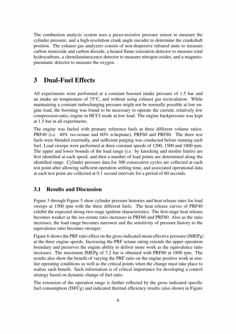
Figure 3 through Figure 5 show cylinder pressure histories and heat release rates for loadsweeps at 1500 rpm with the three different fuels. The heat release curves of PRF40exhibit the expected strong two-stage ignition characteristics. The first-stage heat releasebecomes weaker as the iso-octane ratio increases in PRF60 and PRF80. Also as the ratioincreases, the load range becomes narrower and the sensitivity of pressure history to theequivalence ratio becomes stronger.
Figure 6 shows the PRF ratio effect on the gross indicated mean effective pressure (IMEPg)at the three engine speeds. Increasing the PRF octane rating extends the upper operationboundary and preserves the engine ability to deliver more work as the equivalence ratioincreases. The maximum IMEPg of 7.2 bar is obtained with PRF80 at 1800 rpm. Theresults also show the benefit of varying the PRF ratio on the engine positive work at sim-ilar operating conditions as well as the critical points when the change must take place torealize such benefit. Such information is of critical importance for developing a controlstrategy based on dynamic change of fuel ratio.
The extension of the operation range is further reflected by the gross indicated specificfuel consumption (ISFCg) and indicated thermal efficiency results (also shown in Figure
6

−20 −10 0 10 20 3020
30
40
50
60
70
80
90
Cyl
inde
r P
ress
ure
(bar
)
Φ=0.323
0.290
0.258
0.230
0.195
1500 rpmPRF40
−20 −10 0 10 20 30
0
20
40
60
80
100
120
HR
R (
J/de
g)
Φ=0.323
0.290
0.258
0.230
0.195
CAD (deg)
Student Version of MATLAB
Figure 3: Cylinder pressure histories and heat release rates for a load sweep at 1500 rpmwith PRF40 fuel. The heat release curves show the expected strong two-stageignition characteristics of PRF40.
7
−20 −10 0 10 20 3020
30
40
50
60
70
80
90
Cyl
inde
r P
ress
ure
(bar
)
Φ=0.321
0.293
0.270
0.253
0.225
1500 rpmPRF60
−20 −10 0 10 20 30
0
20
40
60
80
100
120
HR
R (
J/de
g)
Φ=0.321
0.293
0.270
0.253
0.225
CAD (deg)
Student Version of MATLAB
Figure 4: Cylinder pressure histories and heat release rates for a load sweep at 1500 rpmwith a PRF60 fuel.
8

−20 −10 0 10 20 3020
30
40
50
60
70
80
90
Cyl
inde
r P
ress
ure
(bar
) Φ=0.358
0.346
0.336
0.324
1500 rpmPRF80
−20 −10 0 10 20 30
0
20
40
60
80
100
120
HR
R (
J/de
g)
Φ=0.358
0.346
0.336
0.324
CAD (deg)
Student Version of MATLAB
Figure 5: Cylinder pressure histories and heat release rates for a load sweep at 1500 rpmwith a PRF80 fuel. The pressure history is strongly sensitive to equivalenceratio.
9

0.1 0.2 0.3 0.40
2
4
6
81200 rpm
Gro
ss IM
EP
(ba
r)
PRF40
PRF60
PRF80
0.1 0.2 0.3 0.4100
200
300
400
500
Gro
ss IS
FC
(g/
kW.h
)
0.1 0.2 0.3 0.40
0.1
0.2
0.3
0.4
0.5
Indi
cate
d E
ffici
ency
, η
Φ
0.1 0.2 0.3 0.40
2
4
6
81500 rpm
0.1 0.2 0.3 0.4100
200
300
400
500
0.1 0.2 0.3 0.40
0.1
0.2
0.3
0.4
0.5
Φ
0.1 0.2 0.3 0.40
2
4
6
81800 rpm
0.1 0.2 0.3 0.4100
200
300
400
500
0.1 0.2 0.3 0.40
0.1
0.2
0.3
0.4
0.5
Φ
Student Version of MATLAB
Figure 6: Gross IMEP, ISFC and indicated efficiency for the three fuels. Increasing theoctane rating (i.e. decreasing the fuel reactivity) extends the upper operationboundary and preserves the engine ability to deliver more work as the equiv-alence ratio increases. It also extends the plateau where the specific fuel con-sumption is minimal and indicated efficiency is maximal. The results in generalreflect the expected low specific fuel consumption and high efficiency charac-teristics of the HCCI engine.
10

6). Increasing the octane rating extends the plateau where the ISFCg is minimal andindicated efficiency is maximal. This plateau, as explained later, defines the operationrange of the HCCI engine. A minimum ISFCg of 185.5 g/kW.h and a maximum indicatedefficiency of 44% are obtained with PRF80 at 1800 rpm. A slight increase in ISFCg anddecrease in indicated efficiency are observed with decreasing engine speed, but the resultsin general reflect the expected low specific fuel consumption and high thermal efficiencycharacteristics of the HCCI engine.
Figure 7 shows the results of CO, HC, and NOx emissions for the three speeds. HC emis-sions plateau around 1500 ppm through most of the operating range, but start to increasesharply as the engine approaches the misfire region that extends over a wide equivalenceratio range until the motoring limit. As the occurrence of misfiring cycles increases, morehydrocarbons escape the combustion chamber unburned. HC emissions normally origi-nate both in the bulk gas and in the piston crevices, but the complex combustion chamberand piston design of the current engine appear to be specially conducive for increasedcrevice unburned hydrocarbons.
A slight increase in HC and CO emissions is observed with higher PRF ratios. This maybe attributed to the increasing cycle to cycle variations observed generally with higherPRF ratio fuels (as can be seen in Figure 8). It is also observed that the climax of COemissions within the misfire region corresponds to the start of increasing trends for bothHC and NOx emissions. This may indicate a special significance of this inflection pointwhere the CO starts to decrease and both HC and NOx start to increase. Such point couldbe used to mark the lower end of the practical load range of the HCCI engine. Thisinflection point is found to correspond here to about 6% IMEP COV. However as thispoint is characterized by significantly high CO levels, the lower load limit is set in thiswork to correspond to 5% IMEP COV as discussed below.
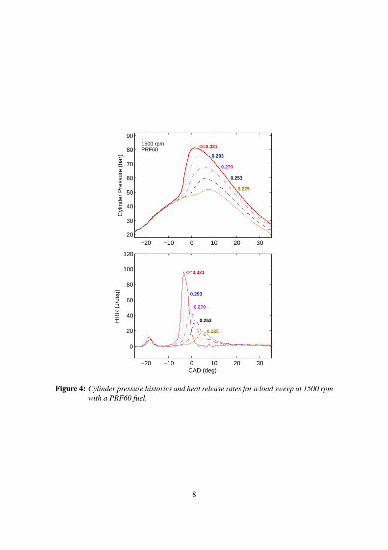
The boundaries of operation at the tested speeds can be inferred from Figure 8 whichshows the readings of maximum pressure rise rate (MPRR) and coefficient of variationin the indicated means effective pressure (IMEP COV). The HCCI operating windowis limited at the high end by the occurrence of knock and at the lower end by misfire.These two limits can be determined respectively in terms of MPRR and IMEP COV. Theselection of specific values for these quantities is based in this work on observing theefficiency curve obtained with each PRF fuel.
The results show that the efficiency plateaus around a maximum value within a certainload range, and drops on both sides due to the occurrence of misfire in the lower side andknock in the upper side. The boundaries of efficiency plateau in the current experimentswere generally found to correspond to an MPRR of about 7 MPa/ms on the high loadlimit (HLL) and 3.5% IMEP COV in the low load limit (LLL). This range is also charac-terized by relatively low CO and HC emissions, as can be seen in Figure 9. However, areasonable extension of the operating range for each fuel can be achieved by relaxing theconstraint on LLL to 5% IMEP COV. This relaxation results in a noticeable, but arguablytolerable, penalty in terms of efficiency and CO emissions. Figure 9 illustrates the defi-nition of the operating range adopted in this work and the impact of relaxing the IMEPCOV constraint on the LLL. For the specific example given in the figure, the maximumgross indicated efficiency plateaus at about 43%, but the LLL corresponds to about 35%.The CO emissions amount to about 1.4% at the 5% IMEP COV constraint compared to
11

0.1 0.2 0.3 0.40
0.5
1
1.5
2
CO
(%
)
0.1 0.2 0.3 0.40
0.5
1
1.5
2x 10
4
HC
(pp
m)
(1200 rpm)
0.1 0.2 0.3 0.40
2
4
6
8
NO
x (p
pm)
Φ
0.1 0.2 0.3 0.40
0.5
1
1.5
2
0.1 0.2 0.3 0.40
0.5
1
1.5
2x 10
4 (1500 rpm)
PRF40PRF60PRF80
0.1 0.2 0.3 0.40
2
4
6
8
Φ
0.1 0.2 0.3 0.40
0.5
1
1.5
2
0.1 0.2 0.3 0.40
0.5
1
1.5
2x 10
4 (1800 rpm)
0.1 0.2 0.3 0.40
2
4
6
8
Φ
Student Version of MATLAB
Figure 7: Exhaust HC, CO, and NOx emissions for the three fuels at 1200 rpm. HCemissions plateau around 1500 ppm through most of the operating range, butstart to increase sharply as the engine approaches the misfire region. The COemissions show very strong sensitivity to operating conditions, ranging from0.1% near the maximum load to about 1.8% in the misfire region. The extremelylow levels of NOx reflect the low temperature combustion regime characterizingthe HCCI engine.
12
0.1 0.2 0.3 0.40
0.1
0.2
0.3
0.4
0.5
IME
P C
oV
1200rpm
0.1 0.2 0.3 0.40
2
4
6
8
Max
. PR
R (
MP
a/m
s)
1200rpm
PRF40PRF60PRF80
0.1 0.2 0.3 0.40
0.1
0.2
0.3
IME
P C
oV
1500rpm
0.1 0.2 0.3 0.40
2
4
6
8M
ax. P
RR
(M
Pa/
ms)
1500rpm
0.1 0.2 0.3 0.40
0.2
0.4
0.6
0.8
IME
P C
oV
Φ
1800rpm
0.1 0.2 0.3 0.40
2
4
6
8
Max
. PR
R (
MP
a/m
s)
Φ
1800rpm
Student Version of MATLAB
Figure 8: Maximum pressure rise rate and variation of mean effective pressure withequivalence ratio. Error bars on maximum pressure rise values represent ±1standard deviation. Increasing the fuel reactivity increases the engine stabil-ity at lower loads but on the other hand makes the engine more susceptible toknock at higher loads. The upper boundary of the operating envelope is set at7 MPa/ms and the lower boundary is set at 5% IMEP COV.
13

only 0.4% at 3.5% IMEP COV. Although the gain in the operating range in this exampleis not significant, reasonable gains are observed for other fuels and conditions.
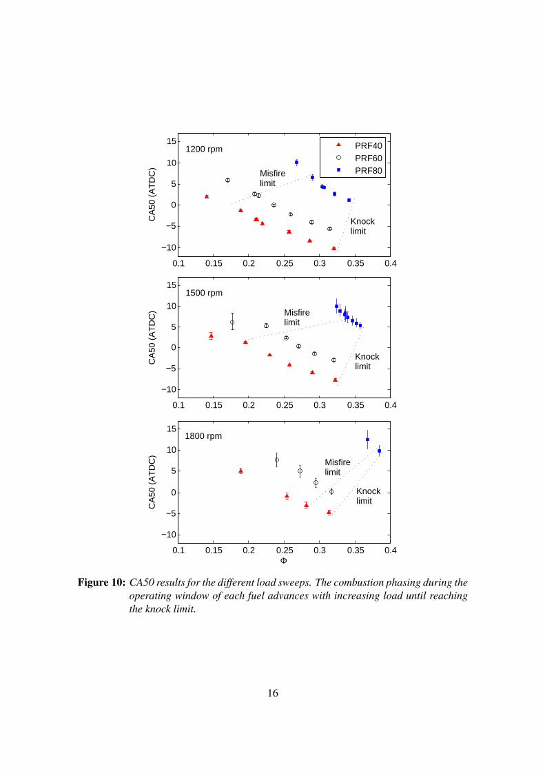
The CA50 results for all load sweeps are shown in Figure 10. The misfire and knocklimits are determined using the conventions described above. For each fuel, the combus-tion phasing advances with increasing load until reaching the knock limit. The operatingwindow becomes narrower with increasing load and speed.
To illustrate these effects further, the engine operation envelopes for the different PRFfuels are constructed in Figure 11. While the envelopes shrink as the PRF octane ratingincreases, they also move upward allowing the engine to operate at higher equivalenceratios and to produce more positive work. The constructed envelopes provide a visualdemonstration of the potential of the dual fuel approach to extend the HCCI operatingwindow. A fueling system that can dynamically vary the ratio between the two fuel com-ponents based on the operating conditions, will allow the HCCI engine to operate at amuch wider operating range. This premise was examined further in a previous modelingstudy in [2].
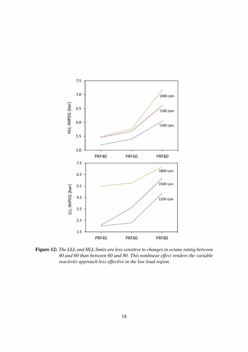
While these results point out to a clear potential for the variable fuel reactivity to expandthe HCCI operating range, they show also that both the LLL and HLL are generally lesssensitive to changes in octane rating between 40 and 60 than between 60 and 80, as il-lustrated in Figure 12. In other words, increasing the reactivity of the PRF fuel becomesincreasingly less effective in controlling the HCCI operation as the engine load decreases.This nonlinear effect may necessitate the use of other combustion control means to com-plement the dual fuel approach during low load operation. One of these possible means isdiscussed in the following section. Other means like varying the compression ratio couldalso be considered for the purpose.
4 Intake Temperature Effects
The results presented in the previous section, while indicating a clear potential for the dualfuel to expand the HCCI operating range, show that the approach becomes less effectiveas the load decreases. For this reason, a set of experiments were carried out to study thepotential of intake air heating as a complementary part to the dual fuel strategy during lowload conditions.
The experiments reported in this section were carried out at the same conditions describedin the previous section, except for the intake air temperature that was raised from 75oCto 90oC. The operating limits conventions described earlier were also applied here. Assuch, a maximum pressure rise rate of 7 MPa/ms was used to mark the high load limit andIMEP COV of 5% was used to mark the low load limit.
4.1 Results and Discussion
Figure 13 through Figure 15 compare the gross ISFC and indicated efficiency results forthe two intake air temperature cases. For both engine speeds of 1200 and 1500 rpm, the
14

0.1 0.15 0.2 0.25 0.3 0.350
2
4
6
8M
ax. P
RR
(M
Pa/
ms)
0.1 0.15 0.2 0.25 0.3 0.350
0.1
0.2
IME
P C
oV
0.1 0.15 0.2 0.25 0.3 0.350
0.2
0.4
Indi
cate
d E
ffici
ency
, η
0.1 0.15 0.2 0.25 0.3 0.350
1
2
CO
(%
)
0.1 0.15 0.2 0.25 0.3 0.350
1
2x 10
4
HC
(pp
m)
Φ
Lowloadlimit
Highloadlimit
IAT = 75oC1500 rpmPRF60
0.05
0.35
7.0
Operating range
Student Version of MATLAB
Figure 9: Definition of the HCCI operating limits. The two limits are set around the edgesof the efficiency plateau, with the high limit adhering more to the upper edgeto avoid knocking operation. The low limit is characterized by rapid decline inefficiency and rise in CO emissions.
15
0.1 0.15 0.2 0.25 0.3 0.35 0.4
−10
−5
0
5
10
15C
A50
(A
TD
C)
1200 rpm
0.1 0.15 0.2 0.25 0.3 0.35 0.4
−10
−5
0
5
10
15
CA
50 (
AT
DC
)
1500 rpm
0.1 0.15 0.2 0.25 0.3 0.35 0.4
−10
−5
0
5
10
15
CA
50 (
AT
DC
)
Φ
1800 rpm
PRF40PRF60PRF80Misfire
limit
Misfirelimit
Misfirelimit
Knocklimit
Knocklimit
Knocklimit
Student Version of MATLAB
Figure 10: CA50 results for the different load sweeps. The combustion phasing during theoperating window of each fuel advances with increasing load until reachingthe knock limit.
16

Figure 11: HCCI operation envelopes for the different PRF ratio fuels. While the en-velopes shrink as the PRF octane rating increases, they also move upwardallowing the engine to operate at higher equivalence ratios and to producemore work.
17
Page 9 of 16
Figure 15: HCCI operation envelopes for the different PRF ratio fuels. While the envelopes shrink as the PRF octane
rating increases, they also move upward allowing the engine to operate at higher equivalence ratios and to produce more
work.
Figure 16: The LLL and HLL limits are less sensitive to changes in octane rating between 40 and 60 than between 60 and 80. This nonlinear effect renders the variable reactivity
approach less effective in the low load region.
While these results point out to a clear potential for the variable fuel reactivity to expand the HCCI operating range, they show also that both the LLL and HLL are generally less sensitive to changes in octane rating between 40 and 60 than between 60 and 80, as illustrated in Figure 16. In other words, increasing the reactivity of the PRF fuel becomes increasingly less effective in controlling the HCCI operation as the engine load decreases. This nonlinear effect may necessitate the use of other combustion control means to complement the dual fuel approach during low load operation. One of these possible means is discussed in the following section. Other means like varying the compression ratio could also be considered for the purpose.
INTAKE TEMPERATURE EFFECTS
The results presented in the previous section, while indicating a clear potential for the dual fuel to expand the HCCI operating range, show that the approach becomes less effective as the load decreases. For this reason, a set of experiments were carried out to study the potential of intake air heating as a complementary part to the dual fuel strategy during low load conditions.
The experiments reported in this section were carried out at the same conditions described in the previous section, except
Figure 12: The LLL and HLL limits are less sensitive to changes in octane rating between40 and 60 than between 60 and 80. This nonlinear effect renders the variablereactivity approach less effective in the low load region.
18

0 1 2 3 4 5 6 7 80.1
0.2
0.3
0.4
0.51200rpm
Φ
PRF60−IAT=75oC
PRF80−IAT=75oC
PRF60−IAT=90oC
PRF80−IAT=90oC
0 1 2 3 4 5 6 7 8100
200
300
400
500
Gro
ss IS
FC
(g/
kW.h
)
0 1 2 3 4 5 6 7 80
0.1
0.2
0.3
0.4
0.5
Indi
cate
d E
ffici
ency
, η
Gross IMEP (bar)
Student Version of MATLAB
Figure 13: Gross ISFC and gross indicated efficiency for PRF60 and PRF80 at intake airtemperature of 75oC and 90oC, and engine speed of 1200 rpm. The higherintake temperature has hardly any effect on the engine performance at thisspeed.
low load range performance of PRF60 was not affected by heating the intake air temper-ature, but suffered a noticeable drop in indicated efficiency towards the high load end. At1800 rpm, the higher intake air temperature resulted in a slight deterioration in perfor-mance with PRF60 towards the high load end, but slightly improved the performance asthe load deceased. With PRF80, the heating of the intake air temperature had no notice-able effect on gross ISFC or efficiency at the three speeds.
The results therefore indicate that heating the intake air temperature has either positive orno effect on the engine performance within the low to medium load region for the twotested fuels. At the high load end, however, higher intake air temperature caused someperformance deterioration in the case of PRF60.
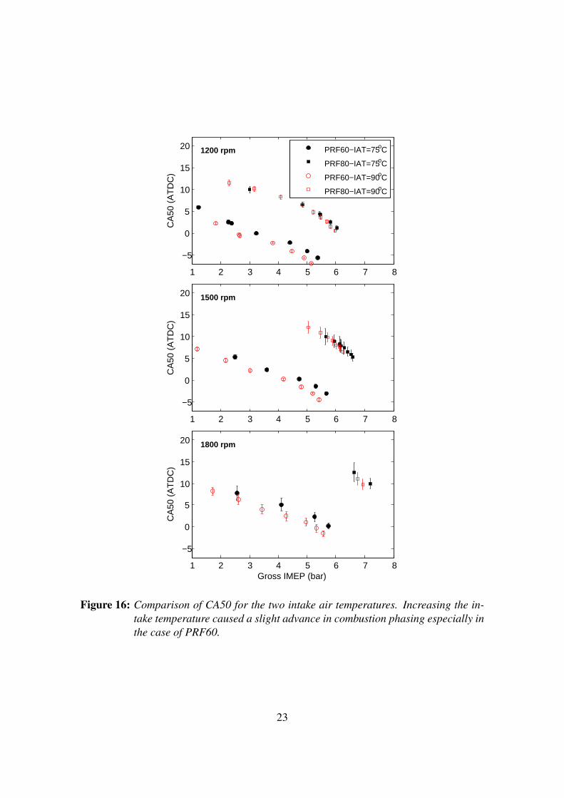
Increasing the intake temperature caused a slight advance in combustion phasing, as canbe seen in Figure 16. This may explain the slight decrease in efficiency at the higher loadend with the higher intake temperature, as the combustion timing becomes too advanced
19

0 1 2 3 4 5 6 7 80.1
0.2
0.3
0.4
0.51500rpm
Φ
PRF60−IAT=75oC
PRF80−IAT=75oC
PRF60−IAT=90oC
PRF80−IAT=90oC
0 1 2 3 4 5 6 7 8100
200
300
400
500
Gro
ss IS
FC
(g/
kW.h
)
0 1 2 3 4 5 6 7 80
0.1
0.2
0.3
0.4
0.5
Indi
cate
d E
ffici
ency
, η
Gross IMEP (bar)
Student Version of MATLAB
Figure 14: Gross ISFC and gross indicated efficiency for PRF60 and PRF80 at intake airtemperature of 75oC and 90oC, and engine speed of 1500 rpm. Here also, thehigher intake temperature has no noticeable effect on the engine performance.
20

0 1 2 3 4 5 6 7 80.1
0.2
0.3
0.4
0.51800rpm
Φ
PRF60−IAT=75oC
PRF80−IAT=75oC
PRF60−IAT=90oC
PRF80−IAT=90oC
0 1 2 3 4 5 6 7 8100
200
300
400
500
Gro
ss IS
FC
(g/
kW.h
)
0 1 2 3 4 5 6 7 80
0.1
0.2
0.3
0.4
0.5
Indi
cate
d E
ffici
ency
, η
Gross IMEP (bar)
Student Version of MATLAB
Figure 15: Gross ISFC and gross indicated efficiency for PRF60 and PRF80 at intake airtemperature of 75oC and 90oC, and engine speed of 1800 rpm.
21
at these conditions.
The CO, HC, and NOx emission results are shown in Figure 17. Increasing the intaketemperature resulted generally in lower CO and HC emissions within the low to inter-mediate load region in the case of PRF60 and at high load in the case of PRF80. Themost noticeable reduction was in CO emissions. This reduction appears to be influencedmainly by the higher temperature history since the difference in equivalence ratio betweenthe two cases is mostly negligible (see Figure 13 through Figure 15).
The values of IMEP COV and MPRR for the two intake temperatures are compared inFigure 18 Heating the intake temperature consistently improved the engine operating sta-bility (as measured by the IMEP COV) in the low and intermediate load regions. On theother hand, the higher intake temperature resulted in a higher pressure rise rate, especiallyat higher loads. The increase in intake temperature shifts the operating envelope at eachspeed to the lower load side and enables a more stable operation in general.
A comparison of the operating envelopes for the two intake temperatures are given inFigure 119. In the case of PRF60, increasing the intake temperature to 90oC resulted in anoticeable extension of the lower load range and a slight decrease in the high load limit.The operating envelope, therefore, was expanded more towards the low load region. WithPRF80, however, only a slight shift of the operating envelope towards the low load side isobserved, especially as the speed increases.
In Figure 20, the expansion in the PRF60 operating envelope due to the heating of theintake air to 90oC is compared to the operating envelope obtained with PRF40 run at 75oC.The results show that both cases resulted in almost similar expansion in the operatingenvelope with respect to the PRF60 running at 75oC. In other words, increasing the intaketemperature from 75oC to 90oC resulted in an operating range equivalent to that obtainedby decreasing the PRF octane rating from 60 to 40.
The results indicate that heating the intake air could be used as an alternative to varyingfuel reactivity to extend the engine operation in low load region. Significantly more heat-ing will be required, however, to achieve this extension for higher engine speeds. It isalso important to note that for the intake air heating approach to be effective, the heatingmust happen within a short time to meet the requirements of engine transient operation.Achieving this fast response intake air heating in practice could be extremely challenging.
5 Summary and Conclusions
A set of experimental results from a single-cylinder HCCI engine using primary referencefuels has been presented and discussed in this paper. The experiments were designed toscrutinize the effects of varying fuel reactivity (as measured by octane rating) on the HCCIengine operating range, and hence assess the potential of using the dual fuel approach tocontrol the HCCI engine. Engine operation envelopes constructed from the experimentalresults showed a noticeable fuel effects on HCCI operation. While the envelopes shrunkfor mixtures with higher octane rating (i.e. lower reactivity), they nevertheless allowedthe engine to operate at higher equivalence ratios and produce more work. These effectsbecame more prominent generally as the speed increased.
22
1 2 3 4 5 6 7 8
−5
0
5
10
15
20
CA
50 (
AT
DC
)
1200 rpm PRF60−IAT=75oC
PRF80−IAT=75oC
PRF60−IAT=90oC
PRF80−IAT=90oC
1 2 3 4 5 6 7 8
−5
0
5
10
15
20
CA
50 (
AT
DC
)
1500 rpm
1 2 3 4 5 6 7 8
−5
0
5
10
15
20
CA
50 (
AT
DC
)
Gross IMEP (bar)
1800 rpm
Student Version of MATLAB
Figure 16: Comparison of CA50 for the two intake air temperatures. Increasing the in-take temperature caused a slight advance in combustion phasing especially inthe case of PRF60.
23

2 4 6 80
0.5
1
1.5
2
CO
(%
)
2 4 6 80
0.5
1
1.5
2
x 104
HC
(pp
m)
1200 rpm
2 4 6 80
2
4
6
8
NO
x (p
pm)
Gross IMEP (bar)
2 4 6 80
0.5
1
1.5
2
2 4 6 80
0.5
1
1.5
2
x 104 1500 rpm
PRF60 − IAT=75oC
PRF80 − IAT=75oC
PRF60 − IAT=90oC
PRF80 − IAT=90oC
2 4 6 80
2
4
6
8
Gross IMEP (bar)
2 4 6 80
0.5
1
1.5
2
2 4 6 80
0.5
1
1.5
2
x 104 1800 rpm
2 4 6 80
2
4
6
8
Gross IMEP (bar)
Student Version of MATLAB
Figure 17: HC, CO and NOx emissions for PRF60 and PRF80 at intake air temperatureof 75oC and 90oC. The error bars represent ±1 standard deviation. The re-sults generally indicate that increasing the intake temperature in the low loadregion has a positive effect on exhaust emissions.
24

2 4 6 80
0.05
0.1
0.15
0.2
0.25
IME
P C
oV
1200 rpm
PRF60−IAT=75oC
PRF80−IAT=75oC
PRF60−IAT=90oC
PRF80−IAT=90oC
2 4 6 80
2
4
6
8
Max
. PR
R (
MP
a/m
s)
1200 rpm
2 4 6 80
0.05
0.1
0.15
0.2
0.25
IME
P C
oV
1500 rpm
2 4 6 80
2
4
6
8M
ax. P
RR
(M
Pa/
ms)
1500 rpm
2 4 6 80
0.05
0.1
0.15
0.2
0.25
IME
P C
oV
Gross IMEP (bar)
1800 rpm
2 4 6 80
2
4
6
8
Max
. PR
R (
MP
a/m
s)
Gross IMEP (bar)
1800 rpm
Student Version of MATLAB
Figure 18: IMEP COV and MPRR for PRF60 and PRF80 at intake air temperature of75oC and 90oC. Heating the intake temperature improved the engine operat-ing stability in the low and intermediate load regions but increased the pres-sure rise rate at higher loads. This shifts the operating envelope at each speedto the lower load side and enables a more stable operation in general.
25
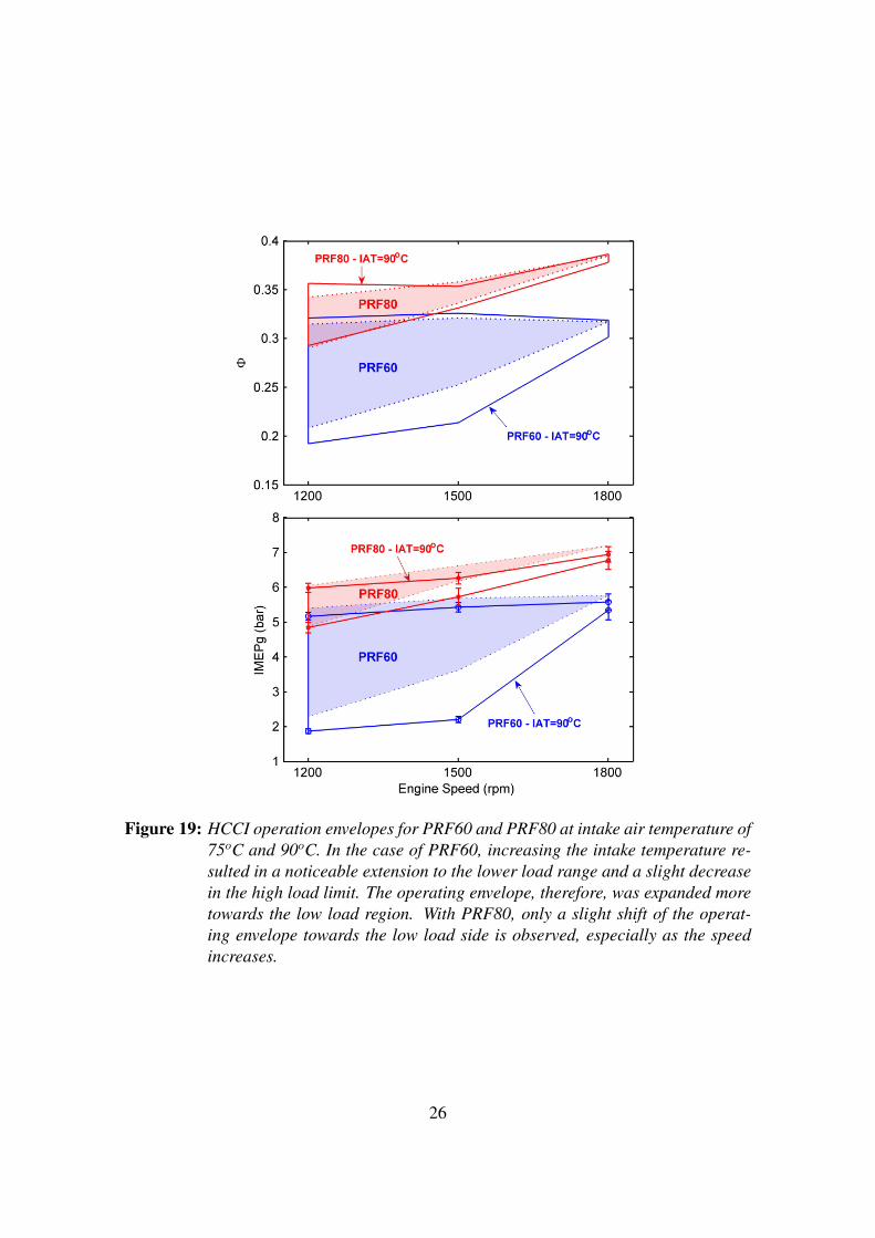
Figure 19: HCCI operation envelopes for PRF60 and PRF80 at intake air temperature of75oC and 90oC. In the case of PRF60, increasing the intake temperature re-sulted in a noticeable extension to the lower load range and a slight decreasein the high load limit. The operating envelope, therefore, was expanded moretowards the low load region. With PRF80, only a slight shift of the operat-ing envelope towards the low load side is observed, especially as the speedincreases.
26

Figure 20: HCCI operation envelopes for PRF40 and PRF60 at intake air temperature of75oC compared to the envelope for PRF60 at intake air temperature of 90oC.Increasing the intake temperature from 75oC to 90oC resulted in an operatingrange almost equivalent to that obtained by decreasing the PRF octane ratingfrom 60 to 40.
27
While the results pointed out to a clear potential for the dual fuel approach to expandthe HCCI operating range, they also showed that both high and low load limits becamegenerally less sensitive to changes in the fuel as the octane rating decreased. In otherwords, increasing the reactivity of the PRF fuel became increasingly less effective incontrolling the HCCI combustion as the engine load decreased. This could necessitate theuse of other combustion control means to complement the dual fuel approach during lowload operation.
A set of experiments were performed to examine the feasibility of using the intake airheating as a complementary approach in the low load region. Some positive, but gen-erally not significant, effects on engine performance and exhaust emissions as a resultof increasing the intake temperature were observed. The most noticeable effect was theconsistent reduction of CO emissions within the low to intermediate load region. Theincreased intake temperature had hardly any effect on the indicated efficiency.
The results indicated that increasing the intake temperature extended the operating enve-lope at each speed to the lower load side and enabled a more stable operation in general. Aquantification of the extension showed that increasing the intake temperature from 75oCto 90oC resulted in an operating range equivalent to that obtained by varying the PRFoctane rating from 60 to 40. This strong effect of intake heating, as a conclusion, allowsit to be used to complement the dual fuel approach for expanding the HCCI operatingenvelope in the low load region.
28
6 Acknowledgement
The authors would like to thank Yoann Viollet and Hassan Babiker of Saudi Aramco’sR&D Center for their help in carrying out the engine experiments.
7 Definitions, Acronyms and Abbreviations
ATDC After top dead centreCA50 Crank shaft degree of 50% heat releaseCOV Coefficient of variationHCCI Homogeneous charge compression ignitionHLL High load limitHRR Net heat release rateIAT Intake air temperatureIMEPg Gross indicated mean effective pressureISFC Indicated specific fuel consumptionLLL Low load limitMPRR Maximum pressure rise ratePFI Port fuel injectionPRF Primary reference fuelSRM Stochastic reactor modelTDC Top dead centreΦ Equivalence ratio
29

References
[1] A. Aldawood, S. Mosbach, M. Kraft, and A. Amer. Multi-objective optimization of akinetics-based HCCI model using engine data. SAE Technical Paper 2011-01-1783,2011.
[2] A. Aldawood, S. Mosbach, and M. Kraft. HCCI combustion control using dual-fuelapproach: Experimental and modeling investigations. SAE Technical Paper 2012-01-1117, 2012.
[3] M. Atkins and C. Koch. The effect of fuel octane and dilutent on homogeneouscharge compression ignition combustion. Proceedings of the Institution of Mechan-ical Engineers, Part D: Journal of Automobile Engineering, 219, 2005.
[4] J. Cha, S. Kwon, and S. Park. An experimental and modelling study of the combus-tion and emission characteristics for gasoline-diesel dual-fuel engines. Proceedingsof the Institution of Mechanical Engineers, Part D: Journal of Automobile Engineer-ing, 225, 2011.
[5] S. Kokjohn, R. Hanson, D. Splitter, and R. Reitz. Experiments and modeling of dual-fuel HCCI and PCCI combustion using in-cylinder fuel blending. SAE TechnicalPaper 2009-01-2647, 2009.
[6] X. Lu, W. Chen, Y. Hou, , and Z. Huang. Study on the ignition, combustion andemissions of HCCI combustion engines fuelled with primary reference fuel. SAETechnical Paper 2005-01-0155, 2005.
[7] J. Ma, X. L, L. Ji, and Z. Huang. An experimental study of HCCI-DI combustionand emissions in a diesel engine with dual fuel. International Journal of ThermalSciences, 47, 2008.
[8] T. Ogura, J. Angelos, W. Green, W. Cheng, T. Kenney, and Y. Xu. Primary referencefuel behavior in a HCCI engine near the low-load limit. SAE Technical Paper 2008-01-1667, 2008.
[9] J. Olsson, P. Tunestl, and B. Johansson. Closed-loop control of an HCCI engine.SAE Technical Paper 2001-01-1031, 2001.
[10] L. Xingcai, H. Yuchun, Z. Linlin, and H. Zhen. Experimental study on the auto-ignition and combustion characteristics in the homogeneous charge compressionignition (HCCI) combustion operation with ethanol/n-heptane blend fuels by portinjection. Fuel, 85, 2006.
30


![HCCI - Update of Progress 2005 - US Department of Energy · HCCI – Update of Progress 2005 HCCI HCCI ... M EP [b a r] B S F C [g/k W-hr] ... Typically used in 2-Stroke Engines at](https://img.pdfslide.us/doc/110x75/5ac4ebc77f8b9a220b8d1053/hcci-update-of-progress-2005-us-department-of-energy-update-of-progress.jpg)