Embed Size (px)
Citation preview
Sensors 2014, 14, 20825-20842; doi:10.3390/s141120825
sensors ISSN 1424-8220
www.mdpi.com/journal/sensors
Review
Dual-Frequency Piezoelectric Transducers for Contrast Enhanced Ultrasound Imaging
K. Heath Martin 1, Brooks D. Lindsey 1, Jianguo Ma 2, Mike Lee 3, Sibo Li 2, F. Stuart Foster 3,
Xiaoning Jiang 2 and Paul A. Dayton 1,*
1 Joint Department of Biomedical Engineering, University of North Carolina at Chapel Hill and
North Carolina State University at Raleigh, Chapel Hill, NC 27599, USA;
E-Mails: [email protected] (K.H.M.); [email protected] (B.D.L.) 2 Department of Mechanical & Aero-Space Engineering, North Carolina State University, Raleigh,
NC 27695, USA; E-Mails: [email protected] (J.M.); [email protected] (S.L.);
[email protected] (X.J.) 3 Sunnybrook Health Sciences Centre, Toronto, ON M4N 3M5, Canada;
E-Mails: [email protected] (M.L.); [email protected] (F.S.F.)
* Author to whom correspondence should be addressed; E-Mail: [email protected];
Tel.: +1-919-966-1175; Fax: +1-919-966-2963.
External Editor: Vittorio M.N. Passaro
Received: 6 August 2014; in revised form: 3 October 2014 / Accepted: 16 October 2014 /
Published: 4 November 2014
Abstract: For many years, ultrasound has provided clinicians with an affordable and
effective imaging tool for applications ranging from cardiology to obstetrics. Development
of microbubble contrast agents over the past several decades has enabled ultrasound to
distinguish between blood flow and surrounding tissue. Current clinical practices using
microbubble contrast agents rely heavily on user training to evaluate degree of localized
perfusion. Advances in separating the signals produced from contrast agents versus
surrounding tissue backscatter provide unique opportunities for specialized sensors designed
to image microbubbles with higher signal to noise and resolution than previously possible.
In this review article, we describe the background principles and recent developments of
ultrasound transducer technology for receiving signals produced by contrast agents while
rejecting signals arising from soft tissue. This approach relies on transmitting at a
low-frequency and receiving microbubble harmonic signals at frequencies many times
higher than the transmitted frequency. Design and fabrication of dual-frequency transducers
OPEN ACCESS
Sensors 2014, 14 20826
and the extension of recent developments in transducer technology for dual-frequency
harmonic imaging are discussed.
Keywords: acoustics; acoustic angiography; dual-frequency; superharmonic; harmonic;
broadband; microbubbles
1. Introduction
Fundamentally, ultrasound images are visual representations of the interaction between sound waves
and the medium of wave propagation. In ultrasound imaging, an acoustic pulse is transmitted into the
field using a transducer capable of producing a temporally short mechanical wave (1–4 cycles)
in response to a voltage applied to the transducer. As the incident wave travels into tissue, some of the
wave’s energy is reflected back toward the transducer by scatterers in the tissue having different acoustic
properties (i.e., density and speed of sound) than the background medium. These backscattered acoustic
waves are received by the same transducer, which converts mechanical waves into time-varying
voltages. These signals are then amplified, digitized, and processed into an image by the ultrasound
imaging system. In the most common mode of operation, called “brightness-mode” or “B-mode”
ultrasound, grayscale images are formed in which pixel values are proportional to the brightness of
scattered acoustic waves. In other system modes, B-mode images are overlaid with colorized maps of
blood velocity (color Doppler) or integrated energy from moving scatterers (power Doppler). However,
at frequencies typically used in transthoracic and transabdominal ultrasound imaging, blood is a poor
ultrasound scatterer which produces echoes approximately a factor of 300 times weaker than surrounding
soft tissues [1], making the detection of blood flow in small vessels challenging. For this reason,
microbubbles are used as injectable contrast agents, which serve as strong scattering sources and thereby
improve imaging of blood flow [2]. While contrast ultrasound is used primarily in cardiology in the
United States, it is used more widely in Europe and Asia, and there are substantial ongoing research
efforts aimed at evaluating microbubbles as a platform for additional diagnostic and therapeutic
applications [3,4]. This review will primarily focus on development of dual-frequency piezoelectric
transducers for imaging nonlinear harmonics produced by microbubbles under ultrasound excitation.
1.1. Theory of Operation
Microbubble contrast agents are micron-sized shelled gas bubbles that are injected into the vascular
space in order to visualize blood flow. When excited by an external acoustic field, microbubbles oscillate
non-linearly, producing waves with harmonic content in addition to the fundamental frequency. The
degree of harmonic content produced by a single interaction between a microbubble and an acoustic
wave increases as the amplitude of the acoustic wave increases, and also increases at frequencies near
the resonance frequency of the microbubble [5–8]. Microbubble resonance frequency depends primarily
on bubble diameter, though many other physical factors also play a role in determining resonance [9,10].
While microbubbles are strong scatterers that are visible on standard B-mode imaging at the fundamental
imaging frequency, the energy arising from microbubbles cannot be separated from that arising from the
Sensors 2014, 14 20827
surrounding tissue. However, by isolating the harmonic signals resulting from microbubble nonlinear
behavior it is possible to image microbubbles alone with high specificity.
An effective approach for minimizing tissue echoes in microbubble-specific imaging is to use higher
order harmonics. An acoustic wave traveling through tissue generates harmonics due to nonlinear
propagation effects, however, most of the energy received at the transducer remains confined to the
transmitted frequency (f0) and the second harmonic (2f0) [11,12]. Alternatively, microbubble echoes
contain higher order harmonics, or “superharmonics,” at frequencies three to 10 times the transmitted
frequency [13–16]. In this review paper, we describe transducer technology designed to transmit at low
frequencies near microbubble resonance and receive only microbubble harmonics at much higher
frequencies, thus spectrally separating microbubble-scattered waves from tissue-scattered waves.
1.2. Summary of Commercial Contrast Detection Methods
Currently, most commercial ultrasound systems form images of microbubbles using frequency
content within the bandwidth of a single transducer, which is used for both transmitting and receiving.
These systems typically reduce tissue echoes by transmitting multiple versions of similar pulses having
varying phases and/or amplitudes, then summing received signals from these pulses. Using this process,
linear signals originating from tissue cancel while nonlinear microbubble signals sum constructively. In
the simplest of these techniques, pulse inversion, a pair of pulses are transmitted which are inverted
replicas of one another (i.e., 180° out of phase) [17]. Linear scatterers produce two sets of similarly
inverted signals, thus when the received signals from each of the two pulses are added together, the net
sum due to linear scattering is zero, assuming no motion has occurred. Because shelled microbubbles
vibrate nonlinearly, waves scattered from the contrast agents contain nonlinear components, which do
not sum to zero, producing an image of microbubbles alone. Various multi-pulse schemes exist in which
the phases and amplitudes of transmitted pulses are altered in order to improve separation of microbubble
and tissue signals or to isolate a specific range of harmonics [18–21]. These algorithms are found on
commercial ultrasound scanners under names such as Cadence Contrast Pulse Sequencing (CPS)
(Siemens) or Power Pulse Inversion (Philips) [22]. The ratio of microbubble to tissue amplitude in an
image is known as contrast to tissue ratio (CTR) and is often expressed in dB as a quantitative metric of
the effectiveness of a contrast imaging technique. Multi-pulse approaches achieve high CTR at the cost
of reduced frame rate and increased susceptibility to motion artifacts. Alternatively, dual-frequency
transducers alleviate these problems because their large effective bandwidths allow high CTR imaging
using a single pulse.
1.3. Design and Fabrication of Piezoelectric Transducers in Diagnostic Ultrasound
1.3.1. Piezoceramic Dimensions
While design theory of piezoelectric transducers is well-covered elsewhere [23,24], basic principles
will be reviewed briefly to elucidate challenges relating to dual-frequency transducer fabrication.
Transducers used in medical ultrasound consist of a thickness mode resonator. Wave propagation
velocity in lead zirconate titanate (PZT) is approximately 4350 m/s [25], resulting in a nominal thickness
(λ/2) of 435 µm at 5 MHz, for example, though other factors also affect transducer resonance [26]. In
Sensors 2014, 14 20828
array transducers, grating lobes are avoided by maintaining inter-element separation less than or equal
to λ/2. Element width-to-thickness ratio must also be considered, as element aspect ratios determine the
acoustic resonance modes [27,28]. Fabrication challenges tend to intensify as feature sizes decrease in
all dimensions with increasing frequency. Tradeoffs between desired resonance frequency and element
dimensions represent a primary challenge in array design.
1.3.2. Element Boundary Condition Considerations
Matching and backing layers designed with desired acoustic properties are attached in series to the
front and back faces of the piezoelectric material, respectively. By reducing the mismatch in acoustic
impedance between the piezoelectric material (ZPZT ≈ 34 MRayl) and tissue (Zwater = 1.5 MRayl),
matching layers increase acoustic transmission into and from the tissue and act as quarter wave
transformers. Backing layers improve bandwidth by damping acoustic vibrations at the rear boundary of
the piezoelectric material. The loading provided by matching and backing layers also modulates the
resonant frequency of the transducer [26]. The primary challenge in design of matching and backing
layers is the tradeoff between high sensitivity and broad bandwidth.
1.3.3. Fabrication, Dicing, and Composites
For piezoelectric transducers operating in thickness mode, a “dice-and-fill” approach is commonly
used in array fabrication. A wafer-dicing saw cuts and isolates sensing elements, and kerfs resulting from
saw cuts are then backfilled to minimize acoustic crosstalk. A dice-and-fill approach is also used to
create low-frequency composite materials [29–31] from plates of either piezoelectric ceramics [32]
or electrostrictive PMN-PT single crystals [33] by dicing the material and filling the gaps with a
polymer [34], then further dicing into individual elements for fabrication of an array. Composite
materials can produce better harmonic images than conventional materials because they yield
transducers with broader bandwidths (>75%) and improved acoustic matching [35]. Fabrication
challenges associated with physical dicing limit acoustic impedance matching in composites.
For harmonic imaging, it may be possible to design a transducer so that both transmission and
receiving frequencies are within the bandwidth of a single composite transducer. These composites can
be made with 1–3 connectivity, mechanically decoupling the thickness-mode vibration resonance from
other undesirable resonances (lateral or elevational modes) [27]. Lateral modes are λ/2 resonances
determined by the dimension of the transducer in the lateral direction, or the dimension of image
formation. Designing with respect to lateral modes takes on added importance in environments such as
intravascular ultrasound (IVUS) in which strict limitations on device size imposed by lumen diameter
can create severe aspect ratios (width-to-thickness) that are normally avoided to preserve forward
looking directional sensitivity. As an alternative to dice-and-fill methods at higher frequencies,
Jiang et al., have demonstrated fabrication of a 40 MHz, 1–3 composite transducer using a plasma
etching-based micromachining technique [36]. A 60 MHz IVUS transducer using 1–3 composite has
been fabricated and tested on a porcine animal model [35]. These high-frequency broadband transducer
materials are promising for imaging microbubble harmonics. The development of high-frequency arrays
was greatly facilitated by the introduction of laser micro-machining by Foster et al., a process which has
Sensors 2014, 14 20829
become a standard for commercially-available high-frequency imaging systems [37]. Providing
individual electrical interconnects also poses a significant fabrication challenge in high-frequency arrays.
While developments in materials and fabrication have led to diagnostic transducers having increased
sensitivity and bandwidth, the use of two independent frequency bands having large separation (at least
3× to 5×) can maximize sensitivity while requiring lower transmit pressures for contrast-specific
imaging applications. In the following sections, we describe recent developments in dual-frequency
transducer technology.
2. Dual-Frequency Transducers
The goal of dual-frequency contrast imaging is to form images of only microbubble harmonics by
transmitting acoustic waves at lower frequencies near microbubble resonance (approximately 1–6 MHz)
and receiving only higher order harmonic vibrations produced by microbubbles (approximately
10–30 MHz). Researchers have recently demonstrated electrostatic transducers that are capable of
encompassing both frequency ranges within a single, extremely broad bandwidth [38,39]. Details of the
operation and fabrication of these transducers, commonly referred to as capacitive micromachined
ultrasound transducers (CMUTs), are discussed elsewhere [40–42]. CMUTs exhibit inherent nonlinear
behavior, which limits their ability to accurately distinguish nonlinear microbubble response, though
ongoing investigations attempt to account for these nonlinearities so they may be used for contrast
detection reliably [43]. Although CMUTs may eventually demonstrate superior performance to
piezoceramics for contrast imaging, they have not yet been demonstrated for this use in vivo. While
researchers continue to investigate ultra-wideband electrostatic transducers as well as approaches for
increasing the bandwidth of piezoelectric transducers [35,36,44,45], this review will primarily focus on
devices that use separate transducers for transmission and reception and thus allow for independent
design of the two transducers to achieve desired characteristics.
2.1. Imaging Microbubble Contrast Agents
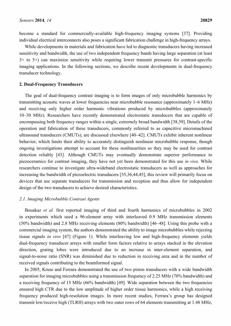
Bouakaz et al. first reported imaging of third and fourth harmonics of microbubbles in 2002
in experiments which used a 96-element array with interleaved 0.9 MHz transmission elements
(50% bandwidth) and 2.8 MHz receiving elements (80% bandwidth) [46–48]. Using this probe with a
commercial imaging system, the authors demonstrated the ability to image microbubbles while rejecting
tissue signals in vivo [47] (Figure 1). While interleaving low and high-frequency elements yields
dual-frequency transducer arrays with smaller form factors relative to arrays stacked in the elevation
direction, grating lobes were introduced due to an increase in inter-element separation, and
signal-to-noise ratio (SNR) was diminished due to reduction in receiving area and in the number of
received signals contributing to the beamformed signal.
In 2005, Kruse and Ferrara demonstrated the use of two piston transducers with a wide bandwidth
separation for imaging microbubbles using a transmission frequency of 2.25 MHz (70% bandwidth) and
a receiving frequency of 15 MHz (66% bandwidth) [49]. Wide separation between the two frequencies
ensured high CTR due to the low amplitude of higher order tissue harmonics, while a high receiving
frequency produced high-resolution images. In more recent studies, Ferrara’s group has designed
transmit low/receive high (TLRH) arrays with two outer rows of 64 elements transmitting at 1.48 MHz,
Sensors 2014, 14 20830
and a central row of 128 elements receiving at 5.24 MHz [50]. In addition to harmonic imaging of
microbubbles, the high-frequency row of this three-row array was used to deliver a long (100 cycle),
low-amplitude (200 kPa peak negative pressure) “pushing” pulse for radiation-force enhanced adhesion
of targeted microbubbles for molecular imaging [51,52]. This work has recently been extended to 3D
molecular imaging [53]. Subsequent generations of this array featured low-frequency rows capable of
delivering either broadband, high peak pressure waveforms for cavitation-mediated therapy or narrower
band, high time-average power waveforms for thermal therapy [54,55]. A similar three-row array with a
central row of 128 elements operating at 1 MHz (90% bandwidth) and elevationally-aligned outer rows of
128 elements operating at 10 MHz (90% bandwidth) was constructed by Vermon (Tours, France) [56].
Figure 1. Schematic of the first design incorporating dual-frequency transducers for the
purpose of contrast detection (top). Odd numbered elements had a center frequency of
2.8 MHz with a fractional bandwidth of 80% while the even elements had a center frequency
of 0.9 MHz with a fractional bandwidth of 50%. Odd numbered elements were used for
imaging superharmonics generated by nonlinear vibrations of microbubbles excited with a
low-frequency pulse provided by the even elements. A photograph of the actual transducer
is shown after the elevational lens has been added (bottom). Figure reprinted with
permission from [46].
In 2010, van Neer et al. compared designs for interleaved and multi-row arrays [57,58]. Designs with
interleaved elements having high ratios of receive to transmit elements (i.e., at least three receive
elements per transmit element) were capable of producing beams with reduced distortion artifacts and
tighter −6 dB beam widths relative to two- or three-row arrays. By greatly increasing the number of
receiving elements, grating lobes of interleaved designs were limited to −40 dB and high SNR was
ensured. However, it should be noted that arrays with interleaved elements of different frequencies
cannot be manufactured using standard dice-and-fill approaches from a single piezoelectric plate without
significant alteration to manufacturing processes (see “Design and Fabrication” section).
In spite of the promise shown by several of these dual-frequency arrays, transition towards
transducers with higher receiving frequencies has been accompanied by several fabrication challenges.
Because standard array production techniques faces difficulties scaling to higher frequencies [59],
Sensors 2014, 14 20831
high-frequency transducers can utilize mechanical steering of a single focused element in lieu of
an array. Many of these focused single-element transducers have been possible due to the use of
flexible piezoelectric composites rather than inflexible piezoelectric ceramics [60,61]. An important
advancement for high-frequency arrays has been the development of composites with large triangular
pillars to suppress lateral modes while maintaining high sensitivity [62,63].
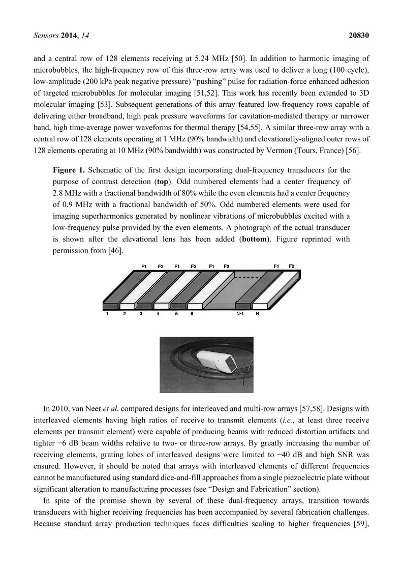
Figure 2. The mechanically steered dual-frequency transducer is composed of a central
high-frequency (25 MHz) spherically focused piston transducer inserted into an annular,
confocally aligned low-frequency transducer (4 MHz). (A, End-on view) Harmonic imaging
is performed by mechanically sweeping the arm while transmitting on the outer element and
receiving on the inner element. (B, Side view)
Using this technology, Foster’s group working with Dayton has constructed several
mechanically-steered transducers consisting of concentric low- (2.5–4 MHz) and high-frequency
(25–30 MHz) elements [64,65]. These probes have been integrated with a commercial small animal
imaging system (VisualSonics, Toronto, ON, Canada) (Figure 2). Imaging with these dual-frequency
transducers has provided a high-resolution (~200 µm), high CTR (~25 dB) imaging technique, which
the authors call “acoustic angiography” due to the resemblance between the vascular images
acquired and those in x-ray, or magnetic resonance angiography [66]. This approach has demonstrated
sensitivity to vessels containing contrast agents at frequencies higher than previously published
(as high as 10 times the transmission frequency) (Figure 3) [67]. As a result, acquired images can be
segmented by computational algorithms to analyze vessel morphology based on quantitative metrics
such as vessel density and tortuosity [67–69].
Several similar transducers have recently been reported. A mechanically-scanned transducer with two
concentric elements operating at 4 MHz and 14 MHz was demonstrated by Guiroy et al. [70].
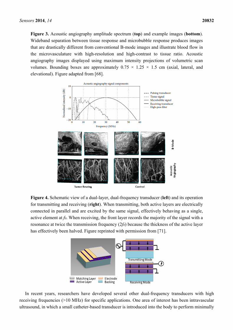
Li et al. have alternatively demonstrated a micromachined PMN-PT 1–3 composite based dual-frequency
(17.5/35 MHz) transducer (Figure 4) for harmonic imaging [71]. In this design, two active layers were
mechanically bonded in series and poled in opposite directions. Composite piezoelectrics and
electrostrictive materials such as PMN-PT have been increasingly utilized over traditional ceramics like
PZT, which have limitations for use at higher frequencies due to manufacturing challenges and grain
dimensions which become increasingly close to one wavelength as frequency increases [72].
Sensors 2014, 14 20832
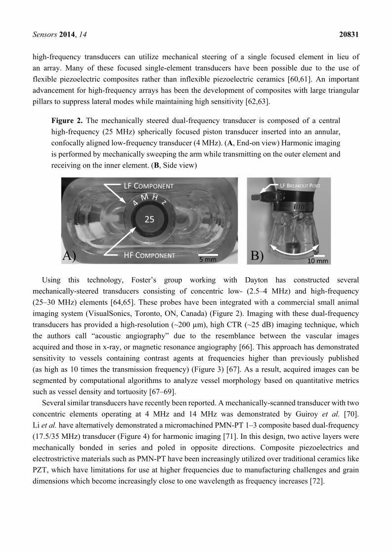
Figure 3. Acoustic angiography amplitude spectrum (top) and example images (bottom).
Wideband separation between tissue response and microbubble response produces images
that are drastically different from conventional B-mode images and illustrate blood flow in
the microvasculature with high-resolution and high-contrast to tissue ratio. Acoustic
angiography images displayed using maximum intensity projections of volumetric scan
volumes. Bounding boxes are approximately 0.75 × 1.25 × 1.5 cm (axial, lateral, and
elevational). Figure adapted from [68].
Figure 4. Schematic view of a dual-layer, dual-frequency transducer (left) and its operation
for transmitting and receiving (right). When transmitting, both active layers are electrically
connected in parallel and are excited by the same signal, effectively behaving as a single,
active element at f0. When receiving, the front layer records the majority of the signal with a
resonance at twice the transmission frequency (2f0) because the thickness of the active layer
has effectively been halved. Figure reprinted with permission from [71].
In recent years, researchers have developed several other dual-frequency transducers with high
receiving frequencies (>10 MHz) for specific applications. One area of interest has been intravascular
ultrasound, in which a small catheter-based transducer is introduced into the body to perform minimally
Sensors 2014, 14 20833
invasive imaging of occlusive plaques within the coronary arteries [73]. In particular, the presence of
vessels known as vasa vasorum (70–180 µm in diameter [74]) in plaques has been hypothesized to be
linked with decreased plaque stability and increased risk of future complications [75]. Because
superharmonic imaging of microbubbles could enable direct visualization of vasa vasorum, several
researchers have pursued dual-frequency transducer designs for this application. In 2005,
Vos et al. developed single element transducers for second harmonic imaging designed with dual
resonance peaks at 20 and 40 MHz and a 1 mm outer diameter [76,77]. This group has also used
commercial IVUS catheters to demonstrate the benefits of pulse inversion detection methods for this
application [78,79].
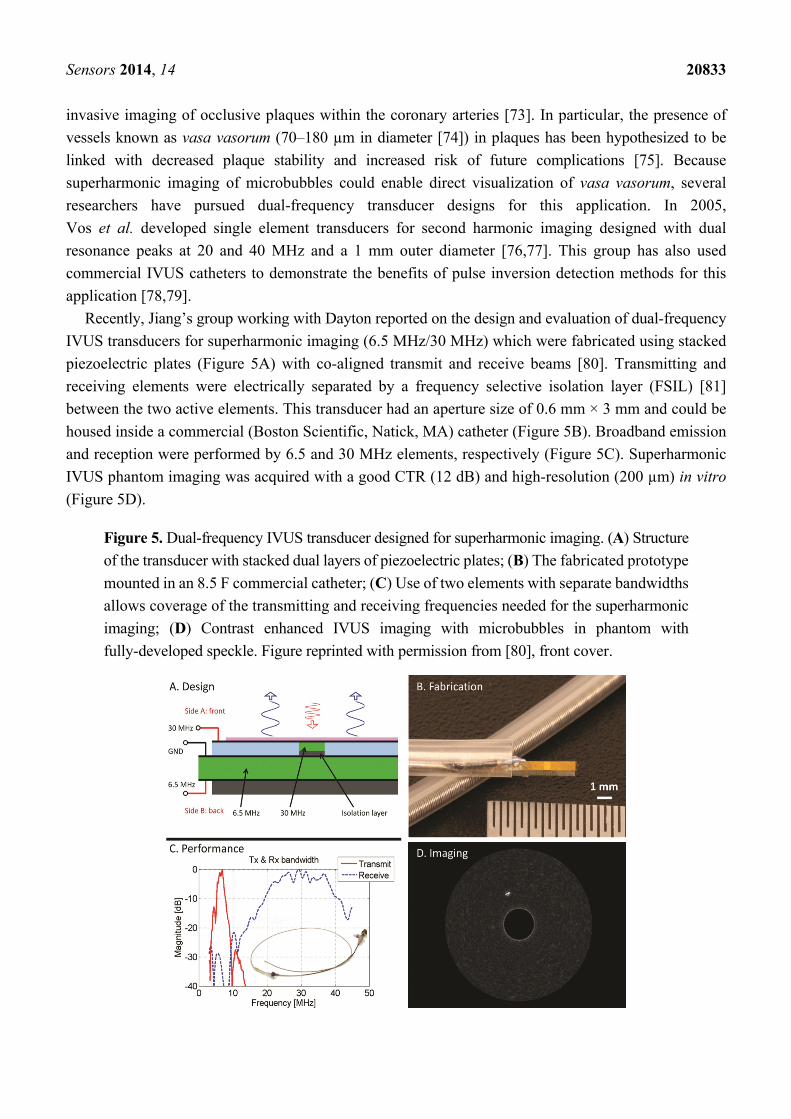
Recently, Jiang’s group working with Dayton reported on the design and evaluation of dual-frequency
IVUS transducers for superharmonic imaging (6.5 MHz/30 MHz) which were fabricated using stacked
piezoelectric plates (Figure 5A) with co-aligned transmit and receive beams [80]. Transmitting and
receiving elements were electrically separated by a frequency selective isolation layer (FSIL) [81]
between the two active elements. This transducer had an aperture size of 0.6 mm × 3 mm and could be
housed inside a commercial (Boston Scientific, Natick, MA) catheter (Figure 5B). Broadband emission
and reception were performed by 6.5 and 30 MHz elements, respectively (Figure 5C). Superharmonic
IVUS phantom imaging was acquired with a good CTR (12 dB) and high-resolution (200 µm) in vitro
(Figure 5D).
Figure 5. Dual-frequency IVUS transducer designed for superharmonic imaging. (A) Structure
of the transducer with stacked dual layers of piezoelectric plates; (B) The fabricated prototype
mounted in an 8.5 F commercial catheter; (C) Use of two elements with separate bandwidths
allows coverage of the transmitting and receiving frequencies needed for the superharmonic
imaging; (D) Contrast enhanced IVUS imaging with microbubbles in phantom with
fully-developed speckle. Figure reprinted with permission from [80], front cover.
Sensors 2014, 14 20834
2.2. Other Applications
Researchers have developed dual-frequency ultrasound arrays for applications other than contrast
agent imaging, which have provided useful insights into design or fabrication strategies. The earliest
reported dual-frequency transducer was that of von Ramm and Smith in 1978, in which a phased array
with adjacent rows of 1.5 and 2.5 MHz elements was designed to reduce off-axis contributions to the
two-way point spread function by misaligning grating lobes from transmitting and receiving arrays [82].
In 1988, Bui et al. showed 1–3 composites can be designed to exhibit multiple frequency sensitivities
by tailoring the dimensions for separate resonance modes [83]. De Fraguier et al. reported separate
transducers for B-mode (4.6 MHz) and color Doppler mode (2.3 MHz) in order to improve Doppler
sensitivity by reducing transmitted frequency and increasing pulse length [84]. Similarly, Saitoh et al.
presented a transducer capable of operating at either 3.75 MHz or 7.5 MHz using two layers of PZT
poled in opposite directions for increasing Doppler sensitivity [85].
In 2000, Hossack et al. reported a dual-frequency transducer to improve sensitivity for tissue
harmonic imaging [86]. This transducer—based on earlier work by Hossack and Auld for increasing
bandwidth [87]—used two piezoelectric layers having independent electrical contacts. The two layers
were operated either in phase when transmitting at f0, or 180° out of phase when receiving at 2f0. Several
other authors developed similar transducers having two resonances at the fundamental and twice the
fundamental [88,89]. Dual-frequency transducer design in tissue harmonic imaging has been studied
extensively in the past and has aided in the development of recent transducer design in contrast
specific imaging. For example, confocal annular elements operating at large frequency separations
(20 and 40 MHz) produced by Kirk Shung’s group were used in tissue harmonic imaging of excised
porcine eyes before similar form factor transducers were used in acoustic angiography [90].
In addition, many other authors have demonstrated dual-frequency arrays for combined
imaging-therapy applications. Recent devices of interest for imaging have included a three-row array
with 128 elements per row for use in prostate cancer imaging and treatment [91], a small-form factor
32-element system for guidance of high-intensity focused ultrasound (HIFU) [92], and a three-row array
for thermal strain imaging performing heating at 1.5 MHz and imaging at 5.5 MHz [93].
Smith et al. have also demonstrated dual-frequency combined imaging and therapeutic catheter-based
devices [94,95]. While a comprehensive review of image guidance in therapeutic ultrasound is
beyond the scope of this review, the interested reader is referred to recent reviews on image-guided
therapy [96], HIFU [97,98] and thermal strain imaging [99].
Several recent design developments within other applications are of particular interest for imaging
microbubble harmonics. Azuma et al. have described the design and fabrication of a 0.5/2.0 MHz
dual-frequency array for sonothrombolysis and transcranial ultrasound imaging [81]. This paper
presented the first dual-frequency array to use a unique design in which the low-frequency array is
positioned directly below the high-frequency array within the transducer housing. Low- and
high-frequency arrays were isolated by the aforementioned FSIL, an important design achievement.
Dual-frequency transducers could also provide distinct advantages over single-frequency transducers in
acoustic radiation force impulse (ARFI) imaging, which visualizes mechanical properties of tissue
using a low-frequency pushing pulse and high-frequency tracking pulses [100]. Finally, Yen et al.
have described several dual-layer 2D array transducers capable of performing 3D rectilinear imaging
Sensors 2014, 14 20835
at 5 and 7.5 MHz at a reduced cost relative to conventional 2D arrays with high channel
counts [101,102]. Linear and 2D bilaminar arrays with frequency-selective layers could enable imaging
of microbubble harmonics over a large field of view with greater image uniformity than that currently
afforded by fixed-focus transducers.
3. Conclusions
Images formed from harmonic content scattered by ultrasound contrast agents have demonstrated
increased image quality over fundamental mode images [103–107], making spectral separation of tissue
and harmonic signals using dual-frequency transducers an attractive approach. Transducers having wide
frequency separation between the transmission and reception bandwidths have allowed for efficient
excitation of microbubbles near resonance and reception of broadband, transient harmonics without
dependence on multi-pulse strategies. Single-pulse harmonic imaging has enabled higher frame rates
and elimination of motion artifacts found in currently-available contrast imaging approaches requiring
multiple pulses. Forming images from higher harmonics has also enabled high-resolution imaging with
reduced attenuation, as high-frequency echoes are subject to attenuation in only a single direction. New
technical developments have demonstrated the potential for dual-layer, dual-frequency arrays for both
2D and 3D imaging.
Acknowledgments
The authors acknowledge financial support from the National Institutes of Health under the grants
1R01EB015508 (XJ), R01EB009066 (PD), R01CA170665 (PD), Department of Defense PC111309
(PD), the Terry Fox Foundation (SF), The Ontario Research Fund (SF), and VisualSonics (SF).
Conflicts of Interest
Authors declare pending patents on dual-frequency transducers and applications detailed in this
manuscript, as well as interest in companies (Visualsonics, Inc., Toronto, ON, Canada) and (SonoVol,
LLC, Chapel Hill, NC, USA).
References
1. Shung, K.K. In vitro experimental results on ultrasonic scattering in biological tissues.
In Ultrasonic Scattering in Biological Tissues; Shung, K.K., Thieme, G.A., Eds.; CRC Press:
Boca Raton, FL, USA, 1992.
2. Gramiak, R.; Shah, P.M. Echocardiography of the aortic root. Investig. Radiol. 1968, 3, 356–366.
3. Ferrara, K.; Pollard, R.; Borden, M. Ultrasound microbubble contrast agents: Fundamentals and
application to gene and drug delivery. Annu. Rev. Biomed. Eng. 2007, 9, 415–447.
4. Klibanov, A.L. Microbubble contrast agents: Targeted ultrasound imaging and ultrasound-assisted
drug-delivery applications. Investig. Radiol. 2006, 41, 354–362.
5. Ainslie, M.A.; Leighton, T.G. Review of scattering and extinction cross-sections, damping factors,
and resonance frequencies of a spherical gas bubble. J. Acoust. Soc. Am. 2011, 130, 3184–3208.
Sensors 2014, 14 20836
6. Lauterborn, W. Numerical investigation of nonlinear oscillations of gas bubbles in liquids.
J. Acoust. Soc. Am. 1976, 59, 283–283.
7. Chen, Q.; Zagzebski, J.; Wilson, T.; Stiles, T. Pressure-dependent attenuation in ultrasound
contrast agents. Ultrasound Med. Biol. 2002, 28, 1041–1051.
8. Sboros, V.; MacDonald, C.A.; Pye, S.D.; Moran, C.M.; Gomatam, J.; McDicken, W.N. The
dependence of ultrasound contrast agents backscatter on acoustic pressure: Theory versus
experiment. Ultrasonics 2002, 40, 579–583.
9. Talu, E.; Hettiarachchi, K.; Zhao, S.; Powell, R.L.; Lee, A.P.; Longo, M.L.; Dayton, P.A.
Tailoring the size distribution of ultrasound contrast agents: Possible method for improving
sensitivity in molecular imaging. Mol. Imaging 2008, 6, 384–392.
10. Streeter, J.E.; Gessner, R.; Miles, I.; Dayton, P.A. Improving sensitivity in ultrasound molecular
imaging by tailoring contrast agent size distribution: In vivo studies. Mol. Imaging 2010, 9, 87–95.
11. Averkiou, M. Tissue harmonic imaging. In IEEE International Ultrasonics Symposium; IEEE:
San Juan, PR, USA, 2000; Volume 2, pp. 1563–1572.
12. Christopher, P.T.; Parker, K.J. New approaches to nonlinear diffractive field propagation.
J. Acoust. Soc. Am. 1991, 90, 488–499.
13. Flynn, H.G. Physics of acoustic cavitation in liquids. Phys. Acoust. 1964, 1, 57–172.
14. De Jong, N.; Cornet, R.; Lancée, C.T. Higher harmonics of vibrating gas-filled microspheres.
Part one: Simulations. Ultrasonics 1994, 32, 447–453.
15. De Jong, N.; Cornet, R.; Lancée, C.T. Higher harmonics of vibrating gas-filled microspheres.
Part two: Measurements. Ultrasonics 1994, 32, 455–459.
16. De Jong, N.; Bouakaz, A.; Frinking, P. Basic acoustic properties of microbubbles.
Echocardiography 2002, 19, 229–240.
17. Simpson, D.H.; Chin, C.T.; Burns, P.N. Pulse inversion doppler: A new method for
detecting nonlinear echoes from microbubble contrast agents. IEEE Trans. Ultrason. Ferroelectr.
Freq. Control 1999, 46, 372–382.
18. Brock-Fisher, G.A.; Poland, M.D.; Rafter, P.G. Means for Increasing Sensitivity in Non-Linear
Ultrasound Imaging Systems. U.S. Patent 5577505 A, 26 November 1996.
19. Eckersley, R.J.; Chin, C.T.; Burns, P.N. Optimising phase and amplitude modulation schemes
for imaging microbubble contrast agents at low acoustic power. Ultrasound Med. Biol. 2005, 31,
213–219.
20. Haider, B.; Chiao, R.Y. Higher order nonlinear ultrasonic imaging. In Proceedings of the
IEEE Ultrasonics Symposium, Caesars Tahoe, NV, USA, 17–20 October 1999; Volume 2,
pp. 1527–1531.
21. Phillips, P. Contrast pulse sequences (CPS): Imaging nonlinear microbubbles. In Proceedings
of the IEEE Ultrasonics Symposium, Atlanta, GA, USA, 7–10 October 2001; Volume 2,
pp. 1739–1745.
22. Phillips, P.; Gardner, P.P.E. Contrast-agent detection and quantification. Eur. Radiol. Suppl. 2004,
14, P4–P10.
23. Hunt, J.W.; Arditi, M.; Foster, F.S. Ultrasound transducers for pulse-echo medical imaging.
IEEE Trans. Biomed. Eng. 1983, 30, 453–481.
Sensors 2014, 14 20837
24. Desilets, C.S.; Fraser, J.D.; Kino, G.S. The design of efficient broad-band piezoelectric
transducers. IEEE Trans. Sonics Ultrason. 1978, SU-25, 115–125.
25. Kino, G.S. Acoustic Waves: Devices, Imaging, and Analog Signal Processing; Prentice Hall PTR:
Englewood Cliffs, NJ, USA, 1987.
26. McKeighen, R.E. Design guidelines for medical ultrasonic arrays. In Medical Imaging 1998:
Ultrasonic Transducer Engineering; The International Society for Optical Engineering: San Diego,
CA, USA, 1998; Volume 3341, pp. 2–18.
27. Chan, H.L.W.; Unsworth, J.; Bui, T. Mode coupling in modified lead titanate/polymer 1–3
composites. J. Appl. Phys. 1989, doi:10.1063/1.342926.
28. Lerch, R. Simulation of piezoelectric devices by two- and three-dimensional finite elements.
IEEE Trans. Ultrason. Ferroelectr. Freq. Control 1990, 37, 233–247.
29. Safari, A.; Newnham, R.E.; Cross, L.E.; Schulze, W.A. Perforated pzt-polymer composites for
piezoelectric transducer applications. Ferroelectrics 1982, 41, 197–205.
30. Smith, W.A.; Shaulov, A.; Auld, B.A. Tailoring the properties of composite piezoelectric materials
for medical ultrasonic transducers. In Proceedings of the IEEE 1985 Ultrasonics Symposium,
San Francisco, CA, USA, 16–18 October 1985; pp. 642–647.
31. Smith, W.A. The application of 1–3 piezocomposites in acoustic transducers. In Proceedings of
the IEEE 7th International Symposium on the Applications of Ferroelectrics, Urbana-Champaign,
IL, USA, 6–8 June 1990; pp. 145–152.
32. Lam, K.H.; Chan, H.L.W. Piezoelectric cement-based 1–3 composites. Appl. Phys. A 2005, 81,
1451–1454.
33. Cheng, K.C.; Chan, H.L.W.; Choy, C.L.; Yin, Q.; Luo, H.; Yin, J. Single crystal
PMN-0.33PT/epoxy 1–3 composites for ultrasonic transducer applications. IEEE Trans. Ultrason.
Ferroelectr. Freq. Control 2003, 50, 1177–1183.
34. Savakus, H.P.; Klicker, K.A.; Newnham, R.E. Pzt-epoxy piezoelectric transducers: A simplified
fabrication procedure. Mater. Res. Bull. 1981, 16, 677–680.
35. Yuan, J.; Rhee, S.; Jiang, X.N. 60 MHz PMN-PT based 1–3 composite transducer for IVUS
imaging. In Proceedings of the IEEE International Ultrasonics Symposium, Beijing, China, 2–5
November 2008; pp. 682–685.
36. Jiang, X.; Yuan, J.; Cheng, A.; Snook, K.; Cao, P.; Rehrig, P.; Hackenberger, W.; Lavalelle, G.;
Geng, X.; Shrout, T. 5I-1 Microfabrication of piezoelectric composite ultrasound transducers
(PC-MUT). In Proceedings of the IEEE International Ultrasonics Symposium, Vancouver, BC,
Canada, 2–6 October 2006; pp. 922–925.
37. Foster, F.S.; Mehi, J.; Lukacs, M.; Hirson, D.; White, C.; Chaggares, C.; Needles, A. A new
15–50 MHz array-based micro-ultrasound scanner for preclinical imaging. Ultrasound Med. Biol.
2009, 35, 1700–1708.
38. Novell, A.; Legros, M.; Felix, N.; Bouakaz, A. Exploitation of capacitive micromachined
transducers for nonlinear ultrasound imaging. IEEE Trans. Ultrason. Ferroelectr. Freq. Control
2009, 56, 2733–2743.
39. Novell, A.; Escoffre, J.M.; Bouakaz, A. Second harmonic and subharmonic for non-linear
wideband contrast imaging using a capacitive micromachined ultrasonic transducer array.
Ultrasound Med. Biol. 2013, 39, 1500–1512.
Sensors 2014, 14 20838
40. Oralkan, O.; Ergun, A.S.; Johnson, J.A.; Karaman, M.; Demirci, U.; Kaviani, K.; Lee, T.H.;
Khuri-Yakub, B.T. Capacitive micromachined ultrasonic transducers: Next-generation arrays for
acoustic imaging? IEEE Trans. Ultrason. Ferroelectr. Freq. Control 2002, 49, 1596–1610.
41. Ergun, A.S.; Yaralioglu, G.G.; Khuri-yakub, B.T. Capacitive micromachined ultrasonic
transducers: Theory and technology. J. Aerosp. Eng. 2003, 16, 76–84.
42. Ergun, A.S.; Huang, Y.; Member, S. Capacitive micromachined ultrasonic transducers: Fabrication
technology. IEEE Trans. Ultrason. Ferroelectr. Freq. Control 2005, 52, 2242–2258.
43. Novell, A.; Legros, M.; Grégoire, J.M.; Dayton, P.A.; Bouakaz, A. Evaluation of bias voltage
modulation sequence for nonlinear contrast agent imaging using a capacitive micromachined
ultrasonic transducer array. Phys. Med. Biol. 2014, 59, 4879–4896.
44. Frijlink, M.E.; Lovstakken, L.; Torp, H. Investigation of transmit and receive performance at the
fundamental and third harmonic resonance frequency of a medical ultrasound transducer.
Ultrasonics 2009, 49, 601–604.
45. Hackenberger, W.; Jiang, X.; Rehrig, P.; Xuecang, G.; Winder, A.; Forsberg, F. Broad band single
crystal transducer for contrast agent harmonic imaging. In Proceedings of the 2003 IEEE
International Ultrasonics Symposium, Honolulu, HI, USA, 5–8 October 2003; Volume 1,
pp. 778–781.
46. Bouakaz, A.; Frigstad, S.; Ten Cate, F.J.; de Jong, N. Super harmonic imaging: A new imaging
technique for improved contrast detection. Ultrasound Med. Biol. 2002, 28, 59–68.
47. Bouakaz, A.; Krenning, B.J.; Vletter, W.B.; ten Cate, F.J.; de Jong, N. Contrast superharmonic
imaging: A feasibility study. Ultrasound Med. Biol. 2003, 29, 547–553.
48. Bouakaz, A.; Cate, F.; de Jong, N. A new ultrasonic transducer for improved contrast nonlinear
imaging. Phys. Med. Biol. 2004, 49, 3515–3525.
49. Kruse, D.E.; Ferrara, K.W. A new imaging strategy using wideband transient response
of ultrasound contrast agents. IEEE Trans. Ultrason. Ferroelectr. Freq. Control 2005, 52,
1320–1329.
50. Stephens, D.N.; Lu, X.M.; Proulx, T.; Walters, W.; Dayton, P.; Tartis, M.; Kruse, D.E.;
Lum, A.F.H.; Kitano, T.; Stieger, S.M.; et al. Multi-frequency array development for drug delivery
therapies: Characterization and first use of a triple row ultrasound probe. In Proceedings of
the IEEE International Ultrasonics Symposium, Vancouver, BC, Canada, 2–6 October 2006;
pp. 66–69.
51. Zheng, H.; Kruse, D.E.; Stephens, D.N.; Ferrara, K.; Sutcliffe, P.; Gardner, E. A sensitive
ultrasonic imaging method for targeted contrast microbubble detection. In Proceedings of the 30th
Annual International IEEE EMBS Conference, Vancouver, BC, Canada, 20–25 August 2008;
pp. 5290–5293.
52. Hu, X.; Zheng, H.; Kruse, D.E.; Sutcliffe, P.; Stephens, D.N.; Ferrara, K.W. A sensitive TLRH
targeted imaging technique for ultrasonic molecular imaging. IEEE Trans. Ultrason. Ferroelectr.
Freq. Control 2010, 57, 305–316.
53. Hu, X.; Caskey, C.F.; Mahakian, L.M.; Kruse, D.E.; Beegle, J.R.; Decleves, A.E.; Rychak, J.J.;
Sutcliffe, P.L.; Sharma, K.; Ferrara, K.W. In vivo validation and 3d visualization of broadband
ultrasound molecular imaging. Am. J. Nucl. Med. Mol. Imaging 2013, 3, 336–349.
Sensors 2014, 14 20839
54. Stephens, D.N.; Kruse, D.E.; Ergun, A.S.; Barnes, S.; Lu, X.M.; Ferrara, K.W. Efficient array
design for sonotherapy. Phys. Med. Biol. 2008, 53, 3943–3969.
55. Kruse, D.E.; Lai, C.Y.; Stephens, D.N.; Sutcliffe, P.; Paoli, E.E.; Barnes, S.H.; Ferrara, K.W.
Spatial and temporal-controlled tissue heating on a modified clinical ultrasound scanner for
generating mild hyperthermia in tumors. IEEE Trans. Biomed. Eng. 2010, 57, 155–166.
56. Ferin, G.; Legros, M.; Felix, N.; Notard, C.; Ratsimandresy, L. Ultra-wide bandwidth array
for new imaging modalities. In Proceedings of the IEEE International Ultrasonics Symposium,
New York, NY, USA, 28–31 October 2007; pp. 204–207.
57. Van Neer, P.L.M.J.; Matte, G.M.; Danilouchkine, M.G.; Verweij, M.D.; de Jong, N. A study of
phased array transducer topology for superharmonic imaging. In Proceedings of the IEEE
International Ultrasonics Symposium, San Diego, CA, USA, 11–14 October 2010; pp. 1222–1223.
58. Van Neer, P.L.; Matte, G.; Danilouchkine, M.G.; Prins, C.; van den Adel, F.; de Jong, N.
Super-harmonic imaging: Development of an interleaved phased-array transducer. IEEE Trans.
Ultrason. Ferroelectr. Freq. Control. 2010, 57, 455–468.
59. Shung, K.K. High frequency ultrasonic imaging. J. Med. Ultrasound 2009, 17, 25–30.
60. Zhao, J.-Z.; Alves, C.H.F.; Snook, K.A.; Cannata, J.A.; Chen, W.-H.; Meyer, R.J.; Ayyappan, S.;
Ritter, T.A.; Shung, K.K. Performance of 50 MHz transducers incorporating fiber composite,
PVDF, PbTiO3, and LiNbO3. In Proceedings of the IEEE International Ultrasonics Symposium,
Caesars Tahoe, NV, USA, 17–20 October 1999; Volume 2, pp. 1185–1190.
61. Lous, G.M.; Cornejo, I.A.; McNulty, T.F.; Safari, A.; Danforth, S.A. Fabrication of
curved ceramic/polymer composite transducer for ultrasonic imaging applications by fused
deposition of ceramics. In Proceedings of the IEEE International Symposium on the Applications
of Ferroelectrics, Montreaux, Switzerland, 24–27 August 1998; pp. 239–242.
62. Brown, J.A.; Foster, E.S.; Needles, A.; Cherin, E.; Lockwood, G.R. Fabrication and performance
of a 40-MHz linear array based on a 1–3 composite with geometric elevation focusing. IEEE Trans.
Ultrason. Ferroelectr. Freq. Control 2007, 54, 1888–1894.
63. Brown, J.A.; Cherin, E.; Jianhua, Y.; Foster, F.S. Fabrication and performance of high-frequency
composite transducers with triangular-pillar geometry. IEEE Trans. Ultrason. Ferroelectr. Freq.
Control 2009, 56, 827–836.
64. Lukacs, M.; Lee, M.; Cherin, E.; Yin, J.; Hirson, D.; Foster, F.S.; Gessner, R.; Dayton, P. Hybrid
dual frequency transducer and scanhead for micro-ultrasound imaging. In Proceedings of the 2009
IEEE International Ultrasonics Symposium, Rome, Italy, 20–23 September 2009; pp. 1000–1003.
65. Gessner, R.; Lukacs, M.; Lee, M.; Cherin, E.; Foster, F.S.; Dayton, P.A. High-resolution,
high-contrast ultrasound imaging using a prototype dual-frequency transducer: In vitro and in vivo
studies. IEEE Trans. Ultrason. Ferroelectr. Freq. Control 2010, 57, 1772–1781.
66. Lindsey, B.D.; Rojas, J.D.; Shelton, S.E.; Martin, K.H.; Dayton, P.A. Acoustic characterization of
contrast-to-tissue ratio and axial resolution for dual-frequency contrast-specific “acoustic
angiography” imaging. IEEE Trans. Ultrason. Ferroelectr. Freq. Control 2014, 61, in press.
67. Gessner, R.C.; Aylward, S.R.; Dayton, P.A. Mapping microvasculature with acoustic angiography
yields quantifiable differences between healthy and tumor-bearing tissue volumes in a rodent
model. Radiology 2012, 264, 733–740.
Sensors 2014, 14 20840
68. Gessner, R.C.; Frederick, C.B.; Foster, F.S.; Dayton, P.A. Acoustic angiography: A new imaging
modality for assessing microvasculature architecture. Int. J. Biomed. Imaging 2013,
doi:10.1155/2013/936593.
69. Shelton, S.E.; Lee, Y.Z.; Foster, F.S.; Lee, M.; Aylward, S.R.; Dayton, P.A. Quantification of
microvascular tortuosity during tumor evolution utilizing acoustic angiography. Submitted for
publication, 2014.
70. Guiroy, A.; Novell, A.; Ringgaard, E.; Lou-Moeller, R.; Gregoire, J.M.; Abellard, A.P.; Zawada, T.;
Bouakaz, A.; Levassort, F. Dual-frequency transducer for nonlinear contrast agent imaging.
IEEE Trans. Ultrason. Ferroelectr. Freq. Control 2013, 60, 2634–2644.
71. Li, S.; Huang, W.; Jiang, X.; Jian, X.; Cui, Y. A dual-layer micromachined PMN-PT 1–3 composite
transducer for broadband ultrasound imaging. In Proceedings of the 2013 IEEE International
Ultrasonics Symposium, Prague, Czech, 21–25 July 2013; Volume 10, pp. 781–784.
72. Shung, K.K.; Cannata, J.M.; Zhou, Q.F. Piezoelectric materials for high frequency medical
imaging applications: A review. J. Electroceram. 2007, 19, 141–147.
73. Nissen, S.E.; Yock, P. Intravascular ultrasound: Novel pathophysiological insights and current
clinical applications. Circulation 2001, 103, 604–616.
74. Kwon, H.M.; Sangiorgi, G.; Ritman, E.L.; Lerman, A.; McKenna, C.; Virmani, R.; Edwards, W.D.;
Holmes, D.R.; Schwartz, R.S. Adventitial vasa vasorum in balloon-injured coronary arteries:
Visualization and quantitation by a microscopic three-dimensional computed tomography
technique. J. Am. Coll. Cardiol. 1998, 32, 2072–2079.
75. Naghavi, M.; Libby, P.; Falk, E.; Casscells, S.W.; Litovsky, S.; Rumberger, J.; Badimon, J.J.;
Stefanadis, C.; Moreno, P.; Pasterkamp, G.; et al. From vulnerable plaque to vulnerable patient: A
call for new definitions and risk assessment strategies: Part i. Circulation 2003, 108, 1664–1672.
76. Vos, H.J.; Frijlink, M.E.; Droog, E.; Goertz, D.E.; Blacquière, G.; Gisolf, A.; de Jong, N.;
van der Steen, A.F.W. Transducer for harmonic intravascular ultrasound imaging. IEEE Trans.
Ultrason. Ferroelectr. Freq. Control 2005, 52, 2418–2422.
77. Vos, H.J.; Frijlink, M.E.; Droog, E.; Goertz, D.E.; Blacquiere, G.; Gisolf, A.; de Jong, N.;
van der Steen, A.F.W. A 20–40 MHz ultrasound transducer for intravascular harmonic imaging.
In Proceedings of the 2004 IEEE International Ultrasonics Symposium, Montreal, QC, Canada,
23–27 August 2004; Volume 3, pp. 1966–1969.
78. Frijlink, M.E.; Goertz, D.E.; van Damme, L.C.A.; Krams, R.; van der Steen, A.F.W. Intravascular
ultrasound tissue harmonic imaging in vivo. IEEE Trans. Ultrason. Ferroelectr. Freq. Control
2006, 53, 1844–1852.
79. Goertz, D.E.; Frijlink, M.E.; Tempel, D.; van Damme, L.C.; Krams, R.; Schaar, J.A.;
ten Cate, F.J.; Serruys, P.W.; de Jong, N.; van der Steen, A.F. Contrast harmonic intravascular
ultrasound: A feasibility study for vasa vasorum imaging. Investig. Radiol. 2006, 41, 631–638.
80. Ma, J.; Martin, K.; Dayton, P.A.; Jiang, X. A preliminary engineering design of intravascular
dual-frequency transducers for contrast-enhanced acoustic angiography and molecular imaging.
IEEE Trans. Ultrason. Ferroelectr. Freq. Control 2014, 61, 870–880.
81. Azuma, T.; Ogihara, M.; Kubota, J.; Sasaki, A.; Umemura, S.; Furuhata, H. Dual-frequency
ultrasound imaging and therapeutic bilaminar array using frequency selective isolation layer.
IEEE Trans. Ultrason. Ferroelectr. Freq. Control 2010, 57, 1211–1224.
Sensors 2014, 14 20841
82. Von Ramm, O.T.; Smith, S.W. A multiple frequency array for improved diagnostic imaging.
IEEE Trans. Sonics Ultrason. 1978, 25, 340–345.
83. Bui, T.; Chan, H.L.W.; Unsworth, J. A multifrequency composite ultrasonic transducer system.
In Proceedings of the IEEE International Ultrasonics Symposium, Chicago, IL, USA, 2–5 October
1988; Volume 2, pp. 627–630.
84. De Fraguier, S.; Gelly, J.F.; Wolnerman, L.; Lannuzel, O. Novel acoustic design for dual frequency
transducers resulting in separate bandpass for color flow mapping. In Proceedings of the IEEE
International Ultrasonics Symposium, Honolulu, HI, USA, 4–7 December 1990; Volume 2,
pp. 799–803.
85. Saitoh, S.; Izumi, M.; Mine, Y. A dual-frequency ultrasonic probe for medical applications.
IEEE Trans. Ultrason. Ferroelectr. Freq. Control 1995, 42, 294–300.
86. Hossack, J.A.; Mauchamp, P.; Ratsimandresy, L. A high bandwidth transducer optimized for
harmonic imaging. In Proceedings of the 2000 IEEE International Ultrasonics Symposium,
San Juan, Puerto Rico, 22–25 October 2000; Volume 2, pp. 1021–1024.
87. Hossack, J.A.; Auld, B.A. Improving the characteristics of a transducer using multiple
piezoelectric layers. IEEE Trans. Ultrason. Ferroelectr. Freq. Control 1993, 40, 131–139.
88. Gururaja, T.R.; Shurland, A.; Chen, J. Medical ultrasonic transducers with switchable frequency
bands centered about f0 and 2f0. In Proceedings of the IEEE International Ultrasonics Symposium,
Toronto, ON, Canada, 5–8 October 1997; Volume 2, pp. 1659–1662.
89. Takeuchi, S.; Al Zaabi, M.R.A.; Sato, T.; Kawashima, N. Development of ultrasound transducer
with double-peak-type frequency characteristics for harmonic imaging and subharmonic imaging.
Jpn. J. Appl. Phys. 2002, 41, 3619–3623.
90. Kim, H.H.; Cannata, J.M.; Liu, R.; Chang, J.H.; Silverman, R.H.; Shung, K.K. 20 MHz/40 MHz
dual element transducers for high frequency harmonic imaging. IEEE Trans. Ultrason.
Ferroelectr. Freq. Control 2008, 55, 2683–2691.
91. Jeong, J.S.; Chang, J.H.; Shung, K.K. Ultrasound transducer and system for real-time simultaneous
therapy and diagnosis for noninvasive surgery of prostate tissue. IEEE Trans. Ultrason.
Ferroelectr. Freq. Control 2009, 56, 1913–1922.
92. Casper, A.J.; Liu, D.; Ballard, J.R.; Ebbini, E.S. Real-time implementation of a dual-mode
ultrasound array system: In vivo results. IEEE Trans. Biomed. Eng. 2013, 60, 2751–2759.
93. Lai, C.Y.; Kruse, D.E.; Caskey, C.F.; Stephens, D.N.; Sutcliffe, P.L.; Ferrara, K.W. Noninvasive
thermometry assisted by a dual-function ultrasound transducer for mild hyperthermia. IEEE Trans.
Ultrason. Ferroelectr. Freq. Control 2010, 57, 2671–2684.
94. Herickhoff, C.D.; Light, E.D.; Bing, K.F.; Mukundan, S.; Grant, G.A.; Wolf, P.D.; Smith, S.W.
Dual-mode intracranial catheter integrating 3d ultrasound imaging and hyperthermia for
neuro-oncology: Feasibility study. Ultrason. Imaging 2009, 31, 81–100.
95. Herickhoff, C.D.; Wilson, C.M.; Grant, G.A.; Britz, G.W.; Light, E.D.; Palmeri, M.L.; Wolf, P.D.;
Smith, S.W. Dual-mode ivus transducer for image-guided brain therapy: Preliminary experiments.
Ultrasound Med. Biol. 2011, 37, 1667–1676.
96. Martin, K.H.; Dayton, P.A. Current status and prospects for microbubbles in ultrasound
theranostics. Wiley Interdiscip. Rev. Nanomed. Nanobiotechnol. 2013, 5, 329–345.
Sensors 2014, 14 20842
97. Kennedy, J.E. High-intensity focused ultrasound in the treatment of solid tumours. Nat. Rev.
Cancer 2005, 5, 321–327.
98. Ter Haar, G.; Coussios, C. High intensity focused ultrasound: Physical principles and devices.
Int. J. Hyperth. 2007, 23, 89–104.
99. Seo, C.H.; Shi, Y.; Huang, S.W.; Kim, K.; O’Donnell, M. Thermal strain imaging: A review.
Interface Focus 2011, 1, 649–664.
100. Shih, C.-C.; Huang, C.-C.; Zhou, Q.; Shung, K.K. High-resolution acoustic-radiation-force-impulse
imaging for assessing corneal sclerosis. IEEE Trans. Med. Imaging 2013, 32, 1316–1324.
101. Chen, Y.; Nguyen, M.; Yen, J.T. 7.5 MHz dual-layer transducer array for 3-d rectilinear imaging.
Ultrason. Imaging 2011, 33, 205–216.
102. Yen, J.T.; Seo, C.H.; Awad, S.I.; Jeong, J.S. A dual-layer transducer array for 3-d rectilinear
imaging. IEEE Trans. Ultrason. Ferroelectr. Freq. Control 2009, 56, 204–212.
103. Basude, R.; Wheatley, M.A. Generation of ultraharmonics in surfactant based ultrasound contrast
agents: Use and advantages. Ultrasonics 2001, 39, 437–444.
104. Shi, W.T.; Forsberg, F.; Hall, A.L.; Chiao, R.Y.; Liu, J.-B.; Miller, S.; Thomenius, K.E.;
Wheatley, M.A.; Goldberg, B.B. Subharmonic imaging with microbubble contrast agents: Initial
results. Ultrason. Imaging 1999, 21, 79–94.
105. Schrope, B.A.; Newhouse, V.L. Second harmonic ultrasonic blood perfusion measurement.
Ultrasound Med. Biol. 1993, 19, 567–579.
106. Chang, P.H.; Shun, K.K.; Wu, S.-J.; Levene, H.B. Second harmonic imaging and harmonic
doppler measurements with albunex. IEEE Trans. Ultrason. Ferroelectr. Freq. Control 1995, 42,
1020–1027.
107. Goertz, D.E.; Cherin, E.; Needles, A.; Karshafian, R.; Brown, A.S.; Burns, P.N.; Foster, F.S. High
frequency nonlinear b-scan imaging of microbubble contrast agents. IEEE Trans. Ultrason.
Ferroelectr. Freq. Control 2005, 52, 65–79.
© 2014 by the authors; licensee MDPI, Basel, Switzerland. This article is an open access article
distributed under the terms and conditions of the Creative Commons Attribution license
(http://creativecommons.org/licenses/by/4.0/).

![HIGH FREQUENCY AND HIGH FILL FACTOR PIEZOELECTRIC ... · machine into two-dimensional (2D) transducer arrays needed for 3D imaging [3]. In contrast, micromachined ultrasonic transducers](https://img.pdfslide.us/doc/110x75/5e8a9a910621ae4ef255c1a2/high-frequency-and-high-fill-factor-piezoelectric-machine-into-two-dimensional.jpg)