Embed Size (px)
Citation preview
Right to technical changes and errors reserved. 2009-09
Dual Channel Speed SensorGEL 2475Sensor optional with current or voltage out-put (standstill monitoring voltage)
Operating Instructions

2 GEL 2475
Published by:
Lenord, Bauer & Co. GmbHDohlenstraße 3246145 Oberhausen GermanyPhone: +49 208 9963–0 Fax: +49 208 676292Internet: www.lenord.de E-Mail: [email protected]
Doc. no. DS12-2475
Lenord + Bauer Table of contents
GEL 2475 3
Table of contents
1 About these Operating Instructions ............................................................... 51.1 General information ................................................................................. 51.2 Validity ..................................................................................................... 51.3 Target group ............................................................................................ 51.4 Revised versions ..................................................................................... 51.5 Abbreviations and glossary ...................................................................... 51.6 Symbols, marks and warnings ................................................................. 6
2 Identification of the speed sensor .................................................................. 72.1 ID plate .................................................................................................... 72.2 Type code ................................................................................................ 82.3 Scope of delivery ..................................................................................... 8
3 How to avoid property damage or malfunctions .......................................... 93.1 Correct use .............................................................................................. 93.2 Notes for operators and manufacturers ................................................... 93.3 Modifications and conversions ................................................................. 93.4 Sources of hazards .................................................................................. 9
3.4.1 Protective cap ............................................................................. 93.4.2 Measuring surface .................................................................... 103.4.3 Air gap between measuring surface and target wheel .............. 103.4.4 Electrostatic discharge .............................................................. 103.4.5 Screwed cable gland ................................................................. 103.4.6 Cable duct ................................................................................. 103.4.7 Dirt ............................................................................................ 11
3.5 Notes on electromagnetic compatibility ................................................. 11
4 Description ..................................................................................................... 13
5 Mounting ......................................................................................................... 155.1 Checking the mounting device ............................................................... 155.2 Securing the speed sensor .................................................................... 165.3 Laying the cable ..................................................................................... 17
6 Connection ..................................................................................................... 186.1 Connector assignment ........................................................................... 186.2 Examples of power supplies .................................................................. 19
6.2.1 Speed sensor with voltage output (GEL 2475V‑xxxL...) ........... 196.2.2 Speed sensor with current output (GEL 2475VI...) ................... 20
6.3 Connecting and testing the speed sensor ............................................. 20
7 Removal and Disposal ................................................................................... 217.1 Removing the sensor ............................................................................. 217.2 Disposal ................................................................................................. 21
8 Maintenance ................................................................................................... 22
9 Faults .............................................................................................................. 23
10 Appendix ......................................................................................................... 2410.1 Technical data ....................................................................................... 2410.2 Scale drawing ........................................................................................ 27
Table of contents Lenord + Bauer
4 GEL 2475
10.3 Assembly drawing .................................................................................. 2810.4 Output signals ........................................................................................ 29
10.4.1 Signal level ................................................................................ 2910.4.2 Signal pattern ............................................................................ 30
10.5 Manufacturer's declaration ..................................................................... 31
Lenord + Bauer 1 About these Operating InstructionsGeneral information
GEL 2475 5
1 About these Operating Instructions
1.1 General information
These operating instructions are part of the product and describe how to use it safely.
Please read the operating instructions carefully before you begin assembly.
Keep the operating instructions for the entire service life of the product.
Make sure that the operating instructions are available to personnel at all times.
Pass the operating instructions on to each subsequent owner or user of the product.
Insert all additions received from the manufacturer.
To avoid property damage or malfunctions, read and observe the specificationsprovided in these Operating instructions.
1.2 Validity
These operating instructions apply to the standard design of the product. This includesall types that are n o t marked with a Y behind the product number in the type code(see section 2.2 → page 8).
A product marked with Y is a customised design with a special assembly and/or modi-fied technical specifications. Depending on the customised modification, additional orother documents may be valid.
1.3 Target group
These operating instructions are intended for electrical specialists and mechanics whoare authorised to mount and electrically connect devices and systems, to put them intooperation, and to label them under the terms of safety-related standards, as well asmachinery operators and manufacturers.
1.4 Revised versions
Date Version What's new?
2009–08–24 1.0 First edition with new layout
2009–09–10 1.1 Cabel type for signal patterns D- and DL changed;connection assignment revised
1.5 Abbreviations and glossary
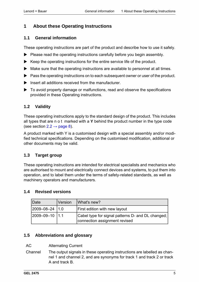
AC Alternating Current
Channel The output signals in these operating instructions are labelled as chan-nel 1 and channel 2, and are synonyms for track 1 and track 2 or trackA and track B.
1 About these Operating Instructions Lenord + BauerSymbols, marks and ...
6 GEL 2475
DC Direct Current
D.P. Diametric Pitch; characteristic of a toothed wheel which is used here forgenerating the count pulsesDefinition: DP = N / PDi = (N + 2) / ODiwith N = number of teeth, PDi = pitch diameter in inches, ODi = outsidediameter in inchesConversion: DP = 25.4 / M
ESD Electrostatic Sensitive Devices
EMC Electromagnetic Compatibility
Idle voltage Standstill monitoring voltage: Constant voltage of 7 V DC, supplied bya 2475xM type sensor as soon as the measuring scale turns so slowlythat the measuring frequency drops below 1 Hz
Measuringscale
General term for target wheel, toothed rack or slotted diskThis guide describes the target wheel in more detail. Comments con-tained in this document also apply to other measuring scales.
Module Module (m); as DP but based on metric ratingDefinition: m = 25.4 / DP = CPm / π = ODm / (N + 2)with CPm = circular pitch (tooth period) in mm,ODm = outside diameter in mm, N = number of teethm = 25.4 / DP
1.6 Symbols, marks and warnings
Symbols and marks are used in these Operating Instructions to enable you to recognizecertain information more quickly.
Indicates a property damage message or addresses practises not relatedto personal safety
Important information for understanding or optimizing procedures.
Indicates an action to be performed
→ page 6 Cross-reference to another part of these Operating Instructions
Lenord + Bauer 2 Identification of the speed sensorID plate
GEL 2475 7
2 Identification of the speed sensor
2.1 ID plate
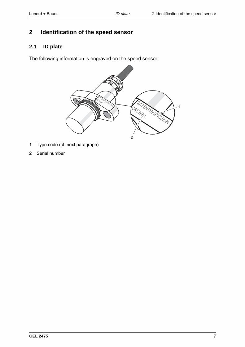
The following information is engraved on the speed sensor:
1 Type code (cf. next paragraph)
2 Serial number
2 Identification of the speed sensor Lenord + BauerType code
8 GEL 2475
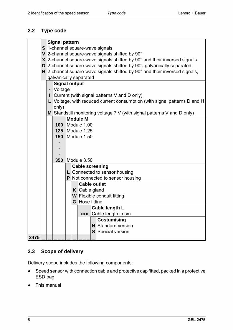
2.2 Type code
Signal patternS 1-channel square-wave signalsV 2-channel square-wave signals shifted by 90°X 2-channel square-wave signals shifted by 90° and their inversed signalsD 2-channel square-wave signals shifted by 90°, galvanically separatedH 2-channel square-wave signals shifted by 90° and their inversed signals,
galvanically separated Signal output
- VoltageI Current (with signal patterns V and D only)L Voltage, with reduced current consumption (with signal patterns D and H
only)M Standstill monitoring voltage 7 V (with signal patterns V and D only) Module M
100 Module 1.00125 Module 1.25150 Module 1.50
···
350 Module 3.50 Cable screening
L Connected to sensor housingP Not connected to sensor housing Cable outlet
K Cable glandW Flexible conduit fittingG Hose fitting
Cable length Lxxx Cable length in cm
CostumisingN Standard versionS Special version
2475 _ _ _ _ _ _ _ _ _ _ _
2.3 Scope of delivery
Delivery scope includes the following components:
Speed sensor with connection cable and protective cap fitted, packed in a protectiveESD bag
This manual
Lenord + Bauer 3 How to avoid property damageCorrect use
GEL 2475 9
3 How to avoid property damage or malfunctions
3.1 Correct use
The speed sensor is intended solely for measurement tasks in the industrial and com-mercial sector. It is installed in a system and must be connected to special evaluationelectronics, contained, for example in a position control unit or an electronic counter.
All other uses shall be deemed incorrect.
3.2 Notes for operators and manufacturers
Personnel training
Make sure that the following requirements are met:
– Assembly, operation, maintenance and removal tasks are performed by trainedand qualified skilled personnel or are checked by a responsible specialist.
– Personnel has received training in electromagnetic compatibility and in handlingelectrostatic-sensitive devices.
Provide personnel with all applicable accident prevention and safety regulations.
Make sure that personnel is familiar with all applicable accident prevention andsafety regulations.
3.3 Modifications and conversions
Unauthorised modifications or conversions may damage the product.
Do not make any modifications or conversions to the product, with theexception of activities described in these operating instructions.
3.4 Sources of hazards
The speed sensor is a sensitive measuring instrument because the active, magneticsensor element is located directly beneath the measuring surface. Mechanical damagecan quickly cause the measurement system to fail.
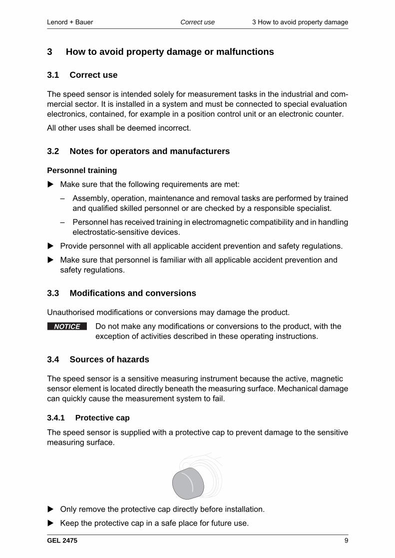
3.4.1 Protective cap
The speed sensor is supplied with a protective cap to prevent damage to the sensitivemeasuring surface.
Only remove the protective cap directly before installation.
Keep the protective cap in a safe place for future use.
3 How to avoid property damage Lenord + BauerSources of hazards
10 GEL 2475
If you are removing the speed sensor for future use, fit the protective cap immedi-ately after removal.
3.4.2 Measuring surface
The speed sensor is highly magnetic on its measuring surfaces. When it is broughtclose to metal objects, it can quickly make contact with them. For example, the meas-uring surface could be damaged if it touches the target wheel or as a result of othermechanical impact.
Ensure that the measuring surface does not come in contact with otherobjects.
3.4.3 Air gap between measuring surface and target wheel
If the air gap, which means the clearance between the measuring surface and the targetwheel is too great, the measurement signal can be lost.
If the air gap is too small, the measuring surface may come in contact with the targetwheel if this runs out of round.
Ensure that the air gap between the measuring surface and the target wheel iswithin the permissible range (see table → page 16).
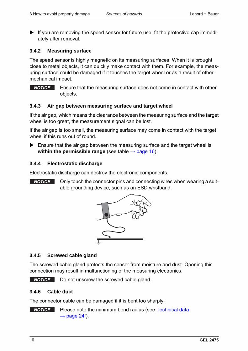
3.4.4 Electrostatic discharge
Electrostatic discharge can destroy the electronic components.
Only touch the connector pins and connecting wires when wearing a suit-able grounding device, such as an ESD wristband:
3.4.5 Screwed cable gland
The screwed cable gland protects the sensor from moisture and dust. Opening thisconnection may result in malfunctioning of the measuring electronics.
Do not unscrew the screwed cable gland.
3.4.6 Cable duct
The connector cable can be damaged if it is bent too sharply.
Please note the minimum bend radius (see Technical data→ page 24f).
Lenord + Bauer 3 How to avoid property damageNotes on EMC
GEL 2475 11
3.4.7 Dirt
The accumulation of ferromagnetic particles between the measuring surface and theteeth of the measuring scale may mean that the speed sensor cannot clearly read thechange from tooth to gap.
Check the speed sensor regularly for dirt, and clean it if necessary (see → page 22).
3.5 Notes on electromagnetic compatibility
To improve the electromagnetic environment please observe the following installationadvice:
Only use connectors with a metal housing or with a housing made from metallisedplastic and shielded cables.
Place the shielding on the connector housing if included in the shielding concept.
Spread the shielding wide.
Keep all unshielded lines as short as possible.
Use large diameter grounding connections (for example, as a low induction groundstrap or ribbon conductor) and keep them short.
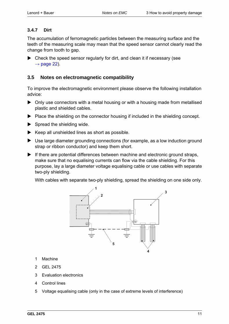
If there are potential differences between machine and electronic ground straps,make sure that no equalising currents can flow via the cable shielding. For thispurpose, lay a large diameter voltage equalising cable or use cables with separatetwo-ply shielding.
With cables with separate two-ply shielding, spread the shielding on one side only.
1 Machine
2 GEL 2475
3 Evaluation electronics
4 Control lines
5 Voltage equalising cable (only in the case of extreme levels of interference)
3 How to avoid property damage Lenord + BauerNotes on EMC
12 GEL 2475
The speed sensor is part of a machine or machinery; include the voltage equalisa-tion for the sensor in the overall shielding concept.
Lay signal and control lines separately from the power cables. If this is not possible,use pairs of twisted and shielded wires and/or lay the encoder line in an iron pipe.
Make sure that surge protective measures have been carried out externally (EN61000-4-5).
Lenord + Bauer 4 Description
GEL 2475 13
4 Description
Task
The speed sensor is intended for measuring the speed of rotary movements withoutmaking contact.
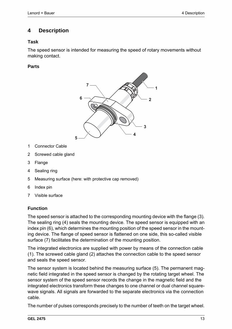
Parts
1 Connector Cable
2 Screwed cable gland
3 Flange
4 Sealing ring
5 Measuring surface (here: with protective cap removed)
6 Index pin
7 Visible surface
Function
The speed sensor is attached to the corresponding mounting device with the flange (3).The sealing ring (4) seals the mounting device. The speed sensor is equipped with anindex pin (6), which determines the mounting position of the speed sensor in the mount-ing device. The flange of speed sensor is flattened on one side, this so-called visiblesurface (7) facilitates the determination of the mounting position.
The integrated electronics are supplied with power by means of the connection cable(1). The screwed cable gland (2) attaches the connection cable to the speed sensorand seals the speed sensor.
The sensor system is located behind the measuring surface (5). The permanent mag-netic field integrated in the speed sensor is changed by the rotating target wheel. Thesensor system of the speed sensor records the change in the magnetic field and theintegrated electronics transform these changes to one channel or dual channel square-wave signals. All signals are forwarded to the separate electronics via the connectioncable.
The number of pulses corresponds precisely to the number of teeth on the target wheel.
4 Description Lenord + Bauer
14 GEL 2475
The types 2475x- and 2475xM provide voltage output signals, type 2475xI providescurrent output signals.
Type 2475xM… also provides a fixed voltage for detecting standstill as soon as thefrequency of the measuring signal drops below 1 Hz.
The power supply for the speed sensor, the evaluation of the pulses and the establish-ment of the control circuit requires separate electronics.
Lenord + Bauer 5 MountingChecking the mounting device
GEL 2475 15
5 Mounting
The speed sensor is mounted in the following steps, which are described in the nextparagraphs:
1. Checking the mounting device
2. Securing the speed sensor
3. Laying the cables
4. Connecting the speed sensor
5. Checking the function
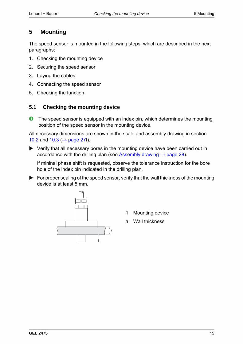
5.1 Checking the mounting device
The speed sensor is equipped with an index pin, which determines the mountingposition of the speed sensor in the mounting device.
All necessary dimensions are shown in the scale and assembly drawing in section10.2 and 10.3 (→ page 27f).
Verify that all necessary bores in the mounting device have been carried out inaccordance with the drilling plan (see Assembly drawing → page 28).
If mininal phase shift is requested, observe the tolerance instruction for the borehole of the index pin indicated in the drilling plan.
For proper sealing of the speed sensor, verify that the wall thickness of the mountingdevice is at least 5 mm.
1 Mounting device
a Wall thickness
5 Mounting Lenord + BauerSecuring the speed sensor
16 GEL 2475
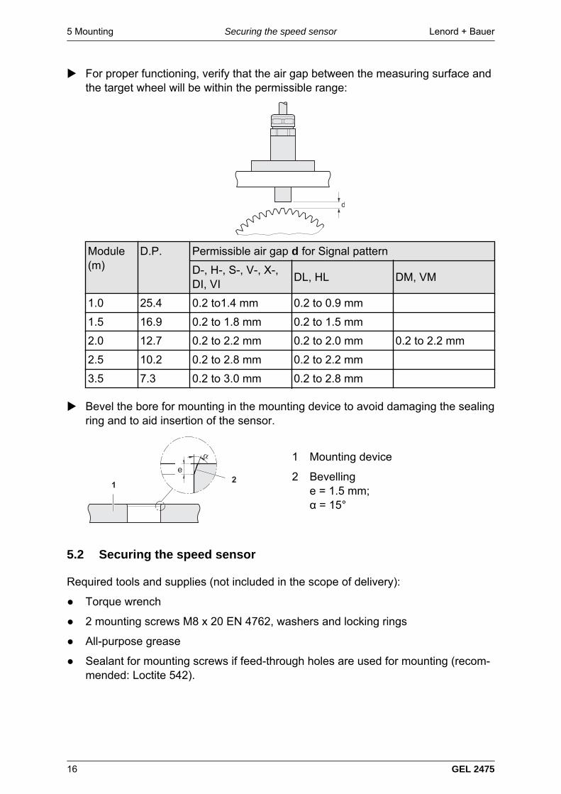
For proper functioning, verify that the air gap between the measuring surface andthe target wheel will be within the permissible range:
Module(m)
D.P. Permissible air gap d for Signal pattern
D-, H-, S-, V-, X-,DI, VI
DL, HL DM, VM
1.0 25.4 0.2 to1.4 mm 0.2 to 0.9 mm
1.5 16.9 0.2 to 1.8 mm 0.2 to 1.5 mm
2.0 12.7 0.2 to 2.2 mm 0.2 to 2.0 mm 0.2 to 2.2 mm
2.5 10.2 0.2 to 2.8 mm 0.2 to 2.2 mm
3.5 7.3 0.2 to 3.0 mm 0.2 to 2.8 mm
Bevel the bore for mounting in the mounting device to avoid damaging the sealingring and to aid insertion of the sensor.
1 Mounting device
2 Bevellinge = 1.5 mm;α = 15°
5.2 Securing the speed sensor
Required tools and supplies (not included in the scope of delivery):
Torque wrench
2 mounting screws M8 x 20 EN 4762, washers and locking rings
All-purpose grease
Sealant for mounting screws if feed-through holes are used for mounting (recom-mended: Loctite 542).
Lenord + Bauer 5 MountingLaying the cable
GEL 2475 17
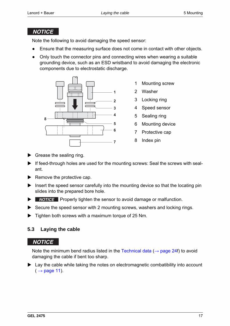
Note the following to avoid damaging the speed sensor:
Ensure that the measuring surface does not come in contact with other objects.
Only touch the connector pins and connecting wires when wearing a suitablegrounding device, such as an ESD wristband to avoid damaging the electroniccomponents due to electrostatic discharge.
1 Mounting screw
2 Washer
3 Locking ring
4 Speed sensor
5 Sealing ring
6 Mounting device
7 Protective cap
8 Index pin
Grease the sealing ring.
If feed-through holes are used for the mounting screws: Seal the screws with seal-ant.
Remove the protective cap.
Insert the speed sensor carefully into the mounting device so that the locating pinslides into the prepared bore hole.
Properly tighten the sensor to avoid damage or malfunction.
Secure the speed sensor with 2 mounting screws, washers and locking rings.
Tighten both screws with a maximum torque of 25 Nm.
5.3 Laying the cable
Note the minimum bend radius listed in the Technical data (→ page 24f) to avoiddamaging the cable if bent too sharp.
Lay the cable while taking the notes on electromagnetic combatibility into account( → page 11).
6 Connection Lenord + BauerConnector assignment
18 GEL 2475
6 Connection
6.1 Connector assignment
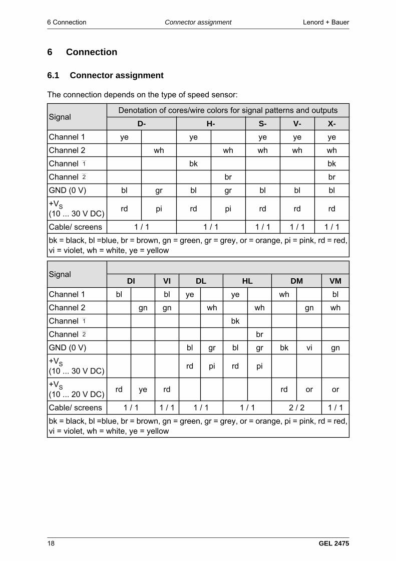
The connection depends on the type of speed sensor:
SignalDenotation of cores/wire colors for signal patterns and outputs
D- H- S- V- X-
Channel 1 ye ye ye ye ye
Channel 2 wh wh wh wh wh
Channel bk bk
Channel br br
GND (0 V) bl gr bl gr bl bl bl
+VS(10 ... 30 V DC)
rd pi rd pi rd rd rd
Cable/ screens 1 / 1 1 / 1 1 / 1 1 / 1 1 / 1
bk = black, bl =blue, br = brown, gn = green, gr = grey, or = orange, pi = pink, rd = red,vi = violet, wh = white, ye = yellow
Signal
DI VI DL HL DM VM
Channel 1 bl bl ye ye wh bl
Channel 2 gn gn wh wh gn wh
Channel bk
Channel br
GND (0 V) bl gr bl gr bk vi gn
+VS(10 ... 30 V DC)
rd pi rd pi
+VS(10 ... 20 V DC)
rd ye rd rd or or
Cable/ screens 1 / 1 1 / 1 1 / 1 1 / 1 2 / 2 1 / 1
bk = black, bl =blue, br = brown, gn = green, gr = grey, or = orange, pi = pink, rd = red,vi = violet, wh = white, ye = yellow
Lenord + Bauer 6 ConnectionExamples of power supplies
GEL 2475 19
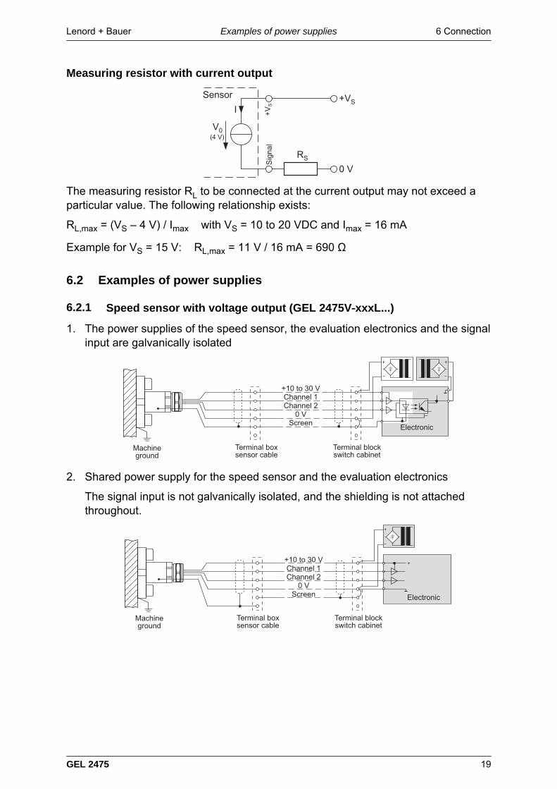
Measuring resistor with current output
+VS
RS
+V
S
V0(4 V)
Sensor
0 V
I
Sig
nal
The measuring resistor RL to be connected at the current output may not exceed aparticular value. The following relationship exists:
RL,max = (VS – 4 V) / Imax with VS = 10 to 20 VDC and Imax = 16 mA Example for VS = 15 V: RL,max = 11 V / 16 mA = 690 Ω
6.2 Examples of power supplies
6.2.1 Speed sensor with voltage output (GEL 2475V‑xxxL...)
1. The power supplies of the speed sensor, the evaluation electronics and the signalinput are galvanically isolated
2. Shared power supply for the speed sensor and the evaluation electronics
The signal input is not galvanically isolated, and the shielding is not attachedthroughout.
6 Connection Lenord + BauerConnecting and testing the speed sensor
20 GEL 2475
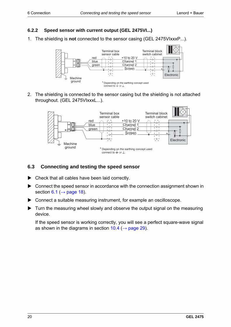
6.2.2 Speed sensor with current output (GEL 2475VI...)
1. The shielding is not connected to the sensor casing (GEL 2475VIxxxP...).
!
! "# #
$
2. The shielding is connected to the sensor casing but the shielding is not attachedthroughout. (GEL 2475VIxxxL...).
!
! "# #
$
6.3 Connecting and testing the speed sensor
Check that all cables have been laid correctly.
Connect the speed sensor in accordance with the connection assignment shown insection 6.1 (→ page 18).
Connect a suitable measuring instrument, for example an oscilloscope.
Turn the measuring wheel slowly and observe the output signal on the measuringdevice.
If the speed sensor is working correctly, you will see a perfect square-wave signalas shown in the diagrams in section 10.4 (→ page 29).
Lenord + Bauer 7 Removal and DisposalRemoving the sensor
GEL 2475 21
7 Removal and Disposal
7.1 Removing the sensor
If the sensor is to be removed for any reason, i.e. relocation of equipment:
– Ensure that the measuring surface does not come in contact with other objects.
– Only touch the connector pins and connecting wires when wearing a suitablegrounding device, such as an ESD wristband to avoid damaging the electroniccomponents due to electrostatic discharge.
Disconnect the speed sensor.
Release the sensor cable.
Loosen and remove the two mounting screws that fix the sensor in the mountingdevice.
Remove the sensor
If the sensor is still to be used: Attach the protective cap to the sensor.
If the original protective cap is no longer available, make sure that comparableprotection is provided for the measuring surface.
7.2 Disposal
Faulty speed sensors should be disposed of in accordance with regional regulationsfor electrical and electronic devices.
8 Maintenance Lenord + Bauer
22 GEL 2475
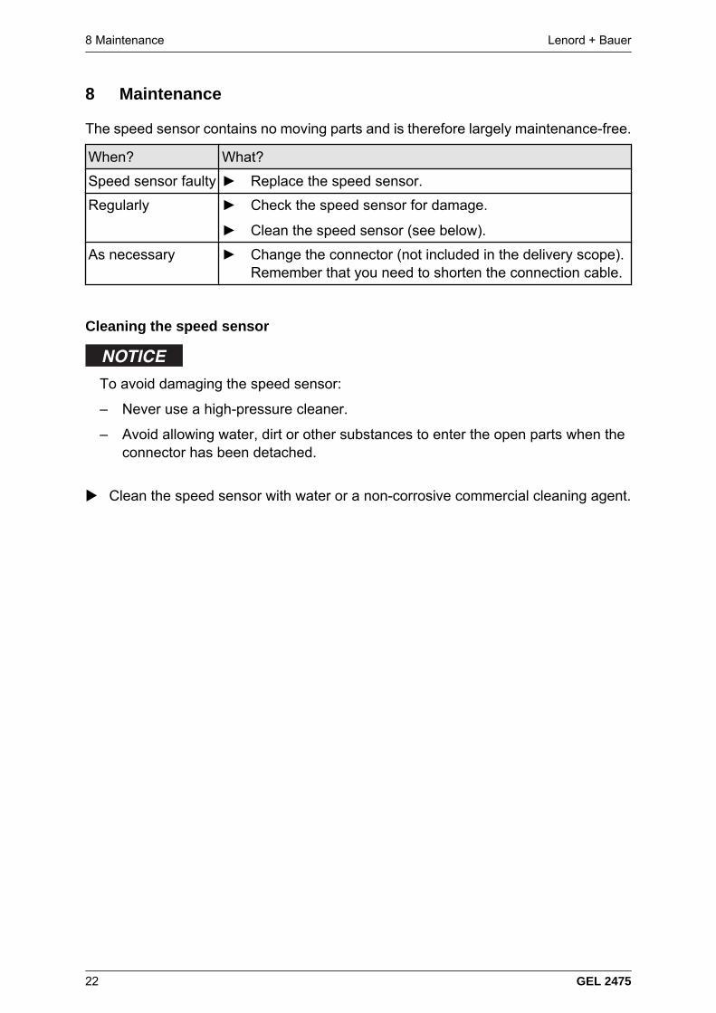
8 Maintenance
The speed sensor contains no moving parts and is therefore largely maintenance-free.
When? What?
Speed sensor faulty Replace the speed sensor.
Regularly Check the speed sensor for damage.
Clean the speed sensor (see below).
As necessary Change the connector (not included in the delivery scope).Remember that you need to shorten the connection cable.
Cleaning the speed sensor
To avoid damaging the speed sensor:
– Never use a high-pressure cleaner.
– Avoid allowing water, dirt or other substances to enter the open parts when theconnector has been detached.
Clean the speed sensor with water or a non-corrosive commercial cleaning agent.
Lenord + Bauer 9 Faults
GEL 2475 23
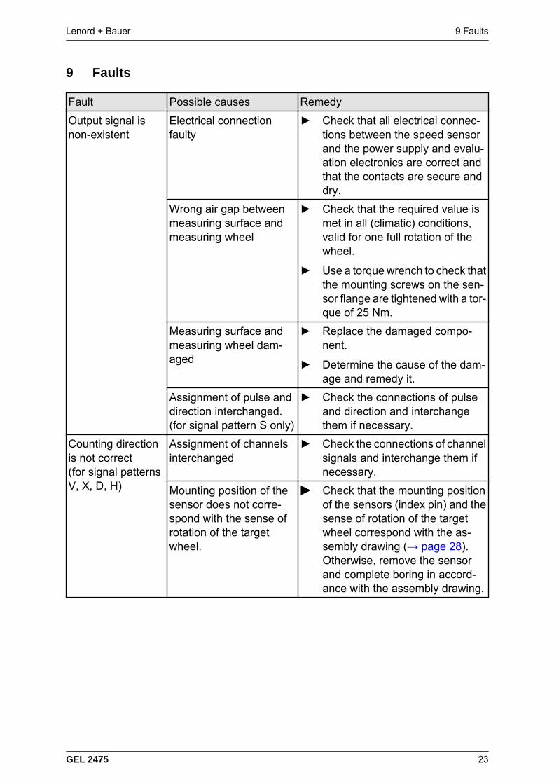
9 Faults
Fault Possible causes Remedy
Output signal isnon-existent
Electrical connectionfaulty
Check that all electrical connec-tions between the speed sensorand the power supply and evalu-ation electronics are correct andthat the contacts are secure anddry.
Wrong air gap betweenmeasuring surface andmeasuring wheel
Check that the required value ismet in all (climatic) conditions,valid for one full rotation of thewheel.
Use a torque wrench to check thatthe mounting screws on the sen-sor flange are tightened with a tor-que of 25 Nm.
Measuring surface andmeasuring wheel dam-aged
Replace the damaged compo-nent.
Determine the cause of the dam-age and remedy it.
Assignment of pulse anddirection interchanged.(for signal pattern S only)
Check the connections of pulseand direction and interchangethem if necessary.
Counting directionis not correct(for signal patternsV, X, D, H)
Assignment of channelsinterchanged
Check the connections of channelsignals and interchange them ifnecessary.
Mounting position of thesensor does not corre-spond with the sense ofrotation of the targetwheel.
Check that the mounting positionof the sensors (index pin) and thesense of rotation of the targetwheel correspond with the as-sembly drawing (→ page 28).Otherwise, remove the sensorand complete boring in accord-ance with the assembly drawing.
10 Appendix Lenord + BauerTechnical data
24 GEL 2475
10 Appendix
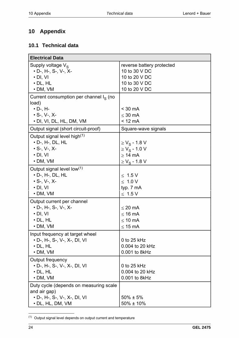
10.1 Technical data
Electrical Data
Supply voltage VS reverse battery protected• D-, H-, S-, V-, X- 10 to 30 V DC• DI, VI 10 to 20 V DC• DL, HL 10 to 30 V DC• DM, VM 10 to 20 V DC
Current consumption per channel IS (noload)
• D-, H- < 30 mA• S-, V-, X- ≤ 30 mA• DI, VI, DL, HL, DM, VM < 12 mA
Output signal (short circuit-proof) Square-wave signals
Output signal level high(1)
• D-, H-, DL, HL ≥ VS - 1.8 V• S-, V-, X- ≥ VS - 1.0 V• DI, VI ≥ 14 mA• DM, VM ≥ VS - 1.8 V
Output signal level low(1)
• D-, H-, DL, HL ≤ 1.5 V• S-, V-, X- ≤ 1.0 V• DI, VI typ. 7 mA• DM, VM ≤ 1.5 V
Output current per channel• D-, H-, S-, V-, X- ≤ 20 mA• DI, VI ≤ 16 mA• DL, HL ≤ 10 mA• DM, VM ≤ 15 mA
Input frequency at target wheel• D-, H-, S-, V-, X-, DI, VI 0 to 25 kHz• DL, HL 0.004 to 20 kHz• DM, VM 0.001 to 8kHz
Output frequency• D-, H-, S-, V-, X-, DI, VI 0 to 25 kHz• DL, HL 0.004 to 20 kHz• DM, VM 0.001 to 8kHz
Duty cycle (depends on measuring scaleand air gap)
• D-, H-, S-, V-, X-, DI, VI 50% ± 5%• DL, HL, DM, VM 50% ± 10%
(1) Output signal level depends on output current and temperature
Lenord + Bauer 10 AppendixTechnical data
GEL 2475 25
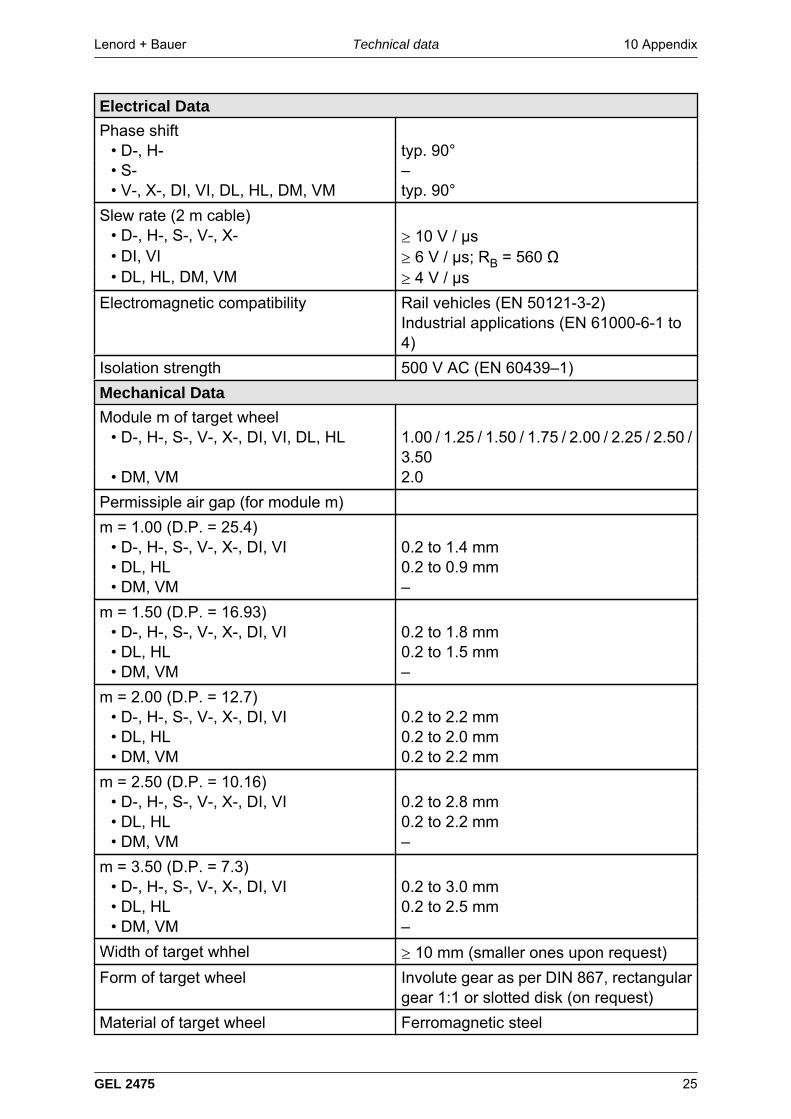
Electrical Data
Phase shift• D-, H- typ. 90°• S- –• V-, X-, DI, VI, DL, HL, DM, VM typ. 90°
Slew rate (2 m cable)• D-, H-, S-, V-, X- ≥ 10 V / μs• DI, VI ≥ 6 V / μs; RB = 560 Ω• DL, HL, DM, VM ≥ 4 V / μs
Electromagnetic compatibility Rail vehicles (EN 50121-3-2)Industrial applications (EN 61000-6-1 to4)
Isolation strength 500 V AC (EN 60439–1)
Mechanical Data
Module m of target wheel• D-, H-, S-, V-, X-, DI, VI, DL, HL 1.00 / 1.25 / 1.50 / 1.75 / 2.00 / 2.25 / 2.50 /
3.50• DM, VM 2.0
Permissiple air gap (for module m)
m = 1.00 (D.P. = 25.4)• D-, H-, S-, V-, X-, DI, VI 0.2 to 1.4 mm• DL, HL 0.2 to 0.9 mm• DM, VM –
m = 1.50 (D.P. = 16.93)• D-, H-, S-, V-, X-, DI, VI 0.2 to 1.8 mm• DL, HL 0.2 to 1.5 mm• DM, VM –
m = 2.00 (D.P. = 12.7)• D-, H-, S-, V-, X-, DI, VI 0.2 to 2.2 mm• DL, HL 0.2 to 2.0 mm• DM, VM 0.2 to 2.2 mm
m = 2.50 (D.P. = 10.16)• D-, H-, S-, V-, X-, DI, VI 0.2 to 2.8 mm• DL, HL 0.2 to 2.2 mm• DM, VM –
m = 3.50 (D.P. = 7.3)• D-, H-, S-, V-, X-, DI, VI 0.2 to 3.0 mm• DL, HL 0.2 to 2.5 mm• DM, VM –
Width of target whhel ≥ 10 mm (smaller ones upon request)
Form of target wheel Involute gear as per DIN 867, rectangulargear 1:1 or slotted disk (on request)
Material of target wheel Ferromagnetic steel
10 Appendix Lenord + BauerTechnical data
26 GEL 2475
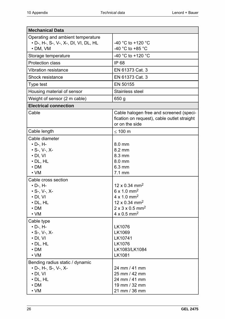
Mechanical Data
Operating and ambient temperature• D-, H-, S-, V-, X-, DI, VI, DL, HL -40 °C to +120 °C• DM, VM -40 °C to +85 °C
Storage temperature -40 °C to +120 °C
Protection class IP 68
Vibration resistance EN 61373 Cat. 3
Shock resistance EN 61373 Cat. 3
Type test EN 50155
Housing material of sensor Stainless steel
Weight of sensor (2 m cable) 650 g
Electrical connection
Cable Cable halogen free and screened (speci-fication on request), cable outlet straightor on the side
Cable length ≤ 100 m
Cable diameter• D-, H- 8.0 mm• S-, V-, X- 8.2 mm• DI, VI 8.3 mm• DL, HL 8.0 mm• DM 6.3 mm• VM 7.1 mm
Cable cross section• D-, H- 12 x 0.34 mm2
• S-, V-, X- 6 x 1.0 mm2
• DI, VI 4 x 1.0 mm2
• DL, HL 12 x 0.34 mm2
• DM 2 x 3 x 0.5 mm2
• VM 4 x 0.5 mm2
Cable type• D-, H- LK1076• S-, V-, X- LK1069• DI, VI LK10741• DL, HL LK1076• DM LK1083/LK1084• VM LK1081
Bending radius static / dynamic• D-, H-, S-, V-, X- 24 mm / 41 mm• DI, VI 25 mm / 42 mm• DL, HL 24 mm / 41 mm• DM 19 mm / 32 mm• VM 21 mm / 36 mm
Lenord + Bauer 10 AppendixScale drawing
GEL 2475 27
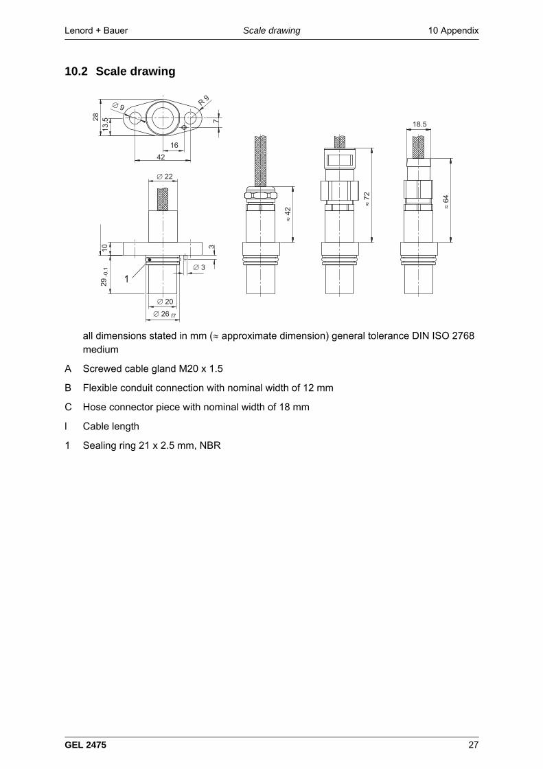
10.2 Scale drawing
% & $
'$(
$(
)*+
,
+
),
'
,
% -%
)
+
all dimensions stated in mm (≈ approximate dimension) general tolerance DIN ISO 2768medium
A Screwed cable gland M20 x 1.5
B Flexible conduit connection with nominal width of 12 mm
C Hose connector piece with nominal width of 18 mm
l Cable length
1 Sealing ring 21 x 2.5 mm, NBR
10 Appendix Lenord + BauerAssembly drawing
28 GEL 2475
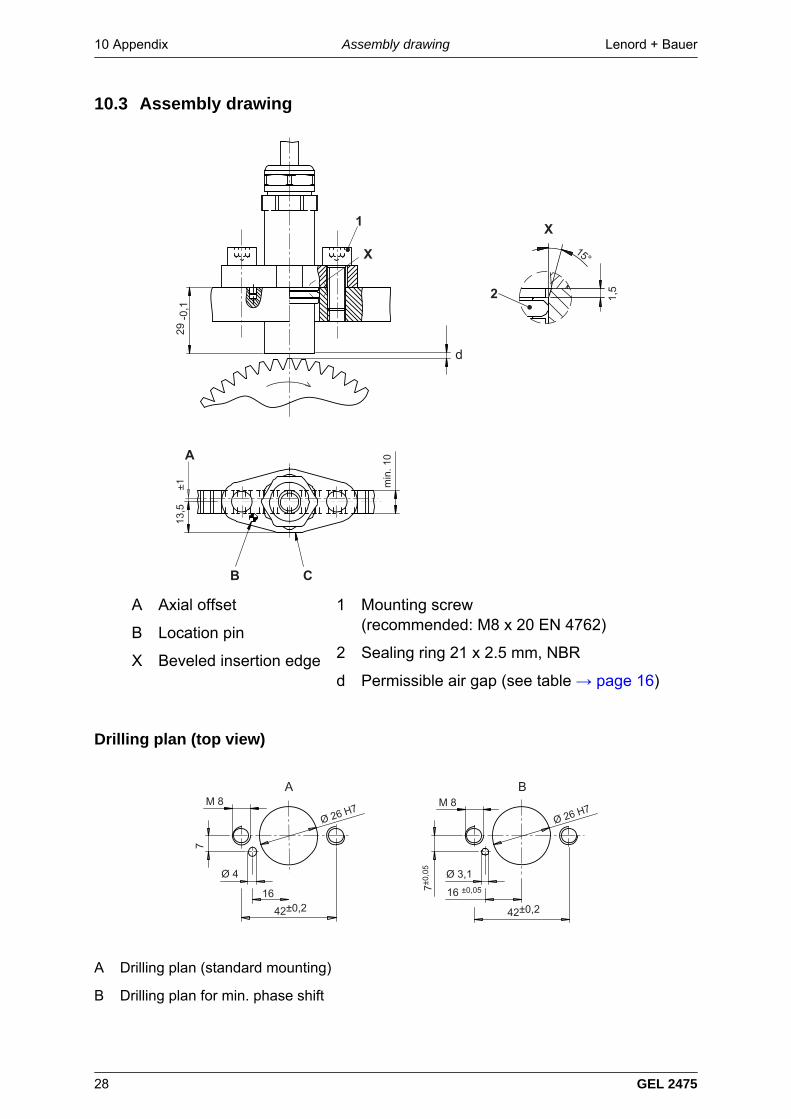
10.3 Assembly drawing
.(
%& .
$
.(
(/
A Axial offset
B Location pin
X Beveled insertion edge
1 Mounting screw(recommended: M8 x 20 EN 4762)
2 Sealing ring 21 x 2.5 mm, NBR
d Permissible air gap (see table → page 16)
Drilling plan (top view)
01
,2 .)2 . (3.
+2 . (
'
3,
+
)
3)4+
'
3)4+
,2 .
A Drilling plan (standard mounting)
B Drilling plan for min. phase shift
Lenord + Bauer 10 AppendixOutput signals
GEL 2475 29
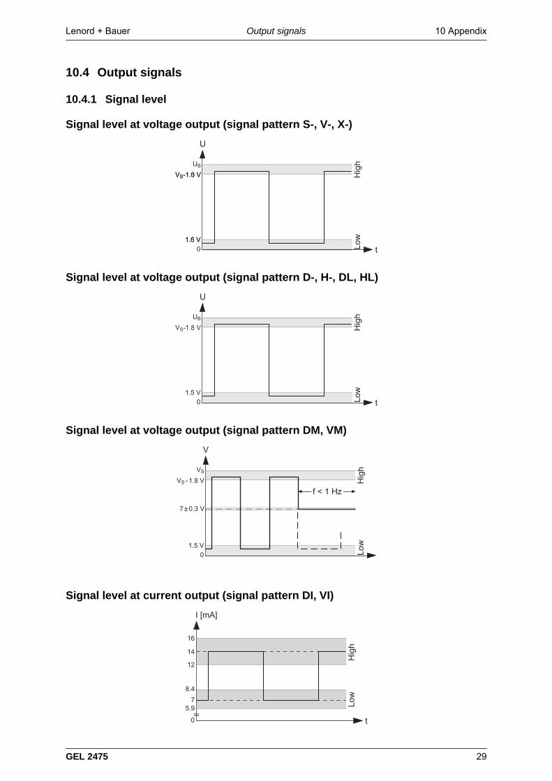
10.4 Output signals
10.4.1 Signal level
Signal level at voltage output (signal pattern S-, V-, X-)
&$
$)
&$'
$(
5
4
6
50
Signal level at voltage output (signal pattern D-, H-, DL, HL)
&$'
$(
5
4
6
50
Signal level at voltage output (signal pattern DM, VM)
+2 $
$(
&$'
4
6
*748
Signal level at current output (signal pattern DI, VI)
10 Appendix Lenord + BauerOutput signals
30 GEL 2475
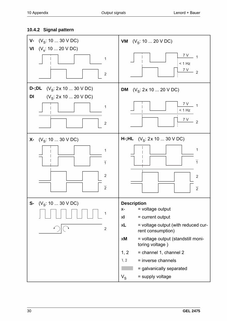
10.4.2 Signal pattern
V- (VS: 10 ... 30 V DC)
VI (Vs: 10 ... 20 V DC)
1
2
VM (VS: 10 ... 20 V DC)
7 V
< 1 Hz
1
27 V
D-;DL (VS: 2 x 10 ... 30 V DC)
DI (VS: 2 x 10 ... 20 V DC)
1
2
DM (VS: 2 x 10 ... 20 V DC)
7 V
< 1 Hz1
27 V
X- (VS: 10 ... 30 V DC)
2
1
1
2
H-;HL (VS: 2 x 10 ... 30 V DC)
2
1
1
2
S- (VS: 10 ... 30 V DC)
1
2
Descriptionx- = voltage output
xI = current output
xL = voltage output (with reduced cur-rent consumption)
xM = voltage output (standstill moni-toring voltage )
1, 2 = channel 1, channel 2
. = inverse channels
= galvanically separated
VS = supply voltage
Lenord + Bauer 10 AppendixManufacturer's declaration
GEL 2475 31
10.5 Manufacturer's declaration
The manufacturer's declaration in accordance with EMC directive 2004/108/EG can befound on the Internet at www.lenord.de.