Embed Size (px)
Citation preview
1����������������� ������ User Manual.
INNER RANGE recommends that all CONCEPT systemsare installed & maintained by
FACTORY CERTIFIED TECHNICIANS.
For a list of Accredited Dealers in your area refer to theInner Range Website. http://www.innerrange.com
������������ ����
�� ��������� ����������
NOTES1) Contents and Index.Turn to the next page for the Table of Contents. The Index commences on Page 104.
2) HELPREMEMBER !! Any time you need it; Help is as close as the press of a key.
3) “Insight” System Management Software.“Insight” is an optional PC Software package that provides most of the systemfunctions and menu options described in this manual. The software is menu drivenand makes system management even easier, in a simple Windows “point and click”environment with a dynamic graphical interface. Consult your Installer for details.
4) Optional Features.This manual describes many optional features that may or may not be utilized in aparticular system. Optional features generally require additional programming and/or installation of additional hardware. Consult the Installer for details of featuresand functions available in your system.
DisclaimerWhile every effort has been made to ensure the accuracy of this manual, the manufacturerand/or it’s agents assume no responsibility or liability for any errors or omissions.Due to ongoing development and product improvements, the contents of this manual aresubject to change without notice.© 1996 - 2004. Inner Range Pty. Ltd. Part Number: 630026

2 CONCEPT 3OOO & Access 4000.CONCEPT 3OOO & Access 4000. User Manual.
CONTENTS
SYSTEM DETAILS ............................................ Inside Front Cover.
SYSTEM OVERVIEW ....................................................................... 4Understanding your system. .................................................................. 4
THE LCD TERMINAL ...................................................................... 8Default LCD Display. ............................................................................ 8The Indicator Lamps. ............................................................................ 9The Keypad. ........................................................................................... 10
USER ALARM SYSTEM OPERATIONS ........................................ 12Level Messages. ..................................................................................... 12LOGON to an LCD Terminal. .............................................................. 13Turning Area/s OFF. ............................................................................. 14Turning Area/s ON. ............................................................................... 16Area Walk Testing. ................................................................................ 17Turning 24 Hour (Tamper) monitoring OFF and ON. .......................... 19Activating a Panic Alarm. ..................................................................... 20Activating a Duress Alarm. ................................................................... 21Acknowledge an Alarm. ........................................................................ 22Acknowledge Latched Alarms. ............................................................. 23USER ACCESS CONTROL OPERATIONS .................................... 24Access (Unlock) a Door. ........................................................................ 24Access (Select) a Secure Floor in an Elevator. ...................................... 25USER SYSTEM STATUS & CONTROL OPERATIONS............... 26View Alarm Review information. ......................................................... 26View Time and Date. ............................................................................. 27View Area Status. .................................................................................. 28Home Auxiliary Control. ....................................................................... 29Air Conditioning Control. ..................................................................... 31
MENU OPTIONS ................................................................................ 33Accessing the Menu. ............................................................................. 33Keypad Functions in the Menu. ............................................................ 34
Information: Menu Option 1 .......................................................... 35REVIEW .............................................................. MENU, 1, 1............. 35LOCATE USER ................................................... MENU, 1, 2............. 36VIEW ANALOGUE VALUES ............................ MENU, 1, 3............. 37VIEW EVENT COUNTER VALUES ................. MENU, 1, 4............. 38
3 IfUsed.[ ][ ][ ][ ][ ][ ][ ][ ][ ][ ]
[ ][ ]
[ ][ ][ ][ ][ ]
[ ][ ][ ][ ]

3����������������� ������ User Manual.
VIEW INPUT STATES ....................................... MENU, 1, 5 ............ 39VIEW POWER MODULE STATUS .................. MENU, 1, 6 ............ 40
Access: Menu Option 2 ................................................................... 42USER PROGRAMMING .................................... MENU, 2, 1 ............ 42User Programming Flowchart. .............................................................. 43DELETING A USER .......................................... MENU, 2, 1 ............ 57USER TYPES ...................................................... MENU, 2, 2 ............ 58LISTS (Door / Lift Car / Floor) ......................... MENU, 2, 3, X ....... 63MENU GROUPS ................................................. MENU, 2, 4, 1 ........ 66RF FOB REGISTRATION .................................. MENU, 2, 7 ............ 71
Isolate: Menu Option 3 ................................................................... 72
Zone Testing: Menu Option 4 ........................................................... 74
Times: Menu Option 5 .................................................................... 76SET TIME AND DATE ...................................... MENU, 5, 1 ............ 76TIMEZONES ...................................................... MENU, 5, 2 ............ 77HOLIDAYS ......................................................... MENU, 5, 3 ............ 81DIARIES ............................................................. MENU, 5, 4 ............ 83
Service: Menu Option 8 .................................................................. 86REQUEST SERVICE .......................................... MENU, 8, 1 ............ 86TEST REPORT ................................................... MENU, 8, 2 ............ 87INSTALLER LOCKOUT .................................... MENU, 8, 3 ............ 87ANSWER PHONE .............................................. MENU, 8, 4 ............ 88
Control: Menu Option 9 ................................................................. 89HOME AUXILIARIES ....................................... MENU, 9, 1 ............ 89DOOR CONTROL (Open/Close) ....................... MENU, 9, 2 ............ 90LIFT CONTROL (Access/Secure) ...................... MENU, 9, 4 ............ 91ADJUST EVENT COUNT ................................. MENU, 9, 6 ............ 92ADJUST AREA USER COUNT ........................ MENU, 9, 7 ............ 93
REMOTE CONTROLWireless RF Remote Fob Operations ................................................ 94Telephone (DTMF) Remote Control. ................................................. 96GSM Mobile phone Control and Alarm messages ........................... 98
INDEX .................................................................................................. 104MENU FLOWCHART ........................................ Inside Rear Cover.
[ ][ ]
[ ]
[ ][ ][ ][ ][ ]
[ ]
[ ]
[ ][ ][ ][ ]
[ ][ ][ ][ ]
[ ][ ][ ][ ][ ]
[ ][ ][ ]
Co
nten
ts
4 ����������������� ������ User Manual.
SYSTEM OVERVIEW
The “3000” & “Access 4000” provide the next generation in Access Control, SecurityManagement and Building Automation Systems. Both systems offer the system designerthe ability to provide Security monitoring, Access Control and Automation as eitherindependent or integrated facilities. Integration can be implemented to whatever degreerequired in each Area of the system being protected and managed.
Many innovative programming options provide the product with the flexibility to fulfilthe security management requirements of the most demanding applications.The programming structure allows for easy expansion and alteration to the systemconfiguration when security needs change, providing the customer with a product thatwill stand the test of time and be ready for all future requirements.
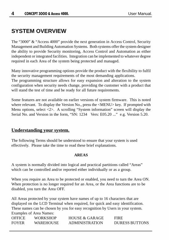
Some features are not available on earlier versions of system firmware. This is notedwhere relevant. To display the Version No., press the <MENU> key. If prompted withMenu options, select <2>. A scrolling “System information” screen will display theSerial No. and Version in the form, “SN: 1234 Vers: E05.20 ...” e.g. Version 5.20.
Understanding your system.
The following Terms should be understood to ensure that your system is usedeffectively. Please take the time to read these brief explanations.
AREAS
A system is normally divided into logical and practical partitions called “Areas”which can be controlled and/or reported either individually or as a group.
When you require an Area to be protected or enabled, you need to turn the Area ON.When protection is no longer required for an Area, or the Area functions are to bedisabled, you turn the Area OFF.
All Areas protected by your system have names of up to 16 characters that aredisplayed on the LCD Terminal when required, for quick and easy identification.These names can be chosen by you for easy recognition by Users in your system.Examples of Area Names:OFFICE WORKSHOP HOUSE & GARAGE FIREFOYER WAREHOUSE ADMINISTRATION DURESS BUTTONS

5����������������� ������ User Manual.
USERS
Your system can be operated by one or more persons called “Users”.Each User must have a PIN Code and/or a Card in order to perform any operations.
A User is also given a name of up to 16 characters for easy identification and a “UserType” to define which Area/s they can control and what other operations they areallowed to perform. In systems incorporating Access Control facilities, the “UserType” also defines which Doors and/or Lift Cars and Floors the User may access.
The User’s name and User Type are assigned by the System Administrator (or otherperson/s who are allowed to program Users) and can be programmed appropriatelyfor each individual User. See “User programming” for an overview.
ZONES and SYSTEM INPUTS
Each Area in your system is protected by using detectors connected to inputs on theequipment. These devices are designed to register movement, unauthorised accessand undesirable situations, in the protected Area. These detector inputs are called“Zones” (also known as sectors in some systems). Zones can also be used as Inputsfor Access Control and Building Automation functions such as Exit buttons,Switches, Thermostats, interface to Remote Control Receivers, etc.
All Zones have programmable names of up to 24 characters, which are displayed onthe LCD Terminal when required for quick and easy identification.
Examples of Zone Input names:FRONT ENTRY DOOR HALLWAY PIRWORKSHOP ROLLER DOOR VAULT WALL SEISMICBASEMENT SMOKE DETECTOR DURESS BUTTON FRONT DESK
This product is also equipped with built-in diagnostic facilities that monitor thesystem for any problems, or attempts to tamper with the equipment. Alarmsgenerated by the system monitoring are called “System Inputs”. System Inputs alsohave names (pre-programmed) that are displayed on the LCD Terminal whenrequired for quick and easy identification.
Examples of System Input names:CABINET TAMPER LOW BATTERY DETECTOR FUSEEXTERNAL SIREN TAMPER DURESS LINE FAULT
OV
ER
VIE
W

6 ����������������� ������ User Manual.
LCD TERMINALS
Many system operations, such as turning Areas ON and OFF, are usually performedat a Terminal.See “The LCD Terminal” on pages 8-11 for full details of display and keypadfunctions.
A system may have up to 99 Terminals connected. Any of these Terminals can beused to operate the system, however, programming may be used to limit theoperations available at some Terminals.
USING A TERMINAL
The first step in using a terminal is always the same. Enter your own secret PINcode using the digit keys on the keypad, then press the <OK> key.The system will now identify you and may greet you by name with a message on thedisplay.After a few seconds, the display will prompt you with the name of the first Area (orArea List) that you are allowed to turn ON and/or OFF and the action required.
THE DISPLAY
The LCD display is used to annunciate alarms, show the status of the system, andguide the User through operations and programming using plain English text.Sometimes it is necessary for the message to be longer than the width of the display.When this occurs, the message will automatically scroll slowly to the left so that youcan view the entire text.Many items in the system can have names programmed to provide easy identificationvia the LCD Display (e.g. Users, User Types, Areas, Zones, Home Auxiliaries, etc.)If an item used in your system is only identified by the default name -e.g. ��������� (the item ID number, preceded by a full stop), you may wish toask the Installer or System Administrator to program a more suitable name for theitem.
HELP
A special feature of this product is the <HELP> key.No matter what stage of an operation you are up to, pressing the <HELP> key willdisplay a Help message related to the specific operation you are performing.If at any time you are not sure what to do next when using the system, press the<HELP> key.

7����������������� ������ User Manual.
DOORS
When Access Control is utilized in your system, each access point that is controlled(Door, Roller Shutter, Turnstile, Boom gate, etc.) is called a “Door”. Installerprogramming options can provide for different types of Doors to be controlled andmonitored in different ways. The way in which a Door is controlled may also varydepending on the time or day of the week.
When you require access through a Door, you must perform the required operation tounlock the door, (e.g. Present your Card at the Reader and/or Enter your PIN, etc.)then open the door and pass through, ensuring the door closes behind you. Avoidleaving the door open longer than necessary as most systems will be programmed todetect “Door Held Open” (Door open too long) and will generate an alarm.
Doors controlled by your system have names that allow for easy identification whenreviewing Access Control activity via the Information Menu.
READERS
Depending on the design of your system, Access Control operations will probably beperformed at a Reader. A Card, Proximity Tag, or Wiegand key, etc. will be swiped/presented/inserted, at a Reader, to gain access through a Door.Note that some systems will provide Access Control via the LCD Terminals (usingPIN codes) and some systems will require a Reader and an LCD Terminal to be usedto gain access through some Doors.
Programming is used to define the Door that each Reader will control, and theoperations allowed at each Reader. For example, a Reader outside the front doormay be programmed to allow the inside Area to be turned OFF when certain Usersuse the Reader to gain access through the door. (Normally, access would not begranted if the Area that the User is about to enter is ON)
AUXILIARIES
Auxiliaries are basically outputs that can be automatically activated by manydifferent types of events in the system. They can be physical outputs used to controlalarm and warning devices, indicator lamps, electric locks, building and homeautomation functions, etc; or they can be used internally in system programming tolink different system operations together. Auxiliaries that need to be controlled byUsers can be defined as “Home Auxiliaries”. They can then be turned On, or Off orturned On for a timed period in minutes or seconds at designated LCD Terminals.
OV
ER
VIE
W

8 ����������������� ������ User Manual.
THE LCD TERMINAL
Default LCD Display.
The LCD Terminal offers a number of options for the Default display.This is the display that will be shown when there are no User operations beingperformed, and no Alarms or other messages to be displayed.
The Default display can be selected separately for each LCD Terminal in yoursystem. The settings can only be programmed by the Installer, who can also adviseyou on the appropriate options.
���
����
SYSTEM READY.If no specific Default Display option has beenchosen, this message will be displayed.
SINGLE AREA STATUS.This option allows the name and current status ofa single Area to be displayed. This is useful whenthe Terminal only provides control of one Area.An option is also provided to allow the UP andDOWN Arrow keys to be used to view the nameand current status of up to 8 sequential Areas.
AREA ARRAY.The Area Array allows the current status of 8Areas to be viewed by Area number.n = Area Off (Disarmed)Y = Area On (Armed)T = Timed Off (Defer Arming timer running)W = Defer Arm Warning. (Timer about to expire)See “Turning Areas Off” for details of the DeferArming feature.An option is also provided to allow the UP andDOWN Arrow keys to be used to view the currentstatus of all Areas in the system by Area number.i.e. Areas 1-8V Areas 9-16V Areas 17-24, etc.
������
������
����������������
��������� �
��������!�������
��!����� ��
����������!�����
�������� ��

9����������������� ������ User Manual.
The Indicator Lamps.
TIME & DATE. (V5 or later only)The Time and Date option allows the currentsystem Time and Date to be displayed.This option is partularly useful if the system isbeing utilized to generate Time-On-Site reports.Users can be provided with a display of the actualsystem Date & Time being logged.
CUSTOM MESSAGE.The “Diaries” feature can be utilized to provide acustomized message that is appropriate for theparticular Site and/or the particular Terminal.Some common applications are:-The Monitoring Station’s Telephone number.-The Installer’s Telephone number.-“Welcome to <your company name>”-“Enter PIN & OK to Logon”.
"# $�%���$&���
��' ����� (�
)�������%�����
������!������
Four multi purpose lamps are provided across the top of the LCD Terminal for quickand simple indication of Area and Alarm Status, Door functions and/or otherconditions. The settings can only be programmed by the Installer, who can alsoadvise you on the appropriate options.
When programmed for “Area Array”, the lamps will indicate the status of 4sequential Areas in the following manner:Off = Area Off (Disarmed)On = Area On (Armed)Flashing = Alarm in this Area.
If the lamps have been programmed to indicate other conditions, please record theirpurpose here:
Lamp 1 ....................................................................................................
Lamp 2 ....................................................................................................
Lamp 3 ....................................................................................................
Lamp 4 ....................................................................................................
TE
RM
INA
L
This option is only available inV5 or later and requires acompatible LCD Terminal.

10 ����������������� ������ User Manual.
Each time a key is pressed, a short “beep” will beemitted to indicate that the key press was accepted.(The Installer can disable the beeping if necessary)
If the Terminal emits a long “beep”, it means that thekey press was not accepted or is not allowed.
You may only press one key at a time but key presssequences may be as fast as you like.
The functions of the 20 keys during User Operations are described below.
The DIGIT keys are used for entering your secret PIN code.You have 10 seconds to enter each digit, and must press the<OK> key when complete.This sequence is required before any panel operations can beperformed.These keys can also be used to search for an item to becontrolled by selecting the first letter of it’s name.
The <OFF> and <ON> keys are used to turn Off or turn On,the Area (or Area List) named on the Display at the time.
The <HELP> key is used to display a “Help message” aboutthe current operation being performed and can be pressed atany time.
The <MENU> key is pressed after PIN code + <OK> if youwish to perform any Menu operations. (Operations otherthan Area On/Off, Door Access, etc.)OR if pressed when not logged on, may allow Review of pastAlarms, if enabled (V3 or later), and System information.
The <END> key is used when you have finished performingthe required operations or if you make a mistake whileentering your PIN code and want to start again.
The Keypad.
Operations & programming are performed by using the keypad on an LCDTerminal.

11����������������� ������ User Manual.
The <OK> key must always be pressed after you have enteredyour secret PIN code. You have 10 seconds to press the <OK>key after you have completed entering the code.
The <LEFT> arrow key will move the cursor to the leftOR when prompted with the Area ON/OFF display, selectsthe “24Hour” (Tamper monitoring) part of the Area to turnON or OFF (Normally restricted to Installer or Owner)OR if pressed when not logged on, may displayAirconditioning control options if enabled. (V2 or later)
The <RIGHT> arrow key will move the cursor to the rightOR when prompted with the Area ON/OFF display, changesthe display mode from AREA to AREA LIST and vice versaOR if pressed when not logged on, may display HomeAuxiliary control options if enabled. (V2 or later)
The <UP> and <DOWN> arrow keys are used to scroll upand down through a list of available items to view, control orprogram. e.g. Areas, Zones, Review messages, etc.OR If pressed when not logged on, may display summary ofArea Status if enabled. (V3 or later)
NOTE: Keypad keys also have other functions when you are selecting, viewing,controlling or programming items in the menu. Details of the keypad functionswhen you are in the menu are provided in the “Menu Options” section of thismanual.
REMEMBER !! Any time you need it,
is as close as the press of a key.
If PIN codes are used to unlock doors, pressing the <OK> key again will perform theDoor unlock operation on the Door associated with the Terminal.On Terminals that are programmed ONLY for Door Access control, the <OK> keymay not need to be pressed twice.(In some cases, the <OK> key may be programmed to unlock a door without a PINcode being used. e.g. In low security periods, or when the Terminal is on the insideof an Exit Door.)
TE
RM
INA
L

12 ����������������� ������ User Manual.
USER OPERATIONS
User operations are the basic day-to-day operations performed on the system.These include: Turning Areas ON and OFF. (Arming and Disarming)
Walk Testing Zones. (If enabled for higher security)Acknowledging Alarm messages.Accessing Doors and/or LiftsViewing “Alarm Review” information and Area Status.Controlling Outputs (Turning Home Auxiliaries ON and OFF)
The system has been designed for simple operation, providing straightforwardprocedures, and display prompts in plain English text. However, if a User at any timeis unsure of what to do next, a simple press of the <HELP> key will provide additionalassistance.
Most User operations begin with the same simple procedure. The User must LOGONto an LCD Terminal by entering their secret PIN code followed by the <OK> key.When this is done, the system verifies the User and depending on the operations allowed,the User is then able to select another key to press to perform the operation required.The LOGON procedure is described on the following page. Each of the operations thatcan be performed will then be described in detail.
Level Messages.
System operation is continuously monitored for problems and special conditions.A “Level Message” is displayed on one or more of the LCD Terminal/s if such a conditionexists and will remain on the LCD display until the condition is rectified.* You will probably need the Installer to rectify any of the first 4 conditions.
EGASSEM NOITPIRCSED
*melborPrewoPdaH,elbisseccafI.detcennocrewopCAevahtonodseludomeromro1
.nodehctiws&detcennocsirewopCAkcehc*melborPyrettaBdaH .egatlovyrettabwolevahseludomeromroenO
*melborPkrowteNdaHlortnoCehthtiwgnitacinummocdeppotsevahseludomeromroenO
.melborpeludomaroegamadelbacebyamerehT.eludoM
*melborPsmmoCdaHlartneC.g.e.sksaTsmmoCeromroenohtiwmelborpasierehT
.cte,retnirP,CP,noitatS desimorpmocebyamgnitropermralA ../dehctalstupnIemoS
delaesnu/derepmat/detalosi"smralAdehctaLegdelwonkcA"eeS
.>5<,>1<,>UNEM<.”setatStupnIweiV"dna.nOnrutottuobaaerA .noitpOgnimrAaerAderrefeD.”ffOs/aerAgninruT“eeSedoCretnE,emaNaerA .pudloHlecna]C[.”snoitpOpuorGuneM“eeS

13����������������� ������ User Manual.
LOGON to an LCD Terminal.
- , Enter your secret PIN Code using the digit keys,then press the <OK> key. Each digit pressed willbe displayed as a hash (#) character.If you make an error while entering your PIN code,press the <END> key and start again.
If there are no messages to be acknowledged, theDisplay may first greet and identify you.Note: Greeting can be disabled in V3 or later.
If there is a message to be acknowledged, refer to“Acknowledge an Alarm”.
The status of the first Area (or Area List) that youare allowed to control is displayed, with a promptto perform an ON or OFF operation.
When your operations are complete, you must Logoffthe Terminal by pressing the <END> key.
*##��+#� � (
,-.��-�/,��,
�))'",
���� ��0&�1����
Logging on is the first step performed in MOST operations.
"#�����2222
NOTES:1) Keypad Lockout. If a Valid PIN code is not entered after a number of successive
tries (usually 5 or 6), the LCD Terminal will display a “Too many tries” messageand will be totally locked out for a pre-determined period. (Normally 60 seconds)A message “Module Lockout: LCD Term. #??” will be logged in the Reviewmemory and an alarm message “Too Many Tries” may be reported.
2) Duress. If you are being forced to perform operations at an LCD Terminalagainst your will, your system may allow a Duress alarm to be activated by usinga special PIN Code. See “Activating a Duress Alarm” for details.
3) PIN discovered. When programming User Codes, if a User attempts to choose aPIN Code that already exists, the message, “This pin not allowed” is displayed.Whenever that PIN Code is now used, the LCD Terminal will display a warning:“Your pin has been discovered by another User. You should change you pin.”If you see this message, you can press <OK> to continue your operation, butmake arrangements to have your PIN Code changed as soon as possible.
LO
GO
N

14 ����������������� ������ User Manual.
� 3���������4���
�5-�-�%�������
Turning Area/s OFF.
Logon to the Terminal as described earlier.(PIN code + <OK>)
After the greeting (if enabled), the display will showthe Area Status etc. as before. To select anotherArea see “AREA SELECTION” on the next page.
At the “Push OFF” prompt, turn the displayed Area(or Area List) OFF by pressing the <OFF> key.
The display will alter accordingly to indicate thatthe operation was successful.
If you are allowed to control more than oneArea:
-DISPLAY MODE.The Display mode can be changed from SingleAREA to AREA LIST and vice versa, by pressingthe <RIGHT ARROW> key.
By using AREA LISTS, you can turn OFF all theAreas in the List that you are allowed to control,with a single operation.
i.e. You can select any Area List in the system.However, only Areas that are in the Area Listselected and are also in the Area List in your “UserType”, or your “Extra Area” will be turned Off.
Once you have Logged on to a Terminal, and have seen the Area status with the “PushOff” or “Push On” message, you may perform the Area OFF or ON operations.
Remember: You have a limited time to turn an Area OFF once you have entered theArea (Usually 30-90 seconds). Ask the Installer for the Entry time used in yoursystem.
�))'",
���� ��0&�1����
�))'",
��������0&�1��
- ,

15����������������� ������ User Manual.
Area O
n/O
ff
�))'",
���6� ������
�))'",
��#&���#��&� ��
- , ,
or
Deferred Arming option.In some applications the system is programmed so that certain User types may onlyturn the Area Off for a limited time. e.g. A cleaner or guard working outside normalworking hours may only turn the Area Off for 60 minute intervals. (V2 or later only)
When these User types turn the Area Off, the displayshows Area is Off with a “Defer timer” running.
At any stage during the defer time, the User canturn the Area Off again, to re-start the timer, (V3or later only) or turn the Area back On and cancelthe timer.
When the timer has only 250 seconds left to run,the LCD Terminal will beep every 2 seconds anddisplay this warning.The User can still perform the Area Off or Area Onoperations during this warning period, but if noaction is taken the Area will automatically turn Onwhen the warning period expires.
NOTE: If more than one Area is about to turn On,the display shows each Area in turn for 2 seconds.
-AREA / AREA LIST SELECTION.You may select other Areas or Area Lists by usingthe <UP> and <DOWN> Arrow keys and/or the<DIGIT> keys to select the 1st letter that the Areaname begins with.
e.g. A system has Areas named “Reception”, “R &D” and “Rodneys Office”.1) To select any of these Areas, press the <6 PQR>key until an Area starting with “R” is displayed.(You may need to press the key between 1 and 3times depending on other Area names in the system)2) If the Area that you require is not displayed, usethe <DOWN> Arrow key to scroll through, andselect, the other Areas starting with that letter.Note: Areas are sorted numerically after the 1stletter.

16 ����������������� ������ User Manual.
Turning Area/s ON.
Logon to the Terminal as described earlier.(PIN code + <OK>)
After the greeting (if enabled), the display will showthe Area Status etc. as before. If you are allowed tocontrol more than one Area, the DISPLAY MODEcan be changed and AREA/S SELECTED asdescribed in “Turning Area/s OFF”.
At the “Push ON” prompt, turn the displayed Area(or Area List) ON by pressing the <ON> key.
After the <ON> key is pressed, the system will testthe state of all the inputs allocated to the Area toensure that they are in the Sealed condition and theArea is ready to be turned ON.
THEN:If all Zones programmed to be tested are Sealed,the Area will turn ON and this display will indicatethat the operation was successful.While this message is displayed, you can press the<ON> key again to view the Exit delay timecounting down in 5 second increments.Remember: You have a limited time to exit theArea once you have turned it ON. (Usually 30-90seconds). Ask the Installer for the Exit time usedin your system.
When the operation is complete the display willreturn to the Area status message.
"�7),�,7",����+
��������0&�1��
"�7),�,7",����+
#8��
6���� (�9# ��
0������8�������
Display briefly shows:
"�7),�,7",����+
���� ��0&�1����
Display briefly shows:
then:
- ,
IMPORTANT NOTE: Some systems in high security applications may have theArea Pre-Arm “Walk Test” feature enabled. (Only available in V3 or later).In most systems this feature is not enabled and the Area ON procedure will simplybe performed as described below.If Walk Testing is enabled on your system, the same procedure is followed exceptthat after the initial test to ensure that all Zones are Sealed, the system then entersWalk Test mode. Refer to “Area Walk Testing” on the following page.
"�7),�,7",����+
,:���;�������$
17����������������� ������ User Manual.
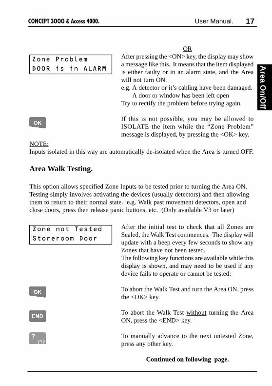
ORAfter pressing the <ON> key, the display may showa message like this. It means that the item displayedis either faulty or in an alarm state, and the Areawill not turn ON.e.g. A detector or it’s cabling have been damaged.
A door or window has been left openTry to rectify the problem before trying again.
If this is not possible, you may be allowed toISOLATE the item while the “Zone Problem”message is displayed, by pressing the <OK> key.
9# ��0�#���
-�������� ��4��+
Area Walk Testing.
This option allows specified Zone Inputs to be tested prior to turning the Area ON.Testing simply involves activating the devices (usually detectors) and then allowingthem to return to their normal state. e.g. Walk past movement detectors, open andclose doors, press then release panic buttons, etc. (Only available V3 or later)
9# �� #��6�����
�#���## �-##�
After the initial test to check that all Zones areSealed, the Walk Test commences. The display willupdate with a beep every few seconds to show anyZones that have not been tested.The following key functions are available while thisdisplay is shown, and may need to be used if anydevice fails to operate or cannot be tested:
To abort the Walk Test and turn the Area ON, pressthe <OK> key.
To abort the Walk Test without turning the AreaON, press the <END> key.
To manually advance to the next untested Zone,press any other key.
Continued on following page.
Area O
n/O
ff
NOTE:Inputs isolated in this way are automatically de-isolated when the Area is turned OFF.

18 ����������������� ������ User Manual.
6����0�����
0&�1��<�=�
If the maximum time allowed for Walk Testing isabout to expire, the normal display will alternatewith this warning. You have 1 minute to completethe Walk test from the time that this warning isfirst displayed.
When all the Zones have been tested and there areno faults, the “Test Passed” message is displayed.
Push <OK> to exit the Walk Test mode and turnON the Area.
The display will indicate that the Area ON operationwas successful, before returning to the Area statusdisplay.Remember: You have a limited time to exit theArea once you have turned it ON. (Usually 60seconds; although the Exit time may have beenprogrammed for a different period by the installer.)
Display Counters. (V3 or later only)In some special applications, after the Area ONmessage, the display will automatically show the“Read Counters” screen. This allows the User toview the results of any automatic or manual testingof devices that have an event output monitored bythe system.e.g. Security cameras (35mm film type) and otherdevices that use consumable materials.
In this screen, you can scroll through the list ofavailable counters to view using the <UP> and<DOWN> arrow keys. Each counter can have aunique 16 character name for easy identification.
When your check of the counters is complete, pushthe <END> key to exit and return to the normaldisplay.
�������#&�
�#��&� �# �>
6��,����+
#8��
6��,����+
���� ��0&�1����
Display briefly shows:
then:
"#& ����7#���
"#& �������

19����������������� ������ User Manual.
Turning 24 Hour (Tamper) monitoring OFF and ON.
Logon to the Terminal as described earlier.(PIN code + <OK>)
After the greeting, the display will show the AreaStatus etc. as before.
Press the <LEFT ARROW> key to change thedisplay mode to show the status of the 24Hr (orTamper) part of the Area.
The display will now show the Area name andindicate if 24Hr (Tamper) monitoring is Off or Onin this Area.
Use the <OFF> or <ON> key to turn the 24Hr(Tamper) monitoring Off or On as required.
NOTE: When the 24Hr monitoring is turned Offin an Area, it will automatically be turned back Onagain when the Area is turned ON to ensure thatTamper monitoring is never compromised.
The display will alter accordingly to indicate thatthe operation was successful.
If you need to turn 24Hr monitoring Off inother Areas:
You may select other Areas by using the <UP> and<DOWN> Arrow keys or the letter key that the Areaname begins with.
0,�'+,6,�
��?��������
0,�'+,6,�
��������0&�1��
0,�'+,6,�
��?������
The 24Hr part of an Area continuously monitors the equipment and inputs for faults ordeliberate interference and activates “Tamper” alarms when these conditions occur.Occasionally the Installer, or a User with the appropriate level of authority, may needto turn the 24Hr part of an Area Off so that maintenance or changes can be performedon equipment or devices (detectors etc.) in the system.Note that most Users in the system will NOT have access to this operation.
- ,
or
Area O
n/O
ff

20 ����������������� ������ User Manual.
Activating a “Panic” Alarm.
Your system may be programmed to allow a Panic alarm to be easily activated from anyLCD Terminal without needing to Log on.A Panic Alarm is activated by simply pressing the <HELP> key three times in a row.
When a Panic alarm is activated, the resulting action will depend on how the optional“Panic” System Inputs are programmed for each of the LCD Terminals in the system.e.g. In some sites, Panic may be required to activate local Sirens and send a report to aComputer in a local Control Room. In other sites Panic may be treated as a “Silent”system alarm with a report sent to a remote monitoring station and no local action atall.
IMPORTANT NOTE: Consult your Installer to detemine if the Panic function isenabled and how it will operate in your system.
?��%����6�� �2��
, ����#&��0'7�$
0�����?,40
�(�� ��#��%� �$
Press the <HELP> key at any LCD Terminal thathas the Panic option enabled.
The display will show the normal logon helpmessage.
Press the <HELP> key again within 60 seconds,
The display will prompt you to press the <HELP>key again if you want to activate the Panic alarm.
Press the <HELP> key again within 10 seconds toactivate the Panic alarm,OR Press the <END> key to abort if you pressedthe Help key a second time accidentally.
The display may show an alarm message, or maysimply return to the normal display depending onhow the Panic alarm is processed.
or
21����������������� ������ User Manual.
Activating a “Duress” Alarm.
Your system may be programmed to allow a Duress alarm to be activated if you arebeing forced to perform operations at an LCD Terminal against your will.
Duress is activated by simply entering a special PIN Code instead of your normal PINCode, when logging on to the LCD Terminal.See “LOGON to an LCD Terminal”.
The resulting action will depend on how the system is programmed.Typically a “Silent” alarm is activated. (A discreet alarm report is sent to the remotemonitoring station)
IMPORTANT NOTE: Consult your Installer:- To detemine if the Duress Code function is enabled in your system.- For details of any Duress Codes that will be used.- For details of how the Duress Code function will operate &/or report.
You may wish to use the space below to record the details of how your Duress Codesystem will operate. (NOTE: The Duress PIN Codes should not be recorded here)
Duress Code processing enabled: (Circle) YES / NO
Method Used: -Special PIN Code/s [ ]-Add 1 to last digit of PIN [ ]
On-Site action (If any) .......................................................................
...........................................................................................................
...........................................................................................................
Monitoring / Reporting action. ..........................................................
...........................................................................................................
...........................................................................................................
Pan
ic/Du
ress

22 ����������������� ������ User Manual.
An Alarm message may be displayed on theTerminal indicating which Area the Alarm hasoccurred in.
Logon to the Terminal as described before.(PIN code + <OK>)
The display will show the specific details of theAlarm and provide a scrolling message if more than16 characters.e.g. “Had Alarm on FRONT DOOR in FOYER”
Note alarm details, then press the <OK> key toacknowledge the message. If there are other Areasthat have had an alarm, the next Area Alarmmessage will be displayed until all Area Alarmmessages have been acknowledged.The display will then show the Area ON/OFFmessage to allow you to continue with youroperation. e.g. Turn the Area OFF.
@@���������� �@@
?������� �# �0'�
?������� ��
��/�7��))'",
Alarm messages must be acknowledged by a User with the appropriate authority. Thesemessages provide precise information of the type of alarm, the Area it has occurred in,and the Zone or System Input that generated the alarm.
- ,
Acknowledge an Alarm.

23����������������� ������ User Manual.
Acknowledge Latched Alarms.
' %&������ �
�������$1��
- ,
Alarm
Ack.
If this message is displayed certain types of alarmsin your system have been programmed to Latch.Latching alarms enables all alarms in an Area to beindividually viewed when this message is displayed.
NOTE: The Latched Alarms message can only becleared if the Input is Sealed. (i.e. The conditioncausing the Alarm has been rectified)This feature is useful for Plant Alarms such as:-Refrigeration Temp too High.-Compressed Air Low.-etc.
Use the <UP> and <DOWN> keys to view allLatched alarms.
then;
Logon to the Terminal to acknowledge the alarm/sand clear the message.
REMEMBER !! Any time you need it,
is as close as the press of a key.

24 ����������������� ������ User Manual.
Access (Unlock) a Door.
Logon to the Terminal as described earlier.(PIN + <OK>). Area Status will display as before.
Press the <OK> key a second time to Un-lock theDoor. (If necessary. See note below)
-##�� #8
& �#$=��
Using an LCD Terminal.Terminals may be programmed to momentarily Unlock a Door to allow access.
NOTE: For any Terminals or Users designated as “Access Only” (No Area Control orMenus), the “Door now unlocked” message will be displayed after PIN + <OK> isentered as this is the only operation required to unlock a door in these circumstances.
- ,
After presentation of the Card, the LCD Terminalwill display a prompt for the PIN code.
Enter your PIN code followed by the <OK> key.The Door will un-lock and the LCD will return tothe normal display. (“Door now unlocked” will notbe shown)
0������, ���
0� �7#8
Using an Access Reader.In Access Control systems Doors are commonly Un-locked using Card Readers.
The Card, Keyfob or Insert key (etc) is simply swiped/presented to the Reader in therequired manner. The system checks the User’s credentials & un-locks the Door if theUser is granted Access. Details of the action are recorded in Review. e.g. Lisa DuncanCard access in Front Door; Dave Ash denied in Fire Door-Time Violation, etc.
The system may be configured so that the Reader LED/s and/or beeper provide anindication of Access Granted or Denied. (Consult the Installer for details)
Card + PIN: In some applications, presentation of the Card must be followed by enteringyour PIN code at an associated LCD Terminal before Access is granted at the door.
- ,
The display will verify that the operation wassuccessful or indicate why the operation could notbe performed. (Access may be denied if the Area isON or User’s TimeZone is not valid, etc.)

25����������������� ������ User Manual.
Access a Floor in an Elevator.
After presentation of the Card, the LCD Terminalwill display a prompt for the PIN code.
Enter your PIN code followed by the <OK> key.The LCD will then return to the normal display andyou can proceed to select a Floor.
0������, ���
0� �7#8
Using a Card Reader.In Lift Access Control systems, Floors are commonly accessed using Card Readers inconjunction with the Floor Selection buttons with the following procedure:
1) In most cases the Card, Key fob or Insert key (etc) is simply swiped or presentedto the Reader inside the Lift Car, in the required manner.The system may be configured so that the Reader LED/s and/or beeper providean indication of Valid or Invalid Card. (Consult the Installer for details)
2) The User then selects the Floor they wish to go to. Note that the User has alimited time (typically 5 to 10 seconds) to select the Floor and only one Floorshould be selected for each Card presented.
3) The system then checks the User’s credentials and the Floor button lampilluminates in the normal manner if the selected Floor is allowed.
4) Details of the action are recorded in Review.e.g. Jane Wills Card access at Lift Car 003.
Bob White denied at Lift Car 4 - Not in List.
Card + PIN: In some applications, presentation of the Card must be followed by enteringyour PIN code at an associated LCD Terminal before a Floor can be selected.
- ,
AC
CE
SS
26 ����������������� ������ User Manual.
View Alarm Review information.
Individual LCD Terminals may be programmed to allow Users to review recent Alarminformation without needing to Log on to the Terminal. (V3 or later only)
7#A�������������
���� �# ���� �$
�������7#A�������������
���� �# �����$��0'��,����.���
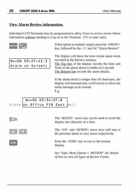
If this option is enabled, simply press the <MENU>key, followed by the <1> key for “Alarm Review”.
The display will show the most recent alarm eventrecorded in the Review memory.The Top line of the display records the Date andTime of the alarm down to tenths of a second.The Bottom line records the alarm details.
If the alarm detail is longer than 16 characters, thedisplay will automatically scroll slowly to allow theentire message to be viewed.E.g.
The <RIGHT> arrow key can be used to scroll thedisplay one character at a time.
The <UP> and <DOWN> arrow keys will step tothe previous alarm or next alarm respectively.
Press the <END> key to exit to the normaldisplay.
See “Info: Menu Option 1 -REVIEW” for detailsof how to view all types of Review Events.
27����������������� ������ User Manual.
View the Time and Date.
This function allows Users to view the current system Time and Date without needingto Log on to the Terminal. (V4.5 or later only)
)����������&(��
���������������!
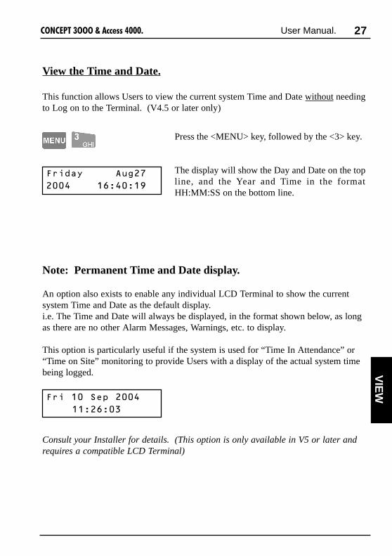
Press the <MENU> key, followed by the <3> key.
The display will show the Day and Date on the topline, and the Year and Time in the formatHH:MM:SS on the bottom line.
Note: Permanent Time and Date display.
An option also exists to enable any individual LCD Terminal to show the currentsystem Time and Date as the default display.i.e. The Time and Date will always be displayed, in the format shown below, as longas there are no other Alarm Messages, Warnings, etc. to display.
This option is particularly useful if the system is used for “Time In Attendance” or“Time on Site” monitoring to provide Users with a display of the actual system timebeing logged.
Consult your Installer for details. (This option is only available in V5 or later andrequires a compatible LCD Terminal)
VIE
W
)�������%�����
������������

28 ����������������� ������ User Manual.
View Area Status.
Individual LCD Terminals may be programmed to allow Users to view the currentstatus of Areas without needing to Log on to the Terminal. (V3 or later only)
���������������
������� � 6.��
.���� (��##
������
If this option is enabled, simply press the <UP> or<DOWN> arrow on the LCD Terminal.
Area Array Option.If Area Array is enabled, the display will show thefirst 8 Areas in the system, with a letter below eachto indicate the current Status. See table below.The <UP> and <DOWN> arrow keys will step tothe previous 8 Areas or next 8 Areas respectively.
The number on the bottom left of the displayindicates the first Area shown in the current array.e.g. 009 = Areas 9 to 16.
017 = Areas 17 to 24.Etc.
Text Array Option.If this option has been selected, the display will showthe status of the Area associated with the Terminalin text form. See table below.The <UP> and <DOWN> arrow keys will step tothe previous Area or next Area respectively.
This option can only be used to view the status of 8Areas beginning at the Terminal’s associated Area.Press <END> when finished.
�������!�������
��!����66 � ��
���������!�����
������� �����
&�(��
����
Array Text DescriptionY is On Area is On.n is Off Area is Off.T is Timed Off Area is Off with a Defer timer running.W About to turn On (Warning period) Area is Off with a Defer timer about to
expire and turn the Area On.
See “Turning Area/s OFF” for more information on Area Defer timers.

29����������������� ������ User Manual.
Home Auxiliary Control.
Individual LCD Terminals may be programmed to allow Users to control specifiedHome Auxiliaries without needing to Log on to the Terminal.
Home Auxiliaries are outputs that can be controlled by a User at an LCD Terminal and/or controlled automatically by the system. They can be turned On, turned Off or turnedOn for a timed period in minutes or seconds. Typical applications for Home Auxiliariesinclude lighting, heating, pool pumps, speaker switching, irrigation, etc.
NOTE: Access to some Home Auxiliaries may be limited to particular User Types.These Home Auxiliaries can only be controlled by Users with access to the “HomeAuxiliaries” Control Menu option. <MENU>, <9>, <1>. After logging on andselecting the Menu option, control options will be the same as described below.
Selecting a Home Auxiliary to Control.
If this option is enabled, simply press the <RIGHT>arrow key on the LCD Terminal.
The display shows the current status of the firstHome Auxiliary.(The example shown opposite is a default HomeAuxiliary name. This type of name should onlyappear for Home Auxiliaries that are not used.)
To select a Home Auxiliary, use the <UP> and<DOWN> Arrow keys to search through the list.
ORSearch for a Home Auxiliary by name by pressingthe DIGIT key that represents the first letter of thename. (You may have to press the key 2 or 3 times,depending on the letter required and the HomeAuxiliary names in the system.)
If the Home Auxiliary you want is not displayedbecause of other names beginning with the sameletter, use the <DOWN> Arrow key to locate it.
0�6'��0,�<,�
������
�?# ���&:����
������
0��4�0B+0
������
or
CO
NT
RO
L

30 ����������������� ������ User Manual.
0��4�0B+0
� �6� ������ �
or , ,
Controlling the Home Auxiliary.
When the desired Home Auxiliary is displayed;
Press the ON key or OFF key to turn theAuxiliary On or Off as required.
OR
Press the <LEFT> arrow key to enter a HomeAuxiliary “On time” in Minutes or the <RIGHT>arrow key to enter an “On time” in Seconds.(V2 or later only)
Use the <DIGIT> keys to enter the time periodrequired, then <OK> to execute the action.
Select another Home Auxiliary to control usingthe <UP> and <DOWN> arrow keys or <DIGIT>keys.
ORPress the <END> key to exit to the normaldisplay.
0��4�0B+0
������
or

31����������������� ������ User Manual.
Air Conditioning Control.
Some sytems utilize special dedicated built-in logic in the Access 4000 for Air-conditioning system Control. This allows Air-conditioning sytems to be controlled bya User at an LCD Terminal and/or controlled automatically by the system.(Only available V2 or later)The User can turn Air-conditioning Zones On and Off, switch between different modesof operation and control Ventilation and Fan settings.
Individual LCD Terminals may be programmed to allow Users to control Air-conditioning sytems without needing to Log on to the Terminal..
If this option is enabled, simply press the<LEFT> arrow key on the LCD Terminal.
The display shows the current status of the Air-conditioning Zone associated with this LCDTerminal.
To select another Air-conditioning Zone, use the<UP> and <DOWN> Arrow keys to searchthrough the list.
ORSearch by name by pressing the <DIGIT> keythat represents the first letter of the Aircon. zonename. If the name you want is not displayedbecause of other names beginning with the sameletter, use the <DOWN> Arrow key to locate it.
When the desired Air-Conditioning Zone isdisplayed, press the <ON> key or <OFF> key toturn the Zone On or Off as required.
AND/ORPress the <LEFT> arrow key to control other Air-conditioning system operations.
Continued on following page.
��$�%��#
���$# �������
�"�����$��# ����
���
or
or and/or
CO
NT
RO
L

32 ����������������� ������ User Manual.
�"����C� �������
�&�# ���$
Use the <RIGHT> arrow key to select the mode ofoperation required.
Press the <LEFT> arrow key again to controlVentilation options.
Use the <RIGHT> arrow key to select the mode ofVentilation required. Normally set to Automatic.
Press the <LEFT> arrow key again to control Fanoptions.
Use the <RIGHT> arrow key to select the mode ofFan operation required. Normally set toAutomatic.
Press the <END> key to exit to the normaldisplay.
On Turn the Airconditioning On.Off Turn the Airconditioning Off.TimeZone Airconditioning system will be automatically turned On and Off
by the TimeZone assigned to it by the installer.
Recirculate Forces the system to use Recirculated air.Fresh Air Forces the system to use Fresh air.Automatic Airconditioning system will automatically select Recirculated or
Fresh air based on whether Heating or Cooling is required andthe status of the Fresh Air thermostat.
�"����)� ������
�&�# ���$
Always On Fan is always on to circulate air regardless of Compressor on/off.Heat Pump Allows warmer air from the “Return air zone” to be pumped to
other zones without using the compressor for heating. Used whenthe return air zone provides another source of heat such as a woodheater.
Automatic Compressor on/off will automatically control Fan on/off.

33����������������� ������ User Manual.
Logon to the Terminal as described earlier.(PIN code + <OK>)
The display will show the Area Status etc. as before.
Now press the <MENU> key. The Menu key canbe used at any time to return to the Main menu
The display will now scroll through the list of Menuoptions that you are allowed to access.There are ten main menu options in the system,numbered from 0 to 9, but User programming willdetermine which options will be available to eachUser.
Press a <DIGIT> key to select a Menu option.
Note: Some options in Sub-menus (e.g. User Codes,Review & Time/Date) require another digit or twoto be pressed. The display will show another sub-menu list similar to the one above when required.
Use the key sequence shown immediately below eachmenu option heading, or the chart at the rear of thismanual to determine the key sequence required toaccess each menu option.
e.g. User Codes: <MENU>, 2, 1.Time/Date: <MENU>, 5, 1.
@@�+�� �+� &�@@
�;' �#��;�$$���
0-Area ON/OFF1-Info 5-Times2-Access 6-Not Used3-Isolate 8-Service4-Test 9-Control(Option 7-Installer, not allowed)
NOTE: When in the menu, youcan return to the Area ON / OFFdisplay by pressing <MENU>,0.
MENU OPTIONS
Users with the appropriate level of authority can perform many other operations andare allowed access to certain programming facilities via the Menu.A Menu Flowchart showing all the Options can be found inside the back cover.All menu options relevant to System Users are described in detail in this manual.Refer to the Table of Contents on page 2 for Menu Options and page numbers.
Accessing the Menu.
�))'",
��������0&�1��
- ,
ME
NU
OP
T.

34 ����������������� ������ User Manual.
Keypad Functions in the Menu.
Scrolls up and down a list of available items to view,program or control. e.g. Users, Zones, Review messages& Home Auxiliaries.
Moves cursor left or selects previous question for thesame item, if the cursor is at the start of the field.
Moves cursor right or Scrolls through the options inmultiple choice questions.
Provides relevant help messages on the displaywhenever required. e.g. Will tell you what to do nextif you are unsure.
Saves the current screen & moves to the next questionor Executes an operation.
Saves the current screen, exits the menu, and logs theUser Off.
Clears the screen for entering new text etc.or Selects first option in multiple choice questions.
Switches between different modes for selecting an itemor answering a question. e.g. Provides option ofselecting an item by ID no. (Zone E01:Z03) or by name(OFFICE PIR).
When programming questions that require a Yes/Noanswer, the “N” (5) key selects No and the “Y” (9) keyselects Yes.
The <DIGIT> keys are used to select an item or optionby number or IDand for programming text where available. (Usernames, Door List names, TimeZone names etc.)
The functions of the 20 keys while performing control, programming or viewingoperations in the menu are described below.

35����������������� ������ User Manual.
Information: Menu Option 1
REVIEW Allows a User to view the list of review events storedin the memory. This may be necessary to find outdetails of user activity or past alarms, etc.
The Display will show the last review event, whichwill probably be a record of yourself accessing theReview Menu.
The <0> key is used to go to the start of review(earliest event still stored) and the <9> key is usedto go to the end of review (last event saved).
<UP> (back) and <DOWN> (forward) Arrow keysare used to search review, one event at a time.
<LEFT>: Forces display to the start of the text.<RIGHT>: Scrolls text one character at a time.
-�$�������������
4� ��������A��8
MODE 1. MODE 2.
Alarms & Restorals. System messages.Reports. Times.Auxiliary On & Offs. Detail.Siren On & Offs. Communications.User operations. Lifts.Area On and Offs. Cards. (V3 or later)Isolates/De-isolates. Spare.Modules. Errors
REVIEW FILTER:The DIGIT keys, 1 to 8 can be used to search back through review for specific typesof events, beginning from the date/time of the event currently displayed.As there are more than 8 filter categories that can be selected, the “Mode” can bechanged by pressing the ON & OFF keys, allowing selection of more categories.You can use these filter keys in conjunction with the UP and DOWN Arrow keys tolocate a specific event and then review all the other events around it in more detail.
Key 12345678
NOTE:
Use to view
the list of review filtercategories available.
(Go to End of Review) then OR (Mode) then
OFF = Mode 1. ON = Mode 2.
RE
VIE
W

36 ����������������� ������ User Manual.
LOCATE USERIn some systems INSIDE and/or OUTSIDE Areaswill have been assigned to Access ControlledDoors. “LOCATE USER” can then be used todisplay the Area that the user is currently in.
The display will show the Area name on the topline and the User name on the bottom line.
To search for a particular User alphabetically,press the <DIGIT> key that represents the firstletter of the User’s name. (You may have to pressthe key 2 or 3 times, depending on the letterrequired and the User names in the system.)
If the User name you want is not displayedbecause of other names beginning with the sameletter, use the <DOWN> Arrow key to locate it.
In this mode the <UP> and <DOWN> Arrowscan be used to scroll through the list of Users.
To find a particular User by number, press the<ON> key to change the display mode.
Use the <DIGIT> keys to enter the User numberrequired. The <RIGHT> Arrow key may be usedto advance the cursor. The <OFF> key may beused to clear the user number before you begin.
Press the <ON> key again to view the Area andUser’s name.
7#��4#$������
D��#
,�C'",�",76�,
-��(#���A
6,6�-,0��6+,76
D#�
B����!�����
7#��4#$������
'7.��-�*��-
"��1
6,6�-,0��6+,76
&�

37����������������� ������ User Manual.
READ ANALOGUE VALUES
In some systems Analogue Input modules areinstalled to monitor variable parameters such asTemperature, humidity, fluid levels, etc.“READ ANALOGUE” can then be used todisplay the current values of the analogue inputs.(V3 or later only)
The display will prompt for an Analogue Modulenumber to view.
The <UP> and <DOWN> arrow keys can be usedto search for a particular Analogue Module,ORUse the <DIGIT> keys to enter the AnalogueModule number.
Press the <OK> key to select the module numberdisplayed.
The display will show the value of the firstAnalogue input on the selected module.
Value updates every 2 seconds and stops updatingafter 2 mins. Press <ON> to refresh the display.
Press <OK> to scroll through the Values for otherZones/Inputs on the same Analogue Module.
Use the <UP> and <DOWN> Arrow keys to scrollthrough the Analogue values for the same Zoneinput number on other Analogue Modules.
Press the <END> key to exit to the normaldisplay.
NOTE: All Analogue Zone Inputs used in thesystem should always be named by the Installer.A screen similar to this showing the default ZoneID will be displayed for Zones that are not used.
� ��#(� #�&��
�#�A��8��E��
"��46��,�6,+0
F�����
.�6,��4,C,4�G4H
F����
E���9��
F�����
STA
TU
S

38 ����������������� ������ User Manual.
READ COUNTERS
In some systems Mini Expander modules areinstalled to perform Event Counting. Counters canbe used to monitor film in security cameras, wateror electricity usage, traffic through a designatedpoint, etc.“READ COUNTERS” can then be used to displaythe current value of the counters. (V3 or later only)
The display will show the result of the first Counteravailable to be viewed.
The <UP> and <DOWN> arrow keys can be usedto scroll through the results of the other counters.
The displayed count is refreshed every 2 seconds byreading the latest count from the relevant MiniExpander module.
Press the <END> key to exit to the normal display.
NOTES:1) All Counters used in the system shouldalways be named by the Installer. A screen similarto this showing the default Counter ID will bedisplayed for Counters that are not used.The installer can disable display of unused Counters.
2) In some applications it may be necessary fora User to adjust the current value of a particularcounter, or reset the counter to zero.This can be done via a separate Menu option thatwill probably be restricted to one or more User Types.Details are provided in “Adjust Counters”, [MENU,9, 6].
"� ������)��
"#& �������
.�����B����G=4H
"#& ����������!
�"#& �������
"#& �����������

39����������������� ������ User Manual.
VIEW INPUT STATES
The system can be programmed to allow Users toview a summary of specific Zones that areenabled and currently in an abnormal condition.“INPUT STATES” can then be used to display thesummary. (V3 or later only)
You may need to use this function when the LCDTerminal displays a message such as:“Some Inputs are Tampered”“Some Inputs are Isolated”etc.
The display will show the first Zone that is in anabnormal state.The summary is prioritised in the following order:1) Isolated Inputs2) Tampered Inputs3) Unsealed Inputs
The <DOWN> arrow key can be used to scrollthrough the list of other abnormal Zone states.
When the bottom of the list is reached, the displaywill show “Finished Check” to indicate that thereare no more abnormal Zones to view.
Press the <END> key to exit to the normaldisplay.
B �������' %&��
6�����������0'�
'�#������' %&��
"&��# �������0'�
)� ��1��
"1�$=
STA
TU
S
REMEMBER !! Any time you need it,
is as close as the press of a key.

40 ����������������� ������ User Manual.
READ POWER MODULE VALUES
In some systems LAN Power Supply Modules areinstalled to provide flexible, general purpose,battery-backed power supply solutions with theadded advantage of immediate status reporting ofPower Supply conditions and problems via theLAN network.
“READ POWER MODULE” can then be used todisplay the current values of Voltage and Currentfor both the Battery Charger and Detector Poweroutputs. (V4.5 or later only)Four Power Module Parameters can be viewed:-Battery Charger Output Voltage.-Battery Charger Output Current.-Detector Output Voltage.-Detector Output Current.
The display will prompt for a Power Modulenumber to view.
The <UP> and <DOWN> arrow keys can be usedto search for a particular Power Module,ORUse the <DIGIT> keys to enter the Power Modulenumber.
Press the <OK> key to select the module numberdisplayed.
The display will show the value of the BatteryCharger Output Voltage on the selected module.
The displayed value is updated every 2 seconds.Updates will timeout after 2 minutes. The <ON>key can be used to refresh the display.
0#8��� #�&��
�#�A��8��0��
0���/���
C#����;�����

41����������������� ������ User Manual.
Use the <UP> and <DOWN> Arrow keys to scrollthrough the results for the same parameter onother Power Modules.ORPress <OK> to advance, in turn, to each of theother Power Module Parameters to be viewed onthe same Power Module.
The display will show the value of the selectedparameter on the selected module.
Use the <ON>, <UP> and <DOWN> Arrows, and<OK> keys to refresh the display or view otherdislays as described above.
Press the <END> key to exit to the normaldisplay.
0���/���
� %��;�����
0���-��
C#����;�����
OR
0���-��
� %��;�����
STA
TU
S

42 ����������������� ������ User Manual.
Access Menu: Menu Option 2
USER PROGRAMMING
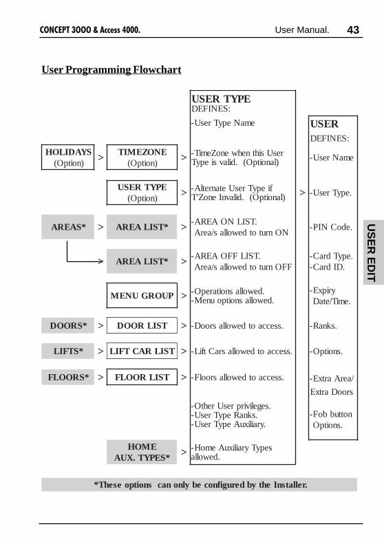
Defining the operations that a User can perform and the items that they can control isachieved by simply assigning a “User Type” to the User. User Types are programmedto cover the system permissions for the different types of Users in the system.Each User Type is given a name (e.g. Admin, Factory staff, Cleaners, Office staff,Guard, etc.) and programming is simplified by the use of:-Menu Groups to define operations/menu options allowed, and-Lists to define the items (Areas, Doors, Lift Cars & Floors) allowed.
The flowchart on the following page shows the different items that are used to create aUser Type. Some items (e.g. Area Lists) that can be assigned to the User Type mustfirst be created by the Installer. Other items (e.g. Door Lists, Menu Groups, etc.) mayalso be created by the Installer or another User such as a System Administrator.
Two special Users are pre-defined.-User 00001 is known as the “Installer Code” and has special privileges including:
Exclusive Access to the Installer Menu.Access to higher level options in the Access, Times and Service Menus.Special options in the Test Menu.
-User 00002 is known as the “Master Code” and is usually assigned to the owner of thesystem or the person responsible for security. Special privileges for U00002 include:
The ability to program/edit all other Users (except User 00001).The option to lockout/enable Installer code access. (If feature is utilized)
When a User’s “User Type” allows permission to program/edit Users (specified via theUser Type’s “Menu Group”), the User is only allowed to program/edit User numbersequal to, or higher than, their own. (Unless User Ranks are utilized in the system)
For this reason, it is recommended that User numbering is planned before programmingthe Users so that the numbering will reflect the level of authority required.e.g. A System administrator who has permission to change all User codes, should beissued a very low User number such as U00003. A Supervisor who only has permissionto change the User codes in their own department should have a User number lowerthan all the staff in that department, but higher than any User with more authority.
User programming allows details to be defined foreach individual User. i.e. Name, PIN code and/orCard details, expiry date/time, operations and itemsallowed (by allocating a “User Type”), etc.
43����������������� ������ User Manual.
User Programming Flowchart
US
ER
ED
IT
EPYTRESU:SENIFED
emaNepyTresU- RESU:SENIFED
SYADILOH)noitpO( > ENOZEMIT
)noitpO( > resUsihtnehwenoZemiT-)lanoitpO(.dilavsiepyT emaNresU-
EPYTRESU)noitpO( > fiepyTresUetanretlA-
)lanoitpO(.dilavnIenoZ'T > .epyTresU-
*SAERA > *TSILAERA > .TSILNOAERA-NOnrutotdewollas/aerA
.edoCNIP-
> *TSILAERA > .TSILFFOAERA-FFOnrutotdewollas/aerA
.epyTdraC-.DIdraC-
PUORGUNEM > .dewollasnoitarepO-.dewollasnoitpouneM-
yripxE-.emiT/etaD
*SROOD > TSILROOD > .sseccaotdewollasrooD- .sknaR-
*STFIL > TSILRACTFIL > .sseccaotdewollasraCtfiL- .snoitpO-
*SROOLF > TSILROOLF > .sseccaotdewollasroolF- /aerAartxE-
srooDartxE
.segelivirpresUrehtO-.sknaRepyTresU-
.yrailixuAepyTresU-nottubboF-
.snoitpO
EMOH*SEPYT.XUA > sepyTyrailixuAemoH-
.dewolla
.rellatsnIehtybderugifnocebylnonacsnoitpoesehT*

44 ����������������� ������ User Manual.
SELECT “USER CODES”.
SELECT A USER TO PROGRAM/EDIT.The display will first allow you to choose a Usernumber to alter. (Method i)Pressing the <ON> key will allow an existing Userto be selected by name.(Alpha-search - Method ii)
In either mode, the <UP> and <DOWN> Arrowswill search through the User numbers/names.
i) <DIGIT> keys are used to enter a User number,ORii) When searching for a particular User name, pressthe <DIGIT> key that represents the first letter ofthe name. (You may have to press the key 2 or 3times to obtain the required letter.)If the User you want is not displayed because ofother names starting with the same letter, use the<DOWN> Arrow key to locate the User’s name.
When the desired User number or name is located,press the <OK> key to proceed with editing.
NOTE: Use the <END> key at any time to savethe current setting and Exit User programming.
USER NAME.The display will show the User number and name.
To enter a new name press the <OFF> key to clearthe screen, then use the <DIGIT> keys to programthe name. Up to 16 characters of text can be entered.To modify an existing name, use the <LEFT> and<RIGHT> Arrow keys to position the cursor underthe letter to be changed, and then use a <DIGIT>key to enter the new letter.
B�����#
�������B�����
)� ��B����7� ��I
���$�
B��������!�7� ��
6��A��
, - - -

45����������������� ������ User Manual.
“RUTH” would be programmed with the sequenceshown opposite.
Pressing a key more than once will scroll throughall the characters associated with that key until theone you require is displayed.
When programming text, the cursor willautomatically advance when a different key ispressed. The <RIGHT> Arrow key only needs tobe used to advance (move) the cursor if the nextletter appears on the same key or the <9> key.
When complete: Press the <OK> key to move onto the “User Type” question for this User.<UP> key to program the previous User name.<DOWN> key to program the next User name.
USER TYPE.Every User is assigned a “User Type” to define whichArea/s, Door/s, Operations, Menu Options, etc. thatthey may access.
Press the <RIGHT> Arrow key to scroll throughthe list until the name of the appropriate User Typeis displayed.Press the <OFF> key to return to the start of thelist, or to set the User Type to “None”.NOTE:A User’s PIN/Card can be disabled but remain inthe system by setting the User Type to “None”.
Pressing the <ON> key will allow a User Type tobe selected by number using the <DIGIT> keys.
When complete: Press the <OK> key to move onto the “PIN number” question for this User.<UP> key to edit the previous User’s “User Type”.<DOWN> key to edit the next User’s “User Type”
P Q R S
•
T U move S
• •
T G H
•
or or
B����!�6%������
7# �
B��������!
�%���B6���
B����!�6%������
�))'",�6�))
or or
EXAMPLE:
US
ER
ED
IT

46 ����������������� ������ User Manual.
PIN CODEAny User who is required to perform anyoperations via a Terminal Keypad will need a PIN(Personal Identification Number).
If changing a code, Press <OFF> first to clear thescreen. Enter a PIN number using the <DIGIT>keys. The PIN may be 1 to 8 digits long, howevera minimum of 4 digits is recommended if the PINcode is to control Areas or access external doors.
When complete: <OK> key to move on to the“Card Type” question for this User.<UP> key to program the previous User’s “PIN”.<DOWN> key to program the next User’s “PIN”.
CARD TYPE.Any User who is required to perform operationswith an access card must have their card detailsentered, beginning with the “Card Type”.
Press the <RIGHT> Arrow key to scroll throughthe list until the name of the appropriate CardType is displayed. (If you need to return to thestart of the list at any stage, press the <OFF> key)
When complete: <OK> key to move on to the carddetails question/s for this User.<UP> key to edit the previous User’s “Card Type”.<DOWN> key to edit the next User’s “Card Type”
The next display will depend on the “Card Type”selected:i) Credit Card. For credit cards etc. or other
non-Site Code magnetic stripe formats.ii) Site Code. For Wiegand formats where the
Site Code is utilized, or Inner Rangemagnetic stripe cards with Site Codeformat.
iii) Direct Entry. For Wiegand cards where theSite Code and/or Format is unknown.
B��������!
0'7�7#�
B��������!
0'7�7#������
- - -
B����!�"���6%��
"������"���
NOTE: The “Card Type” usedin your system should berecorded in the “SystemDetails” inside the Front cover.If not recorded, consult theInstaller for details.
See NOTE below.
or or
or or

47����������������� ������ User Manual.
B����!�.���� (
�#��$����������
B����!��$$ ��7#�
7#�"���
i) CREDIT CARD - ACCOUNT NUMBERThe “Account number” for Credit Cards isprogrammed by entering the account number ORby swiping the card at a Reader.
Keypad Entry. Press the <OFF> key to clear thescreen then the <DIGIT> keys to enter the first 16digits of the Credit Card “Account Number”.Press <OK> when the first 16 digits are entered.
Another screen will be displayed to allow entry of 8more digits, if the Account number is more than 16digits long. (i.e. Allows up to 24 digits in total)
Enter the extra digits as above, using the <OFF>key first to clear the screen. When all digits areentered, or if no extra digits are required, press the<OK> key to move on to “Expiry” question.
Card Entry by Swiping the Card. Press the <ON>key to enable the read function.The display will prompt you to swipe the card atany Reader connected to the designated ReaderModule. Consult the Installer for details.
You have 10 seconds to present the card, then thedisplay will return to the “Card Type” screen.
Press the <OK> key, and the display will show theword **Card** on the Account number screen toindicate that the card was read successfully, and isnow entered for this User.
When complete: <OK> key to move on to the nextquestion for this User.<UP> key to edit the previous User’s “Accnt No”.<DOWN> key to edit the next User’s “Accnt No”.
B����!��$$ ��7#�
G$# �H��@@"���@@
B����!�"���6%��
"������"���
B����!��$$ ��7#�
@@"���@@
or or
- - -
- - -
US
ER
ED
IT

48 ����������������� ������ User Manual.
B����!
'��&��7#�����
B������"���
7& ����������
ii) SITE CODE - CARD NUMBERThe “Card number” for Site Code Cards is defaultedto the User number. Typically, when using “SiteCode” cards, the User’s Card number becomes theirUser number, and the default Card number does notneed to be changed.
It may be necessary to change the default Card no. if the Card no. is a higher valuethan the maximum number of Users allowed, or when a replacement card is issued.
NOTE: Your system may use a Site Code Offset, which may be recorded in the“System Details” inside the Front cover of this manual. If so:The “Card number” entered here = the actual Card ID number, minus the Offsetvalue programmed. e.g. Card ID = 3156; Offset = 3000; So, Card No to program =156.
or or
or or
- - -
- - -
To edit the Card number, press the <OFF> key toclear the screen, then use the <DIGIT> keys to enterthe card number of up to 5 digits. For Card numbersless than 5 digits, insert leading zero’s.
When complete: <OK> key to move on to the “IssueNumber” question for this User’s Card.<UP> key to edit the previous User’s “Card No”.<DOWN> key to edit the next User’s “Card No”.
ii) SITE CODE - ISSUE NUMBERThe “Issue number” for Site Code Cards is defaultedto “000”. This is only changed if the cards beingused support Issue numbers.“000” will allow any issue number to be accepted.
To edit the Issue number, press the <OFF> key toclear the screen then enter the desired Issue numberfrom 001 to 255 with the <DIGIT> keys.
When complete: <OK> key to move on to the nextquestion for this User.<UP> key to edit the previous User’s “Issue No”.<DOWN> key to edit the next User’s “Issue No”.
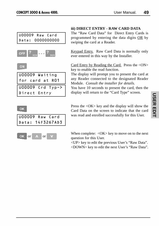
49����������������� ������ User Manual.
B����!���8�"���
-���������������
iii) DIRECT ENTRY - RAW CARD DATAThe “Raw Card Data” for Direct Entry Cards isprogrammed by entering the data digits OR byswiping the card at a Reader.
Keypad Entry. Raw Card Data is normally onlyever entered in this way by the Installer.
Card Entry by Reading the Card. Press the <ON>key to enable the read function.The display will prompt you to present the card atany Reader connected to the designated ReaderModule. Consult the installer for details.You have 10 seconds to present the card, then thedisplay will return to the “Card Type” screen.
Press the <OK> key and the display will show theCard Data on the screen to indicate that the cardwas read and enrolled successfully for this User.
When complete: <OK> key to move on to the nextquestion for this User.<UP> key to edit the previous User’s “Raw Data”.<DOWN> key to edit the next User’s “Raw Data”.
B����!�.���� (
�#��$����������
B����!�"���6%��
-���$��, ��
B����!���8�"���
-�������)�����-�
or or
- - -
US
ER
ED
IT

50 ����������������� ������ User Manual.
USER RANKSDepending on your system configuration, youmay be able to program User Ranks.
If a User has the ability to Program/Edit Usersthey can normally only access User numbersequal to, or higher than, their own.When a User has Ranks programmed, they canonly access User numbers that have a matchingrank set to YES and User numbers that have norank screen to program.
If Ranks are to be programmed for a User, use the<RIGHT> Arrow, followed by the <9> (Y) and<5> (N) keys to set the appropriate rank/s to YESor NO.
When complete: <OK> key to move on to thenext question for this User.<UP> key to edit the previous User’s “Ranks”.<DOWN> key to edit the next User’s “Ranks”.
B����!����������
�� =����
NOTE: Understand how UserRanks operate and plan beforeattempting to program.A detailed explanation &examples are available in theProgrammer’s Manual.
B����!����������
�� =����� �
or or
B����!�,:%�����
��3��3��������
NOTES: 1) Blank Expiry Date & Time Fields will be ignored. e.g. / / 01 - 13 :will mean that User’s Card will only work before 1PM on any day until 31/12/2001.2) When a Code/Card expires all User programming (incl. User Type) is retained.
or or
- - -
- - etc.
EXPIRY DATE AND TIMEDepending on your system configuration, youmay be able to program when a User Code/Cardexpires in the format DD/MM/YY - HH:MM.
Press the <OFF> key to clear the settings then usethe <DIGIT> keys and the <RIGHT> Arrow keyto program an expiry date/time.The default setting shown, or all fields cleared,means that the Expiry function will be ignored.
When complete: <OK> key to move on to thenext question for this User.<UP> key to edit the previous User’s “Expiry”.<DOWN> key to edit the next User’s “Expiry”.
, or

51����������������� ������ User Manual.
B����!��7-4,*���
�%��# ��
[N]o message acknowledgement. Prevent the User from being given the option toacknowledge alarm messages when logged on to aTerminal.
[D]uress Code. Causes the PIN code programmed for this User totrigger a Duress Input whenever it is entered.
IMPORTANT NOTE: If this option is set to Yes, DO NOT use any words in theUser’s name (e.g. Duress, Holdup, etc.) that indicate that a Duress Code is being used,as the name may be displayed in the greeting when the User logs on to the Terminal.
Area [L]ist default. Allows the “Area List” selection screen to appearon the display when this User logs on to theTerminal (rather than individual Area selection).The User can still revert to selection of anindividual Area, if required, by pressing the<RIGHT> arrow key. See “Turning Area/s Off”.
[E]xtra Area Off Allows the User’s “Extra Area” (if assigned) to beturned Off when the User accesses a Door via aReader that allows the “Turn off Extra Area”function. (If enabled by the Installer)(V2 or later only)
No [G]reeting Disables the User greeting from being displayedfor this User, when logging on to an LCDTerminal. (V3 or later only)
or or
USER OPTIONSThere are currently five special options whichmay be set for a User.
Use the <RIGHT> Arrow, followed by the <9>(Y) & <5> (N) keys to set the desired options toYES or NO.
When complete: <OK> key to move on to thenext question for this User.<UP> key to edit the previous User’s “Options”.<DOWN Arrow to edit the next User’s “Options”.
, or
US
ER
ED
IT

52 ����������������� ������ User Manual.
EXTRA AREAThe Area/s that Users can control are normallyonly defined by the Area ON List and Area OFFList allocated to their “User Type”.
The “Extra Area” option allows one Area to beallocated directly to a User.The User will be allowed ON and OFF controlover the “Extra Area” regardless of whether ornot there are Area ON/OFF Lists in their UserType.
In a larger multi-Area system, where most Usersare only allowed control of a single Area, thisoption would avoid the need to program manydifferent Area Lists.
Press the <RIGHT> Arrow key to scroll throughthe Area names until the name of the requiredArea is displayed. (If you need to return to thestart of the list at any stage, press the <OFF> key)
When complete: <OK> key to move on to selectthe next User to program/edit. See Note below.<UP> key to edit the previous User’s “Extra Area”<DOWN> key to edit the next User’s “Extra Area”.
NOTE: If the “Extra Door / Extra Door List”feature is enabled in your system, the <OK> keywill move on to the “Extra Door” and “Extra DoorList” selection screens for this User.
B����!�,:�������
7# �
or or
NOTE: The Extra Areascreen will not be displayed ifExtra Area programming hasbeen disabled for your system.
B����!�,:�������<�'6',�0',�?�0

53����������������� ������ User Manual.
EXTRA DOOR & EXTRA DOOR LISTThe Door/s that Users may access are normallyonly defined by the Door List allocated to their“User Type”.
The “Extra Door”/“Extra Door List” optionsallow one Door and/or Door List to be allocateddirectly to a User. The User will be allowed toaccess these Doors regardless of whether or notthere are Door Lists in their User Type.
These options allow a single Door to be assignedto a User (e.g. A common Door), and permissionsfor different types of Access to be managedseparately. e.g. Door Access and CarparkAccess.
Press the <RIGHT> Arrow key to scroll throughthe Door names until the required name isdisplayed. (If you need to return to the start of thelist at any stage, press the <OFF> key)
When complete, the <OK> key moves the displayon to the Extra Door List screen.<UP> key to edit the previous User’s “Extra Door”<DOWN> key to edit the next User’s “Extra Door”.
The Extra Door List screen is programmed in thesame manner as described above.
When complete: <OK> key to move on to selectthe next User to program/edit. See note below.<UP> key to edit the previous User’s “Extra DoorList”. <DOWN> key to edit the next User’s “ExtraDoor List”.
NOTE: If Wireless RF Fobs are enabled in yoursystem, the <OK> key will move on to the “FobButton” programming screens for this User.
B����!�,:�-##���
7# �
B����!�,:�-##���
+�� �, ���-##�
or or
NOTE: The Extra Door &Extra Door List screens willnot be displayed if this optionis not enabled in your system.
B����!�,:�-4����
"���0��=�7#��
US
ER
ED
IT
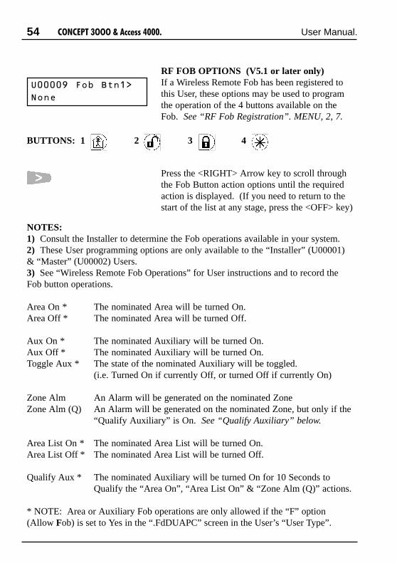
54 ����������������� ������ User Manual.
RF FOB OPTIONS (V5.1 or later only)If a Wireless Remote Fob has been registered tothis User, these options may be used to programthe operation of the 4 buttons available on theFob. See “RF Fob Registration”. MENU, 2, 7.
Press the <RIGHT> Arrow key to scroll throughthe Fob Button action options until the requiredaction is displayed. (If you need to return to thestart of the list at any stage, press the <OFF> key)
B����!�)#��/� ��
7# �
NOTES:1) Consult the Installer to determine the Fob operations available in your system.2) These User programming options are only available to the “Installer” (U00001)& “Master” (U00002) Users.3) See “Wireless Remote Fob Operations” for User instructions and to record theFob button operations.
Area On * The nominated Area will be turned On.Area Off * The nominated Area will be turned Off.
Aux On * The nominated Auxiliary will be turned On.Aux Off * The nominated Auxiliary will be turned On.Toggle Aux * The state of the nominated Auxiliary will be toggled.
(i.e. Turned On if currently Off, or turned Off if currently On)
Zone Alm An Alarm will be generated on the nominated ZoneZone Alm (Q) An Alarm will be generated on the nominated Zone, but only if the
“Qualify Auxiliary” is On. See “Qualify Auxiliary” below.
Area List On * The nominated Area List will be turned On.Area List Off * The nominated Area List will be turned Off.
Qualify Aux * The nominated Auxiliary will be turned On for 10 Seconds toQualify the “Area On”, “Area List On” & “Zone Alm (Q)” actions.
* NOTE: Area or Auxiliary Fob operations are only allowed if the “F” option(Allow Fob) is set to Yes in the “.FdDUAPC” screen in the User’s “User Type”.
BUTTONS: 1 2 3 4
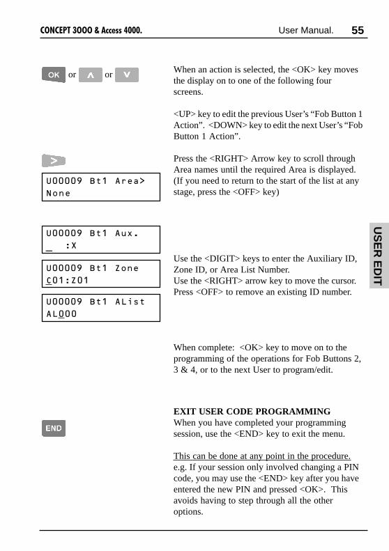
55����������������� ������ User Manual.
EXIT USER CODE PROGRAMMINGWhen you have completed your programmingsession, use the <END> key to exit the menu.
This can be done at any point in the procedure.e.g. If your session only involved changing a PINcode, you may use the <END> key after you haveentered the new PIN and pressed <OK>. Thisavoids having to step through all the otheroptions.
B����!�/��������
7# �
or or When an action is selected, the <OK> key movesthe display on to one of the following fourscreens.
<UP> key to edit the previous User’s “Fob Button 1Action”. <DOWN> key to edit the next User’s “FobButton 1 Action”.
Press the <RIGHT> Arrow key to scroll throughArea names until the required Area is displayed.(If you need to return to the start of the list at anystage, press the <OFF> key)
Use the <DIGIT> keys to enter the Auxiliary ID,Zone ID, or Area List Number.Use the <RIGHT> arrow key to move the cursor.Press <OFF> to remove an existing ID number.
When complete: <OK> key to move on to theprogramming of the operations for Fob Buttons 2,3 & 4, or to the next User to program/edit.
B����!�/����&:�
J���K
B����!�/���9# �
"���9��
B����!�/����4���
�4���
US
ER
ED
IT

56 ����������������� ������ User Manual.
REMEMBER !!Any time you need it,
is as close as the press of a key.
This page intentionally left blank.

57����������������� ������ User Manual.
Select a User to Edit by User number or by Name,in the same manner as described for UserProgramming.
To suspend a User’s operations.Use the <OK> key to advance to the User Typeassignment screen.
Press the <OFF> key to set the “User Type” to“None”. The User’s operations are nowsuspended, but all other details for this User stillremain in the system.
A User can then be re-instated at any time bysimply assigning them a User Type again, with noother programming involved.
Deleting a User.To delete User details either partially orcompletely, simply step through the User Codesprogramming with the <OK> key, using the<OFF> key to delete or default any settings youwish to remove.
DELETING A USER
Deleting or temporarily suspending a User is a simple process.
B������6%����
7# �
etc.
Delete U
ser
B�����#
�������B��!!�
)� ��B����7� ��I
D&���

58 ����������������� ������ User Manual.
USER TYPES
SELECTING A USER TYPE TO PROGRAM.The display will first allow you to choose a UserType to alter.Method i - Select by number. The <DIGIT>keys are used to enter a number OR the <UP>and <DOWN> Arrows will scroll through thenumbers.
Method ii - Alpha-search. Pressing the <ON>key allows the name of an existing User Type tobe selected.
The <UP> and <DOWN> Arrows will searchthrough the names, ORPress the <DIGIT> key that represents the firstletter of the name. (You may have to press thekey 2 or 3 times to obtain the required letter.)If the name you want is not displayed because ofother names starting with the same letter, use the<DOWN> Arrow key to locate the name.
When the desired number or name of the UserType is located, press the <OK> key to proceed.
B����6%���#
�������B6���
)� ��B����6%��I
����$������
OR
OR
then if required.
Some Users, such as System Administrators, maybe allowed to program “User Types”. User Typesare assigned to Users to define the items they areallowed to control, the functions they can performand the Menu options that they can access.
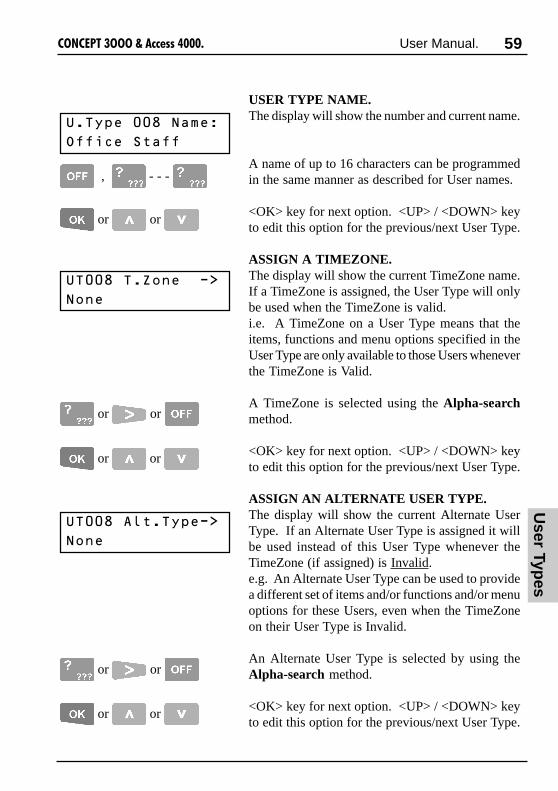
59����������������� ������ User Manual.
B6����6�9# �����
7# �
or or
B�6%������7� ��
����$������
, - - -
USER TYPE NAME.The display will show the number and current name.
A name of up to 16 characters can be programmedin the same manner as described for User names.
<OK> key for next option. <UP> / <DOWN> keyto edit this option for the previous/next User Type.
ASSIGN A TIMEZONE.The display will show the current TimeZone name.If a TimeZone is assigned, the User Type will onlybe used when the TimeZone is valid.i.e. A TimeZone on a User Type means that theitems, functions and menu options specified in theUser Type are only available to those Users wheneverthe TimeZone is Valid.
A TimeZone is selected using the Alpha-searchmethod.
<OK> key for next option. <UP> / <DOWN> keyto edit this option for the previous/next User Type.
ASSIGN AN ALTERNATE USER TYPE.The display will show the current Alternate UserType. If an Alternate User Type is assigned it willbe used instead of this User Type whenever theTimeZone (if assigned) is Invalid.e.g. An Alternate User Type can be used to providea different set of items and/or functions and/or menuoptions for these Users, even when the TimeZoneon their User Type is Invalid.
An Alternate User Type is selected by using theAlpha-search method.
<OK> key for next option. <UP> / <DOWN> keyto edit this option for the previous/next User Type.
or or
or or
B6��������6%���
7# �
or or
or or
User Typ
es

60 ����������������� ������ User Manual.
ASSIGN USER TYPE PERMISSIONS.
Area ON List is assigned to define which Areasthis User Type is allowed to turn On.
Area OFF List is assigned to define which Areasthis User Type is allowed to turn Off.
Menu Group is assigned to define which Operationsand Menu options this User Type is allowed to accessvia the LCD Terminal.
Door List is assigned to define which Doors thisUser Type is allowed to access.
Lift Car List is assigned to define which Lift Carsthis User Type is allowed to access.
Floor List is assigned to define which Floors thisUser Type is allowed to access.
An option is selected by using the Alpha-searchmethod.Press the <DIGIT> key that represents the firstletter of the name AND/OR Press the <RIGHT>arrow key to scroll through the names until therequired name is displayed OR Press <OFF> toset the option to “None”.
B6�����7�4������
�44���,�
B6�����))�4�����
�44���,�
or or
B6����-##�4�����
�-##����������
B6����4����"��
4�����44���
B6����)�##��4����
)4���
B6����+� &�*�%��
�44�+,7B

61����������������� ������ User Manual.
B6�������)�-B�0"
�%������
Allows this User to perform Area and Auxiliarycontrol operations via a Wireless Remote Fob.
Provides longer Door Un-lock time and longerLift button selection time for this User Type.The Door Un-lock time will be 4 times the periodprogrammed by the installer for each Door.Lift button selection time is a separate “Disabledtime” programmed by the installer for each Lift.
Allows this User Type to provide the First PINcode for “Dual Code” Access.
Causes the request for Dual User codes atparticular Door/s to be overridden for this UserType.
Causes the Anti-passback rules at particularDoor/s to be overridden for this User Type.
If set to YES, when a User with this User Type isgranted PIN code access through a Door, theirUser Type will automatically be set to “None”.
If set to YES, when a User with this User Type isgranted Card access through a Door, their UserType will automatically be set to “None”.
or or
USER TYPE OPTIONSThere are currently six special options which maybe set for a User Type.
Use the <RIGHT> Arrow, followed by the <9>(Y) & <5> (N) keys to set the desired options toYES or NO.
<OK> key for next option. <UP> / <DOWN>key to edit this option for the previous/next UserType.
, or
Allow [F]ob operations.(V5.1 or later only)
[d]isabled User.(V3 or later only)
[D]ual Provider.
Override Dual [U]ser.
Override [A]nti-Passback.
Cancel on [P]IN.(For single use PIN codes)
Cancel on [C]ard.(For single use Cards)
User Typ
es
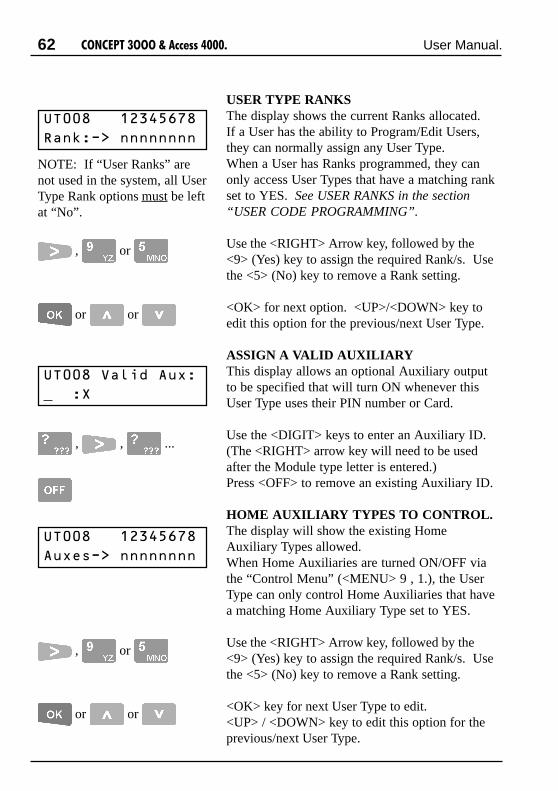
62 ����������������� ������ User Manual.
, , ...
B6��������������
�� =����
B6����C������&:�
����K
B6��������������
�&:�����
USER TYPE RANKSThe display shows the current Ranks allocated.If a User has the ability to Program/Edit Users,they can normally assign any User Type.When a User has Ranks programmed, they canonly access User Types that have a matching rankset to YES. See USER RANKS in the section“USER CODE PROGRAMMING”.
Use the <RIGHT> Arrow key, followed by the<9> (Yes) key to assign the required Rank/s. Usethe <5> (No) key to remove a Rank setting.
<OK> for next option. <UP>/<DOWN> key toedit this option for the previous/next User Type.
ASSIGN A VALID AUXILIARYThis display allows an optional Auxiliary outputto be specified that will turn ON whenever thisUser Type uses their PIN number or Card.
Use the <DIGIT> keys to enter an Auxiliary ID.(The <RIGHT> arrow key will need to be usedafter the Module type letter is entered.)Press <OFF> to remove an existing Auxiliary ID.
HOME AUXILIARY TYPES TO CONTROL.The display will show the existing HomeAuxiliary Types allowed.When Home Auxiliaries are turned ON/OFF viathe “Control Menu” (<MENU> 9 , 1.), the UserType can only control Home Auxiliaries that havea matching Home Auxiliary Type set to YES.
Use the <RIGHT> Arrow key, followed by the<9> (Yes) key to assign the required Rank/s. Usethe <5> (No) key to remove a Rank setting.
<OK> key for next User Type to edit.<UP> / <DOWN> key to edit this option for theprevious/next User Type.
NOTE: If “User Ranks” arenot used in the system, all UserType Rank options must be leftat “No”.
, or
or or
, or
or or
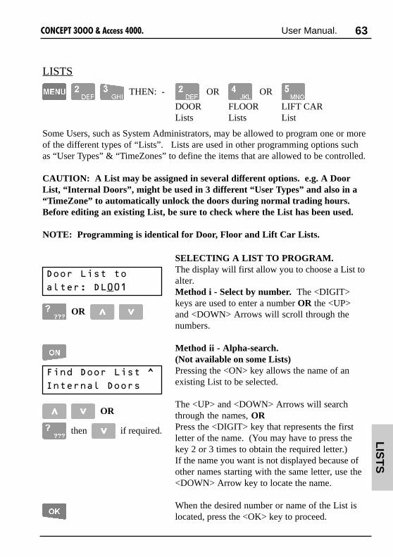
63����������������� ������ User Manual.
LISTS
SELECTING A LIST TO PROGRAM.The display will first allow you to choose a List toalter.Method i - Select by number. The <DIGIT>keys are used to enter a number OR the <UP>and <DOWN> Arrows will scroll through thenumbers.
Method ii - Alpha-search.(Not available on some Lists)Pressing the <ON> key allows the name of anexisting List to be selected.
The <UP> and <DOWN> Arrows will searchthrough the names, ORPress the <DIGIT> key that represents the firstletter of the name. (You may have to press thekey 2 or 3 times to obtain the required letter.)If the name you want is not displayed because ofother names starting with the same letter, use the<DOWN> Arrow key to locate the name.
When the desired number or name of the List islocated, press the <OK> key to proceed.
-##��4�����#
�������-4���
)� ��-##��4����I
' ��� ���-##��
OR
OR
then if required.
THEN: - OR OR
DOOR FLOOR LIFT CARLists Lists List
Some Users, such as System Administrators, may be allowed to program one or moreof the different types of “Lists”. Lists are used in other programming options suchas “User Types” & “TimeZones” to define the items that are allowed to be controlled.
CAUTION: A List may be assigned in several different options. e.g. A DoorList, “Internal Doors”, might be used in 3 different “User Types” and also in a“TimeZone” to automatically unlock the doors during normal trading hours.Before editing an existing List, be sure to check where the List has been used.
NOTE: Programming is identical for Door, Floor and Lift Car Lists.
LIS
TS

64 ����������������� ������ User Manual.
-4����6�9# �����
7# �
or or
-4����7� ��
' ��� ���-##��
, - - -
LIST NAME.The display will show the number and currentname. (Name not available on some Lists)
To enter a new name, press the <OFF> key toclear the screen, then use the <DIGIT> keys toprogram the name. Up to 16 characters of textcan be entered.To modify an existing name, use the <LEFT> and<RIGHT> Arrow keys to position the cursorunder the letter to be changed and then use a<DIGIT> key to enter the new letter.
<OK> key for next option. <UP> or <DOWN>key to edit this option for the previous/next List.
TIMEZONE.The display will show the current TimeZonename.If a TimeZone is assigned, the List will only beallowed when the TimeZone is valid.i.e. A TimeZone on a Door List assigned to aUser Type means that those Users can only accessany of the Doors whenever the TimeZone is Valid.
Press the <DIGIT> key that represents the firstletter of the TimeZone name AND/OR Press the<RIGHT> arrow key to scroll through the namesuntil the required TimeZone is displayed ORPress <OFF> to set the TimeZone to “None”.
<OK> key for next option. <UP> or <DOWN>key to edit this option for the previous/next List.
or or
or or

65����������������� ������ User Manual.
-4��������4�����
7# �
or or
or or
ALTERNATE LIST.The display will show the current Alternate List.If an Alternate List is assigned it will be usedinstead of this List whenever the TimeZone (ifassigned in the previous option) is Invalid.e.g. An Alternate Door List can be used to allowUsers to maintain access to some Doors, evenwhen the TimeZone on their User Type’s DoorList is Invalid.
Press the <DIGIT> key that represents the firstletter of the name of the List AND/OR Press the<RIGHT> arrow key to scroll through the namesuntil the required List is displayed OR Press<OFF> to set the Alternate List to “None”.
<OK> key for next option. <UP> or <DOWN>key to edit this option for the previous/next List.
ASSIGN THE ITEMS TO THE LIST.The display will show the first 8 items (Doors, Lifts,etc.) in the system, with a letter below each toindicate: Y The item is IN the List
n The item is NOT in the List.Use the <RIGHT> Arrow key, followed by the<9> (Yes) key to assign the appropriate items(Doors, Lifts, etc.) to the list. Use the <5> (No)key to remove items from the List.
Press <OK> to step on to the next 8 items, or the<LEFT> arrow to step back to the previous 8 items.The number on the bottom left of the displayindicates the first item shown in the current array.e.g. D017 = Doors 17 to 24.
<UP> or <DOWN> key to edit this option for theprevious/next List,<END> key to exit the Menu, OR<MENU> key to select another Menu option.
-4��������������
-�������
or
or or
or , ...
, or
-4��������!�����
-�������
LIS
TS
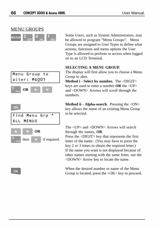
66 ����������������� ������ User Manual.
MENU GROUPS
+� &�*�#&%��#
�������+*���
)� ��+� &�*�%�I
�44�+,7B
OR
OR
then if required.
Some Users, such as System Administrators, maybe allowed to program “Menu Groups”. MenuGroups are assigned to User Types to define whatactions, functions and menu options the UserType is allowed to perform or access when loggedon to an LCD Terminal.
SELECTING A MENU GROUP.The display will first allow you to choose a MenuGroup to alter.Method i - Select by number. The <DIGIT>keys are used to enter a number OR the <UP>and <DOWN> Arrows will scroll through thenumbers.
Method ii - Alpha-search. Pressing the <ON>key allows the name of an existing Menu Groupto be selected.
The <UP> and <DOWN> Arrows will searchthrough the names, ORPress the <DIGIT> key that represents the firstletter of the name. (You may have to press thekey 2 or 3 times to obtain the required letter.)If the name you want is not displayed because ofother names starting with the same letter, use the<DOWN> Arrow key to locate the name.
When the desired number or name of the MenuGroup is located, press the <OK> key to proceed.

67����������������� ������ User Manual.
+*����6�9# �����
7# �
or or
+*����7� ��
�44�+,7B
, - - -
MENU GROUP NAME.The display will show the number and current name.
A name of up to 16 characters can be programmedin the same manner as described for User names.
<OK> key for next option. <UP> or <DOWN> toedit this option for the previous/next Menu Group.
ASSIGN A TIMEZONE.The display will show the current TimeZone name.If a TimeZone is assigned, the Menu Group willonly be used when the TimeZone is valid.i.e. A TimeZone on a Menu Group assigned to aUser Type means that those Users can only performthe actions and access the menu options specifiedin the Menu Group whenever the TimeZone is Valid.
Select a TimeZone using the Alpha-search method.
<OK> key for next option. <UP> / <DOWN> toedit this option for the previous/next Menu Group.
ASSIGN AN ALTERNATE MENU GROUP.The display will show the current Alternate MenuGroup. If an Alternate Menu Group is assigned itwill be used instead of this Menu Group wheneverthe TimeZone (if assigned) is Invalid.e.g. An Alternate Menu Group can be used toprovide a different set of actions and/or menu optionsfor these Users, even when the TimeZone on theirMenu Group is Invalid.
An Alternate Menu Group is selected by using theAlpha-search method.
<OK> key for next option. <UP> / <DOWN> toedit this option for the previous/next Menu Group.
or or
or or
+*��������*�%���
7# �
or or
or or
Men
u G
rps

68 ����������������� ������ User Manual.
MENU GROUP OPTIONSThere are eight functional options which may beset for a Menu Group.
Use the <RIGHT> Arrow, followed by the <9>(Y) & <5> (N) keys to set the desired options toYES or NO.<OK> for next option. <UP> / <DOWN> to editthis option for the previous/next Menu Group.
+*�������'-"�+6
�%������ � � ���
[R]emote Access. Allows remote access via Upload/Download software.
[I]solate on Exit. Allows User to Isolate un-sealed zones on exit.
[D]efer Area On. Implements Area Defer timer operation when theUser turns an Area Off that has been defined as a“Defer” Area. Area automatically re-arms when theDefer timer expires, unless the User performs theArea Off function again before the timer or warningexpires. (V2 or later only)
[C]ancel Holdup. Allows the User to cancel a Holdup alarm before itreports, by entering their PIN at an LCD Terminal.(V2 or later only)
[S]irens Off. Allows Users to automatically turn off any Sirensrunning at the time of PIN code entry, regardless ofwhether they are allowed control of the Area/s thattriggered the siren/s.
[A]cknowledge Messages. Allows Users to acknowledge alarm messages fromany Area, regardless of whether they are allowedcontrol of the Area/s that generated the message/s.
[M]ultiple Areas. Allows the User to turn On/Off more than one Areaat a time via an Area List. Any Area List can bechosen, but only Areas in the User’s On/Off Lists willbe controlled.
[T]amper On/Off. Allows the User to turn Off the 24 Hr or Tamper partof any Area in their Area OFF List.
or or
, or

69����������������� ������ User Manual.
ASSIGN MAIN MENU OPTIONSThis display is used to define the Main Menuoptions that the Menu Group will allow access to.
Use the <RIGHT> Arrow, followed by the <9>(Y) & <5> (N) keys to set the desired options toYES or NO.
<OK> key for next option. <UP> / <DOWN> toedit this option for the previous/next MenuGroup.
+*��������'6��"
++� &�����������
NOTE: Setting the [R]eview, [A]ccess or [Control] menu options to YES does notenable access to all User options within those menus. To allow access to theadditional sub menu options, the appropriate options must also be set in the SubMenu options screen that follows.
[R]eview. (Information Menu) Review (If allowed by Sub Menu option), LocateUser, Read Analogue values, Read Counters andView input states.
[A]ccess Menu. User Codes, User Types, Lists, and Groups.(As allowed by Sub Menu options)
[I]solate Menu. Isolate / De-isolate Inputs.See “Isolate. Menu Option 3” for details.
[T]est Menu. Area Walk Testing. (If enabled in the system)(Only valid in V3 or later)
[t]imes Menu. Time/Date, TimeZones (If allowed by Sub Menuoptions), Holidays.
[.] Spare. Not in use.
[S]ervice Menu. Answer Phone.See “Service. Menu Option 8” for details.
[C]ontrol Menu. Home Auxiliaries, Lock/Open Doors, Secure/FreeLifts and Adjust Counters (If allowed by SubMenu option).
or or
, or
Men
u G
rps

70 ����������������� ������ User Manual.
ASSIGN SUB MENU OPTIONSThis display is used to define the Sub Menuoptions that the Menu Group will allow access to.
Use the <RIGHT> Arrow, followed by the <9>(Y) & <5> (N) keys to set the desired options toYES or NO.<OK> for next option. <UP> / <DOWN> to editthis option for the previous/next Menu Group.
+*������B64*9���
�+� &�����������
[U]ser Code programming.User [T]ypes. Allows access to the specified Menu option if the[L]ists. [A]ccess option is set to “Y” in the previous screen.[G]roups.
Time[Z]ones. Allows access to TimeZones if the [t]imes option isset to “Y” in the previous screen.
[R]eview. Allows access to Review if the [R]eview option is setto “Y” in the previous screen. (V3 or later only)
[A]djust Counters. Allows access to Adjust Counters if [C]ontrol optionset to “Y” in the previous screen. (V3 or later only)
or or
, or
SPECIAL OPTIONSThere are currently 3 special options availablewhen programming Menu Groups. (V3 or later)
The desired options are set to YES or NO in thesame manner as described above.
+*�������?������
��1�������������
[R]eset Latched Alarms. Allows Users to reset “Latched Alarms”. (LatchedAlarms feature is NOT used in most systems)
[H]omeZone Isolate. Forces the Isolate screens to be displayed as “Alpha-search” HomeZones only. Do NOT set to Yes if theHomeZone feature is not used in your system.
[O]wn Area List only. To simplify Area List selection, the User will only bepresented with their User Type’s Area On List. (V4or later only)

71����������������� ������ User Manual.
���$�
B�����B����!
or then
This Menu option allows a Wireless RF RemoteFob to be Registered to a User, and a User’s FobRegistration status to be viewed.
Enter the User number using the <DIGIT> keys,then press <OK>;OR Use the <UP> / <DOWN> Arrow keys to scrollto the required User number, then press <OK>.
The screen will now show the current FobRegistration status for the selected User.
If a Fob transmission is received while this screenis displayed, one of the following will occur:
1) If the transmission is from a Fob that is notregistered, and the displayed User already has aFob registered, then no change will occur.
2) If the transmission is from a Fob that is alreadyregistered, the display will jump to that User andthe Terminal will sound a short beep.
3) If the transmission is from a Fob that is notregistered, and the displayed User does not have aFob registered, then this screen will be displayed.The number in brackets is the Fob button number.
While this screen is displayed, the <ON> key canbe used to register the Fob to the displayed User.
The other Key functions for these screens are:<UP>/<DOWN. Scroll to another User.
<LEFT> Arrow. Back to User selection screen.
De-Register or Clear the displayed Fob.
+���1�8
7#����(�������
RF FOB REGISTRATION
/���
��(�����L�G�H
+���1�8
��(�������
- -
0��$��
��(�������
FO
B R
EG

72 ����������������� ������ User Manual.
Isolate: Menu Option 3
Users with the authority to “Isolate on Exit” can isolate any faulty devices whenprompted during the Area ON procedure. (see “Turning Area/s ON” for details)However, when you know that a device is faulty, (e.g. A roller shutter contact hasbeen damaged by a Forklift) you may also have the authority to Isolate the Zone viathis menu option before anyone attempts to turn the Area ON.Note that System Inputs can also be isolated. e.g. “Expander 01 Ext. Siren Tamper”could be isolated while damaged speaker cabling was awaiting repair.
NOTE: The Isolate menu also allows you to De-isolate Zones if the fault is rectifiedbefore the Area needs to be turned ON.
SELECTING A ZONE TO ISOLATEThere are two methods of selecting a Zone: “Zone ID” OR “HomeZones”.-Zone ID allows selection of any zone in the system by Zone ID number or bysearching through the zone list in numerical order for the zone name.-HomeZones allows selection of any zones that have been designated as HomeZones,by using the quick “Alpha-search” method. (V3 or later only)
You will only be able to use one of these methods depending on the setting of the“[H]omeZone Isolate” option in the special options screen of the Menu Groupassigned to your User Type. See “Menu Groups”.
If a detector or alarm contact is faulty, or theircabling has been shorted or cut, you may be unableto turn ON any Area that the faulty device is in.
9# ���#�'�#�����
"���9��
- -
NOTE: You may use bothmodes, as the ON key canchange the mode at any time.
Zone ID selection.The display will prompt you to enter the Module/Zone (Input) ID of the Zone you wish to isolate.
If you know the Zone ID, use the <OFF> key toclear the screen, then enter the letters/numbers ofthe Zone ID with the <DIGIT> keys, then <OK>.
If the ID is not known, press the <ON> key, andthen scroll through the Zone names in numericalorder using the <UP> and <DOWN> Arrow keys,then <OK>.(Alpha-search using the digit keys is NOT used inthis method)

73����������������� ������ User Manual.
HomeZone selection.The display will show the name and current statusof the first HomeZone. (V3 or later only)
NOTE: Only available if the HomeZones option isused in your system.
The <UP> and <DOWN> Arrows will searchthrough the named HomeZones alphabetically,ORPress the <DIGIT> key that represents the firstletter of the name. (You may have to press thekey 2 or 3 times to obtain the required letter.)If the name you want is not displayed because ofother names starting with the same letter, use the<DOWN> Arrow key to locate the name, thenpress the <OK> key to proceed.
ISOLATE / DE-ISOLATE THE INPUT.The display will now show the name and currentstatus of the Zone/Input .
<OFF> key to Isolate the Zone displayed. AnyZones isolated in this way are automaticallyDe-isolated when the Area is next turned OFF.
<ON> key to De-isolate (or “Enable”) the Zone.<RIGHT> arrow key to “Sticky Isolate” the Zone.
The Zone will remain isolated unlessDe-isolated from the LCD Terminal via thisMenu option.
A brief message will appear on the display toconfirm that the operation was successful.
When complete press the <OK> key to return tothe “Zone to Isolate” display.
�,",06'�7�0'�
, �����
9# ����
#8���#�����
����$��-##������
, �����
OR
then if required
then
or or
ISO
LA
TE

74 ����������������� ������ User Manual.
Testing: Menu Option 4
Testing simply involves activating the devices (usually detectors) and then allowingthem to return to their normal state. e.g. Walk past movement detectors, open andclose doors, press then release panic buttons, etc.The system can perform automatic testing on devices that are regularly activated bymovement, etc., such as PIRs and Door Contacts. However, other types of Inputdevices, such as Glass-break, Smoke & Seismic detectors, Panic buttons, WindowContacts, etc. should also be tested on a regular basis. (e.g. Once every month)
NOTE: The additional Test Menu options shown in the Menu Flowchart at the rearof this manual are only accessible to the Installer. They provide a comprehensiverange of Testing to assist with installation, commissioning and service of the system.
The display will prompt you to select an Area toTest.
The <UP> and <DOWN> Arrows will searchthrough the Area names alphabetically,ORPress the <DIGIT> key that represents the first letterof the name. (You may have to press the key 2 or 3times to obtain the required letter.)If the name you want is not displayed because ofother names starting with the same letter, use the<DOWN> Arrow key to locate the name.
When the Area is selected, press the <OK> key toproceed.
If the maximum time allowed for Walk Testingexpires, the test will be aborted and the display willreturn to the “Area to Test?” prompt.The maximum test time is programmed by theInstaller for each Area. If the max. test time for anArea is set to zero, the maximum test time will thenbe 10 minutes.
������#�6����L�I
0� �$��&��# �
OR
then if required.
Your system may be programmed with an optionto allow Walk testing of specified Zones inparticular Areas. (V3 or later only)

75����������������� ������ User Manual.
NOTE: For comprehensive testing of the system, including the reportingfacilities, a procedure similar to the following is used on appropriate sites:
Arrange with the Central Monitoring Station for testing to be performed periodicallyin “real-life” conditions. This involves setting aside a period when all Areas in thesystem are turned ON, then activating all the Input Devices. A report from theCentral Station is then used to check that all devices activated were reported.This method also tests that Input processing and Reporting options have beenprogrammed appropriately, and that the alarm reporting is occuring effectively.
6����0�����
0&�1��<�=�
After an initial test to check that all Zones areSealed, the Walk Test commences. The display willupdate with a beep every few seconds to show anyZones that have not been tested.The following key functions are available while thisdisplay is shown, and may need to be used if anydevice fails to operate or cannot be tested:
To abort the Walk Test because a Zone is faulty andcannot be tested, press the <OK> key.A “Test Failed” message will be displayed.Press the <OK> key again to return to the “Area toTest?” prompt.
To abort the Walk Test, press the <END> key.The display will briefly show “Operation Aborted”,then return to the “Area to Test?” prompt.
To manually advance to the next untested Zone,press any other key.
When all the Zones have been tested and there areno faults, the “Test Passed” message is displayed.
Push <OK> to exit the Walk Test mode and selectanother Area to Test.
Select another Area to test or Press the <END> keyto exit and return to the normal display.
������#�6����L�I
0� �$�/&��# �
9# �� #��6�����
"#& ������0� �$
ZO
NE
TE
ST

76 ����������������� ������ User Manual.
Times: Menu Option 5
SET TIME AND DATE The time and date can be set and adjusted in the“Times” menu.This will be necessary when the system is firstcommissioned and for daylight saving changes.(This may be done automatically by the system, orin some reporting formats, by the Central Station)
The display will show the system’s current dateand time.
The Date & Time is set in the format:DD/MM/YY-HH:MM The 24 hour clock is used.
Use the <DIGIT> keys to enter in the valuesrequired and the <RIGHT> Arrow key to movethe cursor across the fields.Press <OK> when complete.
NOTE: When OK is pressed, the Date & Time issaved AND the seconds count is set to “00”
The display will now allow you to set the weekday
Use the <RIGHT> Arrow key to select the day ofthe week then press the <OK> key whencomplete.
Press <END> to exit and return to the normaldisplay.
���-����6� ��
��3��3!!������
etc.
���.��=������
.�� ����
REMEMBER !!Any time you need it,
is as close as the press of a key.

77����������������� ������ User Manual.
TIMEZONES
SELECTING A TIMEZONE.The display will allow you to choose a TimeZoneto alter, AND will indicate the current status ofthe TimeZone. (V) = Valid. (I) = Invalid.Method i - Select by number. The <DIGIT>keys are used to enter a number OR the <UP>and <DOWN> Arrows will scroll through thenumbers.
Method ii - Alpha-search. Pressing the <ON>key allows the name of an existing TimeZone tobe selected.
The <UP> and <DOWN> Arrows will searchthrough the names, ORPress the <DIGIT> key that represents the firstletter of the name. (You may have to press thekey 2 or 3 times to obtain the required letter.)If the name you want is not displayed because ofother names starting with the same letter, use the<DOWN> Arrow key to locate the name.
When the desired number or name of theTimeZone is located, press the <OK> key toproceed.
6� �9# ���#��GCH
�������69���
)� ��6M# ���GCHI
.��<'7*�?�B�
OR
OR
then if required.
Some Users, such as System Administrators, maybe allowed to program/edit “TimeZones”.TimeZones may be used to define when User accessto specific functions and items (Areas, Doors, etc)is allowed; and also to provide automated controlof items in the system. e.g. Unlock doors duringbusiness hours, Operate security lights at night, etc.
-A TimeZone provides up to 4 separate time periods each programmed with a Startand End time and Days of the week, including Holiday. See example on next page.-If “Holiday” is set to Yes when programming the Days, the TimeZone will beallowed to be Valid on Holidays for that time period.-A period of 00:00-to-00:00 means ignore that period. Spaces instead of digitsmeans ignore that Start Time or End time in that particular period. e.g. 19:00-to- :
TIM
ES
TIM
ES

78 ����������������� ������ User Manual.
69��������0���#�
�!�����#������
or or
69����7� ��
.��<'7*�?�B�
, - - -
TIMEZONE NAME.The display will show the number and currentname.A name of up to 16 characters can beprogrammed in the same manner as described forUser names.
<OK> key for next option. <UP> or <DOWN> toedit this option for the previous/next TimeZone.
PROGRAM THE FIRST PERIOD.The display will show the current Start Time andEnd Time of the 1st period.
Use the <DIGIT> keys to enter in the valuesrequired and the <RIGHT> Arrow key to movethe cursor across the fields.The <OFF> key can be used to clear all fields.Press <OK> when complete.
<OK> key for next option. <UP> / <DOWN> toedit this option for the previous/next TimeZone.
PROGRAM THE DAYS OF THE WEEK.The display will show the current days assignedto the Timezone period.
Use the <RIGHT> Arrow key, followed by the<9> (Yes) & <5> (No) keys to set the desiredoptions to YES or NO.
<OK> key for next option. <UP> / <DOWN> toedit this option for the previous/next TimeZone.
PROGRAM THE 2nd, 3rd & 4th PERIODS.If you need to program/edit the other TimeZoneperiods, the <OK> key will step through another6 screens that allow the Start and End times andthe Days of the week to be programmed for theseperiods in the same way that the 1st period isprogrammed.
or or
or or
69������+6.6)?
�6����� �����
or or
, or
e.g.To cater for different tradinghours on different days.��������� � ������
������������� ��������
��������
������������� ��������

79����������������� ������ User Manual.
69��������������
?#��������
or or
, or
PROGRAM THE HOLIDAY TYPES.The display will show the current Holiday Typesthat will be obeyed by this Timezone.
The TimeZone will be Invalid on the Holidaytypes specified unless the “H” option is set to Yesin the “Days of the Week” for a particular period.See Program Holidays.
Use the <RIGHT> Arrow, followed by the <9>(Y) & <5> (N) keys to set the desired options toYES or NO.<OK> key for next option. <UP> / <DOWN> toedit this option for the previous/next TimeZone.
TIMEZONE FUNCTION.The display will show the current function thatthe Timezone controls. The function (if enabled)will be an option such as “Auxiliary On/Off”,Area On/Off”, “Door Unlock/Lock”, etc.CAUTION: This, and the following relatedoptions, are normally only programmed/editedby the Installer.Additional information is provided in theProgrammer’s manual.
Use the <RIGHT> Arrow key to select the desiredfunction then press <OK>.
The display/s that follow will vary depending onthe function selected. The examples provided arefor Door Unlock/Lock Control.Typically the first screen allows selection of theitem or list to be controlled.The next screen defines the control options:
69����)& $��# ��
7# �
,
69����-##���#
"# ��#���-���
69�����������)#�
"# ��#������
69����)& $��# ��
-##��GB H4#$=
O On/Secure/Lock/Close when TimeZone goes Valid.F Off/Unsecure/Unlock/Open when TimeZone goes Valid.o On/Secure/Lock/Close when TimeZone goes Invalid.f Off/Unsecure/Unlock/Open when TimeZone goes Invalid.
TIM
ES

80 ����������������� ������ User Manual.
69����E&�����E'
�%��# ��������
or or
, or
PROGRAM THE QUALIFY OPTIONS.The display will show the current Qualify optionsettings. The Qualify options allow the TimeZoneto be Qualified by an Auxiliary.If this option is used, the TimeZone will only beValid when a TimeZone Period is Valid ANDwhen the Qualify conditions are met.
CAUTION: These options are normally onlyprogrammed/edited by the Installer.
Use the <RIGHT> Arrow key, followed by the<9> (Yes) & <5> (No) keys to set the desiredoptions to YES or NO, then <OK> key for nextoption.
69����E&����
�&:������K
etc.
The display allows the Auxiliary to be chosen thatwill Qualify the TimeZone.
Use the <DIGIT> keys to enter in the AuxiliaryID and the <RIGHT> Arrow key to move thecursor across the fields when necessary.Press <OK> when complete.
<OK> key to select another TimeZone toprogram/edit. <END> key to exit to the normaldisplay.
Q Qualify the TimeZone with an Auxiliary. When Aux. is Off, TimeZone willalways be Invalid, regardless of whether any TimeZone Periods are valid.
I Invert Qualify. Reverse the qualify conditions. When the Aux. is On,TimeZone will always be Invalid, regardless of whether any TimeZonePeriods are valid.

81����������������� ������ User Manual.
HOLIDAYS
SELECTING A HOLIDAY.The display will allow you to choose a Holiday toalter.
Method i - Select by number. Use the <DIGIT>keys to enter a number OR <UP> & <DOWN>Arrows to scroll through the numbers.
Method ii - Alpha-search. Press the <ON> keyto select the name of an existing Holiday.
The <UP> and <DOWN> Arrows will searchthrough the names, ORPress the <DIGIT> key that represents the firstletter of the name. (You may have to press thekey 2 or 3 times to obtain the required letter.)If the name you want is not displayed because ofother names starting with the same letter, use the<DOWN> Arrow key to locate the name.
When the desired number or name of the Holidayis located, press the <OK> key to proceed.
?#������#
��������?���
)� ��?#�������I
7,.��,���-��
OR
OR
then if required.
Some Users, such as System Administrators, maybe allowed to program “Holidays”.Holidays are used with TimeZones to definewhether a TimeZone will be Invalid or Valid ondates designated as Holidays.
-A Holiday can be a single date or a period defined with a Start date & an End date.-Holidays are defined as Month/Date. No Year is defined, so moveable holidaysmust be re-programmed every Year.-Each Holiday programmed must also be assigned the Holiday “Types” that are toapply to it. In most systems, holidays will not need to be broken down into differenttypes, so all Holidays will be assigned “Type 1” only.-In some systems where different types of Holidays are to effect different TimeZones,it will be necessary to divide the Holidays into different types. e.g. Type 1 = Publicholidays, Type 2 = School vacations, Type 3 = Summer holiday closedown.
TIM
ES

82 ����������������� ������ User Manual.
?����-�����
��3����#���3��
or or
?����7� ��
7,.��,���-��
, - - -
HOLIDAY NAME.The display will show the number and currentname.A name of up to 16 characters can beprogrammed in the same manner as described forUser names.
<OK> key for next option. <UP> or <DOWN> toedit this option for the previous/next Holiday.
PROGRAM THE HOLIDAY DATE/PERIOD.The display will show the current Start Date andEnd Date of the Holiday.
Use the <DIGIT> keys to enter in the datesrequired and the <RIGHT> Arrow key to movethe cursor across the fields when necessary.The <OFF> key can be used to clear all fields.
<OK> key for next option. <UP> / <DOWN> toedit this option for the previous/next Holiday.
PROGRAM THE HOLIDAY TYPE/S.The display will show the current Types assignedto the Holiday.
Use the <RIGHT> Arrow, followed by the <9>(Y) & <5> (N) keys to set the desired options toYES or NO.
<OK> key to select another Holiday to edit.<UP> / <DOWN> to edit this option for theprevious/next Holiday.
<END> key to exit to the normal display.
NOTE: A Holiday period must be assigned atleast one Type. An explanation of Holiday Typesis found on the previous page.
or or
or or
?��������������
6%�������
or or
, or

83����������������� ������ User Manual.
DIARIES
-�����#
�������-����
OR
Some Users, such as System Administrators, maybe allowed to program “Diaries”.Diaries are mainly used to display customisedmessages on selected LCD Terminals at variousselectable times.
Diaries can also be used to control an Auxiliaryoutput when required. e.g. For activating abeeper to alert users to the Diary message.Any Diary function can also be Qualified byanother Auxiliary, allowing other operations toenable/disable the Diary function if necessary.
SELECTING A DIARY.The display will allow you to choose a Diary toalter.
The <DIGIT> keys are used to enter a numberOR the <UP>/<DOWN> keys will scroll throughthe numbers. (Alpha-search not available)
When the desired number of the Diary is located,press the <OK> key to proceed.
PROGRAM THE DATE AND TIME.The display will show the current settings.
Use the <DIGIT> keys to enter in the date & timewhen the Diary will be valid. The date/timeformat is DD/MM/YY, HH:MM. Use the<RIGHT> Arrow key to move the cursor acrossthe fields.
The <OFF> key can be used to clear all fieldsbefore you start, or to set the Diary “AlwaysValid”. Any blank entry means that field isalways valid. e.g. In the example shown, Diary001 will become valid on the 1st of January inany year for 24 hours (any time).
-�����-����6� ��
��3��3������
and or
Note that the Auxiliary Outputcontrol, Qualify Auxiliary andDiary Functions should onlybe programmed by a qualifiedinstaller.
TIM
ES

84 ����������������� ������ User Manual.
-����������� �
.��$# ���#
, - - -
or or
-������ ���� �
�1���$ ��"# %�
-��������+6.6)
6%�������������
or or
, or
NOTE:To remove a Diary do not press <OFF>. Thiswill make the Diary continuously valid. Instead,set the Date and Time to 00/00/88 - 00:00
<OK> key for next option. <UP> / <DOWN> toedit this option for the previous/next Diary.
PROGRAM VALID DAYS.The display will show the current Days that theDiary message will be Valid.
Use the <RIGHT> Arrow, followed by the <9>(Y) & <5> (N) keys to set the desired options toYES or NO.<OK> key for next option. <UP> / <DOWN> toedit this option for the previous/next Diary.
PROGRAM THE DIARY MESSAGE.The display will show the first line of the Diarymessage.
Up to 16 characters of text can be programmed inthe same manner as described for User names.
NOTE: The first character must not be left blank.
<OK> key for next option. <UP> or <DOWN> toedit this option for the previous/next Diary.
The display will show the second line of the Diarymessage. Up to 16 characters of text can beprogrammed for the 2nd line as described above.
or or

85����������������� ������ User Manual.
-������&�%&��
�&:���J���K
-�����)& $��# ��
7# �
Add 1 Hr. ...................... When Diary goes Valid, adjust Real Time Clock by +1 Hr.(Start of Daylight Saving)
Subtract 1 Hr. ............... When Diary goes Valid, adjust Real Time Clock by -1Hr &change function to “Skip subtract 1 Hr.” (End of DaylightSaving)
Battery Test. .................. When Diary goes Valid, start automatic Battery test cycle.Skip Subtract 1 Hr. ....... Do not select. This option set automatically when necessary.Qualify Aux. ................. (V3 to V3.5 only) Changes the function of the Diary Output
Auxiliary to a Qualify Auxiliary. i.e. The Diary will not beValid unless the specified Auxiliary is On.
, or
then
or then
CAUTION: The following options should only be programmed by the Installer.
ASSIGN A DIARY AUXILIARY.The display will show the current Auxiliaryoutput assigned to the Diary. This Auxiliary willturn on when the Diary is valid, and off wheninvalid.Use the <DIGIT> keys and <RIGHT> Arrow keyto enter in the Auxiliary ID then press <OK>(The <OFF> key can be used to clear all fields.)
ASSIGN A QUALIFY AUXILIARY.The display will show the current QualifyAuxiliary assigned to the Diary. (V4 or lateronly) For the Diary to be valid, the Time & Datemust be valid and the “Qualify Auxiliary”, ifprogrammed in this screen, must be On.
Programmed as described above.(Note: V3 to V3.5 see “Diary Functions” below.)
SELECT A DIARY FUNCTION.The display will show the current functionselected. (V3 or later only) See the table below.
Use the <RIGHT> Arrow key to select a functionthen <OK> to select another Diary to program.
-�����E&�����
�&:���J���K
TIM
ES

86 ����������������� ������ User Manual.
Service: Menu Option 8
REQUEST SERVICE This menu option causes an alarm message to besent to the Monitoring Station to Request aService call. (Only available V3.0 or later)See “Important Notes” above.
Activating the “Request Service” function issimply a matter of selecting the menu option bypressing the key sequence shown above.(<MENU>, <8>, <1>.)
The “Report Initiated” message will be displayedon the LCD Terminal for approximately 2seconds when the function is activated.(Version 4 or later only)
Press the <END> key to exit the menu. This willnot effect the call.
“REQUEST SERVICE” and “TEST REPORT”. IMPORTANT NOTES:
1) These options are only valid if the system is connected to a telephone line and thefunction has been enabled in the Installer programming options.
2) You will need to check that the Monitoring Station provides the services and anyadditional charges that may be incurred.
��%#��
' �������

87����������������� ������ User Manual.
TEST REPORT This menu option causes a message to be sent tothe Monitoring Station to Test the Reportingfunction. (Only available V3.0 or later)See “Important Notes” on the previous page.
You may be instructed by the Installer or theMonitoring station to perform this function to testcommunications. This may be required afterwork has been carried out on the system or thetelephone line, or to restore a “Comms Fail”alarm.
Activating the “Test Report” function is simply amatter of selecting the menu option by pressingthe key sequence shown above.(<MENU>, <8>, <2>.)
The “Report Initiated” message will be displayedon the LCD Terminal for approximately 2seconds when the function is activated.(Version 4 or later only)
Press the <END> key to exit the menu. This willnot effect the call.
This menu option allows the Master User Codeholder to Lockout and Enable the Installer’s PINCode.Note that this feature must be enabled by theInstaller before it can be used.
To change the Installer Lockout setting, press the<9> key to set to Yes, or the <5> key to set to No.The <OK> key must then be pressed to save thesetting.
Press the <END> key to exit the menu.
��%#��
' �������
SE
RV
ICE
INSTALLER LOCKOUT
4#$=#&�
' ��������L�
or then

88 ����������������� ������ User Manual.
ANSWER PHONE If remote access to the system is required forservice purposes via the dialer phone line, theservice technician may ask you to activate the“Answer phone” function, in order to establishthe communications connection.
Activating the Answer Phone function is simply amatter of selecting the menu option by pressingthe key sequence shown. (<MENU>, <8>, <4>.)
DO NOT USE THIS OPTION UNLESSINSTRUCTED TO DO SO BY YOURINSTALLER / SERVICE TECHNICIAN.
The display will show a message to indicate thestatus and then return to the main menu.
Press the <END> key to exit the menu. This willnot effect the remote connection.
� �8��� (
01# �
NOTE: This option is only valid if the Control Module is connected to a telephoneline and the function has been enabled in the Installer programming options.

89����������������� ������ User Manual.
Control: Menu Option 9
HOME AUXILIARIES Home Auxiliaries are outputs in the system thatcan be turned On and Off by a User.
Access to control of some Home Auxiliaries maybe gained by simply pressing the <RIGHT> arrowkey on the LCD Terminal.Other Home Auxiliaries need to be more secureand can only be controlled via access to thisControl Menu option.
After selecting the Menu Option (<MENU>,<9>, <1>) refer to “Home Auxiliary Control”earlier in this manual for details of the Controloptions.
CO
NT
RO
L
REMEMBER !! Any time you need it,
is as close as the press of a key.

90 ����������������� ������ User Manual.
DOOR CONTROL
The “Door Open/Close” option allows a User withthe appropriate authority to Un-lock and Lockindividual Doors (V3 or later only) or all Doors inthe Door List assigned to their User Type.
e.g. If Doors are programmed for “free access”during the day, it may be necessary to re-lock thedoors if all the staff leave early to attend acompany function at another location.ORIt may be necessary to un-lock doors if free accessis required outside normal working hours to allowstaff to fulfil an urgent order.
The display will allow you to enter the number ofthe Door to control.
Use the <DIGIT> keys to enter the two digit Doornumber then <OK>. (Press <END> to abort)A Door number of “00” will include all Doors inthe User’s Door List.
The display will now allow you to select the “Lock”or “Unlock” operation.
Press the <4> (L) key to Lock the Door.Press the <7> (U) key to Unlock the Door.
The display will briefly show the “Operation Done”message to indicate that the operation was successfuland then return to the main menu.
Press the <END> key to exit to the normaldisplay or select another Menu option.
-##���#
"# ��#�L����
NOTE: Only Doors includedin the User’s “Door List”(defined in their “User Type”)can be controlled.
G4H#$=�#�
GBH �#$=�L
�%�����#
-# �

91����������������� ������ User Manual.
LIFT CONTROL
“Lift Access/Secure” allows a User with theappropriate authority to Access or Secure Floor/sin a specific Lift Car. If accessed, all Users mayaccess the floors. If secured, only valid Users mayaccess the floors.e.g. If Floors are normally programmed for “freeaccess” during the day, it may be necessary to Securethe floors to restrict access during a VIP visit.ORIf access is required outside normal working hoursfor staff to complete an urgent project, it may benecessary to Access the Floors.
The display will allow you to enter the number ofthe Lift Car to control.
Use the <DIGIT> keys to enter the two digit LiftCar number then <OK>. (Press <END> to abort)A Lift Car number of “00” will include all Lifts.
The display will allow you to enter the number ofthe Floor to control. (V3 or later only)
Use the <DIGIT> keys to enter the two digit Floornumber then <OK>. (Press <END> to abort)A Lift Car number of “00” will include all Floors.
The display will allow you to select the “Access(Free) Floor” or “Secure Floor” operation.
Press the <1> (A) key to Access (Free) the Floor.Press the <7> (S) key to Secure the Floor.
The display will briefly show the “Operation Done”message to indicate that the operation was successfuland then return to the main menu.
Press the <END> key to exit to the normaldisplay or select another Menu option.
4���
"���L���
)�##�
�#��#�L���
G�H$$����#�
GH�$&���L
�%�����#
-# �
CO
NT
RO
L

92 ����������������� ������ User Manual.
ADJUST EVENT COUNT
Adjust Event Count allows a User with theappropriate authority to reset an Event Counter(to 0) or to set the count value to the requirednumber.(V3 or later only)
The display will show the first Counter and thecurrent count value.
Use the <UP> and <DOWN> arrow keys to selectthe Counter to reset or adjust.
Use the <DIGIT> keys and <RIGHT> Arrow key(if necessary) to enter in the count value thenpress <OK>.The <OFF> key can be used to clear the field.(Reset to 0)
Press the <END> key to exit to the normaldisplay or select another Menu option.
"� ������)��
��" �����������
�"#& �������
��" �����������
, or
then

93����������������� ������ User Manual.
ADJUST AREA USER COUNT
Adjust Area User Count allows a User with theappropriate authority to reset an Area UserCounter (to 0) or to set the count value to therequired number.(V5 or later only)
The display will show the first Area User Counterand the current count value.
Use the <UP> and <DOWN> arrow keys to selectthe Area User Counter to reset or adjust.
Use the <DIGIT> keys and <RIGHT> Arrow key(if necessary) to enter in the count value thenpress <OK>.The <OFF> key can be used to clear the field.(Reset to 0)
Press the <END> key to exit to the normaldisplay or select another Menu option.
�����7& ����#�
B�����������
, or
then
�����7& ����#�
B�����������
CO
NT
RO
L

94 ����������������� ������ User Manual.
Wireless Remote Fob Operations.
Some sytems may utilize 4-Button Wireless Remote Fobs to perform Area control,Auxiliary control, and Alarm functions. Any Fobs to be used in the system must firstbe enrolled by being registered to individual Users. See “RF Fob Registration”, MENU,2, 7.
The Fob button functions are then defined in User programming. For ease of operation,Fob functions will normally be programmed to be similar for all Fob Users in the samesystem. However, as the system allows the function of each button to be individuallyprogrammed for each User, the system also offers the flexibility for different Fob functionsto be defined for different Users. See “User Programming”, MENU, 2, 1.
In consultation with your Installer, use the following pages for planning andrecording the Fob button operations for your system.
Fobs can be programmed to perform the following operations:
Single button Arming. A single button is used to Arm one or more Areas.Two button Arming. A “Qualify” button must be pressed, followed by the
Arm button within 10 Seconds.Single button Disarming. A single button is used to Disarm one or more Areas.Auxiliary On. A single button is used to turn an Auxiliary On.Auxiliary Off. A single button is used to turn an Auxiliary Off.Auxiliary Toggle. A single button is used to change the state of an
Auxiliary.Single button Zone Alarm. A single button is used to generate a Zone Alarm
(e.g. Panic, Duress, Medical Alert, etc).Two button Zone Alarm. A “Qualify” button must be pressed, followed by the
Zone Alarm button within 10 Seconds.
Fob User feedback options.The system can provide the following standard Fob feedback options to controlIndicator or Warning devices such as Sounders, Lamps, Sirens or Keypad beepers.
Area is turned On (Armed) Trigger an Auxiliary output for 2 Seconds.Area is turned Off (Disarmed) Trigger an Auxiliary output for 5 Seconds.Area Fails to Arm Trigger the Siren, and/or another Auxiliary output
for approximately 5 Seconds.
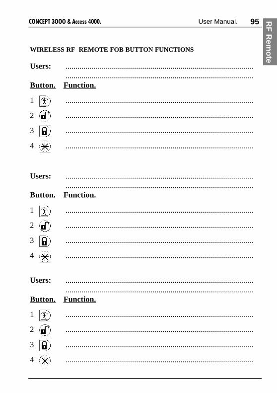
95����������������� ������ User Manual.
WIRELESS RF REMOTE FOB BUTTON FUNCTIONS
Users: ..............................................................................................................................................................................................
Button. Function.
1 ...............................................................................................
2 ...............................................................................................
3 ...............................................................................................
4 ...............................................................................................
RF
Rem
ote

96 ����������������� ������ User Manual.
Telephone Remote Control.
Some sytems may utilize the “DTMF Control” option to allow the system to be controlledby any telephone able to send DTMF tones. i.e. Any touch tone phone. By dialing thesystem and using the telephone keypad, pre-defined Areas and Auxiliary outputs canbe turned On and/or Off with different 4 digit codes. (Only available V3 or later)
Consult your installer for the “Phone number”, “Control Mode” tone and “ControlCodes”. These may be recorded on the following page, but should be kept secure.
OPERATION
1. Dial the system from the telephone.
2. When the system answers the phone, you have 5 seconds to send the “ControlMode” tone to put the system into DTMF Control mode. i.e. Press the single digit on the telephone keypad that representsthe”Control Mode” tone. (You do not need to wait for any prompt)
3. Wait for the system to send back the “Start Tone” (3 short beeps).
4. When you hear the “Start Tone” you then have 10 seconds to start entering a4 digit “Control Code” to perform the required action. Each digit of theControl Code must be entered within 10 seconds of the previous digit.
5. The system will send back an acknowledgement tone to indicate a successful“On” (1 beep) / “Off” (2 beeps) action or “Error” (1 long lower pitch beep).See the table on the following page for details of Acknowledgement tones.
6. After the acknowledgement tone, a new Control Code may be entered or enter“0000” to command the system to hang-up.
NOTES:-If you make an error entering a Control Code, press <*> or <#>, wait for the “StartTone” and start again.-An “On” tone is sent back if you attempt to turn On an item that is already On.-An “Off” tone is sent back if you attempt to turn Off an item that is already Off.-For Security reasons, the system will hang-up if any of the following occurs:
-The 10 second digit timer expires while waiting for Control Code digits.-A Valid Control Code is not entered after 6 successive tries.-A Valid Control Code is not entered within 60 seconds.

97����������������� ������ User Manual.
DTMF CONTROL DETAILS
System Telephone No: .............................................................................
“Control Mode” Tone: ..........................
Control Codes: Action.
___ ___ ___ ___ ..............................................................................................___ ___ ___ ___ ..............................................................................................
___ ___ ___ ___ ..............................................................................................
___ ___ ___ ___ ..............................................................................................
___ ___ ___ ___ ..............................................................................................
___ ___ ___ ___ ..............................................................................................
___ ___ ___ ___ ..............................................................................................
___ ___ ___ ___ ..............................................................................................
(Depending on Memory size fitted, either 8 or 16 Control Codes will be available)
ENOT NOITPIRCSED DESUNEHW
)ydaeR(tratSenoT
hctiphgiHtrohS3speeb)zH0561(
.edomlortnoCFMTDotyrtnenO-.desserpsiyek>#<ro>*<ehtnehW-
enoT"NO"hctiphgiHtrohS1
peeb)zH0561(gnitluserderetnesiedoClortnoCdilaVanehW
.noitcaepyt"nO"nani
enoT"FFO"hctiphgiHtrohS2
speeb)zH0561(gnitluserderetnesiedoClortnoCdilaVanehW
.noitcaepyt"ffO"nani
enoTrorrEhctiprewoLgnoL1
.peeb)zH089(
.deretnesiedoCdilavnInanehW-.detucexeebtonnacnoitcaedoClortnoCnehW-
.seripxeremittigiddnoces01ehtnehW-.seripxeremitdnammocdnoces06ehtnehW-
DT
MF

98 ����������������� ������ User Manual.
GSM Mobile phone Control and Alarm messages.
An optional GSM modem can be installed with your system and programmed to allowcommunications via the GSM Digital Mobile network. (Only available V3.5 or later)The GSM modem may be used to provide the primary or backup alarm reporting to aCentral Monitoring Station.
The GSM Short Message Service (SMS) can also be used to:1) Send simple text commands from a GSM Mobile Phone to receive back system
status information or to control the system and receive back a text confirmation.2) Send specified types of alarm text messages to a nominated GSM Mobile Phone.
The following features are available in V4.5 or later only3) Send specified types of alarm text messages to a nominated GSM Mobile Phone
with a requirement for the Mobile Phone User to acknowledge the message.4) Broadcast specified types of alarm text messages to all GSM Mobile Phones in a
predefined list.5) Send specified types of alarm text messages to a predefined list of GSM Mobile
Phones in turn, until one of the Mobile Phone Users acknowledges the message.
Before you can use this feature:
1. Inform the installer of:-The GSM Mobile phone network to be used.-The phone numbers of the Mobile phones that are to send/receive the messages.-Which type/s of alarm messages you would like to be sent to the Mobile phones.e.g. All alarms, Area On/Off messages, Plant monitoring Alarms, etc.(The installer will need to program the system to enable the function and definethe Area/s that will be reported and the type/s of messages to be reported)
2. Check that Short Message Service is enabled on your GSM Mobile Service.3. Program the “Message Centre Number” into the Mobile phones.
IMPORTANT NOTES:1) V3.50 to V4.0x. Alarm text messages can only be sent to one Mobile phone.
V4.50 or later. Up to 32 Mobile phones can receive Alarm text messagesdepending on the Memory Size installed in your system, and otherCommunications functions that are being utilized.
2) If the SMS Alarm needs to be Acknowledged and is being sent to a list ofTelephone numbers, once the Alarm is acknowledged, the message will not besent to any more Telephone numbers in the list.

99����������������� ������ User Manual.
SMS Alarm Text messages.
Receiving the messages:
The System will send the specified messages to the nominated GSM Mobile phonewith a validity period of 168 hours (1 week). i.e. The message will be discarded bythe network if not received by the nominated Mobile phone within 168 hours.(Note: Validity time was 5 minutes in GSM Modem firmware V1.04 or earliershipped in June/July 2000. The firmware in these earlier units can be upgraded toV1.05 or later to provide 168 hours Validity time)
When received by the Mobile Phone, a message can then be read on the Mobilephone display.Message text sent via the GSM Modem is almost identical to the text shown in the“Review” menu. (<MENU>, 1, 1. See page 28)e.g.Jun12 22:43:50.1 Xmit Alarm on Smoke Detector (B02:Z11) in Office 01AA
Jun13 07:28:20.7 Xmit Office Off by Tony Li 01AB
Jun15 15:54:31.6 Xmit Alarm on Temp Sensor (M05:Z04) in Coolstore 01AC
SMS Alarm ID:
Note the four character ID string that is added to the end of the Review text.This is used to identify the SMS Alarm Text message.
1st two characters: Which Mobile Phone in the list the message has been sent to.-Provided for the Mobile Phone User’s information only.
2nd two characters: The SMS Alarm Text Message ID.-Provided for SMS Alarm Text Acknowledgement if required.See “Acknowledging the Messages” on the following page.
e.g. 01AA = 1st phone number tried for Alarm ID “AA”.03AF = 3rd phone number tried for Alarm ID “AF”
GS
M / S
MS

100 ����������������� ������ User Manual.
Acknowledging SMS Alarm messages:
IMPORTANT NOTES:1) Only required if SMS Alarm Text Message Acknowledgement has been
enabled for your system. If unsure, check with the Installer.2) Open/Close messages also have an SMS Alarm ID, but do not need to be
acknowledged.
The 4 character ID string attached to the end of every SMS Alarm message allows upto 576 unique Alarm IDs before wrap-around occurs.See “SMS Alarm ID” on the previous page.
To acknowledge an Alarm, the Mobile phone user simply replies to the message senderwith the letter “K”, followed by the 2 character Alarm ID.
e.g. To acknowledge Alarm ID “AA”. Send KAA.(No PIN number is required. The senders phone number is checked)
If there are multiple alarm messages to be acknowledged, the additional Alarm IDs canbe added to this reply.e.g. To acknowledge Alarm IDs “AF”, “AG” and “AH”. Send KAFAGAH
Up to 8 Alarms can be outstanding (waiting for acknowledgement) at any one time andeach Alarm has its own Acknowledge timer.Consult with the Installer to determine the acknowledge time to be programmed foryour system.Subsequent Alarms (relevant “Xmit”review entries) are buffered and sent as soon as anAcknowledge timer is free.
To Clear pending SMS Alarm Messages:
The “R” command can be sent to clear any pending SMS Alarms that have not begunto be sent.See “System Control via Short Message Service (SMS)” on the following pages.

101����������������� ������ User Manual.
System Control via Short Message Service (SMS)
The following information must be provided to the installer to enable the feature tooperate as required:
1. The type/s of commands that will be allowed via the GSM Short MessageService. e.g. Area control / Home Auxiliary Control / Zone Isolate & Restore /List Status.
2. For security reasons it is recommended that a PIN code is entered before thecommand text. Inform the installer whether you require this feature or not.(If you do not wish to use a PIN code, step 3 MUST be used)
3. Control can be limited to just one or two Mobile phones. If this is desiredprovide the installer with the phone number/s of the nominated Mobile phone/s.
Before you can use this feature:
1. Check that Short Message Service is enabled on your GSM Mobile Service.2. Check that the “Message Centre Number” is programmed in your Mobile phone.3. Check that your Mobile phone is programmed to send messages as “Text”.4. For ease of use you may enter the system’s GSM Modem phone number as a pre-
programmed number in your Mobile phone.
Send an SMS command:(Actual procedure for sending SMS messages may differ depending on make andmodel of Mobile phone. See your Mobile phone’s User Manual for details)
1. Using your GSM Mobile phone, enter the Text command that you wish toperform according to the tables opposite and select “Send”.If a PIN code is required, enter the PIN code immediately before the textcommand. See examples in the tables opposite.
2. Enter or Select the system’s mobile phone number and send the message.3. Wait for the system to send back the text message or confirmation.
See page 82 for examples of confirmation and information messages.
NOTES:1. Any PIN code used for SMS commands MUST be a PIN code programmed for a
User between User 00001 and User 00032 and any Areas or Home Auxiliaries tobe controlled must be allowed in that User’s “User Type”.
2. Most GSM Mobile phone manufacturers also produce Data Suite software thatinterfaces a PC to a GSM Mobile phone and provides the ability to send andreceive messages via the Short Message Service from a PC.
GS
M / S
MS

102 ����������������� ������ User Manual.
sdnammoclareneG
EH PL .sdnammocelbaliavaehtgnitsilegassemSMSnanruteR
R SMSteseretniop
dnaSMSaivtnesebotdeueuqeratahtsmralagnidnepynalecnaC.segassemSMSecapotdesuremitetunim5SMSehtteser
.deriuqerNIPoNEH.g.e.remitdnaretniopteseRR>NIP<
SMS TEXT COMMANDS. COMMAND SEQUENCE AND OPTIONS:
HINT: If you don't know the Number of the Area or Home Auxiliary you wish tocontrol, remember you can use the ""List"" command to view the Names.
sdnammoclortnoC
metI )DI(rebmuN noitcA )lanoitpO(emiT
A aer
xxxstigid3ot1
ON
FO F
L TSI
a/n a/n
H emoyrailixuA
xxx552ot1
S sdnoce
M setuni
.g.e.NO21aerAN21A>NIP<
.FFO3yrailixuAemoHF3H>NIP<.setuniM021rofNO72yrailixuAemoHM021N72H>NIP<
.sdnoceS51rofNO5yrailixuAemoHS51N5H>NIP<ehttsiLL12A>NIP< etatstnerruC&emaN .12aerAtagninnigebsaerA5foehttsiLL1H>NIP< etatstnerruC&emaN gninnigebseirailixuAemoH5fo
.1yrailixuAemoHta
metI )DI(rebmuN noitcA
a/nZ eno
yyZxxTepyTeludoM=T.oNeludoM=xx
rebmuNenoZ=yy
I etalos
R erotse
.4rebmunrednapxEgiBno51enoZetalosII51Z40BZ>NIP<.g.e.2rebmunrednapxEiniMno5enoZerotseRR50Z20MZ>NIP<

103����������������� ������ User Manual.
SMS CONFIRMATION & INFORMATION MESSAGES:
segassemnoitamrofnIdnanoitamrifnoC
lortnoCaerA .>egassemrorre<>emanaera<RO>ffo/no<wonsi>emanaera<.nOwonsieciffO.g.e
yrailixuAemoHlortnoC
.nim/ces>xxx<rof>ffo/no<denrut>emanxuaemoh<.nim021rofnOdenrutnoitagirrI.g.e
xuAemoH/aerAtsiL
ffOnoitpeceR>100<ffOeciffO>200<
nOmoorerotS>300<ffOaerAnoitcudorP>400<
nOsseruD>500<
enoZetalosIerotseR
detalositcatnoCrettuhsrelloR.g.edetalosi>emantupni<derotsertcatnoCrettuhsrelloR.g.ederotser>emantupni<
PLEH LxxAFxxANxxALxxAFxxHNxxH
sttNxxHmttNxxH
RxxZxxtZIxxZxxtZR
GS
M / S
MS

104 ����������������� ������ User Manual.
INDEX
24 hour (tamper) monitoring 19AAbout to turn on 12, 14Access (unlock) a door 24Access a floor in an elevator 25Access menu 42Acknowledge an alarm 22, 51Acknowledge latched alarms 23Acknowledge messages 68Acknowledge SMS alarms 100Adjust area user count 93Adjust event count 92Air conditioning 31Alarm review 26Alternate user type 59Analog module 37Analogue values 37Answer phone 88Anti-passback 61Area list 15, 51Area off 14Area off list 60Area on 16Area on list 60Area status 28Area user count 93Areas 4, 8Auxiliaries 7CCancel holdup 68Card + PIN 24, 25Card type 46Counters 18, 38Credit card 46, 47DDefer area on 68Deferred arming 14Deleting a user 57Diaries 83Diary message 84
Direct entry 46, 49Disabled user 61Door control 90Door list 60, 63Doors 7DTMF control 96, 97Dual code provider 61Dual user 61Duress 13, 21, 51EEntry time 14Event count 92Exit delay time 16Expiry date and time 50Extra area 51, 52Extra door & extra door list 53FFloor list 60, 63Fob button numbers 54Fob user feedback 94GGSM mobile phone 98GSM SMS 98HHad alarm 22Had Battery problem 12Had Comms problem 12Had Network problem 12Had Power problem 12Help 1, 6, 20, 34Holiday type 79, 82Holidays 81Home auxiliaries 7, 29, 89Home auxiliary types 62Homezone 73Homezone isolate 70IInformation 35Input alarms are latched 23Input states 39Insight 1Installer lockout 87

105����������������� ������ User Manual.
Installer code 42Isolate 72Isolate on exit 68KKeypad 10, 34Keypad lockout 13LLamps 9Latched Alarms 12, 23, 70LCD display 6, 8LCD terminal 6, 8Level messages 12Lift Car List 60, 63Lift control 91Lists 63Locate user 36Lockout installer 87Logon 12, 13MMaster code 42Menu group 60, 66Menu options 33, 69Multiple areas 68OOwn area list only 70PPanic 20PIN code 13, 46PIN discovered 13Power module values 40RReader 7, 24Remote access 68Request service 86Reset latched alarms 70Review 26, 35RF remote fob button functions 95RF fob options 54RF fob registration 71SSend an SMS command 101Single use cards 61
Single use pin codes 61Sirens off 68Site code 46, 48SMS Alarm Text messages 99SMS text commands 102Software 1Sub menu options 70System inputs 5TTamper on/off 68Telephone remote control 96Test report 87Testing 74Testing zones 16Time & date 9, 76, 27Time and date display 27Timezone 59, 64, 67Timezones 77UUser greeting 51User name 44User options 51User programming 42User ranks 50User type 42, 45, 58User type name 59User type options 61User type permissions 60User type ranks 62Users 5VValid auxiliary 62WWalk testing 17Wireless remote fob 54, 61, 71Wireless remote fob operations 94YYour pin has been discovered 13ZZone problem 17Zones 5
IND
EX

106 ����������������� ������ User Manual.
NOTES
Enquiries or comments relating to this manual should be sent to Don Sargent at Inner Range.E-MAIL: [email protected] FAX: +61 3 9753 3499.


![[MS-DTMF]: RTP Payload for DTMF Digits, Telephony Tones](https://img.pdfslide.us/doc/110x75/618761294ef0486d5b31de99/ms-dtmf-rtp-payload-for-dtmf-digits-telephony-tones-.jpg)

