Embed Size (px)
Citation preview
DTIR - DC350 Detailed Design Requirements Part 1, Section 2 Design Requirements Manual Electrical Appendix Division 27 2020 Edition NS Government Structured Cabling Guidelines Rev. 08/14/20
Information Transport Systems
Page 1 of 40
Table of Contents
1 STATEMENT OF PURPOSE ............................................................................................... 3
1.1 GENERAL ................................................................................................................................ 3
2 APPLICABLE SPECIFICATIONS AND STANDARDS .............................................................. 3
2.1 GENERAL ................................................................................................................................ 3 2.2 CAN/CSA STANDARDS ............................................................................................................. 3 2.3 ANSI/TIA/EIA STANDARDS ...................................................................................................... 3 2.4 ANSI/BICSI STANDARDS .......................................................................................................... 4 2.5 BICSI STANDARDS ................................................................................................................... 4
3 CONSULTANT SERVICES / DESIGN REQUIREMENTS ......................................................... 5
3.1 BASIC ELEMENTS ...................................................................................................................... 5 3.2 GENERAL REQUIREMENTS .......................................................................................................... 5 3.3 TECHNICAL SPECIFICATIONS ........................................................................................................ 5 3.4 INFORMATION TRANSPORTATION SYSTEM (ITS) DRAWINGS ............................................................. 7 3.5 TELECOMMUNICATIONS / EQUIPMENT ROOM (TR / ER) SIZING ....................................................... 9 3.6 EQUIPMENT RACK LAYOUTS: ...................................................................................................... 9 3.7 WORK AREA ......................................................................................................................... 11
4 PROJECT DOCUMENTATION ......................................................................................... 11
4.1 BASIC ELEMENTS .................................................................................................................... 11 4.2 AS-BUILT DRAWINGS / DOCUMENTATION ................................................................................... 11 4.3 INSPECTION REPORTS .............................................................................................................. 12 4.4 TEST RESULTS ........................................................................................................................ 13 4.5 MANUFACTURER’S WARRANTY ................................................................................................. 13 4.6 RCDD PROJECT CERTIFICATION ................................................................................................ 13
5 VENDOR REQUIREMENTS ............................................................................................. 13
5.1 BASIC ELEMENTS .................................................................................................................... 13 5.2 VENDOR QUALIFICATIONS ........................................................................................................ 14 5.3 RCDD PROJECT MANAGER ...................................................................................................... 14 5.4 CERTIFICATION AND TESTING .................................................................................................... 15
6 INFORMATION TRANSPORT SYSTEM (ITS) REQUIREMENTS ........................................... 15
6.1 GENERAL .............................................................................................................................. 15 6.2 INFORMATION TRANSPORT SYSTEMS BONDING ............................................................................ 15 6.3 EQUIPMENT ROOM (ER) ......................................................................................................... 15 6.4 TELECOMMUNICATIONS ROOM (TR) .......................................................................................... 16

DTIR - DC350 Detailed Design Requirements Part 1, Section 2 Design Requirements Manual Electrical Appendix Division 27 2020 Edition NS Government Structured Cabling Guidelines Rev. 08/14/20
Information Transport Systems
Page 2 of 40
6.5 ENTRANCE FACILITIES .............................................................................................................. 17 6.6 BACKBONE CABLING ............................................................................................................... 18 6.7 HORIZONTAL CABLING............................................................................................................. 19 6.8 WORK AREA ......................................................................................................................... 21 6.9 SYSTEM ADMINISTRATION........................................................................................................ 23 6.10 SERVICE LOOPS .................................................................................................................. 27 6.11 BACKBONE CABLING PATHWAYS: .......................................................................................... 27 6.12 HORIZONTAL CABLING PATHWAYS: ........................................................................................ 28 6.13 ELECTROMAGNETIC INTERFERENCE (EMI) ............................................................................... 29 6.14 FIELD TESTING ................................................................................................................... 29
7 ITS INFRASTRUCTURE FOR HEALTHCARE FACILITIES ...................................................... 31
7.1 GENERAL .............................................................................................................................. 31 7.2 APPLICABLE CODES AND STANDARDS ......................................................................................... 31 7.3 REFERENCE DOCUMENTS ......................................................................................................... 31 7.4 ITS ROOMS (GENERAL REQUIREMENTS) ..................................................................................... 32 7.5 ENTRANCE ROOMS ................................................................................................................. 32 7.6 TELECOMMUNICATION ROOMS ................................................................................................. 33 7.7 BUILDING SYSTEMS ROOMS ..................................................................................................... 34 7.8 NETWORK CORE ROOMS ......................................................................................................... 36 7.9 ITS PATHWAYS ...................................................................................................................... 37 7.10 WORK AREA OUTLETS ......................................................................................................... 37 7.11 ITS BACKBONE CABLING ...................................................................................................... 37 7.12 ITS HORIZONTAL CABLING ................................................................................................... 39 7.13 SYSTEM ADMINISTRATION.................................................................................................... 39

DTIR - DC350 Detailed Design Requirements Part 1, Section 2 Design Requirements Manual Electrical Appendix Division 27 2020 Edition NS Government Structured Cabling Guidelines Rev. 08/14/20
Information Transport Systems
Page 3 of 40
1 Statement of Purpose
1.1 General 1.1.1 The Nova Scotia Government has developed Information Transport System
Cabling Guidelines. These guidelines form part of the Nova Scotia Department of Transportation and Infrastructure Renewal (NSDTIR), Document DC350 Design Requirements Manual and apply to all information transport system cabling installed in government leased or owned premises.
1.1.2 The purpose of this guideline is to ensure industry standards and code compliance, system integrity, vendor performance, and to protect the interests of the Provincial Government of Nova Scotia related to information transport systems and associated infrastructure.
1.1.3 This document supports a multi-purpose / multi-vendor environment whilst establishing a minimum performance and technical acceptance criteria.
2 Applicable Specifications and Standards
2.1 General 2.1.1 All work shall comply with the latest editions (including all addenda) of the
codes and standards listed in this section. Additional requirements and exceptions to these standards are described in the following Sections of this document. Deviations from this document are not permitted without written approval.
2.2 CAN/CSA Standards 2.2.1 CAN/CSA C22.1-18 - Canadian Electrical Code. 2.2.2 CAN/CSA-C22.2 No. 226-92 (Reaffirmed 2006) - Protectors in
Telecommunications Networks.
2.3 ANSI/TIA/EIA Standards 2.3.1 TIA-526-7 - Measurement of Optical Power Loss of Installed Singlemode Fibre
Cable Plant. 2.3.2 TIA-526-14-A - Optical Power Loss Measurements of Installed Multimode
Fibre Cable Plant. 2.3.3 ANSI/TIA/EIA-568-C.0, Generic Telecommunications Cabling for Customer
Premises 2.3.4 ANSI/TIA/EIA-568-C.1, Commercial Building Telecommunications Cabling
Standard 2.3.5 ANSI/TIA/EIA-568-C.2, Balanced Twisted-Pair Telecommunication Cabling
DTIR - DC350 Detailed Design Requirements Part 1, Section 2 Design Requirements Manual Electrical Appendix Division 27 2020 Edition NS Government Structured Cabling Guidelines Rev. 08/14/20
Information Transport Systems
Page 4 of 40
and Components Standard 2.3.6 ANSI/TIA/EIA-568-C.3 Optical Fiber Cabling Components Standard 2.3.7 ANSI/TIA/EIA-568-C.4 Broadband Coaxial Cabling and Components Standard 2.3.8 ANSI/TIA-569-B - Commercial Building Standard for Telecommunications
Pathways and Spaces. 2.3.9 ANSI/TIA-569-C - Optical Fibre Colour Coding. 2.3.10 ANSI/TIA/EIA-606-C - Administration Standard for Commercial
Telecommunications Infrastructure. 2.3.11 ANSI-J-STD-607-C - Commercial Building Grounding (Earthing) and Bonding
Requirements for Telecommunications. 2.3.12 ANSI/TIA-758-A - Customer-Owned Outside Plant Telecommunications
Infrastructure Standard.
2.4 ANSI/BICSI Standards 2.4.1 ANSI/BICSI 002-2014, Data Center Design and Implementation Best Practices 2.4.2 ANSI/BICSI 003-2014, Building Information Modeling (BIM) Practices for
Information Technology Systems 2.4.3 ANSI/BICSI 004-2018, Information Communication Technology Systems
Design and Implementation Best Practices for Healthcare Institutions and Facilities
2.4.4 ANSI/BICSI 005-2016, Electronic Safety and Security (ESS) System Design and Implementation Best Practices
2.4.5 ANSI/BICSI 006-2015, Distributed Antenna System (DAS) Design and Implementation Best Practices
2.4.6 ANSI/BICSI 007-2017, Information Communication Technology Design and Implementation Practices for Intelligent Buildings and Premises
2.4.7 ANSI/BICSI 008-2018, Wireless Local Area Network (WLAN) Systems Design and Implementation Best Practices
2.4.8 ANSI/BICSI N2-17, Practices for the Installation of Telecommunications and ICT Cabling Intended to Support Remote Power Applications
2.4.9 ANSI/NECA/BICSI 568-2006, Standard for Installing Commercial Building Telecommunications Cabling
2.4.10 ANSI/NECA/BICSI 607-2011, Standard for Telecommunications Bonding and Grounding Planning and Installation Methods for Commercial Buildings
2.5 BICSI Standards 2.5.1 BICSI Telecommunications Distribution Methods Manual (TDMM). 2.5.2 BICSI Information Transport Systems Installation Methods Manual (ITSIMM). 2.5.3 BICSI G1-17, ICT Outside Plant Construction and Installation: General
Practices

DTIR - DC350 Detailed Design Requirements Part 1, Section 2 Design Requirements Manual Electrical Appendix Division 27 2020 Edition NS Government Structured Cabling Guidelines Rev. 08/14/20
Information Transport Systems
Page 5 of 40
3 Consultant Services / Design Requirements
3.1 Basic Elements 3.1.1 The CAN/CSA, ANSI/TIA/EIA and BICSI standards as listed in Section 2 of
this document define the basic elements of the Information Transport System (ITS) cabling structure. Design consultants providing services to the Province of Nova Scotia shall prepare contract documents as detailed within this section.
3.2 General Requirements 3.2.1 Consultants shall submit the following for ITS infrastructure projects:
3.2.1.1 Technical specifications. 3.2.1.2 Information Transport System drawings.
3.3 Technical Specifications 3.3.1 Document Requirements:
3.3.1.1 Consultants shall produce a complete tender document sub-section Information Transport System Distribution within the electrical specifications.
3.3.1.2 The ITS distribution system document shall be formatted in three parts: 3.3.1.2.1 Part 1 - General. 3.3.1.2.2 Part 2 - Products. 3.3.1.2.3 Part 3 - Execution.
3.3.2 Part 1 - General: 3.3.2.1 This portion identifies the overall general requirements of the project in
reference to the provisioning of ITS infrastructure. 3.3.2.2 This section shall provide ITS technical specifications within the
following sub-sections as required by the project: 3.3.2.2.1 Summary. 3.3.2.2.2 References (identified in Section 2 of this document). 3.3.2.2.3 Permits, fees and certificates of approval. 3.3.2.2.4 System description. 3.3.2.2.5 Submittals. 3.3.2.2.6 Quality assurance. 3.3.2.2.7 Warranty requirements. 3.3.2.2.8 Delivery, storage and handling. 3.3.2.2.9 Sequence and scheduling. 3.3.2.2.10 Use of site. 3.3.2.2.11 Continuity of services.

DTIR - DC350 Detailed Design Requirements Part 1, Section 2 Design Requirements Manual Electrical Appendix Division 27 2020 Edition NS Government Structured Cabling Guidelines Rev. 08/14/20
Information Transport Systems
Page 6 of 40
3.3.3 Part 2 - Products: 3.3.3.1 This portion identifies general requirements of the individual
components incorporated in the provisioning of ITS infrastructure. 3.3.3.2 This section shall provide ITS technical specifications within the
following sub-sections as required by the project: 3.3.3.2.1 Acceptable manufacturers. 3.3.3.2.2 Fabrication. 3.3.3.2.3 Suitability. 3.3.3.2.4 Voice/data building backbone cable (including optical
backbone cabling as required). 3.3.3.2.5 Voice horizontal distribution cable. 3.3.3.2.6 Data horizontal distribution cable. 3.3.3.2.7 Optical fibre horizontal distribution cable (as required). 3.3.3.2.8 Campus backbone cable (campus (inter-building)
applications). 3.3.3.2.9 Service provider entrance facilities. 3.3.3.2.10 Voice/data/optical fibre work area outlets. 3.3.3.2.11 Termination Blocks. 3.3.3.2.12 Patch panels. 3.3.3.2.13 Optical fibre patch panels. 3.3.3.2.14 Patch cords and jumper cables. 3.3.3.2.15 Equipment racks and cabinets. 3.3.3.2.16 Building entrance protectors (campus backbone cabling). 3.3.3.2.17 Spare parts.
3.3.4 Part 3 - Execution: 3.3.4.1 This portion identifies construction and installation requirements for
system vendors when provisioning ITS infrastructure. 3.3.4.2 This section shall provide ITS technical specifications within the
following sub-sections as required by the project: 3.3.4.2.1 Site survey. 3.3.4.2.2 Handling of materials. 3.3.4.2.3 Protection of Owner’s facilities. 3.3.4.2.4 Installation. 3.3.4.2.5 Grounding and Bonding. 3.3.4.2.6 Labelling and administration. 3.3.4.2.7 Testing and certification. 3.3.4.2.8 Field quality control. 3.3.4.2.9 RCDD project manager requirement 3.3.4.2.10 Customer/Owner orientation and training. 3.3.4.2.11 Project documentation.

DTIR - DC350 Detailed Design Requirements Part 1, Section 2 Design Requirements Manual Electrical Appendix Division 27 2020 Edition NS Government Structured Cabling Guidelines Rev. 08/14/20
Information Transport Systems
Page 7 of 40
3.4 Information Transportation System (ITS) Drawings 3.4.1 Drawing File Requirements:
3.4.1.1 Consultants shall produce contract document drawings and details within the electrical drawings.
3.4.1.2 Consultants shall make drawing files available to the successful project vendor in AutoCAD (.dwg file format) or Revit, if applicable to assist with vendor compliance requirements.
3.4.1.3 AutoCAD generated drawing files shall be produced to address the following requirements: 3.4.1.3.1 Floor plan drawings. 3.4.1.3.2 Information transport distribution system details. 3.4.1.3.3 Telecommunications space - rack details. 3.4.1.3.4 Telecommunications space - floor layout. 3.4.1.3.5 Information transport system backbone – riser diagram. 3.4.1.3.6 Information transport system grounding and bonding - riser
diagram. 3.4.2 Floor Plan Drawings:
3.4.2.1 Floor plan drawings shall indicate the location of the following information transport system cabling components: 3.4.2.1.1 Work area outlet location. 3.4.2.1.2 Communications outlet type (icon specified). 3.4.2.1.3 Communications outlet configuration (icon specified). 3.4.2.1.4 Serving telecommunications space location. 3.4.2.1.5 Special requirements/considerations notes.
3.4.3 Information Transport System Distribution Details: 3.4.3.1 System detail drawings shall provide additional information required
for information transport system cabling components including: 3.4.3.1.1 Outlet icon details and descriptions. 3.4.3.1.2 Special application details. 3.4.3.1.3 Special installation requirements. 3.4.3.1.4 Architectural details (as required).
3.4.4 Telecommunications Space - Rack Details: 3.4.4.1 Rack detail drawings shall provide rack elevations for each
telecommunications space within the entire project scope. 3.4.4.2 Rack elevation drawings shall provide detailed information for all ITS
distribution system components within the Telecommunications Room(s) (TR) and Equipment Room (ER) including: 3.4.4.2.1 Equipment rack/cabinet dimensions and requirements. 3.4.4.2.2 Equipment rack/cabinet quantities. 3.4.4.2.3 Termination hardware and loading requirements for:
3.4.4.2.3.1 Quantity.

DTIR - DC350 Detailed Design Requirements Part 1, Section 2 Design Requirements Manual Electrical Appendix Division 27 2020 Edition NS Government Structured Cabling Guidelines Rev. 08/14/20
Information Transport Systems
Page 8 of 40
3.4.4.2.3.2 Placement. 3.4.4.2.3.3 Category requirement. 3.4.4.2.3.4 Port count (active / spare). 3.4.4.2.3.5 System application (e.g. horizontal or
backbone). 3.4.4.2.4 Additional hardware requirements (e.g. horizontal managers,
power bars or UPS). 3.4.5 Telecommunications Space - Floor Layout:
3.4.5.1 Telecommunications space floor layout drawings shall be scale drawings and indicate orientation of equipment and hardware as assigned to the footprint of the space. 3.4.5.1.1 Floor layout drawings shall provide detailed information for
all ITS infrastructure components within the TR and ER including: 3.4.5.1.1.1 Equipment rack/cabinet location and
orientation. 3.4.5.1.1.2 Horizontal pathway requirements, location and
orientation. 3.4.5.1.1.3 Backbone pathway requirements, location and
orientation. 3.4.5.1.1.4 Information transport system requirements,
location and orientation (e.g. voice and data telecommunications outlet).
3.4.5.1.1.5 Associated electrical distribution system requirements, location and orientation.
3.4.5.1.1.6 Dimensional and work clearance information. 3.4.6 Information Transport System Backbone (Riser Diagram):
3.4.6.1 Information transport system backbone drawings shall be single-line type drawings to indicate quantity requirements and associated pathway assignments for all building and campus backbone cabling.
3.4.6.2 Backbone system drawings shall provide detailed information for all ITS backbone cabling within and between the TR(s) and ER including: 3.4.6.2.1 Backbone cable type and requirements. 3.4.6.2.2 Backbone cable quantity. 3.4.6.2.3 Information transport systems application. 3.4.6.2.4 Pathway assignment. 3.4.6.2.5 Termination hardware type and location.
3.4.7 Information transport system grounding and bonding - riser diagram. 3.4.7.1 Information transport system backbone drawings shall be single-line
type drawings to indicate size/quantity requirements and associated pathway assignments for all information transport system grounding
DTIR - DC350 Detailed Design Requirements Part 1, Section 2 Design Requirements Manual Electrical Appendix Division 27 2020 Edition NS Government Structured Cabling Guidelines Rev. 08/14/20
Information Transport Systems
Page 9 of 40
and bonding cabling. 3.4.7.2 Grounding and bonding system drawings shall provide detailed
information for all ITS grounding and bonding cabling associated with this system including: 3.4.7.2.1 Grounding and bonding cable type and requirements. 3.4.7.2.2 Grounding and bonding cable quantity. 3.4.7.2.3 Grounding and bonding bus bar sizing. 3.4.7.2.4 Grounding and bonding bus bar location. 3.4.7.2.5 Information transport systems application. 3.4.7.2.6 Pathway assignment. 3.4.7.2.7 Termination hardware type and location.
3.5 Telecommunications / Equipment Room (TR / ER) Sizing 3.5.1 Every building is to be served by at least one TR / ER, with a minimum of one
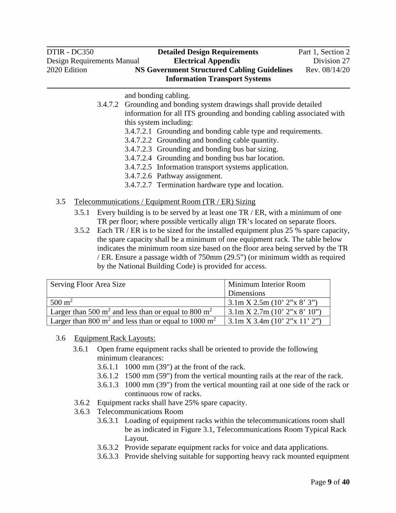
TR per floor; where possible vertically align TR’s located on separate floors. 3.5.2 Each TR / ER is to be sized for the installed equipment plus 25 % spare capacity,
the spare capacity shall be a minimum of one equipment rack. The table below indicates the minimum room size based on the floor area being served by the TR / ER. Ensure a passage width of 750mm (29.5”) (or minimum width as required by the National Building Code) is provided for access.
3.6 Equipment Rack Layouts: 3.6.1 Open frame equipment racks shall be oriented to provide the following
minimum clearances: 3.6.1.1 1000 mm (39") at the front of the rack. 3.6.1.2 1500 mm (59") from the vertical mounting rails at the rear of the rack. 3.6.1.3 1000 mm (39") from the vertical mounting rail at one side of the rack or
continuous row of racks. 3.6.2 Equipment racks shall have 25% spare capacity. 3.6.3 Telecommunications Room
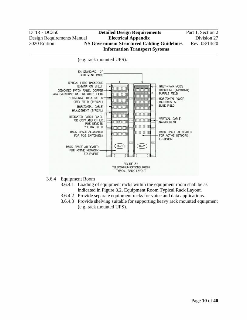
3.6.3.1 Loading of equipment racks within the telecommunications room shall be as indicated in Figure 3.1, Telecommunications Room Typical Rack Layout.
3.6.3.2 Provide separate equipment racks for voice and data applications. 3.6.3.3 Provide shelving suitable for supporting heavy rack mounted equipment
Serving Floor Area Size Minimum Interior Room Dimensions
500 m2 3.1m X 2.5m (10’ 2”x 8’ 3”) Larger than 500 m2 and less than or equal to 800 m2 3.1m X 2.7m (10’ 2”x 8’ 10”) Larger than 800 m2 and less than or equal to 1000 m2 3.1m X 3.4m (10’ 2”x 11’ 2”)
DTIR - DC350 Detailed Design Requirements Part 1, Section 2 Design Requirements Manual Electrical Appendix Division 27 2020 Edition NS Government Structured Cabling Guidelines Rev. 08/14/20
Information Transport Systems
Page 10 of 40
(e.g. rack mounted UPS).
3.6.4 Equipment Room
3.6.4.1 Loading of equipment racks within the equipment room shall be as indicated in Figure 3.2, Equipment Room Typical Rack Layout.
3.6.4.2 Provide separate equipment racks for voice and data applications. 3.6.4.3 Provide shelving suitable for supporting heavy rack mounted equipment
(e.g. rack mounted UPS).

DTIR - DC350 Detailed Design Requirements Part 1, Section 2 Design Requirements Manual Electrical Appendix Division 27 2020 Edition NS Government Structured Cabling Guidelines Rev. 08/14/20
Information Transport Systems
Page 11 of 40
3.7 Work Area 3.7.1 Each telecommunications outlet shall be served by a telecommunications room
located on the same floor as the telecommunications outlet.
4 Project Documentation
4.1 Basic Elements 4.1.1 The CAN/CSA, ANSI/TIA/EIA and BICSI standards as listed in Section 2 of
this document define the basic elements of the Information Transport System (ITS) cabling structure. Vendor firms providing services to the Province of Nova Scotia shall prepare and submit project documentation as detailed within this section.
4.2 As-built Drawings / Documentation 4.2.1 General:
4.2.1.1 Vendors shall prepare record drawings in both hard copy and AutoCAD drawing format in an electronic media format agreeable to the Province as part of compliance with this requirement.
4.2.1.2 Drawings in AutoCAD .dwg file format (and Revit if applicable) shall be provided to the vendor by the consulting services provider for the

DTIR - DC350 Detailed Design Requirements Part 1, Section 2 Design Requirements Manual Electrical Appendix Division 27 2020 Edition NS Government Structured Cabling Guidelines Rev. 08/14/20
Information Transport Systems
Page 12 of 40
compliance of this section. 4.2.1.3 Record drawings shall provide the following information:
4.2.1.3.1 All work area telecommunications outlet locations as constructed.
4.2.1.3.2 Project administration system identifiers for telecommunications outlets.
4.2.1.3.3 Project administration system identifiers for telecommunication spaces (TR and ER).
4.2.1.4 Hard copy format record drawings shall be provided in two complete sets as defined: 4.2.1.4.1 One complete floor plan and riser drawing set, black and
white (colour optional). 4.2.1.4.2 One complete floor plan drawing set, black and white (colour
optional), is to be provided and mounted under plexiglass in all associated telecommunications spaces.
4.2.1.4.3 One complete backbone riser drawing set, black and white (colour optional), is to be provided and mounted under plexiglass in the main telecommunications room.
4.2.1.4.4 One complete grounding / bonding riser drawing set, black and white (colour optional), is to be provided and mounted under plexiglass in the main telecommunications room).
4.2.1.5 Where hard copy record drawings exist on-site in renovations and small additions where the majority of the structured cabling system is not modified or is being reused, update these documents to reflect the installed alterations.
4.2.1.6 Include in the as-built documentation a tabulated matrix in both hard copy and editable electronic format (eg excel) listing the location of the telecommunications outlet by the rack component outlet identifier. The information provided shall include Telecommunication Room number, rack/cabinet number, and patch panel number. Example:
4.3 Inspection Reports 4.3.1 Include a copy of the communications cabling installation permit and all
inspection reports from the AHJ with the documentation. Where an exemption from the requirement for a communications cabling installation permit is provided under the "Electrical Code Regulations - Electrical Installation and

DTIR - DC350 Detailed Design Requirements Part 1, Section 2 Design Requirements Manual Electrical Appendix Division 27 2020 Edition NS Government Structured Cabling Guidelines Rev. 08/14/20
Information Transport Systems
Page 13 of 40
Inspection Act (Nova Scotia)"; include a copy of the record of the work completed by the communications cabling specialist required under this act.
4.4 Test Results 4.4.1 Vendors shall provide test results hard (paper) copy and in digital format on
CDROM and USB stick as part of compliance with this requirement. The test report(s) is to include plot (graphical) data of each test performed.
4.5 Manufacturer’s Warranty 4.5.1 General:
4.5.1.1 Vendors shall provide a manufacturer generated and support Product Warranty and Application Assurance certificates upon completion of installation and acceptance by NSDTIR.
4.5.1.2 Product warranty and appliance assurance shall provide coverage of materials and labour for a minimum of Twenty Years from date of installation and acceptance regardless of installing agent/vendor status.
4.5.1.3 In renovations and small additions where the majority of the structured cabling system is not modified or is being reused, this item may be omitted with DTIR’s permission.
4.6 RCDD Project Certification 4.6.1 General
4.6.1.1 Vendors shall provide RCDD Project Certificate in hard copy format as part of compliance with this requirement; and provide current RCDD seal on the certificate.
4.6.1.2 The RCDD certification shall be provided for compliance as per the requirements within this document.
5 Vendor Requirements
5.1 Basic Elements 5.1.1 The CAN/CSA, ANSI/TIA/EIA and BICSI standards as listed in Section 2 of
this document define the basic elements of the Information Transport System (ITS) cabling structure. Vendor firms providing services to the Province of Nova Scotia shall comply with the qualifications criteria as detailed within this

DTIR - DC350 Detailed Design Requirements Part 1, Section 2 Design Requirements Manual Electrical Appendix Division 27 2020 Edition NS Government Structured Cabling Guidelines Rev. 08/14/20
Information Transport Systems
Page 14 of 40
section.
5.2 Vendor Qualifications 5.2.1 General:
5.2.1.1 Vendor firms providing services to the Province of Nova Scotia shall comply with Section 3 of this document.
5.2.1.2 Qualified vendors shall provide technical field services in compliance with labour standards (e.g. Communications Cabling Specialist (CCS)).
5.2.1.3 Vendors shall comply with all applicable Nova Scotia Workers Compensation requirements.
5.2.1.4 Vendors shall maintain current Nova Scotia Construction Safety Association (NSCSA) compliant status.
5.2.1.5 Qualified vendors shall maintain current Building Industry Construction Services International (BICSI) membership.
5.2.1.6 Qualified vendors shall maintain manufacturer recognition as a certified installation contractor for the ITS product solution being implemented.
5.3 RCDD Project Manager 5.3.1 General
5.3.1.1 The successful Information Transport Distribution System contractor is required to retain the services of one (1) Registered Communications Distribution Designer (RCDD) for the duration of the project. The RCDD must be identified and the successful vendor must provide a copy of the RCDD current certificate and BICSI membership on a timely basis after award of the contract.
5.3.1.2 The RCDD shall maintain responsibility for the following; 5.3.1.2.1 Review and accept the Information Transport Distribution
System materials, hardware and related components proposed.
5.3.1.2.2 Review the proposed pathways and spaces and accept the size and location of all Telecommunications Spaces (TS).
5.3.1.2.3 Notify the Consultant of any issues or concerns related to CAN/CSA, IEE and TIE/EIA specification compliance.
5.3.1.2.4 Review and approve Information Transport Distribution System material shop drawings prior to submission to the Consultant.
5.3.1.2.5 Attend regularly scheduled project construction and job meetings as requested by the project Consultant.
5.3.1.2.6 Ensure system installation practices and procedures comply with all applicable CAN/CSA, IEE and TIE/EIA specifications and procedures.

DTIR - DC350 Detailed Design Requirements Part 1, Section 2 Design Requirements Manual Electrical Appendix Division 27 2020 Edition NS Government Structured Cabling Guidelines Rev. 08/14/20
Information Transport Systems
Page 15 of 40
5.3.1.2.7 Provide regular project status reports and updates as requested by the project Consultant.
5.3.1.2.8 Observe testing and certification procedures and provide manufacturers assurance and warranty.
5.3.1.2.9 Review and approve all project as-built documentation including drawings, test reports, details and provide current RCDD seal on all.
5.4 Certification and Testing 5.4.1 General:
5.4.1.1 Vendors providing services to the Province of Nova Scotia shall provide Product Manufacturers Application Warranty for a minimum of twenty years.
5.4.1.2 Certification and testing documentation shall be provided as a complete part of the project documentation requirements as specified in Section 6 of this document. Documentation shall include a RCDD letter of certification (complete with current RCDD seal) for the complete Information Transport System cabling for the project.
6 Information Transport System (ITS) Requirements
6.1 General 6.1.1 The ANSI/TIA/EIA-568 standards and the BICSI/TDMM define the basic
elements of the information transport system cabling structure. The applicable requirements of those elements as provided to the Province of Nova Scotia are detailed in this section.
6.2 Information Transport Systems Bonding 6.2.1 Refer to DC350 Part 1, Section 2, 26 05 26 Grounding and Bonding for
Electrical Systems for information transport systems bonding requirements.
6.3 Equipment Room (ER) 6.3.1 Copper Terminations:
6.3.1.1 Horizontal and backbone cabling shall be terminated on patch panels containing eight-position connectors with T568A pin/pair assignments using insulation displacement connectors (IDC). Patch panels shall meet the component specification defined in ANSI/TIA-568-C.2
6.3.1.2 Voice backbone cabling shall be terminated using two pairs per connector (pairs 1 and 2).
6.3.1.3 Horizontal distribution and backbone cabling system termination panels
DTIR - DC350 Detailed Design Requirements Part 1, Section 2 Design Requirements Manual Electrical Appendix Division 27 2020 Edition NS Government Structured Cabling Guidelines Rev. 08/14/20
Information Transport Systems
Page 16 of 40
within the ER space shall be maximum 48 port capacity. 6.3.1.4 ER patch panels shall occupy a maximum of 2U rack space per
individual panel. 6.3.1.5 Connectors shall be colour coded as follows:
6.3.1.5.1 White for copper data backbone cabling. 6.3.1.5.2 Orange for incoming voice backbone cabling from the
demarcation point. 6.3.1.5.3 Purple for outgoing voice backbone cabling. 6.3.1.5.4 Grey for data horizontal cabling. 6.3.1.5.5 Blue for voice horizontal cabling. 6.3.1.5.6 Yellow for special applications horizontal cabling.
6.3.2 Optical Fibre Terminations: 6.3.2.1 Horizontal and backbone cabling shall be terminated on patch panels
containing duplex LC connectors. 6.3.2.2 Provide horizontal cable management for owner supplied active
network equipment. The horizontal cable management provided for this equipment shall be equal in number to the horizontal cable management provided for the patch panels.
6.3.2.3 Provide a patch cord for each installed voice and data port plus 25% spare; patch cord lengths are to be minimized, spare patch cords are to be a variety of lengths to a maximum of 5m (15’).
6.3.2.4 Populate unused / spare ports in all patch panels with modular connectors colour coded to match the active ports in the patch panel.
6.3.2.5 Cable tray shall be installed around the perimeter of the equipment room to facilitate cable service loops, sufficient cable support and organization.
6.3.2.6 Cable tray shall be installed above all equipment racks, spanning across the perimeter cable tray, to facilitate cable support, cable drops and organization.
6.3.2.7 Cable tray shall be ladder type or wire basket type.
6.4 Telecommunications Room (TR) 6.4.1 Copper Terminations:
6.4.1.1 Horizontal and backbone cabling shall be terminated on patch panels containing modular eight-position connectors with T568A pin/pair assignments using insulation displacement connectors (IDC). Patch panels shall meet the component specification defined in ANSI/TIA-568-C.2
6.4.1.2 Horizontal distribution and backbone cabling system termination panels within the TR space shall be 48 port capacity.
6.4.1.3 TR patch panels shall occupy a maximum of 2U rack space per

DTIR - DC350 Detailed Design Requirements Part 1, Section 2 Design Requirements Manual Electrical Appendix Division 27 2020 Edition NS Government Structured Cabling Guidelines Rev. 08/14/20
Information Transport Systems
Page 17 of 40
individual panel. 6.4.1.4 Voice backbone cabling shall be terminated using two pairs per
connector (pairs 1 and 2). 6.4.1.5 Connectors shall be colour coded as follows:
6.4.1.5.1 White for copper data backbone cabling. 6.4.1.5.2 Purple for incoming voice backbone cabling. 6.4.1.5.3 Grey for data horizontal cabling. 6.4.1.5.4 Blue for voice horizontal cabling. 6.4.1.5.5 Yellow for special applications (POE, CCTV, etc.) horizontal
cabling. 6.4.1.5.6 Populate unused / spare ports in all patch panels with
modular connectors colour coded to match the active ports in the patch panel.
6.4.2 Optical Fibre Terminations: 6.4.2.1 Horizontal and backbone cabling shall be terminated on patch panels
containing duplex LC connectors. 6.4.3 Equipment racks in shallow telecommunications rooms shall be wall-mounted
cabinets with holes tapped 10-32 at standard spacing. Cabinets shall be hinged and oriented to provide 1000 mm (39") of clearance at the rear. Note: the use of shallow telecommunications rooms requires prior approval by the Province.
6.4.4 Equipment racks shall have 25% spare capacity (minimum). 6.4.5 Provide a patch cord for each installed voice and data port plus 25% spare; patch
cord lengths are to be minimized, spare patch cords are to be a variety of lengths to a maximum of 5m (15’).
6.4.6 Provide horizontal cable management for owner supplied active network equipment. The horizontal cable management provided for this equipment shall be equal in number to the horizontal cable management provided for the patch panels.
6.4.7 Populate unused / spare ports in all patch panels with modular connectors colour coded to match the active ports in the patch panel.
6.4.8 Cable tray shall be installed around the perimeter of the telecommunications room to facilitate service cable loops, sufficient cable support and organization.
6.4.9 Cable tray shall be installed above all equipment racks, spanning across the perimeter cable tray, to facilitate cable support, cable drops and organization.
6.4.10 Cable tray shall be ladder type or wire basket type.
6.5 Entrance Facilities 6.5.1 Building Telecommunications Demarcation:
6.5.1.1 The building information transport system demarcation facilities shall include three basic components:
DTIR - DC350 Detailed Design Requirements Part 1, Section 2 Design Requirements Manual Electrical Appendix Division 27 2020 Edition NS Government Structured Cabling Guidelines Rev. 08/14/20
Information Transport Systems
Page 18 of 40
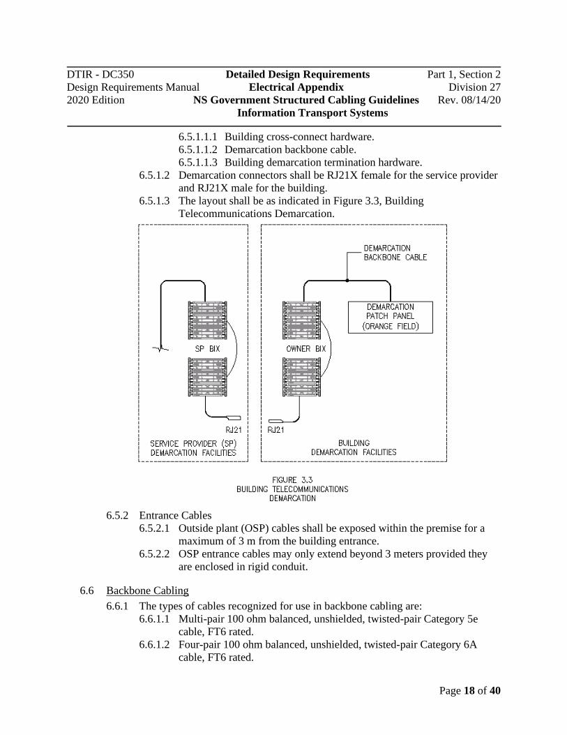
6.5.1.1.1 Building cross-connect hardware. 6.5.1.1.2 Demarcation backbone cable. 6.5.1.1.3 Building demarcation termination hardware.
6.5.1.2 Demarcation connectors shall be RJ21X female for the service provider and RJ21X male for the building.
6.5.1.3 The layout shall be as indicated in Figure 3.3, Building Telecommunications Demarcation.
6.5.2 Entrance Cables
6.5.2.1 Outside plant (OSP) cables shall be exposed within the premise for a maximum of 3 m from the building entrance.
6.5.2.2 OSP entrance cables may only extend beyond 3 meters provided they are enclosed in rigid conduit.
6.6 Backbone Cabling 6.6.1 The types of cables recognized for use in backbone cabling are:
6.6.1.1 Multi-pair 100 ohm balanced, unshielded, twisted-pair Category 5e cable, FT6 rated.
6.6.1.2 Four-pair 100 ohm balanced, unshielded, twisted-pair Category 6A cable, FT6 rated.

DTIR - DC350 Detailed Design Requirements Part 1, Section 2 Design Requirements Manual Electrical Appendix Division 27 2020 Edition NS Government Structured Cabling Guidelines Rev. 08/14/20
Information Transport Systems
Page 19 of 40
6.6.1.3 Twelve or more strands of 62.5/120 or 50/125um multimode optical fibre cable, FT6 rated.
6.6.1.4 Twelve or more strands of singlemode optical fibre cable, FT6 rated.
6.6.2 Voice Backbone Cabling (UTP): 6.6.2.1 All voice copper backbone cabling shall be multi-pair Category 5e. 6.6.2.2 All backbone cables shall have 25% spare capacity.
6.6.3 Data Backbone Cabling (UTP):
6.6.3.1 All data copper backbone cabling shall be 4-pair Category 6A. 6.6.3.2 All backbone cables shall have 25% spare capacity (minimum one
cable).
6.6.4 Data Backbone Cabling (Optical Fibre): 6.6.4.1 The following classes of optical fibre cabling are recognized for
backbone installations, as described in the table below. The recommended class for lengths up to 300 metres is OM4.
6.6.5 All backbone cables shall have 25% spare capacity, with a minimum of twelve strands. 6.6.5.1 A redundant, parallel, spare Category 6A UTP cable shall be installed
for each pair of strands of optical fibre backbone cable where distances do not exceed the maximum recommended installed length of Category 6A cable.
6.7 Horizontal Cabling 6.7.1 The three types of cables recognized for use in horizontal cabling are:
6.7.1.1 Four-pair 100 ohm balanced, unshielded, twisted-pair cable, Utilize
System
Maximum Backbone Length
Maximum Data Rate
Building Backbone (OM3 fibre)
300 m (984 feet)
10 Gb/s
Building Backbone (OM4 fibre)
300 m (984 feet)
10 Gb/s
Building Backbone (OM5 fibre)
400 m (1300 feet)
10 Gb/s
Campus or Building Backbone (OS1 fibre)
2000 m (6560 feet)
10 Gb/s

DTIR - DC350 Detailed Design Requirements Part 1, Section 2 Design Requirements Manual Electrical Appendix Division 27 2020 Edition NS Government Structured Cabling Guidelines Rev. 08/14/20
Information Transport Systems
Page 20 of 40
either FT4 or FT6 rated cabling per National Building Code requirements. In new construction use Category 6A cable only; in renovations and small additions where the majority of the structured cabling system is not modified or is being reused, match the category of the existing infrastructure, where the existing infrastructure is category 6 or less use category 6 cable.
6.7.1.2 Two or more strands of 62.5/125 or 50/125 um multimode optical fibre cable, FT6 rated.
6.7.2 Copper Cabling (UTP) 6.7.2.1 Provide a minimum of two balanced, unshielded, twisted-pair, 4-pair
cables to be installed to each telecommunications outlet location within work area of 10 m2 (100 ft2) minimum.
6.7.2.2 All horizontal cables shall be terminated on modular eight-position connectors with T568A pin/pair assignments using insulation displacement connectors (IDC).
6.7.2.3 Horizontal distribution UTP cabling shall provide outer cable jacket colours assigned for voice and data applications as listed: 6.7.2.3.1 Voice cabling shall have BLUE outer jacket. 6.7.2.3.2 Data cabling shall have WHITE or GREY outer jacket. 6.7.2.3.3 Special application cabling (i.e. CCTV) shall have YELLOW
outer jacket. 6.7.2.4 The maximum horizontal distance in cable length from the horizontal
termination equipment connections in the Telecommunications Room (TR) space to the work area Telecommunications Outlet (TO) is 90 meters (295 feet). For each horizontal channel, a total of 10 meters (33 feet) is permitted for patch cords or jumpers and for equipment cables or cords located in the work area and TR space respectively. The total channel link (horizontal cabling and cords) shall not exceed 100 meters (328 feet).
6.7.3 Optical Fibre Cabling: 6.7.3.1 The approved classes of optical fibre cabling are as described in the
table below. The recommended class is OM4. Classification Type Performance
OM3 50/125 um Multimode Laser Optimized
Minimum bandwidth of 2000 and 500 MHz-km at 850 and 1300 nm, respectively.
OM4 50/125 um Multimode Minimum bandwidth of 4700 and 500 MHz-km at 850 and 1300 nm, respectively.
OM 5 50/125 um Multimode Wideband multimode fiber utilizing 840 nm to 953 nm
DTIR - DC350 Detailed Design Requirements Part 1, Section 2 Design Requirements Manual Electrical Appendix Division 27 2020 Edition NS Government Structured Cabling Guidelines Rev. 08/14/20
Information Transport Systems
Page 21 of 40
6.7.3.2 All horizontal cables shall be terminated on duplex LC connectors.
6.8 Work Area 6.8.1 Telecommunications Outlet Box, New Construction:
6.8.1.1 Each telecommunications outlet box shall be a minimum 102mm (4") sq, minimum 73mm (2 7/8") deep with a manufactured conduit knockout to accommodate a 27mm (1") conduit. The outlet is to be complete with a double gang square welded tile ring one nominal size larger than the installed wall board thickness and a 4 port, keystone style, brushed stainless steel coverplate. Coverplates with recessed inserts for labeling or identification purposes are not acceptable. Receptacle coverplates with 106 adaptors are not acceptable for flush mounted telecommunications outlets installed below ceilings. Where telecommunication outlet boxes are required to be surface mounted, provide a single gang deep “FS” type box (minimum volume 22.5 cubic inches (368 ml)) complete with “FS” type coverplate and 106 adaptor.
6.8.1.2 Each telecommunications outlet box shall have an EMT conduit, minimum 27 mm (1"), stubbed up with a 90 degree or offset bend into the accessible ceiling space of the same room and terminated with a bushing.
6.8.1.3 Each telecommunications outlet box shall be installed within 1000 mm (39") of an electrical outlet and installed at the same height and have a matching coverplate.
6.8.1.4 Work area telecommunications outlets with unique applications shall be addressed appropriately to conform to industry standards and practices (e.g. system furniture bezels, weatherproof outlets and keystone adaptors).
6.8.1.5 Provide a 3m (10’) equipment patch cord for each installed data outlet plus 25% of the total number as spare equipment patch cords.
6.8.2 Telecommunications Outlet Connector, New Construction: 6.8.2.1 Each work area shall be served by a minimum of two Category 6A
cables terminated on modular eight-position connectors with T568A pin/pair assignments using insulation displacement connectors (IDC). Outlet connectors shall meet component specifications per ANSI/TIA-568-C.2
6.8.2.2 Work area telecommunications outlets shall have a minimum 4 port modular jack capacity, be mounted in a single gang brushed stainless steel coverplate. Sufficient cable slack (minimum 200mm) shall be provided and coiled within the back box to allow the removal of the cover plate and access the outlet box.
6.8.2.3 Telecommunications outlet connectors shall meet component

DTIR - DC350 Detailed Design Requirements Part 1, Section 2 Design Requirements Manual Electrical Appendix Division 27 2020 Edition NS Government Structured Cabling Guidelines Rev. 08/14/20
Information Transport Systems
Page 22 of 40
specifications per ANSI/TIA-568-C.2 and shall be colour coded as follows: 6.8.2.3.1 Grey for data or Local Area Network (LAN) connections. 6.8.2.3.2 Blue for voice or other telephony connections. 6.8.2.3.3 Yellow for special applications.
6.8.3 Telecommunications Outlet, minor renovations and small additions where architectural wallboard and finishes are not being disturbed. 6.8.3.1 Each telecommunications outlet shall be installed within 1000 mm
(39") of an electrical outlet, installed at the same height and have a matching coverplate. Receptacle coverplates with 106 adaptors are not acceptable for flush mounted telecommunications outlets installed below ceilings.
6.8.3.2 Work area telecommunications outlets with unique applications shall be addressed appropriately to conform to industry standards and practices (e.g. system furniture bezels, weatherproof outlets and keystone adaptors).
6.8.3.3 Provide a 3m (10’) equipment patch cord for each installed data outlet plus 25% of the total number as spare equipment patch cords.
6.8.4 Telecommunications Outlet Connector, minor renovations and small additions where architectural wallboard and finishes are not being disturbed. 6.8.4.1 Each work area shall be served by a minimum of two four-pair 100
ohm, balanced, unshielded, twisted-pair cables terminated on modular eight-position connectors with T568A pin/pair assignments using insulation displacement connectors (IDC). Outlet connectors shall meet component specifications per ANSI/TIA-568-C.2 Match the category of the existing infrastructure, where the existing infrastructure is category 6 or less use category 6 cable.
6.8.4.2 Work area telecommunications outlets shall have a minimum 4 port modular jack capacity, be mounted in a single gang brushed stainless steel coverplate. Receptacle coverplates with 106 adaptors are not acceptable for flush mounted telecommunications outlets installed below ceilings. Sufficient cable slack (minimum 200mm) shall be provided and coiled within cavity to allow the removal of the cover plate.
6.8.4.3 Telecommunications outlet connectors shall meet component specifications per ANSI/TIA-568-C.2 and shall be colour coded as follows: 6.8.4.3.1 Grey for data or Local Area Network (LAN) connections. 6.8.4.3.2 Blue for voice or other telephony connections. 6.8.4.3.3 Yellow for special applications (POE, CCTV, etc.).
6.8.5 Telecommunications Outlet Connector, Located Above Ceiling: 6.8.5.1 Outlet Connectors provided above ceilings shall be served by a
DTIR - DC350 Detailed Design Requirements Part 1, Section 2 Design Requirements Manual Electrical Appendix Division 27 2020 Edition NS Government Structured Cabling Guidelines Rev. 08/14/20
Information Transport Systems
Page 23 of 40
minimum of two Category 6A cables terminated on modular eight-position connectors with T568A pin/pair assignments using insulation displacement connectors (IDC). Outlet connectors shall meet component specifications per ANSI/TIA-568-C.2
6.8.5.2 The above ceiling telecommunications outlet shall be a 100mm (4") square x 73mm (2 7/8") deep box with 10mm (3/8" ) raised quad receptacle coverplate complete with 2 port 106 keystone adaptors, provide blanks as required the outlet shall be mounted vertically on support structure.
6.8.5.3 Telecommunications outlet connectors shall meet component specifications per ANSI/TIA-568-C.2 and shall be colour coded as follows: 6.8.5.3.1 Grey for data or Local Area Network (LAN) connections. 6.8.5.3.2 Blue for voice or other telephony connections. 6.8.5.3.3 Yellow for special applications (POE, CCTV, etc.).
6.8.6 Optical Fibre Information Transport System (ITS) Outlet Connector: 6.8.6.1 Horizontal optical fibre cables shall be terminated on duplex LC
connectors. 6.8.7 Equipment racks:
6.8.7.1 Equipment racks for voice and data shall be 480 mm (19") open frame type with holes tapped 10-32 at EIA standard spacing and a minimum capacity of 44U. Equipment racks shall be complete with vertical cable management (minimum size 254mm (10”) wide x 230mm (9”) deep) on both sides and be of the same height as the rack.
6.9 System Administration 6.9.1 General
6.9.1.1 The requirements for system administration are Class 2 specified within the ANSI/EIA/TIA-606 standard which provides for the Information Transport System (ITS) infrastructure administration needs within a single building.
6.9.1.2 A unique identifier is to be associated with each element of the ITS infrastructure to be administered.
6.9.1.3 All components of the ITS administration system shall be designed and installed to last the intended life (20 year warranty period) of the ITS system installed.
6.9.2 Telecommunications Spaces 6.9.2.1 All telecommunications spaces within a building shall be uniquely
identified as part of a complete administration system. The TR, ER or MTR shall be identified by the room designation assigned by the architectural design. The assigned number shall be used within the

DTIR - DC350 Detailed Design Requirements Part 1, Section 2 Design Requirements Manual Electrical Appendix Division 27 2020 Edition NS Government Structured Cabling Guidelines Rev. 08/14/20
Information Transport Systems
Page 24 of 40
administration system identifier and shall be a “lamicoid” type plate minimum (50mm H) X (300mm L) as shown below and secured to the exterior of the door frame entering that space.
TR - 234
Denotes Telecommunications Room (TR)
Denotes Architectural Room Number
300mm
50mm
6.9.2.2 All telecommunications equipment racks within the telecommunications space require a unique component identifier as part of the administration system by a “lamicoid” nameplate, minimum (50mm H) X (600mm L) as shown below and secured to the upper horizontal rail of the equipment rack.
6.9.2.3 All ITS termination hardware within the telecommunications space
requires a unique component identifier as part of the administration system. Identifiers must be self-adhesive thermal transfer type and placed appropriately to indicate all ports.
6.9.3 Horizontal Distribution System 6.9.3.1 All horizontal cabling shall be uniquely identified with a wrap type self-
laminating adhesive label with mechanically generated (not hand written) identifier.
6.9.3.2 Horizontal cable identifiers shall denote basic information transport system application and originating telecommunications space termination equipment port as shown;

DTIR - DC350 Detailed Design Requirements Part 1, Section 2 Design Requirements Manual Electrical Appendix Division 27 2020 Edition NS Government Structured Cabling Guidelines Rev. 08/14/20
Information Transport Systems
Page 25 of 40
6.9.4 Work Area
6.9.4.1 For the purposes of system administration, the work area shall include the telecommunications outlet faceplate and all outlet termination hardware.
6.9.4.2 All telecommunications outlet faceplates shall be standard four port configuration with port assignments as shown.
6.9.4.3 All telecommunications outlet locations require a unique component
identifier as part of the administration system by a “lamicoid” nameplate, minimum 120mm H X 70mm L and secured to the wall-space centered and above (min. 12mm) the telecommunications outlet faceplate.
6.9.4.4 Telecommunications work area outlet identifiers must denote basic information transport system application, originating telecommunications space and termination equipment port as shown;

DTIR - DC350 Detailed Design Requirements Part 1, Section 2 Design Requirements Manual Electrical Appendix Division 27 2020 Edition NS Government Structured Cabling Guidelines Rev. 08/14/20
Information Transport Systems
Page 26 of 40
6.9.5 Backbone System
6.9.5.1 All backbone system cabling shall be uniquely identified with a wrap type self-laminating adhesive label with mechanically generated (not hand written) identifier.
6.9.5.2 Backbone cable identifiers shall denote basic information transport system application and originating telecommunications space as shown;
6.9.6 Telecommunications Demarcation Facilities
6.9.6.1 For the purposes of system administration, the information transport system demarcation facilities shall include three basic components; 6.9.6.1.1 Building cross-connect hardware. 6.9.6.1.2 Building demarcation backbone cable 6.9.6.1.3 Building demarcation termination hardware.
6.9.6.2 All Building cross-connect hardware within the telecommunications space requires a unique component identifier as part of the administration system. Identifiers must be self -adhesive thermal transfer type and placed appropriately to indicate applicable pair assignments as shown;

DTIR - DC350 Detailed Design Requirements Part 1, Section 2 Design Requirements Manual Electrical Appendix Division 27 2020 Edition NS Government Structured Cabling Guidelines Rev. 08/14/20
Information Transport Systems
Page 27 of 40
6.9.7 All information transport system demarcation backbone cabling shall be
uniquely identified with a wrap type self-laminating adhesive label with mechanically generated (not hand written) identifier.
6.9.8 All information transport system demarcation backbone cable identifiers shall denote basic telecommunications system application and originating telecommunications space as shown.
6.10 Service Loops 6.10.1 Provide a service loop in the Telecommunications Room / Equipment Room
(TR/ER) and cable slack in the ceiling space above the telecommunications outlet in the horizontal cabling to accommodate future cabling system changes. 6.10.1.1 Preferred Service Loop Method: A 3 m (10 ft) service loop shall be
provided at the Telecommunications / Equipment Room by routing the cables to the rack by the “longest route” in the cable tray within the TR/ER. Ensure a “shortest route” is provided in the cable tray.
6.10.1.2 Alternate Service Loop Method: A 3 m (10 ft) service loop shall be provided at the Telecommunications / Equipment Room by routing a single loop of cable (stored in the cable tray) within the TR/ER, the loop shall have a minimum bend diameter of 225mm (9”).
6.10.1.3 Provide 1.5 m (5 ft) cable slack above the telecommunications outlet in the accessible ceiling space. Do not store slack in bundled loops, store cable slack in a figure-eight configuration with each loop of the figure-eight supported on individual Non-contiguous supports/hangers (Non-contiguous supports/hangers (J hooks)), the loops shall have a minimum bend diameter of 225mm (9”) ; locate the figure-eight within 760mm (30") of the conduit wall stub entry or above ceiling outlet.
6.11 Backbone Cabling Pathways: 6.11.1 A ceiling distribution system shall serve as the backbone pathway, including
ladder type cable tray and/or EMT conduit.
DTIR - DC350 Detailed Design Requirements Part 1, Section 2 Design Requirements Manual Electrical Appendix Division 27 2020 Edition NS Government Structured Cabling Guidelines Rev. 08/14/20
Information Transport Systems
Page 28 of 40
6.11.2 Vertically aligned telecommunications spaces shall be interconnected using conduit sleeves.
6.11.3 All optical fibre backbone cabling shall be installed in 32 mm (1-1/4") orange innerduct. Inner-duct shall be minimum FT-4 (riser) rated and complete with pull tape. The innerduct shall be installed in cable tray or EMT conduit.
6.11.4 Non-contiguous supports/hangers (Non-contiguous supports/hangers (J hooks)) shall not be used for placement of communications backbone cabling.
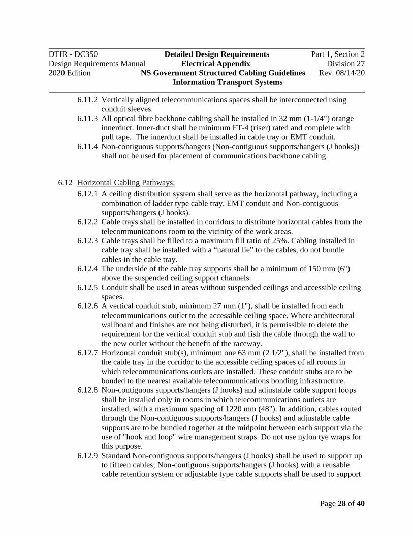
6.12 Horizontal Cabling Pathways: 6.12.1 A ceiling distribution system shall serve as the horizontal pathway, including a
combination of ladder type cable tray, EMT conduit and Non-contiguous supports/hangers (J hooks).
6.12.2 Cable trays shall be installed in corridors to distribute horizontal cables from the telecommunications room to the vicinity of the work areas.
6.12.3 Cable trays shall be filled to a maximum fill ratio of 25%. Cabling installed in cable tray shall be installed with a “natural lie” to the cables, do not bundle cables in the cable tray.
6.12.4 The underside of the cable tray supports shall be a minimum of 150 mm (6") above the suspended ceiling support channels.
6.12.5 Conduit shall be used in areas without suspended ceilings and accessible ceiling spaces.
6.12.6 A vertical conduit stub, minimum 27 mm (1"), shall be installed from each telecommunications outlet to the accessible ceiling space. Where architectural wallboard and finishes are not being disturbed, it is permissible to delete the requirement for the vertical conduit stub and fish the cable through the wall to the new outlet without the benefit of the raceway.
6.12.7 Horizontal conduit stub(s), minimum one 63 mm (2 1/2"), shall be installed from the cable tray in the corridor to the accessible ceiling spaces of all rooms in which telecommunications outlets are installed. These conduit stubs are to be bonded to the nearest available telecommunications bonding infrastructure.
6.12.8 Non-contiguous supports/hangers (J hooks) and adjustable cable support loops shall be installed only in rooms in which telecommunications outlets are installed, with a maximum spacing of 1220 mm (48"). In addition, cables routed through the Non-contiguous supports/hangers (J hooks) and adjustable cable supports are to be bundled together at the midpoint between each support via the use of "hook and loop" wire management straps. Do not use nylon tye wraps for this purpose.
6.12.9 Standard Non-contiguous supports/hangers (J hooks) shall be used to support up to fifteen cables; Non-contiguous supports/hangers (J hooks) with a reusable cable retention system or adjustable type cable supports shall be used to support
DTIR - DC350 Detailed Design Requirements Part 1, Section 2 Design Requirements Manual Electrical Appendix Division 27 2020 Edition NS Government Structured Cabling Guidelines Rev. 08/14/20
Information Transport Systems
Page 29 of 40
sixteen or more cables. The maximum number of cables in a bundle shall not exceed 48.
6.12.10 Utility columns (e.g. pac poles) shall not be used. 6.12.11 Non-contiguous supports/hangers (J hooks) shall not be used in corridor or
common area ceiling spaces except as the pathway for outlets located in these spaces. The pathway shall follow the shortest route possible and be run parallel to building lines to the outlet.
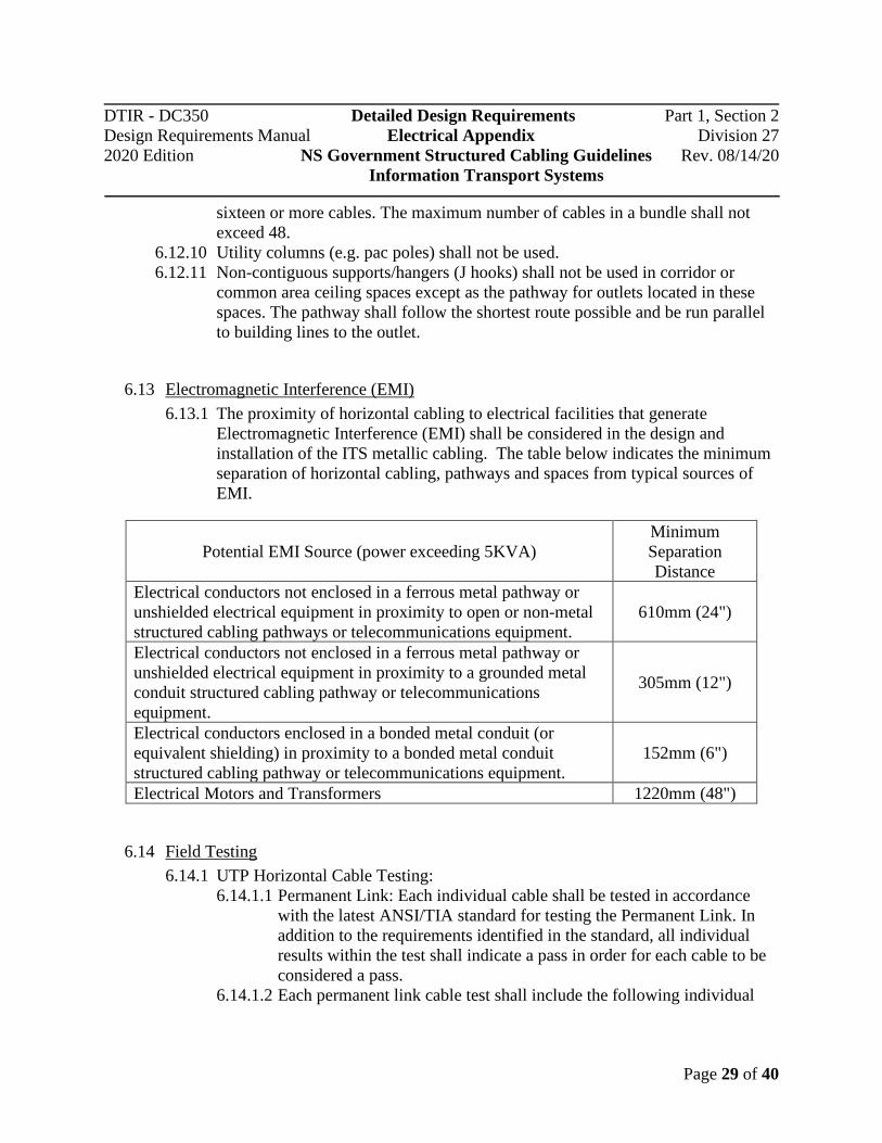
6.13 Electromagnetic Interference (EMI) 6.13.1 The proximity of horizontal cabling to electrical facilities that generate
Electromagnetic Interference (EMI) shall be considered in the design and installation of the ITS metallic cabling. The table below indicates the minimum separation of horizontal cabling, pathways and spaces from typical sources of EMI.
6.14 Field Testing 6.14.1 UTP Horizontal Cable Testing:
6.14.1.1 Permanent Link: Each individual cable shall be tested in accordance with the latest ANSI/TIA standard for testing the Permanent Link. In addition to the requirements identified in the standard, all individual results within the test shall indicate a pass in order for each cable to be considered a pass.
6.14.1.2 Each permanent link cable test shall include the following individual
Potential EMI Source (power exceeding 5KVA)
Minimum Separation Distance
Electrical conductors not enclosed in a ferrous metal pathway or unshielded electrical equipment in proximity to open or non-metal structured cabling pathways or telecommunications equipment.
610mm (24")
Electrical conductors not enclosed in a ferrous metal pathway or unshielded electrical equipment in proximity to a grounded metal conduit structured cabling pathway or telecommunications equipment.
305mm (12")
Electrical conductors enclosed in a bonded metal conduit (or equivalent shielding) in proximity to a bonded metal conduit structured cabling pathway or telecommunications equipment.
152mm (6")
Electrical Motors and Transformers 1220mm (48")

DTIR - DC350 Detailed Design Requirements Part 1, Section 2 Design Requirements Manual Electrical Appendix Division 27 2020 Edition NS Government Structured Cabling Guidelines Rev. 08/14/20
Information Transport Systems
Page 30 of 40
tests: 6.14.1.2.1 Wire Map 6.14.1.2.2 Length 6.14.1.2.3 Propagation Delay 6.14.1.2.4 Propagation Delay Skew 6.14.1.2.5 DC Loop Resistance 6.14.1.2.6 DC Resistance Unbalance within a pair 6.14.1.2.7 DC Resistance Unbalance between pairs pair 6.14.1.2.8 Insertion Loss 6.14.1.2.9 Near End Crosstalk Loss (NEXT) 6.14.1.2.10 Power Sum Near End Crosstalk Loss (PSNEXT) 6.14.1.2.11 Return Loss 6.14.1.2.12 Attenuation Crosstalk Ratio Far End (ACRF) 6.14.1.2.13 Power Sum Attenuation Crosstalk Ration Far End (PSACRF) 6.14.1.2.14 Transverse Conversion Loss (TCL) 6.14.1.2.15 Equal Level Transverse Conversion Transfer Loss
(ELTCTL) 6.14.1.2.16 Power Sum Alien Near–End Crosstalk Loss (PSANEXT) -
Cat 6A only 6.14.1.2.17 Average Power Sum Alien Near End Crosstalk Loss
(Average PSANEXT) 6.14.1.2.18 Power Sum Alien Far–End Crosstalk Loss (PSAFEXT) 6.14.1.2.19 Power Sum Alien Attenuation to Crosstalk Ratio Far–End
(PSAACRF) - Cat 6A only 6.14.1.2.20 Far End Crosstalk Loss (FEXT)UTP Backbone Cable
Testing: 6.14.1.3 Field testing acceptance parameters for Category 3 backbone cabling
shall be: 6.14.1.3.1 Wire map. 6.14.1.3.2 Length.
6.14.1.4 Field testing acceptance parameters for Category 5e backbone cabling shall be the same as for the permanent link with the exceptions as noted.
6.14.1.5 Field testing acceptance parameters for Category 6A backbone cabling shall be the same as for the permanent link.
6.14.2 Optical Fibre Cable Testing:
6.14.2.1 Multimode cables shall be tested using Method B of TIA-526-14-A. 6.14.2.2 Singlemode cables shall be tested using Method A.1 of TIA-526-7.
DTIR - DC350 Detailed Design Requirements Part 1, Section 2 Design Requirements Manual Electrical Appendix Division 27 2020 Edition NS Government Structured Cabling Guidelines Rev. 08/14/20
Information Transport Systems
Page 31 of 40
7 ITS Infrastructure for Healthcare Facilities
7.1 General 7.1.1 This section of the Nova Scotia Government Structured Cabling Guidelines was
developed to further identify the minimum acceptable design and construction standards for Information Transport Systems in Healthcare Facilities in Nova Scotia. This section is to be read in conjunction with the preceding sections of this document and it is intended to provide the additional requirements specific to Healthcare Facilities. Where requirements of the preceding sections have not been specifically exceeded or amended in this section, the requirements of the preceding sections shall be considered minimum standards for all projects. Where specific requirements are indicated in this section, they shall govern.
7.1.2 Section 7 outlines the requirements for ITS infrastructure in all Nova Scotia Health Authority owned and leased healthcare facilities and Izaak Walton Killam (IWK) Health Centre.
7.1.3 Due to the variation in size, layout and classification, not all of the requirements below are applicable. Consult with the Province prior to deviating from the requirements to ensure that proposed changes are acceptable.
7.1.4 The following buildings are excluded from the ITS infrastructure for healthcare facilities: 7.1.4.1 Long term care homes 7.1.4.2 Administration buildings
7.2 Applicable Codes and Standards 7.2.1 CSA Z32, Electrical Safety and Essential Electrical Systems in Health Care
Facilities 7.2.2 CSA Standard Z8000, Canadian Health Care Facilities 7.2.3 CSA Z8001 – Commissioning of Health Care Facilities 7.2.4 CSA Z8002 – Operating and Maintenance of Health Care Facilities 7.2.5 CSA Z317.13 Infection control during construction, renovation and maintenance
of health care facilities 7.2.6 TIA1179-A, Healthcare facility Telecommunications infrastructure Standard 7.2.7 ANSI/BICSI 004-2018, Information Communication Technology Systems
Design and Implementation Best Practices for Healthcare Institutions and Facilities
7.3 Reference Documents 7.3.1 ICTS 13-016 - Physical IT Security Standard (provided by the Province upon

DTIR - DC350 Detailed Design Requirements Part 1, Section 2 Design Requirements Manual Electrical Appendix Division 27 2020 Edition NS Government Structured Cabling Guidelines Rev. 08/14/20
Information Transport Systems
Page 32 of 40
request)
7.4 ITS Rooms (General Requirements) 7.4.1 ITS rooms in healthcare facilities shall be defined as Entrance Rooms,
Telecommunication Rooms, Building Systems Rooms, and Network Core Rooms.
7.4.2 All ITS rooms shall not be located below or adjacent to sources of water. 7.4.3 All ITS rooms shall have anti-static flooring. 7.4.4 Walls of all ITS rooms shall be a minimum of 2hr fire rated, or higher if required
by code. 7.4.5 All ITS rooms shall have caged sprinkler heads. 7.4.6 All ITS rooms shall have dedicated cooling. If cooling units are installed inside
the ITS spaces, they must be coordinated with the ITS infrastructure such that ITS pathways are not obstructed, and the placement does not interfere with planned expansion space. Piping for the cooling units shall not run over the racks or cabinets.
7.4.7 ITS rooms shall be cooled to 18-22°C with a maximum of 60% relative humidity.
7.4.8 Only cabling and piping directly related to ITS space are permitted to enter. 7.4.9 All equipment in ITS spaces shall be on the central UPS power with generator
back-up (if available). If central UPS power is not available, all equipment in ITS spaces shall be on local rack mounted UPS. The rack mounted UPS will be Not-In-Contract and to be provided under FFE&T. The rack mounted UPS will be network connected for monitoring.
7.4.10 All ITS rooms shall be secured with electronic access control using a card reader with a key override.
7.4.11 ITS rooms shall not have any windows. 7.4.12 All new buildings shall use cabinets to install equipment. For renovated spaces,
if racks are currently being used, it is acceptable to continue to use racks. 7.4.13 In ITS rooms equipment shall be installed inside floor mounted network cabinets
whenever possible. Where required by the specific equipment, use wall mounted panels.
7.5 Entrance Rooms 7.5.1 Entrance Rooms shall be the demarcation point for incoming ITS service and
serve as a space for Communications Utility Providers equipment. 7.5.2 In facilities that have a Distributed Antenna System (DAS), the DAS headend
equipment can also be installed inside the Entrance Room. 7.5.3 For healthcare facilities smaller than 5,000gsqm (53,800 ft2) or smaller, a
dedicated Entrance Room is not required. The demarcation for incoming
DTIR - DC350 Detailed Design Requirements Part 1, Section 2 Design Requirements Manual Electrical Appendix Division 27 2020 Edition NS Government Structured Cabling Guidelines Rev. 08/14/20
Information Transport Systems
Page 33 of 40
services can within the Telecommunications Room or Network Core Room. 7.5.4 For primary healthcare facilities larger than 10,000gsqm (107,600 ft2) provide
two (2) separate Entrances Rooms. 7.5.5 For buildings with two (2) Entrance Rooms, provide physical separation by
locating the rooms on opposite sides of the building. 7.5.6 For buildings with one (1) Entrance Rooms, designate a secondary alternative
ITS space for demarcation of the secondary incoming service. 7.5.7 Entrance Rooms shall be above flood level. 7.5.8 Entrance Rooms should be located on an exterior wall so that incoming services
can enter directly in to the room. 7.5.9 Each Entrance Room shall be a minimum of 4m x 3m. Coordinate the size of the
Entrance Room with the Province and Communications Utility Providers and provide larger rooms if required.
7.5.10 All interior walls of Entrance Rooms shall be lined with 19mm (3/4”) thick fire-retardant plywood backboards for mounting equipment.
7.6 Telecommunication Rooms 7.6.1 Telecommunication Rooms (TRs) shall be used for horizontal network cable
distribution. 7.6.2 Each TR shall be sized for a minimum of four (4) network cabinets. Network
cabinets shall have a minimum 914mm (36”) x 1066mm (42”) footprint. 7.6.3 The minimum clearance around all cabinets is 1219mm (48”) in the rear and
1219mm (48”) in the front. There shall also be a minimum of 914mm (36”) clearance on one side of the row of cabinets to allow access to the back.
7.6.4 In Telecommunication Rooms a minimum of one (1) network cabinet shall have physically lockable compartments (top and bottom) to allow for the physical separation and security of Provincial stakeholder equipment within a cabinet.
DTIR - DC350 Detailed Design Requirements Part 1, Section 2 Design Requirements Manual Electrical Appendix Division 27 2020 Edition NS Government Structured Cabling Guidelines Rev. 08/14/20
Information Transport Systems
Page 34 of 40
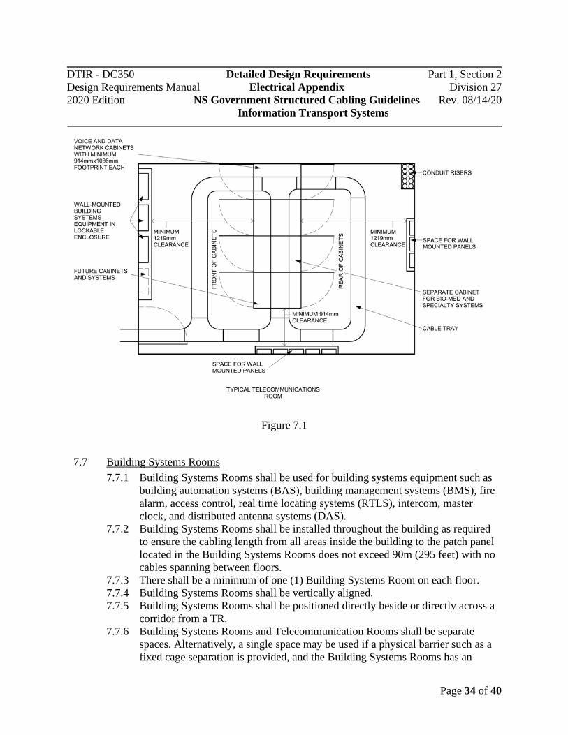
Figure 7.1
7.7 Building Systems Rooms 7.7.1 Building Systems Rooms shall be used for building systems equipment such as
building automation systems (BAS), building management systems (BMS), fire alarm, access control, real time locating systems (RTLS), intercom, master clock, and distributed antenna systems (DAS).
7.7.2 Building Systems Rooms shall be installed throughout the building as required to ensure the cabling length from all areas inside the building to the patch panel located in the Building Systems Rooms does not exceed 90m (295 feet) with no cables spanning between floors.
7.7.3 There shall be a minimum of one (1) Building Systems Room on each floor. 7.7.4 Building Systems Rooms shall be vertically aligned. 7.7.5 Building Systems Rooms shall be positioned directly beside or directly across a
corridor from a TR. 7.7.6 Building Systems Rooms and Telecommunication Rooms shall be separate
spaces. Alternatively, a single space may be used if a physical barrier such as a fixed cage separation is provided, and the Building Systems Rooms has an
DTIR - DC350 Detailed Design Requirements Part 1, Section 2 Design Requirements Manual Electrical Appendix Division 27 2020 Edition NS Government Structured Cabling Guidelines Rev. 08/14/20
Information Transport Systems
Page 35 of 40
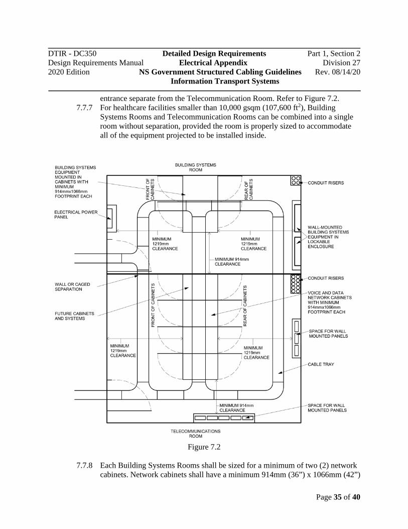
entrance separate from the Telecommunication Room. Refer to Figure 7.2. 7.7.7 For healthcare facilities smaller than 10,000 gsqm (107,600 ft2), Building
Systems Rooms and Telecommunication Rooms can be combined into a single room without separation, provided the room is properly sized to accommodate all of the equipment projected to be installed inside.
Figure 7.2
7.7.8 Each Building Systems Rooms shall be sized for a minimum of two (2) network
cabinets. Network cabinets shall have a minimum 914mm (36”) x 1066mm (42”)

DTIR - DC350 Detailed Design Requirements Part 1, Section 2 Design Requirements Manual Electrical Appendix Division 27 2020 Edition NS Government Structured Cabling Guidelines Rev. 08/14/20
Information Transport Systems
Page 36 of 40
footprint. 7.7.9 The minimum clearance around all cabinets is 1219mm (48”) in the rear and
1219mm (48”) in the front. There shall also be a minimum of 914mm (36”) clearance on one side of the row of cabinets to allow access to the back.
7.7.10 Each Building Systems Room shall be sized for the installed equipment plus 25 % spare capacity, the spare capacity shall be a minimum of one equipment cabinet.
7.8 Network Core Rooms 7.8.1 The Network Core Room (NCR) shall be used for Provincial core and
distribution network equipment where required based on the complexity and operations.
7.8.2 In general, Provincial servers will be located off site at the Provincial off-site Data Centre. In cases where servers are required to be installed on site, the servers will be installed in the NCR.
7.8.3 The NCR shall the main distribution point for the interbuilding and intrabuilding network backbone.
7.8.4 For projects that exceed 50,000gsqm (538,000 ft2) provide both a primary and secondary Network Core Room.
7.8.5 The primary and secondary NCRs shall be physically separated by placing them different floors and on opposite sides of the building.
7.8.6 Both the primary and secondary NCRs shall be installed above grade to minimize risk of flooding.
7.8.7 Network Core Rooms shall have a dry pipe pre-action fire suppression system. 7.8.8 The NCRs will be sized appropriately to allow for the installation of all
anticipated equipment along with a minimum 25% floor space allocated for future expansion.
7.8.9 The NCR be sized for a minimum of six (6) network cabinets. Network cabinets shall have a minimum 914mm (36”) x 1066mm (42”) footprint.
7.8.10 The minimum clearance around all cabinets is 1219mm (48”) in the rear and 1219mm (48”) in the front. There shall also be a minimum of 914mm (36”) clearance on one side of the row of cabinets to allow access to the back.
7.8.11 Rows of network cabinets shall be installed in a hot-aisle cold-aisle configuration.
7.8.12 When the size of the NCR exceeds five (5) network cabinets in size, provide a staging area at the entrance to the room for the Province to setup and test equipment.
7.8.13 All network cabinets and wall mounted panels shall be lockable to provide physical security of their contents.
7.8.14 In NCRs provide separate network cabinets for all Provincial stakeholder

DTIR - DC350 Detailed Design Requirements Part 1, Section 2 Design Requirements Manual Electrical Appendix Division 27 2020 Edition NS Government Structured Cabling Guidelines Rev. 08/14/20
Information Transport Systems
Page 37 of 40
equipment.
7.9 ITS Pathways 7.9.1 Pathways for incoming ITS services shall run from the property line to the
building demarcation point in the Entrance Rooms. 7.9.2 The pathways for the incoming ITS service shall be a concrete enclosed
underground ductbank with a minimum of four (4) 100mm (4”) ducts inside. 7.9.3 When multiple incoming ITS services are brought into the building for
redundancy, provide a pathway for the primary incoming service and a separate pathway for the redundant incoming service.
7.9.4 When multiple pathways are used, pathways shall follow physically diverse routes, never cross, and shall enter the building on opposite sides.
7.9.5 The minimum size of conduits for backbone cable shall be 53mm (2”). Provide larger conduits as required to meet the maximum fill requirements.
7.9.6 For low-voltage building systems, horizontal cabling can share cable trays with network cables if the cables are completely separated using a cable tray divider. Each side of the divider shall not exceed 25% fill.
7.9.7 No more than three (3) horizontal cables shall be installed inside a 27mm (1”) conduit.
7.10 Work Area Outlets 7.10.1 The use of 106 style faceplates is prohibited. 7.10.2 In limited applications decora wall straps with stainless steel faceplates shall be
used with prior approval from the Province. 7.10.3 For wall mounted phones, use a 1-port, single-gang, stainless steel faceplate with
a phone hanger. 7.10.4 Every IPTV (excluding patient rooms) shall have a duplex power outlet and an
outlet with two (2) data drops within 150mm of each other. Mounting height shall be coordinated with the Province to allow the outlets to be hidden behind the screen.
7.11 ITS Backbone Cabling 7.11.1 ITS backbone cabling shall be used between the following ICT spaces:
7.11.1.1 Network Core Room and Telecommunication Rooms; 7.11.1.2 Network Core Room and Building Systems Rooms; 7.11.1.3 Network Core Room and Entrance Rooms.
7.11.2 To improve network uptime ITS backbone cables shall be fully redundant. Each ITS space shall have both a primary and secondary (redundant) backbone cables.
7.11.3 The primary and redundant backbone shall be physically separated and use diverse pathways.
7.11.4 ITS backbone cabling shall be fibre optic cable for data network and multi-pair

DTIR - DC350 Detailed Design Requirements Part 1, Section 2 Design Requirements Manual Electrical Appendix Division 27 2020 Edition NS Government Structured Cabling Guidelines Rev. 08/14/20
Information Transport Systems
Page 38 of 40
UTP for analog and back-up systems. 7.11.5 The data network backbone shall be used to support the following systems
(systems may be segregated virtually): 7.11.5.1 Provincial data network 7.11.5.2 Clinical network 7.11.5.3 VoIP Telephony 7.11.5.4 Security 7.11.5.5 IPTV 7.11.5.6 AV Systems 7.11.5.7 Building Systems
7.11.6 The analog backbone shall be used to support the following systems: 7.11.6.1 Emergency/back-up phone system 7.11.6.2 Fax machines 7.11.6.3 Pay phones 7.11.6.4 Taxi phones 7.11.6.5 ATM/bank machines 7.11.6.6 Elevator phones/intercom
7.11.7 Provide additional backbone cabling (as required), that is physically separate from the Provincial Network, for any third-party systems such as the Provincial research and education network (ACORN network).
7.11.8 ITS backbone cables for data network applications shall be: 7.11.8.1 OM5 multimode fibre optic cables for 10Gb/s applications up to a
maximum distance of 400m (1310’). 7.11.8.2 Singlemode fibre optic cables for 10Gb/s applications (or higher) for
distances greater than 400m (1310’). 7.11.9 For new facilities install both OM5 multimode fibre optic cable and singlemode
fibre optic cable. At a minimum install: 7.11.9.1 24-strands of OM5 multimode fibre optic cable 7.11.9.2 12-strands of singlemode fibre optic cable
7.11.10 Terminate all fibre optic cables in rack mounted patch panels installed inside the network cabinets.
7.11.11 Fibre strands shall be terminated using fusion spliced LC-pigtails. 7.11.12 ITS backbone cabling for analog and back-up applications shall be multipair
UTP cable. At a minimum install: 7.11.12.1 50-pairs of Category 5E UTP cable; or
7.11.13 Terminate all multipair UTP cables on rack mounted patch panels installed inside the network cabinets.
7.11.14 For Category 5E backbone cables, patch panels shall be fully populated with Category 5E modular jacks.

DTIR - DC350 Detailed Design Requirements Part 1, Section 2 Design Requirements Manual Electrical Appendix Division 27 2020 Edition NS Government Structured Cabling Guidelines Rev. 08/14/20
Information Transport Systems
Page 39 of 40
7.12 ITS Horizontal Cabling 7.12.1 The following ICT horizontal cables shall terminate in the Telecommunications
Room: 7.12.1.1 Provincial data network (workstations, laptops, etc…) 7.12.1.2 Clinical systems (BioMed) 7.12.1.3 VoIP telephony 7.12.1.4 IPTV 7.12.1.5 Digital signage 7.12.1.6 Kiosks 7.12.1.7 Medical equipment 7.12.1.8 Printers/copiers/scanners 7.12.1.9 Logistics equipment
7.12.1.10 AV systems 7.12.1.11 Wireless Access Points 7.12.1.12 CCTV cameras 7.12.1.13 Nurse Call (from the room controller)
7.12.2 The following ITS horizontal cables shall terminate in the Building Systems
Rooms: 7.12.2.1 Access Control System (from the controller) 7.12.2.2 RTLS 7.12.2.3 Intercom System 7.12.2.4 Duress Alarms (from the controller) 7.12.2.5 Master Clock System 7.12.2.6 Lighting Controls 7.12.2.7 BAS/BMS 7.12.2.8 Metering 7.12.2.9 Monitoring for fridges and freezers
7.12.2.10 Remote monitoring and control for AV systems 7.12.2.11 Other low-voltage systems
7.12.3 For devices serving the outdoor site that exceed 90m (295’) in length, the use of fibre optic cables with media converts is permitted. Media converts shall be on UPS power with emergency back up to ensure continuous operations.
7.12.4 For clinical systems such as bio-medical network, provide separate panels for terminating horizontal cables. The patch panels for the clinical network shall be installed in a physically separate and secure location inside the network cabinet dedicated to clinical systems.
7.13 System Administration 7.13.1 For healthcare facilities coloured components shall be used to differentiate
DTIR - DC350 Detailed Design Requirements Part 1, Section 2 Design Requirements Manual Electrical Appendix Division 27 2020 Edition NS Government Structured Cabling Guidelines Rev. 08/14/20
Information Transport Systems
Page 40 of 40
between systems. 7.13.2 The coloured components shall include horizontal cables, patch cords and
modular jacks (in some application coloured jack bezels may be used. Confirm application with Province).
7.13.3 The following colours shall be used: 7.13.3.1 Data drops shall be grey 7.13.3.2 Nurse call drops shall be orange 7.13.3.3 Data drops for BioMed shall be red (some facilities use purple. Confirm
colour with the Province)


![1;fit4F;t.,t ifi:;.o‘*.Dtir,suN6 C r D] LEUAL DtiPARTMFMT II...Business, the results show that it is reaching large proportions The year's receipts of the 251 broadcasting stations](https://img.pdfslide.us/doc/110x75/6035d7606b63bf19155108d8/1fit4ftt-ifioadtirsun6-c-r-d-leual-dtipartmfmt-ii-business-the.jpg)