Embed Size (px)
Citation preview

D- P2 7 5 336 (
DTICELECTEFEB07 1994 "
AUSING RDD-100 WH CoRE
SPC-93099-CMC
VERSION 01.00.03
JANUARY 1994
I Thisd dmeflt hals b..n appiovoodto? public telease ci.4 sole: itsdistfrbutlo, is jlu•1e
94-04 125
94 2 04 122

Best
AvailableCopy

REOTDCMNAIN AEFr Uoe
Pa4. o" Woo "Trfl.E AIDS B1 L 5. RI W N o.M 0 0E1S
Using1ho Rto10 with CoREe epos.=F W olo nbdos eef e"dwsu
7. TITE ~WGAND SUBTTLE 5A.S~ADADRS(S. FUNDINfaG OAGANBATK
toVirginia Center of Excellence GM A7-2J11
7. PERORMNGORHGAIZATIONI NACYNAM(S) AND ADDRESS(ES) 10 PERFORMING IORGNIZTIONEVirgina/S entero fEcle e RPO~CRTN ORTLUE
Suite 400801 N. Randolph StreetArlington, VA 22203
11. SUPPLEMENTARY NOTES
N/A12L DISTRIBUTION I AVAILABILITY STATEMENT 12b DISTRIBTION CODE
Ths omhthc ee ppmv IJfor public releaseand sole;its
No Restrictions ditibto is1lmtd13. ABSTRACT (A~n*,xan 200 ww*)
This technical report describes how to develop a specification of software requirements using the Software Productivity Consortium'sCoRE software requirements method from a system requirements and design specification developed using Ascent Logic Corporation'sRDD-1OO. Specifically, this report describes the trnnsition from system design to software requirements analysis when: a) RDD-100 hasbeen used to create system requirements and design specifications, or~ b) the software requirements analysis activity is to be performedaccording to the CoRE method.
RDD-100 is the implementation of the Requirements Driven Design (RDD) system design and engineering method, wherein thesystem design is driven by the customer's expectations of system behavior. CoRE is the Software Productivity Consortium's softwarerequirements engineering method, created to support the development of precise, testable specifications that are demonstrably completeand consistent
An RDD-100 system model contains all of the information needed to begin building a CoRE software requirements specification.This paper describes a process and guidelines for building a CoRE software requirements specification from an RDD-100 system model.The process consists of the following high-level activities: a) identify sources of the necessary CoRE information in the RDD-100 model;b) map that information to an initial CoRE specification; c) complete the CoRE specification.
The Consortium's experience in the use of CoRE with RDD-100 is based on the development of a CoRE specification of softwarerequirements for the HAS Buoy problem from an RDD-100 model of system requirements and design. The guidance provided in thisreport documents our experiences and lessons learned from this case study.__________14. SUBJECT TERMJS 15. NUMBER OF PAGES
Requirements, CASE tool, specification, CORE, RDD-100, system 70design 16.PRICE CODE
17. SECURITY CLASSIFICATION 118. SECURITY CLASSIFICATIOM 19. SECURITY CLASSIFICATION 20. LIMITATION OF ABSTRACTOFREPORT I OF THIS PAGE OFABSTRACT UL
Unclassified Unclassified UnclassifiedINSN 7540-01-280-5500 Standard Form 296 (Rev. 2-89)
prescried by ANSI Std. 230-18

USING RDD-100 WITH CoRE
SPC-93099-CMCAccesion For
NTIS C'iA&l
OTICUnariO. .> -j
VERSION 01.00.03 J. .... .ByJANUARY 1994 y,.ii..............
Richard A. Kirk -.-.. ,---..Haywood S. Osborne Dst j sX_1:.,,
Produced by theSOFTWARE PRODUCTIVITY CONSORTIUM SERVICES CORPORATION
under contract to theVIRGINIA CENTER OF EXCElLENCE
FOR SOFTWARE REUSE AND TECHNOLOGY TRANSFER,
SPC Building2214 Rock Hill Road
Hendon, Vn-giia 22070
Cbo)Ti&h @1994 Salheazt Productivity Ccuwztiiin Services Cospoatim, Herndon, Virgiia. Fenim to up, copy, modify, anddiarbAe this material fir ay putposs and withdnt fee is hereby grned consistent with 48 CPR 2V and 252 and p oided thatthe above wpht notice appears in al copies and that both this coigT notice and this pemimon notice appear in affortingdoc-nentation. Thh material s baed in part upw work sponsored by the Advanced PResr ftjcts Agency under cuat#MDA972*2-J-101& Ihe toutaet does not necessarily reflect the position or the policy cf the U. S. Gvenment, and no officaladmrt should be kfenvd.The nme Saftware Productiv* Ca tma al not be used in advsatsii orpdhlitypestain
to this material or odtwise without the ipor written pemisnic of Scftar Producivity Cansoalum, I= SOFTWAREPROD ITY CONSORI1UM NC AND SOFTWARE PRODUCVy CONSORnIUM SEICmSCORPORATION MAKE NO EPRESE'rATiONS OR WARRANTIES ABOUT THE SUITABII OF THISMATERIAL FOR ANY PURPOSE OR ABOUT ANY OTHER MATER, AND THIS MATERIAL IS PROVIDEDWrrHOUTEXPREMS OR DIPLIED WARRANTY OF ANY KIND.

ADARITS is a service mark ofthe Software productivity Comortium Limited Partnership.IUamwatk is a trademark of Cadre 'Ihmilogies, Imc
RDD-100 and RDD are regidae tradenmark of Ascent Logi Corporation.

CONTENTS
ACKNOWLEDGMENTS .................................................. ix
E UF_•sEfE SUMMARY ................................................... xlL. INTRODUCTION ....................................................... I
1.1 Purpose of This Report ..................................................... 1
1 .2 Background ............................................................... 2
1.3 Questions to Be Answered .................................................. 2
1.4 Intended Audienceu ...... 3
1.5 Organization of This Report ................................................. 3
1.6 Typographic Conventions ................................................... 4
2- OVERVIEW ............................................................ 5
2.1 RDD-100 ................................................................. 5
2.1.1 RDD-10O Method ..................................................... 7
2.1.2 RDD-100 Model ...................................................... 7
2.1.3 RDD-100 Release 4 ................................................... 9
2-2 CoRE .................................................................... 9
2.2.1 CoRE Process Overview ............................................... 11
2.2.2 CoRE Behavioral Model ............................................... 12
2.2.2.1 Environmental Variables .......................................... 13
2.2.2.2 Input and Output Variables ........................................ 13
2.2.2.3 Four-Variable Relations ........................................... 14
2.2.3 CoRE Class Model ................................................... 14
2.3 Comparing RDD-100 and CoRE ............................................. 15
ini

Ccteaf
3. AN APPROACH FOR DERIVING A CoRE MODEL FROM AN RDD-100M ODEL ............................................................... 17
3.1 Building the RDD-100 Model ..................................... 17
3.1.1 RDD-100 System Requirements Analysis ................................. 17
3.1.2 RDD-100 System Functional Analysis .................................... 18
3.1.3 RDD-100 System Design ............................................... 19
3.1.4 Thctics That Support CoRE ............................................. 20
3.2 Identifying CoRE Inputs in the RDD-100 Model ............................... 20
3.2.1 M ission Statement .................................................... 21
3.2.2 System M odel ........................................................ 21
3.2.3 System Requirements Specification ...................................... 21
32-4 System Component Interface Specifications ............................... 22
3.2.5 Requirements Information Relating to System Performance ................. 22
3.3 Mapping the RDD-100 Model to an Initial CoRE Specification ................... 22
3.3.1 CoRE Information Model .............................................. 23
3.3.2 Candidate Environmental Variables ...................................... 23
3.3.3 Likely Changes List ................................................... 23
3.3.4 Environmental Constraints Specification (NAT) ........................... 23
3.4 Completing the CoRE Specification .......................................... 24
3.4.1 Context Diagram ...................................................... 24
3.4.1.1 System Transformation ............................................ 24
3.4.1.2 Tbrminators ..................................................... 24
3.4.1.3 Monitored and Controlled Variables ................................ 24
3.4.2 Input and Output Variable Definitions ................................... 25
3.4.3 T'iing and Accuracy Constraints ........................................ 25
4L EXTENDING THE RDD-100 SCHEMA TO SUPPORT CoRE ................. 27
5GENERATING A CoRE REPORT FROM RDD-100 .......................... 29
Iv

Contents
5.1 The RDD-100 System Engineering Notebook .................................. 29
5.1.1 System Top-Level Description ........................................... 29
5.1.2 System-Level ("Originating") Requirements .............................. 29
5.1.3 Design Constraints .................................................... 29
5.1.4 Issues & Decisions .................................................... 29
5.1.5 Hierarchical Function List .............................................. 30
5.1.6 System Functional Behavior Description .................................. 30
5.1.7 Performance Indices ................................................... 30
5.1.8 Item Dictionary ....................................................... 30
5.1.9 Components ......................................................... 30
5.1.10 Interfaces Between Components ....................................... 30
5.1.11 System "Operational" Parameters ...................................... 30
5.2 A CoRE-Specific Report .................................................... 31
6. USING THE RDD-100 BRIDGE TO TEAMWORK ........................... 33
6.1 The RDD-100 Bridge to Teamwork .......................................... 33
6.2 Using Teamwork With CoRE ................................................ 34
6.3 Using the RDD-100 Bridge to Teamwork for CoRE ............................. 35
APPENDIXM HAS BUOY CASE STUDY ...................................... 37
App.1 HAS Buoy Problem Statement ............................................ 37
App.1.1 Introduction ....................................................... 37
App.1.2 Hardware ..................... ..................... 37
App.1.3 Software Requirements ............................................. 37
App.1.4 Software Timing Requirements ....................................... 38
App.1l5 Priorities .......................................................... 38
App.1.6 HAS Buoy Stabilities and Variabilities ................................. 38

Cantu"s
App.2 HAS Buoy RDD-100 Model .............................................. 40
App.2.1 System Tbp-Level Description ........................................ 41
App.2.2 System-Level ("Originating") Requirements ............................ 44
App2.3 Design Constraints ................................................. 48
App.2.4 Issues & Decisions ................................................. 48
App.2.5 Performance l.dices ................................................ 51
App.2.6 Item Dictionary .................................................... 52
App27 Components ....................................................... 57
App.2.8 Interfaces Between Components ...................................... 61
App.2.9 System "Operational" Parameters .................................... 63
App.3 HAS Buoy CoRE Model ................................................. 63
App.3.1 Mapping From RDD-100 to CoRE .................................... 63
App.3.2 Teamwork-Filtered Version of HAS Buoy .............................. 65
App.3.2.1 Teamwork Process Index ........................................ 65
App.3.2.2 Teamwork Data Dictionary ...................................... 66
App.3.3 The Remaining CoRE Work Products ................................. 69
App.3.3.1 CoRE Information Model ...................................... 69
App.3.3.2 Environmental Variable Definitions ....... ....................... 70
App.3.3.3 Dependency Graph ............................................ 71
App.3.3.4 Relations ..................................................... 71
App.3.3.5 Term s ........................................................ 74
App.3.3.6 Timing and Accuracy Constraints ............................... 74
App.3.4 Input and Output Variable Definitions ................................. 75
App.3.5 Mode Classes ...................................................... 76
LIST OF ABBREVIATIONS AND ACRONYMS ............................ ... 77
F ENCES ............................................................ 79

FIGURES
Figure 1. System Development Activities ............................................ 2
Figure 2. The Proposed Process .................................................... 6
Figure 3. The RDD-100 System Requirements Model ................................. 8
Figure 4. The RDD-100 System Design Model ........................................ 10
Figure 5. The CoRE Process ....................................................... 12
Figure 6. The CoRE Software Requirements Behavioral Model ......................... 13
Figure 7. The CoRE Four-Variable Model .................................. 14
Figure 8. HAS Buoy Behavior Model ................................................ 42
Figure 9. HAS Buoy Behavior Model Including Abstract Object Editor ................... 43
Figure 10. HAS Buoy Component Hierarchy ......................................... 58
Figure 11. HAS Buoy Context Diagram .............................................. 66
Figure 12. CoRE Information Model ................................................ 70
Figure 13. Dependency Graph ..................................................... 72
Figure 14. Example of a Lower Level Data Flow Diagram foi a Class .................... 72
Figure 15. Example of an IN Relation ............................................... 73
Figure 16. Example of an REQ Relation ............................................. 73
Figure 17. Example of an OUT Relation ............................................ 73
Figure 18. HAS Buoy Mode Class .................................................. 76
vii

TABLES
Table 1. CoRE Inputs in the RDD-100 Model ........................................ 21
Tible 2. CoRE Products in the RDD-100 Model ...................................... 22
Tible 3. Extended Schema for CoRE ................................................ 27
Tible 4. RDD-100 Elements Mapping to Teamwork .................................... 33
Table 5. Teamwork's Support for CoRE Elements ..................................... 34
Tible 6. Sample Generated Data Dictionary Entry .................................... 36
Tbble 7. Mapping From RDD-100 to CoRE ....... .......................... 63
Tbleb 8. Mapping From RDD-100 to Initial CoRE Products ............................ 64
Table 9. Mapping From RDD-100 to Additional CoRE Products ........................ 65
vii

ACKNOWLEDGMENTS
The Consortium wishes to recognize those who contributed to the effort that resulted in this report:
"• Internal reviewers Mike Cochran, Steve artik, and Roger Williams
"* External reviewers Larry Flesher (Boeing), Joel O'Rourke (Ascent Logic Corporation), MarkPampe (Boeing), and Chuck von Flotow (Martin Marietta)
"* Howard Lykins and Doug Smith, who contributed to the CoRE solution for the HAS Buoy
problem
"* Project manager Stuart Faulk
"• Technical editor Mary Mallonee, administrative word processor Deborah Tipeni, andproofreader Tina Medina

This page intentionally left blank
EXECUTIVE SUMMARY
This technical report describes how to develop a specification of software requirements using theSoftware Productivity Consortium Requirements Engineering (CoRE) software requirementsmethod from a system requirements and design specification developed using Ascent LogicCorporation's RDD-100. Specifically, this report describes the transition from system design tosoftware requirements analysis when:
"* RDD-100 has been used to create system requirements and design specifications.
"• The software requirements analysis activity is to be performed according to the CoREmethod.
RDD-100 is the implementation of the Requirements Driven Design (RDD) system design andengineering method (Ascent Logic Corporation 1992a), wherein the system design is driven by thecustomer's expectations of system behavior. CoRE is the Software Productivity Consortium'ssoftware requirements engineering method (Software Productivity Consortium 1993) created tosupport the development of precise, testable specifications that are demonstrably complete andconsistent.
An RDD-100 system model contains all of the information needed to begin building a CoRE softwarerequirements specification. This report describes a process and guidelines for building a CoREsoftware requirements specification from an RDD-100 system model. The process consists of thefollowing high-level activities:
"• Identifying sources of the necessary CoRE information in the RDD-100 model
* Mapping that information to an initial CoRE specification
"• Completing the CoRE specification
The Conisortium's experience in the use of CoRE with RDD-100 is based on the development of aCoRE specification of software requirements for the Host-at-Sea (HAS) Buoy problem from anRDD-100 model of system requirements and design. The guidance provided in this report documentsthe Consortium's experiences and lessons learned from this case study.
Thupage sntentiona1~y left blank.

1. INTRODUCTION
The RDD-100 tool was developed to support a systems engineering process wherein the system designis driven by the customer's expectations of system behavior. The Consortium Requirements Engineer-ing (CoRE) method is a software requirements engineering method supporting the development ofprecise, testable specifications that are demonstrably complete and consistent. The RequirementsDriven Design (RDD) systems engineering methodology supported by RDD-100 is generallywnelated to the CORE method, meaning that any direct support from RDD-100 for CoRE is coinci-
dental. Therefore, the best approach to using RDD-100 and CoRE together is to determine how totransition from system specification using RDD-100 to software requirements analysis using CoRE.
1I PURPOSE OF THIS REPORT
The purpose of this report is to describe how best to develop a CoRE software requirementsspecification from an RDD system design model developed using RDD-100. That is, given anRDD-100 model of system requirements and design, this report describes how one can mosteffectively develop a specification of software requirements using the CoRE method. Cadre'steamwork can be used to build a CoRE software requirements specification and is assumed to be thetool of choice for the CoRE practitioner.
An RDD-100 system model contains all of the information needed to begin building a CoRE softwarerequirements specification. This report describes a process and guidelines for building a CoREsoftware requirements specification from an RDD-100 system model. The process consists of thefollowing activities:
"* Use Ascent Logic's Extender to extend the RDD-100 database schema so that it recognizesCoRE elements (optional).
"* Given an RDD-100 model of system requirements and design from systems engineering,identify those parts of the model that systems engineers need for CORE (making use of theextended RDD-100 database schema if possible).
"* Generate a report from the RDD-100 model to facilitate mapping to CORE elements
(optional).
"* Filter the RDD-100 model into teamwork using Ascent Logic's teamwork bridge (optional).
"* Create an initial CORE specification from the RDD-100 model (using the generatedteamwork model and/or CoRE report to facilitate if possible).
"* Complete the CoRE specification and begin software design.

1. Intrzouctim
Both the CoRE method and RDD-100 tool are continually evolving to include new features andcapabilities. This report is based on the Consortium Requirements Engineering Guidebook, version01.00.09 (Software Productivity Consortium 1993) and RDD-100, release 3.0.2 (Ascent LogicCorporation 1992a). Subsequent versions of this report will encompass additional features ofenhanced versions of CoRE and RDD-100. Release 4.0 of RDD-100 was delivered during theproduction of this report.
1.2 BACKGROUND
Figure 1 presents a simplistic, high-level view of the activities performed in developing a system. First,the system requirements are analyzed, and then a system design is created by allocating requirementsto hardware and software components. Then, hardware and software development occurs in parallel.This report is only concerned with software development. Software development consists of three acti-vities: requirements analysis, design, and implementation. This report describes the transition fromsystenm design to software requirements analysis when both of the following are true:
"* RDD-100 has been used to create system requirements and design specifications.
"* The software requirements analysis activity is to be performed according to the CoREmethod.
Hardm=Develqvment
Figure 1. System Development Activities
The shaded region in Figure I identifies those activities of system development that are addressed bythis report. A small portion of the system design box is shaded because, near the end of system design,some information not traditionally provided by an RDD-100 specification can be provided to ease thetransition to software requirements analysis using CoRE. The entire software requirements analysisbox is shaded because a significant portion of the CoRE method is affected by the use of an RDD-100specification.
1.3 QUESTIONS TO BE ANSWERED
This report is intended to provide detailed answers to the following questions:
Given an RDD-100 specification of system requirements and design, how can an engineermost effectively develop a specification of software requirements using the CoRE method?(An engineer can use the approach shown in Figure 2 and described throughout the remainingsections of the report.)
2

1. Introduction
"* Does the RDD-100 system specification contain all the information an engineer needs to builda CoRE specification? (Yes, see Section 3.2.)
"* How does an engineer map system requirements expressed in RDD-100 to CoRE? (SeeSection 3.3.)
" Can the RDD-100 database schema be extended to include the CoRE schema? (Yes, however,Ascent Logics Abstract Object Editor provides better support for the CoRE schema, asdescribed in Section 4.)
"* Can a CoRE specific report be generated using RDD-100's Report Writer that will facilitatethe development of a CoRE specification from an RDD-100 model? (Yes, as described inSection 5.)
"* Can the RDD-100 bridge to teamwork support an automated transition from an RDD-100system design to a CoRE software requirements activity using teamwork? (Yes, as describedin Section 6.)
This report answers these questions and includes a supporting example.
1.4 INTENDED AUDIENCE
This report is intended to guide software requirements engineers in developing a CoRE specificationfrom an RDD-100 system specification. The systems engineer using RDD-100 to develop a systemdesign can use this report to help identify the kinds of information that a software requirements engi-neer using CoRE would expect to find in the RDD -100 model, thus allowing smoother transition fromsystem design to software requirements and design. This report can be used by process and methoddevelopers to help describe an engineering process, including both the RDD-100 tool and the CoREmethod.
It is assumed that readers of this report have a fundamental understanding of RDD-100 and CoRE.Although this report contains brief overviews of RDD-100 and CoRE, readers should be familiar withRDD -100 User's Guide (Ascent Logic Corporation 1992a) and Consoniwn Requiements EngineeringGuidebook (Software Productivity Consortium 1993) before reading this report.
1.5 ORGANIZATION OF THIS REPORT
The remainder of the report is organized as follows:
"* Section 2 provides overviews of RDD-100 and CoRE and compares and contrasts them.
" Section 3 describes an approach for deriving a CoRE software requirements specificationfrom an RDD-100 system design specification. It describes where to look in the RDD-100model for information needed by CoRE and describes how to build the CoRE model from theRDD-100 specification.
"* Section 4 describes how systems engineers might extend the standard, underlying databaseschema of RDD-100 so that it recognizes CoRE constructs and, therefore, facilitates mappingfrom an RDD-100 model to a CoRE model.
3

" Section 5 describes a CoRE specific report that can be generated using RDD-100's ReportWriter to facilitate the development of a CoRE specification from an RDD-100 model.
" Section 6 describes how to use the RDD-100 bridge to Cadre's teamwodk/RT tool for thoseusing teaswoe*/RT to build a CoRE specification.
" The Appendix contains selected examples from the Host-at-Sea (HAS) Buoy system casestudy that illustrate the approach described in this report.
1.6 TYPOGRAPHIC CONVENTIONS
This report uses the following typographic conventions:
Serif font ....................... General presentation of information.
ked seif font ............... Publication titles and, in the Appendix, elementrelationships and attributes.
Boldfaced serif font ................ Section headings and emphasis.
Bo'~aed italicized saf font ....... Run-in headings in buffeted lists and, in the Appendix,minor subsections.
MicIzed sans serff font ......... RDD-100 element names.
yEwiter font ................ Syntax of code or software responses.
4

2. OVERVIEW
This section provides an overview of the process and framework upon which the remainder of thereport is based. The proposed process for developing a CoRE specification from an RDD-100specification is composed of the following activities:
"* Use Ascent Logices Extender to extend the RDD-100 database schema so that it recognizesCoRE elements (optional).
" Given an RDD-100 model of system requirements and design from systems engineering,identify those parts of the model that systems engineers need for CoRE (making use of theextended RDD-100 database schema if possible).
"* Generate a report from the RDD-100 model to facilitate mapping to CoRE elements
(optional).
"* Filter the RDD-100 model into teamwork using Ascent Logic's teamwork bridge (optional).
"* Create an initial CoRE specification from the RDD-100 model (using the generatedteamwork model and/or CoRE report to facilitate if possible).
"* Complete the CoRE specification and begin software design.
Figure 2 illustrates the propoý-td process and shows how it fits into the system development processillustrated in Figure 1. Boxes represent activities, and arrows indicate sequencing; iteration is implicitand is not shown. External activities are those performed as usual, regardless of the use of the pro-posed process (although some assumptions must be made about the RDD-100 system design model,as described in Section 3.1). Required and optional activities are those activities performed specifical-ly when building a CoRE specification from an RDD-100 system design model, as described in thisreport.
Although Figure 2 does not illustrate it, the process is iterative, meaning that the sequence of activitiesmay be repetitive (i.e., all arrows in Figure 2 are really bidirectional). For example, after building aninitial CoRE specification, systems engineers might decide to revisit the Identify CoRE Inputs activitybecause of the acquisition of new or clarifying information.
The remainder of this section provides context for the remainder of this report. Sections 2.1 and 2.2describe the relevant features of RDD-100 and CoRE, respectively. Section 2.3 compares andcontrasts RDD-100 and CoRE.
2.1 RDD-100
RDD-100 is the implementation of the RDD system design and engineering method (Ascent LogicCorporation 1992a). RDD encompasses both an empirically derived method for designing systems

2.I Ovview
Figure 2. .h Prop.osed Proc.s
ar sue System soxt warep a ufaements Funpr ioal system as byt m o re ti
soains Descipiea po m lt v o ore d alysisactiv ities.ei
Et ides a nerate muism ReIfying a ltae
dataase lem nts, s thir attrbue, and- reaiosip etwe them.* kuimem Exractor. Facilae thSpecification ofaSytepeciuiremethierrhyb
RDD-100 CoRE Bridge to "
schemo Rei em t dcamuoe
Fiigubeh Terofo thoiese
and the rigorous use of a structured, executable language that implements anentid-relationship-attribute (ERA) data model for the systems engineering database. Because of thegeneraliy allowed by the ERA data home wheer used to model an
anterprise, a manufacturing process, a large communications system, a subsystem, or relativelylow-level behaviors, such as communications protocols. RDD-100 has implemented the ERA modelusing an object-oriented database, which contains only one instance of the system's descriptive dataand provides multiple views of the data for the design and analysis activities.
Automated components of RDD-100 that are of particular interest include (O'Rourke 1993):
"* Eknwe• Editor. Provides an interactive mechanism for specifying and traversing RDD-100database elements, their attributes, and relationships between them.
"• Reqiana Extractor. Facilitates the specification of a system requirement hierarchy byextracting portions of requirements documents.
" Graphics Editor. Permits engineers to describe the dynamic properties of systems using agraphics language describing behavior in terms of the time sequences of inputs, functions, and
outputs-
"• Dynmk• Ver~kation Facfiiy. Provides dynamic execution of the system specification as adiscrete event simulation from within the systems engineering database.
"• F-ader. Allows the user to extend the underlying ERA database schema of RDD-100 toaccommodate more specialized needs (e.g., the engineering change proposal process or theproposal development process).
6

2. Overcview
"* aport Writw. Allows the generation of predefined or tailored reports from the RDD-100database.
"* Teamwork Bridge. Automatically generates a teamwork model from an RDD-100 database.
This section provides a high-level description of RDD-100's systems engineering method (see Section2.1.1) and data model (see Section 2.1.2) to establish a framework for subsequent sections.
Release 4.0 of RDD-100 provides additional tools for manipulating the contents of the database,including a multielement editor and abstract object modeling. Section 2.1.3 provides a brief overviewof how those capabilities may be useful for CoRE specifications. However, the details of Release 4.0capabilities are beyond the scope of this paper.
2.1.1 RDD-100 M~MOD
RDD, the method underlying the RDD-100 tool, is aimed at finding a way to develophigh-performance, high-reliability systems composed of hardware, software, and people. O'Rourke(1993) describes the RDD-100 method as a process wherein the system design is driven by thecustomer's expectations of a system behavior, which is traced directly to system requirements andtheir original source. The system design is expressed as an allocation of system behaviors (functions)onto the various components that will compose the implemented system.
O'Rourke (1993) describes the RDD-100 method as the following set of activities:
"* Define the engineering problem and system boundaries.
"* Define a candidate component architecture.
"• Extract and index requirements; describe desired behavior.
"* Decompose and allocate behavior to components (i.e., hardware, software, people, etc.).
"* Identify and specify interfaces.
"* Perform feasibility and tradeoff analysis.
"* Describe failure mode behavior.
"• Plan system integration and test.
"* Optimize design.
"* Generate specifications and documentation.
"* Perform verification and validation against expected behavior.
In the context of this report, the first three activities in the above list are considered systemrequirements activities. The remaining activities are part of the system design process.
2.1.2 RDD-100 MoDmm
The RDD-100 model includes two kinds of elements: those that are part of the system requirementsmodel and those that are part of the system design model. RDD-100 system requirements elementsof interest for this report include the following (Ascent Logic Corporation 1992a, 1993a):
7
2.Ovaview
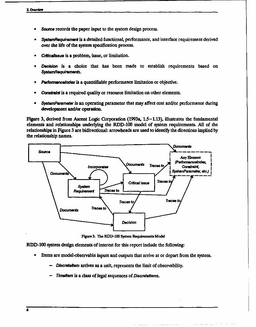
" Source records the paper input to the system design process.
"* SatwnmRqulrewnW is a detailed functional, performance, and interface requirement derived
over the life of the system specification process.
"* Cr~lallasue is a problem, issue, or limitation.
"* Dechion is a choice that has been made to establish requirements based onSymWMequr~enas.
"* Pw•mwnxsndex is a quantifiable performance limitation or objective.
" Comstma is a required quality or resource limitation on other elements.
"• SyatParameter is an operating parameter that may affect cost and/or performance duringdevelopment and/or operation.
Figure 3, derived from Ascent Logic Corporation (1993a, 1.5-1.13), illustrates the fundamentalelements and relationships underlying the RDD-100 model of system requirements. All of therelationships in Figure 3 are bidirectional: arrowheads are used to identify the directions implied bythe relationship names.
Documerts oe CunWr•
I ySwnParenw, etc.)
Reqw., wn T races o I
Figure 3. The RDD-100 System Requiements Model
RDD-100 system design elements of interest for this report include the following:
* Items are model-observable inputs and outputs that arrive at or depart from the system.
- DlMcretefm arrives as a unit, represents the limit of observability.
- Tineltem is a class of legal sequences of Discrete tems.
8. . . . . . . .. . . . . . . .. . .

2. Overew
" Functions transform arriving items into departing items.
- DiscrteFuncfion transforms one Discreteltern into an unordered collection ofDlWcreelterns.
- TimeFunction is an aggregation of DiscreteFunctions or TimeFunctins that transformsan ordered collection of Discreteltems or Timettems into an ordered collection ofDiscre/tejins.
"* Component is one of the parts (hardware, software, or human) in a system, for example, asubsystem.
"* Graphic constructs represent concurrency, iteration, loops, conditions, selection, and
replication.
- Net represents sequences of inputs or outputs.
- FNet represents sequences of behavior (functions).
"* ItemrUnk is a logical pathway that carries a message item from one RDDProcess to another.
"• Externa/ystem is a separate system outside the required system's boundary.
"* Interface is a mechanism for items to flow across the system boundary or from one componentto another.
Figure 4 illustrates the fundamental elements and relationships underlying the RDD-100 model ofsystem design. The legend identifies the names of the relationships that identify how the sourceelements on the left side of Figure 4 relate to the target elements on the right side of Figure 4.
2.1.3 RDD-100 RELEAS 4
The folowing new products from Release 4 of RDD-100 may provide improved support for CoRE:
o Mu/ti-Elemmt View. Provides the ability to view and edit multiple RDD-100 database elementsand relationships in a single window. Among other advantages, this tool should facilitatedecomposition of Source documents into hierarchies of SystemRequlrements.
o Asa Object Editor (and Real World Object Editor). Provides the ability to overlay a databaseschema on top of the existing one. This tool allows the user to tailor an RDD-100 model formethods such as CoRE and obviates the need to modify the RDD-100 database schema, asdescribed in Section 4.
A future release of this report will discuss Release 4.0 of RDD-100 in detail.
2.2 CoRE
CoRE is a method for analyzing, capturing, and specifying software requirements (SoftwareProductivity Consortium 1993). The Consortium has worked with industrial developers of real-timeand embedded systems to provide a method that addresses their needs. CoRE supports the
9

2. Omvavl
10 2
Legend1 Aflocatedto
Carpnert2 &A fIn3 Connected to4 Composed of5 IrP~flst8qtXc
NOMIM 8 Refened by
S6 •Wet10 Decomposes
71meftem11 PerfomsDisInroteetto
Figune 4. The RDD-100 System Design Model
development of precise testable specifications that are demonstrably complete and consistent. CoREalso supports key process issues, such as managing changing requirements and reuse. CoRE is a single,coherent requirements method that:
"I megratesObjec-OriemedandFormalModds. A CoRE specification organizes the details of thebehavioral model into classes of objects, which provides a mechanism for abstraction, separa-tion of concerns, and information hiding. Systems engineers use the CoRE class structure toaddress objectives like change management or reuse.
"* Inftraft Graphical wad igorous cin,. Graphic representation helps all parties (e.g.,customers, engineers, designers, and programmers) to grasp essential relationships amongsystem components. CoRE provides a consistent, rigorous interpretation of both graphicaland mathematical notations. This allows the graphical specifications to combine smoothlywith the detailed specifications that are best given in mathematical and textual notation.
"* UssExising Skils andNtations. The language used to specify requirements in CoRE is basedon familiar concepts and existing notations.
"* Permits Nonalgorithmic Speci#caon. CoRE is nonalgorithmic in the sense that systemsengineers can specify the required behavior of a system without having to provide an algorithm
10

2. Overview
or detailed design; i.e., systems engineers can always specify the behavior in terms of what thesystem must do rather than how it does it.
PrvWdes Guidance. The CoRE process model provides practical guidance in developing boththe object structure and the behavioral requirements. The behavioral model provides a stan-dardized structure that helps the developer determine the class structure. The behavioralmodel also forms the basis of a systematic process for developing a complete requirementsspecification.
Requirements in CoRE are written in terms of two underlying models: the behavioral model and theclass model. The CoRE process describes the order in which the specification is composed, the behav-ioral model captures what the software must do, and the class model organizes that information. Sec-tion 2.2.1 provides an overview of the CoRE process, Section 2.2.2 describes the behavioral model,and Section 2.2.3 describes the class model.
2.2.1 CoRE PRocEss Ovuviiw
The CoRE process is a sequence of activities that systems engineers follow to develop a CoRErequirements specification. The CoRE process is driven by two concerns. The first concern is thestepoby-step construction of a required behavior specification in terms of the CoRE behavioral modelfor a particular system. The goal is to develop a complete and consistent description of the requiredbehavior. The second concern is the step-by-step packaging of specification pieces in elements of theclass structure. This aspect of the method satisfies packaging goals, such as change management andreuse. Because packaging and specification activities overlap in time, the threads of these activitiesare intertwined in the CoRE method.
The input to the CoRE process is some form of system requirements specification (i.e., the firstactivity, identifying system constraints, assumes that a system specification is available). The outputof the CoRE process is a complete specification of the software requirements (i.e., suitable for asoftware design process).
The CoRE process is a description of an "ideal" process. The process is idealized rather than "real"in that it does not account for errors, requirements changes, unknown requirements, or other factorsrequiring additional iteration, experimentation, or backtracking. An ideal process is useful becauseit provides an external standard to guide development and it serves as a yardstick for measuringprogress. Thus, the ideal CORE process is divided into a sequence of five activities:
d Ident Environmetal Variables. Systems engineers identify candidate environmentalvariables and the relations among them. The overall goal is to identify environmentalquantities that denote the monitored and controlled variables, relationships that will becomeparts of the required (REQ) and natural (NAI) relations, and relationships that will becomepart of the generalization/specialization structure. Identify likely changes and their impactson these environmental variables.
SPreliminary B&mior Specifiation. Systems engineers identify and specify the monitored andcontrolled variables. They identify undesired events to which the system must respond and de-fine monitored variables to denote them. They identify the domain and scheduling type foreach controlled variable and identify modes.
11
2. Oeviaw
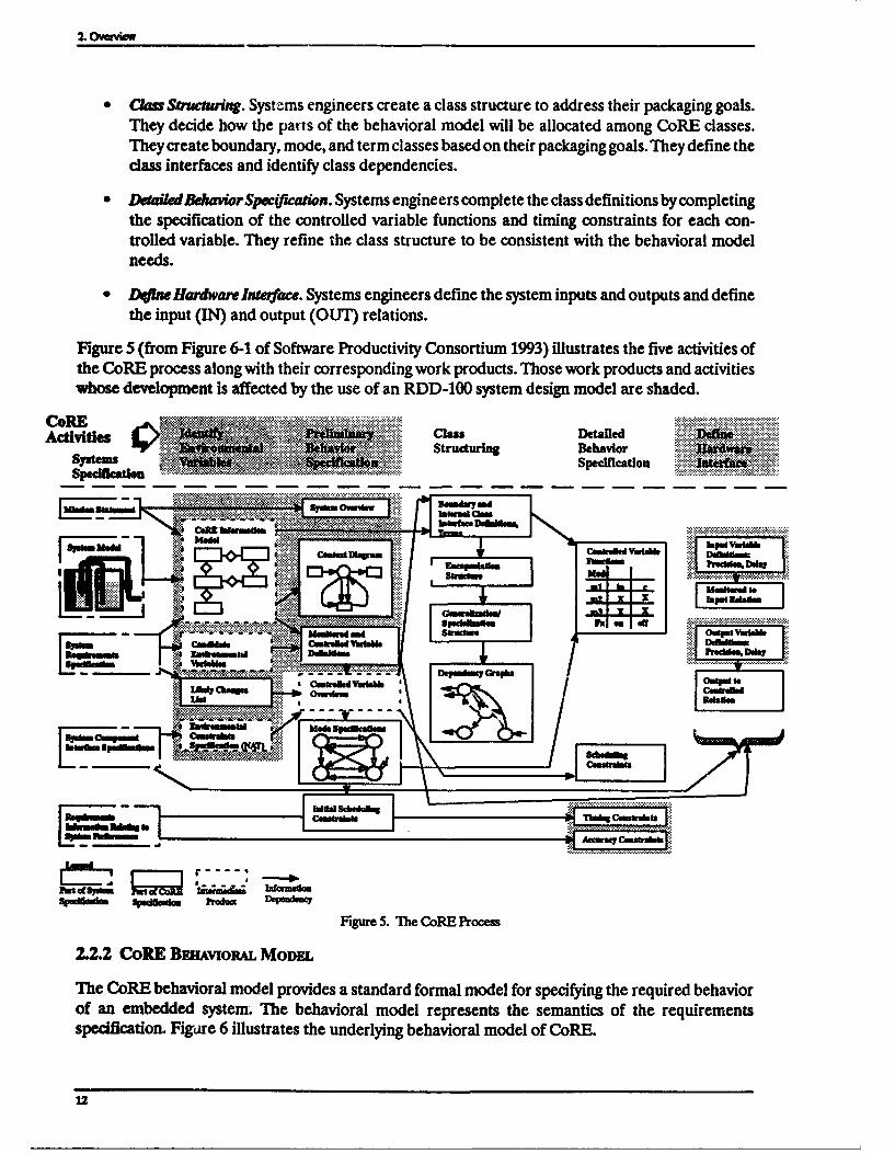
" Cl= Swuctwwing. Systems engineers create a class structure to address their packaging goals.They decide how the parts of the behavioral model will be allocated among CoRE classes.They create boundary, mode, and term classes based on their packaging goals. They define theclass interfaces and identify class dependencies.
" DwailedBehaviorSpwe(cadon. Systems engineers complete the class definitions by completingthe specification of the controlled variable functions and timing constraints for each con-trolled variable. They refine the class structure to be consistent with the behavioral modelneeds.
" DOW Hardware Interface. Systems engineers define the system inputs and outputs and definethe input (IN) and output (OUT) relations.
Figure 5 (from Figure 6-1 of Software Productivity Consortium 1993) illustrates the five activities ofthe CoRE process along with their corresponding work products. Those work products and activitieswhose development is affected by the use of an RDD-100 system design model are shaded.
CoRE ggxg - lasDeaieActivities
% In : MIN, Structuring BehaviorSyste.•M w Speifcation ....
Specification .' .
.........__ __ _ MwaqS4mtnhls
Figure 5. The CoRF_ Process
2.2.2 CoRE BmvoRiL MoDE
The CoRE behavioral model provides a standard formal model for specifying the required behaviorof an embedded system. The behavioral model represents the semantics of the requirementsspecification. Figare 6 illustrates the underlying behavioral model of CoRE.
12

2. Overview
This section is divided into three subsections, each of which describes a part of the behavioral modelthat is of particular interest for this report: environmental variables (Section 2.2.2.1), input and outputvariables (Section 2.2.2.2), and four-variable relations (Section 2.2.2.3).
Four-Variable Four-VartbleReation Subrelation
tan
I RQ ý - REQ Subeati,
Beh]vir NAT NATMSubrelation
IN H IN Sureltio-
Fgure 6. The CoRE Software Requirements Behavioral Model
2.2.2.1 Environmental Variables
Environmental variables are physical quantities of interest in the environment of a system. For
example, air pressure is of interest to an automotive engine-control system. There are two kinds ofenvironmental variables:
Monitored Variables. Environental quantities the system must track (e.g., the ambient air
pressure).
SControlled Oape. Environmental quantities the system sets (e.g., the fuel flow to the
cylinders).
2.2.2.2 Input and Output Variables
Input and output variables are variables representing discrete inputs or outputs of the software. Thecomplete definition of an input (output) variable describes precisely how the software reads from"(writes to) a device, including the protocol for reading from (writing to) a device and a mapping"between abstract values and the bit patterns read from (written to) the device.
13

2. Oveview
2.2±3 Four-Variable Relations
Four-variable relations contain ordered pairs of environmental variables and input and outputvariables. There are four kinds of relations in the CoRE behavioral model:
" NAT. NAT specifies the external constraints on the values that the environmental variables canassume. These constraints are properties of the environment that affect the software but existindependently of the software.
" REQ. REQ specifies properties that the system is required to maintain between monitoredand controlled variables. The REQ relation is the fundamental means of specifying behavioralrequirements with CoRE.
"* IN. IN expresses values taken on by the monitored variables as a function of bit settings orother low-level hardware settings (input variables).
"* OUT. OUT specifies values of controlled variables as a function of the values of outputvariables.
Figure 7 illustrates how these variables are related by the four kinds of relations.
REQ
Micr ControlledVariable Variable
IN NAT our
Input Variable Output Variable
Figure 7. The CoRE Fouw-Variable Model
2.2.3 CoRE CLAss MODEL
The CoRE class model provides a set of facilities for packaging the information in a CoREspecification. The class model allows you to divide the specification into relatively independent partsand to control the relationships between parts. The class model is not intended to imply anyrequirements about the behavior of the software.
The information in the four-variable model is partitioned among a set of CoRE classes. A CoRE classis a template for defining a subclass or object (conversely, an object is always an instance of a class).Systems engineers determine such characteristics as the number of classes, what information is hiddenby each class, and which parts of the model are allocated to the same class based on their overall goalsfor the requirements structure. There are three kinds of CoRE classes:
"* Bowudary C•,as. Contain the definitions of the system's monitored and controlled variables.
"* Mode Classes. Encapsulate mode machine definitions and provide mode information.
"* Term Clhse. Provide any terms (named expressions of monitored variables) not provided bythe boundary and mode classes.
14

2. Overview
CoRE's class model exists with quite different motivations than those of design and implementationmethods. CoRE deals with objects and classes as buckets for containing interesting parts for the sakeof designing the specification rather than the system. Designing a specification with classes differsfrom designing a system for object-oriented implementation in the following ways:
0 The CoRE class structure is part of the requirements specification, intended to facilitatepackaging; it is not part of the system itself. It may be that a different class structure will beapplied to the system during implementation.
* Although CoRE recognizes an inheritance from superclasses, the idea of class structure forencapsulating (hiding) information and the depends-on relationship between specificationobjects are much more important.
The inheritance relationship is a dominant feature of the structure of programs to be built withobject-oriented implementation languages primarily because of the overwhelming importance ofreusing code from superclasses. Code reuse and, consequently, the inheritance relationship are nottypically critical concerns during requirements specification.
The classes in a CoRE specification are best viewed as "cell walls" created to contain:
"* Encapsulated information (secrets)
"* Parts of the system that are likely to change, as opposed to those prone to remain stable
2.3 COMPARING RDD-100 AND CoRE
RDD-100 supports system requirements analysis and design, where a system is made up of hardware,software, and people. CoRE supports software requirements analysis. For CoRE to be applied to asoftware system that is part of a larger system specified using RDD-100, the RDD-100 model must(and does) contain all of the information needed to build a CoRE specification. Of course, the CoRErequirements writer must know which parts of the RDD-100 model are useful for CoRE and whichare not.
The earliest activity in the RDD-100 process consists of decomposing system requirementsdocuments into hierarchies of individual system requirements. The subset of these systemrequirements related to the software subsystem being specified using CoRE along with any relatedRDD-100 database elements derived from them provides the basis for a CoRE specification.
RDD-100 encourages the systems engineer to define the environment in which the proposed systemwill operate. The environment includes those external systems and environmental entities that havean effect upon the system and those variables that are transferred between the system and the environ-ment or external system. This information is essential to a CoRE specification, which specifies therequired relationships between variables that are monitored by the software system and those that arecontrolled. RDD-100 captures this information using behavior diagrams and provides automatictranslation to the context diagram format recognized by CoRE.
CoRE provides powerful techniques for nonalgorithmic expressions. CoRE's focus is on tabularmathematical descriptions of actions as a function of events, conditions, and modes. RDD-100 doesnot currently support this notation; it allows specification of behavior using flowlike descriptions for
15

Z ovrview
timing and sequencing (behavior diagrams). RDD-100 was not intended to and does not provide thetools necessary to build a CoRE software requirements specification.
RDD-100 offers robust modeling features for analyzing a system design. The system design isspecified using a hierarchy of behavior diagrams. Making a design analyzable requires the systemdesigner to include decisions related to logic, sequencing, or concurrency in the behavior diagrams.From the CoRE perspective, these kinds of decisions may be considered design decisions that shouldbe avoided during software requirements analysis. As a result, a completed RDD-100 specification,composed via the RDD methodology, may have more information than is necessary to build a CoREspecification. More precisely, it is likely that only the highest level behavior diagrams in the RDD-100model's hierarchy will be needed for CoRE.
In summary, an RDD-100 system model does not contain all of the information that a CoRE softwarerequirements specification contains. There is an inherent difference in the level and amount of detailbetween system and software specifications. The software specification contains requirements thatare derived from the system specification. A complete CoRE specification cannot be automaticallygenerated from an RDD-100 specification. However, RDD-100 is a suitable starting point for CoREbecause it contains all of the information needed to begin CoRE. The CoRE requirements writer mustknow where in an RDD-100 model to find relevant pieces of information and how to build a CoREspecification from them. The best use of RDD-100 with CoRE is to build the CoRE specification witha more appropriate tool, such as teamwork, and to make use of the facilities RDD-100 provides fortransitioning from system design using RDD-100 to software requirements using teamwork (andCoRE).
16

3. AN APPROACH FOR DERIVING A CoRE MODELFROM AN RDD-100 MODEL
This section describes an approach, including the process, guidelines, and examples, for deriving aCoRE software requirements model from an RDD-100 system requirements and design model. Theactivities involved in this approach include:
"* Building the RDD-100 model (Section 3.1)
"* Identifying CoRE inputs in the RDD-100 model (Section 3.2)
"* Mapping the information contained in an RDD-100 model to an initial CoRE specification(Section 3.3)
"• Completing the CoRE specification (Section 3A)
This set of activities is not intended to be strictly sequential; iteration is expected.
3.1 BUILDING THE RDD-100 MODEL
To describe an approach for deriving a CoRE model from an RDD-100 model, it is necessary to makesome assumptions aboutwhat is contained in the RDD-100 model. This section describes the assumedprocess for developing a system requirements model using RDD-100. The intention is to provide theleast number of constraints possible so that the approach is applicable to the widest possible range ofestablished RDD-100 users.
The assumed process includes a subset of those activities described in Alford (n.d.). The RDD-100model should not be built any differently than usual, but for the purposes of CoRE, it is assumed thata minimal set of activities has been performed. The assumed process for developing a systemrequirements model using RDD-100 includes:
"• System requ~rciants analysis (Section 3.1.1)
"* System functional analysis (Section 3.1.2)
"* System design (Section 3.1.3)
Section 3.1.4 offers some suggested tactics for building the RDD-100 model for those systemsengineers who know beforehand that CoRE will be used to specify software requirements.
3.1.1 RDD-100 Sys-m Rw•umamrs ANAxsis
The RDD-100 system requirements analysis activity begins by identifying individual systemrequirements statements from requirements documents (e.g., a mission statement). Each such
17

3. An Afprouih for Derh. a CoRE MOMel From an RDD-100 Modr
requirements document is identified in the RDD-100 database by creating an associated element oftype Source. The RDD-100 requirements extractor can be used to parse a textual document and tocreate a hierarchy of individual system requirements in the database, known as SystemRequirementelements. The resulting relationships between elements are:
" Documents relationships are created between Source elements and the SysternRequirementelements they contain.
"* Incorporates relationships are created between SystemRequirement elements and their childSystemnRequirement elements in the hierarchy.
CrOitsue elements are created for recording technical issues critical to the successful developmentof the system. Documents relationships relate Source elements to Crlticailssue elements, and TracesTorelationships record their traceability from SystemRequirement elements. When critical issues areresolved, their resolutions are recorded in Decision elements, and TracesTo relationships are used torelate these element pairs. Decision elements may result in the creation of additionalSystemRequirement elements, and TracesTo relationships are also used to relate these element pairs.Documents relationships may also relate Source elements to Decison elements. Figure 3 illustrates theelements and relationships supporting the RDD-100 system requirements analysis activity.
For the HAS Buoy case study described the Appendix, there were two Source elements: the HAS Buoyproblem statement (see Section App.1) and a list of requirements stabilities and variabilities (see Sec-tion App.1.6). Section App.2.2 documents the hierarchy of SystemRequlrement elements. Cfticallsueand Decision elements are described in Section App.2.4.
3.1.2 RDD.100 SysrUm FurcnoNAL AALYsiS
In the RDD-100 system functional analysis activity, systems engineers develop a functional model thatreflects the functional requirements of the system (Alford n.d.). The goal is to develop a functionalmodel that represents the desired behavior of the system. During this activity, systems engineers willdefine how the system will logically operate and provide a basis of how the allocated design mustbehave. This activity consists of identifying system subsets called Components, whose behaviors arespecified using behavior diagrams.
Begin the RDD-100 system functional analysis activity by decomposing the system into Componentsas follows:
"* Create a Component element of type System representing the entire specification, with thename of your system (Components of a particular type are created by setting the ComponentType attribute of the Component accordingly).
"* Create Component elements of type ExternalSystem representing systems external to your ownwith which your system must interact.
"* Create Component elements of type Environment representing entities in the environment thathave an effect on your system.
" Create Component elements of other types (e.g., Subsystem, CSCI, etc.) representing internalparts of the system such that all SystemRequirement elements have been mapped to a
is

3. Art Appvuah for DR!=%n a OWE Model Frm an RDD-100 Moded
Componet element (either directly by the TracesTo relationship or indirectly through thefunctional model).
Specify the behaviors of these Compnents as follows:
"* Specify the behavior of the Syastm Component element by creating a behavior diagram (FNet)that contains the functions performed by all related EtemaAytm, Envim ent and other
"* Create a HasContext relationship between the System Component element and the FNetelement.
"* Specify interactions between Components using elements of type T7metem, DLscretettem, orIntnce.
"* Describe the precise behavior of an individual Component element by decomposing andallocating functionality to TimeFunction and DiscreteFuncton elements.
"• Specify timing requirements in the "duration" attributes of Functs for subsequentmodeling. Create Pedoommcelndex elements as necessary to capture timing requirements.
"* Create additional Critcalissue and Decision elements during this activity as you realize theirneed.
The remaining, lower level details of the behavior diagrams are completed such that sufficient detailis provided to allow RDD-100 to execute the behavior diagram using the Dynamic Verification Facil-ity. These lower level details are considered design by CoRE: although some may imply constraintsupon the software requirements, others may not be used during the application of CoRE.
Section App.2.7 of the HAS Buoy case study describes the Component elements that were identifiedand shows the hierarchy graphically.
&L3 RDD-100 Swfm DESIGN
System design is the final activity of the RDD-100 process. The RDD-100 system design activityconsists of allocating the system behavior (functionality) to the system architecture (Alford n.d.). Theengineer should consider several allocation strategies, which can be evaluated using the DynamicVerification Facility.
System design using RDD-100 is performed by creating AllocatedTo relationships betweenDIscrteiunction elements and Component elements. DiscreteFunction elements are aggregated toreflect the behavior of the Component (i.e., show inputs, outputs, and the logic the Component is toPerform).
Section App.2.7 identifies the Allocated'o relationships that were identified for the HAS Buoy casestudy.
19
3. An A! awcit fc De"n8 a CoE Model From an RDD-100 Model
3.1.4 TAcncs THAT SUPPo~r CoRE
This section offers some suggested tactics for building the RDD-100 model for those systemsengineers who know beforehand that CoRE will be used to specify software requirements:
"Use techniques that allow you to isolate those parts of the RDD-100 model that are likely tomap to CoRE elements (i.e., those RDD-100 elements identified in Sections 3.1.1 through3.1.3). For example, use naming conventions for identifying those RDD-100 elements that areof particular interest to CoRE (e.g., Components, Discreteltems, etc.). In the HAS Buoy exam-ple, the names of RDD-100 elements of interest to CoRE were capitalized, while those thatwere not of interest were stated in lower case.
" When using RDD-100 and creating elements that will later become part of a CoREspecification (e.g., monitored variables, terms, etc.), make sure that these elements are notused in ways contrary to the use of CoRE. For example, perform modeled manipulations onDlscreteltms that you expect to become monitored variables via a series of intermediate stepsso that you can represent these manipulations as CoRE terms, and store them in relevantproblem classes.
" Make the behavior diagram corresponding to the CoRE context diagram executable, andavoid any more detail than is necessary to do so. RDD-100's DVF is a useful tool for evaluatinga system design. However, DVF leads you to specify algorithmic FNets, which are likely toprovide more detail than is necessary for CoRE.
" When using the element editor, specify as much CoRE-relevant information as possible whenrecording the textual templates associated with elements (e.g., always specify the Descriptionattribute of elements). Also, make good use of the consistency checking, particularly the"fundamental" and "system engineering" levels of checking.
An RDD-100 model is generally useful for CoRE, and the remainder of this report is based on theassumption that the systems engineer using RDD-100 was not aware of the intent to subsequentlycreate a CoRE specification. However, if the systems engineer using RDD-100 is aware of a subse-quent CoRE specification, the tactics described in this section should facilitate transition from RDDto CoRE.
3.2 IDENTIFYING CoRE INPUTS IN THE RDD-100 MODEL
The RDD-100 system model should contain all of the information needed to begin building a CoREsoftware specification. In fact, the RDD-100 model is likely to contain more information than is need-ed for CoRE. In any case, the systems engineer should verify that the RDD-100 model contains thenecessary inputs to CoRE.
As Figure 5 shows, the necessary inputs to CoRE are: mission statement, system model, systemrequirements specification, system component interface specifications, and requirementsinformation relating to system performance. This section is divided into five subsections describinghow each of these inputs might be recorded in an RDD-100 model. ibble 1 summarizes the mappingfrom RDD-100 schema elements to CoRE inputs and identifies where to locate candidate RDD-100schema elements in the RDD-100 System Engineering Notebook (SEN).
20

3. As Approah fo Derivin a CoRE Model From an RDD-100 Model
Table 1. CoRE Inputs in the RDD-100 Model
CoRE Inputs Candidate RDD-100 Where Found (SEN Chapter)
Schema Element(s)
Mission statement Souce External to RDD-100--input documents
System model FNAt (system context diagram) FNet: context diagram is Figure 1-1Campo"" Components: Chapter 1, "System
Top-Level Description"
System requirements SygemRsqdreffw Chapter 2, "System-Level Operatingspecification Requirements*System component Irtwtace Chapter 10, "Interfaces Between Compo-interface specifications ftemUl* nents"
Requirements information Pwftunr.endinr Chapter 7, "Performance Indices"relating to systemperformance
32.1 MSmoN STammm
The mission statement is a high-level description of system requirements. The CoRE requirementswriter should look at RDD-100 elements of type Source to find the mission statement.
For the HAS Buoy case study, the equivalent of the mission statement was the HAS Ada-based DesignApproach for Real-Tune Systems (ADARTSS) Problem Statement in Section App.1, which wasidentified in the RDD-100 database by a Source element.
3.L2 ~srm MODEL
The system model is a functional description of the behavior of the proposed system. The CoRErequirements writer should look at the RDD-100 behavior diagram (FNet) that models the behaviorof the entire system to find the system model. In the RDD-100 model, a Component element of typeSystem, named appropriately, should be related to an FNet by a HasContext relationship. This FNetmodels the behavior of the entire system.
Figure 8 shows the system model for the HAS Buoy case study. It is the behavioral model representingthe Symem Companei element.
3±.3 Sywm Rgmummm SPEmcFIATm
The system requirements specification is a detailed description of system requirements. The CoRErequirements writer should look at the RDD-100 hierarchy of SystemRequirement elements to find therequirements that make up the system requirements specification. RDD-100's Report Writerprovides the capability to automatically generate reports, such as the system requirementsspecification, using a variety of templates, including MIL-STD-490A, DOD-STD-2167A, oruser-defined specifications.
The hierarchy of SystemRequirement elements (see Section App.2.2) or the entireRDD-100-generated SEN (see Section App.2) could have served as the system requirementsspecification for the HAS Buoy case study.
21

. An ftMd 1r Dabbg a Co.E Mode Rom w RDD-100 Modl
3.2.4 Swum Comaomm INTEmcE SPscinIcAONS
System component interface specifications describe the interfaces between the subsystems in a systemand between the system and its environment. The CoRE requirements writer should look at RDD-100TknWlem, Ddmcetem, iweUmik, and Internee elements to find system component interface specifica-tions. Of particular interest are those elements that are shared by the System Comapon element (seeSection 3.2.2) and other Component elements.
Sections App.2.6 and App.2.8 of the HAS Buoy case study identify Timet em, Discretelt em, Itemunk,and knwface elements that may be included in the system component interface specification.
3.25 RDxQuI ms INiORMATION RELATING TO Syrm PERFORMANCE
Requirements information relating to system performance typically specify end-to-end system timingrequirements. The CoRE requirements writer should look at RDD-100 Pedormancindex elementsto find requirements information related to system performance. However, during subsequent CoREactivitie4 the requirements likely to identify additional timing and accuracy requirements (e.g., forREQ relations) are not and should not be contained in the RDD-100 model.
Section App.2.5 identifies the Perfrmancelndex elements for the HAS Buoy case study.
3.3 MAPPING THE RDD-100 MODEL TO AN INITIAL CoRE SPECIFICATION
This section describes how elements of an RDD-100 system design model map to a CoRE softwarerequirements specification. Based on the RDD-100 approach described in Section 3.1, it describeswhat elements of the CoRE model are most likely to be found in the RDD-100 model.
As Figure 5 shows, the first CoRE activity, Identify Environmental Variables, includes developmentof the following. CoRE information model, candidate environmental variables, likely changes list, andenvironmental constraints specification (NAT). This section is divided into four subsections, each ofwhich describes what parts of an RDD-100 model contain the information needed to build one ofthose products. Uhble 2 summarizes the mapping from RDD-100 schema elements to CoRE products.
"Ibble 2. CoRE Products in the RDD-100 Model
CoRE Products Candidate RDD-100 Where Fond (SEN Chapter)Schema Element(s) _here__ ound_(SENChapter)
CoRE information model Inteudec Chapter 10, "Interfaces BetweenComponet Components"Dsowa~teftwn
Candidate environmental Interaoe Chapter 1, "System Top-Level Description"variables Campormt Chapter 8, "Item Dictionary"
EwnaSWem
Oftkalt=N
Dod~bn
i.kely dumVgs list COftlo•aS Chapter 4, "Issues & Decisions"DechkSytwnParametar
Environmental constraints ctur•akt Chapter 3, -Design Constraints"spcification (NAT)
22

3. An Approach for Deriving a CoRE Model From an RDD- 100 Model
3.3.1 CORE IWoRm~nON MODEL
The CoRE information model captures physical entities and the associations between them that maybe relevant to the software. An RDD-100 System Component element maps to the system entity in theCoRE information model. Other kinds of Componn elements, especially ExternalSystem andEnvironment Conmonent elements, are candidates for additional entities in the CoRE informationmodel. Intewfac elements that represent connections between those Components map to relationshipsbetween the corresponding entities in the CoRE information model. Discreteltem and Timeltemelements that are communicated by those Components map to attributes of entities.
Section App.3.31 contains the CoRE information model for the HAS Buoy case study.
3.3.2 CANDIATE ENvMo zrAIL VARMIM
Candidate environmental variables (i.e., monitored and controlled variables) can be derived from:
" The likely changes list (see Section 3.3.3)
"* Devices, environmental entities, or external hardware or software that has an effect on yoursystem (see Section 3.3.1)
From the RDD-100 perspective, candidate environmental variables can be derived from any of thefollowing RDD-100 elements: Interface, Component, EtemalSystern, Discreteltem, Timeeltem,CWtlassue, Decision, or SystemParameter.
Section App.3.1 identifies candidate environmental variables for the HAS Buoy case study.
3.3.3 Luvm CHmGEs Lisr
The likely changes list identifies likely changes in system requirements. Likely changes should beindicated by the existence of Crltlalssue, Decision, or SystemParameter elements in the RDD-100model. If any of these elements exist in the RDD-100 model, apply the CoRE criteria to determinewhether the element indicates the need for an addition to the likely changes list.
Section App.1.6 provides a list of likely changes for the HAS Buoy case study. Section App.2.4identifies related RDD-100 Critlcallssue and Decision elements (there were no SystemParameterelements).
3.3.4 ENvntoNamuAL CoNsrRAwLs SPECIFAnTION (NAT)
Environmental constraints are information about environmental variables related to possible valuesand interpretation of these values, e.g., the type of the quantity, possible range of values, and maxi-mum rate of change. Environmental constraints may be indicated by the existence of Constraint ele-ments in the RDD-100 model. Environmental constraints on the set of possible values that anenvironmental variable can take on are recorded by the NAT relation.
The HAS Buoy case study does not provide any examples of NAT relations derived from Constraintelements.
23

& AapvMk far Duu% a C*RE Modl Frm m RDD-100 Mod
3.4 COMPLETING THE CoRE SPECIFICATION
This section describes how the remaining parts of a CoRE specification are affected by the use ofRDD-100 after mapping the RDD-100 model to an initial CoRE specification as described in Section3.3. In particular, it describes, from the CoRE perspective, where to find the necessary informationto complete the CoRE specification when the RDD-100 is used as the front end to CoRE. Those partsof a CoRE specification that are unaffected by the use of RDD-100 are not described here.
As Figure 5 shows, the following remaining CoRE products are affected by the use of RDD-100 forsystems engineering: context diagram (including monitored and controlled variables), input and out-put variable definitions, and timing and accuracy constraints. This section is divided into subsectionsthat describe what parts of an RDD-100 model contain the information needed to build one of thoseproducts.
3.4.1 Comm DIAGRAM
The CoRE context diagram captures the interaction of a software system within its environment. TheCoRE context diagram represents a subset of the environment that might be represented in a contextdiagram for an entire system, such as for the system model described in Section 3.2.2. In some cases,however, the two context diagrams may be equivalent in scope, such as in the HAS Buoy case study,as shown in Section App.3.2.1.
The CoRE context diagram includes a system transformation (Section 3.4.1.1), terminators (Section3.4.1.2), and monitored and controlled variables (Section 3.4.1.3).
34.1.1 System Transformation
The system transformation on the context diagram is derived from the system entity in the CoREinformation model, which was derived from an RDD-100 System Component, named appropriately(see Section 3.3.1). The name of the system transformation may be inherited from the correspondingRDD-100 element.
3.4.1.2 Terminators
Terminators on a CoRE context diagram represent boundary classes. Boundary classes:
"* Represent information about the environment that is relevant to specifying the behavior of thesoftware
"* Require external resources (devices or external software subsystems) to acquire or influencethe information
The set of boundary classes is derived from the likely changes list and the CoRE information modelas described in Section 3.3.1, which are based on corresponding Component, Criticalissue, Decision, orSystenmParameter elements in the RDD-100 model.
3.4.1.3 Monitored and Controlled Variables
CoRE environmental variables are physical quantities of interest to the software. Monitored variablesare environmental variables measured by the software. Controlled variables are controlled by the
24

3. An Apromch for Dvag a CoRE Model From an RDD-100 Model
software. Monitored and controlled variables appear on the context diagram as arrows between thesystem transformation and terminators (boundary classes).
Candidate environmental variables can be found in the CoRE information model (see Section 3.3.1)."Iically, environmental variables will appear as attributes of entities in the CoRE information mod-el. Specifically, when RDD-100 is used, monitored variable candidates can be derived from RDD-100Dbcrete/tn and Tmetewn elements whose Source is a Componet with a corresponding entity in theCoRE information model. Controlled variable candidates can be derived from RDD-100 Discrete/ternand TimeAen elements whose Target is a Compornt with a corresponding entity in the CoRE informa-tion model. CoRE recommends using the environmental constraints (see Section 3.3.4) and the likelychanges list (see Section 3.3.3) as a guide in identifying and specifying the definitions of monitoredand controlled variables.
3.4.2 Imrur AmD Ourprm VARmALE DEFIwoNrNs
IN relations record how the software can use input variables to approximate the values of monitoredvariables. OUT relations record how the software can usc output variables to set the values of con-trolled variables. Input variables are descriptions of physical interfaces to the environment that allowsoftware to determine the values of monitored variables. Output variables are descriptions of physicalinterfaces to the environment that allow software to set the values of controlled variables.
Section 3.2.4 specifies that system component interface specifications should be contained by7ime/tern, DiMcretetem, or Intedface elements that are shared by the System Component element andother Componen elements, particularly those of type ExtemalSystem or Environment. ThoseComponent elements of type ExternalSystem or Environment, whose behavior should be specified usingbehavior diagrams, are useful in specifying IN and OUT relations. The Time/tern, Discreteltem,ItemUnk, or Interface elements referred to by Section 3.2.4 are useful in specifying the correspondinginput and output variables.
IN and OUT relations for the HAS Buoy case study are contained in Sections App.3.3.4.1 andApp.3.3.4.3, respectively.
3.4.3 ThroNG Am AccuRwcy CONsflwn
CoRE timing and accuracy constraints define the allowable tolerance in terms of timing and accuracyassociated with CoRE's mathematical relations. These constraints, which are sometimes based onrequirements information relating to system performance (see Section 3.2.5), may be derived fromPerfomancelndex elements when using RDD-100 for system design. In other cases, timing andaccuracy constraints will be determined later in the CoRE process after the RDD-100 model has beencompleted.
SectionApp.3.3.6 identifies the timing and accuracyconstraints for the HAS Buoycase study thatwerecaptured in the RDD-100 model.
25

3. Aa 6E2!!!!L Wa D"rvm a CDRE Model Fromi an RDD4IUO Model
Thupage intentionalfy left blank,
26

4. EXTENDING THE RDD-100 SCHEMA TOSUPPORT CoRE
The RDD-100 Extender (Ascent Logic Corporation 1991a) allows systems engineers to tailor theunderlying database schema of RDD-100 for their own needs. Extending the schema such thatCoRE-specific elements, such as monitored variables and input variables, are recognized byRDD-100 will allow systems engineers to specify designs that are more consistent with the needs ofCoRE.
Table 3 identifies those elements and relationships systems engineers might add to the RDD-100database schema in support of CoRE as Figure 7 shows. Making these additions to the standard,underlying database schema of RDD-100 allows it to recognize CoRE concepts and, therefore,facilitates mapping from an RDD-100 model to a CoRE model.
Table 3. Extended Schema for CoRE
Source Element Relationship Target Element
Controlled Variable IsA KindOf Environmental VariableNAT Inverse Monitored VariableREQ Inverse Monitored Variable
OUT Inverse Output VariableMonitored Variable IsA Kind Of Environmental Variable
NAT Controlled VariableREQ Controlled Variable
IN Input VariableInput Variable Is A Kind-Of Input/Output Variable
IN Inverse Monitored VariableOutput Variable IsA Kind-Of Input/Output Variable
OUT Controlled Variable
In experimentation with the RDD-100 Extender for the purpose of supporting CoRE, the Consortiumconcluded that the benefit obtained by modifying the RDD-100 database schema for CoRE use is mar-ginal. By adding CoRE-specific elements to the schema, new elements are created that parallel thepurposes of existing elements. The benefit obtained is the capability to refer to RDD-100 elementsby the names of their equivalent CoRE elements (e.g., monitored variable, input variable).
Ascent Logic Corporation has delivered Release 4.0 of RDD-100 (this report assumes version 3.0.2of PDD-100), which contains Real World and Abstract Object Editors that obviate the need to extend
27

4. ROSS% the RDD-100 Soma to SUpo CoRE
the database schema for CoRE using the Extender. The same benefits provided by the Extender canbe obtained using the Object Editors of Release 4.0 of RDD-100 without the drawbacks. The ObjectEditors allow systems engineers to overlay a modified schema onto the predefined RDD-100 schemaso that database elements are not replicated for the modified schema. Therefore, TUble 3 is includedin this report because it useful for identifying the objects and relations that might be added to the sche-ma using the Object Editors. In a future version of this report, this section will describe in detail theuse of the Real World and Abstract Object Editors instead of the Extender.
28

5. GENERATING A CoRE REPORT FROM RDD-100
This section describes a CoRE-specific report that can be automatically generated by RDD-100 tosimplify the process of building an initial CoRE specification from an RDD-100 model. Generatingsuch a report requires that systems engineers use RDD-100's Report Writer (Ascent LogicCorporation 1992b) to define the contents of the report.
RDD-100's Report Writer provides templates ready for use, including the following reports: SEN,data dictionary, component interface, requirements allocation, requirements traceability, and2167A-compliant reports (Interface Requirements Specification, System/Segment Specification,System/Segment Design Document, and, soon, the Software Requirements Specification).
The predefined report that is most helpful to a CoRE analyst is the SEN (Ascent Logic Corporation,1991b). Section 5.1 describes the contents of the SEN. Section 5.2 describes various options forgenerating a CoRE-specific report.
5.1 THE RDD-100 SYSTEM ENGINEERING NOTEBOOK
This section describes the RDD-100 SEN. For each section of the SEN, there is a correspondingsubsection containing a short discussion of its contents and applicability to CoRE.
5.1.1 Sysrm Top.Ljm DEscmnrON
This section is very useful to CoRE: it describes a high-level view (a TimeFunction) of the system andidentifies the major Components from which the system is built. It also identifies all external interfaces,performance requirements, sources of system requirements, etc. related to the high-level view of thesystem. Finally, it contains the behavior diagram illustrating system functionality from the highestleveL This behavior diagram is very useful in mapping to a CoRE context diagram.
5.1.2 Sysr m.LErv ("OmGiNAmG") REQunmwu
This section contains the hierarchy of system requirements in alphabetical order, includingidentification of relationships between them and other RDD-100 database elements. These systemrequirements are useful to many CoRE activities.
5.1.3 DESIGN CONSTRAINT
This section identifies RDD-100 Constraint elements and their relationships to other RDD-100database elements. These Constraints are useful in identifying CoRE NAT relations.
5.1.4 IssuEs & DECIsioNS
This section identifies RDD-100 Critcalissue and Decision elements, which are important to CoREwhen identifying likely changes and candidate environmental variables.
29

10sawadog a CoR8 Report Pia RDD-100
5.1.5 HIWARCCAL FUNCrION LISr
This section identifies the RDD-100 77m-Fwctons that have been decomposed into lower levelTkeFwctn or Discrete•'ntions (excluding those that are performed by Components). Thesefunctions generally represent a lower level of detail than is necessary for CoRE and, therefore, arenot likely to be of interest to CoRE. Section 5.1.6 describes the details of these functions.
5.1.6 Swm FuNcnoNAL B=AvioR DEscm'nON
This section contains the behavior diagrams for the RDD-100 TimeFunctions identified inSection 5.1.5. These functions generally represent a lower level of detail than is necessary for CoREand, therefore, are not likely to be of interest to CoRE.
5.1.7 PERRMANCE INDICES
This section describes the Perfornmanceindex elements that appear in the RDD-100 database, whichare of interest to CoRE when specifying timing and accuracy constraints.
5.1.8 ITEM Dic-noNARy
This section describes each Timeltem and DiscreteItem in the RDD-100 database. Timeftem andDiscretem elements are important to the CoRE practitioner when specifying the CoRE informationmodel, monitored and controlled variables, and input and output variable definitions.
S.l.9 COMPONENIe
This section of the SEN describes the characteristics of Components in the RDD-100 database, whichare important throughout the CoRE process. This section illustrates the hierarchy of systemComponents. This hierarchy is useful in understanding the structure of the RDD-100 model but is notrequired by CoRE.
5.1.10 IN=FACES BErwEN CoMpoNEmTS
This section describes the interfaces between Component elements, including elements of typesTimeltem, Discreteltem, Interface, and ItemUnk. This information is important to the CoRE practitionerwhen specifying the CoRE information model, monitored and controlled variables, and input andoutput variable definitions.
5.1.11 SWUM "OPMTIONAJ' PARAMETERS
This section describes the SystemParameter elements that appear in the RDD-100 database, whichmay be of interest to CoRE when identifying candidate environmental variables and likely changes.
30

5. Generating a CoRE Report From RDD-100
5.2 A CoRE-SPECIFIC REPORT
There are two ways to generate CoRE-specific reports using RDD-100's Report Writer:
"* Predefined RDD-100 reports can be modified after being generated using a text editor.
" The contents of predefined RDD-100 reports are specified using hierarchies of behaviordiagrams, identified by ReportNet elements in the RDD-100 database. Systems engineers canadd or delete RepoitNet elements or modify the behavior diagrams that define RepotNets sothat the Report Writer produces a report describing those database elements of interest tothem.
Two ways to modify predefined RDD-100 reports to generate CoRE specific reports using the ReportWriter are:
" Begin with the predefined RDD-100 SEN:
- Modify the headings of individual sections to indicate the potential for mapping fromRDD-100 elements to CoRE elements (e.g., modify section headings for the sectionscontaining Extema/System and Environment Componerns to indicate the potential formapping to CoRE environmental variables).
- Remove those sections that are not of interest to CoRE (i.e., the sections containingthe Hierarchical Function List and System Functional Behavior Specification).
"* Ifan RDD-100 schema modification has been made to support CoRE (see Section 4), a specialCoRE report could be generated that represents all information assigned to CoRE-specificschema elements. To do this, you could begin with the Repor~Nts and behavior diagrams usedby the Report Writer that specify a similar predefined report and modify them such that theyspecify a report containing CoRE-specific schema elements.
The best approach to generating a CoRE-specific report using RDD-100's Report Writer for specificneeds depends on the amount of time systems engineers are willing to invest and their expected pay-back in terms of the amount of time they expect to save using the Report Writer. Systems engineersmust trade off these parameters to determine which of the above approaches best suits their needs.
31

&Gemeft ua OaMqcRothcAm RDD-100o
ThMpage Wnentional left blank
32

6. USING THE RDD-100 BRIDGE TO TEAMWORK
Ascent Logic provides a bridge that allows systems engineers to translate RDD-100 behaviordiagrams to teamwork context diagrams, data flow/control flow diagrams, and data dictionary entries.Cadre's teamwork (Cadre Technologies, Inc. 1990) can be used to develop CoRE work products,although it does not currently support CoRE directly. If systems engineers are using teamwork torecord a CoRE specification, RDD-100's bridge to teamwork can provide a head start in building theirCoRE specification. Some RDD-100 elements can be automatically translated to teamwork objectsthat are useful when building a CORE specification.
Section 6.1 provides an overview of how the RDD-100 bridge to teamwork works. Section 6.2 providesan overview of how teamwork can be used to support CoRE. Section 6.3 describes how to use theRDD-100 bridge to Cadre's teamwo,*/RT tool to support the CoRE method.
6.1 THE RDD-100 BRIDGE TO TEAMWORK
Ascent Logic Corporation (1993b) describes the facility that allows systems engineers to translateRDD-100 behavior diagrims to teamwork context diagrams, data flow/control flow diagrams, anddata dictionary entries. This bridge automates the transfer of certain elements from an RDD-100 da-tabase to the teamwork database by automatically generating CASE Data Interchange Format(CDIF) files from the RDD-100 model. CDIF files can be loaded into the teamwork database usingthe twkput command, which is part of teamwork's standard tool kit (Cadre Technologies, Inc. 1990).
The mapping from RDD-100 elements to teamwork objects is implemented according to the mappingshown in Thble 4. The automated mapping to teamwork assumes that the system design is developedusing RDD-100 behavior diagrams that adhere to some constraints defined in Ascent LogicCorporation (1993b, 2-4).
Table 4. RDD-100 Elements Mapping to Teammwk
RDD Element Teamwrk ObjectSytem ModelComponmnt Model
TlmeFunction Process Bubble or TerminatorDecreteFunction P-Spec (proces specification)
17metern Data Flow or Control FlowDiscretetern Data Flow or Control FlowDataStore Data Store
Note that only a subset of the elements supported by RDD-100 map to teamwork objects. Also, thereis no mapping to teamwork control specifications, including: state-transition diagrams, state-eventmatrices, process activation tables, and decision tables.
33

& hko the EDD-1G !3t~ so Ihemko
Data dictionary entries are also generated for each generated teamwork data flow, control flow, anddata store. Ascent Logic Corporation (1993b, 2-5) describes the contents of the generated datadictionary entries as follows:
"* Data dictionary entries for flows mapped from RDD-100 Timeitems list all items in theThNw's current decomposition.
" The Decnvimon attribute of RDD-100 elements is included in the comments section of datadictionary entries. All other filled-in attributes of those elements are listed as teamworkextended attributes (i.e., at the end of the data dictionary entry following a dashed line).
6.2 USING TEAMWORK WITH CoRE
Much of the information in a CoRE specification can be recorded in teamwork in a straightforwardmanner. Teamwork can graphically record much of the information that specifies CoRE functionalrequirements using teamwork's decision tables and state transition diagrams. The rest of the CoREspecification can be recorded as text in teamwork's data dictionary.
Users can capture CoRE specifications in teamwork because CoRE was designed to use notations andformalisms that are common to available tools (e.g., data flow/control flow diagrams, finite state ma-chines, etc.). Because CoRE departs from some conventions assumed by teamwork, the tool does notsupport CoRE as completely as it supports real-time structured analysis. In particular, the checks pro-vided by teamwork are not useful to the CoRE user, and some of the CoRE specification is recordedas uninterpreted text.
The mapping from CoRE elements to teamwork objects is shown in Ikble 5.
"lhble 5. Teauwo,*'s Support for CoRE Elements
CoRE Vements Teamzawo ObjectsInformation model Entity Entity in entity relationship diagram
Relationship Relation in entity relationship diagramAttribute Defined in data dictionary entry for class
Boundary class Class Process bubble in data flow diagramMode class control bar in data flow diagram
Class interface Control flows from process bubbles or fromcontrol bars that represent mode classes
Environmental variable Monitored variable Data flow from terminator on context diagramData dictionary entry
Controlled variable Data flow to terminator on context diagram
Data dictionary entryInput/output variable Input variable Data dictionary entry
Output variable Data dictionary entry
Four-variable relations REQ function Control bar in data flow diagramDecision table
34

6. Using the RDD-100 Bridge to Tamaw*
Table 5, continued
CORlzhoembm Teamnww ObjcsNAT relation* Mext specification in data dictionary entry for
controlled variableIN relation' Text specification in data dictionary entry for
input variable
OUT relation* Text specification in data dictionary entry for_output variable
Mode class Mode dams Control bar in data flow diagramState transition diagram in control specification
A commonly used mapping for teamwork four-variable relations is to a control bar and a correspondingdecision table.
It is not obvious from "Ible 5 how CoRE makes use of context diagrams. A CoRE context diagramis used in much the same way as with teamwork, the central transformation represents the system tobe built, and terminators represent external entities that have an effect on the system. The most signifi-cant difference is, however, that on the CoRE context diagram, arrows between terminators and thetransformation represent environmental variables, not necessarily the flow of data.
6.3 USING THE RDD-100 BRIDGE TO TEAMWORK FOR CoRE
Of all the objects in the teamwork model generated by RDD-1O0's teamwork filter, the most usefulpart, in CoRE's perspective, is the context diagram. However, it probably will need modification foruse by CoRE. Tbrminators on the teamwork context diagram are mapped from RDD-100 Compowetelements of typeWE•wtkm#,wn, whose behavior is described using 77meFunctlons. Although this map-ping is useful for CoRE, it will not always be a precise mapping to CoRE terminators, which representeither sources of monitored variables or targets of controlled variables. Data flows on the CoRE con-text diagram are equivalent to monitored and controlled variables. The context diagram generatedby RDD-100 may not adhere to this convention. The HAS Buoy Context Diagram of the HAS Buoycase study (Section App. 3.2.1) provides an example of the context diagram generated by RDD-100.
The data dictionary generated by RDD-100's teamwork filter provides useful definitions for CoRE.For example, when a data flow on the teamwork context diagram generated by RDD-100 maps to aCoRE environmental variable, the data dictionary entry for the data flow is useful as the specificationof the environmental variable.
Attributes of the source RDD-100 elements are provided in the generated data dictionary entries (seeibble 6). Most of these attribute values are useful for a CoRE specification. For example, the mini-mum value, maximum value, and units fields in Table 6 are useful when defining CoRE's input andoutput data items. However, some of these attributes may not be useful, such as RDD_ Type, shownin Ibble 6.
35

6. 2f the RDD-100 !ftto m Wmnsw
lhbe 6. Sample Generated Data Dictionary Entry
Ai__Teperature_DI (data flow, pl) -* An environmental variable dencribing the atmosphere.
Author System User;Creation Date 11 August 1993;Modification Date 7 October 1993;Modification Time 3:36300 pm;Minimum Value -40.0;Maximum Value 60.0;Mean Value 20.0;Units degree Celsius;Si.e 1;Item Type physical;RDD Type message;
When teamwork objects are created using RDD-100s filter, RDD-100 is forced to generate labels forcertain objects, such as transformations and data flows. RDD-100 has adopted a convention for identi-fying sources of those teamwork objects in the RDD-100 database. For example, the suffix " DI" isadded to the labels of teamwork objects mapped from D/scmeteems, and the suffix "_TF" is added tothe labels of teamwork objects mapped from TimeFunctions. These labels are generally effective in con-veying the purposes of the objects and traceability back to the RDD-100 model. However, maintainingthese labels may become burdensome for the CoRE practitioner using teamwork, and it may be a use-ful exercise to strip those suffixes from the teamwork objects after the traceability from RDD-100 toteamwork is understood and recorded.
The lower level (below level 0) data flow/control flow diagrams and p-specs generated by RDD-100are based on the hierarchy of TimeFunctons in the RDD-100 model. These diagrams indicate the rela-tionships between TimeFunction, DiscreteFunction, Timeltem, Discreteltem, and Dataftore elements inthe RDD-100 model according to the mapping in 1Ihble 4. Lower level data flow/control flow diagramsin CoRE are used to specify requirements class hierarchies, organized into classes. Any effective useof the RDD-100"s automaticallygenerated data flow/control flow diagram hierarchy for CoRE wouldbe coincidental because criteria for building a hierarchy of RDD-100 TimeFunctions are unrelated tothe criteria for building a CoRE requirements class hierarchy.
36

APPENDIX: HAS BUOY CASE STUDY
This appendix contains examples from the HAS Buoy system case study. The examples were selectedwith the intent to illustrate application of the guidelines contained in this report.
Section App.1 contains the document that records the HAS Buoy problem statement upon which thecase study was based. Section App.2 contains the RDD-100 system design of the HAS Buoy built fromthe problem statement of Section App.1. Section App.3 contains the CoRE model for the HAS Buoythat was derived based on the RDD-100 model in Section App.2.
APP.1 HAS BUOY PROBLEM STATEMENT
This section contains the document that records the HAS Buoy problem statement upon which thecase studywas based. The problem statement was adapted from SoftwareEngineeingPtincip/es (NavalResearch Laboratory 1980).
App.1.1 INTRODUMCON
The Navy intends to deploy HAS buoys to provide navigation and weather data to air and ship trafficat sea. The buoys will collect wind, temperature, and location data and will periodically broadcast sum-maries. Passing vessels will be able to request more detailed information. In addition, HAS buoys willbe deployed in the event of accidents at sea to aid sea search operations.
App.1.2 HARDWAR
Each HAS buoy will contain a small computer, a set of wind and temperature sensors, and a radioreceiver and transmitter. The temperature sensors take air and water temperature (Centigrade).Each buoy will have one or more wind sensors to observe wind magnitude in knots and one or morewind sensors to observe wind direction. Buoy geographic position is determined by use of a radioreceiver link with the Omega navigation system.
Some HAS buoys are also equipped with a red light and an emergency button. The red light may bemade to flash by a request radioed from a vessel during a sea search operation. If the sailors are ableto reach the buoy, they may press the emergency button to initiate SOS broadcasts from the buoy.
App.1.3 SovnwvE RQuniw
The software for the HAS buoy must satisfy the following requirements:
Maintain current wind and temperature information by monitoring sensors regularly andaveraging readings.
37

A.•a HM Dog Cmse S
" Calculate location via the Omega navigation system.
" Broadcast wind and temperature information every 60 seconds.
"* Broadcast more detailed reports in response to requests from passing vessels. Theinformation broadcast and the data rate will depend on the type of vessel making the request(ship or airplane). All requests and reports will be transmitted in the RAINFORM format.
" Broadcast weather history information in response to requests from ships or satellites. Thehistory report consists of the periodic 60-second reports from the last 48 hours.
" Broadcast an SOS signal in place of the ordinary 60-second message after a sailor presses theemergency button. This should continue until a vessel sends a reset signal.
" Cause the red light to start and stop flashing in response to requests from passing vessels.
" Accept external update data. Although HAS buoys calculate their own position, they must alsoaccept correction information from passing vessels. The software must use the information toupdate its internal database.
App.1.4 SoTWAR IDMING REQuIREms
In order to maintain accurate information, readings must be taken from the sensing devices at thefollowing fixed intervals:
temperature sensors: every 10 seconds
wind sensors: every 30 seconds
App.1.5 Pwoim'Es
Since the buoy can transmit only one report at a time, conflicts will arise.
If the transmitter is free and more than one report is ready, the next report will be chosen accordingto the following priority ranking:
SOS 1 highestPeriodic 1
Airplane Request 2
Ship Request 3
Weather History 4 lowest
App.1.6 HAS Buoy STABnuTUms ND VARmAnumES
This section identifies additional requirements imposed onto the HAS Buoy system. Each of theserequirements is classified as either stable (not likely to change) or variable (likely to change).
38

Appeadiw: HAS Buoy Case Study
The HAS Buoy requirements that are expected to change are as follows:
1. The number of sensors of each type with which it is equipped.
2. The types of sensors with which it is equipped. In addition to different temperature and wind speedsensors, a Buoy may be equipped with sonar sensors, wave spectra sensors, and other sensors thatmonitor the ocean environment.
3. The range, resolution, and response time of the sensors used.
4. The frequency with which sensors are sampled.
5. The equipment used to determine location. Some buoys may use the Omega navigation systemand its successors. Others may use inertial measurement systems.
6. The sources of external messages that the buoy may receive. In addition to U.S. Navy ships, somebuoys may receive messages from satellites.
7. The format of the messages transmitted and received by the buoy.
8. The history interval, i.e., the length of time of the history.
9. The computer system used, including the speed, primary memory size, and availability ofsecondary memory.
10. The number of computers used.
11. The number and type of radio transmitters and receivers used.
12. The frequency with which wind and temperature data will be transmitted. The expected frequencyis once per minute.
13. For some buoys, the position of some sensors may have to be recorded, e.g., water temperaturesensors may be deliberately deployed at different depths.
14. The frequency with which various types of BIT are performed, the types and frequencies ofoccurrence of sensor and computer malfunction that require recovery strategies to be invoked,and the strategies for recovery from resource failure.
The HAS Buoy requirements that are considered to be stable are as follows:
1. The buoy is equipped with a set of sensors that monitor environmental conditions. The value ofa particular environmental condition at a given time is a function of the readings of sensors thatcan measure, directly or indirectly, the condition. (A typical function used is the average.) Thenumber and types of sensors onboard a particular buoy are fixed once the buoy begins operation.
2. The buoy monitors at least air and water temperature and wind speed. It monitors them at itslocation.
3. The buoy can determine its location to within a specified tolerance.
39
Appendix HAS Buoy Case Study
4. The buoy maintains a finite history of the environmental data it has collected, a history of itslocation, and a correlation between the two. Included in the history is the time at which data werecollected. The required length of the history does not change once the buoy begins operation.
5. The buoy is equipped with at least one radio transmitter and at least one receiver that enable itto receive and transmit messages. It shall at least be able to receive messages from passing U.S.Navy ships in the standard RAINFORM format.
6. The buoy transmits messages containing current wind and temperature information periodically.The period does not change once the buoy begins operation.
7. The buoy will respond to requests that it receives, via radio, to transmit more detailed reports onenvironmental conditions and to transmit weather history information, including both weatherdata and the loca!on and time at which the weather conditions occurred.
& The buoy is equipped with an emergency switch, which, when flipped, causes the buoy to transmitan SOS signal in place of its periodic wind and temperature reports. The SOS signal ceases whenthe buoy receives a reset message.
9. When the location as determined by the buoy is significantly different from the location suppliedexternally, the buoy will use self-diagnostics to attempt to determine and eliminate the source ofthe error. The criteria for significantly different are fixed once the buoy begins operation.
10. The buoy shall function without noticeable degradation with damage to up to 20% of its sensors.If more than 20% are improperly functioning, both periodic and request reports shall be markedsuspect. In the event that data are considered unusable, a defective report shall be sent in placeof the suspect data.
APP.2 HAS BUOY RDD-100 MODEL
This section contains the RDD-100 system design of the HAS Buoy built from the problem statementof Section App.1. The RDD-100 model of the HAS Buoy system is most easily represented in a reportby providing the RDD-100 SEN for the system.
The RDD-100 SEN provides a report including a complete description of all of the information in theRDD-100 database. However, much of this information is not applicable for the software require-ments engineer using CoRE (see Section 5). Therefore, only those parts of the SEN that are of interestto CoRE users are included in this section. In particular, the following portions of the SEN are notincluded in this section:
"• Section 5, Hierarchical Function List
"• Section 6, System Functional Behavior Description
Note that the RDD-100 notational conventions have been adhered to as closely as possible. That is:
* Major subsections are numbered (e.g., App.2.1 System Top-Level Description).
* Minor subsections are in boldfaced italicized seqfont.
40

Appendir. HAS Boy Came StWy
0 Relationships and attributes of elements are in ita"•cized serif font.
An additional convention has been adopted for this report: RDD-100 database elements that are notexpected to be of interest to CoRE are named with all lower case letters (e.g., "sensor interface box"instead of "Sensor Interface Box").
App.Z.1 Sym4 Top.LEmv DEscTwnoN
H/AS Buoy
Purpose. This is the set of all requirements for the overall buoy system.
Built From Components:
External System: AirSystem: HAS Buoy
1.1 sensors packageSubsystem: 1.1.1 Sensors
1.1.2 sensor interface box1.2 communications package
1.2.1 comm interface boxSubsystem: 1.2.2 transmitterSubsystem: 1.2.3 receiver
1.3 other packagesExternal System: lightExternal System: Omega SystemExternal System: SailorExternal System: VesselExternal System: Water
External Interfaces
System-Level Performance Requirements:
Air Temperature AccuracyPeriod Accuracy to 10%Water Temperature Accuracy
Source Document: HAS ADARTS Problem Statement
Performs Top-Level Function:
HAS Buoy (see Figure 8). Note: Although the Abstract Object Editor is provided in Release 4.0 ofRDD-100 (not Version 3.0.2), Figure 9, which requires the Abstract Object Editor, is included be-cause it illustrates the effectiveness of the new tool for supporting CoRE. Note that Figure 9 identifiesthose Discreteftems that may map to CoRE environmental variables.
41

Appmdt HAS B"o Cm Study
]I
II
422
42[ -

Appendi: HAS Buoy Cm Study
I
43

Appaf HAS Dwg Coo Stud
lnputr
Air Temperature source: ExternaLSystem: AirBuoy Location source: External~ystem: Omega SystemEmrgncy Button source: FXternalSystem: SailorVessel Request source: ExternalSystem: Vessel%ter Temperature source: ExternalSystem: Water
Wind Direction source: FxternaLSystem: AirWind Magnitude source: FXternalSystem: Air
Red Ught destination. ExternalSystem: Light
Report destination. ExternalSystem: Vessel
F"ZLeuel Symem Fwunion"
HAS Buoy 7lmeFunction: 0 Buoy Performance
App.2 SYS1T-.LEM, ("OmGu ciI?') REQUIREMEN
In order to reduce the size of this document only a few system-level requirements are provided in theirentirety for exemplary purposes. Only the names of the remaining system-level requirements areprovided.
Air Tanpawureu
The buoy monitors at least air and water temperature and wind speed. It monitors them at its location.
Traces To: PerformanceIndex: Air Temperature Accuracy
Source Document: HAS Stabilities
Cetmmmication
The buoys will collect wind, temperature, and location data and will periodically broadcastsummaries. Passing vessels will be able to request more detailed information.
Incorporates System Requirement(s):
History IntervalMessage FormatMessage SourceNumber of TransceiversResponse to Requests
44

Appeadi HAS BnaW Con SWdY
T w T.- PerformanceIndex: Period Accuracy to 10%
Sourc Document: HAS ADAKES Problem Statement
Docr~dow
9. The computer system used, including the speed, primary memory size, andavailability of secondary memory.
Source Document: HAS Variabilities
&in.geuy Switch
8. The buoy is equipped with an emergency switch, which, when flipped, causes thebuoy to utansmit an SOS signal in place of its periodic wind and temperaturereports. The SOS signal ceases when the buoy receives a reset message.
Source Document. HAS Stabilities
DrwaipLction:
9. The buoy can accept location data from external sources, such as passing ships,via radio messages. When the location as determined by the buoy is significantlydifferent from the location supplied externally, the buoy will useself-diagnostics to att-Vpt to determine and eliminate the source of the error.The criteria for signifi,,ntly different are fixed once the buoy begins operation.
Incorporates Sytem Requirement(s): Self Diagnosis
Source Document: HAS Stabilities
Mod Ped udicity
6. The buoy transmits messages containing current wind and temperature informationperiodically. The period does not change once the buoy begins operation.
Source Document: HAS Stabilities
Grace/d Degradaton
Dwip~oL
10. The buoy shall function without noticeable degradation with damage to up to 20% of its sensors.If more than 20% are improperly functioning, both periodic and request reports shall be marked
45

suspect. In the event that data are considered unusable, a defective report shall be sent in place of thesuspect datv.
IncpMoa Sysem Requirement(s): Suspect Reports
Source Documen: HAS Stabilities
Depatin
Each HAS buoy will contain a small computer, a set of wind and temperature sensors, and a radioreceiver and transmitter. The temperature sensors take air and water temperature (Centigrade). Eachbuoy will have one or more wind sensors to observe wind magnitude in knots and one or more windsensors to observe wind direction. Buoy geographic position is determined by use of a radio receiverlink with the Omega navigation system.
Some HAS buoys are also equipped with a red light and an emergency button. The red light may bemade to flash by a request radioed from a vessel during a sea search operation. If the sailors are ableto reach the buoy, they may press the emergency button to initiate SOS broadcasts from the buoy.
Incorpoates System Requirement(s):
Comumunications
ComputerEmergency SwitchGraceful DegradationHistory IntervalMalfunctionsMessage FormatMessage SourceNumber of ComputersNumber of TransceiversResponse to RequestsSuspect Reports
Source Document. HAS ADAMTS Problem Statement
H'Idouy IatW
Desc-ap & The history interval, i.e., the length of time of the history.
Source Document: HAS Variabilities
H'TLry Maianfenwe
4. The buoy maintains a finite history of the environmental data it has collected, a history of itslocation, and a correlation between the two. Included in the history is the time at which data werecollected. The required length of the history does not change once the buoy begins operation.
46

Awed HAS BOW CM. &I
SawWe Document: HAS Stabilities
Ite remaining system-level requirements are listed by name only.
IACAm Thk"me
AhM rm Forma
Mfinimum CoNulaon
Numder of Comp
NuMbker tlwcu
Samrkher
Sewmw llmn beod
Swp.XRogeu
DMwuese 7Pej
SINO -S*wei-Sr-I n
47

AW KM haftCm 4
App.3 DMGN CONSImMAR
Dam*" The buoy's parts shouldn't cost more than $2,000.
C*ubAWM
Decision: Available HardwareDecision: Two Formats
led Ram•. Decision: TWo Formats
Dw~d
The buoy ... shall at least be able to receive messages from passing U.S. Navy ships in the standardRAINFORM format.
Domain Stabilities, #5
Conubw
Clticallssue: How Many Formats?Decision: Two Formats
Drced Rom:
QiticalLssue: How Many Formats?SystemRequirement: Message FormatSystemRequirement: Message SourceDecision: Two Formats
App±•4 Issuzs a DECISIONS
Dwcinthat tracefrom Critiak Issues
Im: Enwr Correcion?
Od8nar:. System User
O da Date: 23 August 1993
How is the required error correction to be performed?
From #9, "HAS Stabilities": "When the location as determined by the buoy is significantly differentfrom the location supplied externally, the buoy will use self-diagnostics to attempt to determine andeliminate the source of the error. The criteria for significantly different are fixed once the buoy beginsoperation."
48

Apmek HAS B," Ce Stly
Smwv Document: HAS Stabilities
Systemitequlremait: Location Tolerance__s__em__uim_ : Malfunctions
7w 7b.- Source: HAS Stabilities
huoce How Mmny Rrma?
O Sldtor- system User
Orgueion Date.- 23 August 1993
At least one format must be recognized for message passing (standard RAINFORM format). Areothers required by the existing vessels' communications gear? How many others are desirable?
7hcd From." Decision: IWo Formats
7Mwi~ 7b.:
Source: HAS StabilitiesConstraint: RAINFORM Format
:How Much Hiftry?
Odgiator. System User
Odginadon Date-. 23 August 1993
What is the longest history trail required by any HAS buoy?
#4 in Source: "The buoy maintains a finite history of the environmental data it has collected, a historyof its location, and a correlation between the two. Included in the history is the time at which datawere collected."
Source Document: HAS Stabilities
7raced From: Decision: Available Hardware
2Mw To: Source: HAS Stabilities
Dedions that do not trace from Criica Issues
Dalsizm Available Hardware
Appowd By: System User
49

-=h HMS hoy Cm. Swdy
AppvW Date: 23 August 1993
Hstory will be kept based on the available RAM memory provided in the onboard computer. Nospecific added provision will be added, to contain costs.
The buoy maintains a finite history of the environmental data it has collected, a history of its location,and a correlation between the two. Included in the history is the time at which data were collected.The required length of the history does not change once the buoy begins operation.
Ahemadwx
1) If a long string of history is not a necessity, history should be kept based only on the available RAMmemory provided in the onboard computer.
2) If a long string of history is important, extra RAM memory should be provided in the onboardcomputeL
Choim- No. 1 is chosen, pending further notice.
Source Document: HAS ADARIS Problem Statement
Truces To: CriticalIssue: How Much History?
De.oin TNo Format
Approved By. System User
4ppvwa Date: 23 August 1993
Dapo"o RAINFORM format will be supported, and a standard SOS format will be supported.
Pb/km.-
The buoy is equipped with at least one radio transmitter and at least one receiver that enable it toreceive and transmit messages. It shall at least be able to receive messages from passing U.S. Navyships in the standard RAINFORM format.
Aftemaivex
1) The explicit requiremr only for RAINFORM.
2) But, the critical nature of SOSes suggests recognizing older formats as well.
3) Flexibility would be Improved if an onboard mechanism to vary selection of formats wasprovided.
5O

-nad HAS Buo Can Std
Choict- #2 was chosen, the 3rd running afoul of cost constraints.
Souam Document: HAS Stabilities
T)uw To:
Constraint: CostCiticallssue: How Many Formats?SystemRequirement: Message FonnatSystemRequirement: Message SourceSystemRequirement: Minimum CommunicationsConsuainu RAINFORM Format
App.2.S PEMRoNC INDICES
Air TwpmftuwAccww
Det"rOn: Air temperature must be kept to within 1 degree Centigrade.
UX&L:Unit."
Categoy: Measurement
FEAitd By.
Component: HAS BuoySystem: HAS BuoyComponent: 1.1.1 - Sensors
Thwed From
SystemRequirement: Air TemperatureSystemRequirement: Sensors
PerioAccuracy to 10%
The broadcast cycle must be accurate to within 3 seconds for the wind sensors, andI second for the temperature sensors.
Unift
Catgory: Measurement
Exhiite By.
Component: HAS BuoySystem: HAS Buoy
51

-HAS Buoy Cue 31"
Component: 1.2 - communications packageComponent: 1.2.2 - transmitter
SystemRequirement: CommunicationsSystemRequirement: Software Tuming
LW "od Water temperature must be kept to within 1 degree Centigrade.
Unit
Catqwr- Measurement
FA UbiWWdBy.
Component: HAS BuoySystem: HAS BuoyComponent: 1.1.1 - Sensors
SystemRequirement: SensorsSystemRequirement: Water Temperature
App..6 ITm DICrIONARY
Ouq• FRom-
Component: 1.2 communications packageComponent: 1.2.1 comm interface boxDiscreteFunction: 2.1.1 receive message
(Allocated Onto: Component: comm interface box)
Input To:
Component: 1.1 sensors packageComponent: 1.1.2 sensor interface boxDiscreteFunction: 1.2.2 wait for ack(Allocated Onto: Component: sensor interface box)
Air 7Tmpffaftm
Demuon An environmental variable describing the atmosphere.
OUpu From-: ExternalSystem: Air
52

Apped tHAS Buoy Cn Stu
Inputa Tb:
System HAS BuoyComponent: I simple WB
System: HAS BuoyComponmt: 1.1 sensors packageSubsystem: 1.1.1 SensorsDiscreteFunction: 1.1.1 gather periodic samples(Allocated Onto: Subsystem: Sensors)
Allocated to Component: External System: Air
Buoy Locadon
Dec0 "o An environmental variable describing where the HAS buoy is situated.
Output From ExternalSystem: Omega System
Input Tb:
System: HAS BuoyComponent: 1 simple WBSystem: HAS BuoyComponent: 1.2 communications packageSubsystem: 1.2.3 receiverDiscreteFunction: 2.3.1 receive navigation signal(Allocated Onto: Subsystem: receiver)
Allocated to Component: External System: Omega System
collected data
Output From:
Subsystem: 1.1.1 SensorsDiscreteFunction: 1.1.1 gather periodic samples(Allocated Onto: Subsystem: Sensors)
Input To:
Component. 1.1.2 sensor interface boxDiscreteFunction: 1.2.1 send message(Allocated Onto: Component: sensor interface box)
Enwiency Button
Descrioon
An environmental variable describing whether a sailor has gotten to the HAS buoy and pressed thebutton to cut on the emergency beacon.
53
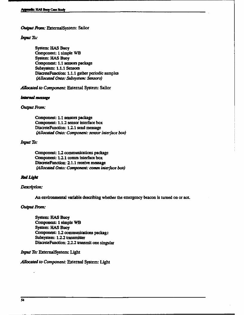
AMMO HAS &my Case S
Outpu Rhmo ExternalSystem: Sailor
System: HAS BuoyComponent: 1 simple WBSystem: HAS BuoyComponent: 1.1 sensors packageSubsystem: 1.1.1 SensorsDiscreteFunction: 1.1.1 gather periodic samples(Allocated Onto: &&bsystem. Sensors)
Allocated to Component: External System: Sailor
kntoRaod m
Outpu From:
Component: 1.1 sensors packageComponent: 1.1.2 sensor Interface boxDiscreteFunction: 1.2.1 send message(Allocated Onto: Component: sensor interface box)
Input TO:
Component: 1.2 communications packageComponent: 1.2.1 comm interface boxDiscreteFunction: 2.1.1 receive message(Allocated Onto: Component: comm interface box)
Red Light
Deipton:
An environmental variable describing whether the emergency beacon is turned on or not.
Outpu FRO-
System: HAS BuoyComponent: 1 simple WBSystem: HAS BuoyComponent: 1.2 communications packageSubsystem: 1.2.2 transmitterDiscreteFunction: 2.2.2 transmit one singular
Input To: ExternalSystem: Light
Allocated to Component: External System: Light
54

Appendix: HAS Buoy Case Study
kP4"
An environmental variable embodying the weather and location report previously requested.
Output From:
System: HAS BuoyComponent: I simple WB
System: HAS BuoyComponent: 1.2 communications package
Subsystem: 1.2.2 transmitterDiscreteFunction: 2.2.1 transmit one periodic(Allocated Onto: Subsystem: transmitter)
Input To: ExternalSystem: Vessel
Allocated to Component: External System: Vessel
&amISMit iem
Output From:
Component: 1.2.1 comm interface boxDiscreteFunction: 2.1.1 receive message(Allocated Onto: Component: comm interface box)
Input To:
Subsystem: 1.2.2 transmitterDiscreteFunction: 2.2.1 transmit one periodic(Allocated Onto: Subsystem: transmitter)
Vend Request
An environmental variable describing a vessel's desire to get a current weather and/or location report.
Output From: ExternalSystem: Vessel
Input To:
System: HAS BuoyComponent: I simple WBSystem: HAS BuoyComponent: 1.1 sensors packageSubsystem: 1.1.1 SensorsDiscreteFunction: 1.1.1 gather periodic samples(Allocated Onto: Subsystem: Sensors)
55

Appft HAS B"o Cue SiY
Allocated to Component: External System: Vessel
Descr4-iion: An environmental variable describing the surrounding ocean.
Output FmL" ExternalSystem: Water
System: HAS BuoyComponent: I simple WBSystem: HAS BuoyComponent: 1.1 sensors packageSubsystem: 1.1.1 SensorsDiscreteFunction: 1.1.1 gather periodic samples(Allocated Onto: Subsystem: Sensors)
Allocated to Component: External System: Water
Wruid Direction
Descriton: An environmental variable describing which way the wind is blowing.
Output From: ExternalSystem: Air
Input To:System: HAS BuoyComponent: I simple WBSystem: HAS BuoyComponent: 1.1 sensors packageSubsystem: 1.1.1 SensorsDiscreteFunction: 1.1.1 gather periodic samples(Allocated Onto: Subsystem: Sensors)
Canie by interface ink" Wind Direction
Allocated to Component: External System: Air
rmdMagnftde
Description: An environmental variable describing how big the wind is.
Output Fron. ExternalSystem: Air
Input To:
System: HAS BuoyComponent: 1 simple WBSystem: HAS BuoyComponent: 1.1 sensors packageSubsystem: 1.1.1 Sensors
56

Append• HAS Btuoy Cue Study
DiscreteFunction: 1.1.1 gather periodic samples(Allocated Onto: Subsystem: Sensors)
Allocated to Component: External System: Air
App.7 Coimo•ms
In order to reduce the size of this document, this section describes only a subset of the Componentsin their entirety. All of the Components, however, are identified. Figure 10 illustrates the componenthierarchy described in this section.Air
Component l•e: External System
Desa "on. HAS Buoy must perform measurements of the atmosphere.
Builds Higher-Level Component/System:
ExternalSystem: AirSystem: HAS Buoy
Allocated Items:
DiscreteItem: Air TemperatureDiscreteItem: Wind DirectionDiscreteItem: Wind Magnitude
HAS Boy
Component Type: System
Desoiptn."
HAS Buoy is the internal part of the system, comprising all hardware and its embedded software.
Builds Higher-Level Component/System: System: HAS Buoy
Built From Components:
1.1 sensors package1.2 communications package1.3 other packages
Allocated Functions:
"TimeFunction: 0 Buoy Performance"flmeFunction: 1 HAS Buoy
Component-Level Performace Requirements:
Air Temperature AccuracyPeriod Accuracy to 10%Vater Temperature Accuracy
57

A-fuf HAS BW rC So*
se
$8I

APPeAm HAS DOW Cute Stu
Component 73pe External System
Desacdon: HAS Buoy must turn on a red emergency light in this external medium.
Builds Higher-Level ComponentlSystem:
System: HAS BuoyExternalSystem: light
Allocated Items: DiscreteItem: Red Light
Om4a S3an
Component 15pe: External System
Desvpion: HAS Buoy must be located via information from this external medium.
Builds Higher-Level Component/System:
System: HAS BuoyExtemalSystem: Omega System
Allocated Items: DiscreteItem: Buoy Location
Sailor
Component 7:pe: External System
Desaipon
HAS Buoy must take emergency button pushes from this personal, but external, medium.
Builds Higher-Level Component/System:
System: HAS BuoyFxtemalSystem: Sailor
Allocated Items: DiscreteItem: Emergency Button
Component 7Tpe: External System
Detaption: HAS Buoy must receive requests from, and send reports to, this external medium.
Builds Higher-Level Component/System:
System: HAS BuoyExtemalSystem: Vessel
59

Aocated ltems:
Discreteftem: ReportDiscretcem: Vessel Request
Component Tpe. External System
Descrdon: HAS Buoy must perform measurements of this external medium.
Bds Higher-Level ComponentlSystem:
System: HAS BuoyExternalSystem: Water
Allocated Items: DiscreteItem: Water Temperature
1 simple WB
Component 7Tpe:
Bulb From Components:
1.1 sensors package1.2 communications package1.3 other packages
1.1 sensors package
Component Type"
Builds Higher-Level ComponentlSystem:
Component: HAS BuoyComponent: 1 simple WB
Built From Components:
Subsystem: 1.1.1 Sensors1.1.2 sensor interface box
Allocated Functions: TimeFunction: 1 sensor functions
The remaining components are listed only by name.
1.J Sensors
1.1.2 sewer interface box
1.2 commucataons package
60

-peaft HAS M CAN Stu*
12.1 cn lo e box1.232 bm.m
1.23 recebw
1.3 .skwpockaga
App.U Im FACES BEmvEm COMPONENIS
Iems Flowi "from" Component: comnm interface box"into" Component: sensor interface box
Diseteltem: acknowledgementOutput FRwo" 2.1.1 - receive messeInput To: 1.2.2 - wait for acd
Itsms Flowing "from" Component: comm interface box"into" Component: sensors package
Discreteltem: acknowledgementOutput Fron.. 2.1.1 - receive messageInput To: I - sensor functions
Items Flowing "from" Component: comm interface box"into" Subsystemn transmitter
DiscreteItem: transmit itemOutput From. 2.1.1 - receive messageInput To: 2.2.1 - transmit one periodic
Items Flowing "from" Component: communications package"into" Component: sensor interface box
Discreteltem: acknowledgementOutput From: 2 - communication functionsInput To: 1.2.2 - wait for ack
Items Flowing "from" Component: communications package"into" Component: sensors package
DiscreteItem: acknowledgementOutput From: 2 - communication functionsInput To:. - sensor functions
Items Flowing "from" Component: sensor interface box"into" Component: comm interface box
DiscreteItem: internal messageOutput From: 1.2.1 - send messageInput To: 2.1.1 - receive message
61
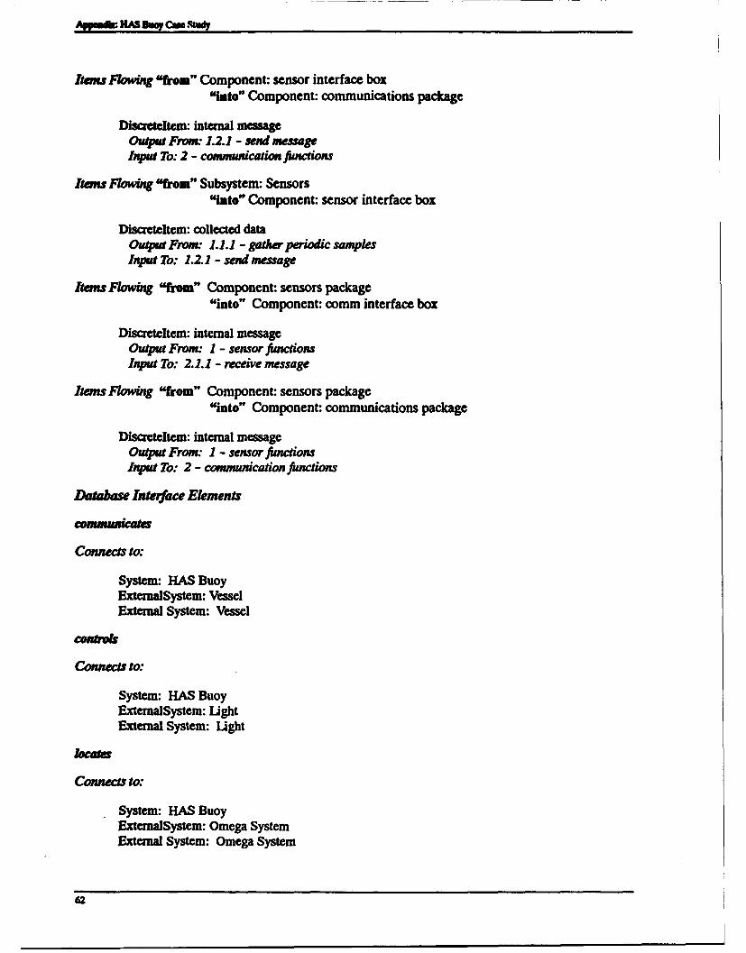
Items Flowing "from" Component: sensor interface box"into" Component: communications package
Discreteltem: internal messageOutput From. 1.2.1 - send messageInput To: 2 - communication functions
items Flowing "from" Subsystem: Sensors"into" Component: sensor interface box
Discreteltem: collected dataOutput Fromn 1.1.1 - gather periodic samplesInput To: 1.2.1 - send message
Items Flowing "from" Component: sensors package"into" Component: comm interface box
DiscreteItem: internal messageOutput From.. 1 - sensor functionsInput To: 2.1.1 - receive message
items Flowing "from" Component: sensors package"into" Component: communications package
Discreteltem: internal messageOutput From: I - sensor functionsInput To: 2 - communication functions
Dtabase Interface Elements
Connects to:
System: HAS BuoyExternalSystem: VesselExternal System: Vessel
Connects to:
System: HAS BuoyExtemalSystem: LightExternal System: Light
/octa
Connects to:
System: HAS BuoyExternalSystem: Omega SystemExternal System: Omega System
62

-fenh HAS Duq cM sh
ExternalSystem: AirExternal System: AirSystem: HAS BuoyExternal System: WaterExternalSystem: Water
Connect, to:
System: HAS BuoyExternal System: SailorExternalSystem: Sailor
App." Sisru UOMAMoNtr P"A~Mus
This section did not apply to this case study.
APP.3 HAS BUOY CoRE MODEL
This section contains the CoRE model for the HAS Buoy that was derived based on the RDD-100model in Section App.2. Section App.3.1 describes how RDD-100 database elements of the HAS Buoymodel were mapped to CoRE elements. Section App.3.2 contains the results of filtering the RDD-100model into teamwork format. Section App.3.3 contains the remaining CoRE work products for theHAS Buoy system-
App.3.1 MAPPmG FROM RDD-100 To CoRE
"Ibble 7 summarizes how RDD-100 database elements map to CoRE inputs for the HAS Buoy model,according to the mapping specified in Section 3.2. For each expected input to CoRE, Table 7 identifies:
"* The RDD-100 database elements providing the necessary information
"* An estimation of the degree of completeness provided by the mapping
Table 7. Mapping From RDD-100 to CoRE
Execed CoRE InpUts RDD-.00 Element Iype (HAS Buoy Instanc•) Degree of MappingMission statement soums Complete
0 HAS ADARTS Problem Statement* HAS Stabilities* HAS Variabilities
System model FNet Complete* System Context Diagram
"* HAS Buoy (system)"* Air (external system)", Water (external system)"* Vessel (external system)"* Light (external system)"* Omega System (external system)* Sailor (external system)
63

Aff f HAS "e CM.S
Table 7, continued
System requirements Sysyrn ireWin Completespeification • Air Temperature
"* Communications"* Computer"* Emergency Switch"* External Location"* Fixed Periodicity"• etc. (see Section Appl.2)
System component interface Interice Completespecifications IwnLk*
Diacrskwn
Requirements information Perfamwice.inex Incompleterelating to system performance * Air Temperature Accuracy
" Period Accuracy to 10%"* %ater Temperature Accuracy
Table 8 summarizes how the initial set of CoRE work products were derived from RDD-100 databaseelements for the HAS Buoy model, according to the mapping specified in Section 3.3.
Table 8. Mapping From RDD-100 to Initial CoRE Products
CoRE Products RDD-100 Element lype (HAS Buoy Instances) Degree of Mapping
CoRE information model Intwface Complete"* communications"* controls"* locates"* monitors"* switches
"• Air"* Water* VesseleLight* Omega System* Sailor
. HAS Buoy
Candidate environmental Discreteftern Completevariables * Vessel Request
"• Report"* Air Temperature"* Vater Ibmperature"* Wind Magnitude"* Wind Direction"* Buoy Location"* Emergency Button* Red Light
64

Appeeft HAS B4" Cm Study
ilble 8, continued
Likely changes list Cducanmn Complete"* Error Correction?"* How Many Formats?"* How Much History?
"* Available Hardware"* 7wo Formats
Environmental constraints Cotutait Incompletespecification OWST) • Cost
* RAINFORM Format
Mible 9 summarizes how the additional CoRE work products were derived from RDD-100 databaseelements for the HAS Buoy model, according to the mapping specified in Section 3.4.
Ibble 9. Mapping From RDD-100 to Mditioaal CoRE Products
CoRE Products RDD-100 Element 7ype (HAS Buoy Instances) Degre of Mapping
Context diagram FNI Complete* System Context Diagram
Monitored and controlled vari- Dlscmeftm Incompleteable definitions a Vessel Request
0 Report* Air Temperature* Water Temperaturea Wind Magnitude* Wind Direction• Buoy Location- Emergency Button- Red light
App.3.2 TvAWOKREM. M= VENsION OF HAS BuoY
This section contains those teamwork work products that were generated by RDD-100's teamworkfilter from the RDD-100 model of the HAS Buoy system. Some parts of the generated teamworkmodel were not useful for CoRE and have been omitted.
Section App.3.2.1 contains the generated teamwork process index, and Section App.3.2.2 contains thegenerated teamwork data dictionary.
App,3.U.1 Teamwork Process Index
The teamwork process index generated by RDD-100 contained a context diagram, a data flow/controlflow diagram hierarchy, and a number of p-specs. The context diagram was derived from the behaviordiagram for the RDD-100 System Compownt. Each data flow/control flow diagram in the hierarchywas derived from a corresponding RDD-100 FNet or TimeFunction. The data flow/control flowdiagrams contained a data transformation for each DiscreteFuncton contained by the FNet orTkmeFunction. Data flows in and out of data transformations were derived from Discreteftemns that wereinputs and outputs of the DlscreteFunctions.
65

-fftf HAS ftq Cme1
The generated context diagram in Figure 11 turned out to be ideal for CoRE.
Contut-Diag .SYuteM~ontextjhaV=JmN
HAsD..yTF
AltIP 0 Salhw.IY
Whuplude..nI RerWt.DI
Red..L/sht..DI
[Omega..Siste....IT .Loam.D WaterTmperature DI Waa1
Figure 11. HAS Buoy Contct Diagram
Neither the generated data flow/control flow diagrams nor the generated p-specs were useful forCoRE because they provide too low a level of detail. The generated p-specs contained only input andoutput lists.
App.3.2.2 Teamwork Data Dictionary
This section contains the teamwork data dictionary entries generated by RDD-100.
acknowledgement DI (data flow, pel) -
Author System User;Creation Date 31 January 1992;Modification Date 7 October 1993;Modification Time 3:35:59 pm;Size 1;RDD Type message;
Air TemperatureDI (data flow, pel) -* An environmental variable describing the atmosphere. *
Author System User;Creation Date 11 August 1993;
66

Appd HAS BuWj Cam SR
Modification Date 7 October 1993;Modification Time 3:36:00 pm;Minimum Value -40.0;Maximum Value 60.0;Mean Value 20.0;Units degree Celsius;Size 1;item Type physical;RDD Type message;
BuoyLocationDI (data flow, pel) -* An environmental variable describing where the HAS buoy is situated.
Author System User;Creation Date 11 August 1993;Modification Date 7 October 1993;Modification Time 3:36:00 pm;Units characters;Size 10;Item Type data;RDD Type message;
collected dataDI (data flow, pel) -
Author System User;Creation Date 31 January 1992;Modification Date 7 October 1993;Modification Time 3:36:01 pm;Size 1;RDD Type message;
EmergencyButtonDI (data flow, pel) -* An environmental variable describing whether a sailor has gotten to
the HAS buoy and pressed the button to cut on the emergency beacon.
Author System User;Creation Date 11 August 1993;Modification Date 7 October 1993;Modification Time 3:36:01 pm;Minimum Value 0.0;Maximum Value 0.0;Units B.its;Size 1;Item Type digital;RDD Type message;
internalmessageDI (data flow, pel) -
Author System User;Creation Date 31 January 1992;Modification Date 7 October 1993;Modification Time 3:36:02 pm;
67

Appeaf HAS Diay C& Stwdy
Size 1;RDD Type message;
Red LightDI (data flow, p.l) -* An environmental variable describing whether the emergency beacon is
turned on or not. *
Author System User;Creation Date 11 August 1993;Modification Date 7 October 1993;Modification Time 3:36:02 pm;Minimum Value 0.0;Maximum Value 0.0;Units Bits;Size 1;Item Type digital;RDD Type message;
ReportDI (data flow, 1 1) -
* An environmental variable embodying the weather and location reportpreviously requested.*
Author System User;Creation Date 11 August 1993;Modification Date 7 October 1993;Modification Time 3:36:02 pm;Units characters;Size 100;Item Type data;RDD Type message;
transmit-item DI (data flow, pel) -
Author System User;Creation Date 31 January 1992;Modification Date 7 October 1993;Modification Time 3:36:03 pm;Size 1;RDD Type message;
VesselRequestDI (data flow, p.l) -* An environmental variable describing a vessel's desire to get a
current weather and/or location report.*
Author System User;Creation Date 11 August 1993;Modification Date 7 October 1993;Modification Time 3:36:03 pm;Units characters;Size 1;Item Type data;RDD Type message;
68
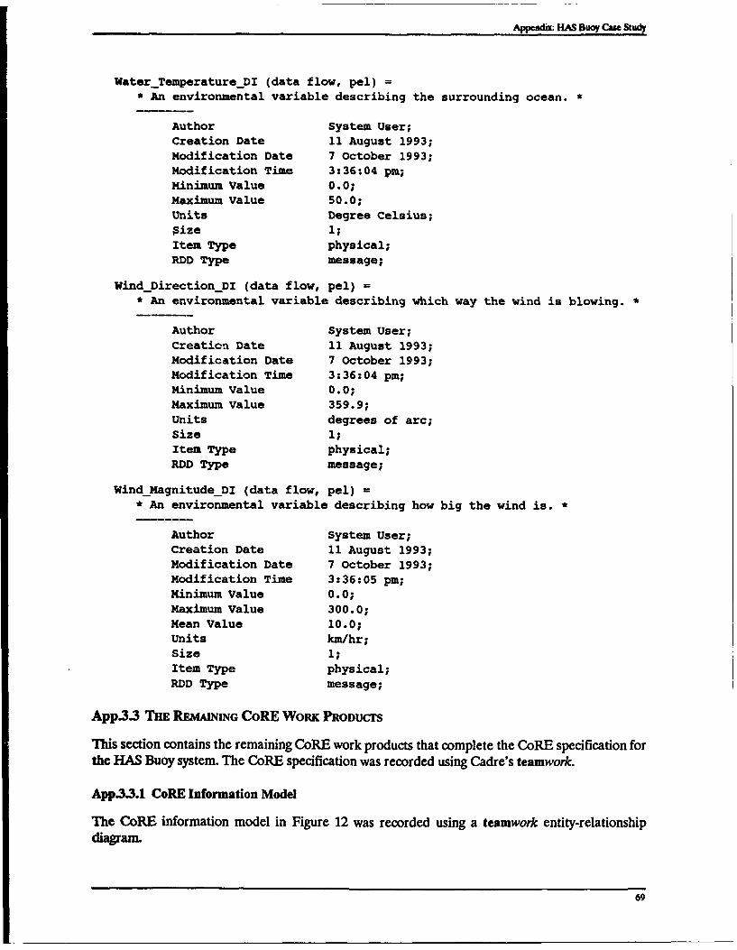
Appendi: HAS BDu Cue Stwy
WaterTemperatureDI (data flow, pel) =* An environmental variable describing the surrounding ocean.
Author System User;Creation Date 11 August 1993;Modification Date 7 October 1993;Modification Time 3:36:04 pm;Minimum Value 0.0;Maximum Value 50.0;Units Degree Celsius;Size 1;Item Type physical;RDD Type message;
WindDirectionDI (data flow, pel) =* An environmental variable describing which way the wind is blowing.
Author System User;Creation Date 11 August 1993;Modification Date 7 October 1993;Modification Time 3:36:04 pm;Minimum Value 0.0;Maximum Value 359.9;Units degrees of arc;Size 1;Item Type physical;RDD Type message;
Wind Magnitude_DI (data flow, pel) =* An environmental variable describing how big the wind is.
Author System User;Creation Date 11 August 1993;Modification Date 7 October 1993;Modification Time 3:36:05 pm;Minimum Value 0.0;Maximum Value 300.0;Mean Value 10.0;Units km/hr;Size 1;Item Type physical;RDD Type message;
App.3.3 THE REMAINIG CoRE WoRK PRODUCrS
This section contains the remaining CoRE work products that complete the CoRE specification forthe HAS Buoy system. The CoRE specification was recorded using Cadre's teamwork.
App3.3.1 CoRE Information Model
The CoRE information model in Figure 12 was recorded using a teamwork entity-relationshipdiagranL
69

Appsadk HAS ftoy Can Sludy
o-n
I0-
I 0<-N
Figure 12. CoRE Information Model
App3.3.2 Environmental Variable Definitions
Monitored variables are identified on the system context diagram as system input data flows.Controlled variables are identified on the system context diagram as system output data flows. Thedata dictionary entries associated with the data flows define the environmental variables. Someexamples of environmental variable definitions are shown below.
WaterTemperature (data flow) =Temperature.
Variable WaterTemperature (MonitoredVariable)PhysicalInterpretation The temperature of the water four feet below the
surface of the water in degrees centigrade.Type TEMPERATUREValues 0 .. 100
WindDirection (data flow)Direction.
Variable WindDirection (Monitoredvariable)PhysicalInterpretation The direction the wind is blowing in degrees
(where 0 is due north and 90 is due east),measured 10 feet above the surface of the water.
Type DIRECTIONValues 0 <= WindDirection < 360 (0 = north, 90 = east,
180 = south, 270 = west)
Report (data flow) -
ReportType+ ASCIIReport
70

__________________________Appendix: HAS Buoy Cue Study
Variable Report (ControlledVariable)PhysicalInterpretation
while ReportType-SOSReportbroadcasting data defined by DDE SOSData
while Report _Type-Wind andTemperature Reportbroadcasting data defined by DDE WindandTemperatureData
while Report Type-WeatherHistoryReportbroadcasting data defined by DDE WeatherHistoryData
while ReportType-AirplaneDetailedReportbroadcasting data defined by DDE AirplaneDetailedData
while ReportType-Ship_DetailedReportbroadcasting data defined by DDE ShipDetailedData
while ReportType-None, no broadcastingType Enumeration + ASCII TextValues for Enumeration, see PhysicalInterpretation
for ASCII Text, standard 8-bit ASCII characterset
App.3.3.3 Dependency Graph
The CoRE dependency graph in Figure 13 was recorded using a teamwork level 0 data flow diagram.Classes are illustrated using data transformations. Terms and environmental variables on class inter-faces are illustrated using data flows between transformations. Input and output variables areillustrated using external input and output data flows.
Data flow diagrams were also used to identify the IN, REQ, and OUT relations contained by eachclass. There is a lower level data flow diagram (see Figure 14) attached to each class on the dependencygraph containing those relations.
App.3.3A Relations
IN, REQ, and OUT relations were defined using teamwork process activation tables. NAT relationswere defined textually in the data dictionary. The following subsections contain examples of theserelations.
App.3.3.4.1 IN Relations
Figure 15 illustrates an example of an IN relation for the monitored variable Wind(INRelation for Wind). WindVectorX and WindVectorY are terms defined in the data dictionary.WindSensors is the input variable used to derive the Wind monitored variable.
IN relations are also needed for the following monitored variables:
"* Air Temperature
"* Waterýlmperature
"• BuoyLocation
"• VesselRequest
"* EmergencyButton
71

taffmadHAS UT CM Sudy
Wind~Object
Wiud~ector .2 IN Rel tion frWn
VVn endo Timingues
Air9emeemaerr
Directionperaturedensor
SI I Reltio forAir Temperature
Ai avTuepSesrTmg
Fiur 1. izntperofac Woe ee aaFo ig amtfr aO
72 itrfc

Appendix: HAS Buoy~ Con Stany
2-s2;IN _Relaioq_!or -Wid
Camilitin I Coujllon 2 a' VWWSeK5Mr(C1) - WInd5~ason(C2) = Wiad~easm(C3)= WlndSmsmu(C4)in
WVs~dw~oX > - 0 Waddw tr> 0~ Wini~ctorY 0 WMadVectorX 0
winirisdarX >- 0 WiadVecteY < 0 0 ABS(VWndVectoY) WiadVectorX 0
'mwhuctorx c< 0 or Wn~dw 0: %InflMctoY 0 0 ABS(WlndVectorX)
VVn~ew < C~~ww 0 ABStoredY) 0 ABS(WIdV~cteX)
Figure 15. Example of an IN Relation
App.33.4.2 REQ Relations
Figure 16 illustrates an example of a REQ relation (REQ_ Relation_forReport) that maps multiplemonitored variables to the controlled variable Report.
S-31;10REQRelation for Report
Event U~~ epeeor¶yie ReporL.ASCJILReport--------------------- --------------------II----------------------------------------
@T(IlMwe MOD 60]1=0) when JaMode(SOS) ii SOSReport" ASCU(SOSData)
@T(rfnme MOD 601=-0) when JnMode(Norinal) :: Wind andpertwre Repea ASCII(WindndTemaprtureD.ab
@TVss~~ue -ip~eDaI0PwtRquA) 'W aeý Detailed Report" ASCII(Airplaneý Detailedk Data)@T(%eael~qeA - "WhpDetaII0_Rtpoat.Requeat") "ShipDetailedReport ASCU(Sklpdeafled..Data)
OT(VesseiRequeat - wHistoryRortRequest") "Weather _Histoa Report" ASCliWater..H~storyData)
Figure 16. Example of an REQ Relation
A REQ relation is also needed for the controlled variable RedLight.
App.3..43 OUT RELATioNS
Figure 17 illustrates an example of an OUT relation (OUTRelation-forRedLight). An OUTrelation is also required for the controlled variable Report.
LighLSwitch ; ; RedLight ]8-2, [---------------------- U ------------
O~ ato orRd~gt LightOn : "On"
Light Off -Off-
Figure 17. Example of an OUT Relation
73

App.3.3AA NAT Relations
Examples of NAT relations for the HAS Buoy system are shown below:.
-100 <- AirTemperature <- 100 (degrees centigrade)
0 <- WindMagnitude <- 250 (nautical miles per hour)
AM3.3.S Tanrs
Terms were specified using data dictionary entries. Some examples of term definitions are shownbelow:
AveragedhirTemperature (data flow) -
AveragedAirTemperature : TBMPZRATURB:- ROUND I (SUM i: 0 <- i <- 5 :: Air'1aperature(t-10*i) / 6 ) ]
Wind and_TemperatureData (data flow) -* WindandTemperature can be expressed as a function of time t, where
Wind-andTemperatureData (t) - the set including each of thefollowing at time t: *
BuoyLocation"+ AveragedWaterTemperature"+ AveragedAirTemperature"+ AveragedWindDirection"+ AveragedWindMagnitude }
App.3.3.6 Timing and Accuracy Constraints
Tuning and accuracy constraints were specified using data dictionary entries attached to each IN,OUT and REQ relation. Each relation has a body of text with the suffix " Timing" attached to theappropriate teamwork process activation table. The data dictionary entries associated with thesebodies of text specify timing and accuracy constraints. Examples are shown below:
WindSensorTiming (data flow) -
Periodic (sensoroffset,30.0 second period,1.0 second delay).
The wind sensor values are updated every 30 seconds, but the valueis up to I second old by the time the software gets it.
ReportTiming (data flow) -Periodic (startupoffset + 30 seconds,
60.0 second period,5.0 second delay)
andDemand (startupoffset,
reportrequest (ReportType),reportingdelay (ReportType)).
74

AppendiE HAS 8"o~ Cue SlWiY
Reports are generated regularly, but special reports can also berequested.
reporting delay (data flow) -
when Airplane DetailedReport -> 2.0 minutes;when Ship DetailedReport -> 5.0 minutes;when WeatherHistoryReport -> 6.0 minutes;
Each kind of report requires a different response time based onthe time the platform will be in range.
App.3.4 INPuT AND OUrrT VAPiUT DEFNmONS
Input and output variables were specified using data dictionary entries. Some examples of input andoutput variable definitions are shown below-
AirTemperatureSensor (data flow) -
DataItem AirTemperatureSensorHardware Air temperature sensorValues -128 <- AirTemperatureSensor <- 127DataTransfer Port BDataRepresentation 8-bits, two's-complement integer
Button-Indicator (data flow) -
DataItem Button-IndicatorHardware Emergency button on buoyValues Pressed (1) or released (0)DataTransfer Port EDataRepresentation Most significant bit (bit 0) of the 8-bit port:
2#lxxxxxxx# - Pressed,2#Oxxxxxxx# - Released.
OutgoingRadioMessage (data flow) -
DataItem OutgoingRadioMessageHardware Radio transmitterValues SOSReport,
WindandTemperatureReport,AirplaneyDetailedReport,Ship Detailed Report,WeatherHistoryReport,None.
DataTransfer Port GDataRepresentation 512 bytes:
Byte 1: 2#10000001# means bytes 3-512 contain a page of an SOS Report2#10000010# means bytes 3-512 contain a page of a
WindandTemperature_Report2#10000011# means bytes 3-512 contain a page of an
AirplaneDetailed Report
75

ApmhHAS B"ar CM Study
2#10000100# means bytes 3-512 contain a page of aShipDetailedReport
2#10000101# means bytes 3-512 contain a page of aWeather His tory_Aeport
2#Oxxxxxxx# means None - no message is be transmitted (ignorebytes 2-512)
Byte 2: Bits 0-3: 4-bits range 1 .. 16 representing total number ofpages in message
Bits 4-7: 4-bits range 1 .. 16 representing number of pagebeing transmitted
Bytes 3-512: Message represented by ASCII characters.End of message represented by 16#FF#.
App.3.5 MODE OuASSES
Mode classes were defined using teamwork state-transition diagrams. There was only one mode classfor the HAS Buoy problem (see Figure 18).
9-sl;14
Mode&_ClforSyszNMode 1o SOS
Termlnate SOS Slnal
Button-Presed I-4FNormal]
Figue 18. HAS Buoy Mode ams
76

LIST OF ABBREVIATIONS AND ACRONYMS
ADAM Ada-based Design Approach for Real-Tune Systems
CASE computer-aided software engineering
CDIF CASE Data Interchange Format
CoRE Consortium Requirements Engineering
ERA entity-relationship-attribute
HAS Host-at-Sea
IN input (CoRE's abbreviation for "input" relations)
NAT natural (CoRE's abbreviation for "natural" relations)
n.d. no date
OUT output (CoRE's abbreviation for "output" relations)
p-spec process specification
RDD Requirements Driven Design
REQ required (CoRE's abbreviation for "required" relations)
SEN System Engineering Notebook
77

UNS of Abb,.vkuim aod Auoayn
Mhipage Wnentionally left blank
78

REFERENCES
Alford, Mack Behavior Based System Test Planning. San Jose, California:n.d. Ascent Logic Corporation.
Ascent Logic Corporation RDD-100 Exensible Database Manager, release 3.0. San Jose,1991a California: Ascent Logic Corporation.
1991b RDD-I0 Syem Engineering Notebook, release 3.0. San Jose,California: Ascent Logic Corporation.
1992a RDD-100 User's Guide, release 3.0.2. San Jose, California:Ascent Logic Corporation.
1992b RDD-10Report WriterManual, release 3.0. San Jose, California:Ascent Logic Corporation.
1993a RDD-100 Customer Education. San Jose, California: AscentLogic Corporation.
1993b RDD-100 Bridge to teamwork. Beta 1. San Jose, California:Ascent Logic Corporation.
Cadre Týbhnologies, Inc. teamwork Toolkit Utilities User's Guide, release 4.0. Providence,1990 Rhode Island: Cadre Technologies, Inc.
Naval Research Laboratory Software Engineering Prnciples. Washington, D.C.: Naval1980 Research Laboratory.
O'Rourke, Joel RDD-100: A System Engineering Support Tool Review Draft, Rev.1993 02. San Jose, California: Ascent Logic Corporation.
Software Productivity Consortium Requirements Engineering Guidebook,Consortium SPC-92060-CMC, version 01.00.09. Herndon, Virginia:1993 Software Productivity Consortium.
79

Mh page intentionaily left blank
so