Embed Size (px)
Citation preview
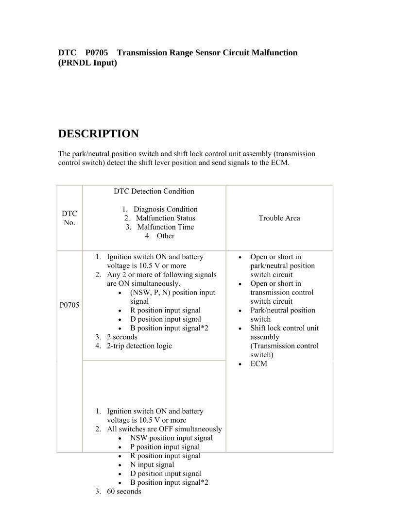
DTC P0705 Transmission Range Sensor Circuit Malfunction (PRNDL Input)
DESCRIPTION The park/neutral position switch and shift lock control unit assembly (transmission control switch) detect the shift lever position and send signals to the ECM.
DTC No.
DTC Detection Condition
1. Diagnosis Condition 2. Malfunction Status 3. Malfunction Time
4. Other
Trouble Area
1. Ignition switch ON and battery voltage is 10.5 V or more
2. Any 2 or more of following signals are ON simultaneously.
• (NSW, P, N) position input signal
• R position input signal • D position input signal • B position input signal*2
3. 2 seconds 4. 2-trip detection logic
P0705
1. Ignition switch ON and battery voltage is 10.5 V or more
2. All switches are OFF simultaneously • NSW position input signal • P position input signal • R position input signal • N input signal • D position input signal • B position input signal*2
3. 60 seconds
• Open or short in park/neutral position switch circuit
• Open or short in transmission control switch circuit
• Park/neutral position switch
• Shift lock control unit assembly (Transmission control switch)
• ECM
4. 2-trip detection logic
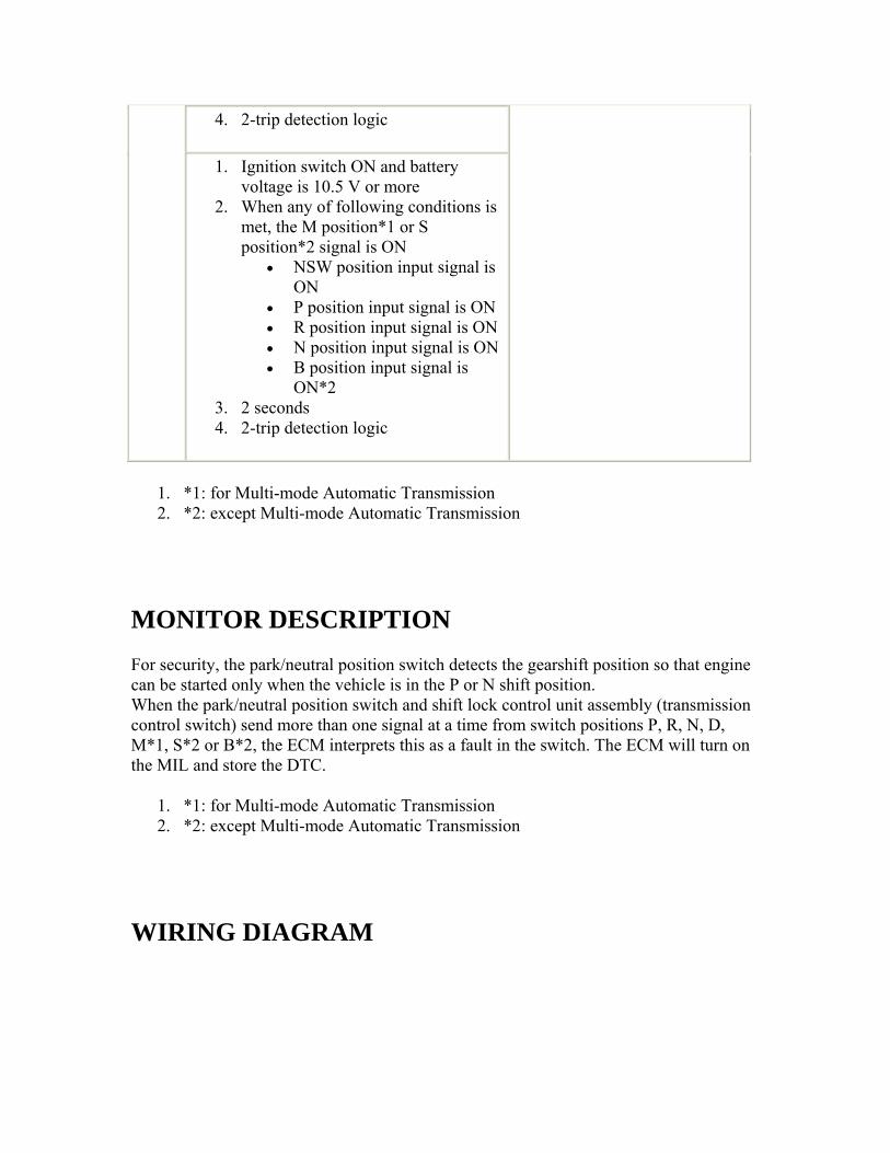
1. Ignition switch ON and battery voltage is 10.5 V or more
2. When any of following conditions is met, the M position*1 or S position*2 signal is ON
• NSW position input signal is ON
• P position input signal is ON • R position input signal is ON • N position input signal is ON • B position input signal is
ON*2 3. 2 seconds 4. 2-trip detection logic
1. *1: for Multi-mode Automatic Transmission 2. *2: except Multi-mode Automatic Transmission
MONITOR DESCRIPTION For security, the park/neutral position switch detects the gearshift position so that engine can be started only when the vehicle is in the P or N shift position. When the park/neutral position switch and shift lock control unit assembly (transmission control switch) send more than one signal at a time from switch positions P, R, N, D, M*1, S*2 or B*2, the ECM interprets this as a fault in the switch. The ECM will turn on the MIL and store the DTC.
1. *1: for Multi-mode Automatic Transmission 2. *2: except Multi-mode Automatic Transmission
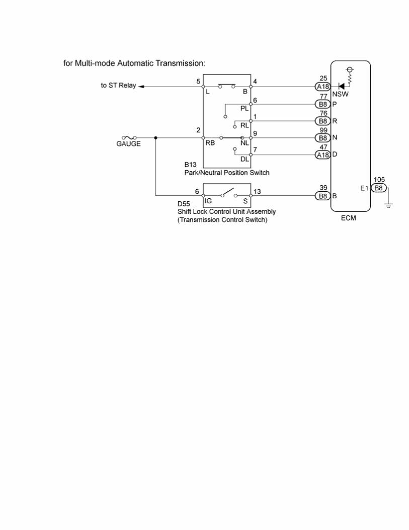
WIRING DIAGRAM
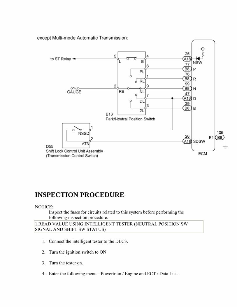
INSPECTION PROCEDURE NOTICE:
Inspect the fuses for circuits related to this system before performing the following inspection procedure.
1.READ VALUE USING INTELLIGENT TESTER (NEUTRAL POSITION SW SIGNAL AND SHIFT SW STATUS)
1. Connect the intelligent tester to the DLC3.
2. Turn the ignition switch to ON.
3. Turn the tester on.
4. Enter the following menus: Powertrain / Engine and ECT / Data List.
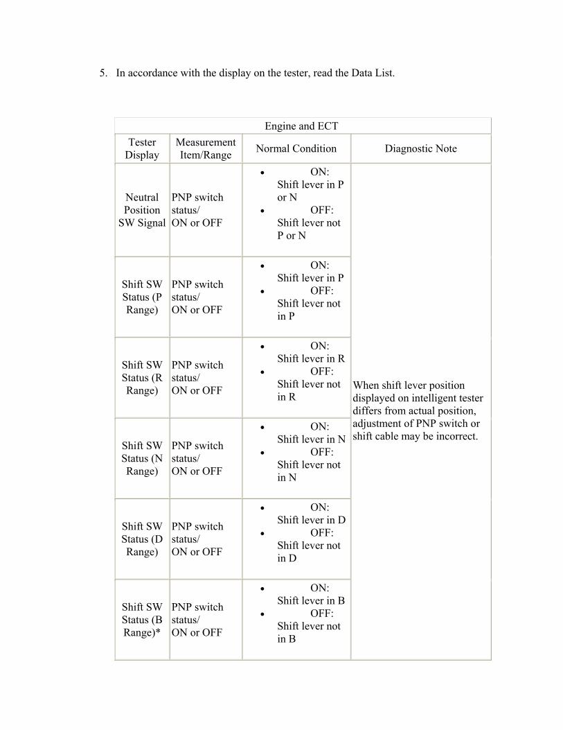
5. In accordance with the display on the tester, read the Data List.
Engine and ECT Tester
Display Measurement Item/Range Normal Condition Diagnostic Note
Neutral Position
SW Signal
PNP switch status/ ON or OFF
• ON: Shift lever in P or N
• OFF: Shift lever not P or N
Shift SW Status (P Range)
PNP switch status/ ON or OFF
• ON: Shift lever in P
• OFF: Shift lever not in P
Shift SW Status (R Range)
PNP switch status/ ON or OFF
• ON: Shift lever in R
• OFF: Shift lever not in R
Shift SW Status (N Range)
PNP switch status/ ON or OFF
• ON: Shift lever in N
• OFF: Shift lever not in N
Shift SW Status (D Range)
PNP switch status/ ON or OFF
• ON: Shift lever in D
• OFF: Shift lever not in D
Shift SW Status (B Range)*
PNP switch status/ ON or OFF
• ON: Shift lever in B
• OFF: Shift lever not in B
When shift lever position displayed on intelligent tester differs from actual position, adjustment of PNP switch or shift cable may be incorrect.
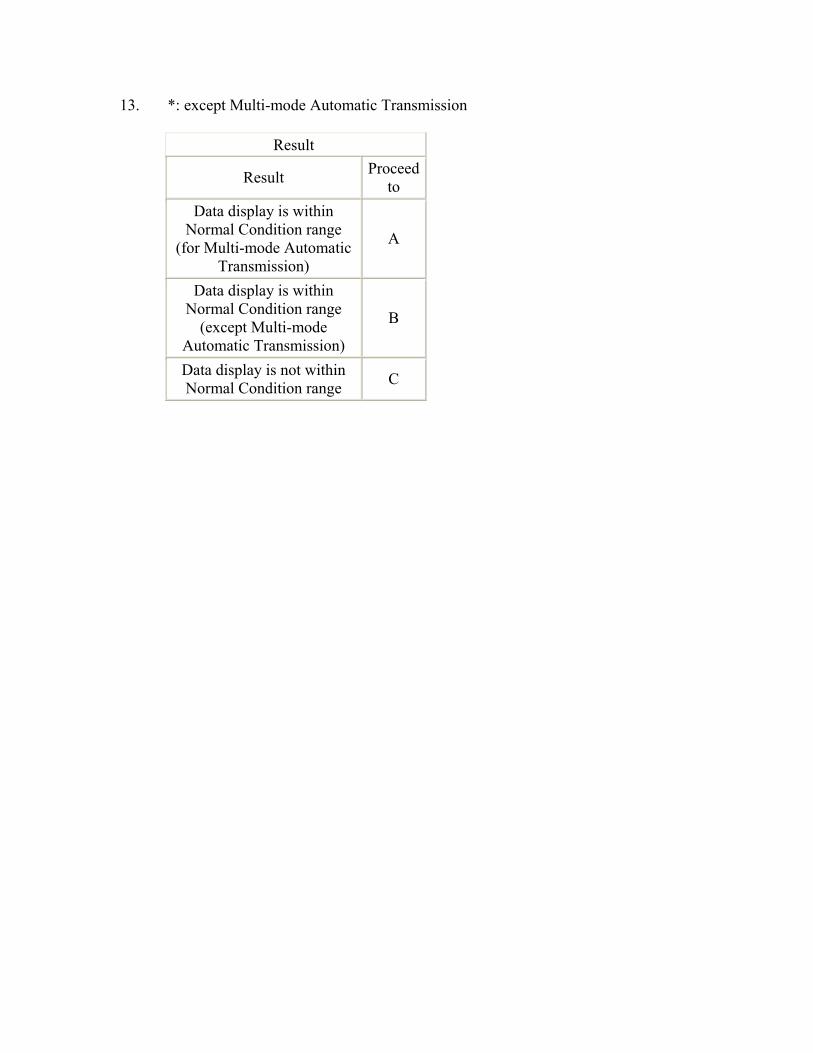
13. *: except Multi-mode Automatic Transmission
Result
Result Proceed to
Data display is within Normal Condition range
(for Multi-mode Automatic Transmission)
A
Data display is within Normal Condition range
(except Multi-mode Automatic Transmission)
B
Data display is not within Normal Condition range C
B
Go to step 8
C
Go to step 13
A
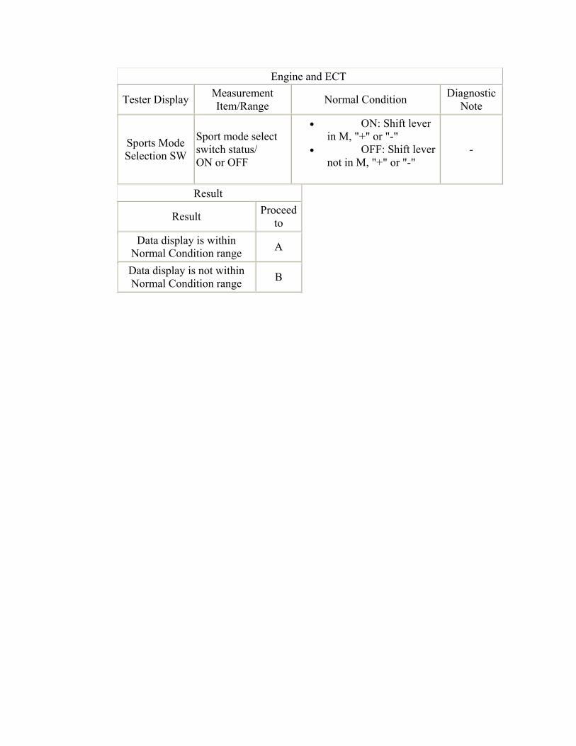
2.READ VALUE USING INTELLIGENT TESTER (SPORTS MODE SELECTION SW)
1. Enter the following menus: Powertrain / Engine and ECT / Data List.
2. In accordance with the display on the tester, read the Data List.
Engine and ECT
Tester Display Measurement Item/Range Normal Condition Diagnostic
Note
Sports Mode Selection SW
Sport mode select switch status/ ON or OFF
• ON: Shift lever in M, "+" or "-"
• OFF: Shift lever not in M, "+" or "-"
-
Result
Result Proceed to
Data display is within Normal Condition range A
Data display is not within Normal Condition range B
B
Go to step 3
A
CHECK INTERMITTENT PROBLEMS () 3.INSPECT SHIFT LOCK CONTROL UNIT ASSEMBLY (TRANSMISSION CONTROL SWITCH)
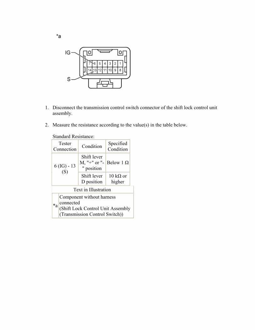
1. Disconnect the transmission control switch connector of the shift lock control unit assembly.
2. Measure the resistance according to the value(s) in the table below.
Standard Resistance: Tester
Connection Condition Specified Condition
Shift lever M, "+" or "-" position
Below 1 Ω6 (IG) - 13
(S) Shift lever D position
10 kΩ or higher
Text in Illustration
*a
Component without harness connected (Shift Lock Control Unit Assembly (Transmission Control Switch))
NG
REPLACE SHIFT LOCK CONTROL UNIT ASSEMBLY ()
OK
4.CHECK HARNESS AND CONNECTOR (IG POWER SUPPLY)
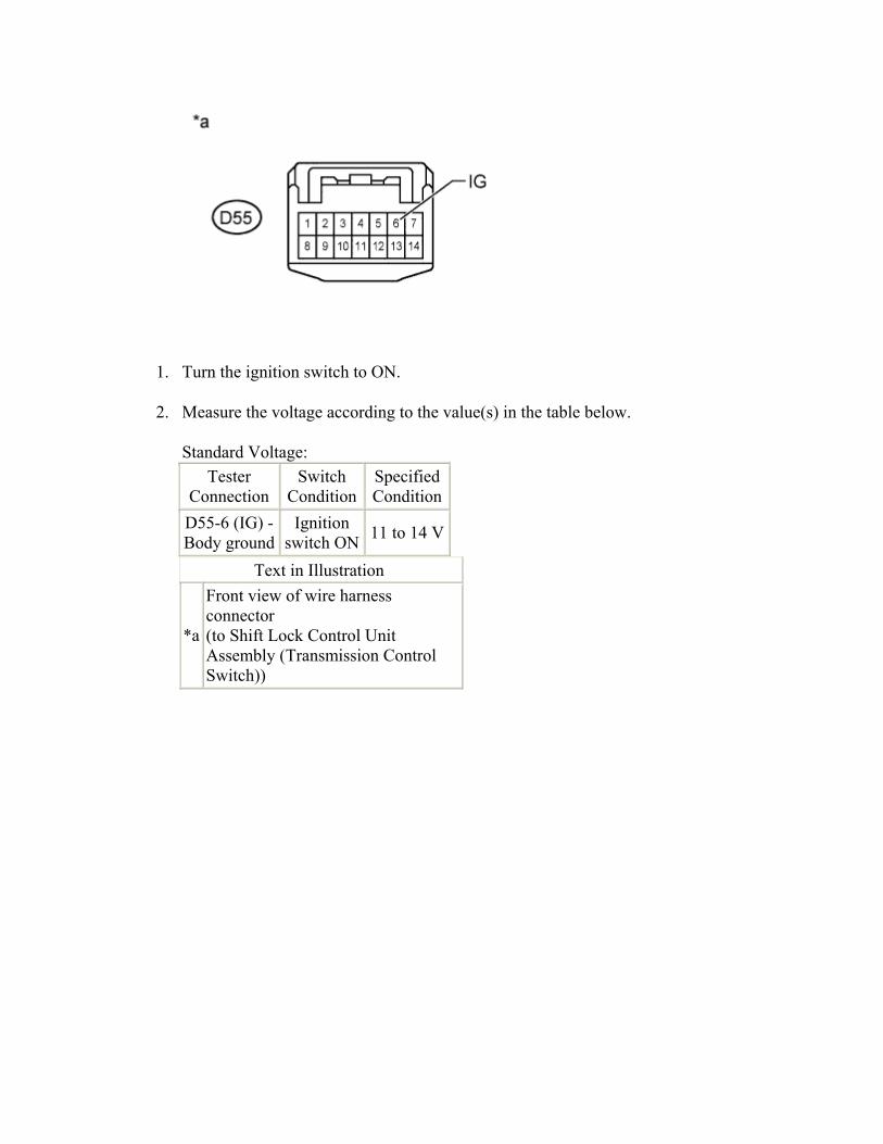
1. Turn the ignition switch to ON.
2. Measure the voltage according to the value(s) in the table below.
Standard Voltage: Tester
Connection Switch
ConditionSpecified Condition
D55-6 (IG) - Body ground
Ignition switch ON 11 to 14 V
Text in Illustration
*a
Front view of wire harness connector (to Shift Lock Control Unit Assembly (Transmission Control Switch))
NG
REPAIR OR REPLACE HARNESS OR CONNECTOR
OK
5.CHECK HARNESS AND CONNECTOR (SHIFT LOCK CONTROL UNIT ASSEMBLY - ECM)
1. Disconnect the ECM connector.
2. Measure the resistance according to the value(s) in the table below.
Standard Resistance:
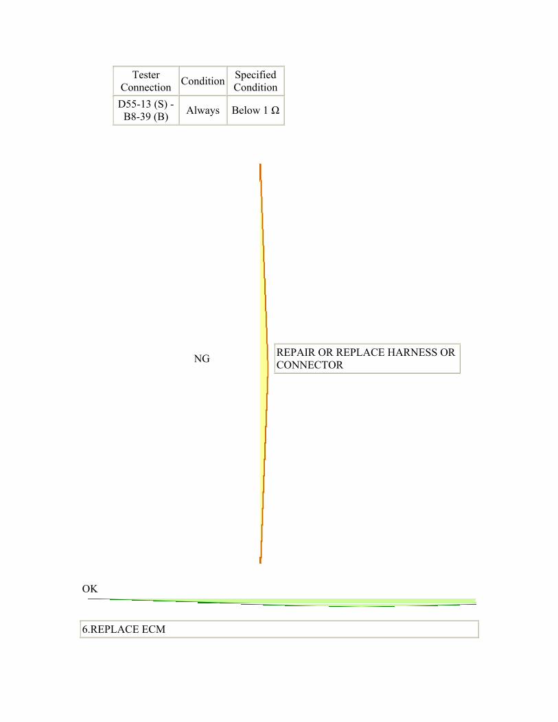
Tester Connection Condition Specified
Condition D55-13 (S) -
B8-39 (B) Always Below 1 Ω
NG
REPAIR OR REPLACE HARNESS OR CONNECTOR
OK
6.REPLACE ECM
1. Replace the ECM ().
NEXT
7.PERFORM INITIALIZATION
1. Perform the initialization ().
2. Check for DTCs again ().
NEXT
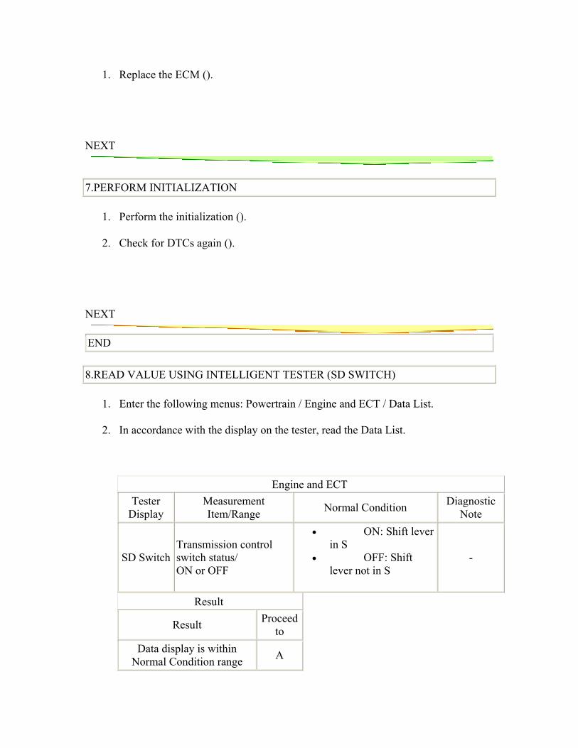
END 8.READ VALUE USING INTELLIGENT TESTER (SD SWITCH)
1. Enter the following menus: Powertrain / Engine and ECT / Data List.
2. In accordance with the display on the tester, read the Data List.
Engine and ECT Tester
Display Measurement Item/Range Normal Condition Diagnostic
Note
SD Switch Transmission control switch status/ ON or OFF
• ON: Shift lever in S
• OFF: Shift lever not in S
-
Result
Result Proceed to
Data display is within Normal Condition range A
Data display is not within Normal Condition range B
B
Go to step 9
A
CHECK INTERMITTENT PROBLEMS () 9.INSPECT SHIFT LOCK CONTROL UNIT ASSEMBLY (TRANSMISSION CONTROL SWITCH)
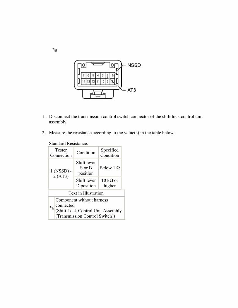
1. Disconnect the transmission control switch connector of the shift lock control unit assembly.
2. Measure the resistance according to the value(s) in the table below.
Standard Resistance: Tester
Connection Condition Specified Condition
Shift lever S or B
position Below 1 Ω
1 (NSSD) - 2 (AT3)
Shift lever D position
10 kΩ or higher
Text in Illustration
*a
Component without harness connected (Shift Lock Control Unit Assembly (Transmission Control Switch))
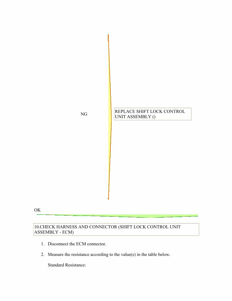
NG
REPLACE SHIFT LOCK CONTROL UNIT ASSEMBLY ()
OK
10.CHECK HARNESS AND CONNECTOR (SHIFT LOCK CONTROL UNIT ASSEMBLY - ECM)
1. Disconnect the ECM connector.
2. Measure the resistance according to the value(s) in the table below.
Standard Resistance:
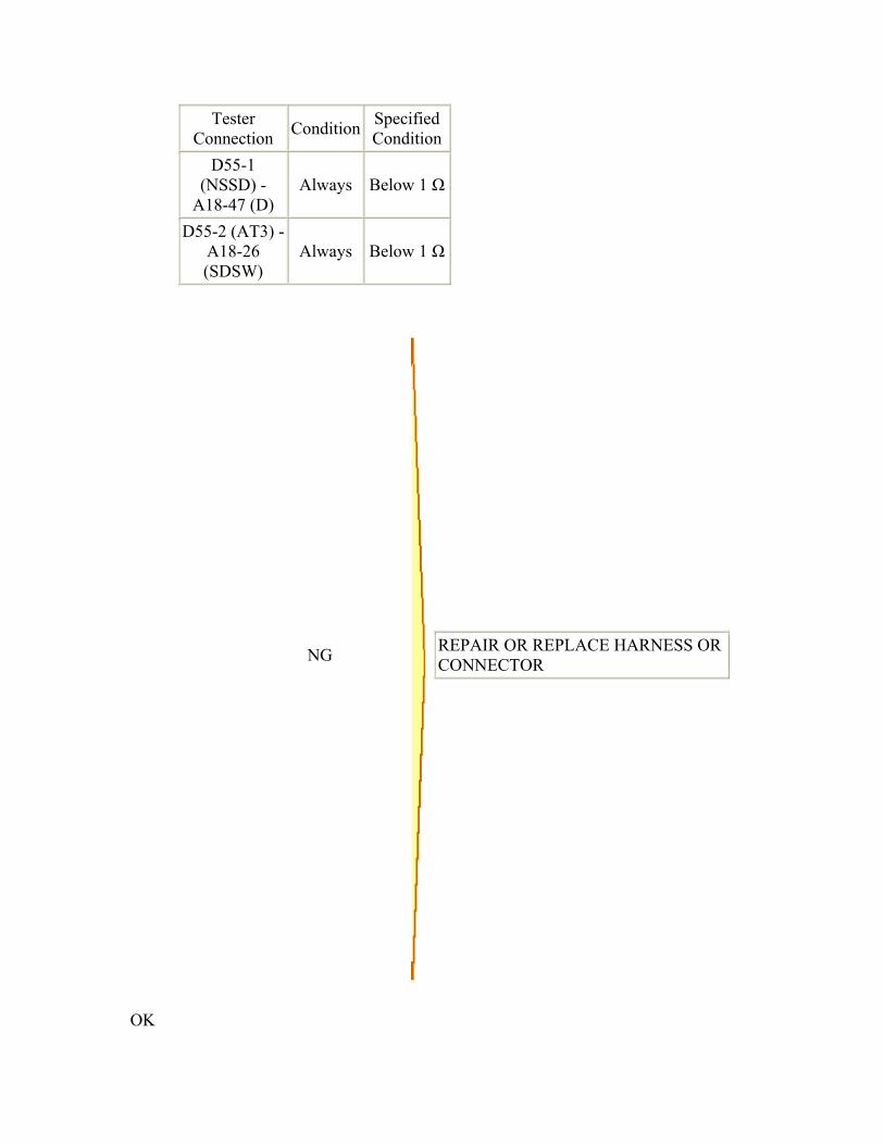
Tester Connection Condition Specified
ConditionD55-1
(NSSD) - A18-47 (D)
Always Below 1 Ω
D55-2 (AT3) - A18-26 (SDSW)
Always Below 1 Ω
NG
REPAIR OR REPLACE HARNESS OR CONNECTOR
OK
11.REPLACE ECM
1. Replace the ECM ().
NEXT
12.PERFORM INITIALIZATION
1. Perform the initialization ().
2. Check for DTCs again ().
NEXT
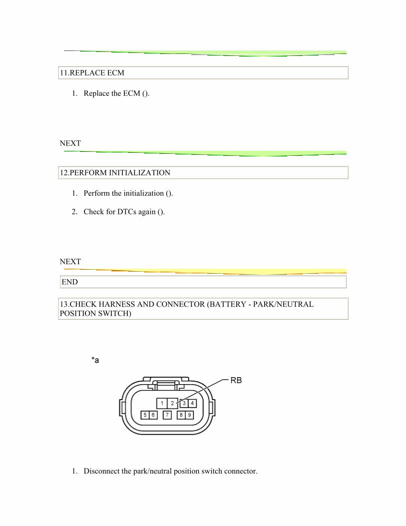
END 13.CHECK HARNESS AND CONNECTOR (BATTERY - PARK/NEUTRAL POSITION SWITCH)
1. Disconnect the park/neutral position switch connector.
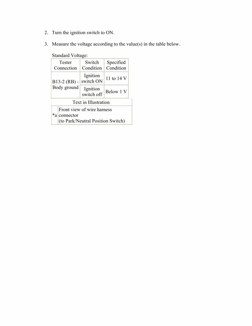
2. Turn the ignition switch to ON.
3. Measure the voltage according to the value(s) in the table below.
Standard Voltage: Tester
Connection Switch
ConditionSpecified Condition
Ignition switch ON 11 to 14 V
B13-2 (RB) - Body ground Ignition
switch off Below 1 V
Text in Illustration
*a Front view of wire harness connector (to Park/Neutral Position Switch)
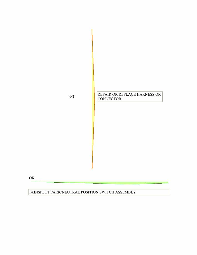
NG
REPAIR OR REPLACE HARNESS OR CONNECTOR
OK
14.INSPECT PARK/NEUTRAL POSITION SWITCH ASSEMBLY
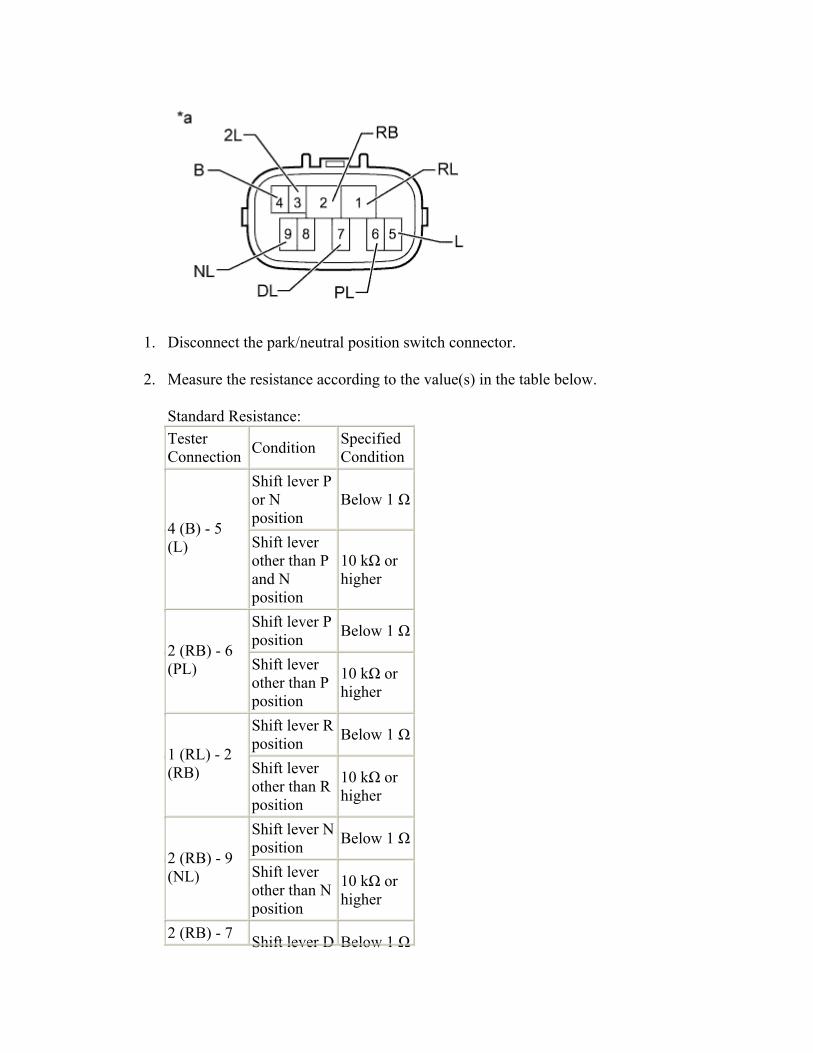
1. Disconnect the park/neutral position switch connector.
2. Measure the resistance according to the value(s) in the table below.
Standard Resistance: Tester Connection Condition Specified
Condition Shift lever P or N position
Below 1 Ω
4 (B) - 5 (L) Shift lever
other than P and N position
10 kΩ or higher
Shift lever P position Below 1 Ω
2 (RB) - 6 (PL) Shift lever
other than P position
10 kΩ or higher
Shift lever R position Below 1 Ω
1 (RL) - 2 (RB) Shift lever
other than R position
10 kΩ or higher
Shift lever N position Below 1 Ω
2 (RB) - 9 (NL) Shift lever
other than N position
10 kΩ or higher
2 (RB) - 7 Shift lever D Below 1 Ω
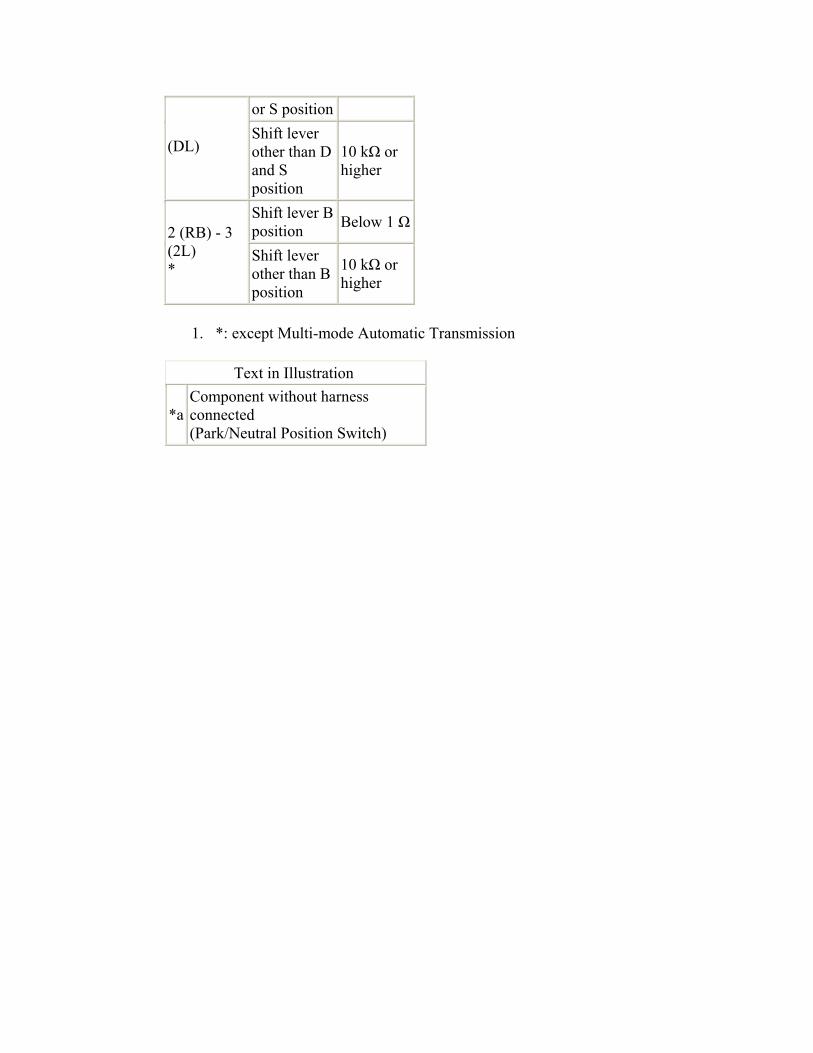
or S position
(DL) Shift lever other than D and S position
10 kΩ or higher
Shift lever B position Below 1 Ω
2 (RB) - 3 (2L) *
Shift lever other than B position
10 kΩ or higher
1. *: except Multi-mode Automatic Transmission
Text in Illustration
*a Component without harness connected (Park/Neutral Position Switch)
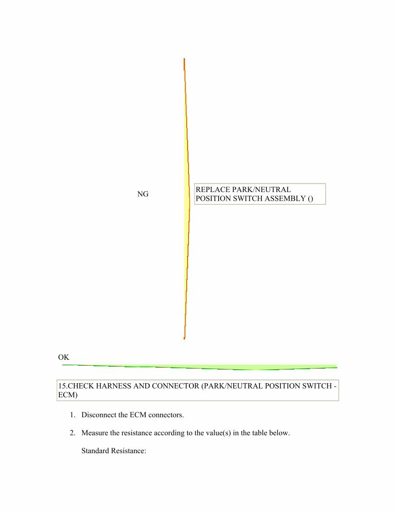
NG
REPLACE PARK/NEUTRAL POSITION SWITCH ASSEMBLY ()
OK
15.CHECK HARNESS AND CONNECTOR (PARK/NEUTRAL POSITION SWITCH - ECM)
1. Disconnect the ECM connectors.
2. Measure the resistance according to the value(s) in the table below.
Standard Resistance:
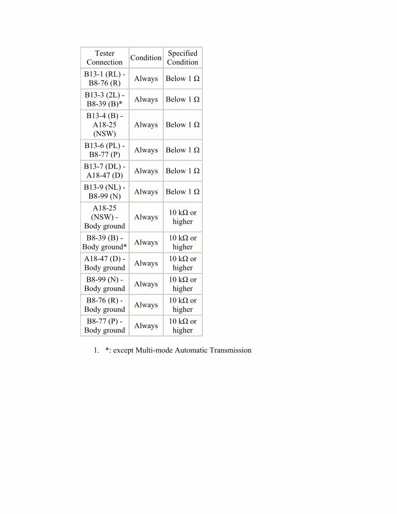
Tester Connection Condition Specified
ConditionB13-1 (RL) -
B8-76 (R) Always Below 1 Ω
B13-3 (2L) - B8-39 (B)* Always Below 1 Ω
B13-4 (B) - A18-25 (NSW)
Always Below 1 Ω
B13-6 (PL) - B8-77 (P) Always Below 1 Ω
B13-7 (DL) - A18-47 (D) Always Below 1 Ω
B13-9 (NL) - B8-99 (N) Always Below 1 Ω
A18-25 (NSW) -
Body ground Always 10 kΩ or
higher
B8-39 (B) - Body ground* Always 10 kΩ or
higher A18-47 (D) - Body ground Always 10 kΩ or
higher B8-99 (N) -
Body ground Always 10 kΩ or higher
B8-76 (R) - Body ground Always 10 kΩ or
higher B8-77 (P) -
Body ground Always 10 kΩ or higher
1. *: except Multi-mode Automatic Transmission
NG
REPAIR OR REPLACE HARNESS OR CONNECTOR
DTC P0711 Transmission Fluid Temperature Sensor "A" Performance
DESCRIPTION
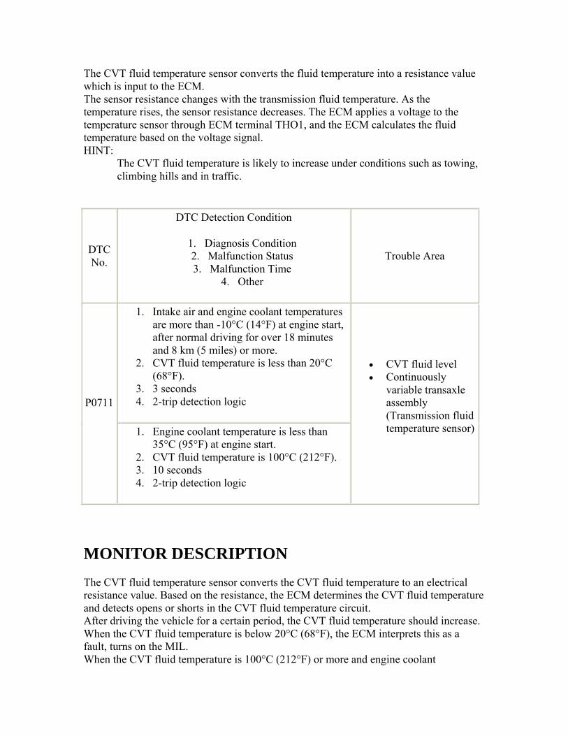
The CVT fluid temperature sensor converts the fluid temperature into a resistance value which is input to the ECM. The sensor resistance changes with the transmission fluid temperature. As the temperature rises, the sensor resistance decreases. The ECM applies a voltage to the temperature sensor through ECM terminal THO1, and the ECM calculates the fluid temperature based on the voltage signal. HINT:
The CVT fluid temperature is likely to increase under conditions such as towing, climbing hills and in traffic.
DTC No.
DTC Detection Condition
1. Diagnosis Condition 2. Malfunction Status 3. Malfunction Time
4. Other
Trouble Area
1. Intake air and engine coolant temperatures are more than -10°C (14°F) at engine start, after normal driving for over 18 minutes and 8 km (5 miles) or more.
2. CVT fluid temperature is less than 20°C (68°F).
3. 3 seconds 4. 2-trip detection logic P0711
1. Engine coolant temperature is less than 35°C (95°F) at engine start.
2. CVT fluid temperature is 100°C (212°F). 3. 10 seconds 4. 2-trip detection logic
• CVT fluid level • Continuously
variable transaxle assembly (Transmission fluid temperature sensor)
MONITOR DESCRIPTION The CVT fluid temperature sensor converts the CVT fluid temperature to an electrical resistance value. Based on the resistance, the ECM determines the CVT fluid temperature and detects opens or shorts in the CVT fluid temperature circuit. After driving the vehicle for a certain period, the CVT fluid temperature should increase. When the CVT fluid temperature is below 20°C (68°F), the ECM interprets this as a fault, turns on the MIL. When the CVT fluid temperature is 100°C (212°F) or more and engine coolant
temperature reaches 35°C (95°F) after engine cold start, the ECM also determines this as a fault, turns on the MIL, and stores the DTC.
INSPECTION PROCEDURE
1.CHECK OTHER DTCS OUTPUT (IN ADDITION TO DTC P0711)
1. Connect the intelligent tester to the DLC3.
2. Turn the ignition switch to ON.
3. Turn the tester on.
4. Enter the following menus: Powertrain / Engine and ECT / DTC / Current or Pending.
5. Read the DTCs using the tester.
Result
Result Proceed to
Only P0711 is output A P0711 and other DTCs are
output B
6. HINT: 7. If any other DTCs besides P0711 are output, perform troubleshooting for those
DTCs first.
B
GO TO DTC CHART ()
A
2.CHECK TRANSMISSION FLUID LEVEL
1. Check the CVT fluid level ().
OK: CVT fluid level is correct.
NG
ADD FLUID
OK
3.REPLACE CONTINUOUSLY VARIABLE TRANSAXLE ASSEMBLY
1. Replace the continuously variable transaxle assembly ().
NEXT
4.PERFORM INITIALIZATION
1. Perform the initialization ().
2. Check for DTCs again ().
NEXT
END
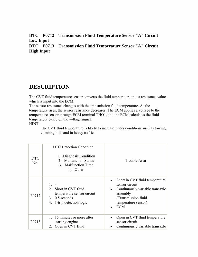
DTC P0712 Transmission Fluid Temperature Sensor "A" Circuit Low Input DTC P0713 Transmission Fluid Temperature Sensor "A" Circuit High Input
DESCRIPTION The CVT fluid temperature sensor converts the fluid temperature into a resistance value which is input into the ECM. The sensor resistance changes with the transmission fluid temperature. As the temperature rises, the sensor resistance decreases. The ECM applies a voltage to the temperature sensor through ECM terminal THO1, and the ECM calculates the fluid temperature based on the voltage signal. HINT:
The CVT fluid temperature is likely to increase under conditions such as towing, climbing hills and in heavy traffic.
DTC No.
DTC Detection Condition
1. Diagnosis Condition 2. Malfunction Status 3. Malfunction Time
4. Other
Trouble Area
P0712
1. - 2. Short in CVT fluid
temperature sensor circuit 3. 0.5 seconds 4. 1-trip detection logic
• Short in CVT fluid temperature sensor circuit
• Continuously variable transaxle assembly (Transmission fluid temperature sensor)
• ECM
P0713 1. 15 minutes or more after
starting engine 2. Open in CVT fluid
• Open in CVT fluid temperature sensor circuit
• Continuously variable transaxle
temperature sensor circuit 3. 0.5 seconds 4. 1-trip detection logic
assembly (Transmission fluid temperature sensor)
• ECM
MONITOR DESCRIPTION The CVT fluid temperature sensor converts the CVT fluid temperature to an electrical resistance value. Based on the resistance, the ECM determines the CVT fluid temperature and detects opens or shorts in the CVT fluid temperature circuit. If the resistance value of the CVT fluid temperature is less than 79 Ω*1 or more than 156 kΩ*2, the ECM interprets this as a fault in the CVT fluid sensor or wiring. The ECM turns on the MIL and stores the DTC. *1: 150°C (302°F) or more is indicated regardless of the actual CVT fluid temperature. *2: -40°C (-40°F) is indicated regardless of the actual CVT fluid temperature. HINT:
The CVT fluid temperature can be checked on the intelligent tester display.
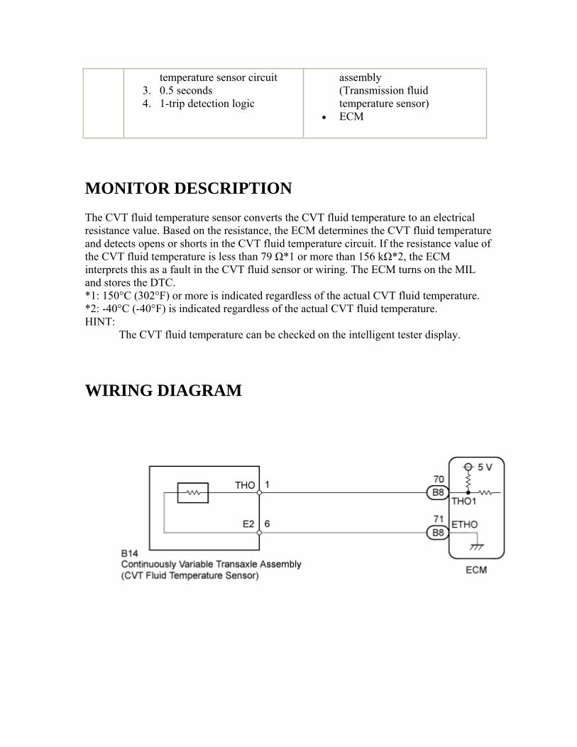
WIRING DIAGRAM
INSPECTION PROCEDURE
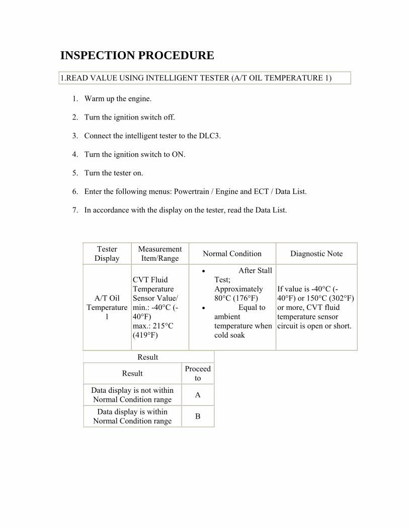
1.READ VALUE USING INTELLIGENT TESTER (A/T OIL TEMPERATURE 1)
1. Warm up the engine.
2. Turn the ignition switch off.
3. Connect the intelligent tester to the DLC3.
4. Turn the ignition switch to ON.
5. Turn the tester on.
6. Enter the following menus: Powertrain / Engine and ECT / Data List.
7. In accordance with the display on the tester, read the Data List.
Tester Display
Measurement Item/Range Normal Condition Diagnostic Note
A/T Oil Temperature
1
CVT Fluid Temperature Sensor Value/ min.: -40°C (-40°F) max.: 215°C (419°F)
• After Stall Test; Approximately 80°C (176°F)
• Equal to ambient temperature when cold soak
If value is -40°C (-40°F) or 150°C (302°F) or more, CVT fluid temperature sensor circuit is open or short.
Result
Result Proceed to
Data display is not within Normal Condition range A
Data display is within Normal Condition range B
B
Go to step 4
A
2.INSPECT CONTINUOUSLY VARIABLE TRANSAXLE ASSEMBLY (CVT FLUID TEMPERATURE SENSOR)
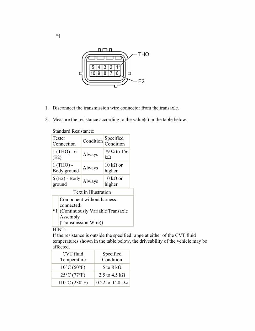
1. Disconnect the transmission wire connector from the transaxle.
2. Measure the resistance according to the value(s) in the table below.
Standard Resistance: Tester Connection Condition Specified
Condition 1 (THO) - 6 (E2) Always 79 Ω to 156
kΩ 1 (THO) - Body ground Always 10 kΩ or
higher 6 (E2) - Body ground Always 10 kΩ or
higher Text in Illustration
*1
Component without harness connected: (Continuously Variable Transaxle Assembly (Transmission Wire))
HINT: If the resistance is outside the specified range at either of the CVT fluid temperatures shown in the table below, the driveability of the vehicle may be affected.
CVT fluid Temperature
Specified Condition
10°C (50°F) 5 to 8 kΩ 25°C (77°F) 2.5 to 4.5 kΩ
110°C (230°F) 0.22 to 0.28 kΩ
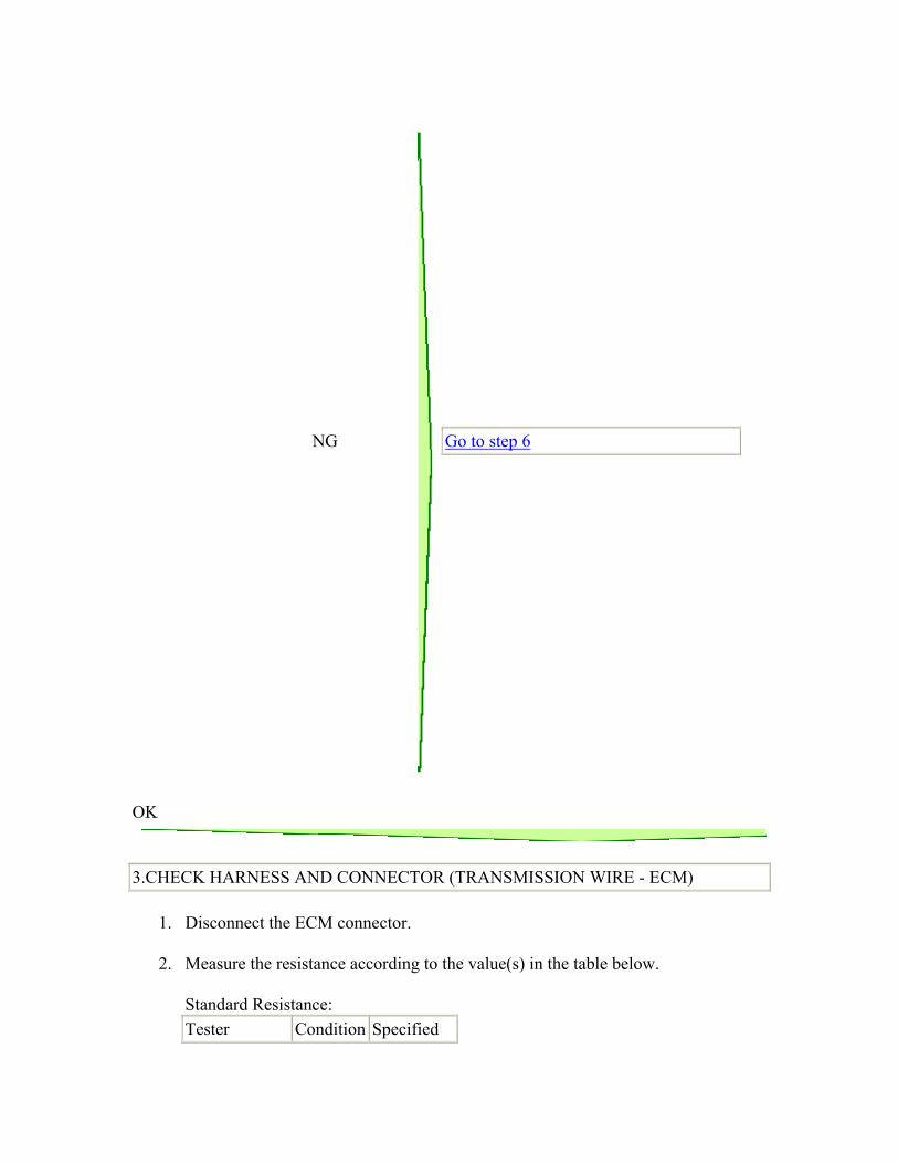
NG
Go to step 6
OK
3.CHECK HARNESS AND CONNECTOR (TRANSMISSION WIRE - ECM)
1. Disconnect the ECM connector.
2. Measure the resistance according to the value(s) in the table below.
Standard Resistance: Tester Condition Specified
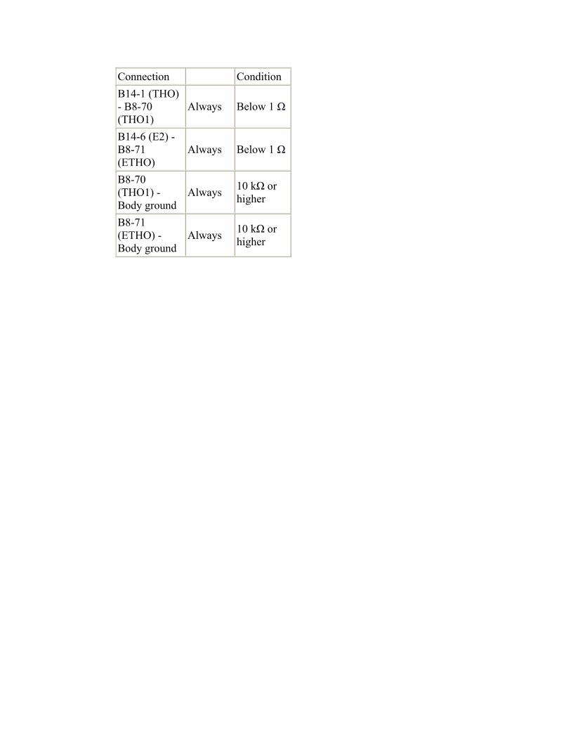
Connection Condition B14-1 (THO) - B8-70 (THO1)
Always Below 1 Ω
B14-6 (E2) - B8-71 (ETHO)
Always Below 1 Ω
B8-70 (THO1) - Body ground
Always 10 kΩ or higher
B8-71 (ETHO) - Body ground
Always 10 kΩ or higher
NG
REPAIR OR REPLACE HARNESS OR CONNECTOR
OK
4.REPLACE ECM
1. Replace the ECM ().
NEXT
5.PERFORM INITIALIZATION
1. Perform the initialization ().
2. Check for DTCs again ().
NEXT
END 6.REPLACE CONTINUOUSLY VARIABLE TRANSAXLE ASSEMBLY
1. Replace the continuously variable transaxle assembly ().
NEXT
7.PERFORM INITIALIZATION
1. Perform the initialization ().
2. Check for DTCs again ().
NEXT
END
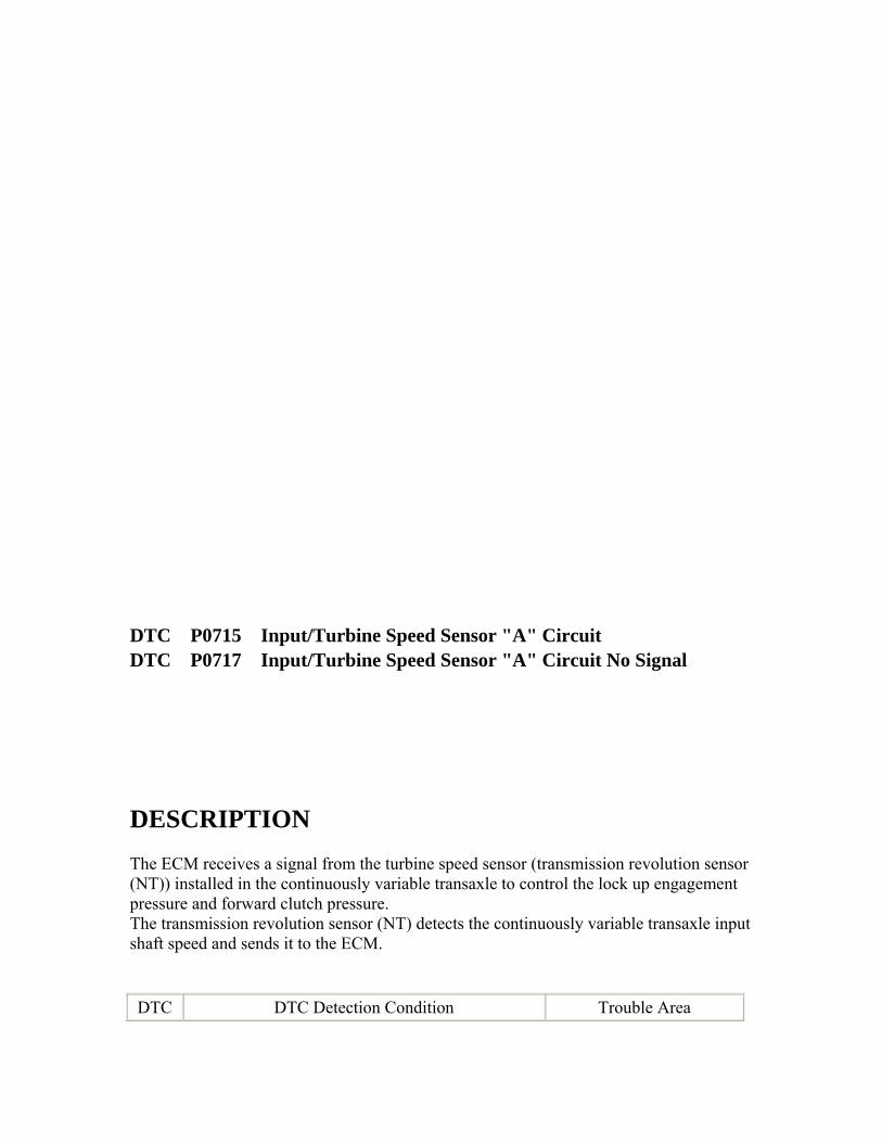
DTC P0715 Input/Turbine Speed Sensor "A" Circuit DTC P0717 Input/Turbine Speed Sensor "A" Circuit No Signal
DESCRIPTION The ECM receives a signal from the turbine speed sensor (transmission revolution sensor (NT)) installed in the continuously variable transaxle to control the lock up engagement pressure and forward clutch pressure. The transmission revolution sensor (NT) detects the continuously variable transaxle input shaft speed and sends it to the ECM. DTC DTC Detection Condition Trouble Area
No. 1. Diagnosis Condition 2. Malfunction Status 3. Malfunction Time
4. Other
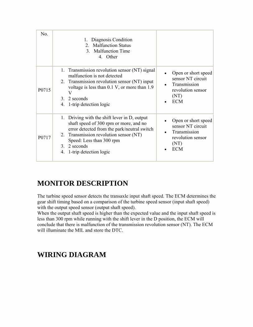
P0715
1. Transmission revolution sensor (NT) signal malfunction is not detected
2. Transmission revolution sensor (NT) input voltage is less than 0.1 V, or more than 1.9 V
3. 2 seconds 4. 1-trip detection logic
• Open or short speed sensor NT circuit
• Transmission revolution sensor (NT)
• ECM
P0717
1. Driving with the shift lever in D, output shaft speed of 300 rpm or more, and no error detected from the park/neutral switch
2. Transmission revolution sensor (NT) Speed: Less than 300 rpm
3. 2 seconds 4. 1-trip detection logic
• Open or short speed sensor NT circuit
• Transmission revolution sensor (NT)
• ECM
MONITOR DESCRIPTION The turbine speed sensor detects the transaxle input shaft speed. The ECM determines the gear shift timing based on a comparison of the turbine speed sensor (input shaft speed) with the output speed sensor (output shaft speed). When the output shaft speed is higher than the expected value and the input shaft speed is less than 300 rpm while running with the shift lever in the D position, the ECM will conclude that there is malfunction of the transmission revolution sensor (NT). The ECM will illuminate the MIL and store the DTC.
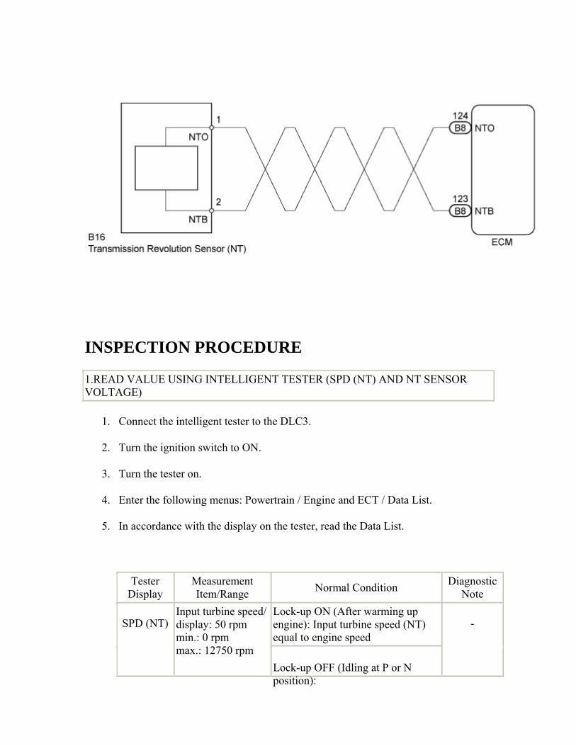
WIRING DIAGRAM
INSPECTION PROCEDURE
1.READ VALUE USING INTELLIGENT TESTER (SPD (NT) AND NT SENSOR VOLTAGE)
1. Connect the intelligent tester to the DLC3.
2. Turn the ignition switch to ON.
3. Turn the tester on.
4. Enter the following menus: Powertrain / Engine and ECT / Data List.
5. In accordance with the display on the tester, read the Data List.
Tester Display
Measurement Item/Range Normal Condition Diagnostic
Note Lock-up ON (After warming up engine): Input turbine speed (NT) equal to engine speed
SPD (NT) Input turbine speed/display: 50 rpm min.: 0 rpm max.: 12750 rpm
Lock-up OFF (Idling at P or N position):
-
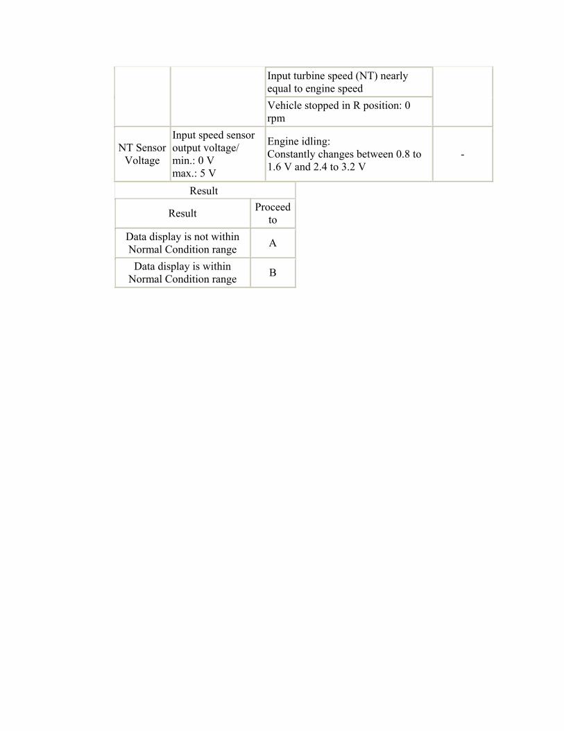
Input turbine speed (NT) nearly equal to engine speed Vehicle stopped in R position: 0 rpm
NT Sensor Voltage
Input speed sensor output voltage/ min.: 0 V max.: 5 V
Engine idling: Constantly changes between 0.8 to 1.6 V and 2.4 to 3.2 V
-
Result
Result Proceed to
Data display is not within Normal Condition range A
Data display is within Normal Condition range B
B
Go to step 4
A
2.INSPECT TRANSMISSION REVOLUTION SENSOR (NT)
1. Remove the transmission revolution sensor (NT) () and then connect the battery.
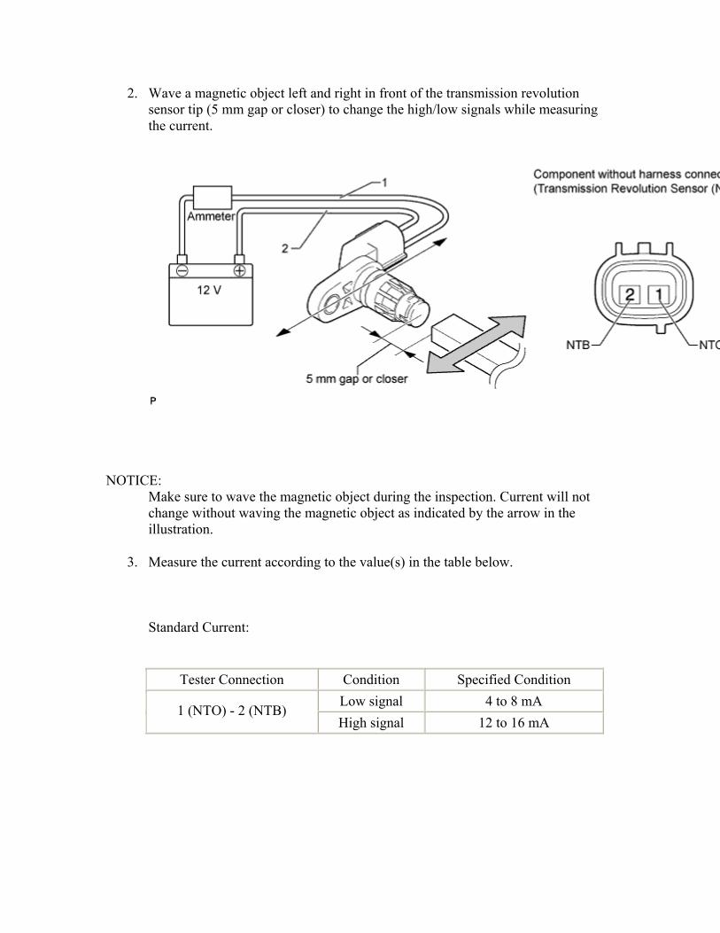
2. Wave a magnetic object left and right in front of the transmission revolution sensor tip (5 mm gap or closer) to change the high/low signals while measuring the current.
NOTICE: Make sure to wave the magnetic object during the inspection. Current will not change without waving the magnetic object as indicated by the arrow in the illustration.
3. Measure the current according to the value(s) in the table below.
Standard Current:
Tester Connection Condition Specified Condition Low signal 4 to 8 mA
1 (NTO) - 2 (NTB) High signal 12 to 16 mA
NG
REPLACE TRANSMISSION REVOLUTION SENSOR (NT) ()
OK
3.CHECK HARNESS AND CONNECTOR (TRANSMISSION REVOLUTION SENSOR (NT) - ECM)
1. Disconnect the ECM connector.
2. Measure the resistance according to the value(s) in the table below.
Standard Resistance:
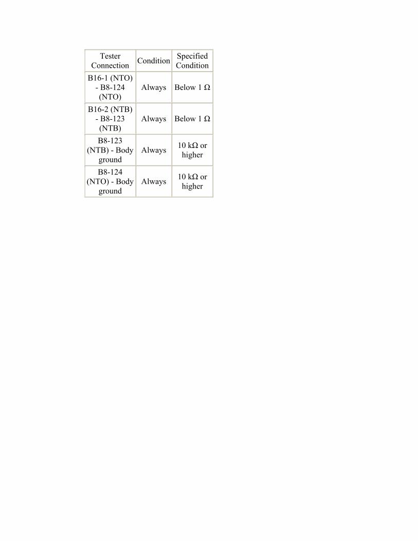
Tester Connection Condition Specified
ConditionB16-1 (NTO)
- B8-124 (NTO)
Always Below 1 Ω
B16-2 (NTB) - B8-123 (NTB)
Always Below 1 Ω
B8-123 (NTB) - Body
ground Always 10 kΩ or
higher
B8-124 (NTO) - Body
ground Always 10 kΩ or
higher

NG
REPAIR OR REPLACE HARNESS OR CONNECTOR
OK
4.REPLACE ECM
1. Replace the ECM ().
NEXT

5.PERFORM INITIALIZATION
1. Perform the initialization ().
2. Check for DTCs again ().
NEXT
END
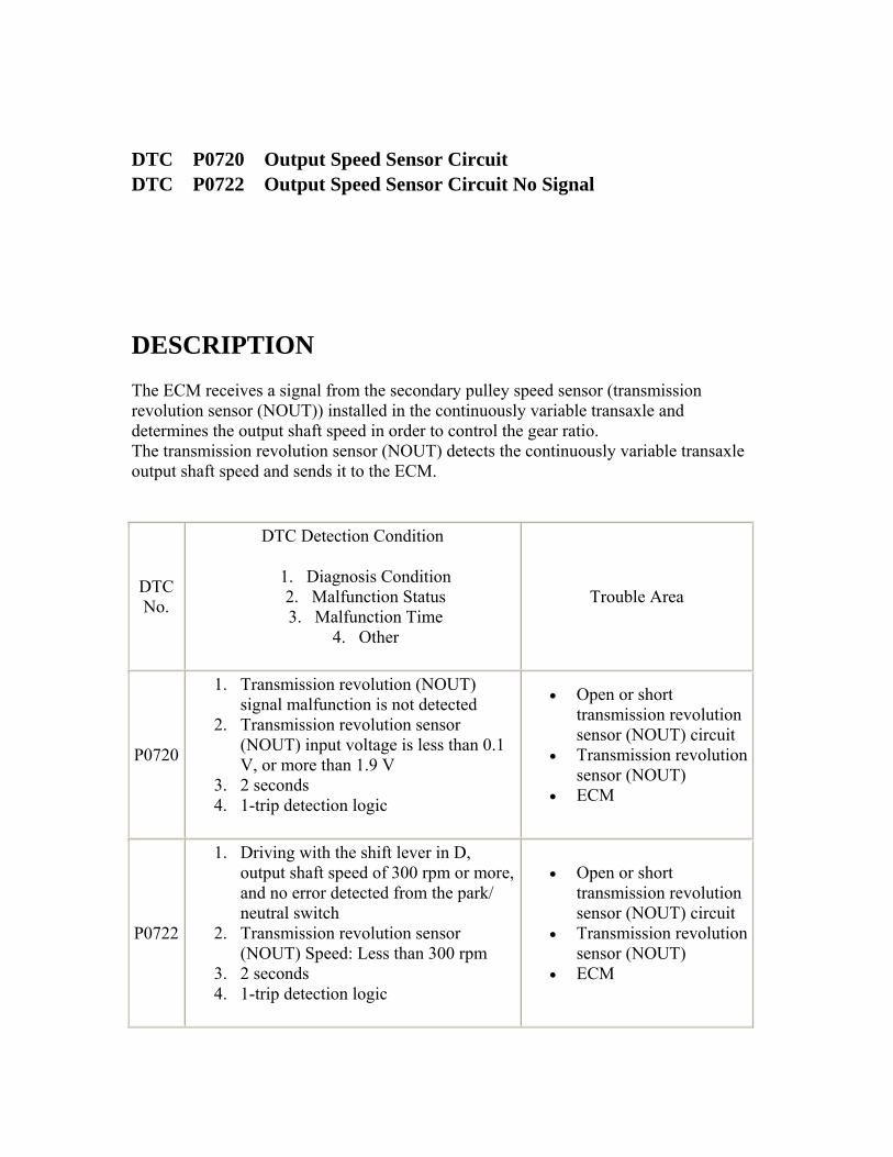
DTC P0720 Output Speed Sensor Circuit DTC P0722 Output Speed Sensor Circuit No Signal
DESCRIPTION The ECM receives a signal from the secondary pulley speed sensor (transmission revolution sensor (NOUT)) installed in the continuously variable transaxle and determines the output shaft speed in order to control the gear ratio. The transmission revolution sensor (NOUT) detects the continuously variable transaxle output shaft speed and sends it to the ECM.
DTC No.
DTC Detection Condition
1. Diagnosis Condition 2. Malfunction Status 3. Malfunction Time
4. Other
Trouble Area
P0720
1. Transmission revolution (NOUT) signal malfunction is not detected
2. Transmission revolution sensor (NOUT) input voltage is less than 0.1 V, or more than 1.9 V
3. 2 seconds 4. 1-trip detection logic
• Open or short transmission revolution sensor (NOUT) circuit
• Transmission revolution sensor (NOUT)
• ECM
P0722
1. Driving with the shift lever in D, output shaft speed of 300 rpm or more, and no error detected from the park/ neutral switch
2. Transmission revolution sensor (NOUT) Speed: Less than 300 rpm
3. 2 seconds 4. 1-trip detection logic
• Open or short transmission revolution sensor (NOUT) circuit
• Transmission revolution sensor (NOUT)
• ECM
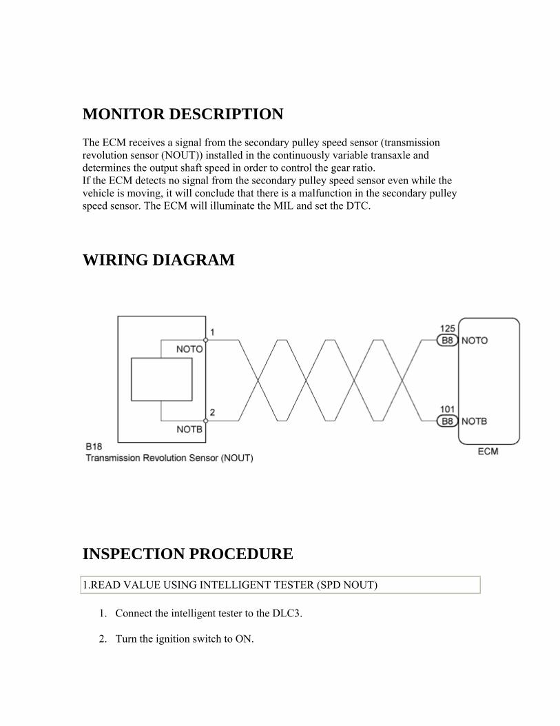
MONITOR DESCRIPTION The ECM receives a signal from the secondary pulley speed sensor (transmission revolution sensor (NOUT)) installed in the continuously variable transaxle and determines the output shaft speed in order to control the gear ratio. If the ECM detects no signal from the secondary pulley speed sensor even while the vehicle is moving, it will conclude that there is a malfunction in the secondary pulley speed sensor. The ECM will illuminate the MIL and set the DTC.
WIRING DIAGRAM
INSPECTION PROCEDURE
1.READ VALUE USING INTELLIGENT TESTER (SPD NOUT)
1. Connect the intelligent tester to the DLC3.
2. Turn the ignition switch to ON.
3. Turn the tester on.
4. Enter the following menus: Powertrain / Engine and ECT / Data List.
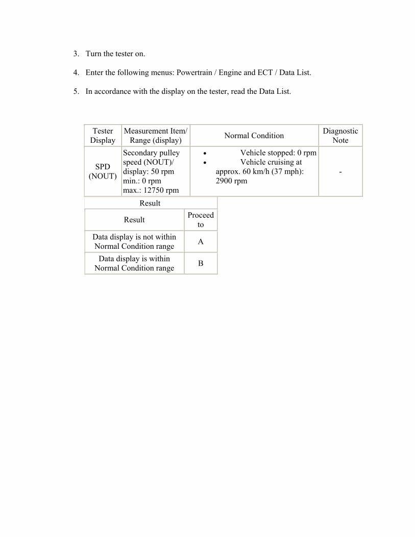
5. In accordance with the display on the tester, read the Data List.
Tester Display
Measurement Item/Range (display) Normal Condition Diagnostic
Note
SPD (NOUT)
Secondary pulley speed (NOUT)/ display: 50 rpm min.: 0 rpm max.: 12750 rpm
• Vehicle stopped: 0 rpm • Vehicle cruising at
approx. 60 km/h (37 mph): 2900 rpm
-
Result
Result Proceed to
Data display is not within Normal Condition range A
Data display is within Normal Condition range B
B
Go to step 4
A
2.INSPECT TRANSMISSION REVOLUTION SENSOR (NOUT)
1. Remove the transmission revolution sensor (NOUT) () and then connect the battery.
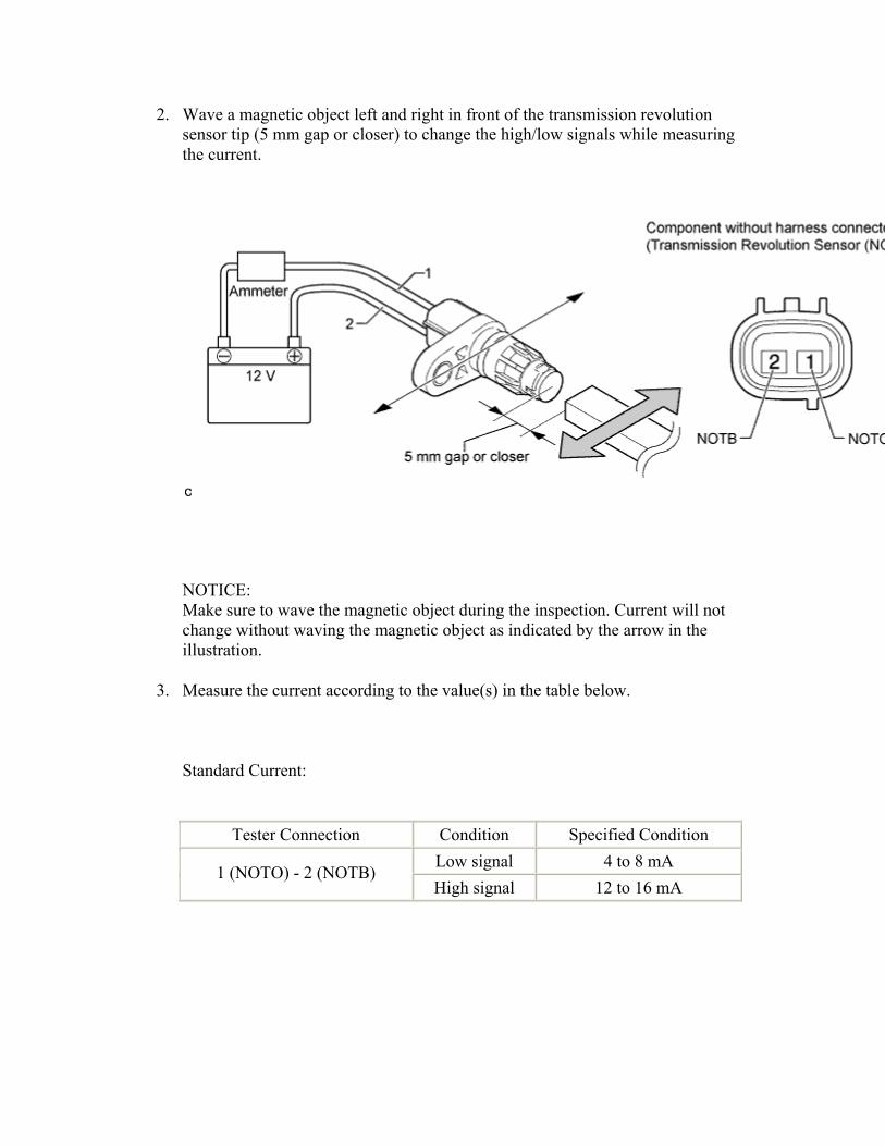
2. Wave a magnetic object left and right in front of the transmission revolution sensor tip (5 mm gap or closer) to change the high/low signals while measuring the current.
NOTICE: Make sure to wave the magnetic object during the inspection. Current will not change without waving the magnetic object as indicated by the arrow in the illustration.
3. Measure the current according to the value(s) in the table below.
Standard Current:
Tester Connection Condition Specified Condition Low signal 4 to 8 mA
1 (NOTO) - 2 (NOTB) High signal 12 to 16 mA

NG
REPLACE TRANSMISSION REVOLUTION SENSOR (NOUT) ()
OK
3.CHECK HARNESS AND CONNECTOR (TRANSMISSION REVOLUTION SENSOR (NOUT) - ECM)
1. Disconnect the ECM connector.
2. Measure the resistance according to the value(s) in the table below.
Standard Resistance:
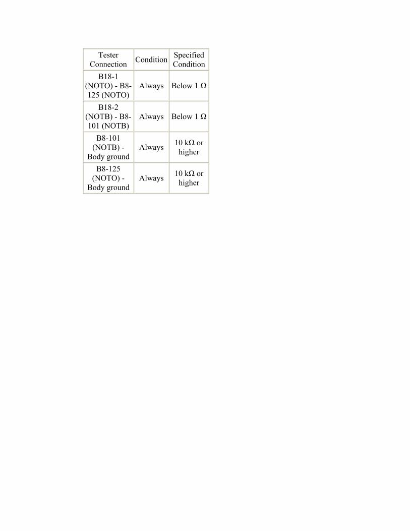
Tester Connection Condition Specified
ConditionB18-1
(NOTO) - B8-125 (NOTO)
Always Below 1 Ω
B18-2 (NOTB) - B8-101 (NOTB)
Always Below 1 Ω
B8-101 (NOTB) -
Body ground Always 10 kΩ or
higher
B8-125 (NOTO) -
Body ground Always 10 kΩ or
higher

NG
REPAIR OR REPLACE HARNESS OR CONNECTOR
OK
4.REPLACE ECM
1. Replace the ECM ().
NEXT

5.PERFORM INITIALIZATION
1. Perform the initialization ().
2. Check for DTCs again ().
NEXT
END
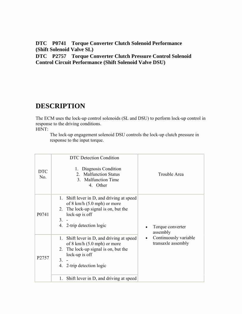
DTC P0741 Torque Converter Clutch Solenoid Performance (Shift Solenoid Valve SL) DTC P2757 Torque Converter Clutch Pressure Control Solenoid Control Circuit Performance (Shift Solenoid Valve DSU)
DESCRIPTION The ECM uses the lock-up control solenoids (SL and DSU) to perform lock-up control in response to the driving conditions. HINT:
The lock-up engagement solenoid DSU controls the lock-up clutch pressure in response to the input torque.
DTC No.
DTC Detection Condition
1. Diagnosis Condition 2. Malfunction Status 3. Malfunction Time
4. Other
Trouble Area
P0741
1. Shift lever in D, and driving at speed of 8 km/h (5.0 mph) or more
2. The lock-up signal is on, but the lock-up is off
3. - 4. 2-trip detection logic
1. Shift lever in D, and driving at speed of 8 km/h (5.0 mph) or more
2. The lock-up signal is on, but the lock-up is off
3. - 4. 2-trip detection logic
P2757
1. Shift lever in D, and driving at speed
• Torque converter assembly
• Continuously variable transaxle assembly
of 8 km/h (5.0 mph) or more 2. The lock-up signal is off, but the
lock-up is on 3. - 4. 2-trip detection logic
MONITOR DESCRIPTION When performing lock-up control (on/off) of the torque converter, the ECM compares the rotating speeds of the turbine (NT) and engine (NE) to detect mechanical malfunctions in the lock-up control solenoids (SL and DSU). When the rotating speeds are different, the ECM detects the problem, illuminates the MIL and stores the DTC.
INSPECTION PROCEDURE
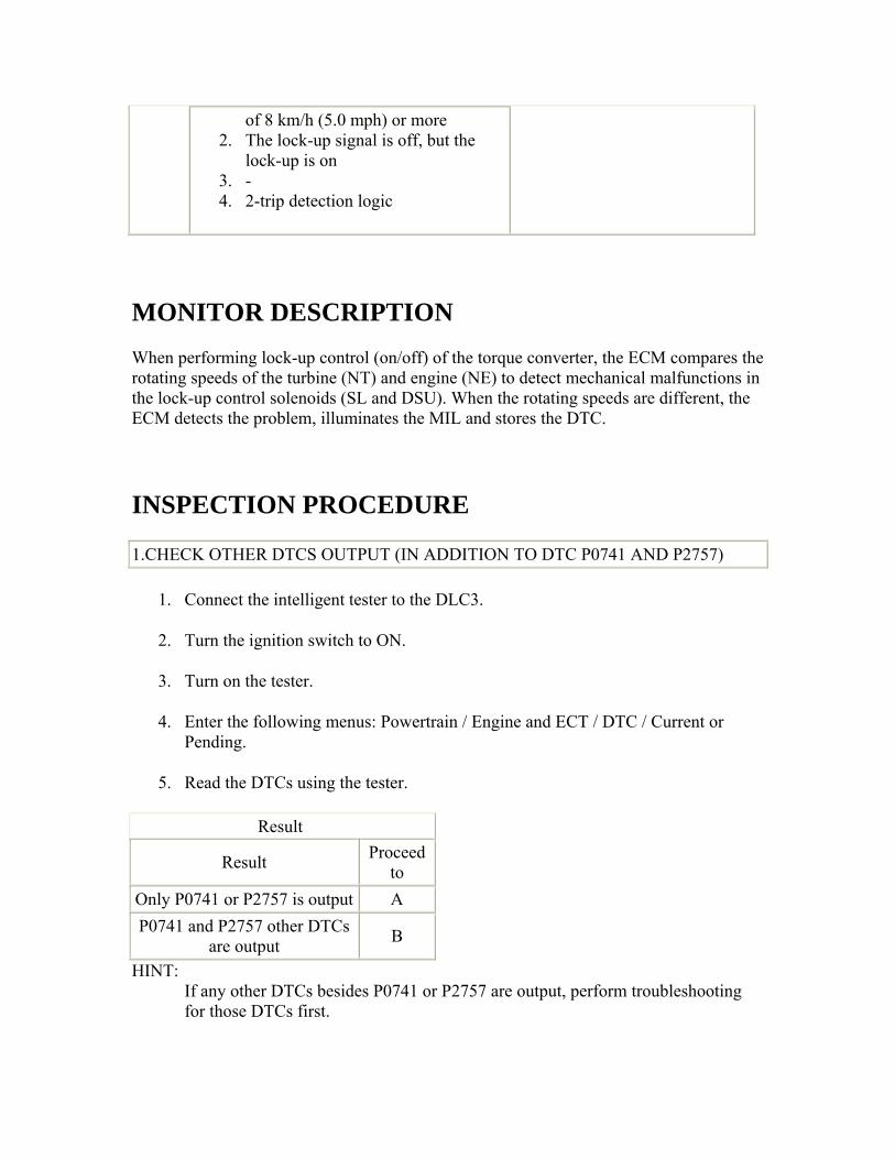
1.CHECK OTHER DTCS OUTPUT (IN ADDITION TO DTC P0741 AND P2757)
1. Connect the intelligent tester to the DLC3.
2. Turn the ignition switch to ON.
3. Turn on the tester.
4. Enter the following menus: Powertrain / Engine and ECT / DTC / Current or Pending.
5. Read the DTCs using the tester.
Result
Result Proceed to
Only P0741 or P2757 is output A P0741 and P2757 other DTCs
are output B
HINT: If any other DTCs besides P0741 or P2757 are output, perform troubleshooting for those DTCs first.
B
GO TO DTC CHART ()
A
2.CLEAR DTC
1. Clear the DTC ().
NEXT
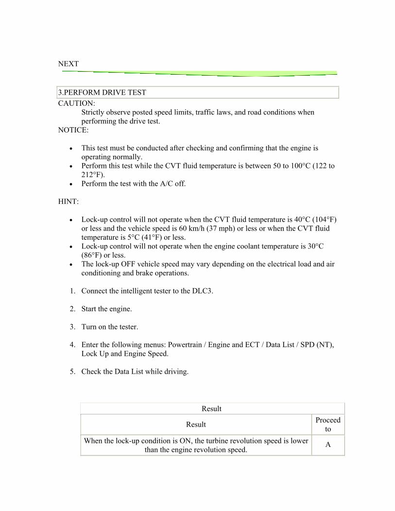
3.PERFORM DRIVE TEST CAUTION:
Strictly observe posted speed limits, traffic laws, and road conditions when performing the drive test.
NOTICE:
• This test must be conducted after checking and confirming that the engine is operating normally.
• Perform this test while the CVT fluid temperature is between 50 to 100°C (122 to 212°F).
• Perform the test with the A/C off.
HINT:
• Lock-up control will not operate when the CVT fluid temperature is 40°C (104°F) or less and the vehicle speed is 60 km/h (37 mph) or less or when the CVT fluid temperature is 5°C (41°F) or less.
• Lock-up control will not operate when the engine coolant temperature is 30°C (86°F) or less.
• The lock-up OFF vehicle speed may vary depending on the electrical load and air conditioning and brake operations.
1. Connect the intelligent tester to the DLC3.
2. Start the engine.
3. Turn on the tester.
4. Enter the following menus: Powertrain / Engine and ECT / Data List / SPD (NT), Lock Up and Engine Speed.
5. Check the Data List while driving.
Result
Result Proceed to
When the lock-up condition is ON, the turbine revolution speed is lower than the engine revolution speed.
A
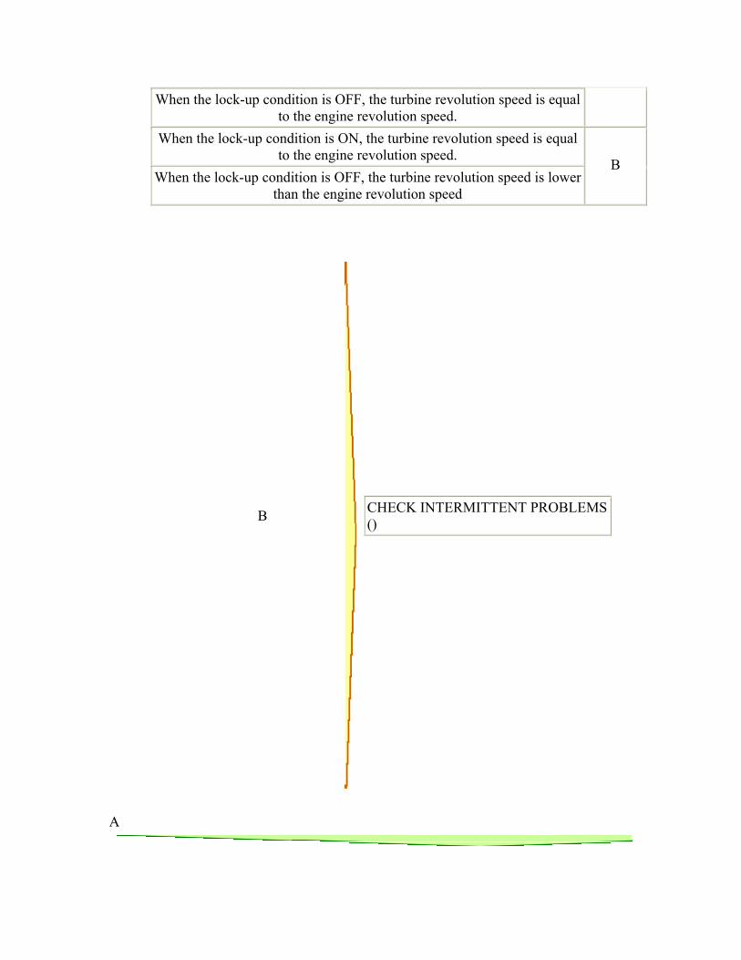
When the lock-up condition is OFF, the turbine revolution speed is equal to the engine revolution speed.
When the lock-up condition is ON, the turbine revolution speed is equal to the engine revolution speed.
When the lock-up condition is OFF, the turbine revolution speed is lower than the engine revolution speed
B
B
CHECK INTERMITTENT PROBLEMS ()
A
4.REPLACE TORQUE CONVERTER ASSEMBLY AND CONTINUOUSLY VARIABLE TRANSAXLE ASSEMBLY
1. Replace torque converter assembly and continuously variable transaxle assembly ().
NEXT
5.PERFORM INITIALIZATION
1. Perform the initialization ().
2. Check for DTCs again ().
NEXT
END
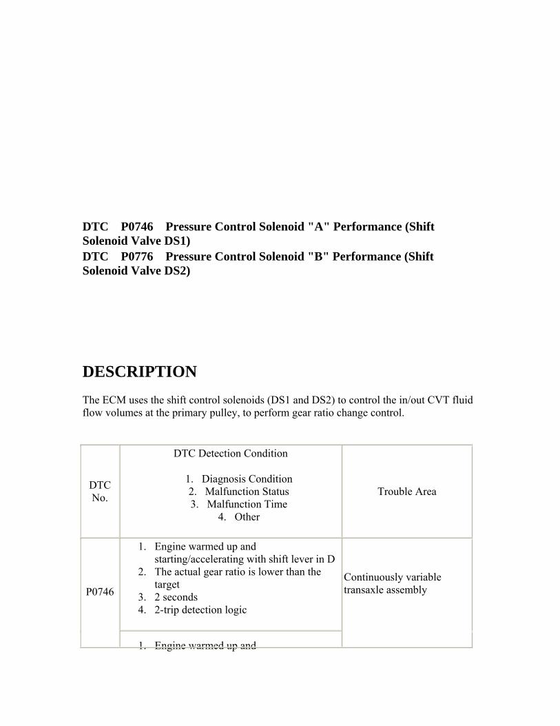
DTC P0746 Pressure Control Solenoid "A" Performance (Shift Solenoid Valve DS1) DTC P0776 Pressure Control Solenoid "B" Performance (Shift Solenoid Valve DS2)
DESCRIPTION The ECM uses the shift control solenoids (DS1 and DS2) to control the in/out CVT fluid flow volumes at the primary pulley, to perform gear ratio change control.
DTC No.
DTC Detection Condition
1. Diagnosis Condition 2. Malfunction Status 3. Malfunction Time
4. Other
Trouble Area
1. Engine warmed up and starting/accelerating with shift lever in D
2. The actual gear ratio is lower than the target
3. 2 seconds 4. 2-trip detection logic
P0746
1. Engine warmed up and
Continuously variable transaxle assembly
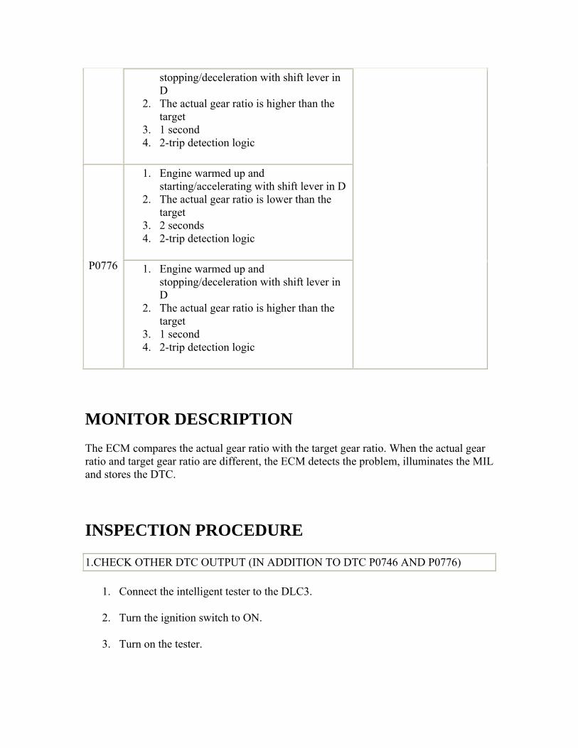
stopping/deceleration with shift lever in D
2. The actual gear ratio is higher than the target
3. 1 second 4. 2-trip detection logic
1. Engine warmed up and starting/accelerating with shift lever in D
2. The actual gear ratio is lower than the target
3. 2 seconds 4. 2-trip detection logic
P0776 1. Engine warmed up and stopping/deceleration with shift lever in D
2. The actual gear ratio is higher than the target
3. 1 second 4. 2-trip detection logic
MONITOR DESCRIPTION The ECM compares the actual gear ratio with the target gear ratio. When the actual gear ratio and target gear ratio are different, the ECM detects the problem, illuminates the MIL and stores the DTC.
INSPECTION PROCEDURE
1.CHECK OTHER DTC OUTPUT (IN ADDITION TO DTC P0746 AND P0776)
1. Connect the intelligent tester to the DLC3.
2. Turn the ignition switch to ON.
3. Turn on the tester.
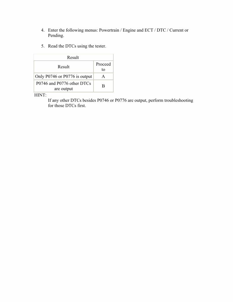
4. Enter the following menus: Powertrain / Engine and ECT / DTC / Current or Pending.
5. Read the DTCs using the tester.
Result
Result Proceed to
Only P0746 or P0776 is output A P0746 and P0776 other DTCs
are output B
HINT: If any other DTCs besides P0746 or P0776 are output, perform troubleshooting for those DTCs first.
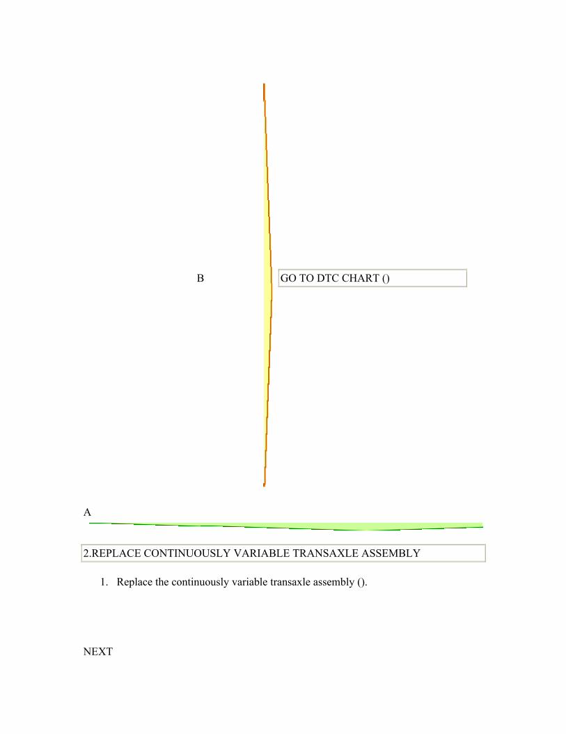
B
GO TO DTC CHART ()
A
2.REPLACE CONTINUOUSLY VARIABLE TRANSAXLE ASSEMBLY
1. Replace the continuously variable transaxle assembly ().
NEXT

3.PERFORM INITIALIZATION
1. Perform the initialization ().
2. Check for DTCs again ().
NEXT
END
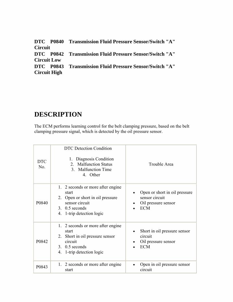
DTC P0840 Transmission Fluid Pressure Sensor/Switch "A" Circuit DTC P0842 Transmission Fluid Pressure Sensor/Switch "A" Circuit Low
DTC P0843 Transmission Fluid Pressure Sensor/Switch "A" Circuit High
DESCRIPTION The ECM performs learning control for the belt clamping pressure, based on the belt clamping pressure signal, which is detected by the oil pressure sensor.
DTC No.
DTC Detection Condition
1. Diagnosis Condition 2. Malfunction Status 3. Malfunction Time
4. Other
Trouble Area
P0840
1. 2 seconds or more after engine start
2. Open or short in oil pressure sensor circuit
3. 0.5 seconds 4. 1-trip detection logic
• Open or short in oil pressure sensor circuit
• Oil pressure sensor • ECM
P0842
1. 2 seconds or more after engine start
2. Short in oil pressure sensor circuit
3. 0.5 seconds 4. 1-trip detection logic
• Short in oil pressure sensor circuit
• Oil pressure sensor • ECM
P0843 1. 2 seconds or more after engine start
• Open in oil pressure sensor circuit
2. Open in oil pressure sensor circuit
3. 0.5 seconds 4. 1-trip detection logic
• Oil pressure sensor • ECM
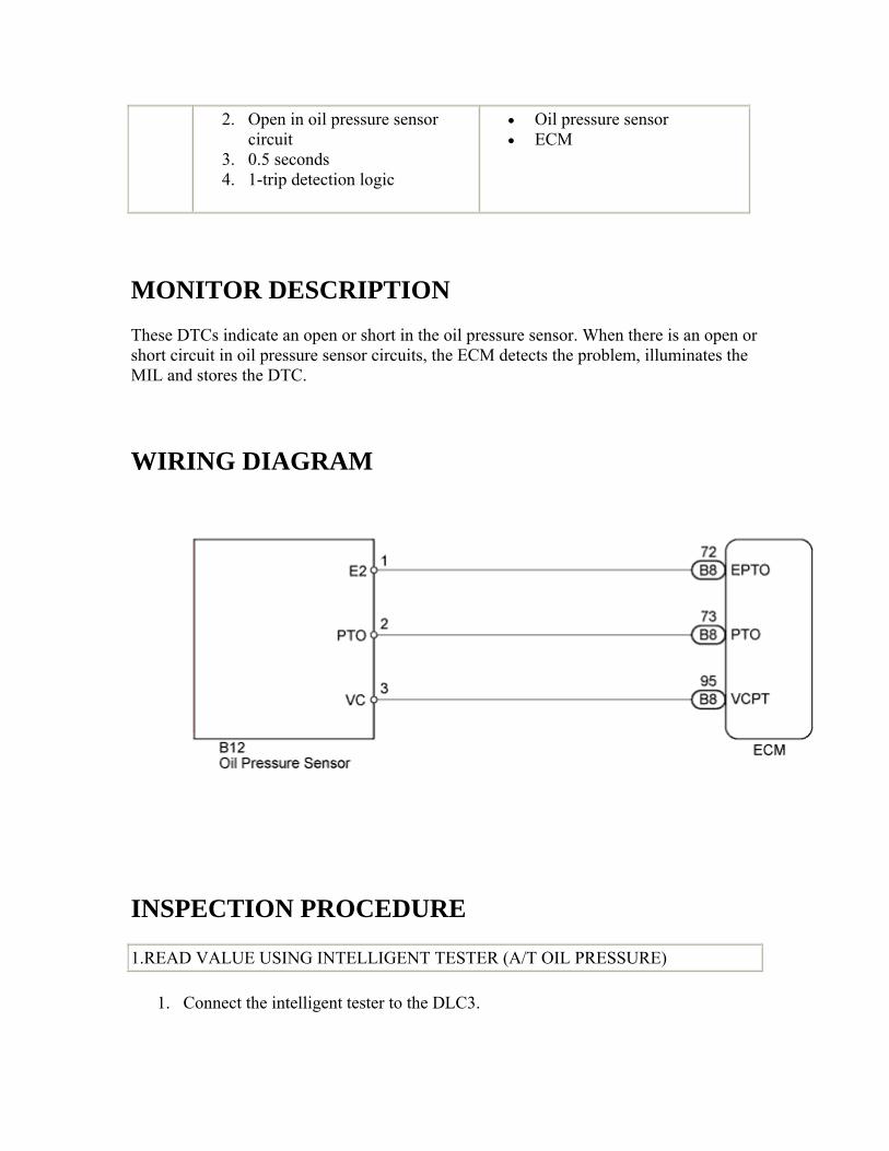
MONITOR DESCRIPTION These DTCs indicate an open or short in the oil pressure sensor. When there is an open or short circuit in oil pressure sensor circuits, the ECM detects the problem, illuminates the MIL and stores the DTC.
WIRING DIAGRAM
INSPECTION PROCEDURE
1.READ VALUE USING INTELLIGENT TESTER (A/T OIL PRESSURE)
1. Connect the intelligent tester to the DLC3.
2. Turn the ignition switch to ON.
3. Turn the tester on.
4. Enter the following menus: Powertrain / Engine and ECT / Data List.
5. In accordance with the display on the tester, read the Data List.
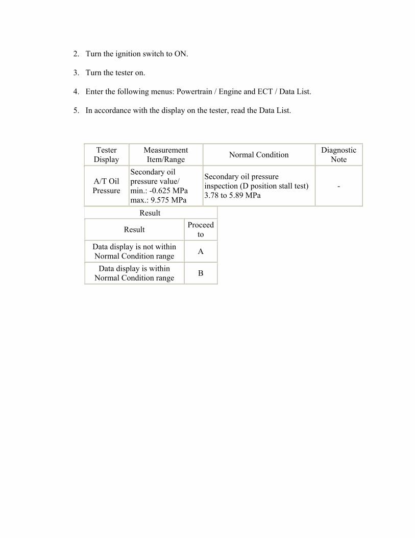
Tester Display
Measurement Item/Range Normal Condition Diagnostic
Note
A/T Oil Pressure
Secondary oil pressure value/ min.: -0.625 MPa max.: 9.575 MPa
Secondary oil pressure inspection (D position stall test) 3.78 to 5.89 MPa
-
Result
Result Proceed to
Data display is not within Normal Condition range A
Data display is within Normal Condition range B
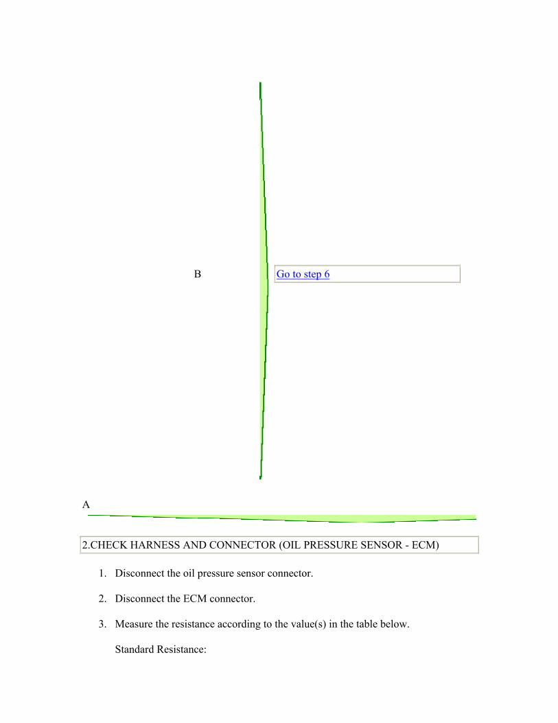
B
Go to step 6
A
2.CHECK HARNESS AND CONNECTOR (OIL PRESSURE SENSOR - ECM)
1. Disconnect the oil pressure sensor connector.
2. Disconnect the ECM connector.
3. Measure the resistance according to the value(s) in the table below.
Standard Resistance:
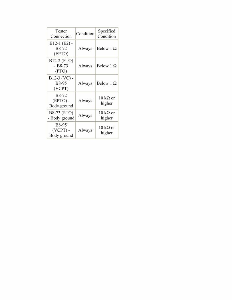
Tester Connection Condition Specified
Condition B12-1 (E2) -
B8-72 (EPTO)
Always Below 1 Ω
B12-2 (PTO) - B8-73 (PTO)
Always Below 1 Ω
B12-3 (VC) - B8-95
(VCPT) Always Below 1 Ω
B8-72 (EPTO) -
Body ground Always 10 kΩ or
higher
B8-73 (PTO) - Body ground Always 10 kΩ or
higher B8-95
(VCPT) - Body ground
Always 10 kΩ or higher
NG
REPAIR OR REPLACE HARNESS OR CONNECTOR
OK
3.INSPECT ECM (VCPT TERMINAL VOLTAGE)
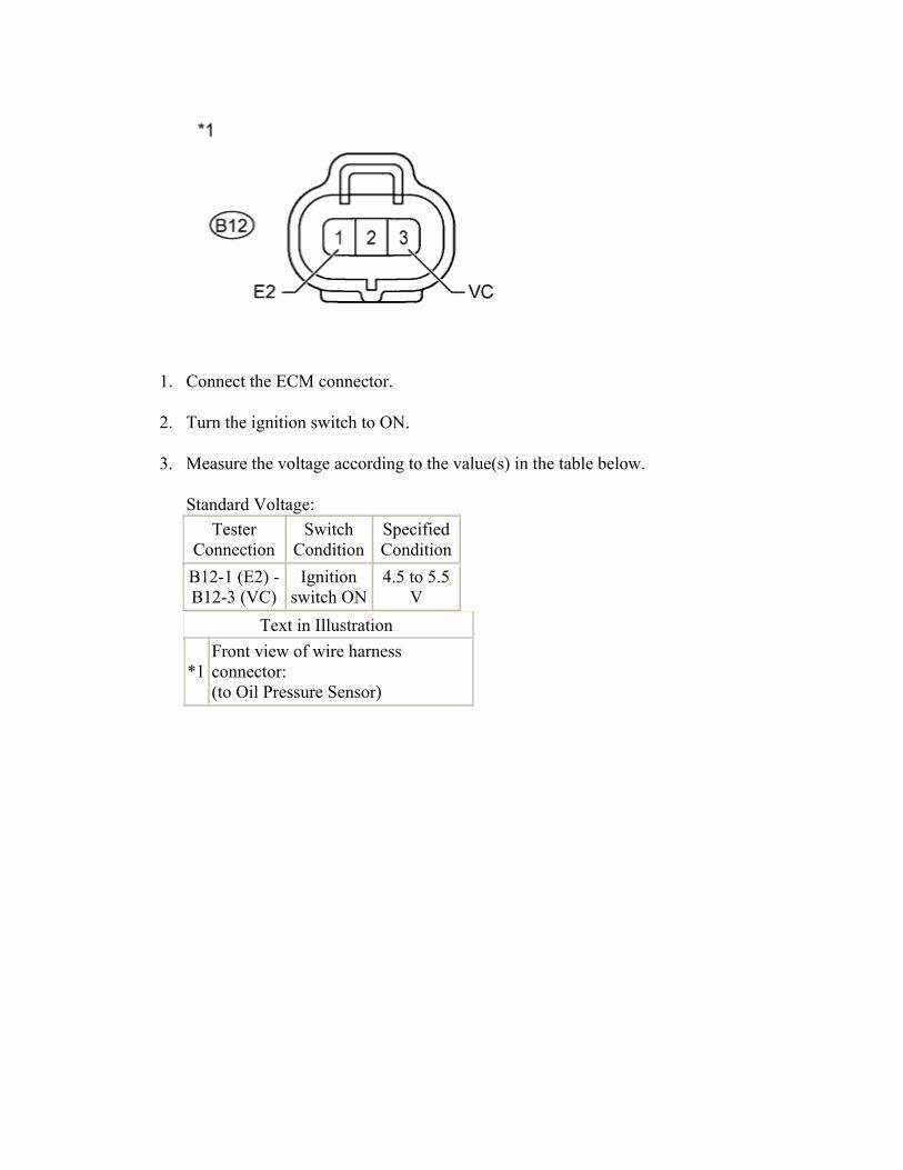
1. Connect the ECM connector.
2. Turn the ignition switch to ON.
3. Measure the voltage according to the value(s) in the table below.
Standard Voltage: Tester
Connection Switch
ConditionSpecified Condition
B12-1 (E2) - B12-3 (VC)
Ignition switch ON
4.5 to 5.5 V
Text in Illustration
*1 Front view of wire harness connector: (to Oil Pressure Sensor)
NG
Go to step 6
OK
4.REPLACE OIL PRESSURE SENSOR
1. Replace the oil pressure sensor ().
NEXT
5.PERFORM INITIALIZATION
1. Perform the initialization ().
2. Check for DTCs again ().
NEXT
END 6.REPLACE ECM
1. Replace the ECM ().
NEXT
7.PERFORM INITIALIZATION
1. Perform the initialization ().
2. Check for DTCs again ().
NEXT
END
DTC P0841 Transmission Fluid Pressure Sensor/Switch "A" Circuit Range/Performance DTC P2829 Pressure Control Solenoid "K" Performance (Shift Solenoid Valve SLS)
DESCRIPTION The ECM controls the secondary oil pressure calibration based on the secondary oil pressure signal detected by the oil pressure sensor. DTC No. DTC Detection Condition Trouble Area
1. Diagnosis Condition 2. Malfunction Status 3. Malfunction Time
4. Other
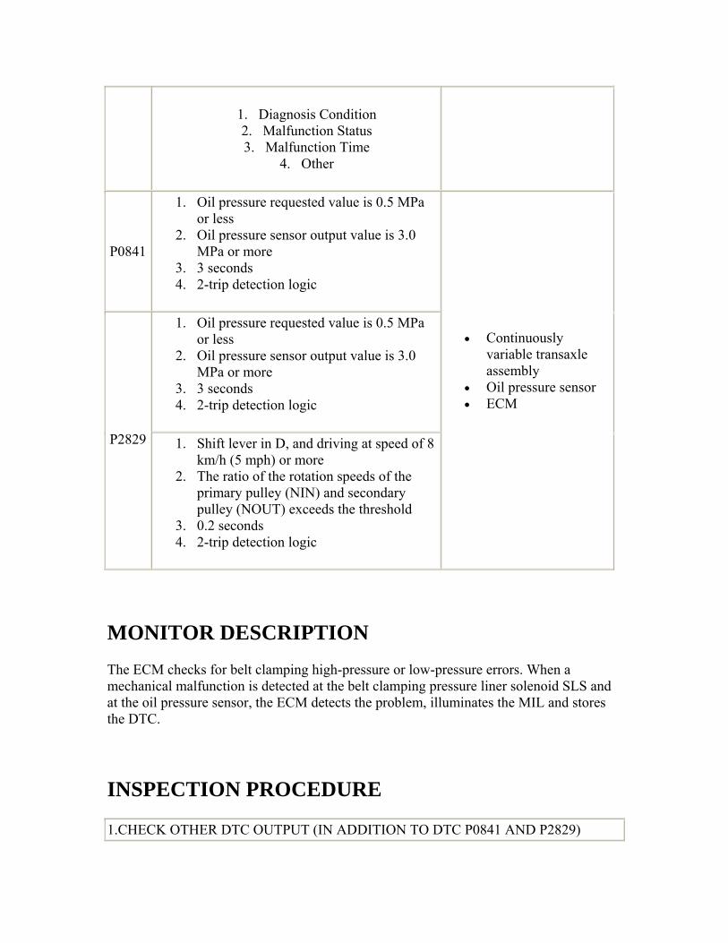
P0841
1. Oil pressure requested value is 0.5 MPa or less
2. Oil pressure sensor output value is 3.0 MPa or more
3. 3 seconds 4. 2-trip detection logic
1. Oil pressure requested value is 0.5 MPa or less
2. Oil pressure sensor output value is 3.0 MPa or more
3. 3 seconds 4. 2-trip detection logic
P2829 1. Shift lever in D, and driving at speed of 8 km/h (5 mph) or more
2. The ratio of the rotation speeds of the primary pulley (NIN) and secondary pulley (NOUT) exceeds the threshold
3. 0.2 seconds 4. 2-trip detection logic
• Continuously variable transaxle assembly
• Oil pressure sensor • ECM
MONITOR DESCRIPTION The ECM checks for belt clamping high-pressure or low-pressure errors. When a mechanical malfunction is detected at the belt clamping pressure liner solenoid SLS and at the oil pressure sensor, the ECM detects the problem, illuminates the MIL and stores the DTC.
INSPECTION PROCEDURE
1.CHECK OTHER DTC OUTPUT (IN ADDITION TO DTC P0841 AND P2829)
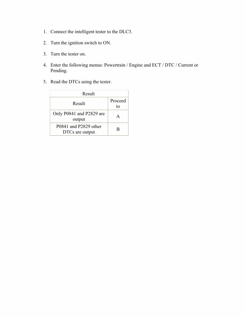
1. Connect the intelligent tester to the DLC3.
2. Turn the ignition switch to ON.
3. Turn the tester on.
4. Enter the following menus: Powertrain / Engine and ECT / DTC / Current or Pending.
5. Read the DTCs using the tester.
Result
Result Proceed to
Only P0841 and P2829 are output A
P0841 and P2829 other DTCs are output B
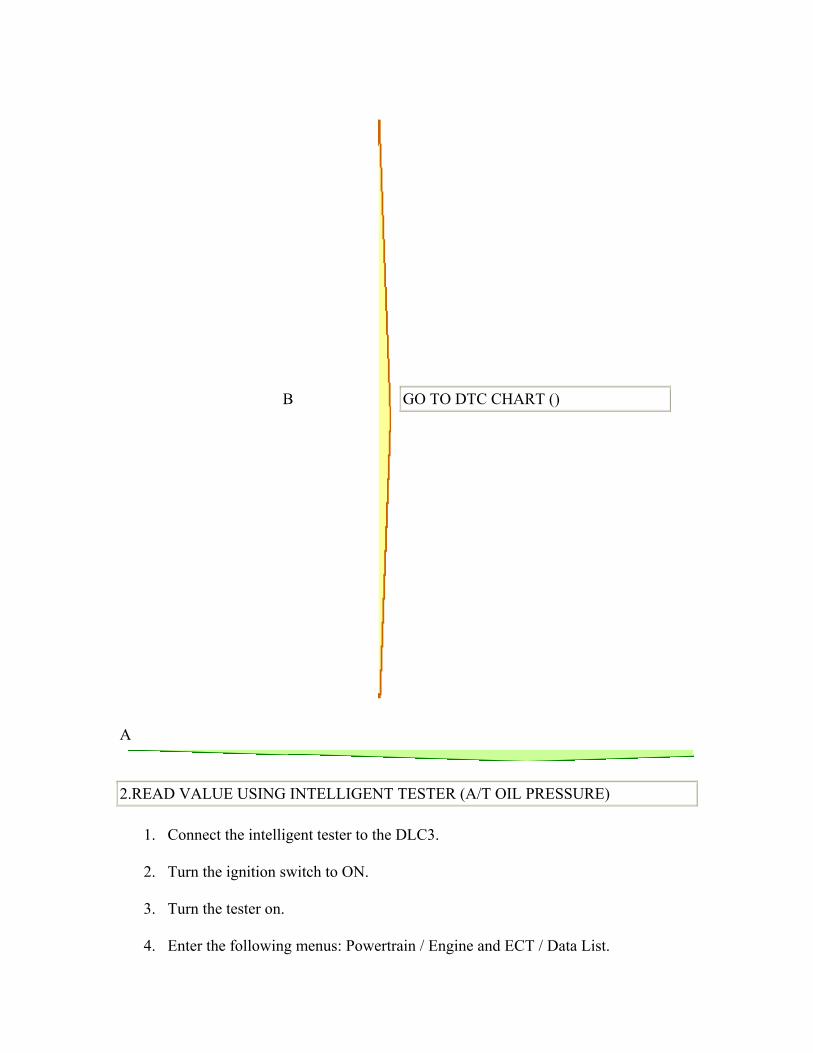
B
GO TO DTC CHART ()
A
2.READ VALUE USING INTELLIGENT TESTER (A/T OIL PRESSURE)
1. Connect the intelligent tester to the DLC3.
2. Turn the ignition switch to ON.
3. Turn the tester on.
4. Enter the following menus: Powertrain / Engine and ECT / Data List.
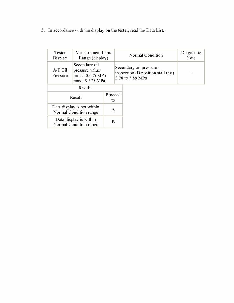
5. In accordance with the display on the tester, read the Data List.
Tester Display
Measurement Item/Range (display) Normal Condition Diagnostic
Note
A/T Oil Pressure
Secondary oil pressure value/ min.: -0.625 MPa max.: 9.575 MPa
Secondary oil pressure inspection (D position stall test) 3.78 to 5.89 MPa
-
Result
Result Proceed to
Data display is not within Normal Condition range A
Data display is within Normal Condition range B
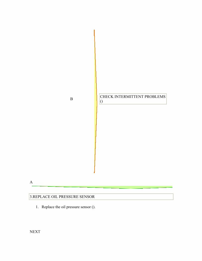
B
CHECK INTERMITTENT PROBLEMS ()
A
3.REPLACE OIL PRESSURE SENSOR
1. Replace the oil pressure sensor ().
NEXT
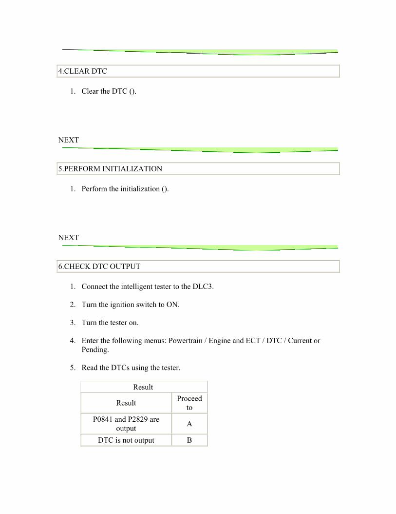
4.CLEAR DTC
1. Clear the DTC ().
NEXT
5.PERFORM INITIALIZATION
1. Perform the initialization ().
NEXT
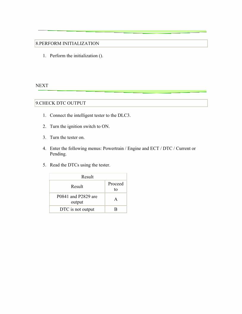
6.CHECK DTC OUTPUT
1. Connect the intelligent tester to the DLC3.
2. Turn the ignition switch to ON.
3. Turn the tester on.
4. Enter the following menus: Powertrain / Engine and ECT / DTC / Current or Pending.
5. Read the DTCs using the tester.
Result
Result Proceed to
P0841 and P2829 are output A
DTC is not output B
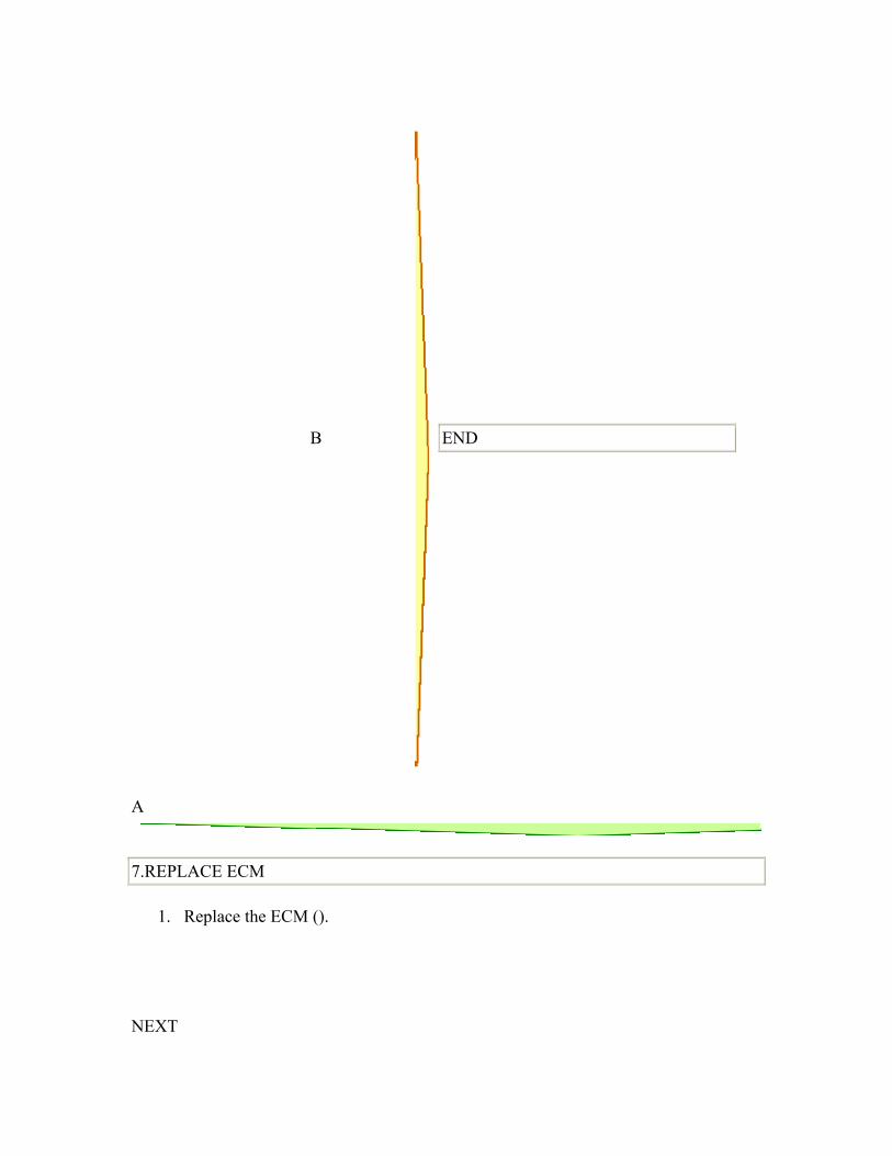
B
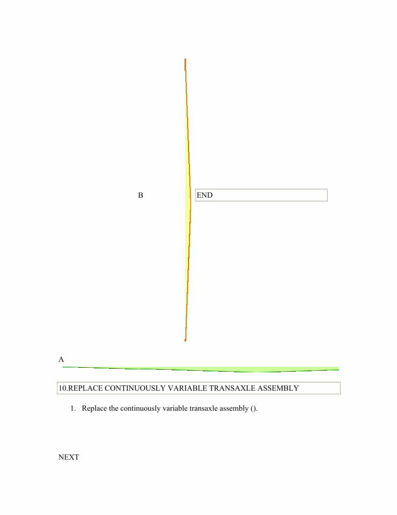
END
A
7.REPLACE ECM
1. Replace the ECM ().
NEXT
8.PERFORM INITIALIZATION
1. Perform the initialization ().
NEXT
9.CHECK DTC OUTPUT
1. Connect the intelligent tester to the DLC3.
2. Turn the ignition switch to ON.
3. Turn the tester on.
4. Enter the following menus: Powertrain / Engine and ECT / DTC / Current or Pending.
5. Read the DTCs using the tester.
Result
Result Proceed to
P0841 and P2829 are output A
DTC is not output B
B
END
A
10.REPLACE CONTINUOUSLY VARIABLE TRANSAXLE ASSEMBLY
1. Replace the continuously variable transaxle assembly ().
NEXT
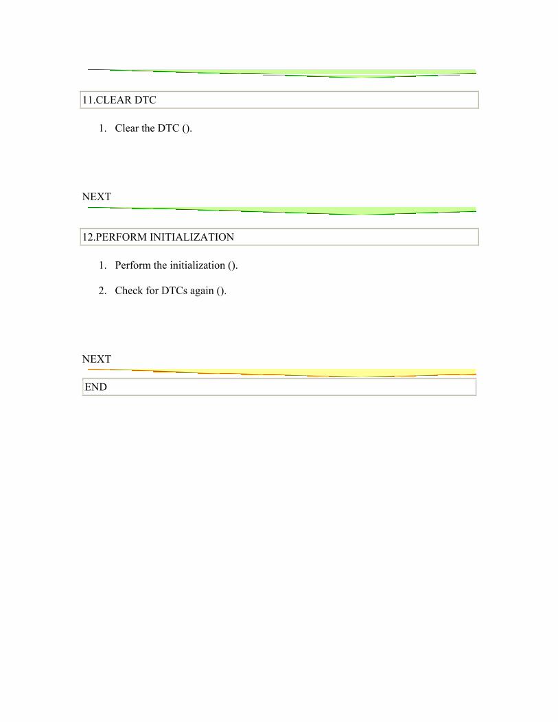
11.CLEAR DTC
1. Clear the DTC ().
NEXT
12.PERFORM INITIALIZATION
1. Perform the initialization ().
2. Check for DTCs again ().
NEXT
END
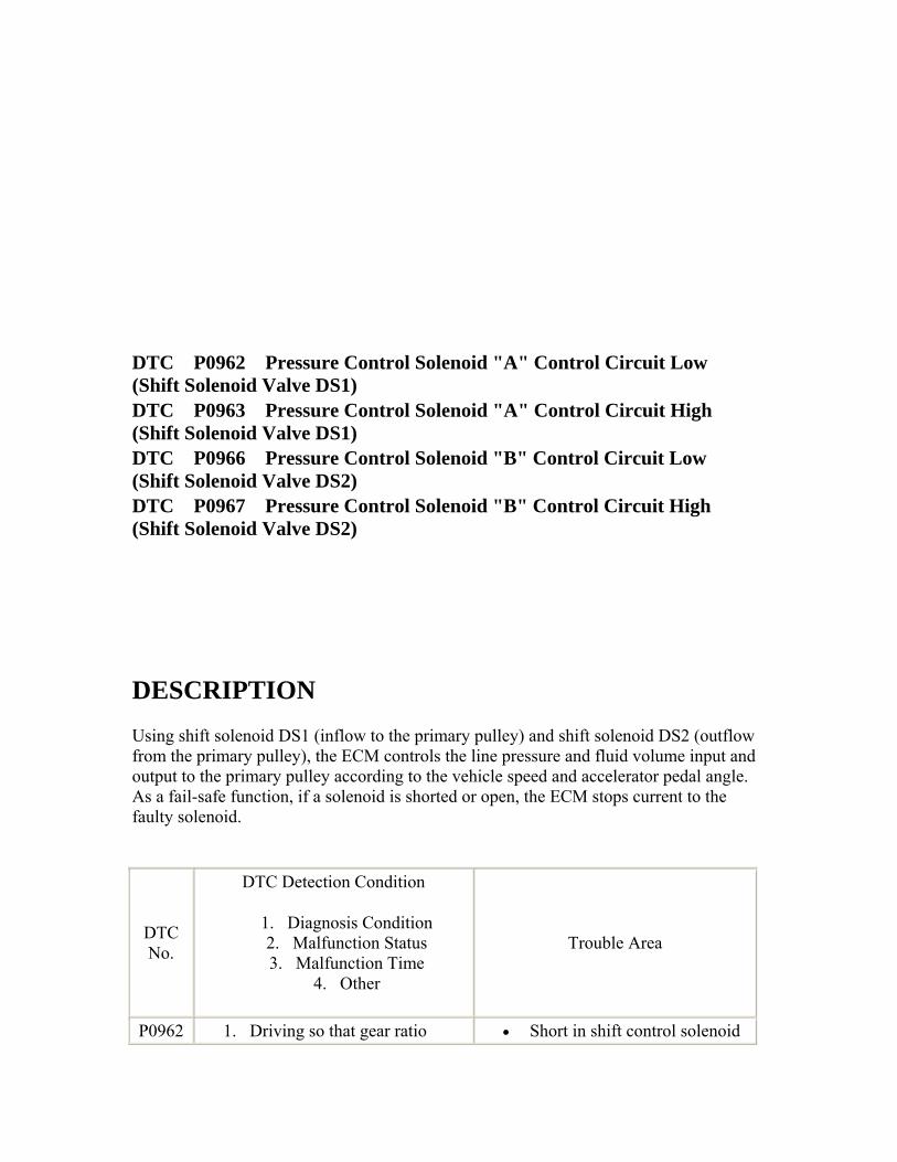
DTC P0962 Pressure Control Solenoid "A" Control Circuit Low (Shift Solenoid Valve DS1) DTC P0963 Pressure Control Solenoid "A" Control Circuit High (Shift Solenoid Valve DS1)
DTC P0966 Pressure Control Solenoid "B" Control Circuit Low (Shift Solenoid Valve DS2)
DTC P0967 Pressure Control Solenoid "B" Control Circuit High (Shift Solenoid Valve DS2)
DESCRIPTION Using shift solenoid DS1 (inflow to the primary pulley) and shift solenoid DS2 (outflow from the primary pulley), the ECM controls the line pressure and fluid volume input and output to the primary pulley according to the vehicle speed and accelerator pedal angle. As a fail-safe function, if a solenoid is shorted or open, the ECM stops current to the faulty solenoid.
DTC No.
DTC Detection Condition
1. Diagnosis Condition 2. Malfunction Status 3. Malfunction Time
4. Other
Trouble Area
P0962 1. Driving so that gear ratio • Short in shift control solenoid
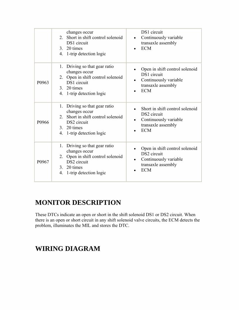
changes occur 2. Short in shift control solenoid
DS1 circuit 3. 20 times 4. 1-trip detection logic
DS1 circuit • Continuously variable
transaxle assembly • ECM
P0963
1. Driving so that gear ratio changes occur
2. Open in shift control solenoid DS1 circuit
3. 20 times 4. 1-trip detection logic
• Open in shift control solenoid DS1 circuit
• Continuously variable transaxle assembly
• ECM
P0966
1. Driving so that gear ratio changes occur
2. Short in shift control solenoid DS2 circuit
3. 20 times 4. 1-trip detection logic
• Short in shift control solenoid DS2 circuit
• Continuously variable transaxle assembly
• ECM
P0967
1. Driving so that gear ratio changes occur
2. Open in shift control solenoid DS2 circuit
3. 20 times 4. 1-trip detection logic
• Open in shift control solenoid DS2 circuit
• Continuously variable transaxle assembly
• ECM
MONITOR DESCRIPTION These DTCs indicate an open or short in the shift solenoid DS1 or DS2 circuit. When there is an open or short circuit in any shift solenoid valve circuits, the ECM detects the problem, illuminates the MIL and stores the DTC.
WIRING DIAGRAM
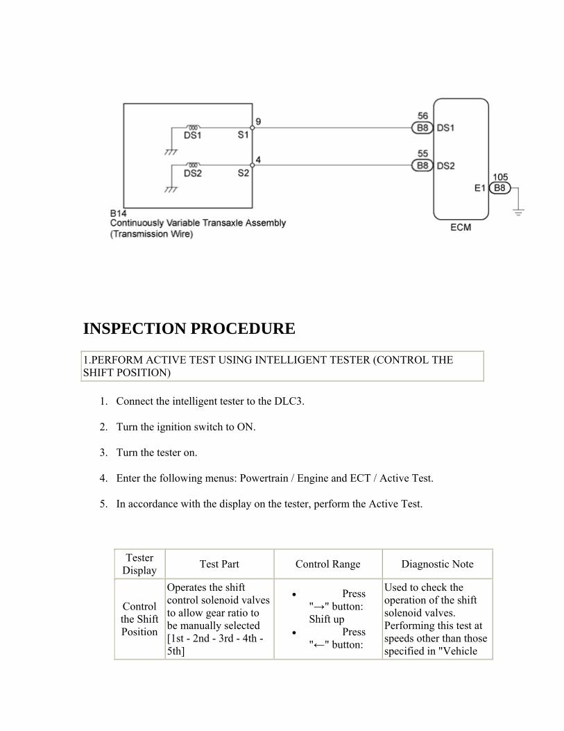
INSPECTION PROCEDURE
1.PERFORM ACTIVE TEST USING INTELLIGENT TESTER (CONTROL THE SHIFT POSITION)
1. Connect the intelligent tester to the DLC3.
2. Turn the ignition switch to ON.
3. Turn the tester on.
4. Enter the following menus: Powertrain / Engine and ECT / Active Test.
5. In accordance with the display on the tester, perform the Active Test.
Tester Display Test Part Control Range Diagnostic Note
Control the Shift Position
Operates the shift control solenoid valves to allow gear ratio to be manually selected [1st - 2nd - 3rd - 4th - 5th]
• Press "→" button: Shift up
• Press "←" button:
Used to check the operation of the shift solenoid valves. Performing this test at speeds other than those specified in "Vehicle
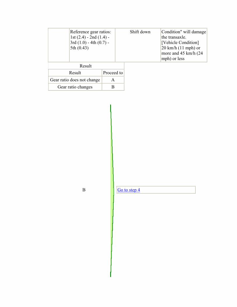
Reference gear ratios: 1st (2.4) - 2nd (1.4) - 3rd (1.0) - 4th (0.7) - 5th (0.43)
Shift down Condition" will damage the transaxle. [Vehicle Condition] 20 km/h (11 mph) or more and 45 km/h (24 mph) or less
Result Result Proceed to
Gear ratio does not change A Gear ratio changes B
B
Go to step 4
A
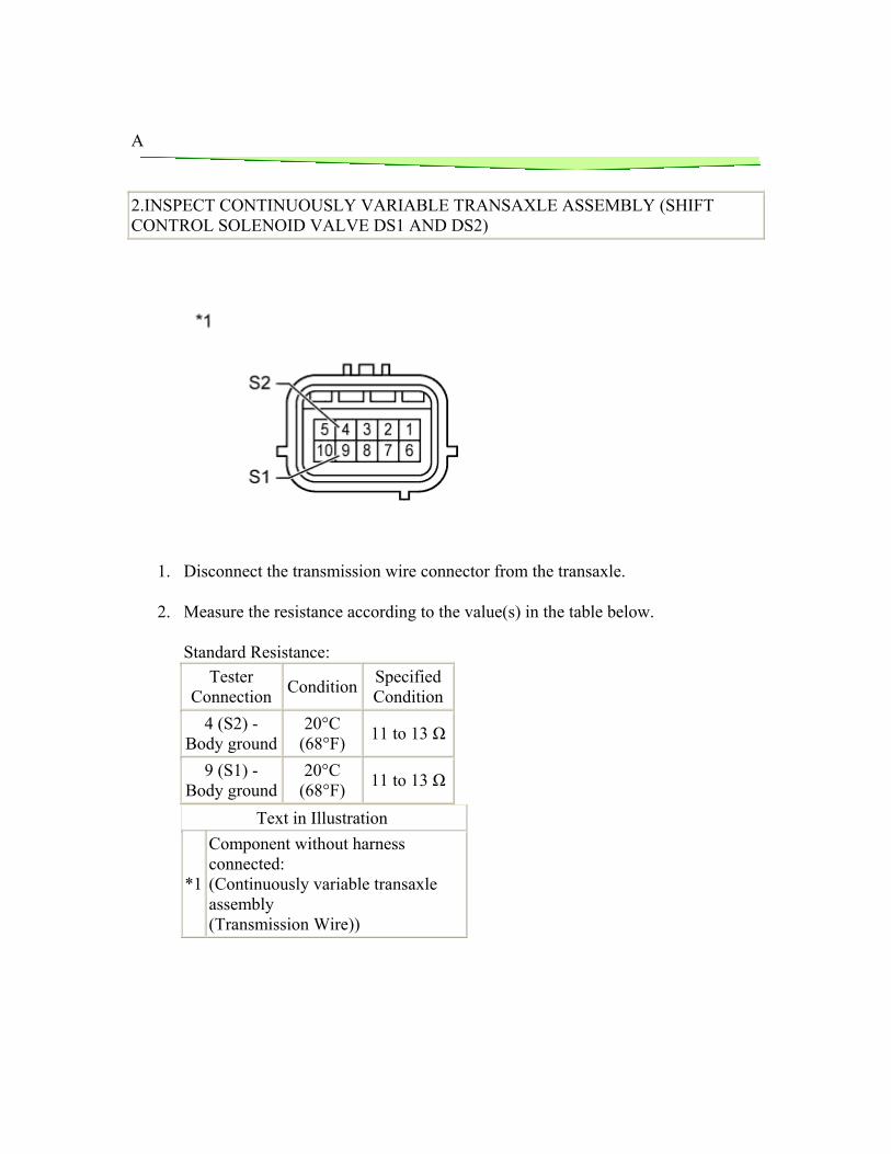
2.INSPECT CONTINUOUSLY VARIABLE TRANSAXLE ASSEMBLY (SHIFT CONTROL SOLENOID VALVE DS1 AND DS2)
1. Disconnect the transmission wire connector from the transaxle.
2. Measure the resistance according to the value(s) in the table below.
Standard Resistance: Tester
Connection Condition Specified Condition
4 (S2) - Body ground
20°C (68°F) 11 to 13 Ω
9 (S1) - Body ground
20°C (68°F) 11 to 13 Ω
Text in Illustration
*1
Component without harness connected: (Continuously variable transaxle assembly (Transmission Wire))
NG
Go to step 6
OK
3.CHECK HARNESS AND CONNECTOR (TRANSMISSION WIRE - ECM)
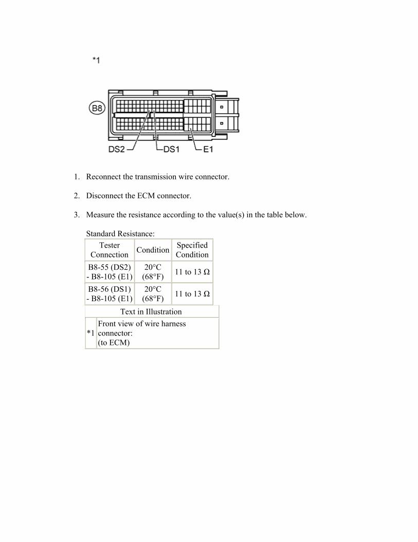
1. Reconnect the transmission wire connector.
2. Disconnect the ECM connector.
3. Measure the resistance according to the value(s) in the table below.
Standard Resistance: Tester
Connection Condition Specified Condition
B8-55 (DS2) - B8-105 (E1)
20°C (68°F) 11 to 13 Ω
B8-56 (DS1) - B8-105 (E1)
20°C (68°F) 11 to 13 Ω
Text in Illustration
*1 Front view of wire harness connector: (to ECM)

NG
REPAIR OR REPLACE HARNESS OR CONNECTOR
OK
4.REPLACE ECM
1. Replace the ECM ().
NEXT

5.PERFORM INITIALIZATION
1. Perform the initialization ().
2. Check for DTCs again ().
NEXT
END 6.REPLACE CONTINUOUSLY VARIABLE TRANSAXLE ASSEMBLY
1. Replace the continuously variable transaxle assembly ().
NEXT
7.PERFORM INITIALIZATION
1. Perform the initialization ().
2. Check for DTCs again ().
NEXT
END
DTC P1585 Acceleration Sensor Circuit
DESCRIPTION The ECM determines the vehicle inclination based on a signal from the yaw rate and acceleration sensor to perform neutral control. If a malfunction is determined in the yaw rate and acceleration sensor based on a malfunction signal from the brake actuator assembly, the ECM cancels neutral control as a fail-safe function. HINT:
• The ECM receives a yaw rate and acceleration sensor signal from the brake actuator assembly via CAN communication.
• If a CAN communication DTC is output, perform troubleshooting for that DTC first.
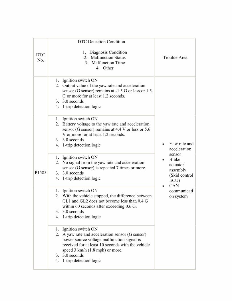
DTC No.
DTC Detection Condition
1. Diagnosis Condition 2. Malfunction Status 3. Malfunction Time
4. Other
Trouble Area
1. Ignition switch ON 2. Output value of the yaw rate and acceleration
sensor (G sensor) remains at -1.5 G or less or 1.5 G or more for at least 1.2 seconds.
3. 3.0 seconds 4. 1-trip detection logic
1. Ignition switch ON 2. Battery voltage to the yaw rate and acceleration
sensor (G sensor) remains at 4.4 V or less or 5.6 V or more for at least 1.2 seconds.
3. 3.0 seconds 4. 1-trip detection logic
1. Ignition switch ON 2. No signal from the yaw rate and acceleration
sensor (G sensor) is repeated 7 times or more. 3. 3.0 seconds 4. 1-trip detection logic
1. Ignition switch ON 2. With the vehicle stopped, the difference between
GL1 and GL2 does not become less than 0.4 G within 60 seconds after exceeding 0.6 G.
3. 3.0 seconds 4. 1-trip detection logic
P1585
1. Ignition switch ON 2. A yaw rate and acceleration sensor (G sensor)
power source voltage malfunction signal is received for at least 10 seconds with the vehicle speed 3 km/h (1.8 mph) or more.
3. 3.0 seconds 4. 1-trip detection logic
• Yaw rate and acceleration sensor
• Brake actuator assembly (Skid control ECU)
• CAN communication system
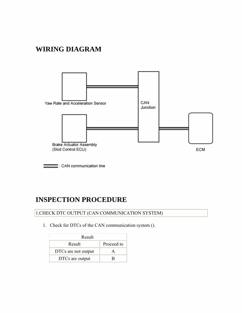
WIRING DIAGRAM
INSPECTION PROCEDURE
1.CHECK DTC OUTPUT (CAN COMMUNICATION SYSTEM)
1. Check for DTCs of the CAN communication system ().
Result Result Proceed to
DTCs are not output A DTCs are output B
B
GO TO CAN COMMUNICATION SYSTEM ()
A
2.READ VALUE USING INTELLIGENT TESTER (G SENSOR)
1. Connect the intelligent tester to the DLC3.
2. Turn the ignition switch to ON.
3. Turn the tester on.
4. Enter the following menus: Powertrain / Engine and ECT / Data List.
5. In accordance with the display on the tester, read the Data List.
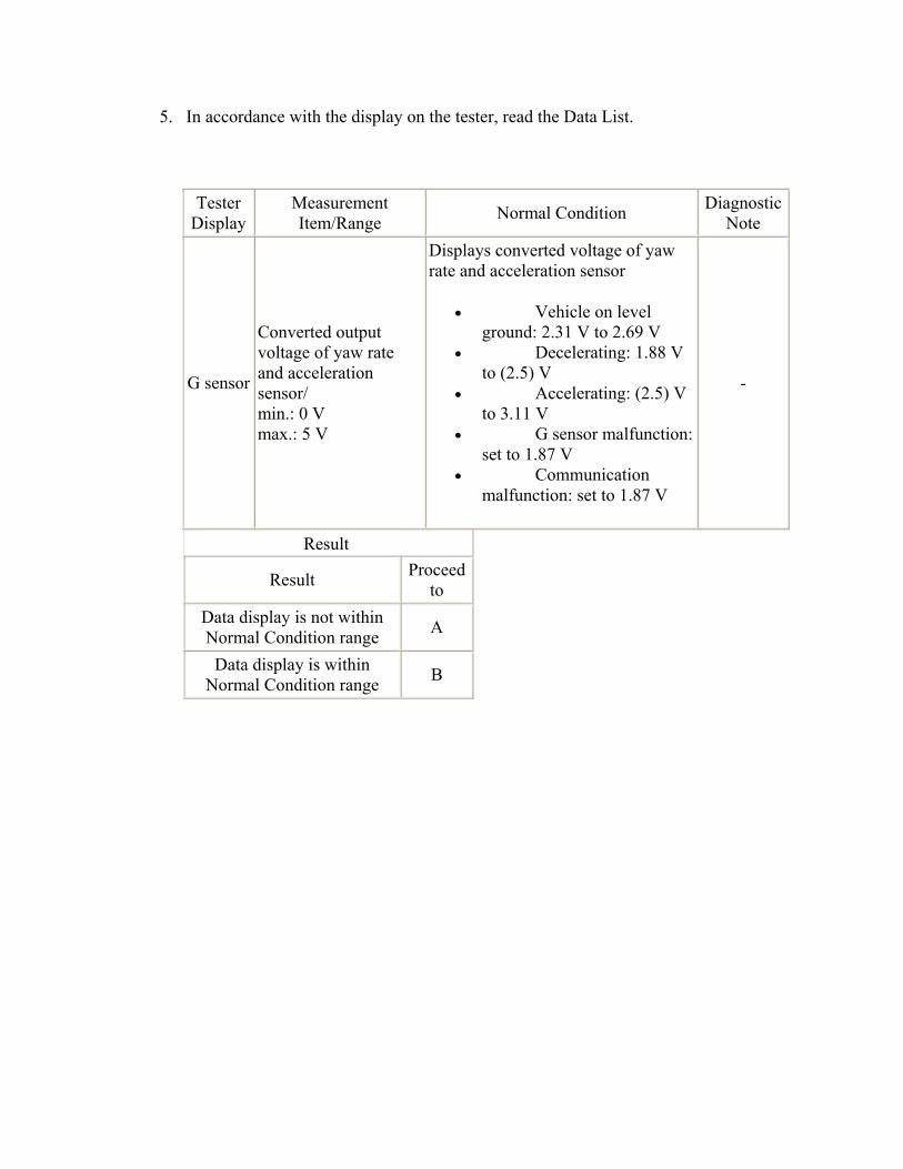
Tester Display
Measurement Item/Range Normal Condition Diagnostic
Note
G sensor
Converted output voltage of yaw rate and acceleration sensor/ min.: 0 V max.: 5 V
Displays converted voltage of yaw rate and acceleration sensor
• Vehicle on level ground: 2.31 V to 2.69 V
• Decelerating: 1.88 V to (2.5) V
• Accelerating: (2.5) V to 3.11 V
• G sensor malfunction: set to 1.87 V
• Communication malfunction: set to 1.87 V
-
Result
Result Proceed to
Data display is not within Normal Condition range A
Data display is within Normal Condition range B

B
REPLACE BRAKE ACTUATOR ASSEMBLY ()
A
3.REPLACE YAW RATE AND ACCELERATION SENSOR
1. Replace yaw rate and acceleration sensor ().
NEXT

4.PERFORM INITIALIZATION
1. Perform the initialization ().
2. Check for DTCs again ().
NEXT
END
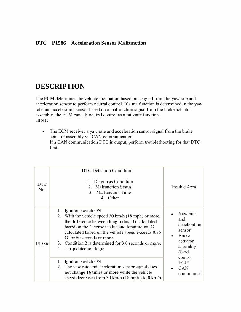
DTC P1586 Acceleration Sensor Malfunction
DESCRIPTION The ECM determines the vehicle inclination based on a signal from the yaw rate and acceleration sensor to perform neutral control. If a malfunction is determined in the yaw rate and acceleration sensor based on a malfunction signal from the brake actuator assembly, the ECM cancels neutral control as a fail-safe function. HINT:
• The ECM receives a yaw rate and acceleration sensor signal from the brake actuator assembly via CAN communication. If a CAN communication DTC is output, perform troubleshooting for that DTC first.
DTC No.
DTC Detection Condition
1. Diagnosis Condition 2. Malfunction Status 3. Malfunction Time
4. Other
Trouble Area
1. Ignition switch ON 2. With the vehicle speed 30 km/h (18 mph) or more,
the difference between longitudinal G calculated based on the G sensor value and longitudinal G calculated based on the vehicle speed exceeds 0.35 G for 60 seconds or more.
3. Condition 2 is determined for 3.0 seconds or more. 4. 1-trip detection logic
P1586
1. Ignition switch ON 2. The yaw rate and acceleration sensor signal does
not change 16 times or more while the vehicle speed decreases from 30 km/h (18 mph ) to 0 km/h.
• Yaw rate and acceleration sensor
• Brake actuator assembly (Skid control ECU)
• CAN communicat
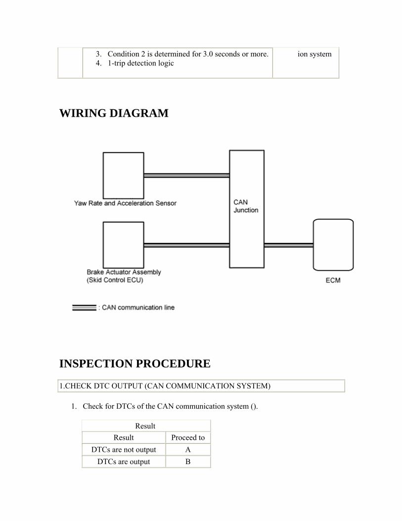
3. Condition 2 is determined for 3.0 seconds or more. 4. 1-trip detection logic
ion system
WIRING DIAGRAM
INSPECTION PROCEDURE
1.CHECK DTC OUTPUT (CAN COMMUNICATION SYSTEM)
1. Check for DTCs of the CAN communication system ().
Result Result Proceed to
DTCs are not output A DTCs are output B
B
GO TO CAN COMMUNICATION SYSTEM ()
A
2.CHECK OTHER DTC OUTPUT (IN ADDITION TO DTC P1586)
1. Clear the DTCs ().
2. Perform a road test where the vehicle is driven at 30 km/ h (18 mph) or more, the brakes are applied at least 16 times and the vehicle is finally stopped.
3. Connect the intelligent tester to the DLC3.
4. Turn the ignition switch to ON.
5. Turn the tester on.
6. Enter the following menus: Powertrain / Engine and ECT / DTC / Current or Pending.
7. Read the DTCs using the tester.
Result
Result Proceed to
Only P1586 is output A P1586 and other DTCs are
output B
8. HINT: 9. If any other codes besides DTC P1586 are output, perform troubleshooting for
those DTCs first.
B
GO TO DTC CHART ()
A
3.READ VALUE USING INTELLIGENT TESTER
1. Connect the intelligent tester to the DLC3.
2. Turn the ignition switch to ON.
3. Turn the tester on.
4. Enter the following menus: Powertrain / Engine and ECT / Data List.

5. In accordance with the display on the tester, read the Data List.
Tester Display
Measurement Item/Range Normal Condition Diagnostic
Note
G sensor
Converted output voltage of yaw rate and acceleration sensor/ min.: 0 V max.: 5 V
Displays converted voltage of yaw rate and acceleration sensor
• Vehicle on level ground: 2.31 V to 2.69 V
• Decelerating: 1.88 V to (2.5) V
• Accelerating: (2.5) V to 3.11 V
• G sensor malfunction: set to 1.87 V
• Communication malfunction: set to 1.87 V
-
Result
Result Proceed to
Data display is not within Normal Condition range A
Data display is within Normal Condition range B
B
REPLACE BRAKE ACTUATOR ASSEMBLY ()
A
4.REPLACE YAW RATE AND ACCELERATION SENSOR
1. Replace yaw rate and acceleration sensor ().
NEXT

5.PERFORM INITIALIZATION
1. Perform the initialization ().
2. Check for DTCs again ().
NEXT
END
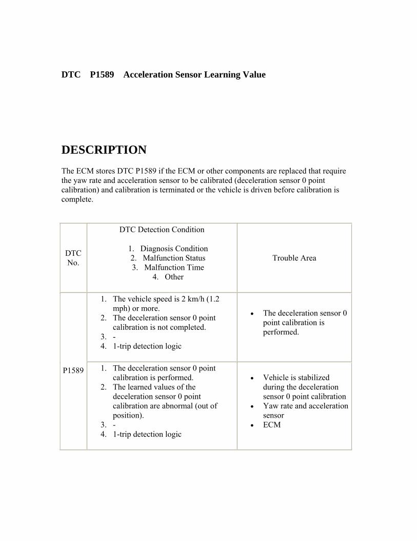
DTC P1589 Acceleration Sensor Learning Value
DESCRIPTION The ECM stores DTC P1589 if the ECM or other components are replaced that require the yaw rate and acceleration sensor to be calibrated (deceleration sensor 0 point calibration) and calibration is terminated or the vehicle is driven before calibration is complete.
DTC No.
DTC Detection Condition
1. Diagnosis Condition 2. Malfunction Status 3. Malfunction Time
4. Other
Trouble Area
1. The vehicle speed is 2 km/h (1.2 mph) or more.
2. The deceleration sensor 0 point calibration is not completed.
3. - 4. 1-trip detection logic
• The deceleration sensor 0 point calibration is performed.
P1589 1. The deceleration sensor 0 point calibration is performed.
2. The learned values of the deceleration sensor 0 point calibration are abnormal (out of position).
3. - 4. 1-trip detection logic
• Vehicle is stabilized during the deceleration sensor 0 point calibration
• Yaw rate and acceleration sensor
• ECM
INSPECTION PROCEDURE
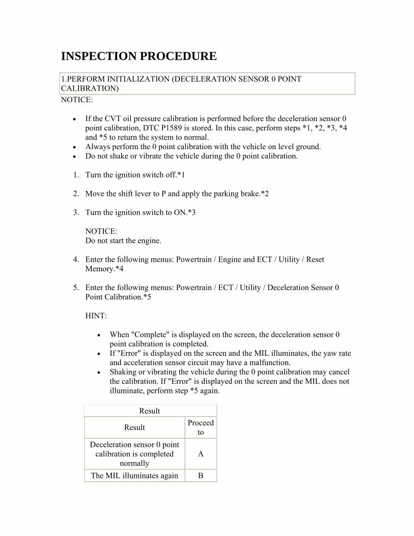
1.PERFORM INITIALIZATION (DECELERATION SENSOR 0 POINT CALIBRATION) NOTICE:
• If the CVT oil pressure calibration is performed before the deceleration sensor 0 point calibration, DTC P1589 is stored. In this case, perform steps *1, *2, *3, *4 and *5 to return the system to normal.
• Always perform the 0 point calibration with the vehicle on level ground. • Do not shake or vibrate the vehicle during the 0 point calibration.
1. Turn the ignition switch off.*1
2. Move the shift lever to P and apply the parking brake.*2
3. Turn the ignition switch to ON.*3
NOTICE: Do not start the engine.
4. Enter the following menus: Powertrain / Engine and ECT / Utility / Reset Memory.*4
5. Enter the following menus: Powertrain / ECT / Utility / Deceleration Sensor 0 Point Calibration.*5
HINT:
• When "Complete" is displayed on the screen, the deceleration sensor 0 point calibration is completed.
• If "Error" is displayed on the screen and the MIL illuminates, the yaw rate and acceleration sensor circuit may have a malfunction.
• Shaking or vibrating the vehicle during the 0 point calibration may cancel the calibration. If "Error" is displayed on the screen and the MIL does not illuminate, perform step *5 again.
Result
Result Proceed to
Deceleration sensor 0 point calibration is completed
normally A
The MIL illuminates again B
B
Go to step 3
A
2.PERFORM CVT OIL PRESSURE CALIBRATION NOTICE:
Do not initialize the learned values.
1. Turn the ignition switch off and wait at least 30 seconds.
2. Turn the ignition switch to ON and wait at least 2 seconds.
NOTICE: Do not start the engine.
3. Enter the following menus: Powertrain / Engine and ECT / Utility.
4. Start the engine and wait at least 5 seconds.
5. Enter the following menus: Powertrain / Engine and ECT / Utility / CVT Oil Pressure Calibration.
HINT:
• During the CVT oil pressure calibration, the engine idle speed will increase.
• When "Complete" is displayed on the screen, the CVT oil pressure calibration is completed.
• The learned values cannot be cleared by only disconnecting and reconnecting the cable to the negative (-) battery terminal.
6. Check for DTCs again.
NEXT
END 3.CHECK YAW RATE AND ACCELERATION SENSOR
1. Check the yaw rate and acceleration sensor for any inclination, bracket deformation or installation clearance.
OK: The yaw rate and acceleration sensor is installed correctly.
NG
SECURELY INSTALL YAW RATE AND ACCELERATION SENSOR
OK
4.READ VALUE USING INTELLIGENT TESTER (G SENSOR)
1. Connect the intelligent tester to the DLC3.
2. Turn the ignition switch to ON.
3. Turn the tester on.
4. Enter the following menus: Powertrain / Engine and ECT / Data List.

5. In accordance with the display on the tester, read the Data List.
Tester Display Measurement Item/Range Normal Condition Diagnostic
Note
G sensor
Converted output voltage of yaw rate and acceleration sensor/ min.: 0 V max.: 5 V
Vehicle on level ground: 2.31 V to 2.69 V
-
Result
Result Proceed to
Data display is not within Normal Condition range A
Data display is within Normal Condition range B
NG
Go to step 7
OK
5.REPLACE ECM
1. Replace the ECM ().
NEXT
6.PERFORM INITIALIZATION
1. Perform the initialization ().
2. Check for DTCs again ().
NEXT
END 7.REPLACE YAW RATE AND ACCELERATION SENSOR
1. Replace the yaw rate and acceleration sensor ().
NEXT
8.PERFORM INITIALIZATION
1. Perform the initialization ().
2. Check for DTCs again ().
NEXT
END
DTC P1750 Brake ECU Malfunction
DESCRIPTION When the ECM receives an error signal from the brake actuator assembly (skid control ECU), P1750 is stored.
DTC No.
DTC Detection Condition
1. Diagnosis Condition 2. Malfunction Status 3. Malfunction Time
Trouble Area
4. Other
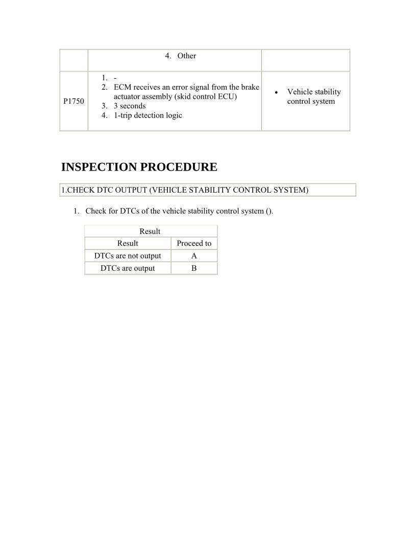
P1750
1. - 2. ECM receives an error signal from the brake
actuator assembly (skid control ECU) 3. 3 seconds 4. 1-trip detection logic
• Vehicle stability control system
INSPECTION PROCEDURE
1.CHECK DTC OUTPUT (VEHICLE STABILITY CONTROL SYSTEM)
1. Check for DTCs of the vehicle stability control system ().
Result Result Proceed to
DTCs are not output A DTCs are output B
B
GO TO VEHICLE STABILITY CONTROL SYSTEM ()
A
CHECK INTERMITTENT PROBLEMS ()
DTC P2763 Torque Converter Clutch Pressure Control Solenoid Control Circuit High (Shift Solenoid Valve DSU) DTC P2764 Torque Converter Clutch Pressure Control Solenoid Control Circuit Low (Shift Solenoid Valve DSU)
DESCRIPTION The ECM controls the signal to the lock-up engagement solenoid DSU and performs lock-up clutch pressure control in response to the input torque value.
DTC No.
DTC Detection Condition
1. Diagnosis Condition 2. Malfunction Status 3. Malfunction Time
Trouble Area
4. Other
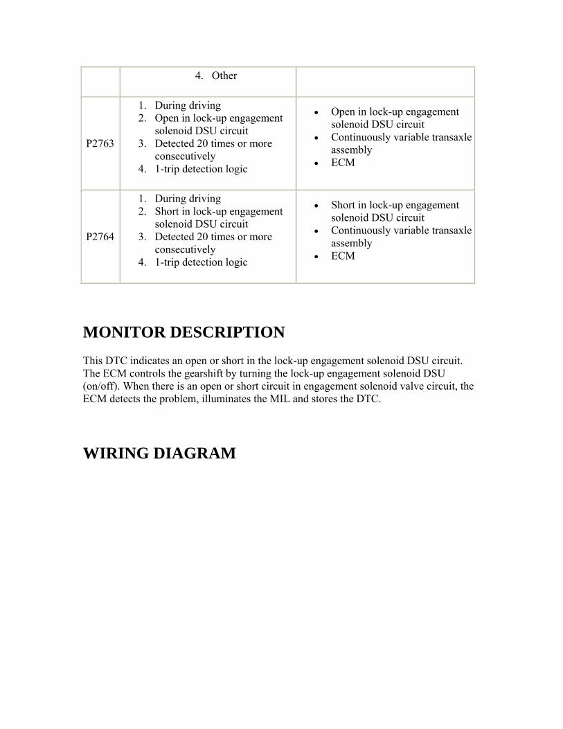
P2763
1. During driving 2. Open in lock-up engagement
solenoid DSU circuit 3. Detected 20 times or more
consecutively 4. 1-trip detection logic
• Open in lock-up engagement solenoid DSU circuit
• Continuously variable transaxle assembly
• ECM
P2764
1. During driving 2. Short in lock-up engagement
solenoid DSU circuit 3. Detected 20 times or more
consecutively 4. 1-trip detection logic
• Short in lock-up engagement solenoid DSU circuit
• Continuously variable transaxle assembly
• ECM
MONITOR DESCRIPTION This DTC indicates an open or short in the lock-up engagement solenoid DSU circuit. The ECM controls the gearshift by turning the lock-up engagement solenoid DSU (on/off). When there is an open or short circuit in engagement solenoid valve circuit, the ECM detects the problem, illuminates the MIL and stores the DTC.
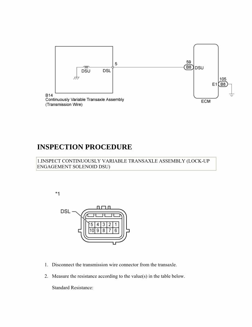
WIRING DIAGRAM
INSPECTION PROCEDURE
1.INSPECT CONTINUOUSLY VARIABLE TRANSAXLE ASSEMBLY (LOCK-UP ENGAGEMENT SOLENOID DSU)
1. Disconnect the transmission wire connector from the transaxle.
2. Measure the resistance according to the value(s) in the table below.
Standard Resistance:
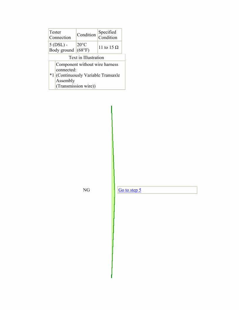
Tester Connection Condition Specified
Condition 5 (DSL) - Body ground
20°C (68°F) 11 to 15 Ω
Text in Illustration
*1
Component without wire harness connected: (Continuously Variable Transaxle Assembly (Transmission wire))
NG
Go to step 5
OK
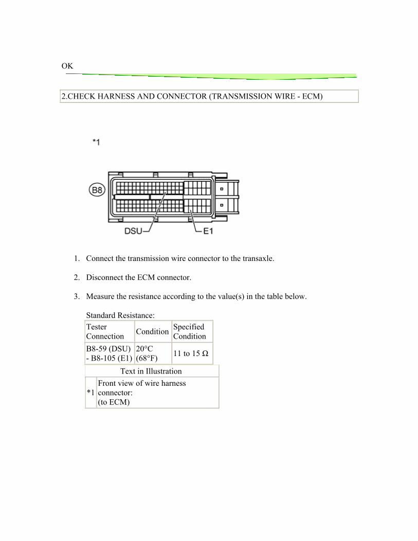
2.CHECK HARNESS AND CONNECTOR (TRANSMISSION WIRE - ECM)
1. Connect the transmission wire connector to the transaxle.
2. Disconnect the ECM connector.
3. Measure the resistance according to the value(s) in the table below.
Standard Resistance: Tester Connection Condition Specified
Condition B8-59 (DSU) - B8-105 (E1)
20°C (68°F) 11 to 15 Ω
Text in Illustration
*1 Front view of wire harness connector: (to ECM)

NG
REPAIR OR REPLACE HARNESS OR CONNECTOR
OK
3.REPLACE ECM
1. Replace the ECM ().
NEXT

4.PERFORM INITIALIZATION
1. Perform the initialization ().
2. Check for DTCs again ().
NEXT
END 5.REPLACE CONTINUOUSLY VARIABLE TRANSAXLE ASSEMBLY
1. Replace the continuously variable transaxle assembly ().
NEXT
6.PERFORM INITIALIZATION
1. Perform the initialization ().
2. Check for DTCs again ().
NEXT
END
DTC P2767 Input / Turbine Speed Sensor "B" Circuit No Signal
DESCRIPTION The ECM detects the input shaft rotation speed based on the signal from the primary pulley speed sensor (transmission revolution sensor NIN) and performs gear ratio change control.
DTC No.
DTC Detection Condition
1. Diagnosis Condition 2. Malfunction Status 3. Malfunction Time
Trouble Area
4. Other
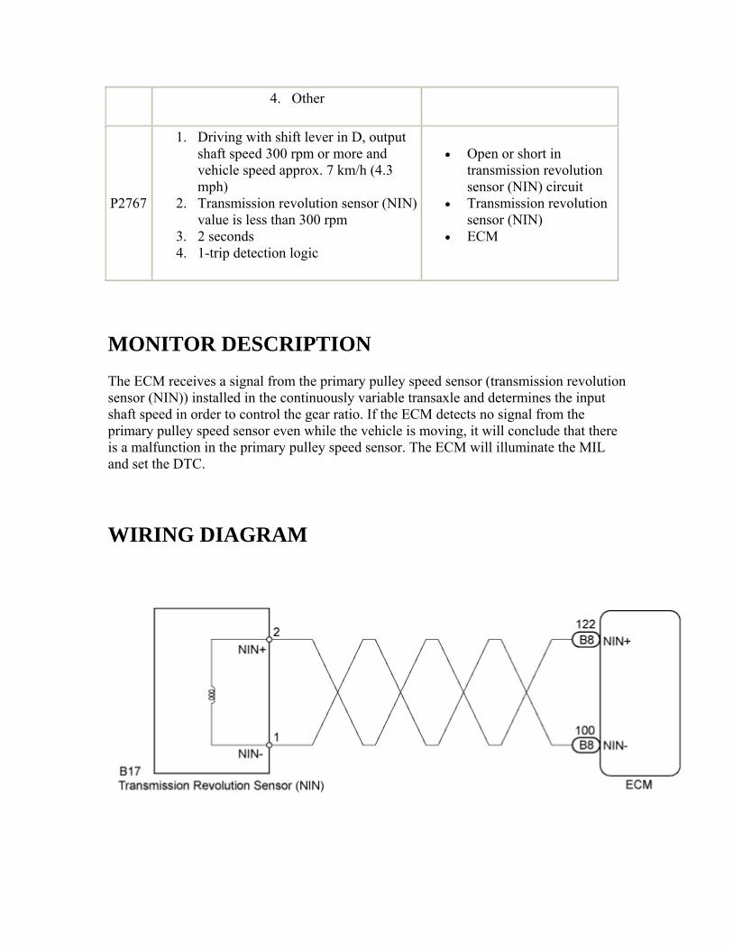
P2767
1. Driving with shift lever in D, output shaft speed 300 rpm or more and vehicle speed approx. 7 km/h (4.3 mph)
2. Transmission revolution sensor (NIN) value is less than 300 rpm
3. 2 seconds 4. 1-trip detection logic
• Open or short in transmission revolution sensor (NIN) circuit
• Transmission revolution sensor (NIN)
• ECM
MONITOR DESCRIPTION The ECM receives a signal from the primary pulley speed sensor (transmission revolution sensor (NIN)) installed in the continuously variable transaxle and determines the input shaft speed in order to control the gear ratio. If the ECM detects no signal from the primary pulley speed sensor even while the vehicle is moving, it will conclude that there is a malfunction in the primary pulley speed sensor. The ECM will illuminate the MIL and set the DTC.
WIRING DIAGRAM
INSPECTION PROCEDURE
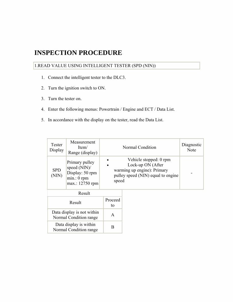
1.READ VALUE USING INTELLIGENT TESTER (SPD (NIN))
1. Connect the intelligent tester to the DLC3.
2. Turn the ignition switch to ON.
3. Turn the tester on.
4. Enter the following menus: Powertrain / Engine and ECT / Data List.
5. In accordance with the display on the tester, read the Data List.
Tester Display
Measurement Item/
Range (display)Normal Condition Diagnostic
Note
SPD (NIN)
Primary pulley speed (NIN)/ Display: 50 rpmmin.: 0 rpm max.: 12750 rpm
• Vehicle stopped: 0 rpm • Lock-up ON (After
warming up engine): Primary pulley speed (NIN) equal to engine speed
-
Result
Result Proceed to
Data display is not within Normal Condition range A
Data display is within Normal Condition range B
B
Go to step 4
A
2.INSPECT TRANSMISSION REVOLUTION SENSOR (NIN)
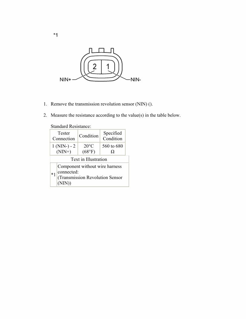
1. Remove the transmission revolution sensor (NIN) ().
2. Measure the resistance according to the value(s) in the table below.
Standard Resistance: Tester
Connection Condition Specified Condition
1 (NIN-) - 2 (NIN+)
20°C (68°F)
560 to 680 Ω
Text in Illustration
*1
Component without wire harness connected: (Transmission Revolution Sensor (NIN))
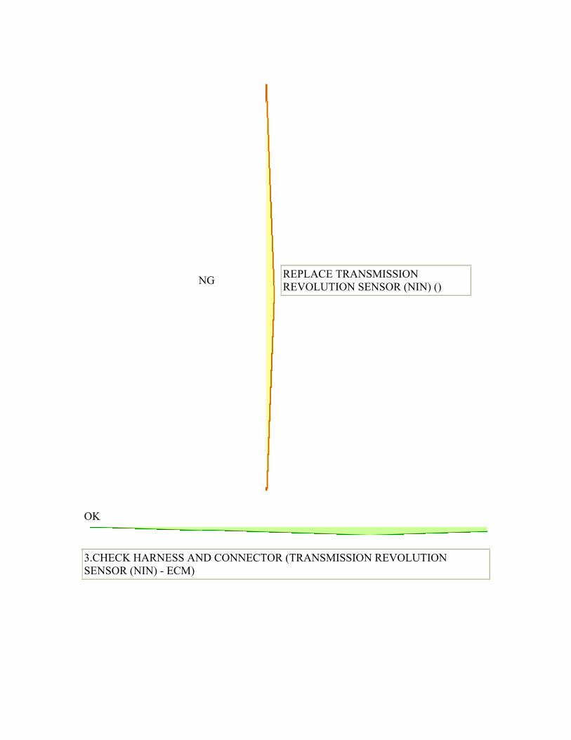
NG
REPLACE TRANSMISSION REVOLUTION SENSOR (NIN) ()
OK
3.CHECK HARNESS AND CONNECTOR (TRANSMISSION REVOLUTION SENSOR (NIN) - ECM)
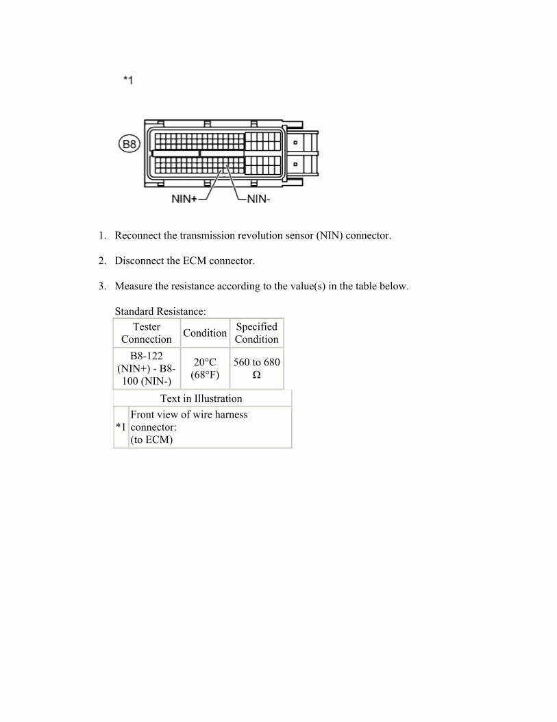
1. Reconnect the transmission revolution sensor (NIN) connector.
2. Disconnect the ECM connector.
3. Measure the resistance according to the value(s) in the table below.
Standard Resistance: Tester
Connection Condition Specified Condition
B8-122 (NIN+) - B8-100 (NIN-)
20°C (68°F)
560 to 680 Ω
Text in Illustration
*1 Front view of wire harness connector: (to ECM)

NG
REPAIR OR REPLACE HARNESS OR CONNECTOR
OK
4.REPLACE ECM
1. Replace the ECM ().
NEXT

5.PERFORM INITIALIZATION
1. Perform the initialization ().
2. Check for DTCs again ().
NEXT
END
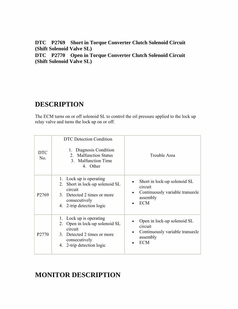
DTC P2769 Short in Torque Converter Clutch Solenoid Circuit (Shift Solenoid Valve SL) DTC P2770 Open in Torque Converter Clutch Solenoid Circuit (Shift Solenoid Valve SL)
DESCRIPTION The ECM turns on or off solenoid SL to control the oil pressure applied to the lock up relay valve and turns the lock up on or off.
DTC No.
DTC Detection Condition
1. Diagnosis Condition 2. Malfunction Status 3. Malfunction Time
4. Other
Trouble Area
P2769
1. Lock up is operating 2. Short in lock-up solenoid SL
circuit 3. Detected 2 times or more
consecutively 4. 2-trip detection logic
• Short in lock-up solenoid SL circuit
• Continuously variable transaxle assembly
• ECM
P2770
1. Lock up is operating 2. Open in lock-up solenoid SL
circuit 3. Detected 2 times or more
consecutively 4. 2-trip detection logic
• Open in lock-up solenoid SL circuit
• Continuously variable transaxle assembly
• ECM
MONITOR DESCRIPTION
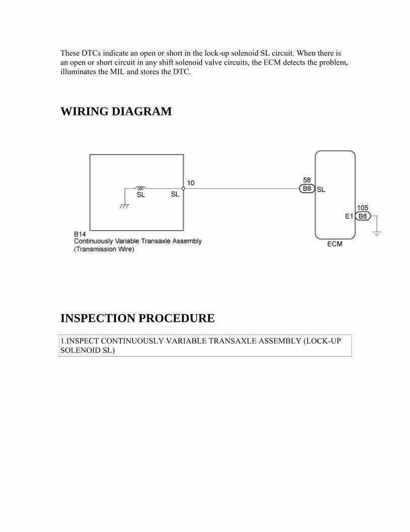
These DTCs indicate an open or short in the lock-up solenoid SL circuit. When there is an open or short circuit in any shift solenoid valve circuits, the ECM detects the problem, illuminates the MIL and stores the DTC.
WIRING DIAGRAM
INSPECTION PROCEDURE
1.INSPECT CONTINUOUSLY VARIABLE TRANSAXLE ASSEMBLY (LOCK-UP SOLENOID SL)
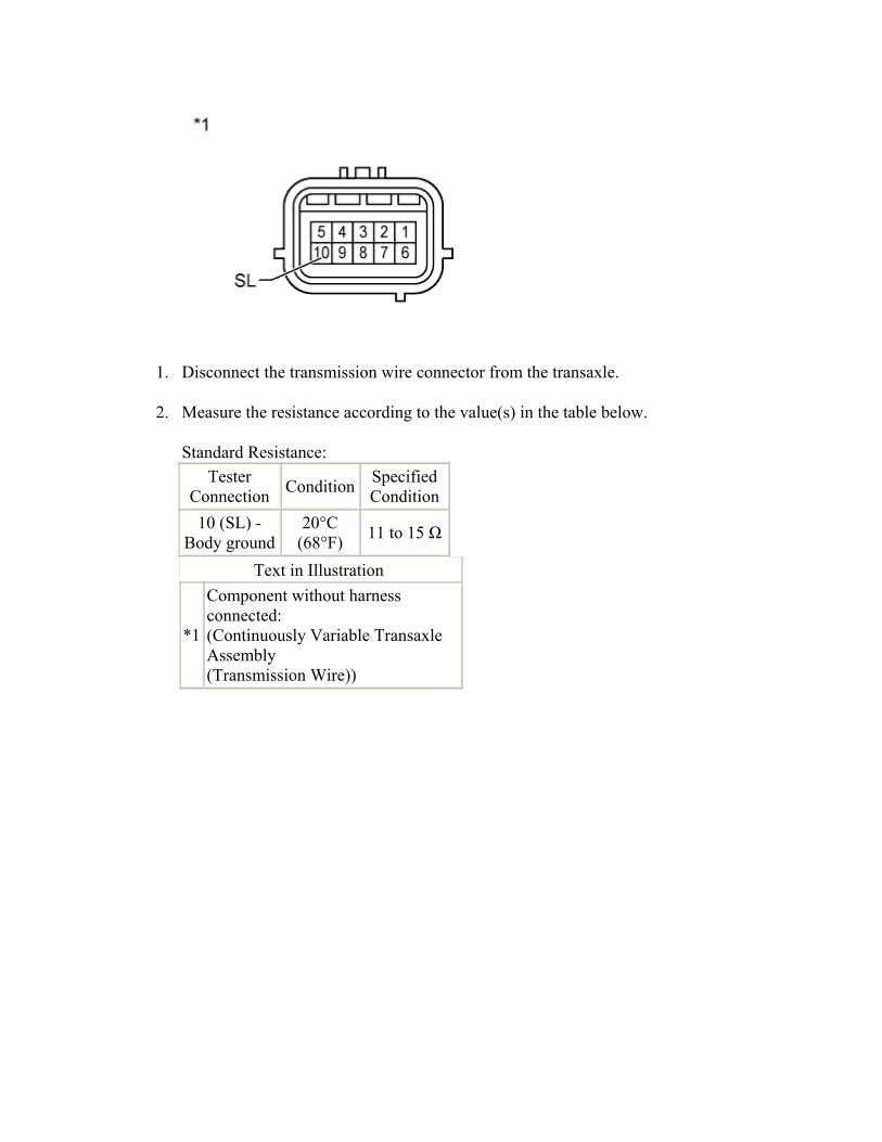
1. Disconnect the transmission wire connector from the transaxle.
2. Measure the resistance according to the value(s) in the table below.
Standard Resistance: Tester
Connection Condition Specified Condition
10 (SL) - Body ground
20°C (68°F) 11 to 15 Ω
Text in Illustration
*1
Component without harness connected: (Continuously Variable Transaxle Assembly (Transmission Wire))

NG
Go to step 5
OK
2.CHECK HARNESS AND CONNECTOR (TRANSMISSION WIRE - ECM)
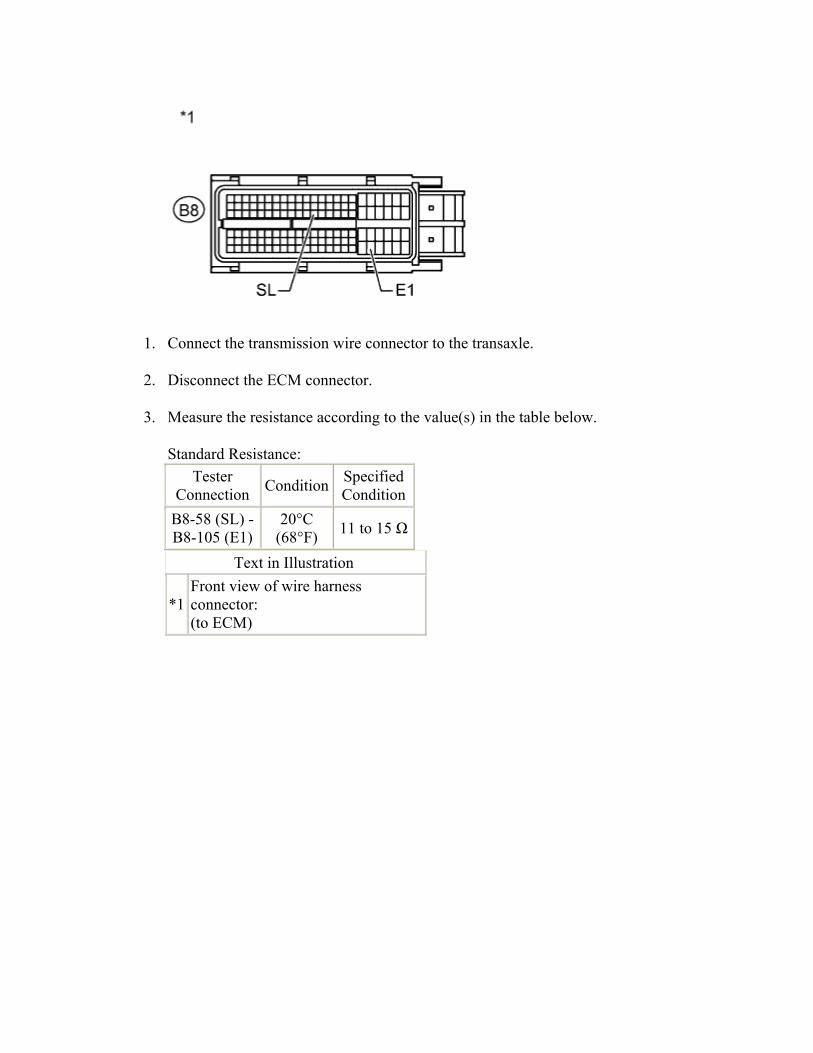
1. Connect the transmission wire connector to the transaxle.
2. Disconnect the ECM connector.
3. Measure the resistance according to the value(s) in the table below.
Standard Resistance: Tester
Connection Condition Specified Condition
B8-58 (SL) - B8-105 (E1)
20°C (68°F) 11 to 15 Ω
Text in Illustration
*1 Front view of wire harness connector: (to ECM)

NG
REPAIR OR REPLACE HARNESS OR CONNECTOR
OK
3.REPLACE ECM
1. Replace the ECM ().
NEXT

4.PERFORM INITIALIZATION
1. Perform the initialization ().
2. Check for DTCs again ().
NEXT
END 5.REPLACE CONTINUOUSLY VARIABLE TRANSAXLE ASSEMBLY
1. Replace the continuously variable transaxle assembly ().
NEXT
6.PERFORM INITIALIZATION
1. Perform the initialization ().
2. Check for DTCs again ().
NEXT
END
DTC P282B Pressure Control Solenoid "K" Electrical (Shift Solenoid Valve SLS)
DESCRIPTION The ECM uses the SLS solenoid valve to control the secondary pulley pressure and belt clamping pressure according to the input shaft torque force. Additionally, solenoid SLS is used to control the forward clutch hydraulic pressure when the forward clutch is engaged and the neutral control is operating.
DTC No. DTC Detection Condition Trouble Area
1. Diagnosis Condition 2. Malfunction Status 3. Malfunction Time
4. Other
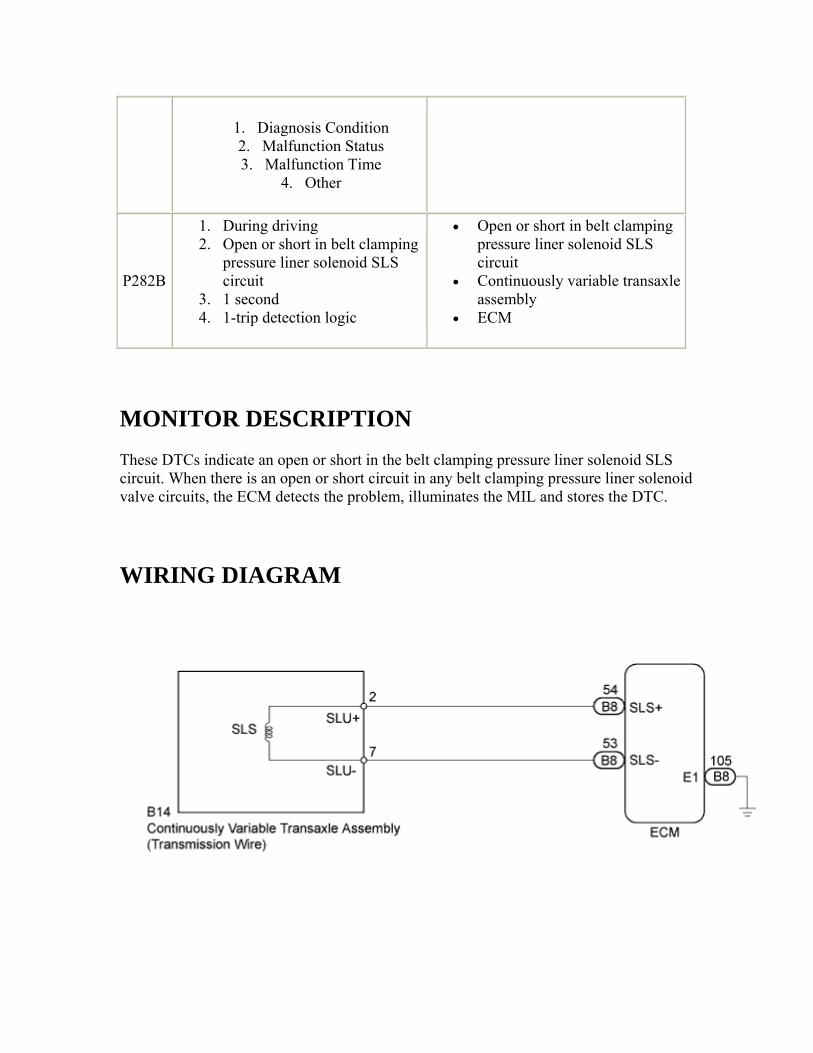
P282B
1. During driving 2. Open or short in belt clamping
pressure liner solenoid SLS circuit
3. 1 second 4. 1-trip detection logic
• Open or short in belt clamping pressure liner solenoid SLS circuit
• Continuously variable transaxle assembly
• ECM
MONITOR DESCRIPTION These DTCs indicate an open or short in the belt clamping pressure liner solenoid SLS circuit. When there is an open or short circuit in any belt clamping pressure liner solenoid valve circuits, the ECM detects the problem, illuminates the MIL and stores the DTC.
WIRING DIAGRAM
INSPECTION PROCEDURE
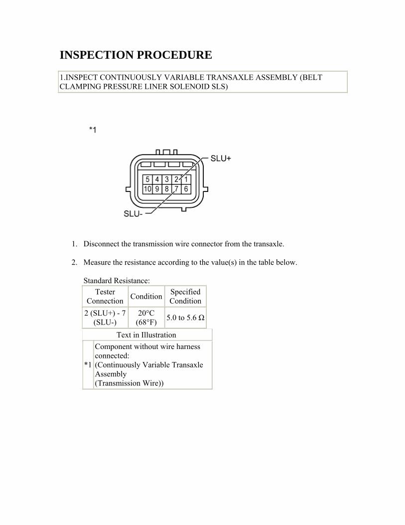
1.INSPECT CONTINUOUSLY VARIABLE TRANSAXLE ASSEMBLY (BELT CLAMPING PRESSURE LINER SOLENOID SLS)
1. Disconnect the transmission wire connector from the transaxle.
2. Measure the resistance according to the value(s) in the table below.
Standard Resistance: Tester
Connection Condition Specified Condition
2 (SLU+) - 7 (SLU-)
20°C (68°F) 5.0 to 5.6 Ω
Text in Illustration
*1
Component without wire harness connected: (Continuously Variable Transaxle Assembly (Transmission Wire))

NG
Go to step 5
OK
2.CHECK HARNESS AND CONNECTOR (TRANSMISSION WIRE - ECM)
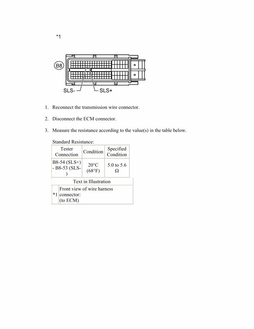
1. Reconnect the transmission wire connector.
2. Disconnect the ECM connector.
3. Measure the resistance according to the value(s) in the table below.
Standard Resistance: Tester
Connection Condition Specified Condition
B8-54 (SLS+) - B8-53 (SLS-
)
20°C (68°F)
5.0 to 5.6 Ω
Text in Illustration
*1 Front view of wire harness connector: (to ECM)
NG
REPAIR OR REPLACE HARNESS OR CONNECTOR
OK
3.REPLACE ECM
1. Replace ECM ().
NEXT
4.PERFORM INITIALIZATION
1. Perform the initialization ().
2. Check for DTCs again ().
NEXT
END 5.REPLACE CONTINUOUSLY VARIABLE TRANSAXLE ASSEMBLY
1. Replace continuously variable transaxle assembly ().
NEXT
6.PERFORM INITIALIZATION
1. Perform the initialization ().
2. Check for DTCs again ().
NEXT
END
DTC U0129 Lost Communication with Brake System Control Module
DESCRIPTION The ECM receives signals sent from the skid control ECU via the CAN communication system. When DTCs indicating a CAN communication system malfunction are output, repair the CAN communication system before repairing each corresponding sensor.
DTC No.
DTC Detection Condition
1. Diagnosis Condition Trouble Area
2. Malfunction Status 3. Malfunction Time
4. Other
U0129
1. Ignition switch ON 2. No communication between the ECM and
Skid Control ECU. 3. 2.34 seconds 4. 1-trip detection logic
• CAN communication system
• Brake actuator assembly (Skid control ECU)
• ECM
INSPECTION PROCEDURE
1.CLEAR DTC AND PERFORM ROAD TEST
1. Clear the DTCs ().
HINT: Write down the currently output DTCs before clearing them.
2. Start the engine, drive at a low speed and perform the inspection.
NEXT
2.CHECK DTC OUTPUT
1. Connect the intelligent tester to the DLC3.
2. Turn the ignition switch to ON.
3. Turn the tester on.
4. Enter the following menus: Powertrain / Engine and ECT / DTC / Current or Pending.
5. Read the DTCs using the tester.
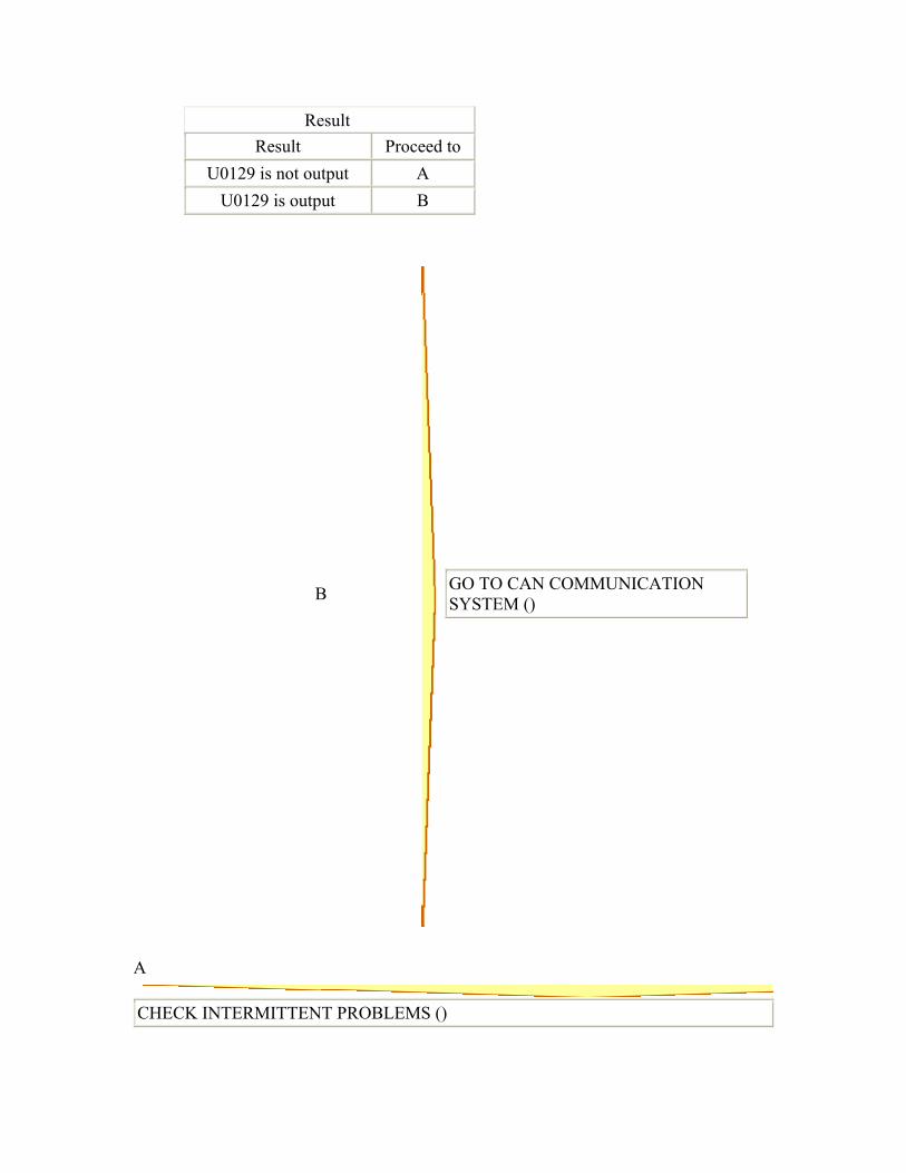
Result Result Proceed to
U0129 is not output A U0129 is output B
B
GO TO CAN COMMUNICATION SYSTEM ()
A
CHECK INTERMITTENT PROBLEMS ()