Embed Size (px)
Citation preview

aerospace ermetoTechnical service
DN12 VALVEASSEMBLY AND OPERATIONAL
MANUAL
DT : N� 0619DATE : 02.10PAGE : 1 / 13Ind : D
D N 1 2 V A L V EA S S E M B L Y A N D O P E R A T I O N A L M A N U A L

aerospace ermetoTechnical service
DN12 VALVEASSEMBLY AND OPERATIONAL
MANUAL
DT : N� 0619DATE : 02.10PAGE : 2 / 13Ind : D
CONTENTS
1 - PURPOSE _________________________________________________________________ 3
2 – PRODUCTS CONCERNED__________________________________________________ 3
3 - PRESENTATION___________________________________________________________ 3
4 – TECHNICAL FEATURES ___________________________________________________ 4
4.1 - Use ____________________________________________________________________ 4
4.2 - Fluids carried ___________________________________________________________ 4
4.3 - Connections_____________________________________________________________ 4
5 - ASSEMBLY _______________________________________________________________ 7
5.1 – Internal safety check valve ________________________________________________ 7
5.2 –Upper angle valve ________________________________________________________ 7
6 – maintenance _______________________________________________________________ 7
7 - OPERATION _____________________________________________________________ 10
7.1 – Manual controls ________________________________________________________ 10
8 - LIMITATIONS AND PRECAUTIONS FOR USE_______________________________ 11
9 - ENVIRONMENT AND RECYCLING ________________________________________ 12
APPENDIX __________________________________________________________________ 13
D 02/10 S. MINIER Add �8 and �9 : limitations and environment
C 11/07 S. MINIER Add Molykote G-rapid+ grease
B 01/05 R. JOSSE Modif of the thightening torque of the valve mounting
A 01/04 R. JOSSE Adding precision into the fluid list and removing of the UN 1052 in the 70900 family
0 08/03 R. JOSSE 1st Edition
Index Date Author Designation

aerospace ermetoTechnical service
DN12 VALVEASSEMBLY AND OPERATIONAL
MANUAL
DT : N� 0619DATE : 02.10PAGE : 3 / 13Ind : D
1 - PURPOSE
The purpose of this specification is to define the assembly and operational procedure for DN12 valves.
2 – PRODUCTS CONCERNED
Family 70800 steel series :
R11102 – 960162: valve- check valve unit PN80- R11117 – 960174: valve unit- R11116 – 960172: check valve unit G3/8
R10846 – 960136: valve- check valve unit PN80- R11117 – 960174: valve unit- R10860 – 960173: check valve unit G1/2
R11964 – 960604: valve-plate unit PN150- R11117 – 960174: valve unit- R11956 – 960603: double plate unit
R11897 – 960576: valve- check valve unitPN150- R11898 – 960577: refrigerant valve unit- R11906 – 960578: refrigerant check valve unit
Family 70900 stainless steel series :
R12098 – 960683: valve- check valve unit PN166- R12097 – 960682: stainless steel valve unit- R12347 – 960821: stainless steel check valve unit
R12345 – 960819: valve- check valve unit PN166- R12346 – 960820: all stainless steel valve unit- R12347 – 960821: all stainless steel check valve unit
3 - PRESENTATION
The DN12 ERMETO valve with manual controls is specially designed to equip containers.
It is composed of an internal valve mounted on the container plate and of a 90� output valve placed on it.
The same controls are used to open and close the valve and check valve.
The DN12 ERMETO valve is used to fill and empty mobile containers.
aerospace ermetoTechnical service
DN12 VALVEASSEMBLY AND OPERATIONAL
MANUAL
DT : N� 0619DATE : 02.10PAGE : 4 / 13Ind : D
4 – TECHNICAL FEATURES
4.1 - USE
- Nominal diameter : 12 mm- Service pressure : up to 166 Bar depending on model- Temperature : - 40 to + 70�C depending on model- Manual controls : hexagonal nut (27) on flats.
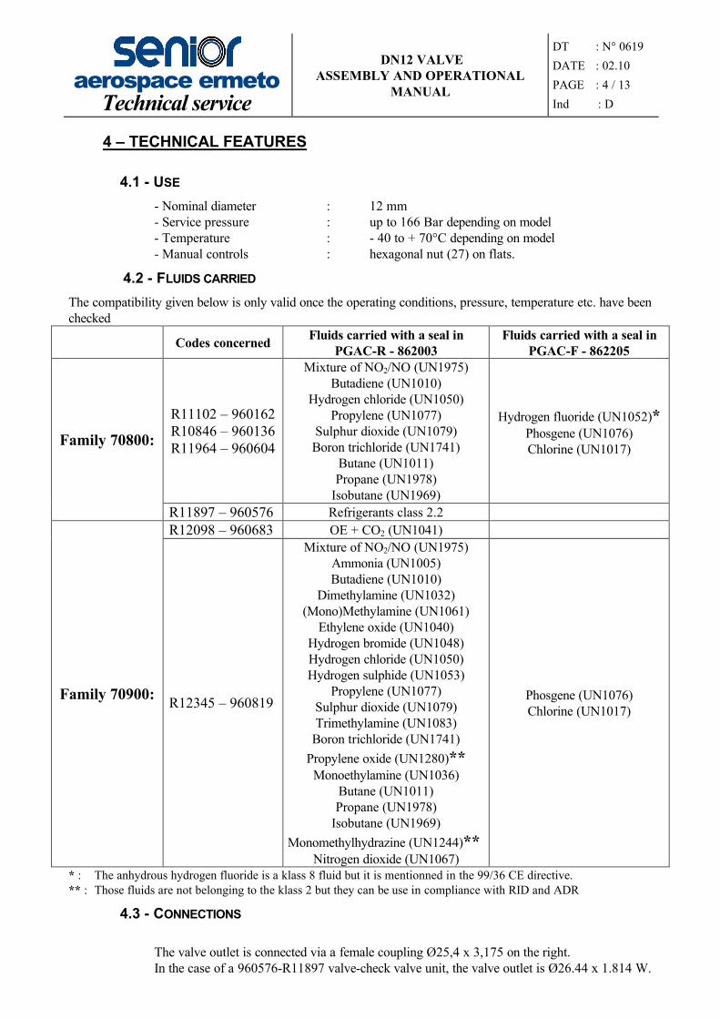
4.2 - FLUIDS CARRIED
The compatibility given below is only valid once the operating conditions, pressure, temperature etc. have been checked
Codes concerned Fluids carried with a seal in PGAC-R - 862003
Fluids carried with a seal in PGAC-F - 862205
R11102 – 960162R10846 – 960136R11964 – 960604
Mixture of NO2/NO (UN1975)Butadiene (UN1010)
Hydrogen chloride (UN1050)Propylene (UN1077)
Sulphur dioxide (UN1079)Boron trichloride (UN1741)
Butane (UN1011)Propane (UN1978)
Isobutane (UN1969)
Hydrogen fluoride (UN1052)*Phosgene (UN1076)Chlorine (UN1017)Family 70800:
R11897 – 960576 Refrigerants class 2.2 R12098 – 960683 OE + CO2 (UN1041)
Family 70900: R12345 – 960819
Mixture of NO2/NO (UN1975)Ammonia (UN1005)Butadiene (UN1010)
Dimethylamine (UN1032)(Mono)Methylamine (UN1061)
Ethylene oxide (UN1040)Hydrogen bromide (UN1048)Hydrogen chloride (UN1050)Hydrogen sulphide (UN1053)
Propylene (UN1077)Sulphur dioxide (UN1079)Trimethylamine (UN1083)
Boron trichloride (UN1741)Propylene oxide (UN1280)**
Monoethylamine (UN1036)Butane (UN1011)Propane (UN1978)
Isobutane (UN1969)Monomethylhydrazine (UN1244)**
Nitrogen dioxide (UN1067)
Phosgene (UN1076)Chlorine (UN1017)
* : The anhydrous hydrogen fluoride is a klass 8 fluid but it is mentionned in the 99/36 CE directive.** : Those fluids are not belonging to the klass 2 but they can be use in compliance with RID and ADR
4.3 - CONNECTIONS
The valve outlet is connected via a female coupling �25,4 x 3,175 on the right.In the case of a 960576-R11897 valve-check valve unit, the valve outlet is �26.44 x 1.814 W.
aerospace ermetoTechnical service
DN12 VALVEASSEMBLY AND OPERATIONAL
MANUAL
DT : N� 0619DATE : 02.10PAGE : 5 / 13Ind : D
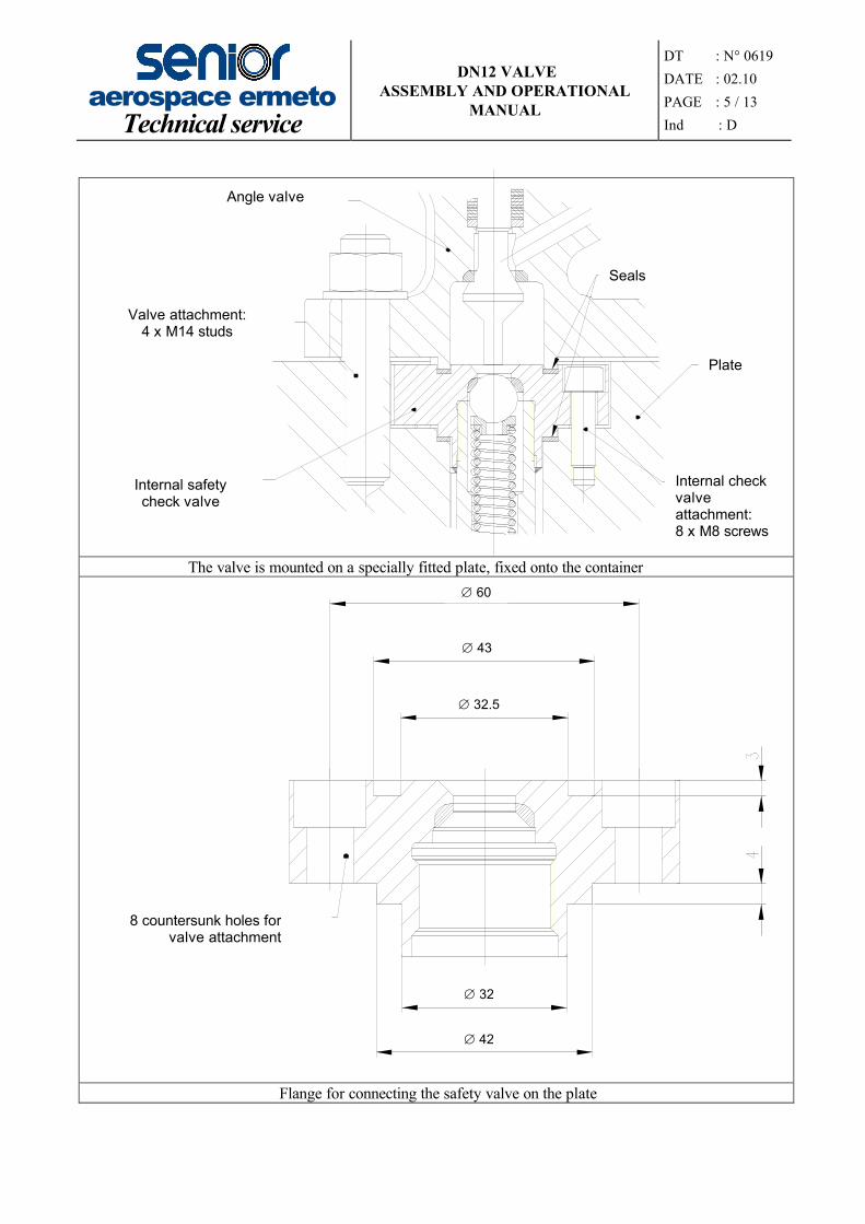
The valve is mounted on a specially fitted plate, fixed onto the container
�
�
�
�
�
Flange for connecting the safety valve on the plate
Angle valve
Valve attachment:4 x M14 studs
Internal safety check valve
Seals
Plate
Internal check valve attachment:8 x M8 screws
8 countersunk holes for valve attachment
60
43
32.5
32
42

aerospace ermetoTechnical service
DN12 VALVEASSEMBLY AND OPERATIONAL
MANUAL
DT : N� 0619DATE : 02.10PAGE : 6 / 13Ind : D
�
�
�
4 TROUS �
�
Flange for connecting the double joint DN12 valve.� �2
6.44
x
1.81
4 W
DN12 valve side outlet
4 holes 16
33.5
42
124
96
25
.4 x
3.1
75 B
SW
26
.44
x 1.
814
Wde
pend
ing
on m
odel

aerospace ermetoTechnical service
DN12 VALVEASSEMBLY AND OPERATIONAL
MANUAL
DT : N� 0619DATE : 02.10PAGE : 7 / 13Ind : D
5 - ASSEMBLY
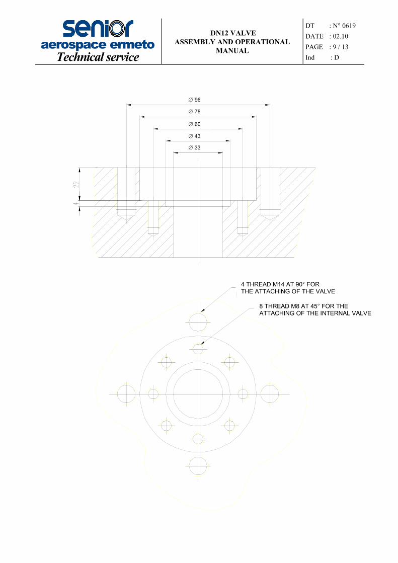
5.1 – INTERNAL SAFETY CHECK VALVE (see diagram page 09)
The internal safety check valve is mounted on a specially fitted plate as shown on the diagram on page 10. This is fixed on the tank.
1. – Position the seal (2) (according to the fluid used), 43x33x1.5, in the plate groove.
2. – Grease the eight threaded holes
3. – Assemble the internal valve in the plate and attach it using the 8 hexagonal socket setscrews (1), tighten them up in crosswise order to a torque of 1.6 daN.m.
4. – In liquid phase, a pickup tube can be connected to the thread at the end of the internal check valve.
5. – Check the torques at least six hours after the operations.
5.2 –UPPER ANGLE VALVE: (see diagram page 09)
1. Place the second seal (2), 43x33x1.5, in the internal valve groove.
2. Position the valve on the internal check valve and screw the 4 x M14 nuts (3), complete with their washer, onto the studs. Tighten them in crosswise order to a torque of 5 daN.m.
4. Check the torque at least six hours after the operation.
6 – MAINTENANCE
- Check presence of grease in order to ensure the correct operation of the tap, by lifting the red cap above the rod casing.- If grease is required:
open the tap and add more Molykote MoS2 G-Rapid + grease, both inside the case and on the rod.
- Move the tap several times to allow the grease to penetrate into the control system.

aerospace ermetoTechnical service
DN12 VALVEASSEMBLY AND OPERATIONAL
MANUAL
DT : N� 0619DATE : 02.10PAGE : 8 / 13Ind : D
Valve
Plate
Internal valve
aerospace ermetoTechnical service
DN12 VALVEASSEMBLY AND OPERATIONAL
MANUAL
DT : N� 0619DATE : 02.10PAGE : 9 / 13Ind : D
�
�
�
�
�
8 TROUS A 45░ POUR
4 TROUS M14 A 90░ POUR
96
78
60
43
33
4 THREAD M14 AT 90� FOR THE ATTACHING OF THE VALVE
8 THREAD M8 AT 45� FOR THE ATTACHING OF THE INTERNAL VALVE

aerospace ermetoTechnical service
DN12 VALVEASSEMBLY AND OPERATIONAL
MANUAL
DT : N� 0619DATE : 02.10PAGE : 10 / 13Ind : D
7 - OPERATION
The DN 12 ERMETO valve is a manually controlled valve.
7.1 – MANUAL CONTROLS (see diagram above)
7.1.1 - OpeningCheck that the stem guide (3) is on the high position "F" (valve shut)Slowly unscrew the cap nut (1) with a 32 hexagonal wrenchConnect the valve outletUnscrew the stem bushing (2) until stem guide (3) is on the low position "O" (valve open)
with a 27 hexagonal wrench
7.1.2 - Closing
Screw the stem bushing (2) with a 27 hexagonal dynamometric wrench up to the high position "F" then apply a torque of 5 daN.m.
Important: only disconnect the valve after scavenging the nozzles and checking for nil residual pressure on the drainage line.
Screw back the cap nut (1) at a torque of 5 daN.m. with a 32 hexagonal wrench.
0F
0F
0F
ERMETODN 12

aerospace ermetoTechnical service
DN12 VALVEASSEMBLY AND OPERATIONAL
MANUAL
DT : N� 0619DATE : 02.10PAGE : 11 / 13Ind : D
8 - LIMITATIONS AND PRECAUTIONS FOR USE
The following usage conditions are taken from Risk Analysis DT775 and are listed here because they are not explained in the paragraphs above.
● Risks linked to an impact following an accident:- The appliance is designed with minimal impact resistance (KV>27J).- The user should take care to fit the appliances on containers equipped with permanent or temporary protective devices.- The user should always check that the security cover is locked correctly before moving the container.
● Risks linked to corrosion caused by the environment of the appliance:- The user should check or create suitable protection for carbon steel appliances in relation to their environment.
● Risks linked to the action of the flame:- The appliance should not be in contact with the flame.
● Risks linked to the deterioration of seals with time (tap service life):- The user should ensure that the flange seals are replaced each time the appliance is used.- The user should ensure that the appliance is overhauled in accordance with the regulations in force.- The user should make sure that the appliance has been overhauled by Senior Aeorspace Ermeto or one of its appointed service agents before any change of fluid.- The user should check that the appliance is liquid-tight after every loading.
● Risks linked to stresses caused by the pipework:- The user should ensure that no stresses are caused when fitting equipment adjacent to the tap.
● Risks linked to dismantling the appliance under pressure:- The user must make sure that the appliance is not under pressure before doing any work on it.- The tap may only be dismantled by personnel qualified by Senior Aerospace Ermeto.
● Risks linked to modifications to the appliance:- No modification may be made to the appliance by the user (drilling, welding, grinding, etc.)
● Risks linked to sealing:- Have the appliance overhauled by Senior Aerospace Ermeto or one of its appointed service agents.
● Risks linked to the projection of products onto the appliance:- The user should make sure that the appliance is not placed close to a source of liquid or solid projections (sand blasting, high pressure washing, grinding, etc) that could damage it.

aerospace ermetoTechnical service
DN12 VALVEASSEMBLY AND OPERATIONAL
MANUAL
DT : N� 0619DATE : 02.10PAGE : 12 / 13Ind : D
● Risks linked to unsatisfactory storage conditions:- The user should ensure that the appliance remains in its original packaging during storage.
● Risks linked to lightning and earthquakes:- This appliance is not designed to withstand lightning or earthquakes.
9 - ENVIRONMENT AND RECYCLING
SENIOR AEROSPACE ERMETO is constantly improving its environmental management systems covering waste, pollution prevention, recycling and the respect of the laws and regulations in force. These requirements apply to all activities, equipment, materials and personnel of the company.
Our undertaking:- Conformity with the laws and regulations in force, and improving respect for the environment- Taking into account environmental factors when making decisions on planning, purchasing and operation.- Using eco-design to take into account the end of life recycling of products- Appropriate training for all the personnel- Regular monitoring of our performance on environmental matters- Reuse and recycling whenever possible- Use of materials that respect the environment
Our products are 100 % recyclable; they should not be thrown in a dustbin with domestic waste.There are organisations specialising in the collection, treatment and recycling of these products. Plastic parts should be separated from metal parts before recycling.

aerospace ermetoTechnical service
DN12 VALVEASSEMBLY AND OPERATIONAL
MANUAL
DT : N� 0619DATE : 02.10PAGE : 13 / 13Ind : D
APPENDIX
DN12 self adhesive label

INSTRUCTIONS :OUVERTURE :
V�rifier que le guide-tige Rep. 3 est sur la position haute (robinet ferm�) (Fig. 1).D�visser lentement l’�crou bouchon Rep. 1 avec une cl� hexagonale de 32.
Raccorder la sortie du robinet.D�visser la douille de tige Rep. 2 jusqu'� ce que le guide-tige Rep. 3 soit sur la position basse avec une cl� hexagonale de 27 (robinet ouvert) (Fig. 2)
FERMETURE :
Visser la douille de tige Rep. 2 avec une cl� dynamom�trique hexagonale de 27 jusqu'� la position haute (fig. 1) puis appliquer un couple de 05 daN.m.Attention : ne d�brancher le robinet qu’apr�s balayage des tubulures et contr�le de la pression r�siduelle nulle sur la ligne de vidange.Revisser l’�crou bouchon Rep. 1 au couple de 05 daN.m avec une cl� hexagonale de 32.
Ne pas d�passer les couples de serrage indiqu�s sous peine de d�t�rioration de l’�tanch�it� du robinet
ANLEITUNG :�FFNEN :
Achtung: pr�fen daβ der Spindel-Stand-Anzeige “3“ auf h�he position gestellt ist (Ventil Zu) (Abb. 1) Verschlussmutter “1“ mit einem 32er Schl�ssel langsam l�sen.Seitenanschluss anschliβenSpindelmutter “2“ mit einem 27er Schl�ssel so weit l�sen bis die Spindel-Stand-Anzeige 3 auf niederposition positioniert ist (Ventil ge�ffnet) (Abb. 2)
SCHLIE�EN :
Spindelmutter “2“ mit einem 27er Drehmomentschl�ssel anziehen bis der Spindel-Stand-Anzeige “3“ auf h�heposition gestellt ist (Abb. 1). Danach mit einem Drehmoment von 05 daN.m festziehen.
Achtung : abschlieβen n�r wenn die Entnahmeleitung gesp�lt und drucklos ist.VERSCHLUSSMUTTER “1“ MIT EINEM 32ER SCHL�SSEL BIS EINEM DREHMOMENT VON 05 DAN.M FESTZIEHEN.
Anziehdrehmoment keinesfalls �berschreiten / Ventil kann am Sitz undicht werden !
INSTRUCTIONS :OPENING :
Check that the valve is on the up position (valve closed) (Fig. 1)Unscrew the plug nut ref. n�1 using a spanner (size 32).Connect the valve outletUnscrew nut ref. n�2 to the down position using a spanner (size 27) (valve open) (Fig. 2)
CLOSING :
Screw nut ref. n� 2 using a torque spanner size 27 until it reaches the upper position, then apply a torque of 05 daN.m.Be carefull : deconnect the valve only when the ligne has been outgazed and the pressure is zero.Screw back the plug nut ref. n� 1 to a torque of 05 daN.m using a spanner (size 32).
If the torque level indicated is exceeded, the valve seal will be damaged
Fig.1
Fig.2ERMETODN12
F
O
F
O
1
3
2