Embed Size (px)
Citation preview
DT | Device Testing
Edition 09-2017
DT
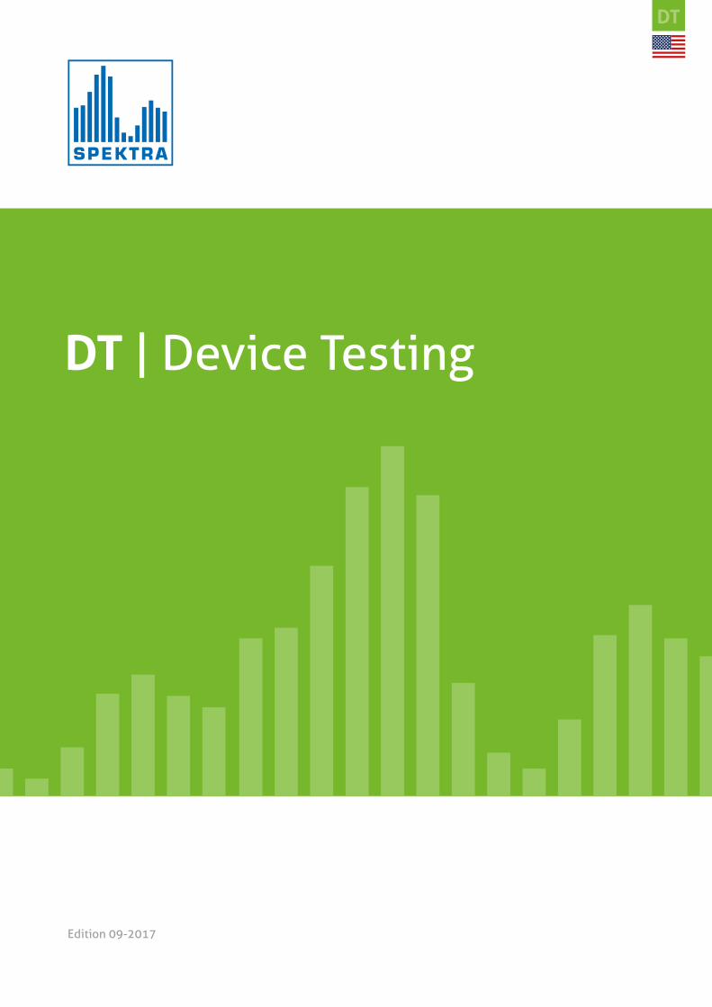
Outstanding
internationalperformance
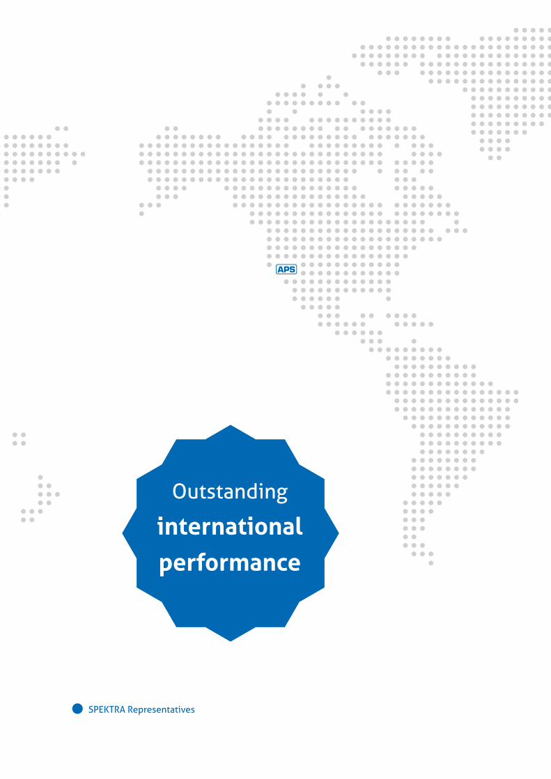
SPEKTRA Representatives
Who are we?
SPEKTRA Schwingungstechnik und Akustik GmbH Dresden, Germany was launched in 1994 by employees of the former state-owned company VEB Robotron Messelektronik Dresden, department of sound, vibration and force measurement. Up to 1989, this company was one of the leading manufacturers of measurement instrumentation for sound and vibration engineering worldwide. Based on decades
of experience in the field of „electrical measurement of mechanical quantities“, SPEKTRA has developed into a stable, mid-sized enterprise in the field of sound and vibration engineering. Advanced techno-logies and innovative ideas of our employees make SPEKTRA your premium partner for the develop-ment of measuring and testing systems as well as mechanical exciter for various applications.
CS | Calibration Solutions
DT | Device Testing
ST | Structural Testing
ES | Engineering Solutions
DT | Device TestingBecause of the company’s experience with the development of precision calibration equipment, SPEKTRA is able to offer various test systems that simulate and stimulate nearly every type of dynamic measurement. SPEKTRA also offers test and calibration services as an alternative to test equipment ownership.
Our Portfolio Competences
S-TEST System MEMS Sensor development and characterization Vibration Excitation - High Frequency Vibration Excitation - Medium Frequency Vibration Excitation - Low Frequency Piezoelectrical Excitation Shock Excitation Acoustic Excitation Pressure Excitation Temperature Sensitivity Magnetic Excitation Dynamic Rotation Excitation Electrical and Functional Testing Electrical Testing Accessories S-TEST System Concept How to find your optimum Device Testing Solution
Services Measurement Service – Device Characterization and Environmental Simulation Feasibility Studies Consulting
Professional Training
Selected References

www.spektra-dresden.com 7
1.1 Kalibrieren
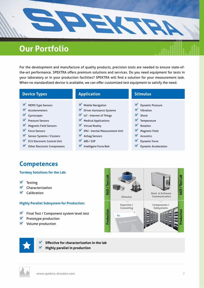
Our Portfolio
For the development and manufacture of quality products, precision tools are needed to ensure state-of-t e art per ormance SP TRA o ers premium solutions and services Do ou need e uipment or tests in
our la orator or in our production acilities SP TRA ill find a solution or our measurement tas en no standardized device is availa le e can o er customized test e uipment to satis t e need
Competences
R&
D /
Tes
t Lab
Prod
ucti
on
R&
D /
Tes
t Lab
Prod
ucti
on
Expertise /Consulting
Components /Subsystems
Stimulus
&D
/ T
est L
ab
Hard- & Software Communication
Device Types StimulusApplication
MEMS Type Sensors
Accelerometers
Gyroscopes
Pressure Sensors
Magnetic Field Sensors
Force Sensors
Sensor Systems / Clusters
ECU Electronic Control Unit
Other Electronic Components
Dynamic Pressure
Vibration
Shock
Temperature
Rotation
Magnetic Field
Acoustics
Dynamic Force
Dynamic Acceleration
Mobile Navigation
Driver Assistance Systems
IoT - Internet of Things
Medical Applications
Virtual Reality
IMU - Inertial Measurement Unit
Airbag Sensors
ABS / ESP
Intelligent Force Bolt
Turnkey Solutions for the Lab:
Testing Characterization Calibration
Highly Parallel Subsystem for Production:
Final Test / Component system level test Prototype production Volume production
ective or c aracteri ation in t e la Highly parallel in production
www.spektra-dresden.com8
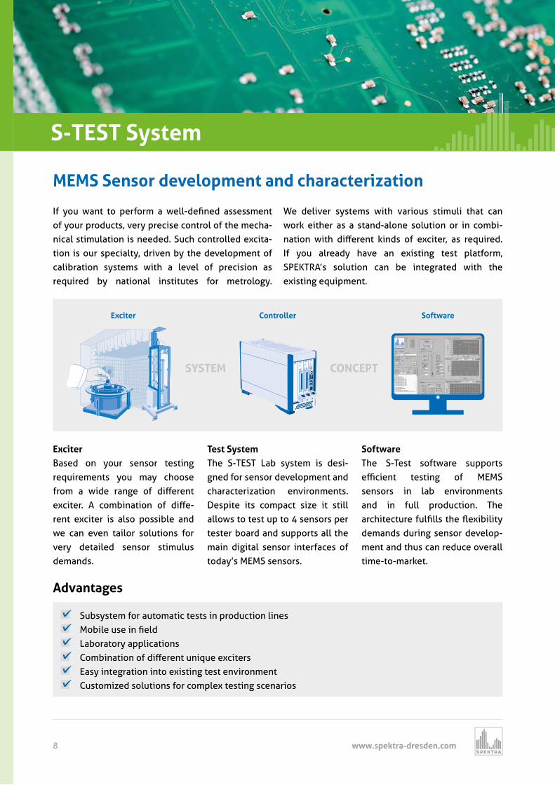
ou ant to per orm a ell defined assessment of your products, very precise control of the mecha-nical stimulation is needed. Such controlled excita-tion is our specialty, driven by the development of calibration systems with a level of precision as required by national institutes for metrology.
We deliver systems with various stimuli that can work either as a stand-alone solution or in combi-nation it di erent inds o e citer as re uired If you already have an existing test platform, SPEKTRA’s solution can be integrated with the existing equipment.
ControllerExciter Software
BA
BA
DFE
USB
1USB
2USB
0GBE
SYSTEM CONCEPT
S-TEST System
ExciterBased on your sensor testing requirements you may choose rom a ide range o di erent
e citer A com ination o di e-rent exciter is also possible and we can even tailor solutions for very detailed sensor stimulus demands.
Test System The S-TEST Lab system is desi-gned for sensor development and characterization environments. Despite its compact size it still allows to test up to 4 sensors per tester board and supports all the main digital sensor interfaces of today’s MEMS sensors.
Software The S-Test software supports e cient testing o M MS sensors in lab environments and in full production. The arc itecture ulfills t e e i ilit demands during sensor develop-ment and thus can reduce overall time-to-market.
Subsystem for automatic tests in production lines Mo ile use in field Laboratory applications Com ination o di erent uni ue e citers Easy integration into existing test environment Customized solutions for complex testing scenarios
Advantages
S Sen or evelopment an c aracteri ation
www.spektra-dresden.com 9
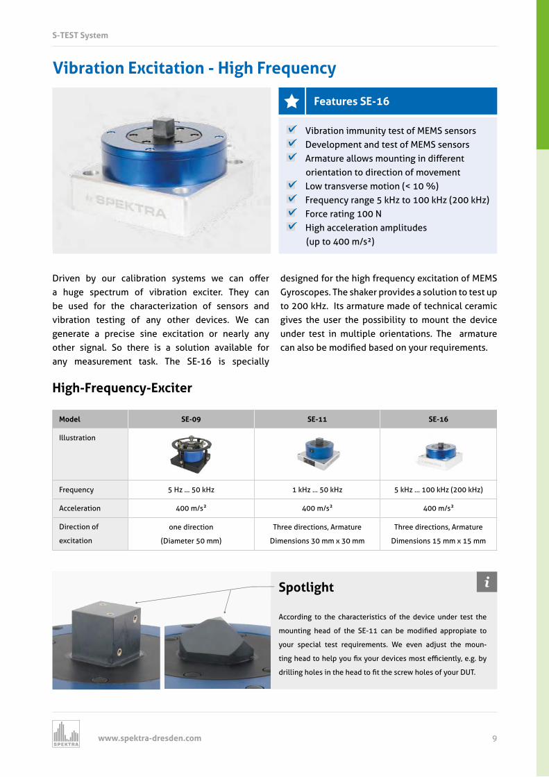
Vibration Excitation - High Frequency
High-Frequency-Exciter
Model SE-09 SE-11 SE-16
Illustration
Frequency 5 Hz ... 50 kHz 1 kHz ... 50 kHz 5 kHz ... 100 kHz (200 kHz)
Acceleration 400 m/s 400 m/s 400 m/s
Direction of
excitation
one direction
(Diameter 50 mm)
Three directions, Armature
Dimensions 30 mm x 30 mm
Three directions, Armature
Dimensions 15 mm x 15 mm
Driven our cali ration s stems e can o er a huge spectrum of vibration exciter. They can be used for the characterization of sensors and vibration testing of any other devices. We can generate a precise sine excitation or nearly any other signal. So there is a solution available for any measurement task. The SE-16 is specially
designed for the high frequency excitation of MEMS Gyroscopes. The shaker provides a solution to test up to 200 kHz. Its armature made of technical ceramic gives the user the possibility to mount the device under test in multiple orientations. The armature can also e modified ased on our re uirements
Vibration immunity test of MEMS sensors Development and test of MEMS sensors Armature allo s mounting in di erent
orientation to direction of movement Low transverse motion (< 10 %) Frequency range 5 kHz to 100 kHz (200 kHz) Force rating 100 N High acceleration amplitudes
(up to 400 m/s²)
Spotlight
According to the characteristics of the device under test the
mounting ead o t e S can e modified appropiate to
your special test requirements. We even adjust the moun-
ting ead to elp ou fi our devices most e cientl e g
drilling oles in t e ead to fit t e scre oles o our D T
S-TEST System
Features SE-16
www.spektra-dresden.com10
S-TEST System
Medium-Frequency-Exciter
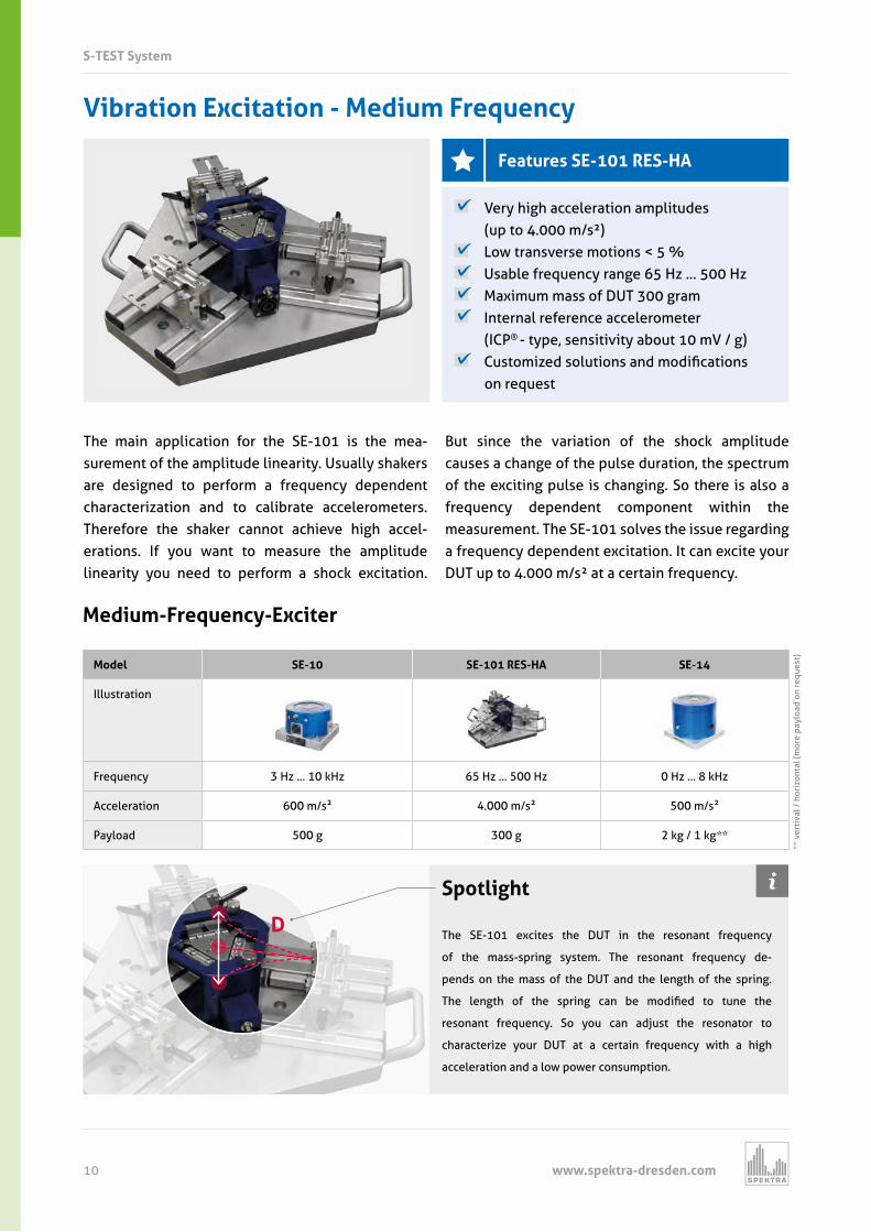
Model SE-10 SE-101 RES-HA SE-14
Illustration
Frequency z z z z z z
Acceleration m s m s m s
Payload g g g g
Vibration Excitation - Medium Frequency
The main application for the SE-101 is the mea- surement of the amplitude linearity. Usually shakers are designed to perform a frequency dependent characterization and to calibrate accelerometers. Therefore the shaker cannot achieve high accel- erations. If you want to measure the amplitude linearity you need to perform a shock excitation.
But since the variation of the shock amplitude causes a change of the pulse duration, the spectrum of the exciting pulse is changing. So there is also a frequency dependent component within the measurement. The SE-101 solves the issue regarding a frequency dependent excitation. It can excite your DUT up to 4.000 m/s² at a certain frequency.
Very high acceleration amplitudes (up to 4.000 m/s²)
Low transverse motions < 5 % Usable frequency range 65 Hz ... 500 Hz Maximum mass of DUT 300 gram Internal reference accelerometer
(ICP® - type, sensitivity about 10 mV / g) Customized solutions and modifications
on request
Spotlight
The SE-101 excites the DUT in the resonant frequency
of the mass-spring system. The resonant frequency de-
pends on the mass of the DUT and the length of the spring.
T e lengt o t e spring can e modified to tune t e
resonant frequency. So you can adjust the resonator to
characterize your DUT at a certain frequency with a high
acceleration and a low power consumption.
D
ver
tiva
l
oriz
onta
l (m
ore
palo
ad o
n re
uest
)
Features SE-101 RES-HA
www.spektra-dresden.com 11
S-TEST System
Medium-Frequency-Exciter
Model SE-10 SE-101 RES-HA SE-14
Illustration
Frequency z z z z z z
Acceleration m s m s m s
Payload g g g g
Low-Frequency-Exciter
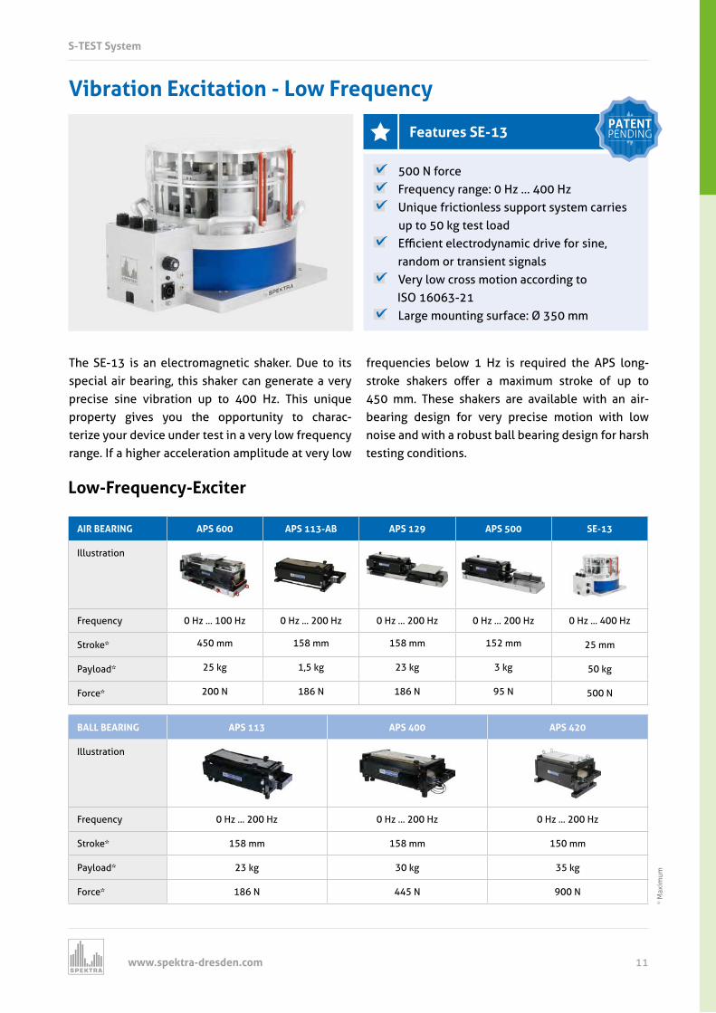
AIR BEARING APS 600 APS 113-AB APS 129 APS 500 SE-13
Illustration
Frequency z z z z z z z z z z
Stro e mm mm mm mm mm
Pa load g g g g g
orce
BALL BEARING APS 113 APS 400 APS 420
Illustration
Frequency z z z z z z
Stro e mm mm mm
Pa load g g g
orce
Vibration Excitation - Low Frequency
The SE-13 is an electromagnetic shaker. Due to its special air bearing, this shaker can generate a very precise sine vibration up to 400 Hz. This unique property gives you the opportunity to charac- terize your device under test in a very low frequency range. If a higher acceleration amplitude at very low
frequencies below 1 Hz is required the APS long- stro e s a ers o er a ma imum stro e o up to 450 mm. These shakers are available with an air- bearing design for very precise motion with low noise and with a robust ball bearing design for harsh testing conditions.
500 N force Frequency range: 0 Hz … 400 Hz Unique frictionless support system carries
up to 50 kg test load cient electrod namic drive or sine
random or transient signals Very low cross motion according to
ISO 16063-21 Large mounting surface: Ø 350 mm
Ma
imum
Features SE-13PATENTPENDING
www.spektra-dresden.com12
S-TEST System
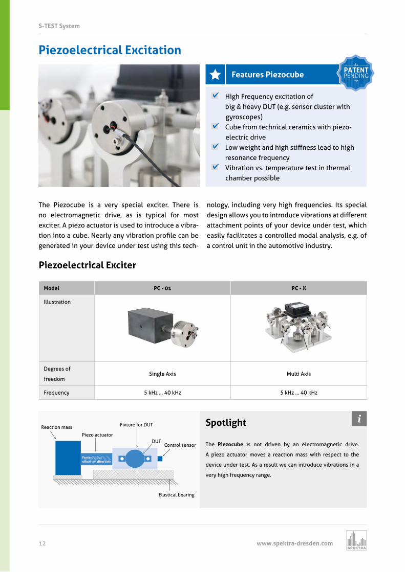
Pie oelectrical citation
High Frequency excitation of big & heavy DUT (e.g. sensor cluster with gyroscopes)
Cube from technical ceramics with piezo- electric drive
o eig t and ig sti ness lead to ig resonance frequency
Vibration vs. temperature test in thermal chamber possible
Pie oelectrical citer
Model PC - 01 PC - X
Illustration
Degrees of
freedomSingle Axis Multi Axis
Frequency z z z z
The Piezocube is a very special exciter. There is no electromagnetic drive, as is typical for most exciter. A piezo actuator is used to introduce a vibra-tion into a cu e earl an vi ration profile can e generated in your device under test using this tech-
nology, including very high frequencies. Its special design allo s ou to introduce vi rations at di erent attachment points of your device under test, which easily facilitates a controlled modal analysis, e.g. of a control unit in the automotive industry.
Spotlight
The Pie oc e is not driven by an electromagnetic drive.
A piezo actuator moves a reaction mass with respect to the
device under test. As a result we can introduce vibrations in a
very high frequency range.
Reaction mass
Piezo actuator
Fixture for DUT
DUTControl sensor
Force outputvibration direction
Elastical bearing
eat re Pie oc e PATENTPENDING
www.spektra-dresden.com 13
S-TEST System
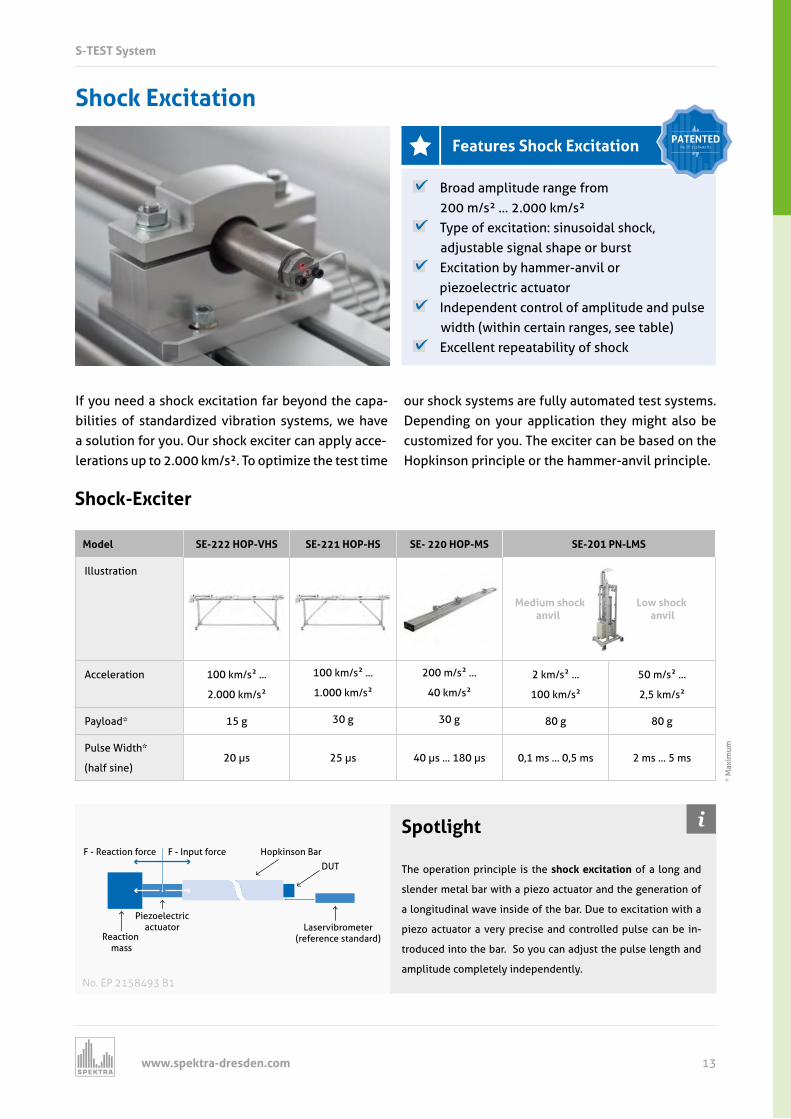
Shock Excitation
If you need a shock excitation far beyond the capa-bilities of standardized vibration systems, we have a solution for you. Our shock exciter can apply acce-lerations up to 2.000 km/s². To optimize the test time
our shock systems are fully automated test systems. Depending on your application they might also be customized for you. The exciter can be based on the Hopkinson principle or the hammer-anvil principle.
Broad amplitude range from 200 m/s² ... 2.000 km/s²
Type of excitation: sinusoidal shock, adjustable signal shape or burst
Excitation by hammer-anvil or piezoelectric actuator
Independent control of amplitude and pulse width (within certain ranges, see table)
Excellent repeatability of shock
Shock-Exciter
Model SE-222 HOP-VHS SE-221 HOP-HS SE- 220 HOP-MS S P S
Illustration
Acceleration m s
m s
m s
m s
m s
m s
m s
m s
m s
m s
Pa load g g g g g
Pulse idt
(half sine) s s s s ms ms ms ms
Medium shock Low shock anvil anvil
Spotlight
The operation principle is the shock excitation of a long and
slender metal bar with a piezo actuator and the generation of
a longitudinal wave inside of the bar. Due to excitation with a
piezo actuator a very precise and controlled pulse can be in-
troduced into the bar. So you can adjust the pulse length and
amplitude completely independently.
Ma
imum
F - Reaction force F - Input force Hopkinson Bar
DUT
Laservibrometer(reference standard)
Piezoelectricactuator
Reaction mass
No. EP 2158493 B1
Features Shock Excitation PATENTEDNo. EP 2158493 B1
www.spektra-dresden.com14
S-TEST System
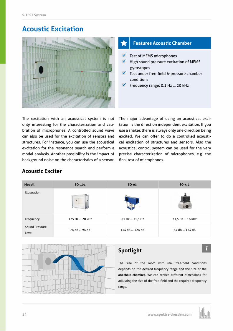
Acoustic Excitation
The excitation with an acoustical system is not only interesting for the characterization and cali-bration of microphones. A controlled sound wave can also be used for the excitation of sensors and structures. For instance, you can use the acoustical excitation for the resonance search and perform a modal analysis. Another possibility is the impact of background noise on the characteristics of a sensor.
The major advantage of using an acoustical exci- tation is the direction independent excitation. If you use a shaker, there is always only one direction being e cited e can o er to do a controlled acousti-cal excitation of structures and sensors. Also the acoustical control system can be used for the very precise characterization of microphones, e.g. the final test o microp ones
Test of MEMS microphones High sound pressure excitation of MEMS
gyroscopes Test under ree field & pressure c am er
conditions Frequency range: 0,1 Hz ... 20 kHz
Acoustic Exciter
Modell SQ-101 SQ-03 SQ-4.2
Illustration
Frequency z z z z z z
Sound Pressure
Level d d d d d d
Spotlight
T e size o t e room it real ree field conditions
depends on the desired frequency range and the size of the
anechoic chamber e can realize di erent dimensions or
adjusting t e size o t e ree field and t e re uired re uenc
range.
Features Acoustic Chamber
www.spektra-dresden.com 15
S-TEST System
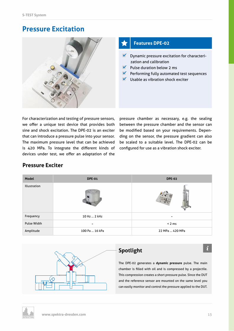
Pressure Excitation
For characterization and testing of pressure sensors, e o er a uni ue test device t at provides ot
sine and shock excitation. The DPE-02 is an exciter that can introduce a pressure pulse into your sensor. The maximum pressure level that can be achieved is MPa To integrate t e di erent inds o devices under test e o er an adaptation o t e
pressure chamber as necessary, e.g. the sealing between the pressure chamber and the sensor can
e modified ased on our re uirements Depen-ding on the sensor, the pressure gradient can also be scaled to a suitable level. The DPE-02 can be configured or use as a vi ration s oc e citer
Dynamic pressure excitation for characteri- zation and calibration
Pulse duration below 2 ms Performing fully automated test sequences Usable as vibration shock exciter
Pressure Exciter
Model DPE-01 DPE-02
Illustration
Frequency z z -
Pulse Width - ms
Amplitude Pa Pa MPa MPa
Spotlight
The DPE-02 generates a dynamic pressure pulse. The main
c am er is filled it oil and is compressed a projectile
This compression creates a short pressure pulse. Since the DUT
and the reference sensor are mounted on the same level you
can easily monitor and control the pressure applied to the DUT.
Features DPE-02
www.spektra-dresden.com16
S-TEST System
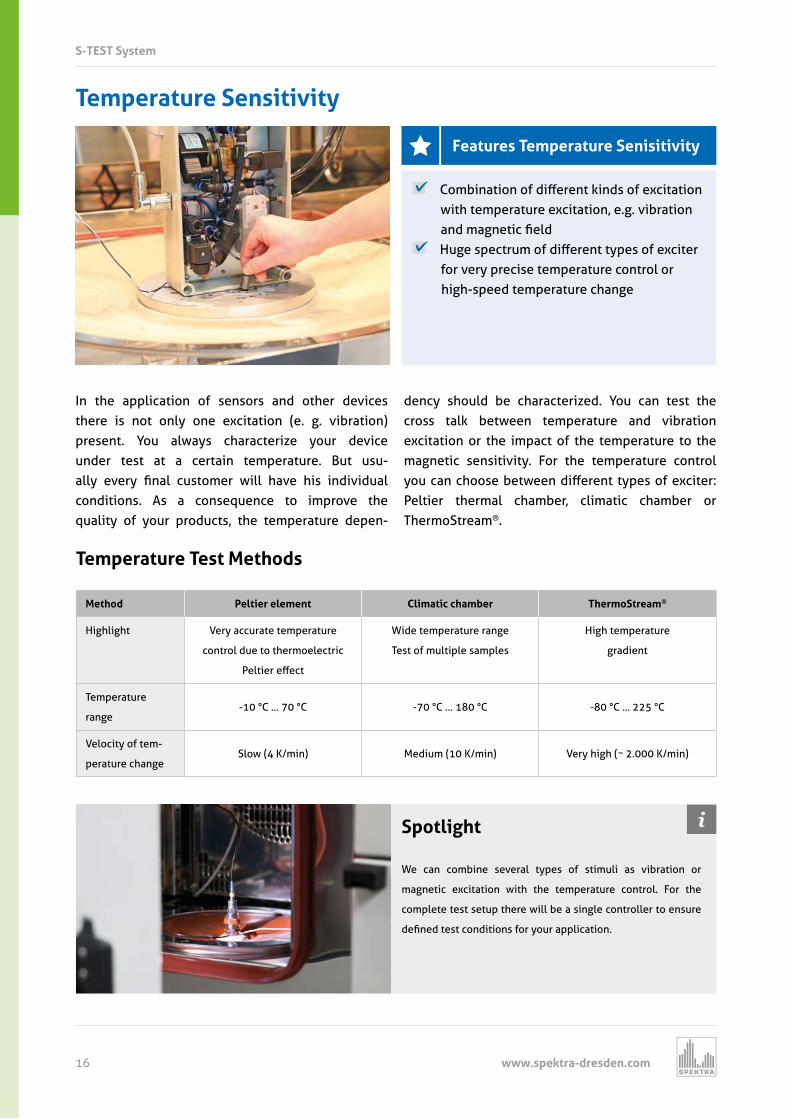
Temperature Sensitivity
In the application of sensors and other devices there is not only one excitation (e. g. vibration) present. You always characterize your device under test at a certain temperature. But usu- all ever final customer ill ave is individual conditions. As a consequence to improve the quality of your products, the temperature depen-
dency should be characterized. You can test the cross talk between temperature and vibration excitation or the impact of the temperature to the magnetic sensitivity. For the temperature control
ou can c oose et een di erent t pes o e citer Peltier thermal chamber, climatic chamber or ThermoStream®.
Com ination o di erent inds o e citation with temperature excitation, e.g. vibration and magnetic field
uge spectrum o di erent t pes o e citer for very precise temperature control or high-speed temperature change
Temperature Test Methods
Method Peltier element Climatic chamber ThermoStream®
Highlight Very accurate temperature
control due to thermoelectric
Peltier e ect
Wide temperature range
Test of multiple samples
High temperature
gradient
Temperature
range-10 °C ... 70 °C -70 °C ... 180 °C -80 °C ... 225 °C
Velocity of tem-
perature changeSlow (4 K/min) Medium (10 K/min) Very high ( ~ 2.000 K/min)
Spotlight
We can combine several types of stimuli as vibration or
magnetic excitation with the temperature control. For the
complete test setup there will be a single controller to ensure
defined test conditions or our application
Features Temperature Senisitivity
www.spektra-dresden.com 17
S-TEST System
Driven our customers e al a s aim or ne t pes o d namic stimuli to ulfill our re uirements Many of our products go back to such cooperations. If you have any measurement task please contact us.
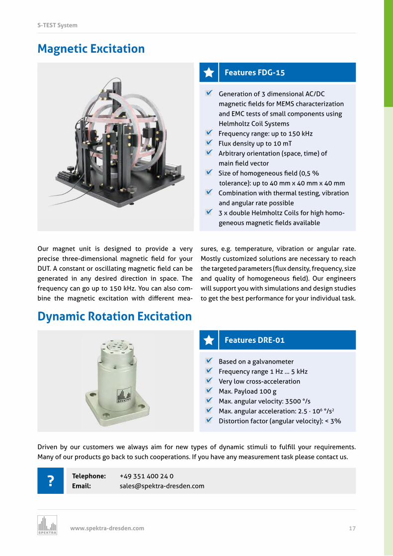
Magnetic Excitation
Our magnet unit is designed to provide a very precise t ree dimensional magnetic field or our D T A constant or oscillating magnetic field can e generated in any desired direction in space. The frequency can go up to 150 kHz. You can also com-
ine t e magnetic e citation it di erent mea
sures, e.g. temperature, vibration or angular rate. Mostly customized solutions are necessary to reach t e targeted parameters ( u densit re uenc size and ualit o omogeneous field) Our engineers will support you with simulations and design studies to get the best performance for your individual task.
Generation of 3 dimensional AC/DC magnetic fields or M MS c aracterization and EMC tests of small components using Helmholtz Coil Systems
Frequency range: up to 150 kHz Flux density up to 10 mT Arbitrary orientation (space, time) of
main field vector Size o omogeneous field (
tolerance): up to 40 mm x 40 mm x 40 mm Combination with thermal testing, vibration
and angular rate possible 3 x double Helmholtz Coils for high homo-
geneous magnetic fields availa le
Telephone: +49 351 400 24 0 Email: [email protected]
Dynamic Rotation Excitation
Based on a galvanometer Frequency range 1 Hz … 5 kHz Very low cross-acceleration Max. Payload 100 g Max. angular velocity: 3500 °/s Max. angular acceleration: 2.5 · 106 °/s2
Distortion factor (angular velocity): < 3%
Features DRE-01
Features FDG-15
www.spektra-dresden.com18
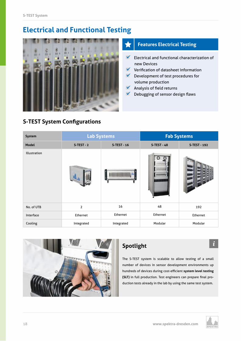
Electrical and Functional Testing
S-TEST System
Features Electrical Testing
Electrical and functional characterization of new Devices
erification o datas eet in ormation Development of test procedures for
volume production Anal sis o field returns De ugging o sensor design a s
S S Sy tem onfi ration
System Lab Systems Fab Systems
Model S-TEST - 2 S-TEST - 16 S-TEST - 48 S-TEST - 192
Illustration
No. of UTB
Interface Ethernet Ethernet Ethernet Ethernet
Cooling Integrated Integrated Modular Modular
Spotlight
The S-TEST system is scalable to allow testing of a small
number of devices in sensor development environments up
undreds o devices during cost e cient system level testing
(SLT) in ull production Test engineers can prepare final pro-
duction tests already in the lab by using the same test system.
www.spektra-dresden.com 19
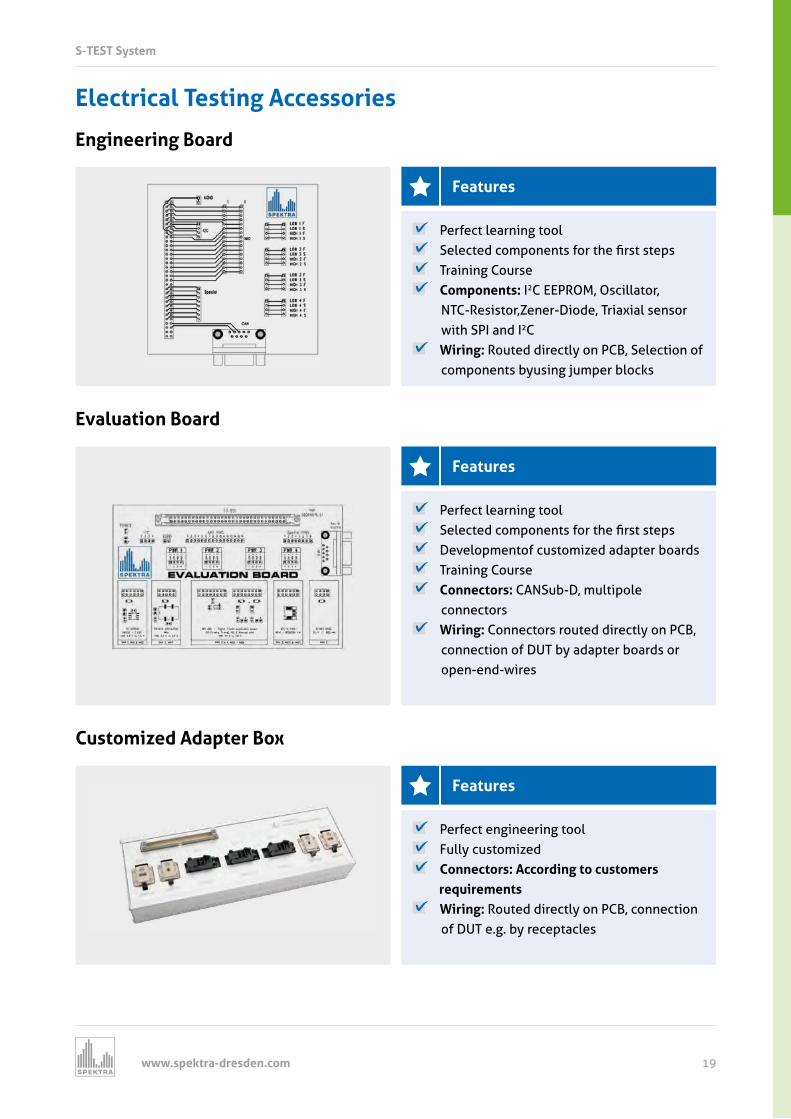
Electrical Testing Accessories
Engineering Board
Features
Perfect learning tool Selected components or t e first steps Training Course Components: I2C EEPROM, Oscillator,
NTC-Resistor,Zener-Diode, Triaxial sensor with SPI and I2C
Wiring: Routed directly on PCB, Selection of components byusing jumper blocks
Evaluation Board
Features
Perfect learning tool Selected components or t e first steps Developmentof customized adapter boards Training Course Connectors: CANSub-D, multipole
connectors Wiring: Connectors routed directly on PCB,
connection of DUT by adapter boards or open-end-wires
tomi e apter o
Features
Perfect engineering tool Fully customized Connectors: According to customers
requirements Wiring: Routed directly on PCB, connection
of DUT e.g. by receptacles
S-TEST System
www.spektra-dresden.com20
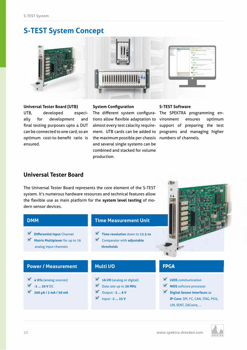
Power / Measurement FPGA
DMM
Universal Tester Board
S-TEST System
16 I/O (analog or digital)
Data rate up to
Output: -2 … 6 V
Input: -2 … 25 V
Multi I/O
Time resolution down to 12.5 ns
Comparator with adjustable
thresholds
Time Measurement Unit
4 V/Is (analog sources)
-2 … 20 V DC
200 µA / 2 mA / 50 mA
LVDS communication
NIOS softcore processor
Digital Sensor Interfaces as
IP-Core: SPI, I2C, CAN, JTAG, PSI5,
LIN, SENT, ZACwire, …
Di erential np t Channel
Matrix Multiplexer for up to 16
analog input channels
The Universal Tester Board represents the core element of the S-TEST system. It’s numerous hardware resources and technical features allow t e e i le use as main plat orm or t e system level testing of mo-dern sensor devices.
S-TEST System Concept
Universal Tester Board (UTB)UTB, developed especi-ally for development and final testing purposes upto D T can be connected to one card, so an optimum cost to enefit ratio is ensured.
Sy tem onfi rationT e di erent s stem configura-tions allo e i le adaptation to almost every test calacity require-ment. UTB cards can be added to the maximum possible per chassis and several single systems can be combined and stacked for volume production.
S-TEST SoftwareThe SPEKTRA programming en-vironment ensures optimum support of preparing the test programs and managing higher numbers of channels.
FPGA
The Universal Tester Board represents the core element of the S-TEST system. It’s numerous hardware resources and technical features allow
www.spektra-dresden.com 21
S-TEST System
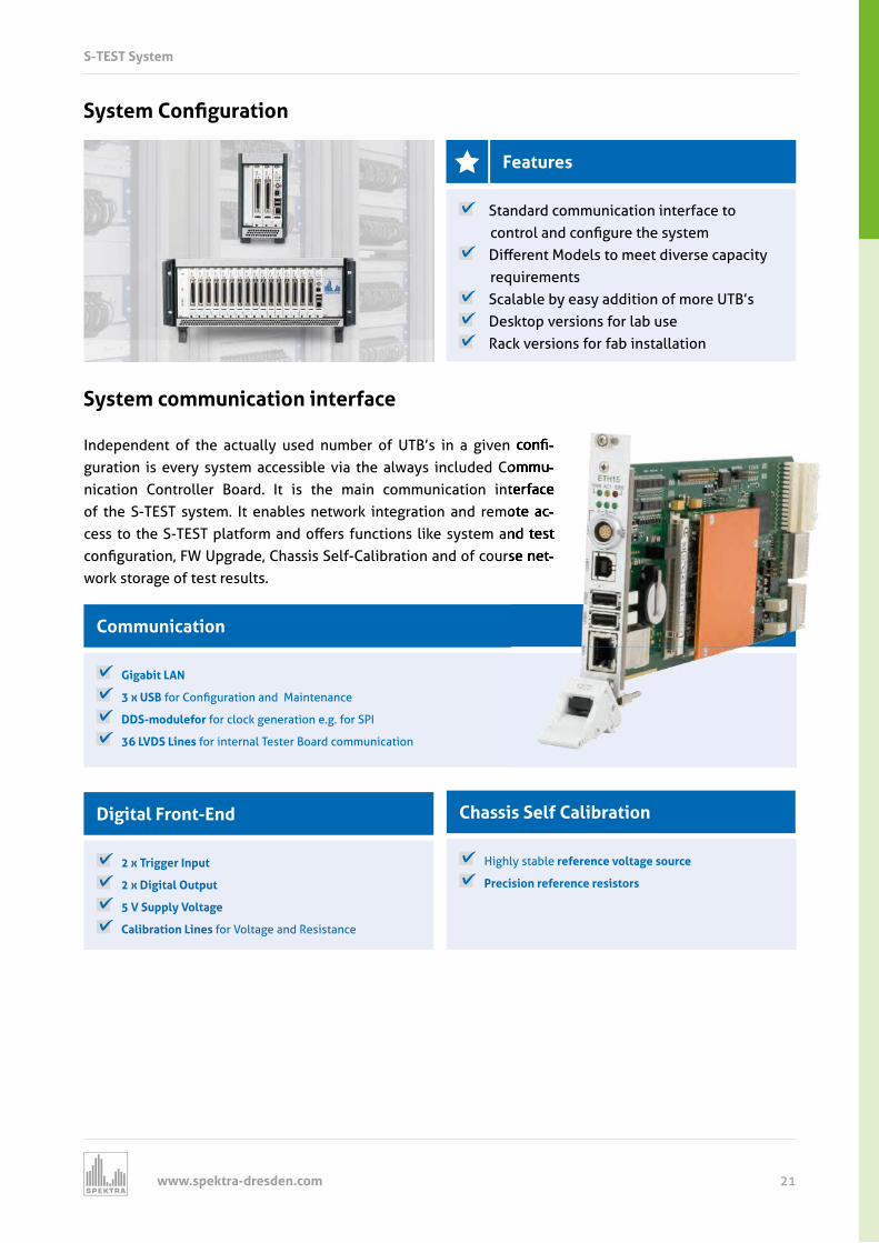
Communication
Chassis Self CalibrationDigital Front-End
Gigabit LAN
3 x USB or Configuration and Maintenance
DDS-modulefor for clock generation e.g. for SPI
36 LVDS Lines for internal Tester Board communication
Highly stable reference voltage source
Precision reference resistors
2 x Trigger Input
2 x Digital Output
5 V Supply Voltage
Calibration Lines for Voltage and Resistance
System communication interface
Sy tem onfi ration
Features
Standard communication interface to control and configure t e s stem
Di erent Models to meet diverse capacit requirements
Scalable by easy addition of more UTB’s Desktop versions for lab use Rack versions for fab installation
ndependent o t e actuall used num er o T s in a given confi-guration is every system accessible via the always included Commu-nication Controller Board. It is the main communication interface of the S-TEST system. It enables network integration and remote ac-cess to t e S T ST plat orm and o ers unctions li e s stem and test configuration pgrade C assis Sel Cali ration and o course net-work storage of test results.
ndependent o t e actuall used num er o T s in a given confi-guration is every system accessible via the always included Commu-nication Controller Board. It is the main communication interface of the S-TEST system. It enables network integration and remote ac-cess to t e S T ST plat orm and o ers unctions li e s stem and test configuration pgrade C assis Sel Cali ration and o course net-
www.spektra-dresden.com22
S-TEST System
Implementation of Digital Communication
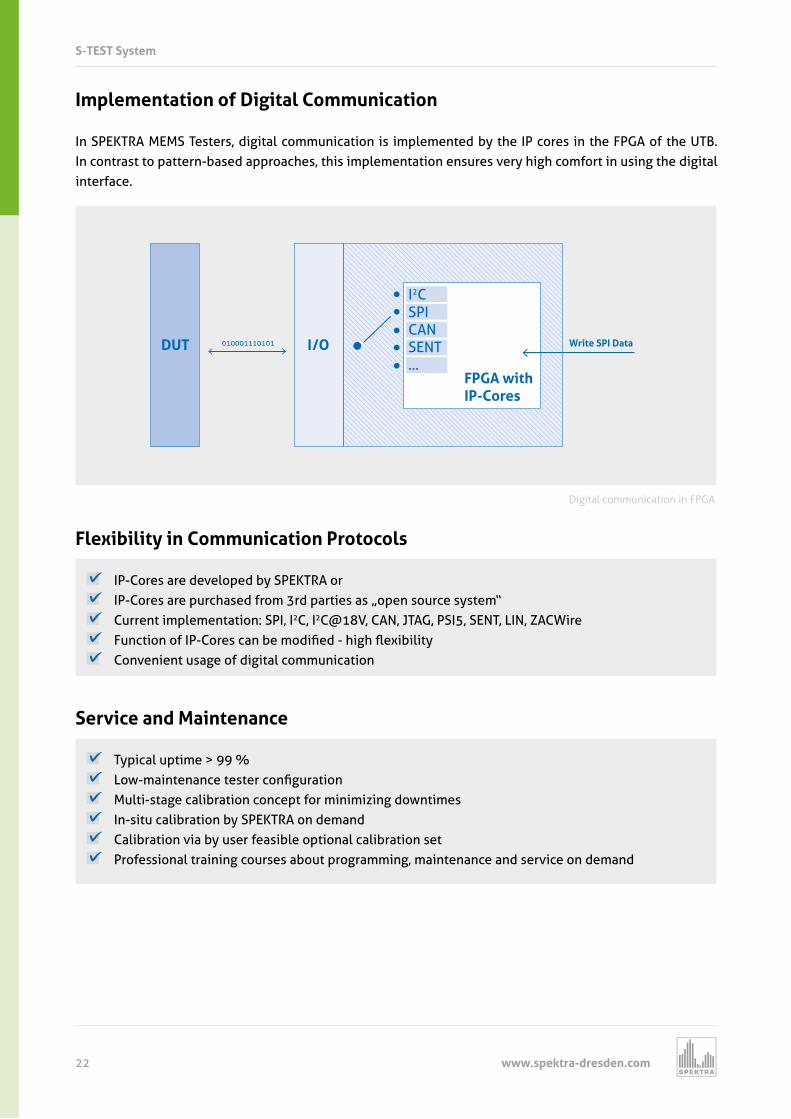
In SPEKTRA MEMS Testers, digital communication is implemented by the IP cores in the FPGA of the UTB. In contrast to pattern-based approaches, this implementation ensures very high comfort in using the digital interface.
IP-Cores are developed by SPEKTRA or P Cores are purc ased rom rd parties as open source s stem Current implementation: SPI, I2C, I2C@18V, CAN, JTAG, PSI5, SENT, LIN, ZACWire unction o P Cores can e modified ig e i ilit Convenient usage of digital communication
Flexibility in Communication Protocols
Typical uptime > 99 % o maintenance tester configuration Multi-stage calibration concept for minimizing downtimes In-situ calibration by SPEKTRA on demand Calibration via by user feasible optional calibration set Professional training courses about programming, maintenance and service on demand
Service and Maintenance
DUT I/O Write SPI Data
I2CSPICANSENT...
FPGA withIP-Cores
010001110101
Digital communication in FPGA
www.spektra-dresden.com 23
S-TEST System
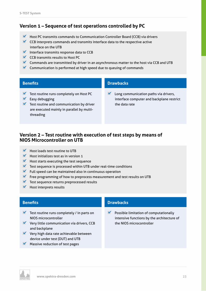
Host PC transmits commands to Communication Controller Board (CCB) via drivers CCB interprets commands and transmits interface data to the respective active
interface on the UTB Interface transmits response data to CCB CCB transmits results to Host PC Commands are transmitted by driver in an asynchronous matter to the host via CCB and UTB Communication is performed at high speed due to queuing of commands
Version 1 – Sequence of test operations controlled by PC
Test routine runs completely on Host PC Easy debugging Test routine and communication by driver
are executed mainly in parallel by multi- threading
enefit
Long communication paths via drivers, interface computer and backplane restrict the data rate
Drawbacks
Host loads test routine to UTB Host initializes test as in version 1 Host starts executing the test sequence Test sequence is processed within UTB under real-time conditions Full speed can be maintained also in continuous operation Free programming of how to preprocess measurement and test results on UTB Test sequence returns preprocessed results Host interprets results
Version 2 – Test routine with execution of test steps by means of NIOS Microcontroller on UTB
Test routine runs completely / in parts on NIOS microcontroller
Very little communication via drivers, CCB and backplane
Very high data rate achievable between device under test (DUT) and UTB
Massive reduction of test pages
enefit
Possible limitation of computationally intensive functions by the architecture of the NIOS microcontroller
Drawbacks
www.spektra-dresden.com24
S-TEST Software
Reduced programming e ort ull o ine unctionalit uided s stem configuration Parallelization
Program code generation Automatic logging Configuration o project variations
o r enefit
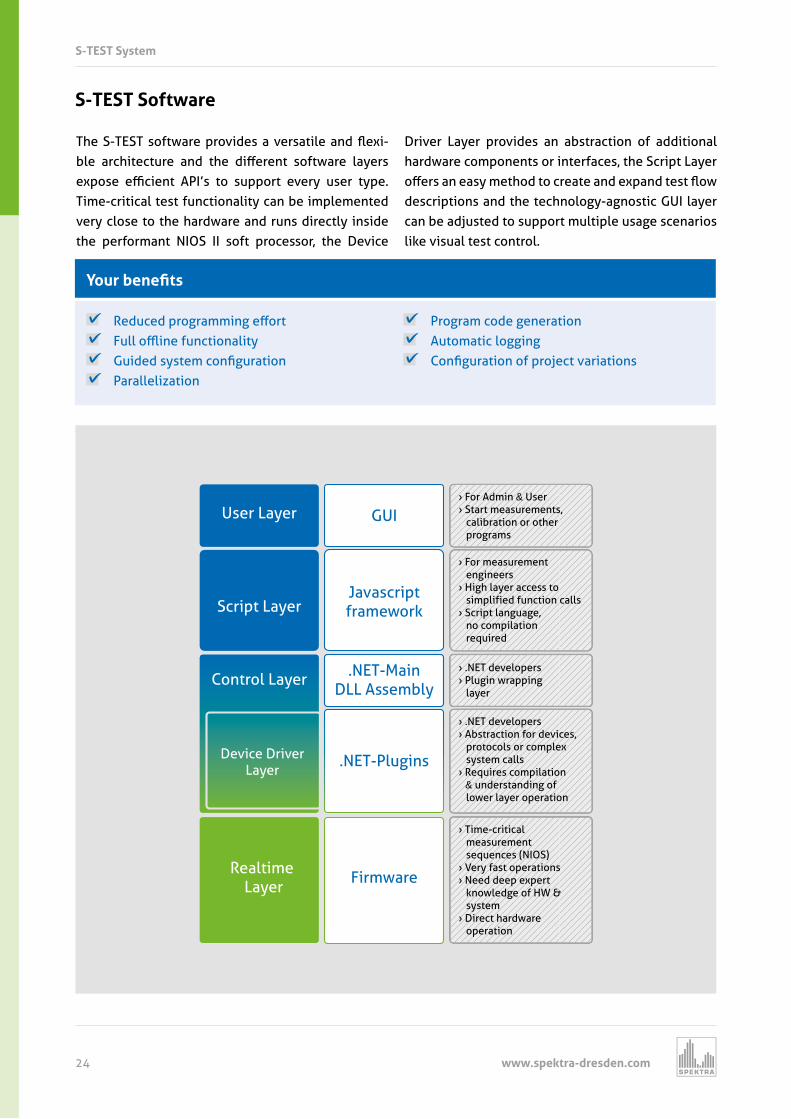
T e S T ST so t are provides a versatile and e i-le arc itecture and t e di erent so t are la ers
e pose e cient AP s to support ever user t pe Time-critical test functionality can be implemented very close to the hardware and runs directly inside the performant NIOS II soft processor, the Device
Driver Layer provides an abstraction of additional hardware components or interfaces, the Script Layer o ers an eas met od to create and e pand test o descriptions and the technology-agnostic GUI layer can be adjusted to support multiple usage scenarios like visual test control.
S-TEST System
User Layer GUI
Javascriptframework
.NET-MainDLL Assembly
.NET-Plugins
Firmware
Script Layer
Control Layer
Device DriverLayer
Realtime Layer
› For Admin & User› Start measurements, calibration or other programs
› For measurement engineers› High layer access to simplified function calls› Script language, no compilation required
› .NET developers› Plugin wrapping layer
› .NET developers› Abstraction for devices, protocols or complex system calls› Requires compilation & understanding of lower layer operation
› Time-critical measurement sequences (NIOS)› Very fast operations› Need deep expert knowledge of HW & system› Direct hardware operation
www.spektra-dresden.com 25
Specification
Development
Project Deployment
IC-Requirements (Test Specification)
Tester Resources (Measurement Devices)
Pin Mapping
Project Test Run& Optimization
Testprogram & RealtimeControl over JavaScript
Parallel & Realtime Program
1234
5678
BA
BA
DFE
USB
1USB
2USB
0GBE
Project Administration
S-TEST System
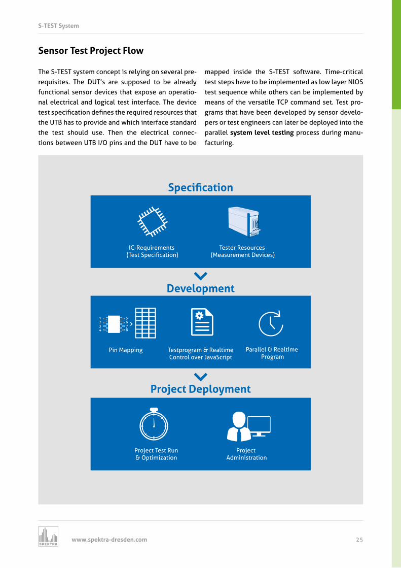
Sensor Test Project Flow
The S-TEST system concept is relying on several pre-requisites. The DUT’s are supposed to be already functional sensor devices that expose an operatio-nal electrical and logical test interface. The device test specification defines t e re uired resources t at the UTB has to provide and which interface standard the test should use. Then the electrical connec-tions between UTB I/O pins and the DUT have to be
mapped inside the S-TEST software. Time-critical test steps have to be implemented as low layer NIOS test sequence while others can be implemented by means of the versatile TCP command set. Test pro-grams that have been developed by sensor develo-pers or test engineers can later be deployed into the parallel system level testing process during manu-facturing.
www.spektra-dresden.com26
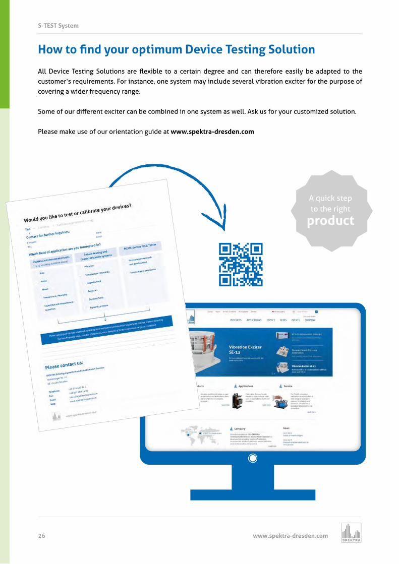
o to fin yo r optim m Device e tin Sol tion
All Device Testing Solutions are e i le to a certain degree and can t ere ore easil e adapted to t e customer‘s requirements. For instance, one system may include several vibration exciter for the purpose of covering a wider frequency range.
Some o our di erent e citer can e com ined in one s stem as ell As us or our customized solution
Please make use of our orientation guide at www.spektra-dresden.com
A quick stepto the right
product
S-TEST System
www.spektra-dresden.com 27
S-TEST System
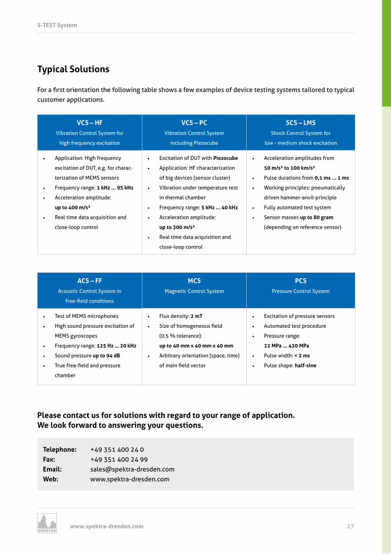
Typical Solutions
or a first orientation t e ollo ing ta le s o s a e e amples o device testing s stems tailored to t pical customer applications.
VCS – HFVibration Control System for
high frequency excitation
VCS – PCVibration Control System
including Piezocube
SCS – LMSShock Control System for
low - medium shock excitation
• Application: High frequency
excitation of DUT, e.g. for charac-
terization of MEMS sensors
• Frequency range:
• Acceleration amplitude:
up to 400 m/s²
• Real time data acquisition and
close-loop control
• Excitation of DUT with Pie oc e
• Application: HF characterization
of big devices (sensor cluster)
• Vibration under temperature test
in thermal chamber
• Frequency range:
• Acceleration amplitude:
up to 300 m/s²
• Real time data acquisition and
close-loop control
• Acceleration amplitudes from
50 m/s² to 100 km/s²
• Pulse durations from 0,1 ms ... 1 ms
• Working principles: pneumatically
driven hammer-anvil-principle
• Fully automated test system
• Sensor masses up to 80 gram
(depending on reference sensor)
ACS – FFAcoustic Control System in
ree field conditions
MCSMagnetic Control System
PCSPressure Control System
• Test of MEMS microphones
• High sound pressure excitation of
MEMS gyroscopes
• Frequency range:
• Sound pressure up to 94 dB
• True ree field and pressure
chamber
• Flux density: 2 mT
• Size o omogeneous field
(0.5 % tolerance):
up to 40 mm x 40 mm x 40 mm
• Arbitrary orientation (space, time)
o main field vector
• Excitation of pressure sensors
• Automated test procedure
• Pressure range:
22 MPa ... 420 MPa
• Pulse width: < 2 ms
• Pulse shape: half-sine
Please contact us for solutions with regard to your range of application. We look forward to answering your questions.
Telephone: +49 351 400 24 0Fax: +49 351 400 24 99Email: [email protected]: www.spektra-dresden.com
www.spektra-dresden.com28
A wide variety of SPEKTRA Test and Characterization Systems are available in our measurement and test laboratory for performing measurements and investigations of all kinds. Take advantage of the competence o our sta and t e e i le availa ilit o our ide range o Device Testing S stems and use t em or solving your test jobs.
Our Performance Spectrum
Feasibility Studies
You need to solve a test job but you do not have any appropriate test method or test instrumentation at hand ? So do employ the know-how of our engineers to specify your demands based on theoretical and practical investigations / studies.
Consulting
Modern measurement instrumentation is getting smaller and smaller, more and more compact, and more and more e cient in per ormance o ever its use ma cause pro lems t at are more and more complex, and possible remedies are becoming less and less transparent. If when dealing with your own products or services rendered you are faced with problems that you and your associates are unable to solve, keep us in mind, perhaps we can help you. SPEKTRA, with our many years of experience in measurement technology, may be able to solve your measuring task / problems or provide advice on how to tackle your problems.
S-TEST Services
Device excitation with various stimuli (vibration, shock, pressure, sound) Device sensitivit tests (temperature magnetic field) Combined measurement of various stimuli (e.g. temperature-vibration, temperature-magnetic-
field )
easi ilit studies ased on ell defined test specifications T eoretical as ell as practical investigations into t e e ects o in uence varia les on our
device under test Competent advice in all questions of sound and vibration engineering
ea rement Service Device aracteri ation an Environmental Simulation
www.spektra-dresden.com 29
1.4 Kalibrierschulungen Professional Training
Would you like to optimize your business processes and make your business even more successful? Tap your full potential - with customized SPEKTRA trainings. Whether as an employee in the calibration labo-ratory, part of a project team or product users, our training courses will prepare you better for your job. Well-grounded, compact and precisely matching your industry and goals.
Training I - S-TEST Lab Application Seminar
Training II - S-TEST Fab User Seminar
rainin tomi e er eminar on re e t
All o ered seminars are also availa le as individual trainings at customer s site e ould e app to adapt t e content according to our specific needs or assist ou in finding t e rig t solution or our demands. Please contact us:
Details, participation requirements, duration and price of the seminars can be found in our detailed training catalog.
Vibration Control System (VCS) Sine excitation up to 4.000 m/s2 using the SPEKTRA Resonator SE-101 High frequency and three-dimensional excitation
S-TEST-Seminar for application / development S-TEST-Seminar for calibration S-TEST-Seminar for service / maintenance
Telephone: +49 351 400 24 0 Email: [email protected]
www.spektra-dresden.com30
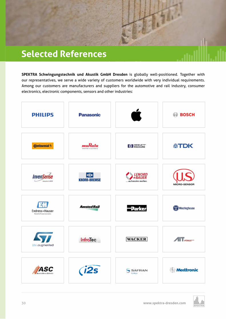
SPEKTRA Schwingungstechnik und Akustik GmbH Dresden is globally well-positioned. Together with our representatives, we serve a wide variety of customers worldwide with very individual requirements. Among our customers are manufacturers and suppliers for the automotive and rail industry, consumer electronics, electronic components, sensors and other industries:
SPEKTRA Service
1.4 Kalibrierschulungen Selected References
o to fin
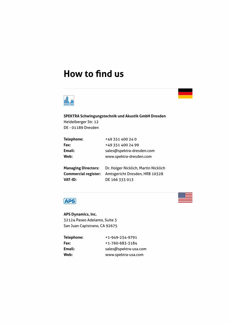
SPEKTRA Schwingungstechnik und Akustik GmbH DresdenHeidelberger Str. 12DE - 01189 Dresden
Telephone: +49 351 400 24 0Fax: +49 351 400 24 99Email: [email protected]: www.spektra-dresden.com
Managing Directors: Dr. Holger Nicklich, Martin NicklichCommercial register: Amtsgericht Dresden, HRB 10328VAT-ID: DE 166 333 013
APS Dynamics, Inc.32124 Paseo Adelanto, Suite 3San Juan Capistrano, CA 92675
Telephone: +1-949-234-9791Fax: +1-760-683-3184Email: [email protected]: www.spektra-usa.com

www.spektra-dresden.com