Embed Size (px)
Citation preview
DatasheetApplies to Part Numbers:
587040 / 587041
Intellivox - DSX180
DDSX180SX180
• No part of this document including thesoftware described in it may bereproduced, transmitted, transcribed,stored in a database system or translatedwithout the express written permission ofJBL Professional. Documentation kept bythe end-user for backup purposes isexcluded from the above mentioned.
• All products and corporate namesmentioned in this document may beregistered trademarks or copyrights of theirrespective companies. They are used herefor indicative purposes only.
• The information contained in thisdocument has been carefully checked foraccuracy, however no guarantee is givenwith respect to the correctness. JBLProfessional accepts no responsibility orliability for any errors or inaccuracies thatmay appear in this document or theproducts and/or software described in it.
• Specifications and informationcontained in this document are subject tochange at any time without notice.
2 201401-IVX-DSX180
JBL Professional® Intellivox-DSX180 data sheet rev 2.1
User Notice:
1. Architectural and engineering specifications . . . . . . . . . . . . . . . . . . . . . . . . . . . . . .4-5
2. Specifications . . . . . . . . . . . . . . . . . . . . . . . . . . . . . . . . . . . . . . . . . . . . . . . . . . . . . .6-7
3. Mechanical details . . . . . . . . . . . . . . . . . . . . . . . . . . . . . . . . . . . . . . . . . . . . . . . . . .8-9
4. Optional Accessories . . . . . . . . . . . . . . . . . . . . . . . . . . . . . . . . . . . . . . . . . . . . . . . . .10
5. DSP block diagram . . . . . . . . . . . . . . . . . . . . . . . . . . . . . . . . . . . . . . . . . . . . . . . . . .11
3
JBL Professional® Intellivox-DSX180 data sheet rev 2.1
Table of Contents
201401-IVX-DSX180
The unit shall be constructed as a line-arrayof ten 4” full-range loudspeakers equippedwith moisture resistant diaphragms andfour horn loaded dome tweeters.
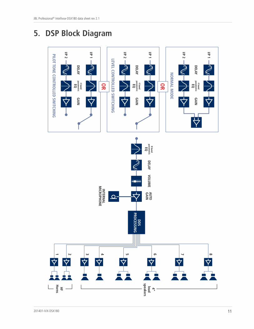
All signal processing functions, necessaryto properly drive a directivity controlledline-array with electronical aimingproperties, shall be implemented on-boardin order to reduce the overhead costsrelated to external connections. Thecomplete electronics shall be mounted ona chassis which is placed in a separatedcompartment at the front-side of theenclosure. Electronics shall consist of anaudio input module, two input / eightoutput channel DSP section, eight poweramplifiers with protection circuitry and aswitched-mode power supply. Poweramplifiers one and two shall drive twohorn loaded dome tweeters each, poweramplifiers three and four shall drive oneloudspeaker each and power amplifiersfive through eight shall drive twoloudspeakers each.
The input section shall be transformerbalanced. All necessary array signalprocessing shall be implemented in the digital
domain by means of a 900MFLOPS 32bitsDSP. The DSP shall realize appropriate outputchannel filters and delays. Besides theaforementioned, the DSP shall be able torealize EQ, pre-delay, volume and autogain,and compression as required. The DSPsoftware and coefficients shall reside in non-volatile memory in order to facilitateadaptations and software updates.
The control unit shall be equipped with afully isolated RS-485 based full-duplexserial network interface. This control unitshall serve three main functions:
• Remote monitoring of parameters likestatus of the DSP, amplifiers and loads,external pilot tone, status of the ambientnoise sensing microphone, chassistemperature, ambient noise level,ambient temperature, control for theinput section etc.
• Remote control of beam parameters,volume and analog pre-gain, pre-delay,EQ, autogain configuration andsurveillance related parameters.
• Updating DSP software and factory unitprogramming.
4 201401-IVX-DSX180
JBL Professional® Intellivox-DSX180 data sheet rev 2.1
1. Architectural and engineering specifications
The audio signal shall be connected to a 6pmale 5 mm pitch cage clamp connector (asWAGO series 231). The RS-485 signal shall beconnected to a 5p cage clamp connector of thesame type as specified above. The unit shall beequipped with a 3p male IEC mains supplyconnector. All connectors shall be groupedtogether on the electronics chassis and shallbe accessible from the front and the rear ofthe unit.
The enclosure shall be constructed of steelfinished with an epoxy coating. At the backside of the enclosure a total of two bracketattachment points shall be provided (locatednear the outer ends). The protective front shallconsist of a perforated steel grill which can beclicked onto four snap-in studs mounted onthe enclosure.
The complete loudspeaker unit shall meet thefollowing criteria:
Typical frequency range of the complete array130 - 18k Hz on axis (+/- 3 dB), max. SPL at30 m of 89 dBSPL continuous and 92 dBSPLpeak, adjustable vertical beam shape isdefined by the DDS (Digital DirectivitySynthesis) algorithm, fixed horizontal openingangle of 130° (-6 dB, averaged 1k to 4k Hz).
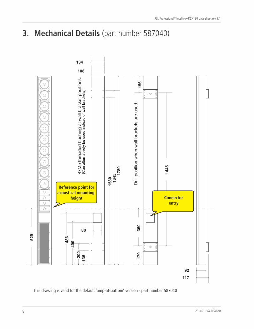
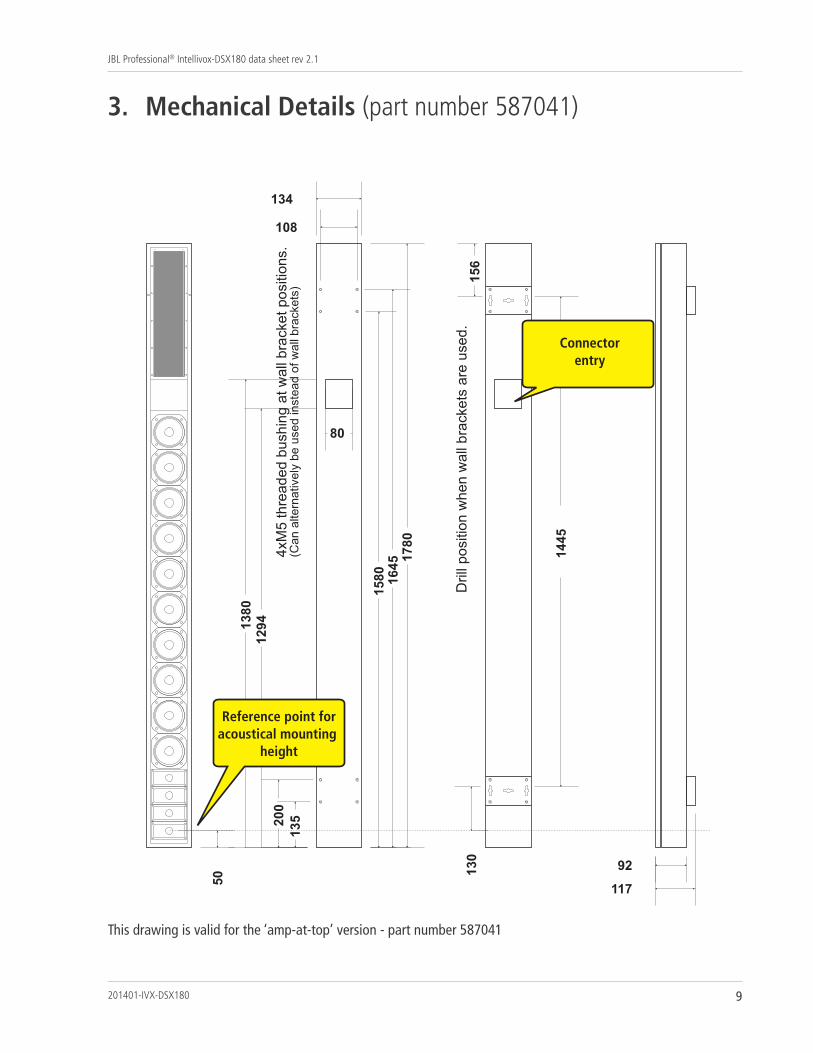
Dimensions are 1780 mm (70.1”) H x 134 mm (5.3”) W x 92 mm (3.6”) D.
Weight 19 kg (42 lbs).
The loudspeaker unit shall be the JBLProfessional® model Intellivox-DSX180.
5
JBL Professional® Intellivox-DSX180 data sheet rev 2.1
201401-IVX-DSX180
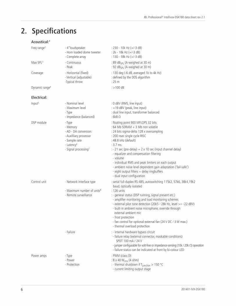
Acoustical:1
Freq range2 - 4”loudspeaker : 230 - 10k Hz (+/-3 dB)- Horn loaded dome tweeter : 2k - 18k Hz (+/-3 dB)- Complete array : 130 - 18k Hz (+/-3 dB)
Max SPL3 - Continuous : 89 dBSPL (A-weighed at 30 m)- Peak : 92 dBSPL (A-weighed at 30 m)
Coverage - Horizontal (fixed) : 130 deg (-6 dB, averaged 1k to 4k Hz)- Vertical (adjustable) : defined by the DDS algorithm-Typical throw : 25 m
Dynamic range4 : >100 dB
Electrical:
Input5 - Nominal level : 0 dBV (RMS, line input)- Maximum level : +19 dBV (peak, line input)- Type : dual line input, transformer balanced- Impedance (balanced) : 6k8 Ω
DSP module - Type : floating point 900 MFLOPS 32 bits- Memory : 64 Mb SDRAM + 3 Mb non volatile- AD - DA conversion: : 24 bits sigma-delta 128 x oversampling- Auxilliary processor : 200 nsec single cycle RISC- Sample rate : 48.8 kHz (default)- Latency6 : 3.7 ms- Signal processing7 : - 21 sec (pre-delay) + 2 x 10 sec (input channel delay)
- equalizer and compensation filtering- volume- individual RMS and peak limiters on each output- ambient noise level dependent gain adaptation (‘fail-safe’)- eight output filters + delay ringbuffers- dual input configuration
Control unit - Network interface type : serial full-duplex RS-485, autoswitching 115k2, 57k6, 38k4,19k2baud, optically isolated
- Maximum number of units8 : 126 units- Remote surveillance : - general status (DSP running, signal present etc.)
- amplifier monitoring and load monitoring schemes- external pilot tone detection (20k5 - 28k Hz, level >= -22 dBV)- built-in ambient noise microphone, override through external ambient mic
- frost protection- fan control for optional external fan (24 V DC / 3 W max.)- thermal overload protection
- Failure : - internal hardware bypass circuit- failure relay (external connector, maskable conditions)
SPDT 100 mA / 24 V- jumper configurable for volt-free or impedance-sensing (10k / 20k Ω) operation- failure status can be indicated at front by bi-colour LED
Power amps - Type : PWM (class D)- Power : 8 x 40 Wrms (4 ohm)- Protection : - thermal shutdown if Tjunction > 150 °C
- current limiting output stage
6 201401-IVX-DSX180
JBL Professional® Intellivox-DSX180 data sheet rev 2.1
2. Specifications
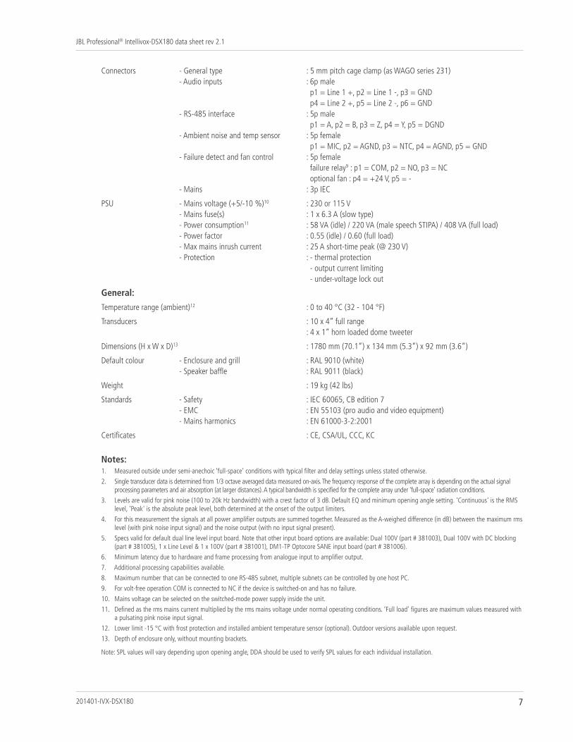
Connectors - General type : 5 mm pitch cage clamp (as WAGO series 231)- Audio inputs : 6p male
p1 = Line 1 +, p2 = Line 1 -, p3 = GNDp4 = Line 2 +, p5 = Line 2 -, p6 = GND
- RS-485 interface : 5p malep1 = A, p2 = B, p3 = Z, p4 = Y, p5 = DGND
- Ambient noise and temp sensor : 5p femalep1 = MIC, p2 = AGND, p3 = NTC, p4 = AGND, p5 = GND
- Failure detect and fan control : 5p femalefailure relay9 : p1 = COM, p2 = NO, p3 = NCoptional fan : p4 = +24 V, p5 = -
- Mains : 3p IEC
PSU - Mains voltage (+5/-10 %)10 : 230 or 115 V- Mains fuse(s) : 1 x 6.3 A (slow type)- Power consumption11 : 58 VA (idle) / 220 VA (male speech STIPA) / 408 VA (full load)- Power factor : 0.55 (idle) / 0.60 (full load)- Max mains inrush current : 25 A short-time peak (@ 230 V)- Protection : - thermal protection
- output current limiting- under-voltage lock out
General:
Temperature range (ambient)12 : 0 to 40 °C (32 - 104 °F)
Transducers : 10 x 4” full range: 4 x 1” horn loaded dome tweeter
Dimensions (H x W x D)13 : 1780 mm (70.1”) x 134 mm (5.3”) x 92 mm (3.6”)
Default colour - Enclosure and grill : RAL 9010 (white)- Speaker baffle : RAL 9011 (black)
Weight : 19 kg (42 lbs)
Standards - Safety : IEC 60065, CB edition 7- EMC : EN 55103 (pro audio and video equipment)- Mains harmonics : EN 61000-3-2:2001
Certificates : CE, CSA/UL, CCC, KC
Notes:1. Measured outside under semi-anechoic ‘full-space’ conditions with typical filter and delay settings unless stated otherwise.
2. Single transducer data is determined from 1/3 octave averaged data measured on-axis. The frequency response of the complete array is depending on the actual signalprocessing parameters and air absorption (at larger distances). A typical bandwidth is specified for the complete array under 'full-space' radiation conditions.
3. Levels are valid for pink noise (100 to 20k Hz bandwidth) with a crest factor of 3 dB. Default EQ and minimum opening angle setting. 'Continuous' is the RMSlevel, 'Peak' is the absolute peak level, both determined at the onset of the output limiters.
4. For this measurement the signals at all power amplifier outputs are summed together. Measured as the A-weighed difference (in dB) between the maximum rmslevel (with pink noise input signal) and the noise output (with no input signal present).
5. Specs valid for default dual line level input board. Note that other input board options are available: Dual 100V (part # 381003), Dual 100V with DC blocking(part # 381005), 1 x Line Level & 1 x 100V (part # 381001), DM1-TP Optocore SANE input board (part # 381006).
6. Minimum latency due to hardware and frame processing from analogue input to amplifier output.
7. Additional processing capabilities available.
8. Maximum number that can be connected to one RS-485 subnet, multiple subnets can be controlled by one host PC.
9. For volt-free operation COM is connected to NC if the device is switched-on and has no failure.
10. Mains voltage can be selected on the switched-mode power supply inside the unit.
11. Defined as the rms mains current multiplied by the rms mains voltage under normal operating conditions. ’Full load’ figures are maximum values measured witha pulsating pink noise input signal.
12. Lower limit -15 °C with frost protection and installed ambient temperature sensor (optional). Outdoor versions available upon request.
13. Depth of enclosure only, without mounting brackets.
Note: SPL values will vary depending upon opening angle, DDA should be used to verify SPL values for each individual installation.
7
JBL Professional® Intellivox-DSX180 data sheet rev 2.1
201401-IVX-DSX180
135 20
0
400 48
6
1580
16
45 17
80
179
1445
156
92
117
80
4xM
5 th
read
ed b
ushi
ng a
t wal
l bra
cket
pos
ition
s.(C
an a
ltern
ativ
ely
be u
sed
inst
ead
of w
all b
rack
ets)
Dril
l pos
ition
whe
n w
all b
rack
ets
are
used
.
108
134
529
350
Reference point foracoustical mounting
height Connectorentry
8 201401-IVX-DSX180
JBL Professional® Intellivox-DSX180 data sheet rev 2.1
3. Mechanical Details (part number 587040)
This drawing is valid for the default ‘amp-at-bottom’ version - part number 587040
1294
13
80
135 20
0
1580
16
45 17
80
1445
156
92
117
Dril
l pos
ition
whe
n w
all b
rack
ets
are
used
.
108
134
4xM
5 th
read
ed b
ushi
ng a
t wal
l bra
cket
pos
ition
s.(C
an a
ltern
ativ
ely
be u
sed
inst
ead
of w
all b
rack
ets)
80
50 13
0
Reference point foracoustical mounting
height
Connectorentry
9
JBL Professional® Intellivox-DSX180 data sheet rev 2.1
3. Mechanical Details (part number 587041)
201401-IVX-DSX180
This drawing is valid for the ‘amp-at-top’ version - part number 587041
10 201401-IVX-DSX180
JBL Professional® Intellivox-DSX180 data sheet rev 2.1
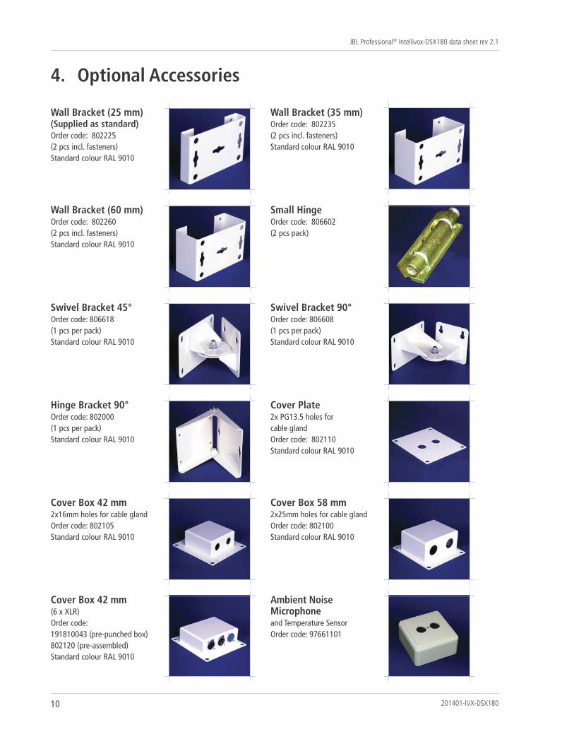
4. Optional Accessories
Wall Bracket (25 mm)(Supplied as standard)Order code: 802225 (2 pcs incl. fasteners)Standard colour RAL 9010
Wall Bracket (35 mm)Order code: 802235 (2 pcs incl. fasteners)Standard colour RAL 9010
Wall Bracket (60 mm)Order code: 802260 (2 pcs incl. fasteners)Standard colour RAL 9010
Small HingeOrder code: 806602(2 pcs pack)
Swivel Bracket 45°Order code: 806618(1 pcs per pack)Standard colour RAL 9010
Swivel Bracket 90°Order code: 806608(1 pcs per pack)Standard colour RAL 9010
Hinge Bracket 90°Order code: 802000(1 pcs per pack)Standard colour RAL 9010
Cover Plate2x PG13.5 holes for cable glandOrder code: 802110Standard colour RAL 9010
Cover Box 42 mm2x16mm holes for cable glandOrder code: 802105Standard colour RAL 9010
Cover Box 58 mm2x25mm holes for cable glandOrder code: 802100Standard colour RAL 9010
Cover Box 42 mm (6 x XLR)Order code: 191810043 (pre-punched box)802120 (pre-assembled)Standard colour RAL 9010
Ambient NoiseMicrophone and Temperature SensorOrder code: 97661101
11
JBL Professional® Intellivox-DSX180 data sheet rev 2.1
5. DSP Block Diagram
201401-IVX-DSX180
87654321
4” loud
speakers
HF
Horns
4 bandparam
etric
I/P 1
GA
IND
ELAYEQ
VOLU
ME
DELAY
AUTO
GA
IN
INTERN
AL
MICRO
PHO
NE
I/P 2
NO
RMA
L MO
DE
I/P 1
I/P 2LEVEL CON
TROLLED
SWITCH
ING
I/P 1
I/P 2
PILOT TO
NE CO
NTRO
LLED SW
ITCHIN
G
OR
OR
EQ
8 bandparam
etric
DD
SPRO
CESSING
4 bandparam
etricG
AIN
DELAY
EQ
4 bandparam
etricG
AIN
DELAY
EQ

JBL Professional8500 Balboa Boulevard
Northridge, CA 91329 U.S.A.© Copyright 2014 JBL Professional
www.jblpro.com