Embed Size (px)
Citation preview
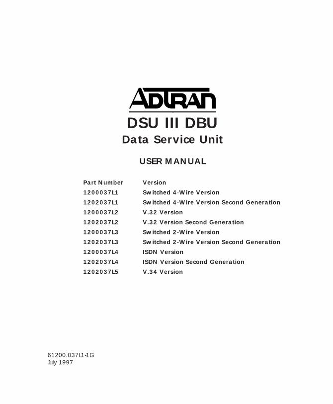
DSU III DBUData Service Unit
USER MANUAL
Part Number Version
1200037L1 Switched 4-Wire Version
1202037L1 Switched 4-Wire Version Second Generation
1200037L2 V.32 Version
1202037L2 V.32 Version Second Generation
1200037L3 Switched 2-Wire Version
1202037L3 Switched 2-Wire Version Second Generation
1200037L4 ISDN Version
1202037L4 ISDN Version Second Generation
1202037L5 V.34 Version
61200.037L1-1GJuly 1997
Trademark:DATAPATH is a registered trademark of CAE electronics and is used by NorthernTelecom under license.
Hayes is a registered trademark of Hayes Microcomputer Products, Inc.
901 Explorer BoulevardP.O. Box 140000
Huntsville, AL 35814-4000Phone: (205) 963-8000
© 1997 ADTRAN, Inc.All rights reserved.
Printed in USA.
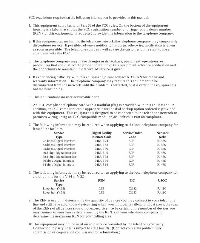
FCC regulations require that the following information be provided in this manual:
1. This equipment complies with Part 68 of the FCC rules. On the bottom of the equipmenthousing is a label that shows the FCC registration number and ringer equivalence number(REN) for this equipment. If requested, provide this information to the telephone company.
2. If this equipment causes harm to the telephone network, the telephone company may temporarilydiscontinue service. If possible, advance notification is given, otherwise, notification is givenas soon as possible. The telephone company will advise the customer of the right to file acomplaint with the FCC.
3. The telephone company may make changes in its facilities, equipment, operations, orprocedures that could affect the proper operation of this equipment; advance notification andthe opportunity to maintain uninterrupted service is given.
4. If experiencing difficulty with this equipment, please contact ADTRAN for repair andwarranty information. The telephone company may require this equipment to bedisconnected from the network until the problem is corrected, or it is certain the equipment isnot malfunctioning.
5. This unit contains no user-serviceable parts.
6. An FCC compliant telephone cord with a modular plug is provided with this equipment. Inaddition, an FCC compliant cable appropriate for the dial backup option ordered is providedwith this equipment. This equipment is designed to be connected to the telephone network orpremises wiring using an FCC compatible modular jack, which is Part 68 compliant.
7. The following information may be required when applying to the local telephone company forleased line facilities:
Service Digital Facility Service Order NetworkType Interface Code Code Jacks
2.4 kbps Digital Interface 04DU5-24 6.0F RJ-48S4.8 kbps Digital Interface 04DU5-48 6.0F RJ-48S9.6 kbps Digital Interface 04DU5-96 6.0F RJ-48S19.2 kbps Digital Interface 04DU5-19 6.0F RJ-48S38.4 kbps Digital Interface 04DU5-38 6.0F RJ-48S56 kbps Digital Interface 04DU5-56 6.0F RJ-48S64 kbps Digital Interface 04DU5-64 6.0F RJ-48S
8. The following information may be required when applying to the local telephone company fora dial-up line for the V.34 or V.32:
Service REN FIC USOCType
Loop Start (V.32) 0.3B 02LS2 RJ-11CLoop Start (V.34) 0.8B 02LS2 RJ-11C
9. The REN is useful in determining the quantity of devices you may connect to your telephoneline and still have all of those devices ring when your number is called. In most areas, the sumof the RENs of all devices should not exceed five. To be certain of the number of devices youmay connect to your line as determined by the REN, call your telephone company todetermine the maximum REN for your calling area.
10.This equipment may not be used on coin service provided by the telephone company.Connection to party lines is subject to state tarriffs. (Contact your state public utilitycommission or corporation commission for information.)
Table of Contents
FEDERAL COMMUNICATIONS COMMISSIONRADIO FREQUENCY INTERFERENCE STATEMENT
This equipment has been tested and found to comply with the limits for a Class A digitaldevice, pursuant to Part 15 of the FCC rules. These limits are designed to provide reason-able protection against harmful interference when the equipment is operated in a commercialenvironment. This equipment generates, uses, and can radiate radio frequency energy and,if not installed and used in accordance with the instruction manual, may cause harmfulinterference to radio frequencies. Operation of this equipment in a residential area is likelyto cause harmful interference in which case the user will be required to correct the interfer-ence at his own expense.
Shielded cables must be used with this unit to ensure compliance with Class A FCC limits.
Change or modifications to this unit not expressly approved by theparty responsible for compliance could void the user's authority tooperate the equipment.
CANADIAN EMISSIONS REQUIREMENTS
This digital apparatus does not exceed the Class A limits for radio noise emissionsfrom digital apparatus as set out in the interference-causing equipment standardentitled "Digital Apparatus," ICES-003 of the Department of Communications.
Cet appareil nuerique respecte les limites de bruits radioelectriques applicables auxappareils numeriques de Class A prescrites dans la norme sur le materiel brouilleur:"Appareils Numeriques," NMB-003 edictee par le ministre des Communications.
Table of Contents
CANADIAN EQUIPMENT LIMITATIONS
Notice: The Canadian Industry and Science Canada label identifies certifiedequipment. This certification means that the equipment meets certain telecom-munications network protective, operational, and safety requirements. TheDepartment does not guarantee the equipment will operate to the user's satisfac-tion.
Before installing this equipment, users should ensure that it is permissible to beconnected to the facilities of the local telecommunications company. The equip-ment must also be installed using an acceptable method of connection. In somecases, the company's inside wiring associated with a single line individualservice may be extended by means of a certified connector assembly (telephoneextension cord). The customer should be aware that compliance with the aboveconditions may not prevent degradation of service in some situations.
Repairs to certified equipment should be made by an authorized Canadianmaintenance facility designated by the supplier. Any repairs or alterations madeby the user to this equipment, or equipment malfunctions, may give the telecom-munications company cause to request the user to disconnect the equipment.
Users should ensure for their own protection that the electrical ground connec-tions of the power utility, telephone lines and internal metallic water pipesystem, if present, are connected together. This precaution may be particularlyimportant in rural areas.
Caution: Users should not attempt to make such connections themselves, butshould contact the appropriate electric inspection authority, or an electrician, asappropriate.
The Load Number (LN) assigned to each terminal device denotes the percentageof the total load to be connected to a telephone loop which is used by the device,to prevent overloading. The termination on a loop may consist of any combina-tion of devices subject only to the requirement that the total of the Load Num-bers of all devices does not exceed 100.
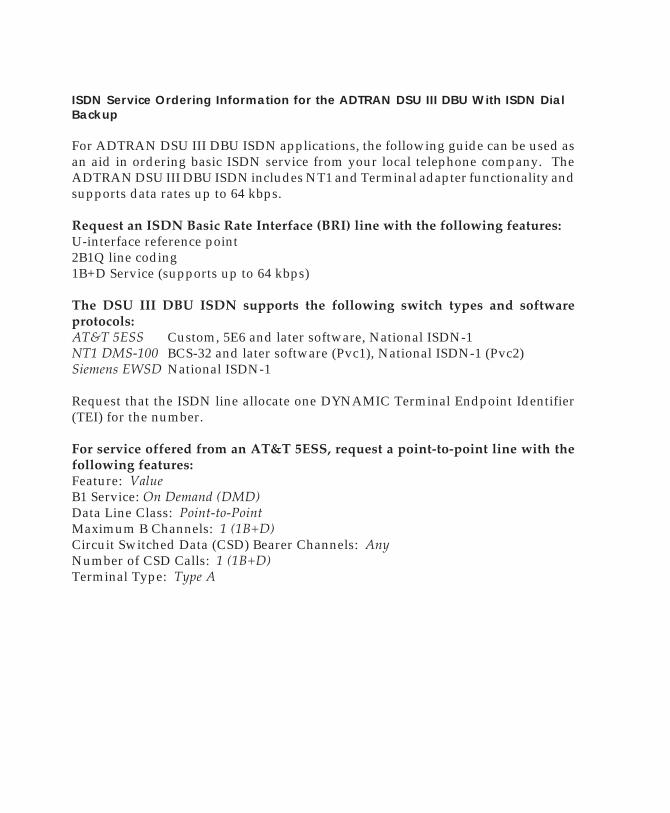
ISDN Service Ordering Information for the ADTRAN DSU III DBU With ISDN DialBackup
For ADTRAN DSU III DBU ISDN applications, the following guide can be used asan aid in ordering basic ISDN service from your local telephone company. TheADTRAN DSU III DBU ISDN includes NT1 and Terminal adapter functionality andsupports data rates up to 64 kbps.
Request an ISDN Basic Rate Interface (BRI) line with the following features:U-interface reference point2B1Q line coding1B+D Service (supports up to 64 kbps)
The DSU III DBU ISDN supports the following switch types and softwareprotocols:AT&T 5ESS Custom, 5E6 and later software, National ISDN-1NT1 DMS-100 BCS-32 and later software (Pvc1), National ISDN-1 (Pvc2)Siemens EWSD National ISDN-1
Request that the ISDN line allocate one DYNAMIC Terminal Endpoint Identifier(TEI) for the number.
For service offered from an AT&T 5ESS, request a point-to-point line with thefollowing features:Feature: ValueB1 Service: On Demand (DMD)Data Line Class: Point-to-PointMaximum B Channels: 1 (1B+D)Circuit Switched Data (CSD) Bearer Channels: AnyNumber of CSD Calls: 1 (1B+D)Terminal Type: Type A
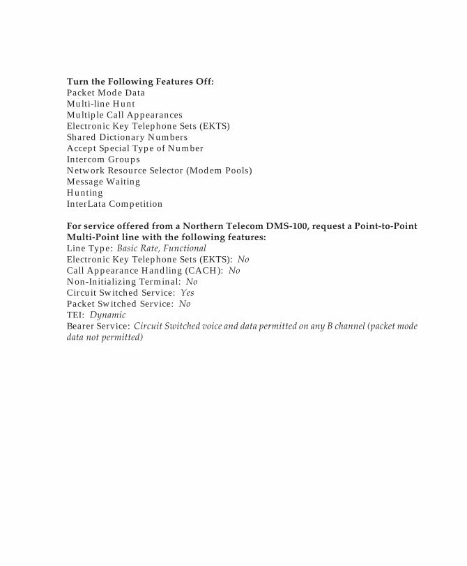
Turn the Following Features Off:Packet Mode DataMulti-line HuntMultiple Call AppearancesElectronic Key Telephone Sets (EKTS)Shared Dictionary NumbersAccept Special Type of NumberIntercom GroupsNetwork Resource Selector (Modem Pools)Message WaitingHuntingInterLata Competition
For service offered from a Northern Telecom DMS-100, request a Point-to-PointMulti-Point line with the following features:Line Type: Basic Rate, FunctionalElectronic Key Telephone Sets (EKTS): NoCall Appearance Handling (CACH): NoNon-Initializing Terminal: NoCircuit Switched Service: YesPacket Switched Service: NoTEI: DynamicBearer Service: Circuit Switched voice and data permitted on any B channel (packet modedata not permitted)

Table of Contents
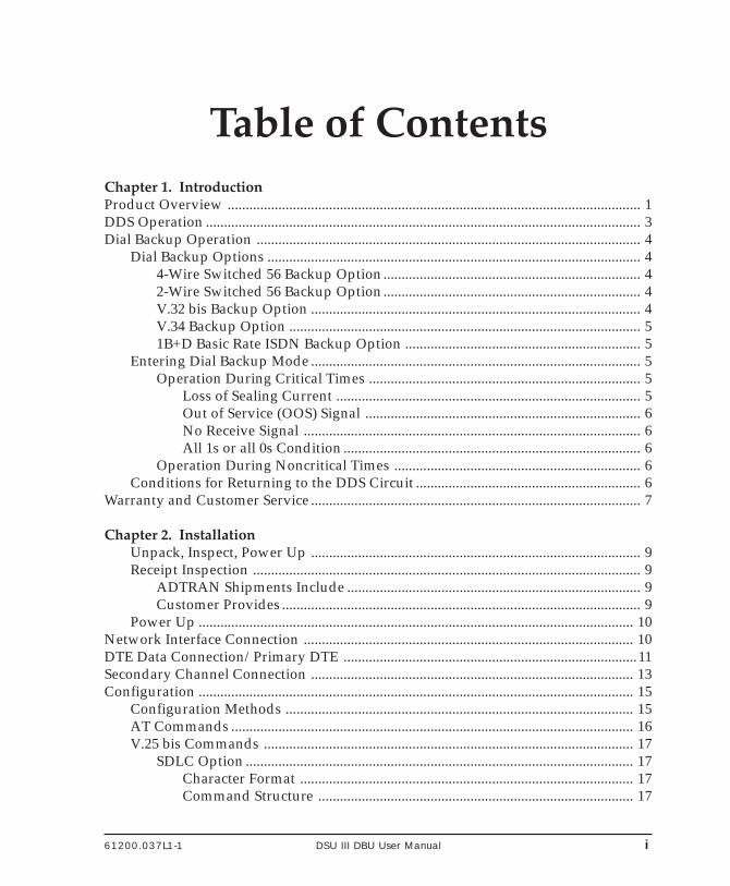
Table of Contents
Table of ContentsChapter 1. IntroductionProduct Overview .................................................................................................................. 1DDS Operation ........................................................................................................................ 3Dial Backup Operation .......................................................................................................... 4
Dial Backup Options ....................................................................................................... 44-Wire Switched 56 Backup Option....................................................................... 42-Wire Switched 56 Backup Option....................................................................... 4V.32 bis Backup Option ........................................................................................... 4V.34 Backup Option ................................................................................................. 51B+D Basic Rate ISDN Backup Option ................................................................. 5
Entering Dial Backup Mode ........................................................................................... 5Operation During Critical Times ........................................................................... 5
Loss of Sealing Current .................................................................................... 5Out of Service (OOS) Signal ............................................................................ 6No Receive Signal ............................................................................................. 6All 1s or all 0s Condition .................................................................................. 6
Operation During Noncritical Times .................................................................... 6Conditions for Returning to the DDS Circuit .............................................................. 6
Warranty and Customer Service ........................................................................................... 7
Chapter 2. InstallationUnpack, Inspect, Power Up ........................................................................................... 9Receipt Inspection ........................................................................................................... 9
ADTRAN Shipments Include ................................................................................. 9Customer Provides ................................................................................................... 9
Power Up ........................................................................................................................ 10Network Interface Connection ........................................................................................... 10DTE Data Connection/Primary DTE .................................................................................11Secondary Channel Connection ......................................................................................... 13Configuration ........................................................................................................................ 15
Configuration Methods ................................................................................................ 15AT Commands ............................................................................................................... 16V.25 bis Commands ...................................................................................................... 17
SDLC Option ........................................................................................................... 17Character Format ............................................................................................ 17Command Structure ....................................................................................... 17
61200.037L1-1 DSU III DBU User Manual i
Table of Contents
ii DSU III DBU User Manual 61200.037L1-1
Bi-Sync Option ........................................................................................................ 17Character Format ............................................................................................ 17Command Structure ....................................................................................... 17
Asynchronous Option ........................................................................................... 18Character Format ............................................................................................ 18Command Structure ....................................................................................... 18
Command Descriptions ......................................................................................... 18Syntax and Possible Responses ............................................................................ 19
CNL (Configuration Local) ............................................................................ 19CNR (Configuration Remote) ....................................................................... 19
Remote Command......................................................................................................... 19
Chapter 3. OperationMenu Structure .............................................................................................................. 21Main Menu ..................................................................................................................... 21
Status ................................................................................................................. 21Test .................................................................................................................... 22Configuration (CONFIG) ............................................................................... 22Dial .................................................................................................................... 22
Basic Menu Navigation ................................................................................................ 22Front Panel ............................................................................................................................. 23
LCD Window ................................................................................................... 24Enter .................................................................................................................. 24Numeric Keypad ............................................................................................. 24Shift ................................................................................................................... 24Quick ................................................................................................................. 25Cancel ............................................................................................................... 25Up and Down Arrows .................................................................................... 25LED Description .............................................................................................. 25
Rear Panel .............................................................................................................................. 26
Chapter 4. Configuration OverviewLocal and Remote Configuration ....................................................................................... 29
Chapter 5. Configuring Network OptionsNetwork Options .................................................................................................................. 33
Loop Rate ........................................................................................................................ 35Network Address .......................................................................................................... 36Remote Configuration .................................................................................................. 36Clock Source ................................................................................................................... 37
Table of Contents
61200.037L1-1 DSU III DBU User Manual iii
Chapter 6. Configuring DTE OptionsDTE Options .......................................................................................................................... 39
DTE Rate ......................................................................................................................... 39Connector Type ............................................................................................................. 42Data Format .................................................................................................................... 43DTE Command Option................................................................................................. 44Transmit Clock ............................................................................................................... 45Clear to Send (CS) Options .......................................................................................... 46Anti -Stream ................................................................................................................... 48CD Options ..................................................................................................................... 49Data Terminal Ready (TR) Options ............................................................................ 50Data Set Ready (SR) Options ....................................................................................... 51Secondary Rate .............................................................................................................. 52
Chapter 7. Configuring Test OptionsTest Options ........................................................................................................................... 55
Test Timeout ................................................................................................................... 56Remote Digital Loopback (RDL) ................................................................................. 56EIA LLB ........................................................................................................................... 57EIA RLB .......................................................................................................................... 57DBU Answer Test .......................................................................................................... 58
Chapter 8. Configuring Dial OptionsDial Options .......................................................................................................................... 59
Phone Number ............................................................................................................... 61ISDN Dial Backup .................................................................................................. 61
Setting the Service Profile Identifier (SPID) ................................................ 61Setting the Local Directory (LOC) Number ................................................ 62
DBU Options for All Models ....................................................................................... 63Automatic DBU ............................................................................................... 63Number to Dial ................................................................................................ 63Originate/Answer .......................................................................................... 63When Out of Service (OOS) ........................................................................... 63No Receive (RX) Signal .................................................................................. 63No Sealing Current ......................................................................................... 63When all 1s/0s ................................................................................................. 64Auto Restore .................................................................................................... 64Redial Counter ................................................................................................. 64Fail Timer.......................................................................................................... 64Wait to Redial ................................................................................................... 65
Table of Contents
iv DSU III DBU User Manual 61200.037L1-1
DBU Options for 2-wire and 4-wire............................................................................ 66Network Type .................................................................................................. 66
DBU Options for V.32 bis and V.34 ........................................................................... 66Error Control .................................................................................................... 66Flow Control .................................................................................................... 66Compression .................................................................................................... 66
DBU Options for ISDN ................................................................................................. 68Switch Type ...................................................................................................... 68
DBU Passcode ................................................................................................................ 68
Chapter 9. Dial OptionsDial Options .......................................................................................................................... 69
Answer Unit Connected to DDS Line ........................................................................ 70Dial Backup ...................................................................................................... 70
Originate Unit Connected to DDS Line...................................................................... 70Dial Backup ...................................................................................................... 70Stay on Leased ................................................................................................. 70DBU Online Test .............................................................................................. 70
Dial Options During Dial Backup........................................................................ 70Hang Up ........................................................................................................... 70Stay On Line ..................................................................................................... 70
Chapter 10. StatusStatus ...................................................................................................................................... 71
Network Rate, DTE Rate, and Data Format .............................................................. 71Dial Backup Information .............................................................................................. 72
Type of Dial Backup Service .......................................................................... 72Current Status of Dial Backup Mode ........................................................... 72
DSU Operation and Network Status .......................................................................... 74Current DSU III DBU Status ................................................................................. 74Current DDS Network Status ............................................................................... 74
DTE Control Leads and Status .................................................................................... 75
Chapter 11. Testing and TroubleshootingTest Overview ........................................................................................................................ 77
Initiating a Test .............................................................................................................. 78Test Status Display ........................................................................................................ 79Exiting a Test .................................................................................................................. 79
Troubleshooting .................................................................................................................... 81Messages from the DSU/CSU ..................................................................................... 81
Table of Contents
61200.037L1-1 DSU III DBU User Manual v
Troubleshooting New Installs ..................................................................................... 82Test Sequence for Troubleshooting New Installs or Existing Circuits ........... 83
Local Unit Diagnostics ......................................................................................................... 84DTE & Loop (LL) ........................................................................................................... 86
Test Description ...................................................................................................... 86Test Purpose ............................................................................................................ 86Initiating .................................................................................................................. 87Interpreting Test Results ....................................................................................... 87
Loop Only (RT) .............................................................................................................. 88Test Purpose ............................................................................................................ 88Initiating .................................................................................................................. 88Interpreting Test Results ....................................................................................... 89
DTE Only ........................................................................................................................ 90Test Purpose ............................................................................................................ 90Initiating .................................................................................................................. 90Interpreting Test Results ....................................................................................... 91
DTE With Test Pattern .................................................................................................. 92Test Purpose ............................................................................................................ 92Initiating .................................................................................................................. 92Interpreting Test Results ....................................................................................... 93
Test Pattern ..................................................................................................................... 94Test Purpose ............................................................................................................ 94Initiating .................................................................................................................. 95Interpreting Test Results ....................................................................................... 95
Self Test ........................................................................................................................... 96Test Purpose ............................................................................................................ 96Initiating .................................................................................................................. 96Interpreting Test Results ....................................................................................... 96
Remote Unit Diagnostics ..................................................................................................... 97Test Purpose ............................................................................................................ 97Initiating .................................................................................................................. 98Test Results ............................................................................................................. 98Interpreting Test Results ....................................................................................... 98
DBU Connection ................................................................................................................... 99Test Purpose ............................................................................................................ 99Initiating ................................................................................................................ 100Interpreting Test Results ..................................................................................... 100
Chapter 12. Manual CommandManual Command.............................................................................................................. 101
Table of Contents
vi DSU III DBU User Manual 61200.037L1-1
Appendix A. AT Commands .......................................................................................... 105
Appendix B. Default Configuration ProfilesDefault Configuration Profiles ......................................................................................... 109
Profile 1 ........................................................................................................... 109Profile 2 ........................................................................................................... 109Profiles 3 and 4 .............................................................................................. 109
Appendix C. DSU to Modem InterconnectModem Tail Circuit Application ........................................................................................113
Appendix D. EIA-232 Connector56 and 64 kbps Application ................................................................................................115
Appendix E. Specifications SummarySpecification and Features ..................................................................................................117
Operating Modes ...........................................................................................117Data Rates ........................................................................................................117DTE Rates ........................................................................................................117DTE Interface Data Rates ..............................................................................117FCC Approval .................................................................................................117DTE Interfaces ................................................................................................118Data Buffering ................................................................................................118Clocking ...........................................................................................................118Diagnostics ......................................................................................................118Line Requirements .........................................................................................118Line Interface ..................................................................................................118Receiver Sensitivity ........................................................................................118Environment ...................................................................................................118Physical ............................................................................................................118Power ...............................................................................................................118
Glossary ................................................................................................................................119
Index ..................................................................................................................................... 127
List of TablesTable 2-A Pin Assignments for Line 1 Connector ........................................................ 10Table 2-B Pin Assignments for Line 2 Connector .........................................................11Table 2-C Pin Assignments for Primary EIA-232 Connector ..................................... 12
Table of Contents
61200.037L1-1 DSU III DBU User Manual vii
Table 2-D Pin Assignments for Primary V.35 Connector ............................................ 13Table 2-E Pin Assignments for Auxiliary EIA-232 Connector ................................... 14Table 5-A Network Options AT Commands ................................................................. 34Table 6-A DTE Rate Options AT Commands ................................................................ 41Table 6-B Data Format Commands ................................................................................ 43Table 6-C Transmit Clock AT Commands ..................................................................... 45Table 6-D CS Options AT Commands ............................................................................ 47Table 6-E Short and Long Delays at Different Operating Speeds ............................. 47Table 6-F Anti-Stream AT Commands .......................................................................... 49Table 6-G CD Options AT Commands ........................................................................... 50Table 6-H TR Options AT Commands ........................................................................... 51Table 6-I SR Options AT Commands ............................................................................ 52Table 6-J Secondary Rate AT Commands ................................................................... 53Table 7-A Test Options AT Commands .......................................................................... 55Table 8-A AT Commands for Storing Phone Numbers ............................................... 62Table 8-B DBU Options AT Commands for All Models ............................................. 65Table 8-C DBU Options AT Commands for V.32 bis and V.34 Backup ..................... 67Table 11-A Messages from the DSU/CSU ....................................................................... 81Table 11-B Troubleshooting New Installs ....................................................................... 82Table 11-C Test AT Commands ......................................................................................... 84Table 11-D DTE with Test Pattern Commands ............................................................... 85Table 11-E Remote Tests and AT Commands ................................................................. 97Table 12-A Manual Commands ...................................................................................... 103Table A-A AT Commands ............................................................................................... 105Table B-A Default Configuration Profiles .....................................................................110
List of FiguresFigure 1-1 Typical Point-to-Point Application for DSU III DBU ................................. 2Figure 3-1 Example of Basic Menu Navigation ........................................................... 23Figure 3-2 DSU III DBU Front View .............................................................................. 24Figure 3-3 DSU III DBU Rear View ............................................................................... 27Figure 4-1 Complete Configuration Menu ................................................................... 31Figure 5-1 Setting Loop Rate Options ........................................................................... 35Figure 5-2 Setting the Network Address ...................................................................... 36Figure 5-3 Remote Configuration .................................................................................. 36Figure 5-4 Setting the Clock Source ............................................................................... 37Figure 6-1 Selecting DTE Rates ...................................................................................... 40Figure 6-2 Selecting the Connector Type ...................................................................... 42Figure 6-3 Selecting Asynchronous or Synchronous Data Format ........................... 43Figure 6-4 Selecting DTE Command Option ............................................................... 44
Table of Contents
viii DSU III DBU User Manual 61200.037L1-1
Figure 6-5 Transmit Clock Options ................................................................................ 45Figure 6-6 Selecting CS Options ..................................................................................... 46Figure 6-7 Anti-Stream Options ..................................................................................... 48Figure 6-8 Selecting CD Options .................................................................................... 49Figure 6-9 Selecting Data Terminal Ready (TR) Options ........................................... 50Figure 6-10 Setting Data Set Ready (SR) Options .......................................................... 51Figure 6-11 Setting the Secondary Rate .......................................................................... 52Figure 7-1 Setting Test Timeout Option ........................................................................ 56Figure 7-2 Remote Digital Loopback ............................................................................. 56Figure 7-3 EIA Local Loopback Options ....................................................................... 57Figure 7-4 EIA Remote Loopback Options ................................................................... 57Figure 7-5 DBU Answer Test Option ............................................................................. 58Figure 8-1 Dial Backup Options ..................................................................................... 60Figure 8-2 Editing Stored Phone Numbers .................................................................. 61Figure 9-1 Dial Options Menu ........................................................................................ 69Figure 10-1 Status Display ................................................................................................ 71Figure 11-1 Normal Operation Before Initiating Loopback Test ................................. 77Figure 11-2 Initiating a Test .............................................................................................. 78Figure 11-3 Sample Test Status Displays ........................................................................ 79Figure 11-4 Complete Test Menu ..................................................................................... 80Figure 11-5 DTE & Loop Test ........................................................................................... 86Figure 11-6 Initiating a DTE & Loop Test ....................................................................... 87Figure 11-7 Loop Only Test ............................................................................................... 88Figure 11-8 Initiating a Loop Only Test .......................................................................... 89Figure 11-9 DTE Only Test Diagram ............................................................................... 90Figure 11-10 Initiating a DTE Only Test ............................................................................ 91Figure 11-11 DTE with Test Pattern ................................................................................... 92Figure 11-12 Initiating a DTE with Test and Test Pattern ............................................... 93Figure 11-13 Test Pattern Only ........................................................................................... 94Figure 11-14 Initiating a Test Using a Test Pattern .......................................................... 95Figure 11-15 Initiating a Self Test ....................................................................................... 96Figure 11-16 V.54 RDL with Test Pattern .......................................................................... 97Figure 11-17 Initiating a Remote Test ................................................................................ 98Figure 11-18 DBU Connection Test .................................................................................... 99Figure 11-19 Initiating a DBU Connection Test ............................................................. 100Figure 12-1 Manual Command ...................................................................................... 102Figure C-1 DSU to Modem Interconnect ......................................................................113Figure D-1 EIA-232 Connector .......................................................................................115
61200.037L1-1 DSU III DBU User Manual 1
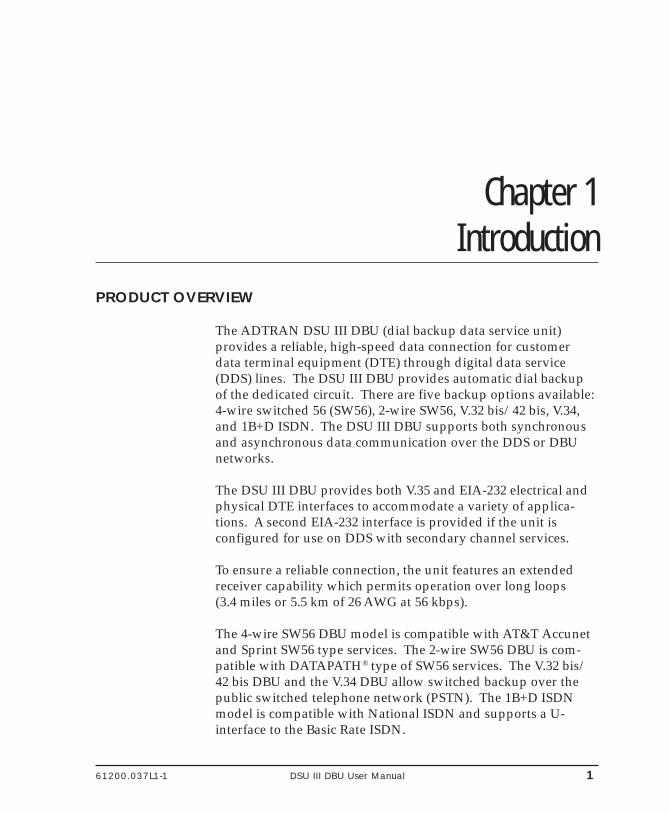
Chapter 1. Introduction
Chapter 1Introduction
PRODUCT OVERVIEW
The ADTRAN DSU III DBU (dial backup data service unit)provides a reliable, high-speed data connection for customerdata terminal equipment (DTE) through digital data service(DDS) lines. The DSU III DBU provides automatic dial backupof the dedicated circuit. There are five backup options available:4-wire switched 56 (SW56), 2-wire SW56, V.32 bis/42 bis, V.34,and 1B+D ISDN. The DSU III DBU supports both synchronousand asynchronous data communication over the DDS or DBUnetworks.
The DSU III DBU provides both V.35 and EIA-232 electrical andphysical DTE interfaces to accommodate a variety of applica-tions. A second EIA-232 interface is provided if the unit isconfigured for use on DDS with secondary channel services.
To ensure a reliable connection, the unit features an extendedreceiver capability which permits operation over long loops(3.4 miles or 5.5 km of 26 AWG at 56 kbps).
The 4-wire SW56 DBU model is compatible with AT&T Accunetand Sprint SW56 type services. The 2-wire SW56 DBU is com-patible with DATAPATH® type of SW56 services. The V.32 bis/42 bis DBU and the V.34 DBU allow switched backup over thepublic switched telephone network (PSTN). The 1B+D ISDNmodel is compatible with National ISDN and supports a U-interface to the Basic Rate ISDN.
2 DSU III DBU User Manual 61200.037L1-1
Chapter 1. Introduction
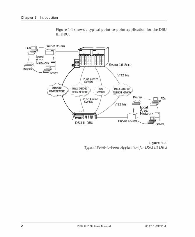
Figure 1-1 shows a typical point-to-point application for the DSUIII DBU.
2 or 4-wire SW56
2 or 4-wire SW56
V.32 bis
V.32 bis
DEDICATEDPRIVATE NETWORK
PUBLIC SWITCHEDDIGITAL NETWORK
PUBLIC SWITCHEDTELEPHONE NETWORK
ISDNNETWORK
ENTER 1 2 3
4 5 6
7 8 9
#0*CANCELSHIFT SHIFT
D
A
E
B
F
C
RS CS TD RD CD A LM TS TRS CS TD RD CD A LM TS T
DSU III DBU
1 1622 33 44 55 66 77 88 99 1010 1111 1212 1313 1414 1515
RS
CS
TD
RD
CD
DTE
LOOP
RDL
PTRN
ERROR
ALM
SELECT
TEST
DSU III ARDSU III AR DSU III ARDSU III AR DSU III ARDSU III AR DSU III ARDSU III AR DSU III S4WDSU III S4W DSU III S4WDSU III S4W DSU III S4WDSU III S4W DSU III DBUDSU III DBUDSU III S4WDSU III S4W DSU III DBUDSU III DBU DSU III DBUDSU III DBU DSU III DBUDSU III DBU DSU S2WDSU S2W DSU S2WDSU S2W DSU S2WDSU S2W
POWER SUPPLYPOWER SUPPLY POWER SUPPLYPOWER SUPPLY
DIAL STATUS
TEST CONFIG ENTER
1 2 3
4 5 6
7 8 9
0
DIALMATE
CANCEL
SHELF
CONTROLLER
RS
CS
TD
RD
CD
DTE
LOOP
RDL
PTRN
ERROR
ALM
SELECT
TEST
RS
CS
TD
RD
CD
DTE
LOOP
RDL
PTRN
ERROR
ALM
SELECT
TEST
RS
CS
TD
RD
CD
DTE
LOOP
RDL
PTRN
ERROR
ALM
SELECT
TEST
RS
CS
TD
RD
CD
DTE
LOOP
RDL
PTRN
ERROR
ALM
SELECT
TEST
RS
CS
TD
RD
CD
DTE
LOOP
RDL
PTRN
ERROR
ALM
SELECT
TEST
RS
CS
TD
RD
CD
DTE
LOOP
RDL
PTRN
ERROR
ALM
SELECT
TEST
RS
CS
TD
RD
CD
DTE
LOOP
RDL
PTRN
ERROR
ALM
SELECT
TEST
RS
CS
TD
RD
CD
DTE
LOOP
RDL
PTRN
ERROR
ALM
SELECT
TEST
RS
CS
TD
RD
CD
DTE
LOOP
RDL
PTRN
ERROR
ALM
SELECT
TEST
RS
CS
TD
RD
CD
DTE
LOOP
RDL
PTRN
ERROR
ALM
SELECT
TEST
RS
CS
TD
RD
CD
DTE
LOOP
RDL
PTRN
ERROR
ALM
SELECT
TEST
+5V
+5V
+12V
+12V
-12V
-12V
-5V CHEC
K
RS
CS
TD
RD
CD
DTE
LOOP
RDL
PTRN
ERROR
ALM
SELECT
TEST
RS
CS
TD
RD
CD
DTE
LOOP
RDL
PTRN
ERROR
ALM
SELECT
TEST
RS
CS
TD
RD
CD
DTE
LOOP
RDL
PTRN
ERROR
ALM
SELECT
TEST
+5V
+5V
+12V
+12V
-12V
-12V
-5V CHEC
K
SERVER
PCs
PRINTER
BRIDGE/ROUTER
LocalAreaNetwork
LocalAreaNetwork
SMART 16 SHELF
DSU III DBU SERVER
PCsPRINTER
BRIDGE/ROUTER
Figure 1-1Typical Point-to-Point Application for DSU III DBU
61200.037L1-1 DSU III DBU User Manual 3
Chapter 1. Introduction
DDS OPERATION
DDS is a nationwide service that allows interconnection andtransport of data at speeds up to 64 kbps. The local exchangecarriers provide the local loop service to DDS customers andmay provide data for routing Inter-LATA to an interexchangecarrier. In DDS mode, the DSU III DBU supports the 56/64 kbpsDDS service rate yielding DTE rates of 2.4, 4.8, 9.6, 19.2, 38.4(sync or async), 56 kbps, and 64 kbps. An additional rate of 57.6is available in asynchronous mode. The unit can be configuredto run slower DTE rates (async or sync) over the 56 kbps service.Secondary channel operation is supported at all service rates upto 56 kbps, providing terminal rates of 75, 150, 300, 600, 1200,and 2400 bps. The secondary rates available depend on theservice rate configured.
4 DSU III DBU User Manual 61200.037L1-1
Chapter 1. Introduction
DIAL BACKUP OPERATION
There are five backup options available: 4-wire SW56, 2-wireSW56, V.32 bis/42 bis,V.34, and 1B+D ISDN. Contact the localtelco provider to determine which services are available.
Dial Backup Options
4-Wire Switched 56 Backup Option
This dial-up 4-wire DDS allows customers to pay for dataconnection only for the time the unit is active. The regionaloperating companies provide the 4-wire local loop service toSW56 customers. In SW56 mode, the DSU III DBU supportsDTE rates of 2.4, 4.8, 9.6, 19.2, 38.4 (asynchronous or synchro-nous), and 56 kbps (synchronous). An additional DTE rate of57.6 kbps is available in async modes.
2-Wire Switched 56 Backup Option
DATAPATH is a switched digital service offered under variousservice names by the local service provider. The services aregenerally provided by the Northern Telecom DMS/SL100 familyof central office switches. DATAPATH allows the customer topay for high speed data transfer, up to 56 kbps, only when theunit is active. The dial-up service is delivered via a 2-wire localloop that can be up to 18,000 feet at a signal level of -45 dB.
V.32 bis Backup Option
The V.32 bis/42 bis modem in an asynchronous mode can useV.42 bis data compression to make up for a slower connectionrate. V.42 bis increases the effective data throughput from 14.4kbps to as high as 57.6 kbps, depending on the data type. Nocompression is supported in synchronous operation. In synchro-nous applications the maximum speed supported for backup is14.4 kbps.
61200.037L1-1 DSU III DBU User Manual 5
Chapter 1. Introduction
V.34 Backup Option
The V.34 modem has all of the V.32 bis modem's modes ofoperation, plus V.34 and V.FC modes. This allows the V.34option to run synchronous rates up to 28.8 kbps as opposed tothe V.32 at 14.4 kbps. In asynchronous mode the throughput at57.6 kbps is less dependent on data types.
1B+D Basic Rate ISDN Backup Option
1B+D Basic Rate ISDN service provides the customer with aswitched 56/64 kbps circuit. The default data rate for this optionis 56K. The 64 kbps data rate may be revised by using theSMART dial string as described in the section ISDN Dial Backupin the chapter Configuring Dial Options. This option provides a Uinterface to the ISDN network.
Entering Dial Backup Mode
When a condition for entering dial backup mode is detected, theAlarm LED turns on, and the buzzer sounds. The buzzeralternates between 30 seconds on and 30 seconds off unless theDDS line is restored or it is disabled by using the Quick key andselecting Turn Off Beep. See the section Front Panel in thechapter Operation for more information on the Quick key.
Operation During Critical Times
The following four conditions will cause a DSU III DBU to enterdial backup mode:
Loss of Sealing CurrentSealing current is a low voltage DC current provided by thecentral office (CO) to prevent corrosion over the copper wiresused in the local loop. Sealing current may also be used for localloop testing purposes. An absence of sealing current generally isan indication that the loop is open.
6 DSU III DBU User Manual 61200.037L1-1
Chapter 1. Introduction
Out of Service (OOS) SignalAn OOS signal, generated by the network, indicates a device (ordevices) in the network is out of service.
No Receive SignalThis is an indication that the local loop copper pairs may beeither open or shorted or the OCU in the CO is inoperative. In aprivate network this may indicate that the transmitter of theremote DSU is inoperative.
All 1s or all 0s ConditionThis condition is usually generated by the network to indicatesome device (or devices) in the network is inoperative. Upondetecting an all 1s or all 0s condition, the DSU III DBU initiates ahandshake routine to determine whether the remote unit's DTEis the source of the all 1s or 0s condition or if an actual networkfailure exists.
Operation During Noncritical Times
The DSU III DBU may be configured not to enter dial backupmode if data terminal ready (DTR) is low. This feature preventsthe DSU III DBU from entering dial backup during noncriticaltimes such as nights and weekends.
For more information, see the chapter Configuring Dial BackupOptions.
Conditions for Returning to the DDS Circuit
The DSU III DBU can be configured to automatically revert tothe DDS circuit from the dial backup mode or wait to be re-turned to the DDS manually. Once the DSU III DBU enters dialbackup mode, the unit polls the DDS circuit once every 100 ms todetermine if the condition causing the DDS circuit failure hasbeen corrected. Once the DSU III DBU determines that theproblem has been properly corrected and the DDS circuit isstable, it will wait for the amount of time specified in the restoretimer (1 - 255 minutes) before reverting to the DDS circuit.Polling of the DDS circuit is non-intrusive and return to the DDS
61200.037L1-1 DSU III DBU User Manual 7
Chapter 1. Introduction
circuit generally takes 2 - 3 seconds. The backup connection ismaintained for one minute after the DDS circuit is restored.
For more information see the chapter Configuring Dial BackupOptions.
WARRANTY AND CUSTOMER SERVICE
ADTRAN will replace or repair this product within five yearsfrom the date of shipment if it does not meet its publishedspecifications or fails while in service. For detailed warranty,repair and return information refer to the ADTRAN EquipmentWarranty and Repair and Return Policy Procedure.
Return Material Authorization (RMA) is required prior toreturning equipment to ADTRAN.
For service, RMA requests, or further information, contact one ofthe numbers listed on the inside back cover of this manual.

8 DSU III DBU User Manual 61200.037L1-1
Chapter 1. Introduction
61200.037L1-1 DSU III DBU User Manual 9
Chapter 2. Installation
Chapter 2Installation
UNPACK, INSPECT, POWER UP
Receipt Inspection
Carefully inspect the DSU III DBU for any shipping damage. Ifdamage is suspected, file a claim immediately with the carrierand contact ADTRAN Customer Service. If possible, keep theoriginal shipping container for use in shipping the DSU III DBUfor repair or for verification of damage during shipment.
ADTRAN Shipments Include
The following items are included in ADTRAN shipments of theDSU III DBU:
• DSU III DBU unit• An 8-position modular to 8-position modular cable• The user manual• Appropriate cable for the backup option selected
Customer Provides
The customer must provide an EIA-232 interface cable withstandard 25-pin male D-type connectors (Cannon or Cinch DB-19604-432) or a V.35 cable.
10 DSU III DBU User Manual 61200.037L1-1
Chapter 2. Installation
Power UpEach DSU unit is provided with a captive eight-foot power cord,terminated by a three-prong plug which connects to a grounded115 VAC power receptacle.
Power to the DSU must be provided from a grounded 115 VAC, 60 Hzreceptacle.
NETWORK INTERFACE CONNECTION
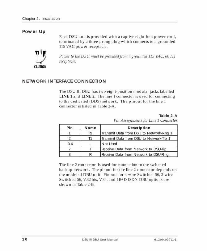
The DSU III DBU has two eight-position modular jacks labelledLINE 1 and LINE 2. The line 1 connector is used for connectingto the dedicated (DDS) network. The pinout for the line 1connector is listed in Table 2-A.
Table 2-APin Assignments for Line 1 Connector
Pin Name Description1 R1 Transmit Data from DSU to Network-Ring 12 T1 Transmit Data from DSU to Network-Tip 1
3-6 - Not Used7 T Receive Data from Network to DSU-Tip8 R Receive Data from Network to DSU-Ring
The line 2 connector is used for connection to the switchedbackup network. The pinout for the line 2 connector depends onthe model of DBU unit. Pinouts for 4-wire Switched 56, 2-wireSwitched 56, V.32 bis, V.34, and 1B+D ISDN DBU options areshown in Table 2-B.
61200.037L1-1 DSU III DBU User Manual 11
Chapter 2. Installation
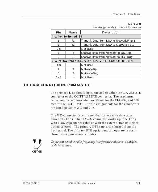
Table 2-BPin Assignments for Line 2 Connector
Pin Name Description4-wire Switched 56
1 R1 Transmit Data from DSU to Network-Ring 12 T1 Transmit Data from DSU to Network-Tip 1
3-6 - Not Used7 T Receive Data from Network to DSU-Tip8 R Receive Data from Network to DSU-Ring
2-wire Switched 56, V.32 bis, V.34, and 1B+D ISDN 1-3 - Not Used
4 T Network-Tip5 R Network-Ring
6 - 8 - Not Used
DTE DATA CONNECTION/PRIMARY DTE
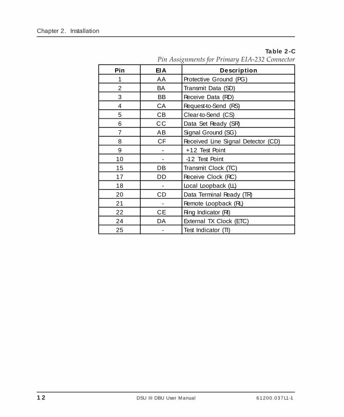
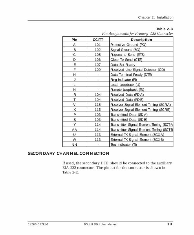
The primary DTE should be connected to either the EIA-232 DTEconnector or the CCITT V.35 DTE connector. The maximumcable lengths recommended are 50 feet for the EIA-232, and 100feet for the CCITT V.35. The pin assignments for the connectorsare listed in Tables 2-C and 2-D.
The V.35 connector is recommended for use with data ratesabove 19.2 kbps. The EIA-232 connector works up to 56 kbpswith a low capacitance cable or with the external transmit clockoption selected. The primary DTE rate is configured from thefront panel. The primary DTE equipment can operate in asyn-chronous or synchronous modes.
To prevent possible radio frequency interference emissions, a shieldedcable is required.
12 DSU III DBU User Manual 61200.037L1-1
Chapter 2. Installation
Table 2-CPin Assignments for Primary EIA-232 Connector
Pin EIA Description1 AA Protective Ground (PG)2 BA Transmit Data (SD)3 BB Receive Data (RD)4 CA Request-to-Send (RS)5 CB Clear-to-Send (CS)6 CC Data Set Ready (SR)7 AB Signal Ground (SG)8 CF Received Line Signal Detector (CD)9 - +12 Test Point
10 - -12 Test Point15 DB Transmit Clock (TC)17 DD Receive Clock (RC)18 - Local Loopback (LL)20 CD Data Terminal Ready (TR)21 - Remote Loopback (RL)22 CE Ring Indicator (RI)24 DA External TX Clock (ETC)25 - Test Indicator (TI)
61200.037L1-1 DSU III DBU User Manual 13
Chapter 2. Installation
Table 2-DPin Assignments for Primary V.35 Connector
Pin CCITT DescriptionA 101 Protective Ground (PG)B 102 Signal Ground (SG)C 105 Request to Send (RTS)D 106 Clear To Send (CTS)E 107 Data Set ReadyF 109 Received Line Signal Detector (CD)H - Data Terminal Ready (DTR)J - Ring Indicator (RI)L - Local Loopback (LL)N - Remote Loopback (RL)R 104 Received Data (RD-A)T 104 Received Data (RD-B)V 115 Receiver Signal Element Timing (SCR-A)X 115 Receiver Signal Element Timing (SCR-B)P 103 Transmitted Data (SD-A)S 103 Transmitted Data (SD-B)Y 114 Transmitter Signal Element Timing (SCT-A)
AA 114 Transmitter Signal Element Timing (SCT-B)U 113 External TX Signal Element (SCX-A)W 113 External TX Signal Element (SCX-B)
NN - Test Indicator (TI)
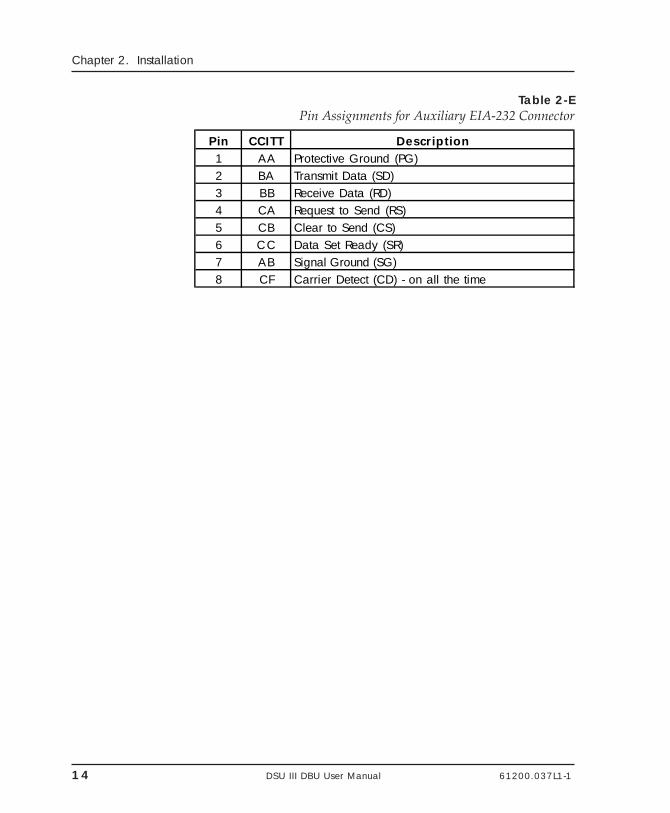
SECONDARY CHANNEL CONNECTION
If used, the secondary DTE should be connected to the auxiliaryEIA-232 connector. The pinout for the connector is shown inTable 2-E.
14 DSU III DBU User Manual 61200.037L1-1
Chapter 2. Installation
Table 2-EPin Assignments for Auxiliary EIA-232 Connector
Pin CCITT Description1 AA Protective Ground (PG)2 BA Transmit Data (SD)3 BB Receive Data (RD)4 CA Request to Send (RS)5 CB Clear to Send (CS)6 CC Data Set Ready (SR)7 AB Signal Ground (SG)8 CF Carrier Detect (CD) - on all the time
61200.037L1-1 DSU III DBU User Manual 15
Chapter 2. Installation
CONFIGURATION
The DSU III contains four different user profiles (sets of configu-ration options) that are stored in read-only memory. Theseprofiles are listed in the appendix Default Configuration Profiles.The unit is shipped from the factory with profile 1 (defaultconfiguration) loaded into the nonvolatile configurationmemory. If profile 1 matches the desired system requirements,then no additional configuration is required to put the unit intoservice. If profile 1 does not match the desired system require-ments, modify the default configuration or select another profilemore closely matching the desired configuration and modify.
When a new profile is loaded or the existing profile is modified,it is stored in the nonvolatile configuration memory. The DSU IIIDBU is then configured with that profile every time power isturned on or the unit is reset.
See the chapter Manual Command for information on loadingdefault configuration profiles.
Configuration Methods
The DSU III DBU provides three methods for local configurationand three different methods for remote configuration: ATcommands, V.25 commands, and front panel commands.
16 DSU III DBU User Manual 61200.037L1-1
Chapter 2. Installation
AT Commands
In addition to the front panel, the DSU III DBU can be config-ured and controlled with in-band AT commands from an asyn-chronous DTE port just as modems are.
To exit the data mode and enter the command mode, the asyn-chronous DTE device must transmit a proper escape sequence ofthree pluses (+++) to the DSU III DBU. A specified time delaymust occur between the last data character and the first escapesequence character. This is the guard time delay, and it can bechanged by writing a value to the S12 register. The default valuefor the guard time is one second. For a valid escape sequence tooccur, the DTE must transmit the escape code character threetimes in succession with delay between each character being lessthan the guard time.
Once the command mode is entered, AT commands can betransmitted to the DSU III DBU to configure most of the optionsor initiate tests to check both the DSU III DBU and the networkconnections. All command lines must begin with the AT charac-ter set in either capital or lower case letters.
The command line may contain a single command or a series ofcommands after the AT attention code. When a series of com-mands is used, the individual commands may be separated withspaces for readability. The maximum length for a command lineis 40 characters. Each command line is executed by the DSU IIIDBU upon receipt of a terminating character. The defaultterminating character is a carriage return (ASCII 013), but it canbe changed by writing a different value to register S3.
Before the terminating character is transmitted, the commandline can be edited by using the backspace character (ASCII 008)to erase errors so the proper commands can be entered.
Valid AT commands for the DSU III DBU are listed in the appen-dix AT Commands.
61200.037L1-1 DSU III DBU User Manual 17
Chapter 2. Installation
V.25 bis Commands
When configured for the V.25 bis option, the DSU III DBUaccepts in-band dialing and configuration commands from bothsynchronous and asynchronous DTE ports.
The V.25 bis option supports the following protocols:
• SDLC• Bi-Sync• Asynchronous
SDLC Option
Character Format• Data bits - 8• Parity bit - Ignored
Command Structure[F][A][C][V.25 bis COMMAND][FCS][F]
The address field [A] is FFH. The control field [C] is set to 13Hexcept for cases of multi-frame responses. For this case, thecontrol field is set to 03H in all but the last frame. The 03H in thecontrol field indicates that other frames are to follow while the13H in the control field indicates the final frame.
Bi-Sync Option
Character Format• Data bits - 7• Parity bit - Odd
Command Structure[SYN][SYN][STX][V.25 bis COMMAND][ETX]
18 DSU III DBU User Manual 61200.037L1-1
Chapter 2. Installation
Asynchronous Option
Character Format• Start bit - 1• Data bits - 7• Parity bit - Even• Stop bit - 1
Command Structure[V.25 bis COMMAND][CR][LF]
Command Descriptions
The ADTRAN V.25 bis command set is a subset of the CCITTV.25 bis command set. In addition to the CCITT commandssupported, ADTRAN has added configuration commands forboth local and remote DSUs. The ADTRAN V.25 bis commandset follows:
CNL Configuration localCNR Configuration remote
Possible responses to V.25 bis commands follows:
VALA Valid V.25 command processedINV An invalid command detectedINVCU Unknown command detectedINVPS Invalid parameter syntaxINVPV Invalid parameter valueINVBL Invalid local passwordINVBM Invalid remote password
If verbose responses are disabled (ATV0), the following three-character responses are the only ones returned:
VAL Valid V.25 command processedINV Invalid command received
61200.037L1-1 DSU III DBU User Manual 19
Chapter 2. Installation
Syntax and Possible Responses
CNL (Configuration Local)This command is used to pass AT commands to the local DSUvia the V.25 bis command processor. This allows the DSU IIIDBU to be configured with AT commands using a synchronousinterface. The format is as follows:
CNL[LOCAL PASSWORD];AT[ONE OR MORE AT COMMANDS]
A local password may not be required depending on the presentconfiguration of the unit. Responses to CNL commands arereturned in the data format currently configured. Possibleresponses include: VALA and INVAn.
CNR (Configuration Remote)This command is used to pass AT commands over the networkto the remote DSU via the V.25 bis command processor. Thisallows a remote DSU III DBU to be configured from a synchro-nous interface. The format of this command follows:
CNR[REMOTE PASSWORD];AT[ONE OR MORE AT COMMANDS]
The remote password may or may not be required depending onthe present configuration of the remote unit. Responses to theCNR commands are returned in the data format currentlyconfigured. Possible responses include: VAL and INVAn.
Remote Command
The DSU III DBU can be controlled remotely from another DSUIII DBU. The Configuration (CONFIG) menu allows the DSU IIIDBU remote configuration capability to be enabled or disabled.For more information, see the chapter Configuration Overview.

20 DSU III DBU User Manual 61200.037L1-1
Chapter 2. Installation
61200.037L1-1 DSU III DBU User Manual 21
Chapter 3. Operation
Chapter 3Operation
MENU STRUCTURE
The DSU III DBU uses a multilevel menu approach to access itsmany features. All menu operations are displayed in the LCDwindow.
The opening menu is the access point to all other operations.Each Main menu item has several functions and submenus toidentify and access specific parameters.
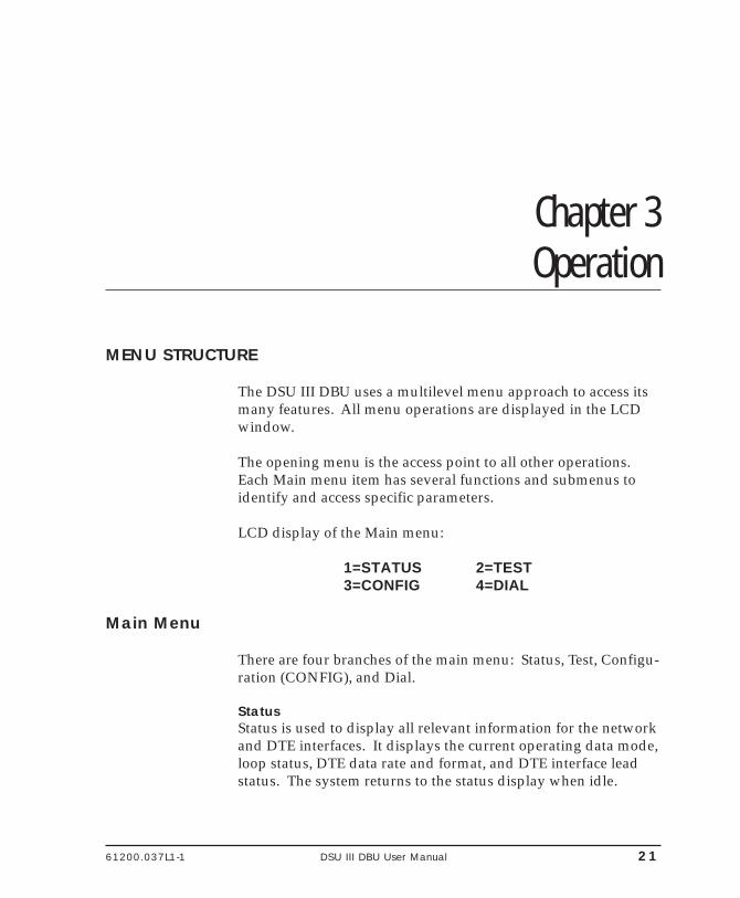
LCD display of the Main menu:
1=STATUS 2=TEST3=CONFIG 4=DIAL
Main Menu
There are four branches of the main menu: Status, Test, Configu-ration (CONFIG), and Dial.
StatusStatus is used to display all relevant information for the networkand DTE interfaces. It displays the current operating data mode,loop status, DTE data rate and format, and DTE interface leadstatus. The system returns to the status display when idle.
22 DSU III DBU User Manual 61200.037L1-1
Chapter 3. Operation
TestTest is used to control local and remote testing. Select local orremote testing, and the type of test and test pattern whenrequired.
Configuration (CONFIG)Configuration is used to select network and DTE operatingparameters. When certain loop rates (56 or 64 kbps) are selected,a scramble option submenu is displayed instead of the DTE Ratemenu to control scrambling.
DialDial provides manual dialing functions. Key in a number to dialor select one of the ten stored numbers.
Basic Menu Navigation
Four function keys on the left side of the DSU III DBU keypadallow the various menu branches to be entered, exited, andscrolled through. The four function keys are defined below:
Enter Selects a displayed item.Up Arrow Scrolls up a menu tree.Down Arrow Scrolls down a menu tree.Cancel Exits (back one level) from the current
branch of the menu.
To choose a menu item, press the corresponding number oralpha character on the keypad (press Shift to activate menuitems with alpha selections). The item flashes on and off to showit is the currently selected (active) choice. Pressing either the Upor Down Arrow scrolls through the available menu items. PressEnter to select the item.
61200.037L1-1 DSU III DBU User Manual 23
Chapter 3. Operation
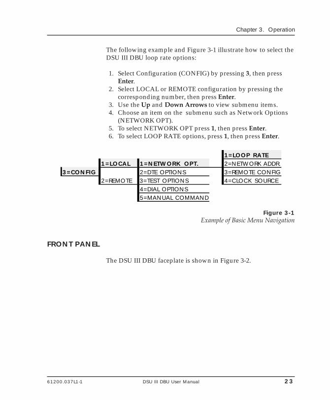
The following example and Figure 3-1 illustrate how to select theDSU III DBU loop rate options:
1. Select Configuration (CONFIG) by pressing 3, then pressEnter.
2. Select LOCAL or REMOTE configuration by pressing thecorresponding number, then press Enter.
3. Use the Up and Down Arrows to view submenu items.4. Choose an item on the submenu such as Network Options
(NETWORK OPT).5. To select NETWORK OPT press 1, then press Enter.6. To select LOOP RATE options, press 1, then press Enter.
1=LOOP RATE1=LOCAL 1=NETWORK OPT. 2=NETWORK ADDR.
3=CONFIG 2=DTE OPTIONS 3=REMOTE CONFIG2=REMOTE 3=TEST OPTIONS 4=CLOCK SOURCE
4=DIAL OPTIONS5=MANUAL COMMAND
Figure 3-1Example of Basic Menu Navigation
FRONT PANEL
The DSU III DBU faceplate is shown in Figure 3-2.
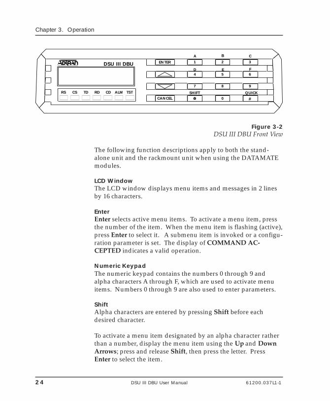
24 DSU III DBU User Manual 61200.037L1-1
Chapter 3. Operation
DSU III DBU ENTER
CANCEL
1A
SHIFT QUICK
2
B
3C
4 5ED
6F
7 8 9
* 0 #RS CS TD RD CD ALM TST
Figure 3-2DSU III DBU Front View
The following function descriptions apply to both the stand-alone unit and the rackmount unit when using the DATAMATEmodules.
LCD WindowThe LCD window displays menu items and messages in 2 linesby 16 characters.
EnterEnter selects active menu items. To activate a menu item, pressthe number of the item. When the menu item is flashing (active),press Enter to select it. A submenu item is invoked or a configu-ration parameter is set. The display of COMMAND AC-CEPTED indicates a valid operation.
Numeric KeypadThe numeric keypad contains the numbers 0 through 9 andalpha characters A through F, which are used to activate menuitems. Numbers 0 through 9 are also used to enter parameters.
ShiftAlpha characters are entered by pressing Shift before eachdesired character.
To activate a menu item designated by an alpha character ratherthan a number, display the menu item using the Up and DownArrows; press and release Shift, then press the letter. PressEnter to select the item.
61200.037L1-1 DSU III DBU User Manual 25
Chapter 3. Operation
If a key is pressed without using Shift, the numbered itembecomes active instead of the alpha item. If this happens, repeatthe correct procedure.
QuickThe Quick key used during most operations returns immedi-ately to the Main menu. During a test, the Quick key displaysthe Exit Test screen. During dial backup, Quick displays a menuwith options to Hang Up or Stay on the Line.
CancelCancel stops the current activity and returns to the previousmenu. Repeat until the desired menu level is reached. When asubmenu item is displayed, press Cancel to exit the currentdisplay and return to the previous menu. Repeat as necessary.
Up and Down ArrowsUp and Down Arrows scroll through the submenu items avail-able in the current menu. Submenu items appear two at a timein a circular or wrapping fashion. When the submenu items arescrolled, they continuously appear from beginning to end in aforward (Down Arrow) or reverse (Up Arrow) pattern.
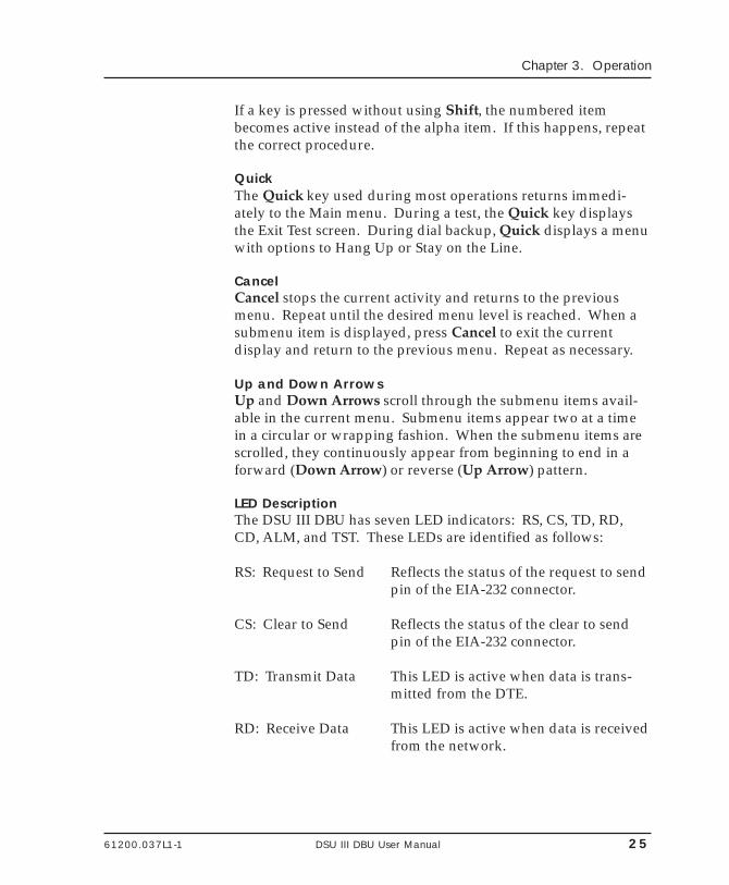
LED DescriptionThe DSU III DBU has seven LED indicators: RS, CS, TD, RD,CD, ALM, and TST. These LEDs are identified as follows:
RS: Request to Send Reflects the status of the request to sendpin of the EIA-232 connector.
CS: Clear to Send Reflects the status of the clear to sendpin of the EIA-232 connector.
TD: Transmit Data This LED is active when data is trans-mitted from the DTE.
RD: Receive Data This LED is active when data is receivedfrom the network.
26 DSU III DBU User Manual 61200.037L1-1
Chapter 3. Operation
CD: Carrier Detect This LED is active when frame synchro-nization is achieved and the DSU IIIDBU is ready to transfer data.
ALM: Alarm Indication This LED activates whenever an alarmcondition exists. Alarm conditionsinclude:
• Open loop on network• No frame synchronization• Unit in dial backup• Problem on dial backup line
TST: Test Mode This LED is on whenever the unit is intest mode.
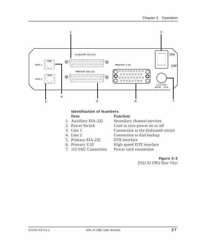
REAR PANEL
The rear panel contains three DTE connectors which provideprimary channel V.35 or EIA-232, and a secondary channel EIA-232 port (auxiliary EIA -232). An 8-pin telco jack, a captivepower cord, and a power switch are also located on the rearpanel. Pin assignments for the DTE and network connectionsare listed in the chapter Installation. The DSU III DBU rear panelis shown in Figure 3-3.
61200.037L1-1 DSU III DBU User Manual 27
Chapter 3. Operation
ON
OFF
AUXILIARY EIA-232
PRIMARY EIA-232
115 VAC60HZ .15A
PRIMARY V.35
1 2
3 5 6 7
LINE 2
LINE 1
4
Identification of NumbersItem Function
1. Auxiliary EIA-232 Secondary channel services2. Power Switch Used to turn power on or off3. Line 1 Connection to the dedicated circuit4. Line 2 Connection to dial backup5. Primary EIA-232 DTE interface6. Primary V.35 High speed DTE interface7. 115 VAC Connection Power cord connection
Figure 3-3DSU III DBU Rear View
28 DSU III DBU User Manual 61200.037L1-1
Chapter 3. Operation
61200.037L1-1 DSU III DBU User Manual 29
Chapter 4. Configuration Overview
Chapter 4Configuration Overview
LOCAL AND REMOTE CONFIGURATION
The DSU III DBU can be configured locally using the front panel,or communications can be established with a remote DSU so thefront panel of the local DSU can be used to configure the remoteDSU. During remote configuration the DSU III DBU prompts forthe remote address before displaying the Configuration menus.
The Configuration menu consists of a group of five submenusrelating to a specific interface or function of the DSU III DBU thatrequires setup:
1=Network Opt. Network Interface Parameters2=DTE Options DTE Interface Parameters3=Test Options Unit Test Options4=Dial Options Unit Dialing Options5=Manual Command ADTRAN Specific Commands
The DSU III DBU contains four different user profiles (sets ofconfiguration options) stored in read only memory; see theappendix Default Configuration Profiles. The unit is shipped fromthe factory with profile number 1 (default configuration) loadedinto the current (nonvolatile configuration) memory. If profile 1matches requirements for the system, then no additional con-figuration is required to put the unit into service. If profile 1does not match system requirements it can be modified, or one
30 DSU III DBU User Manual 61200.037L1-1
Chapter 4. Configuration Overview
of the other profiles that more closely matches the systemrequirements can be loaded into current memory. When adifferent profile is loaded, or the existing profile is modified, it isstored in the current (nonvolatile configuration) memory. TheDSU III DBU is then configured with that profile every timepower is turned on or until the unit is reset.
For detailed information on configuration see the chaptersConfiguring Network Options, Configuring DTE Options, Configur-ing Test Options, Configuring Dial Backup Options, and ManualCommand.
A complete Configuration menu is shown in Figure 4-1.
61200.037L1-1 DSU III DBU User Manual 31
Chapter 4. Configuration Overview
Figure 4-3Complete Configuration Menu
1=AUTO2=2.4K3=4.8K 1=NO SEC. CH.4=9.6K 2=SEC. CHANNEL5=19.2K6=38.4K
1=LOOP RATE 7=56K8=64K
1=NETWORK OPT.2=NETWORK ADDR. ENTER NETWORK 1=DTE RATE Options vary according
ADDRESS:00 to loop rate STORED NUMBER TO1=PHONE NUMBER EDIT: (1-10) NNNNNNN
3=REMOTE CONFIG. 1=DISABLED 1=RS-2322=ENABLED 2=CONNECTOR TYPE 2=V.35 ISDN Dial Backup
STORED NUMBER 9 EDIT SPID4=CLOCK SOURCE 1=MASTER 3=DATA FORMAT 1=ASYNCHRONOUS 1=ASYNC 9 BITS NUMBER NNNNNNN
2=FROM NETWORK 2=SYNCHRONOUS 2=ASYNC 10 BITS STORED NUMBER 10 EDIT LOC3=ASYNC 11 BITS DIRECTORY NUM NNNNNNN
1=DISABLED4=DTE CMD OPTION 2=AT COMMANDS SET 1=AUTOMATIC DBU 1=DISABLED
2=DTE OPTIONS 3=V.25 SYNC 2=ENABLED4=V.25 BSC/ASYNC 2=NUMBER TO DIAL 1=DBU WITH #1
2=DBU WITH #2ENTER TIMEOUT 5=TRANSMIT CLOCK 1=NORMAL 3=ORIGIN/ANSWER 1=DBU ORIGINATE
1=TEST TIMEOUT (0=OFF) : 00 SEC 2=EXTERNAL 1=FORCED ON 2=DBU ANSWER 1=ENABLED2=FOLLOWS RS 1=CS DELAY SHORT 4=WHEN OOS 2=DISABLED
2=RDL EN/DIS 1=RDL IGNORED 6=CS OPTIONS 3=FOLLOWS CD 2=CS DELAY LONG 5=NO RX SGNL 1=ENABLED2=RDL ACCEPTED 2=DISABLED
7=ANTI-STREAM 1=TIMER OFF 4=FOLLOWS RS+CD 1=CS DELAY SHORT 6=NO SEAL CUR. 1=ENABLED3=TEST OPTIONS 3=EIA LLB EN/DIS 1=DISABLED 2=TIME 10 SEC. 2=CS DELAY LONG 2=DISABLED
2=ENABLED 3=TIME 30 SEC. 7=WHEN ALL 1s/0s 1=ENABLED4=TIME 60 SEC. 2=DISABLED
4=EIA RLB EN/DIS 1=DISABLED 8=CD OPTIONS 1=FORCED ON 8=AUTO RESTORE RESTORE TIMER2=ENABLED 2=NORMAL (0=OFF): - - MIN
1=LOCAL 1=IGNORED 9=REDIAL COUNTER ENTER REDIAL5=DBU ANS. TEST 1=DISABLED 9=TR OPTIONS 2=COMMAND SWITCH 1=FORCED ON COUNT: - -
2=ENABLED 3=NO DBU IF OFF 2=OFF OOS ONLY A=FAIL TIMER AUTO DBU FAIL3=CONFIG A=SR OPTIONS 3=OFF LOCD ONLY TIME: - -
4=OFF TEST ONLY2=REMOTE ENTER ADDRESS B=SECONDARY RATE 1=OFF B=WAIT TO REDIAL WAIT TO REDIAL
2=75 TIME: - - SEC3=150 2-wire & 4-wire Dial Backup4=300 C=NETWORK TYPE 1=AT&T/MCI/OTHER5=600 2=US SPRINT6=1.2K7=2.4K V.32bis and V.34 Dial Backup
4=DIAL OPTIONS C=ERROR CONTROL 1=BUFFERED2=DBU OPTIONS 2=DIRECT
3=RELIABLE MNP4=AUTO MNP5=RELIABLE V.426=REL. V.42/MNP
5=MANUAL COMMAND COMMAND: 00 COMMAND: HH 7=AUTO V.42/MNP 1=DISABLEDVALUE:00 D=FLOW CONTROL 2=XON/XOFF
3=CTS ONLYE=COMPRESSION 1=DISABLED 4=RTS/CTS
2=ENABLED 5=UNI. XON/XOFF
ISDN Dial Backup1=AT&T 5ESS
C=SWITCH TYPE 2=NT DMS-1003=NATIONAL ISDN1

32 DSU III DBU User Manual 61200.037L1-1
Chapter 4. Configuration Overview
61200.037L1-1 DSU III DBU User Manual 33
Chapter 5. Configuring Network Options
Chapter 5Configuring Network Options
NETWORK OPTIONS
The Network Options configuration parameters control the loopoperation of the DSU III DBU.
Once a parameter is set, Command Accepted is displayed brieflybefore returning to the active menu.
Table 5-A shows the AT commands used to set the NetworkOptions.
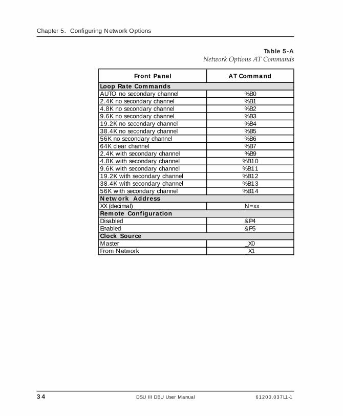
34 DSU III DBU User Manual 61200.037L1-1
Chapter 5. Configuring Network Options
Table 5-ANetwork Options AT Commands
Front Panel AT Command
Loop Rate CommandsAUTO no secondary channel %B02.4K no secondary channel %B14.8K no secondary channel %B29.6K no secondary channel %B319.2K no secondary channel %B438.4K no secondary channel %B556K no secondary channel %B664K clear channel %B72.4K with secondary channel %B94.8K with secondary channel %B109.6K with secondary channel %B1119.2K with secondary channel %B1238.4K with secondary channel %B1356K with secondary channel %B14Network AddressXX (decimal) _N=xxRemote ConfigurationDisabled &P4Enabled &P5Clock SourceMaster _X0From Network _X1
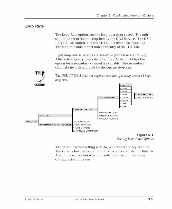
61200.037L1-1 DSU III DBU User Manual 35
Chapter 5. Configuring Network Options
Loop Rate
The Loop Rate option sets the loop operating speed. The unitshould be set to the rate required by the DDS Service. The DSUIII DBU also supports subrate DTE data over a 56 kbps loop.The loop rate must be set independently of the DTE rate.
Eight loop rate selections are available (shown in Figure 5-1).After selecting any loop rate other than Auto or 64 kbps theoption for a secondary channel is available. The secondarychannel rate is determined by the current loop rate.
The DSU III DBU does not support subrates operating over a 64 kbpsloop rate.
1=AUTO2=2.4K3=4.8K4=9.6K 1=NO SEC. CH.
1=LOOP RATE 5=19.2K 2=SEC. CHANNEL6=38.4K7=56K8=64K
1=NETWORK OPT.2=NETWORK ADDR
1=LOCAL 3=REMOTE CONFIG.4=CLOCK SOURCE
3=CONFIG 2=DTE OPTIONS2=REMOTE ENTER ADDRESS 3=TEST OPTIONS
4=DIAL OPTIONS5=MANUAL COMMAND
Figure 5-1Setting Loop Rate Options
The default factory setting is Auto, with no secondary channel.The various loop rates and format selections are listed in Table 5-A with the equivalent AT commands that perform the sameconfiguration functions.
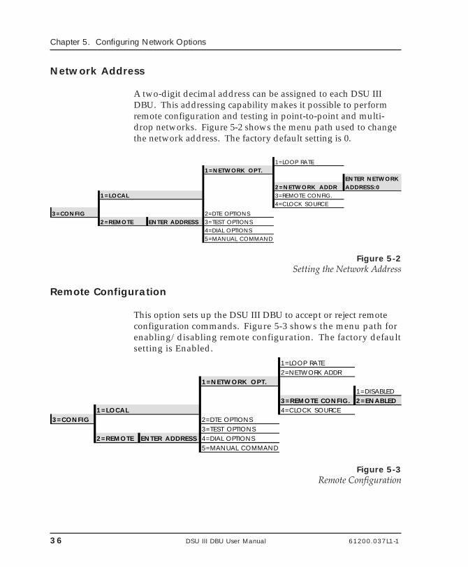
36 DSU III DBU User Manual 61200.037L1-1
Chapter 5. Configuring Network Options
Network Address
A two-digit decimal address can be assigned to each DSU IIIDBU. This addressing capability makes it possible to performremote configuration and testing in point-to-point and multi-drop networks. Figure 5-2 shows the menu path used to changethe network address. The factory default setting is 0.
1=LOOP RATE1=NETWORK OPT.
ENTER NETWORK2=NETWORK ADDR ADDRESS:0
1=LOCAL 3=REMOTE CONFIG.4=CLOCK SOURCE
3=CONFIG 2=DTE OPTIONS2=REMOTE ENTER ADDRESS 3=TEST OPTIONS
4=DIAL OPTIONS5=MANUAL COMMAND
Figure 5-2Setting the Network Address
Remote Configuration
This option sets up the DSU III DBU to accept or reject remoteconfiguration commands. Figure 5-3 shows the menu path forenabling/disabling remote configuration. The factory defaultsetting is Enabled.
1=LOOP RATE2=NETWORK ADDR
1=NETWORK OPT.1=DISABLED
3=REMOTE CONFIG. 2=ENABLED1=LOCAL 4=CLOCK SOURCE
3=CONFIG 2=DTE OPTIONS3=TEST OPTIONS
2=REMOTE ENTER ADDRESS 4=DIAL OPTIONS5=MANUAL COMMAND
Figure 5-3Remote Configuration
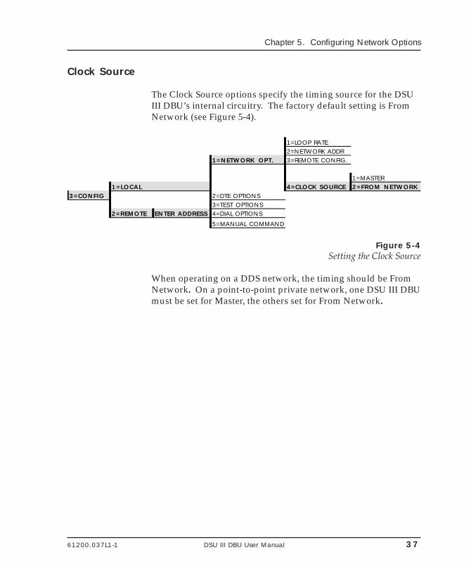
61200.037L1-1 DSU III DBU User Manual 37
Chapter 5. Configuring Network Options
Clock Source
The Clock Source options specify the timing source for the DSUIII DBU’s internal circuitry. The factory default setting is FromNetwork (see Figure 5-4).
1=LOOP RATE2=NETWORK ADDR
1=NETWORK OPT. 3=REMOTE CONFIG.
1=MASTER1=LOCAL 4=CLOCK SOURCE 2=FROM NETWORK
3=CONFIG 2=DTE OPTIONS3=TEST OPTIONS
2=REMOTE ENTER ADDRESS 4=DIAL OPTIONS
5=MANUAL COMMAND
Figure 5-4Setting the Clock Source
When operating on a DDS network, the timing should be FromNetwork. On a point-to-point private network, one DSU III DBUmust be set for Master, the others set for From Network.

38 DSU III DBU User Manual 61200.037L1-1
Chapter 5. Configuring Network Options
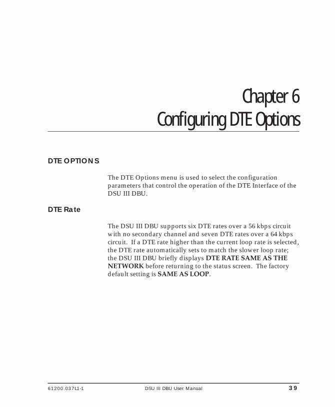
61200.037L1-1 DSU III DBU User Manual 39
Chapter 6. Configuring DTE Options
Chapter 6Configuring DTE Options
DTE OPTIONS
The DTE Options menu is used to select the configurationparameters that control the operation of the DTE Interface of theDSU III DBU.
DTE Rate
The DSU III DBU supports six DTE rates over a 56 kbps circuitwith no secondary channel and seven DTE rates over a 64 kbpscircuit. If a DTE rate higher than the current loop rate is selected,the DTE rate automatically sets to match the slower loop rate;the DSU III DBU briefly displays DTE RATE SAME AS THENETWORK before returning to the status screen. The factorydefault setting is SAME AS LOOP.
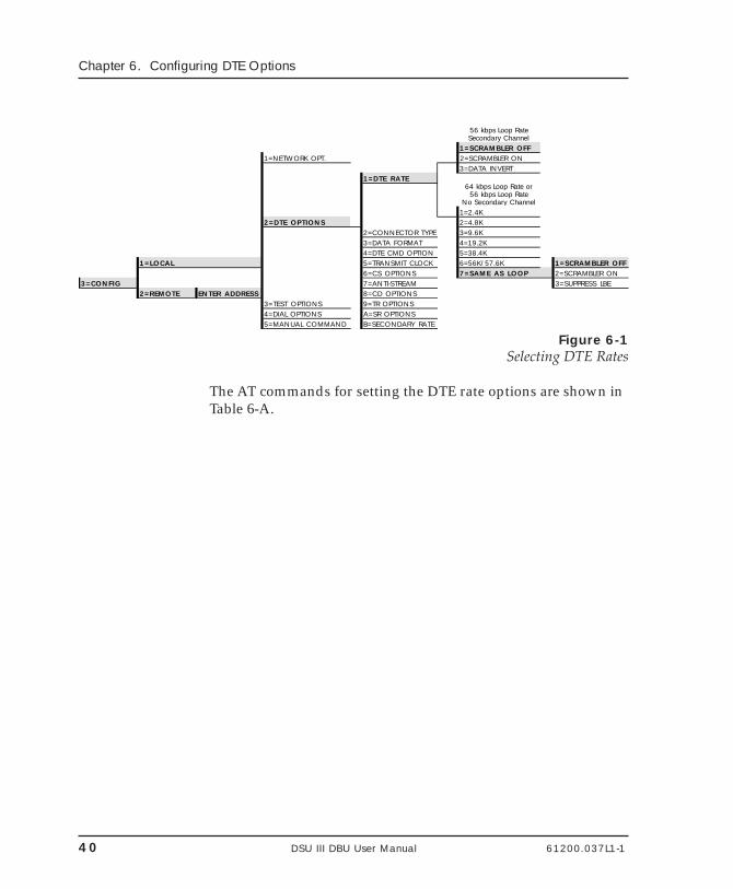
40 DSU III DBU User Manual 61200.037L1-1
Chapter 6. Configuring DTE Options
56 kbps Loop Rate Secondary Channel
1=SCRAMBLER OFF1=NETWORK OPT. 2=SCRAMBLER ON
3=DATA INVERT1=DTE RATE
64 kbps Loop Rate or56 kbps Loop Rate
No Secondary Channel 1=2.4K
2=DTE OPTIONS 2=4.8K2=CONNECTOR TYPE 3=9.6K3=DATA FORMAT 4=19.2K4=DTE CMD OPTION 5=38.4K
1=LOCAL 5=TRANSMIT CLOCK 6=56K/57.6K 1=SCRAMBLER OFF6=CS OPTIONS 7=SAME AS LOOP 2=SCRAMBLER ON
3=CONFIG 7=ANTI-STREAM 3=SUPPRESS LBE2=REMOTE ENTER ADDRESS 8=CD OPTIONS
3=TEST OPTIONS 9=TR OPTIONS4=DIAL OPTIONS A=SR OPTIONS5=MANUAL COMMAND B=SECONDARY RATE
Figure 6-1Selecting DTE Rates
The AT commands for setting the DTE rate options are shown inTable 6-A.
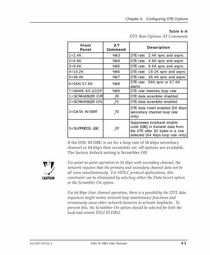
61200.037L1-1 DSU III DBU User Manual 41
Chapter 6. Configuring DTE Options
Table 6-ADTE Rate Options AT Commands
FrontPanel
ATCommand Description
1=2.4K %K3 DTE rate: 2.4K sync and async2=4.8K %K4 DTE rate: 4.8K sync and async3=9.6K %K5 DTE rate: 9.6K sync and async4=19.2K %K6 DTE rate: 19.2K sync and async5=38.4K %K7 DTE rate: 38.4K sync and async
6=56K/57.6K %K8 DTE rate: 56K sync or 57.6K async
7=SAME AS LOOP %K9 DTE rate matches loop rate1=SCRAMBLER OFF _F0 DTE data scrambler disabled2=SCRAMBLER ON _F1 DTE data scrambler enabled
3=DATA INVERT _F2DTE data invert enabled (56 kbps secondary channel loop rate only)
3=SUPPRESS LBE _F2Suppresses loopback enable code (LBE) in transmit data from the DTE after 30 bytes in a row detected (64 kbps loop rate only)
If the DSU III DBU is set for a loop rate of 56 kbps secondarychannel or 64 kbps then scrambler on/off options are available.The factory default setting is Scrambler Off.
For point-to-point operation at 56 kbps with secondary channel, thenetwork requires that the primary and secondary channel data not beall zeros simultaneously. For HDLC protocol applications, thisconstraint can be eliminated by selecting either the Data Invert optionor the Scrambler On option.
For 64 kbps clear channel operation, there is a possibility the DTE datasequences might mimic network loop maintenance functions anderroneously cause other network elements to activate loopbacks. Toprevent this, the Scrambler On option should be selected for both thelocal and remote DSU III DBU.
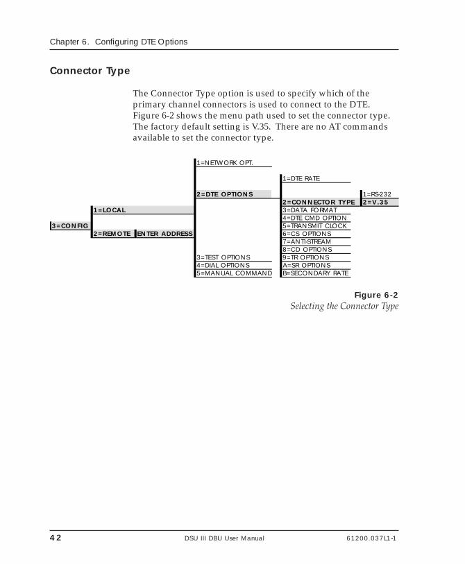
42 DSU III DBU User Manual 61200.037L1-1
Chapter 6. Configuring DTE Options
Connector Type
The Connector Type option is used to specify which of theprimary channel connectors is used to connect to the DTE.Figure 6-2 shows the menu path used to set the connector type.The factory default setting is V.35. There are no AT commandsavailable to set the connector type.
1=NETWORK OPT.
1=DTE RATE
2=DTE OPTIONS 1=RS-2322=CONNECTOR TYPE 2=V.35
1=LOCAL 3=DATA FORMAT4=DTE CMD OPTION
3=CONFIG 5=TRANSMIT CLOCK2=REMOTE ENTER ADDRESS 6=CS OPTIONS
7=ANTI-STREAM8=CD OPTIONS
3=TEST OPTIONS 9=TR OPTIONS4=DIAL OPTIONS A=SR OPTIONS5=MANUAL COMMAND B=SECONDARY RATE
Figure 6-2Selecting the Connector Type
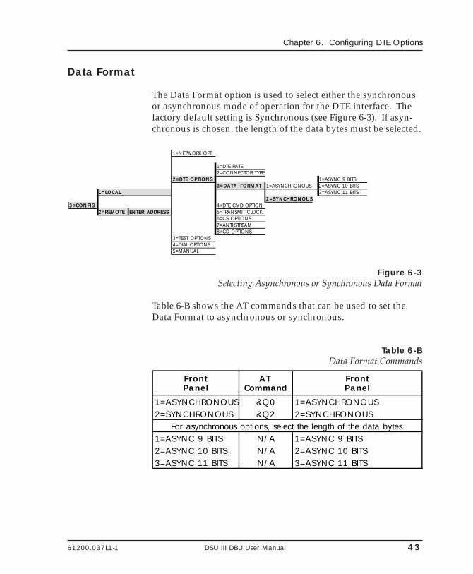
61200.037L1-1 DSU III DBU User Manual 43
Chapter 6. Configuring DTE Options
Data Format
The Data Format option is used to select either the synchronousor asynchronous mode of operation for the DTE interface. Thefactory default setting is Synchronous (see Figure 6-3). If asyn-chronous is chosen, the length of the data bytes must be selected.
1=NETWORK OPT.
1=DTE RATE2=CONNECTOR TYPE
2=DTE OPTIONS 1=ASYNC 9 BITS3=DATA FORMAT 1=ASYNCHRONOUS 2=ASYNC 10 BITS
1=LOCAL 3=ASYNC 11 BITS2=SYNCHRONOUS
3=CONFIG 4=DTE CMD OPTION2=REMOTE ENTER ADDRESS 5=TRANSMIT CLOCK
6=CS OPTIONS7=ANTI-STREAM8=CD OPTIONS
3=TEST OPTIONS4=DIAL OPTIONS5=MANUAL
Figure 6-3Selecting Asynchronous or Synchronous Data Format
Table 6-B shows the AT commands that can be used to set theData Format to asynchronous or synchronous.
Table 6-BData Format Commands
FrontPanel
AT Command
FrontPanel
1=ASYNCHRONOUS &Q0 1=ASYNCHRONOUS2=SYNCHRONOUS &Q2 2=SYNCHRONOUS
For asynchronous options, select the length of the data bytes.1=ASYNC 9 BITS N/A 1=ASYNC 9 BITS2=ASYNC 10 BITS N/A 2=ASYNC 10 BITS3=ASYNC 11 BITS N/A 3=ASYNC 11 BITS
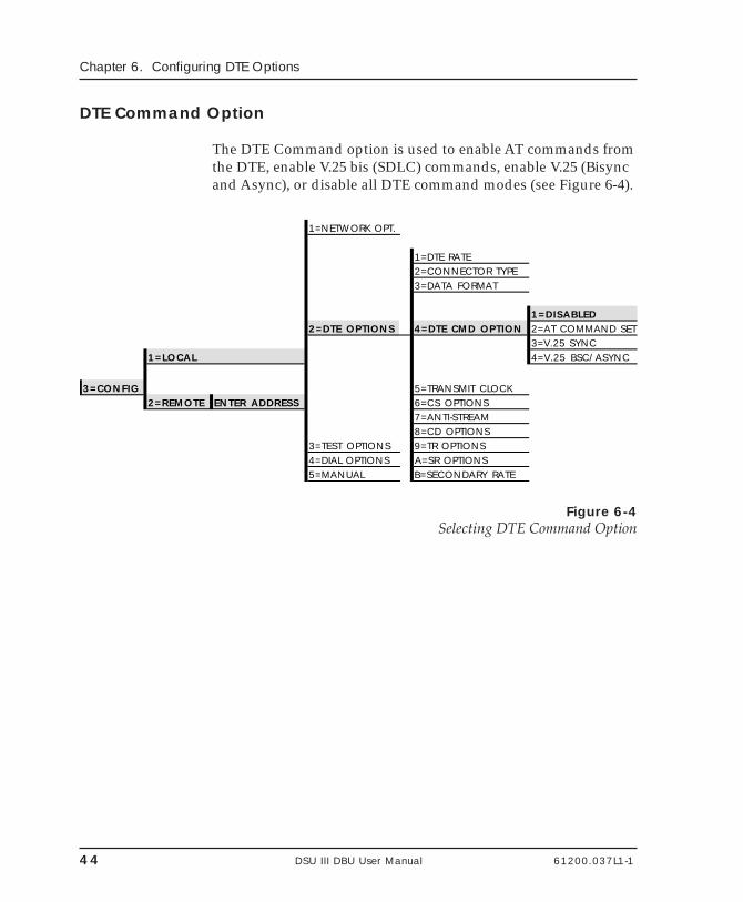
44 DSU III DBU User Manual 61200.037L1-1
Chapter 6. Configuring DTE Options
DTE Command Option
The DTE Command option is used to enable AT commands fromthe DTE, enable V.25 bis (SDLC) commands, enable V.25 (Bisyncand Async), or disable all DTE command modes (see Figure 6-4).
1=NETWORK OPT.
1=DTE RATE2=CONNECTOR TYPE3=DATA FORMAT
1=DISABLED2=DTE OPTIONS 4=DTE CMD OPTION 2=AT COMMAND SET
3=V.25 SYNC1=LOCAL 4=V.25 BSC/ASYNC
3=CONFIG 5=TRANSMIT CLOCK2=REMOTE ENTER ADDRESS 6=CS OPTIONS
7=ANTI-STREAM8=CD OPTIONS
3=TEST OPTIONS 9=TR OPTIONS4=DIAL OPTIONS A=SR OPTIONS5=MANUAL B=SECONDARY RATE
Figure 6-4Selecting DTE Command Option
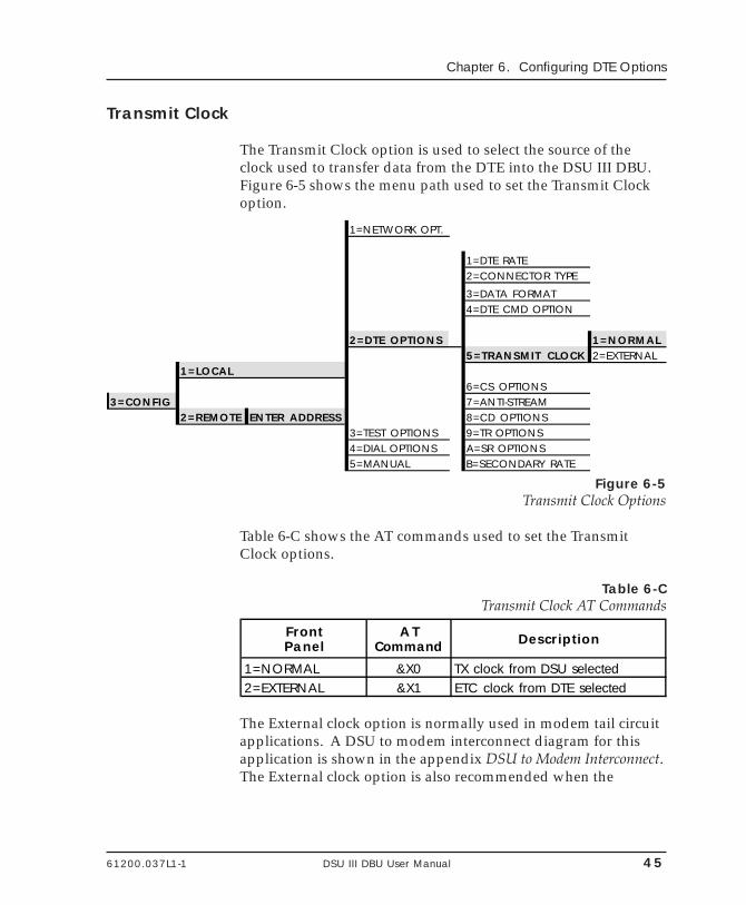
61200.037L1-1 DSU III DBU User Manual 45
Chapter 6. Configuring DTE Options
Transmit Clock
The Transmit Clock option is used to select the source of theclock used to transfer data from the DTE into the DSU III DBU.Figure 6-5 shows the menu path used to set the Transmit Clockoption.
1=NETWORK OPT.
1=DTE RATE2=CONNECTOR TYPE
3=DATA FORMAT4=DTE CMD OPTION
2=DTE OPTIONS 1=NORMAL5=TRANSMIT CLOCK 2=EXTERNAL
1=LOCAL6=CS OPTIONS
3=CONFIG 7=ANTI-STREAM2=REMOTE ENTER ADDRESS 8=CD OPTIONS
3=TEST OPTIONS 9=TR OPTIONS4=DIAL OPTIONS A=SR OPTIONS5=MANUAL B=SECONDARY RATE
Figure 6-5Transmit Clock Options
Table 6-C shows the AT commands used to set the TransmitClock options.
Table 6-CTransmit Clock AT Commands
FrontPanel
ATCommand Description
1=NORMAL &X0 TX clock from DSU selected2=EXTERNAL &X1 ETC clock from DTE selected
The External clock option is normally used in modem tail circuitapplications. A DSU to modem interconnect diagram for thisapplication is shown in the appendix DSU to Modem Interconnect.The External clock option is also recommended when the
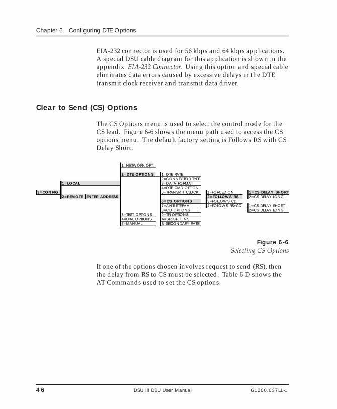
46 DSU III DBU User Manual 61200.037L1-1
Chapter 6. Configuring DTE Options
EIA-232 connector is used for 56 kbps and 64 kbps applications.A special DSU cable diagram for this application is shown in theappendix EIA-232 Connector. Using this option and special cableeliminates data errors caused by excessive delays in the DTEtransmit clock receiver and transmit data driver.
Clear to Send (CS) Options
The CS Options menu is used to select the control mode for theCS lead. Figure 6-6 shows the menu path used to access the CSoptions menu. The default factory setting is Follows RS with CSDelay Short.
1=NETWORK OPT.
2=DTE OPTIONS 1=DTE RATE2=CONNECTOR TYPE
1=LOCAL 3=DATA FORMAT4=DTE CMD OPTION
3=CONFIG 5=TRANSMIT CLOCK 1=FORCED ON 1=CS DELAY SHORT2=REMOTE ENTER ADDRESS 2=FOLLOWS RS 2=CS DELAY LONG
6=CS OPTIONS 3=FOLLOWS CD7=ANTI-STREAM 4=FOLOWS RS+CD 1=CS DELAY SHORT8=CD OPTIONS 2=CS DELAY LONG
3=TEST OPTIONS 9=TR OPTIONS4=DIAL OPTIONS A=SR OPTIONS5=MANUAL B=SECONDARY RATE
Figure 6-6Selecting CS Options
If one of the options chosen involves request to send (RS), thenthe delay from RS to CS must be selected. Table 6-D shows theAT Commands used to set the CS options.
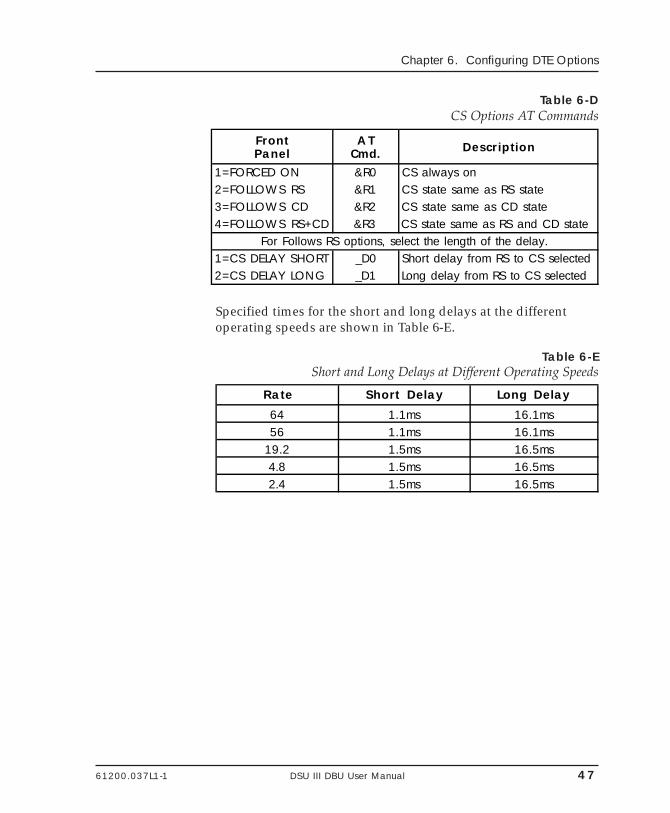
61200.037L1-1 DSU III DBU User Manual 47
Chapter 6. Configuring DTE Options
Table 6-DCS Options AT Commands
FrontPanel
ATCmd. Description
1=FORCED ON &R0 CS always on2=FOLLOWS RS &R1 CS state same as RS state3=FOLLOWS CD &R2 CS state same as CD state4=FOLLOWS RS+CD &R3 CS state same as RS and CD state
For Follows RS options, select the length of the delay.1=CS DELAY SHORT _D0 Short delay from RS to CS selected2=CS DELAY LONG _D1 Long delay from RS to CS selected
Specified times for the short and long delays at the differentoperating speeds are shown in Table 6-E.
Table 6-EShort and Long Delays at Different Operating Speeds
Rate Short Delay Long Delay
64 1.1ms 16.1ms56 1.1ms 16.1ms
19.2 1.5ms 16.5ms4.8 1.5ms 16.5ms2.4 1.5ms 16.5ms
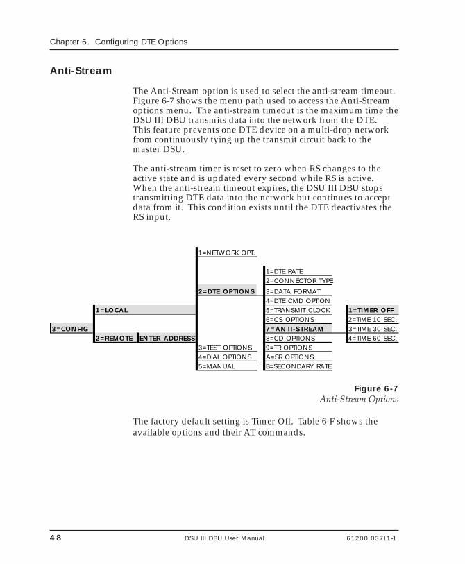
48 DSU III DBU User Manual 61200.037L1-1
Chapter 6. Configuring DTE Options
Anti-Stream
The Anti-Stream option is used to select the anti-stream timeout.Figure 6-7 shows the menu path used to access the Anti-Streamoptions menu. The anti-stream timeout is the maximum time theDSU III DBU transmits data into the network from the DTE.This feature prevents one DTE device on a multi-drop networkfrom continuously tying up the transmit circuit back to themaster DSU.
The anti-stream timer is reset to zero when RS changes to theactive state and is updated every second while RS is active.When the anti-stream timeout expires, the DSU III DBU stopstransmitting DTE data into the network but continues to acceptdata from it. This condition exists until the DTE deactivates theRS input.
1=NETWORK OPT.
1=DTE RATE2=CONNECTOR TYPE
2=DTE OPTIONS 3=DATA FORMAT4=DTE CMD OPTION
1=LOCAL 5=TRANSMIT CLOCK 1=TIMER OFF6=CS OPTIONS 2=TIME 10 SEC.
3=CONFIG 7=ANTI-STREAM 3=TIME 30 SEC.2=REMOTE ENTER ADDRESS 8=CD OPTIONS 4=TIME 60 SEC.
3=TEST OPTIONS 9=TR OPTIONS4=DIAL OPTIONS A=SR OPTIONS5=MANUAL B=SECONDARY RATE
Figure 6-7Anti-Stream Options
The factory default setting is Timer Off. Table 6-F shows theavailable options and their AT commands.
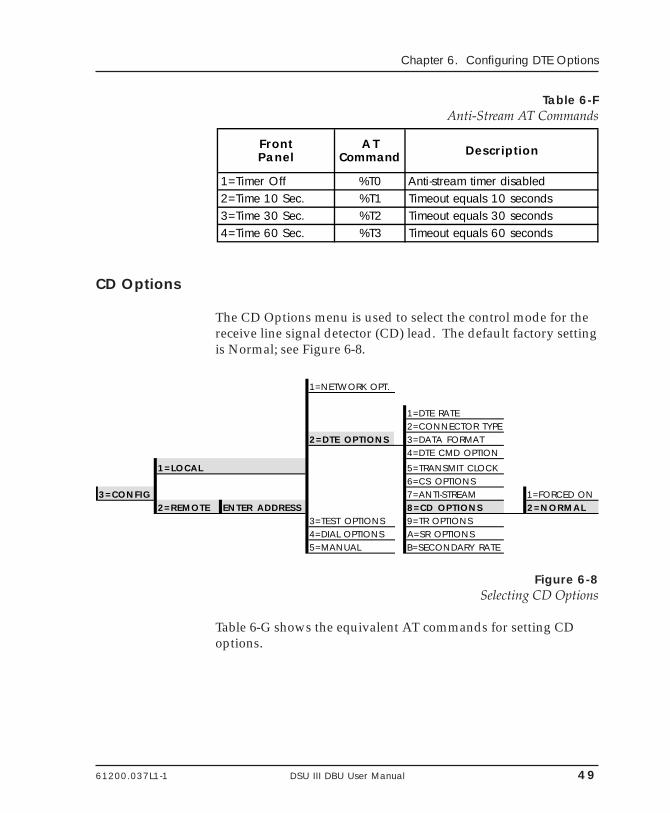
61200.037L1-1 DSU III DBU User Manual 49
Chapter 6. Configuring DTE Options
Table 6-FAnti-Stream AT Commands
FrontPanel
ATCommand Description
1=Timer Off %T0 Anti-stream timer disabled2=Time 10 Sec. %T1 Timeout equals 10 seconds3=Time 30 Sec. %T2 Timeout equals 30 seconds4=Time 60 Sec. %T3 Timeout equals 60 seconds
CD Options
The CD Options menu is used to select the control mode for thereceive line signal detector (CD) lead. The default factory settingis Normal; see Figure 6-8.
1=NETWORK OPT.
1=DTE RATE2=CONNECTOR TYPE
2=DTE OPTIONS 3=DATA FORMAT4=DTE CMD OPTION
1=LOCAL 5=TRANSMIT CLOCK6=CS OPTIONS
3=CONFIG 7=ANTI-STREAM 1=FORCED ON2=REMOTE ENTER ADDRESS 8=CD OPTIONS 2=NORMAL
3=TEST OPTIONS 9=TR OPTIONS4=DIAL OPTIONS A=SR OPTIONS5=MANUAL B=SECONDARY RATE
Figure 6-8Selecting CD Options
Table 6-G shows the equivalent AT commands for setting CDoptions.
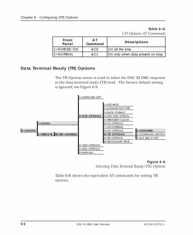
50 DSU III DBU User Manual 61200.037L1-1
Chapter 6. Configuring DTE Options
Table 6-GCD Options AT Commands
FrontPanel
ATCommand Descriptions
1=FORCED ON &C0 On all the time2=NORMAL &C1 On only when data present on loop
Data Terminal Ready (TR) Options
The TR Options menu is used to select the DSU III DBU responseto the data terminal ready (TR) lead. The factory default settingis Ignored; see Figure 6-9.
1=NETWORK OPT.
1=DTE RATE2=CONNECTOR TYPE
3=DATA FORMAT2=DTE OPTIONS 4=DTE CMD OPTION
5=TRANSMIT CLOCK1=LOCAL 6=CS OPTIONS
7=ANTI-STREAM3=CONFIG 8=CD OPTIONS 1=IGNORED
2=REMOTE ENTER ADDRESS 9=TR OPTIONS 2=COMMAND SWITCHA=SR OPTIONS 3=NO DBU IF OFFB=SECONDARY RATE
3=TEST OPTIONS4=DIAL OPTIONS5=MANUAL
Figure 6-9Selecting Data Terminal Ready (TR) Options
Table 6-H shows the equivalent AT commands for setting TRoptions.
61200.037L1-1 DSU III DBU User Manual 51
Chapter 6. Configuring DTE Options
Table 6-HTR Options AT Commands
FrontPanel
ATCommand Descriptions
1=IGNORE &D0 Ignore the TR input
2=COMMAND SWITCH &D2 Switch to command state if TR is off
3=NO DBU IF OFF &D3 No dial backup if TR is off
Data Set Ready (SR) Options
The SR Options menu is used to select the operating mode forthe data set ready (SR) lead. Use Shift + A to activate the SROptions submenu press Enter to enter the SR Options submenu.The factory default setting is Off Test Only (shown in Figure 6-10).
1=DTE RATE1=NETWORK OPT. 2=CONNECTOR TYPE
3=DATA FORMAT2=DTE OPTIONS 4=DTE CMD OPTION
5=TRANSMIT CLOCK1=LOCAL 6=CS OPTIONS
7=ANTI-STREAM3=CONFIG 3=TEST OPTIONS 8=CD OPTIONS 1=FORCED ON
2=REMOTE ENTER ADDRESS 4=DIAL OPTIONS 9=TR OPTIONS 2=OFF OOS ONLY5=MANUAL A=SR OPTIONS 3=OFF TEST ONLY
B=SECONDARY RATE 4=OFF TEST +OOS
Figure 6-10Setting Data Set Ready (SR) Options
Table 6-I shows the AT commands for setting SR options.
52 DSU III DBU User Manual 61200.037L1-1
Chapter 6. Configuring DTE Options
Table 6-ISR Options AT Commands
FrontPanel
ATCommand Descriptions
1=FORCED ON &S0_C1 Always on2=OFF OOS ONLY &S1_C1 Off when network out of service3=OFF TEST ONLY &S0_C0 Off for test only4=OFF TEST+OOS &S1_C0 Off for test and OOS
Secondary Rate
The Secondary Rate option is used to select the operating speedfor the secondary channel if the secondary channel option wasselected during setup of the Network Options. See Figure 6-11.
Use Shift + B to activate the secondary rate submenu. Thefactory default is Off.
1=NETWORK OPT.
1=DTE RATE2=CONNECTOR TYPE3=DATA FORMAT
2=DTE OPTIONS 4=DTE CMD OPTION5=TRANSMIT CLOCK
1=LOCAL 6=CS OPTIONS 1=OFF7=ANTI-STREAM 2=75
3=CONFIG 8=CD OPTIONS 3=1502=REMOTE ENTER ADDRESS 9=TR OPTIONS 4=300
A=SR OPTIONS 5=600B=SECONDARY RATE 6=1.2K
7=2.4K3=TEST OPTIONS4=DIAL OPTIONS5=MANUAL
Figure 6-11Setting the Secondary Rate
61200.037L1-1 DSU III DBU User Manual 53
Chapter 6. Configuring DTE Options
Table 6-J shows the equivalent AT commands for setting thesecondary rate option.
Table 6-JSecondary Rate AT Commands
FrontPanel
ATCommand Descriptions
1=OFF _Y0 No secondary channel selected2=75 _Y1 Secondary chanel rate: 75 bps3=150 _Y2 Secondary channel rate: 150 bps4=300 _Y3 Secondary channel rate: 300 bps5=600 _Y4 Secondary channel rate: 600 bps6=1.2K _Y5 Secondary channel rate: 1200 bps7=2.4K _Y6 Secondary channel rate: 2400 bps
54 DSU III DBU User Manual 61200.037L1-1
Chapter 6. Configuring DTE Options
61200.037L1-1 DSU III DBU User Manual 55
Chapter 7. Configuring Test Options
Chapter 7Configuring Test Options
TEST OPTIONS
The Test Options menu enables or disables different test modesand specifies the maximum test time allowed. Table 7-A showsthe AT commands for setting the Test options.
Table 7-ATest Options AT Commands
FrontPanel
ATCommand Description
Enter Timeout S18=x Specify 0 - 255 second test timeout
RDL Ignored &T5 RDL request from remote DSU ignored
RDL Accepted &T4 RDL request acceptedEIA LLB Disabled _A0 Responds to local loopbackEIA LLB Enabled _A1 No response to local loopbackEIA RLB Disabled _R0 No response to remote loopbackEIA RLB Enabled _R1 Responds to remote loopback
56 DSU III DBU User Manual 61200.037L1-1
Chapter 7. Configuring Test Options
Test Timeout
The Test Timeout option sets the length of time a DSU III DBUremains in a test mode before automatically returning to the datamode. Enter the timeout in two-digit decimal value. The factorydefault setting is off (0). Figure 7-1 shows the menu path used toaccess Test Timeout.
1=NETWORK OPT.2=DTE OPTIONS
1=LOCAL 1=TEST TIMEOUT ENTER TIMEOUT3=TEST OPTIONS 2=RDL EN/DIS (0=OFF) : 00 SEC
3=CONFIG 3=EIA LLB EN/DIS2=REMOTE ENTER ADDRESS 4=EIA RLB EN/DIS
5=DBU ANS. TEST4=DIAL OPTIONS5=MANUAL
Figure 7-1Setting Test Timeout Option
Remote Digital Loopback (RDL)
The RDL option specifies whether or not the DSU III DBUresponds to an RDL request from the far end of the circuit. Thefactory default setting is RDL Accepted. Figure 7-2 shows themenu path for the RDL option.
1=NETWORK TYPE2=DTE OPTIONS
1=TEST TIMEOUT 1=RDL IGNORED3=TEST OPTIONS 2=RDL EN/DIS 2=RDL ACCEPTED
1=LOCAL 3=EIA LLB EN/DIS4=EIA RLB EN/DIS
3=CONFIG 5=DSU ANS. TEST2=REMOTE ENTER ADDRESS 4=DIAL OPTIONS
5=MANUAL
Figure 7-2Remote Digital Loopback
61200.037L1-1 DSU III DBU User Manual 57
Chapter 7. Configuring Test Options
EIA LLB
The EIA LLB (Electronics Industries Association local loopback)option specifies whether or not the DSU III DBU responds to thelocal loopback input from the DTE. The factory default settingis Disabled. Figure 7-3 shows the menu path used to access theEIA LLB option.
1=NETWORK TYPE2=DTE OPTIONS
1=LOCAL 1=TEST TIMEOUT3=TEST OPTIONS 2=RDL EN/DIS
3=CONFIG 3=EIA LLB EN/DIS 1=DISABLED2=REMOTE ENTER ADDRESS 4=EIA RLB EN/DIS 2=ENABLED
5=DBU ANS. TEST4=DIAL OPTIONS5=MANUAL
Figure 7-3EIA Local Loopback Options
EIA RLB
The EIA RLB (remote loopback) option specifies whether or notthe DSU III DBU responds to the RLB input from the DTE. Thefactory default setting is Disabled. Figure 7-4 shows the menupath for the EIA RLB options.
1=NETWORK TYPE2=DTE OPTIONS
1=LOCAL 1=TEST TIMEOUT3=TEST OPTIONS 2=RDL EN/DIS
3=CONFIG 3=EIA LLB EN/DIS2=REMOTE ENTER ADDRESS 4=EIA RLB EN/DIS 1=DISABLED
5=DBU ANS. TEST 2=ENABLED4=DIAL OPTIONS5=MANUAL
Figure 7-4EIA Remote Loopback Options
58 DSU III DBU User Manual 61200.037L1-1
Chapter 7. Configuring Test Options
DBU Answer Test
The dial backup connection can be tested while data is passingon the DDS. In order for this test to be performed, DBU AnswerTest must be enabled on the remote unit. If DBU Answer Test isnot enabled, the remote unit will not accept a DBU test from theother end.
1=NETWORK TYPE2=DTE OPTIONS
1=LOCAL 1=TEST TIMEOUT3=TEST OPTIONS 2=RDL EN/DIS
3=CONFIG 3=EIA LLB EN/DIS2=REMOTE ENTER ADDRESS 4=EIA RLB EN/DIS 1=DISABLED
5=DBU ANS. TEST 2=ENABLED4=DIAL OPTIONS5=MANUAL
Figure 7-5DBU Answer Test Option
61200.037L1-1 DSU III DBU User Manual 59
Chapter 8. Configuring Dial Options
Chapter 8Configuring Dial Options
DIAL OPTIONS
The Dial Options menu stores up to ten phone numbers, definesthe dial backup operation when the DDS circuit fails, andprograms the passcode security feature of the DSU III DBU.
Figure 8-1 shows the full Dial Backup Options (4=Dial Options)menu. Shaded items are restricted to the specified DBU version.
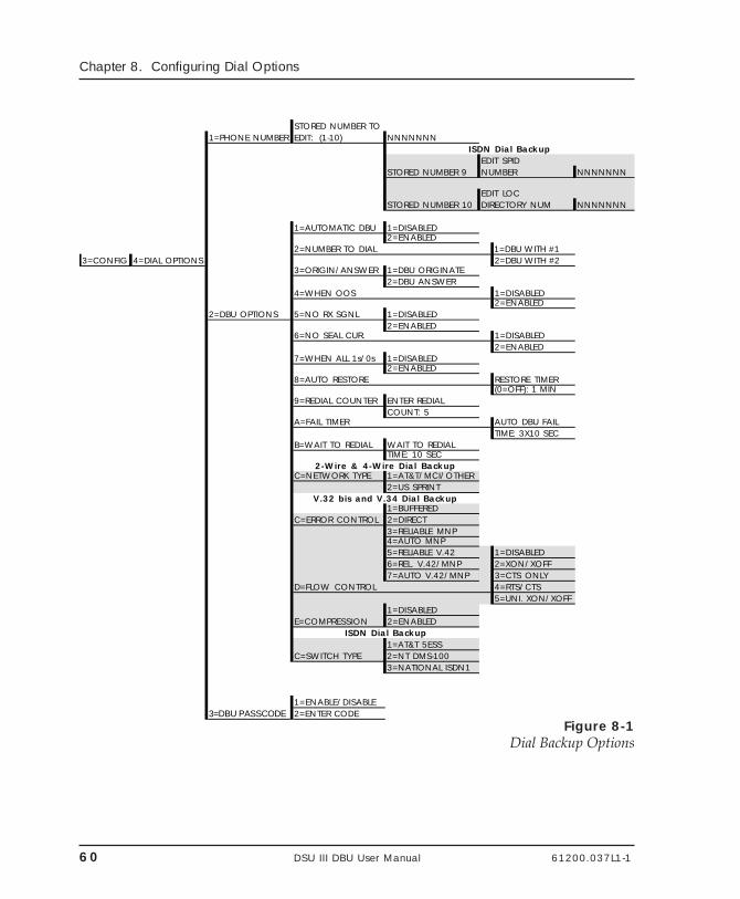
60 DSU III DBU User Manual 61200.037L1-1
Chapter 8. Configuring Dial Options
STORED NUMBER TO1=PHONE NUMBER EDIT: (1-10) NNNNNNN
ISDN Dial BackupEDIT SPID
STORED NUMBER 9 NUMBER NNNNNNN
EDIT LOCSTORED NUMBER 10 DIRECTORY NUM NNNNNNN
1=AUTOMATIC DBU 1=DISABLED2=ENABLED
2=NUMBER TO DIAL 1=DBU WITH #13=CONFIG 4=DIAL OPTIONS 2=DBU WITH #2
3=ORIGIN/ANSWER 1=DBU ORIGINATE2=DBU ANSWER
4=WHEN OOS 1=DISABLED2=ENABLED
2=DBU OPTIONS 5=NO RX SGNL 1=DISABLED2=ENABLED
6=NO SEAL CUR. 1=DISABLED2=ENABLED
7=WHEN ALL 1s/0s 1=DISABLED2=ENABLED
8=AUTO RESTORE RESTORE TIMER(0=OFF): 1 MIN
9=REDIAL COUNTER ENTER REDIALCOUNT: 5
A=FAIL TIMER AUTO DBU FAILTIME: 3X10 SEC
B=WAIT TO REDIAL WAIT TO REDIALTIME: 10 SEC
2-Wire & 4-Wire Dial BackupC=NETWORK TYPE 1=AT&T/MCI/OTHER
2=US SPRINTV.32 bis and V.34 Dial Backup
1=BUFFEREDC=ERROR CONTROL 2=DIRECT
3=RELIABLE MNP4=AUTO MNP5=RELIABLE V.42 1=DISABLED6=REL. V.42/MNP 2=XON/XOFF7=AUTO V.42/MNP 3=CTS ONLY
D=FLOW CONTROL 4=RTS/CTS5=UNI. XON/XOFF
1=DISABLEDE=COMPRESSION 2=ENABLED
ISDN Dial Backup1=AT&T 5ESS
C=SWITCH TYPE 2=NT DMS-1003=NATIONAL ISDN1
1=ENABLE/DISABLE3=DBU PASSCODE 2=ENTER CODE
Figure 8-1Dial Backup Options
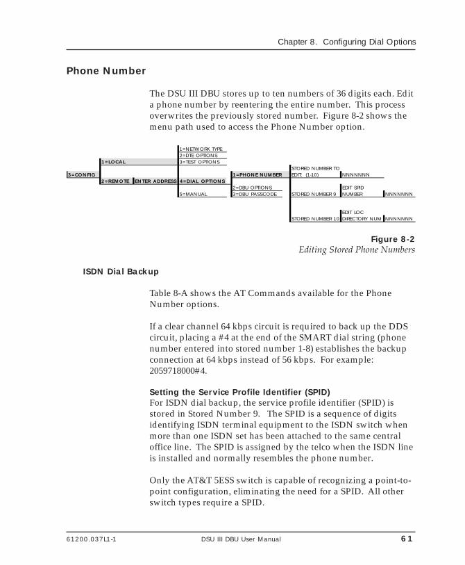
61200.037L1-1 DSU III DBU User Manual 61
Chapter 8. Configuring Dial Options
Phone Number
The DSU III DBU stores up to ten numbers of 36 digits each. Edita phone number by reentering the entire number. This processoverwrites the previously stored number. Figure 8-2 shows themenu path used to access the Phone Number option.
1=NETWORK TYPE2=DTE OPTIONS
1=LOCAL 3=TEST OPTIONSSTORED NUMBER TO
3=CONFIG 1=PHONE NUMBER EDIT: (1-10) NNNNNNN2=REMOTE ENTER ADDRESS 4=DIAL OPTIONS
2=DBU OPTIONS EDIT SPID5=MANUAL 3=DBU PASSCODE STORED NUMBER 9 NUMBER NNNNNNN
EDIT LOCSTORED NUMBER 10 DIRECTORY NUM NNNNNNN
Figure 8-2Editing Stored Phone Numbers
ISDN Dial Backup
Table 8-A shows the AT Commands available for the PhoneNumber options.
If a clear channel 64 kbps circuit is required to back up the DDScircuit, placing a #4 at the end of the SMART dial string (phonenumber entered into stored number 1-8) establishes the backupconnection at 64 kbps instead of 56 kbps. For example:2059718000#4.
Setting the Service Profile Identifier (SPID)For ISDN dial backup, the service profile identifier (SPID) isstored in Stored Number 9. The SPID is a sequence of digitsidentifying ISDN terminal equipment to the ISDN switch whenmore than one ISDN set has been attached to the same centraloffice line. The SPID is assigned by the telco when the ISDN lineis installed and normally resembles the phone number.
Only the AT&T 5ESS switch is capable of recognizing a point-to-point configuration, eliminating the need for a SPID. All otherswitch types require a SPID.
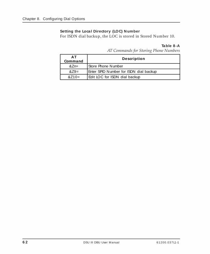
62 DSU III DBU User Manual 61200.037L1-1
Chapter 8. Configuring Dial Options
Setting the Local Directory (LOC) NumberFor ISDN dial backup, the LOC is stored in Stored Number 10.
Table 8-AAT Commands for Storing Phone Numbers
AT Command
Description
&Zn= Store Phone Number&Z9= Enter SPID Number for ISDN dial backup
&Z10= Edit LOC for ISDN dial backup
61200.037L1-1 DSU III DBU User Manual 63
Chapter 8. Configuring Dial Options
DBU Options for All Models
The DBU Options are used to select the modes of operation forthe Dial Backup features. There are ten standard options avail-able with additional options for specific backup services. Table8-B lists the DBU options and their AT commands for all models.
Automatic DBUThe Automatic DBU option specifies whether the unit automati-cally enters dial backup mode or waits for manual setup. Thefactory default setting is Disable.
Number to DialThe Number to Dial option offers a selection of stored numbersfor the unit to automatically dial. If the leased line fails, and theDSU III DBU is set to originate, it dials the numbers (in chrono-logical order) specified under this option to set up the dialbackup line. The factory default setting is Dial Stored #1.
Originate/AnswerThis option specifies whether the DSU III DBU originates orwaits to answer if the dedicated circuit fails. One end must beset to Originate and the other to Answer. The factory defaultsetting is Answer.
When Out of Service (OOS)When enabled, the DSU III DBU enters backup mode if an out-of-service condition is detected. The factory default setting isEnable.
No Receive (RX) SignalWhen enabled, the DSU III DBU enters backup mode when aloss of signal is detected. The factory default setting is Enable.
No Sealing CurrentWhen enabled, the DSU III DBU enters backup mode when aloss of sealing current is detected. The factory default setting isEnable.
64 DSU III DBU User Manual 61200.037L1-1
Chapter 8. Configuring Dial Options
When all 1s/0sWhen this option is enabled, the DSU III DBU monitors thereceive data for strings of 1s or 0s that are longer than the FailTimer. If this condition is detected, the local DSU III DBUinitiates a handshake routine with the remote unit to determineif the DTE is generating the constant data pattern or if thenetwork has failed.
Auto RestoreOnce the DDS circuit is restored, the DSU III DBU remains inbackup until the DDS circuit is active for the length of timespecified for the restore timer. The selection is entered in min-utes (up to 255). If set to 0, the DDS must be restored manually.The factory default setting is 1 minute.
RESTORE TIMER(0=OFF) __ __ MIN
Redial CounterThis option sets the number of times the DSU III DBU redials thefar end when entering backup mode. The redial count, which ismanually entered, can be up to a maximum of 99 attempts. If theDSU III DBU encounters a busy or reorder, it attempts to estab-lish the call the specified number of times. The factory defaultsetting is 5.
ENTER REDIALCOUNT: __ __
Fail TimerThis option sets the amount of time the dedicated circuit failurecondition must be active before the DSU III DBU attemptsbackup. The amount of time, which is manually entered, can beup to a maximum of 99 seconds. The factory default setting is 3seconds.
AUTO DBU FAILTIME: __ __ SEC
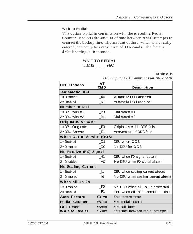
61200.037L1-1 DSU III DBU User Manual 65
Chapter 8. Configuring Dial Options
Wait to RedialThis option works in conjunction with the preceding RedialCounter. It selects the amount of time between redial attempts toconnect the backup line. The amount of time, which is manuallyentered, can be up to a maximum of 99 seconds. The factorydefault setting is 10 seconds.
WAIT TO REDIALTIME: __ __ SEC
Table 8-BDBU Options AT Commands for All Models
DBU Options AT CMD Description
Automatic DBU1=Disabled _K0 Automatic DBU disabled2=Enabled _K1 Automatic DBU enabledNumber to Dial1=DBU with #1 _B0 Dial stored #12=DBU with #2 _B1 Dial stored #2Originate/Answer1=DBU Originate _E0 Originates call if DDS fails2=DBU Answer _E1 Answers call if DDS failsWhen Out of Service (OOS)1=Enabled _G1 DBU when OOS2=Disabled _G0 No DBU for OOSNo Receive (RX) Signal1=Enabled _H1 DBU when RX signal absent2=Disabled _H0 No DBU when RX signal absentNo Sealing Current1=Enabled _I1 DBU when sealing current absent2=Disabled _I0 No DBU when sealing current absentWhen all 1s/0s1=Disabled _P0 No DBU when all 1s/0s detetected2=Enabled _P1 DBU when all 1s/0s condition existsAuto Restore S31=x Sets restore timerRedial Counter S57=x Sets redial counterFail Timer S58=x Sets fail timerWait to Redial S59=x Sets time between redial attempts
66 DSU III DBU User Manual 61200.037L1-1
Chapter 8. Configuring Dial Options
DBU Options for 2-wire and 4-wire
Network TypeThis option selects the company providing the switched digitalservice. When US Sprint is selected, an automatic echo cancelersuppressor tone is emitted by the DSU III DBU when dialing.Options include: AT&T/MCI/Other and US Sprint.
DBU Options for V.32 bis and V.34
Table 8-C shows the equivalent AT commands for setting ErrorControl, Flow Control , and Compression options.
Error ControlThis option determines the type of error control to be negotiatedat the start of a V.32 bis or V.34 modem connection. The factorydefault setting is AUTO V.42/MNP.
Flow ControlThis option is used to select the type of flow control used by theV.32 bis or V.34 modem. The factory default setting is CTS Only.
CompressionThis option is used to select V.42 bis data compression for V.32bis or V.34 operation when running asynchronously. Whenenabled, data throughput speeds as high as 57.6 kbps may beachieved. For synchronous applications, the speed is limited to amaximum of 14.4 kbps for the V.32 and 28.8 kbps for the V.34.The factory default setting is Enabled.
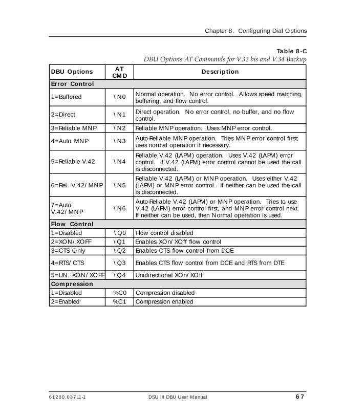
61200.037L1-1 DSU III DBU User Manual 67
Chapter 8. Configuring Dial Options
Table 8-CDBU Options AT Commands for V.32 bis and V.34 Backup
DBU Options AT CMD
Description
Error Control
1=Buffered \N0 Normal operation. No error control. Allows speed matching, buffering, and flow control.
2=Direct \N1 Direct operation. No error control, no buffer, and no flow control.
3=Reliable MNP \N2 Reliable MNP operation. Uses MNP error control.
4=Auto MNP \N3 Auto-Reliable MNP operation. Tries MNP error control first; uses normal operation if necessary.
5=Reliable V.42 \N4Reliable V.42 (LAPM) operation. Uses V.42 (LAPM) error control. If V.42 (LAPM) error control cannot be used the call is disconnected.
6=Rel. V.42/MNP \N5Reliable V.42 (LAPM) or MNP operation. Uses either V.42 (LAPM) or MNP error control. If neither can be used the call is disconnected.
7=Auto V.42/MNP \N6
Auto-Reliable V.42 (LAPM) or MNP operation. Tries to use V.42 (LAPM) error control first, and MNP error control next. If neither can be used, then Normal operation is used.
Flow Control 1=Disabled \Q0 Flow control disabled2=XON/XOFF \Q1 Enables XOn/XOff flow control3=CTS Only \Q2 Enables CTS flow control from DCE
4=RTS/CTS \Q3 Enables CTS flow control from DCE and RTS from DTE
5=UN. XON/XOFF \Q4 Unidirectional XOn/XOff Compression1=Disabled %C0 Compression disabled2=Enabled %C1 Compression enabled
68 DSU III DBU User Manual 61200.037L1-1
Chapter 8. Configuring Dial Options
DBU Options for ISDN
Switch TypeThis option selects the type of telco CO switch providing theISDN service. There are three options for ISDN switch types:
• AT&T 5ESS• NT DMS-100• National ISDN1
DBU Passcode
The dial backup passcode adds an additional level of security tothe DSU III DBU. A passcode of one to ten characters can beprogrammed into the unit.
When a dial backup connection is established, the originate unittransmits a pre-programmed passcode to the answer unit overthe dial backup connection before the connection is consideredvalid. The answer unit compares the received passcode to a pre-programmed passcode. If the passcode matches, the receive unitsends a Passcode OK message to the originate unit and goes on-line. If the passcode does not match, the receive unit sends anInvalid Passcode message to the originate unit and terminatesthe dial backup connection. If a passcode is not received by ananswer unit with passcode enable, or if the Passcode OKmessage is not received by an originate unit with passcodeenable, the dial backup connection is terminated.
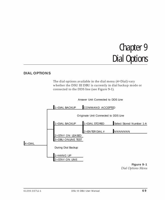
61200.037L1-1 DSU III DBU User Manual 69
Chapter 9. Dial Options
Chapter 9Dial Options
DIAL OPTIONS
The dial options available in the dial menu (4=Dial) varywhether the DSU III DBU is currently in dial backup mode orconnected to the DDS line (see Figure 9-1).
Answer Unit Connected to DDS Line
1=DIAL BACKUP COMMAND ACCEPTED
Originate Unit Connected to DDS Line
1=DIAL BACKUP 1=DIAL STORED Select Stored Number 1-A
2=ENTER DIAL # NNNNNNN2=STAY ON LEASED3=DBU ONLINE TEST
4=DIALDuring Dial Backup
1=HANG UP2=STAY ON LINE
Figure 9-1Dial Options Menu
70 DSU III DBU User Manual 61200.037L1-1
Chapter 9. Dial Options
Answer Unit Connected to DDS Line
Dial BackupThe message COMMAND ACCEPTED is displayed and theDSU III DBU waits for an incoming call. When an incoming callis detected the DSU III DBU answers the call and enters dialbackup.
Originate Unit Connected to DDS Line
Dial BackupThe DSU III DBU prompts to dial a stored number or enter anumber to dial for dial backup.
Stay on LeasedThe DSU III DBU remains on the leased line and does not enterdial backup mode.
DBU Online TestThis option allows the dial backup connection to be testedmanually without interrupting the data on the DDS. A stored ormanually entered number can be used.
DBU Answer Test must be enabled on the far end to perform a DBUon-line test.
Dial Options During Dial Backup
Hang UpTerminates the dial backup connection and attempts to reestab-lish communication on the DDS line.
Stay On LineThis DSU III DBU remains in dial backup mode and returns tothe Main menu.
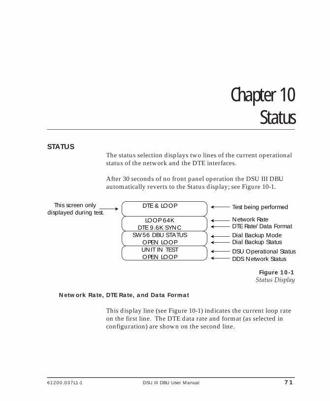
61200.037L1-1 DSU III DBU User Manual 71
Chapter 10. Status
Chapter 10Status
STATUSThe status selection displays two lines of the current operationalstatus of the network and the DTE interfaces.
After 30 seconds of no front panel operation the DSU III DBUautomatically reverts to the Status display; see Figure 10-1.
1
1
1
1
DTE & LOOP
LOOP 64KDTE 9.6K SYNC
SW56 DBU STATUSOPEN LOOPUNIT IN TESTOPEN LOOP
Test being performed
Network RateDTE Rate/Data FormatDial Backup ModeDial Backup StatusDSU Operational StatusDDS Network Status
This screen only displayed during test.
Figure 10-1Status Display
Network Rate, DTE Rate, and Data Format
This display line (see Figure 10-1) indicates the current loop rateon the first line. The DTE data rate and format (as selected inconfiguration) are shown on the second line.
72 DSU III DBU User Manual 61200.037L1-1
Chapter 10. Status
Dial Backup Information
Type of Dial Backup ServiceThis display line (see Figure 10-1) indicates the type of dialbackup service installed in the DSU III DBU. The followingmessages are displayed according to the dial backup optioninstalled in the DSU III DBU:
DU DBU Status 2-wire Switched 56 backup option in-stalled.
ISDN DBU Status 1 B+D Basic Rate ISDN backup optioninstalled.
SW56 DBU Status 4-wire Switched 56 backup optioninstalled.
V.32 DBU Status V.32 backup option installed.
V.34 DBU Status V.34 backup option installed.
DBU Status No backup service option card installed Not Installed in the DSU III DBU unit.
Current Status of Dial Backup ModeThis display line (see Figure 10-1) indicates the backup servicestatus. Possible messages include the following:
Answering Call The DSU III DBU detected an incomingcall message and is initiating call setupprocedure.
Call Disconnect Call disconnect message received fromthe remote end.
61200.037L1-1 DSU III DBU User Manual 73
Chapter 10. Status
Called Unit Busy The unit called is currently busy andcannot be connected (ISDN only).
Dialing The unit is dialing the selected number.
Going to DBU The DSU III DBU is entering dial backupmode.
Idle Messages are not being transmitted butthe service is immediately available foruse.
Incoming Call Incoming call messages being received.
In Dial Backup The DSU III DBU is currently in dialbackup mode.
No RX Signal Sealing current detected but no datasignal received from telco.
No wink from CO Switched 56 provider encountered aservice problem (4-Wire SW56 only).
Not Installed No dial backup option installed in theDSU III DBU.
OOS/OOF From Net Out-of-service signal or out-of-framecondition exists. The call cannot becompleted because the called terminal orthe called terminal's access line is out ofservice or is faulty (2-wire and 4-wireSW56 only).
Open Loop The physical connection to the backupline has been broken (2-wire and 4-wireSW56 only).
DBU Line in RDL Remote end initiated a test.
74 DSU III DBU User Manual 61200.037L1-1
Chapter 10. Status
Test From Telco The network provider has activated theCSU loopback (2-wire and 4-wire SW56only).
DBU Test Pattern The DSU III DBU is currently performinga test with a pattern.
Waiting for Call The originating DSU III DBU is waitingon a call from the remote end.
DSU Operation and Network Status
Current DSU III DBU StatusThis display line (see Figure 10-1) indicates current DSU III DBUstatus. Possible messages are:
Data Mode In data mode, the data set ready (SR) andrequest to send (RTS) circuits are on, andthe DSU III DBU is ready to send data.
Unit in Test The DSU III DBU is currently in testmode, use the Arrows to scroll throughthe menus to display the type of testbeing performed.
Current DDS Network StatusThis display line (see Figure 10-1) displays the status of the maintelco line. For normal operation this should display LOOP ISNORMAL, other possible messages are described as follows:
Answering Call The DSU III DBU detects an incomingcall.
Check Telco The transmit and receive (Tx/Rx) pairs ofthe loop connection are reversed. Thepairs should be swapped for normaloperation.
Going To DBU This message is displayed briefly whileswitching from the dedicated service todial backup mode.
61200.037L1-1 DSU III DBU User Manual 75
Chapter 10. Status
In Dial Backup The DSU is in dial backup mode.
LL Test From Telco An LL test has been initiated from thetelco.
Loop is Normal The DSU is connected to the dedicatedline.
OOS/OOF The telco is transmitting an out-of-servicecode.
Open Loop The DDS physical connection has beenbroken.
Waiting for Call The DBU module is waiting for a call.
DTE Control Leads and Status
Four additional DTE interface leads are displayed with theircurrent status (on or off) displayed below. The leads are identi-fied as follows:
TR - Data terminal readySR - Data set readyLLB - Local loopbackRLB - Remote loopback.

76 DSU III DBU User Manual 61200.037L1-1
Chapter 10. Status
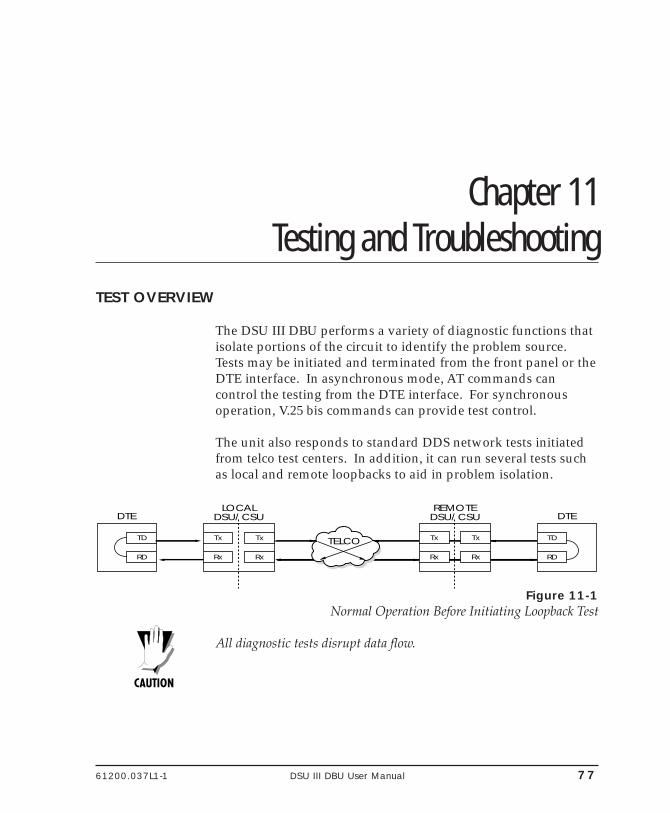
61200.037L1-1 DSU III DBU User Manual 77
Chapter 11. Testing and Troubleshooting
Chapter 11Testing and Troubleshooting
TEST OVERVIEW
The DSU III DBU performs a variety of diagnostic functions thatisolate portions of the circuit to identify the problem source.Tests may be initiated and terminated from the front panel or theDTE interface. In asynchronous mode, AT commands cancontrol the testing from the DTE interface. For synchronousoperation, V.25 bis commands can provide test control.
The unit also responds to standard DDS network tests initiatedfrom telco test centers. In addition, it can run several tests suchas local and remote loopbacks to aid in problem isolation.
LOCALDSU/CSU
REMOTEDSU/CSUDTE DTE
RD
TD
Rx
Tx
Rx
Tx
Rx
Tx
Rx
Tx
RD
TD TELCO
Figure 11-1Normal Operation Before Initiating Loopback Test
All diagnostic tests disrupt data flow.
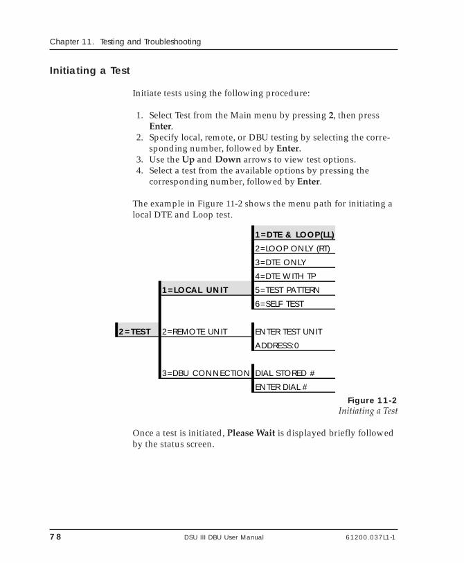
78 DSU III DBU User Manual 61200.037L1-1
Chapter 11. Testing and Troubleshooting
Initiating a Test
Initiate tests using the following procedure:
1. Select Test from the Main menu by pressing 2, then pressEnter.
2. Specify local, remote, or DBU testing by selecting the corre-sponding number, followed by Enter.
3. Use the Up and Down arrows to view test options.4. Select a test from the available options by pressing the
corresponding number, followed by Enter.
The example in Figure 11-2 shows the menu path for initiating alocal DTE and Loop test.
1=DTE & LOOP(LL)
2=LOOP ONLY (RT)
3=DTE ONLY
4=DTE WITH TP
1=LOCAL UNIT 5=TEST PATTERN
6=SELF TEST
2=TEST 2=REMOTE UNIT ENTER TEST UNIT
ADDRESS:0
3=DBU CONNECTION DIAL STORED #
ENTER DIAL #Figure 11-2
Initiating a Test
Once a test is initiated, Please Wait is displayed briefly followedby the status screen.
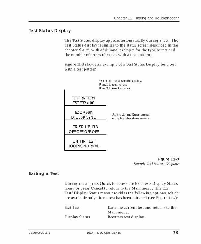
61200.037L1-1 DSU III DBU User Manual 79
Chapter 11. Testing and Troubleshooting
Test Status Display
The Test Status display appears automatically during a test. TheTest Status display is similar to the status screen described in thechapter Status, with additional prompts for the type of test andthe number of errors (for tests with a test pattern).
Figure 11-3 shows an example of a Test Status Display for a testwith a test pattern.
TEST PATTERNTST ERR = 00
LOOP 56KDTE 56K SYNC
TR SR LLB RLBOFF OFF OFF OFF
UNIT IN TESTLOOP IS NORMAL
While this menu is on the display:Press 1 to clear errors. Press 2 to inject an error.
Use the Up and Down arrows to display other status screens.
Figure 11-3Sample Test Status Displays
Exiting a Test
During a test, press Quick to access the Exit Test/Display Statusmenu or press Cancel to return to the Main menu. The ExitTest/Display Status menu provides the following options, whichare available only after a test has been initiated (see Figure 11-4):
Exit Test Exits the current test and returns to theMain menu.
Display Status Reenters test display.
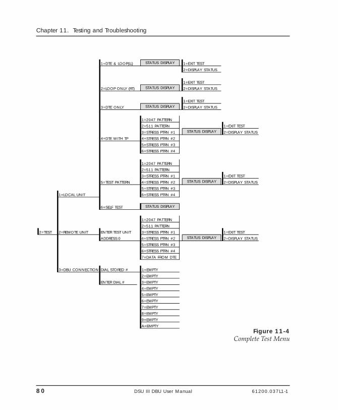
80 DSU III DBU User Manual 61200.037L1-1
Chapter 11. Testing and Troubleshooting
1=DTE & LOOP(LL) STATUS DISPLAY 1=EXIT TEST
2=DISPLAY STATUS
1=EXIT TEST
2=LOOP ONLY (RT) STATUS DISPLAY 2=DISPLAY STATUS
1=EXIT TEST
3=DTE ONLY STATUS DISPLAY 2=DISPLAY STATUS
1=2047 PATTERN
2=511 PATTERN 1=EXIT TEST
3=STRESS PTRN #1 STATUS DISPLAY 2=DISPLAY STATUS
4=DTE WITH TP 4=STRESS PTRN #2
5=STRESS PTRN #3
6=STRESS PTRN #4
1=2047 PATTERN
2=511 PATTERN
3=STRESS PTRN #1 1=EXIT TEST
5=TEST PATTERN 4=STRESS PTRN #2 STATUS DISPLAY 2=DISPLAY STATUS
5=STRESS PTRN #3
1=LOCAL UNIT 6=STRESS PTRN #4
6=SELF TEST STATUS DISPLAY
1=2047 PATTERN
2=511 PATTERN
2=TEST 2=REMOTE UNIT ENTER TEST UNIT 3=STRESS PTRN #1 1=EXIT TEST
ADDRESS:0 4=STRESS PTRN #2 STATUS DISPLAY 2=DISPLAY STATUS
5=STRESS PTRN #3
6=STRESS PTRN #4
7=DATA FROM DTE
3=DBU CONNECTION DIAL STORED # 1=EMPTY
2=EMPTY
ENTER DIAL # 3=EMPTY
4=EMPTY
5=EMPTY
6=EMPTY
7=EMPTY
8=EMPTY
9=EMPTY
A=EMPTYFigure 11-4
Complete Test Menu
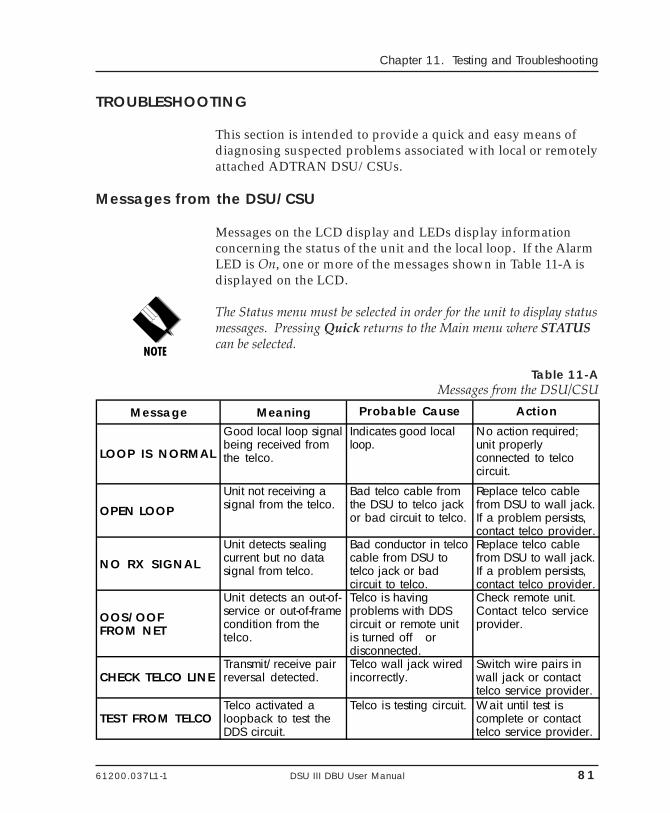
61200.037L1-1 DSU III DBU User Manual 81
Chapter 11. Testing and Troubleshooting
TROUBLESHOOTING
This section is intended to provide a quick and easy means ofdiagnosing suspected problems associated with local or remotelyattached ADTRAN DSU/CSUs.
Messages from the DSU/CSU
Messages on the LCD display and LEDs display informationconcerning the status of the unit and the local loop. If the AlarmLED is On, one or more of the messages shown in Table 11-A isdisplayed on the LCD.
The Status menu must be selected in order for the unit to display statusmessages. Pressing Quick returns to the Main menu where STATUScan be selected.
Table 11-AMessages from the DSU/CSU
Message Meaning Probable Cause Action
LOOP IS NORMAL
Good local loop signal being received from the telco.
Indicates good local loop.
No action required; unit properly connected to telco circuit.
OPEN LOOP
Unit not receiving a signal from the telco.
Bad telco cable from the DSU to telco jack or bad circuit to telco.
Replace telco cable from DSU to wall jack. If a problem persists, contact telco provider.
NO RX SIGNAL
Unit detects sealing current but no data signal from telco.
Bad conductor in telco cable from DSU to telco jack or bad circuit to telco.
Replace telco cable from DSU to wall jack. If a problem persists, contact telco provider.
OOS/OOFFROM NET
Unit detects an out-of-service or out-of-frame condition from the telco.
Telco is having problems with DDS circuit or remote unit is turned off or disconnected.
Check remote unit. Contact telco service provider.
CHECK TELCO LINETransmit/receive pair reversal detected.
Telco wall jack wired incorrectly.
Switch wire pairs in wall jack or contact telco service provider.
TEST FROM TELCOTelco activated a loopback to test the DDS circuit.
Telco is testing circuit. Wait until test is complete or contact telco service provider.
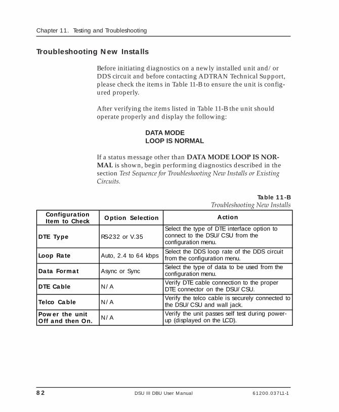
82 DSU III DBU User Manual 61200.037L1-1
Chapter 11. Testing and Troubleshooting
Troubleshooting New Installs
Before initiating diagnostics on a newly installed unit and/orDDS circuit and before contacting ADTRAN Technical Support,please check the items in Table 11-B to ensure the unit is config-ured properly.
After verifying the items listed in Table 11-B the unit shouldoperate properly and display the following:
DATA MODELOOP IS NORMAL
If a status message other than DATA MODE LOOP IS NOR-MAL is shown, begin performing diagnostics described in thesection Test Sequence for Troubleshooting New Installs or ExistingCircuits.
Table 11-BTroubleshooting New Installs
Configuration Item to Check Option Selection Action
DTE Type RS-232 or V.35Select the type of DTE interface option to connect to the DSU/CSU from the configuration menu.
Loop Rate Auto, 2.4 to 64 kbpsSelect the DDS loop rate of the DDS circuit from the configuration menu.
Data Format Async or SyncSelect the type of data to be used from the configuration menu.
DTE Cable N/AVerify DTE cable connection to the proper DTE connector on the DSU/CSU.
Telco Cable N/AVerify the telco cable is securely connected to the DSU/CSU and wall jack.
Power the unit Off and then On. N/A
Verify the unit passes self test during power-up (displayed on the LCD).
61200.037L1-1 DSU III DBU User Manual 83
Chapter 11. Testing and Troubleshooting
Test Sequence for Troubleshooting New Installs or Existing Circuits
If your DSU is suspected of having problems, perform a SelfTest to determine if the unit is in good health.
If your DSU is receiving excessive errors requiring retransmis-sion of data, first perform a DTE with Test Pattern to determineif the unit's internal transmitter and receiver is operating errorfree. If problem persists, perform a Remote Test to verify theconnection between the local and remote unit is error free. Runthe test using all available test patterns.
If an external BERT tester is available, these additional tests may beperformed:
• DTE & Loop Test• DTE Only Test• Loop Only Test
If the unit fails any of these tests or the problem has not beendetermined, contact ADTRAN Technical Support; see inside backcover.
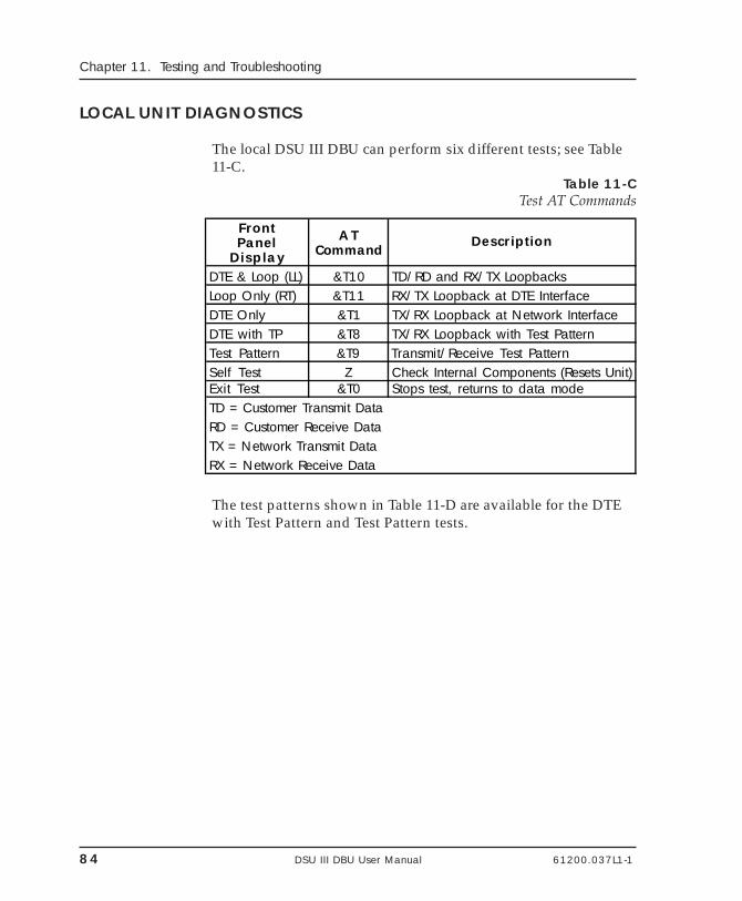
84 DSU III DBU User Manual 61200.037L1-1
Chapter 11. Testing and Troubleshooting
LOCAL UNIT DIAGNOSTICS
The local DSU III DBU can perform six different tests; see Table11-C.
Table 11-CTest AT Commands
FrontPanel
Display
ATCommand
Description
DTE & Loop (LL) &T10 TD/RD and RX/TX LoopbacksLoop Only (RT) &T11 RX/TX Loopback at DTE InterfaceDTE Only &T1 TX/RX Loopback at Network InterfaceDTE with TP &T8 TX/RX Loopback with Test PatternTest Pattern &T9 Transmit/Receive Test PatternSelf Test Z Check Internal Components (Resets Unit)Exit Test &T0 Stops test, returns to data modeTD = Customer Transmit DataRD = Customer Receive DataTX = Network Transmit DataRX = Network Receive Data
The test patterns shown in Table 11-D are available for the DTEwith Test Pattern and Test Pattern tests.
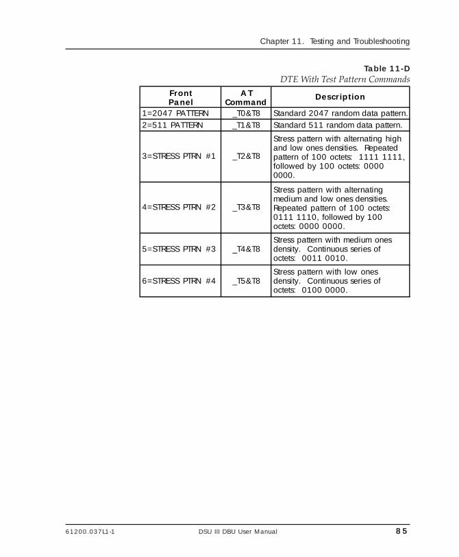
61200.037L1-1 DSU III DBU User Manual 85
Chapter 11. Testing and Troubleshooting
Table 11-DDTE With Test Pattern Commands
FrontPanel
ATCommand
Description
1=2047 PATTERN _T0&T8 Standard 2047 random data pattern.2=511 PATTERN _T1&T8 Standard 511 random data pattern.
3=STRESS PTRN #1 _T2&T8
Stress pattern with alternating high and low ones densities. Repeated pattern of 100 octets: 1111 1111, followed by 100 octets: 0000 0000.
4=STRESS PTRN #2 _T3&T8
Stress pattern with alternating medium and low ones densities. Repeated pattern of 100 octets: 0111 1110, followed by 100 octets: 0000 0000.
5=STRESS PTRN #3 _T4&T8Stress pattern with medium ones density. Continuous series of octets: 0011 0010.
6=STRESS PTRN #4 _T5&T8Stress pattern with low ones density. Continuous series of octets: 0100 0000.
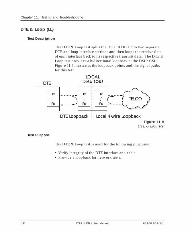
86 DSU III DBU User Manual 61200.037L1-1
Chapter 11. Testing and Troubleshooting
DTE & Loop (LL)
Test Description
The DTE & Loop test splits the DSU III DBU into two separateDTE and loop interface sections and then loops the receive dataof each interface back to its respective transmit data. The DTE &Loop test provides a bidirectional loopback at the DSU/CSU.Figure 11-5 illustrates the loopback points and the signal pathsfor this test.
LOCALDSU/CSUDTE
Rx
Tx
Rx
Tx
Rx
TxTELCO
DTE Loopback Local 4-wire LoopbackFigure 11-5
DTE & Loop Test
Test Purpose
The DTE & Loop test is used for the following purposes:
• Verify integrity of the DTE interface and cable.• Provide a loopback for network tests.
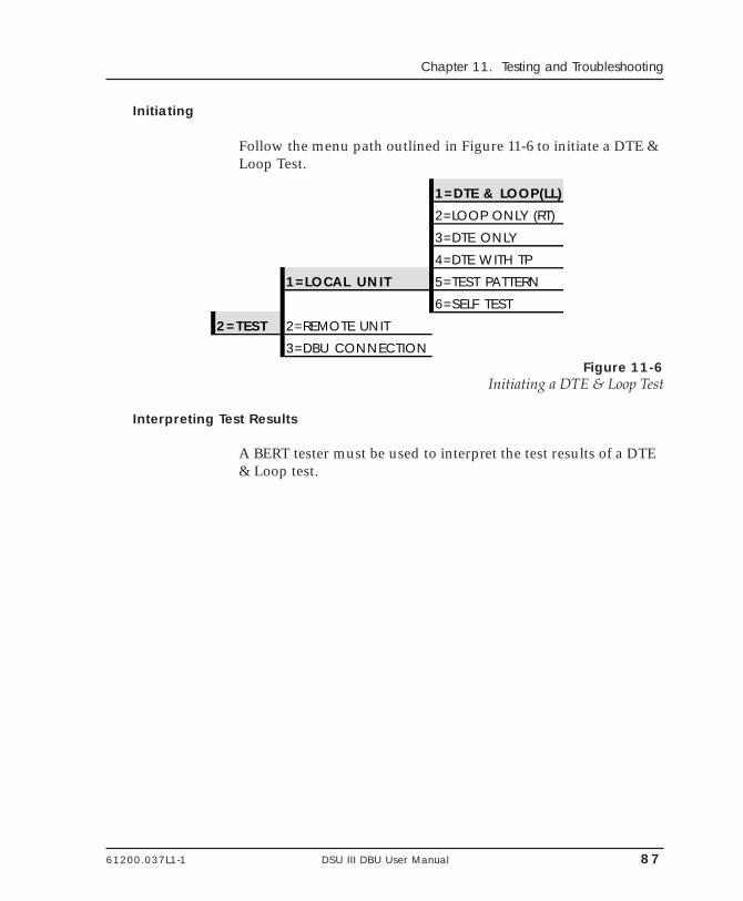
61200.037L1-1 DSU III DBU User Manual 87
Chapter 11. Testing and Troubleshooting
Initiating
Follow the menu path outlined in Figure 11-6 to initiate a DTE &Loop Test.
1=DTE & LOOP(LL)
2=LOOP ONLY (RT)
3=DTE ONLY
4=DTE WITH TP
1=LOCAL UNIT 5=TEST PATTERN
6=SELF TEST
2=TEST 2=REMOTE UNIT
3=DBU CONNECTIONFigure 11-6
Initiating a DTE & Loop Test
Interpreting Test Results
A BERT tester must be used to interpret the test results of a DTE& Loop test.
88 DSU III DBU User Manual 61200.037L1-1
Chapter 11. Testing and Troubleshooting
Loop Only (RT)
The Loop Only (RT) test allows the loop interface and a majorportion of the DTE interface for the local DSU III DBU to betested from the remote site over the actual communicationcircuit. Figure 11-7 illustrates the loopback point and the signalpaths for this test.
LOCALDSU/CSU
Rx
Tx
Rx
TxTELCO
Local 4-wire Loopback
DTEInterface
Figure 11-7Loop Only Test
Test Purpose
The Loop Only test is used to provide a loopback for networktests.
Initiating
Follow the menu path outlined in Figure 11-8 to initiate a LoopOnly test.
61200.037L1-1 DSU III DBU User Manual 89
Chapter 11. Testing and Troubleshooting
1=DTE & LOOP(LL)
2=LOOP ONLY (RT)
3=DTE ONLY
4=DTE WITH TP
1=LOCAL UNIT 5=TEST PATTERN
2=TEST 6=SELF TEST
2=REMOTE UNIT
3=DBU CONNECTIONFigure 11-8
Initiating a Loop Only TestInterpreting Test Results
The Loop Only test is used for the purpose of looping the DDScircuit back to the telco. No test results are available from thelocal DSU III DBU.
90 DSU III DBU User Manual 61200.037L1-1
Chapter 11. Testing and Troubleshooting
DTE Only
The DTE Only test provides a method for testing both the DTEinterface drivers and receivers of the local DSU III DBU plus itsloop transmitter and receiver. For this test, the loop transmitdata is connected to the loop receive data at a point close to thephysical network interface. This test can be used to verifyproper operation between the local DTE and the local DSU IIIDBU.
When this test is implemented, the far unit receives an OOS/OOFmessage from the network and enters an alarm state.
DTELOCAL
DSU/CSU
Rx
Tx
Rx
Tx
RD
TD
Figure 11-9DTE Only Test Diagram
Test Purpose
The DTE Only test is used for the following purposes:
• Verify integrity of the DTE interface.• Verify integrity of connection between DTE and DSU III DBU.
Initiating
Follow the menu path outlined in Figure 11-10 to initiate a DTEOnly test.
61200.037L1-1 DSU III DBU User Manual 91
Chapter 11. Testing and Troubleshooting
1=DTE & LOOP(LL)
2=LOOP ONLY (RT)
3=DTE ONLY
4=DTE WITH TP
1=LOCAL UNIT 5=TEST PATTERN
2=TEST 6=SELF TEST
2=REMOTE UNIT
3=DBU CONNECTION
Figure 11-10Initiating a DTE Only Test
Interpreting Test Results
A BERT tester must be used to interpret the test results of a DTEOnly test.
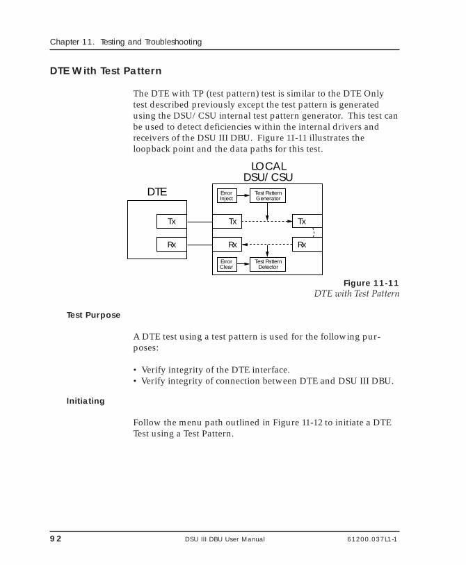
92 DSU III DBU User Manual 61200.037L1-1
Chapter 11. Testing and Troubleshooting
DTE With Test Pattern
The DTE with TP (test pattern) test is similar to the DTE Onlytest described previously except the test pattern is generatedusing the DSU/CSU internal test pattern generator. This test canbe used to detect deficiencies within the internal drivers andreceivers of the DSU III DBU. Figure 11-11 illustrates theloopback point and the data paths for this test.
DTE
LOCALDSU/CSU
Rx
Tx
Rx
Tx
Rx
Tx
Test PatternGenerator
ErrorInject
Test PatternDetector
ErrorClear
Figure 11-11DTE with Test Pattern
Test Purpose
A DTE test using a test pattern is used for the following pur-poses:
• Verify integrity of the DTE interface.• Verify integrity of connection between DTE and DSU III DBU.
Initiating
Follow the menu path outlined in Figure 11-12 to initiate a DTETest using a Test Pattern.
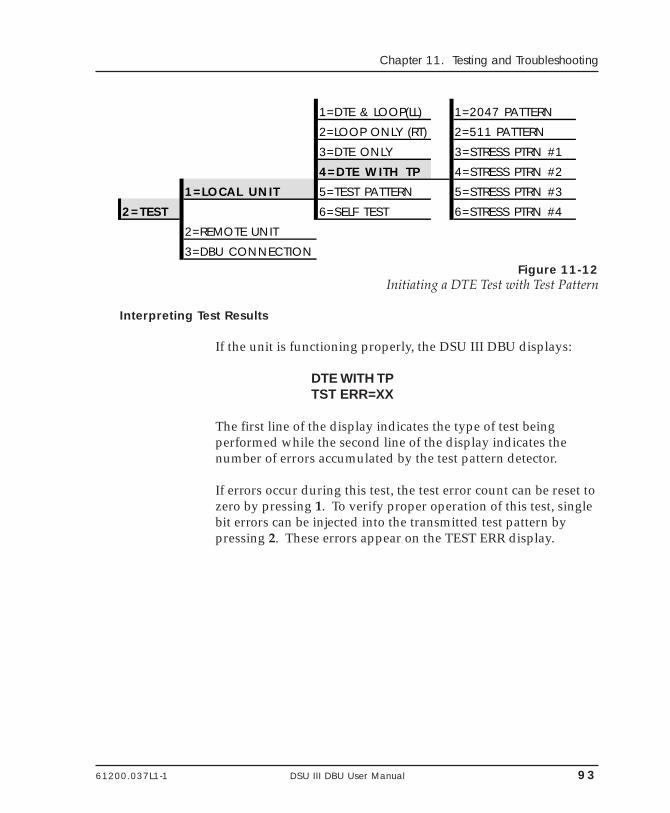
61200.037L1-1 DSU III DBU User Manual 93
Chapter 11. Testing and Troubleshooting
1=DTE & LOOP(LL) 1=2047 PATTERN
2=LOOP ONLY (RT) 2=511 PATTERN
3=DTE ONLY 3=STRESS PTRN #1
4=DTE WITH TP 4=STRESS PTRN #2
1=LOCAL UNIT 5=TEST PATTERN 5=STRESS PTRN #3
2=TEST 6=SELF TEST 6=STRESS PTRN #4
2=REMOTE UNIT
3=DBU CONNECTIONFigure 11-12
Initiating a DTE Test with Test Pattern
Interpreting Test Results
If the unit is functioning properly, the DSU III DBU displays:
DTE WITH TPTST ERR=XX
The first line of the display indicates the type of test beingperformed while the second line of the display indicates thenumber of errors accumulated by the test pattern detector.
If errors occur during this test, the test error count can be reset tozero by pressing 1. To verify proper operation of this test, singlebit errors can be injected into the transmitted test pattern bypressing 2. These errors appear on the TEST ERR display.
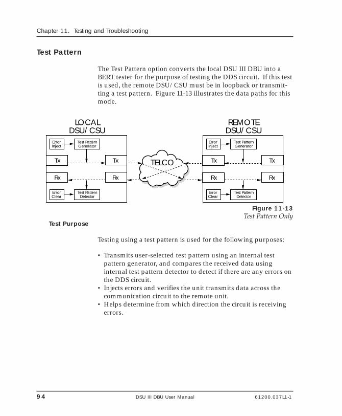
94 DSU III DBU User Manual 61200.037L1-1
Chapter 11. Testing and Troubleshooting
Test Pattern
The Test Pattern option converts the local DSU III DBU into aBERT tester for the purpose of testing the DDS circuit. If this testis used, the remote DSU/CSU must be in loopback or transmit-ting a test pattern. Figure 11-13 illustrates the data paths for thismode.
LOCALDSU/CSU
Rx
Tx
Rx
Tx TELCO
Test PatternGenerator
ErrorInject
Test PatternDetector
ErrorClear
REMOTEDSU/CSU
Rx
Tx
Rx
Tx
Test PatternGenerator
ErrorInject
Test PatternDetector
ErrorClear
Figure 11-13Test Pattern Only
Test Purpose
Testing using a test pattern is used for the following purposes:
• Transmits user-selected test pattern using an internal testpattern generator, and compares the received data usinginternal test pattern detector to detect if there are any errors onthe DDS circuit.
• Injects errors and verifies the unit transmits data across thecommunication circuit to the remote unit.
• Helps determine from which direction the circuit is receivingerrors.
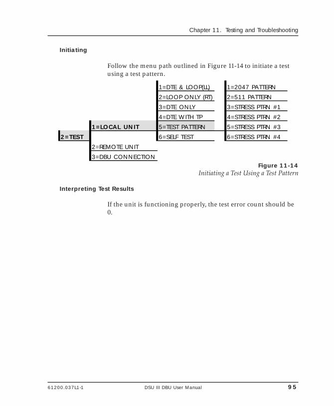
61200.037L1-1 DSU III DBU User Manual 95
Chapter 11. Testing and Troubleshooting
Initiating
Follow the menu path outlined in Figure 11-14 to initiate a testusing a test pattern.
1=DTE & LOOP(LL) 1=2047 PATTERN
2=LOOP ONLY (RT) 2=511 PATTERN
3=DTE ONLY 3=STRESS PTRN #1
4=DTE WITH TP 4=STRESS PTRN #2
1=LOCAL UNIT 5=TEST PATTERN 5=STRESS PTRN #3
2=TEST 6=SELF TEST 6=STRESS PTRN #4
2=REMOTE UNIT
3=DBU CONNECTIONFigure 11-14
Initiating a Test Using a Test Pattern
Interpreting Test Results
If the unit is functioning properly, the test error count should be0.
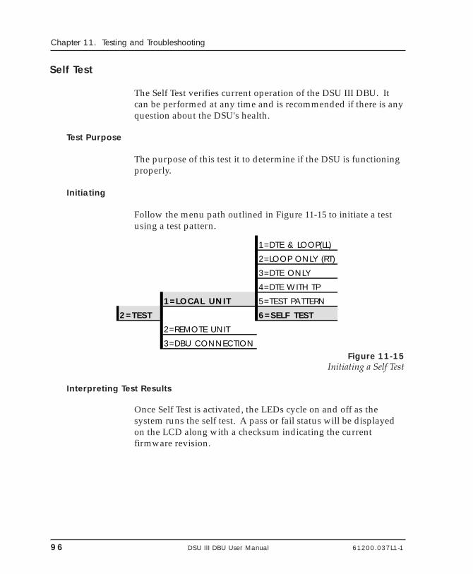
96 DSU III DBU User Manual 61200.037L1-1
Chapter 11. Testing and Troubleshooting
Self Test
The Self Test verifies current operation of the DSU III DBU. Itcan be performed at any time and is recommended if there is anyquestion about the DSU's health.
Test Purpose
The purpose of this test it to determine if the DSU is functioningproperly.
Initiating
Follow the menu path outlined in Figure 11-15 to initiate a testusing a test pattern.
1=DTE & LOOP(LL)
2=LOOP ONLY (RT)
3=DTE ONLY
4=DTE WITH TP
1=LOCAL UNIT 5=TEST PATTERN
2=TEST 6=SELF TEST
2=REMOTE UNIT
3=DBU CONNECTIONFigure 11-15
Initiating a Self Test
Interpreting Test Results
Once Self Test is activated, the LEDs cycle on and off as thesystem runs the self test. A pass or fail status will be displayedon the LCD along with a checksum indicating the currentfirmware revision.
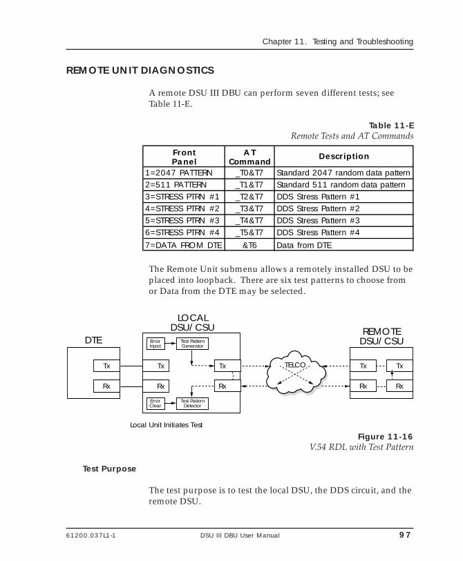
61200.037L1-1 DSU III DBU User Manual 97
Chapter 11. Testing and Troubleshooting
REMOTE UNIT DIAGNOSTICS
A remote DSU III DBU can perform seven different tests; seeTable 11-E.
Table 11-ERemote Tests and AT Commands
FrontPanel
ATCommand
Description
1=2047 PATTERN _T0&T7 Standard 2047 random data pattern2=511 PATTERN _T1&T7 Standard 511 random data pattern3=STRESS PTRN #1 _T2&T7 DDS Stress Pattern #14=STRESS PTRN #2 _T3&T7 DDS Stress Pattern #25=STRESS PTRN #3 _T4&T7 DDS Stress Pattern #36=STRESS PTRN #4 _T5&T7 DDS Stress Pattern #47=DATA FROM DTE &T6 Data from DTE
The Remote Unit submenu allows a remotely installed DSU to beplaced into loopback. There are six test patterns to choose fromor Data from the DTE may be selected.
DTE
LOCALDSU/CSU REMOTE
DSU/CSU
Rx
Tx
Rx
Tx
Local Unit Initiates Test
Rx
Tx TELCO
Test PatternGenerator
ErrorInject
Test PatternDetector
ErrorClear
Rx
Tx
Rx
Tx
Figure 11-16V.54 RDL with Test Pattern
Test Purpose
The test purpose is to test the local DSU, the DDS circuit, and theremote DSU.
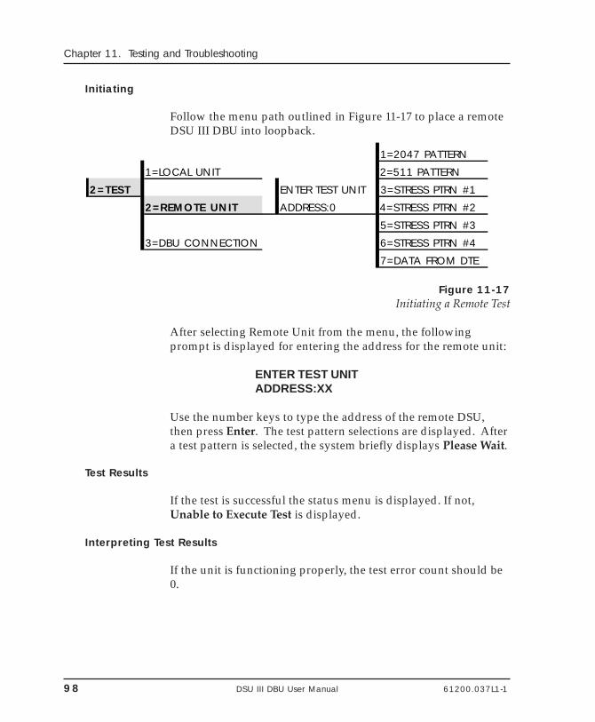
98 DSU III DBU User Manual 61200.037L1-1
Chapter 11. Testing and Troubleshooting
Initiating
Follow the menu path outlined in Figure 11-17 to place a remoteDSU III DBU into loopback.
1=2047 PATTERN
1=LOCAL UNIT 2=511 PATTERN
2=TEST ENTER TEST UNIT 3=STRESS PTRN #1
2=REMOTE UNIT ADDRESS:0 4=STRESS PTRN #2
5=STRESS PTRN #3
3=DBU CONNECTION 6=STRESS PTRN #4
7=DATA FROM DTE
Figure 11-17Initiating a Remote Test
After selecting Remote Unit from the menu, the followingprompt is displayed for entering the address for the remote unit:
ENTER TEST UNITADDRESS:XX
Use the number keys to type the address of the remote DSU,then press Enter. The test pattern selections are displayed. Aftera test pattern is selected, the system briefly displays Please Wait.
Test Results
If the test is successful the status menu is displayed. If not,Unable to Execute Test is displayed.
Interpreting Test Results
If the unit is functioning properly, the test error count should be0.
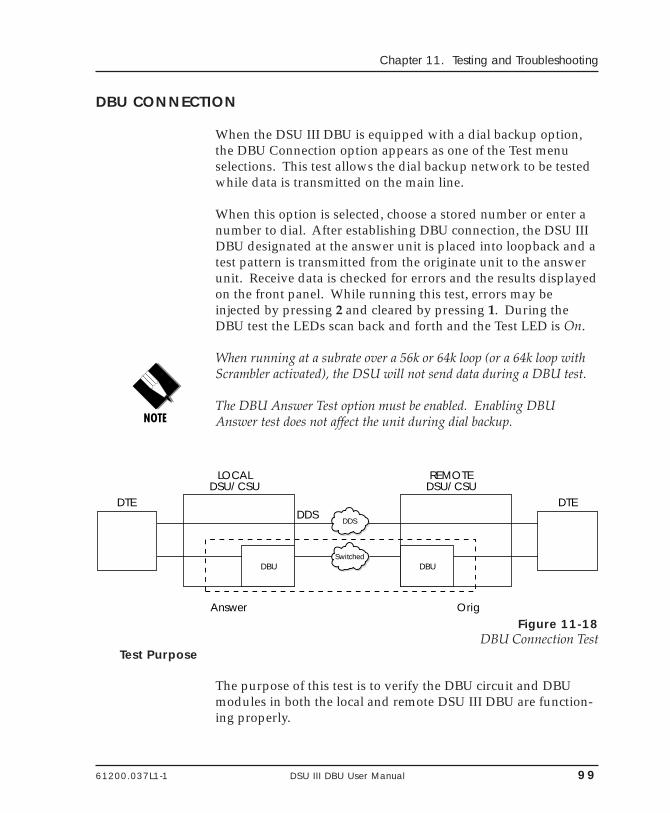
61200.037L1-1 DSU III DBU User Manual 99
Chapter 11. Testing and Troubleshooting
DBU CONNECTION
When the DSU III DBU is equipped with a dial backup option,the DBU Connection option appears as one of the Test menuselections. This test allows the dial backup network to be testedwhile data is transmitted on the main line.
When this option is selected, choose a stored number or enter anumber to dial. After establishing DBU connection, the DSU IIIDBU designated at the answer unit is placed into loopback and atest pattern is transmitted from the originate unit to the answerunit. Receive data is checked for errors and the results displayedon the front panel. While running this test, errors may beinjected by pressing 2 and cleared by pressing 1. During theDBU test the LEDs scan back and forth and the Test LED is On.
When running at a subrate over a 56k or 64k loop (or a 64k loop withScrambler activated), the DSU will not send data during a DBU test.
The DBU Answer Test option must be enabled. Enabling DBUAnswer test does not affect the unit during dial backup.
DTE
Answer Orig
DDSDTE
DBU DBU
DDS
Switched
LOCALDSU/CSU
REMOTEDSU/CSU
Figure 11-18DBU Connection Test
Test Purpose
The purpose of this test is to verify the DBU circuit and DBUmodules in both the local and remote DSU III DBU are function-ing properly.
100 DSU III DBU User Manual 61200.037L1-1
Chapter 11. Testing and Troubleshooting
Initiating
Follow the menu path outlined in Figure 11-20 to place a remoteDSU III DBU into loopback.
1=LOCAL UNIT 1=98376113
2=TEST 2=REMOTE UNIT 2=EMPTY
3=EMPTY
3=DBU CONNECTION DIAL STORED # 4=EMPTY
5=EMPTY
ENTER DIAL # 6=EMPTY
7=EMPTY
8=EMPTY
9=EMPTY
A=EMPTY
Figure 11-19Initiating a DBU Connection Test
Interpreting Test Results
If the unit is functioning properly, the DSU III DBU displays:
DBU TEST PATTERNTST ERR = 0000
61200.037L1-1 DSU III DBU User Manual 101
Chapter 12. Manual Command
Chapter 12Manual Command
MANUAL COMMAND
The Manual Command option is a shortcut method for enteringconfiguration and control commands for the DSU III DBU.
The first display prompts the user to enter the command num-ber.
COMMAND:00
Figure 12-1 shows the menu path for manual command. Theavailable manual commands are listed in Table 12-A.
102 DSU III DBU User Manual 61200.037L1-1
Chapter 12. Manual Command
1=NETWORK OPT.1=LOCAL 2=DTE OPTIONS
3=TEST OPTIONS3=CONFIG 4=DIAL OPTIONS
2=REMOTE ENTER ADDRESS COMMAND:005=MANUAL COMMAND COMMAND:00 VALUE:00
Figure 12-1Manual Command
Use the number keys to enter the hexadecimal command num-ber. Press Enter to complete. Once the command number isentered, the display shows both the command number and thepresent value or setting for the command. The command valuecan be edited or reissued with the existing value.
COMMAND: XXVALUE: 00
Use the number keys to enter the hexadecimal value. PressEnter to complete. The system briefly displays CommandAccepted and returns to the active menu.
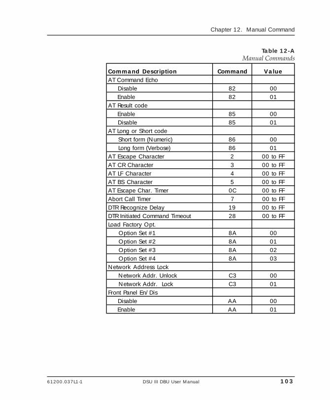
61200.037L1-1 DSU III DBU User Manual 103
Chapter 12. Manual Command
Table 12-AManual Commands
Command Description Command ValueAT Command Echo Disable 82 00 Enable 82 01AT Result code Enable 85 00 Disable 85 01AT Long or Short code Short form (Numeric) 86 00 Long form (Verbose) 86 01AT Escape Character 2 00 to FFAT CR Character 3 00 to FFAT LF Character 4 00 to FFAT BS Character 5 00 to FFAT Escape Char. Timer 0C 00 to FFAbort Call Timer 7 00 to FFDTR Recognize Delay 19 00 to FFDTR Initiated Command Timeout 28 00 to FFLoad Factory Opt. Option Set #1 8A 00 Option Set #2 8A 01 Option Set #3 8A 02 Option Set #4 8A 03Network Address Lock Network Addr. Unlock C3 00 Network Addr. Lock C3 01Front Panel En/Dis Disable AA 00 Enable AA 01

104 DSU III DBU User Manual 61200.037L1-1
Chapter 12. Manual Command
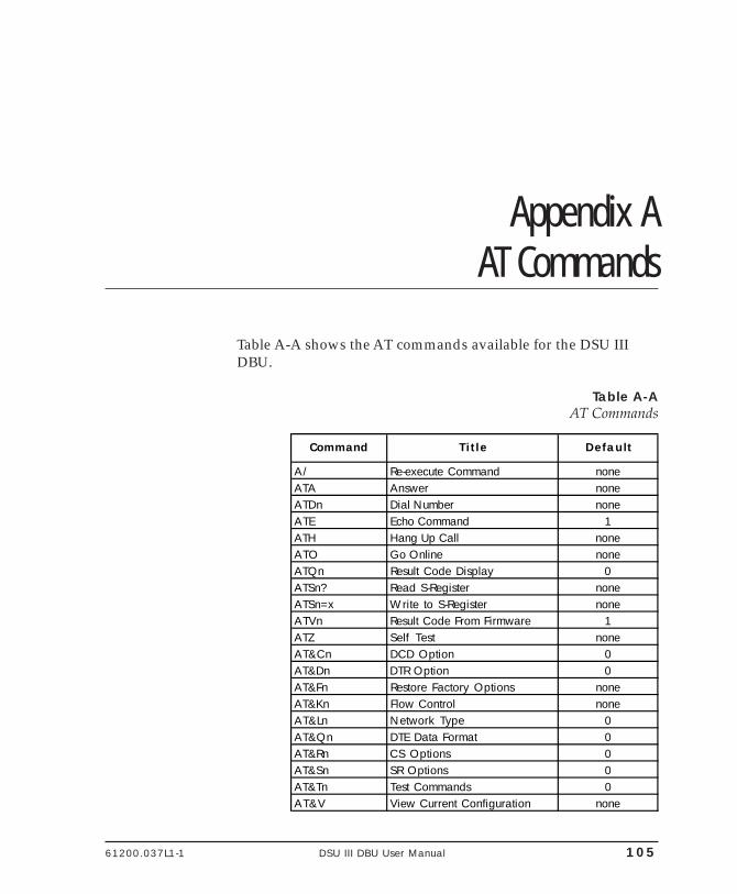
61200.037L1-1 DSU III DBU User Manual 105
Appendix A. AT Commands
Appendix AAT Commands
Table A-A shows the AT commands available for the DSU IIIDBU.
Table A-AAT Commands
Command Title Default
A/ Re-execute Command noneATA Answer noneATDn Dial Number noneATE Echo Command 1ATH Hang Up Call noneATO Go Online noneATQn Result Code Display 0ATSn? Read S-Register noneATSn=x Write to S-Register noneATVn Result Code From Firmware 1ATZ Self Test noneAT&Cn DCD Option 0AT&Dn DTR Option 0AT&Fn Restore Factory Options noneAT&Kn Flow Control noneAT&Ln Network Type 0AT&Qn DTE Data Format 0AT&Rn CS Options 0AT&Sn SR Options 0AT&Tn Test Commands 0AT&V View Current Configuration none
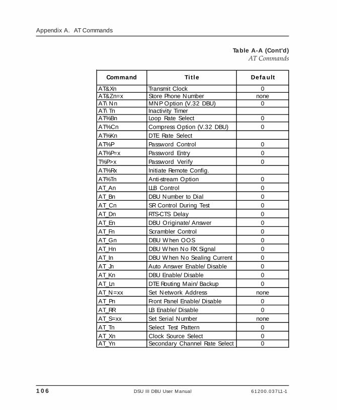
106 DSU III DBU User Manual 61200.037L1-1
Appendix A. AT Commands
Table A-A (Cont'd)AT Commands
Command Title Default
AT&Xn Transmit Clock 0AT&Zn=x Store Phone Number noneAT\Nn MNP Option (V.32 DBU) 0AT\Tn Inactivity TimerAT%Bn Loop Rate Select 0AT%Cn Compress Option (V.32 DBU) 0AT%Kn DTE Rate SelectAT%P Password Control 0AT%P=x Password Entry 0T%P>x Password Verify 0AT%Rx Initiate Remote Config.AT%Tn Anti-stream Option 0AT_An LLB Control 0AT_Bn DBU Number to Dial 0AT_Cn SR Control During Test 0AT_Dn RTS-CTS Delay 0AT_En DBU Originate/Answer 0AT_Fn Scrambler Control 0AT_Gn DBU When OOS 0AT_Hn DBU When No RX Signal 0AT_In DBU When No Sealing Current 0AT_Jn Auto Answer Enable/Disable 0AT_Kn DBU Enable/Disable 0AT_Ln DTE Routing Main/Backup 0AT_N=xx Set Network Address noneAT_Pn Front Panel Enable/Disable 0AT_RR LB Enable/Disable 0AT_S=xx Set Serial Number noneAT_Tn Select Test Pattern 0AT_Xn Clock Source Select 0AT_Yn Secondary Channel Rate Select 0
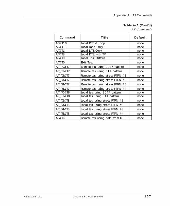
61200.037L1-1 DSU III DBU User Manual 107
Appendix A. AT Commands
Table A-A (Cont'd)AT Commands
Command Title Default
AT&T10 Local DTE & Loop noneAT&T11 Local Loop Only noneAT&T1 Local DTE Only noneAT&T8 Local DTE with TP noneAT&T9 Local Test Pattern noneAT&T0 Exit Test noneAT_T0&T7 Remote test using 2047 pattern noneAT_T1&T7 Remote test using 511 pattern noneAT_T2&T7 Remote test using stress PTRN #1 noneAT_T3&T7 Remote test using stress PTRN #2 noneAT_T4&T7 Remote test using stress PTRN #3 noneAT_T5&T7 Remote test using stress PTRN #4 noneAT_T0&T8 Local test using 2047 pattern noneAT_T1&T8 Local test using 511 pattern noneAT_T2&T8 Local test using stress PTRN #1 noneAT_T3&T8 Local test using stress PTRN #2 noneAT_T4&T8 Local test using stress PTRN #3 noneAT_T5&T8 Local test using stress PTRN #4 noneAT&T6 Remote test using data from DTE none

108 DSU III DBU User Manual 61200.037L1-1
Appendix A. AT Commands
61200.037L1-1 DSU III DBU User Manual 109
Appendix B. Default Configuration Profiles
Appendix BDefault Configuration Profiles
The DSU III DBU contains four different user profiles (sets ofconfigurations options) stored in read-only memory; see Table B-A. The unit is shipped from the factory with profile 1 loadedinto the nonvolatile configuration memory. See the chaptersInstallation and Manual Command for more information.
Profile 1Profile 1 is configured for a 56 kbps, synchronous, point-to-pointor dial-up operation with a V.35 connector. Automatic DBU hasbeen disabled for this configuration profile.
Profile 2Use profile 2 for a 56 kbps, asynchronous, point-to-point or dial-up operation, with an EIA-232 connector. Automatic DBU hasbeen disabled for this configuration profile.
Profiles 3 and 4Profiles 3 and 4 are used for enabling dial backup using twoDSU III DBU units. One unit must be set for Answer and theother for Originate. Use profile 3 to set the remote unit toAnswer and profile 4 to set the host unit to Originate.
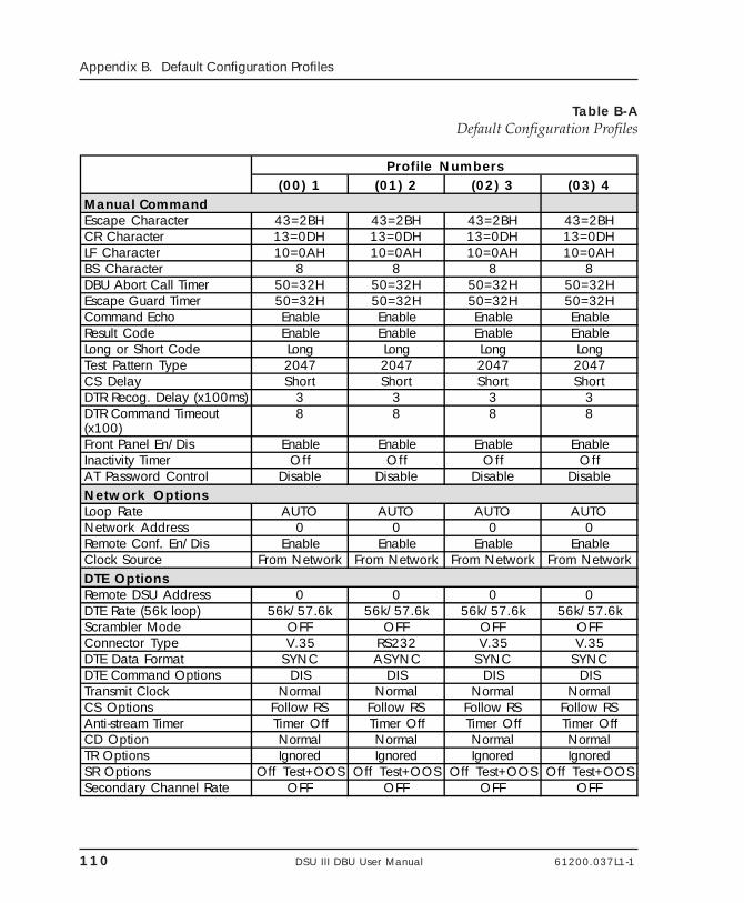
110 DSU III DBU User Manual 61200.037L1-1
Appendix B. Default Configuration Profiles
Table B-ADefault Configuration Profiles
Profile Numbers(00) 1 (01) 2 (02) 3 (03) 4
Manual CommandEscape Character 43=2BH 43=2BH 43=2BH 43=2BHCR Character 13=0DH 13=0DH 13=0DH 13=0DHLF Character 10=0AH 10=0AH 10=0AH 10=0AHBS Character 8 8 8 8DBU Abort Call Timer 50=32H 50=32H 50=32H 50=32HEscape Guard Timer 50=32H 50=32H 50=32H 50=32HCommand Echo Enable Enable Enable EnableResult Code Enable Enable Enable EnableLong or Short Code Long Long Long LongTest Pattern Type 2047 2047 2047 2047CS Delay Short Short Short ShortDTR Recog. Delay (x100ms) 3 3 3 3DTR Command Timeout (x100)
8 8 8 8
Front Panel En/Dis Enable Enable Enable EnableInactivity Timer Off Off Off OffAT Password Control Disable Disable Disable DisableNetwork OptionsLoop Rate AUTO AUTO AUTO AUTONetwork Address 0 0 0 0Remote Conf. En/Dis Enable Enable Enable EnableClock Source From Network From Network From Network From NetworkDTE OptionsRemote DSU Address 0 0 0 0DTE Rate (56k loop) 56k/57.6k 56k/57.6k 56k/57.6k 56k/57.6kScrambler Mode OFF OFF OFF OFFConnector Type V.35 RS232 V.35 V.35DTE Data Format SYNC ASYNC SYNC SYNCDTE Command Options DIS DIS DIS DISTransmit Clock Normal Normal Normal NormalCS Options Follow RS Follow RS Follow RS Follow RSAnti-stream Timer Timer Off Timer Off Timer Off Timer OffCD Option Normal Normal Normal NormalTR Options Ignored Ignored Ignored IgnoredSR Options Off Test+OOS Off Test+OOS Off Test+OOS Off Test+OOSSecondary Channel Rate OFF OFF OFF OFF
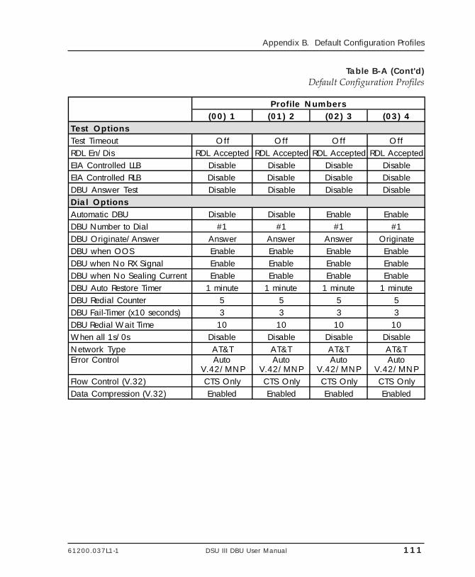
61200.037L1-1 DSU III DBU User Manual 111
Appendix B. Default Configuration Profiles
Table B-A (Cont'd)Default Configuration Profiles
Profile Numbers(00) 1 (01) 2 (02) 3 (03) 4
Test OptionsTest Timeout Off Off Off OffRDL En/Dis RDL Accepted RDL Accepted RDL Accepted RDL AcceptedEIA Controlled LLB Disable Disable Disable DisableEIA Controlled RLB Disable Disable Disable DisableDBU Answer Test Disable Disable Disable DisableDial OptionsAutomatic DBU Disable Disable Enable EnableDBU Number to Dial #1 #1 #1 #1DBU Originate/Answer Answer Answer Answer OriginateDBU when OOS Enable Enable Enable EnableDBU when No RX Signal Enable Enable Enable EnableDBU when No Sealing Current Enable Enable Enable EnableDBU Auto Restore Timer 1 minute 1 minute 1 minute 1 minuteDBU Redial Counter 5 5 5 5DBU Fail-Timer (x10 seconds) 3 3 3 3DBU Redial Wait Time 10 10 10 10When all 1s/0s Disable Disable Disable DisableNetwork Type AT&T AT&T AT&T AT&TError Control Auto
V.42/MNPAuto
V.42/MNPAuto
V.42/MNPAuto
V.42/MNPFlow Control (V.32) CTS Only CTS Only CTS Only CTS OnlyData Compression (V.32) Enabled Enabled Enabled Enabled
112 DSU III DBU User Manual 61200.037L1-1
Appendix B. Default Configuration Profiles
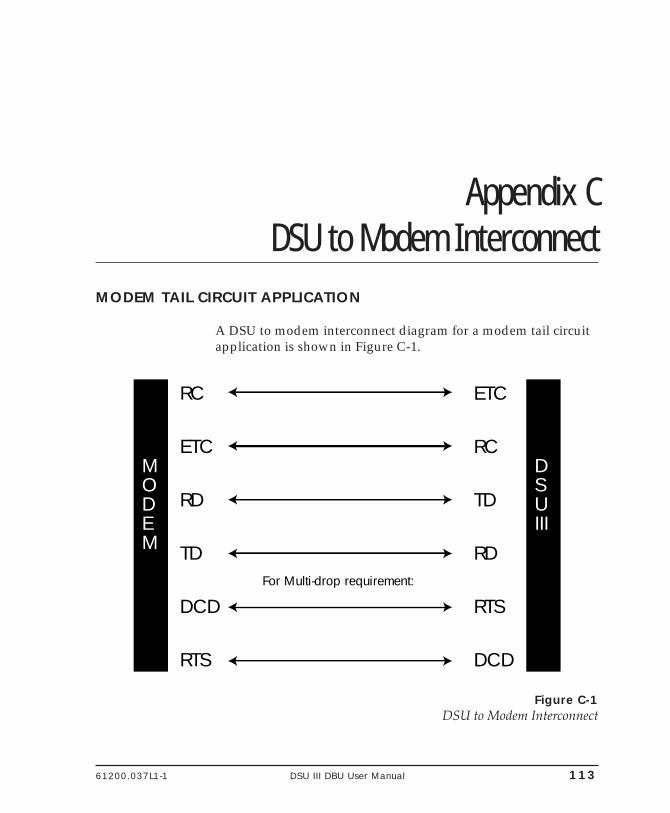
61200.037L1-1 DSU III DBU User Manual 113
Appendix C. DSU to Modem Interconnect
Appendix CDSU to Modem Interconnect
MODEM TAIL CIRCUIT APPLICATION
A DSU to modem interconnect diagram for a modem tail circuitapplication is shown in Figure C-1.
MODEM
DSUIII
RC
ETC
RD
TD
DCD
RTS
ETC
RC
TD
RD
RTS
DCD
For Multi-drop requirement:
Figure C-1DSU to Modem Interconnect

114 DSU III DBU User Manual 61200.037L1-1
Appendix C. DSU to Modem Interconnect
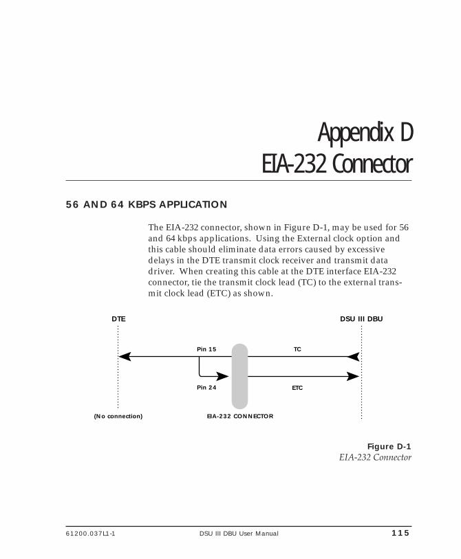
61200.037L1-1 DSU III DBU User Manual 115
Appendix D. EIA -232 Connector
Appendix DEIA-232 Connector
56 AND 64 KBPS APPLICATION
The EIA-232 connector, shown in Figure D-1, may be used for 56and 64 kbps applications. Using the External clock option andthis cable should eliminate data errors caused by excessivedelays in the DTE transmit clock receiver and transmit datadriver. When creating this cable at the DTE interface EIA-232connector, tie the transmit clock lead (TC) to the external trans-mit clock lead (ETC) as shown.
EIA-232 CONNECTOR
Pin 15
Pin 24
TC
ETC
(No connection)
DSU III DBUDTE
Figure D-1EIA-232 Connector

116 DSU III DBU User Manual 61200.037L1-1
Appendix D. EIA-232 Connector
61200.037L1-1 DSU III DBU User Manual 117
Appendix E. Specifications Summary
Appendix ESpecifications Summary
SPECIFICATIONS AND FEATURES
This section describes the standard specifications and featuresincorporated in the DSU III DBU.
Operating ModesDedicated DDS: Point-to-point and multipointSwitched Backup: (Automatic or manual) 4-wire Switched 56, 2-wire Switched 56, V.32 bis/V.42 bis, or ISDN (1B+D)
Data RatesDedicated mode service rates: 2.4, 4.8, 9.6, 19.2, 38.4, 56, and 64kbpsSwitched mode service rate: 56 kbps and 64 kbps
DTE Rates DTE-to-loop rate matching in both dedicated and switchedmodesSynchronous rates: 2.4, 4.8, 9.6, 19.2, 38.4, 56, and 64Asynchronous rates: 2.4, 4.8, 9.6, 19.2, 38.4, and 57.6 kbps
DTE Interface Data RatesV.35 and EIA-232: up to 57.6 kbps async, up to 64 kbps sync
FCC ApprovalFCC part 15, class A and Part 68
118 DSU III DBU User Manual 61200.037L1-1
Appendix E. Specifications Summary
DTE InterfacesBoth EIA-232 and V.35 electrical and physical DTE interfaces
Data BufferingInternal slack buffer
ClockingNormal DDS or private network tributary(slaved to network receive clock)Private network master (internal clock)Private network master (slaved to external clock)
DiagnosticsNetwork: CSU and DSU loopbacksUser: Local DTE and loop, remote V.54Test Patterns: 2047, 511, DDS, and stress patterns 1-4
Line RequirementsLoop transmission parameters as defined in:
AT&T PUB 62310: Dedicated DDSAT&T PUB 41468: Switched 56SPRINT TS 0046: Switched 56
Line InterfaceRJ-48S, 4-wire, full duplexBackup as applicable
Receiver Sensitivity-45dB at all rates
EnvironmentOperating Temperature: 0OC to 50OC (32OF to 122OF)Storage Temperature: -20OC to 70OC (-4OF to 158OF)
PhysicalRelative Humidity: Up to 95%, non-condensingDimensions: 2.25"H, 8.75"W, 10.25"DWeight: 3 lbs
Power115 VAC, 60 Hz, 8 W
61200.037L1-1 DSU III DBU User Manual 119
Glossary
Glossary2047
A pseudorandom test pattern that is repeated every 2047 bits; used to test DSU/CSUs.
511A pseudorandom test pattern that is repeated every 511 bits; used to test DSU/CSUs.
2-Wire Switched 56A Northern Telecom proprietary 56 kbps switched digital data service offered bytelco service providers and delivered to users over a single pair of copper wires.
4-Wire Switched 56An AT&T proprietary 56/64 kbps switched digital data service offered by telcoservice providers and delivered to users over four copper wires.
AT&T Publication 41458An AT&T specification titled "Special Access Connections to the AT&TCommunications Network," used to design compatibility into DSU/CSUproducts.
AT&T Publication 62310An AT&T specification titled "Digital Data System Channel InterfaceSpecification," used to design compatibility in DSU/CSU products.
BERTBit error rate test. A known pattern of bits is transmitted and the errors receivedare counted to figure the bit error rate. The idea is to measure the quality of data
120 DSU III DBU User Manual 61200.037L1-1
Glossary
transmission. The bit error rate is the ratio of received bits that are in error,relative to the number of bits received. Usually expressed in a power of 10.
CDCarrier Detect. A signal generated by a modem or DSU/CSU. CD indicates itsconnection status. If the CD light is on, the device is speaking to another device.
channel service unitCSU. A DCE device used to connect a digital phone line (T1 or Switched 56 line)coming in from the phone company to either a multiplexer, a channel bank, ordirectly to another device producing a digital signal (for example a digital PBX, aPC, or data communications device). A CSU performs certain line-conditioningand equalization functions, and responds to loopback commands sent from thecentral office. A CSU regenerates digital signals. It monitors them for problems,and provides a way of testing the digital circuit.
clockingAn oscillator-generated signal that provides a timing reference for a transmissionlink. A clock provides signals used in a transmission system to control the timingof certain functions. The clock has two functions: (1) to generate periodic signalsfor synchronization and (2) to provide a time base.
control portAn interface to a device or system that allows users to issue commandspertaining to dialing, configuration, diagnostics, management, etc.
CPECustomer premise equipment. All telecommunications terminal equipmentlocated on the customer premises, including telephone sets, private branchexchanges (PBXs), data terminals, and customer-owned coin-operatedtelephones.
CSSee CTS.
CSUSee Channel Service Unit.
61200.037L1-1 DSU III DBU User Manual 121
Glossary
CSU loopbackA telco initiated test which loops the CSU portion of the DSU/CSU back to thetelco and allows the telco to test the DDS circuit as well as the CSU portion of thecustomer's DSU/CSU.
CTSClear to send. A signal on the DTE interface indicating that the DCE is clear tosend data. Sometimes referred to as CS.
data compressionA technique for encoding information so that fewer data bits are required torepresent a given amount of data. Compression facilitates the transmission ofmore data for a given amount of transmission time and circuit capacity. It alsoreduces the amount of memory required for data storage.
data service unitDSU. A device designed to transmit and receive digital data on digitaltransmission facilities.
DDSDataphone Digital Service also called Digital Data System. A private line digitalservice for transmitting data end-to-end at speeds of 2.4, 4.8, 9.6, and 56 kbps andin some cases 19.2, 38.4, or 64 kbps. The systems can use central hub offices forobtaining test access, bridging legs of multipoint circuits, and cross connectingequipment. DDS is offered on an inter-LATA basis by AT&T and on an intra-LATA basis by the Bell operating companies.
DDS Stress Patterns 1-4A series of test patterns designed to test DDS circuits. Each pattern is designedto stress the DDS circuit in a particular manner to assure its reliability.
DSUSee data service unit.
DSU loopbackA telco initiated test which loops the DSU back to the telco and is used to test theDDS circuit as well as the DSU/CSU.
122 DSU III DBU User Manual 61200.037L1-1
Glossary
DTEData terminal equipment. In the EIA-232C standard specification, the EIA-232Cis connected between the DCE and a DTE. The main difference between the DCEand the DTE is that pins two and three are reversed.
DTE to loop rate matchingA feature designed into ADTRAN DSU/CSU products that allows slower DTEdevices to communicate over 56/64 kbps digital circuits.
DTR-dialingData terminal ready. A control signal sent from the DTE to the DCE thatindicates the DTE is powered on and ready to communicate. DTR dialing allowsa DSU/CSU to dial a predetermined number when DTR goes high.
EIA-232CA set of standards specifying various electrical and mechanical characteristics forinterfaces between computers, terminals, and modems. Defines the mechanicaland electrical characteristics for connecting DTE and DCE data communicationsdevices. It defines what the interface does, circuit functions, and theircorresponding connector pin assignments. The standard applies to bothsynchronous and asynchronous binary data transmission.
EIA-366AAn EIA interface standard for autodialing.
FCC Part 15 of Class ARadiated and conducted emissions standards set for commercial and industrialuse.
FCC Part 15 of Class BRadiated and conducted emissions standards set for residential use.
FCC Part 68FCC rules and regulations intended to provide protection of the telephonenetwork from harm caused by connection of equipment to the network.
in-bandSignaling (dialing, diagnostics, management, configuration, etc.) over the samechannel used for data.
61200.037L1-1 DSU III DBU User Manual 123
Glossary
ISDNIntegrated Services Digital Network. A network architecture that enables end-to-end digital connections. The network supports diverse services throughintegrated access arrangements and defines a limited set of standard,multipurpose interfaces for equipment vendors, network providers, andcustomers. Interworking with a public switched telephone network is retained.
local DTE and loop testA test initiated by the user that loops the DSU to the central office and back. Thisis used to test the local DSU's DTE and local loop.
multidropA communications arrangement in which multiple devices share a commontransmission channel, although only one may transmit at a time.
out-of-bandSignaling that is separated from the channel carrying information (voice, data,video, etc.). Typically the separation is accomplished by a filter. The signalingincludes dialing and other supervisory signals.
private network tributary clockingClocking in which the timing is derived from the DDS loop.
private network master clockingClocking in which timing is derived internally from the DSU.
private network master - slaved to external clockClocking in which timing is slaved to the DSU's external transmit clock.
PSTNPublic switched telephone network. A direct distance dialing telephone networkthat is available for public use. The network is an integrated system oftransmission and switching facilities, signaling processors, and associatedoperations support systems that is shared by customers. PSTN also is calledpublic network, public switched network, or public telephone network.
point-to-point A private circuit, conversation, or teleconference in which there is one person ateach end, usually connected by some dedicated transmission modem.
124 DSU III DBU User Manual 61200.037L1-1
Glossary
RDLRemote digital loopback.
remote configurationA feature designed into ADTRAN DSU/CSU products that allow a remote DSU/CSU to be configured from a local DSU/CSU or VT 100 compatible terminal.
remote V.54 testA diagnostic feature that allows testing of the DDS circuit by looping the remoteDSU/CSU back to the local DSU/CSU.
RJ-45SRegistered jack. 8-pin connector used for data transmission over standardtelephone wire. Single line, 2-wire T/R, PR/PC, programmed data, 8 position,keyed.
scramblerA device that transposes or inverts signals, or otherwise encodes a message atthe transmitter, to make it unintelligible at a receiver not equipped with anappropriately set descrambling device.
serviceThe provision of telecommunications to customers by a common carrier,administration, or private operating agency, using voice, data, and/or videotechnologies.
SNMPSimple Network Management Protocol. A control and reporting scheme widelyused to manage devices from different vendors. SNMP operates on top of theInternet protocol.
SRData set ready. A signal on the EIA-232 interface that indicates if communicationis connected and ready to start handshaking control signals so communicationcan begin.
switchedIn regards to DSU/CSUs, the ability to perform the functions of establishing andreleasing connections on a per call basis between two or more circuits, services orcommunications systems. The DSU III S2W and DSU III S4W are examples ofSwitched 56 DSU/CSUs.
61200.037L1-1 DSU III DBU User Manual 125
Glossary
tail circuitA feeder circuit, which may be digital or analog, that provides an access line to adigital or analog network.
U interfaceA twisted-pair subscriber loop carrying an ISDN 160 kbps digital signal betweenthe ISDN central office and the NT1 at the customer premises.
ULUnderwriters Laboratories. A laboratory established by the National Board ofFire Underwriters that tests equipment, materials, and systems that may affectinsurance risks, with special reference to fire dangers and other hazards to life.
UL 1459A UL rating that assures the connected equipment (DSU/CSU) providesprotection from current overloads and power line crosses.
V.25 bisAutomatic calling and answering command set including the ability to workwith async, bisync and HDLC devices. Provides a small subset of the functionsof the Hayes® Standard AT Command Set.
V.32 bisHigher speed CCITT standard for full-duplex transmission on two-wire leasedand dial-up lines at 4.8, 7.2, 9.6, 12, and 14.4 kbps. They do not rely oncompression to achieve that high speed.
V.34Latest high-speed CCITT standard for full-duplex transmission on two-wireleased and dial-up lines at the following rates: 2.4, 4.8, 7.2, 9.6, 12, 14.4, 16.8, 19.2,21.6, 24, 26.4, and 28.8 kbps without compression. The maximum connection ratebetween two V.34 modems is 28.8 kbps. Occasionally, connections occur at 26.4,24, and 21.6 kbps because line quality differs from one call to the next.
V.FC (V. Fast Class)Proprietary modulation scheme developed by Rockwell International for datacommunication speeds up to 28.8 kbps.
VT 100A non-intelligent terminal or terminal emulation mode used for asynchronouscommunications.

126 DSU III DBU User Manual 61200.037L1-1
Glossary
61200.037L1-1 DSU III DBU User Manual 127
Index
IndexSymbols
1B+D basic rate ISDN 52-Wire Switched 56 4–5, 1192047 1194-Wire Switched 56 4, 119511 119
A
all 1s or all 0s condition 6, 64answer
AT command 63, 105call 72, 74
anti-stream 48–49AT command 49, 106factory default 48time 110
asynchronousword length 111
AT commands 16, 77, 105–107answer 105anti-stream 49auto answer enable/disable 106auto restore 65automatic DBU 65clear to send (CS) 47, 105clock source select 106compress option 106compression 67
data format 43data set ready (SR) 52, 105
control during test 106data terminal ready (DTR) option 105data terminal ready (TR) 51DBU
enable/disable 106number to dial 106originate/answer 106when no RX signal 106when no sealing current 106when OOS 106
DBU options 67dial number 105DTE
data format 105rate 40, 106routing main/backup 106
echo command 105error control 67fail timer 65flow control 67, 105front panel 106go online 105hang up 105inactivity timer 105initiate remote configuration 106LLB control 106loop rate select 106
128 DSU III DBU User Manual 61200.037L1-1
Index
network address 106network type 105no receive (RX) signal 65no sealing current 65number to dial 65originate/answer 65out of service (OOS) 65password
control 106entry 106verify 106
phone number 62, 105power up user profile 105re-execute command 105redial counter 65reset 105restore factory options 105result code display 105result code from firmware 105RTS-CTS delay 106S-register
read 105write to 105
scrambler control 106secondary rate 53serial number 106test commands 105test pattern 106transmit clock 45, 105view current configuration 105wait to redial 65
AT password control 110AT&T 5ESS 68AT&T Publication 41458 119AT&T Publication 62310 119auto answer enable/disable
AT command 106auto DBU fail 64auto restore
AT commands 65
automatic DBU 63AT commands 65
auxiliary EIA-232 27
B
back space character 110BERT 119
C
call disconnect 72cancel 22, 25carriage return character 110carrier detect (CD) 26, 49, 110channel service unit 120check telco 74clear to send (CS) 25, 46–47, 110
AT commands 47, 105clock source 37
AT command 106clocking 118, 120command echo 110compress option
AT command 106compression 66
AT commands 67configuration 22
dial backup 59–68DTE options 39local 29methods 15network options 33remote 29test options 55–58
configuration local 19configuration remote 19connector
EIA-232 115connector type 42
factory default 42
61200.037L1-1 DSU III DBU User Manual 129
Index
control port 120CPE 120CS 120CSU 120CSU loopback 121CTS 120, 121customer service 7, 9
D
data buffering 118data compression 111, 121data format 43, 71
AT commands 43factory default 43
data invert option 41data mode 74data rates 117data service unit 121data set ready (SR) 51–52, 75
AT commands 52, 106factory default 51
data terminal ready (TR) 50–51, 75AT commands 51factory default 50
DATAPATH 1, 4DBU abort call timer 110DBU answer test 58DBU auto restore time 110DBU connection 99DBU enable/disable
AT command 106DBU line in RDL 73DBU number to dial 110
AT command 106DBU online test 70DBU options
2-wire and 4-wire 66all models 63–65AT commands 67ISDN 68
V.32 bis 66–67DBU originate/answer 110
AT command 106DBU passcode 68DBU status 72DBU when no RX signal 110
AT command 106DBU when no sealing current
AT command 106DBU when OOS 110
AT command 106DDS 121DDS circuit
conditions for returning to 6DDS network status 74DDS stress patterns 1-4 121diagnostics 118dial 22dial backup 70
configuration 59–68ISDN 61mode 69
entering 5status 72
status information 72dial number
AT command 105dial options 29, 69–70dial up operation 109dialing 73digital data service (DDS)
1, 3, 5, 6, 10, 37, 69down arrow 22, 25DSU 121DSU loopback 121DSU status 74DSU to modem interconnect 113DTE 122DTE & loop (LL) 86DTE command option 44
130 DSU III DBU User Manual 61200.037L1-1
Index
DTE command set 110DTE connectors 26DTE control leads 75DTE data connection 11DTE data format 110
AT command 105DTE interface 27, 77, 118
parameters 29DTE only 90DTE options 29DTE rate 39, 71, 110, 117
AT commands 40factory default 39for 56 kbps loop rate with no second-
ary 40same as the network 39select AT command 106
DTE routing main/backupAT command 106
DTE status 75DTE to loop rate matching 122DTE type 110DTR command timeout 110DTR option
AT command 105DTR recognize delay 110DTR-dialing 122DU DBU status 72
E
echo commandAT command 105
EIA controlled LLB 110EIA controlled RLB 110EIA local loopback (LLB) 57EIA remote loopback (RLB) 57EIA-232 connector 115
auxiliary 14pin assignments 12, 14
EIA-232 interface 1
EIA-232C 122EIA-366A 122enter 22, 24environment 118error control 66
AT commands 67escape character 110escape guard timer 110exit test 79external clock 45, 115
F
fail timer 64AT command 65
FCC Part 15 of Class A 122FCC Part 15 of Class B 122FCC Part 68 122flow control 105
AT commands 66, 67front panel
AT commands 106enable/disable 110
function keys 22
G
go onlineAT command 105
going to DBU 73, 74
H
hang up 70AT command 105
I
idle 73in dial backup 73, 75in-band 122inactivity timer 110
AT command 105
61200.037L1-1 DSU III DBU User Manual 131
Index
incoming call 73initiate remote configuration
AT command 106installation 9–19INV 18INVBL 18INVBM 18INVCU 18INVPS 18INVPV 18ISDN 123
DBU options 68DBU status 72dial backup 61
L
LB enable/disableAT command 106
LCD window 24LED
description 25, 26line 1 connector 10line 2 connector 10line feed character 110line interfaces 118line requirements 118LL test from telco 75LLB control
AT command 106local configuration 29local DTE and loop test 123local loopback 75, 77local unit
test 84long code 110loop is normal 74, 75loop only (RT) 88loop rate 23, 34, 111
AT command 106loss of sealing current 5
M
main menu 21, 25, 79manual command 29, 101–103menu navigation 21, 22, 23modem tail circuit
application 113multidrop 123
N
national ISDN1 68network
interface connection 10interface parameters 29
network address 36AT command 106
network options 23, 29, 33–37network rate 71network status 74network timing 110network type 66
AT command 105no DBU installed - DBU status 72no receive (RX) signal 6, 63, 73
AT commands 65no sealing current 63
AT commands 65no wink from CO 73not installed 73NT DMS-100 68number to dial 63
AT commands 65numeric keypad 24
O
OOS/OOF from net 73OOS/OOF from telco 75open loop 73, 75operating modes 117operation 21–27, 77–100
132 DSU III DBU User Manual 61200.037L1-1
Index
originate 63originate/answer 63
AT commands 65out of service (OOS) 63
AT commands 65signal 6
out-of-band 123
P
password controlAT command 106
password entryAT command 106
password verifyAT command 106
phone number 61AT command 62, 105
pin assignmentsauxiliary EIA-232 connector 14line 1 connector 10line 2 connector 11primary EIA-232 connector 12primary V.35 connector 13
point-to-point 123point-to-point operation 41, 109power 118power cord 27power switch 27power up 10primary DTE 11primary EIA-232 27primary V.35 27private network master
slaved to external clock 123private network master clocking 123private network tributary clocking 123PSTN 123
Q
quick 25
R
RDL 124enable/disable 110
re-execute commandAT command 105
read S-register 105rear panel 26receipt inspection 9receive (RX) signal 63receive data 25receiver sensitivity 118redial counter 64
AT commands 65remote command 19remote configuration 29, 124
enable/disable 36, 110remote digital loopback (RDL) 56remote loopback 75, 77remote V.54 test 124rest
AT command 105restore factory options
AT command 105restore timer 64result code 110result code display 105result code from
AT command 105return material authorization (RMA) 7RJ-45S 124RTS-CTS delay
AT command 106RX-CTS delay 110
S
S-register
61200.037L1-1 DSU III DBU User Manual 133
Index
read 105write 105
scrambler 124scrambler control
AT command 106scrambler mode 111scrambler on option 41scrambler on/off
factory default 41sealing current 63secondary channel 26, 52
connection 13rate 111services 27
secondary rate 52–53AT commands 53factory default 52
self test 96serial number
AT command 106service 124shift 24short code 110SNMP 124specifications 117SR 124SR options 110
AT command 105status 21, 71
DDS network 74dial backup mode 72
stay on leased 70stay on line 70SW56 DBU status 72switch type 68switched 124synchronous operation 77
T
tail circuit 125
telco jack 26temperature 118test 22, 75
DTE only 90loop only 88self 96test pattern 94
test commands 84AT commands 105
test from telco 74test menu 80test mode manual 26test options 29
configuration 55–58test pattern 94
AT command 106test pattern type 110test timeout 56, 110TR option 110transmit clock 45, 115
AT command 45, 105timing source 110
transmit data 25
U
U interface 125UL 125UL 1459 125unit dialing options 29unit in test 74unit test options 29up arrow 22, 25
V
V.25 bis 125V.25 bis commands 17, 77
asynchronous option 18bi-sync option 17SDLC option 17
134 DSU III DBU User Manual 61200.037L1-1
Index
V.32 bis 125V.32 bis backup option 4V.32 bis/42 bis 1, 4V.32 DBU status 72V.34 1, 5, 10, 66, 125
DBU status 72V.35 connector 11, 13
pin assignments 13V.FC (V. Fast Class) 125VALA 18view current configuration
AT command 105VT 100 125
W
wait to redial 65AT commands 65
waiting for call 74, 75when out of service (OOS) 63write to S-register 105
Product Support Information
Presales Inquiries and Applications SupportPlease contact your local distributor, ADTRAN ApplicationsEngineering, or ADTRAN Sales:
Applications Engineering (800) 615-1176Sales (800) 827-0807
Post-Sale SupportPlease contact your local distributor first. If your local distribu-tor cannot help, please contact ADTRAN Technical Support andhave the unit serial number available.
Technical Support (888) 4ADTRAN
Repair and ReturnIf ADTRAN Technical Support determines that a repair isneeded, Technical Support will coordinate with the ReturnMaterial Authorization (RMA) department to issue an RMAnumber. For information regarding equipment currently inhouse or possible fees associated with repair, contact RMAdirectly at the following number:
RMA Department (205) 963-8722
Identify the RMA number clearly on the package (below ad-dress), and return to the following address:
ADTRAN, Inc.RMA Department901 Explorer BoulevardHuntsville, Alabama 35806
RMA # _____________

![Cis TelePresenCo Ce isDn link...ISDN PRI Interface 1 testShutdown ISDN BRI Interface [1..4] testLoopmode ISDN BRI Interface [1..4] testPattern Cisco telePresence ISDN Link Administrator](https://img.pdfslide.us/doc/110x75/6131c5191ecc51586944f1c2/cis-telepresenco-ce-isdn-link-isdn-pri-interface-1-testshutdown-isdn-bri-interface.jpg)


![DBU Database Utility - ProData - Custom AS400 Software · Welcome to ProData’s DBU Database Utility documentation. ... On the command line enter [DBU] and press [F4] to bring up](https://img.pdfslide.us/doc/110x75/5ac2756f7f8b9a213f8e55c1/dbu-database-utility-prodata-custom-as400-software-to-prodatas-dbu-database.jpg)