Embed Size (px)
Citation preview

DSU IIDigital Telephone System
System Manual
This publication is applicable to the following commonequipment: J0408, J0816, and J1632 with softwarerevision 2A and later
R
SupportsImpact, Impression, DigiTech, andScout Telephones

System Hardware AndSoftware Instructions
This publication is applicable to the following equipment:J0408, with software revision 2A and laterJ0816, with software revision 2A and laterJ1632, with software revision 2A and later
Printed in U.S.A. IMI66–132.0211/96
DSU IIDigital Telephone System
Supports Impact, Impression, DigiTech, and ScoutTelephones

Accredited by the Dutch Councilfor Certification for certification
and registration activities.
Comdial’s Quality Management System IsCertified To The ISO 9001 Standard.
Attention
Comdial® makes every effort to design the features in our communicationssystems to be fully interactive. Under certain conditions, some features may beincompatible with each other and will not work simultaneously. Comdialassumes no responsibility for problems caused by incompatible features.
The possible combinations of accessories and features are far too numerous forus to document in this manual. Furthermore, Comdial Corporation cannotguarantee that features will operate as described in this publication when theyare combined with other features.

Introducing The DSU II DigitalTelephone System
Section Title ..................................................................................................................Page
1.1 Using This Manual .....................................................................................1–2
1.2 Using Related Publications........................................................................1–31.2.1 Locating User Information ...............................................................................1–3
1.3 Detailing The Accessory Information ......................................................1–51.3.1 Analog Terminal Interface .............................................................................. 1–51.3.2 Headset Operation ............................................................................................1–51.3.3 Battery Back Up ...............................................................................................1–61.3.4 DSS/BLF Console ............................................................................................1–61.3.5 Caller ID ...........................................................................................................1–61.3.6 Tracker..............................................................................................................1–61.3.7 DVA .................................................................................................................1–61.3.8 DIU...................................................................................................................1–6
1.4 Summarizing The Hardware ....................................................................1–7
1.5 Describing The Common Equipment.......................................................1–8
1.6 Describing The Stations...........................................................................1–101.6.1 DigiTech Telephones .....................................................................................1–101.6.2 ImpactTelephones .........................................................................................1–121.6.3 Impression Telephones...................................................................................1–141.6.4 Scout 900MX Telephone .................................................................................1–161.6.4 Station Controls and Indicators ......................................................................1–18
1.7 Understanding The General Specifications ...........................................1–211.7.1 Feature Codes .................................................................................................1–231.7.2 System Ringing Patterns.................................................................................1–26
1.8 Seeking Repair Assistance.......................................................................1–27
1
DSU II Digital Telephone System IMI66–132
Introducing The DSU II Digital Telephone System 1–1

1.1 Using This Manual
This publication contains a technical discussion of the digital telephone system; it providesstep-by-step instructions for installation and programming. If you are unfamiliar with theequipment, read this manual at least once before you attempt to install and program the system.The five chapters in this manual are as follows.
• Chapter One,Introducing The DSU II Digital Telephone System, is a general description ofthe digital telephone system, the supporting documentation, and the equipment hardware.
• Chapter Two,Installing The DSU II Digital Telephone System, contains installationinstructions and connection details.
• Chapter Three,Programming The DSU II Digital Telephone System, gives you instructionsfor setting the operating parameters of the system.
• Chapter Four,Recording The Programming Information, contains charts for recordingprogramming decisions.
• Appendix A,Describing The System Features, details features the digital telephone systemoffers.
IMI66–132 DSU II Digital Telephone System
1–2 Introducing The DSU II Digital Telephone System

1.2 Using Related Publications
The following publications contain information applicable to the digital telephone system.Should you need copies of these publications, contact your Comdial inside sales representative.
ComdialInside Sales DepartmentP.O. Box 7266Charlottesville VA 22906Call: 1-800-347-1432
1.2.1 Locating User Information
Working With Electrostatically Sensitive Components
IMI 01-005 Handling of Electrostatically Sensitive Components
Operating With DigiTech Telephones and Consoles
These user guides are for DigiTech telephones with product codes 7700S, 7714X, and 7714S,with revision A through H, and console DD32X.
• GCA70–183 DigiTech Multiline Telephone System User’s Guide
• GCA70–182 DigiTech Attendant’s Guide
• GCA70–184 DigiTech Station User’s Guide
• GCA70–232 DigiTech Single-Line Proprietary Telephone User’s Guide
• GCA70–187 DigiTech DSS/BLF Console User’s Guide
These user guides are for DigiTech telephones with product codes 7700S, 7714X, and 7714S,with revision I and later, and console DD32X.
• GCA70–220 DigiTech LCD Speakerphone System User’s Guide
• GCA70–221 DigiTech Multiline Telephone System User’s Guide
• GCA70–228 DigiTech Attendant’s Supplement
• GCA70–232 DigiTech Single-Line Proprietary Telephone User’s Guide
• GCA70–187 DigiTech DSS/BLF Console User’s Guide
DSU II Digital Telephone System IMI66–132
Introducing The DSU II Digital Telephone System 1–3

Operating With Impact Telephones and Consoles
These user guides are for telephones with product codes 8024S, 8124S, 8012S, 8112N, 8101N,and console IB64X.
• GCA70–245 Impact LCD Speakerphone System User’s Guide
• GCA70–244 Impact Multiline Telephone System User’s Guide
• GCA70–247 Impact Attendant’s Supplement
• GCA70–248 Impact Station User’s Guide
• GCA70–246 Impact Single-Line Proprietary Telephone User’s Guide
• GCA70–256 Impact DSS/BLF Console User’s Guide
Operating With Impression Telephones
These user guides are for telephones with product codes 2022S, 2122S, 2122X, and 2101N.
• GCA70–328 Impression LCD Speakerphone System User’s Guide
• GCA70–329 Impression non-LCD Speakerphone And Monitor Telephone System User’sGuide
• GCA70–330 Impression Single Line Proprietary Telephone User’s Guide
• GCA70–332 Impression LCD Speakerphone Station User’s Guide
• GCA70–333 Impression non-LCD Speakerphone And Monitor Telephone Station User’sGuide
Operating With Industry-Standard Telephones Through The ATI-D
• GCA70–239 User’s Guide For The Industry-Standard Telephone
• IMI89–037 Installation Instructions For The Analog Terminal Interface (ATI-D).
IMI66–132 DSU II Digital Telephone System
1–4 Introducing The DSU II Digital Telephone System

1.3 Detailing The Accessory Information
The digital telephone system is capable of supporting several accessory software and hardwaredevices. You can add voice mail, industry standard telephones, and headset capabilities to yourdigital telephone system.
1.3.1 Analog Terminal Interface
By employing the Analog Terminal Interface device (ATI-D), the digital telephone system cansupport the operation of the following accessories:
• ExecuMail and Versatile Voice Processing, systems
• Industry-standard telephones and telephone devices.
For more information on the ATI-D, see section 2.19.2,Installing The Analog TerminalInterface.
1.3.2 Headset Operation
The Comdial DigiTech speakerphones with product codes of 7700S, revision H and earlier,include a built-in headset port. Speakerphones with a revision of I and later andImpactLCDspeakerphones with product code 8024S provide an auxiliary jack for headset interface. TheImpression telephone provides headset capability through its handset jack.
Contact your Comdial Inside Sales Representative for a list of compatible headset manufacturers.
NOTE: The system delivers subdued off-hook voice announce (SOHVA) messages to theheadset port. Because a telephone headset exhibits a “coupling” effect between the earpiece and the microphone, it may allow the outside party to hear the SOHVA message.
DSU II Digital Telephone System IMI66–132
Introducing The DSU II Digital Telephone System 1–5

1.3.3 Battery Back Up
You can install an optional battery backup that provides power to the system in the event of apower failure. For more information, see section 2.18.1,Installing The Battery Backup.
1.3.4 DSS/BLF Console
You can add a separate DSS/BLF console to provide additional DSS/BLF buttons to a particularstation (such as an attendant). These additional DSS/BLF buttons work just like the DSS/BLFbuttons on the telephone. For more information, see section 2.6,Installing The DSS/BLFConsole.
1.3.5 Caller ID
Using the Caller Identification Interface (product code CID08), the digital telephone systemprovides caller ID information as part of the SMDR printout and as ASCII data input for usewith personal-computer-based application programs.
1.3.6 Tracker
With Tracker you can send messages to Tracker Pagers assigned to a station extension number.When the pager is activated the user reads the message on the pager’s LCD display. The systemdelivers alpha/numeric or numeric-only messages depending on the Tracker Model being used.
1.3.7 DVA
Digital voice announcing uses a hardware peripheral device (product code DVA01) connected toa digital station port to play recorded messages during an in-progress call. The DVA stores themessages in its memory for recall when needed.
1.3.8 DIU
The Data Interface Unit (DIU) is a device connected to a digital station port of a DSU. The DIUprovides connections for a digital multiline telephone and another device such as a industrystandard telephone (IST), FAX, or modem. The DIU switches the voice path from the DSU toeither the digital telephone or the IST by pressing a button on the digital telephone.
IMI66–132 DSU II Digital Telephone System
1–6 Introducing The DSU II Digital Telephone System

1.4 Summarizing The Hardware
The digital telephone system consists of an electronic Digital Service Unit (DSU)—usuallyreferred to as “common equipment”—optional expansion modules to extend station and linecapacities, dedicated digital electronic key telephones, and interconnecting wiring consisting ofsmall, 2- or 4-conductor, twisted-pair cable. The digital telephone system supports all Comdialproprietary digital telephone models.
The station and line capacity of the base unit and optional expansion modules are detailed in thefollowing chart.
ModelNumber
CO/PBXCapacity
StationCapacity
J0408 4 8J0816 8 16J1632 16 32JM408 4 8JM008 0 8 industry-standard
telephones
DSU II Digital Telephone System IMI66–132
Introducing The DSU II Digital Telephone System 1–7
1.5 Describing The Common Equipment
The common equipment base unit for the DSU II digital telephone system is a fully electronicdevice. It is essentially a special purpose computer system acting as a communications controllerbetween central office (CO), private branch exchange (PBX), or CENTREX supplied lines andthe proprietary digital telephone stations. The software design of the common equipmentprovides complete system support and great flexibility of operation.
All DSU II systems have analog, loop-start line interfaces to the public switched network.Special intergrated circuits (COder/DECoder or CODEC chips) in the line circuits translateanalog voice information to and from the digital domain. Internally, the system is fully digitaland has Pulse Code Modulation (PCM) highways that are time-division multiplexed into PCMchannels. Each digital station has two B-channels available for voice and/or data and oneD-channel available for telephone control. This arrangement is known as 2B+D. The systemmaintains communication with the stations with digital loop transceiver circuits that are undersystem software control. A time switch intergrated circuit, also under system software control,routes calls, creates conferences, and set padding levels as required.
The common equipment consists of a base unit, which provides complete feature support, andoptional expansion modules for additional lines and stations. It is contained in a contemporarymetal housing designed to be inconspicuous in a modern office environment. It is engineered tobe wall or rack mounted.
IMI66–132 DSU II Digital Telephone System
1–8 Introducing The DSU II Digital Telephone System
CAJS074
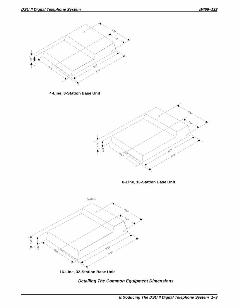
4-Line, 8-Station Base Unit
8-Line, 16-Station Base Unit
16-Line, 32-Station Base Unit
3.7
8"
3.7
8"
2.8
9"
2.1
3"
2.1
3"
16.50"
14.88"
7.43"
20.50"
21.30"
14.88"
7.43"
26.25"
27.58"16.50"
16.50"
14.88"
7.43"
4.5
4"
26.25"
27.58"
Detailing The Common Equipment Dimensions
DSU II Digital Telephone System IMI66–132
Introducing The DSU II Digital Telephone System 1–9

1.6 Describing The Stations
The digital telephones used with the DSU II digital telephone system are electronic,microprocessor-controlled, devices. They allow not only multiline pickup but also single buttonaccess to features available from the serving CO, PBX, CENTREX, or common equipment. Thedigital telephones are available in several different styles with several models available in eachstyle. The following list details the available telephones.
1.6.1 DigiTech Telephones
1
4
7
2
5
8
0
3
6
9
#OPER
PRS
GHI
TUV
JKL
ABC
WXY
MNO
DEF
HOLD TAP
DIGITECHCOMDIAL
SPKR
TAPTRANS
CONF
MUTE
HOLD ITCM
12X14LCD
DIGITECHCOMDIAL
SPKR
TAPTRANS
CONF
MUTE
HOLD ITCM
7714X Monitor Telephone7714S Speaker Telephone
7700S LCD Speakerphone
7701X Single Line Proprietary Telephone DD32X DSS/BLF Console
CAJS075
Viewing The DigiTech Telephone Images
IMI66–132 DSU II Digital Telephone System
1–10 Introducing The DSU II Digital Telephone System

8.625"
6.451"
7.658"
8.625"
4.983"
4.069"
1.112"
1.251"
2.887"
4.007"
CAJS045
7714X
7714S
7700S
7701X
Detailing The DigiTech Dimensions
DSU II Digital Telephone System IMI66–132
Introducing The DSU II Digital Telephone System 1–11

1.6.2 Impact Telephones
COMDIAL
1 2 3
4
7 8
0 #
9
5 6
QZ ABC DEF
MNO
WXY
GHI
PRS TUV
OPER
JKL
TRNS/CNF
HOLD
TAP
INTERCOM
COMDIAL
1 2 3
4
7 8
0 #
9
5 6
QZ ABC DEF
MNO
WXY
GHI
PRS TUV
OPER
JKL
TRNS/CNF
HOLD
TAP
INTERCOM
8112N Non-Monitor IB64X DSS/BLF Console 8101NSingle Line Proprietary Telephone
CAJS076
MUTESHIFTSPEAKERINTERCOM
TRNS/CNF
TAPHOLD
OPER
TUVPRS WXY
DEFABCQZ
MNOJKLGHI
0
87 9
321
#
654
8024S LCD Speakerphone
MUTESHIFTSPEAKERINTERCOM
TRNS/CNF
TAPHOLD
OPER
TUVPRS WXY
DEFABCQZ
MNOJKLGHI
0
87 9
321
#
654
8124S Speakerphone
MUTE
SHIFT
SPEAKER
INTERCOM
TRNS/CNF
TAPHOLD
OPER
TUVPRS WXY
DEFABCQZ
MNOJKLGHI
0
87 9
321
#
654
8112S Speakerphone
MUTE
SHIFT
SPEAKER
INTERCOM
TRNS/CNF
TAPHOLD
OPER
TUVPRS WXY
DEFABCQZ
MNOJKLGHI
0
87 9
321
#
654
8012S LCD Speakerphone
Viewing The Impact Telephone Images
IMI66–132 DSU II Digital Telephone System
1–12 Introducing The DSU II Digital Telephone System

8012S, 8112S
8101N,8112N8024S, 8124S
4.640
10.750
9.080
7.130
8.900 8.900
3.731
1.034
8.900
CAJS077
Detailing The Impact Dimensions
DSU II Digital Telephone System IMI66–132
Introducing The DSU II Digital Telephone System 1–13
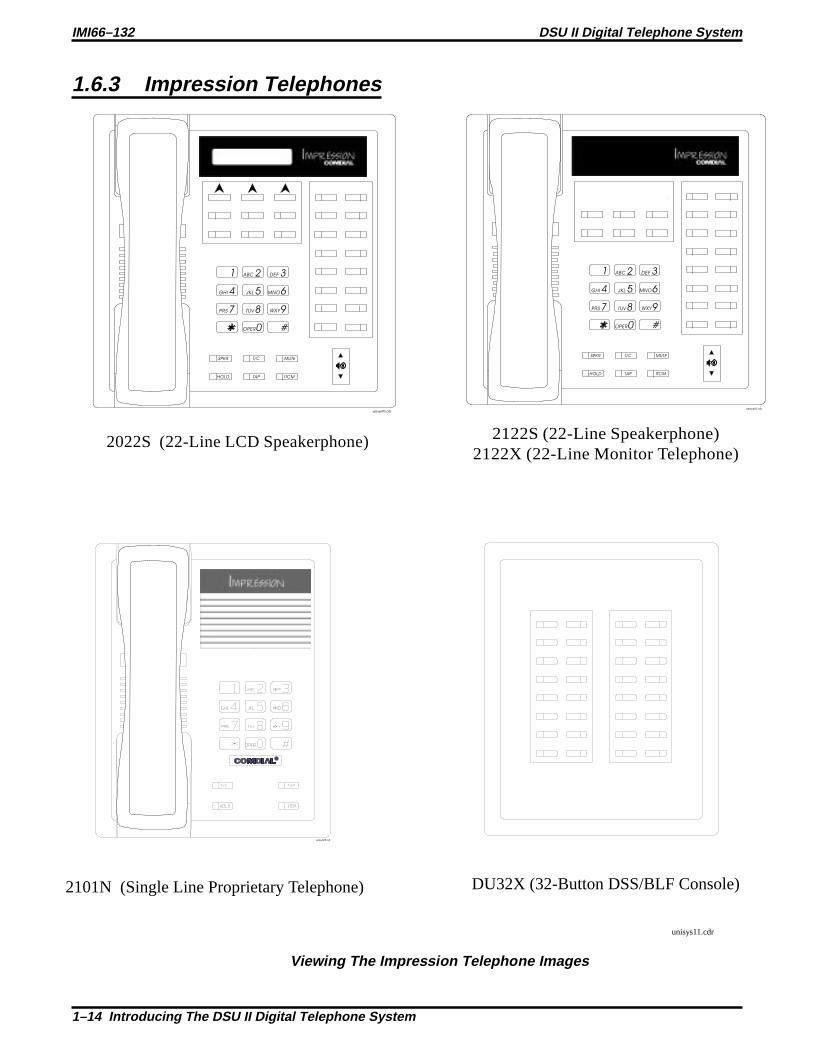
1.6.3 Impression Telephones
2122S (22-Line Speakerphone)2122X (22-Line Monitor Telephone)
2022S (22-Line LCD Speakerphone)
2101N (Single Line Proprietary Telephone)
unisys11.cdr
1 2
4
7
0
8 9
5 6
3
#
ABC
GHI
PRS
OPER
TUV WXY
JKL MNO
DEF
SPKR
HOLD TAP ITCM
T/C MUTE
unisyn05.cdr
1 2
4
7
0
8 9
5 6
3
#
ABC
GHI
PRS
OPER
TUV WXY
JKL MNO
DEF
SPKR
HOLD TAP ITCM
T/C MUTE
unisyn01.cdr
unisyn09.cdr
DU32X (32-Button DSS/BLF Console)
R
Viewing The Impression Telephone Images
IMI66–132 DSU II Digital Telephone System
1–14 Introducing The DSU II Digital Telephone System
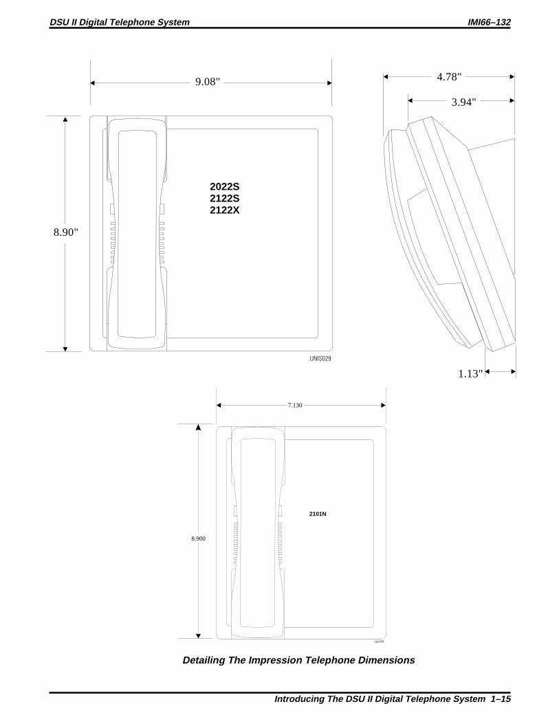
9.08"
8.90"
1.13"
4.78"
3.94"
UNIS029
2022S2122S2122X
7.130
8.900
cajs109
2101N
Detailing The Impression Telephone Dimensions
DSU II Digital Telephone System IMI66–132
Introducing The DSU II Digital Telephone System 1–15
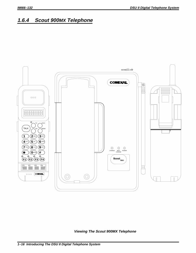
1.6.4 Scout 900 MX Telephone
CHARGE POWERBATTCHARGE
scout22.cdr
F1 F2 F3 F4
1 2
4
7
F1 F2 F3 F4
3
5
8
0
6
9
#
ABC
T/C HOLD
MEMOTAPTALK
GHI
PRS
DEF
JKL
TUV
OPER
MNO
WXY
Scout900MX
Viewing The Scout 900MX Telephone
IMI66–132 DSU II Digital Telephone System
1–16 Introducing The DSU II Digital Telephone System

VOL
MUTE
HEADSET
F1 F2 F3 F4
1 2
4
7
F1 F2 F3 F4
3
5
8
0
6
9
#
ABC
T/C HOLD
MEMOTAPTALK
GHI
PRS
DEF
JKL
TUV
OPER
MNO
WXY
CHARGE
POWER
BATTCHARGE
Scout
900MX
scout21.cdr
8.150
2.185 1.090
1.850
3.465
7.300
5.120
Detailing the Scout 900MX Dimensions
DSU II Digital Telephone System IMI66–132
Introducing The DSU II Digital Telephone System 1–17

1.6.5 Station Controls And Indicators
Ringer Volume Control
Each station has a ringer volume control. Adjust the ringer volume of each station to suit yourneeds.
Telephone Model Control Location7114S, 7114X, 8024S, 8124S,8012S, 8112S2022S, 2122S, 2122X
Rocker switch located on front face plate.Adjust while ringing to set volume.
7701X, 8101N, 8112N2101N
Switch on bottom housing. Set for fixedvolume levels
Scout 900MX Button on telephone’s upper right edge
Display Intensity
You can adjust the intensity (brightness and contrast) of the display on LCD telephones any timethe telephone is idle and on-hook.
To adjust the display intensity, press and hold the MUTE button on DigiTech telephones untilyou achieve the desired intensity or selectDISP on Impactand Impression telephones throughthe interactive buttons.
DIGITECHCOMDIAL
SPKR
TAPTRANS
CONF
MUTE
HOLD ITCM
CAJS075A
Rocker Switch
Ringer Volume Switch CAJS096
Locating The Telephone Ringer Volume Control
VOL
MUTE
HEADSET
EXP 95 vo l
Volume Control
(Press once for
each setting.)
IMI66–132 DSU II Digital Telephone System
1–18 Introducing The DSU II Digital Telephone System

MUTE
SHIFT
SPEAKER
INTERCOM
TRNS/CNF
TAPHOLD
OPER
TUVPRS WXY
DEFABCQZ
MNOJKLGHI
0
87 9
321
#
654
DIGITECHCOMDIAL
SPKR
TAPTRANS
CONF
MUTE
HOLD ITCM
LCD Alphanumeric Display Interactive Buttons(NOT Programmable)
Speaker
Handset
TAPButton
Transfer/ConferenceButton
MessageWaitingLight
HoldButton
IntercomButton
MicrophoneOpening
Speaker Button
Mute Button
Shift Button
Volume Control
Keypad
Progammable Buttons
Auxiliary Jack(On bottom)
TAPButton
Transfer/ConferenceButton
Speaker
MuteButton
SpeakerButton
VolumeControl
MessageWaitingLight
HoldButton
MicrophoneOpening
IntercomButton
ProgrammableButtons
Interactive Buttons(NOT Programmable)
LCD Alphanumeric Display
CAJS107
Locating DigiTech And Impact Controls And Indicators
DSU II Digital Telephone System IMI66–132
Introducing The DSU II Digital Telephone System 1–19

cajs110
LCD Display
Interactive ButtonsSpeaker
Mute Button
T/C Button
SPKR Button
MessageWaiting Light
Hold Button
TAP Button
ITCM Button
Feature Buttons,Line Buttons, andDSS Buttons
Volume Control
Microphone Opening
1 2
4
7
0
8 9
5 6
3
#
ABC
GHI
PRS
OPER
TUV WXY
JKL MNO
DEF
SPKR
HOLD TAP ITCM
T/C MUTE
Locating Impression Controls And Indicators
VOL
MUTE
HEADSET
F1 F2 F3 F4
1 2
4
7
F1 F2 F3 F4
3
5
8
0
6
9
#
ABC
T/C HOLD
MEMOTAPTALK
GHI
PRS
DEF
JKL
TUV
OPER
MNO
WXY
Antenna
Receiver
Display
Message/Talk LED
Talk Button
TAP Button
NumericKeypad
FunctionButtons
OptionalVibratorAccess
Microphone
Volume Button
Belt Clip
Mute Button
T/C Button
Hold Button
Memo Button
BatteryPack
FunctionButton LEDs
FunctionButton Labels
Head SetJack
RechargingContacts
EXP95HST
Locating Scout 900MX Controls And Indicators
IMI66–132 DSU II Digital Telephone System
1–20 Introducing The DSU II Digital Telephone System

1.7 Understanding The General Specifications
System CapacityJ0408 J0816 J01632 JM408 JM008
Lines 4 8 16 4 0Stations 8 16 32 8 8 ISTDSS/BLF Consoles Two per
station—one perstation port
Two perstation—one perstation port
Two perstation—one perstation port
Two perstation—one perstation port
Not Applicable
Intercom Paths Non-blocking Non-blocking Non-blocking Non-blocking Non-blockingMaximumSimultaneousIntercomConversations
Non-blocking Non-blocking Non-blocking Non-blocking Non-blocking
Paging Ports 1 1 1 Not Applicable Not ApplicablePark Orbits 9 9 9 Not Applicable Not ApplicableSystem Speed Dials 99 99 99 Not Applicable Not ApplicableStation Speed Dials 10 10 10 Not Applicable Not ApplicableAutodials Unused Button Unused Buttons Unused Buttons Not Applicable Not ApplicablePower Fail Circuits1 1 1 1 Not ApplicableMemory RetentionAfter Power Loss
60 hours minimum
Common Equipment DimensionsJ0408 J0816 J1632 JM408 and JM008
Width (inches) 16.5 16.5 16.5 16.5
Height (inches) 21.3 27.1 27.6 9.25
Depth (inches) 3.8 3.8 4.5 1.75
Weight (pounds) 17.5 26 30.5 4
Station DimensionsDigiTech
Multiline Single-Line Proprietary
Footprint (inches) 8.625 X 7.658 6.5 X 8.5
Weight (pounds) 2.5 1.9
Impact12-line 24-line Single-Line Proprietary
Footprint (inches) 9.08 X 8.9 10.75 X 8.9 8.9 X 7.13Weight (pounds) 2.3 2.6 1.75
ImpressionMultiline Single-Line Proprietary
Footprint (inches) 9.08 X 8.9 8.9 X 7.13
Weight (pounds) 2.5 (approx.) 1.9
DSU II Digital Telephone System IMI66–132
Introducing The DSU II Digital Telephone System 1–21

Station Dimensions–continued
Scout 900 MX
Base Unit Handset
Footprint (inches) 7.30 X 5.12 8.15 X 2.19 X 1.85 with belt clip
Weight (ounces) 16 oz less AC adapter 8.5 oz with battery and belt clip
Conferencing
Maximum Combinationsat Any One Time
J0408 and J0816 J16321 five-way plus 1 three-way plus 2SOHVA
4 five-way plus 1 three-way plus 1SOHVA
2 four-way plus 2 SOHVA 6 four-way plus 2 three-way1 four-way plus 3 three-way 3 four-way plus 9 three-way5 three-way plus 1 SOHVA 16 three-way
SMDA Storage CapacityJ0408 J0816 J1632
800 1600 1600
Station Cable RequirementsType 2-wire (1-pair) twisted, non-shielded cableMaximum Length 1000 feet with 24 gauge wire, 2000 feet with 22 gauge wireSwitching Principle Digital, time division multiplexing (TDM). Provides non-blocking switching with stored
program control
Operating EnvironmentTemperature 32-122 degrees F (0-50 degrees C)Humidity 90 percent relative, non-condensing
Power Requirements
J0408 J0816 J1632JM408 and
JM008Voltage 90-129 VAC Single phase all models
Current 0.6A 2.0 A 2.1A Not Applicable
Power 70W 135W 150W Not Applicable
Volt/Amps 80VA 190VA 200VA Not Applicable
TerminationsStation Standard 50-pin male connectors for connection to external distribution fieldLine Standard 6-conductor mini-jack (USOC 14C)
IMI66–132 DSU II Digital Telephone System
1–22 Introducing The DSU II Digital Telephone System

Music InterfaceInput Level 3 Volts peak-to-peak maximumInput Impedance Approximately 500 OhmsConnector RCA phono jack
Station Message Detail Recording PortFormat Serial, pseudo RS-232CParity NoneData Bits 7 or 8 (programmable)Stop Bits 1 or 2 (programmable)Baud Rate Programmable in class of serviceHandshaking X on -X off Hardware -CTSCable Length 500 feet maximum
PA PortOutput Level 400 Millivolts peak-to-peak (typical speech)Output Impedance Approximately 500 OhmsConnector RCA phono jack
Central Office LimitsLoop Limits 1900 Ohms maximum loopCable Insulation Leakage 15,000 Ohms minimum
Industry/Regulatory StandardsFCC Part 15, Class A RF emissions certifiedFCC Part 68 Telco registered (fully protected)IC CS03 Telco certifiedUL 1459 safety approved by OSHA approved NAVLAPCSA C22.2 No. 225 safety approved by OSHA approved NAVLAPEIA RS478Bell publication 48002 guidanceHearing aid compatible handset
Regulatory CodesCVWUSA-61535-KF-ECVWUSA-61536-MF-E02LS29.0YRJ14C or RJ21X0.4B1.2B
DSU II Digital Telephone System IMI66–132
Introducing The DSU II Digital Telephone System 1–23

1.7.1 Feature Codes
Feature Dialing CodeAll Call Page (Through Station Speakers) INTERCOM, 87Attendant Calling INTERCOM, 0Automatic Redialing Programmed ButtonBackground Music On INTERCOM, 1
Off INTERCOM, # 1Automatic Call Back Activate INTERCOM, (ext no), 6
Cancel INTERCOM, # 6Station-to-Station Messaging Activate INTERCOM, (ext no),7
Cancel INTERCOM, # 7, (ext no)LCD Messaging Set INTERCOM, 02 (1–0)
Cancel INTERCOM, # 02Call Forward Personal INTERCOM, 05, (ext no)
Cancel INTERCOM, # 05All Calls INTERCOM, 5, (ext no)Cancel INTERCOM, # 5
Call Park Park Orbits 1–9 INTERCOM, (91–99)Pick Up INTERCOM, # (91–99)
Call Pick Up Directed INTERCOM, 4, (ext no)Group INTERCOM, # 4
Call Waiting Tone Send INTERCOM, (ext no),01Cancel Hang Up
Do Not Disturb Set Programmed ButtonCancel Programmed Button
Executive Override INTERCOM, (ext no), 03External Page INTERCOM, 89Handsfree Answer Inhibit Set MUTE
Cancel MUTEHold Manual HOLD
Exclusive HOLD, HOLDDirect INTERCOM, 90, (ext no)Direct Hold Pick Up INTERCOM, # 90
Line Answer From Any Station INTERCOM, 80Line Group Access Group 1 INTERCOM, 9
Group 2 INTERCOM, 81Group 3 INTERCOM, 82Group 4 INTERCOM, 83
Line QueuingEnable Line Group INTERCOM, (gp code),8Cancel INTERCOM, # 8
Meet Me Answer Paging INTERCOM, 88Message Waiting Set INTERCOM, 3, (ext no)
Cancel From Idle INTERCOM, # 3, (ext no)Cancel On Line INTERCOM,Retrieve Message INTERCOM, HOLD
Night Transfer (Attendant) On INTERCOM, # 03,Programmed Button
Off INTERCOM, # 03,Programmed Button
Personal Ringing Tones Set Tones 1–6 INTERCOM, 4 (1–6)
IMI66–132 DSU II Digital Telephone System
1–24 Introducing The DSU II Digital Telephone System

Pulse/Tone Switching #Redial Last Dialed Number #Save Number Redial Use HOLD, Programmed Button
Store Programmed ButtonService Observing INTERCOM, # 03, (ext no)Speed Dial Station 0–9
System 01–99TAP (on line) Activate INTERCOM, #04Toll Restriction Override Activate INTERCOM, 6 (extension
number, code)Tracker Pager Enable INTERCOM,06
Disable INTERCOM, #06Send Message INTERCOM, #01
Voice Announce Block Block INTERCOM, 2Unblock INTERCOM, # 2
Zone Page Zone 1 INTERCOM, 84Zone 2 INTERCOM, 85Zone 3 INTERCOM, 86
DSU II Digital Telephone System IMI66–132
Introducing The DSU II Digital Telephone System 1–25

1.7.2 System Ringing Patterns
Ring Type Ring CadenceCO/PBX Line Ring Host system ring cadenceIntercom Tone Signaling Two 150 msec. tone bursts every four secondsVoice Signaling alert One 215 msec. tone burstTimed hold recall at station that put call on hold Three 150 msec. tone bursts at the end of each timeout
periodCall back alert One 80 msec. tone burst followed by three 150 msec. tone
bursts and one 80 msec. tone burstQueue Enabled
Call forward alert One 80 msec. tone burstTransfer ringing Two 1.1 sec tone busts every four seconds
Tone Type Tone CadenceDial Tone Continuous onCalled station ring-back One sec. on and three sec. offBase level program entry 80 msec. tone burst sounded onceError tone—incorrect entry 530 msec. tone burst sounded three timesAll-call and zone paging notification tone 80 msec. tone burst followed by 280 msec. toneBusy tone
530 msec. tones sounded continuouslyOverride feature not allowedNight transfer feature not allowedCall waiting tone Three 80 msec. tone bursts sounded onceCalled station in do-not-disturb mode 140 msec. tone burst sounded twice every 1.5 sec.Call-back busy feature on 260 msec. tone burst sounded onceSystem is awaiting memory dial number or key mappingentry after location is specified
80 msec. tone burst sounded continuously
Override feature on warning tone Six 100 msec. tone bursts sounded for 1.5 secs.SOHVA toneDISD ringback tone Dual 440/480 Hz tone sounded 1 sec. on/1 sec. offDISD dial tone 381 Hz tone sounded continuouslyDISD confirmation tone Two 125 sec. bursts of 381 Hz tone sounded onceDISD busy/error tone Three 500 msec. bursts of 381 Hz tone sounded once
IMI66–132 DSU II Digital Telephone System
1–26 Introducing The DSU II Digital Telephone System

1.8 Seeking Repair Assistance
If your common equipment cabinet or individual stations need repair, you may return theequipment to Comdial. Comdial will, at its option, either repair or replace it. There is a fixedcharge for this repair. For information on this charge, call or write to the address given below.
ComdialP.O. Box 7266Charlottesville VA 22906Attn: Repair DepartmentTelephone: (804) 978-2400
1-800-877-4448
If you do return equipment for repair, pack it carefully to prevent damage. Any damages duringshipment are your responsibility. You should ship the equipment freight or postage prepaid. Theshipping address is given below.
Comdial1180 Seminole TrailCharlottesville, VA 22901Attention Repair Department
DSU II Digital Telephone System IMI66–132
Introducing The DSU II Digital Telephone System 1–27


Installing The DSU II DigitalTelephone System
Section Title ...........................................................................................................Page
2.1 Considering the Mounting Requirements................................................2–42.1.1 Tools And Hardware ..............................................................................2–52.1.2 Underwriters Laboratories Installation Notice .......................................2–52.1.3 Hybrid Installation..................................................................................2–5
2.2 Mounting The Cabinet...............................................................................2–6
2.3 Making The AC Power Connection .........................................................2–82.3.1 Identifying The Fuses .............................................................................2–82.3.2 Grounding The System.........................................................................2–10
2.4 Connecting The Lines ..............................................................................2–122.4.1 Detailing The Line Connections.......................................................... 2–142.4.2 Reassigning The Line Ports ..................................................................2–142.4.3 Protecting The Lines.............................................................................2–14
2.5 Connecting The Stations..........................................................................2–162.5.1 Grounding The Unused Station Cables ................................................2–172.5.2 Relocating The Stations........................................................................2–172.5.3 Installing The Cable Clips ....................................................................2–172.5.4 Connecting Stations To The J0408...................................................... 2–192.5.5 Connecting Stations To The J0816...................................................... 2–202.5.6 Connecting Stations To The J1632...................................................... 2–212.5.7 Wall Mounting The Telephone Stations...............................................2–23
2
DSU II Digital Telephone System IMI66–132
Installing The DSU II Digital Telephone System 2 – 1

Section Title ...........................................................................................................Page
2.6 Installing DSS/BLF Consoles ..................................................................2–26
2.7 Connecting A Power Failure Station......................................................2–28
2.8 Using The Auxiliary Equipment Interface ............................................2–29
2.9 Common The Audible And Auxiliary Ringing Interface.....................2–302.9.1 Connecting Outside Lines ....................................................................2–302.9.2 Connecting Selected Ports ....................................................................2–30
2.10 Using The External Paging Interface .....................................................2–32
2.11 Using A Line Port As An External Paging Interface............................2–33
2.12 Connecting Data Devices To The System ..............................................2–342.12.1 Making Modular Jack Data Connections .............................................2–342.12.2 Making The Common Equipment Data Connections.......................... 2–362.12.3 Connecting A Personal Computer For Remote Programming .............2–38
2.13 Using The Music Interface ......................................................................2–40
2.14 Using The Add-On Expansion Module ..................................................2–412.14.1 Using The JM408 Module....................................................................2–412.14.2 Using The JM008 Module................................................................... 2–442.14.3 Installing An Add-On Expansion Module........................................... 2–48
2.15 Checking The System Installation ..........................................................2–502.15.1 Checking The Resistance......................................................................2–502.15.2 Checking The Voltage ..........................................................................2–502.15.3 Checking The General Operating Conditions ..................................... 2–51
IMI66–132 DSU II Digital Telephone System
2 – 2 Installing The DSU II Digital Telephone System

Section Title ...........................................................................................................Page
2.16 Isolating Failures......................................................................................2–512.16.1 Checking The System Status Indicator.................................................2–512.16.2 Testing The Stations .............................................................................2–51
2.17 Loading And Up-Grading The System Software..................................2–522.17.1 Introducing The Software Key .............................................................2–522.17.2 Introducing The Software Disks...........................................................2–532.17.3 Loading The Software ..........................................................................2–54
2.18 Installing The System Options And Accessories .................................. 2–602.18.1 Installing The Battery Back Up Assembly .......................................... 2–602.18.2 Installing the Analog Terminal Interface............................................. 2–642.18.3 Installing the Data Interface Unit .........................................................2–722.18.4 Supporting Caller Identification Service ..............................................2–762.18.5 Supporting The Tracker Paging System...............................................2–802.18.6 Supporting DVA Operation..................................................................2–822.18.7 Installing The Personal Computer Interface Unit................................. 2-842.18.8 Connecting The Versatile Voice Processing Voice Mail System ........2–86
2.19 FCC Rules And Regulations .................................................................. 2–88
DSU II Digital Telephone System IMI66–132
Installing The DSU II Digital Telephone System 2 – 3

2.1 Considering The Mounting RequirementsThe following requirements will help you to install the DSU II digital telephone system.
• Locate the equipment cabinet within four feet of an AC electrical outlet dedicatedexclusively to the use of this equipment. The outlet must be a 117 VAC 15 AMP circuitwith a third-wire ground supplied to a standard electrical outlet (NEMA 5–15R).
• Mount the common equipment within 25 feet of the TELCO/PBX jacks. The recommendednominal distance is 7 feet.
• Choose a secure and dry mounting location that has adequate ventilation. The temperaturerange of the location must be within 32–122 degrees F (0–50 degrees C) and that therelative humidity is less than 90 percent, non-condensing.
• If the mounting surface is damp or if it is made of concrete or masonry material, you mustattach a backboard to the mounting surface for mounting the common equipment. Suitablemounting backboards are available commercially or you can construct one from 3/4-inchplywood by cutting it to size.
IMI66–132 DSU II Digital Telephone System
2 – 4 Installing The DSU II Digital Telephone System

2.1.1 Tools And Hardware
You will need the following tools and materials to install the common equipment.
• Fasteners—wood screws (1/4 x 1-inch round head), toggle bolts, or wall anchors,
• Screwdriver—to match fasteners,
• Electric drill—if prepared holes are required,
• Connecting tool—for fastening wires to a type-66 connector block,
• Crimping tool—for 623-type modular plugs,
• Volt/Ohm Meter.
2.1.2 Underwriters Laboratories Installation Notice
Per The Underwriters Laboratories standard 1459, 2nd edition, be aware of the followingprecautions when installing telephone equipment that is to be directly connected to the telephonecompany network:
• Never install telephone wiring during a lightning storm,
• Never install telephone jacks in wet locations unless the jack is specifically designed forwet locations,
• Never touch un-insulated telephone wires or terminals unless the telephone line has beendisconnected at the network interface,
• Use caution when installing or modifying telephone lines.
2.1.3 Hybrid Installation
Whenever a programmer assigns lines to line groups, the digital telephone system automaticallyassumes the hybrid mode. Your local telephone company may charge a higher monthly fee foroperation of a hybrid system; therefore, the FCC requires that you report the equipment-typecategory designation number (KF for key system, MF for hybrid system) to the telephonecompany at the time of installation.
FCC Registration NumbersKey System CVWUSA-61535-KF-EHybrid System CVWUSA-61536-MF-E
DSU II Digital Telephone System IMI66–132
Installing The DSU II Digital Telephone System 2 – 5

2.2 Mounting The Cabinet
After thoroughly reviewing Section 2.1 and fully understanding its subject matter, use thefollowing procedure to mount the common equipment cabinet
1. Unpack and carefully inspect all equipment for shipping damage. Notify the shipperimmediately of any damages that you find. Verify that the packages contain all parts andaccessories needed for proper installation and operation.
2. If the mounting location requires a backboard, attach it securely to provide a stable mountingsurface for the equipment.
3. Refer to Figure 2-1 or to the PP032-001 mounting template included in the literature thataccompanies the common equipment cabinet for the locating dimensions required for thethree mounting screws, and mark their locations on the mounting surface.
4. Drill holes in the mounting surface of a proper size to accommodate the hardware beingused. If necessary, prepare these holes with inserts, anchors or other attachment devices asdictated by the type of mounting surface.
5. Insert the two top screws into the mounting surface and tighten them to within approximately1/8-inch of the surface.
6. Hang the cabinet on the top screws using the mounting holes located on the rear of thecabinet. Note that these holes are elongated with an enlargement at one end. This featureallows the cabinet to snap down on the screws to secure the mounting when the cabinet ishung on them.
7. Insert a third screw through the mounting tab located on the lower edge of the cabinet andinto the mounting surface, and tighten it into place.
8. Place the individual telephone stations as desired and in keeping with accepted industry andoffice standards. You can wall mount a telephone station if necessary (see Section 2.5.7 fordetails).
IMI66–132 DSU II Digital Telephone System
2 – 6 Installing The DSU II Digital Telephone System

DSU250.CDR
4.54"
3.78"
3.78"
16.50"
16.50"
16.50"
27.58"
27.58"
21.30"
0.88"
0.87"
26.65"
26.25"
20.50"
Back of16-Line, 32-Station
Base Unit
Back of8-Line, 16-Station
Base Unit
Back of4-Line, 8-Station
Base Unit
4-Line, 8-Station Base Unit
8-Line, 16-Station Base Unit
16-Line, 32-Station Base Unit
0.88"
Detailing The DSU II Cabinet Dimensions
DSU II Digital Telephone System IMI66–132
Installing The DSU II Digital Telephone System 2 – 7

2.3 Making The AC Power ConnectionYou must employ a dedicated 117VAC 15 AMP circuit, with a third-wire ground, supplied to astandard electrical outlet (NEMA 5-15R) for the AC power connection.
• For added equipment protection, connect a plug-in power line surge protector between thepower cord and the AC outlet.
• Thoroughly check out the installation before connecting the power cord to an electricaloutlet to apply AC power to the system.
2.3.1 Identifying The Fuses
The system is protected against short circuit damage by a fuse located on the right side of thecommon equipment cabinet. Always replace the fuse with one of the same value and type;otherwise, equipment damage could result.
Comparing Cabinets And Their Fuse Types
Cabinet Fuse ValueJ0408 1A 250V slow-blow typeJ0816 3A 250V slow-blow typeJ1632 3A 250V slow-blow type
IMI66–132 DSU II Digital Telephone System
2 – 8 Installing The DSU II Digital Telephone System

Typicalearth
ground
Groundingterminal
Plug-in powerline surge
protector (typical)
Dedicated 117VAC15 AMP NEMA 5-15R
electrical outletwith third-wire ground
Fuse(See text)
DSU211
Making The AC Power Connections
DSU II Digital Telephone System IMI66–132
Installing The DSU II Digital Telephone System 2 – 9

2.3.2 Grounding The System
If spare conductors exist in the cables between the station and the 66M-xx connector blocks, it isgood practice to connect them to an earth ground. Doing this may help prevent them frominducing radio frequency and/or AC interference into the system. It is also good practice todisconnect any unused station jacks from the connector block and ground that wiring to an earthground as well.
Transient voltage spikes, if induced onto CO or CENTREX lines, can travel through the cableand into the common equipment. The telephone company offers basic protection against thiscondition but it is usually designed to protect the central office circuits. While it will alsoprovide some protection to the common equipment, you should not rely upon it for totalprotection. To help ensure that external over-voltage surges do not damage the system, youshould install and properly ground primary protection devices, such as gas discharge tubes orsimilar devices, on all lines. While the line boards have internal secondary surge protection onall line ports, in order for this protection to be effective, youMUST connect the commonequipment cabinet to a reliable, effective earth ground.
Proper DSU grounding is necessary for trouble-free operation and personnel safety. The DSUhas the following three types of grounds:
• Service Ground—a neutral power line wire that is connected to the ground bus in thepremises’ AC power panel,
• System Ground—a non-current carrying power line wire that is connected to the ground busin the premises’ AC power panel,
• Frame Ground—a low impedance conductor that places the common equipment cabinet atreference ground potential. The frame ground provides the greatest safety by limitingelectrical potential between non-current carrying parts of the system. The commonequipment cabinet provides a ground stud on its cabinet for access to its frame ground.
Effective grounding requires that you connect the frame ground to a good earth ground. A goodearth ground is one such as the ground bus in the premises’ AC power panel or a public metalliccold water pipe at a point immediately at its entrance to the premises and ahead of any meters,pumps, or insulating sections that have been added for vibration reduction. Avoid using thepremises’ structural steel frame as it may not be at earth ground potential. Make the groundconnection with #10 or #12 insulated, solid copper grounding wire.Keep the ground wireseparate from the three-wire AC line cord ground, do not splice it, and keep it as short aspossible.
The impedance of the wiring between the common equipment cabinet and the earth ground mustnot exceed 0.25 ohms and the impedance between the earth ground and the power company’sreference standard ground must not exceed 4 ohms. Use an acceptable low impedance measuringdevice to measure the impedance of these paths. The #10 or #12 wire size will minimize thewiring impedance; however, if the impedance between earth ground and the power company’sstandard reference ground exceeds 5 ohms, contact the local power company. The ground pathmust always be of sufficient current-carrying capacity to prevent a build up of voltages that mayresult in circuit noise, hazard to personnel, or equipment damage.
IMI66–132 DSU II Digital Telephone System
2 – 10 Installing The DSU II Digital Telephone System

Be sure that all of the ground connections are without splices and are visible for inspection andmaintenance. Tag all of the ground connections with a sign that reads:Do Not Remove OrDisconnect.
If you install expansion modules on the base cabinet, attach at least a #10 or #12 insulated, solidcopper wire between the frame ground stud on the expansion module(s) to the frame ground studon the base cabinet.
Remember, if spare conductors exist in the cables that run between the stations and the 66M-xxconnector blocks, it is good practice to connect them to earth ground. Doing this may helpprevent them from introducing radio frequency and/or AC interference into the system. Alsoremember that it is good practice to disconnect any unused station jacks from the connectorblock and ground that wiring to earth ground as well.
Typical Earth Ground (see text)
Frame Ground Stud
DSU212
#10 or #12 Insulated, SolidCopper Grounding Wire
Grounding The System
DSU II Digital Telephone System IMI66–132
Installing The DSU II Digital Telephone System 2 – 11

2.4 Connecting The LinesThe line terminations for the common equipment cabinet are standard modular plug/jackconnections. Line configuration must be loop start only. Each modular jack provides terminationfor two lines. Modular line jacks 1 and 2 also provide termination for an auxiliary pair inaddition to the two outside lines. The outside line termination can be a type 66M-xx connectorblock or individual 6-position modular jacks. The line cord that is routed between the outsideline termination and the common equipment termination should be twisted-pair wiring. TheJ0408, J0816 and J1632 common equipment supports the installation of up to 4, 8, or 16 lines,respectively. Add-on expansion modules are available to expand the line capacity of the systems.
4-Line, 8-Station Base Unit
Lines 3 & 4, Aux. Line 4Lines 1 & 2, Aux. Line 2
GroundingTerminal Line Jacks 1 & 2, Aux. Line 2
Line Jacks 3 & 4, Aux. Line 4Line Jacks 5 & 6Line Jacks 7 & 8
8-Line, 16-Station Base Unit
16-Line, 32-Station Base Unit
Lines 1 & 2, Aux 1 (Line 2)Lines 3 & 4, Aux 2 (Line 4)
Lines 5 & 6Lines 7 & 8Line 9 & 10
Line 11 & 12Line 13 & 14Line 15 & 16 DSU219
GroundingTerminal
GroundingTerminal
Locating The Line Connections
IMI66–132 DSU II Digital Telephone System
2 – 12 Installing The DSU II Digital Telephone System

RING 2RING 1TIP 1TIP 2
RING 4RING 3TIP 3TIP 4
RING 6RING 5TIP 5TIP 6
RING 8RING 7TIP 7TIP 8
CO/PBXLINES
Line TerminationsType 66M-XXConnector Block
orIndividual 6-PositionModular jacks
(Typical 8-Line, 16-StationBase Unit Shown)
CAJS083
6-Wire TwistedPair Cable
654321
No Conn.Ring 2Ring 1Tip 1Tip 2No. Conn.
654321
Aux. RingRing 2Ring 1Tip 1Tip 2Aux. Tip
Pin designation forLine Jacks 1 and 2
Pin designation forLine Jacks 5 and 6
Detailing The CO Interface
DSU II Digital Telephone System IMI66–132
Installing The DSU II Digital Telephone System 2 – 13

2.4.1 Detailing The Line Connections
The table on the next page shows the line connection details for all three of the commonequipment base units. Jacks one and two are the same for all three cabinets, jacks three and fourare the same for both the J0816 and J1632 cabinets, and jacks five through eight are onlyavailable on the J1632 cabinet.
2.4.2 Reassigning The Line Ports
After you have initially connected a line to a particular line port and programmed its attributes(or left it with the system defaulted values), you can reassign the line and its attributes to adifferent port by programming action if you wish. Refer to Chapter 3 for the line to line portreassignment programming details.
CAUTION
While this feature allows you to make adds, moves, and changes without relocating the linewiring, it is not a substitute for correct wiring and should not be used as such. Be sure torecord any reassignments that you make.
2.4.3 Protecting The Lines
Transient voltage spikes, if induced onto CO or CENTREX lines, can travel through the cableand into the common equipment. The telephone company offers basic protection against thiscondition but it is usually designed to protect the central office circuits. While it will alsoprovide some protection to the common equipment, it should not be relied upon for totalprotection. To help ensure that external over-voltage surges do not damage the system, themanufacturer recommends that gas discharge tubes, or similar primary protection devices, beinstalled and properly grounded on all lines (a selection of solid-state protection devices that areuseful for this purpose is available from ITW Linx, Elk Grove Village, Illinois 60007).
IMI66–132 DSU II Digital Telephone System
2 – 14 Installing The DSU II Digital Telephone System

Understanding The Line Connection DetailsCommon Equipment Type Line Jack Pin No. Connection Telephone Number
J0408,J0816,
andJ1632
1
1 Auxiliary 1 (Line 2) Tip2 Line 2 Tip3 Line 1 Tip4 Line 1 Ring5 Line 2 Ring6 Auxiliary 1 (Line 2) Ring
2
1 Auxiliary 2 (Line 4) Tip2 Line 4 Tip3 Line 3 Tip4 Line 3 Ring5 Line 4 Ring6 Auxiliary 2 (Line 4) Ring
J0816and
J1632
3
1 No Connection2 Line 6 Tip3 Line 5 Tip4 Line 5 Ring5 Line 6 Ring6 No Connection
4
1 No Connection2 Line 8 Tip3 Line 7 Tip4 Line 7 Ring5 Line 8 Ring6 No Connection
J1632
5
1 No Connection2 Line 10 Tip3 Line 9 Tip4 Line 9 Ring5 Line 10 Ring6 No Connection
6
1 No Connection2 Line 12 Tip3 Line 11 Tip4 Line 11 Ring5 Line 12 Ring6 No Connection
7
1 No Connection2 Line 14 Tip3 Line 13 Tip4 Line 13 Ring5 Line 14 Ring6 No Connection
8
1 No Connection2 Line 16 Tip3 Line 15 Tip4 Line 15 Ring5 Line 16 Ring6 No Connection
DSU II Digital Telephone System IMI66–132
Installing The DSU II Digital Telephone System 2 – 15

2.5 Connecting The StationsThe DSU II digital telephone system supports the operation of proprietary Comdial telephones.
The J0408, J0816 and J1632 common equipment supports the installation of up to eight, 16, or32 telephones, respectively. Add-on expansion modules are available to expand the stationcapacity of the systems. You can add one expansion module to the J0408, and two expansionmodules to the J0816 and J1632. The JM408 expansion module provides interface for eightproprietary stations (plus interface for four lines) while the JM008 expansion module providesinterface for eight industry-standard devices.
Connections between the common equipment and the stations are typically via type 66M-xxconnector blocks which are cable connected to the common equipment’s 50–pin male connector.The connector block is, in turn, wired to modular jacks that accept the modular line cordconnected between it and the telephones.
The maximum distance allowed from the common equipment to the stations is per the followinglist:
• Multiline Telephones—1000 feet using #24 gauge, twisted-pair cable or 2000 feet using#22 gauge cable
When installing the system telephones keep in mind that each station port supports only oneproprietary telephone and the system does not allow you to bridge two stations to a singlemodular jack.
Always route station wiring a minimum of 12 inches from any other parallel wires or electricaldevices. If electrical noise or RF energy is at a high level, you may need to use shielded cablewith the shield connected to the cabinet ground lug.
IMI66–132 DSU II Digital Telephone System
2 – 16 Installing The DSU II Digital Telephone System

2.5.1 Grounding The Unused Station Cables
Remember, if spare conductors exist in the cables that run between the stations and the 66M-xxconnector blocks, it is good practice to connect them to earth ground. Doing this may helpprevent them from introducing radio frequency and/or AC interference into the system. Alsoremember that it is good practice to disconnect any unused station jacks from the connectorblock and ground that wiring to earth ground as well.
Remove insulation and twist together all spare wires at the wall outlet. Ground the wires at the66M-xx to the common equipment cabinet ground lug.
2.5.2 Relocating The Stations
The Comdial proprietary telephones identify themselves to the system when you install them.The system assigns an extension number and all other programmable attributes to station ports asa default that you can reprogram as needed. Plus, you can use programming action to reassignattributes of one station port to a different station port if you wish. Refer to the automatic stationrelocation programming procedure and the station-to-station programming procedure found inChapter 3.
NOTE: The system will not allow you to relocate the station 10 to station port 10 assignment.
CAUTION
While this feature allows you to make adds, moves, and changes without relocating the stationwiring, it is not a substitute for correct wiring and should not be used as such. Be sure torecord any reassignments that you make.
2.5.3 Installing The Cable Clips
Each cabinet-mounted 50-pin male connector is equipped with a retaining clip. This clip isdesigned to secure the mated connection once it is made. The clip does this by snapping into aslot on the cable-mounted connector when it is pressed together with the cabinet-mountedconnector. This retaining clip must be pulled back slightly to unsnap it before the connectors canbe separated.
DSU II Digital Telephone System IMI66–132
Installing The DSU II Digital Telephone System 2 – 17

16-Line, 32-Station Base Unit
Stations 10-25
Stations 26-41Power Fail Station
(pins 3 & 4)
GroundingTerminal
4-Line, 8-Station Base Unit
Station 10-17,Power Fail Station
GroundingTerminal
Station 10-25Power Fail Station
GroundingTerminal
8-Line, 16-Station Base Unit
DSU220DSU220
Locating The Station Connections
IMI66–132 DSU II Digital Telephone System
2 – 18 Installing The DSU II Digital Telephone System

2.5.4 Connecting Stations To The J0408
This table shows the color-coded connections for a J0408 common equipment cabinet.
Connecting Stations To The J0408 Common Equipment Cabinet25-Pair Connections Two-Wire Connections Station Connections
Wire Color Pair Pin No.Clip
Term.Pair Wire Color Station Location
White-Blue 1 26 1 Signal Path Green 10Blue-White 1 2 RedWhite-Orange 2 27 3 Signal Path Green 11Orange-White 2 4 RedWhite-Green 3 28 5 Signal Path Green 12Green-White 3 6 RedWhite-Brown 4 29 7 Signal Path Green 13Brown-White 4 8 RedWhite-Slate 5 30 9 Signal Path Green 14Slate-White 5 10 RedRed-Blue 6 31 11 Signal Path Green 15Blue-Red 6 12 RedRed-Orange 7 32 13 Signal Path Green 16Orange-Red 7 14 RedRed-Green 8 33 15 Signal Path Green 17Green-Red 8 16 RedRed-Brown 9 34 17Brown-Red 9 18Red-Slate 10 35 19Slate-Red 10 20Black-Blue 11 36 21Blue-Black 11 22Black-Orange 12 37 23Orange-Black 12 24Black-Green 13 38 25Green-Black 13 26Black-Brown 14 39 27Brown-Black 14 28Black-Slate 15 40 29Slate-Black 15 30Yellow-Blue 16 41 31Blue-Yellow 16 32Yellow-Orange 17 42 33Orange-Yellow 17 34Yellow-Green 18 43 35Green-Yellow 18 36Yellow-Brown 19 44 37Brown-Yellow 19 38Yellow-Slate 20 45 39Slate-Yellow 20 40Violet-Blue 21 46 41Blue-Violet 21 42Violet-Orange 22 47 43Orange-Violet 22 44Violet-Green 23 48 45 Common AudibleGreen-Violet 23 46Violet-Brown 24 49 47 Station 17 AudibleBrown-Violet 24 48Violet-Slate 25 50 49 Power Fail StationSlate-Violet 25 50
DSU II Digital Telephone System IMI66–132
Installing The DSU II Digital Telephone System 2 – 19
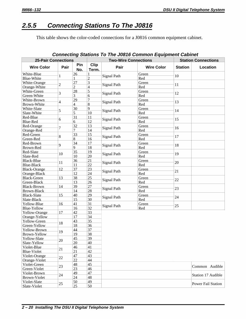
2.5.5 Connecting Stations To The J0816
This table shows the color-coded connections for a J0816 common equipment cabinet.
Connecting Stations To The J0816 Common Equipment Cabinet25-Pair Connections Two-Wire Connections Station Connections
Wire Color PairPinNo.
ClipTerm.
Pair Wire Color Station Location
White-Blue 1 26 1 Signal Path Green 10Blue-White 1 2 RedWhite-Orange 2 27 3 Signal Path Green 11Orange-White 2 4 RedWhite-Green 3 28 5 Signal Path Green 12Green-White 3 6 RedWhite-Brown 4 29 7 Signal Path Green 13Brown-White 4 8 RedWhite-Slate 5 30 9 Signal Path Green 14Slate-White 5 10 RedRed-Blue 6 31 11 Signal Path Green 15Blue-Red 6 12 RedRed-Orange 7 32 13 Signal Path Green 16Orange-Red 7 14 RedRed-Green 8 33 15 Signal Path Green 17Green-Red 8 16 RedRed-Brown 9 34 17 Signal Path Green 18Brown-Red 9 18 RedRed-Slate 10 35 19 Signal Path Green 19Slate-Red 10 20 RedBlack-Blue 11 36 21 Signal Path Green 20Blue-Black 11 22 RedBlack-Orange 12 37 23 Signal Path Green 21Orange-Black 12 24 RedBlack-Green 13 38 25 Signal Path Green 22Green-Black 13 26 RedBlack-Brown 14 39 27 Signal Path Green 23Brown-Black 14 28 RedBlack-Slate 15 40 29 Signal Path Green 24Slate-Black 15 30 RedYellow-Blue 16 41 31 Signal Path Green 25Blue-Yellow 16 32 RedYellow-Orange 17 42 33Orange-Yellow 17 34Yellow-Green 18 43 35Green-Yellow 18 36Yellow-Brown 19 44 37Brown-Yellow 19 38Yellow-Slate 20 45 39Slate-Yellow 20 40Violet-Blue 21 46 41Blue-Violet 21 42Violet-Orange 22 47 43Orange-Violet 22 44Violet-Green 23 48 45 Common AudibleGreen-Violet 23 46Violet-Brown 24 49 47 Station 17 AudibleBrown-Violet 24 48Violet-Slate 25 50 49 Power Fail StationSlate-Violet 25 50
IMI66–132 DSU II Digital Telephone System
2 – 20 Installing The DSU II Digital Telephone System

2.5.6 Connecting Stations To The J1632
The following two tables show the color-coded connections for a J1632 common equipmentcabinet.
Connecting Stations To J1 On The J1632 Common Equipment Cabinet25-Pair Connections Two-Wire Connections Station Connections
Wire Color PairPinNo.
ClipTerm.
Pair Wire Color Station Location
White-Blue 1 26 1 Signal Path Green 10Blue-White 1 2 RedWhite-Orange 2 27 3 Signal Path Green 11Orange-White 2 4 RedWhite-Green 3 28 5 Signal Path Green 12Green-White 3 6 RedWhite-Brown 4 29 7 Signal Path Green 13Brown-White 4 8 RedWhite-Slate 5 30 9 Signal Path Green 14Slate-White 5 10 RedRed-Blue 6 31 11 Signal Path Green 15Blue-Red 6 12 RedRed-Orange 7 32 13 Signal Path Green 16Orange-Red 7 14 RedRed-Green 8 33 15 Signal Path Green 17Green-Red 8 16 RedRed-Brown 9 34 17 Signal Path Green 18Brown-Red 9 18 RedRed-Slate 10 35 19 Signal Path Green 19Slate-Red 10 20 RedBlack-Blue 11 36 21 Signal Path Green 20Blue-Black 11 22 RedBlack-Orange 12 37 23 Signal Path Green 21Orange-Black 12 24 RedBlack-Green 13 38 25 Signal Path Green 22Green-Black 13 26 RedBlack-Brown 14 39 27 Signal Path Green 23Brown-Black 14 28 RedBlack-Slate 15 40 29 Signal Path Green 24Slate-Black 15 30 RedYellow-Blue 16 41 31 Signal Path Green 25Blue-Yellow 16 32 RedYellow-Orange 17 42 33Orange-Yellow 17 34Yellow-Green 18 43 35Green-Yellow 18 36Yellow-Brown 19 44 37Brown-Yellow 19 38Yellow-Slate 20 45 39Slate-Yellow 20 40Violet-Blue 21 46 41Blue-Violet 21 42Violet-Orange 22 47 43Orange-Violet 22 44Violet-Green 23 48 45Green-Violet 23 46Violet-Brown 24 49 47Brown-Violet 24 48Violet-Slate 25 50 49Slate-Violet 25 50
DSU II Digital Telephone System IMI66–132
Installing The DSU II Digital Telephone System 2 – 21

Connecting Stations To J2 On The J1632 Common Equipment Cabinet25-Pair Connections Two-Wire Connections Station Connections
Wire Color PairPinNo.
ClipTerm.
Pair Wire Color Station Location
White-Blue 1 26 1 Signal Path Green 26Blue-White 1 2 RedWhite-Orange 2 27 3 Signal Path Green 27Orange-White 2 4 RedWhite-Green 3 28 5 Signal Path Green 28Green-White 3 6 RedWhite-Brown 4 29 7 Signal Path Green 29Brown-White 4 8 RedWhite-Slate 5 30 9 Signal Path Green 30Slate-White 5 10 RedRed-Blue 6 31 11 Signal Path Green 31Blue-Red 6 12 RedRed-Orange 7 32 13 Signal Path Green 32Orange-Red 7 14 RedRed-Green 8 33 15 Signal Path Green 33Green-Red 8 16 RedRed-Brown 9 34 17 Signal Path Green 34Brown-Red 9 18 RedRed-Slate 10 35 19 Signal Path Green 35Slate-Red 10 20 RedBlack-Blue 11 36 21 Signal Path Green 36Blue-Black 11 22 RedBlack-Orange 12 37 23 Signal Path Green 37Orange-Black 12 24 RedBlack-Green 13 38 25 Signal Path Green 38Green-Black 13 26 RedBlack-Brown 14 39 27 Signal Path Green 39Brown-Black 14 28 RedBlack-Slate 15 40 29 Signal Path Green 40Slate-Black 15 30 RedYellow-Blue 16 41 31 Signal Path Green 41Blue-Yellow 16 32 RedYellow-Orange 17 42 33Orange-Yellow 17 34Yellow-Green 18 43 35Green-Yellow 18 36Yellow-Brown 19 44 37Brown-Yellow 19 38Yellow-Slate 20 45 39Slate-Yellow 20 40Violet-Blue 21 46 41Blue-Violet 21 42Violet-Orange 22 47 43Orange-Violet 22 44Violet-Green 23 48 45Green-Violet 23 46Violet-Brown 24 49 47Brown-Violet 24 48Violet-Slate 25 50 49Slate-Violet 25 50
IMI66–132 DSU II Digital Telephone System
2 – 22 Installing The DSU II Digital Telephone System

2.5.7 Wall Mounting The Telephone Stations
The DigiTech (product code 77nnn),Impact(product code 8nnnn), and Impression (productcode 2nnnn) telephones are shipped from the factory configured for desk use. To convert themfor wall-mounting, follow the procedures outlined below.
To convert the DigiTech model 77nnn telephones for wall-mounting,
1. Disconnect line cord and handset cord from telephone.
2. Turn telephone over to expose lower housing.
CAUTION
The telephone circuitry is sensitive to static electricity discharge. Be sure that your body andthe workplace are properly grounded to avoid any static electricity discharge while youperform step 3.
3. Remove screws that attach lower housing toupper housing. Carefully separate lower andupper housings making sure not to disconnectwiring between them.
4. Rotate lower housing 180 degrees. Do notdisturb any internal wiring.
5. Refasten lower housing to upper housing.Make sure no wires are caught between upperand lower housings. Do not over-tightenscrews wile refastening the housings.
6. Route line cord through appropriate channelon lower housing, and reconnect it totelephone. You may substitute a shorter linecord if you wish.
7. Reconnect the handset cord.
Upper housing
Remove lower housing,rotate 180 degreesand replace
CAHS003
Rotating The Lower Housing OnModel 77nnn Telephones
DSU II Digital Telephone System IMI66–132
Installing The DSU II Digital Telephone System 2 – 23

To convert the Impact (models 80nnn and 81nnn) and Impression (models 20nnand 21nnn) telephones for wall-mounting,
1. Turn telephone over and disconnect line cord and handset cord from telephone. Do notdamage line cord on plastic dressing tabs.
2. Remove screws from pedestal and unlatch it from telephone housing, rotate it 180 degrees,re-latch its tabs in the slots in the lower housing of the telephone, and replace screws.
3. Route line cord as appropriate, and reconnect it to telephone. Substitute shorter line cord ifdesired.
4. This telephone has a reversible handset retaining hook. When wall mounting, pull up thishook and rotate it 180 degrees.
5. Reconnect the handset cord.
There are wall-mounting enhancement kits available through your normal distribution channels.These kits include a handset cradle cup that you can screw-mount to the telephone’s upperhousing. The product codes for these enhancement kits are: HCCI for theImpacttelephones(models 80nnn and 81nnn) and Impression telephones (models 20nnn and 21nnn), and HCCXfor the DigiTech telephones (model 77nnn).
Pull up spring-loadedhandset wall tab,rotate it 180 degrees,and release.
CAJS004
LowerHousing
Pedestal
UnsnapPedestalHere
Rotate pedestal180 degrees forwall mounting.
CAJS005
Reversing The Pedestal And Handset Hook(Model 80nnn, 81nnn, 20nnn and 21nnn Telephones)
IMI66–132 DSU II Digital Telephone System
2 – 24 Installing The DSU II Digital Telephone System

To wall-mount the telephones,
After configuring a telephone for wall mounting, either mount it directly on the wall using two#10 pan-head screws (obtained locally), or mount it on a wall jack cover plate. If using a walljack cover plate, use an AT&T type 630B wall plate for best results.
1. If #10 screws are used, thread them into the wall within 1/8-inch of the surface. Refer to theillustration for the spacing dimensions.
2. Position the keyhole-shaped holes in the bottom of the telephone over the #10 screws or thecover plate studs. Slide the telephone down until a slight click is felt.
3. To remove the telephone, lift to unsnap both screws or studs from the bottom housing, andthen lift away from the wall.
3 15/16"
Wall Plate - OR - #10 Screws
NOTE: AT&T 630B wall plate is recommendedfor secure mount.
CAJS006
Detailing The Station Wall Mounting
DSU II Digital Telephone System IMI66–132
Installing The DSU II Digital Telephone System 2 – 25

2.6 Installing DSS/BLF ConsolesThe digital telephone system supports the installation and use of DigiTech DD32X,ImpactIB64X, and Impression DU32X consoles at any available station port. The number of installedconsoles is limited only by port availability; however, since a console complements a companiontelephone located in an adjacent station port, you can use up to one-half of the available stationports for consoles. In addition, with the dual console feature (discussed later), a full two-thirds ofthe total station port capacity is available for console use.
You can assign two consoles to one telephone, each taking its own station port. This feature isespecially useful with DigiTech DD32X and Impression DU32X consoles and a J1632 systemthat has one or two JM408 expansion modules included with it. Thisdual console featureallowsa station user to monitor up to 48 stations from one station location using 32-button consoles.
Install the first console at the station port that is logic-paired with the station that you wish tocomplement. Install the second console at any station port except 10 or 11 and, using class ofservice programming, assign it to the same station port that is logic-paired with the first console.
Detailing The Digital Station Port Logic Pairing10–11 26–27 42–4312–13 28–29 44–4514–15 30–31 46–4716–17 32–33 48–4918–19 34–35 50–5120–21 36–37 52–5322–23 38–39 54–5524–25 40–41 56–57
You can install the DSS/BLF console at any station port and assign it to a station without firstinstalling a console at the station’s logic-paired port if you wish. This configuration isconvenient for adding a console to an existing telephone installation that already has itslogic-paired port occupied; however, do not use this configuration for assigning a console tostation ports 10 and 12 because the console buttons will not be usable for programming. Asdiscussed above, this feature is also useful for adding a second console to a station that alreadyhas a paired console installed with it.
The digital telephone system automatically recognizes a console when you connect it to a stationport and automatically assigns the station intercom numbers to the console buttons for directstation selection (DSS) purposes with associated busy lamp field (BLF) status lights. However,the console buttons are fully programmable and the station user can customize them as he or shesees fit by programming them as DSS buttons or as automatic dialing (autodial) buttons.
When the user programs the buttons for DSS use, autodial capability is also available at asecondary level at each DSS button.
IMI66–132 DSU II Digital Telephone System
2 – 26 Installing The DSU II Digital Telephone System

While the first console (the one installed at the logic-paired port) extends the autodial buttons ofthe paired telephone by 48 and provides DSS/BLF coverage for station ports 10 through 57, thesecond console (the one installed at the programmed station port) provides DSS/BLF coverageas follows:
• On a 32-station system with two 8-station expansion modules, the first 16 buttons areautomatically assigned (defaulted) to station ports 42 through 57 for DSS purposes.
• On a 32-station system with one 8-station expansion module, the first 8 buttons areautomatically assigned (defaulted) to station ports 42 through 49 for DSS purposes.
• On any other smaller station capacity system, all buttons are unassigned.
When you install a console and program it to complement a telephone without first having aconsole installed at a port that is logic-paired to that telephone, its button assignment isautomatically defaulted, as described above, but the user can reprogram it as required. It isimportant to remember that when you program for a second console, the system sets the consolebutton mapping to that which is described above. When you clear the assignment, the systemresets the button mapping to match a logic-paired console. This means that when you clear thesecond console feature, the console installed at that port complements the telephone that isinstalled at its logic-paired port instead of the telephone that is located at the program-designatedport, and its buttons are automatically reassigned to station ports 10 through 57.
DIGITECHCOMDIAL
SPKR
TAPTRANS
CONF
MUTE
HOLD ITCM
123456789
1011121314151617181920212223242526272829303132333435363738394041424344454647484950
CLIP TERMIINALS
50
261
25
TypicalTelephone
Paired-PortDSS/BLFConsole
SecondDSS/BLFConsole
CAJS008
Connecting DSS/BLF Consoles
DSU II Digital Telephone System IMI66–132
Installing The DSU II Digital Telephone System 2 – 27

2.7 Connecting A Power Failure StationThe system provides a tip and ring pair connected to line 1 as an emergency power failurecircuit. This circuit is active during a commercial AC power failure if an external batteryassembly is not installed to provide battery back-up power to the system. Connect an industrystandard, single-line telephone, such as a model 2500, to a power failure pair and use it toprovide communications capability until the AC power to the system is restored.
NOTE: The system also provides one power failure connection with each add-on expansionmodule.
3738394041424344454647484950
Power Failure Jack (pins 3 & 4)(16-Line, 32-Station Base Unit)
Power Failure Terminals onStation Connection Block
(4-Line, 8-Station and 8-Line, 16-Station Base Units)
DSU221
Typical Industry StandardNon-electronic Telephone(Power Failure Interface)
Typical Industry StandardNon-electronic Telephone(Power Failure Interface)
Pin 3 = Power Failure TipPin 4 = Power Failure Ring
1 2 3 4 5 6
Making A Power Failure Connection
IMI66–132 DSU II Digital Telephone System
2 – 28 Installing The DSU II Digital Telephone System

2.8 Using The Auxiliary Equipment InterfaceYou can connect an industry-standard telephone or a data device such as a modem or a FAXmachine on a line ahead of the common equipment if you wish. If you do so, the system candetect an off-hook condition in the connected device and turn on the line status light at thesystem telephones to indicate that the line is busy.
Connection is across tip and ring of lines 2 and 4. The system provides the auxiliary interfaceconnections at terminals 1 and 6 of common equipment line jacks 1 and 2.
NOTE: When you are employing this auxiliary interface feature, the line-to-line portreassignment feature (Section 2.4.2 ) works as described except in regard to line 2and line 4. You can only reassign Line 2 to line port 4 and line 4 to line port 2.
DSU210
123456
123456
AuxiliaryInterfacefor Line 2
TIP 2LineJack
1
LineJack
2TIP 4
RING 4
RING 2
AuxiliaryInterfacefor Line 4
Optional non-keysystem telephonedevice or datadevice. (No A-leadcontrol required)
Making The Auxiliary Interface Connections
DSU II Digital Telephone System IMI66–132
Installing The DSU II Digital Telephone System 2 – 29

2.9 Connecting The Common AudibleAnd Auxiliary Ringing Interface
You can use the relay closure dry-contact points for controlling external audible equipment.These contact closures track the pattern of the ringing for incoming calls. The contacts are closedduring the ringing period and are open during the silent period.
CAUTION
Do not exceed a 1 amp at 24 volts (0.5 amp at 48 volts) load on these control terminals. If theload requirements exceed this limit, connect the load through an external slave relay. DONOT CONNECT THESE CONTROL TERMINALS DIRECTLY TO THE 117VAC LINE.
2.9.1 Connecting Outside Lines
Common audible terminalsprovide a dry-contact closure whenever any of the outside lines thatyou have connected to the common equipment ring with an incoming call.
2.9.2 Connecting Selected Ports
Station 17 audible terminals provide a dry-contact relay closure whenever ringing is sent tostation 17 or to a programmable destination. Use class of service programming to choose eitherthe station 17 or the programmable paging port as the ringing destination. Refer to Chapter 3 forprogramming details.
When you have programmed for station port 17 ringing, it is a common practice to use acustomer-supplied external device to provide loud ringing and connected in a manner similar tothe common audible arrangement shown in the illustration on the next page.
CAUTION
Do not connect an external paging device or any external ringing device to station port 17connections.
When you have programmed for paging port ringing, it is a common practice to use acustomer-supplied external paging amplifier connected to the paging port to amplify andbroadcast the ringing tones sent to the paging port by the system. You can employ the relayclosures that appear at the ringing terminals to energize the external paging amplifier during theperiods when the ringing tones are being sent if necessary.
NOTE: Refer to Section 2.10 for a discussion of external paging amplifier connections andinformation for using the paging port ringing terminals in an alternate paging enablefunction.
IMI66–132 DSU II Digital Telephone System
2 – 30 Installing The DSU II Digital Telephone System
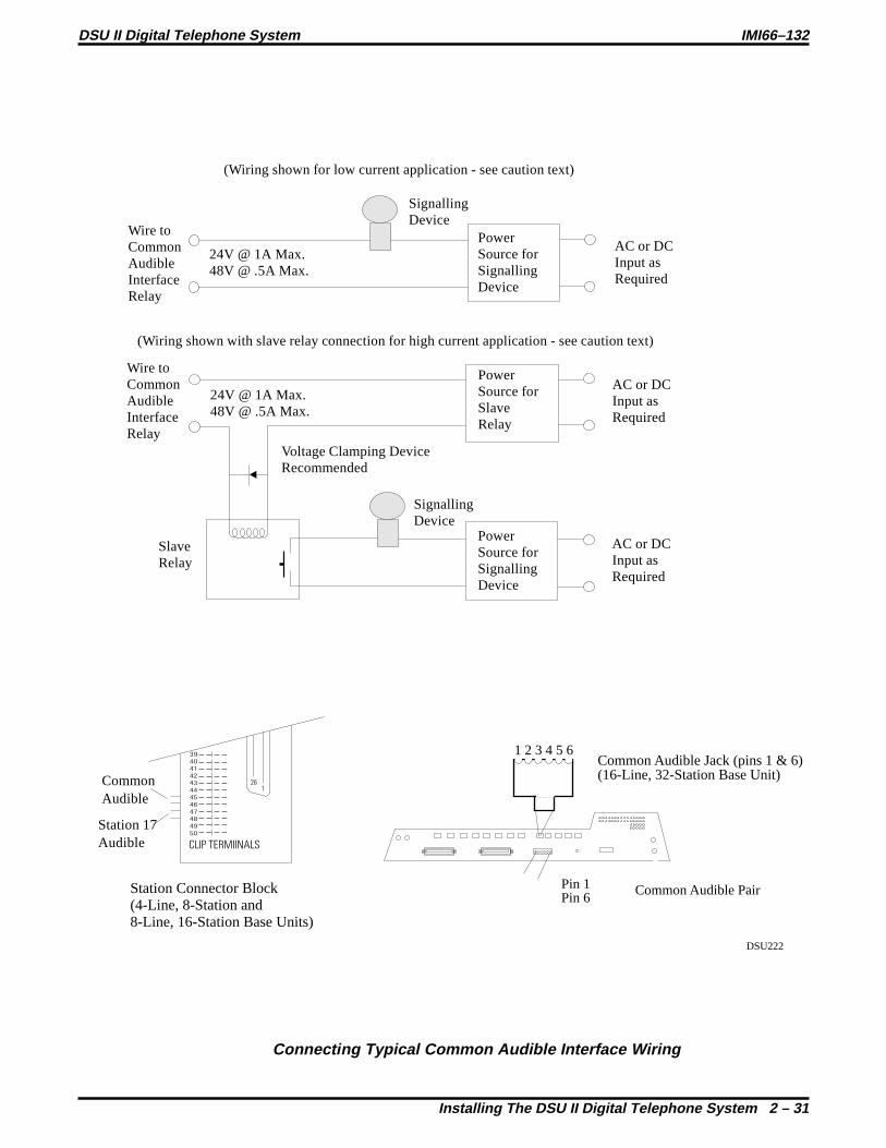
CLIP TERMIINALS
261
CommonAudible
Station 17Audible
39
40
41
42
43
44
45
46
47
48
49
50
Station Connector Block(4-Line, 8-Station and8-Line, 16-Station Base Units)
(Wiring shown for low current application - see caution text)
Wire toCommonAudibleInterfaceRelay
Wire toCommonAudibleInterfaceRelay
SignallingDevice
SignallingDevice
PowerSource forSignallingDevice
AC or DCInput asRequired
AC or DCInput asRequired
AC or DCInput asRequired
24V @ 1A Max.48V @ .5A Max.
24V @ 1A Max.48V @ .5A Max.
(Wiring shown with slave relay connection for high current application - see caution text)
PowerSource forSlaveRelay
Voltage Clamping DeviceRecommended
SlaveRelay
PowerSource forSignallingDevice
DSU222
Common Audible Jack (pins 1 & 6)(16-Line, 32-Station Base Unit)
1 2 3 4 5 6
Pin 1Pin 6 Common Audible Pair=
Connecting Typical Common Audible Interface Wiring
DSU II Digital Telephone System IMI66–132
Installing The DSU II Digital Telephone System 2 – 31

2.10 Using The External Paging InterfaceThe system provides a special transformer-isolated paging port that you can use to couple thesystem to a customer-supplied external paging amplifier. This external paging port does notprovide a talk-back path nor will it recognize DTMF dial tones.
You can use the relay closure dry-contact points that the system makes available at the ringingport terminal for controlling the external paging amplifier during a paging operation. Thesecontacts close and stay closed during the time that a paging operation is active to provide aconstant enable signal path for the paging amplifier.
NOTE: This paging enable constant closure function overrides the ring pattern closureprovided when ringing is sent to the paging port.
• Connect the audio input of a customer-supplied external paging amplifier to the paging port.
• If the paging amplifier requires an enable signal, connect the enable leads to the station 17audible terminals.
J1632 Base Unit
J1 Connector BlockStation 17 Audible Connection for
(J0408 and J0816 Systems)
123456789
1011121314151617181920212223242526272829303132333435363738394041424344454647484950
CLIP TERMIINALS
50
261
25
Audio Input
Enable Input
Connect AudioInput To CommonEquipmentPaging Port
DSU224
PA System
J0408 Base Unit
Paging Port
J0816 Base Unit
Paging Port
Paging Port
DSU224
1 2 3 4 5 6
Pin 2Pin 5 Station 17 Audible Pair=
Connecting A Typical External Paging Interface
IMI66–132 DSU II Digital Telephone System
2 – 32 Installing The DSU II Digital Telephone System

2.11 Using A Line Port As AnExternal Paging Interface
You can use class of service programming to program a line port to be an AUXILIARY port. Asan AUXILIARY port, a user can use it to couple a telephone to an external paging device thatyou have wired to the line port. He or she does this from any station with that line presence bypressing the proper line button to select the AUXILIARY port. The user can dial DTMF tones ordial pulses through the AUXILIARY port as needed. The paging enable relay closure featurediscussed previously is not available for use with this installation.
• Connect the audio input of a customer-supplied external paging amplifier to the tip and ringleads of the AUXILIARY port.
• You can install a DTMF tone select, zone-paging amplifier if you wish. If you do installthis type of amplifier, the user must dial the zone-select code after he or she presses theAUXILIARY port line select button.
RING 2RING 1TIP 1TIP 2
RING 4RING 3TIP 3TIP 4
RING 6RING 5TIP 5TIP 6RING 8RING 7TIP 7TIP 8
CO/PBXLINES
Line Termination
Type 66M-XXConnector Block
orIndividual 6-PositionModular Jacks
.
.
PA System
Program line port asauxiliary port and connectPA system to tip and ringpair of that port.
AudioInput
DSU215
Connecting A Line Port As An External Paging Port
DSU II Digital Telephone System IMI66–132
Installing The DSU II Digital Telephone System 2 – 33

2.12 Connecting Data Devices To The SystemThe DSU II includes serial data ports for use. The common equipment cabinet provides theseports as standard modular jacks labeled COM 1 and COM 2 This section contains information ontwo stages of wiring these connections for data devices.
Section 2.12.1 explains connections from stations to modular jacks. Section 2.12.2 details wiringfrom the modular jack to the DSU.
2.12.1 Making Modular Jack Data Connections
Modular jack connections are wiring connections from a station to a modular (wall) jack.
The system provides two serial data ports on the J0408 and four serial data ports on the J0816and J1632 for use.
• When you use a personal computer (PC) to perform class of service programming or to loadsystem software into the system, connect it to COM 1.
• When you use a serial data printer for SMDR, SMDA, COS printout, or Caller ID, connectit to the COM 2.
NOTE: The distance between a data device and the common equipment can be up to 500 feetin a quiet electrical environment. Some sites may require shielded cable for longruns. For longer distances, you must install limited distance modems to relay the datacommunications between the common equipment and a data device.
When preparing a cable for connection to a data device, refer to the manufacturer’s manual forthe equipment being interfaced and make the following wiring connections:
• Wire the common equipment RD (data from device to common equipment) connection tothe device TD (transmit data) connection.
• Wire the common equipment TD (data to device from common equipment) connection tothe device RD (receive data) connection.
• Wire the common equipment SG (signal ground) connection to the device SG (signalground) connection.
• If required for proper operation, wire the common equipment CTS (clear-to-send statusfrom device to common equipment) connection to the device RTS (request-to-send)connection.
NOTE: The common equipment requires a positive voltage, with respect to signal ground, inorder to send data.
IMI66–132 DSU II Digital Telephone System
2 – 34 Installing The DSU II Digital Telephone System

IBM
IBM
IBM
5
4 3
2
Front Viewof Jack
6 5 4 3 2 1
TDRDSGFrom COM 1
Serial Data Port
Typical VDTInterface
Typical625A2
ModularJack
Industry StandardModular Line Cord
(4-conductor)
Typical modular to EIA adapterwiring shown for reference only.
Typical Personal Computer
TypicalData Printer
1
2
3
4
5
6
7
8
9
10
11
12
13
14
15
16
17
18
19
20
21
22
23
24
25
1
2
3
4
5
6
FrontView of
Jack
SG
RDTD
5
4 3
2
Front Viewof Jack
6 5 4 3 2 1
TD
SGFrom COM 2Serial Data Port
Typical DataPrinter Interface
Typical625A2
ModularJack
Industry StandardModular Line Cord
(4-conductor)
Typical modular to EIA adapterwiring shown for reference only.
1
2
3
4
5
6
7
8
9
10
11
12
13
14
15
16
17
18
19
20
21
22
23
24
25
1
2
3
4
5
6
FrontView of
Jack
SG
RD
dsu263.cdr
CAJS105
1
2
3
4
5
6
7
8
9
123456
Front Viewof 6-ConductorModular Jack
Rear Viewof 9-Pin FemaleEIA Connector
SGTDRDCTS
Typical Modular To 9-Pin EIA AdapterWiring Shown For Reference Only
Connecting Data Devices Through Modular Connections
DSU II Digital Telephone System IMI66–132
Installing The DSU II Digital Telephone System 2 – 35

2.12.2 Making The Common Equipment Data Connections
You must make wiring connections from the modular jack (wall jack) to the common equipmentcabinet modular jack for the data connection.
The default data communications format is as follows:
• 8-bit data with 1 stop bit and no parity
• Baud rate of 9600 baud.
Configure a data device to match this format for initial operation or reprogram the system’s dataformat to match those of a data device. The tables below list the system’s data ports.
NOTE: The distance between a data device and the common equipment can be up to 500 feetin a quiet electrical environment. Some sites may require shielded cable for longruns. For longer distances, you must install limited distance modems to relay the datacommunications between the common equipment and a data device.
IMI66–132 DSU II Digital Telephone System
2 – 36 Installing The DSU II Digital Telephone System

J1632 Base Unit
J0408 Base Unit
J0816 Base Unit
Com 2
Com 2
Com 2
Com 3
Com 3
1.= Request to Send (RTS)2.= Clear to Send (CTS)3. = Receive Data (RD)4. = Transmit Data (TD)5. = Signal Ground (SG)6. = No Connection
Com 1
Com 1
Com 1
Com 4
Com 4
DSU225
(Front View of Jack)
654321
Making Data Connections To The System
DSU II Digital Telephone System IMI66–132
Installing The DSU II Digital Telephone System 2 – 37

2.12.3 Connecting A Personal ComputerFor Remote Programming
You can connect a personal computer (PC) to the DSU II digital telephone system remotelythrough modems as described below. (For information on direct connection, refer to Section2.12.1. )
You will need the following customer-supplied equipment:
• PC and appropriate software program,
• Pair of data modems.
The data modems must be: “Hayes-compatible,” capable of 300-, 1200-, 2400-, or 9600-bauddata speeds, and have auto-answer capability. Be sure to verify the auto-answer capability beforepurchasing the units. You are assured of best results if you employ modems of the same makeand model at both the installation site and the remote programming site.
Make the equipment connections per the following procedure:
1. Determine the signal needs of the modem from the user’s manual for it. (The digitaltelephone system only requires TD, RD, and SG but the modems may require more signals.Check with the modem manufacturer for special requirements).
2. Wire the proper connector (to match the data jack) on one end of a length of multiline cable.
3. Punch down the appropriate leads on the connector block.
4. Connect the network jack of the data modem to an outside telephone line. (If a line is notreserved for remote programming, have a line switch installed so that on site personnel canswitch the outside telephone line between the data modem and the digital telephone systemcabinet when you are going to perform remote programming.)
5. Refer to the user’s manual for the modem, and program the modem to automatically answerafter the first ring.
6. Interface the PC with the modem at the programming site per the user’s manuals for theequipment be used.
7. Establish a communications link for programming the system from a remote site.
• If you have had a line switch installed at the customer site, call someone there and ask themto set it for modem operation.
• After the outside line is connected to the modem, make the data link between theoriginating and the remote modems, and perform programming from your remote site justas if the PC was connected directly to the system.
IMI66–132 DSU II Digital Telephone System
2 – 38 Installing The DSU II Digital Telephone System

If you experience difficulty in establishing a communications path between your PC, modems,and the digital telephone system, note the suggestions that are listed below.
• Confirm that the modems are wired correctly. Be sure RD, TD, and SG are connected to thesystem’s serial data connection. Reverse connections at pins 2 and 3 if necessary.Sometimes you must strap pin 4 to 5, or pin 6 to 7, or pin 6 to 8 to 20 in the modem wiring.Check the modem’s installation manual for this requirement. Also check the manual for anyadditional wiring connections.
• Use a breakout box data tester to troubleshoot the data communications lines.
• Be sure that your modem has: auto-answer capability, DTR override, and CD override andthat the Result Codes, On-Line Echo, Off-Line Echo, and Flow Control are disabled. Plus,make sure that you have enabled the modem’s auto-answer feature. The way to do this is toprogram an initialization string into the modem. A typical initialization string that usesgeneric modem AT Commands for connection to a telephone system’s serial data port is asfollows: AT E0 F1 L2 Q1 S0=0 &C0 &D0 &K0 &W0 &Y0. Remember, this is a typicalinitialization string—not all modems will respond to it. You should refer to your modem’sinstruction manual if you have difficulty.
TypicalPersonal Computer
Data Jack
LineSwitch
Telco Network
NetworkJack
DataJack
Typical CommonEquipment Cabinet
DataPort
LinePort
Network Jack
DataModem
DataModem
dsu260.cdr
Installing A Personal Computer For Remote Programming
DSU II Digital Telephone System IMI66–132
Installing The DSU II Digital Telephone System 2 – 39

2.13 Using The Music InterfaceIf music is to be part of the system, connect a customer-provided music source to the commonequipment music interface jack (phono jack) provided for this purpose. The impedance of thisinput is approximately 500Ω. Use the volume control on the music source to adjust the audiolevel of the music as required.
Music Interface
Music Source(for music on hold
and background music)
DSU216
Using The Music Interface
IMI66–132 DSU II Digital Telephone System
2 – 40 Installing The DSU II Digital Telephone System

2.14 Using The Add-On Expansion ModulesYou can install optional add-on expansion modules to the DSU II common equipment base unitto increase the line and station capacity of an installed system.
• The JM408 expansion module provides an additional four lines and eight digital proprietarystations.
• The JM008 expansion module provides interface and ring generation for eightindustry-standard telephone devices.
Base UnitType
Base Unit Capacity ExpansionModule Type
Total System Capacity
LinesSystemStations
LinesSystemStations
ISTs
J0408 4 8 one JM408 8 16 -one JM008 4 8 8
J0816 8 16
one JM408 12 24 -two JM408 16 32 -one JM008 8 16 8two JM008 8 16 16one JM408 andone JM008
12 24 8
J1632 16 32
one JM408 20 40 -two JM408 24 48 -one JM008 16 32 8two JM008 16 32 16one JM408 andone Jm008
20 40 8
2.14.1 Using The JM408 Module
The JM408 expansion module provides to an installed system an additional four lines and eightdigital proprietary stations. The default numbering of the expanded lines and stations begin withthe next higher line or station port number from that provided by the host base unit. Thenumbering continues sequentially from top module to bottom module if two modules areinstalled. For example: The defaulted 8-line, 16-station base unit provides station ports 10through 25 and lines 1 through 8. When installed, a JM408 expansion module provides stationports 26 through 33 and lines 9 through 12 thus creating a 12 line by 24 station system.
Each expansion module provides a tip and ring pair as an emergency power failure circuit. Thiscircuit is connected to the first module-provided line.
DSU II Digital Telephone System IMI66–132
Installing The DSU II Digital Telephone System 2 – 41

Connecting Lines To The JM408 Expansion Module
The expansion module’s line connections are available at two modular jacks. When facing thejack openings, lines 1 and 2 are provided by the jack on the right and lines 3 and 4 are providedby the jack on the left.
Line JackPin
NumberConnection
TelephoneNumber
1
1 No Connection2 Line 2M Tip3 Line 1M Tip4 Line 1MRing5 Line 2M Ring6 No Connection
2
1 No Connection2 Line 4M Tip3 Line 3M Tip4 Line 3M Ring5 Line 4M Ring6 No Connection
IMI66–132 DSU II Digital Telephone System
2 – 42 Installing The DSU II Digital Telephone System

Connecting Stations To The JM408 Expansion Module
The station connections are available at a 50-pin connector.
25-Pair Connections Two-Wire Connections Station Connections
Wire Color Pair Pin No.ClipTerm.
Pair Wire Color Station Location
White-Blue 1 26 1 Signal Path Green 1MBlue-White 1 2 RedWhite-Orange 2 27 3 Signal Path Green 2MOrange-White 2 4 RedWhite-Green 3 28 5 Signal Path Green 3MGreen-White 3 6 RedWhite-Brown 4 29 7 Signal Path Green 4MBrown-White 4 8 RedWhite-Slate 5 30 9 Signal Path Green 5MSlate-White 5 10 RedRed-Blue 6 31 11 Signal Path Green 6MBlue-Red 6 12 RedRed-Orange 7 32 13 Signal Path Green 7MOrange-Red 7 14 RedRed-Green 8 33 15 Signal Path Green 8MGreen-Red 8 16 RedRed-Brown 9 34 17
Spare Pair
Brown-Red 9 18Red-Slate 10 35 19Slate-Red 10 20Black-Blue 11 36 21Blue-Black 11 22Black-Orange 12 37 23Orange-Black 12 24Black-Green 13 38 25Green-Black 13 26Black-Brown 14 39 27Brown-Black 14 28Black-Slate 15 40 29Slate-Black 15 30Yellow-Blue 16 41 31Blue-Yellow 16 32Yellow-Orange 17 42 33Orange-Yellow 17 34Yellow-Green 18 43 35Green-Yellow 18 36Yellow-Brown 19 44 37Brown-Yellow 19 38Yellow-Slate 20 45 39Slate-Yellow 20 40Violet-Blue 21 46 41Blue-Violet 21 42Violet-Orange 22 47 43Orange-Violet 22 44Violet-Green 23 48 45Green-Violet 23 46Violet-Brown 24 49 47Brown-Violet 24 48Violet-Slate 25 50 49 Signal Path Tip Power Fail StationSlate-Violet 25 50 Ring
DSU II Digital Telephone System IMI66–132
Installing The DSU II Digital Telephone System 2 – 43

2.14.2 Using The JM008 Module
The JM008 expansion module provides an interface for a wide variety of industry-standardtelephone (IST) equipment such as 500 and 2500-type telephones, cordless telephones, voicemail systems, answering machines, FAX machines, and data modems.
Each IST port drives a load with a maximum ringer equivalence number (REN) of 2.0. Checkthe REN number of the connected IST equipment so you do not exceed the capacity of the ISTport. Improper operation may result if you exceed the REN maximum.
The default numbering of the expansion module stations begin with the next higher station portnumber from that provided by the host base unit. The numbering continues sequentially from topmodule to bottom module if two modules are installed. For example: The defaulted 8-line,16-station base unit provides station ports 10 through 25. When installed, a JM008 expansionmodule provides station ports 26 through 33. A second JM008, when installed in the bottommounting location, provides station ports 34 through 41.
CAUTION
If you install both a JM408 and a JM008 on the same cabinet, you must install the JM408 atthe upper expansion module location or the lines provided by the JM408 will not function.
When you install the JM008 and connect IST devices to it, there are several programmingrequirements that you must consider. Refer to Chapter 3, Section 3.10 for complete details.
IMI66–132 DSU II Digital Telephone System
2 – 44 Installing The DSU II Digital Telephone System

Connecting Stations To The JM008 Module
The station connections are available at a 50-pin connector.
25-Pair Connections Two-Wire Connections Station Connections
Wire Color Pair Pin No.Clip
Term.Pair Connection Station Location
White-Blue 1 26 1 Signal Path Tip 1MBlue-White 1 2 RingWhite-Orange 2 27 3 Signal Path Tip 2MOrange-White 2 4 RingWhite-Green 3 28 5 Signal Path Tip 3MGreen-White 3 6 RingWhite-Brown 4 29 7 Signal Path Tip 4MBrown-White 4 8 RingWhite-Slate 5 30 9 Signal Path Tip 5MSlate-White 5 10 RingRed-Blue 6 31 11 Signal Path Tip 6MBlue-Red 6 12 RingRed-Orange 7 32 13 Signal Path Tip 7MOrange-Red 7 14 RingRed-Green 8 33 15 Signal Path Tip 8MGreen-Red 8 16 RingRed-Brown 9 34 17
Spare Pairs
Brown-Red 9 18Red-Slate 10 35 19Slate-Red 10 20Black-Blue 11 36 21Blue-Black 11 22Black-Orange 12 37 23Orange-Black 12 24Black-Green 13 38 25Green-Black 13 26Black-Brown 14 39 27Brown-Black 14 28Black-Slate 15 40 29Slate-Black 15 30Yellow-Blue 16 41 31Blue-Yellow 16 32Yellow-Orange 17 42 33Orange-Yellow 17 34Yellow-Green 18 43 35Green-Yellow 18 36Yellow-Brown 19 44 37Brown-Yellow 19 38Yellow-Slate 20 45 39Slate-Yellow 20 40Violet-Blue 21 46 41Blue-Violet 21 42Violet-Orange 22 47 43Orange-Violet 22 44Violet-Green 23 48 45Green-Violet 23 46Violet-Brown 24 49 47Brown-Violet 24 48Violet-Slate 25 50 49Slate-Violet 25 50
DSU II Digital Telephone System IMI66–132
Installing The DSU II Digital Telephone System 2 – 45

Checking Industry-Standard Telephone Connections To The JM008 Module
When you connect industry-standard telephones to the JM008 expansion module, the maximumdistance allowed from the common equipment to the telephone is 1500 feet if you use #24 gaugeor larger, twisted pair cable.
Check the installation of industry-standard telephones for proper operation by performing thefollowing voltage measurements under the conditions listed:– have both the common equipment and the stations connected to the station connector block,– have bridging clips installed on the connector block,– have the system powered and operational.
Measure DC voltage across the tip and ring pair of each installed industry-standard telephonewith a DC voltmeter. You should read:+24 volts DC+/- 2 volts.
Call each industry-standard telephone to stimulate the ring generator assembly, and measure theAC ringing voltage across the tip and ring pair of each called telephone.You should read:55 volts AC +/- 5 volts.
If your measured voltages are different from the values shown herein, it could indicate a wiringerror or equipment problem.
IMI66–132 DSU II Digital Telephone System
2 – 46 Installing The DSU II Digital Telephone System

Installing An OPX Long Loop Adapter With The JM008
You must use an OPX long loop adapter if you wish to adapt the JM008’s IST station port tosupport an off-premise IST application. An OPX long loop adapter connects to a singletelephone line and can greatly extend the line’s loop length (the Proctor Model 46222 adapter*,for example, can extend line length to 30,000 feet).
*Proctor & Associates Company, Redmond WA
CAUTION
When you connect an OPX long loop adapter to an off-premise extension (OPX), you mustinstall primary protectors in series with the tip/ring pair of the telephone line that is routed tothe OPX. This action is necessary to protect both the user and the equipment from transientvoltage spikes that can travel through the cable. The telephone company offers basicprotection against this condition; however, that protection is usually designed to safeguard thecentral office circuits and you cannot rely upon it to protect common equipment. To helpinsure that external over-voltage surges do not damage the system, installation specialistsrecommend that you install and properly ground gas discharge tubes or similar primaryprotection devices on the telephone line that routes between the adapter and the OPX.
To install the OPX long loop adapter:
• Follow manufacturer’s instructions for unpacking, inspecting, mounting and wiring theadapter unit.
• Plug a modular cable into the system jack on the adapter and connect the opposite end ofthe cable to the JM008’s station port.
• Plug a modular cord into the telephone jack on the adapter and connect the opposite end ofthe cord to the OPX line.
• Plug the adapter power cord into a standard 117 VAC, 3-wire electrical outlet.
DSU II Digital Telephone System IMI66–132
Installing The DSU II Digital Telephone System 2 – 47

2.14.3 Installing An Add-On Expansion Module
Each JM408 or JM008 add-on expansion module measures 15.5" wide x 9.4" high x 1.6" wideand weighs approximately 4 pounds. The modules are designed so that you can attach them tothe base unit and connect them to it via cabling.
NOTE: If you plan to upgrade the system software at the same time that you add expansionmodules,add the expansion modules first by following steps 1 through 11. Then,after you have installed the expansion modules and programmed for the new stationsand line ports, upgrade the software as described in the discussion titled,LoadingAnd Up-Grading The System Software.
To install an expansion module to a base unit, follow the procedure detailed in steps 1–11.
CAUTION
You must always connect the first module to the top location on the base unit.
1. Disconnect both AC power and external battery back-up power from the system.
2. Remove and set aside nameplate from base unit. This action exposes internal cable connectoron base unit circuit board.
3. Reach through opening in base unit and mate module cable plug with base unit circuit boardconnectors.
4. Push excess cable inside base unit housing through connector opening.
5. Install expansion module in place on all four mounting holes. Be sure excess cable is notpinched between add-on module and base unit.
6. Pull module down to latch in place.
7. Use appropriate screw driver to tighten module securing screw into base unit threadedfastener.
8. Snap nameplate into slots on top of module housing.
9. Attach #10 or #12 insulated, solid copper wire between the frame ground stud on theexpansion module and the frame ground stud on the common equipment cabinet.
10. Reconnect the power to the system.
11. Refer to Chapter 3, and perform configuration programming for new station and line ports.
IMI66–132 DSU II Digital Telephone System
2 – 48 Installing The DSU II Digital Telephone System

Typical Base Unit
Typical Add-On Module
(8-Line, 16-Station Base Unit)
Nameplate(Remove to expose baseunit connectors)Top
Location
BottomLocation
Upper Mounting Holes(2 Places)
Lower Mounting Holes(2 Places)
Connecting Cableand Plug
Snap Slots forNameplate
SecuringScrew
GroundModulesto Base
Unit
cajs111.cdr
Ground Base CabinetTo Earth Ground.
Installing The Add-On Expansion Module
DSU II Digital Telephone System IMI66–132
Installing The DSU II Digital Telephone System 2 – 49

2.15 Checking The System InstallationThe system operating features are set to default conditions at initial power-up. These conditionsprovide a basic operating system with a known set of parameters, and you should check out thesystem with the default conditions in place. At any time while the system is operating, you canreset default conditions from station port 10 or 12 following the instructions provided in chapter3, Programming.
2.15.1 Checking The Resistance
Measure the resistance at the station connector blocks under the following conditions.
• AC power cord disconnected from electrical outlet.
• Common equipment connected to station connector blocks.
• Stations wired and wiring punched down on blocks.
• Bridging clips removed from blocks to isolate stations from common equipment.
Measure the resistance of each installed station and wiring from the station side of the connectorblocks. Resistance values will vary with cable length and station type but should be within thefollowing limits:
• Greater than 700 KΩ
2.15.2 Checking The Voltage
Make the following voltage measurements at the station connector blocks under the followingconditions:
• Bridging clips installed
• AC power connected to the common equipment
Measure the voltage across the signal pair. The measured voltage for proprietary telephones mustbe within the following limits:
• 28–36 VDC
NOTE: Refer to Section 2.14.2 for information on testing industry-standard telephonesconnected through the JM008 expansion module.
IMI66–132 DSU II Digital Telephone System
2 – 50 Installing The DSU II Digital Telephone System

2.15.3 Checking The General Operating Conditions
1. Check the green light emitting diode (LED) system status indicator. Be sure that it is onsteady. If it is off or flashing, refer to the paragraph titledChecking the System StatusIndicator.
2. Refer to the user’s guide for operating information and perform a general operational test ofthe system by exercising the features from station port 10 or 11. Operational parameters areper the system default conditions as detailed in Chapter 4 until class of service programmingis performed.
3. Once the basic system is verified as operational, perform the class of service programming asdescribed in Chapter 3.
2.16 Isolating FailuresSection 2.17 will help you to find and identify problems that might occur in the digital telephonesystem.
2.16.1 Checking The System Status Indicator
A green LED located on the common equipment cabinet is the system status indicator. Thisindicator light comes on when power is supplied to the system. If the indicator flashes afterpower up, it signals that the processor has failed or that the software is not operating. Unplug andreconnect the AC power to the power supply and observe the LED indication. If it still shows aflashing indication, equipment replacement may be necessary.
2.16.2 Testing The Stations
To test the multiline stations for proper operation:
1. Disconnect line cord at station base then reconnect it.
2. On DigiTech telephones, press and hold theMUTE button.On Impactand Impression telephones, press and hold1 on the keypad.Station will automatically perform self test routine.
3. Release test button as soon as test begins. Sequence of test is as follows:a. indicators will light in sequence,b. ringer will sound—be sure volume is set to low or high,c. indicators and ringer will then turn off at the same time.
4. Replace any station that does not pass the self test.
DSU II Digital Telephone System IMI66–132
Installing The DSU II Digital Telephone System 2 – 51

2.17 Loading And Up-Grading The System SoftwareThe DSU II contains flash memory that you load with operating software when you install thesystem and later re-load with software up-grades as they become available.
The operating software package consists of three parts: The boot-loader EPROMs that isfactory-installed as part of the system, and the software key and software disks that you orderseparately. The software disks include the boot loader interface disk and the operating softwaredisks.
2.17.1 Introducing The Software Key
The software key is a hardware device to un-lock the DSU II so it can accept the systemoperating software. Factory technicians program and initialize the software key, and make itavailable in several different configurations.
The configurations are as listed below:DSUII–SW01DSUII–SW05DSUII–SW10DSUII–SW25The configurations control the number of times that you can use a key to load or up-gradeoperating software into a system; however, it does not matter which DSU II system you load.(For example, with a DSUII–SW01 key, you can load any DSU II system one time; however,with the DSUII–SW25, you can load or up-grade one system 25 times or load 25 differentsystems one time—your choice.)
IMI66–132 DSU II Digital Telephone System
2 – 52 Installing The DSU II Digital Telephone System

2.17.2 Introducing The Software Disks
There are several standard 3.5-inch magnetic diskettes for each software part number. This groupof diskettes include the boot loader interface and the system operating software. You place thesediskettes (commonly referred to as floppy disks), into your personal computer (PC) in a certainorder just as you would any set of program disks.
CAUTION
The system operating software is unique for each of the three system sizes. Be sure that youload the correct system software for the size system that you are installing.
Parallel Port25-Pin D Connector
Rear View of TypicalPersonal Computer (PC)
Security KeyConnect To Computer's
Parallel Port
CAJS031j.cdr
Modular To EIA AdapterConnect To Serial Port(Both 9-Pin and 25-Pinadapters are available.)
Connect ToCOM 1 PortOn DSU II
4-Conductor Line Cord
Serial Ports9-Pin D Connector25-Pin D Connector
Connecting The Security Key
DSU II Digital Telephone System IMI66–132
Installing The DSU II Digital Telephone System 2 – 53

2.17.3 Loading The Software
Installing The Bootloader Interface
You must install the boot loader interface on your PC before you can install the system operatingsoftware.
Installing The Bootloader Interface Software With Windows 95*
1. Insert the bootloader interface disk (labeleddisk1) in your PC’s disk drive.
2. From theStart menu, selectRun .
3. At the prompt line, type:<drive>:\disk1\setupwhere <drive> is the letter of your source diskdrive.
4. Click Ok. The Bootloader Interface installation window appears.
NOTE: Alternately, you can use theExplorer View to navigate to the source <drive> andthen to thedisk1 folder . Once there, double click onsetup.exe and the BootloaderInterface installation window appears.
5. Remove the bootloader interface disk from you computer’s disk drive.
6. From the Bootloader Interface load window, follow the on-screen prompts to finish loadingthe software. The installation creates a DSU II BTLDR I/F window complete withappropriate icons.
NOTE: Your PC’s screen may now show the DSU II BTLDR I/F folder; however, if it doesnot: selectStart , then selectProgram s, and then navigate to DSU II BTLDR I/Ffolder.
7. From the DSU II BTLDR I/F window, double click on theInstall SKey Driver icon.
8. SelectExpress and follow the on-screen prompts.
9. When you reach the prompt to restart windows, do so.
*Windows 95 is a registered trademark of Microsoft Corporation, Redmond, Washington
IMI66–132 DSU II Digital Telephone System
2 – 54 Installing The DSU II Digital Telephone System
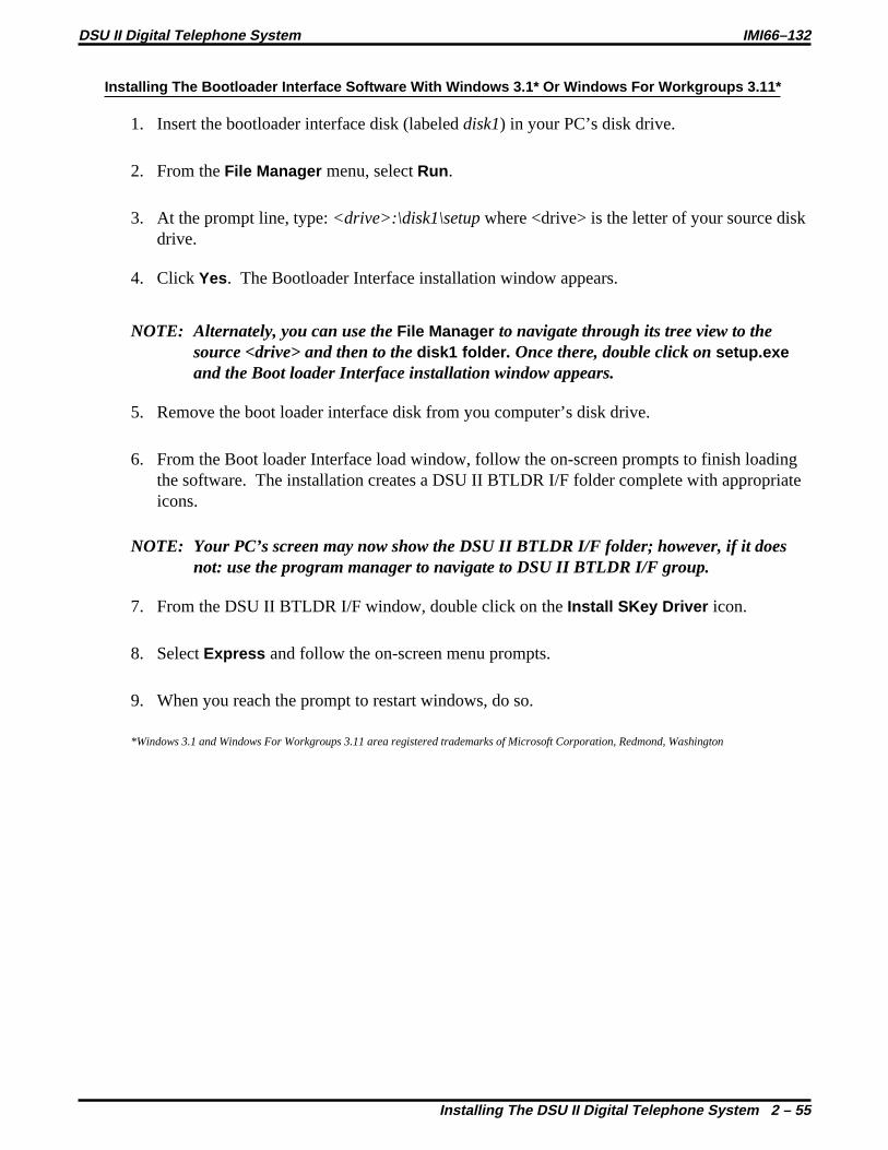
Installing The Bootloader Interface Software With Windows 3.1* Or Windows For Workgroups 3.11*
1. Insert the bootloader interface disk (labeleddisk1) in your PC’s disk drive.
2. From theFile Manager menu, selectRun .
3. At the prompt line, type:<drive>:\disk1\setupwhere <drive> is the letter of your source diskdrive.
4. Click Yes. The Bootloader Interface installation window appears.
NOTE: Alternately, you can use theFile Manager to navigate through its tree view to thesource <drive> and then to thedisk1 folder . Once there, double click onsetup.exeand the Boot loader Interface installation window appears.
5. Remove the boot loader interface disk from you computer’s disk drive.
6. From the Boot loader Interface load window, follow the on-screen prompts to finish loadingthe software. The installation creates a DSU II BTLDR I/F folder complete with appropriateicons.
NOTE: Your PC’s screen may now show the DSU II BTLDR I/F folder; however, if it doesnot: use the program manager to navigate to DSU II BTLDR I/F group.
7. From the DSU II BTLDR I/F window, double click on theInstall SKey Driver icon.
8. SelectExpress and follow the on-screen menu prompts.
9. When you reach the prompt to restart windows, do so.
*Windows 3.1 and Windows For Workgroups 3.11 area registered trademarks of Microsoft Corporation, Redmond, Washington
DSU II Digital Telephone System IMI66–132
Installing The DSU II Digital Telephone System 2 – 55

Un-installing The Bootloader Interface
The software provides a means by which you can un-install it if you wish.
For Windows 95 operating systems,
1. From theStart menu, selectPrograms , and navigate to the DSU II BTLDR I/F folder.
2 Double click on theUnstall icon.
3. In the event that you were accessing the DSU II BTLDR I/F folder and its contents, you mayneed to manually delete the folder and its contents. From Explorer view, navigate through<drive> toWINDOWS, then toSTART-MENU, then toPROGRAMS, and finally toDSU IIBTLDR I/F . From there, delete all short-cuts associated with the bootloader interface.
For Windows 3.1 and Windows For Workgroups 3.11,
From theProgram Manager , navigate toDSU II BTLDR I/F , and double click theUninstallicon.
Installing The System Operating Software
CAUTION
In this software loading sequence, the system will prompt you to save the class of service database. ALWAYS SAVE THE DATA BASE FIRST before you proceed with the software load.Saving the data base first ensures that you will have it available should something go wrongduring the software loading procedure. Later, after you have finished loading the systemsoftware, master clear the system and reload the data base that you saved before you loadedthe software.
Saving The Class Of Service Data Base (Using An XMODEM-Type Communications Program)
Use the PC and an XMODEM-type communications software program to save the DSU IIsystem’s class of service data base before you load the software. The following procedureillustrates a typical data base down-load usingPROCOMM(produced by DatastormTechnologies Inc.). Other software programs are also available that you can use for this purpose.
1. When the PC display prompts for a password, typeI746 or the current system passwordand pressRETURN (This causes main COS programming menu to be displayed).
2. From main menu, make all selections necessary to perform class of service programmingthen return to the main menu.
3. From main menu, press1 andRETURN (This causes system COS programming menu to bedisplayed).
IMI66–132 DSU II Digital Telephone System
2 – 56 Installing The DSU II Digital Telephone System

4. From the system menu, press4 andRETURN (This causes load/save menu to bedisplayed.) From load/save menu, you can down-load the COS data base to your PC(usually to some temporary location on your hard drive).
To down-load the data base,(a) press1 andRETURN,(b) pressPAGE DOWN,(c) press1 to choose XMODEM protocol,(d) type destination file name for the down-loaded data base—include destination
drive (for example, C:\ cust.001)(e) pressRETURN. The data base automatically down-loads to the destination file.
To down-load speed dials and auto dials,(a) press3 andRETURN,(b) repeat above steps b–e.
To up-load the data base after you have up-graded the system operation software andmaster-cleared the system,(a) press2 thenRETURN(b) pressPAGE UP(c) press1 to choose XMODEM protocol(e) type file name of saved COS data—include source drive if necessary(f) pressRETURN. The data base is automatically up-loads to the DSU II system.
To up-load speed dials and auto dials,(a) press4 andRETURN,(b) repeat above steps b–f.
If the up-load completes properly, the screen displays:Xmodem transfer complete, no errors.
5. Return to the main menu and log off.
DSU II Digital Telephone System IMI66–132
Installing The DSU II Digital Telephone System 2 – 57

Loading The System Operating Software (Using The DSU II Bootloader Interface)
1. Connect the security key to the parallel port on the PC.
NOTE: If you wish to view the available up-grade count and the system type supported by thesecurity key, selectKey from the main menu and then selectView .
2. Install the system operating software disk (labeleddisk2) in your PC’s disk drive.(Alternately, you could have pre-loaded the disk’s contents into a file location on your PC’shard drive.)
3. With Windows 3.1 click the boot loader icon to open the DSU II BTLDR I/F window andfrom there click theBoot loader Interface icon.With Windows 95, selectStart , Programs , DSU II BTLDRI_F , andDSU II Boot loaderInterface . The DSU II Boot loader Interface window will open.
4. From theDSU II Boot loader Interface window, select theSystem drop-down menu, andthen selectUpgrade.
5. Follow the on-screen prompts until you reach the Logon Dialog window.
6. At the Logon Dialog window, select the appropriate user type, and typeI746 or yourcurrent system programming password.
7. Follow the on-screen prompts until you reach the appropriate DSU II System Binary FileSelection Dialog box.
8. Use the Drive pull-down menu to select the location where the DSU II System Binary Fileresides.
9. Navigate to and then select the appropriate DSU II System Binary File displayed in the FileSelection Dialog box. The system software load automatically begins. A typical load willtake approximately nine minutes.
IMI66–132 DSU II Digital Telephone System
2 – 58 Installing The DSU II Digital Telephone System

Master Clearing The System
After you load the system operating software, master clear the system. Master clearing returnsthe entire system configuration to factory settingsand clears all stored auto and speed dialnumbers.
NOTE: Do not do this unless you want to clear all of the programmed data base.
1. Type the passwordI746ÿ(this will get you into the main menu) andRETURN.
2. Press1 for System C.O.S. andRETURN.
3. Press1 for System Defaults andRETURN.
4. Press8 for Master Clear System Data andRETURN.
5. Pressy to confirm andRETURN.
6. PressCTRL C to return to main menu andRETURN.
7. Up-load the class of service data base that you saved before you loaded the system operatingsoftware (see the previous paragraph titledSaving The Class Of Service Data Baseforup-loading procedure.
DSU II Digital Telephone System IMI66–132
Installing The DSU II Digital Telephone System 2 – 59
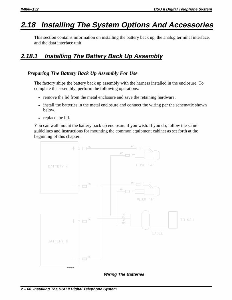
2.18 Installing The System Options And AccessoriesThis section contains information on installing the battery back up, the analog terminal interface,and the data interface unit.
2.18.1 Installing The Battery Back Up Assembly
Preparing The Battery Back Up Assembly For Use
The factory ships the battery back up assembly with the harness installed in the enclosure. Tocomplete the assembly, perform the following operations:
• remove the lid from the metal enclosure and save the retaining hardware,
• install the batteries in the metal enclosure and connect the wiring per the schematic shownbelow,
• replace the lid.
You can wall mount the battery back up enclosure if you wish. If you do, follow the sameguidelines and instructions for mounting the common equipment cabinet as set forth at thebeginning of this chapter.
batt3.cdr
Wiring The Batteries
IMI66–132 DSU II Digital Telephone System
2 – 60 Installing The DSU II Digital Telephone System

batt1.cdr
Installing The Batteries
DSU II Digital Telephone System IMI66–132
Installing The DSU II Digital Telephone System 2 – 61
Connecting The Battery Back Up Assembly
The common equipment provides an interface connector for the connection of an optionalexternal battery assembly.
CAUTION
Be sure that the AC power cord is connected to the electrical outlet before connecting anexternal battery assembly to the common equipment interface connector. This ensures thatinternal protection circuitry is operating to prevent damage that could result from improperconnection.
The external battery assembly provides a minimum of one hour of operation should the ACpower to the system be interrupted. The assembly has a 15 ampere-hour current rating and isfused with the following value: 4A 250V 3AG type.
The external battery assembly may include batteries from either of the following suppliers:
• Model PS-12150 from Power-Sonic Corporation, Redwood City CA, 94032
• Model PE12V15 from GS PORTALAC, City Of Industry CA, 91748
The minimum battery backup time for a fully configured system can be calculated using theformula:
Back Up Time (in hours) = K(15)1 + [(0.1) (N)]
K (Constant) = 0.9 for J0408 with or without an expansion module0.8 for J0816 with or without expansion modules0.8 for J1632 with or without expansion modules
15 = ampere-hoursN = total number of stations
Example:Assume that a J1632 system plus two JM408 modules are installed along with the optionalbattery assembly to provide back-up power.
Back up time =(0.8) (15)
=12
= 2.1 Hours1+[(0.1) (48)] 5.8
IMI66–132 DSU II Digital Telephone System
2 – 62 Installing The DSU II Digital Telephone System

During AC operation, the common equipment provides recharging current to maintain thevoltage potential of the external battery assembly at an operational level. The charging circuitmay not provide an adequate charge if an installed battery assembly has a current rating ofgreater than 40 ampere-hours. You should measure the battery assembly voltage every threemonths.
For proper backup capabilities, make sure the batteries meet the following specifications:
• With a fully-charged battery assembly disconnected from the common equipment, themeasured voltage must be greater than 12 VDC but should not exceed 13.5 VDC.
• With a fully-charged battery assembly connected to the common equipment, the measuredvoltage should be less than 13.8 VDC. If the voltage measures higher than this limit,contact your Comdial Technical Services representative.
• The open output of the common equipment battery charger connection measures 13.6-13.8VDC. If the charging voltage measures higher or lower than this range, contact yourComdial Technical Services representative
• An optional external battery assembly requires approximately 10 hours to completelyre-charge to full potential after it has been completely discharged and, in some cases, wheninitially installed.
FrameGround
Stud
Plug-in powerline surge
protector (typical)
Dedicated 117VAC15 AMP NEMA 5-15R
electrical outletwith third-wire ground
DSU217
TypicalEarth
Ground
Optional ExternalBattery andCable Assembly
Interface Connector(For Optional External Battery Assembly)
(R)(G)
(W)(BK)
Connecting The Battery Back-Up Assembly
DSU II Digital Telephone System IMI66–132
Installing The DSU II Digital Telephone System 2 – 63

2.18.2 Installing The Analog Terminal Interface
Introducing The Analog Terminal Interface (ATI-D)
The ATI-D is a multipurpose,on-premiseaccessory for the DSU II digital telephone system.It has dual circuits that provide the following features:
• INDUSTRY-STANDARD TELEPHONE (IST) INTERFACE-This feature adapts mostindustry-standard telephone (IST) devices to the digital telephone system. The ATI-D willaccept both tone (DTMF) and pulse (rotary) dialing from these devices.
• SYSTEM INTERCONNECTION-This feature allows an installer to connect two digitaltelephone systems to each other using two ATI-Ds andon-premisewiring. Wheninterconnected, either telephone system treats the other telephone system as an IST device.The two telephone systems are not integrated together and do not share features.
• MODEM ADAPTER-This feature allows the flow of switched data between a data sourceand a data receiver through the digital telephone system.
• VOICE MAIL/ANSWERING MACHINE INTERFACE-This feature allows an installer toconnect voice mail systems and automated answering devices to the digital telephonesystem.
CAUTION
The ATI-D by itself does not support any off-premise service. Never connect the ATI-D to atelephone company-supplied line unless you have first installed an acceptable OPX long loopadapter.
The ATI-D is housed in a self-contained metal enclosure that can be wall mounted if desired.The ATI-D is powered by the digital telephone system through the station port connections andemploys an internal ringing generator to generate a ringing signal for an IST. Dual, high-quality,low-loss, balanced, telephone transmission circuitry supports two IST inputs.
One 2-pair cable (four-wire) connects the ATI-D to two common equipment station ports. Asingle pair of wires connects the external analog IST equipment to the ATI-D. Modularconnectors are provided to allow quick connections.
Each ATI-D circuit drives a load with a maximum ringer equivalence number (REN) of 2.0, thusallowing more than one IST connection at each interface input. Check the REN number of theconnected IST equipment so as not to exceed the capacity of the ATI-D. Improper operationmay result if the REN maximum of the ATI-D is exceeded.
The ATI-D supports a wide variety of IST equipment such as 500 and 2500-type telephones,cordless telephones, voice mail systems, answering machines, FAX machines, and data modems.
IMI66–132 DSU II Digital Telephone System
2 – 64 Installing The DSU II Digital Telephone System

Detailing The The Analog Terminal Interface Specifications
Power requirements: Supplied by the common equipment
Ringing voltage: 55 VAC Nominal @ 20 Hz(45 VAC minimum)Power rated to maximumREN = 2.0
Battery feed voltage: 24 VDC nominal
Loop current limits between ATI-Dand IST interface: 20 ma min. at 620 ohms
70 ma max. at 0 ohms
DC loop limits from ATI-D toindustry standard interface per port: 620 ohms maximum including interfaced telephony device.
(Approximately 4000 feet with #26 AWG twisted-pair cableand 300 ohm device load.)(Approximately 500 feet if two IST devices are connected inparallel on same tip and ring pair.)
DC loop limits from ATI-D to voicemail system: Approximately 1000 feet with #26 AWG twisted-pair cable.
Cable insulation resistance: 30,000 ohms minimum
Cable requirement ATI-D to system 2-pair twisted cable; 25 feet maximum length. (Both commonequipment station ports must always be connected to theATI-D for every installation, and they must be paired insequence - 12 & 13, 14 & 15, etc.)
Cable terminations: 623-type, 4-conductor mini jacks
Dialing: Industry-standard DTMF or Dial pulse (rotary) with nominalmake/break ratio of 40/60 @ 10 PPS
Ringing cadence: Outside calls = 2 second on -4 seconds off
Intercom calls = Two bursts:1 second on - .5 second off,1 second on - 3.5 seconds off
Operating temperature: 32-122 F (0-50 C)
Humidity: 90 % relative, non-condensing
Height: 2.375 inches
Width: 8.062 inches
Length: 11.125 inches
Weight: 4 lbs. (plus 2 lbs.for packing material)
FCC registered and listed for safety compliance as part of digital telephone system
FCC certified, Part 15 (class A)
DSU II Digital Telephone System IMI66–132
Installing The DSU II Digital Telephone System 2 – 65

Mounting The Analog Terminal Interface
Refer to Section 2.1 at the beginning of this chapter for system mounting considerations that arealso applicable to the analog terminal interface.
Mounting Procedure
1. Unpack and carefully inspect the ATI-D for shipping damage. Notify the shipperimmediately of any damage found. Verify that the package contains all parts and accessoriesneeded for proper installation and operation.
2. If a backboard is required at the mounting location, attach it securely to provide a stablemounting surface.
3. Use the base of the ATI-D as a template or measure for mounting hole locations per thedimension details shown in the illustration on the next page.
4. Drill holes of a proper size to accommodate the hardware being used into the mountingsurface. If necessary, prepare these holes with inserts, anchors or other attachment devices asdictated by the type of mounting surface.
5. Insert the two top screws into the mounting surface and tighten them to within approximately1/8-inch of the surface.
6. Hang the ATI-D on the top screws using the mounting holes located on the rear of thecabinet. Note that these holes are elongated with an enlargement at one end. This featureallows the cabinet to snap down on the screws to secure the mounting when the cabinet ishung on them.
7. Insert a third screw through the mounting tab located on the lower edge of the cabinet andinto the mounting surface; tighten it into place.
IMI66–132 DSU II Digital Telephone System
2 – 66 Installing The DSU II Digital Telephone System

10 15/16
2 3/8
7 3/16
11 3/16
5 5/8
11
Outline Dimensions(In Inches)
Spacing ForMounting Hardware
(In Inches)
AW139
Detailing The ATI Dimensions
DSU II Digital Telephone System IMI66–132
Installing The DSU II Digital Telephone System 2 – 67

Connecting The Analog Terminal Interface
Connect the ATI-D per the diagram detailed on the following page. A grounding wire is notrequired for operation; however, one is desirable for decreasing radio frequency interference andelectrostatic discharge susceptibility. The ATI-D housing provides a frame ground stud for thispurpose. Connect a #10 or #12, insulated, solid copper wire between this ground stud and areliable earth ground.
NOTE: You must connect both station ports to the ATI-D, even if you plan to use only oneIST device. Connect the first ATI-D port to an even station port. All ATI-D ports mustbe paired.
CAUTION
Be careful when connecting the wiring between the common equipment and the ATI-D. Besure to connect the common equipment station ports to the COMMON EQUIPMENT (KSU)jack on the ATI-D. Damage to the ATI-D could occur if this wiring is mistakenly connected tothe IST jack.
Use a voltmeter to check for the presence of voltage on the ATI-D IST jack.
1. Be sure that you have installed all the wiring between the ATI-D and the common equipmentstation ports.
2. Measure for DC voltage on IST jack:-Measure between TIP leads and common equipment grounding stud.-Measure between RING leads and common equipment grounding stud.-Measure between TIP leads and RING leads.The measured voltage must be within following limits:MEASUREMENT VOLTAGETip to Ground +3 to +11 VDCRing to Ground -13 to -21 VDCTip to Ring +23 to +25 VDC(The TIP lead is positive with respect to the RING lead.)
Understanding Analog Terminal Interface Programming Requirements
Once you have connected the ATI-D to the system there are several programming steps that youshould take to make it fully operational. Refer to Chapter 3, Section 3.10 for complete details.
Installing A Voice Mail Interface
You can use the ATI-D to provide interfacing for a customer-supplied voice processing system.The ATI-D, using paired station ports (such as 12 and 13 or 14 and 15), will support two voicemail ports.
To complete the installation, connect the voice mail ports to the IST jacks on the ATI-D.
IMI66–132 DSU II Digital Telephone System
2 – 68 Installing The DSU II Digital Telephone System

Common Equipment JackPIN 1 No ConnectionPIN 2 Odd Station (Tip)PIN 3 Even Station (Tip)PIN 4 Even Station (Ring)PIN 5 Odd Station (Ring)PIN 6 No Connection
Line JackPIN 1 No ConnectionPIN 2 IST 2 (Tip)PIN 3 IST 1 (Tip)PIN 4 IST 1 (Ring)PIN 5 IST 2 (Ring)PIN 6 No Connection
65
4 32
1PIN Locations OnJacks - Front View
EarthGround(Optional)
123456789
1011121314151617181920212223242526272829303132333435363738394041424344454647484950
CLIP TERMINALS
50
261
25
Typical StationConnector Block
ATI-D
CommonEquipmentJack Line Jack
Connect to Station Connector Jack
ATI3
On-Permise IST Jacks 1 and 2
Interconnecting The ATI-D
DSU II Digital Telephone System IMI66–132
Installing The DSU II Digital Telephone System 2 – 69

Installing An OPX Long Loop Adapter ToThe Analog Terminal Interface For Off-Premise Service
As stated previously, the analog terminal interface is an on-premise device. You must use anOPX long loop adapter if you wish to adapt the ATI-D to support an off-premise application. AnOPX long loop adapter connects to a single telephone line and can greatly extend the line’s looplength (the Proctor Model 46222 adapter*, for example, can extend line length to 30,000 feet).
*Proctor & Associates Company, Redmond WA
CAUTION
When you connect an adapter to an off-premise extension (OPX), you must install primaryprotectors in series with the tip/ring pair of the telephone line that is routed to the OPX. Thisaction is necessary to protect both the user and the equipment from transient voltage spikesthat can travel through the cable. The telephone company offers basic protection against thiscondition; however, that protection is usually designed to safeguard the central office circuitsand you cannot rely upon it to protect common equipment. To help insure that externalover-voltage surges do not damage the system, installation specialists recommend that youinstall and properly ground gas discharge tubes or similar primary protection devices on thetelephone line that routes between the adapter and the OPX.
To install the OPX long loop adapter:
• Follow manufacturer’s instructions for unpacking, inspecting, mounting and wiring theadapter unit.
• Plug a modular cable into the system jack on the adapter and connect the opposite end ofthe cable to the IST jack on the ATI-D.
• Plug a modular cord into the telephone jack on the adapter and connect the opposite end ofthe cord to the OPX line.
• Plug the adapter power cord into a standard 117 VAC, 3-wire electrical outlet.
IMI66–132 DSU II Digital Telephone System
2 – 70 Installing The DSU II Digital Telephone System

EarthGround(Optional)
123456789
1011121314151617181920212223242526272829303132333435363738394041424344454647484950
CLIP TERMINALS
50
261
25
Typical StationConnector Block
ATI-D
CommonEquipmentJack IST Jack
Off-Premise IST Jack
OPXLong LoopAdapter
On-Premise IST Jack
Connect to station connectorjack on common equipment.
CAJS106
117 VAC
4
4
3
3
2
2
5
5
Installing The Long Loop Adapter
DSU II Digital Telephone System IMI66–132
Installing The DSU II Digital Telephone System 2 – 71

2.18.3 Installing The Data Interface Unit
Unpack the Data Interface Unit (DIU) and check for the following parts:
• Telephone line cord
• Power cable with attached transformer.
Installing The Mechanical Components
You can install the DIU in either a free-standing manner or you can mount it on a wall.
When mounting the DIU on a wall:
1. Select a location that is close to a standard 115 VAC electrical wall outlet. The location youselect should also be convenient to the digital telephone and the Industry Standard Telephone(IST), FAX, or modem-whichever one you will be connecting to the DIU.
2. Once you have selected the location for mounting the DIU, mark two locations for themounting screws as follows:
a. make the first mark,
b. measure 3 13/16 inches horizontally from the first mark and make the second mark.
Mounting The Data Interface Unit
IMI66–132 DSU II Digital Telephone System
2 – 72 Installing The DSU II Digital Telephone System

3. Install two #8 X 3/4-inch screws in the wall at the locations you marked in step 2. Tightenthe screws until the screw heads are 1/4-inch from the surface of the wall.
4. Place the DIU on the wall with the screw heads inserted into the slots provided on the bottomsurface of the DIU. Slide the DIU onto the screw heads until it is firmly attached to thescrews.
Installing The DIU Mounting Screws
DSU II Digital Telephone System IMI66–132
Installing The DSU II Digital Telephone System 2 – 73

Making The Data Interface Unit Cable Connections
Four cable connections are required to the DIU-station line cord, digital telephone line cord,IST/FAX/MODEM line cord, and power cable.
1. Disconnect the line cord on the digital telephone from the digital station port connector andplug it into the connector labeled PHONE on the DIU.
2. Plug the line cord from the IST device you are installing with the DIU (such as a FAXmachine, or modem) into the DIU connector labeled FAX/MODEM.
3. Plug the transformer attached to one end of the power cable into a 115 VAC electrical walloutlet. Connect the other end of the power cable into the DIU connector labeled POWER.The green LED on the DIU will be on to indicate power is being supplied to the DIU.
4. Plug one end of a standard line cord into the connector labeled LINE on the DIU. Plug theother end of the line cord into the digital station port connector.
NOTE: DIU power loss will create the same symptoms as the disconnection of the DIU fromthe digital telephone system. If this occurs, plug the multiline digital telephonedirectly into a digital station port connector.
Preparing The DSU II For DIU Operation
Once you have verified that the system contains the correct software, you must program thesystem for DIU operation. See Chapter 4,System Programmingfor programming details.
IMI66–132 DSU II Digital Telephone System
2 – 74 Installing The DSU II Digital Telephone System

Typical MultilineDigital Telephone( Model8012S Illustrated)Impact
To KSUStation Port
Making The DIU Cable Connections
DSU II Digital Telephone System IMI66–132
Installing The DSU II Digital Telephone System 2 – 75

2.18.4 Supporting Caller Identification Service
You can provide Caller ID information through the serial data port COM2 using the Caller IDInterface (product code CID08) and a special equipment-supplied cable. Caller ID informationfor incoming calls shows on the displays of the system’s LCD speakerphones.
Make the connections that are detailed in the following statements.
• Connect the CO lines providing Caller ID data to both the common equipment and theCID08 line jacks in the same numerical order.
• Connect the CID08-supplied cable between the CID08 and the COM2 serial dataconnection on the common equipment.
• With the Caller ID Interface installed, you can also add two leads to provide the TD and SGsignals to a data printer or personal computer (PC). These leads are useful for adding callerID enhancement to the SMDA/SMDR printout or for providing messages in the ASCIIformat suitable for use with PC-based applications programs.
CommonEquipment
Cabinet7, 8
5, 6
3, 4
1, 2
ModularLinePorts
Lines to CommonEquipment
Modular Jacks
SerialData PortCOM2
To Central Office Line Connections
8 7 6 5 4 3 2 1 PWR
To AC Outlet
Customer-Supplied
Cable
Ports
CID08 Caller ID Interface
INRS-232
OUTRS-232
CrossConnectionBlock
Lines to CID08Caller IDInterface
dsu261.cdr
Connecting The Caller ID Interface
IMI66–132 DSU II Digital Telephone System
2 – 76 Installing The DSU II Digital Telephone System

PORTS
12345678POWER RS-232
OUT
RS-232
IN
Modular Line Jacks
Power Supply Connector
Serial Data Connectors
Locating The CID08 Connectors
PORTS
RS-232 In
CID08Unit #1
RS-232 Out
Lines 1-8
PORTS
RS-232 In
CID08Unit #2
RS-232 Out
Lines 9-16
PORTS
RS-232 In
CID08Unit #3
RS-232 Out
Lines 17-24
To Either COM2Serial Data Portor To Next CID08Unit
Combining Multiple CID08 Units
CTS (Pin 2)RD (Pin 3)
(Pin 5) SG(Pin 4) TD
9
5
8
4
7
3
6
2
1
FromCaller ID
Unit
RS-232 OUTMale
9-Pin, "D"-sub
Solder Cup Side
TD
SG
RDSG
To SerialData PrinterVDT or PC
To COM2Serial Data Port
DXP001
Detailing The CID08 Cable Connection sdsu264.cdr
DSU II Digital Telephone System IMI66–132
Installing The DSU II Digital Telephone System 2 – 77
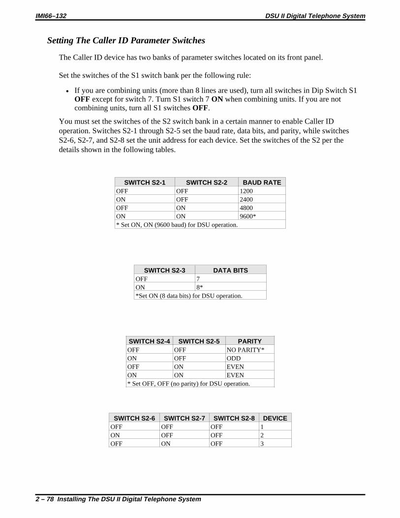
Setting The Caller ID Parameter Switches
The Caller ID device has two banks of parameter switches located on its front panel.
Set the switches of the S1 switch bank per the following rule:
• If you are combining units (more than 8 lines are used), turn all switches in Dip Switch S1OFF except for switch 7. Turn S1 switch 7ON when combining units. If you are notcombining units, turn all S1 switchesOFF.
You must set the switches of the S2 switch bank in a certain manner to enable Caller IDoperation. Switches S2-1 through S2-5 set the baud rate, data bits, and parity, while switchesS2-6, S2-7, and S2-8 set the unit address for each device. Set the switches of the S2 per thedetails shown in the following tables.
SWITCH S2-1 SWITCH S2-2 BAUD RATEOFF OFF 1200ON OFF 2400OFF ON 4800ON ON 9600** Set ON, ON (9600 baud) for DSU operation.
SWITCH S2-3 DATA BITSOFF 7ON 8**Set ON (8 data bits) for DSU operation.
SWITCH S2-4 SWITCH S2-5 PARITYOFF OFF NO PARITY*ON OFF ODDOFF ON EVENON ON EVEN* Set OFF, OFF (no parity) for DSU operation.
SWITCH S2-6 SWITCH S2-7 SWITCH S2-8 DEVICEOFF OFF OFF 1ON OFF OFF 2OFF ON OFF 3
IMI66–132 DSU II Digital Telephone System
2 – 78 Installing The DSU II Digital Telephone System

Power LED
Data LED
Dip Switch 2 (Switches 1-8)
Dip Switch 1 (Switches 1-8)
PWR DATA
Caller IDS1 S2
CAJS092
LocatingThe CID08 DIP Switches
DSU II Digital Telephone System IMI66–132
Installing The DSU II Digital Telephone System 2 – 79

2.18.5 Supporting The Tracker Paging System
The optional Tracker paging system allows you to send alpha/numeric or numeric-only messagesto the Tracker Pagers assigned to a station extension number. The type of message that thesystem delivers is dependent on the Tracker Pager model being used. Tracker’s paging optionrequires only one connection to the digital telephone system; however, you will need to takeseveral programming steps to make it operational.
• If you use station 10 programming to configure the system, install the Tracker base stationto the common equipment cabinet’s COM1 serial data port. Then, after you have completedthe installation, take the programming action detailed in Chapter 3, Section 3.17.
• If you use a video display terminal (VDT) to configure the system, you must connect it tothe COM1 serial data port andyou must take programming action to enable the TrackerPager option and enable Tracker Pagers at stations before you actually install theTracker Pager system. (This is necessary since the Tracker Pager system also uses theCOM1 serial data port and there would be no way to program with a VDT if the TrackerPager system was already installed.)
1. When you finish programming, press CONTROL C for the main menu, and log out from theprogramming mode.
2. Disconnect the VDT from COM 1. As soon as you do this, the system begins polling COM1every two seconds and waiting for a response from a Tracker base station.
3. Connect the Tracker Pager system to COM1. As soon as you connect the Tracker basestation to COM1, the DSU II system recognizes the Tracker base station’s presence andmakes Tracker Pager features available to the system users.
NOTE: While the Tracker base station remains connected, the system continues to poll theport every 10 seconds to verify its presence. This means that if you disconnect theTracker base station to reconnect the VDT, you may have to wait as long as 10seconds for the system to notice that you have replaced the Tracker base station witha VDT.
IMI66–132 DSU II Digital Telephone System
2 – 80 Installing The DSU II Digital Telephone System

PowerOn/OffSwitch
Power-InJack
ON
OFF
POWER
ALARM
EXTERNAL TRANSMITTER
TELEPHONE EIA RS-232C
ANTENNA
Modular To EIA AdapterWith Male DB25 Connector
(Supplied InInstallation Kit)
Kit-suppliedLine Cord
To Serial DataPort COM 1
TrackerPowerSupply
dsu262.cdr
Connecting The Tracker Base Station
DSU II Digital Telephone System IMI66–132
Installing The DSU II Digital Telephone System 2 – 81
2.18.6 Supporting DVA Operation
Digital voice announcing uses a hardware peripheral device (product code DVA01) connected toa digital station port to play pre-recorded announcements and messages during an in-progresscall. The DVA stores the pre-recorded messages in its memory for recall when needed.
The DVA derives its operating power from the common equipment cabinet’s digital station port;however, the DVA also provides internal connections for a battery. When installed, this batterypowers memory that holds the stored messages should someone disconnect the DVA for somereason. Should you need to replace this battery, use one that meets the following specifications:
• Output-8.4 volts, 100 mAh
• Type-Sealed, rechargeable Ni-Cad battery
• Model-Varta V7/8R or equivalent (Varta Batteries Inc., 300 Executive Blvd., Elmsford NY10523)
To install the DVA device,
1. Position the DVA01 in a convenient location.
2. Connect the DVA01 to a digital station port using an RJ14C-configured standard two-wireline cord.
3. If you need to input pre-recorded messages during programming, use a customer-suppliedaudio cable terminated with 3.5mm (1/8 inch) phone plug on one end and and appropriatetape recorder mating connector on the other end.
4. Refer to Chapter 4 for details, and program the system for DVA operation.
IMI66–132 DSU II Digital Telephone System
2 – 82 Installing The DSU II Digital Telephone System

DVA003
TAPE INSTATION
RESET
DVA01
PWR IN USE
1
2
3
4
5
6
7
8
9
10
11
12
13
14
15
16
17
18
19
20
21
22
23
24
25
26
27
28
29
30
31
32
33
34
35
36
37
38
39
40
41
42
43
44
45
46
47
48
49
50
CLIP TERMINALS
50
261
25
Typical StationConnector Block
Station Jack Pin-OutPin 1Pin 2Pin 3Pin 4Pin 5Pin 6
No ConnectionNo ConnectionTip 1Ring 1No ConnectionNo Connection
25-PairMale ToFemaleCable
(Typical)To CommonEquipment
Cabinet
6 5 4 3 2 1
TI RI
R2T2
GREEN RED
FRONTVIEW
OF JACK
1 NO CONNECTION2 NO CONNECTION3 RI-RED-VOICE4 TI-GREEN-VOICE5 NO CONNECTION6 NO CONNECTION
STATIONSITE
Typical StationWall Jack Wiring
65
4
12
3
Audio Tape Recorder
For DSU installations,connect to DVA01'stape in jack.
Interconnecting The DVA Device
DSU II Digital Telephone System IMI66–132
Installing The DSU II Digital Telephone System 2 – 83

2.18.7 Installing The Personal Computer Interface Unit
(Projected Availability of this feature is first quarter of 1997)
The Personal Computer Interface Unit (PCIU) is a device that you can connect between a digitalstation port and its proprietary telephone. The PCIU allows telephone users to initiate telephoneand voice mail related functions from their personal computer (PC).
The PCIU includes Service Provider Interface (SPI) software on computer diskettes. When youinstall this SPI software on a PC, the PC users can employ their Telephony ApplicationsProgramming Interface (TAPI), third-party Microsoft* Windows applications programs tocontrol many useful telephone functions.
When you make the Visual Voice Processing (V.V.P.) Visual Call Manager (VCM) softwareoption available, the voice mail system can use the serial data path to the PCIU to send messagesto the telephone’s display and to the SPI on the PC.
*Microsoft is a registered trademark of Microsoft Corporation, Redmond, Washington
Making The PCIU Cable Connections
Four cable connections are required to the PCIU-station line cord, digital telephone line cord, PCcable, and power cable.
1. Disconnect the line cord on the digital telephone from the digital station port connector andplug it into the connector labeled PHONE on the PCIU.
2. Connect the supplied serial data cable between the PC’s serial data port (COM port) and thePCIU’s serial port connector.
3. Plug one end of a standard line cord into the connector labeled LINE on the PCIU. Plug theother end of the line cord into the digital station port connector.
4. Plug the transformer attached to one end of the power cable into a 115 VAC electrical walloutlet. Connect the other end of the power cable into the PCIU connector labeled POWER.The green LED on the PCIU will be on to indicate power is being supplied to the PCIU.
NOTE: PCIU power loss will create the same symptoms as the disconnection of the PCIUfrom the digital telephone system. If this occurs, plug the digital telephone directly into adigital station port connector.
IMI66–132 DSU II Digital Telephone System
2 – 84 Installing The DSU II Digital Telephone System

Making The PCIU Operational
To make the PCIU operational, you need only follow the instructions enclosed with the SPIsoftware, and load it on the user’s PC. There is no programming action required on the DSU IIdigital telephone system to make the PCIU operational; however, it does require that thesoftware revision be at 2A or later. However, if you use the PCIU with the V.V.P. voice mailsystem, you must program enable the Visual Voice Mail (VVM) option.
Female DB9 SerialPort Connector
MUTESHIFTSPEAKERINTERCOM
TRNS/ CNF
TAPHOLD
OPER
TUVPRS WXY
DEFABCQZ
MNOJKLGHI
0
87 9
321
#
654
COMDIAL
123456789
1011121314151617181920212223242526272829303132333435363738394041424344454647484950
CLIP TERMIINALS
50
261
25
6 5 4 3 2 1
TI RI
R2T2
GREEN RED
FRONTVIEW
OF JACK
1 NO CONNECTION2 NO CONNECTION3 RI-RED-VOICE4 TI-GREEN-VOICE5 NO CONNECTION6 NO CONNECTION
Serial Port Phone Line Power
Male DB9 SerialPort Connector
SuppliedSerial DataCable
PCIU115 VAC Outlet
Typical StationConector Block
Station JackWiring
SuppliedTwo-WireLine Cord
PCIUPowerSupply
To SystemStationConnection
Typical PC Typical Proprietary Telephone pciu04.cdr
Making The PCIU Cable Connections
DSU II Digital Telephone System IMI66–132
Installing The DSU II Digital Telephone System 2 – 85

2.18.8 Connecting The Versatile VoiceProcessing Voice Mail System
The Versatile Voice Processing (VVP) voice mail system provides voice mail and automaticattendant features to the DSU II digital telephone system. A Comdial proprietary voice boardand proprietary software package installed in a personal computer (PC) provides the VVPfeature. A separate publication, which is supplied with the VVP equipment, discusses itsinstallation, programming, and operating details. The information contained below discusses theVVP connections to the DSU II.
The VVP requires industry-standard telephone (IST) station ports for its interface to the DSU II.Each VVP voice port requires its own IST interface. To provide the necessary IST interfaces,you must either install a JM008 expansion module (Section 2.14.2) or connect an ATI-D(Section 2.18.2) to the DSU II common equipment cabinet. Remember, one JM008 expansionmodule provides eight IST ports while each ATI-D provides two.
The VVP software uses both voice and signalling paths between the DSU II and the VVP voiceprocessing circuit board. By using an in-band signalling technique, the IST ports handle both ofthese paths. The efficiency of in-band signalling is dependent upon the availability of idle paths,and busy systems that rely on in-band signalling sometimes slow down. Busy systems workmore efficiently when the signalling path is provided through a serial data connection betweenthe VVP’s PC and the DSU II’s common equipment. This arrangement is termed serialintegration. You must provide serial integration if VVP includes the optional Visual Voice Mail(VVM) feature or if you are using the PCIU (Section 2.18.7) to provide this feature to a singlesystem telephone.
IMI66–132 DSU II Digital Telephone System
2 – 86 Installing The DSU II Digital Telephone System

DSU II Cabinet COM1and COM2 Serial Data Ports
Pin 1 = No ConnectionPin 2 = (CTS) Clear to SendPin 3 = (RD) Receive DataPin 4 = (TD) Transmit DataPin 5 = (SG) Signal GroundPin 6 = No Connection
65
4
12
3
email004.cdr
Versatitle Voice ProcessingVoice Mail Computer
TypicalRear View
Serial Data Ports9-Pin and 25-PinConfigurations
5
4 3
2
Front Viewof Jack
6 5 4 3 2 1
RDCTSSG
For Serial IntegrationConnect DSU II'sCOM1 or COM2 SerialData Port To PC'sSerial Data Port
Typical625A2
ModularJack
Industry StandardFour-Conductor
Modular Line Cord
Typical modular to EIA adapterwiring shown for reference only.
(Viewed from rear of PC)14
15
16
17
18
19
20
21
22
23
24
25
1
2
3
4
5
6
FrontView of
Jack
SG
RD
TD
Connect to matchingserial data port onvoice mail computeras appropriate
RTS
1
2
3
4
5
6
SG
RTS RDTD
9-DB to modular
25-DB to modular
4
64
6
89
8
9
10
11
FrontView of
Jack
TD
VoiceBoardPorts
Industry-StandardFour-ConductorLine Cord
Connect Voice Board Port To DSU II'sIndustry-Standard Telephone Port(Supplied By Either JM008 Expansion ModuleOr ATI-D Analog Terminal Interface Device)
Connecting VVP To The Digital Telephone System
DSU II Digital Telephone System IMI66–132
Installing The DSU II Digital Telephone System 2 – 87

2.19 FCC Rules And RegulationsThis electronic key system complies with Federal Communications Commission (FCC) Rules, Part 68. The FCCregistration label on the common equipment cabinet contains the FCC registration number, the ringer equivalencenumber, the model number, and the serial number or production date of the system.
Notifying The Telephone Company
Unless a telephone operating company provides and installs the system, the telephone operating company whichprovides the lines must be notified before a connection is made to them. Provide the telephone company with thelines (telephone numbers) involved, the FCC registration number, the ringer equivalence number, the FacilitiesInterface Code (FIC), the Universal Service Ordering Code (USOC), and the USOC jack required. The FCCregistration number and the ringer equivalence number is provided on the label attached to the common equipment.The FIC and USOC information is provided in the equipment’s general specifications found in equipment systemmanual. The user/installer is required to notify the telephone company when final disconnection of this equipmentfrom the telephone company line occurs.
Understanding Telephone Network Compatibility
When necessary, the telephone operating company provides information on the maximum number of telephones orringers that can be connected to one line, as well as any other applicable technical information. The telephoneoperating company can temporarily discontinue service and make changes which could affect the operation of thisequipment. They must, however, provide adequate notice, in writing, of any future equipment changes that wouldmake the system incompatible.
Understanding Installation Requirements
Connection of the electronic key system to the telephone lines must be through a universal service order code(USOC) outlet jack supplied by the telephone operating company. If the installation site does not have the properoutlet, ask the telephone company business office to install one. The correct outlet jack for this system is either atype RJ21X or type RJ14C.
Understanding Party Line And Coin Line Limitations
Local telephone company regulations may not permit connections to party lines and coin lines by anyone except thetelephone operating company.
Troubleshooting The Service Problem
If a service problem occurs, first try to determine if the trouble is in the on-site system or in the telephone companyequipment. Disconnect all equipment not owned by the telephone company.If this corrects the problem, the faulty equipment must not be reconnected to the telephone line until the problem hasbeen corrected. Any trouble that causes improper operation of the telephone network may require the telephonecompany to discontinue service to the trouble site after they notify the user of the reason.
Authorizing Repairs
FCC regulations do not permit repair of customer owned equipment by anyone except the manufacturer, theirauthorized agent, or others who might be authorized by the FCC. However, routine repairs can be made according tothe maintenance instructions in this publication, provided that all FCC restrictions are obeyed.
IMI66–132 DSU II Digital Telephone System
2 – 88 Installing The DSU II Digital Telephone System

Recognizing Radio Frequency Interference
The electronic key system contains incidental radio frequency generating circuitry and, if not installed and usedproperly, may cause interference to radio and television reception. This equipment has been tested and found tocomply with the limits for a Class A computing device pursuant to Subpart J of Part 15 of FCC Rules. These limitsare designed to provide reasonable protection against such interference when operated in a commercial environment.Operation of this equipment in a residential area may cause interference to radio and television reception; in whichcase the user is encouraged to take whatever measures may be required to correct the interference. If this equipmentdoes cause interference to radio or television reception, which can be determined by turning the equipment off andon, the user is encouraged to try to correct the interference by one or more of the following measures: Reorient thetelevision or radio’s receiving antenna, and/or relocate the DSU, the individual telephone stations, and the radio orTV with respect to each other. If necessary, the user should consult the manufacturer or an experiencedradio/television technician for additional suggestions. The user may find the following booklet prepared by theFederal Communications Commission helpful: “How to Identify and Resolve Radio-TV Interference Problems.”This booklet is available from the Government Printing Office, Washington D.C. 20402. Stock No.004-000-00345-4.
This equipment has been tested and found to comply with the limits of a Class A digital device, pursuant to Part 15of the FCC Rules. These limits are designed to provide reasonable protection against harmful interference when theequipment is operated in a commercial environment. This equipment generates, uses, and can radiate radiofrequency energy and, if not installed and used in accordance with the instruction manual, may cause harmfulinterference to radio communications. Operation of this equipment in a residential area is likely to cause harmfulinterference in which case the user will be required to correct the interference at his own expense.
This digital apparatus does not exceed the (Class A) limits for radio noise emissions from digital apparatus set out inthe Radio Interference Regulations of the Canadian Department of Communications.
Le pre’sent appareil nume’rique n’emet pes de bruits radioe’lectriques de’passant les limites applicables auxappareils nume’riques (de la class A) prescrites dans le Re’glement sur le brouillage radioe’lectrique e’dicte’ par leministe’re des Communications du Canada.
CAUTION
Changes or modifications to this unit not expressly approved by the partyresponsible for compliance could void the user’s authority to operate the equipment.
Determining The Ringer Equivalence Number
The REN of each line is 0.4B. The FCC requires the installer to determine the total REN for each line, and record itat the equipment.
DSU II Digital Telephone System IMI66–132
Installing The DSU II Digital Telephone System 2 – 89

This page remains blank intentionally.
IMI66–132 DSU II Digital Telephone System
2 – 90 Installing The DSU II Digital Telephone System

Programming The DSU II System
Section Title ..........................................................................................................Page
3.1 Using Chapter Three .................................................................................3–7
3.2 Understanding System Programming......................................................3–73.2.1 Using A Telephone To Program The System.........................................3–73.2.2 Supporting DigiTech Telephones (Revision I And Later) .................... 3–83.2.3 Converting Button Designations ............................................................3–93.2.4 Using A VDT To Program The System ...............................................3–113.2.5 Using Block Programming ...................................................................3–113.2.6 Master Clearing The System ................................................................3–113.2.7 Using Programming Overlays ..............................................................3–11
3.3 Master Clearing and Defaulting The System ........................................3–123.3.1 Master Clearing The System ................................................................3–123.3.2 Defaulting The System .........................................................................3–123.3.3 Defaulting The Lines ............................................................................3–123.3.4 Defaulting The Stations ........................................................................3–133.3.5 Defaulting The Button Assignments ....................................................3–133.3.6 Defaulting The Toll Restriction Tables ................................................3–133.3.7 Programming Password Protection ......................................................3–14
3.4 System Features........................................................................................3–163.4.1 Automatic Station Relocation...............................................................3–163.4.2 Data Baud Rate.....................................................................................3–173.4.3 Do Not Disturb (DND) .........................................................................3–183.4.4 Exclusive Hold .....................................................................................3–193.4.5 Music On Hold .....................................................................................3–193.4.6 LCD Messaging....................................................................................3–203.4.7 PA Port Options....................................................................................3–223.4.8 Station Monitoring................................................................................3–243.4.9 System Alarm Reporting ......................................................................3–253.4.10 System Clock........................................................................................3–263.4.11 System Speed Dial ...............................................................................3–263.4.12 Tandem Attendant ................................................................................3–28
3DSU II Digital Telephone System IMI66–132
Programming The DSU II System 3 – 1

Section Title ..........................................................................................................Page
3.4.13 Tone or Voice Signaling.......................................................................3–283.4.14 Inhibiting System Features ...................................................................3–29
3.5 System Timing..........................................................................................3–303.5.1 Call Park Recall Time...........................................................................3–303.5.2 Extended DTMF Tones For Automatic Dialing...................................3–313.5.3 Pause Time ...........................................................................................3–323.5.4 Recall/Flash ..........................................................................................3–323.5.5 Timed Hold Recall................................................................................3–333.5.6 Unanswered Call Transfer Recall Time ...............................................3–34
3.6 Line Programming...................................................................................3–353.6.1 Abandoned Hold Release .....................................................................3–353.6.2 Automatic Privacy ................................................................................3–363.6.3 Line Disable..........................................................................................3–373.6.4 Line Groups ..........................................................................................3–373.6.5 Line Names...........................................................................................3–383.6.6 Line Port Functions ..............................................................................3–403.6.7 Line To Line Port Re-Assignment........................................................3–413.6.8 Pulse/Tone Switchable .........................................................................3–423.6.9 Block Programming..............................................................................3–433.6.10 Positive Disconnect Supervision ..........................................................3–44
3.7 Station Features........................................................................................3–453.7.1 Access Denied ......................................................................................3–463.7.2 All-Call and Zone Paging .....................................................................3–473.7.3 Audible Monitoring ..............................................................................3–493.7.4 Automatic Hold ....................................................................................3–503.7.5 Automatic Privacy ................................................................................3–513.7.6 Call Forward On Busy/Ring–No Answer.............................................3–523.7.7 Call Origination Denied........................................................................3–543.7.8 Central Message Desk ..........................................................................3–543.7.9 Data Security Port.................................................................................3–553.7.10 Dual Console Feature ...........................................................................3–553.7.11 Executive Override ...............................................................................3–563.7.12 Flexible Ringing Assignments..............................................................3–573.7.13 Flexible Station Numbering..................................................................3–60
IMI66–132 DSU II Digital Telephone System
3 – 2 Programming The DSU II System

Section Title ..........................................................................................................Page
3.7.14 Group Call Pickup ................................................................................3–603.7.15 Handset Volume Control OnImpactTelephones................................ 3–613.7.16 Headset Interface ..................................................................................3–623.7.17 Interactive Buttons............................................................................... 3–633.7.18 Idle Line Preference..............................................................................3–643.7.19 Personal Ringing Tones........................................................................3–653.7.20 Prime Line, Prime Group, And Prime Intercom...................................3–663.7.21 Message Wait Originate .......................................................................3–663.7.22 Ringing Line Preference.......................................................................3–673.7.23 Subdued Off-Hook Voice Announce (SOHVA) Features .................. 3–673.7.24 Service Observing.................................................................................3–713.7.25 Station Disable......................................................................................3–723.7.26 Station Name ........................................................................................3–723.7.27 Station To Station Port Reassignment ..................................................3–743.7.28 System Alarm Report Stations .............................................................3–753.7.29 Voice Announce Blocking....................................................................3–763.7.30 Block Programming..............................................................................3–76
3.8 Button Mapping The Stations (Non-Square Configuration) .............. 3–773.8.1 Account Code Button ...........................................................................3–783.8.2 Automatic Call-Back Button ................................................................3–783.8.3 Blank Buttons .......................................................................................3–793.8.4 Call Forward Button .............................................................................3–793.8.5 Call Park Orbit Button..........................................................................3–803.8.6 Do Not Disturb (DND) Button .............................................................3–803.8.7 DSS/BLF Button...................................................................................3–813.8.8 Line Button ...........................................................................................3–823.8.9 Line Group Button................................................................................3–823.8.10 Line Group Queue Button ....................................................................3–833.8.11 Multiple Intercom Button .....................................................................3–833.8.12 Privacy Button ......................................................................................3–843.8.13 Save Button...........................................................................................3–843.8.14 Voice Announce Block Button.............................................................3–853.8.15 Zone Page/All-Call Button ...................................................................3–85
DSU II Digital Telephone System IMI66–132
Programming The DSU II System 3 – 3

Section Title ..........................................................................................................Page
3.9 Account Codes..........................................................................................3–863.9.1 Account Code Length...........................................................................3–863.9.2 Account Code List ................................................................................3–873.9.3 Enabled or Disabled Account Codes ....................................................3–883.9.4 Forced or Optional Entry Account Codes ............................................3–883.9.5 Message Display Time For Account Codes .........................................3–903.9.6 Verified Account Code Entry ...............................................................3–91
3.10 The Industry-Standard Telephone Interface ........................................3–923.10.1 IST Station Port Line Assignment........................................................3–923.10.2 IST Distinctive Ringing........................................................................3–943.10.3 IST Through Dialing ............................................................................3–94
3.11 Direct Department Calling......................................................................3–953.11.1 Access Codes For Direct Department Calling......................................3–963.11.2 Line Ports For Direct Department Calling ...........................................3–963.11.3 Station Ports For Direct Department Calling .......................................3–973.11.4 Unanswered Call Transfer Recall Time
For Direct Department Calling .............................................................3–983.11.5 Call Forward On Ring—No Answer ....................................................3–99
3.12 Direct Inward Station Dialing...............................................................3–1003.12.1 Dial Time Limit ..................................................................................3–1003.12.2 Inhibiting DISD Digit Dialing............................................................3–1013.12.3 DISD Assist Station............................................................................3–1013.12.4 DISD Incoming Rings ........................................................................3–1023.12.5 Enable/Disable Call Waiting Tone .....................................................3–102
3.13 Data Printer Service...............................................................................3–1033.13.1 Enable Data Printer Operation............................................................3–103
3.14 Voice Mail Interface...............................................................................3–1043.14.1 Voice Mail Port ..................................................................................3–1053.14.2 Automatic Transfer of Voice Mail .....................................................3–1083.14.3 Voice Mail Line ID.............................................................................3–1083.14.4 Voice Mail Transfer on Busy .............................................................3–1093.14.5 Transferring Callers To Voice Mail ...................................................3–1093.14.6 Positive Disconnect Supervision ........................................................3–1103.14.7 Voice Mail Pause................................................................................3–110
IMI66–132 DSU II Digital Telephone System
3 – 4 Programming The DSU II System

Section Title ..........................................................................................................Page
3.15 Versatile Voice Processing.....................................................................3–1113.15.1 Using Tracker Paging System With Versatile Voice Processing ...... 3–1113.15.2 Using Tracker For Message Notification ...........................................3–1123.15.3 Transferring Callers To Voice Mail ...................................................3–1123.15.4 Auto Station Logon ............................................................................3–1123.15.5 Visual Voice Mail Support .................................................................3–113
3.16 Integrated Call Costing .........................................................................3–1143.16.1 Call Costing Flow Diagram Examples ...............................................3–1153.16.2 Exception Tables (Local Calls And Long Distance Calls)................ 3–1213.16.3 Office Code Band Tables (Local Calls) .............................................3–1223.16.4 Zone Call Band Tables (Long Distance Calls) ...................................3–1233.16.5 Area Code Band Tables (Long Distance Calls)..................................3–1243.16.6 Call Rate Tables (Local And Long Distance Calls) ...........................3–1253.16.7 Discard Digits .....................................................................................3–1273.16.8 Dialing Time And Answer Time ........................................................3–1283.16.9 LCD Speakerphone Display Of Costed Calls.....................................3–129
3.17 Specialized Route Access.......................................................................3–1303.17.1 Enable The SRA Feature ....................................................................3–1303.17.2 Enable SRA Office And Area Code Tables .......................................3–1313.17.3 Enable Special SRA Area Code Tables..............................................3–1333.17.4 Insert Digits For SRA .........................................................................3–1353.17.5 SRA Overflow Line Group.................................................................3–1363.17.6 SRA Wait Time ..................................................................................3–137
3.18 Station Message DetailAccounting/Reporting (SMDA/SMDR) ..............................................3–1383.18.1 SMDA Department Numbers .............................................................3–1393.18.2 SMDA Station Assignment ................................................................3–1393.18.3 SMDA Printout...................................................................................3–1403.18.4 SMDR Printout ...................................................................................3–1423.18.5 SMDA Records Deleted By The Attendant .......................................3–143
DSU II Digital Telephone System IMI66–132
Programming The DSU II System 3 – 5

Section Title ..........................................................................................................Page
3.19 Toll Restriction Tables...........................................................................3–1443.19.1 Assign Entries To Toll Restriction Tables .........................................3–1453.19.2 Programming Toll Restriction Table Entries......................................3–1463.19.3 Assign Toll Restriction Tables To Lines............................................3–1473.19.4 Assign Toll Restriction Tables To Stations........................................3–1473.19.5 Assign Toll Restriction Tables To Stations
For Night Transfer (of ringing) ..........................................................3–1483.19.6 Assign Toll Restriction Tables To System Speed Dial Calls ............ 3–1483.19.7 Assign Toll Restriction Override (TRO) Code...................................3–1493.19.8 Positive Disconnect Supervision ........................................................3–150
3.20 The Tracker Paging System..................................................................3–1513.20.1 Preparing The System.........................................................................3–1523.20.2 Enabling The Tracker Paging System ................................................3–1523.20.3 Enabling The Tracker Pagers For Stations .........................................3–1533.20.4 Setting The Data Parameters ..............................................................3–153
3.21 Digital Voice Announcing (DVA) .........................................................3–1543.21.1 Programming For DCD Operation .....................................................3–1553.21.2 DCD Department Transfers Before Disconnect .................................3–1553.21.3 Programming For DISD Operation ....................................................3–1563.21.4 Enabling/Disabling Digital Voice Announcing (DVA) .................... 3–1573.21.5 Programming The DVA Messages.....................................................3–158
3.22 The Data Interface Unit.........................................................................3–1603.22.1 Programming Data Buttons ................................................................3–1603.22.2 Remote Data Station...........................................................................3–1613.22.3 Creating Data Security Groups...........................................................3–161
3.23 Caller ID Service Support .....................................................................3–1623.23.1 Assigning Caller ID Lines (required programming) ..........................3–1653.23.2 Assigning Caller ID Stations (required programming) ..................... 3–1653.23.3 Configuring Com 2 Data Port (required programming) .................... 3–1663.23.4 Setting The Audible First Ring Feature (optional programming) ......3–1663.23.5 Setting The Caller ID Distribution (optional programming)............. 3–1673.23.6 Assigning A “SAVE” button (optional programming) ..................... 3–167
IMI66–132 DSU II Digital Telephone System
3 – 6 Programming The DSU II System

3.1 Using Chapter ThreeSince Chapter 3 deals only with the programming of the system, each programming stepincludes only a brief explanation of that feature. Therefore, before you begin programming thesystem, familiarize yourself with all of the system’s features that are discussed in Appendix A.By doing so, you can be certain that you are programming what the customer wants.
NOTE: Prior to taking any programming action, determine all desired parameters andrequirements. Record this data on the programming reference tables provided inChapter 4.
3.2 Understanding System ProgrammingWhile the Digital Telephone System offers many functional possibilities, it is your programmingthat determines the system’s operation. You can program the system in two ways: using atelephone, or using a Video Display Terminal (VDT) or personal computer runningcommunications software. The programming instructions in this manual detail the telephoneprogramming method. The VDT programming menu is menu-driven and you can follow itson-screen directions.
DSU II Digital Telephone System IMI66–132
Programming The DSU II System 3 – 7

3.2.1 Using A Telephone To Program The System
Perform Class of Service configuration programming from station port 10 or station port 12. Thesystem will not accept programming commands from any other station port in the system. Forbest programming results, use an LCD speakerphone and a DSS/BLF console at station port 11or 13 to see which features are assigned to individual stations. While you can install anynon-LCD digital telephone and use it for programming, visual feedback of the programmingoperations will not be available. You must always keep the handset of the LCD speakerphoneon-hook while you use this telephone to program the system.
NOTE: Be sure the system is not in the night transfer (of ringing) mode of operationwhen you perform the programming steps.
3.2.2 Supporting DigiTech Telephones (Revision I And Later)
There are several items that you need to consider when connecting revision I and later DigiTechtelephones to the DSU II digital telephone system:
• Always program station ports to provide ringing line preference to revision I and laterDigiTech telephones (and to all Impression andImpacttelephones) that are connected there.This action is necessary to activate the orange LED feature on these telephones. The orangestatus light indicates a ringing line to distinguish it from lines that are in use or on hold.
IMI66–132 DSU II Digital Telephone System
3 – 8 Programming The DSU II System
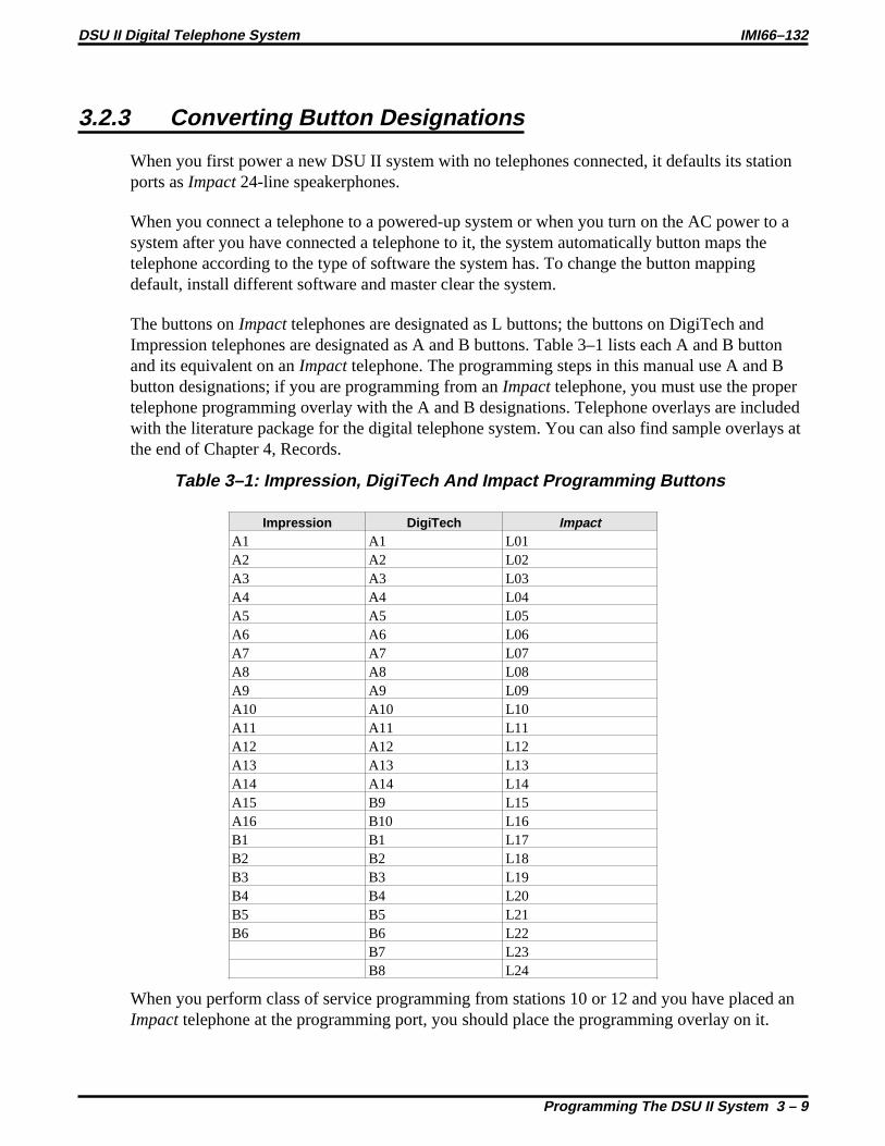
3.2.3 Converting Button Designations
When you first power a new DSU II system with no telephones connected, it defaults its stationports asImpact24-line speakerphones.
When you connect a telephone to a powered-up system or when you turn on the AC power to asystem after you have connected a telephone to it, the system automatically button maps thetelephone according to the type of software the system has. To change the button mappingdefault, install different software and master clear the system.
The buttons onImpacttelephones are designated as L buttons; the buttons on DigiTech andImpression telephones are designated as A and B buttons. Table 3–1 lists each A and B buttonand its equivalent on anImpacttelephone. The programming steps in this manual use A and Bbutton designations; if you are programming from anImpacttelephone, you must use the propertelephone programming overlay with the A and B designations. Telephone overlays are includedwith the literature package for the digital telephone system. You can also find sample overlays atthe end of Chapter 4, Records.
Table 3–1: Impression, DigiTech And Impact Programming Buttons
Impression DigiTech ImpactA1 A1 L01A2 A2 L02A3 A3 L03A4 A4 L04A5 A5 L05A6 A6 L06A7 A7 L07A8 A8 L08A9 A9 L09A10 A10 L10A11 A11 L11A12 A12 L12A13 A13 L13A14 A14 L14A15 B9 L15A16 B10 L16B1 B1 L17B2 B2 L18B3 B3 L19B4 B4 L20B5 B5 L21B6 B6 L22
B7 L23B8 L24
When you perform class of service programming from stations 10 or 12 and you have placed anImpacttelephone at the programming port, you should place the programming overlay on it.
DSU II Digital Telephone System IMI66–132
Programming The DSU II System 3 – 9

This makes the button designations match the A and B designations called for in this systemprogramming manual.
When button mapping using a telephone different from the telephones being programmed(cross-model button mapping), you may need either a programming overlay or Table 3–1depending on the type of telephone installed at the programming port.
If all system telephones are the same type, when you press a button at the programming station,you select the same button on the telephone that you are mapping. No overlay or conversionchart is needed.
When you mix telephones on the same system and you are cross-model button mapping, youwill need either an overlay or the conversion chart. The overlay works best when you are usingan Impacttelephone to button map an Impression or DigiTech telephone. The chart is moreconvenient when you are using a DigiTech or Impression telephone to button map anImpacttelephone. In either case, when you map a line to a selected button, it is best if you choose theline by dialing its code rather than by pressing a button on the programming station to representit. To choose lines 1 through 24, you must dial01 through024.
The following examples explain when you need to use conversions.
• To select buttonL21 for reprogramming on anImpacttelephone using anotherImpacttelephone at station 10 for programming, press buttonL21 on the station 10 telephone. (Noconversion is required in this example.)
• To select buttonB5 for reprogramming on an Impression or DigiTech telephone whileusing anImpacttelephone for programming, press the button designated asB5 by theprogramming overlay on theImpacttelephone at station 10 (this is actually L21 but theoverlay did the conversion for you).
• To select buttonL21 for reprogramming on anImpacttelephone while using an Impressionor DigiTech telephone for programming, press buttonB5 on the Impression or DigiTechtelephone at station 10. (You use the conversion chart to convert the B5 button to an L21button.)
IMI66–132 DSU II Digital Telephone System
3 – 10 Programming The DSU II System

3.2.4 Using A VDT To Program The System
You can perform class of service programming using a Video Display Terminal (VDT) with anRS-232 compatible, serial interface. (You can use a personal computer running acommunications software program in place of the VDT if you wish.) VDT programming iscompletely menu driven and easy to follow. It is arranged somewhat differently from station portprogramming categories to facilitate menu usage.
3.2.5 Using Block Programming
You can program a group of lines or stations to have the same configuration as one that you havealready programmed. This block programming feature eliminates the need to individuallyprogram every line or station that requires the same configuration.
3.2.6 Master Clearing The System
After you have completely installed a telephone system for the first time or if a system that youpreviously installed has been turned off and placed out of service for a period of time (severalweeks, for example), perform a master clear programming procedure before placing it intoservice. If you plan to perform a master clear procedure, perform it first before performing anyother programming procedure. The master clear procedure clears all memory locations of anyunwanted data that may be stored there. Master clearing also clears any previously programmeddata, such as autodial numbers and defaults all class-of-service conditions. Therefore, neverperform a master clear procedure on an existing installed system unless data loss and COSdefault are acceptable. Refer to the information provided in the procedure titled Master Clear forprogramming details.
3.2.7 Using Programming Overlays
The literature package with the system includes a programming overlay for use in identifying thebuttons required for programming. The overlay fits over the buttons of the programming station.A full size copy of available programming overlays is also included at the end of Chapter 4. Theoverlays correspond to the programming steps listed for each feature, so when you are directedto press B1, for example, the overlay details which button is B1 for your telephone.
If you are programming the system from a VDT, it is best to allow the telephones to identifythemselves to the system before you button map them. When you do this, the VDT presents theproper button designations in its prompt and you will not need an overlay or conversion chart.The system queries you to designate the telephone type for unoccupied station ports. Upon yourresponse, the system presents the proper button designations in the prompts for these ports.
DSU II Digital Telephone System IMI66–132
Programming The DSU II System 3 – 11

3.3 Master Clearing and Defaulting The System
You can return the entire programming configuration to the factory settings using the master clearprocedure. You can also return the individual system, line, and station class of service configurations totheir factory settings using the system, line, and station default procedures. The operating parameters andclass of service values provided by the factory settings will provide satisfactory performance in a broadrange of site applications.
CAUTION
Not only does the master clear procedure return ALL programmed variables to aknown state of operation it also clears all currently stored autodial and speed dialnumbers.
3.3.1 Master Clearing The System
Description: Returns entire system configuration to factory settings and clears all stored auto andspeed dial numbers.
To Program: 1. PressINTERCOM , dial # 7 4 6. “CONFIG. MODE”
2. Dial 90. “MASTER CLEAR”
3. Dial 5 1 6 8 4to clear the entire system.System returns to normal operation mode automatically.
3.3.2 Defaulting The System
Description: Returns the system configuration features to factory settings.
To Program: 1. PressINTERCOM , dial # 7 4 6. “CONFIG. MODE”
2. Dial 10. “SYSTEM DEFAULT”
3. Press# to default system features.System returns to configuration mode automatically.
3.3.3 Defaulting The Lines
Description Returns the line configuration features to factory settings.
To Program: 1. PressINTERCOM , dial # 7 4 6. “CONFIG. MODE”
2. Dial 30. “LINE DEFAULT”
3. Press# to default line features.System returns to configuration mode automatically.
IMI66–132 DSU II Digital Telephone System
3 – 12 Programming The DSU II System

3.3.4 Defaulting The Stations
Description: Returns the station configuration features to factory settings.
To Program: 1. PressINTERCOM, dial # 7 4 6. “CONFIG. MODE”
2. Dial 50. “STATION DEFAULT”
3. Dial 00 to default station ports system-wide—OR—select individual station port to be defaulted:— Station 10–57 = Dial 10–57.
4. Dial for next station to default—OR—dial for configuration mode orSPEAKER to quit.
3.3.5 Defaulting The Button Assignments
Description: Returns the button mapping of individual stations to its factory setting.
To Program: 1. PressINTERCOM , dial # 7 4 6. “CONFIG. MODE”
2. Dial 56. “BUTTON MAPPING”
3. Dial 01. “BUTTON DEFAULT”
4. Select station ports to be defaulted—Station 10–57 = Dial10– 57.
5. Dial for next button mapping feature—OR—dial for configuration mode orSPEAKER to quit.
3.3.6 Defaulting The Toll Restriction Tables
Description: The system defaults two toll restriction tables with preprogrammed values and assignsthem to the lines. You need only to assign them the stations to put them into effect. Thepreprogrammed values are as follows:Table 1 (deny) Table 2 (allow)Entry 1 = 1 Entry 1= 1800Entry 2 = 976 Entry 2 = 911Entry 3 = 411Entry 4 = 0These values will provide satisfactory system performance in a broad range of siteapplications; however, they can be changed as needed to meet different toll restrictionneeds.
To Program: 1. Dial 70 “DEFAULT TOLL”
2. Press # to default toll tables
3. Dial for configuration mode orSPEAKER to quit.
DSU II Digital Telephone System IMI66–132
Programming The DSU II System 3 – 13

3.3.7 Programming Password Protection
Description: The system provides two different entry levels for programming and allows for adifferent password for each entry. You must use the VDT programming method tochange them as needed to provide security against unauthorized program entries. The twoprogramming entry levels are the installer level and the administrator level. You enter theinstaller level, using the installer password, to perform all programming functionsincluding major changes such as master clearing or line type programming.Administrators enter the administrator level, using the administrator password, toperform most programming functions except those major changes just mentioned. Youcan make the two passwords different to limit access to either programming level to onlycertain special or authorized people. Additionally, you can construct a password that willprevent all COS programming entry from station 10.
Default Passwords
The default passwords are detailed in the following list:VDT Installer Innn (nnn = 746)VDT Administrator Innn (nnn = 236)Station 10 Installer INTERCOM#nnn (nnn = 746)Station 10 Administrator INTERCOM#nnn (nnn = 236)
Customized Passwords
Customized passwords can be alpha-numeric or numeric only (no spaces allowed) andmust contain six characters. To retain the ability to enter programming from station 10,you must maintain the Innn format in the VDT password and you must enter onlynumbers in the nnn entry; however, you must not enter a zero for the leadingn.
Once you customize a password, it remains customized and you must use the newpassword to gain entry into the system for future programming tasks. Neither default normaster clear will erase the customized password. It is very important that you keep a hardcopy of the customized password since it provides the only entry to system COSprogramming through either the VDT or station 10. If no one can remember thecustomized password, Comdial’s Technical Services Department can provide emergencyentrybut it charges a fee for this service. Otherwise, you must disconnect all AC powerand any battery back-up equipment, wait an extended period of time (up to severalweeks) for the internal memory protection to completely discharge, and reprogram thesystem using the default password to gain entry.
NOTE: Password protection programming is a Video Display Terminal feature only. You can notcustomize a password using station 10 programming entry.
IMI66–132 DSU II Digital Telephone System
3 – 14 Programming The DSU II System

To Program: 1. From keyboard, type I746 for the programming mode.
2. From main COS programming menu,—type6 to change installer password—OR——type7 to change administrator password and pressRETURN.
3. At menu prompt, type customized password using any six alpha-numeric or numericonly characters.
NOTE: To retain the ability to enter programming from station 10, you mustmaintain the Innn format in the VDT password and you must enter onlynumbers in the nnn entry; however, you must not enter a zero for theleading n.
4. As directed by next menu prompt, repeat step 3 to ensure that you entered correctcode.
5. When finished, return to main menu and log out of programming.
DSU II Digital Telephone System IMI66–132
Programming The DSU II System 3 – 15

3.4 System Features
Configuring the system means that you are setting the parameters that will be true system-wide. Youshould make a record in Chapter 4 of all programming decisions that you make—it will help you keeptrack of what you have done and will help you troubleshoot any problem that might arise later.
NOTE: A lighted LED next to the programming button for the selection indicates the currentconfiguration. When a single button provides a toggle (on/off) action, the lighted LEDindicates the active feature.
The first step in any programming sequence is to enter the base level. Once in this mode, you can dial thefeature code for any desired configuration. Enter the base level with the following procedure:pressINTERCOM then dial# 7 4 6. When you want to end the programming, press theSPEAKERbutton to end the programming procedure and return the system to normal operation.
3.4.1 Automatic Station Relocation
Description: With this feature, the system will automatically recognize a particular station should thatstation be re-located to a different station port. The system will supply the same COSparameters at this new port as was programmed for the station at the original port. Thisfeature allows users to relocate their telephone from one station port location to anotheryet retain their original telephone features.
NOTE: If you turn this feature on, be sure to make the station users understand thattheir telephone parameters could change if they trade telephones from port toport. If you want automatic relocation to take place, do nothing and wait forthe light to turn off on its own, or press theHOLD button to immediatelyaccept the relocation. If you do not want automatic relocation to take place,press the# button while the message waiting light is flashing.
To Program: 1. Dial 27. “AUTO STA RELOCAT”
2. PressA1 to toggle between enable and disable (LED On = Enable)—OR—dial 1 to Enable (A1 LED On)dial 2 to Disable.
3. Dial for configuration mode.
To change setting, repeat procedure and make opposite selection.
IMI66–132 DSU II Digital Telephone System
3 – 16 Programming The DSU II System

3.4.2 Data Baud Rate
Description: The speed or baud rate of the data bit stream, which carries the SMDR and configurationdata between the system and an external data device, must be programmed to match therequirements of the data device.
NOTE: If you use XMODEM protocol for data transfer between a PC and thecommon equipment, you must use 8-bit data.
To Program: 1. Dial 15. “BAUD RATE”
2. Dial code for serial data port to be programmed:Dial 1 for COM 1,Dial 2 for COM 2,Dial 3 for COM 3,Dial 4 for COM 4.
3. Choose baud rate—Dial 01or PressA1 “W nD nS 110”—Dial 02or PressA2 “W nD nS 150”—Dial 03or PressA3 “W nD nS 300 ”—Dial 04or PressA4 “W nD nS 600”—Dial 05or PressA5 “W nD nS 1200”—Dial 06or PressA8 “W nD nS 2400”—Dial 07or PressA9 “W nD nS 4800”—Dial 08or PressA10 “W nD nS 9600”—Dial 09or PressA11 “W nD nS 19200”—Dial 10or PressA7 for 7 data bits
and 2 stop bits “W 7D 2S ZZZZZ”—Dial 11or PressA14 for 8 data bits
and 1 stop bit. “W 8D 1S ZZZZZ”
4. Dial for next data port.
5. Dial for configuration mode.
To change setting, repeat procedure and make opposite selection.
DSU II Digital Telephone System IMI66–132
Programming The DSU II System 3 – 17

3.4.3 Do Not Disturb (DND)
All of the following features are part of the Do Not Disturb (DND) application.
Do Not Disturb ButtonDescription: A telephone user can press a button (either one that you have mapped on that station or
one that is provided by an interactive button on an LCD speakerphone) to set the stationto a DND condition.
To program: 1. Dial 56. “BUTTON MAPPING ”
2. Dial 07. “ASSIGN DND CODE ”
3. Select button to be programmed—PressA1–A14, B1–B10.
4. Select station ports to be programmed with a DND button:— Station 10–57 = Dial10––57, or pressC10–C57.
5. Dial for further DND button assignment—OR—dial for next button mapping feature—OR—dial for configuration mode.
To clear, dial5604, press button, dial# and repeat steps 4 and 5.
Do Not Disturb InhibitDescription: You can inhibit the ability to set DND on a system-wide basis.
To Program: 1. Dial 19. “DND XXXXXXXX ”
2. PressA1 to toggle between Enable and Disable (LED On = Enable)—OR—dial 1 to Enable (A1 LED On) “DND ENABLED ”dial 2 to Disable. “DND DISABLED”
3. Dial for configuration mode.
To change setting, repeat procedure and make opposite selection.
IMI66–132 DSU II Digital Telephone System
3 – 18 Programming The DSU II System

Do Not Disturb Override CapabilityDescription: A caller to a DND station can override a DND condition when you program the calling
station to have the DND override feature.
To Program: 1. Dial 53. “STATION FEATURES”
2. Dial 03. “DND OVERRIDE”
3. Select station ports to be programmed—Station 10–57 = Dial10–57, or pressC10–C57.
4. Dial for next station feature—OR—dial for configuration mode.
To change setting, repeat procedure and make different selection.
3.4.4 Exclusive Hold
Description: This feature prevents a telephone user at one station from picking up a call that a userplaced on hold at another station. You can enable or disable it system-wide using thisprocedure.
To Program: 1. Dial 23. “XXXXXXX EXC HOLD”
2. PressA1 to toggle between enable and disable (LED On = Enable)—OR—dial 1 to Enable (A1 LED On) “ENABLE EXC HOLD ”dial 2 to Disable. “DISABLE EXC HOLD”
3. Dial for configuration mode.
To change setting, repeat procedure and make opposite selection.
3.4.5 Music On Hold
Description: When you connect an external music source to the system, it will provide music tooutside lines that are placed on hold. You can disable the music using this programmingprocedure. System attendants also have access to this feature
To Program 1. Press04. “MOH XXXXXXXX”
2. PressA1 to toggle between enable and disable (LED On = Enabled)—OR—dial 1 to Enable (A1 LED on) “MOH ENABLED”dial 2 to Disable. “MOH DISABLED”
3. Dial for configuration mode.
To change setting, repeat procedure and make opposite selection.
DSU II Digital Telephone System IMI66–132
Programming The DSU II System 3 – 19

3.4.6 LCD Messaging
Description: You can create messages that telephone users can set at their stations to be displayed byany LCD speakerphone that calls them on the intercom line. The system provides twostandard messages but you can use this programming procedure to create up to 10 custommessages. System attendants also have access to this feature, but they must use station 10or 12 to program messages.
To Program: 1. Dial 05. “LCD MESSAGES ”
2. Dial 1–0 for message number. “XXXX... ”
3. Dial # to clear current message.
4. Refer to the character code table, and compose message (maximum 16 characters).
5. Dial two-digit codes to create message. “YYYYYYY... ”—OR—dial 10 for pre-programmed message “BACK AT ”—OR—dial 20 for pre-programmed message. “CALL”
6. Dial for next message location and repeat steps 2–5.
7. Dial for configuration mode.
IMI66–132 DSU II Digital Telephone System
3 – 20 Programming The DSU II System

Character Code TableCharacter Code Character Code Character CodeA 21 a 24 Space 12B 22 b 25 - 15
C 23 c 26 ; 17
D 31 d 34 / 18
E 32 e 35 “ 19
F 33 f 36 . 27
G 41 g 44 , 28
H 42 h 45 : 29
I 43 i 46 1 01J 51 j 54 2 02K 52 k 55 3 03L 53 l 56 4 04M 61 m 64 5 05N 62 n 65 6 06O 63 o 66 7 07P 71 p 74 8 08Q 11 q 14 9 09R 72 r 75 0 00S 73 s 76T 81 t 84U 82 u 85V 83 v 86W 91 w 94X 92 x 95Y 93 y 96Z 13 z 16
DSU II Digital Telephone System IMI66–132
Programming The DSU II System 3 – 21

3.4.7 PA Port Options
The common equipment includes a special paging port that you can use to couple the system to acustomer-supplied external paging amplifier. The following section details the programming features forthe paging port.
Ringing TypeDescription: You can assign lines to the PA port for direct ring, delayed ring, or night transfer (of
ringing).
To Program: 1. Dial 60. “P.A. OPTIONS ”
2. Choose ringing assignment—Dial 1 for direct ring “DIRECT RING”—Dial 2 for delay ring “DELAY RING”—Dial 3 for night ring. “NIGHT RING”
3. Select line ports—Line port 1–14 = Dial01–14or pressA1– A14—Line port 15, 16 = Dial15, 16or pressB1, B2—Line port 17–24 = Dial17–24or pressHOLD then pressA1–A8.
NOTE: LEDs turn on when the line is assigned.
4. Dial for next PA option— OR—dial for configuration mode.
To change setting, repeat procedure and make opposite selection.
Zone PagingDescription: You can also assign zone or all-call paging to the PA port.
To Program: 1. Dial 60. “P.A. OPTIONS ”
2. Dial 4 to assign zone paging. “P.A. ZONES ”
3. Choose zone.—PressA1 or dial1 for zone 1—PressA2 or dial2 for zone 2—PressA3 or dial3 for zone 3—PressA4 or dial4 for all-call.
NOTE: A1, A2, A3, or A4 LED turns on when a zone is assigned.
4. Dial for next PA option—OR—dial for configuration mode.
To change setting, repeat procedure and make different selection.
IMI66–132 DSU II Digital Telephone System
3 – 22 Programming The DSU II System

Ringing Relay TrackingDescription: You can select the tracking source for the ringing relay to be either station 17 ringing or
the ringing that you have assigned to the paging port. Making it track the ringing thatyou have assigned to the PA port provides relay control for the customer-supplied PAamplifier if needed.
To Program: 1. Dial 60. “P.A. PORT ”
2. Dial 5. “RELAY XXXXXXX”
3. Choose relay tracking assignment—PressA1 to toggle between paging port and station port 17 (LED On = paging port)—OR——dial 1 for station port 17 “RELAY STA. 17”—dial 2 for paging port. “RELAY P.A. PORT”
4. Dial for next PA option— OR—dial for configuration mode.
To change setting, repeat procedure and make different selection.
Ringing TonesDescription: You can choose between the intercom tone and the DTMF tone for these PA port ringing
tones. The intercom tone provides a soft tone and the DTMF provides a loud tone.
To Program: 1. Dial 60. “P.A. PORT ”
2. Dial 6. “P.A. XXXX TONE ”
3. Choose tone assignment—PressA1 to toggle between intercom and DTMF tone (LED On = Intercom Tone)—OR——Dial 1 for Intercom tone “P.A. ITCM TONE ”—Dial 2 for DTMF tone. “P.A. DTMF TONE ”
4. Dial for next PA option—OR—Dial for configuration mode.To change setting, repeat procedure and make different selection.
DSU II Digital Telephone System IMI66–132
Programming The DSU II System 3 – 23

3.4.8 Station Monitoring
You can enable two types of station monitoring: visual ring indication and audible monitoring.
Visual Ring IndicationDescription: The DSS/BLF at a station provides idle, busy, and ringing status of all of the monitored
stations. If users deem the flashing BLF lights associated with visual ring indicationdistracting, you can disable this visual indication system-wide using this procedure.
To Program: 1. Dial 20. “MONITOR XXXXXXX”
2. PressA1 to toggle between enable and disable (LED On = Enable)—OR——dial 1 to Enable (A1 LED = On) “MONITOR ENABLED”—dial 2 to Disable. “MONITOR DISABLED”
3. Dial for configuration mode.
To change setting, repeat procedure and make opposite selection.
Audible Monitoring (Station Monitoring)Description: If you enable this visual ring indication, you can also enable audible indication of both
direct and delayed ringing on a per-station basis if you wish.
To Program: 1. Dial 53. “STATION FEATURES”
2. Dial 20. “AUDIBLE MONITOR ”
3. Dial 1 for no audible monitoring. “NONE”Dial 2 for direct ring monitoring “DIRECT RING”Dial 3 for delayed ring monitoring. “DELAYED RING”
4. Select stations for programming:—Station 10–57 = Dial10– 57, or pressC10–C57.
5. Dial next monitoring condition—OR—dial for next station feature—OR—Dial for configuration mode.
To change setting, repeat procedure and make different selection.
IMI66–132 DSU II Digital Telephone System
3 – 24 Programming The DSU II System

3.4.9 System Alarm Reporting
The system can send special codes that convey certain system alarm conditions to selected stations wherethey will show on their LCD displays.
System Alarm Report EnablingDescription: Enable the system alarm reporting on a system-wide basis using this feature.
To Program: 1. Dial 28. “ALARM REPORTS”
2. PressA1 to toggle between enable and disable (LED On = Enable).—OR—dial 1 to enable “MONITOR ENABLED”dial 2 to disable. “MONITOR DISABLED”
3. Dial for configuration mode.
To change setting, repeat procedure and make different selection.
System Alarm Report StationsDescription: Enable the system alarm reporting on the desired stations using this feature.
To Program: 1. Dial 53. “STATION FEATURES”
2. Dial 28. “ALARM RECEIVE”
3. Select station ports for programming—Station 10–57 = Dial10–57, or pressC10–C57.
4. Dial for next station feature—OR—dial for configuration mode.
To change setting, repeat procedure and make different selection.
DSU II Digital Telephone System IMI66–132
Programming The DSU II System 3 – 25

3.4.10 System Clock
Description: The system clock maintains current date and time information. The system provides thisinformation to LCD speakerphones for display. Set the system time with this feature.The system attendant also has access to this feature.
To Program: 1. Dial 01. “SET CLOCK ”Long Form Short Form—Dial 00–99for yr. —Dial 00–23 for hr.—Dial 01–12 for mo. —Dial00–59 for min.—Dial 01–31for day —Dial # to assign hours and minutes—Dial 00–23for hr.—Dial 00–59 for min.
2. Dial for configuration mode.
To change setting, repeat procedure and make different selection.
3.4.11 System Speed Dial
Description: The system speed dial is a system-wide list of numbers that all users can access forautomatic dialing. Those users with two-line display LCD speakerphones can scrollthrough the list of names that you assign to the system speed dial numbers using theirspeakerphone’s display. After scrolling through the list, they can pick the name they wishto call, and automatically dial the number assigned to the name. The system scrolls thisindex of names in the sequence that you or the attendant sorted the entries; therefore, besure to arrange the entries in a sequence that best meets the system user’s needs.
To Program: 1. Dial 02. “SYS SPEED DIAL”
2. Dial 01–99for storage location. “XXXXXXXX...”
3. Dial # to clear current entry. “LINE: ”
4. Choose line, line group, or intercomto be used with speed dial number. “LINE XX ”—Line port 1–14 = Dial01–14or pressA1–A14.—Line port 15, 16 = Dial15, 16or pressB1, B2.—Line port 17–24 = Dial17–24or pressHOLD , A1–A8.—Dial 90 for last line used or prime line. “PRIME LINE”—Dial 91–94for line group 1–4. “LINE GROUP 1”—PressITCM button for intercom line. “XXXXX...”
5. Dial number for storage (32 digits max).—If required, pressHOLD button to store a pause.—If required, pressTAP button to store a hookflash.
6. PressT/C button to program name.
7. Enter digits from character chart on the next page to spell name (up to 16 characters).—OR—PressT/C button to leave name blank.
IMI66–132 DSU II Digital Telephone System
3 – 26 Programming The DSU II System

8. PressT/C button to save the number and name.
9. Repeat steps 2–9 for all speed dial numbers.—OR—Press for configuration mode.
Upper Case Character ChartCharacter CodeA 21B 22C 23D 31E 32F 33G 41H 42I 43J 51K 52L 53M 61N 62O 63P 71Q 11R 72S 73T 81U 82V 83W 91X 92Y 93
Lower Case Character ChartCharacter Codea 24b 25c 26d 34e 35f 36g 44h 45i 46j 54k 55l 56m 64n 65o 66p 74q 14r 75s 76t 84u 85v 86w 94x 95y 96z 16
Symbol And NumberCharacter Chart
Character CodeSPACE 12; 17/ 18“ 19. 27, 28: 291 012 023 034 045 056 067 078 089 09
DSU II Digital Telephone System IMI66–132
Programming The DSU II System 3 – 27

3.4.12 Tandem Attendant
Description: When you enable this feature, a recall from an unanswered call transfer or timed holdrecall will ring at both attendant stations. When you disable it, only the attendant stationthat transferred the call will ring.
To Program: 1. Dial 24. “TANDEM ATTN XXX ”
2. PressA1 to toggle between enable and disable (LED On = Enable)—OR—dial 1 to Enable (A1 LED is on) “TANDEM ATTN ON”dial 2 to Disable. “TANDEM ATTN OFF ”
3. Dial for configuration mode.
To change setting, repeat procedure and make different selection.
3.4.13 Tone or Voice Signaling
Description: Intercom calls can be tone signaled or voice signaled. Use this programming feature toselect the system’s signaling choice. With either method set as the system’s first choice,the user can choose the other method as needed.
To Program: 1. Dial 16. “XXXXX ANN. FIRST”
2. PressA1 to toggle between Voice To Tone (LED On = voice signaling)—OR—dial 1 for Voice First “VOICE ANN. FIRST”dial 2 for Tone First. “TONE ANN. FIRST”
3. Dial for configuration mode.
To change setting, repeat procedure and make different selection.
IMI66–132 DSU II Digital Telephone System
3 – 28 Programming The DSU II System

3.4.14 Inhibiting System Features
Description: You can disable certain features system-wide to prevent unauthorized users fromtampering with the system. You can performing the system default procedure to re-enablefeatures that you disable with this feature inhibit procedure.
To Program: 1. Dial 29. “FEATURE INHIBIT”
2. Select feature.—Dial 01 to disable Line Group 1—Dial 02 to disable Line Group 2—Dial 03 to disable Line Group 3—Dial 04 to disable Line Group 4—Dial 05 to disable Zone 1 Paging—Dial 06 to disable Zone 2 Paging—Dial 07 to disable Zone 3 Paging—Dial 08 to disable All Call—Dial 09 to disable Meet Me Page—Dial 10 to disable Night Transfer—Dial 11 to disable Background Music—Dial 12 to disable Voice Announce Block—Dial 13 to disable Message Waiting—Dial 14 to disable Call Pickup—Dial 15 to disable Call Forward—Dial 16 to disable Automatic Call Back—Dial 17 to disable Station-to-Station Messaging—Dial 18 to disable Line Group Queue—Dial 19 to disable Directed Station Hold—Dial 20 to disable Call Park orbit 1—Dial 21 to disable Call Park orbit 2—Dial 22 to disable Call Park orbit 3—Dial 23 to disable Call Park orbit 4—Dial 24 to disable Call Park orbit 5—Dial 25 to disable Call Park orbit 6—Dial 26 to disable Call Park orbit 7—Dial 27 to disable Call Park orbit 8—Dial 28 to disable Call Park orbit 9—Dial 29 to disable Call Waiting—Dial 30 to disable LCD Messaging—Dial 31 to disable Executive Override/Service Observing—Dial 32 to disable Account Code—Dial 33 to disable Personal Call Forward—Dial 34 to enable all features—Dial for next item—Dial for configuration mode.
DSU II Digital Telephone System IMI66–132
Programming The DSU II System 3 – 29

3.5 System Timing
The digital telephone system has several attributes that control timing dimensions of system operation.The following features set these various timing attributes.
3.5.1 Call Park Recall Time
Description: A call that remains in a parking orbit for a programmed length of time automaticallyreturns to a timed hold recall condition at the parking station. Set the call park recall timewith this programming feature.
To Program: 1. Dial 22. “C.P. RECALL X"
2. Select recall time (program button LED On = Selected Time)— Dial 1 or pressA1 = 1 min “C.P. RECALL 1”— Dial 2 or pressA2 = 2 min “C.P. RECALL 2”— Dial 3 or pressA3 = 3 min “C.P. RECALL 3”— Dial 4 or pressA4 = 4 min “C.P. RECALL 4”—Dial 5 or pressA5 = 5 min “C.P. RECALL 5”—Dial 6 or pressA8 = 6 min “C.P. RECALL 6”—Dial 7 or pressA9 = Never Recall. “NEVER RECALL”
3. Dial for configuration mode.
To change setting, repeat procedure and make different selection.
IMI66–132 DSU II Digital Telephone System
3 – 30 Programming The DSU II System

3.5.2 Extended DTMF Tones For Automatic Dialing
Description: When a telephone user dials a number automatically (autodial, saved number redial, etc),the duration of the generated DTMF tones are as you set them with this programmingoption. This feature is useful when automatically dialed numbers access answeringmachines, banking computers, or voice mail, for example, that require DTMF tones thatare longer than standard tones.
To Program: 1. Dial 26. “DTMF DIALNG XXXX”
2. Choose DTMF tone length—Dial 01or pressA1 = 60 msec “DTMF DIALNG 60”—Dial 02or pressA2 = 80 msec “DTMF DIALNG 80”—Dial 03or pressA3 = 100 msec “DTMF DIALNG 100”— Dial 04or pressA4 = 120 msec “DTMF DIALNG 120”—Dial 05or pressA5 = 160 msec “DTMF DIALNG 160”—Dial 06or pressA6 = 240 msec “DTMF DIALNG 240”—Dial 07or pressA7 = 320 msec “DTMF DIALNG 320”—Dial 08or pressA8 = 400 msec “DTMF DIALNG 400”—Dial 09or pressA9 = 480 msec “DTMF DIALNG 480”— Dial 10or pressA10 = 560 msec “DTMF DIALNG 560”—Dial 11or pressA11 = 720 msec “DTMF DIALNG 720”—Dial 12or pressA12 = 880 msec “DTMF DIALNG 880”—Dial 13or pressA13 = 1040 msec “DTMF DIALNG 1040”
3. Dial for configuration mode.
To change setting, repeat procedure and make different selection.
DSU II Digital Telephone System IMI66–132
Programming The DSU II System 3 – 31

3.5.3 Pause Time
Description: During auto dials and speed dials, it is sometimes necessary to delay the sending of digitsto give switching equipment time to prepare for receiving them. A pause is stored for thispurpose whenever the user presses theHOLD button. You can set the length of the pausewith this programming feature.
To Program: 1. Dial 13. “PAUSE TIME XXX”
2. Select time.—Dial 1 or PressA1 “PAUSE TIME 0.50”—Dial 2 or PressA2 “PAUSE TIME 1”—Dial 3 or PressA3 “PAUSE TIME 1.50”—Dial 4 or PressA4 “PAUSE TIME 2”—Dial 5 or PressA5 “PAUSE TIME 3”—Dial 6 or PressA8 “PAUSE TIME 5”—Dial 7 or PressA9 “PAUSE TIME 7.50”—Dial 8 or PressA10 “PAUSE TIME 10”—Dial 9 or PressA11 “PAUSE TIME 15”—Dial 0 or PressA12. “PAUSE TIME 20”
3. Dial for configuration mode.
To change setting, repeat procedure and make different selection.
3.5.4 Recall/Flash
Description: The system can generate either a line disconnect (recall) or a host system feature accesssignal (flash) depending upon the programmed time.
To Program: 1. Dial 12. “RECALL/FLSH XXXX”
2. Select time.—Dial 1 or PressA1 “RECALL/FLSH 0.08”—Dial 2 or PressA2 “RECALL/FLSH 0.30”—Dial 3 or PressA3 “RECALL/FLSH 0.50”—Dial 4 or PressA4 “RECALL/FLSH 0.60”—Dial 5 or PressA5 “RECALL/FLSH 0.75”—Dial 6 or PressA8 “RECALL/FLSH 0.88”—Dial 7 or PressA9 “RECALL/FLSH 1”—Dial 8 or PressA10 “RECALL/FLSH 1.50”—Dial 9 or PressA11 “RECALL/FLSH 2”—Dial 0 or PressA12. “RECALL/FLSH 3”
3. Dial for configuration mode.
To change setting, repeat procedure and make different selection.
IMI66–132 DSU II Digital Telephone System
3 – 32 Programming The DSU II System

3.5.5 Timed Hold Recall
Description: After a call has been on hold for a programmed length of time, the system will recall thestation that placed the call on hold. Set the hold recall time with this programmingprocedure.
To Program: 1. Dial 14. “HOLD RECALL XXX”
2. Select time—Dial 1 or PressA1 “HOLD RECALL 30”—Dial 2 or PressA2 “HOLD RECALL 60”—Dial 3 or PressA3 “HOLD RECALL 90”—Dial 4 or PressA4 “HOLD RECALL 120”—Dial 5 or PressA5 “HOLD RECALL 180”—Dial 6 or PressA8 “HOLD RECALL 240”—Dial 7 or PressA9 “HOLD RECALL 300”—Dial 8 or PressA10 “HOLD RECALL 360”—Dial 9 or PressA11 “HOLD RECALL 420”—Dial 0 or PressA12. “HOLD RECALL 0”
3. Dial for configuration mode.
To change setting, repeat procedure and make different selection.
DSU II Digital Telephone System IMI66–132
Programming The DSU II System 3 – 33

3.5.6 Unanswered Call Transfer Recall Time
Description: A transferred call that remains unanswered after a programmed length of time will returnto the transferring station for answering. Set the transfer recall time with thisprogramming procedure.
To Program: 1. Dial 11. “TRANSFER RECALL ”
2. Dial 1 (station transfer recall) “STA XFR RCL XXX ”— OR—dial 2 (department transfer recall). “DEPT XFR RCL XXX”
3. Choose transfer time.—Dial 1 or PressA1 “STA XFR RCL 10”—Dial 2 or PressA2 “STA XFR RCL 20”—Dial 3 or PressA3 “STA XFR RCL 25”—Dial 4 or PressA4 “STA XFR RCL 30”—Dial 5 or PressA5 “STA XFR RCL 45”— Dial 6 or PressA8 “STA XFR RCL 60”—Dial 7 or PressA9 “STA XFR RCL 90”—Dial 8 or PressA10 “STA XFR RCL 120”— Dial 9 or PressA11 “STA XFR RCL 180”—Dial 0 or PressA12. “STA XFR RCL 400”
4. Press for next transfer recall feature.
5. Press for configuration mode.
To change setting, repeat procedure and make different selection.
IMI66–132 DSU II Digital Telephone System
3 – 34 Programming The DSU II System

3.6 Line Programming
By using line configuration, you can program the parameters for individual lines. The programmingdecisions you make for a particular line will only be true for that line and not for the entire telephonesystem. You should make a record in Chapter 4 of all programming decisions that you make—it will helpyou keep track of what you have done and will help you troubleshoot any problem that might arise later.
NOTE: A lighted LED next to the programming button for the selection indicates the currentconfiguration. When a single button provides a toggle (on/off) action, the lighted LEDindicates the active feature.
The first step in any programming sequence is to enter the base level. Once in this mode, you can dial thefeature code for any desired configuration. Enter the base level with the following procedure: pressINTERCOM then dial# 7 4 6. The last step is to press theSPEAKER button to end theprogramming procedure and return the system to normal operation.
To make a line port selection, press a programming button or dial a selection number on the keypad asdetailed in the following chart.
Table 3–3: Line Port Codes
LINE PROG. BUTTONS KEYPAD BUTTONS1–14 A1–A14 01–1415, 16 B1, B2 15, 1617–24 HOLD plus A1–A8 17– 24
3.6.1 Abandoned Hold Release
Description: When a distant party abandons a hold condition and disconnects from a line (hangs up),the central office will send a forward disconnect signal to the digital telephone system.This signal can be either 50 ms. or 350 ms. in length. Find out from the telephonecompany what the signal length is, and program the all of the central office line ports tomatch it using this programming procedure.
To Program: 1. Dial 38. “HOLD RELEASE 50 ”
2. Select hold release time for line ports (LED On = 50 msec).— Line port 1–14 = Dial01–14or pressA1–A14—Line port 15, 16 = Dial15, 16or pressB1, B2—Line port 17–24 = Dial17– 24or pressHOLD then pressA1–A8.
3. Dial for configuration mode.
To change setting, repeat procedure and make different selection.
DSU II Digital Telephone System IMI66–132
Programming The DSU II System 3 – 35

3.6.2 Automatic Privacy
You can make a line private or non-private. In the private mode, a station has exclusive use of a lineduring a call. Lines are private unless you re-program them and make them non-private.
Private Or Non-Private LinesDescription: Use this programming feature to set which lines are private or non-private.
To Program: 1. Dial 40. “PRIVACY RELEASE”
2. Select line ports to be non-private (LED On = Non Private)— Line port 1–14 = Dial01–14or PressA1–A14—Line port 15, 16 = Dial15, 16or pressB1, B2—Line port 17–24 = Dial17– 24or pressHOLD then pressA1–A8.
3. Dial for configuration mode.
To change setting, repeat procedure and make different selection.
Automatic Privacy ReleaseDescription: You can arrange for individual station to automatically release privacy while on certain
lines. With this arrangement, other stations can join that particular station whenever it ison the privacy release line.
To Program: 1. Dial 54. “STA/LINE CONFIG.”
2. Dial 4. “PRIVACY RELEASE”
3. Select line ports:—Line port 1–14 = Dial01–14or PressA1– A14.—Line port 15, 16 = Dial15, 16or pressB1, B2.—Line port 17–24 = Dial17– 24or pressHOLD then pressA1–A8.
4. Dial # when all line ports are selected.
5. Select station ports to be programmed—Station 10–57 = Dial10–57, or pressC10–C57.
6. Dial when all station ports are selected—OR—dial for next station/line feature—OR—dial for configuration mode.
To change setting, repeat procedure and make different selection.
IMI66–132 DSU II Digital Telephone System
3 – 36 Programming The DSU II System

3.6.3 Line Disable
Description: You can take a line port out of service when necessary (because of defect or some otherreason) using this programming procedure.
To Program: 1. Dial 31. “DISABLE LINES”
2. Select line ports to be disabled.—Line port 1–14 = Dial01–14or PressA1–A14—Line port 15, 16 = Dial15, 16or pressB1, B2—Line port 17–24 = Dial17– 24or pressHOLD then pressA1–A8.
3. Dial for configuration mode.
To enable a disabled line, use the procedure described in section 3.6.6,Line PortFunctions,and program it as a central office line.
3.6.4 Line Groups
Description: Group outside lines of the same type together for dial-up outgoing access. Access codesfor the line groups are as follows:—Group 1 = Dial 9— Group 2 = Dial81—Group 3 = Dial82—Group 4 = Dial83.
NOTE: When you perform this procedure, the system automatically arranges itselffor hybrid operation. Remember, hybrid operation may incur a highermonthly tariff than what the key system operation incurs. Ask the localtelephone company for details.
To Program: 1. Dial 35. “ASSIGN LINE GRPS”
2. Dial 0 for no groups assigned “NO LINE GROUP”— OR——Dial 1 for Line Group 1 “LINE GROUP 1”—Dial 2 for Line Group 2 “LINE GROUP 2”—Dial 3 for Line Group 3 “LINE GROUP 3”—Dial 4 for Line Group 4. “LINE GROUP 4”
3. Select line ports to be assigned (LED On = Lines Assigned).— Line port 1–14 = Dial01–14or pressA1–A14—Line port 15–16 = Dial15–16or pressB1–B2—Line port 17–24 = Dial17–24or pressHOLD then pressA1–A8.
4. Dial for next group—OR—dial for next feature—OR—dial for configuration mode.
To change the settings, repeat procedure and make different selections.
DSU II Digital Telephone System IMI66–132
Programming The DSU II System 3 – 37

3.6.5 Line Names
Description: You can name lines as to their function to identify them for use. Names such as WATTS,CO, etc., when appearing on the LCD speakerphone displays, make locating a desiredline easier for the station user to do. A line name can contain up to five characters. Seethe chart on the following page for the line-name characters.
To Program: 1. Dial 34. “LINE NAME”
2. Select line ports to be assigned—Line port 1–14 = Dial01–14or pressA1–A14—Line port 15, 16= Dial 15, 16or pressB1, B2—Line port 17–24 = Dial17– 24or pressHOLD then pressA1–A8.
3. Press# to clear current name.
4. Dial line name character codes (5 characters maximum for each line port from thecharacter code table shown on the next page—each character is represented by twodigits).Examples: —WATTS = Dial91 21 81 81 73
—0156 = Dial00, 01, 05, 06
5. Dial and repeat last three steps for next line—OR—dial for configuration mode.
To change setting, repeat procedure and make different selection.
IMI66–132 DSU II Digital Telephone System
3 – 38 Programming The DSU II System

Character Code TableCharacter Code Character Code Character CodeA 21 a 24 Space 12B 22 b 25 - 15
C 23 c 26 ; 17
D 31 d 34 / 18
E 32 e 35 “ 19
F 33 f 36 . 27
G 41 g 44 , 28
H 42 h 45 : 29
I 43 i 46 1 01J 51 j 54 2 02K 52 k 55 3 03L 53 l 56 4 04M 61 m 64 5 05N 62 n 65 6 06O 63 o 66 7 07P 71 p 74 8 08Q 11 q 14 9 09R 72 r 75 0 00S 73 s 76T 81 t 84U 82 u 85V 83 v 86W 91 w 94X 92 x 95Y 93 y 96Z 13 z 16
DSU II Digital Telephone System IMI66–132
Programming The DSU II System 3 – 39

3.6.6 Line Port Functions
You can set individual line ports to function as auxiliary line ports, for a paging amplifier, for example, orto function with standard CO lines.
Auxiliary LinesDescription: You can condition a line port to serve as a port for an external paging amplifier.
To program: 1. Dial 32. “AUXILIARY LINES”
2. Select line ports to be assigned (LED On = Assigned).—Line port 1–14 = Dial01–14or PressA1–A14.—Line port 15, 16 = Dial15, 16or pressB1, B2.—Line port 17–24 = Dial17– 24or pressHOLD then pressA1–A8.
3. Dial for configuration mode.
To change setting, repeat procedure and make different selection.
Central Office LinesDescription: You can condition line ports to serve as a ports for standard telephone company supplied
central office lines.
To program: 1. Dial 33. “C.O. LINES”
2. Select line ports to be assigned—Line port 1–14 = Dial01–14or PressA1–A14.—Line port 15, 16 = Dial15, 16or pressB1, B2.—Line port 17–24 = Dial17– 24or pressHOLD then pressA1–A8.
3. Dial for configuration mode.
To change setting, repeat procedure and make different selection.
IMI66–132 DSU II Digital Telephone System
3 – 40 Programming The DSU II System

3.6.7 Line To Line Port Re-Assignment
Description: You can reassign the programming attributes for a line that the installer has connected toa particular line port to a different line port with this programming action. This featureallows you to automatically exchange all software attributes for one line with thoseassigned to another at a different line port without physically re-locating the lines orreprogramming any of the attributes.
To Program: 1. Dial 41. “ASSIGN LOGICAL/PHYS ”
2. Select currently assigned line port number. “PHYS LATCH XX”—Line port 1–14 = Dial01–14or PressA1–A14.—Line port 15, 16 = Dial15, 16or pressB1, B2.—Line port 17–24 = Dial17– 24or pressHOLD then pressA1–A8.
3. Dial new line port number (01–24= line 1–24). “LOGICAL LINE XX”
4. Dial # to make assignment.
5. Repeat steps 2–4 for another assignment—OR—dial for configuration mode.
To change setting, repeat procedure and make different selection or make same portselections in both steps 2 and 3 to match logical to physical assignment.
DSU II Digital Telephone System IMI66–132
Programming The DSU II System 3 – 41

3.6.8 Pulse/Tone Switchable
You can configure individual lines to have tone dialing or pulse dialing at default.
Pulse DialingDescription: If the installer has connected rotary dial lines to the system, you must condition those line
ports as pulse dial ports.
NOTE: The user can switch from pulse dialing (rotary dial signaling) to tone dialing(dual tone multiple frequency—DTMF) for accessing special circuitsrequiring DTMF tones, such as banking machines, when they need to do sofrom a rotary dial line.
To Program: 1. Dial 36. “PULSE DIAL”
2. Select pulse dial line ports (LED On = Pulse):—Line port 1– 14 = Dial01–14or PressA1–A14.—Line port 15, 16 = Dial15, 16or pressB1, B2.—Line port 17–24 = Dial17– 24or pressHOLD then pressA1–A8—OR—dial 00 to default all lines to pulse dial.
3. Dial for configuration mode.
To change setting, repeat procedure and make different selection.
Tone DialingDescription: If the installer has connected tone dial lines to the system, you must condition those line
ports as tone dial ports.
To Program: 1. Dial 37. “TONE DIAL”
2. Select pulse dial line ports (LED On = Pulse):—Line port 1– 14 = Dial01–14or PressA1–A14.—Line port 15, 16 = Dial15, 16or pressB1, B2.—Line port 17–24 = Dial17– 24or pressHOLD then pressA1–A8—OR—dial 00 to default all lines to tone dial.
3. Dial for configuration mode.
To change setting, repeat procedure and make different selection.
IMI66–132 DSU II Digital Telephone System
3 – 42 Programming The DSU II System

3.6.9 Block Programming
Description: You can use this configuration procedure to assign those features that you have assignedto any one line (using the procedures detailed on the previous pages) to any other line orto an entire block of lines.
To Program: Line Button Method
1. Dial 42. “BLK PROGRAMMING”
2. Select model line port. “MODEL LINE XX”Line port 1–14 = PressA1–A14Line port 15, 16 = PressB1, B2Line port 17–24 = Press HOLD then pressA1–A8.
3. Select lines to match model line (as detailed above).
4. Dial and repeat steps 2 and 3 for next model line.—OR—Dial for configuration mode.
Keypad Method
1. Dial 42. “BLK PROGRAMMING”
2. Select model line port “MODEL LINE XX”Line port 1– 24 = Dial01–24.
3. Dial first line port in block (dial01–24).
4. Dial #.
5. Dial last line port in block (dial01–24).
6. Dial #.
7. Dial for next model line.— OR—Dial for configuration mode.
NOTE: The first, last, and all line ports in between will be block programmed like the model line port.To block program an individual line port, select the first line port and last line port to be thesame number. For example: 01, 02#, 02# programs line 02 the same as line port 01 isprgrammed.
DSU II Digital Telephone System IMI66–132
Programming The DSU II System 3 – 43

3.6.10 Positive Disconnect Supervision
Description: When a station is on line with an outside caller and the caller hangs up, the CO may senda positive disconnect signal to the DSU II. You can enable the positive disconnectsupervision feature on a per-line basis. If you enable positive disconnect supervision,when the system receives the CO’s positive disconnect signal the system resets the tollrestriction, releases the curent call record, and creates a new call record in its place.
To Program: 1. Dial 48. “DIS. SUPERVISION”
2. Select line ports for disconnect supervision (LED On = lines selected to receivetables).—Line port 1–14 = Dial01–04or pressA1–A14.— Line port 15, 16 = Dial15, 16or pressB1, B2.—Line port 17–24 = Dial17–24or pressHOLD then pressA1–A8.
3. Dial for configuration mode.
IMI66–132 DSU II Digital Telephone System
3 – 44 Programming The DSU II System

3.7 Station Features
Station programming means that you are programming the functions for one particular station, or port.While it isn’t necessary, it is a good idea to do station programming after you have done system and lineprogramming. You should make a record in Chapter 4 of all programming decisions that you make—itwill help you keep track of what you have done and will help you troubleshoot any problem that mightarise later.
NOTE: A lighted LED next to the programming button for the selection indicates the currentconfiguration. When a single button provides a toggle (on/off) action, the lighted LEDindicates the active feature.
The first step in any programming sequence is to enter the base level. Once in this mode, you can dial thefeature code for any desired configuration. Enter the base level with the following procedure:pressINTERCOM then dial# 7 4 6. The last step is to press theSPEAKER button to end theprogramming procedure and return the system to normal operation.
Make station port selection by dialing a selection number on the keypad or pressing the console buttonaccording the following reference table.
Station Port Codes
Station Ports Keypad Buttons Console Buttons10–57 10–57 C10–57
DSU II Digital Telephone System IMI66–132
Programming The DSU II System 3 – 45

3.7.1 Access Denied
Description: You can deny access to certain lines at certain stations. When you do this, a station usercannot select a denied line.
To Program: 1. Dial 54. “STA/LINE CONFIG.”
2. Dial 5. “ACCESS DENY”
3. Select line ports (LED On = Access Denied)—Line port 1–14 = Dial01–14or pressA1–A14—Line port 15, 16 = Dial15, 16or pressB1, B2—Line port 17–24 = Dial17–24or pressHOLD then pressA1–A8.
4. Dial # when all line ports are selected.
5. Select station ports (LED On = Feature Assigned)—Station 10–57 = Dial10–57or pressC10–C57.
6. Dial when all station ports are selected—OR—dial for next station/line feature—OR—dial for configuration mode.
To change setting, repeat procedure and make different selection.
To clear current setting, repeat procedure.
IMI66–132 DSU II Digital Telephone System
3 – 46 Programming The DSU II System

3.7.2 All-Call and Zone Paging
You can program the system so that the users can make announcements to stations located in certain areasof the site or to all of the stations. Similarly, you can program a station with one-button access to thepaging feature.
Assign All-Call Or Zone Paging FeatureDescription: Telephone users can receive voice announcements through their telephone loudspeakers,
or through an external paging amplifier and speaker connected to a PA port. They cantransmit these voice announcements with their telephone handsets. You can arrange theprogramming so that the users can make announcements to stations located in certainareas of the site or to all of the stations. By default, All-Call Originate and Receive isavailable to all stations.
To Program: 1. Dial 55. “PAGING”
2. Choose paging assignment—Dial 1 for zone 1 originate “ORIGINATE ZONE 1”—Dial 2 for zone 2 originate “ORIGINATE ZONE 2”—Dial 3 for zone 3 originate “ORIGINATE ZONE 3”—Dial 4 for all-call originate “ALL-CALL ORIG.”—Dial 5 for zone 1 receive “RECEIVE ZONE 1”—Dial 6 for zone 2 receive “RECEIVE ZONE 2”—Dial 7 for zone 3 receive “RECEIVE ZONE 3”—Dial 8 for all-call receive “ALL-CALL RECEIVE”—Dial 9 to clear all assignments. “CLEAR PAGING”
3. Select station ports (LED On = Feature Active).—Station 10– 57 = Dial10–57or pressC10–C57.
4. Dial to assign other paging—OR—dial for configuration mode.
To change setting, repeat procedure and make different selection.
DSU II Digital Telephone System IMI66–132
Programming The DSU II System 3 – 47

Assign All-Call and Zone Paging ButtonDescription: If you wish, you can assign a paging button to provide a station with one-button access to
the all-call and zone paging feature.
To Program: 1. Dial 56. “BUTTON MAPPING ”
2. Dial 09. “ASSIGN ZONE”
3. Select button to be programmed (LED On = Paging Button).— PressA1–A14, B1–B8.
4. Dial 1–3for zone 1–3 “ASSIGN ZONE X ”— OR—dial 4 for all-call. “ASSIGN ALL CALL ”
5. Select station ports (LED On = Button Assigned To Port)— Station 10–57: Dial10–57or pressC10–C57.
6. Dial for further paging button assignment—OR—dial for next button mapping feature—OR—dial for configuration mode.
To clear a paging button, dial5604, press paging button, dial#, and repeat steps 5 and 6.
IMI66–132 DSU II Digital Telephone System
3 – 48 Programming The DSU II System

3.7.3 Audible Monitoring
The DSS/BLF at a multiline station provides a visual indication of idle, busy, and ringing status of themonitored stations. You can also provide audible indication of direct and delayed ringing for selectedstations; however, you must first enable the station monitoring feature on a system-wide basis.
Enable Audible MonitoringDescription: Enable audible monitoring on a system-wide basis using this feature.
To Program 1. Dial 20. “MONITOR XXXXXXX”
2. PressA1 to switch between enable and disable (LED On = Enable)—OR—dial 1 to Enable “MONITOR ENABLED”dial 2 to Disable. “MONITOR DISABLED”
3. Dial for configuration mode.
To change setting, repeat procedure and make opposite selection.
Assign Audible Monitoring To StationsDescription: Once you have enabled audible monitoring system wide, you must select each station and
the type of audible monitoring that you want to program.
To Program: 1. Dial 53. “STATION FEATURES”
2. Dial 20. “AUDIBLE MONITOR ”
3. Select monitoring type.—Dial 1 for no audible monitoring “NONE”—Dial 2 for direct ring monitoring “DIRECT RING”—Dial 3 for delayed ring monitoring. “DELAYED RING ”
4. Select stations ports (LED On = Feature Assigned)—Station 10–57: Dial10–57or pressC10–C57.
5. Dial next monitoring condition—OR—dial for next station feature—OR—dial for configuration mode.
To change setting, repeat procedure and make different selection.
DSU II Digital Telephone System IMI66–132
Programming The DSU II System 3 – 49

3.7.4 Automatic Hold
You can give station users the ability to place an existing line or intercom call on hold when she or hepresses another line button.
Automatic Hold With Line CallsDescription: When you enable this feature, the telephone user can automatically place an existing line
call on hold when she or he presses another line button to answer a second call.
To Program: 1. Dial 53. “STATION FEATURES”
2. Dial 11. “AUTO HOLD ”
3. Select station ports (LED On = Feature Assigned).—Station 10–57: Dial10–57or pressC10–C57.
4. Dial for next station feature—OR—dial for configuration mode.
To clear current setting, repeat procedure.
Automatic Hold With Intercom CallsDescription: If you want the telephone user to also have the automatic hold feature while he or she is
on an existing intercom call and presses another intercom button or a line button, takethis additional programming action.
To Program: 1. Dial 53. “STATION FEATURES”
2. Dial 12. “ITCM AUTO HOLD”
3. Select station ports (LED On = Feature Assigned)—Station 10–57: Dial10–57or pressC10–C57.
4. Dial for next station feature— OR—dial for configuration mode.
To clear current setting, repeat procedure.
IMI66–132 DSU II Digital Telephone System
3 – 50 Programming The DSU II System

3.7.5 Automatic Privacy
You can make a line private or non-private. In the private mode, a station has exclusive use of a lineduring a call. You can arrange for individual stations to automatically release privacy while on privatelines.
Make A Line Private Or Non-PrivateDescription: Use this feature to make a particular line private or non-private.
To Program: 1. Dial 40. “PRIVACY RELEASE ”
2. Select line ports to be non-private (LED On = Non Private Port)—Line port 1–14 = Dial01–14or PressA1–A14—Line port 15, 16 = Dial15, 16or pressB1, B2—Line port 17–24 = Dial17–24or pressHOLD then pressA1–A8.
3. Dial for configuration mode.
To clear current setting, repeat procedure.
Arrange Station To Automatically Release Privacy On Private LineDescription: You can arrange for individual stations to automatically release privacy while on private
lines. With this arrangement, other stations can join the programmed station whenever itis on the line that you have assigned as a privacy release line.
To Program: 1. Dial 54. “STA/LINE CONFIG.”
2. Dial 4. “PRIVACY RELEASE”
3. Select privacy release line ports (LED On = Selected Ports).— Line port 1–14 = Dial01–14or pressA1–A14—Line port 15, 16 = Dial15, 16or pressB1, B2—Line port 17–24 = Dial17–24or pressHOLD then pressA1–A8.
4. Dial # when all line ports are selected.
5. Select station ports (LED On = Feature Assigned)—Station 10–57: Dial10–57or pressC10–C57.
6. Dial when all station ports are selected—OR—dial for next station/line feature—OR—dial for configuration mode.
To clear current setting, repeat procedure.
DSU II Digital Telephone System IMI66–132
Programming The DSU II System 3 – 51

3.7.6 Call Forward On Busy/Ring–No Answer
The system can automatically forward busy and/or ring-no answer (RNA) calls to a new station. Thesystem sends these calls to any idle station associated either by intercom hunt group or by departmentwith the called station. Use this feature to arrange for calls to cycle rapidly through such associatedstations by testing each one in turn with several rings.
Call Forwarding Of RNA CallsDescription: Enable call forward of RNA calls for individual stations using this programming feature.
NOTE: If you enable this feature, also program the system intercom signaling astone for the first choice.
To Program: 1. Dial 53. “STATION FEATURES”
2. Dial 21. “CALL FWD RNA”
3. Dial 0–9for 0–9 rings before forwarding. “RING S= X”
4. Select station ports (LED On = Feature Assigned)—Station 10–57: Dial10–57or pressC10–C57.
5. Dial for for additional station ring assignments,—OR—dial for next station feature,—OR—dial for configuration mode.
To remove call forwarding from a station, assign 0 rings.
Call Forwarding Of Busy CallsDescription: Enable call forward of busy calls for individual stations using this programming feature.
To Program: 1. Dial 53. “STATION FEATURES”
2. Dial 41. “CALL FWD BUSY”
3. Select station ports (LED On = Feature Assigned)—Station 10–57: Dial10–57or pressC10–C57.
4. Dial for next station feature—OR—dial for configuration mode.
IMI66–132 DSU II Digital Telephone System
3 – 52 Programming The DSU II System

Set Tone First Intercom SignalingDescription: You must set the first choice intercom signaling method to tone first to ensure forwarding
of calls that encounter a busy signal or a ring with no answer.
To Program: 1. Dial 16. “XXXXX ANN. FIRST”
2. PressA1 to toggle from Voice To Tone (LED Off = Tone)— OR—dial 2 for Tone First. “TONE ANN. FIRST”
3. Dial for configuration mode.
To change setting, repeat procedure and make opposite selection.
Intercom Hunt GroupDescription: You can link stations together to form intercom hunt groups. Calls to a busy station that
is in a hunt group will search the group for an idle station to ring.
To Program: 1. Dial 53. “STATION FEATURES”
2. Dial 18. “HUNT LINK”
3. Select first linking station— Station 10–57 = Dial10–57or pressC10–C57.
4. Select second linking station—Station 10–57 = Dial10–57or pressC10–C57.
5. Dial for another link(Example A: 17 to 16, 18 to 16 and 19 to 16)(Example B: 16 to 17, 17 to 18, and 18 to 16)—OR—dial for next station feature—OR—dial for configuration mode.
To clear current setting, hunt link station to itself.
DSU II Digital Telephone System IMI66–132
Programming The DSU II System 3 – 53

3.7.7 Call Origination Denied
Description: You can deny users of selected stations the ability to originate calls on specified lines.This feature does not prevent the user from answering incoming calls on these lines.
To Program: 1. Dial 54. “STA/LINE CONFIG.”
2. Dial 6. “ORIGINATION DENY”
3. Select line ports (LED On = Selected Ports).—Line port 1–14 = Dial01–14or pressA1–A14—Line port 15, 16 = Dial15, 16or pressB1, B2—Line port 17–24 = Dial17–24or pressHOLD then pressA1–A8.
4. Dial # when all line ports are selected.
5. Select station ports (LED On = Feature Assigned)—Station 10–57: Dial10–57or pressC10–C57.
6. Dial when all station ports are selected—OR—dial for next station/line feature—OR—dial for configuration mode.
To clear current setting, repeat procedure.
3.7.8 Central Message Desk
Description: Use this feature to designate one station in the system as the central message desk. Whenyou do this, the system automatically arranges for the central message desk station tohave message wait originate capability so that it can control message waiting lights atother stations.
To Program: 1. Dial 53. “STATION FEATURES”
2. Dial 08. “MSG DESK”
3. Select station ports (LED On = Feature Assigned)—Station 10–57: Dial10–57or pressC10–C57.
4. Dial for next station feature—OR—dial for configuration mode.
To clear current setting, repeat procedure.
IMI66–132 DSU II Digital Telephone System
3 – 54 Programming The DSU II System

3.7.9 Data Security Port
Description: While port is active on a call, this feature prevents any incoming tones associated withother system features from interrupting the call.
To Program: 1. Dial 53. “STATION FEATURES”
2. Dial 26. “DATA SECURE PORT”
3. Select station port (LED On = Feature Assigned)—Station 10– 57: Dial10–57or pressC10–C57.
4. Dial for next station feature—OR—dial for configuration mode.
To clear current setting, repeat procedure.
3.7.10 Dual Console Feature
Description: The dual console feature allow users to have two DSS/BLF consoles to complement onetelephone.
To program: 1. Dial 53 for station features. “STATION FEATURES”
2. Dial 34 to enable second console. “SECOND CONSOLE ”
3. Select console port—Station 10–57: Dial10–57or pressC10–C57.
4. Select station port that console is to complement—Station 10– 57: Dial10–57or pressC10–C57.
5. Dial for next station feature—OR—dial for configuration mode.
To clear second-console assignment, perform the following steps:(a) Repeat steps 1 through 3 above(b) Type console port number twice(c) Dial for configuration mode.
DSU II Digital Telephone System IMI66–132
Programming The DSU II System 3 – 55

3.7.11 Executive Override
Description: You can provide selected stations with busy override. This feature allows the station tooverride a busy condition at a station, sound a warning tone, and gain access to theexisting conversation.
To Program: 1. Dial 53. “STATION FEATURES”
2. Dial 02. “EXEC. OVERRIDE ”
3. Select station ports (LED On = Feature Assigned)—Station 10–57: Dial10–57or pressC10–C57.
4. Dial for next station feature—OR—Dial for configuration mode.
To clear current setting, repeat procedure.
IMI66–132 DSU II Digital Telephone System
3 – 56 Programming The DSU II System

3.7.12 Flexible Ringing Assignments
You can enable different ringing assignments for individual lines and stations.
Direct/Delayed RingingDescription: You must program ringing assignments on a per station/per line basis. You can control
ringing for every line that has appearance at a station assigning immediate, or direct,ringing to some lines and delayed ringing to others.
NOTE: Do not program direct ringing for lines that you assign to the directdepartment calling feature.
To Program: 1. Dial 54. “STA/LINE CONFIG.”
2. Dial 1 “DIRECT RING”—OR—Dial 2. “DELAY RING”
NOTE: For no station ringing, skip step 3 and make no line selection.
3. Select line ports for ringing (LED On = Selected Ports).—Line port 1–14 = Dial01–14or pressA1–A14—Line port 15, 16 = Dial15, 16or pressB1, B2—Line port 17–24= Dial 17–24or pressHOLD then pressA1–A8.
4. Dial # when all line ports are selected.
5. Select station ports (LED On = Feature Assigned)—Station 10–57: Dial10–57or pressC10–C57.
6. Dial when all station ports are selected—OR—dial for next station/line ringing assignment—OR—dial for configuration mode.
To clear current setting, repeat procedure.
DSU II Digital Telephone System IMI66–132
Programming The DSU II System 3 – 57

Night Transfer (Of Ringing)—Line/Station AssignmentsDescription: You or the system attendant can place the system into the night transfer (of ringing) mode
of operation. While in this mode of operation, the system will activate special line/stationringing assignments. Use this procedure to program these assignments.
To Program: 1. Dial 54. “STA/LINE CONFIG”
2. Dial 3. “NIGHT RING”
3. Select line ports for night ringing (LED On = Selected Ports)—Line port 1–14 = Dial01–14or pressA1–A14—Line port 15, 16 = Dial15, 16or pressB1, B2—Line port 17–24 = Dial17–24or pressHOLD then pressA1–A8.
4. Dial # when all line ports are selected.
5. Select station ports (LED On = Feature Assigned)—Station 10–57 = Dial10 - 57or pressC10–C57.
6. Dial when all station ports are selected—OR—dial for next station/line feature—OR—dial for configuration mode.
To clear current setting, repeat procedure.
Night Transfer (Of Ringing)—OperationDescription: After you have assigned Night Transfer (Of Ringing) to all desired the stations and lines,
you must enable the feature operation with this procedure.
To Program: 1. Dial 03. “NIGHT XFER XXX ”
2. PressA1 to toggle between enable and disable (LED On = Enabled)—OR—dial 1 to Enable (A1 LED on) “NIGHT XFER ON ”dial 2 to Disable. “NIGHT XFER OFF”
3. Dial for configuration mode.
To change setting, repeat procedure and make opposite selection.
IMI66–132 DSU II Digital Telephone System
3 – 58 Programming The DSU II System

Delayed Ringing TimesDescription: You assign delayed ringing to stations for specific lines, you can also set the time length
of the delay.
To Program: 1. Dial 17. “SYSTEM FEATURES ”
2. Dial 05. “DELAY RING XX”
3. Select delay time (LED On = Selected Time)—Dial 1 or pressA1 = 6 seconds “DELAY RING 6”—Dial 2 or pressA2 = 12 seconds “DELAY RING 12”—Dial 3 or pressA3 = 18 seconds “DELAY RING 18”—Dial 4 or pressA4 = 24 seconds “DELAY RING 24”—Dial 5 or pressA5 = 30 seconds “DELAY RING 30”—Dial 6 or pressA8 = 36 seconds “DELAY RING 36”—Dial 7 or pressA9 = 42 seconds “DELAY RING 42”—Dial 8 or pressA10 = 48 seconds “DELAY RING 48”—Dial 9 or pressA11 = 54 seconds “DELAY RING 54”—Dial 0 or pressA12 = 60 seconds “DELAY RING 60”
4. Dial for configuration mode.
5. PressSPEAKER to end.
To clear current setting, repeat procedure and make different selection.
Allow Ringer OffDescription: With the operating system parameters set to default, the rocker switch volume control on
DigiTech andImpactand Impression multiline telephones sets the ringer volume levelbetween off and a maximum level. You can disable the allow ringer off on a system-widebasis. When you do this, users can set the ringer volume of their telephones between aminimum and a maximum level, but can not completely silence it.
To Program: 1. Dial 17. “SYSTEM FEATURES ”
2. Dial 04. “RING OFF XXXXXX”
3. Press A1 to toggle between ringer off allow and not allow.(LED On = Ringer Off allowed)—OR—Dial 1 to allow ringer off. “RING OFF ENABLE”Dial 2 to not allow ringer off. “RING OFF DISABLE”
4. Dial for configuration mode.
5. PressSPEAKER to end.
DSU II Digital Telephone System IMI66–132
Programming The DSU II System 3 – 59

3.7.13 Flexible Station Numbering
Description: The system supports a flexible station numbering plan for calling individual stations anddepartments. You can program each station port to respond to the dialing of any availablenumber between 10 and 7999; however, the system will not allow you to assign the samedialing code as both a station extension number and a department access code, nor willthe system allow you to assign an extension number or access code conflict such as 15and 1500.
To Program: 1. Dial 52. “ACCESS CODE”
2. Dial 1 to assign extension number. “ASSIGN EXT. NUM”
3. Select station port “EXT. XXXX ”—Station 10–57 = Dial10–57or pressC10–C57.
4. Dial new extension number. “EXT. XXXX YYYY ”
NOTE: Extension number can be max. of four digits. If less than four digits, leadingzeros must be dialed before number. (Example: For ext. no. 15, dial 0015).
5. Select next station number and assign extension number— OR—dial for configuration mode.
To change setting, repeat procedure and make a different selection.
3.7.14 Group Call Pickup
Description: If a call rings to any station in a prearranged group, a user at another station in that groupcan dial a group pickup code and answer the call. Assign the stations to call pickupgroups using this procedure.
To Program: 1. Dial 53. “STATION FEATURES”
2. Dial 16. “GRP. CALL PICKUP”
3. Dial 0 for no group—OR—dial 1–4for group 1–4. “GROUP X ”
4. Select station ports (LED On = Feature Assigned)—Station 10–57 = Dial10–57or pressC10–C57.
5. Dial for next group— OR—dial for next station feature— OR—dial for configuration mode.
To remove station from call pickup group, assign it to group 0.
IMI66–132 DSU II Digital Telephone System
3 – 60 Programming The DSU II System

3.7.15 Handset Volume Control On Impact Telephones
Description: Impactand Impression telephones have 8 handset volume settings at default. You mayincrease the number of volume settings to 13 on an individual station basis.
To Program: 1. Dial 53. “STATION FEATURES”
2. Dial 38. “HANDSET VOLUME”
3. Select station ports (LED on = Feature Assigned):—Station 10–57: Dial10–57or pressC10–C57.
4. Dial for next station feature—OR—dial for configuration mode.
To change setting, repeat procedure and make different selection.
DSU II Digital Telephone System IMI66–132
Programming The DSU II System 3 – 61

3.7.16 Headset Interface
You can program LCD speakerphones equipped with the optional headset jack to use a headset as well asthe handset or speakerphone.
NOTE: The system delivers subdued off-hook voice announcements (SOHVA) to the headset.Because a headset exhibits a coupling effect between the earpiece and microphone, it mayallow the outside party to hear a SOHVA message. You should inform the user of thispossibility.
Headset Operation As A Class Of serviceDescription: When employing DigiTech speakerphones (models 7700S, rev. H and earlier, and 7016S
only), you must use this programming procedure to arrange for a station port to allowheadset operation.
To Program: 1. Dial 53. “STATION FEATURES”
2. Dial 13. “HEADSET MODE”
3. Select station ports (LED On = Feature Assigned)—Station 10–57: Dial10–57or pressC10–C57.
4. Dial for next station feature—OR—dial for configuration mode.
To change setting, repeat procedure and make opposite selection.
Headset Operation As A User FunctionDescription: To arrange for headset operation at a user’s telephone ( DigiTech models 7700S, rev. I
and later,Impactmodel 8024S, and Impression models 20nnn and 21nnn) you mustprogram a headset button at the LCD speakerphone to activate the headset option.
To Program: 1. PressINTERCOM at the user’s telephone.
2. Dial 1.
3. Select button to be programmed.—PressA1–A14, B1–B10.
4. Dial 94.
5. PressSPEAKER to end.
NOTE: On Impression telephones (models 20nnn and 21nnn) you must disconnectthe handset and plug the headset cord in its place.
IMI66–132 DSU II Digital Telephone System
3 – 62 Programming The DSU II System

3.7.17 Interactive Buttons
Description: The digital telephone system supports the operation of interactive buttons on all currentlyproduced Comdial proprietary LCD speakerphones. Interactive buttons provide userswith quick, easy access to system features and an expanded display that prompts them onfeature operation and progress. DigiTech andImpactLCD speakerphones provideinteractive buttons to the user at all times; however, the DigiTech LCD speakerphones(revision H and earlier) do not provide interactive buttons at default and you must takethis programming action to enable them.
To Program: 1. Dial 53. “STATION FEATURES”
2. Dial 17. “SOFT KEYS”
3. Select station ports (LED on = Feature Assigned):—Station 10–57: Dial10–57or pressC10–C57.
4. Dial for next station/line feature.—OR—Dial for configuration mode.
5. PressSPEAKER to end.
DSU II Digital Telephone System IMI66–132
Programming The DSU II System 3 – 63

3.7.18 Idle Line Preference
Description: When you enable idle line preference, a station will automatically connect to anyassigned and idle line that you have programmed for this purpose when the user takes thestation off hook.
To Program: 1. Dial 54. “STA/LINE CONFIG.”
2. Dial 7. “IDLE LINE PREF.”
3. Select line ports (LED On = Selected Port)—Line port 1–14 = Dial01–14or pressA1–A14—Line port 15, 16 = Dial15, 16or pressB1, B2— Line port 17–24 = Dial17–24or press HOLD then pressA1–A8.
4. Dial # when all line ports are selected.
5. Select station ports (LED On = Feature Assigned)—Station 10–57: Dial10–57or pressC10–C57.
6. Dial when all station ports are selected—OR—dial for next station/line feature—OR—dial for configuration mode.
To clear current setting, repeat procedure.
IMI66–132 DSU II Digital Telephone System
3 – 64 Programming The DSU II System

3.7.19 Personal Ringing Tones
Description: You can program stations to ring in one of six distinctive tones:1. 666/571 Hz @ 16 Hz warble2. 1000/800 Hz @ 16 Hz warble3. 666/571 Hz @ 23 Hz warble4. 1000/800 Hz @ 23 Hz warble5. 500/444 Hz @ 16 Hz warble6. 500/444 Hz @ 23 Hz warble
To Program: 1. Dial 53. “STATION FEATURES”
2. Dial 14. “RINGING TONE”
3. Select ringing tone—Dial 1 for tone 1 “RINGING TONE 1”—Dial 2 for tone 2 “RINGING TONE 2”—Dial 3 for tone 3 “RINGING TONE 3”—Dial 4 for tone 4 “RINGING TONE 4”— Dial 5 for tone 5. “RINGING TONE 5”—Dial 6 for tone 6. “RINGING TONE 6”
4. Select station ports (LED On = Feature Assigned)—Station 10–57 = Dial10–57or pressC10–C57.
5. Dial for next ringing tone assignment—OR—press for next station feature—OR—Press for configuration mode.
To change setting, repeat procedure and make different selection.
DSU II Digital Telephone System IMI66–132
Programming The DSU II System 3 – 65

3.7.20 Prime Line, Prime Group, And Prime Intercom
Description: If you assign a group of lines, an intercom line, or one individual line to a particularstation for use as its prime line, the station automatically selects it for use when the usertakes it off-hook.
To Program: 1. Dial 53. “STATION FEATURES”
2. Dial 15. “PRIME LINE ”
3a. Assign prime line “PRIME LINE XX”—Line port 1– 14 = Dial01–14or pressA1–A14—Line port 15, 16 = Dial15, 16or pressB1, B2—Line port 17–24 = Dial17–24or pressHOLD then pressA1–A8.
3b. Assign prime group, dial51–54for groups 1–4. “PRIME LINE GRP X”
3c. Assign prime intercom, Dial50 for intercom line.“PRIME INTERCOM”
4. Select station ports (LED On = Feature Assigned)—Station 10–57 = Dial10–57or pressC10–C57.
5. Dial for next prime line, group, or intercom assignment—OR—press for next station feature—OR—press for configuration mode.
To clear current setting, repeat procedure.
3.7.21 Message Wait Originate
Description: Any station that you program with this feature can control the message waiting light atother stations in the system. When a station user observes the message waiting light turnon, he or she can pressINTERCOM and thenHOLD to call the station that controlledthe light.
To Program: 1. Dial 53. “STATION FEATURES”
2. Dial 06. “MSG. WAIT ORIG.”
3. Select station ports (LED On = Feature Selected).—Station 10–57: Dial10–57or pressC10–C57.
4. Dial for next station feature—OR—dial for configuration mode.
To clear current setting, repeat procedure.
IMI66–132 DSU II Digital Telephone System
3 – 66 Programming The DSU II System

3.7.22 Ringing Line Preference
Description: When you assign this feature to a station, it will automatically answer a ringing line whenits user takes it off-hook.
To Program: 1. Dial 53. “STATION FEATURES”
2. Dial 09. “RING LINE PREF.”
3. Select station ports (LED On = Feature Selected)—Station 10–57: Dial10–57or pressC10–C57.
4. Dial for next station feature—OR—dial for configuration mode.
To clear current setting, repeat procedure.
3.7.23 Subdued Off-Hook Voice Announce (SOHVA) Features
With the subdued off-hook voice announce feature, a user can make an announcement to another stationthat is busy with a call. The station receiving the SOHVA can hear the message, while the distant partycannot. A station using the speakerphone cannot receive a SOHVA.
SOHVA DisableDescription: The SOHVA feature is standard for every station; however, you can disable it for
selected stations with this programming selection.
To Program: 1. Dial 53. “STATION FEATURES”
2. Dial 24 . “SOHVA”
3. Select station port (LED On = Feature Assigned)—Station 10– 57 = Dial10–57or pressC10–C57.
4. Dial for next station feature—OR—dial for configuration mode.
To clear current setting, repeat procedure.
DSU II Digital Telephone System IMI66–132
Programming The DSU II System 3 – 67

SOHVA GroupsDescription: Use this procedure to arrange station ports to originate and/or receive SOHVA calls by
assigning SOHVA calling groups to them. Also provide selective SOHVA calling to thesystem by arranging certain station ports together into groups for SOHVA callingbetween one another while excluding other station ports in the system. The systemprovides eight different fixed-configuration SOHVA groups.
To Program: 1. Dial 53. “STATION FEATURES”
2. Dial 30. “SOHVA GROUP”
3. Dial 1–8 for group 1–8. “SOHVA GROUP X ”
4. Select all station ports to receive SOHVA group (LED On = Feature Assigned)—Station 10–57: Dial10–57or pressC10–C57.
5. Dial and repeat steps 4 and 5 for additional SOHVA group/station assignments—OR—dial for next station feature—OR—dial for configuration mode.
To remove station from SOHVA group, assign it to group 0.
IMI66–132 DSU II Digital Telephone System
3 – 68 Programming The DSU II System

Fixed SOHVA Groups
SHOVA Group Group Configurations +Group 1 1 2 3 4 5 6 7 8Receive From X
Originate To X X X X
Group 2 1 2 3 4 5 6 7 8
Receive From X X
Originate To X X X
Group 3 1 2 3 4 5 6 7 8
Receive From X X X
Originate To X X
Group 4 1 2 3 4 5 6 7 8
Receive From X X X
Originate To
Group 5 1 2 3 4 5 6 7 8
Receive From X
Originate To X
Group 6 1 2 3 4 5 6 7 8
Receive From X
Originate To X
Group 7 1 2 3 4 5 6 7 8
Receive From X
Originate To X
Group 8 1 2 3 4 5 6 7 8
Receive From X
Originate To X
DSU II Digital Telephone System IMI66–132
Programming The DSU II System 3 – 69

SOHVA Tone Burst QuantitiesDescription: Use this procedure to set the number of SOHVA tone bursts that sounds at the system
stations. You can choose from one to six tone bursts, and the choice that you make hereaffects all stations that receive SOHVA calls.
To Program: 1. Dial 17. “SYSTEM FEATURES ”
2. Dial 03. “SOHVA TONES n ”
3. Select the quantity of tone bursts.—Dial 1–6or pressA1–A5, A8 (LED On = enabled)
4. Dial for configuration mode.
5. PressSPEAKER to end.
To change setting, repeat procedure and make a different selection.
IMI66–132 DSU II Digital Telephone System
3 – 70 Programming The DSU II System

3.7.24 Service Observing
You can give selected stations the capability to monitor, in an un-announced manner, an active call atanother station.
Assign Service ObservingDescription: Select stations to have the service observe feature using this programming.
NOTE: Since this feature requires the executive override feature to function, thesystem automatically enables that feature for the station when you enableservice observing. You can also arrange selected stations so that they cannotbe service observed.
To Program: 1. Dial 53. “STATION FEATURES”
2. Dial 10. “SERVICE OBSERVE ”
3. Select station ports (LED On = Feature Assigned).—Station 10–57: Dial10–57or pressC10–C57.
4. Dial for next station feature—OR—dial for configuration mode.
To clear current setting, repeat procedure.
Block Service ObservingDescription: You can block a user’s capability to use service observing.
To Program: 1. Dial 53. “STATION FEATURES”
2. Dial 29. “UNOBSERVABLE ”
3. Select station ports (LED On = Feature Assigned)—Station 10–57 = Dial10–57or pressC10–C57.
4. Dial for next station feature—OR—dial for configuration.
To clear current setting, repeat procedure.
DSU II Digital Telephone System IMI66–132
Programming The DSU II System 3 – 71

3.7.25 Station Disable
Description: You can disable station ports on a per station basis.
To Program: 1. Dial 59. “DISABLE STATIONS”
2. Select station ports to be disabled (LED On = Disabled)— Station 10–57: Dial10–57or pressC10–C57.
3. Dial for configuration mode.
To enable station, repeat procedure and make opposite selection.
3.7.26 Station Name
Description: You can assign individual names or category names to stations. These names will then bedisplayed by LCD speakerphones when they are called by the named stations. Typicalnames could be TEC SER, MKT 1, J Smith. System attendants also have access to thisstation naming feature.
To Program: 1. Dial 06. “STATION NAMES ”
2. Select station port (LED On = Selected). “XXXXXX ”—Station 10–57: Dial10–57or pressC10–C57.
3. Dial # to clear current station name.
4. Refer to character code table, and compose station name (7 digits maximum).
5. Dial two-digit codes to form station name. “XXXXXXX YYYYYYY”
6. Dial for next station and repeat steps 2–5—OR—dial for configuration mode.
To change setting, repeat procedure and make different selection.
IMI66–132 DSU II Digital Telephone System
3 – 72 Programming The DSU II System

Character Code TableCharacter Code Character Code Character CodeA 21 a 24 Space 12B 22 b 25 - 15
C 23 c 26 ; 17
D 31 d 34 / 18
E 32 e 35 “ 19
F 33 f 36 . 27
G 41 g 44 , 28
H 42 h 45 : 29
I 43 i 46 1 01J 51 j 54 2 02K 52 k 55 3 03L 53 l 56 4 04M 61 m 64 5 05N 62 n 65 6 06O 63 o 66 7 07P 71 p 74 8 08Q 11 q 14 9 09R 72 r 75 0 00S 73 s 76T 81 t 84U 82 u 85V 83 v 86W 91 w 94X 92 x 95Y 93 y 96Z 13 z 16
DSU II Digital Telephone System IMI66–132
Programming The DSU II System 3 – 73

3.7.27 Station To Station Port Reassignment
Description: Use this procedure to reassign the programming attributes for a station connected to aparticular station port to a different station port (logical to physical reassignment). Thisfeature allows you to automatically exchange all software attributes for a station (logicalassignment) connected at one station port with those attributes assigned to another stationat a different station port without physically relocating the stations (physical assignment)or reprogramming any of the attributes.
You can use this programming action to reassign the extension number and all otherprogrammable attributes that you have assigned to one station port to a different port.This feature allows you to make adds, moves, and changes without relocating the stationwiring.
NOTE: Do not confuse this feature with the automatic station relocation featurediscussed in the system configuration portion of these programmingprocedures. Also note that the system will not allow you to reassign thestation 10/station port 10 assignment.
To Program: 1. Dial 57 to re-assign station to port. “ASSIGN STA/PORT ”
2. Dial station extension number,0010–7999. “PHYS POR T XX”
3. Dial physical port number10–57. “LOGICAL STA XX ”
4. Dial # to make assignment.
5. Dial for configuration mode.
To change setting, repeat procedure and make different selection.
IMI66–132 DSU II Digital Telephone System
3 – 74 Programming The DSU II System

3.7.28 System Alarm Report Stations
You can program the system to report any system alarms to designated stations.
Enable Alarm ReportingDescription: If you arrange the system to report alarms, also use this programming feature to enable
stations to display alarm reports after the station user takes appropriate action.
To Program: 1. Dial 28. “ALARM REPORTS ”
2. PressA1 to toggle between enable and disable (LED On = Enable)—OR—dial 1 to enabledial 2 to disable.
3. Dial for configuration mode.
To change setting, repeat procedure and make different selection.
Select Alarm Reporting StationsDescription: After you turn on the alarm reporting feature, use this procedure to select the alarm
reporting station.
To Program: 1. Dial 53. “STATION FEATURES”
2. Dial 28. “ALARM RECEIVE ”
3. Select station ports (LED On = Selected)—Station 10–57: Dial10–57or pressC10-C57.
4. Dial for next station feature—OR—dial for configuration mode.
To clear current setting, repeat procedure.
DSU II Digital Telephone System IMI66–132
Programming The DSU II System 3 – 75

3.7.29 Voice Announce Blocking
Description: This feature allows a station user to block voice-signaled intercom calls.
To Program: 1. Dial 53. “STATION FEATURES”
2. Dial 04. “VOICE BLOCK”
3. Select station ports (LED On = Selected).—Station 10–57 = Dial10–57or pressC10-C57.
4. Dial for next station feature— OR—dial for configuration mode.
To clear current setting, repeat procedure.
3.7.30 Block Programming
Description: You can use this station configuration procedure to assign those features that you haveassigned to any one station to any other station or to an entire block of stations. Blockprogramming includes any mapped button attributes (see section 3.8,Button MappingThe Stations) that you have assigned to the model station port.
To Program: 1. Dial 58. “BLK PROGRAMMING ”
2. Select model station port (LED On = Selected)— Station 10– 57 = dial10–57or pressC10–C57. “MODEL STA XX”
3. Dial first station port in block (dial code as above).
4. Dial #.
5. Dial last station port in block (dial code as above).
6. Dial #.
7. Dial for further block programming—OR—dial for configuration mode.
NOTE: The first, last and all station ports in between will be block programmed likethe model station port. To block program an individual station port, select thefirst and last port to be the same number. (For example: 25, 26# 26#programs station 26 exactly as 25 .)
IMI66–132 DSU II Digital Telephone System
3 – 76 Programming The DSU II System

3.8 Button Mapping The Stations(Non-Square System Configuration)
You can assign (map) every programmable button at each digital station to be line-select buttons so thatthey provide access to outside lines; to be direct station select (DSS) buttons so that they provide quickaccess to system stations; to be special purpose buttons so that they provide telephone users withone-button access to features; or to be idle buttons so that they provide autodial locations for the stationuser.
Three idle (unmapped) buttons serve as dynamic line buttons. Dynamic line buttons provide a location forthe system to temporarily assign a line appearance to a station that normally does not have that particularline assigned to it. While a line is in appearance there, the user can perform any normal call handlingoperations that he or she wishes to perform. The lines are identified as follows: B1, B2, and B3 onDigiTech telephones (product codes 7700S, 7714X, and 7114S), B1, B2, and B3 on Impressiontelephones (product codes 2022S, 2122S, 2122X, and 2101N), or L1, L2, and L3 onImpacttelephones(product codes 8012S, 8024S, 8112N, 8112S, and 8124S). Refer to section 4.4,Recording The StationConfigurations, for button illustrations.
When you map a button at a station port, press the corresponding button on the programming station toselect the button to be mapped. If you must map buttons at a station port while using a programmingtelephone that does not provide a full complement of buttons, you can dial a 3-digit code to select abutton. The table below lists the 3-digit codes and their corresponding buttons.
Button Codes For Impression, DigiTech, and Impact TelephonesCode Impression DigiTech Impact120 A1 A1 L01118 A2 A2 L02116 A3 A3 L03114 A4 A4 L04112 A5 A5 L05110 A6 A6 L06108 A7 A7 L07121 A8 A8 L08119 A9 A9 L09117 A10 A10 L10115 A11 A11 L11113 A12 A12 L12111 A13 A13 L13109 A14 A14 L14122 A15 B9 L15123 A16 B10 L16100 B1 B1 L17101 B2 B2 L18102 B3 B3 L19103 B4 B4 L20104 B5 B5 L21105 B6 B6 L22106 B7 L23107 B8 L24
DSU II Digital Telephone System IMI66–132
Programming The DSU II System 3 – 77

3.8.1 Account Code Button
Description: Press the account code button and then dial an account code to record a call into aparticular category without interrupting the call.
To Program: 1. Dial 56. “BUTTON MAPPING”
2. Dial 17. “ASSIGN ACCT KEY ”
3. Select button to be programmed—PressA1–A14, B1–B10.
4. Select station ports (LED On = Selected)—Station 10–57 = Dial10–57or dialC10–C57.
5. Dial for further ACCOUNT CODE button assignment—OR—dial for next button mapping feature—OR—dial for next configuration mode.
To clear assignment , dial5604, press button, dial# select station, and dial.
3.8.2 Automatic Call-Back Button
Description: When a user presses this button after they encounter a busy tone, the system willautomatically ring both the called station and the user’s station when the called stationbecomes idle.
To Program: 1. Dial 56. “BUTTON MAPPING”
2. Dial 10. “ASSIGN CALL BACK”
3. Select button to be programmed—PressA1–A14, B1–B10.
4. Select station ports (LED On = Selected)—Station 10–57: Dial10–57or pressC10–C57.
5. Dial for next AUTO CALL-BACK button assignment—OR—dial for next button mapping feature—OR—dial for configuration mode.
To clear assignment , dial5604, press button, dial# select station, and dial.
IMI66–132 DSU II Digital Telephone System
3 – 78 Programming The DSU II System

3.8.3 Blank Buttons
Description: Blank those buttons that you want to be dynamic line buttons or autodial buttons.
NOTE: When blanking buttons, be sure a previously assigned button is idle (featurenot selected by user) before you blank it.
To Program: 1. Dial 56. “BUTTON MAPPING”
2. Dial 04. “BLANK/AUTODIAL”
3. Select all buttons to be programmed—PressA1–A14, B1– B10.
4. Dial #.
5. Select station ports (LED On = Selected).—Station 10–57 = Dial10–57or pressC10-C57.
6. Dial for further button blanking—OR—dial for next button mapping feature—OR—dial for configuration mode.
3.8.4 Call Forward Button
Description: This button provides one-button forwarding of all calls to another extension.
To Program: 1. Dial 56. “BUTTON MAPPING”
2. Dial 11. “ASSIGN CALL FWD ”
3. Select button to be programmed—PressA1–A14, B1–B10.
4. Select station ports (LED On = Selected).—Station 10–57 = Dial10– 57or pressC10–C57.
5. Dial for next CALL FORWARD button assignment—OR—dial for next button mapping feature—OR—dial for configuration mode.
To clear assignment , dial5604, press button, dial# select station, and dial.
DSU II Digital Telephone System IMI66–132
Programming The DSU II System 3 – 79

3.8.5 Call Park Orbit Button
Description: The call park orbit button will automatically park an active call in orbit when the userpresses it.
To Program: 1. Dial 56. “BUTTON MAPPING ”
2. Dial 12. “ASSIGN CALL PK”
3. Select button to be programmed—PressA1–A14, B1–B10.
4. Dial 1–9for parking orbit 1–9. “ASSIGN CALL PK X”
5. Select station ports (LED On = Selected).—Station 10–57: Dial10–57or pressC10–57.
6. Dial for next CALL PARK ORBIT button assignment—OR—dial for next button mapping feature—OR—dial for configuration mode.
To clear assignment, dial5604, press button, dial# select station, and dial.
3.8.6 Do Not Disturb (DND) Button
Description: Pressing the DND button prevents other stations from calling the DND station.
To Program: 1. Dial 56. “BUTTON MAPPING”
2. Dial 07. “ASSIGN DND CODE”
3. Select button to be programmed—PressA1–A14, B1–B10.
4. Select station ports (LED On = Selected)—Station 10–57 = Dial10–57or pressC10–C57.
5. Dial for further DND button assignment—OR—dial for next button mapping feature—OR—dial for configuration mode.
To clear assignment , dial5604, press button, dial # select station, and dial.
IMI66–132 DSU II Digital Telephone System
3 – 80 Programming The DSU II System

3.8.7 DSS/BLF Button
Description: DSS buttons provide quick access to system stations and their lights and show the busystatus of the monitored stations.
To Program: 1. Dial 56. “BUTTON MAPPING”
2. Dial 03. “ASSIGN DSS/BLF”
3. Select button to be programmed—PressA1–A14, B1–B10.
4. Select station port (LED On = Selected).—Station 10–57 = Dial10–57or pressC10–C57.
5. Repeat steps 3 and 4 until all ports are assigned.
6. Dial #.
7. Select station ports (LED On = Selected)—Station 10–57 = Dial10–57or pressC10–C57.
8. Dial for further DSS/BLF button assignment—OR—dial for next button mapping feature—OR—dial for configuration mode.
To clear assignment , dial5604, press button, dial# select station, and dial.
DSU II Digital Telephone System IMI66–132
Programming The DSU II System 3 – 81

3.8.8 Line Button
Description: Line select buttons provide access to outside lines.
To Program: 1. Dial 56. “BUTTON MAPPING”
2. Dial 02. “ASSIGN LINE”
3. Select button to be programmed:—PressA1–A14, B1–B10.
4. Select line ports to be assigned.—Line port1–14= Dial 01–14or PressA1–A14—Line port15, 16 =Dial 15–16or PressB1, B2—Line port17–24= Dial 17–24or pressHOLD then pressA1–A8.
5. Repeat steps 3 and 4 until all lines are assigned.
6. Dial # to finish button mapping.
7. Select station port (LED On = Selected)—Station 10–57: Dial10–57or pressC10–C57.
8. Dial for further LINE/BUTTON assignment—OR—dial for next button mapping feature—OR—dial for configuration mode.
To clear assignment , dial5604, press button, dial# select station, and dial.
3.8.9 Line Group Button
Description: This button provides one-button access to a line group.
To Program: 1. Dial 56. “BUTTON MAPPING ”
2. Dial 13. “ASSIGN LINE GRP”
3. Select button to be programmed—PressA1–A14, B1–B10.
4. Dial 1–4for line group 1–4. “ASSIGN LINE GRP X”
5. Select station ports (LED On = Selected)—Station 10–57 = Dial10–57or pressC10–C57.
6. Dial for next LINE GROUP button assignment—OR—dial for next button mapping feature—OR—dial for configuration mode.
To clear assignment, dial5604, press button, dial# select station, and dial.
IMI66–132 DSU II Digital Telephone System
3 – 82 Programming The DSU II System

3.8.10 Line Group Queue Button
Description: A station user can queue for a busy line by pressing a line group queue button.
To Program: 1. Dial 56. “BUTTON MAPPING ”
2. Dial 15. “ASSIGN LINE GRP Q”
3. Select button to be programmed—PressA1–A14, B1–B10.
4. Select station ports (LED On = Selected).—Station 10–57 = Dial10–57or pressC10–C57.
5. Dial for next LINE GROUP QUEUE button assignment—OR—dial for next button mapping feature—OR—dial for configuration mode.
To clear assignment, dial5604, press button, dial# select station, and dial.
3.8.11 Multiple Intercom Button
Description: You can assign a second intercom button to stations that may make many intercom calls.
To Program: 1. Dial 56. “BUTTON MAPPING ”
2. Dial 05. “ASSIGN 2ND INTERCOM ”
3. Select button to be programmed:—PressA1–A14, B1–B10.
4. Select station ports (LED On = Selected)—Station 10–57: Dial10–57or pressC10–C57.
5. Dial for further MULTIPLE INTERCOM button assignment—OR—dial for next button mapping feature—OR—dial for configuration mode.
To clear assignment, dial5604, press button, dial# select station, and dial.
DSU II Digital Telephone System IMI66–132
Programming The DSU II System 3 – 83

3.8.12 Privacy Button
Description: A user engaged in a private call can press the privacy button to change a current call intoa non-private one.
To Program: 1. Dial 56. “BUTTON MAPPING ”
2. Dial 06. “ASSIGN PRIVACY ”
3. Select button to be programmed—PressA1–A14, B1–B10.
4. Select station ports (LED On = Selected)—Station 10–57: Dial10–57or pressC10–C57.
5. Dial for further PRIVACY button assignment—OR—dial for next button mapping feature—OR—dial for configuration mode.
To clear assignment , dial5604, press button, dial# select station, and dial.
3.8.13 Save Button
Description: A telephone user can press the SAVE button to store the last dialed number for laterredial.
To Program: 1. Dial 56. “BUTTON MAPPING”
2. Dial 08. “ASSIGN SAVE”
3. Select button to be programmed—PressA1–A14, B1–B10.
4. Select station ports (LED On = Selected)—Station 10–57 = Dial10–57or pressC10–C57.
5. Dial for further SAVE button assignment—OR—dial for next button mapping feature—OR—dial for configuration mode.
To clear assignment, dial5604, press button, dial# select station, and dial.
IMI66–132 DSU II Digital Telephone System
3 – 84 Programming The DSU II System

3.8.14 Voice Announce Block Button
Description: Telephone users can block voice announced intercom calls and station paging by pressingthis button.
To Program: 1. Dial 56. “BUTTON MAPPING ”
2. Dial 14. “ASSIGN V. A. B.”
3. Select button to be programmed—PressA1–A14, B1–B10.
4. Select station ports (LED On = Selected)—Station 10–57 = Dial10–57or pressC10–C57.
5. Dial for next VOICE ANNOUNCE BLOCK button assignment—OR—dial for next button mapping feature—OR—dial for configuration mode.
To clear assignment , dial5604, press button, dial# select station, and dial.
3.8.15 Zone Page/All-Call Button
Description: This button will provide a station with one-button access to all-call and zone paging.
To Program: 1. Dial 56. “BUTTON MAPPING ”
2. Dial 09. “ASSIGN ZONE”
3. Select button to be programmed—PressA1–A14, B1–B10.
4. Dial 1–3for zone 1–3 “ASSIGN ZONE X”— OR—dial 4 for all-call. “ASSIGN ALL CALL ”
5. Select station ports (LED On = Selected)Station 10–57 = Dial10–57or pressC10–C57.
6. Dial for further paging button assignment—OR—dial for next button mapping feature—OR—dial for configuration mode.
To clear assignment, dial5604, press button, dial#, select station, and dial.
DSU II Digital Telephone System IMI66–132
Programming The DSU II System 3 – 85

3.9 Account Codes
The digital telephone system uses account codes to identify calls by category, or by any other desiredgrouping, so that it can record the cost of the calls by that category or grouping. The account code can beeither verified or not verified by the system; plus, the system can either force the users to use the accountcodes or make their use of it optional. When you enable account code verification, the system comparesthe account code entered by a station user with the account entries that you have programmed. If thesystem does not find a match and the account code entry is optional, the system sounds an error tonethrough the telephone but does not prevent dialing; however, if forced entry is enabled, the systemprevents further dialing until the user enters a matching account code.
You should make a record in Chapter 4 of all programming decisions that you make—it will help youkeep track of what you have done and will help you troubleshoot any problem that might arise later.
NOTE: A lighted LED next to the programming button for the selection indicates the currentconfiguration. When a single button provides a toggle (on/off) action, the lighted LEDindicates the active feature.
The first step in any programming sequence is to enter the base level. Once in this mode, you can dial thefeature code for any desired configuration. Enter the base level with the following procedure:pressINTERCOM then dial# 7 4 6. When you want to end the programming, press theSPEAKERbutton to end the programming procedure and return the system to normal operation.
3.9.1 Account Code Length
Length For Verified Account CodesDescription:
This feature defines the number of digits that the system will verify before it accepts the account code asvalid. Verified account code length also defines the number of valid account codes that the system willstore (as shown in the following table).Be aware that when you change the verified account code length,the system empties the current list of valid account codes.
Account Code Lengths
DigitsVerified
Number OfCodes
3 10004 4005, 6 2667, 8 2009, 10 16011, 12 13313, 14 11415, 16 100
To Program: To specify the number of verifiable account code digits,
1. Dial 75. “SMDA PROGRAMMING”
2. Dial 15. “DIGITS VALID X ”
3. Dial number of digits3–16to be verified.
4. Dial for configuration mode.
To change setting, repeat procedure and make different selection.
IMI66–132 DSU II Digital Telephone System
3 – 86 Programming The DSU II System

Length For Entered Account CodesDescription: This feature defines the number of account code digits that a user must enter before the
system will accept the code. Account code length can range from 3 to 16 digits;however, its length must always be equal to or greater than the current verified accountcode length.
To Program: To specify the number of entered account code digits,
1. Dial 75. “SMDA PROGRAMMING”
2. Dial 09. “MAX ACCT CODE X ”
3. Dial number of digits (3—16) for account code length.
NOTE: The entered digits must be equal to or greater than the verifiable digitsspecified in Section 3.9.1 but can not be greater than 16.
4. Dial for configuration mode.
To change setting, repeat procedure and make different selection.
3.9.2 Account Code List
Description: Use this programming feature to create the list of account codes for use.
To Program: 1. Dial 75. “SMDA PROGRAMMING”
2. Dial 05. “SET ACCT. CODE”
3. Dial account code digits. Maximum number of digits must be equal to number ofaccount code digits specified inSection 3.9.1.
4. To enter another account code, dial#, then dial its number.
5. Dial for configuration mode.
To remove account codes from list,
1. Dial 75. “SMDA PROGRAMMING”
2. Dial 06. “CLEAR ACCT. CODE”
3. Dial account code to be removed.
4. To remove another account code, dial#, then dial its number.
5. Dial for configuration mode.
DSU II Digital Telephone System IMI66–132
Programming The DSU II System 3 – 87

3.9.3 Enabled or Disabled Account Codes
Description: Use this procedure to enable or disable the account code feature for the system.
To Program: 1. Dial 75. “SMDA PROGRAMMING”
2. Dial 07. “XXXXXXXX ACCOUNT”
3. Press A1 to toggle the feature on or off (LED On = Enabled).—OR—Dial 1 to enable account codes. “ENABLE ACCOUNT”Dial 2 to disable account codes. “DISABLE ACCOUNT”
4. Dial for configuration mode.
To change setting, repeat procedure and make opposite selection.
3.9.4 Forced or Optional Entry Account Codes
Description: Use this programming procedure to arrange for the system to either force the user’s toenter account codes before they can make calls or to make the enter of account codes anoptional condition.
To Program: 1. Dial 53. “STATION FEATURES”
2. Dial 35. “FORCE ACCT. CODE”
3. PressA1 for forced account codes on all stations—OR—pressA2 for optional account codes on all stations.
4. Select station ports to be exempted (LED On = Forced, Off = Optional)—Dial 10–57or pressC10–C57.
5. Dial for configuration mode.
6. To change setting, repeat procedure and make opposite selection.
IMI66–132 DSU II Digital Telephone System
3 – 88 Programming The DSU II System

Forced Account Code Emergency NumbersDescription: Even if you arrange for the system to force account code entries, users can always dial
emergency numbers without first entering an account code. Use this programming featureto enter up to 10 emergency numbers. Each number can be a minimum of 1 digit and amaximum of 12 digits.
To Program: 1. Dial 75. “SMDA PROGRAMMING”
2. Dial 16. “SET EMER. NUMBER”
3. Dial emergency number (up to 12 digits).
4. To enter another emergency number, dial#, then dial number.
5. Dial for configuration mode.
To clear emergency numbers
1. Dial 53. “STATION FEATURES”
2. Dial 17. “CLR EMER. NUMBER”
3. Dial emergency number to be cleared (up to 12 digits).
4. To clear another number, dial#, then dial number.
5. Dial for configuration mode.
DSU II Digital Telephone System IMI66–132
Programming The DSU II System 3 – 89

3.9.5 Message Display Time For Account Codes
Description: When you enable the account code feature, LCD speakerphones prompt users to enter anaccount code with a displayed message that the system clears at the end of aprogrammable display time. Use this procedure to set the length of time for the displaywithin the range of 1 to 20 seconds. (The default setting is 5 seconds.) If account codesare forced, the system drops the line if the user fails to enter a valid account code duringthe display period. You also can make this prompting message appear in the telephonedisplay when the user answers an incoming call. This prompting feature will remindusers to enter account codes for answered calls.
To Program: 1. Dial 75. “SMDA PROGRAMMING”
2. Dial 10. “DISPLAY TIME X ”
3. Dial 1–20to select new display time (in seconds).
4. Dial for configuration mode.
To change setting, repeat procedure and make different selection.
Incoming And Outgoing Call Prompt For Account Code EntriesDescription: You must enable or disable the account code message display time for both incoming and
outgoing calls.
To Program: 1. Dial 75. “SMDA PROGRAMMING”
2. Dial 11 for Incoming Calls “XXXXXXX INCOMING”—OR—dial 12 for Outgoing Calls. “XXXXXXX OUTGOING”
3. PressA1 to toggle feature on or off LED On = Enabled)—OR—dial 1 to enable “ENABLE INCOMING”dial 2 to disable. “DISABLE INCOMING”
4. dials for configuration mode.
To change setting, repeat procedure and make opposite selection.
IMI66–132 DSU II Digital Telephone System
3 – 90 Programming The DSU II System

3.9.6 Verified Account Code Entry
Description: Use this programming procedure to arrange for the system to either verify or not verifythe account codes that users enter.
To Program: 1. Dial 75. “SMDA PROGRAMMING”.
2. Dial 08. “VERIFICATION XXX.
3. PressA1 to toggle the feature on or off (LED On = Verified)—OR—dial 1 to enable verification “VERIFICATION ON ”dial 2 to disable verification. “VERIFICATION OFF”
5. Dial for configuration mode.
To change setting, repeat procedure and make opposite selection.
DSU II Digital Telephone System IMI66–132
Programming The DSU II System 3 – 91

3.10 The Industry-Standard Telephone (IST) Interface
The JM008 Expansion ModuleThe JM008 expansion module is an optional accessory cabinet that you mount on the DSU II’s commonequipment cabinet to provide the system with an interface for eight IST devices.
The Analog Terminal InterfaceThe Analog Terminal Interface device (ATI-D) is a multipurposeon-premiseaccessory. It has dualcircuits that allows the connection of two IST devices to the DSU II system.
NOTE: Connect the first ATI-D port to an even station port. All ATI-D ports must be paired.
Understanding The Programming Requirements For The IST InterfaceThe IST provides basic intercom service coupled with the ability to access outside lines. Throughprogramming, the IST acts as either an intercom-only telephone or as a full-featured business telephone.You can program the station port through which the IST is being interfaced either for prime intercom orfor prime line automatic and idle line preference. (Default is for prime intercom.) You can also programthe station port for distinctive ringing and to match the type of dialing method employed by the IST.
You should make a record in Chapter 4 of all programming decisions that you make—it will help youkeep track of what you have done and will help you troubleshoot any problem that might arise later.
NOTE: A lighted LED next to the programming button for the selection indicates the currentconfiguration. When a single button provides a toggle (on/off) action, the lighted LEDindicates the active feature.
The first step in any programming sequence is to enter the base level. Once in this mode, you can dial thefeature code for any desired configuration. Enter the base level by pressingINTERCOM , then dialing# 7 4 6. Press theSPEAKER button to end the programming procedure and return the system tonormal operation.
3.10.1 IST Station Port Line Assignment
Description: When you program the port through which the IST is interfaced for primeintercom, the affect on the user is different depending upon whether the system isoperating as a key system or as a hybrid system—On key configured systems, proprietary telephone users give the IST access to outsidelines for call origination through the use of the call transfer feature. You can assignoutside line ringing to the station port for IST call answering purposes by programmingthe station port for the ringing line preference feature and enable ringing for all desiredlines.—On hybrid configured systems, the system gives the IST access to outside lines throughline group access. With line group access, IST users dial the group access code over theintercom line to access an outside line for use. The common equipment then selects oneof the grouped idle lines for use in the order from the highest numbered line to the lowestnumbered line.
When you program the port through which the IST is interfaced for Prime LineAutomatic And Idle Line Preference, program an outside line as a prime line at thestation port, or program the station port for idle line preference and then program one ofthe assigned idle lines as a prime line. With both the prime line automatic and the idle
IMI66–132 DSU II Digital Telephone System
3 – 92 Programming The DSU II System

line preference features, the IST has outside line dial tone when users lift the handset.You can assign outside line ringing to the station port for IST call answering purposes oryou can enable the ringing line preference feature for the station port. The intercom lineis available to an IST even though you have arranged it to have outside line access. Aftergoing off-hook, IST users obtain intercom dial tone by performing a hookflash. Toperform a hookflash, they must press and release the hookswitch. This action either dropsthe outside line (if no digits are dialed after lifting the handset) or places it on hold (ifdigits were dialed) and provides intercom dial tone.
To Program: To assign a prime intercom or assign a prime line (prime line automatic),
1. Dial 53. “STATION FEATURES”
2. Dial 15. “PRIME LINE ”
3a. Assign prime line “PRIME LINE XX”—Line port 1– 14 = Dial01–14or pressA1–A14—Line port 15, 16 = Dial15, 16or pressB1, B2—Line port 17–24 = Dial17–24or pressHOLD then pressA1–A8.
3b. Assign prime group, dial51–54for groups 1–4. “PRIME LINE GRP X”
3c. Assign prime intercom, Dial50 for intercom line.“PRIME INTERCOM”
4. Select station ports (LED On = Feature Assigned)—Station 10–57 = Dial10–57or pressC10–C57.
5. Dial for next prime line, group, or intercom assignment—OR—press for next station feature—OR—press for configuration mode.
To enable idle line preference,
1. Dial 54. “STA/LINE CONFIG.”
2. Dial 7. “IDLE LINE PREF.”
3. Select line ports (LED On = Selected Port)—Line port 1–14 = Dial01–14or pressA1–A14—Line port 15, 16 = Dial15, 16or pressB1, B2— Line port 17–24 = Dial17–24or press HOLD then pressA1–A8.
4. Dial # when all line ports are selected.
5. Select station ports (LED On = Feature Assigned)—Station 10–57: Dial10–57or pressC10–C57.
6. Dial when all station ports are selected—OR—dial for next station/line feature—OR—dial for configuration mode.
DSU II Digital Telephone System IMI66–132
Programming The DSU II System 3 – 93

3.10.2 IST Distinctive Ringing
Description: Intercom calls that ring at IST equipment have a different cadence than outside calls. Forthe JM008 interface, the intercom ring cadence is: 0.5 sec. on, .1 sec. off, 0.5 sec. on, 4sec. off, and the outside call ring cadence is: 2 sec. on, 4 sec. off. For the ATI-Dinterface, the intercom ring cadence is: 1 sec. on, .5 sec. off, 1 sec. on, 3.5 sec. off, andthe outside call ring cadence is: 2 sec. on, 4 sec. off.If needed, you can disable this distinctive ringing feature to make the intercom ringcadence the same as that for outside calls.
To Program: 1. Dial 53. “STATION FEATURES”
2. Dial 33. “DIST. RING XX ”
3. PressA1 to toggle between enable and disable (LED On = Enable)—OR—dial 1 to Enable (A1 LED = Enable) “DIST. RING ON”dial 2 to Disable. “DIST. RING OFF ”
4. Dial for next feature—OR—dial for configuration mode.
To change setting, repeat procedure and make opposite selection.
3.10.3 IST Through Dialing
Description: With this programming feature enabled, any DTMF signaling tones that are generated bythe IST equipment pass through the JM008 or ATI-D, the common equipment, and anyline connection into the switched network. The system automatically enables this featurewhen you connect the JM008 or ATI-D to the DSU II. Equipment such as the proprietaryvoice mail systems and the 2500 tone dial telephone require thru dialing; however, youshould disable this feature for equipment such as model 500 rotary-dial telephones.
To Program: 1. Dial 53. “STATION FEATURES”
2. Dial 07. “ATI THRU DIALING”
3. Select station ports (LED On = Selected)—Station 10–57 = Dial10–57or pressC10–C57.
4. Dial for next feature—OR—dial for configuration mode.
To clear current setting, repeat procedure.
IMI66–132 DSU II Digital Telephone System
3 – 94 Programming The DSU II System

3.11 Direct Department Calling
Direct department calling allows the system to assign lines to one of four different departments. Callsreceived on department lines and calls that are transferred to a department from within the system searchfor an idle station in that department.
The system distributes department calls evenly throughout the department stations. It does this by placingnewly received calls, transferred calls, and held calls in a queue for servicing, assigning these calls a timestamp to ensure that they are serviced in the order of their arrival, and routing them to the departmentstations in an orderly manner.
The system allows you to create a maximum of four departments with a maximum of 16 stations and aminimum of 3 stations (plus one overflow station) in each department. Since you can assign a station tomore than one department, you can add the attendant station to serve as the overflow station in everydepartment. You can also assign separate access codes (extension numbers) to each department. The userscan use these access codes for making intercom calls or doing call transfers to the department.
You must assign lines and stations to a department but you do not need to assign department lines toappear at line buttons on department stations. If a site requires that a particular department line appear ata particular department station, you can assign it; however, you must disable both direct and delayedringing for that line at that station.
Always program the department stations to have a short RNA time to allow a call to search rapidlythrough a department for an answer. Further, map a Do Not Disturb (DND) button for each departmentstation so that users can press it to place their stations in an off-duty condition.
Understand, that the departments that you form for use with this direct department calling feature are notthe same departments that you form for SMDA reporting.
You should make a record in Chapter 4 of all programming decisions that you make—it will help youkeep track of what you have done and will help you troubleshoot any problem that might arise later.
NOTE: A lighted LED next to the programming button for the selection indicates the currentconfiguration. When a single button provides a toggle (on/off) action, the lighted LEDindicates the active feature.
The first step in any programming sequence is to enter the base level. Once in this mode, you can dial thefeature code for any desired configuration. Enter the base level with the following procedure:pressINTERCOM then dial# 7 4 6. When you want to end the programming, press theSPEAKERbutton to end the programming procedure and return the system to normal operation.
DSU II Digital Telephone System IMI66–132
Programming The DSU II System 3 – 95

3.11.1 Access Codes For Direct Department Calling
Description: You can program department access codes to be any number between 10 and 7999;however, the system will not allow you to assign the same dialing code as both a stationextension number and a department access code; nor will the system allow an extensionnumber conflict such as 15 and 1500. Further, with system defaulted extension numbers,the assigned department access codes must start at 0058 or larger.
To Program: 1. Dial 52. “ACCESS CODE”
2. Dial 2 to assign access codes to departments.“DEPT. CALLING ”
3. Dial 1–4for department 1–4. “DEPT X YYYY ”
4. Dial new access code. “DEPT X YYYY ZZZZ”
NOTE: New code can be maximum of four digits. If less than four digits, leadingzeros must be dialed before number. Code cannot conflict with stationextension numbers.
5. Dial next department number and program access code—OR—dial for next access code feature—OR—dial for configuration mode.
3.11.2 Line Ports For Direct Departmental Calling
Description: You can assign outside lines to one of four different departments if you wish. If you dothis, calls received on a line that you have assigned to a department will hunt for any idlestation in that department to ring.
To Program: 1. Dial 39. “DEPT. CALLING ”
2. Select department—Dial 0 for none “NO DEPARTMENT ”—Dial 1 for department 1 “DEPARTMENT 1"—Dial 2 for department 2 ”DEPARTMENT 2"—Dial 3 for department 3 “DEPARTMENT 3"—Dial 4 for department 4. ”DEPARTMENT 4"
3. Select line ports to be assigned (LED On = Assigned)—Line port1–14= Dial 01–14or PressA1–A14—Line port15, 16= Dial 15, 16or pressB1, B2—Line port17–24= Dial 17–24or pressHOLD then pressA1–A8.
4. Dial for next department—OR—dial for configuration mode.
IMI66–132 DSU II Digital Telephone System
3 – 96 Programming The DSU II System

3.11.3 Station Ports For Direct Department Calling
Description: You can group stations by department to allow a call to search for an idle station within adepartment. This search occurs when a busy or RNA is encountered at a calleddepartment station. The system allows up to four departments with up to 16 stations and aminimum of 3 stations in each one. You can place one additional station in eachdepartment to serve as a termination station. Calls that roll to a termination station willfollow a call forward if it is set at that station.
To Program: 1. Dial 53. “STATION FEATURES”
2. Dial 19. “DEPT. CALLING ”
3. Dial 1–4 for department. 1–4. “DEPARTMENT X
4. Select department stations—Station 10–57 = Dial10–57.
5. Dial to program next department.
6. Dial 5–8for termination station in department 1–4.“DEPARTMENT X ”
7. Select termination station—Station 10–57 = Dial10– 57.
8. Dial to program next department termination station—OR—dial for next station feature—OR—dial for configuration mode.
DSU II Digital Telephone System IMI66–132
Programming The DSU II System 3 – 97

3.11.4 Unanswered Call Transfer Recall TimeFor Direct Department Calling
Description: A transferred call that remains unanswered in a department after a programmed length oftime will return to the transferring station for answering. Set the department transferrecall time with this programming procedure.
To Program: 1. Dial 11. “TRANSFER RECALL”
2. Dial 2 (department transfer recall). “DEPT XFR RCL XXX”
3. Choose transfer time.—Dial 1 or PressA1 “DEPT XFR RCL 10”—Dial 2 or PressA2 “DEPT XFR RCL 20”—Dial 3 or PressA3 “DEPT XFR RCL 25”—Dial 4 or PressA4 “DEPT XFR RCL 30”—Dial 5 or PressA5 “DEPT XFR RCL 45”—Dial 6 or PressA8 “DEPT XFR RCL 60”—Dial 7 or PressA9 “DEPT XFR RCL 90”—Dial 8 or PressA10 “DEPT XFR RCL 120”—Dial 9 or PressA11 “DEPT XFR RCL 180”—Dial 0 or PressA12. “DEPT XFR RCL 400”
4. Press for next transfer recall feature.
5. Press for configuration mode.
To change setting, repeat procedure and make different selection.
IMI66–132 DSU II Digital Telephone System
3 – 98 Programming The DSU II System

3.11.5 Call Forward on Ring—No Answer
The system can automatically forward ring-no answer calls to a new station. The system sends these callsto any idle station associated by department with the called station. Use this feature to arrange for calls tocycle rapidly through such associated stations by testing each one in turn with several rings.
Call Forwarding Of RNA CallsDescription: Enable call forward of RNA calls for individual stations using this programming feature.
NOTE: If you enable this feature, also program the system intercom signaling astone for the first choice.
To Program: 1. Dial 53. “STATION FEATURES”
2. Dial 21. “CALL FWD RNA”
3. Dial 0–9for 0–9 rings before forwarding. “RING S= X”
4. Select station ports (LED On = Feature Assigned)—Station 10–57: Dial10–57or pressC10–C57.
5. Dial for for additional station ring assignments,—OR—dial for next station feature,—OR—dial for configuration mode.
To remove call forwarding from a station, assign 0 rings.
Set Tone First Intercom SignalingDescription: You must set the first choice intercom signaling method to tone first to ensure forwarding
of calls that encounter a busy signal or ring with no answer.
To Program: 1. Dial 16. “XXXXX ANN. FIRST”
2. PressA1 to toggle from Voice To Tone (LED Off = Tone)—OR—dial 2 for Tone First. “TONE ANN. FIRST”
3. Dial for configuration mode.
To change setting, repeat procedure and make opposite selection.
DSU II Digital Telephone System IMI66–132
Programming The DSU II System 3 – 99

3.12 Direct Inward Station Dialing (DISD)
The DISD feature allows an external party to call an intercom station directly without assistance by theattendant. The system must receive the DISD call on a line that you have programmed to allow thisfeature. You can program any line to be a DISD line for both the normal mode of operation and the nighttransfer (of ringing) mode of operation.
You can program the number of rings that the system allows on a DISD line. If you set a large number ofrings, stations that have a line appearance for the DISD line have time to handle the call in a regularmanner before the system takes control of the call. If you wish to dedicate a line for DISD use, it is a goodpractice to set it for one ring so that the system can quickly take control of the call. By setting the numberof rings to 0, you can disable the line for DISD use.
You can program the amount of time the system allows for a DISD caller to dial an extension number.You can also program the DISD assist station that will answer calls not completed during the dial timelimit.
It is a good practice for you to connect a music source to the system to let callers know they have not beendisconnected during a camp-on situation when the DISD feature is controlling the call.
You should make a record in Chapter 4 of all programming decisions that you make—it will help youkeep track of what you have done and will help you troubleshoot any problem that might arise later.
NOTE: A lighted LED next to the programming button for the selection indicates the currentconfiguration. When a single button provides a toggle (on/off) action, the lighted LEDindicates the active feature.
The first step in any programming sequence is to enter the base level. Once in this mode, you can dial thefeature code for any desired configuration. Enter the base level with the following procedure:pressINTERCOM then dial# 7 4 6. When you want to end the programming, press theSPEAKERbutton to end the programming procedure and return the system to normal operation.
3.12.1 Dial Time Limit
Description: When a caller does not complete extension number dialing within the programmed dialtime limit, the system routes a DISD call to the assist station if you have programmedone; otherwise, it drops the line.
To Program: 1. Dial 44. “DISD DIALTIME X ”
2. Press program button to select dial time limit: (LED On = Enabled)—Dial 1 or pressA1 = 6 seconds “DISD DIALTIME 6”—Dial 2 or pressA2 = 9 seconds “DISD DIALTIME 9”—Dial 3 or pressA3 = 12 seconds “DISD DIALTIME 12”—Dial 4 or pressA4 = 15 seconds “DISD DIALTIME 15”—Dial 5 or pressA5 = 20 seconds “DISD DIALTIME 20”—Dial 6 or pressA8 = 30 seconds “DISD DIALTIME 30”—Dial 7 or pressA9 = 40 seconds “DISD DIALTIME 40”—Dial 8 or pressA10 = 60 seconds “DISD DIALTIME 60”—Dial 9 or pressA11 = 90 seconds “DISD DIALTIME 90”—Dial 0 or pressA12 = 0 seconds. “DISD DIALTIME 0”
3. Press for configuration mode.
To change setting, repeat procedure and make different selection.
IMI66–132 DSU II Digital Telephone System
3 – 100 Programming The DSU II System

3.12.2 Inhibiting DISD Digit Dialing
Description: You can prevent callers from dialing on the DISD line when the system is in the nighttransfer (of ringing) mode of operation.
To Program: 1. Dial 17. “SYSTEM FEATURES”
2. Dial 09. “DISD DIALING XX”
3. PressA1 to toggle between enable and disable (LED On = Enable).—OR—Dial 1 to Enable (A1 LED is on) “DISD DIALING ON”Dial 2 to Disable. “DISD DIALING OFF”
4. Press for configuration mode.
To change setting, repeat procedure and make different selection.
3.12.3 DISD Assist Station
Description: When a caller does not complete extension number dialing within the programmed dialtime limit, the system routes the call to the DISD assist station.
To Program: 1. Dial 46. “DISD ASSIST”
2. Choose operating mode to be programmed—Dial 1 or pressA1 = normal mode “DISD ASSIST DAY X ”—Dial 2 or pressA2 = night transfer (of ringing) mode.“DISD ASSIST NITE”
3. Select assist station.—Dial 00 for no DISD assist station (line drops after timeout)—Dial 10–57or pressC10–C57(LED On = Selected).
4. Dial # .
5. Assign line ports to DISD assist station (LED On = Assigned)—Line port 1–14 = Dial01–14or PressA1–A14—Line port 15, 16 = Dial15, 16or PressB1, B2—Line port 17–24 = Dial17-24or pressHOLD then pressA1–A8.
6. Press and repeat steps 2 and 3 for further assist station programming—OR—press for configuration mode.
To change setting, repeat procedure and make different selection.
DSU II Digital Telephone System IMI66–132
Programming The DSU II System 3 – 101

3.12.4 DISD Incoming Rings
Description: The number of rings that occur on a DISD line before it is answered is programmable.Setting a large number of rings allows time for a call to be serviced in a regular mannerby stations that have line appearance for the DISD line if such action is desired.
To Program: 1. Dial 45. “DISD RINGS”
2. Press program button to choose operating mode—Dial 1 or pressA1 = normal mode “DISD RINGS DAY X”—Dial 2 or pressA2 = night transfer (of ringing) mode.“DISD RINGS NITE X”
3. Select rings to occur before line is answered—Dial 0 for no rings (disables DISD for the line)—Dial 1–9 = rings 1–9.
4. Dial #.
5. Assign line ports to have designated ring (LED On = Assigned)—Line port 1–14 = Dial01–14or PressA1–A14—Line port 15, 16 = Dial15, 16or PressB1, B2—Line port 17-24 = Dial17-24or pressHOLD then pressA1–A8.
6. Press and repeat steps 2 and 3 for further DISD ring assignment—OR—press for configuration mode.
To change setting, repeat procedure and make different selection.
3.12.5 Enable/Disable Call Waiting Tone
Description: The call waiting tone sent to the called party can be enabled or disabled.
To Program: 1. Dial 17 for system features. “SYSTEM FEATURES”
2. Dial 11 for DISD call waiting tone. “DISD CALL WAIT”
3. PressA1 to toggle between enable and disable—OR—Dial 1 to enable call waiting tones.Dial 2 to disable call waiting tones.
6. Press for further system features—OR—press for configuration mode.
IMI66–132 DSU II Digital Telephone System
3 – 102 Programming The DSU II System

3.13 Data Printer Service
When you connect a data printer to the system, the system automatically prints the station message detailrecord (SMDR) for the entire system without any programming or user intervention.
You call also command the data printer to print partial or complete printouts of the configuration data forthe system. While you are using the printer to print the configuration data or SMDA information, thesystem temporarily halts the SMDR printout although it continues to collect the SMDR data. You shouldnote, however, that if it logs more than two calls for any one line, call records may be lost.
NOTE: A lighted LED next to the programming button for the selection indicates the currentconfiguration. When a single button provides a toggle (on/off) action, the lighted LEDindicates the active feature.
The first step in any programming sequence is to enter the base level. Once in this mode, you can dial thefeature code for any desired configuration. Enter the base level with the following procedure:pressINTERCOM then dial# 7 4 6. When you want to end the programming, press theSPEAKERbutton to end the programming procedure and return the system to normal operation.
3.13.1 Enable Data Printer Operation
To Program: 1. Dial 91. “PRINT CONFIG.”
2. Choose configuration—Dial 1 to print all configuration data “PRINT ALL”—Dial 2 to print system data “PRINT SYSTEM ”—Dial 3 to print line data “PRINT LINES”—Dial 4 to print data for all stations “PRINT STATIONS”—Dial 5 to print data for selected station “PRINT STA.”—Select station to be printed—Dial 10–57 for stations 10–57 “PRINT STA. XXX”—Dial 6 to print toll restriction assignment “PRINT TOLL”—Dial 7 to abort printing. “ABORT PRINT”
3. Dial for configuration mode.
DSU II Digital Telephone System IMI66–132
Programming The DSU II System 3 – 103

3.14 Voice Mail Interface
The digital telephone system supports the use of a voice mail system connected to the commonequipment’s station ports through the JM008 expansion module or the ATI-D analog terminal interfacedevice. The JM008 is an industry-standard telephone station module that supplies eight IST ports. TheATI-D is a multipurposeon-premiseaccessory that has dual circuits to allow a 2-port system to interfaceto two digital station ports. Two ATI-D devices are needed to interface 4-port systems.
In addition to the required programming task of identifying the station ports as voice mail ports, there areseveral other programming considerations associated with voice mail operation that are optional for useas needed.
You should make a record in Chapter 4 of all programming decisions that you make—it will help youkeep track of what you have done and will help you troubleshoot any problem that might arise later.
NOTE: A lighted LED next to the programming button for the selection indicates the currentconfiguration. When a single button provides a toggle (on/off) action, the lighted LEDindicates the active feature.
The first step in any programming sequence is to enter the base level. Once in this mode, you can dial thefeature code for any desired configuration. Enter the base level with the following procedure:pressINTERCOM then dial# 7 4 6. When you want to end the programming, press theSPEAKERbutton to end the programming procedure and return the system to normal operation.
NOTE: Some features only apply to specific Comdial voice mail systems (that is, ExecuMail orV.V.P.). If you are using a different voicemail system, you may have to perform additionalprogramming steps to make these features operational.
IMI66–132 DSU II Digital Telephone System
3 – 104 Programming The DSU II System

3.14.1 Voice Mail Port
Assign The Voice Mail PortDescription: When you connect the voice mail equipment to a common equipment station port either
through an IST interface or directly to the port (depending upon the type of voice mailequipment you are using), you must use thisassign voice mail portfeature to enable thestation port as a voice mail port. This feature only applies to voice mail systemssupported by Comdial’s proprietary DTMF integration. Once you perform this step, thestation port will only emit DTMF tones (it will not emit INTERCOM tones or ring-backtones).
NOTE: When you are interfacing voice mail equipment through an ATI-D deviceand you later replace the ATI-D with a proprietary digital multilinetelephone, the system automatically disables the port as a voice mail port;however, if you disconnect the voice mail equipment from the ATI-D andreplace it with a model 2500 telephone, you must reprogram the station portso that it is no longer programmed as a voice mail port.
To Program: 1. Dial 53. “STATION FEATURES”
2. Dial 32. “VOICE MAIL PORT ”
3. Select station ports to be programmed (LED On = Selected)—Station 10–57 = Dial10–57or pressC10–C57.
4. Dial for next feature—OR—dial for configuration mode.
DSU II Digital Telephone System IMI66–132
Programming The DSU II System 3 – 105

Assign Ringing For Automatic Attendant OperationDescription: With its automatic attendant feature, the voice mail system automatically answers any
line that is ringing at a voice mail port. As a default, the system automatically enablesringing line preference for any port that you have identified as a voice mail port. Youmust choose a ringing assignment for the lines that you have assigned to the voice mailports before the voice mail system can provide the automatic attendant feature.
To Program: 1. Dial 54. “STA/LINE CONFIG”
2. Dial 1 for direct ringing “DIRECT RING”—OR—dial 2 for delayed ringing “DELAY RING”—OR—dial 3 for night transfer (of ringing). “NIGHT RING”
3. Select line ports for direct ringing—Line port 1–14 = Dial01–14or pressA1–A14—Line port 15, 16 = Dial15, 16or pressB1, B2—Line port 17–24 = Dial17–24or pressHOLD then pressA1–A8.
4. Dial # when all line ports are selected.
5. Select voice mail ports to be programmed (LED On = Selected)—Station 12–57 = dial12–57or pressC12–C57.
6. Dial when all station ports are selected.
7. Dial for configuration mode.
To change setting, repeat procedure and make different selection.
To clear current setting, repeat procedure.
Assign The Voice Mail Stations To Hunt GroupDescription: You must assign all voice mail ports to a circular hunt group to take advantage of that
feature’s multiple-port interface capability. Make a circular hunt group by linking allvoice mail ports to one another and then linking the last voice mail port in the hunt groupwith the first voice mail port in the hunt group. For example, with the voice mail systemproperly connected to station ports 014, 015, 016, and 017, place port 014 in a hunt groupand link 015 to it, then place 015 in a hunt group and link 016 to it, then place 016 in ahunt group and link 017 to it, and finally place 017 in a hunt group and link 014 to it tocomplete the circle. With this arrangement, a call will first try to ring at port 014, then tryport 015 and so forth until it tries all four voice mail ports.
To make this hunt group completely functional, you must also assign call forwarding forboth ring no-answer and busy calls to the voice mail ports.
IMI66–132 DSU II Digital Telephone System
3 – 106 Programming The DSU II System

To assign voice mail ports to a hunt group,
1. Dial 53. “STATION FEATURES”
2. Dial 18. “HUNT LINK”
3. Select first voice mail port—Station 12–57 = Dial12–57or pressC12–C57.
4. Select second voice mail port—Station 12–57 = Dial12–57or pressC12–C57.
5. Dial for another link(Example: 16 to 17, 17 to 18, and 18 to 16)—OR—dial for next station feature—OR—dial for configuration mode.
Disable link by repeating procedure and linking station to itself.
To enable call forward of RNA calls and busy calls and to set tone first intercom signalling,
1. Dial 53. “STATION FEATURES”
2. Dial 21. “CALL FWD RNA”
3. Dial 0–9for 0–9 rings before forwarding. “RING S= X”(To remove call forwarding from a station, assign 0 rings),
4. Select station ports (LED On = Feature Assigned)—Station 12–57: Dial12–57or pressC12–C57.
5. Dial for station feature.
6. Dial 41. “CALL FWD BUSY”
7. Select station ports (LED On = Feature Assigned)—Station 12–57: Dial12–57or pressC12–C57.
8. Dial for configuration mode.
DSU II Digital Telephone System IMI66–132
Programming The DSU II System 3 – 107

3.14.2 Automatic Transfer of Voice Mail
Description: Use this programming feature to arrange for an immediate connection of a transferredline from voice mail to a digital station port.
To Program: 1. Dial 25. “V MAIL AUTO XFER”
2. PressA1 to toggle between enable and disable (LED On = Enable)—OR—dial 1 to enable (A1 LED is on)dial 2 to disable.
3. Dial for configuration mode.
To change setting, repeat procedure and make different selection.
NOTE: Do not turn on this feature if you turn on the screen and/or confirm optionsprovided by the voice mail system. These two options provide an immediatetransfer that will prevent the voice mail system from providing any screen orconfirm action.
3.14.3 Voice Mail Line ID
Description: You can assign voice mail identification (ID) numbers to the voice mail lines. A voicemail ID number can contain a maximum of six digits. A voice mail ID number allows thevoice mail equipment to identify which line it is answering and play the appropriategreeting. The ID numbers that you assign here must match the ID numbers that youassign when you program the voice mail equipment.
To Program: 1. Dial 43. “VOICE MAIL LN ID”
2. Select line port (LED On = Line assigned)—Line port 1–14 = Dial01–14or pressA1–A14—Line port 15, 16 = Dial15, 16or pressB1, B2—Line port 17–24 = Dial17–24or pressHOLD then pressA1–A8.
3. Dial # to clear current ID.
4. Dial ID number (6 digit maximum).
5. Dial for further ID assignment—OR—dial for configuration mode.
IMI66–132 DSU II Digital Telephone System
3 – 108 Programming The DSU II System

3.14.4 Voice Mail Transfer on Busy
Description: Normally, the auto-attendant routes calls from a busy station to that station’s voice mailbox. Alternately, you can arrange for the system to alert the busy station when the voicemail system is attempting to transfer a call. You may need to program the attendantstation to have this option.
To Program: 1. Dial 53. “STATION FEATURES”.
2. Dial 31. “VMAIL XFR ON BSY”.
3. Select station ports to be programmed (LED On = Selected).—Station ports 10–57: Dial10– 57or pressC10–C57
4. Dial for next feature—OR—dial for configuration mode.
To clear current setting, repeat procedure.
3.14.5 Transferring Callers To Voice Mail
Description: You can program a “Transfer To Voice Mail” button to automate the process oftransferring a caller to a mail box. Use this button in conjuction with a DSS or a mail boxextension number followed by a “2.”
To Program: 1. PressINTERCOM 1.
2. Press the button to which you wish to assign this feature.
3. Press6 followed by the first voice mail port station number.
4. PressSPEAKER to exit.
DSU II Digital Telephone System IMI66–132
Programming The DSU II System 3 – 109
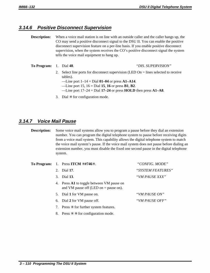
3.14.6 Positive Disconnect Supervision
Description: When a voice mail station is on line with an outside caller and the caller hangs up, theCO may send a positive disconnect signal to the DSU II. You can enable the positivedisconnect supervision feature on a per-line basis. If you enable positive disconnectsupervision, when the system receives the CO’s positive disconnect signal the systemtells the voice mail equipment to hang up.
To Program: 1. Dial 48. “DIS. SUPERVISION”
2. Select line ports for disconnect supervision (LED On = lines selected to receivetables).—Line port 1–14 = Dial01–04or pressA1–A14.—Line port 15, 16 = Dial15, 16or pressB1, B2.—Line port 17–24 = Dial17–24or pressHOLD then pressA1–A8.
3. Dial for configuration mode.
3.14.7 Voice Mail Pause
Description: Some voice mail systems allow you to program a pause before they dial an extensionnumber. You can program the digital telephone system to pause before receiving digitsfrom a voice mail system. This capability allows the digital telephone system to matchthe voice mail system’s pause. If the voice mail system does not pause before dialing anextension number, you must disable the fixed one second pause in the digital telephonesystem.
To Program: 1. PressITCM #746. “CONFIG. MODE”
2. Dial 17. “SYSTEM FEATURES”
3. Dial 13. “VM PAUSE XXX”
4. PressA1 to toggle between VM pause onand VM pause off (LED on = pause on).
5. Dial 1 for VM pause on. “VM PAUSE ON”
6. Dial 2 for VM pause off. “VM PAUSE OFF”
7. Press for further system features.
8. Press for configuration mode.
IMI66–132 DSU II Digital Telephone System
3 – 110 Programming The DSU II System

3.15 Versatile Voice Processing
The digital telephone system supports the Versatile Voice Processing (V.V.P.) voice mail system. Inaddition to the programming requirements detailed in Section 3.14, the following sections detail specificprocedures for programming the system to support the V.V.P. voice processing system.
3.15.1 Using The Tracker Paging System With Versatile Voice Processing
Description: The Tracker is available for use with the DSU II digital telephone system. To makeeffective use of a Tracker paging system used in conjuction with the V.V.P. voice mailsystem, program two mail boxes for each person using a Tracker. The second mail boxwill be used to park the caller and track the called person. When a caller selects toPress3 for other options,V.V.P. will place the call in a Park Orbit while paging the calledparty.
NOTE: If the V.V.P. system includes the Visual Voice Mail option (Section 3.15.5), you can not useTracker and VVM at the same time since they both use the COM 1 serial data port.
Standard Mail BoxTo Program: 1. Leave the Pager Number field blank.
2. Set the Pager Type to Name
3. In theIf caller chooses other optionsfield, selectGo to box.
4. In the Box field enter a box number that is defined as a paging box.
Paging Mail BoxTo Program: Set the following parameters for the paging mail box.
1. Define this box number so that the system can link it to the person’s regular mail boxbut do not choose a number that is another extension or mail box. For example,preceed the mail box number with a7 for all pager boxes.
2. SelectBlind Transfer Type.
3. Enter01plus the actual mail box number forTransfer To,
4. Record a name for this box such as,Tracker for Joe Smithor Paging Joe Smith.
DSU II Digital Telephone System IMI66–132
Programming The DSU II System 3 – 111

3.15.2 Using Tracker For Message Notification
Description: You can program the Tracker to notify mail box users when they have new messages.
To Program: In theMessage Deliveryfield for all mail box owners with a Tracker, enter the followingcode:,01,X
3.15.3 Transferring Callers To Voice Mail
Description: You can program aTransfer To Voice Mailbutton to automate the process of transferringa caller to a mail box. Use this button in conjuction with a DSS or a mail box extensionnumber followed by a2.
To Program: 1. PressINTERCOM 1.
2. Press the button to which you wish to assign this feature.
3. Press6 followed by the first voice mail port station number.
4. PressSPEAKER to exit.
3.15.4 Auto Station Logon
Description: You can program a button to automatically connect a mail box owner to his or her mailbox.
To Program: 1. PressINTERCOM 1.
2. Press the button to which you wish to assign this feature.
3. PressINTERCOM .
4. Press#.
5. Enter the mail box number.
6. PressSPEAKER to exit.
The Auto Station Logon button will take the mail box owner to the mail box password prompt. Thefollowing entries must be added to the TRANS.TXT file for this feature to work properly:
9#XX=#,,,,,XX#XX=#,,,,,XX
IMI66–132 DSU II Digital Telephone System
3 – 112 Programming The DSU II System

3.15.5 Visual Voice Mail Support
Description: Visual Voice mail (VVM) support provides proprietarty, two-line display LCDspeakerphone stations with visual messages and interactive buttons. This message andbutton functionality enhances the station’s use with V.V.P. voice mail equipment.
NOTE: If the V.V.P. system includes the Visual Voice Mail option, you can not use Tracker andVVM at the same time since they both use the COM 1 serial data port.
To Program: 1. Dial 17. “SYSTEM FEATURES”
2. Dial 12. “VMM XXXXXXX”
3. Dial code to enable or disable:—Dial 1 to enable. “VMM ENABLED”—Dial 2 to disable. “VMM DISABLED”
—OR—
4. PressA1 to toggle between enable and disable.
5. Press for system features.
6. Press for configuration mode.
DSU II Digital Telephone System IMI66–132
Programming The DSU II System 3 – 113

3.16 Integrated Call Costing
Call costing provides a means of establishing costing that the system can apply to outside calls made fromsystem telephones. Call costing computes charges for a call after it is completed. It does not restrictdialing as toll restriction does. The system provides several ways of establishing call costing that are asfollows:
• exception tables for local and long distance calls,
• office code band tables for local calls,
• zone call band tables for long distance calls,
• area code band tables for long distance calls,
• call rate tables for local and long distance calls.
With this range of costing methods, it is possible to apply reasonable rates for the entire country. Thesystem applies call costing to a dialed number as described below. Refer toSection 3.16.1for anillustration of the call costing process.
You should make a record in Chapter 4 of all programming decisions that you make—it will help youkeep track of what you have done and will help you troubleshoot any problem that might arise later.
NOTE: A lighted LED next to the programming button for the selection indicates the currentconfiguration. When a single button provides a toggle (on/off) action, the lighted LEDindicates the active feature.
The first step in any programming sequence is to enter the base level. Once in this mode, you can dial thefeature code for any desired configuration. Enter the base level with the following procedure:pressINTERCOM then dial# 7 4 6. When you want to end the programming, press theSPEAKERbutton to end the programming procedure and return the system to normal operation.
IMI66–132 DSU II Digital Telephone System
3 – 114 Programming The DSU II System

3.16.1 Call Costing Flow Diagram Examples
Call Costing Flow Diagram
DSU II Digital Telephone System IMI66–132
Programming The DSU II System 3 – 115
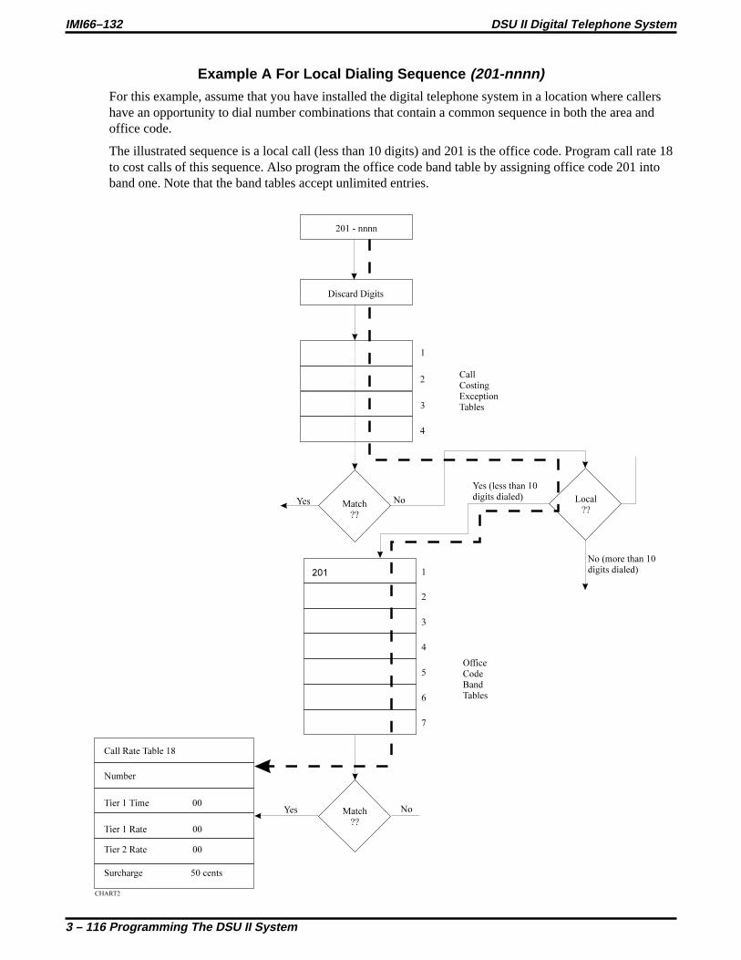
Example A For Local Dialing Sequence (201-nnnn)For this example, assume that you have installed the digital telephone system in a location where callershave an opportunity to dial number combinations that contain a common sequence in both the area andoffice code.
The illustrated sequence is a local call (less than 10 digits) and 201 is the office code. Program call rate 18to cost calls of this sequence. Also program the office code band table by assigning office code 201 intoband one. Note that the band tables accept unlimited entries.
IMI66–132 DSU II Digital Telephone System
3 – 116 Programming The DSU II System

Example B For Long Distance With Office Code Dialing Sequence (1-201-201-nnnn)The illustrated sequence is a long distance call (more than 10 digits) with 201 as both the area code andthe office code. Program call rate table 25 to cost calls of this sequence. Also, program the zone call bandtable by adding office code 201 to area code 201 in band one. Add any other office codes (for example478) to area code 201 in band one as required.
DSU II Digital Telephone System IMI66–132
Programming The DSU II System 3 – 117

Example C For Long Distance Dialing Sequence (1-201-nnn-nnnn)This illustrated sequence is a long distance call (more than 10 digits) with 201 as the area code. Programcall rate table 11 to cost calls in this sequence. Also, program the area code band table by adding areacode 201 to band one.
IMI66–132 DSU II Digital Telephone System
3 – 118 Programming The DSU II System

Example D For Exception Dialing Sequence (nnn-nnnn, 1-nnn-nnnn)Program call rate table one to cost calls that do not match any other programmed call rate table.
DSU II Digital Telephone System IMI66–132
Programming The DSU II System 3 – 119

Typical SMDR Call Report For The Call Costing Examples
10 1 12/28/90 16:05 0.9 2014567 $0.50 (see note 1)
10 1 12/28/90 16:06 1.8 12017894567 $1.35 (see note 3)
10 1 12/28/90 16:08 1.5 12014785693 $1.12 (see note 3)10 1 12/28/90 16:11 1.5 2012014563 $2.50 (see note 2)10 2 12/28/90 16:12 0.5 5551212 $1.00 (see note 4)10 1 12/28/90 16:13 1.1 2012013 $0.50 (see note 1)
Note 1: Costed by rate table 18Note 2: Costed by rate table 25Note 3: Costed by rate table 11Note 4: Costed by rate table 1
Typical SMDA Call Report For The Call Costing Examples
Station Report for Extension -10
Date : 12/28/90 Time : 16:15
DATE TIME STATION ACCOUNT LENGTH COST I/O RING LINE NUMBER12/28 16:05 10 0.9 $0.50 0 1 201456712/28 16:06 10 1.8 $1.35 0 1 1201789456712/28 16:08 10 1.5 $1.12 0 1 1201478569312/28 16:11 10 1.5 $2.50 0 1 201201456312/28 16:12 10 0.5 $1.00 0 2 555121212/28 16:13 10 1.1 $0.50 0 1 2012013
TOTALS: 5.8 $6.97 INCOMING 0AVERAGES: 0.9 $1.16 OUTGOING 6
TOTAL CALLS 6
IMI66–132 DSU II Digital Telephone System
3 – 120 Programming The DSU II System

3.16.2 Exception Tables (Local Calls And Long Distance Calls)
Description: The system compares all calls to entries in four exception tables (one entry per table).These tables provide the first priority level of costing. The system searches these tableson a first match basis. This means that the first programmed entry that matches the call isthe one that the system uses. It does not make a search for the best possible match. Thesystem costs the matched calls using the rates that you program into the call rate tablesthat you assign to the exception tables. You can provide very specific exceptions to abracket of calls similar to the following example.
Example: With all calls to area code 804 costed at a particular rate, make an exceptionfor 804-555-1212 by programming exception table 1 with that number. Since exceptiontable entries are the highest priority, the values in the call rate table assigned to exceptiontable 1 are applied to all calls made to the 804-555-1212 number.
To Program: 1. Dial 78. “EXCEPTION TBL”
2. Dial 1–4for entry 1–4. “ENTRY X”
3. Dial 1 to assign the call rate table. “CALL COST TBL XX”
4. Dial 01–33for call rate table number.
5. Dial .
6. Dial 2 to assign matching digits. “XXXXXXXXXXXXXXXX”
7. Dial # to clear current entry.
8. Dial matching digits(16 digits maximum, # = match anything). “XXXXXXXXXXXXXXXX”
9. Dial for next entry, and repeat steps 2–9 until you have made all entries.
10. Dial for configuration mode.
To change setting, repeat procedure and make different selection.
DSU II Digital Telephone System IMI66–132
Programming The DSU II System 3 – 121

3.16.3 Office Code Band Tables (Local Calls)
Description: The system measures the number of dialed digits in calls that do not match exceptiontables. It compares calls with numbers that have less than 10 digits (local calls) to entriesthat you have made in office code banding tables. Office code band tables are the secondpriority level of costing for local calls. They provide a means for you to assign localoffice codes into different bands and apply a separate call costing rate table to each band.Bands 1–7 are associated with call rate tables 18–24 respectively. Use office code bandtables to cost calls made within a specific area code but to sites located at differentgeographic distances from the calling location.
Example: A telephone company exchange consists of office codes 976, 977, and 978.Office code 976 is assigned to an outlying area while office codes 977 and 978 areassigned to the heart of the city. Assign 977 and 978 to one office code band table and976 to another one. Program a special call costing rate for each banding table. Then, thesystem costs the calls that users make to 976-nnnn at a different rate than it costs the callsthat users make to 977-nnnn or 978-nnnn.
To Program: 1. Dial 75. “SMDA PROGRAMMING”
2. Dial 01 to program costing bands. “COSTING BANDS”
3. Dial 1 to program office code bands. “OFFICE CODE BANDS”
4. Dial 0 to assign no band “NO BAND”—OR—dial 1–7for bands 1–7. “BAND X”
5. Dial 200–999to assign office code.
6. Dial # and repeat step 5 for additional code.
7. Dial and repeat steps 4-6 to program next band.
8. Dial for next SMDA feature—OR—dial for configuration mode.
To change setting, repeat procedure and make different selection.
IMI66–132 DSU II Digital Telephone System
3 – 122 Programming The DSU II System

3.16.4 Zone Call Band Tables (Long Distance Calls)
Description: In certain heavily populated geographic areas, different area codes exist within the samegeographic distance (zone) from the calling location. In these cases, use zone call bandtables to cost calls based upon the zone, or geographic distance, from the calling location.
The system measures all calls that do not match exception tables for the number of digitsthat the user dials. It then compares those calls with numbers that have 10 digits or more(long distance calls) to entries that you make in the zone call band tables. Zone call bandtables are the second priority level of costing for long distance calls. They assign officecodes and corresponding area code into different zones and apply a separate call costingrate table to each zone. Zone call band tables 1–4 are associated with call rate tables25–28. A call must match both the office code and area code of an entry before thesystem costs it by a zone call band table.
Example: Zone 1 contains area code 203 with office codes 445 and 456. It also containsarea code 412 with office code 508. Zone 2 contains area code 203 with office code 545.Zone 2 also contains area code 412 with office code 654. Zone 1 is costed at one rate andzone 2 is costed at another rate. A call made to 1-203-445-nnnn, 1-203-456-nnnn, or1-412-508-nnnn is costed at a different rate than a call made to 1-203-545-nnnn or1-412-654-nnnn.
To Program: 1. Dial 75. “SMDA PROGRAMMING”
2. Dial 01 to program costing bands. “COSTING BANDS ”
3. Dial 3 to program zone call bands. “ZONE BANDS”
4. Dial 0 if no zone is to be assigned. “NO ZONE”—OR—dial 1–4for zones 1–4. “ZONE X”
5. Dial 200–999to assign an area code.
6. Dial #.
7. Dial 200–999to assign an office code.
8. Dial # and repeat step 7 for another office code.
9. Dial and repeat steps 3–9 to add another area code to same zone or to program nextzone.
10. Dial for next SMDA feature—OR—dial for configuration mode.
To change setting, repeat procedure and make different selection.
DSU II Digital Telephone System IMI66–132
Programming The DSU II System 3 – 123

3.16.5 Area Code Band Table (Long Distance Calls)
Description: The system compares the long distance calls that do not match entries in zone call bandtables to entries that you have made in area code band tables. Area code band tables arethe third priority level of costing for long distance calls. Area code band tables 1–7 areassociated with call rate costing tables 11–17. Use area code band tables to cost callsbased upon the area code of the called number. Assign any or all area codes nnn(200–999) to one of seven different bands. Group area codes into bands based onfrequently called areas, distance from the caller, or any other desired category.
Example: Assign area codes 703 and 804 to area code band table 1. Assign area code415 to area code band table 7. Calls made to numbers such as 1-703-nnn-nnnn and1-804-nnn-nnnn are costed with values assigned to call rate table 11. Calls made tonumbers such as 1-415-nnn-nnnn are costed with values assigned to call rate table 17.
To Program: 1. Dial 75. “SMDA PROGRAMMING”
2. Dial 01 to program costing bands. “COSTING BANDS ”
3. Dial 2 to program area code bands. “AREA CODE BANDS”
4. Dial 0 if no band is to be assigned. “NO BAND ”—OR—dial 1–7for bands1–7. “BAND X ”
5. Dial 200–999to assign area code.
6. Dial # and repeat step 6 for additional code.
7. Dial and repeat steps 3-6 to program next band.
8. Dial for next SMDA feature—OR—dial for configuration mode.
To change setting, repeat procedure and make different selection.
IMI66–132 DSU II Digital Telephone System
3 – 124 Programming The DSU II System

3.16.6 Call Rate Tables (Local And Long Distance Calls)
Description: The system compares local calls and long distance calls that do not match entries in anyexception table, office code band table, zone call band table or area code band table withthe entries that you have made in call rate tables 2–10 and 29–33. It then costs those callswith the rates assigned to the call rate tables with the entries that matches the dialednumbers.Costing by call rate table is the third priority level of costing for local calls and the fourthpriority level of costing for long distance calls. You can use the call rate tables to costany calls that require special or extraordinary rates such as 1-800-555-1212 or1-900-976-nnnn.When you make entries in the call rate tables, enter digits that match digits in thenumbers that users dial from their stations. You can program a maximum of 16 digits intoeach call rate table. Since a dialed number must match all of the digits that you haveentered into a table before the system recognizes a match, you can program # charactersinto a table in place of a specific digits to serve as “match anything” digits. This featureeliminates the need for entering every number is a series of numbers that you wish to costat a special rate (for instance, 1900#######).If the system can not match a dialed number with entries that you have made in the callrate tables, it costs that call with the rate that you have assigned to call rate table 1 (thetable of last resort for costing all calls).
Office code band tables = call rate tables 18–24Zone call band tables = call rate tables 25–28Area code band tables = call rate tables 11–17
Table 3–9: Call Rate Table Programming Example
Program step 2 from Section3.16.6
Call rate table = 33
Program step 5 from Section3.16.6
Entry number = 19009762525
Program step 7 from Section3.16.6
Tier 1 time = 30 (30 minutes)
Program step 9 from Section3.16.6
Tier 1 rate = 120 ($1.20)
Program step 11 from Section3.16.6
Tier 2 rate = 75 ($.75)
Program step 13 from Section3.16.6
Surcharge = 50 ($.50)
DSU II Digital Telephone System IMI66–132
Programming The DSU II System 3 – 125

To Program: 1. Dial 76. “CALL COST TBL ”
2. Dial table number (01–33). “CALL COST TBL XX”
3. Dial 1 to enter matching digits. “XXXXXXXX ”
NOTE: Call Cost Table 1 will not accept matching digits.
4. Dial # to clear previous digits.
5. Dial matching digits for costed number(16 max. # = match anything digit). “XXXXXXXX ”
6. Dial to end matching digits.
NOTE : Dialing a 00 or a 000 as an entry in steps 7, 9, 11, and 13 will clear thecurrent entry for those steps.
7. Dial 2 then dial01–99for Tier 1 time in tenths of minutes. “TIER 1 TIME XX ”
8. Dial .
9. Dial 3 then dial001–999for Tier 1 rate in cents. “TIER 1 RATE XXX ”
10. Dial.
11. Dial4 then dial001–999for Tier 2 rate in cents. “TIER 2 RATE XXX ”
12. Dial.
13. Dial5 then dial001–999for surcharge rate in cents. “SURCHARGE XXX ”
14. Dial to program next call cost table and repeat steps 2-14 until all tables areentered.
15. Dial for configuration mode.
To change setting, repeat procedure and make different selection.
IMI66–132 DSU II Digital Telephone System
3 – 126 Programming The DSU II System

3.16.7 Discard Digits
Description: When the digital telephone system is installed behind a host system such as a PBX orCENTREX, users must dial access codes before obtaining an outside line dial tone. Toensure that the system costs a call on just the actual telephone number that the user dials,you should arrange for the system to ignore these access codes. You can program up tosix different access codes entries with up to eight digits per entry.
Example: If the system is installed behind a PBX using a 9 as an outside line accesscode, program a 9 as the discard digit. When a number such as 9-555-1212 is dialed,the 9 is discarded and the call is costed based on 555-1212.
To Program: 1. Dial 75. “SMDA PROGRAMMING”
2. Dial 01 to program costing bands. “COSTING BANDS”
3. Dial 4 to program discard digits. “DISCARD DIGITS”
4. Dial 1–6to select entry 1–6. “ENTRY X”
5. Dial # for no discard digits—OR—dial up to eight discard digits and then dial#. “XXXXXXXX”
6. Dial and repeat steps 4–5 to program next discard digit entry.
7. Dial for next SMDA feature—OR—dial for configuration mode.
To change setting, repeat procedure and make different selection.
DSU II Digital Telephone System IMI66–132
Programming The DSU II System 3 – 127

3.16.8 Dialing Time And Answer Time
Dial Time Limit
Description: The system does not include dialing time when it records the time of a call for costing.You can program the amount of time that the system ignores for dialing purposes.
To Program: 1. Dial 75. “SMDA PROGRAMMING”
2. Dial 02 to program dial time limit. “DIAL TIME XXX”
3. Dial time in tenths of a minute(001–999or dial000to clear). “XXXX”
4. Dial for next SMDA feature—OR—dial for configuration mode.
To change setting, repeat procedure and make different selection.
Answer Time Limit
Description: You can program the system to wait for a period of time before beginning to record costsfor a call. This answer time allows a call to ring and be answered by the called partybefore the system costs it.
To Program: 1. Dial 75. “SMDA PROGRAMMING”
2. Dial 03 to program answer time limit. “ANSWER TIME XXX ”
3. Dial time in tenths of a minute(001–999or dial000to clear). “XXX ”
4. Dial for next SMDA feature—OR—dial for configuration mode.
To change setting, repeat procedure and make different selection.
IMI66–132 DSU II Digital Telephone System
3 – 128 Programming The DSU II System

3.16.9 LCD Speakerphone Display of Costed Calls
Description: When you arrange the digital telephone system to cost the calls, you should also arrangefor the LCD speakerphones being employed with the system to display the cost of eachcall the user make from that station.
To Program: 1. Dial 53. “STATION FEATURES”
2. Dial 27. “LCD CALL COST”
3. Select station ports for programming—Station 10–57 = Dial10–57or pressC10–C57.
4. Dial for next station feature—OR—dial for configuration mode.
To clear current setting, repeat procedure.
DSU II Digital Telephone System IMI66–132
Programming The DSU II System 3 – 129

3.17 Specialized Route Access (SRA)
The SRA feature allows the system to select a line group based on the digits the user has dialed. By doingthis, it matches calls with their ideal routes. The feature provides a table-driven routing scheme where thenumbers the users dial cause the system to chose a line group after comparing the dialed number withentries in an office code table, and area code table or, four special area code tables.
You should make a record in Chapter 4 of all programming decisions that you make—it will help youkeep track of what you have done and will help you troubleshoot any problem that might arise later.
CAUTION
You can only program the SRA feature from the VDT and not from station 10.
Line group dialing codes 81, 82, and 83 do not provide access to the SRA feature, but they could providea means of bypassing SRA, allowing users access to line groups outside of the specialized routingprocess. To ensure that the system routes all calls through SRA, use the feature inhibit programmingprocedure described in section 3.14.4 to inhibit dialing codes 81, 82, 83.
The first step in the VDT programming sequence is to enter password. Do this by typingI746. Oncein the programming mode, type a selection number from the main menu and follow the screen prompts tocomplete your programming requirements.
3.17.1 Enable The SRA Feature
Description: When you enable the SRA feature, you must first clear all assigned prime line, idle linepreference, and direct line appearance to inhibit all direct line access for the systemstations, and you must assign lines to the line groups the system will use.
To Program: 1. TypeI 7 4 6 and pressRETURN.
2. From the main menu, type1 and pressRETURN for system COS menu.
3. From the system COS menu, type16 for specialized route access menuand pressRETURN.
4. From specialized route access menu, type1 for SRA featureand pressRETURN.
5. Type1 to enable or type0 to disable SRA feature and pressRETURN.
6. To return to the main menu, press and holdCTRL and typeC.
IMI66–132 DSU II Digital Telephone System
3 – 130 Programming The DSU II System

3.17.2 Enable SRA Office Code And Area Code Tables
Description: The office code table matches a dialed office code with one of the office codes that youhave entered in the table, and routes the call over the line group that you have entered forthat office code. The area code table matches a dialed area code with one of the areacodes that you have entered in the table, and routes the call over the line group that youhave entered for that area code.
NOTE: When programming the tables, note that all table entries are defaulted to linegroup 1; therefore, to minimize programming effort, assign area/office codeswith the fewest entries to line groups 2 through 4. For example: if you areentering area codes 200 through 299 and codes 200 through 209 requires oneline group while codes 210 through 299 requires another line group, leaveline group 1 assigned to the larger quantity of entries that require the mostprogramming effort (210-299) and reprogram the line group for the smallerquantity of entries.
Office Code TableTo Program: 1. TypeI 7 4 6 and pressRETURN.
2. From the main menu, type1 and pressRETURN for system COS menu.
3. From the system COS menu, type16 for specialized route access menuand pressRETURN.
4. From specialized route access menu, type2 for office code table menuand pressRETURN.
5. Type1–4 for line group to match office codes and pressRETURN.
6. Type office code(s) for routing over programmed group numberand pressRETURN.(typennn ornnn,nnn,nnn,nnn for one code or several codes) or typeALL to assignevery office code from 000 through 999).
7. To return to the main menu, press and holdCTRL and typeC.
DSU II Digital Telephone System IMI66–132
Programming The DSU II System 3 – 131

Area Code TableTo program: 1. TypeI 7 4 6 and pressRETURN.
2. From the main menu, type1 and pressRETURN for system COS menu.
3. From the system COS menu, type16 for specialized route access menuand pressRETURN.
4. From specialized route access menu, type3 for area code table menuand pressRETURN.
5. Type1–4for line group to match area codes and pressRETURN.
6. Type area code(s) for routing over programmed group number and pressRETURN.(type nnn or nnn,nnn,nnn,nnn for one code or several codes or typeALL to assignevery area code from 000 through 999).
7. To return to the main menu, press and holdCTRL and typeC.
IMI66–132 DSU II Digital Telephone System
3 – 132 Programming The DSU II System

3.17.3 Enable Special SRA Area Code Tables
Description: The four special area code tables must first match a dialed area code and then match thedialed office code with office code entries in the matched table. With a complete matchfound, the system routes the call over the line group that you have assigned to thematched office code in the matched special area code table.
NOTE: When programming the special area code tables, note that all office codeentries are defaulted to line group 1; therefore, to minimize programmingeffort, assign those codes with the fewest entries to line groups 2 through 4.For example: if you are programming for code entries 200 through 299, andcodes 000 through 209 requires one line group while codes 210 through 299requires another line group, leave line group 1 assigned to the larger quantityof entries that require the most programming effort (210-299)and reprogramthe line group for the smaller quantity of entries.
Assigning the Special Area CodesTo Program: To assign the special area codes to the four tables,
1. TypeI 7 4 6 and pressRETURN.
2. From the main menu, type1 and pressRETURN for system COS menu.
3. From the system COS menu, type16 for specialized route access menuand pressRETURN.
4. From specialized route access menu, type6 to assign area code to special tableand pressRETURN.
5. Type1–4to choose special table 1–4 and pressRETURN.
6. Type specific area code for table and pressRETURN.
7. Repeat steps 4 through 5 for each remaining special table and pressRETURN.
8. To clear the special area code tables if needed—type7 and pressRETURN—type1–4for table 1–4—pressRETURN, and repeat as necessary.
9. Return to the system COS menu.
DSU II Digital Telephone System IMI66–132
Programming The DSU II System 3 – 133

Assigning line groups to the special office code entries,To Program: 1. From the system COS menu, type16 for specialized route access menu and press
RETURN.
2. From specialized route access menu, type4 for special area code table menuand pressRETURN.
3. Type1–4for special table 1–4 and pressRETURN.
4. Type1–4to choose line group 1–4 and pressRETURN.
5. Type all office code(s) that require call routing over the line group that you set in step4, and pressRETURN (typennn ornnn,nnn,nnn,nnn for one code or several codesor typeALL to assign every office code from 000 through 999).
6. Type4 and repeat steps 3 through 5 to add additional line groups to office codes inthe same table or to program the next special area code table.
7. To return to the main menu, press and holdCTRL and typeC.
IMI66–132 DSU II Digital Telephone System
3 – 134 Programming The DSU II System

3.17.4 Insert Digits For SRA
Description: You may program the system, on a per line group basis, to insert up to 8 digits before adialed number. This feature is useful if the dialed number must match a specific formatfor the group being used. You may insert numbers 0–9,, #, or P for pause.
To Program: 1. TypeI 7 4 6 and pressRETURN.
2. From the main menu, type1 and pressRETURN for system COS menu.
3. From the system COS menu, type16 for specialized route access menuand pressRETURN.
4. Type8 for assign insert digit menu and pressRETURN.
5. Type1–4for line group number and pressRETURN.
6. Type SRA insert digits. (You may use a maximum of 8 digits. Digits may include0–9,, #, and P for pause.)PressRETURN.
7. Repeat steps 4–6 to assign insert digits for each line group.
8. To clear the insert digits if needed—type9 and pressRETURN—type1–4for line group number and pressRETURN and repeat as necessary.
9. To return to the main menu, press and holdCTRL and typeC.
DSU II Digital Telephone System IMI66–132
Programming The DSU II System 3 – 135

3.17.5 SRA Overflow Line Group
Description: You can assign an overflow line group that the system can route calls over when no linesare free in the line group assigned to the matching entry; otherwise, the system will returnbusy tone to the caller when this condition exists.
NOTE: If you arrange for the system to insert digits on a particular line group, anoverflow group will take on the characteristics of the line group that is rollingover to it including the insert digits.
To Program: 1. TypeI 7 4 6 and pressRETURN.
2. From the main menu, type1 and pressRETURN for system COS menu.
3. From the system COS menu, type16 for specialized route access menu and pressRETURN.
4. From specialized route access menu, type5 for overflow line group and pressRETURN.
5. Type1–4for line group 1–4 or0 for no line group. PressRETURN.
6. To return to the main menu, press and holdCTRL and typeC.
IMI66–132 DSU II Digital Telephone System
3 – 136 Programming The DSU II System

3.17.6 SRA Wait Time
Description: Once a caller begins to dial digits, he or she has a certain period of time in which to dialeach new digit. After the caller has stopped dialing digits and the end of the time-outperiod has occurred, the system analyzes the dialed digits and routes the call by followingthe table-driven routing scheme. Use this procedure to select the SRA wait time.
To Program: 1. TypeI 7 4 6 and pressRETURN.
2. From the main menu, type1 and pressRETURN for system COS menu.
3. From the system COS menu, type16 for specialized route access menu and pressRETURN.
4. Type10 for assign SRA wait time menu and pressRETURN.
5. Type2, 3, or 4 for 2, 3, or 4 seconds and pressRETURN.
6. To return to the main menu, press and holdCTRL and typeC.
DSU II Digital Telephone System IMI66–132
Programming The DSU II System 3 – 137

3.18 Station Message DetailAccounting/Reporting (SMDA/SMDR)
The system produces five different call cost reports for printing:
1. Detailed report of all stations.
2. Detailed report of all accounts.
3. Trunk summary report.
4. Department summary report.
5. All records.
The system generates reports automatically for printing whenever it detects that its records storage area is95 percent full. You can use class of service programming to choose the reports that you want the systemto generate. It generates the reports for printing in the order that you selected and at a certain time eachday. You can also take programming action that causes the system to delete all printed records except forthose it collects during the printing operation. It stores these records for later printing.
You should make a record in Chapter 4 of all programming decisions that you make—it will help youkeep track of what you have done and will help you troubleshoot any problem that might arise later.
NOTE: A lighted LED next to the programming button for the selection indicates the currentconfiguration. When a single button provides a toggle (on/off) action, the lighted LEDindicates the active feature.
The first step in any programming sequence is to enter the base level. Once in this mode, you can dial thefeature code for any desired configuration. Enter the base level with the following procedure:pressINTERCOM then dial# 7 4 6. When you want to end the programming, press theSPEAKER button to end the programming procedure and return the system to normal operation.
IMI66–132 DSU II Digital Telephone System
3 – 138 Programming The DSU II System

3.18.1 SMDA Department Numbers
Description: Use this programming feature to define different SMDA department numbers
To Program: 1. Dial 75. “SMDA PROGRAMMING”
2. Dial 04 to define department numbers. “SMDA DEPARTMENTS”
3. Dial 1–8for department 1–8. “DEPT X”
4. Dial 0000–9999for department number. “DEPT X YYYY”
5. Dial for next department, and repeat steps 3–7 until all departments are numbered.
6. Dial for next SMDA feature.
7. Dial for configuration mode.
To change setting, repeat procedure and make different selection.
3.18.2 SMDA Station Assignment
Description: Assign stations to the departments so that SMDA call cost reports will only includeinformation concerning that specific station arrangement.
To Program: 1. Dial 53. “STATION FEATURES”
2. Dial 22. “SMDA DEPARTMENTS”
3. Dial 0 for no SMDA department “DEPARTMENT 0”—OR—dial 1–8 for dept 1–8. “DEPARTMENT X”
4. Select stations for SMDA department (LED On = Selected)—Station10–57 =Dial 10–57or pressC10–C57.
5. Dial for additional department/station assignments—OR—dial for next station feature—OR—dial for configuration mode.
To change setting, repeat procedure and make different selection.
DSU II Digital Telephone System IMI66–132
Programming The DSU II System 3 – 139

3.18.3 SMDA Printout
Automatic SMDA ReportsDescription: Call cost reports, produced by the system for printing, are generated automatically
whenever the system detects that the records storage area is ninety-five percent full.Program the system to automatically generate these reports for printing at a certain timeeach day if desired.
To Program: 1. Dial 75. “SMDA PROGRAMMING”
2. Dial 13 for auto report time “AUTO TIME XXXX”—Dial new time in hours and minutes (HH MM in 24 hour time) or dial to acceptcurrent time. To clear the time dial0000.
3. Dial 14 for report definition. “AUTO REPORT ”
4. Choose reports for printing.—Dial 1 for station report “STATION REPORT”—Dial 2 account report “ACCOUNT REPORT”—Dial 3 line report “LINE REPORT”—Dial 4 department report “DEPT. REPORT”—Dial 5 print all “PRINT RECORDS”—Dial 6 delete records “DELETE RECORDS”—Dial 7 for DCD report. “DCD REPORT”
5. Dial for next SMDA feature—OR—dial for configuration mode.
To change setting, repeat procedure and make different selection.
IMI66–132 DSU II Digital Telephone System
3 – 140 Programming The DSU II System

SMDA Report PrintoutDescription: You can command the system to print several different types of SMDA reports and to
delete all stored SMDA records.
NOTE: The departmental call distribution report reflects statistics based on currentdepartmental station assignments. Before you use the previous programmingfeature to reassign stations to different departments, it is a good practice to:(1) print the departmental call report and any other desired SMDA reports,(2) make any desired reassignments, (3) delete all SMDA records.
To Program: 1. Dial 07. “SMDA REPORTS”
2. Choose report for printout—Dial 1 # for all stations “STATION REPORT”—Dial 1, 10–57, # for one station “STATION REPORT”—Dial 2 # for all lines “TRUNK REPORT”—Dial 3 # for SMDA department “DEPT. REPORT”—Dial 4 # for account code “ACCOUNT REPORT”—Dial 5 # for auto report. “AUTO REPORT”—Dial 6 # for all records “PRINT RECORDS”—Dial 7 # to delete records “DELETE RECORDS”—Dial 0 # for DCD report “DCD REPORT”—Dial 8 to obtain the number of free records
remaining in system “FREE RECS XXXXX”—Dial 9 to abort printout. “ABORT PRINT”
3. Dial for configuration mode.
DSU II Digital Telephone System IMI66–132
Programming The DSU II System 3 – 141

3.18.4 SMDR Printout
SMDR Printout As System CollectedDescription: With this programming step, SMDR provides continuous printout of system-wide station
call activity as it is collected by the system.
To Program: 1. Dial 77.
2. Dial 2. “SMDR PRINT XXX”
3. PressA1 to toggle between enable and disable (A1 LED On = Enabled)—OR—dial 1 to enable printing “SMDR PRINT ON”dial 2 to disable printing. “SMDR PRINT OFF”
4. Dial for configuration mode.
To change setting, repeat procedure and make opposite selection.
SMDR Cost ReportingDescription: Programming action adds the cost of each reported call to the SMDR printout.
To Program: 1. Dial 77. “SMDR PRINT ”
2. Dial 1. “XXXXXXX COSTING ”
3. PressA1 to toggle between enable and disable (A1 LED On = Enabled)—OR—dial 1 to enable “WITH COSTING ”dial 2 to disable. “WITHOUT COSTING ”
4. Dial for configuration mode.
To change setting, repeat procedure and make opposite selection.
IMI66–132 DSU II Digital Telephone System
3 – 142 Programming The DSU II System

3.18.5 SMDA Records Deleted By The Attendant
Description: This programming step gives the attendant station the ability to delete SMDA recordswhen commanded to do so by its user. During day-to-day system operation, whenSMDA records exceed storage capacity, the attendant can delete current records to makeroom for additional ones if you perform this programming step. Typically the attendantwould do this after he or she has requested the system to print an SMDA report. If youhave set the system to delete the records after it has generated an automatic report, youusually do not need to give the attendant this manual deletion feature.
To Program: 1. Dial 18. “ATTN DELETE XXX”
2. PressA1 to toggle between enable and disable (LED On = Enable)—OR—dial 1 to Enable “ATTN DELETE ON”dial 2 to Disable. “ATTN DELETE OFF”
3. Dial for configuration mode.
To change setting, repeat procedure and make opposite selection.
DSU II Digital Telephone System IMI66–132
Programming The DSU II System 3 – 143

3.19 Toll Restriction Tables
The toll restriction feature uses entries that you make in 16 different tables to prohibit some or all stationsfrom calling a wide range of number combinations. In order for toll restriction to take effect, you mustcomplete the following three-fold process:
• you must program entries in one or more toll tables,
• you must assign toll tables to all appropriate lines,
• you must assign toll tables to all appropriate stations,
• After you program the toll tables and assign them to both a line and the station that uses that line, thesystem activates the programmed toll restriction at the station.
You should make a record in Chapter 4 of all programming decisions that you make—it will help youkeep track of what you have done and will help you troubleshoot any problem that might arise later.
NOTE: A lighted LED next to the programming button for the selection indicates the currentconfiguration. When a single button provides a toggle (on/off) action, the lighted LEDindicates the active feature.
The first step in any programming sequence is to enter the base level. Once in this mode, you can dial thefeature code for any desired configuration. Enter the base level with the following procedure:pressINTERCOM then dial # 7 4 6. When you want to end the programming, press theSPEAKERbutton to end the programming procedure and return the system to normal operation.
IMI66–132 DSU II Digital Telephone System
3 – 144 Programming The DSU II System

3.19.1 Assign Entries To Toll Restriction Tables
Description: Plan and execute system toll restriction in the sequence detailed in the following steps.
1. Determine the types of dialing restrictions that you wish imposed on the system.Typically, this includes access codes which result in toll charges, and certain localnumbers as desired.
2. If you wish the restricted dialing codes to be imposed consistently on most or allstations in the system, list them on one or two tables. If you must allow for a widevariation in the dialing restrictions, spread the listing out across several tables.
3. Strategically group the listings on the tables so that a list of restrictions can beapplied to a particular station or group of stations.
4. Designate each table as a DENY table or as an ALLOW table. The system preventsthe dialing of numbers entered in a DENY table. ALLOW tables take precedenceover DENY tables. Therefore, an entry in an allow table will provide an explicitexception to an entry in a DENY table. Note that the system always permits thedialing of any number not explicitly denied. Also, note that the system will not tollrestrict system speed dial numbers unless you specify them to be restricted with aseparate programming step.Example A: Provide a simple and broad toll restriction format by creating a DENYtable with two entries: ENTRY (1) = 1; ENTRY (2) = 0. This format prevents alllong distance and operator calls.Example B: Prevent the dialing of all numbers within the (804) area code, whileallowing the dialing of one specific number within that area code. by entering 1804in a DENY table and 18049782200 in an ALLOW table.
5. Press the # button in place of a particular digit to condense a range of numbers intoone entry. The # character is a “match-anything” digit, and can be included in anentry in either a DENY table or an ALLOW table.Example A: If 357, 377, 387, and 397 dialing is to be prohibited, list one entry of3#7 on a DENY table to cover them all.Example B: Since area codes typically have a 1 or a 0 as a middle digit, preventlong distance calls to those area codes by entering 1#1# and 1#0# in an DENY table.
6. Since it is important that emergency numbers never be restricted, always create anallow table with entries of 911 and 1911 to override any DENY tables that you havecreated.
7. If the system is installed behind a PBX, include an access code as part of every tableentry.
8. The system defaults two toll restriction tables with preprogrammed values andassigns them to the lines. You need only to assign them the stations to put them intoeffect. The preprogrammed values are as follows:
Default Toll RestrictionsTable 1 = Deny Table 2 = AllowEntry 1 = 1 Entry 1 = 1800Entry 2 = 976 Entry 2 = 911Entry 3 = 411Entry 4 = 0
DSU II Digital Telephone System IMI66–132
Programming The DSU II System 3 – 145

3.19.2 Programming Toll Restriction Table Entries
To Program: 1. Dial 71. “TOLL TABLE”
2. Dial 01–16—OR—pressA1–A14, B1, B2 for toll table1–16. “XXXXX TABLE Y”
3. Establish an allow or a deny table (A1 LED on = allow, A2 LED On = deny)—Dial 5 or pressA1 for allow “ALLOW TABLE Y”—Dial 6 or pressA2 for deny. “DENY TABLE Y”
4. Dial 1–4or pressA8–A11 for entry number 1–4.“XXXXXX”
5. Dial # to clear current entry.
6. Dial keypad digits (0–9, #) to enter numbers. “XXXXXX ...”
7. Dial for next entry and repeat steps 4–6 until all table restrictions are entered.
8. Dial for next table and repeat steps 2–7 until all tables are entered.
9. Dial for configuration mode.
To change setting, repeat procedure and make different selection.
IMI66–132 DSU II Digital Telephone System
3 – 146 Programming The DSU II System

3.19.3 Assign Toll Restriction Tables To Lines
Description: Once you have created the toll restriction tables, assign them to lines.
To Program: 1. Dial 72. “ASSIGN TOLL-LINE”
2. Dial 01–16or pressA1–A14, B1, B2 for toll table 1–16.
3. Dial # to finish entry and display lines.
4. Select line ports (LED On = Lines selected to receive tables)—Line port 1–16 = Dial01–14or PressA1–A14—Line port 15, 16 = Dial15, 16or PressB1, B2—Line port 17–24 = Dial17–24or pressHOLD then dialA1–A8.
5. Dial and repeat steps 2–4 for next toll table to line assignment—OR—dial for configuration mode.
To clear current setting, repeat procedure.
3.19.4 Assign Toll Restriction Tables To Stations
Description: Once you have created the toll restriction tables, assign them to stations.
To Program: 1. Dial 73. “ASSIGN TOLL-STA.”
2. Dial 01–16or pressA1–A14, B1, B2 for tables 1–16 (LED On = Selected table).
3. Dial # to finish entry.
4. Select station ports (LED On = station ports to receive tables)—Station 10–57 = Dial10–57or pressC10–C57.
5. Dial for next toll table to station assignment.—OR—dial for configuration mode.
To clear current setting, repeat procedure.
DSU II Digital Telephone System IMI66–132
Programming The DSU II System 3 – 147

3.19.5 Assign Toll Restriction Tables To StationsFor Night Transfer (of ringing)
Description: Toll tables assigned with this feature have an effect only when the attendant places thetelephone system in the night transfer (of ringing) mode of operation.
To Program: 1. Dial 74. “ASSIGN TOLL-NITE”
2. Dial 01–16or pressA1–A14, B1, B2for toll tables 1–16 (LED On = Selected table).
3. Dial # to finish entry.
4. Select station ports (LED On = station ports to receive tables)—Station 10–57 = Dial10– 57or pressC10–C57.
5. Dial for next toll table to night answer assignment—OR—dial for configuration mode.
To clear current setting, repeat procedure.
3.19.6 Assign Toll Restriction Tables To System Speed Dial Calls
Description: When you enable this feature, the system applies toll restriction tables that you haveassigned to a station to the system speed dial calls that users make from that station.
To Program: 1. Dial 53. “STATION FEATURES”
2. Dial 05. “SYS SPD TOLL RST”
3. Select station ports (LED On = station ports assigned)—Station 10–57 = Dial10–57or pressC10–C57
4. Dial for next station feature—OR—dial for configuration mode.
To clear current setting, repeat procedure.
IMI66–132 DSU II Digital Telephone System
3 – 148 Programming The DSU II System

3.19.7 Assign Toll Restriction Override (TRO) Code
Description: The TRO feature allows users to override the toll restriction that they encounter at otherstations with their own station’s toll restriction assignments. In programming for thisfeature, create a four-digit TRO code that users can dial to override the toll restrictions ofany station that they happen to be using and replace it with a toll restriction that matchestheir home station.
NOTE: The system marks outgoing line calls that users make after entering a TRO code with a (T) inits SMDR/SMDA printouts. The station number that it prints is that of the overriding stationand not the actual station that the call was made from.
To Program: 1. Dial 53 for station features. “STATION FEATURES”
2. Dial 25 for toll restriction override codes. “TOLL R. OVERRIDE”
NOTE: If you are programming with a DSS/BLF console, notice that it’s status LEDs turn on toindicate stations that have an assigned TRO code (C10–C57 = station ports 10–57).
3. Select station port—Station 10–57 = dial10–57or pressC10–C57(LED flashes = selected station port, display shows TRO if assigned).
4. Type four-digit TRO code. “NNNN ”
5. Repeat steps 3 and 4 for next station port.
6. Dial for configuration mode.
To remove a TRO code, repeat steps 1 through 3, select station port, press#.
DSU II Digital Telephone System IMI66–132
Programming The DSU II System 3 – 149

3.19.8 Positive Disconnect Supervision
Description: When a station is on line with an outside caller and the caller hangs up, the CO may senda positive disconnect signal to the DSU II. You can enable the positive disconnectsupervision feature on a per-line basis. If you enable positive disconnect supervision,when the system receives the CO’s positive disconnect signal, the system resets the tollrestriction, releases the current call record, and creates a new call record in its place.
To Program: 1. Dial 48. “DIS. SUPERVISION”
2. Select line ports for disconnect supervision (LED On = lines selected to receivetables).—Line port 1–14 = Dial01–04or pressA1–A14—Line port 15, 16 = Dial15, 16or pressB1, B2—Line port 17–24 = Dial17–24or pressHOLD then pressA1–A8.
3. Dial for configuration mode.
IMI66–132 DSU II Digital Telephone System
3 – 150 Programming The DSU II System

3.20 The Tracker Paging System
The optional Tracker Paging System allows users to send alpha/numeric or numeric-only messages toTracker pagers assigned to station extension numbers. The type of message that the system deliversdepends upon the model Tracker Pager being used.
You should make a record of all programming decisions that you make—it will help you keep track ofwhat you have done and will help you troubleshoot any problem that might arise later.
NOTE: A lighted LED next to the programming button for the selection indicates the currentconfiguration. When a single button provides a toggle (on/off) action, the lighted LEDindicates the feature is active.
The first step in any programming sequence is to enter the base level. Once in this mode, you can dial thefeature code for any desired configuration. Enter the base level with the following procedure: pressINTERCOM then dial#746. When you want to end the programming, press theSPEAKER buttonto end the programming procedure and return the system to normal operation.
DSU II Digital Telephone System IMI66–132
Programming The DSU II System 3 – 151

3.20.1 Enabling The Tracker Paging System
Description: Use this procedure to enable the Tracker Paging System feature as a system-wide feature.
To Program: 1. Dial 17. “SYSTEM FEATURES”
2. Dial 06. “TRACKER XXXXXX”
3. PressA1 to toggle between enable or disable (LED On = Enabled)—OR—dial 1 to Enable (A1 LED On) “TRACKER ENABLED”dial 2 to Disable.
4. Press for configuration mode. “TRACKER DISABLED”
To change setting, repeat procedure and make opposite selection.
3.20.2 Enabling Tracker Pagers For Stations
Description: After you have enabled the Tracker Paging System as a system-wide feature, enable theTracker pagers at individual stations. Station users can disable a Tracker Pager bypressingINTERCOM #06 or enable a Pager by pressingINTERCOM 06.
To Program: 1. Dial 53. “STATION FEATURES”
2. Dial 37. “DISPLAY PAGER”
3. Enable Tracker pager operation—Dial 10–57or pressC10–C57(LED On = Enabled).
4. Press for configuration mode.
To clear current setting, repeat procedure.
NOTE: The Pager’s ID must be programmed to correspond to a DSU stationnumber. Pager programming must be done through the Tracker base station.Refer to the “Program Mode” section of IMI89–138, Operating InstructionsFor The Tracker Paging System.
IMI66–132 DSU II Digital Telephone System
3 – 152 Programming The DSU II System

3.20.3 Setting The Data Parameters
Description: You must set the data parameters of the data port where you connect Tracker to 9600baud, eight data bits, one stop bit, and no handshaking to ensure proper Tracker operation.
NOTE: The Tracker base station must also be programmed for 9600 baud so that itmatches the DSU setting. The default Tracker base station baud setting is9600; however, if you want to check or change the baud setting in the basestation, refer to section V, “Software Configuration,” of 68P81101B25–O,Alphanumeric Interface Option.
To Program: 1. Dial 15. “BAUD RATE”
2. Dial 1 for port A
3. Dial 0811for data parameters.
4. Press for configuration mode.
DSU II Digital Telephone System IMI66–132
Programming The DSU II System 3 – 153

3.21 Digital Voice Announcing (DVA)
Digital voice announcing uses a hardware peripheral device (product code DVA01) connected to a digitalstation port to play pre-recorded announcements and messages during an in-progress call. The DVAstores the pre-recorded messages in its memory for recall when needed. While the DVA is not automatic,it enhances the following features by providing automated voice prompts and dialing instructions tocallers; direct department call with department calling distribution (DCD), direct inward station dialing(DISD), and Tracker Paging System. Before you can enhance the DCD or DISD features, you mustcompletely program them using instructions earlier in this chapter. Refer to section 3.11,Configuring TheDirect Department Callingfor DCD programming information. Refer to section 3.12,Configuring TheDirect Inward Station Dialingfor DISD programming.
You should use chapter 4,SystemRecordsto record the programming decisions that you make—it willhelp you keep track of what you have done and will help you troubleshoot any problem that might ariselater.
NOTE: A lighted LED next to the programming button for the selection indicates the currentconfiguration. When a single button provides a toggle (on/off) action, the lighted LEDindicates the active feature.
The first step in any programming sequence is to enter the base level. Once in this mode, you can dial thefeature code for any desired configuration. Enter the base level with the following procedure: pressINTERCOM the dial#746. When you want to end the programming, press theSPEAKER button toend the programming procedure and return the system to normal operation.
IMI66–132 DSU II Digital Telephone System
3 – 154 Programming The DSU II System
3.21.1 Programming For DCD Operation
Description: When you plan to enhance DCD operation with the DVA, you must first completelyprogram the system for DCD operation.
To Program: To enable the system for DCD operation, refer to the instructions in section 3.11,DirectDepartment Callingand complete the following steps:
1. Assign direct department dialing access code (often referred to as a department pilotnumber).
2. Assign direct department calling line ports.
3. Assign direct department calling station ports.
4. Refer to the instructions in section 3.7.6,Call Forward On Busy/Ring No-Answer,and program the department stations to have ring no-answer call forwarding.
5. Use the procedure described immediately below, and program the DCD departmenttransfers before disconnect.
3.21.2 DCD Department Transfers Before Disconnect
Description: Because the system will continue transferring a call back to a department after a recall toDVA time-out has occurred, you can set the number of transfer times that occur beforethe system drops the call.
To Program: 1. Dial 17. “SYSTEM FEATURES”
2. Dial 10. “DEPT XFR X”
3. Choose 1–9 transfer times or set system to always transfer.(LED On = Enabled)—Dial 1 or pressA1 “DEPT XFR 1”—Dial 2 or pressA2 “DEPT XFR 2”—Dial 3 or pressA3 “DEPT XFR 3”—Dial 4 or pressA4 “DEPT XFR 4”—Dial 5 or pressA5 “DEPT XFR 5”—Dial 6 or pressA8 “DEPT XFR 6”—Dial 7 or pressA9 “DEPT XFR 7”—Dial 8 or pressA10 “DEPT XFR 8”—Dial 9 or pressA11 “DEPT XFR 9”—Dial 0 or pressA12 “NEVER DISCONNECT”
4. Press for configuration mode.
To change setting, repeat procedure and make different selection.
DSU II Digital Telephone System IMI66–132
Programming The DSU II System 3 – 155

3.21.3 Programming For DISD Operation
Description: When you plan to enhance DISD operation with the DVA, you must first completelyprogram the system for DISD operation.
NOTE: You should set a DISD dial time that is as long as the maximum time neededto complete the longest DVA message. For example, if the longest DVAmessage is 60 seconds, set the DISD dial time to 60 seconds. If the DISD dialtime is longer than the DVA message, the message will repeat itself. If theDISD dial time is shorter than the DVA message, the message will not finish.
To Program: To enable the system for DISD operation, refer to section 3.12,Direct Inward StationDialing Configuration, and complete the following steps:
1. Program the dial time limit.
2. Assign a DISD Assist station.
3. Program the DISD Incoming Rings.
4. Program inhibit DISD digit dialing.
IMI66–132 DSU II Digital Telephone System
3 – 156 Programming The DSU II System

3.21.4 Enabling/Disabling Digital Voice Announcing (DVA)
Description: You can enable DVA support for both DISD and DCD operation.
To Program: To assign DVA support for DISD operation.
1. Dial 17. “SYSTEM FEATURES”
2. Dial 07. “DISD DVA XXXXXXX”
3. Press A1 to toggle between enable and disable (LED on = Enable)—OR—Dial 1 to Enable (A1 LED is on) “DISD DVA ENABLE”Dial 2 to Disable. “DISD DVA DISABLE”
4. Press for configuration mode.
To change setting, repeat procedure and make opposite selection.
To Program: To assign DVA support for DCD operation.
1. Dial 17. “SYSTEM FEATURES”
2. Dial 08. “DCD DVA XXXXXXX”
3. PressA1 to toggle between enable and disable (LED On = Enable).—OR—Dial 1 to Enable (A1 LED is on) “DCD DVA ENABLE”Dial 2 to Disable. “DCD DVA DISABLE”
4. Press for configuration mode.
To change setting, repeat procedure and make opposite selection.
DSU II Digital Telephone System IMI66–132
Programming The DSU II System 3 – 157

3.21.5 Programming The DVA Messages
Description: You or the system attendant can store the customized messages in the DVA device in oneof two ways: by delivering them from the telephone handset at station 10 or 12 or byplaying the contents of a professionally-supplied tape recording into the DVA memory.The DVA provides up to four unique messages. The total available message time is twominutes for one message if needed. Because of the time constraints, it is a good practiceto script your messages ahead of time so that you can read them aloud in a clear andconcise manner as you store them in the DVA memory.
The voice prompt messages fall into four categories:
Day Answer MessagesFor DCD callers—“Welcome to Acme’s sales department, all of our agents are busy. Please stay on theline and an agent will answer your call as soon as possible.”
For DISD callers—“Welcome to Acme’s Company. If you know your party’s extension, dial it now;otherwise, stay on the line and an attendant will answer your call.”
Night Answer MessagesFor DCD callers—“Welcome to Acme’s sales department. Our hours are eight to four-thirty. Please calltomorrow during those hours.”
For DISD callers—“Welcome to Acme Company. Our hours are eight to four-thirty. Please calltomorrow during those hours.”
Recall MessagesFor DCD callers—“Please hold. An agent will be with you as soon as possible.”
For DISD callers—“The party you have called is not available. Please dial a new extension number.”
For DISD callers to systems that have the Tracker Paging System installed—“The party you have calledis not available. Please dial a new extension number or dial # plus your call-back number followed byanother # to page your party.”
Drop Message“Thanks for calling Acme, good bye.”
IMI66–132 DSU II Digital Telephone System
3 – 158 Programming The DSU II System

To Program: 1. Dial 08. “DVA TABLE NUM”
2. Choose the message style.—Dial 1 for DISD message style. “PORT NUMBER”—Dial 2 for DCD message style. “PORT NUMBER”
3. Select DVA station ports—Dial 10–57or pressC10–C57(LED On = Selected).
4. Press# to end DVA station port entry. “DVA MESSAGES”
5. Press0 to erase all four messages.
6. Dial code for message type you wish to record—Dial 5 to record day answer message—Dial 6 to record night answer message—Dial 7 to record recall message—Dial 8 to record drop message—Dial 9 to stop recording.
7. Record the messages using either step a or step b, described below. Note the lengthof time for the message. Remember, the maximum allowed time for messages is twominutes.a. Read the message aloud into the telephone handset mouthpiece.—OR—b. Start the audio tape recorder and play the pre-recorded message.
8. Press9 and repeat steps 6–7 for each message.
9. Dial code to listen to your recorded messages.—Dial 1 to play day answer message.—Dial 2 to play night answer message.—Dial 3 to play recall message.—Dial 4 to play drop message.—Dial 9 to stop playback.
10. To record or play messages for another DVA, press and repeat steps 2–8.
11. When finished, pressSPEAKER to end.
NOTE: You should set a DISD dial time that is as long as the maximum time neededto complete the longest DVA message. For example, if the longest DVAmessage is 60 seconds, set the DISD dial time to 60 seconds. If the DISD dialtime is longer that the DVA message, the message will repeat itself. If theDISD dial time is shorter than the DVA message, the message will not finish.
DSU II Digital Telephone System IMI66–132
Programming The DSU II System 3 – 159

3.22 The Data Interface Unit
The Data Interface Unit (DIU) is a device connected to a digital station port. The DIU providesconnection for a digital multiline telephone and another device such as an Industry standard telephone(IST), FAX, or modem. The DIU switches the voice path from the DSU to either the digital telephone orthe IST telephone by pressing a button on the digital telephone.
When the DIU is in the digital mode, the digital telephone will function fully and the IST telephone willnot function at all. When the DIU is in the IST mode, the IST functions fully and the digital telephonewill not have a voice path; however, the digital telephone will continue to receive LED and LCDmessages and send certain button messages.
The first step in any programming sequence is to enter the base level. Once in this mode, you can dial thefeature code for any desired configuration. Enter the base level with the following procedure: pressINTERCOM then dial#746. When you want to end the programming, press theSPEAKER buttonto end the programming procedure and return the system to normal operation.
3.22.1 Programming Data Buttons
Description: After you install a data interface unit, you must program a data button on the multilinetelephone connected to the DIU.
To Program: 1. Dial 56 for button mapping. “BUTTON MAPPING”
2. Dial 18 for data button. “ASSIGN DATA”
3. Select button to be programmed with data button—pressA1–A14, B1–B10
4. Select station ports to be programmedfor station 10–57, dial10–57or pressC10–C57.
5. Dial for next data button assignment—OR—Dial for next button mapping feature—OR—Dial for next configuration mode.
IMI66–132 DSU II Digital Telephone System
3 – 160 Programming The DSU II System

3.22.2 Remote Data Station
Description: Use this procedure to program the system to allow remote control of a DIU from one ormore multiline digital telephones assigned to other station ports. Remote commands areblocked when the station is busy with a call.
To Program: 1. Dial 53 for station features. “STA. FEATURES”
2. Dial 39 for data station. “DATA STATION”
3. Enter data station number.
4. Select station ports to be programmed—for station 10–57, dial10–57or pressC10–C57.
5. Dial for next station feature,—OR—Dial for next configuration mode.
3.22.3 Creating Data Security Groups
Description: When using several DIUs, you can set up one through three data security groups. Use asecurity group to prevent callers outside your group from accessing IST devices, such aspersonal computers, within your group. Any number of stations can be put into onegroup. Station to station calls can still be made. By default, all stations are assigned todata security group 0 (no security group).
To Program: 1. Dial 53 for station features. “STA. FEATURES”
2. Dial 40 for data group. “DATA GROUP”
3. Dial 1–3for data group 1–3 or dial0 for none.
4. Select station ports to be programmed—for station 10–57, dial10–57or pressC10–C57.
5. Dial for next data group assignment—OR—Dial for next station feature—OR—Dial for next configuration mode.
DSU II Digital Telephone System IMI66–132
Programming The DSU II System 3 – 161

3.23 Caller ID Service Support
When you subscribe to Caller ID service, the central office sends Caller ID data over the lines. After theCaller ID device deciphers the data, it is displayed on a system LCD speakerphone. You must programlines and stations for Caller ID service.
NOTE: A lighted LED next to the programming button for the selection indicates the currentconfiguration. When a single button provides a toggle (on/off) action, the lighted LEDindicates the active feature.
Since the station receives Caller ID data between the first and second rings, you can arrange for the firstring on Caller ID lines to be either audible or silent. Selecting the silent option ensures that the Caller IDdata is displayed prior to ringing, eliminating the loss of Caller ID data to premature answering.
A station user may automatically retrieve and dial the last Caller ID number displayed at his or her stationby using a “SAVE” button assigned to the station.
CAUTION
Seven-, eight-, and 11-digit numbers are always dialable while 10-digit numbersmust be transformed by the system before they are dialable. To arrange for thesystem to transform a 10-digit number into dialable format you must use the VDTprogramming method to program the local area code and 6-digit area/office codesinto the system’s memory. You can not do this from station 10 or 12.
All Caller ID features require that the customer-supplied Caller ID interface (product code CID08) deliverits data to the system’s RS232 data port B. You must configure this port to match the output of thedecoder device. The recommended configuration is 9600 baud, with eight data bits and one stop bit.
The system provides Caller ID information as part of the SMDR printout. An example of this appearsbelow.
IMI66–132 DSU II Digital Telephone System
3 – 162 Programming The DSU II System

Caller ID Information On SMDR Printout
Call # Station # Line # Date TimeCalllength
AnswerTime
CalledorCalling #
Call Cost
1 1000 12 10/15/92 04:38 0.11234567890123456
$ 0.51
2 12 3 10/15/92 00:56 0.2 55512123 1 10/15/92 00:56 NOANS .2 /55512344 10 1 10/15/92 00:56 0.1 .1 /55512345 4 10/15/92 01:00 NOANS .26 10 4 10/15/92 01:00 0.1 .07 10 1(D) 10/15/92 04:23 0.2 .1 /5556789 $ 0.008 10 1(D) 10/15/92 04:19 0.2 .1 $ 0.00
(1) outgoing call (5) unanswered incoming call, without Caller ID(2) outgoing call (6) answered incoming call, without Caller ID(3) unanswered incoming call, with Caller ID (7) answered incoming DISD call, with Caller ID(4) answered incoming call, with Caller ID (8) unanswered incoming DISD call, without Caller ID
If SMDR printout is not already turned on (default), turn it on as follows:
1. PressITCM and dial#746.
2. Dial 772. “SMDR PRINT XXX”
3. Dial 1 to enable printout. “SMDR PRINT ON”
4. Dial for configuration mode orSPEAKER to quit.
DSU II Digital Telephone System IMI66–132
Programming The DSU II System 3 – 163

As an option, you can arrange for the system to provide Caller ID data distribution through the RS232data port B to a personal computer (PC) just as it supplies SMDA data to a data printer. This data consistsof four special-purpose messages and is in the ASCII format suitable for use with PC-based applicationprograms. The messages are as follows:
Typical Message 1—sent out as soon as Caller ID data arrives from the COMessage ID
and Identifier(3 bytes)
Line No.(2 bytes)
Caller ID Data(15 bytes)
End of Message(2 bytes)
3E 3C 31 30 35 31 2D 38 30 34 2D 39 37 38 2D 32 32 30 30 20 0D 0A> < 1 0 1 1 — 8 0 4 — 9 7 8 — 2 2 0 0 CR LF
Typical Message 2—sent when a ringing line with CID is answered or retrieved from hold.Message ID
andIdentifier(3 bytes)
Line No.(2 bytes)
StationNo.
(2 bytes)
End ofMessage(2 bytes)
3E 3C 32 31 32 31 30 0D 0A> < 2 1 2 1 0 CR LF
Typical Message 3—sent when CID data is not received from answered line or when aline is taken off-hook
Message IDand
Identifier(3 bytes)
Line No.(2 bytes)
StationNo.
(2 bytes)
End ofMessage(2 bytes)
3E 3C 33 31 35 31 32 0D 0A> < 3 1 5 1 2 CR LF
Typical Message 4—sent when line is made idleMessage ID
andIdentifier(3 bytes)
Line No.(2 bytes)
End ofMessage(2 bytes)
3E 3C 34 30 35 0D 0A> < 4 0 5 CR LF
IMI66–132 DSU II Digital Telephone System
3 – 164 Programming The DSU II System

3.23.1 Assigning Caller ID Lines (required programming)
Description: Programs lines to receive Caller ID service.
To Program: 1. Dial 47. “CALLER ID LINES”
2. Select line ports (LED On = Selected)Line Port 1–14 = Dial01–14or A1–A14Line Port 15, 16 = Dial15, 16or pressB1, B2Line Port 17–24 = Dial17–24or pressHOLDand then pressA1–A8.
3. Press for configuration mode.
3.23.2 Assigning Caller ID Stations (required programming)
Description: Programs stations to receive Caller ID information.
To Program: 1. Dial 53. “STATION FEATURES”
2. Dial 36. “CALLER ID STA.”
3. Select station ports. (LED On = Selected)—Station 10–57 = Dial10–57or pressC10–C57.
4. Press for configuration mode.
DSU II Digital Telephone System IMI66–132
Programming The DSU II System 3 – 165

3.23.3 Configuring COM 2 Serial Data Port (required programming)
Description: If the COM 2 serial data port is not currrently set at its default values (9600 baud, 8 databits, and 1 stop bit) program that port to have those values so that it will receive Caller IDdata.
To Program: 1. Dial 15. “BAUD RATE”
2. Dial 2 for COM 2.
3. PressA10 for 9600 baud. “W nD nS 9600"
4. Dial 11or pressA14 for 8 data bitsand 1 stop bit. “W 8D 1S ZZZZZ”
5. Dial for configuration mode.
3.23.4 Setting The Audible First Ring Feature (optional programming)
Description: Turns on the Audible First Ring feature for the system.
To Program: 1. Dial 17. “SYSTEM FEATURES”
2. Dial 01. “CID FIRST RING”
3. Dial 1 to enable the audible first ring (LED on)—OR—Dial 2 to silence the first ring on Caller ID lines.
4. Press for configuration mode.
IMI66–132 DSU II Digital Telephone System
3 – 166 Programming The DSU II System

3.23.5 Setting The Caller ID Distribution (optional programming)
Description: Sends Caller ID information to data port B for access by a PC.
To Program: 1. Dial 17. “SYSTEM FEATURES”
2. Dial 02. “CID DISTRIBUTION”
3. Dial 1 to enable Caller ID distribution (LED on)—OR—Dial 2 to disable Caller ID distribution.
4. Press for configuration mode.
3.23.6 Assigning A “SAVE” Button (optional programming)
Description: Selects a “SAVE” button to display and redial the most recent Caller ID number receivedat a station.
To Program: 1. Dial 56. “BUTTON MAPPING”
2. Dial 08. “ASSIGN SAVE”
3. Select button to be programmed—pressA1–A14, B1–B10.
4. Select station ports to have SAVE button (LED On = Assigned)—station 10–57 = Dial10–57or pressC10–C57.
5. Press for configuration mode.
DSU II Digital Telephone System IMI66–132
Programming The DSU II System 3 – 167

System Records
4.1 Programming Password Records .............................................................4–3
4.2 System Configuration Records .................................................................4–3
4.3 Recording The Line Configurations.......................................................4–11
4.4 Recording The Station Configurations ..................................................4–13
4.5 Recording The Account Code Configurations ......................................4–19
4.6 Recording The Industry-Standard Telephone Configurations ...........4–21
4.7 Direct Department Calling Records.......................................................4–22
4.8 Direct Inward Station Dialing (DISD) Records ....................................4–23
4.9 Recording The Voice Mail Interface Configurations ...........................4–24
4.10 Recording The Integrated Call Costing Configurations ......................4–27
4.11 Station Message Detail Accounting/Reporting Records.......................4–32
4.12 Recording The Specialized Route Access Configurations....................4–33
4.13 Recording Toll Restriction Table Configurations.................................4–37
4.13.1 Toll Restriction Tables—continued......................................................4–38
4.13.2 Toll Restriction Tables—Line Assignments ........................................4–40
4.13.3 Toll Restriction Assignments ...............................................................4–41
4
DSU II Digital Telephone System IMI66–132
Recording The System Settings 4 – 1

4.14 Caller ID Service Support Configuration Chart...................................4–42
4.15 Tracker Paging System Records.............................................................4–44
4.16 DigitalVoice Announcing Records..........................................................4–45
4.17 Data Interface Unit Records ...................................................................4–48
4.18 Overlay For The 7700S Telephone.........................................................4–49
4.19 Overlay For The 7714X And 7714S Telephones ...................................4–51
4.20 Overlay For The 7714X, 7714S, And 7700S Telephones......................4–53
4.21 Overlay For The 8024S And 8124 Telephones ......................................4–55
4.22 Overlay For The 8012S And 8112S Telephones....................................4–57
4.23 Overlay For The DD32X-xx....................................................................4–59
4.24 Overlay For The IB64X...........................................................................4–61
4.25 Overlay For Impression Telephone........................................................4–63
4.26 Over For Impression DSS/BLF Console................................................4–65
IMI66–132 DSU II Digital Telephone System
4 – 2 Recording The System Settings

4.1 Programming Password Records
PasswordDescription
Default Password Customized Password
VDT Installer I 746
VDTAdministrator
I 236
Station 10Installer
INTERCOM #746
Station 10Administrator
INTERCOM #236
4.2 System Configuration Records
Automatic Station Relocation
Enable Disable
Default = Disable
Do Not Disturb Inhibit System-Wide
Enable Disable
Do Not Disturb Override Stations (10-57)
DND Button (A1-A14, B1-B10)
Default = Inhibit enabled, no overrideassigned, no DND button.
Exclusive Hold
Enable Disable
Default = Enabled
DSU II Digital Telephone System IMI66–132
Recording The System Settings 4 – 3
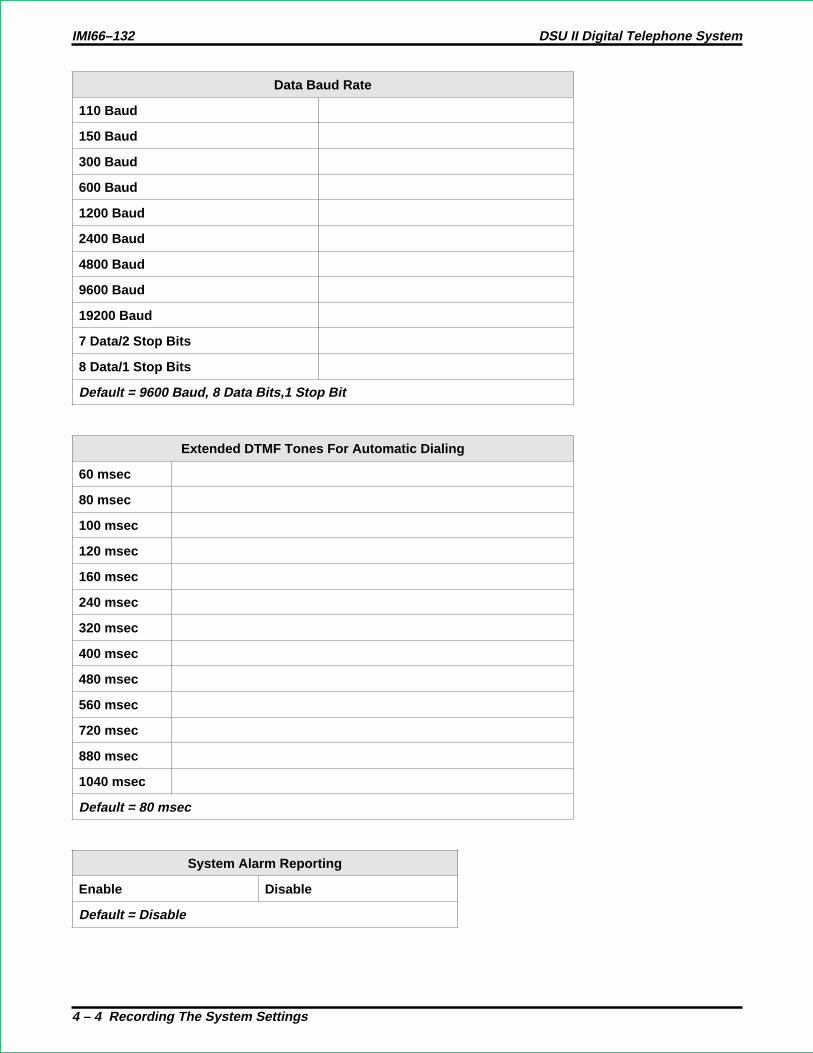
Data Baud Rate
110 Baud
150 Baud
300 Baud
600 Baud
1200 Baud
2400 Baud
4800 Baud
9600 Baud
19200 Baud
7 Data/2 Stop Bits
8 Data/1 Stop Bits
Default = 9600 Baud, 8 Data Bits,1 Stop Bit
Extended DTMF Tones For Automatic Dialing
60 msec
80 msec
100 msec
120 msec
160 msec
240 msec
320 msec
400 msec
480 msec
560 msec
720 msec
880 msec
1040 msec
Default = 80 msec
System Alarm Reporting
Enable Disable
Default = Disable
IMI66–132 DSU II Digital Telephone System
4 – 4 Recording The System Settings

Station Monitoring
Visual Ring Indication Enable Disable
Audible Ring Indication Stations (10-57)
Default = Visual indication disabled, no audible indication assigned.
Tandem Attendant
Enable Disable
Default = Disable
Tone or Voice Signaling
Voice Tone
Default = Tone
SOHVA Tone Bursts 1 2 3 4 5 6
Default = 6
PA Options
Direct Ringing Lines(1-24)
Delayed Ringing Lines(1-24)
Night Ringing Lines(1-24)
Zone Paging Enabled Zone 1 Zone 2 Zone 3 All-Call
Relay Port RelayTracking
Station 17 Paging Port
PA Port Signal Tone Intercom DTMF
Defaults = No ringing lines, all-call paging, station 17 ringing, and intercom tone.
Allow Ringer Off Option
Enabled Disabled
Default = Enabled
DSU II Digital Telephone System IMI66–132
Recording The System Settings 4 – 5

LCD Messages
Msg.No.
Location
1 2 3 4 5 6 7 8 9 10
1
2
3
4
5
6
7
8
9
10
11
12
13
14
15
16
Default: 1 = Back At, 2 = Call
IMI66–132 DSU II Digital Telephone System
4 – 6 Recording The System Settings

System Speed Dial Record (Be sure to record a line group number with each speed dial number.)
Loc Number Name Loc Number Name Loc Number Name Loc Number Name
01 26 51 76
02 27 52 77
03 28 53 78
04 29 54 79
05 30 55 80
06 31 56 81
07 32 57 82
08 33 58 83
09 34 59 84
10 35 60 85
11 36 61 86
12 37 62 87
13 38 63 88
14 39 64 89
15 40 65 90
16 41 66 91
17 42 67 92
18 43 68 93
19 44 69 94
20 45 70 95
21 46 71 96
22 47 72 97
23 48 73 98
24 49 74 99
25 50 75
DSU II Digital Telephone System IMI66–132
Recording The System Settings 4 – 7

Call Park Recall Time
1 min 5 min
2 min 6 min
3 min Never
4 min
Default = 2 minutes
Pause Time
.5 sec 5.0 sec
1.0 sec 7.5 sec
1.5 sec 10 sec
2.0 sec 15 sec
3.0 sec 20 sec
Default = 1 second
Recall/Flash Time
.08 sec .88 sec
.30 sec 1.0 sec
.50 sec 1.5 sec
.60 sec 2.0 sec
.75 sec 3.0 sec
Default = 2 seconds
IMI66–132 DSU II Digital Telephone System
4 – 8 Recording The System Settings

Timed Hold Recall Time
30 sec 240 sec
60 sec 300 sec
90 sec 360 sec
120 sec 420 sec
180 sec Never
Default = 60 seconds
Unanswered Call Transfer Recall Time
10 sec 60 sec
20 sec 90 sec
25 sec 120 sec
30 sec 180 sec
45 sec 240 sec
Default = 20 seconds For Stations
Unanswered Call Transfer Recall Time
10 sec 60 sec
20 sec 90 sec
25 sec 120 sec
30 sec 180 sec
45 sec 240 sec
Default = 20 seconds For Departments
Delayed Ringing Delay Time
6 sec 36 sec
12 sec 42 sec
18 sec 48 sec
24 sec 54 sec
30 sec 60 sec
Default = 18 seconds
DSU II Digital Telephone System IMI66–132
Recording The System Settings 4 – 9

Feature Inhibit
Feature Disabled EnabledLine Group 1Line Group 2Line Group 3Line Group 4Zone 1 PagingZone 2 PagingZone 3 PagingAll CallMeet Me PageNight TransferBackground MusicVoice Announce BlockMessage WaitingCall PickupCall ForwardAutomatic Call BackStation-to-Station Mesg.Line Group QueueDirected Station HoldCall Park Orbit 1Call Park Orbit 2Call Park Orbit 3Call Park Orbit 4Call Park Orbit 5Call Park Orbit 6Call Park Orbit 7Call Park Orbit 8Call Park Orbit 9Call WaitingLCD MessagingExecutive Override/ Service ObservingAccount CodePersonal Call ForwardEnable All FeaturesDefault = All features enabled
IMI66–132 DSU II Digital Telephone System
4 – 10 Recording The System Settings

4.3 Recording The Line Configurations
FeatureLine Port (Write number, name, group, or other data.)
1 2 3 4 5 6 7 8
Abandoned Hold Release (50/350 msec)
Automatic Privacy (On/Off)
Privacy Release Stations (10-57)
Line Port Disable (On/Off)
Line Groups (0, 1-4)
Line Name (5 characters)
Line Port Function (AUX/CO)
Line To Line Port Reassignment (1/1, etc.)
Pulse/Tone Switchable (pulse/tone)
Voice Mail ID (6 digits max)
Default = 50 msec hold release, privacy on all with no station released, no disabled lines, no groupsassigned, no names assigned, all ports co, same line/port, all tone dialing, no VM ID.
FeatureLine Port (Write number, name, group, or other data.)
9 10 11 12 13 14 15 16
Abandoned Hold Release (50/350 msec)
Automatic Privacy (On/Off)
Privacy Release Stations (10-57)
Line Port Disable (On/Off)
Line Groups (0, 1-4)
Line Name (5 characters)
Line Port Function (AUX/CO)
Line To Line Port Reassignment (1/1, etc.)
Pulse/Tone Switchable (pulse/tone)
Voice Mail ID (6 digits max)
Default = 50 msec hold release, privacy on all with no station released, no disabled lines, no groupsassigned, no names assigned, all ports co, same line/port, all tone dialing, no VM ID.
DSU II Digital Telephone System IMI66–132
Recording The System Settings 4 – 11

FeatureLine Port (Write number, name, group, or other data.)
17 18 19 20 21 22 23 24
Abandoned Hold Release (50/350 msec)
Automatic Privacy (On/Off)
Privacy Release Stations (10-57)
Line Port Disable (On/Off)
Line Groups (0, 1-4)
Line Name (5 characters)
Line Port Function (AUX/CO)
Line To Line Port Reassignment (1/1, etc.)
Pulse/Tone Switchable (pulse/tone)
Voice Mail ID (6 digits max)
Default = 50 msec hold release, privacy on all with no station released, no disabled lines, no groupsassigned, no names assigned, all ports co, same line/port, all tone dialing, no VM ID.
Block Programming
Model Line Port Start Line Port End Line Port
IMI66–132 DSU II Digital Telephone System
4 – 12 Recording The System Settings

4.4 Recording The Station Configurations
Use this sheet as an individual station record or as a record for a block of similarly programmed stations.You can make copies of this blank sheet as needed to meet the system capacity.
Feature Choice Default Enter Station Port Numbers
Access Denied Lines 1–24 None
All-Call and Zone Paging Receive All/1–3 All
Originate All/1–3 All
Audible Monitoring None/Dir/Delay None
Automatic Hold Yes/No No
Automatic Hold - Intercom Yes/No No
Automatic PrivacyPrivacy Release None/1–24 None
Call Forward On Ring No-Answer No/1–9 Rings No
Call Forward On Busy Yes/No No
Call Origination Denied No/1–24 No
Central Message Desk Yes/No No
Data Security Port Yes/No No
Do Not Disturb Overide Yes/No No
Dual Console Feature No/10–57 No
Executive Override Yes/No No
Flexible RingingDirect 1–24 All (Sta. 10, 17)
Delayed 1–24 None
Night Transfer (of ringing) 1–24 All (Sta. 10, 17)
Flexible Station Numbering 10–7999 Ext = Port
Group Call Pickup 1–4 1
Headset Interface Yes/No No
Idle Line Preference No/ 1–24 No
Intercom Hunt Group 10–57 None
Personal Ring Tones 1–6 1
PrimeLine 1–24 None
Group 1–4 None
Intercom Itcm. None
Message Waiting Originate Yes/No Yes
Ringing Line Preference Yes/No No
SOHVA Disable Yes/No No
SOHVA Groups None/1–8 None
Service Observing Yes/No No
Station Disable Yes/No No
Station To Station Port Reassignment 10/57 Sta = Port
System Alarm Report Yes/No No
Voice Announce Blocking Yes/No No
Block Programming
Model Station Port
First Station Port
Last Station Port
DSU II Digital Telephone System IMI66–132
Recording The System Settings 4 – 13

7700S LCD Speakerphone
DIGITECHCOMDIAL
SPKR
TAPTRANS
CONF
MUTE
HOLD ITCM
A1A2A3A4A5A6A7
A8A9A10A11A12A13A14
B5B6B7B8B9B10
7714S Speakerphone
7714X Monitor Telephone
DIGITECHCOMDIAL
SPKR
TAPTRANS
CONF
MUTE
HOLD ITCM
A1A2A3A4A5A6A7
A8A9A10A11A12A13A14
B5B6B7B8B9B10
DEFAULT SETTINGS:B1-B10 = Line 1 - Line 10, and A1 = 23, A2 = 21, A3 = 19, A4 = 17, A5 = 15, A6 = 13,A7 = 11, A8 = 24, A9 = 22, A10 = 20, A11 = 18, A12 = 16, A13 = 14, A14 = 12
BUTTON ASSIGNMENT CHART
A1
A2
A3
A4
A5
A6
A7
A8
A9
A10
A11
A12
A13
A14
B1
B2
B3
B4
B5
B6
B7
B8
B9
B10
PORT NUMBER
INTERCOM NUMBER
STATION NAME
STATION LOCATION
TELEPHONETYPE
MODEL
BUTTON
BLK
Lnn
Snn
DND
PRI
IC2
ACC
SAV
ZPn
AC
ACB
CF
CPn
TGn
VAB
TGQ
DESCRIPTION
Blank
Lines 1 - 24
Stations 10 - 57
Do Not Disturb
Privacy
Second Intercom
Account Code
Save
Zone Page 1 - 3
All-Call Page
Automatic Call Back
Call Forward
Call Park Orbit 1 - 9
Line Group 1 - 4
Voice Announce Block
Line Group Queue
. . . .
. . . .
. . . .
. . . .
. . . .
. . . .
. . . .
. . . .
. . . .
. . . .
. . . .
. . . .
. . . .
. . . .
. . . .
. . . .
CAJS020
Button Mapping The DigiTech Telephones (Rev. I and later)Complete one record sheet for each station.
Copy this blank record sheet as required for additional stations.
B1
B1
B2
B2
B3
B3
B4
B4
IMI66–132 DSU II Digital Telephone System
4 – 14 Recording The System Settings

PORT NUMBER
INTERCOM NUMBER
STATION NAME
STATION LOCATION
TELEPHONETYPE
MODEL
BUTTON
BLK
Lnn
Snn
DND
PRI
IC2
ACC
SAV
ZPn
AC
ACB
CF
CPn
TGn
VAB
TGQ
DESCRIPTION
Blank
Lines 1 - 24
Stations 10 - 57
Do Not Disturb
Privacy
Second Intercom
Account Code
Save
Zone Page 1 - 3
All-Call Page
Automatic Call Back
Call Forward
Call Park Orbit 1 - 9
Line Group 1 - 4
Voice Announce Block
Line Group Queue
. . . .
. . . .
. . . .
. . . .
. . . .
. . . .
. . . .
. . . .
. . . .
. . . .
. . . .
. . . .
. . . .
. . . .
. . . .
. . . .
BUTTON ASSIGNMENT CHART
A1
A2
A3
A4
A5
A6
A7
A8
A9
A10
A11
A12
A13
A14
B1
B2
B3
B4
B5
B6
B7
B8
7700S LCD Speakerphone
7714S Speakerphone
7714X Monitor Telephone
HOLD
SPKR
MUTE
TAP
TRANS
CONF
SH I F TMW
I TCM
COMDIAL DIGITECH
1
4
7
2
5
8
0
3
6
9
#
ABC
JKL
TUV
OPER
GH I
PRS
SYS
DEF
MNO
WXY
RDLB5
B4
B6
B7
B8
B1 B2
B3
A1
A2
A3
A4
A5
A6
A7
A8
A9
A0
A11
A12
A13
A14
COMDIAL DIGITECH
TAP
MUTE
SPKR
HOLD I TCM
TRANS
CONF
1 2
4
7
5
8
0
6
9
#
3ABC
GHI
PRS
SYS
JKL
TUV
OPER
MNO
WXY
RDL
DEF
A1
A2
A3
A4
A5
A6
A7
A8
A9
A10
A11
A12
A13
A14
B1
B2
B3
DEFAULT SETTINGS:B1-B8 = Line 1 - Line 8, and A1 = 21, A2 = 19, A3 = 17, A4 = 15, A5 = 13, A6 = 11,A7 = 9, A8 = 22, A9 = 20, A10 = 18, A11 = 16, A12 = 14, A13 = 12, A14 = 10
CAJS021
Button Mapping The DigiTech Telephones (Rev. A-H)Complete one record sheet for each station.
Copy this blank record sheet as required for additional stations.
DSU II Digital Telephone System IMI66–132
Recording The System Settings 4 – 15

MUTE
SHIFT
SPEAKER
INTERCOM
TRNS/CNF
TAPHOLD
OPER
TUVPRS WXY
DEFABCQZ
MNOJKLGHI
0
87 9
321
#
654
COMDIAL
IMP100
PORT NUMBER
INTERCOM NUMBER
STATION NAME
STATION LOCATION
TELEPHONETYPE
MODEL
BUTTON
BLK
Lnn
Snn
DND
PRI
IC2
ACC
SAV
ZPn
AC
ACB
CF
CPn
TGn
VAB
TGQ
DESCRIPTION
Blank
Lines 1 - 24
Stations 10 - 57
Do Not Disturb
Privacy
Second Intercom
Account Code
Save
Zone Page 1 - 3
All-Call Page
Automatic Call Back
Call Forward
Call Park Orbit 1 - 9
Line Group 1 - 4
Voice Announce Block
Line Group Queue
. . . .
. . . .
. . . .
. . . .
. . . .
. . . .
. . . .
. . . .
. . . .
. . . .
. . . .
. . . .
. . . .
. . . .
. . . .
. . . .
BUTTON ASSIGNMENT CHART
L01
L02
L03
L04
L05
L06
L07
L08
L09
L10
L11
L12
A1
A2
A3
A4
A5
A6
A7
A8
A9
A10
A11
A12
IMPACT
BUTTON*DigiTechEQUIV.
PROGRAMMEDASSIGNMENT
*DEFAULT:L1-L12 = LINE 1 - LINE 12
CAJS019
8012S 12-Line LCD Speakerphone
L01L02L03L04L05L06L07L08L09L10L11L12
MUTE
SHIFT
SPEAKER
INTERCOM
TRNS/CNF
TAPHOLD
OPER
TUVPRS WXY
DEFABCQZ
MNOJKLGHI
0
87 9
321
#
654
COMDIAL
IMP100A
8112S 12-Line Speakerphone
L01L02L03L04L05L06L07L08L09L10L11L12
Button Mapping The Impact TelephonesComplete one record sheet for each station.
Copy this blank record sheet as required for additional stations.
IMI66–132 DSU II Digital Telephone System
4 – 16 Recording The System Settings
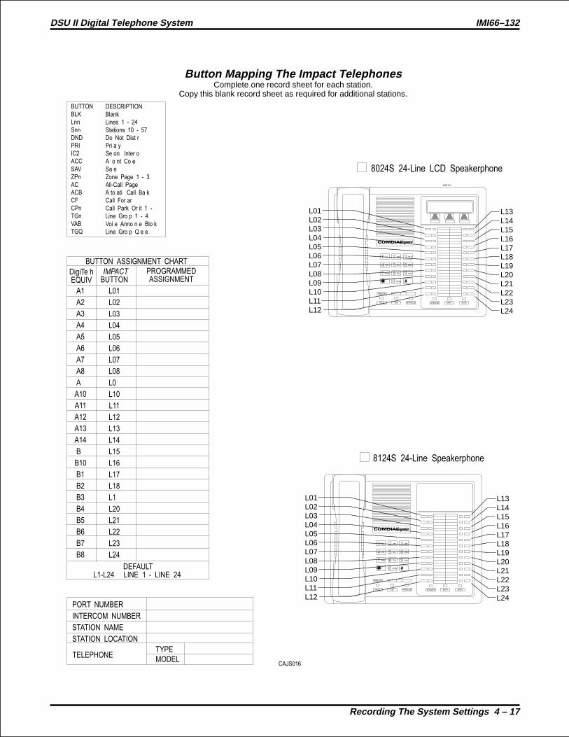
PORT NUMBER
INTERCOM NUMBER
STATION NAME
STATION LOCATION
TELEPHONETYPE
MODEL
BUTTON
BLK
Lnn
Snn
DND
PRI
IC2
ACC
SAV
ZPn
AC
ACB
CF
CPn
TGn
VAB
TGQ
DESCRIPTION
Blank
Lines 1 - 24
Stations 10 - 57
Do Not Disturb
Privacy
Second Intercom
Account Code
Save
Zone Page 1 - 3
All-Call Page
Automatic Call Back
Call Forward
Call Park Orbit 1 - 9
Line Group 1 - 4
Voice Announce Block
Line Group Queue
. . . .
. . . .
. . . .
. . . .
. . . .
. . . .
. . . .
. . . .
. . . .
. . . .
. . . .
. . . .
. . . .
. . . .
. . . .
. . . .
A1
A2
A3
A4
A5
A6
A7
A8
A9
A10
A11
A12
A13
A14
B9
B10
B1
B2
B3
B4
B5
B6
B7
B8
DigiTechEQUIV.
BUTTON ASSIGNMENT CHART
L01
L02
L03
L04
L05
L06
L07
L08
L09
L10
L11
L12
L13
L14
L15
L16
L17
L18
L19
L20
L21
L22
L23
L24
IMPACT
BUTTON*PROGRAMMEDASSIGNMENT
*DEFAULT:L1-L24 = LINE 1 - LINE 24
8024S 24-Line LCD Speakerphone
MUTESHIFTSPEAKERINTERCOM
TRNS/CNF
TAPHOLD
OPER
TUVPRS WXY
DEFABCQZ
MNOJKLGHI
0
87 9
321
#
654
COMDIAL
IMP103
L13L14L15L16L17L18L19L20L21L22L23L24
L01L02L03L04L05L06L07L08L09L10L11L12
8124S 24-Line Speakerphone
MUTESHIFTSPEAKERINTERCOM
TRNS/CNF
TAPHOLD
OPER
TUVPRS WXY
DEFABCQZ
MNOJKLGHI
0
87 9
321
#
654
COMDIAL
L13L14L15L16L17L18L19L20L21L22L23L24
L01L02L03L04L05L06L07L08L09L10L11L12
CAJS016
Button Mapping The Impact TelephonesComplete one record sheet for each station.
Copy this blank record sheet as required for additional stations.
DSU II Digital Telephone System IMI66–132
Recording The System Settings 4 – 17

PORT NUMBERINTERCOM NUMBERSTATION NAMESTATION LOCATION
TELEPHONETYPEMODEL
cajs068y.cdr
BUTTON ASSIGNMENT CHARTL01L02L03L04
Default:L01 = Line 1L02 = Line 2L03 = Line 3L04 = Intercom
Scout 900mxDigital WirelessTelephone
L03
L04
L01
L02 F1 F2 F3 F4
1 2
4
7
F1 F2 F3 F4
3
5
8
0
6
9
#
ABC
T/C HOLD
MEMOTAPTALK
GHI
PRS
DEF
JKL
TUV
OPER
MNO
WXY
Button Mapping The Scout 900 Digital Wireless TelephoneMXComplete one record sheet for each station.
Copy this blank record sheet as required for additional stations.
BUTTON
BLK
Lnn
Snn
DND
PRI
IC2
ACC
SAV
ZPn
AC
ACB
CF
CPn
TGn
VAB
TGQ
DESCRIPTION
Blank
Lines 1 - 24
Stations 10 - 57
Do Not Disturb
Privacy
Second Intercom
Account Code
Save
Zone Page 1 - 3
All-Call Page
Automatic Call Back
Call Forward
Call Park Orbit 1 - 9
Line Group 1 - 4
Voice Announce Block
Line Group Queue
. . . .
. . . .
. . . .
. . . .
. . . .
. . . .
. . . .
. . . .
. . . .
. . . .
. . . .
. . . .
. . . .
. . . .
. . . .
. . . .
IMI66–132 DSU II Digital Telephone System
4 – 18 Recording The System Settings

2022S LCD Speakerphone
2122S Speakerphone
2122X Monitor Telephone
DEFAULT SETTINGS:B1-B6 = Line 1 - Line 6, and A1 = 7, A2 = 9, A3 = 11, A4 = 13, A5 = 15, A6 = 17,A7 = 19, A8 = 21, A9 = 8, A10 = 10, A11 = 12, A12 = 14, A13 = 16, A14 = 18, A15 = 20,A16 = 22
BUTTON ASSIGNMENT CHART
A1
A2
A3
A4
A5
A6
A7
A8
A9
A10
A11
A12
A13
A14
A15
A16
B1
B2
B3
B4
B5
B6
PORT NUMBER
INTERCOM NUMBER
STATION NAME
STATION LOCATION
TELEPHONETYPE
MODEL
BUTTON
BLK
Lnn
Snn
DND
PRI
IC2
ACC
SAV
ZPn
AC
ACB
CF
CPn
TGn
VAB
TGQ
DESCRIPTION
Blank
Lines 1 - 24
Stations 10 - 57
Do Not Disturb
Privacy
Second Intercom
Account Code
Save
Zone Page 1 - 3
All-Call Page
Automatic Call Back
Call Forward
Call Park Orbit 1 - 9
Line Group 1 - 4
Voice Announce Block
Line Group Queue
. . . .
. . . .
. . . .
. . . .
. . . .
. . . .
. . . .
. . . .
. . . .
. . . .
. . . .
. . . .
. . . .
. . . .
. . . .
. . . .
CAJS108
Button Mapping The Impression TelephonesComplete one record sheet for each station.
Copy this blank record sheet as required for additional stations.
1 2
4
7
0
8 9
5 6
3
#
ABC
GHI
PRS
OPER
TUV WXY
JKL MNO
DEF
SPKR
HOLD TAP ITCM
T/C MUTE
B1 B2 B3
B4 B5 B6
A1 A9
A2 A10
A3 A11
A4 A12
A5 A13
A6 A14
A7 A15
A8 A16
1 2
4
7
0
8 9
5 6
3
#
ABC
GHI
PRS
OPER
TUV WXY
JKL MNO
DEF
SPKR
HOLD TAP ITCM
T/C MUTE
B1 B2 B3
B4 B5 B6
A1 A9
A2 A10
A3 A11
A4 A12
A5 A13
A6 A14
A7 A15
A8 A16
DSU II Digital Telephone System IMI66–132
Recording The System Settings 4 – 19
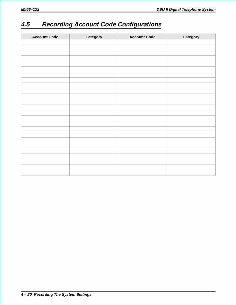
4.5 Recording Account Code Configurations
Account Code Category Account Code Category
IMI66–132 DSU II Digital Telephone System
4 – 20 Recording The System Settings

Account Code Usage Enabled DisabledVerification On OffUsage Status Forced Optional
Station Exceptions
Verified DigitsAccount Code LengthEmergency No. 1Emergency No. 2Emergency No. 3Emergency No. 4Emergency No. 5Emergency No. 6Emergency No. 7Emergency No. 8Emergency No. 9Emergency No. 10LCD Display TimeDisplay On Incoming Yes NoDefault = Acouunt Code Usage: Disabled
Verified Status: OnUsage Status: ForcedExceptions: NoneVerified Digits: ThreeAccount Code Digits: 3Display Time: 5 secondsIncoming Display: On
DSU II Digital Telephone System IMI66–132
Recording The System Settings 4 – 21

4.6 Recording The Industry-Standard Telephone Configurations
Distinctive Ringing
Enabled
Disabled
Default = Enabled
Thru Dialing Port
10 26 42
11 27 43
12 28 44
13 29 45
14 30 46
15 31 47
16 32 48
17 33 49
18 34 50
19 35 51
20 36 52
21 37 53
22 38 54
23 39 55
24 40 56
25 41 57
Default = Not Enabled
IMI66–132 DSU II Digital Telephone System
4 – 22 Recording The System Settings
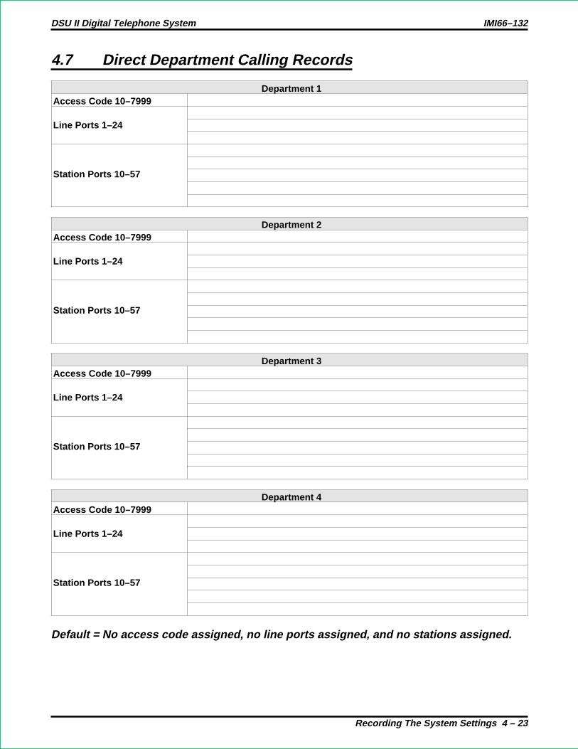
4.7 Direct Department Calling Records
Department 1Access Code 10–7999
Line Ports 1–24
Station Ports 10–57
Department 2Access Code 10–7999
Line Ports 1–24
Station Ports 10–57
Department 3Access Code 10–7999
Line Ports 1–24
Station Ports 10–57
Department 4Access Code 10–7999
Line Ports 1–24
Station Ports 10–57
Default = No access code assigned, no line ports assigned, and no stations assigned.
DSU II Digital Telephone System IMI66–132
Recording The System Settings 4 – 23

4.8 Direct Inward Station Dialing (DISD) Records
Dial TimeLimit
6 sec 9 sec 12 sec 15 sec 20 sec 30 sec 40 sec 60 sec 90 sec 0 sec
Default = 12 Seconds
Assist StationStation Assigned Lines AssignedDay StationNight StationDefault = Station 10 Day And Night
Incoming Ring Line Port Assigned012456789
Default = 0 Rings
IMI66–132 DSU II Digital Telephone System
4 – 24 Recording The System Settings

4.9 Recording The Voice Mail Interface Configurations
Voice Mail Station Port
10 26 42
11 27 43
12 28 44
13 29 45
14 30 46
15 31 47
16 32 48
17 33 49
18 34 50
19 35 51
20 36 52
21 37 53
22 38 54
23 39 55
24 40 56
25 41 57
Default = Not Enabled
DSU II Digital Telephone System IMI66–132
Recording The System Settings 4 – 25

Automatic Attendant Ringing Lines (1–24)
Station Direct Delay Night Station Direct Delay Night
10 34
11 35
12 36
13 37
14 38
15 39
16 40
17 41
18 42
19 43
20 44
21 45
22 46
23 47
24 48
25 49
26 50
27 51
28 52
29 53
30 54
31 55
32 56
33 57
Default = Not Assigned
IMI66–132 DSU II Digital Telephone System
4 – 26 Recording The System Settings

Automatic Transfer Of Voice Mail
Enable
Disable
Default = Disabled
Voice Mail Line Port Identification
1 9 17
2 10 18
3 11 19
4 12 20
5 13 21
6 14 22
7 15 23
8 16 24
Default = No ID Assigned
Voice Mail Transfer On Busy Station Port
10 26 42
11 27 43
12 28 44
13 29 45
14 30 46
15 31 47
16 32 48
17 33 49
18 34 50
19 35 51
20 36 52
21 37 53
22 38 54
23 39 55
24 40 56
25 41 57
Default = Not Enabled
DSU II Digital Telephone System IMI66–132
Recording The System Settings 4 – 27

4.10 Recording The Integrated Call Costing Configurations
Exception Tables
ExceptionTable
DigitsCostTable
1 2 3 4 5 6 7 8 9 10 11 12 13 14 15 16
1
2
3
4
Default = None Assigned
Office Code Band Tables
Band Office Code Prefix
1
2
3
4
5
6
7
Default = None Assigned
Zone Call Band Tables
Band
1
2
3
4
Default = None Assigned
Area Code Band Tables
Band
1
2
3
4
5
6
7
Default = None Assigned
IMI66–132 DSU II Digital Telephone System
4 – 28 Recording The System Settings

Discard Digits
Entry Digits
1 2 3 4 5 6 7 8
1
2
3
4
5
6
Default = No Discard Digits Assigned
Dial Time Limit
01-999 Seconds
Default = 0 Seconds
Answer Time Limit
01-999 Seconds
Default = 0 Seconds
DSU II Digital Telephone System IMI66–132
Recording The System Settings 4 – 29

Call Rate Table 1
Tier 1 Time
Tier 1 Rate
Tier 2 Rate
Surcharge
Call Rate Table 2
Number
Tier 1 Time
Tier 1 Rate
Tier 2 Rate
Surcharge
Call Rate Table 3
Number
Tier 1 Time
Tier 1 Rate
Tier 2 Rate
Surcharge
Call Rate Table 4
Number
Tier 1 Time
Tier 1 Rate
Tier 2 Rate
Surcharge
Call Rate Table 5
Number
Tier 1 Time
Tier 1 Rate
Tier 2 Rate
Surcharge
Call Rate Table 6
Number
Tier 1 Time
Tier 1 Rate
Tier 2 Rate
Surcharge
Call Rate Table 7
Number
Tier 1 Time
Tier 1 Rate
Tier 2 Rate
Surcharge
Call Rate Table 8
Number
Tier 1 Time
Tier 1 Rate
Tier 2 Rate
Surcharge
Call Rate Table 9
Number
Tier 1 Time
Tier 1 Rate
Tier 2 Rate
Surcharge
Call Rate Table 10
Number
Tier 1 Time
Tier 1 Rate
Tier 2 Rate
Surcharge
Call Rate Table 11
Number
Tier 1 Time
Tier 1 Rate
Tier 2 Rate
Surcharge
Call Rate Table 12
Number
Tier 1 Time
Tier 1 Rate
Tier 2 Rate
Surcharge
IMI66–132 DSU II Digital Telephone System
4 – 30 Recording The System Settings

Call Rate Table 13
Number
Tier 1 Time
Tier 1 Rate
Tier 2 Rate
Surcharge
Call Rate Table 14
Number
Tier 1 Time
Tier 1 Rate
Tier 2 Rate
Surcharge
Call Rate Table 15
Number
Tier 1 Time
Tier 1 Rate
Tier 2 Rate
Surcharge
Call Rate Table 16
Number
Tier 1 Time
Tier 1 Rate
Tier 2 Rate
Surcharge
Call Rate Table 17
Number
Tier 1 Time
Tier 1 Rate
Tier 2 Rate
Surcharge
Call Rate Table 18
Number
Tier 1 Time
Tier 1 Rate
Tier 2 Rate
Surcharge
Call Rate Table 19
Number
Tier 1 Time
Tier 1 Rate
Tier 2 Rate
Surcharge
Call Rate Table 20
Number
Tier 1 Time
Tier 1 Rate
Tier 2 Rate
Surcharge
Call Rate Table 21
Number
Tier 1 Time
Tier 1 Rate
Tier 2 Rate
Surcharge
Call Rate Table 22
Number
Tier 1 Time
Tier 1 Rate
Tier 2 Rate
Surcharge
Call Rate Table 23
Number
Tier 1 Time
Tier 1 Rate
Tier 2 Rate
Surcharge
Call Rate Table 24
Number
Tier 1 Time
Tier 1 Rate
Tier 2 Rate
Surcharge
DSU II Digital Telephone System IMI66–132
Recording The System Settings 4 – 31
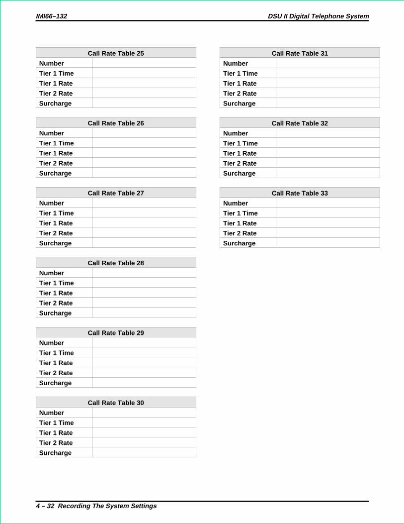
Call Rate Table 25
Number
Tier 1 Time
Tier 1 Rate
Tier 2 Rate
Surcharge
Call Rate Table 26
Number
Tier 1 Time
Tier 1 Rate
Tier 2 Rate
Surcharge
Call Rate Table 27
Number
Tier 1 Time
Tier 1 Rate
Tier 2 Rate
Surcharge
Call Rate Table 28
Number
Tier 1 Time
Tier 1 Rate
Tier 2 Rate
Surcharge
Call Rate Table 29
Number
Tier 1 Time
Tier 1 Rate
Tier 2 Rate
Surcharge
Call Rate Table 30
Number
Tier 1 Time
Tier 1 Rate
Tier 2 Rate
Surcharge
Call Rate Table 31
Number
Tier 1 Time
Tier 1 Rate
Tier 2 Rate
Surcharge
Call Rate Table 32
Number
Tier 1 Time
Tier 1 Rate
Tier 2 Rate
Surcharge
Call Rate Table 33
Number
Tier 1 Time
Tier 1 Rate
Tier 2 Rate
Surcharge
IMI66–132 DSU II Digital Telephone System
4 – 32 Recording The System Settings

4.11 Station Message Detail Accounting/Reporting Records
Department Department Number Department Station
1
2
3
4
5
6
7
8
Default = None Assigned
Automatic Report Time
Hours
Minutes
Selected Records
All Stations
One Station
Account Report
Line Report
Department Report
Print All Records
Delete Records
DCD Report
Default = None Assigned
SMDR Cost Reporting Enabled Disabled
SMDR Printout Enabled Disabled
Default = No Cost Reported, Printout Enabled
DSU II Digital Telephone System IMI66–132
Recording The System Settings 4 – 33

4.12 Recording The Specialized Route Access Configurations
Specialized Route AccessEnabled Disabled
Default = Disabled
Office Code TableOffice Code Line Group
1 2 3 4
Default = Line Group 1
IMI66–132 DSU II Digital Telephone System
4 – 34 Recording The System Settings
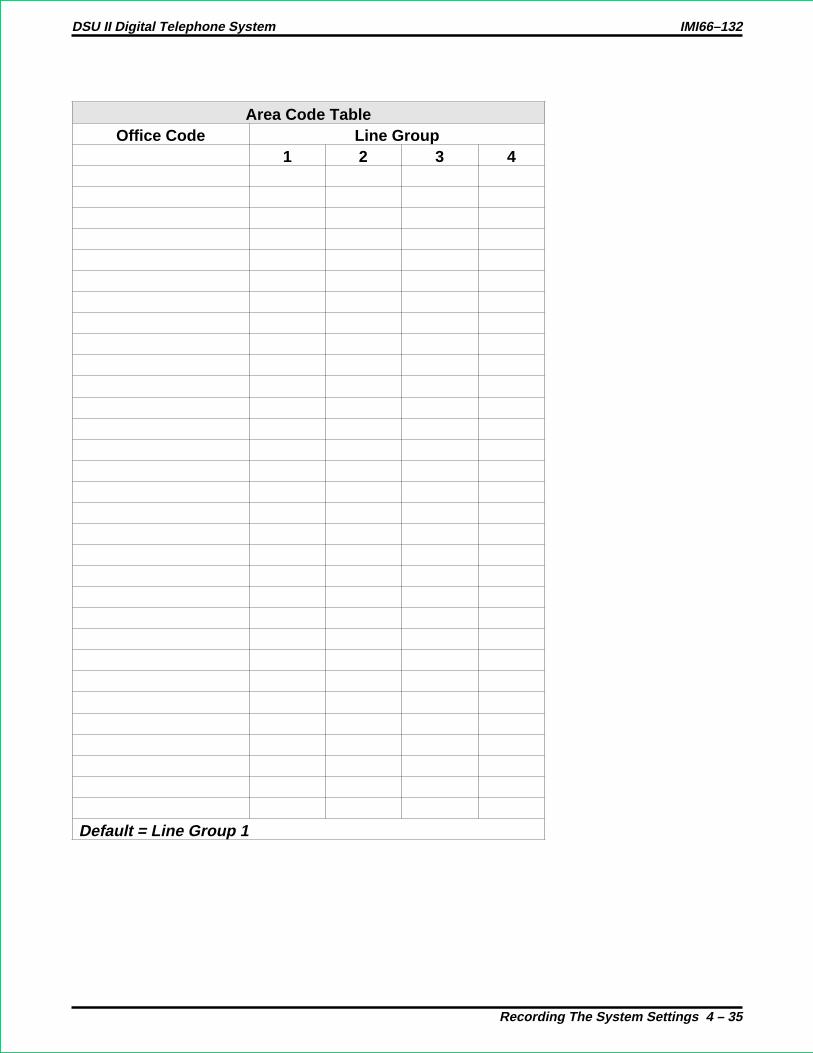
Area Code TableOffice Code Line Group
1 2 3 4
Default = Line Group 1
DSU II Digital Telephone System IMI66–132
Recording The System Settings 4 – 35

Special Area Code Table 1Area Code =Office Code Line Group000-999 1 2 3 4
Default = Line Group 1
Special Area Code Table 3Area Code =Office Code Line Group000-999 1 2 3 4
Default = Line Group 1
Special Area Code Table 2Area Code =Office Code Line Group000-999 1 2 3 4
Special Area Code Table 4Area Code =Office Code Line Group000-999 1 2 3 4
Default = Line Group 1
IMI66–132 DSU II Digital Telephone System
4 – 36 Recording The System Settings

Overflow Line GroupDefault = None
SRA Wait Time 2 seconds 3 seconds 4 secondsDefault = 4 seconds
LineGroup
Insert Digits1 2 3 4 5 6 7 8
1234
Default = None
DSU II Digital Telephone System IMI66–132
Recording The System Settings 4 – 37
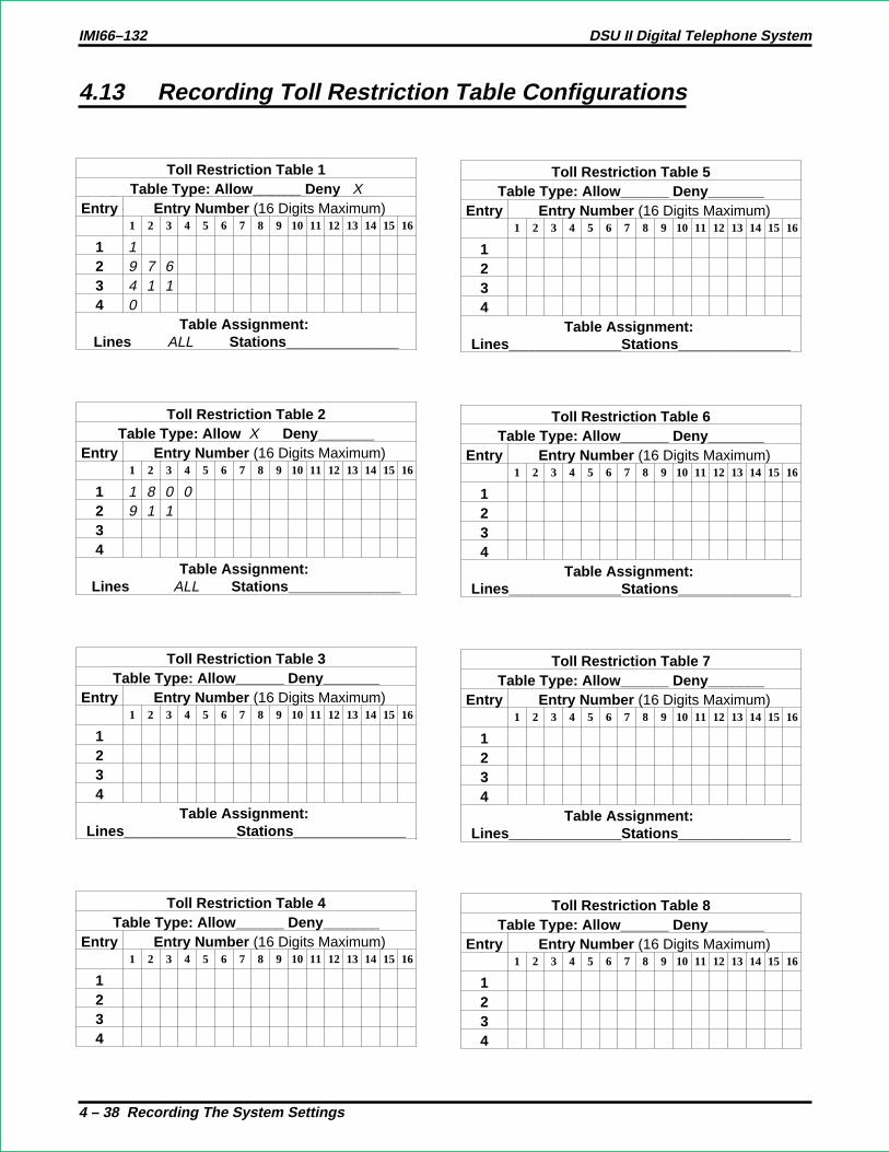
4.13 Recording Toll Restriction Table Configurations
4.15.1 Toll Restriction TablesToll Restriction Table 1
Table Type: Allow______ Deny XEntry Entry Number (16 Digits Maximum)
1 2 3 4 5 6 7 8 9 10 11 12 13 14 15 16
1 12 9 7 63 4 1 14 0
Table Assignment:Lines ALL Stations______________
Toll Restriction Table 2Table Type: Allow X Deny_______
Entry Entry Number (16 Digits Maximum)1 2 3 4 5 6 7 8 9 10 11 12 13 14 15 16
1 1 8 0 02 9 1 134
Table Assignment:Lines ALL Stations______________
Toll Restriction Table 3Table Type: Allow______ Deny_______
Entry Entry Number (16 Digits Maximum)1 2 3 4 5 6 7 8 9 10 11 12 13 14 15 16
1234
Table Assignment:Lines______________Stations______________
Toll Restriction Table 4Table Type: Allow______ Deny_______
Entry Entry Number (16 Digits Maximum)1 2 3 4 5 6 7 8 9 10 11 12 13 14 15 16
1234
Toll Restriction Table 5Table Type: Allow______ Deny_______
Entry Entry Number (16 Digits Maximum)1 2 3 4 5 6 7 8 9 10 11 12 13 14 15 16
1234
Table Assignment:Lines______________Stations______________
Toll Restriction Table 6Table Type: Allow______ Deny_______
Entry Entry Number (16 Digits Maximum)1 2 3 4 5 6 7 8 9 10 11 12 13 14 15 16
1234
Table Assignment:Lines______________Stations______________
Toll Restriction Table 7Table Type: Allow______ Deny_______
Entry Entry Number (16 Digits Maximum)1 2 3 4 5 6 7 8 9 10 11 12 13 14 15 16
1234
Table Assignment:Lines______________Stations______________
Toll Restriction Table 8Table Type: Allow______ Deny_______
Entry Entry Number (16 Digits Maximum)1 2 3 4 5 6 7 8 9 10 11 12 13 14 15 16
1234
IMI66–132 DSU II Digital Telephone System
4 – 38 Recording The System Settings

4.13.1 Toll Restriction Tables—continued
Toll Restriction Table 13Table Type: Allow______ Deny_______
Entry Entry Number (16 Digits Maximum)1 2 3 4 5 6 7 8 9 10 11 12 13 14 15 16
1234
Table Assignment:Lines______________Stations______________
Toll Restriction Table 14Table Type: Allow______ Deny_______
Entry Entry Number (16 Digits Maximum)1 2 3 4 5 6 7 8 9 10 11 12 13 14 15 16
1234
Table Assignment:Lines______________Stations______________
Toll Restriction Table 15Table Type: Allow______ Deny_______
Entry Entry Number (16 Digits Maximum)1 2 3 4 5 6 7 8 9 10 11 12 13 14 15 16
1234
Table Assignment:Lines______________Stations______________
Toll Restriction Table 16Table Type: Allow______ Deny_______
Entry Entry Number (16 Digits Maximum)1 2 3 4 5 6 7 8 9 10 11 12 13 14 15 16
1234
Toll Restriction Table 9Table Type: Allow______ Deny_______
Entry Entry Number (16 Digits Maximum)1 2 3 4 5 6 7 8 9 10 11 12 13 14 15 16
1234
Table Assignment:Lines______________Stations______________
Toll Restriction Table 10Table Type: Allow______ Deny_______
Entry Entry Number (16 Digits Maximum)1 2 3 4 5 6 7 8 9 10 11 12 13 14 15 16
1234
Table Assignment:Lines______________Stations______________
Toll Restriction Table 11Table Type: Allow______ Deny_______
Entry Entry Number (16 Digits Maximum)1 2 3 4 5 6 7 8 9 10 11 12 13 14 15 16
1234
Table Assignment:Lines______________Stations______________
Toll Restriction Table 12Table Type: Allow______ Deny_______
Entry Entry Number (16 Digits Maximum)1 2 3 4 5 6 7 8 9 10 11 12 13 14 15 16
1234
DSU II Digital Telephone System IMI66–132
Recording The System Settings 4 – 39

4.13.2 Toll Restriction Tables—Line Assignments
Assign Toll Restriction Tables To LinesPort Tables Port Tables
1 132 143 154 165 176 187 198 209 2110 2211 2312 24
Default = All Tables Assigned To All Ports
IMI66–132 DSU II Digital Telephone System
4 – 40 Recording The System Settings

4.13.3 Toll Restriction Assignments
Station Port Toll Table AssignmentsNormal Calls Night Transfer Calls Speed Dial Calls Override Code
101112131415161718192021222324252627282930313233343536373839404142434445464748495051525354555657
Default = None Assigned
DSU II Digital Telephone System IMI66–132
Recording The System Settings 4 – 41

4.14 Caller ID Service Support Configuration Chart
Caller ID Lines (list 1–24 for lines)
Default = None Assigned
Caller ID Stations (list 10–57 for stations)
Default = None Assigned
Audible First Ring Enable Disable
Default = Disabled
IMI66–132 DSU II Digital Telephone System
4 – 42 Recording The System Settings

SAVE Button Stations (list 10–57 for stations)
Default = None Assigned
Caller ID Distribution To COM 2 Enable Disable
Default = Disabled
COM 2 Configuration
Baud Rate 9600 Other (see system configuration record)
Data Bits 8 Data/1 Stop 7 Data/2 Stop
Default = 9600 Baud, 8 Data Bits, 1 Stop Bit
DSU II Digital Telephone System IMI66–132
Recording The System Settings 4 – 43

4.15 Tracker Paging System Records
Tracker Paging System
Enabled Disabled
Default = Disabled
Tracker Pager Station Assignments
Station Port Enabled Station Port Enabled Station Port Enabled
10 26 42
11 27 43
12 28 44
13 29 45
14 30 46
15 31 47
16 32 48
17 33 49
18 34 50
19 35 51
20 36 52
21 37 53
22 38 54
23 39 55
24 40 56
25 41 57
Default = Disabled
IMI66–132 DSU II Digital Telephone System
4 – 44 Recording The System Settings

4.16 Digital Voice Announcing Records
Enable/Disable DVA Operation
Feature Enabled Disabled
DVA Support for DCD
DVA Support for DISD
Default = Disabled
DCD Department Transfers Before Disconnect
DCD DepartmentTransfers BeforeDisconnect
1 2 3 4 5 6 7 8 9NeverDisconnect
Default = Never Disconnect
Inhibit DISD Digit Dialing— During Night Transfer (of Ringing) Operation
DISD Digit Dialing During NightTransfer (of Ringing) Operation
Enabled(Dialing On)
Disabled(Dialing Off)
Default = Enabled
DISD Dial Time Limit
DISD DialTime Limit
6 sec. 9 sec. 12 sec. 15 sec. 20 sec. 30 sec. 40 sec. 60 sec. 90 sec. 0 sec.
Default = 12 sec.
DSU II Digital Telephone System IMI66–132
Recording The System Settings 4 – 45

DVA Messages (Copy this blank sheet for a record of each DVA.)
Message Type DCD Message DISD Message
Day Answer Message(Message 1)
Night Answer Message(Message 2)
Recall Message(Message 3)
Drop Message(Message 4)
IMI66–132 DSU II Digital Telephone System
4 – 46 Recording The System Settings

DVA Station Ports
Station Port DVA Assigned Station Port DVA Assigned
10 34
11 35
12 36
13 37
14 38
15 39
16 40
17 41
18 42
19 43
20 44
21 45
22 46
23 47
24 48
25 49
26 50
27 51
28 52
29 53
30 54
31 55
32 56
33 57
Default = None Assigned
DSU II Digital Telephone System IMI66–132
Recording The System Settings 4 – 47

4.17 Data Interface Unit Records
Station DIU Location Security Group Station DIU Location Security Group
10 34
11 35
12 36
13 37
14 38
15 39
16 40
17 41
18 42
19 43
20 44
21 45
22 46
23 47
24 48
25 49
26 50
27 51
28 52
29 53
30 54
31 55
32 56
33 57
Defaults = No DIUs assigned. Security groups = 0 (no assignments).
Example: The following entries show that station 12 has been programmed so that the data button(labeled “DATA”) on the digital telephone at station 12 will activate the DIU connected at station 29.Also, this example shows that station 29 is assigned to security group 2.
12 29 —
29 29 2
IMI66–132 DSU II Digital Telephone System
4 – 48 Recording The System Settings

Appendix A:Understanding TheSystem Features
A
Abandoned Hold ReleaseIf an on-hold party hangs up at the CO/PBX end of a connection, causing an interruptionin the line current, the system will drop the line from the hold condition and return it toservice. The time interval between hang-up and line-drop is programmable in line classof service programming with choices of either 50 msec or 350 msec. This feature isusually dependent upon special arrangements that must be made at the CO end of theconnection. The line select indicator will turn off to indicate an idle line after a call onthat line has been abandoned.
See also,Hold.
Access DeniedThe system programmer can deny access to particular lines at certain stations in thesystem. A station user cannot select a denied line for use. This feature is programmableon a per line/per station basis in station class of service programming.
See also,Line Features.
A
DSU II Digital Telephone System IMI66–132
Digital Telephone System Features A – 1
Account Codes (With Forced Positive Verification)System users can employ account codes to identify calls by category or by any otherdesired grouping so that the system can print reports. The account code entry can bevoluntary or the programmer can arrange the system so that the users are forced to enteran account code before they can make an outgoing call. The system compares theaccount code entered by a station user with a list of programmed account entries.
The programmer must program the system so that it verifies an entered account code asvalid. If he or she enables verification and the system cannot match an account code thata user has dialed with the programmed account code entries, the system will sound anerror tone if account code
entry is voluntary, or it will prevent the user from further dialing until he or she enters amatching account code if account code entry is forced.
A user must enter an account code either before dialing an outgoing call or after thedistant party on an incoming call has hung up. Additionally, users may enter an accountcode before they select a line for an outgoing call if they wish. When they enter anaccount code without a line selection, the code will apply to any line they subsequentlyselect at that station. On incoming and outgoing calls, the user who enters the accountcode is associated with the call record except when the call is transferred. On transferredcalls, the transferee is associated with the call record.
As a feature to LCD speakerphone users, the programmer can arrange for a message toappear in the telephone’s display to prompt the user to enter an account code duringincoming or before outgoing calls. He or she can also assign the length of time that thedisplay appears. The user must enter account code digits after the message appears. If theprogrammer has set the system to verify code entry, it then makes a verification attempt.If the system cannot verify the account code it causes the display to show an errormessage. The user may then re-enter the account code at this point. If the verificationattempt is successful (or if the system does not require that the code be verified), thedisplay will return to its normal date and time message. If the account codes are forcedand the call is outgoing, then the line is dropped at the end of the display time if the userhas not entered a valid account code. The programmable range for the display time is 1 to20 seconds. When the feature is not enabled, the system inhibits the display prompt.
When a station user activates the last number redial or automatic redial features foroutgoing calls, the system will automatically re-use the last account code the user enteredat that station unless he or she enters a new one before activating the redial feature.
In addition to turning on the account code feature, enabling its verification, and making iteither voluntary or forced, the programmer must set the account code length, specify thenumber of digits that the system will verify, and make up the entire list of account codesthat the users will use. Account code length defines the number of digits that a user mustenter before the system will accept the code. The length can range from three to 16 digits
IMI66–132 DSU II Digital Telephone System
A – 2 Digital Telephone System Features

but cannot be lower than the verified account code length. The verified account codelength defines the number of digits that the system will verify before it accepts anaccount code as valid. As well, verified account code length defines the number of validaccount codes that a programmer can store (as shown in the following table). Aprogrammer should be aware that when he or she changes the verified account codelength, the system automatically empties the list of valid account codes.
Account Code Length And Valid Account Codes
Digits Verified Number of Valid Account Codes3 10004 4005, 6 2667, 8 2009, 10 16011, 12 13313, 14 11415, 16 100
Even though a programmer has arranged a system to force users to enter account codesbefore making calls, they can always dial certain programmer-defined emergencynumbers without an accompanying account code entry. The system allows a maximum of10 programmable emergency numbers. The minimum length of an emergency number is1 digit and the maximum length is 12 digits. Users may dial emergency numbersmanually, through system speed dial, personal speed dial, last-number redial, orautomatic redial—with or without account code entry.
DSU II Digital Telephone System IMI66–132
Digital Telephone System Features A – 3

Forced Account Code Entry For CENTREX Users
The programmer may set the TAP time so that CENTREX usersdo nothave to re-enteran account code after pressing the TAP button. The programmer may also set the systemso that non-CENTREX usersdo have to enter an account code after pressing TAP.
• If the TAP time is set for 1 second or less (the hookflash time), the system will notclear an account code after a TAP entry. This enables CENTREX users to do hostsystem transfers without entering an account code a second time.
• If the programmer sets the TAP time for 1.5 seconds or more (the recall time), thesystem clears the account code after TAP entry. This forces non-CENTREX usersto re-enter an account code if they press TAP to recall a new dial tone.
Account Code ButtonA programmer can use station class of service programming to assign an account codebutton to any programmable button location at a station as part of the button mappingprocedure. With this account code button available, the user can press it and then dial anaccount code without interrupting the call. Only the user of the Account Code button willhear the DTMF tones when he or she dials the code. The distant on-line party will nothear the DTMF tones, and the system will not place the line on hold. The user can hearthe distant on-line party while he or she is dialing an account code. If the telephone doesnot provide an account code button, the user must dial an intercom code before he or shedials the account code digits.
All-Call PagingAll-call paging allows all stations to receive announcements through the station speakerat once. The system can also send all-call paging to the paging port where it applies it tothe input of an external paging amplifier. Origination of announcements must be via thestation handset. A programmer can arrange each station to receive and/or originateall-call page. He or she enables the ability to receive and originate all-call paging at astation through station class of service programming.
See also,Paging.
Analog Terminal Interface SupportThe digital telephone system supports the operation of the Analog Terminal Interface(ATI-D). The ATI-D is a multipurpose on-premise accessory with dual circuits thatprovide an industry-standard telephone interface. This feature adapts mostindustry-standard (IST) devices and voice processing systems to the digital telephonesystem. The ATI-D accepts both tone and pulse (rotary) dialing from these devices. EachATI-D circuit will drive a load with a maximum ringer equivalence number (REN) of 2.0thus allowing more than one IST connection at each ATI-D circuit input. The ATI-Dsupports a wide variety of IST equipment such as model 500 and 2500 telephones,cordless telephones, answering machines, and FAX machines. The ATI-D is housed in ametal enclosure and is powered by the telephone system through the station port
IMI66–132 DSU II Digital Telephone System
A – 4 Digital Telephone System Features

connections. It contains a ringing generator to generate a ringing signal for the ISTdevices.
Area Paging InterfaceAny station user can dial a special code number in response to an all-call or zone pageand be connected to the paging party in a private conversation. All-call or zone paging isprovided to the stations through the station class of service programming.
See also,Paging.
Assist ButtonThis feature allows a station user to program a button to be used for sending a message toan LCD speakerphone. Once programmed, the station user can press the ASSIST buttonat anytime to sound a tone burst at the called station and present a preprogrammedmessage in the station display. The user can send a message while on a call withoutalerting the distant party. This feature is useful for requesting assistance while engagingon a call. For example, a customer service representative could request assistance from asupervisor while talking to a problem caller. The supervisor, upon receiving the tone andnoting the display message, could perform an executive override or service observingaction to join the call or monitor it.
See also,Messaging.
Automatic CallbackIf a telephone user encounters a busy tone or a ring no-answer after calling an intercomstation, She or he can dial a special code number that will cause the system toautomatically ring both the user’s telephone and the one that he or she was calling. Thisautomatic callback occurs after the busy station becomes idle or after the user at the ringno-answer station takes some action at it that indicates to the system that it is available tobe answered. No class of service programming is required to enable this feature.
See also,Intercom.
DSU II Digital Telephone System IMI66–132
Digital Telephone System Features A – 5

Automatic Dialing Of Stored Numbers
Automatic Dialing
The system supports up to 24 automatic dial (autodial) numbers per station. Autodialbuttons can store up to 16 digits plus an intercom or line selection. Stored digits include0–9, and #. The system stores a pause at any point where the HOLD button is pressed,and stores a hookflash at any point where the TAP button is pressed. Automatic dialingprovides a way to obtain one-button access to frequently used system features. Thisfeature does not require any class of service to enable it.
Programmable DSS/BLF
A station user can store one-button, direct station selection (DSS) at any memory buttonlocation to create a DSS memory button. When this button is pressed, any active outsidecall is automatically placed on hold and an intercom call is automatically made to thatpreviously stored station number. The visual indicators of the stations programmed at thebutton locations form a busy lamp field (BLF). The BLF conveys station status to theuser. An autodial number can also be programmed as a secondary function at everyDSS/BLF memory location. No class of service is required.
Station Speed Dial
Each station provides 10 speed dial number locations at the keypad buttons. Stationspeed dial numbers can be up to 16 digits in length and can include line or intercomselection, numbers, #,, pauses, and hookflash signals. A user can store a pause bypressing the HOLD button and store a hookflash signal by pressing the TAP button.
System Speed Dial
The system provides 99 system-wide speed dial numbers. The system speed dial numberscan be up to thirty-two digits in length, and can include numbers, #,, pauses, andhookflash signals. The attendant programs the system speed dial numbers and names atstation 10 or 12 for use at every station in the system. No class of service programming isrequired.
IMI66–132 DSU II Digital Telephone System
A – 6 Digital Telephone System Features

Automatic Hold For IntercomIf a user selects the second intercom line while a call is active on the first intercom line,this automatic hold feature lets the system automatically place the first intercom call onhold. Use station class of service programming to enable this feature.
See also,Hold.
Automatic Hold—Transfer To LineA programmer can use class of service programming to make this system featureavailable to selected stations. When enabled, a user can press any line button and causean active line to automatically go on hold. This feature allows a user to move from line toline without having to press the HOLD button to place any current calls on hold. Usestation class of service programming to enable this feature at the desired stations.
See also,Hold.
Automatic Pause InsertionWhen the system stores a dialed number for later redial, it automatically stores a pausewhenever the user waits between digits for at least two seconds. The system inserts theautomatic pause in the stored number sequence at the point where the manual pause indialing occurred. The length of the automatic pause is programmable.
See also,Automatic Dialing of Stored NumbersandRedialing.
Automatic Redial (Of Busy Number Or Unanswered Call)A user can automatically redial a busy number or unanswered call by activating thisfeature. Once the user activates automatic redial, the station will select the line,automatically dial the number, and wait for a response. It will do this once a minute forapproximately 10 minutes unless the user deactivates the feature by pressing that buttonor another button or by lifting the handset. The feature cycle is timed and does not havebusy detection circuitry. Because of this, if the user is operating handsfree when thecalled party answers, she or he must lift the handset to prevent the caller from being cutoff by the timing cycle. The automatic redial button is a designated programmable buttonposition and the user must program its location to make it active.
See also,Redialing.
DSU II Digital Telephone System IMI66–132
Digital Telephone System Features A – 7

Automatic Station RelocationWith this feature, the system will automatically recognize a particular station should thatstation be relocated to a new station port. When someone places a telephone at a new portlocation, it will continue to provide the same class of service parameters and respond tothe same extension numbers as it did at the original station port. A programmer mustenable this system feature using system class of service programming. As an addedfeature when someone plugs an LCD speakerphone in a new station port, the system willprompt the user on the display to verify the relocation of features.
Auxiliary Equipment InterfaceAn installer can use the auxiliary equipment interface to connect a telephone device or adata device to an outside line ahead of the common equipment. The system can detect anoff-hook condition in a device that an installer has connected to the auxiliary equipmentinterface, and turn on the status light for that line at telephones that have that lineappearance. It does this to indicate that the line is busy and not available for station use.Auxiliary equipment interface connections provide connections to lines 2 and 4. A usercannot interrupt an external device by pressing the line button unless the line has beenprogrammed to be non-private.
Auxiliary Ringer InterfaceThe auxiliary ringer interface provides “dry-contact” relay closures which track theringing pattern whenever the system sends ringing to a programmable destination.Programmers can program relay control to be activated when the system sends ringing tostation port 17 or to the paging port.
When programmed for station port 17 ringing, an installer often uses an external deviceto provide loud ringing. When programmed for paging port ringing, an installer ofteninstalls an external paging amplifier to sound the rings. The system supplies ringing tonesto the paging port along with the relay closures. It can send the ringing tones to the inputof an external paging amplifier and the installer can arrange the wiring so that the relayclosures energize the paging amplifier while it is receiving the ringing tone. Use systemclass of service programming to choose either the paging port or station port 17 for theringing port relay control. Also use system class of service to determine the type ofringing sent to the paging port. Use station class of service programming to determine thetype of ringing that the system sends to station port 17.
Programmers can arrange for the system to send ringing tones for particular linesthrough the PA port. They can choose between intercom tone and DTMF signaling tonefor the PA port ringing. They should choose the intercom tone if they desire a soft toneand the DTMF tone if they desire a loud tone.
See also,Ringing.
IMI66–132 DSU II Digital Telephone System
A – 8 Digital Telephone System Features

B
Background MusicIf the installer connects a customer-provided external music source to the system, themusic from that source will sound through the station loudspeakers after the users turn iton at their stations. They can adjust the loudness of this background music with theloudspeaker volume control. The system automatically turns the background music offduring calls. This feature requires no class of service programming.
See also,Music Features.
Basic Key Service (1A2) EmulationThe system provides all of the basic, 1A2-type, key service features. These features are:selective line pickup, common line pickup, multiline pickup, and hold. No special classof service programming is required.
Battery Back-Up
Battery Back-Up (Chassis, Cable, And Batteries)
The manufacturer offers battery back-up assemblies including chassis, cable, fuses, andbatteries as optional kits available through normal distribution channels. The assembliesare designed so that installers can connect them directly to the uninterruptable powersource (UPS) interface located on the common equipment chassis. The system does notrequire any action from the telephone user to make it operate on battery power nor does itrequire any class of service programming action on the programmer’s part.
Battery Back-Up Interface
The common equipment cabinet provides an interface for an optional battery back-up kitto give full uninterrupted system power in case of an AC power loss. The switching andcharge circuitry are in the common equipment, while the batteries, chassis, and cable arepackaged as a separate option. When plugged into an active AC power source thecommon equipment will constantly charge the attached batteries. Built-in circuitryautomatically switches to battery power when AC power is lost. With batteries at fullcharge, a fully loaded system will operate for a minimum of one hour without AC power.
DSU II Digital Telephone System IMI66–132
Digital Telephone System Features A – 9

Block ProgrammingA programmer can assign a particular line or station’s class of service to an entire blockof lines or stations with one programming action. This feature eliminates the need forhim or her to individually program stations and lines with the same class of service. Aprogrammer can perform a block programming class of service after he or she hasprogrammed a station class of service or line class of service for a particular station orline.
See also,Class Of Service.
C
Call Announce With Handsfree AnswerbackThe internal loudspeaker at each station provides call-announce capability over theintercom link. A user can make a handsfree response to a call-announce call withoutlifting the handset.
The user can use the MUTE button to block all handsfree answerback response. Thisarrangement will prevent a station user from monitoring another station site using themonitoring ability of the voice announce feature. When a user presses the MUTE button,all handsfree answerback is disabled, inhibiting any off-site monitoring. The MUTE lightturns on to indicate that this feature is active.
See also,Intercom.
Call Costing And Station Message Detail Accounting ReportsThe system provides built-in, estimated costing of all outside calls. It also providesstation message detail accounting (SMDA) printout reports of all costed calls anddisplays call costs on LCD speakerphones.
Call costing, in general, provides a means of establishing costs to be applied to outsidecalls made from system telephones. Call costing computes charges for a call after it iscompleted. It does not restrict dialing as toll restriction does. Call costs are based on atwo-tier time rate and includes a line surcharge cost. A programmer can programallowances for call set-up and minimum call duration. The system provides several waysof determining call costing, making it possible to apply reasonable rates for the entirecountry.
The system will automatically provide a report whenever the costed call storage reaches95 percent of capacity. Additionally, the programmer can arrange for these reports to beprinted automatically at a specific time of day.
IMI66–132 DSU II Digital Telephone System
A – 10 Digital Telephone System Features

The system can produce five different SMDA records:
• Detailed report sorted by stations,
• Detailed report sorted by account codes,
• Line summary report,
• Department summary report,
• Department Call Distribution (DCD),
• A general output of all records.
Upon completion of report printing, the telephone attendant can delete all records thesystem used for the reports. The system will not delete any call records created betweenthe time the report printout was started and completed. If the attendant does not delete thereports after they are printed, a later command to delete records will delete all records atthat point and not just the ones that were printed in the previously generated reports. Theprogrammer can take programming action to always delete the records after they havebeen printed. The attendant has the ability to request particular reports to be printed atany time they are required.
The programmer can establish account codes to allow system users to identify calls bycategory or by any other desired grouping so that the system can report costing by thatcategory or grouping. Further, the programmer can define department numbers andassign stations to different departments so that the system can produce call cost reportson a department-by-department basis.
Programmers must use call costing and SMDA reporting class of service programming toset the costing features, and assign stations to specific SMDA departments using thestation class of service programming. He or she can also enable the LCD speakerphonedisplay of costed calls through station class of service programming.
SMDA Reporting Through VDT Programming and Per-Station SMDA
The programmer can use the VDT programming option to request that the system sendSMDA reports to either data port A or data port B for printout. It is also possible to usethis feature remotely through a data communications arrangement to capture SMDAreports. In addition, the system provides SMDA station reports for individual stationswhen the attendant requests them by dialing certain code numbers at station 10 or 12.Note, however, that the system can provide only one station report at a time.
Station Message Detail Recording (SMDR)
The SMDR feature generates a call record for printing as soon as the system collects therecord. It presents the call record at an RS-232 level as ASCII transmit data in an80-column format at the data port available for that purpose.
DSU II Digital Telephone System IMI66–132
Digital Telephone System Features A – 11

Call Forwarding
Call Forwarding On All Calls
This feature allows a station user to designate another station or the attendant station asthe recipient of all calls normally directed to ring at his or her station. If the user has callforwarding enabled when the attendant activates night transfer of ringing, the systemforwards the night ringing assignment of the user’s station. Calls that the systemforwards to a recipient station can be forwarded again by that station user to anotherstation. Thus, two levels of call forwarding on all calls can occur, first, from station A tostation B and then, from station B to station C. As a reminder that call forwarding isenabled, a short tone burst will occur at the user’s station for each intercom call that itreceives while its calls are forwarded.
When the programmer has assigned a call forward button to a station, its associated LEDwill turn on to indicate that the feature is enabled when the user presses it; however, ifthe call forward button is programmed as a second level to a DSS/BLF button, the systemreserves the LED indication for BLF indication. On LCD speakerphones that arerecipients of call forwarding, the display will indicate the extension number or stationname for the station from which an intercom call was forwarded.
Call Forwarding—Personal
Call forwarding of personal calls allows a station user to designate another stationnumber (or the attendant station number) to be the recipient of intercom and prime linecalls normally directed to that user’s station. For each intercom call received while callforward is enabled, a ring reminder (short tone burst) will be sounded at the forwardingstation to remind the user that his or her calls are being forwarded. On LCDspeakerphones that are recipients of call forwarding, the display will indicate theextension number or station name for the station from which an intercom call wasforwarded.
Call Forwarding of Ring No-Answer (RNA) and/or Busy Calls
With this call forwarding enhancement, the sytem can forward both the RNA and thebusy calls that a station receives or forward just the RNA or just the busy calls that thestation receives. Being able to separate these call forwarding schemes allows users tohave forwarding just for the calls that ring their stations when they are away from theirtelephones but not burden their hunt-linked fellows with calls they receive while they arebusy on existing calls.
A RNA call first rings for a programmed number of times at the receiving station thenstart ringing at the station that is hunt-linked to the receiving station. If that hunt-linkedstation is also hunt-linked to another station, the call will follow that link. A call to a busystation will immediately start ringing at the station that is hunt-linked to the busy station.If that hunt-linked station is also hunt-linked to another station, the call will follow thatlink.
IMI66–132 DSU II Digital Telephone System
A – 12 Digital Telephone System Features

To enable this feature enhancement, programmers must first enable tone first signallingand arrange an intercom hunt group. Then, they can individually enable call forwardingfor RNA calls and call forwaring for busy calls. They can turn on either call forwardingscheme alone or turn on both schemes as the site demands dictate.
Ring-No-Answer Forwarding Of Transferred Calls
This feature enhances the existing automatic RNA call forwarding feature to includeforwarding of transferred lines to individual stations. When a telephone user transfers aline to a station, the call will ring at the station receiving the transfer for the programmednumber of rings. After that, the call will start ringing at the station that is hunt-linked tothe station first receiving the transfer. If that station is also hunt-linked to another station,the call will follow that link. When the transfer recall time expires, the call will recallback to the station that initiated the transfer. The hunt link can be a circular one. Thetransferred line will circle the hunt link until it recalls. Alternately, the station can behunt-linked to voice mail so that a transferred call will forward to the station’s voice mailbox if it is unanswered. For this feature to work properly, the following details must beconsidered:
• you must hunt-link the station receiving a transfer to another station;
• you must program the number of rings to occur before forwarding;
• you must insure that the transfer recall time is larger than the total time of RNA toall hunt linked stations (if it is not, the transferred call will recall before the callgets to the end of the hunt link).
For an example of this last consideration, assume station 12 is hunt-linked to station 13which is also hunt-linked to station 14. Further assume that station 12 and 13 have theirRNA’s set to two rings. A call that is transferred to station 12 will ring there twice, thenit will ring at station 13 twice, then it will ring station 14 until transfer recall time expires.Each transfer ring cycle is approximately four seconds; therefore, the line will ring thestation for approximately eight seconds before it moves to the next station. Since thereare three stations linked together, this event will require 24 seconds. This means that youshould set the transfer recall time for 25 seconds or higher.
You can use this formula to determine minimum transfer recall time:
If:4 = transfer ring cycle time in secondsR = how many RNA rings assigned per stationS = how many stations are in hunt list
Then:4 x R x S = minimum transfer recall time
DSU II Digital Telephone System IMI66–132
Digital Telephone System Features A – 13

Call ParkThe call park feature is similar to a manual hold condition. A user can park a call aparticular station and retrieve it at any station in the system by dialing the appropriateaccess code.
NOTE: The retrieving station must have access to the line on which the call appears.
Calls are parked and retrieved within the system through the use of dialing codes. Thesystem provides nine parking circuits (orbits). Call park, when used with the pagingfeatures, allows a system attendant to direct calls to roving personnel. A call that is left ina parking orbit for preprogrammed length of time automatically returns to a timed holdrecall condition at the station where the user originally parked the call.
See also,Hold.
Call Pickup
Directed Call Pickup
A station user can dial a code, followed by the extension number of a ringing station, toanswer the ringing call.
Group Call Pickup
If a call rings to any station in a pre-programmed group and another user in the groupwishes to answer the call, that user may dial the group pickup code and answer the call.Four different groups can exist with any number of stations in a group. Overlap isprovided by allowing stations to be in more than one group thus enabling those stationsto pick up for stations in more than one group. The programmer must place the systemstations in logical answering groups by group them together using the station class ofservice programming.
Call Transfer
Screened Call Transfer
Screened call transfer allows station users to transfer outside calls from one station toanother, via the intercom link, in one of two ways. If both stations have access to the line,a user effects a common line pickup transfer. If the other station does not have access tothe incoming line, the user uses the transfer/conference button to effect the transfer. For ascreened transfer, the transferring user precedes the transfer with an announcement to theparty that is to receive the transferred call.
IMI66–132 DSU II Digital Telephone System
A – 14 Digital Telephone System Features

Unanswered Call Transfer Recall Timing
A transferred call that is unanswered after a pre-programmed length of time will return tothe station that transferred it. The system will return the call to both attendant stationswhen the tandem attendant feature is enabled. When LCD speakerphones are employed,the display will show the station number or name as well as the line number that is beingre-called. The system class of service programming determines the recall time for anunanswered call transfer.
Unscreened Call Transfer
A user can transfer a call to another station without first announcing it. The transferredcall will camp-on to the other station where it will ring and await an answer. The call willautomatically ring back to the transferring station after a programmable recall period.There is no limit as to how many calls users can camp-on to another station. Atransferred call will only ring if the station is idle. If the station is busy, the call will waituntil it is idle before it rings. The programmer can use the system class of serviceprogramming to set the recall time for an unanswered transferred call.
Call Waiting ToneA telephone user can signal a busy station with the call waiting tone to indicate that he orshe wishes to contact them. Users dial a special code to activate the call waiting tone.
Caller IDThe central office sends Caller ID data along lines assigned to the Caller ID service.Caller ID information is displayed at a system LCD speakerphone only if theprogrammer assigns that telephone to the Caller ID service, and then only for thoseCaller ID lines that are assigned to that station and arranged to perform as follows:
• ring audibly
• can be answered by user pressing button for the ringing line
• are transferred to the station.
The station receives Caller ID data between the first and second rings. A programmer canenable the first ring for a line assigned to Caller ID to be either audible or silent.Selecting the “silent” option ensures that the Caller ID data is displayed prior to ringing,nearly eliminating the loss of Caller ID data.
Station users may automatically retrieve and dial the last Caller ID number displayed at astation by using a preprogrammed SAVE recovery button. Because the programmer canstore the local area code and up to 100 6-digit area code and local office codes, ten-digitCaller ID numbers can automatically be transformed into a format that can be dialed.
DSU II Digital Telephone System IMI66–132
Digital Telephone System Features A – 15

(seven-, eight-, and eleven-digit Caller ID numbers are already in a format that can bedialed and do not need to be transformed.)
The system will dial those numbers that are present in the 6-digit table as local calls evenif they are in different area codes.
All Caller ID features require that the Caller ID decoder device (product code CID08)deliver Caller ID data to the system’s RS-232 data port B. The programmer mustconfigure this port to match the output of the Caller ID decoder device. Therecommended configuration is 9600 baud, with eight data bits and one stop bit. Theprogrammer must use VDT programming to do this.
Caller ID distribution is in the form of messages which specify the Caller ID data forlines with incoming calls, and identify the stations answering such lines. The data is inthe ASCII format and is suitable for use with PC-based application programs.
Calling Station Identification On BLFIf a user has stored the station number of a calling station into the direct stationselect/busy lamp field (DSS/BLF) of his or her station, the flashing of the correspondingBLF light will identify the caller. The BLF lights also indicate the status of the DSStelephone using the department pilot number.
Class Of Service
Block Programming
A programmer can assign a particular line or station’s class of service to an entire blockof lines or stations with one programming action. This feature eliminates the need forhim or her to individually program stations and lines with the same class of service. Aprogrammer can perform a block programming class of service after he or she hasprogrammed a station class of service or line class of service for a particular station orline.
Class Of Service Programming (From Main Station)
Class of service (COS) programming is used by the installer/programmer to configureand assign all system, line, station, and special purpose operating features. Theinstaller/programmer enters COS programming by dialing an access code over theintercom line. System administrators can enter COS programming with another code toreprogram any system, station, or special purpose operating feature that may requirechange at a later date. Line reprogramming ability is not available through systemadministration programming. The system attendant can reprogram certain system-wide
IMI66–132 DSU II Digital Telephone System
A – 16 Digital Telephone System Features

features that require periodic change by entering COS programming with another codeprovided for this purpose. The station user can program individual stations for speed dial,autodial and direct station selection (DSS) by entering COS with a code provided for thatpurpose. Thus, COS programming is arranged with a hierarchical order from the highest(the installer/programmer) to the lowest (the station user) level with a higher levelprogrammer having the ability to do anything a lower level programmer can do withoutexiting a current programming mode. However, only the station user can program thespeed dial and autodial locations at a telephone.
All class of service (COS) programming is performed from station 10 or 12. Any stationand console combination will function in this mode and provide visual feedback with theLED associated with the programming button. By employing an LCD speakerphone,however, the programmer will have the benefit of display prompts and verifications tosimplify and clarify the programming procedures.
Flexible Station And Line Class Of Service Control
The extension number of a station and all other programmable attributes that are initiallyassigned to a particular station port and the line, along with all programmable lineattributes that are initially connected to a particular line port can be re-assigned to adifferent port through programming action. This feature allows adds, moves, and changeswithout re-locating the station and line wiring. A programmer can use line and stationclass of service programming are used to reassign stations and lines.
Class Of Service Programming (From Video Display Terminal)
A programmer can use an asynchronous, serial data terminal with an RS-232 interface toeffect class of service programming through menu-driven procedures. For moreinformation on VDT programming, see section 3.2.2
Class Of Service Program Printout
The common equipment provides serial data ports that the installer can use to interfacean RS-232 compatible, asynchronous serial data printer to the system. The connectedprinter will provide a printout of class of service and toll restriction records. Theprogrammer can use the data printer service class of service programming procedure tospecify the nature and extent of each requested printout. He or she can use the systemclass of service programming to specify the bit-length and baud rate of the data.
Default Functional Program
At initial power-up, the system sets the operating features to a specific group of operatingconditions (default conditions). The default conditions provide a complete operatingsystem for normal use. The installer can leave the system defaulted or reprogram as
DSU II Digital Telephone System IMI66–132
Digital Telephone System Features A – 17

desired. After a programmer has reprogrammed a system, he or she can re-default it byusing the system, line, and station class of service programming or use a master clear todefault the entire system and erase all stored programmable button information.
Remote Programming And Administration
Both remote class of service programming and the transmission of SMDR data forprinting are available through serial data ports. The system supports X-on X-off terminalcontrol codes as well as a DTR signal for handshaking. The system data communicationsoperates per the popular XMODEM protocol. The database can be uploaded ordownloaded, error free, from or to a remote computer that is running software thatsupports the XMODEM protocol. The two serial data ports allow VDT programming(either local or remote) to be conducted through one port at the same time that the otherport is being used to send SMDR data for printing. VDT programming of the system ismenu driven.
Common Audible Ringer InterfaceConnections are available at the common equipment that provides “dry-contact” relayclosures whenever an incoming line rings. These contact closures track the ringingpattern and can be used to control an external signaling device.
See also,Ringing.
Conferencing
Add-On Conferencing
With this feature, a user at a station that is operating in a private mode can add up tothree other stations to an outside call.
Multiline Conferencing
This feature will allow one station to access up to four outside lines at the same timeresulting in a conference arrangement. The user employs the transfer/conference buttonto effect the conference.
Unsupervised Conferencing
After a user has established a conference between an internal party and a maximum oftwo external parties, this feature allows the internal party to drop out of the conference bydialing a special code. The conference between the two outside parties continues in anunsupervised condition.
IMI66–132 DSU II Digital Telephone System
A – 18 Digital Telephone System Features

Console SupportThe digital telephone system supports the installation and use of a DSS/BLF console atany available station port. The number of installed consoles is limited only by portavailability; however, since a console complements a companion telephone located in anadjacent station port, the installer can use up to one-half of the available station ports forconsoles. In addition with the dual console feature (discussed later), a full two-thirds ofthe total station port capacity is available for console use.
The installer can assign two consoles (usually two 32-button consoles) to one telephoneusing one station port each. This feature is especially useful when used with a G1632system that has one or two GM408 expansion modules included with it. The installer canplace the first console at the station port that is logic-paired with the station that he or shewishes to complement. The installer can put the second console at any station port except10 or 11 and use class of service programming to assign it to the station port that islogic-paired with the first console.
The installer can put a console at any station port and assign it to a station without firstinstalling a console at the station’s logic-paired port. This configuration is convenient foradding a console to an existing telephone installation that already has its logic-paired portoccupied; however, one must not use this configuration for assigning a console to stationports 10 and 12 because the console buttons will not be usable for programming.
As discussed above, this feature is also useful for adding a second console to a stationthat already has a paired console installed with it.
The digital telephone system automatically recognizes a console when it is connected to astation port and automatically assigns station intercom numbers to the console buttons fordirect station selection (DSS) purposes with associated busy lamp field (BLF) statuslights. However, the console buttons are fully programmable and the station user cancustomize them as he or she sees fit by programming them as DSS buttons or asautomatic dialing (autodial) buttons. When the user programs the buttons for DSS use,autodial capability is also available at a secondary level at each DSS button. The first 48buttons on a 64-button console are programmable for DSS and/or autodial use.
DSU II Digital Telephone System IMI66–132
Digital Telephone System Features A – 19

While the first console (the one installed at the logic-paired port) extends the autodialbuttons of the paired telephone by 48 and provides DSS/BLF coverage for station ports10 through 57, the second console (the one installed at the programmed station port)provides DSS/BLF coverage as follows:
• On a 32-station system with two 8-station expansion modules, the first 16 buttonsare automatically assigned (defaulted) to station ports 42 through 57 for DSSpurposes.
• On a 32-station system with one 8-station expansion module, the first 8 buttons areautomatically assigned (defaulted) to station ports 42 through 49 for DSS purposes.
• On any other smaller station capacity system, all buttons are unassigned.
When an installer installs a console and programs it to complement a telephone withoutfirst having a console installed at a port that is logic-paired to that telephone, its buttonassignment is automatically defaulted, as described above, but the user can reprogram itas required. It is important to remember that when a programmer programs for a secondconsole, the system sets the console button mapping to that which is described above.When a programmer clear the assignment, the system resets the button mapping to matcha logic-paired console. This means that when the second console feature is cleared, theconsole installed at that port complements the telephone that is installed at itslogic-paired port instead of the telephone that is located at the program designated port,and its buttons are automatically reassigned to stations 10 through 57.
D
Data Interface UnitThe Data Interface Unit (DIU) is a device that provides the capability to plug an IndustryStandard Telephone (IST) or another device (such as a FAX machine or modem) into thedigital station port of a Digital Service Unit (DSU).
The DIU functions as a switch that connects the DSU station voice channel to either thedigital proprietary phone port (connector labeled “PHONE”) or the IST port (connectorlabeled “FAX/MODEM”). The IST port can be used to provide a data connection for aFAX or modem. It can also be used for virtually any IST device such as a cordlesstelephone or answering machine.
In addition to the power connector, the DIU has a connector for a digital multilinetelephone (Impactor DigiTech), and another connector that you can use for any one ofthe following on-premise devices:
• Industry Standard Telephone (IST)
• facsimile machine (FAX), or
• modem.
IMI66–132 DSU II Digital Telephone System
A – 20 Digital Telephone System Features

The user controls the DIU by pressing a preprogrammed DATA button on his/her digitaltelephone. The installer can also program a DATA button on a remote telephone that cancontrol the DIU as well. The DATA LED on the digital telephone provides the user withvisual feedback on DIU status.
The system administrator can program up to three security groups and assign them towork groups. This safeguards stored data on IST devices such as personal computers bydenying access to users from outside the group. For example, if a caller in security group1 calls a station in security group 2, and the IST device on the DIU at the called station isselected, the caller will hear a busy tone. When the multiline telephone on the DIU isselected instead, the caller can make a station to station call in the normal manner.
The DIU will operate reliably at baud rates up to 9600 (outside calls) and 14400(intercom calls).
Data SecurityThis data security feature will prevent any type of tone (DTMF, camp-on, barge-in, etc.)from interrupting a call that is active on a port programmed with the feature. Thisprevents interference to non-voice communications from occurring when the port isbeing used as a data port (when operating a modem through an ATI-D port for, example).The programmer can use station class of service programming to enable a data securityport.
Default Functional ProgramAt initial power-up, the system sets the operating features to a specific group of operatingconditions (default conditions). The default conditions provide a complete operatingsystem for normal use. The installer can leave the system defaulted or reprogram asdesired. After a programmer has reprogrammed a system, he or she can re-default it byusing the system, line, and station class of service programming or use a master clear todefault the entire system and erase all stored programmable button information.
See also,Class Of Service.
Default Toll RestrictionThe system defaults two toll restriction tables with pre-programmed values andpre-assigned to all lines. The programmer needs only to assign these tables to the stationsby programming action to put them into effect. He or she can use the toll restriction tableconfiguration class of service programming to reprogram the defaulted tables withdifferent information as needed.
See also,Toll Restriction.
DSU II Digital Telephone System IMI66–132
Digital Telephone System Features A – 21

Delayed RingingRinging assignments are programmable. A station can be programmed to providedelayed ringing on some lines while providing immediate ringing on other lines.Delayed ringing is assigned to certain lines at each station through station class of serviceprogramming. When a programmer assigns delayed ringing to a station for certain lines,he or she can also assign the time length of the delay.
See also,Ringing.
Departmental Calling Distribution (DCD) ReportRefer to the discussion titled Direct Department Calling With Departmental CallDistribution (DCD).
Designated Programmable ButtonsDesignated programmable buttons are those that the programmer assigns to a stationusing the button mapping procedures that are a part of station class of serviceprogramming. These buttons provide one-button access to a broad range of features.While the programmer must assign most designated buttons, the station users can assignthe auto redial button and the response message button themselves.
Dial 0 For System AttendantThe system attendant station (station 10) is signaled whenever anyone dials the digit 0 onthe intercom line.
Dial By NameThe Dial By Name feature allows users to employ any two-line display, LCDspeakerphone to search through an index of names and automatically call the locatedname.
By pressing theoption button, users enter the Dial By Name menu. From that menu, theyeither press theint button for intercom calling or theext button for speed dial calling,and then dial three digits for the first three letters of the name they want to locate. Thesystem displays the first match to the dialed digits that it finds. The user can then eitherpress thedial button to make the call to the displayed location or press thenext button todisplay the next name in the index.
IMI66–132 DSU II Digital Telephone System
A – 22 Digital Telephone System Features

The Dial By Name feature uses the seven-character station names associated with thestation ports for searching through the list of stations for intercom calling. 16-characternames are used for searching through the list of system speed dial entries.
When users make a sequential search through the stored index of names, the systemsearches the list as it was entered. Programmers or system attendats must arrange the listin the desired sequence as they store the entries.
Digital Voice AnnouncingDigital voice announcing uses a hardware peripheral device (product code DVA01)connected to a digital station port to play recorded messages during an in-progress call.The DVA stores the messages in its memory for recall when needed. The systemattendant stores messages in the DVA device by delivering them from the telephonehandset of station 10 or 12 or by playing the contents of a professionally-supplied taperecording into the DVA memory. When enabled by the DSU II, the DVA provides up tofour messages. The total available message time is two minutes. With each DVAservicing one outside line, the system installer can add several DVAs to enable the digitaltelephone system to answer several lines with digital voice announcing.
While the DVA is not an automatic attendant, it enhances the following features: directdepartment calling with departmental calling distribution (DCD), direct inward stationdialing (DISD), and Tracker Paging System. DVA enhances these features by providingautomated voice prompts and dialing instruction to callers. In general, the voice promptmessages of of four categories illustrated in the following examples:
Day Answer Messages
For DCD callers—“Welcome to Acme’s sales department, all of our agents are busy.Please stay on the line and an agent will answer your call as soon as possible.”
For DISD callers—“Welcome to Acme Company. If you know your party’s extension,dial it now; otherwise, stay on the line and an attendant will answer your call.”
DSU II Digital Telephone System IMI66–132
Digital Telephone System Features A – 23

Night Answer Messages
For DCD callers—“Welcome to Acme’s sales department. Our hours are eight tofour-thirty. Please call tomorrow during those hours.”
For DISD callers—“Welcome to Acme Company. Our hours are eight to four-thirty.Please call tomorrow during those hours.”
Recall Messages
For DCD callers—“Please hold. An agent will be with you as soon as possible.”
For DISD callers—“The party you have called is not available. Please dial a newextension number.”
For DISD callers in systems that have the Tracker Paging System installed—“The partyyou have called is not available. Please dial a new extension number or dial # plus yourcall-back number followed by another # to page your party.
Drop Message
—“Thanks for calling Acme, good-bye.”
Typically, the DVA services a DCD call in the following manner:
1. A caller rings a department line.
2. If all department stations are busy, the DSU answers the call and triggers theDVA to play the day or night answer message. The DSU transfers the line to thedepartment if the system is in the day mode or drops the line if it is in the nightmode.
3. A transferred line recalls to the DSU after a transfer recall time, and the DVAplays a recall message to the caller. The DSU transfers the call once more to thedepartment. This action repeats for a programmed number of times.
4. After the last recall, the DVA plays the drop message and the DSU drops the line.
Typically, the DVA services a DISD call in the following manner:
1. A caller rings a DISD line.
2. After a programmed number of rings, the DSU answers the call and triggers theDVA to play the day or night answer message.
3. The DSU decodes the digits that the caller dials and rings the station ordepartment dialed by the caller. Should the caller dial an incorrect extension, theDSU sends an error tone and asks the caller to dial the code again.
IMI66–132 DSU II Digital Telephone System
A – 24 Digital Telephone System Features
4. A DISD line recalls to the DSU after a transfer recall time, and the DVA plays arecall message to the caller. The DSU transfers the call once more to the same ordifferent stations. This action repeats three times.
5. After the last recall, the DVA plays the drop message and the DSU drops the line.
The installer can connect DVA devices to any available digital station ports. Theavailability of station ports limits the number of DVA devices that can be connected tothe system. The system programmer arranges the DSU class of service programming tocustomize the DVA operation for specific applications.
See also,Digital Voice Announcing
Direct Department Calling With Departmental Call DistributionThe system enhances direct department calling with departmental call distribution (DCD)and provides a means by which outside lines can be assigned to one of four differentdepartments. Calls received on department lines and calls that are transferred to adepartment from within the system search for an idle station in that department. Thesystem distributes department calls evenly throughout the department stations foranswering with individual stations having the ability to be taken out of service asnecessary. The system places calls received on department lines and calls that aretransferred to a department from within the system in a queue for servicing. It assignsnew calls, transferred calls, and held calls a time stamp so that they will be serviced inthe order of their arrival.
The system allows up to four departments and allows up to 16 stations and a minimum of3 stations (plus one overflow station) in each one. The programmer can assign a stationto more than one department, if desired. Since the programmer can assign a station tomore than one department, she or he can add the attendant station to serve as theoverflow station for all departments if desired. The programmer can assign separate pilotnumbers (extension numbers) to each department that the users can use for makingintercom calls or doing call transfers to the department.
The direct department calling feature requires that the programmer assign lines andstations to a department. It does not require that he or she assign department lines toappear at buttons on department stations. If a site requires that a particular departmentline must appear at a particular department station, the programmer can assign it;however, the programmer must ensure that neither direct nor delayed ringing is enabledfor that line at that station.
An incoming call searches for the first station available to answer a call. If all stations ina department are busy or ring with no answer (RNA call), the call will go to the overflowstation in that department (if one has been programmed). If there is no overflow stationprogrammed, the call continues to try the department stations until it is answered or
DSU II Digital Telephone System IMI66–132
Digital Telephone System Features A – 25

dropped by the caller. The caller continues to receive ringback tone until the call isanswered. The overflow station can service the call or transfer it back to the departmentusing the department pilot number. When the call is transferred back to the departmentby an overflow station, it will not return to the overflow station until that station is idleand has no ringing calls either new or transferred. Instead, the call will camp-on at thedepartment and wait for a station to become idle. The caller will receive music while onhold if the system is so equipped. To provide reassurance to the caller during ringing it isrecommended that a music source be connected to the system. The call will remain in aheld state until it is answered or until the department transfer recall timeout period hasended.
When the recall timeout period has ended, the call will return to the transferring station.
Intercom calls that are made to the department will test the department stations for busyor a RNA. If all stations are busy, a busy tone is returned to the caller. Intercom calls willnot camp-on at the department but will go to the overflow station. Further, the systemcamp-on feature cannot be used to camp-on to a department.
Subsequent calls to a department on a particular line always try the next station in thedepartment from whichever station serviced the last call on that line.
To understand this, assume a department with stations 15, 16, and 12 assigned asdepartment members 1, 2, and 3. Further assume lines 1, 2, and 3 are programmed to ringin this department. To create a randomizing effect, the system tracks for each line whichdepartment member (1, 2, or 3) serviced it last. When the next call arrives on line 1, forinstance, the system makes a search for the next idle department member after the lastone that serviced a call on line 1. Since there are several lines assigned to the departmentand conversation times and wrap-up times vary, a natural random distribution of calls onlines 1, 2, and 3 at stations 15, 16, and 12 will occur. Further, since the system is keepingtrack on a per line basis of the servicing stations as department members instead ofstation numbers, the programmer could rearrange the department list without having anyeffect on call distribution. As the programmer adds more stations to a department, therandomizing effect improves.
Since the RNA time of a station is a programmable feature, department stations can beset to have a short RNA time to allow a call to search rapidly through a department for ananswer.
When an outside or transferred call is ringing at a department station, the station user canpress the pre-programmed Do Not Disturb (DND) button to place the station in anoff-duty condition. While off-duty, all outside and transferred calls skip to the nextdepartment station. This off-duty condition remains set until the DND button is pressedagain to place the station back in service. When the overflow station is set to DND, allincoming and transferred calls will return to the department queue.
IMI66–132 DSU II Digital Telephone System
A – 26 Digital Telephone System Features

A department station can also be taken out of service and placed in a wrap-up mode toprovide the user time for doing such things as follow-up paperwork. While a station is ina wrap-up mode, all outside and transferred calls skip to the next department station. Thestation user sets the wrap-up mode by pressing Hold DND and presses these buttonsagain to clear the wrap-up mode.
It should be noted that the departments formed for use with this direct department callingfeature are different from those departments used in SMDA reporting. Assign departmenttransfer recall time (unanswered call transfer recall time feature) using the system class ofservice programming. Assign lines for direct department calling using the line class ofservice programming. Assign department stations, access codes to departments (flexiblenumbering feature), and busy/RNA timeout (call forward—busy feature) using thestation class of service programming.
Departmental Calling Distribution (DCD) Report
The attendant station can request a Departmental Calling Distribution (DCD) report thatprovides a compilation of department call activity. The statistics that are reported arebased on the department assignments that are active at the time of the report and areextracted from the SMDR records collected by the system. For a report to be generated, adepartment must exist. All calls that are included in the DCD report, must meet thefollowing conditions before they are reported as department calls:
• They must be incoming calls. Outgoing calls are not reported in the DCD report.
• The port number of the line which received the call must be one that is assigned toa department.
• The port number of the station which answered the call must be assigned to adepartment.
A DCD report consists of the following columns of information:
Station Number: The station name or extension number of the station being reported.
Idle Time: The amount of time that the station is on-hook and available to answer a call.
Dept. Calls: The amount of time spent on incoming calls that rang into the departmentand calls that were transferred to the department.
Hold Time: The amount of time that department calls spent in an on-hold state at aparticular station.
Avg. Dept. Calls: The average time per call (including on-hold time) that a station spenton a call.
DSU II Digital Telephone System IMI66–132
Digital Telephone System Features A – 27

Wrap-Up Time : The time that a station spent in a wrap-up mode doing such things asfollow-up paperwork. While a station is in a wrap-up mode, it does not receivedepartment calls. The station user sets a wrap-up mode by pressingHold andDND andrepeats the procedure to clear the wrap-up mode.
Missed Calls: The total number of calls that are not answered at a station and that arecycled by the system to another station for answering.
Other Calls: This is a summation of the time spent on outgoing call activity, incomingcall activity on non-department lines, plus all intercom call activity.
On-Duty Time: The on-duty time includes a summation of idle time, department calltime, wrap-up time, and other call time.
Off-Duty Time: The time that a station spent in a do not disturb mode. While in ado-not-disturb condition, a station is not available to receive calls. The station user sets ado-not-disturb mode by pressing DND and repeats the procedure to clear the do notdisturb mode.
Unanswered Calls: Total number of calls that went unanswered at a department.
Calls Answered After 36 Seconds:Total number of calls that waited at least 36 seconds(approximately six rings from the CO) before being answered.
Calls Handled By Overflow Station: Total number of calls that were answered andtransferred by the overflow station and then answered and serviced by another station.
Calls Terminated At Overflow Station: Total number of calls that were received by theoverflow station and were either answered but not transferred or were dropped by thecaller before being answered.
If you wish, you can enhance the DCD feature with digital voice announcing.
See also,Digital Voice Announcing.
Direct Inward Station Dialing (DISD)The DISD feature allows an external party to call an intercom station directly withoutassistance by the attendant. The DISD call must be received on a line which has beenspecially programmed to allow this feature. Any line can be programmed to be a DISDline for both the normal mode of operation and the night transfer (of ringing) mode ofoperation.
IMI66–132 DSU II Digital Telephone System
A – 28 Digital Telephone System Features

The number of rings which occurs on a DISD line before it is answered is programmable.By setting a large number of rings, time is allowed for a call to be serviced in a regularmanner by stations that have a line appearance for the DISD line. Setting the number ofrings to 0 disables the line for DISD use. If a line is to be dedicated for DISD use, it is agood practice to set it for one ring. The amount of time allowed for an extension numberto be dialed is programmable and a DISD assist station can be programmed to answercalls that are not completed during this dial time limit.
When a DISD line is called, it rings for a programmed number of rings. If the call is notanswered in a normal manner by a station with the line appearance during this time, thesystem answers it and, if the programmer has chosen this feature, presents a DISD dialtone to the caller. The system then waits for an extension number to be dialed from thecalling telephone. Only one DISD line is serviced at a time; therefore, an incoming callcould ring for more than the programmed number of rings if a DISD call is beingserviced when a second DISD call is received.
When a valid extension number is dialed, a confirmation tone is sounded, the systemattempts a transfer, and the called station rings if it is idle. If a called station does notanswer within the transfer recall timeout period, the call is returned to DISD dial tone. Ifthe called station has the call forward feature set, the forwarded station rings. If a calledstation is busy, the call is placed on hold and camped-on at the busy station. The systemwill send a call waiting tone to the busy party if the programmer has enabled the callwaiting tone feature. If the camp-on is not answered within the transfer recall timeoutperiod, a busy tone is given followed by DISD dial tone. The system will return the callerto DISD dial tone two additional times and then drop the line (a total of three attemptsare made).
NOTE: The system routes calls made to busy and ring-no-answer stations to an idlestation in the hunt group. If no idle stations are available, the call iscamped-on at the dialed station.
If an invalid extension number is dialed, an error tone is sounded before the DISD dialtone is returned. If a mistake in dialing is made, the caller can dial a for a new DISDdial tone. The system will return the caller to DISD dial tone two additional times andthen drop the line. If extension number dialing is not completed within the programmeddial time limit, the call is routed to the DISD assist station if one is programmed;otherwise, the line is dropped. The programmer may select a DISD dial time limit of 0seconds, allowing callers to obtain a transfer to the assist station without having to dialany digits. If the assist station is busy (call will camp-on at the assist station) or if theassist station does not answer before the transfer recall timeout period, the system willreturn the caller to DISD dial tone. If extension number dialing is not completed withinthe dial time limit this time, the line is dropped.
The installer should connect a music source to the system so the music can provide areassurance to the caller during a camp-on situation when the DISD feature is being used.
See also,Digital Voice Announcing
DSU II Digital Telephone System IMI66–132
Digital Telephone System Features A – 29
Direct Station Call Hold (Station Park)This feature allows a station user to park a call at a specific station where it will be heldwithout ringing. A feature code plus a station extension number can be dialed over theintercom line to park the call or a programmable button can be programmed to provide a“directed hold” to a specific station. The parked call is picked up by directed station bydialing a feature code. It can be picked up at any station through the use of the callpickup feature. No class of service is required.
See also,Call Pick-Up—Directed and Call Park.
Direct Station Selection (DSS) ProgrammableA station user can store one-button, direct station selection (DSS) at any memory buttonlocation to create a DSS memory button. When this button is pressed, any active outsidecall is automatically placed on hold and an intercom call is automatically made to thatpreviously stored station number. The visual indicators of the stations programmed at thebutton locations form a busy lamp field (BLF). The BLF conveys station status to theuser. An autodial number can also be programmed as a secondary function at everyDSS/BLF memory location. No class of service is required.
See also,Automatic Dialing.
Distinctive RingingThe ringing cadence of an incoming call is the same as the ringing cadence of theTELCO, PBX, or CENTREX system. The ringing cadence of an intercom call presentstwo tone bursts sounded every four seconds.
See also,Ringing.
Do Not DisturbAny station can be set to a do-not-disturb mode (DND) using the designated DNDprogrammable button and associated indicator (indicator will light when DND is active).While in the DND mode, the station will not ring on any incoming call nor will it acceptan intercom call. A party making an intercom call to a station set in the do-not-disturbmode hears a fast busy tone. The feature cannot be overridden by the calling party unlessthe override feature is enabled. The DND feature is used with the departmental callingfeature to provide a station wrap-up mode and a station off-duty mode.
IMI66–132 DSU II Digital Telephone System
A – 30 Digital Telephone System Features

Do Not Disturb Inhibit
The system can be programmed to inhibit any station from entering the DND mode.System class of service programming is used to program this feature.
Do Not Disturb Override
Stations can be provided with DND override capability which will allow them to call astation that is set in the DND mode. The Executive/Attendant Override feature must alsobe active for DND override feature to function. Station class of service programming isused to assign this feature.
Dual IntercomThis feature provides for two separate intercom lines at the same station. One intercomline is fixed and is accessed with the Intercom button. The other intercom line isprogrammable and is accessed by a programmable button selected for that purpose byclass of service programming. Calls are handled on the intercom lines in much the samemanner as outside calls are handled using the line buttons.
Special considerations are as follows:
• Distant party hang-up causes intercom link to drop.
• Intercom call to station already busy on intercom rings in subdued fashion andflashes indicator associated with other intercom button.
• With both intercom lines busy, a third intercom call results in a subdued off-hookvoice announce (if enabled) at busy station.
• Pressing a DSS button while on an active intercom call will drop the distant partyunless the automatic hold feature is enabled for the intercom line through class ofservice programming.The hold button can be used, however, to place an intercom call on hold beforeselecting the other intercom line for use.
• Any action taken on the intercom by a station being observed via the serviceobserving feature will cause the observing station to return to an idle state.
The station class of service button mapping procedure assigns a programmable button toserve as the second intercom button.
See also,Intercom.
DSU II Digital Telephone System IMI66–132
Digital Telephone System Features A – 31

Dynamic Line ButtonsThrough class of service programming, the programmer can arrange certain idle linebuttons to serve as dynamic line buttons. This feature allows the system to temporarilyassign a line to a station that normally does not have the line assigned to it, and have thatline appear on a dynamic line button. While the call is appearing on the dynamic linebutton (LED on), any normal call handling operations can be performed. Station class ofservice programming allows certain buttons to be programmed as dynamic line buttons
E
End-To-End Signaling
End-To-End Signaling On Intercom
After an intercom call has been established with an analog telephony device that isconnected to the system through the JM008 expansion module or ATI-D analog terminalinterface device, the system can continue to send dialing signals (DTMF tones) throughthe intercom path. This feature can be performed from every station in the system, and isused by peripherals such as voice mail equipment.
End-To-End Signaling On Lines
After an outside call has been established, the system can continue to send dialing signals(DTMF tones) through the telco network and have them received at the distant end forinward call completion (bank by telephone, etc.). This conventional, off-hook dialingfeature can be performed from every station in the system.
Exclusive HoldExclusive hold prohibits a held call from being retrieved by any other station. Theexclusive hold condition also links a call on hold to the timed hold recall timeout feature.After timeout, the system causes audible and visual signaling to occur and reverts theexclusive hold condition to a normal line hold condition.
See also,Hold.
Exclusive Hold System-Wide Enable/DisableThis feature allows programmers to use system class of service programming to enable ordisable exclusive hold capability on a system-wide basis.
See also,Hold.
IMI66–132 DSU II Digital Telephone System
A – 32 Digital Telephone System Features

Executive/Attendant OverrideThis feature allows the user of a station, upon encountering a busy signal at anotherstation, to dial a code that will override the busy signal of a call, sound a warning tone,and allow access to the existing conversation. This feature is enabled through stationclass of service programming.
External Paging InterfaceA dedicated paging port or a spare line port can be interfaced with an external pagingamplifier. The paging amplifier can then be dial-accessed by stations in the system.DTMF tones can be dialed through the line port to provide zone selection if provided bythe external paging amplifier. The dedicated paging port does not support any“talk-back” capability even if such a feature is provided by the external equipment. Theline class of service programming arranges a line port for external paging interface. Thesystem precedes an announcement through the paging port with an alerting tone.Programmers can choose between an intercom tone or a DTMF signaling tone for thispaging alert tone. They should choose the intercom tone for a soft alert and choose theDTMF tone for a loud alert.
See also,Paging.
F
Feature InhibitA large array of individual features can be disabled system-wide to provide a basictelephone system. A basic telephone system is useful for installation environments wherea large proportion of the stations are accessible to unauthorized users thus subject totampering or for environments where station users must be limited as to the variety offeatures allowed to them. Features are disabled by system class of service. Once disabled,they can enabled by turning on all features at once using the system defaultprogramming.
Flexible Ringing AssignmentsRinging assignments are programmable on a per station/per line basis. Ringing can becontrolled for every line that has an appearance at each station. Delayed ringing isassigned to certain lines at each station through station class of service programming.
See also,Ringing.
DSU II Digital Telephone System IMI66–132
Digital Telephone System Features A – 33

Flexible Ringing Assignments Of PA PortThe PA port can be programmed for flexible ringing assignments and zone pages. Anydesired lines can be programmed for direct ring, delay ring, or night transfer (of ringing)at this port. Paging can be to programmed zone or to all-call. A speaker can be connectedto the PA port to sound the ringing that is generated by the system and sent to this portand paging announcements when they are sent to the programmed zone. Using such anarrangement, it is possible for a user to determine that certain lines are ringing, such as ina night transfer (of ringing) mode, and go to the nearest telephone and answer the call.The most common use for this arrangement is as a night bell eliminating the need forexternal equipment as required with the common ringer and auxiliary ringer interface.The speaker cannot be used for voice response as the path is one-way only. Use systemclass of service programming to assign ringing and paging to a PA port.
See also,Ringing.
Flexible Station And Line Class Of Service ControlThe extension number of a station and all other programmable attributes that are initiallyassigned to a particular station port and the line, along with all programmable lineattributes that are initially connected to a particular line port can be re-assigned to adifferent port through programming action. This feature allows adds, moves, and changeswithout re-locating the station and line wiring. A programmer can use line and stationclass of service programming are used to reassign stations and lines.
See also,Class Of Service.
Flexible Station Numbering PlanThe system supports a flexible station numbering plan for individual stations. Eachstation can be programmed to respond to the dialing of any available number between 10and 7999. This feature may be used to match the calling number of a station located in apre-numbered area to that area number. A combination of two, three, or four digitextension numbers can be assigned as long as they do not conflict. For example: If 21 isassigned as an extension number, there can not be any other extension number assignedthat begins with a 21. The system class of service programming is used to assignextension numbers to individual station ports.
See also,Square/Non-Square Configuration.
IMI66–132 DSU II Digital Telephone System
A – 34 Digital Telephone System Features

Full Button Programmability Of FeaturesA programmer, or in many cases the users themselves, can make most system featuresavailable at programmable buttons merely by storing the specific access codes necessaryfor dialing the features. Storable features include those that can utilize lamp (on/off)supervision (e.g., call park orbits). The system will store all feature access codes exceptfor those requiring Transfer/Conference button action. It will store continuous strings ofdigits (including presses of the intercom button) up to the maximum amount of storabledigits (16) allowed in an autodial entry.
See also,Programmable Buttons.
H
Handsfree Answer InhibitThe user can use the MUTE button to block all handsfree answerback response. Thisarrangement will prevent a station user from monitoring another station site using themonitoring ability of the voice announce feature. When a user presses the MUTE button,all handsfree answerback is disabled thus inhibiting any off-site monitoring. The MUTElight turns on steady to indicate that this feature is active.
See also,Mute.
Headset CapabilityCertain proprietary LCD speakerphones include an auxiliary jack that provides aninterface for a headset. To use a headset, the user merely plugs it into the telephoneauxiliary jack and presses the appropriate button on his or her telephone to enable theheadset mode. (In the case of Impression LCD speakerphones, users disconnect thehandset and connect a headset in its place.) The telephone transfers its speakerphonefunction to the headset. To enhance the headset usefulness, the system delivers subduedoff-hook voice announce (SOHVA) messages to the headset when it is in use.
DSU II Digital Telephone System IMI66–132
Digital Telephone System Features A – 35
Hold
Abandoned Hold Release
If an on-hold party hangs up at the CO/PBX end of a connection, causing an interruptionin the line current, the system will drop the line from the hold condition and return it toservice. The time interval between hang-up and line-drop is programmable in line classof service programming with choices of either 50 msec or 350 msec. This feature isusually dependent upon special arrangements that must be made at the CO end of theconnection. The line select indicator will turn off to indicate an idle line after a call onthat line has been abandoned.
Automatic Hold For Intercom
If a user selects the second intercom line while a call is active on the first intercom line,this automatic hold feature lets the system automatically place the first intercom call onhold. Use station class of service programming to enable this feature.
Automatic Hold—Transfer To Intercom (Answer Hold)
If a user selects the intercom line while an outside line call is active, this system featurecauses the system to automatically place the outside call on hold. This feature does notrequire class of service programming to enable it.
Automatic Hold—Transfer To Line
A programmer can use class of service programming to make this system featureavailable to selected stations. When enabled, a user can press any line button and causean active line to automatically go on hold. This feature allows a user to move from line toline without having to press the HOLD button to place any current calls on hold. Usestation class of service programming to enable this feature at the desired stations.
Call Park
The call park feature is similar to a manual hold condition. A user can park a call aparticular station and retrieve it at any station in the system by dialing the appropriateaccess code.
NOTE: The retrieving station must have access to the line on which the call appears.
Calls are parked and retrieved within the system through the use of dialing codes. Thesystem provides nine parking circuits (orbits). Call park, when used with the pagingfeatures, allows a system attendant to direct calls to roving personnel. A call that is left ina parking orbit for preprogrammed length of time automatically returns to a timed holdrecall condition at the station where the user originally parked the call.
IMI66–132 DSU II Digital Telephone System
A – 36 Digital Telephone System Features

Exclusive Hold
Exclusive hold prohibits a held call from being retrieved by any other station. Theexclusive hold condition also links the held call to the timed hold recall timeout feature.After timeout, the system causes audible and visual signaling to occur reverts theexclusive hold condition to a normal line hold condition.
Exclusive Hold System-Wide Enable/Disable
This feature allows programmers to use system class of service programming to enable ordisable exclusive hold capability on a system-wide basis.
Manual Hold
A button activated feature at each station will place an outside line on hold. When a userpresses the HOLD button while on a call, the system places the call on hold, provides adistinctive flash rate of the line button indicator, and allows the user to access otherstation features. A user at the holding station or at any other station that has access to theline can retrieve the held call.
Timed Hold Recall
After a call has been on hold for a programmed length of time the system will re-call thestation that placed the call on hold. The programmer sets the timed hold recall timeperiod using system class of service programming.
I
I Hold And I Use IndicationsThe light associated with a line button provides a visual indication of the status of thatline. When a station user has a line in-use or on-hold at a station, the light indicationprovided at that station is of a different color than the indication provided at the otherstations in the system. No class of service programming is required.
DSU II Digital Telephone System IMI66–132
Digital Telephone System Features A – 37

Idle Line PreferenceWhen a station is programmed for idle line preference, it will automatically be connectedto the first assigned idle line. The system can be programmed on a per station basis toenable idle line preference. When idle line preference is enabled, taking the handsetoff-hook will automatically connect the station to any assigned line that is idle and hasbeen arranged for this feature. The line button will not have to be pressed. If this featureis used in conjunction with prime line automatic, the user will be given prime line firstwhen going off-hook. An idle line will be given if the prime line is in use. The stationclass of service programming enables this feature on a per station/per line basis.
See also,Line Features.
Impression Telephone SupportThe digital telephone system supports the use of Comdial Impression digital telephones.This new proprietary digital telephone style is available in the following models:
2022S–FB and –PT LCD Speakerphone2122S–FB and –PT Non-LCD Speakerphone2122X–FB and –PT Non-LCD Monitor Telephone2101N–FB and –PT Single Line Proprietary TelephoneDU32X–FB and –PT 32-Button DSS/BLF Console
Impression telephones are completely compatible with all of the features provided by thedigital telephone system and require no unique programming.
Industry-Standard Telephone SupportThe digital telephone system supports the use of an industry-standard telephone (IST)such as a model 2500. It does this through an the JM008 expansion module or ATI-Danalog terminal interface.
An IST provides a full range of system features to the system telephone users andoperates in one of two different modes as determined by the system installer. He or shemay program the telephone to provide an intercom dial tone when a user lifts the handset.This arrangement is known as “prime intercom.” Alternately, the installer may programthe telephone to provide outside line dial tone instead. This arrangement is known as“prime line automatic” or “idle line preference.” With prime intercom, users can dial thesystem feature codes as soon as they lift the IST’s handset. With prime line automatic oridle line preference, users must obtain intercom dial tone before dialing the variousfeature codes. They do this by pressing and releasing the hookswitch after they hear theoutside line dial tone. This action either drops the outside line (if no digits are dialed after
IMI66–132 DSU II Digital Telephone System
A – 38 Digital Telephone System Features

the handset is lifted) or places the outside line on hold (if digits are dialed) and causesintercom dial tone to return to the IST.
Pressing and releasing the hookswitch is commonly known as flashing the hookswitch orperforming a FLASH. Some ISTs are equipped with a TAP button, Users can press theTAP button to cause the same effect as performing a FLASH.
The system provides a feature that allows IST users to FLASH an outside line for somepurpose (for example, to access a host system feature). Since flashing the IST hookswitchwhile on an outside line accesses the intercom dial tone, users must dial a code toactually generate the FLASH signal over the outside line.
Intercom Features
Automatic Callback
If a telephone user encounters a busy tone or a ring no-answer after calling an intercomstation, She or he can dial a special code number that will cause the system toautomatically ring both the user’s telephone and the one that he or she was calling. Thisautomatic callback occurs after the busy station becomes idle or after the user at the ringno-answer station takes some action at it that indicates to the system that it is available tobe answered. No class of service programming is required to enable this feature.
Call Announce With Handsfree Answerback
The internal loudspeaker at each station provides call-announce capability over theintercom link. A user can make a handsfree response to a call-announce call withoutlifting the handset.
The user can use the MUTE button to block all handsfree answerback response. Thisarrangement will prevent a station user from monitoring another station site using themonitoring ability of the voice announce feature. When a user presses the MUTE button,all handsfree answerback is disabled thus inhibiting any off-site monitoring. The MUTElight turns on steady to indicate that this feature is active.
Dual Intercom
This feature provides for two separate intercom lines at the same station. One intercomline is fixed and is accessed with the Intercom button. The other intercom line isprogrammable and is accessed by a programmable button selected for that purpose byclass of service programming. Calls are handled on the intercom lines in much the samemanner as outside calls are handled using the line buttons.
Special considerations are as follows:
• Distant party hang-up causes intercom link to drop.
DSU II Digital Telephone System IMI66–132
Digital Telephone System Features A – 39

• Intercom call to station already busy on intercom rings in subdued fashion andflashes indicator associated with other intercom button.
• With both intercom lines busy, a third intercom call results in a subdued off-hookvoice announce (if enabled) at busy station.
• Pressing a DSS button while on an active intercom call will drop the distant partyunless the automatic hold feature is enabled for the intercom line through class ofservice programming.The hold button can be used, however, to place an intercom call on hold beforeselecting the other intercom line for use.
• Any action taken on the intercom by a station being observed via the serviceobserving feature will cause the observing station to return to an idle state.
The station class of service button mapping procedure assigns a programmable button toserve as the second intercom button.
Intercom Call Progress Tones
Intercom call progress is marked by special tones. A steady tone is provided for dial tone.Ring-back tone is one second on and three seconds off. For tone-signaled intercom calls,a two-tone burst is sounded every four seconds at a called station and returned to thecaller as ring-back. For a voice signaled intercom call, a single tone burst is sounded at acalled station. When a called station is busy, a busy signal of one-half second on andone-half second off is received at the calling station. The system supplies a fast busy tonewhen the called station is in the do not disturb mode. Analog terminal interface ports areonly supplied with the regular busy tone since fast busy tones could interfere with theoperation of some accessories that can be connected to this port.
For more information, see section 1.7.2,System Ringing Patterns.
Intercom Hunt Group
Station ports can be assigned to intercom hunt groups. When a station that is assigned toa hunt group is busy or is a ring-no-answer (RNA), a call to it will ring at the next idlestation in the group. A hunt group can be terminal or circular. A call will route down aterminal group from the called station until it finds an idle station or reaches the end ofthe group. A call will search around a circular group until it encounters an idle station oruntil all stations in the circular group are searched. The ringing time at anyone station isprogrammable. Hunt groups are created through station class of service programming.
Intercom Line Timeout
Should the intercom line be selected with no dialing or other action taking place, theintercom will timeout after 15 seconds, and return to an idle state.
IMI66–132 DSU II Digital Telephone System
A – 40 Digital Telephone System Features

Tone Or Voice Signaling
The system allows intercom calls to be tone signaled or voice signaled as the usersdesire; however, the programmer uses system class of service programming proceduresto determine which signaling method the system will employed as the primary method.Regardless of the programmer’s arrangement, telephone users can take action to use thealternate method when they need it. See the paragraph titledIntercom Call ProgressTonesfor a discussion of the intercom signaling tones.
Voice Announce Blocking
This feature allows station users to block voice announced intercom signaling by dialinga code or pressing a programmable button programmed for that purpose. Theprogrammable button used to block voice signaling is enabled by station class of serviceprogramming.
K
Key System/Hybrid ConfigurationThe system can operate as either a key system (KF designation) or as a hybrid system(MF designation). In the past, this digital telephone system provided a hardware strapthat installers could move to distinguish between hybrid system and key systemoperation; however, recent rulings by the FCC have eliminated the need for the hardwarestrap. Therefore, whenever the programmer assigns lines to line groups, the systemautomatically assumes the hybrid mode.
The KF and MF designations are equipment type categories as stipulated in FCC rulesand regulations, Part 68, and appear as part of the FCC Registration Number on theequipment label. The installer must report the appropriate registration number to thetelephone company at the time of connection along with other FCC mandatedinformation. Operationally, the hybrid configuration allows dial access to (automaticselection of) outgoing lines. The specific system feature that is enabled by themultifunction (hybrid) configuration isLine Group (Including Dial Access). Since this isa PBX type feature, it may incur a higher monthly tariff to the telephone company.
L
Last Number RedialEach station is provided with a last number redial feature. This feature will save 32 digitsof the last outside number dialed. A newly dialed number will always automaticallyreplace a previously dialed number. Upon command, the system will choose a line andredial the saved number. The system will first choose the prime line if assigned and idle.If it is busy or unavailable, the system will choose any line assigned to idle line
DSU II Digital Telephone System IMI66–132
Digital Telephone System Features A – 41

preference. If they are unavailable, the system will chose the last line used at the station.If it is busy, no further choice is made. No class of service is required.
See also,Redialing.
LCD MessagingStandard and system-supplied custom display messages can be set by dialing a specificcode at any station. Such messages are to be received and displayed by any LCDspeakerphone that calls the station which set the message. When a message is set, theintercom light at the setting station will flash to indicate that the feature is active.
See also,Messaging.
LCD SupportThe system supports the use of digital telephones having a Liquid Crystal Display(LCD). The display is capable of providing the station user with a visual presentation of:call cost, call duration, number dialed, name of called station, name of active feature,date and time, and programming prompts.
Interactive Button Support
The LCD speakerphone provides the user with three interactive buttons and expandedLCD displays as a standard feature. The interactive buttons provide the user with quick,easy access to system features and straightforward button programming without dialingcodes. The expanded displays prompt the telephone user on the operation and progress ofmany of the telephone features and provides designations for the interactive buttons.Since the interactive buttons provide many user features, their immediate functions varywith the feature. The button functions change to match the feature that the user iscurrently operating. At any given time, the current button designations show in thedisplay window.
Button Query
Station users who have LCD speakerphones can use their interactive buttons to access thebutton query feature. With this feature, the station user can cause his or her LCDspeakerphone to show the function of each of its buttons on its display.
IMI66–132 DSU II Digital Telephone System
A – 42 Digital Telephone System Features

Line Features
Access Denied, Line Access Restriction
The system programmer can deny access to particular lines at certain stations in thesystem. A station user cannot select a denied line for use. This feature is programmableon a per line/per station basis in station class of service programming.
Line Answer From Any Station (Night Mode)
When the attendant programs the system for nighttime operation using the night transferof ringing feature, the line answer from any station feature is made active. With thisfeature, a user can dial an access code over the intercom line to allow him to answer anyringing outside line. The line need not be ringing at the user’s station for this feature tobe used.
Idle Line Preference
When a station is programmed for idle line preference, it will automatically be connectedto the first assigned idle line. The system can be programmed on a per station basis toenable idle line preference. When idle line preference is enabled, taking the handsetoff-hook will automatically connect the station to any assigned line that is idle and hasbeen arranged for this feature. The line button will not have to be pressed. If this featureis used in conjunction with prime line automatic, the user will be given prime line firstwhen going off-hook. An idle line will be given if the prime line is in use. The stationclass of service programming enables this feature on a per station/per line basis.
Line Groups
Outside lines can be grouped together in up to four different groups. Users can programan autodial button to select a line group or manually enter a dialing code for access to aline. Grouping can reserve certain lines for certain clusters of stations as in atenant-service arrangement. The assignment of line groups frees station buttons normallyused for line selection thus making these buttons available for use with a feature such aspersonal DSS/BLF with station-to-station messaging. Lines are placed in line groupswith the line class of service programming.
Line Preselection
A line can be manually selected before lifting the handset (for handsfree dialing) or afterthe handset is lifted.
DSU II Digital Telephone System IMI66–132
Digital Telephone System Features A – 43

Line And Line Group Queuing
With the line queuing feature, the station user can take action that will place a station in aqueue where it awaits the availability of a line or line group. The station is automaticallysignaled with five-ring bursts when the line is available to it for use. Each station canqueue one line at a time.
Originating Denied
The ability to originate calls on certain lines can be denied at individual stations throughsystem programming. The originating denied feature is programmed on a per station/perline basis. Originating denied does not prevent a user from answering a ringing line,retrieving a held call or receiving a transferred call. Call origination on a line is denied ata particular station by the station class of service programming.
Prime Line Automatic
If the programmer uses station class of service programming to enable prime lineautomatic at a station, the system will automatically select the designated outside line,intercom line or line group when the user lifts the handset. A user can pre-empt primeline pickup by preselecting another line before lifting the handset. If the prime line isringing, it is automatically answered when the user lifts the handset.
Ringing Line Preference
The system can be programmed on a per station basis to provide ringing line preferenceon all lines programmed for ringing at the station. When ringing line preference isenabled at a station, taking the handset off-hook automatically connects the station to anyoutside line that is ringing at it. A line button will not have to be pressed. With ringingline preference enabled, the telephones denote a ringing line with an orange coloredstatus light. If a station also has prime line assigned, the prime line will always beanswered first even though it may be the second line to ring. The ability of a particularstation to answer a ringing line without line selection is enabled by the station class ofservice programming.
IMI66–132 DSU II Digital Telephone System
A – 44 Digital Telephone System Features

M
Manual HoldA button activated feature at each station will place an outside line on hold. When a userpresses the HOLD button while on a call, the system places the call on hold, provides adistinctive flash rate of the line button indicator, and allows the user to access otherstation features. A user at the holding station or at any other station that has access to theline can retrieve the held call.
See also,Hold.
Meet-Me Answer PageAny station user can dial a special code number in response to an all-call or zone pageand be connected to the paging party in a private conversation. All-call or zone paging isprovided to the stations through the station class of service programming.
See also,Paging.
Memory Retention Without BatteriesThe system memory is electronically protected during AC power failures by an electronicdevice sometimes known as a “super cap.” The stored program data will remain inmemory for a minimum of 60 hours provided that the system has been poweredcontinuously for at least 30 minutes prior to the power failure or disconnection. Also, thesystem clock will continue to run and keep time for at least 30 minutes after an ACpower failure or disconnection.
Messaging
Assist Button
This feature allows a station user to program a button to be used for sending a message toan LCD speakerphone. Once programmed, the station user can press the ASSIST buttonat anytime to ring the called station and present a preprogrammed message in the stationdisplay. The user can send a message while on a call without alerting the distant party.This feature is useful for requesting assistance while engaging on a call. For example, acustomer service representative could request assistance from a supervisor while talkingto a problem caller. The supervisor, upon receiving the tone and noting the displaymessage, could perform an executive override or service observing action to join the callor monitor it.
DSU II Digital Telephone System IMI66–132
Digital Telephone System Features A – 45

LCD Messaging
Standard and system-supplied custom display messages can be set by dialing a specificcode at any station. Such messages are to be received and displayed by any LCDspeakerphone that calls the station which set the message. When a message is set, theintercom light at the setting station will flash to indicate that the feature is active.
Message Waiting
Special feature access codes enable a station user to control the message waiting (MW)light at other stations in the system. When the message waiting light is turned on at astation, a call can be automatically placed to the station that turned it on.
Alternately, one station can be designated by COS programming as the central messagedesk and can be arranged for exclusive message waiting control. The central messagedesk can be used to control message waiting lights and deliver messages to and from allother stations in the system. The ability of a station to originate a message waiting signalis enabled by programming action. Station class of service programming provides astation with the ability to originate a message waiting signal and is used to create acentral message desk. The system defaults the messsage wait originate feature as enabled.
Response Messaging
This feature allows a user to reply in a non-verbal manner to a voice announce ortone-signaled intercom call or to a subdued off-hook voice announce call if the intercomcaller is using an LCD speakerphone. A station user can press a programmable button inresponse to an intercom call and send a message to be shown on the display of the callingstation. Response messages are pre-programmed by the attendant and later stored bystation users at programmable buttons on their individual stations as need dictates.
Station-To-Station Messaging
If a station has a DSS/BLF appearance at another station, a callback message indicationcan be left at that station with the DSS/BLF appearance. The user can dial a special codeto turn on the BLF light at the called station that is assigned to the calling station. Thislight indicates that a callback is requested. The light is automatically turned off if asuccessful callback is made.
If a station number is not programmed for a DSS/BLF appearance at another station,attempting to place a call back message will cause the central message desk station toring. If there is no central message desk assigned, no action will occur.
IMI66–132 DSU II Digital Telephone System
A – 46 Digital Telephone System Features

Modular Wiring And Jacks 2- Or 4-Conductor Wire SystemThe system can be completely interconnected by employing industry standard 50-pinconnectors and modular plug/jack combinations. Station wiring is number 22 or 24gauge, 2-conductor, twisted-pair cable throughout the system. If the installer uses4-conductor twisted-pair cable, it provides a spare pair for a separate wiring purposewhen needed.
Music Features
Background Music
If the installer connects a customer-provided external music source to the system, themusic from that source will sound through the station loudspeakers after the users turn iton at their stations. They can adjust the loudness of this background music with theloudspeaker volume control. The system automatically turns the background music offduring calls. This feature requires no class of service programming.
Music Interface
The common equipment cabinet includes an input jack where the installer can connect acustomer-provided music source.
Music-On-Hold
When an installer connects a customer-provided music source to the system through themusic interface jack, the system supplies that music to the outside lines that users placeon hold.
Music-On-Hold System-Wide Enable/Disable
After the installer has arranged for the system to supply customer-provided music to callsthat users place on hold, the attendant can disable the feature on a system-wide basis.
MuteEvery monitor telephone and speakerphone has a MUTE button which, when pressed,will mute the handset transmitter (or internal microphone on speakerphones) to preventthe user’s voice from being heard by the distant party. The MUTE light turns on steadyto indicate a muted condition. The MUTE button provides push-on/push-off operation onspeakerphones. No class of service is required.
DSU II Digital Telephone System IMI66–132
Digital Telephone System Features A – 47

Handsfree Answer Inhibit
The user can use the MUTE button to block all handsfree answerback response. Thisarrangement will prevent a station user from monitoring another station site using themonitoring ability of the voice announce feature. When a user presses the MUTE button,all handsfree answerback is disabled thus inhibiting any off-site monitoring. The MUTElight turns on steady to indicate that this feature is active.
N
Night Transfer (Of Ringing)Night transfer (of ringing) is an attendant-controlled feature that transfers the day ringingprogram of all incoming calls to a particular station or stations for off-hour or specialpurpose answering. The night transfer mode can only be activated from station 10 or 12.The individual lines at each station that are to be transferred with this feature are selectedby station class of service programming.
See also,Ringing.
O
On-Hook DialingEvery monitor and speakerphone provides manual and/or automatic dialing while thestation handset is on-hook. The telephone loudspeaker monitors call progress forcompletion. (The handset must be taken off-hook to provide the voice link onnon-speakerphone stations.)
Originating DeniedThe ability to originate calls on certain lines can be denied at individual stations throughsystem programming. The originating denied feature is programmed on a per station/perline basis. Originating denied does not prevent a user from answering a ringing line,retrieving a held call or receiving a transferred call. Call origination on a line is denied ata particular station by the station class of service programming.
See also,Line Features.
IMI66–132 DSU II Digital Telephone System
A – 48 Digital Telephone System Features

P
Paging
All-Call Paging
All-call paging allows all stations to receive announcements through the station speakerat once. The system can also send all-call paging to the paging port where it applies it tothe input of an external paging amplifier. Origination of announcements must be via thestation handset. A programmer can arrange each station to receive and/or originateall-call page. He or she enables the ability to receive and originate all-call paging at astation through station class of service programming.
External Paging Interface
A dedicated paging port or a spare line port can be interfaced with an external pagingamplifier. The paging amplifier can then be dial-accessed by stations in the system.DTMF tones can be dialed through the line port to provide zone selection if provided bythe external paging amplifier. The dedicated paging port does not support any “talk-back’capability even if such a feature is provided by the external equipment. The line class ofservice programming arranges a line port for external paging interface. The systemprecedes an announcement through the paging port with an alerting tone. Programmerscan choose between an intercom tone or a DTMF signaling tone for this paging alerttone. They should choose the intercom tone for a soft alert and choose the DTMF tonefor a loud alert.
Meet-Me Answer Page
Any station user can dial a special code number in response to an all-call or zone pageand be connected to the paging party in a private conversation. All-call or zone paging isprovided to the stations through the station class of service programming.
Zone Paging
Zone paging allows groups of stations to receive announcements through the stationspeakers. The programming can enable zone paging in up to four different zones. Zonepaging can also be received at the paging port where it can be connected to the input ofan external paging amplifier. The ability of each station to originate and/or receive a pageand the arrangement of the paging into different zones are controlled by station class ofservice programming. Zone paging through the paging port is enabled by system class ofservice programming.
DSU II Digital Telephone System IMI66–132
Digital Telephone System Features A – 49

PBX/CENTREX/CO CompatibleSystem features and programmable buttons support the requirements of most PBXs,Central Offices, and CENTREX systems. Numbers, #‘s,‘s, programmable pauses, andflash signals can be made a part of every stored number for access to host system featurecodes.
Personal Computer Interface Unit (PCIU)The Personal Computer Interface Unit (PCIU) is a device that you can connect between adigital station port and its proprietary telephone. The PCIU allows telephone users toinitiate telephone and voice mail related functions from their personal computer (PC).
The PCIU includes Service Provider Interface (SPI) software on computer diskettes.With this software installed on the user’s PC, the PC users can employ their TelephonyApplications Programming Interface (TAPI), third-party Microsoft* Windowsapplications programs to control many useful telephone functions.
When the Visual Voice Processing (V.V.P.) Visual Call Manager (VCM) software optionis available, the voice mail system can use the serial data path to the PCIU to sendmessages to the telephone’s display and to the SPI on the PC.
*Microsoft is a registered trademark of Microsoft Corporation, Redmond, Washington
Personalized Ringing ToneThe system provides a group of distinctive tones for station ringing. A station user canchoose a tone from this group to provide a distinctive ring at his or her telephone. Often,when several telephones are located close to each other, each user chooses a differentpersonal ring tone. The system provides six distinctive tones for users to choose from.
See also,Ringing.
Pooled Line Access (Line Group Access)Outside lines can be grouped together in up to four different groups. Users can programan autodial button to select a line group or manually enter a dialing code for access to aline. Grouping can reserve certain lines for certain clusters of stations as in atenant-service arrangement. The assignment of line groups frees station buttons normallyused for line selection thus making these buttons available for use with a feature such aspersonal DSS/BLF with station-to-station messaging. Lines are placed in line groupswith the line class of service programming.
SeeLine Features.
IMI66–132 DSU II Digital Telephone System
A – 50 Digital Telephone System Features

Power Failure TransferAn installer can connect an industry-standard telephone such as the model 2500 to aspecial connection to serve as a power-fail telephone. If an AC power failure occurs, thesystem automatically connects the power-fail telephone directly to an outside line. Userscan make normal origination and reception of calls on a power-fail telephone during anAC power failure. The system will automatically disconnect the power-fail telephonefrom the outside line as soon as AC power returns.
Prime Line AutomaticIf the programmer uses station class of service programming to enable prime lineautomatic at a station, the system will automatically select the designated outside line,intercom line or line group when the user lifts the handset. A user can pre-empt primeline pickup by preselecting another line before lifting the handset. If the prime line isringing, it is automatically answered when the user lifts the handset.
See also,Line Features.
Privacy
Automatic Privacy
A programmer can make a line private or non-private through programming. In theprivate mode, a station has exclusive use of the line during a call. No other station canaccess that line unless the user of the private line adds another station through the use ofthe add-on conference feature. In the non-private mode, another station with that lineappearance can gain access at the same time (sometimes known as common line pickup).A line is specified as private or non-private through the line class of serviceprogramming. Through station class of service programming, a programmer can make aline non-private at a particular station.
See also,Conferencing.
Privacy—Designated Programmable Button
The programmer can arrange for stations to provide a privacy button. If a line is private,a user can press the privacy button to change it into a non-private one. If the line isnon-private, pressing the button will have no effect. Station class of service programmingis used to program the programmable button function at the stations.
DSU II Digital Telephone System IMI66–132
Digital Telephone System Features A – 51

Privacy Release/Brokerage Service
See the previous paragraph titledPrivacy—Designated Programmable Button
Private Lines (Access Denied)The system programmer can deny access to particular lines at certain stations in thesystem. A station user cannot select a denied line for use. This feature is programmableon a per line/per station basis in station class of service programming.
See also,Line Features.
Programmable DSS/BLFA station user can store one-button, direct station selection (DSS) at any memory buttonlocation to create a DSS memory button. When this button is pressed, any active outsidecall is automatically placed on hold and an intercom call is automatically made to thatpreviously stored station number. The visual indicators of the stations programmed at thebutton locations form a busy lamp field (BLF). The BLF conveys station status to theuser. An autodial number can also be programmed as a secondary function at everyDSS/BLF memory location. No class of service is required.
See also,Automatic Dialing.
Programmable ButtonsA programmer, or in many cases the users themselves, can make most system featuresavailable at programmable buttons merely by storing the specific access codes necessaryfor dialing the features. Storable features include those that can utilize lamp (on/off)supervision (e.g., call park orbits). The system will store all feature access codes exceptfor those requiring Transfer/Conference button action. It will store continuous strings ofdigits (including presses of the intercom button) up to the maximum amount of storabledigits (16) allowed in an autodial entry.
IMI66–132 DSU II Digital Telephone System
A – 52 Digital Telephone System Features

Programming Password ProtectionNo one can enter a programming mode to reprogram the system without first entering apassword. The system provides two different entry levels for programming and allowsfor a different password for each entry. The two programming entry levels are theinstaller level and the administrator level. Programmers can enter the installer level, usingthe installer password, to perform all programming functions including major changessuch as master clearing and line type programming. They can enter the administratorlevel, using the administrator password, to perform most programming functions exceptthose major changes just mentioned. Programmers can use the VDT programmingmethod to change the passwords from their default values as needed to provide securityagainst unauthorized program entries. They can do this when the system is initiallyinstalled and programmed, or at any later time as needed. Additionally, programmers canconstruct a password that will prevent all COS programming entry from station 10.Customized passwords can be alpha-numeric or numeric only (no spaces allowed) andmust contain six characters. To retain the ability to enter programming from station 10,programmers must maintain the Innn format in the VDT password and enter onlynumbers in the nnn entry; however, they must not enter a zero for the leading n. Oncecustomized, a password remains customized. Neither default nor master clear will eraseit. Programmers must use the new password to gain entry into the system for futureprogramming tasks. It is very important that someone keep a hard copy of the customizedpassword since it provides the only entry to system COS programming through either theVDT or station 10. If no one can remember the customized password, the manufacturercan provide emergency entry but there is a charge for this service. Otherwise, the installermust disconnect all AC power and any battery back up equipment, wait at for anextended period of time (up to several weeks) for the internal memory protection tocompletely discharge, and reprogram the system using the default password to gain entry.
Pulse/Tone SwitchableThe programmer can program the system on a per line basis using the line class ofservice programming to allow the stations to switch from pulse to DTMF type dialing asneeded. Alternately, she or he can program the system to only allow tone dialing.
DSU II Digital Telephone System IMI66–132
Digital Telephone System Features A – 53

R
Redialing
Automatic Redial (Of Busy Number Or Unanswered Call)
A user can automatically redial a busy number or unanswered call by activating thisfeature. Once the user activates automatic redial, the station will select the line,automatically dial the number, and wait for a response. It will do this once a minute forapproximately 10 minutes unless the user deactivates the feature by pressing that buttonor another button or by lifting the handset. The feature cycle is timed and does not havebusy detection circuitry. Because of this, if the user is operating handsfree when thecalled party answers, she or he must lift the handset to prevent the caller from being cutoff by the timing cycle. The automatic redial button is a designated programmable buttonposition and the user must program its location to make it active.
Automatic Pause Insertion
When the system stores a dialed number for later redial, it automatically stores a pausewhenever the user waits between digits for at least two seconds. The system inserts theautomatic pause in the stored number sequence at the point where the manual pause indialing occurred. The length of the automatic pause is programmable.
Last Number Redial
Each station is provided with a last number redial feature. This feature will save 32 digitsof the last outside number dialed. A newly dialed number will always automaticallyreplace a previously dialed number. Upon command, the system will choose a line andredial the saved number. The system will first choose the prime line if assigned and idle.If it is busy or unavailable, the system will choose any line assigned to idle linepreference. If they are unavailable, the system will chose the last line used at the station.If it is busy, no further choice is made. No class of service is required.
Saved Number Redial
This feature enables a button action to save the first 16 digits of the last number manuallydialed from the keypad. The saved number can be redialed at a later time. The savednumber is permanently available for later use until it is replaced with a new number.
When the caller identification feature is active, this saved number redial feature will savethe Caller ID number for redial.
IMI66–132 DSU II Digital Telephone System
A – 54 Digital Telephone System Features

Response MessagingThis feature allows a user to reply in a non-verbal manner to a voice announce ortone-signaled intercom call or to a subdued off-hook voice announce call if the intercomcaller is using an LCD speakerphone. A station user can press a programmable button inresponse to an intercom call and send a message to be shown on the display of the callingstation. Response messages are pre-programmed by the attendant and later stored bystation users at programmable buttons on their individual stations as need dictates.
See also,Messaging.
Remote Programming And AdministrationBoth remote class of service programming and the transmission of SMDR data forprinting are available through serial data ports. The system supports X-on X-off terminalcontrol codes as well as a DTR signal for handshaking. The system data communicationsoperates per the popular XMODEM protocol. The database can be uploaded ordownloaded, error free, from or to a remote computer that is running software thatsupports the XMODEM protocol. The two serial data ports allow VDT programming(either local or remote) to be conducted through one port at the same time that the otherport is being used to send SMDR data for printing. VDT programming of the system ismenu driven.
See also,Class Of Service.
Ringer Volume ControlDigiTech,Impact, and Impression telephones have a ringer volume control thattelephone users can operate to adjust the loudness of the ringer at his or her station.
Ringing
Auxiliary Ringer Interface
The auxiliary ringer interface provides “dry-contact” relay closures which track theringing pattern whenever the system sends ringing to a programmable destination.Programmers can program relay control to be activated when the system sends ringing tostation port 17 or to the paging port.
When programmed for station port 17 ringing, an installer often uses an external deviceto provide loud ringing. When programmed for paging port ringing, an installer ofteninstalls an external paging amplifier to sound the rings. The system supplies ringing tonesto the paging port along with the relay closures. It can send the ringing tones to the input
DSU II Digital Telephone System IMI66–132
Digital Telephone System Features A – 55

of an external paging amplifier and the installer can arrange the wiring so that the relayclosures energize the paging amplifier while it is receiving the ringing tone. Use systemclass of service programming to choose either the paging port. or station port 17 for theringing port relay control. Also use system class of service to determine the type ofringing sent to the paging port. Use station class of service programming to determinesthe type of ringing that the system sends to station port 17.
Programmers can arrange for the system to send ringing tones for particular linesthrough the PA port. They can choose between intercom tone and DTMF signaling tonefor the PA port ringing. They should choose the intercom tone if they desire a soft toneand the DTMF tone if they desire a loud tone.
Common Audible Ringer Interface
Connections are available at the common equipment that provides “dry-contact” relayclosures whenever an incoming line rings. These contact closures track the ringingpattern and can be used to control an external signaling device.
Delayed Ringing
Ringing assignments are programmable. A station can be programmed to providedelayed ringing on some lines while providing immediate ringing on other lines.Delayed ringing is assigned to certain lines at each station through station class of serviceprogramming. When a programmer assigns delayed ringing to a station for certain lines,he or she can also assign the time length of the delay.
Distinctive Ringing
The ringing cadence of an incoming call is the same as the ringing cadence of theTELCO, PBX, or CENTREX system. The ringing cadence of an intercom call presentstwo tone bursts sounded every four seconds.
Flexible Ringing Assignments
Ringing assignments are programmable on a per station/per line basis. Ringing can becontrolled for every line that has an appearance at each station. Delayed ringing isassigned to certain lines at each station through station class of service programming.
Flexible Ringing Assignments Of PA Port
The PA port can be programmed for flexible ringing assignments and zone pages. Anydesired lines can be programmed for direct ring, delay ring, or night transfer (of ringing)at this port. Paging can be to programmed zone or to all-call. A speaker can be connectedto the PA port to sound the ringing that is generated by the system and sent to this port
IMI66–132 DSU II Digital Telephone System
A – 56 Digital Telephone System Features
and paging announcements when they are sent to the programmed zone. Using such anarrangement, it is possible for a user to determine that certain lines are ringing, such as ina night transfer (of ringing) mode, and go to the nearest telephone and answer the call.The most common use for this arrangement is as a night bell eliminating the need forexternal equipment as required with the common ringer and auxiliary ringer interface.The speaker cannot be used for voice response as the path is one-way only. Use systemclass of service programming to assign ringing and paging to a PA port.
Night Transfer (Of Ringing)
Night transfer (of ringing) is an attendant-controlled feature that transfers the day ringingprogram of all incoming calls to a particular station or stations for off-hour or specialpurpose answering. The night transfer mode can only be activated from station 10 or 12.The individual lines at each station that are to be transferred with this feature are selectedby station class of service programming.
Night Transfer (Of Ringing) Button
A night transfer of ringing, or night mode, button is available at attendant stations. Thenight mode button gives attendants at stations 10 and 12 the ability to place the systeminto the night transfer of ringing mode of operation by simply pressing one button insteadof entering the multiple keystroke sequence previously required. The night mode buttontoggles the feature on and off with one keystroke and the light located above theIntercom button on attendant telephones flutters to indicate when the night transfer orringing is active.
Personalized Ringing Tone
The system provides a group of distinctive tones for station ringing. A station user canchoose a tone from this group to provide a distinctive ring at his or her telephone. Often,when several telephones are located close to each other, each user chooses a differentpersonal ring tone. The system provides six distinctive tones for users to choose from.
Subdued Ringing
When a station is busy on a call and another call comes to the same station, the systemwill automatically subdue the ringing of the second call to a lower volume.
DSU II Digital Telephone System IMI66–132
Digital Telephone System Features A – 57

Ringing Line PreferenceThe system can be programmed on a per station basis to provide ringing line preferenceon all lines programmed for ringing at the station. When ringing line preference isenabled at a station, taking the handset off-hook automatically connects the station to anyoutside line that is ringing at it. A line button will not have to be pressed. With ringingline preference enabled, the telephones denote a ringing line with an orange coloredstatus light. If a station also has prime line assigned, the prime line will always beanswered first even though it may be the second line to ring. The ability of a particularstation to answer a ringing line without line selection is enabled by the station class ofservice programming.
See also,Line Features.
S
Saved Number RedialThis feature enables a button action to save the first 16 digits of the last number manuallydialed from the keypad. The saved number can be redialed at a later time. The savednumber is permanently available for later use until it is replaced with a new number.
When the caller identification feature is active, this saved number redial feature will savethe identified number for redial.
See also,Redial.
Scout 900 MX Digital Wireless TelephoneThe DSU II supports the Scout 900MX Digital Wireless Telephone. The Scout telephoneis a 900 megahertz, spread-spectrum, wireless telephone. While the Scout operates muchlike an Impacttelephone, you should note that a few operational differences do exist. The“Call Announce Receive” and “All Call Receive” features require that you install andenable a headset. The Scout does not support the “Autoredial” or “voice response toSOHVA.” It is a good idea to program any Scout telephone station port with “DelayedRinging” to an ExecuMail port or attendant station in case the user is out of range whenhe or she receives a call.
The Scout does have a range test that the installer or user can perform. Comdial highlyrecommends that the installer perform a preliminary on-site range test to make sure theScout meets the customer’s needs (for more information on how to use the range-testfeature, see GCA70–308).
There is no limit to the number of Scout telephones that you can install on a system.However, because of channel restrictions, only nine Scouts can be in use at one time
IMI66–132 DSU II Digital Telephone System
A – 58 Digital Telephone System Features

within the same general area. If all nine channels are in use and a tenth Scout telephonetries to place a call, the LCD will indicate “System Busy” and deny the call. If you doinstall more than one Scout wireless telephone, Comdial recommends that you leave atleast 10 feet between adjacent base units. The range of each Scout telephone is affectedby the layout and location of the base unit, so it is a good idea to install the base unit inan unimpeded area and at desk-level or higher.
The Scout handset has three programmable buttons and one intercom button that giveyou access to the telephone system’s features. Depending on the feature, either theend-user or the system programmer can set these buttons. Scout does not require anyadditional programming.
Self DiagnosticsEach station can execute a self test when so enabled by anyone who wishes to do so. Thistest verifies processor, indicator, and tone functions.
Service ObservingService observing allows a third party to enter an in-progress call in an unannouncedmuted mode to monitor the conversation. The system does not send any warning toneswhen the call entry is made. This feature is useful in allowing a supervisor to monitor theperformance of an employee during a phone conversation with a client. For a station toprovide the service observing feature, it must also have the executive override featureenabled. When the programmer enables the service observing feature, the systemautomatically enables the executive override feature as well. A programmer can enable orblock service observing (and executive override) at each desired station using stationclass of service programming procedures.
Speakerphone SupportThe digital telephone system’s speakerphone support enables a speakerphone’s ability tooriginate handsfree operation for voice-signaled intercom calls in addition to all of theother features that it normally provides.
Specialized Route AccessThe digital telephone system provides a specialized route access feature that, whenenabled, allows the system to select a line group based on the digits the user has dialed.By doing this, it matches calls with their best suited routes. The feature provides atable-driven routing scheme where the numbers that users dial cause the system to chose
DSU II Digital Telephone System IMI66–132
Digital Telephone System Features A – 59

a line group after comparing the dialed number with entries that are contained in anoffice code table, an area code table, and four special area code look-up tables.
The specialized route access operates in the following manner: When the caller pressesINTERCOM and dials 9 or presses a preprogrammed button, the system returns a specialdial tone. The caller then has 10 seconds in which to dial some digits; otherwise, thetelephone will return to its idle state. Once a caller begins to dial digits, he or she has acertain period of time in which to dial each new digit. The system programmer selectsthis time-out period through programming. After the caller has stopped dialing digits andthe end of the time-out period has occurred, the system analyzes the dialed digits androutes the call by following the table-driven routing scheme depending upon how theprogrammer has arranged the system.
The system routes calls based on comparison matches between the dialed number and theentries that it finds in either an office code table, an area code table, or four special tablesfor selected area codes. These tables contain 1000 entries from 000 to 999 and theprogrammer can assign one line group to each entry; therefore, a routing match is alwayspossible.
The system matches dialed digits with table entries in the following manner:
• If the first digit that the caller dials is not a 1 or a 0, and if he or she dials less than10 digits (such as : nnn-nnnn), the system evaluates the first three digits as an officecode, searches for the office code in the office code table, and finds a line group.
• If the first digit is either a 1 or a 0 (such as: n-nnn-nnnn), the system ignores thefirst digit and evaluates the next three digits as an office code, searches for theoffice code in the office code table, and finds a line group,
• If the first digit that the caller dials is neither a 1 nor a 0, and if he or she dials 10digits or more (such as nnn-nnn-nnnn), the system evaluates the first three digits asan area code and the following three digits as an office code.
• If the first digit that the caller dials is either a 1 or a 0 (such as n-nnn-nnn-nnnn),the system ignores the first digit, evaluates the next three digits as an area code, andevaluates the following three digits as an office code.
• After digit evaluation the system routes the call as per the following discussion: Ifthere is a special table that matches the dialed area code, the system searches thattable for the dialed office code and finds a line group. If there is not a special tablefor that area code, the system just searches the area code table for it and finds a linegroup.
IMI66–132 DSU II Digital Telephone System
A – 60 Digital Telephone System Features

The following information illustrates the digit evaluation scheme.
Digit Evaluation
Quantity Of DigitsDialed
Actual Dialed DigitsDigits Evaluated BySystem To Find LineGroup
2 67 0673 118 1184 5123 5127 9782200 9788 19782200 97810 8049782200 804, 97811 18049782200 804, 978
The example below shows how calls to area code 202 are routed using line group 2, callsto office code 202 are routed using line group 1, calls to office code 973 in area code 716are routed using line group 4, and all other calls are routed using line group 1.
Routing Calls Through Different Line Groups
Special Tables For Selected Area Codes(Each table is for office code entries in a specific area code.)
Entries000–999
OfficeCode Table
Area CodeTable
Area Code 1(716)
Area Code 2( )
Area Code 3( )
Area Code 4( )
000 1 1001 1 1002 1 1202 1 2 1212 1 1 1973 1 4997 1 1998 1 1999 1 1
The programmer can arrange for the system to insert up to eight digits (including * and #as well as 0–9) ahead of a dialed number for a selected line group. Further, theprogrammer can enter a pause of system-determined length as a character in the digitstring.
To help understand this digit insertion, review this typical arrangement for transparentCENTREX operation (This example assumes that the CENTREX extensions do notconflict with the office codes.): With the digital telephone system installed behind aCENTREX system, callers can make outgoing calls without having to dial 9. Assume
DSU II Digital Telephone System IMI66–132
Digital Telephone System Features A – 61

that the CENTREX extensions are 3300–3399. Take programming action to assign linegroup 2 to entries 330–339 in the office code table. This means that calls on CENTREXextensions will use line group 2 and all other calls will default to use line group 1.Program the 9 digit as the insertion digit for line group 1. With this set up, when a callerdials a number other than a CENTREX extension, the system automatically inserts a 9ahead of the dialed digits and routes the call over line group 1.
If no lines are free in a selected line group, the system will route the call to an overflowline group if the programmer has assigned one; otherwise, the system will return busytone to the caller.
NOTE: If the programmer has arranged for the system to insert digits on a particularline group, he or she should consider arranging for the system to insert digits in theoverflow line group as well. This consideration is necessary only if it is important forthe call to route through the same common carrier as was the original line group.
While line group dialing codes 81, 82, and 83 do not provide access to the SRA feature,they could provide a means of bypassing SRA by allowing users access to line groupsoutside of the SRA process. To insure that the system routes all calls through SRA,programmers should use the feature inhibit programming procedure to inhibit dialingcodes 81, 82, and 83.
Using Specialized Route Access For Simplified Toll Restriction
In anticipation of the implementation of the revised North American dialing plan, theSRA feature provides the system with the ability to deny calling to designated area oroffice codes. The programmer merely assigns a line group that contains no assigned linesto the designated office or area code. This prevents the system from routing calls fordialed numbers containing those particular area or office codes since there is no lineavailable. This action will work only for manually dialed numbers because automaticallydialed numbers, with no line preselect, employ the last used line and therefore cannot berestricted.
Square/Non-Square ConfigurationA programmer can arrange for a system to be square or non-square as desired. In a squaresystem, the line 1 buttons of all telephone stations select line 1, the line 2 buttons selectline 2, etc. In a non-square system, each line select button at every station may beassigned individually to select any line. A programmer can perform unique buttonmapping for line appearance on each station using the station class of serviceprogramming.
IMI66–132 DSU II Digital Telephone System
A – 62 Digital Telephone System Features

Flexible Station Numbering Plan
The system supports a flexible station numbering plan for individual stations. Eachstation can be programmed to respond to the dialing of any available number between 10and 7999. This feature may be used to match the calling number of a station located in apre-numbered area to that area number. A combination of two, three, or four digitextension numbers can be assigned as long as they do not conflict. For example: If 21 isassigned as an extension number, there can not be any other extension number assignedthat begins with a 21. The system class of service programming is used to assignextension numbers to individual station ports.
Tenant Service
A system programmer can arrange for one telephone system to be used for multipletenants at a site location by employing flexible line appearance at each station. Theprogrammer can perform button mapping for line appearance on each station in thesystem using the station class of service programming.
Station Monitoring With DSS Call PickupThe busy lamp field (BLF) of a station can provide visual indication of the idle, busy,and ringing status of monitored stations. This monitoring station can also provide audibleindication of any direct and delayed ringing that occurs at the monitored station if theprogrammer has enabled the visual ring indication feature. A user at the monitoringstation can make a one-button pickup of a ringing call at a monitored station by pressingthe direct station selection (DSS) button associated with the ringing station.
The programmer can enable or disable the flashing BLF lights associated with visual ringindication on a system-wide basis. When the programmer enables the flashing lights, heor she can then enable the audible indication of ringing on a station-by-station basis.
Station Speed DialEach station provides 10 speed dial number locations at the keypad buttons. Stationspeed dial numbers can be up to 16 digits in length and can include line or intercomselection, numbers, #,, pauses, and hookflash signals. A user can store a pause bypressing the HOLD button and store a hookflash signal by pressing the TAP button.
See also,Automatic Dialing.
DSU II Digital Telephone System IMI66–132
Digital Telephone System Features A – 63

Station-To-Station MessagingIf a station has a DSS/BLF appearance at another station, a callback message indicationcan be left at that station with the DSS/BLF appearance. The user can dial a special codeto turn on the BLF light at the called station that is assigned to the calling station. Thislight indicates that a callback is requested. The light is automatically turned off if asuccessful callback is made.
If a station number is not programmed for a DSS/BLF appearance at another station,attempting to place a call back message will cause the central message desk station toring. If there is no central message desk assigned, no action will occur.
See also,Messaging.
Subdued Off-Hook Voice AnnounceWith the subdued off-hook voice announce (SOHVA) feature, a user can make a voiceannouncement from one station to another station that is off-hook and busy on a call. Astation being operated in a handsfree mode cannot receive a SOHVA. With SOHVA, thecaller delivers the call and the user receiving the call responds to it in a secure mannerthat prevents the distant party from hearing either the announcement or the response.The system precedes the announcement with a tone alert that it delivers to the handsetreceiver of the called telephone. It also supplies a tone to the announcing caller to alertthem that they are making a SOHVA call. A programmer can set the quantity of tonebursts from one to six. A user can respond to the SOHVA announcement either verballyor non-verbally. He or she either effects a verbal response by pressing and holding theMUTE button and speaking into the handset or effects a non-verbal response by pressinga pre-programmed button to send a message to be shown on the display of theannouncing station (if it is an LCD speakerphone). The system automatically disconnectsthe announcing station after it delivers the response message to it (and displayed if anLCD speakerphone). Stations that have the voice announce blocking feature turned oncannot receive a SOHVA. A programmer can use station class of service programming todisable the SOHVA feature at a station port if desired.
Subdued Off-Hook Voice Announce Originate Button
This feature allows a telephone user to program a button at his or her station that she orhe must press before delivering a SOHVA call. This SOHVA enabled button allows acaller, after hearing a busy signal, to decide whether to interrupt the called party in aSOHVA manner. If the caller decides that the called should be interrupted, the caller canpress the button and complete the SOHVA call. This button, along with SOHVA groups,allows system users greater control of the callers that are allowed to make SOHVA callsand of the situations in which they are allowed to make them.
IMI66–132 DSU II Digital Telephone System
A – 64 Digital Telephone System Features

Subdued Off-Hook Voice Announce (SOHVA) Groups
The programmer can program the ability of station ports to originate and/or receiveSOHVA calls by assigning SOHVA calling groups to station ports. This means that heor she can arrange certain station ports together for SOHVA calling between one anotherwhile excluding other station ports in the system from this group.
The system provides eight different SOHVA groups that are fixed into a variety ofSOHVA receive/originate configurations. A programmer can assign one SOHVA groupto each station port to allow or to deny SOHVA receive and/or originate capability to it.By properly assigning SOHVA groups to station ports, the programmer can open orblock SOHVA paths between stations.
The system is defaulted with no SOHVA groups assigned. When a station port does nothave a SOHVA group assigned to it, it’s user can originate SOHVA calls to any stationport and receive SOHVA calls from any station port.
SOHVA groups arefixed by the system into the following configurations:
SOHVA Groups and Their Configurations
SOHVA Group Group ConfigurationsGroup 1 1 2 3 4 5 6 7 8Receive From XOriginate To X X X XGroup 2 1 2 3 4 5 6 7 8Receive From X XOriginate To X X XGroup 3 1 2 3 4 5 6 7 8Receive From X XOriginate To X XGroup 4 1 2 3 4 5 6 7 8Receive From X X XOriginate ToGroup 5 1 2 3 4 5 6 7 8Receive From XOriginate To XGroup 6 1 2 3 4 5 6 7 8Receive From XOriginate To XGroup 7 1 2 3 4 5 6 7 8Receive From XOriginate To XGroup 8 1 2 3 4 5 6 7 8Receive From XOriginate To X
DSU II Digital Telephone System IMI66–132
Digital Telephone System Features A – 65

Example 1: Allow station port 10 to originate SOHVA messages to all stations in thesystem and allow those stations the ability to originate SOHVA messages to each otherbut not to station port 10. Assign group 1 to station port 10 and assign group 2 to allother station ports.
Example 2: Allow station ports 14 and 15 to receive and originate SOHVA callsbetween each other but deny both receive and originate capability from any other systemstations. Assign group 8 to both station port 14 and station port 15. Do not assign group 8to any other station portbut be sure that all station ports have a group assigned to them.
The programmer assigns SOHVA groups using the station class of service programmingprocedure.
Subdued RingingWhen a station is busy on a call and another call comes to the same station, the systemwill automatically subdue the ringing of the second call to a lower volume.
See also,Ringing.
System Alarm ReportsThe programmer can arrange the system to report alarm and status conditions to aparticular station or stations that he or she has enabled to receive them. The alarmreceiving station must be an LCD speakerphone. When a station is enabled to receivealarms, its user can take appropriate action to cause the alarm codes to be presented onthe LCD display. A programmer must use both system and station class of serviceprogramming to enable this feature.
System Speed DialThe system provides 99 system-wide speed dial numbers. The system speed dial numberscan be up to thirty-two digits in length, and can include numbers, #,, pauses, andhookflash signals. The attendant programs the system speed dial numbers and names atstation 10 or 12 for use at every station in the system. No class of service programming isrequired.
See also,Automatic Dialing.
IMI66–132 DSU II Digital Telephone System
A – 66 Digital Telephone System Features

T
Tandem AttendantWhen the programmer uses system class of service programming to enable the tandemattendant feature, a recall from an unanswered call transfer or a timed hold recall willring at the normal attendant station (station 10) that set the transfer or hold condition, andalso ring at the tandem attendant station (station 12).
TAP (Flash/Recall)If the host system provides custom calling features via a hookflash signal, theprogrammer should program the system so that the TAP button will generate a “flash”signal when a user presses it. If custom calling features are not available to digitaltelephone system users, the programmer should program the TAP button to function as apositive disconnect, dial tone recall button. The flash and recall features are mutuallyexclusive. The programmer uses the system class of service programming procedures toset the flash or recall TAP time.
Tenant ServiceA system programmer can arrange for one telephone system to be used for multipletenants at a site location by employing flexible line appearance at each station. Theprogrammer can perform button mapping for line appearance on each station in thesystem using the station class of service programming.
See also,Square/Non-Square Configuration.
Timed Hold RecallAfter a call has been on hold for a programmed length of time the system will re-call thestation that placed the call on hold. The programmer sets the timed hold recall timeperiod using system class of service programming.
See also,Hold.
DSU II Digital Telephone System IMI66–132
Digital Telephone System Features A – 67

Toll Restriction
Default Toll Restriction
The system defaults two toll restriction tables with pre-programmed values andpre-assigned to all lines. The programmer needs only to assign these tables to the stationsby programming action to put them into effect. He or she can use the toll restriction tableconfiguration class of service programming to reprogram the defaulted tables withdifferent information as needed.
Flexible Toll Restriction
A system programmer can configure system toll call restriction to prohibit some or allstations from calling a wide range of number combinations. The restricted numbers arespecified on up to 16 tables. The system assigns several broad-range values to two ofthese tables, and assigns the tables to all lines as a default condition. The programmerneeds only to enable the default tables on a per station basis to activate the default tollrestriction.
In general, toll restriction works as follows:
The programmable tables of restricted numbers can contain up to four entries and eachentry can contain up to 16 digits.
A programmer programs each table of restricted numbers to be an “allow” table or a“deny” table with entries in an “allow” table overriding entries in a “deny” table. Thisarrangement allows the programmer to enable exceptions to toll restriction. For example,he or she can arrange the table entries so that the system allows the dialing of1-800-xxx-xxxx numbers even though it denies the dialing of all 1-xxx-xxx-xxxxnumbers. A programmer can store a “match anything” symbol (#) to represent any digitfrom 0 to 9 in the individual entries thus providing him or her with a broad range ofnumber combinations to choose from.
The programmer can individually assign the programmed toll restriction tables to eachappropriate station and line. Therefore, when an outside call is dialed, the systemexamines the dialed number and makes a comparison between it and the toll restrictiontables. Any tables that the programmer assigned to BOTH the station being used and theselected line determine the restrictions to be imposed. It should be noted that the systemwill automatically disconnect a line from a station if its user dials a restricted number ona restricted line from a restricted station.
Night Mode Toll Restriction
A programmer can assign toll restriction tables to any or all stations in the system thatwill only take effect when the system is in the night transfer (of ringing) mode. These toll
IMI66–132 DSU II Digital Telephone System
A – 68 Digital Telephone System Features

tables replace any that he or she may have assigned to the station for normal, or daymode, operation. For example: a programmer can arrange for a station that has no othertoll restriction table assignment to receive a toll restriction table which will restricteverything but local calls and will only take effect when the system is placed in the nighttransfer (of ringing) mode. Therefore, even though users can make toll calls from thisstation during daytime operation, they can make no toll calls from it when the attendantprograms the system for nighttime operation using the night transfer of ringing feature.
NOTE: Do not confuse this night mode toll restriction table assignment with the nighttransfer (of ringing) feature.
Toll Restriction Override
The toll restriction override (TRO) feature allows users to override the toll restriction thatthey encounter at other stations with their own station’s toll restriction assignments. Inprogramming for this feature, the programmer creates a four-digit TRO code that userscan dial to override the toll restrictions of any station that they happen to be using andreplace it with a toll restriction that matches their home station. After entering a TROcode, a user gets his or her own prime line or idle line preference and its accompanyingtoll restriction assignment. They then have 15 seconds to dial an outgoing call. Once theyhang up from a call, they have 15 seconds to make another call without having to re-entertheir TRO code. The system marks outgoing line calls that users make after entering aTRO code with a (T) in its SMDR/SMDA printouts. The station number that it prints isthat of the overriding station and not the actual station that the call was made from. If auser transfers a TRO call or places it on hold and picks it up at another station, the callbelongs to the new station.
Positive Disconnect Supervision
When a station is on line with an outside caller and the caller hangs up, the CO may senda positive disconnect signal to the telephone system. A programmer can enable a positivedisconnect supervision feature on a per line basis. With this feature enabled when thetelephone system detects the CO’s positive disconnect signal, the system resets the tollrestriction, releases the current call record, and creates a new call record in its place.
Tone Or Voice Signaling (Intercom)The system allows intercom calls to be tone signaled or voice signaled as the usersdesire; however, the programmer uses system class of service programming proceduresto determine which signaling method the system will employed as the primary method.Regardless of the programmer’s arrangement, telephone users can take action to use thealternate method when they need it. See the paragraph titledIntercom Call ProgressTonesfor a discussion of the intercom signaling tones.
See also,Intercom.
DSU II Digital Telephone System IMI66–132
Digital Telephone System Features A – 69

Tracker Paging SystemThe optional Tracker Paging System is a wireless paging system that uses an externalbase station connected to the common equipment cabinet and individual portable pagersassigned to the system station extension numbering plan. The Tracker Paging Systemallows telephone users to send alpha/numeric or numeric-only messages to Trackerpagers assigned to station extension numbers. The type of message that the systemdelivers is dependent on the model Tracker pager being used. The Tracker base stationrequires only one connection to the digital telephone system; however, the installer willneed to take several programming steps to make it operational.
Transferring CallsSeeCall Transfer.
Transfer/Conference ButtonThe telephones provide this fixed button that gives quick, easy transferring andconferencing.
U
Unanswered Call Transfer Recall TimingA transferred call that is unanswered after a pre-programmed length of time will return tothe station that transferred it. The system will return the call to both attendant stationswhen the tandem attendant feature is enabled. When LCD speakerphones are employed,the display will show the station number or name as well as the line number that is beingre-called. The system class of service programming determines the recall time for anunanswered call transfer.
See also,Call Transfer.
IMI66–132 DSU II Digital Telephone System
A – 70 Digital Telephone System Features

Unscreened Call TransferA user can transfer a call to another station without first announcing it. The transferredcall will camp-on to the other station where it will ring and await an answer. The call willautomatically ring back to the transferring station after a programmable recall period.There is no limit as to how many calls users can camp-on to another station. Atransferred call will only ring if the station is idle. If the station is busy, the call will waituntil it is idle before it rings. The programmer can use the system class of serviceprogramming to set the recall time for an unanswered transferred call.
See also,Call Transfer.
V
Visual Voice Mail SupportVisual Voice Mail (VVM) support provides proprietary, two-line display LCDspeakerphone stations with visual messages and interactive buttons. This message andbutton fuctionality enhances the stations with visual messages and interactive buttons.This message and button functionality enhances the station’s use with Comdial VersatileVoice Processing (VVP) voice mail equipment. To implement VVM support, the systemprogrammer must enable it with class of service programming action. Since VVMrequires the same serial data connection to the common equipment cabinet as does theTracker Paging System, the Tracker Paging System is unavailable while VVM isoperational.
When enabled, VVM causes the speakerphone to display aVMAIL button that userspress to call the voice mail system. After they press this button, the system prompts themto enter a password. (This password is one that the programmer assigns to the stations.)Once users enter the password, the speakerphone’s display shows the VVP’s main menu.From there, users can select the operation they wish to persue.
When there is a message waiting, the display shows the message quantity in place of theVMAIL button (for example,5 MSG). Users press theMSG buttonw to play the storedmessages. The system prompts the user to enter a password (if programmed to requireone) before it plays the new messages.
DSU II Digital Telephone System IMI66–132
Digital Telephone System Features A – 71

Voice Announce BlockingThis feature allows station users to block voice announced intercom signaling by dialinga code or pressing a programmable button programmed for that purpose. Theprogrammable button used to block voice signaling is enabled by station class of serviceprogramming.
SeeIntercom.
Voice Mail SupportThe digital telephone system supports the use of voice processing equipment connectedto the system’s station ports through the ATI-D analog terminal interface. The ATI-D isa multipurposeon-premiseaccessory for the digital telephone system. It has dual circuitsthat allow the voice mail equipment to interface to two station ports. In addition to therequired programming task of identifying the station ports as voice mail ports, there areseveral other programming considerations associated with voice mail operation that theprogrammer can make whenever their options are wanted. These options include thefollowing features:
Automatic Attendant
With the automatic attendant feature, the voice mail system automatically answers anyline that is ringing at a voice mail port. As a default, the system automatically enablesringing line preference for any port the programmer identifies as voice mail ports. Theprogrammer must choose a ringing assignment for the lines assigned to the voice mailport before the voice mail system can provide the automatic attendant feature.
Automatic Transfer Of Voice Mail
The programmer can choose the immediate transfer mode for voice mail transfers.However, if he turns on the screen and/or confirm options provided by the voice mailsystem, he must not choose the immediate transfer mode because it allows the system totransfer a call as soon as it answers it precluding any screen and confirm action that thevoice mail equipment can provide.
Hunt Groups
When a station port that has been assigned to an intercom hunt group is busy, a call to itwill ring at the next idle station port in the group. A call will try to ring every port in ahunt group and if all are busy, the telephone system will return a busy tone to the caller.A programmer can assign all voice mail ports to a circular hunt group to take advantageof its multiple-port interface capability. With this arrangement, a call will first try to ringat the first port, then try the next one and so forth until it tries all four ports.
IMI66–132 DSU II Digital Telephone System
A – 72 Digital Telephone System Features

Positive Disconnect Supervision
When a station is on line with an outside caller and the caller hangs up, the CO may senda positive disconnect signal to the digital telephone system. The system passes this signalto the voice mail equipment thus signaling it also to hang up.
Voice Mail Line ID
The programmer can program the voice mail lines with identification (ID) numbers thatallow the voice mail equipment to identify which line it is answering. The ID numbersthat the programmer assigns here must match the ID numbers that are selected as part ofvoice mail system programming.
Voice Mail Pause
Some voice mail systems allow you to program a pause before they dial an extensionnumber. You can program the digital telephone system to pause before receiving digitsfrom a voice mail system. This capability allows the digital telephone system to matchthe voice mail system’s pause. If the voice mail system does not pause before dialing anextension number, you must disable the fixed one second pause in the digital telephonesystem.
Voice Mail Transfer On Busy
The programmer can arrange the telephone system to alert a busy telephone that thevoice mail equipment is attempting to transfer a call to it. Without this programming, thevoice mail equipment will automatically route the call to a voice mail box when itencounters a busy signal. With this option, when the voice mail equipment tries totransfer a call to a station that is busy on a call (outside or intercom call) and the stationhas an available intercom line (stations can be programmed to have a second intercom),the intercom will ring subdued. The user can answer the call by pressing the button of theringing intercom line. In general, attendants will probably desire this feature so they canhandle multiple calls, while other station users may prefer to have a message taken whenthey are already busy on a call.
Volume ControlEvery Impact, Impression, DigiTech, and Scout telephone has a multipurpose volumecontrol for adjusting the loudness of the ringer, the speaker, the handset, the headset, andthe group listening mode. LCD speakerphones display the new volume setting wheneverthe user presses the rocker switch volume control located on the telephone’s faceplate.
There are four ringer levels (Scout has two plus off). At default system settings, users canset the ringer loudness at their stations from completely off to maximum. System
DSU II Digital Telephone System IMI66–132
Digital Telephone System Features A – 73

programmers may disable the ringer-off feature on a system-wide basis. Whenprogrammers take this option, users can set the ringer volume to a low level but cannotcompletely silence it.
The number of handset loudness levels is different for the different telephone models.The DigiTech telephones have 8 handset volume settings. At default,ImpactandImpression telephones have 8 handset volume settings, but the installer may increase thenumber of volume settings on individual stations to 13. Users working in noisyenvironments and users with hearing impairments may find the increased number ofvolume settings useful. The Scout has two handset volume levels.
There are 8 headset volume levels on DigiTech telephones, 13 onImpactand Impressiontelephones and two on Scout telephones.Impact,Impression, and DigiTech telephoneshave 8 speaker volume levels. DigiTech telephones have 7 group listening volume levels,Impactand Impression telephones have 8.
Z
Zone Paging (Via Station Speakers)Zone paging allows groups of stations to receive announcements through the stationspeakers. The programming can enable zone paging in up to four different zones. Zonepaging can also be received at the paging port where it can be connected to the input ofan external paging amplifier. The ability of each station to originate and/or receive a pageand the arrangement of the paging into different zones are controlled by station class ofservice programming. Zone paging through the paging port is enabled by system class ofservice programming.
See also,Paging.
IMI66–132 DSU II Digital Telephone System
A – 74 Digital Telephone System Features

Index
AAbandoned Hold Release 3–35, A-1, A-36AC Power Connection 2_8Access Codes For Direct Department Calling 3–95Access Denied 3–46, A-1Access Denied, Line Access Restriction A-43Accessory Information 1_5Account Codes A-23–86
Button 3–78, A-4Configuration Records 4–19Display Time For 3–90Enabled or Disabled 3–88Entry, Verified 3–91Forced or Optional Entry 3–88Length 3–86List 3–87
Add-On Conferencing A-18Add-On Expansion Module
Installing 2–46Using 2–41
Alarm Reporting 3–25Alarm Report Enabling 3–25Alarm Report Stations 3–25, 3–75
All-Call and Zone Paging 3–47All-Call Paging A-49, A-4Analog Terminal Interface 1–5
Installing 2–64Configuration Records 4–21Support A-4
Answer Hold A-36Area Code Band Tables (Long Distance Calls) 3–124Area Paging Interface A-5Assign Entries To Toll Restriction Tables 3–145Assign Toll Restriction
Override (TRO) Code 3–149To Lines 3–147To Stations 3–147To Stations For Night Transfer 3–148To System Speed Dial Calls 3–148
Assigning A SAVE Button 3–167Assigning Caller ID Lines 3–165Assigning Caller ID Stations 3–165Assist Button A-45, A-5ATI Support 1–5, A-4ATI-D Installation 2–64
Audible First Ring Feature (For Caller ID) 3–166Audible Monitoring 3–24, 3–49Auto Station Logon 3–112Automatic Attendant A-72Automatic Callback A-5, A-39Automatic Dialing A-6
Of Stored Numbers A-6Extended DTMF Tones For 3–31
Automatic Hold 3–50Automatic Transfer To Intercom A-36Automatic Transfer To Line A-7, A-36For Intercom A-7, A-36
Automatic Pause Insertion A-7, A-54Automatic Privacy Release 3–36Automatic Privacy 3–36, 3–51, A-51Automatic Redial A-7, A-54Automatic Station Relocation 3–16, A-8Automatic Transfer of Voice Mail 3–108, A-72Auxiliary Equipment Interface A-8
Using 2–29Auxiliary Lines 3–40Auxiliary Ringer Interface A-8, A-55
BBackground Music A-9, A-47Basic Key Service (1A2) Emulation A-9Battery Back Up Assembly, Installing The 2–60Battery Back Up 1–6, A-9Blank Buttons 3–79Block Programming A-10, A-16, 3–11, 3–43, 3–76Button Designations, Converting 3–9Button Mapping The Stations 3–77Button Query A-42Buttons, Interactive 3–63
CCabinet Mounting 2_6Cable Clips, Installing The 2–17Call Announce With HandsfreeAnswerback A-10, A-39
Call Costing 3–114And SMDA Reports A-10Flow Diagram Examples 3–115
Call ForwardButton 3–79Busy/Ring–No Answer 3–52, 3–98
DSU II Digital Telephone System IMI66–132
Index – 1

Call Forwarding A-12Of Busy Calls 3–52Of RNA Calls A-12, 3–52On All Calls A-12, A-12Personal A-12
Call Origination Denied 3–54Call Park A-14, A-36
Orbit Button 3–80Recall Time 3–30
Call Pickup A-14Call Rate Tables 3–125Call Transfer A-14Call Waiting Tone A-15
Enable/Disable 3–102Call-Back Button 3–78Caller ID 1–6, A-15
Configuring COM 2 Serial Data Port For 3–166Assigning Lines 3–165Assigning Stations 3–165Service Support 2–76, 3–162Service Support Configuration Chart 4–42Setting The Distribution 3–167
Calling Station Identification On BLF A-16Central Message Desk 3–54Central Office Lines 3–40Checking
General Operating Conditions 2–49Resistance 2–48System Status Indicator 2–49Voltage 2–48
CID08 Installation 2–76Class Of Service A-16
Program Printout A-17Programming From Main Station A-16Programming From VDT A-17
Clock 3–26Common Audible And Auxiliary Ringing Interface
Connecting Outside Lines 2–30Connecting Selected Ports 2–30Connecting The 2–30
Common Audible Ringer Interface A-18, A-56Common Equipment, Describing The 1_8Conferencing A-18Configuring Serial Data Port For Caller ID 3–166Connecting A Power Failure Station 2–28Connecting A VDT For Remote Programming 2–38Connecting Data Devices To The System 2–34Connecting Stations
To The J0408 2–19To The J0816 2–20To The J1632 2–21
Connecting The Common AudibleAnd Auxiliary Ringing Interface 2–30
ConnectingLines 2–12Stations 2–16VVP Voice Mail System 2-86
Considering The Mounting Requirements 2–4Console Support A-19Converting Button Designations 3–9Creating Data Security Groups 3–161
DData Baud Rate 3–17Data Connections
Making Modular Jack 2–34Making The Common Equipment 2–36
Data Devices, Connecting To The System 2–34Data Interface Unit Records 4–48Data Interface Unit 3–160, A-20
Installing 2–72Data Parameters, Setting The 3–153Data Printer Operation, Enable 3–103Data Printer Service 3–103Data Security Port 3–55Data Security A-21Day Answer Messages A-23DCD
Department Transfers Before Disconnect 3–155Operation, Programming For 3–155Report A-27
Default Functional Program A-17, A-21Default Toll Restriction A-21, A-68Defaulting
Button Assignments 3–13Lines 3–12Stations 3–13System 3–12Toll Restriction Tables 3–13
Delayed Ringing A-22, A-56Departmental Calling Distribution Report A-22, A-27Describing
Common Equipment 1–8Stations 1–10
Designated Programmable Buttons A-22Detailing The Accessory Information 1–5Detailing The Line Connections 2–14Dial 0 For System Attendant A-22Dial By Name A-22Dial Time Limit 3–100Digital Voice Announcing (DVA) 3–154, A-23Digital Voice Announcing Records 4–45DigiTech Telephone
Descriptions 1–10Supporting Revision I And Later 3–8
IMI66–132 DSU II Digital Telephone System
Index – 2

Direct Department Calling 3–94Access Codes 3–95Call Forward On Busy/Ring—No Answer 3–98Line Ports 3–95Records 4–22Station Ports 3–96With Departmental Call Distribution A-25
Direct Inward Station Dialing (DISD) A-28, 3–99Records 4–23
Direct Station Call Hold (Station Park) A-30Direct Station Selection (DSS) Programmable A-30Directed Call Pickup A-14Discard Digits 3–127DISD (Direct Inward Station Dialing) A-28, 3–99
Assist Station 3–101Incoming Rings 3–102Operation, Programming For 3–156Records 4–23
Display Time For Account Codes 3–90Distinctive Ringing A-30, A-56DIU (Data Interface Unit) 1–6, 3–160
Creating Data Security Groups 3–161Data Buttons, Programming 3–160Installation 2–72Records 4–48Remote Data Station 3–161
Do Not Disturb (DND) A-30, 3–18Button 3–80Inhibit A-31Override A-31
Drop Message A-24DSS/BLF Button 3–81DSS/BLF Console 1–6
Installing 2–26DTMF Tones For Automatic Dialing 3–31Dual Console Feature 3–55Dual Intercom A-31, A-39DVA (Digital Voice Announcer) 1_6, 3–154, A-23
Enabling/Disabling 3–157Programming The Messages 3–158Operation Support 2–82Records 4-45
Dynamic Line Buttons A-32
EEnable
Data Printer Operation 3–103Special SRA Area Code Tables 3–133SRA Office And Area Code Tables 3–131The SRA Feature 3–130The Tracker Pagers For Stations 3–153The Tracker Paging System 3–152
Enable/DisableCall Waiting Tone 3–102Account Codes 3–88Digital Voice Announcing (DVA) 3–157
End-To-End Signaling A-32On Intercom A-32On Lines A-32
Exception Tables 3–121Exclusive Hold 3–19, A-32, A-37
System-Wide Enable/Disable A-32, A-37Executive Override 3–56Executive/Attendant Override A-33Extended DTMF Tones For Automatic Dialing 3–31External Paging Interface A-33, A-49
Using 2–32
FFailure Isolation 2–49FCC Registration Numbers 2_5FCC Rules And Regulations 2–88Feature Codes 1–22Features Inhibit 3–29, A-33Flash/Recall A-67Flexible Ringing Assignments 3–33, A-56, A-57
Of PA Port A-34, A-56Flexible Station And Line COS Control A-17, A-34Flexible Station Numbering Plan A-34, A-63Flexible Station Numbering 3–60Flexible Toll Restriction A-68Forced Account Code Entry For CENTREX A-4Forced or Optional Entry Account Codes 3–88Full Button Programmability Of Features A-35Fuses, Identifying The 2_8
GGrounding The System 2–10Grounding The Unused Station Cables 2–17Group Call Pickup 3–60, A-14
HHandset Volume Control OnImpactTelephones 3–61Handsfree Answer Inhibit A-35, A-48Hardware, Summarizing The 1_7Headset
Capability A-35Interface 3–62Operation 1–5
Hold A-36Hunt Groups A-72Hybrid Installation 2–5
II Hold And I Use Indications A-37Identifying The Fuses 2–8Idle Line Preference 3–64, A-38, A-43Impact Telephone Descriptions 1–12Impression Telephone
Descriptions 1–14Support A-38
Industry-Standard Telephone Support A-38Inhibiting DISD Digit Dialing 3–100Inhibiting System Features 3–29Insert Digits For SRA 3–135
DSU II Digital Telephone System IMI66–132
Index – 3

InstallingAdd-On Expansion Module 2–46Analog Terminal Interface 2–64Battery Back Up Assembly 2–60Cable Clips 2–17Data Interface Unit 2–72DSS/BLF Consoles 2–26Personal Computer Interface Unit 2-84System Options And Accessories 2–60
Integrated Call Costing 3–114Configuration Records 4–27
Interactive Button Support A-42Interactive Buttons 3–63Intercom Call Progress Tones A-40Intercom Features A-39Intercom Hunt Group 3–53, A-40Intercom Line Time-out A-40Introducing The Software Disks 2–51Introducing The Software Key 2–50Isolating Failures 2–49IST
Distinctive Ringing 3–93Interface 3–92Through Dialing 3–93
JJM008 Module 2–41, 2–44
KKey System/Hybrid Configuration A-41
LLast Number Redial A-41, A-54LCD
Messaging 3–20, A-42, A-46Speakerphone Display Of Costed Calls 3–129Support A-42
Line And Line Group Queuing A-44LineAnswer From Any Station (Night Mode) A-43Line
Button 3–82Configuration Records 4–11Connections 2_12, 2_14Disable 3–37Features A-43Group Access A-50Group Button 3–82Group Queue Button 3–83Groups 3–37, A-43Names 3–38Port Functions 3–40Port Reassignment 2_14Ports For Direct Department Calling 3–95Preselection A-43Programming 3–35Protection 2_14Port Re-Assignment 3–41
Loading And Up-Grading The System Software 2–50Loading The Software 2–52Locating User Information 1–3
MMaking Modular Jack Data Connections 2–34Making The AC Power Connection 2–8Making The Common EquipmentData Connections 2–36
Manual Hold A-37, A-45Master Clearing and
Defaulting The System 2–57, 3–11, 3–12Meet-Me Answer Page A-45, A-49Memory Retention Without Batteries A-45Message Wait Originate 3–66Message Waiting A-46Messaging A-45Modular Wiring And Jacks,2- or 4-Conductor Wire System A-47
Mounting The Cabinet 2–6Multiline Conferencing A-18Multiple Intercom Button 3–83Music Features A-47Music Interface A-47
Using The 2–40Music On Hold 3–19, A-47
System-Wide Enable/Disable A-47Mute A-47
NNight Answer Messages A-24Night Mode Toll Restriction A-68Night Mode A-43Night Transfer (Of Ringing) Button A-57Night Transfer (Of Ringing) A-48, A-57Non-Square Configuration 3–77, A-62
OOffice Code Band Tables (Local Calls) 3–122On-Hook Dialing A-48Options And Accessories, Installing 2–60OPX Long Loop Adapter Installation 2_70Originating Denied A-44, A-48Overlay
7700S Telephone 4–497714X And 7714S Telephones 4–517714X, 7714S, And 7700S Telephones 4–538012S And 8112S Telephones 4–578024S And 8124 Telephones 4–55DD32X-xx 4–59IB64X 4–61Impression DSS/BLF Console 4_65Impression Telephone 4_63
PPA Port Options 3–22Paging Interface, Using A Line Port 2–33Paging A-49
IMI66–132 DSU II Digital Telephone System
Index – 4

Password ProtectionProgramming 3–14Records 4–3
Pause Time 3–32PBX/CENTREX/CO Compatible A-50Personal Computer Interface Unit (PCIU) A-50
Installation 2_84Personal Ringing Tones 3–65Personalized Ringing Tone A-50, A-57Pooled Line Access (Line Group Access) A-50Port Reassignment 3–74Positive Disconnect
Supervision 3–44, 3–110, 3–150, A-69, A-73Power Failure Station, Connecting A 2–28Power, AC Connection 2_8Prime Line Automatic 3_66, A-44, A-51Prime Line, Prime Group, And Prime Intercom 3–66Privacy Button 3–84
Designated Programmable Button A-51Privacy Release 3–51Privacy Release/Brokerage Service A-52Privacy A-51Private Lines (Access Denied) A-52Private or Non-Private Line 3–51, 3–36Programmable Buttons A-52Programmable DSS/BLF A-6, A-52Programming
Block 3–11Data Buttons 3–160DCD Operation 3–155DISD Operation 3–156DVA Messages 3–158Overlays 3–11, 4–49, 4–51, 4–53
4–55, 4–59, 4–61, 4–63, 4–65Password Protection 3–14, A-53Using A Telephone 3–7Toll Restriction Table Entries 3–146Understanding System 3_17Using A Telephone 3–7Using A VDT 3–11
Protecting The Lines 2–14Publications, Related 1_3Pulse Dialing 3–42Pulse/Tone Switchable 3–42, A-53
RReassigning The Line Ports 2–14Recall Messages A-24Recall Time, Unanswered Call Transfer 3–34Recall/Flash 3–32Recording
Account Code Configurations 4–19IST Configurations 4–21Integrated Call Costing Configurations 4–27Line Configurations 4–11Specialized Route Access Configurations 4–33Station Configurations 4–13Toll Restriction Table Configurations 4–37
Voice Mail Interface Configurations 4–24Redialing A-54Relay Tracking of Ringing 3–23Relocating The Stations 2–17Remote Data Station 3–161Remote Programming And Administration A-18, A-55Repair Assistance, Seeking 1–25Resistance Checking 2–48Response Messaging A-46, A-55Ringer Volume Control A-55Ringer, Allow Off 3–59Ringing A-55
Assignments, Flexible 3–57, A-56Patterns 1_24Relay Tracking 3–23Ringing Tones, Personal 3–23, 3–65Types 3–22Delayed Times 3–59Delayed/Direct 3–58Night Transfer 3–58
Ringing Line Preference 3–67, A-44, A-58Ring-No-Answer Forwarding Of Transferred CallsA-13
SSave Button 3–84
Assigning For Caller ID 3–167Saved Number Redial A-54, A-58Scout 900MX Digital Wireless Telephone A-58Screened Call Transfer A-14Seeking Repair Assistance 1–25Self Diagnostics A-59Serial Data Port
Configuring COM 2 For Caller ID 3–166Connecting Data Devices To The System 2–34Setting The Data Parameters 3–153
Service Observing 3–71, A-59Setting The Audible First Ring Feature 3–166Setting The Caller ID Distribution 3–167Setting The Data Parameters 3–153Signaling, Tone or Voice 3–28SMDA A-11
Department Numbers 3–139Printout 3–140Records Deleted By The Attendant 3–143Reporting Through VDT Programming andPer-Station SMDA A-11Station Assignment 3–139
SMDA/SMDR 3–138SMDR A-11
Printout 3–142Software
Disks 2–51Key 2–50Loading 2–52Loading And Up-Grading The System 2–50
SOHVA Features A-64, 3–67Speakerphone Support A-59Specialized Route Access Configuration Records 4–33
DSU II Digital Telephone System IMI66–132
Index – 5

Specialized Route Access 3–130, A-59Specifications, Understanding The General 1–19Speed Dial 3–26Square/Non-Square Configuration A-62SRA 3–130, A-59
Enable 3–130Enable Office And Area Code Tables 3–131Enable Special Area Code Tables 3–133Overflow Line Group 3–136Insert Digits For 3–135Wait Time 3–137
StationButton Mapping 3–77Configuration Records 4–13Connections 2_16, 2_19, 2_20, 2_21Controls and Indicators 1–16Disable 3–72Describing 1_10Features 3–45Messaging A-46, A-64Monitoring With DSS Call Pickup 3–24, A-63Name 3–72Numbering 3–60Park A-30Ports For Direct Department Calling 3–96Port Reassignment 3–74Relocation 2_17Speed Dial A-6, A-63SMDA Reporting 3–138SMDA Record 4–32SMDR A-11Testing 2–49
Subdued Off-Hook Voice Announce (SOHVA) A-64Groups A-65Features 3–67Originate Button A-64
Subdued Ringing A-57, A-66Summarizing The Hardware 1–7Supporting
Caller Identification Service 2–76DigiTech Telephones 3–8DVA Operation 2–82Tracker Paging System 2–80
System AlarmReport Stations 3–75Reporting 3–25Reports A-66
System Clock 3–26System Configuration Records 4–3System Features Programming 3–16System Programming, Understanding 3–17System Ringing Patterns 1–24System Software, Loading And Up-Grading The 2–50System Speed Dial 3–26, A-6, A-66System Status Indicator, Checking The 2–49System Timing 3–30
TTandem Attendant 3–28, A-67TAP (Flash/Recall) A-67Tenant Service A-63, A-67Testing The Stations 2–49The Industry-Standard Telephone Interface 3–92Time And Answer Time 3–128Timed Hold Recall 3–33, A-37, A-67Toll Restriction A-68
Assign Override (TRO) Code 3–149Assignment Records 4–41
Toll Restriction TableConfiguration Records 4–37Entries 3–146
Toll Restriction Tables 3–144Assign Entries 3–145Assign To Lines 3–147Assign To Stations 3–147Assign To Stations For Night Transfer 3–148Assign To System Speed Dial Calls 3–148Line Assignments Record 4–40
Toll Restriction Override A-69Tone Dialing 3–42Tone First Intercom Signalling 3–53Tone Or Voice Signaling 3–28, A-41, A-69Tools And Hardware 2–5Tracker Pagers For Stations, Enabling The 3–153Tracker Paging System 1–6, 3–151, A-70
Enabling 3–152Preparing 3–152Records 4–44Support 2–80Using For Message Notification 3–112Using With VVP 3–111
Transfer/Conference Button A-70Transferring Callers To Voice Mail 3–109, 3–112Transferring Calls A-70
UUnanswered Call Transfer
Recall Time 3–34, A-15, A-7Recall Time For Direct Department Calling 3–97
Understanding System Programming 3–7Understanding The General Specifications 1–19Underwriters Laboratories Installation Notice 2–5Unscreened Call Transfer A-15, A-71Unsupervised Conferencing A-18User Information, Locating 1–3
IMI66–132 DSU II Digital Telephone System
Index – 6

Using A Line Port As AnExternal Paging Interface 2–33
Using A Telephone To Program The System 3–7Using A VDT To Program The System 3–11Using Block Programming 3–11Using Programming Overlays 3–11Using Related Publications 1–3Using Specialized Route AccessFor Simplified Toll Restriction A-62
Using The Add-On Expansion Module 2–41Using The Auxiliary Equipment Interface 2–29Using The External Paging Interface 2–32Using The JM008 Module 2–44Using The JM408 Module 2–41Using The Music Interface 2–40Using This Manual 1–2Using Tracker For Message Notification 3–112Using Tracker Paging System With Versatile VoiceProcessing 3–111
VVDT Connection 2–38Verified Account Code Entry 3–91
Versatile Voice Processing 3–111Connecting 2-86Using Tracker Paging System With 3–111
Visual Ring Indication 3–24Visual Voice Mail Support 3–113, A-71Voice Announce Block Button 3–85Voice Announce Blocking 3–76, A-41, A-72Voice Mail Interface 3–104
Configuration Records 4–24Voice Mail
Automatic Transfer 3–108Line ID 3–108, A-73Pause 3–110, A-73Port 3–105Support A-72Transfer On Busy 3–109, A-73Transferring Callers To 3–109, 3–112
Voltage Checking 2–48Volume Control A-73VVP 3–111
WWall Mounting The Telephone Stations 2–23
ZZone Call Band Tables (Long Distance Calls) 3–123Zone Page/All-Call Button 3–85Zone Paging (Via Station Speakers) A-74Zone Paging 3–22, A-49
DSU II Digital Telephone System IMI66–132
Index – 7
This manual has been developed by Comdial Corporation (the “Company”) and is intended for the use of its customers and service personnel.The information in this manual is subject to change without notice. While every effort has been made to eliminate errors, the Companydisclaims liability for any difficulties arising for the interpretation of the information contained herein.The information contained herein does not purport to cover all details or variations in equipment nor to provide for every possible contingencyto be met in connection with installation, operation, or maintenance. Should further information be desired, or should particular problems arisewhich are not covered sufficiently for the purchaser’s purposes contact, Comdial, Inside Sales Department, P.O. Box 7266, Charlottesville,Virginia 22906.
Limited WarrantyThe initial hardware and software of all Comdial Corporation (“Comdial”) products accompanying this installation manual shall be referred tocollectively herein as the “Product”. Non-Comdial products are warranted solely by the manufacturer in accordance with the manufacturer’swarranty, and are sold by Comdial “as is”. Comdial warrants, only to its purchaser and its authorized dealers, that, under normal operatingconditions, (a) the Product hardware (except for fuses, lamps and other consumables) and the medium on which the Product software iscontained will be free from defects in material and workmanship, and (b) the Product software will perform substantially in accordance with thespecifications set out in the user guide accompanying the Product which is prepared by Comdial, in each case for the period specifically stated inthe warranty accompanying the Product, measured from the manufacturing date stamped on the Product hardware or software, as the case maybe, provided however, development products, i.e., products which have not yet been approved by Comdial for production, are sold pursuant toComdial’s field trial agreement and are warranted as set out therein. Comdial’s sole obligation under this warranty or under any other legalobligation with respect to the Product is to repair or replace, at its option, the Product at its Charlottesville, Virginia, headquarters, free ofcharge, if the Product is deemed defective by Comdial during the warranty period, with refurbished or new equipment or parts, at Comdial’soption, when the Product is returned to Comdial, freight or postage prepaid, during the warranty period, provided however, if Comdial is notable, using reasonable efforts, to cure or correct a defect, Comdial’s sole obligation shall then be to refund (or cause to be refunded) an equitableportion of the price Comdial was paid for the Product. This warranty does not apply if, in the sole judgment of Comdial, the Product, or anypart(s) or component(s) thereof, have been improperly installed or installed or used in combination or in assembly with hardware or software notsupplied by Comdial and which are not compatible with the Product or which are of inferior quality, design or performance, or the Product, orany part(s) or component(s) thereof, have been improperly handled, misused, abused, altered, tampered with, accidentally damaged, or damagedor malfunction or fail to function as a result of causes beyond Comdial’s reasonable control, including acts of God such as fire, flood, water, orlightning or other incidence of excessive or insufficient voltage or failure to follow instructions. Repair, wiring, or alteration of the Productother than as specifically authorized by Comdial or its authorized repair agent is prohibited and will void this warranty. This warranty does notcover costs associated with installation, removal, or reinstallation of the Product. Comdial does not warrant that the Product is compatible withall telephone or switching systems or that the Product is invulnerable or immune from unauthorized or fraudulent use, or unaccounted for accessto the Product. THIS WARRANTY IS EXCLUSIVE, BEING IN LIEU OF ALL OTHER WARRANTIES, EXPRESS OR IMPLIED,INCLUDING, BUT NOT LIMITED TO, ANY IMPLIED WARRANTY OF MERCHANTABILITY OR FITNESS FOR A PARTICULARPURPOSE.
Limitation Of LiabilityWITHOUT EXPANDING UPON THE FOREGOING WARRANTY, THE MAXIMUM LIABILITY OF COMDIAL UNDER ANYWARRANTY, STATUTORY, EXPRESS OR IMPLIED, IS LIMITED TO THE PURCHASE PRICE OF THE PRODUCT. COMDIALSHALL HAVE NO RESPONSIBILITY FOR DAMAGE TO PROPERTY OR ANY OTHER LOSS OR INJURY, INCLUDINGCONSEQUENTIAL, INCIDENTAL, OR INDIRECT DAMAGES, SUCH AS LOSS OF PROFITS OR LOSS OF BUSINESSINFORMATION, DAMAGES DUE TO BUSINESS INTERRUPTION OR ANY OTHER PECUNIARY LOSS, EVEN IF COMDIAL HASBEEN ADVISED OF THE POSSIBILITY OF SUCH DAMAGES, OR PUNITIVE DAMAGES, RESULTING FROM THE PURCHASE,POSSESSION, INSTALLATION, OPERATION, REPAIR, USE OF OF OR INABILITY TO USE, THE PRODUCT, OR THEUNAUTHORIZED OR THE FRAUDULENT USE OF, OR UNACCOUNTED FOR ACCESS TO, THE PRODUCT, ALL SUCH CLAIMSBEING HEREBY EXPRESSLY WAIVED. THE PURCHASER’S EXCLUSIVE WARRANTY AND REMEDY SHALL BE ONLY ASSTATED HEREIN.
This warranty gives you specific legal rights and you may also have other rights which may vary from state to state. Some states do not allowlimitations on how long an implied warranty lasts or the exclusion or limitation of incidental or consequential damages, so the above limitationsmay not apply to you. If the Magnuson Moss Act should be held to apply to the sale of the Product by a court of competent jurisdiction, theimplied warranty of fitness for a particular purpose shall extend for one year from the date of manufacture. No Comdial dealer nor any otherperson or entity other than Comdial may extend or modify this warranty, and no such modification or extension shall be effective unless it is inwriting.

TECHNICAL ADVISORY BULLETIN
Date: February 1997 Issue: TAB001–DSU II
Software Enhancement 3AFor The DSU II Digital Telephone System
This TAB discusses software release 3A for the DSU II digital telephone system. Release 3A includes thefollowing new features:
• Call Forward Outside System (CFOS)
TAB pages 7, 9, 15, 17, 23, 31
• DCD Enhancements: —Ring Longest Idle—Ring All On Transferred Line
TAB pages 11, 21, 25
• SRA Enhancements: —Speed Dialing with SRA—Alternate Line Groups
TAB pages 13, 19, 27
• 2 Additional data ports to support Voice Mail and Tracker on DSU II 816 and 1632
TAB pages 3, 5, 6, 29
When upgrading software, observe the following guidelines:
1. Save current COS database to disk.2. Install the new software.3. Master clear the system.4. Restore the database.5. Make additional programming if desired.
The information in this TAB is in the form of pages that you can insert in the following manual:• IMI66–132, System Hardware And Software Instructions For The DSU II Digital Telephone System.
The features in this TAB are presented in the order they would appear in the manual; they are not groupedtogether. Refer to the list above for a list of features and their pages.
R
This manual has been developed by Comdial Corporation (the “Company”) and is intended for the use of its customers and service personnel. The information in this manual issubject to change without notice. While every effort has been made to eliminate errors, the Company disclaims liability for any difficulties arising for the interpretation of theinformation contained herein.The information contained herein does not purport to cover all details or variations in equipment nor to provide for every possible contingency to be met in connection withinstallation, operation, or maintenance. Should further information be desired, or should particular problems arise which are not covered sufficiently for the purchaser’s purposescontact, Comdial, Inside Sales Department, P.O. Box 7266, Charlottesville, Virginia 22906.
Printed in U.S.A.

2.12.1 Making Modular Jack Data Connections
Modular jack connections are wiring connections from a station to a modular (wall) jack.
The system provides two serial data ports on the J0408:
• Connect a video display terminal (VDT), Tracker, or VoiceMail to COM 1.
• Connect a serial data printer or Caller ID to COM 2.
The system provides four serial data ports on the J0816 and J1632:
• Connect a video display terminal (VDT) to COM 1.
• Connect a serial data printer or Caller ID to COM 2.
• Connect VoiceMail to COM 3.
• Connect Tracker to COM4.
NOTE: The distance between a data device and the common equipment can be up to 500 feetin a quiet electrical environment. Some sites may require shielded cable for longruns. For longer distances, you must install limited distance modems to relay the datacommunications between the common equipment and a data device.
When preparing a cable for connection to a data device, refer to the manufacturer’s manual forthe equipment being interfaced and make the following wiring connections:
• Wire the common equipment RD (data from device to common equipment) connection tothe device TD (transmit data) connection.
• Wire the common equipment TD (data to device from common equipment) connection tothe device RD (receive data) connection.
• Wire the common equipment SG (signal ground) connection to the device SG (signalground) connection.
• If required for proper operation, wire the common equipment CTS (clear-to-send statusfrom device to common equipment) connection to the device RTS (request-to-send)connection.
NOTE: The common equipment requires a positive voltage, with respect to signal ground, inorder to send data.
TAB001 – page 3
DSU II Digital Telephone System IMI66–132
Installing The DSU II Digital Telephone System 2 – 34A

2.18.5 Supporting The Tracker Paging System
The optional Tracker paging system allows you to send alpha/numeric or numeric-only messagesto the Tracker Pagers assigned to a station extension number. The type of message that thesystem delivers is dependent on the Tracker Pager model being used. Tracker’s paging optionrequires only one connection to the digital telephone system; however, you will need to takeseveral programming steps to make it operational.
• If you use station 10 programming to configure the system, install the Tracker base stationto the common equipment cabinet’s communications serial data port. Then, after you havecompleted the installation, take the programming action detailed in Chapter 3, Section 3.17.
• If you use a video display terminal (VDT) to configure the system, you must connect it tothe COM1 serial data port andyou must take programming action to enable the TrackerPager option and enable Tracker Pagers at stations before you actually install theTracker Pager system. (This is necessary since the Tracker Pager system also uses theCOM1 serial data port and there would be no way to program with a VDT if the TrackerPager system was already installed.)
To connect Tracker to a J0408,
1. When you finish programming, press CONTROL C for the main menu, and log out from theprogramming mode.
2. Disconnect the VDT from COM 1. As soon as you do this, the system begins polling COM1every two seconds and waiting for a response from a Tracker base station.
3. Connect the Tracker Pager system to COM1. As soon as you connect the Tracker basestation to COM1, the DSU II system recognizes the Tracker base station’s presence andmakes Tracker Pager features available to system users.
NOTE: While the Tracker base station remains connected, the system continues to poll theport every 10 seconds to verify its presence. This means that if you disconnect theTracker base station to reconnect the VDT, you may have to wait as long as 10seconds for the system to notice that you have replaced the Tracker base station witha VDT.
To connect Tracker to a J0816 or a J1632,
1. Connect the Tracker Pager system to COM4. As soon as you connect the Tracker basestation to COM4, the DSU II system recognizes the Tracker base station’s presence andmakes Tracker Pager features available to system users.
TAB001 – page 5
DSU II Digital Telephone System IMI66–132
Installing The DSU II Digital Telephone System 2 – 80A

PowerOn/OffSwitch
Power-InJack
ON
OFF
POWER
ALARM
EXTERNAL TRANSMITTER
TELEPHONE EIA RS-232C
ANTENNA
Modular To EIA AdapterWith Male DB25 Connector
(Supplied InInstallation Kit)
Kit-suppliedLine Cord
To Serial Data Port(COM1 for J0408,
COM4 for J0816 and J1632)
TrackerPowerSupply
dsu262.cdr
TAB001 – page 6
IMI66–132 DSU II Digital Telephone System
2 – 80B Installing The DSU II Digital Telephone System

3.4.15 Call Forward Outside System
Description: Call Forward Outside System (CFOS) gives station users the ability to forward line callsto a location outside the DSU II Digital Telephone System. Be sure to set the abandonhold release time on all lines that you use for CFOS to match the C.O. abandon holdrelease time.
To Program: 1. PressITCM , dial #746. “CONFIG MODE”
2. Dial 17 for system features. “SYSTEM FEATURES”
3. Dial 14 for system CFOS. “CFOS XXXXXXX”
4. PressA1 key to toggle between enable and disabled (LED On = Enable)—OR—dial 1 to Enable “CFOS ENABLED”dial 2 to Disable. “CFOS DISABLED”
5. Dial for system features.
6. Dial for configuration mode.
TAB001 – page 7
DSU II Digital Telephone System IMI66–132
Programming The DSU II System 3 – 29A

Call Forward Outside System For Station PortsDescription: Use this procedure to enable or disable the CFOS (Call Forward Outside System) feature
for the station ports you select.
To Program: 1. PressITCM , dial #746. “CONFIG. MODE”
2. Dial 53 for station features. “STATION FEATURES”
3. Dial 42 for station CFOS. “CFOS STATIONS”
4. Select station ports for programming to toggle statusStation 10–57 = Dial10–57—OR—Press DSS keysC10–C57on DSS console to enable or disable (LED On = Enable).
5. Dial for station features.
6. Dial for configuration mode.
TAB001 – page 9
DSU II Digital Telephone System IMI66–132
Programming The DSU II System 3 – 53A

3.11.6 DCD Type Ring All Stations
Description: Enabling the system-wide ring all DCD feature causes a transferred call to ring at all idlestations in a department until it is answered. The answering station gets the call while theremaining stations retain their original status.
Default = disabled
To Program: 1. PressITCM , dial #746. “CONFIG MODE”
2. Dial 17 for system features. “SYSTEM FEATURES”
3. Dial 15 for Ring All. “RING ALL XXX”
4. PressA1 key to toggle between enable and disable (LED On = Enable)—OR—dial 1 to Enable “RING ALL ON”dial 2 to Disable. “RING ALL OFF”
5. Dial for system features.—OR—Dial for configuration mode.
3.11.7 DCD Type Longest Idle Distribution
Description: Enabling the system-wide longest idle DCD feature causes any call to a department toring at the station that has been idle for the longest period of time. If the station is inDND mode, the call rings the next longest-idle station.
Default = disabled
To Program: 1. PressITCM , dial #746. “CONFIG MODE”
2. Dial 17 for system features. “SYSTEM FEATURES”
3. Dial 16 for DCD longest idle. “LONGEST IDLE XXX”
4. PressA1 key to toggle between enable and disable (LED On = Enable).—OR—Dial 1 to Enable “LONGEST IDLE ON”Dial 2 to Disable. “LONGEST IDLE OFF”
5. Dial for system features.—OR—Dial for configuration mode.
TAB001 – page 11
DSU II Digital Telephone System IMI66–132
Programming The DSU II System 3 – 99A

3.17.7 SRA Alternate Line Groups
Description: The alternate line groups feature enables the system to try an alternate line group if nolines are available in the original group. Each line group can have one alternate linegroup. No alternate line groups are assigned by default. SRA alternate line groups areincluded in database printouts.
If digit insertion is programmed, it will be done for the actual line group the call is beingrouted over.
To Program: 1. EnterI746 for Main menu.
2. Enter1 for system COS menu.
3. Enter16 for Specialized Route Access menu.
4. Enter11 for SRA Alternate line group.
5. Enter1–4for the line group number.
6. Enter1–4the alternate line group number.
TAB001 – page 13
DSU II Digital Telephone System IMI89–132
Programming The DSU II System 3 – 137A
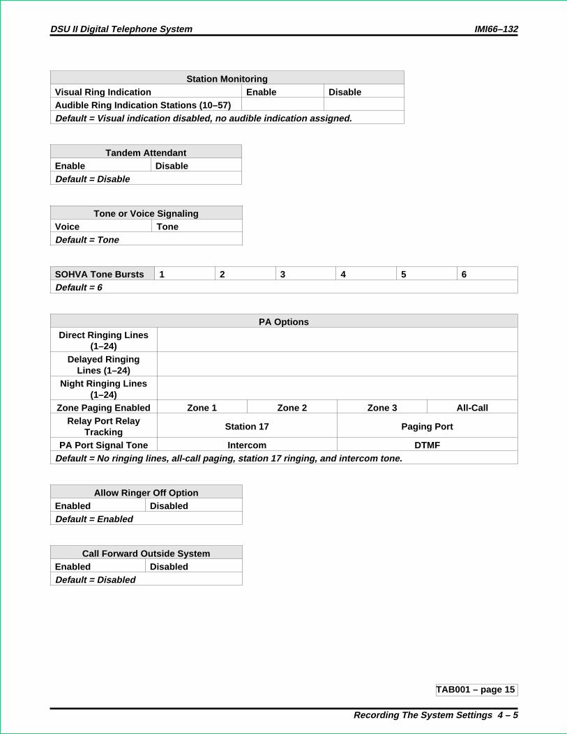
Station MonitoringVisual Ring Indication Enable DisableAudible Ring Indication Stations (10–57)Default = Visual indication disabled, no audible indication assigned.
Tandem AttendantEnable DisableDefault = Disable
Tone or Voice SignalingVoice ToneDefault = Tone
SOHVA Tone Bursts 1 2 3 4 5 6Default = 6
PA OptionsDirect Ringing Lines
(1–24)Delayed Ringing
Lines (1–24)Night Ringing Lines
(1–24)Zone Paging Enabled Zone 1 Zone 2 Zone 3 All-Call
Relay Port RelayTracking
Station 17 Paging Port
PA Port Signal Tone Intercom DTMFDefault = No ringing lines, all-call paging, station 17 ringing, and intercom tone.
Allow Ringer Off OptionEnabled DisabledDefault = Enabled
Call Forward Outside SystemEnabled DisabledDefault = Disabled
TAB001 – page 15
DSU II Digital Telephone System IMI66–132
Recording The System Settings 4 – 5
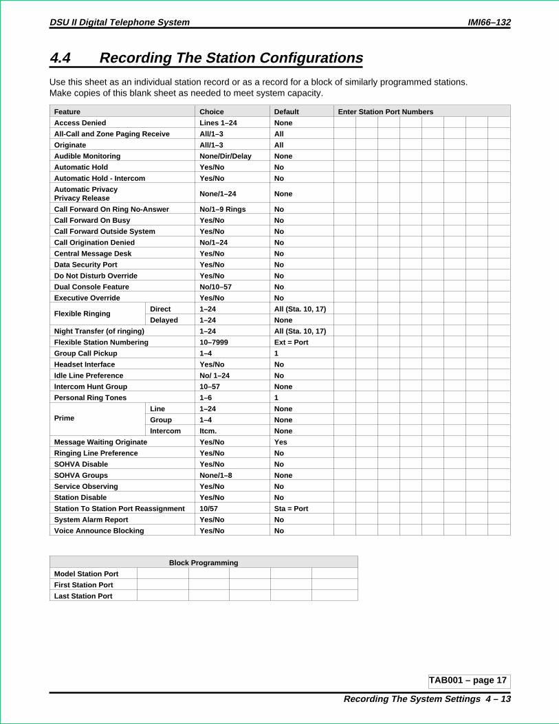
4.4 Recording The Station Configurations
Use this sheet as an individual station record or as a record for a block of similarly programmed stations.Make copies of this blank sheet as needed to meet system capacity.
Feature Choice Default Enter Station Port Numbers
Access Denied Lines 1–24 None
All-Call and Zone Paging Receive All/1–3 All
Originate All/1–3 All
Audible Monitoring None/Dir/Delay None
Automatic Hold Yes/No No
Automatic Hold - Intercom Yes/No No
Automatic PrivacyPrivacy Release
None/1–24 None
Call Forward On Ring No-Answer No/1–9 Rings No
Call Forward On Busy Yes/No No
Call Forward Outside System Yes/No No
Call Origination Denied No/1–24 No
Central Message Desk Yes/No No
Data Security Port Yes/No No
Do Not Disturb Override Yes/No No
Dual Console Feature No/10–57 No
Executive Override Yes/No No
Flexible RingingDirect 1–24 All (Sta. 10, 17)
Delayed 1–24 None
Night Transfer (of ringing) 1–24 All (Sta. 10, 17)
Flexible Station Numbering 10–7999 Ext = Port
Group Call Pickup 1–4 1
Headset Interface Yes/No No
Idle Line Preference No/ 1–24 No
Intercom Hunt Group 10–57 None
Personal Ring Tones 1–6 1
PrimeLine 1–24 None
Group 1–4 None
Intercom Itcm. None
Message Waiting Originate Yes/No Yes
Ringing Line Preference Yes/No No
SOHVA Disable Yes/No No
SOHVA Groups None/1–8 None
Service Observing Yes/No No
Station Disable Yes/No No
Station To Station Port Reassignment 10/57 Sta = Port
System Alarm Report Yes/No No
Voice Announce Blocking Yes/No No
Block Programming
Model Station Port
First Station Port
Last Station Port
TAB001 – page 17
DSU II Digital Telephone System IMI66–132
Recording The System Settings 4 – 13

Overflow Line GroupDefault = None
Line Group Alternate Line Group1234
Default = None
SRA Wait Time 2 seconds 3 seconds 4 secondsDefault = 4 seconds
LineGroup
Insert Digits1 2 3 4 5 6 7 8
1234
Default = None
TAB001 – page 19
DSU II Digital Telephone System IMI66–132
Recording The System Settings 4 – 37

4.7 Direct Department Calling Records
Enable/Disable DCD Type Ring All StationsEnabled Disabled
Enable/Disable DCD Type Longest Idle DistributionEnabled Disabled
Department 1Access Code 10–7999
Line Ports 1–24
Station Ports 10–57
Department 2Access Code 10–7999
Line Ports 1–24
Station Ports 10–57
Department 3Access Code 10–7999
Line Ports 1–24
Station Ports 10–57
Department 3Access Code 10–7999
Line Ports 1–24
Station Ports 10–57
Default = No access code assigned, no line ports assigned, and no stations assigned.TAB001 – page 21
DSU II Digital Telephone System IMI66–132
Recording The System Settings 4 – 23

Call Forward Outside SystemThe Call Forward Outside System (CFOS) feature allows the system to forwardincoming or transferred line calls to telephone numbers outside the system. The CFOSfeature forwards calls over any available outbound lines or line groups. Since CFOSinvolves outbound calls, those calls are subject to all line access, toll restriction, andspecialized route access restrictions normally imposed on the users. Any calls that CFOScan not service (no outbound line available, toll restricted, and so forth), ring the systemas normal calls. The CFOS feature is useful for after-hours forwarding of business callsto alternate sites such as a home or cellular telephone. To help system managers keepaccount of CFOS activity, the system marks CFOS calls with anF in the SMDA recordsprintout.
Users activate or deactivate CFOS by dialing a feature code or pressing a preprogrammedbutton. Once users activate CFOS, they select the outbound line or line group in any ofthe normal line selections methods available to them. They also designate the forwarddestination by dialing the number or pressing a speed dial button. (If users do not make aline and destination choice, the system uses the most recently used selections.) Once auser activates CFOS, it remains active and neither system resets nor power outages willdeactivate it. After activation, incoming or transferred calls to an idle CFOS-enabledstation forward outside the system to the CFOS destination over the selected outboundline or line group.
CFOS remains in effect in the event of loss of power or a system reset. Lines used forCFOS must have their abandon hold release time set to match the central office. BecauseCFOS is a powerful feature with the potential for abuse, several safety features have beenadded. Programming safeguards include the ability to enable the feature only on selectedstations and master control ability for enabling and disabling the feature system-wide.Ultimate responsibility for system integrity, however, lies with the system administrator.
Comdial has taken reasonable steps in the design of all product features, including CFOS,which protect against unauthorized or fraudulent access to, or use of, a system, or whichprotect against unauthorized, fraudulent or unaccounted-for access to, or use of, longdistance lines. However, no system is entirely invulnerable or immune from unauthorizedor fraudulent access or use, or unaccounted-for access or use, and therefore Comdialdisclaims any and all liability, and makes no warranty, express or implied, relating tounauthorized or fraudulent access or use, or unaccounted-for access or use.
NOTES: (1) CFOS will not work unless the abandon hold release time on all lines usedfor CFOS matches the C.O. abandon hold release time.
(2) Calls forwarded through CFOS may experience lower audio levels due tothe normal line resistance of C.O. lines. Low audio level is usually onlynoticeable on long line loops. If signal loss is a problem at a particular site, theinstaller may need to add a line amplifier (repeater) in the lines.
TAB001 – page 23
DSU II Digital Telephone System IMI66–132
Digital Telephone System Features A – 12A

Departmental Call DistributionSoftware 3A contains the following enhancements to the DCD feature:
Ring All On Transferred Line Call
By enabling the system-wide ring all DCD feature, a transferred line call ringing to adepartment will ring all idle stations in the department until the call is answered. Theanswering station gets the call and remaining stations retain their original status.
The Ring All On Transferred Line Call feature is disabled by default.
Ring Longest Idle Station
The Ring Longest Idle Station feature causes a direct-ringing line call, a transferred linecall, or an intercom call to ring at the longest-idle station in a department. If thelongest-idle station is in Do Not Disturb or Ring No Answer mode, the system routes thecall to the next available station in the group.
TAB001 – page 25
DSU II Digital Telephone System IMI66–132
Digital Telephone System Features A – 22A
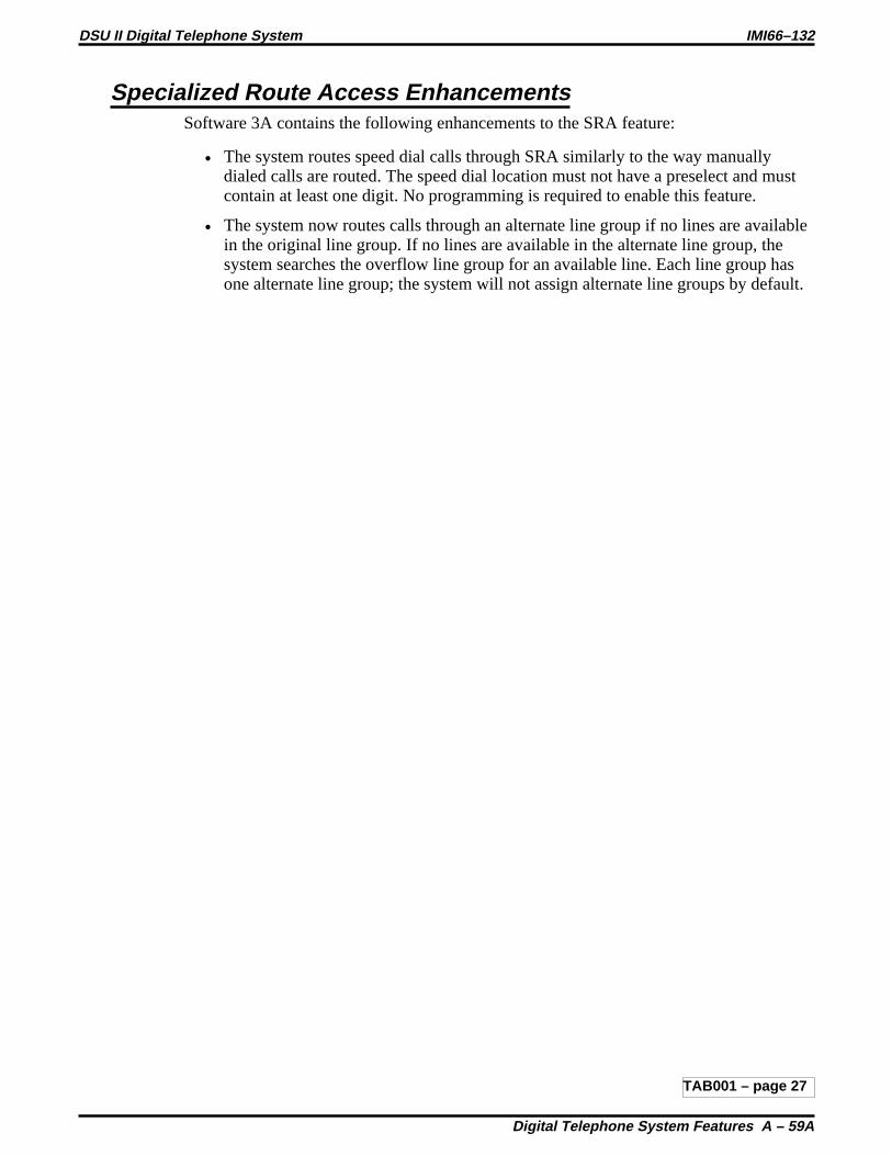
Specialized Route Access EnhancementsSoftware 3A contains the following enhancements to the SRA feature:
• The system routes speed dial calls through SRA similarly to the way manuallydialed calls are routed. The speed dial location must not have a preselect and mustcontain at least one digit. No programming is required to enable this feature.
• The system now routes calls through an alternate line group if no lines are availablein the original line group. If no lines are available in the alternate line group, thesystem searches the overflow line group for an available line. Each line group hasone alternate line group; the system will not assign alternate line groups by default.
TAB001 – page 27
DSU II Digital Telephone System IMI66–132
Digital Telephone System Features A – 59A
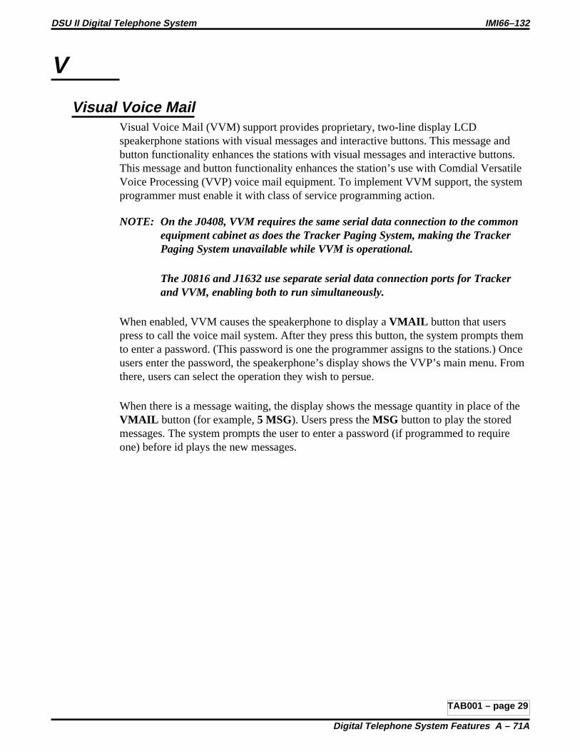
V
Visual Voice MailVisual Voice Mail (VVM) support provides proprietary, two-line display LCDspeakerphone stations with visual messages and interactive buttons. This message andbutton functionality enhances the stations with visual messages and interactive buttons.This message and button functionality enhances the station’s use with Comdial VersatileVoice Processing (VVP) voice mail equipment. To implement VVM support, the systemprogrammer must enable it with class of service programming action.
NOTE: On the J0408, VVM requires the same serial data connection to the commonequipment cabinet as does the Tracker Paging System, making the TrackerPaging System unavailable while VVM is operational.
The J0816 and J1632 use separate serial data connection ports for Trackerand VVM, enabling both to run simultaneously.
When enabled, VVM causes the speakerphone to display aVMAIL button that userspress to call the voice mail system. After they press this button, the system prompts themto enter a password. (This password is one the programmer assigns to the stations.) Onceusers enter the password, the speakerphone’s display shows the VVP’s main menu. Fromthere, users can select the operation they wish to persue.
When there is a message waiting, the display shows the message quantity in place of theVMAIL button (for example,5 MSG). Users press theMSG button to play the storedmessages. The system prompts the user to enter a password (if programmed to requireone) before id plays the new messages.
TAB001 – page 29
DSU II Digital Telephone System IMI66–132
Digital Telephone System Features A – 71A

Activating CFOS From Individual Stations
NOTE: This section is formatted like a typical user’s guide so that, ifyou wish, you may cut it out and insert it in the user’s guidesyou distribute to your customers.
The Call Forward Outside System (CFOS) feature gives station usersthe ability to forward line calls to a remote location outside the system.CFOS remains in effect in the event of a loss of power or a system reset.
• To activate the CFOS feature,
1. PressITCM 07.
2. Press the speed dial button programmed with the targetnumber,—OR—Press a line button,—OR—Dial 0 for the Prime line or last used line,—OR—Dial 1–4Line Group number.
3. Dial desired digits0–9(max 16 digits)
4. PressHOLD for Pause or pressTAP for Flash.
5. PressSPEAKER to end.
• To deactivate CFOS feature,
1. PressINTERCOM # 07 .
TAB001 – page 31
TECHNICAL ADVISORY BULLETIN
Date: September 1997 Issue: TAB002–DSU II
Software Enhancements For The Digital Telephone System
This bulletin discusses the following software enhancements and feature additions to the digital telephone system that areavailable with software release 4A and later:
• New Impact SCSTelephone support
When upgrading software, observe the following guidelines:
NOTE: It is always a good practice to save the data base for backup purposes beforeyou up-grade the system software revision.
The following pages describe theImpact SCStelephone support. Note that TAB002–DSUII presents this information asseparate pages that you can insert in your system manual (IMI66–132). If you do this, the information will be available foryour future reference and use.
R

1.6.5 Impact Telephone New Model Support
Digital telephone systems support a group of newly designedImpacttelephone models. Themodel numbers of these telephones are listed below.
8324S — 24 Line Half-Duplex LCD Speakerphone8324F — 24 Line Full-Duplex LCD Speakerphone8312S — 12 Line Half-Duplex LCD Speakerphone8212S — 12 Line Half-Duplex Speakerphone8212N — Multiline Proprietary Telephone8201N — Single Line Proprietary TelephoneIB48X — 48-Button DSS/BLF ConsoleIB24X — 24-Button DSS/BLF ConsoleIMIST — IST Module
Button Mapping The New Impact Telephone Models
On Model 8324F, 8324S, 8212S, and 8312S telephones, you can move the intercom button fromits defaulted and marked location at the lower rightmost button position to any programmablebutton location. If you map a new location for the intercom button, be sure to clear the previousassigned location. If you delete the intercom button from a telephone, the system will restore it atthe default location the next time that power turns off and back on at the telephone. Use thefollowing button mapping program procedure to map the new intercom button location.
1. At the programming station, press the defaultedINTERCOM button and dial#746 toenter the programming mode.
2. Dial 56. “BUTTON MAPPING”
3. Dial 19. “ASSIGN ITCM ”
4. Select button to be programmed—PressA1–A14, B1–B10.
5. Select station ports (LED On = Selected)—Station 10–57 = Dial10–57or dialC10–C57.
6. Dial for further intercom button assignment, or dial to return to the configurationmode.
NOTE: To clear a button assignment while in the configuration mode, dial5604, press thebutton, dial#, select the station, and dial.
7. End the programming session by pressing theSPEAKER button.
IMI66–132 DSU II Digital Telephone System
Introducing The DSU II Digital Telephone System 1–17a

8212S,8212N,8201N,and IB24X
8324F,8312S, 8324S,
and IB48X
9.065 6.315
8.819 8.819
4.4423.283
1.550
image_2.cdr
Viewing The New Impact Telephone Dimensions
DSU II Digital Telephone System IMI66–132
1–17b Introducing The DSU II Digital Telephone System

Illustrating The New Impact Telephone Models
The following illustrations show the outline and dimensional views of the newImpacttelephones.
IB48X IB24X
8212S
2ABC1 3DEF
6MNO5JKL4GHI
7PRS 8TUV 9WXY
#0*
SPEAKER
MESSAGE
TRNS/CONF
HOLD
MUTE
TAP
COMDIAL
8212N
TAP
MUTE
HOLD
TRNS/CONF
INTERCOM
MESSAGE
* 0 #
WXY 9TUV 8PRS 7
GHI 4 JKL 5 MNO6
DEF 31 ABC 2
COMDIAL
8201N
TAP
MUTE
HOLD
TRNS/CONF
INTERCOM
MESSAGE
* 0 #
WXY 9TUV 8PRS 7
GHI 4 JKL 5 MNO6
DEF 31 ABC 2
COMDIAL
2ABC1 3DEF
6MNO5JKL4GHI
7PRS 8TUV 9WXY
#0*
COMDIAL
SHIFT
MUTE
SPEAKER
TRNS/CONF
HOLD
TAP
MESSAGE
8324F8324S8324F8324S 8312S
COMDIAL
* 0 #
WXY 9TUV 8PRS 7
GHI 4 JKL 5 MNO6
DEF 31 ABC 2 MESSAGE
TAP
HOLD
TRNS/CONF
SPEAKER
MUTE
SHIFT
8412F
COMDIAL
MESSAGE
* 0 #
WXY 9TUV 8PRS 7
GHI 4 JKL 5 MNO6
DEF 31 ABC 2
TAP
HOLD
TRNS/CONF
SPEAKER
MUTE
SHIFT
blnk
image_1.cdr
Viewing The New Impact Telephone Outlines
IMI66–132 DSU II Digital Telephone System
Introducing The DSU II Digital Telephone System 1–17c

MUTE
SHIFT
SPEAKER
INTERCOM
TRNS/CNF
TAPHOLD
OPER
TUVPRS WXY
DEFABCQZ
MNOJKLGHI
#
SpeakerButton
Dialpad
Handset
TelephoneSpeaker
Intercom Button
Lights forProgrammableButtons. DSS/BLF. Features. Lines
Microphone Opening
Typical Impact SCS Speakerphone Controls And Indicators
DSU II Digital Telephone System IMI66–132
1–17d Introducing The DSU II Digital Telephone System

TECHNICAL ADVISORY BULLETIN
Date: May 1998 Issue: TAB003–DSU II
Software Release 5A For The Digital Telephone System
This TAB discusses DSU II software release 5A, which includes the following new features:
• Ringback on Transfer,
• Delay Ring in Night Mode,
• Quick Transfer,
• Secure Account Code Entry,
• Call Record Enhancement.
The operation and programming of these features is discussed in the next five sections of this document. Theinformation is presented as separate pages that you can insert in your system manual (IMI66–132).
NOTE: Before you up-grade the system software, it is a good practice to save the database for backuppurposes.
This manual has been developed by Comdial Corporation (the “Company”) and is intended for the use of its customers and service personnel. The information in this manual issubject to change without notice. While every effort has been made to eliminate errors, the Company disclaims liability for any difficulties arisingfrom the interpretation of theinformation contained herein.The information contained herein does not purport to cover all details or variations in equipment or to provide for every possible contingency tobe met in connection with installation, operation, or maintenance. Should further information be desired, or should particular problems arise which are not covered sufficientlyfor the purchaser’s purposes, contact Comdial, Inside Sales Department, P.O. Box 7266, Charlottesville, Virginia 22906.
Printed in U.S.A. TAB003–DSU II5/98

3.4.15 Ringback On Transfer
Description: With Ringback On Transfer enabled, when an outside call is transferred to anotherstation, the system gives ringback to the outside caller instead of music on hold. Thisfeature is disabled at default.
To Program: 1. Dial 17 for system features. “SYSTEM FEATURES”
2. Dial 17 for ringback on transfer. “RINGBACK XFER XXX”
3. PressA1 to toggle between enabled and disabled (LED On = Enabled).—OR—Dial 1 to enable. “RINGBACK XFER ON”Dial 2 to disable. “RINGBACK XFR OFF”
4. Dial for configuration mode.
To change setting, repeat procedure and make different selection.
TAB003 – page 3
DSU II Digital Telephone System IMI89–132
Programming The DSU II System 3 – 29a

Delay Ring In Night ModeDescription: This feature adds the option of programming delayed ringing in night mode (delayed
ringing could previously only be assigned to day mode). This feature affects stationringing assignments as well as system PA port ringing. At default, this feature does notallow delayed ringing during night mode.
To Program: Ringing Assignment:
1. Dial 54 for station/line features “STA/LINE CONFIG”
2. Dial 3 for night direct ring. “NITE DIRECT RING”—OR—Dial 8 for night delay ring. “NITE DELAY RING”
3. Select line ports for delayed night ringing (LED On = Selected Ports).—Line port 1–14 = Dial01–14or pressA1–A14.—Line port 15, 16 = Dial15, 16or pressB1, B2.—Line port 17–24 = Dial17–24or pressHOLD then pressA1–A8.
4. Dial # when all line ports are selected.
5. Select station ports (LED On = Feature Assigned)—Station 10–57 = Dial10–57or pressC10–C57.
6. Dial when all station ports are selected.—OR—Dial for next station/line feature.—OR—Dial for configuration mode.
To change setting, repeat procedure and make different selection.
PA Port Ringing Type:
1. Dial 60 for PA Options. “P.A. OPTIONS”
2. Dial 3 for night direct ring. “NITE DIRECT RING”—OR—Dial 7 for night delay ring. “NITE DELAY RING”
3. Select line ports (LED On = Line selected):—Line port 1–14 = Dial01–14or pressA1–A14.—Line port 15, 16 = Dial15, 16or pressB1, B2.—Line port 17–24 = Dial17–24ore pressHOLD then pressA1–A8.
4. Dial for next PA option.—OR—Dial for configuration mode.
TAB003 – page 5
DSU II Digital Telephone System IMI66–132
Programming The DSU II System 3 – 59a

3.7.31 Quick Transfer
Description: The Quick Transfer feature allows users to transfer line calls without having to press theTRANSFER/CONFERENCE key. When this feature is enabled, users can transfer callsby pressing the appropriate DSS key (orINTERCOM + extension number) and thenhanging up. This feature is disabled at default.
To Program: 1. Dial 53 for station features. “STATION FEATURES”
2. Dial 43 for quick transfer. “QUICK TRANSFER”
3. Select station ports (LED On = Selected):—Station 10–57: Dial10–57or pressC10–C57.
4. Dial for next station feature—OR—dial for configuration mode.
To change setting, repeat procedure and make different selection.
TAB003 – page 7
DSU II Digital Telephone System IMI89–132
Programming The DSU II System 3 – 76a

3.9.7 Secure Account Code Entry
Description: When system-wide account code entry is enabled, the system prompts users to enter anaccount code when they select an incoming or outgoing line. If the Secure Account Codeentry feature is enabled, the digits will be displayed as “” characters in the LCD duringaccount code entry. At default, this feature is disabled.
The Secure Account Code entry status is shown with the toll restriction C.O.S. printout.
To Program: 1. Dial 75 for SMDA programming. “SMDA PROGRAMMING”
2. Dial 18 for secure account code entry. “SECURE ACC. XXX”
3. PressA1 key to toggle between enable and disable (LED On = Enable).—OR—Dial 1 to Enable “SECURE ACC. ON”Dial 2 to Disable “SECURE ACC. OFF”
4. Dial for configuration mode.
To change setting, repeat procedure and make different selection.
TAB003 – page 9
DSU II Digital Telephone System IMI66–132
Programming The DSU II System 3 – 91a

Call Recording
During a line call, the LCD works differently depending on whether or not you are usingvoice mail with serial integration:
• If you do not have serial voice mail, the LCD shows theARDL SAVE TIMERoptions on line 2. The system replaces these options with a call timer after 60seconds.
• If you do have serial voice mail, the system replaces theSAVE button with aRECbutton, and the LCD shows:ARDL REC TIMER on line 2. This remains on theLCD for the duration of the call. Pressing theTIMER button at any point duringthe call displays the call timer.
Whether or not you are using serial voice mail, if you have enabled call costing, thesystem replaces theTIMER button with aCOST button.
TAB003 – page 11
DSU II Digital Telephone System IMI66–132
Digital Telephone System Features A – 72a

TECHNICAL ADVISORY BULLETIN
Date: November 1998 Issue: TAB004–DSU II
Software Release 5B For The Digital Telephone System
This TAB discusses DSU II software release 5B, that includes the following new feature:
• Disconnect Notification
The disconnect notification feature allows the DSUII system to operate properly with CT Voice. By notifying the CT Voicesystem whenever the distant party disconnects, delays are prevented.
The operation and programming of this feature is discussed in the next section of this document. The information is presentedas separate pages that you can insert in your system manual (IMI66–132).
NOTE: Before you up-grade the system software, it is a good practice to save the database for backuppurposes.
This manual has been developed by Comdial Corporation (the “Company”) and is intended for the use of its customers and service personnel. The information in this manualis subject to change without notice. While every effort has been made to eliminate errors, the Company disclaims liability for any difficulties arising from the interpretation ofthe information contained herein.The information contained herein does not purport to cover all details or variations in equipment or to provide for every possible contingencyto be met in connection with installation, operation, or maintenance. Should further information be desired, or should particular problems arise which are not coveredsufficiently for the purchaser’s purposes, contact Comdial, Inside Sales Department, P.O. Box 7266, Charlottesville, Virginia 22906.
Printed in U.S.A. TAB004–DSU II11/98

3.6.11 Disconnect Notification
Description: With the Disconnect Notification feature, the system sends a DTMF “A” digit to the ISTstation ports whenever the distant party (internal or external) hangs up. The system alsosends a disconnect digit when an IST telephone signals a hookflash to retrieve a line fromhold that has been dropped through abandon hold release. Installers must enable linedisconnect supervision for this feature to function on outside calls. This feature isdisabled at default. The purpose of this feature is to avoid delays that may occur ondisconnects when the CT Voice application is being used.
To Program: 1. Press ITCM, dial *#746* “CONFIG MODE”
2. Dial 53 for station features “STATION FEATURES”
3. Dial 44 for disconnect notification ”DISCONNECT NOTIF”
4. Select station ports (LED On = Feature Assigned):Station 10 - 57: Dial10 - 57ORPressC10 - C57.
5. Dial for next station featureORDial for configuration mode.
3-44a Programming The DSU II System
IMI66-132 DSU II Digital Telephone System
Tab004 – page 3

4.4 Recording The Station Configurations
Use this sheet as an individual station record or as a record for a block of similarly programmed stations.You can make copies of this blank sheet as needed to meet the system capacity.
Feature Choice Default Enter Station Port Numbers
Access Denied Lines 1–24 NoneAll-Call and Zone Paging Receive All/1–3 AllOriginate All/1–3 AllAudible Monitoring None/Dir/Delay NoneAutomatic Hold Yes/No NoAutomatic Hold - Intercom Yes/No NoAutomatic PrivacyPrivacy Release
None/1–24 None
Call Forward On Ring No-Answer No/1–9 Rings NoCall Forward On Busy Yes/No NoCall Origination Denied No/1–24 NoCentral Message Desk Yes/No NoData Security Port Yes/No NoDisconnect Notification Yes/No NoDo Not Disturb Overide Yes/No NoDual Console Feature No/10–57 NoExecutive Override Yes/No NoFlexible Ringing Direct 1–24 All (Sta. 10, 17)
Delayed 1–24 NoneNight Transfer (of ringing) 1–24 All (Sta. 10, 17)Flexible Station Numbering 10–7999 Ext = PortGroup Call Pickup 1–4 1Headset Interface Yes/No NoIdle Line Preference No/ 1–24 NoIntercom Hunt Group 10–57 NonePersonal Ring Tones 1–6 1Prime Line 1–24 None
Group 1–4 NoneIntercom Itcm. None
Message Waiting Originate Yes/No YesRinging Line Preference Yes/No NoSOHVA Disable Yes/No NoSOHVA Groups None/1–8 NoneService Observing Yes/No NoStation Disable Yes/No NoStation To Station Port Reassignment 10/57 Sta = PortSystem Alarm Report Yes/No NoVoice Announce Blocking Yes/No No
Block ProgrammingModel Station PortFirst Station PortLast Station Port
DSU II Digital Telephone System IMI66-132
Recording The System Settings 4-13a
TAB004 – page 5

Disconnect Notification
Use the disconnect notification feature to reduce delays resulting from disconnects. These delays occurwhen using the CT Voice application.
When you enable this feature, it causes the system to send a DTMF “A” digit to IST station portswhenever the distant party (internal or external) hangs up. The system also sends a disconnect digit whenan IST telephone signals a hookflash to retrieve a line from hold that has been dropped through abandonhold release.
Installers must enable line disconnect supervision for this feature to function on outside calls. This featureis disabled at default.
During station class of service data printout, the disconnect notification status is included on the printout.
A-30a Digital Telephone System Features
IMI66-132 DSU II Digital Telephone System
TAB004 – page 7