Embed Size (px)
Citation preview
Disclaimer: This document was part of the FirstEuropean DSP Education and Research Conference.It may have been written by someone whose nativelanguage is not English. TI assumes no liability for thequality of writing and/or the accuracy of theinformation contained herein.
Digital Signal Processing Solutions forMotor Control Using the TMS320F240DSP-Controller
Author: S. Bejerke
ESIEE, ParisSeptember 1996SPRA345
IMPORTANT NOTICE
Texas Instruments (TI™) reserves the right to make changes to its products or to discontinue anysemiconductor product or service without notice, and advises its customers to obtain the latest version ofrelevant information to verify, before placing orders, that the information being relied on is current.
TI warrants performance of its semiconductor products and related software to the specifications applicableat the time of sale in accordance with TI’s standard warranty. Testing and other quality control techniquesare utilized to the extent TI deems necessary to support this warranty. Specific testing of all parameters ofeach device is not necessarily performed, except those mandated by government requirements.
Certain application using semiconductor products may involve potential risks of death, personal injury, orsevere property or environmental damage (“Critical Applications”).
TI SEMICONDUCTOR PRODUCTS ARE NOT DESIGNED, INTENDED, AUTHORIZED, OR WARRANTEDTO BE SUITABLE FOR USE IN LIFE-SUPPORT APPLICATIONS, DEVICES OR SYSTEMS OR OTHERCRITICAL APPLICATIONS.
Inclusion of TI products in such applications is understood to be fully at the risk of the customer. Use of TIproducts in such applications requires the written approval of an appropriate TI officer. Questions concerningpotential risk applications should be directed to TI through a local SC sales office.
In order to minimize risks associated with the customer’s applications, adequate design and operatingsafeguards should be provided by the customer to minimize inherent or procedural hazards.
TI assumes no liability for applications assistance, customer product design, software performance, orinfringement of patents or services described herein. Nor does TI warrant or represent that any license,either express or implied, is granted under any patent right, copyright, mask work right, or other intellectualproperty right of TI covering or relating to any combination, machine, or process in which suchsemiconductor products or services might be or are used.
Copyright © 1997, Texas Instruments Incorporated

TRADEMARKS
TI is a trademark of Texas Instruments Incorporated.
Other brands and names are the property of their respective owners.

CONTACT INFORMATION
US TMS320 HOTLINE (281) 274-2320
US TMS320 FAX (281) 274-2324
US TMS320 BBS (281) 274-2323
US TMS320 email [email protected]
ContentsAbstract ........................................................................................................................... 7Product Support on the World Wide Web .................................................................... 8Introduction..................................................................................................................... 9The Different DSP Architectures and their Digital Motor Control TargetApplications .................................................................................................................. 10Architecture of the DSP-Controller TMS320F240 ...................................................... 12Sensorless Control Algorithms - Overview................................................................ 15Practical Examples ....................................................................................................... 16
Kalman Observer of an Induction Motor ................................................................... 16Realization with the DSP-Controller F240 ........................................................ 19Practical Results of the Kalman Observer........................................................ 20
Sensorless Controlled PMSM Drive ......................................................................... 21Single Chip Realization with the DSP-Controller F240..................................... 23Practical Results............................................................................................... 24
Conclusion .................................................................................................................... 24Acknowledgment .......................................................................................................... 25Literature ....................................................................................................................... 25
FiguresFigure 1. The TI Fixed Point DSP Family ........................................................................ 11Figure 2. Structure of the DSP-Controller TMS320F240 ................................................. 13Figure 3. System Concept of Kalman Observed Induction Motor using the C240........... 20Figure 4. Speed Reversal with Kalman Filter .................................................................. 20Figure 5. Sensorless Vector Control Scheme of a PMSM Drive ..................................... 22Figure 6. Structure of a Sliding Mode Observer .............................................................. 23Figure 7. Single Chip Realization of a Sensorless PMSM Drive ..................................... 24
TablesTable 1. Memory Requirements of Kalman Filter ........................................................... 21
Digital Signal Processing Solutions for Motor Control Using the TMS320F240 DSP-Controller 7
Digital Signal Processing Solutionsfor Motor Control Using the
TMS320F240 DSP-Controller
Abstract
Digital Signal processing technology is enabling cost effective andenergy efficient control system design. The performance of a DSParchitecture allows an intelligent approach to reduce the completesystem costs of digital motion control applications using cheaperelectrical motors, fewer sensors, and smaller sizes of EMI filters.To provide also a cost optimal solution Texas Instruments (TI™)developed a single chip solution combining the features of aMicrocontroller and the performance advantages of a DSP core.This new - so called "DSP-Controller" delivers the real-time MIPSand the tightly integrated peripherals to implement optimal controlalgorithms with no cost penalty. This paper deals with an overviewof DSP solutions in digital motor control applications whereby thefocus will be the new DSP-Controller and its applications.
This document was part of the first European DSP Education andResearch Conference that took place September 26 and 27, 1996in Paris. For information on how TI encourages students fromaround the world to find innovative ways to use DSPs, see TI’sWorld Wide Web site at www.ti.com.

SPRA345
8 Digital Signal Processing Solutions for Motor Control Using the TMS320F240 DSP-Controller
Product Support on the World Wide Web
Our World Wide Web site at www.ti.com contains the most up todate product information, revisions, and additions. Usersregistering with TI&ME can build custom information pages andreceive new product updates automatically via email.
SPRA345
Digital Signal Processing Solutions for Motor Control Using the TMS320F240 DSP-Controller 9
Introduction
The requirements of electrical drive systems increases by therequest of more performance, higher integration, easier toprogram and lower cost. To optimize the drive system severalways can be chosen. One is to stay with standard control conceptand its sensors and try to reduce only the device cost. Anotherone is to reduce the sensor elements using sensorless controltechniques, which requires normally more computationperformance. Combining both ways leads normally to a systemcost optimized solution.
Based on these trends TI developed a new controller conceptwhich integrates a Digital Signal Processor (DSP) core withintelligent peripherals to achieve a single chip solution also forsensorless controlled drive systems. The new controller family isnamed "DSP-Controller". The DSP-Controller TMS320F240 will bedescribed in detail.
Out of the feature list of the DSP-Controllers an overview ofsensorless control techniques will be given, whereby the targetdrives base on 3 phase permanent magnet synchronous motors(PMSM) and 3 phase induction cage motors. For the inductioncage motor a practical implementation will be presented. In thecase of the induction motor it is a Kalman Observer to eliminateany speed and rotor position sensor. The main problems toimplement a complex Kalman Observer on a l6Bit Fixed PointDSP core is included into scaling task. The practical realizationand its results confirm that it is possible. Most other publicationsare using Floating Point arithmetic, which is not acceptable inmass production out of cost reasons.
The paper starts with a brief overview of the different types ofDSPs and their application fields. Afterwards the new DSP familythe DSP-Controller TMS320F240 will be introduced. Severalpractical motor control applications and their implementation willbe discussed.
SPRA345
10 Digital Signal Processing Solutions for Motor Control Using the TMS320F240 DSP-Controller
The Different DSP Architectures and their Digital MotorControl Target Applications
The DSP family is subdivided into three different types: thecombination of an integration of a 32Bit RISC processor andseveral advanced DSPs like the TMS320C8x family, the 32BitFloating Point Devices e.g. TMS320C3x, and the l6Bit Fixed PointDSPs.
Regarding the TMS3208x and its 2 BOBS (Billion Operation PerSecond) the digital motor control application field is very small.One typical application is the control of magnet bearings normallyused in turbines to reduce the friction to a minimum. Theapplication fields for 32 Floating Point DSPs are ComputerNumerical Controlled (CNC) machines, high precision linearmotors with a resolution down to a range of l00nm, and in the fieldof research and pre-development. Especially the use of good highlevel language support like "C" and its efficient conversion is hereimportant. The work is focused on the research work and not onthe cost optimization.
The 16 Fixed Point DSP can be used in all types of BLDC, PMSM,Switched Reluctance motors, as well squirrel cage inductionmotors. Main application are industrial power converters and whitegoods with the aim to reduce the sensor elements, to increase theefficiency (the important green aspect), to reduce the noises aswell as to decrease the system costs. The Fixed Point DSPs withits performance range of 6.5 to 100MPS are able to control acomplete enhanced motor management system including asensorless approach, power factor correction, security and servicefeatures, human machine interface, as well as the digital motorcontrol itself.
To achieve a single chip DSP solution TI developed a new DSP-Controller Family the TMS320F240 and its derivatives. How thenew DSP-Controller generation is embedded into the Fixed PointDSP family, is shown in Figure 1.
SPRA345
Digital Signal Processing Solutions for Motor Control Using the TMS320F240 DSP-Controller 11
Figure 1. The TI Fixed Point DSP Family
The next section, Architecture of the DSP-ControllerTMS320F240, will explain the new DSP-Controller more in detail.
SPRA345
12 Digital Signal Processing Solutions for Motor Control Using the TMS320F240 DSP-Controller
Architecture of the DSP-Controller TMS320F240
The DSP-Controller F240 in an integration of a digital signalprocessor core with the peripherals of a Microcontroller. Theperformance as well as the intelligent peripherals meet therequirements of an enhanced motor management system beingon capable of executing of 20 million instruction per second. Thishigh performance allows the execution of manifold tasks and ofcomplex control like sensorless controlled drives (Kalman Filter,Observers) in real time. Minimizing of control loop delays orcontrol cycles times improve the dynamic behavior and result in abetter disturbance behavior.
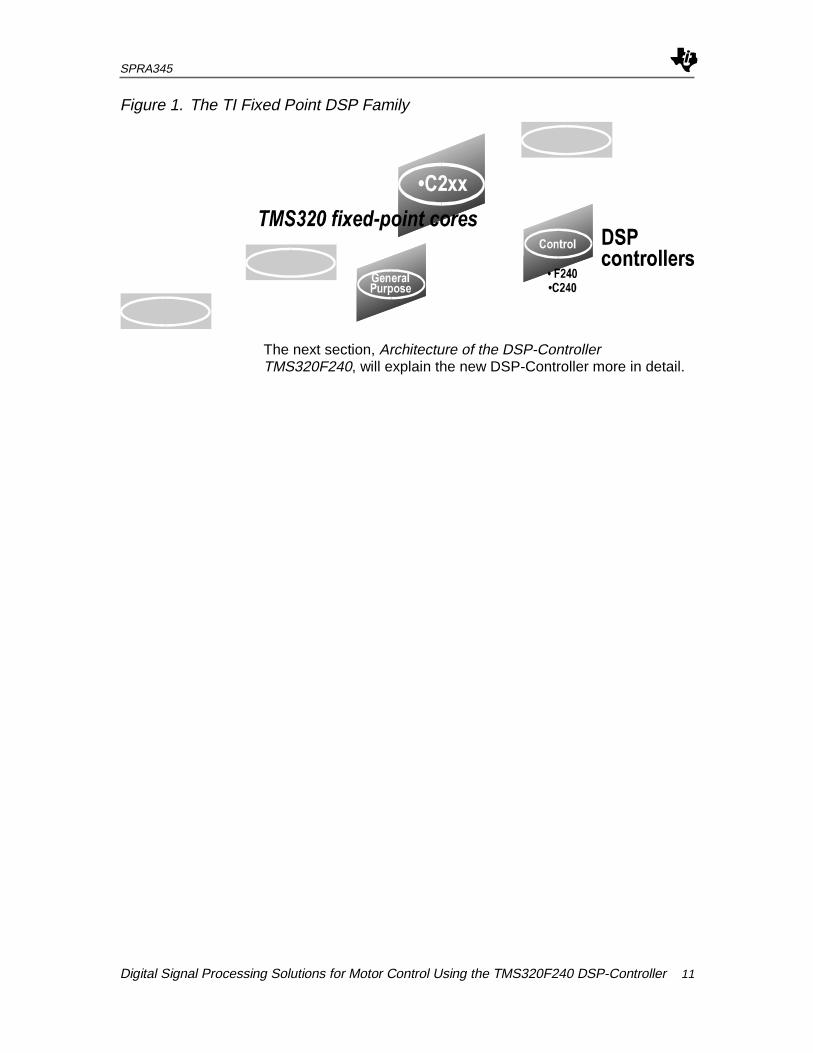
The DSP-Controller F240 has been optimized for digital controlsystem applications and has all the architectural featuresnecessary for high-speed signal processing. The devicepossesses all the peripheral needed to provide a single chipstand-alone DSP-Controller. These peripherals include bitselectable I/O ports, a high speed serial port, 12 high precisionpulse width modulation outputs, four capture inputs, 4independent timers, and 2 10bit AD converter with 16 inputchannels. The ’DSP-Controller F240’ architecture is also optimizedfor processing control signals. A 16 bit word length is used alongwith 32 bit registers for storing intermediate results, and twohardware shifters are available to scale numbers independent ofthe CPU. This combination minimizes quantization and truncationerrors, and increases processing power for additional functions. Adiagram of the DSP-Controller F240 is given in Figure 2.
SPRA345
Digital Signal Processing Solutions for Motor Control Using the TMS320F240 DSP-Controller 13
Figure 2. Structure of the DSP-Controller TMS320F240
The DSP-Controller F240 core architecture is based on theTMS320C5x, which utilizes a modified Harvard architecture forspeed and flexibility. The main characteristic of the 2xLP core isthe static design of the C5x generation with its 4 level pipelinearchitecture combined with the instruction set of the 2ndgeneration of TI DSPs. In a strict Harvard architecture, programand data memory lie in two separate spaces, permitting a fulloverlap of instruction fetch and execution. This processoraddresses three memory spaces: program memory space forinstructions; data memory space for data variables; andInput/Output port space for accessing peripheral registers anddata. The processor can address up to 64Kx16 words of programmemory, 64Kx16 words of local data memory and 64Kx16 wordsof I/O ports. Already integrated are 544x16 words of Dual AccessRAM and l6Kx16 words of FLASH program memory. The Flashversion is named F240 and the ROM version with C240.
The intelligent peripherals consist out of the Event Manager (EV)block, the communication unit (SPI and SCI), test and programinterface (JTAG), the AD converters, and for system protection aWatchdog timer and a Low Voltage Detection (LVD) unit.
SPRA345
14 Digital Signal Processing Solutions for Motor Control Using the TMS320F240 DSP-Controller
The event manager with its 3 16bit timer supports up to 12 pulsewidth modulated outputs for motor control, Power FactorCorrection (PFC), as well as Digital Analog Converters. 6 of the 12PWM channels are dedicated for the control of 3 phase drives likeAC motors or Switched Reluctance machines. The pulse patterngenerator supports different kinds of PWM modes e.g.asymmetric, symmetric, and space vector modulation. In the caseof Space Vector PWM (SVPWM) the DSP-Controller generatesautomatically the linear combination of the basic space vectorsand reduces so 50% of the software overhead.
Further feature is to start the AD converter from the EventManager without any load of the DSP core. This trigger signal isfree programmable using one of the timer compare registers. Thisfeature will be used to synchronize the PWM outputs with themeasurement of state variables of the system. Additionally theevent manager includes 4 capture inputs to measure for examplethe commutation signals of a brushless motor, an interface for anoptical encoder with quadrature interpretation, and aprogrammable dead time unit to protect the power switches.
The AD converter block includes 2 10bit AD converters with 2Samples & Hold circuits and each of the ADC has 8 inputchannels. The conversion time is less than 10µs. In summary theon-chip peripherals of the DSP-Controller make it the idealsolution for digital control.i
SPRA345
Digital Signal Processing Solutions for Motor Control Using the TMS320F240 DSP-Controller 15
Sensorless Control Algorithms - Overview
The sensorless controller aims to control the motor without theuse of a position sensor to give the rotor’s position and speed. Toa degree the term sensorless is a misnomer as the system stilluses current and/or voltage sensors. It is from these current andvoltage measurements that the controller must estimate the rotor’sspeed and position. A short overview of sensorless controlalgorithms will be given for 3 phase PMSM drives and InductionMotor. The class of trapezoidal Brushless DC motor will be notcovered in this paper.
Several sensorless control strategies have been investigatedusing MATLAB/SIMULINK. In the case of PMSM drives followingmethods have been simulated and improved:
q Open flux integration
q Open flux integration with auto offset compensation
q INFORM - developed by Dr. Schroedl
q Sliding Mode Observer
The open flux integration methodsii,iii base on the stator voltageequation of a PMSM drive. Problems still exist at the beginningwith the integration constant and its identification. To eliminate thisproblem an auto offset compensation algorithm was developed.iv
The INFORM method is able to detect the rotor position atstandstill in Permanent Magnet based motorsv, and is patented.The INFORM algorithm is based upon detecting the changes inthe individual stator coil inductance due to the orientation of therotor flux generated by its Permanent Magnet. The statorinductance is defined to be the rate of change of the stator flux.This stator flux is composed of two components, the rotor flux andthe flux generated by the current is flowing through the coil. It isalso possible to transfer the INFORM method to induction motors.
The Sliding Mode Observer is explained in detail in the section,Practical Examples. In comparison the sliding mode observer hassome advantages in comparison to the other methods. Out of thesliding approach this control scheme showed a very robustbehavior and is simple to implement. These are the main reasonswhy we have chosen to transfer the simulation to a practicalimplementation, as it will be shown in Practical Examples
SPRA345
16 Digital Signal Processing Solutions for Motor Control Using the TMS320F240 DSP-Controller
Practical Examples
Practical implementation on the DSP-Controller will be given inthis section. The first one is a Kalman Observer application usingan induction cage motor and the second is a sensorless controlledPMSM drive using a sliding mode observer approach. Practicalresults will be presented for each application.
Kalman Observer of an Induction Motor
The first practical example, which requests a DSP-Controller, is aKalman Observer to receive in a sensorless way the actual valuesof the rotor position, the rotor velocity, and the rotor flux. In manycases it is impossible to use sensors for velocity or positionmeasurement, either because it is technically impossible, or tooexpensive. The Kalman observer has a good dynamic behavior,disturbance resistance, and it can work even in standstill.vi Thispractical example is based on a field orientated control method,whereby the necessary control variable position, speed, and rotorflux will be estimated with a Kalman observer.
Implementing a Kalman observer is a very complex problem, andit requires the model of the AC motor to be calculated in real time.Also the observer equations must be calculated, which normallymeans many matrix multiplication and one matrix inversion. Theserequirements can be fulfilled by a processor with high calculationperformance. The DSP-Controller is especially well suited for thispurpose, because of its good calculation-performance/price ratio.
To give an impression of the complexity of a Kalman observer ofan induction motor the theoretical background will be derived.
The Kalman filter provides a solution that directly cares for theeffects of the disturbance noises. The errors in the parameters willnormally also be handled as noise. The system is describable withthe following equations.
SPRA345
Digital Signal Processing Solutions for Motor Control Using the TMS320F240 DSP-Controller 17
rBuAxx ++=& (System) (1)
ρ+= Cxy (Measurement) (2)
Where r and p are the system and the measurement noise. Theassumptions regarding the noises are, that these noises arestationary, white, uncorrelated and Gauss noises, and theirexpectation is 0. The definition of the covariance matrices of thesenoises is:
QrrEr T == }{)cov( (3)
RE T == }{)cov( ρρρ (4)
Where E{.} denotes expected value.The overall structure of the Kalman observer leads to the systemequations:
,)( KyBuxKCAx +−=∧∧
⋅
(5)
Whereby K denote the matrix of the Kalman filter. The setting ofthe matrix K will be done based on the covariance of the noises.The quality of measurement of the goodness of the observation isgiven by:
}~{ 2
1i
n
ixEJ
=Σ= (6)
This depends on the choice of K. K has to be chosen to make Jminimal.
1−= RPCK T (7)
Where P can be calculated from the solution of the followingequation:
SPRA345
18 Digital Signal Processing Solutions for Motor Control Using the TMS320F240 DSP-Controller
01 =−−−− QPAAPCPRPC TT (8)
Q and R have to be set up based on the stochastic properties ofthe corresponding noises. Since these are usually not known, theyare used as weight matrices in most cases. In a recursivealgorithm is presented for the discrete time case to provide thesolution for this equation. This algorithm is in fact the EKF(extended Kalman Filter) algorithm, because the matrix of theKalman observer K, will be online calculated. The EKF is alsocapable of handling nonlinear systems, such as the inductionmotor.
Let us now see the recursive form of the EKF.vii All symbols in thefollowing formulas denote matrices or vectors. They are notdenoted with a special notation, because there is no possibility ofmixing them up with scalars.
)),(( 1|1 kxhyKxx kkkkkkkk −− −+= (9)
11
1
−=
−−
∂∂−= kk
xxkkkkk P
x
hKPP
kk
(10)
1
11
111
−
=−
==−
+
∂∂
∂∂
∂∂=
−−−
Rx
hP
x
h
x
hPK
kkkkkk xx
T
kkxxxx
T
kkk (11)
),,,1( 1||1 kkkkk uxkkx −+ +Φ= (12)
Tkk
xx
T
kkxx
kk Qx
Px
Pkkkk
ΓΓ+∂Φ∂
∂Φ∂=
==+1
(13)
Where
kkkkkkkkkk uxBxAuxkk )((),,,1( 1 +=+Φ − (14)
SPRA345
Digital Signal Processing Solutions for Motor Control Using the TMS320F240 DSP-Controller 19
( ) ( )h x k C x xk k k k k k k| | |,− − −=1 1 1 (15)
These are the system vector and the output vector. Thesevectors can be explicitly calculated. The matrix K is thefeedback matrix of the EKF. This matrix determines howthe state vector of the EKF is modified after the output ofthe model is compared to the real output of the system. Atthis point it is important to mention, that this system ofequations contains many matrix operations, which mean aproblem to implement in real time.
To implement this recursive algorithm of course we willneed the model of the motor, which means the matrices A,B and C , from which we have to calculate the matrices Φand h. The discrete model of the induction motor is given inequation 16 and 17 using the sample time T:
kS
S
L
k
R
R
S
S
RR
H
RR
H
LR
RH
LR
H
L
R
LR
H
LR
RH
L
R
k
R
R
S
s
u
u
KT
i
i
TTT
T
LT
TT
TT
LT
KL
RLT
KL
LT
K
KT
KL
LT
KL
RLT
K
KT
i
i
+
ΨΨ
−
−−
−−
−
=
+
β
α
β
α
β
α
β
α
β
α
ωω
ω
ω
ω
ωψψ
00
00
00
10
01
1
10000
01
10
01
10
010
001
2
2
1
(16)
k
R
R
S
S
kS
S
i
i
i
i
ΨΨ
=
ωβ
α
β
α
β
α
00010
00001 (17)
In summary the DSP-Controller must calculates first Φ and hmatrix using afterwards the calculation of the Kalman matrix Kwith the matrix inversion operation. This must be done in real time,because the system matrix A includes also state variables like thevelocity ω.
Realization with the DSP-Controller F240
Figure 3 presents a complete system schematics. The DSP-Controller measures only 2 of the 3 stator phase currents. Noadditional measurements are necessary. The load and itsbehavior must be not nearer defined. This is application specific.
SPRA345
20 Digital Signal Processing Solutions for Motor Control Using the TMS320F240 DSP-Controller
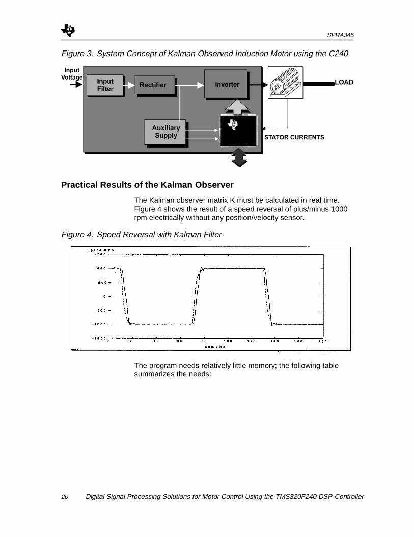
Figure 3. System Concept of Kalman Observed Induction Motor using the C240
Practical Results of the Kalman Observer
The Kalman observer matrix K must be calculated in real time.Figure 4 shows the result of a speed reversal of plus/minus 1000rpm electrically without any position/velocity sensor.
Figure 4. Speed Reversal with Kalman Filter
The program needs relatively little memory; the following tablesummarizes the needs:
SPRA345
Digital Signal Processing Solutions for Motor Control Using the TMS320F240 DSP-Controller 21
Table 1. Memory Requirements of Kalman Filter
Program Part Program Size (Words) Data Size (Words)Control + Kalman Filter 3641 631
Monitor Program 1577 603
Libraries 1605 309
Stack 0 1024
Σ Memory requirement 6823 2564
The DSP-Controller has a computing power of 20 MIPS at 20MHz, which means a cycle time of 50 ns. The computation of thecontrol happens in a 500 µs cycle, so the processor has 10,000cycles available. The processor is using currently about 4400-4700 cycles, and this means, that it has time to performforeground tasks, such as Monitor programs, or othercommunications. The processor computing capacity is used toabout 50%, but the cycle times could also be reduced.
Sensorless Controlled PMSM Drive
As already discussed in the section, Architecture of the DSP-Controller TMS320F240, one possible sensorless control methodis a sliding mode observer. In several application is the efficiencyvery important as well as based on cost and reliability reason it isnot allowed to use a speed, position, or Hall (commutation signals)sensor. Out of these requirement sliding mode observer strategyhas the several advantages like its robustness, easyimplementation etc.
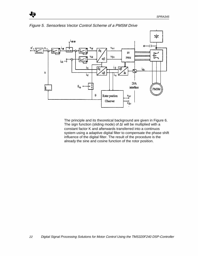
Using a sinusoidal permanent magnet synchronous motor(PMSM) the standard control scheme is a vector control method,whereby the state variables will be transformed to a coordinatesystem rotating synchronous with the rotor. In rotor framecoordinates the PMSM behaves like a separately exited DCmotor. The exact value of the rotor position is mandatory to controlthe speed, to transform the state variables, and to achieve a highefficiency. The control scheme is illustrated in Figure 5.
SPRA345
22 Digital Signal Processing Solutions for Motor Control Using the TMS320F240 DSP-Controller
Figure 5. Sensorless Vector Control Scheme of a PMSM Drive
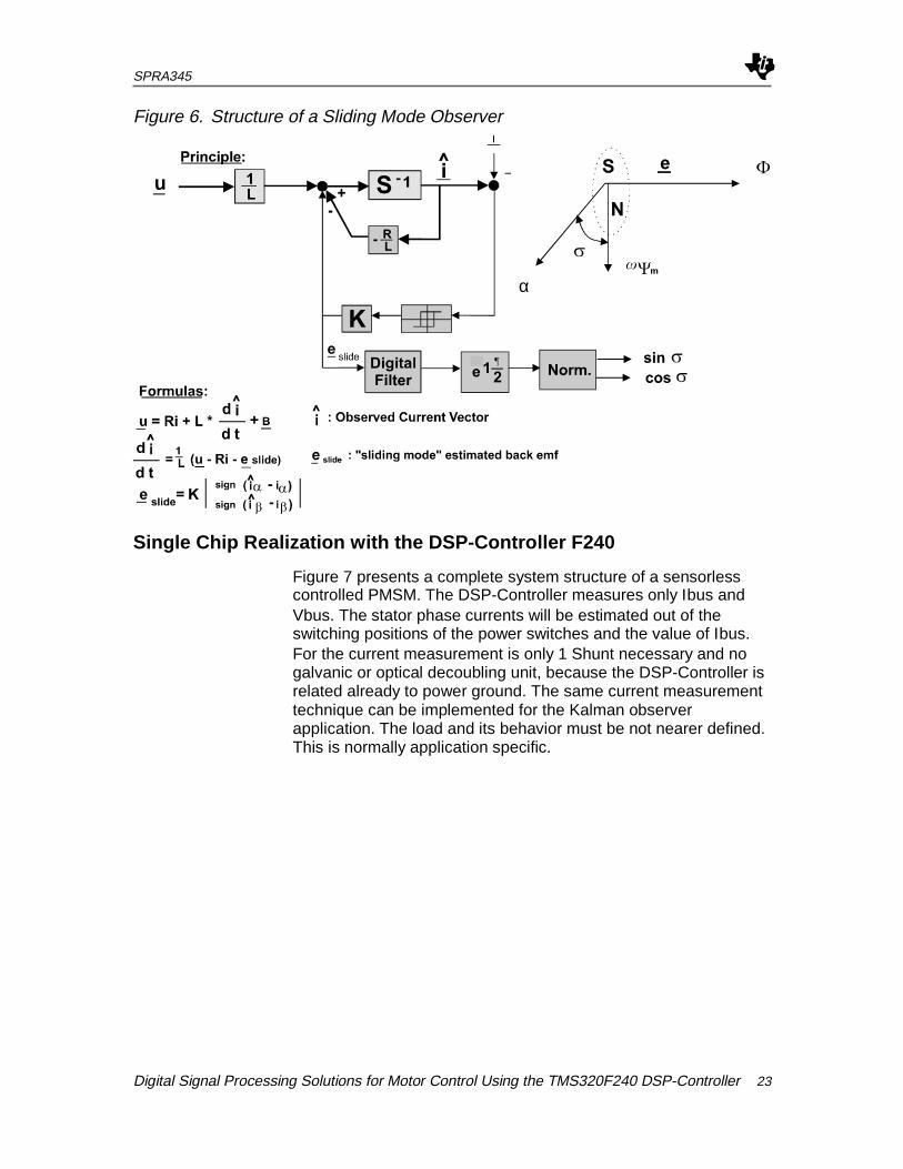
The principle and its theoretical background are given in Figure 6.The sign function (sliding mode) of ∆Ι will be multiplied with aconstant factor K and afterwards transferred into a continuossystem using a adaptive digital filter to compensate the phase shiftinfluence of the digital filter. The result of the procedure is thealready the sine and cosine function of the rotor position.
SPRA345
Digital Signal Processing Solutions for Motor Control Using the TMS320F240 DSP-Controller 23
Figure 6. Structure of a Sliding Mode Observer
α
Single Chip Realization with the DSP-Controller F240
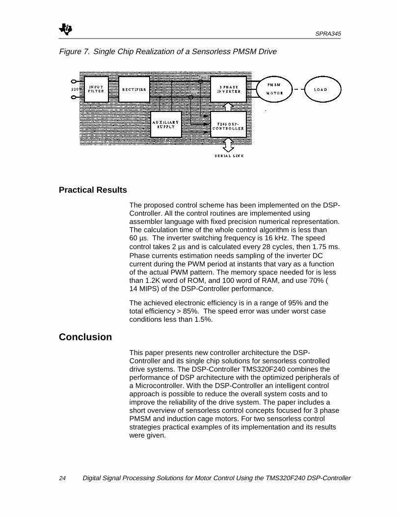
Figure 7 presents a complete system structure of a sensorlesscontrolled PMSM. The DSP-Controller measures only Ιbus andVbus. The stator phase currents will be estimated out of theswitching positions of the power switches and the value of Ιbus.For the current measurement is only 1 Shunt necessary and nogalvanic or optical decoubling unit, because the DSP-Controller isrelated already to power ground. The same current measurementtechnique can be implemented for the Kalman observerapplication. The load and its behavior must be not nearer defined.This is normally application specific.
SPRA345
24 Digital Signal Processing Solutions for Motor Control Using the TMS320F240 DSP-Controller
Figure 7. Single Chip Realization of a Sensorless PMSM Drive
VBUS
IBUS
Practical Results
The proposed control scheme has been implemented on the DSP-Controller. All the control routines are implemented usingassembler language with fixed precision numerical representation.The calculation time of the whole control algorithm is less than60 µs. The inverter switching frequency is 16 kHz. The speedcontrol takes 2 µs and is calculated every 28 cycles, then 1.75 ms.Phase currents estimation needs sampling of the inverter DCcurrent during the PWM period at instants that vary as a functionof the actual PWM pattern. The memory space needed for is lessthan 1.2K word of ROM, and 100 word of RAM, and use 70% (14 MIPS) of the DSP-Controller performance.
The achieved electronic efficiency is in a range of 95% and thetotal efficiency > 85%. The speed error was under worst caseconditions less than 1.5%.
Conclusion
This paper presents new controller architecture the DSP-Controller and its single chip solutions for sensorless controlleddrive systems. The DSP-Controller TMS320F240 combines theperformance of DSP architecture with the optimized peripherals ofa Microcontroller. With the DSP-Controller an intelligent controlapproach is possible to reduce the overall system costs and toimprove the reliability of the drive system. The paper includes ashort overview of sensorless control concepts focused for 3 phasePMSM and induction cage motors. For two sensorless controlstrategies practical examples of its implementation and its resultswere given.
SPRA345
Digital Signal Processing Solutions for Motor Control Using the TMS320F240 DSP-Controller 25
Acknowledgment
Special thanks to Balazs Simor, who has implemented anddocumented the Kalman Observer for an induction cage driveduring his diploma thesis time.viii
Literature
i "TMS320C240 User’s Guide - Preliminary", Texas Instruments, 1996ii "A Stator Flux-Orientated Voltage Source Variable-Speed Drive Based
on dc Link Measurement", Xue Y., Xu X., Habetler T. &Divan D., IEEE T-IA, 27(5), Sept/Oct 1991.
iii "Sensorless Position Detection using the Supply Voltage for aProgrammable Current Drive for Synchronous Motors",Cardoletti L. & Jufer M., Proc EPE 1991, pp4-l23 - 4-127.
iv "MATLAB Simulation of Sensorless Brushless DC Motors", TexasInstruments, 1996.
v "Sensorless Control of Permanent Magnet Synchronous Motors",Schroedl M., Electric Machines and Power Systems,22(2), Mar/Apr 1994, pp173-185.
vi "Application of Kalman Filters and Extended Luenberger Observers inInduction Motor Drives" T. Du, P. Vas, A.F. Stronach,M.A. Brdys, Intelligent Motion Proceedings, 1994.
vii "Einsatz eines Kalman-Filters zum feldorientierten Betrieb einerAsynchronmaschine ohne mechanische Sensoren" B.-J.Brunsbach, G. Henneberger, Archiv fuer Elektrotechnik1990 (Springer Verlag).
viii "Comparative Study of Rotor Flux Estimation in Induction Motors witha Nonlinear Observer and the Extended Kalman Filter"C.Manes, F. Parasiliti, M. Tursini, IECON 1994.


![Descendants of James Kirtley [#4] & Jemima Robertsarslanmb.org/kirtley/Descendants-4.pdf · 2015-12-01 · 1 4. James KIRTLEY (male) D. before 1790 @ [19927] M. /1/ to [7270] Jemima](https://img.pdfslide.us/doc/110x75/5f4e9ece242e1a1bc678b962/descendants-of-james-kirtley-4-jemima-2015-12-01-1-4-james-kirtley-male.jpg)