Embed Size (px)
Citation preview
Digital Signal Processing Solutionfor
AC Induction Motor
Application NoteBPRA043
2
IMPORTANT NOTICE
Texas Instruments (TI) reserves the right to make changes to its products or todiscontinue any semiconductor product or service without notice, and advises itscustomers to obtain the latest version of relevant information to verify, before placingorders, that the information being relied on is current.
TI warrants performance of its semiconductor products and related software to thespecifications applicable at the time of sale in accordance with TI’s standard warranty.Testing and other quality control techniques are utilized to the extent TI deemsnecessary to support this warranty. Specific testing of all parameters of each device isnot necessarily performed, except those mandated by government requirements.
Certain applications using semiconductor products may involve potential risks of death,personal injury, or severe property or environmental damage ("Critical Applications").
TI SEMICONDUCTOR PRODUCTS ARE NOT DESIGNED, INTENDED,AUTHORIZED, OR WARRANTED TO BE SUITABLE FOR USE IN LIFE-SUPPORTAPPLICATIONS, DEVICES OR SYSTEMS OR OTHER CRITICAL APPLICATIONS.
Inclusion of TI products in such applications is understood to be fully at the risk of thecustomer. Use of TI products in such applications requires the written approval of anappropriate TI officer. Questions concerning potential risk applications should bedirected to TI through a local SC sales office.
In order to minimize risks associated with the customer’s applications, adequate designand operating safeguards should be provided by the customer to minimize inherent orprocedural hazards.
TI assumes no liability for applications assistance, customer product design, softwareperformance, or infringement of patents or services described herein. Nor does TIwarrant or represent that any license, either express or implied, is granted under anypatent right, copyright, mask work right, or other intellectual property right of TI coveringor relating to any combination, machine, or process in which such semiconductorproducts or services might be or are used.
Copyright 1996, Texas Instruments Incorporated

3
Abstract
This document presents a solution to control an AC induction motor using theTMS320C24x. This new family of DSP controllers enables cost-effective design ofintelligent controllers for brushless motors which can yield enhanced operation,fewer system components, lower system cost and increased efficiency. This methodpresented is the Field Orientated Control (F.O.C.). The algorithm maintainsefficiency in a wide range of speeds and takes into consideration torque changeswith transient phases by processing a dynamic model of the motor. Among thesolutions proposed are ways to suppress phase current sensors and use anobserver for speed sensorless control.
4
Table of Contents
1. Introduction ____________________________________________ 6
2. The DSP in Motor Control ________________________________ 6
2.1 Motor Control Trend___________________________________ 6
2.2 Benefits of the DSP Controllers __________________________ 7
2.3 A Large Range of Applications __________________________ 8
3. The TMS320C24x Family _________________________________ 9
4. Control Strategy________________________________________ 10
4.1 Electric Motors ______________________________________ 10
4.2 The AC Induction Motor ______________________________ 11
4.3 The Scalar Control ___________________________________ 11
4.4 The Vector Control ___________________________________ 12
5. Enhanced Motor Control ________________________________ 13
5.1 The FOC Algorithm Structure __________________________ 13
5.2 Space Vector Modulation ______________________________ 15
5.3 Field Weakening of the Motor at High Speeds
with Closed Loop Scheme______________________________ 18
5.4 Maximum DC Bus Voltage of the Inverter Control _________ 20
6. Sensors Reduction ______________________________________ 21
6.1 Current Remote Measurement and Calculation ____________ 21
6.2 Using a Speed Sensor _________________________________ 22
6.3 A Kalman Observer___________________________________ 23
7. An Example Studied_____________________________________ 24
7.1 Power Electronics ____________________________________ 24
7.2 The Control Strategy__________________________________ 25
7.3 Software Implementation ______________________________ 25

5
7.4 Results _____________________________________________ 26
8. Conclusion_____________________________________________ 26
9. References_____________________________________________ 27

6
1. Introduction
The Motor Control industry is a strong aggressive sector. Each industry to remaincompetitive, must reduce costs but also has to answer to power consumptionreduction and EMI radiation reduction issues imposed by governments and powerplant lobbies. The results of these constraining factors are the need of enhancedalgorithms. DSP technology allows to achieve both, a high level of performance aswell as a system cost reduction.
Texas Instruments launches a new DSP, referenced TMS320C240, specificallydesigned for the Digital Motor Control segment. This device combining a 16 bitfixed-point DSP core with microcontroller peripherals in a single chip solution ispart of a new generation of DSPs called the DSP controllers.
2. The DSP in Motor Control
2.1 Motor Control TrendMarket analysis shows that most of all industrial motor applications use ACinduction motors. The reasons for this include high robustness, reliability, lowprice and high efficiency (up to 80%). However, the use of induction motors alsohas its disadvantages, these lie mostly in its difficult controllability, due to itscomplex mathematical model, its non linear behaviour during saturation effect andthe electrical parameter oscillation which depends on the physical influence of thetemperature.
Traditionally motor control was designed with analog components, they are easy todesign and can be implemented with relatively inexpensive components. However,there are several drawbacks with analog systems. Aging and temperature can bringabout component variation causing the system to need regular adjustment, as theparts count increase the reliability of the system decreases. Analog componentsraise tolerance issues and upgrades are difficult as the design is hardwired.
Digital systems offer improvements over analog designs. Drift is eliminated sincemost functions are performed digitally, upgrades can easily be made in softwareand part count is also reduced since digital systems can handle several functions onchip.

7
Digital Signal Processors go on further to provide high speed, high resolution andsensorless algorithms in order to reduce system costs. Providing a more precisecontrol to achieve better consumption or radiation performances often meansperforming more calculations, the use of some 1-cycle multiplication & additioninstructions included in a DSP speeds-up calculations.
Generally fixed point DSPs are preferred for motor control for two reasons. Firstly,fixed point DSPs cost much less than the floating point DSPs. Secondly, for mostapplication a dynamic range of 16 bits is enough. If and when needed, the dynamicrange can be increased in a fixed-point processor by doing floating-pointcalculations in software.
2.2 Benefits of the DSP ControllersThe performances of an AC induction motor are strongly dependent on its control.DSP controllers enable enhanced real time algorithms as well as sensorless control.The combination of both allows to reduce the number of components and tooptimize the design of silicon, to achieve a system cost reduction.
A powerful processor such as a DSP controller does the following:
• favours system cost reduction by an efficient control in all speed range implyingright dimensioning of power device circuits
• performs high level algorithms due to reduced torque ripple, resulting in lowervibration and longer life time
• enables a reduction of harmonics using enhanced algorithms, to meet easierrequirements and to reduce filters cost
• removes speed or position sensors by the implementation of sensorlessalgorithms
• decreases the number of look-up tables which reduces the amount of memoryrequired
• real-time generation of smooth near-optimal reference profiles and movetrajectories, resulting in better-performing
• controls power switching inverters and generates high-resolution PWM outputs• provides single chip control system
8
DSP-controller
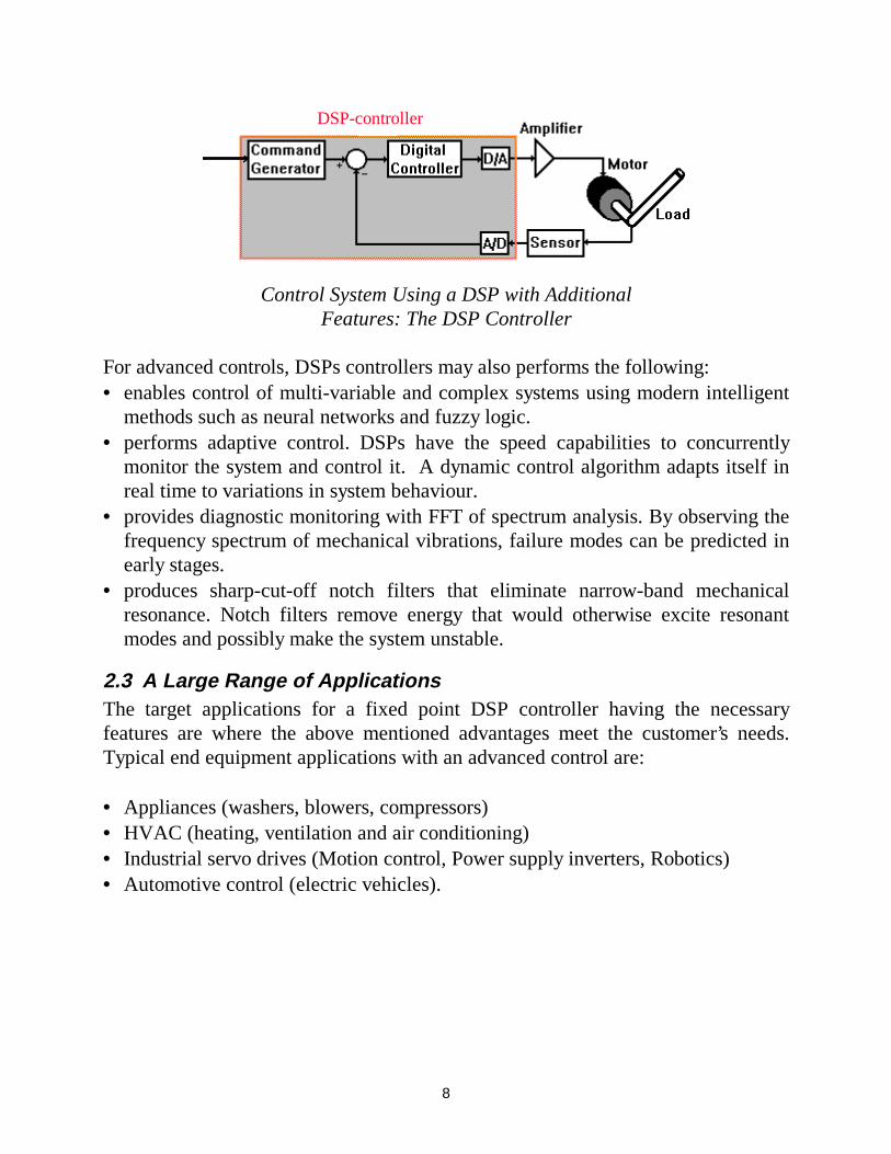
Control System Using a DSP with AdditionalFeatures: The DSP Controller
For advanced controls, DSPs controllers may also performs the following:• enables control of multi-variable and complex systems using modern intelligent
methods such as neural networks and fuzzy logic.• performs adaptive control. DSPs have the speed capabilities to concurrently
monitor the system and control it. A dynamic control algorithm adapts itself inreal time to variations in system behaviour.
• provides diagnostic monitoring with FFT of spectrum analysis. By observing thefrequency spectrum of mechanical vibrations, failure modes can be predicted inearly stages.
• produces sharp-cut-off notch filters that eliminate narrow-band mechanicalresonance. Notch filters remove energy that would otherwise excite resonantmodes and possibly make the system unstable.
2.3 A Large Range of ApplicationsThe target applications for a fixed point DSP controller having the necessaryfeatures are where the above mentioned advantages meet the customer’s needs.Typical end equipment applications with an advanced control are:
• Appliances (washers, blowers, compressors)• HVAC (heating, ventilation and air conditioning)• Industrial servo drives (Motion control, Power supply inverters, Robotics)• Automotive control (electric vehicles).
9
3. The TMS320C24x Family
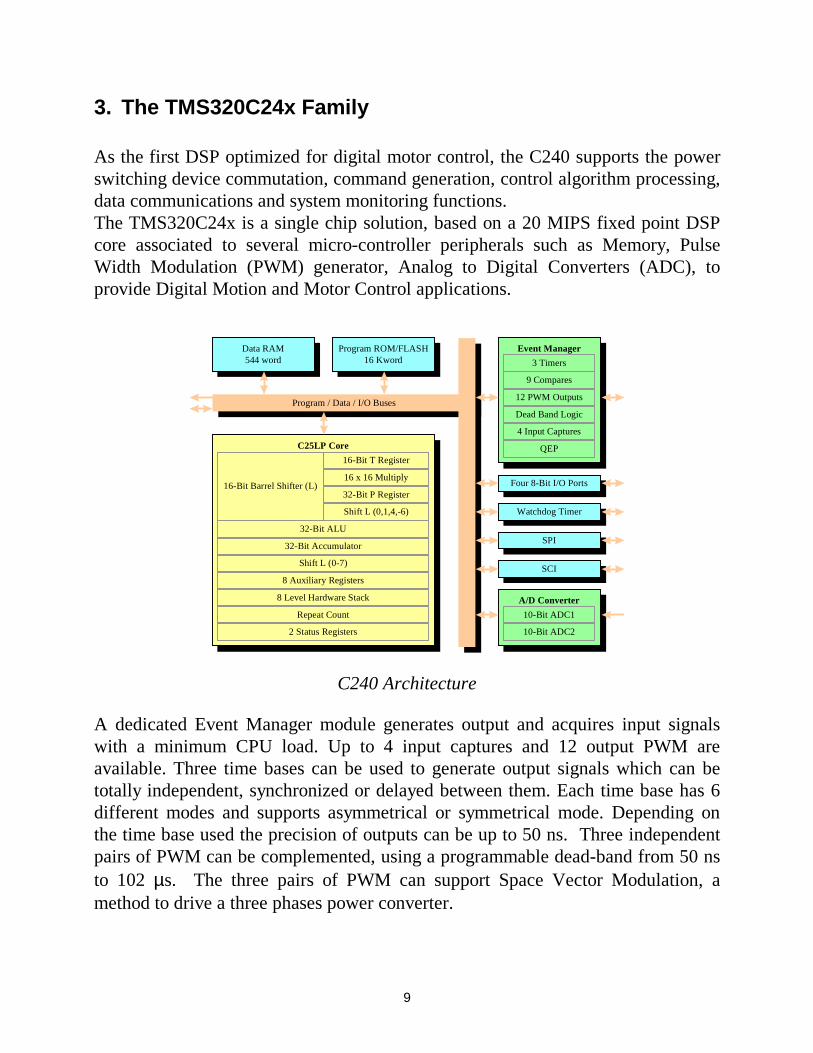
As the first DSP optimized for digital motor control, the C240 supports the powerswitching device commutation, command generation, control algorithm processing,data communications and system monitoring functions.The TMS320C24x is a single chip solution, based on a 20 MIPS fixed point DSPcore associated to several micro-controller peripherals such as Memory, PulseWidth Modulation (PWM) generator, Analog to Digital Converters (ADC), toprovide Digital Motion and Motor Control applications.
Program / Data / I/O BusesProgram / Data / I/O Buses
SCISCI
SPISPI
Watchdog TimerWatchdog Timer
Four 8-Bit I/O PortsFour 8-Bit I/O Ports
Program ROM/FLASH16 Kword
Program ROM/FLASH16 Kword
Data RAM544 word
Data RAM544 word
C25LP Core
2 Status Registers
Repeat Count
32-Bit Accumulator
Shift L (0-7)
8 Auxiliary Registers
8 Level Hardware Stack
32-Bit ALU
Shift L (0,1,4,-6)
32-Bit P Register
16-Bit T Register
16 x 16 Multiply16-Bit Barrel Shifter (L)
Event ManagerEvent Manager
3 Timers
9 Compares
12 PWM Outputs
Dead Band Logic
4 Input Captures
QEP
A/D ConverterA/D Converter
10-Bit ADC1
10-Bit ADC2
C240 Architecture
A dedicated Event Manager module generates output and acquires input signalswith a minimum CPU load. Up to 4 input captures and 12 output PWM areavailable. Three time bases can be used to generate output signals which can betotally independent, synchronized or delayed between them. Each time base has 6different modes and supports asymmetrical or symmetrical mode. Depending onthe time base used the precision of outputs can be up to 50 ns. Three independentpairs of PWM can be complemented, using a programmable dead-band from 50 nsto 102 µs. The three pairs of PWM can support Space Vector Modulation, amethod to drive a three phases power converter.
10
The device includes a watchdog timer and a Real Time Interrupt (RTI) module.The watchdog module monitors software and hardware operations. A three pinSerial Communication Interface (SCI) supports communication between CPU andother asynchronous peripherals. A high speed synchronous Serial PeripheralInterface (SPI) is also available for communication between the CPU and externalperipherals or another micro-controller. Up to 28 individually programmable I/Opins are available.
4. Control Strategy
4.1 Electric Motors
Electric Motors
AC DC
Asynchronous Synchronous
Induction Brushless DC Sinewave Hysteresis Step Reluctance
Squirrelcage
Wound rotor
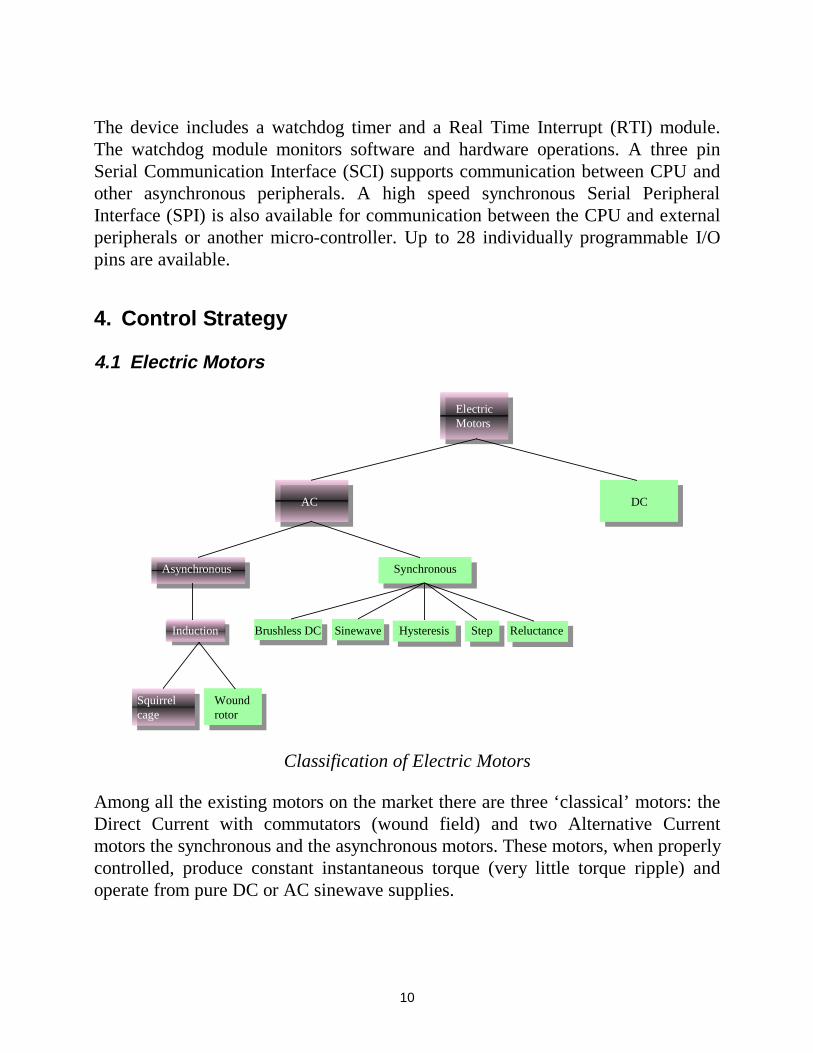
Classification of Electric Motors
Among all the existing motors on the market there are three ‘classical’ motors: theDirect Current with commutators (wound field) and two Alternative Currentmotors the synchronous and the asynchronous motors. These motors, when properlycontrolled, produce constant instantaneous torque (very little torque ripple) andoperate from pure DC or AC sinewave supplies.

11
The motor studied in this note is part of the Alternative Current supplied motors. Itis the squirrel cage asynchronous motor, named AC induction motor, as the rotor isnot in phase, apart from the rotor pole number with the stator phase currents.
4.2 The AC Induction MotorAsynchronous motors are based on induction. The least expensive and most widelyspread induction motor is the squirrel cage motor. The wires along the rotor axisare connected by a metal ring at the ends resulting in a short circuit. There is nocurrent supply needed from outside the rotor to create a magnetic field in the rotor.This is the reason why this motor is so robust and inexpensive. The stator phasescreate a magnetic field in the air gap rotating at the speed of the stator frequency(ωe). The changing field induces a current in the cage wires which then results inthe formation of a second magnetic field around the rotor wires. As a consequenceof the forces created by these two fields, the rotor starts rotating in the direction ofthe stator field but at a slower speed (ωr). If the rotor revolved at the samefrequency as the stator then the rotor field would be in phase with the stator fieldand no induction would be possible. The difference between the stator and rotorfrequency is called slip frequency (ωslip = ωe - ωr).
An Asynchronous Motor
There are several ways to control an induction motor in torque, speed or position,they can be categorized into two groups: the scalar and the vector control.
4.3 The Scalar ControlScalar control means that variables are controlled only in magnitude and thefeedback and command signals are proportional to dc quantities. A scalar controlmethod can only drive the stator frequency using a voltage or a current as acommand.
12
Among the scalar method known to control an induction motor, one assumes thatby varying the stator voltages in proportion with frequency, the torque is keptconstant.
V
V
f
f0 0
=
The speed-torque curves are obtained by simply shifting the reference curve (V0, f0)along the frequency axis, while maintaining its shape. This Voltage on Frequencymethod is based on steady-state characteristics of the motor and the assumptionthat the stator voltages and currents are sinusoidal. Applied to the majority ofexisting variable-speed AC drives by mean of an open-loop constant V/f voltagesource converters, this standard control method has no inner current controller. Theadvantages of this control technique is its simplicity it is easy and fast to programand requires only few calculation capabilities.
The drawbacks are the very poor reaction time for load changes and the efficiencyduring these operation points. A speed controller that takes into considerationtorque changes and avoid undesirable trips can barely be achieved with a V/f open-loop control. This method needs some characteristic plots to describe part of thecontrol. One method to obtain these plots is to pre-calculate and store them in thememory which requires additional silicon costs. The other way is to use a powerfulprocessor and calculate in real time all the characteristics.
4.4 The Vector ControlThe vector control is referring not only to the magnitude but also to the phase ofthese variables. Matrix and vectors are used to represent the control quantities.This method takes into consideration not only successive steady-states but realmathematical equations that describe the motor itself, the control results obtainedhave a better dynamic for torque variations in a wider speed range. The spacephasor theory is a method to handle the equations.
Though the induction motor have a very simple structure, its mathematical model iscomplex due to the coupling factor between a large number of variables and thenon-linearities. The Field Oriented Control (FOC) offers a solution to circumventthe need to solve high order equations and achieve an efficient control with highdynamic.
13
This approach needs more calculations than a standard V/f control scheme. Thiscan be solved by the use of a calculation unit included in a Digital Signal Processor(DSP) and has the following advantages:
• full motor torque capability at low speed• better dynamic behaviour• higher efficiency for each operation point in a wide speed range• decoupled control of torque and flux• short term overload capability• four quadrant operation.
5. Enhanced Motor Control
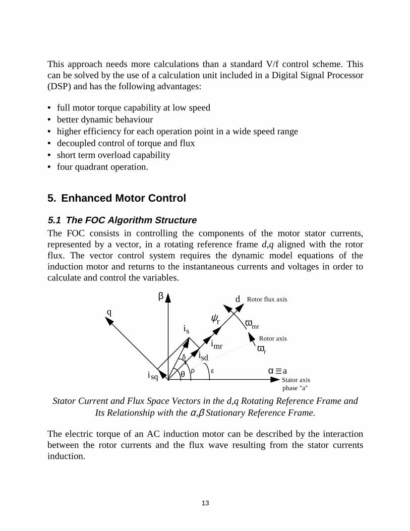
5.1 The FOC Algorithm StructureThe FOC consists in controlling the components of the motor stator currents,represented by a vector, in a rotating reference frame d,q aligned with the rotorflux. The vector control system requires the dynamic model equations of theinduction motor and returns to the instantaneous currents and voltages in order tocalculate and control the variables.
θ α
β
a
dq ψr
isq Stator axisphase "a"
Rotor flux axis
Rotor axis
is mrω
ωrsdi
imrδ
ερ
Stator Current and Flux Space Vectors in the d,q Rotating Reference Frame andIts Relationship with the α,β Stationary Reference Frame.
The electric torque of an AC induction motor can be described by the interactionbetween the rotor currents and the flux wave resulting from the stator currentsinduction.
14
( )[ ]m L m i imreM sj= ℑ
2
3 0ϕ *
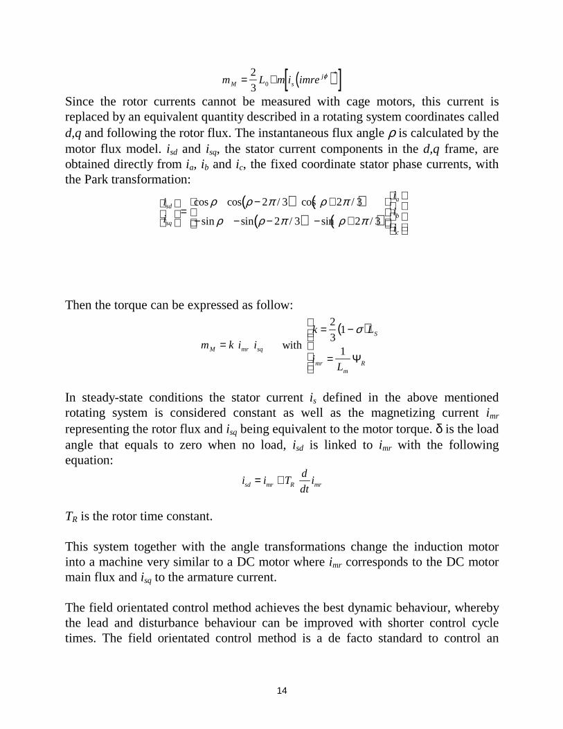
Since the rotor currents cannot be measured with cage motors, this current isreplaced by an equivalent quantity described in a rotating system coordinates calledd,q and following the rotor flux. The instantaneous flux angle ρ is calculated by themotor flux model. isd and isq, the stator current components in the d,q frame, areobtained directly from ia, ib and ic, the fixed coordinate stator phase currents, withthe Park transformation:
( ) ( )( ) ( )
i
i
i
i
i
sd
sq
a
b
c
=
− +
− − − − +
cos cos / cos /
sin sin / sin /
ρ ρ π ρ π
ρ ρ π ρ π
2 3 2 3
2 3 2 3
Then the torque can be expressed as follow:
m k i iM mr sq= with
( )k L
iL
S
mrm
R
= −
=
2
31
1
σ
Ψ
In steady-state conditions the stator current is defined in the above mentionedrotating system is considered constant as well as the magnetizing current imr
representing the rotor flux and isq being equivalent to the motor torque. δ is the loadangle that equals to zero when no load, isd is linked to imr with the followingequation:
i i Td
dtisd mr R mr= +
TR is the rotor time constant.
This system together with the angle transformations change the induction motorinto a machine very similar to a DC motor where imr corresponds to the DC motormain flux and isq to the armature current.
The field orientated control method achieves the best dynamic behaviour, wherebythe lead and disturbance behaviour can be improved with shorter control cycletimes. The field orientated control method is a de facto standard to control an

15
induction motor in adjustable speed drive applications with quickly changing loadas well as reference speeds. Its advantage is that by transforming measurable statorvariables into a system based on field coordinates the complexity of the system canbe enormously reduced. As a result a relatively simple control method very similarto a separated exited DC motor can be applied.
The role of the DSP in such a system is to translate the stator variables (currentsand angle) into a flux model as well as compare the values with the referencevalues and update the PI controllers. After the back transformation from field tostator coordinates the output voltage will be impressed to the machine with asymmetric, an asymmetric PWM whereby the pulse pattern is on-line computed bythe DSP or a hardware generated space vector method. In some systems theposition is measured by an encoder, this extra cost can be avoided implementing anobserver model or in particular cases, a Kalman filter. These algorithms arecomplex and therefore require a fast processor, a fixed-point DSP is able toperform the above controls with short cycle times.
i_sqcontroller
i_sdcontrolleur
SpacevectorPWMmodulation
PowerConverter
ACmotor
PowerSupply
Fluxcontroller
Speedcontroller
Fluxmodel
Coordinatetransformation
i_a
i_b
i_sdi_sq
i_mr
i_mref
u_sd
u_sq
wr
Speedset-point
Block Diagram of a Three Phases Asynchronous Motor DriverUsing a FOC Structure
5.2 Space Vector ModulationPulse Width Modulation technique is used to generate the required voltage orcurrent to feed the motor or phase signals. This method is increasingly used for ACdrives with the condition that the harmonic current is as small as possible and the
16
maximum output voltage is as large as possible. Generally, the PWM schemesgenerate the switching position patterns by comparing three-phase sinusoidalwaveforms with a triangular carrier.
In recent years, the space vector theory demonstrated some improvement for boththe output crest voltage and the harmonic copper loss. The maximum outputvoltage based on the space vector theory is 2
3 = 1.155 times as large as the
conventional sinusoidal modulation. It enables to feed the motor with a highervoltage than the easier sub-oscillation modulation method. This modulator allowsto have a higher torque at high speeds, and a higher efficiency.
Motor
Ia
Ib
Ic
Udc
Sa
Sa
Sb Sc
Sb Sc
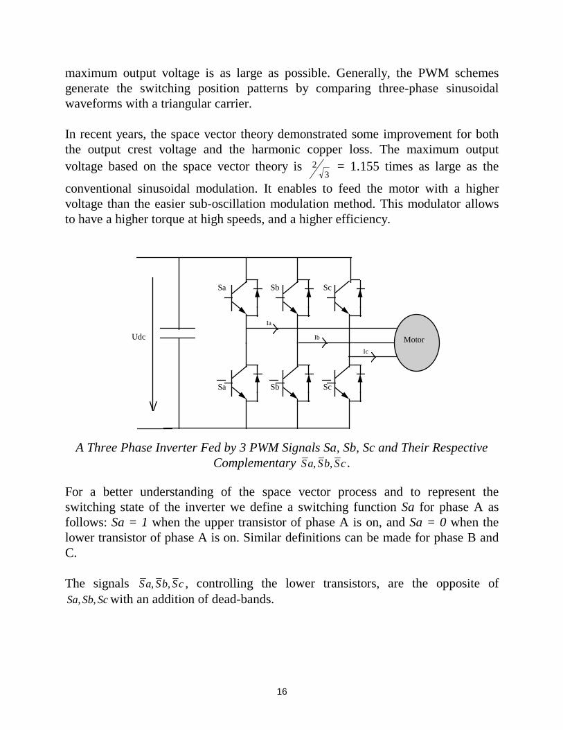
A Three Phase Inverter Fed by 3 PWM Signals Sa, Sb, Sc and Their RespectiveComplementary Sa Sb Sc, , .
For a better understanding of the space vector process and to represent theswitching state of the inverter we define a switching function Sa for phase A asfollows: Sa = 1 when the upper transistor of phase A is on, and Sa = 0 when thelower transistor of phase A is on. Similar definitions can be made for phase B andC.
The signals Sa Sb Sc, , , controlling the lower transistors, are the opposite ofSa Sb Sc, , with an addition of dead-bands.
17
Dead-band is the name given to the time difference between the commutations ofthe upper and lower transistor of one phase. The two transistors of each phase arethen never conducting at the same time. The aim of the dead-band is to protect thepower devices during commutation by avoiding conduction overlap and then hightransient current.
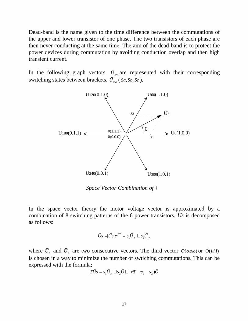
In the following graph vectors, v
U xxx are represented with their correspondingswitching states between brackets,
v
U xxx ( Sa Sb Sc, , ).
U0(1.0.0)U180(0.1.1)
U240(0.0.1)
0(1.1.1)
0(0.0.0)
U120(0.1.0) U60(1.1.0)
U300(1.0.1)
θ
Us
S1
S2
Space Vector Combination of i
In the space vector theory the motor voltage vector is approximated by acombination of 8 switching patterns of the 6 power transistors. Us is decomposedas follows:
v v v v
Us Us e s U s Ujx y= = +| | θ
1 2
where v
U x and v
U x are two consecutive vectors. The third vector r
O o o o( )1 1 or r
O i i i( )1 1
is chosen in a way to minimize the number of swtiching commutations. This can beexpressed with the formula:
TUs s U s U T s s Ox y
v v v v
= + + − −1 2 1 2( )
18
U60 0U0
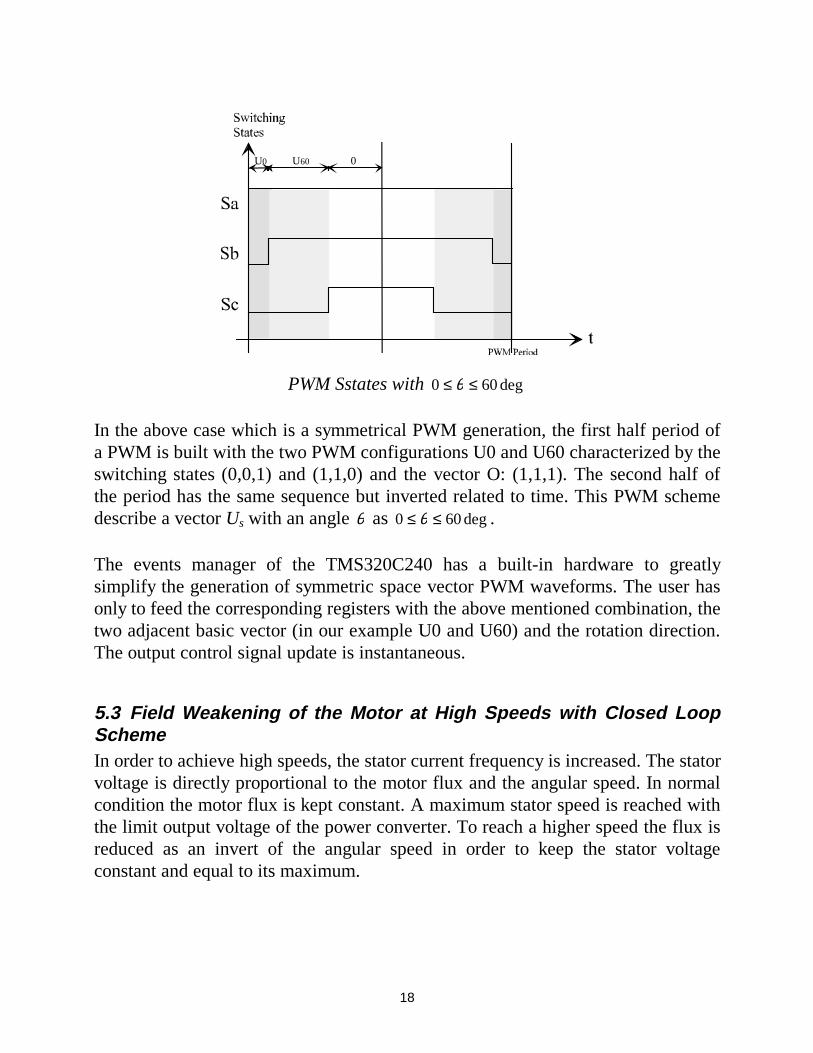
PWM Sstates with 0 60≤ ≤θ deg
In the above case which is a symmetrical PWM generation, the first half period ofa PWM is built with the two PWM configurations U0 and U60 characterized by theswitching states (0,0,1) and (1,1,0) and the vector O: (1,1,1). The second half ofthe period has the same sequence but inverted related to time. This PWM schemedescribe a vector Us with an angle θ as 0 60≤ ≤θ deg .
The events manager of the TMS320C240 has a built-in hardware to greatlysimplify the generation of symmetric space vector PWM waveforms. The user hasonly to feed the corresponding registers with the above mentioned combination, thetwo adjacent basic vector (in our example U0 and U60) and the rotation direction.The output control signal update is instantaneous.
5.3 Field Weakening of the Motor at High Speeds with Closed LoopSchemeIn order to achieve high speeds, the stator current frequency is increased. The statorvoltage is directly proportional to the motor flux and the angular speed. In normalcondition the motor flux is kept constant. A maximum stator speed is reached withthe limit output voltage of the power converter. To reach a higher speed the flux isreduced as an invert of the angular speed in order to keep the stator voltageconstant and equal to its maximum.
19
ω
φ0
φua
ua0
Voltage control range
Field controlrange
Field controlrange
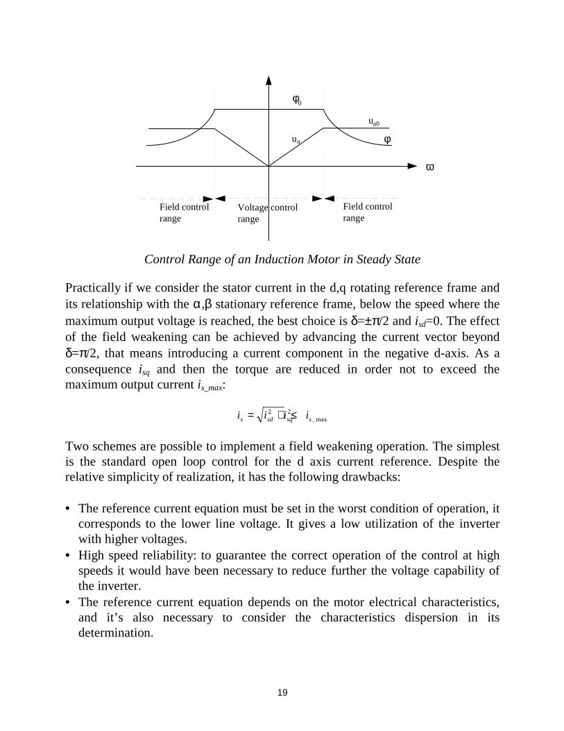
Control Range of an Induction Motor in Steady State
Practically if we consider the stator current in the d,q rotating reference frame andits relationship with the α,β stationary reference frame, below the speed where themaximum output voltage is reached, the best choice is δ=±π/2 and isd=0. The effectof the field weakening can be achieved by advancing the current vector beyondδ=π/2, that means introducing a current component in the negative d-axis. As aconsequence isq and then the torque are reduced in order not to exceed themaximum output current is_max:
i i i is sd sq s= + ≤2 2_max
Two schemes are possible to implement a field weakening operation. The simplestis the standard open loop control for the d axis current reference. Despite therelative simplicity of realization, it has the following drawbacks:
• The reference current equation must be set in the worst condition of operation, itcorresponds to the lower line voltage. It gives a low utilization of the inverterwith higher voltages.
• High speed reliability: to guarantee the correct operation of the control at highspeeds it would have been necessary to reduce further the voltage capability ofthe inverter.
• The reference current equation depends on the motor electrical characteristics,and it’s also necessary to consider the characteristics dispersion in itsdetermination.
20
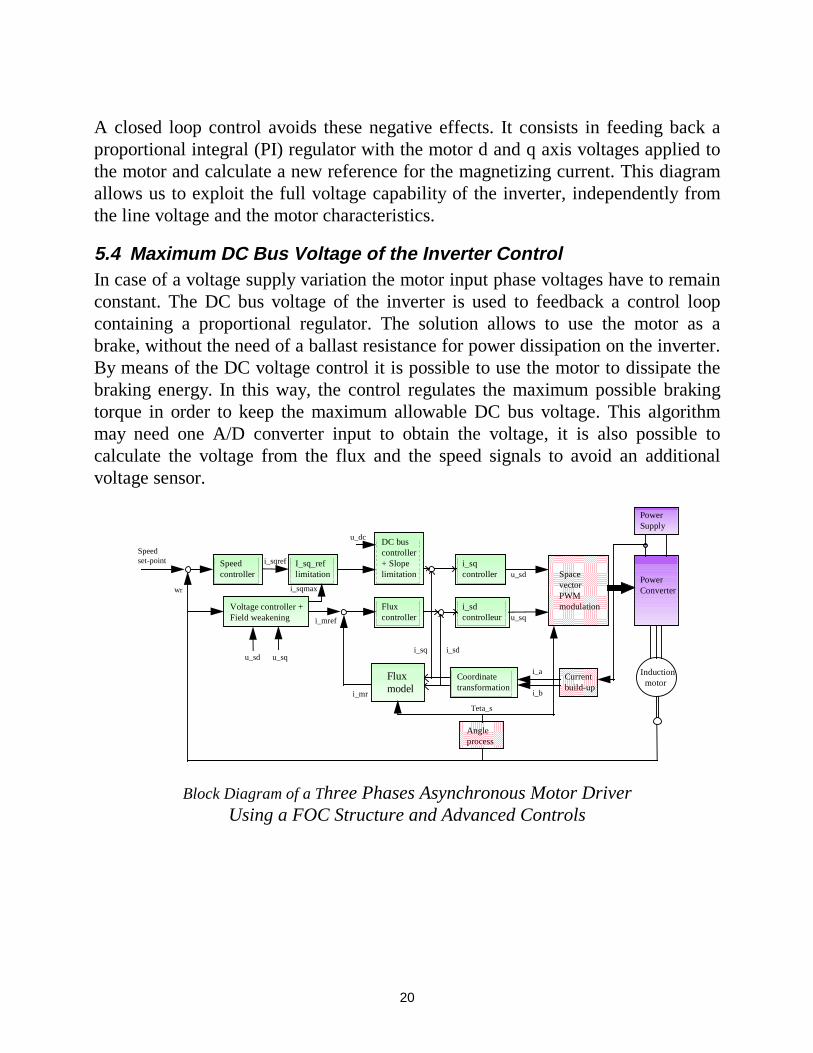
A closed loop control avoids these negative effects. It consists in feeding back aproportional integral (PI) regulator with the motor d and q axis voltages applied tothe motor and calculate a new reference for the magnetizing current. This diagramallows us to exploit the full voltage capability of the inverter, independently fromthe line voltage and the motor characteristics.
5.4 Maximum DC Bus Voltage of the Inverter ControlIn case of a voltage supply variation the motor input phase voltages have to remainconstant. The DC bus voltage of the inverter is used to feedback a control loopcontaining a proportional regulator. The solution allows to use the motor as abrake, without the need of a ballast resistance for power dissipation on the inverter.By means of the DC voltage control it is possible to use the motor to dissipate thebraking energy. In this way, the control regulates the maximum possible brakingtorque in order to keep the maximum allowable DC bus voltage. This algorithmmay need one A/D converter input to obtain the voltage, it is also possible tocalculate the voltage from the flux and the speed signals to avoid an additionalvoltage sensor.
i_sqcontroller
i_sdcontrolleur
SpacevectorPWMmodulation
PowerConverter
Induction motor
PowerSupply
Fluxcontroller
DC buscontroller+ Slopelimitation
I_sq_reflimitation
Speedcontroller
Fluxmodel
Coordinatetransformation
Currentbuild-up
i_a
i_b
i_sdi_sq
Voltage controller +Field weakening
i_mr
i_mref
u_sd
u_sq
u_dc
i_sqmax
Angleprocess
Teta_s
wr
Speedset-point i_sqref
u_sd u_sq
Block Diagram of a Three Phases Asynchronous Motor DriverUsing a FOC Structure and Advanced Controls

21
6. Sensors Reduction
6.1 Current Remote Measurement and CalculationIn most of the inverter systems, information on the phase currents is required. Thefirst method of obtaining those currents is to directly sense them but this requires,depending on the load schematic, at least two sensors applied directly on the motorphases. These types of sensors are usually expensive because they must be isolatedand therefore sophisticated.
The other way is to sense only the line current, and estimate the 3 phase currents.This second method requires a simple cheap SHUNT as a sensor.
InputVoltage
Current Estimator Synoptic
As we directly control the inverters switching state, it is possible to know the exactelectrical route taken by the input current through the inverter to the phase. We canthen directly link the phase currents to the line current. The information wemeasure to obtain the phase currents is a result of a real sense on the current andnot the result of a simulation requiring a model of the output circuit. Themeasurement process is totally independent from the input and output hardware ofthe inverter.
22
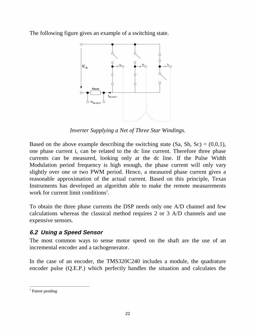
The following figure gives an example of a switching state.
U V W
1
2
3
4
5
6
U dc
~UDCOUT
IDCOUT
Shunt
Inverter Supplying a Net of Three Star Windings.
Based on the above example describing the switching state (Sa, Sb, Sc) = (0,0,1),one phase current ic can be related to the dc line current. Therefore three phasecurrents can be measured, looking only at the dc line. If the Pulse WidthModulation period frequency is high enough, the phase current will only varyslightly over one or two PWM period. Hence, a measured phase current gives areasonable approximation of the actual current. Based on this principle, TexasInstruments has developed an algorithm able to make the remote measurementswork for current limit conditions1.
To obtain the three phase currents the DSP needs only one A/D channel and fewcalculations whereas the classical method requires 2 or 3 A/D channels and useexpensive sensors.
6.2 Using a Speed SensorThe most common ways to sense motor speed on the shaft are the use of anincremental encoder and a tachogenerator.
In the case of an encoder, the TMS320C240 includes a module, the quadratureencoder pulse (Q.E.P.) which perfectly handles the situation and calculates the
1 Patent pending
23
speed and the direction of the rotation using only two digital inputs and a 16 or 32bit internal timer register.
There are several types of tachogenerators, some build a dc voltage proportional tothe motor speed, others generate a number of pulses per rotor revolution.
In the first case, one of the 16 A/D converters channel of the TMS320C240 isconnected to the tachogenerator output.
For an hall effect sensor, the pulses, enter a capture and a software driver allowsthe frequency measurement. The implemented software is called at fixed timeintervals no longer than the minimum period of the measurable frequency . Asthere is only one signal, it is not possible to measure the motor speed sign. Anartifice is inserted to add the sign to this speed measurement. The speed sign ismemorized in a variable and only when the motor speed goes under apredetermined speed this variable is updated with the current sign. This also allowsthe user to execute fast speed reversing cycles of the motor.
6.3 A Kalman ObserverIn many cases it is impossible to use sensors for velocity or position measurement,either because it is technically impossible, or it is too expensive. Among theobservers capable of controlling an AC induction speed sensorless motor is theKALMAN observer. It has a good dynamic behavior, disturbance resistance, and itcan work even a standstill. On a field orientated control method but its is verydependent on the environment it has been designed for the necessary controlvariables position, speed, and rotor flux will be estimated with a Kalman observer.
Implementing a Kalman observer is a very complex problem, and it requires themodel of the AC motor to be calculated in real time. Also the observer equationsmust be calculated, which normally means many matrix multiplication and onematrix inversion. These requirements can be fulfilled by a processor with highcalculation performance. The DSP is especially well suited for this purpose,because of its good calculation-performance/price ratio.
The Kalman filter provides a solution, that directly cares for the effects of thedisturbance noises. The system is describable with the following equations.

24
x Ax B r
y Cx
.
= + += +
ρWhere r and ρ are the system and the measurement noise. The followingassumptions are made regarding the noise, it is stationary, white, uncorrelated andGaussian, and its expectation is 0.
7. An Example Studied
Below is an example of the implementation and realization of an asynchronousmotor controlled in speed and connected to an alternative voltage supplier. Fewresults are given.
7.1 Power Electronics
TMS320C240DSP
controller
InputFilter
Rectifier
AuxiliarySupply
InputVoltage
Inverter
AC inductionmotor
Tachometer
communications
Load
Sensor
Three Phases Asynchronous Motor Driver
The input filter block includes the hardware protections, EMI filter and an optionalpower factor correction (PFC). The PFC may be active or passive, in the case ofactive it can be entirely handled by the DSP. To achieve a continuous voltage outof the alternative input signal, a single phase input bridge with tank capacitor isneeded represented as the rectifier block To generate the phase voltages withvariable amplitude and frequency a 3 phase inverter is used, based on an IGBTtechnology. The system is controlled by the DSP TMS320C240. The inputs are, atachogenerator to measure the speed, a resistor divider to sense the voltage bus(VBUS ), a resistor sensor on the line (IBUS ) to estimate the phase currents, and atemperature sensor. The controller use a serial link to communicate. The auxiliarysupply feeds the inverter driver and the logic circuitry.
25
7.2 The Control Strategy
Speedsensor
Power Amp
Speed feedback
Very high bandwidth current feedback
TMS320C240DSP
controller
AC inductionmotor
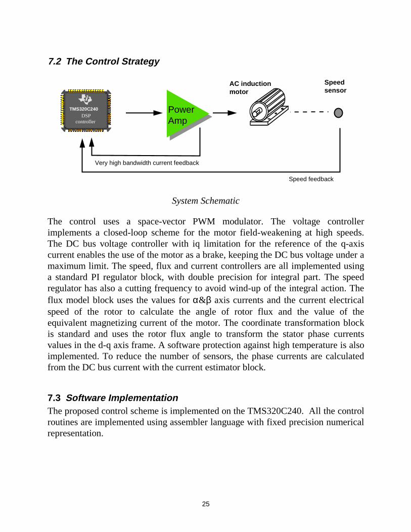
System Schematic
The control uses a space-vector PWM modulator. The voltage controllerimplements a closed-loop scheme for the motor field-weakening at high speeds.The DC bus voltage controller with iq limitation for the reference of the q-axiscurrent enables the use of the motor as a brake, keeping the DC bus voltage under amaximum limit. The speed, flux and current controllers are all implemented usinga standard PI regulator block, with double precision for integral part. The speedregulator has also a cutting frequency to avoid wind-up of the integral action. Theflux model block uses the values for α&β axis currents and the current electricalspeed of the rotor to calculate the angle of rotor flux and the value of theequivalent magnetizing current of the motor. The coordinate transformation blockis standard and uses the rotor flux angle to transform the stator phase currentsvalues in the d-q axis frame. A software protection against high temperature is alsoimplemented. To reduce the number of sensors, the phase currents are calculatedfrom the DC bus current with the current estimator block.
7.3 Software ImplementationThe proposed control scheme is implemented on the TMS320C240. All the controlroutines are implemented using assembler language with fixed precision numericalrepresentation.
26
The control algorithm is synchronised by the DSP internal Timer that generatesinterrupts.
The speed is controlled once among several control cycles and uses a hall effecttachogenerator.Phase current remote measurements need sampling of the inverter DC currentduring the 16 kHz PWM period. The sampling time varies as a function of theactual PWM pattern. This is obtained driving the A/D conversion through an otherinterrupt (Compare Register interrupt) and the result is received through an end-of-conversion interrupt.
7.4 ResultsThe memory space needed is less than 3K word of ROM, and 544 word of RAM,and use less than 50% (10 MIPS) of the DSP power. The complete control loop iscalculated in less than 35µs.
The speed range is from 0 to 12,000 rpm with a worst speed error under 1%.
The efficiency of the power electronic stage is in the range of 95%, and the totalefficiency of the system is > 85%.
8. Conclusion
This paper presents a new controller architecture the DSP controller. The DSP-Controller TMS320C240 combines the performance of a DSP architecture with theoptimized peripherals of a Microcontroller in a single chip solutions for the controlof an induction motor. With the DSP controller an intelligent control approach ispossible to reduce the overall system costs and to improve the reliability of thedrive system.
27
9. References
• ‘TMS320C240, TMS320F240 DSP controllers from Texas Instruments, October1996
• ‘Control of Electrical Drives’ from Werner Leonhard, Ed. Springer,1996• ‘Vector control of AC Drives’ Arpad Kelemen & Maria Imecs, Ed. G.J. Retter,
1987• ‘Brushless Permanent-Magnet and Reluctance Motor Drives’ from T.J.E. Miller,
Oxford Science publications 1993• ‘Digital Signal Processing Solutions for Motor Control’ by Stefan Beierke,
Texas Instruments.• ‘Comparative Study of Rotor Flux Estimation in Induction Motors with a
Nonlinear Observer and the Extended Kalman Filter”C. Manes, F. Parasiliti, M.Tursini, IECON 1994.
• ‘Application of Kalman Filters and Extended Luenberger Observers in InductionMotor Drives” T. Du, P. Vas, A.F. Stronach, M.A. Brdys, Intelligent MotionProceedings, 1994.