Embed Size (px)
Citation preview

LION SERIES DSP Controlled UPS
40-60-80 kVA 3 Phase In - 3 Phase Out
Sinercom srl Headquarter: Via G. Cappalonga 9/A- 00043 Ciampino (Rm) (Italy)
tel. +39.06.79800323 fax +39.06.79814644 Factory: Via Cascina Secchi 247/4b - 24040 Isso (BG)
tel. +39.0363.938231 fax +39.0363.998235
USER MANUAL


CONTENTS
I. GENERAL DESCRIPTION ...................................................................................... 3
1.1 Introduction ....................................................................................................... 3 1.2 Design Concept ................................................................................................ 5
1.2.1 Description of Blocks ............................................................................... 6 1.2.2 Operating Conditions of UPS……………………………………………..6
1.3 Front view of UPS Conditions of ups ................................................................. 7 1.4 Technical Specifications .................................................................................... 9
II. UPS INSTALLATION .............................................................................................. 10
2.1. Introduction ....................................................................................................... 10 2.2. Unpacking ......................................................................................................... 10 2.3. Equipment Positioning ...................................................................................... 10 2.4. Connecting the UPS Power Cables ................................................................... 11 2.5. Safety Earth ...................................................................................................... 11 2.6. Cable Connection Procedure ............................................................................ 11
2.6.1. Description of Connection Terminals of the UPS ....................................... 12 2.7. Battery Installation ............................................................................................ 13
III. FRONT PANEL ....................................................................................................... 17
3.1. Introduction ....................................................................................................... 17 3.2. Front Panel Menu Descriptions ......................................................................... 17
3.2.1 MEASUREMENTS menu ........................................................................... 20 3.2.2 ALARM LOGS menu .................................................................................. 23 3.2.3 INFORMATION menu ................................................................................ 23 3.2.4 OPTIONS menu ......................................................................................... 24 3.2.5 COMMAND menu ...................................................................................... 27 3.2.6 TIME menu................................................................................................. 27 3.2.7 SERVICE menu ......................................................................................... 28 3.2.8 ADJUST menu ........................................................................................... 28 3.2.9 User Pasword ............................................................................................. 29
3.3. Alarms and warning messages ......................................................................... 29 3.4. Alarm messages and quick troubleshooting ...................................................... 32
1
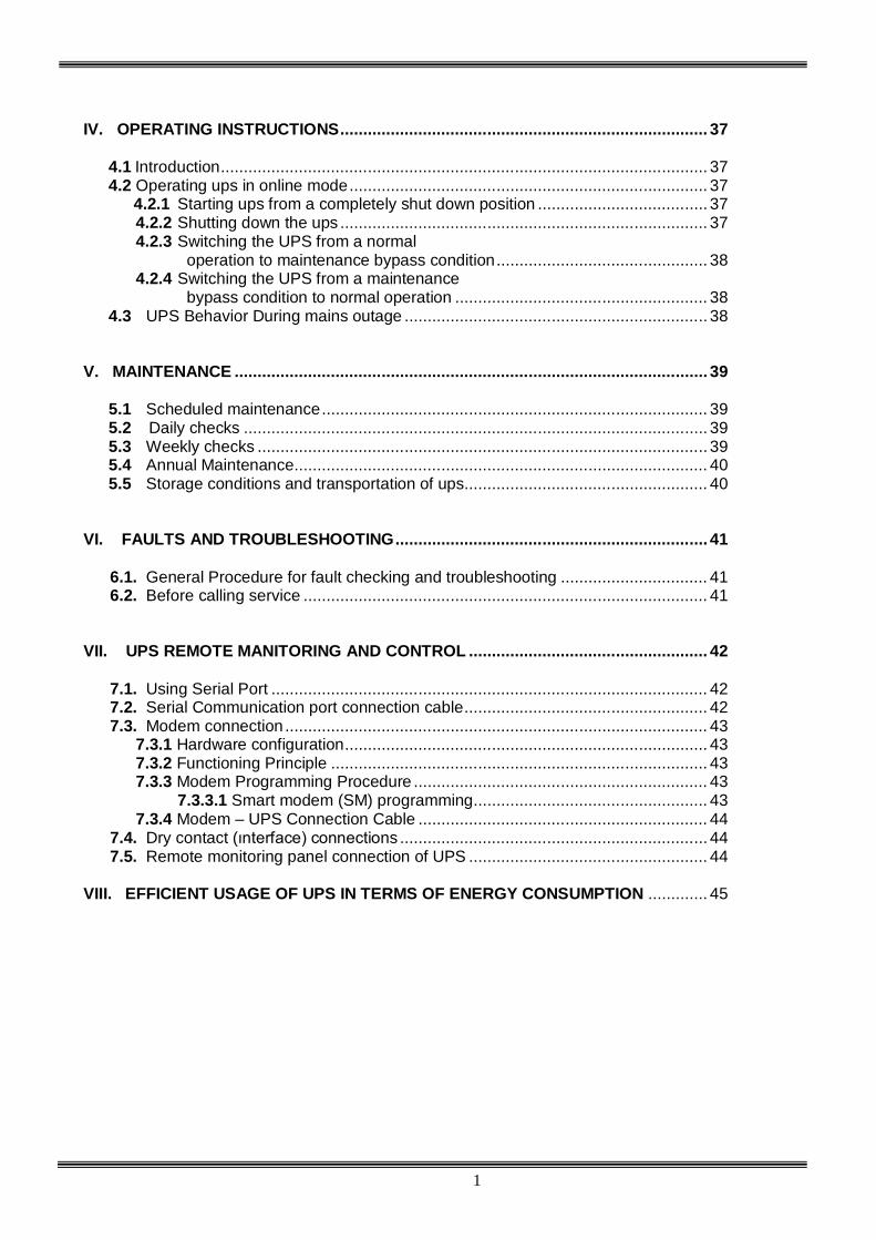
IV. OPERATING INSTRUCTIONS ................................................................................ 37
4.1 Introduction .......................................................................................................... 37 4.2 Operating ups in online mode .............................................................................. 37
4.2.1 Starting ups from a completely shut down position ..................................... 37 4.2.2 Shutting down the ups ................................................................................ 37 4.2.3 Switching the UPS from a normal
operation to maintenance bypass condition .............................................. 38 4.2.4 Switching the UPS from a maintenance
bypass condition to normal operation ....................................................... 38 4.3 UPS Behavior During mains outage .................................................................. 38
V. MAINTENANCE ....................................................................................................... 39
5.1 Scheduled maintenance .................................................................................... 39 5.2 Daily checks ..................................................................................................... 39 5.3 Weekly checks .................................................................................................. 39 5.4 Annual Maintenance .......................................................................................... 40 5.5 Storage conditions and transportation of ups ..................................................... 40
VI. FAULTS AND TROUBLESHOOTING .................................................................... 41
6.1. General Procedure for fault checking and troubleshooting ................................ 41 6.2. Before calling service ........................................................................................ 41
VII. UPS REMOTE MANITORING AND CONTROL .................................................... 42
7.1. Using Serial Port ............................................................................................... 42 7.2. Serial Communication port connection cable ..................................................... 42 7.3. Modem connection ............................................................................................ 43
7.3.1 Hardware configuration ............................................................................... 43 7.3.2 Functioning Principle .................................................................................. 43 7.3.3 Modem Programming Procedure ................................................................ 43 7.3.3.1 Smart modem (SM) programming ................................................... 43 7.3.4 Modem – UPS Connection Cable ............................................................... 44
7.4. Dry contact (ınterface) connections ................................................................... 44 7.5. Remote monitoring panel connection of UPS .................................................... 44
VIII. EFFICIENT USAGE OF UPS IN TERMS OF ENERGY CONSUMPTION ............. 45

2
SAFETY
IMPORTANT NOTICES 1. Read instructions carefully before installing and starting the UPS. 2. All warnings in the manual should be adhered to. 3. All operating instructions should be followed. 4. The unit should be supplied by a grounded outlet. Do not operate the unit without a ground source. 5. Power cables of the UPS should be routed carefully so that they are not to be walked on. 6. Please save this manual. 7. Please save or recycle the packaging materials.
WARNING!
Do not insert any object into ventilation holes or other openings. To reduce the risk of fire or electric shock, install in temperature and humidity controlled
indoor area free of conductive contaminants. To reduce the risk of fire, replace fuses with the same type and rating when necessary.
CAUTION! Only qualified personnel should install or service UPS/batteries. Risk of electric shock, do not remove cover. No user serviceable parts inside, refer
servicing to qualified service personnel. The output may be energized even when the unit is not connected to a mains supply. Risk of electric shock! Hazardous live parts inside. This unit is energized from the
battery supply even when the input AC power is disconnected. To reduce the risk of electric shock, disconnect the UPS from the mains supply before installing
a computer interface signal cable. Reconnect the power cables only after signaling interconnections have been made.
CAUTION !
Units are designed to operate on the concrete floor.
ABOUT THE BATTERIES
CAUTION: RISK OF ELECTRIC SHOCK! The battery circuit is not isolated from the mains voltage. Hazardous voltages may
occur between the battery terminals and the ground! A battery can present a risk of electric shock or burn from high short circuit currents. The
following precautions should be taken when working on batteries : * Remove watches, rings or other metal objects. * Use tools with insulated handles. The batteries in this UPS are recyclable. Batteries must be disposed of according to local
environmental laws. The batteries contain lead and pose a hazard to the environment and human health if not disposed of properly.
Do not dispose of batteries in a fire. The batteries may explode. Do not open or mutilate the
batteries. They contain an electrolyte which is toxic and harmful to the skin and eyes. If electrolyte comes into contact with the skin the affected area should be washed immediately.
The internal energy source (the battery) cannot be de-energized by the user. When changing batteries, install the same number and same type of batteries.
3
I. GENERAL DESCRIPTION
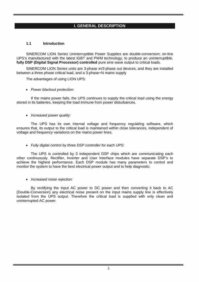
1.1 Introduction
SINERCOM LION Series Uninterruptible Power Supplies are double-conversion; on-line
UPS’s manufactured with the latest IGBT and PWM technology, to produce an uninterruptible, fully DSP (Digital Signal Processor) controlled pure sine wave output to critical loads.
SINERCOM LION Series units are 3-phase in/3-phase out devices, and they are installed between a three phase critical load, and a 3-phase+N mains supply
The advantages of using LION UPS:
Power blackout protection: If the mains power fails, the UPS continues to supply the critical load using the energy
stored in its batteries, keeping the load immune from power disturbances. Increased power quality: The UPS has its own internal voltage and frequency regulating software, which
ensures that, its output to the critical load is maintained within close tolerances, independent of voltage and frequency variations on the mains power lines.
Fully digital control by three DSP controller for each UPS: The UPS is controlled by 3 independent DSP chips which are communicating each
other continuously. Rectifier, Inverter and User Interface modules have separate DSP’s to achieve the highest performance. Each DSP module has many parameters to control and monitor the system to have the best electrical power output and to help diagnostic.
Increased noise rejection: By rectifying the input AC power to DC power and then converting it back to AC
(Double-Conversion) any electrical noise present on the input mains supply line is effectively isolated from the UPS output. Therefore the critical load is supplied with only clean and uninterrupted AC power.

4
Basic Features:
PWM and IGBT technology Pure sinusoidal output wave form and true on-line topology High input power factor (IGBT rectifier), Input current limiting Low input current THD (IGBT rectifier) Low output voltage THD High AC/AC and DC/AC efficiency (up to 94%) 3 separate DSP (Digital Signal Processor) control Cold-start feature Static By-Pass feature: Provides uninterruptable transfer to bypass source in case of overload
or UPS fault. Bypass leakage current sense system Maintenance bypass switch and warning system, by-pass short circuit protection Separate bypass input facility (split bypass), generator operation sense input LCD alphanumeric display panel providing battery, load, voltage, power and status information
in detail to user Improved diagnostics and correct fault infor mation Up to 192 event memory record system (7000 alarms or warnings total) Real time clock and calendar system Overload operation 10 minutes at 100% - 125% load, 1 minute at 125% - 150% load Output overload, over-current and short circuit protection, output current limiting Reliable operation at even 100% unbalanced load condition Non-linear load supply feature (CF 3:1) Double polarity battery (with common terminal) Automatic and manual battery test and battery temperature compensation features 3 separate maintenance clock counters Battery charge with current limiting Automatic and manual boost charge feature Battery deep discharge protection Temperature protection with 3 separate sensors Interactive communication Diagnostic and settings with PC ability 2 separate RS232 communication ports (standard) Multi UPS monitoring on same communication line by RS485 (optional) 4 dry contact alarm relay outputs as standard (8 optional relay outputs) Improved remote monitoring panel system (optional) RS232 port multiplexer (optional) Direct network connection with optional SNMP support MODBUS Adapter (optional) AT command set definitions for dump modems Communication via Windows based T-MON software and remote monitoring and control of UPS
via modem Optional softwares compatible for most computer platforms Ability for labeling of UPSs by users Emergency power-off support Conformity to international and local standards AC input and output filters Optional graphic front panel CE compliance Input, bypass and load phase order protection Optional leakage current alarm system Input and output isolation transformers (optional) Enhanced accessory options 100.000 hours MTBF 2 years system warranty 10 years spare parts warranty

5
1.2 Design Concept
S1 (F1-F2-F3) : Rectifier Input Switch / Fuse S2 (F4-F5-F6) : Bypass Input Switch / Fuse S3 : Maintenance Bypass Switch S4 (F7-F8-F9) : Output Switch / Fuse S5 (F10-F11-F12) : Battery Switch / Fuse K1 : Rectifier Input Contactor K2 : Inverter Output Contactor
Rectifier / Charger
3 PHASE MAINS I/P
Battery (Dual Polarity)
Maintenance Bypass Switch
Static Bypass
S2 (F4-F5-F6)
S1 (F1-F2-F3)
S5 (F10-F11-F12)
S3
S4 (F7-F8-F9) Inverter
K2
3 PHASE AC Output
K1 - -
SB

6
1.2.1 DESCRIPTION OF BLOCKS
RECTIFIER: In LION Series UPSs, a DSP controlled IGBT rectifier with PWM technique is used to increase input power factor (PFC) and to decrease input current harmonics (THDI). The IGBT rectifier accepts 3-phase AC input and produces a dual polarity DC voltage for both supplying the inverter and charging the batteries. BATTERIES: Batteries are used as reserve DC power supply for the Inverter in case of mains failure. In LION Series, batteries are connected in series with a center-tap output to obtain a dual polarity DC supply. Batteries are discharged by the inverter during mains failure. The discharged batteries are re-charged by the IGBT Rectifier on a constant voltage / current limiting basis, if AC mains power is available. INVERTER: It is manufactured by using the latest IGBT and DSP (Digital Signal Processing) technologies, and Pulse Width Modulation (PWM) technique. The Inverter converts the DC BUS voltage supplied by the IGBT Rectifier and / or the batteries into a well regulated, fully digital controlled 3-phase AC voltage with fixed voltage and frequency. The output of the inverter is used to supply the critical loads connected to the UPS output. STATIC TRANSFER SWITCH (STATIC BYPASS): This is an electronically controlled transfer switch, which enables the critical load to be connected either to inverter output or to by-pass power source. During normal operation, the load is supplied by the inverter output, but in case of an overload or a UPS failure it is automatically transferred to the bypass source without any interruption. MAINTENANCE BYPASS SWITCH (MBS): This is a manually controlled mechanical switch, which is used to supply the critical load, using the bypass source, when the UPS is shut down for maintenance or troubleshooting purposes. The load is unprotected against mains supply disturbances and black-outs when it is connected to either static or maintenance bypass supply. 1.2.2. OPERATING CONDITIONS OF UPS UPS may be in one of the following operating conditions:
A. Normal Operation (If Mains supply is available): All fuses and power switches are closed (except the Maintenance Bypass Switch), and the load is supplied by the Inverter Output. During normal operation, the Rectifier supplies DC power to the Inverter and charges the Batteries at the same time.
B. Battery Operation :
The Batteries are connected to the Rectifier output. In case of a mains failure (mains power outage or AC input voltage out of tolerance), the Rectifier stops operating and the DC voltage necessary for the inverter operation is supplied by the batteries. Therefore the AC voltage output supplying the critical load is not interrupted, until the batteries are fully discharged. At the end of the discharging time the inverter is turned off and it start again automatically, together with the rectifier, when the mains power is restored, and the UPS returns o normal operation. For UPS with a split bypass source, at the end of discharging time, static transfer switch transfers the load to the split bypass source without interruption if the split bypass source is available and in acceptable tolerances about voltage and frequency, as still the rectifier input is not available. The Rectifier is also turned off and inverter operates on batteries during automatic or manual battery test procedure.
C. By-Pass Operation : If the Inverter output is overloaded or in case of a problem in the UPS, the static switch transfers the load to the bypass supply without any interruption, provided that the bypass supply is available and within the tolerated limits regarding voltage and frequency. At the end of the overloading period, if the fault condition is restored, static switch transfers the critical load again to the inverter output. Note that, during operation from the bypass supply, the critical load may be effected by any possible disturbances or power failure in the bypass supply.

7
1.3 Front view of UPS Connection Panel
Figure 1.3 a 40 - 60 kVA switches, fuses and interface connections
COM1 - RS232 Communation Socket
(DB9 female)
Relay Output contacts
Batt. circuit breaker output
and input
Generator input
Temperature sensor
Relay 2
S7 On/off switch
S5 (Akü input, F10-F11-F12)
S1 (AC input, F1-F2-F3)
S3 (maintenance by-pass’ı)
S2 (By-Pass, F4-F5-F6)
S4 (AC output, F7-F8-F9)
Relay 3
SNMP (Optional)
Emergency stop
Relay 4
COM2 - RS232 Communation Socket
(DB9 female)

8
Relay Output contacts
Batt. circuit breaker output
and input
Generator input
Temperature sensor
Relay 2
Relay 3 Emergency
stop
Relay 4
COM1 - RS232 Communation Socket
(DB9 female)
SNMP
COM2 - RS232 Communation Socket
(DB9 female)
Figure 1.3 b 80 kVA switches, fuses and interface connections
PARALLEL PORT 2
PARALLEL PORT 1
S7 On/off switch
S5 (Battery input, F10-F11-F12)
S1 (AC input, F1-F2-F3)
S3 (maintenance by-pass’ı)
S2 (By-Pass, F4-F5-F6)
S4 (AC output, F7-F8-F9)

9
1.4 Technical Specifications
MODEL LION40K LION60K LION80K Output (KVA) 40 kVA 60 kVA 80 kVA Output (KW) 36 kW 54 kW 72 kW Output Power Factor 0,9 INPUT
Number of Phases 3 Phase + Neutral Input Voltage 220/380, 230/400 or 240/415 Vac Input Voltage Tolerance +20% , -25% (+15% at 240/415Vac) Input Power Factor (PF) 0,98 - 0,99 (at full load) Input THDI <= 5% (at full load) Input Frequency 50 Hz. 5% By-pass Voltage 220/380, 230/400 or 240/415 Vac 3 Phase + Neutral By-pass Frequency 50 Hz. 2% RFI Level EN62040-2 OUTPUT Number of Phases 3 Phase + Neutral Output Voltage 220/380, 230/400 or 240/415 Vac Output Voltage Tolerance 1% Output Frequency 50 Hz. Output Frequency Tolerance (Synchronous) 2% Output Frequency Tolerance (Battery) 0,2% Efficiency (100% Load) up to 94% Load Crest Factor 3:1 Output Voltage THD (linear load) <3% Overload 125% Load 10min. , 150% Load 1min. BATTERY
Total Number 60 blocks 12V (2x30 serial 60 batteries) Float Charge Voltage (250C) 405V DC End of Discharge Voltage 300V DC Battery Test Automatic and Manual Boost Charge Available COMMUNICATION INTERFACES
RS232 Com Port 2 each standard (COM1 and COM2) External Temperature Measurement Input Available (standard) RS485 Comm. Port Optional Remote Monitoring Panel Optional SNMP Adapter Optional Modbus Adapter Optional Alarm Relay Contacts 4 each dry contacts (function programmable) 8 optional Digital Inputs 2 each optional Emergency Power-Off Input Available (standard)
ENVIRONMENT Operating Temperature 0 – 400C Operating Humidity <= %90 (non-condensing) Acoustic Noise <62dB Dimensions (WxDxH) (mm) 515 x 855 x 1450 Device Type and Protection Class Class 1 – IP20 Weight (Without Batteries) (app. kgs) 175 180 194

10
II. UPS INSTALLATION 2.1 Introduction
WARNING!!! Do not apply electrical power to the UPS equipment before the arrival of authorized service personnel.
The UPS equipment should be installed only by qualified service personnel.
The connection of the batteries and the maintenance should be done by qualified service personnel.
Do not make any short- circuit to the battery poles. Because of high voltage and high short-circuit current, there is risk of electrical shock or burn.
Eye protection should be worn to prevent injury from accidental electrical arcs. Remove rings, watches and all metal objects. Only use tools with insulated handles. Wear rubber gloves.
This chapter contains location installation information of the UPS and the batteries. All the establishments have their own specialties and needs. So in this part, the installation procedure is not being explained step by step. Instead, general procedure and the applications are explained for the technical personnel. 2.2 Unpacking
The UPS is packed and enclosed in a structural cardboard carton to protect it from damage. 1) Inspect for damage that may have occurred during the shipment If any damage is noted, call the shipper
immediately and retain the shipping carton and the UPS. 2) Carefully open the carton and take the UPS out. 3) Retain the carton and packing material for future use.
Unit package contents: 1) A user manual and Guarantee certificate. 2) Battery cabinet and/or shelf (Optional) 3) Battery connection cables.
2.3 Equipment Positioning
ATTENTION: Units are designed to operate on the concrete floor.
1. The equipment’s installation place must be an easy serving place. 2. Install the UPS in a protected area with adequate air flow and free of excessive dust. 3. You must therefore allow for a minimum gap of 250 mm behind the unit to allow adequate air flow 4. Select a suitable place (temperature between 0C and 40C) and the relative humidity (%90 max) 5. It is recommended to place the equipment in an air-conditioned the room (24C) 6. Temperature is a major factor in determining the battery life and capacity. Keep batteries away from main
heat sources or main air inlets etc. 7. In case of an operating the UPS in a dusty place, clean the air with a suitable air filtration system. 8. Keep out of your equipment from explosive and flammable items. 9. Avoid direct sunlight, rain, and high humidity. WARNING!!! Check the capacity of the forklift if it is available for lifting.
DO NOT LEAN OR LIFT THE UPS CABINET AFTER THE BATTERIES HAVE BEEN INSTALLED.

11
2.4 Connecting the UPS Power Cables
WARNING!!! A separate power line should be used to supply the UPS AC input. Never use the same line to
supply another electrical device. Do not use any additional cable to increase the length of the UPS’s input cable. It is advised to use an MCCB suitable for the input current on the UPS’s input line.
The connection of the electrical panel should be supplied by a grounded outlet. Otherwise, the UPS and
the load connected to the output will be left ungrounded. The grounding system must be checked, and must be strengthen if required. Potential difference between ground and neutral must be less than 3V AC.
Descriptions of the UPS input output cable connection terminals are shown in figure 2.1
Recommended input line cable and fuse ratings are given in the table below.
UPS power (kVA)
Recommended cable size (mm2)
Line input Bypass input / UPS output External Battery
Input / output Cable connections
U-V-W-N
Battery connections
+ & -
10 10 10 6 16mm2 terminal 16mm2 terminal
15 10 10 10 16mm2 terminal 16mm2 terminal
20 10 10 10 16mm2 terminal 16mm2 terminal
30 16 16 16 16mm2 terminal 16mm2 terminal NOTES: The neutral conductor should be sized for 1,5 times the output/bypass phase current. These
recommendations are for guideline purposes only and are superceded by local regulations and codes of practice.
2.5 Safety Earth The safety earth cable must be connected to the earth BUS BAR and bonded to each cabinet in the system and also the earthing and neutral bonding arrangements must be in accordance with the local laws. ATTENTION!!! Failure to follow adequate earthing procedures can result in electric shock hazard to
personnel, or the risk of fire. 2.6 Cable connection procedure
WARNING!!! All connections of the UPS must be done by qualified service personnel
After positioning the UPS, the cables must be connected as described below:
1. Verify all switches and fuses in front of the UPS are at “0” position. (OFF)
2. Connect the 3 phase AC input coming from the mains distribution panel to the AC input terminals as shown on the label. (Figure 2.1)
ATTENTION!!!: ENSURE CORRECT PHASE SEQUENCE. If there is a phase sequence error, UPS doesn’t transfer the load to INVERTER output. If you can’t see SYNC:OK in the INFORMATION MENU on LCD, then change the input phase sequence.
3. Connect the output of the UPS to the load distribution panel.
4. Connect the battery groups. Refer to battery installation section.

12
WARNING : - CHECK BOTH OF THE BATTERY GROUPS FOR CORRECT POLARITY AND VOLTAGE - DO NOT TURN ON THE BATTERY SWITCH (F5) BEFORE STARTING THE UPS 5. Connect the copper earth bus, to the safety earth of the mains distribution panel.
NOTE : The earth and the neutral connections must be in accordance with the local rules.
WARNING: Note that the Input Neutral (N1) MUST also be connected to K10 terminal 2.6.1 Description of connection terminals of the UPS :
Figure 2.2 a 40 - 60 kVA Cable Connection
Figure 2.2 a 80 kVA Cable Connection

13
As shown on the power connection label of the UPS, U1, V1 and W1 phase of the incoming 3 phase supply are used as the bypass inputs under normal conditions, if there is not a separate bypass supply (split bypass).
If there is a separate 3- phase AC supply for bypass (Split Bypass): a-) Remove the links between K4 – K5, K6 – K7 and K8 – K9. b-) Connect the phases of the bypass source U2, V2 and W2 to K5, K7 and K9 respectively. c-) Connect the Neutral (N2) of the Bypass source to K11. Note that the Neutral of the 3 phase input supply (N1) and the Neutral of the 3-phase bypass supply (N2) must always be connected together to form the Neutral of the AC output.
2.7 Battery Installation WARNING!!! Be careful while connecting batteries. ATTENTION!!! Open the battery switch/fuse before making any connection on the batteries. The batteries associated with the UPS equipment are usually contained in a purpose-built battery cabinet. In LION Series 40-60 KVA UPSs, there is enough space for 60 pieces of 12V 7Ah maintenance free batteries. Where battery racks are used, they should be sited and assembled in accordance with the battery manufacturer’s recommendations. In general, batteries require a well-ventilated, clean and dry environment at reasonable temperatures to obtain efficient battery operation. In general a minimum space of 10 mm must be left on all vertical sides of the battery block. A minimum clearance of 20 mm should be allowed between the cell surface and any walls. All metal racks and cabinets must be earthed. 1. Unpack each battery and check its terminal voltage with a suitable load. Any battery with terminal voltage
less than 10,5V must be charged before installation. 2. Please check the battery connecting hardware and documents. (cables, trays, connection diagrams) 3. Please locate suitable number of batteries on each rack, according to the battery installation and
connection diagram given with the unit. 4. Start locating the batteries from top to the bottom on the racks. 5. Be careful about the connection between the racks and polarities. 6. After interconnecting the batteries, connect “+”, “0” and “-“ leads of the batteries to the battery input
terminals on the UPS. Be careful to connect the batteries correctly and do not turn on (S5) before checking all connections and before starting the UPS. In DS300 Series UPS, 60 blocks of batteries are connected in series, in such a way that they form two strings of batteries with opposite polarity; with a center tap connection to the NEUTRAL (N1-N2) internally.
NOTE THAT SEPARATE CABLES FROM EACH BATTERY GROUP SHOULD BE CONNECTED TO K2 TERMINALS TO FORM THE MIDPOINT CONNECTION.
WARNING!!! NEVER TURN ON S5 (BATTERY FUSE) WITHOUT CENTER POINT CONNECTION TO K2.

14
+ - + - + - + - + -
+ - + - + - + - + -
30x12V Batteries
30x12V Batteries
( + ) ( 0 ) ( - ) 360V
360V
( 0 )
K1 K2 K3 K2
Figure 2.3 External Battery Connections (60x12V)

15
Figure 2.3a LION Series, 40 - 60 - 80 KVA Internal Battery Connections (2x30=60x12V 7Ah)

16
Figu
re 2
.3b
LI
ON
Ser
ies,
40
- 60
- 80
KVA
Inte
rnal
Bat
tery
Con
nect
ions
(2x6
0=12
0x12
V 7A
h)
two
grou
ps o
f bat
terie
s (w
ith c
omm
on-p
oint
) in
para
llel

17
III. FRONT PANEL 3.1 Input The front panel of UPS, consisting of a 4 lines alphanumeric display, 7 status lamps, plus 5 function keys, allows the complete monitoring of the UPS status. The mimic flow diagram helps to comprehend the operating status of the UPS. By using the function keys operator can moves on menus and change some parameters.
Figure 3.1 Control panel oft he UPS
L1 : Maintenance bypass switch on indicator lamp L2 : Load on bypass indicator lamp L3 : Input voltage indicator lamp L4 : Rectifier run pilot lamp L5 : Battery operation indicator lamp L6 : Load on UPS indicator lamp L7 : Output switch on indicator lamp
There are 5 control buttons on the UPS Front panel ,ENTER button provides selection decleration,up and down buttons provides to surf on menus, (+) and (-) buttons are used for adjustments or option selection.
3.2 Front Panel Menu Descriptions : By using (), () and ENTER buttons you can access the following menus. At the end of each menu there is <ENTER> EXIT message will be showed, if you press enter you will exit to upper menu. All menus have 3 or 4 levels.

18
Ana menu (Level 1)
Menu Usage 1 STATUS Enter Status menu 2 MEASUREMENTS Enter Measurements menu 3 ALARM LOGS Enter Alarm logs menu 4 INFORMATION Enter Information menu 5 OPTIONS Enter Options menu 6 COMMAND Enter Command menu 7 TIME Enter Time menu 8 SERVİCE Enter Service menu 9 PASSWORD Enter Password screen 10 ADJUST Enter Adjust menu Goto 1 Sub menus (Level 2) Level 1 Level 2 Page Level 3 STATUS Status of the UPS MEASUREMENTS INPUT Input measurements BYPASS Bypass measurements INVERTER Inverter measurements OUTPUT Output measurements DC DC measurements GENERAL General measurements ENTER - EXIT ALARM LOGS UPS LOG RECORD Page1 ENTER CLEAR LOG Page1 ENTER - EXIT INFORMATION RS232 Comm 1:-- 2:-- Page1 Maximum UPS power Page1 Nominal voltage and frequency Page1 Inverter firmware version Page2 PFC firmware version Page2 Panel firmware version Page2 UPS Model Page3 Communication protocol Page3 Chassis nr Page3 ENTER - EXIT OPTIONS LCD OPTIONS LCD panel options COMM.OPTIONS Communication options ALARM OPTIONS Alarm options BYPASS OPTIONS Bypass options ENTER - EXIT COMMAND By-pass transfer Page1 Boost charge start Page1 Short battery test start Page1 Relay check Page2 Dialup modem programming Page2 Alarm sound ON/OFF Page3 Warning sound interval Page3 ENTER - EXIT TIME Current time Page1 Current date Page1 Set hour Page2 Set minute Page2 Set day Page3

19
Level 1 Level 2 Page Level 3 Set month Page3 Set year Page3 Update time and date Page4 ENTER - EXIT SERVİCE Operating hourmeter Page1 Maximum load Page1 ENTER Fault reset Page1 Fan maintenance hourmeter Page2 Batt.maintenance hourmeter Page2 General maintenance hourmeter Page2 Logout command Page3 ENTER - EXIT PASSWORD Getting service code Page1 Type service password Page1 Type user password Page1 ENTER - EXIT ADJUST (in English) Group adjustments Automatic settings Inverter factory options Options list Rectifier factory options Options list Panel adjustments Options list AC input adjustments AC input settings AC Bypass adjustments AC bypass settings AC output adjustments AC output settings DC adjustments DC settings Power adjustments Power settings ENTER - EXIT

20
3.2.1 MEASUREMENTS menu All mesasured values of the UPS can be monitored from this menu.
Use up and down buttons to move on submenu
MEASUREMENTS / INPUT (Level 2) All rectifier input measurements are located in this menu, use up and down buttons to move on submenu
MEASUREMENTS / INPUT Page 1 (Level 3) P-N L1 L2 L3 Page header Vinp: 221/222/223 V Phase to neutral measured AC input voltages Iinp: 000/000/000 A Measured RMS AC input phase currents …………………………….. Current alarm messages Up previous page ,down next page
MEASUREMENTS / INPUT Page 2 (Level 3) P-P L13 L21 L32 Page header Vinp: 381/382/383 V Phase to phase measured AC input voltages Finp: 49.6 Hz Measured rectifier input frequency …………………………….. Current alarm messages Up previous page ,down next page
MEASUREMENTS / INPUT Page 3 (Level 3) ENTER - EXIT ENTER exit to upper menu …………………………….. Current alarm messages Up previous page, down next page MEASUREMENTS / BYPASS (Level 2) All by-pass input measurements are located in this menu, use up and down buttons to move on submenu
MEASUREMENTS / BYPASS Page 1 (Level 3) P-N L1 L2 L3 Page header Vbyp: 221/222/223 V Phase to neutral measured AC bypass input voltages OK OK -- Bypass voltage status …………………………….. Current alarm messages Up previous page, down next page
MEASUREMENTS / BYPASS Page 2(Level 3) P-P L13 L21 L32 Page header Vbyp: 381/382/383 V Phase to phase measured AC bypass input voltages Fbyp: OK / 50.0 Hz Measured bypass input frequency …………………………….. Current alarm messages Up previous page, down next page
MEASUREMENTS / BYPASS Page 3(Level 3) ENTER - EXIT ENTER exit to upper menu …………………………….. Current alarm messages Up previous page, down next page

21
MEASUREMENTS / INVERTER MENU (Level 2) All inverter measurements are located in this menu, use up and down buttons to move on submenu
MEASUREMENTS / INVERTER Page 1 (Level 3) P-N L1 L2 L3 Page header Vinv: 221/222/223 V Phase to neutral measured AC Inverter output voltages Finv: 50.0 Hz Measured Inverter output frequency …………………………….. Current alarm messages Up previous page, down next page
MEASUREMENTS / INVERTER Page 2 (Level 3) ENTER - EXIT ENTER exit to upper menu …………………………….. Current alarm messages Up previous page, down next page MEASUREMENTS / OUTPUT MENU (Level 2) All UPS output measurements are located in this menu, use up and down buttons to move on submenu
MEASUREMENTS / OUTPUT Page 1 (Level 3) P-N L1 L2 L3 Page header Vout: 221/222/223 V Phase to neutral measured AC UPS output voltages Iout: 00.0/00.0/00.0 A Measured AC RMS load currents …………………………….. Current alarm messages Up previous page, down next page
MEASUREMENTS / OUTPUT Page 2 (Level 3) P-P L13 L21 L32 Page header Vout: 381/382/383 V Phase to phase measured AC UPS output voltages Fout: 50.0 Hz Measured UPS output frequency …………………………….. Current alarm messages Up previous page, down next page
MEASUREMENTS / OUTPUT Page 3 (Level 3) Load 000/000/000 % Measured load percentage KW 000.0/000.0/000.0 Measured output watt power KVA 000.0/000.0/000.0 Measured output KVA power …………………………….. Current alarm messages Up previous page, down next page
MEASUREMENTS / OUTPUT Page 4 (Level 3) PF: ---- ---- ---- Load power factor C.F: 0.0 / 0.0 / 0.0 Load crest factor …………………………….. Current alarm messages Up previous page, down next page
MEASUREMENTS / OUTPUT Page 5 (Level 3) ENTER - EXIT ENTER exit to upper menu …………………………….. Current alarm messages Up previous page, down next page

22
MEASUREMENTS / DC MENU (Level 2) All DC measurements are located in this menu, use up and down buttons to move on submenu
MEASUREMENTS / DC Page 1 (Level 3) Vbat 405/-405 V Measured battery voltages Ichrg 00.0/00.0 A Measured battery charge currents Idisch 00.0/00.0 A Measured battery discharge currents …………………………….. Current alarm messages Up previous page, down next page
MEASUREMENTS / DC Page 2 (Level 3) Batteries : 30 x 2 Batteries in one group Par.Batts : 1 Parallel battery groups Batt. A/H : 007 Ah Battery amper / hour rating …………………………….. Current alarm messages Up previous page, down next page
MEASUREMENTS / DC Page 3 (Level 3) Backup time 0000 min Calculated remaining time …………………………….. Current alarm messages Up previous page, down next page
MEASUREMENTS / DC Page 4 (Level 3) ENTER - EXIT ENTER exit to upper menu …………………………….. Current alarm messages Up previous page ,down next page MEASUREMENTS / GENERAL MENU Temperature measurements are located in this menu, use up and down buttons to move on submenu
MEASUREMENTS / GENERAL Page 1 (Level 3) TH1: ---- C Measured external sensor temperature TH2: 24.2 C Measured battery cabinet inside temperature TH3: ---- C Measured internal sensor temperature …………………………….. Current alarm messages Up previous page, down next page
MEASUREMENTS / GENERAL Page 2 (Level 3) ENTER - EXIT ENTER exit to upper menu …………………………….. Current alarm messages Up previous page, down next page

23
3.2.2 ALARM LOGS MENU Use this menu to see the alarm log records
ALARM LOGS Page 1 (Level 2) UPS LOG RECORD Page header >001>081110 14:33:26 Event no ,date and time (left and right buttons move) ENTER CLEAR LOG ENTER buton clears all log memory …………………………….. Current alarm messages Up upper line, down next line
ALARM LOGS Page 2 (Level 2) ENTER - EXIT ENTER exit to upper menu …………………………….. Current alarm messages Up previous page, down next page 3.2.3 INFORMATION MENU Some usefull informations are located in this menu , use up and down buttons to move on submenu
INFORMATION MENU Page 1 (Level 2) RS232 Comm: 1:-- 2-- RS232 activity indicator for com1 and com2 MAX Power: 60000 VA Maximum ups output power as VA Nom:220/050 220/050 Nominal input, output voltage and frequency …………………………….. Current alarm messages Up previous page, down next page
INFORMATION MENU Page 2 (Level 2) Inv version: 00001 Inverter module firmware version Pfc version:00001 PFC rectifier module firmware version Lcd version:00001 Front panel modul firmware version …………………………….. Current alarm messages Up previous page, down next page
INFORMATION MENU Page 3 (Level 2) Model:CL360D Model name of the UPS Protocol:TX301 Communication protocol version Chassis nr: 123456 UPS chassis nr …………………………….. Current alarm messages Up previous page, down next page
INFORMATION MENU Page 4 (Level 2) ENTER - EXIT ENTER exit to upper menu …………………………….. Current alarm messages Up previous page, down next page

24
3.2.4 OPTIONS MENU Use up and down buttons to move cursor on submenu at the end of page you move to next page. Menu has 3 level structure, if user password is enabled some parameters requires user password. Level 3 LCD panel options group Panel language selection Page1 Button click ON/OFF Page1 LCD backlight brigthness Page2 Backlight delay Page2 Backlight dim.delay Page2 ENTER - EXIT Page3
OPTIONS / LCD OPTIONS Page 1 (Level 3) >LANGUAGE:ENGLISH Left and right change panel language (P3330) CLICK: ON/OFF Left and right buton click sound ON/OFF …………………………….. Current alarm messages Up upper line, down next line ,(+) or (-) options ,ENTER select an option
OPTIONS / LCD OPTIONS Page 2 (Level 3) >BACKLIGHT:XXXXXXXXX Left and right LCD backlight brightness adjust BL DELAY:CLOSED Backlight delay BL DIM:CLOSED Back light half option selection …………………………….. Current alarm messages Up upper line, down next line ,(+) or (-) options ,ENTER select an option
OPTIONS / LCD OPTIONS Page 3 (Level 3) ENTER - EXIT ENTER exit to upper menu …………………………….. Current alarm messages Up previous page, down next page Level 3 – Communication options Remote control ON/OFF Page1 COM2 port function Page1 SNMP internal/external Page1 Relay 1 function selection Page2 Relay 2 function selection Page2 Relay 3 function selection Page2 Relay 4 function selection Page3 Relay 5 function selection Page3 Optional Relay 6 function selection Page3 Optional Relay 7 function selection Page4 Optional Relay 8 function selection Page4 Optional Relay 9 function selection Page4 Optional Relay 10 function selection Page5 Optional Relay 11 function selection Page5 Optional Relay 12 function selection Page5 Optional REPO input ON/OFF Page6 ENTER - EXIT Page7

25
OPTIONS / COMMUNICATION OPTIONS Page 1 (Level 3) REMOTE CNTRL: ON/OFF Left and right remote control ON/OFF >COM2:SERVICE PORT Com 2 serial port function selection SNMP : INTERNAL/EXTERNAL SNMP adaptor location …………………………….. Current alarm messages Up upper line, down next line ,(+) or (-) options ,ENTER select an option
OPTIONS / COMMUNICATION OPTIONS Page 2 (Level 3) >RELAY1: Left and right buton relay function selection RELAY 2: Left and right buton relay function selection RELAY 3: Left and right buton relay function selection …………………………….. Current alarm messages Up upper line, down next line ,(+) or (-) options, ENTER select an option
OPTIONS / COMMUNICATION OPTIONS Page 3 (Level 3) > RELAY 4: Left and right buton relay function selection RELAY 5: Left and right buton relay function selection (option) RELAY 6: Left and right buton relay function selection (option) …………………………….. Current alarm messages Up upper line, down next line ,(+) or (-) options, ENTER select an option
OPTIONS / COMMUNICATION OPTIONS Page 4 (Level 3) > RELAY 7: Left and right buton relay function selection (option) RELAY 8: Left and right buton relay function selection (option) RELAY 9: Left and right buton relay function selection (option) …………………………….. Current alarm messages Up upper line, down next line ,(+) or (-) options, ENTER select an option
OPTIONS / COMMUNICATION OPTIONS Page 5 (Level 3) > RELAY 10: Left and right buton relay function selection (option) RELAY 11: Left and right buton relay function selection (option) RELAY 12: Left and right buton relay function selection (option) …………………………….. Current alarm messages Up upper line, down next line ,(+) or (-) options, ENTER select an option
OPTIONS / COMMUNICATION OPTIONS Page 6 (Level 3) REPO : ON / OFF Emergency stop input enabled or disabled …………………………….. Current alarm messages Up upper line, down next line ,(+) or (-) options, ENTER select an option
OPTIONS / COMMUNICATION OPTIONS Page 7 (Level 3) ENTER - EXIT ENTER exit to upper menu …………………………….. Current alarm messages Up previous page, down next page Level 3 Alarm options Warning beep interval Page1 Warning log ON/OFF Page1 Status log ON/OFF Page1 ALF restart ON/OFF Page2 ENTER - EXIT Page3

26
OPTIONS / ALARM OPTIONS Page 1 (Level 3)
>WARNING INTRVL:10 sc Warning beep interval adjustment in seconds WARNING LOG:ON/OFF Left and right warning LOG record ON/OFF STATUS LOG:ON/OFF Left and right status log record ON/OFF …………………………….. Current alarm messages Up upper line, down next line ,(+) or (-) options, ENTER select an option
OPTIONS / ALARM OPTIONS Page 2 (Level 3) >ALF RESTART: USER/AUTO During mains restore start USER/AUTO (R1174/2) …………………………….. Current alarm messages Up upper line, down next line ,(+) or (-) options, ENTER select an option
OPTIONS / ALARM OPTIONS Page 3 (Level 3) ENTER - EXIT ENTER exit to upper menu …………………………….. Current alarm messages Up previous page, down next page Level 3 - Bypass options VAT transfer ON/OFF Page1 Gen set bypass ON/OFF Page1 Gen set synchron ON/OFF Page1 ENTER - EXIT Page2
OPTIONS / BYPASS OPTIONS Page 1 (Level 3) VAT TRANSFER:ON/OFF Left and right VAT transfer system ON/OFF (R1174/3) >GEN SET BYP:FORBID/FREE Left and right bypass to generator FORBID/FREE (R1174/5) GEN SET SYNC:XTAL/SYNC Left and right generator synchron XTAL/SYNC (R1174/6) …………………………….. Current alarm messages Up upper line ,down next line ,(+) or (-) options ,ENTER select an option
OPTIONS / BYPASS OPTIONS Page 2 (Level 3) ENTER - EXIT ENTER exit to upper menu …………………………….. Current alarm messages Up previous page ,down next page
27
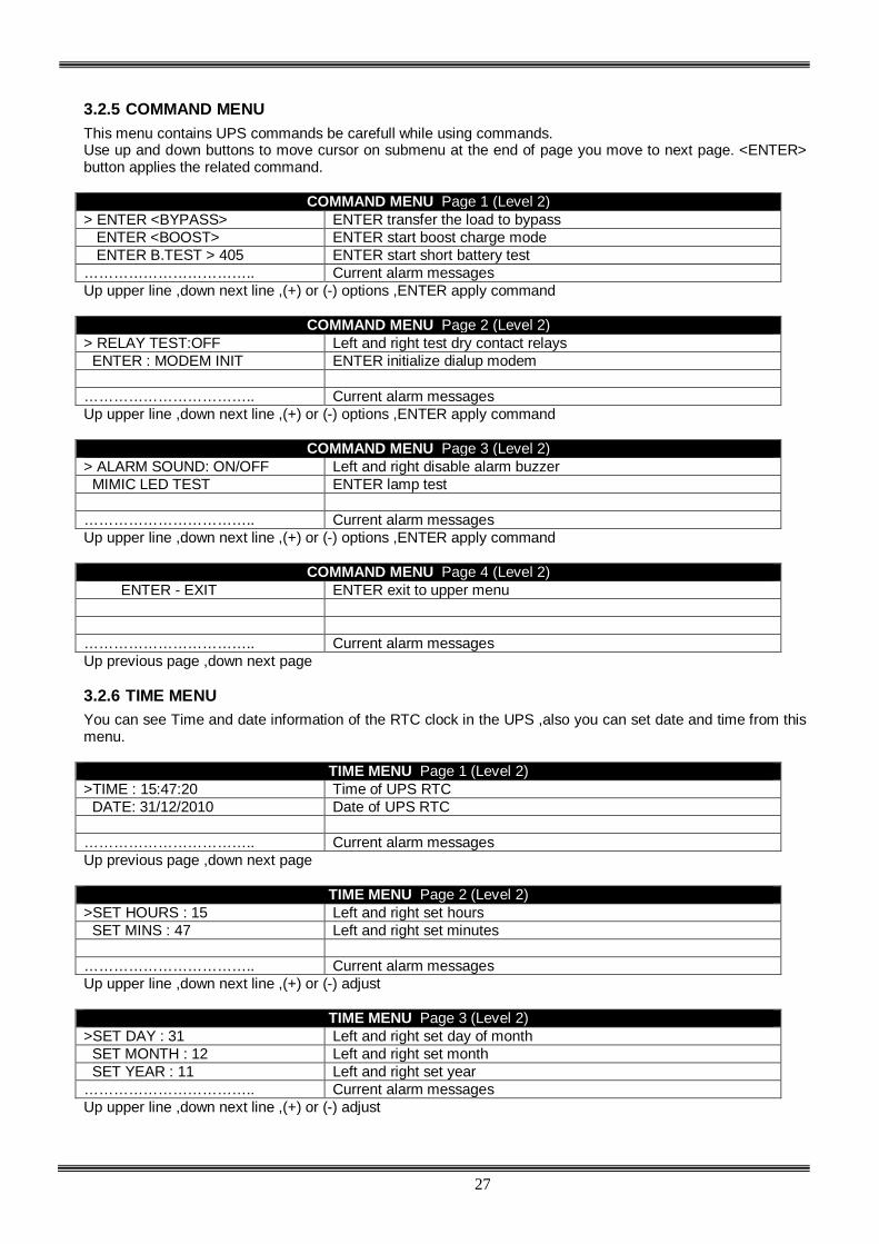
3.2.5 COMMAND MENU This menu contains UPS commands be carefull while using commands. Use up and down buttons to move cursor on submenu at the end of page you move to next page. <ENTER> button applies the related command.
COMMAND MENU Page 1 (Level 2) > ENTER <BYPASS> ENTER transfer the load to bypass ENTER <BOOST> ENTER start boost charge mode ENTER B.TEST > 405 ENTER start short battery test …………………………….. Current alarm messages Up upper line ,down next line ,(+) or (-) options ,ENTER apply command
COMMAND MENU Page 2 (Level 2) > RELAY TEST:OFF Left and right test dry contact relays ENTER : MODEM INIT ENTER initialize dialup modem …………………………….. Current alarm messages Up upper line ,down next line ,(+) or (-) options ,ENTER apply command
COMMAND MENU Page 3 (Level 2) > ALARM SOUND: ON/OFF Left and right disable alarm buzzer MIMIC LED TEST ENTER lamp test …………………………….. Current alarm messages Up upper line ,down next line ,(+) or (-) options ,ENTER apply command
COMMAND MENU Page 4 (Level 2) ENTER - EXIT ENTER exit to upper menu …………………………….. Current alarm messages Up previous page ,down next page 3.2.6 TIME MENU You can see Time and date information of the RTC clock in the UPS ,also you can set date and time from this menu.
TIME MENU Page 1 (Level 2) >TIME : 15:47:20 Time of UPS RTC DATE: 31/12/2010 Date of UPS RTC …………………………….. Current alarm messages Up previous page ,down next page
TIME MENU Page 2 (Level 2)
>SET HOURS : 15 Left and right set hours SET MINS : 47 Left and right set minutes …………………………….. Current alarm messages Up upper line ,down next line ,(+) or (-) adjust
TIME MENU Page 3 (Level 2)
>SET DAY : 31 Left and right set day of month SET MONTH : 12 Left and right set month SET YEAR : 11 Left and right set year …………………………….. Current alarm messages Up upper line ,down next line ,(+) or (-) adjust

28
TIME MENU Page 4 (Level 2) ENTER <UPDATE> ENTER apply new time and date settings …………………………….. Current alarm messages Up previous page ,down next page ,ENTER apply new time and date settings
TIME MENU Page 5 (Level 2)
ENTER - EXIT ENTER exit to upper menu …………………………….. Current alarm messages Up previous page ,down next page 3.2.7 SERVICE MENU This menu contains some helpfull service information and some commands. Use up and down buttons to move cursor on submenu at the end of page you move to next page.
SERVİCE MENU Page 1 (Level 2) >HOURMETER:00075 Total operating hour of the UPS MAXLOAD:015 020 025 % From power on recorded maximum power ENTER<FAULT RESET> ENTER fault reset …………………………….. Current alarm messages Up upper line ,down next line
SERVİCE MENU Page 2 (Level 2) FAN MAINT: 01000 Remaining hours to FAN maintenance BAT MAINT :01200 Remaining hours to battery maintenance GEN.MAINT: 00500 Remaining hours to general maintenance …………………………….. Current alarm messages If maintenance counters are disabled CANCEL word is shown.
SERVİCE MENU Page 3 (Level 2) >LOGOUT: -- ENTER Exit from service login status …………………………….. Current alarm messages Up previous page ,down next page ,ENTER Logout from login status
SERVİCE MENU Page 4 (Level 2) ENTER - EXIT ENTER to EXIT from menu and return to upper level
…………………………….. current alarms appears sequentially 3.2.8 ADJUST MENU This menu is prepared for service purposes there is no user adjustable parameter in this menu.

29
3.2.9 USER PASSWORD Some commands or some option selections are required user password, if menu position is required password window comes to screen and UPS asks for user password. If you lost user password our service personnel will recover your user password. User password is 4 digits numbers, move cursor with left and right buttons, select digit and adjust the number with up and down buttons. Do this for all digits and if password is typed completely press ENTER button if the password is correct A43 USER LOGIN message will be shown on the LCD panel of the UPS.
Password screen -USER PASSWORD- *************** * 1234 * ***************
The password giren as an illustration . only authorized service personel has the useful password. 3.3 Alarms and warning messages
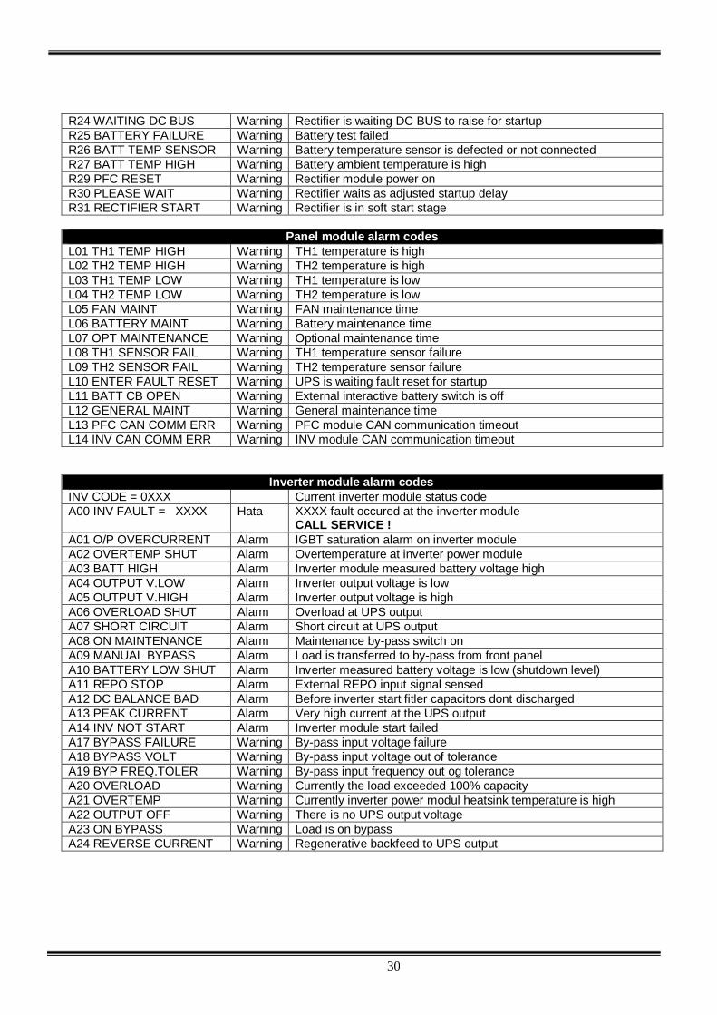
The internal structure of the LION Series UPS is modular, these are: -PFC Rectifier module -Inverter module -Front panel module Module alarms and warnings are cathegorized according to modules at the front of the Alarm or warning message module information is added: -RXX Rectifier alarms and warnings -AXX Inverter alarms and warnings -LXX LCD front panel alarms and warnings More then one alarm can be shown on the UPS front panel with time shared order. If 4 alarms are occurred at the same time every 2 seconds 1 message will be showed, next 2 seconds 2.message will be showed etc.. If A00 or R00 Alarm is shown on the LCD panel we understand that there is a system fault at the related module. We saw the message in the A00 INV FAULT = XXXX or R00 PFC FAULT = XXXX format. Numbers shown in X determines the status code which tells the problem to us. See status code table for details of codes.
Rectifier module alarm codes
REC CODE = XXXX XXXX SYSTEM fault occured at the rectifer module R00 REC FAULT = XXXX Fault Rectifier AC input voltage is high
CALL SERVICE ! R01 AC INPUT HIGH Alarm Rectifier AC input voltage is low R02 LINE FAILURE Alarm Rectifier DC output voltage is high R03 DC BUS HIGH Alarm The rectifier DC output voltage is high, rectifier stop R05 FREQ TOLER Alarm Rectifier input frequcny out of tolerant R06 OVERTEMPERATURE Alarm Rectifier heatsink temperature high R07 BLACKOUT Alarm Short voltage blackout at rectifier AC input R08 I/P OVERCURRENT Alarm Rectifier IGBT saturation alarm R09 ROTATE PHASE Alarm Rectifier input phase sequency incorrect R14 PFC MANUAL STOP Alarm Inverter module stopped rectifier R15 DC LOW Alarm DC BUS voltage is lower then DC rectifier start voltage R17 BATTERY TEST Warning Currently battery test is performing R18 BOOST CHARGE Warning Currently rectifier is in boost charge mode R19 AC HIGH Alarm AC Peak voltage is bigger then 20% of nominal range R20 INPUT CB OPEN Warning Input CB is off R21 PFC STOP Warning Currently Rectifier module stop R22 POS CHG LIMIT Warning (+)Battery charge current limited R23 NEG CHG LIMIT Warning (-)Battery charge current limited
30
R24 WAITING DC BUS Warning Rectifier is waiting DC BUS to raise for startup R25 BATTERY FAILURE Warning Battery test failed R26 BATT TEMP SENSOR Warning Battery temperature sensor is defected or not connected R27 BATT TEMP HIGH Warning Battery ambient temperature is high R29 PFC RESET Warning Rectifier module power on R30 PLEASE WAIT Warning Rectifier waits as adjusted startup delay R31 RECTIFIER START Warning Rectifier is in soft start stage
Panel module alarm codes
L01 TH1 TEMP HIGH Warning TH1 temperature is high L02 TH2 TEMP HIGH Warning TH2 temperature is high L03 TH1 TEMP LOW Warning TH1 temperature is low L04 TH2 TEMP LOW Warning TH2 temperature is low L05 FAN MAINT Warning FAN maintenance time L06 BATTERY MAINT Warning Battery maintenance time L07 OPT MAINTENANCE Warning Optional maintenance time L08 TH1 SENSOR FAIL Warning TH1 temperature sensor failure L09 TH2 SENSOR FAIL Warning TH2 temperature sensor failure L10 ENTER FAULT RESET Warning UPS is waiting fault reset for startup L11 BATT CB OPEN Warning External interactive battery switch is off L12 GENERAL MAINT Warning General maintenance time L13 PFC CAN COMM ERR Warning PFC module CAN communication timeout L14 INV CAN COMM ERR Warning INV module CAN communication timeout
Inverter module alarm codes INV CODE = 0XXX Current inverter modüle status code A00 INV FAULT = XXXX Hata XXXX fault occured at the inverter module
CALL SERVICE ! A01 O/P OVERCURRENT Alarm IGBT saturation alarm on inverter module A02 OVERTEMP SHUT Alarm Overtemperature at inverter power module A03 BATT HIGH Alarm Inverter module measured battery voltage high A04 OUTPUT V.LOW Alarm Inverter output voltage is low A05 OUTPUT V.HIGH Alarm Inverter output voltage is high A06 OVERLOAD SHUT Alarm Overload at UPS output A07 SHORT CIRCUIT Alarm Short circuit at UPS output A08 ON MAINTENANCE Alarm Maintenance by-pass switch on A09 MANUAL BYPASS Alarm Load is transferred to by-pass from front panel A10 BATTERY LOW SHUT Alarm Inverter measured battery voltage is low (shutdown level) A11 REPO STOP Alarm External REPO input signal sensed A12 DC BALANCE BAD Alarm Before inverter start fitler capacitors dont discharged A13 PEAK CURRENT Alarm Very high current at the UPS output A14 INV NOT START Alarm Inverter module start failed A17 BYPASS FAILURE Warning By-pass input voltage failure A18 BYPASS VOLT Warning By-pass input voltage out of tolerance A19 BYP FREQ.TOLER Warning By-pass input frequency out og tolerance A20 OVERLOAD Warning Currently the load exceeded 100% capacity A21 OVERTEMP Warning Currently inverter power modul heatsink temperature is high A22 OUTPUT OFF Warning There is no UPS output voltage A23 ON BYPASS Warning Load is on bypass A24 REVERSE CURRENT Warning Regenerative backfeed to UPS output

31
A25 INV RESET Warning Inverter module power on A26 BATTERY LOW Warning Batteries are going to full discharge A27 GENERATOR MODE Warning Generator set is running A28 O/P PHASE LOSS Warning Anyone of the UPS output phases there is no voltage A29 SYNCHRON BAD Warning Inverter is not synchron to by-pass input A30 SHORT CIRCUIT Warning Short circuit occured at the UPS output currenty normal A31 OUTPUT SWITCH Warning Output switch of the UPS is off A32 SERVICE LOGIN Warning Service login active A34 BYP ROTATE PHASE Warning By-pass phase sequency incorrect A35 INV STOP Warning Inverter module interrupted A36 INV DC DOWN Warning DC BUS voltage is less then 120 volts DC A37 AC CURR LIMIT Warning Inverter output current limited A38 FUSE FAILURE Warning Any fuse in UPS is blowned A39 PSP FAILURE Alarm Inverter control board power supply out of tolerant A40 INVERTER START Warning Inverter is in soft start stage wait for finish A43 USER LOGIN Warning User logged in to UPS A45 SERV.PASSWORD Fault For UPS startup service password required
If any alarm shown on the LCD panel without A00 and R00 message UPS will start automatically if the conditions are normal. But if you see A00 or R00 code with any alarm together you must CALL SERVICE ! If the message is warning UPS continues to run there is no problem. To support technical service status cods are used, each status code tells different event to us.

32
3.4 Alarm messages and quick troubleshooting Alarm codes and messages are showed at the 4.line of the LCD panel various messages tells different events at some messages user can make some simple controls and they can decide that they must call service or not. NOTE : If R00 REC FAULT = XXXX or A00 INV FAULT = XXXX message is shown on the LCD panel the other alarm or warning messages will not be shown. R00 REC FAULT = XXXX Call service R01 AC INPUT HIGH The input voltage of the UPS is very high check the AC input voltage if really high wait until the voltage is normal. R02 LINE FAILURE The input voltage of the UPS is very low ,check the AC input voltage if the input voltage is low wait until the AC input voltage is normal. R03 DC BUS HIGH Call service R05 FREQ TOLER The AC input voltage frequency of the UPS is out of tolerance wait until the input frequency is normal. R06 OVERTEMPERATURE Overtemperature at rectifier module call service. R07 BLACKOUT There is a short blackout at the AC input voltage of the UPS, this is temporary wait until the AC input voltage is normal. R08 I/P OVERCURRENT Call service R09 ROTATE PHASE The phase sequency at the UPS input is reverse please refer to a technical personnel to provide correct phase sequency R14 PFC MANUAL STOP This message shows that rectifier is stopped for any alarm reason check the other alarm shown together with this alarm. R15 DC LOW DC BUS voltage or battery voltage is very low wait 10 minutes then call service R17 BATTERY TEST For 30 seconds UPS is performing battery test at the end of the test UPS decides batries are OKEY or not, then UPS returns to normal operation automatically. R18 BOOST CHARGE For 10 hours boost charge mode is activated from UPS, at the end of 10 hours UPS returns to normal charge mode R19 AC HIGH The AC input votage of the UPS is 20% higher then nominal input votage, wait until the AC input voltage is normal.

33
R20 INPUT CB OPEN The input of the UPS is isolated from mains power with contactor ,this message will be shown with another alarm always. Check the other alarm code. R21 PFC STOP Rectifier is stopped itself wait it must start again, another alarm code shows the reason of the rectifier stop. Wait for 1 minute if alarm continues call service. R22 POS CHG LIMIT, R23 NEG CHG LIMIT This message is normal if the battery charge current is rached to limit value during battery charge. R24 WAITING DC BUS The DC BUS voltage of the UPS is not enough to startup wait 2 minutes if message continues call service. R25 BATTERY FAILURE At the last battery test one or more defected batteries found, call service. R26 BATT TEMP SENSOR Battery temperature sensor mulfunction, call service. R27 BATT TEMP HIGH If batteries are located at the outside of the UPS cabinet check battery ambient temperature if hot use air cooling system. If batteries are internal check the UPS ambient temperature if normal call service. L02 TH2 TEMP HIGH, L04 TH2 TEMP LOW UPS TH2 cabinet inside temperature is out of tolerance check the followings: -If UPS air inlets and outlets covred by dust clean -If any material prevents air flow at UPS air inlets or outlets take the material -If UPS ambient temperature is high then 45 C ,use air cooling system L05 FAN MAINT Maintenance due of the cooling fans of the UPS, call service. L06 BATTERY MAINT Maintenance due of the UPS batteries, call service. L08 TH1 SENSOR FAIL, L09 TH2 SENSOR FAIL TH1 or TH2 temperature measurement sensors are defected, call service. L10 ENTER FAULT RESET Call service L11 BATT CB OPEN The battery switch of the UPS is OFF, in this case UPS runs normally but if mains failure alarm occures the output voltage of the UPS shutdown. Please turn ON the battery switch. L12 GENERAL MAINT Maintenance due of the general maintenance, call service. L13 PFC CAN COMM ERR Call service. L14 INV CAN COMM ERR Call service. A00 INV FAULT = XXXX Call service.

34
A01 O/P OVERCURRENT Check the new load which are connected to UPS nowadays the total load power maybe exceeds maximum power of the UPS. Otherwise call service. A02 OVERTEMP SHUT Inverter modüle heatsink temperature is out of tolerance check the followings: -If UPS air inlets and outlets covred by dust clean -If any material prevents air flow at UPS air inlets or outlets take the material -If UPS ambient temperature is high then 45 C, use air cooling system A03 BATT HIGH DC BUS voltage or battery voltage of the UPS is high, if inductive load is used this event sometimes occures if alarm continues call service. A04 OUTPUT V.LOW The output voltage of the inverter is low call service A05 OUTPUT V.HIGH The output voltage of the inverter is high call service A06 OVERLOAD SHUT The total load which is connected to the UPS is exceeded 100% capacity of the UPS if message continues call service they will check UPS, but probably you need higher power range UPS. Note: Some load inrush curents causes overload event then current is normal. A07 SHORT CIRCUIT There is short circuit at the output of the UPS check installation and loads. A08 ON MAINTENANCE The maintenance by-pas switch of the UPS is ON <1>position, there is a lock on this switch which prevents unauthorized personnel use. A09 MANUAL BYPASS Load is transferred to by-pass from UPS command menu, transfer the load to the inverter. A10 BATTERY LOW SHUT The DC BUS or battery voltage of the UPS is low. If the mains is OKEY call service. If the there is nomains voltage wait until mains OKEY UPS will start automatically. A11 REPO STOP External repo button pressed, to restart turn off and on the UPS A12 DC BALANCE BAD Call service A13 PEAK CURRENT Very high curent measured at the UPS output, check loads A14 INV NOT START Call service A17 BYPASS FAILURE, A18 BYPASS VOLT, A19 BYP FREQ.TOLER The input of the UPS or by-pass input of the UPS voltage or frequency is out of tolerance ,wait until the voltage is normal if message continues long time check input fuses ,switches etc. at the distrubution panel. A20 OVERLOAD UPS is currently running but the load percentage exceede 100% capacity of the UPS ,if this situation continues inverter will stop after a delay.Check the loads at the UPS output.

35
A21 OVERTEMP Inverter module heatsink temperature is highcheck the followings: -If UPS air inlets and outlets covred by dust clean -If any material prevents air flow at UPS air inlets or outlets take the material -If UPS ambient temperature is high then 45 C, use air cooling system A22 OUTPUT OFF During mains failure if the battery backup time is finished this message is normal ,there is no energy so the UPS shutdown the output voltage. If this message is permanent call service, otherwise wait until the message is deleted automatically from LCD screen. A23 ON BYPASS From any reason UPS transferred the load to bypass, check the other alarm code which shown together with this alarm it shows the by-pass reason. If the UPS stays at this position for a long time call service. A24 REVERSE CURRENT Any load such as motorsa are connected to UPS output and the load in regenerative mode ,it is applying reverse energy to the UPS output. Call service A25 INV RESET This is the power on indicator of the inverter modüle, during ower on for 10 seconds this message will be shown at the end of 10 seconds the mesage will be cleared. A26 BATTERY LOW The DC BUS or battery voltage of the UPS is low, still UPS is running but DC voltage is going down. If this alarm occures during mains failure it means that there is no energy from batteries this is normal. But if this alarm occures during mains OKEY call service. A27 GENERATOR MODE UPS is running in generator mode when generator set stops UPS returns to normal operating mode automatically. A28 O/P PHASE LOSS Call service A29 SYNCHRON BAD This is only warning that showa the inverter and by-pass voltages are not synchron to each other ,there is nothing to do wait until they matches. A30 SHORT CIRCUIT Shorter then 4 alternance (40 milliseconds) short circuit occured at theoutput of the UPS, now UPS isrunning but you must check the installation and loads. A31 OUTPUT SWITCH The output switch of the UPS is OFF <0>position, turn on <1>position the output switch A32 SERVICE LOGIN Service ersonnel logged in to UPS this is only warning. A34 BYP ROTATE PHASE The phase sequency of the by-pass source is not match the UPS output phase sequency. Please check the by-pass phase sequency if wrong change phases. A35 INV STOP The message shows that the inverter modüle stopped from any reason ,check the other alarm code which is shown together with this mesage.

36
A36 INV DC DOWN Call service A37 AC CURR LIMIT Alarm shows us the output current is very high (higher then 150%) the UPS limited the output current. This status is temporary but if continues call service. A38 FUSE FAILURE Call service A39 PSP FAILURE Call service A43 USER LOGIN User logged in to UPS this is only warning A45 SERV.PASSWORD Call service , UPS start impossible

37
IV. OPERATING INSTRUCTIONS After all the electrical connections of UPS have been made and while all the circuit breakers and switchtes of the device are turned OFF (at “0” position); 1. Check the polarities of battery connections:
K1 : + V (nominal voltage +360V, float charge voltage +405V) K2-K2 : 0 V (common terminal for ‘’+’’ and ‘’-‘’ battery groups) K3 : - V (nominal voltage -360V, float charge voltage -405V)
2. Check 3-phase AC input and neutral connections (care should be taken fort he phase order). ATTENTION!!! TWO CABLES FOR EACH BATTERY GROUP SHOULD BE USED FOR EXTERNAL BATTERY CONNECTION, AND THE COMMON POINT CONNECTION SHOULD BE MADE ON K2 TERMİNAL BLOCK!
WARNING ! : UPS should never be operated without neutral connection.
3. Check the output load connections of UPS. 4.2.1 Starting UPS from a completely shut down position: 1. Turn ON S1 (AC Input) switch (switch to ‘’1’’ position)
2. Turn ON S2 (Bypass) switch (switch to ‘’1’’ position)
3. Turn ON S4 (AC Output) switch (switch to ‘’1’’ position) ATTENTION!!! BYPASS VOLTAGE WILL BE CONNECTED TO THE OUTPUT TERMINALS OF UPS WHEN THE ON/OFF SWITCH (S7) IS SWITCHED ON ! 4. Turn on S7 (On/Off) switch (to ‘’1’’ position). LCD panel activates, and ‘’INV RESET” or “PFC RESET’’ message appears on the display meaning that the rectifier starts to operate.
5. A few seconds later red bypass light (L2) on front panel turns off and gren inverter light (L6) turns on. L6 light indicates that the UPS has started normal operation and generating uninterruptable power for the critical load. 6. Turn on S5 switch (to “1” position) to connect the battery group to UPS. 7. UPS is ready and in normal operation now.
4.2.2 Shutting down the UPS After closing all the critical loads supplied by the UPS output: 1. Turn off S4 (AC Output) switch (to ‘’0’’ position). 2. Turn off S7 (On/Off) switch (to ‘’0’’ position). 3. Turn off S5 (Battery) switch (to ‘’0’’ position). 4. Turn off S2 (Bypass) switch (to ‘’0’’ position). 5. Turn off S1 (AC Input) switch (to ‘’0’’ position). After performing the above procedure, UPS is completetely shut-down. In this case PFC rectifier and inverter is not operating and the batteries are not being charged.
4.1 INTRODUCTION
4.2 OPERATING UPS IN ONLINE MODE

38
4.2.3 Switching the UPS from a Normal Operation to Maintenance Bypass Condition 1. Enter COMMANDS menu by using UP and DOWN buttons on front panel during normal operation. Select ENTER<BYPASS> command by using again the UP and DOWN buttons and pres ENTER button. The critical load is transferred to bypass supply in this case and it is shown at LCD display with “A09 MANUAL BYPASS” message. Besides L6 (load on UPS) light on front panel will be off and L2 light (bypass) will be on.
2. Turn on S3 (Maintenance Bypass) switch (after unlocking and taking away the padlock on it) to ‘’1’’ position.
3. Turn off S7, S5, S1, S2 and S4 switches (to ‘’0’’ position). In this case, bypass voltage is connected directly to the output of UPS and the critical load is supplied via maintenance bypass switch. No AC or DC supply is connected to the inside and the circuits of UPS. 4.2.4 Switching the UPS from a Maintenance Bypass Condition to Normal Operation 1. Turn on S1 (AC Input) switch (to ‘’1’’ position).
2. Turn on S2 (Bypass) switch (to ‘’1’’ position).
3. Turn on S4 (AC Output) switch (to ‘’1’’ position).
4. Turn on S7 (On/Off) switch (to ‘’1’’ position). LCD panel activates, and main menu will appear at the display. Also “A08 ON MAINTENANCE” message shown and the inverter will not start yet.
5. Turn off S3 (Maintenance Bypass) switch (to ‘’0’’ position). Inverter will start automatically following the turning off of S3 switch.
6. Connect the batteries by turning on S5 (Battery) switch (to ‘’1” position). Now UPS is ready for uninterruptable operation.
When the mains voltage is not available " R02 LINE FAILURE " message appears on LCD display. Sound warning on and off is heard at the same time. UPS continues to supply the critical loads by converting the battery voltage to AC voltage and provides operation without data losses or any other fault. Battery autonomy time may be prolonged by shutting down the unnecessary loads for that moment. But do not turn on these loads again during battery operation. After a short period of time when the line voltage is available again, UPS returns to normal operation automatically and the alarm message on the display disappears. Shut down the critical loads in a period of minimum possible autonomy time (depends on the Ah capacity, charge status, age of the batteries, actual load percentage of UPS and the ambient temperature). Otherwise critical loads will be out of power at the end of battery autonomy time. “A26 BATTERY LOW” message appears first on front panel display during battery operation if battery voltage drops below a defined level. “A10 BATTERY LOW SHUT” message appears on front panel display when the battery voltage drops to the end of discharge voltage and UPS shuts itself down. Critical loads will be out of electrical power. If a reserved generator in the system and if it’s available, that will start to supply the necessary electrical power to UPS input and batteries start to be charged immediately. By means of using UPS together with a immediately available generator system, battery discharge time decreases and so they will be charged quickly after a mains outage.
4.3 UPS Behavior During Mains Outage

39
V. MAINTENANCE
ATTENTION !!! There are no parts inside the UPS or battery group that needs service or maintenance work that should be done by user. Therefore DO NOT OPEN THE COVER OF UPS. Never touch on any terminal of battery group. There is risk of electric shock inside the UPS even when it is completely turned off (because of energy storage components). Therefore unauthorized openning of the UPS cabinet for repairment, maintenance etc. is not recommended and forbidden. Otherwise serious injuries may happen. 5.1 Scheduled Maintenance Some parts and components used inside UPS requires periodic maintenance by service personnel. Besides, some power equipment inside the UPS need good air circulation for cooling functions. In this case, the UPS should be cleaned against dust periodically. Cooling fans are mechanical and moving parts and they should be checked periodically for this reason. Also the batteries should be checked periodically that if they are in good condition or not. LION Series UPS informs the user about these procedures when the maintenance time is up with its 3 independent hour counter as warnings: FAN MAINTENANCE counter BATTERY MAINTENANCE counter GENERAL MAINTENANCE counter This type of protective maintenance prevents small problems turning up to big failures. LION Series UPS has been designed to require very low user maintenance work. User should only make below maintenance procedure for long years of trouble-free operation. 5.2 Daily Checks Observe the UPS daily and check the following: Examine the operator control panel (front panel). Ensure that all LED indicators and parameter measurements are normal and there is no warning or alarm messages on LCD display.
Examine that there is any sign of overheating the UPS or not.
Check the rotation of cooling fans visually.
Check if there is a remarkable change in the sound of UPS or not.
Check if air inlets of the cabinet cooling system are not congested with dust or any other foreign object. Clean them with a vacuum cleaner if any present.
Take care not to leave any object on the UPS cabinet. 5.3 Weekly Checks 1. Examine the front panel and record the results.
2. Measure (from Measurements Menu) each of three phase voltages and record the values.
3. Measure (from Measurements Menu) UPS output current values and record the values.
4. Perform a Manual Battery Test (from Commands Menu) and check the status oft he batteries.
5. Cabinet covers may be cleaned with a soft damped (not wet) cloth.

40
Take notes if possible when you are examining the UPS. Compare the notes with previous ones and try to determine if there is a change or not. If there is a difference between the previous notes and the new ones, search for and record any new load added to UPS output between two records and the magnitude, place and type of the new load, if possible. This information may help to technical authority who will search for the cause of event in case of a failure. If there is a remarkable difference between the records without any obvious reason, call technical service immediately. 5.4 Annual Maintenance Annual maintenance by authorized service should be done at least two times a year in order to provide safe and efficient operation your UPS and battery group. UPS generates a warning message when the maintenance time has expired. 5.5 Storage Conditions and Transportation of UPS 1- Check battery charge status by performing a manual battery test before living the UPS in a storage place. If charge level is not high enough, leave the UPS for at least 12 hours to charge the batteries. 2- Disconnection oft he cables should be done by an authorized service personnel. 3- Batteries should be recharged once every 6 months during storage. 4- Store the UPS and the batteries in a cool and dry place. Ideal storage temperature for UPS: 0 0C to 40 0C max. Ideal storage temperature for batteries:10 0C to 35 0C max. 5- UPS should be fixed on its pallet for transporting. It should be carried by a forklift with ist pallet.

41
VI. FAULTS AND TROUBLESHOOTING 6.1 General Procedure For Fault Checking And Troubleshooting UPS contains complicated electronic control circuits. In order to locate any fault occurring circuits, an advanced knowledge about the circuitry and its operation principles must be known. The aim of this section is to give the knowledge required at the first intervention. There is no practical way to locate any possible fault. Most of the faults do not occur as a performance decrement. Generally, the UPS operates normally or switches into by-pass mode. But in order to determine any change in load or the system the parameters must be recorded regularly as mentioned previously. Generally, the output voltage can deviate %2 from the predefined values. If values differ more than this percentage then reasons must be investigated. The following general structure must be systematically followed while trying to indicate the error: Fault determination: First step is to record the messages, indicator panel LEDs, operating parameter values and last status of switches. This must be done before Fixing interventions: After recording all indications, check the meaning of the fault and alarm messages using “The operator control indicator panel”. If anything related, follow the related procedure. Reporting the fault: Service personal must clearly report the work done. Hence, if any other error occurs there will be enough information to fix it. 6.2 Before Calling Service Please check and note the following: 1- Did you read the user manual carefully and applied the procedures accordingly?
2- Are the switches and circuit breakers of UPS in their normal position?
3- Is there electric power at the UPS line connection distribution panel?
4- Did you turn the battery switch on (to “1“ position) when UPS started to operate in normal mode?
5- Which of the warning lights on front panel is (are) on?
6- Is there any change in the load level at the output of UPS?
7- Did any overload condition happen or not?

42
VII. UPS REMOTE MONITORING AND CONTROL
Following external connections are available for LION Series UPSs.
Communication by serial port connection. Dry contact (interface board) connections. Remote monitoring panel. Using one of above communication options is satisfactory for remote monitoring and control in most of the systems. But in some systems may use 2 or 3 of above options at the same time. In this case accessories group produced by Tescom may help to make appropriate solutions. 7.1 Using Serial Port Two serial communication port is included on LION Series UPS cabinet (com1 and com2). Both of them may be used for user communication. But in service status duty of com2 port is changed and set as service port in Options Menu. All data of UPS can be accessed by this communication way. All the voltage and current values measured by UPS, alarms, warning and status messages can be monitored. Because the communication system is designed in an interactive manner, UPS may get commands from monitoring and control units. These commands are listed below: Switch to BYPASS Switch to INVERTER SOUND on/off Adjust UPS time and date Quick BATTERY TEST BATTERY TEST until battery low alarm CANCEL battery test Turn off UPS output voltage immediately (SHUTDOWN) Turn off UPS output voltage after delay (WAITING SHUTDOWN) Turn off UPS output voltage (SHUTDOWN) and turn on UPS output voltage (WAITING RESTART) CANCEL SHUTDOWN RENAME UPS These commands are evaluated only if REMOTE CNTRL: ON option is selected in OPTİONS/COMMUNICATION OPTIONS menu and if user password is sent from this (com2) port. Otherwise UPS doesn’t perform these commands and only information can be obtained from the ports. Special softwares are required in order to use the serial communication ports. Some of the commands above have special functions and they can only be activated and used by operating TMON program groups on a PC that is serially connected to UPS. TMON program group includes softwares developed by SINERCOM. Additionally, remote monitoring and control is provided in every kind of operating systems, by using worldwide known and continuously devoloping software programs. These softwares can be supplied from SINERCOM. 7.2 Serial Communication Port Connection Cable The maximum length for RS232 communication cable should be 25 meters. For remote panel and UPS connection the same pin configuration is valid. Connection terminals of RS232 cable is shown below for com1 and com2 ports:
UPS Side Panel Side 9 Tx 2 Rx 7 Gnd 5 Gnd 6 Rx 3 Tx

43
7.3 Modem Connection A LION Series UPS can be controlled through a normal telephone line by means of a remote operator connected through a PC with modem device, who performs a phone call to the UPS connected number. So the operator can see all parameters and control the UPS (if permitted from OPTIONS MENU). 7.3.1 Hardware Configuration All requirements for modem connection are as follows: PC with modem WINDOWS 98 Available UPS control software (T-MON) NULL modem which is connected to UPS UPS has its command set to set NULL modem to auto answer mode. In order to do this, press ENTER button for 3 seconds in ENTER: MODEM INIT item in COMMAND MENU after the hardware is installed. A short beep sound warning is heard after pressing the buton. RX and TX lights of the connected modem activates. Modem is set after this to answer external calls by telephone line. To test this, call the telephone number that the modem is connected with another phone and listen the modem sound. NOTE : Not all the modems are compatible with the command set on UPS. In such a case modem should be set by connecting a PC. 7.3.2 Functioning Principle The remote operator, by means of a PC and a modem device and using the remote connection function of the control software, calls the UPS through the number to which this is connected. The NULL modem device, connected to the UPS, will answer the call and convert the data coming from UPS’s serial port on to the telephone line. This way all measurements and controls allowed by the RS232 serial port can be carried out. 7.3.3 Modem Programming Procedure Smart modem (SM) is the one connected to PC, and NULL Modem (NM) is the one connected to the UPS. Standard Hayes AT programming language is the suitable language for modems. In usual applications a modem which uses AT command set should be selected. 7.3.3.1 Smart Modem (SM) Programming The connected modem to PC (smart modem) will be programmed from UPS control software (T-Mon) automatically. B0 E1 F1 M1 Q0 V1 X3 BAUD = 2400 PARITY = N WORDLEN = 8 DIAL = TONE (TONE which can be programmed) &A3 &B1 &C1 &D0 &H1 &I0 &K1 &M4 &N0 &R2 &S0 &T5 &Y1

44
7.3.4 Modem – UPS Connection Cable
Connection of Smart Modem device to UPS is made with standard modem cable and it’s supplied as standard accessory for smart modem. This cable is required if an external modem will be used, and not necessary for internal modems.
Connection cable between NULL Modem and UPS should be installed as follows:
UPS DB9 Female
MODEM DB25 Male
6 3 7 7 9 2
7.4 Dry Contact (Interface) Connections
Some important events of the UPS can be monitored or controlled by these connections. These functions are listed below:
Terminal 2 teractive battery circuit breaker drive output or programmable alarm relay output 4 Interactive battery circuit breaker position sense input 6 enerator operation sense input 8 Remote Emergency Power Off button input (REPO) 10 External TH1 temperature sensor input -12 Function programmable relay contact output 2 -14 Function programmable relay contact output 3 -16 Function programmable relay contact output 4
ATTENTION: Maximum 42Vac or 60Vac voltage may be applied to the dry contacts of the interface. Dry contact relay outputs are NO (Normally Open) type, ie. the relay is not activated if alarm is not present and the contacts are open circuit.
7.5 Remote Monitoring Panel Connection of UPS
This panel is used to control and monitor UPS remotely up to 400 m. distance from it. Panel is located in monitoring and control room. If the distance is not longer than 25 m. RS232, if longer RS485 communication protocol is used. RS485 requires additional adapter.
Remote monitoring panel communicates UPS in a serial way and transfers information to user. Remote panel requires 220Vac 50Hz supply voltage and it is recommended to get this supply from UPS output.
Battery Circuit
Breaker
Generator input
Repo input
TH1 Sensor
Relay 2
Relay 3
Relay 4

45
VIII. EFFICIENT USAGE OF UPS IN TERMS OF ENERGY CONSUMPTION
Products should be used according to the conditions and procedures defined in the manual. When this is made the most efficient usage of the product is guaranteed.
1. Energy efficiency means, decreasing consumed energy amount to the minimum level possible in everystep of living activities, without a decrease in quality or amount of produced work or product, and keeping this principle permanent.
An efficiency value is said in operation of every energy consuming device. Roughly, efficiency can be defined as the ratio of work or power -we obtain- at the output of a system, to that of -we give- at the input of same system.
Keeping below recommendations during the selection and operation of an electric powered product, provide more useful, economical and long-lasting usage in terms of energy efficiency. Therefore, user profits economically, as well as supporting to create a cleaner environment and protecting our world sources.
2. Every electric powered device is designed appropriate to a defined power level. Device capacity shouldbe selected according to its load requirement for an efficient operation.
3. Ensure to operate your device in convenient electrical conditions defined in technical specificationstable. It will work more efficiently in those conditions.
4. Check that operating environment is compatible to defined conditions.
5. Check if the place of installation is suitable as per the conditions mentioned in the relevant section of themanual.
6. By means of the periodically maintenance work, faulty or unefficient components of the device may bedetected before the major failures. This results in more efficient operation and prevention of failures.
7. Usage of recyclable materials is one of a remarkable keys to more efficient energy consumption in total.Users should dispose the expired recyclable materials (batteries, electronic components etc.) according to local directions and laws.
Sinercom srl Headquarter: Via G. Cappalonga 9/A- 00043 Ciampino (Rm)
(Italy) tel. +39.06.79800323 fax +39.06.79814644
Factory: Via Cascina Secchi 247/4b - 24040 Isso (BG) tel. +39.0363.938231 fax +39.0363.998235