Embed Size (px)
Citation preview

DSP based Vector Control of Induction Motors
Bpra073, Bpra076

2008-10-10SUN Dan
College of Electrical Engineering, Zhejiang University 2
Introduction
For many years, induction motors have been preferred for a variety of industrial applications because of their robust and rugged construction.
Until a few years ago, the induction motor could either be plugged directly into the grid (uncontrolled) or controlled by means of the well-known scalar volts per Hertz (V/f) method.
In variable speed drives, both methods have serious drawbacks in the areas of efficiency, reliability, and electromagnetic interference (EMI).

2008-10-10SUN Dan
College of Electrical Engineering, Zhejiang University 3
IntroductionWith the uncontrolled method, even a simple change in the reference speed is not possible.Additionally, its system integration depends highly on the motor design (i.e., starting torque vs. maximum torque, torque vs. inertia, number of pole pairs, etc).
The scalar V/f method is able to provide speed variation, but this method cannot provide real-time control.
In other words, the system response is only satisfactory at steady state and not during transient conditions.
This results in excessive current and over-heating, which necessitate the drive to be oversized.
This over-design no longer makes the motor cost effective due to the high cost of the drive circuitry.

2008-10-10SUN Dan
College of Electrical Engineering, Zhejiang University 4
Introduction
By using real-time processors such as the LF2407 DSPcontroller, and with an accurate induction motor model, the development of highly reliable and accurate variable speed motor drives becomes possible.
With the advent of field-oriented control (FOC) schemes, induction motors can be made to operate similar to separatelyexcited dc motors.
The indirect field oriented controls, or vector control, for speed and torque controlled AC drives are becoming the industrystandard in order to obtain high dynamic motor performance.

2008-10-10SUN Dan
College of Electrical Engineering, Zhejiang University 5
Introduction
The control algorithm explained in this chapter is a rotor fluxfield-orientated control strategy.
In this chapter, we will go through not only the implementationof the control software, but also the theoretical and practicalaspects of the vector control.
In the end, the reader will be familiar with the different parts of the FOC strategy of the induction motor as well as the developmental steps involved.
The reader should also be able to apply this induction motor drive solution to other desired systems.

2008-10-10SUN Dan
College of Electrical Engineering, Zhejiang University 6
Three-Phase Induction Motor
Three-phase induction machines are asynchronous machines that operate below the synchronous speed when motoringand above the synchronous speed when generating.
They are the most popular machine used in industry today and are rugged and require very little maintenance.

2008-10-10SUN Dan
College of Electrical Engineering, Zhejiang University 7
Three-Phase Induction Motor
Compared to dc motors, induction motors are not as easy to control.
They typically draw large starting currents, about six to eight times their full load values, and operate with lagging power factor when loaded.
However, with the advent of the vector control concept for motor control, it is possible to decouple the torque and the flux, thus making the control of the induction motor very similar to that of the dc motor.

2008-10-10SUN Dan
College of Electrical Engineering, Zhejiang University 8
Induction Motor Construction
The dc motor can be called a conduction motor because the electric power is conducted directly to the armature through the brushes and commutator.
In the case of induction motors, the rotor receives power by induction;
the same way a secondary of a two-winding transformer receives power from the primary.
This is why the induction motor can be treated as a rotating transformer, where the primary winding is stationary, but the secondary is free to rotate.
We use this concept to develop the equivalent circuit for induction motors.

2008-10-10SUN Dan
College of Electrical Engineering, Zhejiang University 9
Induction Motor Construction
The most popular type of induction motor used is the squirrelcage induction motor
Short-circuited rotor bars of the squirrel cage induction motor.

2008-10-10SUN Dan
College of Electrical Engineering, Zhejiang University 10
Induction Motor Construction
The rotor consists of a laminated core with parallel slots for carrying the rotor conductors, which are usually heavy bars of copper, aluminum, or alloys.
One bar is placed in each slot; or rather, the bars are inserted from the end when the semi-closed slots are used. The rotor bars are brazed, electrically welded, or bolted to two heavy and stout short-circuiting end-rings, thus completing the squirrel cageconstruction. The rotor bars are permanently short circuited on themselves. The rotor slots are usually not parallel to the shaft, but are given a slight angle, called a skew, which increases the rotor resistance due to increased length of rotor bars and an increase in the slip for a given torque. The skew is also advantageous because it reduces the magnetic hum while the motor is operating and reduces the locking tendency, or cogging, of the rotor teeth.

2008-10-10SUN Dan
College of Electrical Engineering, Zhejiang University 11
Operation
When the three-phase stator windings are fed by a three-phase supply, a magnetic flux of a constant magnitude rotating at synchronous speed is created inside the motor.
Due to the relative speed between the rotating flux and the stationary conductors, an electromagnetic force (EMF) is induced in the rotor in accordance with Faraday’s laws of electromagnetic induction.
The frequency of the induced EMF is the same as the supply frequency, and the magnitude is proportional to the relative velocity between the flux and the conductors.
The direction of this EMF is given by Fleming’s right-hand rule.

2008-10-10SUN Dan
College of Electrical Engineering, Zhejiang University 12
Operation
Since the rotor bars form a closed path, a rotor current is produced which, according to Lenz’s law, is opposite to that of the relative velocity between the rotating flux and the conductors. Therefore, the rotor current develops in the same direction as the flux and tries to catch up with the rotating flux.

2008-10-10SUN Dan
College of Electrical Engineering, Zhejiang University 13
Slip
The difference between the synchronous speed ωe and the actual speed ωr of the motor is called the slip.

2008-10-10SUN Dan
College of Electrical Engineering, Zhejiang University 14
Voltage Equations of the Idealized Motor Model
The idealized circuit model of the three-phase induction machine is shown

2008-10-10SUN Dan
College of Electrical Engineering, Zhejiang University 15
Voltage Equations of the Idealized Motor Model
Stator voltage equations:
Rotor voltage equations:

2008-10-10SUN Dan
College of Electrical Engineering, Zhejiang University 16
Voltage Equations of the Idealized Motor Model
Flux linkage equations:
where:

2008-10-10SUN Dan
College of Electrical Engineering, Zhejiang University 17
Voltage Equations of the Idealized Motor Model
The stator-to-stator and rotor-to-rotor winding inductances are:

2008-10-10SUN Dan
College of Electrical Engineering, Zhejiang University 18
Voltage Equations of the Idealized Motor Model
The stator-to-rotor mutual inductances are dependent on the rotor angle:
where:Lls = Stator winding leakage inductance per phaseLss = Self inductance of stator windingLsm= Peak value of stator to rotor mutual inductance Lsr = Peak value of stator to rotor mutual inductance

2008-10-10SUN Dan
College of Electrical Engineering, Zhejiang University 19
Voltage Equations of the Idealized Motor Model
We can see that the idealized machine is described by sixfirst-order differential equations; one for each winding.
These differential equations are coupled to one another by the mutual inductances between the windings.
The stator-to-rotor coupling terms are a function of the rotor position, so when the rotor rotates, the coupling terms changewith time.
To solve this problem, induction motor equations are transferred to the quadrature rotating reference frame such that the mutual inductances are not time dependent.
2008-10-10SUN Dan
College of Electrical Engineering, Zhejiang University 20
Reference Frame Theory
Reference frame theory is an integral part of electric drives.
Reference frames are powerful tools for the analysis and application of sophisticated control techniques,
particularly in the case of the three-phase induction and synchronous machines.
Using reference frame theory, it is possible to transform the machine phase variables to another reference frame.
By judicious choice of the reference frames, it is possible to considerably reduce the complexity of the model machine.

2008-10-10SUN Dan
College of Electrical Engineering, Zhejiang University 21
Reference Frame Theory
Reference frame theory has become especially important for digital motor control where the need for accurate but simple motor models is essential.
Though the theory can be extended to any arbitrary reference frame, the two most commonly used reference frames are the Stationary Reference Frame and the Synchronous Reference Frame.
The Clarke and Park transformations are used to transfer the induction motor equations to these frames.
The transformations are discussed before in detail and are repeated here for reference.

2008-10-10SUN Dan
College of Electrical Engineering, Zhejiang University 22
Reference Frame Theory
Clarke’s transformation is given by
where

2008-10-10SUN Dan
College of Electrical Engineering, Zhejiang University 23
Reference Frame Theory
Park’s Transformation is represented by
where the rotor position is given by

2008-10-10SUN Dan
College of Electrical Engineering, Zhejiang University 24
Model in the Arbitrary q-d-0
As mentioned previously, the two most common reference frames chosen to represent the induction motor are the stationary and the synchronous reference frames.
The stationary reference frame has the q-d-0 variables of the machine in the same frame as those normally used for the supply network.
In the case of the synchronously rotating reference frame, the q-d-0 variables are constants at steady state.

2008-10-10SUN Dan
College of Electrical Engineering, Zhejiang University 25
Model in the Arbitrary q-d-0
Assuming that the induction motor is rotating at speed ω in the direction of rotor rotation, the machine equations in the stationary reference frame can be obtained by setting ω = 0.
Likewise, the equations in the synchronous reference frame are obtained by setting ω = ωe.

2008-10-10SUN Dan
College of Electrical Engineering, Zhejiang University 26
Model in the Arbitrary q-d-0
Applying transformation to the stator windings a-b-c voltages, the stator winding q-d-0 voltages in the arbitrary reference frame are obtained.
Applying the transformation to the rotor voltage equation, we get:
2008-10-10SUN Dan
College of Electrical Engineering, Zhejiang University 27
Model in the Arbitrary q-d-0
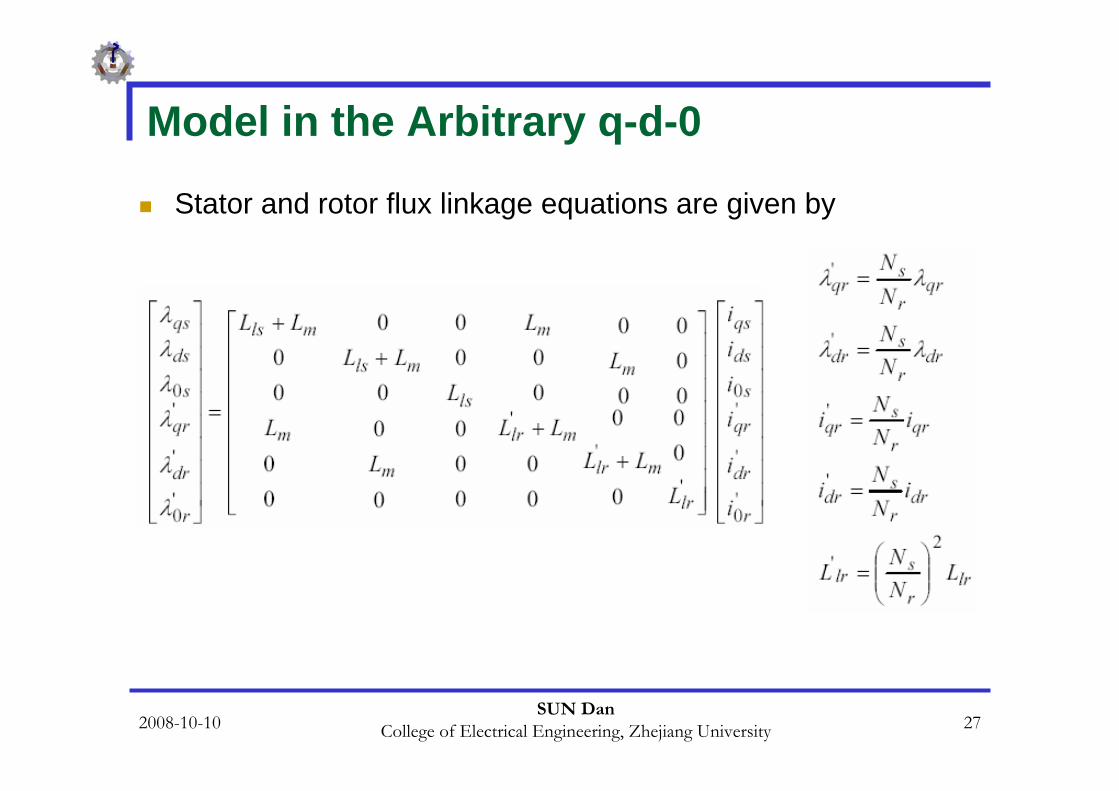
Stator and rotor flux linkage equations are given by

2008-10-10SUN Dan
College of Electrical Engineering, Zhejiang University 28
Model in the Arbitrary q-d-0
Magnetizing inductance on the stator side is given by
The electromagnetic torque equation is given by
2008-10-10SUN Dan
College of Electrical Engineering, Zhejiang University 29
Field Oriented Control
The term “vector” control refers to the control technique that controls both the amplitude and the phase of ac excitation voltage.
Vector control therefore controls the spatial orientation of the electromagnetic fields in the machine.
This has led to the coining of the term field oriented control (FOC), which is used for controllers that maintain a 90o
spatial orientation between the critical field components.

2008-10-10SUN Dan
College of Electrical Engineering, Zhejiang University 30
Field Oriented Control
The term “field angle control” refers to the control strategy where the system is not at 90o of spatial orientation.
In order to properly comprehend vector control, we must understand the principle of dc machine torque control on which FOC is based.

2008-10-10SUN Dan
College of Electrical Engineering, Zhejiang University 31
DC Machine Torque Control
The required 90o of spatial orientation between key field components can be compared to the dc motor, where the armature winding magnetic field and the filed winding magnetic filed are always in quadrature.
The objective is to force the control of the induction machine to be similar to the control of a dc motor, i.e., torque control.
In dc machines, the field and the armature winding axes are orthogonal to one another, making the MMFs established orthogonal.
If the iron saturation is ignored, then the orthogonal fields can be considered to be completely decoupled.

2008-10-10SUN Dan
College of Electrical Engineering, Zhejiang University 32
DC Machine Torque Control
For dc machines, the developed torque is
whereka = Constantψ(If) = Field fluxIa = Armature current
Since the torque angle is always 90o, the flux and the torque can be controlled independently. The torque is controlled by adjusting the field current If, and the fluxis directly controlled by adjusting the armature current Ia.

2008-10-10SUN Dan
College of Electrical Engineering, Zhejiang University 33
DC Machine Torque Control
It is important to maintain a constant field flux for good torque control.
It is also important to maintain an independently controlled armature current in order to overcome the effects of the resistance of the armature winding, leakage inductance, and the induced voltage.
A spatial angle of 90o between the flux and MMF axes has to be maintained in order to limit interaction between the MMF and the flux.

2008-10-10SUN Dan
College of Electrical Engineering, Zhejiang University 34
DC Machine Torque Control
If these conditions are met at every instant of time, the torquewill always follow the current.
In the case of dc machines, there is constant field flux and 90o
torque angle due to the commutator and the separate field excitation system.
In ac machines, these conditions have to be attained by using external controls, making the system more complex and difficult to understand.

2008-10-10SUN Dan
College of Electrical Engineering, Zhejiang University 35
FOC, Direct and Indirect Approaches
With vector control, the mechanically robust induction motorscan be used in high performance applications where dc motors were previously used.
The key feature of the control scheme is the orientation of the synchronously rotating q-d-0 frame to the rotor flux vector.
The d-axis component is aligned with the rotor flux vector and regarded as the flux-producing current component.
On the other hand, the q-axis current, which is perpendicular to the d-axis, is solely responsible for torque production.

2008-10-10SUN Dan
College of Electrical Engineering, Zhejiang University 36
FOC, Direct and Indirect Approaches
In order to apply a rotor flux field orientation condition, the rotor flux linkage is aligned with the d-axis. we can obtain the field oriented condition.

2008-10-10SUN Dan
College of Electrical Engineering, Zhejiang University 37
FOC, Direct and Indirect Approaches
We can find out that in this case controls the rotor flux linkage and controls the electromagnetic torque.
The reference currents of the q-d-0 axis are converted to the reference phase voltages as the commanded voltages for the control loop.
Given the position of the rotor flux and two-phase currents, this generic algorithm implements the instantaneous direct torque and flux control by means of coordinate transformations and PI regulators,
thereby achieving accurate and efficient motor control.

2008-10-10SUN Dan
College of Electrical Engineering, Zhejiang University 38
FOC, Direct and Indirect Approaches
In asynchronous drives, the mechanical rotor angular speed is not, by definition, equal to the rotor flux angular speed.
This implies that the necessary rotor flux position cannot be detected directly by the mechanical position sensor provided with the asynchronous motor explained here.
It is clear that for implementing vector control we have to determine the rotor flux position.
Two basic approaches to determine the rotor flux position angle have evolved.

2008-10-10SUN Dan
College of Electrical Engineering, Zhejiang University 39
FOC, Direct and Indirect Approaches

2008-10-10SUN Dan
College of Electrical Engineering, Zhejiang University 40
FOC, Direct and Indirect Approaches
The direct scheme shown in Figure (a), electrically determines the rotor flux position from measurements using field angle sensors.
The indirect scheme illustrated in Figure (b), measures the rotor position and utilizes the slip relation to compute the angle of the rotor flux relative to the rotor axis.
From the feasibility point of view, implementation of the direct method is difficult if not sometimes impossible.
Therefore, in this chapter, the indirect method is considered as a solution for implementing FOC.

2008-10-10SUN Dan
College of Electrical Engineering, Zhejiang University 41
FOC, Direct and Indirect Approaches
The indirect method is based on the calculation of the slip speed ,required for correct field orientation.
It is proven that we can control torque and field by ids and iqs in the excitation frame.
However, in the implementation of field-oriented control, we need to know ids and iqs in the stationary reference frame.
So, we have to know the angular position of the rotor flux to transform ids and iqs from the excitation frame to the stationaryframe.

2008-10-10SUN Dan
College of Electrical Engineering, Zhejiang University 42
FOC, Direct and Indirect Approaches
By using , and using actual rotor speed, the rotor flux position is obtained.
or

2008-10-10SUN Dan
College of Electrical Engineering, Zhejiang University 43
FOC, Direct and Indirect Approaches
In literature, the algorithm of finding rotor flux position using the calculated and measured or is called the Current Model Method.
The Current Model takes ids and iqs as inputs as well as the rotor mechanical speed and gives the rotor flux position as an output.

2008-10-10SUN Dan
College of Electrical Engineering, Zhejiang University 44
FOC, Direct and Indirect Approaches
Following Figure shows the block diagram of the vector control strategy in which speed regulation is possible using a control loop.

2008-10-10SUN Dan
College of Electrical Engineering, Zhejiang University 45
FOC, Direct and Indirect Approaches
The absence of the field angle sensors, along with the ease of operation at low speeds, has increased the popularity of the indirect vector control strategy.
While the direct method is inherently the most desirable scheme, it suffers from the unreliability in measuring the flux.
Although the indirect method can approach the performance of the direct measurement scheme, its major weakness is the accuracy of the control gain, which heavily depends on the motor parameters.

2008-10-10SUN Dan
College of Electrical Engineering, Zhejiang University 46
FOC, Direct and Indirect ApproachesAs shown in the Figure, two-phase current feeds the Clarke transformation block. These projection outputs are indicated as and .
These two components of the current provide the inputs to Park’s transformation, which gives the currents in the excitation reference frame.
The and components, which are outputs of the Park transformation block, are compared to their reference values , the flux reference, and , the torque reference.
The torque command, , comes from the output of the speed controller.
The flux command, , is the output of the flux controller which indicates the right rotor flux command for every speed reference.

2008-10-10SUN Dan
College of Electrical Engineering, Zhejiang University 47
FOC, Direct and Indirect ApproachesFor we can use the fact that the magnetizing current is usually between 40 and 60% of the nominal current.
For operating in speeds above the nominal speed, a field weakening section should be used in the flux controller section.
The current regulator outputs, and , are applied to the inverse Park transformation.
The outputs of this projection are and , which are the components of the stator voltage vector in the orthogonal reference frame.
They form the inputs of the SVPWM block. The outputs of this block are the signals that drive the inverter.

2008-10-10SUN Dan
College of Electrical Engineering, Zhejiang University 48
FOC, Direct and Indirect Approaches
Note that both the Park and the inverse Park transformations require the exact rotor flux position, which is given by the current model block.
This block needs the rotor resistance or rotor time constant as a parameter. Accurate knowledge of the rotor resistance is essential to achieve the highest possible efficiency from the control structure. Lack of this knowledge results in the detuning of the FOC.
In the Figure, a SVPWM has been used to emulate and in order to implement current regulation.

2008-10-10SUN Dan
College of Electrical Engineering, Zhejiang University 49
Simulation Results for the IM Control System
The drive system with the proposed control strategy has been simulated prior to laboratory experimentation.
For simulation purposes, software packages such as Matlab/SimulinkTM and Advanced Continuous Simulation Language (ACSL)TM can be used.
In this section, SimulinkTM has been used to model the induction motor, the vector control, and the SVPWM.

2008-10-10SUN Dan
College of Electrical Engineering, Zhejiang University 50
Simulation Results for the IM Control System
The induction motor has been simulated with the dynamic q-d-0 model using the nominal parameters.

2008-10-10SUN Dan
College of Electrical Engineering, Zhejiang University 51
Simulation Results for the IM Control System
The dc link voltage in the simulation is equal to 100V.
Maximum phase current has been limited to the rated value.
Initially, the magnetizing current is set at 60% of the rated current.

2008-10-10SUN Dan
College of Electrical Engineering, Zhejiang University 52
Simulation Results for the IM Control System
(a) reference speed, (b) actual speed, (c) load torque, (d) electromagnetic torque, (e) stator d-axis current in the rotating reference frame, (f) stator q-axis current in the rotating reference frame, (g) phase-A current.

2008-10-10SUN Dan
College of Electrical Engineering, Zhejiang University 53
Induction Motor Speed Control System
Based on the previous analysis, an induction motor speed control system is developed.
The total control system consists of the induction motor, the power electronics converter, the sensor, and the controller.

2008-10-10SUN Dan
College of Electrical Engineering, Zhejiang University 54
Power Electronic Converter
the power electronics converter in induction motor control system consists of two parts: a front-end rectifier and a three-phase full bridge inverter in the right-hand side.
The rectifier usually is a full-bridge diode. In case of a regenerative system, a power switch rectifier is used.The inverter is usually responsible for both the electronic commutation and current regulation.
Pulse-width-modulated current controllers are typically used to regulate the actual machine currents to match the sinusoidal current reference waveforms.

2008-10-10SUN Dan
College of Electrical Engineering, Zhejiang University 55
Power Electronic Converter
The power hardware used to implement and test the induction motor drive system can support an input voltage of 1200 V and a maximum current of 50 A.
The hardware is based on six power IGBTs (SKM 50GB 123D), driven by the DSP controller via the integrated driver SKHI22.
The power and the control components are insolated from one another by the use of opto-couplers in the gate drive signal path.

2008-10-10SUN Dan
College of Electrical Engineering, Zhejiang University 56
Sensors
Two types of sensors for the induction motor control system are used. One is a current sensor and the other is a position sensor.
The phase current sensing is performed via two current sensors supplied with ±15V. Their maximum input currents can be changed by the number of turns in the primary winding, and the output is a bipolarvoltage.

2008-10-10SUN Dan
College of Electrical Engineering, Zhejiang University 57
Sensors-position
Encoders or resolvers serve as the position sensor because every point of the rotor position is needed to synchronize the rotor with the stator excitation.
the structure of an optical encoder:

2008-10-10SUN Dan
College of Electrical Engineering, Zhejiang University 58
Sensors-position
It consists of a light source, a radially slotted disk and photoelectric sensors.
The disk rotates with the rotor. The two photo sensors detect the light passing through the slotsin the disk.
When the light is hidden, a logic “0” is generated by the sensors.
When the light passes through the slots of the disk, a logic “1”is produced.

2008-10-10SUN Dan
College of Electrical Engineering, Zhejiang University 59
Sensors-position
These logic signals are shown :
By counting the number of pulses, the motor speed can be calculated.The direction of rotation can be determined by detecting the leading signal between signal A and signal B.

2008-10-10SUN Dan
College of Electrical Engineering, Zhejiang University 60
Controller
The controller of the induction motor control system is used to read the feedback current and position signals, to implement the speed or torque control algorithm, and to generate the gate signals based on the control signal.
We have used the LF2407 as a controller.

2008-10-10SUN Dan
College of Electrical Engineering, Zhejiang University 61
Controller
The interface of the LF2407:
Two quadrature counters detect the rising and falling edges of the encoder signals. Two input channels related to the 10-bit Analog-to-Digital Converter (ADC) are selected to read the two-phase currents.The pins PWM1 to PWM6 output the gating signals to the gate drive circuitry.

2008-10-10SUN Dan
College of Electrical Engineering, Zhejiang University 62
Implementation of FOC of Induction Motor

2008-10-10SUN Dan
College of Electrical Engineering, Zhejiang University 63
Implementation of FOC of Induction Motor
Some practical aspects of implementation:
The software organization, the utilization of different variables, and the handling of the DSP controller resources are described.
In addition, the control structure for the per-unit model is presented.
Next, some numerical considerations have been made in order to address the problems inherent within fixed-point calculation.

2008-10-10SUN Dan
College of Electrical Engineering, Zhejiang University 64
Some practical aspects of implementation:
As described, current model is one of the most important blocks in the block diagram of IM VC system.
The inputs of this block are the currents and mechanical speed of rotor.
Two sections of this chapter deal with technical points that should be considered during current and speed measurement, as well as their scaling.
Implementation of FOC of Induction Motor

2008-10-10SUN Dan
College of Electrical Engineering, Zhejiang University 65
Some practical aspects of implementation:
Also, there are some points to be noted during development of the current model in software; therefore, one section is dedicated to current model implementation.
A PI controller is used in the field oriented speed control of the induction motor as a regulator for current and speed control.
The PI structure and block diagram are presented in another section.
Implementation of FOC of Induction Motor

2008-10-10SUN Dan
College of Electrical Engineering, Zhejiang University 66
Software Organization
The body of the software consists of two main modules: the initialization module and the PWM Interrupt Service Routine (ISR) module.
The initialization model is executed only once at startup. The PWM ISR module interrupts the waiting infinite loop when the timer underflows. When the underflow interrupt flag is set, the corresponding ISR is served.

2008-10-10SUN Dan
College of Electrical Engineering, Zhejiang University 67
Software Organization
The complete FOC algorithm is executed within the PWM ISR so that it runs at the same frequency as the switching frequencyor at a fraction of it.
The wait loop could be easily replaced with a user interface.

2008-10-10SUN Dan
College of Electrical Engineering, Zhejiang University 68
Base Values and Per-Unit Model
It is often convenient to express machine parameters and variables of per-unit quantities.
Moreover, the LF2407 is a fixed point DSP, so using a normalized per-unit model of the induction motor is easierthan using real parameters.
In this model, all quantities refer to the base values. Base power and base voltage are selected, and all parameters and variables are normalized using these base quantities.

2008-10-10SUN Dan
College of Electrical Engineering, Zhejiang University 69
Base Values and Per-Unit Model
Although one might violate this convention from time to time when dealing with instantaneous quantities,
the rms values of the rated phase voltage and current are generally selected as the base voltage for the a-b-c variables
while the peak value is generally selected as the base voltage for d-q variables.

2008-10-10SUN Dan
College of Electrical Engineering, Zhejiang University 70
Base Values and Per-Unit Model
The base values are determined from the nominal values:
where , In,Vn and fn are the nominal phase current, the nominal phase to neutral voltage, and the nominal frequency in a star-connected induction motor, respectively.Ib and Vb are the maximum values of the nominal phase current and voltage, is the electrical nominal rotor flux speed, and is the base flux.

2008-10-10SUN Dan
College of Electrical Engineering, Zhejiang University 71
Numerical Considerations
The per-unit model has been developed so that the software representation of speed, current, and flux is equal to 1.0 when the motor has reached its nominal speed under nominal load and magnetizing current.
During transients, the current might reach higher values than the nominal current Ib in order to achieve a short response time.
Also, the motor speed might exceed the nominal speed ( ), andthen every per-unit value might be greater than 1.0.
This fact necessitates foreseeing these situations and determines the most suitable numerical format used for the software.

2008-10-10SUN Dan
College of Electrical Engineering, Zhejiang University 72
The Numerical Format Determination
The numerical format used in the major part of this chapter is as follows:
four bits are dedicated to the integer part, and twelve bits are dedicated to the fractional part.
This numeric format is denoted by Q4.12. The resolution for this format is given by

2008-10-10SUN Dan
College of Electrical Engineering, Zhejiang University 73
The Numerical Format Determination
With the sign extension mode of the LF2407 set, the link between the real quantity and its Q4.12 format representation is illustrated in the following Figure.

2008-10-10SUN Dan
College of Electrical Engineering, Zhejiang University 74
The Numerical Format Determination
The reason for this particular format is that the drive control quantities are, for the most part, not usually greater than fourtimes their nominal values.
In other words, not greater than four when the per-unit model is considered.
Where this is not the case, a different format will be chosen. The selection of a range of [-8,8] ensures that the software values can handle each drive control quantity, not only during steady state operation but also during transient operation.

2008-10-10SUN Dan
College of Electrical Engineering, Zhejiang University 75
The Numerical Format Determination
The Qx.y numeric format uses x bits for the integer part and y bits for the fractional part, so the resolution is .
If z is the per-unit value to implement, then its software value is in Qx.y format.
Care must be taken when performing operations with a generic Qx.yformat. Adding two Qx.y formatted numbers may result in numerical representation overflow. To avoid this kind of problem, one possible solution is to perform the addition in the high side of the Accumulator and set the saturation bit.Another option is to assume that the result will not be out of the maximum range.

2008-10-10SUN Dan
College of Electrical Engineering, Zhejiang University 76
The Numerical Format Determination
The second solution can be used in this implementation if we know that the control quantities do not exceed half of the maximum value in the Q4.12 format.The result can still be represented in the Q4.12 format and directly considered as Q4.12 format, thereby allowing for a higher level of precision.
As far as the multiplication is concerned, the result (in the 32-bit Accumulator) must either be shifted x positions to the left and the least significant word stored or be shifted y positions to the right with the last significant word being stored.
The stored result is in Qx.y format.

2008-10-10SUN Dan
College of Electrical Engineering, Zhejiang University 77
The Numerical Format Determination
Figure shows two Qx.y formatted 16-bit variables that are multiplied by one another.

2008-10-10SUN Dan
College of Electrical Engineering, Zhejiang University 78
The Numerical Format Determination
The result of this multiplication in Qx.y format is represented in gray in the 32-bit Accumulator. Both solutions are depicted.
(1) Left shift and store high accumulator, (2) Right shift and store low accumulator.

2008-10-10SUN Dan
College of Electrical Engineering, Zhejiang University 79
The Numerical Format Determination
Note that in this section there are also constants that cannot be represented by the Q4.12 format.
Operations requiring different formats follow exactly the same process as that explained above.

2008-10-10SUN Dan
College of Electrical Engineering, Zhejiang University 80
Implementation of FOC of IM-Review

2008-10-10SUN Dan
College of Electrical Engineering, Zhejiang University 81
Implementation of FOC of IM-Review
Software Organization two main modules
Base Values and Per-Unit Model per-unit quantities
The Numerical Format DeterminationQ4.12, Q8.8
Current Measurement →

2008-10-10SUN Dan
College of Electrical Engineering, Zhejiang University 82
Current Measurement
The field-oriented control structure requires two-phase currentas inputs.
Here, current transducers sense these two currents. The current sensor output therefore needs to be rearrangedand scaled so that it may be used by the control software in Q4.12 format value. The complete process of acquiring the current is depicted in the following Figure.

2008-10-10SUN Dan
College of Electrical Engineering, Zhejiang University 83
Current Measurement
The output signal of current transducer can be either positiveor negative. This signal must be adjusted by the analog interface into a range of (0,3.3V?) to allow the ADC module to read both positive and negative values. Figure shows the inside of the signal conditioner.
2008-10-10SUN Dan
College of Electrical Engineering, Zhejiang University 84
Current Measurement
The amplifier gain is chosen such that sensing Iabc=Imax results in the absolute value of the amplifier output to be equal to 1.65V.
Note that Imax represents the maximum measurable current, which is not necessarily equal to the maximum phase current.
This information is useful at the point where current scalingbecomes necessary.
The ADC input voltage is now converted into a 10-bit digital value.
The 1.65V analog offset is digitally subtracted from the converted result, thereby giving a signed integer value of the sensed current.

2008-10-10SUN Dan
College of Electrical Engineering, Zhejiang University 85
Current Measurement
The result of this process is shown:

2008-10-10SUN Dan
College of Electrical Engineering, Zhejiang University 86
Current Measurement
Because the variable format is Q4.12, the sensed phase currents must now be expressed with the per-unit model and then be converted into the Q4.12 format.Notice that the per-unit representation of the current is defined as the ratio between the measured current and the base current, andthe maximum current handled by the hardware is represented by the value 512 (?). The per-unit current conversion into the Q4.12 format is achieved by multiplying the sensed current by the following constant:

2008-10-10SUN Dan
College of Electrical Engineering, Zhejiang University 87
Current Measurement
In one single calculation, this constant performs not only the per-unit modeling but also the numerical conversion into Q4.12 format.
When nominal current flows in a motor running at nominal speed, the current sensing and scaling block output is 1000h(equivalent to 1 per-unit).

2008-10-10SUN Dan
College of Electrical Engineering, Zhejiang University 88
Current Measurement
The reader may change the numerical format by amending the numerator value and may adapt this constant to its own current sensing range by recalculating Kcu with its own Imaxvalue.
In this control system, maximum measurable current and base current are Imax = 12A and Ib = 10.7A, respectively.
The constant value is:
Note that Kcu is outside the Q4.12 format range.

2008-10-10SUN Dan
College of Electrical Engineering, Zhejiang University 89
Current Measurement
The most appropriate format to accommodate this constant is the Q8.8 format, which has a resolution of

2008-10-10SUN Dan
College of Electrical Engineering, Zhejiang University 90
Current MeasurementThe block of assembly code below reads and scales the current of phase A.
; Reading and scaling current value of phase ALDP #RESULT2>>7LACL RESULT2 ;Reading A/D result registerRPT #5 ;Shift to right 6 timesSFRAND #0000001111111111bSUB #512 ;Subtracting offset valueLDP #IASACL IALAR AR0, #KcurLT IAMPY * ;Multiplying by coefficient to scale the current valuePACSFLSACH IA,7 ;Save current value in proper variable
2008-10-10SUN Dan
College of Electrical Engineering, Zhejiang University 91
Speed Measurement
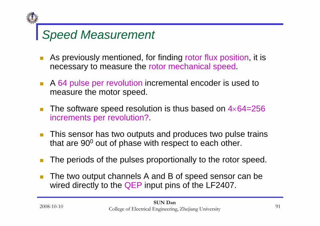
As previously mentioned, for finding rotor flux position, it is necessary to measure the rotor mechanical speed.
A 64 pulse per revolution incremental encoder is used to measure the motor speed.
The software speed resolution is thus based on 4×64=256increments per revolution?.
This sensor has two outputs and produces two pulse trains that are 900 out of phase with respect to each other.
The periods of the pulses proportionally to the rotor speed.
The two output channels A and B of speed sensor can be wired directly to the QEP input pins of the LF2407.
2008-10-10SUN Dan
College of Electrical Engineering, Zhejiang University 92
Speed Measurement
Because a low count encoder is used in the control system, and because this encoder does not have enough resolution at low speeds, the control system uses two methods in order to estimate the induction motor speed.
One method has enough accuracy in the high speed region, above 200 rpm,
and the other has appropriate resolution in the low speed region under 200 rpm.

2008-10-10SUN Dan
College of Electrical Engineering, Zhejiang University 93
Speed Measurement
The first method, which is utilized during high speed, is based on counting the number of encoder pulses in a specific time interval.
However, the second method is based on the measurement of time between two encoder pulses.
Based on the motor speed, the developed program can utilize the advantages of both methods and switch between the two methods based on the actual speed of the motor.

2008-10-10SUN Dan
College of Electrical Engineering, Zhejiang University 94
Speed Estimation during High-Speed Region
As previously mentioned, this method is based on counting the number of encoder pulses in a specified time interval.
The QEP assigned timer counts the number of pulses and records it in the timer counter register (TxCNT).
As the mechanical time constant is much slower than the electrical one, the speed regulation loop frequency might be lower than the current loop frequency.

2008-10-10SUN Dan
College of Electrical Engineering, Zhejiang University 95
Speed Estimation during High-Speed Region
The speed regulation loop frequency is obtained in this program by means of a software counter.
This counter accepts the PWM interrupt as input clock and its period is the software variable called SPEEDSTEP.
The counter variable is named speedstep.
When speedstep is equal to SPEEDSTEP, the number of pulses counted is stored in another variable called np and thus the speed can be calculated.

2008-10-10SUN Dan
College of Electrical Engineering, Zhejiang University 96
Speed Estimation during High-Speed Region
The scheme shows the structure of the speed feedback generator.

2008-10-10SUN Dan
College of Electrical Engineering, Zhejiang University 97
Speed Estimation during High-Speed Region
Assuming that np is the number of encoder pulses in oneSPEEDSTEP period when the rotor turns at the nominal speed, a software constant Kspeed should be chosen as follows:
The speed feedback can then be transformed into a Q4.12 format, which can be used in the control software.

2008-10-10SUN Dan
College of Electrical Engineering, Zhejiang University 98
Speed Estimation during High-Speed Region
In the proposed control system, the nominal speed is 1800 rpm and SPEEDSTEP is set to 125. np can be calculated as follows:
where
Hence Kspeed is given by:

2008-10-10SUN Dan
College of Electrical Engineering, Zhejiang University 99
Speed Estimation during High-Speed Region
Note that Kspeed is out of the Q4.12 format range.
The most appropriate format to handle this constant is the Q8.8 format.
The speed feedback in Q4.12 format is then obtained from the encoder by multiplying np by Kspeed.

2008-10-10SUN Dan
College of Electrical Engineering, Zhejiang University 100
Speed Estimation during High-Speed Region
The flow chart of speed measurement :

2008-10-10SUN Dan
College of Electrical Engineering, Zhejiang University 101
Speed Estimation during High-Speed Region
A portion of the assembly code that measures and scales the rotor speed is given below.
; Start of speed calculation in high speed regionLDP #T2CON>>7LACC T2CNT ;Read counter register of encoder pulse counterSPLK #7FFFh, T2CNT ;Set counter value to 7FFFhSUB #7FFFh ;Subtract 7FFFh from counter read value to omit offsetLDP #Speedtmp ;Save this value in SpeedtmpSACL SpeedtmpLAR AR0, #KspeedLT Speedtmp ;Multiply Speedtmp by Kspeed to find out scaled
;speed valueMPY *PACSACH N,4 ;Save speed value in proper variable in Q4.12 format

2008-10-10SUN Dan
College of Electrical Engineering, Zhejiang University 102
Speed Measurement during Low-Speed Region
To detect the edges of two successive encoder pulses, the developed program can use either the QEP counter or the capture unit input pins. The program has to measure the time between two successive pulses, so it must utilize another GP timer. In this program, Timer 3 has been dedicated to the time measurement.During the interrupt service routine of the capture unit or counter QEP, speed can be calculated. To obtain the actual speed of the motor, the appropriate number is divided by the value in the count register of Timer 3.

2008-10-10SUN Dan
College of Electrical Engineering, Zhejiang University 103
Speed Measurement during Low-Speed Region
As it can be inferred, at very low speeds an overflow may occur in Timer 3.
The counter would then reset itself to zero and start counting up again. This event results in a large error in speed measurement.
To avoid this event, Timer 3 will be disabled in the overflow interrupt service routine.
However, this timer is enabled in the capture unit (counter QEP) interrupt.
2008-10-10SUN Dan
College of Electrical Engineering, Zhejiang University 104
Speed Measurement during Low-Speed Region
The pre-scalar of Timer 3 is set to x/128, giving the input clock a 234375 Hz frequency.
To obtain the speed value in Q4.12 format, 31238×4 (a constant number) is loaded in the accumulator.
This number will be divided by the counter register of Timer 3.

2008-10-10SUN Dan
College of Electrical Engineering, Zhejiang University 105
Speed Measurement during Low-Speed Region
The flow-chart of this implementation is presented :

2008-10-10SUN Dan
College of Electrical Engineering, Zhejiang University 106
The Current Model
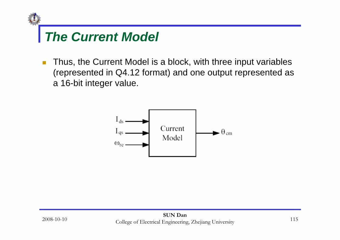
In indirect FOC, the Current Model is used to find the rotor flux position.
This module takes ids and iqs as inputs plus the rotor electrical speed ωre and then calculates the rotor flux position θcm.

2008-10-10SUN Dan
College of Electrical Engineering, Zhejiang University 107
The Current Model
The current model is based on the following equations:

2008-10-10SUN Dan
College of Electrical Engineering, Zhejiang University 108
The Current Model
in transient case, we get:
assume
where im is the magnetizing current, therefore we get:

2008-10-10SUN Dan
College of Electrical Engineering, Zhejiang University 109
In order to find the rotor flux speed, we use the following equation in a per-unit system.
where θ is the rotor flux position and and are the rotor time constant and rotor electrical speed, respectively.
The rotor time constant is critical to the correct functionality of the Current Model. This system outputs the rotor flux speed, which in turn will be integrated to get the rotor flux position.
The Current Model

2008-10-10SUN Dan
College of Electrical Engineering, Zhejiang University 110
The Current Model
Assuming that , we can get the discretizedequations as follows:

2008-10-10SUN Dan
College of Electrical Engineering, Zhejiang University 111
The Current Model
For example, let the constants and be renamed to Ktand Kr, respectively. Here we have:
By knowing the rotor flux speed (fs), the rotor flux position (θcm) is computed by the integration formula in the per-unit system.

2008-10-10SUN Dan
College of Electrical Engineering, Zhejiang University 112
The Current Model
As the rotor flux position range is [0, 2π], 16-bit integer values have been used to achieve the maximum resolution. Figure illustrates the relationship between the flux position and its numerical representation:

2008-10-10SUN Dan
College of Electrical Engineering, Zhejiang University 113
The Current Model
is calledθinc. This variable is the rotor angle variation within one sampling period. At nominal operation θinc. is equal to
. In one mechanical revolution performed at nominal speed, there are increments of the rotor flux position.
Let K be defined as the constant, which converts the [0, 2π] range into the [0, 65535] range. K is calculated as follows:

2008-10-10SUN Dan
College of Electrical Engineering, Zhejiang University 114
The Current Model
Note that here we choose the Q1.15 format for this constant because the maximum value of which is 65535, represents 1 per-unit and the value of θ cannot be greater than 1 per-unit.
With the help of this constant, the rotor flux position computation and its formatting becomes:
2008-10-10SUN Dan
College of Electrical Engineering, Zhejiang University 115
The Current Model
Thus, the Current Model is a block, with three input variables(represented in Q4.12 format) and one output represented as a 16-bit integer value.

2008-10-10SUN Dan
College of Electrical Engineering, Zhejiang University 116
The Current ModelThe code block below shows a portion of the assembly algorithm that determines the rotor flux position.
;start of calculation rotor flux positionLDP #IDS_R ;start of calculation magnetizing currentLACC IDS_RSUB ImrSACL temp1MAR *, AR0LAR AR0, #KrLT temp1MPY *PACSACH temp1,4LACC temp1ADD ImrSACL ImrBCND Imr_Neqz, NEQLACC #0SACL temp1B IQS_Rp

2008-10-10SUN Dan
College of Electrical Engineering, Zhejiang University 117
The Current ModelImr_Neqz: ;if Imr != 0 then start of slip frequency calculation
LACC ImrSACL temp2LACC IQS_RABSSACL temp1LACC temp1,12RPT #15SUBC temp2SACL temp1LACC IQS_RBCND IQS_Rp, GT ;if IQS is negative then change sign of IQS/ImrLACC temp1NEGSACL temp1

2008-10-10SUN Dan
College of Electrical Engineering, Zhejiang University 118
The Current ModelIQS_Rp:
LAR AR0, #KtLT temp1MPY *PACSACH temp1,4LACC temp1ADD N ;add rotor speed to slip frequencySACL fs ;find rotor flux speed end of calculation of
;rotating flux speed

2008-10-10SUN Dan
College of Electrical Engineering, Zhejiang University 119
The Current Model;Start of finding Rotor Flux position by using integral of fs
LACC fsABSSACL temp1LAR AR0, #Kfs ;multiplying fs bu Kfs, a constant value
;to find increment or decrement in rotor flux ;position
LT temp1MPY *PACSACH teta_inc,4bit fs,0BCND fs_neg, TC ;go to fs_neg if teta_inc is negativeLACL teta_incADDS TETASACL TETA ; find new rotor flux position if teta_inc is negativeB fs_pos

2008-10-10SUN Dan
College of Electrical Engineering, Zhejiang University 120
The Current Modelfs_neg
LACL TETASUBS teta_incSACL TETA ;find new roto flux position if teta_inc is positive
fs_pos
; end of finding Rotor flux position

2008-10-10SUN Dan
College of Electrical Engineering, Zhejiang University 121
The PI regulator
An electrical drive based on the Field Orientated Control needs two constants as control parameters: the torque component reference and the flux component reference .
The classical PI regulator is well suited to regulate the torqueand flux feedback to the desired values.
This is because it is able to reach constant references by correctly setting both the proportional term and the integral term
which are, respectively, responsible for the error sensibility and for the steady state error.

2008-10-10SUN Dan
College of Electrical Engineering, Zhejiang University 122
The PI regulator
The numerical expression of the PI regulator is as follows:
which is represented :

2008-10-10SUN Dan
College of Electrical Engineering, Zhejiang University 123
The PI regulator
The limiting point is that during normal operation, large reference value variations or disturbances may occur, resulting in the saturation and overflow of the regulator variables and output.
If they are not controlled, this non-linearity detriments the dynamic performance of the system.
To solve this problem, one solution is to add to the previous structure a correction of the integral component :

2008-10-10SUN Dan
College of Electrical Engineering, Zhejiang University 124
The PI regulator
The PI regulators are implemented with output saturation and integral component correction.
The constants Kpi, Ki, Kcor, proportional, integral, and integral correction components, are selected based on the sampling period and on the motor parameters.
These values should be changed based on the motor speed.

2008-10-10SUN Dan
College of Electrical Engineering, Zhejiang University 125
The PI regulatorTo show the routine of the PI controller in assembly, the following section of code is given:LDP #N_ref ;Start of PI procedureLACC N_ref ;Load reference speedSUB N ;subtract motor speed from reference speed to find errorSACL err_N ;put error in err_NLACC xi_N,12 ;load previous value of PI output controllerLAR AR0, #Kp_N ;start of multiplication Kp*errorLT err_NMPY *APAC ;Add previous output of controller with new value Y(p)=Y(p-1)+Kp*errorSACH Upi_N,4LACC Upi_N ;start of positive saturation value < (max)ABSSUB IQS_RmaxBCND N_sat, GT ;if value is less than (max) go to negative saturationLACL Upi_NB N_LIMIT

2008-10-10SUN Dan
College of Electrical Engineering, Zhejiang University 126
The PI regulatorN_sat
BIT Upi_N, 0 ;start of negative saturation (min)<valueBCND Upi_Ngz, NTC ;if Upi_N is positive, then go to Upi_NgzLACL IQS_RminSACL Upi_NB N_LIMIT
Upi_NgzLACL IQS_RmaxSACL Upi_N

2008-10-10SUN Dan
College of Electrical Engineering, Zhejiang University 127
The PI regulatorN_LIMIT
SACL IQS_R ;start of correction procedureLAR AR0, #Ki_NLT err_NMPY *PACADD xi_N, 12SACH xi_N,4LACC xi_N ;start of saturation on integrator outputABSSUB IQS_RmaxBCND x_sat, GTLACL xi_NB x_LIMIT

2008-10-10SUN Dan
College of Electrical Engineering, Zhejiang University 128
The PI regulatorx_sat
BIT xi_N, 0BCND xi_Ngz, NTC ;if xi_N is positive, then go to xi_NgzLACL IQS_RminSACL xi_NB x_LIMIT
xi_NgzLACL IQS_RmaxSACL xi_N
x_LIMITSACL xi_N
; end of PI procedure

2008-10-10SUN Dan
College of Electrical Engineering, Zhejiang University 129
Calculation of Sine and Cosine Functions
In order to generate the sine and the cosine of an angle, a sine table and indirect addressing mode by auxiliary register AR has been used.
This algorithm and code examples are presented before.

2008-10-10SUN Dan
College of Electrical Engineering, Zhejiang University 130
FOC, Direct and Indirect Approaches
Following Figure shows the block diagram of the vector control strategy in which speed regulation is possible using a control loop.

2008-10-10SUN Dan
College of Electrical Engineering, Zhejiang University 131
flow chart of IM FOC Control
This routine is placed inside the PWM interrupt service routine.

2008-10-10SUN Dan
College of Electrical Engineering, Zhejiang University 132
Experimental Results
In our experiment, the motor has been coupled to a DC generator. The generator can be loaded with an adjustable resistor providing a variables load.
As explained in the previous sections, the flux reference ( ) in the normal speed range has been set at 0.4 per-unit.
To avoid the maximum phase current being greater than 1 per-unit ( ), may not be higher than 0.8 per-unit.
This torque reference limitation is integrated into the control software using the IQS_ref_max constant, which is set to 0CCDh (4.12 format).

2008-10-10SUN Dan
College of Electrical Engineering, Zhejiang University 133
Experimental Results
The following scope captures show the transient and steady state operations:
the load torque, reference speed, motor speed, and phase current of the motor during transient operation.
Before a change of the reference speed, a magnetizing current isapplied to the motor to build the magnetizing flux. By increasing the load, a breaking torque is applied to the motor.
In this figure, the reference speed is 100 rpm and the load torque is 45.5 (lb-in).

2008-10-10SUN Dan
College of Electrical Engineering, Zhejiang University 134
Experimental ResultsStart up, no-load condition, (1) load torque, (2) reference speed 100 rpm, (3)
motor speed, (4) phase current.

2008-10-10SUN Dan
College of Electrical Engineering, Zhejiang University 135
Conclusion
In this chapter, the theory of field-oriented control of induction motors was described.
The structure and organization of software written for the LF2407 DSP controller was also presented.
Some technical points and tools were presented to assist in developing a working model for an induction motor drive.
The modular structure of this presentation and guidelines allow the reader to quickly grasp the aspects of FOC, thereby assisting the reader in developing software for specific needs.

2008-10-10SUN Dan
College of Electrical Engineering, Zhejiang University 136
Reference and reading materials
1. Texas Instruments, Implementation of a Speed Field Orientated Control of Three Phase AC Induction Motor using TMS320LF240, Literature Number: BPRA076, March 1998.
2. Texas Instruments, Field Orientated Control of Three Phase AC-motors, Literature Number: BPRA073, December 1997.


![PowerScan Series OBD II / EOBD II /CAN - pudn.comread.pudn.com/downloads169/doc/comm/776467/CAN-BUS OBD2...② It will display [UIO P-SCAN OBD-CAN], then press the “OK” button](https://img.pdfslide.us/doc/110x75/5faac688d056284f791b1c23/powerscan-series-obd-ii-eobd-ii-can-pudn-obd2-a-it-will-display-uio.jpg)