Embed Size (px)
Citation preview
Ch1
Ch2MODEINPUT
CLIP
LEVEL
Ch3
Ch4
Ch5
Ch6LOHI
MODEINPUT
CLIP
LEVEL
LOHI
MODEINPUT
CLIP
LEVEL
LOHI
96kHz - 24bit
GLADEN DSP6TO8 AEROSPACE
REM +BAT
SUPPLYGNDOUT IN
ON
OFF BTL SE
AUTOSENSE
dB-12
0
dB-12
0
dB-12
0
Ch1
Ch2MODEINPUT
CLIP
LEVEL
Ch3
Ch4
Ch5
Ch6LOHI
MODEINPUT
CLIP
LEVEL
LOHI
MODEINPUT
CLIP
LEVEL
LOHI
96kHz - 24bit
GLADEN DSP6TO8 AEROSPACE
REM +BAT
SUPPLYGNDOUT IN
ON
OFF BTL SE
AUTOSENSE
dB-12
0
dB-12
0
dB-12
0
Ch1
Ch2
Ch3
Ch4
Ch5
Ch6
Ch7
Ch8
SOUND PROCESSOR96kHz - 24bit
OPT OUTOPT INCOAX IN
BT
ST
USB
RCD
AVVERTENZE:
INTERROMPERE IMMEDIATAMENTE L’USO IN CASO DI PROBLEMI. Diversamente s i potrebbero causare danni alla persona o al prodotto. Per riparazioni, rivolgersi ad un rivenditore autorizzato MOSCONI.
NON SMONTARE O MODIFICARE. Tale azione potrebbe causare incidenti, incendi o scosse elettriche. Ogni tipo di manomissione comporta il decadimento immediato della garanzia.
I COLLEGAMENTI E L’ INSTALLAZIONE D E V O N O E S S E R E E F F E T T U AT I D A PERSONALE QUALIFICATO. I collegamenti e l’installazione dell’apparecchio richiedono conoscenze tecniche ed esperienza particolari. Per ragioni di sicurezza, contattare sempre un rivenditore autorizzato per eseguire una corretta installazione del prodotto.
N O N I N S T A L L A R E I N L U O G H I ECCESSIVAMENTE UMIDI O POLVEROSI. Evitare di installare l’apparecchio in luoghi eccessivamente umidi o polverosi. La presenza di umidità o polvere all’interno del prodotto potrebbe causare problemi di funzionamento.
NON INSTALLARE A CONTATTO DI SUPERFICI SENSIBILI AL CALORE. L’amplificatore può raggiungere una temperatura superiore agli 80°, il contatto con superfici e materiali sensibili al calore potrebbe causare incendi o altri danni
N E L L ’ E F F E T T U A R E I F O R I , N O N DANNEGGIARE I TUBI O I CAVI. Nell’effettuare i fori nel telaio per l’installazione, fare attenzione a non entrare in contatto, danneggiare o ostruire i tubi, i condotti della benzina, i serbatoio i cavi elettrici. La non osservanza di queste precauzioni potrebbe causare incendi.
NON OSTRUIRE I CANALI DI VENTILAZIONE. B l o c c a n d o l i s i p o t r e b b e c a u s a r e u n surriscaldamento interno dell’apparecchio che potrebbe dare luogo a incendi.
UTILIZZARE IL PRODOTTO IN VEICOLI CON BATTERIA DA 12 V. Un utilizzo diverso da quello indicato potrebbe causare incendi, scosse elettriche o altri incidenti.
PRIMA DI ESEGUIRE I COLLEGAMENTI, SCOLLEGARE IL CAVO DEL TERMINALE NEGATIVO DELLA BATTERIA. Altrimenti potrebbero derivare scosse elettriche o altre lesioni dovute a cortocircuiti.
E S E G U I R E C O R R E T T A M E N T E I COLLEGAMENTI. Utilizzare cavi di dimensioni adeguate e rispettare tutte le polarità, altrimenti potrebbero derivarne incendi o danni al prodotto.
EVITARE CHE I CAVI SI IMPIGLINO AGLI OGGETTI C IRCOSTANTI . E f fe t t ua re i collegamenti seguendo le istruzioni in modo che i cavi non interferiscano con la guida. I cavi o i fili che interferiscono o si impigliano in parti quali lo sterzo, la leva del cambio, i pedali, ecc. potrebbero essere pericolosi.
SISTEMARE I CAVI IN MODO CHE NON VENGANO PIEGATI O COMPRESSI DA PARTI METALLICHE TAGLIENTI. Per evitare che vengano danneggiati o piegati, sistemare i cavi e i fili lontano da parti mobili (quali le guide dei sedili) o da parti taglienti o aguzze. Se i cavi vengono fatti passare attraverso un foro metallico, utilizzare un anello di gomma per evitare che l’isolante dei cavi venga tagliato dal bordo metallico del foro.
PER ESEGUIRE I COLLEGAMENTI DI TERRA, NON UTILIZZARE BULLONI O DADI DEI SISTEMI DI FRENATA O DI STERZO. Non utilizzare MAI bulloni o dadi dei sistemi di frenata e di sterzo (o di qualsiasi altro sistema di sicurezza), o dei serbatoi per eseguire l’installazione o per i collegamenti di terra. L’utilizzo di queste parti potrebbe inibire il controllo del veicolo e causare incendi o altro.
USARE FUSIBILI DI RICAMBIO DI ADEGUATO AMPERAGGIO. Altrimenti potrebbero derivarne incendi o scosse elettriche.
U T I L I Z Z A R E L E PA RT I A C C E S S O R I E SPECIFICATE E INSTALLARLE IN MODO CORRETTO. Assicurarsi di utilizzare accessori specifici in dotazione.
NON EFFETTUARE ALCUNA OPERAZIONE CHE POSSA DISTOGLIERE L’ATTENZIONE DALLA GUIDA DEL VEICOLO. Qualsiasi operazione che necessita di attenzione prolungata deve essere effettuata solo dopo il completo arresto del veicolo. Arrestare sempre il veicolo in un luogo sicuro prima di effettuare queste operazioni. In caso contrario si potrebbero causare incidenti.
TENERE IL VOLUME AD UN LIVELLO CHE PERMETTA DI UDIRE I RUMORI ESTERNI DURANTE LA GUIDA. Livelli eccessivi di volume, in grado di coprire suoni quali le sirene dei mezzi di soccorso o segnali stradali di attenzione (ad esempio, passaggi a livello, ecc.) possono essere pericolosi e provocare incidenti. Inoltre, l’ascolto di audio ad alto volume in auto può provocare danni all’udito.
ACHTUNG! WARNHINWEISE:
STELLEN SIE DEN GEBRAUCH IM FALLE EINER STÖRUNG EIN. Die Nichteinhaltung kann zu einem Schaden an dem Produkt führen. Für eine Reparatur wenden Sie sich bitte an einen autorisierten MOSCONI Fachhändler.
ZERLEGEN ODER MODIFIZIEREN SIE DAS PRODUKT NICHT: Dies könnte zu Unfällen, Feuer oder elektrischen Schocks führen. Jeglicher Umbau oder Modifikation des Produkts hebt sämtliche Garantieansprüche sofort auf.
DER EINBAU SOWIE DIE VERKABELUNG DES PRODUKTS SOLLTE VON QUALIFIZIERTEM P E R S O N A L A U S G E F Ü H R T W E R D E N . Besonderes technisches Wissen und Erfahrung ist für den Einbau und die Verkabelung dieses Produkts von Nöten. Um die Sicherheit zu wahren, kontaktieren Sie immer einen autorisierten Händler, der dieses Produkt fachgerecht einbaut.
NICHT AN FEUCHTEN ODER STAUBIGEN PLÄTZEN EINBAUEN. Vermeiden Sie den Einbau des Produkts innerhalb übermäßig feuchten oder staubigen Orten. Das eindringen von Feuchtigkeit oder Staub kann zu einem Ausfall führen.
KEINE LEITUNGEN UND KABEL WÄHREND DES BOHRENS VON LÖCHERN BESCHÄDIGEN. Wenn Sie Löcher bohren, vermeiden Sie Beschädigungen. Besonders den Kontakt mit: Leitungen, der Kraftstoffleitung, dem Tank und elektrischen Kabeln. Die Unterlassung dieser Vorsichtsmaßnahmen führt zu einer Feuergefahr.
BLOCKIEREN SIE KEINE ENTLÜFTUNGS Ö F F N U N G E N O D E R H I T Z E S E N K E N D E ELEMENTE. Das Blockieren von Öffnungen oder hitzesenkenden Elementen kann die Temperaturen innerhalb des Verstärkers erhöhen. Dies kann zu Feuer führen.
B E N U T Z E N S I E D I E S E S P R O D U K T AUSSCHLIEßLICH IN FAHRZEUGEN MIT 12V STROMVERSORGUNG. Die Benutzung des Produkts bei anderer Stromstärke als 12V kann zu Feuer, elektrischen Schocks oder Unfällen führen.
K L E M M E N S I E D I E N E G A T I V E BATTERIELEITUNG VOR DEM ANSCHLUSS DES GERÄTS AB. Die Nichterfüllung kann elektrische Schocks oder andere Beschädigungen aufgrund eines Kurzschlusses hervorrufen.
STELLEN SIE SACHGEMÄßE VERKABELUNG SICHER. Um Feuer und Schaden am Produkt zu vermeiden, verwenden Sie passend starke Kabel und achten Sie auf Polarität der Anschlüsse.
VERMEIDEN SIE EIN DURCHEINANDER VON KABELN MIT FAHRZEUGTEILEN. Stellen Sie s a c h g e m ä ß e V e r k a b e l u n g l a u t Bedienungsanleitung sicher, so dass die Kabel den eigentlichen Betrieb eines Fahrzeugs nicht behindern. Kabel, die sich mit Lenkelementen, dem Schalthebel, Pedalen etc. verwickeln können gefährlich sein.
LEGEN SIE DIE KABEL SO AUS, DASS SIE NICHT GEKRÜMMT SIND ODER VON SCHARFEN METALLISCHEN KANTEN EINGEDRÜCKT WERDEN. Um eine Beschädigung und eine Krümmung der Kabel zu vermeiden, verlegen Sie die Kabel weit entfernt von beweglichen Teilen (wie Sitzschienen) und von scharfen und spitzigen Fahrzeugteilen. Falls die Kabel durch ein Loch des Metalls gelegt werden, benutzen Sie einen Gummiring, um zu gewährleisten, dass die Kabelisolation nicht von einer scharfen Kante aufgeschnitten wird.
FÜR EINEN MASSEANSCHLUSS NIEMALS SCHRAUBEN VERWENDEN, DIE ZUM LENK- ODER BREMSSYSTEM GEHÖREN. NIEMALS Schrauben des Lenk- oder Bremssystems (oder anderer Sicherheitssysteme) oder des Tanks verwenden, um einen Masseanschluss herzustellen. Der Gebrauch einer dieser Teile kann die Fähigkeit, das Auto zu steuern, beeinträchtigen und Unfälle, Feuer oder anderen Schaden hervorrufen.
NUTZEN SIE GERÄTESCHUTZSICHERUNGEN M I T H I N R E I C H E N D E R A M P E R E BELASTBARKEIT. Andererseits können Feuer und elektrische Schocks auftreten.
B E N U T Z E N S I E E I N W A N D F R E I E ZUBEHÖRTEILE UND BEFOLGEN SIE DIE INSTALLATIONSANLEITUNG. Benutzen Sie ausschließlich vorschriftsmäßige Zubehörteile. Der Gebrauch anderer Komponenten kann das Produkt beschädigen oder zu einem unsachgemäßen Einbau führen. Komponenten könnten nicht sicher verkabelt sein und eine Fehlfunktion oder Gefahr darstellen.
GEBRAUCHEN SIE DAS PRODUKT NICHT SO, DASS IHRE AUFMERKSAMKEIT VOM FAHREN A B G E L E N K T I S T. J e d e H a n d l u n g , d i e kontinuierliche Aufmerksamkeit verlangt, muss im stehenden Zustand des Fahrzeugs vollzogen werden. Beim Ausführen solcher Handlungen stoppen sie das Fahrzeug immer in einer sicheren Zone. Nichteinhaltung kann Unfälle verursachen.
HALTEN SIE DIE LAUTSTÄRKE AUF EINEM SOLCHEN LEVEL, DER IHNEN ERLAUBT, EXTERNE GERÄUSCHE WÄHREND DES FAHRENS ZU HÖREN. Überhöhte Lautstärkepegel, welche die Sirene von Notfallfahrzeugen, das Geräusch von Eisenbahnen etc. übertönen, können gefährlich sein und Unfälle verursachen. Außerdem kann das sehr laute Musikhören innerhalb eines Fahrzeugs das Gehör schädigen.
WARNING! CAUTION:
IN CASE OF TROUBLE IMMEDIATELY DISCONTINUE USE. Failure to comply may cause injury or damage the product. For repair please contact an authorized MOSCONI dealer.
DO NOT DISASSEMBLE OR MODIFY THE PRODUCT: This action may result in accidents, fire or electric shock. Any alteration or modification to the product immediately voids any expressed or implied warranty.
THE INSTALLATION AND CONNECTION OF THE PRODUCT SHOULD BE PERFORMED BY QUALIFIED PERSONNEL. The installation and connection of the product require specific technical background and experience. . For safety reasons, always contact an authorized dealer to install the product in a correct way.
DO NOT INSTALL IN AREAS PARTICULARY HUMID OR DUSTY. Avoid installing the product in areas excessively humid or dusty. Presence of humidity or dust inside the product can cause malfunction.
WHILE DRILLING HOLES, DO NOT DAMAGE TUBING AND CABLES. While drilling holes in your vehicle during installation, pay close attention to avoid damaging, blocking or contact with: tubing, the fuel lines, the fuel tank and electrical cables. Failure to follow these precautions will pose a fire hazard and damages.
DO NOT OBSTRUCT VENTS OR HEAT SINKING PANELS. Blocking vents or heat sinking panels may cause increased temperatures inside the amplifier. This may cause a fire hazard.
USE THIS PRODUCT EXCLUSIVELY IN VEHICLES WITH 12V POWER. Using the product with electrical power other than 12V may cause fires, electric shock or other accidents.
DISCONNECT THE NEGATIVE (GROUND) BATTERY LEAD BEFORE CONNECTING THE PRODUCT. Failure to do so may cause electric shock or other damage and injury due to short circuit.
ENSURE PROPER CONNECTIONS. To avoid fire hazard and damage to the product, use cables of proper gauge and pay close attention to the polarity of the connections.
AVOID TANGLING THE CABLES TO VEHICLE PARTS. Make proper connections by following the instructions so that the cables do not interfere with proper vehicle operation. Cables that tangle with steering components, gear lever, brake pedals, etc may be dangerous.
LAY OUT THE CABLES TO ENSURE THAT THEY ARE NOT BENT OR COMPRESSED BY SHARP METAL EDGES. To avoid damaging or bending the cables, lay out the cables far from moving parts (such as the seat rails) and from sharp or pointy vehicle parts. If the cables are to pass through a hole in a metal sheet, use a rubber ring to ensure that the cable insulation won't be cut by any sharp edge.
TO ESTABLISH A GROUND CONNECTION DO NOT USE BOLTS THAT BELONG TO THE STEERING OR BRAKING SYSTEM. NEVER use bolts from the steering or braking system (or any other safety system) or the fuel tank to establish a ground connection. Using any of these parts may impair your ability to control the vehicle and cause accidents, fire or other damage.
USE FUSES WITH ADEQUATE AMP RATING. Otherwise there may be fires or electric shock.
USE THE CORRECT ACCESSORY PARTS AND FOLLOW THE INSTALLATION INSTRUCTIONS. Be sure to use only specified accessory parts. Using other components may damage the product or result in improper installation. Components may not be connected securely and cause malfunction or danger.
DO NOT OPERATE THE PRODUCT IN WAYS THAT MAY DISTRACT YOUR ATTENTION FROM DRIVING. Any operation that requires continued attention must be done when the vehicle is at full stop. Always stop the vehicle in a safe area when performing such operations. Failure to do so may cause accidents.
MAINTAIN THE VOLUME AT LEVELS THAT ALLOW EXTERNAL NOISES TO BE AUDIBLE WHILE DRIVING. Excessive volume levels, capable of blocking the sound of emergency vehicles, rail crossings, etc, may be dangerous and cause accidents. Furthermore, listening to audio at high volume inside a vehicle may cause damage to your hearing.
WARNING!DISCONNECT THE BATTERY LEADS BEFORE INSTALLATION, MAINTENANCE OR REMOVAL.
12VWARNING!USE ONLY IN VEHICLES WITH A 12 VOLT NEGATIVE GROUND
-20 ~ 70°C10 ~ 90%
USE
TH
IS S
WIT
CH
for t
his
conf
igur
atio
nD
O N
OT
USE
TH
IS f
or th
is c
onfig
urat
ion
HI LEVEL SIGNAL INPUT
AN
ALO
G C
ON
NE
CTI
ON
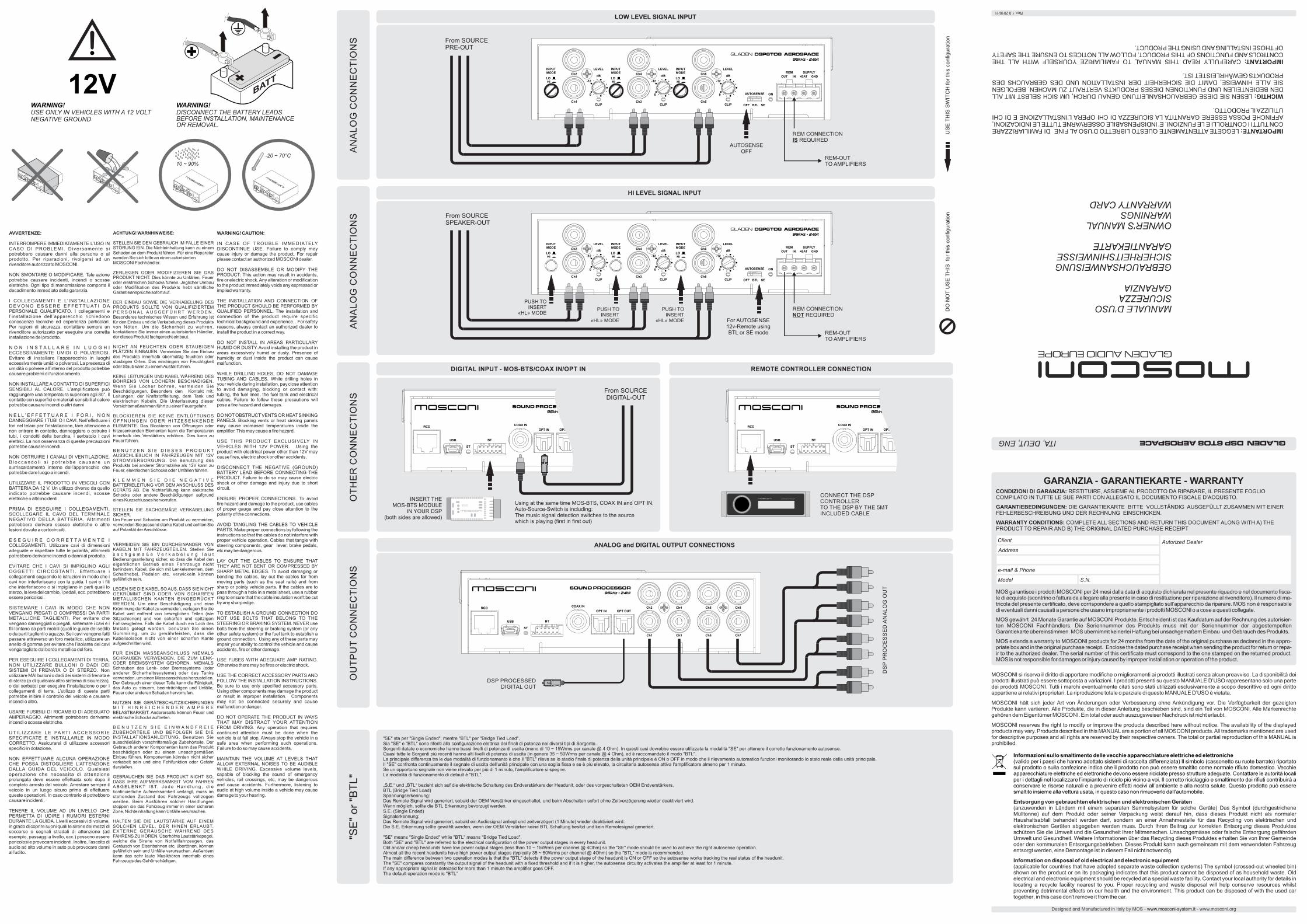
S From SOURCE PRE-OUT
AN
ALO
G C
ON
NE
CTI
ON
S From SOURCE SPEAKER-OUT
PUSH TOINSERT
«HL» MODEPUSH TO
INSERT«HL» MODE
PUSH TOINSERT
«HL» MODE
OTH
ER
CO
NN
EC
TIO
NS
DIGITAL INPUT - MOS-BTS/COAX IN/OPT IN
GLADEN DSP CONTROLLER
CONNECT THE DSP CONTROLLERTO THE DSP BY THE 5MTINCLUDED CABLE
MOS-BTS
INSERT THEMOS-BTS MODULE
IN YOUR DSP(both sides are allowed)
REMOTE CONTROLLER CONNECTION
REM CONNECTIONIS REQUIRED
REM-OUTTO AMPLIFIERS
LOW LEVEL SIGNAL INPUT
From SOURCE DIGITAL-OUT
ANALOG and DIGITAL OUTPUT CONNECTIONS
OU
TPU
T C
ON
NE
CTI
ON
S
DSP PROCESSEDDIGITAL OUT
DS
P P
RO
CE
SS
ED
AN
ALO
G O
UT
"SE" sta per "Single Ended", mentre "BTL" per "Bridge Tied Load".Sia "SE" e "BTL" sono riferiti alla configurazione elettrica dei finali di potenza nei diversi tipi di Sorgente.Sorgenti datate o economiche hanno bassi livelli di potenza di uscita (meno di 10 ~ 15Wrms per canale @ 4 Ohm). In questi casi dovrebbe essere utilizzata la modalità "SE" per ottenere il corretto funzionamento autosense.Quasi tutte le Sorgenti più recenti hanno alti livelli di potenza di uscita (in genere 35 ~ 50Wrms per canale @ 4 Ohm), ed è raccomandato il modo "BTL".La principale differenza tra le due modalità di funzionamento è che il "BTL" rileva se lo stadio finale di potenza della unità principale è ON o OFF in modo che il rilevamento automatico funzioni monitorando lo stato reale della unità principale.Il "SE" confronta continuamente il segnale di uscita dell'unità principale con una soglia fissa e se è più elevato, la circuiteria autosense attiva l'amplificatore almeno per 1 minuto.Se un opportuno segnale non viene rilevato per più di 1 minuto, l'amplificatore si spegne.La modalità di funzionamento di default è "BTL".
„S.E.“ und „BTL“ bezieht sich auf die elektrische Schaltung des Endverstärkers der Headunit, oder des vorgeschalteten OEM Endverstärkers.BTL (Bridge Tied Load)Spannungserkennung:Das Remote Signal wird generiert, sobald der OEM Verstärker eingeschaltet, und beim Abschalten sofort ohne Zeitverzögerung wieder deaktiviert wird.Wenn möglich, sollte die BTL Erkennung bevorzugt werden.S.E. (Single Ended)Signalerkennung:Das Remote Signal wird generiert, sobald ein Audiosignal anliegt und zeitverzögert (1 Minute) wieder deaktiviert wird:Die S.E. Erkennung sollte gewählt werden, wenn der OEM Verstärker keine BTL Schaltung besitzt und kein Remotesignal generiert.
"SE" means "Single Ended" while "BTL" means "Bridge Tied Load".Both "SE" and "BTL" are referred to the electrical configuration of the power output stages in every headunit.Old and/or cheap headunits have low power output stages (less than 10 ~ 15Wrms per channel @ 4Ohm) so the "SE" mode should be used to achieve the right autosense operation.Almost all the recent headunits have high power output stages (typically 35 ~ 50Wrms per channel @ 4Ohm) so the "BTL" mode is recommended.The main difference between two operation modes is that the "BTL" detects if the power output stage of the headunit is ON or OFF so the autosense works tracking the real status of the headunit.The "SE" compares constantly the output signal of the headunit with a fixed threshold and if it is higher, the autosense circuitry activates the amplifier at least for 1 minute.If any appropriate signal is detected for more than 1 minute the amplifier goes OFF.The default operation mode is "BTL”
"SE"
or "
BTL"
Designed and Manufactured in Italy by MOS - - www.mosconi.orgwww.mosconi-system.it
GARANZIA - GARANTIEKARTE - WARRANTY CONDIZIONI DI GARANZIA: RESTITUIRE, ASSIEME AL PRODOTTO DA RIPARARE, IL PRESENTE FOGLIO COMPILATO IN TUTTE LE SUE PARTI CON ALLEGATO IL DOCUMENTO FISCALE D’ACQUISTO.
GARANTIEBEDINGUNGEN: DIE GARANTIEKARTE BITTE VOLLSTÄNDIG AUSGEFÜLLT ZUSAMMEN MIT EINER FEHLERBESCHREIBUNG UND DER RECHNUNG EINSCHICKEN.
WARRANTY CONDITIONS: COMPLETE ALL SECTIONS AND RETURN THIS DOCUMENT ALONG WITH A) THE PRODUCT TO REPAIR AND B) THE ORIGINAL DATED PURCHASE RECEIPT
MOS garantisce i prodotti MOSCONI per 24 mesi dalla data di acquisto dichiarata nel presente riquadro e nel documento fisca-le di acquisto (scontrino o fattura da allegare alla presente in caso di restituzione per riparazione al rivenditore). Il numero di ma-tricola del presente certificato, deve corrispondere a quello stampigliato sull’apparecchio da riparare. MOS non è responsabile di eventuali danni causati a persone che usano impropriamente i prodotti MOSCONl o a cose a questi collegate.
MOS gewährt 24 Monate Garantie auf MOSCONI Produkte. Entscheident ist das Kaufdatum auf der Rechnung des autorisier-ten MOSCONI Fachhändlers. Die Seriennummer des Produkts muss mit der Seriennummer der abgestempelten Garantiekarte übereinstimmen. MOS übernimmt keinerlei Haftung bei unsachgemäßem Einbau und Gebrauch des Produkts.
MOS extends a warranty to MOSCONI products for 24 months from the date of the original purchase as declared in the appro-priate box and in the original purchase receipt. Enclose the dated purchase receipt when sending the product for return or repa-ir to the authorized dealer. The serial number of this certificate must correspond to the one stamped on the returned product. MOS is not responsible for damages or injury caused by improper installation or operation of the product.
Autorized DealerAddress
e-mail & Phone
Client
S.N. Model
MOSCONI si riserva il diritto di apportare modifiche o miglioramenti ai prodotti illustrati senza alcun preavviso. La disponibilità dei prodotti illustrati può essere sottoposta a variazioni. I prodotti presenti su questo MANUALE D’USO rappresentano solo una parte dei prodotti MOSCONI. Tutti i marchi eventualmente citati sono stati utilizzati esclusivamente a scopo descrittivo ed ogni diritto appartiene ai relativi proprietari. La riproduzione totale o parziale di questo MANUALE D’USO è vietata.
MOSCONI hält sich jeder Art von Änderungen oder Verbesserung ohne Ankündigung vor. Die Verfügbarkeit der gezeigten Produkte kann variieren. Alle Produkte, die in dieser Anleitung beschieben sind, sind ein Teil von MOSCONI. Alle Markenrechte gehören dem Eigentümer MOSCONI. Ein total oder auch auszugsweiser Nachdruck ist nicht erlaubt.
MOSCONI reserves the right to modify or improve the products described here without notice. The availability of the displayed products may vary. Products described in this MANUAL are a portion of all MOSCONI products. All trademarks mentioned are used for descriptive purposes and all rights are reserved by their respective owners. The total or partial reproduction of this MANUAL is prohibited.
Informazioni sullo smaltimento delle vecchie apparecchiature elettriche ed elettroniche(valido per i paesi che hanno adottato sistemi di raccolta differenziata) Il simbolo (cassonetto su ruote barrato) riportato sul prodotto o sulla confezione indica che il prodotto non può essere smaltito come normale rifiuto domestico. Vecchie apparecchiature elettriche ed elettroniche devono essere riciclate presso strutture adeguate. Contattare le autorità locali per i dettagli nel localizzare l’impianto di riciclo più vicino a voi. Il corretto riciclaggio e smaltimento dei rifiuti contribuirà a conservare le risorse naturali e a prevenire effetti nocivi all’ambiente e alla nostra salute. Questo prodotto può essere smaltito insieme alla vettura usata, in questo caso non rimuoverlo dall’automobile.
Entsorgung von gebrauchten elektrischen und elektronischen Geräten(anzuwenden in Ländern mit einem separaten Sammelsystem für solche Geräte) Das Symbol (durchgestrichene Mülltonne) auf dem Produkt oder seiner Verpackung weist darauf hin, dass dieses Produkt nicht als normaler Haushaltsabfall behandelt werden darf, sondern an einer Annahmestelle für das Recycling von elektrischen und elektronischen Geräten abgegeben werden muss. Durch Ihren Beitrag zur korrekten Entsorgung dieses Produktes schützen Sie die Umwelt und die Gesundheit Ihrer Mitmenschen. Unsachgemässe oder falsche Entsorgung gefährden Umwelt und Gesundheit. Weitere Informationen über das Recycling dieses Produktes erhalten Sie von Ihrer Gemeinde oder den kommunalen Entsorgungsbetrieben. Dieses Produkt kann auch gemeinsam mit dem verwendeten Fahrzeug entsorgt werden, eine Demontage ist in diesem Fall nicht notwendig.
Information on disposal of old electrical and electronic equipment(applicable for countries that have adopted separate waste collection systems) The symbol (crossed-out wheeled bin) shown on the product or on its packaging indicates that this product cannot be disposed of as household waste. Old electrical and electronic equipment should be recycled at a special waste facility. Contact your local authority for details in locating a recycle facility nearest to you. Proper recycling and waste disposal will help conserve resources whilst preventing detrimental effects on our health and the environment. This product can be disposed of with the used car together, in this case don't remove it from the car.
MANUALE D’USOSICUREZZAGARANZIA
GEBRAUCHSANWEISUNGSICHERHEITSHINWEISSEGARANTIEKARTE
OWNER’S MANUALWARNINGSWARRANTY CARD
IMPORTANTE: LEGGETE ATTENTAMENTE QUESTO LIBRETTO D’USO AL FINE DI FAMILIARIZZARE CON TUTTI I CONTROLLI E LE FUNZIONI. E’ INDISPENSABILE OSSERVARNE TUTTE LE INDICAZIONI, AFFINCHÉ POSSA ESSERE GARANTITA LA SICUREZZA DI CHI OPERA L’INSTALLAZIONE E DI CHI UTILIZZA IL PRODOTTO.
WICHTIG: LESEN SIE DIESE GEBRAUCHSANLEITUNG GENAU DURCH, UM SICH SELBST MIT ALL DEN BEDIENTEILEN UND FUNKTIONEN DIESES PRODUKTS VERTRAUT ZU MACHEN. BEFOLGEN SIE ALLE HINWEISE, DAMIT DIE SICHERHEIT DER INSTALLATION UND DES GEBRAUCHS DES PRODUKTS GEWÄHRLEISTET IST.
IMPORTANT: CAREFULLY READ THIS MANUAL TO FAMILIARIZE YOURSELF WITH ALL THE CONTROLS AND FUNCTIONS OF THIS PRODUCT. FOLLOW ALL NOTICES TO ENSURE THE SAFETY OF THOSE INSTALLING AND USING THE PRODUCT.
ITA, DEUT, ENG
Rev. 1.0 2016/11
GLADEN AUDIO EUROPE
GLADEN DSP 6TO8 AEROSPACE
AUTOSENSEOFF
REM CONNECTIONNOT REQUIRED
REM-OUTTO AMPLIFIERS
For AUTOSENSE12v-Remote usingBTL or SE mode
Using at the same time MOS-BTS, COAX IN and OPT IN, Auto-Source-Switch is including: The music signal detection switches to the source which is playing (first in first out)
12V
LED
RO
SSO
: il D
SP è
infu
nzio
ne.
LED
RO
T: d
er D
SP is
t ein
gesc
halte
t.
LED
RED
:the
DSP
is o
n.
AU
TOSE
NSE
: spo
star
e su
SE
se
l’aut
orad
io n
on h
a te
cnol
ogia
BTL
"SE"
sta
per
"Sin
gle
Ende
d", m
entre
"BTL
" per
"Brid
ge T
ied
Load
".Si
a "S
E" e
"BTL
" son
o rif
eriti
alla
con
figur
azio
ne e
lettr
ica
dei f
inal
i di p
oten
za n
ei d
iver
si
tipi d
i Sor
gent
e.So
rgen
ti da
tate
o e
cono
mic
he h
anno
bas
si li
velli
di p
oten
za d
i usc
ita (m
eno
di 1
0 ~
15W
rms
per c
anal
e @
4 O
hm).
In q
uest
i cas
i dov
rebb
e es
sere
util
izza
ta la
mod
alità
"SE"
pe
r otte
nere
il c
orre
tto fu
nzio
nam
ento
aut
osen
se.
Qua
si tu
tte le
Sor
gent
i più
rece
nti h
anno
alti
live
lli di
pot
enza
di u
scita
(in
gene
re 3
5 ~
50W
rms
per c
anal
e @
4 O
hm),
ed è
racc
oman
dato
il m
odo
"BTL
".La
prin
cipa
le d
iffer
enza
tra
le d
ue m
odal
ità d
i fun
zion
amen
to è
che
il "B
TL" r
ileva
se
lo
stad
io fi
nale
di p
oten
za d
ella
uni
tà p
rinci
pale
è O
N o
OFF
in m
odo
che
il ril
evam
ento
au
tom
atic
o fu
nzio
na il
mon
itora
ggio
del
lo s
tato
real
e de
lla u
nità
prin
cipa
le.
Il "S
E" c
onfro
nta
cont
inua
men
te il
seg
nale
di u
scita
del
l'uni
tà p
rinci
pale
con
una
sog
lia
fissa
e s
e è
più
elev
ato,
la c
ircui
teria
aut
osen
se a
ttiva
l'am
plifi
cato
re a
lmen
o pe
r 1
min
uto.
Se u
n op
portu
no s
egna
le n
on v
iene
rile
vato
per
più
di 1
min
uto,
l'am
plifi
cato
re s
i spe
gne.
La m
odal
ità d
i fun
zion
amen
to d
i def
ault
è "B
TL".
AU
TOSE
NSE
: Ste
llen
Sie
auf
SE
wen
n di
e W
iede
rgab
eque
lle k
ein
BTL
-Ver
stär
ker
ist
„S.E
.“ un
d „B
TL“ b
ezie
ht s
ich
auf d
ie e
lekt
risch
e Sc
haltu
ng d
es E
ndve
rstä
rker
s de
r H
eadu
nit,
oder
des
vor
gesc
halte
ten
OEM
End
vers
tärk
ers.
BT
L (B
ridge
Tie
d Lo
ad) S
pann
ungs
erke
nnun
g:D
as R
emot
e Si
gnal
wird
gen
erie
rt, s
obal
d de
r OEM
Ver
stär
ker e
inge
scha
ltet,
und
beim
Ab
scha
lten
sofo
rt oh
ne Z
eitv
erzö
geru
ng w
iede
r dea
ktiv
iert
wird
. Wen
n m
öglic
h, s
ollte
die
BT
L Er
kenn
ung
bevo
rzug
t wer
den.
S.E.
(Sin
gle
Ende
d) S
igna
lerk
ennu
ng:
Das
Rem
ote
Sign
al w
ird g
ener
iert,
sob
ald
ein
Audi
osig
nal a
nlie
gt u
nd z
eitv
erzö
gert
(1
Min
ute)
wie
der d
eakt
ivie
rt w
ird:
Die
S.E
. Erk
ennu
ng s
ollte
gew
ählt
wer
den,
wen
n de
r OEM
Ver
stär
ker k
eine
BTL
Sc
haltu
ng b
esitz
t und
kei
n R
emot
esig
nal g
ener
iert.
AU
TOSE
NSE
: sw
itch
to S
E, i
f you
r sou
rce
has
not a
BTL
tech
nolo
gy"S
E" m
eans
"Sin
gle
Ende
d" w
hile
"BTL
" mea
ns "B
ridge
Tie
d Lo
ad".
Both
"SE"
and
"BTL
" are
refe
rred
to th
e el
ectri
cal c
onfig
urat
ion
of th
e po
wer
out
put
stag
es in
eve
ry h
eadu
nit.
Old
and
/or c
heap
hea
duni
ts h
ave
low
pow
er o
utpu
t sta
ges
(less
than
10
~ 15
Wrm
s pe
r ch
anne
l @ 4
Ohm
) so
the
"SE"
mod
e sh
ould
be
used
to a
chie
ve th
e rig
ht a
utos
ense
op
erat
ion.
Alm
ost a
ll th
e re
cent
hea
duni
ts h
ave
high
pow
er o
utpu
t sta
ges
(typi
cally
35
~ 50
Wrm
s pe
r cha
nnel
@ 4
Ohm
) so
the
"BTL
" mod
e is
reco
mm
ende
d.Th
e m
ain
diffe
renc
e be
twee
n tw
o op
erat
ion
mod
es is
that
the
"BTL
" det
ects
if th
e po
wer
ou
tput
sta
ge o
f the
hea
duni
t is
ON
or O
FF s
o th
e au
tose
nse
wor
ks tr
acki
ng th
e re
al
stat
us o
f the
hea
duni
t.Th
e "S
E" c
ompa
res
cons
tant
ly th
e ou
tput
sig
nal o
f the
hea
duni
t with
a fi
xed
thre
shol
d an
d if
it is
hig
her,
the
auto
sens
e ci
rcui
try a
ctiv
ates
the
ampl
ifier
at l
east
for 1
min
ute.
If an
y ap
prop
riate
sig
nal i
s de
tect
ed fo
r mor
e th
an 1
min
ute
the
ampl
ifier
goe
s O
FF.
The
defa
ult o
pera
tion
mod
e is
"BTL
”
WA
RN
ING
!U
se p
ower
cab
les
with
a g
auge
that
is a
ppro
pria
te to
the
curr
ent l
oad
and
to th
e le
ngth
of t
he c
able
. The
tabl
e in
this
man
ual i
ndic
ates
the
min
imum
gau
ge fo
r saf
e us
e. W
hene
ver p
ossi
ble,
use
the
larg
est
gaug
e av
aila
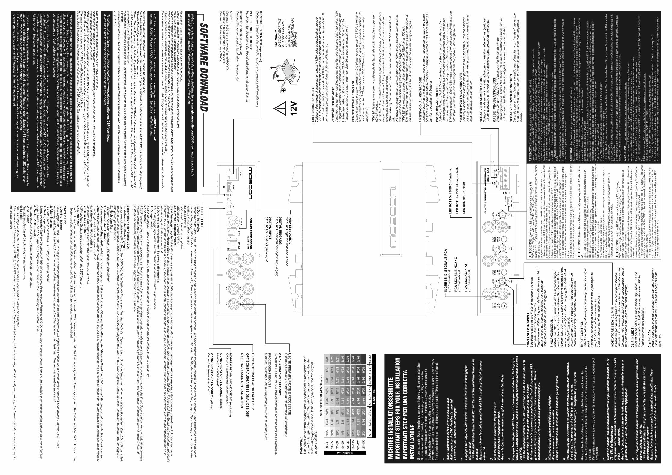
ble. 14/2
12/4
12/4
10/6
10/6
10/6
10/6
12/4
8/9
8/9
8/9
8/9
8/9
8/9
8/9
8/9
8/9
6/14
6/14
6/14
6/14
6/14
6/14
6/14
6/14
6/14
6/14
4/21
4/21
4/21
4/21
4/21
4/21
4/21
4/21
4/21
4/21
4/21
4/21
4/21
4/21
2/34
2/34
2/34
2/34
2/34
2/34
2/34
2/34
2/34
2/34
2/34
2/34
2/34
2/34
0/54
0/54
0/54
0/54
0/54
0/54
0/54
0/54
0-1.
21.
2-2.
12.
1-3.
13.
1-4.
04.
0-4.
94.
9-5.
85.
8-6.
7
0-20
20-3
5
35-5
0
50-6
5
65-8
5
85-1
05
105-
125
125-
150
6.7-
8.5
CURRENT (A)
LEN
GTH
(m.)
2M
IN. S
ECTI
ON
(AW
G/m
m)
WA
RN
ING
!D
ISC
ON
NEC
T TH
E
BATT
ERY
LEAD
S
BEFO
RE
IN
STAL
LATI
ON
, M
AIN
TEN
ANC
E O
R
REM
OVA
L.
USC
ITE PREA
MPLIFIC
ATE E PRO
CESSATE
Collegare I term
inali ai corrispondenti terminali agli am
plificatori
CIN
CH
-AU
SGA
NG
/ PRE-O
UT
Verbinden Sie den P
re-Out des D
SP m
it dem C
incheingang des Verstärkers.
PRO
CESSED
PREO
UTS
Connect Term
inals to the corresponding terminals to the am
plifier
Stec
ken
Sie
den
Jum
per u
m (i
m In
nere
n au
f der
Plat
ine)
, wen
n St
örge
räus
che
durc
h ei
neM
asse
schl
eife
hör
bar s
ind.
GROU
ND L
OOP
JUM
PER
Chan
ge
,
if no
ises
are
aud
ible
bec
ause
of a
gro
und
loop
.
Cam
biar
e
se s
ono
udib
ili ru
mor
i pro
voca
ti da
ane
lli d
im
assa
.
Um d
en m
axim
alen
Dyn
amik
umfa
ng z
u er
reic
hen,
bei
gle
ichz
eitig
ger
ings
tmög
liche
m
Grun
drau
sche
n, is
t es
notw
endi
g da
s Ei
n/Au
sgan
gssi
gnal
rich
tig e
inzu
stel
len.
To
reac
h th
e m
axim
um d
ynam
ic ra
nge
– si
mul
tane
ousl
y w
ith th
e le
ast p
ossi
ble
back
grou
nd n
oise
– it
's n
eces
sary
to a
djus
t the
in/o
utpu
t.Pe
r otte
nere
la m
assi
ma
resa
din
amic
a e
cont
empo
rane
amen
te il
min
or ru
mor
e di
fond
o,
è ne
cess
ario
otti
mizz
are
i liv
elli
di in
gres
so/u
scita
sia
del
DSP
che
deg
li am
plifi
cato
ri.
1 Audi
o Au
sgän
ge d
es D
SPs
sollt
en a
bgek
lem
mt s
ein.
Audi
o ou
tput
from
the
DSP
shou
ld b
e di
scon
nect
ed.
Le u
scite
del
DSP
dev
ono
esse
re s
colle
gate
.
2 Eing
angs
-Lev
el-R
egle
r des
DSP
und
der
End
stuf
e au
f Min
imum
dre
hen
(geg
en
Uhrz
eige
rsin
n).
Turn
the
inpu
t le
vel-c
ontro
llers
of t
he D
SP a
nd th
e am
plifi
er c
ount
ercl
ockw
ise
to th
e m
inim
um
Rego
lare
al m
inim
o i c
ontro
lli d
i sen
sibi
lità
del D
SP e
deg
li am
plifi
cato
ri (in
sen
so
antio
rario
).
3 Rosa
Rau
sche
n m
it m
axim
alem
Peg
el a
bspi
elen
.Pl
ay th
e pi
nk n
oise
with
max
imum
leve
l.Av
viar
e la
ripr
oduz
ione
del
rum
ore
rosa
(pin
k no
ise)
al m
assi
mo
livel
lo.
4 Eing
angs
- Lev
el-R
egle
r des
DSP
lang
sam
im U
hrze
iger
sinn
dre
hen
bis
die
Eing
angs
-Sa
tus
LED
anfä
ngt a
ufzu
blin
ken.
Dan
n de
n Le
vel-R
egle
r sow
eit z
urüc
kdre
hen
bis
dies
e au
s bl
eibt
.Tu
rn th
e in
put g
ain-
cont
rolle
r of t
he D
SP s
low
ly c
lock
wis
e un
til th
e in
put s
tatu
s LE
D be
gins
to fl
ash.
The
n tu
rn th
e ga
in-c
ontro
ller b
ack
until
it s
tops
.Ru
otar
e le
ntam
ente
in s
enso
ora
rio le
rego
lazi
oni d
ei li
velli
di i
ngre
sso
nel D
SP
(pot
enzi
omet
ri) fi
no a
qua
ndo
il LE
D di
sta
to in
izia
a la
mpe
ggia
re. R
ipor
tare
le
ntam
ente
indi
etro
la re
gola
zion
e fin
o a
quan
do e
sso
si s
pegn
e.
5 Wie
derg
abeq
uelle
sto
ppen
und
End
stuf
e an
schl
ieße
n.St
op th
e so
urce
and
con
nect
the
ampl
ifier
.Fe
rmat
e la
ripr
oduz
ione
del
rum
ore
rosa
e c
onne
ttete
gli
ampl
ifica
tori.
6 Vore
inst
ellu
ng d
er A
ktiv
wei
che
im D
SP z
um S
chut
z de
r Lau
tspr
eche
r vor
nehm
en.
Pre-
set t
he a
ctiv
e cr
osso
ver i
n th
e DS
P, to
pro
tect
the
spea
kers
.Co
nfig
urat
e il
cros
sove
r atti
vo n
el D
SP, p
er s
alva
guar
dare
gli
alto
parla
nti.
Hier
zu s
ollte
n di
e Em
pfeh
lung
en d
es L
auts
prec
herh
erst
elle
rs b
each
tet w
erde
n.Fo
r thi
s, th
e re
com
men
datio
ns fr
om th
e m
anuf
actu
rers
of t
he s
peak
ers
shou
ld b
e ob
serv
ed.
Per q
uest
a op
eraz
ione
seg
uite
scr
upol
osam
ente
le in
dica
zioni
forn
ite d
al p
rodu
ttore
deg
li al
topa
rlant
i.
7 Mus
ik d
er H
eadu
nit
mit
max
imal
em u
nver
zerr
ten
Pege
l abs
piel
en (
mei
sten
s b
ei c
a.
75 ~
80%
des
Reg
elbe
reic
hs)
Play
mus
ic w
ith th
e he
adun
it se
t to
the
max
imum
und
isto
rted
leve
l (us
ually
75
÷ 80
%
of th
e
high
est l
evel
).Av
viat
e la
ripr
oduz
ione
mus
ical
e co
n la
radi
o re
gola
ta a
l mas
sim
o liv
ello
indi
stor
to
(sol
itam
ente
il 7
5 ÷
80%
del
mas
sim
o liv
ello
ragg
iung
ibile
).
8 Gain
-Reg
ler d
er E
ndst
ufe
lang
sam
im U
hrze
iger
sinn
dre
hen
bis
der g
ewün
scht
e un
d un
verz
errte
Peg
el e
rrei
cht i
st.
Turn
the
gain
-con
trolle
r of t
he a
mpl
ifier
slo
wly
clo
ckw
ise
until
the
wan
ted
and
undi
stor
ted
leve
l is
reac
hed.
Rego
lare
lent
amen
te in
sen
so o
rario
la s
ensi
bilit
à de
gli a
mpl
ifica
tori
fino
a ra
ggiu
nger
e il
mas
sim
o vo
lum
e in
dist
orto
di l
avor
o de
side
rato
.
IMPO
RTAN
T ST
EPS
FOR
YOUR
INST
ALLA
TION
IMPO
RTAN
TI S
TEP
PER
UNA
CORR
ETTA
INST
ALLA
ZION
E
WIC
HTIG
E IN
STAL
LATI
ONSS
CHRI
TTE
ATTE
NZI
ON
E! B
TL è
la m
odal
ità p
rede
finita
del
la fu
nzio
ne A
UTO
SEN
SE.
Un
uso
impr
oprio
del
la m
odal
ità S
E po
trebb
e po
rtare
in p
oche
ore
alla
sca
rica
com
plet
a de
lla b
atte
ria a
uto.
Usa
te la
mod
alità
SE
escl
usiv
amen
te a
vos
tro ri
schi
o e
solo
se
stre
ttam
ente
nec
essa
rio.
MO
SCO
NI-G
LAD
EN n
on è
resp
onsa
bile
in a
lcun
mod
o pe
r eve
ntua
li da
nni c
ausa
ti da
ll'abu
so d
i que
sta
funz
ione
.U
sand
o la
mod
alità
SE,
vog
liate
seg
uire
atte
ntam
ente
alm
eno
una
delle
rego
le il
lust
rate
in s
egui
to.
Con
clus
a l'in
stal
lazi
one,
ver
ifica
te c
he il
DSP
si s
peng
a en
tro p
ochi
min
uti d
allo
spe
gnim
ento
del
la s
orge
nte.
Se q
uest
o no
n ac
cade
, la
mod
alità
SE
non
è ad
atta
ai v
ostri
sco
pi e
non
dev
e es
sere
usa
ta.
Rip
orta
re l'
inte
rrutto
re A
UTO
SEN
SE n
ella
pos
izio
ne B
TL.
In m
odal
ità S
E è
scon
sigl
iato
lasc
iare
sco
llega
ti gl
i ing
ress
i non
util
izza
ti, c
osì p
otet
e:1
– At
tivar
e la
mod
alità
Hig
h Le
vel e
col
lega
re i
poli
fredd
i di o
gni i
ngre
sso
(le p
arti
met
allic
he e
ster
ne d
egli
RC
A) a
lla m
assa
di b
atte
ria
GN
D.
2 –
Attiv
are
la m
odal
ità L
ow L
evel
e c
hiud
ere
gli i
ngre
ssi c
on d
ei c
aric
hi d
a 50
Ohm
(ter
min
ator
i di s
egna
le).
3 –
Usa
re d
egli
sdop
piat
ori (
Y) p
er c
olle
gare
tutti
gli
ingr
essi
alla
line
a di
seg
nale
prin
cipa
le e
d im
post
are
il m
ixer
del
la G
UI (
softw
are
di
cont
rollo
) a 0
% p
er le
line
e in
utiliz
zate
.
AC
HTU
NG
! Die
Gru
ndei
nste
llung
der
Aut
osen
se is
t der
BTL
Mod
e!Be
i uns
achg
emäß
er V
erw
endu
ng d
es S
E-Be
trieb
smod
us k
ann
es d
azu
führ
en, d
ass
die
Auto
sens
e da
s R
emot
esig
nal n
icht
zuv
erlä
ssig
sc
halte
t und
die
Bat
terie
ent
lade
n w
ird. V
erw
ende
n Si
e de
n SE
-Bet
riebs
mod
us n
ur d
ann,
wen
n al
le a
nder
en M
öglic
hkei
ten
nich
t fu
nktio
nier
en u
nd S
ie s
ich
sich
er s
ind,
das
s di
eser
sac
hgem
äß fu
nktio
nier
t! Si
e ha
ndel
n in
eig
ener
Ver
antw
ortu
ng, G
LAD
EN M
OSC
ON
I üb
erni
mm
t kei
nerle
i Haf
tung
bei
Mis
sbra
uch
der A
utos
ense
Fun
ktio
n!Bi
tte b
each
ten
Sie
folg
ende
Hin
wei
se!
Bei I
nbet
riebn
ahm
e is
t dar
auf z
u ac
hten
, das
s di
e Au
tose
nse
sach
gem
äß fu
nktio
nier
t und
som
it de
r DSP
und
die
rem
oteg
esch
alte
ten
Vers
tärk
er in
nerh
alb
wen
iger
Min
uten
abs
chal
ten,
nac
hdem
das
Aut
orad
io (g
gf. w
ird d
er V
erst
ärke
r des
Fah
rzeu
gs e
rst n
ach
dem
H
erun
terfa
hren
des
CAN
-BU
S ab
gesc
halte
t!) a
bges
chal
tet w
urde
. Sol
lte d
er S
E-M
ode
das
Rem
otes
igna
l nic
ht a
bsch
alte
n, is
t die
ser
Betri
ebsm
odus
nic
ht k
ompa
tibel
! Bitt
e ve
rwen
den
Sie
dann
den
BTL
- MO
DE.
Tech
nisc
he E
rklä
rung
zum
SE-
Mod
e:
Im S
E-M
ode
darf
kein
er d
er E
ingä
nge
mas
sefre
i und
som
it un
benu
tzt s
ein!
3 M
öglic
hkei
ten
für d
ie n
icht
bel
egte
n Ei
ngän
ge:
1. Im
Hig
h Le
vel E
inga
ngsm
odus
ver
bind
en S
ie d
en A
ußen
leite
r (de
r Cin
chbu
chse
des
frei
en E
inga
ngs)
des
Ein
gang
s m
it de
r Bat
terie
ode
r G
ehäu
sem
asse
.2.
Im L
ow L
evel
Ein
gang
smod
us v
erbi
nden
Sie
mit
eine
m 5
0 O
hm W
ider
stan
d de
n Au
ßenl
eite
r (de
r Cin
chbu
chse
des
frei
en E
inga
ngs)
mit
dem
Inne
nlei
ter.
3. V
erw
ende
n Si
e Y-
Kabe
l um
alle
frei
en E
ingä
nge
mit
dem
Hau
ptsi
gnal
zu
verb
inde
n un
d se
tzen
Sie
dan
n im
Mix
er M
enü
0%. A
chte
n Si
e da
rauf
, das
s al
le E
ingä
nge
im g
leic
hen
Eing
angs
mod
us (H
igh-
oder
Low
-Lev
el M
ode)
ges
chal
tet s
ind.
WA
RN
ING
! BTL
mod
e is
the
defa
ult m
ode
for t
he A
UTO
SEN
SE fe
atur
e.An
impr
oper
use
of S
E m
ode
may
brin
g yo
ur c
ar b
atte
ry to
a c
ompl
ete
disc
harg
e in
few
hou
rs.
Use
SE
only
exc
lusi
vely
at y
our o
wn
risk
and
if al
l the
oth
er o
ptio
ns d
on't
wor
k fo
r you
.M
OSC
ON
I-GLA
DEN
is n
ot re
spon
sibl
e in
any
way
for d
amag
es c
ause
d by
a m
isus
e of
this
feat
ure.
If yo
u de
cide
to u
se S
E m
ode,
ple
ase
follo
w c
aref
ully
at l
east
one
of t
he ru
les
here
in d
escr
ibed
.O
nce
the
inst
alla
tion
has
been
com
plet
ed, y
ou m
ust c
heck
that
the
DSP
sw
itche
s of
f with
in fe
w m
inut
es a
fter t
hat t
he h
eadu
nit i
s po
wer
ed
off.
If it
does
n't h
appe
n, S
E m
ode
is n
ot s
uita
ble
for y
our p
urpo
ses
and
it ha
sn't
be u
sed.
Brin
g ba
ck th
e AU
TOSE
NSE
sw
itch
to B
TL m
ode.
In S
E m
ode
it is
not
reco
mm
ende
d to
kee
p flo
atin
g th
e un
used
inpu
ts, s
o yo
u ca
n:1
- Set
them
to H
igh
Leve
l mod
e an
d co
nnec
t the
col
d po
les
(the
exte
rnal
met
al p
late
s of
eac
h R
CA)
to th
e ba
ttery
GN
D.
2 - S
et th
em in
Low
Lev
el m
ode
and
clos
e th
em w
ith a
50
Ohm
dum
my
load
(bal
last
).3
– U
se c
able
spl
itter
s (Y
) to
conn
ect a
ll th
e in
puts
to th
e m
ain
sign
al a
nd s
et th
e G
UI (
cont
rol s
oftw
are)
mix
er to
0%
for t
he u
nuse
d lin
es.
IND
ICAT
OR
E LE
Ds
CLI
P-IN
si a
ccen
de q
uand
o il
segn
ale
in in
gres
so s
uper
a il
livel
lo
ottim
ale
di fu
nzio
nam
ento
. Reg
olar
e la
sen
sibi
lità
d'in
gres
so
(pot
enzi
omet
ro) i
n m
odo
che
il LE
D la
mpe
ggi b
reve
men
te a
l m
assi
mo
volu
me
che
utili
zzer
ete
nella
sor
gent
e
CLI
P-in
LED
Sle
ucht
et b
ei z
u ho
her E
inga
ngss
pann
ung.
Ste
llen
SIe
die
E
inga
ngse
mpf
indl
ichk
eit (
Pot
i) so
ein
, das
s di
e LE
D b
ei
Pea
ks m
axim
al k
urz
aufb
linkt
.
Clip
in L
EDs
shin
es d
urin
g to
o hi
gh in
put v
olta
ge. S
et th
e In
put s
ensi
tivity
(G
ain
pote
ntio
met
er) t
hat t
he L
ED
flas
hes
brie
fly a
t pea
k m
axim
um.
AC
CEN
SIO
NE
REM
OTA
C
olle
gare
il te
rmin
ale
di a
ccen
sion
e re
mot
a (+
12V
) del
la s
orge
nte
al c
onne
ttore
FA
STO
N d
ell’a
mpl
ifica
tore
util
izza
ndo
un c
avet
to o
ppor
tuna
men
te te
rmin
ato.
In
caso
di u
tiliz
zo d
ella
funz
ione
AU
TOS
EN
SE
è p
ossi
bile
util
izza
re il
term
inal
e R
EM
co
me
usci
ta p
er p
ilota
re l'
acce
nsio
ne d
i altr
i am
plifi
cato
ri (*
)
VER
STÄ
RK
ER R
EMO
TEV
erbi
nden
Sie
den
Rem
ote-
Ein
gang
mit
dem
Rem
ote-
Aus
gang
des
Aut
orad
ios
(12V
A
usga
ng fü
r Ver
stär
ker o
der a
utom
atis
che
Ant
enne
). Im
Fal
le d
er V
erw
endu
ng d
er
Aut
osen
se-F
unkt
ion,
ist e
s m
öglic
h de
n R
EM
-Ein
gang
als
ein
en 1
2 Vo
lt R
EM
-A
usga
ng z
u nu
tzen
, um
ein
en e
xter
nen
Vers
tärk
er e
in/a
us z
u sc
halte
n. (*
)
REM
OTE
PO
WER
CO
NTR
OL
Con
nect
the
rem
ote
pow
er te
rmin
al (+
12V
) of t
he s
ourc
e to
the
FAS
TON
con
nect
or
of th
e am
plifi
er u
sing
a p
rope
rly te
rmin
ated
cab
le If
use
d th
e au
tose
nce
func
tion,
it's
po
ssib
le to
use
the
RE
M-e
ntry
as
a 12
V R
EM
-exi
t, to
sta
rt or
sto
p an
ext
erna
lly
ampl
ifier
. (*)
(*)N
OTA
: la
mas
sim
a co
rren
te p
rele
vabi
le d
al te
rmin
ale
RE
M n
on d
eve
supe
rare
i 10
0mA
cont
inui
.Le
usc
ite R
EM
è li
mita
ta in
cor
rent
e e
può
sost
ener
e co
rtoci
rcui
ti ac
cide
ntal
i per
un
tem
po m
assi
mo
di 1
0 se
cond
i. Il
supe
ram
ento
di t
ale
limite
può
pro
voca
re d
anni
irr
ever
sibi
li al
circ
uito
di a
ccen
sion
e.(*
)Anm
erku
ng: D
ie m
axim
ale,
erla
ubte
Stro
mau
fnah
me
am R
EM
-Ans
chlu
ß 10
0 m
A.
Die
RE
M-A
usga
ng h
at e
ine
Stro
mbe
gren
zung
. Wen
n di
ese
Gre
nze
über
schr
itten
w
ird, k
ann
die
RE
M-S
chal
tung
dau
erha
ft be
schä
digt
wer
den.
(*)N
OTE
: the
max
imum
cur
rent
dra
in a
llow
ed o
n th
e R
EM
pin
is 1
00 m
A.
The
RE
M o
utpu
t has
a c
urre
nt li
mite
r and
can
sub
stai
n a
shor
t circ
uit c
ondi
tion.
If
this
lim
it w
ill b
e ex
ceed
ed, t
he R
EM
circ
uitry
cou
ld b
e pe
rman
ently
dam
aged
.C
ON
TRO
LLO R
EMO
TO (opzionale)
Collegare il term
inale del controllo remoto al connettore dell’am
plificatore
PEGELFER
NB
EDIEN
UN
G:
Verbinden Sie die Leitung der P
egelfernbedienung mit dieser B
uchse
REM
OTE C
ON
TRO
L (optional)C
onnect the remote control term
inal to this connector
NO
TE:
Channels 1-2-3-4 are intended as «FR
ON
T»C
hannels 5-6 are intended as «RE
AR
»C
hannels 7-8 are intended as «SU
B»
MO
DU
LO D
I CO
MU
NIC
AZIO
NE B
T (opzionale)C
ollegare il terminale del m
odulo bluetooth
CO
MM
UN
ICATIO
N B
T MO
DU
LE (optional)B
luetooth Modul S
teckplatz
CO
MM
UN
ICATIO
N B
T MO
DU
LE (optional)C
onnect the bluetooth terminal
NEG
ATIV
O D
I ALI
MEN
TAZI
ON
EC
olle
gare
sal
dam
ente
il m
orse
tto a
d un
pun
to m
etal
lico
della
vet
tura
ripu
lito
da
resi
dui,
utili
zzan
do u
n ca
vo il
più
cor
to p
ossi
bile
e o
ppor
tuna
men
te te
rmin
ato.
MA
SSE
(MIN
US)
AN
SCH
LUSS
Verb
inde
n S
ie d
en „
SU
PP
LY -
“ Ans
chlu
ss d
er E
ndst
ufe
mit
der
Fahr
zeug
karo
sser
ie. A
chte
n S
ie d
arau
f, d
ass
die
Kon
takt
fläch
e sa
uber
, tro
cken
un
d un
lack
iert
ist!
Ben
ütze
n S
ie e
in m
öglic
hst
kurz
es V
erbi
ndun
gska
bel
NEG
ATIV
E PO
WER
CO
NN
ETIO
N
Sec
urel
y co
nnec
t the
cla
mp
to a
met
allic
par
t of t
he fr
ame
or c
hass
is o
f the
veh
icle
. S
trip
the
pain
t and
deb
ris, a
nd u
se th
e sh
orte
st p
ossi
ble
cabl
e w
ith th
e pr
oper
te
rmin
al.
POSI
TIVO
DI A
LIM
ENTA
ZIO
NE
Col
lega
re il
mor
setto
al p
olo
Pos
itivo
del
la b
atte
ria u
tiliz
zand
o un
cav
o il
più
corto
po
ssib
ile e
opp
ortu
nam
ente
term
inat
o. S
i con
sigl
ia l’
utili
zzo
di u
n fu
sibi
le e
ster
no il
pi
ù vi
cino
pos
sibi
le a
lla b
atte
ria
12V
(PLU
S) A
NSC
HLU
SSVe
rbin
den
Sie
den
„SU
PP
LY +
“ Ans
chlu
ss d
er E
ndst
ufe
mit
dem
Plu
spol
der
Fa
hrze
ugba
tterie
. Ver
wen
den
Sie
hie
rfür e
in m
öglic
hst k
urze
s K
abel
mit
eine
m
ausr
eich
ende
m Q
uers
chni
tt. A
chtu
ng: B
enüt
zen
Sie
unb
edin
gt e
ine
exte
rne
Sic
heru
ng (o
ptio
nal).
Die
Grö
ße m
uss
ents
prec
hend
dem
Kab
elqu
ersc
hnitt
sei
n un
d be
fest
igen
Sie
die
se s
o na
h w
ie m
öglic
h am
Plu
spol
der
Fah
rzeu
gbat
terie
.
POSI
TIVE
PO
WER
CO
NN
ECTI
ON
Secu
rely
Con
nect
the
clam
p to
the
posi
tive
lead
of t
he b
atte
ry. U
se th
e sh
orte
st
poss
ible
cab
le w
ith th
e pr
oper
term
inal
. We
reco
mm
end
usin
g an
ext
erna
l fus
e as
cl
ose
as p
ossi
ble
to th
e ba
ttery
.
Requisiti di sistem
a: Window
s Vista,7,8 o 10 (32 e 64 bit).C
liccare su “setup.exe” e installare il programm
a con relativa icona sul desktop (Mosconi D
SP
). P
er favore osservare l'ordine dei prossimi passi:
Avviare il programm
a con un doppio click sull'icona. Accendere il D
SP
poi collegarlo, attraverso il cavo US
B fornito, al P
C. La connessione avverrà
dopo circa 60 secondi. Ora decidere se trasferire i dati dal D
SP al P
C o viceversa.
il Menu contiene anche un film
ato (formato M
p4, è presente anche Adobe Q
uicktime che potrebbe essere richiesto).
Per chiudere, term
inare il programm
a e disconnettere il cavo US
B dal D
SP, quindi dal P
C. Tutte le m
odifiche verranno salvate automaticam
ente.
System
voraussetzung: Window
s Vista, 7, 8 oder 10 (32 und 64 bit). N
ach dem A
usführen der "setup.exe" Datei w
ird das Program
m autom
atisch installiert und ein Icon MO
SC
ON
I DS
P auf dem D
esktop angezeigt.B
itte die Reihenfolge der nächsten S
chritte beachten!S
tarten Sie das P
rogramm
durch einen Doppelklick auf das Icon.D
anach den DS
P einschalten und das mitgelieferte U
SB
Kabel zw
ischen DS
P und P
C stecken. Innerhalb 60 sec. w
ird automatisch eine Verbindung hergestellt. E
ntscheiden Sie nun, ob S
ie die Daten aus dem
DS
P zum P
C
oder vom P
C zum
DS
P kopieren möchten.
Innerhalb des Program
ms befindet sich eine Videoanleitung (M
P4 Form
at) die Sie durch das P
rogramm
führt (eventuell wird A
dobe Quicktim
e benötigt).Zum
Beenden schließen S
ie das Program
m und trennen S
ie die Verbindung zwischen D
SP und P
C. D
ie Einstellungen w
erden automatisch
gespeichert.
System
requirements: W
indows Vista, 7, 8 or 10 (32 and 64 bit).
After starting the "setup.exe",the program
will install autom
atically and place an icon (MO
SC
ON
I DS
P) on the desktop.
Please note the order of the next steps!
Start the program
by double-clicking the icon.Turn on the DS
P and, w
ith provided cable, connect the DS
P by the US
B port to your P
C U
SB
hub. W
ithin 60 seconds it will connect autom
atically. Now
decide whether you w
ant to copy the data from the D
SP to the P
C or P
C to the D
SP.
The menu contains a video tutorial (M
P4 form
at) (Adobe m
ay need QuickTim
e).To exit, close the program
and close the connection between the D
SP and P
C. The settings are saved autom
atically.
Importante: Sovrapponendo forti equalizzazioni in ingresso e/o uscita con valori m
olto alti di "Q" nel crossover è facile portare in
saturazione (clipping) il segnale e, conseguentemente, sovraccaricare gli altoparlanti. Si prega di controllare sem
pre i LED rossi di
clipping dopo ogni settaggio. Si raccomanda il m
assimo scrupolo e attenzione quando si im
postano i valori dei vari settaggi per evitare qualsiasi danneggiam
ento al prodotto e alla salute. Per applicazioni totalmente attive: per proteggere il vostro tw
eeter dalle basse frequenze dovute ad una regolazione non corretta o anche da un eventuale bug nel softw
are, raccomandiam
o di usare un condensatore da 10 μF posto in serie al tw
eeter.
Wichtig: D
urch das Überlagern von Equalizerbändern, sow
ie beim Einpegeln des Input- oder/und O
utput-Signals, sehr hohen variablen Q
- Faktoren bei den Frequenzweichenfiltern, kann die G
esamtverstärkung des D
SP ein Clipping verursachen, w
elches die Lautsprecher überlasten kann. Bitte beachten Sie im
mer die ST clipping LED
und unterlassen Sie es, solche nicht praxisgerechten Einstellungen unnötigerw
eise zu provozieren. Aus Sicherheitsgründen wird em
pfohlen im Vollaktivbetrieb einen 10 F Kondensator in
Reihe vor dem
Hochtöner zu schalten.
Important: By overlaying equalization in the input and/or output and very high variable Q
-factors in the crossover filters it is easy to cause very high clipping gains, w
hich can overload a speaker. Please consider always the ST w
arning clipping LED at the every
stage. Practical attitudes are needed when setting up, otherw
ise damage w
ill be caused.Full active application: To protect your tw
eeter against low frequencies due to w
rong adjustments or even a softw
are bug, we
recomm
end you to use a serial 10 F capacitor in front of your tweeter!
Potrai trovare la versione più recente del softw
are direttamente su w
ww
.gladen-audio.com/D
SP/download/ se non hai la
possibilità di fare il download, ti preghiam
o di rivolgerti al rivenditore
To get the latest software version please dow
nload on ww
w.gladen-audio.com
/DSP/dow
nload/If you don't have the dow
nload possibility, please contact your dealer.
SOFTWARE DOW
NLOAD
Bitte laden S
ie sich die neueste Softw
areversion von ww
w.gladen-audio.com
/DSP/dow
nload/herunter. S
ollten Sie keine M
öglichkeit dazu haben, kontaktieren Sie bitte IhrenFachhändler.
USC
ITA OTTIC
A ELAB
OR
ATA DA D
SPO
PTISCH
ER A
USG
AN
GSSIG
NA
L DES D
SPD
SP PRO
CESSED
OPTIC
AL O
UTPU
T
CO
NTR
OLL
O IN
GR
ESSI
Sel
ezio
nare
alto
o b
asso
live
llo d
i ing
ress
o a
seco
nda
dell’
usci
ta u
tiliz
zata
del
l’aut
orad
ioR
egol
are
la s
ensi
bilit
à d’
ingr
esso
del
l’am
plifi
cato
re p
erch
é si
ad
atti
al li
vello
del
seg
nale
gen
erat
o da
lla s
orge
nte.
Con
sulta
re il
man
uale
di u
so d
ella
sor
gent
e
EIN
GA
NG
SMO
DU
SW
ähle
n S
ie „H
I“ LE
VE
L, w
enn
Sie
ein
Lau
tspr
eche
rsig
nal
ansc
hlie
ßen
wol
len
(sch
on v
erst
ärkt
es S
igna
l vom
Rad
io).
Wäh
len
Sie
„ LO
“ LE
VE
L, w
enn
Sie
ein
unv
erst
ärkt
es S
igna
l an
schl
ieße
n w
olle
n (V
orve
rstä
rker
ausg
ang
(Cin
ch/M
ini-I
so)
vom
Rad
io/P
roze
ssor
).D
rehe
n S
ie a
m „V
OLT
“ Reg
ler u
m d
en V
erst
ärke
r Ihr
em
Rad
io/P
roze
ssor
bzg
l. de
r Lau
tstä
rke
anzu
pass
en
INPU
T C
ON
TRO
LS
elec
t the
hi-l
ow in
put v
olta
ge c
once
rnin
g th
e so
urce
out
put
leve
lA
djus
t the
sen
sitiv
ity o
f the
am
plifi
er to
the
inpu
t sig
nal t
o ad
apt t
o th
e le
vel o
f the
aud
io s
ourc
e.
Con
sult
the
man
ual o
f the
aud
io s
ourc
e.
LED D
I STATO:
1.: Durante l'avvio:
Lampeggio lento (per 3 sec.): Il D
SP è in fase di avvio e legge il codice dalla m
emoria eeprom
. (se l'avvio fallisce vengono eseguiti un massim
o di 5 tentativi). Abbassam
ento della luminosità
(serie di lampeggi della durata com
plessiva di ~1 secondo). Il microprocessore scrive nel registro del D
SP i valori dei filtri, dei ritardi tem
porali e dei guadagni. Ogni lam
peggio corrisponde alla scrittura riuscita di un registro.2.: D
opo l'avvio:LE
D spento: L'avvio è com
pletato.LE
D acceso: L'avvio è fallito.
3.: Durante il funzionam
ento:B
revi lampeggi irregolari: il livello di uscita è in prossim
ità della saturazione (ci sono ancora 3dB di m
argine). Lampeggi veloci e regolari: saturazione del convertitore A
D, l'ingresso viene
silenziato a protezione. Acceso fisso: è stata attivata la com
mutazione autom
atica su una sorgente ausiliaria (per esempio l'ingresso S
P-D
if o il flusso dati BlueTooth) ed il m
iscelatore principale è inattivo. Il LE
D rim
ane acceso fino a quando il processore non si riporta automaticam
ente sulla sorgente principale, quando cioè non viene più identificato alcun flusso dati alternativo ed il m
iscelatore principale viene riattivato.4.: D
urante la connessione con il software di controllo:
Il LED
lampeggia ogni volta che l'interfaccia invia un com
mando al processore.
5.: Spegnimento:
Il LED
lampeggia 1 volta al secondo per tutta la durata dello spegnim
ento (il ritardo di spegnimento predefinito è pari a 3 secondi).
6.: Speciale:Il LE
D rim
ane acceso se il microprocessore si blocca a causa di un errore o se viene collegato un adattatore esterno per la program
mazione del D
SP. D
opo il caricamento riuscito di un firm
ware
(vedere procedura di aggiornamento firm
ware tram
ite software di controllo), il LE
D si accende per ~1 secondo (durante la fase di reset), poi lam
peggia velocemente per ~2 secondi (fase di
scrittura del firmw
are). Terminato con successo l'aggiornam
ento il DS
P si riavvia.
Beschreibung der Status LED
:1.: W
ährend des Startvorgangs:Langsam
es Aufblinken (für 3 S
ec.): Der D
SP
-Chip ist im
Selfboot- P
rozess und liest den Code des E
eproms (
wiederhol
). Die LE
D ist für ca. 1 S
ek. bis zu 5m
al t nach einem
ermittelten B
ootfehlergedim
mt und blinkt dabei sehr schnell: D
ie MC
U schreibt die W
erte des Filters, der Zeitverzögerung und des Gain in das D
SP
-Register. Jedes schnelle A
ufleuchten bedeutet, daß ein Register
erfolgreich geschrieben ist.2.: N
ach dem Start:
LED
aus: Start w
ar erfolgreich. LED
bleibt an: Bootfehler!
3.: Während dem
Betrieb:
Kurzes unregelm
äßiges Aufleuchten: A
usgangspegel ist 3dB unterhalb des C
lippings. Schnelles regelmäßiges A
ufleuchten. AD
C-Ü
berlauf, Eingangssignal zu hoch, S
ignal wird gem
utet. D
auerhaft an: Ein A
utofade Signal w
urde erkannt und der Hauptm
ischer ist nicht mehr aktiv. D
ie LED
leuchtet solange wie der A
utofade Mixer aktiv ist und erlischt erst, nachdem
dieser wieder
zum H
auptmischer zurück gew
echselt ist.4.: W
ährend der GU
I-Ausführung:
Mit jedem
Übertragen eines B
efehls blinkt die LED
kurz auf.5.: B
eim A
usschalten:W
ährend das System
sich abschaltet, blinkt die LED
langsam.
6.: Ausnahm
e:D
ie LED
bleibt an, wenn die M
CU
einen Fehler meldet oder w
enn ein PureP
ath I2C A
dapter verbunden ist. Nach einer erfolgreichen Ü
bertragung der GU
I Daten, leuchtet die LE
D für ca.1 S
ek. ( S
ystem w
ird zurückgesetzt) und blinkt dann schnell für ca. 2 Sek. (D
aten werden neu geschrieben).
STATUS LED
:1: D
uring Startup:S
low Toggle (for 3 sec.): The D
SP chip is in selfboot process and read the code from
eeprom (it w
ill repeat the process up to 5 times after a detected boot failure). D
imm
ed LED
~1 sec. (extrem
ely fast toggle): The MC
U w
rite the values of filter, time-delay and gain in the D
SP register. E
ach fast flash: One register is w
ritten successful2: A
fter Startup:LE
D off: S
tartup successful. LED
stays on: Startup failure.
3: During operation:
Short, unregular flashes: Output Level 3dB
below clipping. Fast, regular flashes: A
DC
-Overflow
, input in protect mute. Stay on: A
n autofade event was detected and the m
ain mixer isn´t no
longer active. The LED
stays on so long any other mixer is active and during the backfade tim
e.4: D
uring GU
I operation:The LE
D flashes w
ith every incoming com
mand from
the GU
I.5: Shutdow
n:The LE
D toggle slow
(0,5 Hz) during the shutdow
n-time.
6: Special:The LE
D stays on if the M
CU
is stopped by an error or an connected PureP
ath I2C adapter.
After an successful firm
ware upload (G
UI), the LE
D sw
itch on (~1 sec., reset) and flashes fast (~2 sec., self programm
ing). After the self program
ming, the firm
ware create an reset and jum
p to the startup routine.
ING
RES
SI D
I SEG
NA
LE R
CA
(Ch
1-2-
3-4-
5-6)
RC
A SI
GN
AL
EIN
GA
NG
(C
h 1-
2-3-
4-5-
6)
RC
A SI
GN
AL
INPU
T (C
h 1-
2-3-
4-5-
6)
ING
RESSI D
IGITA
L(S
/P-D
IF) Ingresso coassiale o ottico
DIG
ITAL EIN
GA
NG
(S/P
-DIF) K
oaxialen oder optischen Eingang
DIG
ITAL IN
PUT
(S/P
-DIF) C
oaxial or Optical input
Ch1
Ch2
MO
DE
INPU
T
CLI
P
LEVE
L
Ch3
Ch4
Ch5
Ch6
LO HI
MO
DE
INPU
T
CLI
P
LEVE
L
LO HI
MO
DE
INPU
T
CLI
P
LEVE
L
LO HI
96
kH
z -
24
bit
GL
AD
EN
DS
P6
TO
8 A
ER
OS
PA
CE
REM
+B
ATSUPP
LY GN
DO
UT
IN
ON
OFF
B
TL
SE
AU
TOSE
NSE
dB-1
2 0
dB-1
2 0
dB-1
2 0
Ch1
Ch2
Ch3
Ch4
Ch5
Ch6
Ch7
Ch8
SO
UN
D P
RO
CE
SS
OR
96
kH
z - 2
4b
it
OPT O
UT
OPT IN
CO
AX IN
BT
ST
USB
RC
D