Embed Size (px)
Citation preview
User Manual
DSL-6740UVDSL/Ethernet Router with Wi-Fi and Built-in Switch
May 2013
DSL-6740U VDSL/Ethernet Router with Wi-Fiand Built-in Switch
User Manual
ContentsChapter 1. Introduction..........................................4
Contents and Audience.......................................................4Conventions.................................................................4Document Structure..........................................................4
Chapter 2. Overview..............................................5General Information.........................................................5Specifications..............................................................6Product Appearance.........................................................11
Front Panel and Left Side Panel..........................................11Back Panel...............................................................13
Delivery Package...........................................................14
Chapter 3. Installation and Connection..........................15Before You Begin...........................................................15Connecting to PC...........................................................16
PC with Ethernet Adapter.................................................16Obtaining IP Address Automatically in OS Windows XP......................17Obtaining IP Address Automatically in OS Windows 7.......................20PC with Wi-Fi Adapter....................................................25Configuring Wi-Fi Adapter in OS Windows XP...............................26Configuring Wi-Fi Adapter in OS Windows 7................................27
Connecting to Web-based Interface..........................................29Web-based Interface Structure..............................................30Saving and Restoring Settings..............................................33
Chapter 4. Configuring via Web-based Interface..................35Click'n'Connect............................................................35
Creating WAN Connection..................................................37PPPoE or PPPoA Connection..............................................37IPoA or Static IP Connection...........................................44Dynamic IP Connection..................................................50Bridge Connection......................................................56
Checking Internet Availability...........................................60Configuring Wireless Connection..........................................61
Wireless Network Settings Wizard...........................................64Virtual Server Settings Wizard.............................................67Status.....................................................................69
Network Statistics.......................................................69DSL Status...............................................................70WAN Status...............................................................71DHCP.....................................................................72Routing Table............................................................73Clients..................................................................74
Net........................................................................75WAN......................................................................75
Creating VDSL WAN Connection...........................................76Creating ADSL WAN Connection...........................................81Creating Ethernet WAN Connection.......................................88
LAN......................................................................94
Page 2 of 158
DSL-6740U VDSL/Ethernet Router with Wi-Fiand Built-in Switch
User Manual
Wi-Fi......................................................................97Basic Settings...........................................................97Security Settings........................................................99MAC Filter..............................................................102Station List............................................................104WPS.....................................................................105
Using WPS Function via Web-based Interface............................107Using WPS Function without Web-based Interface........................107
Additional Settings.....................................................109Advanced..................................................................111
UPnP....................................................................112Interface Grouping......................................................113DDNS....................................................................117DNS.....................................................................118Routing.................................................................119ADSL....................................................................121Remote Access...........................................................122TR-069 Client...........................................................124
Firewall..................................................................126IP Filters..............................................................126Virtual Servers.........................................................129DMZ.....................................................................132Application Rules.......................................................133MAC Filter..............................................................135
Control...................................................................137Parent Control..........................................................137URL Filter..............................................................140
System....................................................................142Administrator Password..................................................143Configuration...........................................................144System Log..............................................................145Firmware Upgrade........................................................147NTP Client..............................................................149Telnet..................................................................150
Chapter 5. Operation Guidelines................................151Safety Instructions.......................................................151Wireless Installation Considerations......................................152Creating Two Connections on One Channel...................................153
VDSL WAN Connections....................................................153ADSL WAN Connections....................................................154Ethernet WAN Connections................................................155
Chapter 6. Abbreviations and Acronyms..........................157
Page 3 of 158
DSL-6740U VDSL/Ethernet Router with Wi-Fiand Built-in Switch
User Manual
Introduction
CHAPTER 1. INTRODUCTION
Contents and Audience
This manual describes the router DSL-6740U and explains how to configure and operate it.
This manual is intended for users familiar with basic networking concepts, who create an in-home local area network, and system administrators, who install and configure networks in offices.
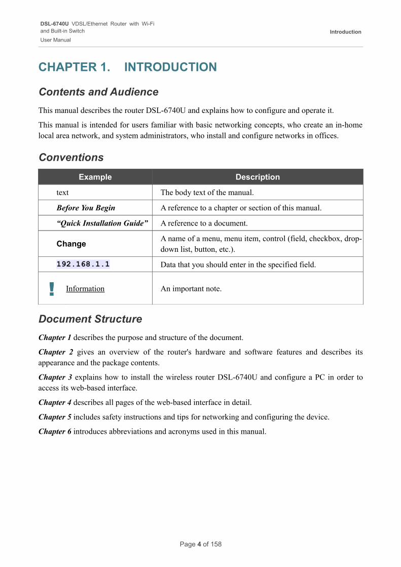
Conventions
Example Description
text The body text of the manual.
Before You Begin A reference to a chapter or section of this manual.
“Quick Installation Guide” A reference to a document.
ChangeA name of a menu, menu item, control (field, checkbox, drop-down list, button, etc.).
192.168.1.1 Data that you should enter in the specified field.
! Information An important note.
Document Structure
Chapter 1 describes the purpose and structure of the document.
Chapter 2 gives an overview of the router's hardware and software features and describes its appearance and the package contents.
Chapter 3 explains how to install the wireless router DSL-6740U and configure a PC in order to access its web-based interface.
Chapter 4 describes all pages of the web-based interface in detail.
Chapter 5 includes safety instructions and tips for networking and configuring the device.
Chapter 6 introduces abbreviations and acronyms used in this manual.
Page 4 of 158
DSL-6740U VDSL/Ethernet Router with Wi-Fiand Built-in Switch
User Manual
Overview
CHAPTER 2. OVERVIEW
General Information
The DSL-6740U device is an affordable high-end VDSL/Ethernet router developed for home and SOHO (Small Office/Home Office) networks. It provides fast and simple broadband access to the Internet and a shared connection for multi users. The device allows accessing the Internet via VDSL/ADSL technology and via Ethernet technology.
DSL-6740U provides all the essentials for creating a secure high-speed wireless and wired network: VDSL2/VDSL/ADSL2+/ADSL2/ADSL standards, Fast Ethernet standard, the built-in firewall, the QoS engine, and numerous additional features.
The router is equipped with a VDSL port to connect to a high-speed VDSL line. The built-in 4-port switch enables you to connect Ethernet-enabled computers, game consoles, and other devices to your network. In addition, any Ethernet port of the device can be used to connect to a private Ethernet line.
Also DSL-6740U can operate as a base station for connecting wireless devices of the standards 802.11b, 802.11g, and 802.11n. The router supports multiple functions for the wireless interface: several security standards (WEP, WPA/WPA2), MAC address filtering, and the WPS function.
The wireless router DSL-6740U includes a built-in firewall. The advanced security functions minimize threats of hacker attacks, prevent unwanted intrusions to your network, and block access to unwanted websites for users of your LAN.
You can configure and manage the settings of the wireless router DSL-6740U via the user-friendly web-based interface (the interface is available in several languages).
Page 5 of 158
DSL-6740U VDSL/Ethernet Router with Wi-Fiand Built-in Switch
User Manual
Overview
Specifications*
Interfaces
• VDSL: 1 RJ-11 port
• LAN: 4 RJ-45 10/100BASE-TX Fast Ethernet ports
• WLAN: built-in 802.11b, g, and n wireless interface
Frequency Range
• 802.11b
◦ 2400 ~ 2484MHz ISM band
• 802.11g
◦ 2400 ~ 2484MHz ISM band
• 802.11n
◦ ISM band
◦ Channel frequency for HT40: 2422 ~ 2452MHz
◦ Channel frequency for HT20: 2400 ~ 2483.5MHz
Wireless Data Rate
• 802.11b: 11, 5.5, 2, 1Mbps per channel, auto fallback
• 802.11g: 54, 48, 36, 24, 18, 12, 9, 6Mbps per channel, auto fallback
• 802.11n
◦ HT20: up to 150Mbps
◦ HT40: up to 300Mbps
Modulation Schemes
• 802.11b: CCK, DQPSK, DBPSK
• 802.11g: 64QAM, 16QAM, QPSK, BPSK, DSSS
• 802.11n
◦ HT20 and HT40: 64 QAM, 16QAM, QPSK, BPSK
Wireless Network Range1
• Indoors: up to 300 feet (100 meters)
• Outdoors: up to 900 feet (300 meters)
* The device features are subject to change without notice. For the latest versions of the firmware and relevant documentation, visit www.dlink.ru.
1 Wireless network range varies depending on the actual environment.
Page 6 of 158
DSL-6740U VDSL/Ethernet Router with Wi-Fiand Built-in Switch
User Manual
Overview
VDSL/ADSL Standards
• VDSL2
◦ ITU G.993.2
◦ Support of 8a, 8b, 8c, 8d, 12a, 12b, 17a, 30a profiles
• ADSL
◦ Multi-mode, ANSI T1.413 Issue 2, ITU-T G.992.1 (G.dmt) Annex A, ITU-T G.992.2 (G.lite) Annex A, ITU-T G.994.1 (G.hs)
• ADSL2
◦ ITU-T G.992.3 (G.dmt.bis) Annex A/L/M, ITU-T G.992.4 (G.lite.bis) Annex A
• ADSL2+
◦ ITU-T G.992.5 Annex A/L/M
WAN Connection Types
• VDSL
◦ PPPoE
◦ Static IP
◦ Dynamic IP
◦ Bridge
• ADSL
◦ PPPoE
◦ PPPoA
◦ IPoA
◦ Static IP
◦ Dynamic IP
◦ Bridge
• Ethernet
◦ PPPoE
◦ Static IP
◦ Dynamic IP
◦ Bridge
Page 7 of 158
DSL-6740U VDSL/Ethernet Router with Wi-Fiand Built-in Switch
User Manual
Overview
Wireless Network
• IEEE 802.11n standard, IEEE 802.11b/g compliant
• Support of guest wireless network
• WEP data encryption
• WPA/WPA2 security supporting TKIP, AES and TKIP+AES
• MAC-based access to wireless network
• PIN and PBC methods of WPS
• Advanced settings
ATM/PPP Protocols
• Bridged and routed Ethernet encapsulation
• VC-based or LLC-based multiplexing
• ATM Forum UNI3.1/4.0 PVC (up to 8 PVCs)
• ATM Adaptation Layer Type 5 (AAL5)
• ITU-T I.610 OAM F4/F5 loopback
• ATM QoS
• PPP over ATM (RFC 2364)
• PPP over Ethernet (PPPoE)
• Keep-alive for PPP connections
Network Protocols and Functions
• Additional IP address for LAN interface
• Static IP routing
• NAT (Network Address Translation)
• DHCP server/client/relay
• DNS relay
• DDNS
• UPnP
• Support of VLAN
• IGMP proxy
• IGMP snooping
• TR-069 client
Page 8 of 158
DSL-6740U VDSL/Ethernet Router with Wi-Fiand Built-in Switch
User Manual
Overview
Firewall and Access Management Functions
• Network Address Translation (NAT)
• Stateful Packet Inspection (SPI)
• MAC filtering based on time of day and day of week
• URL filter
• Packet filtering (IP/ICMP/TCP/UDP)
• Virtual servers
• Prevention of DoS attacks
• Intrusion detection system
• DMZ
• Port Triggering
QoS
• Interface grouping
• VLAN priority (802.1p)
Configuration and Management
• Multilingual web-based interface for configuration and management
• Access via TELNET
• Firmware update via web-based interface
• Saving/restoring configuration to/from file
• Support of remote logging
• Automatic synchronization of system time with NTP server and manual time/date setup
LEDs
• Power
• DSL
• Internet
• LAN 1-4
• WLAN
• WPS
Page 9 of 158
DSL-6740U VDSL/Ethernet Router with Wi-Fiand Built-in Switch
User Manual
Overview
Power
• External power adapter DC 12V/1A
• ON/OFF power switch
• Enable/disable wireless connection button
• Reset to Factory Defaults button
• WPS button
Operating Temperature
• From 0 to 40 °C (from 32 to 104 °F)
Storage Temperature
• From -20 to 70 °C (from -4 to 158 °F)
Humidity
• From 5% to 95% non-condensing
Page 10 of 158

DSL-6740U VDSL/Ethernet Router with Wi-Fiand Built-in Switch
User Manual
Overview
Product Appearance
Front Panel and Left Side Panel
Figure 1. Front panel view.
LED Mode Description
Power
Solid green The router is powered on.
No light The router is powered off.
Solid red The router is in the crash recovery mode.
DSL
Solid green DSL has been synchronized.
Blinking green Detecting a carrier signal and synchronizing DSL.
No light No carrier signal.
Page 11 of 158
DSL-6740U VDSL/Ethernet Router with Wi-Fiand Built-in Switch
User Manual
Overview
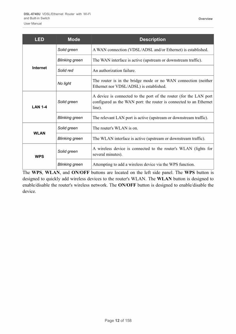
LED Mode Description
Internet
Solid green A WAN connection (VDSL/ADSL and/or Ethernet) is established.
Blinking green The WAN interface is active (upstream or downstream traffic).
Solid red An authorization failure.
No lightThe router is in the bridge mode or no WAN connection (neither Ethernet nor VDSL/ADSL) is established.
LAN 1-4Solid green
A device is connected to the port of the router (for the LAN port configured as the WAN port: the router is connected to an Ethernet line).
Blinking green The relevant LAN port is active (upstream or downstream traffic).
WLANSolid green The router's WLAN is on.
Blinking green The WLAN interface is active (upstream or downstream traffic).
WPSSolid green
A wireless device is connected to the router's WLAN (lights for several minutes).
Blinking green Attempting to add a wireless device via the WPS function.
The WPS, WLAN, and ON/OFF buttons are located on the left side panel. The WPS button is designed to quickly add wireless devices to the router's WLAN. The WLAN button is designed to enable/disable the router's wireless network. The ON/OFF button is designed to enable/disable the device.
Page 12 of 158
DSL-6740U VDSL/Ethernet Router with Wi-Fiand Built-in Switch
User Manual
Overview
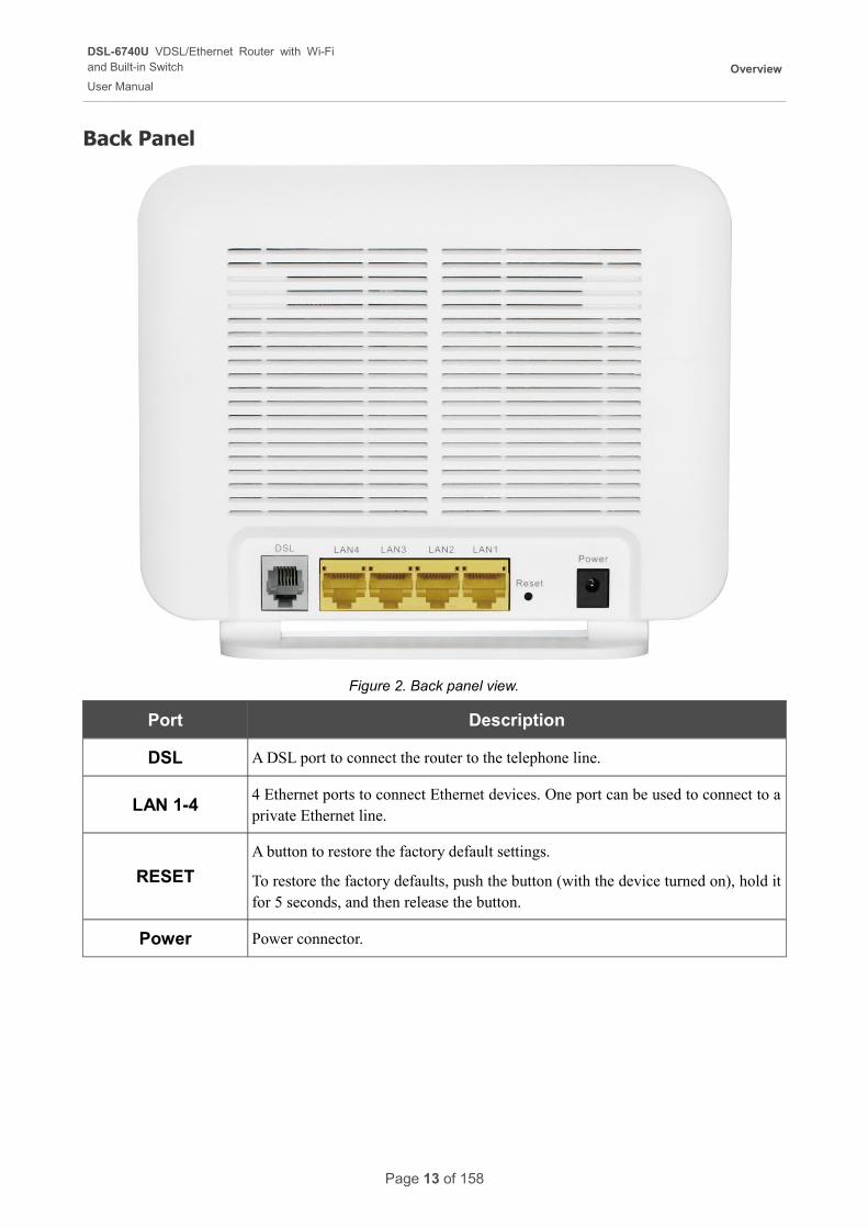
Back Panel
Figure 2. Back panel view.
Port Description
DSL A DSL port to connect the router to the telephone line.
LAN 1-44 Ethernet ports to connect Ethernet devices. One port can be used to connect to a private Ethernet line.
RESET
A button to restore the factory default settings.
To restore the factory defaults, push the button (with the device turned on), hold it for 5 seconds, and then release the button.
Power Power connector.
Page 13 of 158
DSL-6740U VDSL/Ethernet Router with Wi-Fiand Built-in Switch
User Manual
Overview
Delivery Package
The following should be included:
• Wireless router DSL-6740U
• Power adapter DC 12V/1A
• RJ-11 telephone cable
• Ethernet cable (CAT 5E)
• Splitter
• “Quick Installation Guide” (brochure).
The “User Manual” and “Quick Installation Guide” documents in Russian and English are available on D-Link website (see ftp://dlink.ru/pub/VDSL2/DSL-6740U/Description/).
! Using a power supply with a different voltage rating than the one included will cause damage and void the warranty for this product.
Page 14 of 158
DSL-6740U VDSL/Ethernet Router with Wi-Fiand Built-in Switch
User Manual
Installation and Connection
CHAPTER 3. INSTALLATION AND CONNECTION
Before You Begin
Please, read this manual prior to installing the device. Make sure that you have all the necessary information and equipment.
Operating System
Configuration of the multifunction wireless VDSL/Ethernet router DSL-6740U (hereinafter referred to as “the router”) is performed via the built-in web-based interface. The web-based interface is available from any operating system that supports a web browser.
Web Browser
The following web browsers are recommended:
• Apple Safari 5 and later
• Google Chrome 5 and later
• Microsoft Internet Explorer 7 and later
• Mozilla Firefox 5 and later
• Opera 10 and later.
For successful operation, JavaScript should be enabled on the web browser. Make sure that JavaScript has not been disabled by other software (such as virus protection or web user security packages) running on your computer.
Wired or Wireless NIC (Ethernet or Wi-Fi Adapter)
Any computer that uses the router should be equipped with an Ethernet or Wi-Fi adapter (NIC). If your computer is not equipped with such a device, install an Ethernet or Wi-Fi adapter prior to using the router.
Wireless Connection
Wireless workstations from your network should be equipped with a wireless 802.11b, g, or n NIC (Wi-Fi adapter). In addition, you should specify the values of SSID, channel number and security settings defined in the web-based interface of the router for all these wireless workstations.
Page 15 of 158
DSL-6740U VDSL/Ethernet Router with Wi-Fiand Built-in Switch
User Manual
Installation and Connection
Connecting to PC
PC with Ethernet Adapter
1. Make sure that your PC is powered off.
2. Connect an Ethernet cable between any of four Ethernet ports located on the back panel of the router and the Ethernet port of your PC.
3. To connect the router to a DSL line: connect a phone cable between the DSL port of the router and the MODEM port of the splitter. Connect your phone to the PHONE port of the splitter. Then connect another phone cable between a phone jack and the LINE port of the splitter.
4. To connect the router to an Ethernet line: connect the Ethernet cable between any of four Ethernet ports located on the back panel of the router and the Ethernet line.
5. Connect the power cord to the power connector port on the back panel of the router, then plug the power adapter into an electrical outlet or power strip.
6. Turn on the router by pressing the ON/OFF button on its left side panel.
7. Turn on your PC and wait until your operating system is completely loaded.
Page 16 of 158
DSL-6740U VDSL/Ethernet Router with Wi-Fiand Built-in Switch
User Manual
Installation and Connection
Obtaining IP Address Automatically in OS Windows XP
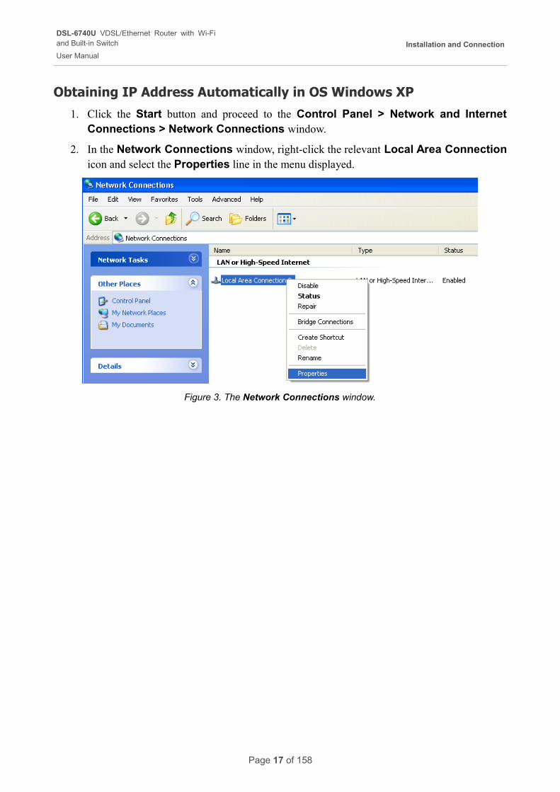
1. Click the Start button and proceed to the Control Panel > Network and Internet Connections > Network Connections window.
2. In the Network Connections window, right-click the relevant Local Area Connection icon and select the Properties line in the menu displayed.
Figure 3. The Network Connections window.
Page 17 of 158
DSL-6740U VDSL/Ethernet Router with Wi-Fiand Built-in Switch
User Manual
Installation and Connection
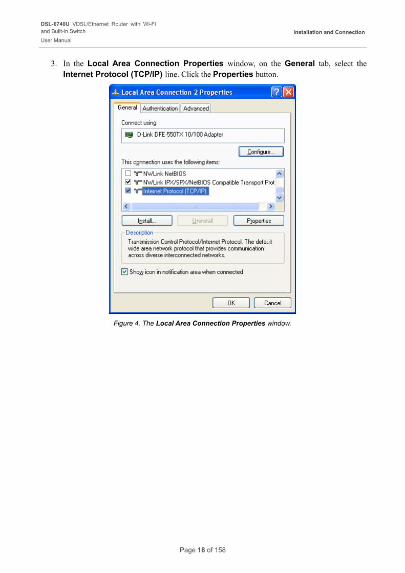
3. In the Local Area Connection Properties window, on the General tab, select the Internet Protocol (TCP/IP) line. Click the Properties button.
Figure 4. The Local Area Connection Properties window.
Page 18 of 158
DSL-6740U VDSL/Ethernet Router with Wi-Fiand Built-in Switch
User Manual
Installation and Connection
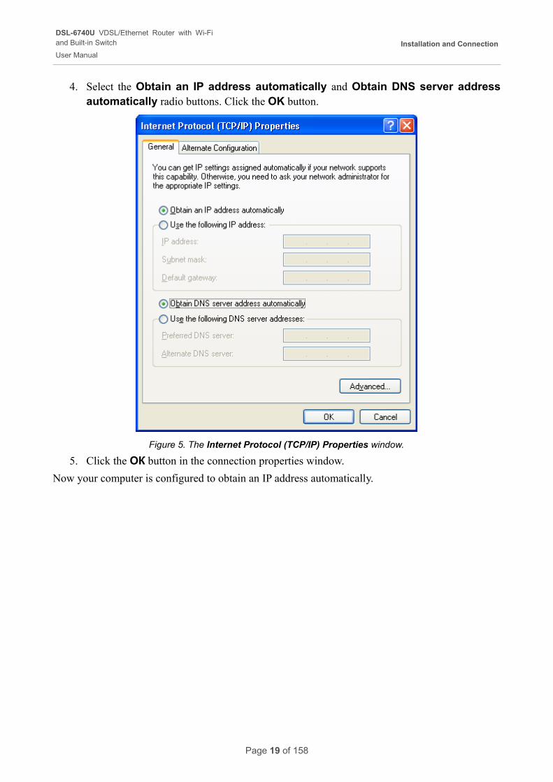
4. Select the Obtain an IP address automatically and Obtain DNS server address automatically radio buttons. Click the OK button.
Figure 5. The Internet Protocol (TCP/IP) Properties window.
5. Click the ОК button in the connection properties window.
Now your computer is configured to obtain an IP address automatically.
Page 19 of 158
DSL-6740U VDSL/Ethernet Router with Wi-Fiand Built-in Switch
User Manual
Installation and Connection
Obtaining IP Address Automatically in OS Windows 7
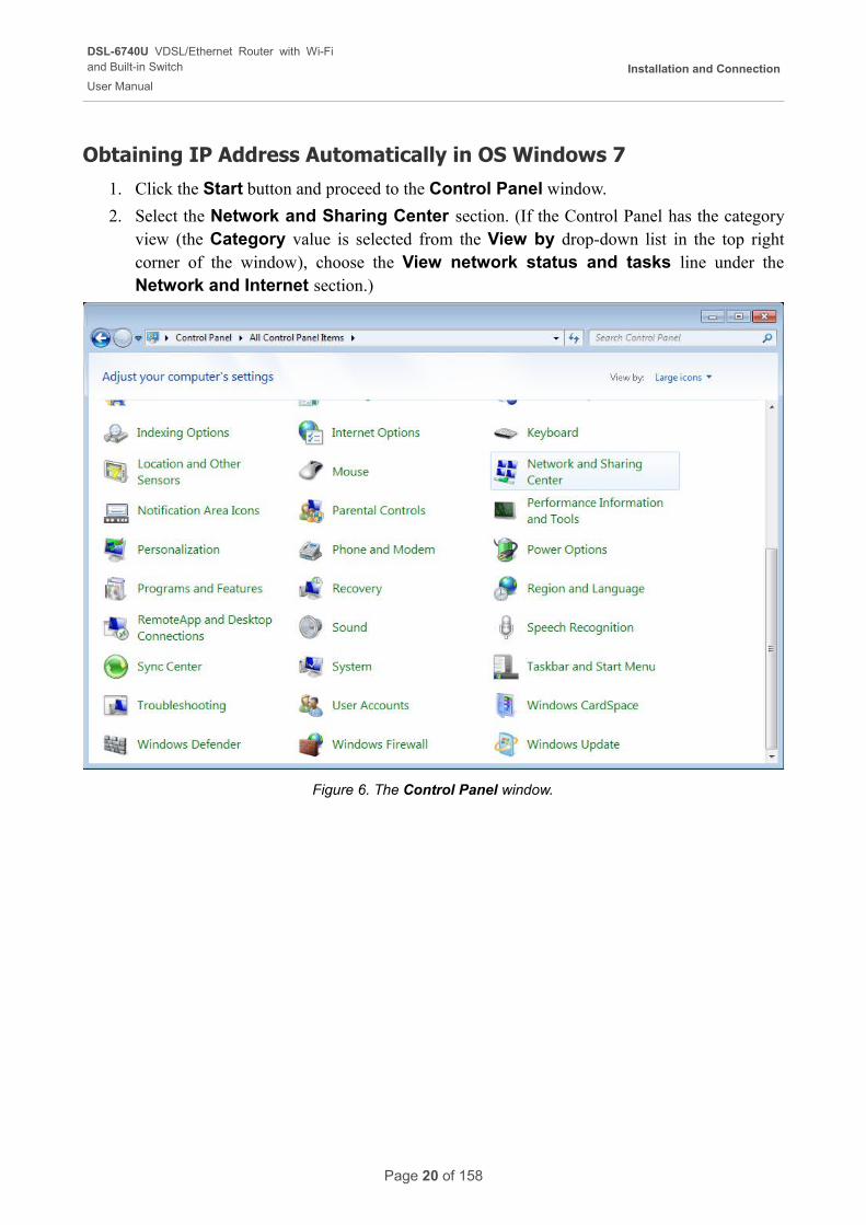
1. Click the Start button and proceed to the Control Panel window.
2. Select the Network and Sharing Center section. (If the Control Panel has the category view (the Category value is selected from the View by drop-down list in the top right corner of the window), choose the View network status and tasks line under the Network and Internet section.)
Figure 6. The Control Panel window.
Page 20 of 158

DSL-6740U VDSL/Ethernet Router with Wi-Fiand Built-in Switch
User Manual
Installation and Connection
3. In the menu located on the left part of the window, select the Change adapter settings line.
Figure 7. The Network and Sharing Center window.
Page 21 of 158
DSL-6740U VDSL/Ethernet Router with Wi-Fiand Built-in Switch
User Manual
Installation and Connection
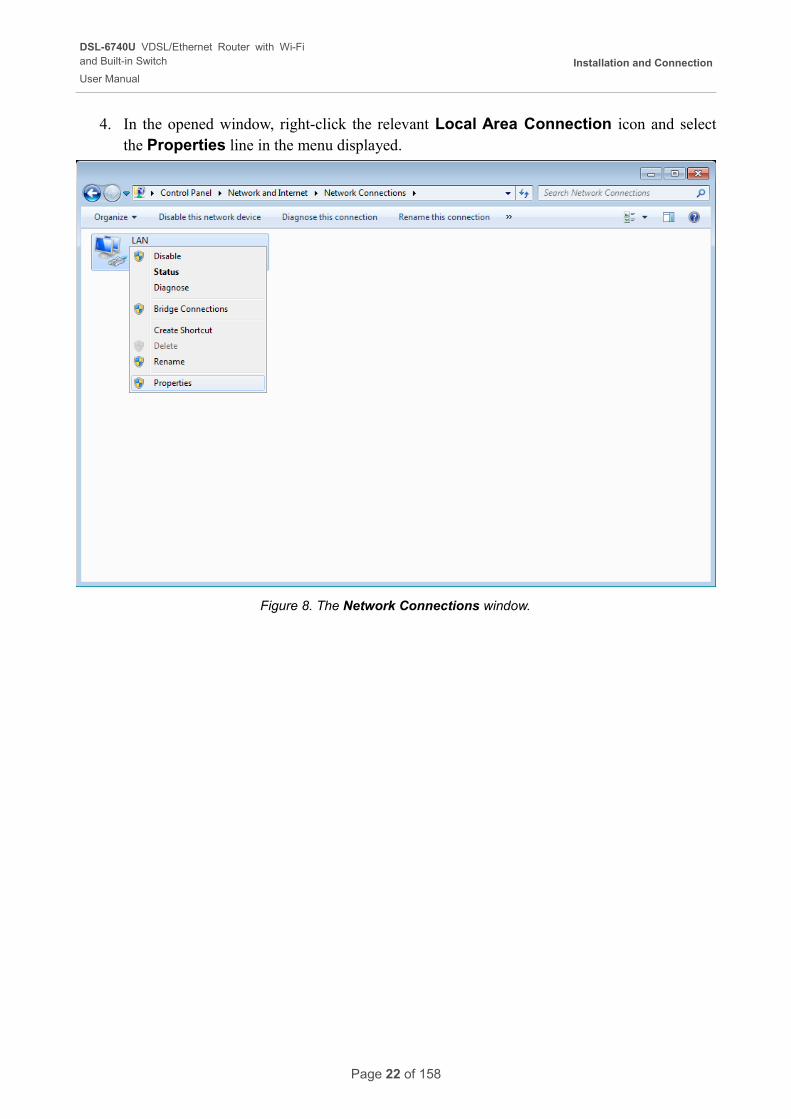
4. In the opened window, right-click the relevant Local Area Connection icon and select the Properties line in the menu displayed.
Figure 8. The Network Connections window.
Page 22 of 158
DSL-6740U VDSL/Ethernet Router with Wi-Fiand Built-in Switch
User Manual
Installation and Connection
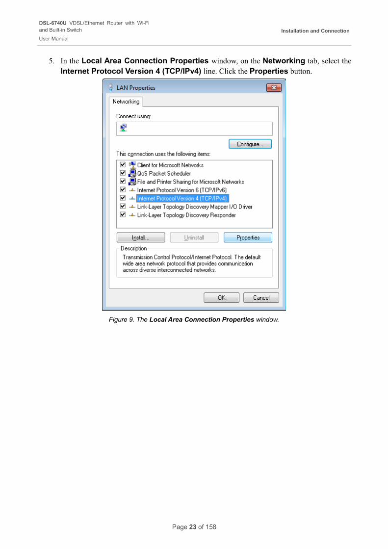
5. In the Local Area Connection Properties window, on the Networking tab, select the Internet Protocol Version 4 (TCP/IPv4) line. Click the Properties button.
Figure 9. The Local Area Connection Properties window.
Page 23 of 158
DSL-6740U VDSL/Ethernet Router with Wi-Fiand Built-in Switch
User Manual
Installation and Connection
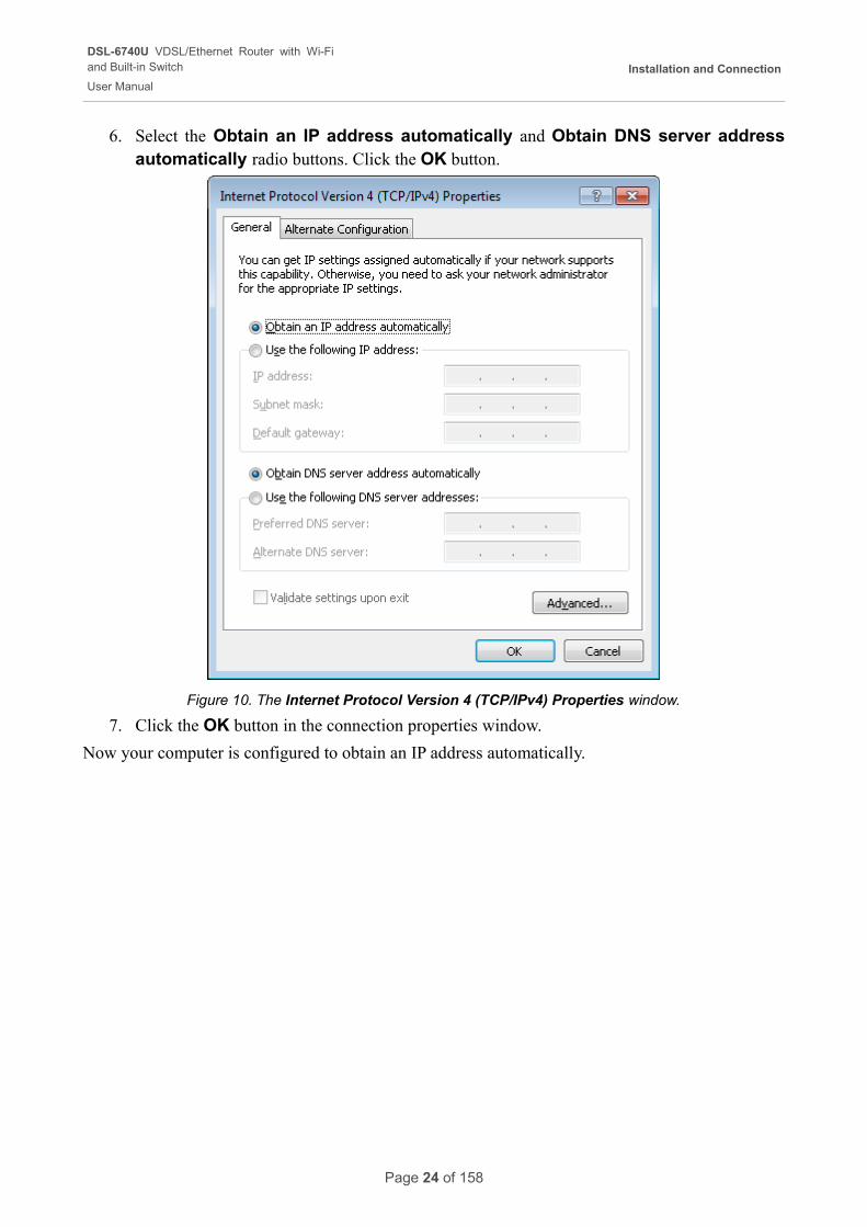
6. Select the Obtain an IP address automatically and Obtain DNS server address automatically radio buttons. Click the OK button.
Figure 10. The Internet Protocol Version 4 (TCP/IPv4) Properties window.
7. Click the OK button in the connection properties window.
Now your computer is configured to obtain an IP address automatically.
Page 24 of 158
DSL-6740U VDSL/Ethernet Router with Wi-Fiand Built-in Switch
User Manual
Installation and Connection
PC with Wi-Fi Adapter
1. To connect the router to a DSL line: connect a phone cable between the DSL port of the router and the MODEM port of the splitter. Connect your phone to the PHONE port of the splitter. Then connect another phone cable between a phone jack and the LINE port of the splitter.
2. To connect the router to an Ethernet line: connect the Ethernet cable between any of four Ethernet ports located on the back panel of the router and the Ethernet line.
3. Connect the power cord to the power connector port on the back panel of the router, then plug the power adapter into an electrical outlet or power strip.
4. Turn on the router by pressing the ON/OFF button on its left side panel.
5. Turn on the router's wireless connection by pressing the WLAN button on its left side panel.
6. Turn on your PC and wait until your operating system is completely loaded.
7. Turn on your Wi-Fi adapter. As a rule, modern notebooks with built-in wireless NICs are equipped with a button or switch that turns on/off the wireless adapter (refer to your PC documents). If your PC is equipped with a pluggable wireless NIC, install the software provided with your Wi-Fi adapter.
Page 25 of 158
DSL-6740U VDSL/Ethernet Router with Wi-Fiand Built-in Switch
User Manual
Installation and Connection
Configuring Wi-Fi Adapter in OS Windows XP
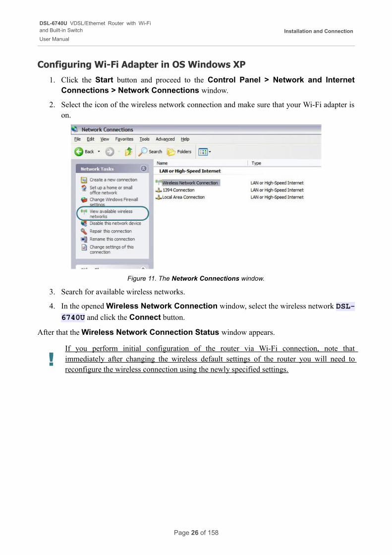
1. Click the Start button and proceed to the Control Panel > Network and Internet Connections > Network Connections window.
2. Select the icon of the wireless network connection and make sure that your Wi-Fi adapter is on.
Figure 11. The Network Connections window.
3. Search for available wireless networks.
4. In the opened Wireless Network Connection window, select the wireless network DSL-
6740U and click the Connect button.
After that the Wireless Network Connection Status window appears.
!If you perform initial configuration of the router via Wi-Fi connection, note that immediately after changing the wireless default settings of the router you will need to reconfigure the wireless connection using the newly specified settings.
Page 26 of 158
DSL-6740U VDSL/Ethernet Router with Wi-Fiand Built-in Switch
User Manual
Installation and Connection
Configuring Wi-Fi Adapter in OS Windows 7
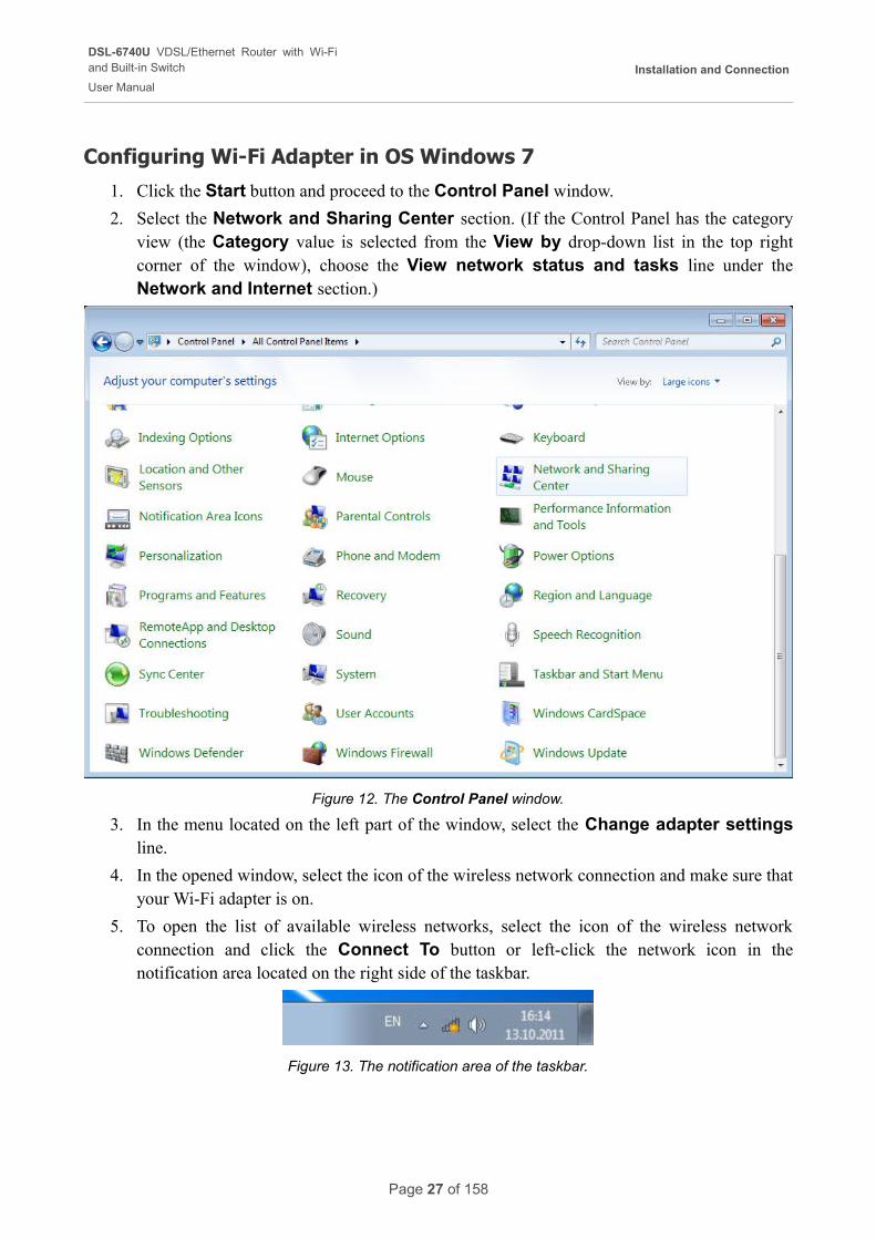
1. Click the Start button and proceed to the Control Panel window.
2. Select the Network and Sharing Center section. (If the Control Panel has the category view (the Category value is selected from the View by drop-down list in the top right corner of the window), choose the View network status and tasks line under the Network and Internet section.)
Figure 12. The Control Panel window.
3. In the menu located on the left part of the window, select the Change adapter settings line.
4. In the opened window, select the icon of the wireless network connection and make sure that your Wi-Fi adapter is on.
5. To open the list of available wireless networks, select the icon of the wireless network connection and click the Connect To button or left-click the network icon in the notification area located on the right side of the taskbar.
Figure 13. The notification area of the taskbar.
Page 27 of 158
DSL-6740U VDSL/Ethernet Router with Wi-Fiand Built-in Switch
User Manual
Installation and Connection
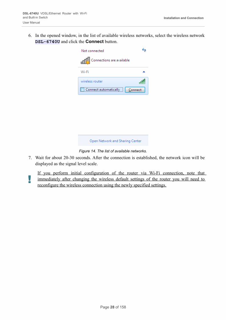
6. In the opened window, in the list of available wireless networks, select the wireless network DSL-6740U and click the Connect button.
Figure 14. The list of available networks.
7. Wait for about 20-30 seconds. After the connection is established, the network icon will be displayed as the signal level scale.
!If you perform initial configuration of the router via Wi-Fi connection, note that immediately after changing the wireless default settings of the router you will need to reconfigure the wireless connection using the newly specified settings.
Page 28 of 158
DSL-6740U VDSL/Ethernet Router with Wi-Fiand Built-in Switch
User Manual
Installation and Connection
Connecting to Web-based Interface
When you have configured your computer, you can access the web-based interface and configure needed parameters (for example, create an interface to connect to the Internet, change the parameters of the wireless network, specify the settings of the firewall, edit the password for the administrator account, etc.)
1. Start a web browser (see the Before You Begin section, page 15).
2. In the address bar of the web browser, enter the IP address of the router (by default, the following IP address is specified: 192.168.1.1). Press the Enter key.
Figure 15. Connecting to the web-based interface of the DSL-6740U device.
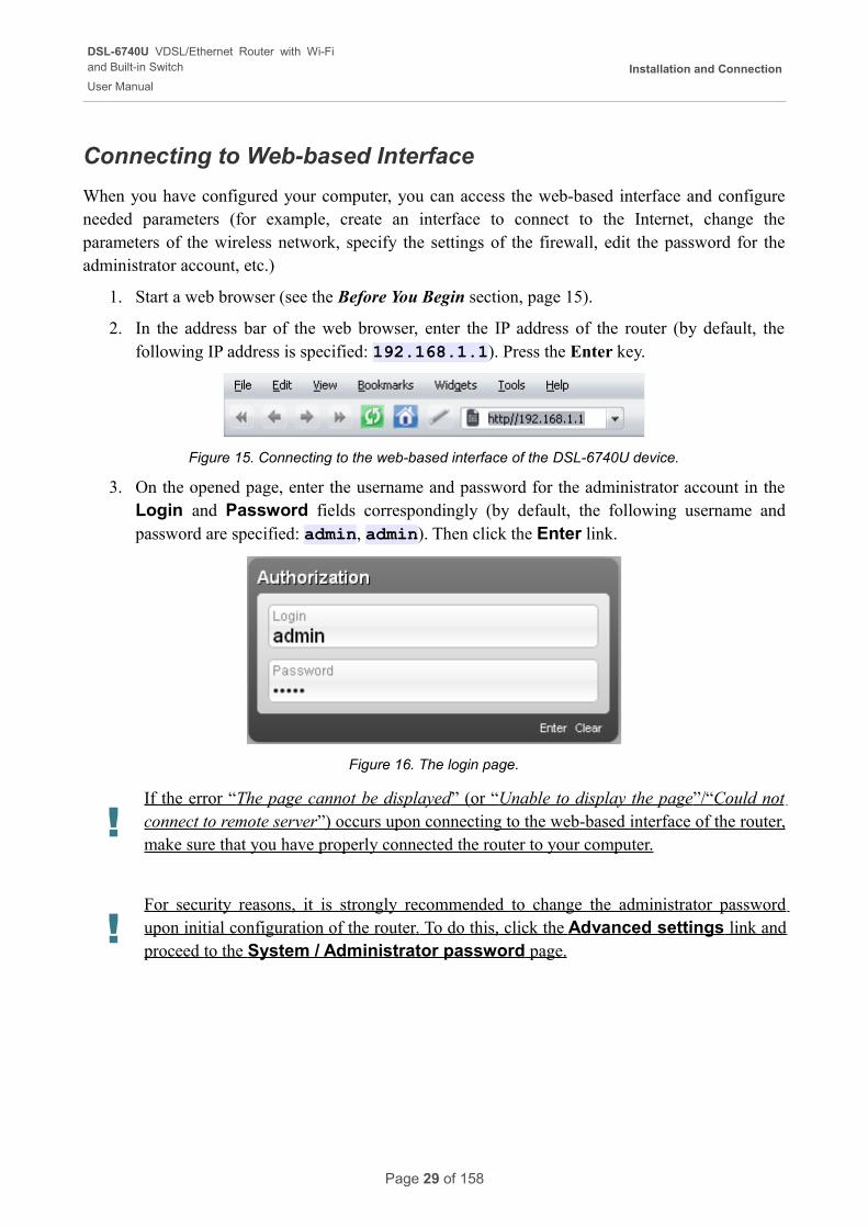
3. On the opened page, enter the username and password for the administrator account in the Login and Password fields correspondingly (by default, the following username and password are specified: admin, admin). Then click the Enter link.
Figure 16. The login page.
!If the error “ The page cannot be displayed ” (or “ Unable to display the page ”/“ Could not connect to remote server ”) occurs upon connecting to the web-based interface of the router, make sure that you have properly connected the router to your computer.
!For security reasons, it is strongly recommended to change the administrator password upon initial configuration of the router . To do this, click the Advanced settings link and proceed to the System / Administrator password page.
Page 29 of 158
DSL-6740U VDSL/Ethernet Router with Wi-Fiand Built-in Switch
User Manual
Installation and Connection
Web-based Interface Structure
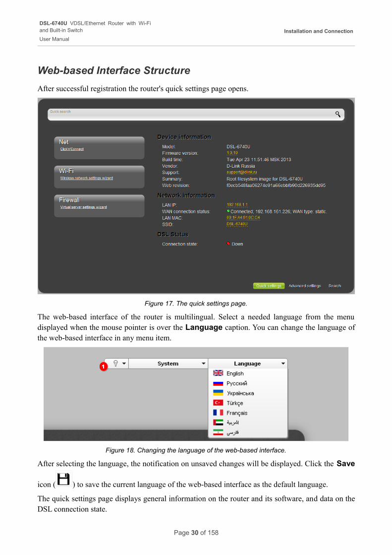
After successful registration the router's quick settings page opens.
Figure 17. The quick settings page.
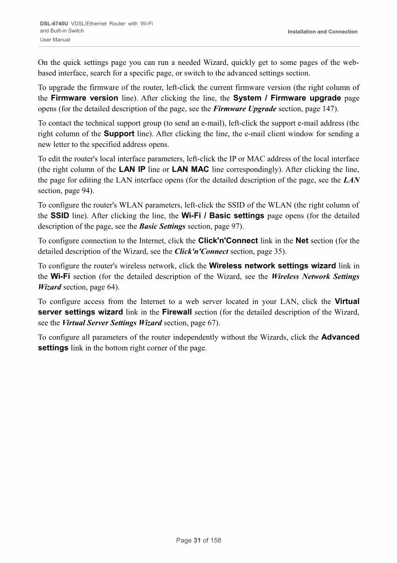
The web-based interface of the router is multilingual. Select a needed language from the menu displayed when the mouse pointer is over the Language caption. You can change the language of the web-based interface in any menu item.
Figure 18. Changing the language of the web-based interface.
After selecting the language, the notification on unsaved changes will be displayed. Click the Save
icon ( ) to save the current language of the web-based interface as the default language.
The quick settings page displays general information on the router and its software, and data on the DSL connection state.
Page 30 of 158
DSL-6740U VDSL/Ethernet Router with Wi-Fiand Built-in Switch
User Manual
Installation and Connection
On the quick settings page you can run a needed Wizard, quickly get to some pages of the web-based interface, search for a specific page, or switch to the advanced settings section.
To upgrade the firmware of the router, left-click the current firmware version (the right column of the Firmware version line). After clicking the line, the System / Firmware upgrade page opens (for the detailed description of the page, see the Firmware Upgrade section, page 147).
To contact the technical support group (to send an e-mail), left-click the support e-mail address (the right column of the Support line). After clicking the line, the e-mail client window for sending a new letter to the specified address opens.
To edit the router's local interface parameters, left-click the IP or MAC address of the local interface (the right column of the LAN IP line or LAN MAC line correspondingly). After clicking the line, the page for editing the LAN interface opens (for the detailed description of the page, see the LAN section, page 94).
To configure the router's WLAN parameters, left-click the SSID of the WLAN (the right column of the SSID line). After clicking the line, the Wi-Fi / Basic settings page opens (for the detailed description of the page, see the Basic Settings section, page 97).
To configure connection to the Internet, click the Click'n'Connect link in the Net section (for the detailed description of the Wizard, see the Click'n'Connect section, page 35).
To configure the router's wireless network, click the Wireless network settings wizard link in the Wi-Fi section (for the detailed description of the Wizard, see the Wireless Network SettingsWizard section, page 64).
To configure access from the Internet to a web server located in your LAN, click the Virtual server settings wizard link in the Firewall section (for the detailed description of the Wizard, see the Virtual Server Settings Wizard section, page 67).
To configure all parameters of the router independently without the Wizards, click the Advanced settings link in the bottom right corner of the page.
Page 31 of 158
DSL-6740U VDSL/Ethernet Router with Wi-Fiand Built-in Switch
User Manual
Installation and Connection
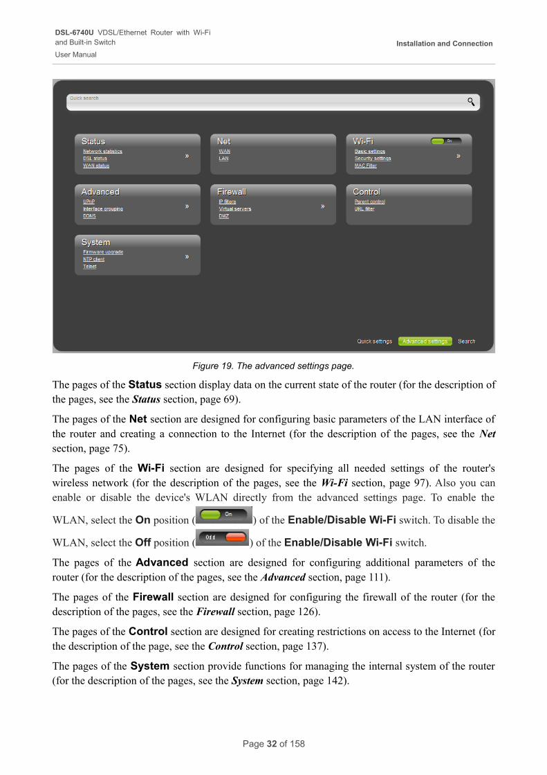
Figure 19. The advanced settings page.
The pages of the Status section display data on the current state of the router (for the description of the pages, see the Status section, page 69).
The pages of the Net section are designed for configuring basic parameters of the LAN interface of the router and creating a connection to the Internet (for the description of the pages, see the Net section, page 75).
The pages of the Wi-Fi section are designed for specifying all needed settings of the router's wireless network (for the description of the pages, see the Wi-Fi section, page 97). Also you can enable or disable the device's WLAN directly from the advanced settings page. To enable the
WLAN, select the On position ( ) of the Enable/Disable Wi-Fi switch. To disable the
WLAN, select the Off position ( ) of the Enable/Disable Wi-Fi switch.
The pages of the Advanced section are designed for configuring additional parameters of the router (for the description of the pages, see the Advanced section, page 111).
The pages of the Firewall section are designed for configuring the firewall of the router (for the description of the pages, see the Firewall section, page 126).
The pages of the Control section are designed for creating restrictions on access to the Internet (for the description of the page, see the Control section, page 137).
The pages of the System section provide functions for managing the internal system of the router (for the description of the pages, see the System section, page 142).
Page 32 of 158
DSL-6740U VDSL/Ethernet Router with Wi-Fiand Built-in Switch
User Manual
Installation and Connection
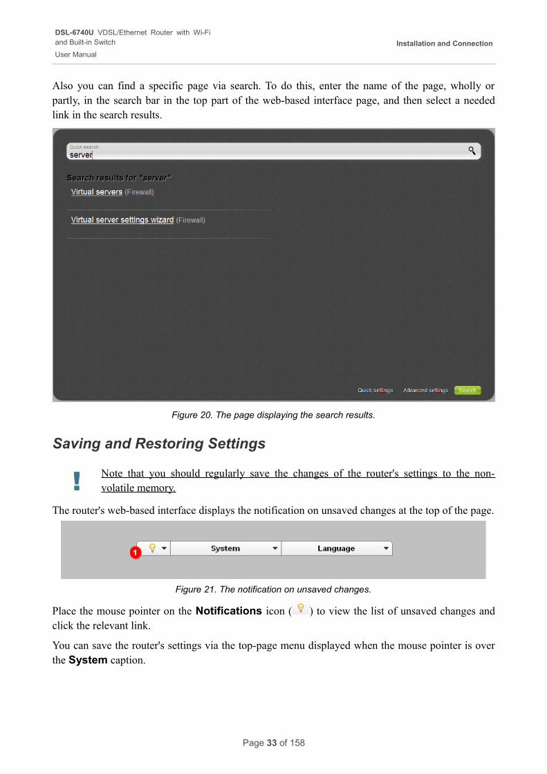
Also you can find a specific page via search. To do this, enter the name of the page, wholly or partly, in the search bar in the top part of the web-based interface page, and then select a needed link in the search results.
Figure 20. The page displaying the search results.
Saving and Restoring Settings
! Note that you should regularly save the changes of the router's settings to the non-volatile memory.
The router's web-based interface displays the notification on unsaved changes at the top of the page.
Figure 21. The notification on unsaved changes.
Place the mouse pointer on the Notifications icon ( ) to view the list of unsaved changes and click the relevant link.
You can save the router's settings via the top-page menu displayed when the mouse pointer is over the System caption.
Page 33 of 158
DSL-6740U VDSL/Ethernet Router with Wi-Fiand Built-in Switch
User Manual
Installation and Connection
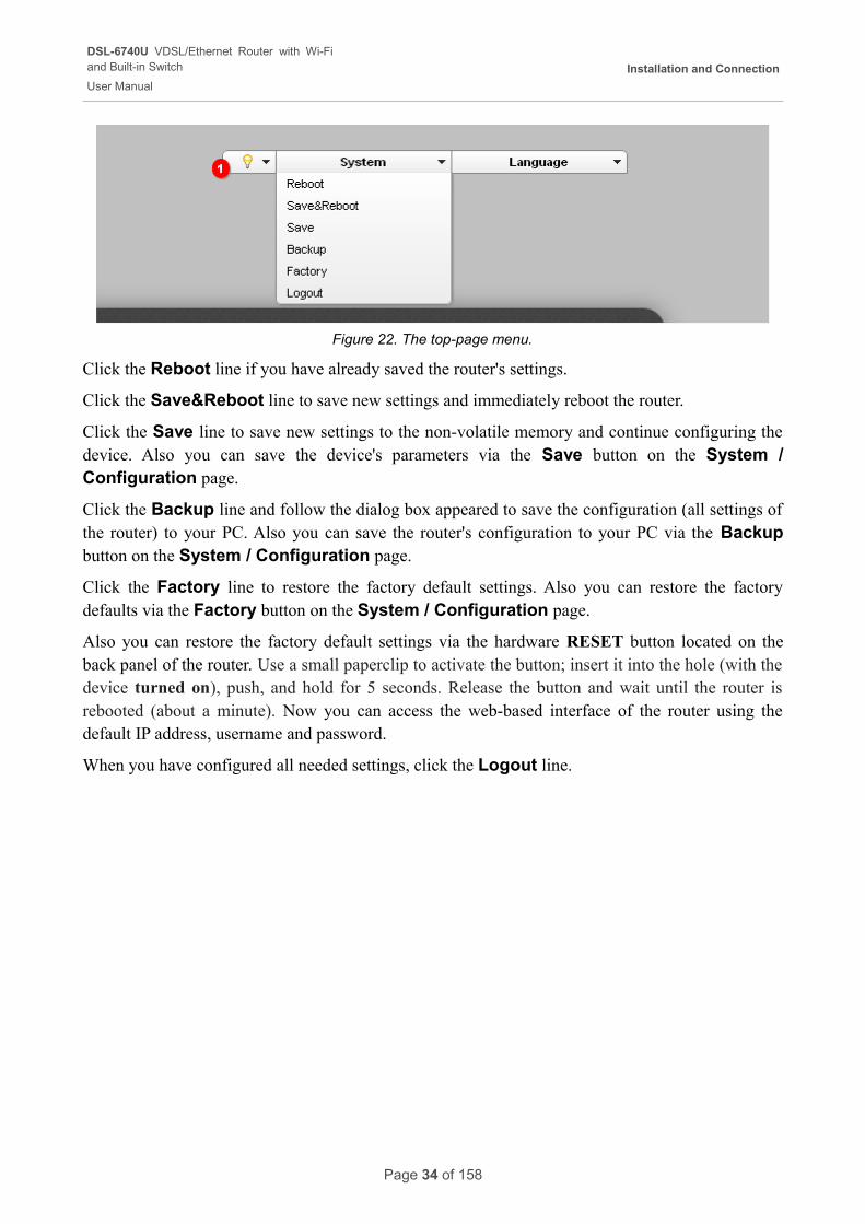
Figure 22. The top-page menu.
Click the Reboot line if you have already saved the router's settings.
Click the Save&Reboot line to save new settings and immediately reboot the router.
Click the Save line to save new settings to the non-volatile memory and continue configuring the device. Also you can save the device's parameters via the Save button on the System / Configuration page.
Click the Backup line and follow the dialog box appeared to save the configuration (all settings of the router) to your PC. Also you can save the router's configuration to your PC via the Backup button on the System / Configuration page.
Click the Factory line to restore the factory default settings. Also you can restore the factory defaults via the Factory button on the System / Configuration page.
Also you can restore the factory default settings via the hardware RESET button located on the back panel of the router. Use a small paperclip to activate the button; insert it into the hole (with the device turned on), push, and hold for 5 seconds. Release the button and wait until the router is rebooted (about a minute). Now you can access the web-based interface of the router using the default IP address, username and password.
When you have configured all needed settings, click the Logout line.
Page 34 of 158
DSL-6740U VDSL/Ethernet Router with Wi-Fiand Built-in Switch
User Manual
Configuring via Web-based Interface
CHAPTER 4. CONFIGURING VIA WEB-BASED INTERFACE
Click'n'Connect
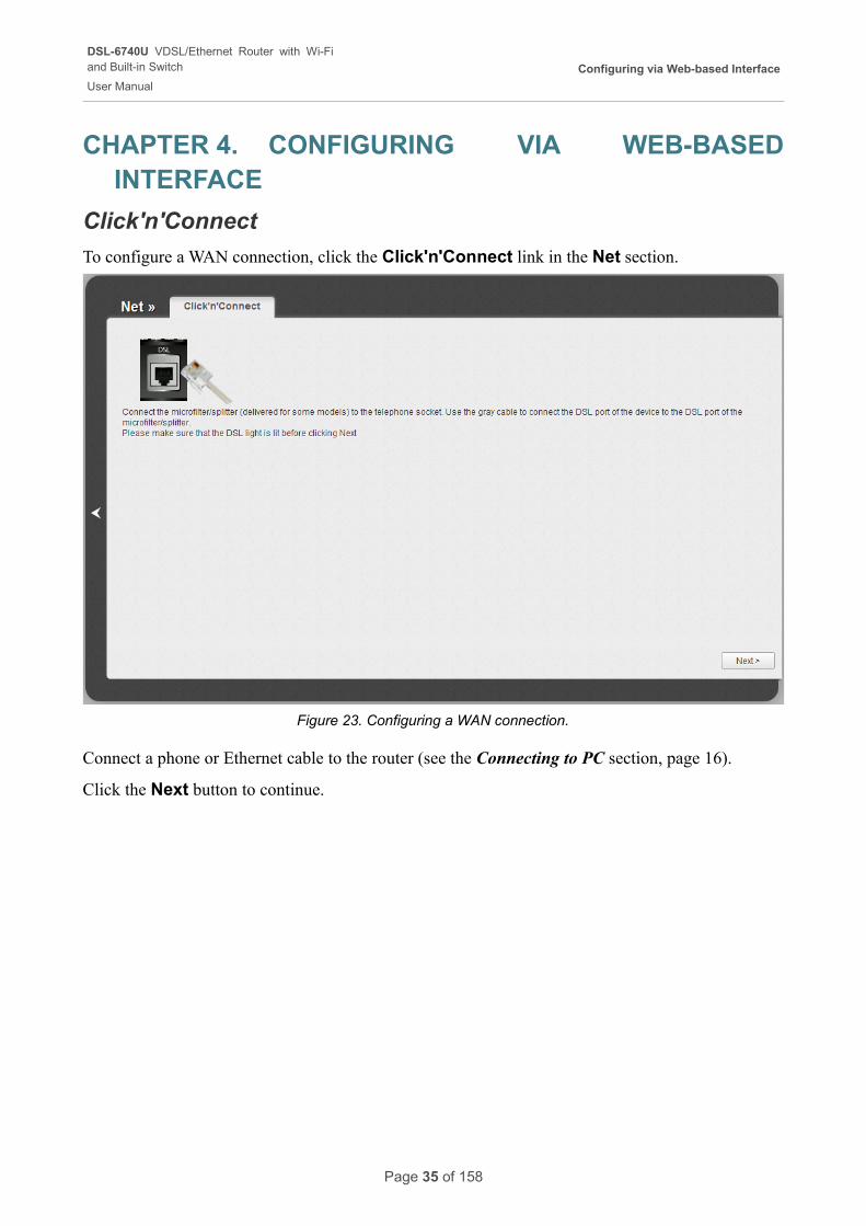
To configure a WAN connection, click the Click'n'Connect link in the Net section.
Figure 23. Configuring a WAN connection.
Connect a phone or Ethernet cable to the router (see the Connecting to PC section, page 16).
Click the Next button to continue.
Page 35 of 158
DSL-6740U VDSL/Ethernet Router with Wi-Fiand Built-in Switch
User Manual
Configuring via Web-based Interface
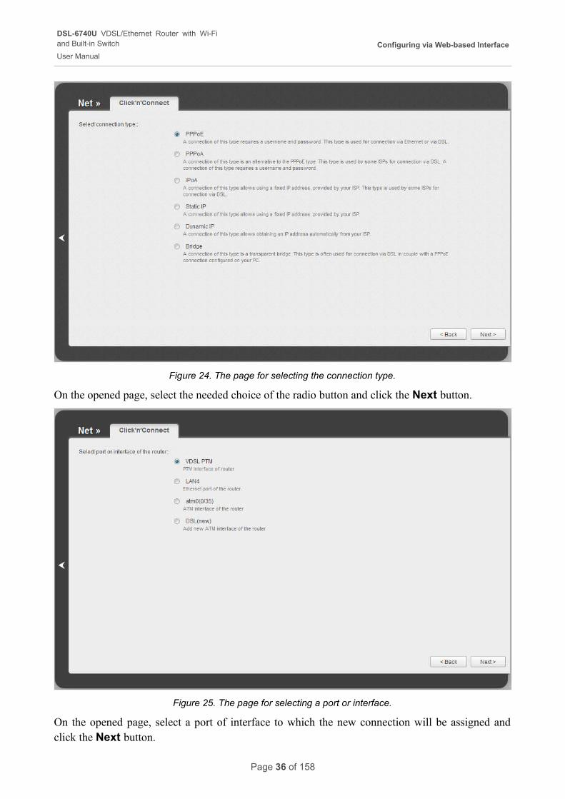
Figure 24. The page for selecting the connection type.
On the opened page, select the needed choice of the radio button and click the Next button.
Figure 25. The page for selecting a port or interface.
On the opened page, select a port of interface to which the new connection will be assigned and click the Next button.
Page 36 of 158
DSL-6740U VDSL/Ethernet Router with Wi-Fiand Built-in Switch
User Manual
Configuring via Web-based Interface
Creating WAN Connection
PPPoE or PPPoA Connection
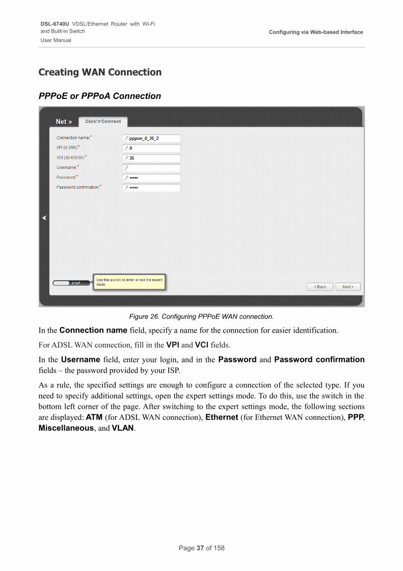
Figure 26. Configuring PPPoE WAN connection.
In the Connection name field, specify a name for the connection for easier identification.
For ADSL WAN connection, fill in the VPI and VCI fields.
In the Username field, enter your login, and in the Password and Password confirmation fields – the password provided by your ISP.
As a rule, the specified settings are enough to configure a connection of the selected type. If you need to specify additional settings, open the expert settings mode. To do this, use the switch in the bottom left corner of the page. After switching to the expert settings mode, the following sections are displayed: ATM (for ADSL WAN connection), Ethernet (for Ethernet WAN connection), PPP, Miscellaneous, and VLAN.
Page 37 of 158
DSL-6740U VDSL/Ethernet Router with Wi-Fiand Built-in Switch
User Manual
Configuring via Web-based Interface
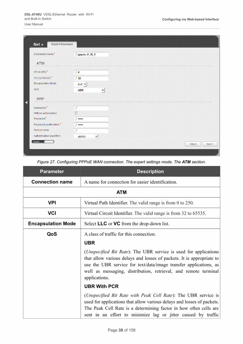
Figure 27. Configuring PPPoE WAN connection. The expert settings mode. The ATM section.
Parameter Description
Connection name A name for connection for easier identification.
ATM
VPI Virtual Path Identifier. The valid range is from 0 to 250.
VCI Virtual Circuit Identifier. The valid range is from 32 to 65535.
Encapsulation Mode Select LLC or VC from the drop-down list.
QoS A class of traffic for this connection.
UBR
(Unspecified Bit Rate): The UBR service is used for applications that allow various delays and losses of packets. It is appropriate to use the UBR service for text/data/image transfer applications, as well as messaging, distribution, retrieval, and remote terminal applications.
UBR With PCR
(Unspecified Bit Rate with Peak Cell Rate): The UBR service is used for applications that allow various delays and losses of packets. The Peak Cell Rate is a determining factor in how often cells are sent in an effort to minimize lag or jitter caused by traffic
Page 38 of 158
DSL-6740U VDSL/Ethernet Router with Wi-Fiand Built-in Switch
User Manual
Configuring via Web-based Interface
Parameter Description
inconsistencies. When you select this value from the drop-down list, the Peak Cell Rate field is displayed. Specify a required value (in cells per second).
CBR
(Constant Bit Rate): This service is used for applications that require a constant data rate. It is mostly used for transferring uncompressed audio and video, e.g. videoconferencing, interactive audio (telephony), audio/video distribution (television, distance education, e-shops), and retrieval (video-on demand, audio libraries). When you select this value from the drop-down list, the Peak Cell Rate field is displayed. Specify a required value (in cells per second).
Non Realtime VBR
(Non-Real-time Variable Bit Rate): This service can be used for transferring data that have critical response-time requirements, e.g. air ticket booking, bank transactions, and process monitoring. When you select this value from the drop-down list, the Peak Cell Rate, Sustainable Cell Rate, and Maximum Burst Size fields are displayed. Specify required values.
Realtime VBR
(Real-time Variable Bit Rate): This service is used for delay-sensitive applications such as real time video. The Rt-VBR provides higher network flexibility than the CBR service. When you select this value from the drop-down list, the Peak Cell Rate, Sustainable Cell Rate, and Maximum Burst Size fields are displayed. Specify required values.
Page 39 of 158
DSL-6740U VDSL/Ethernet Router with Wi-Fiand Built-in Switch
User Manual
Configuring via Web-based Interface
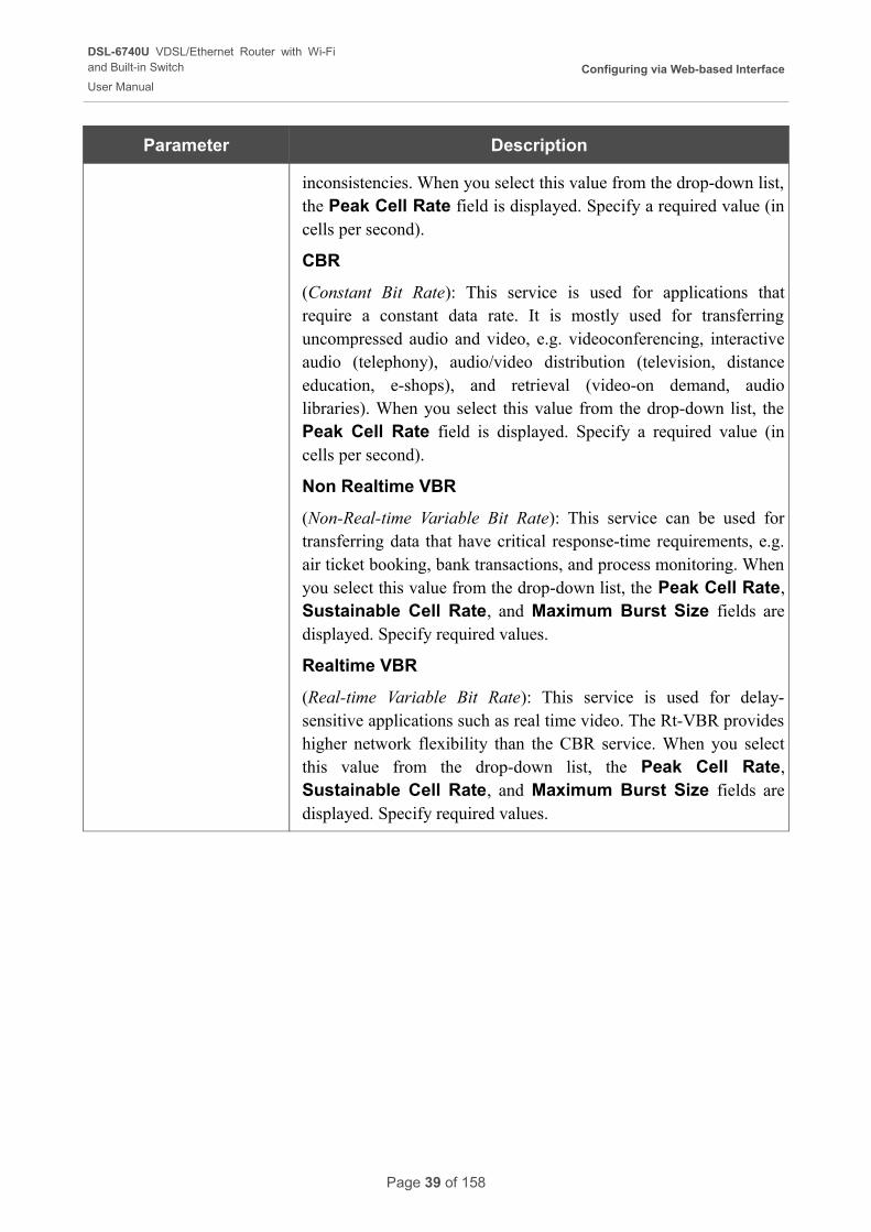
Figure 28. Configuring PPPoE WAN connection. The expert settings mode. The Ethernet section.
Parameter Description
Ethernet
MTU The maximum size of units transmitted by the interface.
MAC
A MAC address assigned to the interface. This parameter is mandatory if your ISP uses MAC address binding. In the field, enter the MAC address registered by your ISP upon concluding the agreement.
Also you can set the address of a device connected to the router's LAN at the moment. To do this, select the relevant value from the drop-down list (the field will be filled in automatically).
Page 40 of 158
DSL-6740U VDSL/Ethernet Router with Wi-Fiand Built-in Switch
User Manual
Configuring via Web-based Interface
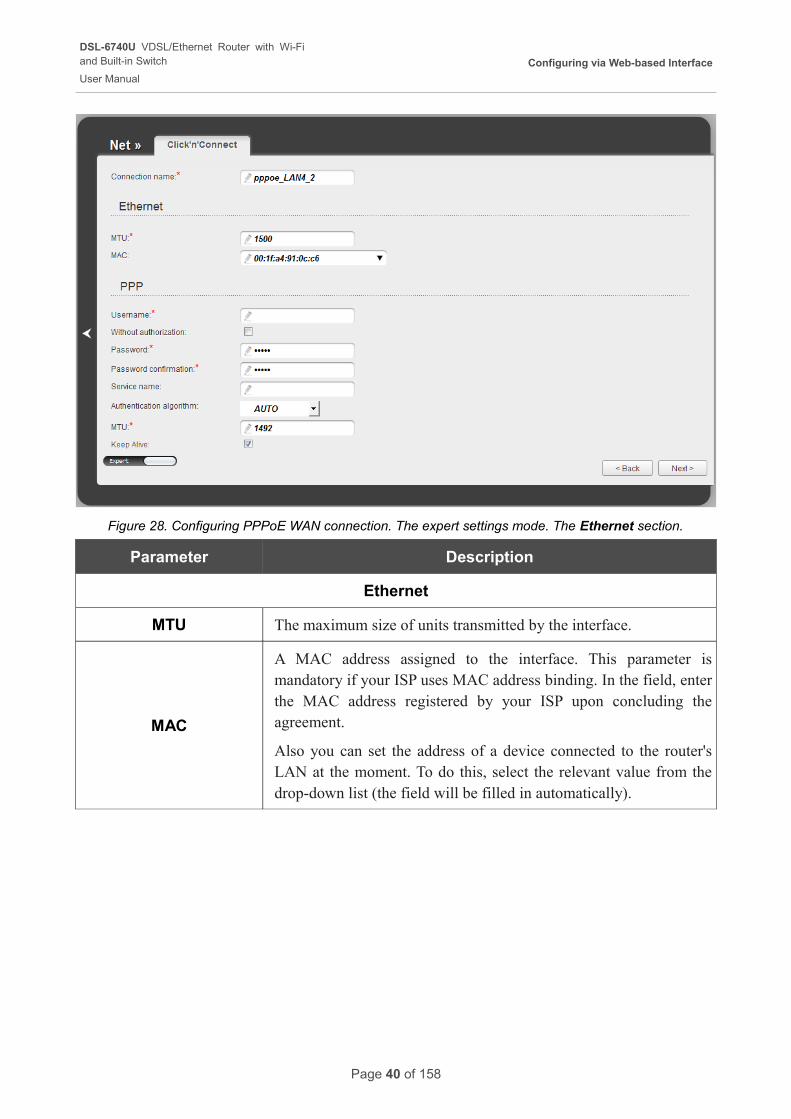
Figure 29. Configuring PPPoE WAN connection. The expert settings mode. The PPP section.
Parameter Description
PPP
Username A username (login) to access the Internet.
Without authorizationSelect the checkbox if you don't need to enter a username and password to access the Internet.
Password A password to access the Internet.
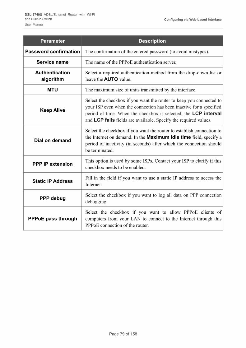
Password confirmation The confirmation of the entered password (to avoid mistypes).
Service nameDisplayed for the PPPoE type only.
The name of the PPPoE authentication server.
Authentication algorithm
Select a required authentication method from the drop-down list or leave the AUTO value.
MTU The maximum size of units transmitted by the interface.
Keep Alive
Select the checkbox if you want the router to keep you connected to your ISP even when the connection has been inactive for a specified period of time. When the checkbox is selected, the LCP interval and LCP fails fields are available. Specify the required values.
Page 41 of 158
DSL-6740U VDSL/Ethernet Router with Wi-Fiand Built-in Switch
User Manual
Configuring via Web-based Interface
Parameter Description
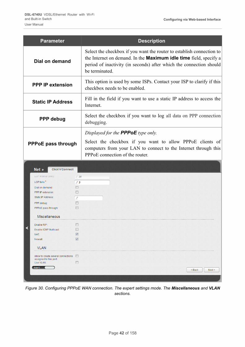
Dial on demand
Select the checkbox if you want the router to establish connection to the Internet on demand. In the Maximum idle time field, specify a period of inactivity (in seconds) after which the connection should be terminated.
PPP IP extensionThis option is used by some ISPs. Contact your ISP to clarify if this checkbox needs to be enabled.
Static IP AddressFill in the field if you want to use a static IP address to access the Internet.
PPP debugSelect the checkbox if you want to log all data on PPP connection debugging.
PPPoE pass through
Displayed for the PPPoE type only.
Select the checkbox if you want to allow PPPoE clients of computers from your LAN to connect to the Internet through this PPPoE connection of the router.
Figure 30. Configuring PPPoE WAN connection. The expert settings mode. The Miscellaneous and VLAN sections.
Page 42 of 158
DSL-6740U VDSL/Ethernet Router with Wi-Fiand Built-in Switch
User Manual
Configuring via Web-based Interface
Parameter Description
Miscellaneous
Enable RIP Select the checkbox to allow using RIP for this connection.
Enable IGMP MulticastSelect the checkbox to allow multicast traffic from the external network (e.g. video streaming) to be received.
NATSelect the checkbox if you want one WAN IP address to be used for all computers of your LAN.
FirewallSelect the checkbox to enable protection against ARP and DDoS attacks.
VLAN (displayed for the PPPoE type only)
Allow to create several connections assigned
to this port
Select the checkbox to allow the router to use several untagged connections.
Use VLANSelect the checkbox to allow the router to use tagged VLAN connections.
VLAN IDAn identifier for the VLAN. The field is displayed when the Use VLAN checkbox is selected.
VLAN priorityA priority tag for the type of traffic transmitted. The field is displayed when the Use VLAN checkbox is selected.
Click the Next button to continue.
After that the page displaying all specified settings opens. Click the Apply button to create the connection or the Back button to specify other settings.
After clicking the Apply button, the page for checking the Internet availability opens (see the Checking Internet Availability section, page 60).
Page 43 of 158
DSL-6740U VDSL/Ethernet Router with Wi-Fiand Built-in Switch
User Manual
Configuring via Web-based Interface
IPoA or Static IP Connection
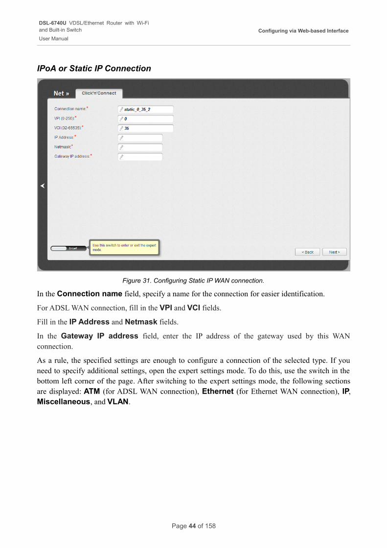
Figure 31. Configuring Static IP WAN connection.
In the Connection name field, specify a name for the connection for easier identification.
For ADSL WAN connection, fill in the VPI and VCI fields.
Fill in the IP Address and Netmask fields.
In the Gateway IP address field, enter the IP address of the gateway used by this WAN connection.
As a rule, the specified settings are enough to configure a connection of the selected type. If you need to specify additional settings, open the expert settings mode. To do this, use the switch in the bottom left corner of the page. After switching to the expert settings mode, the following sections are displayed: ATM (for ADSL WAN connection), Ethernet (for Ethernet WAN connection), IP, Miscellaneous, and VLAN.
Page 44 of 158
DSL-6740U VDSL/Ethernet Router with Wi-Fiand Built-in Switch
User Manual
Configuring via Web-based Interface
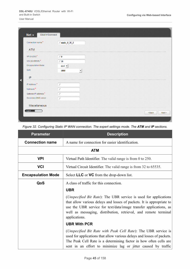
Figure 32. Configuring Static IP WAN connection. The expert settings mode. The ATM and IP sections.
Parameter Description
Connection name A name for connection for easier identification.
ATM
VPI Virtual Path Identifier. The valid range is from 0 to 250.
VCI Virtual Circuit Identifier. The valid range is from 32 to 65535.
Encapsulation Mode Select LLC or VC from the drop-down list.
QoS A class of traffic for this connection.
UBR
(Unspecified Bit Rate): The UBR service is used for applications that allow various delays and losses of packets. It is appropriate to use the UBR service for text/data/image transfer applications, as well as messaging, distribution, retrieval, and remote terminal applications.
UBR With PCR
(Unspecified Bit Rate with Peak Cell Rate): The UBR service is used for applications that allow various delays and losses of packets. The Peak Cell Rate is a determining factor in how often cells are sent in an effort to minimize lag or jitter caused by traffic
Page 45 of 158
DSL-6740U VDSL/Ethernet Router with Wi-Fiand Built-in Switch
User Manual
Configuring via Web-based Interface
Parameter Description
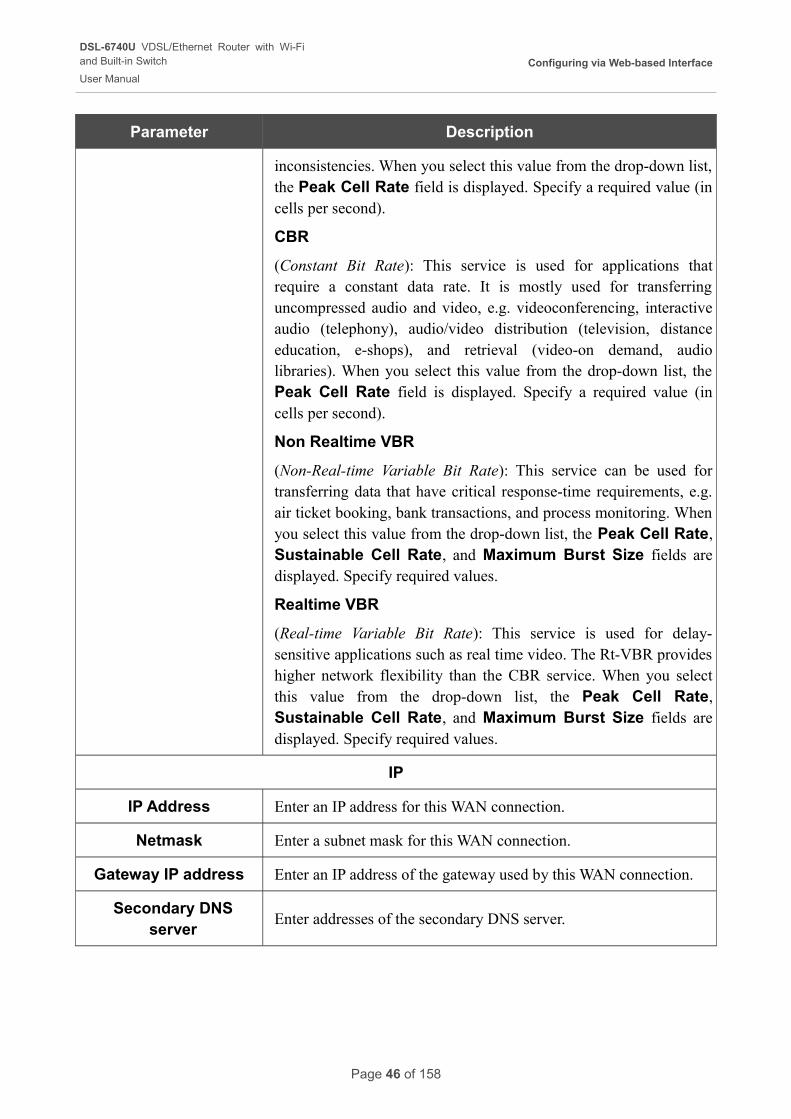
inconsistencies. When you select this value from the drop-down list, the Peak Cell Rate field is displayed. Specify a required value (in cells per second).
CBR
(Constant Bit Rate): This service is used for applications that require a constant data rate. It is mostly used for transferring uncompressed audio and video, e.g. videoconferencing, interactive audio (telephony), audio/video distribution (television, distance education, e-shops), and retrieval (video-on demand, audio libraries). When you select this value from the drop-down list, the Peak Cell Rate field is displayed. Specify a required value (in cells per second).
Non Realtime VBR
(Non-Real-time Variable Bit Rate): This service can be used for transferring data that have critical response-time requirements, e.g. air ticket booking, bank transactions, and process monitoring. When you select this value from the drop-down list, the Peak Cell Rate, Sustainable Cell Rate, and Maximum Burst Size fields are displayed. Specify required values.
Realtime VBR
(Real-time Variable Bit Rate): This service is used for delay-sensitive applications such as real time video. The Rt-VBR provides higher network flexibility than the CBR service. When you select this value from the drop-down list, the Peak Cell Rate, Sustainable Cell Rate, and Maximum Burst Size fields are displayed. Specify required values.
IP
IP Address Enter an IP address for this WAN connection.
Netmask Enter a subnet mask for this WAN connection.
Gateway IP address Enter an IP address of the gateway used by this WAN connection.
Secondary DNS server
Enter addresses of the secondary DNS server.
Page 46 of 158
DSL-6740U VDSL/Ethernet Router with Wi-Fiand Built-in Switch
User Manual
Configuring via Web-based Interface
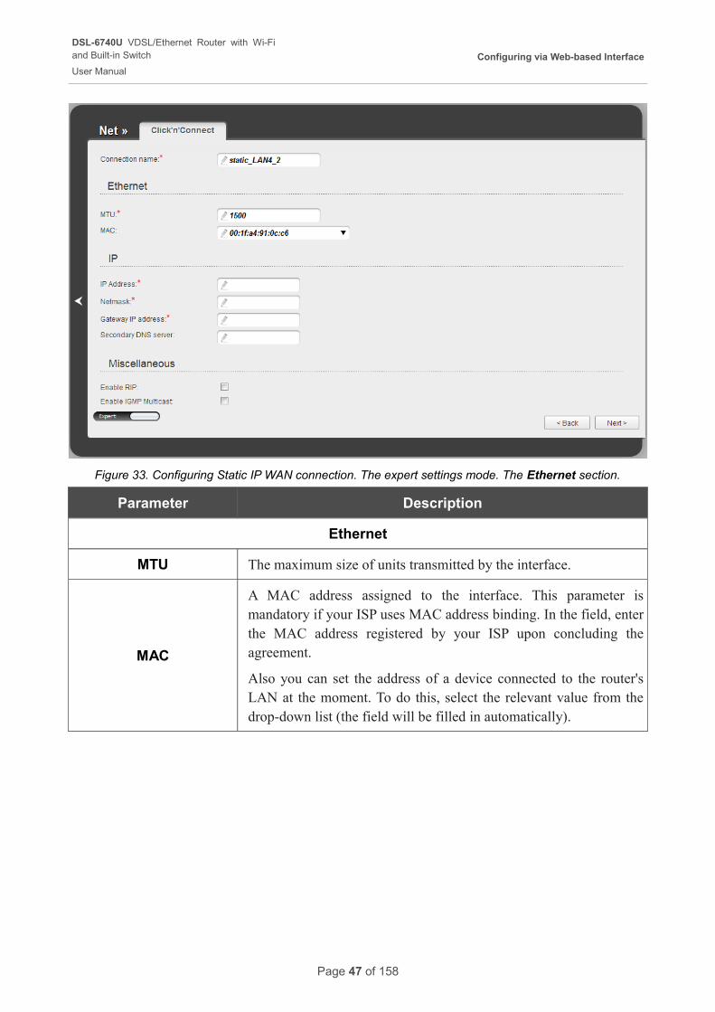
Figure 33. Configuring Static IP WAN connection. The expert settings mode. The Ethernet section.
Parameter Description
Ethernet
MTU The maximum size of units transmitted by the interface.
MAC
A MAC address assigned to the interface. This parameter is mandatory if your ISP uses MAC address binding. In the field, enter the MAC address registered by your ISP upon concluding the agreement.
Also you can set the address of a device connected to the router's LAN at the moment. To do this, select the relevant value from the drop-down list (the field will be filled in automatically).
Page 47 of 158
DSL-6740U VDSL/Ethernet Router with Wi-Fiand Built-in Switch
User Manual
Configuring via Web-based Interface
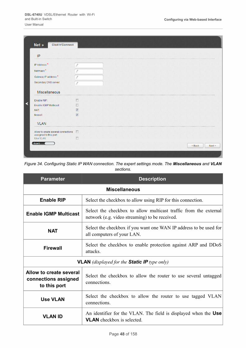
Figure 34. Configuring Static IP WAN connection. The expert settings mode. The Miscellaneous and VLAN sections.
Parameter Description
Miscellaneous
Enable RIP Select the checkbox to allow using RIP for this connection.
Enable IGMP MulticastSelect the checkbox to allow multicast traffic from the external network (e.g. video streaming) to be received.
NATSelect the checkbox if you want one WAN IP address to be used for all computers of your LAN.
FirewallSelect the checkbox to enable protection against ARP and DDoS attacks.
VLAN (displayed for the Static IP type only)
Allow to create several connections assigned
to this port
Select the checkbox to allow the router to use several untagged connections.
Use VLANSelect the checkbox to allow the router to use tagged VLAN connections.
VLAN IDAn identifier for the VLAN. The field is displayed when the Use VLAN checkbox is selected.
Page 48 of 158
DSL-6740U VDSL/Ethernet Router with Wi-Fiand Built-in Switch
User Manual
Configuring via Web-based Interface
Parameter Description
VLAN priorityA priority tag for the type of traffic transmitted. The field is displayed when the Use VLAN checkbox is selected.
Click the Next button to continue.
After that the page displaying all specified settings opens. Click the Apply button to create the connection or the Back button to specify other settings.
After clicking the Apply button, the page for checking the Internet availability opens (see the Checking Internet Availability section, page 60).
Page 49 of 158
DSL-6740U VDSL/Ethernet Router with Wi-Fiand Built-in Switch
User Manual
Configuring via Web-based Interface
Dynamic IP Connection
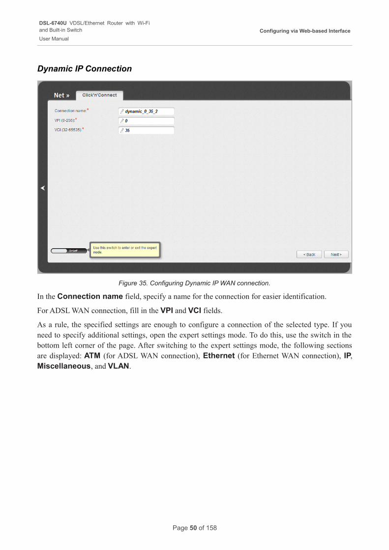
Figure 35. Configuring Dynamic IP WAN connection.
In the Connection name field, specify a name for the connection for easier identification.
For ADSL WAN connection, fill in the VPI and VCI fields.
As a rule, the specified settings are enough to configure a connection of the selected type. If you need to specify additional settings, open the expert settings mode. To do this, use the switch in the bottom left corner of the page. After switching to the expert settings mode, the following sections are displayed: ATM (for ADSL WAN connection), Ethernet (for Ethernet WAN connection), IP, Miscellaneous, and VLAN.
Page 50 of 158
DSL-6740U VDSL/Ethernet Router with Wi-Fiand Built-in Switch
User Manual
Configuring via Web-based Interface
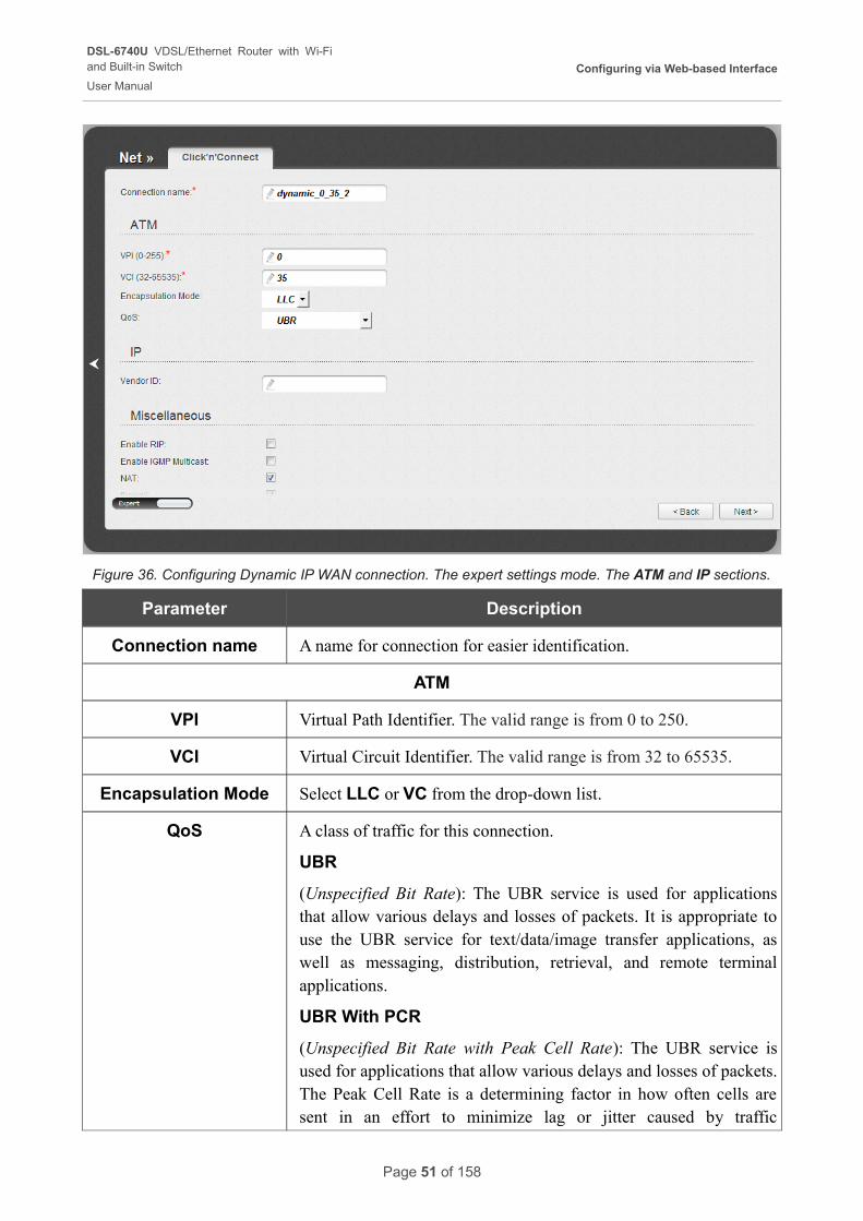
Figure 36. Configuring Dynamic IP WAN connection. The expert settings mode. The ATM and IP sections.
Parameter Description
Connection name A name for connection for easier identification.
ATM
VPI Virtual Path Identifier. The valid range is from 0 to 250.
VCI Virtual Circuit Identifier. The valid range is from 32 to 65535.
Encapsulation Mode Select LLC or VC from the drop-down list.
QoS A class of traffic for this connection.
UBR
(Unspecified Bit Rate): The UBR service is used for applications that allow various delays and losses of packets. It is appropriate to use the UBR service for text/data/image transfer applications, as well as messaging, distribution, retrieval, and remote terminal applications.
UBR With PCR
(Unspecified Bit Rate with Peak Cell Rate): The UBR service is used for applications that allow various delays and losses of packets. The Peak Cell Rate is a determining factor in how often cells are sent in an effort to minimize lag or jitter caused by traffic
Page 51 of 158
DSL-6740U VDSL/Ethernet Router with Wi-Fiand Built-in Switch
User Manual
Configuring via Web-based Interface
Parameter Description
inconsistencies. When you select this value from the drop-down list, the Peak Cell Rate field is displayed. Specify a required value (in cells per second).
CBR
(Constant Bit Rate): This service is used for applications that require a constant data rate. It is mostly used for transferring uncompressed audio and video, e.g. videoconferencing, interactive audio (telephony), audio/video distribution (television, distance education, e-shops), and retrieval (video-on demand, audio libraries). When you select this value from the drop-down list, the Peak Cell Rate field is displayed. Specify a required value (in cells per second).
Non Realtime VBR
(Non-Real-time Variable Bit Rate): This service can be used for transferring data that have critical response-time requirements, e.g. air ticket booking, bank transactions, and process monitoring. When you select this value from the drop-down list, the Peak Cell Rate, Sustainable Cell Rate, and Maximum Burst Size fields are displayed. Specify required values.
Realtime VBR
(Real-time Variable Bit Rate): This service is used for delay-sensitive applications such as real time video. The Rt-VBR provides higher network flexibility than the CBR service. When you select this value from the drop-down list, the Peak Cell Rate, Sustainable Cell Rate, and Maximum Burst Size fields are displayed. Specify required values.
IP
Vendor ID The identifier of your ISP. Optional.
Page 52 of 158
DSL-6740U VDSL/Ethernet Router with Wi-Fiand Built-in Switch
User Manual
Configuring via Web-based Interface
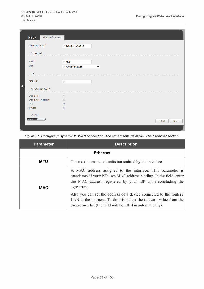
Figure 37. Configuring Dynamic IP WAN connection. The expert settings mode. The Ethernet section.
Parameter Description
Ethernet
MTU The maximum size of units transmitted by the interface.
MAC
A MAC address assigned to the interface. This parameter is mandatory if your ISP uses MAC address binding. In the field, enter the MAC address registered by your ISP upon concluding the agreement.
Also you can set the address of a device connected to the router's LAN at the moment. To do this, select the relevant value from the drop-down list (the field will be filled in automatically).
Page 53 of 158
DSL-6740U VDSL/Ethernet Router with Wi-Fiand Built-in Switch
User Manual
Configuring via Web-based Interface
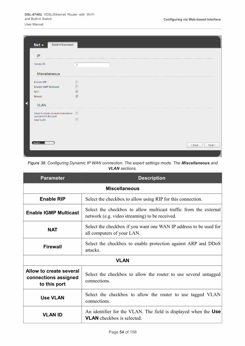
Figure 38. Configuring Dynamic IP WAN connection. The expert settings mode. The Miscellaneous and VLAN sections.
Parameter Description
Miscellaneous
Enable RIP Select the checkbox to allow using RIP for this connection.
Enable IGMP MulticastSelect the checkbox to allow multicast traffic from the external network (e.g. video streaming) to be received.
NATSelect the checkbox if you want one WAN IP address to be used for all computers of your LAN.
FirewallSelect the checkbox to enable protection against ARP and DDoS attacks.
VLAN
Allow to create several connections assigned
to this port
Select the checkbox to allow the router to use several untagged connections.
Use VLANSelect the checkbox to allow the router to use tagged VLAN connections.
VLAN IDAn identifier for the VLAN. The field is displayed when the Use VLAN checkbox is selected.
Page 54 of 158

DSL-6740U VDSL/Ethernet Router with Wi-Fiand Built-in Switch
User Manual
Configuring via Web-based Interface
Parameter Description
VLAN priorityA priority tag for the type of traffic transmitted. The field is displayed when the Use VLAN checkbox is selected.
Click the Next button to continue.
After that the page displaying all specified settings opens. Click the Apply button to create the connection or the Back button to specify other settings.
After clicking the Apply button, the page for checking the Internet availability opens (see the Checking Internet Availability section, page 60).
Page 55 of 158
DSL-6740U VDSL/Ethernet Router with Wi-Fiand Built-in Switch
User Manual
Configuring via Web-based Interface
Bridge Connection
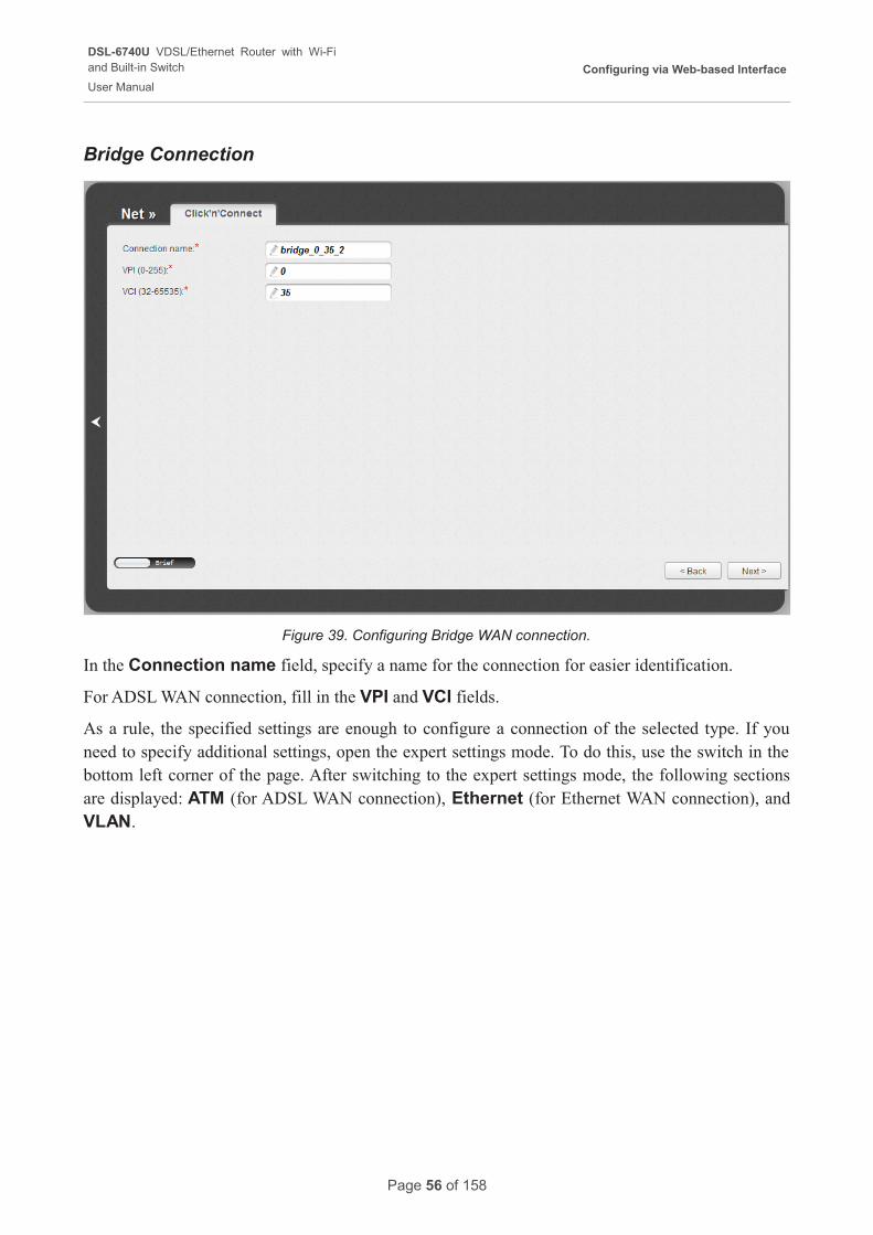
Figure 39. Configuring Bridge WAN connection.
In the Connection name field, specify a name for the connection for easier identification.
For ADSL WAN connection, fill in the VPI and VCI fields.
As a rule, the specified settings are enough to configure a connection of the selected type. If you need to specify additional settings, open the expert settings mode. To do this, use the switch in the bottom left corner of the page. After switching to the expert settings mode, the following sections are displayed: ATM (for ADSL WAN connection), Ethernet (for Ethernet WAN connection), and VLAN.
Page 56 of 158
DSL-6740U VDSL/Ethernet Router with Wi-Fiand Built-in Switch
User Manual
Configuring via Web-based Interface
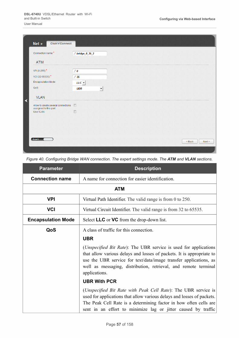
Figure 40. Configuring Bridge WAN connection. The expert settings mode. The ATM and VLAN sections.
Parameter Description
Connection name A name for connection for easier identification.
ATM
VPI Virtual Path Identifier. The valid range is from 0 to 250.
VCI Virtual Circuit Identifier. The valid range is from 32 to 65535.
Encapsulation Mode Select LLC or VC from the drop-down list.
QoS A class of traffic for this connection.
UBR
(Unspecified Bit Rate): The UBR service is used for applications that allow various delays and losses of packets. It is appropriate to use the UBR service for text/data/image transfer applications, as well as messaging, distribution, retrieval, and remote terminal applications.
UBR With PCR
(Unspecified Bit Rate with Peak Cell Rate): The UBR service is used for applications that allow various delays and losses of packets. The Peak Cell Rate is a determining factor in how often cells are sent in an effort to minimize lag or jitter caused by traffic
Page 57 of 158
DSL-6740U VDSL/Ethernet Router with Wi-Fiand Built-in Switch
User Manual
Configuring via Web-based Interface
Parameter Description
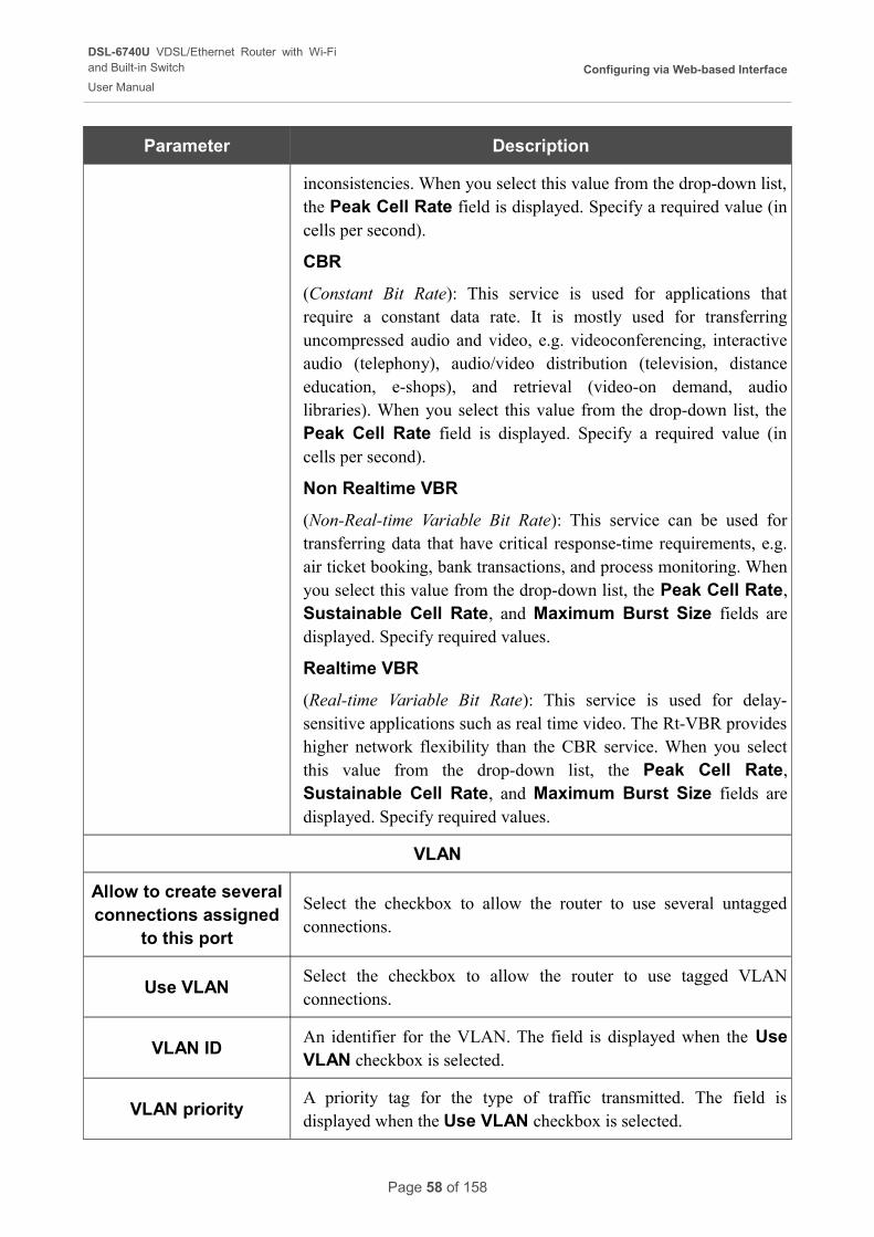
inconsistencies. When you select this value from the drop-down list, the Peak Cell Rate field is displayed. Specify a required value (in cells per second).
CBR
(Constant Bit Rate): This service is used for applications that require a constant data rate. It is mostly used for transferring uncompressed audio and video, e.g. videoconferencing, interactive audio (telephony), audio/video distribution (television, distance education, e-shops), and retrieval (video-on demand, audio libraries). When you select this value from the drop-down list, the Peak Cell Rate field is displayed. Specify a required value (in cells per second).
Non Realtime VBR
(Non-Real-time Variable Bit Rate): This service can be used for transferring data that have critical response-time requirements, e.g. air ticket booking, bank transactions, and process monitoring. When you select this value from the drop-down list, the Peak Cell Rate, Sustainable Cell Rate, and Maximum Burst Size fields are displayed. Specify required values.
Realtime VBR
(Real-time Variable Bit Rate): This service is used for delay-sensitive applications such as real time video. The Rt-VBR provides higher network flexibility than the CBR service. When you select this value from the drop-down list, the Peak Cell Rate, Sustainable Cell Rate, and Maximum Burst Size fields are displayed. Specify required values.
VLAN
Allow to create several connections assigned
to this port
Select the checkbox to allow the router to use several untagged connections.
Use VLANSelect the checkbox to allow the router to use tagged VLAN connections.
VLAN IDAn identifier for the VLAN. The field is displayed when the Use VLAN checkbox is selected.
VLAN priorityA priority tag for the type of traffic transmitted. The field is displayed when the Use VLAN checkbox is selected.
Page 58 of 158
DSL-6740U VDSL/Ethernet Router with Wi-Fiand Built-in Switch
User Manual
Configuring via Web-based Interface
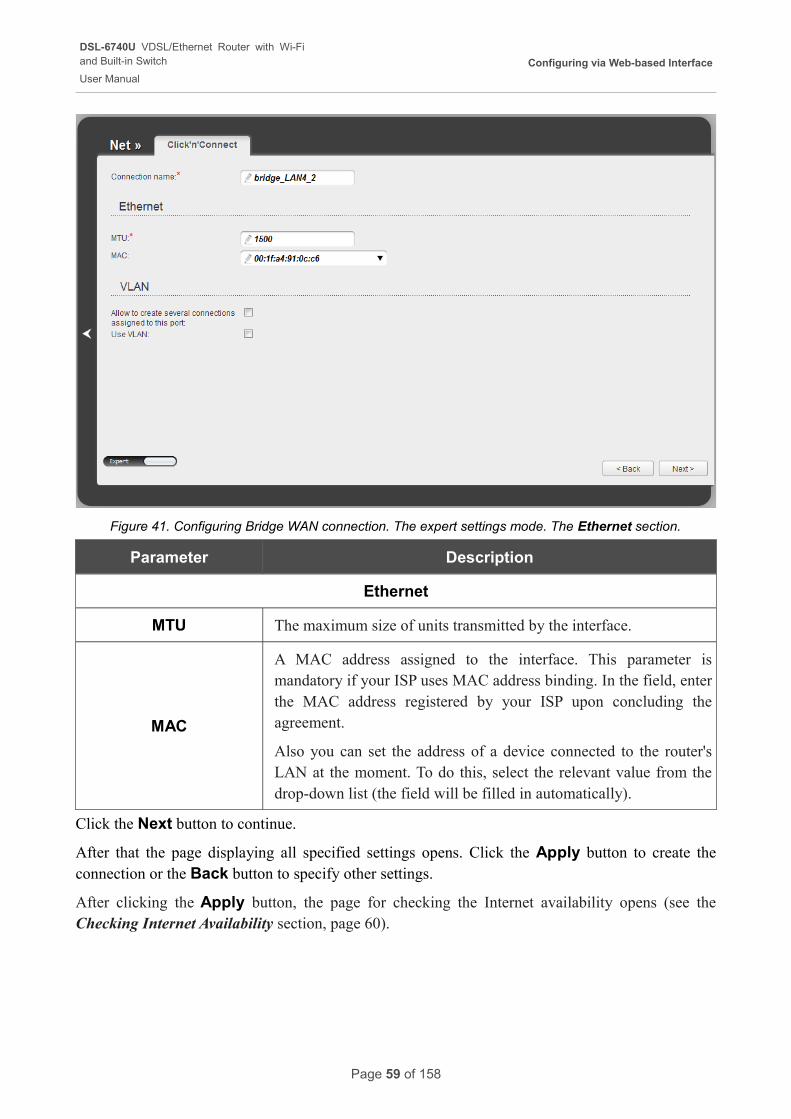
Figure 41. Configuring Bridge WAN connection. The expert settings mode. The Ethernet section.
Parameter Description
Ethernet
MTU The maximum size of units transmitted by the interface.
MAC
A MAC address assigned to the interface. This parameter is mandatory if your ISP uses MAC address binding. In the field, enter the MAC address registered by your ISP upon concluding the agreement.
Also you can set the address of a device connected to the router's LAN at the moment. To do this, select the relevant value from the drop-down list (the field will be filled in automatically).
Click the Next button to continue.
After that the page displaying all specified settings opens. Click the Apply button to create the connection or the Back button to specify other settings.
After clicking the Apply button, the page for checking the Internet availability opens (see the Checking Internet Availability section, page 60).
Page 59 of 158
DSL-6740U VDSL/Ethernet Router with Wi-Fiand Built-in Switch
User Manual
Configuring via Web-based Interface
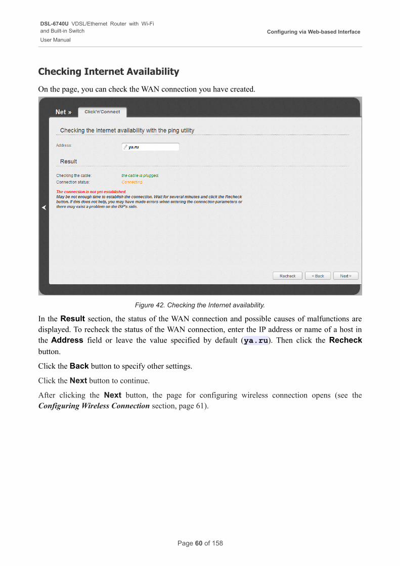
Checking Internet Availability
On the page, you can check the WAN connection you have created.
Figure 42. Checking the Internet availability.
In the Result section, the status of the WAN connection and possible causes of malfunctions are displayed. To recheck the status of the WAN connection, enter the IP address or name of a host in the Address field or leave the value specified by default (ya.ru). Then click the Recheck
button.
Click the Back button to specify other settings.
Click the Next button to continue.
After clicking the Next button, the page for configuring wireless connection opens (see the Configuring Wireless Connection section, page 61).
Page 60 of 158
DSL-6740U VDSL/Ethernet Router with Wi-Fiand Built-in Switch
User Manual
Configuring via Web-based Interface
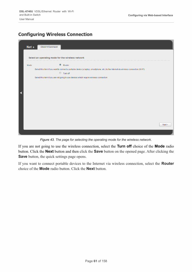
Configuring Wireless Connection
Figure 43. The page for selecting the operating mode for the wireless network.
If you are not going to use the wireless connection, select the Turn off choice of the Mode radio button. Click the Next button and then click the Save button on the opened page. After clicking the Save button, the quick settings page opens.
If you want to connect portable devices to the Internet via wireless connection, select the Router choice of the Mode radio button. Click the Next button.
Page 61 of 158
DSL-6740U VDSL/Ethernet Router with Wi-Fiand Built-in Switch
User Manual
Configuring via Web-based Interface
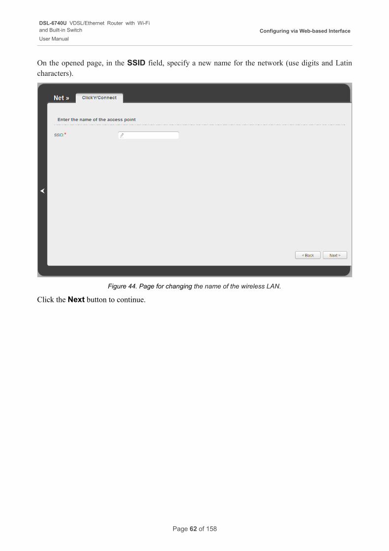
On the opened page, in the SSID field, specify a new name for the network (use digits and Latin characters).
Figure 44. Page for changing the name of the wireless LAN.
Click the Next button to continue.
Page 62 of 158
DSL-6740U VDSL/Ethernet Router with Wi-Fiand Built-in Switch
User Manual
Configuring via Web-based Interface
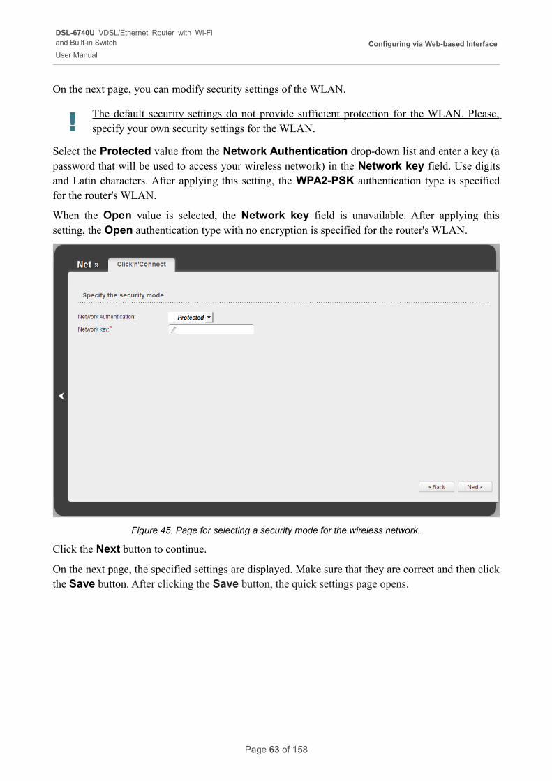
On the next page, you can modify security settings of the WLAN.
! The default security settings do not provide sufficient protection for the WLAN. Please, specify your own security settings for the WLAN.
Select the Protected value from the Network Authentication drop-down list and enter a key (a password that will be used to access your wireless network) in the Network key field. Use digits and Latin characters. After applying this setting, the WPA2-PSK authentication type is specified for the router's WLAN.
When the Open value is selected, the Network key field is unavailable. After applying this setting, the Open authentication type with no encryption is specified for the router's WLAN.
Figure 45. Page for selecting a security mode for the wireless network.
Click the Next button to continue.
On the next page, the specified settings are displayed. Make sure that they are correct and then click the Save button. After clicking the Save button, the quick settings page opens.
Page 63 of 158
DSL-6740U VDSL/Ethernet Router with Wi-Fiand Built-in Switch
User Manual
Configuring via Web-based Interface
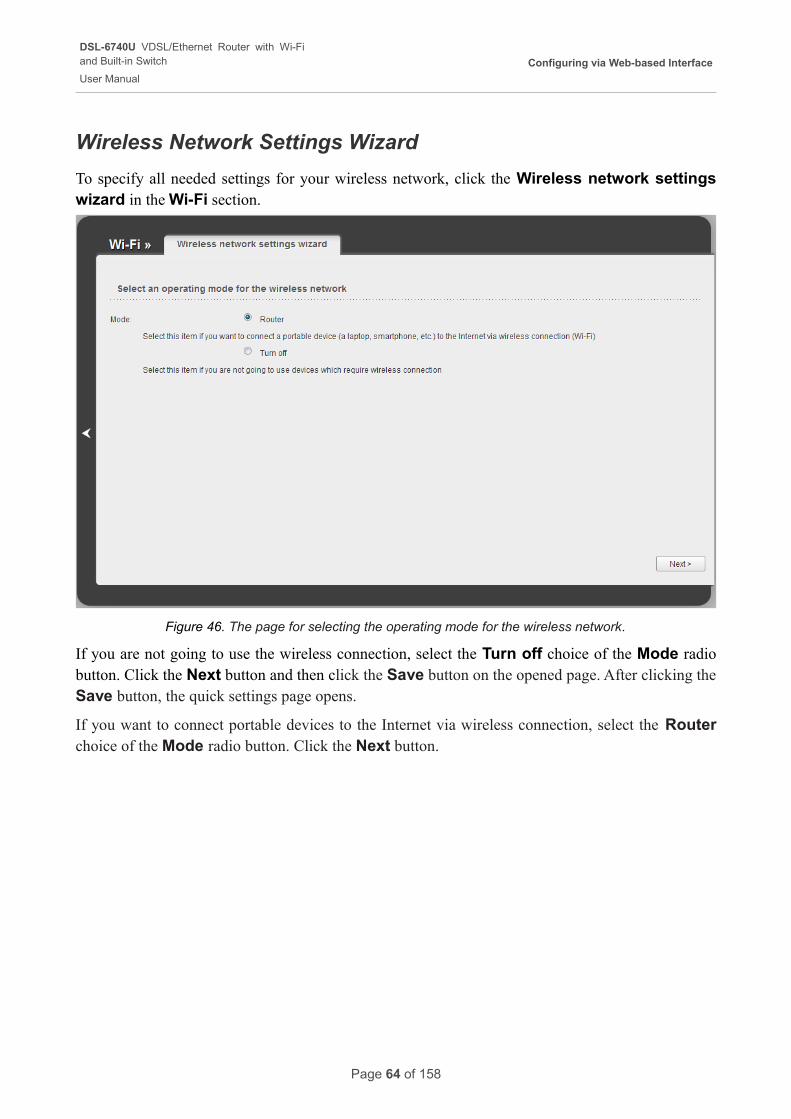
Wireless Network Settings Wizard
To specify all needed settings for your wireless network, click the Wireless network settings wizard in the Wi-Fi section.
Figure 46. The page for selecting the operating mode for the wireless network.
If you are not going to use the wireless connection, select the Turn off choice of the Mode radio button. Click the Next button and then click the Save button on the opened page. After clicking the Save button, the quick settings page opens.
If you want to connect portable devices to the Internet via wireless connection, select the Router choice of the Mode radio button. Click the Next button.
Page 64 of 158
DSL-6740U VDSL/Ethernet Router with Wi-Fiand Built-in Switch
User Manual
Configuring via Web-based Interface
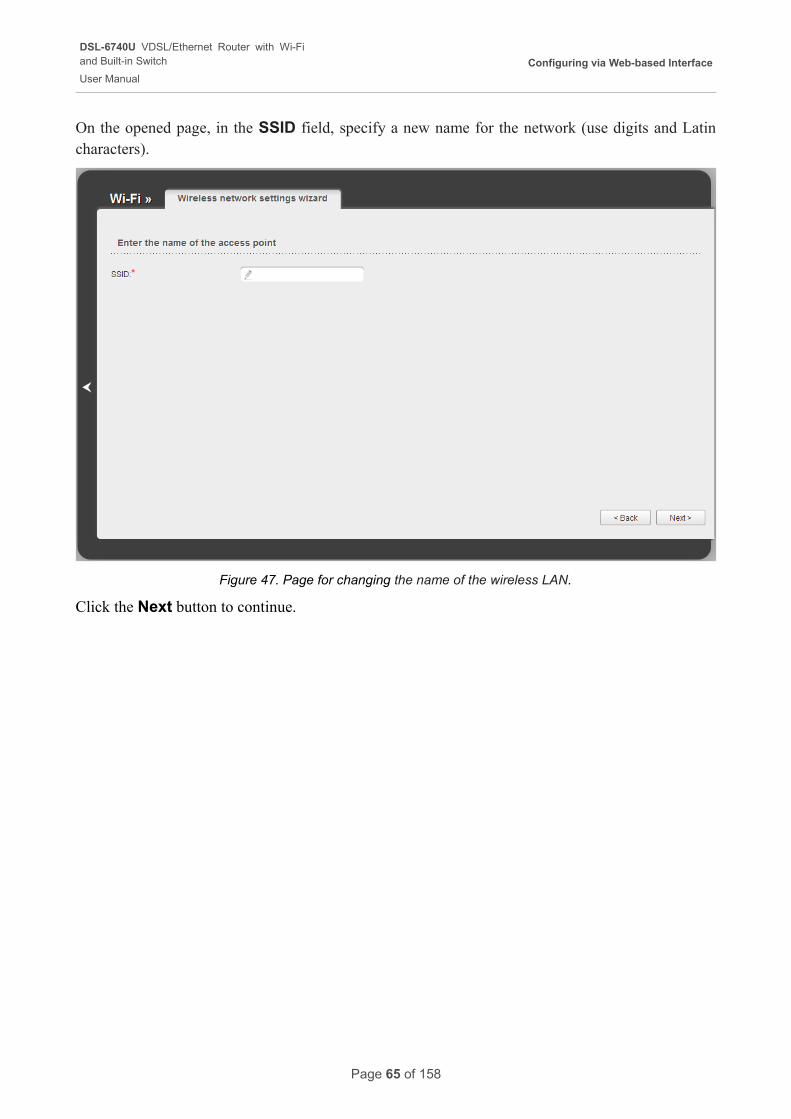
On the opened page, in the SSID field, specify a new name for the network (use digits and Latin characters).
Figure 47. Page for changing the name of the wireless LAN.
Click the Next button to continue.
Page 65 of 158
DSL-6740U VDSL/Ethernet Router with Wi-Fiand Built-in Switch
User Manual
Configuring via Web-based Interface
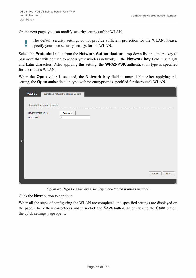
On the next page, you can modify security settings of the WLAN.
! The default security settings do not provide sufficient protection for the WLAN. Please, specify your own security settings for the WLAN.
Select the Protected value from the Network Authentication drop-down list and enter a key (a password that will be used to access your wireless network) in the Network key field. Use digits and Latin characters. After applying this setting, the WPA2-PSK authentication type is specified for the router's WLAN.
When the Open value is selected, the Network key field is unavailable. After applying this setting, the Open authentication type with no encryption is specified for the router's WLAN.
Figure 48. Page for selecting a security mode for the wireless network.
Click the Next button to continue.
When all the steps of configuring the WLAN are completed, the specified settings are displayed on the page. Check their correctness and then click the Save button. After clicking the Save button, the quick settings page opens.
Page 66 of 158
DSL-6740U VDSL/Ethernet Router with Wi-Fiand Built-in Switch
User Manual
Configuring via Web-based Interface
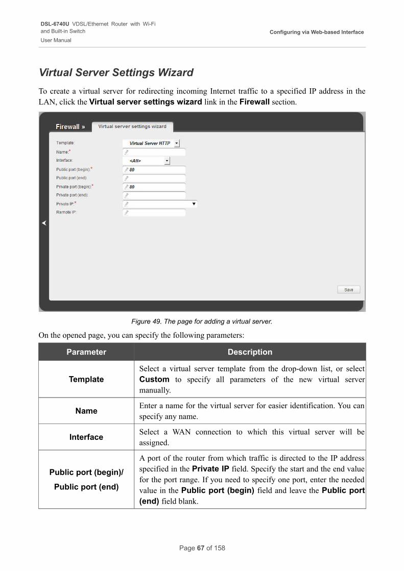
Virtual Server Settings Wizard
To create a virtual server for redirecting incoming Internet traffic to a specified IP address in the LAN, click the Virtual server settings wizard link in the Firewall section.
Figure 49. The page for adding a virtual server.
On the opened page, you can specify the following parameters:
Parameter Description
TemplateSelect a virtual server template from the drop-down list, or select Custom to specify all parameters of the new virtual server manually.
NameEnter a name for the virtual server for easier identification. You can specify any name.
InterfaceSelect a WAN connection to which this virtual server will be assigned.
Public port (begin)/
Public port (end)
A port of the router from which traffic is directed to the IP address specified in the Private IP field. Specify the start and the end value for the port range. If you need to specify one port, enter the needed value in the Public port (begin) field and leave the Public port (end) field blank.
Page 67 of 158
DSL-6740U VDSL/Ethernet Router with Wi-Fiand Built-in Switch
User Manual
Configuring via Web-based Interface
Parameter Description
Private port (begin)/
Private port (end)
Enter the IP address of the server from the local area network. To choose a device connected to the router's LAN at the moment, select the relevant value from the drop-down list (the field will be filled in automatically).
Private IP
Enter the IP address of the server from the local area network. To choose a device connected to the router's LAN at the moment, select the relevant value from the drop-down list (the field will be filled in automatically).
Remote IP Enter the IP address of the server from the external network.
When needed settings are configured, click the Save button. After successful creation of the virtual server a notification appears. Click the OK button in the notification window, and then click the
Back icon ( ) on the left side of the page to get back to the quick settings page.
Page 68 of 158
DSL-6740U VDSL/Ethernet Router with Wi-Fiand Built-in Switch
User Manual
Configuring via Web-based Interface
Status
The pages of this section display data on the current state of the router:
• network statistics
• DSL connection status
• active WAN connections
• IP addresses leased by the DHCP server
• the routing table
• data on devices connected to the router's network and its web-based interface.
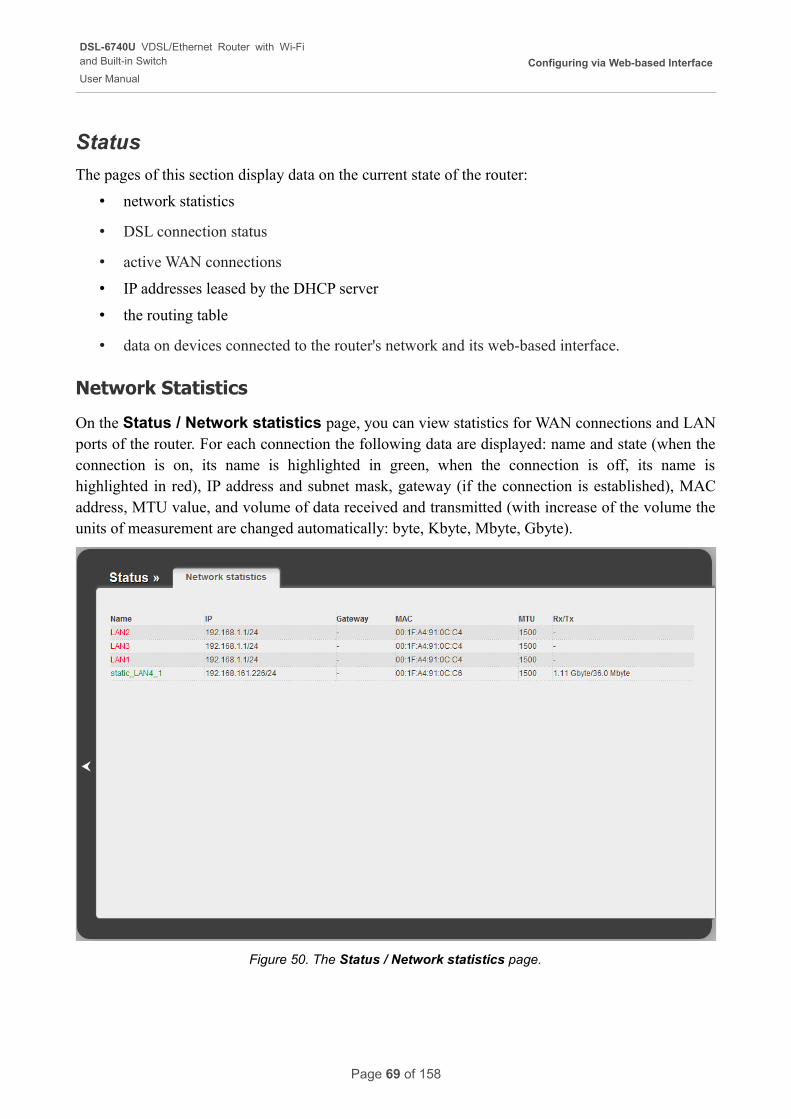
Network Statistics
On the Status / Network statistics page, you can view statistics for WAN connections and LAN ports of the router. For each connection the following data are displayed: name and state (when the connection is on, its name is highlighted in green, when the connection is off, its name is highlighted in red), IP address and subnet mask, gateway (if the connection is established), MAC address, MTU value, and volume of data received and transmitted (with increase of the volume the units of measurement are changed automatically: byte, Kbyte, Mbyte, Gbyte).
Figure 50. The Status / Network statistics page.
Page 69 of 158
DSL-6740U VDSL/Ethernet Router with Wi-Fiand Built-in Switch
User Manual
Configuring via Web-based Interface
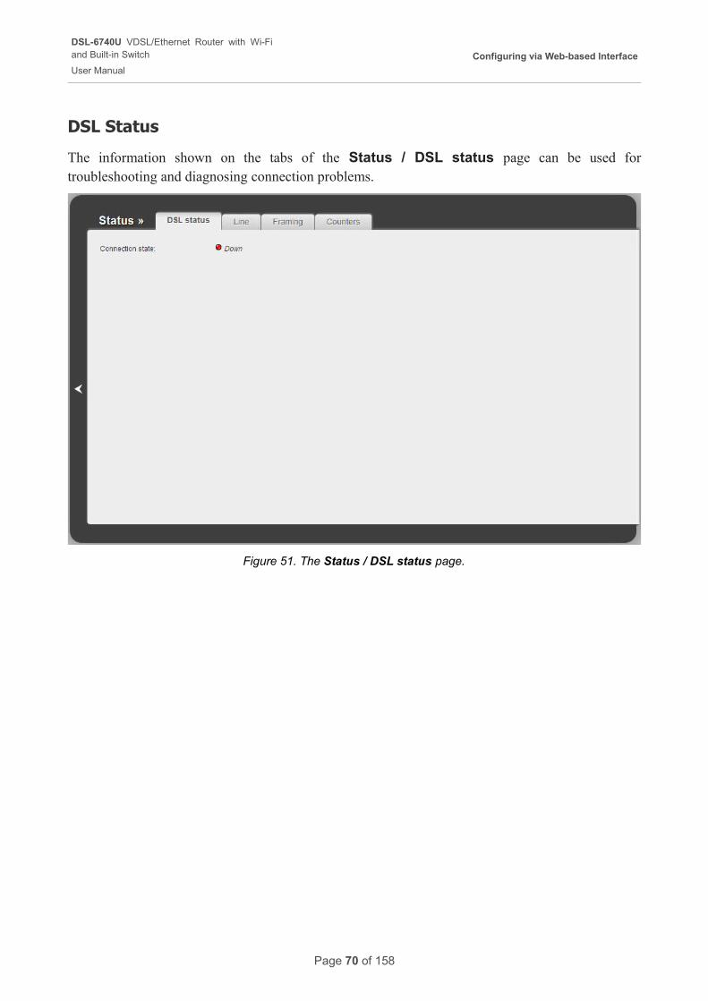
DSL Status
The information shown on the tabs of the Status / DSL status page can be used for troubleshooting and diagnosing connection problems.
Figure 51. The Status / DSL status page.
Page 70 of 158
DSL-6740U VDSL/Ethernet Router with Wi-Fiand Built-in Switch
User Manual
Configuring via Web-based Interface
WAN Status
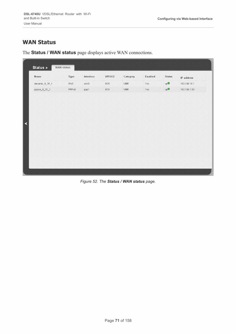
The Status / WAN status page displays active WAN connections.
Figure 52. The Status / WAN status page.
Page 71 of 158
DSL-6740U VDSL/Ethernet Router with Wi-Fiand Built-in Switch
User Manual
Configuring via Web-based Interface
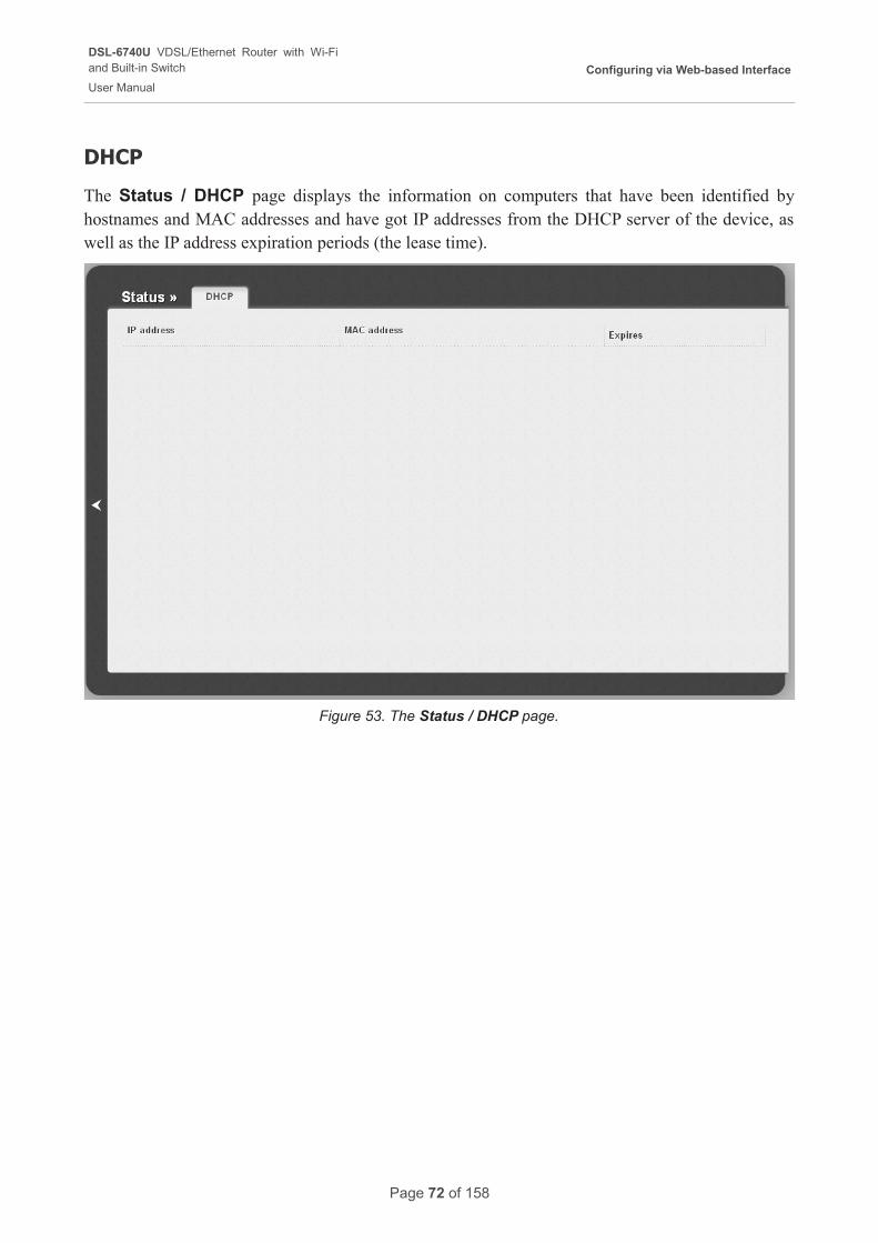
DHCP
The Status / DHCP page displays the information on computers that have been identified by hostnames and MAC addresses and have got IP addresses from the DHCP server of the device, as well as the IP address expiration periods (the lease time).
Figure 53. The Status / DHCP page.
Page 72 of 158
DSL-6740U VDSL/Ethernet Router with Wi-Fiand Built-in Switch
User Manual
Configuring via Web-based Interface
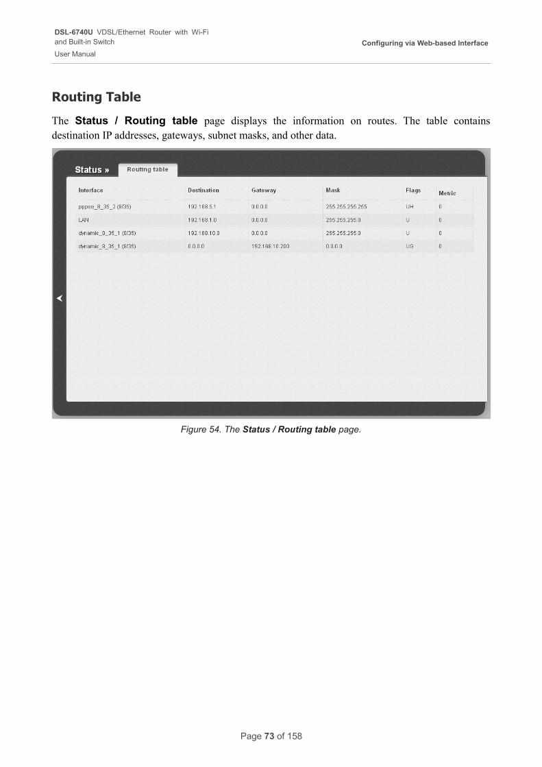
Routing Table
The Status / Routing table page displays the information on routes. The table contains destination IP addresses, gateways, subnet masks, and other data.
Figure 54. The Status / Routing table page.
Page 73 of 158
DSL-6740U VDSL/Ethernet Router with Wi-Fiand Built-in Switch
User Manual
Configuring via Web-based Interface
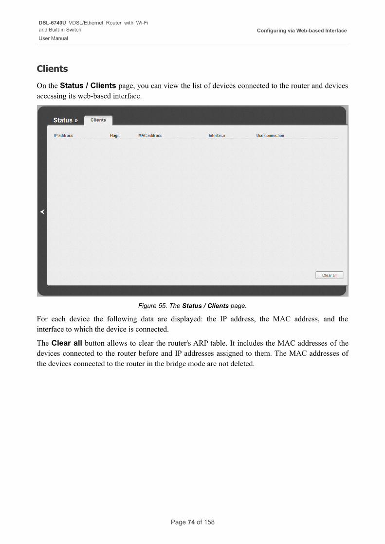
Clients
On the Status / Clients page, you can view the list of devices connected to the router and devices accessing its web-based interface.
Figure 55. The Status / Clients page.
For each device the following data are displayed: the IP address, the MAC address, and the interface to which the device is connected.
The Clear all button allows to clear the router's ARP table. It includes the MAC addresses of the devices connected to the router before and IP addresses assigned to them. The MAC addresses of the devices connected to the router in the bridge mode are not deleted.
Page 74 of 158
DSL-6740U VDSL/Ethernet Router with Wi-Fiand Built-in Switch
User Manual
Configuring via Web-based Interface
Net
In this menu you can configure basic parameters of the router's local area network and configure connection to the Internet (a WAN connection).
WAN
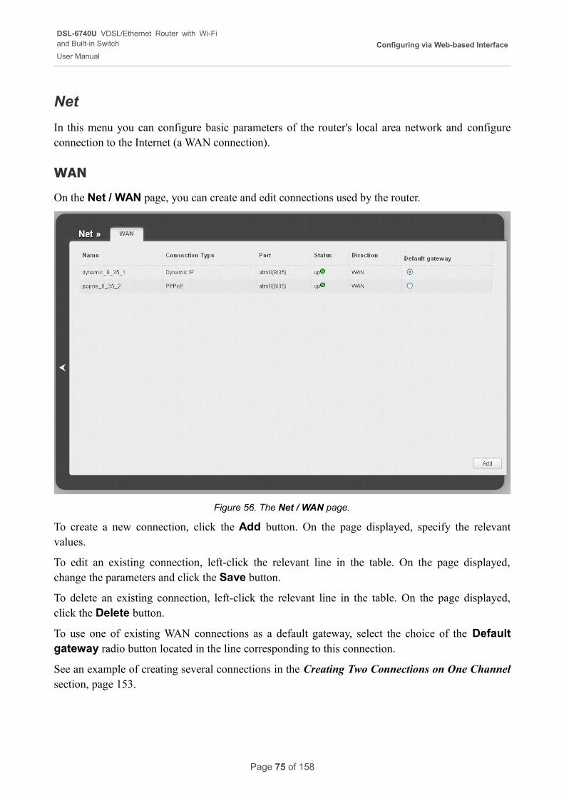
On the Net / WAN page, you can create and edit connections used by the router.
Figure 56. The Net / WAN page.
To create a new connection, click the Add button. On the page displayed, specify the relevant values.
To edit an existing connection, left-click the relevant line in the table. On the page displayed, change the parameters and click the Save button.
To delete an existing connection, left-click the relevant line in the table. On the page displayed, click the Delete button.
To use one of existing WAN connections as a default gateway, select the choice of the Default gateway radio button located in the line corresponding to this connection.
See an example of creating several connections in the Creating Two Connections on One Channel section, page 153.
Page 75 of 158
DSL-6740U VDSL/Ethernet Router with Wi-Fiand Built-in Switch
User Manual
Configuring via Web-based Interface
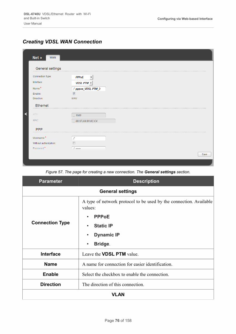
Creating VDSL WAN Connection
Figure 57. The page for creating a new connection. The General settings section.
Parameter Description
General settings
Connection Type
A type of network protocol to be used by the connection. Available values:
• PPPoE
• Static IP
• Dynamic IP
• Bridge.
Interface Leave the VDSL PTM value.
Name A name for connection for easier identification.
Enable Select the checkbox to enable the connection.
Direction The direction of this connection.
VLAN
Page 76 of 158
DSL-6740U VDSL/Ethernet Router with Wi-Fiand Built-in Switch
User Manual
Configuring via Web-based Interface
Parameter Description
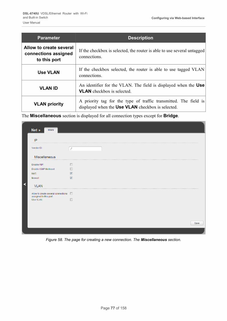
Allow to create several connections assigned
to this port
If the checkbox is selected, the router is able to use several untagged connections.
Use VLANIf the checkbox selected, the router is able to use tagged VLAN connections.
VLAN IDAn identifier for the VLAN. The field is displayed when the Use VLAN checkbox is selected.
VLAN priorityA priority tag for the type of traffic transmitted. The field is displayed when the Use VLAN checkbox is selected.
The Miscellaneous section is displayed for all connection types except for Bridge.
Figure 58. The page for creating a new connection. The Miscellaneous section.
Page 77 of 158
DSL-6740U VDSL/Ethernet Router with Wi-Fiand Built-in Switch
User Manual
Configuring via Web-based Interface
Parameter Description
Miscellaneous
Enable RIP Select the checkbox to allow using RIP for this connection.
Enable IGMP MulticastSelect the checkbox to allow multicast traffic from the external network (e.g. video streaming) to be received.
NATSelect the checkbox if you want one WAN IP address to be used for all computers of your LAN.
FirewallSelect the checkbox to enable protection against ARP and DDoS attacks.
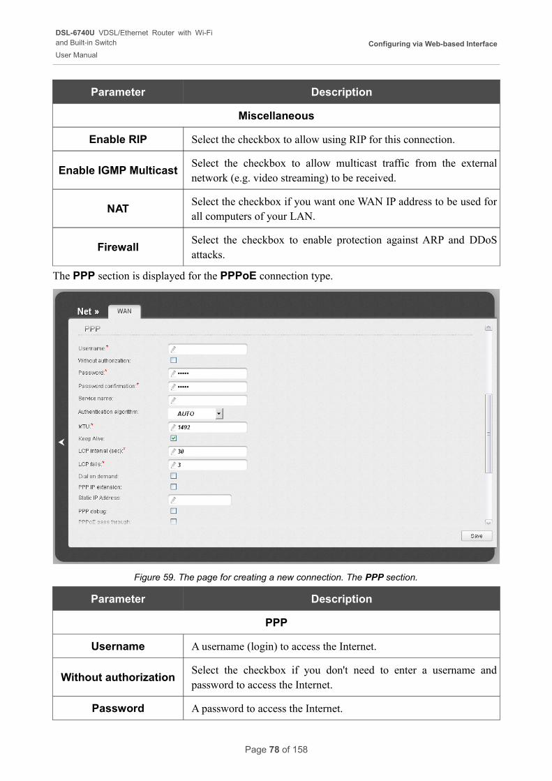
The PPP section is displayed for the PPPoE connection type.
Figure 59. The page for creating a new connection. The PPP section.
Parameter Description
PPP
Username A username (login) to access the Internet.
Without authorizationSelect the checkbox if you don't need to enter a username and password to access the Internet.
Password A password to access the Internet.
Page 78 of 158
DSL-6740U VDSL/Ethernet Router with Wi-Fiand Built-in Switch
User Manual
Configuring via Web-based Interface
Parameter Description
Password confirmation The confirmation of the entered password (to avoid mistypes).
Service name The name of the PPPoE authentication server.
Authentication algorithm
Select a required authentication method from the drop-down list or leave the AUTO value.
MTU The maximum size of units transmitted by the interface.
Keep Alive
Select the checkbox if you want the router to keep you connected to your ISP even when the connection has been inactive for a specified period of time. When the checkbox is selected, the LCP interval and LCP fails fields are available. Specify the required values.
Dial on demand
Select the checkbox if you want the router to establish connection to the Internet on demand. In the Maximum idle time field, specify a period of inactivity (in seconds) after which the connection should be terminated.
PPP IP extensionThis option is used by some ISPs. Contact your ISP to clarify if this checkbox needs to be enabled.
Static IP AddressFill in the field if you want to use a static IP address to access the Internet.
PPP debugSelect the checkbox if you want to log all data on PPP connection debugging.
PPPoE pass throughSelect the checkbox if you want to allow PPPoE clients of computers from your LAN to connect to the Internet through this PPPoE connection of the router.
Page 79 of 158
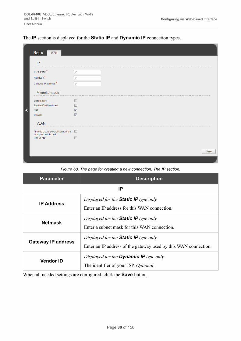
DSL-6740U VDSL/Ethernet Router with Wi-Fiand Built-in Switch
User Manual
Configuring via Web-based Interface
The IP section is displayed for the Static IP and Dynamic IP connection types.
Figure 60. The page for creating a new connection. The IP section.
Parameter Description
IP
IP AddressDisplayed for the Static IP type only.
Enter an IP address for this WAN connection.
NetmaskDisplayed for the Static IP type only.
Enter a subnet mask for this WAN connection.
Gateway IP addressDisplayed for the Static IP type only.
Enter an IP address of the gateway used by this WAN connection.
Vendor IDDisplayed for the Dynamic IP type only.
The identifier of your ISP. Optional.
When all needed settings are configured, click the Save button.
Page 80 of 158
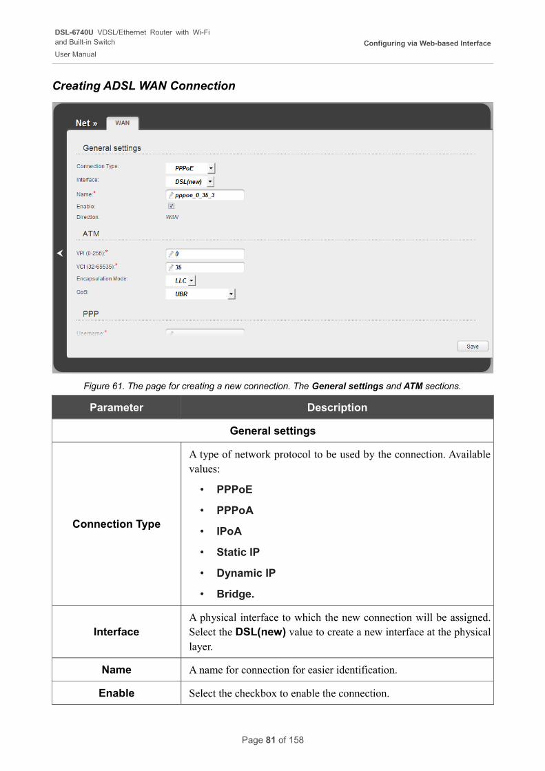
DSL-6740U VDSL/Ethernet Router with Wi-Fiand Built-in Switch
User Manual
Configuring via Web-based Interface
Creating ADSL WAN Connection
Figure 61. The page for creating a new connection. The General settings and ATM sections.
Parameter Description
General settings
Connection Type
A type of network protocol to be used by the connection. Available values:
• PPPoE
• PPPoA
• IPoA
• Static IP
• Dynamic IP
• Bridge.
InterfaceA physical interface to which the new connection will be assigned. Select the DSL(new) value to create a new interface at the physical layer.
Name A name for connection for easier identification.
Enable Select the checkbox to enable the connection.
Page 81 of 158
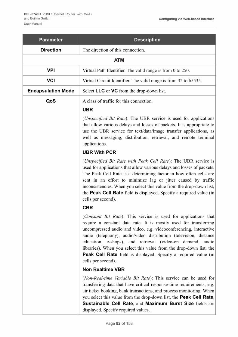
DSL-6740U VDSL/Ethernet Router with Wi-Fiand Built-in Switch
User Manual
Configuring via Web-based Interface
Parameter Description
Direction The direction of this connection.
ATM
VPI Virtual Path Identifier. The valid range is from 0 to 250.
VCI Virtual Circuit Identifier. The valid range is from 32 to 65535.
Encapsulation Mode Select LLC or VC from the drop-down list.
QoS A class of traffic for this connection.
UBR
(Unspecified Bit Rate): The UBR service is used for applications that allow various delays and losses of packets. It is appropriate to use the UBR service for text/data/image transfer applications, as well as messaging, distribution, retrieval, and remote terminal applications.
UBR With PCR
(Unspecified Bit Rate with Peak Cell Rate): The UBR service is used for applications that allow various delays and losses of packets. The Peak Cell Rate is a determining factor in how often cells are sent in an effort to minimize lag or jitter caused by traffic inconsistencies. When you select this value from the drop-down list, the Peak Cell Rate field is displayed. Specify a required value (in cells per second).
CBR
(Constant Bit Rate): This service is used for applications that require a constant data rate. It is mostly used for transferring uncompressed audio and video, e.g. videoconferencing, interactive audio (telephony), audio/video distribution (television, distance education, e-shops), and retrieval (video-on demand, audio libraries). When you select this value from the drop-down list, the Peak Cell Rate field is displayed. Specify a required value (in cells per second).
Non Realtime VBR
(Non-Real-time Variable Bit Rate): This service can be used for transferring data that have critical response-time requirements, e.g. air ticket booking, bank transactions, and process monitoring. When you select this value from the drop-down list, the Peak Cell Rate, Sustainable Cell Rate, and Maximum Burst Size fields are displayed. Specify required values.
Page 82 of 158
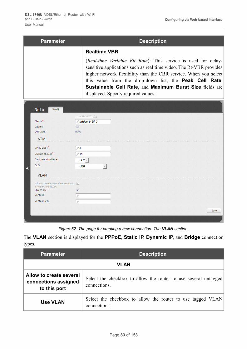
DSL-6740U VDSL/Ethernet Router with Wi-Fiand Built-in Switch
User Manual
Configuring via Web-based Interface
Parameter Description
Realtime VBR
(Real-time Variable Bit Rate): This service is used for delay-sensitive applications such as real time video. The Rt-VBR provides higher network flexibility than the CBR service. When you select this value from the drop-down list, the Peak Cell Rate, Sustainable Cell Rate, and Maximum Burst Size fields are displayed. Specify required values.
Figure 62. The page for creating a new connection. The VLAN section.
The VLAN section is displayed for the PPPoE, Static IP, Dynamic IP, and Bridge connection types.
Parameter Description
VLAN
Allow to create several connections assigned
to this port
Select the checkbox to allow the router to use several untagged connections.
Use VLANSelect the checkbox to allow the router to use tagged VLAN connections.
Page 83 of 158
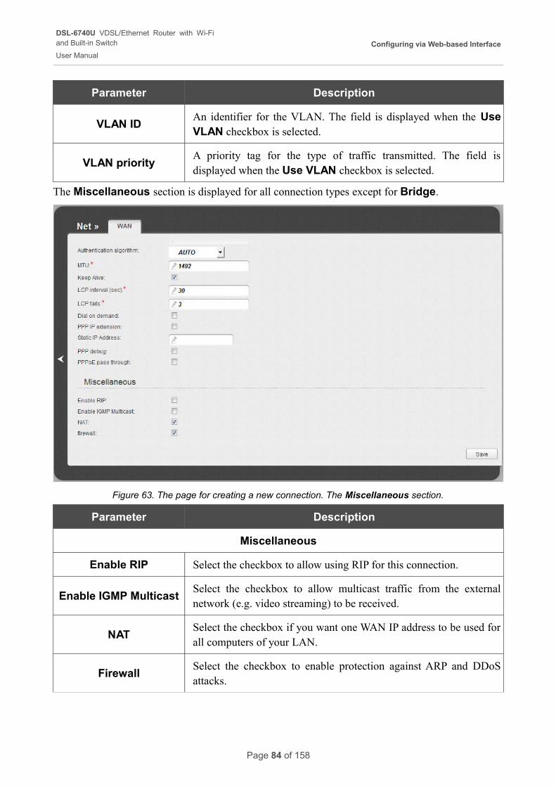
DSL-6740U VDSL/Ethernet Router with Wi-Fiand Built-in Switch
User Manual
Configuring via Web-based Interface
Parameter Description
VLAN IDAn identifier for the VLAN. The field is displayed when the Use VLAN checkbox is selected.
VLAN priorityA priority tag for the type of traffic transmitted. The field is displayed when the Use VLAN checkbox is selected.
The Miscellaneous section is displayed for all connection types except for Bridge.
Figure 63. The page for creating a new connection. The Miscellaneous section.
Parameter Description
Miscellaneous
Enable RIP Select the checkbox to allow using RIP for this connection.
Enable IGMP MulticastSelect the checkbox to allow multicast traffic from the external network (e.g. video streaming) to be received.
NATSelect the checkbox if you want one WAN IP address to be used for all computers of your LAN.
FirewallSelect the checkbox to enable protection against ARP and DDoS attacks.
Page 84 of 158
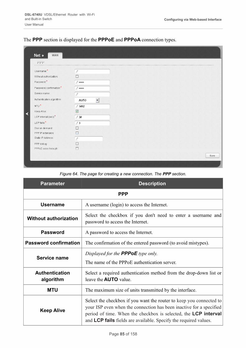
DSL-6740U VDSL/Ethernet Router with Wi-Fiand Built-in Switch
User Manual
Configuring via Web-based Interface
The PPP section is displayed for the PPPoE and PPPoA connection types.
Figure 64. The page for creating a new connection. The PPP section.
Parameter Description
PPP
Username A username (login) to access the Internet.
Without authorizationSelect the checkbox if you don't need to enter a username and password to access the Internet.
Password A password to access the Internet.
Password confirmation The confirmation of the entered password (to avoid mistypes).
Service nameDisplayed for the PPPoE type only.
The name of the PPPoE authentication server.
Authentication algorithm
Select a required authentication method from the drop-down list or leave the AUTO value.
MTU The maximum size of units transmitted by the interface.
Keep Alive
Select the checkbox if you want the router to keep you connected to your ISP even when the connection has been inactive for a specified period of time. When the checkbox is selected, the LCP interval and LCP fails fields are available. Specify the required values.
Page 85 of 158
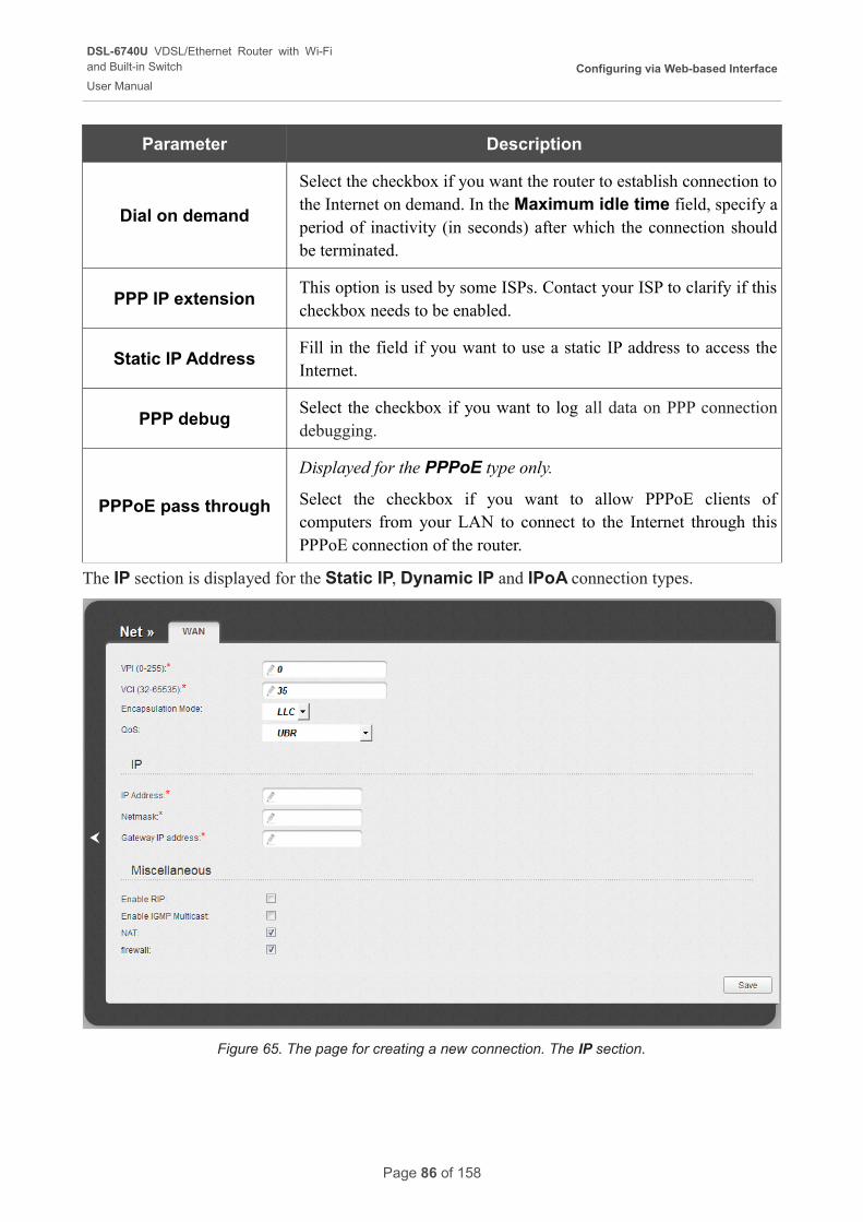
DSL-6740U VDSL/Ethernet Router with Wi-Fiand Built-in Switch
User Manual
Configuring via Web-based Interface
Parameter Description
Dial on demand
Select the checkbox if you want the router to establish connection to the Internet on demand. In the Maximum idle time field, specify a period of inactivity (in seconds) after which the connection should be terminated.
PPP IP extensionThis option is used by some ISPs. Contact your ISP to clarify if this checkbox needs to be enabled.
Static IP AddressFill in the field if you want to use a static IP address to access the Internet.
PPP debugSelect the checkbox if you want to log all data on PPP connection debugging.
PPPoE pass through
Displayed for the PPPoE type only.
Select the checkbox if you want to allow PPPoE clients of computers from your LAN to connect to the Internet through this PPPoE connection of the router.
The IP section is displayed for the Static IP, Dynamic IP and IPoA connection types.
Figure 65. The page for creating a new connection. The IP section.
Page 86 of 158
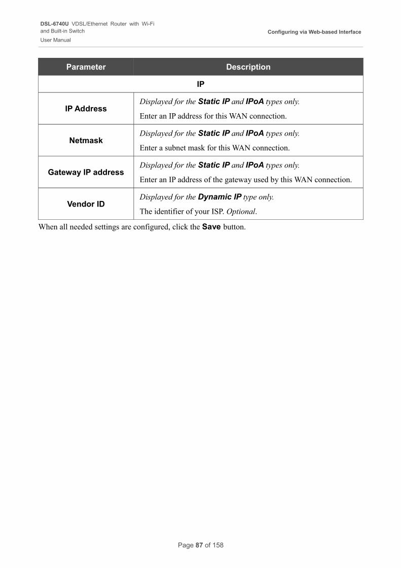
DSL-6740U VDSL/Ethernet Router with Wi-Fiand Built-in Switch
User Manual
Configuring via Web-based Interface
Parameter Description
IP
IP AddressDisplayed for the Static IP and IPoA types only.
Enter an IP address for this WAN connection.
NetmaskDisplayed for the Static IP and IPoA types only.
Enter a subnet mask for this WAN connection.
Gateway IP addressDisplayed for the Static IP and IPoA types only.
Enter an IP address of the gateway used by this WAN connection.
Vendor IDDisplayed for the Dynamic IP type only.
The identifier of your ISP. Optional.
When all needed settings are configured, click the Save button.
Page 87 of 158
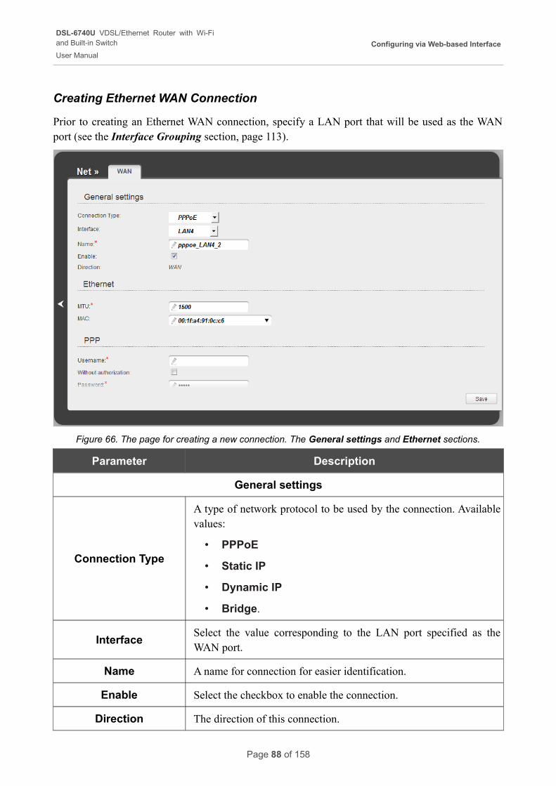
DSL-6740U VDSL/Ethernet Router with Wi-Fiand Built-in Switch
User Manual
Configuring via Web-based Interface
Creating Ethernet WAN Connection
Prior to creating an Ethernet WAN connection, specify a LAN port that will be used as the WAN port (see the Interface Grouping section, page 113).
Figure 66. The page for creating a new connection. The General settings and Ethernet sections.
Parameter Description
General settings
Connection Type
A type of network protocol to be used by the connection. Available values:
• PPPoE
• Static IP
• Dynamic IP
• Bridge.
InterfaceSelect the value corresponding to the LAN port specified as the WAN port.
Name A name for connection for easier identification.
Enable Select the checkbox to enable the connection.
Direction The direction of this connection.
Page 88 of 158
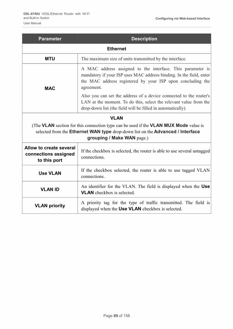
DSL-6740U VDSL/Ethernet Router with Wi-Fiand Built-in Switch
User Manual
Configuring via Web-based Interface
Parameter Description
Ethernet
MTU The maximum size of units transmitted by the interface.
MAC
A MAC address assigned to the interface. This parameter is mandatory if your ISP uses MAC address binding. In the field, enter the MAC address registered by your ISP upon concluding the agreement.
Also you can set the address of a device connected to the router's LAN at the moment. To do this, select the relevant value from the drop-down list (the field will be filled in automatically).
VLAN
(The VLAN section for this connection type can be used if the VLAN MUX Mode value is selected from the Ethernet WAN type drop-down list on the Advanced / Interface
grouping / Make WAN page.)
Allow to create several connections assigned
to this port
If the checkbox is selected, the router is able to use several untagged connections.
Use VLANIf the checkbox selected, the router is able to use tagged VLAN connections.
VLAN IDAn identifier for the VLAN. The field is displayed when the Use VLAN checkbox is selected.
VLAN priorityA priority tag for the type of traffic transmitted. The field is displayed when the Use VLAN checkbox is selected.
Page 89 of 158
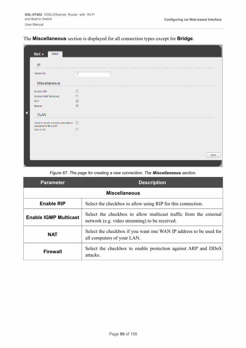
DSL-6740U VDSL/Ethernet Router with Wi-Fiand Built-in Switch
User Manual
Configuring via Web-based Interface
The Miscellaneous section is displayed for all connection types except for Bridge.
Figure 67. The page for creating a new connection. The Miscellaneous section.
Parameter Description
Miscellaneous
Enable RIP Select the checkbox to allow using RIP for this connection.
Enable IGMP MulticastSelect the checkbox to allow multicast traffic from the external network (e.g. video streaming) to be received.
NATSelect the checkbox if you want one WAN IP address to be used for all computers of your LAN.
FirewallSelect the checkbox to enable protection against ARP and DDoS attacks.
Page 90 of 158
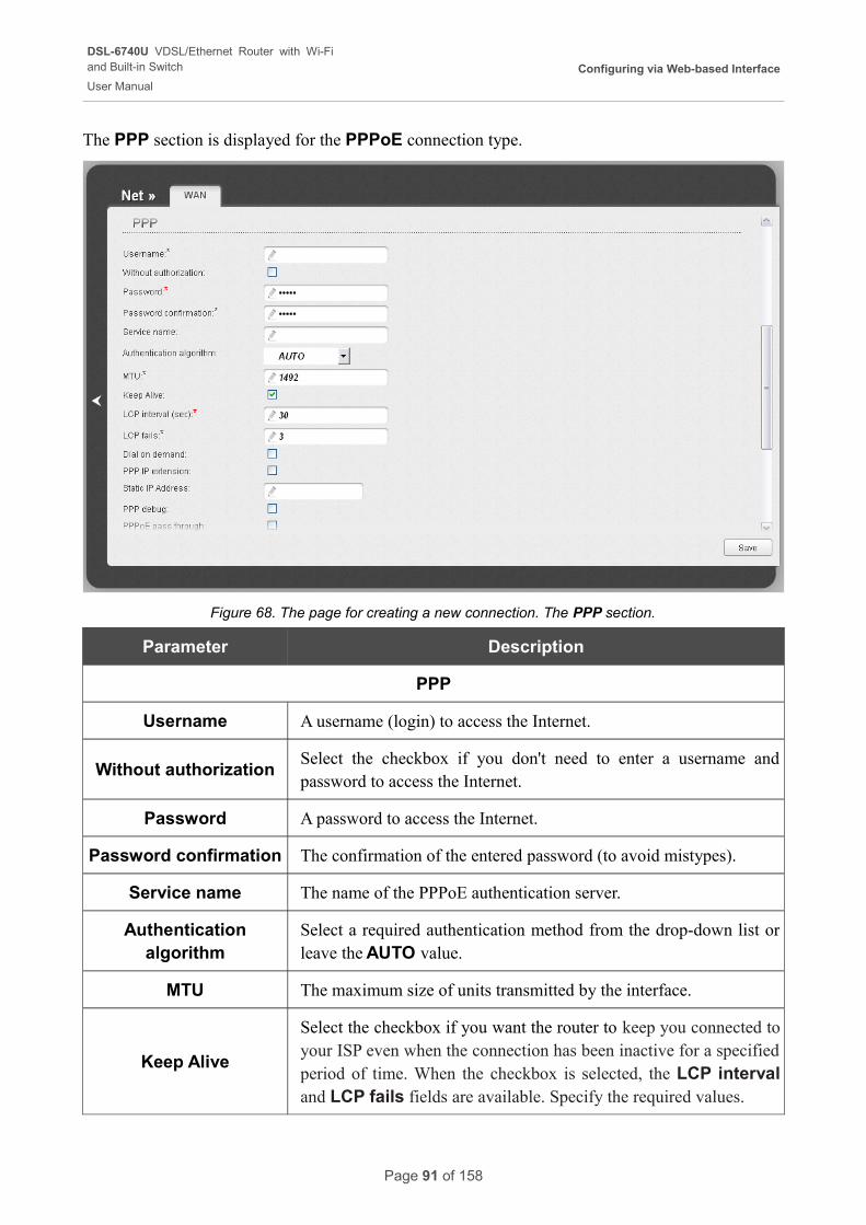
DSL-6740U VDSL/Ethernet Router with Wi-Fiand Built-in Switch
User Manual
Configuring via Web-based Interface
The PPP section is displayed for the PPPoE connection type.
Figure 68. The page for creating a new connection. The PPP section.
Parameter Description
PPP
Username A username (login) to access the Internet.
Without authorizationSelect the checkbox if you don't need to enter a username and password to access the Internet.
Password A password to access the Internet.
Password confirmation The confirmation of the entered password (to avoid mistypes).
Service name The name of the PPPoE authentication server.
Authentication algorithm
Select a required authentication method from the drop-down list or leave the AUTO value.
MTU The maximum size of units transmitted by the interface.
Keep Alive
Select the checkbox if you want the router to keep you connected to your ISP even when the connection has been inactive for a specified period of time. When the checkbox is selected, the LCP interval and LCP fails fields are available. Specify the required values.
Page 91 of 158
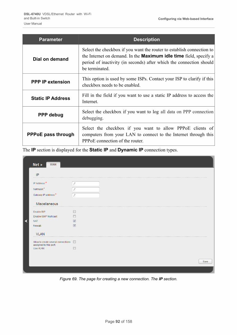
DSL-6740U VDSL/Ethernet Router with Wi-Fiand Built-in Switch
User Manual
Configuring via Web-based Interface
Parameter Description
Dial on demand
Select the checkbox if you want the router to establish connection to the Internet on demand. In the Maximum idle time field, specify a period of inactivity (in seconds) after which the connection should be terminated.
PPP IP extensionThis option is used by some ISPs. Contact your ISP to clarify if this checkbox needs to be enabled.
Static IP AddressFill in the field if you want to use a static IP address to access the Internet.
PPP debugSelect the checkbox if you want to log all data on PPP connection debugging.
PPPoE pass throughSelect the checkbox if you want to allow PPPoE clients of computers from your LAN to connect to the Internet through this PPPoE connection of the router.
The IP section is displayed for the Static IP and Dynamic IP connection types.
Figure 69. The page for creating a new connection. The IP section.
Page 92 of 158
DSL-6740U VDSL/Ethernet Router with Wi-Fiand Built-in Switch
User Manual
Configuring via Web-based Interface
Parameter Description
IP
IP AddressDisplayed for the Static IP type only.
Enter an IP address for this WAN connection.
NetmaskDisplayed for the Static IP type only.
Enter a subnet mask for this WAN connection.
Gateway IP addressDisplayed for the Static IP type only.
Enter an IP address of the gateway used by this WAN connection.
Vendor IDDisplayed for the Dynamic IP type only.
The identifier of your ISP. Optional.
When all needed settings are configured, click the Save button.
Page 93 of 158
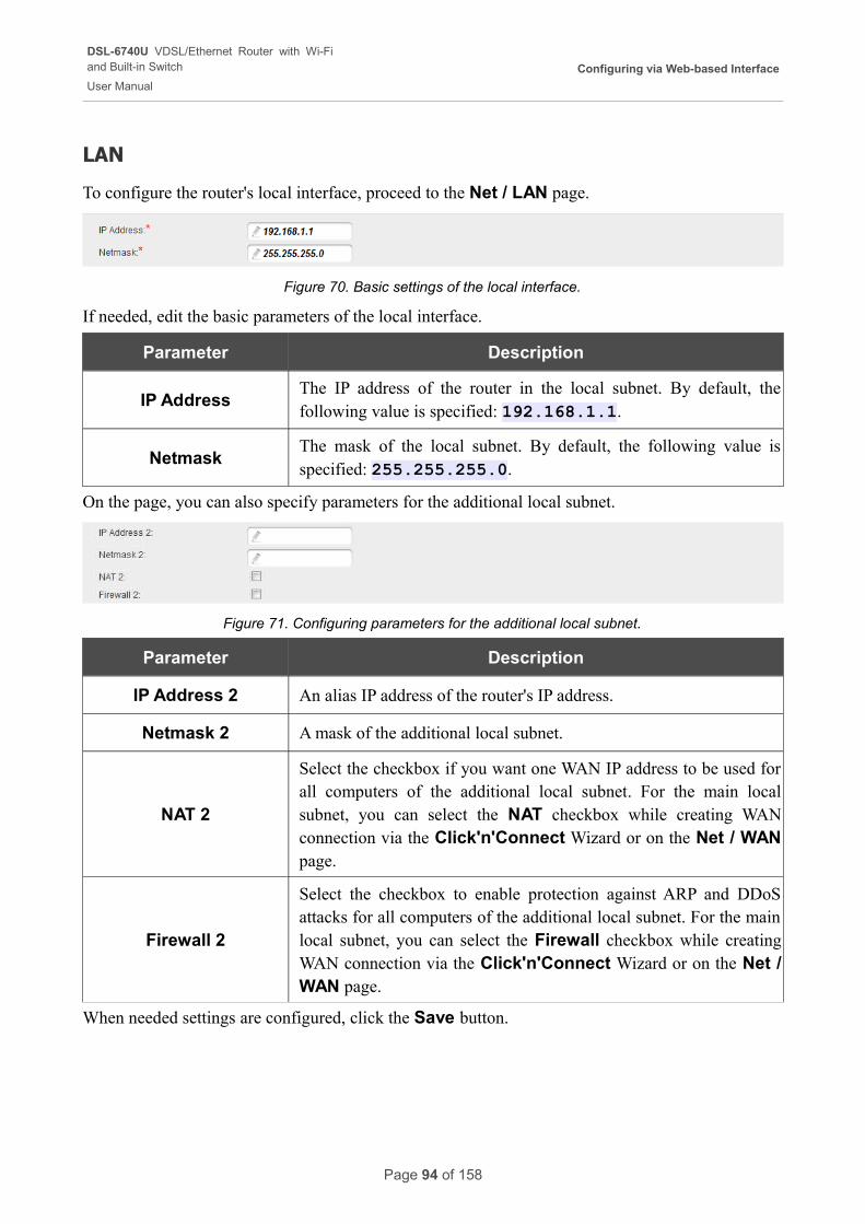
DSL-6740U VDSL/Ethernet Router with Wi-Fiand Built-in Switch
User Manual
Configuring via Web-based Interface
LAN
To configure the router's local interface, proceed to the Net / LAN page.
Figure 70. Basic settings of the local interface.
If needed, edit the basic parameters of the local interface.
Parameter Description
IP AddressThe IP address of the router in the local subnet. By default, the following value is specified: 192.168.1.1.
NetmaskThe mask of the local subnet. By default, the following value is specified: 255.255.255.0.
On the page, you can also specify parameters for the additional local subnet.
Figure 71. Configuring parameters for the additional local subnet.
Parameter Description
IP Address 2 An alias IP address of the router's IP address.
Netmask 2 A mask of the additional local subnet.
NAT 2
Select the checkbox if you want one WAN IP address to be used for all computers of the additional local subnet. For the main local subnet, you can select the NAT checkbox while creating WAN connection via the Click'n'Connect Wizard or on the Net / WAN page.
Firewall 2
Select the checkbox to enable protection against ARP and DDoS attacks for all computers of the additional local subnet. For the main local subnet, you can select the Firewall checkbox while creating WAN connection via the Click'n'Connect Wizard or on the Net / WAN page.
When needed settings are configured, click the Save button.
Page 94 of 158
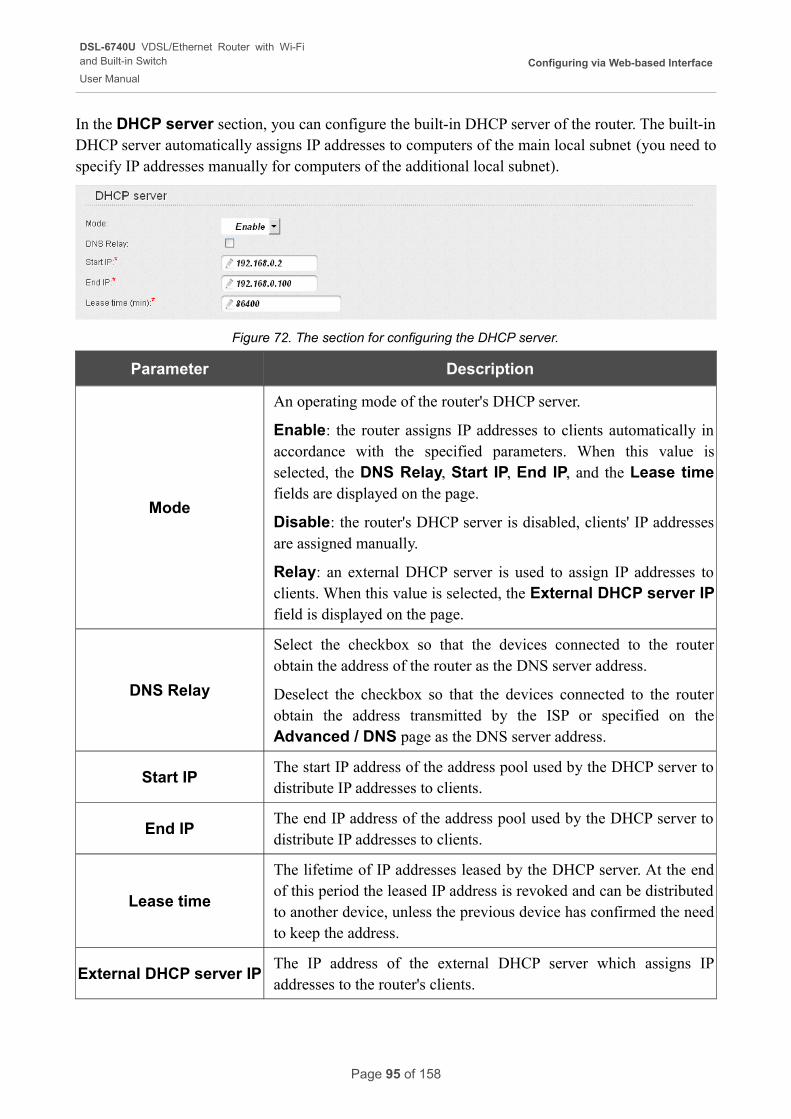
DSL-6740U VDSL/Ethernet Router with Wi-Fiand Built-in Switch
User Manual
Configuring via Web-based Interface
In the DHCP server section, you can configure the built-in DHCP server of the router. The built-in DHCP server automatically assigns IP addresses to computers of the main local subnet (you need to specify IP addresses manually for computers of the additional local subnet).
Figure 72. The section for configuring the DHCP server.
Parameter Description
Mode
An operating mode of the router's DHCP server.
Enable: the router assigns IP addresses to clients automatically in accordance with the specified parameters. When this value is selected, the DNS Relay, Start IP, End IP, and the Lease time fields are displayed on the page.
Disable: the router's DHCP server is disabled, clients' IP addresses are assigned manually.
Relay: an external DHCP server is used to assign IP addresses to clients. When this value is selected, the External DHCP server IP field is displayed on the page.
DNS Relay
Select the checkbox so that the devices connected to the router obtain the address of the router as the DNS server address.
Deselect the checkbox so that the devices connected to the router obtain the address transmitted by the ISP or specified on the Advanced / DNS page as the DNS server address.
Start IPThe start IP address of the address pool used by the DHCP server to distribute IP addresses to clients.
End IPThe end IP address of the address pool used by the DHCP server to distribute IP addresses to clients.
Lease time
The lifetime of IP addresses leased by the DHCP server. At the end of this period the leased IP address is revoked and can be distributed to another device, unless the previous device has confirmed the need to keep the address.
External DHCP server IPThe IP address of the external DHCP server which assigns IP addresses to the router's clients.
Page 95 of 158
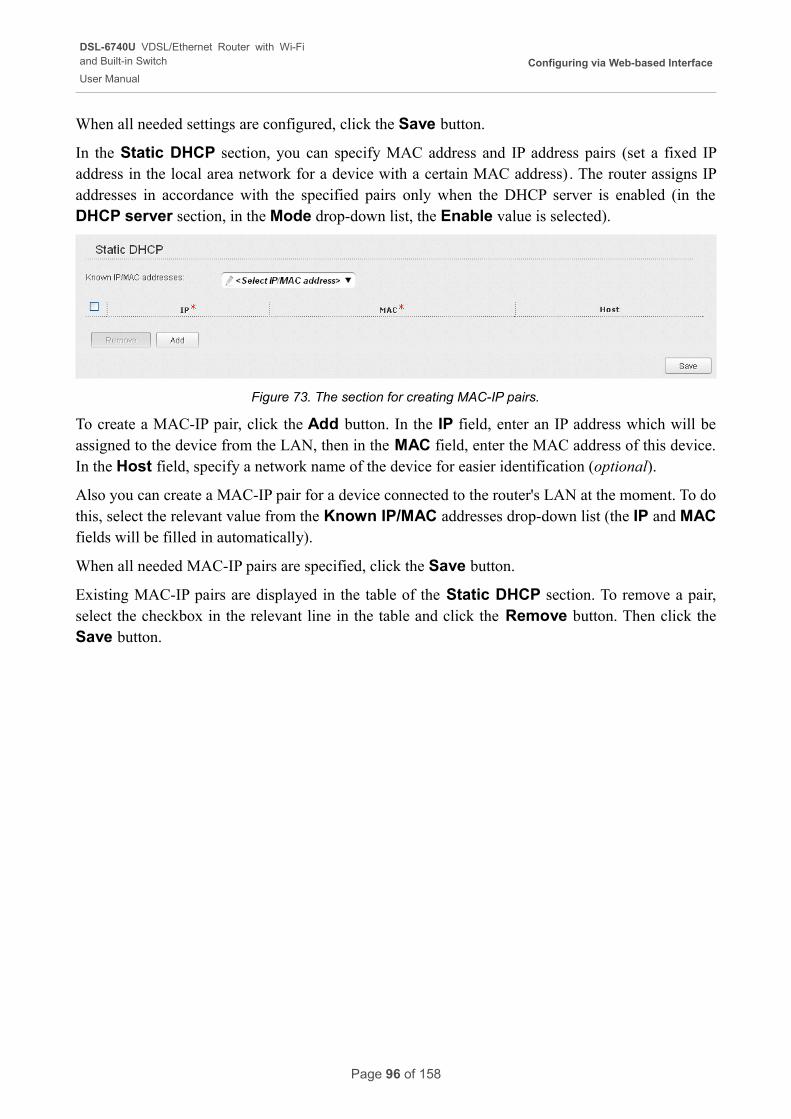
DSL-6740U VDSL/Ethernet Router with Wi-Fiand Built-in Switch
User Manual
Configuring via Web-based Interface
When all needed settings are configured, click the Save button.
In the Static DHCP section, you can specify MAC address and IP address pairs (set a fixed IP address in the local area network for a device with a certain MAC address). The router assigns IP addresses in accordance with the specified pairs only when the DHCP server is enabled (in the DHCP server section, in the Mode drop-down list, the Enable value is selected).
Figure 73. The section for creating MAC-IP pairs.
To create a MAC-IP pair, click the Add button. In the IP field, enter an IP address which will be assigned to the device from the LAN, then in the MAC field, enter the MAC address of this device. In the Host field, specify a network name of the device for easier identification (optional).
Also you can create a MAC-IP pair for a device connected to the router's LAN at the moment. To do this, select the relevant value from the Known IP/MAC addresses drop-down list (the IP and MAC fields will be filled in automatically).
When all needed MAC-IP pairs are specified, click the Save button.
Existing MAC-IP pairs are displayed in the table of the Static DHCP section. To remove a pair, select the checkbox in the relevant line in the table and click the Remove button. Then click the Save button.
Page 96 of 158
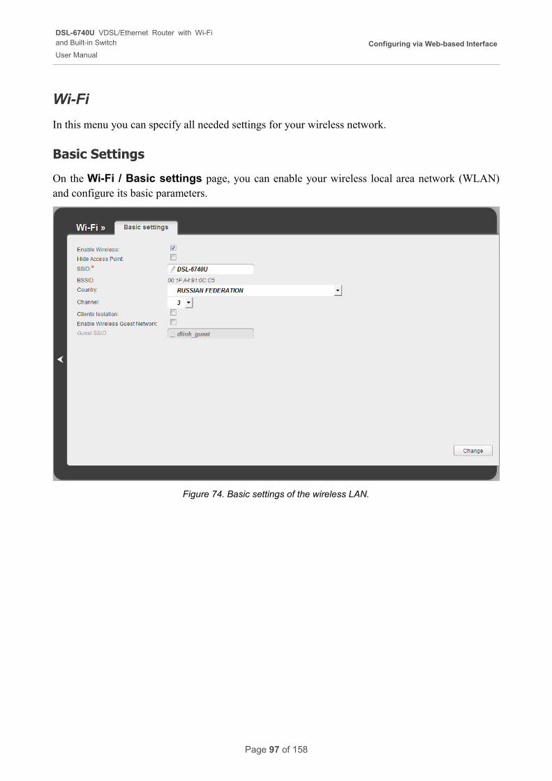
DSL-6740U VDSL/Ethernet Router with Wi-Fiand Built-in Switch
User Manual
Configuring via Web-based Interface
Wi-Fi
In this menu you can specify all needed settings for your wireless network.
Basic Settings
On the Wi-Fi / Basic settings page, you can enable your wireless local area network (WLAN) and configure its basic parameters.
Figure 74. Basic settings of the wireless LAN.
Page 97 of 158
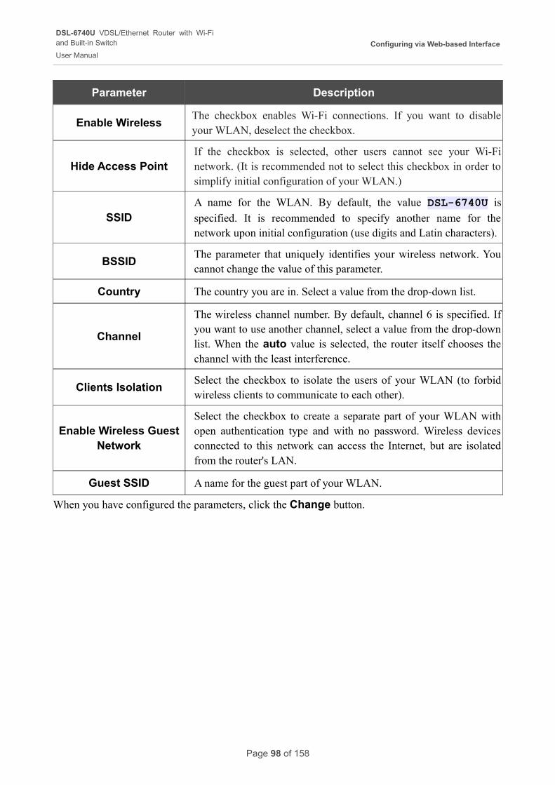
DSL-6740U VDSL/Ethernet Router with Wi-Fiand Built-in Switch
User Manual
Configuring via Web-based Interface
Parameter Description
Enable WirelessThe checkbox enables Wi-Fi connections. If you want to disable your WLAN, deselect the checkbox.
Hide Access PointIf the checkbox is selected, other users cannot see your Wi-Fi network. (It is recommended not to select this checkbox in order to simplify initial configuration of your WLAN.)
SSIDA name for the WLAN. By default, the value DSL-6740U is
specified. It is recommended to specify another name for the network upon initial configuration (use digits and Latin characters).
BSSIDThe parameter that uniquely identifies your wireless network. You cannot change the value of this parameter.
Country The country you are in. Select a value from the drop-down list.
Channel
The wireless channel number. By default, channel 6 is specified. If you want to use another channel, select a value from the drop-down list. When the auto value is selected, the router itself chooses the channel with the least interference.
Clients IsolationSelect the checkbox to isolate the users of your WLAN (to forbid wireless clients to communicate to each other).
Enable Wireless Guest Network
Select the checkbox to create a separate part of your WLAN with open authentication type and with no password. Wireless devices connected to this network can access the Internet, but are isolated from the router's LAN.
Guest SSID A name for the guest part of your WLAN.
When you have configured the parameters, click the Change button.
Page 98 of 158
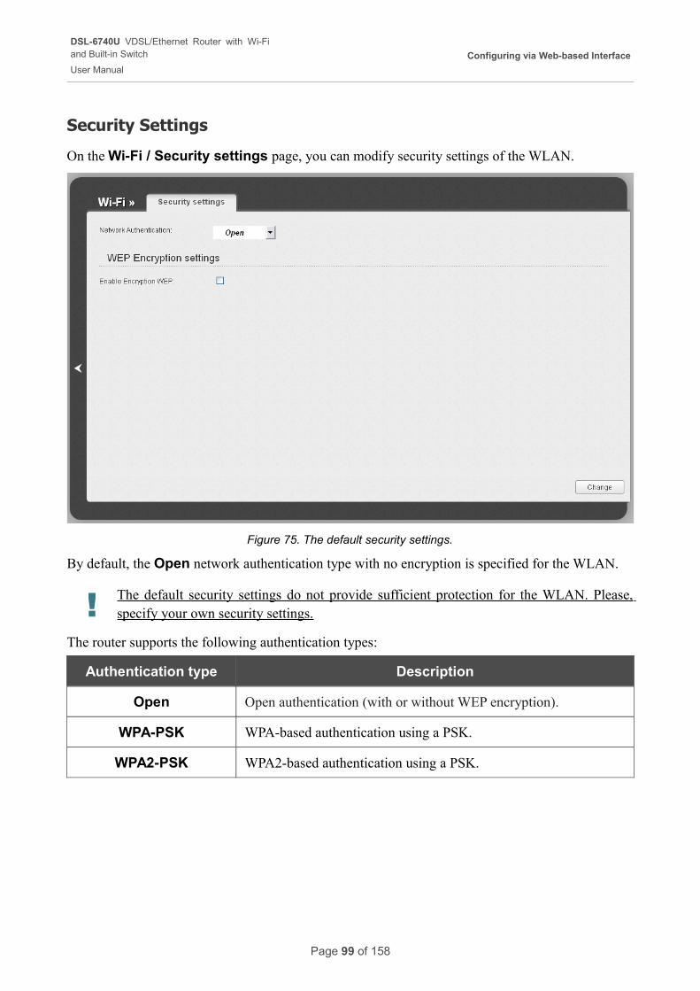
DSL-6740U VDSL/Ethernet Router with Wi-Fiand Built-in Switch
User Manual
Configuring via Web-based Interface
Security Settings
On the Wi-Fi / Security settings page, you can modify security settings of the WLAN.
Figure 75. The default security settings.
By default, the Open network authentication type with no encryption is specified for the WLAN.
! The default security settings do not provide sufficient protection for the WLAN. Please, specify your own security settings.
The router supports the following authentication types:
Authentication type Description
Open Open authentication (with or without WEP encryption).
WPA-PSK WPA-based authentication using a PSK.
WPA2-PSK WPA2-based authentication using a PSK.
Page 99 of 158
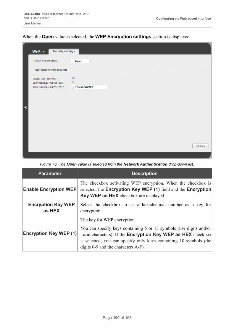
DSL-6740U VDSL/Ethernet Router with Wi-Fiand Built-in Switch
User Manual
Configuring via Web-based Interface
When the Open value is selected, the WEP Encryption settings section is displayed:
Figure 76. The Open value is selected from the Network Authentication drop-down list.
Parameter Description
Enable Encryption WEPThe checkbox activating WEP encryption. When the checkbox is selected, the Encryption Key WEP (1) field and the Encryption Key WEP as HEX checkbox are displayed.
Encryption Key WEP as HEX
Select the checkbox to set a hexadecimal number as a key for encryption.
Encryption Key WEP (1)
The key for WEP encryption.
You can specify keys containing 5 or 13 symbols (use digits and/or Latin characters). If the Encryption Key WEP as HEX checkbox is selected, you can specify only keys containing 10 symbols (the digits 0-9 and the characters A-F).
Page 100 of 158
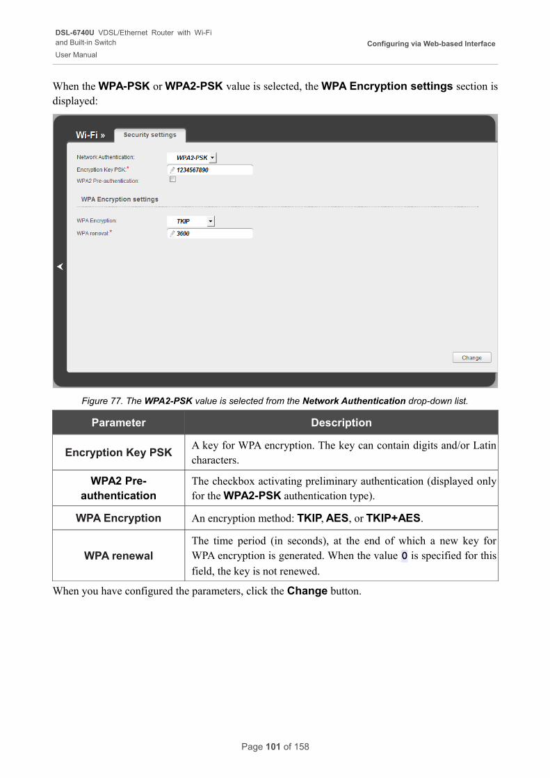
DSL-6740U VDSL/Ethernet Router with Wi-Fiand Built-in Switch
User Manual
Configuring via Web-based Interface
When the WPA-PSK or WPA2-PSK value is selected, the WPA Encryption settings section is displayed:
Figure 77. The WPA2-PSK value is selected from the Network Authentication drop-down list.
Parameter Description
Encryption Key PSKA key for WPA encryption. The key can contain digits and/or Latin characters.
WPA2 Pre-authentication
The checkbox activating preliminary authentication (displayed only for the WPA2-PSK authentication type).
WPA Encryption An encryption method: TKIP, AES, or TKIP+AES.
WPA renewalThe time period (in seconds), at the end of which a new key for WPA encryption is generated. When the value 0 is specified for this
field, the key is not renewed.
When you have configured the parameters, click the Change button.
Page 101 of 158
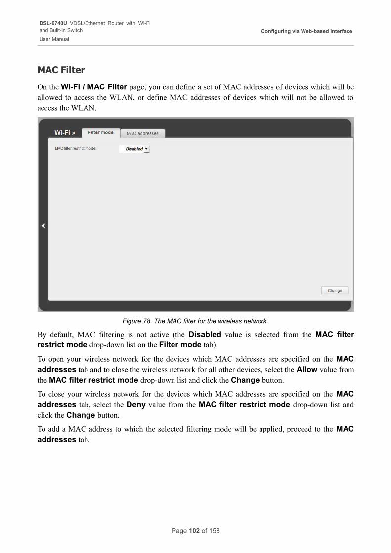
DSL-6740U VDSL/Ethernet Router with Wi-Fiand Built-in Switch
User Manual
Configuring via Web-based Interface
MAC Filter
On the Wi-Fi / MAC Filter page, you can define a set of MAC addresses of devices which will be allowed to access the WLAN, or define MAC addresses of devices which will not be allowed to access the WLAN.
Figure 78. The MAC filter for the wireless network.
By default, MAC filtering is not active (the Disabled value is selected from the MAC filter restrict mode drop-down list on the Filter mode tab).
To open your wireless network for the devices which MAC addresses are specified on the MAC addresses tab and to close the wireless network for all other devices, select the Allow value from the MAC filter restrict mode drop-down list and click the Change button.
To close your wireless network for the devices which MAC addresses are specified on the MAC addresses tab, select the Deny value from the MAC filter restrict mode drop-down list and click the Change button.
To add a MAC address to which the selected filtering mode will be applied, proceed to the MAC addresses tab.
Page 102 of 158
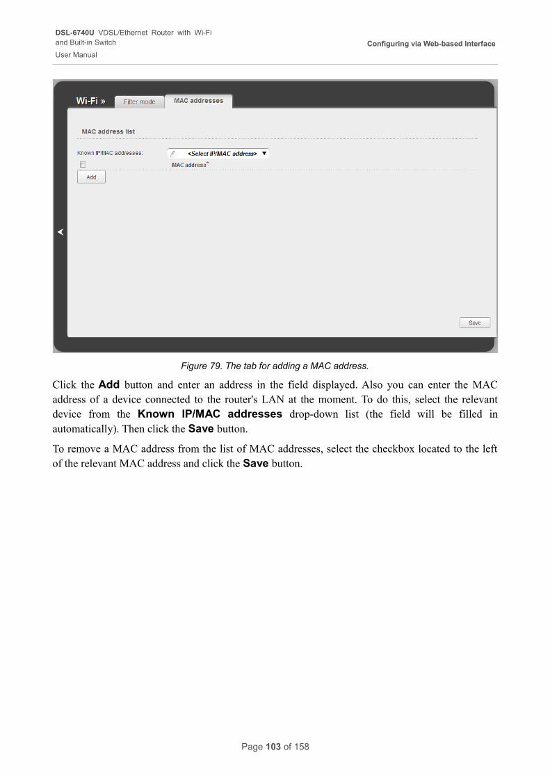
DSL-6740U VDSL/Ethernet Router with Wi-Fiand Built-in Switch
User Manual
Configuring via Web-based Interface
Figure 79. The tab for adding a MAC address.
Click the Add button and enter an address in the field displayed. Also you can enter the MAC address of a device connected to the router's LAN at the moment. To do this, select the relevant device from the Known IP/MAC addresses drop-down list (the field will be filled in automatically). Then click the Save button.
To remove a MAC address from the list of MAC addresses, select the checkbox located to the left of the relevant MAC address and click the Save button.
Page 103 of 158
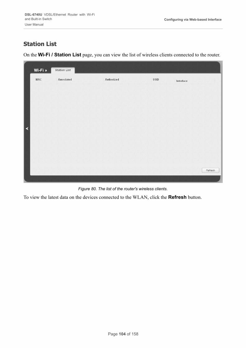
DSL-6740U VDSL/Ethernet Router with Wi-Fiand Built-in Switch
User Manual
Configuring via Web-based Interface
Station List
On the Wi-Fi / Station List page, you can view the list of wireless clients connected to the router.
Figure 80. The list of the router's wireless clients.
To view the latest data on the devices connected to the WLAN, click the Refresh button.
Page 104 of 158
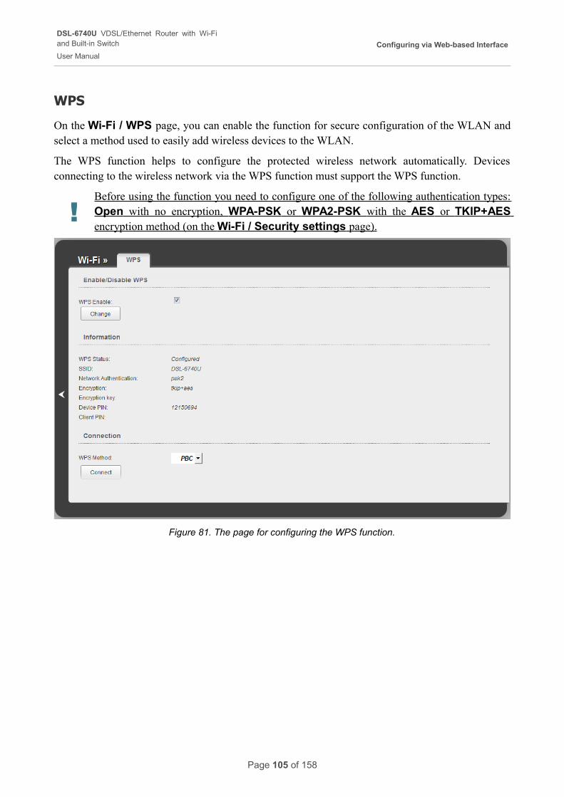
DSL-6740U VDSL/Ethernet Router with Wi-Fiand Built-in Switch
User Manual
Configuring via Web-based Interface
WPS
On the Wi-Fi / WPS page, you can enable the function for secure configuration of the WLAN and select a method used to easily add wireless devices to the WLAN.
The WPS function helps to configure the protected wireless network automatically. Devices connecting to the wireless network via the WPS function must support the WPS function.
!Before using the function you need to configure one of the following authentication types: Open with no encryption, WPA-PSK or WPA2-PSK with the AES or TKIP+AES encryption method (on the Wi-Fi / Security settings page).
Figure 81. The page for configuring the WPS function.
Page 105 of 158
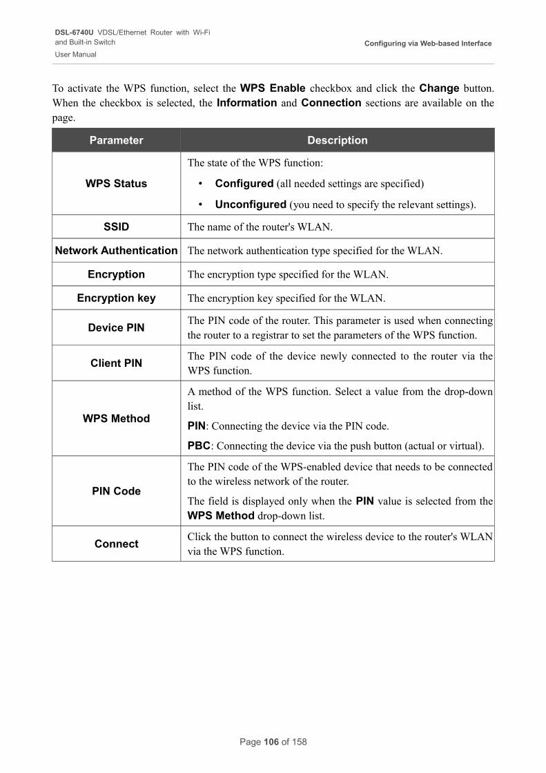
DSL-6740U VDSL/Ethernet Router with Wi-Fiand Built-in Switch
User Manual
Configuring via Web-based Interface
To activate the WPS function, select the WPS Enable checkbox and click the Change button. When the checkbox is selected, the Information and Connection sections are available on the page.
Parameter Description
WPS Status
The state of the WPS function:
• Configured (all needed settings are specified)
• Unconfigured (you need to specify the relevant settings).
SSID The name of the router's WLAN.
Network Authentication The network authentication type specified for the WLAN.
Encryption The encryption type specified for the WLAN.
Encryption key The encryption key specified for the WLAN.
Device PINThe PIN code of the router. This parameter is used when connecting the router to a registrar to set the parameters of the WPS function.
Client PINThe PIN code of the device newly connected to the router via the WPS function.
WPS Method
A method of the WPS function. Select a value from the drop-down list.
PIN: Connecting the device via the PIN code.
PBC: Connecting the device via the push button (actual or virtual).
PIN Code
The PIN code of the WPS-enabled device that needs to be connected to the wireless network of the router.
The field is displayed only when the PIN value is selected from the WPS Method drop-down list.
ConnectClick the button to connect the wireless device to the router's WLAN via the WPS function.
Page 106 of 158
DSL-6740U VDSL/Ethernet Router with Wi-Fiand Built-in Switch
User Manual
Configuring via Web-based Interface
Using WPS Function via Web-based Interface
To add a wireless device via the PIN method of the WPS function, follow the next steps:
1. Select the WPS Enable checkbox.
2. Click the Change button.
3. Select the PIN value from the WPS Method drop-down list.
4. Select the PIN method in the software of the wireless device that you want to connect to the router's WLAN.
5. Click the relevant button in the software of the wireless device that you want to connect to the WLAN.
6. Right after that, enter the PIN code specified on the cover of the wireless device or in its software in the PIN Code field.
7. Click the Connect button in the web-based interface of the router.
To add a wireless device via the PBC method of the WPS function, follow the next steps:
1. Select the WPS Enable checkbox.
2. Click the Change button.
3. Select the PBC value from the WPS Method drop-down list.
4. Select the PBC method in the software of the wireless device that you want to connect to the router's WLAN.
5. Click the relevant button in the software or press the WPS button on the cover of the wireless device that you want to connect to the WLAN.
6. Click the Connect button in the web-based interface of the router.
Using WPS Function without Web-based Interface
You can add a wireless device to the router's WLAN without accessing the web-based interface of the router. To do this, you need to configure the following router's settings:
1. Specify corresponding security settings for the wireless network of the router.
2. Select the WPS Enable checkbox.
3. Click the Change button.
4. Save the settings and close the web-based interface (click the Save line in the top-page menu displayed when the mouse pointer is over the System caption, then click the Logout line).
Page 107 of 158
DSL-6740U VDSL/Ethernet Router with Wi-Fiand Built-in Switch
User Manual
Configuring via Web-based Interface
Later you will be able to add wireless devices to the WLAN by pressing the WPS button of the router.
1. Select the PBC method in the software of the wireless device that you want to connect to the router's WLAN.
2. Click the relevant button in the software or press the WPS button on the cover of the wireless device that you want to connect to the WLAN.
3. Press the WPS button of the router.
After clicking the button the WPS LED blinks. If the wireless device has been successfully connected to the WLAN, the LED stops blinking and lights green for several minutes.
Page 108 of 158
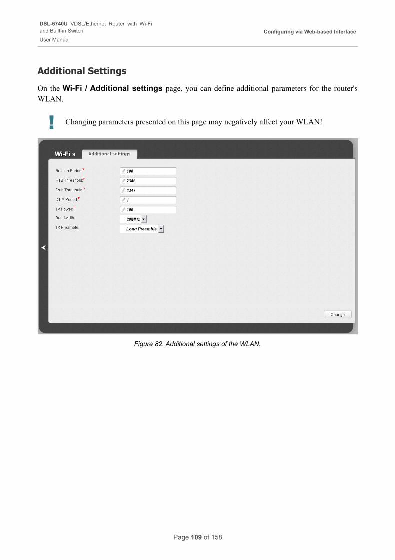
DSL-6740U VDSL/Ethernet Router with Wi-Fiand Built-in Switch
User Manual
Configuring via Web-based Interface
Additional Settings
On the Wi-Fi / Additional settings page, you can define additional parameters for the router's WLAN.
! Changing parameters presented on this page may negatively affect your WLAN!
Figure 82. Additional settings of the WLAN.
Page 109 of 158
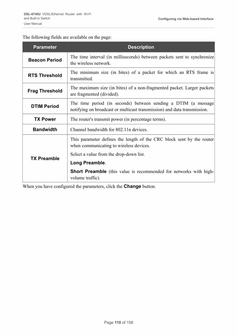
DSL-6740U VDSL/Ethernet Router with Wi-Fiand Built-in Switch
User Manual
Configuring via Web-based Interface
The following fields are available on the page:
Parameter Description
Beacon PeriodThe time interval (in milliseconds) between packets sent to synchronize the wireless network.
RTS ThresholdThe minimum size (in bites) of a packet for which an RTS frame is transmitted.
Frag ThresholdThe maximum size (in bites) of a non-fragmented packet. Larger packets are fragmented (divided).
DTIM PeriodThe time period (in seconds) between sending a DTIM (a message notifying on broadcast or multicast transmission) and data transmission.
TX Power The router's transmit power (in percentage terms).
Bandwidth Channel bandwidth for 802.11n devices.
TX Preamble
This parameter defines the length of the CRC block sent by the router when communicating to wireless devices.
Select a value from the drop-down list.
Long Preamble.
Short Preamble (this value is recommended for networks with high-volume traffic).
When you have configured the parameters, click the Change button.
Page 110 of 158
DSL-6740U VDSL/Ethernet Router with Wi-Fiand Built-in Switch
User Manual
Configuring via Web-based Interface
Advanced
In this menu you can configure advanced settings of the router:
• enable the UPnP function
• define interface groups and allow the router to connect to a private Ethernet line
• configure a DDNS service
• add name servers
• define static routes
• edit the ADSL connection parameters
• create rules for remote access to the web-based interface
• configure TR-069 client.
Page 111 of 158
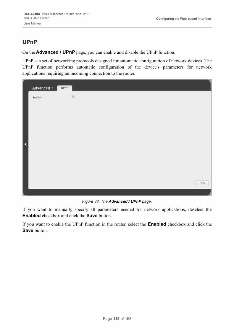
DSL-6740U VDSL/Ethernet Router with Wi-Fiand Built-in Switch
User Manual
Configuring via Web-based Interface
UPnP
On the Advanced / UPnP page, you can enable and disable the UPnP function.
UPnP is a set of networking protocols designed for automatic configuration of network devices. The UPnP function performs automatic configuration of the device's parameters for network applications requiring an incoming connection to the router.
Figure 83. The Advanced / UPnP page.
If you want to manually specify all parameters needed for network applications, deselect the Enabled checkbox and click the Save button.
If you want to enable the UPnP function in the router, select the Enabled checkbox and click the Save button.
Page 112 of 158
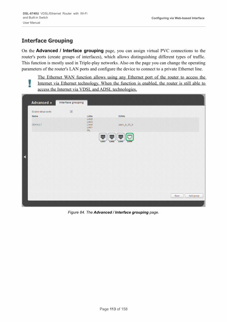
DSL-6740U VDSL/Ethernet Router with Wi-Fiand Built-in Switch
User Manual
Configuring via Web-based Interface
Interface Grouping
On the Advanced / Interface grouping page, you can assign virtual PVC connections to the router's ports (create groups of interfaces), which allows distinguishing different types of traffic. This function is mostly used in Triple-play networks. Also on the page you can change the operating parameters of the router's LAN ports and configure the device to connect to a private Ethernet line.
!The Ethernet WAN function allows using any Ethernet port of the router to access the Internet via Ethernet technology. When the function is enabled, the router is still able to access the Internet via VDSL and ADSL technologies.
Figure 84. The Advanced / Interface grouping page.
Page 113 of 158
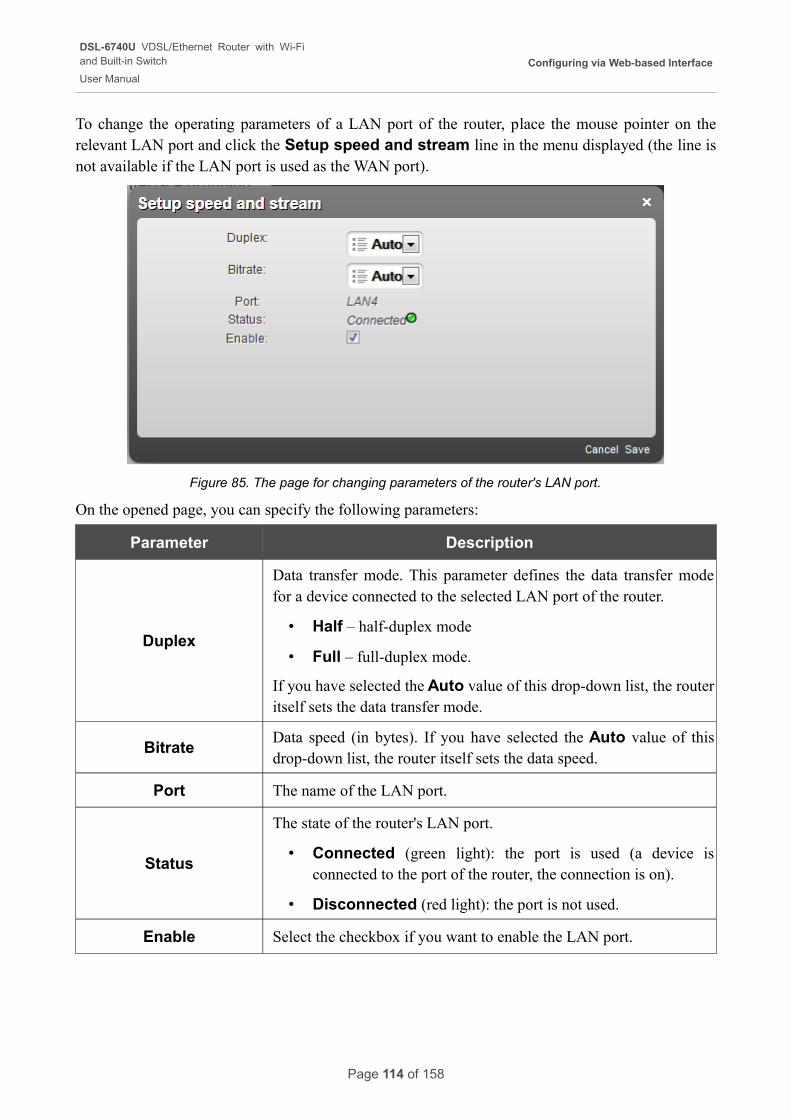
DSL-6740U VDSL/Ethernet Router with Wi-Fiand Built-in Switch
User Manual
Configuring via Web-based Interface
To change the operating parameters of a LAN port of the router, place the mouse pointer on the relevant LAN port and click the Setup speed and stream line in the menu displayed (the line is not available if the LAN port is used as the WAN port).
Figure 85. The page for changing parameters of the router's LAN port.
On the opened page, you can specify the following parameters:
Parameter Description
Duplex
Data transfer mode. This parameter defines the data transfer mode for a device connected to the selected LAN port of the router.
• Half – half-duplex mode
• Full – full-duplex mode.
If you have selected the Auto value of this drop-down list, the router itself sets the data transfer mode.
BitrateData speed (in bytes). If you have selected the Auto value of this drop-down list, the router itself sets the data speed.
Port The name of the LAN port.
Status
The state of the router's LAN port.
• Connected (green light): the port is used (a device is connected to the port of the router, the connection is on).
• Disconnected (red light): the port is not used.
Enable Select the checkbox if you want to enable the LAN port.
Page 114 of 158
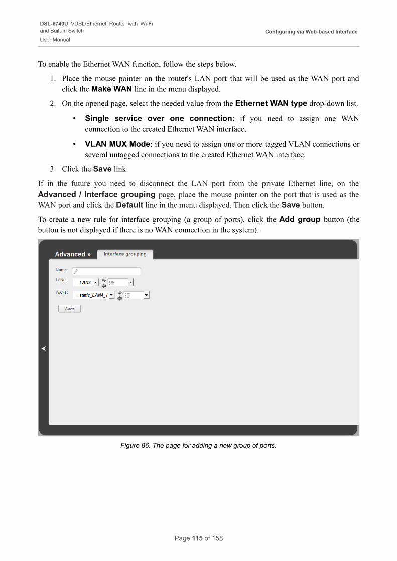
DSL-6740U VDSL/Ethernet Router with Wi-Fiand Built-in Switch
User Manual
Configuring via Web-based Interface
To enable the Ethernet WAN function, follow the steps below.
1. Place the mouse pointer on the router's LAN port that will be used as the WAN port and click the Make WAN line in the menu displayed.
2. On the opened page, select the needed value from the Ethernet WAN type drop-down list.
• Single service over one connection: if you need to assign one WAN connection to the created Ethernet WAN interface.
• VLAN MUX Mode: if you need to assign one or more tagged VLAN connections or several untagged connections to the created Ethernet WAN interface.
3. Click the Save link.
If in the future you need to disconnect the LAN port from the private Ethernet line, on the Advanced / Interface grouping page, place the mouse pointer on the port that is used as the WAN port and click the Default line in the menu displayed. Then click the Save button.
To create a new rule for interface grouping (a group of ports), click the Add group button (the button is not displayed if there is no WAN connection in the system).
Figure 86. The page for adding a new group of ports.
Page 115 of 158
DSL-6740U VDSL/Ethernet Router with Wi-Fiand Built-in Switch
User Manual
Configuring via Web-based Interface
You can specify the following parameters:
Parameter Description
NameA name for the group for easier identification. You can specify any name.
LANs
The list of available internal interfaces is displayed in the left drop-down list.
Use the button ==> to move interfaces to the right drop-down list.
WANs
WAN connections to which the new group will be assigned. WAN connections of PPPoA and IPoA type cannot be added to groups.
Use the button ==> to move WAN connections to the right drop-down list.
Click the Save button.
! When you add an interface to the new group, it is excluded from the group to which it has been assigned before.
To edit or remove an existing group, select the relevant group on the Advanced / Interface grouping page. On the page displayed, change the parameters and click the Save button, or click the Delete button. When you delete a group, interfaces assigned to it are reassigned to the DEFAULT group.
Page 116 of 158
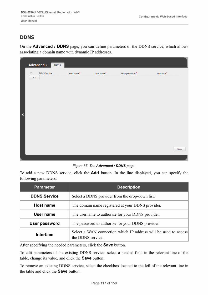
DSL-6740U VDSL/Ethernet Router with Wi-Fiand Built-in Switch
User Manual
Configuring via Web-based Interface
DDNS
On the Advanced / DDNS page, you can define parameters of the DDNS service, which allows associating a domain name with dynamic IP addresses.
Figure 87. The Advanced / DDNS page.
To add a new DDNS service, click the Add button. In the line displayed, you can specify the following parameters:
Parameter Description
DDNS Service Select a DDNS provider from the drop-down list.
Host name The domain name registered at your DDNS provider.
User name The username to authorize for your DDNS provider.
User password The password to authorize for your DDNS provider.
InterfaceSelect a WAN connection which IP address will be used to access the DDNS service.
After specifying the needed parameters, click the Save button.
To edit parameters of the existing DDNS service, select a needed field in the relevant line of the table, change its value, and click the Save button.
To remove an existing DDNS service, select the checkbox located to the left of the relevant line in the table and click the Save button.
Page 117 of 158
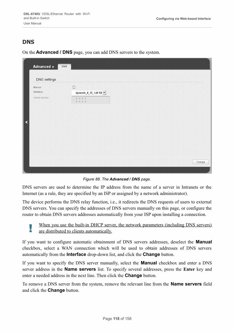
DSL-6740U VDSL/Ethernet Router with Wi-Fiand Built-in Switch
User Manual
Configuring via Web-based Interface
DNS
On the Advanced / DNS page, you can add DNS servers to the system.
Figure 88. The Advanced / DNS page.
DNS servers are used to determine the IP address from the name of a server in Intranets or the Internet (as a rule, they are specified by an ISP or assigned by a network administrator).
The device performs the DNS relay function, i.e., it redirects the DNS requests of users to external DNS servers. You can specify the addresses of DNS servers manually on this page, or configure the router to obtain DNS servers addresses automatically from your ISP upon installing a connection.
! When you use the built-in DHCP server, the network parameters (including DNS servers) are distributed to clients automatically.
If you want to configure automatic obtainment of DNS servers addresses, deselect the Manual checkbox, select a WAN connection which will be used to obtain addresses of DNS servers automatically from the Interface drop-down list, and click the Change button.
If you want to specify the DNS server manually, select the Manual checkbox and enter a DNS server address in the Name servers list. To specify several addresses, press the Enter key and enter a needed address in the next line. Then click the Change button.
To remove a DNS server from the system, remove the relevant line from the Name servers field and click the Change button.
Page 118 of 158
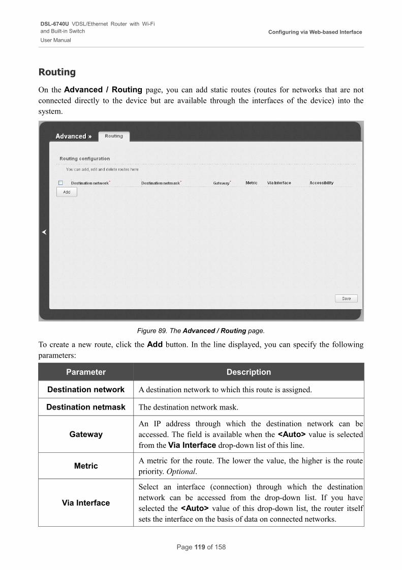
DSL-6740U VDSL/Ethernet Router with Wi-Fiand Built-in Switch
User Manual
Configuring via Web-based Interface
Routing
On the Advanced / Routing page, you can add static routes (routes for networks that are not connected directly to the device but are available through the interfaces of the device) into the system.
Figure 89. The Advanced / Routing page.
To create a new route, click the Add button. In the line displayed, you can specify the following parameters:
Parameter Description
Destination network A destination network to which this route is assigned.
Destination netmask The destination network mask.
GatewayAn IP address through which the destination network can be accessed. The field is available when the <Auto> value is selected from the Via Interface drop-down list of this line.
MetricA metric for the route. The lower the value, the higher is the route priority. Optional.
Via Interface
Select an interface (connection) through which the destination network can be accessed from the drop-down list. If you have selected the <Auto> value of this drop-down list, the router itself sets the interface on the basis of data on connected networks.
Page 119 of 158
DSL-6740U VDSL/Ethernet Router with Wi-Fiand Built-in Switch
User Manual
Configuring via Web-based Interface
After specifying the needed parameters, click the Save button.
To edit an existing route, select a needed field in the relevant line of the table, change its value, and click the Save button.
To remove an existing route, select the checkbox located to the left of the relevant line in the table and click the Save button.
If you need to specify a host from the LAN as the default route, select the <Auto> value from the Via Interface drop-down list, enter 0.0.0.0 in the Destination network and Destination
netmask fields, enter the IP address of the host from the LAN in the Gateway field, and then click the Save button.
Page 120 of 158
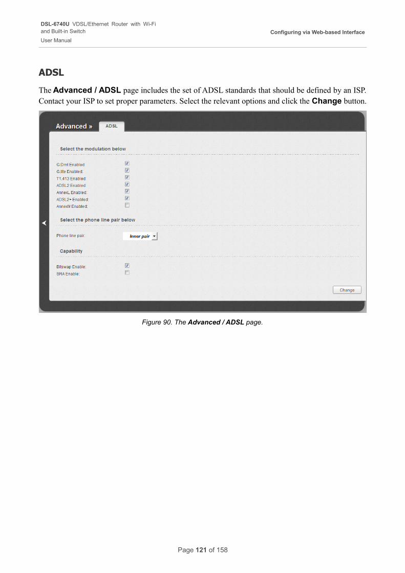
DSL-6740U VDSL/Ethernet Router with Wi-Fiand Built-in Switch
User Manual
Configuring via Web-based Interface
ADSL
The Advanced / ADSL page includes the set of ADSL standards that should be defined by an ISP. Contact your ISP to set proper parameters. Select the relevant options and click the Change button.
Figure 90. The Advanced / ADSL page.
Page 121 of 158
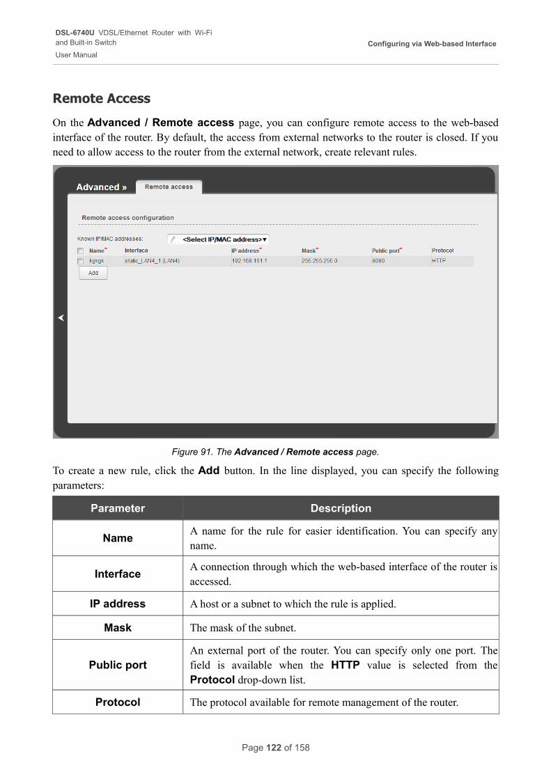
DSL-6740U VDSL/Ethernet Router with Wi-Fiand Built-in Switch
User Manual
Configuring via Web-based Interface
Remote Access
On the Advanced / Remote access page, you can configure remote access to the web-based interface of the router. By default, the access from external networks to the router is closed. If you need to allow access to the router from the external network, create relevant rules.
Figure 91. The Advanced / Remote access page.
To create a new rule, click the Add button. In the line displayed, you can specify the following parameters:
Parameter Description
NameA name for the rule for easier identification. You can specify any name.
InterfaceA connection through which the web-based interface of the router is accessed.
IP address A host or a subnet to which the rule is applied.
Mask The mask of the subnet.
Public portAn external port of the router. You can specify only one port. The field is available when the HTTP value is selected from the Protocol drop-down list.
Protocol The protocol available for remote management of the router.
Page 122 of 158
DSL-6740U VDSL/Ethernet Router with Wi-Fiand Built-in Switch
User Manual
Configuring via Web-based Interface
After specifying the needed parameters, click the Save button.
To edit a rule for remote access, select a needed field in the relevant line of the table, change its value, and click the Save button.
To remove a rule for remote access, select the checkbox located to the left of the relevant line in the table and click the Save button.
Page 123 of 158
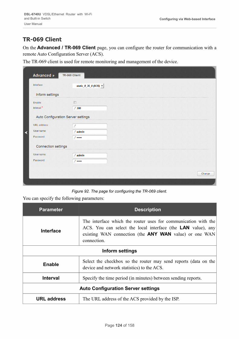
DSL-6740U VDSL/Ethernet Router with Wi-Fiand Built-in Switch
User Manual
Configuring via Web-based Interface
TR-069 ClientOn the Advanced / TR-069 Client page, you can configure the router for communication with a remote Auto Configuration Server (ACS).
The TR-069 client is used for remote monitoring and management of the device.
Figure 92. The page for configuring the TR-069 client.
You can specify the following parameters:
Parameter Description
Interface
The interface which the router uses for communication with the ACS. You can select the local interface (the LAN value), any existing WAN connection (the ANY WAN value) or one WAN connection.
Inform settings
EnableSelect the checkbox so the router may send reports (data on the device and network statistics) to the ACS.
Interval Specify the time period (in minutes) between sending reports.
Auto Configuration Server settings
URL address The URL address of the ACS provided by the ISP.
Page 124 of 158
DSL-6740U VDSL/Ethernet Router with Wi-Fiand Built-in Switch
User Manual
Configuring via Web-based Interface
Parameter Description
User nameThe username to connect to the ACS. The username can contain digits, Latin letters (uppercase and/or lowercase), and characters available on the keyboard.
PasswordThe password to connect to the ACS. The password can contain digits, Latin letters (uppercase and/or lowercase), and characters available on the keyboard.
Connection settings
User nameThe username which the ACS uses to connect to the router. The username can contain digits, Latin letters (uppercase and/or lowercase), and characters available on the keyboard.
PasswordThe password which the ACS uses to connect to the router. The password can contain digits, Latin letters (uppercase and/or lowercase), and characters available on the keyboard.
When you have configured the parameters, click the Change button.
Page 125 of 158
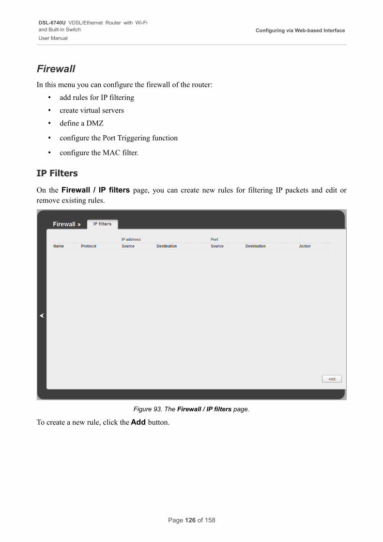
DSL-6740U VDSL/Ethernet Router with Wi-Fiand Built-in Switch
User Manual
Configuring via Web-based Interface
Firewall
In this menu you can configure the firewall of the router:
• add rules for IP filtering
• create virtual servers
• define a DMZ
• configure the Port Triggering function
• configure the MAC filter.
IP Filters
On the Firewall / IP filters page, you can create new rules for filtering IP packets and edit or remove existing rules.
Figure 93. The Firewall / IP filters page.
To create a new rule, click the Add button.
Page 126 of 158
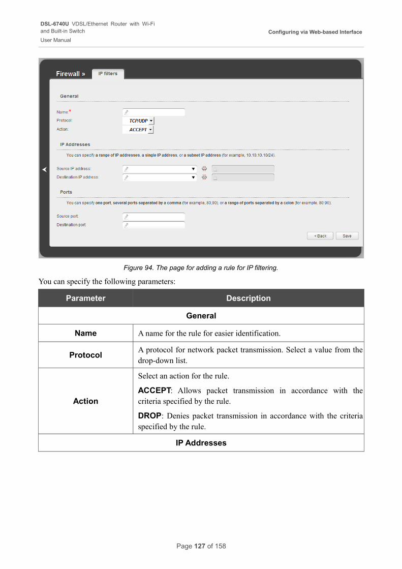
DSL-6740U VDSL/Ethernet Router with Wi-Fiand Built-in Switch
User Manual
Configuring via Web-based Interface
Figure 94. The page for adding a rule for IP filtering.
You can specify the following parameters:
Parameter Description
General
Name A name for the rule for easier identification.
ProtocolA protocol for network packet transmission. Select a value from the drop-down list.
Action
Select an action for the rule.
ACCEPT: Allows packet transmission in accordance with the criteria specified by the rule.
DROP: Denies packet transmission in accordance with the criteria specified by the rule.
IP Addresses
Page 127 of 158
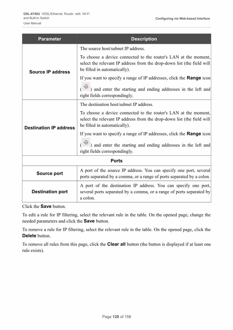
DSL-6740U VDSL/Ethernet Router with Wi-Fiand Built-in Switch
User Manual
Configuring via Web-based Interface
Parameter Description
Source IP address
The source host/subnet IP address.
To choose a device connected to the router's LAN at the moment, select the relevant IP address from the drop-down list (the field will be filled in automatically).
If you want to specify a range of IP addresses, click the Range icon
( ) and enter the starting and ending addresses in the left and right fields correspondingly.
Destination IP address
The destination host/subnet IP address.
To choose a device connected to the router's LAN at the moment, select the relevant IP address from the drop-down list (the field will be filled in automatically).
If you want to specify a range of IP addresses, click the Range icon
( ) and enter the starting and ending addresses in the left and right fields correspondingly.
Ports
Source portA port of the source IP address. You can specify one port, several ports separated by a comma, or a range of ports separated by a colon.
Destination portA port of the destination IP address. You can specify one port, several ports separated by a comma, or a range of ports separated by a colon.
Click the Save button.
To edit a rule for IP filtering, select the relevant rule in the table. On the opened page, change the needed parameters and click the Save button.
To remove a rule for IP filtering, select the relevant rule in the table. On the opened page, click the Delete button.
To remove all rules from this page, click the Clear all button (the button is displayed if at least one rule exists).
Page 128 of 158

DSL-6740U VDSL/Ethernet Router with Wi-Fiand Built-in Switch
User Manual
Configuring via Web-based Interface
Virtual Servers
On the Firewall / Virtual servers page, you can create virtual servers for redirecting incoming Internet traffic to a specified IP address in the local area network.
Figure 95. The Firewall / Virtual servers page.
To create a new virtual server, click the Add button.
Page 129 of 158
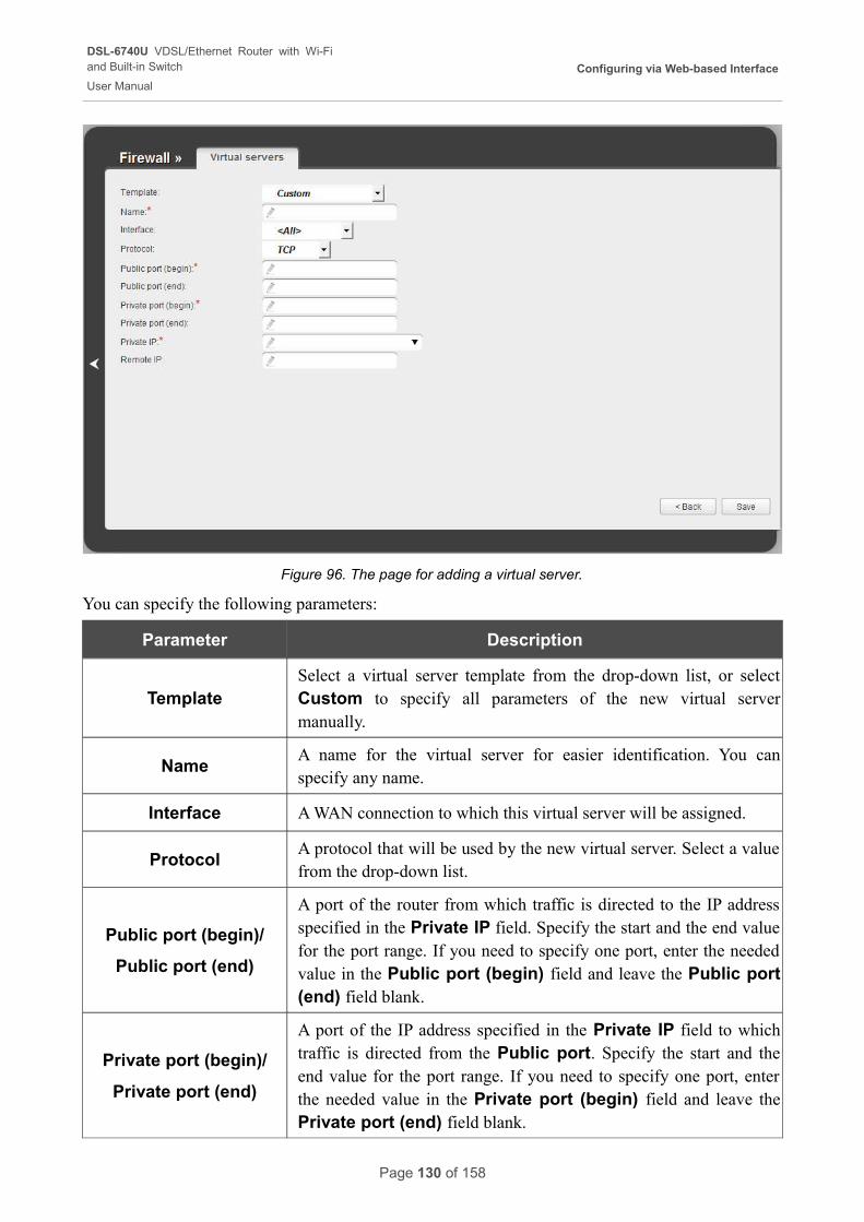
DSL-6740U VDSL/Ethernet Router with Wi-Fiand Built-in Switch
User Manual
Configuring via Web-based Interface
Figure 96. The page for adding a virtual server.
You can specify the following parameters:
Parameter Description
TemplateSelect a virtual server template from the drop-down list, or select Custom to specify all parameters of the new virtual server manually.
NameA name for the virtual server for easier identification. You can specify any name.
Interface A WAN connection to which this virtual server will be assigned.
ProtocolA protocol that will be used by the new virtual server. Select a value from the drop-down list.
Public port (begin)/
Public port (end)
A port of the router from which traffic is directed to the IP address specified in the Private IP field. Specify the start and the end value for the port range. If you need to specify one port, enter the needed value in the Public port (begin) field and leave the Public port (end) field blank.
Private port (begin)/
Private port (end)
A port of the IP address specified in the Private IP field to which traffic is directed from the Public port. Specify the start and the end value for the port range. If you need to specify one port, enter the needed value in the Private port (begin) field and leave the Private port (end) field blank.
Page 130 of 158
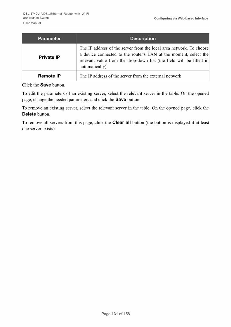
DSL-6740U VDSL/Ethernet Router with Wi-Fiand Built-in Switch
User Manual
Configuring via Web-based Interface
Parameter Description
Private IP
The IP address of the server from the local area network. To choose a device connected to the router's LAN at the moment, select the relevant value from the drop-down list (the field will be filled in automatically).
Remote IP The IP address of the server from the external network.
Click the Save button.
To edit the parameters of an existing server, select the relevant server in the table. On the opened page, change the needed parameters and click the Save button.
To remove an existing server, select the relevant server in the table. On the opened page, click the Delete button.
To remove all servers from this page, click the Clear all button (the button is displayed if at least one server exists).
Page 131 of 158
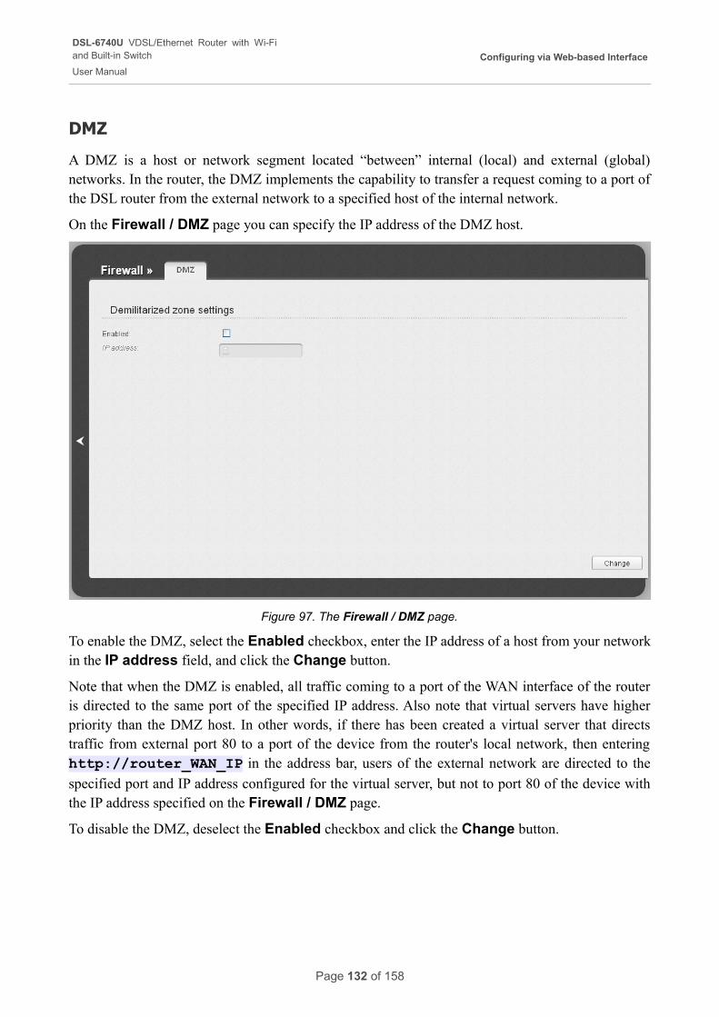
DSL-6740U VDSL/Ethernet Router with Wi-Fiand Built-in Switch
User Manual
Configuring via Web-based Interface
DMZ
A DMZ is a host or network segment located “between” internal (local) and external (global) networks. In the router, the DMZ implements the capability to transfer a request coming to a port of the DSL router from the external network to a specified host of the internal network.
On the Firewall / DMZ page you can specify the IP address of the DMZ host.
Figure 97. The Firewall / DMZ page.
To enable the DMZ, select the Enabled checkbox, enter the IP address of a host from your network in the IP address field, and click the Change button.
Note that when the DMZ is enabled, all traffic coming to a port of the WAN interface of the router is directed to the same port of the specified IP address. Also note that virtual servers have higher priority than the DMZ host. In other words, if there has been created a virtual server that directs traffic from external port 80 to a port of the device from the router's local network, then entering http://router_WAN_IP in the address bar, users of the external network are directed to the
specified port and IP address configured for the virtual server, but not to port 80 of the device with the IP address specified on the Firewall / DMZ page.
To disable the DMZ, deselect the Enabled checkbox and click the Change button.
Page 132 of 158
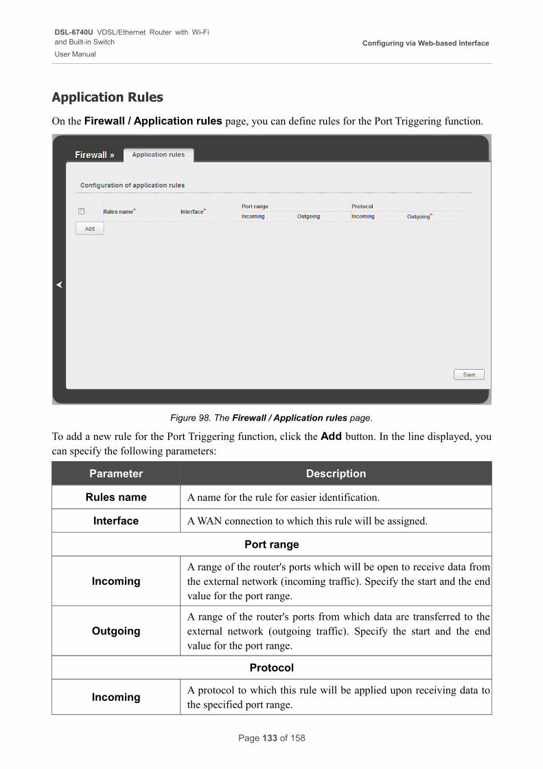
DSL-6740U VDSL/Ethernet Router with Wi-Fiand Built-in Switch
User Manual
Configuring via Web-based Interface
Application Rules
On the Firewall / Application rules page, you can define rules for the Port Triggering function.
Figure 98. The Firewall / Application rules page.
To add a new rule for the Port Triggering function, click the Add button. In the line displayed, you can specify the following parameters:
Parameter Description
Rules name A name for the rule for easier identification.
Interface A WAN connection to which this rule will be assigned.
Port range
IncomingA range of the router's ports which will be open to receive data from the external network (incoming traffic). Specify the start and the end value for the port range.
OutgoingA range of the router's ports from which data are transferred to the external network (outgoing traffic). Specify the start and the end value for the port range.
Protocol
IncomingA protocol to which this rule will be applied upon receiving data to the specified port range.
Page 133 of 158
DSL-6740U VDSL/Ethernet Router with Wi-Fiand Built-in Switch
User Manual
Configuring via Web-based Interface
Parameter Description
OutgoingA protocol to which this rule will be applied upon transferring data from the specified port range.
After specifying the needed parameters, click the Save button.
To edit an existing rule for the Port Triggering function, select a needed field in the relevant line of the table, change its value, and click the Save button.
To remove an existing rule for the Port Triggering function, select the checkbox located to the left of the relevant line in the table and click the Save button.
Page 134 of 158
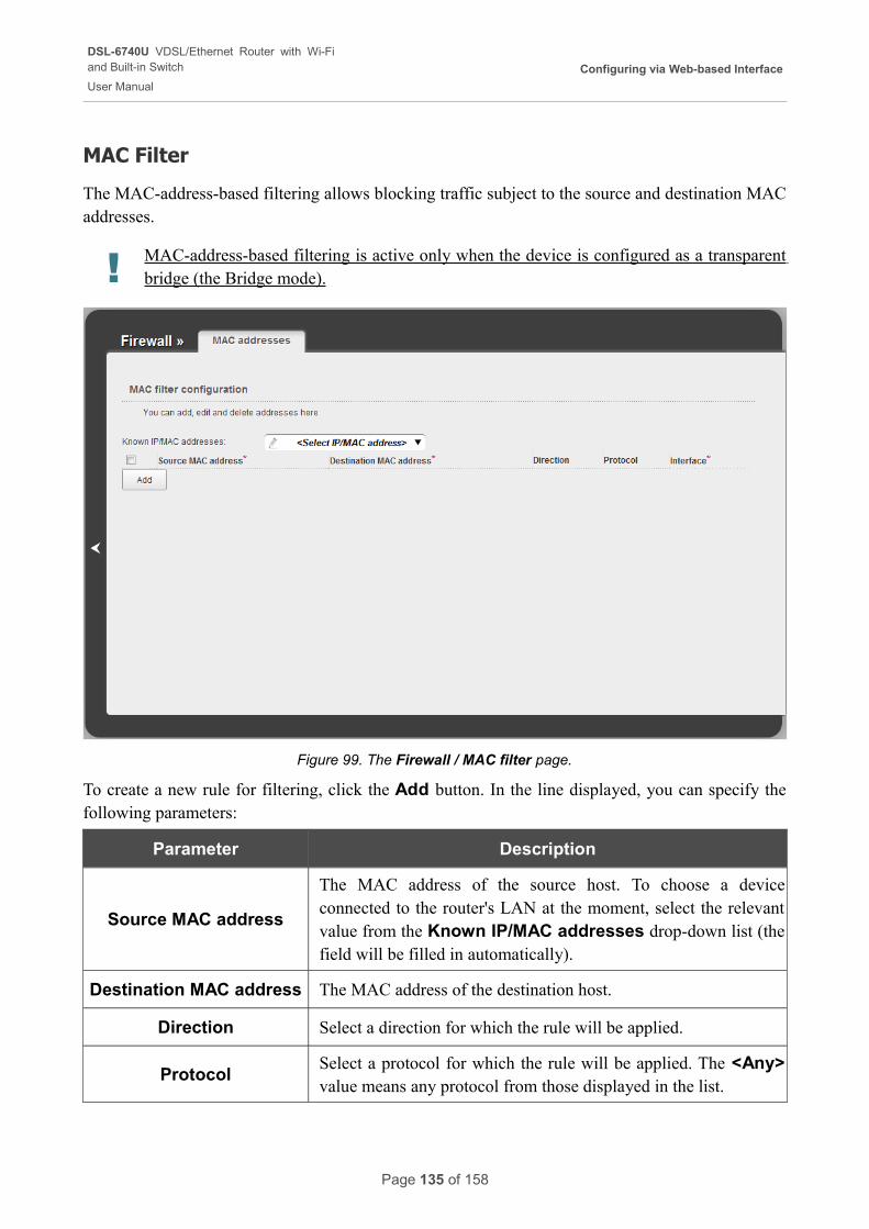
DSL-6740U VDSL/Ethernet Router with Wi-Fiand Built-in Switch
User Manual
Configuring via Web-based Interface
MAC Filter
The MAC-address-based filtering allows blocking traffic subject to the source and destination MAC addresses.
! MAC-address-based filtering is active only when the device is configured as a transparent bridge (the Bridge mode).
Figure 99. The Firewall / MAC filter page.
To create a new rule for filtering, click the Add button. In the line displayed, you can specify the following parameters:
Parameter Description
Source MAC address
The MAC address of the source host. To choose a device connected to the router's LAN at the moment, select the relevant value from the Known IP/MAC addresses drop-down list (the field will be filled in automatically).
Destination MAC address The MAC address of the destination host.
Direction Select a direction for which the rule will be applied.
ProtocolSelect a protocol for which the rule will be applied. The <Any> value means any protocol from those displayed in the list.
Page 135 of 158
DSL-6740U VDSL/Ethernet Router with Wi-Fiand Built-in Switch
User Manual
Configuring via Web-based Interface
Parameter Description
InterfaceSelect a WAN connection (with the Bridge connection type only) for which the rule will be applied.
After specifying the needed parameters, click the Save button.
To edit a rule for filtering, select a needed field in the relevant line of the table, change its value, and click the Save button.
To remove a rule for filtering, select the checkbox located to the left of the relevant line in the table and click the Save button.
Page 136 of 158
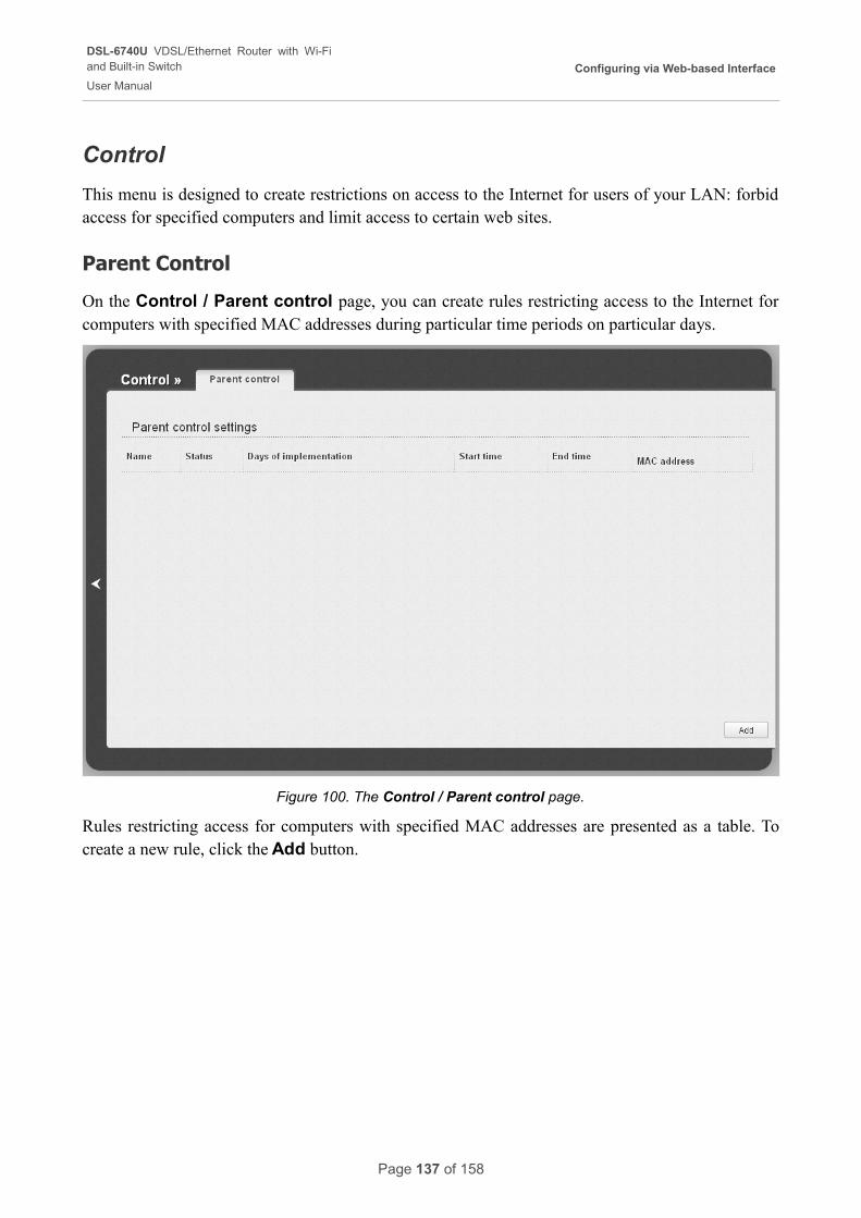
DSL-6740U VDSL/Ethernet Router with Wi-Fiand Built-in Switch
User Manual
Configuring via Web-based Interface
Control
This menu is designed to create restrictions on access to the Internet for users of your LAN: forbid access for specified computers and limit access to certain web sites.
Parent Control
On the Control / Parent control page, you can create rules restricting access to the Internet for computers with specified MAC addresses during particular time periods on particular days.
Figure 100. The Control / Parent control page.
Rules restricting access for computers with specified MAC addresses are presented as a table. To create a new rule, click the Add button.
Page 137 of 158
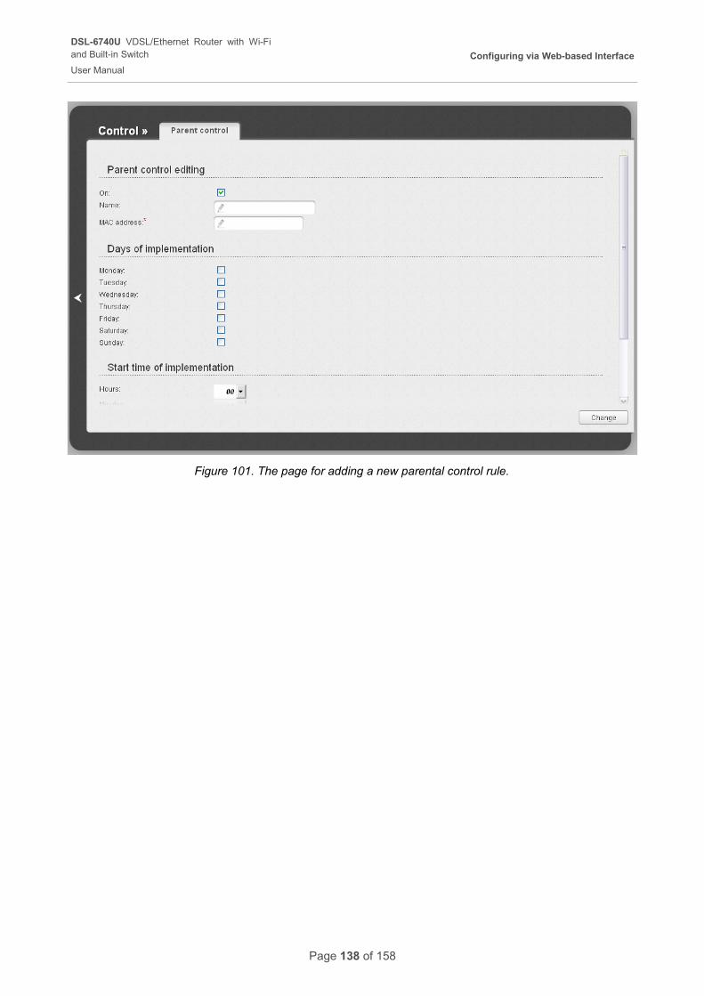
DSL-6740U VDSL/Ethernet Router with Wi-Fiand Built-in Switch
User Manual
Configuring via Web-based Interface
Figure 101. The page for adding a new parental control rule.
Page 138 of 158
DSL-6740U VDSL/Ethernet Router with Wi-Fiand Built-in Switch
User Manual
Configuring via Web-based Interface
You can specify the following parameters:
Parameter Description
Parent control editing
On Select the checkbox to enable the rule.
NameA name for the rule for easier identification. You can specify any name.
MAC addressThe MAC address of the computer to which this rule will be applied.
Days of implementation
Select checkboxes corresponding to the needed days of the week.
Start time of implementation
Hours
MinutesStart time of the rule application.
End time of implementation
Hours
MinutesEnd time of the rule application.
Click the Change button.
To delete an existing rule, select the relevant rule in the table. On the opened page, click the Delete button.
Page 139 of 158
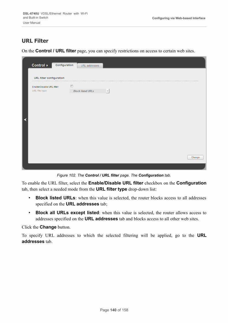
DSL-6740U VDSL/Ethernet Router with Wi-Fiand Built-in Switch
User Manual
Configuring via Web-based Interface
URL Filter
On the Control / URL filter page, you can specify restrictions on access to certain web sites.
Figure 102. The Control / URL filter page. The Configuration tab.
To enable the URL filter, select the Enable/Disable URL filter checkbox on the Configuration tab, then select a needed mode from the URL filter type drop-down list:
• Block listed URLs: when this value is selected, the router blocks access to all addresses specified on the URL addresses tab;
• Block all URLs except listed: when this value is selected, the router allows access to addresses specified on the URL addresses tab and blocks access to all other web sites.
Click the Change button.
To specify URL addresses to which the selected filtering will be applied, go to the URL addresses tab.
Page 140 of 158
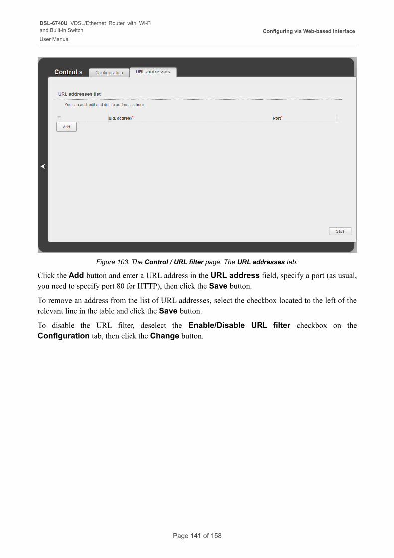
DSL-6740U VDSL/Ethernet Router with Wi-Fiand Built-in Switch
User Manual
Configuring via Web-based Interface
Figure 103. The Control / URL filter page. The URL addresses tab.
Click the Add button and enter a URL address in the URL address field, specify a port (as usual, you need to specify port 80 for HTTP), then click the Save button.
To remove an address from the list of URL addresses, select the checkbox located to the left of the relevant line in the table and click the Save button.
To disable the URL filter, deselect the Enable/Disable URL filter checkbox on the Configuration tab, then click the Change button.
Page 141 of 158
DSL-6740U VDSL/Ethernet Router with Wi-Fiand Built-in Switch
User Manual
Configuring via Web-based Interface
System
In this menu you can do the following:
• change the password used to access the router's settings
• save the current settings to the non-volatile memory
• create a backup of the router's configuration
• restore the router's configuration from a previously saved file
• restore the factory default settings
• view the system log
• update the firmware of the router
• configure automatic synchronization of the system time or manually configure the date and time for the router
• allow or forbid access to the router via TELNET.
Page 142 of 158
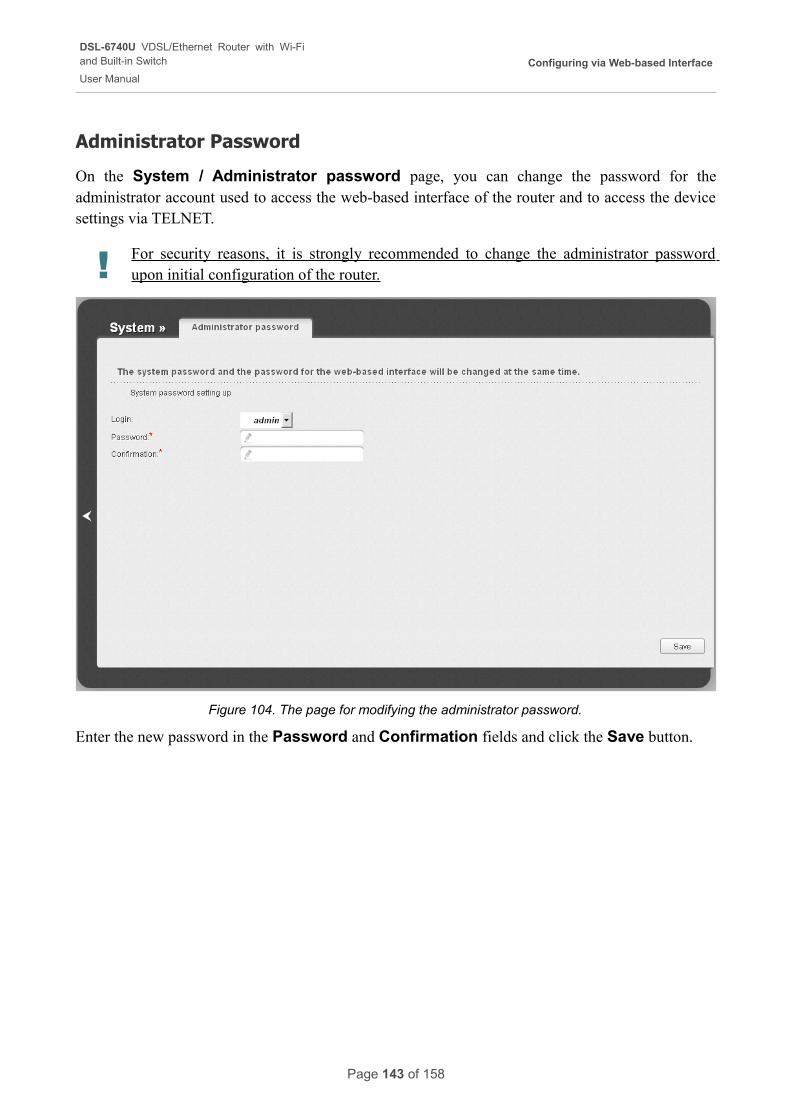
DSL-6740U VDSL/Ethernet Router with Wi-Fiand Built-in Switch
User Manual
Configuring via Web-based Interface
Administrator Password
On the System / Administrator password page, you can change the password for the administrator account used to access the web-based interface of the router and to access the device settings via TELNET.
! For security reasons, it is strongly recommended to change the administrator password upon initial configuration of the router.
Figure 104. The page for modifying the administrator password.
Enter the new password in the Password and Confirmation fields and click the Save button.
Page 143 of 158
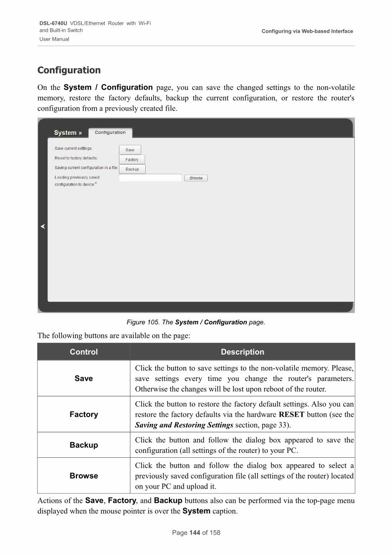
DSL-6740U VDSL/Ethernet Router with Wi-Fiand Built-in Switch
User Manual
Configuring via Web-based Interface
Configuration
On the System / Configuration page, you can save the changed settings to the non-volatile memory, restore the factory defaults, backup the current configuration, or restore the router's configuration from a previously created file.
Figure 105. The System / Configuration page.
The following buttons are available on the page:
Control Description
SaveClick the button to save settings to the non-volatile memory. Please, save settings every time you change the router's parameters. Otherwise the changes will be lost upon reboot of the router.
FactoryClick the button to restore the factory default settings. Also you can restore the factory defaults via the hardware RESET button (see the Saving and Restoring Settings section, page 33).
BackupClick the button and follow the dialog box appeared to save the configuration (all settings of the router) to your PC.
BrowseClick the button and follow the dialog box appeared to select a previously saved configuration file (all settings of the router) located on your PC and upload it.
Actions of the Save, Factory, and Backup buttons also can be performed via the top-page menu displayed when the mouse pointer is over the System caption.
Page 144 of 158
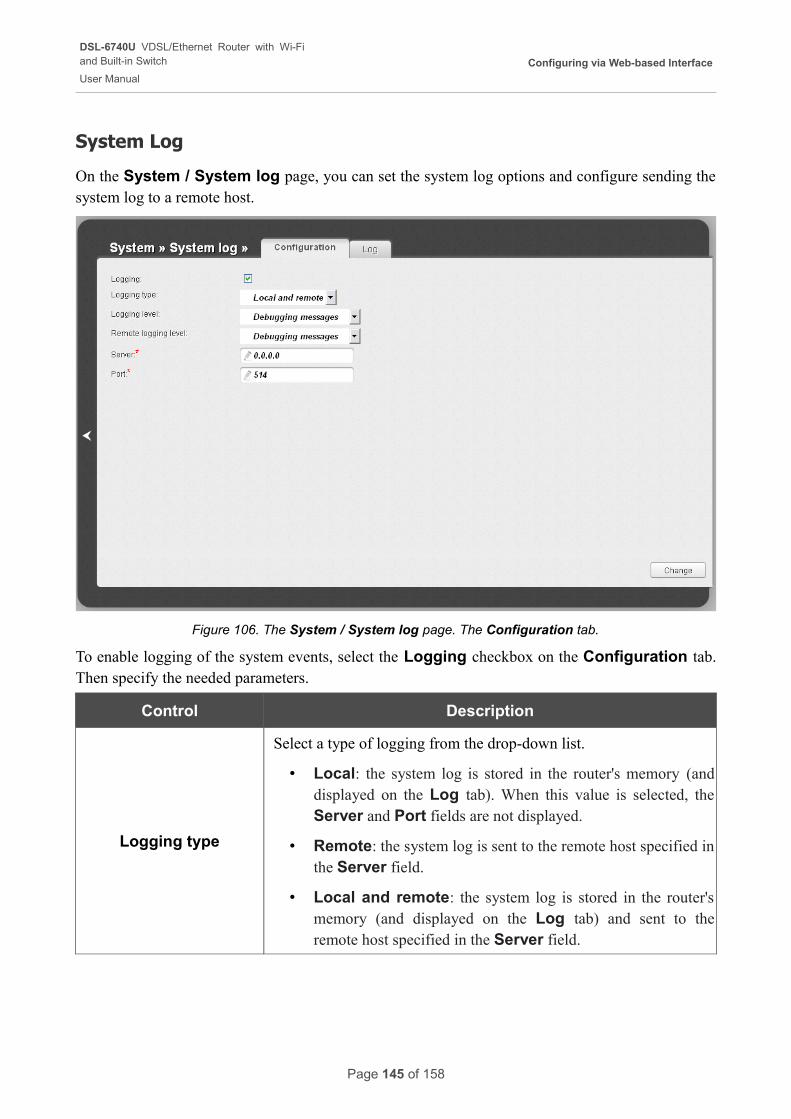
DSL-6740U VDSL/Ethernet Router with Wi-Fiand Built-in Switch
User Manual
Configuring via Web-based Interface
System Log
On the System / System log page, you can set the system log options and configure sending the system log to a remote host.
Figure 106. The System / System log page. The Configuration tab.
To enable logging of the system events, select the Logging checkbox on the Configuration tab. Then specify the needed parameters.
Control Description
Logging type
Select a type of logging from the drop-down list.
• Local: the system log is stored in the router's memory (and displayed on the Log tab). When this value is selected, the Server and Port fields are not displayed.
• Remote: the system log is sent to the remote host specified in the Server field.
• Local and remote: the system log is stored in the router's memory (and displayed on the Log tab) and sent to the remote host specified in the Server field.
Page 145 of 158
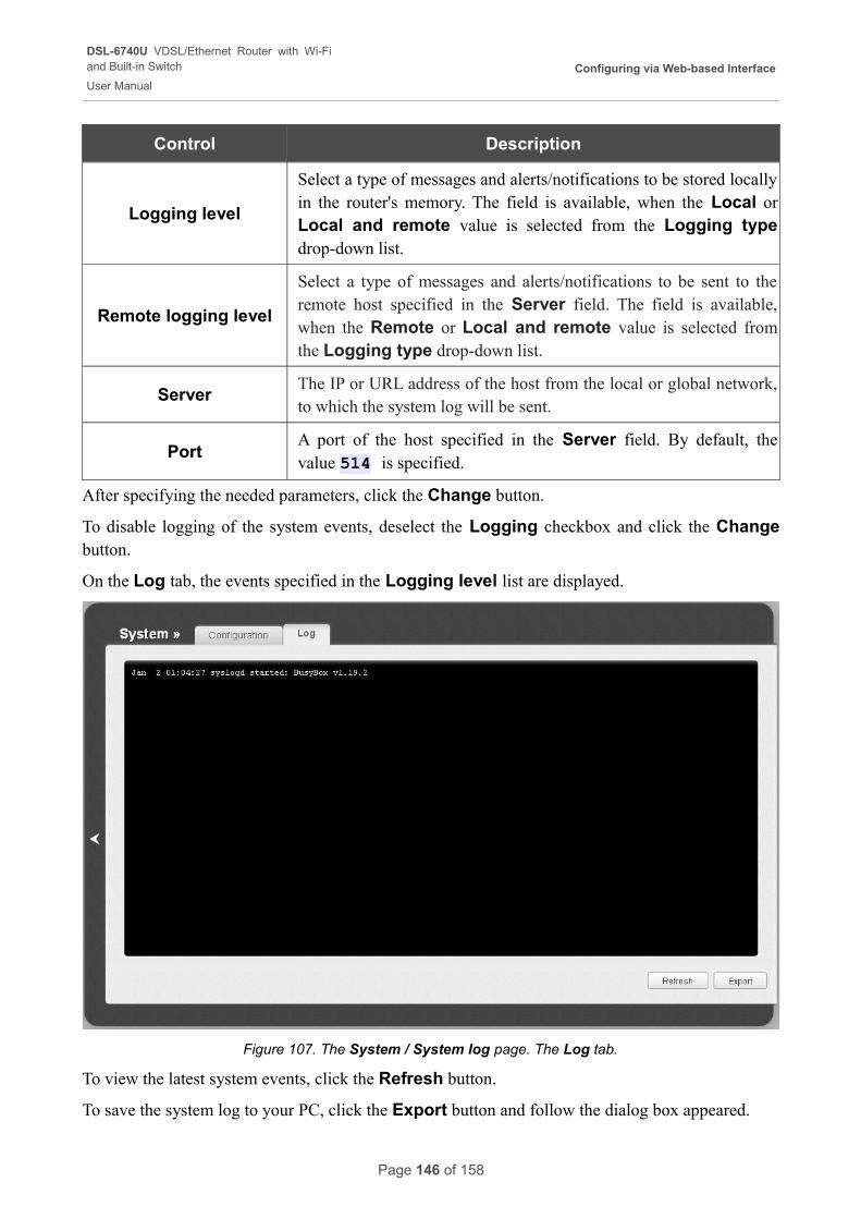
DSL-6740U VDSL/Ethernet Router with Wi-Fiand Built-in Switch
User Manual
Configuring via Web-based Interface
Control Description
Logging level
Select a type of messages and alerts/notifications to be stored locally in the router's memory. The field is available, when the Local or Local and remote value is selected from the Logging type drop-down list.
Remote logging level
Select a type of messages and alerts/notifications to be sent to the remote host specified in the Server field. The field is available, when the Remote or Local and remote value is selected from the Logging type drop-down list.
ServerThe IP or URL address of the host from the local or global network, to which the system log will be sent.
PortA port of the host specified in the Server field. By default, the value 514 is specified.
After specifying the needed parameters, click the Change button.
To disable logging of the system events, deselect the Logging checkbox and click the Change button.
On the Log tab, the events specified in the Logging level list are displayed.
Figure 107. The System / System log page. The Log tab.
To view the latest system events, click the Refresh button.
To save the system log to your PC, click the Export button and follow the dialog box appeared.
Page 146 of 158
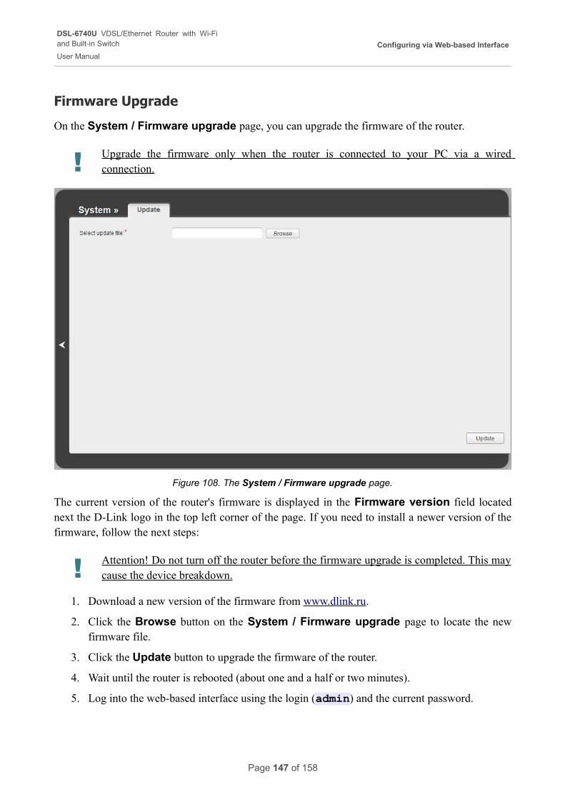
DSL-6740U VDSL/Ethernet Router with Wi-Fiand Built-in Switch
User Manual
Configuring via Web-based Interface
Firmware Upgrade
On the System / Firmware upgrade page, you can upgrade the firmware of the router.
! Upgrade the firmware only when the router is connected to your PC via a wired connection.
Figure 108. The System / Firmware upgrade page.
The current version of the router's firmware is displayed in the Firmware version field located next the D-Link logo in the top left corner of the page. If you need to install a newer version of the firmware, follow the next steps:
! Attention! Do not turn off the router before the firmware upgrade is completed. This may cause the device breakdown.
1. Download a new version of the firmware from www.dlink.ru.
2. Click the Browse button on the System / Firmware upgrade page to locate the new firmware file.
3. Click the Update button to upgrade the firmware of the router.
4. Wait until the router is rebooted (about one and a half or two minutes).
5. Log into the web-based interface using the login (admin) and the current password.
Page 147 of 158
DSL-6740U VDSL/Ethernet Router with Wi-Fiand Built-in Switch
User Manual
Configuring via Web-based Interface
6. Select the Factory line in the top-page menu displayed when the mouse pointer is over the System caption.
7. Wait until the router is rebooted. Log into the web-based interface, using the default IP address, login and password (192.168.1.1, admin, admin).
Page 148 of 158
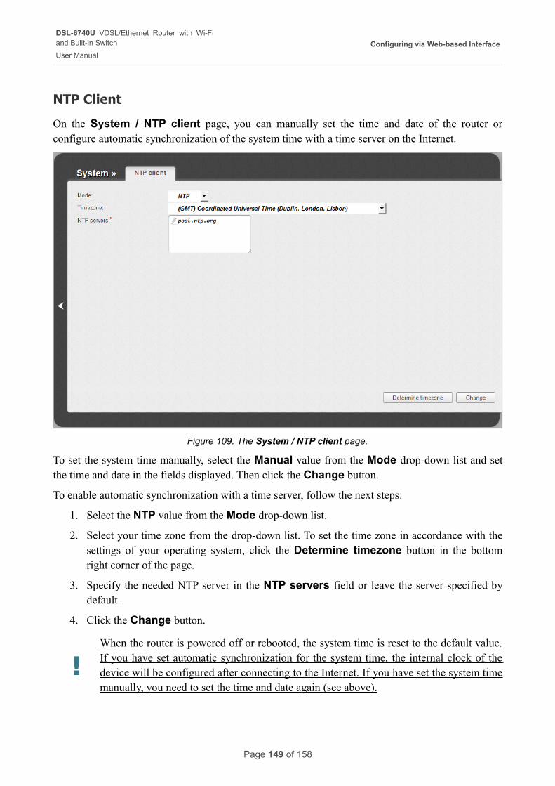
DSL-6740U VDSL/Ethernet Router with Wi-Fiand Built-in Switch
User Manual
Configuring via Web-based Interface
NTP Client
On the System / NTP client page, you can manually set the time and date of the router or configure automatic synchronization of the system time with a time server on the Internet.
Figure 109. The System / NTP client page.
To set the system time manually, select the Manual value from the Mode drop-down list and set the time and date in the fields displayed. Then click the Change button.
To enable automatic synchronization with a time server, follow the next steps:
1. Select the NTP value from the Mode drop-down list.
2. Select your time zone from the drop-down list. To set the time zone in accordance with the settings of your operating system, click the Determine timezone button in the bottom right corner of the page.
3. Specify the needed NTP server in the NTP servers field or leave the server specified by default.
4. Click the Change button.
!When the router is powered off or rebooted, the system time is reset to the default value. If you have set automatic synchronization for the system time, the internal clock of the device will be configured after connecting to the Inter net. If you have set the system time manually, you need to set the time and date again (see above).
Page 149 of 158
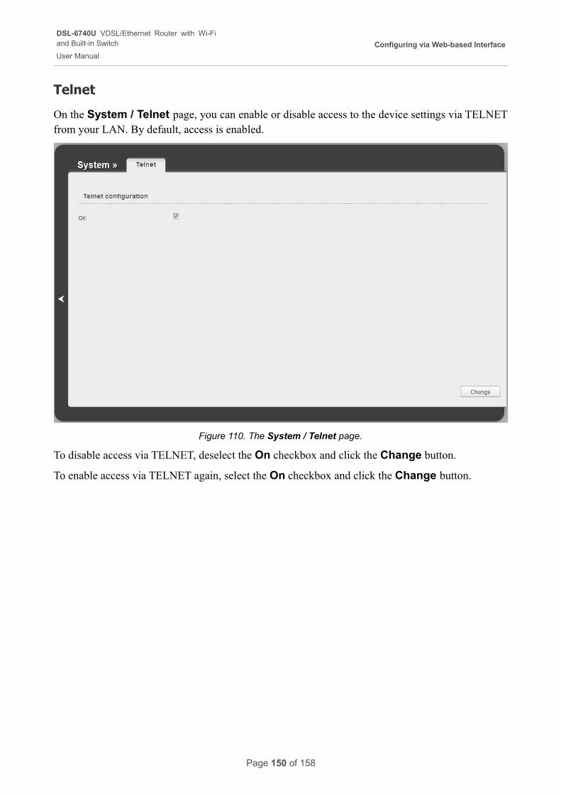
DSL-6740U VDSL/Ethernet Router with Wi-Fiand Built-in Switch
User Manual
Configuring via Web-based Interface
Telnet
On the System / Telnet page, you can enable or disable access to the device settings via TELNET from your LAN. By default, access is enabled.
Figure 110. The System / Telnet page.
To disable access via TELNET, deselect the On checkbox and click the Change button.
To enable access via TELNET again, select the On checkbox and click the Change button.
Page 150 of 158
DSL-6740U VDSL/Ethernet Router with Wi-Fiand Built-in Switch
User Manual
Operation Guidelines
CHAPTER 5. OPERATION GUIDELINES
Safety Instructions
Place your router on a flat horizontal surface. Make sure that the router is provided with sufficient ventilation.
To prevent overheating, do not obstruct the ventilation openings of the router.
Plug the router into a surge protector to reduce the risk of damage from power surges and lightning strikes.
Operate the router only from an electrical outlet with the correct power source as indicated on the adapter.
Do not open the cover of the router. Otherwise any warranty will be invalidated.
Unplug the equipment before dusting and cleaning. Use a damp cloth to clean the equipment. Do not use liquid/aerosol cleaners or magnetic/static cleaning devices.
Page 151 of 158
DSL-6740U VDSL/Ethernet Router with Wi-Fiand Built-in Switch
User Manual
Operation Guidelines
Wireless Installation Considerations
The DSL-6740U device lets you access your network using a wireless connection from virtually anywhere within the operating range of your wireless network. Keep in mind, however, that the number, thickness and location of walls, ceilings, or other objects that the wireless signals must pass through, may limit the range. Typical ranges vary depending on the types of materials and background RF noise in your home or office. To maximize your wireless range, follow the guidelines below.
1. Keep the number of walls and ceilings between the DSL-6740U device and other network devices to a minimum – each wall or ceiling can reduce your wireless network range by 3-90 feet (1-30 meters).
2. Be aware of the direct line between network devices. Place your devices so that the signal travels straight through a wall or ceiling (instead of at an angle) for better reception.
3. Building materials make a difference. A solid metal door or aluminum studs may have a negative effect on your wireless range. Try to position your router, access points, and computers so that the signal passes through drywalls or open doorways. Materials and objects such as glass, steel, metal, walls with insulation, water (fish tanks), mirrors, file cabinets, brick, and concrete will degrade your wireless signal.
4. Keep your router away (at least 3-6 feet or 1-2 meters) from electrical devices or appliances that generate RF noise.
5. If you are using 2.4 GHz cordless phones or X-10 equipment (wireless devices such as ceiling fans, lights, and home security systems), your wireless connection may degrade dramatically or drop completely. Make sure your 2.4 GHz phone base is as far away from your wireless devices as possible. Note, that the base transmits a signal even if the phone in not in use.
Page 152 of 158
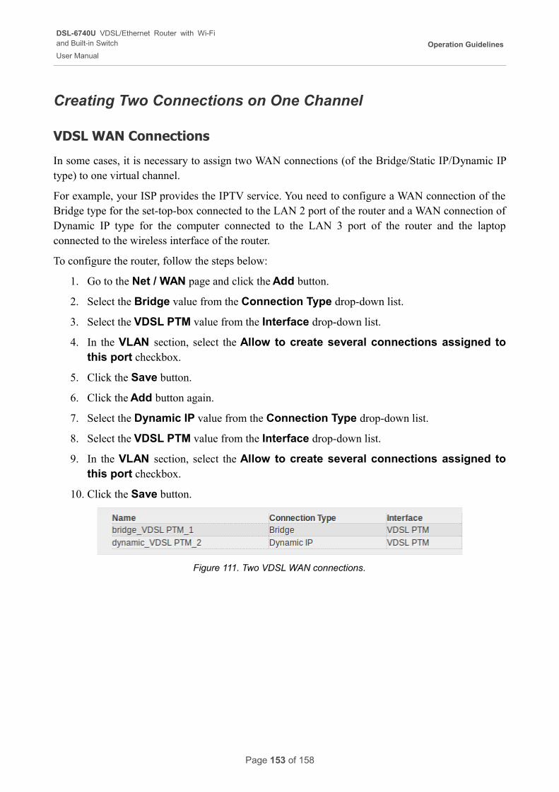
DSL-6740U VDSL/Ethernet Router with Wi-Fiand Built-in Switch
User Manual
Operation Guidelines
Creating Two Connections on One Channel
VDSL WAN Connections
In some cases, it is necessary to assign two WAN connections (of the Bridge/Static IP/Dynamic IP type) to one virtual channel.
For example, your ISP provides the IPTV service. You need to configure a WAN connection of the Bridge type for the set-top-box connected to the LAN 2 port of the router and a WAN connection of Dynamic IP type for the computer connected to the LAN 3 port of the router and the laptop connected to the wireless interface of the router.
To configure the router, follow the steps below:
1. Go to the Net / WAN page and click the Add button.
2. Select the Bridge value from the Connection Type drop-down list.
3. Select the VDSL PTM value from the Interface drop-down list.
4. In the VLAN section, select the Allow to create several connections assigned to this port checkbox.
5. Click the Save button.
6. Click the Add button again.
7. Select the Dynamic IP value from the Connection Type drop-down list.
8. Select the VDSL PTM value from the Interface drop-down list.
9. In the VLAN section, select the Allow to create several connections assigned to this port checkbox.
10. Click the Save button.
Figure 111. Two VDSL WAN connections.
Page 153 of 158
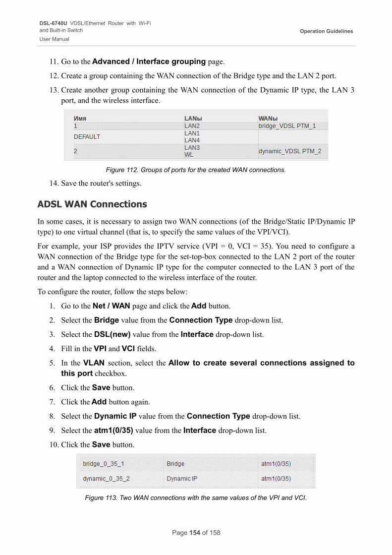
DSL-6740U VDSL/Ethernet Router with Wi-Fiand Built-in Switch
User Manual
Operation Guidelines
11. Go to the Advanced / Interface grouping page.
12. Create a group containing the WAN connection of the Bridge type and the LAN 2 port.
13. Create another group containing the WAN connection of the Dynamic IP type, the LAN 3 port, and the wireless interface.
Figure 112. Groups of ports for the created WAN connections.
14. Save the router's settings.
ADSL WAN Connections
In some cases, it is necessary to assign two WAN connections (of the Bridge/Static IP/Dynamic IP type) to one virtual channel (that is, to specify the same values of the VPI/VCI).
For example, your ISP provides the IPTV service (VPI = 0, VCI = 35). You need to configure a WAN connection of the Bridge type for the set-top-box connected to the LAN 2 port of the router and a WAN connection of Dynamic IP type for the computer connected to the LAN 3 port of the router and the laptop connected to the wireless interface of the router.
To configure the router, follow the steps below:
1. Go to the Net / WAN page and click the Add button.
2. Select the Bridge value from the Connection Type drop-down list.
3. Select the DSL(new) value from the Interface drop-down list.
4. Fill in the VPI and VCI fields.
5. In the VLAN section, select the Allow to create several connections assigned to this port checkbox.
6. Click the Save button.
7. Click the Add button again.
8. Select the Dynamic IP value from the Connection Type drop-down list.
9. Select the atm1(0/35) value from the Interface drop-down list.
10. Click the Save button.
Figure 113. Two WAN connections with the same values of the VPI and VCI.
Page 154 of 158
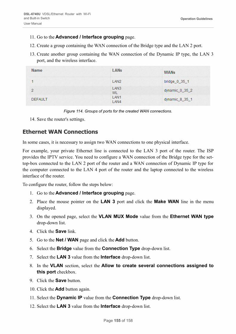
DSL-6740U VDSL/Ethernet Router with Wi-Fiand Built-in Switch
User Manual
Operation Guidelines
11. Go to the Advanced / Interface grouping page.
12. Create a group containing the WAN connection of the Bridge type and the LAN 2 port.
13. Create another group containing the WAN connection of the Dynamic IP type, the LAN 3 port, and the wireless interface.
Figure 114. Groups of ports for the created WAN connections.
14. Save the router's settings.
Ethernet WAN Connections
In some cases, it is necessary to assign two WAN connections to one physical interface.
For example, your private Ethernet line is connected to the LAN 3 port of the router. The ISP provides the IPTV service. You need to configure a WAN connection of the Bridge type for the set-top-box connected to the LAN 2 port of the router and a WAN connection of Dynamic IP type for the computer connected to the LAN 4 port of the router and the laptop connected to the wireless interface of the router.
To configure the router, follow the steps below:
1. Go to the Advanced / Interface grouping page.
2. Place the mouse pointer on the LAN 3 port and click the Make WAN line in the menu displayed.
3. On the opened page, select the VLAN MUX Mode value from the Ethernet WAN type drop-down list.
4. Click the Save link.
5. Go to the Net / WAN page and click the Add button.
6. Select the Bridge value from the Connection Type drop-down list.
7. Select the LAN 3 value from the Interface drop-down list.
8. In the VLAN section, select the Allow to create several connections assigned to this port checkbox.
9. Click the Save button.
10. Click the Add button again.
11. Select the Dynamic IP value from the Connection Type drop-down list.
12. Select the LAN 3 value from the Interface drop-down list.
Page 155 of 158
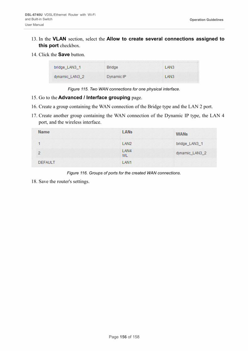
DSL-6740U VDSL/Ethernet Router with Wi-Fiand Built-in Switch
User Manual
Operation Guidelines
13. In the VLAN section, select the Allow to create several connections assigned to this port checkbox.
14. Click the Save button.
Figure 115. Two WAN connections for one physical interface.
15. Go to the Advanced / Interface grouping page.
16. Create a group containing the WAN connection of the Bridge type and the LAN 2 port.
17. Create another group containing the WAN connection of the Dynamic IP type, the LAN 4 port, and the wireless interface.
Figure 116. Groups of ports for the created WAN connections.
18. Save the router's settings.
Page 156 of 158
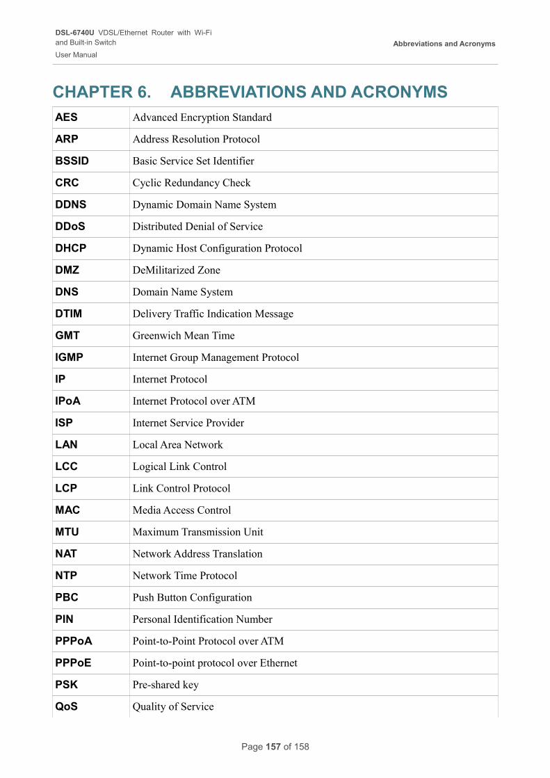
DSL-6740U VDSL/Ethernet Router with Wi-Fiand Built-in Switch
User Manual
Abbreviations and Acronyms
CHAPTER 6. ABBREVIATIONS AND ACRONYMS
AES Advanced Encryption Standard
ARP Address Resolution Protocol
BSSID Basic Service Set Identifier
CRC Cyclic Redundancy Check
DDNS Dynamic Domain Name System
DDoS Distributed Denial of Service
DHCP Dynamic Host Configuration Protocol
DMZ DeMilitarized Zone
DNS Domain Name System
DTIM Delivery Traffic Indication Message
GMT Greenwich Mean Time
IGMP Internet Group Management Protocol
IP Internet Protocol
IPoA Internet Protocol over ATM
ISP Internet Service Provider
LAN Local Area Network
LCC Logical Link Control
LCP Link Control Protocol
MAC Media Access Control
MTU Maximum Transmission Unit
NAT Network Address Translation
NTP Network Time Protocol
PBC Push Button Configuration
PIN Personal Identification Number
PPPoA Point-to-Point Protocol over ATM
PPPoE Point-to-point protocol over Ethernet
PSK Pre-shared key
QoS Quality of Service
Page 157 of 158
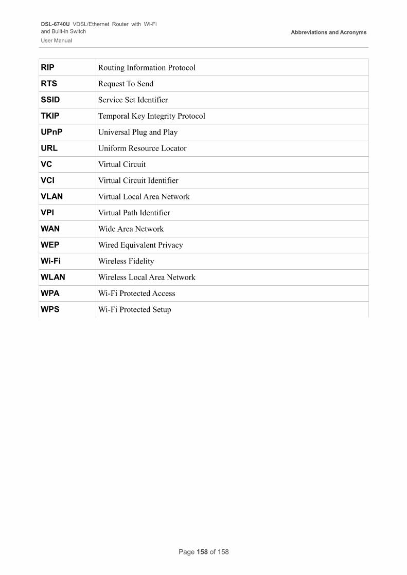
DSL-6740U VDSL/Ethernet Router with Wi-Fiand Built-in Switch
User Manual
Abbreviations and Acronyms
RIP Routing Information Protocol
RTS Request To Send
SSID Service Set Identifier
TKIP Temporal Key Integrity Protocol
UPnP Universal Plug and Play
URL Uniform Resource Locator
VC Virtual Circuit
VCI Virtual Circuit Identifier
VLAN Virtual Local Area Network
VPI Virtual Path Identifier
WAN Wide Area Network
WEP Wired Equivalent Privacy
Wi-Fi Wireless Fidelity
WLAN Wireless Local Area Network
WPA Wi-Fi Protected Access
WPS Wi-Fi Protected Setup
Page 158 of 158