Embed Size (px)
Citation preview
Product Registration: Register your new product at http://warranty.harmanpro.com.
Obtaining Other Language Versions: To obtain information in another language about the use of this product, please contact your local HARMAN Professional Distributor. If you need assistance locating your local distributor, please visit www.crownaudio.com/where_to_buy.
This manual does not include all of the details of design, production, or variations of the equipment. Nor does it cover every possible situation which may arise during installation, operation or maintenance.
The information provided in this manual was deemed accurate as of the publication date. However, updates to this information may have occurred. To obtain the latest version of this manual, please visit the Crown website at www.crownaudio.com.
Trademark Notice: Crown, Crown Audio, and Amcron are registered trademarks of Crown International. Other trademarks are the property of their respective owners. Later versions of this manual and additional information about this product may be available at the Crown website at www.crownaudio.com.
Some models may be exported under the name Amcron®
©2015 by HARMAN International, Inc., 1718 W. Mishawaka Rd., Elkhart, Indiana 46517-9439 U.S.A. Telephone: 574-294-8000.
DSi 8Mn Cinema System Monitor
DSi 8Mn Cinema System Monitor Operation Manual
5058516 - 04/15
+3+2+1
0-1-3-5-7
-10-20-30-40
DSi 8Mn Cinema System Monitor
Operation Manualpage 2
1. Read these instructions.
2. Keep these instructions.
3. Heed all warnings.
4. Follow all instructions.
5. Do not use this apparatus near water.
6. Clean only with a dry cloth.
7. Do not block any ventilation openings. Install in accordance with the manufacturer’s instructions.
8. Do not install near any heat sources such as radiators, heat registers, stoves, or other apparatus (including amplifiers) that produce heat.
9. Do not defeat the safety purpose of the polarized or grounding-type plug. A polarized plug has two blades with one wider than the other. A grounding-type plug has two blades and a third grounding prong. The wide blade or the third prong is provided for your safety. If the provided plug does not fit into your outlet, consult an electrician for replacement of the obsolete outlet.
10. Protect the power cord from being walked on or pinched, particularly at plugs, convenience receptacles, and the point where they exit from the apparatus.
11. Only use attachments/accessories specified by the manufacturer.
12. Use only with a cart, stand, tripod, bracket, or table specified by the manufacturer, or sold with the apparatus. When a cart is used, use caution when moving the cart/apparatus combination to avoid injury from tip-over.
13. Unplug this apparatus during lightning storms or when unused for long periods of time.
14. Refer all servicing to qualified service personnel. Servicing is required when the apparatus has been damaged in any way, such as power-supply cord or plug is damaged, liquid has been spilled or objects have fallen into the apparatus, the apparatus has been exposed to rain or moisture, does not operate normally, or has been dropped.
15. Use the mains plug to disconnect the apparatus from the mains.
16. WARNING: TO REDUCE THE RISK OF FIRE OR ELECTRIC SHOCK, DO NOT EXPOSE THIS APPARATUS TO RAIN OR MOISTURE.
17. DO NOT EXPOSE THIS EQUIPMENT TO DRIPPING OR SPLASHING AND ENSURE THAT NO OBJECTS FILLED WITH LIQUIDS, SUCH AS VASES, ARE PLACED ON THE EQUIPMENT.
18. THE MAINS PLUG OF THE POWER SUPPLY CORD SHALL REMAIN READILY OPERABLE.
TO PREVENT ELECTRIC SHOCK DO NOT REMOVE TOP OR BOTTOM COVERS. NO USER SERVICEABLE PARTS INSIDE. REFER SERVICING TO QUALIFIED SERVICE PERSONNEL.
TO COMPLETELY DISCONNECT THIS EQUIPMENT FROM THE AC MAINS, DISCONNECT THE POWER SUPPLY CORD PLUG FROM THE AC RECEPTACLE. THE MAINS PLUG OF THE POWER SUPPLY CORD SHALL REMAIN READILY OPERABLE.
WATCH FOR THESE SYMBOLS:
The lightning bolt triangle is used to alert the user to the risk of electric shock.
The exclamation point triangle is used to alert the user to important operating or maintenance instructions.
Important Safety Instructions
FCC COMPLIANCE NOTICEThis device complies with part 15 of the FCC rules. Operation is subject to the following two conditions: (1) This device may not cause harmful interference, and (2) this device must accept any interference received, including interference that may cause undesired operation.
CAUTION: Changes or modifications not expressly approved by the party responsible for compliance could void the user’s authority to operate the equipment.
NOTE: This equipment has been tested and found to comply with the limits for a Class A digital device, pursuant to part 15 of the FCC Rules. These limits are designed to provide reasonable protection against harmful interference when the equipment is operated in a commercial environment. This equipment generates, uses, and can radiate radio frequency energy and, if not installed and used in accordance with the instruction manual, may cause harmful interference to radio communications. Operation of this equipment in a residential area is likely to cause harmful interference in which case the user will be required to correct the interference at his own expense.
DSi 8Mn Cinema System Monitor
page 3Operation Manual
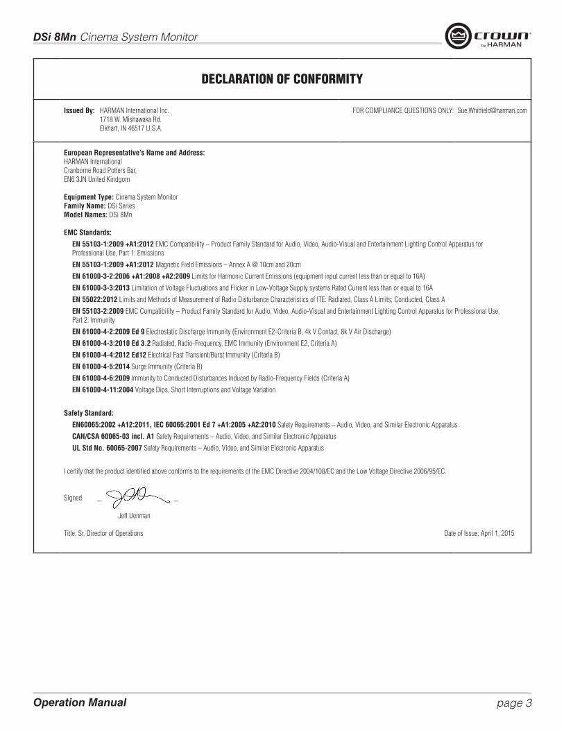
DECLARATION OF CONFORMITY
Issued By: HARMAN International Inc. 1718 W. Mishawaka Rd. Elkhart, IN 46517 U.S.A.
FOR COMPLIANCE QUESTIONS ONLY: [email protected]
European Representative’s Name and Address:HARMAN InternationalCranborne Road Potters Bar,EN6 3JN United Kindgom
Equipment Type: Cinema System MonitorFamily Name: DSi SeriesModel Names: DSi 8Mn
EMC Standards:
EN 55103-1:2009 +A1:2012 EMC Compatibility – Product Family Standard for Audio, Video, Audio-Visual and Entertainment Lighting Control Apparatus for Professional Use, Part 1: Emissions
EN 55103-1:2009 +A1:2012 Magnetic Field Emissions – Annex A @ 10cm and 20cm
EN 61000-3-2:2006 +A1:2008 +A2:2009 Limits for Harmonic Current Emissions (equipment input current less than or equal to 16A)
EN 61000-3-3:2013 Limitation of Voltage Fluctuations and Flicker in Low-Voltage Supply systems Rated Current less than or equal to 16A
EN 55022:2012 Limits and Methods of Measurement of Radio Disturbance Characteristics of ITE: Radiated, Class A Limits; Conducted, Class A
EN 55103-2:2009 EMC Compatibility – Product Family Standard for Audio, Video, Audio-Visual and Entertainment Lighting Control Apparatus for Professional Use, Part 2: Immunity
EN 61000-4-2:2009 Ed 9 Electrostatic Discharge Immunity (Environment E2-Criteria B, 4k V Contact, 8k V Air Discharge)
EN 61000-4-3:2010 Ed 3.2 Radiated, Radio-Frequency, EMC Immunity (Environment E2, Criteria A)
EN 61000-4-4:2012 Ed12 Electrical Fast Transient/Burst Immunity (Criteria B)
EN 61000-4-5:2014 Surge Immunity (Criteria B)
EN 61000-4-6:2009 Immunity to Conducted Disturbances Induced by Radio-Frequency Fields (Criteria A)
EN 61000-4-11:2004 Voltage Dips, Short Interruptions and Voltage Variation
Safety Standard:
EN60065:2002 +A12:2011, IEC 60065:2001 Ed 7 +A1:2005 +A2:2010 Safety Requirements – Audio, Video, and Similar Electronic Apparatus
CAN/CSA 60065-03 incl. A1 Safety Requirements – Audio, Video, and Similar Electronic Apparatus
UL Std No. 60065-2007 Safety Requirements – Audio, Video, and Similar Electronic Apparatus
I certify that the product identified above conforms to the requirements of the EMC Directive 2004/108/EC and the Low Voltage Directive 2006/95/EC.
Signed ______________________
Jeff Denman
Title: Sr. Director of Operations Date of Issue: April 1, 2015
DSi 8Mn Cinema System Monitor
Operation Manualpage 4
Important Safety Instructions ............................................................................................................... 2
Declaration of Conformity ................................................................................................................... 3
Table of Contents ............................................................................................................................. 4
Welcome ...................................................................................................................................... 5
Front Panel Features ......................................................................................................................... 6
Back Panel Features ......................................................................................................................... 6
System Overview .............................................................................................................................. 7
Installation ..................................................................................................................................... 9
System Configuration ......................................................................................................................... 13
System Operation ............................................................................................................................. 16
Connector Pin Outs ........................................................................................................................... 19
Service ......................................................................................................................................... 26
Warranty ....................................................................................................................................... 28
Table of Contents
DSi 8Mn Cinema System Monitor
page 5Operation Manual
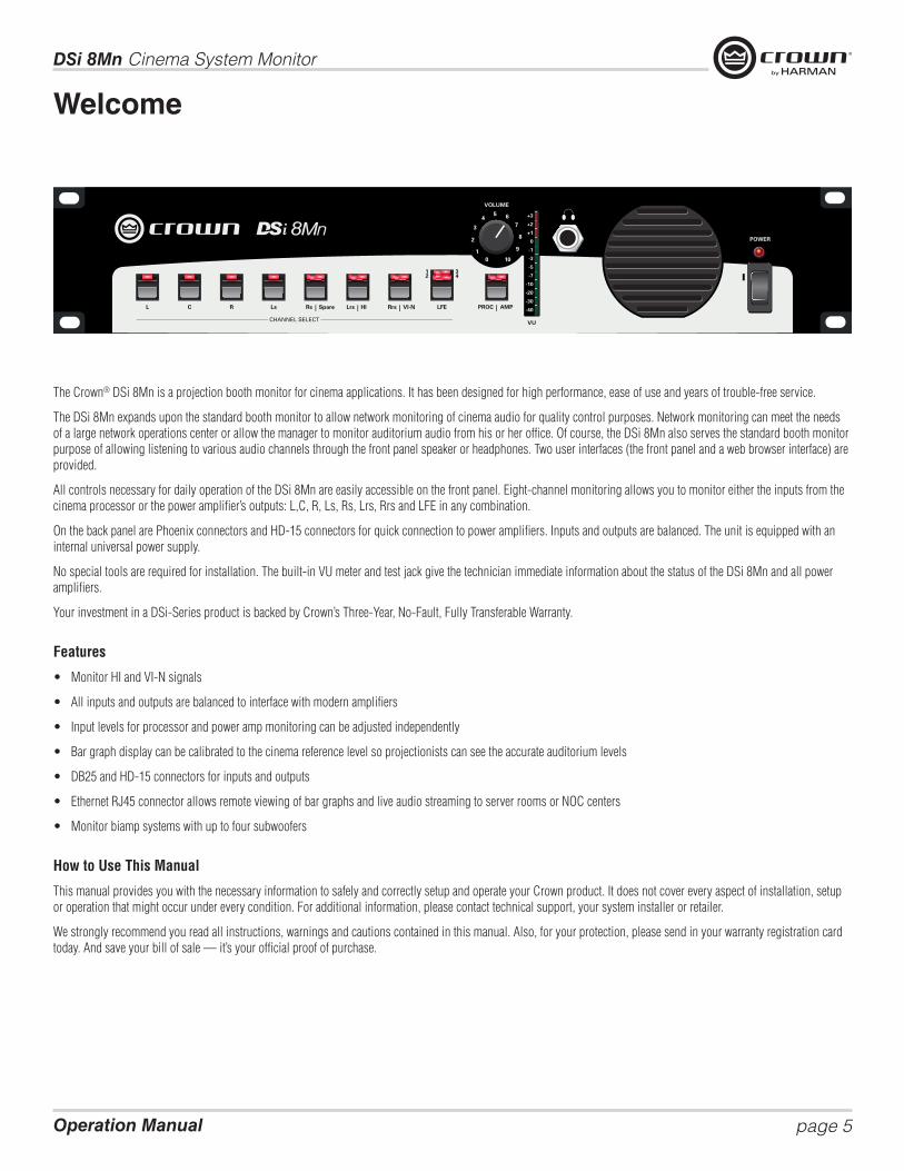
The Crown® DSi 8Mn is a projection booth monitor for cinema applications. It has been designed for high performance, ease of use and years of trouble-free service.
The DSi 8Mn expands upon the standard booth monitor to allow network monitoring of cinema audio for quality control purposes. Network monitoring can meet the needs of a large network operations center or allow the manager to monitor auditorium audio from his or her office. Of course, the DSi 8Mn also serves the standard booth monitor purpose of allowing listening to various audio channels through the front panel speaker or headphones. Two user interfaces (the front panel and a web browser interface) are provided.
All controls necessary for daily operation of the DSi 8Mn are easily accessible on the front panel. Eight-channel monitoring allows you to monitor either the inputs from the cinema processor or the power amplifier’s outputs: L,C, R, Ls, Rs, Lrs, Rrs and LFE in any combination.
On the back panel are Phoenix connectors and HD-15 connectors for quick connection to power amplifiers. Inputs and outputs are bal anced. The unit is equipped with an internal universal power supply.
No special tools are required for installation. The built-in VU meter and test jack give the technician immediate information about the status of the DSi 8Mn and all power amplifiers.
Your investment in a DSi-Series product is backed by Crown’s Three-Year, No-Fault, Fully Transferable Warranty.
Features
• Monitor HI and VI-N signals
• All inputs and outputs are balanced to interface with modern amplifiers
• Input levels for processor and power amp monitoring can be adjusted independently
• Bar graph display can be calibrated to the cinema reference level so projectionists can see the accurate auditorium levels
• DB25 and HD-15 connectors for inputs and outputs
• Ethernet RJ45 connector allows remote viewing of bar graphs and live audio streaming to server rooms or NOC centers
• Monitor biamp systems with up to four subwoofers
How to Use This Manual
This manual provides you with the necessary information to safely and correctly setup and operate your Crown product. It does not cover every aspect of installation, setup or operation that might occur under every condition. For additional information, please contact technical support, your system installer or retailer.
We strongly recommend you read all instructions, warnings and cautions contained in this manual. Also, for your protection, please send in your warranty registration card today. And save your bill of sale — it’s your official proof of purchase.
Welcome
+3+2+1
0-1-3-5-7
-10-20-30-40
DSi 8Mn Cinema System Monitor
Operation Manualpage 6
+3+2+1
0-1-3-5-7
-10-20-30-40
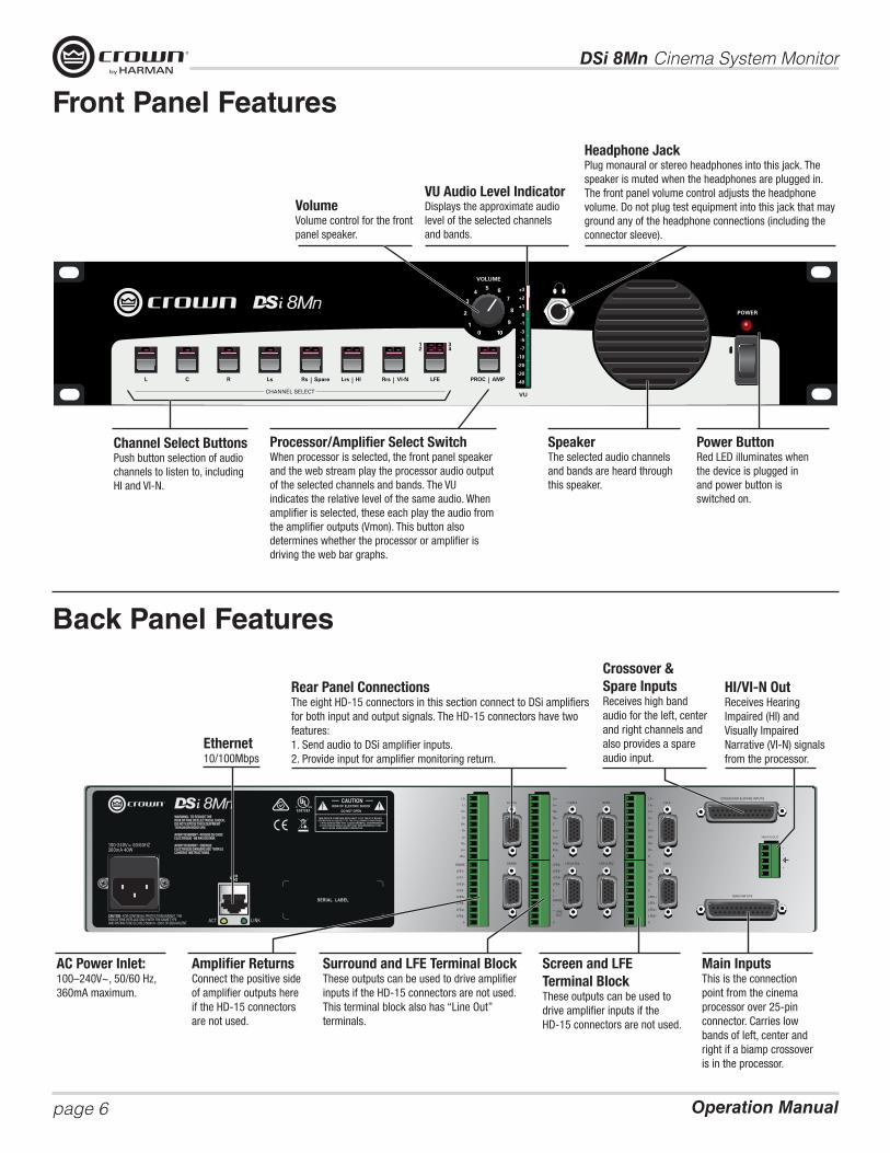
VolumeVolume control for the front panel speaker.
Channel Select ButtonsPush button selection of audio channels to listen to, including HI and VI-N.
Power ButtonRed LED illuminates when the device is plugged in and power button is switched on.
VU Audio Level IndicatorDisplays the approximate audio level of the selected channels and bands.
Processor/Amplifier Select SwitchWhen processor is selected, the front panel speaker and the web stream play the processor audio output of the selected channels and bands. The VU indicates the relative level of the same audio. When amplifier is selected, these each play the audio from the amplifier outputs (Vmon). This button also determines whether the processor or amplifier is driving the web bar graphs.
Headphone JackPlug monaural or stereo headphones into this jack. The speaker is muted when the headphones are plugged in. The front panel volume control adjusts the headphone volume. Do not plug test equipment into this jack that may ground any of the headphone connections (including the connector sleeve).
SpeakerThe selected audio channels and bands are heard through this speaker.
LhLrs/Rrs
SPARE
Lrs/Rrs
LFE3/LFE4
Rl/Rh
LFE1/LFE2
Ll/LhCROSSOVER & SPARE INPUTS
MAIN INPUTS
HI/VI-N OUT
Cl/Ch
Li
Ch
Cl
Rh
Rl
Ls
Rs
Lrs
Rrs
SPARE
LFE1+
LFE1-
LFE2+
LFE2-
LFE3+
LFE3-
LFE4+
LFE4-
E
Ls+
Ls-
Rs+
Rs-
E
Lrs+
Lrs-
Rrs+
Rrs-
E
LFE3+
LFE3-
LFE4+
LFE4-
SPARE
LINEOUT
E
+
-
+
-
E
Lh+
Lh-
Ll+
Ll-
E
Rh+
Rh-
Rl+
Rl-
E
Ch+
Ch-
Cl+
Cl-
E
LFE1+
LFE1-
LFE2+
LFE2-
E
+
-
+
-
Amplifier ReturnsConnect the positive side of amplifier outputs here if the HD-15 connectors are not used.
Surround and LFE Terminal BlockThese outputs can be used to drive amplifier inputs if the HD-15 connectors are not used. This terminal block also has “Line Out” terminals.
Screen and LFE Terminal BlockThese outputs can be used to drive amplifier inputs if the HD-15 connectors are not used.
Main InputsThis is the connection point from the cinema processor over 25-pin connector. Carries low bands of left, center and right if a biamp crossover is in the processor.
Rear Panel ConnectionsThe eight HD-15 connectors in this section connect to DSi amplifiers for both input and output signals. The HD-15 connectors have two features:1. Send audio to DSi amplifier inputs.2. Provide input for amplifier monitoring return.
Crossover & Spare InputsReceives high band audio for the left, center and right channels and also provides a spare audio input.
HI/VI-N OutReceives Hearing Impaired (HI) and Visually Impaired Narrative (VI-N) signals from the processor.
Ethernet10/100Mbps
AC Power Inlet: 100–240V~, 50/60 Hz, 360mA maximum.
Front Panel Features
Back Panel Features
DSi 8Mn Cinema System Monitor
page 7Operation Manual
The DSi 8Mn expands upon the standard booth monitor to allow network monitoring of cinema audio for quality control purposes. Network monitoring can meet the needs of a large network operations center or allow the manager to monitor auditorium audio from his or her office. Of course, the DSi 8Mn also serves the standard booth monitor purpose of allowing listening to various audio channels through the front panel speaker or headphones. Two user interfaces (the front panel and a web browser interface) are provided. The capabilities of each are listed below.
Front Panel User Interface • Push button selection of audio channels to listen to, including HI and VI-N
• Listen to processor output or amplifier output
• Listen to individual bands of biamp crossover whether located in processor or amplifier
• LED level indicator of channels being listened to
• Front panel control for speaker and headphone volume
• Internal speaker
• Front panel headphone jack
Network User Interface • Web browser based (no software to install, use any operating system, monitor on desktop or tablet computer)
• Bar graph display of all processor output or amplifier output levels (individual biamp bands if crossover in processor or amplifier)
• Streaming audio monitoring of selected audio channels or bands from processor or amplifier
Audio Inputs and Outputs
The DSi 8Mn simplifies the audio wiring of the booth. Audio from the cinema sound processor is delivered over one or two (for biamp crossover in processor) standard 25-pin D connectors (DB-25F). This eliminates the need for special cables or “break-out boards” for processors that have outputs only on DB-25 connectors.
The DSi 8Mn has standard DE-15F (also known as HD-15 or VGA) connectors to drive the amplifiers. These standard connectors drive two channel amplifiers with balanced audio and provide a “Vmon” return signal so the amplifier output can be monitored.
The DSi 8Mn also has pluggable terminal blocks for the interface to the amplifiers. These are used with amplifiers that do not have the DE-15 connectors. Terminals are provided for balanced audio to each channel of each amplifier. Terminals also accept a sample of the amplifier output so the output of the amplifier can be monitored.
Biamped Systems
The DSi 8Mn supports the monitoring of systems with biamped screen channels (left, center, and right). If the crossover is located before the monitor (either within the sound processor or between the sound processor and the DSi 8Mn), the DSi 8Mn can monitor the total audio for each channel as well as the individual bands for the screen channels. If the crossover is located after the monitor (within the amplifiers or after the amplifiers), the DSi 8Mn can monitor the full-range audio from the processor and monitor the individual bands from the amplifiers or crossover outputs. If the crossovers are located within the speakers, individual band samples are generally not available for monitoring. In this case, the DSi 8Mn would be configured with no crossover. When individual band monitoring is available, the front panel and web browser buttons “scroll” through the bands. The sequence is: off – both – low – high – off.
System Overview
DSi 8Mn Cinema System Monitor
Operation Manualpage 8
System OverviewBlock Diagrams
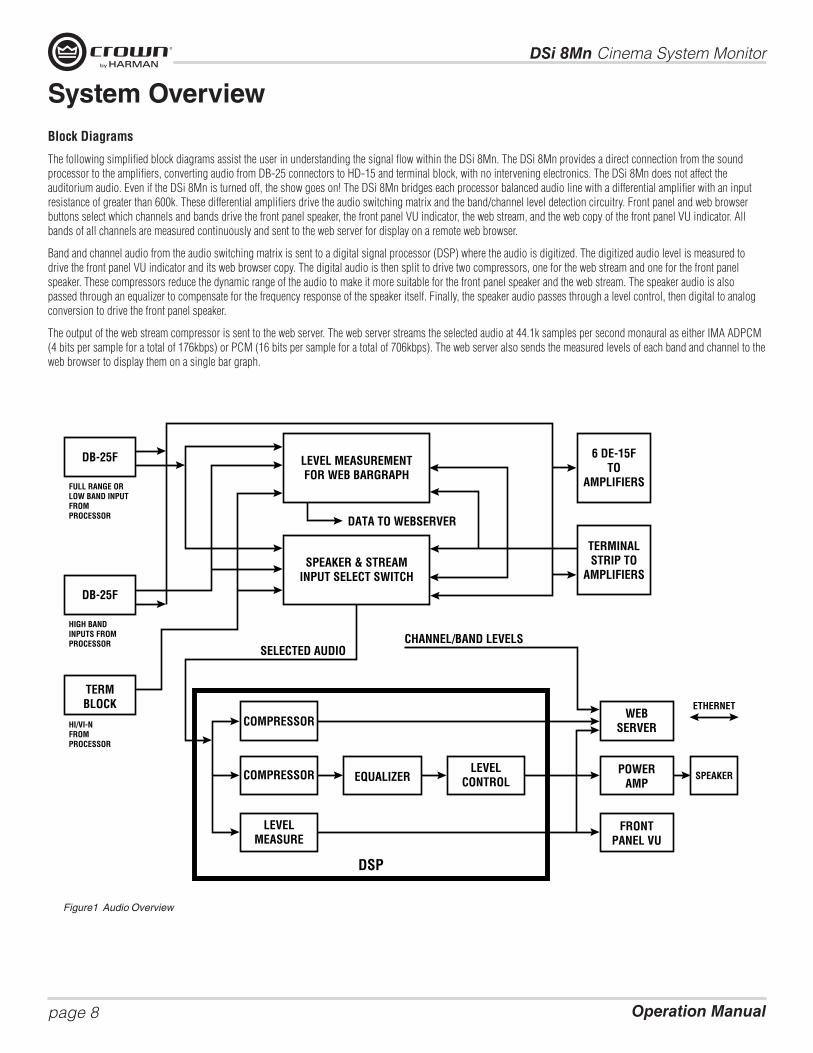
The following simplified block diagrams assist the user in understanding the signal flow within the DSi 8Mn. The DSi 8Mn provides a direct connection from the sound processor to the amplifiers, converting audio from DB-25 connectors to HD-15 and terminal block, with no intervening electronics. The DSi 8Mn does not affect the auditorium audio. Even if the DSi 8Mn is turned off, the show goes on! The DSi 8Mn bridges each processor balanced audio line with a differential amplifier with an input resistance of greater than 600k. These differential amplifiers drive the audio switching matrix and the band/channel level detection circuitry. Front panel and web browser buttons select which channels and bands drive the front panel speaker, the front panel VU indicator, the web stream, and the web copy of the front panel VU indicator. All bands of all channels are measured continuously and sent to the web server for display on a remote web browser.
Band and channel audio from the audio switching matrix is sent to a digital signal processor (DSP) where the audio is digitized. The digitized audio level is measured to drive the front panel VU indicator and its web browser copy. The digital audio is then split to drive two compressors, one for the web stream and one for the front panel speaker. These compressors reduce the dynamic range of the audio to make it more suitable for the front panel speaker and the web stream. The speaker audio is also passed through an equalizer to compensate for the frequency response of the speaker itself. Finally, the speaker audio passes through a level control, then digital to analog conversion to drive the front panel speaker.
The output of the web stream compressor is sent to the web server. The web server streams the selected audio at 44.1k samples per second monaural as either IMA ADPCM (4 bits per sample for a total of 176kbps) or PCM (16 bits per sample for a total of 706kbps). The web server also sends the measured levels of each band and channel to the web browser to display them on a single bar graph.
DB-25F
DB-25F
LEVEL MEASUREMENTFOR WEB BARGRAPH
6 DE-15FTO
AMPLIFIERS
TERMINALSTRIP TO
AMPLIFIERSSPEAKER & STREAM
INPUT SELECT SWITCH
FULL RANGE ORLOW BAND INPUTFROM PROCESSOR
HIGH BANDINPUTS FROMPROCESSOR
HI/VI-NFROM PROCESSOR
DATA TO WEBSERVER
SELECTED AUDIOCHANNEL/BAND LEVELS
DSP
ETHERNET
SPEAKER
TERMBLOCK
COMPRESSOR
COMPRESSOR EQUALIZERLEVEL
CONTROLPOWER
AMP
WEBSERVER
FRONTPANEL VU
LEVELMEASURE
Figure1 Audio Overview
DSi 8Mn Cinema System Monitor
page 9Operation Manual
InstallationInitial Power Up
A quick power-up test of the DSi 8Mn is suggested before mounting it in the equipment rack and wiring it up. This test can quickly detect shipping or other damage.
• Turn the AC power switch to the off position.
• Using the supplied AC line cord or one appropriate for the installation location (the power supply is a universal input supply 100-240 V~, 50/60 Hz), connect the DSi 8Mn to the AC line.
• Turn on the AC power switch. The red LED above the power switch should light. The other LEDs will flash as the unit goes through its power on self-test. After the power on self-test, only the Power and Processor LEDs should remain lit.
• Press each of the channel buttons several times. LEDs above the buttons should change. If a screen channel is set for biamp, the LED will stay lit through several button presses since the sequence is off – all – low – high – off.
• Press the PROC/AMP button and verify that the LEDs above the button toggle with each button push.
System Hardware Mounting and Grounding
The DSi 8Mn is designed to mount in a standard 19 inch (482.6 mm) rack and is two rack units high (3.5 inches, 88.9mm). The DSi 8Mn should be mounted at a convenient height in the equipment rack considering ease of use of the front panel controls and the routing of wiring between the DSi 8Mn, the processor, and the amplifiers. The DSi 8Mn includes a three-prong grounding plug and a three-wire power cord to accommodate a safe ground path from the chassis to the electrical system ground. Defeating this ground by removing the ground prong is not recommended.
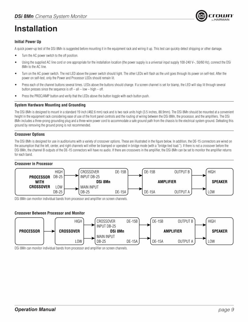
Crossover Options
The DSi 8Mn is designed for use in auditoriums with a variety of crossover options. These are illustrated in the figure below. In addition, the DE-15 connectors are wired on the assumption that the left, center, and right channels will either be biamped or operated in bridge mode (with a “bridge tied load.”). If there is not a crossover before the DSi 8Mn, the channel B outputs of the DE-15 connectors will have no audio. If there are crossovers in the amplifier, the DSi 8Mn can be set to monitor the amplifier returns for each band.
Crossover Between Processor and Monitor
Crossover in Processor
DSi 8Mn can monitor individual bands from processor and amplifier on screen channels.
DSi 8Mn can monitor individual bands from processor and amplifier on screen channels.
PROCESSORWITH
CROSSOVERDSi 8Mn AMPLIFIER SPEAKER
HIGHDB-25
LOWDB-25
CROSSOVERINPUT DB-25
MAIN INPUTDB-25
DE-15B
DE-15A
HIGH
LOW
OUTPUT B
OUTPUT A
DE-15B
DE-15A
OUTPUT B
OUTPUT A
PROCESSOR CROSSOVER
HIGH
LOW
DE-15B
DE-15A
DE-15B
DE-15A
CROSSOVERINPUT DB-25
MAIN INPUTDB-25
DSi 8Mn AMPLIFIER SPEAKER
HIGH
LOW
DSi 8Mn Cinema System Monitor
Operation Manualpage 10
Installation
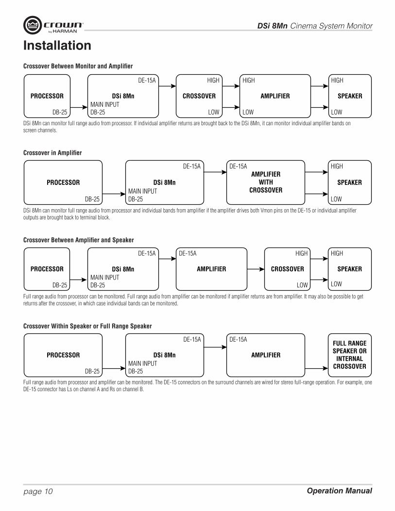
DSi 8Mn can monitor full range audio from processor and individual bands from amplifier if the amplifier drives both Vmon pins on the DE-15 or individual amplifier outputs are brought back to terminal block.
Full range audio from processor can be monitored. Full range audio from amplifier can be monitored if amplifier returns are from amplifier. It may also be possible to get returns after the crossover, in which case individual bands can be monitored.
Full range audio from processor and amplifier can be monitored. The DE-15 connectors on the surround channels are wired for stereo full-range operation. For example, one DE-15 connector has Ls on channel A and Rs on channel B.
Crossover in Amplifier
Crossover Between Amplifier and Speaker
Crossover Within Speaker or Full Range Speaker
PROCESSOR CROSSOVER
HIGH
LOW
DB-25
DE-15A
MAIN INPUTDB-25
DSi 8Mn
HIGH
LOW
AMPLIFIER SPEAKER
HIGH
LOW
DE-15A
PROCESSOR DSi 8MnAMPLIFIER
WITHCROSSOVER
DB-25
DE-15A
MAIN INPUTDB-25
SPEAKER
HIGH
LOW
SPEAKER
HIGH
LOW
CROSSOVER
HIGH
LOW
PROCESSOR
DB-25
DE-15A
MAIN INPUTDB-25
DE-15A
AMPLIFIERDSi 8Mn
DE-15A
PROCESSOR
DB-25
DE-15A
MAIN INPUTDB-25
DSi 8Mn AMPLIFIER
FULL RANGE SPEAKER OR
INTERNALCROSSOVER
DSi 8Mn can monitor full range audio from processor. If individual amplifier returns are brought back to the DSi 8Mn, it can monitor individual amplifier bands on screen channels.
Crossover Between Monitor and Amplifier
DSi 8Mn Cinema System Monitor
page 11Operation Manual
Installation
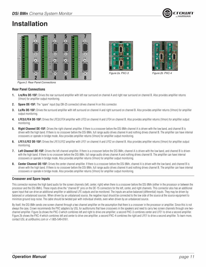
Rear Panel Connections
1. Lrs/Rrs DE-15F: Drives the rear surround amplifier with left rear surround on channel A and right rear surround on channel B. Also provides amplifier returns (Vmon) for amplifier output monitoring.
2. Spare DE-15F: The “spare” input (top DB-25 connector) drives channel A on this connector.
3. Ls/Rs DE-15F: Drives the surround amplifier with left surround on channel A and right surround on channel B. Also provides amplifier returns (Vmon) for amplifier output monitoring.
4. LFE3/LFE4 DE-15F: Drives the LFE3/LFE4 amplifier with LFE3 on channel A and LFE4 on channel B. Also provides amplifier returns (Vmon) for amplifier output monitoring.
5. Right Channel DE-15F: Drives the right channel amplifier. If there is a crossover before the DSi 8Mn channel A is driven with the low band, and channel B is driven with the high band. If there is no crossover before the DSi 8Mn, full range audio drives channel A and nothing drives channel B. The amplifier can have internal crossovers or operate in bridge mode. Also provides amplifier returns (Vmon) for amplifier output monitoring.
6. LFE1/LFE2 DE-15F: Drives the LFE1/LFE2 amplifier with LFE1 on channel A and LFE2 on channel B. Also provides amplifier returns (Vmon) for amplifier output monitoring.
7. Left Channel DE-15F: Drives the left channel amplifier. If there is a crossover before the DSi 8Mn, channel A is driven with the low band, and channel B is driven with the high band. If there is no crossover before the DSi 8Mn, full range audio drives channel A and nothing drives channel B. The amplifier can have internal crossovers or operate in bridge mode. Also provides amplifier returns (Vmon) for amplifier output monitoring.
8. Center Channel DE-15F: Drives the center channel amplifier. If there is a crossover before the DSi 8Mn, channel A is driven with the low band, and channel B is driven with the high band. If there is no crossover before the DSi 8Mn, full range audio drives channel A and nothing drives channel B. The amplifier can have internal crossovers or operate in bridge mode. Also provides amplifier returns (Vmon) for amplifier output monitoring.
Crossover and Spare Inputs
This connector receives the high band audio for the screen channels (left, center, right) when there is a crossover before the DSi 8Mn (either in the processor or between the processor and the DSi 8Mn). These inputs drive the “channel B” pins on the DE-15 connectors for the left, center, and right channels. This connector also has an additional spare input that can drive an additional amplifier or additional LFE outputs and be monitored. The inputs are active balanced (differential) inputs. They may be driven by balanced or unbalanced sources. When driven by an unbalanced source, the negative input should be connected to the low side of the source at the source equipment to minimize ground loop noise. The cable should be twisted pair with individual shields, even when driven by an unbalanced source.
By itself, the DSi 8Mn sends one screen channel through a two channel amplifier on the assumption that there is a crossover in the processor or amplifier. Since this is not always the case, Crown recommends the PXC adapters by USL for auditoriums that have crossovers in the speakers and need to carry two screen channels through one two-channel amplifier. Figure 2a shows the PXC-3 which combines left and right to drive one amplifier; a second PXC-3 combines center and LFE1 to drive a second amplifier. Figure 2b shows the PXC-4 which combines left and center to drive one amplifier; a second PXC-4 combines the right and LFE1 to drive a second amplifier. To learn more, contact USL at [email protected] or +1 805-549-0161.
1
2
3
4
5
6
7
8Figure 2 Rear Panel Connections
Figure 2a PXC-3 Figure 2b PXC-4
DSi 8Mn Cinema System Monitor
Operation Manualpage 12
InstallationDE-15F Amplifier Connectors
The DSi 8Mn converts the DB-25 audio connector common on sound processors to the DE-15F connector (also called HD-15 or VGA) connector common on amplifiers. As described previously, the surround channels are “stereo” with two channels per connector. The screen channels have one channel per connector. If the screen channel is biamped before the DSi 8Mn, channel A carries the low frequencies, and channel B carries the high frequencies. If the screen channel is not biamped before the DSi 8Mn channel A carries the full range audio, and channel B is silent.
The DE-15F connectors also provide an amplifier output return (Vmon or Voltage Monitor) to the DSi 8Mn. Surround channels return the left on channel A and the right on channel B. The screen channels return the low band on channel A and the high band on channel B if the crossover is located before the DSi 8Mn (in the processor or between the processor and the DSi 8Mn or if crossovers in the amplifier are enabled.
The DSi 8Mn, by itself, always sends one screen channel through a two channel amplifier on the assumption there is a crossover in the processor or amplifier.
Terminal Block Amplifier Connectors
The DSi 8Mn provides pluggable terminal blocks to connect to the power amplifiers. These are commonly used with amplifiers that do not use the DE-15 connectors. Balanced outputs (+ and -) are provided for amplifier channels A and B. As with the DE-15 connectors, channel A carries the low band and channel B carries the high band in biamped installations. These are marked with l and h on the rear panel (for example, Lh+ for the positive side of the high band of the left channel). If there is not a crossover before the DSi 8Mn, the full range signal will be available on the low band output of the DSi 8Mn. In addition, terminals marked E (earth) are available for connection to cable shields.
There are also pluggable terminal blocks to connect to amplifier outputs when DE-15 connectors are not used. One of these terminals connects to the positive terminal each amplifier output. The E terminal should be used to connect to a cable shield. Do NOT connect this to the negative output of the amplifier. Doing so could damage the amplifier or result in feedback. As with the terminals driving the amplifier, l is for the low band (channel A) and h is for the high band. If biamped amplifier outputs are not available, connect only to the ‘l’ terminals (the low band return).
LFE Connections and Configuration
The DSi 8Mn can drive up to four LFE amplifiers. All four can be driven by a single LFE input from the processor, or LFE3 and LFE4 can be driven by the “spare” input (on the top DB25 connector on the rear panel). A 6-pin header with two jumpers is visible on the rear panel. Move both jumpers to the top position (jumping top left to middle left and top right to middle right) to have the LFE input drive LFE3 and LFE4. Move these jumpers to the bottom position to have the spare input drive LFE3 and LFE4.
Hearing Imparied (HI) and Visually Impaired Narrative (VI-N) Connections
The DSi 8Mn includes a pluggable terminal block for connection to the HI and VI-N outputs of the sound processor. A cable should be run from the DSi 8Mn to these outputs on the sound processor. At the sound processor, these terminals also connect to the HI/VI-N transmitter (such as a USL UPC-28). These connections allow the DSi 8Mn to show the levels of the HI/VI-N signals and allow the signal to be listened to both locally and remotely.
Ethernet Connector
The Ethernet connector allows for remote monitoring of the audio passing through the DSi 8Mn. A remote web browser can be used to select audio to listen to, see levels, and listen to the audio. In addition, the Ethernet connector is used when configuring the DSi 8Mn.
DSi 8Mn Cinema System Monitor
page 13Operation Manual
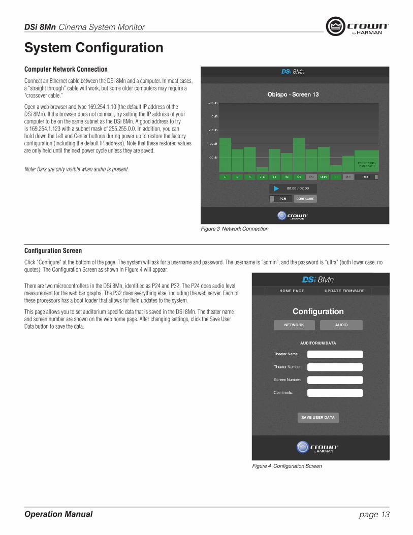
Computer Network Connection
Connect an Ethernet cable between the DSi 8Mn and a computer. In most cases, a “straight through” cable will work, but some older computers may require a “crossover cable.”
Open a web browser and type 169.254.1.10 (the default IP address of the DSi 8Mn). If the browser does not connect, try setting the IP address of your computer to be on the same subnet as the DSi 8Mn. A good address to try is 169.254.1.123 with a subnet mask of 255.255.0.0. In addition, you can hold down the Left and Center buttons during power up to restore the factory configuration (including the default IP address). Note that these restored values are only held until the next power cycle unless they are saved.
Note: Bars are only visible when audio is present.
Configuration Screen
Click “Configure” at the bottom of the page. The system will ask for a username and password. The username is “admin”, and the password is “ultra” (both lower case, no quotes). The Configuration Screen as shown in Figure 4 will appear.
There are two microcontrollers in the DSi 8Mn, identified as P24 and P32. The P24 does audio level measurement for the web bar graphs. The P32 does everything else, including the web server. Each of these processors has a boot loader that allows for field updates to the system.
This page allows you to set auditorium specific data that is saved in the DSi 8Mn. The theater name and screen number are shown on the web home page. After changing settings, click the Save User Data button to save the data.
System Configuration
Figure 3 Network Connection
Figure 4 Configuration Screen
DSi 8Mn Cinema System Monitor
Operation Manualpage 14
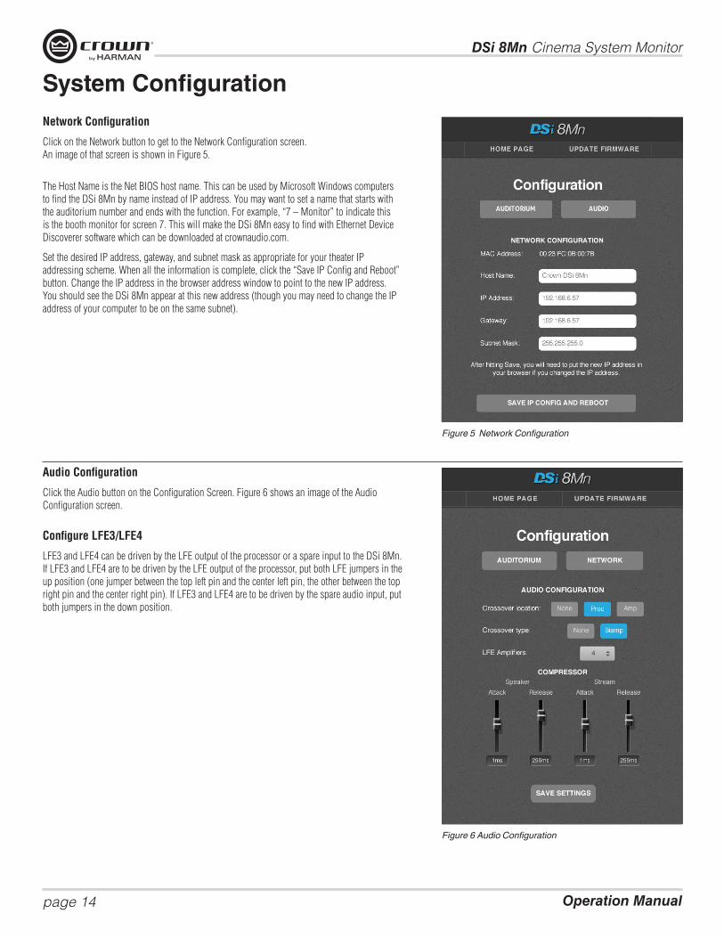
System ConfigurationNetwork Configuration
Click on the Network button to get to the Network Configuration screen. An image of that screen is shown in Figure 5.
Audio Configuration
Click the Audio button on the Configuration Screen. Figure 6 shows an image of the Audio Configuration screen.
The Host Name is the Net BIOS host name. This can be used by Microsoft Windows computers to find the DSi 8Mn by name instead of IP address. You may want to set a name that starts with the auditorium number and ends with the function. For example, “7 – Monitor” to indicate this is the booth monitor for screen 7. This will make the DSi 8Mn easy to find with Ethernet Device Discoverer software which can be downloaded at crownaudio.com.
Set the desired IP address, gateway, and subnet mask as appropriate for your theater IP addressing scheme. When all the information is complete, click the “Save IP Config and Reboot” button. Change the IP address in the browser address window to point to the new IP address. You should see the DSi 8Mn appear at this new address (though you may need to change the IP address of your computer to be on the same subnet).
Figure 5 Network Configuration
Figure 6 Audio Configuration
Configure LFE3/LFE4
LFE3 and LFE4 can be driven by the LFE output of the processor or a spare input to the DSi 8Mn. If LFE3 and LFE4 are to be driven by the LFE output of the processor, put both LFE jumpers in the up position (one jumper between the top left pin and the center left pin, the other between the top right pin and the center right pin). If LFE3 and LFE4 are to be driven by the spare audio input, put both jumpers in the down position.
DSi 8Mn Cinema System Monitor
page 15Operation Manual
System ConfigurationSelect the location of the crossover, if any. If none is selected, the left, center, and right channels are assumed to be full-range. Pressing the front panel or browser button will toggle these channels on and off on the monitor speaker and web stream. If the crossover location is set to Proc, the left, center, and right channels will step through an off- full range – low band – high band – off sequence for both the processor and amplifiers. If the crossover location is set to Amp, the left, center, and right channels will toggle on and off if the processor is selected and through the sequence of off- full range – low band – high band – off when the amplifier is selected. These settings also affect the web bar graph display. If biamp audio is available on the processor or amplifier, the individual bands are shown on the bar graph. The crossover type can be biamp or none.
The DSi 8Mn allows for monitoring of the individual LFE amplifier returns. Select the number of LFE amplifiers that are used in this auditorium. The front panel and web LFE buttons allow sequencing through the individual LFE returns when the amplifier is selected (instead of the processor). In addition, the individual LFE returns are shown on the web bar graph when the amplifier is selected.
The DSi 8Mn includes compressors for the speaker and web stream. These reduce the dynamic range to be suitable for these applications. The attack and release times are adjustable, though the default values are normally suitable. A significantly slower attack time can cause clipping because the compressor would react too slowly to a loud sound. A shorter release time increase the average volume but can result in low frequency distortion as the compressor starts to follow low frequency waveforms.
Once the settings on this page are complete, press the “Save Settings” button.
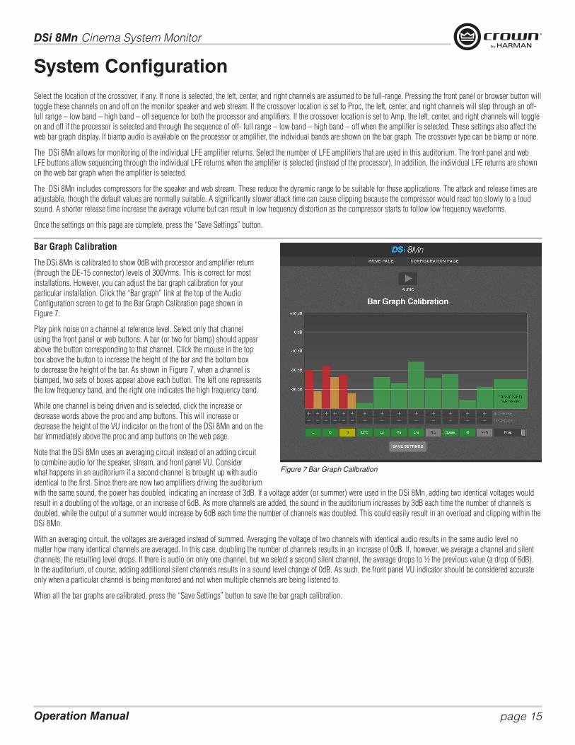
Bar Graph Calibration
The DSi 8Mn is calibrated to show 0dB with processor and amplifier return (through the DE-15 connector) levels of 300Vrms. This is correct for most installations. However, you can adjust the bar graph calibration for your particular installation. Click the “Bar graph” link at the top of the Audio Configuration screen to get to the Bar Graph Calibration page shown in Figure 7.
Play pink noise on a channel at reference level. Select only that channel using the front panel or web buttons. A bar (or two for biamp) should appear above the button corresponding to that channel. Click the mouse in the top box above the button to increase the height of the bar and the bottom box to decrease the height of the bar. As shown in Figure 7, when a channel is biamped, two sets of boxes appear above each button. The left one represents the low frequency band, and the right one indicates the high frequency band.
While one channel is being driven and is selected, click the increase or decrease words above the proc and amp buttons. This will increase or decrease the height of the VU indicator on the front of the DSi 8Mn and on the bar immediately above the proc and amp buttons on the web page.
Note that the DSi 8Mn uses an averaging circuit instead of an adding circuit to combine audio for the speaker, stream, and front panel VU. Consider what happens in an auditorium if a second channel is brought up with audio identical to the first. Since there are now two amplifiers driving the auditorium with the same sound, the power has doubled, indicating an increase of 3dB. If a voltage adder (or summer) were used in the DSi 8Mn, adding two identical voltages would result in a doubling of the voltage, or an increase of 6dB. As more channels are added, the sound in the auditorium increases by 3dB each time the number of channels is doubled, while the output of a summer would increase by 6dB each time the number of channels was doubled. This could easily result in an overload and clipping within the DSi 8Mn.
With an averaging circuit, the voltages are averaged instead of summed. Averaging the voltage of two channels with identical audio results in the same audio level no matter how many identical channels are averaged. In this case, doubling the number of channels results in an increase of 0dB. If, however, we average a channel and silent channels, the resulting level drops. If there is audio on only one channel, but we select a second silent channel, the average drops to ½ the previous value (a drop of 6dB). In the auditorium, of course, adding additional silent channels results in a sound level change of 0dB. As such, the front panel VU indicator should be considered accurate only when a particular channel is being monitored and not when multiple channels are being listened to.
When all the bar graphs are calibrated, press the “Save Settings” button to save the bar graph calibration.
Figure 7 Bar Graph Calibration
DSi 8Mn Cinema System Monitor
Operation Manualpage 16
System Configuration
System Operation
Power Up Configuration
The “Save Settings” buttons on the various configuration screens save all the current settings. The currently selected audio channels/bands for monitoring and the processor/amp selection are also saved. Use the buttons on the unit or the web page to select which channels are fed to the speaker and stream, then hit “Save Settings.” These button settings will be restored the next time the unit is powered up.
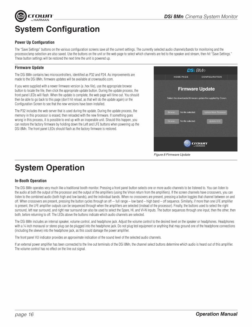
Firmware Update
The DSi 8Mn contains two microcontrollers, identified as P32 and P24. As improvements are made to the DSi 8Mn, firmware updates will be available at crownaudio.com.
If you were supplied with a newer firmware version (a .hex file), use the appropriate browse button to locate the file, then click the appropriate update button. During the update process, the front panel LEDs will flash. When the update is complete, the web page will time out. You should then be able to go back to this page (don’t hit reload, as that will do the update again) or the Configuration Screen to see that the new versions have been installed.
The P32 includes the web server that is used during the update. During the update process, the memory in this processor is erased, then reloaded with the new firmware. If something goes wrong in this process, it is possible to end up with an inoperable unit. Should this happen, you can restore the factory firmware by holding down the Left and LFE buttons when powering up the DSi 8Mn. The front panel LEDs should flash as the factory firmware is restored.
In-Booth Operation
The DSi 8Mn operates very much like a traditional booth monitor. Pressing a front panel button selects one or more audio channels to be listened to. You can listen to the audio at both the output of the processor and the output of the amplifiers (using the Vmon return from the amplifiers). If the screen channels have crossovers, you can listen to the combined audio (both high and low bands), and the individual bands. When no crossovers are present, pressing a button toggles that channel between on and off. When crossovers are present, pressing the button cycles through an off -- full range – low band – high band – off sequence. Similarly, if more than one LFE amplifier is present, the LFE amplifier outputs can be sequenced through when the amplifiers are selected (instead of the processor). Finally, the buttons used to select the right surround, left rear surround, and right rear surround can also be used to select the Spare, HI, and VI-N inputs. The button sequences through one input, then the other, then both, before returning to off. The LEDs above the buttons indicate which audio channels are selected.
The DSi 8Mn includes an internal speaker, volume control, and headphone jack. Adjust the volume control to the desired level on the speaker or headphones. Headphones with a ¼ inch monaural or stereo plug can be plugged into the headphone jack. Do not plug test equipment or anything that may ground one of the headphone connections (including the sleeve) into the headphone jack, as this could damage the power amplifier.
The front panel VU indicator provides an approximate indication of the sound level of the selected audio channels.
If an external power amplifier has been connected to the line out terminals of the DSi 8Mn, the channel select buttons determine which audio is heard out of this amplifier. The volume control has no effect on the line out signal.
Figure 8 Firmware Update
DSi 8Mn Cinema System Monitor
page 17Operation Manual
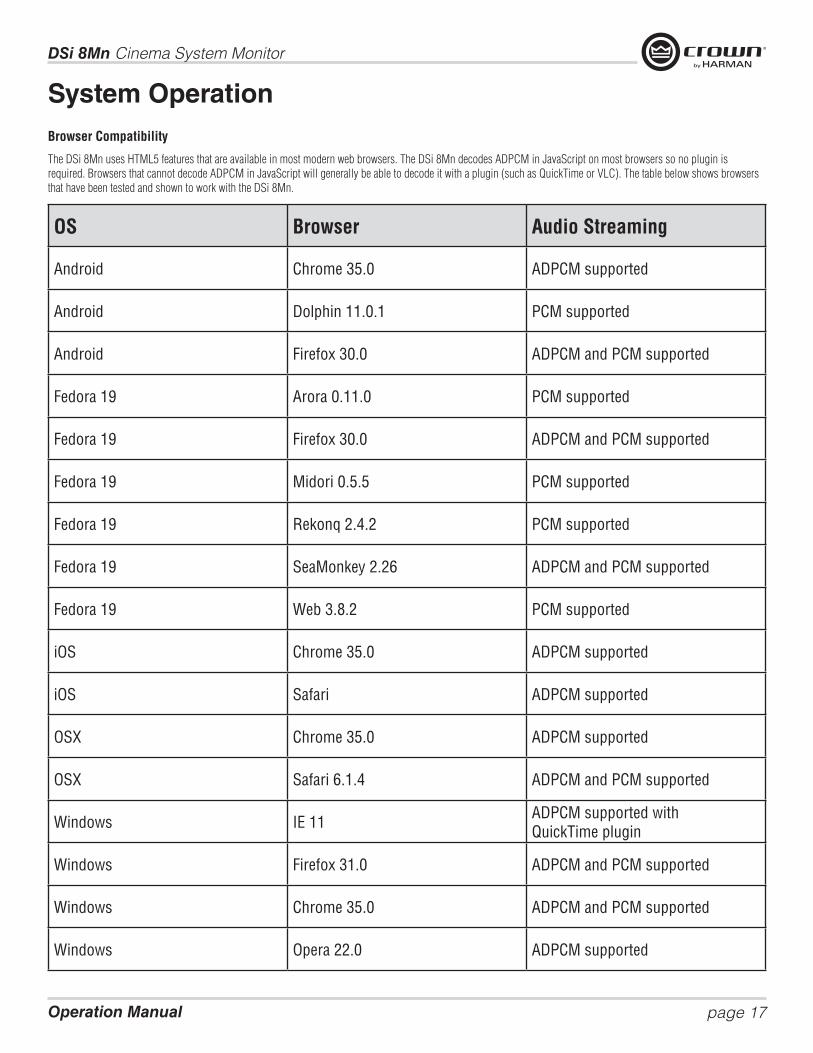
System OperationBrowser Compatibility
The DSi 8Mn uses HTML5 features that are available in most modern web browsers. The DSi 8Mn decodes ADPCM in JavaScript on most browsers so no plugin is required. Browsers that cannot decode ADPCM in JavaScript will generally be able to decode it with a plugin (such as QuickTime or VLC). The table below shows browsers that have been tested and shown to work with the DSi 8Mn.
OS Browser Audio Streaming
Android Chrome 35.0 ADPCM supported
Android Dolphin 11.0.1 PCM supported
Android Firefox 30.0 ADPCM and PCM supported
Fedora 19 Arora 0.11.0 PCM supported
Fedora 19 Firefox 30.0 ADPCM and PCM supported
Fedora 19 Midori 0.5.5 PCM supported
Fedora 19 Rekonq 2.4.2 PCM supported
Fedora 19 SeaMonkey 2.26 ADPCM and PCM supported
Fedora 19 Web 3.8.2 PCM supported
iOS Chrome 35.0 ADPCM supported
iOS Safari ADPCM supported
OSX Chrome 35.0 ADPCM supported
OSX Safari 6.1.4 ADPCM and PCM supported
Windows IE 11 ADPCM supported with QuickTime plugin
Windows Firefox 31.0 ADPCM and PCM supported
Windows Chrome 35.0 ADPCM and PCM supported
Windows Opera 22.0 ADPCM supported
DSi 8Mn Cinema System Monitor
Operation Manualpage 18
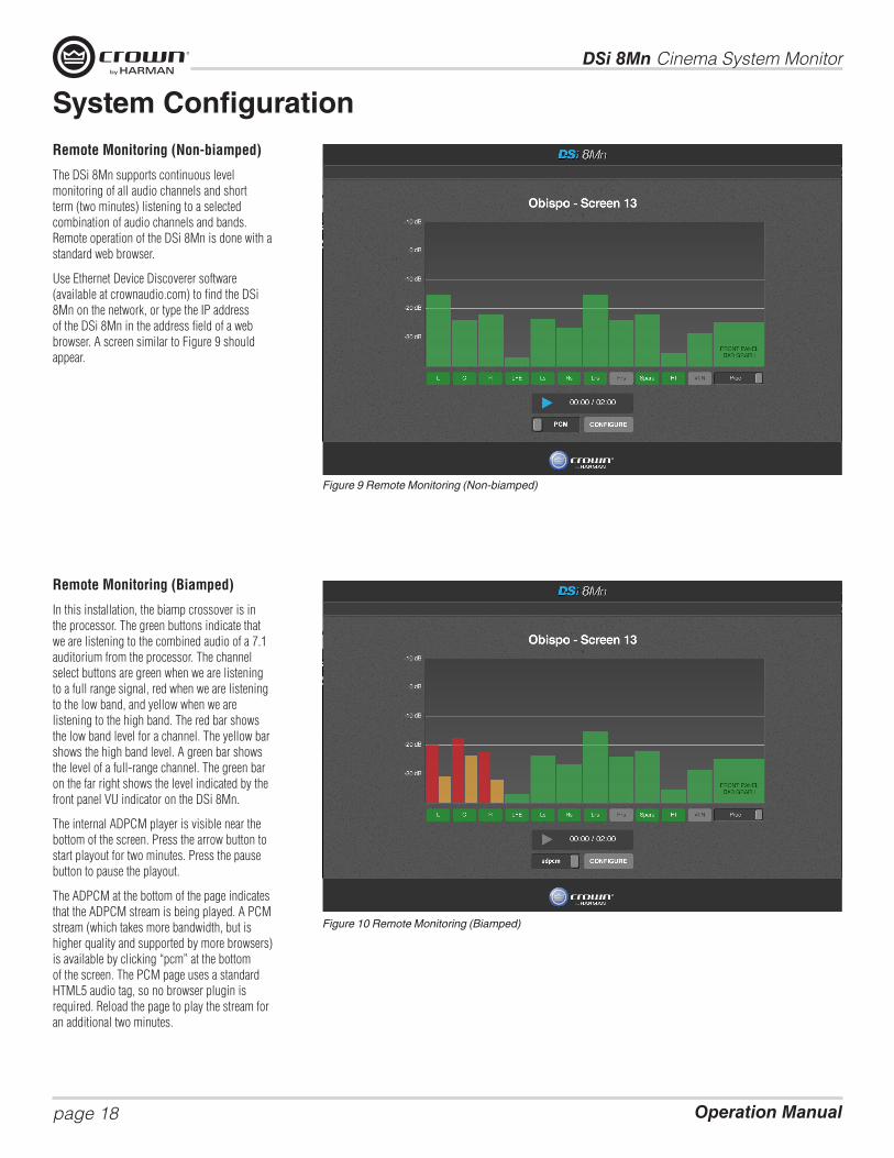
Remote Monitoring (Non-biamped)
The DSi 8Mn supports continuous level monitoring of all audio channels and short term (two minutes) listening to a selected combination of audio channels and bands. Remote operation of the DSi 8Mn is done with a standard web browser.
Use Ethernet Device Discoverer software (available at crownaudio.com) to find the DSi 8Mn on the network, or type the IP address of the DSi 8Mn in the address field of a web browser. A screen similar to Figure 9 should appear.
Remote Monitoring (Biamped)
In this installation, the biamp crossover is in the processor. The green buttons indicate that we are listening to the combined audio of a 7.1 auditorium from the processor. The channel select buttons are green when we are listening to a full range signal, red when we are listening to the low band, and yellow when we are listening to the high band. The red bar shows the low band level for a channel. The yellow bar shows the high band level. A green bar shows the level of a full-range channel. The green bar on the far right shows the level indicated by the front panel VU indicator on the DSi 8Mn.
The internal ADPCM player is visible near the bottom of the screen. Press the arrow button to start playout for two minutes. Press the pause button to pause the playout.
The ADPCM at the bottom of the page indicates that the ADPCM stream is being played. A PCM stream (which takes more bandwidth, but is higher quality and supported by more browsers) is available by clicking “pcm” at the bottom of the screen. The PCM page uses a standard HTML5 audio tag, so no browser plugin is required. Reload the page to play the stream for an additional two minutes.
System Configuration
Figure 9 Remote Monitoring (Non-biamped)
Figure 10 Remote Monitoring (Biamped)
DSi 8Mn Cinema System Monitor
page 19Operation Manual
Connector Pin Outs
For convenience, all connector pin outs are located in this section.
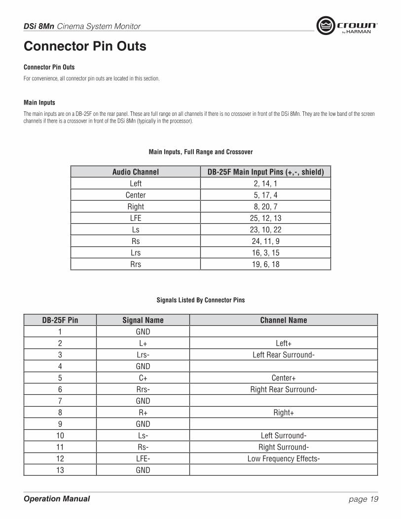
Main Inputs
The main inputs are on a DB-25F on the rear panel. These are full range on all channels if there is no crossover in front of the DSi 8Mn. They are the low band of the screen channels if there is a crossover in front of the DSi 8Mn (typically in the processor).
Main Inputs, Full Range and Crossover
Signals Listed By Connector Pins
Connector Pin Outs
Audio Channel DB-25F Main Input Pins (+,-, shield)Left 2, 14, 1
Center 5, 17, 4Right 8, 20, 7LFE 25, 12, 13Ls 23, 10, 22Rs 24, 11, 9Lrs 16, 3, 15Rrs 19, 6, 18
DB-25F Pin Signal Name Channel Name1 GND2 L+ Left+3 Lrs- Left Rear Surround-4 GND5 C+ Center+6 Rrs- Right Rear Surround-7 GND8 R+ Right+9 GND10 Ls- Left Surround-11 Rs- Right Surround-12 LFE- Low Frequency Effects-13 GND
DSi 8Mn Cinema System Monitor
Operation Manualpage 20
Signals Listed By Connector Pins
Signals Listed By Channels
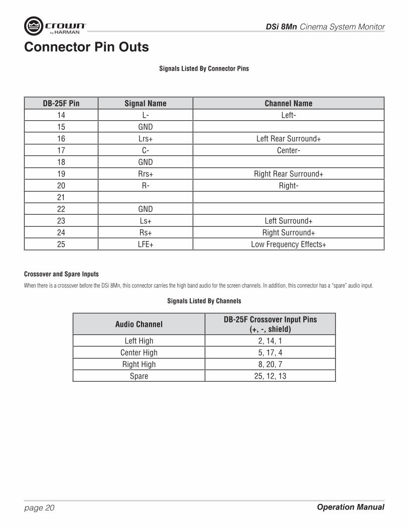
Crossover and Spare Inputs
When there is a crossover before the DSi 8Mn, this connector carries the high band audio for the screen channels. In addition, this connector has a “spare” audio input.
DB-25F Pin Signal Name Channel Name14 L- Left-15 GND16 Lrs+ Left Rear Surround+17 C- Center-18 GND19 Rrs+ Right Rear Surround+20 R- Right-2122 GND23 Ls+ Left Surround+24 Rs+ Right Surround+25 LFE+ Low Frequency Effects+
Audio Channel DB-25F Crossover Input Pins (+, -, shield)
Left High 2, 14, 1Center High 5, 17, 4Right High 8, 20, 7
Spare 25, 12, 13
Connector Pin Outs
DSi 8Mn Cinema System Monitor
page 21Operation Manual
Signals Listed By Connector Pins
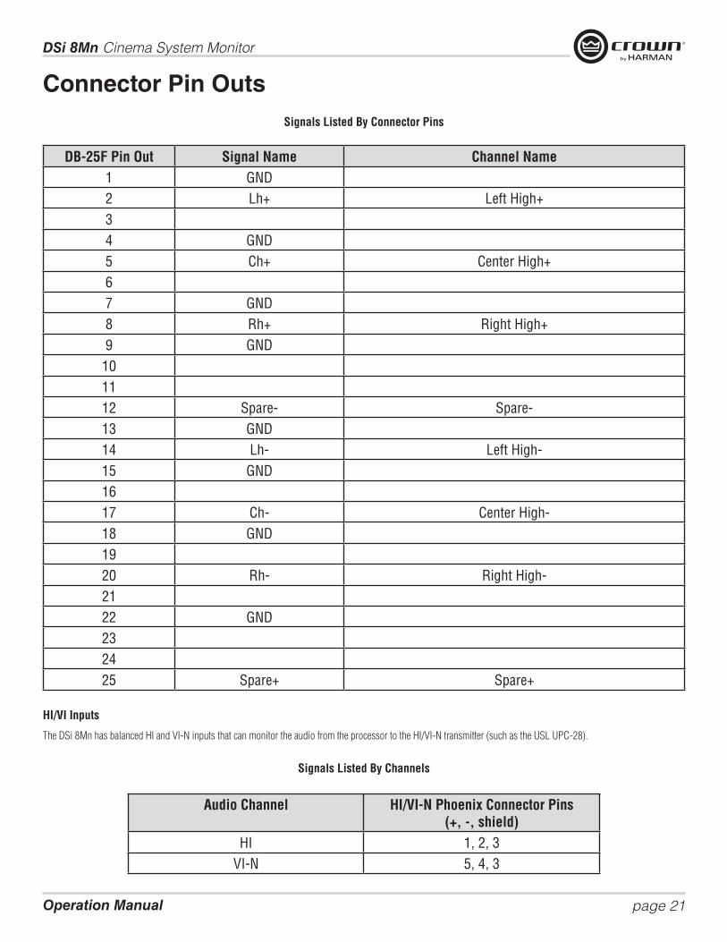
HI/VI Inputs
The DSi 8Mn has balanced HI and VI-N inputs that can monitor the audio from the processor to the HI/VI-N transmitter (such as the USL UPC-28).
DB-25F Pin Out Signal Name Channel Name1 GND2 Lh+ Left High+34 GND5 Ch+ Center High+67 GND8 Rh+ Right High+9 GND101112 Spare- Spare-13 GND14 Lh- Left High-15 GND1617 Ch- Center High-18 GND1920 Rh- Right High-2122 GND232425 Spare+ Spare+
Connector Pin Outs
Signals Listed By Channels
Audio Channel HI/VI-N Phoenix Connector Pins (+, -, shield)
HI 1, 2, 3VI-N 5, 4, 3
DSi 8Mn Cinema System Monitor
Operation Manualpage 22
Connector Pin OutsSignals Listed By Connector Pins
DE-15F Signals by Pin
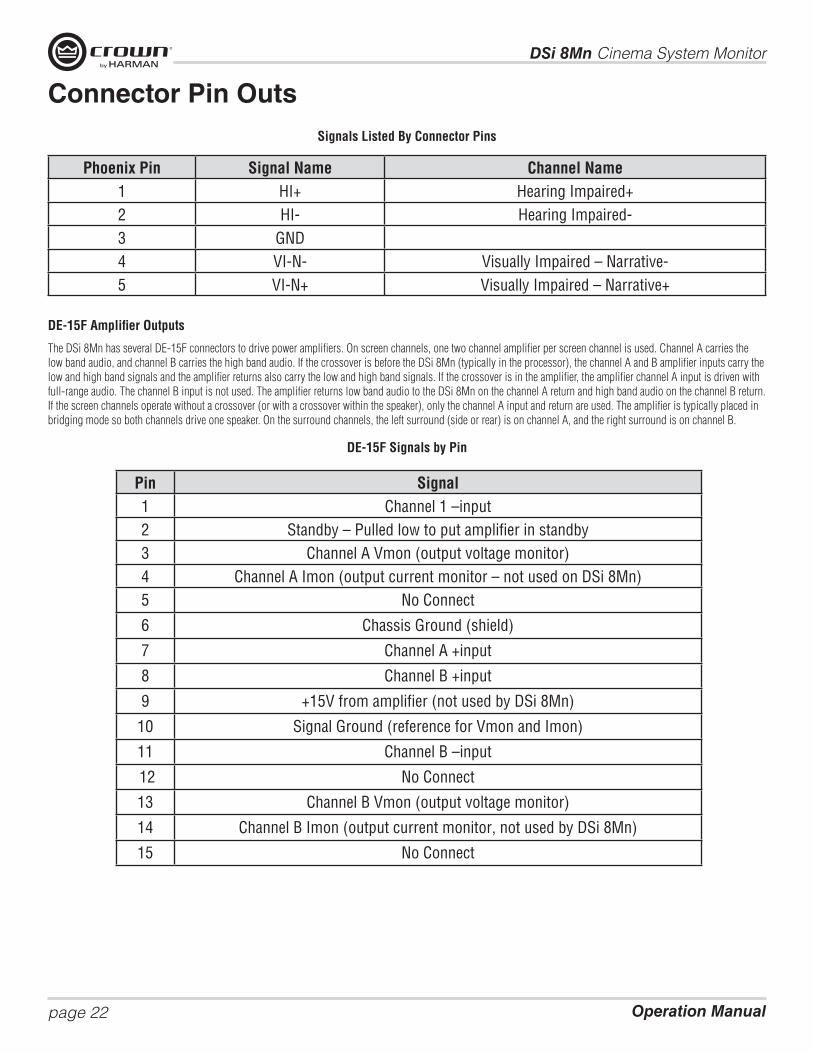
Phoenix Pin Signal Name Channel Name1 HI+ Hearing Impaired+2 HI- Hearing Impaired-3 GND4 VI-N- Visually Impaired – Narrative-5 VI-N+ Visually Impaired – Narrative+
Pin Signal1 Channel 1 –input2 Standby – Pulled low to put amplifier in standby3 Channel A Vmon (output voltage monitor)4 Channel A Imon (output current monitor – not used on DSi 8Mn)5 No Connect
6 Chassis Ground (shield)
7 Channel A +input
8 Channel B +input
9 +15V from amplifier (not used by DSi 8Mn)
10 Signal Ground (reference for Vmon and Imon)
11 Channel B –input
12 No Connect
13 Channel B Vmon (output voltage monitor)
14 Channel B Imon (output current monitor, not used by DSi 8Mn)
15 No Connect
DE-15F Amplifier Outputs
The DSi 8Mn has several DE-15F connectors to drive power amplifiers. On screen channels, one two channel amplifier per screen channel is used. Channel A carries the low band audio, and channel B carries the high band audio. If the crossover is before the DSi 8Mn (typically in the processor), the channel A and B amplifier inputs carry the low and high band signals and the amplifier returns also carry the low and high band signals. If the crossover is in the amplifier, the amplifier channel A input is driven with full-range audio. The channel B input is not used. The amplifier returns low band audio to the DSi 8Mn on the channel A return and high band audio on the channel B return. If the screen channels operate without a crossover (or with a crossover within the speaker), only the channel A input and return are used. The amplifier is typically placed in bridging mode so both channels drive one speaker. On the surround channels, the left surround (side or rear) is on channel A, and the right surround is on channel B.
DSi 8Mn Cinema System Monitor
page 23Operation Manual
Connector Pin Outs
Screen Channel Terminal Block
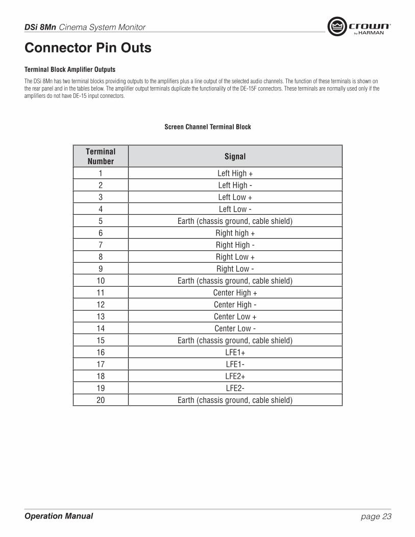
Terminal Block Amplifier Outputs
The DSi 8Mn has two terminal blocks providing outputs to the amplifiers plus a line output of the selected audio channels. The function of these terminals is shown on the rear panel and in the tables below. The amplifier output terminals duplicate the functionality of the DE-15F connectors. These terminals are normally used only if the amplifiers do not have DE-15 input connectors.
Terminal Number Signal
1 Left High +2 Left High - 3 Left Low +4 Left Low -5 Earth (chassis ground, cable shield)6 Right high +7 Right High - 8 Right Low +9 Right Low -
10 Earth (chassis ground, cable shield)11 Center High +12 Center High -13 Center Low +14 Center Low -15 Earth (chassis ground, cable shield)16 LFE1+17 LFE1-18 LFE2+19 LFE2-20 Earth (chassis ground, cable shield)
DSi 8Mn Cinema System Monitor
Operation Manualpage 24
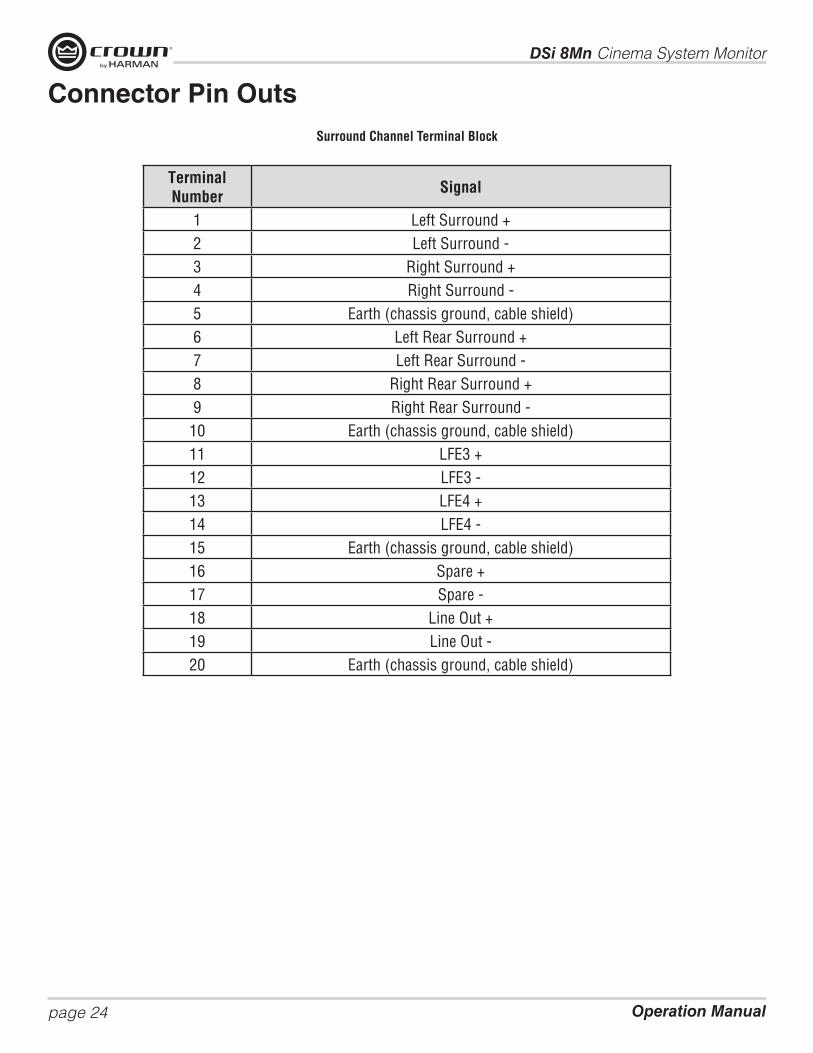
Surround Channel Terminal Block
Terminal Number Signal
1 Left Surround +2 Left Surround - 3 Right Surround +4 Right Surround -5 Earth (chassis ground, cable shield)6 Left Rear Surround +7 Left Rear Surround - 8 Right Rear Surround +9 Right Rear Surround - 10 Earth (chassis ground, cable shield)11 LFE3 +12 LFE3 -13 LFE4 +14 LFE4 -15 Earth (chassis ground, cable shield)16 Spare +17 Spare -18 Line Out +19 Line Out -20 Earth (chassis ground, cable shield)
Connector Pin Outs
DSi 8Mn Cinema System Monitor
page 25Operation Manual
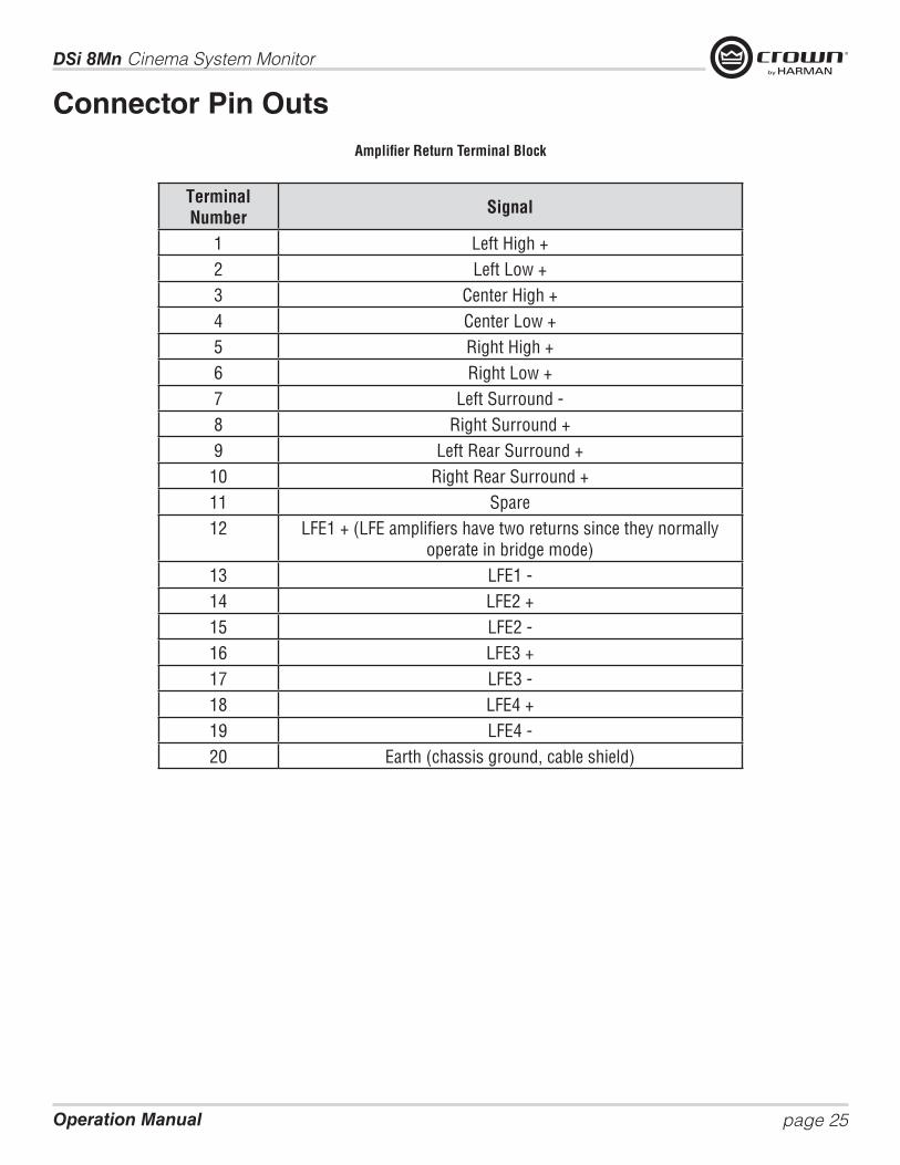
Amplifier Return Terminal Block
Terminal Number Signal
1 Left High +2 Left Low + 3 Center High +4 Center Low +5 Right High +6 Right Low +7 Left Surround -8 Right Surround +9 Left Rear Surround +10 Right Rear Surround +11 Spare12 LFE1 + (LFE amplifiers have two returns since they normally
operate in bridge mode)13 LFE1 -14 LFE2 +15 LFE2 -16 LFE3 +17 LFE3 -18 LFE4 +19 LFE4 -20 Earth (chassis ground, cable shield)
Connector Pin Outs
DSi 8Mn Cinema System Monitor
Operation Manualpage 26
Crown products are quality units that rarely require servicing. Before returning your unit for servicing, please contact Crown Technical Support to verify the need for servicing.
Warranty is only valid within the country in which the product was purchased.
This unit has very sophisticated circuitry which should only be serviced by a fully trained technician. This is one reason why each unit bears the following label:
CAUTION: To prevent electric shock, do not remove covers. No user serviceable parts inside. Refer servicing to a qualified technician.
Complete the Service Return Authorization form in the back of this manual, when returning a Crown product to the factory or authorized service center. The form must be included with your product inside the box or in a packing slip envelope securely attached to the outside of the shipping carton. Do not send this form separately.
Worldwide Service
Service may be obtained from an authorized service center (contact your local Crown/Amcron representative or our office for a list of authorized service centers). To obtain service, simply present the bill of sale as proof of purchase along with the defective unit to an authorized service center. They will handle the necessary paperwork and repair.
Remember to transport your unit in the original factory pack.
US and Canada Service
Service may be obtained in one of two ways: from an authorized service center or from the factory. You may choose either. It is important that you have your copy of the bill of sale as your proof of purchase.
Service at a US or Canada Service Center
This method usually saves the most time and effort. Simply present your bill of sale along with the defective unit to an authorized service center to obtain service. They will handle the necessary paperwork and repair. Remember to transport the unit in the original factory pack. A list of authorized service centers in your area can be obtained from Crown Factory Service, or online from http://www.crownaudio.com/en/support/service_lookup
Factory Service
Crown accepts no responsibility for non-serviceable product that is sent to us for factory repair. It is the owner’s responsibility to ensure that their product is serviceable prior to sending it to the factory.
A Service Return Authorization (SRA) is required for product being sent to the factory for repair. An SRA can be completed online at http://www.crownaudio.com/support/rma. If you do not have access to the web, please call Customer Service at 574.294.8200 or 800.342.6939 extension 8205 in North America, Puerto Rico and the Virgin Islands only.
For warranty service, we will pay for ground shipping both ways in the United States. Contact Customer Service to obtain prepaid shipping labels prior to sending the unit. Or, if you prefer, you may prepay the cost of shipping, and HARMAN will reimburse you. Send copies of the shipping receipts to HARMAN to receive reimbursement.
Your repaired unit will be returned via UPS ground. Please contact us if other arrangements are required.
Factory Service Shipping Instructions:
1. Service Return Authorization (SRA) is required for product being sent to the factory for service. Please complete the SRA by going to http://www.crownaudio.com/support/rma. If you do not have access to our website, call 1.800.342.6939, extension 8205 and we will create the SRA for you.
2. See packing instructions that follow.
3. Ship product to: HARMAN Factory Service 1718 W Mishawaka Rd. Elkhart, IN 46517
Service
DSi 8Mn Cinema System Monitor
page 27Operation Manual
4. Use a bold black marker and write the SRA number on three sides of the box.
5. Record the SRA number for future reference. The SRA number can be used to check the repair status.
Packing Instructions
Important: These instructions must be followed. If they are not followed, HARMAN International, Inc. assumes no responsibility for damaged goods and/or accessories that are sent with your unit.
1. Fill out and include the Service Return Authorization Request in the back of this manual.
2. Do not ship any accessories (manuals, cords, hardware, etc.) with your unit. These items are not needed to service your product. We will not be responsible for these items.
3. When shipping your Crown product, it is important that it has adequate protection. We recommend you use the original pack material when returning the product for repair. If you do not have the original box, please call HARMAN at 800.342.6939 or 574.294.8210 and order new pack material. (Do not ship your unit in a wood or metal cabinet).
4. If you provide your own shipping pack, the minimum recommended requirements for materials are as follows:
a. 275 P.S.I. burst test, double-wall carton that allows for 2-inch solid Styrofoam on all six sides of unit or 3 inches of plastic bubble wrap on all six sides of unit.
b. Securely seal the package with an adequate carton sealing tape.
c. Do not use light boxes or “peanuts”. Damage caused by poor packaging will not be covered under warranty.
Enclose the completed Service Return Authorization Request (or securely attach it to the outside of carton) and re-seal the shipping pack with a sturdy carton sealing tape.
Estimate Approval
Approval of estimate must be given within 30 days after being notified by HARMAN International. Units still in the possession of HARMAN after 30 days of the estimate will become the property of HARMAN International.
Payment of Non-Warranty Repairs
Payment on out-of-warranty repairs must be received within 30 days of the repair date. Units unclaimed after 30 days become the property of HARMAN International.
If you have any questions, please contact HARMAN.
HARMAN Factory Service 1718 W. Mishawaka Rd., Elkhart, Indiana 46517 U.S.A.
Telephone: 574-294-8200 800-342-6939 (North America, Puerto Rico, and Virgin Islands only)
Facsimile: 574-294-8301 (Technical Support) 574-294-8124 (Factory Service)
Web site: www.crownaudio.com
Service
DSi 8Mn Cinema System Monitor
Operation Manualpage 28
SUMMARY OF WARRANTYCrown International, 1718 West Mishawaka Road, Elkhart, Indiana 46517-4095 U.S.A. warrants to you, the ORIGINAL PURCHASER and ANY SUBSEQUENT OWNER of each NEW Crown product, for three years from the date of purchase by the original purchaser (the “warranty period”) that the new Crown product is free of defects in materials and workmanship. We further warrant the new Crown product regardless of the reason for failure, except as excluded in this Warranty.
*Warranty is only valid within the United States of America. For information on Warranty outside of the U.S.A, please contact your local distributor.
ITEMS EXCLUDED FROM THIS CROWN WARRANTYThis Crown Warranty is in effect only for failure of a new Crown product which occurred within the Warranty Period. It does not cover any product which has been damaged because of any intentional misuse, accident, negligence, or loss which is covered under any of your insurance contracts. This Crown Warranty also does not extend to the new Crown product if the serial number has been defaced, altered, or removed.
WHAT THE WARRANTOR WILL DOWe will remedy any defect, regardless of the reason for failure (except as excluded), by repair, replacement, or refund. We may not elect refund unless you agree, or unless we are unable to provide replacement, and repair is not practical or cannot be timely made. If a refund is elected, then you must make the defective or malfunctioning product available to us free and clear of all liens or other encumbrances. The refund will be equal to the actual purchase price, not including interest, insurance, closing costs, and other finance charges less a reasonable depreciation on the product from the date of original purchase. Warranty work can only be performed at our authorized service centers or at the factory. Warranty work for some products can only be performed at our factory. We will remedy the defect and ship the product from the service center or our factory within a reasonable time after receipt of the defective product at our authorized service center or our factory. All expenses in remedying the defect, including surface shipping costs in the United States, will be borne by us. (You must bear the expense of shipping the product between any foreign country and the port of entry in the United States including the return shipment, and all taxes, duties, and other customs fees for such foreign shipments.)
HOW TO OBTAIN WARRANTY SERVICEYou must notify us of your need for warranty service within the warranty period. All components must be shipped in a factory pack, which, if needed, may be obtained from us free of charge. Corrective action will be taken within a reasonable time of the date of receipt of the defective product by us or our authorized service center. If the repairs made by us or our authorized service center are not satisfactory, notify us or our authorized service center immediately.
DISCLAIMER OF CONSEQUENTIAL AND INCIDENTAL DAMAGESYOU ARE NOT ENTITLED TO RECOVER FROM US ANY INCIDENTAL DAMAGES RESULTING FROM ANY DEFECT IN THE NEW CROWN PRODUCT. THIS INCLUDES ANY DAMAGE TO ANOTHER PRODUCT OR PRODUCTS RESULTING FROM SUCH A DEFECT. SOME STATES DO NOT ALLOW THE EXCLUSION OR LIMITATIONS OF INCIDENTAL OR CONSEQUENTIAL DAMAGES, SO THE ABOVE LIMITATION OR EXCLUSION MAY NOT APPLY TO YOU.
WARRANTY ALTERATIONSNo person has the authority to enlarge, amend, or modify this Crown Warranty. This Crown Warranty is not extended by the length of time which you are deprived of the use of the new Crown product. Repairs and replacement parts provided under the terms of this Crown Warranty shall carry only the unexpired portion of this Crown Warranty.
DESIGN CHANGESWe reserve the right to change the design of any product from time to time without notice and with no obligation to make corresponding changes in products previously manufactured.
LEGAL REMEDIES OF PURCHASERTHIS CROWN WARRANTY GIVES YOU SPECIFIC LEGAL RIGHTS, YOU MAY ALSO HAVE OTHER RIGHTS WHICH VARY FROM STATE TO STATE. No action to enforce this Crown Warranty shall be commenced after expiration of the warranty period.
THIS STATEMENT OF WARRANTY SUPERSEDES ANY OTHERS CONTAINED IN THIS MANUAL FOR CROWN PRODUCTS. 04/15
Warranty — UNITED STATES ONLY

DSi 8Mn Cinema System Monitor
page 29Operation Manual
DSi 8Mn Cinema System Monitor
Operation Manualpage 30
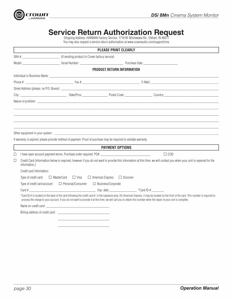
Service Return Authorization Request Shipping Address: HARMAN Factory Service, 1718 W. Mishawaka Rd., Elkhart, IN 46517
You may also request a service return authorization at www.crownaudio.com/support/rma
PLEASE PRINT CLEARLY
SRA #: ______________________ (If sending product to Crown factory service)
Model: ______________________ Serial Number: _________________________ Purchase Date: ____________________
PRODUCT RETURN INFORMATION
Individual or Business Name: ___________________________________________________________________________________________________
Phone #: ____________________________ Fax #:__________________________________ E-Mail:________________________________________
Street Address (please, no P.O. Boxes): ____________________________________________________________________________________________
City: ___________________________ State/Prov:_______________ Postal Code: ________________ Country:________________________________
Nature of problem: __________________________________________________________________________________________________________
________________________________________________________________________________________________________________________
________________________________________________________________________________________________________________________
________________________________________________________________________________________________________________________
________________________________________________________________________________________________________________________
Other equipment in your system: ________________________________________________________________________________________________
If warranty is expired, please provide method of payment. Proof of purchase may be required to validate warranty.
PAYMENT OPTIONS
I have open account payment terms. Purchase order required. PO#: _____________________________ COD
Credit Card (Information below is required; however if you do not want to provide this information at this time, we will contact you when your unit is repaired for the information.)
Credit card information:
Type of credit card: MasterCard Visa American Express Discover
Type of credit card account: Personal/Consumer Business/Corporate
Card # _______________________________________ Exp. date: ________________ *Card ID #: _______
* Card ID # is located on the back of the card following the credit card #, in the signature area. On American Express, it may be located on the front of the card. This number is required to process the charge to your account. If you do not want to provide it at this time, we will call you to obtain this number when the repair of your unit is complete.
Name on credit card: _____________________________________
Billing address of credit card: ______________________________
______________________________
______________________________
DSi 8Mn Cinema System Monitor
page 31Operation Manual