Embed Size (px)
Citation preview
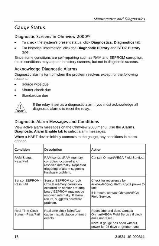
DSGH®
Radiation-Based Detector with GEN2000® Electronics for Density Measurement
QUICK REFERENCE GUIDE

Revision History
31524-US-090811 3
Revision History
Version of manual Description Date
1.0 Initial release 051025
1.1 Electronics revision 090306
1.2 Added perforated view for ground - Wiring
090811
This document contains proprietary information of Ohmart/VEGA Corporation. It shall not be reproduced in whole, or in part, in any form, without the expressed written permission of the Ohmart/VEGA Corporation. The material in this document is provided for informational purposes only and is subject to change without notice. ISO 9001 approval by Lloyd's Register Quality Assurance Limited, to these Quality Management System Standards: ISO 9001:2000, ANSI/ASQC Q9001-2000, Approval Certificate No. 107563.

Notes
4 31524-US-090811
NOTES

Table of Contents
31524-US-090811 5
Table of Contents Revision History ................................................ 3 Table of Contents ............................................. 5 Wiring .............................................................. 7
Current Loop Output .............................................................. 9 Auxiliary Input Frequency Signal ........................................... 9 Relay ...................................................................................... 9 RS-485 ................................................................................... 9
Setup and Calibration ..................................... 11 Current Loop (analog output calibration) ............................. 11
Set up 4 mA ........................................................................... 11 Set up 20 mA ......................................................................... 11 Select Linearity ....................................................................... 11 Calibrate Gauge ..................................................................... 12
Maintenance and Diagnostics .......................... 15 Alarm Types ......................................................................... 15 Gauge Status ....................................................................... 16
Diagnostic Screens in Ohmview 2000™ ................................ 16 Acknowledge Diagnostic Alarms ............................................ 16 Diagnostic Alarm Messages and Conditions .......................... 16
Troubleshooting ................................................................... 18 Test points ............................................................................. 18 LED Indicators........................................................................ 19
Field Repair Procedures ...................................................... 21 Replace CPU or Power Supply Board .................................... 21
Periodic Maintenance .......................................................... 21
Customer Service ............................................ 24 U.S., Canada, and Worldwide ............................................. 24

Notes
6 31524-US-090811
NOTES

Wiring
7 31516-US-090811
Wiring Follow the diagram and the steps below for wiring connections. 1. Make connections at the removable terminal strips mounted on the power
board. 2. Access the power board by removing the explosion-proof housing cap. 3. Connect the power earth ground wire with the internal and external ground
screw. 4. Access the ground screws by removing the top cover.
123456789
1011121314
Interconnecting Terminals – GEN2000 HART 1 Power In (L) 2 Power In (N) 3 Relay Normally Open (NO) 4 Relay Common (C) 5 Relay Normally Closed (NC) 6 Frequency + 7 Frequency - 8 + 6V Auxiliary Input Power (Not used in HART Applications) 9 Common 10 -6V Auxiliary Input Power 11 Auxiliary Input Frequency Signal + 12 Auxiliary Input Frequency Signal - 13 Current Loop Output + 14 Current Loop Output –

Wiring
8 31524-US-090811
1
2
DSGH Exploded View 1 Power Supply Board 2 CPU Board
123456789
1011121314
1
DSGH Perforated View 1 Customer Earth Ground and Ground to Housing
!CAUTION
Do not apply power until thoroughly checking all the wiring. Not all connections are required for operation. For example, Terminal 10 (-6V, Auxiliary Input Power) may not be used with newer electronics. The power input terminals are not polarity-sensitive.
• The AC power source voltage input is 100 - 230 VAC ±10% (90 - 250 VAC) at 50 - 60 Hz, at 15 VA (or 25 VA with optional heater) maximum power consumption.
• Do not share the AC power with transient-producing loads. Use an individual AC lighting circuit. Supply a separate earth ground.

Wiring
9 31516-US-090811
• The DC power source voltage input is 20–60 VDC (<100 mV, 1 - 1,000 Hz ripple) at 15 VA maximum power consumption. DC power cable can be part of a single cable 4-wire hookup, or can be separate from output signal cable.
• Wire must meet power per local code. • Use wire suitable for +40 °C above surrounding ambient temperature. • All field wiring must have insulation suitable for 250 volts or higher.
!NOTE
Not all connections are required for operation. The power input terminals are not polarity-sensitive. The HART signal may not operate with some isolating barriers or other non-resistive loads.
Current Loop Output The current loop output signal is 4 … 20 mA into 250 - 800 Ω load. Pin 13 is positive (+) and Pin 14 is negative (-). HART communication protocol (BEL202 FSK standard) is available on these connections. The output is isolated to standard ISA 50.1 Type 4 Class U. When using signal (4 … 20 mA output) cables (customer supplied), they must meet these specifications: • Maximum cable length is 3,280 ft. (1,000 m) • All wires should be per local code When using DC power, the signal and power can run on a single cable 4-wire hookup (2 wires for power, 2 wires for 4 ... 20 mA).
Auxiliary Input Frequency Signal Frequency input signal is 0–100 kHz ≤, true digital.
Relay Relay contacts are rated at 6 A at 240 VAC, 6 A at 24 VDC, or 1/4 HP at 120 VAC. Frequency input signal is 0 - 100 kHz ≤, true digital.
RS-485 The CPU board contains clearly labeled RS-485 connections. Use shielded wire per local code at a maximum length of 2,000 ft. (609 m). 1. Connect positive terminals together. 2. Connect negative terminals together. 3. Connect ground terminals together.

Notes
10 31524-US-090811
NOTES

Setup and Calibration
11 31516-US-090811
Setup and Calibration Before using the gauge to make measurements, you must: • Calibrate it to relate the detection of radiation from the source to the level of
the process material. • Calibrate the current loop to a reference ammeter or the DCS.
Current Loop (analog output calibration) Before completing a current loop calibration: 1. Connect an ammeter anywhere along the current loop (in series). 2. Make sure there is a 250 - 800 Ω load on the current loop. If no load or an
insufficient load exists on the loop, it may require temporary placement of a resistor.
3. Hook the meter in series with the load resistor. 4. Open Ohmview 2000™ Perform the following steps to calibrate the current loop.
Set up 4 mA 1. Click Calibration, Current Loop Cal. 2. Click Execute. 3. Click OK. 4. Read the ammeter and enter the actual milliamp reading. 5. Click OK. 6. Click YES if the ammeter reads 4.00 mA or NO for any other reading. 7. Repeat until the meter reads 4.00 mA. 8. Read the ammeter and enter the actual milliamp reading. 9. Click OK. 10. Click OK.
Set up 20 mA 1. Read the ammeter and enter the actual milliamp reading. 2. Click OK. 3. Click YES if the ammeter reads 20.00 mA or NO for any other reading. 4. Repeat until the meter reads 20.00 mA. 5. Read the ammeter; enter the actual milliamp reading. 6. Click OK. 7. Click OK.
Select Linearity The majority of density applications use the equation linearizer to calculate the process value. For density applications, the equation is the default and we recommend it in most circumstances. If the results from the equation linearizer method are not satisfactory, contact Ohmart/VEGA Field service to explain the other options. The linearizer equation calculates a density reading for a given

Setup and Calibration
12 31524-US-090811
count reading at the detector. To make the correct calculation, it relies on the following information: • Vessel’s inner diameter system parameter • Span settings parameter • Source type parameter • Data used in the initial calibration • Absorption co-efficient For information on linearity options, see the DSGH Installation and Operation Guide. 1. Click Setup, Gauge Setup, Linearizer Type. 2. Click Equation.
Calibrate Gauge To calibrate your gauge, you must complete the Standard Method (2-point) or the Two-Point Process Calibration steps.
Standard Method (2-point)
1. Set the low density and collect Cal Low data. 2. Set the high density and collect Cal High data. 3. Collect the linearizer table data. 4. Calculate the linearity. 5. Calculate the calibration. 6. Perform the data collection steps in any sequence, depending on your ability
to empty and fill the vessel. To perform a calibration you must complete the following: 1. Click Equation from the Setup, Gauge Setup tab. 2. Check that the parameters (vessel inner diameter, engineering units,
measurement span, and source type) are correct. 3. Start the gauge 4 hours before start of calibration. 4. Fill vessel or pipe with process. 5. Prepare to draw a sample while the gauge is collecting data. 6. Measure a process sample with the density gauge and enter the actual
density.
!NOTE
The accuracy of the calibration depends upon the accuracy of the sample. Obtain an accurate reading, from a laboratory, of the sample read by the gauge.
Two Point Process Calibration (Preferred Method)
You must provide high and low process conditions when performing a two-point calibration. If using the standard method, record the sensor counts and levels at each step:
Set Low Density
1. Click Calibration, 2 Point Calibration, Cal Low Collect.

Setup and Calibration
13 31516-US-090811
2. Click Start. 3. Click Accept. 4. Enter the actual process value (from the laboratory) in engineering units. 5. Click OK.
Set High Density
1. Click Calibration, 2 Point Calibration, Cal High Collect. 2. Click Start. 3. Click Accept. 4. Enter the actual process value (from the laboratory) in engineering units. 5. Click OK.
Collect Linearizer Table Data
1. Click Calibration, Linearizer Data Pt, Create Data Point. 2. At the prompt, enter the known process value. 3. Accept or reject the results when they appear. 4. Repeat the procedure for all available values
Calculate Calibration
1. Click Calibration, 2 Point Calibration. 2. Click Calculate Results. 3. Click OK. 4. Click OK.
One point process calibration
The one point calibration measures one process sample. 1. Click Calibration, 1 Point Calibration. 2. Click Execute. 3. Click OK. 4. Click Start. 5. Click Accept. 6. Take a sample to the laboratory and return with a density process value in
the proper engineering units. 7. Enter the sample density (PV) from the laboratory in the proper engineering
units. 8. Click OK. 9. Click OK.

Notes
14 31524-US-090811
NOTES

Maintenance and Diagnostics
15 31516-US-090811
Maintenance and Diagnostics The transmitter system alerts you to detector problems by: • Posting messages on the Ohmview 2000 message screen. • De-energizing the output relay. • Distinctly changing the current loop output. • Tracking the current status and history in the Gauge status screens.
Alarm Types
Name Description
Diagnostic Diagnostic alarm provides information about level gauge system and alerts users when periodic procedures are due.
Analog Analog alarm sets the current loop mA to 2 mA or 22 mA when detector outputs zero (0) counts. If analog alarm is on, check the following: • Is source holder shutter in On or Open position to create the required
radiation field? • Is there extreme build-up on walls or other material that is shielding
detector from radiation field? • Are electrical connections from sensor assembly to CPU board
damaged or disconnected?
Process Process alarm triggers when process level is above or below a set point (high limit or low limit). Enter choice of low or high limit and set point on Alarm | Relay Setup tab. This alarm only works for output relay. The gauge acknowledges or resets process alarm when process value returns to set point value.
X-ray X-ray alarm changes current loop mA output in response to marked increase in radiation field. This change prevents control problems when external radiographic sources are in the area during vessel inspections. Gauge sets current loop output at value measured 10 seconds before condition. Gauge cycles until radiation field is back to normal level or until a time-out period of 60 minutes passes.
Alarm Output Diagnostic Analog Process X-ray
Option to trigger relay √ √ √
Display HART message Optional
Current loop output affected √ √
Gauge status and gauge history √
Maintenance and Diagnostics
16 31524-US-090811
Gauge Status
Diagnostic Screens in Ohmview 2000™ • To check the system’s present status, click Diagnostics, Diagnostics tab. • For historical information, click the Diagnostic History and STDZ History
tabs. Since some conditions are self-repairing such as RAM and EEPROM corruption, these conditions may appear in history screens, but not in diagnostic screens.
Acknowledge Diagnostic Alarms Diagnostic alarms turn off when the problem resolves except for the following reasons: • Source wipe due • Shutter check due • Standardize due
!NOTE
If the relay is set as a diagnostic alarm, you must acknowledge all diagnostic alarms to reset the relay.
Diagnostic Alarm Messages and Conditions View active alarm messages on the Ohmview 2000 menu. Use the Alarms, Diagnostic Alarm Enable tab to select alarm messages. When a HART device initially connects to the gauge, any conditions in alarm appear.
Condition Description Action
RAM Status - Pass/Fail
RAM corrupt/RAM memory corruption occurred and resolved internally. Repeated triggering of alarm suggests hardware problem.
Consult Ohmart/VEGA Field Service.
Sensor EEPROM - Pass/Fail
Sensor EEPROM corrupt/ Critical memory corruption occurred on sensor pre-amp board EEPROM may not be resolved internally. If alarm recurs, suggests hardware problem.
Check for recurrence by acknowledging alarm. Cycle power to unit. If it recurs, contact Ohmart/VEGA Field Service.
Real Time Clock Status - Pass/Fail
Real time clock failed/Can cause miscalculation of timed events.
Reset time and date. Contact Ohmart/VEGA Field Service if clock does not reset. Note: If gauge has been without power for 28 days or greater, you

Maintenance and Diagnostics
17 31516-US-090811
must reset clock.
Sensor Temp Probe - Pass/Fail
Sensor temp probe fail/Sensor temperature probe may not be functioning, which results in erroneous measurements.
Verify sensor temperature on Diagnostics, Process Chain tab. If temperature reads - 0.5 °C constantly, probe may be broken and CPU board may need replacement. Contact Ohmart/VEGA Field Service.
Source Wipe Due - No/Yes
Source wipe due Perform source wipe. Log shutter check on Source Functions tab.
CPU EEPROM - Pass/Fail
CPU EPPROM corrupt/Critical memory corruption occurred on CPU board EEPROM may not be resolved internally. If alarm recurs, suggests hardware problem.
To check for recurrence, acknowledge alarm. Cycle power to unit. If it recurs, contact Ohmart/VEGA Field Service for advice.
Sensor Status - Pass/Fail
Sensor fail/ Less than 1 count seen in last 10 seconds (configurable by Field Service.) Indicates sensor is malfunctioning.
Contact Ohmart/VEGA Field Service.
Sensor Voltage Status - Pass/Fail
Sensor high voltage fail/High voltage on PMT is outside usable range.
Contact Ohmart/VEGA Field Service.
Standardize Due - No/Yes
Standardize Due Perform a new standardization procedure.
Shutter Check Due - No/Yes
Shutter Check Due Perform shutter check. Acknowledge on Source Functions tab.
New Hardware Found - No/Yes
New hardware found?/CPU board detects configuration mismatch. CPU board or sensor assembly may have been replaced or one of EEPROM configurations is incorrect.
Contact Ohmart/VEGA Field Service first. If they concur, click Diagnostics, New Hardware, No New Hardware and click OK.
Process Out of Range - No/Yes
Process out of measurement range/Current process value is not within limits set by Max level and Min level in gauge span settings.
Contact Ohmart/VEGA Field Service.
X-Ray Alarm - No/Yes
Note that there are high levels of x-ray radiation in area that can affect process measurement.
Contact Ohmart/VEGA for more information.

Maintenance and Diagnostics
18 31524-US-090811
Troubleshooting Two circuit boards are field-replaceable.
Power Supply Board and CPU Board
Test points Power Supply Board
Label Description
H1 HART connection
H2 HART connection
TP1 Isolated ground
TP2 Loop current test point 200 mV/mA loop current, referenced to isolated ground
CPU board
Label Description
Count Raw input signal coming from the preamplifier
GND Logic ground
U5 pin 8 +5V power supply test point, referenced to logic ground
Maintenance and Diagnostics
19 31516-US-090811
Jumpers
Jumpers JP1 and JP2 on the power supply board set the current loop source or sink mode. The gauge does not use jumpers J1 through J4 on the CPU board.
!NOTE
Do not change the jumpers from the current setting without calling Ohmart/VEGA Field Service.
Mode Gauge Current Loop Jumper Setting
Source mode Self-powered JP1 Pins 1-2, JP2 Pins 2-3
Sink mode DCS-powered JP1 Pins 2-3, JP2 Pins 1-2
LED Indicators Power Supply Board
LED Description Normal Condition
Error Condition Recommendation
+6V +6V DC voltage level to electronics
ON OFF - electronics are not receiving +6 V DC required for functioning
Verify +6 V on pin 8 of terminal strip (Pin 9 can be used as ground reference. Check fuse on power supply board. Check power input terminals 1 and 2.
+24V Analog output loop voltage
ON OFF - 24 V not present on 4 ... 20 mA output and HART communications are bad
Check loop wiring and jumpers JP1, JP2 on power supply board. Replace power supply board.
Relay Relay condition indicator
ON - relay energized. OFF - relay de-energized
None Check against relay output terminals 3, 4, and 5. If no relay output, replace power supply board.
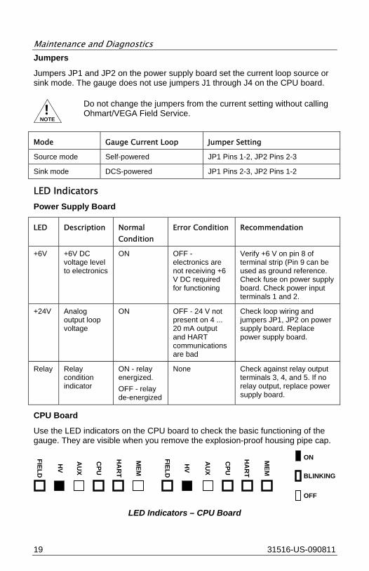
CPU Board
Use the LED indicators on the CPU board to check the basic functioning of the gauge. They are visible when you remove the explosion-proof housing pipe cap.
FIELD
MEM
HA
RT
CPU
AU
X
HV
FIELD
HV
AU
X
CPU
HA
RT
MEM
ON
BLINKING
OFF
LED Indicators – CPU Board

Maintenance and Diagnostics
20 31524-US-090811
!NOTE
If the LED band displays the Memory Corrupt pattern, call Ohmart/VEGA Field Service to report this condition. The gauge does not operate if the FLASH chip is corrupt.
CPU LEDs
Description Normal Condition Error Condition Recommendation
Mem Memory corruption
OFF Blink Pattern 1-CPU EEPROM corrupt 2-Sensor EEPROM corrupt 3-Both EEPROMs corrupt 4-RAM corrupt 5-Memory mismatch ON solid-Combination of errors
Check software diagnostics. Call Ohmart/VEGA Field service.
HART
HART communication indicator
ON - blinks when receiving HART messages
None Check device and connection on loop
CPU Central processing unit
Blinks at rate of once per second
LED does not blink. CPU not functioning
Check power input. Replace CPU board.
Aux Auxiliary input frequency signal indicator
Blinks if auxiliary input is present
None Check auxiliary input wiring terminals 11 and 12 with meter for frequency signal. Check auxiliary input equipment.
HV Sensor high voltage
On - high voltage is within specification
Off-high voltage is outside of specification
Call Ohmart/VEGA Field Service.
Field Radiation field indicator
Cycles in proportion to radiation field intensity at detector. On for 10 seconds for each mR/hr, then off for 2 seconds. (Use LED 5, which blinks 1 time/second to time LED1 for field indicator.)
None Check for closed source shutter, buildup, and/or insulation.

Maintenance and Diagnostics
21 31516-US-090811
Field Repair Procedures
!CAUTION
Use appropriate electrostatic discharge procedures to prevent damage to the electrical components of the gauge.
Before replacing a circuit board, call Ohmart/VEGA Field Service. The sensor EEPROM contains a backup of the CPU board EEPROM. After replacing the CPU board, you must perform a memory backup to update the CPU board’s EEPROM with the information in the sensor board EEPROM.
Replace CPU or Power Supply Board 1. Turn off power to the gauge. 2. Remove the housing cover. 3. Remove the plastic electronics cover. 4. Remove the terminal wiring connector. 5. Remove the three (3) screws holding the electronics package in place. 6. Carefully pull the electronics package out of the housing. 7. Remove the appropriate board from the clamshell assembly by removing the
three (3) mounting nuts.
!NOTE
If you are changing the CPU board, you must move the old firmware chip to the new board if the new board firmware is different.
8. Carefully reconnect any ribbon cables. 9. Install the electronics package in the housing. 10. Replace the three (3) mounting nuts. 11. Reconnect the terminal wiring connector. 12. Install the plastic electronics cover. 13. Install the housing cover. 14. Turn on the power to the unit. 15. Connect a HART communicator to the unit and verify that the unit is
operational.
!NOTE
If you change the CPU board, a New Hardware Found error message normally appears when you connect with the HART communicator. In Ohmview 2000, click Diagnostics, New hardware, New CPU and click OK for a new backup of EEPROMS.
Periodic Maintenance Follow this suggested schedule to prevent problems and to comply with radiation regulations. • Recalibrate - As required by process conditions. • Source holder shutter check - Every 6 months unless otherwise required by
the appropriate nuclear regulatory body.

Maintenance and Diagnostics
22 31524-US-090811
• Source wipe - Every 3 years unless otherwise required by the appropriate nuclear regulatory body.
!NOTE
Refer to the DSGH Installation and Operation Guide and the Radiation Safety Manual for more information about recalibration and shutter checks and source wipe tests.

Notes
23 31516-US-090811
NOTES

Customer Service
24 31524-US-090811
Customer Service U.S., Canada, and Worldwide Within the United States, Ohmart/VEGA has Field Service Engineers available for onsite service, emergency services, or equipment start up.
Contact Information Telephone Number/E-mail Address
Monday through Friday 8:00 A.M. - 5:00 P.M. EST (Eastern Standard Time)
1-513-272-0131
Emergencies: Follow the voice mail instructions
1-513-272-0131
International (Worldwide) 1-513-272-0131
Fax 1-513-272-0133
Field Service e-mail [email protected]
Nuclear Services e-mail [email protected]

4170 Rosslyn Drive
Cincinnati, Ohio 45209 USA
telephone: 1.513.272.0131
fax: 1.513.272.0133
web: www.ohmartvega.com
e-mail: [email protected]
3152
4-U
S-0
9030
6