Embed Size (px)
Citation preview

COMPLEX SOLUTIONS MADE SIMPLE.
DEEP SEA ELECTRONICS PLC
DSE5520 AUTOMATIC MAINS FAILURE
CONTROL MODULE
OPERATING MANUAL
CALL US TODAY 1-888-POWER-58
REQUEST A QUOTE [email protected]
SHOP ONLINE www.genpowerusa.com
DSE Model 5520 Automatic Mains Failure Control and Instrumentation System Operators Manual
057-016 5520 OPERATING MANUAL ISSUE 6.1 18/06/07 AM
2
Deep Sea Electronics Plc Highfield House Hunmanby North Yorkshire YO14 0PH ENGLAND Sales Tel: +44 (0) 1723 890099 Sales Fax: +44 (0) 1723 893303 E-mail: [email protected] Website: www.deepseaplc.com
DSE Model 5520 Control and Instrumentation System Operators Manual © Deep Sea Electronics Plc All rights reserved. No part of this publication may be reproduced in any material form (including photocopying or storing in any medium by electronic means or other) without the written permission of the copyright holder except in accordance with the provisions of the Copyright, Designs and Patents Act 1988. Applications for the copyright holder’s written permission to reproduce any part of this publication should be addressed to Deep Sea Electronics Plc at the address above. Any reference to trademarked product names used within this publication is owned by their respective companies. Deep Sea Electronics Plc reserves the right to change the contents of this document without prior notice.
1 BIBLIOGRAPHY
1. IEEE Std C37.2-1996 IEEE Standard Electrical Power System Device Function Numbers and Contact Designations. Institute of Electrical and Electronics Engineers Inc. ISBN 1-55937-879-4
2. Diesel generator handbook. L.L.J.Mahon. ISBN 0-7506-1147-2 3. On-Site Power Generation. EGSA Education Committee. ISBN 0-9625949-3-8
CALL US TODAY 1-888-POWER-58
REQUEST A QUOTE [email protected]
SHOP ONLINE www.genpowerusa.com
DSE Model 5520 Automatic Mains Failure Control and Instrumentation System Operators Manual
057-016 5520 OPERATING MANUAL ISSUE 6.1 18/06/07 AM 3
TABLE OF CONTENTS Section Page 1 BIBLIOGRAPHY .............................................................................................. 2
2 INTRODUCTION .............................................................................................. 6 2.1 CLARIFICATION OF NOTATION USED WITHIN THIS PUBLICATION. .......................... 7 2.2 ICON DESCRIPTIONS ......................................................................................................... 7
3 OPERATION .................................................................................................... 8 3.1 CONTROL ............................................................................................................................ 8 3.2 AUTOMATIC OPERATION ................................................................................................. 9
3.2.1 MAINS FAILURE ........................................................................................................... 9 3.2.2 REMOTE START IN ISLAND MODE ..........................................................................11 3.2.3 REMOTE START ON LOAD .......................................................................................13
3.3 MANUAL OPERATION......................................................................................................15 3.4 TEST OPERATION ............................................................................................................17
4 PROTECTIONS .............................................................................................. 19 4.1 WARNINGS ........................................................................................................................19 4.2 ANALOGUE PRE-ALARMS ..............................................................................................23 4.3 SHUTDOWNS ....................................................................................................................26 4.4 ELECTRICAL TRIPS .........................................................................................................30 4.5 ROCOF / VECTOR SHIFT .................................................................................................32
DESCRIPTION OF CONTROLS .......................................................................... 33 4.6 TYPICAL LCD DISPLAY SCREENS .................................................................................33
4.6.1 TYPICAL STATUS DISPLAY ......................................................................................33 4.6.2 TYPICAL INSTRUMENT DISPLAY ............................................................................34 4.6.3 TYPICAL ALARM DISPLAY ........................................................................................34 4.6.4 TYPICAL EVENT DISPLAY ........................................................................................35 4.6.5 VIEWING THE INSTRUMENT AND EVENT LOG PAGES ........................................36 4.6.6 SYNCHROSCOPE OPERATION ...............................................................................37
4.7 COMPLETE INSTRUMENTATION LIST ...........................................................................38 4.7.1 BASIC INSTRUMENTATION ......................................................................................38 4.7.2 ENHANCED ENGINE INSTRUMENTATION .............................................................38
4.8 ACCESSING THE FRONT PANEL CONFIGURATION EDITOR .....................................39 4.8.1 ENTERING THE CONFIGURATION EDITOR PIN NUMBER ....................................39 4.8.2 EDITING VALUES .......................................................................................................40 4.8.3 LIST OF ADJUSTABLE PARAMETERS (MAIN CONFIGURATION EDITOR) .........41 4.8.4 LIST OF ADJUSTABLE PARAMETERS (APPLICATION EDITOR) ..........................42
4.9 DISPLAY EDITOR .............................................................................................................43 4.9.1 EDITING ‘DISPLAY EDITOR’ CONFIGURATION VALUES ......................................43
5 LED IDENTIFICATION AND FRONT PANEL LAYOUT ................................ 45 5.1 CONFIGURABLE LED IDENTIFICATION DIAGRAM ......................................................45
6 LED INDICATORS AND LOGO INSERT ....................................................... 46
7 CONTROL PUSH-BUTTONS ........................................................................ 47
8 INSTALLATION INSTRUCTIONS .................................................................. 50 8.1 PANEL CUT-OUT ..............................................................................................................50 8.2 COOLING ...........................................................................................................................50 8.3 UNIT DIMENSIONS ...........................................................................................................50
9 ELECTRICAL CONNECTIONS...................................................................... 51 9.1 CONNECTION DETAILS ...................................................................................................51
9.1.1 PLUG “A” 8 WAY .........................................................................................................51 9.1.2 PLUG “B” 11 WAY .......................................................................................................51 9.1.3 PLUG “C” 9 WAY ........................................................................................................52 9.1.4 PLUG “D” 3 WAY ........................................................................................................52
CALL US TODAY 1-888-POWER-58
REQUEST A QUOTE [email protected]
SHOP ONLINE www.genpowerusa.com
DSE Model 5520 Automatic Mains Failure Control and Instrumentation System Operators Manual
057-016 5520 OPERATING MANUAL ISSUE 6.1 18/06/07 AM
4
9.1.5 PLUG “E” 5 WAY ........................................................................................................ 52 9.1.6 PLUG “F” 8 WAY ........................................................................................................ 53 9.1.7 PLUG “G” 4 WAY ........................................................................................................ 53 9.1.8 PLUG “H” 12 WAY ...................................................................................................... 53 9.1.9 PC CONFIGURATION INTERFACE CONNECTOR .................................................. 54 9.1.10 EXPANSION INTERFACE CONNECTOR ................................................................. 54
9.2 CONNECTOR FUNCTION DETAILS ................................................................................ 55 9.2.1 PLUG “A” 8 WAY ........................................................................................................ 55 9.2.2 PLUG “B” 11 WAY ...................................................................................................... 55 9.2.3 PLUG “C” 9 WAY ........................................................................................................ 56 9.2.4 PLUG “D” 3 WAY ........................................................................................................ 56 9.2.5 PLUG “E” 5 WAY ........................................................................................................ 57 9.2.6 PLUG “F” 8 WAY ........................................................................................................ 57 9.2.7 PLUG “G” 4 WAY ........................................................................................................ 57 9.2.8 PLUG “H” 12 WAY ...................................................................................................... 58
9.3 ENGINE CONTROL UNIT INTERFACE ........................................................................... 59 10 SPECIFICATION ......................................................................................... 60
11 COMMISSIONING ....................................................................................... 62 11.1.1 PRE-COMMISSIONING ............................................................................................. 62
11.2 BYPASSING ALARMS AT STARTUP .......................................................................... 63 11.3 COMMISSIONING SCREENS ....................................................................................... 63
11.3.1 SCREEN 1 .................................................................................................................. 63 11.3.2 SCREEN 2 .................................................................................................................. 63 11.3.3 SCREEN 3 .................................................................................................................. 63 11.3.4 SCREEN 4 .................................................................................................................. 63
12 FAULT FINDING .......................................................................................... 64
13 TYPICAL WIRING DIAGRAM ..................................................................... 65
14 FACTORY DEFAULT CONFIGURATION ................................................... 66
15 SENDER WIRING RECOMMENDATIONS .................................................. 70 15.1.1 USING EARTH RETURN (SINGLE WIRE) SENDERS. ............................................ 70 15.1.2 USING INSULATED RETURN (TWO WIRE) SENDERS. ......................................... 71
16 APPENDIX ................................................................................................... 72 16.1 5520 IDMT TRIPPING CURVES (TYPICAL) ................................................................. 72 16.2 5510 SHORT CIRCUIT TRIPPING CURVES (TYPICAL) ............................................. 72 16.3 ACCESSORIES ............................................................................................................. 73
16.3.1 OUTPUT EXPANSION ............................................................................................... 73 RELAY OUTPUT EXPANSION (157).................................................................................... 73 LED OUTPUT EXPANSION (548) ........................................................................................ 73
16.3.2 INPUT EXPANSION (P130/P540/P541) .................................................................... 73 16.4 COMMUNICATIONS OPTION ....................................................................................... 74
16.4.1 DESCRIPTION ........................................................................................................... 74 16.4.2 PC TO CONTROLLER (DIRECT) CONNECTION ..................................................... 74 16.4.3 MODEM TO CONTROLLER CONNECTION ............................................................. 74 16.4.4 RS485 LINK TO CONTROLLER ................................................................................ 75
TYPICAL BUILDING MANAGEMENT SCHEME USING RS485 MONITORING ................. 76 16.4.5 MODBUS™ ................................................................................................................. 76
16.5 IEEE C37.2 STANDARD ELECTRICAL POWER SYSTEM DEVICE FUNCTION NUMBERS .................................................................................................................................... 77 16.6 ENCLOSURE CLASSIFICATIONS ............................................................................... 79
IP CLASSIFICATIONS .......................................................................................................... 79 NEMA CLASSIFICATIONS ................................................................................................... 80
12. SYNCHRONISING NOTES .......................................................................... 81 16.6.1 CHECK SYNC ............................................................................................................ 81 16.6.2 AUTO SYNC ............................................................................................................... 81 16.6.3 LOAD CONTROL ....................................................................................................... 81
CALL US TODAY 1-888-POWER-58
REQUEST A QUOTE [email protected]
SHOP ONLINE www.genpowerusa.com
DSE Model 5520 Automatic Mains Failure Control and Instrumentation System Operators Manual
057-016 5520 OPERATING MANUAL ISSUE 6.1 18/06/07 AM 5
MAINS CT ..............................................................................................................................81 16.6.4 TYPICAL PEAK LOPPING SYSTEM ..........................................................................82
CALL US TODAY 1-888-POWER-58
REQUEST A QUOTE [email protected]
SHOP ONLINE www.genpowerusa.com
DSE Model 5520 Automatic Mains Failure Control and Instrumentation System Operators Manual
057-016 5520 OPERATING MANUAL ISSUE 6.1 18/06/07 AM
6
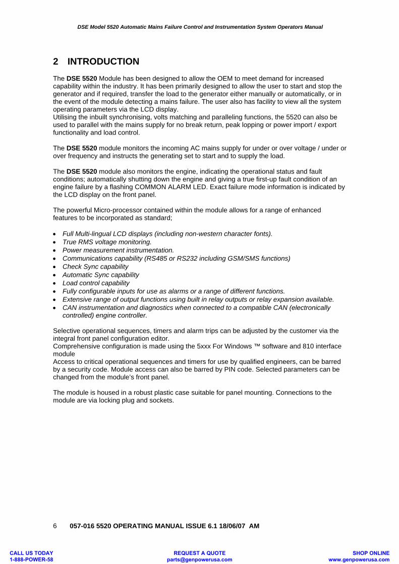
2 INTRODUCTION The DSE 5520 Module has been designed to allow the OEM to meet demand for increased capability within the industry. It has been primarily designed to allow the user to start and stop the generator and if required, transfer the load to the generator either manually or automatically, or in the event of the module detecting a mains failure. The user also has facility to view all the system operating parameters via the LCD display. Utilising the inbuilt synchronising, volts matching and paralleling functions, the 5520 can also be used to parallel with the mains supply for no break return, peak lopping or power import / export functionality and load control. The DSE 5520 module monitors the incoming AC mains supply for under or over voltage / under or over frequency and instructs the generating set to start and to supply the load. The DSE 5520 module also monitors the engine, indicating the operational status and fault conditions; automatically shutting down the engine and giving a true first-up fault condition of an engine failure by a flashing COMMON ALARM LED. Exact failure mode information is indicated by the LCD display on the front panel. The powerful Micro-processor contained within the module allows for a range of enhanced features to be incorporated as standard; • Full Multi-lingual LCD displays (including non-western character fonts). • True RMS voltage monitoring. • Power measurement instrumentation. • Communications capability (RS485 or RS232 including GSM/SMS functions) • Check Sync capability • Automatic Sync capability • Load control capability • Fully configurable inputs for use as alarms or a range of different functions. • Extensive range of output functions using built in relay outputs or relay expansion available. • CAN instrumentation and diagnostics when connected to a compatible CAN (electronically
controlled) engine controller. Selective operational sequences, timers and alarm trips can be adjusted by the customer via the integral front panel configuration editor. Comprehensive configuration is made using the 5xxx For Windows ™ software and 810 interface module Access to critical operational sequences and timers for use by qualified engineers, can be barred by a security code. Module access can also be barred by PIN code. Selected parameters can be changed from the module’s front panel. The module is housed in a robust plastic case suitable for panel mounting. Connections to the module are via locking plug and sockets.
CALL US TODAY 1-888-POWER-58
REQUEST A QUOTE [email protected]
SHOP ONLINE www.genpowerusa.com
DSE Model 5520 Automatic Mains Failure Control and Instrumentation System Operators Manual
057-016 5520 OPERATING MANUAL ISSUE 6.1 18/06/07 AM 7
2.1 CLARIFICATION OF NOTATION USED WITHIN THIS PUBLICATION.
NOTE: Highlights an essential element of a procedure to ensure correctness.
CAUTION! Indicates a procedure or practice which, if not strictly observed, could result in damage or destruction of equipment.
WARNING!
Indicates a procedure or practice which could result in injury to personnel or loss of life if not followed correctly.
© Deep Sea Electronics Plc owns the copyright to this manual, which cannot be copied, reproduced or disclosed to a third party without prior written permission.
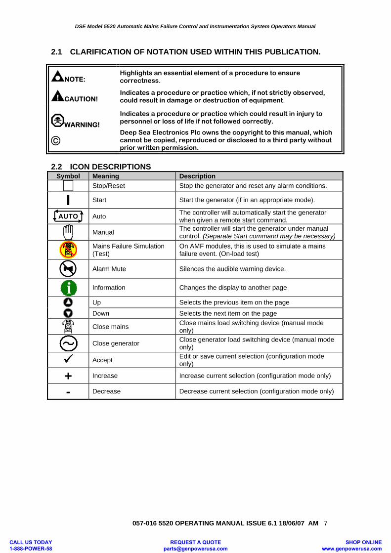
2.2 ICON DESCRIPTIONS
Symbol Meaning Description
Stop/Reset Stop the generator and reset any alarm conditions.
I Start Start the generator (if in an appropriate mode).
Auto The controller will automatically start the generator
when given a remote start command.
Manual The controller will start the generator under manual
control. (Separate Start command may be necessary)
Mains Failure Simulation (Test)
On AMF modules, this is used to simulate a mains failure event. (On-load test)
Alarm Mute Silences the audible warning device.
Information Changes the display to another page
Up Selects the previous item on the page
Down Selects the next item on the page
Close mains Close mains load switching device (manual mode
only)
Close generator Close generator load switching device (manual mode
only)
Accept Edit or save current selection (configuration mode only)
+ Increase Increase current selection (configuration mode only)
- Decrease Decrease current selection (configuration mode only)
CALL US TODAY 1-888-POWER-58
REQUEST A QUOTE [email protected]
SHOP ONLINE www.genpowerusa.com
DSE Model 5520 Automatic Mains Failure Control and Instrumentation System Operators Manual
057-016 5520 OPERATING MANUAL ISSUE 6.1 18/06/07 AM
8
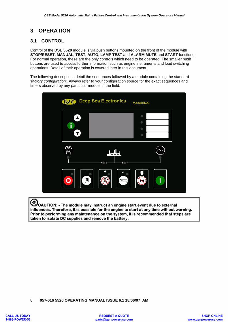
3 OPERATION 3.1 CONTROL Control of the DSE 5520 module is via push buttons mounted on the front of the module with STOP/RESET, MANUAL, TEST, AUTO, LAMP TEST and ALARM MUTE and START functions. For normal operation, these are the only controls which need to be operated. The smaller push buttons are used to access further information such as engine instruments and load switching operations. Detail of their operation is covered later in this document. The following descriptions detail the sequences followed by a module containing the standard ‘factory configuration’. Always refer to your configuration source for the exact sequences and timers observed by any particular module in the field.
CAUTION: - The module may instruct an engine start event due to external influences. Therefore, it is possible for the engine to start at any time without warning. Prior to performing any maintenance on the system, it is recommended that steps are taken to isolate DC supplies and remove the battery.
CALL US TODAY 1-888-POWER-58
REQUEST A QUOTE [email protected]
SHOP ONLINE www.genpowerusa.com
DSE Model 5520 Automatic Mains Failure Control and Instrumentation System Operators Manual
057-016 5520 OPERATING MANUAL ISSUE 6.1 18/06/07 AM 9
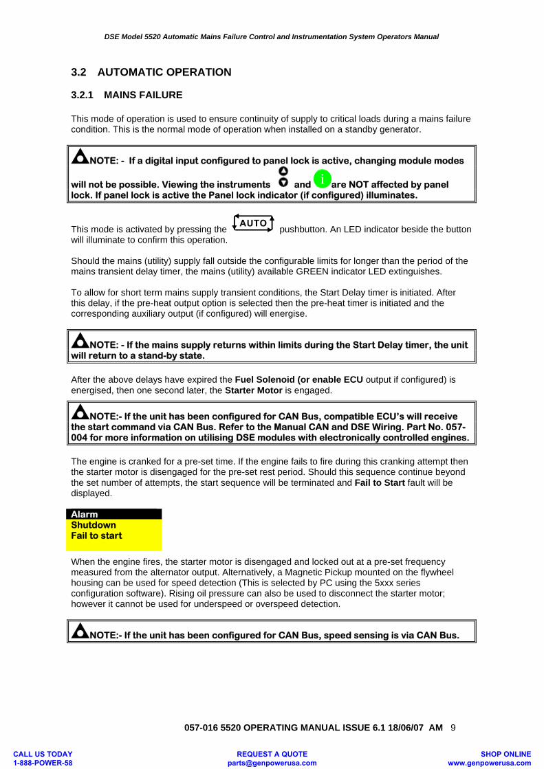
3.2 AUTOMATIC OPERATION 3.2.1 MAINS FAILURE This mode of operation is used to ensure continuity of supply to critical loads during a mains failure condition. This is the normal mode of operation when installed on a standby generator.
NOTE: - If a digital input configured to panel lock is active, changing module modes
will not be possible. Viewing the instruments and i are NOT affected by panel lock. If panel lock is active the Panel lock indicator (if configured) illuminates.
This mode is activated by pressing the pushbutton. An LED indicator beside the button will illuminate to confirm this operation. Should the mains (utility) supply fall outside the configurable limits for longer than the period of the mains transient delay timer, the mains (utility) available GREEN indicator LED extinguishes. To allow for short term mains supply transient conditions, the Start Delay timer is initiated. After this delay, if the pre-heat output option is selected then the pre-heat timer is initiated and the corresponding auxiliary output (if configured) will energise.
NOTE: - If the mains supply returns within limits during the Start Delay timer, the unit will return to a stand-by state.
After the above delays have expired the Fuel Solenoid (or enable ECU output if configured) is energised, then one second later, the Starter Motor is engaged.
NOTE:- If the unit has been configured for CAN Bus, compatible ECU’s will receive the start command via CAN Bus. Refer to the Manual CAN and DSE Wiring. Part No. 057-004 for more information on utilising DSE modules with electronically controlled engines.
The engine is cranked for a pre-set time. If the engine fails to fire during this cranking attempt then the starter motor is disengaged for the pre-set rest period. Should this sequence continue beyond the set number of attempts, the start sequence will be terminated and Fail to Start fault will be displayed. Alarm Shutdown Fail to start
When the engine fires, the starter motor is disengaged and locked out at a pre-set frequency measured from the alternator output. Alternatively, a Magnetic Pickup mounted on the flywheel housing can be used for speed detection (This is selected by PC using the 5xxx series configuration software). Rising oil pressure can also be used to disconnect the starter motor; however it cannot be used for underspeed or overspeed detection.
NOTE:- If the unit has been configured for CAN Bus, speed sensing is via CAN Bus.
CALL US TODAY 1-888-POWER-58
REQUEST A QUOTE [email protected]
SHOP ONLINE www.genpowerusa.com
DSE Model 5520 Automatic Mains Failure Control and Instrumentation System Operators Manual
057-016 5520 OPERATING MANUAL ISSUE 6.1 18/06/07 AM
10
After the starter motor has disengaged, the Safety On timer is activated, allowing Oil Pressure, High Engine Temperature, Under-speed, Charge Fail and any delayed Auxiliary fault inputs to stabilise without triggering the fault. Once the engine is running, the Warm Up timer, if selected is initiated, allowing the engine to stabilise before accepting the load. After the Warm-up timer has expired then the module will transfer the load from the failed mains supply to the generator output. It will observe the following sequence. The Mains Contactor/Breaker will be instructed to open and after a short delay (transfer delay), the Generator Contactor/Breaker will be instructed to close. The generator will then supply the requirements of the load.
NOTE:-A load transfer will not be initiated until the Oil Pressure has risen. This prevents excessive wear on the engine.
When the mains supply returns, the Stop delay timer is initiated. Once it has expired, the set is synchronised and paralleled with the mains supply. The system remains in this condition until expiry of the Parallel run timer. Once this has expired, the module will ramp the remaining load from the generator to mains supply. The Generator Contact/Breaker will open and the Cooling timer is then initiated, allowing the engine a cooling down period off load before shutting down. Once the Cooling timer expires, the Fuel Solenoid is de-energised, bringing the generator to a stop. During the parallel run, the module can be configured to either run at a fixed level output, or to maintain an output in relation to the load level on the mains. For full details of these mode please refer to the manual ‘The Guide to sync and load share Pt1’ Should the mains supply fall outside limits once again the set will return on load.
NOTE: - When synchronising is enabled, the mains supply is checked before closing any load switching device. If the supply is live, synchronising will take place before any closure takes place.
NOTE: - Synchronising can be disabled if the application does not require this function. Contact your genset supplier in the first instance for further details.
CALL US TODAY 1-888-POWER-58
REQUEST A QUOTE [email protected]
SHOP ONLINE www.genpowerusa.com
DSE Model 5520 Automatic Mains Failure Control and Instrumentation System Operators Manual
057-016 5520 OPERATING MANUAL ISSUE 6.1 18/06/07 AM 11
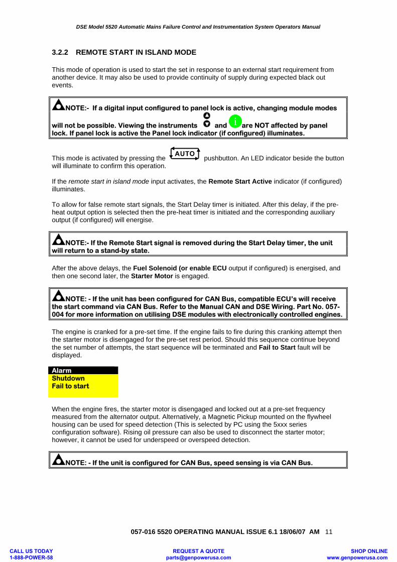
3.2.2 REMOTE START IN ISLAND MODE This mode of operation is used to start the set in response to an external start requirement from another device. It may also be used to provide continuity of supply during expected black out events.
NOTE:- If a digital input configured to panel lock is active, changing module modes
will not be possible. Viewing the instruments and i are NOT affected by panel lock. If panel lock is active the Panel lock indicator (if configured) illuminates.
This mode is activated by pressing the pushbutton. An LED indicator beside the button will illuminate to confirm this operation. If the remote start in island mode input activates, the Remote Start Active indicator (if configured) illuminates. To allow for false remote start signals, the Start Delay timer is initiated. After this delay, if the pre-heat output option is selected then the pre-heat timer is initiated and the corresponding auxiliary output (if configured) will energise.
NOTE:- If the Remote Start signal is removed during the Start Delay timer, the unit will return to a stand-by state.
After the above delays, the Fuel Solenoid (or enable ECU output if configured) is energised, and then one second later, the Starter Motor is engaged.
NOTE: - If the unit has been configured for CAN Bus, compatible ECU’s will receive the start command via CAN Bus. Refer to the Manual CAN and DSE Wiring. Part No. 057-004 for more information on utilising DSE modules with electronically controlled engines.
The engine is cranked for a pre-set time. If the engine fails to fire during this cranking attempt then the starter motor is disengaged for the pre-set rest period. Should this sequence continue beyond the set number of attempts, the start sequence will be terminated and Fail to Start fault will be displayed. Alarm Shutdown Fail to start When the engine fires, the starter motor is disengaged and locked out at a pre-set frequency measured from the alternator output. Alternatively, a Magnetic Pickup mounted on the flywheel housing can be used for speed detection (This is selected by PC using the 5xxx series configuration software). Rising oil pressure can also be used to disconnect the starter motor; however, it cannot be used for underspeed or overspeed detection.
NOTE: - If the unit is configured for CAN Bus, speed sensing is via CAN Bus.
CALL US TODAY 1-888-POWER-58
REQUEST A QUOTE [email protected]
SHOP ONLINE www.genpowerusa.com
DSE Model 5520 Automatic Mains Failure Control and Instrumentation System Operators Manual
057-016 5520 OPERATING MANUAL ISSUE 6.1 18/06/07 AM
12
After the starter motor has disengaged, the Safety On timer is activated, allowing Oil Pressure, High Engine Temperature, Under-speed, Charge Fail and any delayed Auxiliary fault inputs to stabilise without triggering the fault. Once the engine is running, the Warm Up timer, if selected is initiated, allowing the engine to stabilise before accepting the load.
NOTE: - A load transfer will not be initiated until the Oil Pressure has risen. This prevents excessive wear on the engine.
The Generator will first be instructed to synchronise with the mains supply before closing the Generator Contact/Breaker and transferring load from mains to generator until the generator is supplying the required amount of power (adjustable using 5xxx configuration software). When the supplies have been in parallel for the duration of the parallel run time, the load will ramp off the mains supply and onto the generator. The Mains Contactor/Breaker will be instructed to open. The generator will then supply the requirements of the load. When the remote start signal is removed, the Stop delay timer is initiated. Once it has expired, the set is synchronised and paralleled with the mains supply. The system remains in this condition until expiry of the Parallel run timer. Once this has expired, the module will ramp the remaining load from the generator to mains supply. The Generator Contact/Breaker will open and the Cooling timer is then initiated, allowing the engine a cooling down period off load before shutting down. Once the Cooling timer expires, the Fuel Solenoid is de-energised, bringing the generator to a stop.
NOTE: - Synchronising can be disabled if the application does not require this function. Contact your generating set supplier in the first instance for further details.
NOTE: - The internal ‘Scheduler’ can be configured to operate they system in the same manner as described for the Remote start input. Please refer to the 5xxx Configuration Software manuals for full details on the feature.
CALL US TODAY 1-888-POWER-58
REQUEST A QUOTE [email protected]
SHOP ONLINE www.genpowerusa.com

DSE Model 5520 Automatic Mains Failure Control and Instrumentation System Operators Manual
057-016 5520 OPERATING MANUAL ISSUE 6.1 18/06/07 AM 13
3.2.3 REMOTE START ON LOAD This mode of operation is used to start the set in response to rising load levels on the mains supply (if configured).
NOTE: - If a digital input configured to panel lock is active, changing module modes
will not be possible. Viewing the instruments and i are NOT affected by panel lock. If panel lock is active the Panel lock indicator (if configured) illuminates.
This mode is activated by pressing the pushbutton. An LED indicator beside the button will illuminate to confirm this operation. Should the load level on the mains supply exceed a pre-set level the module will initiate a start sequence. To allow for short duration load surges, the Start Delay timer is initiated. After this delay, if the pre-heat output option is selected then the pre-heat timer is initiated and the corresponding auxiliary output (if configured) will energise.
NOTE: - If the load level returns below the pre-set level during the Start Delay timer, the unit will return to a stand-by state.
After the above delays, the Fuel Solenoid (or enable ECU output if configured) is energised, and then one second later, the Starter Motor is engaged.
NOTE: - If the unit has been configured for CAN Bus, compatible ECU’s will receive the start command via CAN Bus. Refer to the Manual CAN and DSE Wiring. Part No. 057-004 for more information on utilising DSE modules with electronically controlled engines.
The engine is cranked for a pre-set time. If the engine fails to fire during this cranking attempt then the starter motor is disengaged for the pre-set rest period. Should this sequence continue beyond the set number of attempts, the start sequence will be terminated and Fail to Start fault will be displayed. Alarm Shutdown Fail to start When the engine fires, the starter motor is disengaged and locked out at a pre-set frequency measured from the alternator output. Alternatively, a Magnetic Pickup mounted on the flywheel housing can be used for speed detection (This is selected by PC using the 5xxx series configuration software). Rising oil pressure can also be used to disconnect the starter motor; however, it cannot be used for underspeed or overspeed detection.
NOTE: - If the unit is configured for CAN Bus, speed sensing is via CAN Bus.
CALL US TODAY 1-888-POWER-58
REQUEST A QUOTE [email protected]
SHOP ONLINE www.genpowerusa.com
DSE Model 5520 Automatic Mains Failure Control and Instrumentation System Operators Manual
057-016 5520 OPERATING MANUAL ISSUE 6.1 18/06/07 AM
14
After the starter motor has disengaged, the Safety On timer is activated, allowing Oil Pressure, High Engine Temperature, Under-speed, Charge Fail and any delayed Auxiliary fault inputs to stabilise without triggering the fault. Once the engine is running, the Warm Up timer, if selected is initiated, allowing the engine to stabilise before accepting the load. After the Warm-up timer has expired then the module will transfer the load from the mains supply to the generator output. It will observe the following sequence. The Generator will first be instructed to synchronise with the mains supply. Once these are matched, the Generator Contact/Breaker will be instructed to close. The load will then be ramped from the Mains to the appropriate level on the generator. The generator will then supply the requirements of the load.
NOTE: - A load transfer will not be initiated until the Oil Pressure has risen. This prevents excessive wear on the engine.
When the remote start on load input is removed, the Stop delay timer is initiated. Once this timer has expired, the module will ramp the load from the generator to mains supply. The Generator Contact/Breaker will open and the Cooling timer is then initiated, allowing the engine a cooling down period off load before shutting down. Once the Cooling timer expires, the Fuel Solenoid is de-energised, bringing the generator to a stop. During the parallel run, the module can be configured to either run at a fixed level output, or to maintain an output in relation to the load level on the mains.
NOTE: - When synchronising is enabled, the mains supply is checked before closing any load switching device. If the supply is live, synchronising will take place before any closure takes place.
NOTE: - Synchronising can be disabled if the application does not require this function. Contact your genset supplier in the first instance for further details.
NOTE: - The load level mode of operation relies on a Current Transformer (CT) fitted to the mains feed of the system. This is then used for measurement of the mains current used in the load level calculations.
CALL US TODAY 1-888-POWER-58
REQUEST A QUOTE [email protected]
SHOP ONLINE www.genpowerusa.com
DSE Model 5520 Automatic Mains Failure Control and Instrumentation System Operators Manual
057-016 5520 OPERATING MANUAL ISSUE 6.1 18/06/07 AM 15
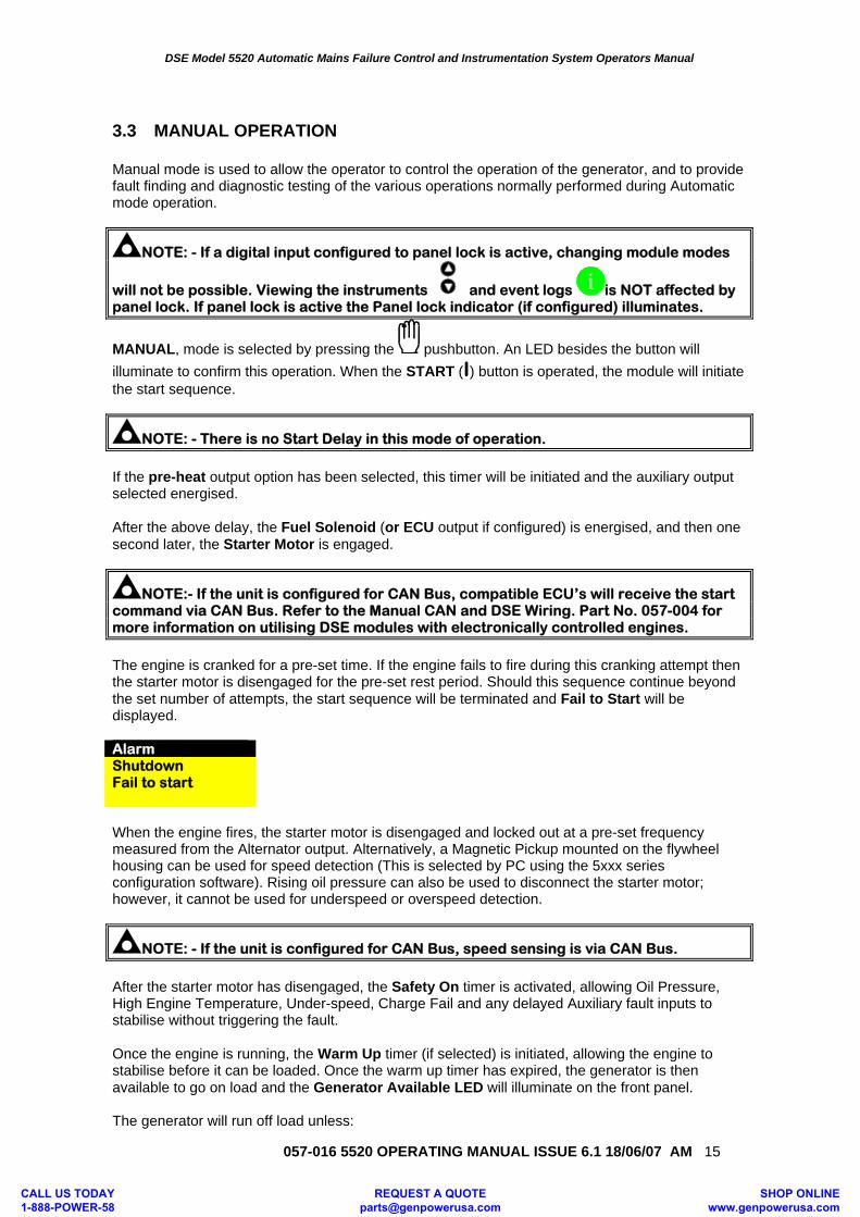
3.3 MANUAL OPERATION Manual mode is used to allow the operator to control the operation of the generator, and to provide fault finding and diagnostic testing of the various operations normally performed during Automatic mode operation.
NOTE: - If a digital input configured to panel lock is active, changing module modes
will not be possible. Viewing the instruments and event logs i is NOT affected by panel lock. If panel lock is active the Panel lock indicator (if configured) illuminates.
MANUAL, mode is selected by pressing the pushbutton. An LED besides the button will illuminate to confirm this operation. When the START (I) button is operated, the module will initiate the start sequence.
NOTE: - There is no Start Delay in this mode of operation.
If the pre-heat output option has been selected, this timer will be initiated and the auxiliary output selected energised. After the above delay, the Fuel Solenoid (or ECU output if configured) is energised, and then one second later, the Starter Motor is engaged.
NOTE:- If the unit is configured for CAN Bus, compatible ECU’s will receive the start command via CAN Bus. Refer to the Manual CAN and DSE Wiring. Part No. 057-004 for more information on utilising DSE modules with electronically controlled engines.
The engine is cranked for a pre-set time. If the engine fails to fire during this cranking attempt then the starter motor is disengaged for the pre-set rest period. Should this sequence continue beyond the set number of attempts, the start sequence will be terminated and Fail to Start will be displayed. Alarm Shutdown Fail to start When the engine fires, the starter motor is disengaged and locked out at a pre-set frequency measured from the Alternator output. Alternatively, a Magnetic Pickup mounted on the flywheel housing can be used for speed detection (This is selected by PC using the 5xxx series configuration software). Rising oil pressure can also be used to disconnect the starter motor; however, it cannot be used for underspeed or overspeed detection.
NOTE: - If the unit is configured for CAN Bus, speed sensing is via CAN Bus.
After the starter motor has disengaged, the Safety On timer is activated, allowing Oil Pressure, High Engine Temperature, Under-speed, Charge Fail and any delayed Auxiliary fault inputs to stabilise without triggering the fault. Once the engine is running, the Warm Up timer (if selected) is initiated, allowing the engine to stabilise before it can be loaded. Once the warm up timer has expired, the generator is then available to go on load and the Generator Available LED will illuminate on the front panel. The generator will run off load unless:
CALL US TODAY 1-888-POWER-58
REQUEST A QUOTE [email protected]
SHOP ONLINE www.genpowerusa.com
DSE Model 5520 Automatic Mains Failure Control and Instrumentation System Operators Manual
057-016 5520 OPERATING MANUAL ISSUE 6.1 18/06/07 AM
16
1. The mains supply fails, 2. A Remote Start on load signal is applied, or an on-load run is configured in the scheduler.
3. The Close Generator button is pressed. If any of the above signals are received, the generator is synchronised and paralleled with the mains supply (if available). During the parallel run, the module can be configured to either run at a fixed level output, or to maintain an output in relation to the load level on the mains. For full details of these mode please refer to the manual ‘The Guide to sync and load share Pt1’ Parallel operation:
• If the Close Generator button is pressed again while in parallel, then the module will transfer the load fully to the generators, removing the load from the mains supply. This will be achieved by ramping the load from the parallel operating level to the generator. The Mains
Contactor/Breaker will then be opened. Pressing the Close Mains button will cause the module to re-synchronise the generator with the mains supply and then return to parallel operation.
• If the Close Mains button is pressed while in parallel, the module will open the generator load switching device, transferring the load fully to the mains supply.
If Auto mode is selected and the mains supply is healthy, and the remote start on load signal not active, and the scheduler is not calling for a run, then the Return Delay Timer will start. Once this has expired then the module will exit parallel operation and will ramp the load back to the mains supply. It will then open the Generator Contactor/Breaker. The generator will then run off load allowing the engine a cooling period. Selecting STOP (O) de-energises the FUEL SOLENOID, bringing the generator to a stop.
WARNING: - Operation of the STOP button in any mode will stop the generator operation and return the load switching system to a safe state. This operation may lead to loss of supply to the load. It is recommended that the STOP button is only operated once the generator is OFF LOAD and the mains is supplying the load.
NOTE: - Synchronising can be disabled if the application does not require this function. Contact your genset supplier in the first instance for further details. If synchronising is disabled the system will always perform an open transition when switching the load from the mains to the generator or when returning to the mains. The parallel run stages of the sequence are not used when operating in this way.
NOTE: - When synchronising is enabled, the mains supply is checked before closing any load switching device. If the supply is live, synchronising will take place before any closure takes place.
CALL US TODAY 1-888-POWER-58
REQUEST A QUOTE [email protected]
SHOP ONLINE www.genpowerusa.com
DSE Model 5520 Automatic Mains Failure Control and Instrumentation System Operators Manual
057-016 5520 OPERATING MANUAL ISSUE 6.1 18/06/07 AM 17
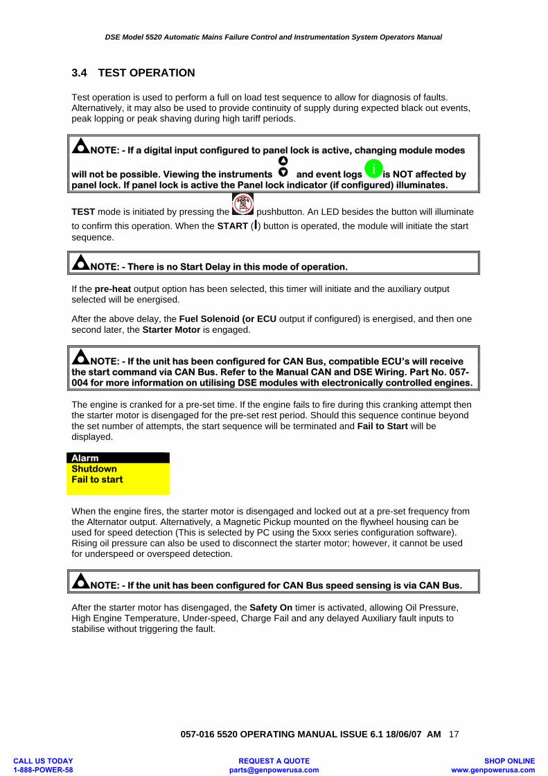
3.4 TEST OPERATION Test operation is used to perform a full on load test sequence to allow for diagnosis of faults. Alternatively, it may also be used to provide continuity of supply during expected black out events, peak lopping or peak shaving during high tariff periods.
NOTE: - If a digital input configured to panel lock is active, changing module modes
will not be possible. Viewing the instruments and event logs i is NOT affected by panel lock. If panel lock is active the Panel lock indicator (if configured) illuminates.
TEST mode is initiated by pressing the pushbutton. An LED besides the button will illuminate to confirm this operation. When the START (I) button is operated, the module will initiate the start sequence.
NOTE: - There is no Start Delay in this mode of operation. If the pre-heat output option has been selected, this timer will initiate and the auxiliary output selected will be energised. After the above delay, the Fuel Solenoid (or ECU output if configured) is energised, and then one second later, the Starter Motor is engaged.
NOTE: - If the unit has been configured for CAN Bus, compatible ECU’s will receive the start command via CAN Bus. Refer to the Manual CAN and DSE Wiring. Part No. 057-004 for more information on utilising DSE modules with electronically controlled engines. The engine is cranked for a pre-set time. If the engine fails to fire during this cranking attempt then the starter motor is disengaged for the pre-set rest period. Should this sequence continue beyond the set number of attempts, the start sequence will be terminated and Fail to Start will be displayed. Alarm Shutdown Fail to start When the engine fires, the starter motor is disengaged and locked out at a pre-set frequency from the Alternator output. Alternatively, a Magnetic Pickup mounted on the flywheel housing can be used for speed detection (This is selected by PC using the 5xxx series configuration software). Rising oil pressure can also be used to disconnect the starter motor; however, it cannot be used for underspeed or overspeed detection.
NOTE: - If the unit has been configured for CAN Bus speed sensing is via CAN Bus. After the starter motor has disengaged, the Safety On timer is activated, allowing Oil Pressure, High Engine Temperature, Under-speed, Charge Fail and any delayed Auxiliary fault inputs to stabilise without triggering the fault.
CALL US TODAY 1-888-POWER-58
REQUEST A QUOTE [email protected]
SHOP ONLINE www.genpowerusa.com
DSE Model 5520 Automatic Mains Failure Control and Instrumentation System Operators Manual
057-016 5520 OPERATING MANUAL ISSUE 6.1 18/06/07 AM
18
Once the engine is running, the Warm Up timer, if selected is initiated, allowing the engine to stabilise before accepting the load. After the Warm-up timer has expired then the module will transfer the load from the mains supply to the generator output. It will observe the following sequence. The Generator will first be instructed to synchronise with the mains supply. Once these are matched the Generator Contact/Breaker will be instructed to close. The load will then be ramped from the Mains to the appropriate level on the generator. It will remain in this state whilst in the TEST mode. If the module has an active remote start in island mode input or the internal scheduler has been configured for island mode then the parallel run time will activate. When this expires, the load will ramp off the mains supply and onto the generator. The Mains Contactor/Breaker will be instructed to open The generator will then supply the requirements of the load.
NOTE:-A load transfer will not be initiated until the Oil Pressure has risen. This prevents excessive wear on the engine.
The system will then remain in this mode of operation until a different mode is selected. It is
recommended that mode is used to cancel the TEST mode.
When mode is selected the Stop delay timer is initiated. Once it has expired, the set is synchronised and paralleled with the mains supply. The system remains in this condition until expiry of the Parallel run timer. Once this has expired the module will ramp the remaining load from the generator to mains supply. The Generator Contact/Breaker will open and the Cooling timer is then initiated, allowing the engine a cooling down period off load before shutting down. Once the Cooling timer expires the Fuel Solenoid is de-energised, bringing the generator to a stop. During the parallel run the module can be configured to either run at a fixed level output, or to maintain an output in relation to the load level on the mains. For full details of these mode please refer to the manual ‘The Guide to sync and load share Pt1’
NOTE:- When synchronising is enabled, the mains supply is checked before closing any load switching device. If the supply is live, synchronising will take place before any closure takes place.
NOTE:- Synchronising can be disabled if the application does not require this function. Contact your genset supplier in the first instance for further details.
CALL US TODAY 1-888-POWER-58
REQUEST A QUOTE [email protected]
SHOP ONLINE www.genpowerusa.com
DSE Model 5520 Automatic Mains Failure Control and Instrumentation System Operators Manual
057-016 5520 OPERATING MANUAL ISSUE 6.1 18/06/07 AM 19
4 PROTECTIONS When an alarm is present the Audible Alarm will sound and the Common alarm LED (if configured) will illuminate.
The audible alarm can be silenced by pressing the ‘Mute’ button
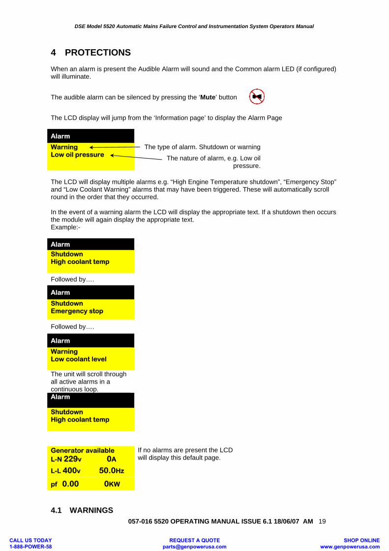
The LCD display will jump from the ‘Information page’ to display the Alarm Page Alarm
Warning Low oil pressure
The type of alarm. Shutdown or warning
The nature of alarm, e.g. Low oil pressure.
The LCD will display multiple alarms e.g. “High Engine Temperature shutdown”, “Emergency Stop” and “Low Coolant Warning” alarms that may have been triggered. These will automatically scroll round in the order that they occurred. In the event of a warning alarm the LCD will display the appropriate text. If a shutdown then occurs the module will again display the appropriate text. Example:- Alarm Shutdown High coolant temp
Followed by….
Alarm Shutdown Emergency stop
Followed by….
Alarm
Warning Low coolant level
The unit will scroll through all active alarms in a continuous loop. Alarm Shutdown High coolant temp
Generator available L-N 229v 0A
If no alarms are present the LCD will display this default page. L-L 400v 50.0Hz
pf 0.00 0KW
4.1 WARNINGS
CALL US TODAY 1-888-POWER-58
REQUEST A QUOTE [email protected]
SHOP ONLINE www.genpowerusa.com
DSE Model 5520 Automatic Mains Failure Control and Instrumentation System Operators Manual
057-016 5520 OPERATING MANUAL ISSUE 6.1 18/06/07 AM
20
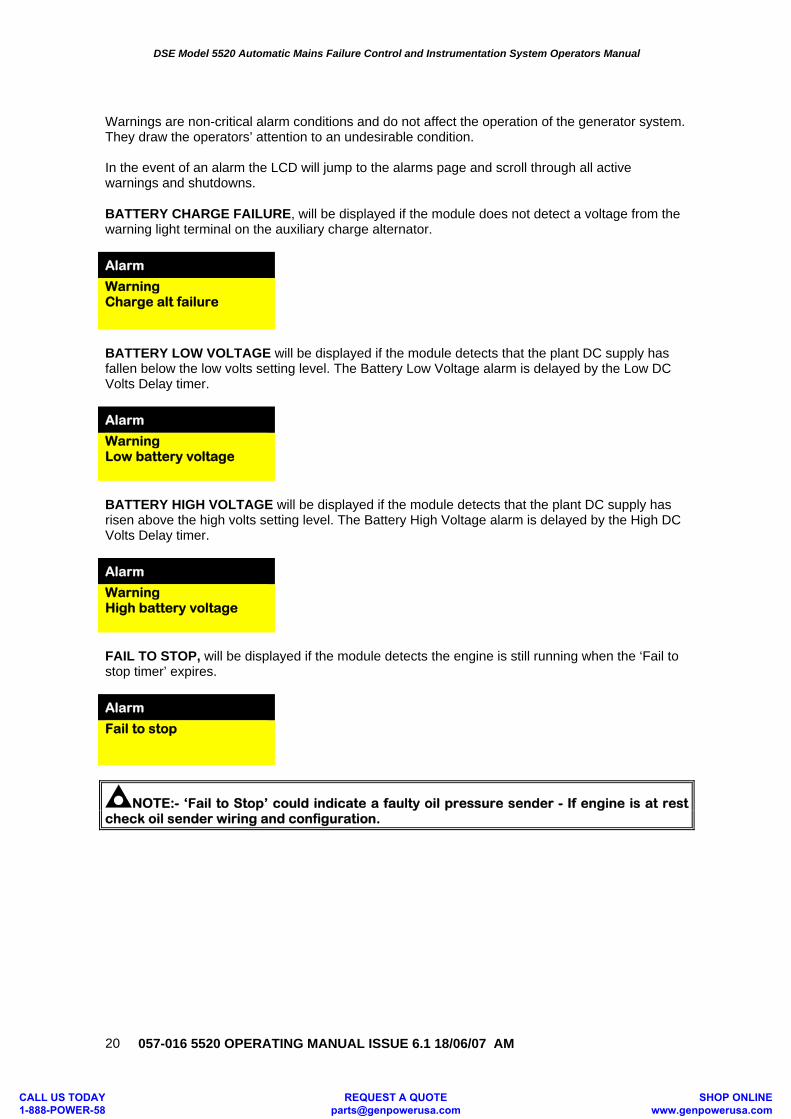
Warnings are non-critical alarm conditions and do not affect the operation of the generator system. They draw the operators’ attention to an undesirable condition. In the event of an alarm the LCD will jump to the alarms page and scroll through all active warnings and shutdowns. BATTERY CHARGE FAILURE, will be displayed if the module does not detect a voltage from the warning light terminal on the auxiliary charge alternator. Alarm Warning Charge alt failure
BATTERY LOW VOLTAGE will be displayed if the module detects that the plant DC supply has fallen below the low volts setting level. The Battery Low Voltage alarm is delayed by the Low DC Volts Delay timer. Alarm Warning Low battery voltage
BATTERY HIGH VOLTAGE will be displayed if the module detects that the plant DC supply has risen above the high volts setting level. The Battery High Voltage alarm is delayed by the High DC Volts Delay timer. Alarm Warning High battery voltage
FAIL TO STOP, will be displayed if the module detects the engine is still running when the ‘Fail to stop timer’ expires. Alarm Fail to stop
NOTE:- ‘Fail to Stop’ could indicate a faulty oil pressure sender - If engine is at rest check oil sender wiring and configuration.
CALL US TODAY 1-888-POWER-58
REQUEST A QUOTE [email protected]
SHOP ONLINE www.genpowerusa.com
DSE Model 5520 Automatic Mains Failure Control and Instrumentation System Operators Manual
057-016 5520 OPERATING MANUAL ISSUE 6.1 18/06/07 AM 21
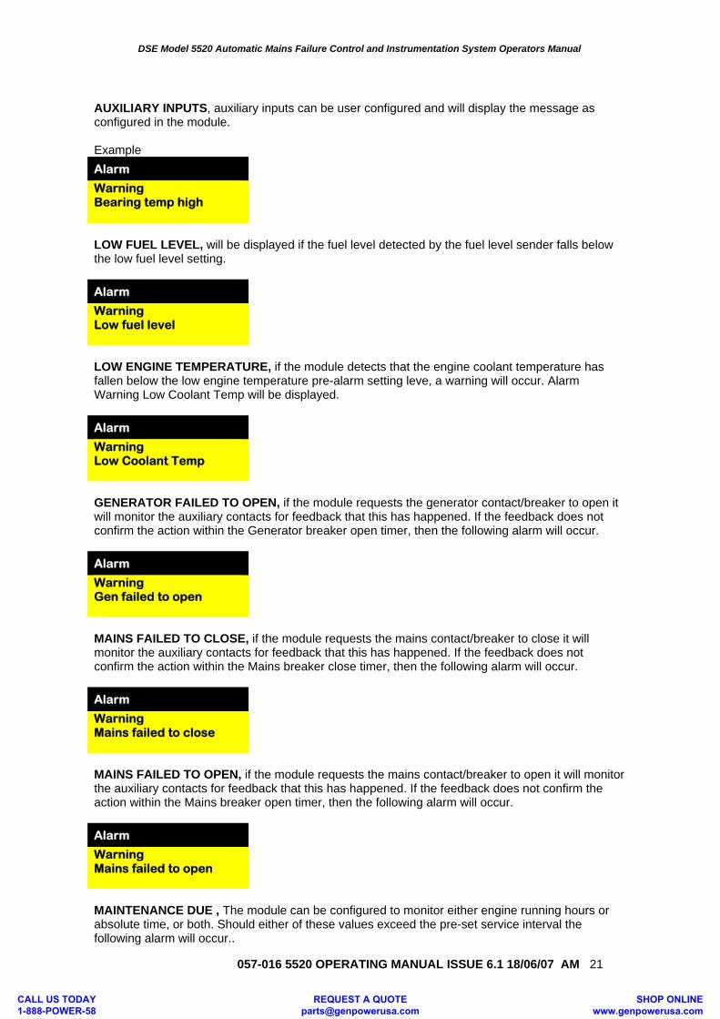
AUXILIARY INPUTS, auxiliary inputs can be user configured and will display the message as configured in the module. Example Alarm Warning Bearing temp high
LOW FUEL LEVEL, will be displayed if the fuel level detected by the fuel level sender falls below the low fuel level setting. Alarm Warning Low fuel level
LOW ENGINE TEMPERATURE, if the module detects that the engine coolant temperature has fallen below the low engine temperature pre-alarm setting leve, a warning will occur. Alarm Warning Low Coolant Temp will be displayed. Alarm Warning Low Coolant Temp
GENERATOR FAILED TO OPEN, if the module requests the generator contact/breaker to open it will monitor the auxiliary contacts for feedback that this has happened. If the feedback does not confirm the action within the Generator breaker open timer, then the following alarm will occur. Alarm Warning Gen failed to open
MAINS FAILED TO CLOSE, if the module requests the mains contact/breaker to close it will monitor the auxiliary contacts for feedback that this has happened. If the feedback does not confirm the action within the Mains breaker close timer, then the following alarm will occur. Alarm Warning Mains failed to close
MAINS FAILED TO OPEN, if the module requests the mains contact/breaker to open it will monitor the auxiliary contacts for feedback that this has happened. If the feedback does not confirm the action within the Mains breaker open timer, then the following alarm will occur. Alarm Warning Mains failed to open
MAINTENANCE DUE , The module can be configured to monitor either engine running hours or absolute time, or both. Should either of these values exceed the pre-set service interval the following alarm will occur..
CALL US TODAY 1-888-POWER-58
REQUEST A QUOTE [email protected]
SHOP ONLINE www.genpowerusa.com
DSE Model 5520 Automatic Mains Failure Control and Instrumentation System Operators Manual
057-016 5520 OPERATING MANUAL ISSUE 6.1 18/06/07 AM
22
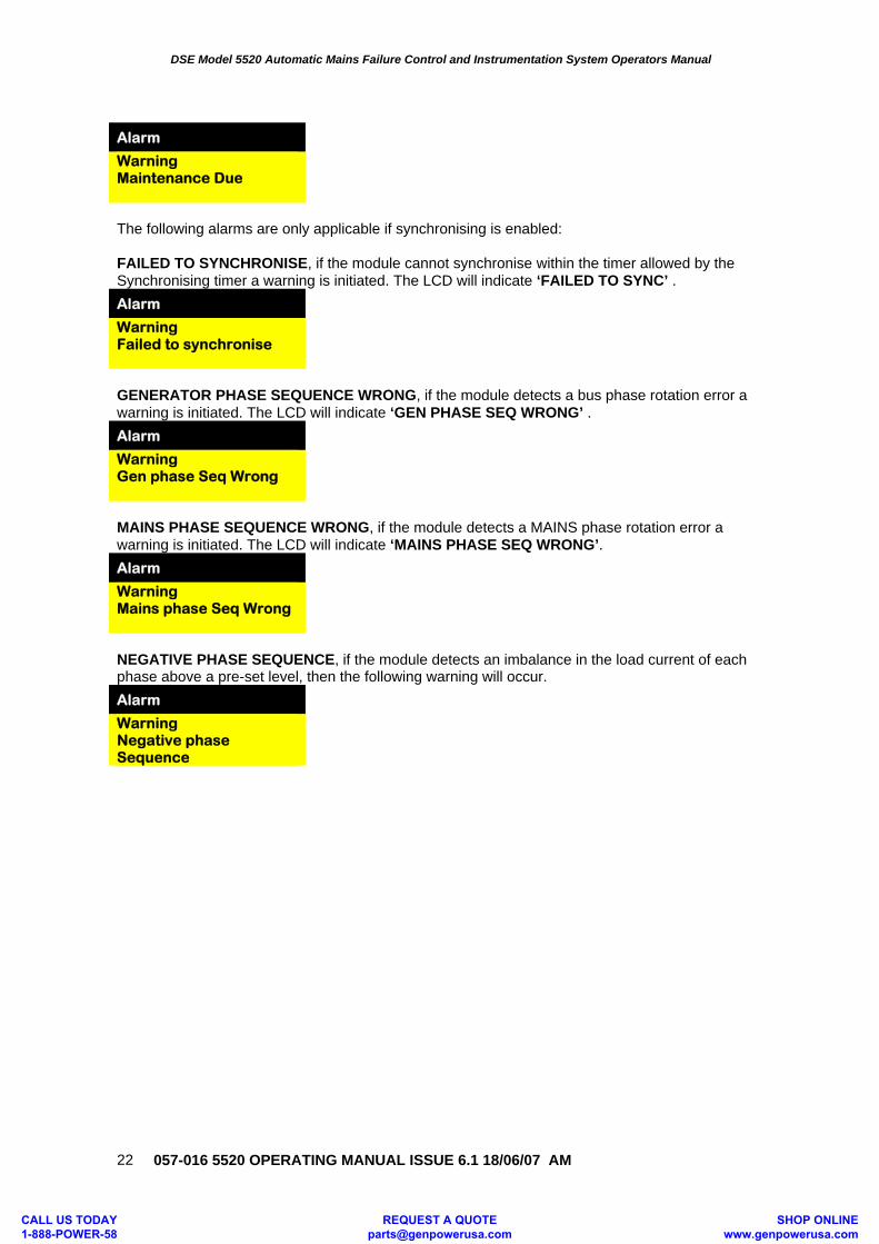
Alarm Warning Maintenance Due
The following alarms are only applicable if synchronising is enabled: FAILED TO SYNCHRONISE, if the module cannot synchronise within the timer allowed by the Synchronising timer a warning is initiated. The LCD will indicate ‘FAILED TO SYNC’ . Alarm Warning Failed to synchronise
GENERATOR PHASE SEQUENCE WRONG, if the module detects a bus phase rotation error a warning is initiated. The LCD will indicate ‘GEN PHASE SEQ WRONG’ . Alarm Warning Gen phase Seq Wrong
MAINS PHASE SEQUENCE WRONG, if the module detects a MAINS phase rotation error a warning is initiated. The LCD will indicate ‘MAINS PHASE SEQ WRONG’. Alarm Warning Mains phase Seq Wrong
NEGATIVE PHASE SEQUENCE, if the module detects an imbalance in the load current of each phase above a pre-set level, then the following warning will occur. Alarm Warning Negative phase Sequence
CALL US TODAY 1-888-POWER-58
REQUEST A QUOTE [email protected]
SHOP ONLINE www.genpowerusa.com
DSE Model 5520 Automatic Mains Failure Control and Instrumentation System Operators Manual
057-016 5520 OPERATING MANUAL ISSUE 6.1 18/06/07 AM 23
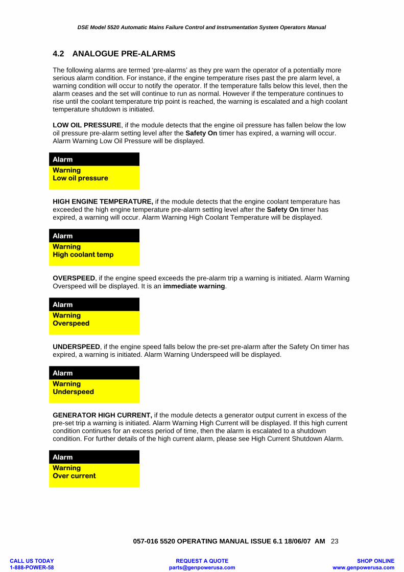
4.2 ANALOGUE PRE-ALARMS The following alarms are termed ‘pre-alarms’ as they pre warn the operator of a potentially more serious alarm condition. For instance, if the engine temperature rises past the pre alarm level, a warning condition will occur to notify the operator. If the temperature falls below this level, then the alarm ceases and the set will continue to run as normal. However if the temperature continues to rise until the coolant temperature trip point is reached, the warning is escalated and a high coolant temperature shutdown is initiated. LOW OIL PRESSURE, if the module detects that the engine oil pressure has fallen below the low oil pressure pre-alarm setting level after the Safety On timer has expired, a warning will occur. Alarm Warning Low Oil Pressure will be displayed. Alarm Warning Low oil pressure
HIGH ENGINE TEMPERATURE, if the module detects that the engine coolant temperature has exceeded the high engine temperature pre-alarm setting level after the Safety On timer has expired, a warning will occur. Alarm Warning High Coolant Temperature will be displayed. Alarm Warning High coolant temp
OVERSPEED, if the engine speed exceeds the pre-alarm trip a warning is initiated. Alarm Warning Overspeed will be displayed. It is an immediate warning. Alarm Warning Overspeed
UNDERSPEED, if the engine speed falls below the pre-set pre-alarm after the Safety On timer has expired, a warning is initiated. Alarm Warning Underspeed will be displayed. Alarm Warning Underspeed
GENERATOR HIGH CURRENT, if the module detects a generator output current in excess of the pre-set trip a warning is initiated. Alarm Warning High Current will be displayed. If this high current condition continues for an excess period of time, then the alarm is escalated to a shutdown condition. For further details of the high current alarm, please see High Current Shutdown Alarm. Alarm Warning Over current
CALL US TODAY 1-888-POWER-58
REQUEST A QUOTE [email protected]
SHOP ONLINE www.genpowerusa.com
DSE Model 5520 Automatic Mains Failure Control and Instrumentation System Operators Manual
057-016 5520 OPERATING MANUAL ISSUE 6.1 18/06/07 AM
24
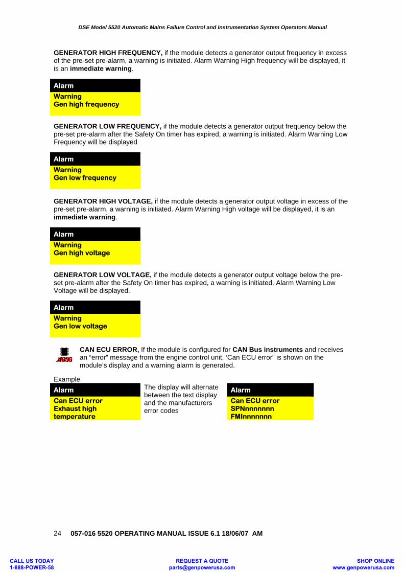
GENERATOR HIGH FREQUENCY, if the module detects a generator output frequency in excess of the pre-set pre-alarm, a warning is initiated. Alarm Warning High frequency will be displayed, it is an immediate warning.
Alarm Warning Gen high frequency
GENERATOR LOW FREQUENCY, if the module detects a generator output frequency below the pre-set pre-alarm after the Safety On timer has expired, a warning is initiated. Alarm Warning Low Frequency will be displayed
Alarm Warning Gen low frequency
GENERATOR HIGH VOLTAGE, if the module detects a generator output voltage in excess of the pre-set pre-alarm, a warning is initiated. Alarm Warning High voltage will be displayed, it is an immediate warning.
Alarm Warning Gen high voltage
GENERATOR LOW VOLTAGE, if the module detects a generator output voltage below the pre-set pre-alarm after the Safety On timer has expired, a warning is initiated. Alarm Warning Low Voltage will be displayed.
Alarm Warning Gen low voltage
CAN ECU ERROR, If the module is configured for CAN Bus instruments and receives an “error” message from the engine control unit, ‘Can ECU error” is shown on the module’s display and a warning alarm is generated.
Example Alarm The display will alternate
between the text display and the manufacturers error codes
Alarm Can ECU error Exhaust high temperature
Can ECU error SPNnnnnnnn FMInnnnnnn
CALL US TODAY 1-888-POWER-58
REQUEST A QUOTE [email protected]
SHOP ONLINE www.genpowerusa.com
DSE Model 5520 Automatic Mains Failure Control and Instrumentation System Operators Manual
057-016 5520 OPERATING MANUAL ISSUE 6.1 18/06/07 AM 25
INSUFFICIENT CAPACITY, if the module is configured to limit the import Kw on the mains supply, variations in the load levels will be matched by increasing the Kw on the generator. Should the load level increase to a sufficient demand that the generator is giving 100% of its rating. Further increases in demand will need to be met by increasing the Kw on the mains supply as the generator cannot supply any more. The system will issue the warning alarm to indicate that it can no longer regulate the Kw present on the mains until the total load level is reduced.
Alarm Warning Insufficient Capacity
LOSS OF EXCITATION, the module will monitor the KVAr present on the generator. Should this exceed a pre-set amount of negative VAr this indicates a possible loss of excitation on the alternator. The following alarm will then be generated.
Alarm Warning Loss of Excitation
CALL US TODAY 1-888-POWER-58
REQUEST A QUOTE [email protected]
SHOP ONLINE www.genpowerusa.com
DSE Model 5520 Automatic Mains Failure Control and Instrumentation System Operators Manual
057-016 5520 OPERATING MANUAL ISSUE 6.1 18/06/07 AM
26
4.3 SHUTDOWNS Shutdowns are latching and stop the Generator. The alarm must be cleared and the fault removed to reset the module.
NOTE:- The alarm condition must be rectified before a reset will take place. If the alarm condition remains it will not be possible to reset the unit (The exception to this is the Low Oil Pressure alarm and similar ‘delayed alarms’, as the oil pressure will be low with the engine at rest).
FAIL TO START, if the engine does not fire after the pre-set number of attempts has been made a shutdown will be initiated. Alarm Shutdown Fail To Start will be displayed. Alarm Shutdown Fail to start EMERGENCY STOP, removal of the positive DC Supply from the Emergency Stop input will initiate a shutdown of the Generator and prevent any attempt to restart the Generator until the Emergency Stop push-button has been reset. Additionally it removes the positive DC supply from both the Fuel Solenoid and Starter Solenoid. Alarm Shutdown Emergency Stop will be displayed. Alarm Shutdown Emergency stop
NOTE:- The Emergency Stop positive signal must be present otherwise the unit will shutdown.
LOW OIL PRESSURE, if the module detects that the engine oil pressure has fallen below the low oil pressure trip setting level after the Safety On timer has expired, a shutdown will occur. Alarm Shutdown Low Oil Pressure will be displayed. Alarm Shutdown Low oil pressure HIGH ENGINE TEMPERATURE, if the module detects that the engine coolant temperature has exceeded the high engine temperature trip setting level after the Safety On timer has expired, a shutdown will occur. Alarm Shutdown High Engine Temperature will be displayed. Alarm Shutdown High coolant temp
CALL US TODAY 1-888-POWER-58
REQUEST A QUOTE [email protected]
SHOP ONLINE www.genpowerusa.com
DSE Model 5520 Automatic Mains Failure Control and Instrumentation System Operators Manual
057-016 5520 OPERATING MANUAL ISSUE 6.1 18/06/07 AM 27
OVERSPEED, if the engine speed exceeds the pre-set trip a shutdown is initiated. Alarm Shutdown Overspeed will be displayed. Overspeed is not delayed, it is an immediate shutdown. Alarm Shutdown Overspeed
NOTE:-During the start-up sequence the overspeed trip logic can be configured to allow an extra trip level margin. This is used to prevent nuisance tripping on start-up - Refer to the 55xx series configuration software manual under heading ‘Overspeed Overshoot’ for details. UNDERSPEED, if the engine speed falls below the pre-set trip after the Safety On timer has expired, a shutdown is initiated. Alarm Shutdown Underspeed will be displayed. Alarm Shutdown Underspeed GENERATOR HIGH FREQUENCY, if the module detects a generator output frequency in excess of the pre-set trip a shutdown is initiated. Alarm Shutdown High Frequency will be displayed, it is an immediate shutdown. Alarm Shutdown Gen high frequency GENERATOR LOW FREQUENCY, if the module detects a generator output frequency below the pre-set trip after the Safety On timer has expired, a shutdown is initiated. Alarm Shutdown Low Frequency will be displayed. Alarm Shutdown Gen low frequency GENERATOR HIGH VOLTAGE, if the module detects a generator output voltage in excess of the pre-set trip a shutdown is initiated. Alarm Shutdown High Volts will be displayed, it is an immediate shutdown. Alarm Shutdown Gen high voltage GENERATOR LOW VOLTAGE, if the module detects a generator output voltage below the pre-set trip after the Safety On timer has expired, a shutdown is initiated. Alarm Shutdown Low Volts will be displayed. Alarm Shutdown Gen low voltage
NOTE:-Generator voltage and frequency alarms can be delayed by the ‘Gen Transient ignore’ timer. This is to prevent nuisance tripping when applying or removing load on the generator.
CALL US TODAY 1-888-POWER-58
REQUEST A QUOTE [email protected]
SHOP ONLINE www.genpowerusa.com
DSE Model 5520 Automatic Mains Failure Control and Instrumentation System Operators Manual
057-016 5520 OPERATING MANUAL ISSUE 6.1 18/06/07 AM
28
OIL PRESSURE SENDER OPEN CIRCUIT, if the module detects a loss of signal from the oil pressure sender (open circuit) a shutdown is initiated. Alarm Shutdown Sender Fault will be displayed. Sender failure is not delayed, it is an immediate shutdown. Alarm Shutdown Oil press sender fault
MAGNETIC PICKUP OPEN CIRCUIT, if the module detects a problem with the connection to the magnetic pickup (open circuit) a shutdown is initiated. MPU failure is not delayed, it is an immediate shutdown. Alarm Shutdown MPU open circuit
AUXILIARY INPUTS, if an auxiliary input has been configured as a shutdown the appropriate message will be displayed as configured by the user. Alarm Shutdown Bearing temp high LOSS OF SPEED SIGNAL, if the speed sensing signal is lost during cranking, a shutdown is initiated. Alarm Shutdown Loss of Speed Signal will be displayed. Alarm Shutdown Loss of speed signal
NOTE:- This will only occur if the magnetic pickup speed sensing signal is lost during cranking or during the safety on timer. If the signal is lost during normal operation the Generator will shutdown with an Under-speed alarm.
CAN DATA FAIL, If the module is configured for CANbus operation and does not detect data on the engine CANbus datalink, a shutdown will occur and ‘Can data fail’ is shown on the module’s display.
Alarm Shutdown Can data fail
CALL US TODAY 1-888-POWER-58
REQUEST A QUOTE [email protected]
SHOP ONLINE www.genpowerusa.com
DSE Model 5520 Automatic Mains Failure Control and Instrumentation System Operators Manual
057-016 5520 OPERATING MANUAL ISSUE 6.1 18/06/07 AM 29
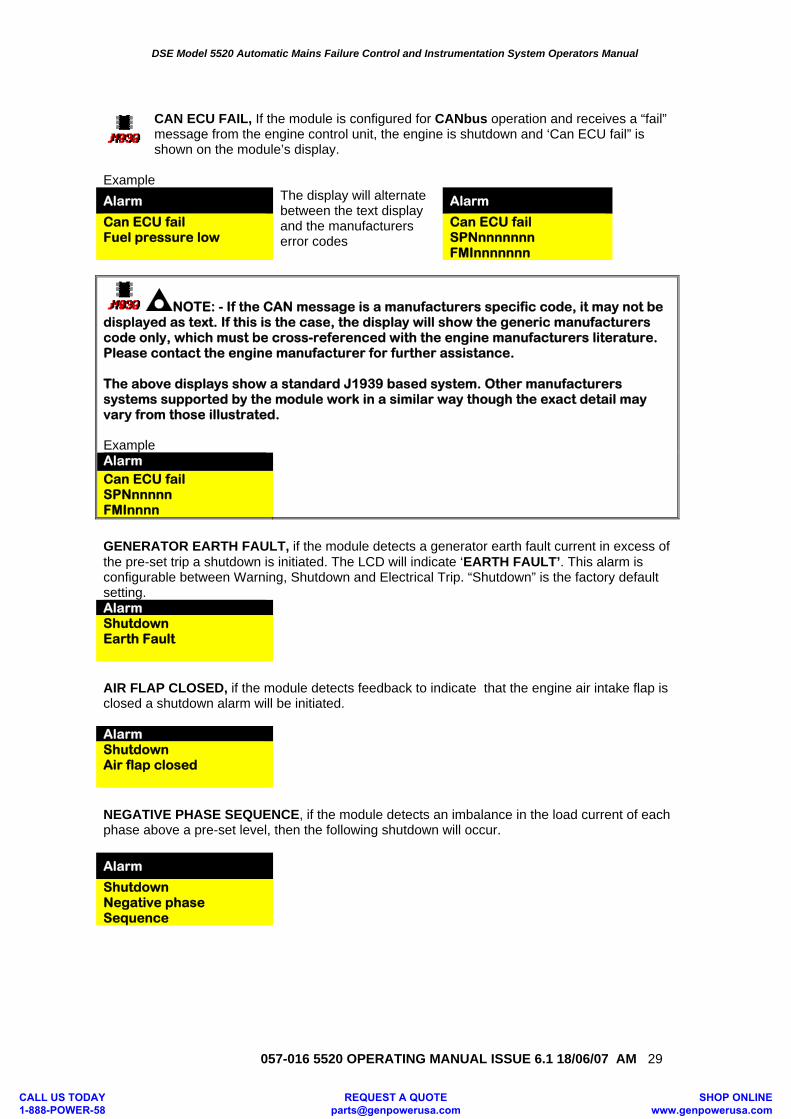
CAN ECU FAIL, If the module is configured for CANbus operation and receives a “fail” message from the engine control unit, the engine is shutdown and ‘Can ECU fail” is shown on the module’s display.
Example Alarm The display will alternate
between the text display and the manufacturers error codes
Alarm Can ECU fail Fuel pressure low
Can ECU fail SPNnnnnnnn FMInnnnnnn
NOTE: - If the CAN message is a manufacturers specific code, it may not be displayed as text. If this is the case, the display will show the generic manufacturers code only, which must be cross-referenced with the engine manufacturers literature. Please contact the engine manufacturer for further assistance. The above displays show a standard J1939 based system. Other manufacturers systems supported by the module work in a similar way though the exact detail may vary from those illustrated. Example Alarm Can ECU fail SPNnnnnn FMInnnn
GENERATOR EARTH FAULT, if the module detects a generator earth fault current in excess of the pre-set trip a shutdown is initiated. The LCD will indicate ‘EARTH FAULT’. This alarm is configurable between Warning, Shutdown and Electrical Trip. “Shutdown” is the factory default setting. Alarm Shutdown Earth Fault AIR FLAP CLOSED, if the module detects feedback to indicate that the engine air intake flap is closed a shutdown alarm will be initiated. Alarm Shutdown Air flap closed NEGATIVE PHASE SEQUENCE, if the module detects an imbalance in the load current of each phase above a pre-set level, then the following shutdown will occur. Alarm Shutdown Negative phase Sequence
CALL US TODAY 1-888-POWER-58
REQUEST A QUOTE [email protected]
SHOP ONLINE www.genpowerusa.com
DSE Model 5520 Automatic Mains Failure Control and Instrumentation System Operators Manual
057-016 5520 OPERATING MANUAL ISSUE 6.1 18/06/07 AM
30
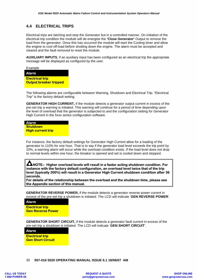
4.4 ELECTRICAL TRIPS Electrical trips are latching and stop the Generator but in a controlled manner. On initiation of the electrical trip condition the module will de-energise the ‘Close Generator’ Output to remove the load from the generator. Once this has occurred the module will start the Cooling timer and allow the engine to cool off-load before shutting down the engine. The alarm must be accepted and cleared and the fault removed to reset the module. AUXILIARY INPUTS, if an auxiliary input has been configured as an electrical trip the appropriate message will be displayed as configured by the user. Example Alarm Electrical trip Output breaker tripped
The following alarms are configurable between Warning, Shutdown and Electrical Trip. “Electrical Trip” is the factory default setting. GENERATOR HIGH CURRENT, if the module detects a generator output current in excess of the pre-set trip a warning is initiated. This warning will continue for a period of time depending upon the level of overload that the generator is subjected to and the configuration setting for Generator High Current in the 5xxx series configuration software. Alarm Shutdown High current trip For instance, the factory default settings for Generator High Current allow for a loading of the generator to 110% for one hour. That is to say if the generator load level exceeds the trip point by 10%, a warning alarm will occur while the overload condition exists. If the load level does not drop to normal levels within one hour, the breaker is opened and set is cooled down and stopped.
NOTE:- Higher overload levels will result in a faster acting shutdown condition. For instance with the factory default configuration, an overload level twice that of the trip level (typically 200%) will result in a Generator High Current shutdown condition after 36 seconds. For details of the relationship between the overload and the shutdown time, please see the Appendix section of this manual.
GENERATOR REVERSE POWER, if the module detects a generator reverse power current in excess of the pre-set trip a shutdown is initiated. The LCD will indicate ‘GEN REVERSE POWER’. Alarm Electrical trip Gen Reverse Power
GENERATOR SHORT CIRCUIT, if the module detects a generator fault current in excess of the pre-set trip a shutdown is initiated. The LCD will indicate ‘GEN SHORT CIRCUIT’. Alarm Electrical trip Gen Short Circuit
CALL US TODAY 1-888-POWER-58
REQUEST A QUOTE [email protected]
SHOP ONLINE www.genpowerusa.com
DSE Model 5520 Automatic Mains Failure Control and Instrumentation System Operators Manual
057-016 5520 OPERATING MANUAL ISSUE 6.1 18/06/07 AM 31
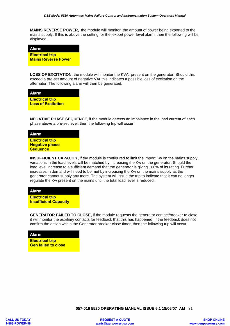
MAINS REVERSE POWER, the module will monitor the amount of power being exported to the mains supply. If this is above the setting for the ‘export power level alarm’ then the following will be displayed.
Alarm Electrical trip Mains Reverse Power
LOSS OF EXCITATION, the module will monitor the KVAr present on the generator. Should this exceed a pre-set amount of negative VAr this indicates a possible loss of excitation on the alternator. The following alarm will then be generated.
Alarm Electrical trip Loss of Excitation
NEGATIVE PHASE SEQUENCE, if the module detects an imbalance in the load current of each phase above a pre-set level, then the following trip will occur. Alarm Electrical trip Negative phase Sequence INSUFFICIENT CAPACITY, if the module is configured to limit the import Kw on the mains supply, variations in the load levels will be matched by increasing the Kw on the generator. Should the load level increase to a sufficient demand that the generator is giving 100% of its rating. Further increases in demand will need to be met by increasing the Kw on the mains supply as the generator cannot supply any more. The system will issue the trip to indicate that it can no longer regulate the Kw present on the mains until the total load level is reduced. Alarm Electrical trip Insufficient Capacity
GENERATOR FAILED TO CLOSE, if the module requests the generator contact/breaker to close it will monitor the auxiliary contacts for feedback that this has happened. If the feedback does not confirm the action within the Generator breaker close timer, then the following trip will occur. Alarm Electrical trip Gen failed to close
CALL US TODAY 1-888-POWER-58
REQUEST A QUOTE [email protected]
SHOP ONLINE www.genpowerusa.com
DSE Model 5520 Automatic Mains Failure Control and Instrumentation System Operators Manual
057-016 5520 OPERATING MANUAL ISSUE 6.1 18/06/07 AM
32
4.5 ROCOF / VECTOR SHIFT
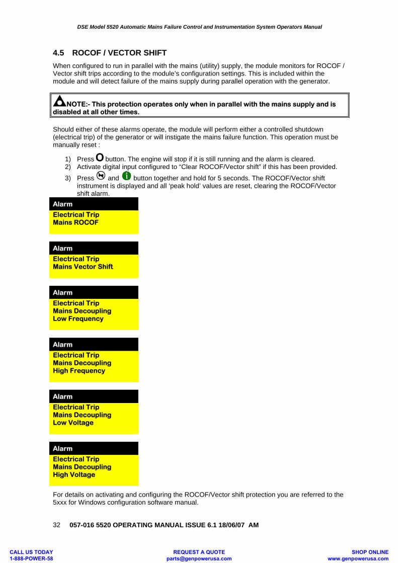
When configured to run in parallel with the mains (utility) supply, the module monitors for ROCOF / Vector shift trips according to the module’s configuration settings. This is included within the module and will detect failure of the mains supply during parallel operation with the generator.
NOTE:- This protection operates only when in parallel with the mains supply and is disabled at all other times.
Should either of these alarms operate, the module will perform either a controlled shutdown (electrical trip) of the generator or will instigate the mains failure function. This operation must be manually reset :
1) Press button. The engine will stop if it is still running and the alarm is cleared. 2) Activate digital input configured to “Clear ROCOF/Vector shift” if this has been provided.
3) Press and button together and hold for 5 seconds. The ROCOF/Vector shift instrument is displayed and all ‘peak hold’ values are reset, clearing the ROCOF/Vector shift alarm.
Alarm Electrical Trip Mains ROCOF Alarm Electrical Trip Mains Vector Shift Alarm Electrical Trip Mains Decoupling Low Frequency Alarm Electrical Trip Mains Decoupling High Frequency Alarm Electrical Trip Mains Decoupling Low Voltage Alarm Electrical Trip Mains Decoupling High Voltage
For details on activating and configuring the ROCOF/Vector shift protection you are referred to the 5xxx for Windows configuration software manual.
CALL US TODAY 1-888-POWER-58
REQUEST A QUOTE [email protected]
SHOP ONLINE www.genpowerusa.com
DSE Model 5520 Automatic Mains Failure Control and Instrumentation System Operators Manual
057-016 5520 OPERATING MANUAL ISSUE 6.1 18/06/07 AM 33
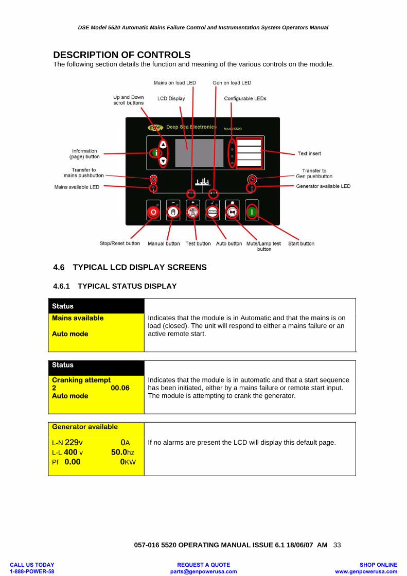
DESCRIPTION OF CONTROLS The following section details the function and meaning of the various controls on the module.
4.6 TYPICAL LCD DISPLAY SCREENS 4.6.1 TYPICAL STATUS DISPLAY
Status
Mains available Auto mode
Indicates that the module is in Automatic and that the mains is on load (closed). The unit will respond to either a mains failure or an active remote start.
Status
Cranking attempt 2 00.06 Auto mode
Indicates that the module is in automatic and that a start sequence has been initiated, either by a mains failure or remote start input. The module is attempting to crank the generator.
Generator available
If no alarms are present the LCD will display this default page.
L-N 229v 0A L-L 400 v 50.0hz Pf 0.00 0KW
CALL US TODAY 1-888-POWER-58
REQUEST A QUOTE [email protected]
SHOP ONLINE www.genpowerusa.com
DSE Model 5520 Automatic Mains Failure Control and Instrumentation System Operators Manual
057-016 5520 OPERATING MANUAL ISSUE 6.1 18/06/07 AM
34
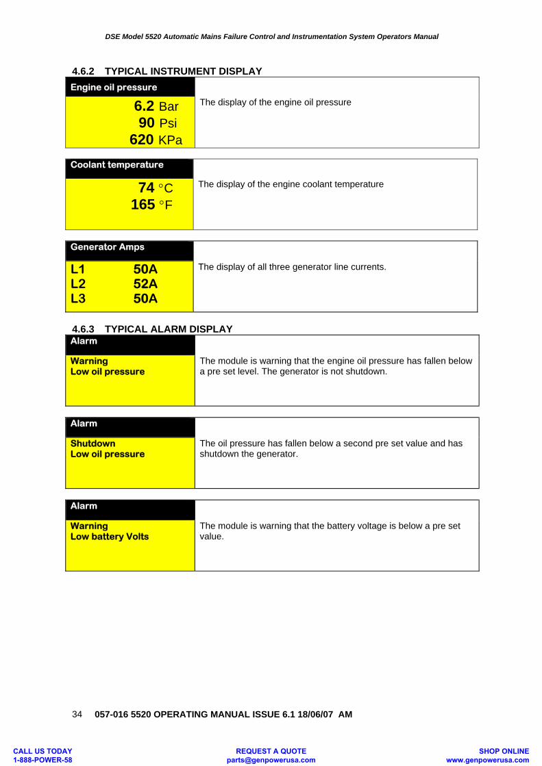
4.6.2 TYPICAL INSTRUMENT DISPLAY Engine oil pressure
6.2 Bar 90 Psi 620 KPa
The display of the engine oil pressure
Coolant temperature
74 °C 165 °F
The display of the engine coolant temperature
Generator Amps
L1 50A L2 52A L3 50A
The display of all three generator line currents.
4.6.3 TYPICAL ALARM DISPLAY Alarm
Warning Low oil pressure
The module is warning that the engine oil pressure has fallen below a pre set level. The generator is not shutdown.
Alarm
Shutdown Low oil pressure
The oil pressure has fallen below a second pre set value and has shutdown the generator.
Alarm
Warning Low battery Volts
The module is warning that the battery voltage is below a pre set value.
CALL US TODAY 1-888-POWER-58
REQUEST A QUOTE [email protected]
SHOP ONLINE www.genpowerusa.com
DSE Model 5520 Automatic Mains Failure Control and Instrumentation System Operators Manual
057-016 5520 OPERATING MANUAL ISSUE 6.1 18/06/07 AM 35
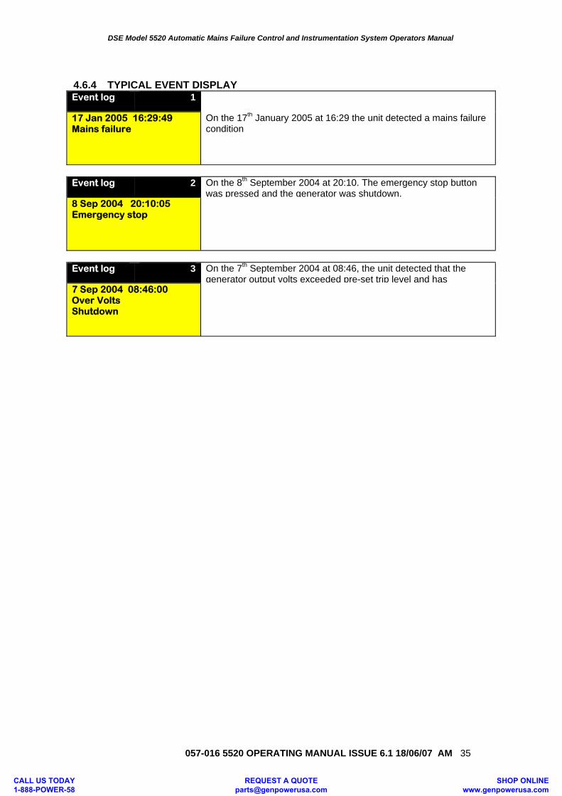
4.6.4 TYPICAL EVENT DISPLAY Event log 1
17 Jan 2005 16:29:49 Mains failure
On the 17th January 2005 at 16:29 the unit detected a mains failure condition
Event log 2 On the 8th September 2004 at 20:10. The emergency stop button
was pressed and the generator was shutdown. 8 Sep 2004 20:10:05 Emergency stop
Event log 3 On the 7th September 2004 at 08:46, the unit detected that the
generator output volts exceeded pre-set trip level and has 7 Sep 2004 08:46:00 Over Volts Shutdown
CALL US TODAY 1-888-POWER-58
REQUEST A QUOTE [email protected]
SHOP ONLINE www.genpowerusa.com
DSE Model 5520 Automatic Mains Failure Control and Instrumentation System Operators Manual
057-016 5520 OPERATING MANUAL ISSUE 6.1 18/06/07 AM
36
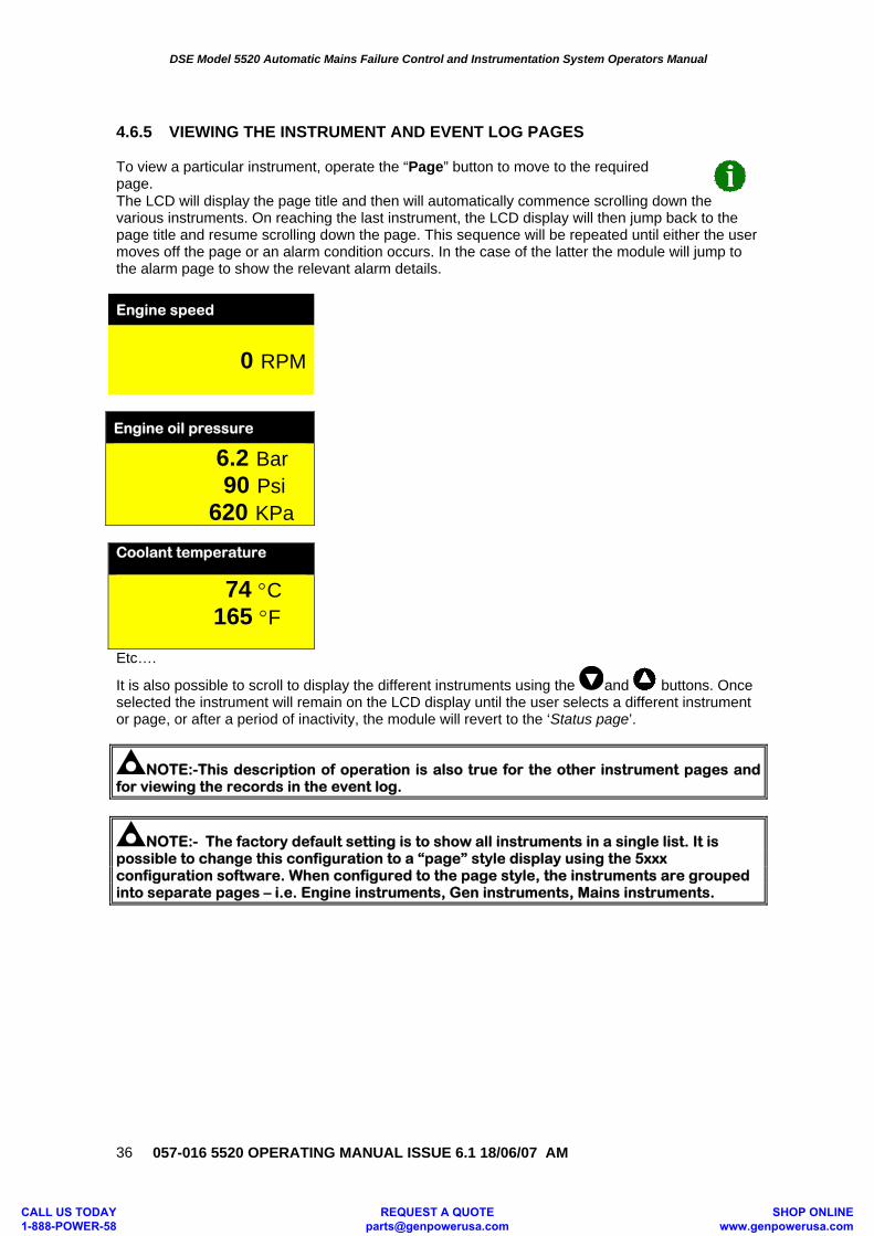
4.6.5 VIEWING THE INSTRUMENT AND EVENT LOG PAGES To view a particular instrument, operate the “Page” button to move to the required page. The LCD will display the page title and then will automatically commence scrolling down the various instruments. On reaching the last instrument, the LCD display will then jump back to the page title and resume scrolling down the page. This sequence will be repeated until either the user moves off the page or an alarm condition occurs. In the case of the latter the module will jump to the alarm page to show the relevant alarm details. Engine speed
0 RPM
Engine oil pressure
6.2 Bar 90 Psi 620 KPa Coolant temperature
74 °C 165 °F
Etc….
It is also possible to scroll to display the different instruments using the and buttons. Once selected the instrument will remain on the LCD display until the user selects a different instrument or page, or after a period of inactivity, the module will revert to the ‘Status page’.
NOTE:-This description of operation is also true for the other instrument pages and for viewing the records in the event log.
NOTE:- The factory default setting is to show all instruments in a single list. It is possible to change this configuration to a “page” style display using the 5xxx configuration software. When configured to the page style, the instruments are grouped into separate pages – i.e. Engine instruments, Gen instruments, Mains instruments.
CALL US TODAY 1-888-POWER-58
REQUEST A QUOTE [email protected]
SHOP ONLINE www.genpowerusa.com
DSE Model 5520 Automatic Mains Failure Control and Instrumentation System Operators Manual
057-016 5520 OPERATING MANUAL ISSUE 6.1 18/06/07 AM 37
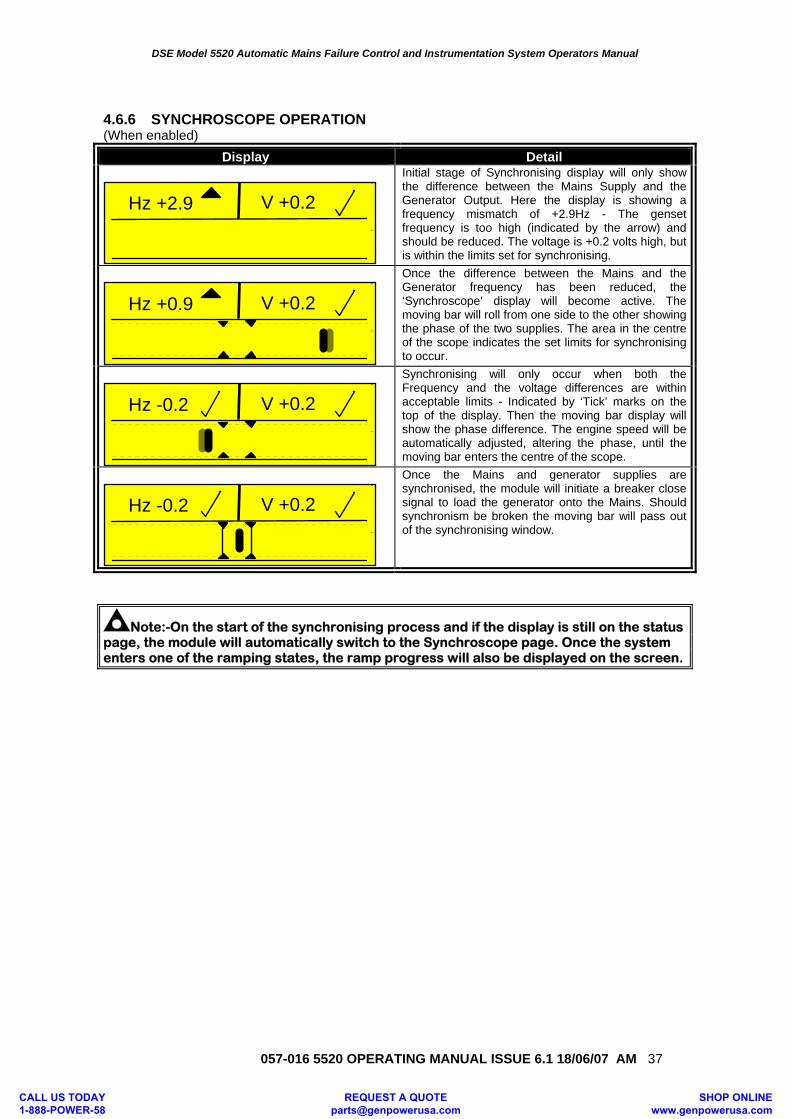
4.6.6 SYNCHROSCOPE OPERATION (When enabled)
Display Detail
Hz +2.9 V +0.2
Initial stage of Synchronising display will only show the difference between the Mains Supply and the Generator Output. Here the display is showing a frequency mismatch of +2.9Hz - The genset frequency is too high (indicated by the arrow) and should be reduced. The voltage is +0.2 volts high, but is within the limits set for synchronising.
Hz +0.9 V +0.2
Once the difference between the Mains and the Generator frequency has been reduced, the ‘Synchroscope’ display will become active. The moving bar will roll from one side to the other showing the phase of the two supplies. The area in the centre of the scope indicates the set limits for synchronising to occur.
Hz -0.2 V +0.2
Synchronising will only occur when both the Frequency and the voltage differences are within acceptable limits - Indicated by ‘Tick’ marks on the top of the display. Then the moving bar display will show the phase difference. The engine speed will be automatically adjusted, altering the phase, until the moving bar enters the centre of the scope.
Hz -0.2 V +0.2
Once the Mains and generator supplies are synchronised, the module will initiate a breaker close signal to load the generator onto the Mains. Should synchronism be broken the moving bar will pass out of the synchronising window.
Note:-On the start of the synchronising process and if the display is still on the status page, the module will automatically switch to the Synchroscope page. Once the system enters one of the ramping states, the ramp progress will also be displayed on the screen.
CALL US TODAY 1-888-POWER-58
REQUEST A QUOTE [email protected]
SHOP ONLINE www.genpowerusa.com
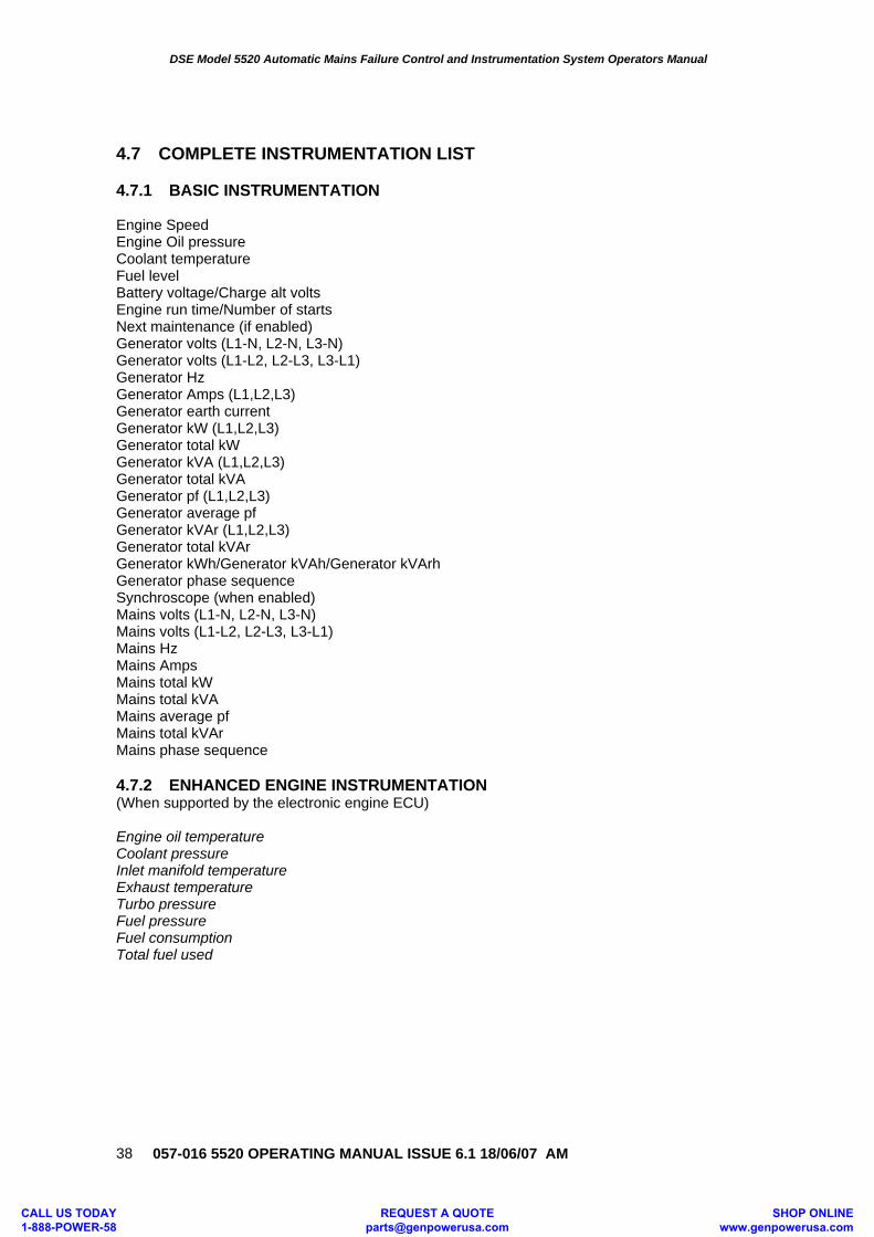
DSE Model 5520 Automatic Mains Failure Control and Instrumentation System Operators Manual
057-016 5520 OPERATING MANUAL ISSUE 6.1 18/06/07 AM
38
4.7 COMPLETE INSTRUMENTATION LIST 4.7.1 BASIC INSTRUMENTATION Engine Speed Engine Oil pressure Coolant temperature Fuel level Battery voltage/Charge alt volts Engine run time/Number of starts Next maintenance (if enabled) Generator volts (L1-N, L2-N, L3-N) Generator volts (L1-L2, L2-L3, L3-L1) Generator Hz Generator Amps (L1,L2,L3) Generator earth current Generator kW (L1,L2,L3) Generator total kW Generator kVA (L1,L2,L3) Generator total kVA Generator pf (L1,L2,L3) Generator average pf Generator kVAr (L1,L2,L3) Generator total kVAr Generator kWh/Generator kVAh/Generator kVArh Generator phase sequence Synchroscope (when enabled) Mains volts (L1-N, L2-N, L3-N) Mains volts (L1-L2, L2-L3, L3-L1) Mains Hz Mains Amps Mains total kW Mains total kVA Mains average pf Mains total kVAr Mains phase sequence 4.7.2 ENHANCED ENGINE INSTRUMENTATION (When supported by the electronic engine ECU) Engine oil temperature Coolant pressure Inlet manifold temperature Exhaust temperature Turbo pressure Fuel pressure Fuel consumption Total fuel used
CALL US TODAY 1-888-POWER-58
REQUEST A QUOTE [email protected]
SHOP ONLINE www.genpowerusa.com
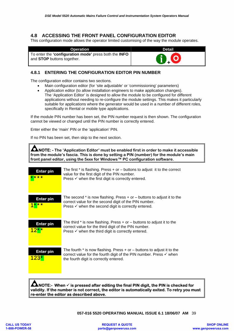
DSE Model 5520 Automatic Mains Failure Control and Instrumentation System Operators Manual
057-016 5520 OPERATING MANUAL ISSUE 6.1 18/06/07 AM 39
4.8 ACCESSING THE FRONT PANEL CONFIGURATION EDITOR This configuration mode allows the operator limited customising of the way the module operates.
Operation Detail To enter the ‘configuration mode’ press both the INFO and STOP buttons together. + 4.8.1 ENTERING THE CONFIGURATION EDITOR PIN NUMBER The configuration editor contains two sections.
• Main configuration editor (for ‘site adjustable’ or ‘commissioning’ parameters) • Application editor (to allow installation engineers to make application changes).
The ‘Application Editor’ is designed to allow the module to be configured for different applications without needing to re-configure the module settings. This makes it particularly suitable for applications where the generator would be used in a number of different roles, specifically in Rental or mobile type applications.
If the module PIN number has been set, the PIN number request is then shown. The configuration cannot be viewed or changed until the PIN number is correctly entered. Enter either the ‘main’ PIN or the ‘application’ PIN. If no PIN has been set, then skip to the next section.
NOTE: - The ‘Application Editor’ must be enabled first in order to make it accessible from the module’s fascia. This is done by setting a PIN (number) for the module’s main front panel editor, using the 5xxx for Windows™ PC configuration software.
Enter pin The first * is flashing. Press + or – buttons to adjust it to the correct
value for the first digit of the PIN number. Press when the first digit is correctly entered. ****
Enter pin The second * is now flashing. Press + or – buttons to adjust it to the correct value for the second digit of the PIN number. Press when the second digit is correctly entered. 1***
Enter pin The third * is now flashing. Press + or – buttons to adjust it to the
correct value for the third digit of the PIN number. Press when the third digit is correctly entered. 12**
Enter pin The fourth * is now flashing. Press + or – buttons to adjust it to the correct value for the fourth digit of the PIN number. Press when the fourth digit is correctly entered. 123*
NOTE:- When is pressed after editing the final PIN digit, the PIN is checked for validity. If the number is not correct, the editor is automatically exited. To retry you must re-enter the editor as described above.
CALL US TODAY 1-888-POWER-58
REQUEST A QUOTE [email protected]
SHOP ONLINE www.genpowerusa.com
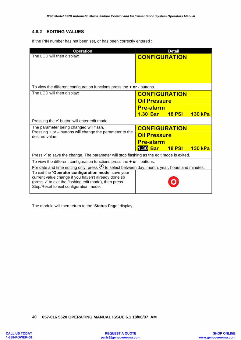
DSE Model 5520 Automatic Mains Failure Control and Instrumentation System Operators Manual
057-016 5520 OPERATING MANUAL ISSUE 6.1 18/06/07 AM
40
4.8.2 EDITING VALUES If the PIN number has not been set, or has been correctly entered :
Operation Detail The LCD will then display: CONFIGURATION
To view the different configuration functions press the + or - buttons. The LCD will then display: CONFIGURATION
Oil Pressure Pre-alarm 1.30 Bar 18 PSI 130 kPa
Pressing the button will enter edit mode : The parameter being changed will flash. Pressing + or – buttons will change the parameter to the desired value.
CONFIGURATION Oil Pressure Pre-alarm 1.30 Bar 18 PSI 130 kPa
Press to save the change. The parameter will stop flashing as the edit mode is exited. To view the different configuration functions press the + or - buttons. For date and time editing only: press to select between day, month, year, hours and minutes. To exit the ‘Operator configuration mode’ save your current value change if you haven’t already done so (press to exit the flashing edit mode), then press Stop/Reset to exit configuration mode.
The module will then return to the ‘Status Page’ display.
CALL US TODAY 1-888-POWER-58
REQUEST A QUOTE [email protected]
SHOP ONLINE www.genpowerusa.com
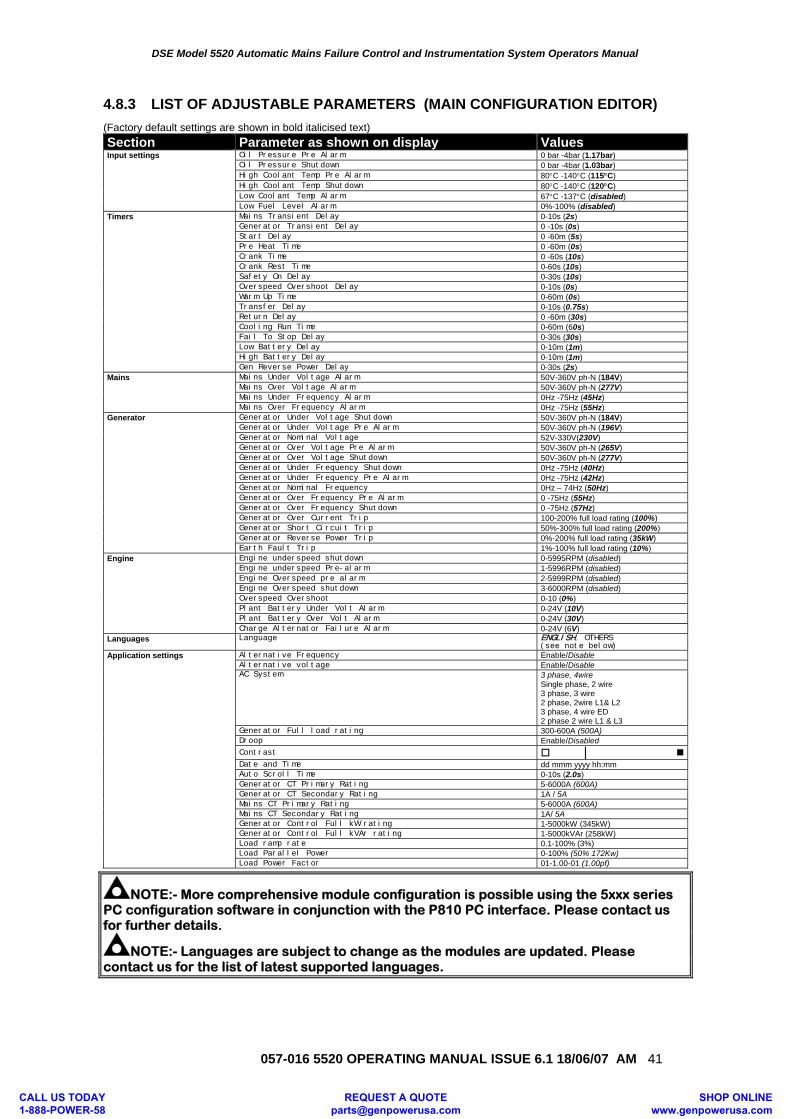
DSE Model 5520 Automatic Mains Failure Control and Instrumentation System Operators Manual
057-016 5520 OPERATING MANUAL ISSUE 6.1 18/06/07 AM 41
4.8.3 LIST OF ADJUSTABLE PARAMETERS (MAIN CONFIGURATION EDITOR) (Factory default settings are shown in bold italicised text) Section Parameter as shown on display Values Input settings Oil Pressure Pre Alarm 0 bar -4bar (1.17bar) Oil Pressure Shutdown 0 bar -4bar (1.03bar) High Coolant Temp Pre Alarm 80°C -140°C (115°C) High Coolant Temp Shutdown 80°C -140°C (120°C) Low Coolant Temp Alarm 67°C -137°C (disabled) Low Fuel Level Alarm 0%-100% (disabled) Timers Mains Transient Delay 0-10s (2s) Generator Transient Delay 0 -10s (0s) Start Delay 0 -60m (5s) Pre Heat Time 0 -60m (0s) Crank Time 0 -60s (10s) Crank Rest Time 0-60s (10s) Safety On Delay 0-30s (10s)
Overspeed Overshoot Delay 0-10s (0s) Warm Up Time 0-60m (0s) Transfer Delay 0-10s (0.75s)
Return Delay 0 -60m (30s) Cooling Run Time 0-60m (60s) Fail To Stop Delay 0-30s (30s)
Low Battery Delay 0-10m (1m) High Battery Delay 0-10m (1m) Gen Reverse Power Delay 0-30s (2s) Mains Mains Under Voltage Alarm 50V-360V ph-N (184V) Mains Over Voltage Alarm 50V-360V ph-N (277V) Mains Under Frequency Alarm 0Hz -75Hz (45Hz) Mains Over Frequency Alarm 0Hz -75Hz (55Hz) Generator Generator Under Voltage Shutdown 50V-360V ph-N (184V) Generator Under Voltage Pre Alarm 50V-360V ph-N (196V) Generator Nominal Voltage 52V-330V(230V) Generator Over Voltage Pre Alarm 50V-360V ph-N (265V) Generator Over Voltage Shutdown 50V-360V ph-N (277V) Generator Under Frequency Shutdown 0Hz -75Hz (40Hz) Generator Under Frequency Pre Alarm 0Hz -75Hz (42Hz) Generator Nominal Frequency 0Hz – 74Hz (50Hz) Generator Over Frequency Pre Alarm 0 -75Hz (55Hz) Generator Over Frequency Shutdown 0 -75Hz (57Hz) Generator Over Current Trip 100-200% full load rating (100%) Generator Short Circuit Trip 50%-300% full load rating (200%) Generator Reverse Power Trip 0%-200% full load rating (35kW) Earth Fault Trip 1%-100% full load rating (10%) Engine Engine underspeed shutdown 0-5995RPM (disabled) Engine underspeed Pre-alarm 1-5996RPM (disabled) Engine Overspeed pre alarm 2-5999RPM (disabled) Engine Overspeed shutdown 3-6000RPM (disabled) Overspeed Overshoot 0-10 (0%) Plant Battery Under Volt Alarm 0-24V (10V) Plant Battery Over Volt Alarm 0-24V (30V) Charge Alternator Failure Alarm 0-24V (6V) Languages Language ENGLISH, OTHERS
(see note below) Application settings Alternative Frequency Enable/Disable
Alternative voltage Enable/Disable AC System 3 phase, 4wire
Single phase, 2 wire 3 phase, 3 wire 2 phase, 2wire L1& L2 3 phase, 4 wire ED 2 phase 2 wire L1 & L3
Generator Full load rating 300-600A (500A) Droop Enable/Disabled Contrast | Date and Time dd mmm yyyy hh:mm Auto Scroll Time 0-10s (2.0s) Generator CT Primary Rating 5-6000A (600A) Generator CT Secondary Rating 1A / 5A Mains CT Primary Rating 5-6000A (600A) Mains CT Secondary Rating 1A/ 5A Generator Control Full kW rating 1-5000kW (345kW) Generator Control Full kVAr rating 1-5000kVAr (258kW) Load ramp rate 0.1-100% (3%) Load Parallel Power 0-100% (50% 172Kw) Load Power Factor 01-1.00-01 (1.00pf)
NOTE:- More comprehensive module configuration is possible using the 5xxx series PC configuration software in conjunction with the P810 PC interface. Please contact us for further details.
NOTE:- Languages are subject to change as the modules are updated. Please contact us for the list of latest supported languages.
CALL US TODAY 1-888-POWER-58
REQUEST A QUOTE [email protected]
SHOP ONLINE www.genpowerusa.com
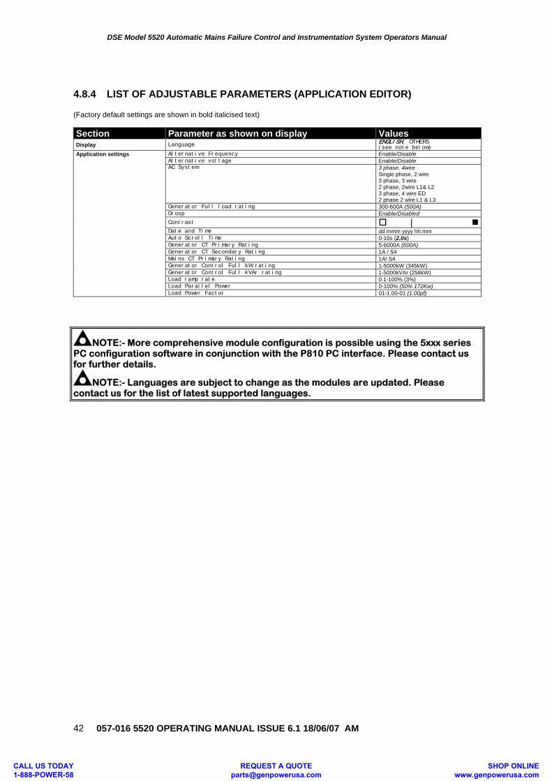
DSE Model 5520 Automatic Mains Failure Control and Instrumentation System Operators Manual
057-016 5520 OPERATING MANUAL ISSUE 6.1 18/06/07 AM
42
4.8.4 LIST OF ADJUSTABLE PARAMETERS (APPLICATION EDITOR) (Factory default settings are shown in bold italicised text) Section Parameter as shown on display Values Display Language ENGLISH, OTHERS
(see note below) Application settings Alternative Frequency Enable/Disable
Alternative voltage Enable/Disable AC System 3 phase, 4wire
Single phase, 2 wire 3 phase, 3 wire 2 phase, 2wire L1& L2 3 phase, 4 wire ED 2 phase 2 wire L1 & L3
Generator Full load rating 300-600A (500A) Droop Enable/Disabled Contrast |
Date and Time dd mmm yyyy hh:mm Auto Scroll Time 0-10s (2.0s) Generator CT Primary Rating 5-6000A (600A) Generator CT Secondary Rating 1A / 5A Mains CT Primary Rating 1A/ 5A Generator Control Full kW rating 1-5000kW (345kW) Generator Control Full kVAr rating 1-5000kVAr (258kW) Load ramp rate 0.1-100% (3%) Load Parallel Power 0-100% (50% 172Kw) Load Power Factor 01-1.00-01 (1.00pf)
NOTE:- More comprehensive module configuration is possible using the 5xxx series PC configuration software in conjunction with the P810 PC interface. Please contact us for further details.
NOTE:- Languages are subject to change as the modules are updated. Please contact us for the list of latest supported languages.
CALL US TODAY 1-888-POWER-58
REQUEST A QUOTE [email protected]
SHOP ONLINE www.genpowerusa.com
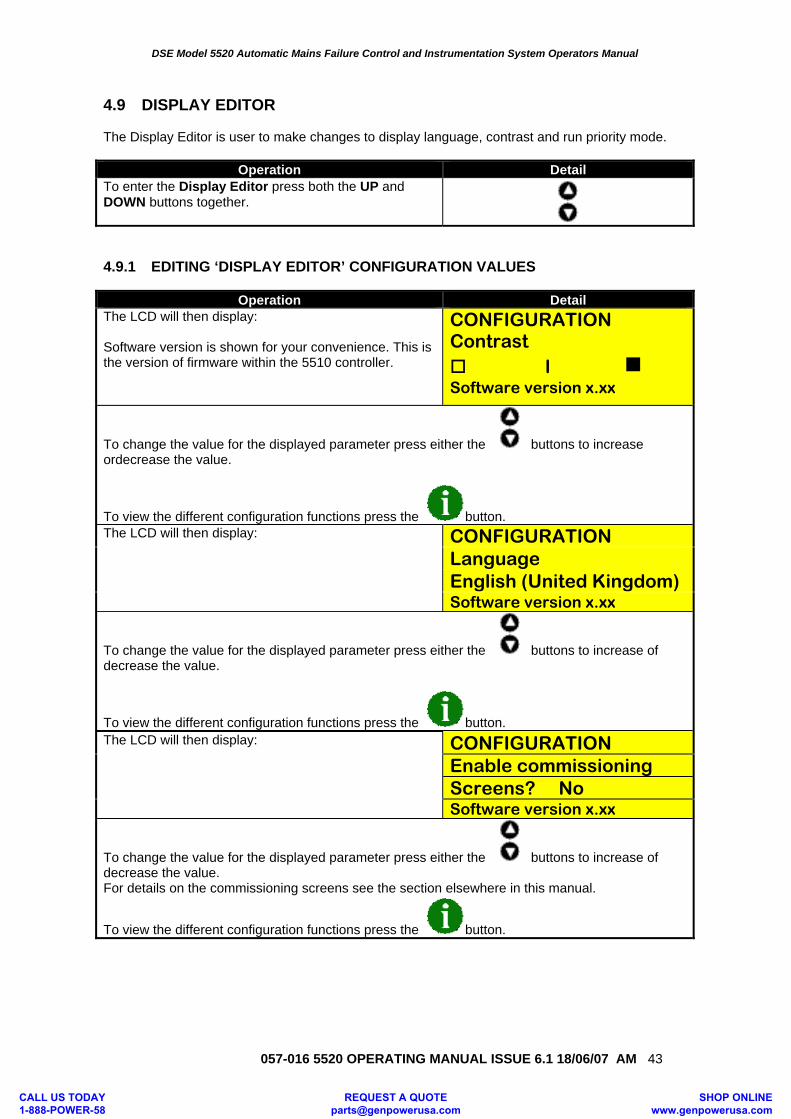
DSE Model 5520 Automatic Mains Failure Control and Instrumentation System Operators Manual
057-016 5520 OPERATING MANUAL ISSUE 6.1 18/06/07 AM 43
4.9 DISPLAY EDITOR The Display Editor is user to make changes to display language, contrast and run priority mode.
Operation Detail To enter the Display Editor press both the UP and DOWN buttons together. 4.9.1 EDITING ‘DISPLAY EDITOR’ CONFIGURATION VALUES
Operation Detail The LCD will then display: Software version is shown for your convenience. This is the version of firmware within the 5510 controller.
CONFIGURATION Contrast
l Software version x.xx
To change the value for the displayed parameter press either the buttons to increase ordecrease the value.
To view the different configuration functions press the button. The LCD will then display: CONFIGURATION
Language English (United Kingdom) Software version x.xx
To change the value for the displayed parameter press either the buttons to increase of decrease the value.
To view the different configuration functions press the button. The LCD will then display:
CONFIGURATION Enable commissioning Screens? No Software version x.xx
To change the value for the displayed parameter press either the buttons to increase of decrease the value. For details on the commissioning screens see the section elsewhere in this manual.
To view the different configuration functions press the button.
CALL US TODAY 1-888-POWER-58
REQUEST A QUOTE [email protected]
SHOP ONLINE www.genpowerusa.com
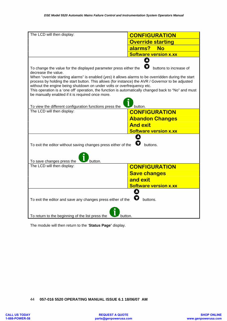
DSE Model 5520 Automatic Mains Failure Control and Instrumentation System Operators Manual
057-016 5520 OPERATING MANUAL ISSUE 6.1 18/06/07 AM
44
The LCD will then display:
CONFIGURATION Override starting alarms? No Software version x.xx
To change the value for the displayed parameter press either the buttons to increase of decrease the value. When “override starting alarms” is enabled (yes) it allows alarms to be overridden during the start process by holding the start button. This allows (for instance) the AVR / Governor to be adjusted without the engine being shutdown on under volts or overfrequency etc. This operation is a ‘one off’ operation, the function is automatically changed back to “No” and must be manually enabled if it is required once more.
To view the different configuration functions press the button. The LCD will then display:
CONFIGURATION Abandon Changes And exit Software version x.xx
To exit the editor without saving changes press either of the buttons.
To save changes press the button. The LCD will then display:
CONFIGURATION Save changes and exit Software version x.xx
To exit the editor and save any changes press either of the buttons.
To return to the beginning of the list press the button. The module will then return to the ‘Status Page’ display.
CALL US TODAY 1-888-POWER-58
REQUEST A QUOTE [email protected]
SHOP ONLINE www.genpowerusa.com
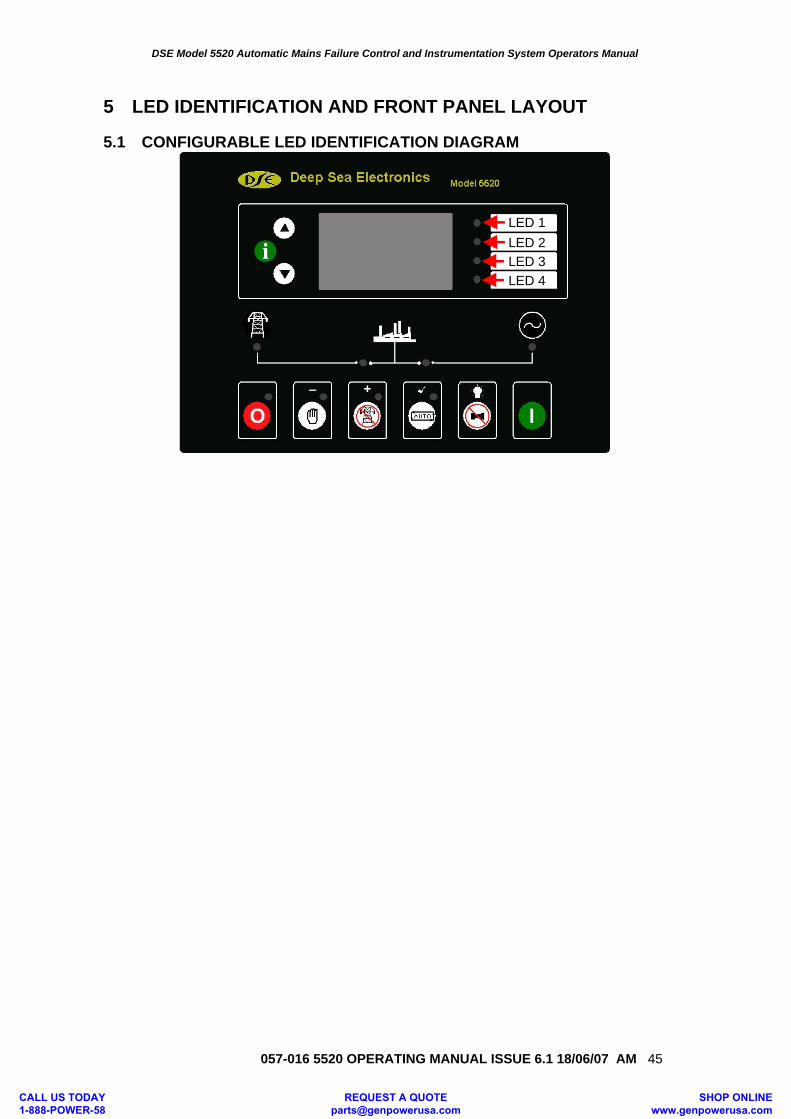
DSE Model 5520 Automatic Mains Failure Control and Instrumentation System Operators Manual
057-016 5520 OPERATING MANUAL ISSUE 6.1 18/06/07 AM 45
5 LED IDENTIFICATION AND FRONT PANEL LAYOUT 5.1 CONFIGURABLE LED IDENTIFICATION DIAGRAM
LED 1LED 2LED 3LED 4
CALL US TODAY 1-888-POWER-58
REQUEST A QUOTE [email protected]
SHOP ONLINE www.genpowerusa.com
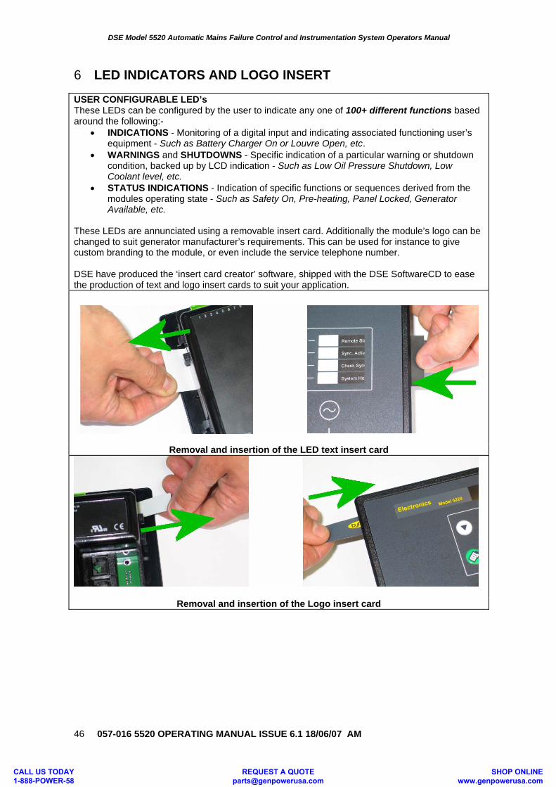
DSE Model 5520 Automatic Mains Failure Control and Instrumentation System Operators Manual
057-016 5520 OPERATING MANUAL ISSUE 6.1 18/06/07 AM
46
6 LED INDICATORS AND LOGO INSERT USER CONFIGURABLE LED’s These LEDs can be configured by the user to indicate any one of 100+ different functions based around the following:-
• INDICATIONS - Monitoring of a digital input and indicating associated functioning user’s equipment - Such as Battery Charger On or Louvre Open, etc.
• WARNINGS and SHUTDOWNS - Specific indication of a particular warning or shutdown condition, backed up by LCD indication - Such as Low Oil Pressure Shutdown, Low Coolant level, etc.
• STATUS INDICATIONS - Indication of specific functions or sequences derived from the modules operating state - Such as Safety On, Pre-heating, Panel Locked, Generator Available, etc.
These LEDs are annunciated using a removable insert card. Additionally the module’s logo can be changed to suit generator manufacturer’s requirements. This can be used for instance to give custom branding to the module, or even include the service telephone number. DSE have produced the ‘insert card creator’ software, shipped with the DSE SoftwareCD to ease the production of text and logo insert cards to suit your application.
Removal and insertion of the LED text insert card
Removal and insertion of the Logo insert card
CALL US TODAY 1-888-POWER-58
REQUEST A QUOTE [email protected]
SHOP ONLINE www.genpowerusa.com
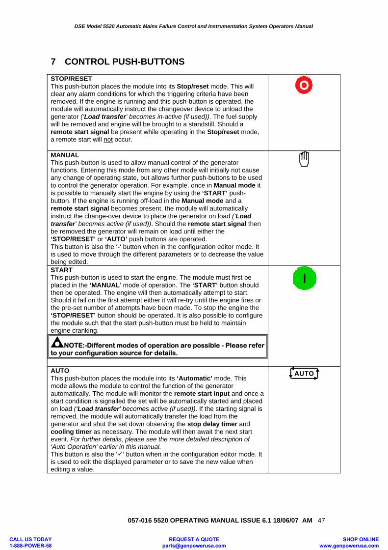
DSE Model 5520 Automatic Mains Failure Control and Instrumentation System Operators Manual
057-016 5520 OPERATING MANUAL ISSUE 6.1 18/06/07 AM 47
7 CONTROL PUSH-BUTTONS STOP/RESET This push-button places the module into its Stop/reset mode. This will clear any alarm conditions for which the triggering criteria have been removed. If the engine is running and this push-button is operated, the module will automatically instruct the changeover device to unload the generator (‘Load transfer’ becomes in-active (if used)). The fuel supply will be removed and engine will be brought to a standstill. Should a remote start signal be present while operating in the Stop/reset mode, a remote start will not occur.
MANUAL This push-button is used to allow manual control of the generator functions. Entering this mode from any other mode will initially not cause any change of operating state, but allows further push-buttons to be used to control the generator operation. For example, once in Manual mode it is possible to manually start the engine by using the ‘START’ push-button. If the engine is running off-load in the Manual mode and a remote start signal becomes present, the module will automatically instruct the change-over device to place the generator on load (‘Load transfer’ becomes active (if used)). Should the remote start signal then be removed the generator will remain on load until either the ‘STOP/RESET’ or ‘AUTO’ push buttons are operated. This button is also the ‘-‘ button when in the configuration editor mode. It is used to move through the different parameters or to decrease the value being edited.
START This push-button is used to start the engine. The module must first be placed in the ‘MANUAL’ mode of operation. The ‘START’ button should then be operated. The engine will then automatically attempt to start. Should it fail on the first attempt either it will re-try until the engine fires or the pre-set number of attempts have been made. To stop the engine the ‘STOP/RESET’ button should be operated. It is also possible to configure the module such that the start push-button must be held to maintain engine cranking.
NOTE:-Different modes of operation are possible - Please refer to your configuration source for details.
AUTO This push-button places the module into its ‘Automatic’ mode. This mode allows the module to control the function of the generator automatically. The module will monitor the remote start input and once a start condition is signalled the set will be automatically started and placed on load (‘Load transfer’ becomes active (if used)). If the starting signal is removed, the module will automatically transfer the load from the generator and shut the set down observing the stop delay timer and cooling timer as necessary. The module will then await the next start event. For further details, please see the more detailed description of ‘Auto Operation’ earlier in this manual. This button is also the ‘ ‘ button when in the configuration editor mode. It is used to edit the displayed parameter or to save the new value when editing a value.
CALL US TODAY 1-888-POWER-58
REQUEST A QUOTE [email protected]
SHOP ONLINE www.genpowerusa.com
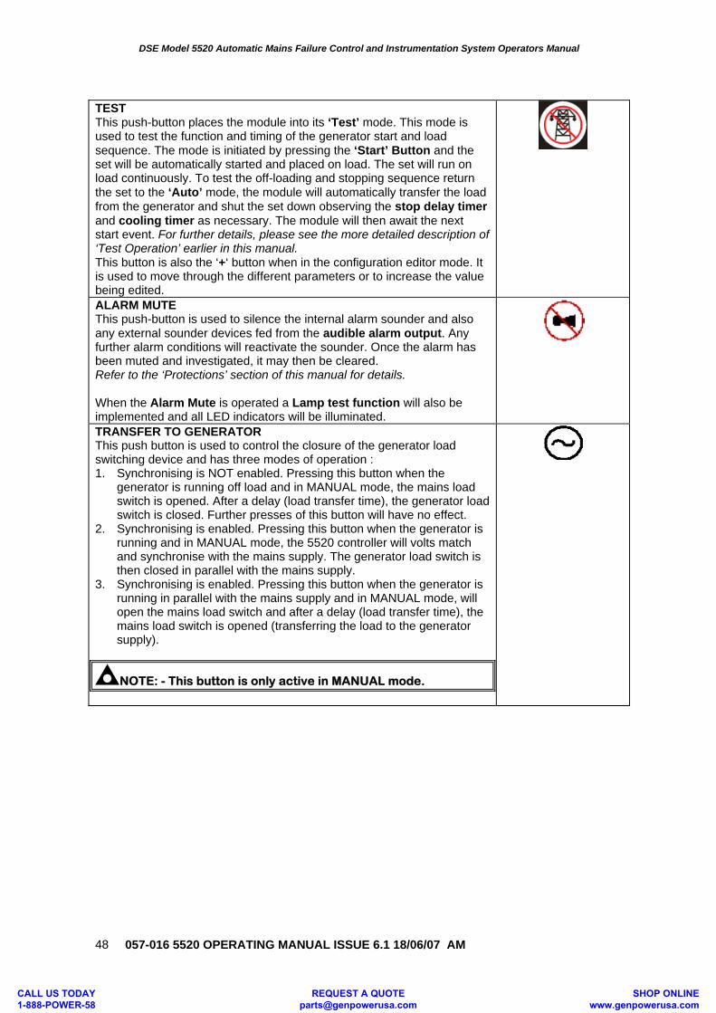
DSE Model 5520 Automatic Mains Failure Control and Instrumentation System Operators Manual
057-016 5520 OPERATING MANUAL ISSUE 6.1 18/06/07 AM
48
TEST This push-button places the module into its ‘Test’ mode. This mode is used to test the function and timing of the generator start and load sequence. The mode is initiated by pressing the ‘Start’ Button and the set will be automatically started and placed on load. The set will run on load continuously. To test the off-loading and stopping sequence return the set to the ‘Auto’ mode, the module will automatically transfer the load from the generator and shut the set down observing the stop delay timer and cooling timer as necessary. The module will then await the next start event. For further details, please see the more detailed description of ‘Test Operation’ earlier in this manual. This button is also the ‘+‘ button when in the configuration editor mode. It is used to move through the different parameters or to increase the value being edited.
ALARM MUTE This push-button is used to silence the internal alarm sounder and also any external sounder devices fed from the audible alarm output. Any further alarm conditions will reactivate the sounder. Once the alarm has been muted and investigated, it may then be cleared. Refer to the ‘Protections’ section of this manual for details. When the Alarm Mute is operated a Lamp test function will also be implemented and all LED indicators will be illuminated.
TRANSFER TO GENERATOR This push button is used to control the closure of the generator load switching device and has three modes of operation : 1. Synchronising is NOT enabled. Pressing this button when the
generator is running off load and in MANUAL mode, the mains load switch is opened. After a delay (load transfer time), the generator load switch is closed. Further presses of this button will have no effect.
2. Synchronising is enabled. Pressing this button when the generator is running and in MANUAL mode, the 5520 controller will volts match and synchronise with the mains supply. The generator load switch is then closed in parallel with the mains supply.
3. Synchronising is enabled. Pressing this button when the generator is running in parallel with the mains supply and in MANUAL mode, will open the mains load switch and after a delay (load transfer time), the mains load switch is opened (transferring the load to the generator supply).
NOTE: - This button is only active in MANUAL mode.
CALL US TODAY 1-888-POWER-58
REQUEST A QUOTE [email protected]
SHOP ONLINE www.genpowerusa.com
DSE Model 5520 Automatic Mains Failure Control and Instrumentation System Operators Manual
057-016 5520 OPERATING MANUAL ISSUE 6.1 18/06/07 AM 49
TRANSFER TO MAINS This push button is used to control the closure of the mains load switching device and has three modes of operation : 1. Synchronising is NOT enabled. Pressing this button when the
generator is running on load and in MANUAL mode, the generator load switch is opened. After a delay (load transfer time), the mains load switch is closed. Further presses of this button will have no effect.
2. Synchronising is enabled. Pressing this button when the generator is running on load and in MANUAL mode, the 5520 controller will volts match and synchronise with the mains supply. The generator load switch is then closed in parallel with the mains supply.
3. Synchronising is enabled. Pressing this button when the generator is in MANUAL mode and running in parallel with the mains supply will open the generator load switch, transferring the load back to the mains supply only.
NOTE: - This button is only active in MANUAL mode.
CALL US TODAY 1-888-POWER-58
REQUEST A QUOTE [email protected]
SHOP ONLINE www.genpowerusa.com
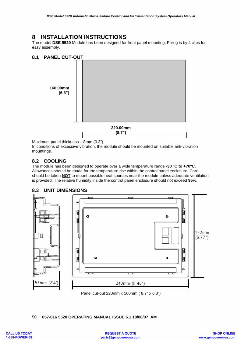
DSE Model 5520 Automatic Mains Failure Control and Instrumentation System Operators Manual
057-016 5520 OPERATING MANUAL ISSUE 6.1 18/06/07 AM
50
8 INSTALLATION INSTRUCTIONS The model DSE 5520 Module has been designed for front panel mounting. Fixing is by 4 clips for easy assembly. 8.1 PANEL CUT-OUT
220.00mm (8.7”)
Maximum panel thickness – 8mm (0.3”) In conditions of excessive vibration, the module should be mounted on suitable anti-vibration mountings. 8.2 COOLING The module has been designed to operate over a wide temperature range -30 ºC to +70ºC. Allowances should be made for the temperature rise within the control panel enclosure. Care should be taken NOT to mount possible heat sources near the module unless adequate ventilation is provided. The relative humidity inside the control panel enclosure should not exceed 95%. 8.3 UNIT DIMENSIONS
Panel cut-out 220mm x 160mm ( 8.7” x 6.3”)
160.00mm (6.3”)
CALL US TODAY 1-888-POWER-58
REQUEST A QUOTE [email protected]
SHOP ONLINE www.genpowerusa.com
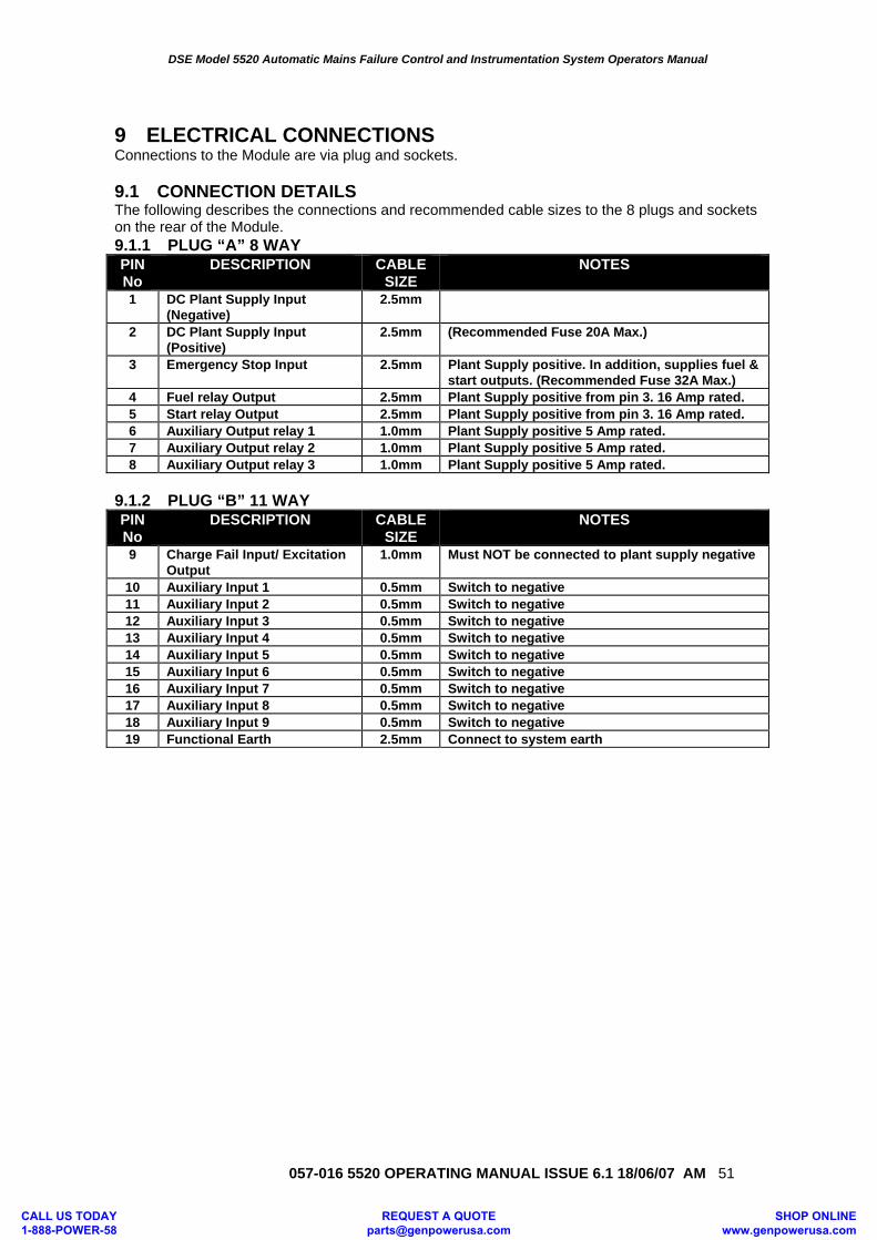
DSE Model 5520 Automatic Mains Failure Control and Instrumentation System Operators Manual
057-016 5520 OPERATING MANUAL ISSUE 6.1 18/06/07 AM 51
9 ELECTRICAL CONNECTIONS Connections to the Module are via plug and sockets. 9.1 CONNECTION DETAILS The following describes the connections and recommended cable sizes to the 8 plugs and sockets on the rear of the Module. 9.1.1 PLUG “A” 8 WAY PIN No
DESCRIPTION CABLE SIZE
NOTES
1 DC Plant Supply Input (Negative)
2.5mm
2 DC Plant Supply Input (Positive)
2.5mm (Recommended Fuse 20A Max.)
3 Emergency Stop Input 2.5mm Plant Supply positive. In addition, supplies fuel & start outputs. (Recommended Fuse 32A Max.)
4 Fuel relay Output 2.5mm Plant Supply positive from pin 3. 16 Amp rated. 5 Start relay Output 2.5mm Plant Supply positive from pin 3. 16 Amp rated. 6 Auxiliary Output relay 1 1.0mm Plant Supply positive 5 Amp rated. 7 Auxiliary Output relay 2 1.0mm Plant Supply positive 5 Amp rated. 8 Auxiliary Output relay 3 1.0mm Plant Supply positive 5 Amp rated.
9.1.2 PLUG “B” 11 WAY PIN No
DESCRIPTION CABLE SIZE
NOTES
9 Charge Fail Input/ Excitation Output
1.0mm Must NOT be connected to plant supply negative
10 Auxiliary Input 1 0.5mm Switch to negative 11 Auxiliary Input 2 0.5mm Switch to negative 12 Auxiliary Input 3 0.5mm Switch to negative 13 Auxiliary Input 4 0.5mm Switch to negative 14 Auxiliary Input 5 0.5mm Switch to negative 15 Auxiliary Input 6 0.5mm Switch to negative 16 Auxiliary Input 7 0.5mm Switch to negative 17 Auxiliary Input 8 0.5mm Switch to negative 18 Auxiliary Input 9 0.5mm Switch to negative 19 Functional Earth 2.5mm Connect to system earth
CALL US TODAY 1-888-POWER-58
REQUEST A QUOTE [email protected]
SHOP ONLINE www.genpowerusa.com
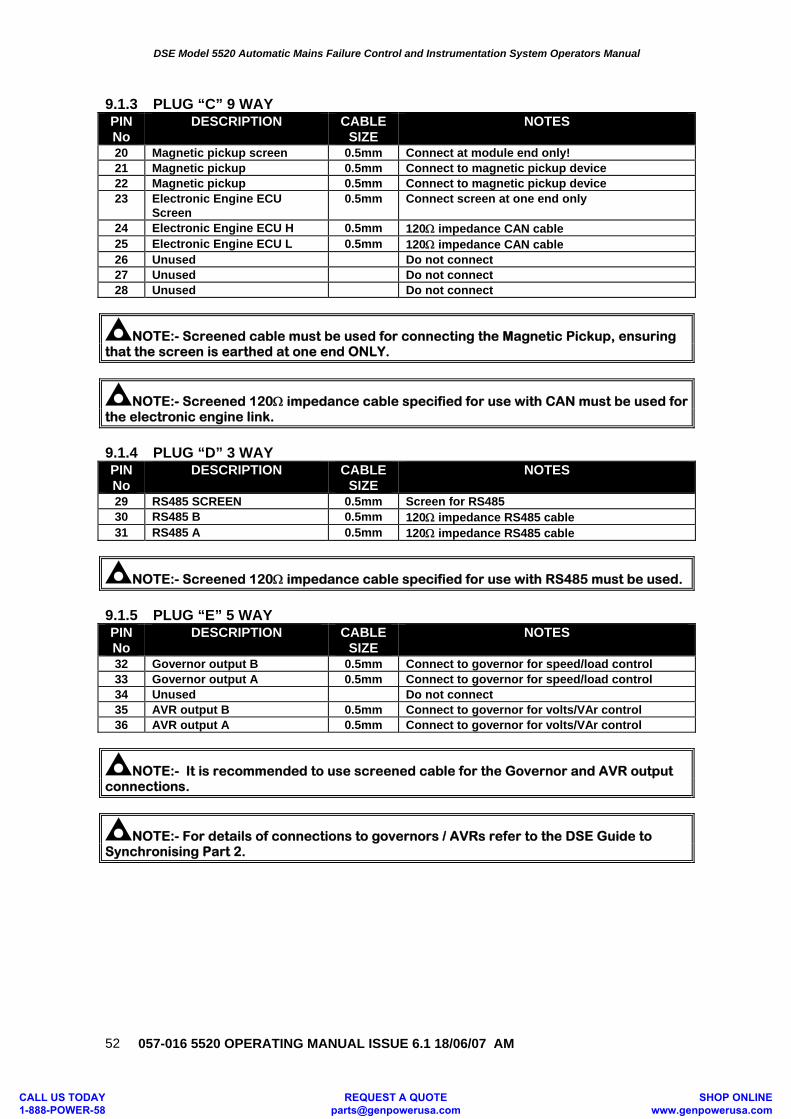
DSE Model 5520 Automatic Mains Failure Control and Instrumentation System Operators Manual
057-016 5520 OPERATING MANUAL ISSUE 6.1 18/06/07 AM
52
9.1.3 PLUG “C” 9 WAY PIN No
DESCRIPTION CABLE SIZE
NOTES
20 Magnetic pickup screen 0.5mm Connect at module end only! 21 Magnetic pickup 0.5mm Connect to magnetic pickup device 22 Magnetic pickup 0.5mm Connect to magnetic pickup device 23 Electronic Engine ECU
Screen 0.5mm Connect screen at one end only
24 Electronic Engine ECU H 0.5mm 120Ω impedance CAN cable 25 Electronic Engine ECU L 0.5mm 120Ω impedance CAN cable 26 Unused Do not connect 27 Unused Do not connect 28 Unused Do not connect
NOTE:- Screened cable must be used for connecting the Magnetic Pickup, ensuring that the screen is earthed at one end ONLY.
NOTE:- Screened 120Ω impedance cable specified for use with CAN must be used for the electronic engine link.
9.1.4 PLUG “D” 3 WAY PIN No
DESCRIPTION CABLE SIZE
NOTES
29 RS485 SCREEN 0.5mm Screen for RS485 30 RS485 B 0.5mm 120Ω impedance RS485 cable 31 RS485 A 0.5mm 120Ω impedance RS485 cable
NOTE:- Screened 120Ω impedance cable specified for use with RS485 must be used.
9.1.5 PLUG “E” 5 WAY PIN No
DESCRIPTION CABLE SIZE
NOTES
32 Governor output B 0.5mm Connect to governor for speed/load control 33 Governor output A 0.5mm Connect to governor for speed/load control 34 Unused Do not connect 35 AVR output B 0.5mm Connect to governor for volts/VAr control 36 AVR output A 0.5mm Connect to governor for volts/VAr control
NOTE:- It is recommended to use screened cable for the Governor and AVR output connections.
NOTE:- For details of connections to governors / AVRs refer to the DSE Guide to Synchronising Part 2.
CALL US TODAY 1-888-POWER-58
REQUEST A QUOTE [email protected]
SHOP ONLINE www.genpowerusa.com
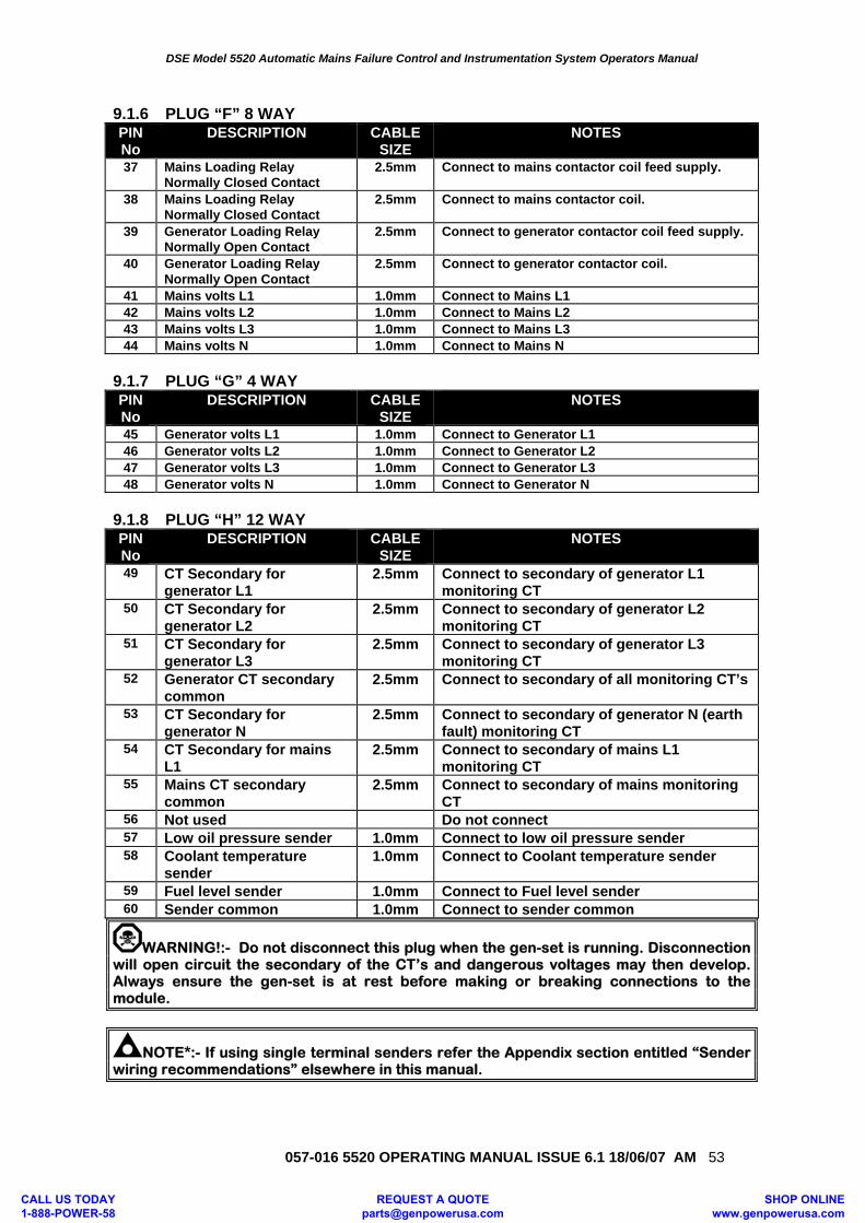
DSE Model 5520 Automatic Mains Failure Control and Instrumentation System Operators Manual
057-016 5520 OPERATING MANUAL ISSUE 6.1 18/06/07 AM 53
9.1.6 PLUG “F” 8 WAY PIN No
DESCRIPTION CABLE SIZE
NOTES
37 Mains Loading Relay Normally Closed Contact
2.5mm Connect to mains contactor coil feed supply.
38 Mains Loading Relay Normally Closed Contact
2.5mm Connect to mains contactor coil.
39 Generator Loading Relay Normally Open Contact
2.5mm Connect to generator contactor coil feed supply.
40 Generator Loading Relay Normally Open Contact
2.5mm Connect to generator contactor coil.
41 Mains volts L1 1.0mm Connect to Mains L1 42 Mains volts L2 1.0mm Connect to Mains L2 43 Mains volts L3 1.0mm Connect to Mains L3 44 Mains volts N 1.0mm Connect to Mains N
9.1.7 PLUG “G” 4 WAY PIN No
DESCRIPTION CABLE SIZE
NOTES
45 Generator volts L1 1.0mm Connect to Generator L1 46 Generator volts L2 1.0mm Connect to Generator L2 47 Generator volts L3 1.0mm Connect to Generator L3 48 Generator volts N 1.0mm Connect to Generator N
9.1.8 PLUG “H” 12 WAY PIN No
DESCRIPTION CABLE SIZE
NOTES
49 CT Secondary for generator L1
2.5mm Connect to secondary of generator L1 monitoring CT
50 CT Secondary for generator L2
2.5mm Connect to secondary of generator L2 monitoring CT
51 CT Secondary for generator L3
2.5mm Connect to secondary of generator L3 monitoring CT
52 Generator CT secondary common
2.5mm Connect to secondary of all monitoring CT’s
53 CT Secondary for generator N
2.5mm Connect to secondary of generator N (earth fault) monitoring CT
54 CT Secondary for mains L1
2.5mm Connect to secondary of mains L1 monitoring CT
55 Mains CT secondary common
2.5mm Connect to secondary of mains monitoring CT
56 Not used Do not connect 57 Low oil pressure sender 1.0mm Connect to low oil pressure sender 58 Coolant temperature
sender 1.0mm Connect to Coolant temperature sender
59 Fuel level sender 1.0mm Connect to Fuel level sender 60 Sender common 1.0mm Connect to sender common
WARNING!:- Do not disconnect this plug when the gen-set is running. Disconnection will open circuit the secondary of the CT’s and dangerous voltages may then develop. Always ensure the gen-set is at rest before making or breaking connections to the module.
NOTE*:- If using single terminal senders refer the Appendix section entitled “Sender wiring recommendations” elsewhere in this manual.
CALL US TODAY 1-888-POWER-58
REQUEST A QUOTE [email protected]
SHOP ONLINE www.genpowerusa.com
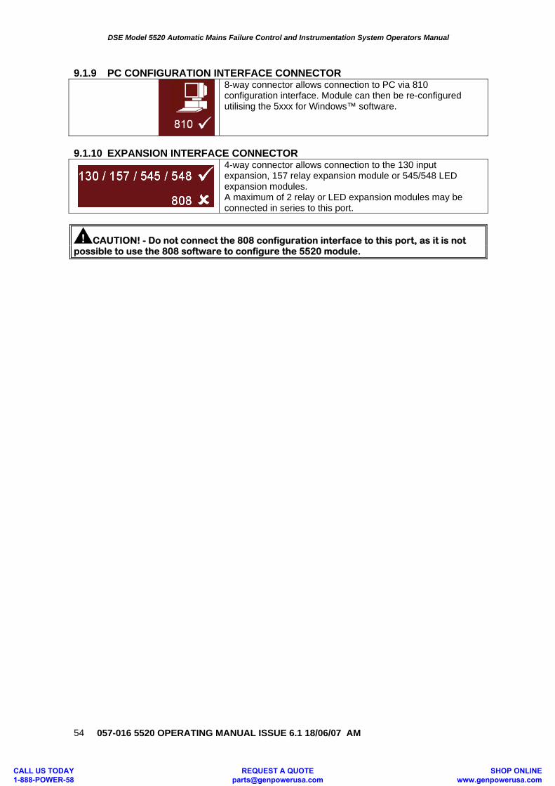
DSE Model 5520 Automatic Mains Failure Control and Instrumentation System Operators Manual
057-016 5520 OPERATING MANUAL ISSUE 6.1 18/06/07 AM
54
9.1.9 PC CONFIGURATION INTERFACE CONNECTOR
8-way connector allows connection to PC via 810 configuration interface. Module can then be re-configured utilising the 5xxx for Windows™ software.
9.1.10 EXPANSION INTERFACE CONNECTOR
4-way connector allows connection to the 130 input expansion, 157 relay expansion module or 545/548 LED expansion modules. A maximum of 2 relay or LED expansion modules may be connected in series to this port.
CAUTION! - Do not connect the 808 configuration interface to this port, as it is not possible to use the 808 software to configure the 5520 module.
CALL US TODAY 1-888-POWER-58
REQUEST A QUOTE [email protected]
SHOP ONLINE www.genpowerusa.com
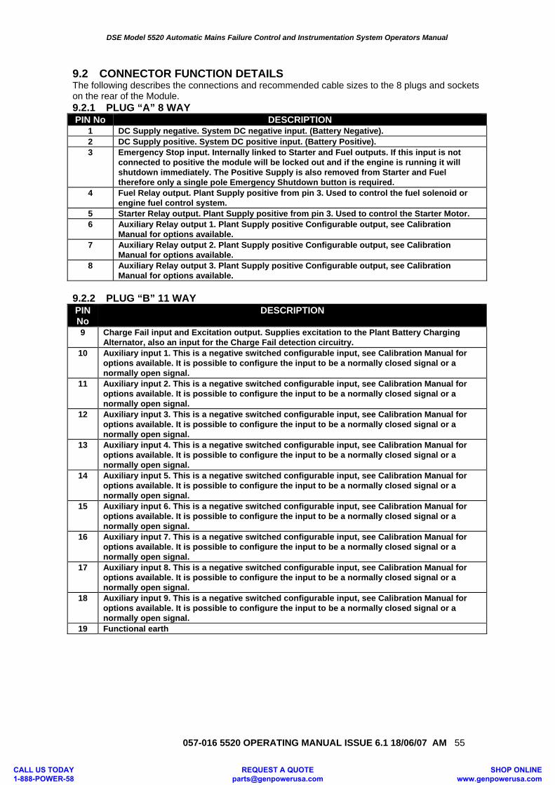
DSE Model 5520 Automatic Mains Failure Control and Instrumentation System Operators Manual
057-016 5520 OPERATING MANUAL ISSUE 6.1 18/06/07 AM 55
9.2 CONNECTOR FUNCTION DETAILS The following describes the connections and recommended cable sizes to the 8 plugs and sockets on the rear of the Module. 9.2.1 PLUG “A” 8 WAY PIN No DESCRIPTION
1 DC Supply negative. System DC negative input. (Battery Negative). 2 DC Supply positive. System DC positive input. (Battery Positive). 3 Emergency Stop input. Internally linked to Starter and Fuel outputs. If this input is not
connected to positive the module will be locked out and if the engine is running it will shutdown immediately. The Positive Supply is also removed from Starter and Fuel therefore only a single pole Emergency Shutdown button is required.
4 Fuel Relay output. Plant Supply positive from pin 3. Used to control the fuel solenoid or engine fuel control system.
5 Starter Relay output. Plant Supply positive from pin 3. Used to control the Starter Motor. 6 Auxiliary Relay output 1. Plant Supply positive Configurable output, see Calibration
Manual for options available. 7 Auxiliary Relay output 2. Plant Supply positive Configurable output, see Calibration
Manual for options available. 8 Auxiliary Relay output 3. Plant Supply positive Configurable output, see Calibration
Manual for options available. 9.2.2 PLUG “B” 11 WAY PIN No
DESCRIPTION
9 Charge Fail input and Excitation output. Supplies excitation to the Plant Battery Charging Alternator, also an input for the Charge Fail detection circuitry.
10 Auxiliary input 1. This is a negative switched configurable input, see Calibration Manual for options available. It is possible to configure the input to be a normally closed signal or a normally open signal.
11 Auxiliary input 2. This is a negative switched configurable input, see Calibration Manual for options available. It is possible to configure the input to be a normally closed signal or a normally open signal.
12 Auxiliary input 3. This is a negative switched configurable input, see Calibration Manual for options available. It is possible to configure the input to be a normally closed signal or a normally open signal.
13 Auxiliary input 4. This is a negative switched configurable input, see Calibration Manual for options available. It is possible to configure the input to be a normally closed signal or a normally open signal.
14 Auxiliary input 5. This is a negative switched configurable input, see Calibration Manual for options available. It is possible to configure the input to be a normally closed signal or a normally open signal.
15 Auxiliary input 6. This is a negative switched configurable input, see Calibration Manual for options available. It is possible to configure the input to be a normally closed signal or a normally open signal.
16 Auxiliary input 7. This is a negative switched configurable input, see Calibration Manual for options available. It is possible to configure the input to be a normally closed signal or a normally open signal.
17 Auxiliary input 8. This is a negative switched configurable input, see Calibration Manual for options available. It is possible to configure the input to be a normally closed signal or a normally open signal.
18 Auxiliary input 9. This is a negative switched configurable input, see Calibration Manual for options available. It is possible to configure the input to be a normally closed signal or a normally open signal.
19 Functional earth
CALL US TODAY 1-888-POWER-58
REQUEST A QUOTE [email protected]
SHOP ONLINE www.genpowerusa.com
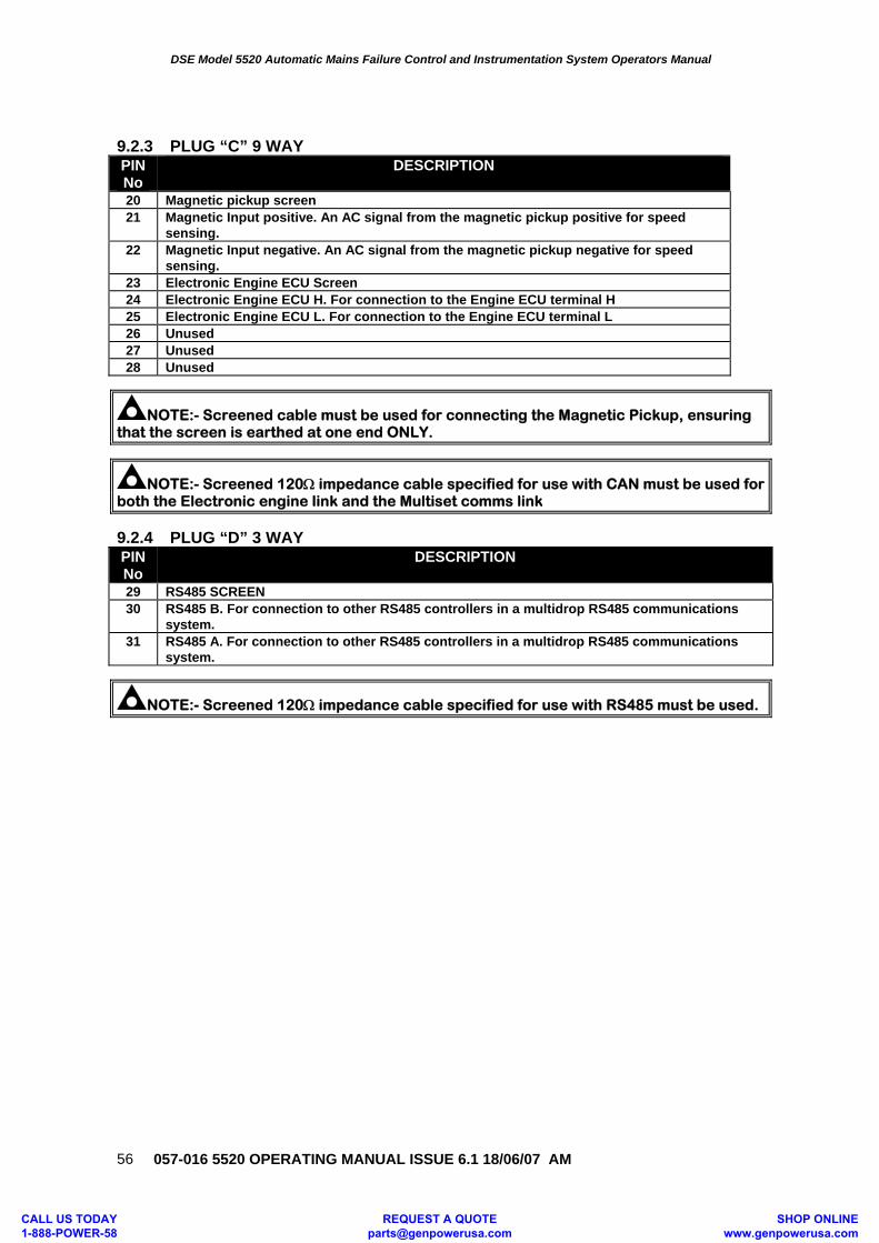
DSE Model 5520 Automatic Mains Failure Control and Instrumentation System Operators Manual
057-016 5520 OPERATING MANUAL ISSUE 6.1 18/06/07 AM
56
9.2.3 PLUG “C” 9 WAY PIN No
DESCRIPTION
20 Magnetic pickup screen 21 Magnetic Input positive. An AC signal from the magnetic pickup positive for speed
sensing. 22 Magnetic Input negative. An AC signal from the magnetic pickup negative for speed
sensing. 23 Electronic Engine ECU Screen 24 Electronic Engine ECU H. For connection to the Engine ECU terminal H 25 Electronic Engine ECU L. For connection to the Engine ECU terminal L 26 Unused 27 Unused 28 Unused
NOTE:- Screened cable must be used for connecting the Magnetic Pickup, ensuring that the screen is earthed at one end ONLY.
NOTE:- Screened 120Ω impedance cable specified for use with CAN must be used for both the Electronic engine link and the Multiset comms link 9.2.4 PLUG “D” 3 WAY PIN No
DESCRIPTION
29 RS485 SCREEN 30 RS485 B. For connection to other RS485 controllers in a multidrop RS485 communications
system. 31 RS485 A. For connection to other RS485 controllers in a multidrop RS485 communications
system.
NOTE:- Screened 120Ω impedance cable specified for use with RS485 must be used.
CALL US TODAY 1-888-POWER-58
REQUEST A QUOTE [email protected]
SHOP ONLINE www.genpowerusa.com
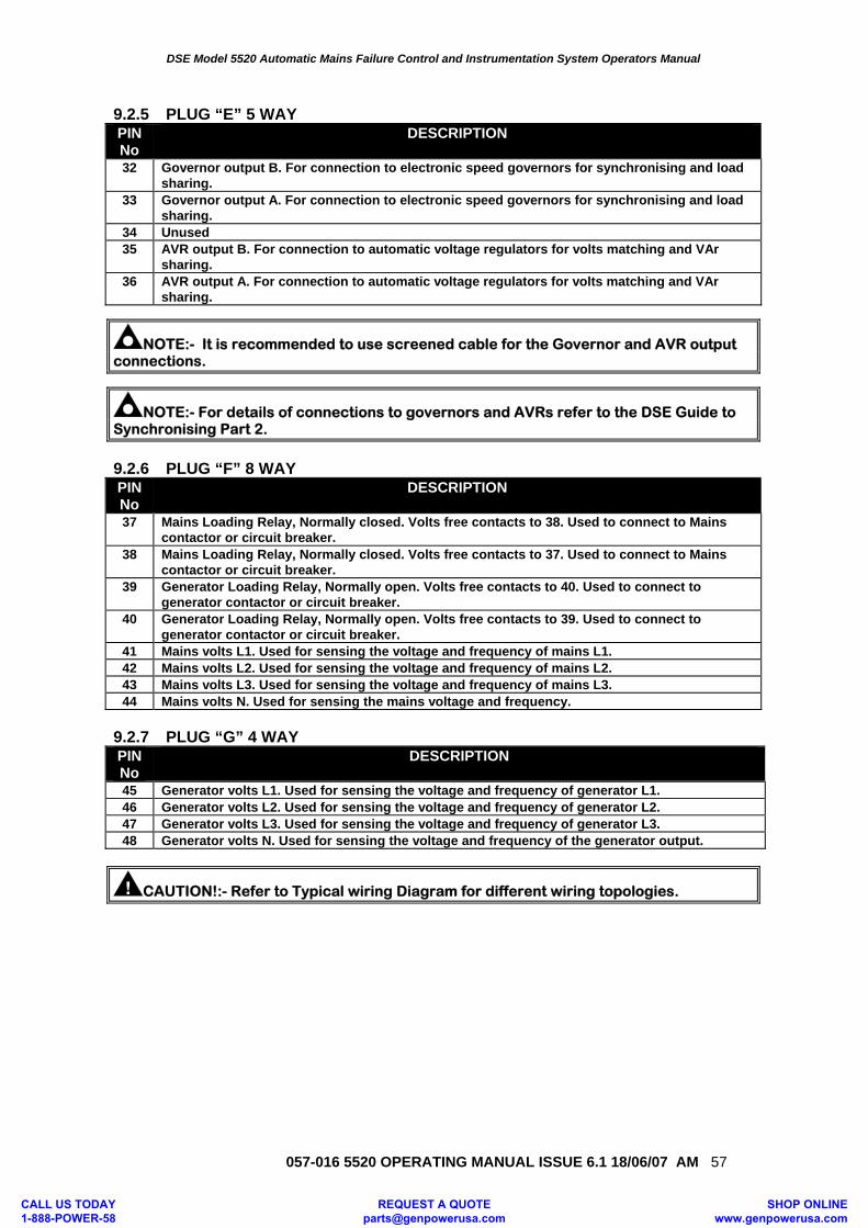
DSE Model 5520 Automatic Mains Failure Control and Instrumentation System Operators Manual
057-016 5520 OPERATING MANUAL ISSUE 6.1 18/06/07 AM 57
9.2.5 PLUG “E” 5 WAY PIN No
DESCRIPTION
32 Governor output B. For connection to electronic speed governors for synchronising and load sharing.
33 Governor output A. For connection to electronic speed governors for synchronising and load sharing.
34 Unused 35 AVR output B. For connection to automatic voltage regulators for volts matching and VAr
sharing. 36 AVR output A. For connection to automatic voltage regulators for volts matching and VAr
sharing.
NOTE:- It is recommended to use screened cable for the Governor and AVR output connections.
NOTE:- For details of connections to governors and AVRs refer to the DSE Guide to Synchronising Part 2.
9.2.6 PLUG “F” 8 WAY PIN No
DESCRIPTION
37 Mains Loading Relay, Normally closed. Volts free contacts to 38. Used to connect to Mains contactor or circuit breaker.
38 Mains Loading Relay, Normally closed. Volts free contacts to 37. Used to connect to Mains contactor or circuit breaker.
39 Generator Loading Relay, Normally open. Volts free contacts to 40. Used to connect to generator contactor or circuit breaker.
40 Generator Loading Relay, Normally open. Volts free contacts to 39. Used to connect to generator contactor or circuit breaker.
41 Mains volts L1. Used for sensing the voltage and frequency of mains L1. 42 Mains volts L2. Used for sensing the voltage and frequency of mains L2. 43 Mains volts L3. Used for sensing the voltage and frequency of mains L3. 44 Mains volts N. Used for sensing the mains voltage and frequency.
9.2.7 PLUG “G” 4 WAY PIN No
DESCRIPTION
45 Generator volts L1. Used for sensing the voltage and frequency of generator L1. 46 Generator volts L2. Used for sensing the voltage and frequency of generator L2. 47 Generator volts L3. Used for sensing the voltage and frequency of generator L3. 48 Generator volts N. Used for sensing the voltage and frequency of the generator output.
CAUTION!:- Refer to Typical wiring Diagram for different wiring topologies.
CALL US TODAY 1-888-POWER-58
REQUEST A QUOTE [email protected]
SHOP ONLINE www.genpowerusa.com
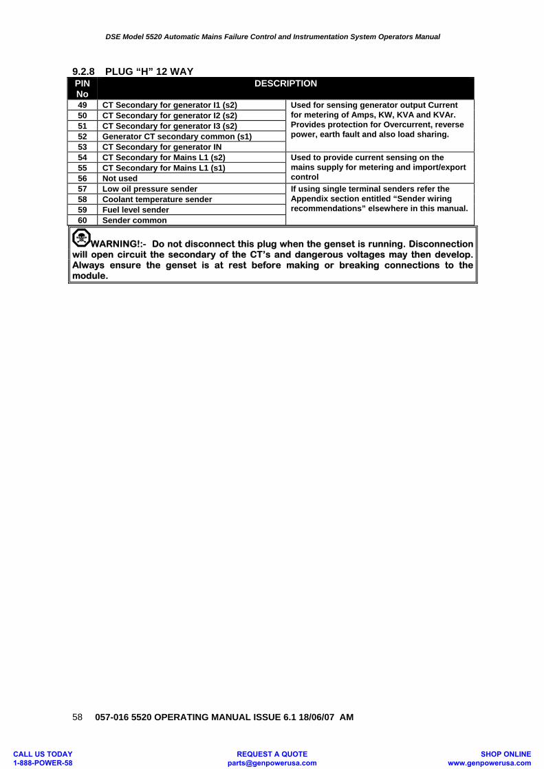
DSE Model 5520 Automatic Mains Failure Control and Instrumentation System Operators Manual
057-016 5520 OPERATING MANUAL ISSUE 6.1 18/06/07 AM
58
9.2.8 PLUG “H” 12 WAY PIN No
DESCRIPTION
49 CT Secondary for generator I1 (s2) Used for sensing generator output Current for metering of Amps, KW, KVA and KVAr. Provides protection for Overcurrent, reverse power, earth fault and also load sharing.
50 CT Secondary for generator I2 (s2) 51 CT Secondary for generator I3 (s2) 52 Generator CT secondary common (s1) 53 CT Secondary for generator IN 54 CT Secondary for Mains L1 (s2) Used to provide current sensing on the
mains supply for metering and import/export control
55 CT Secondary for Mains L1 (s1) 56 Not used 57 Low oil pressure sender If using single terminal senders refer the
Appendix section entitled “Sender wiring recommendations” elsewhere in this manual.
58 Coolant temperature sender 59 Fuel level sender 60 Sender common
WARNING!:- Do not disconnect this plug when the genset is running. Disconnection will open circuit the secondary of the CT’s and dangerous voltages may then develop. Always ensure the genset is at rest before making or breaking connections to the module.
CALL US TODAY 1-888-POWER-58
REQUEST A QUOTE [email protected]
SHOP ONLINE www.genpowerusa.com
DSE Model 5520 Automatic Mains Failure Control and Instrumentation System Operators Manual
057-016 5520 OPERATING MANUAL ISSUE 6.1 18/06/07 AM 59
9.3 ENGINE CONTROL UNIT INTERFACE The module is capable of interfacing with the ECU fitted to electronically injected engines. Different manufacturers engines utilise various different interfaces and protocols. As this is a rapidly developing area we recommend checking with DSE Support as to which engines are currently supported. The module will monitor the engines operating parameters such as engine speed, oil pressure, engine temperature (among others) in order to closely monitor and control the engine. The data that is gathered by the engine controller is then transmitted on an industry standard communications interface. This allows generator controllers such as the DSE 55xx range to access these engine parameters with no physical connection to the sensor device. Utilising the technology present on the engine in this way gives less connections to the engine, higher reliability and better diagnosis of engine related problems.
NOTE:- For further details for connections to electronic engines refer to the manual CAN and DSE Wiring. Part No. 057-004
CALL US TODAY 1-888-POWER-58
REQUEST A QUOTE [email protected]
SHOP ONLINE www.genpowerusa.com
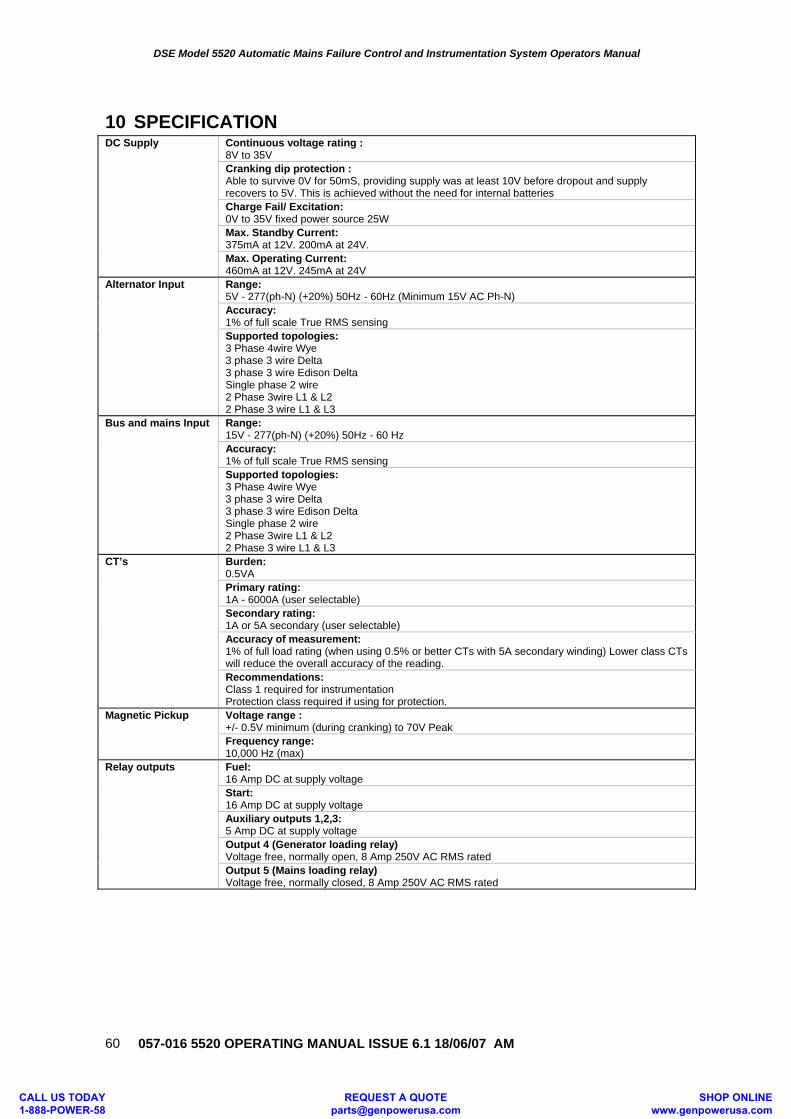
DSE Model 5520 Automatic Mains Failure Control and Instrumentation System Operators Manual
057-016 5520 OPERATING MANUAL ISSUE 6.1 18/06/07 AM
60
10 SPECIFICATION
DC Supply Continuous voltage rating : 8V to 35V Cranking dip protection : Able to survive 0V for 50mS, providing supply was at least 10V before dropout and supply recovers to 5V. This is achieved without the need for internal batteries Charge Fail/ Excitation: 0V to 35V fixed power source 25W Max. Standby Current: 375mA at 12V. 200mA at 24V. Max. Operating Current: 460mA at 12V. 245mA at 24V
Alternator Input Range: 5V - 277(ph-N) (+20%) 50Hz - 60Hz (Minimum 15V AC Ph-N) Accuracy: 1% of full scale True RMS sensing Supported topologies: 3 Phase 4wire Wye 3 phase 3 wire Delta 3 phase 3 wire Edison Delta Single phase 2 wire 2 Phase 3wire L1 & L2 2 Phase 3 wire L1 & L3
Bus and mains Input Range: 15V - 277(ph-N) (+20%) 50Hz - 60 Hz Accuracy: 1% of full scale True RMS sensing Supported topologies: 3 Phase 4wire Wye 3 phase 3 wire Delta 3 phase 3 wire Edison Delta Single phase 2 wire 2 Phase 3wire L1 & L2 2 Phase 3 wire L1 & L3
CT’s Burden: 0.5VA Primary rating: 1A - 6000A (user selectable) Secondary rating: 1A or 5A secondary (user selectable) Accuracy of measurement: 1% of full load rating (when using 0.5% or better CTs with 5A secondary winding) Lower class CTs will reduce the overall accuracy of the reading. Recommendations: Class 1 required for instrumentation Protection class required if using for protection.
Magnetic Pickup Voltage range : +/- 0.5V minimum (during cranking) to 70V Peak Frequency range: 10,000 Hz (max)
Relay outputs Fuel: 16 Amp DC at supply voltage Start: 16 Amp DC at supply voltage Auxiliary outputs 1,2,3: 5 Amp DC at supply voltage Output 4 (Generator loading relay) Voltage free, normally open, 8 Amp 250V AC RMS rated Output 5 (Mains loading relay) Voltage free, normally closed, 8 Amp 250V AC RMS rated
CALL US TODAY 1-888-POWER-58
REQUEST A QUOTE [email protected]
SHOP ONLINE www.genpowerusa.com
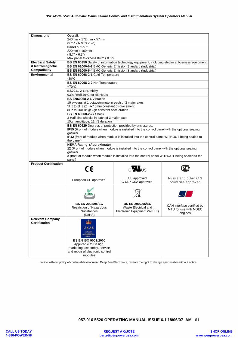
DSE Model 5520 Automatic Mains Failure Control and Instrumentation System Operators Manual
057-016 5520 OPERATING MANUAL ISSUE 6.1 18/06/07 AM 61
Dimensions Overall:
240mm x 172 mm x 57mm (9 ½“ x 6 ¾” x 2 ¼”) Panel cut-out: 220mm x 160mm ( 8.7” x 6.3”) Max panel thickness 8mm ( 0.3”)
Electrical Safety /Electromagnetic Compatibility
BS EN 60950 Safety of information technology equipment, including electrical business equipment BS EN 61000-6-2 EMC Generic Emission Standard (Industrial) BS EN 61000-6-4 EMC Generic Emission Standard (Industrial)
Environmental BS EN 60068-2-1 Cold Temperature -30°C BS EN 60068-2-2 Hot Temperature +70°C BS2011-2-1 Humidity 93% RH@40°C for 48 Hours BS EN60068-2-6 Vibration 10 sweeps at 1 octave/minute in each of 3 major axes 5Hz to 8Hz @ +/-7.5mm constant displacement 8Hz to 500Hz @ 2gn constant acceleration BS EN 60068-2-27 Shock 3 Half sine shocks in each of 3 major axes 15gn amplitude, 11mS durationBS EN 60529 Degrees of protection provided by enclosures: IP55 (Front of module when module is installed into the control panel with the optional sealing gasket). IP42 (front of module when module is installed into the control panel WITHOUT being sealed to the panel) NEMA Rating (Approximate) 12 (Front of module when module is installed into the control panel with the optional sealing gasket). 2 (front of module when module is installed into the control panel WITHOUT being sealed to the panel)
Product Certification
C US
European CE approved. UL approved C-UL / CSA approved.
Russia and other CIS countries approved
BS EN 2002/95/EC Restriction of Hazardous
Substances (RoHS)
BS EN 2002/96/EC Waste Electrical and
Electronic Equipment (WEEE)
CAN interface certified by MTU for use with MDEC
engines
Relevant Company Certification
BS EN ISO 9001:2000 Applicable to Design,
marketing, assembly, service and repair of electronic control
modules
In line with our policy of continual development, Deep Sea Electronics, reserve the right to change specification without notice.
CALL US TODAY 1-888-POWER-58
REQUEST A QUOTE [email protected]
SHOP ONLINE www.genpowerusa.com
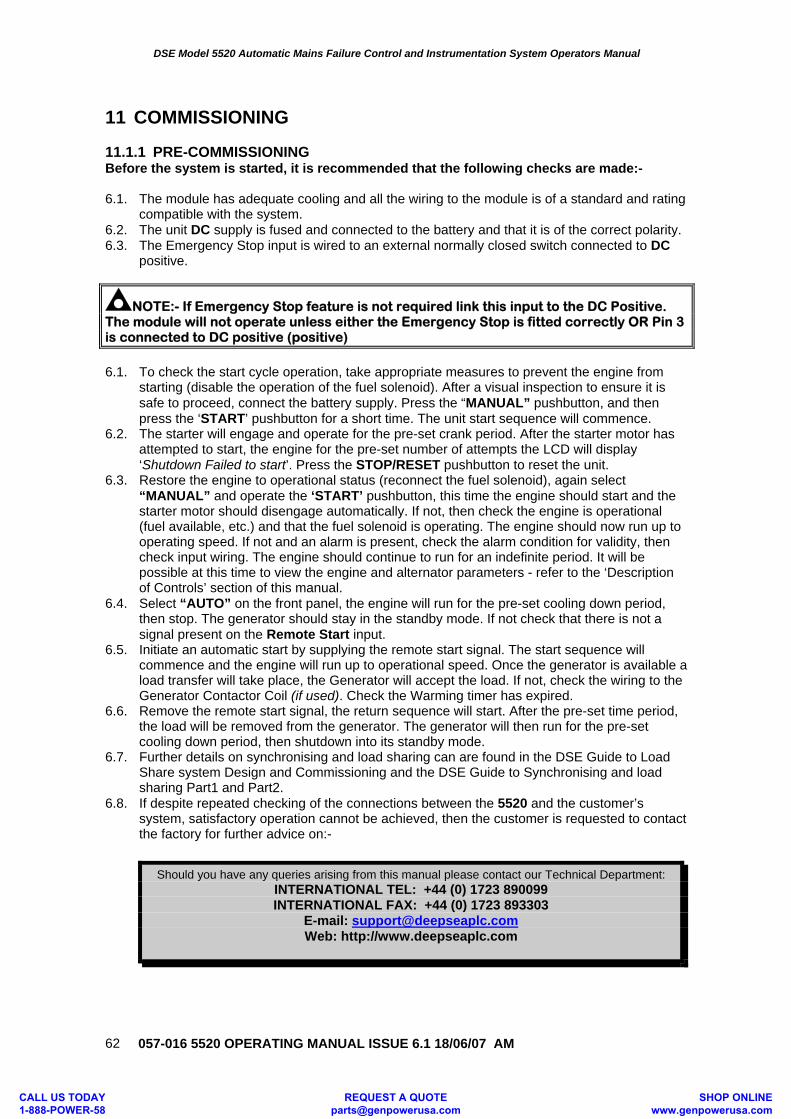
DSE Model 5520 Automatic Mains Failure Control and Instrumentation System Operators Manual
057-016 5520 OPERATING MANUAL ISSUE 6.1 18/06/07 AM
62
11 COMMISSIONING 11.1.1 PRE-COMMISSIONING Before the system is started, it is recommended that the following checks are made:- 6.1. The module has adequate cooling and all the wiring to the module is of a standard and rating
compatible with the system. 6.2. The unit DC supply is fused and connected to the battery and that it is of the correct polarity. 6.3. The Emergency Stop input is wired to an external normally closed switch connected to DC
positive.
NOTE:- If Emergency Stop feature is not required link this input to the DC Positive. The module will not operate unless either the Emergency Stop is fitted correctly OR Pin 3 is connected to DC positive (positive)
6.1. To check the start cycle operation, take appropriate measures to prevent the engine from
starting (disable the operation of the fuel solenoid). After a visual inspection to ensure it is safe to proceed, connect the battery supply. Press the “MANUAL” pushbutton, and then press the ‘START’ pushbutton for a short time. The unit start sequence will commence.
6.2. The starter will engage and operate for the pre-set crank period. After the starter motor has attempted to start, the engine for the pre-set number of attempts the LCD will display ‘Shutdown Failed to start’. Press the STOP/RESET pushbutton to reset the unit.
6.3. Restore the engine to operational status (reconnect the fuel solenoid), again select “MANUAL” and operate the ‘START’ pushbutton, this time the engine should start and the starter motor should disengage automatically. If not, then check the engine is operational (fuel available, etc.) and that the fuel solenoid is operating. The engine should now run up to operating speed. If not and an alarm is present, check the alarm condition for validity, then check input wiring. The engine should continue to run for an indefinite period. It will be possible at this time to view the engine and alternator parameters - refer to the ‘Description of Controls’ section of this manual.
6.4. Select “AUTO” on the front panel, the engine will run for the pre-set cooling down period, then stop. The generator should stay in the standby mode. If not check that there is not a signal present on the Remote Start input.
6.5. Initiate an automatic start by supplying the remote start signal. The start sequence will commence and the engine will run up to operational speed. Once the generator is available a load transfer will take place, the Generator will accept the load. If not, check the wiring to the Generator Contactor Coil (if used). Check the Warming timer has expired.
6.6. Remove the remote start signal, the return sequence will start. After the pre-set time period, the load will be removed from the generator. The generator will then run for the pre-set cooling down period, then shutdown into its standby mode.
6.7. Further details on synchronising and load sharing can are found in the DSE Guide to Load Share system Design and Commissioning and the DSE Guide to Synchronising and load sharing Part1 and Part2.
6.8. If despite repeated checking of the connections between the 5520 and the customer’s system, satisfactory operation cannot be achieved, then the customer is requested to contact the factory for further advice on:-
Should you have any queries arising from this manual please contact our Technical Department: INTERNATIONAL TEL: +44 (0) 1723 890099 INTERNATIONAL FAX: +44 (0) 1723 893303
E-mail: [email protected] Web: http://www.deepseaplc.com
CALL US TODAY 1-888-POWER-58
REQUEST A QUOTE [email protected]
SHOP ONLINE www.genpowerusa.com
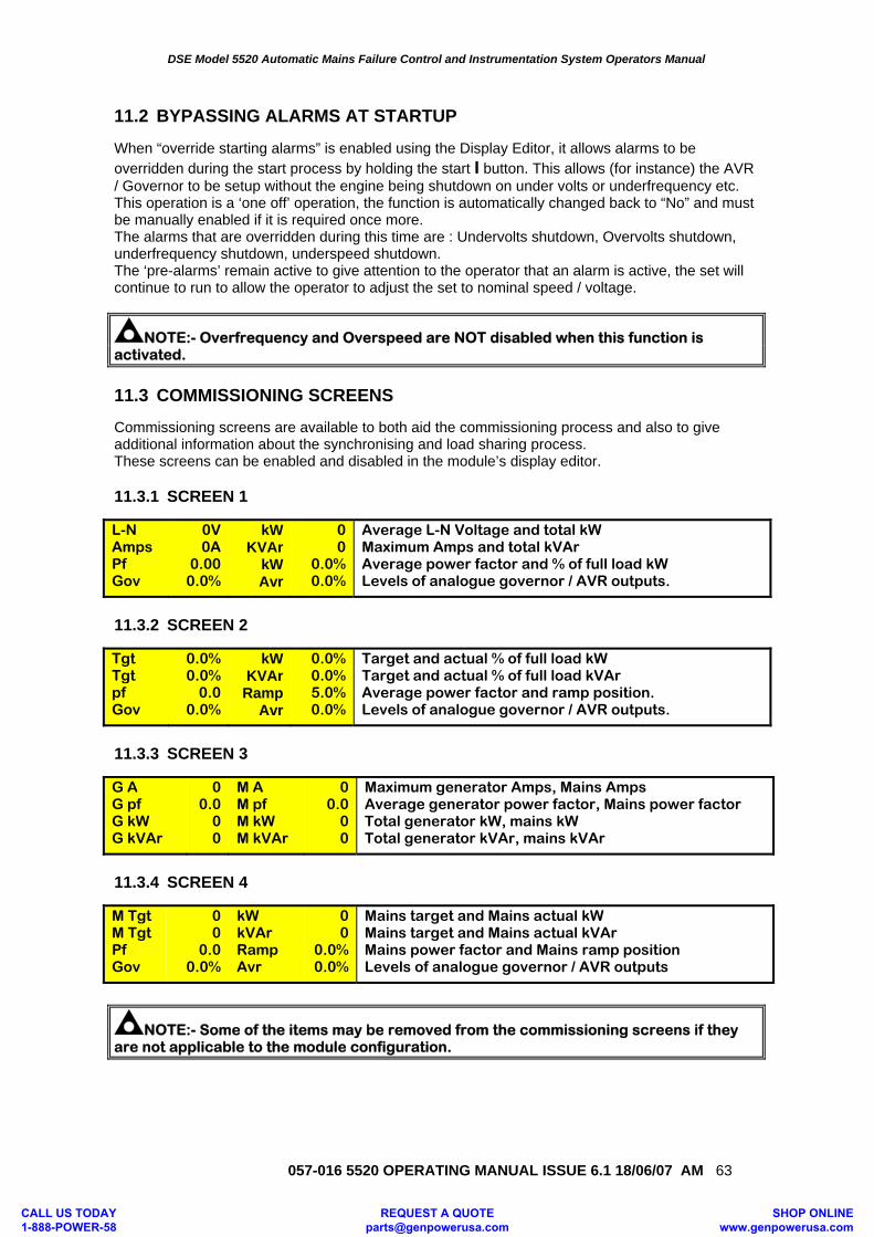
DSE Model 5520 Automatic Mains Failure Control and Instrumentation System Operators Manual
057-016 5520 OPERATING MANUAL ISSUE 6.1 18/06/07 AM 63
11.2 BYPASSING ALARMS AT STARTUP When “override starting alarms” is enabled using the Display Editor, it allows alarms to be overridden during the start process by holding the start I button. This allows (for instance) the AVR / Governor to be setup without the engine being shutdown on under volts or underfrequency etc. This operation is a ‘one off’ operation, the function is automatically changed back to “No” and must be manually enabled if it is required once more. The alarms that are overridden during this time are : Undervolts shutdown, Overvolts shutdown, underfrequency shutdown, underspeed shutdown. The ‘pre-alarms’ remain active to give attention to the operator that an alarm is active, the set will continue to run to allow the operator to adjust the set to nominal speed / voltage.
NOTE:- Overfrequency and Overspeed are NOT disabled when this function is activated.
11.3 COMMISSIONING SCREENS Commissioning screens are available to both aid the commissioning process and also to give additional information about the synchronising and load sharing process. These screens can be enabled and disabled in the module’s display editor. 11.3.1 SCREEN 1 L-N Amps Pf Gov
0V 0A
0.00 0.0%
kW KVAr
kW Avr
0 0
0.0% 0.0%
Average L-N Voltage and total kW Maximum Amps and total kVAr Average power factor and % of full load kW Levels of analogue governor / AVR outputs.
11.3.2 SCREEN 2 Tgt Tgt pf Gov
0.0% 0.0%
0.0 0.0%
kW KVAr Ramp
Avr
0.0% 0.0% 5.0% 0.0%
Target and actual % of full load kW Target and actual % of full load kVAr Average power factor and ramp position. Levels of analogue governor / AVR outputs.
11.3.3 SCREEN 3 G A G pf G kW G kVAr
0 0.0
0 0
M A M pf M kW M kVAr
0 0.0
0 0
Maximum generator Amps, Mains Amps Average generator power factor, Mains power factor Total generator kW, mains kW Total generator kVAr, mains kVAr
11.3.4 SCREEN 4 M Tgt M Tgt Pf Gov
0 0
0.0 0.0%
kW kVAr Ramp Avr
0 0
0.0% 0.0%
Mains target and Mains actual kW Mains target and Mains actual kVAr Mains power factor and Mains ramp position Levels of analogue governor / AVR outputs
NOTE:- Some of the items may be removed from the commissioning screens if they are not applicable to the module configuration.
CALL US TODAY 1-888-POWER-58
REQUEST A QUOTE [email protected]
SHOP ONLINE www.genpowerusa.com
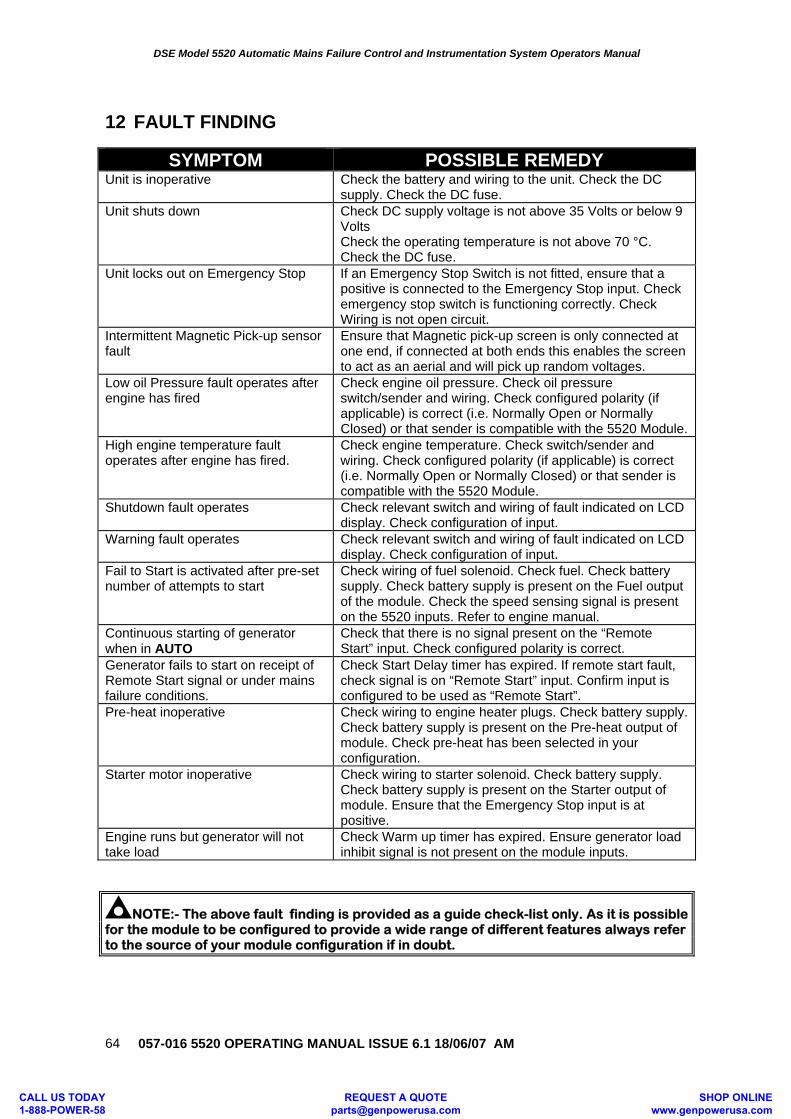
DSE Model 5520 Automatic Mains Failure Control and Instrumentation System Operators Manual
057-016 5520 OPERATING MANUAL ISSUE 6.1 18/06/07 AM
64
12 FAULT FINDING
SYMPTOM POSSIBLE REMEDY Unit is inoperative Check the battery and wiring to the unit. Check the DC
supply. Check the DC fuse. Unit shuts down Check DC supply voltage is not above 35 Volts or below 9
Volts Check the operating temperature is not above 70 °C. Check the DC fuse.
Unit locks out on Emergency Stop If an Emergency Stop Switch is not fitted, ensure that a positive is connected to the Emergency Stop input. Check emergency stop switch is functioning correctly. Check Wiring is not open circuit.
Intermittent Magnetic Pick-up sensor fault
Ensure that Magnetic pick-up screen is only connected at one end, if connected at both ends this enables the screen to act as an aerial and will pick up random voltages.
Low oil Pressure fault operates after engine has fired
Check engine oil pressure. Check oil pressure switch/sender and wiring. Check configured polarity (if applicable) is correct (i.e. Normally Open or Normally Closed) or that sender is compatible with the 5520 Module.
High engine temperature fault operates after engine has fired.
Check engine temperature. Check switch/sender and wiring. Check configured polarity (if applicable) is correct (i.e. Normally Open or Normally Closed) or that sender is compatible with the 5520 Module.
Shutdown fault operates Check relevant switch and wiring of fault indicated on LCD display. Check configuration of input.
Warning fault operates Check relevant switch and wiring of fault indicated on LCD display. Check configuration of input.
Fail to Start is activated after pre-set number of attempts to start
Check wiring of fuel solenoid. Check fuel. Check battery supply. Check battery supply is present on the Fuel output of the module. Check the speed sensing signal is present on the 5520 inputs. Refer to engine manual.
Continuous starting of generator when in AUTO
Check that there is no signal present on the “Remote Start” input. Check configured polarity is correct.
Generator fails to start on receipt of Remote Start signal or under mains failure conditions.
Check Start Delay timer has expired. If remote start fault, check signal is on “Remote Start” input. Confirm input is configured to be used as “Remote Start”.
Pre-heat inoperative Check wiring to engine heater plugs. Check battery supply. Check battery supply is present on the Pre-heat output of module. Check pre-heat has been selected in your configuration.
Starter motor inoperative Check wiring to starter solenoid. Check battery supply. Check battery supply is present on the Starter output of module. Ensure that the Emergency Stop input is at positive.
Engine runs but generator will not take load
Check Warm up timer has expired. Ensure generator load inhibit signal is not present on the module inputs.
NOTE:- The above fault finding is provided as a guide check-list only. As it is possible for the module to be configured to provide a wide range of different features always refer to the source of your module configuration if in doubt.
CALL US TODAY 1-888-POWER-58
REQUEST A QUOTE [email protected]
SHOP ONLINE www.genpowerusa.com
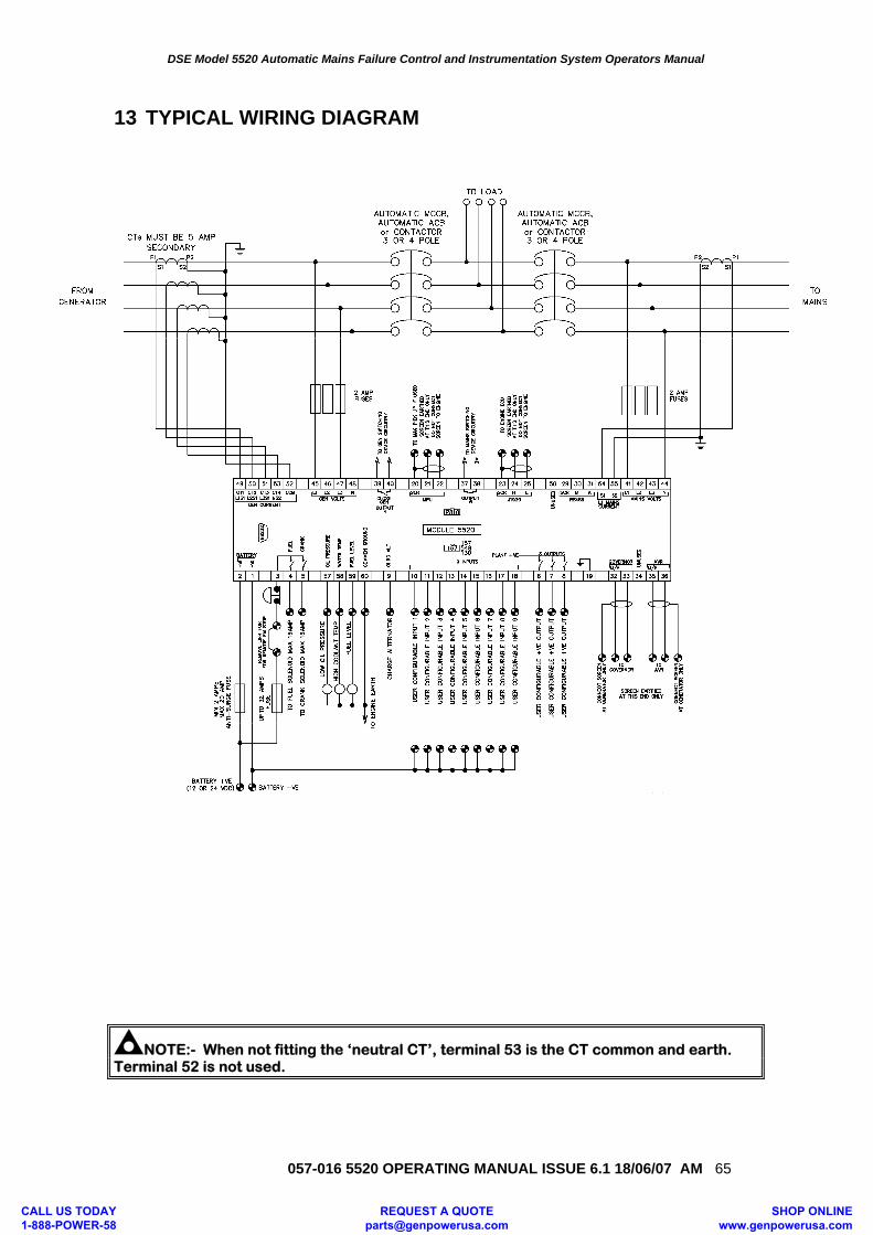
DSE Model 5520 Automatic Mains Failure Control and Instrumentation System Operators Manual
057-016 5520 OPERATING MANUAL ISSUE 6.1 18/06/07 AM 65
13 TYPICAL WIRING DIAGRAM
NOTE:- When not fitting the ‘neutral CT’, terminal 53 is the CT common and earth. Terminal 52 is not used.
CALL US TODAY 1-888-POWER-58
REQUEST A QUOTE [email protected]
SHOP ONLINE www.genpowerusa.com
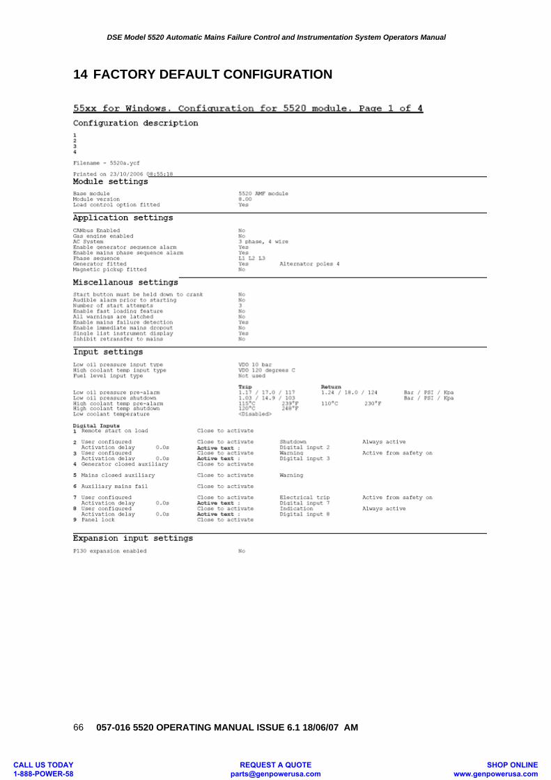
DSE Model 5520 Automatic Mains Failure Control and Instrumentation System Operators Manual
057-016 5520 OPERATING MANUAL ISSUE 6.1 18/06/07 AM
66
14 FACTORY DEFAULT CONFIGURATION
CALL US TODAY 1-888-POWER-58
REQUEST A QUOTE [email protected]
SHOP ONLINE www.genpowerusa.com
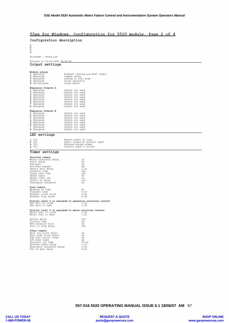
DSE Model 5520 Automatic Mains Failure Control and Instrumentation System Operators Manual
057-016 5520 OPERATING MANUAL ISSUE 6.1 18/06/07 AM 67
CALL US TODAY 1-888-POWER-58
REQUEST A QUOTE [email protected]
SHOP ONLINE www.genpowerusa.com
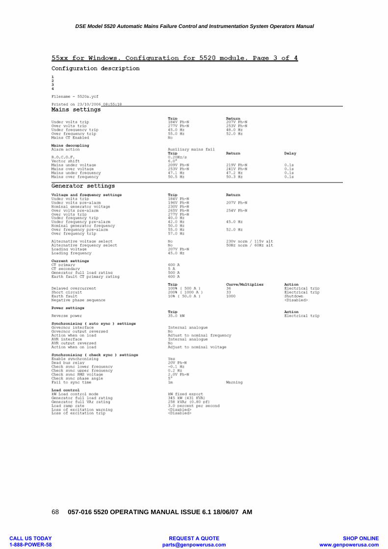
DSE Model 5520 Automatic Mains Failure Control and Instrumentation System Operators Manual
057-016 5520 OPERATING MANUAL ISSUE 6.1 18/06/07 AM
68
CALL US TODAY 1-888-POWER-58
REQUEST A QUOTE [email protected]
SHOP ONLINE www.genpowerusa.com
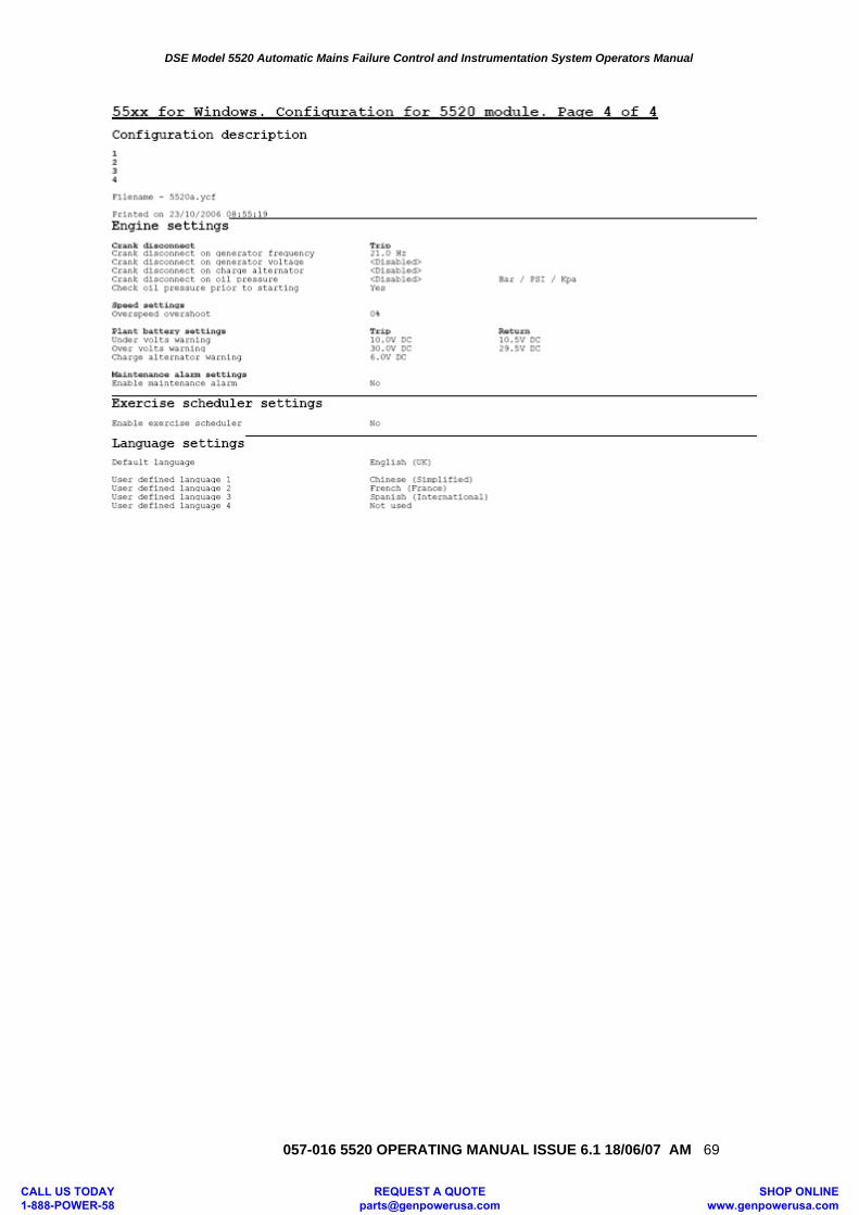
DSE Model 5520 Automatic Mains Failure Control and Instrumentation System Operators Manual
057-016 5520 OPERATING MANUAL ISSUE 6.1 18/06/07 AM 69
CALL US TODAY 1-888-POWER-58
REQUEST A QUOTE [email protected]
SHOP ONLINE www.genpowerusa.com
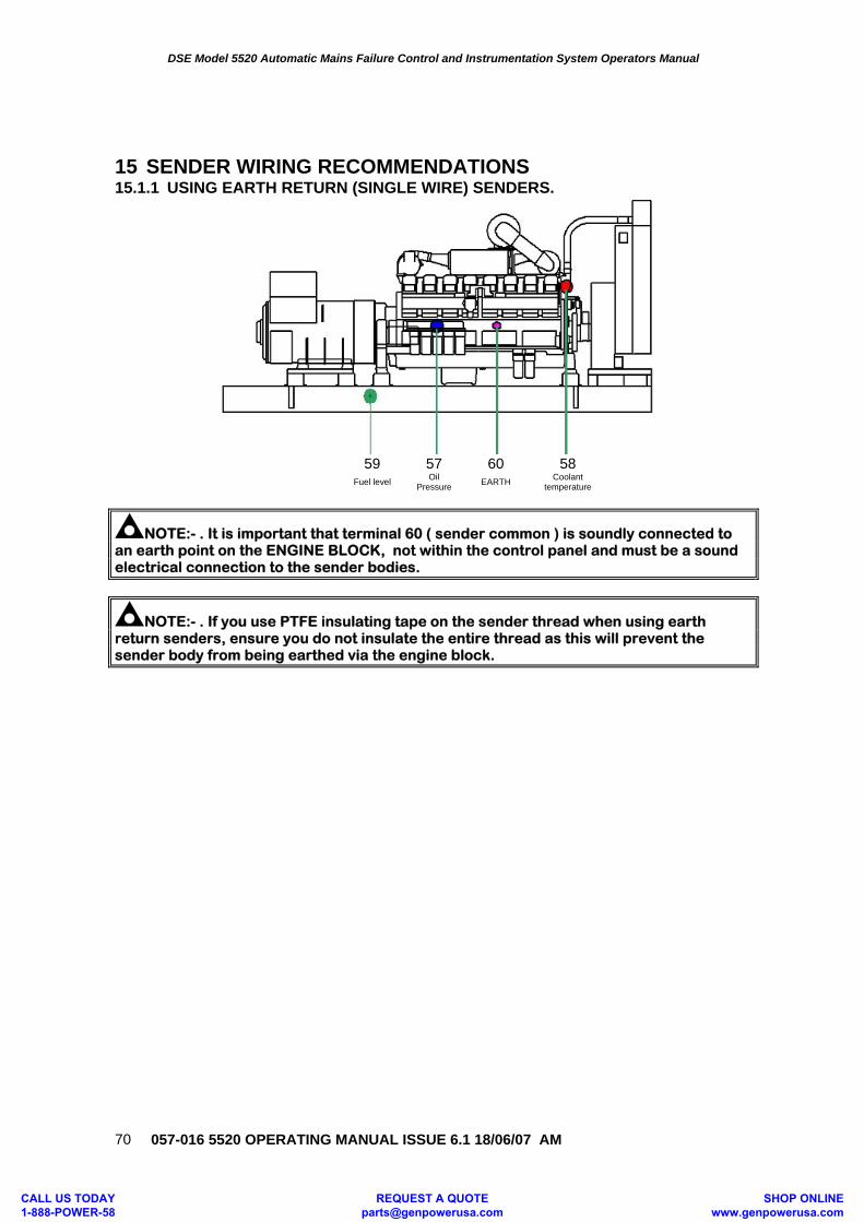
DSE Model 5520 Automatic Mains Failure Control and Instrumentation System Operators Manual
057-016 5520 OPERATING MANUAL ISSUE 6.1 18/06/07 AM
70
15 SENDER WIRING RECOMMENDATIONS 15.1.1 USING EARTH RETURN (SINGLE WIRE) SENDERS.
59 57 60 58 Fuel level Oil
Pressure EARTH Coolant temperature
NOTE:- . It is important that terminal 60 ( sender common ) is soundly connected to an earth point on the ENGINE BLOCK, not within the control panel and must be a sound electrical connection to the sender bodies.
NOTE:- . If you use PTFE insulating tape on the sender thread when using earth return senders, ensure you do not insulate the entire thread as this will prevent the sender body from being earthed via the engine block.
CALL US TODAY 1-888-POWER-58
REQUEST A QUOTE [email protected]
SHOP ONLINE www.genpowerusa.com
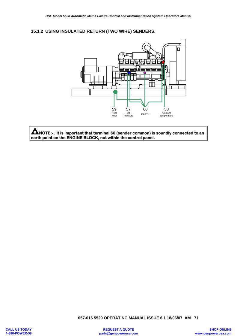
DSE Model 5520 Automatic Mains Failure Control and Instrumentation System Operators Manual
057-016 5520 OPERATING MANUAL ISSUE 6.1 18/06/07 AM 71
15.1.2 USING INSULATED RETURN (TWO WIRE) SENDERS.
59 57 60 58 Fuel
level Oil
Pressure EARTH Coolant temperature
NOTE:- . It is important that terminal 60 (sender common) is soundly connected to an earth point on the ENGINE BLOCK, not within the control panel.
CALL US TODAY 1-888-POWER-58
REQUEST A QUOTE [email protected]
SHOP ONLINE www.genpowerusa.com
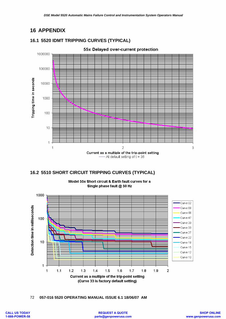
DSE Model 5520 Automatic Mains Failure Control and Instrumentation System Operators Manual
057-016 5520 OPERATING MANUAL ISSUE 6.1 18/06/07 AM
72
16 APPENDIX 16.1 5520 IDMT TRIPPING CURVES (TYPICAL)
16.2 5510 SHORT CIRCUIT TRIPPING CURVES (TYPICAL)
CALL US TODAY 1-888-POWER-58
REQUEST A QUOTE [email protected]
SHOP ONLINE www.genpowerusa.com
DSE Model 5520 Automatic Mains Failure Control and Instrumentation System Operators Manual
057-016 5520 OPERATING MANUAL ISSUE 6.1 18/06/07 AM 73
16.3 ACCESSORIES 16.3.1 OUTPUT EXPANSION There are several methods of output expansion available for the 55xx range of modules: - RELAY OUTPUT EXPANSION (157) An expansion module is available, which connects to the configuration socket, and enables the 55xx to use eight additional relays, providing Volt-free contacts for customer connection. A maximum of two of these units can be used give 16 independent volt-free contacts. The 157’s need to be identified as module ‘A’ and module ‘B’ Refer to technical data sheet on the 157 relay module for further details. LED OUTPUT EXPANSION (548) An expansion module is available, which connects to the configuration socket, and enables the 55xx to use the eight additional LED’s on the 548 module, providing remote LED’s indication. A maximum of two of these units can be used give 16 independent remote LED’s. The 548’s need to be identified as module ‘A’ and module ‘B’ Refer to technical data sheet on the 548 LED modules for further details. It is possible to use a mix of 157 and 548 modules to give both relay and LED expansion if required. 16.3.2 INPUT EXPANSION (P130/P540/P541) It is possible to increase the number of monitored inputs available by utilising either:
DSE P130 input expansion. 540 / 541 Protection Expansion/Annunciator.
Please refer to the relevant product documentation for further details.
CALL US TODAY 1-888-POWER-58
REQUEST A QUOTE [email protected]
SHOP ONLINE www.genpowerusa.com
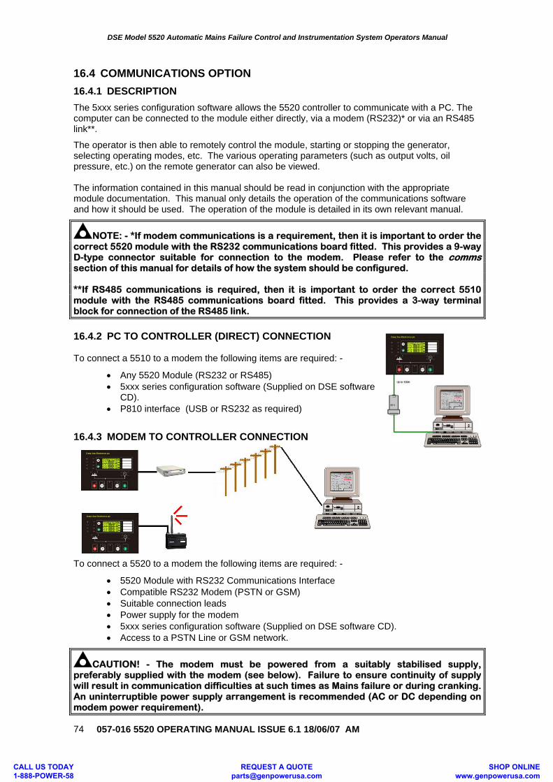
DSE Model 5520 Automatic Mains Failure Control and Instrumentation System Operators Manual
057-016 5520 OPERATING MANUAL ISSUE 6.1 18/06/07 AM
74
16.4 COMMUNICATIONS OPTION
16.4.1 DESCRIPTION
The 5xxx series configuration software allows the 5520 controller to communicate with a PC. The computer can be connected to the module either directly, via a modem (RS232)* or via an RS485 link**.
The operator is then able to remotely control the module, starting or stopping the generator, selecting operating modes, etc. The various operating parameters (such as output volts, oil pressure, etc.) on the remote generator can also be viewed. The information contained in this manual should be read in conjunction with the appropriate module documentation. This manual only details the operation of the communications software and how it should be used. The operation of the module is detailed in its own relevant manual.
NOTE: - *If modem communications is a requirement, then it is important to order the correct 5520 module with the RS232 communications board fitted. This provides a 9-way D-type connector suitable for connection to the modem. Please refer to the comms section of this manual for details of how the system should be configured. **If RS485 communications is required, then it is important to order the correct 5510 module with the RS485 communications board fitted. This provides a 3-way terminal block for connection of the RS485 link.
16.4.2 PC TO CONTROLLER (DIRECT) CONNECTION To connect a 5510 to a modem the following items are required: -
• Any 5520 Module (RS232 or RS485) • 5xxx series configuration software (Supplied on DSE software
CD). • P810 interface (USB or RS232 as required)
16.4.3 MODEM TO CONTROLLER CONNECTION
To connect a 5520 to a modem the following items are required: -
• 5520 Module with RS232 Communications Interface • Compatible RS232 Modem (PSTN or GSM) • Suitable connection leads • Power supply for the modem • 5xxx series configuration software (Supplied on DSE software CD). • Access to a PSTN Line or GSM network.
CAUTION! - The modem must be powered from a suitably stabilised supply, preferably supplied with the modem (see below). Failure to ensure continuity of supply will result in communication difficulties at such times as Mains failure or during cranking. An uninterruptible power supply arrangement is recommended (AC or DC depending on modem power requirement).
CALL US TODAY 1-888-POWER-58
REQUEST A QUOTE [email protected]
SHOP ONLINE www.genpowerusa.com
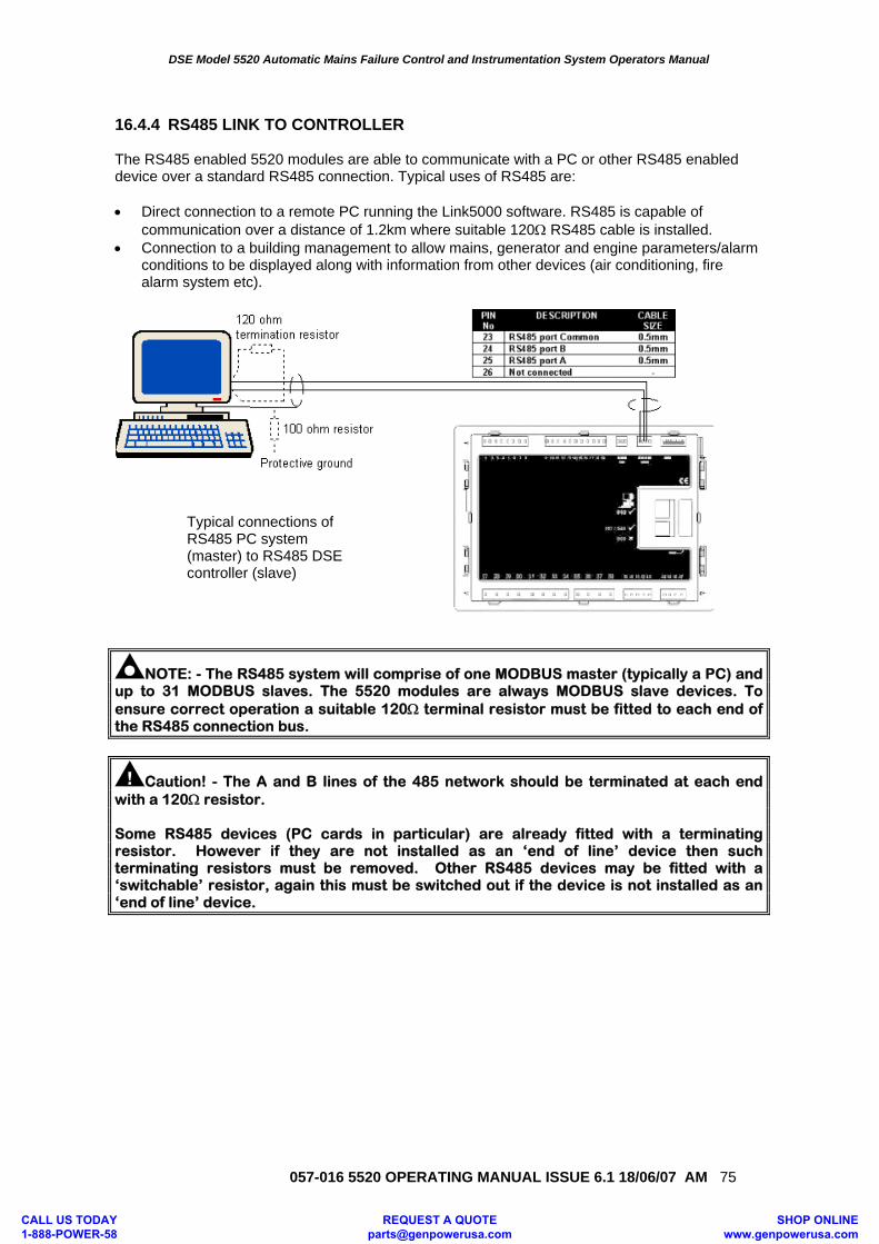
DSE Model 5520 Automatic Mains Failure Control and Instrumentation System Operators Manual
057-016 5520 OPERATING MANUAL ISSUE 6.1 18/06/07 AM 75
16.4.4 RS485 LINK TO CONTROLLER The RS485 enabled 5520 modules are able to communicate with a PC or other RS485 enabled device over a standard RS485 connection. Typical uses of RS485 are: • Direct connection to a remote PC running the Link5000 software. RS485 is capable of
communication over a distance of 1.2km where suitable 120Ω RS485 cable is installed. • Connection to a building management to allow mains, generator and engine parameters/alarm
conditions to be displayed along with information from other devices (air conditioning, fire alarm system etc).
NOTE: - The RS485 system will comprise of one MODBUS master (typically a PC) and up to 31 MODBUS slaves. The 5520 modules are always MODBUS slave devices. To ensure correct operation a suitable 120Ω terminal resistor must be fitted to each end of the RS485 connection bus.
Caution! - The A and B lines of the 485 network should be terminated at each end with a 120Ω resistor. Some RS485 devices (PC cards in particular) are already fitted with a terminating resistor. However if they are not installed as an ‘end of line’ device then such terminating resistors must be removed. Other RS485 devices may be fitted with a ‘switchable’ resistor, again this must be switched out if the device is not installed as an ‘end of line’ device.
Typical connections of RS485 PC system (master) to RS485 DSE controller (slave)
CALL US TODAY 1-888-POWER-58
REQUEST A QUOTE [email protected]
SHOP ONLINE www.genpowerusa.com
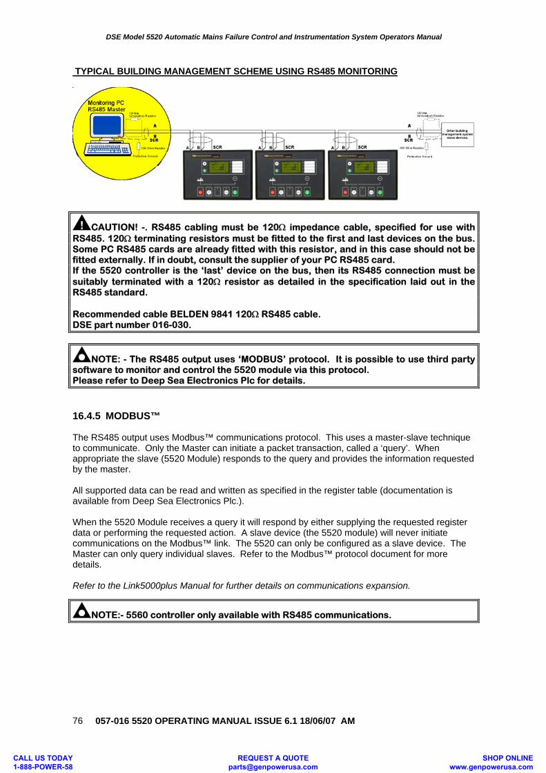
DSE Model 5520 Automatic Mains Failure Control and Instrumentation System Operators Manual
057-016 5520 OPERATING MANUAL ISSUE 6.1 18/06/07 AM
76
TYPICAL BUILDING MANAGEMENT SCHEME USING RS485 MONITORING
CAUTION! -. RS485 cabling must be 120Ω impedance cable, specified for use with RS485. 120Ω terminating resistors must be fitted to the first and last devices on the bus. Some PC RS485 cards are already fitted with this resistor, and in this case should not be fitted externally. If in doubt, consult the supplier of your PC RS485 card. If the 5520 controller is the ‘last’ device on the bus, then its RS485 connection must be suitably terminated with a 120Ω resistor as detailed in the specification laid out in the RS485 standard. Recommended cable BELDEN 9841 120Ω RS485 cable. DSE part number 016-030.
NOTE: - The RS485 output uses ‘MODBUS’ protocol. It is possible to use third party software to monitor and control the 5520 module via this protocol. Please refer to Deep Sea Electronics Plc for details.
16.4.5 MODBUS™ The RS485 output uses Modbus™ communications protocol. This uses a master-slave technique to communicate. Only the Master can initiate a packet transaction, called a ‘query’. When appropriate the slave (5520 Module) responds to the query and provides the information requested by the master. All supported data can be read and written as specified in the register table (documentation is available from Deep Sea Electronics Plc.). When the 5520 Module receives a query it will respond by either supplying the requested register data or performing the requested action. A slave device (the 5520 module) will never initiate communications on the Modbus™ link. The 5520 can only be configured as a slave device. The Master can only query individual slaves. Refer to the Modbus™ protocol document for more details. Refer to the Link5000plus Manual for further details on communications expansion.
NOTE:- 5560 controller only available with RS485 communications.
CALL US TODAY 1-888-POWER-58
REQUEST A QUOTE [email protected]
SHOP ONLINE www.genpowerusa.com
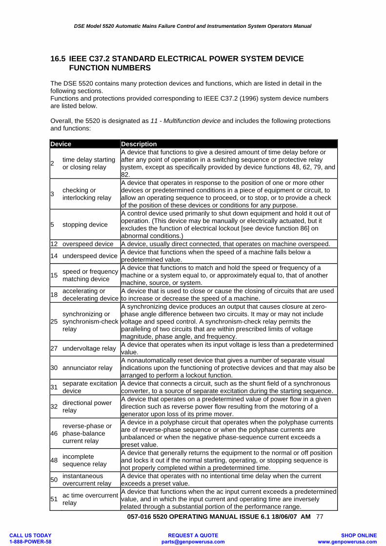
DSE Model 5520 Automatic Mains Failure Control and Instrumentation System Operators Manual
057-016 5520 OPERATING MANUAL ISSUE 6.1 18/06/07 AM 77
16.5 IEEE C37.2 STANDARD ELECTRICAL POWER SYSTEM DEVICE
FUNCTION NUMBERS The DSE 5520 contains many protection devices and functions, which are listed in detail in the following sections. Functions and protections provided corresponding to IEEE C37.2 (1996) system device numbers are listed below. Overall, the 5520 is designated as 11 - Multifunction device and includes the following protections and functions: Device Description
2 time delay starting or closing relay
A device that functions to give a desired amount of time delay before or after any point of operation in a switching sequence or protective relay system, except as specifically provided by device functions 48, 62, 79, and 82.
3 checking or interlocking relay
A device that operates in response to the position of one or more other devices or predetermined conditions in a piece of equipment or circuit, to allow an operating sequence to proceed, or to stop, or to provide a check of the position of these devices or conditions for any purpose.
5 stopping device
A control device used primarily to shut down equipment and hold it out of operation. (This device may be manually or electrically actuated, but it excludes the function of electrical lockout [see device function 86] on abnormal conditions.)
12 overspeed device A device, usually direct connected, that operates on machine overspeed.
14 underspeed device A device that functions when the speed of a machine falls below a predetermined value.
15 speed or frequency matching device
A device that functions to match and hold the speed or frequency of a machine or a system equal to, or approximately equal to, that of another machine, source, or system.
18 accelerating or decelerating device
A device that is used to close or cause the closing of circuits that are used to increase or decrease the speed of a machine.
25 synchronizing or synchronism-check relay
A synchronizing device produces an output that causes closure at zero-phase angle difference between two circuits. It may or may not include voltage and speed control. A synchronism-check relay permits the paralleling of two circuits that are within prescribed limits of voltage magnitude, phase angle, and frequency.
27 undervoltage relay A device that operates when its input voltage is less than a predetermined value.
30 annunciator relay A nonautomatically reset device that gives a number of separate visual indications upon the functioning of protective devices and that may also be arranged to perform a lockout function.
31 separate excitation device
A device that connects a circuit, such as the shunt field of a synchronous converter, to a source of separate excitation during the starting sequence.
32 directional power relay
A device that operates on a predetermined value of power flow in a given direction such as reverse power flow resulting from the motoring of a generator upon loss of its prime mover.
46 reverse-phase or phase-balance current relay
A device in a polyphase circuit that operates when the polyphase currents are of reverse-phase sequence or when the polyphase currents are unbalanced or when the negative phase-sequence current exceeds a preset value.
48 incomplete sequence relay
A device that generally returns the equipment to the normal or off position and locks it out if the normal starting, operating, or stopping sequence is not properly completed within a predetermined time.
50 instantaneous overcurrent relay
A device that operates with no intentional time delay when the current exceeds a preset value.
51 ac time overcurrent relay
A device that functions when the ac input current exceeds a predetermined value, and in which the input current and operating time are inversely related through a substantial portion of the performance range.
CALL US TODAY 1-888-POWER-58
REQUEST A QUOTE [email protected]
SHOP ONLINE www.genpowerusa.com
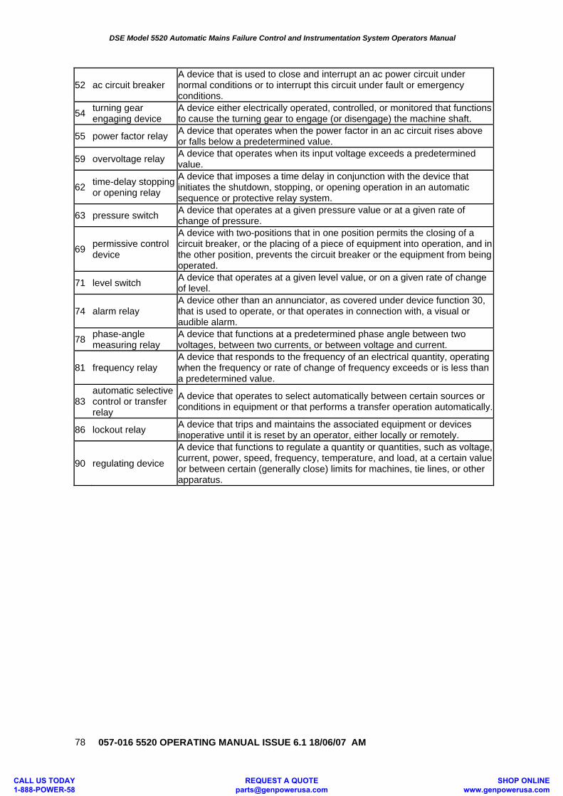
DSE Model 5520 Automatic Mains Failure Control and Instrumentation System Operators Manual
057-016 5520 OPERATING MANUAL ISSUE 6.1 18/06/07 AM
78
52 ac circuit breaker A device that is used to close and interrupt an ac power circuit under normal conditions or to interrupt this circuit under fault or emergency conditions.
54 turning gear engaging device
A device either electrically operated, controlled, or monitored that functions to cause the turning gear to engage (or disengage) the machine shaft.
55 power factor relay A device that operates when the power factor in an ac circuit rises above or falls below a predetermined value.
59 overvoltage relay A device that operates when its input voltage exceeds a predetermined value.
62 time-delay stopping or opening relay
A device that imposes a time delay in conjunction with the device that initiates the shutdown, stopping, or opening operation in an automatic sequence or protective relay system.
63 pressure switch A device that operates at a given pressure value or at a given rate of change of pressure.
69 permissive control device
A device with two-positions that in one position permits the closing of a circuit breaker, or the placing of a piece of equipment into operation, and in the other position, prevents the circuit breaker or the equipment from being operated.
71 level switch A device that operates at a given level value, or on a given rate of change of level.
74 alarm relay A device other than an annunciator, as covered under device function 30, that is used to operate, or that operates in connection with, a visual or audible alarm.
78 phase-angle measuring relay
A device that functions at a predetermined phase angle between two voltages, between two currents, or between voltage and current.
81 frequency relay A device that responds to the frequency of an electrical quantity, operating when the frequency or rate of change of frequency exceeds or is less than a predetermined value.
83 automatic selective control or transfer relay
A device that operates to select automatically between certain sources or conditions in equipment or that performs a transfer operation automatically.
86 lockout relay A device that trips and maintains the associated equipment or devices inoperative until it is reset by an operator, either locally or remotely.
90 regulating device
A device that functions to regulate a quantity or quantities, such as voltage, current, power, speed, frequency, temperature, and load, at a certain value or between certain (generally close) limits for machines, tie lines, or other apparatus.
CALL US TODAY 1-888-POWER-58
REQUEST A QUOTE [email protected]
SHOP ONLINE www.genpowerusa.com
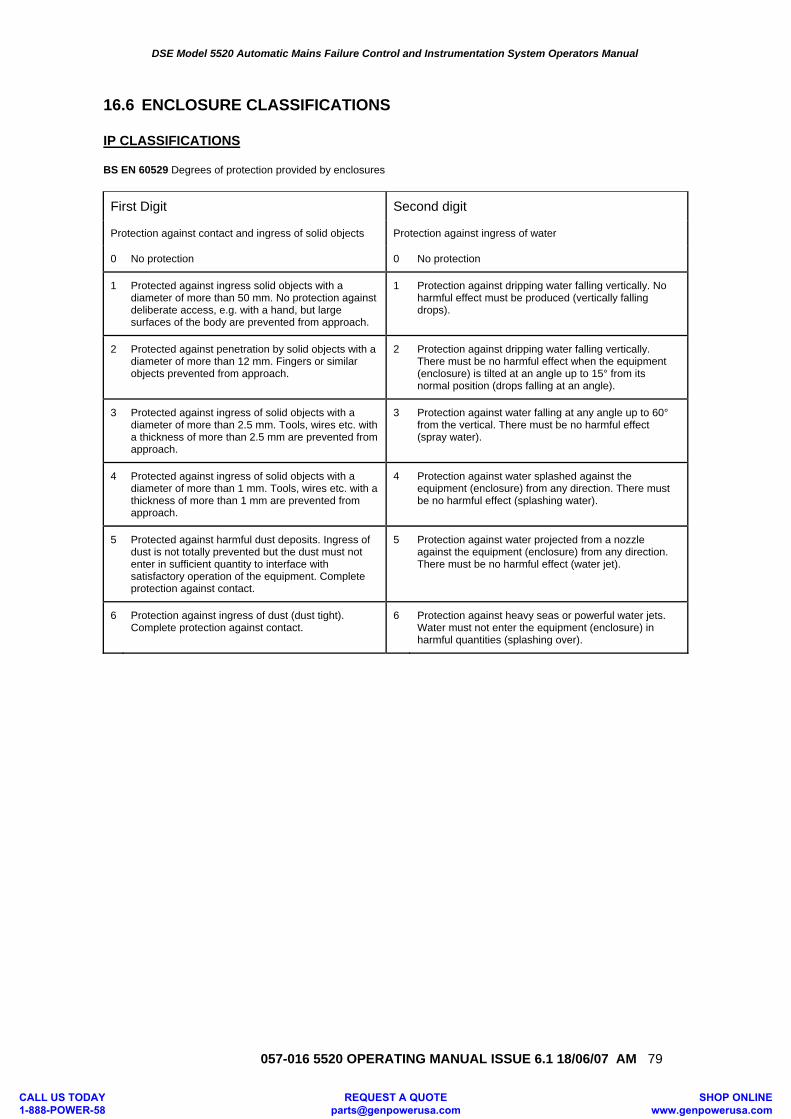
DSE Model 5520 Automatic Mains Failure Control and Instrumentation System Operators Manual
057-016 5520 OPERATING MANUAL ISSUE 6.1 18/06/07 AM 79
16.6 ENCLOSURE CLASSIFICATIONS IP CLASSIFICATIONS BS EN 60529 Degrees of protection provided by enclosures
First Digit Second digit
Protection against contact and ingress of solid objects Protection against ingress of water
0 No protection 0 No protection
1 Protected against ingress solid objects with a diameter of more than 50 mm. No protection against deliberate access, e.g. with a hand, but large surfaces of the body are prevented from approach.
1 Protection against dripping water falling vertically. No harmful effect must be produced (vertically falling drops).
2 Protected against penetration by solid objects with a diameter of more than 12 mm. Fingers or similar objects prevented from approach.
2 Protection against dripping water falling vertically. There must be no harmful effect when the equipment (enclosure) is tilted at an angle up to 15° from its normal position (drops falling at an angle).
3 Protected against ingress of solid objects with a diameter of more than 2.5 mm. Tools, wires etc. with a thickness of more than 2.5 mm are prevented from approach.
3 Protection against water falling at any angle up to 60° from the vertical. There must be no harmful effect (spray water).
4 Protected against ingress of solid objects with a diameter of more than 1 mm. Tools, wires etc. with a thickness of more than 1 mm are prevented from approach.
4 Protection against water splashed against the equipment (enclosure) from any direction. There must be no harmful effect (splashing water).
5 Protected against harmful dust deposits. Ingress of dust is not totally prevented but the dust must not enter in sufficient quantity to interface with satisfactory operation of the equipment. Complete protection against contact.
5 Protection against water projected from a nozzle against the equipment (enclosure) from any direction. There must be no harmful effect (water jet).
6 Protection against ingress of dust (dust tight). Complete protection against contact.
6 Protection against heavy seas or powerful water jets. Water must not enter the equipment (enclosure) in harmful quantities (splashing over).
CALL US TODAY 1-888-POWER-58
REQUEST A QUOTE [email protected]
SHOP ONLINE www.genpowerusa.com
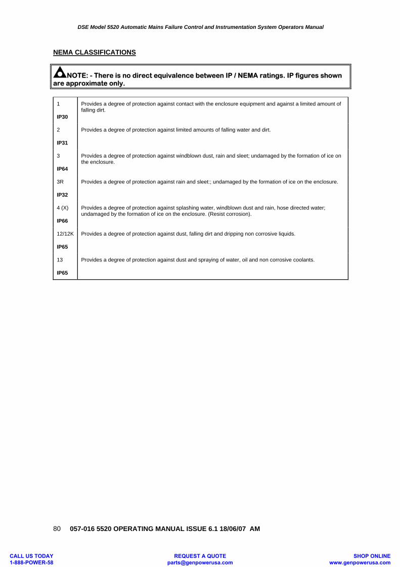
DSE Model 5520 Automatic Mains Failure Control and Instrumentation System Operators Manual
057-016 5520 OPERATING MANUAL ISSUE 6.1 18/06/07 AM
80
NEMA CLASSIFICATIONS
NOTE: - There is no direct equivalence between IP / NEMA ratings. IP figures shown are approximate only.
1
IP30
Provides a degree of protection against contact with the enclosure equipment and against a limited amount of falling dirt.
2
IP31
Provides a degree of protection against limited amounts of falling water and dirt.
3
IP64
Provides a degree of protection against windblown dust, rain and sleet; undamaged by the formation of ice on the enclosure.
3R
IP32
Provides a degree of protection against rain and sleet:; undamaged by the formation of ice on the enclosure.
4 (X)
IP66
Provides a degree of protection against splashing water, windblown dust and rain, hose directed water; undamaged by the formation of ice on the enclosure. (Resist corrosion).
12/12K
IP65
Provides a degree of protection against dust, falling dirt and dripping non corrosive liquids.
13
IP65
Provides a degree of protection against dust and spraying of water, oil and non corrosive coolants.
CALL US TODAY 1-888-POWER-58
REQUEST A QUOTE [email protected]
SHOP ONLINE www.genpowerusa.com
DSE Model 5520 Automatic Mains Failure Control and Instrumentation System Operators Manual
057-016 5520 OPERATING MANUAL ISSUE 6.1 18/06/07 AM 81
12. SYNCHRONISING NOTES Optionally, the 5520 controller can be configured to synchronise, volts match and parallel with the mains supply. This facility can be used to supply a fixed amount of power to the load and/or mains supply or provide no-break (closed transition) transfers to and from the generator supply. Additionally, with the addition of the optional Mains CT, the module can be used to automatically start the set upon rising mains load and use the generator set to keep the mains load below an adjustable level. 16.6.1 CHECK SYNC (If enabled) The module will control the operation of the load-switching device to allow parallel operation with the mains supply only when the two supplies are in Synchronism. These functions can be used to provide manual Peak lopping/ Peak shaving and short duration no-break or bump-less transfers back to the mains supply following a mains failure. Refer to the 5xxx software manual for further details. 16.6.2 AUTO SYNC (If enabled) The module provides control signals to the Engine Governor and the Alternator AVR to control the speed and voltage output from the generating set. These functions can be used to provide peak lopping/ peak shaving (without load share control) and true no-break or bump-less transfers back to the mains supply following a mains failure. The 5xxx module provides the ability to control the generator by adjusting the speed (frequency) and voltage being output. Several methods of providing this control are available. The following pages give a schematic overview of the interface with the engine governor and alternator AVR. Refer to the 5xxx software manual for further details. 16.6.3 LOAD CONTROL (If enabled) The module features all the functions associated with the Check sync and autosync features and in addition it provides control signals to the Engine Governor and the Alternator AVR while in parallel with the mains (utility) supply to provide soft loading (load ramping) and control the amount of load (kW and kVAr) supplied by the generating set. These functions can be used to provide peak lopping / peak shaving and true no-break or bump-less transfers back to the mains supply following a mains failure. MAINS CT Mains current monitoring is included as standard to allow (optional) automatic starting of the set on rising load levels to allow true peak lopping / shaving, ramping of the load from the mains to the set and vice versa and more. Refer to the 5xxx software manual for further details.
CALL US TODAY 1-888-POWER-58
REQUEST A QUOTE [email protected]
SHOP ONLINE www.genpowerusa.com
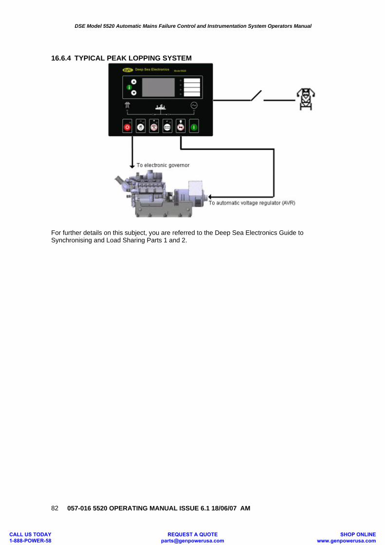
DSE Model 5520 Automatic Mains Failure Control and Instrumentation System Operators Manual
057-016 5520 OPERATING MANUAL ISSUE 6.1 18/06/07 AM
82
16.6.4 TYPICAL PEAK LOPPING SYSTEM
For further details on this subject, you are referred to the Deep Sea Electronics Guide to Synchronising and Load Sharing Parts 1 and 2.
CALL US TODAY 1-888-POWER-58
REQUEST A QUOTE [email protected]
SHOP ONLINE www.genpowerusa.com