Embed Size (px)
Citation preview
053-068 ISS 1
D E E P S E A E L E C T R O N I C S
DSE124 INSTALLATION INSTRUCTIONS
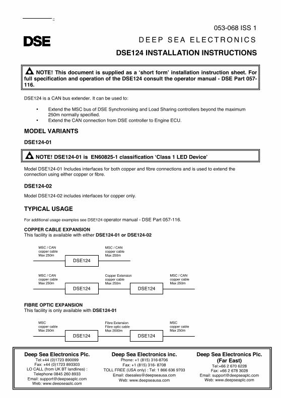
NOTE! This document is supplied as a ‘short form’ installation instruction sheet. For full specification and operation of the DSE124 consult the operator manual - DSE Part 057-116. DSE124 is a CAN bus extender. It can be used to:
• Extend the MSC bus of DSE Synchronising and Load Sharing controllers beyond the maximum 250m normally specified.
• Extend the CAN connection from DSE controller to Engine ECU. MODEL VARIANTS DSE124-01
NOTE! DSE124-01 is EN60825-1 classification ‘Class 1 LED Device’ Model DSE124-01 Includes interfaces for both copper and fibre connections and is used to extend the connection using either copper or fibre. DSE124-02 Model DSE124-02 includes interfaces for copper only. TYPICAL USAGE For additional usage examples see DSE124 operator manual - DSE Part 057-116. COPPER CABLE EXPANSION This facility is available with either DSE124-01 or DSE124-02 FIBRE OPTIC EXPANSION This facility is only available with DSE124-01
Deep Sea Electronics Plc. Tel:+44 (0)1723 890099
Fax: +44 (0)1723 893303 LO CALL (from UK BT landlines) :
Telephone 0845 260 8933 Email: [email protected]
Web: www.deepseaplc.com
Deep Sea Electronics inc. Phone: +1 (815) 316-8706 Fax: +1 (815) 316- 8708
TOLL FREE (USA only) : Tel: 1 866 636 9703 Email: [email protected]
Web: www.deepseausa.com
Deep Sea Electronics Plc. (Far East)
Tel:+66 2 670 6228 Fax: +66 2 678 3028
Email: [email protected] Web: www.deepseaplc.com
DSE124
MSC / CAN copper cable Max 250m
MSC / CAN copper cable Max 250m
DSE124
MSC / CAN copper cable Max 250m
Copper Extension copper cable Max 250m
DSE124
MSC / CAN copper cable Max 250m
DSE124
MSC copper cable Max 250m
Fibre Extension Fibre optic cable Max 2000m
DSE124
MSC copper cable Max 250m
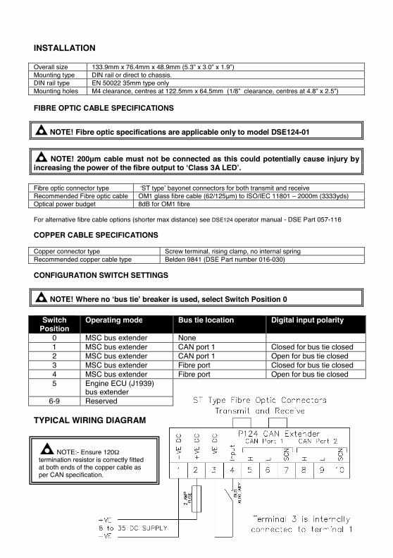
INSTALLATION Overall size 133.9mm x 76.4mm x 48.9mm (5.3” x 3.0” x 1.9”) Mounting type DIN rail or direct to chassis. DIN rail type EN 50022 35mm type only Mounting holes M4 clearance, centres at 122.5mm x 64.5mm (1/8” clearance, centres at 4.8” x 2.5”) FIBRE OPTIC CABLE SPECIFICATIONS
NOTE! Fibre optic specifications are applicable only to model DSE124-01
NOTE! 200µm cable must not be connected as this could potentially cause injury by increasing the power of the fibre output to ‘Class 3A LED’. Fibre optic connector type ‘ST type’ bayonet connectors for both transmit and receive Recommended Fibre optic cable OM1 glass fibre cable (62/125µm) to ISO/IEC 11801 – 2000m (3333yds) Optical power budget 8dB for OM1 fibre For alternative fibre cable options (shorter max distance) see DSE124 operator manual - DSE Part 057-116 COPPER CABLE SPECIFICATIONS Copper connector type Screw terminal, rising clamp, no internal spring Recommended copper cable type Belden 9841 (DSE Part number 016-030) CONFIGURATION SWITCH SETTINGS
NOTE! Where no ‘bus tie’ breaker is used, select Switch Position 0
Switch
Position Operating mode Bus tie location Digital input polarity
0 MSC bus extender None 1 MSC bus extender CAN port 1 Closed for bus tie closed 2 MSC bus extender CAN port 1 Open for bus tie closed 3 MSC bus extender Fibre port Closed for bus tie closed 4 MSC bus extender Fibre port Open for bus tie closed 5 Engine ECU (J1939)
bus extender
6-9 Reserved TYPICAL WIRING DIAGRAM
NOTE:- Ensure 120Ω termination resistor is correctly fitted at both ends of the copper cable as per CAN specification.
DSEEXTRA®
DSE124 CAN extender operator manual
Document Number 057-116
Author : Anthony Manton
DSE Model 124 CAN Extender Operators Manual
2 Part No. 057-116 DSE Model 124 CAN Extender Operators Manual ISSUE 1 26/01/2010 ADM
Deep Sea Electronics Plc Highfield House Hunmanby North Yorkshire YO14 0PH ENGLAND Sales Tel: +44 (0) 1723 890099 Sales Fax: +44 (0) 1723 893303 E-mail: [email protected] Website: www.deepseaplc.com
DSE Model 124 CAN Extender Operators Manual © Deep Sea Electronics Plc All rights reserved. No part of this publication may be reproduced in any material form (including photocopying or storing in any medium by electronic means or other) without the written permission of the copyright holder except in accordance with the provisions of the Copyright, Designs and Patents Act 1988. Applications for the copyright holder’s written permission to reproduce any part of this publication should be addressed to Deep Sea Electronics Plc at the address above. The DSE logo and the names DSEUltra, DSEControl, DSEPower, DSEExtra, DSEMarine and DSENet are UK registered trademarks of Deep Sea Electronics PLC. Any reference to trademarked product names used within this publication is owned by their respective companies. Deep Sea Electronics Plc reserves the right to change the contents of this document without prior notice. Amendments since last publication Amd. No. Comments Issue 1 First release Clarification of notation used within this publication.
NOTE:
Highlights an essential element of a procedure to ensure correctness.
CAUTION!
Indicates a procedure or practice, which, if not strictly observed, could result in damage or destruction of equipment.
WARNING!
Indicates a procedure or practice, which could result in injury to personnel or loss of life if not followed correctly.
DSE Model 124 CAN Extender Operators Manual
Part No. 057-116 DSE Model 124 CAN Extender Operators Manual ISSUE 1 26/01/2010 ADM 3
TABLE OF CONTENTS
Section Page 1 BIBLIOGRAPHY ........................................................................................... 4
1.1 INSTALLATION INSTRUCTIONS ................................................................................. 4 1.2 MANUALS .................................................................................................................. 4
2 INTRODUCTION ........................................................................................... 4
3 SPECIFICATIONS ........................................................................................ 5 3.1 PART NUMBERING .................................................................................................... 5 3.1 POWER SUPPLY REQUIREMENTS ............................................................................ 6 3.2 TERMINAL SPECIFICATION........................................................................................ 6 3.3 INPUTS ...................................................................................................................... 6
3.3.1 DIGITAL INPUT .................................................................................................... 6 3.4 COMMUNICATION PORTS ......................................................................................... 6
3.4.1 COPPER PORTS.................................................................................................. 6 3.4.2 FIBRE OPTIC PORT ............................................................................................. 8
3.5 DIMENSIONS AND MOUNTING ................................................................................... 9 3.5.1 DIMENSIONS ....................................................................................................... 9 3.5.2 WEIGHT............................................................................................................... 9
3.6 APPLICABLE STANDARDS ......................................................................................... 9
4 INSTALLATION.......................................................................................... 10 4.1 TERMINAL DESCRIPTION ........................................................................................ 10
4.1.1 SCREW TERMINALS (DSE124-01 AND DSE124-02) ............................................ 10 4.1.2 ST BAYONET OPTICAL CONNECTIONS (DSE124-01 ONLY)............................... 11
5 TYPICAL CONNECTION DIAGRAM ........................................................... 12
6 TYPICAL SYSTEM SCHEMATICS ............................................................. 13 6.1 COPPER CABLE EXPANSION................................................................................... 13
6.1.1 EXTENDING THE DSE LOAD SHARE MULTISET COMMUNICATIONS (MSC) LINK13 6.1.2 EXTENDING THE DSE CAN LINK TO AN ENGINE ECU ........................................ 14
6.2 FIBRE OPTIC EXPANSION........................................................................................ 15 6.2.1 EXTENDING THE DSE LOAD SHARE MULTISET COMMUNICATIONS (MSC) LINK15 6.2.2 EXTENDING THE DSE CAN LINK TO AN ENGINE ECU ........................................ 16
6.3 FIBRE OPTIC EXPANSION WITH ‘T’ JUNCTION TO COPPER .................................. 17 6.4 COMPLEX EXAMPLE WITH OPTIC FIBRE AND COPPER EXTENSIONS ................... 18
7 BUS TIE BREAKER ................................................................................... 19 7.1 BREAKING A COPPER MSC LINK ............................................................................ 19 7.2 BREAKING A FIBRE MSC LINK................................................................................. 20
8 CONTROLS AND INDICATIONS ................................................................ 21 8.1 CONFIGURATION SWITCH ....................................................................................... 21 8.2 STATUS LEDS.......................................................................................................... 21
9 MAINTENANCE, SPARES, REPAIR AND SERVICING .............................. 22
10 WARRANTY ............................................................................................ 22
11 DISPOSAL .............................................................................................. 22 11.1 WEEE (WASTE ELECTRICAL AND ELECTRONIC EQUIPMENT) ............................ 22 11.2 ROHS (RESTRICTION OF HAZARDOUS SUBSTANCES)........................................ 22
DSE Model 124 CAN Extender Operators Manual
4 Part No. 057-116 DSE Model 124 CAN Extender Operators Manual ISSUE 1 26/01/2010 ADM
1 BIBLIOGRAPHY The following DSE publications are available to assist with usage of the DSE124 CAN extender module. 1.1 INSTALLATION INSTRUCTIONS DSE PART DESCRIPTION 053-068 DSE124 installation instructions. - Also supplied in the packing box with the DSE124 1.2 MANUALS
DSE PART DESCRIPTION 057-004 Electronic Engines and DSE wiring. - Details connections of the CAN link to the engine ECU 057-047 Load Share Design and Commissioning Guide
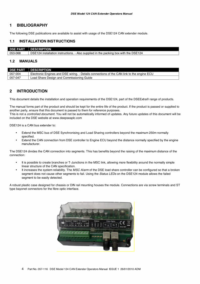
2 INTRODUCTION This document details the installation and operation requirements of the DSE124, part of the DSEExtra® range of products. The manual forms part of the product and should be kept for the entire life of the product. If the product is passed or supplied to another party, ensure that this document is passed to them for reference purposes. This is not a controlled document. You will not be automatically informed of updates. Any future updates of this document will be included on the DSE website at www.deepseaplc.com DSE124 is a CAN bus extender to:
• Extend the MSC bus of DSE Synchronising and Load Sharing controllers beyond the maximum 250m normally specified.
• Extend the CAN connection from DSE controller to Engine ECU beyond the distance normally specified by the engine manufacturer.
The DSE124 divides the CAN connection into segments. This has benefits beyond the raising of the maximum distance of the connection:
• It is possible to create branches or T-Junctions in the MSC link, allowing more flexibility around the normally simple linear structure of the CAN specification.
• It increases the system reliability. The MSC Alarm of the DSE load share controller can be configured so that a broken segment does not cause other segments to fail. Using the Status LEDs on the DSE124 module allows the failed segment to be easily detected.
A robust plastic case designed for chassis or DIN rail mounting houses the module. Connections are via screw terminals and ST type bayonet connectors for the fibre optic interface.
DSE Model 124 CAN Extender Operators Manual
Part No. 057-116 DSE Model 124 CAN Extender Operators Manual ISSUE 1 26/01/2010 ADM 5
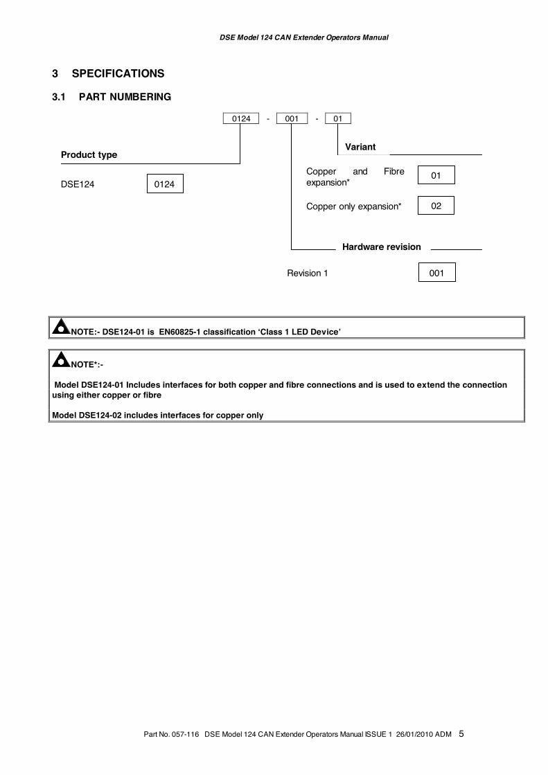
3 SPECIFICATIONS 3.1 PART NUMBERING
0124 - 001 - 01
NOTE:- DSE124-01 is EN60825-1 classification ‘Class 1 LED Device’
NOTE*:- Model DSE124-01 Includes interfaces for both copper and fibre connections and is used to extend the connection using either copper or fibre Model DSE124-02 includes interfaces for copper only
Product type
DSE124 0124
Variant
Copper and Fibre expansion*
01
Hardware revision
Revision 1 001
Copper only expansion* 02
DSE Model 124 CAN Extender Operators Manual
6 Part No. 057-116 DSE Model 124 CAN Extender Operators Manual ISSUE 1 26/01/2010 ADM
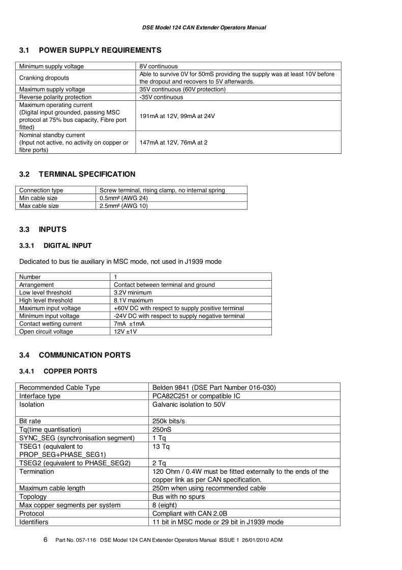
3.1 POWER SUPPLY REQUIREMENTS Minimum supply voltage 8V continuous
Cranking dropouts Able to survive 0V for 50mS providing the supply was at least 10V before the dropout and recovers to 5V afterwards.
Maximum supply voltage 35V continuous (60V protection) Reverse polarity protection -35V continuous Maximum operating current (Digital input grounded, passing MSC protocol at 75% bus capacity, Fibre port fitted)
191mA at 12V, 99mA at 24V
Nominal standby current (Input not active, no activity on copper or fibre ports)
147mA at 12V, 76mA at 2
3.2 TERMINAL SPECIFICATION Connection type Screw terminal, rising clamp, no internal spring Min cable size 0.5mm² (AWG 24) Max cable size 2.5mm² (AWG 10)
3.3 INPUTS 3.3.1 DIGITAL INPUT Dedicated to bus tie auxiliary in MSC mode, not used in J1939 mode Number 1 Arrangement Contact between terminal and ground Low level threshold 3.2V minimum High level threshold 8.1V maximum Maximum input voltage +60V DC with respect to supply positive terminal Minimum input voltage -24V DC with respect to supply negative terminal Contact wetting current 7mA ±1mA Open circuit voltage 12V ±1V 3.4 COMMUNICATION PORTS 3.4.1 COPPER PORTS Recommended Cable Type Belden 9841 (DSE Part Number 016-030) Interface type PCA82C251 or compatible IC Isolation Galvanic isolation to 50V
Bit rate 250k bits/s Tq(time quantisation) 250nS SYNC_SEG (synchronisation segment) 1 Tq TSEG1 (equivalent to PROP_SEG+PHASE_SEG1)
13 Tq
TSEG2 (equivalent to PHASE_SEG2) 2 Tq Termination 120 Ohm / 0.4W must be fitted externally to the ends of the
copper link as per CAN specification. Maximum cable length 250m when using recommended cable Topology Bus with no spurs Max copper segments per system 8 (eight) Protocol Compliant with CAN 2.0B Identifiers 11 bit in MSC mode or 29 bit in J1939 mode
DSE Model 124 CAN Extender Operators Manual
Part No. 057-116 DSE Model 124 CAN Extender Operators Manual ISSUE 1 26/01/2010 ADM 7
Message format Compatible with DSE MSC bus in MSC mode and J1939 in J1939 mode
DSE Model 124 CAN Extender Operators Manual
8 Part No. 057-116 DSE Model 124 CAN Extender Operators Manual ISSUE 1 26/01/2010 ADM
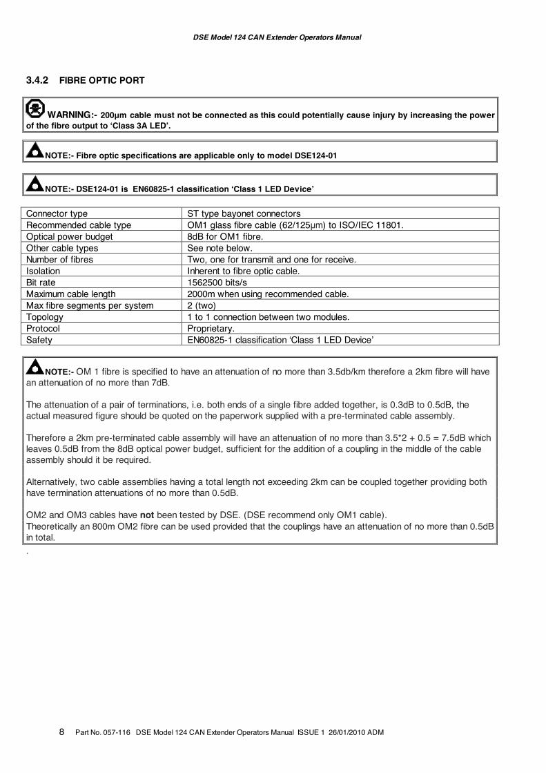
3.4.2 FIBRE OPTIC PORT
WARNING:- 200µm cable must not be connected as this could potentially cause injury by increasing the power of the fibre output to ‘Class 3A LED’.
NOTE:- Fibre optic specifications are applicable only to model DSE124-01
NOTE:- DSE124-01 is EN60825-1 classification ‘Class 1 LED Device’ Connector type ST type bayonet connectors Recommended cable type OM1 glass fibre cable (62/125µm) to ISO/IEC 11801. Optical power budget 8dB for OM1 fibre. Other cable types See note below. Number of fibres Two, one for transmit and one for receive. Isolation Inherent to fibre optic cable. Bit rate 1562500 bits/s Maximum cable length 2000m when using recommended cable. Max fibre segments per system 2 (two) Topology 1 to 1 connection between two modules. Protocol Proprietary. Safety EN60825-1 classification ‘Class 1 LED Device’
NOTE:- OM 1 fibre is specified to have an attenuation of no more than 3.5db/km therefore a 2km fibre will have an attenuation of no more than 7dB. The attenuation of a pair of terminations, i.e. both ends of a single fibre added together, is 0.3dB to 0.5dB, the actual measured figure should be quoted on the paperwork supplied with a pre-terminated cable assembly. Therefore a 2km pre-terminated cable assembly will have an attenuation of no more than 3.5*2 + 0.5 = 7.5dB which leaves 0.5dB from the 8dB optical power budget, sufficient for the addition of a coupling in the middle of the cable assembly should it be required. Alternatively, two cable assemblies having a total length not exceeding 2km can be coupled together providing both have termination attenuations of no more than 0.5dB. OM2 and OM3 cables have not been tested by DSE. (DSE recommend only OM1 cable). Theoretically an 800m OM2 fibre can be used provided that the couplings have an attenuation of no more than 0.5dB in total. .
DSE Model 124 CAN Extender Operators Manual
Part No. 057-116 DSE Model 124 CAN Extender Operators Manual ISSUE 1 26/01/2010 ADM 9
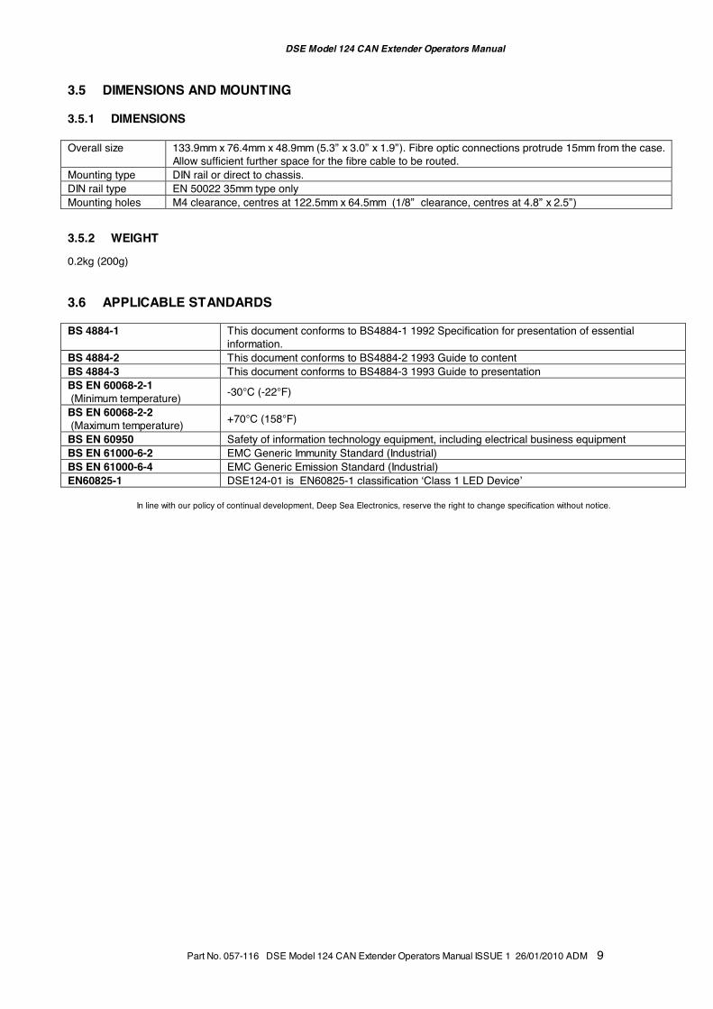
3.5 DIMENSIONS AND MOUNTING 3.5.1 DIMENSIONS Overall size 133.9mm x 76.4mm x 48.9mm (5.3” x 3.0” x 1.9”). Fibre optic connections protrude 15mm from the case.
Allow sufficient further space for the fibre cable to be routed. Mounting type DIN rail or direct to chassis. DIN rail type EN 50022 35mm type only Mounting holes M4 clearance, centres at 122.5mm x 64.5mm (1/8” clearance, centres at 4.8” x 2.5”) 3.5.2 WEIGHT 0.2kg (200g) 3.6 APPLICABLE STANDARDS BS 4884-1 This document conforms to BS4884-1 1992 Specification for presentation of essential
information. BS 4884-2 This document conforms to BS4884-2 1993 Guide to content BS 4884-3 This document conforms to BS4884-3 1993 Guide to presentation BS EN 60068-2-1 (Minimum temperature) -30°C (-22°F)
BS EN 60068-2-2 (Maximum temperature) +70°C (158°F)
BS EN 60950 Safety of information technology equipment, including electrical business equipment BS EN 61000-6-2 EMC Generic Immunity Standard (Industrial) BS EN 61000-6-4 EMC Generic Emission Standard (Industrial) EN60825-1 DSE124-01 is EN60825-1 classification ‘Class 1 LED Device’
In line with our policy of continual development, Deep Sea Electronics, reserve the right to change specification without notice.
DSE Model 124 CAN Extender Operators Manual
10 Part No. 057-116 DSE Model 124 CAN Extender Operators Manual ISSUE 1 26/01/2010 ADM
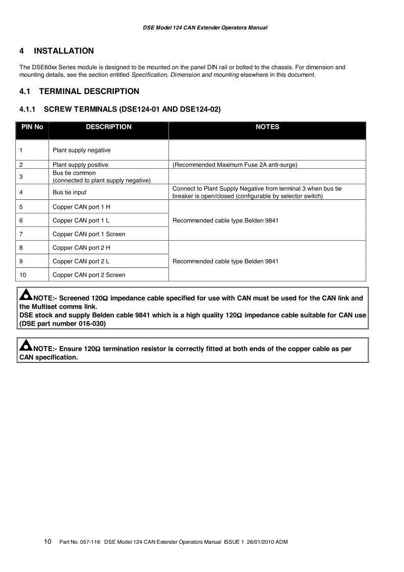
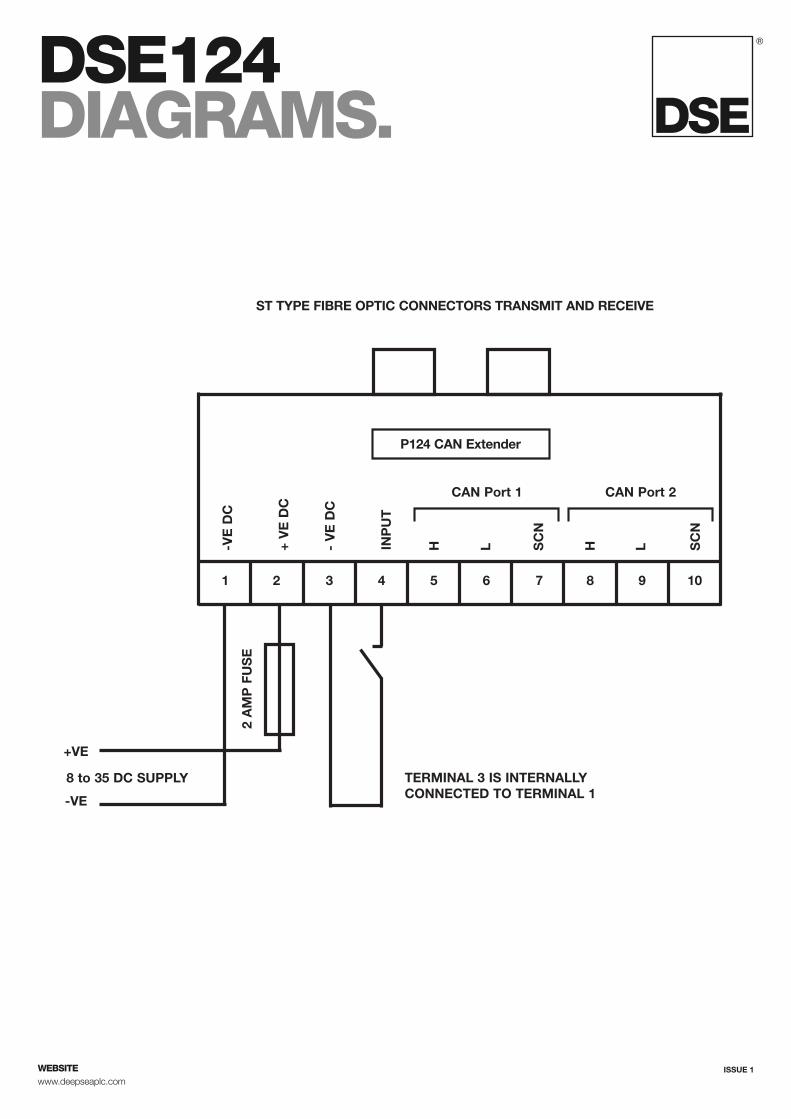
4 INSTALLATION The DSE60xx Series module is designed to be mounted on the panel DIN rail or bolted to the chassis. For dimension and mounting details, see the section entitled Specification, Dimension and mounting elsewhere in this document. 4.1 TERMINAL DESCRIPTION 4.1.1 SCREW TERMINALS (DSE124-01 AND DSE124-02) PIN No DESCRIPTION NOTES
1 Plant supply negative
2 Plant supply positive (Recommended Maximum Fuse 2A anti-surge)
3 Bus tie common (connected to plant supply negative)
4 Bus tie input Connect to Plant Supply Negative from terminal 3 when bus tie breaker is open/closed (configurable by selector switch)
5 Copper CAN port 1 H
Recommended cable type Belden 9841 6 Copper CAN port 1 L
7 Copper CAN port 1 Screen
8 Copper CAN port 2 H
Recommended cable type Belden 9841 9 Copper CAN port 2 L
10 Copper CAN port 2 Screen
NOTE:- Screened 120ΩΩΩΩ impedance cable specified for use with CAN must be used for the CAN link and the Multiset comms link. DSE stock and supply Belden cable 9841 which is a high quality 120ΩΩΩΩ impedance cable suitable for CAN use (DSE part number 016-030)
NOTE:- Ensure 120ΩΩΩΩ termination resistor is correctly fitted at both ends of the copper cable as per CAN specification.
DSE Model 124 CAN Extender Operators Manual
Part No. 057-116 DSE Model 124 CAN Extender Operators Manual ISSUE 1 26/01/2010 ADM 11
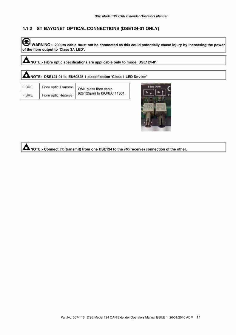
4.1.2 ST BAYONET OPTICAL CONNECTIONS (DSE124-01 ONLY)
WARNING:- 200µm cable must not be connected as this could potentially cause injury by increasing the power of the fibre output to ‘Class 3A LED’.
NOTE:- Fibre optic specifications are applicable only to model DSE124-01
NOTE:- DSE124-01 is EN60825-1 classification ‘Class 1 LED Device’
FIBRE Fibre optic Transmit OM1 glass fibre cable (62/125µm) to ISO/IEC 11801.
FIBRE Fibre optic Receive
NOTE:- Connect Tx (transmit) from one DSE124 to the Rx (receive) connection of the other.
DSE Model 124 CAN Extender Operators Manual
12 Part No. 057-116 DSE Model 124 CAN Extender Operators Manual ISSUE 1 26/01/2010 ADM
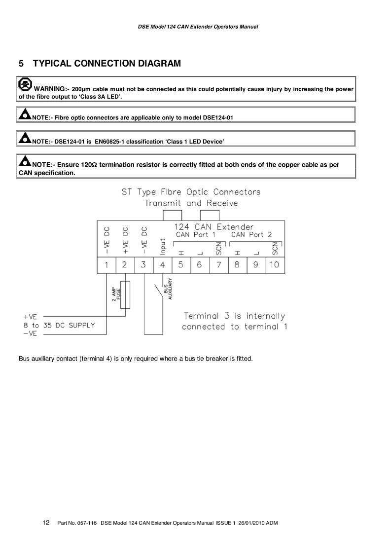
5 TYPICAL CONNECTION DIAGRAM
WARNING:- 200µm cable must not be connected as this could potentially cause injury by increasing the power of the fibre output to ‘Class 3A LED’.
NOTE:- Fibre optic connectors are applicable only to model DSE124-01
NOTE:- DSE124-01 is EN60825-1 classification ‘Class 1 LED Device’
NOTE:- Ensure 120ΩΩΩΩ termination resistor is correctly fitted at both ends of the copper cable as per CAN specification.
Bus auxiliary contact (terminal 4) is only required where a bus tie breaker is fitted.
DSE Model 124 CAN Extender Operators Manual
Part No. 057-116 DSE Model 124 CAN Extender Operators Manual ISSUE 1 26/01/2010 ADM 13
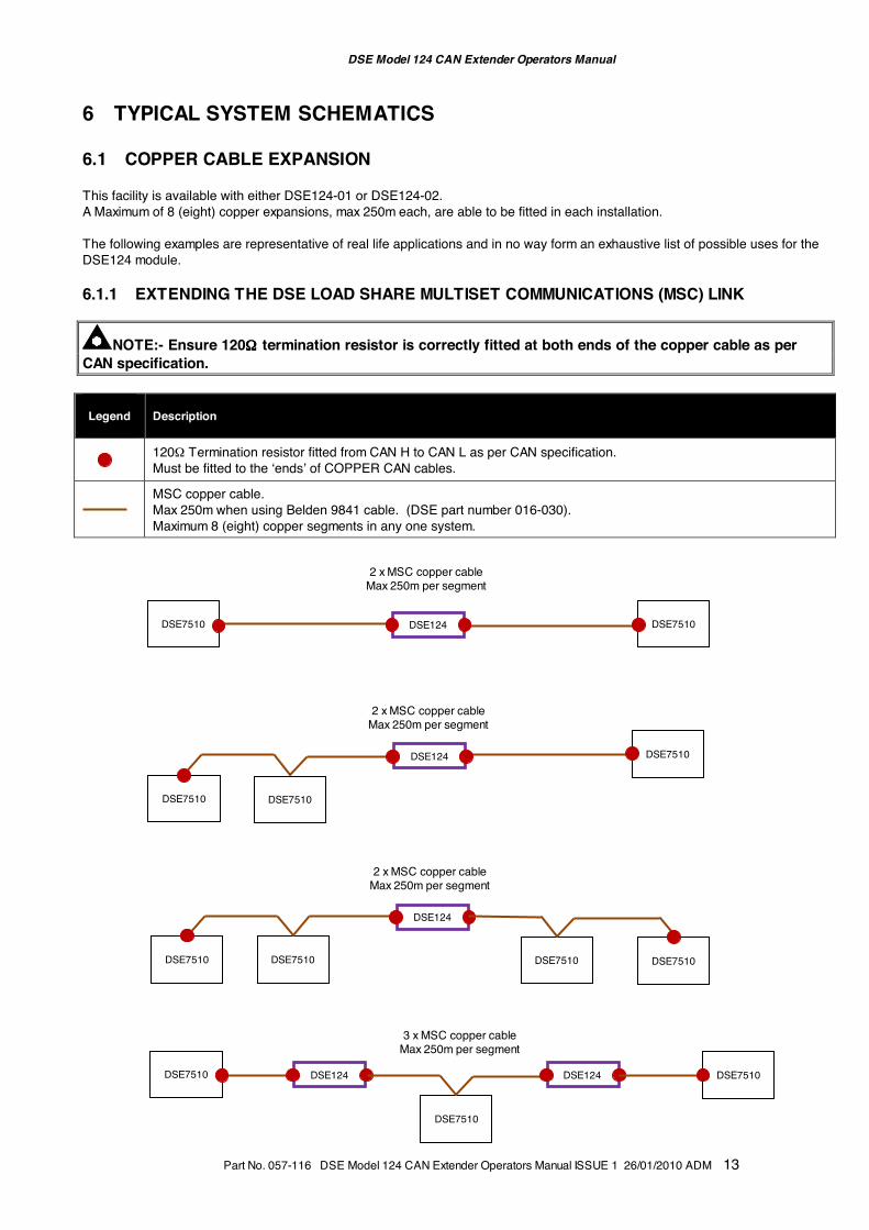
6 TYPICAL SYSTEM SCHEMATICS
6.1 COPPER CABLE EXPANSION This facility is available with either DSE124-01 or DSE124-02. A Maximum of 8 (eight) copper expansions, max 250m each, are able to be fitted in each installation. The following examples are representative of real life applications and in no way form an exhaustive list of possible uses for the DSE124 module. 6.1.1 EXTENDING THE DSE LOAD SHARE MULTISET COMMUNICATIONS (MSC) LINK
NOTE:- Ensure 120ΩΩΩΩ termination resistor is correctly fitted at both ends of the copper cable as per CAN specification. Legend
Description
120Ω Termination resistor fitted from CAN H to CAN L as per CAN specification. Must be fitted to the ‘ends’ of COPPER CAN cables.
MSC copper cable. Max 250m when using Belden 9841 cable. (DSE part number 016-030). Maximum 8 (eight) copper segments in any one system.
3 x MSC copper cable Max 250m per segment
DSE124
DSE7510
DSE7510
DSE7510
DSE7510
DSE7510
DSE124
DSE7510
DSE7510
DSE124
DSE7510
DSE7510
DSE124
DSE7510
DSE7510
DSE7510
DSE124
2 x MSC copper cable Max 250m per segment
2 x MSC copper cable Max 250m per segment
2 x MSC copper cable Max 250m per segment
DSE Model 124 CAN Extender Operators Manual
14 Part No. 057-116 DSE Model 124 CAN Extender Operators Manual ISSUE 1 26/01/2010 ADM
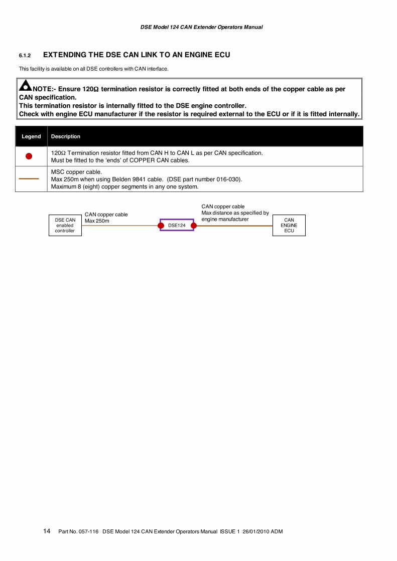
6.1.2 EXTENDING THE DSE CAN LINK TO AN ENGINE ECU This facility is available on all DSE controllers with CAN interface.
NOTE:- Ensure 120ΩΩΩΩ termination resistor is correctly fitted at both ends of the copper cable as per CAN specification. This termination resistor is internally fitted to the DSE engine controller. Check with engine ECU manufacturer if the resistor is required external to the ECU or if it is fitted internally. Legend
Description
120Ω Termination resistor fitted from CAN H to CAN L as per CAN specification. Must be fitted to the ‘ends’ of COPPER CAN cables.
MSC copper cable. Max 250m when using Belden 9841 cable. (DSE part number 016-030). Maximum 8 (eight) copper segments in any one system.
DSE124
CAN copper cable Max 250m
CAN copper cable Max distance as specified by engine manufacturer DSE CAN
enabled controller
CAN ENGINE
ECU
DSE Model 124 CAN Extender Operators Manual
Part No. 057-116 DSE Model 124 CAN Extender Operators Manual ISSUE 1 26/01/2010 ADM 15
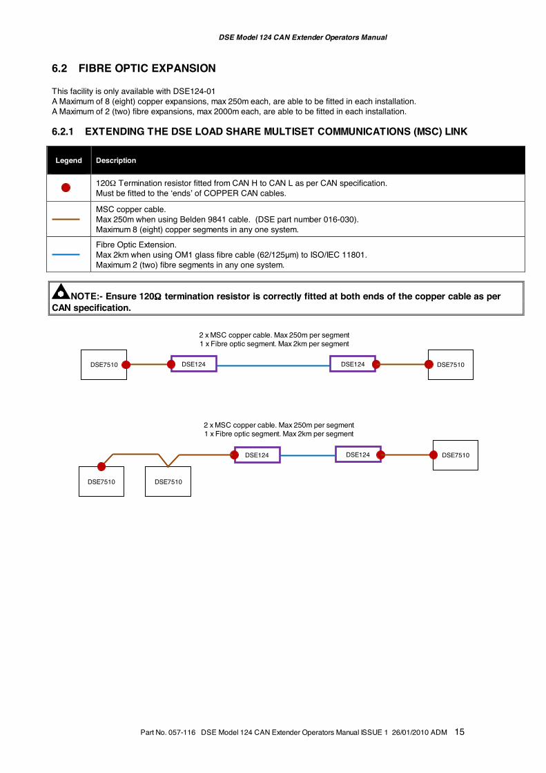
6.2 FIBRE OPTIC EXPANSION This facility is only available with DSE124-01 A Maximum of 8 (eight) copper expansions, max 250m each, are able to be fitted in each installation. A Maximum of 2 (two) fibre expansions, max 2000m each, are able to be fitted in each installation. 6.2.1 EXTENDING THE DSE LOAD SHARE MULTISET COMMUNICATIONS (MSC) LINK Legend
Description
120Ω Termination resistor fitted from CAN H to CAN L as per CAN specification. Must be fitted to the ‘ends’ of COPPER CAN cables.
MSC copper cable. Max 250m when using Belden 9841 cable. (DSE part number 016-030). Maximum 8 (eight) copper segments in any one system.
Fibre Optic Extension. Max 2km when using OM1 glass fibre cable (62/125µm) to ISO/IEC 11801. Maximum 2 (two) fibre segments in any one system.
NOTE:- Ensure 120ΩΩΩΩ termination resistor is correctly fitted at both ends of the copper cable as per CAN specification.
2 x MSC copper cable. Max 250m per segment 1 x Fibre optic segment. Max 2km per segment
DSE124
DSE7510
DSE7510 DSE124
2 x MSC copper cable. Max 250m per segment 1 x Fibre optic segment. Max 2km per segment
DSE124
DSE7510 DSE124
DSE7510
DSE7510
DSE Model 124 CAN Extender Operators Manual
16 Part No. 057-116 DSE Model 124 CAN Extender Operators Manual ISSUE 1 26/01/2010 ADM
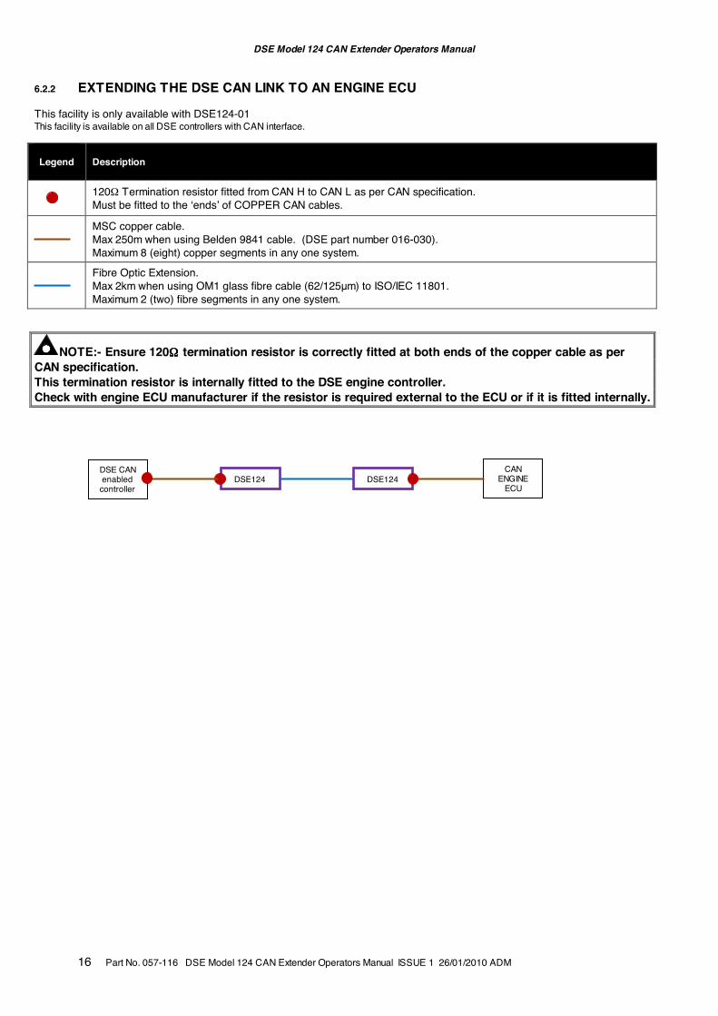
6.2.2 EXTENDING THE DSE CAN LINK TO AN ENGINE ECU This facility is only available with DSE124-01 This facility is available on all DSE controllers with CAN interface. Legend
Description
120Ω Termination resistor fitted from CAN H to CAN L as per CAN specification. Must be fitted to the ‘ends’ of COPPER CAN cables.
MSC copper cable. Max 250m when using Belden 9841 cable. (DSE part number 016-030). Maximum 8 (eight) copper segments in any one system.
Fibre Optic Extension. Max 2km when using OM1 glass fibre cable (62/125µm) to ISO/IEC 11801. Maximum 2 (two) fibre segments in any one system.
NOTE:- Ensure 120ΩΩΩΩ termination resistor is correctly fitted at both ends of the copper cable as per CAN specification. This termination resistor is internally fitted to the DSE engine controller. Check with engine ECU manufacturer if the resistor is required external to the ECU or if it is fitted internally.
DSE CAN enabled
controller
CAN ENGINE
ECU DSE124 DSE124
DSE Model 124 CAN Extender Operators Manual
Part No. 057-116 DSE Model 124 CAN Extender Operators Manual ISSUE 1 26/01/2010 ADM 17
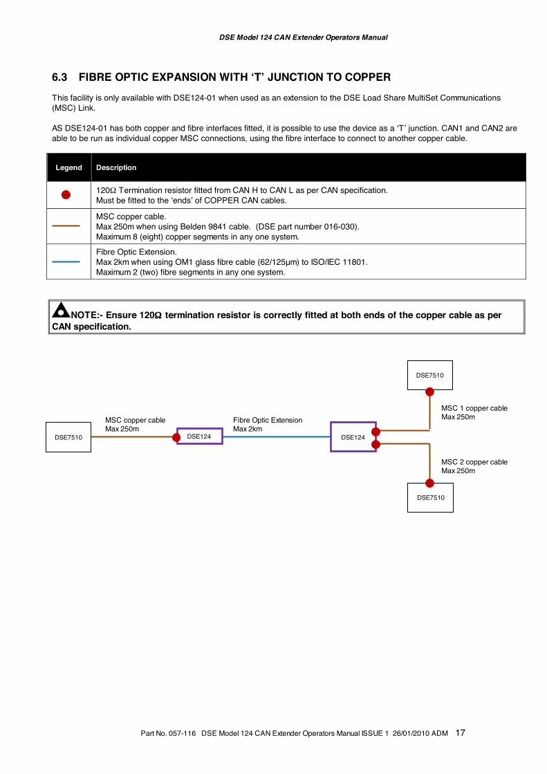
6.3 FIBRE OPTIC EXPANSION WITH ‘T’ JUNCTION TO COPPER This facility is only available with DSE124-01 when used as an extension to the DSE Load Share MultiSet Communications (MSC) Link. AS DSE124-01 has both copper and fibre interfaces fitted, it is possible to use the device as a ‘T’ junction. CAN1 and CAN2 are able to be run as individual copper MSC connections, using the fibre interface to connect to another copper cable. Legend
Description
120Ω Termination resistor fitted from CAN H to CAN L as per CAN specification. Must be fitted to the ‘ends’ of COPPER CAN cables.
MSC copper cable. Max 250m when using Belden 9841 cable. (DSE part number 016-030). Maximum 8 (eight) copper segments in any one system.
Fibre Optic Extension. Max 2km when using OM1 glass fibre cable (62/125µm) to ISO/IEC 11801. Maximum 2 (two) fibre segments in any one system.
NOTE:- Ensure 120ΩΩΩΩ termination resistor is correctly fitted at both ends of the copper cable as per CAN specification.
DSE124
MSC copper cable Max 250m
Fibre Optic Extension Max 2km
DSE124
MSC 2 copper cable Max 250m
MSC 1 copper cable Max 250m
DSE7510
DSE7510
DSE7510
DSE Model 124 CAN Extender Operators Manual
18 Part No. 057-116 DSE Model 124 CAN Extender Operators Manual ISSUE 1 26/01/2010 ADM
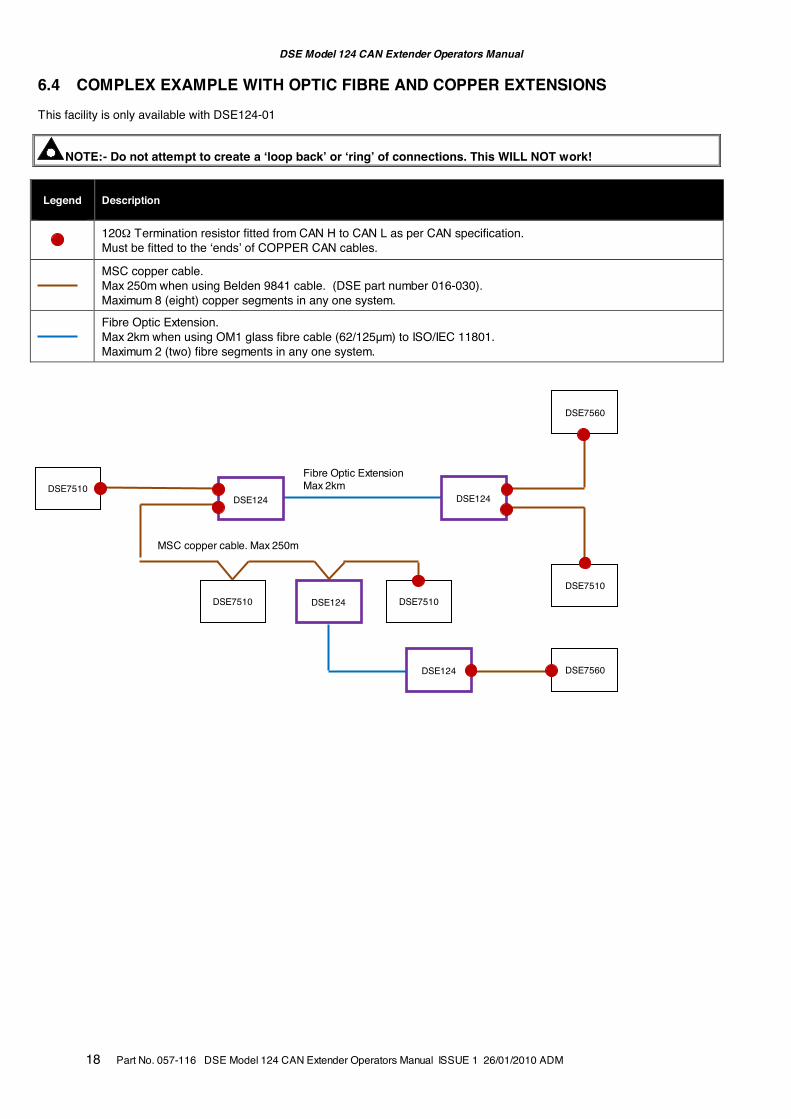
6.4 COMPLEX EXAMPLE WITH OPTIC FIBRE AND COPPER EXTENSIONS This facility is only available with DSE124-01
NOTE:- Do not attempt to create a ‘loop back’ or ‘ring’ of connections. This WILL NOT work! Legend
Description
120Ω Termination resistor fitted from CAN H to CAN L as per CAN specification. Must be fitted to the ‘ends’ of COPPER CAN cables.
MSC copper cable. Max 250m when using Belden 9841 cable. (DSE part number 016-030). Maximum 8 (eight) copper segments in any one system.
Fibre Optic Extension. Max 2km when using OM1 glass fibre cable (62/125µm) to ISO/IEC 11801. Maximum 2 (two) fibre segments in any one system.
DSE124
DSE124
DSE7510
DSE7560
DSE7510
DSE7510
DSE124
DSE7510
DSE7560
DSE124
Fibre Optic Extension Max 2km
MSC copper cable. Max 250m
DSE Model 124 CAN Extender Operators Manual
Part No. 057-116 DSE Model 124 CAN Extender Operators Manual ISSUE 1 26/01/2010 ADM 19
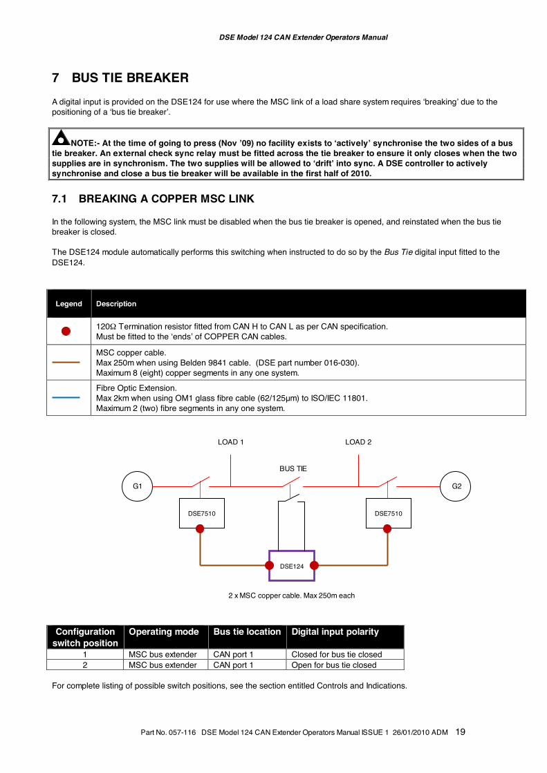
7 BUS TIE BREAKER A digital input is provided on the DSE124 for use where the MSC link of a load share system requires ‘breaking’ due to the positioning of a ‘bus tie breaker’.
NOTE:- At the time of going to press (Nov ’09) no facility exists to ‘actively’ synchronise the two sides of a bus tie breaker. An external check sync relay must be fitted across the tie breaker to ensure it only closes when the two supplies are in synchronism. The two supplies will be allowed to ‘drift’ into sync. A DSE controller to actively synchronise and close a bus tie breaker will be available in the first half of 2010. 7.1 BREAKING A COPPER MSC LINK In the following system, the MSC link must be disabled when the bus tie breaker is opened, and reinstated when the bus tie breaker is closed. The DSE124 module automatically performs this switching when instructed to do so by the Bus Tie digital input fitted to the DSE124. Legend
Description
120Ω Termination resistor fitted from CAN H to CAN L as per CAN specification. Must be fitted to the ‘ends’ of COPPER CAN cables.
MSC copper cable. Max 250m when using Belden 9841 cable. (DSE part number 016-030). Maximum 8 (eight) copper segments in any one system.
Fibre Optic Extension. Max 2km when using OM1 glass fibre cable (62/125µm) to ISO/IEC 11801. Maximum 2 (two) fibre segments in any one system.
Configuration
switch position Operating mode Bus tie location Digital input polarity
1 MSC bus extender CAN port 1 Closed for bus tie closed 2 MSC bus extender CAN port 1 Open for bus tie closed
For complete listing of possible switch positions, see the section entitled Controls and Indications.
DSE7510
DSE7510
DSE124
2 x MSC copper cable. Max 250m each
LOAD 1 LOAD 2
BUS TIE
G1 G2
DSE Model 124 CAN Extender Operators Manual
20 Part No. 057-116 DSE Model 124 CAN Extender Operators Manual ISSUE 1 26/01/2010 ADM
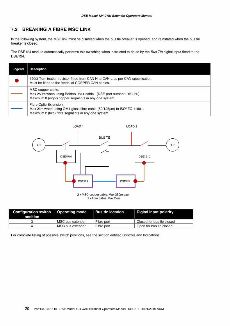
7.2 BREAKING A FIBRE MSC LINK In the following system, the MSC link must be disabled when the bus tie breaker is opened, and reinstated when the bus tie breaker is closed. The DSE124 module automatically performs this switching when instructed to do so by the Bus Tie digital input fitted to the DSE124. Legend
Description
120Ω Termination resistor fitted from CAN H to CAN L as per CAN specification. Must be fitted to the ‘ends’ of COPPER CAN cables.
MSC copper cable. Max 250m when using Belden 9841 cable. (DSE part number 016-030). Maximum 8 (eight) copper segments in any one system.
Fibre Optic Extension. Max 2km when using OM1 glass fibre cable (62/125µm) to ISO/IEC 11801. Maximum 2 (two) fibre segments in any one system.
Configuration switch
position Operating mode Bus tie location Digital input polarity
3 MSC bus extender Fibre port Closed for bus tie closed 4 MSC bus extender Fibre port Open for bus tie closed
For complete listing of possible switch positions, see the section entitled Controls and Indications.
DSE7510
DSE7510
DSE124
2 x MSC copper cable. Max 250m each 1 x fibre cable. Max 2km
LOAD 1 LOAD 2
BUS TIE
G1 G2
DSE124
DSE Model 124 CAN Extender Operators Manual
Part No. 057-116 DSE Model 124 CAN Extender Operators Manual ISSUE 1 26/01/2010 ADM 21
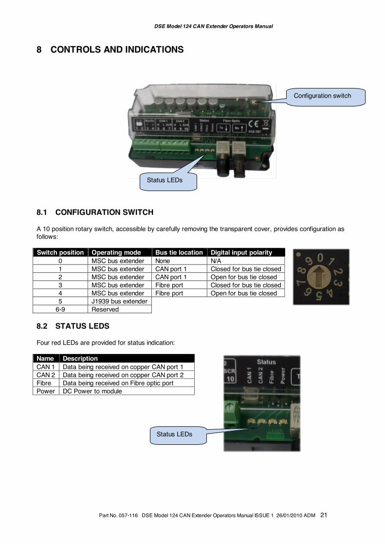
8 CONTROLS AND INDICATIONS
8.1 CONFIGURATION SWITCH A 10 position rotary switch, accessible by carefully removing the transparent cover, provides configuration as follows: Switch position Operating mode Bus tie location Digital input polarity
0 MSC bus extender None N/A 1 MSC bus extender CAN port 1 Closed for bus tie closed 2 MSC bus extender CAN port 1 Open for bus tie closed 3 MSC bus extender Fibre port Closed for bus tie closed 4 MSC bus extender Fibre port Open for bus tie closed 5 J1939 bus extender
6-9 Reserved 8.2 STATUS LEDS Four red LEDs are provided for status indication: Name Description
CAN 1 Data being received on copper CAN port 1 CAN 2 Data being received on copper CAN port 2 Fibre Data being received on Fibre optic port Power DC Power to module
Status LEDs
Configuration switch
Status LEDs
DSE Model 124 CAN Extender Operators Manual
22 Part No. 057-116 DSE Model 124 CAN Extender Operators Manual ISSUE 1 26/01/2010 ADM
9 MAINTENANCE, SPARES, REPAIR AND SERVICING The DSE124 is designed to be Fit and Forget. As such, there are no user serviceable parts within the controller. In the case of malfunction, you should contact your original equipment supplier (OEM). 10 WARRANTY DSE provides limited warranty to the equipment purchaser at the point of sale. For full details of any applicable warranty, you are referred to your original equipment supplier (OEM). 11 DISPOSAL 11.1 WEEE (WASTE ELECTRICAL AND ELECTRONIC EQUIPMENT) Directive 2002/96/EC If you use electrical and electronic equipment you must store, collect, treat, recycle and dispose of WEEE separately from your other waste. 11.2 ROHS (RESTRICTION OF HAZARDOUS SUBSTANCES) Directive 2002/95/EC:2006 To remove specified hazardous substances (Lead, Mercury, Hexavalent Chromium, Cadmium, PBB & PBDE´s) Exemption Note: Category 9. (Monitoring & Control Instruments) as defined in Annex 1B of the WEEE directive will be exempt from the RoHS legislation. This was confirmed in the August 2005 UK´s Department of Trade and Industry RoHS REGULATIONS Guide (Para 11). Despite this exemption DSE has been carefully removing all non RoHS compliant components from our supply chain and products. When this is completed a Lead Free & RoHS compatible manufacturing process will be phased into DSE production. This is a process that is almost complete and is being phased through different product groups.
DSE124DIAGRAMS.
®
ISSUE 1WEBSITEwww.deepseaplc.com
CAN Port 2CAN Port 1
- V
E D
C
-VE
DC
2 A
MP
FU
SE
+ V
E D
C
INP
UT
H L SC
N
L SC
N
H1 2 3 4 5 6 7 8 9 10
+VE
-VE
8 to 35 DC SUPPLY TERMINAL 3 IS INTERNALLYCONNECTED TO TERMINAL 1
P124 CAN Extender
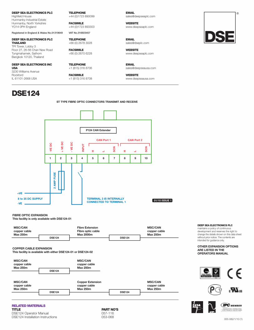
ST TYPE FIBRE OPTIC CONNECTORS TRANSMIT AND RECEIVE
®DSEEXTRA®
BATTERYCHARGERSAND EXPANSIONMODULES.DSE124 CANBUS EXTENDER
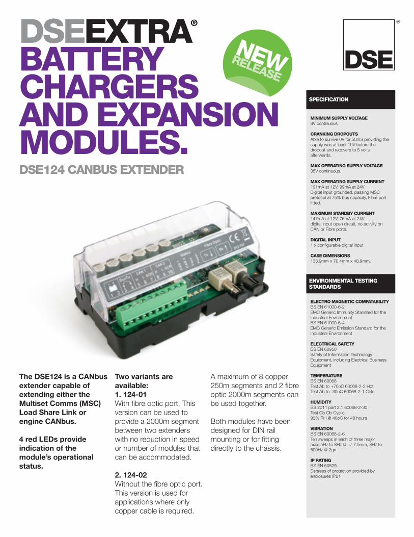
The DSE124 is a CANbusextender capable ofextending either theMultiset Comms (MSC)Load Share Link orengine CANbus.
4 red LEDs provideindication of themodule’s operationalstatus.
Two variants areavailable:1. 124-01With fibre optic port. Thisversion can be used toprovide a 2000m segmentbetween two extenderswith no reduction in speedor number of modules thatcan be accommodated.
2. 124-02Without the fibre optic port.This version is used forapplications where onlycopper cable is required.
A maximum of 8 copper250m segments and 2 fibreoptic 2000m segments canbe used together.
Both modules have beendesigned for DIN railmounting or for fittingdirectly to the chassis.
SPECIFICATION
ENVIRONMENTAL TESTINGSTANDARDS
ELECTRO MAGNETIC COMPATABILITYBS EN 61000-6-2EMC Generic Immunity Standard for theIndustrial EnvironmentBS EN 61000-6-4EMC Generic Emission Standard for theIndustrial Environment
ELECTRICAL SAFETYBS EN 60950Safety of Information TechnologyEquipment, including Electrical BusinessEquipment
TEMPERATUREBS EN 60068Test Ab to +70oC 60068-2-2 HotTest Ab to -30oC 60068-2-1 Cold
HUMIDITYBS 2011 part 2.1 60068-2-30Test Cb Ob Cyclic93% RH @ 40oC for 48 hours
VIBRATIONBS EN 60068-2-6Ten sweeps in each of three majoraxes 5Hz to 8Hz @ +/-7.5mm, 8Hz to500Hz @ 2gn
IP RATINGBS EN 60529.Degrees of protection provided byenclosures IP21
MINIMUM SUPPLY VOLTAGE8V continuous
CRANKING DROPOUTSAble to survive 0V for 50mS providing thesupply was at least 10V before thedropout and recovers to 5 voltsafterwards.
MAX OPERATING SUPPLY VOLTAGE35V continuous.
MAX OPERATING SUPPLY CURRENT191mA at 12V, 99mA at 24V.Digital input grounded, passing MSCprotocol at 75% bus capacity, Fibre portfitted.
MAXIMUM STANDBY CURRENT147mA at 12V, 76mA at 24Vdigital input open circuit, no activity onCAN or Fibre ports.
DIGITAL INPUT1 x configurable digital input
CASE DIMENSIONS133.9mm x 76.4mm x 48.9mm.
NEWRELEASE
®
DEEP SEA ELECTRONICS INCUSA3230 Williams AvenueRockfordIL 61101-2668 USA
TELEPHONE+1 (815) 316 8706
FACSIMILE+1 (815) 316 8708
WEBSITEwww.deepseausa.com
DEEP SEA ELECTRONICS PLCHighfield HouseHunmanby Industrial EstateHunmanby, North YorkshireYO14 0PH England
TELEPHONE+44 (0)1723 890099
FACSIMILE+44 (0)1723 893303
WEBSITEwww.deepseaplc.com
Registered in England & Wales No.01319649 VAT No.316923457
DEEP SEA ELECTRONICS PLCTHAILANDTPI Tower, Lobby 3Floor 27, 26-56 Chan New RoadTungmahamek, SathomBangkok 10120, Thailand
TELEPHONE+66 (0) 2678 3028
FACSIMILE+66 (0) 2670 6228
WEBSITEwww.deepseaplc.com
DEEP SEA ELECTRONICS PLCmaintains a policy of continuousdevelopment and reserves the right tochange the details shown on this data sheetwithout prior notice. The contents areintended for guidance only.
OTHER EXPANSION OPTIONSARE LISTED IN THEOPERATORS MANUAL
055-082/1/10 (1)
CAN Port 2CAN Port 1
-V
ED
C
-VE
DC
2A
MP
FUS
E
+V
ED
C
INP
UT
H L SC
N
L SC
N
H
1 2 3 4 5 6 7 8 9 10
+VE
-VE
8 to 35 DC SUPPLY TERMINAL 3 IS INTERNALLYCONNECTED TO TERMINAL 1 01/10 ISSUE 1
P124 CAN Extender
ST TYPE FIBRE OPTIC CONNECTORS TRANSMIT AND RECEIVE
DSE124
RELATED MATERIALSTITLE PART NO’SDSE124 Operator Manual 057-116DSE124 Installation Instructions 053-068
DSE124
MSC/CANcopper cableMax 250m
FIBRE OPTIC EXPANSIONThis facility is only available with DSE124-01
COPPER CABLE EXPANSIONThis facility is available with either DSE124-01 or DSE124-02
Fibre ExtensionFibre optic cableMax 2000m
MSC/CANcopper cableMax 250m
DSE124
DSE124
MSC/CANcopper cableMax 250m
Copper Extensioncopper cableMax 250m
MSC/CANcopper cableMax 250m
DSE124
DSE124
MSC/CANcopper cableMax 250m
MSC/CANcopper cableMax 250m