Embed Size (px)
Citation preview
DSAENCL 4000 SERIESSOFTWARE REQUIREMENTS SPECIFICATION
V5.03
07/2010
ii
Table of Contents
DSAENCL CONTROL AND CONFIGURATION. . . . . . . . . . . . . . . . . . . . . . . . . . . . . . . . . . . . . . . . . . . . . 1
DSAENCL COMMAND STRUCTURE and SYNTAX.. . . . . . . . . . . . . . . . . . . . . . . . . . . . . . . . . . . . . . . . . 1
DSAENCL4000 COMMAND LIST. . . . . . . . . . . . . . . . . . . . . . . . . . . . . . . . . . . . . . . . . . . . . . . . . . . . . . . . 2
A/D CALIBRATION (NON-TEMPERATURE COMPENSATED).. . . . . . . . . . . . . . . . . . . . . . . . . . 2
A/D CALIBRATION (TEMPERATURE COMPENSATED). . . . . . . . . . . . . . . . . . . . . . . . . . . . . . . 3
A/D COEFFICIENT CALCULATION (NON-TEMPERATURE COMPENSATED). . . . . . . . . . . . . 4
A/D COEFFICIENT CALCULATION (TEMPERATURE COMPENSATED). . . . . . . . . . . . . . . . . . 5
AUXILIARY COMMAND. . . . . . . . . . . . . . . . . . . . . . . . . . . . . . . . . . . . . . . . . . . . . . . . . . . . . . . . . 6
CALIBRATE . . . . . . . . . . . . . . . . . . . . . . . . . . . . . . . . . . . . . . . . . . . . . . . . . . . . . . . . . . . . . . . . . . 7
CALIBRATE INSERT . . . . . . . . . . . . . . . . . . . . . . . . . . . . . . . . . . . . . . . . . . . . . . . . . . . . . . . . . . . 8
CALIBRATE ZERO. . . . . . . . . . . . . . . . . . . . . . . . . . . . . . . . . . . . . . . . . . . . . . . . . . . . . . . . . . . . . 9
CALIBRATOR COMMAND. . . . . . . . . . . . . . . . . . . . . . . . . . . . . . . . . . . . . . . . . . . . . . . . . . . . . . 10
CHANNEL . . . . . . . . . . . . . . . . . . . . . . . . . . . . . . . . . . . . . . . . . . . . . . . . . . . . . . . . . . . . . . . . . . 11
CLEAR. . . . . . . . . . . . . . . . . . . . . . . . . . . . . . . . . . . . . . . . . . . . . . . . . . . . . . . . . . . . . . . . . . . . . 12
CONTROL PRESSURE RESET. . . . . . . . . . . . . . . . . . . . . . . . . . . . . . . . . . . . . . . . . . . . . . . . . . 13
DELETE. . . . . . . . . . . . . . . . . . . . . . . . . . . . . . . . . . . . . . . . . . . . . . . . . . . . . . . . . . . . . . . . . . . . 14
DELETE FILE. . . . . . . . . . . . . . . . . . . . . . . . . . . . . . . . . . . . . . . . . . . . . . . . . . . . . . . . . . . . . . . . 15
DELTA. . . . . . . . . . . . . . . . . . . . . . . . . . . . . . . . . . . . . . . . . . . . . . . . . . . . . . . . . . . . . . . . . . . . . . 16
DIGITAL OUTPUT. . . . . . . . . . . . . . . . . . . . . . . . . . . . . . . . . . . . . . . . . . . . . . . . . . . . . . . . . . . . 17
DISCONNECT FROM HOST. . . . . . . . . . . . . . . . . . . . . . . . . . . . . . . . . . . . . . . . . . . . . . . . . . . . 18
ERROR. . . . . . . . . . . . . . . . . . . . . . . . . . . . . . . . . . . . . . . . . . . . . . . . . . . . . . . . . . . . . . . . . . . . . 19
FILL. . . . . . . . . . . . . . . . . . . . . . . . . . . . . . . . . . . . . . . . . . . . . . . . . . . . . . . . . . . . . . . . . . . . . . . . 20
FRAME TRIGGER. . . . . . . . . . . . . . . . . . . . . . . . . . . . . . . . . . . . . . . . . . . . . . . . . . . . . . . . . . . . 21
INSERT. . . . . . . . . . . . . . . . . . . . . . . . . . . . . . . . . . . . . . . . . . . . . . . . . . . . . . . . . . . . . . . . . . . . . 22
LIST ALL CONVERSION COEFFICIENTS.. . . . . . . . . . . . . . . . . . . . . . . . . . . . . . . . . . . . . . . . . 23
LIST A/D CORRECTION TABLE (NON-TEMPERATURE COMPENSATED). . . . . . . . . . . . . . . 24
LIST A/D CORRECTION TABLE (TEMPERATURE COMPENSATED). . . . . . . . . . . . . . . . . . . 25
LIST CALIBRATION VARIABLES. . . . . . . . . . . . . . . . . . . . . . . . . . . . . . . . . . . . . . . . . . . . . . . . 26
LIST BOOT LOADER GROUP VARIABLES. . . . . . . . . . . . . . . . . . . . . . . . . . . . . . . . . . . . . . . . 27
LIST DIGITAL VARIABLES . . . . . . . . . . . . . . . . . . . . . . . . . . . . . . . . . . . . . . . . . . . . . . . . . . . . . 28
LIST FILE CONTENTS. . . . . . . . . . . . . . . . . . . . . . . . . . . . . . . . . . . . . . . . . . . . . . . . . . . . . . . . . 29
LIST FILES. . . . . . . . . . . . . . . . . . . . . . . . . . . . . . . . . . . . . . . . . . . . . . . . . . . . . . . . . . . . . . . . . . 30
LIST GAIN VARIABLES. . . . . . . . . . . . . . . . . . . . . . . . . . . . . . . . . . . . . . . . . . . . . . . . . . . . . . . . 31
LIST ID CHIP IDENTIFICATION. . . . . . . . . . . . . . . . . . . . . . . . . . . . . . . . . . . . . . . . . . . . . . . . . . 32
LIST ID CHIP SETTINGS. . . . . . . . . . . . . . . . . . . . . . . . . . . . . . . . . . . . . . . . . . . . . . . . . . . . . . . 33
LIST IDENTIFICATION VARIABLES. . . . . . . . . . . . . . . . . . . . . . . . . . . . . . . . . . . . . . . . . . . . . . 34
LIST MASTER CONVERSION COEFFICIENTS. . . . . . . . . . . . . . . . . . . . . . . . . . . . . . . . . . . . . 35
LIST MODULE INFORMATION VARIABLES. . . . . . . . . . . . . . . . . . . . . . . . . . . . . . . . . . . . . . . . 36
LIST OFFSET VARIABLES.. . . . . . . . . . . . . . . . . . . . . . . . . . . . . . . . . . . . . . . . . . . . . . . . . . . . . 37
LIST PROFILE LIST. . . . . . . . . . . . . . . . . . . . . . . . . . . . . . . . . . . . . . . . . . . . . . . . . . . . . . . . . . . 38
LIST SCAN VARIABLES. . . . . . . . . . . . . . . . . . . . . . . . . . . . . . . . . . . . . . . . . . . . . . . . . . . . . . . . 39
LIST SCAN GROUP VARIABLES.. . . . . . . . . . . . . . . . . . . . . . . . . . . . . . . . . . . . . . . . . . . . . . . . 40
LIST SYSTEM COMPONENTS. . . . . . . . . . . . . . . . . . . . . . . . . . . . . . . . . . . . . . . . . . . . . . . . . . 41
PURGE. . . . . . . . . . . . . . . . . . . . . . . . . . . . . . . . . . . . . . . . . . . . . . . . . . . . . . . . . . . . . . . . . . . . . 44
REBOOT. . . . . . . . . . . . . . . . . . . . . . . . . . . . . . . . . . . . . . . . . . . . . . . . . . . . . . . . . . . . . . . . . . . . 45
RESTART. . . . . . . . . . . . . . . . . . . . . . . . . . . . . . . . . . . . . . . . . . . . . . . . . . . . . . . . . . . . . . . . . . . 46
SAVE. . . . . . . . . . . . . . . . . . . . . . . . . . . . . . . . . . . . . . . . . . . . . . . . . . . . . . . . . . . . . . . . . . . . . . . 47
SAVE BOOT LOADER VARIABLES. . . . . . . . . . . . . . . . . . . . . . . . . . . . . . . . . . . . . . . . . . . . . . . 48
iii
SCAN. . . . . . . . . . . . . . . . . . . . . . . . . . . . . . . . . . . . . . . . . . . . . . . . . . . . . . . . . . . . . . . . . . . . . . 49
SET. . . . . . . . . . . . . . . . . . . . . . . . . . . . . . . . . . . . . . . . . . . . . . . . . . . . . . . . . . . . . . . . . . . . . . . . 51
SLOTS.. . . . . . . . . . . . . . . . . . . . . . . . . . . . . . . . . . . . . . . . . . . . . . . . . . . . . . . . . . . . . . . . . . . . . 52
STATUS. . . . . . . . . . . . . . . . . . . . . . . . . . . . . . . . . . . . . . . . . . . . . . . . . . . . . . . . . . . . . . . . . . . . 53
STOP.. . . . . . . . . . . . . . . . . . . . . . . . . . . . . . . . . . . . . . . . . . . . . . . . . . . . . . . . . . . . . . . . . . . . . . 54
TEMPERATURE. . . . . . . . . . . . . . . . . . . . . . . . . . . . . . . . . . . . . . . . . . . . . . . . . . . . . . . . . . . . . . 55
TEMPERATURE GRADIENT COMPENSATION. . . . . . . . . . . . . . . . . . . . . . . . . . . . . . . . . . . . . 56
VERSION. . . . . . . . . . . . . . . . . . . . . . . . . . . . . . . . . . . . . . . . . . . . . . . . . . . . . . . . . . . . . . . . . . . 57
W RITE ID CHIP VARIABLES. . . . . . . . . . . . . . . . . . . . . . . . . . . . . . . . . . . . . . . . . . . . . . . . . . . . 58
ZERO. . . . . . . . . . . . . . . . . . . . . . . . . . . . . . . . . . . . . . . . . . . . . . . . . . . . . . . . . . . . . . . . . . . . . . 59
DSAENCL CONFIGURATION VARIABLES. . . . . . . . . . . . . . . . . . . . . . . . . . . . . . . . . . . . . . . . . . . . . . . 60
GENERAL SCAN VARIABLES (Group S). . . . . . . . . . . . . . . . . . . . . . . . . . . . . . . . . . . . . . . . . . 60
ADTRIG <code>. . . . . . . . . . . . . . . . . . . . . . . . . . . . . . . . . . . . . . . . . . . . . . . . . . . . . . . . 60
BINADDR <port> <IP address>. . . . . . . . . . . . . . . . . . . . . . . . . . . . . . . . . . . . . . . . . . . . 60
FM <code>. . . . . . . . . . . . . . . . . . . . . . . . . . . . . . . . . . . . . . . . . . . . . . . . . . . . . . . . . . . . 60
IFC <char 1> <char 2>. . . . . . . . . . . . . . . . . . . . . . . . . . . . . . . . . . . . . . . . . . . . . . . . . . . 60
PERIOD <period>. . . . . . . . . . . . . . . . . . . . . . . . . . . . . . . . . . . . . . . . . . . . . . . . . . . . . . 61
QPKTS <enable>. . . . . . . . . . . . . . . . . . . . . . . . . . . . . . . . . . . . . . . . . . . . . . . . . . . . . . . 61
SCANTRIG <code>. . . . . . . . . . . . . . . . . . . . . . . . . . . . . . . . . . . . . . . . . . . . . . . . . . . . . 61
TEMPPOLL <code>. . . . . . . . . . . . . . . . . . . . . . . . . . . . . . . . . . . . . . . . . . . . . . . . . . . . . 61
TIMESTAMP <code>. . . . . . . . . . . . . . . . . . . . . . . . . . . . . . . . . . . . . . . . . . . . . . . . . . . . 61
CONVERSION VARIABLES (Group C). . . . . . . . . . . . . . . . . . . . . . . . . . . . . . . . . . . . . . . . . . . . 62
A2DCOR <code>. . . . . . . . . . . . . . . . . . . . . . . . . . . . . . . . . . . . . . . . . . . . . . . . . . . . . . . 62
BIN <code>. . . . . . . . . . . . . . . . . . . . . . . . . . . . . . . . . . . . . . . . . . . . . . . . . . . . . . . . . . . 62
CALAVG <sample average>. . . . . . . . . . . . . . . . . . . . . . . . . . . . . . . . . . . . . . . . . . . . . . 62
CALPER <period>. . . . . . . . . . . . . . . . . . . . . . . . . . . . . . . . . . . . . . . . . . . . . . . . . . . . . . 62
CALZDLY <delay>. . . . . . . . . . . . . . . . . . . . . . . . . . . . . . . . . . . . . . . . . . . . . . . . . . . . . . 62
CVTUNIT <value>. . . . . . . . . . . . . . . . . . . . . . . . . . . . . . . . . . . . . . . . . . . . . . . . . . . . . . 63
EU <code>. . . . . . . . . . . . . . . . . . . . . . . . . . . . . . . . . . . . . . . . . . . . . . . . . . . . . . . . . . . . 63
FILLONE <code>. . . . . . . . . . . . . . . . . . . . . . . . . . . . . . . . . . . . . . . . . . . . . . . . . . . . . . . 63
MAXEU <value>. . . . . . . . . . . . . . . . . . . . . . . . . . . . . . . . . . . . . . . . . . . . . . . . . . . . . . . . 64
MINEU <value>. . . . . . . . . . . . . . . . . . . . . . . . . . . . . . . . . . . . . . . . . . . . . . . . . . . . . . . . 64
MPBS <number of planes>. . . . . . . . . . . . . . . . . . . . . . . . . . . . . . . . . . . . . . . . . . . . . . . 64
STARTCALZ <code>. . . . . . . . . . . . . . . . . . . . . . . . . . . . . . . . . . . . . . . . . . . . . . . . . . . . 64
UNITSCAN <units>. . . . . . . . . . . . . . . . . . . . . . . . . . . . . . . . . . . . . . . . . . . . . . . . . . . . . 65
ZC <code>. . . . . . . . . . . . . . . . . . . . . . . . . . . . . . . . . . . . . . . . . . . . . . . . . . . . . . . . . . . . 65
DIGITAL OUTPUT CONFIGURATION VARIABLES (Group D). . . . . . . . . . . . . . . . . . . . . . . . . . 66
DLYPG <value>. . . . . . . . . . . . . . . . . . . . . . . . . . . . . . . . . . . . . . . . . . . . . . . . . . . . . . . . 66
DLYPGSEQ <value>. . . . . . . . . . . . . . . . . . . . . . . . . . . . . . . . . . . . . . . . . . . . . . . . . . . . 66
DOUTCALZ <value>. . . . . . . . . . . . . . . . . . . . . . . . . . . . . . . . . . . . . . . . . . . . . . . . . . . . 66
DOUTPG <value>. . . . . . . . . . . . . . . . . . . . . . . . . . . . . . . . . . . . . . . . . . . . . . . . . . . . . . 66
DOUTPGSEQ <value>.. . . . . . . . . . . . . . . . . . . . . . . . . . . . . . . . . . . . . . . . . . . . . . . . . . 66
DOUTPU <value>. . . . . . . . . . . . . . . . . . . . . . . . . . . . . . . . . . . . . . . . . . . . . . . . . . . . . . 67
DOUTSCAN <value>. . . . . . . . . . . . . . . . . . . . . . . . . . . . . . . . . . . . . . . . . . . . . . . . . . . . 67
DOUTREADY <value>. . . . . . . . . . . . . . . . . . . . . . . . . . . . . . . . . . . . . . . . . . . . . . . . . . . 67
BANKA <value>. . . . . . . . . . . . . . . . . . . . . . . . . . . . . . . . . . . . . . . . . . . . . . . . . . . . . . . . 67
BANKB <value>. . . . . . . . . . . . . . . . . . . . . . . . . . . . . . . . . . . . . . . . . . . . . . . . . . . . . . . . 67
BANKUSR <value>. . . . . . . . . . . . . . . . . . . . . . . . . . . . . . . . . . . . . . . . . . . . . . . . . . . . . 67
SCAN GROUP CONFIGURATION VARIABLES (Group 1 Only). . . . . . . . . . . . . . . . . . . . . . . . . 68
AVG1 <sample average>. . . . . . . . . . . . . . . . . . . . . . . . . . . . . . . . . . . . . . . . . . . . . . . . . 68
CHAN1 <channels>. . . . . . . . . . . . . . . . . . . . . . . . . . . . . . . . . . . . . . . . . . . . . . . . . . . . . 68
FPS1 <frames>. . . . . . . . . . . . . . . . . . . . . . . . . . . . . . . . . . . . . . . . . . . . . . . . . . . . . . . . 69
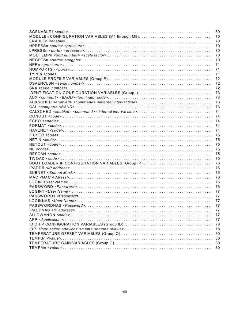
SGENABLE1 <code>. . . . . . . . . . . . . . . . . . . . . . . . . . . . . . . . . . . . . . . . . . . . . . . . . . . . 69
iv
MODULEn CONFIGURATION VARIABLES (M1 through M8). . . . . . . . . . . . . . . . . . . . . . . . . . . 70
ENABLEn <enable>. . . . . . . . . . . . . . . . . . . . . . . . . . . . . . . . . . . . . . . . . . . . . . . . . . . . . 70
HPRESSn <ports> <pressure>. . . . . . . . . . . . . . . . . . . . . . . . . . . . . . . . . . . . . . . . . . . . 70
LPRESSn <ports> <pressure>. . . . . . . . . . . . . . . . . . . . . . . . . . . . . . . . . . . . . . . . . . . . . 70
MODTEMPn <port number> <scale factor>.. . . . . . . . . . . . . . . . . . . . . . . . . . . . . . . . . . 70
NEGPTSn <ports> <negpts>. . . . . . . . . . . . . . . . . . . . . . . . . . . . . . . . . . . . . . . . . . . . . . 70
NPRn <pressure>.. . . . . . . . . . . . . . . . . . . . . . . . . . . . . . . . . . . . . . . . . . . . . . . . . . . . . . 71
NUMPORTSn <ports>. . . . . . . . . . . . . . . . . . . . . . . . . . . . . . . . . . . . . . . . . . . . . . . . . . . 71
TYPEn <code>. . . . . . . . . . . . . . . . . . . . . . . . . . . . . . . . . . . . . . . . . . . . . . . . . . . . . . . . . 71
MODULE PROFILE VARIABLES (Group P). . . . . . . . . . . . . . . . . . . . . . . . . . . . . . . . . . . . . . . . . 72
DSAENCLSN <serial number>. . . . . . . . . . . . . . . . . . . . . . . . . . . . . . . . . . . . . . . . . . . . 72
SNn <serial number>. . . . . . . . . . . . . . . . . . . . . . . . . . . . . . . . . . . . . . . . . . . . . . . . . . . . 72
IDENTIFICATION CONFIGURATION VARIABLES (Group I). . . . . . . . . . . . . . . . . . . . . . . . . . . 73
AUX <comport> <BAUD><terminator code>. . . . . . . . . . . . . . . . . . . . . . . . . . . . . . . . . . 73
AUXSCHED <enabled> <command> <internal interval time>. . . . . . . . . . . . . . . . . . . . . 73
CAL <comport> <BAUD>. . . . . . . . . . . . . . . . . . . . . . . . . . . . . . . . . . . . . . . . . . . . . . . . . 73
CALSCHED <enabled> <command> <internal interval time>. . . . . . . . . . . . . . . . . . . . . 74
CONOUT <code>.. . . . . . . . . . . . . . . . . . . . . . . . . . . . . . . . . . . . . . . . . . . . . . . . . . . . . . 74
ECHO <enable>. . . . . . . . . . . . . . . . . . . . . . . . . . . . . . . . . . . . . . . . . . . . . . . . . . . . . . . . 74
FORMAT <code>. . . . . . . . . . . . . . . . . . . . . . . . . . . . . . . . . . . . . . . . . . . . . . . . . . . . . . . 74
HAVENET <code>. . . . . . . . . . . . . . . . . . . . . . . . . . . . . . . . . . . . . . . . . . . . . . . . . . . . . . 74
IFUSER <code>. . . . . . . . . . . . . . . . . . . . . . . . . . . . . . . . . . . . . . . . . . . . . . . . . . . . . . . . 75
NETIN <code>. . . . . . . . . . . . . . . . . . . . . . . . . . . . . . . . . . . . . . . . . . . . . . . . . . . . . . . . . 75
NETOUT <code>. . . . . . . . . . . . . . . . . . . . . . . . . . . . . . . . . . . . . . . . . . . . . . . . . . . . . . . 75
NL <code>. . . . . . . . . . . . . . . . . . . . . . . . . . . . . . . . . . . . . . . . . . . . . . . . . . . . . . . . . . . . 75
RESCAN <code>. . . . . . . . . . . . . . . . . . . . . . . . . . . . . . . . . . . . . . . . . . . . . . . . . . . . . . . 75
TW OAD <code>. . . . . . . . . . . . . . . . . . . . . . . . . . . . . . . . . . . . . . . . . . . . . . . . . . . . . . . . 75
BOOT LOADER IP CONFIGURATION VARIABLES (Group IP). . . . . . . . . . . . . . . . . . . . . . . . . 76
IPADDR <IP address>. . . . . . . . . . . . . . . . . . . . . . . . . . . . . . . . . . . . . . . . . . . . . . . . . . . 76
SUBNET <Subnet Mask>.. . . . . . . . . . . . . . . . . . . . . . . . . . . . . . . . . . . . . . . . . . . . . . . . 76
MAC <MAC Address>. . . . . . . . . . . . . . . . . . . . . . . . . . . . . . . . . . . . . . . . . . . . . . . . . . . 76
LOGIN <User Name>. . . . . . . . . . . . . . . . . . . . . . . . . . . . . . . . . . . . . . . . . . . . . . . . . . . . 76
PASSW ORD <Password>. . . . . . . . . . . . . . . . . . . . . . . . . . . . . . . . . . . . . . . . . . . . . . . . 76
LOGIN1 <User Name>. . . . . . . . . . . . . . . . . . . . . . . . . . . . . . . . . . . . . . . . . . . . . . . . . . . 77
PASSW ORD1 <Password>. . . . . . . . . . . . . . . . . . . . . . . . . . . . . . . . . . . . . . . . . . . . . . . 77
LOGINNAS <User Name>. . . . . . . . . . . . . . . . . . . . . . . . . . . . . . . . . . . . . . . . . . . . . . . . 77
PASSW ORDNAS <Password>. . . . . . . . . . . . . . . . . . . . . . . . . . . . . . . . . . . . . . . . . . . . 77
IPADDNAS <IP address>.. . . . . . . . . . . . . . . . . . . . . . . . . . . . . . . . . . . . . . . . . . . . . . . . 77
ALLOW ANON <code>. . . . . . . . . . . . . . . . . . . . . . . . . . . . . . . . . . . . . . . . . . . . . . . . . . . 77
APP <Application>. . . . . . . . . . . . . . . . . . . . . . . . . . . . . . . . . . . . . . . . . . . . . . . . . . . . . . 77
ID CHIP CONFIGURATION VARIABLES (Group ID). . . . . . . . . . . . . . . . . . . . . . . . . . . . . . . . . . 78
IDP <loc> <site> <device> <mem> <name> <value>. . . . . . . . . . . . . . . . . . . . . . . . . . . 78
TEMPERATURE OFFSET VARIABLES (Group O). . . . . . . . . . . . . . . . . . . . . . . . . . . . . . . . . . . 80
TEMPBn <value>. . . . . . . . . . . . . . . . . . . . . . . . . . . . . . . . . . . . . . . . . . . . . . . . . . . . . . . 80
TEMPERATURE GAIN VARIABLES (Group G). . . . . . . . . . . . . . . . . . . . . . . . . . . . . . . . . . . . . . 80
TEMPMn <value> . . . . . . . . . . . . . . . . . . . . . . . . . . . . . . . . . . . . . . . . . . . . . . . . . . . . . . 80
DSAENCL ID Chip Data Format. . . . . . . . . . . . . . . . . . . . . . . . . . . . . . . . . . . . . . . . . . . . . . . . . . . . . . . . 81
Permanent Memory Data Format. . . . . . . . . . . . . . . . . . . . . . . . . . . . . . . . . . . . . . . . . . . . . . . . . 81
EEPROM Memory Data Format. . . . . . . . . . . . . . . . . . . . . . . . . . . . . . . . . . . . . . . . . . . . . . . . . . 82
RAD Temperature A/D Board. . . . . . . . . . . . . . . . . . . . . . . . . . . . . . . . . . . . . . . . . . . . . 82
RAD Pressure A/D Board.. . . . . . . . . . . . . . . . . . . . . . . . . . . . . . . . . . . . . . . . . . . . . . . . 82
Pressure Scanner Module. . . . . . . . . . . . . . . . . . . . . . . . . . . . . . . . . . . . . . . . . . . . . . . . 83
RAD Digital I/O Device. . . . . . . . . . . . . . . . . . . . . . . . . . . . . . . . . . . . . . . . . . . . . . . . . . . 83
v
Test Fixture. . . . . . . . . . . . . . . . . . . . . . . . . . . . . . . . . . . . . . . . . . . . . . . . . . . . . . . . . . . 83
Scanivalve DSP Boot Loader. . . . . . . . . . . . . . . . . . . . . . . . . . . . . . . . . . . . . . . . . . . . . . . . . . . . . . . . . . . 84
Boot Loader and Application File System. . . . . . . . . . . . . . . . . . . . . . . . . . . . . . . . . . . . . . . . . . . 84
DIP Switch Settings. . . . . . . . . . . . . . . . . . . . . . . . . . . . . . . . . . . . . . . . . . . . . . . . . . . . . . . . . . . . 85
Host Communication. . . . . . . . . . . . . . . . . . . . . . . . . . . . . . . . . . . . . . . . . . . . . . . . . . . . . . . . . . . 85
Commands. . . . . . . . . . . . . . . . . . . . . . . . . . . . . . . . . . . . . . . . . . . . . . . . . . . . . . . . . . . . . . . . . . 85
DSAENCL Scan Function. . . . . . . . . . . . . . . . . . . . . . . . . . . . . . . . . . . . . . . . . . . . . . . . . . . . . . . . . . . . . 87
Internal Trigger. . . . . . . . . . . . . . . . . . . . . . . . . . . . . . . . . . . . . . . . . . . . . . . . . . . . . . . . . . . . . . . 87
External Trigger. . . . . . . . . . . . . . . . . . . . . . . . . . . . . . . . . . . . . . . . . . . . . . . . . . . . . . . . . . . . . . . 87
Hardware Trigger. . . . . . . . . . . . . . . . . . . . . . . . . . . . . . . . . . . . . . . . . . . . . . . . . . . . . . . . . . . . . 87
Software Trigger. . . . . . . . . . . . . . . . . . . . . . . . . . . . . . . . . . . . . . . . . . . . . . . . . . . . . . . . . . . . . . 87
DSAENCL Profile File.. . . . . . . . . . . . . . . . . . . . . . . . . . . . . . . . . . . . . . . . . . . . . . . . . . . . . . . . . . . . . . . . 88
Module Profile File. . . . . . . . . . . . . . . . . . . . . . . . . . . . . . . . . . . . . . . . . . . . . . . . . . . . . . . . . . . . . . . . . . . 88
Binary Scan Packets. . . . . . . . . . . . . . . . . . . . . . . . . . . . . . . . . . . . . . . . . . . . . . . . . . . . . . . . . . . . . . . . . 89
Packets without Module-Port Information. . . . . . . . . . . . . . . . . . . . . . . . . . . . . . . . . . . . . . . . . . . 89
Packets with Module-Port Information. . . . . . . . . . . . . . . . . . . . . . . . . . . . . . . . . . . . . . . . . . . . . 90
APPENDIX A - TEMPERATURE COMPENSATED PRESSURE CONVERSION. . . . . . . . . . . . . . . . . . 91
APPENDIX B - ENGINEERING UNIT CONVERSION CONSTANTS. . . . . . . . . . . . . . . . . . . . . . . . . . . . 92
APPENDIX C - CHANGE LIST. . . . . . . . . . . . . . . . . . . . . . . . . . . . . . . . . . . . . . . . . . . . . . . . . . . . . . . . . 93
vi
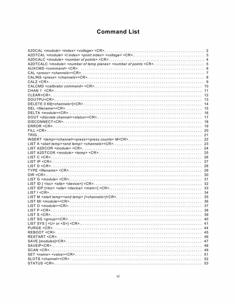
Command List
A2DCAL <module> <index> <voltage> <CR>. . . . . . . . . . . . . . . . . . . . . . . . . . . . . . . . . . . . . . . . . . . . . . . 2
A2DTCAL <module> <t index> <point index> <voltage> <CR>.. . . . . . . . . . . . . . . . . . . . . . . . . . . . . . . . . 3
A2DCALC <module> <number of points> <CR>. . . . . . . . . . . . . . . . . . . . . . . . . . . . . . . . . . . . . . . . . . . . . 4
A2DTCALC <module> <number of temp planes> <number of points <CR>. . . . . . . . . . . . . . . . . . . . . . . . 5
AUXCMD <command> <CR>. . . . . . . . . . . . . . . . . . . . . . . . . . . . . . . . . . . . . . . . . . . . . . . . . . . . . . . . . . . 6
CAL <press> <channels><CR>. . . . . . . . . . . . . . . . . . . . . . . . . . . . . . . . . . . . . . . . . . . . . . . . . . . . . . . . . . 7
CALINS <press> <channels><CR>. . . . . . . . . . . . . . . . . . . . . . . . . . . . . . . . . . . . . . . . . . . . . . . . . . . . . . . 8
CALZ <CR>. . . . . . . . . . . . . . . . . . . . . . . . . . . . . . . . . . . . . . . . . . . . . . . . . . . . . . . . . . . . . . . . . . . . . . . . . 9
CALCMD <calibrator command> <CR>. . . . . . . . . . . . . . . . . . . . . . . . . . . . . . . . . . . . . . . . . . . . . . . . . . . 10
CHAN 1 <CR>. . . . . . . . . . . . . . . . . . . . . . . . . . . . . . . . . . . . . . . . . . . . . . . . . . . . . . . . . . . . . . . . . . . . . . 11
CLEAR<CR>. . . . . . . . . . . . . . . . . . . . . . . . . . . . . . . . . . . . . . . . . . . . . . . . . . . . . . . . . . . . . . . . . . . . . . . 12
DOUTPU<CR>. . . . . . . . . . . . . . . . . . . . . . . . . . . . . . . . . . . . . . . . . . . . . . . . . . . . . . . . . . . . . . . . . . . . . . 13
DELETE 0 69[<channels>]<CR>. . . . . . . . . . . . . . . . . . . . . . . . . . . . . . . . . . . . . . . . . . . . . . . . . . . . . . . . 14
DEL <filename><CR>. . . . . . . . . . . . . . . . . . . . . . . . . . . . . . . . . . . . . . . . . . . . . . . . . . . . . . . . . . . . . . . . 15
DELTA <module><CR>. . . . . . . . . . . . . . . . . . . . . . . . . . . . . . . . . . . . . . . . . . . . . . . . . . . . . . . . . . . . . . . 16
DOUT <discrete channel><status><CR>.. . . . . . . . . . . . . . . . . . . . . . . . . . . . . . . . . . . . . . . . . . . . . . . . . 17
DISCONNECT<CR>. . . . . . . . . . . . . . . . . . . . . . . . . . . . . . . . . . . . . . . . . . . . . . . . . . . . . . . . . . . . . . . . . 18
ERROR <CR>. . . . . . . . . . . . . . . . . . . . . . . . . . . . . . . . . . . . . . . . . . . . . . . . . . . . . . . . . . . . . . . . . . . . . . 19
FILL <CR>. . . . . . . . . . . . . . . . . . . . . . . . . . . . . . . . . . . . . . . . . . . . . . . . . . . . . . . . . . . . . . . . . . . . . . . . . 20
TRIG. . . . . . . . . . . . . . . . . . . . . . . . . . . . . . . . . . . . . . . . . . . . . . . . . . . . . . . . . . . . . . . . . . . . . . . . . . . . . . 21
INSERT <temp><channel><press><press counts> M<CR>. . . . . . . . . . . . . . . . . . . . . . . . . . . . . . . . . . . 22
LIST A <start temp><end temp> <channels><CR>. . . . . . . . . . . . . . . . . . . . . . . . . . . . . . . . . . . . . . . . . . 23
LIST A2DCOR <module> <CR>. . . . . . . . . . . . . . . . . . . . . . . . . . . . . . . . . . . . . . . . . . . . . . . . . . . . . . . . 24
LIST A2DTCOR <module> <temp> <CR>. . . . . . . . . . . . . . . . . . . . . . . . . . . . . . . . . . . . . . . . . . . . . . . . . 25
LIST C <CR>. . . . . . . . . . . . . . . . . . . . . . . . . . . . . . . . . . . . . . . . . . . . . . . . . . . . . . . . . . . . . . . . . . . . . . . 26
LIST IP <CR>. . . . . . . . . . . . . . . . . . . . . . . . . . . . . . . . . . . . . . . . . . . . . . . . . . . . . . . . . . . . . . . . . . . . . . . 27
LIST D <CR>. . . . . . . . . . . . . . . . . . . . . . . . . . . . . . . . . . . . . . . . . . . . . . . . . . . . . . . . . . . . . . . . . . . . . . . 28
TYPE <filename> <CR>. . . . . . . . . . . . . . . . . . . . . . . . . . . . . . . . . . . . . . . . . . . . . . . . . . . . . . . . . . . . . . . 29
DIR <CR>. . . . . . . . . . . . . . . . . . . . . . . . . . . . . . . . . . . . . . . . . . . . . . . . . . . . . . . . . . . . . . . . . . . . . . . . . . 30
LIST G <module> <CR>.. . . . . . . . . . . . . . . . . . . . . . . . . . . . . . . . . . . . . . . . . . . . . . . . . . . . . . . . . . . . . . 31
LIST ID [ <loc> <site> <device>] <CR>. . . . . . . . . . . . . . . . . . . . . . . . . . . . . . . . . . . . . . . . . . . . . . . . . . . 32
LIST IDP [<loc> <site> <device> <mem>] <CR>. . . . . . . . . . . . . . . . . . . . . . . . . . . . . . . . . . . . . . . . . . . . 33
LIST I <CR>. . . . . . . . . . . . . . . . . . . . . . . . . . . . . . . . . . . . . . . . . . . . . . . . . . . . . . . . . . . . . . . . . . . . . . . . 34
LIST M <start temp><end temp> [<channels>]<CR>. . . . . . . . . . . . . . . . . . . . . . . . . . . . . . . . . . . . . . . . 35
LIST MI <module><CR>.. . . . . . . . . . . . . . . . . . . . . . . . . . . . . . . . . . . . . . . . . . . . . . . . . . . . . . . . . . . . . . 36
LIST O <module><CR>. . . . . . . . . . . . . . . . . . . . . . . . . . . . . . . . . . . . . . . . . . . . . . . . . . . . . . . . . . . . . . . 37
LIST P <CR>. . . . . . . . . . . . . . . . . . . . . . . . . . . . . . . . . . . . . . . . . . . . . . . . . . . . . . . . . . . . . . . . . . . . . . . 38
LIST S <CR>. . . . . . . . . . . . . . . . . . . . . . . . . . . . . . . . . . . . . . . . . . . . . . . . . . . . . . . . . . . . . . . . . . . . . . . 39
LIST SG <group><CR>. . . . . . . . . . . . . . . . . . . . . . . . . . . . . . . . . . . . . . . . . . . . . . . . . . . . . . . . . . . . . . . 40
LIST SYS [ <U> or <S>] <CR>.. . . . . . . . . . . . . . . . . . . . . . . . . . . . . . . . . . . . . . . . . . . . . . . . . . . . . . . . . 41
PURGE <CR>. . . . . . . . . . . . . . . . . . . . . . . . . . . . . . . . . . . . . . . . . . . . . . . . . . . . . . . . . . . . . . . . . . . . . . 44
REBOOT <CR>. . . . . . . . . . . . . . . . . . . . . . . . . . . . . . . . . . . . . . . . . . . . . . . . . . . . . . . . . . . . . . . . . . . . . 45
RESTART <CR>. . . . . . . . . . . . . . . . . . . . . . . . . . . . . . . . . . . . . . . . . . . . . . . . . . . . . . . . . . . . . . . . . . . . 46
SAVE [modules]<CR>. . . . . . . . . . . . . . . . . . . . . . . . . . . . . . . . . . . . . . . . . . . . . . . . . . . . . . . . . . . . . . . . 47
SAVEIP<CR>. . . . . . . . . . . . . . . . . . . . . . . . . . . . . . . . . . . . . . . . . . . . . . . . . . . . . . . . . . . . . . . . . . . . . . . 48
SCAN <CR>. . . . . . . . . . . . . . . . . . . . . . . . . . . . . . . . . . . . . . . . . . . . . . . . . . . . . . . . . . . . . . . . . . . . . . . . 49
SET <name> <value><CR>. . . . . . . . . . . . . . . . . . . . . . . . . . . . . . . . . . . . . . . . . . . . . . . . . . . . . . . . . . . . 51
SLOTS <channel><CR>. . . . . . . . . . . . . . . . . . . . . . . . . . . . . . . . . . . . . . . . . . . . . . . . . . . . . . . . . . . . . . 52
STATUS <CR>. . . . . . . . . . . . . . . . . . . . . . . . . . . . . . . . . . . . . . . . . . . . . . . . . . . . . . . . . . . . . . . . . . . . . . 53

vii
STOP <CR>. . . . . . . . . . . . . . . . . . . . . . . . . . . . . . . . . . . . . . . . . . . . . . . . . . . . . . . . . . . . . . . . . . . . . . . . 54
TEMP <type><CR>. . . . . . . . . . . . . . . . . . . . . . . . . . . . . . . . . . . . . . . . . . . . . . . . . . . . . . . . . . . . . . . . . . 55
TGRAD<CR>. . . . . . . . . . . . . . . . . . . . . . . . . . . . . . . . . . . . . . . . . . . . . . . . . . . . . . . . . . . . . . . . . . . . . . . 56
VER <CR>. . . . . . . . . . . . . . . . . . . . . . . . . . . . . . . . . . . . . . . . . . . . . . . . . . . . . . . . . . . . . . . . . . . . . . . . . 57
IDPW RITE <address> <site> <device> <mtype> <CR>. . . . . . . . . . . . . . . . . . . . . . . . . . . . . . . . . . . . . . 58
ZERO <CR>. . . . . . . . . . . . . . . . . . . . . . . . . . . . . . . . . . . . . . . . . . . . . . . . . . . . . . . . . . . . . . . . . . . . . . . . 59
Configuration Variables
GENERAL SCAN VARIABLES (Group S). . . . . . . . . . . . . . . . . . . . . . . . . . . . . . . . . . . . . . . . . . . . . . . . . 60
ADTRIG <code>. . . . . . . . . . . . . . . . . . . . . . . . . . . . . . . . . . . . . . . . . . . . . . . . . . . . . . . . . . . . . . . . . . . . . 60
BINADDR <port> <IP address>. . . . . . . . . . . . . . . . . . . . . . . . . . . . . . . . . . . . . . . . . . . . . . . . . . . . . . . . . 60
FM <code>. . . . . . . . . . . . . . . . . . . . . . . . . . . . . . . . . . . . . . . . . . . . . . . . . . . . . . . . . . . . . . . . . . . . . . . . . 60
IFC <char 1> <char 2>. . . . . . . . . . . . . . . . . . . . . . . . . . . . . . . . . . . . . . . . . . . . . . . . . . . . . . . . . . . . . . . . 60
PERIOD <period>.. . . . . . . . . . . . . . . . . . . . . . . . . . . . . . . . . . . . . . . . . . . . . . . . . . . . . . . . . . . . . . . . . . . 61
QPKTS <enable>. . . . . . . . . . . . . . . . . . . . . . . . . . . . . . . . . . . . . . . . . . . . . . . . . . . . . . . . . . . . . . . . . . . . 61
SCANTRIG <code>. . . . . . . . . . . . . . . . . . . . . . . . . . . . . . . . . . . . . . . . . . . . . . . . . . . . . . . . . . . . . . . . . . 61
TEMPPOLL <code>. . . . . . . . . . . . . . . . . . . . . . . . . . . . . . . . . . . . . . . . . . . . . . . . . . . . . . . . . . . . . . . . . . 61
TIMESTAMP <code>. . . . . . . . . . . . . . . . . . . . . . . . . . . . . . . . . . . . . . . . . . . . . . . . . . . . . . . . . . . . . . . . . 61
CONVERSION VARIABLES (Group C). . . . . . . . . . . . . . . . . . . . . . . . . . . . . . . . . . . . . . . . . . . . . . . . . . . 62
A2DCOR <code>. . . . . . . . . . . . . . . . . . . . . . . . . . . . . . . . . . . . . . . . . . . . . . . . . . . . . . . . . . . . . . . . . . . . 62
BIN <code>.. . . . . . . . . . . . . . . . . . . . . . . . . . . . . . . . . . . . . . . . . . . . . . . . . . . . . . . . . . . . . . . . . . . . . . . . 62
CALAVG <sample average>. . . . . . . . . . . . . . . . . . . . . . . . . . . . . . . . . . . . . . . . . . . . . . . . . . . . . . . . . . . 62
CALPER <period>. . . . . . . . . . . . . . . . . . . . . . . . . . . . . . . . . . . . . . . . . . . . . . . . . . . . . . . . . . . . . . . . . . . 62
CALZDLY <delay>. . . . . . . . . . . . . . . . . . . . . . . . . . . . . . . . . . . . . . . . . . . . . . . . . . . . . . . . . . . . . . . . . . . 62
CVTUNIT <value>. . . . . . . . . . . . . . . . . . . . . . . . . . . . . . . . . . . . . . . . . . . . . . . . . . . . . . . . . . . . . . . . . . . 63
EU <code>. . . . . . . . . . . . . . . . . . . . . . . . . . . . . . . . . . . . . . . . . . . . . . . . . . . . . . . . . . . . . . . . . . . . . . . . . 63
FILLONE <code>. . . . . . . . . . . . . . . . . . . . . . . . . . . . . . . . . . . . . . . . . . . . . . . . . . . . . . . . . . . . . . . . . . . . 63
MAXEU <value>. . . . . . . . . . . . . . . . . . . . . . . . . . . . . . . . . . . . . . . . . . . . . . . . . . . . . . . . . . . . . . . . . . . . . 64
MINEU <value>. . . . . . . . . . . . . . . . . . . . . . . . . . . . . . . . . . . . . . . . . . . . . . . . . . . . . . . . . . . . . . . . . . . . . 64
MPBS <number of planes>. . . . . . . . . . . . . . . . . . . . . . . . . . . . . . . . . . . . . . . . . . . . . . . . . . . . . . . . . . . . 64
STARTCALZ <code>. . . . . . . . . . . . . . . . . . . . . . . . . . . . . . . . . . . . . . . . . . . . . . . . . . . . . . . . . . . . . . . . . 64
UNITSCAN <units>. . . . . . . . . . . . . . . . . . . . . . . . . . . . . . . . . . . . . . . . . . . . . . . . . . . . . . . . . . . . . . . . . . 65
ZC <code>. . . . . . . . . . . . . . . . . . . . . . . . . . . . . . . . . . . . . . . . . . . . . . . . . . . . . . . . . . . . . . . . . . . . . . . . . 65
DIGITAL OUTPUT CONFIGURATION VARIABLES (Group D). . . . . . . . . . . . . . . . . . . . . . . . . . . . . . . . 66
DLYPG <value>. . . . . . . . . . . . . . . . . . . . . . . . . . . . . . . . . . . . . . . . . . . . . . . . . . . . . . . . . . . . . . . . . . . . . 66
DLYPGSEQ <value>. . . . . . . . . . . . . . . . . . . . . . . . . . . . . . . . . . . . . . . . . . . . . . . . . . . . . . . . . . . . . . . . . 66
DOUTCALZ <value>. . . . . . . . . . . . . . . . . . . . . . . . . . . . . . . . . . . . . . . . . . . . . . . . . . . . . . . . . . . . . . . . . 66
DOUTPG <value>. . . . . . . . . . . . . . . . . . . . . . . . . . . . . . . . . . . . . . . . . . . . . . . . . . . . . . . . . . . . . . . . . . . 66
DOUTPGSEQ <value>.. . . . . . . . . . . . . . . . . . . . . . . . . . . . . . . . . . . . . . . . . . . . . . . . . . . . . . . . . . . . . . . 66
DOUTPU <value>. . . . . . . . . . . . . . . . . . . . . . . . . . . . . . . . . . . . . . . . . . . . . . . . . . . . . . . . . . . . . . . . . . . 67
DOUTSCAN <value>. . . . . . . . . . . . . . . . . . . . . . . . . . . . . . . . . . . . . . . . . . . . . . . . . . . . . . . . . . . . . . . . . 67
DOUTREADY <value>. . . . . . . . . . . . . . . . . . . . . . . . . . . . . . . . . . . . . . . . . . . . . . . . . . . . . . . . . . . . . . . . 67
BANKA <value>. . . . . . . . . . . . . . . . . . . . . . . . . . . . . . . . . . . . . . . . . . . . . . . . . . . . . . . . . . . . . . . . . . . . . 67
BANKB <value>. . . . . . . . . . . . . . . . . . . . . . . . . . . . . . . . . . . . . . . . . . . . . . . . . . . . . . . . . . . . . . . . . . . . . 67
BANKUSR <value>. . . . . . . . . . . . . . . . . . . . . . . . . . . . . . . . . . . . . . . . . . . . . . . . . . . . . . . . . . . . . . . . . . 67
SCAN GROUP CONFIGURATION VARIABLES (Group 1 Only). . . . . . . . . . . . . . . . . . . . . . . . . . . . . . . 68
AVG1 <sample average>. . . . . . . . . . . . . . . . . . . . . . . . . . . . . . . . . . . . . . . . . . . . . . . . . . . . . . . . . . . . . . 68
CHAN1 <channels> .. . . . . . . . . . . . . . . . . . . . . . . . . . . . . . . . . . . . . . . . . . . . . . . . . . . . . . . . . . . . . . . . . 68
FPS1 <frames>. . . . . . . . . . . . . . . . . . . . . . . . . . . . . . . . . . . . . . . . . . . . . . . . . . . . . . . . . . . . . . . . . . . . . 69
viii
SGENABLE1 <code>. . . . . . . . . . . . . . . . . . . . . . . . . . . . . . . . . . . . . . . . . . . . . . . . . . . . . . . . . . . . . . . . . 69
MODULEn CONFIGURATION VARIABLES (M1 through M8). . . . . . . . . . . . . . . . . . . . . . . . . . . . . . . . . 70
ENABLEn <enable>. . . . . . . . . . . . . . . . . . . . . . . . . . . . . . . . . . . . . . . . . . . . . . . . . . . . . . . . . . . . . . . . . . 70
HPRESSn <ports> <pressure>. . . . . . . . . . . . . . . . . . . . . . . . . . . . . . . . . . . . . . . . . . . . . . . . . . . . . . . . . 70
LPRESSn <ports> <pressure>. . . . . . . . . . . . . . . . . . . . . . . . . . . . . . . . . . . . . . . . . . . . . . . . . . . . . . . . . . 70
MODTEMPn <port number> <scale factor>. . . . . . . . . . . . . . . . . . . . . . . . . . . . . . . . . . . . . . . . . . . . . . . . 70
NEGPTSn <ports> <negpts>. . . . . . . . . . . . . . . . . . . . . . . . . . . . . . . . . . . . . . . . . . . . . . . . . . . . . . . . . . . 70
NPRn <pressure>.. . . . . . . . . . . . . . . . . . . . . . . . . . . . . . . . . . . . . . . . . . . . . . . . . . . . . . . . . . . . . . . . . . . 71
NUMPORTSn <ports>. . . . . . . . . . . . . . . . . . . . . . . . . . . . . . . . . . . . . . . . . . . . . . . . . . . . . . . . . . . . . . . . 71
TYPEn <code>. . . . . . . . . . . . . . . . . . . . . . . . . . . . . . . . . . . . . . . . . . . . . . . . . . . . . . . . . . . . . . . . . . . . . . 71
MODULE PROFILE VARIABLES (Group P). . . . . . . . . . . . . . . . . . . . . . . . . . . . . . . . . . . . . . . . . . . . . . . 72
DSAENCLSN <serial number>.. . . . . . . . . . . . . . . . . . . . . . . . . . . . . . . . . . . . . . . . . . . . . . . . . . . . . . . . . 72
SNn <serial number>. . . . . . . . . . . . . . . . . . . . . . . . . . . . . . . . . . . . . . . . . . . . . . . . . . . . . . . . . . . . . . . . . 72
IDENTIFICATION CONFIGURATION VARIABLES (Group I). . . . . . . . . . . . . . . . . . . . . . . . . . . . . . . . . . 73
AUX <comport> <BAUD><terminator code>. . . . . . . . . . . . . . . . . . . . . . . . . . . . . . . . . . . . . . . . . . . . . . . 73
AUXSCHED <enabled> <command> <internal interval time>. . . . . . . . . . . . . . . . . . . . . . . . . . . . . . . . . . 73
CAL <comport> <BAUD>. . . . . . . . . . . . . . . . . . . . . . . . . . . . . . . . . . . . . . . . . . . . . . . . . . . . . . . . . . . . . . 73
CALSCHED <enabled> <command> <internal interval time>. . . . . . . . . . . . . . . . . . . . . . . . . . . . . . . . . . 74
CONOUT <code>. . . . . . . . . . . . . . . . . . . . . . . . . . . . . . . . . . . . . . . . . . . . . . . . . . . . . . . . . . . . . . . . . . . . 74
ECHO <enable>. . . . . . . . . . . . . . . . . . . . . . . . . . . . . . . . . . . . . . . . . . . . . . . . . . . . . . . . . . . . . . . . . . . . . 74
FORMAT <code>. . . . . . . . . . . . . . . . . . . . . . . . . . . . . . . . . . . . . . . . . . . . . . . . . . . . . . . . . . . . . . . . . . . . 74
HAVENET <code>. . . . . . . . . . . . . . . . . . . . . . . . . . . . . . . . . . . . . . . . . . . . . . . . . . . . . . . . . . . . . . . . . . . 74
IFUSER <code>. . . . . . . . . . . . . . . . . . . . . . . . . . . . . . . . . . . . . . . . . . . . . . . . . . . . . . . . . . . . . . . . . . . . . 75
NETIN <code>. . . . . . . . . . . . . . . . . . . . . . . . . . . . . . . . . . . . . . . . . . . . . . . . . . . . . . . . . . . . . . . . . . . . . . 75
NETOUT <code>. . . . . . . . . . . . . . . . . . . . . . . . . . . . . . . . . . . . . . . . . . . . . . . . . . . . . . . . . . . . . . . . . . . . 75
NL <code>. . . . . . . . . . . . . . . . . . . . . . . . . . . . . . . . . . . . . . . . . . . . . . . . . . . . . . . . . . . . . . . . . . . . . . . . . 75
RESCAN <code>. . . . . . . . . . . . . . . . . . . . . . . . . . . . . . . . . . . . . . . . . . . . . . . . . . . . . . . . . . . . . . . . . . . . 75
TW OAD <code>. . . . . . . . . . . . . . . . . . . . . . . . . . . . . . . . . . . . . . . . . . . . . . . . . . . . . . . . . . . . . . . . . . . . . 75
BOOT LOADER IP CONFIGURATION VARIABLES (Group IP). . . . . . . . . . . . . . . . . . . . . . . . . . . . . . . . 76
IPADDR <IP address>. . . . . . . . . . . . . . . . . . . . . . . . . . . . . . . . . . . . . . . . . . . . . . . . . . . . . . . . . . . . . . . . 76
SUBNET <Subnet Mask>.. . . . . . . . . . . . . . . . . . . . . . . . . . . . . . . . . . . . . . . . . . . . . . . . . . . . . . . . . . . . . 76
MAC <MAC Address>. . . . . . . . . . . . . . . . . . . . . . . . . . . . . . . . . . . . . . . . . . . . . . . . . . . . . . . . . . . . . . . . 76
LOGIN <User Name>. . . . . . . . . . . . . . . . . . . . . . . . . . . . . . . . . . . . . . . . . . . . . . . . . . . . . . . . . . . . . . . . . 76
PASSW ORD <Password>. . . . . . . . . . . . . . . . . . . . . . . . . . . . . . . . . . . . . . . . . . . . . . . . . . . . . . . . . . . . . 76
LOGIN1 <User Name>. . . . . . . . . . . . . . . . . . . . . . . . . . . . . . . . . . . . . . . . . . . . . . . . . . . . . . . . . . . . . . . . 77
PASSW ORD1 <Password>. . . . . . . . . . . . . . . . . . . . . . . . . . . . . . . . . . . . . . . . . . . . . . . . . . . . . . . . . . . . 77
LOGINNAS <User Name>. . . . . . . . . . . . . . . . . . . . . . . . . . . . . . . . . . . . . . . . . . . . . . . . . . . . . . . . . . . . . 77
PASSW ORDNAS <Password>. . . . . . . . . . . . . . . . . . . . . . . . . . . . . . . . . . . . . . . . . . . . . . . . . . . . . . . . . 77
IPADDNAS <IP address>.. . . . . . . . . . . . . . . . . . . . . . . . . . . . . . . . . . . . . . . . . . . . . . . . . . . . . . . . . . . . . 77
ALLOW ANON <code>. . . . . . . . . . . . . . . . . . . . . . . . . . . . . . . . . . . . . . . . . . . . . . . . . . . . . . . . . . . . . . . . 77
APP <Application>. . . . . . . . . . . . . . . . . . . . . . . . . . . . . . . . . . . . . . . . . . . . . . . . . . . . . . . . . . . . . . . . . . . 77
ID CHIP CONFIGURATION VARIABLES (Group ID). . . . . . . . . . . . . . . . . . . . . . . . . . . . . . . . . . . . . . . . 78
IDP <loc> <site> <device> <mem> <name> <value>. . . . . . . . . . . . . . . . . . . . . . . . . . . . . . . . . . . . . . . . 78
TEMPERATURE OFFSET VARIABLES (Group O).. . . . . . . . . . . . . . . . . . . . . . . . . . . . . . . . . . . . . . . . . 80
TEMPBn <value>. . . . . . . . . . . . . . . . . . . . . . . . . . . . . . . . . . . . . . . . . . . . . . . . . . . . . . . . . . . . . . . . . . . . 80
TEMPERATURE GAIN VARIABLES (Group G). . . . . . . . . . . . . . . . . . . . . . . . . . . . . . . . . . . . . . . . . . . . 80
TEMPMn <value> . . . . . . . . . . . . . . . . . . . . . . . . . . . . . . . . . . . . . . . . . . . . . . . . . . . . . . . . . . . . . . . . . . . 80
1
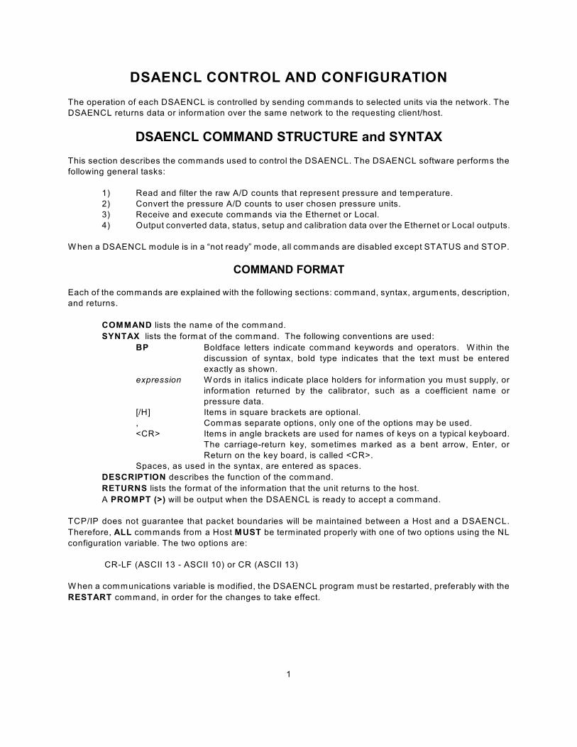
DSAENCL CONTROL AND CONFIGURATION
The operation of each DSAENCL is controlled by sending commands to selected units via the network. The
DSAENCL returns data or information over the same network to the requesting client/host.
DSAENCL COMMAND STRUCTURE and SYNTAX
This section describes the commands used to control the DSAENCL. The DSAENCL software performs the
following general tasks:
1) Read and filter the raw A/D counts that represent pressure and temperature.
2) Convert the pressure A/D counts to user chosen pressure units.
3) Receive and execute commands via the Ethernet or Local.
4) Output converted data, status, setup and calibration data over the Ethernet or Local outputs.
W hen a DSAENCL module is in a “not ready” mode, all commands are disabled except STATUS and STOP.
COMMAND FORMAT
Each of the commands are explained with the following sections: command, syntax, arguments, description,
and returns.
COMMAND lists the name of the command.
SYNTAX lists the format of the command. The following conventions are used:
BP Boldface letters indicate command keywords and operators. W ithin the
discussion of syntax, bold type indicates that the text must be entered
exactly as shown.
expression W ords in italics indicate place holders for information you must supply, or
information returned by the calibrator, such as a coefficient name or
pressure data.
[/H] Items in square brackets are optional.
, Commas separate options, only one of the options may be used.
<CR> Items in angle brackets are used for names of keys on a typical keyboard.
The carriage-return key, sometimes marked as a bent arrow, Enter, or
Return on the key board, is called <CR>.
Spaces, as used in the syntax, are entered as spaces.
DESCRIPTION describes the function of the command.
RETURNS lists the format of the information that the unit returns to the host.
A PROMPT (>) will be output when the DSAENCL is ready to accept a command.
TCP/IP does not guarantee that packet boundaries will be maintained between a Host and a DSAENCL.
Therefore, ALL commands from a Host MUST be terminated properly with one of two options using the NL
configuration variable. The two options are:
CR-LF (ASCII 13 - ASCII 10) or CR (ASCII 13)
W hen a communications variable is modified, the DSAENCL program must be restarted, preferably with the
RESTART command, in order for the changes to take effect.
2
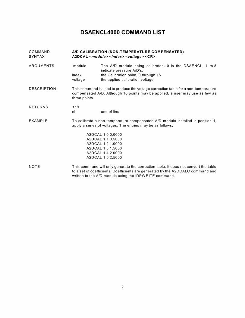
DSAENCL4000 COMMAND LIST
COMMAND A/D CALIBRATION (NON-TEMPERATURE COMPENSATED)
SYNTAX A2DCAL <module> <index> <voltage> <CR>
ARGUMENTS module The A/D module being calibrated. 0 is the DSAENCL, 1 to 8
indicate pressure A/D’s.
index the Calibration point, 0 through 15
voltage the applied calibration voltage
DESCRIPTION This command is used to produce the voltage correction table for a non-temperature
compensated A/D. Although 16 points may be applied, a user may use as few as
three points.
RETURNS <nl>
nl end of line
EXAMPLE To calibrate a non-temperature compensated A/D module installed in position 1,
apply a series of voltages. The entries may be as follows:
A2DCAL 1 0 0.0000
A2DCAL 1 1 0.5000
A2DCAL 1 2 1.0000
A2DCAL 1 3 1.5000
A2DCAL 1 4 2.0000
A2DCAL 1 5 2.5000
NOTE This command will only generate the correction table. It does not convert the table
to a set of coefficients. Coefficients are generated by the A2DCALC command and
written to the A/D module using the IDPW RITE command.
3
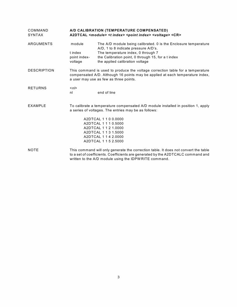
COMMAND A/D CALIBRATION (TEMPERATURE COMPENSATED)
SYNTAX A2DTCAL <module> <t index> <point index> <voltage> <CR>
ARGUMENTS module The A/D module being calibrated. 0 is the Enclosure temperature
A/D, 1 to 8 indicate pressure A/D’s.
t index The temperature index, 0 through 7
point index- the Calibration point, 0 through 15, for a t index
voltage the applied calibration voltage
DESCRIPTION This command is used to produce the voltage correction table for a temperature
compensated A/D. Although 16 points may be applied at each temperature index,
a user may use as few as three points.
RETURNS <nl>
nl end of line
EXAMPLE To calibrate a temperature compensated A/D module installed in position 1, apply
a series of voltages. The entries may be as follows:
A2DTCAL 1 1 0 0.0000
A2DTCAL 1 1 1 0.5000
A2DTCAL 1 1 2 1.0000
A2DTCAL 1 1 3 1.5000
A2DTCAL 1 1 4 2.0000
A2DTCAL 1 1 5 2.5000
NOTE This command will only generate the correction table. It does not convert the table
to a set of coefficients. Coefficients are generated by the A2DTCALC command and
written to the A/D module using the IDPW RITE command.
4
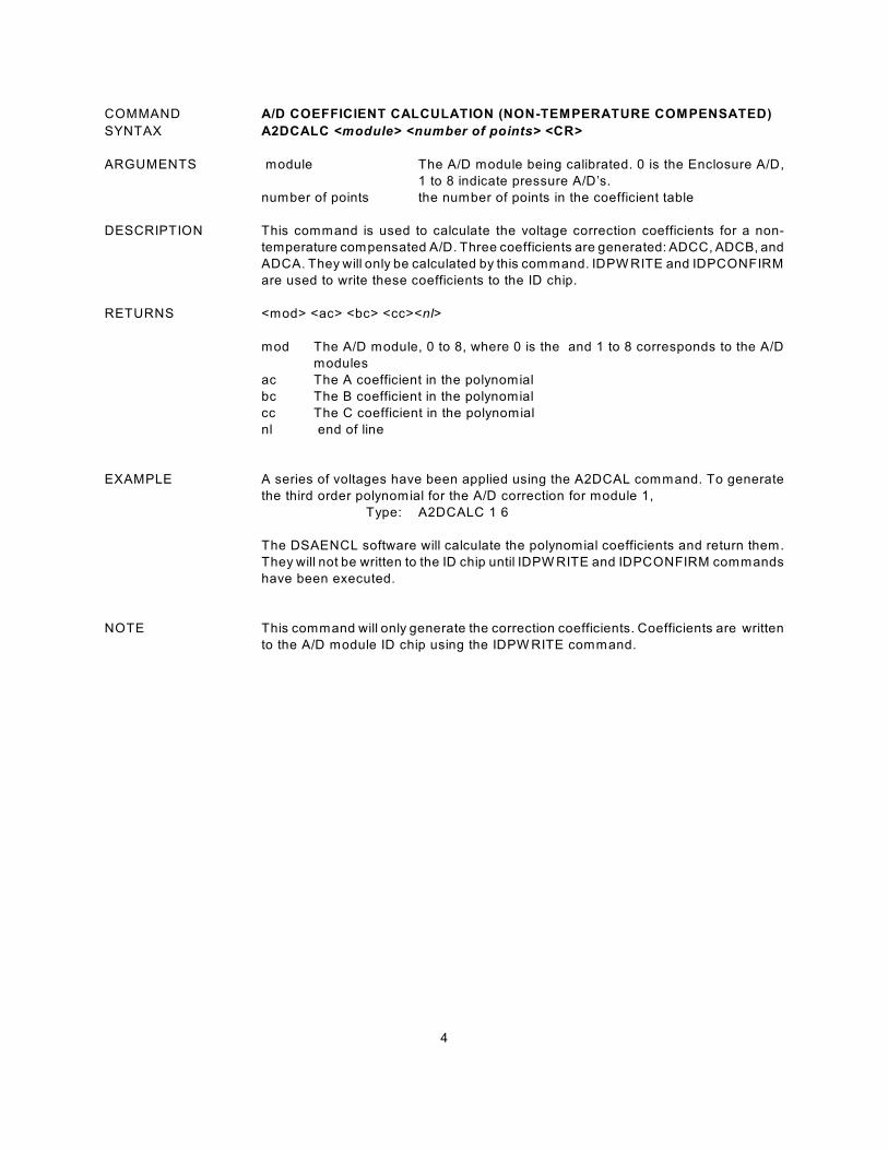
COMMAND A/D COEFFICIENT CALCULATION (NON-TEMPERATURE COMPENSATED)
SYNTAX A2DCALC <module> <number of points> <CR>
ARGUMENTS module The A/D module being calibrated. 0 is the Enclosure A/D,
1 to 8 indicate pressure A/D’s.
number of points the number of points in the coefficient table
DESCRIPTION This command is used to calculate the voltage correction coefficients for a non-
temperature compensated A/D. Three coefficients are generated: ADCC, ADCB, and
ADCA. They will only be calculated by this command. IDPW RITE and IDPCONFIRM
are used to write these coefficients to the ID chip.
RETURNS <mod> <ac> <bc> <cc><nl>
mod The A/D module, 0 to 8, where 0 is the and 1 to 8 corresponds to the A/D
modules
ac The A coefficient in the polynomial
bc The B coefficient in the polynomial
cc The C coefficient in the polynomial
nl end of line
EXAMPLE A series of voltages have been applied using the A2DCAL command. To generate
the third order polynomial for the A/D correction for module 1,
Type: A2DCALC 1 6
The DSAENCL software will calculate the polynomial coefficients and return them.
They will not be written to the ID chip until IDPW RITE and IDPCONFIRM commands
have been executed.
NOTE This command will only generate the correction coefficients. Coefficients are written
to the A/D module ID chip using the IDPW RITE command.

5
COMMAND A/D COEFFICIENT CALCULATION (TEMPERATURE COMPENSATED)
SYNTAX A2DTCALC <module> <number of temp planes> <number of points <CR>
ARGUMENTS module The A/D module being calibrated. 0 is the Enclosure A/D, 1 to 8
indicate pressure A/D’s.
index the Calibration point, 0 through 15
voltage the applied calibration voltage
DESCRIPTION This command is used to produce the voltage correction coefficients for a
temperature compensated A/D. Although 16 points may be applied, a user may use
as few as three points.
RETURNS <mod> <ac> <bc> <cc><nl>
mod The A/D module, 0 to 8, where 0 is the Enclosure and 1 to 8 corresponds
to the A/D modules
ac The A coefficient in the polynomial
bc The B coefficient in the polynomial
cc The C coefficient in the polynomial
nl - end of line
EXAMPLE A series of voltages have been applied using the A2DCAL command. To generate
the third order polynomial for the A/D correction for module 1,
Type: A2DTCALC 1 6
The DSAENCL software will calculate the polynomial coefficients and return them.
They will not be written to the ID chip until IDPW RITE and IDPCONFIRM commands
have been executed.
NOTE This command will only generate the correction coefficients. Coefficients are written
to the A/D module ID chip using the IDPW RITE command.

6
COMMAND AUXILIARY COMMAND
SYNTAX AUXCMD <command> <CR>
ARGUMENTS < command> Any valid string to an auxiliary device connected to a serial port
DESCRIPTION This command permits a host computer to send a command to a device connected
to a DSAENCL. The variable: AUX, must be enabled for this command to be
recognized.
RETURNS <nl>
nl end of line
EXAMPLE If a user wanted to command a calibrator, SPC3000, connected to the serial port to
apply a pressure to the DSA modules, the following command would be issued:
AUXCMD [a]GP 15 <CR> where a is the address of the calibrator
The calibrator will output 15 psi.
NOTES W hen BIN is set to 1 and the BINADDR is set to a value other than zero, the data
from the AUX or CAL commands are converted to a BINARY format and output over
the UDP binary port specified in the BINADDR variable. The data format is:
<ID byte> 1 byte, the value will be 1 if the data are from a calibrator
or 2 if the data are from an auxiliary unit.
<pressure> 4 bytes of floating point binary pressure data
7
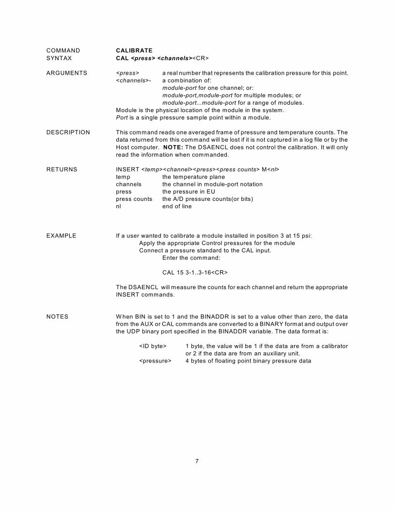
COMMAND CALIBRATE
SYNTAX CAL <press> <channels><CR>
ARGUMENTS <press> a real number that represents the calibration pressure for this point.
<channels>- a combination of:
module-port for one channel; or:
module-port,module-port for multiple modules; or
module-port...module-port for a range of modules.
Module is the physical location of the module in the system.
Port is a single pressure sample point within a module.
DESCRIPTION This command reads one averaged frame of pressure and temperature counts. The
data returned from this command will be lost if it is not captured in a log file or by the
Host computer. NOTE: The DSAENCL does not control the calibration. It will only
read the information when commanded.
RETURNS INSERT <temp><channel><press><press counts> M<nl>
temp the temperature plane
channels the channel in module-port notation
press the pressure in EU
press counts the A/D pressure counts(or bits)
nl end of line
EXAMPLE If a user wanted to calibrate a module installed in position 3 at 15 psi:
Apply the appropriate Control pressures for the module
Connect a pressure standard to the CAL input.
Enter the command:
CAL 15 3-1..3-16<CR>
The DSAENCL will measure the counts for each channel and return the appropriate
INSERT commands.
NOTES W hen BIN is set to 1 and the BINADDR is set to a value other than zero, the data
from the AUX or CAL commands are converted to a BINARY format and output over
the UDP binary port specified in the BINADDR variable. The data format is:
<ID byte> 1 byte, the value will be 1 if the data are from a calibrator
or 2 if the data are from an auxiliary unit.
<pressure> 4 bytes of floating point binary pressure data
8
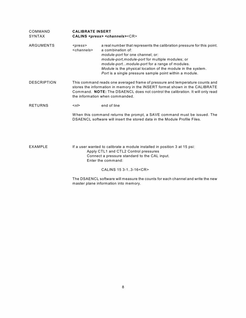
COMMAND CALIBRATE INSERT
SYNTAX CALINS <press> <channels><CR>
ARGUMENTS <press> a real number that represents the calibration pressure for this point.
<channels> a combination of:
module-port for one channel; or:
module-port,module-port for multiple modules; or
module-port...module-port for a range of modules.
Module is the physical location of the module in the system.
Port is a single pressure sample point within a module.
DESCRIPTION This command reads one averaged frame of pressure and temperature counts and
stores the information in memory in the INSERT format shown in the CALIBRATE
Command. NOTE: The DSAENCL does not control the calibration. It will only read
the information when commanded.
RETURNS <nl> end of line
W hen this command returns the prompt, a SAVE command must be issued. The
DSAENCL software will insert the stored data in the Module Profile Files.
EXAMPLE If a user wanted to calibrate a module installed in position 3 at 15 psi:
Apply CTL1 and CTL2 Control pressures
Connect a pressure standard to the CAL input.
Enter the command:
CALINS 15 3-1..3-16<CR>
The DSAENCL software will measure the counts for each channel and write the new
master plane information into memory.

9
COMMAND CALIBRATE ZERO
SYNTAX CALZ <CR>
ARGUMENTS None
DESCRIPTION Commands the DSAENCL to perform a zero calibration. This operation produces
A/D count values for each pressure channel that is subtracted from the raw pressure
counts before conversion to the engineering units. The data are stored in a Zero
Array and a Delta Array. These values may be read by executing a ZERO or DELTA
command. This command places the DSAENCL in the CALZ Mode until the
command is completed or a STOP command is issued. CALZ requires
approximately 15 seconds to complete.
RETURNS <nl>
nl end of line
EXAMPLE To update the current ZERO file and correct for any zero drift of the transducers:
Enter the command:
CALZ
The DSAENCL software will measure the zero counts for each channel and update
the Zero and Delta Arrays. The DSAENCL software will write the information into the
file, ZERO.CFG when a SAVE Command is executed.
NOTES General rules for use of a CALZ command
1. Power Up A CALZ should be executed after the DSAENCL and
DSA3016 modules have stabilized.
2. Power Cycle A CALZ should be executed if power is cycled, or if a
REBOOT, or RESTART command is executed.
3. REBOOT A CALZ should be executed after a REBOOT command.
4. Module Swap A CALZ should be executed after a module position swap.
If the module has reached stability before the swap, the
CALZ may be executed immediately after a LIST SYS U
command.
5. Module Change A CALZ should be executed after a module change. The
module should be allowed to stabilize before executing the
CALZ command, but after a LIST SYS U command.
The Zero and Delta Arrays are cleared when the DSAENCL is powered down or
when a REBOOT command is executed. The data in the ZERO.cfg file is intended
to be historical data. The Zero and Delta values are not reloaded at power up or
restart because it is impossible to determine how long the power has been off. This
also is designed to insure that a new set of zeros is acquired if modules have been
switched, or changed without a power cycle.
10
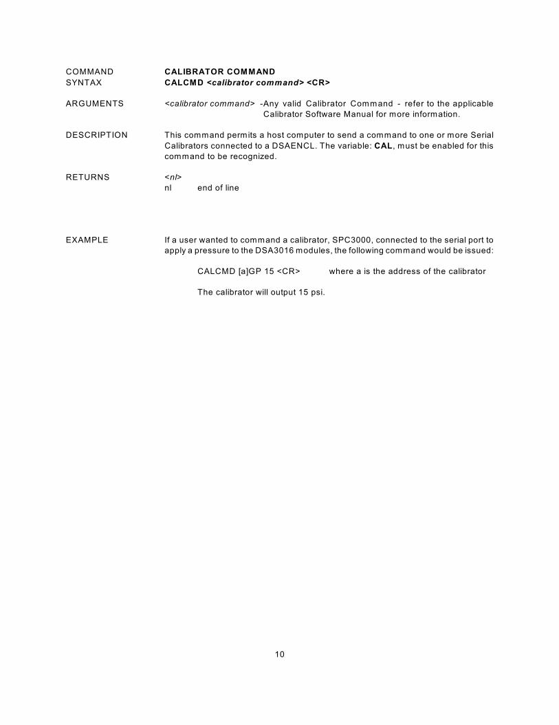
COMMAND CALIBRATOR COMMAND
SYNTAX CALCMD <calibrator command> <CR>
ARGUMENTS <calibrator command> -Any valid Calibrator Command - refer to the applicable
Calibrator Software Manual for more information.
DESCRIPTION This command permits a host computer to send a command to one or more Serial
Calibrators connected to a DSAENCL. The variable: CAL, must be enabled for this
command to be recognized.
RETURNS <nl>
nl end of line
EXAMPLE If a user wanted to command a calibrator, SPC3000, connected to the serial port to
apply a pressure to the DSA3016 modules, the following command would be issued:
CALCMD [a]GP 15 <CR> where a is the address of the calibrator
The calibrator will output 15 psi.

11
COMMAND CHANNEL
SYNTAX CHAN 1 <CR>
ARGUMENTS none
DESCRIPTION This command outputs the channel configuration for the scan group entered in the
argument.
RETURNS CHAN 1: <index><mod><port><lpress> <hpress><len><eu><nll>
index the channel index (1 based)
mod the module number (0 based)
port the port number in the module (0 based)
lpress the minimum pressure value
hpress the maximum pressure value
len the number of channels in this list
eu the eu conversion setting, 0 = raw counts, 1 = EU
nl end of line
EXAMPLE To verify the which channels have been assigned to be output:
Type:
CHAN 1 <CR>
If 2 modules are configured in the scan group, The DSAENCL will return:
CHAN 1: 1 1 1 -15.000000 15.000000 32 1
CHAN 1: 1 1 2 -15.000000 15.000000 32 1
CHAN 1: 1 1 3 -15.000000 15.000000 32 1
CHAN 1: 1 1 4 -15.000000 15.000000 32 1
CHAN 1: 1 1 5 -15.000000 15.000000 32 1
CHAN 1: 1 1 6 -15.000000 15.000000 32 1
CHAN 1: 1 1 7 -15.000000 15.000000 32 1
CHAN 1: 1 1 8 -15.000000 15.000000 32 1
CHAN 1: 1 1 9 -15.000000 15.000000 32 1
CHAN 1: 1 1 10 -15.000000 15.000000 32 1
:: :: : : : : : :: :: :: :: : :
CHAN 1: 1 2 15 -15.000000 15.000000 32 1
CHAN 1: 1 2 16 -15.000000 15.000000 32 1
>
This shows that all 16 ports of two 16 channel modules have been assigned in
sequence for a total of 32 channels. The modules are installed in positions 1 and
2. The minimum full scale pressure value for both modules is -15.0 engineering
units. The maximum pressure value is 15.0 engineering units. The output data will
be in engineering units

12
COMMAND CLEAR
SYNTAX CLEAR<CR>
ARGUMENTS None
DESCRIPTION Commands the DSAENCL to clear any errors that have occurred. The errors are
sent to the client in response to an ERROR command.
RETURNS <nl>
nl end of line.
EXAMPLE To clear any errors listed in the ERROR Buffer, the following command would be
issued:
CLEAR <CR>
The ERROR buffer will be cleared
.

13
COMMAND CONTROL PRESSURE RESET
SYNTAX DOUTPU<CR>
ARGUMENTS none.
DESCRIPTION Resets the control pressures to the power up condition. This also will reset DOUTsS
that have manually set.
RETURNS <nl>
nl end of line.
EXAMPLE To reset the control pressures to the power up mode after several operations of the
BANK(x) commands, Type:
DOUTPU<Enter>
14
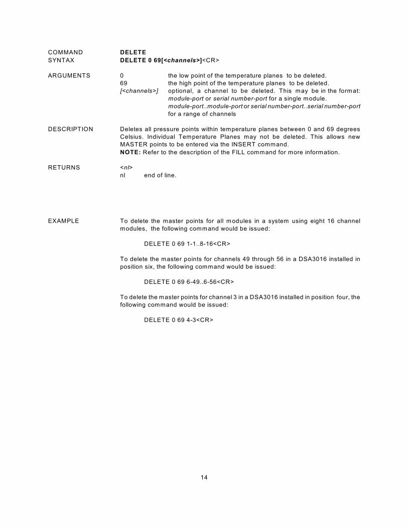
COMMAND DELETE
SYNTAX DELETE 0 69[<channels>]<CR>
ARGUMENTS 0 the low point of the temperature planes to be deleted.
69 the high point of the temperature planes to be deleted.
[<channels>] optional, a channel to be deleted. This may be in the format:
module-port or serial number-port for a single module.
module-port..module-port or serial number-port..serial number-port
for a range of channels
DESCRIPTION Deletes all pressure points within temperature planes between 0 and 69 degrees
Celsius. Individual Temperature Planes may not be deleted. This allows new
MASTER points to be entered via the INSERT command.
NOTE: Refer to the description of the FILL command for more information.
RETURNS <nl>
nl end of line.
EXAMPLE To delete the master points for all modules in a system using eight 16 channel
modules, the following command would be issued:
DELETE 0 69 1-1..8-16<CR>
To delete the master points for channels 49 through 56 in a DSA3016 installed in
position six, the following command would be issued:
DELETE 0 69 6-49..6-56<CR>
To delete the master points for channel 3 in a DSA3016 installed in position four, the
following command would be issued:
DELETE 0 69 4-3<CR>

15
COMMAND DELETE FILE
SYNTAX DEL <filename><CR>
ARGUMENTS <filename> - the file to be deleted in the format: scanxxx.dat
DESCRIPTION Deletes data files from the ENCL folder on the DSAENCL Micro SD chip.
RETURNS <nl>
nl end of line.
EXAMPLE To delete the file, SCAN002.dat from the hard drive:
Type: DEL SCAN002.dat
To verify that the file was deleted, refer to the List Files Command.
16
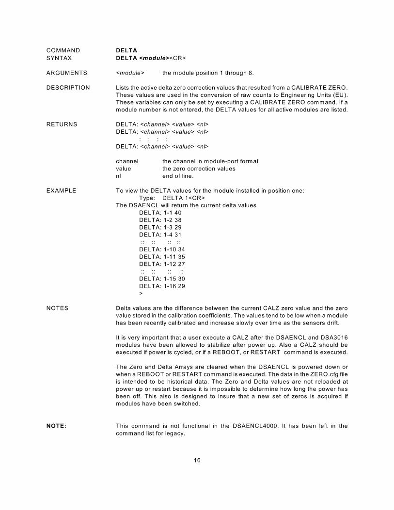
COMMAND DELTA
SYNTAX DELTA <module><CR>
ARGUMENTS <module> the module position 1 through 8.
DESCRIPTION Lists the active delta zero correction values that resulted from a CALIBRATE ZERO.
These values are used in the conversion of raw counts to Engineering Units (EU).
These variables can only be set by executing a CALIBRATE ZERO command. If a
module number is not entered, the DELTA values for all active modules are listed.
RETURNS DELTA: <channel> <value> <nl>
DELTA: <channel> <value> <nl>
: : : :
DELTA: <channel> <value> <nl>
channel the channel in module-port format
value the zero correction values
nl end of line.
EXAMPLE To view the DELTA values for the module installed in position one:
Type: DELTA 1<CR>
The DSAENCL will return the current delta values
DELTA: 1-1 40
DELTA: 1-2 38
DELTA: 1-3 29
DELTA: 1-4 31
:: :: :: ::
DELTA: 1-10 34
DELTA: 1-11 35
DELTA: 1-12 27
:: :: :: ::
DELTA: 1-15 30
DELTA: 1-16 29
>
NOTES Delta values are the difference between the current CALZ zero value and the zero
value stored in the calibration coefficients. The values tend to be low when a module
has been recently calibrated and increase slowly over time as the sensors drift.
It is very important that a user execute a CALZ after the DSAENCL and DSA3016
modules have been allowed to stabilize after power up. Also a CALZ should be
executed if power is cycled, or if a REBOOT, or RESTART command is executed.
The Zero and Delta Arrays are cleared when the DSAENCL is powered down or
when a REBOOT or RESTART command is executed. The data in the ZERO.cfg file
is intended to be historical data. The Zero and Delta values are not reloaded at
power up or restart because it is impossible to determine how long the power has
been off. This also is designed to insure that a new set of zeros is acquired if
modules have been switched.
NOTE: This command is not functional in the DSAENCL4000. It has been left in the
command list for legacy.
17
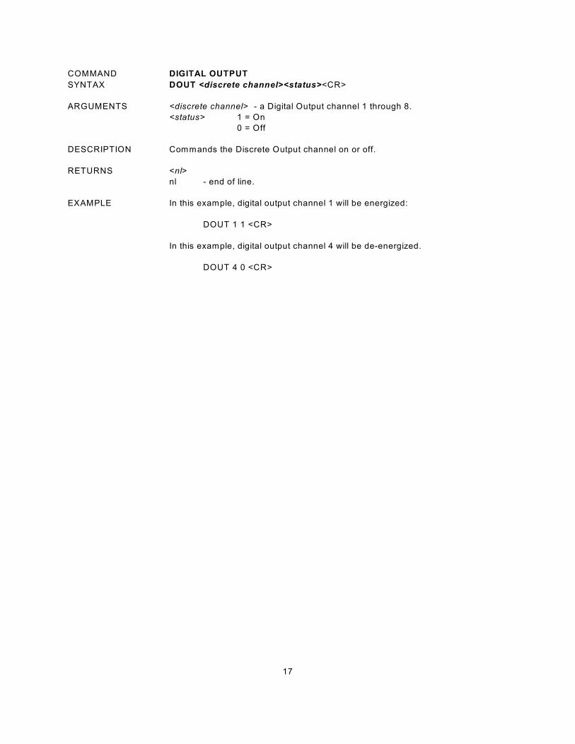
COMMAND DIGITAL OUTPUT
SYNTAX DOUT <discrete channel><status><CR>
ARGUMENTS <discrete channel> - a Digital Output channel 1 through 8.
<status> 1 = On
0 = Off
DESCRIPTION Commands the Discrete Output channel on or off.
RETURNS <nl>
nl - end of line.
EXAMPLE In this example, digital output channel 1 will be energized:
DOUT 1 1 <CR>
In this example, digital output channel 4 will be de-energized.
DOUT 4 0 <CR>
18
COMMAND DISCONNECT FROM HOST
SYNTAX DISCONNECT<CR>
ARGUMENTS none.
DESCRIPTION Disconnects the DSAENCL from the Host computer. Once this command is issued
the Ethernet connection between the Host and the DSAENCL will be cleanly
disconnected. The Host may re-connect to the DSAENCL by a normal TCP/IP
connection method.
RETURNS <nl>
nl - end of line.
EXAMPLE To disconnect a DSAENCL from a Host ,Type:
DISCONNECT <Enter>
19
COMMAND ERROR
SYNTAX ERROR <CR>
ARGUMENTS None
DESCRIPTION Lists the errors that have occurred since the last CLEAR. Only the first 30 errors will
be listed. If more than 30 errors have occurred, the message:
ERROR: Greater than 30 errors occurred" will appear at the end of the list.
RETURNS ERROR: <error message><nl>
ERROR: <error message><nl>
: : : :
ERROR: <error message><nl>
error message - an error message shown in the error list.
nl - end of line.
EXAMPLE To read the contents of the Error Buffer:
Type: ERROR
The DSAENCL will return the last 30 errors in the format::
ERROR: Module or Port not found
ERROR: List MI no group number
ERROR: Group not between 1 and 8
If no errors have been logged, the DSAENCL will return:
ERROR: No errors
NOTE The Error Buffer is only updated if the configuration variable: IFUSER , is set to 0.
W hen IFUSER is set to 1, errors will be displayed as they occur.

20
COMMAND FILL
SYNTAX FILL <CR>
ARGUMENTS None
DESCRIPTION Sorts Fills the Conversion Table temperature planes in ascending order.
The method used to FILL the conversion tables is determined by the setting of the
variable: FILLONE. This variable is in the Conversion Group.
If FILLONE is set to zero, the FILL command will fill the conversion tables by
calculating the temperature planes between Master Planes.
If FILLONE is set to one, the FILL command will copy the data in the first Master
Plane encountered to all other planes. If a second Master Plane is encountered, the
FILL will be terminated, and an error will be logged.
RETURNS <nl>
nl end of line.
EXAMPLE In this example, new MASTER points have been loaded and the coefficient table
must be completed.
Type: FILL<CR>
The FILL command only needs to be used if MASTER points are added to the
coefficients and the program is not restarted. W hen the program is started,
restarted, or reloaded, The MASTER points are loaded into memory from the Module
Profile Files and a FILL is executed by the program.
21
COMMAND FRAME TRIGGER
SYNTAX TRIG
ARGUMENTS None
DESCRIPTION This command acts as a software trigger to the DSAENCL. W hen ADTRIG is set to
1, an averaged frame of data will be output when the DSAENCL receives the TRIG
command or a <TAB> character code (9 HEX or Control I). This will continue until
a STOP command is issued or the Frames per Scan variable is met. The data
format will depend upon the setting of EU, BIN and FORMAT. This command will
also send the command set in the AUXSCHED, and/or CALSCHED variables.
EXAMPLE A scan command is executed with EU set to 1, BIN set to 0, ADTRIG set to 1, and
FORMAT set to 0. The DSAENCL will wait for a Hardware trigger, the TRIG
command or a <TAB> character (9 HEX or Control I). W hen one of the Data are
scrolled and will be displayed as follows:
Frame # <number>
Time <time> <µs or ms>
<chan> <temp eu>
“ “
” ”
<chan> <temp eu>
For information on other formats, refer to the SCAN command .
22
COMMAND INSERT
SYNTAX INSERT <temp><channel><press><press counts> M<CR>
ARGUMENTS <temp> an integer from 0 to 69.75 that represents the temperature in
degrees Celsius.
<channel> a combination of module and port. Syntax is:
module-port or serial number-port for one channel.
<press> a real number that represents the calibration pressure point.
<press counts> a signed integer from 32767 to -32768 that represents the
current pressure counts from the sensor.
DESCRIPTION Inserts one pressure-pressure counts entry into the Correction Table. Only master
points are accepted.
The LIST MASTER and LIST ALL commands download the contents of the
conversion table in the format required by this INSERT command.
If a MASTER plane is overwritten, an error will be generated.
RETURNS <nl>
nl End of line.
EXAMPLE Although INSERT commands are most often entered from a Module Profile File, they
may be entered from a keyboard.
The following command will insert a master point at 30.5EC for channel 1 of the
module installed in position 3. The applied pressure is 11.9998 psi, the measured
counts are 26376.
INSERT 30.50 3-1 11.9998 26376 M
The following command will insert a master point at 48.75EC for channel 9 of the
module installed in position 3. The applied pressure is 10.9998 psi, the measured
counts are 20254.
INSERT 48.75 3-9 10.9998 20254 M
The following command will insert a master point at 43.75EC for channel 16 of
module serial number 209. The applied pressure is -2.4864 psi, the measured
counts are -6651.
INSERT 43.75 209-16 -2.4864 -6651 M
23
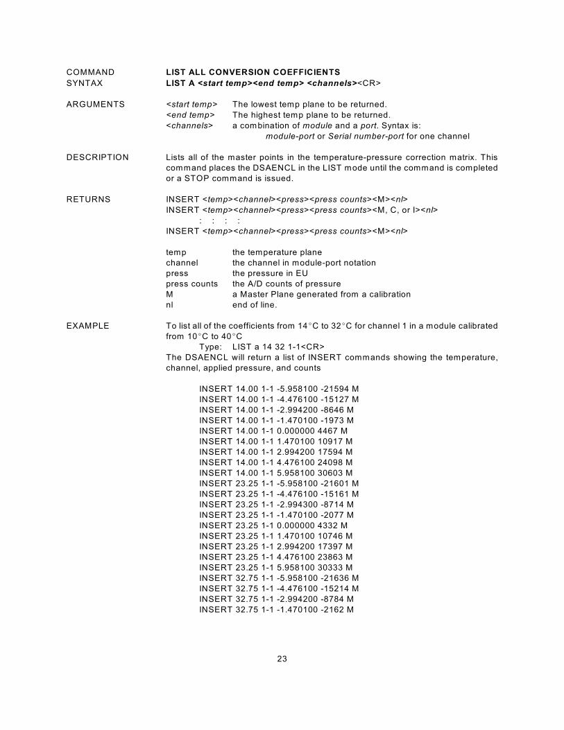
COMMAND LIST ALL CONVERSION COEFFICIENTS
SYNTAX LIST A <start temp><end temp> <channels><CR>
ARGUMENTS <start temp> The lowest temp plane to be returned.
<end temp> The highest temp plane to be returned.
<channels> a combination of module and a port. Syntax is:
module-port or Serial number-port for one channel
DESCRIPTION Lists all of the master points in the temperature-pressure correction matrix. This
command places the DSAENCL in the LIST mode until the command is completed
or a STOP command is issued.
RETURNS INSERT <temp><channel><press><press counts><M><nl>
INSERT <temp><channel><press><press counts><M, C, or I><nl>
: : : :
INSERT <temp><channel><press><press counts><M><nl>
temp the temperature plane
channel the channel in module-port notation
press the pressure in EU
press counts the A/D counts of pressure
M a Master Plane generated from a calibration
nl end of line.
EXAMPLE To list all of the coefficients from 14EC to 32EC for channel 1 in a module calibrated
from 10EC to 40EC
Type: LIST a 14 32 1-1<CR>
The DSAENCL will return a list of INSERT commands showing the temperature,
channel, applied pressure, and counts
INSERT 14.00 1-1 -5.958100 -21594 M
INSERT 14.00 1-1 -4.476100 -15127 M
INSERT 14.00 1-1 -2.994200 -8646 M
INSERT 14.00 1-1 -1.470100 -1973 M
INSERT 14.00 1-1 0.000000 4467 M
INSERT 14.00 1-1 1.470100 10917 M
INSERT 14.00 1-1 2.994200 17594 M
INSERT 14.00 1-1 4.476100 24098 M
INSERT 14.00 1-1 5.958100 30603 M
INSERT 23.25 1-1 -5.958100 -21601 M
INSERT 23.25 1-1 -4.476100 -15161 M
INSERT 23.25 1-1 -2.994300 -8714 M
INSERT 23.25 1-1 -1.470100 -2077 M
INSERT 23.25 1-1 0.000000 4332 M
INSERT 23.25 1-1 1.470100 10746 M
INSERT 23.25 1-1 2.994200 17397 M
INSERT 23.25 1-1 4.476100 23863 M
INSERT 23.25 1-1 5.958100 30333 M
INSERT 32.75 1-1 -5.958100 -21636 M
INSERT 32.75 1-1 -4.476100 -15214 M
INSERT 32.75 1-1 -2.994200 -8784 M
INSERT 32.75 1-1 -1.470100 -2162 M
24
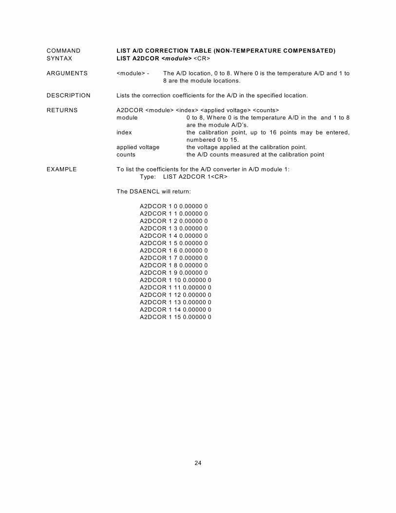
COMMAND LIST A/D CORRECTION TABLE (NON-TEMPERATURE COMPENSATED)
SYNTAX LIST A2DCOR <module> <CR>
ARGUMENTS <module> - The A/D location, 0 to 8. W here 0 is the temperature A/D and 1 to
8 are the module locations.
DESCRIPTION Lists the correction coefficients for the A/D in the specified location.
RETURNS A2DCOR <module> <index> <applied voltage> <counts>
module 0 to 8, W here 0 is the temperature A/D in the and 1 to 8
are the module A/D’s.
index the calibration point, up to 16 points may be entered,
numbered 0 to 15.
applied voltage the voltage applied at the calibration point.
counts the A/D counts measured at the calibration point
EXAMPLE To list the coefficients for the A/D converter in A/D module 1:
Type: LIST A2DCOR 1<CR>
The DSAENCL will return:
A2DCOR 1 0 0.00000 0
A2DCOR 1 1 0.00000 0
A2DCOR 1 2 0.00000 0
A2DCOR 1 3 0.00000 0
A2DCOR 1 4 0.00000 0
A2DCOR 1 5 0.00000 0
A2DCOR 1 6 0.00000 0
A2DCOR 1 7 0.00000 0
A2DCOR 1 8 0.00000 0
A2DCOR 1 9 0.00000 0
A2DCOR 1 10 0.00000 0
A2DCOR 1 11 0.00000 0
A2DCOR 1 12 0.00000 0
A2DCOR 1 13 0.00000 0
A2DCOR 1 14 0.00000 0
A2DCOR 1 15 0.00000 0
25
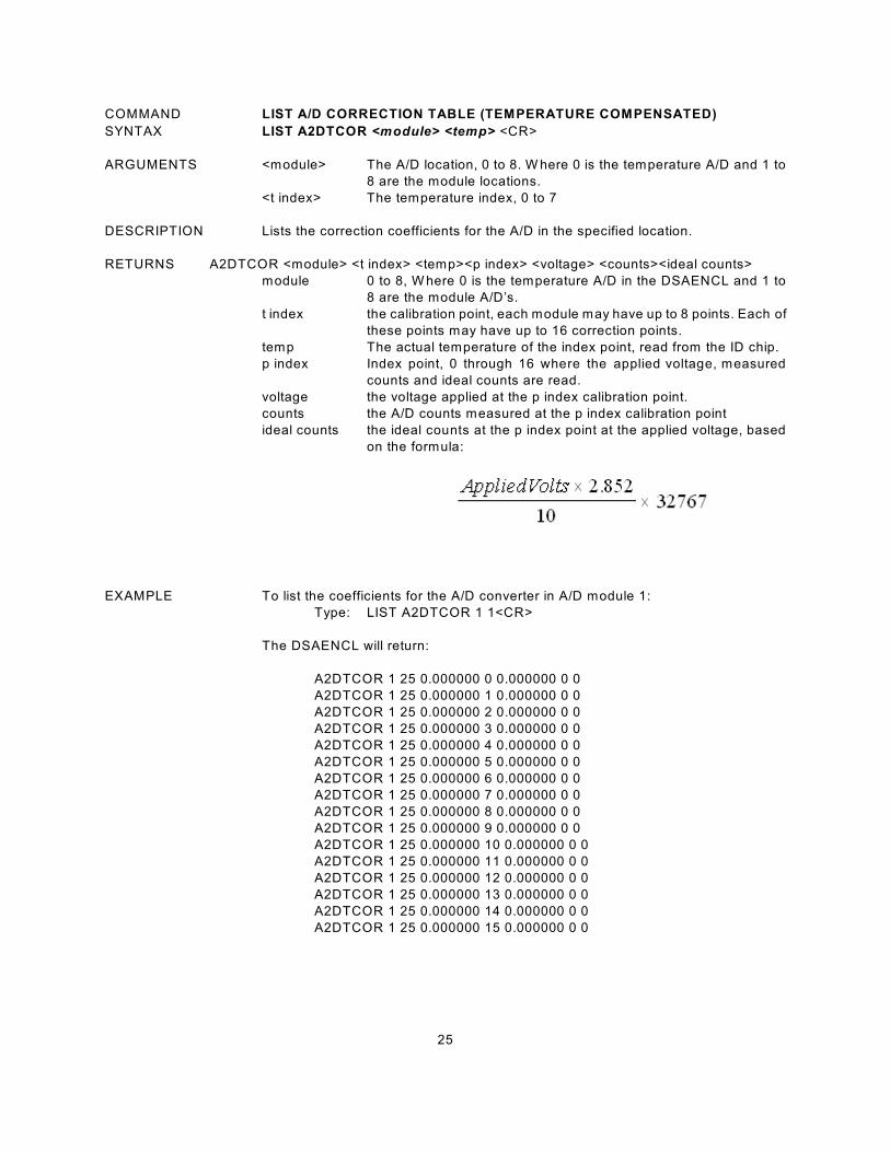
COMMAND LIST A/D CORRECTION TABLE (TEMPERATURE COMPENSATED)
SYNTAX LIST A2DTCOR <module> <temp> <CR>
ARGUMENTS <module> The A/D location, 0 to 8. W here 0 is the temperature A/D and 1 to
8 are the module locations.
<t index> The temperature index, 0 to 7
DESCRIPTION Lists the correction coefficients for the A/D in the specified location.
RETURNS A2DTCOR <module> <t index> <temp><p index> <voltage> <counts><ideal counts>
module 0 to 8, W here 0 is the temperature A/D in the DSAENCL and 1 to
8 are the module A/D’s.
t index the calibration point, each module may have up to 8 points. Each of
these points may have up to 16 correction points.
temp The actual temperature of the index point, read from the ID chip.
p index Index point, 0 through 16 where the applied voltage, measured
counts and ideal counts are read.
voltage the voltage applied at the p index calibration point.
counts the A/D counts measured at the p index calibration point
ideal counts the ideal counts at the p index point at the applied voltage, based
on the formula:
EXAMPLE To list the coefficients for the A/D converter in A/D module 1:
Type: LIST A2DTCOR 1 1<CR>
The DSAENCL will return:
A2DTCOR 1 25 0.000000 0 0.000000 0 0
A2DTCOR 1 25 0.000000 1 0.000000 0 0
A2DTCOR 1 25 0.000000 2 0.000000 0 0
A2DTCOR 1 25 0.000000 3 0.000000 0 0
A2DTCOR 1 25 0.000000 4 0.000000 0 0
A2DTCOR 1 25 0.000000 5 0.000000 0 0
A2DTCOR 1 25 0.000000 6 0.000000 0 0
A2DTCOR 1 25 0.000000 7 0.000000 0 0
A2DTCOR 1 25 0.000000 8 0.000000 0 0
A2DTCOR 1 25 0.000000 9 0.000000 0 0
A2DTCOR 1 25 0.000000 10 0.000000 0 0
A2DTCOR 1 25 0.000000 11 0.000000 0 0
A2DTCOR 1 25 0.000000 12 0.000000 0 0
A2DTCOR 1 25 0.000000 13 0.000000 0 0
A2DTCOR 1 25 0.000000 14 0.000000 0 0
A2DTCOR 1 25 0.000000 15 0.000000 0 0
26
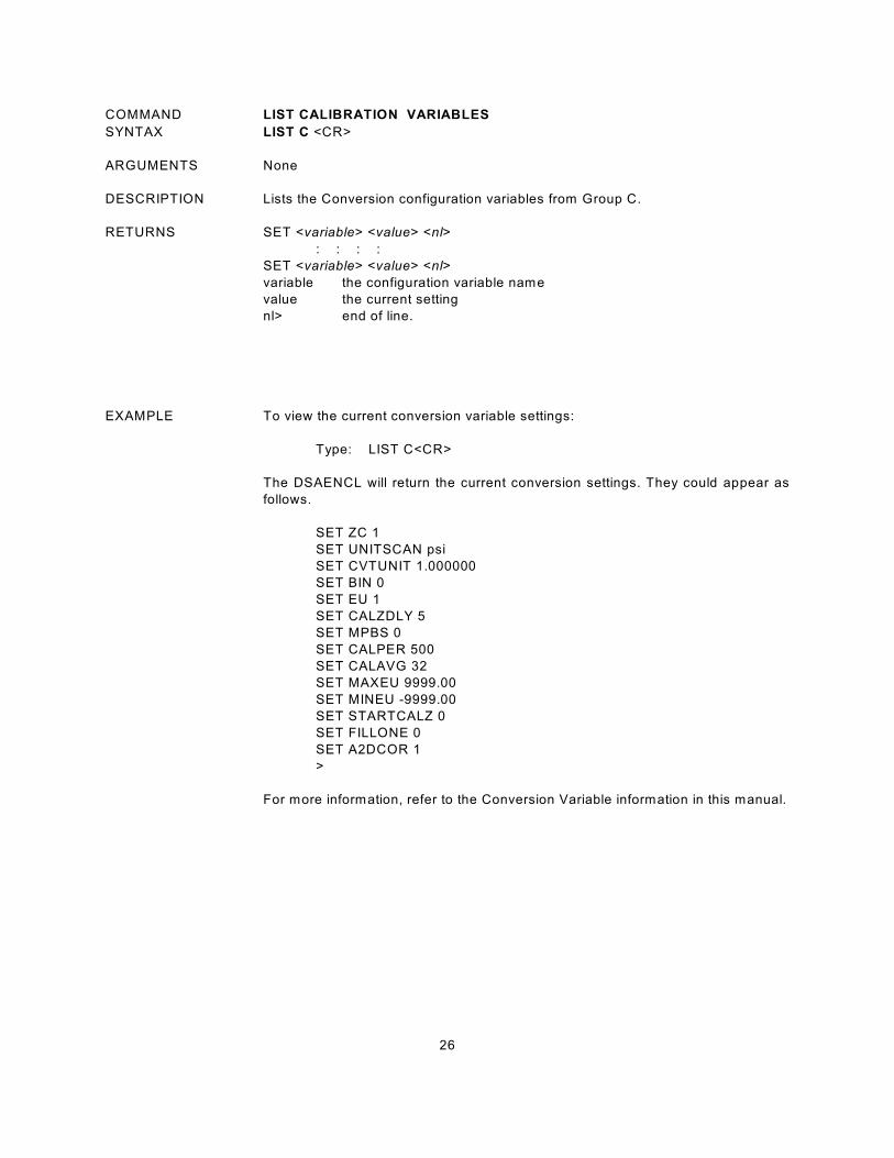
COMMAND LIST CALIBRATION VARIABLES
SYNTAX LIST C <CR>
ARGUMENTS None
DESCRIPTION Lists the Conversion configuration variables from Group C.
RETURNS SET <variable> <value> <nl>
: : : :
SET <variable> <value> <nl>
variable the configuration variable name
value the current setting
nl> end of line.
EXAMPLE To view the current conversion variable settings:
Type: LIST C<CR>
The DSAENCL will return the current conversion settings. They could appear as
follows.
SET ZC 1
SET UNITSCAN psi
SET CVTUNIT 1.000000
SET BIN 0
SET EU 1
SET CALZDLY 5
SET MPBS 0
SET CALPER 500
SET CALAVG 32
SET MAXEU 9999.00
SET MINEU -9999.00
SET STARTCALZ 0
SET FILLONE 0
SET A2DCOR 1
>
For more information, refer to the Conversion Variable information in this manual.
27
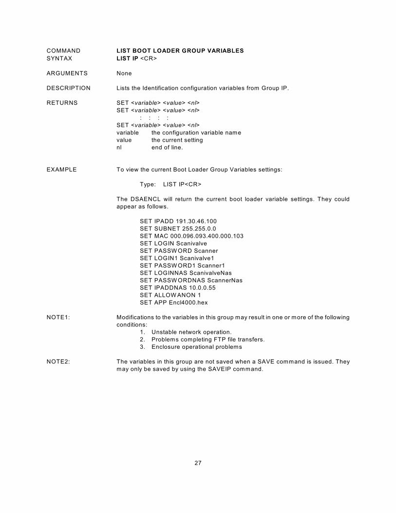
COMMAND LIST BOOT LOADER GROUP VARIABLES
SYNTAX LIST IP <CR>
ARGUMENTS None
DESCRIPTION Lists the Identification configuration variables from Group IP.
RETURNS SET <variable> <value> <nl>
SET <variable> <value> <nl>
: : : :
SET <variable> <value> <nl>
variable the configuration variable name
value the current setting
nl end of line.
EXAMPLE To view the current Boot Loader Group Variables settings:
Type: LIST IP<CR>
The DSAENCL will return the current boot loader variable settings. They could
appear as follows.
SET IPADD 191.30.46.100
SET SUBNET 255.255.0.0
SET MAC 000.096.093.400.000.103
SET LOGIN Scanivalve
SET PASSW ORD Scanner
SET LOGIN1 Scanivalve1
SET PASSW ORD1 Scanner1
SET LOGINNAS ScanivalveNas
SET PASSW ORDNAS ScannerNas
SET IPADDNAS 10.0.0.55
SET ALLOW ANON 1
SET APP Encl4000.hex
NOTE1: Modifications to the variables in this group may result in one or more of the following
conditions:
1. Unstable network operation.
2. Problems completing FTP file transfers.
3. Enclosure operational problems
NOTE2: The variables in this group are not saved when a SAVE command is issued. They
may only be saved by using the SAVEIP command.
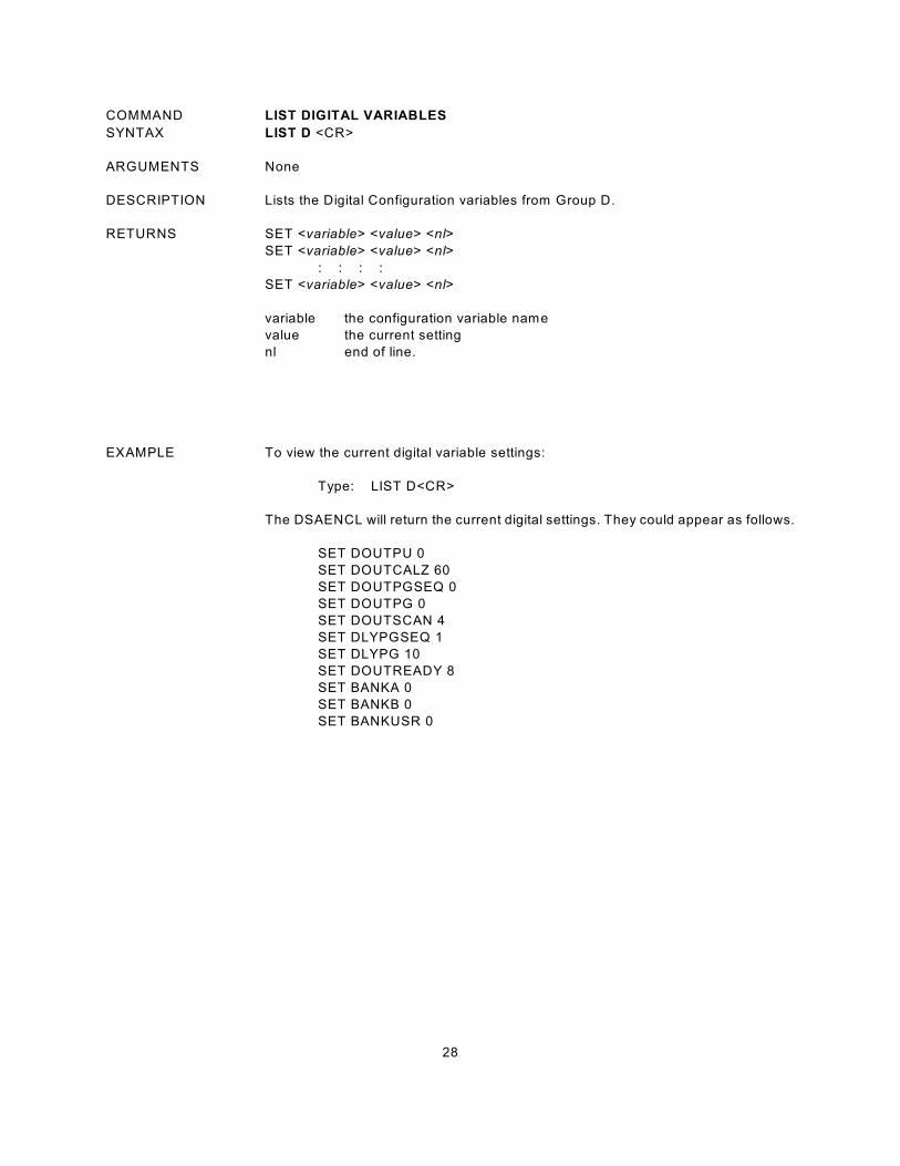
28
COMMAND LIST DIGITAL VARIABLES
SYNTAX LIST D <CR>
ARGUMENTS None
DESCRIPTION Lists the Digital Configuration variables from Group D.
RETURNS SET <variable> <value> <nl>
SET <variable> <value> <nl>
: : : :
SET <variable> <value> <nl>
variable the configuration variable name
value the current setting
nl end of line.
EXAMPLE To view the current digital variable settings:
Type: LIST D<CR>
The DSAENCL will return the current digital settings. They could appear as follows.
SET DOUTPU 0
SET DOUTCALZ 60
SET DOUTPGSEQ 0
SET DOUTPG 0
SET DOUTSCAN 4
SET DLYPGSEQ 1
SET DLYPG 10
SET DOUTREADY 8
SET BANKA 0
SET BANKB 0
SET BANKUSR 0

29
COMMAND LIST FILE CONTENTS
SYNTAX TYPE <filename> <CR>
ARGUMENTS <filename> The file to be listed. The file must be in the DSAENCL Folder.
DESCRIPTION Lists the contents of the named file. This command is intended to allow a user to
check the contents of one of the setup file son the Micro SD Card..
RETURNS <nl>
nl end of line.
EXAMPLE To list the contents of the CV.gpf file, Type
TYPE CV.gpf <enter>
The contents of the file will be listed. The variables listed below are sampling of an
actual cv.gpf file
SET NL 0
SET DISPIN 0
SET HAVENET 1
SET HAVEARINC 0
SET CONOUT 2
SET NETOUT 2
SET FORMAT 0
SET NETIN 1
SET IFUSER 1
SET ECHO 0
SET CAL 0 9600
SET CALSCHED 0 rp 0
SET AUX 0 9600 1
SET AUXSCHED 0 rp 0
SET RESCAN 0 0
:: :: :: ::
:: :: :: ::
:: :: :: ::
SET MPBS 5
SET CALPER 500
SET CALAVG 64
SET MAXEU 9999.00
SET MINEU -9999.00
SET STARTCALZ 2727
SET FILLONE 0
SET A2DCOR 1
SET SIMTMODE OFF
SET SIMTEMP 25.00
>
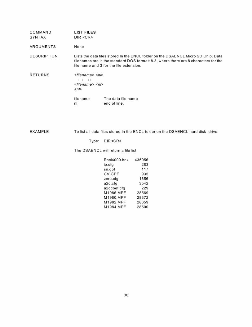
30
COMMAND LIST FILES
SYNTAX DIR <CR>
ARGUMENTS None
DESCRIPTION Lists the data files stored In the ENCL folder on the DSAENCL Micro SD Chip. Data
filenames are in the standard DOS format: 8.3, where there are 8 characters for the
file name and 3 for the file extension.
RETURNS <filename> <nl>
: : : :
<filename> <nl>
<nl>
filename The data file name
nl end of line.
EXAMPLE To list all data files stored In the ENCL folder on the DSAENCL hard disk drive:
Type: DIR<CR>
The DSAENCL will return a file list
Encl4000.hex 435056
ip.cfg 283
sn.gpf 117
CV.GPF 935
zero.cfg 1656
a2d.cfg 3542
a2dcoef.cfg 229
M1986.MPF 28569
M1980.MPF 28372
M1982.MPF 28659
M1984.MPF 2 8500
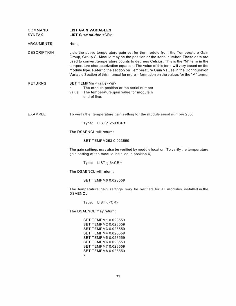
31
COMMAND LIST GAIN VARIABLES
SYNTAX LIST G <module> <CR>
ARGUMENTS None
DESCRIPTION Lists the active temperature gain set for the module from the Temperature Gain
Group, Group G. Module may be the position or the serial number. These data are
used to convert temperature counts to degrees Celsius. This is the "M" term in the
temperature characterization equation. The value of this term will vary based on the
module type. Refer to the section on Temperature Gain Values in the Configuration
Variable Section of this manual for more information on the values for the “M” terms.
RETURNS SET TEMPMn <value><nl>
n The module position or the serial number
value The temperature gain value for module n
nl end of line.
EXAMPLE To verify the temperature gain setting for the module serial number 253,
Type: LIST g 253<CR>
The DSAENCL will return:
SET TEMPM253 0.023559
The gain settings may also be verified by module location. To verify the temperature
gain setting of the module installed in position 6,
Type: LIST g 6<CR>
The DSAENCL will return:
SET TEMPM6 0.023559
The temperature gain settings may be verified for all modules installed in the
DSAENCL.
Type: LIST g<CR>
The DSAENCL may return:
SET TEMPM1 0.023559
SET TEMPM2 0.023559
SET TEMPM3 0.023559
SET TEMPM4 0.023559
SET TEMPM5 0.023559
SET TEMPM6 0.023559
SET TEMPM7 0.023559
SET TEMPM8 0.023559
>
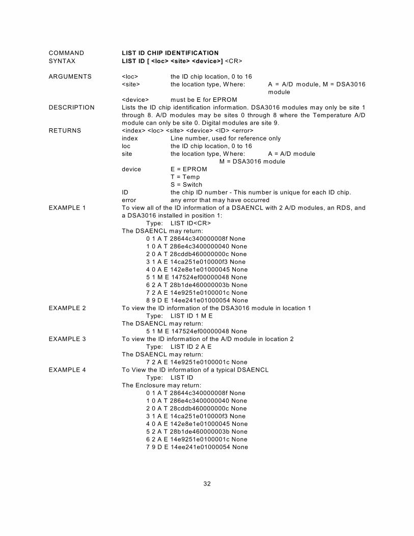
32
COMMAND LIST ID CHIP IDENTIFICATION
SYNTAX LIST ID [ <loc> <site> <device>] <CR>
ARGUMENTS <loc> the ID chip location, 0 to 16
<site> the location type, W here: A = A/D module, M = DSA3016
module
<device> must be E for EPROM
DESCRIPTION Lists the ID chip identification information. DSA3016 modules may only be site 1
through 8. A/D modules may be sites 0 through 8 where the Temperature A/D
module can only be site 0. Digital modules are site 9.
RETURNS <index> <loc> <site> <device> <ID> <error>
index Line number, used for reference only
loc the ID chip location, 0 to 16
site the location type, W here: A = A/D module
M = DSA3016 module
device E = EPROM
T = Temp
S = Switch
ID the chip ID number - This number is unique for each ID chip.
error any error that may have occurred
EXAMPLE 1 To view all of the ID information of a DSAENCL with 2 A/D modules, an RDS, and
a DSA3016 installed in position 1:
Type: LIST ID<CR>
The DSAENCL may return:
0 1 A T 28644c340000008f None
1 0 A T 286e4c3400000040 None
2 0 A T 28cddb460000000c None
3 1 A E 14ca251e010000f3 None
4 0 A E 142e8e1e01000045 None
5 1 M E 147524ef00000048 None
6 2 A T 28b1de460000003b None
7 2 A E 14e9251e0100001c None
8 9 D E 14ee241e01000054 None
EXAMPLE 2 To view the ID information of the DSA3016 module in location 1
Type: LIST ID 1 M E
The DSAENCL may return:
5 1 M E 147524ef00000048 None
EXAMPLE 3 To view the ID information of the A/D module in location 2
Type: LIST ID 2 A E
The DSAENCL may return:
7 2 A E 14e9251e0100001c None
EXAMPLE 4 To View the ID information of a typical DSAENCL
Type: LIST ID
The Enclosure may return:
0 1 A T 28644c340000008f None
1 0 A T 286e4c3400000040 None
2 0 A T 28cddb460000000c None
3 1 A E 14ca251e010000f3 None
4 0 A E 142e8e1e01000045 None
5 2 A T 28b1de460000003b None
6 2 A E 14e9251e0100001c None
7 9 D E 14ee241e01000054 None

33
COMMAND LIST ID CHIP SETTINGS
SYNTAX LIST IDP [<loc> <site> <device> <mem>] <CR>
ARGUMENTS <loc> the ID chip location, 1 to 8
<site> the location type, W here: A = A/D module , M = DSA3016 module
<device> the device type, always E for EPROM
<mem> the memory type, W here: E = EPROM, P = PROM
DESCRIPTION Lists the ID chip settings. DSA3016 modules may only be site 1 through 8. A/D
modules may be sites 1 through 8. If the location, site, and device are not specified,
the settings for all chips will be returned.
RETURNS SET IDP <loc> <site> <device> <mem> <name> <value>
loc the ID chip location, 1 to 8
site the location type, W here: A = A/D module, M = DSA3016 module
device the device type, always E for EPROM
mem the memory type, W here: P = PROM, E = EPROM
name the parameter name
value the parameter value
EXAMPLE 1 To view all of the ID chip information of the chip in A/D module in position 1:
Type: LIST IDP 1 A<CR>
The DSAENCL may return:
SET IDP 1 A E P DFC 1
SET IDP 1 A E P DMC 0
SET IDP 1 A E P SN 111
SET IDP 1 A E P REV A
SET IDP 1 A E P MDATE 7/1/2002
SET IDP 1 A E E ADCA 0.000000
SET IDP 1 A E E ADCB 0.996481
SET IDP 1 A E E ADCC 2.070793
SET IDP 1 A E E ECC 0.001499
SET IDP 1 A E E GAIN 0
SET IDP 1 A E E ACDATE 7/1/2002
SET IDP 1 A E E ADCD 6.50000
EXAMPLE 2 To view the ID chip information of the chip in the DSA3016 module in position 1:
Type: LIST IDP 1 M<CR>
The DSAENCL may return:
SET IDP 1 M E P DFC 2
SET IDP 1 M E P DMC 4
SET IDP 1 M E P SN 301
SET IDP 1 M E P REV A
SET IDP 1 M E P MDATE 1/27/2000
SET IDP 1 M E E RTYPE 0
SET IDP 1 M E E RVALUE 1
SET IDP 1 M E E RCORA 0.000000
SET IDP 1 M E E RCORB 0.000000
SET IDP 1 M E E RCDATE 1/27/2000
SET IDP 1 M E E PCDATE 8/16/2002
SET IDP 1 M E E NPR1 15.000000
SET IDP 1 M E E NPR2 15.000000
SET IDP 1 M E E VALVE 1
SET IDP 1 M E E XDUCER 0
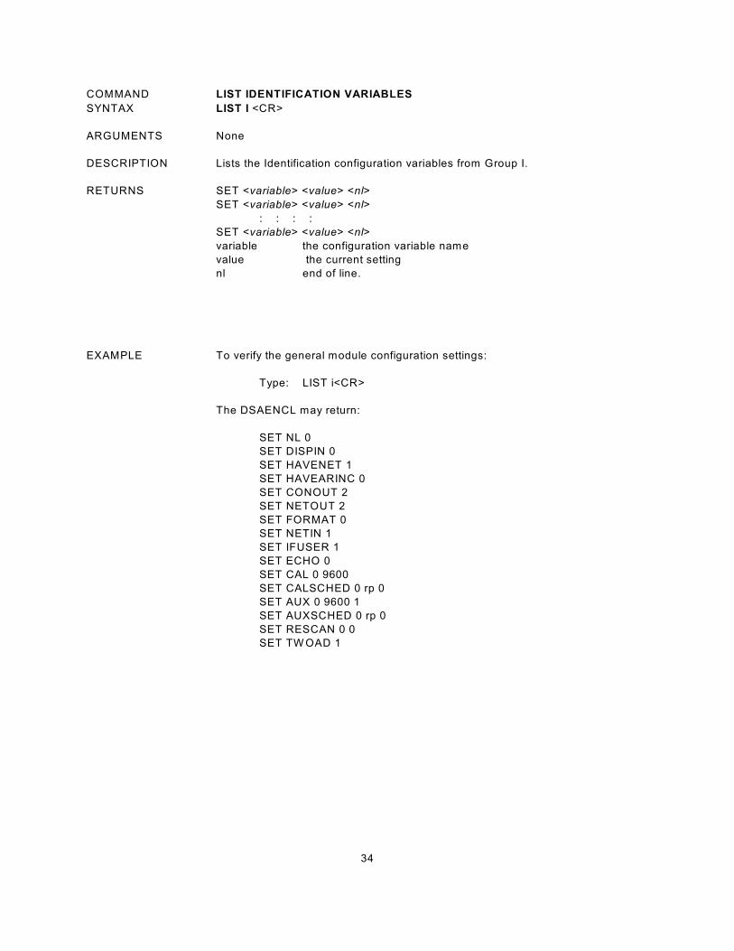
34
COMMAND LIST IDENTIFICATION VARIABLES
SYNTAX LIST I <CR>
ARGUMENTS None
DESCRIPTION Lists the Identification configuration variables from Group I.
RETURNS SET <variable> <value> <nl>
SET <variable> <value> <nl>
: : : :
SET <variable> <value> <nl>
variable the configuration variable name
value the current setting
nl end of line.
EXAMPLE To verify the general module configuration settings:
Type: LIST i<CR>
The DSAENCL may return:
SET NL 0
SET DISPIN 0
SET HAVENET 1
SET HAVEARINC 0
SET CONOUT 2
SET NETOUT 2
SET FORMAT 0
SET NETIN 1
SET IFUSER 1
SET ECHO 0
SET CAL 0 9600
SET CALSCHED 0 rp 0
SET AUX 0 9600 1
SET AUXSCHED 0 rp 0
SET RESCAN 0 0
SET TW OAD 1
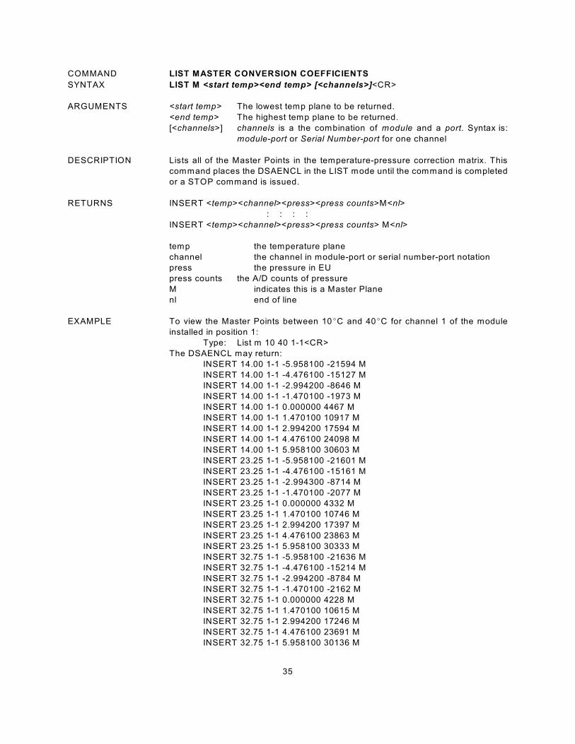
35
COMMAND LIST MASTER CONVERSION COEFFICIENTS
SYNTAX LIST M <start temp><end temp> [<channels>]<CR>
ARGUMENTS <start temp> The lowest temp plane to be returned.
<end temp> The highest temp plane to be returned.
[<channels>] channels is a the combination of module and a port. Syntax is:
module-port or Serial Number-port for one channel
DESCRIPTION Lists all of the Master Points in the temperature-pressure correction matrix. This
command places the DSAENCL in the LIST mode until the command is completed
or a STOP command is issued.
RETURNS INSERT <temp><channel><press><press counts>M<nl>
: : : :
INSERT <temp><channel><press><press counts> M<nl>
temp the temperature plane
channel the channel in module-port or serial number-port notation
press the pressure in EU
press counts the A/D counts of pressure
M indicates this is a Master Plane
nl end of line
EXAMPLE To view the Master Points between 10EC and 40EC for channel 1 of the module
installed in position 1:
Type: List m 10 40 1-1<CR>
The DSAENCL may return:
INSERT 14.00 1-1 -5.958100 -21594 M
INSERT 14.00 1-1 -4.476100 -15127 M
INSERT 14.00 1-1 -2.994200 -8646 M
INSERT 14.00 1-1 -1.470100 -1973 M
INSERT 14.00 1-1 0.000000 4467 M
INSERT 14.00 1-1 1.470100 10917 M
INSERT 14.00 1-1 2.994200 17594 M
INSERT 14.00 1-1 4.476100 24098 M
INSERT 14.00 1-1 5.958100 30603 M
INSERT 23.25 1-1 -5.958100 -21601 M
INSERT 23.25 1-1 -4.476100 -15161 M
INSERT 23.25 1-1 -2.994300 -8714 M
INSERT 23.25 1-1 -1.470100 -2077 M
INSERT 23.25 1-1 0.000000 4332 M
INSERT 23.25 1-1 1.470100 10746 M
INSERT 23.25 1-1 2.994200 17397 M
INSERT 23.25 1-1 4.476100 23863 M
INSERT 23.25 1-1 5.958100 30333 M
INSERT 32.75 1-1 -5.958100 -21636 M
INSERT 32.75 1-1 -4.476100 -15214 M
INSERT 32.75 1-1 -2.994200 -8784 M
INSERT 32.75 1-1 -1.470100 -2162 M
INSERT 32.75 1-1 0.000000 4228 M
INSERT 32.75 1-1 1.470100 10615 M
INSERT 32.75 1-1 2.994200 17246 M
INSERT 32.75 1-1 4.476100 23691 M
INSERT 32.75 1-1 5.958100 30136 M
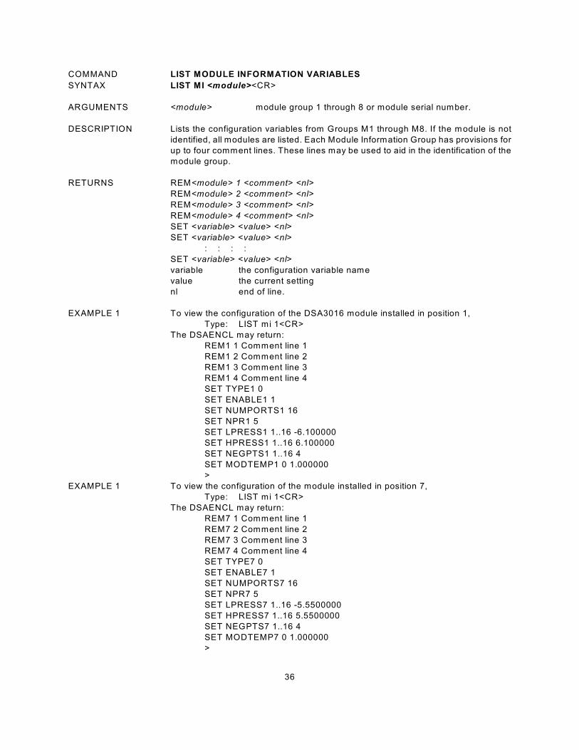
36
COMMAND LIST MODULE INFORMATION VARIABLES
SYNTAX LIST MI <module><CR>
ARGUMENTS <module> module group 1 through 8 or module serial number.
DESCRIPTION Lists the configuration variables from Groups M1 through M8. If the module is not
identified, all modules are listed. Each Module Information Group has provisions for
up to four comment lines. These lines may be used to aid in the identification of the
module group.
RETURNS REM<module> 1 <comment> <nl>
REM<module> 2 <comment> <nl>
REM<module> 3 <comment> <nl>
REM<module> 4 <comment> <nl>
SET <variable> <value> <nl>
SET <variable> <value> <nl>
: : : :
SET <variable> <value> <nl>
variable the configuration variable name
value the current setting
nl end of line.
EXAMPLE 1 To view the configuration of the DSA3016 module installed in position 1,
Type: LIST mi 1<CR>
The DSAENCL may return:
REM1 1 Comment line 1
REM1 2 Comment line 2
REM1 3 Comment line 3
REM1 4 Comment line 4
SET TYPE1 0
SET ENABLE1 1
SET NUMPORTS1 16
SET NPR1 5
SET LPRESS1 1..16 -6.100000
SET HPRESS1 1..16 6.100000
SET NEGPTS1 1..16 4
SET MODTEMP1 0 1.000000
>
EXAMPLE 1 To view the configuration of the module installed in position 7,
Type: LIST mi 1<CR>
The DSAENCL may return:
REM7 1 Comment line 1
REM7 2 Comment line 2
REM7 3 Comment line 3
REM7 4 Comment line 4
SET TYPE7 0
SET ENABLE7 1
SET NUMPORTS7 16
SET NPR7 5
SET LPRESS7 1..16 -5.5500000
SET HPRESS7 1..16 5.5500000
SET NEGPTS7 1..16 4
SET MODTEMP7 0 1.000000
>
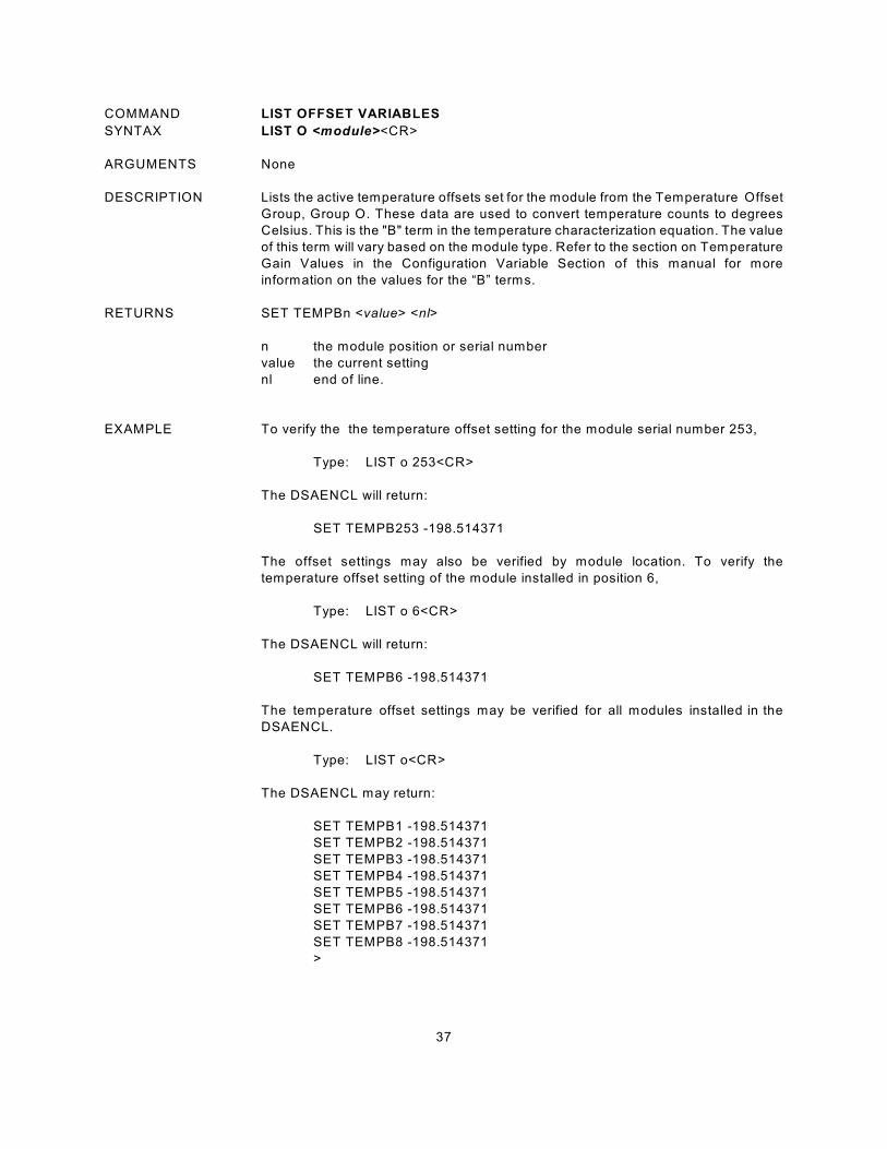
37
COMMAND LIST OFFSET VARIABLES
SYNTAX LIST O <module><CR>
ARGUMENTS None
DESCRIPTION Lists the active temperature offsets set for the module from the Temperature Offset
Group, Group O. These data are used to convert temperature counts to degrees
Celsius. This is the "B" term in the temperature characterization equation. The value
of this term will vary based on the module type. Refer to the section on Temperature
Gain Values in the Configuration Variable Section of this manual for more
information on the values for the “B” terms.
RETURNS SET TEMPBn <value> <nl>
n the module position or serial number
value the current setting
nl end of line.
EXAMPLE To verify the the temperature offset setting for the module serial number 253,
Type: LIST o 253<CR>
The DSAENCL will return:
SET TEMPB253 -198.514371
The offset settings may also be verified by module location. To verify the
temperature offset setting of the module installed in position 6,
Type: LIST o 6<CR>
The DSAENCL will return:
SET TEMPB6 -198.514371
The temperature offset settings may be verified for all modules installed in the
DSAENCL.
Type: LIST o<CR>
The DSAENCL may return:
SET TEMPB1 -198.514371
SET TEMPB2 -198.514371
SET TEMPB3 -198.514371
SET TEMPB4 -198.514371
SET TEMPB5 -198.514371
SET TEMPB6 -198.514371
SET TEMPB7 -198.514371
SET TEMPB8 -198.514371
>
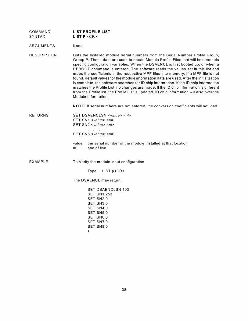
38
COMMAND LIST PROFILE LIST
SYNTAX LIST P <CR>
ARGUMENTS None
DESCRIPTION Lists the Installed module serial numbers from the Serial Number Profile Group,
Group P. These data are used to create Module Profile Files that will hold module
specific configuration variables. W hen the DSAENCL is first booted up, or when a
REBOOT command is entered, The software reads the values set in this list and
maps the coefficients in the respective MPF files into memory. If a MPF file is not
found, default values for the module information data are used. After the initialization
is complete, the software searches for ID chip information. If the ID chip information
matches the Profile List, no changes are made. If the ID chip information is different
from the Profile list, the Profile List is updated. ID chip information will also override
Module Information.
NOTE: If serial numbers are not entered, the conversion coefficients will not load.
RETURNS SET DSAENCLSN <value> <nl>
SET SN1 <value> <nl>
SET SN2 <value> <nl>
: : : :
SET SN8 <value> <nl>
value the serial number of the module installed at that location
nl end of line.
EXAMPLE To Verify the module input configuration
Type: LIST p<CR>
The DSAENCL may return:
SET DSAENCLSN 103
SET SN1 253
SET SN2 0
SET SN3 0
SET SN4 0
SET SN5 0
SET SN6 0
SET SN7 0
SET SN8 0
>
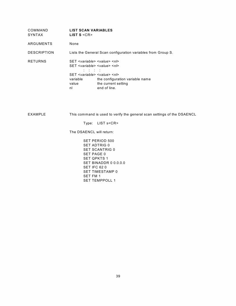
39
COMMAND LIST SCAN VARIABLES
SYNTAX LIST S <CR>
ARGUMENTS None
DESCRIPTION Lists the General Scan configuration variables from Group S.
RETURNS SET <variable> <value> <nl>
SET <variable> <value> <nl>
: : : :
SET <variable> <value> <nl>
variable the configuration variable name
value the current setting
nl end of line.
EXAMPLE This command is used to verify the general scan settings of the DSAENCL
Type: LIST s<CR>
The DSAENCL will return:
SET PERIOD 500
SET ADTRIG 0
SET SCANTRIG 0
SET PAGE 0
SET QPKTS 1
SET BINADDR 0 0.0.0.0
SET IFC 62 0
SET TIMESTAMP 0
SET FM 1
SET TEMPPOLL 1
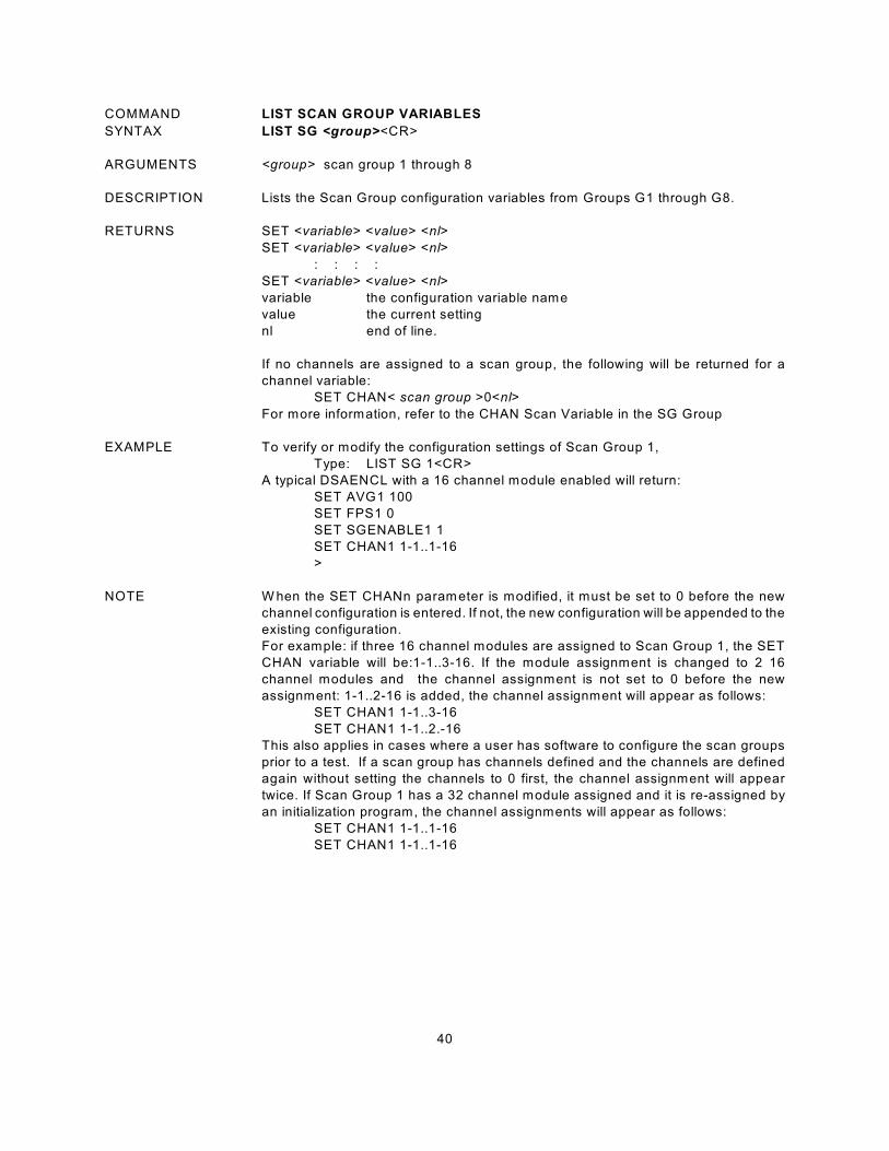
40
COMMAND LIST SCAN GROUP VARIABLES
SYNTAX LIST SG <group><CR>
ARGUMENTS <group> scan group 1 through 8
DESCRIPTION Lists the Scan Group configuration variables from Groups G1 through G8.
RETURNS SET <variable> <value> <nl>
SET <variable> <value> <nl>
: : : :
SET <variable> <value> <nl>
variable the configuration variable name
value the current setting
nl end of line.
If no channels are assigned to a scan group, the following will be returned for a
channel variable:
SET CHAN< scan group >0<nl>
For more information, refer to the CHAN Scan Variable in the SG Group
EXAMPLE To verify or modify the configuration settings of Scan Group 1,
Type: LIST SG 1<CR>
A typical DSAENCL with a 16 channel module enabled will return:
SET AVG1 100
SET FPS1 0
SET SGENABLE1 1
SET CHAN1 1-1..1-16
>
NOTE W hen the SET CHANn parameter is modified, it must be set to 0 before the new
channel configuration is entered. If not, the new configuration will be appended to the
existing configuration.
For example: if three 16 channel modules are assigned to Scan Group 1, the SET
CHAN variable will be:1-1..3-16. If the module assignment is changed to 2 16
channel modules and the channel assignment is not set to 0 before the new
assignment: 1-1..2-16 is added, the channel assignment will appear as follows:
SET CHAN1 1-1..3-16
SET CHAN1 1-1..2.-16
This also applies in cases where a user has software to configure the scan groups
prior to a test. If a scan group has channels defined and the channels are defined
again without setting the channels to 0 first, the channel assignment will appear
twice. If Scan Group 1 has a 32 channel module assigned and it is re-assigned by
an initialization program, the channel assignments will appear as follows:
SET CHAN1 1-1..1-16
SET CHAN1 1-1..1-16
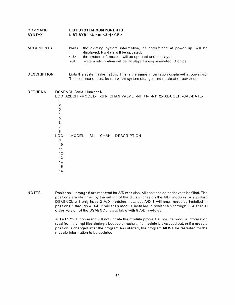
41
COMMAND LIST SYSTEM COMPONENTS
SYNTAX LIST SYS [ <U> or <S>] <CR>
ARGUMENTS blank the existing system information, as determined at power up, will be
displayed. No data will be updated.
<U> the system information will be updated and displayed.
<S> system information will be displayed using simulated ID chips.
DESCRIPTION Lists the system information. This is the same information displayed at power up.
This command must be run when system changes are made after power up.
RETURNS DSAENCL Serial Number N
LOC A2DSN -MODEL- -SN- CHAN VALVE -NPR1- -NPR2- XDUCER -CAL-DATE-
1
2
3
4
5
6
7
8
LOC -MODEL- -SN- CHAN DESCRIPTION
9
10
11
12
13
14
15
16
NOTES Positions 1 through 8 are reserved for A/D modules. All positions do not have to be filled. The
positions are identified by the setting of the dip switches on the A/D modules. A standard
DSAENCL will only have 2 A/D modules installed. A/D 1 will scan modules installed in
positions 1 through 4. A/D 2 will scan module installed in positions 5 through 8. A special
order version of the DSAENCL is available with 8 A/D modules.
A List SYS U command will not update the module profile file, nor the module information
read from the mpf files during a boot up or restart. If a module is swapped out, or if a module
position is changed after the program has started, the program MUST be restarted for the
module information to be updated.
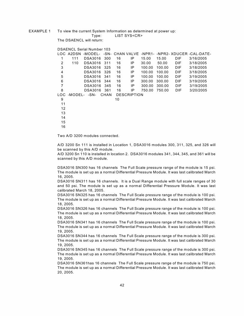
42
EXAMPLE 1 To view the current System Information as determined at power up:
Type: LIST SYS<CR>
The DSAENCL will return:
DSAENCL Serial Number 103
LOC A2DSN -MODEL- -SN- CHAN VALVE -NPR1- -NPR2- XDUCER -CAL-DATE-
1 111 DSA3016 300 16 IP 15.00 15.00 DIF 3/16/2005
2 110 DSA3016 311 16 IP 30.00 50.00 DIF 3/18/2005
3 DSA3016 325 16 IP 100.00 100.00 DIF 3/18/2005
4 DSA3016 326 16 IP 100.00 100.00 DIF 3/18/2005
5 DSA3016 341 16 IP 100.00 100.00 DIF 3/19/2005
6 DSA3016 344 16 IP 300.00 300.00 DIF 3/19/2005
7 DSA3016 345 16 IP 300.00 300.00 DIF 3/19/2005
8 DSA3016 361 16 IP 750.00 750.00 DIF 3/20/2005
LOC -MODEL- -SN- CHAN DESCRIPTION
9 10
11
12
13
14
15
16
Two A/D 3200 modules connected.
A/D 3200 Sn 111 is installed in Location 1, DSA3016 modules 300, 311, 325, and 326 will
be scanned by this A/D module.
A/D 3200 Sn 110 is installed in location 2. DSA3016 modules 341, 344, 345, and 361 will be
scanned by this A/D module.
DSA3016 SN300 has 16 channels The Full Scale pressure range of the module is 15 psi.
The module is set up as a normal Differential Pressure Module. It was last calibrated March
16, 2005.
DSA3016 SN311 has 16 channels. It is a Dual Range module with full scale ranges of 30
and 50 psi. The module is set up as a normal Differential Pressure Module. It was last
calibrated March 18, 2005.
DSA3016 SN325 has 16 channels The Full Scale pressure range of the module is 100 psi.
The module is set up as a normal Differential Pressure Module. It was last calibrated March
18, 2005.
DSA3016 SN326 has 16 channels The Full Scale pressure range of the module is 100 psi.
The module is set up as a normal Differential Pressure Module. It was last calibrated March
18, 2005.
DSA3016 SN341 has 16 channels The Full Scale pressure range of the module is 100 psi.
The module is set up as a normal Differential Pressure Module. It was last calibrated March
19, 2005.
DSA3016 SN344 has 16 channels The Full Scale pressure range of the module is 300 psi.
The module is set up as a normal Differential Pressure Module. It was last calibrated March
19, 2005.
DSA3016 SN345 has 16 channels The Full Scale pressure range of the module is 300 psi.
The module is set up as a normal Differential Pressure Module. It was last calibrated March
19, 2005.
DSA3016 SN361has 16 channels The Full Scale pressure range of the module is 750 psi.
The module is set up as a normal Differential Pressure Module. It was last calibrated March
20, 2005.
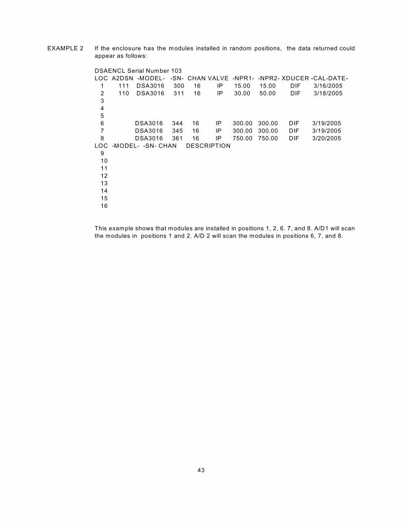
43
EXAMPLE 2 If the enclosure has the modules installed in random positions, the data returned could
appear as follows:
DSAENCL Serial Number 103
LOC A2DSN -MODEL- -SN- CHAN VALVE -NPR1- -NPR2- XDUCER -CAL-DATE-
1 111 DSA3016 300 16 IP 15.00 15.00 DIF 3/16/2005
2 110 DSA3016 311 16 IP 30.00 50.00 DIF 3/18/2005
3
4
5
6 DSA3016 344 16 IP 300.00 300.00 DIF 3/19/2005
7 DSA3016 345 16 IP 300.00 300.00 DIF 3/19/2005
8 DSA3016 361 16 IP 750.00 750.00 DIF 3/20/2005
LOC -MODEL- -SN- CHAN DESCRIPTION
9
10
11
12
13
14
15
16
This example shows that modules are installed in positions 1, 2, 6. 7, and 8. A/D1 will scan
the modules in positions 1 and 2. A/D 2 will scan the modules in positions 6, 7, and 8.
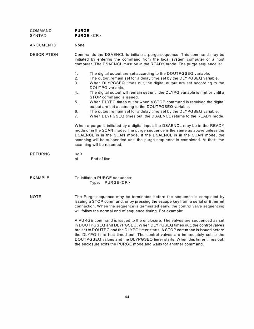
44
COMMAND PURGE
SYNTAX PURGE <CR>
ARGUMENTS None
DESCRIPTION Commands the DSAENCL to initiate a purge sequence. This command may be
initiated by entering the command from the local system computer or a host
computer. The DSAENCL must be in the READY mode. The purge sequence is:
1. The digital output are set according to the DOUTPGSEQ variable.
2. The output remain set for a delay time set by the DLYPGSEQ variable.
3. W hen DLYPGSEQ times out, the digital output are set according to the
DOUTPG variable.
4. The digital output will remain set until the DLYPG variable is met or until a
STOP command is issued.
5. W hen DLYPG times out or when a STOP command is received the digital
output are set according to the DOUTPGSEQ variable.
6. The output remain set for a delay time set by the DLYPGSEQ variable.
7. W hen DLYPGSEQ times out, the DSAENCL returns to the READY mode.
W hen a purge is initiated by a digital input, the DSAENCL may be in the READY
mode or in the SCAN mode. The purge sequence is the same as above unless the
DSAENCL is in the SCAN mode. If the DSAENCL is in the SCAN mode, the
scanning will be suspended until the purge sequence is completed. At that time
scanning will be resumed.
RETURNS <nl>
nl End of line.
EXAMPLE To initiate a PURGE sequence:
Type: PURGE<CR>
NOTE The Purge sequence may be terminated before the sequence is completed by
issuing a STOP command, or by pressing the escape key from a serial or Ethernet
connection. W hen the sequence is terminated early, the control valve sequencing
will follow the normal end of sequence timing. For example:
A PURGE command is issued to the enclosure. The valves are sequenced as set
in DOUTPGSEQ and DLYPGSEQ. W hen DLYPGSEQ times out, the control valves
are set to DOUTPG and the DLYPG timer starts. A STOP command is issued before
the DLYPG time has timed out. The control valves are immediately set to the
DOUTPGSEQ values and the DLYPGSEQ timer starts. W hen this timer times out,
the enclosure exits the PURGE mode and waits for another command.
45
COMMAND REBOOT
SYNTAX REBOOT <CR>
ARGUMENTS None
DESCRIPTION Commands the DSAENCL software to restart the ENCL4000.hex program.
RETURNS <nl>
nl End of line.
EXAMPLE To initiate a Reboot sequence,
Type: REBOOT<CR>

46
COMMAND RESTART
SYNTAX RESTART <CR>
ARGUMENTS None
DESCRIPTION Commands the software to restart the DSAENCL application.
RETURNS <nl>
nl - End of line.
EXAMPLE To initiate a Restart sequence,
Type: RESTART<CR>
47
COMMAND SAVE
SYNTAX SAVE [modules]<CR>
ARGUMENTS [Modules] Syntax is:
module for one module
module,module,module for several modules
module..module for a range of modules
Module is the physical location of the module in the DSAENCL3200.
DESCRIPTION Commands the DSAENCL to save the configuration variables, and correction tables
to the Micro SD Card. Correction tables are saved as .MPF files for all modules
specified in the command.
If a module, several modules, or a range of modules is not specified, the correction
tables for all enabled modules will be saved.
All configuration variables except the variables in the Boot Loader Group (IP
Group)will be saved by any variation of this command.
The following files are updated when a SAVE command is issued:
SN.cfg The P group configuration variables
ZERO.cfg The current ZERO and DELTA data from the most recent
CALZ.
Mxxxx.mpf The module calibration coefficients, where xxxx is the
module serial number.
CV.gpf All other configuration variables
A2D.cfg The A/D correction coefficients.
RETURNS <nl>
nl End of line.
EXAMPLES To save the current configuration variable settings and conversion coefficients for
all enabled modules
Type: SAVE<CR>
To save the current configuration variable settings and conversion coefficients for
module 4 only.
Type: SAVE 4<CR>
To save the current configuration variable settings and conversion coefficients for
modules 1, 3, and 7 only.
Type: SAVE 1,3,7<CR>
To save the current configuration variable settings and conversion coefficients for
modules 3, 4, 5, 6 and 7 only.
Type: SAVE 3..7<CR>
NOTE: The SAVE command requires approximately 60 seconds to complete. Normally,
commands entered during this time would be ignored, but it is possible on rare
occasions to cause the enclosure firmware to freeze.
48
COMMAND SAVE BOOT LOADER VARIABLES
SYNTAX SAVEIP<CR>
ARGUMENTS None
DESCRIPTION Commands the DSAENCL to save the boot loader configuration variables to the
Micro SD Card. Boot loader configuration variables are saved to the ip.cfg file.
The SAVEIP write process requires two commands to complete.
1, The SAVEIP command stages the IP configuration variables and prepares
the software to write to the Micro SD Card. This command does not actually
perform the write.
2. The write process does not occur until a SAVEIPCONFIRM command is
issued. The SAVEIPCONFIRM command is considered to be part of the
SAVEIP command.
EXAMPLE To save the current bootloader configuration variable settings
Type: SAVEIP<CR>
The software will return the following message:
W ARNING: This action could cause network communication problems.
Type SAVEIPCONFIRM confirm SAVEIP or STOP to
cancel the operation.
Type SAVEIPCONFIRM to complete the SAVE.
NOTE 1 Changes to the bootloader configuration variables will not take effect until power is
cycled, or a REBOOT command is issued.
NOTE 2 The SAVEIP command requires approximately 60 seconds to complete. Normally,
commands entered during this time would be ignored, but it is possible on rare
occasions to cause the enclosure firmware to freeze..
49
COMMAND SCAN
SYNTAX SCAN <CR>
ARGUMENTS None
DESCRIPTION Commands the DSAENCL to scan the pressure sensors and output scan data. The
SCAN function operation depends on the setting of ADTRIG and SCANTRIG.
ADTRIG = 0
SCANTRIG = 0
The SCAN function will be initiated immediately when the SCAN command is
received. Data will be acquired at the rate determined by the settings of PERIOD,
AVGn and the Number of Channels. In a DSAENCL Number of Channels is always
64. Data will be output in Averaged Frames as the Frames are ready until FPS is
satisfied or a STOP Command is received.
ADTRIG = 0
SCANTRIG = 1
In this case, a hardware trigger will initiate the SCAN function. The Software trigger
will not initiate the SCAN function. Data will be acquired at the rate determined by the
settings of PERIOD, AVGn and the Number of Channels. In a DSAENCL, Number
of Channels is always 64. Scanning will continue until FPS is satisfied or a STOP
command is received. Multiple trigger pulses received during a scan will be ignored.
ADTRIG = 1
SCANTRIG = 0
In this case, the SCAN command only enables the scan function. The DSAENCL
will enter the W TRIG mode and wait for a hardware or software trigger. W hen a
trigger is received, the DSAENCL will acquire and output one averaged frame of
data and re-enter the W TRIG mode. Data will be acquired at the rate determined by
the settings of PERIOD, AVGn and the Number of Channels. In a DSAENCL
Number of Channels is always 64. Multiple trigger pulses received during a scan
will be ignored. W hen a Frame has been output, the next trigger will repeat the
process. This will continue until the Frames per Scan Variable has been satisfied or
a STOP command is received.
RETURNS The format of the returned data is based on the setting of the BIN configuration
variable. If BIN is set to 1 the Scan Packets are returned in Binary Format(Refer to
the section on Binary Data Packets for more information). If BIN is set to 0, the scan
packets are returned in ASCII Format as follows:
<group> <frame> <channel> <pressure> <nl>
<group> <frame> <channel> <pressure> <nl>
:: :: :: :: ::
<group> <frame> <channel> <pressure> <nl>
group the scan group number from 1 to 8
frame the current frame number
channel the channel in module-port format
pressure the pressure in either counts or real number format based on the
setting of the EU configuration variable.
nl end of line.

50
EXAMPLE A scan group is set up to display 16 channels of module 1 with fps set to 1
Type: SCAN<CR>
The DSAENCL returns:
Group=1 Frame=0000001
101= 0.0052 102= .0086 103= -0.0015 104= 0.0017 105= -0.0162 106= 0.0035
107= 0.0036 108= 0.0114 109= 0.0031 110= 0.0073 111= 0.0111 112= -0.0035
113= 0.0057 114= 0.0097 115= 0.0049 116= 0.0086
NOTES 1. Only channels that are listed with the LIST SGn command are returned.
The field length is not fixed. Scan Groups are returned as they are ready.
2. All frames are separate parsable frames.
3. If ADTRIG is set to 1, SCANTRIG must be set to 0. If SCANTRIG is set to 1, ADTRIG must
be set to 0.
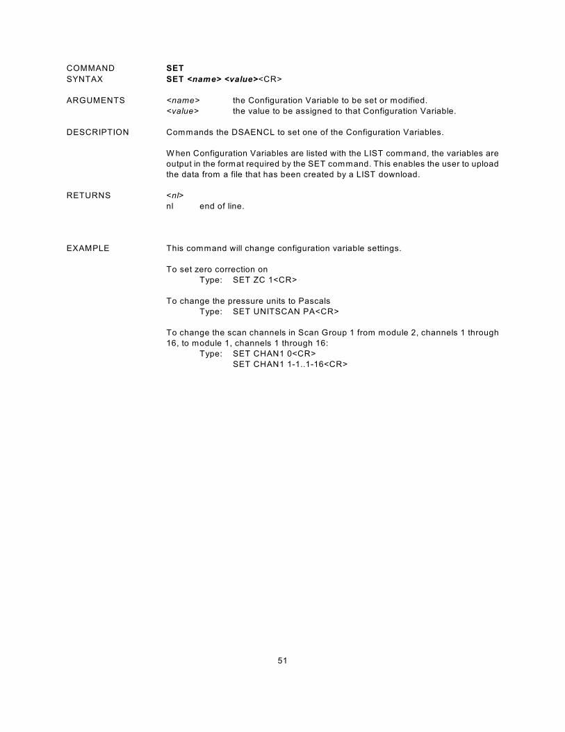
51
COMMAND SET
SYNTAX SET <name> <value><CR>
ARGUMENTS <name> the Configuration Variable to be set or modified.
<value> the value to be assigned to that Configuration Variable.
DESCRIPTION Commands the DSAENCL to set one of the Configuration Variables.
W hen Configuration Variables are listed with the LIST command, the variables are
output in the format required by the SET command. This enables the user to upload
the data from a file that has been created by a LIST download.
RETURNS <nl>
nl end of line.
EXAMPLE This command will change configuration variable settings.
To set zero correction on
Type: SET ZC 1<CR>
To change the pressure units to Pascals
Type: SET UNITSCAN PA<CR>
To change the scan channels in Scan Group 1 from module 2, channels 1 through
16, to module 1, channels 1 through 16:
Type: SET CHAN1 0<CR>
SET CHAN1 1-1..1-16<CR>

52
COMMAND SLOTS
SYNTAX SLOTS <channel><CR>
ARGUMENTS <channel> The channel in module-port format
DESCRIPTION Queries the DSAENCL to return the 10 boundary pressures for the 9 pressure slots
defined for a given channel.
RETURNS Press 9 <pressure> <nl>
Press 8 <pressure> <nl>
Press 7 <pressure> <nl>
Press 6 <pressure> <nl>
Press 5 <pressure> <nl>
Press 4 <pressure> <nl>
Press 3 <pressure> <nl>
Press 2 <pressure> <nl>
Press 1 <pressure> <nl>
Press 0 <pressure> <nl>
EXAMPLE To determine the boundary pressures for channel 1 of the 5 psi module s/n 253
Type: SLOTS 253-1<CR>
The DSAENCL will return:
Press 9 6.10000
Press 8 4.88000
Press 7 3.66000
Press 6 2.44000
Press 5 1.22000
Press 4 0.00000
Press 3 -1.52500
Press 2 -3.05000
Press 1 -4.57500
Press 0 -6.10000
The pressures applied during a calibration must be selected so that there are not two
or more applied pressures in any one slot. The module in the example above has
been set up with 4 negative points. By default, it will have 4 positive points as a
calibration must always include a zero point.
In this example, the slots for channel 1 of a 15 psi module in input 2 is configured for
2 negative points
Type SLOTS 2-1<CR>
The DSAENCL will return:
Press 9 15.00000
Press 8 12.85714
Press 7 10.71429
Press 6 8.57143
Press 5 6.42857
Press 4 4.28572
Press 3 2.14286
Press 2 0.00000
Press 1 -7.50000
Press 0 -15.00000
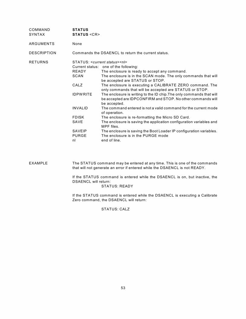
53
COMMAND STATUS
SYNTAX STATUS <CR>
ARGUMENTS None
DESCRIPTION Commands the DSAENCL to return the current status.
RETURNS STATUS: <current status><nl>
Current status: one of the following:
READY The enclosure is ready to accept any command.
SCAN The enclosure is in the SCAN mode. The only commands that will
be accepted are STATUS or STOP.
CALZ The enclosure is executing a CALIBRATE ZERO command. The
only commands that will be accepted are STATUS or STOP.
IDPW RITE The enclosure is writing to the ID chip.The only commands that will
be accepted are IDPCONFIRM and STOP. No other commands will
be accepted.
INVALID The command entered is not a valid command for the current mode
of operation.
FDISK The enclosure is re-formatting the Micro SD Card.
SAVE The enclosure is saving the application configuration variables and
MPF files.
SAVEIP The enclosure is saving the Boot Loader IP configuration variables.
PURGE The enclosure is in the PURGE mode
nl end of line.
EXAMPLE The STATUS command may be entered at any time. This is one of the commands
that will not generate an error if entered while the DSAENCL is not READY.
If the STATUS command is entered while the DSAENCL is on, but inactive, the
DSAENCL will return:
STATUS: READY
If the STATUS command is entered while the DSAENCL is executing a Calibrate
Zero command, the DSAENCL will return:
STATUS: CALZ
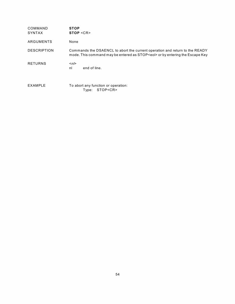
54
COMMAND STOP
SYNTAX STOP <CR>
ARGUMENTS None
DESCRIPTION Commands the DSAENCL to abort the current operation and return to the READY
mode. This command may be entered as STOP<eol> or by entering the Escape Key
RETURNS <nl>
nl end of line.
EXAMPLE To abort any function or operation:
Type: STOP<CR>
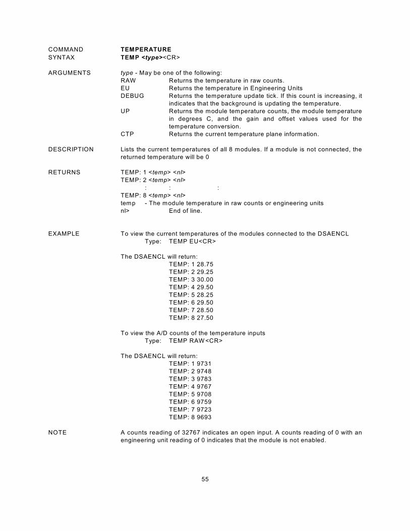
55
COMMAND TEMPERATURE
SYNTAX TEMP <type><CR>
ARGUMENTS type - May be one of the following:
RAW Returns the temperature in raw counts.
EU Returns the temperature in Engineering Units
DEBUG Returns the temperature update tick. If this count is increasing, it
indicates that the background is updating the temperature.
UP Returns the module temperature counts, the module temperature
in degrees C, and the gain and offset values used for the
temperature conversion.
CTP Returns the current temperature plane information.
DESCRIPTION Lists the current temperatures of all 8 modules. If a module is not connected, the
returned temperature will be 0
RETURNS TEMP: 1 <temp> <nl>
TEMP: 2 <temp> <nl>
: : :
TEMP: 8 <temp> <nl>
temp - The module temperature in raw counts or engineering units
nl> End of line.
EXAMPLE To view the current temperatures of the modules connected to the DSAENCL
Type: TEMP EU<CR>
The DSAENCL will return:
TEMP: 1 28.75
TEMP: 2 29.25
TEMP: 3 30.00
TEMP: 4 29.50
TEMP: 5 28.25
TEMP: 6 29.50
TEMP: 7 28.50
TEMP: 8 27.50
To view the A/D counts of the temperature inputs
Type: TEMP RAW <CR>
The DSAENCL will return:
TEMP: 1 9731
TEMP: 2 9748
TEMP: 3 9783
TEMP: 4 9767
TEMP: 5 9708
TEMP: 6 9759
TEMP: 7 9723
TEMP: 8 9693
NOTE A counts reading of 32767 indicates an open input. A counts reading of 0 with an
engineering unit reading of 0 indicates that the module is not enabled.

56
COMMAND TEMPERATURE GRADIENT COMPENSATION
SYNTAX TGRAD<CR>
ARGUMENTS none
DESCRIPTION This command reads the temperature of the A/D modules and stores this
information in a table. This table is then used to estimate the A/D module
temperatures during a scan based on the temperature of the DSAENCL.
RETURNS <Location> <DSAENCL Temp> <A/D Temp> <Delta Temp> <nl>
Location A/D Location, 1 through 8
DSAENCL Temp Measured Temperature of the DSAENCL in degrees C
A/D Temp Measured Temperature of the DSAENCL A/D Module in
this location.
Delta Temp The calculated Temperature differential for the A/D Module
in this location.
nl End of line.
NOTE The DSAENCL software can only read the temperature of the DSAENCL when in the
scan mode. The temperature of the A/D modules connected to the DSAENCL can
be estimated based on the gradient calculation derived from the table generated by
this command.
EXAMPLE A DSAENC has two A/D modules installed To calculate and store the temperature
differential for these modules, Type:
TGRAD<enter>
The DSAENCL software will calculate the differential temperatures and return:
Loc 1 Base 33.187500 Temp 28.562500 Delta -4.625000
Loc 2 Base 33.187500 Temp 27.750000 Delta -5.437500
57
COMMAND VERSION
SYNTAX VER <CR>
ARGUMENTS none
DESCRIPTION Requests the version number of the ENCL4000.hex file.
RETURNS VERSION: <version string> <nl>
EXAMPLE To determine the version of ENCL4000.hex software in use:
Type: VER<CR>
The DSAENCL will return:
VERSION: 5.03v
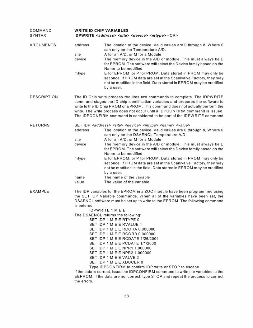
58
COMMAND WRITE ID CHIP VARIABLES
SYNTAX IDPWRITE <address> <site> <device> <mtype> <CR>
ARGUMENTS address The location of the device. Valid values are 0 through 8, W here 0
can only be the Temperature A/D.
site A for an A/D, or M for a Module
device The memory device in the A/D or module. This must always be E
for EPROM. The software will select the Device family based on the
Name to be modified.
mtype E for EPROM, or P for PROM. Data stored in PROM may only be
set once. If PROM data are set at the Scanivalve Factory, they may
not be modified in the field. Data stored in EPROM may be modified
by a user.
DESCRIPTION The ID Chip write process requires two commands to complete. The IDPW RITE
command stages the ID chip identification variables and prepares the software to
write to the ID Chip PROM or EPROM. This command does not actually perform the
write. The write process does not occur until a IDPCONFIRM command is issued.
The IDPCONFIRM command is considered to be part of the IDPW RITE command
RETURNS SET IDP <address> <site> <device> <mtype> <name> <value>
address The location of the device. Valid values are 0 through 8, W here 0
can only be the DSAENCL Temperature A/D.
site A for an A/D, or M for a Module
device The memory device in the A/D or module. This must always be E
for EPROM. The software will select the Device family based on the
Name to be modified.
mtype E for EPROM, or P for PROM. Data stored in PROM may only be
set once. If PROM data are set at the Scanivalve Factory, they may
not be modified in the field. Data stored in EPROM may be modified
by a user.
name The name of the variable
value The value of the variable
EXAMPLE The IDP variables for the EPROM in a ZOC module have been programmed using
the SET IDP Variable commands. W hen all of the variables have been set, the
DSAENCL software must be set up to write to the EPROM. The following command
is entered:
IDPW RITE 1 M E E
The DSAENCL returns the following:
SET IDP 1 M E E RTYPE 0
SET IDP 1 M E E RVALUE 1
SET IDP 1 M E E RCORA 0.000000
SET IDP 1 M E E RCORB 0.000000
SET IDP 1 M E E RCDATE 1/26/2004
SET IDP 1 M E E PCDATE 1/1/2000
SET IDP 1 M E E NPR1 1.000000
SET IDP 1 M E E NPR2 1.000000
SET IDP 1 M E E VALVE 2
SET IDP 1 M E E XDUCER 0
Type IDPCONFIRM to confirm IDP write or STOP to escape
If the data is correct, issue the IDPCONFIRM command to write the variables to the
EEPROM. If the data are not correct, type STOP and repeat the process to correct
the errors.

59
COMMAND ZERO
SYNTAX ZERO <CR>
ARGUMENTS none.
DESCRIPTION Lists the active zero correction values that obtained from a CALIBRATE ZERO
command. These data are used in the conversion of raw counts to Engineering Units
(EU). These values may only be set by executing a CALIBRATE ZERO.
RETURNS ZERO: <channel> <value> <nl>
ZERO: <channel> <value> <nl>
: : : :
ZERO: <channel> <value> <nl>
channel the channel in module-port or serial number-port format
value the zero correction values
nl end of line.
EXAMPLE To view the current zeros for module 1
Type: ZERO 1<CR>
The DSAENCL will return:
ZERO: 1-1 160
ZERO: 1-2 165
ZERO: 1-3 68
ZERO: 1-4 131
ZERO: 1-5 41
ZERO: 1-6 162
ZERO: 1-7 145
ZERO: 1-8 233
ZERO: 1-9 158
ZERO: 1-10 150
ZERO: 1-11 156
ZERO: 1-12 96
ZERO: 1-13 19
ZERO: 1-14 134
ZERO: 1-15 132
ZERO: 1-16 238

60
DSAENCL CONFIGURATION VARIABLES
GENERAL SCAN VARIABLES (Group S)
VARIABLE ADTRIG <code>
VALID VALUES 0 or 1
DEFAULT VALUE 0
DATA TYPE integer
DESCRIPTION This variable determines the method for a Frame Trigger.
0 Frame timing is controlled by an internal timer set by PERIOD.
1 Frame tim ing is controlled by an external hardware or a software trigger.
W hen ADTRIG is enabled, a frame will be triggered whenever a hardware
or software trigger input is received. The hardware trigger is a hard wired
input to the power input connector. The Software trigger is a TAB, or Ctrl I,
character. W hen a SCAN command is received, the DSAENCL enters a
W AIT state until a trigger pulse is received. At that time, the DSAENCL will
acquire and output one averaged frame of data and re-enter the W AIT state.
This will continue until a STOP command is received or the FPS variable is
satisfied. Multiple trigger pulses received during a scan will be ignored.
VARIABLE BINADDR <port> <IP address>
VALID VALUES port 0 to 65535
IP address any valid IP address
DEFAULT VALUE port 0
IP address 0.0.0.0
DATA TYPE integer
DESCRIPTION W hen port is set to 0, data are NOT sent out over the binary address port, Data are
sent over the standard TCP port. If port is 0 to 65535, data are sent over that port
to the IP address identified in a UDP format.
VARIABLE FM <code>
VALID VALUES 1
DEFAULT VALUE 1
DATA TYPE integer
DESCRIPTION Not used in the DSAENCL4000. This variable is a non-operational variable. It is for
legacy use only.
VARIABLE IFC <char 1> <char 2>
VALID VALUES char 1 Any valid ASCII character
char 2 Any valid ASCII character
DEFAULT VALUE char 1 62
char 2 0
DATA TYPE integer
DESCRIPTION This variable sets the interframe characters to be used when transmitting ASCII
unformatted output. If only one character is desired, char 2 must be set to 0. If both
characters are set to 0, no interframe characters will be transmitted.
EXAMPLE If a Carriage Return is desired between frames, the following command would be
used:
SET IFC 13 0

61
VARIABLE PERIOD <period>
VALID VALUES 10 to 4294967295
DEFAULT VALUE 500
DATA TYPE integer
DESCRIPTION This master period variable sets the sample rate, in microseconds, of the pressure
A/D converters and the one temperature A/D converter. Period is the dwell time
between channels. All Scan Groups use the this variable. Period is only one of the
terms required to determine data rate. Data rate is determined by the equation:
Data Rate is expressed in Hertz per channel
Period is in microseconds
Channels is always 64 in a standard DSAENCL
AVG is the average term for that scan group
NOTE: Channels will always equal 64 in a DSAENCL with 2 A/D modules. Channels will
always equal 16 in a DSAENCL with 8 A/D modules.
VARIABLE QPKTS <enable>
VALID VALUES 1
DEFAULT VALUE 1
DATA TYPE integer
DESCRIPTION Not used in the DSAENCL4000. This variable is a non-operational variable. It is for
legacy use only.
VARIABLE SCANTRIG <code>
VALID VALUES 0
DEFAULT VALUE 0
DATA TYPE integer
DESCRIPTION Not used in the DSAENCL4000. This variable is a non-operational variable. It is for
legacy use only.
VARIABLE TEMPPOLL <code>
VALID VALUES 1
DEFAULT VALUE 1
DATA TYPE integer
DESCRIPTION Not used in the DSAENCL4000. This variable is a non-operational variable. It is for
legacy use only.
VARIABLE TIMESTAMP <code>
VALID VALUES 0 or 1
DEFAULT VALUE 1
DATA TYPE integer
DESCRIPTION Not used in the DSAENCL4000. This variable is a non-operational variable. It is for
legacy use only.
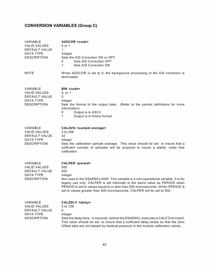
62
CONVERSION VARIABLES (Group C)
VARIABLE A2DCOR <code>
VALID VALUES 0 or 1
DEFAULT VALUE 1
DATA TYPE Integer
DESCRIPTION Sets the A/D Correction ON or OFF.
0 Sets A/D Correction OFF
1 Sets A/D Correction ON
NOTE W hen A2DCOR is set to 0, the background processing of the A/D correction is
terminated.
VARIABLE BIN <code>
VALID VALUES 0, or 1
DEFAULT VALUE 0
DATA TYPE integer
DESCRIPTION Sets the format of the output data: (Refer to the packet definitions for more
information)
0 Output is in ASCII
1 Output is in binary format
VARIABLE CALAVG <sample average>
VALID VALUES 2 to 256
DEFAULT VALUE 32
DATA TYPE integer
DESCRIPTION Sets the calibration sample average. This value should be set to insure that a
sufficient number of samples will be acquired to insure a stable, noise free
calibration.
VARIABLE CALPER <period>
VALID VALUES 500
DEFAULT VALUE 500
DATA TYPE integer
DESCRIPTION Not used in the DSAENCL4000. This variable is a non-operational variable. It is for
legacy use only. CALPER is set internally to the same value as PERIOD when
PERIOD is set to values equal to or less than 500 microseconds. W hen PERIOD is
set to values greater than 500 microseconds, CALPER will be set to 500.
VARIABLE CALZDLY <delay>
VALID VALUES 5 to 128
DEFAULT VALUE 5
DATA TYPE integer
DESCRIPTION Sets the delay time, in seconds, before the DSAENCL executes a CALZ Command.
This value should be set to insure that a sufficient delay exists so that the Zero
Offset data are not biased by residual pressure in the module calibration valves.

63
VARIABLE CVTUNIT <value>
VALID VALUES any real number
DEFAULT VALUE 1.0
DATA TYPE float
DESCRIPTION This is the conversion factor to convert from PSI units to the desired scanning units.
This value may be set directly or by setting the UNITSCAN variable.
VARIABLE EU <code>
VALID VALUES 0, 1
DEFAULT VALUE 1
DATA TYPE integer
DESCRIPTION Sets the units of the output data:
0 Output is in raw counts
1 Output is in selected engineering units
W hen the A/D counts reach 32767 or -32768, and EU is set to 1, the DSAENCL will
output the values set in MAXEU and MINEU to indicate that a conversion error may
exist. The DSAENCL will also output these values when the maximum or minimum
master conversion planes are exceeded.
VARIABLE FILLONE <code>
VALID VALUES 0, 1
DEFAULT VALUE 0
DATA TYPE integer
DESCRIPTION Sets the type of fill that will be performed.
0 The pressure conversion planes will be filled using several Master Planes
1 The pressure conversion planes will be filled using a single Master Plane
If FILLONE is set to 1 during the execution of a FILL command, the software will
copy the data from the first Master Plane encountered to all other temperature
planes. If a second Master Plane is found, the FILL will be terminated and an error
will be logged. Normally, a pressure conversion plane is filled using two to nine
Master Planes.
NOTE This function is designed for a who user wishes to calibrate his modules at one
temperature and is able to maintain the temperature of the module(s) to ±0.25 C."
If a user is not able to maintain the temperature of his modules to ±0.25 C, large"
errors may result.
If FILLONE is set to 1 when a full set of coefficients are available, and a FILL
command is issued, the coefficients will all be set to the value of the first Master
Plane in the coefficient file.
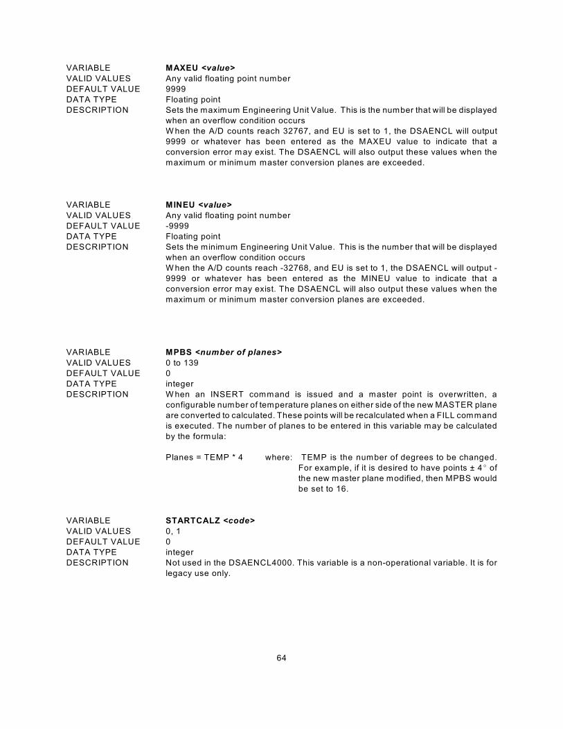
64
VARIABLE MAXEU <value>
VALID VALUES Any valid floating point number
DEFAULT VALUE 9999
DATA TYPE Floating point
DESCRIPTION Sets the maximum Engineering Unit Value. This is the number that will be displayed
when an overflow condition occurs
W hen the A/D counts reach 32767, and EU is set to 1, the DSAENCL will output
9999 or whatever has been entered as the MAXEU value to indicate that a
conversion error may exist. The DSAENCL will also output these values when the
maximum or minimum master conversion planes are exceeded.
VARIABLE MINEU <value>
VALID VALUES Any valid floating point number
DEFAULT VALUE -9999
DATA TYPE Floating point
DESCRIPTION Sets the minimum Engineering Unit Value. This is the number that will be displayed
when an overflow condition occurs
W hen the A/D counts reach -32768, and EU is set to 1, the DSAENCL will output -
9999 or whatever has been entered as the MINEU value to indicate that a
conversion error may exist. The DSAENCL will also output these values when the
maximum or minimum master conversion planes are exceeded.
VARIABLE MPBS <number of planes>
VALID VALUES 0 to 139
DEFAULT VALUE 0
DATA TYPE integer
DESCRIPTION W hen an INSERT command is issued and a master point is overwritten, a
configurable number of temperature planes on either side of the new MASTER plane
are converted to calculated. These points will be recalculated when a FILL command
is executed. The number of planes to be entered in this variable may be calculated
by the formula:
Planes = TEMP * 4 where: TEMP is the number of degrees to be changed.
For example, if it is desired to have points ± 4E of
the new master plane modified, then MPBS would
be set to 16.
VARIABLE STARTCALZ <code>
VALID VALUES 0, 1
DEFAULT VALUE 0
DATA TYPE integer
DESCRIPTION Not used in the DSAENCL4000. This variable is a non-operational variable. It is for
legacy use only.

65
VARIABLE UNITSCAN <units>
VALID VALUES see list below
DEFAULT VALUE PSI
DATA TYPE string
DESCRIPTION This sets the output engineering units for the DSAENCL. Setting this value will also
set CVTUNITS. CVTUNITS may be set to a different value, however UNITSCAN
must be set first. The units supported are:
ATM FTH2O KGM2 MH2O OZFT2
BAR GCM2 KIPIN2 MMHG OZIN2
CMHG INHG KNM2 MPA PA
CMH2O INH2O KPA NCM2 PSF
DECIBAR KGCM2 MBAR NM2 PSI
TORR
NOTE If a value other than those listed is entered, The DSAENCL will default to PSI.
VARIABLE ZC <code>
VALID VALUES 0, 1
DEFAULT VALUE 1
DATA TYPE integer
DESCRIPTION Enables or disables zero correction of the pressure data
0 No zero correction is performed.
1 Zero correction is performed.
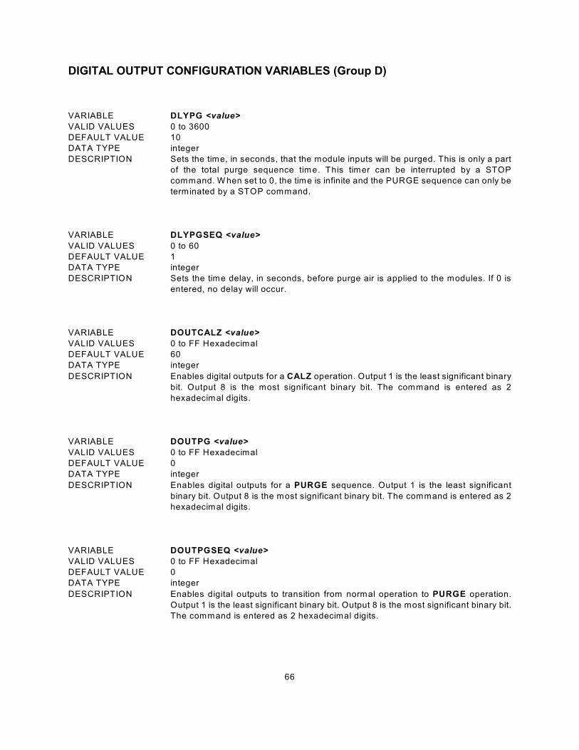
66
DIGITAL OUTPUT CONFIGURATION VARIABLES (Group D)
VARIABLE DLYPG <value>
VALID VALUES 0 to 3600
DEFAULT VALUE 10
DATA TYPE integer
DESCRIPTION Sets the time, in seconds, that the module inputs will be purged. This is only a part
of the total purge sequence time. This timer can be interrupted by a STOP
command. W hen set to 0, the time is infinite and the PURGE sequence can only be
terminated by a STOP command.
VARIABLE DLYPGSEQ <value>
VALID VALUES 0 to 60
DEFAULT VALUE 1
DATA TYPE integer
DESCRIPTION Sets the time delay, in seconds, before purge air is applied to the modules. If 0 is
entered, no delay will occur.
VARIABLE DOUTCALZ <value>
VALID VALUES 0 to FF Hexadecimal
DEFAULT VALUE 60
DATA TYPE integer
DESCRIPTION Enables digital outputs for a CALZ operation. Output 1 is the least significant binary
bit. Output 8 is the most significant binary bit. The command is entered as 2
hexadecimal digits.
VARIABLE DOUTPG <value>
VALID VALUES 0 to FF Hexadecimal
DEFAULT VALUE 0
DATA TYPE integer
DESCRIPTION Enables digital outputs for a PURGE sequence. Output 1 is the least significant
binary bit. Output 8 is the most significant binary bit. The command is entered as 2
hexadecimal digits.
VARIABLE DOUTPGSEQ <value>
VALID VALUES 0 to FF Hexadecimal
DEFAULT VALUE 0
DATA TYPE integer
DESCRIPTION Enables digital outputs to transition from normal operation to PURGE operation.
Output 1 is the least significant binary bit. Output 8 is the most significant binary bit.
The command is entered as 2 hexadecimal digits.
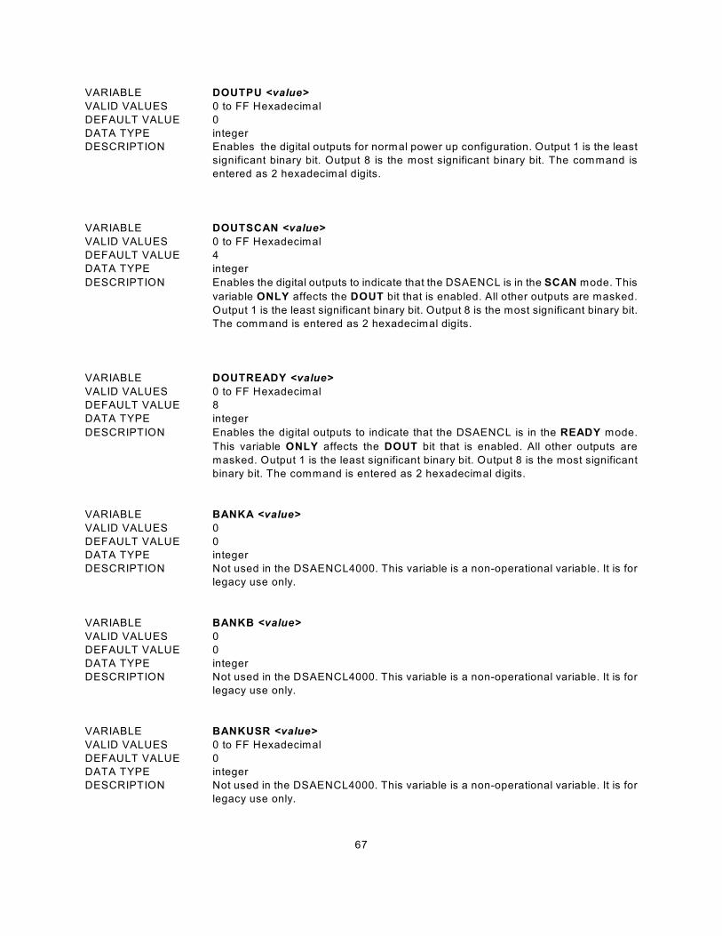
67
VARIABLE DOUTPU <value>
VALID VALUES 0 to FF Hexadecimal
DEFAULT VALUE 0
DATA TYPE integer
DESCRIPTION Enables the digital outputs for normal power up configuration. Output 1 is the least
significant binary bit. Output 8 is the most significant binary bit. The command is
entered as 2 hexadecimal digits.
VARIABLE DOUTSCAN <value>
VALID VALUES 0 to FF Hexadecimal
DEFAULT VALUE 4
DATA TYPE integer
DESCRIPTION Enables the digital outputs to indicate that the DSAENCL is in the SCAN mode. This
variable ONLY affects the DOUT bit that is enabled. All other outputs are masked.
Output 1 is the least significant binary bit. Output 8 is the most significant binary bit.
The command is entered as 2 hexadecimal digits.
VARIABLE DOUTREADY <value>
VALID VALUES 0 to FF Hexadecimal
DEFAULT VALUE 8
DATA TYPE integer
DESCRIPTION Enables the digital outputs to indicate that the DSAENCL is in the READY mode.
This variable ONLY affects the DOUT bit that is enabled. All other outputs are
masked. Output 1 is the least significant binary bit. Output 8 is the most significant
binary bit. The command is entered as 2 hexadecimal digits.
VARIABLE BANKA <value>
VALID VALUES 0
DEFAULT VALUE 0
DATA TYPE integer
DESCRIPTION Not used in the DSAENCL4000. This variable is a non-operational variable. It is for
legacy use only.
VARIABLE BANKB <value>
VALID VALUES 0
DEFAULT VALUE 0
DATA TYPE integer
DESCRIPTION Not used in the DSAENCL4000. This variable is a non-operational variable. It is for
legacy use only.
VARIABLE BANKUSR <value>
VALID VALUES 0 to FF Hexadecimal
DEFAULT VALUE 0
DATA TYPE integer
DESCRIPTION Not used in the DSAENCL4000. This variable is a non-operational variable. It is for
legacy use only.
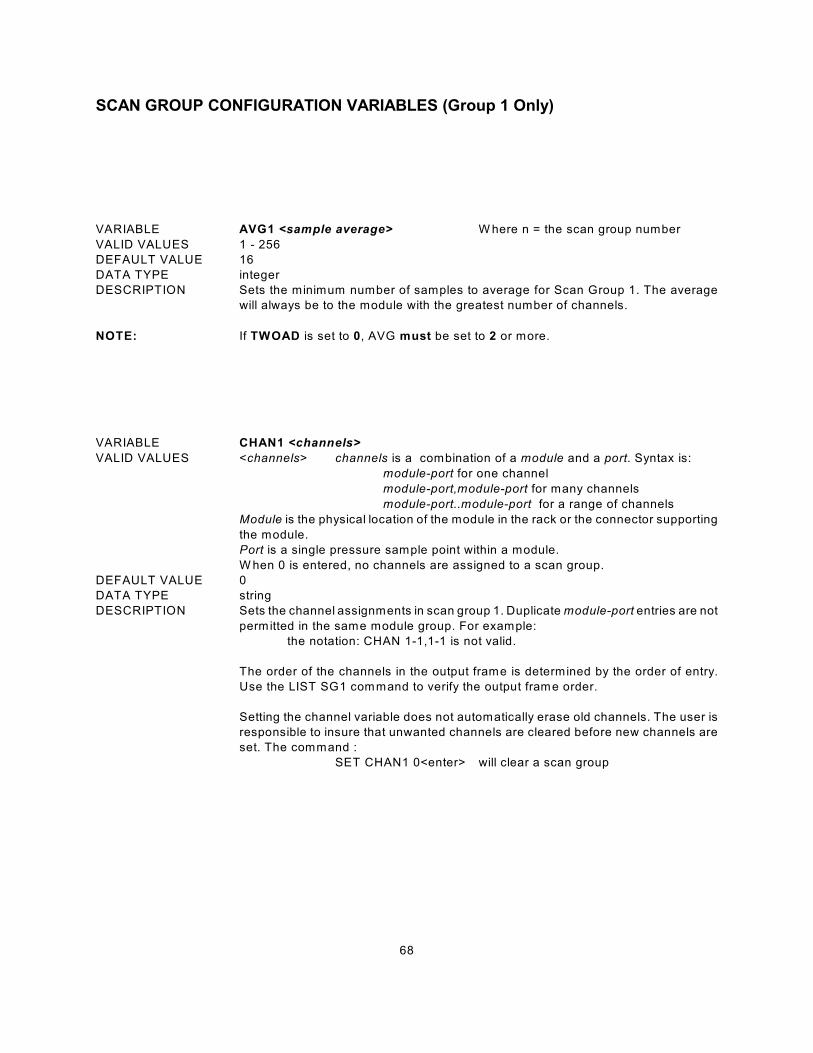
68
SCAN GROUP CONFIGURATION VARIABLES (Group 1 Only)
VARIABLE AVG1 <sample average> W here n = the scan group number
VALID VALUES 1 - 256
DEFAULT VALUE 16
DATA TYPE integer
DESCRIPTION Sets the minimum number of samples to average for Scan Group 1. The average
will always be to the module with the greatest number of channels.
NOTE: If TWOAD is set to 0, AVG must be set to 2 or more.
VARIABLE CHAN1 <channels>
VALID VALUES <channels> channels is a combination of a module and a port. Syntax is:
module-port for one channel
module-port,module-port for many channels
module-port..module-port for a range of channels
Module is the physical location of the module in the rack or the connector supporting
the module.
Port is a single pressure sample point within a module.
W hen 0 is entered, no channels are assigned to a scan group.
DEFAULT VALUE 0
DATA TYPE string
DESCRIPTION Sets the channel assignments in scan group 1. Duplicate module-port entries are not
permitted in the same module group. For example:
the notation: CHAN 1-1,1-1 is not valid.
The order of the channels in the output frame is determined by the order of entry.
Use the LIST SG1 command to verify the output frame order.
Setting the channel variable does not automatically erase old channels. The user is
responsible to insure that unwanted channels are cleared before new channels are
set. The command :
SET CHAN1 0<enter> will clear a scan group
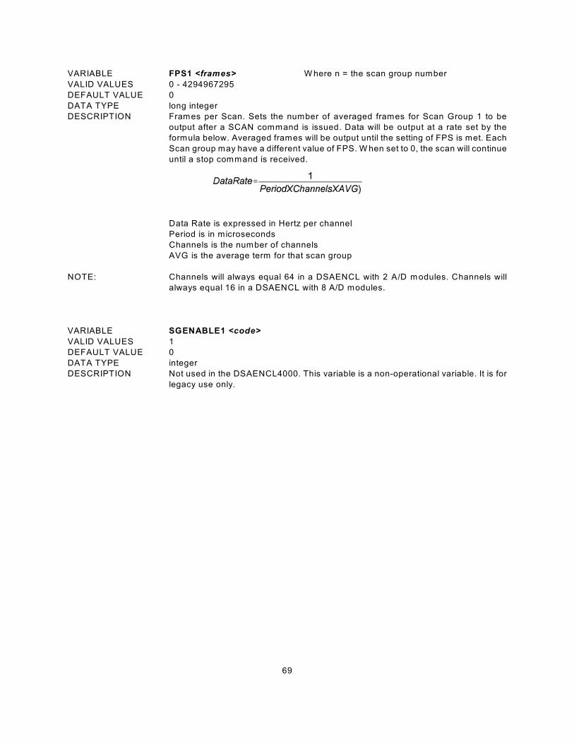
69
VARIABLE FPS1 <frames> W here n = the scan group number
VALID VALUES 0 - 4294967295
DEFAULT VALUE 0
DATA TYPE long integer
DESCRIPTION Frames per Scan. Sets the number of averaged frames for Scan Group 1 to be
output after a SCAN command is issued. Data will be output at a rate set by the
formula below. Averaged frames will be output until the setting of FPS is met. Each
Scan group may have a different value of FPS. W hen set to 0, the scan will continue
until a stop command is received.
Data Rate is expressed in Hertz per channel
Period is in microseconds
Channels is the number of channels
AVG is the average term for that scan group
NOTE: Channels will always equal 64 in a DSAENCL with 2 A/D modules. Channels will
always equal 16 in a DSAENCL with 8 A/D modules.
VARIABLE SGENABLE1 <code>
VALID VALUES 1
DEFAULT VALUE 0
DATA TYPE integer
DESCRIPTION Not used in the DSAENCL4000. This variable is a non-operational variable. It is for
legacy use only.
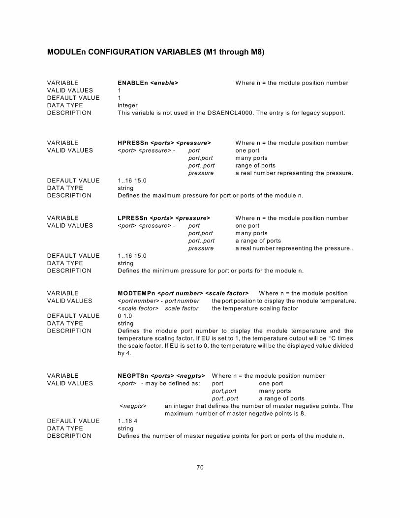
70
MODULEn CONFIGURATION VARIABLES (M1 through M8)
VARIABLE ENABLEn <enable> W here n = the module position number
VALID VALUES 1
DEFAULT VALUE 1
DATA TYPE integer
DESCRIPTION This variable is not used in the DSAENCL4000. The entry is for legacy support.
VARIABLE HPRESSn <ports> <pressure> W here n = the module position number
VALID VALUES <port> <pressure> - port one port
port,port many ports
port..port range of ports
pressure a real number representing the pressure.
DEFAULT VALUE 1..16 15.0
DATA TYPE string
DESCRIPTION Defines the maximum pressure for port or ports of the module n.
VARIABLE LPRESSn <ports> <pressure> W here n = the module position number
VALID VALUES <port> <pressure> - port one port
port,port many ports
port..port a range of ports
pressure a real number representing the pressure..
DEFAULT VALUE 1..16 15.0
DATA TYPE string
DESCRIPTION Defines the minimum pressure for port or ports for the module n.
VARIABLE MODTEMPn <port number> <scale factor> W here n = the module position
VALID VALUES <port number> - port number the port position to display the module temperature.
<scale factor> scale factor the temperature scaling factor
DEFAULT VALUE 0 1.0
DATA TYPE string
DESCRIPTION Defines the module port number to display the module temperature and the
temperature scaling factor. If EU is set to 1, the temperature output will be EC times
the scale factor. If EU is set to 0, the temperature will be the displayed value divided
by 4.
VARIABLE NEGPTSn <ports> <negpts> W here n = the module position number
VALID VALUES <port> - may be defined as: port one port
port,port many ports
port..port a range of ports
<negpts> an integer that defines the number of master negative points. The
maximum number of master negative points is 8.
DEFAULT VALUE 1..16 4
DATA TYPE string
DESCRIPTION Defines the number of master negative points for port or ports of the module n.
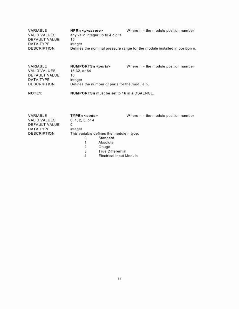
71
VARIABLE NPRn <pressure> W here n = the module position number
VALID VALUES any valid integer up to 4 digits
DEFAULT VALUE 15
DATA TYPE integer
DESCRIPTION Defines the nominal pressure range for the module installed in position n.
VARIABLE NUMPORTSn <ports> W here n = the module position number
VALID VALUES 16,32, or 64
DEFAULT VALUE 16
DATA TYPE integer
DESCRIPTION Defines the number of ports for the module n.
NOTE1: NUMPORTSn must be set to 16 in a DSAENCL.
VARIABLE TYPEn <code> W here n = the module position number
VALID VALUES 0, 1, 2, 3, or 4
DEFAULT VALUE 0
DATA TYPE integer
DESCRIPTION This variable defines the module n type:
0 Standard
1 Absolute
2 Gauge
3 True Differential
4 Electrical Input Module
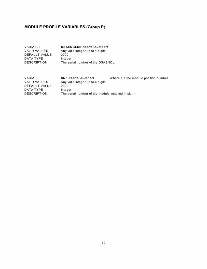
72
MODULE PROFILE VARIABLES (Group P)
VARIABLE DSAENCLSN <serial number>
VALID VALUES Any valid integer up to 4 digits
DEFAULT VALUE 0000
DATA TYPE Integer
DESCRIPTION The serial number of the DSAENCL.
VARIABLE SNn <serial number> W here n = the module position number
VALID VALUES Any valid integer up to 4 digits
DEFAULT VALUE 0000
DATA TYPE Integer
DESCRIPTION The serial number of the module installed in slot n.

73
IDENTIFICATION CONFIGURATION VARIABLES (Group I)
VARIABLE AUX <comport> <BAUD><terminator code>
VALID VALUES See Below
DEFAULT VALUE comport - 0
BAUD - 9600
Terminator code - 2
DATA TYPE integer
DESCRIPTION Determines and identifies communications to External Serial Devices
Comport 0 No external device connected.
1 An external device is connected to COM1
2 An external device is connected to COM2
BAUD Fixed at 9600.
Terminator code 0 null terminator
1 CR
2 CR LF
3 LF CR
4 LF
NOTE W hen COMPORT 2 is used, the NO HOST dip switch must be set. If not, the
enclosure will output sign on information to the serial device.
VARIABLE AUXSCHED <enabled> <command> <internal interval time>
VALID VALUES See Below
DEFAULT VALUE enabled - 0
command - RP
Internal interval time - 0
DATA TYPE integer, string
DESCRIPTION W hen enabled, identifies the command to be sent to the external serial device when
an ADTrig is received. The internal interval time is in milliseconds.
enabled 0 AUXSCHED is not enabled.
1 AUXSCHED is enabled
command Any valid command.
Internal interval time The valid range is 0 or 500 to 100,000 milliseconds
W hen this time is set to 0, the command will be output
immediately with an external trigger. For this function to
operate correctly, ADTRIG must also be set to 1.
VARIABLE CAL <comport> <BAUD>
VALID VALUES See Below
DEFAULT VALUE comport - 0
BAUD - 9600
DATA TYPE integer
DESCRIPTION Determines and identifies communications to Serial Calibrators
Comport 0 No Calibrator is connected.
1 A Calibrator is connected to COM1
2 A Calibrator is connected to COM2
BAUD Fixed at 9600.
NOTE W hen COMPORT 2 is used, the NO HOST dip switch must be set. If not, the
enclosure will output sign on information to the serial device.

74
VARIABLE CALSCHED <enabled> <command> <internal interval time>
VALID VALUES See Below
DEFAULT VALUE enabled - 0
command - RP
internal interval time - 0
DATA TYPE integer, string
DESCRIPTION W hen enabled, identifies the command to be sent to the serial calibrator(s) when an
ADTrig is received. The internal interval time is in milliseconds
enabled 0 CALSCHED is not enabled.
1 CALSCHED is enabled
command Any valid calibrator command.
Internal interval time The valid range is 0 or 500 to 100,000 milliseconds
W hen this time is set to 0, the command will be output
immediately with an external trigger. For this function to
operate correctly, ADTRIG must also be set to 1.
VARIABLE CONOUT <code>
VALID VALUES 2
DEFAULT VALUE 2
DATA TYPE integer
DESCRIPTION Not used in the DSAENCL4000. This variable is a non-operational variable. It is for
legacy use only.
VARIABLE ECHO <enable>
VALID VALUES 0 or 1
DEFAULT VALUE 0
DATA TYPE Integer
DESCRIPTION Determines if characters received from the network or the serial host will be echoed
back to the host.
0 - Echo is disabled
1 - Echo is enabled
VARIABLE FORMAT <code>
VALID VALUES 0, 1, 2, or 3
DEFAULT VALUE 0
DATA TYPE Integer
DESCRIPTION Determines if data are to be scrolled on the display.
0 data are scrolled
1 data are displayed in place, formatted for a VT100 terminal.
2 data are output in a debug format:
<frame> <A/D 1 m-p> <A/D 1 counts> <A/D 2 m-p> <A/D 2 counts> <eol>
3 data are scrolled in a fixed format. Five positions with no decimal . The port
field is fixed at two places with a leading zero if necessary.
VARIABLE HAVENET <code>
VALID VALUES 1
DEFAULT VALUE 1
DATA TYPE Integer
DESCRIPTION Not used in the DSAENCL4000. This variable is a non-operational variable. It is for
legacy use only.
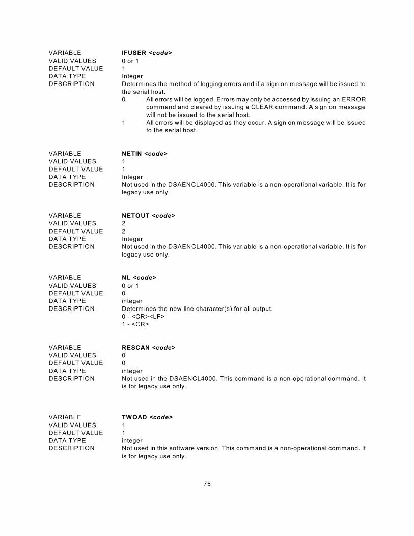
75
VARIABLE IFUSER <code>
VALID VALUES 0 or 1
DEFAULT VALUE 1
DATA TYPE Integer
DESCRIPTION Determines the method of logging errors and if a sign on message will be issued to
the serial host.
0 All errors will be logged. Errors may only be accessed by issuing an ERROR
command and cleared by issuing a CLEAR command. A sign on message
will not be issued to the serial host.
1 All errors will be displayed as they occur. A sign on message will be issued
to the serial host.
VARIABLE NETIN <code>
VALID VALUES 1
DEFAULT VALUE 1
DATA TYPE Integer
DESCRIPTION Not used in the DSAENCL4000. This variable is a non-operational variable. It is for
legacy use only.
VARIABLE NETOUT <code>
VALID VALUES 2
DEFAULT VALUE 2
DATA TYPE Integer
DESCRIPTION Not used in the DSAENCL4000. This variable is a non-operational variable. It is for
legacy use only.
VARIABLE NL <code>
VALID VALUES 0 or 1
DEFAULT VALUE 0
DATA TYPE integer
DESCRIPTION Determines the new line character(s) for all output.
0 - <CR><LF>
1 - <CR>
VARIABLE RESCAN <code>
VALID VALUES 0
DEFAULT VALUE 0
DATA TYPE integer
DESCRIPTION Not used in the DSAENCL4000. This command is a non-operational command. It
is for legacy use only.
VARIABLE TWOAD <code>
VALID VALUES 1
DEFAULT VALUE 1
DATA TYPE integer
DESCRIPTION Not used in this software version. This command is a non-operational command. It
is for legacy use only.
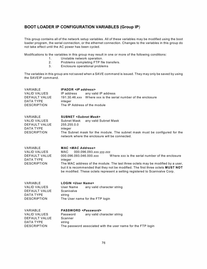
76
BOOT LOADER IP CONFIGURATION VARIABLES (Group IP)
This group contains all of the network setup variables. All of these variables may be modified using the boot
loader program, the serial connection, or the ethernet connection. Changes to the variables in this group do
not take effect until the AC power has been cycled.
Modifications to the variables in this group may result in one or more of the following conditions:
1. Unstable network operation.
2. Problems completing FTP file transfers.
3. Enclosure operational problems
The variables in this group are not saved when a SAVE command is issued. They may only be saved by using
the SAVEIP command.
VARIABLE IPADDR <IP address>
VALID VALUES IP address any valid IP address
DEFAULT VALUE 191.30.46.xxx W here xxx is the serial number of the enclosure
DATA TYPE integer
DESCRIPTION The IP Address of the module
VARIABLE SUBNET <Subnet Mask>
VALID VALUES Subnet Mask any valid Subnet Mask
DEFAULT VALUE 255.255.0.0
DATA TYPE integer
DESCRIPTION The Subnet mask for the module. The subnet mask must be configured for the
network where the enclosure will be connected.
VARIABLE MAC <MAC Address>
VALID VALUES MAC 000.096.093.xxx.yyy.zzz
DEFAULT VALUE 000.096.093.046.000.xxx W here xxx is the serial number of the enclosure
DATA TYPE integer
DESCRIPTION The MAC address of the module. The last three octets may be modified by a user,
but it is recommended that they not be modified. The first three octets MUST NOT
be modified. These octets represent a setting registered to Scanivalve Corp.
VARIABLE LOGIN <User Name>
VALID VALUES User Name any valid character string
DEFAULT VALUE Scanivalve
DATA TYPE string
DESCRIPTION The User name for the FTP login
VARIABLE PASSWORD <Password>
VALID VALUES Password any valid character string
DEFAULT VALUE Scanner
DATA TYPE string
DESCRIPTION The password associated with the user name for the FTP login
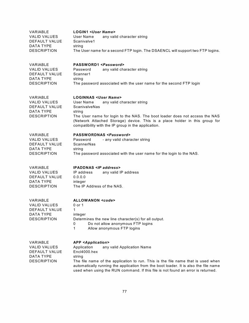
77
VARIABLE LOGIN1 <User Name>
VALID VALUES User Name any valid character string
DEFAULT VALUE Scanivalve1
DATA TYPE string
DESCRIPTION The User name for a second FTP login. The DSAENCL will support two FTP logins.
VARIABLE PASSWORD1 <Password>
VALID VALUES Password any valid character string
DEFAULT VALUE Scanner1
DATA TYPE string
DESCRIPTION The password associated with the user name for the second FTP login
VARIABLE LOGINNAS <User Name>
VALID VALUES User Name any valid character string
DEFAULT VALUE ScanivalveNas
DATA TYPE string
DESCRIPTION The User name for login to the NAS. The boot loader does not access the NAS
(Network Attached Storage) device. This is a place holder in this group for
compatibility with the IP group in the application.
VARIABLE PASSWORDNAS <Password>
VALID VALUES Password - any valid character string
DEFAULT VALUE ScannerNas
DATA TYPE string
DESCRIPTION The password associated with the user name for the login to the NAS.
VARIABLE IPADDNAS <IP address>
VALID VALUES IP address any valid IP address
DEFAULT VALUE 0.0.0.0
DATA TYPE integer
DESCRIPTION The IP Address of the NAS.
VARIABLE ALLOWANON <code>
VALID VALUES 0 or 1
DEFAULT VALUE 1
DATA TYPE integer
DESCRIPTION Determines the new line character(s) for all output.
0 Do not allow anonymous FTP logins
1 Allow anonymous FTP logins
VARIABLE APP <Application>
VALID VALUES Application any valid Application Name
DEFAULT VALUE Encl4000.hex
DATA TYPE string
DESCRIPTION The file name of the application to run. This is the file name that is used when
automatically running the application from the boot loader. It is also the file name
used when using the RUN command. If this file is not found an error is returned.
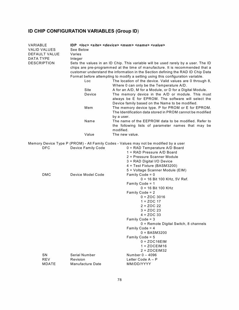
78
ID CHIP CONFIGURATION VARIABLES (Group ID)
VARIABLE IDP <loc> <site> <device> <mem> <name> <value>
VALID VALUES See Below
DEFAULT VALUE Varies
DATA TYPE Integer
DESCRIPTION Sets the values in an ID Chip. This variable will be used rarely by a user. The ID
chips are pre-programmed at the time of manufacture. It is recommended that a
customer understand the information in the Section defining the RAD ID Chip Data
Format before attempting to modify a setting using this configuration variable.
Loc The location of the device. Valid values are 0 through 8,
W here 0 can only be the Temperature A/D.
Site A for an A/D, M for a Module, or D for a Digital Module.
Device The memory device in the A/D or module. This must
always be E for EPROM. The software will select the
Device family based on the Name to be modified.
Mem The memory device type. P for PROM or E for EPROM.
The Identification data stored in PROM cannot be modified
by a user.
Name The name of the EEPROM data to be modified. Refer to
the following lists of parameter names that may be
modified.
Value The new value.
Memory Device Type P (PROM) - All Family Codes - Values may not be modified by a user
DFC Device Family Code 0 = RAD Temperature A/D Board
1 = RAD Pressure A/D Board
2 = Pressure Scanner Module
3 = RAD Digital I/O Device
4 = Test Fixture (BASM3200)
5 = Voltage Scanner Module (EIM)
DMC Device Model Code Family Code = 0
0 = 16 Bit 100 KHz, 5V Ref.
Family Code = 1
0 = 16 Bit 100 KHz
Family Code = 2
0 = ZOC 3016
1 = ZOC 17
2 = ZOC 22
3 = ZOC 23
4 = ZOC 33
Family Code = 3
0 = Remote Digital Switch, 8 channels
Family Code = 4
0 = BASM3200
Family Code = 5
0 = ZOC16EIM
1 = ZOCEIM16
2 = ZOCEIM32
SN Serial Number Number 0 – 4096
REV Revision Letter Code A – P
MDATE Manufacture Date MM/DD/YYYY
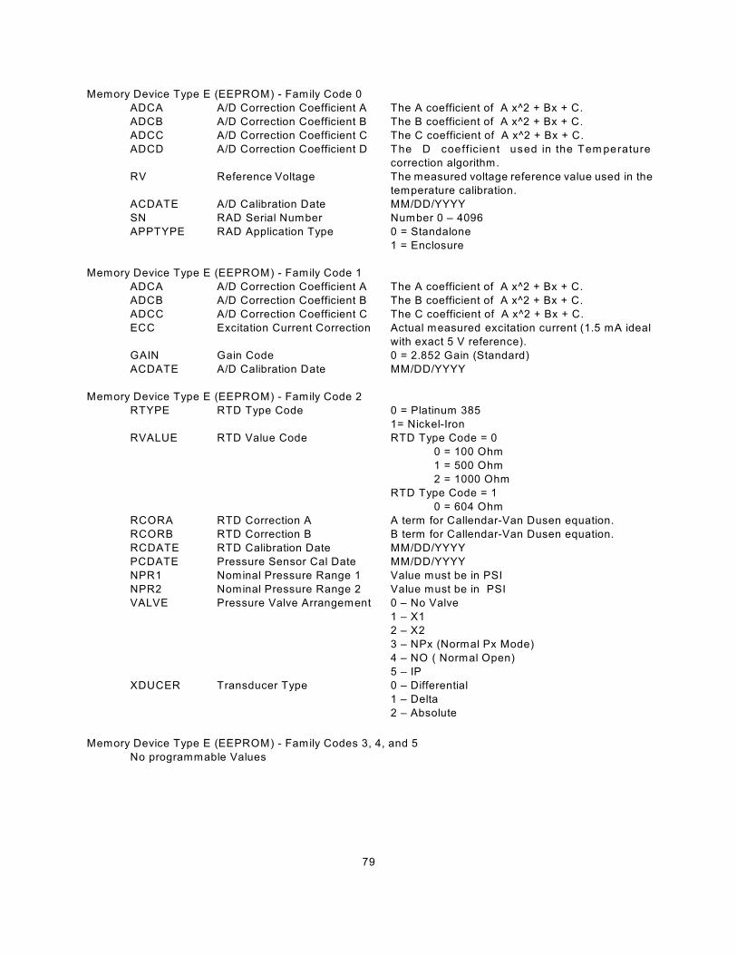
79
Memory Device Type E (EEPROM) - Family Code 0
ADCA A/D Correction Coefficient A The A coefficient of A x^2 + Bx + C.
ADCB A/D Correction Coefficient B The B coefficient of A x^2 + Bx + C.
ADCC A/D Correction Coefficient C The C coefficient of A x^2 + Bx + C.
ADCD A/D Correction Coefficient D The D coeff ic ient used in the Tem perature
correction algorithm.
RV Reference Voltage The measured voltage reference value used in the
temperature calibration.
ACDATE A/D Calibration Date MM/DD/YYYY
SN RAD Serial Number Number 0 – 4096
APPTYPE RAD Application Type 0 = Standalone
1 = Enclosure
Memory Device Type E (EEPROM) - Family Code 1
ADCA A/D Correction Coefficient A The A coefficient of A x^2 + Bx + C.
ADCB A/D Correction Coefficient B The B coefficient of A x^2 + Bx + C.
ADCC A/D Correction Coefficient C The C coefficient of A x^2 + Bx + C.
ECC Excitation Current Correction Actual measured excitation current (1.5 mA ideal
with exact 5 V reference).
GAIN Gain Code 0 = 2.852 Gain (Standard)
ACDATE A/D Calibration Date MM/DD/YYYY
Memory Device Type E (EEPROM) - Family Code 2
RTYPE RTD Type Code 0 = Platinum 385
1= Nickel-Iron
RVALUE RTD Value Code RTD Type Code = 0
0 = 100 Ohm
1 = 500 Ohm
2 = 1000 Ohm
RTD Type Code = 1
0 = 604 Ohm
RCORA RTD Correction A A term for Callendar-Van Dusen equation.
RCORB RTD Correction B B term for Callendar-Van Dusen equation.
RCDATE RTD Calibration Date MM/DD/YYYY
PCDATE Pressure Sensor Cal Date MM/DD/YYYY
NPR1 Nominal Pressure Range 1 Value must be in PSI
NPR2 Nominal Pressure Range 2 Value must be in PSI
VALVE Pressure Valve Arrangement 0 – No Valve
1 – X1
2 – X2
3 – NPx (Normal Px Mode)
4 – NO ( Normal Open)
5 – IP
XDUCER Transducer Type 0 – Differential
1 – Delta
2 – Absolute
Memory Device Type E (EEPROM) - Family Codes 3, 4, and 5
No programmable Values

80
TEMPERATURE OFFSET VARIABLES (Group O)
VARIABLE TEMPBn <value> W here n = the module position number
VALID VALUES any real number
DEFAULT VALUE -198.514371
DATA TYPE float
DESCRIPTION The "B" term in the conversion equation used to convert temperature counts to
degrees Celsius. If a module number is not specified, all modules will be displayed.
This value is for a Nickel Iron RTD(604Ù at 0E). The conversion formula is:
TEMPERATURE GAIN VARIABLES (Group G)
VARIABLE TEMPMn <value> W here n = the module position number
VALID VALUES any real number
DEFAULT VALUE 0.023559
DATA TYPE float
DESCRIPTION The "M" term in the conversion equation used to convert temperature counts to
degrees Celsius. If a module number is not specified, all modules will be displayed.
This value is for a Nickel Iron RTD(604Ù at 0E). The conversion formula is:
The values listed for gain and offset are used for all ZOC16TC, DSA3016 and DSA3216 series modules.

81
DSAENCL ID Chip Data Format
The RAD system uses the Dallas DS2430A EEPROM chip for storing information about various system
components. The information travels with the hardware, allowing the system to configure itself after power-up.
The DS2430A has two memory areas; a 64 bit permanent memory that is written once during the
manufacturing, and a 256 bit area that can be written multiple times.
The permanent memory area will contain information necessary to identify the device in a format that is
consistent over all of our device types. The 256 bit memory area will have a device dependent format.
Permanent Memory Data Format
The permanent memory area contains a Device Family Code, a Device Model Code, a Serial Number, a
Revision Code, and a Manufacture Date.
Permanent Memory 64 BitsBits Name Description Assigned Values
4 DFC Device Family Code 0 = RAD Temperature A/D Board
1 = RAD Pressure A/D Board
2 = Pressure Scanner Module
3 = RAD Digital I/O Device
4 = Test Fixture
5 = Voltage Scanner Module
4 DMC Device Model Code Family Code = 0
0 = 16 Bit 100 KHz, 5V Ref., Gain = 2.852
Family Code = 1
0 = 16 Bit 100 KHz
Family Code = 2
0 = ZOC 3016
1 = ZOC 17
2 = ZOC 22
3 = ZOC 23
4 = ZOC 33
Family Code = 3
0 = RDS Remote Digital Switch, 8 Channels
Family Code = 4
0 = BASM3200
Family Code = 5
0 = ZOC16EIM
1 = ZOCEIM16
2 = ZOCEIM32
12 SN Serial Number Binary Number 0 – 4096
4 REV Revision Letter Code A – P
16 MDATE Manufacture Date DDDDDMMMMYYYYYYY
DDDDD = Day ( 1 – 31)
MMMM = Month ( 1 – 12)
YYYYYYY = Years Past 2000 ( 0 – 128)
24 Spare
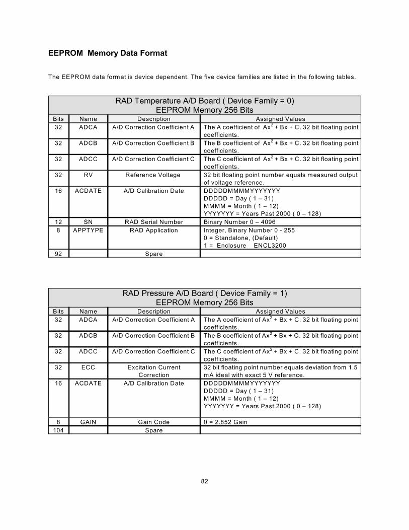
82
EEPROM Memory Data Format
The EEPROM data format is device dependent. The five device families are listed in the following tables.
RAD Temperature A/D Board ( Device Family = 0)EEPROM Memory 256 Bits
Bits Name Description Assigned Values
32 ADCA A/D Correction Coefficient A The A coefficient of Ax + Bx + C. 32 bit floating point2
coefficients.
32 ADCB A/D Correction Coefficient B The B coefficient of Ax + Bx + C. 32 bit floating point2
coefficients.
32 ADCC A/D Correction Coefficient C The C coefficient of Ax + Bx + C. 32 bit floating point2
coefficients.
32 RV Reference Voltage 32 bit floating point number equals measured output
of voltage reference.
16 ACDATE A/D Calibration Date DDDDDMMMMYYYYYYY
DDDDD = Day ( 1 – 31)
MMMM = Month ( 1 – 12)
YYYYYYY = Years Past 2000 ( 0 – 128)
12 SN RAD Serial Number Binary Number 0 – 4096
8 APPTYPE RAD Application Integer, Binary Number 0 - 255
0 = Standalone, (Default)
1 = Enclosure ENCL3200
92 Spare
RAD Pressure A/D Board ( Device Family = 1)EEPROM Memory 256 Bits
Bits Name Description Assigned Values
32 ADCA A/D Correction Coefficient A The A coefficient of Ax + Bx + C. 32 bit floating point2
coefficients.
32 ADCB A/D Correction Coefficient B The B coefficient of Ax + Bx + C. 32 bit floating point2
coefficients.
32 ADCC A/D Correction Coefficient C The C coefficient of Ax + Bx + C. 32 bit floating point2
coefficients.
32 ECC Excitation Current
Correction
32 bit floating point number equals deviation from 1.5
mA ideal with exact 5 V reference.
16 ACDATE A/D Calibration Date DDDDDMMMMYYYYYYY
DDDDD = Day ( 1 – 31)
MMMM = Month ( 1 – 12)
YYYYYYY = Years Past 2000 ( 0 – 128)
8 GAIN Gain Code 0 = 2.852 Gain
104 Spare

83
Pressure Scanner Module ( Device Family = 2)EEPROM Memory 256 Bits
Bits Name Description Assigned Values
8 RTYPE RTD Type Code 0 = Platinum 385
1= Nickel-Iron
8 RVALUE RTD Value Code RTD Type Code = 0
0 = 100 Ohm
1 = 500 Ohm
2 = 1000 Ohm
RTD Type Code = 1
0 = 604 Ohm
32 RCORA RTD Correction A A term for Callendar-Van Dusen equation. Two 32 bit floating
point numbers.
32 RCORB RTD Correction B A and B terms for Callendar-Van Dusen equation. Two 32 bit
floating point numbers.
16 RCDATE RTD Calibration
Date
DDDDDMMMMYYYYYYY
DDDDD = Day ( 1 – 31)
MMMM = Month ( 1 – 12)
YYYYYYY = Years Past 2000 ( 0 – 128)
16 PCDATE Pressure Sensor
Calibration Date
DDDDDMMMMYYYYYYY
DDDDD = Day ( 1 – 31)
MMMM = Month ( 1 – 12)
YYYYYYY = Years Past 2000 ( 0 – 128)
32 NPR1 Nominal Pressure
Range 1
32 Bit Floating Point Number, units of PSI
32 NPR2 Nominal Pressure
Range 2
32 Bit Floating Point Number, units of PSI
8 VALVE Pressure Valve
Arrangement
0 = None
1 = X1
2 = X2
3 = NPX
4 = NO
5 = IP
8 XDUCER Transducer Type 0 = Differential
1 = Delta
2 = Absolute
3 = True Delta P
4 = EIM
64 Spare
RAD Digital I/O Device ( Device Family = 3)EEPROM Memory 256 Bits
Bits Name Description Assigned Values
256 Not Used
Test Fixture ( Device Family = 4)EEPROM Memory 256 Bits
Bits Name Description Assigned Values
256 Not Used
Voltage Scanner ( Device Family = 5)EEPROM Memory 256 Bits
Bits Name Description Assigned Values
256 Not Used
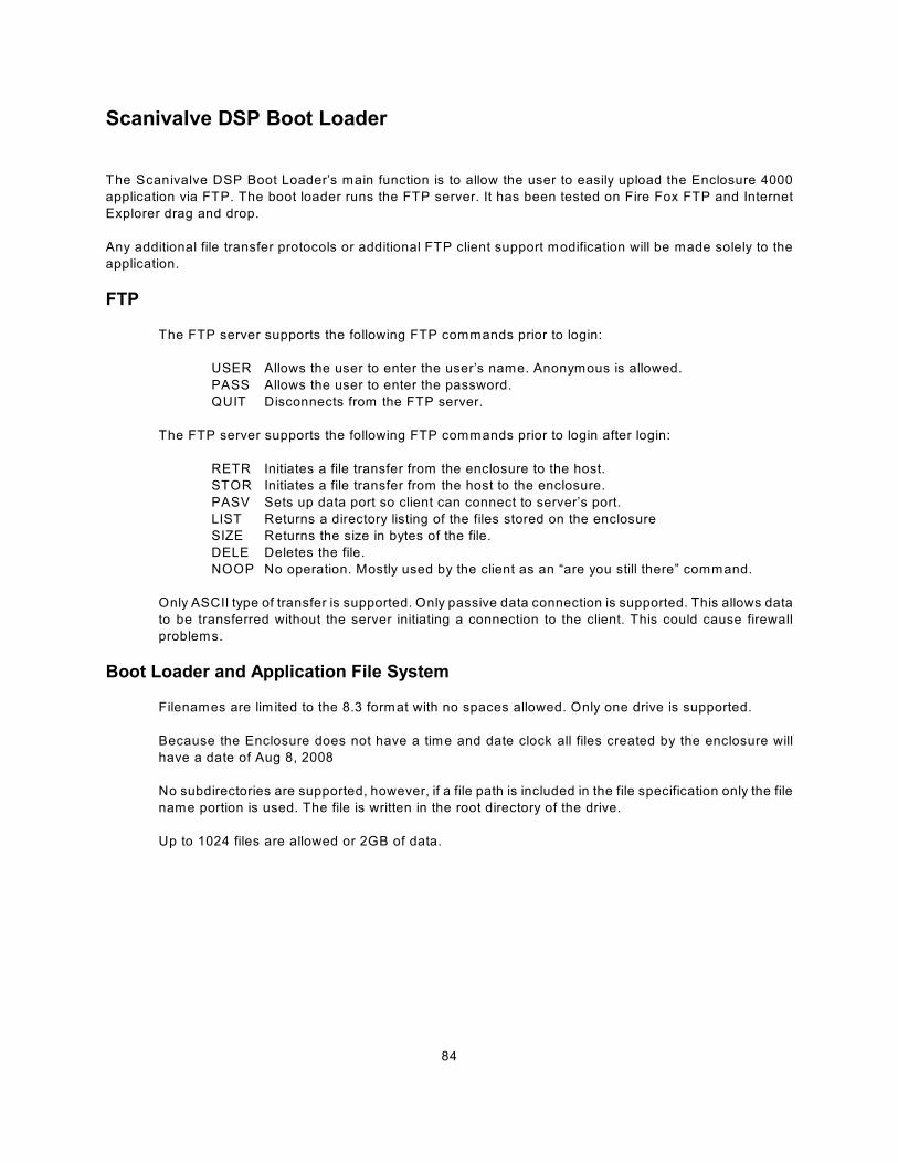
84
Scanivalve DSP Boot Loader
The Scanivalve DSP Boot Loader’s main function is to allow the user to easily upload the Enclosure 4000
application via FTP. The boot loader runs the FTP server. It has been tested on Fire Fox FTP and Internet
Explorer drag and drop.
Any additional file transfer protocols or additional FTP client support modification will be made solely to the
application.
FTP
The FTP server supports the following FTP commands prior to login:
USER Allows the user to enter the user’s name. Anonymous is allowed.
PASS Allows the user to enter the password.
QUIT Disconnects from the FTP server.
The FTP server supports the following FTP commands prior to login after login:
RETR Initiates a file transfer from the enclosure to the host.
STOR Initiates a file transfer from the host to the enclosure.
PASV Sets up data port so client can connect to server’s port.
LIST Returns a directory listing of the files stored on the enclosure
SIZE Returns the size in bytes of the file.
DELE Deletes the file.
NOOP No operation. Mostly used by the client as an “are you still there” command.
Only ASCII type of transfer is supported. Only passive data connection is supported. This allows data
to be transferred without the server initiating a connection to the client. This could cause firewall
problems.
Boot Loader and Application File System
Filenames are limited to the 8.3 format with no spaces allowed. Only one drive is supported.
Because the Enclosure does not have a time and date clock all files created by the enclosure will
have a date of Aug 8, 2008
No subdirectories are supported, however, if a file path is included in the file specification only the file
name portion is used. The file is written in the root directory of the drive.
Up to 1024 files are allowed or 2GB of data.
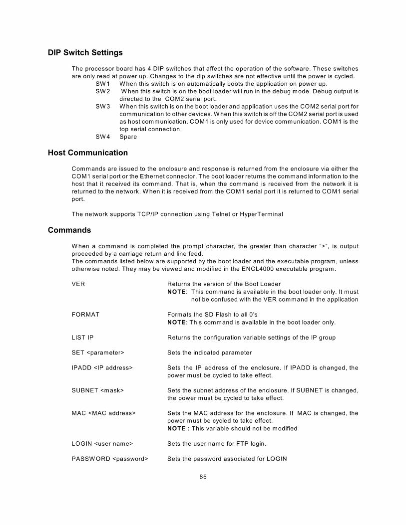
85
DIP Switch Settings
The processor board has 4 DIP switches that affect the operation of the software. These switches
are only read at power up. Changes to the dip switches are not effective until the power is cycled.
SW 1 W hen this switch is on automatically boots the application on power up.
SW 2 W hen this switch is on the boot loader will run in the debug mode. Debug output is
directed to the COM2 serial port.
SW 3 W hen this switch is on the boot loader and application uses the COM2 serial port for
communication to other devices. W hen this switch is off the COM2 serial port is used
as host communication. COM1 is only used for device communication. COM1 is the
top serial connection.
SW 4 Spare
Host Communication
Commands are issued to the enclosure and response is returned from the enclosure via either the
COM1 serial port or the Ethernet connector. The boot loader returns the command information to the
host that it received its command. That is, when the command is received from the network it is
returned to the network. W hen it is received from the COM1 serial port it is returned to COM1 serial
port.
The network supports TCP/IP connection using Telnet or HyperTerminal
Commands
W hen a command is completed the prompt character, the greater than character “>”, is output
proceeded by a carriage return and line feed.
The commands listed below are supported by the boot loader and the executable program, unless
otherwise noted. They may be viewed and modified in the ENCL4000 executable program.
VER Returns the version of the Boot Loader
NOTE: This command is available in the boot loader only. It must
not be confused with the VER command in the application
FORMAT Formats the SD Flash to all 0’s
NOTE: This command is available in the boot loader only.
LIST IP Returns the configuration variable settings of the IP group
SET <parameter> Sets the indicated parameter
IPADD <IP address> Sets the IP address of the enclosure. If IPADD is changed, the
power must be cycled to take effect.
SUBNET <mask> Sets the subnet address of the enclosure. If SUBNET is changed,
the power must be cycled to take effect.
MAC <MAC address> Sets the MAC address for the enclosure. If MAC is changed, the
power must be cycled to take effect.
NOTE : This variable should not be modified
LOGIN <user name> Sets the user name for FTP login.
PASSW ORD <password> Sets the password associated for LOGIN
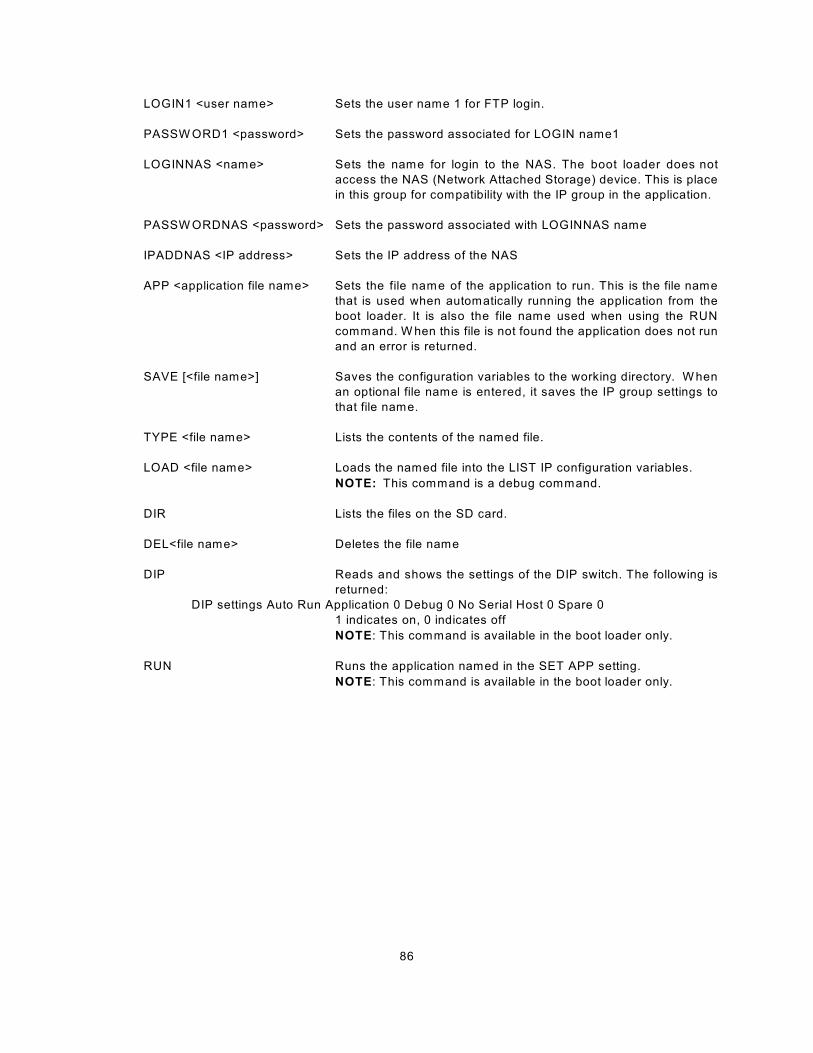
86
LOGIN1 <user name> Sets the user name 1 for FTP login.
PASSW ORD1 <password> Sets the password associated for LOGIN name1
LOGINNAS <name> Sets the name for login to the NAS. The boot loader does not
access the NAS (Network Attached Storage) device. This is place
in this group for compatibility with the IP group in the application.
PASSW ORDNAS <password> Sets the password associated with LOGINNAS name
IPADDNAS <IP address> Sets the IP address of the NAS
APP <application file name> Sets the file name of the application to run. This is the file name
that is used when automatically running the application from the
boot loader. It is also the file name used when using the RUN
command. W hen this file is not found the application does not run
and an error is returned.
SAVE [<file name>] Saves the configuration variables to the working directory. W hen
an optional file name is entered, it saves the IP group settings to
that file name.
TYPE <file name> Lists the contents of the named file.
LOAD <file name> Loads the named file into the LIST IP configuration variables.
NOTE: This command is a debug command.
DIR Lists the files on the SD card.
DEL<file name> Deletes the file name
DIP Reads and shows the settings of the DIP switch. The following is
returned:
DIP settings Auto Run Application 0 Debug 0 No Serial Host 0 Spare 0
1 indicates on, 0 indicates off
NOTE: This command is available in the boot loader only.
RUN Runs the application named in the SET APP setting.
NOTE: This command is available in the boot loader only.

87
DSAENCL Scan Function
W hen a SCAN function is initiated, the DSAENCL will scan all of the channels in the modules enabled in the
software. A/D1 scans modules 1 to 4, and A/D2 scans modules 5 - 8. Each channel in a module will be
accessed at the rate set in the configuration variable, PERIOD. Data from each channel are accumulated
in a buffer until the AVG term is met. The data from each channel are averaged and then output as a FRAME.
This process will continue until the number of frames set in the variable, FPS, have been output, or a STOP
command is received.. W hen FPS has been met, or a STOP command received, the Scan function will stop
and the DSAENCL will return to the READY mode. If FPS is set to 0(zero), the SCAN function will continue
indefinitely until a STOP command is received. A STOP Command may be entered by typing STOP from the
Local or remote keyboard, or by pressing the Escape Key on either input.
Two configuration variables, ADTRIG and SCANTRIG, determine how the SCAN function will be
implemented.
Internal Trigger
W hen these variables are set to 0 (disabled), the SCAN function will be controlled by an internal clock
trigger. The SCAN function will be initiated by a SCAN command issued from the DSAENCL
computer or an external Host computer. Scanning will commence approximately 5 milliseconds after
the SCAN command is received. Each Frame will be acquired as soon as the previous Frame
acquisition is complete. The SCAN function will remain active until FPS is met or a STOP Command
is received.
External Trigger
The DSAENCL SCAN function may be controlled with external triggers. The settings of SCANTRIG
and ADTRIG determine how the SCAN function will be initiated and how each Frame will be acquired.
ADTRIG and SCANTRIG cannot be enabled at the same time.
W hen SCANTRIG is set to 1(enabled), the SCAN function will be initiated by an external hardware
trigger. Frame triggering will be controlled by an internal clock trigger. Scanning will commence
approximately 5 milliseconds after the hardware trigger is received. Each Frame will be acquired as
soon as the previous Frame acquisition is complete. The SCAN function will remain active until FPS
is met or a STOP Command is received. Multiple trigger pulses received while the SCAN function is
active will be ignored. W hen the SCAN function is complete, another trigger will repeat the process.
W hen ADTRIG is set to 1( enabled), the SCAN function will be initiated by the SCAN command. The
DSAENCL will enter the W TRIG mode and wait for a hardware or software trigger. W hen a trigger
is received, the DSAENCL will acquire and output one averaged Frame of data and re-enter the
W TRIG mode. Multiple trigger pulses received during a Frame Scan will be ignored. W hen a frame
has been output, the next trigger will repeat the process. This will continue until the Frames per Scan
Variable has been satisfied or a STOP command is received.
Hardware Trigger
The Hardware Trigger input is optically isolated to prevent grounding problems. It is a TTL level, edge
sensing device. It requires a minimum signal of 9 Vdc @ 6.5 mA. It may accept voltages as high as
15 Vdc. The external trigger input is on pins A and B of the DSAENCL Digital Input connector.
Software Trigger
The Software Trigger is a <TAB> character, or Ctrl I.

88
DSAENCL Profile File
W hen the ENCL4000.hex program is started, including a REBOOT, a Serial Number Profile file will be
generated. This file is named SN.GPF. This file is an ASCII text file and contains the following information:
DSAENCL Serial Number: <serial number><CR><LF>
Module Serial Number in Position 1: <module serial number><CR><LF>
Module Serial Number in Position 2 <module serial number><CR><LF>
Module Serial Number in Position 3: <module serial number><CR><LF>
Module Serial Number in Position 4: <module serial number><CR><LF>
Module Serial Number in Position 5: <module serial number><CR><LF>
Module Serial Number in Position 6: <module serial number><CR><LF>
Module Serial Number in Position 7: <module serial number><CR><LF>
Module Serial Number in Position 8: <module serial number><CR><LF>
If a SN.GPF file exists when the ENCL4000.hex program starts up, it will be overwritten by the information
obtained from the polling of the ID chips.
Module Profile File
Each module has a unique Module Profile File which is created during the initial calibration of the module. This
file is updated each time a SAVE command is executed by the DSAENCL. These files are read when the
ENCL4000.hex program is started, including REBOOT.
The information contained in the Module Profile File is:
REMn 1 <comment><CR><LF>
REMn 2 <comment><CR><LF>
REMn 3 <comment><CR><LF>
REMn 4 <comment><CR><LF>
SET TYPEn <module type><CR><LF>
SET NUMPORTSn <number of ports><CR><LF>
SET NPRn <Nominal Full Scale Pressure Value><CR><LF>
SET TEMPMn <temperature gain factor><CR><LF>
SET TEMPBn <temperature offset factor><CR><LF>
SET LPRESSn <channels> <pressure><CR><LF>
SET HPRESSn <channels> <pressure><CR><LF>
SET NEGPTSn <channels> <number of negative points><CR><LF>
INSERT <temperature> <channels> <pressure> <pressure counts> M<CR><LF>
INSERT <temperature> <channels> <pressure> <pressure counts> M<CR><LF>
: : : : : : : : : : : : : : : : : : :
INSERT <temperature> <channels> <pressure> <pressure counts> M<CR><LF>

89
Binary Scan Packets
Packets without Module-Port Information
Byte Name Value
0 Binary ID 1 = EU (EU =1)
2 = Raw (EU = 0)
1 Group ID 1 to 8
If Tag Bit is set, 80 Hex will be merged with the
Scan Group Number. (81 to 88)
2 and 3 Number of Channels 0 to 512
4 through7 Frame Number 1 to 232
8 through 11 Time in milliseconds 0 to 232
12 through 15 Channel 1 Data 4 bytes per channel
16 through19 Channel 2 Data * 4 bytes per channel
: : : : : : : : : : : : : :
(4n + 8) through (4n + 11) Channel n Data * 4 bytes per channel
* Optional based on Number of Channels setting.
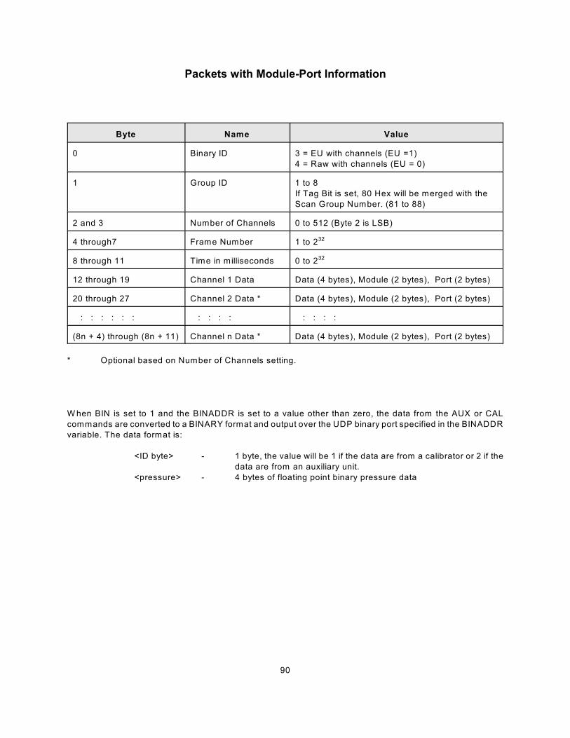
90
Packets with Module-Port Information
Byte Name Value
0 Binary ID 3 = EU with channels (EU =1)
4 = Raw with channels (EU = 0)
1 Group ID 1 to 8
If Tag Bit is set, 80 Hex will be merged with the
Scan Group Number. (81 to 88)
2 and 3 Number of Channels 0 to 512 (Byte 2 is LSB)
4 through7 Frame Number 1 to 232
8 through 11 Time in milliseconds 0 to 232
12 through 19 Channel 1 Data Data (4 bytes), Module (2 bytes), Port (2 bytes)
20 through 27 Channel 2 Data * Data (4 bytes), Module (2 bytes), Port (2 bytes)
: : : : : : : : : : : : : :
(8n + 4) through (8n + 11) Channel n Data * Data (4 bytes), Module (2 bytes), Port (2 bytes)
* Optional based on Number of Channels setting.
W hen BIN is set to 1 and the BINADDR is set to a value other than zero, the data from the AUX or CAL
commands are converted to a BINARY format and output over the UDP binary port specified in the BINADDR
variable. The data format is:
<ID byte> - 1 byte, the value will be 1 if the data are from a calibrator or 2 if the
data are from an auxiliary unit.
<pressure> - 4 bytes of floating point binary pressure data
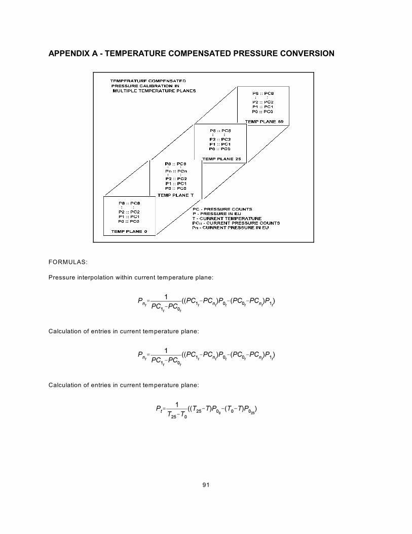
91
APPENDIX A - TEMPERATURE COMPENSATED PRESSURE CONVERSION
FORMULAS:
Pressure interpolation within current temperature plane:
Calculation of entries in current temperature plane:
Calculation of entries in current temperature plane:
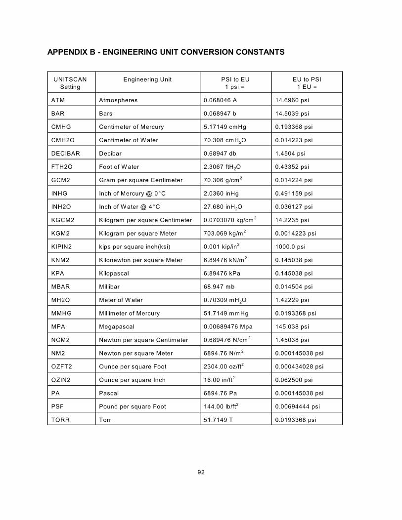
92
APPENDIX B - ENGINEERING UNIT CONVERSION CONSTANTS
UNITSCAN
Setting
Engineering Unit PSI to EU
1 psi =
EU to PSI
1 EU =
ATM Atmospheres 0.068046 A 14.6960 psi
BAR Bars 0.068947 b 14.5039 psi
CMHG Centimeter of Mercury 5.17149 cmHg 0.193368 psi
2CMH2O Centimeter of W ater 70.308 cmH O 0.014223 psi
DECIBAR Decibar 0.68947 db 1.4504 psi
2FTH2O Foot of W ater 2.3067 ftH O 0.43352 psi
GCM2 Gram per square Centimeter 70.306 g/cm 0.014224 psi2
INHG Inch of Mercury @ 0EC 2.0360 inHg 0.491159 psi
2INH2O Inch of W ater @ 4EC 27.680 inH O 0.036127 psi
KGCM2 Kilogram per square Centimeter 0.0703070 kg/cm 14.2235 psi2
KGM2 Kilogram per square Meter 703.069 kg/m 0.0014223 psi2
KIPIN2 kips per square inch(ksi) 0.001 kip/in 1000.0 psi2
KNM2 Kilonewton per square Meter 6.89476 kN/m 0.145038 psi2
KPA Kilopascal 6.89476 kPa 0.145038 psi
MBAR Millibar 68.947 mb 0.014504 psi
2MH2O Meter of W ater 0.70309 mH O 1.42229 psi
MMHG Millimeter of Mercury 51.7149 mmHg 0.0193368 psi
MPA Megapascal 0.00689476 Mpa 145.038 psi
NCM2 Newton per square Centimeter 0.689476 N/cm 1.45038 psi2
NM2 Newton per square Meter 6894.76 N/m 0.000145038 psi2
OZFT2 Ounce per square Foot 2304.00 oz/ft 0.000434028 psi2
OZIN2 Ounce per square Inch 16.00 in/ft 0.062500 psi2
PA Pascal 6894.76 Pa 0.000145038 psi
PSF Pound per square Foot 144.00 lb/ft 0.00694444 psi2
TORR Torr 51.7149 T 0.0193368 psi

93
APPENDIX C - CHANGE LIST
Version 1.00 - Not Released
Version 1.01 - Not Released
Version 1.02 - Not Released
Version 1.03 - Released September 2009
First Release
Version 1.04 - Released December 2009
Added support of A2DCAL
Set the Serial Port - COM2 - as a data destination
Removed NOID support
Added stop SCAN to TCP connect and disconnect
UDP port range extended from 0 to 65535
Corrected a bug in the DELETE command
Corrected a bug in the TYPE command
Added SAVE to the STATUS command
Added RESTART command
Version 1.05 - Released December 2009
Corrected a bug in the PURGE and CALZ timers
Increased the maximum value of PERIOD to 4294967295
Adjusted CALPER settings. CALPER will be set by the software to the value of PERIOD if PERIOD
is equal to or less than 500 m icroseconds. W hen PERIOD is set to values greater than 500
microseconds, CALPER will be set to 500 microseconds.
Version 1.06 - Not Released
Version 1.07 - Not Released
Version 1.08 - Released February 2010
Corrected a major bug in the File Management system that prevented the software from recognizing
files past a deleted file. Any enclosure with a version older than this version must be upgraded.
Corrected a bug in the Serial mode that did not return a carriage return after an escape character was
used to stop a scan.
Corrected a bug that caused the software to not indicate -9999 when a negative full scale value was
exceeded.
Corrected a minor bug in the handling of ID and non ID enabled modules.
Corrected a bug that enabled DOUT 4 at all times.
Activated TGRAD
Corrected minor bugs in IDP commands
Version 5.00 - Released March 2010
Modified the Ethernet connection so a second connection will override an existing connection.
Changed version number to 5.00 to differentiate it from other Enclosure Software versions.
Version 5.01 - Released March 2010
Corrected a bug in the UDP Port assignment
Corrected problems in AUXSCHED and CALSCHED.
94
Version 5.02 - Released June 2010
Changed default setting of SGENABLE1 to 0
Changed default setting of PERIOD to 500
Changed default setting of CALZDLY to 5
Changed default setting of AVG1 to 16
Changed default setting of BINADDR to 0 0.0.0.0
Changed default setting of CALAVG to 32
Version 5.03 - Released July 2010
Improved ASCII data transmission
Added another format type for a special PLC application
Documented the DISCONNECT command