Embed Size (px)
Citation preview
Draft Document for Review July 17, 2010 10:14 pm SG24-8786-01
ibm.com/redbooks
Front cover
IBM System Storage DS8700: Architecture and Implementation
Bertrand DufrasneWerner Bauer
Brenda CareagaJukka Myyrrylainen
Antonio RaineroPaulus Usong
Dual POWER6 based controllers with up to 384 GB of cache
Automatic and Dynamic Data Relocation with Easy Tier
2 TB SATA drives600 GB, 15K rpm FC drives

International Technical Support Organization
IBM System Storage DS8700: Architecture and Implementation
April 2010
Draft Document for Review July 17, 2010 10:14 pm 8786edno.fm
SG24-8786-01
8786edno.fm Draft Document for Review July 17, 2010 10:14 pm
Second Edition (April 2010)
This edition applies to the IBM System Storage DS8700 with DS8000 Licensed Machine Code (LMC) level6.5.1.xx (bundle version 75.1.xx.xx).
This document created or updated on July 17, 2010.
Note: Before using this information and the product it supports, read the information in “Notices” on page xv.
© Copyright International Business Machines Corporation 2010. All rights reserved.Note to U.S. Government Users Restricted Rights -- Use, duplication or disclosure restricted by GSA ADP ScheduleContract with IBM Corp.

Draft Document for Review July 17, 2010 10:14 pm 8786edno.fm
iii

8786edno.fm Draft Document for Review July 17, 2010 10:14 pm
iv IBM System Storage DS8700: Architecture and Implementation
Draft Document for Review July 17, 2010 10:14 pm 8786TOC.fm
Contents
Notices . . . . . . . . . . . . . . . . . . . . . . . . . . . . . . . . . . . . . . . . . . . . . . . . . . . . . . . . . . . . . . . . .xvTrademarks . . . . . . . . . . . . . . . . . . . . . . . . . . . . . . . . . . . . . . . . . . . . . . . . . . . . . . . . . . . . . xvi
Preface . . . . . . . . . . . . . . . . . . . . . . . . . . . . . . . . . . . . . . . . . . . . . . . . . . . . . . . . . . . . . . . . xviiThe team who wrote this book . . . . . . . . . . . . . . . . . . . . . . . . . . . . . . . . . . . . . . . . . . . . . . xviiiBecome a published author . . . . . . . . . . . . . . . . . . . . . . . . . . . . . . . . . . . . . . . . . . . . . . . . . xixComments welcome. . . . . . . . . . . . . . . . . . . . . . . . . . . . . . . . . . . . . . . . . . . . . . . . . . . . . . . .xx
Summary of changes . . . . . . . . . . . . . . . . . . . . . . . . . . . . . . . . . . . . . . . . . . . . . . . . . . . . . xxiApril 2010, Second Edition. . . . . . . . . . . . . . . . . . . . . . . . . . . . . . . . . . . . . . . . . . . . . . . . . . xxi
Part 1. Concepts and architecture. . . . . . . . . . . . . . . . . . . . . . . . . . . . . . . . . . . . . . . . . . . . . . . . . . . . . . . . 1
Chapter 1. Introduction to the IBM System Storage DS8700 . . . . . . . . . . . . . . . . . . . . . 31.1 The DS8700: a member of the DS family . . . . . . . . . . . . . . . . . . . . . . . . . . . . . . . . . . . . 41.2 DS8700 features and functions overview . . . . . . . . . . . . . . . . . . . . . . . . . . . . . . . . . . . . 7
1.2.1 Overall architecture and components . . . . . . . . . . . . . . . . . . . . . . . . . . . . . . . . . . . 71.2.2 Storage capacity . . . . . . . . . . . . . . . . . . . . . . . . . . . . . . . . . . . . . . . . . . . . . . . . . . 101.2.3 Supported environments . . . . . . . . . . . . . . . . . . . . . . . . . . . . . . . . . . . . . . . . . . . . 111.2.4 Copy Services functions . . . . . . . . . . . . . . . . . . . . . . . . . . . . . . . . . . . . . . . . . . . . 111.2.5 DS8000 Thin Provisioning . . . . . . . . . . . . . . . . . . . . . . . . . . . . . . . . . . . . . . . . . . 141.2.6 Easy Tier . . . . . . . . . . . . . . . . . . . . . . . . . . . . . . . . . . . . . . . . . . . . . . . . . . . . . . . . 141.2.7 Service and setup . . . . . . . . . . . . . . . . . . . . . . . . . . . . . . . . . . . . . . . . . . . . . . . . . 151.2.8 Configuration flexibility . . . . . . . . . . . . . . . . . . . . . . . . . . . . . . . . . . . . . . . . . . . . . 151.2.9 IBM Certified Secure Data Overwrite . . . . . . . . . . . . . . . . . . . . . . . . . . . . . . . . . . 16
1.3 Performance features . . . . . . . . . . . . . . . . . . . . . . . . . . . . . . . . . . . . . . . . . . . . . . . . . . 171.3.1 Sophisticated caching algorithms . . . . . . . . . . . . . . . . . . . . . . . . . . . . . . . . . . . . . 171.3.2 Solid State Drives . . . . . . . . . . . . . . . . . . . . . . . . . . . . . . . . . . . . . . . . . . . . . . . . . 171.3.3 Multipath Subsystem Device Driver (SDD) . . . . . . . . . . . . . . . . . . . . . . . . . . . . . . 181.3.4 Performance for System z. . . . . . . . . . . . . . . . . . . . . . . . . . . . . . . . . . . . . . . . . . . 181.3.5 Performance enhancements for System p . . . . . . . . . . . . . . . . . . . . . . . . . . . . . . 191.3.6 Performance enhancements for z/OS Global Mirror . . . . . . . . . . . . . . . . . . . . . . . 19
Chapter 2. DS8700 models . . . . . . . . . . . . . . . . . . . . . . . . . . . . . . . . . . . . . . . . . . . . . . . . 212.1 DS8700 model overview . . . . . . . . . . . . . . . . . . . . . . . . . . . . . . . . . . . . . . . . . . . . . . . . 22
2.1.1 DS8700 Model 941 overview . . . . . . . . . . . . . . . . . . . . . . . . . . . . . . . . . . . . . . . . 232.1.2 Performance Accelerator feature (FC 1980) . . . . . . . . . . . . . . . . . . . . . . . . . . . . . 26
2.2 Scalability for performance: linear scalable architecture. . . . . . . . . . . . . . . . . . . . . . . . 27
Chapter 3. Hardware components and architecture . . . . . . . . . . . . . . . . . . . . . . . . . . . 293.1 Frames . . . . . . . . . . . . . . . . . . . . . . . . . . . . . . . . . . . . . . . . . . . . . . . . . . . . . . . . . . . . . 30
3.1.1 Base frame . . . . . . . . . . . . . . . . . . . . . . . . . . . . . . . . . . . . . . . . . . . . . . . . . . . . . . 303.1.2 Expansion frame . . . . . . . . . . . . . . . . . . . . . . . . . . . . . . . . . . . . . . . . . . . . . . . . . . 313.1.3 Rack operator window . . . . . . . . . . . . . . . . . . . . . . . . . . . . . . . . . . . . . . . . . . . . . 32
3.2 DS8700 architecture . . . . . . . . . . . . . . . . . . . . . . . . . . . . . . . . . . . . . . . . . . . . . . . . . . . 323.2.1 POWER6 processor . . . . . . . . . . . . . . . . . . . . . . . . . . . . . . . . . . . . . . . . . . . . . . . 333.2.2 Peripheral Component Interconnect Express (PCIe) . . . . . . . . . . . . . . . . . . . . . . 333.2.3 Device adapters and host adapters . . . . . . . . . . . . . . . . . . . . . . . . . . . . . . . . . . . 353.2.4 Storage facility architecture. . . . . . . . . . . . . . . . . . . . . . . . . . . . . . . . . . . . . . . . . . 35
© Copyright IBM Corp. 2010. All rights reserved. v
8786TOC.fm Draft Document for Review July 17, 2010 10:14 pm
3.2.5 Server-based SMP design . . . . . . . . . . . . . . . . . . . . . . . . . . . . . . . . . . . . . . . . . . 373.3 Storage facility processor complex (CEC). . . . . . . . . . . . . . . . . . . . . . . . . . . . . . . . . . . 38
3.3.1 Processor memory and cache management . . . . . . . . . . . . . . . . . . . . . . . . . . . . 403.3.2 RIO-G . . . . . . . . . . . . . . . . . . . . . . . . . . . . . . . . . . . . . . . . . . . . . . . . . . . . . . . . . . 403.3.3 I/O enclosures. . . . . . . . . . . . . . . . . . . . . . . . . . . . . . . . . . . . . . . . . . . . . . . . . . . . 41
3.4 Disk subsystem . . . . . . . . . . . . . . . . . . . . . . . . . . . . . . . . . . . . . . . . . . . . . . . . . . . . . . . 413.4.1 Device adapters . . . . . . . . . . . . . . . . . . . . . . . . . . . . . . . . . . . . . . . . . . . . . . . . . . 423.4.2 Disk enclosures. . . . . . . . . . . . . . . . . . . . . . . . . . . . . . . . . . . . . . . . . . . . . . . . . . . 423.4.3 Disk drives . . . . . . . . . . . . . . . . . . . . . . . . . . . . . . . . . . . . . . . . . . . . . . . . . . . . . . 47
3.5 Host adapters . . . . . . . . . . . . . . . . . . . . . . . . . . . . . . . . . . . . . . . . . . . . . . . . . . . . . . . . 483.5.1 Fibre Channel/FICON host adapters. . . . . . . . . . . . . . . . . . . . . . . . . . . . . . . . . . . 48
3.6 Power and cooling. . . . . . . . . . . . . . . . . . . . . . . . . . . . . . . . . . . . . . . . . . . . . . . . . . . . . 493.7 Management console network . . . . . . . . . . . . . . . . . . . . . . . . . . . . . . . . . . . . . . . . . . . 503.8 System Storage Productivity Center (SSPC) . . . . . . . . . . . . . . . . . . . . . . . . . . . . . . . . 513.9 Isolated Tivoli Key Lifecycle Manager (TKLM) server . . . . . . . . . . . . . . . . . . . . . . . . . . 52
Chapter 4. Reliability, Availability, and Serviceability (RAS) of IBM System Storage DS8700 . . . . . . . . . . . . . . . . . . . . . . . . . . . . . . . . . . . . . . . . . . . . . . . . . . . . . . . 55
4.1 Names and terms for DS8700. . . . . . . . . . . . . . . . . . . . . . . . . . . . . . . . . . . . . . . . . . . . 564.2 RAS features of DS8700 CEC . . . . . . . . . . . . . . . . . . . . . . . . . . . . . . . . . . . . . . . . . . . 57
4.2.1 Hypervisor (PHYP) . . . . . . . . . . . . . . . . . . . . . . . . . . . . . . . . . . . . . . . . . . . . . . . . 574.2.2 POWER6 processor . . . . . . . . . . . . . . . . . . . . . . . . . . . . . . . . . . . . . . . . . . . . . . . 584.2.3 AIX operating system . . . . . . . . . . . . . . . . . . . . . . . . . . . . . . . . . . . . . . . . . . . . . . 604.2.4 CEC dual hard drive rebuild . . . . . . . . . . . . . . . . . . . . . . . . . . . . . . . . . . . . . . . . . 614.2.5 RIO-G interconnect . . . . . . . . . . . . . . . . . . . . . . . . . . . . . . . . . . . . . . . . . . . . . . . . 614.2.6 Environmental monitoring . . . . . . . . . . . . . . . . . . . . . . . . . . . . . . . . . . . . . . . . . . . 624.2.7 Resource deallocation . . . . . . . . . . . . . . . . . . . . . . . . . . . . . . . . . . . . . . . . . . . . . 62
4.3 CEC failover and failback . . . . . . . . . . . . . . . . . . . . . . . . . . . . . . . . . . . . . . . . . . . . . . . 634.3.1 Dual operational . . . . . . . . . . . . . . . . . . . . . . . . . . . . . . . . . . . . . . . . . . . . . . . . . . 634.3.2 Failover . . . . . . . . . . . . . . . . . . . . . . . . . . . . . . . . . . . . . . . . . . . . . . . . . . . . . . . . . 654.3.3 Failback. . . . . . . . . . . . . . . . . . . . . . . . . . . . . . . . . . . . . . . . . . . . . . . . . . . . . . . . . 664.3.4 NVS and power outages . . . . . . . . . . . . . . . . . . . . . . . . . . . . . . . . . . . . . . . . . . . . 66
4.4 Data flow in DS8700 . . . . . . . . . . . . . . . . . . . . . . . . . . . . . . . . . . . . . . . . . . . . . . . . . . . 674.4.1 New I/O enclosures. . . . . . . . . . . . . . . . . . . . . . . . . . . . . . . . . . . . . . . . . . . . . . . . 674.4.2 Host connections . . . . . . . . . . . . . . . . . . . . . . . . . . . . . . . . . . . . . . . . . . . . . . . . . 684.4.3 Metadata checks. . . . . . . . . . . . . . . . . . . . . . . . . . . . . . . . . . . . . . . . . . . . . . . . . . 71
4.5 RAS on the HMC. . . . . . . . . . . . . . . . . . . . . . . . . . . . . . . . . . . . . . . . . . . . . . . . . . . . . . 714.5.1 Hardware . . . . . . . . . . . . . . . . . . . . . . . . . . . . . . . . . . . . . . . . . . . . . . . . . . . . . . . 724.5.2 Microcode updates . . . . . . . . . . . . . . . . . . . . . . . . . . . . . . . . . . . . . . . . . . . . . . . . 724.5.3 Call Home and Remote Support . . . . . . . . . . . . . . . . . . . . . . . . . . . . . . . . . . . . . . 72
4.6 RAS on the disk subsystem . . . . . . . . . . . . . . . . . . . . . . . . . . . . . . . . . . . . . . . . . . . . . 724.6.1 RAID configurations . . . . . . . . . . . . . . . . . . . . . . . . . . . . . . . . . . . . . . . . . . . . . . . 724.6.2 Disk path redundancy . . . . . . . . . . . . . . . . . . . . . . . . . . . . . . . . . . . . . . . . . . . . . . 734.6.3 Predictive failure analysis . . . . . . . . . . . . . . . . . . . . . . . . . . . . . . . . . . . . . . . . . . . 744.6.4 Disk scrubbing . . . . . . . . . . . . . . . . . . . . . . . . . . . . . . . . . . . . . . . . . . . . . . . . . . . 744.6.5 RAID 5 overview . . . . . . . . . . . . . . . . . . . . . . . . . . . . . . . . . . . . . . . . . . . . . . . . . . 744.6.6 RAID 6 overview . . . . . . . . . . . . . . . . . . . . . . . . . . . . . . . . . . . . . . . . . . . . . . . . . . 754.6.7 RAID 10 overview . . . . . . . . . . . . . . . . . . . . . . . . . . . . . . . . . . . . . . . . . . . . . . . . . 764.6.8 Spare creation. . . . . . . . . . . . . . . . . . . . . . . . . . . . . . . . . . . . . . . . . . . . . . . . . . . . 77
4.7 RAS on the power subsystem. . . . . . . . . . . . . . . . . . . . . . . . . . . . . . . . . . . . . . . . . . . . 794.7.1 Components . . . . . . . . . . . . . . . . . . . . . . . . . . . . . . . . . . . . . . . . . . . . . . . . . . . . . 794.7.2 Line power loss . . . . . . . . . . . . . . . . . . . . . . . . . . . . . . . . . . . . . . . . . . . . . . . . . . . 804.7.3 Line power fluctuation . . . . . . . . . . . . . . . . . . . . . . . . . . . . . . . . . . . . . . . . . . . . . . 80
vi IBM System Storage DS8700: Architecture and Implementation
Draft Document for Review July 17, 2010 10:14 pm 8786TOC.fm
4.7.4 Power control . . . . . . . . . . . . . . . . . . . . . . . . . . . . . . . . . . . . . . . . . . . . . . . . . . . . 804.7.5 Emergency power off . . . . . . . . . . . . . . . . . . . . . . . . . . . . . . . . . . . . . . . . . . . . . . 81
4.8 RAS and full disk encryption . . . . . . . . . . . . . . . . . . . . . . . . . . . . . . . . . . . . . . . . . . . . . 814.8.1 Deadlock recovery . . . . . . . . . . . . . . . . . . . . . . . . . . . . . . . . . . . . . . . . . . . . . . . . 824.8.2 Dual platform TKLM servers . . . . . . . . . . . . . . . . . . . . . . . . . . . . . . . . . . . . . . . . . 83
4.9 Other features . . . . . . . . . . . . . . . . . . . . . . . . . . . . . . . . . . . . . . . . . . . . . . . . . . . . . . . . 834.9.1 Internal network . . . . . . . . . . . . . . . . . . . . . . . . . . . . . . . . . . . . . . . . . . . . . . . . . . 834.9.2 Remote support . . . . . . . . . . . . . . . . . . . . . . . . . . . . . . . . . . . . . . . . . . . . . . . . . . 844.9.3 Earthquake resistance . . . . . . . . . . . . . . . . . . . . . . . . . . . . . . . . . . . . . . . . . . . . . 84
Chapter 5. Virtualization concepts . . . . . . . . . . . . . . . . . . . . . . . . . . . . . . . . . . . . . . . . . 855.1 Virtualization definition . . . . . . . . . . . . . . . . . . . . . . . . . . . . . . . . . . . . . . . . . . . . . . . . . 865.2 The abstraction layers for disk virtualization . . . . . . . . . . . . . . . . . . . . . . . . . . . . . . . . . 86
5.2.1 Array sites . . . . . . . . . . . . . . . . . . . . . . . . . . . . . . . . . . . . . . . . . . . . . . . . . . . . . . . 875.2.2 Arrays . . . . . . . . . . . . . . . . . . . . . . . . . . . . . . . . . . . . . . . . . . . . . . . . . . . . . . . . . . 885.2.3 Ranks . . . . . . . . . . . . . . . . . . . . . . . . . . . . . . . . . . . . . . . . . . . . . . . . . . . . . . . . . . 895.2.4 Extent Pools . . . . . . . . . . . . . . . . . . . . . . . . . . . . . . . . . . . . . . . . . . . . . . . . . . . . . 905.2.5 Logical volumes . . . . . . . . . . . . . . . . . . . . . . . . . . . . . . . . . . . . . . . . . . . . . . . . . . 935.2.6 Space Efficient volumes . . . . . . . . . . . . . . . . . . . . . . . . . . . . . . . . . . . . . . . . . . . . 955.2.7 Allocation, deletion, and modification of LUNs/CKD volumes. . . . . . . . . . . . . . . . 985.2.8 Logical subsystems (LSS). . . . . . . . . . . . . . . . . . . . . . . . . . . . . . . . . . . . . . . . . . 1045.2.9 Volume access . . . . . . . . . . . . . . . . . . . . . . . . . . . . . . . . . . . . . . . . . . . . . . . . . . 1065.2.10 Virtualization hierarchy summary . . . . . . . . . . . . . . . . . . . . . . . . . . . . . . . . . . . 108
5.3 Benefits of virtualization . . . . . . . . . . . . . . . . . . . . . . . . . . . . . . . . . . . . . . . . . . . . . . . 110
Chapter 6. DS8700 Copy Services Overview . . . . . . . . . . . . . . . . . . . . . . . . . . . . . . . . 1116.1 Copy Services . . . . . . . . . . . . . . . . . . . . . . . . . . . . . . . . . . . . . . . . . . . . . . . . . . . . . . . 1126.2 FlashCopy and IBM FlashCopy SE. . . . . . . . . . . . . . . . . . . . . . . . . . . . . . . . . . . . . . . 113
6.2.1 Basic concepts . . . . . . . . . . . . . . . . . . . . . . . . . . . . . . . . . . . . . . . . . . . . . . . . . . 1136.2.2 Benefits and use . . . . . . . . . . . . . . . . . . . . . . . . . . . . . . . . . . . . . . . . . . . . . . . . . 1156.2.3 Licensing requirements. . . . . . . . . . . . . . . . . . . . . . . . . . . . . . . . . . . . . . . . . . . . 1166.2.4 FlashCopy options . . . . . . . . . . . . . . . . . . . . . . . . . . . . . . . . . . . . . . . . . . . . . . . 1166.2.5 IBM FlashCopy SE options . . . . . . . . . . . . . . . . . . . . . . . . . . . . . . . . . . . . . . . . . 123
6.3 Remote Mirror and Copy. . . . . . . . . . . . . . . . . . . . . . . . . . . . . . . . . . . . . . . . . . . . . . . 1236.3.1 Metro Mirror . . . . . . . . . . . . . . . . . . . . . . . . . . . . . . . . . . . . . . . . . . . . . . . . . . . . 1246.3.2 Global Copy . . . . . . . . . . . . . . . . . . . . . . . . . . . . . . . . . . . . . . . . . . . . . . . . . . . . 1256.3.3 Global Mirror . . . . . . . . . . . . . . . . . . . . . . . . . . . . . . . . . . . . . . . . . . . . . . . . . . . . 1266.3.4 Metro/Global Mirror . . . . . . . . . . . . . . . . . . . . . . . . . . . . . . . . . . . . . . . . . . . . . . . 1296.3.5 z/OS Global Mirror . . . . . . . . . . . . . . . . . . . . . . . . . . . . . . . . . . . . . . . . . . . . . . . 1316.3.6 z/OS Metro/Global Mirror . . . . . . . . . . . . . . . . . . . . . . . . . . . . . . . . . . . . . . . . . . 1316.3.7 Summary of the Copy Services function characteristics . . . . . . . . . . . . . . . . . . . 132
6.4 Interfaces for Copy Services . . . . . . . . . . . . . . . . . . . . . . . . . . . . . . . . . . . . . . . . . . . . 1336.4.1 Hardware Management Console (HMC). . . . . . . . . . . . . . . . . . . . . . . . . . . . . . . 1346.4.2 DS Storage Manager . . . . . . . . . . . . . . . . . . . . . . . . . . . . . . . . . . . . . . . . . . . . . 1346.4.3 DS Command-Line Interface (DS CLI) . . . . . . . . . . . . . . . . . . . . . . . . . . . . . . . . 1356.4.4 Tivoli Storage Productivity Center for Replication (TPC for Replication) . . . . . . 1356.4.5 DS Open application programming interface (DS Open API) . . . . . . . . . . . . . . . 1366.4.6 System z-based I/O interfaces . . . . . . . . . . . . . . . . . . . . . . . . . . . . . . . . . . . . . . 136
6.5 Interoperability. . . . . . . . . . . . . . . . . . . . . . . . . . . . . . . . . . . . . . . . . . . . . . . . . . . . . . . 1376.6 z/OS Global Mirror on zIIP . . . . . . . . . . . . . . . . . . . . . . . . . . . . . . . . . . . . . . . . . . . . . 137
Chapter 7. Performance . . . . . . . . . . . . . . . . . . . . . . . . . . . . . . . . . . . . . . . . . . . . . . . . . 1397.1 DS8700 hardware: performance characteristics . . . . . . . . . . . . . . . . . . . . . . . . . . . . . 140
7.1.1 Fibre Channel switched disk interconnection at the back end . . . . . . . . . . . . . . 140
Contents vii
8786TOC.fm Draft Document for Review July 17, 2010 10:14 pm
7.1.2 Fibre Channel device adapter . . . . . . . . . . . . . . . . . . . . . . . . . . . . . . . . . . . . . . . 1437.1.3 Four-port host adapters . . . . . . . . . . . . . . . . . . . . . . . . . . . . . . . . . . . . . . . . . . . 1447.1.4 IBM System p POWER6: heart of the DS8700 dual cluster design . . . . . . . . . . 1447.1.5 Vertical growth and scalability. . . . . . . . . . . . . . . . . . . . . . . . . . . . . . . . . . . . . . . 146
7.2 Software performance enhancements: synergy items . . . . . . . . . . . . . . . . . . . . . . . . 1467.2.1 End to end I/O priority: synergy with System p AIX and DB2 . . . . . . . . . . . . . . . 1477.2.2 Cooperative caching: synergy with System p AIX and DB2 . . . . . . . . . . . . . . . . 1477.2.3 Long busy wait host tolerance: synergy with System p AIX . . . . . . . . . . . . . . . . 1477.2.4 HACMP-extended distance extensions: synergy with System p AIX . . . . . . . . . 147
7.3 Performance considerations for disk drives . . . . . . . . . . . . . . . . . . . . . . . . . . . . . . . . 1487.4 DS8000 superior caching algorithms . . . . . . . . . . . . . . . . . . . . . . . . . . . . . . . . . . . . . 151
7.4.1 Sequential Adaptive Replacement Cache (SARC) . . . . . . . . . . . . . . . . . . . . . . . 1517.4.2 Adaptive Multi-stream Prefetching (AMP) . . . . . . . . . . . . . . . . . . . . . . . . . . . . . . 1537.4.3 Intelligent Write Caching (IWC). . . . . . . . . . . . . . . . . . . . . . . . . . . . . . . . . . . . . . 153
7.5 Performance considerations for logical configuration . . . . . . . . . . . . . . . . . . . . . . . . . 1557.5.1 Workload characteristics . . . . . . . . . . . . . . . . . . . . . . . . . . . . . . . . . . . . . . . . . . . 1557.5.2 Data placement in the DS8000 . . . . . . . . . . . . . . . . . . . . . . . . . . . . . . . . . . . . . . 1557.5.3 Data placement . . . . . . . . . . . . . . . . . . . . . . . . . . . . . . . . . . . . . . . . . . . . . . . . . . 1567.5.4 Space Efficient volumes and repositories . . . . . . . . . . . . . . . . . . . . . . . . . . . . . . 161
7.6 Performance and sizing considerations for open systems . . . . . . . . . . . . . . . . . . . . . 1637.6.1 Determining the number of paths to a LUN. . . . . . . . . . . . . . . . . . . . . . . . . . . . . 1637.6.2 Dynamic I/O load-balancing: Subsystem Device Driver (SDD). . . . . . . . . . . . . . 1637.6.3 Automatic port queues . . . . . . . . . . . . . . . . . . . . . . . . . . . . . . . . . . . . . . . . . . . . 1647.6.4 Determining where to attach the host . . . . . . . . . . . . . . . . . . . . . . . . . . . . . . . . . 164
7.7 Performance and sizing considerations for System z . . . . . . . . . . . . . . . . . . . . . . . . . 1667.7.1 Host connections to System z servers . . . . . . . . . . . . . . . . . . . . . . . . . . . . . . . . 1667.7.2 Parallel Access Volume (PAV) . . . . . . . . . . . . . . . . . . . . . . . . . . . . . . . . . . . . . . 1677.7.3 z/OS Workload Manager: dynamic PAV tuning . . . . . . . . . . . . . . . . . . . . . . . . . 1697.7.4 HyperPAV . . . . . . . . . . . . . . . . . . . . . . . . . . . . . . . . . . . . . . . . . . . . . . . . . . . . . . 1707.7.5 PAV in z/VM environments . . . . . . . . . . . . . . . . . . . . . . . . . . . . . . . . . . . . . . . . . 1737.7.6 Multiple Allegiance . . . . . . . . . . . . . . . . . . . . . . . . . . . . . . . . . . . . . . . . . . . . . . . 1747.7.7 I/O priority queuing . . . . . . . . . . . . . . . . . . . . . . . . . . . . . . . . . . . . . . . . . . . . . . . 1757.7.8 Performance considerations on Extended Distance FICON. . . . . . . . . . . . . . . . 1767.7.9 High Performance FICON for z (zHPF). . . . . . . . . . . . . . . . . . . . . . . . . . . . . . . . 1777.7.10 Extended distance High Performance FICON . . . . . . . . . . . . . . . . . . . . . . . . . 178
Part 2. Planning and installation . . . . . . . . . . . . . . . . . . . . . . . . . . . . . . . . . . . . . . . . . . . . . . . . . . . . . . . 181
Chapter 8. Physical planning and installation . . . . . . . . . . . . . . . . . . . . . . . . . . . . . . . 1838.1 Considerations prior to installation . . . . . . . . . . . . . . . . . . . . . . . . . . . . . . . . . . . . . . . 184
8.1.1 Who should be involved . . . . . . . . . . . . . . . . . . . . . . . . . . . . . . . . . . . . . . . . . . . 1858.1.2 What information is required . . . . . . . . . . . . . . . . . . . . . . . . . . . . . . . . . . . . . . . . 185
8.2 Planning for the physical installation . . . . . . . . . . . . . . . . . . . . . . . . . . . . . . . . . . . . . . 1868.2.1 Delivery and staging area . . . . . . . . . . . . . . . . . . . . . . . . . . . . . . . . . . . . . . . . . . 1868.2.2 Floor type and loading . . . . . . . . . . . . . . . . . . . . . . . . . . . . . . . . . . . . . . . . . . . . 1868.2.3 Room space and service clearance . . . . . . . . . . . . . . . . . . . . . . . . . . . . . . . . . . 1888.2.4 Power requirements and operating environment . . . . . . . . . . . . . . . . . . . . . . . . 1898.2.5 Host interface and cables . . . . . . . . . . . . . . . . . . . . . . . . . . . . . . . . . . . . . . . . . . 191
8.3 Network connectivity planning. . . . . . . . . . . . . . . . . . . . . . . . . . . . . . . . . . . . . . . . . . . 1928.3.1 Hardware Management Console and network access . . . . . . . . . . . . . . . . . . . . 1928.3.2 System Storage Productivity Center and network access . . . . . . . . . . . . . . . . . 1938.3.3 DSCLI console . . . . . . . . . . . . . . . . . . . . . . . . . . . . . . . . . . . . . . . . . . . . . . . . . . 1948.3.4 DSCIMCLI. . . . . . . . . . . . . . . . . . . . . . . . . . . . . . . . . . . . . . . . . . . . . . . . . . . . . . 194
viii IBM System Storage DS8700: Architecture and Implementation
Draft Document for Review July 17, 2010 10:14 pm 8786TOC.fm
8.3.5 Remote support connection . . . . . . . . . . . . . . . . . . . . . . . . . . . . . . . . . . . . . . . . 1948.3.6 Business to Business VPN connection . . . . . . . . . . . . . . . . . . . . . . . . . . . . . . . . 1958.3.7 Remote power control . . . . . . . . . . . . . . . . . . . . . . . . . . . . . . . . . . . . . . . . . . . . . 1968.3.8 Storage area network connection . . . . . . . . . . . . . . . . . . . . . . . . . . . . . . . . . . . . 1968.3.9 Tivoli Key Lifecycle Manager (TKLM) server for encryption . . . . . . . . . . . . . . . . 1968.3.10 Lightweight Directory Access Protocol (LDAP) server for single sign-on . . . . . 198
8.4 Remote mirror and copy connectivity . . . . . . . . . . . . . . . . . . . . . . . . . . . . . . . . . . . . . 1988.5 Disk capacity considerations. . . . . . . . . . . . . . . . . . . . . . . . . . . . . . . . . . . . . . . . . . . . 199
8.5.1 Disk sparing . . . . . . . . . . . . . . . . . . . . . . . . . . . . . . . . . . . . . . . . . . . . . . . . . . . . 1998.5.2 Disk capacity . . . . . . . . . . . . . . . . . . . . . . . . . . . . . . . . . . . . . . . . . . . . . . . . . . . . 1998.5.3 Solid State Drive (SSD) considerations . . . . . . . . . . . . . . . . . . . . . . . . . . . . . . . 2018.5.4 Full Disk Encryption (FDE) disk considerations . . . . . . . . . . . . . . . . . . . . . . . . . 202
8.6 Planning for growth . . . . . . . . . . . . . . . . . . . . . . . . . . . . . . . . . . . . . . . . . . . . . . . . . . . 203
Chapter 9. HMC planning and setup . . . . . . . . . . . . . . . . . . . . . . . . . . . . . . . . . . . . . . . 2059.1 Hardware Management Console (HMC) overview . . . . . . . . . . . . . . . . . . . . . . . . . . . 206
9.1.1 Storage HMC hardware . . . . . . . . . . . . . . . . . . . . . . . . . . . . . . . . . . . . . . . . . . . 2069.1.2 Private Ethernet networks. . . . . . . . . . . . . . . . . . . . . . . . . . . . . . . . . . . . . . . . . . 207
9.2 HMC software . . . . . . . . . . . . . . . . . . . . . . . . . . . . . . . . . . . . . . . . . . . . . . . . . . . . . . . 2079.2.1 DS Storage Manager GUI . . . . . . . . . . . . . . . . . . . . . . . . . . . . . . . . . . . . . . . . . . 2089.2.2 Command-line interface . . . . . . . . . . . . . . . . . . . . . . . . . . . . . . . . . . . . . . . . . . . 2109.2.3 DS Open Application Programming Interface . . . . . . . . . . . . . . . . . . . . . . . . . . . 2129.2.4 Web-based user interface. . . . . . . . . . . . . . . . . . . . . . . . . . . . . . . . . . . . . . . . . . 213
9.3 HMC activities . . . . . . . . . . . . . . . . . . . . . . . . . . . . . . . . . . . . . . . . . . . . . . . . . . . . . . . 2149.3.1 HMC planning tasks . . . . . . . . . . . . . . . . . . . . . . . . . . . . . . . . . . . . . . . . . . . . . . 2149.3.2 Planning for microcode upgrades . . . . . . . . . . . . . . . . . . . . . . . . . . . . . . . . . . . . 2169.3.3 Time synchronization . . . . . . . . . . . . . . . . . . . . . . . . . . . . . . . . . . . . . . . . . . . . . 2179.3.4 Monitoring with the HMC. . . . . . . . . . . . . . . . . . . . . . . . . . . . . . . . . . . . . . . . . . . 2179.3.5 Call Home and remote support . . . . . . . . . . . . . . . . . . . . . . . . . . . . . . . . . . . . . . 217
9.4 HMC and IPv6. . . . . . . . . . . . . . . . . . . . . . . . . . . . . . . . . . . . . . . . . . . . . . . . . . . . . . . 2189.5 HMC user management . . . . . . . . . . . . . . . . . . . . . . . . . . . . . . . . . . . . . . . . . . . . . . . 222
9.5.1 User management using the DS CLI . . . . . . . . . . . . . . . . . . . . . . . . . . . . . . . . . 2239.5.2 User management using the DS GUI . . . . . . . . . . . . . . . . . . . . . . . . . . . . . . . . . 225
9.6 External HMC . . . . . . . . . . . . . . . . . . . . . . . . . . . . . . . . . . . . . . . . . . . . . . . . . . . . . . . 2299.6.1 External HMC benefits . . . . . . . . . . . . . . . . . . . . . . . . . . . . . . . . . . . . . . . . . . . . 2309.6.2 Configuring DS CLI to use a second HMC . . . . . . . . . . . . . . . . . . . . . . . . . . . . . 230
Chapter 10. DS8700 features and license keys . . . . . . . . . . . . . . . . . . . . . . . . . . . . . . 23310.1 IBM System Storage DS8700 licensed functions . . . . . . . . . . . . . . . . . . . . . . . . . . . 23410.2 Activation of licensed functions . . . . . . . . . . . . . . . . . . . . . . . . . . . . . . . . . . . . . . . . . 236
10.2.1 Obtaining DS8700 machine information . . . . . . . . . . . . . . . . . . . . . . . . . . . . . . 23710.2.2 Obtaining activation codes . . . . . . . . . . . . . . . . . . . . . . . . . . . . . . . . . . . . . . . . 23910.2.3 Applying activation codes using the GUI. . . . . . . . . . . . . . . . . . . . . . . . . . . . . . 24310.2.4 Applying activation codes using the DS CLI . . . . . . . . . . . . . . . . . . . . . . . . . . . 247
10.3 Licensed scope considerations . . . . . . . . . . . . . . . . . . . . . . . . . . . . . . . . . . . . . . . . . 24810.3.1 Why you get a choice . . . . . . . . . . . . . . . . . . . . . . . . . . . . . . . . . . . . . . . . . . . . 24810.3.2 Using a feature for which you are not licensed . . . . . . . . . . . . . . . . . . . . . . . . . 24910.3.3 Changing the scope to All . . . . . . . . . . . . . . . . . . . . . . . . . . . . . . . . . . . . . . . . . 25010.3.4 Changing the scope from All to FB . . . . . . . . . . . . . . . . . . . . . . . . . . . . . . . . . . 25010.3.5 Applying an insufficient license feature key . . . . . . . . . . . . . . . . . . . . . . . . . . . 25110.3.6 Calculating how much capacity is used for CKD or FB. . . . . . . . . . . . . . . . . . . 252
Part 3. Storage configuration. . . . . . . . . . . . . . . . . . . . . . . . . . . . . . . . . . . . . . . . . . . . . . . . . . . . . . . . . . 255
Contents ix
8786TOC.fm Draft Document for Review July 17, 2010 10:14 pm
Chapter 11. Configuration flow . . . . . . . . . . . . . . . . . . . . . . . . . . . . . . . . . . . . . . . . . . . 25711.1 Configuration worksheets . . . . . . . . . . . . . . . . . . . . . . . . . . . . . . . . . . . . . . . . . . . . . 25811.2 Configuration flow . . . . . . . . . . . . . . . . . . . . . . . . . . . . . . . . . . . . . . . . . . . . . . . . . . . 258
Chapter 12. System Storage Productivity Center . . . . . . . . . . . . . . . . . . . . . . . . . . . . 26112.1 System Storage Productivity Center (SSPC) overview. . . . . . . . . . . . . . . . . . . . . . . 262
12.1.1 SSPC components . . . . . . . . . . . . . . . . . . . . . . . . . . . . . . . . . . . . . . . . . . . . . . 26212.1.2 SSPC capabilities . . . . . . . . . . . . . . . . . . . . . . . . . . . . . . . . . . . . . . . . . . . . . . . 26312.1.3 SSPC upgrade options . . . . . . . . . . . . . . . . . . . . . . . . . . . . . . . . . . . . . . . . . . . 264
12.2 SSPC setup and configuration . . . . . . . . . . . . . . . . . . . . . . . . . . . . . . . . . . . . . . . . . 26512.2.1 Configuring SSPC for DS8700 remote GUI access . . . . . . . . . . . . . . . . . . . . . 26512.2.2 Manage embedded CIMOM on DS8700. . . . . . . . . . . . . . . . . . . . . . . . . . . . . . 27312.2.3 Set up SSPC user management . . . . . . . . . . . . . . . . . . . . . . . . . . . . . . . . . . . . 27512.2.4 Set up and discover DS8700 CIMOM from TPC. . . . . . . . . . . . . . . . . . . . . . . . 278
12.3 Maintaining TPC-BE for a DS8700 system . . . . . . . . . . . . . . . . . . . . . . . . . . . . . . . . 28112.3.1 Schedule and monitor TPC tasks . . . . . . . . . . . . . . . . . . . . . . . . . . . . . . . . . . . 28112.3.2 Auditing TPC actions against the DS8700 system . . . . . . . . . . . . . . . . . . . . . . 28212.3.3 Manually recover CIM Agent connectivity after HMC shutdown . . . . . . . . . . . . 283
12.4 Working with a DS8700 system in TPC-BE . . . . . . . . . . . . . . . . . . . . . . . . . . . . . . . 28312.4.1 Display and analyze the overall storage environment. . . . . . . . . . . . . . . . . . . . 28312.4.2 Storage health management. . . . . . . . . . . . . . . . . . . . . . . . . . . . . . . . . . . . . . . 29112.4.3 Display host volumes through SVC to the assigned DS8700 volume. . . . . . . . 291
Chapter 13. Configuration using the DS Storage Manager GUI . . . . . . . . . . . . . . . . . 29313.1 DS Storage Manager GUI overview . . . . . . . . . . . . . . . . . . . . . . . . . . . . . . . . . . . . . 294
13.1.1 Accessing the DS GUI . . . . . . . . . . . . . . . . . . . . . . . . . . . . . . . . . . . . . . . . . . . 29413.1.2 DS GUI Welcome window. . . . . . . . . . . . . . . . . . . . . . . . . . . . . . . . . . . . . . . . . 300
13.2 Logical configuration process . . . . . . . . . . . . . . . . . . . . . . . . . . . . . . . . . . . . . . . . . . 30213.3 Examples of configuring DS8700 storage. . . . . . . . . . . . . . . . . . . . . . . . . . . . . . . . . 303
13.3.1 Define storage complex . . . . . . . . . . . . . . . . . . . . . . . . . . . . . . . . . . . . . . . . . . 30313.3.2 Create arrays . . . . . . . . . . . . . . . . . . . . . . . . . . . . . . . . . . . . . . . . . . . . . . . . . . 30613.3.3 Create ranks . . . . . . . . . . . . . . . . . . . . . . . . . . . . . . . . . . . . . . . . . . . . . . . . . . . 31313.3.4 Create extent pools . . . . . . . . . . . . . . . . . . . . . . . . . . . . . . . . . . . . . . . . . . . . . . 32013.3.5 Configure I/O ports . . . . . . . . . . . . . . . . . . . . . . . . . . . . . . . . . . . . . . . . . . . . . . 32813.3.6 Configure logical host systems . . . . . . . . . . . . . . . . . . . . . . . . . . . . . . . . . . . . . 32913.3.7 Create fixed block volumes. . . . . . . . . . . . . . . . . . . . . . . . . . . . . . . . . . . . . . . . 33413.3.8 Create volume groups. . . . . . . . . . . . . . . . . . . . . . . . . . . . . . . . . . . . . . . . . . . . 33913.3.9 Create LCUs and CKD volumes . . . . . . . . . . . . . . . . . . . . . . . . . . . . . . . . . . . . 34113.3.10 Additional actions on LCUs and CKD volumes. . . . . . . . . . . . . . . . . . . . . . . . 347
13.4 Other DS GUl functions. . . . . . . . . . . . . . . . . . . . . . . . . . . . . . . . . . . . . . . . . . . . . . . 35013.4.1 Check the DS8700’s status. . . . . . . . . . . . . . . . . . . . . . . . . . . . . . . . . . . . . . . . 35013.4.2 Explore the DS8700 hardware . . . . . . . . . . . . . . . . . . . . . . . . . . . . . . . . . . . . . 352
Chapter 14. Configuration with the Command-Line Interface . . . . . . . . . . . . . . . . . . 35714.1 DS Command-Line Interface overview . . . . . . . . . . . . . . . . . . . . . . . . . . . . . . . . . . . 358
14.1.1 Supported operating systems for the DS CLI . . . . . . . . . . . . . . . . . . . . . . . . . . 35814.1.2 User accounts . . . . . . . . . . . . . . . . . . . . . . . . . . . . . . . . . . . . . . . . . . . . . . . . . . 35914.1.3 DS CLI profile . . . . . . . . . . . . . . . . . . . . . . . . . . . . . . . . . . . . . . . . . . . . . . . . . . 35914.1.4 Command structure . . . . . . . . . . . . . . . . . . . . . . . . . . . . . . . . . . . . . . . . . . . . . 36114.1.5 Using the DS CLI application . . . . . . . . . . . . . . . . . . . . . . . . . . . . . . . . . . . . . . 36114.1.6 Return codes. . . . . . . . . . . . . . . . . . . . . . . . . . . . . . . . . . . . . . . . . . . . . . . . . . . 36314.1.7 User assistance . . . . . . . . . . . . . . . . . . . . . . . . . . . . . . . . . . . . . . . . . . . . . . . . 364
14.2 Configuring the I/O ports . . . . . . . . . . . . . . . . . . . . . . . . . . . . . . . . . . . . . . . . . . . . . . 36514.3 Monitoring the I/O ports. . . . . . . . . . . . . . . . . . . . . . . . . . . . . . . . . . . . . . . . . . . . . . . 366
x IBM System Storage DS8700: Architecture and Implementation
Draft Document for Review July 17, 2010 10:14 pm 8786TOC.fm
14.4 Configuring the DS8000 storage for FB volumes . . . . . . . . . . . . . . . . . . . . . . . . . . . 36814.4.1 Create arrays . . . . . . . . . . . . . . . . . . . . . . . . . . . . . . . . . . . . . . . . . . . . . . . . . . 36814.4.2 Create ranks . . . . . . . . . . . . . . . . . . . . . . . . . . . . . . . . . . . . . . . . . . . . . . . . . . . 36914.4.3 Create extent pools . . . . . . . . . . . . . . . . . . . . . . . . . . . . . . . . . . . . . . . . . . . . . . 36914.4.4 Creating FB volumes . . . . . . . . . . . . . . . . . . . . . . . . . . . . . . . . . . . . . . . . . . . . 37214.4.5 Creating volume groups . . . . . . . . . . . . . . . . . . . . . . . . . . . . . . . . . . . . . . . . . . 37814.4.6 Creating host connections . . . . . . . . . . . . . . . . . . . . . . . . . . . . . . . . . . . . . . . . 38014.4.7 Mapping open systems host disks to storage unit volumes . . . . . . . . . . . . . . . 381
14.5 Configuring DS8000 Storage for Count Key Data Volumes . . . . . . . . . . . . . . . . . . . 38414.5.1 Create arrays . . . . . . . . . . . . . . . . . . . . . . . . . . . . . . . . . . . . . . . . . . . . . . . . . . 38414.5.2 Ranks and extent pool creation . . . . . . . . . . . . . . . . . . . . . . . . . . . . . . . . . . . . 38414.5.3 Logical control unit creation . . . . . . . . . . . . . . . . . . . . . . . . . . . . . . . . . . . . . . . 38614.5.4 Create CKD volumes . . . . . . . . . . . . . . . . . . . . . . . . . . . . . . . . . . . . . . . . . . . . 387
Part 4. Host considerations . . . . . . . . . . . . . . . . . . . . . . . . . . . . . . . . . . . . . . . . . . . . . . . . . . . . . . . . . . . 395
Chapter 15. Open systems considerations . . . . . . . . . . . . . . . . . . . . . . . . . . . . . . . . . 39715.1 General considerations . . . . . . . . . . . . . . . . . . . . . . . . . . . . . . . . . . . . . . . . . . . . . . . 398
15.1.1 Getting up-to-date information . . . . . . . . . . . . . . . . . . . . . . . . . . . . . . . . . . . . . 39815.1.2 Boot support . . . . . . . . . . . . . . . . . . . . . . . . . . . . . . . . . . . . . . . . . . . . . . . . . . . 39915.1.3 Additional supported configurations (RPQ). . . . . . . . . . . . . . . . . . . . . . . . . . . . 40015.1.4 Multipathing support: Subsystem Device Driver (SDD) . . . . . . . . . . . . . . . . . . 400
15.2 Windows . . . . . . . . . . . . . . . . . . . . . . . . . . . . . . . . . . . . . . . . . . . . . . . . . . . . . . . . . . 40115.2.1 HBA and operating system settings . . . . . . . . . . . . . . . . . . . . . . . . . . . . . . . . . 40115.2.2 SDD for Windows . . . . . . . . . . . . . . . . . . . . . . . . . . . . . . . . . . . . . . . . . . . . . . . 40215.2.3 Windows 2003 and MPIO . . . . . . . . . . . . . . . . . . . . . . . . . . . . . . . . . . . . . . . . . 40515.2.4 SDD Device Specific Module for Windows 2003 and 2008 . . . . . . . . . . . . . . . 40615.2.5 Windows 2008 and SDDDSM. . . . . . . . . . . . . . . . . . . . . . . . . . . . . . . . . . . . . . 41015.2.6 Dynamic Volume Expansion of a Windows 2000/2003/2008 volume. . . . . . . . 41015.2.7 Boot support . . . . . . . . . . . . . . . . . . . . . . . . . . . . . . . . . . . . . . . . . . . . . . . . . . . 41515.2.8 Windows Server 2003 Virtual Disk Service (VDS) support . . . . . . . . . . . . . . . . 416
15.3 AIX . . . . . . . . . . . . . . . . . . . . . . . . . . . . . . . . . . . . . . . . . . . . . . . . . . . . . . . . . . . . . . 42115.3.1 Finding the Worldwide Port Names. . . . . . . . . . . . . . . . . . . . . . . . . . . . . . . . . . 42115.3.2 AIX multipath support . . . . . . . . . . . . . . . . . . . . . . . . . . . . . . . . . . . . . . . . . . . . 42215.3.3 SDD for AIX . . . . . . . . . . . . . . . . . . . . . . . . . . . . . . . . . . . . . . . . . . . . . . . . . . . 42215.3.4 AIX Multipath I/O (MPIO) . . . . . . . . . . . . . . . . . . . . . . . . . . . . . . . . . . . . . . . . . 42415.3.5 LVM configuration . . . . . . . . . . . . . . . . . . . . . . . . . . . . . . . . . . . . . . . . . . . . . . . 42815.3.6 AIX access methods for I/O . . . . . . . . . . . . . . . . . . . . . . . . . . . . . . . . . . . . . . . 42915.3.7 Dynamic Volume Expansion . . . . . . . . . . . . . . . . . . . . . . . . . . . . . . . . . . . . . . . 43015.3.8 Boot device support . . . . . . . . . . . . . . . . . . . . . . . . . . . . . . . . . . . . . . . . . . . . . 432
15.4 Linux . . . . . . . . . . . . . . . . . . . . . . . . . . . . . . . . . . . . . . . . . . . . . . . . . . . . . . . . . . . . . 43315.4.1 Support issues that distinguish Linux from other operating systems . . . . . . . . 43315.4.2 Reference material . . . . . . . . . . . . . . . . . . . . . . . . . . . . . . . . . . . . . . . . . . . . . . 43315.4.3 Important Linux issues . . . . . . . . . . . . . . . . . . . . . . . . . . . . . . . . . . . . . . . . . . . 43515.4.4 Troubleshooting and monitoring . . . . . . . . . . . . . . . . . . . . . . . . . . . . . . . . . . . . 443
15.5 OpenVMS . . . . . . . . . . . . . . . . . . . . . . . . . . . . . . . . . . . . . . . . . . . . . . . . . . . . . . . . . 44515.5.1 FC port configuration . . . . . . . . . . . . . . . . . . . . . . . . . . . . . . . . . . . . . . . . . . . . 44515.5.2 Volume configuration . . . . . . . . . . . . . . . . . . . . . . . . . . . . . . . . . . . . . . . . . . . . 44615.5.3 Command Console LUN . . . . . . . . . . . . . . . . . . . . . . . . . . . . . . . . . . . . . . . . . . 44715.5.4 OpenVMS volume shadowing. . . . . . . . . . . . . . . . . . . . . . . . . . . . . . . . . . . . . . 449
15.6 VMware . . . . . . . . . . . . . . . . . . . . . . . . . . . . . . . . . . . . . . . . . . . . . . . . . . . . . . . . . . . 44915.6.1 VMware ESX Server 3 . . . . . . . . . . . . . . . . . . . . . . . . . . . . . . . . . . . . . . . . . . . 45015.6.2 VMware disk architecture . . . . . . . . . . . . . . . . . . . . . . . . . . . . . . . . . . . . . . . . . 451
Contents xi
8786TOC.fm Draft Document for Review July 17, 2010 10:14 pm
15.6.3 VMware setup and configuration . . . . . . . . . . . . . . . . . . . . . . . . . . . . . . . . . . . 45115.7 Sun Solaris . . . . . . . . . . . . . . . . . . . . . . . . . . . . . . . . . . . . . . . . . . . . . . . . . . . . . . . . 455
15.7.1 Locating the WWPNs of your HBAs . . . . . . . . . . . . . . . . . . . . . . . . . . . . . . . . . 45515.7.2 Solaris attachment to DS8000 . . . . . . . . . . . . . . . . . . . . . . . . . . . . . . . . . . . . . 45515.7.3 Multipathing in Solaris . . . . . . . . . . . . . . . . . . . . . . . . . . . . . . . . . . . . . . . . . . . . 45615.7.4 Dynamic Volume Expansion with VxVM and DMP . . . . . . . . . . . . . . . . . . . . . . 460
15.8 Hewlett-Packard UNIX (HP-UX. . . . . . . . . . . . . . . . . . . . . . . . . . . . . . . . . . . . . . . . . )46515.8.1 Available documentation. . . . . . . . . . . . . . . . . . . . . . . . . . . . . . . . . . . . . . . . . . 46515.8.2 DS8000-specific software . . . . . . . . . . . . . . . . . . . . . . . . . . . . . . . . . . . . . . . . . 46515.8.3 Locating the WWPNs of HBAs . . . . . . . . . . . . . . . . . . . . . . . . . . . . . . . . . . . . . 46615.8.4 Defining the HP-UX host for the DS8000 . . . . . . . . . . . . . . . . . . . . . . . . . . . . . 46615.8.5 Multipathing. . . . . . . . . . . . . . . . . . . . . . . . . . . . . . . . . . . . . . . . . . . . . . . . . . . . 468
Chapter 16. IBM System z considerations . . . . . . . . . . . . . . . . . . . . . . . . . . . . . . . . . . 47716.1 Connectivity considerations . . . . . . . . . . . . . . . . . . . . . . . . . . . . . . . . . . . . . . . . . . . 47816.2 Operating systems prerequisites and enhancements . . . . . . . . . . . . . . . . . . . . . . . . 47816.3 z/OS considerations . . . . . . . . . . . . . . . . . . . . . . . . . . . . . . . . . . . . . . . . . . . . . . . . . 479
16.3.1 z/OS program enhancements (SPEs). . . . . . . . . . . . . . . . . . . . . . . . . . . . . . . . 47916.3.2 Parallel Access Volume (PAV) definition . . . . . . . . . . . . . . . . . . . . . . . . . . . . . 49016.3.3 HyperPAV z/OS support and implementation . . . . . . . . . . . . . . . . . . . . . . . . . . 492
16.4 z/VM considerations . . . . . . . . . . . . . . . . . . . . . . . . . . . . . . . . . . . . . . . . . . . . . . . . . 49616.4.1 Connectivity . . . . . . . . . . . . . . . . . . . . . . . . . . . . . . . . . . . . . . . . . . . . . . . . . . . 49616.4.2 Supported DASD types and LUNs . . . . . . . . . . . . . . . . . . . . . . . . . . . . . . . . . . 49616.4.3 PAV and HyperPAV z/VM support . . . . . . . . . . . . . . . . . . . . . . . . . . . . . . . . . . 49616.4.4 Missing-interrupt handler (MIH). . . . . . . . . . . . . . . . . . . . . . . . . . . . . . . . . . . . . 497
16.5 VSE/ESA and z/VSE considerations. . . . . . . . . . . . . . . . . . . . . . . . . . . . . . . . . . . . . 49716.6 Extended Distance FICON . . . . . . . . . . . . . . . . . . . . . . . . . . . . . . . . . . . . . . . . . . . . 498
16.6.1 Extended Distance FICON: installation considerations. . . . . . . . . . . . . . . . . . . 49916.7 High Performance FICON for z with multitrack support . . . . . . . . . . . . . . . . . . . . . . 50016.8 z/OS Basic HyperSwap. . . . . . . . . . . . . . . . . . . . . . . . . . . . . . . . . . . . . . . . . . . . . . . 501
Chapter 17. IBM System i considerations. . . . . . . . . . . . . . . . . . . . . . . . . . . . . . . . . . . 50517.1 Supported environment . . . . . . . . . . . . . . . . . . . . . . . . . . . . . . . . . . . . . . . . . . . . . . . 506
17.1.1 Hardware . . . . . . . . . . . . . . . . . . . . . . . . . . . . . . . . . . . . . . . . . . . . . . . . . . . . . 50617.1.2 Software . . . . . . . . . . . . . . . . . . . . . . . . . . . . . . . . . . . . . . . . . . . . . . . . . . . . . . 506
17.2 Logical volume sizes . . . . . . . . . . . . . . . . . . . . . . . . . . . . . . . . . . . . . . . . . . . . . . . . . 50617.3 Protected versus unprotected volumes. . . . . . . . . . . . . . . . . . . . . . . . . . . . . . . . . . . 507
17.3.1 Changing LUN protection . . . . . . . . . . . . . . . . . . . . . . . . . . . . . . . . . . . . . . . . . 50817.4 Adding volumes to the System i configuration . . . . . . . . . . . . . . . . . . . . . . . . . . . . . 508
17.4.1 Using the 5250 interface . . . . . . . . . . . . . . . . . . . . . . . . . . . . . . . . . . . . . . . . . . 50817.4.2 Adding volumes to an Independent Auxiliary Storage Pool . . . . . . . . . . . . . . . 512
17.5 Multipath . . . . . . . . . . . . . . . . . . . . . . . . . . . . . . . . . . . . . . . . . . . . . . . . . . . . . . . . . . 51917.5.1 Avoiding single points of failure . . . . . . . . . . . . . . . . . . . . . . . . . . . . . . . . . . . . 51917.5.2 Configuring multipath . . . . . . . . . . . . . . . . . . . . . . . . . . . . . . . . . . . . . . . . . . . . 52017.5.3 Adding multipath volumes to System i using the 5250 interface. . . . . . . . . . . . 52117.5.4 Adding multipath volumes to System i using System i Navigator . . . . . . . . . . . 52217.5.5 Managing multipath volumes using System i Navigator . . . . . . . . . . . . . . . . . . 52317.5.6 Multipath rules for multiple System i hosts or partitions . . . . . . . . . . . . . . . . . . 52617.5.7 Changing from a single path to multipath . . . . . . . . . . . . . . . . . . . . . . . . . . . . . 526
17.6 Sizing guidelines . . . . . . . . . . . . . . . . . . . . . . . . . . . . . . . . . . . . . . . . . . . . . . . . . . . . 52717.6.1 Planning for arrays and DDMs . . . . . . . . . . . . . . . . . . . . . . . . . . . . . . . . . . . . . 52717.6.2 Cache . . . . . . . . . . . . . . . . . . . . . . . . . . . . . . . . . . . . . . . . . . . . . . . . . . . . . . . . 52817.6.3 Number of System i Fibre Channel adapters . . . . . . . . . . . . . . . . . . . . . . . . . . 528
xii IBM System Storage DS8700: Architecture and Implementation
Draft Document for Review July 17, 2010 10:14 pm 8786TOC.fm
17.6.4 Size and number of LUNs. . . . . . . . . . . . . . . . . . . . . . . . . . . . . . . . . . . . . . . . . 52817.6.5 Recommended number of ranks. . . . . . . . . . . . . . . . . . . . . . . . . . . . . . . . . . . . 52917.6.6 Sharing ranks between System i and other servers . . . . . . . . . . . . . . . . . . . . . 52917.6.7 Connecting using SAN switches . . . . . . . . . . . . . . . . . . . . . . . . . . . . . . . . . . . . 529
17.7 Migration . . . . . . . . . . . . . . . . . . . . . . . . . . . . . . . . . . . . . . . . . . . . . . . . . . . . . . . . . . 53017.7.1 Metro Mirror and Global Copy. . . . . . . . . . . . . . . . . . . . . . . . . . . . . . . . . . . . . . 53017.7.2 IBM i data migration . . . . . . . . . . . . . . . . . . . . . . . . . . . . . . . . . . . . . . . . . . . . . 531
17.8 Boot from SAN . . . . . . . . . . . . . . . . . . . . . . . . . . . . . . . . . . . . . . . . . . . . . . . . . . . . . 53217.8.1 Boot from SAN and cloning. . . . . . . . . . . . . . . . . . . . . . . . . . . . . . . . . . . . . . . . 53217.8.2 Why consider cloning . . . . . . . . . . . . . . . . . . . . . . . . . . . . . . . . . . . . . . . . . . . . 533
Part 5. Maintenance and upgrades . . . . . . . . . . . . . . . . . . . . . . . . . . . . . . . . . . . . . . . . . . . . . . . . . . . . . 535
Chapter 18. Licensed machine code . . . . . . . . . . . . . . . . . . . . . . . . . . . . . . . . . . . . . . . 53718.1 How new microcode is released . . . . . . . . . . . . . . . . . . . . . . . . . . . . . . . . . . . . . . . . 53818.2 Bundle installation . . . . . . . . . . . . . . . . . . . . . . . . . . . . . . . . . . . . . . . . . . . . . . . . . . . 53818.3 DS8700 EFIXes . . . . . . . . . . . . . . . . . . . . . . . . . . . . . . . . . . . . . . . . . . . . . . . . . . . . 53918.4 Concurrent and non-concurrent updates . . . . . . . . . . . . . . . . . . . . . . . . . . . . . . . . . 54018.5 Code updates . . . . . . . . . . . . . . . . . . . . . . . . . . . . . . . . . . . . . . . . . . . . . . . . . . . . . . 54018.6 Host adapter firmware updates . . . . . . . . . . . . . . . . . . . . . . . . . . . . . . . . . . . . . . . . . 54018.7 Loading the code bundle. . . . . . . . . . . . . . . . . . . . . . . . . . . . . . . . . . . . . . . . . . . . . . 54118.8 Post-installation activities . . . . . . . . . . . . . . . . . . . . . . . . . . . . . . . . . . . . . . . . . . . . . 54118.9 Summary. . . . . . . . . . . . . . . . . . . . . . . . . . . . . . . . . . . . . . . . . . . . . . . . . . . . . . . . . . 542
Chapter 19. Monitoring with Simple Network Management Protocol (SNMP). . . . . . 54319.1 Simple Network Management Protocol (SNMP) overview . . . . . . . . . . . . . . . . . . . . 544
19.1.1 SNMP agent . . . . . . . . . . . . . . . . . . . . . . . . . . . . . . . . . . . . . . . . . . . . . . . . . . . 54419.1.2 SNMP manager . . . . . . . . . . . . . . . . . . . . . . . . . . . . . . . . . . . . . . . . . . . . . . . . 54419.1.3 SNMP trap . . . . . . . . . . . . . . . . . . . . . . . . . . . . . . . . . . . . . . . . . . . . . . . . . . . . 54419.1.4 SNMP communication. . . . . . . . . . . . . . . . . . . . . . . . . . . . . . . . . . . . . . . . . . . . 54519.1.5 Generic SNMP security. . . . . . . . . . . . . . . . . . . . . . . . . . . . . . . . . . . . . . . . . . . 54619.1.6 Message Information Base (MIB) . . . . . . . . . . . . . . . . . . . . . . . . . . . . . . . . . . . 54619.1.7 SNMP trap request . . . . . . . . . . . . . . . . . . . . . . . . . . . . . . . . . . . . . . . . . . . . . . 54619.1.8 DS8000 SNMP configuration . . . . . . . . . . . . . . . . . . . . . . . . . . . . . . . . . . . . . . 547
19.2 SNMP notifications . . . . . . . . . . . . . . . . . . . . . . . . . . . . . . . . . . . . . . . . . . . . . . . . . . 54719.2.1 Serviceable event using specific trap 3. . . . . . . . . . . . . . . . . . . . . . . . . . . . . . . 54719.2.2 Copy Services event traps . . . . . . . . . . . . . . . . . . . . . . . . . . . . . . . . . . . . . . . . 548
19.3 SNMP configuration . . . . . . . . . . . . . . . . . . . . . . . . . . . . . . . . . . . . . . . . . . . . . . . . . 556
Chapter 20. Remote support . . . . . . . . . . . . . . . . . . . . . . . . . . . . . . . . . . . . . . . . . . . . . 55720.1 Introduction to remote support . . . . . . . . . . . . . . . . . . . . . . . . . . . . . . . . . . . . . . . . . 558
20.1.1 Suggested reading . . . . . . . . . . . . . . . . . . . . . . . . . . . . . . . . . . . . . . . . . . . . . . 55820.1.2 Organization of this chapter . . . . . . . . . . . . . . . . . . . . . . . . . . . . . . . . . . . . . . . 55820.1.3 Terminology and definitions . . . . . . . . . . . . . . . . . . . . . . . . . . . . . . . . . . . . . . . 559
20.2 IBM policies for remote support . . . . . . . . . . . . . . . . . . . . . . . . . . . . . . . . . . . . . . . . 56020.3 Remote connection types . . . . . . . . . . . . . . . . . . . . . . . . . . . . . . . . . . . . . . . . . . . . . 561
20.3.1 Modem . . . . . . . . . . . . . . . . . . . . . . . . . . . . . . . . . . . . . . . . . . . . . . . . . . . . . . . 56120.3.2 IP network . . . . . . . . . . . . . . . . . . . . . . . . . . . . . . . . . . . . . . . . . . . . . . . . . . . . . 56320.3.3 IP network with traditional VPN. . . . . . . . . . . . . . . . . . . . . . . . . . . . . . . . . . . . . 56420.3.4 IP network with Business to Business (B2B) VPN . . . . . . . . . . . . . . . . . . . . . . 564
20.4 DS8700 support tasks. . . . . . . . . . . . . . . . . . . . . . . . . . . . . . . . . . . . . . . . . . . . . . . . 56520.4.1 Call Home and heartbeat (outbound) . . . . . . . . . . . . . . . . . . . . . . . . . . . . . . . . 56520.4.2 Data offload (outbound) . . . . . . . . . . . . . . . . . . . . . . . . . . . . . . . . . . . . . . . . . . 56620.4.3 Code download (inbound) . . . . . . . . . . . . . . . . . . . . . . . . . . . . . . . . . . . . . . . . . 567
Contents xiii
8786TOC.fm Draft Document for Review July 17, 2010 10:14 pm
20.4.4 Remote support (inbound and two-way) . . . . . . . . . . . . . . . . . . . . . . . . . . . . . . 56720.5 Scenarios . . . . . . . . . . . . . . . . . . . . . . . . . . . . . . . . . . . . . . . . . . . . . . . . . . . . . . . . . 568
20.5.1 No connections . . . . . . . . . . . . . . . . . . . . . . . . . . . . . . . . . . . . . . . . . . . . . . . . . 56820.5.2 Modem only . . . . . . . . . . . . . . . . . . . . . . . . . . . . . . . . . . . . . . . . . . . . . . . . . . . 56820.5.3 Modem and network with no VPN. . . . . . . . . . . . . . . . . . . . . . . . . . . . . . . . . . . 56920.5.4 Modem and traditional VPN . . . . . . . . . . . . . . . . . . . . . . . . . . . . . . . . . . . . . . . 57020.5.5 Modem and B2B VPN. . . . . . . . . . . . . . . . . . . . . . . . . . . . . . . . . . . . . . . . . . . . 571
20.6 Audit logging . . . . . . . . . . . . . . . . . . . . . . . . . . . . . . . . . . . . . . . . . . . . . . . . . . . . . . . 572
Chapter 21. Capacity upgrades and CoD . . . . . . . . . . . . . . . . . . . . . . . . . . . . . . . . . . . 57521.1 Installing capacity upgrades . . . . . . . . . . . . . . . . . . . . . . . . . . . . . . . . . . . . . . . . . . . 576
21.1.1 Installation order of upgrades . . . . . . . . . . . . . . . . . . . . . . . . . . . . . . . . . . . . . . 57721.1.2 Checking how much total capacity is installed . . . . . . . . . . . . . . . . . . . . . . . . . 578
21.2 Using Capacity on Demand (CoD) . . . . . . . . . . . . . . . . . . . . . . . . . . . . . . . . . . . . . . 57921.2.1 What is Capacity on Demand . . . . . . . . . . . . . . . . . . . . . . . . . . . . . . . . . . . . . . 58021.2.2 How to tell if a DS8700 has CoD. . . . . . . . . . . . . . . . . . . . . . . . . . . . . . . . . . . . 58021.2.3 Using the CoD storage . . . . . . . . . . . . . . . . . . . . . . . . . . . . . . . . . . . . . . . . . . . 583
Appendix A. Tools and service offerings . . . . . . . . . . . . . . . . . . . . . . . . . . . . . . . . . . . 585Capacity Magic. . . . . . . . . . . . . . . . . . . . . . . . . . . . . . . . . . . . . . . . . . . . . . . . . . . . . . . . . . 586Disk Magic . . . . . . . . . . . . . . . . . . . . . . . . . . . . . . . . . . . . . . . . . . . . . . . . . . . . . . . . . . . . . 587HyperPAV Analysis . . . . . . . . . . . . . . . . . . . . . . . . . . . . . . . . . . . . . . . . . . . . . . . . . . . . . . 588FLASHDA. . . . . . . . . . . . . . . . . . . . . . . . . . . . . . . . . . . . . . . . . . . . . . . . . . . . . . . . . . . . . . 588IBM i SSD Analyzer Tool . . . . . . . . . . . . . . . . . . . . . . . . . . . . . . . . . . . . . . . . . . . . . . . . . . 590IBM Tivoli Storage Productivity Center . . . . . . . . . . . . . . . . . . . . . . . . . . . . . . . . . . . . . . . 590IBM Certified Secure Data Overwrite . . . . . . . . . . . . . . . . . . . . . . . . . . . . . . . . . . . . . . . . . 591IBM Global Technology Services: service offerings. . . . . . . . . . . . . . . . . . . . . . . . . . . . . . 593IBM STG Lab Services: Service offerings . . . . . . . . . . . . . . . . . . . . . . . . . . . . . . . . . . . . . 594
Abbreviations and acronyms . . . . . . . . . . . . . . . . . . . . . . . . . . . . . . . . . . . . . . . . . . . . . 595
Related publications . . . . . . . . . . . . . . . . . . . . . . . . . . . . . . . . . . . . . . . . . . . . . . . . . . . . 599IBM Redbooks publications . . . . . . . . . . . . . . . . . . . . . . . . . . . . . . . . . . . . . . . . . . . . . . . . 599Other publications . . . . . . . . . . . . . . . . . . . . . . . . . . . . . . . . . . . . . . . . . . . . . . . . . . . . . . . 599Online resources . . . . . . . . . . . . . . . . . . . . . . . . . . . . . . . . . . . . . . . . . . . . . . . . . . . . . . . . 600How to get IBM Redbooks publications . . . . . . . . . . . . . . . . . . . . . . . . . . . . . . . . . . . . . . . 600Help from IBM . . . . . . . . . . . . . . . . . . . . . . . . . . . . . . . . . . . . . . . . . . . . . . . . . . . . . . . . . . 600
Index . . . . . . . . . . . . . . . . . . . . . . . . . . . . . . . . . . . . . . . . . . . . . . . . . . . . . . . . . . . . . . . . . 601
xiv IBM System Storage DS8700: Architecture and Implementation
Draft Document for Review July 17, 2010 10:14 pm 8786spec.fm
Notices
This information was developed for products and services offered in the U.S.A.
IBM may not offer the products, services, or features discussed in this document in other countries. Consult your local IBM representative for information on the products and services currently available in your area. Any reference to an IBM product, program, or service is not intended to state or imply that only that IBM product, program, or service may be used. Any functionally equivalent product, program, or service that does not infringe any IBM intellectual property right may be used instead. However, it is the user's responsibility to evaluate and verify the operation of any non-IBM product, program, or service.
IBM may have patents or pending patent applications covering subject matter described in this document. The furnishing of this document does not give you any license to these patents. You can send license inquiries, in writing, to: IBM Director of Licensing, IBM Corporation, North Castle Drive, Armonk, NY 10504-1785 U.S.A.
The following paragraph does not apply to the United Kingdom or any other country where such provisions are inconsistent with local law: INTERNATIONAL BUSINESS MACHINES CORPORATION PROVIDES THIS PUBLICATION "AS IS" WITHOUT WARRANTY OF ANY KIND, EITHER EXPRESS OR IMPLIED, INCLUDING, BUT NOT LIMITED TO, THE IMPLIED WARRANTIES OF NON-INFRINGEMENT, MERCHANTABILITY OR FITNESS FOR A PARTICULAR PURPOSE. Some states do not allow disclaimer of express or implied warranties in certain transactions, therefore, this statement may not apply to you.
This information could include technical inaccuracies or typographical errors. Changes are periodically made to the information herein; these changes will be incorporated in new editions of the publication. IBM may make improvements and/or changes in the product(s) and/or the program(s) described in this publication at any time without notice.
Any references in this information to non-IBM Web sites are provided for convenience only and do not in any manner serve as an endorsement of those Web sites. The materials at those Web sites are not part of the materials for this IBM product and use of those Web sites is at your own risk.
IBM may use or distribute any of the information you supply in any way it believes appropriate without incurring any obligation to you.
Information concerning non-IBM products was obtained from the suppliers of those products, their published announcements or other publicly available sources. IBM has not tested those products and cannot confirm the accuracy of performance, compatibility or any other claims related to non-IBM products. Questions on the capabilities of non-IBM products should be addressed to the suppliers of those products.
This information contains examples of data and reports used in daily business operations. To illustrate them as completely as possible, the examples include the names of individuals, companies, brands, and products. All of these names are fictitious and any similarity to the names and addresses used by an actual business enterprise is entirely coincidental.
COPYRIGHT LICENSE:
This information contains sample application programs in source language, which illustrate programming techniques on various operating platforms. You may copy, modify, and distribute these sample programs in any form without payment to IBM, for the purposes of developing, using, marketing or distributing application programs conforming to the application programming interface for the operating platform for which the sample programs are written. These examples have not been thoroughly tested under all conditions. IBM, therefore, cannot guarantee or imply reliability, serviceability, or function of these programs.
© Copyright IBM Corp. 2010. All rights reserved. xv
8786spec.fm Draft Document for Review July 17, 2010 10:14 pm
Trademarks
IBM, the IBM logo, and ibm.com are trademarks or registered trademarks of International Business Machines Corporation in the United States, other countries, or both. These and other IBM trademarked terms are marked on their first occurrence in this information with the appropriate symbol (® or ™), indicating US registered or common law trademarks owned by IBM at the time this information was published. Such trademarks may also be registered or common law trademarks in other countries. A current list of IBM trademarks is available on the Web at http://www.ibm.com/legal/copytrade.shtml
The following terms are trademarks of the International Business Machines Corporation in the United States, other countries, or both:
Redbooks (logo) ®
The following terms are trademarks of other companies:
Java and all Java-based trademarks are trademarks of Sun Microsystems, Inc. in the United States, other countries, or both.
Microsoft, Windows, Windows NT, and the Windows logo are trademarks of Microsoft Corporation in the United States, other countries, or both.
Intel, Intel logo, Intel Inside, Intel Inside logo, Intel Centrino, Intel Centrino logo, Celeron, Intel Xeon, Intel SpeedStep, Itanium, and Pentium are trademarks or registered trademarks of Intel Corporation or its subsidiaries in the United States and other countries.
UNIX is a registered trademark of The Open Group in the United States and other countries.
Linux is a trademark of Linus Torvalds in the United States, other countries, or both.
Other company, product, or service names may be trademarks or service marks of others.
Trademarking: Refresh the IBM trademark list.Run the Toolkit RXFM Maintenance Refresh-Toolkit-Rxfm-Rex-Scripts.rex tool.
Trademark search and mark first use of a trademark: Open the book file.Run the Toolkit RXFM Editor_tools Trademark-Search.rex tool.
xvi IBM System Storage DS8700: Architecture and Implementation
Draft Document for Review July 17, 2010 10:14 pm 8786pref.fm
Preface
This IBM® Redbooks® publication describes the concepts, architecture, and implementation of the IBM System Storage™ DS8700 storage subsystem.
This book has reference information that will help you plan for, install, and configure the DS8700 and also discusses the architecture and components.
The IBM System Storage DS8700 is the most advanced model in the IBM DS8000® series. It includes IBM POWER6®-based controllers, with a dual 2-way or dual 4-way processor complex implementation.
Its extended connectivity, with up to 128 Fibre Channel/FICON® ports for host connections, make it suitable for multiple server environments in both the Open Systems and System z® environments. If desired, the DS8700 can be integrated in an LDAP infrastructure.
The DS8700 supports thin provisioning. Depending on your specific needs, the DS8700 storage subsystem can be equipped with SATA drives, FC drives, and Solid® State Drives (SSD). The DS8700 can now automatically optimize the use of SSD drives through its free of charge, Easy Tier feature. The DS8700 also supports Full Disk Encryption (FDE) feature.
For additional information related to specific features, refer to the publications IBM System Storage DS8700 Easy Tier, REDP-4667,IBM System Storage DS8700 Disk Encryption Implementation and Usage Guidelines, REDP-4500, DS8000 Thin Provisioning, REDP-4554, IBM System Storage DS8000: LDAP Authentication, REDP-4505, and DS8000: Introducing Solid State Drives, REDP-4522.
Its switched Fibre Channel architecture, dual processor complex implementation, high availability design, and the advanced Point-in-Time Copy and Remote Mirror and Copy functions that incorporates make the DS8700 storage subsystem suitable for mission-critical business functions.
To read about DS8000 FlashCopy® or FlashCopy SE, and the set of Remote Mirror and Copy functions, refer to the IBM Redbooks publications IBM System Storage DS8000: Copy Services in Open Environments, SG24-6788, DS8000 Copy Services for IBM System z, SG24-6787, IBM System Storage DS8000 Series: IBM FlashCopy SE, REDP-4368, andIBM System Storage DS8000: Remote Pair FlashCopy (Preserve Mirror), REDP-4504.
© Copyright IBM Corp. 2010. All rights reserved. xvii
8786pref.fm Draft Document for Review July 17, 2010 10:14 pm
The team who wrote this book
This book was produced by a team of specialists from around the world working at the International Technical Support Organization, San Jose Center.
Bertrand Dufrasne is an IBM Certified Consulting IT Specialist and Project Leader for IBM System Storage disk products at the International Technical Support Organization, San Jose Center. He has worked at IBM in various IT areas. Bertrand has written many IBM Redbooks publications and has also developed and taught technical workshops. Before joining the ITSO, he worked for IBM Global Services as an Application Architect in the retail, banking, telecommunication, and health care industries. He holds a Masters degree in Electrical Engineering from the Polytechnic Faculty of Mons, Belgium.
Werner Bauer is a certified consulting IT specialist in Germany. He has 29 years of experience in storage software and hardware as well with S/390® and z/OS. His areas of expertise include disaster recovery solutions based on IBM enterprise disk storage subsystems. Werner is a frequent speaker at storage conferences and European GUIDE and SHARE meetings. He has also written extensively in various DS8000 redbooks publications. He holds a degree in Economics from the University of Heidelberg and in Mechanical Engineering from FH Heilbronn..
Brenda Careaga is a Systems Engineer in the US. Brenda has been working for Nestle for the past 7 years and is responsible for the design, implementation and support of System p hardware and storage systems for North and South America, in addition to interfacing with offshore teams and managing/controlling changes being applied to Nestle's Production environment. She holds an MS degree in IT Software engineering and has over 12 years of experience working with AIX, IBM system p servers, IBM high-end storage products. She has also participated and managed projects overseas, with international experience and exposure through Europe and Asia.
Jukka Myyrrylainen is an Advisory IT Specialist in IBM Finland, providing storage services and technical support. He has 24 years of experience with IBM in the storage field. His areas of expertise include IBM high-end disk and tape storage subsystems and the design and implementation of storage solutions and data migration projects. He has co-authored several IBM Redbooks publications for IBM Enterprise Storage Systems. He holds a Masters degree in Mathematics from the University of Helsinki.
Antonio Rainero is a Certified IT Specialist working for Integrated Technology Services organization in IBM Italy. He joined IBM in 1998 and he has more than 10 years of experience in the delivery of storage services both for z/OS and Open systems customers. His areas of expertise include storage subsystems implementation, performance analysis, storage area networks, storage virtualization, disaster recovery and high availability solutions. Antonio holds a degree in Computer Science from University of Udine, Italy.
Paulus Usong started his IBM career in Indonesia decades ago. He rejoined IBM at the Silicon Valley Lab in San Jose. In 1995 he joined the ATS group, now known as the Advanced Technical Skills group. Currently he is a Certified Consulting I/T Specialist. His main responsibilities are handling z system disk storage subsystem performance critical situations and perform remote copy sizing for clients who want to implement the IBM solution for their disaster recovery system. Paulus holds a degree in Mechanical Engineering from Institut Teknologi Bandung, Indonesia.
xviii IBM System Storage DS8700: Architecture and Implementation
Draft Document for Review July 17, 2010 10:14 pm 8786pref.fm
Figure 1 The team:
Thanks to the following people for their contributions to this project:
John BynumWorldwide Technical Support Management
The authors of the previous edition of this book:Steven Joseph, Robert Tondini, Jens Wissenbach, Roland Wolf.
Brian Rinaldi, John Elliott, Kavitah Shah, Cheng-Chong Sung, Dale Anderson, Richard Ripberger, Peter Kimmel, Denise Luzar, Stephen Manthorpe, James Davison, Markus Navarro.
Become a published author
Join us for a two- to six-week residency program! Help write a book dealing with specific products or solutions, while getting hands-on experience with leading-edge technologies. You will have the opportunity to team with IBM technical professionals, Business Partners, and Clients.
Your efforts will help increase product acceptance and customer satisfaction. As a bonus, you will develop a network of contacts in IBM development labs, and increase your productivity and marketability.
Find out more about the residency program, browse the residency index, and apply online at:
ibm.com/redbooks/residencies.html
Preface xix
8786pref.fm Draft Document for Review July 17, 2010 10:14 pm
Comments welcome
Your comments are important to us!
We want our books to be as helpful as possible. Send us your comments about this book or other IBM Redbooks publications in one of the following ways:
� Use the online Contact us review Redbooks form found at:
ibm.com/redbooks
� Send your comments in an e-mail to:
� Mail your comments to:
IBM Corporation, International Technical Support OrganizationDept. HYTD Mail Station P0992455 South RoadPoughkeepsie, NY 12601-5400
xx IBM System Storage DS8700: Architecture and Implementation
Draft Document for Review July 17, 2010 10:14 pm 8786chang.fm
Summary of changes
This section describes the technical changes made in this edition of the book and in previous editions. This edition may also include minor corrections and editorial changes that are not identified.
Summary of Changesfor SG24-8786-01for IBM System Storage DS8700: Architecture and Implementationas created or updated on July 17, 2010.
April 2010, Second Edition
This revision reflects the addition, deletion, or modification of new and changed information described below.
New information� Easy Tier, including Dynamic Volume Relocation and Extent Pool Merge.� Multiple Global Mirror� High Performance FICON - Extended Disatnce� Thin provisionig support� Active volume protection� Disable Recovery key and rekey of encryption key� Remote Pair FlashCopy (Preserve Mirror)
Note that details of the Easy Tier feature, including Dynamic Volume Relocation and Extent Pool Merge topics are covered in a separate Redbooks publication: IBM System Storage DS8700 Easy Tier, REDP-4667
Changed information� New disk capacities � Removed host attachment section � Various updates to Copy Services chapter
© Copyright IBM Corp. 2010. All rights reserved. xxi

8786chang.fm Draft Document for Review July 17, 2010 10:14 pm
xxii IBM System Storage DS8700: Architecture and Implementation
Draft Document for Review July 17, 2010 10:14 pm 8786p01.fm
Part 1 Concepts and architecture
This part gives an overview of the IBM System Storage DS8700 concepts and architecture. The topics covered include:
� Introduction to the IBM System Storage DS8700
� DS8700 models
� Hardware components and architecture
� Reliability, Availability, and Serviceability (RAS) of IBM System Storage DS8700
� Virtualization concepts
� DS8700 Copy Services Overview
Part 1
© Copyright IBM Corp. 2010. All rights reserved. 1

8786p01.fm Draft Document for Review July 17, 2010 10:14 pm
2 IBM System Storage DS8700: Architecture and Implementation
Draft Document for Review July 17, 2010 10:14 pm 8786ch_Introduction.fm
Chapter 1. Introduction to the IBM System Storage DS8700
This chapter introduces the features, functions, and benefits of the IBM System Storage DS8700 storage subsystem. This chapter is meant for readers who just want to get a comprehensive overview of the DS8700 functions and features. Details are covered in subsequent chapters.
The topics covered in the current chapter include:
� The DS8700: a member of the DS family
� DS8700 features and functions overview
� Performance features
1
© Copyright IBM Corp. 2010. All rights reserved. 3
8786ch_Introduction.fm Draft Document for Review July 17, 2010 10:14 pm
1.1 The DS8700: a member of the DS familyIBM has a wide range of product offerings that are based on open standards and that share a common set of tools, interfaces, and innovative features. The System Storage DS® family is designed to offer high availability, multiplatform support, and simplified management tools, all to help you cost-effectively adjust to an on demand world.
The IBM System Storage DS8000 series encompasses the flagship disk enterprise storage products in the IBM System Storage portfolio, and the DS8700 represents the latest in this series.
The DS8700 is designed to support the most demanding business applications with its exceptional all-around performance and data throughput. This, combined with its world-class business resiliency and encryption features, provides a unique combination of high availability, performance, and security. Its tremendous scalability, broad server support, and virtualization capabilities can help simplify the storage environment by consolidating multiple storage systems onto a single DS8700.
Compared with its predecessors, the DS8100 and DS8300, the IBM System Storage DS8700 introduces new functional capabilities, allowing you to choose the combination that is right for your application needs. New capabilities include:
� IBM POWER6 processor technology: The DS8700 features the IBM POWER6 server technology to help support high performance. Compared to the POWER5+™ processor in previous models, the POWER6 processor can deliver more than 50% performance improvement in I/O operations per second in transaction processing workload environments. Additionally, sequential workloads can receive as much as 150% bandwidth improvement. The DS8700 offers either a dual 2-way processor complex or a dual 4-way processor complex.
� Peripheral Component Interconnect Express (PCIe Generation 2) IO enclosures: To improve I/O Operations Per Second (IOPS) and sequential read/write throughput, the new IO enclosures are directly connected to the internal servers with point-to-point PCIe cables. IO enclosures no longer share common loops. They connect directly to each internal server via separate cables and link cards.
� Four-port device adapters: The device adapter processor hardware has been upgraded with processors that are twice as fast, providing more IOPS performance, and thus enabling better utilization of Solid State Drives (SSD).
� A non-disruptive upgrade path for the DS8700 Model 941 and additional Model 94E expansion frames allows processor, cache, and storage enhancement to be performed concurrently without disrupting applications.
� An improved DS GUI management interface with views mappings elements of the logical configuration to physical hardware components.
� Enhancements to disk encryption key management that can help address Payment Card Industry Data Security Standard (PCI-DSS) requirements:
– Encryption deadlock recovery key option: When enabled, this option allows the user to restore access to a DS8700 when the encryption key for the storage is unavailable due to an encryption deadlock scenario.
– Dual platform key server support: DS8000 requires an isolated key server in encryption configurations. The isolated key server currently defined is an IBM System x® server. Dual platform key server support allows two different server platforms to host the key manager with either platform operating in either clear key or secure key mode.
4 IBM System Storage DS8700: Architecture and Implementation
Draft Document for Review July 17, 2010 10:14 pm 8786ch_Introduction.fm
� Value based pricing/licensing: The Operating Environment License is now priced based on the performance, capacity, speed, and other characteristics that provide value in customer environments.
The Release 5.1 microcode (Licensed Machine Code level 6.5.1.xx) introduces new features to improve efficiency, flexibility and performance of DS8700:
� DS8000 Thin Provisioning: This new feature allows the creation of over-provisioned devices for more efficient usage of the storage capacity.
� Quick Initialization for open system (FB) volumes: This new feature provides volume initialization that is up to 2.6 times faster and therefore allows the creation of devices and making them available as soon as the command completes.
� Active Volume Protection: This is a feature that prevents the deletion of volumes still in use.
� Easy Tier: This is a new feature that introduces dynamic data relocation capabilities. Configuration flexibility and overall storage cost-performance can greatly benefit from the exploitation of this feature.
� Storage Tier Advisor Tool: used in conjunction with the Easy Tier facility, this tool helps clients understand their current disk system workloads and provides guidance on how much of their existing data would be better suited for SSDs and what data is better left on traditional spinning drives.
The Release 5.1 microcode also introduces some enhancement on existing features:
� High Performance FICON for System z (zHPF) Extended Distance capability: This new feature enhance zHPF write performance by supporting zHPF “Disable Transfer Ready” protocol.
� Multiple Global Mirror Sessions: This allows creation of separate global mirror sessions so that separate applications can fail-over to remote sites at different times. The support for this feature is available via RPQ only.
� Recovery key Enabling/Disabling and Rekey data key option for the Full Disk Encryption (FDE) feature: Both of these enhancements can help clients satisfy PCI (Payment Card Industry) security standards
� Remote Pair FlashCopy: This allows to establish a FlashCopy relationship where the target is a remote mirror Metro Mirror primary volume keeping the pair in full duplex state.
Besides these new functions, the DS8700 inherits most of the features of its predecessors, the DS8100 and DS8300:
� Storage virtualization offered by the DS8000 series allows organizations to allocate system resources more effectively and better control application quality of service. The DS8000 series improves the cost structure of operations and lowers energy consumption through a tiered storage environment. The availability of Serial ATA (SATA) drives gives you the option to retain frequently accessed or high-value data on Fibre Channel (FC) disk drives and to archive less valuable information on the less costly SATA disk drives.
� The Dynamic Volume Expansion simplifies management by enabling easier, online volume expansion to support application data growth, and to support data center migrations to larger volumes to ease addressing constraints.
� The FlashCopy SE capability enables more Space Efficient utilization of capacity for copies, enabling improved cost effectiveness.
� System Storage Productivity Center (SSPC) single pane control and management integrates the power of the Tivoli Storage Productivity Center (TPC) and the DS Storage Manager user interfaces into a single view.
Chapter 1. Introduction to the IBM System Storage DS8700 5
8786ch_Introduction.fm Draft Document for Review July 17, 2010 10:14 pm
� LDAP authentication support, which allows single sign-on functionality, can simplify user management by allowing the DS8700 to rely on a centralized LDAP directory rather than a local user repository. Refer to IBM System Storage DS8000: LDAP Authentication, REDP-4505 for more information.
� Storage Pool Striping helps maximize performance without special tuning.
� Adaptive Multistream Prefetching (AMP) is a breakthrough caching technology that can dramatically improve sequential performance, thereby reducing times for backup, processing for Business Intelligence, and streaming media.
� RAID 6 allows for additional fault tolerance by using a second independent distributed parity scheme (dual parity).
� The DS8000 series has been certified as meeting the requirements of the IPv6 Read Logo program, indicating its implementation of IPv6 mandatory core protocols and the ability to interoperate with other IPv6 implementations. The IBM DS8000 can be configured in native IPv6 environments. The logo program provides conformance and interoperability test specifications based on open standards to support IPv6 deployment globally.
� Extended Address Volume support extends the addressing capability of System z environments. Volumes can scale up to approximately 223 GB (262,668 cylinders). This capability can help relieve address constraints to support large storage capacity needs. This Extended Address Volumes are supported by z/OS® 1.10 or later versions.
� Optional Solid State Drives provide extremely fast access to data, energy efficiency, and higher system availability.
� Intelligent Write Caching (IWC) improves the Cache Algorithm for random writes. Specifically, database applications would benefit from the new IWC technology.
� The Full Disk Encryption (FDE) feature can protect business sensitive data by providing disk based hardware encryption combined with a sophisticated key management software (Tivoli Key Lifecycle Manager). The Full Disk Encryption support feature is available only as a plant order. Refer to IBM System Storage DS8700 Disk Encryption Implementation and Usage Guidelines, REDP-4500 for more information.
� Business continuity
The DS8000 series is designed for the most demanding, mission-critical environments requiring extremely high availability. It is designed to avoid single points of failure. With the advanced Copy Services functions that the DS8000 series integrates, data availability can be enhanced even further. FlashCopy and FlashCopy SE allow production workloads to continue execution concurrently with data backups.
Metro Mirror, Global Copy, Global Mirror, Metro/Global Mirror, z/OS Global Mirror, and z/OS Metro/Global Mirror business continuity solutions are designed to provide the advanced functionality and flexibility needed to tailor a business continuity environment for almost any recovery point or recovery time objective. The DS8000 also offers three-site solutions with Metro/Global Mirror and z/OS Metro/Global Mirror for additional high availability and disaster protection. z/OS Global Mirror offers Incremental Resync, which can significantly reduce the time needed to restore a D/R environment after a HyperSwap® in a three-site Metro / z/OS Global Mirror configuration, once it is possible to change the copy target destination of a copy relation without requiring a full copy of the data. Another important feature for z/OS Global Mirror (2-site) and z/OS Metro/Global Mirror (3-site) is Extended Distance FICON, which can help reduce the need for channel extenders configurations by increasing the number of read commands in flight.
The Copy Services can be managed and automated with IBM Tivoli Storage Productivity Center for Replication (TPC-R).
6 IBM System Storage DS8700: Architecture and Implementation
Draft Document for Review July 17, 2010 10:14 pm 8786ch_Introduction.fm
1.2 DS8700 features and functions overviewThe IBM System Storage DS8700 is a high-performance, high-capacity series of disk storage subsystems. It offers balanced performance and storage capacity that scales linearly up to hundreds of terabytes.
The IBM System Storage DS8700 highlights include:
� Robust, flexible, enterprise class, and cost-effective disk storage
� Exceptionally high system availability for continuous operations
� Centralized and simplified management
� IBM POWER6 processor technology
� Capacities from 1.1 TB to 614/2048 TB (FC/SATA)
� Eight drive install group of Solid State Disk (SSD). This feature offers the support of eight drive install group of SSD (half disk drive set), providing additional price/performance and capacity flexibility to help address application and business requirements.
� Point-in-time copy function with FlashCopy, FlashCopy SE, or Remote Pair FlashCopy, and Remote Mirror and Copy functions with Metro Mirror, Global Copy, Global Mirror, Metro/Global Mirror, z/OS Global Mirror, and z/OS Metro/Global Mirror with Incremental Resync capability
� Thin Provisioning features
� Dynamic data relocation facilities with Easy Tier
� Support for a wide variety and intermix of OSs, including IBM System i® and System z
� Designed to increase storage efficiency and utilization, the DS8000 can be part of a Green Data Center
1.2.1 Overall architecture and componentsFrom an architectural point of view, the DS8700 offers continuity with respect to the fundamental architecture of the predecessor DS8100 and DS8300 models. This ensures that the DS8700 can leverage a very stable and well-proven operating environment, offering the optimum in availability. The hardware is optimized to provide higher performance, connectivity, and reliability.
The DS8700 is available with different features. The available features are discussed in detail in Chapter 2, “DS8700 models” on page 21.
Chapter 1. Introduction to the IBM System Storage DS8700 7
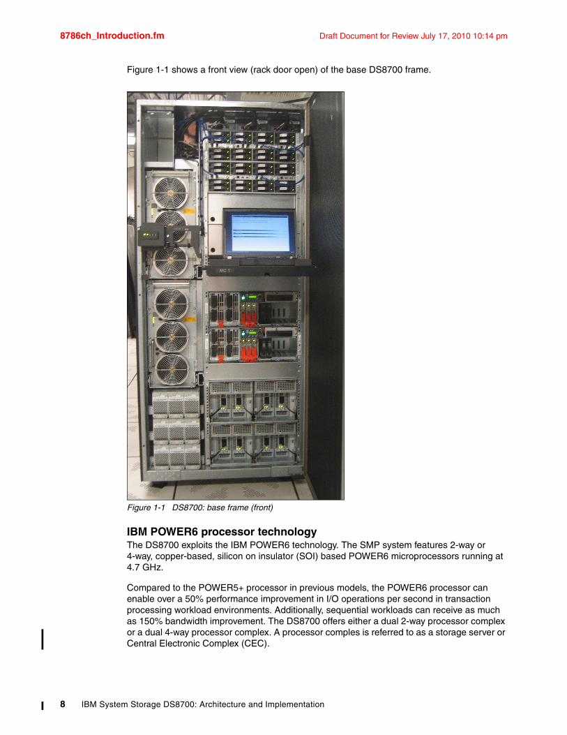
8786ch_Introduction.fm Draft Document for Review July 17, 2010 10:14 pm
Figure 1-1 shows a front view (rack door open) of the base DS8700 frame.
Figure 1-1 DS8700: base frame (front)
IBM POWER6 processor technologyThe DS8700 exploits the IBM POWER6 technology. The SMP system features 2-way or 4-way, copper-based, silicon on insulator (SOI) based POWER6 microprocessors running at 4.7 GHz.
Compared to the POWER5+ processor in previous models, the POWER6 processor can enable over a 50% performance improvement in I/O operations per second in transaction processing workload environments. Additionally, sequential workloads can receive as much as 150% bandwidth improvement. The DS8700 offers either a dual 2-way processor complex or a dual 4-way processor complex. A processor comples is referred to as a storage server or Central Electronic Complex (CEC).
8 IBM System Storage DS8700: Architecture and Implementation
Draft Document for Review July 17, 2010 10:14 pm 8786ch_Introduction.fm
Internal fabricDS8700 uses direct point-to-point high speed PCIe connections to the I/O enclosures to communicate with the device and host adapters. Each single PCIe connection operates at a speed of 2 GBps in each direction. There are up to 16 PCIe connections from the processor complexes to the I/O enclosures.
Switched Fibre Channel Arbitrated Loop (FC-AL)The DS8700 uses switched FC-AL for its disk interconnection. This offers a point-to-point connection to each drive and device adapter, so that there are four paths available from the controllers to each disk drive.
Fibre Channel disk drivesThe DS8700 offers a selection of industry standard Fibre Channel disk drives, including 300 GB (15K rpm), 450 GB (15K rpm) and 600 GB (15K rpm). The 600 GB 15K rpm Fibre Channel Disk Drive provides capacity, allowing a single system to scale up to 614 TB of Fibre Channel capacity. The DS8700 series also allows customers to install Full Disk Encryption drive sets.
Serial ATA drivesWith the 2 TB SATA drives, the DS8700 capacity scales up to 2 PB (1024 TB = 1 petabyte = 1 PB). The SATA drives offer a cost-effective option for lower priority data.
Solid State Drives With the Solid State Drives (SSD), which are available in 73 GB and 146 GB, the DS8700 offers opportunities for ultra high performance applications. The SSD drives are the best choice for I/O intensive workload. They provide up to 100 times the throughput and 10 times lower response time than 15K rpm spinning disks. Additionally, they also consume much less power.
For more information about SSDs, refer to DS8000: Introducing Solid State Drives, REDP-4522.
Host adaptersThe DS8000 series offers host connectivity with four-port Fibre Channel/FICON host adapters. The DS8700 currently supports 4 Gbps Fibre Channel/FICON host adapters.
The 4 Gbps Fibre Channel/FICON Host Adapters are offered in longwave and shortwave, and auto-negotiate to either 4 Gbps, 2 Gbps, or 1 Gbps link speeds. Each port on the adapter can be individually configured to operate with Fibre Channel Protocol (FCP) (also used for mirroring) or FICON.
A DS8700 with the dual 4-way feature can support up to a maximum of 32 host adapters, which provide up to 128 Fibre Channel/FICON ports. Note that ESCON® adapters are no longer supported.
Note: The 600 GB FC disk drives support is available is available on DS8700 with DS8000 Licensed Machine Code (LMC) level 6.5.1.xx (bundle version 75.1.xx.xx) or later.
Note: The 2 TB SATA disk drives support is available is available on DS8700 with DS8000 Licensed Machine Code (LMC) level 6.5.1.xx (bundle version 75.1.xx.xx) or later.
Chapter 1. Introduction to the IBM System Storage DS8700 9
8786ch_Introduction.fm Draft Document for Review July 17, 2010 10:14 pm
Storage Hardware Management Console for the DS8700The Hardware Management Console (HMC) is one of the focal points for configuration, Copy Services management, and maintenance activities. The management console is a dedicated workstation (laptop) that is physically located (installed) inside the DS8700 and can proactively monitor the state of your system, notifying you and IBM when service is required. It can also be connected to your network to enable centralized management of your system using the IBM System Storage DS Command-Line Interface or storage management software utilizing the IBM System Storage DS Open API.
The HMC supports the IPv4 and IPv6 standards. For further information about IPv4 and IPv6, refer to 8.3, “Network connectivity planning” on page 192.
Client and IBM services can also connect to the Hardware Management Console through a Web-base unit interface (WUI), which is connected to the client network. This connection brings improved response time for remote HMC operations. The connection uses a standard SSL based authentication with encryption capability and user ID and password protection.
An external management console is available as an optional feature and can be used as a redundant management console for environments with high availability requirements.
IBM System Storage Productivity Center management consoleThe DS8000 series leverages the IBM System Storage Productivity Center (SSPC), an advanced management console that can provide a view of both IBM and non-IBM storage environments. SSPC can enable a greater degree of simplification for organizations grappling with the growing number of element managers in their environment. The SSPC is an external System x server with pre-installed software, including IBM Tivoli Storage Productivity Center Basic Edition.
Utilizing IBM Tivoli Storage Productivity Center (TPC) Basic Edition software, SSPC extends the capabilities available through the IBM DS Storage Manager. SSPC offers the unique capability to manage a variety of storage devices connected across the storage area network (SAN). The rich, user-friendly graphical user interface provides a comprehensive view of the storage topology, from which the administrator can explore the health of the environment at an aggregate or in-depth view. Moreover, the TPC Basic Edition, which is pre-installed on the SSPC, can be optionally licensed and used to enable more in-depth performance reporting, asset and capacity reporting, and automation for the DS8000, as well as to manage other resources, such as server file systems, tape drives, and libraries.
Tivoli Key Lifecycle Manager (TKLM) isolated key serverThe Tivoli Key Lifecycle Manager software performs key management tasks for IBM encryption enabled hardware, such as the IBM System Storage DS8000 Series family and IBM encryption-enabled tape drives, by providing, protecting, storing, and maintaining encryption keys that are used to encrypt information being written to, and decrypt information being read from, encryption enabled disks.
For DS8700 storage subsystems shipped with Full Disk Encryption (FDE) drives, two TKLM key servers are required. An isolated key server (IKS) with dedicated hardware and non-encrypted storage resources is required and can be ordered from IBM.
1.2.2 Storage capacityThe physical capacity for the DS8700 is purchased through disk drive sets. A disk drive set contains sixteen identical disk drive modules (DDMs), which have the same capacity and the same revolutions per minute (rpm).
10 IBM System Storage DS8700: Architecture and Implementation
Draft Document for Review July 17, 2010 10:14 pm 8786ch_Introduction.fm
In addition, SSD drives can be now be ordered in 8 drive install groups (half disk drive set). This provides additional capacity and price/performance options to address specific application and business requirements. Like for HDD drives, it is of course still possible to order 16 drive install groups (a disk drive set) for SSDs as well.
For additional flexibility, feature conversions are available to exchange existing disk drive sets.
In the first frame, there is space for a maximum of 128 disk drive modules (DDMs) and each Expansion Frame can contain 256 DDMs. With a maximum of 1024 DDMs, the DS8700 model with the dual 4-way feature, using 600 GB drives, provides up to 614 TB of storage capacity with four Expansion Frames. When using 2 TB SATA drives, you can scale up your storage to 2048 TB or 2PB of raw capacity.
The DS8000 can be configured as RAID 5, RAID 6, RAID 10, or as a combination (some restrictions apply for Full Disk Encryption (FDE) and Solid State Drives).
IBM Standby Capacity on Demand offering for the DS8700Standby Capacity on Demand (Standby CoD) provides standby on demand storage for the DS8700 that allows you to access the extra storage capacity whenever the need arises. With CoD, IBM installs up to four disk drive sets (64 disk drives) in your DS8000. At any time, you can logically configure your CoD drives, concurrently with production, and you are automatically be charged for the capacity.
1.2.3 Supported environmentsThe DS8700 offers connectivity support across a broad range of server environments, including IBM System z, System p®, IBM i, and System x servers, as well as servers from Sun and Hewlett-Packard, and non-IBM Intel®-based servers.
The DS8700 supports over 90 platforms. For the most current list of supported platforms, refer to the DS8000 System Storage Interoperation Center at:
http://www.ibm.com/systems/support/storage/config/ssic/index.jsp
This rich support of heterogeneous environments and attachments, along with the flexibility to easily partition the DS8700 storage capacity among the attached environments, can help support storage consolidation requirements and dynamic, changing environments.
1.2.4 Copy Services functionsFor the IT environments that cannot afford to stop their systems for backups, the DS8700 provides a fast replication technique that can provide a point-in-time copy of the data in a few seconds or even less. This function is called FlashCopy.
For data protection and availability needs, the DS8700 provides Metro Mirror, Global Mirror, Global Copy, Metro/Global Mirror, and z/OS Global Mirror, which are Remote Mirror and Copy functions. These functions are also available and are fully interoperable with previous models of the DS8000 family and even the ESS 800 and 750 models. These functions provide storage mirroring and copying over large distances for disaster recovery or availability purposes.
We discuss Copy Services in Chapter 6, “DS8700 Copy Services Overview” on page 111.
Chapter 1. Introduction to the IBM System Storage DS8700 11
8786ch_Introduction.fm Draft Document for Review July 17, 2010 10:14 pm
FlashCopyThe primary objective of FlashCopy is to very quickly create a point-in-time copy of a source volume on a target volume. The benefits of FlashCopy are that the point-in-time target copy is immediately available for use for backups or testing and that the source volume is immediately released so that applications can continue processing with minimal application downtime. The target volume can be either a logical or physical copy of the data, with the latter copying the data as a background process. In a z/OS environment, FlashCopy can also operate at a data set level.
The following sections summarize the options available with FlashCopy.
Multiple Relationship FlashCopyMultiple Relationship FlashCopy allows a source to have FlashCopy relationships with up to 12 targets simultaneously.
Incremental FlashCopyIncremental FlashCopy provides the capability to refresh a LUN or volume involved in a FlashCopy relationship. When a subsequent FlashCopy is initiated, only the data required to bring the target current to the source's newly established point-in-time is copied.
FlashCopy to a remote mirror primaryFlashCopy to a remote mirror primary lets you establish a FlashCopy relationship where the target is a remote mirror (Metro Mirror of Global Copy) primary volume. While the background copy task is copying data from the source to the target, the remote mirror pair goes into a copy pending state.
Remote Pair FlashCopyRemote Pair FlashCopy provides improvement to resiliency solutions by assuring data synchronization when a FlashCopy target is also a Metro Mirror source. This keeps the local and remote site consistent which facilitates recovery, supports HyperSwap, and reduces link bandwidth utilization. Refer to IBM System Storage DS8000: Remote Pair FlashCopy (Preserve Mirror), REDP-4504 for more information.
Consistency GroupsConsistency Groups can be used to maintain a consistent point-in-time copy across multiple LUNs or volumes, or even multiple DS8000, ESS 800, and ESS 750 systems.
Inband commands over remote mirror linkIn a remote mirror environment, inband FlashCopy allows commands to be issued from the local or intermediate site and transmitted over the remote mirror Fibre Channel links for execution on the remote DS8000. This eliminates the need for a network connection to the remote site solely for the management of FlashCopy.
IBM FlashCopy SEThe IBM FlashCopy SE feature provides a “space efficient” copy capability that can greatly reduce the storage capacity needed for point-in-time copies. Only the capacity needed to save pre-change images of the source data is allocated in a copy repository. This enables more space efficient utilization than is possible with the standard FlashCopy function. Furthermore, less capacity can mean fewer disk drives and lower power and cooling requirements, which can help reduce costs and complexity. FlashCopy SE may be especially
Note: The Remote Pair FlashCopy support is available on DS8700 with DS8000 Licensed Machine Code (LMC) level 6.5.1.xx (bundle version 75.1.xx.xx) or later.
12 IBM System Storage DS8700: Architecture and Implementation
Draft Document for Review July 17, 2010 10:14 pm 8786ch_Introduction.fm
useful in the creation of temporary copies for tape backup, online application checkpoints, or copies for disaster recovery testing. For more information about FlashCopy SE, refer to IBM System Storage DS8000 Series: IBM FlashCopy SE, REDP-4368.
Remote Mirror and Copy functionsThe Remote Mirror and Copy functions include Metro Mirror, Global Copy, Global Mirror, and Metro/Global Mirror. There is also z/OS Global Mirror for the System z environments. As with FlashCopy, Remote Mirror and Copy functions can also be established between DS8000 systems and ESS 800/750 systems.
The following sections summarize f the Remote Mirror and Copy options available with the DS8000.
Metro MirrorMetro Mirror, previously called Peer-to-Peer Remote Copy (PPRC), provides a synchronous mirror copy of LUNs or volumes at a remote site within 300 km.
Global CopyGlobal Copy, previously called Extended Distance Peer-to-Peer Remote Copy (PPRC-XD), is a non-synchronous long distance copy option for data migration and backup.
Global MirrorGlobal Mirror provides an asynchronous mirror copy of LUNs or volumes over virtually unlimited distances. The distance is typically limited only by the capabilities of the network and channel extension technology being used.
Metro/Global MirrorMetro/Global Mirror is a three-site data replication solution for both Open Systems and the System z environments. Local site (site a) to intermediate site (site b) provides high availability replication using synchronous Metro Mirror, and intermediate site (site b) to remote site (site c) provides long distance disaster recovery replication using asynchronous Global Mirror.
z/OS Global Mirror z/OS Global Mirror, previously called Extended Remote Copy (XRC), provides an asynchronous mirror copy of volumes over virtually unlimited distances for the System z. It now provides increased parallelism through multiple SDM readers (Multiple Reader capability).
z/OS Metro/Global MirrorThis is a combination of Copy Services for System z environments that uses z/OS Global Mirror to mirror primary site data to a remote location that is at a long distance and also that uses Metro Mirror to mirror the primary site data to a location within the metropolitan area. This enables a z/OS three-site high availability and disaster recovery solution. Now z/OS Global Mirror offers Incremental Resync, which can significantly reduce the time needed to restore a DR environment after a HyperSwap in a three-site z/OS Metro/Global Mirror configuration, once it is possible to change the copy target destination of a copy relation without requiring a full copy of the data.
Note: LMC level 6.5.1.xx.xx enables the Multiple Global Mirror Sessions feature for the DS8700. This allows creation of separate global mirror sessions so that separate applications can fail-over to remote sites at different times. A SCORE/RPQ must be submitted for the full support of this feature.
Chapter 1. Introduction to the IBM System Storage DS8700 13
8786ch_Introduction.fm Draft Document for Review July 17, 2010 10:14 pm
1.2.5 DS8000 Thin ProvisioningIn addition to FlashCopy SE, the DS8700 now also offers the Thin Provisioning feature that allows for volume over-provisioning. With the DS8000 Thin Provisioning it is possible to create a space efficient volumes designed for standard host access. The possible benefits are a more efficient usage of the storage capacity and reduced storage management requirements, hence improving cost efficiency and reducing the Total Cost of Ownership (TCO). For detailed information about DS8000 Thin Provisioning, refer to DS8000 Thin Provisioning, REDP-4554.
1.2.6 Easy TierEasy Tier is a DS8700 built-in dynamic data relocation fearure that allows a host transparent movement of data among the storage subsystem resources. This improves significantly the configuration flexibility as well as the performance tuning and planning.
Easy Tier can operate in two modes:
� Easy Tier Automatic Mode
Easy Tier automatic mode is a facility that autonomically manages the capacity allocated in a DS8700 extent pool containing mixed disk technology (HDD + SSD) in order to place the most demanding pieces of data (hot data) on the appropriate storage media. The data relocation is at extent level. This improves significantly the overall storage cost-performance ratio and simplifies the performance tuning and management.
� Easy Tier Manual Mode
Easy Tier manual mode allows a set of manual initiated actions to relocate data among the storage subsystem resources in dynamic fashion, that is without any disruption of the host operations. The Easy Tier Manual Mode capabilities are the Dynamic Volume Relocation and the Dynamic Extent Pool Merge. Dynamic Volume Relocation allows a DS8700 volume to be migrated to the same or different extent pool. Dynamic Extent Pool Merge allows an extent pool to be merged to another extent pool. By combining these two capabilities we can improve greatly the configuration flexibility of the DS8700.
Easy Tier provides a performance monitoring capability whether or not the licensed feature is activated. The monitoring enables workload data collection that can be offloaded and further processed with the Storage Tiering Advisor Tool. Providing a graphical representation of hot data distribution at volume level, this powerful tool allows to analyze the workload characteristics and evaluate the benefits from a potential usage of the higher performance possible with the Solid State Drive technology.
Refer to DS8700 Easy Tier, REDP-4667 for more information.
Note: The DS8000 Thin Provisioning is a DS8700 firmware feature available with LIC level 6.5.1.xx or later.
Note: Easy Tier is a free (no charge) feature of the IBM System Storage DS87000. It is not supported on systems with the Full Disk Encryption (FDE) feature.
Note: Easy Tier is a DS8700 firmware function available with LMC level 6.5.1.xx or later. An additional no cost LIC feature must be order and installed.
14 IBM System Storage DS8700: Architecture and Implementation
Draft Document for Review July 17, 2010 10:14 pm 8786ch_Introduction.fm
1.2.7 Service and setupThe installation of the DS8700 is performed by IBM in accordance with the installation procedure for this machine. The client’s responsibility is the installation planning, retrieval and installation of feature activation codes, and logical configuration planning and execution.
For maintenance and service operations, the Storage Hardware Management Console (HMC) is the focal point. The management console is a dedicated workstation that is physically located (installed) inside the DS8700 storage subsystem and that can automatically monitor the state of your system, notifying you and IBM when service is required.
We recommend having a dual HMC configuration, particularly when using Full Disk Encryption.
The HMC is also the interface for remote services (Call Home and Call Back), which can be configured to meet client requirements. It is possible to allow one or more of the following:
� Call on error (machine-detected)� Connection for a few days (client-initiated)� Remote error investigation (service-initiated)
The remote connection between the management console and the IBM Service organization is done using a virtual private network (VPN) point-to-point connection over the internet or modem. A new secure SSL connection protocol option is now available for call home support and additional audit logging.
The DS8700 can be ordered with an outstanding four year warranty, an industry first, on both hardware and software.
1.2.8 Configuration flexibilityThe DS8000 series uses virtualization techniques to separate the logical view of hosts onto LUNs from the underlying physical layer, thus providing high configuration flexibility. Virtualization is discussed in Chapter 5, “Virtualization concepts” on page 85.
Dynamic LUN/volume creation, deletion, and expansionThe DS8000 gives a high degree of flexibility in managing storage, allowing LUNs to be created and deleted non-disruptively. Also, when a LUN is deleted, the freed capacity can be used with other free space to form a LUN of a different size. A LUN can also be dynamically increased in size.
Large LUN and large count key data (CKD) volume supportYou can configure LUNs and volumes to span arrays, allowing for larger LUN sizes up to 2 TB. The new maximum CKD volume size is 262,668 cylinders (about 223 GB), greatly reducing the number of volumes to be managed and creating a new volume type on z/OS called 3390 Model A. This new capability is referred to as Extended Address Volumes and requires z/OS 1.10 or later.
Flexible LUN to LSS associationWith no predefined association of arrays to LSSs on the DS8000 series, users are free to put LUNs or CKD volumes into LSSs and make best use of the 256 address range, overcoming previous ESS limitations, particularly for System z.
Chapter 1. Introduction to the IBM System Storage DS8700 15
8786ch_Introduction.fm Draft Document for Review July 17, 2010 10:14 pm
Simplified LUN maskingThe implementation of volume group-based LUN masking (as opposed to adapter-based masking, as on the ESS) simplifies storage management by grouping all or some WWPNs of a host into a Host Attachment. Associating the Host Attachment to a Volume Group allows all adapters within it access to all of the storage in the Volume Group.
Dynamic data relocationThe Easy Tier feature provides a set of capabilities that allow the user to dynamically relocate data among the disk hardware resources. LUNs can be migrated to the same or different extent pool using the Dynamic Volume Relocation capability. With the Dynamic Extent Pool Merge capability an extent pool can be merged to another extent pool. Combining these two capabilities can greatly improve the DS8700 configuration flexibility.
Thin provisioning featuresThe DS8700 provides two different types of space efficient volumes, the Track Space Efficient volumes and the Extent Space Efficient volumes. Both these features enable over-provisioning capabilities that provide the customers with benefits in terms of more efficient usage of the storage capacity and reduced storage management requirements.
Logical definitions: maximum valuesHere is a list of the current DS8000 maximum values for the major logical definitions:
� Up to 255 logical subsystems (LSS)
� Up to 65280 logical devices
� Up to 1280 paths per FC port
� Up to 2 TB LUNs
� Up to 262,668 cylinder CKD volumes, which is provided by a functionality called Extended Address Volumes
� Up to 8192 process logins (509 per SCSI-FCP port)
1.2.9 IBM Certified Secure Data OverwriteSometimes regulations and business prudence require that the data actually be removed when the media is no longer needed.
An STG Lab Services Offering for all the DS8000 series and the ESS models 800 and 750 includes the following services:
� Multi-pass overwrite of the data disks in the storage subsystem� Purging of client data from the server and HMC disks
To discover more about the IBM Certified Secure Data Overwrite service offerings, refer to Appendix A, “Tools and service offerings” on page 585 and contact your IBM sales representative or IBM Business Partner.
Note: The secure overwrite functionality is offered as a service exclusively and is not intended for use by clients, IBM Business Partners, or IBM field support personnel.
16 IBM System Storage DS8700: Architecture and Implementation
Draft Document for Review July 17, 2010 10:14 pm 8786ch_Introduction.fm
1.3 Performance featuresThe IBM System Storage DS8700 offers optimally balanced performance. This is possible because the DS8700 incorporates many performance enhancements, such as the dual 2-way and dual 4-way POWER6 processor complex implementation, faster device adapters, Fibre Channel disk drives, Solid State Drives, and the high bandwidth, fault-tolerant point-to-point PCIe internal interconnections.
With all these components, the DS8700 is positioned at the top of the high performance category.
1.3.1 Sophisticated caching algorithmsIBM Research conducts extensive investigations into improved algorithms for cache management and overall system performance improvements.
Sequential Prefetching in Adaptive Replacement Cache (SARC)One of the performance enhancers of the DS8700 is its self-learning cache algorithm, which improves cache efficiency and enhances cache hit ratios. This algorithm, which is used in the DS8000 series, is called Sequential Prefetching in Adaptive Replacement Cache (SARC).
SARC provides the following abilities:
� Sophisticated, patented algorithms to determine what data should be stored in cache based upon the recent access and frequency needs of the hosts
� Pre-fetching, which anticipates data prior to a host request and loads it into cache
� Self-learning algorithms to adaptively and dynamically learn what data should be stored in cache based upon the frequency needs of the hosts
Adaptive Multi-stream Prefetching (AMP) Adaptive Multi-stream Prefetching is a breakthrough caching technology that improves performance for common sequential and batch processing workloads on the DS8000. AMP optimizes cache efficiency by incorporating an autonomic, workload responsive, and self-optimizing prefetching technology.
Intelligent Write Caching (IWC)IWC improves performance through better write cache management and destaging order of writes. It can double the throughput for random write workload. Specifically, database workloads benefit from this new IWC Cache algorithm.
SARC, AMP, and IWC play complementary roles. While SARC is carefully dividing the cache between the RANDOM and the SEQ lists so as to maximize the overall hit ratio, AMP is managing the contents of the SEQ list to maximize the throughput obtained for the sequential workloads. IWC manages the write cache and decides what order and rate to destage to disk.
1.3.2 Solid State DrivesTo improve data transfer rate (IOPS) and response time, the DS8000 series provides support for Solid State Drives (SSD). Solid State Drives have improved I/O transaction-based performance over traditional platter-based drives. The DS8000 initially offers Solid State Drives in 73 GB and 146 GB capacities, with a nominal 150,000 rpm speed, reflecting the drives' enhanced seek time performance. Solid State Drives are a high-IOPS class enterprise storage device targeted at Tier 0, I/O intensive workload applications that can use high level of fast-access storage. Furthermore the usage of the Solid State Drives technology in
Chapter 1. Introduction to the IBM System Storage DS8700 17
8786ch_Introduction.fm Draft Document for Review July 17, 2010 10:14 pm
conjunction with the Easy Tier Automatic Mode facility provide significant advantages for performance tuning and storage configuration management as well as a remarkable improvement of the overall storage cost to performance ratio.
Solid State Drives offer a number of potential benefits over Hard Disk Drives, including better IOPS performance, lower power consumption, less heat generation, and lower acoustical noise.
The DS8700 can even take better advantage of Solid Disk Drives because of its faster device adapters compared to previous models of the DS8000 family.
1.3.3 Multipath Subsystem Device Driver (SDD)The Multipath Subsystem Device Driver (SDD) is a pseudo-device driver on the host system designed to support the multipath configuration environments in IBM products. It provides load balancing and enhanced data availability capability. By distributing the I/O workload over multiple active paths, SDD provides dynamic load balancing and eliminates data-flow bottlenecks. SDD also helps eliminate a potential single point of failure by automatically rerouting I/O operations when a path failure occurs.
SDD is provided with the DS8000 series at no additional charge. Fibre Channel (SCSI-FCP) attachment configurations are supported in the AIX, HP-UX, Linux®, Windows®, Novell NetWare, and Sun Solaris environments.
For more information about SDD, refer to 15.1.4, “Multipathing support: Subsystem Device Driver (SDD)” on page 400.
1.3.4 Performance for System zThe DS8000 series supports the following IBM performance enhancements for System z environments:
� Parallel Access Volumes (PAV) enable a single System z server to simultaneously process multiple I/O operations to the same logical volume, which can help to significantly reduce device queue delays. This is achieved by defining multiple addresses per volume. With Dynamic PAV, the assignment of addresses to volumes can be automatically managed to help the workload meet its performance objectives and reduce overall queuing. PAV is an optional feature on the DS8000 series.
� HyperPAV is designed to enable applications to achieve equal or better performance than with PAV alone, while also using fewer Unit Control Blocks (UCBs) and eliminating the latency in targeting an alias to a base. With HyperPAV, the system can react immediately to changing I/O workloads.
� Multiple Allegiance expands the simultaneous logical volume access capability across multiple System z servers. This function, along with PAV, enables the DS8000 series to process more I/Os in parallel, helping to improve performance and enabling greater use of large volumes.
� I/O priority queuing allows the DS8000 series to use I/O priority information provided by the z/OS Workload Manager to manage the processing sequence of I/O operations.
� High Performance FICON for z (zHPF) reduces the impact associated with supported commands on current adapter hardware, thereby improving FICON throughput on the
Note: Support for multipath is included in an IBM i server as part of Licensed Internal Code and the IBM i operating system (i5 / OS).
18 IBM System Storage DS8700: Architecture and Implementation
Draft Document for Review July 17, 2010 10:14 pm 8786ch_Introduction.fm
DS8000 I/O ports. The DS8700 also supports the new zHPF I/O commands for multi-track I/O operations. With LMC level 6.5.1.xx.xx the zHPF feature has been further enhanced implementing the zHPF Disable Transfer Ready protocol. This introduces the High Performance FICON Multi-track Extended Distance capability that provide higher throughput for longer distances.
Chapter 7, “Performance” on page 139 gives you more information about the performance aspects of the DS8000 family.
1.3.5 Performance enhancements for System pMany System p users canbenefit from the following DS8000 features:
� End-to-end I/O priorities� Cooperative caching� Long busy wait host tolerance� Automatic Port Queues
More information about these performance enhancements can be found in Chapter 7, “Performance” on page 139.
1.3.6 Performance enhancements for z/OS Global MirrorMany users of z/OS Global Mirror, which is the System z-based asynchronous disk mirroring capability, will benefit from the DS8000 enhancement “z/OS Global Mirror suspend instead of long busy option”. In the event of high workload peaks, which can temporarily overload the z/OS Global Mirror configuration bandwidth, this DS8000 can initiate a z/OS Global Mirror SUSPEND preserving primary site application performance, which is an improvement over the previous LONG BUSY status.
Consider the following points:
� All users of z/OS Global Mirror benefit from the DS8000’s “z/OS Global Mirror Multiple Reader” support. This recent enhancement spreads the z/OS Global Mirror workload across more than a single reader. In the event of high workload peaks restricted to a few volumes, which can mean restricted to a single reader, the peak demand can now be balanced across a set of up to 16 readers. This enhancement provides more efficient use of the site-to-site network capacity, a higher single volume throughput capability, and an environment that can effectively use Parallel Access Volumes.
� Extended Distance FICON is a recently introduced capability that can help reduce the need for channel extenders in z/OS Global Mirror configurations by increasing the numbers of read commands in flight.
Refer to DS8000 Copy Services for IBM System z, SG24-6787 for a detailed discussion of z/OS Global Mirror and related enhancements.
Chapter 1. Introduction to the IBM System Storage DS8700 19

8786ch_Introduction.fm Draft Document for Review July 17, 2010 10:14 pm
20 IBM System Storage DS8700: Architecture and Implementation
Draft Document for Review July 17, 2010 10:14 pm 8786ch_ModelOvw.fm
Chapter 2. DS8700 models
This chapter provides an overview of the IBM System Storage DS8700 storage subsystem, the different models, and how well they scale regarding capacity and performance.
2
© Copyright IBM Corp. 2010. All rights reserved. 21
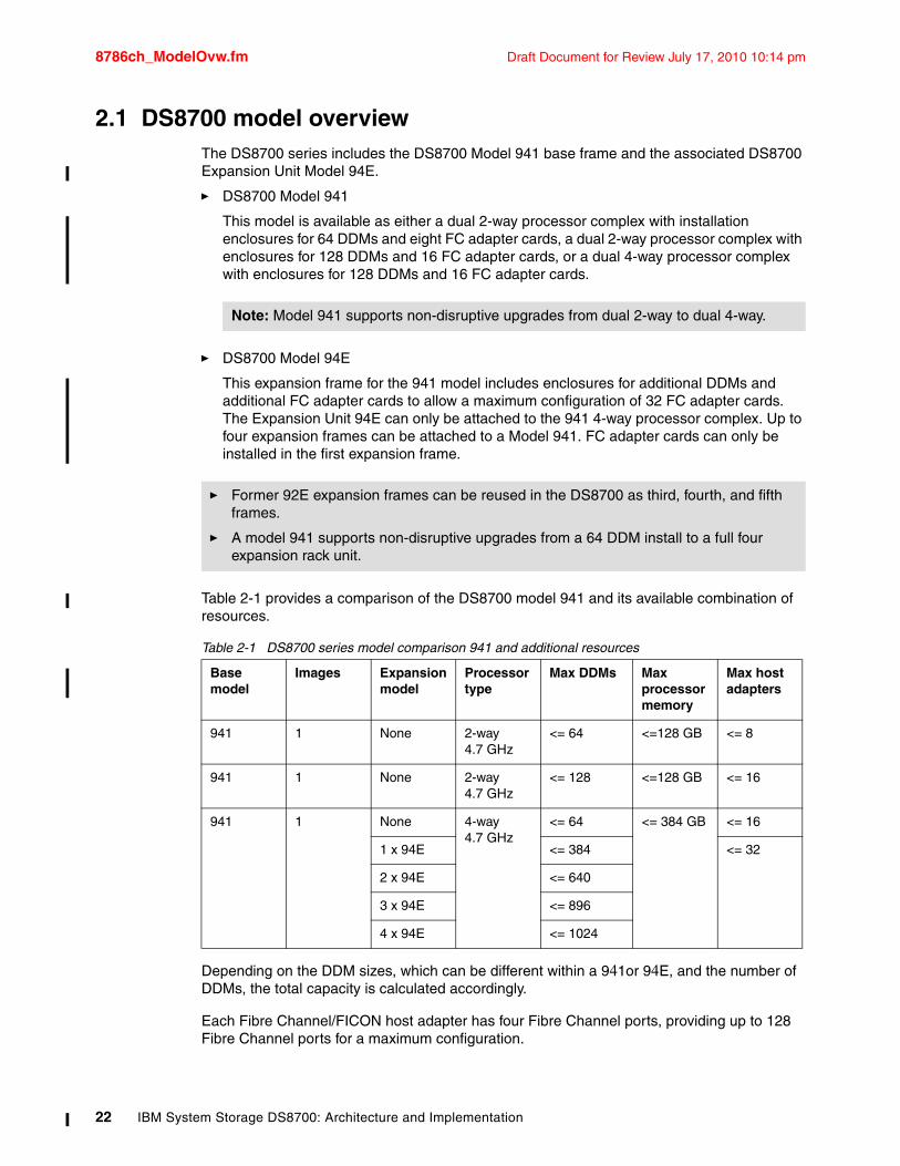
8786ch_ModelOvw.fm Draft Document for Review July 17, 2010 10:14 pm
2.1 DS8700 model overviewThe DS8700 series includes the DS8700 Model 941 base frame and the associated DS8700 Expansion Unit Model 94E.
� DS8700 Model 941
This model is available as either a dual 2-way processor complex with installation enclosures for 64 DDMs and eight FC adapter cards, a dual 2-way processor complex with enclosures for 128 DDMs and 16 FC adapter cards, or a dual 4-way processor complex with enclosures for 128 DDMs and 16 FC adapter cards.
� DS8700 Model 94E
This expansion frame for the 941 model includes enclosures for additional DDMs and additional FC adapter cards to allow a maximum configuration of 32 FC adapter cards. The Expansion Unit 94E can only be attached to the 941 4-way processor complex. Up to four expansion frames can be attached to a Model 941. FC adapter cards can only be installed in the first expansion frame.
Table 2-1 provides a comparison of the DS8700 model 941 and its available combination of resources.
Table 2-1 DS8700 series model comparison 941 and additional resources
Depending on the DDM sizes, which can be different within a 941or 94E, and the number of DDMs, the total capacity is calculated accordingly.
Each Fibre Channel/FICON host adapter has four Fibre Channel ports, providing up to 128 Fibre Channel ports for a maximum configuration.
Note: Model 941 supports non-disruptive upgrades from dual 2-way to dual 4-way.
� Former 92E expansion frames can be reused in the DS8700 as third, fourth, and fifth frames.
� A model 941 supports non-disruptive upgrades from a 64 DDM install to a full four expansion rack unit.
Basemodel
Images Expansionmodel
Processortype
Max DDMs Max processormemory
Max host adapters
941 1 None 2-way 4.7 GHz
<= 64 <=128 GB <= 8
941 1 None 2-way 4.7 GHz
<= 128 <=128 GB <= 16
941 1 None 4-way4.7 GHz
<= 64 <= 384 GB <= 16
1 x 94E <= 384 <= 32
2 x 94E <= 640
3 x 94E <= 896
4 x 94E <= 1024
22 IBM System Storage DS8700: Architecture and Implementation
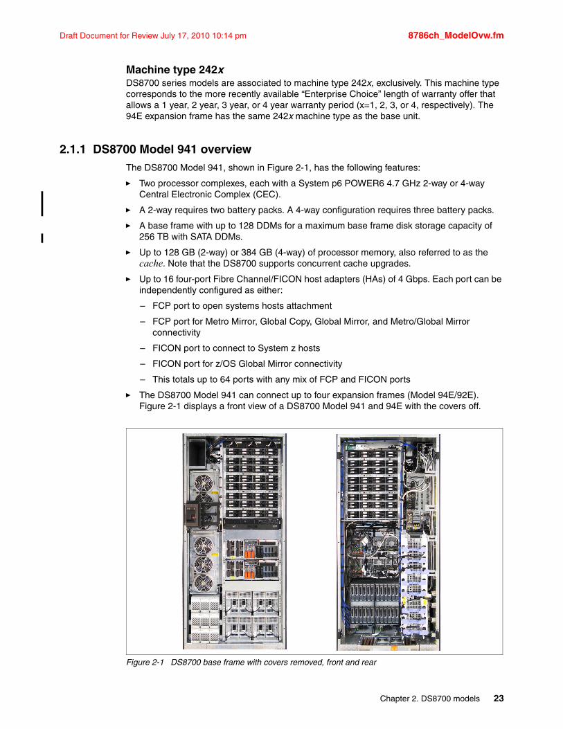
Draft Document for Review July 17, 2010 10:14 pm 8786ch_ModelOvw.fm
Machine type 242xDS8700 series models are associated to machine type 242x, exclusively. This machine type corresponds to the more recently available “Enterprise Choice” length of warranty offer that allows a 1 year, 2 year, 3 year, or 4 year warranty period (x=1, 2, 3, or 4, respectively). The 94E expansion frame has the same 242x machine type as the base unit.
2.1.1 DS8700 Model 941 overviewThe DS8700 Model 941, shown in Figure 2-1, has the following features:
� Two processor complexes, each with a System p6 POWER6 4.7 GHz 2-way or 4-way Central Electronic Complex (CEC).
� A 2-way requires two battery packs. A 4-way configuration requires three battery packs.
� A base frame with up to 128 DDMs for a maximum base frame disk storage capacity of 256 TB with SATA DDMs.
� Up to 128 GB (2-way) or 384 GB (4-way) of processor memory, also referred to as the cache. Note that the DS8700 supports concurrent cache upgrades.
� Up to 16 four-port Fibre Channel/FICON host adapters (HAs) of 4 Gbps. Each port can be independently configured as either:
– FCP port to open systems hosts attachment
– FCP port for Metro Mirror, Global Copy, Global Mirror, and Metro/Global Mirror connectivity
– FICON port to connect to System z hosts
– FICON port for z/OS Global Mirror connectivity
– This totals up to 64 ports with any mix of FCP and FICON ports
� The DS8700 Model 941 can connect up to four expansion frames (Model 94E/92E). Figure 2-1 displays a front view of a DS8700 Model 941 and 94E with the covers off.
Figure 2-1 DS8700 base frame with covers removed, front and rear
Chapter 2. DS8700 models 23
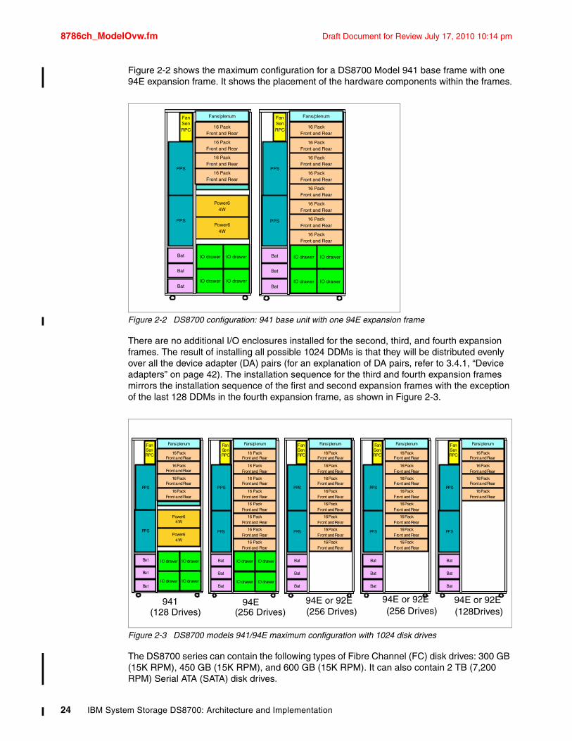
8786ch_ModelOvw.fm Draft Document for Review July 17, 2010 10:14 pm
Figure 2-2 shows the maximum configuration for a DS8700 Model 941 base frame with one 94E expansion frame. It shows the placement of the hardware components within the frames.
Figure 2-2 DS8700 configuration: 941 base unit with one 94E expansion frame
There are no additional I/O enclosures installed for the second, third, and fourth expansion frames. The result of installing all possible 1024 DDMs is that they will be distributed evenly over all the device adapter (DA) pairs (for an explanation of DA pairs, refer to 3.4.1, “Device adapters” on page 42). The installation sequence for the third and fourth expansion frames mirrors the installation sequence of the first and second expansion frames with the exception of the last 128 DDMs in the fourth expansion frame, as shown in Figure 2-3.
Figure 2-3 DS8700 models 941/94E maximum configuration with 1024 disk drives
The DS8700 series can contain the following types of Fibre Channel (FC) disk drives: 300 GB (15K RPM), 450 GB (15K RPM), and 600 GB (15K RPM). It can also contain 2 TB (7,200 RPM) Serial ATA (SATA) disk drives.
Bat
Bat
Bat
IO drawer
PPS
IO drawer
PPS
Fan SenRPC
Power6 4W
Power6 4W
Fans/plenum
IO drawer
IO drawer
16 PackFront and Rear
16 PackFront and Rear
16 PackFront and Rear
16 PackFront and Rear
16 PackFront and Rear
16 PackFront and Rear
16 PackFront and Rear
16 PackFront and Rear
16 PackFront and Rear
16 PackFront and Rear
16 PackFront and Rear
16 PackFront and Rear
Bat
Bat
Bat
IO drawer
PPS
IO drawer
PPS
Fan SenRPC
Fans/plenum
IO drawer
IO drawer
Bat
Bat
Bat
IO drawer
PPS
IO drawer
PPS
Fan SenRPC
Power6 4W
Power6 4W
Fans/plenum
IO drawer
IO drawer
16 PackFront and Rear
16 PackFront and Rear
16 PackFront and Rear
16 PackFront and Rear
16 PackFront and Rear
16 PackFront and Rear
16 PackFront and Rear
16 PackFront and Rear
16 PackFront and Rear
16 PackFront and Rear
16 PackFront and Rear
16 PackFront and Rear
Bat
Bat
Bat
IO drawer
PPS
IO drawer
PPS
Fan SenRPC
Fans/plenum
IO drawer
IO drawer
16 PackFront and Rear
16 PackFront and Rear
16 PackFront and Rear
16 PackFront and Rear
16 PackFront and Rear
16 PackFront and Rear
16 PackFront and Rear
16 PackFront and Rear
Bat
Bat
Bat
PPS
PPS
Fan SenRPC
Fans/plenum
16 PackFront and Rear
16 PackFront and Rear
16 PackFront and Rear
16 PackFront and Rear
Bat
Bat
Bat
PPS
PPS
Fan SenRPC
Fans/plenum
16 PackFront and Rear
16 PackFront and Rear
16 PackFront and Rear
16 PackFront and Rear
16 PackFront and Rear
16 PackFront and Rear
16 PackFront and Rear
16 PackFront and Rear
Bat
Bat
Bat
PPS
PPS
Fan SenRPC
Fans/plenum
941 94E 94E or 92E 94E or 92E 94E or 92E(128Drives)(128 Drives) (256 Drives) (256 Drives) (256 Drives)
24 IBM System Storage DS8700: Architecture and Implementation
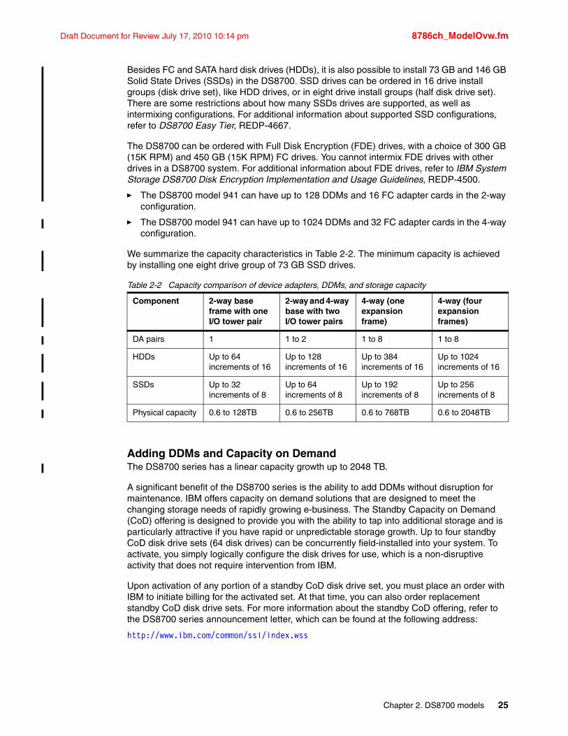
Draft Document for Review July 17, 2010 10:14 pm 8786ch_ModelOvw.fm
Besides FC and SATA hard disk drives (HDDs), it is also possible to install 73 GB and 146 GB Solid State Drives (SSDs) in the DS8700. SSD drives can be ordered in 16 drive install groups (disk drive set), like HDD drives, or in eight drive install groups (half disk drive set). There are some restrictions about how many SSDs drives are supported, as well as intermixing configurations. For additional information about supported SSD configurations, refer to DS8700 Easy Tier, REDP-4667.
The DS8700 can be ordered with Full Disk Encryption (FDE) drives, with a choice of 300 GB (15K RPM) and 450 GB (15K RPM) FC drives. You cannot intermix FDE drives with other drives in a DS8700 system. For additional information about FDE drives, refer to IBM System Storage DS8700 Disk Encryption Implementation and Usage Guidelines, REDP-4500.
� The DS8700 model 941 can have up to 128 DDMs and 16 FC adapter cards in the 2-way configuration.
� The DS8700 model 941 can have up to 1024 DDMs and 32 FC adapter cards in the 4-way configuration.
We summarize the capacity characteristics in Table 2-2. The minimum capacity is achieved by installing one eight drive group of 73 GB SSD drives.
Table 2-2 Capacity comparison of device adapters, DDMs, and storage capacity
Adding DDMs and Capacity on DemandThe DS8700 series has a linear capacity growth up to 2048 TB.
A significant benefit of the DS8700 series is the ability to add DDMs without disruption for maintenance. IBM offers capacity on demand solutions that are designed to meet the changing storage needs of rapidly growing e-business. The Standby Capacity on Demand (CoD) offering is designed to provide you with the ability to tap into additional storage and is particularly attractive if you have rapid or unpredictable storage growth. Up to four standby CoD disk drive sets (64 disk drives) can be concurrently field-installed into your system. To activate, you simply logically configure the disk drives for use, which is a non-disruptive activity that does not require intervention from IBM.
Upon activation of any portion of a standby CoD disk drive set, you must place an order with IBM to initiate billing for the activated set. At that time, you can also order replacement standby CoD disk drive sets. For more information about the standby CoD offering, refer to the DS8700 series announcement letter, which can be found at the following address:
http://www.ibm.com/common/ssi/index.wss
Component 2-way base frame with one I/O tower pair
2-way and 4-way base with two I/O tower pairs
4-way (one expansion frame)
4-way (four expansion frames)
DA pairs 1 1 to 2 1 to 8 1 to 8
HDDs Up to 64increments of 16
Up to 128increments of 16
Up to 384increments of 16
Up to 1024increments of 16
SSDs Up to 32increments of 8
Up to 64increments of 8
Up to 192increments of 8
Up to 256increments of 8
Physical capacity 0.6 to 128TB 0.6 to 256TB 0.6 to 768TB 0.6 to 2048TB
Chapter 2. DS8700 models 25
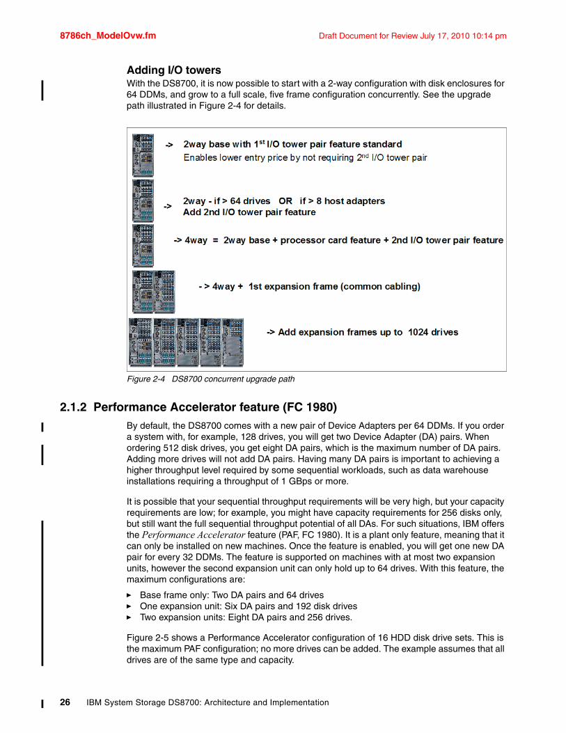
8786ch_ModelOvw.fm Draft Document for Review July 17, 2010 10:14 pm
Adding I/O towersWith the DS8700, it is now possible to start with a 2-way configuration with disk enclosures for 64 DDMs, and grow to a full scale, five frame configuration concurrently. See the upgrade path illustrated in Figure 2-4 for details.
Figure 2-4 DS8700 concurrent upgrade path
2.1.2 Performance Accelerator feature (FC 1980)By default, the DS8700 comes with a new pair of Device Adapters per 64 DDMs. If you order a system with, for example, 128 drives, you will get two Device Adapter (DA) pairs. When ordering 512 disk drives, you get eight DA pairs, which is the maximum number of DA pairs. Adding more drives will not add DA pairs. Having many DA pairs is important to achieving a higher throughput level required by some sequential workloads, such as data warehouse installations requiring a throughput of 1 GBps or more.
It is possible that your sequential throughput requirements will be very high, but your capacity requirements are low; for example, you might have capacity requirements for 256 disks only, but still want the full sequential throughput potential of all DAs. For such situations, IBM offers the Performance Accelerator feature (PAF, FC 1980). It is a plant only feature, meaning that it can only be installed on new machines. Once the feature is enabled, you will get one new DA pair for every 32 DDMs. The feature is supported on machines with at most two expansion units, however the second expansion unit can only hold up to 64 drives. With this feature, the maximum configurations are:
� Base frame only: Two DA pairs and 64 drives� One expansion unit: Six DA pairs and 192 disk drives� Two expansion units: Eight DA pairs and 256 drives.
Figure 2-5 shows a Performance Accelerator configuration of 16 HDD disk drive sets. This is the maximum PAF configuration; no more drives can be added. The example assumes that all drives are of the same type and capacity.
26 IBM System Storage DS8700: Architecture and Implementation
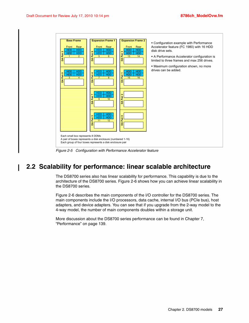
Draft Document for Review July 17, 2010 10:14 pm 8786ch_ModelOvw.fm
Figure 2-5 Configuration with Performance Accelerator feature
2.2 Scalability for performance: linear scalable architectureThe DS8700 series also has linear scalability for performance. This capability is due to the architecture of the DS8700 series. Figure 2-6 shows how you can achieve linear scalability in the DS8700 series.
Figure 2-6 describes the main components of the I/O controller for the DS8700 series. The main components include the I/O processors, data cache, internal I/O bus (PCIe bus), host adapters, and device adapters. You can see that if you upgrade from the 2-way model to the 4-way model, the number of main components doubles within a storage unit.
More discussion about the DS8700 series performance can be found in Chapter 7, “Performance” on page 139.
Configuration example with Performance Accelerator feature (FC 1980) with 16 HDD disk drive sets.
A Performance Accelerator configuration is limited to three frames and max 256 drives.
Maximum configuration shown, no more drives can be added.
Front Rear Front Rear Front RearHDD HDD HDD HDD HDD HDDHDD HDD HDD HDD HDD HDD
1 2 5 6 13 14
HDD HDD HDD HDD HDD HDDHDD HDD HDD HDD HDD HDD
3 4 7 8 15 16
HDD HDDHDD HDD
9 10
HDD HDDHDD HDD
11 12
Each small box represents 8 DDMsA pair of boxes represents a disk enclosure (numbered 1-16)Each group of four boxes represents a disk enclosure pair
DA
Pai
r 0
Expansion Frame 1
DA
Pa
ir 6
DA
Pai
r 4
DA
Pai
r 7
Expansion Frame 2
DA
Pa
ir 3
DA
Pai
r 1
DA
Pai
r 2
DA
Pa
ir 2
DA
Pai
r 0
Base Frame
DA
Pai
r 5
Chapter 2. DS8700 models 27
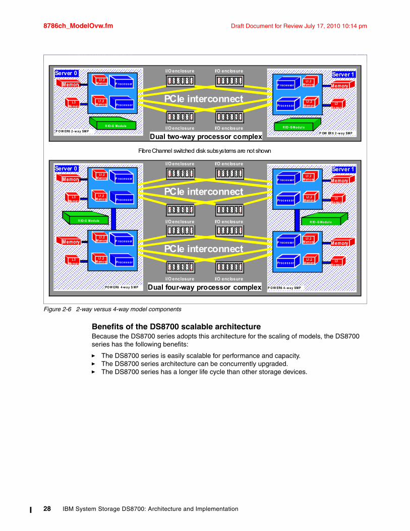
8786ch_ModelOvw.fm Draft Document for Review July 17, 2010 10:14 pm
Figure 2-6 2-way versus 4-way model components
Benefits of the DS8700 scalable architectureBecause the DS8700 series adopts this architecture for the scaling of models, the DS8700 series has the following benefits:
� The DS8700 series is easily scalable for performance and capacity.� The DS8700 series architecture can be concurrently upgraded.� The DS8700 series has a longer life cycle than other storage devices.
IBM TotalStorage™
© 2008 IBMC ti1 DS8k R5 D i | IBM C fid ti l | 10/16/2009
PCIe interconnect
I/O enclosure
I/O enclosure
I/O enclosure
I/O enclosure
Dual two-way processor complex
Dual four-way processor complex
Fibre Channel switched disk subsystems are not shown
PCIe interconnect
I/O enclosure
I/O enclosure
I/O enclosure
I/O enclosure
PCIe interconnect
I/O enclosureI/O enclosure
PO W ER6 4 -w a y S MP
R IO -G Module
Memory
L3 Me mory
P roc e s s or
Proc e s s or
L1 ,2 Memory
L1 ,2 Memory
L3 Me mory
P roc e s s or
Proc e s s or
L1 ,2 Memory
L1 ,2 Memory
Server 0
Memory
P O W ER6 4 - w a y SMP
R IO -G Modul e
Memory
L3 Me mory
P roc e s sor
Proc e s s or
L1 ,2 Memory
L1 ,2 Memory
Memory
L3 Me mory
P roc e s sor
Proc e s s or
L1 ,2 Memory
L1 ,2 Memory
Server 1
R IO - G Modul e
P OW ER 6 2 -w a y SMP
Memory
L3 Me mory
P roc e s sor
Proc e s s or
L1 ,2 Memory
L1 ,2 Memory
Server 1
R IO -G Module
P O W ER6 2 -w a y SMP
Memory
L3 Me mory
P roc e s s or
Proc e s s or
L1 ,2 Memory
L1 ,2 Memory
Server 0
28 IBM System Storage DS8700: Architecture and Implementation
Draft Document for Review July 17, 2010 10:14 pm 8786ch_components.fm
Chapter 3. Hardware components and architecture
This chapter describes the hardware components of the IBM System Storage DS8700. This chapter is intended for readers who want to get more insight into the individual components and the architecture that holds them together.
The following topics are covered in this chapter:
� Frames
� DS8700 architecture
� Storage facility processor complex (CEC)
� Disk subsystem
� Host adapters
� Power and cooling
� Management console network
� System Storage Productivity Center (SSPC)
� Isolated Tivoli Key Lifecycle Manager (TKLM) server
3
© Copyright IBM Corp. 2010. All rights reserved. 29
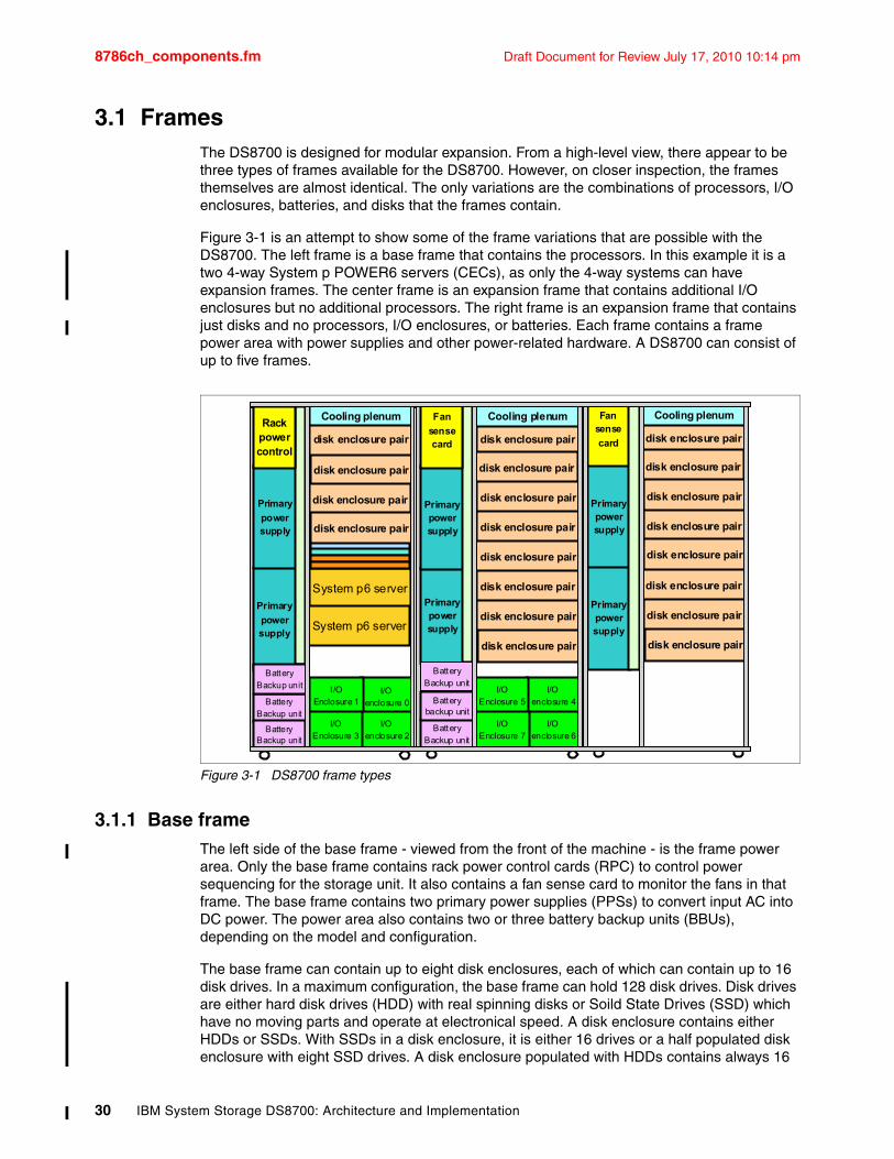
8786ch_components.fm Draft Document for Review July 17, 2010 10:14 pm
3.1 FramesThe DS8700 is designed for modular expansion. From a high-level view, there appear to be three types of frames available for the DS8700. However, on closer inspection, the frames themselves are almost identical. The only variations are the combinations of processors, I/O enclosures, batteries, and disks that the frames contain.
Figure 3-1 is an attempt to show some of the frame variations that are possible with the DS8700. The left frame is a base frame that contains the processors. In this example it is a two 4-way System p POWER6 servers (CECs), as only the 4-way systems can have expansion frames. The center frame is an expansion frame that contains additional I/O enclosures but no additional processors. The right frame is an expansion frame that contains just disks and no processors, I/O enclosures, or batteries. Each frame contains a frame power area with power supplies and other power-related hardware. A DS8700 can consist of up to five frames.
Figure 3-1 DS8700 frame types
3.1.1 Base frameThe left side of the base frame - viewed from the front of the machine - is the frame power area. Only the base frame contains rack power control cards (RPC) to control power sequencing for the storage unit. It also contains a fan sense card to monitor the fans in that frame. The base frame contains two primary power supplies (PPSs) to convert input AC into DC power. The power area also contains two or three battery backup units (BBUs), depending on the model and configuration.
The base frame can contain up to eight disk enclosures, each of which can contain up to 16 disk drives. In a maximum configuration, the base frame can hold 128 disk drives. Disk drives are either hard disk drives (HDD) with real spinning disks or Soild State Drives (SSD) which have no moving parts and operate at electronical speed. A disk enclosure contains either HDDs or SSDs. With SSDs in a disk enclosure, it is either 16 drives or a half populated disk enclosure with eight SSD drives. A disk enclosure populated with HDDs contains always 16
Primarypowersupply
Primarypowersupply
Fan sense
card
disk enclosure pair
disk enclosure pair
BatteryBackup unit
Primary
powersupply
BatteryBackup unit
I/Oenclosure 0
I/O Enclosure 1
I/Oenclosure 2
I/OEnclosure 3
disk enclosure pair
disk enclosure pair
Primary
powersupply
Rackpowercontrol
System p6 server
System p6 server
Cooling plenum
disk enclosure pair
disk enclosure pair
disk enclosure pair
disk enclosure pair
disk enclosure pair
disk enclosure pair
disk enclosure pair
disk enclosure pair
BatteryBackup unit
Battery backup unit
Primarypowersupply
Primarypowersupply
Cooling plenumFan
sensecard
I/Oenclosure 4
I/OEnclosure 5
I/Oenclosure 6
I/OEnclosure 7
disk enclosure pair
disk enclosure pair
disk enclosure pair
disk enclosure pair
disk enclosure pair
disk enclosure pair
disk enclosure pair
disk enclosure pair
Cooling plenum
BatteryBackup unit
Battery Backup unit
30 IBM System Storage DS8700: Architecture and Implementation
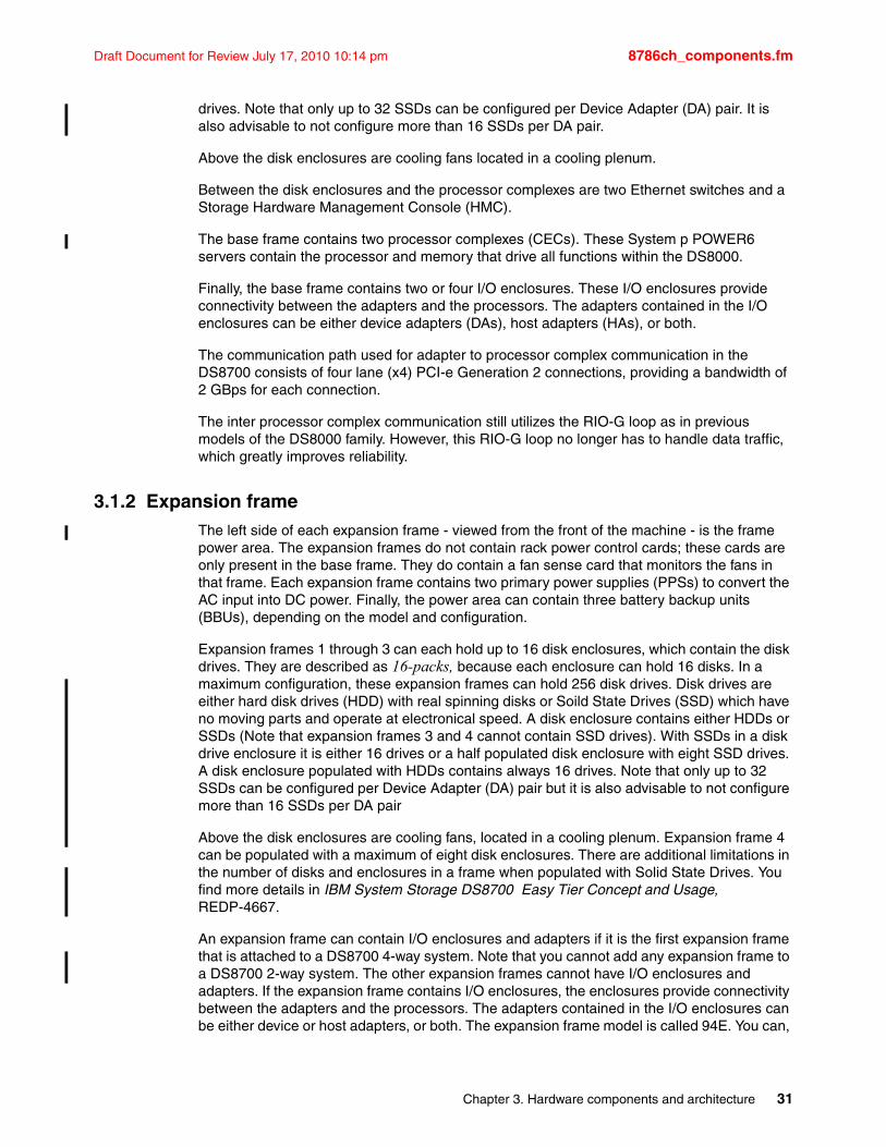
Draft Document for Review July 17, 2010 10:14 pm 8786ch_components.fm
drives. Note that only up to 32 SSDs can be configured per Device Adapter (DA) pair. It is also advisable to not configure more than 16 SSDs per DA pair.
Above the disk enclosures are cooling fans located in a cooling plenum.
Between the disk enclosures and the processor complexes are two Ethernet switches and a Storage Hardware Management Console (HMC).
The base frame contains two processor complexes (CECs). These System p POWER6 servers contain the processor and memory that drive all functions within the DS8000.
Finally, the base frame contains two or four I/O enclosures. These I/O enclosures provide connectivity between the adapters and the processors. The adapters contained in the I/O enclosures can be either device adapters (DAs), host adapters (HAs), or both.
The communication path used for adapter to processor complex communication in the DS8700 consists of four lane (x4) PCI-e Generation 2 connections, providing a bandwidth of 2 GBps for each connection.
The inter processor complex communication still utilizes the RIO-G loop as in previous models of the DS8000 family. However, this RIO-G loop no longer has to handle data traffic, which greatly improves reliability.
3.1.2 Expansion frame The left side of each expansion frame - viewed from the front of the machine - is the frame power area. The expansion frames do not contain rack power control cards; these cards are only present in the base frame. They do contain a fan sense card that monitors the fans in that frame. Each expansion frame contains two primary power supplies (PPSs) to convert the AC input into DC power. Finally, the power area can contain three battery backup units (BBUs), depending on the model and configuration.
Expansion frames 1 through 3 can each hold up to 16 disk enclosures, which contain the disk drives. They are described as 16-packs, because each enclosure can hold 16 disks. In a maximum configuration, these expansion frames can hold 256 disk drives. Disk drives are either hard disk drives (HDD) with real spinning disks or Soild State Drives (SSD) which have no moving parts and operate at electronical speed. A disk enclosure contains either HDDs or SSDs (Note that expansion frames 3 and 4 cannot contain SSD drives). With SSDs in a disk drive enclosure it is either 16 drives or a half populated disk enclosure with eight SSD drives. A disk enclosure populated with HDDs contains always 16 drives. Note that only up to 32 SSDs can be configured per Device Adapter (DA) pair but it is also advisable to not configure more than 16 SSDs per DA pair
Above the disk enclosures are cooling fans, located in a cooling plenum. Expansion frame 4 can be populated with a maximum of eight disk enclosures. There are additional limitations in the number of disks and enclosures in a frame when populated with Solid State Drives. You find more details in IBM System Storage DS8700 Easy Tier Concept and Usage, REDP-4667.
An expansion frame can contain I/O enclosures and adapters if it is the first expansion frame that is attached to a DS8700 4-way system. Note that you cannot add any expansion frame to a DS8700 2-way system. The other expansion frames cannot have I/O enclosures and adapters. If the expansion frame contains I/O enclosures, the enclosures provide connectivity between the adapters and the processors. The adapters contained in the I/O enclosures can be either device or host adapters, or both. The expansion frame model is called 94E. You can,
Chapter 3. Hardware components and architecture 31
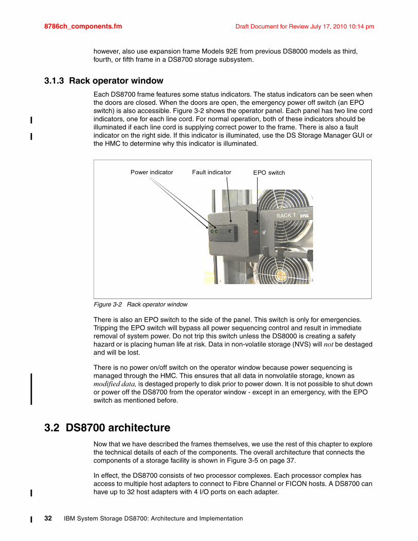
8786ch_components.fm Draft Document for Review July 17, 2010 10:14 pm
however, also use expansion frame Models 92E from previous DS8000 models as third, fourth, or fifth frame in a DS8700 storage subsystem.
3.1.3 Rack operator windowEach DS8700 frame features some status indicators. The status indicators can be seen when the doors are closed. When the doors are open, the emergency power off switch (an EPO switch) is also accessible. Figure 3-2 shows the operator panel. Each panel has two line cord indicators, one for each line cord. For normal operation, both of these indicators should be illuminated if each line cord is supplying correct power to the frame. There is also a fault indicator on the right side. If this indicator is illuminated, use the DS Storage Manager GUI or the HMC to determine why this indicator is illuminated.
Figure 3-2 Rack operator window
There is also an EPO switch to the side of the panel. This switch is only for emergencies. Tripping the EPO switch will bypass all power sequencing control and result in immediate removal of system power. Do not trip this switch unless the DS8000 is creating a safety hazard or is placing human life at risk. Data in non-volatile storage (NVS) will not be destaged and will be lost.
There is no power on/off switch on the operator window because power sequencing is managed through the HMC. This ensures that all data in nonvolatile storage, known as modified data, is destaged properly to disk prior to power down. It is not possible to shut down or power off the DS8700 from the operator window - except in an emergency, with the EPO switch as mentioned before.
3.2 DS8700 architectureNow that we have described the frames themselves, we use the rest of this chapter to explore the technical details of each of the components. The overall architecture that connects the components of a storage facility is shown in Figure 3-5 on page 37.
In effect, the DS8700 consists of two processor complexes. Each processor complex has access to multiple host adapters to connect to Fibre Channel or FICON hosts. A DS8700 can have up to 32 host adapters with 4 I/O ports on each adapter.
Power indicator Fault indicator EPO switch
32 IBM System Storage DS8700: Architecture and Implementation
Draft Document for Review July 17, 2010 10:14 pm 8786ch_components.fm
Fibre Channel adapters are also used to connect to internal fabrics, which are Fibre Channel switches to which the disk drives are connected.
3.2.1 POWER6 processorThe DS8700 is based on POWER6 p570 server technology. The 64-bit POWER6 processors in the p570 server are integrated into a dual-core single chip module and a dual-core dual chip module, with 32 MB of L3 cache, 8 MB of L2 cache, and 12 DDR2 memory DIMM slots. The unique DDR2 memory uses a new memory architecture to provide greater bandwidth and capacity. This enables operating at a higher data rate for large memory configurations. Each new processor card can support up to 12 DDR2 DIMMs running at speeds of up to 667 MHz.
The Symmetric Multi-Processing (SMP) system features 2-way or 4-way, copper-based, Silicon-on Insulator-based (SOI-based) POWER6 microprocessors running at 4.7 GHz.
Each POWER6 processor provides a GX+ bus that is used to connect to an I/O subsystem or fabric interface card. GX+ is a Host Channel Adapter used in POWER6 systems. For more information, refer to IBM System p 570 Technical Overview and Introduction, REDP-4405.
Refer also to Chapter 4, “Reliability, Availability, and Serviceability (RAS) of IBM System Storage DS8700” on page 55 and 7.1.4, “IBM System p POWER6: heart of the DS8700 dual cluster design” on page 144 for additional information about the POWER6 processor.
3.2.2 Peripheral Component Interconnect Express (PCIe)The DS8700 processor complex utilizes a PCIe infrastructure to access the I/O subsystem, which provides a great improvement in performance.
PCI-Express (PCIe) was designed to replace the general-purpose PCI expansion bus, the high-end PCI-X bus, and the Accelerated Graphics Port (AGP) graphics card interface.
PCIe is a serial I/O interconnect. Transfers are bi-directional, which means data can flow to and from a device simultaneously. The PCIe infrastructure involves a switch so that more than one device can transfer data at the same time.
Chapter 3. Hardware components and architecture 33
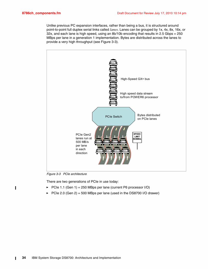
8786ch_components.fm Draft Document for Review July 17, 2010 10:14 pm
Unlike previous PC expansion interfaces, rather than being a bus, it is structured around point-to-point full duplex serial links called lanes. Lanes can be grouped by 1x, 4x, 8x, 16x, or 32x, and each lane is high speed, using an 8b/10b encoding that results in 2.5 Gbps = 250 MBps per lane in a generation 1 implementation. Bytes are distributed across the lanes to provide a very high throughput (see Figure 3-3).
Figure 3-3 PCIe architecture
There are two generations of PCIe in use today:
� PCIe 1.1 (Gen 1) = 250 MBps per lane (current P6 processor I/O)
� PCIe 2.0 (Gen 2) = 500 MBps per lane (used in the DS8700 I/O drawer)
B yte 7
B yte 6
B yte 5
B yte 4
B yte 3
B yte 2
B yte 1
B yte 0
High-Speed GX+ bus
PCIe Switch
Byte 7Byte 6Byte 5Byte 4
Byte 3B yte 2Byte 1B yte 0
SPEEDLIMIT
500MB/s
PCIe Gen2lanes run at500 MB/sper lanein eachdirection
High speed data streamto/from POWER6 processor
Bytes distributedon PCIe lanes
34 IBM System Storage DS8700: Architecture and Implementation
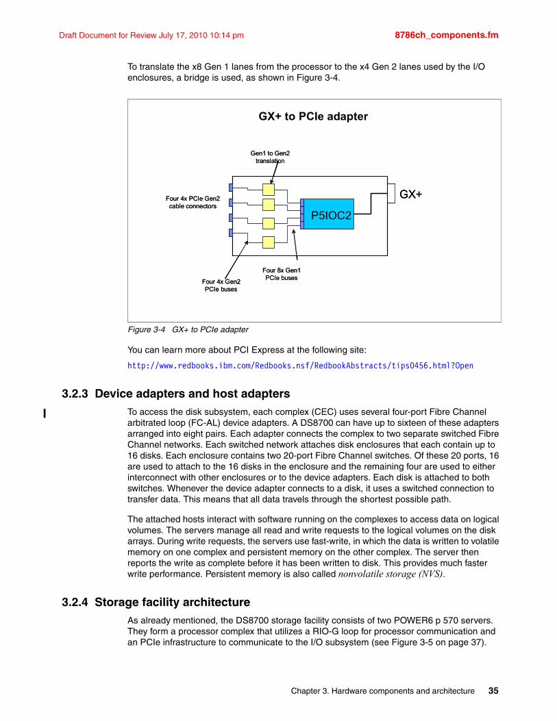
Draft Document for Review July 17, 2010 10:14 pm 8786ch_components.fm
To translate the x8 Gen 1 lanes from the processor to the x4 Gen 2 lanes used by the I/O enclosures, a bridge is used, as shown in Figure 3-4.
Figure 3-4 GX+ to PCIe adapter
You can learn more about PCI Express at the following site:
http://www.redbooks.ibm.com/Redbooks.nsf/RedbookAbstracts/tips0456.html?Open
3.2.3 Device adapters and host adaptersTo access the disk subsystem, each complex (CEC) uses several four-port Fibre Channel arbitrated loop (FC-AL) device adapters. A DS8700 can have up to sixteen of these adapters arranged into eight pairs. Each adapter connects the complex to two separate switched Fibre Channel networks. Each switched network attaches disk enclosures that each contain up to 16 disks. Each enclosure contains two 20-port Fibre Channel switches. Of these 20 ports, 16 are used to attach to the 16 disks in the enclosure and the remaining four are used to either interconnect with other enclosures or to the device adapters. Each disk is attached to both switches. Whenever the device adapter connects to a disk, it uses a switched connection to transfer data. This means that all data travels through the shortest possible path.
The attached hosts interact with software running on the complexes to access data on logical volumes. The servers manage all read and write requests to the logical volumes on the disk arrays. During write requests, the servers use fast-write, in which the data is written to volatile memory on one complex and persistent memory on the other complex. The server then reports the write as complete before it has been written to disk. This provides much faster write performance. Persistent memory is also called nonvolatile storage (NVS).
3.2.4 Storage facility architectureAs already mentioned, the DS8700 storage facility consists of two POWER6 p 570 servers. They form a processor complex that utilizes a RIO-G loop for processor communication and an PCIe infrastructure to communicate to the I/O subsystem (see Figure 3-5 on page 37).
GX+ to PCIe adapter
P5IOC2
Four 4x PCIe Gen2 cable connectors
Gen1 to Gen2 translation
Four 8x Gen1 PCIe buses
GX+
Four 4x Gen2 PCIe buses
P5IOC2
Four 4x PCIe Gen2 cable connectors
Gen1 to Gen2 translation
Four 8x Gen1 PCIe buses
GX+
Four 4x Gen2 PCIe buses
Chapter 3. Hardware components and architecture 35
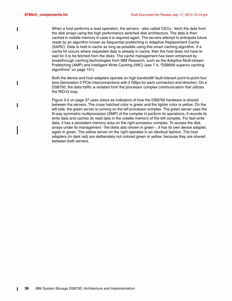
8786ch_components.fm Draft Document for Review July 17, 2010 10:14 pm
When a host performs a read operation, the servers - also called CECs - fetch the data from the disk arrays using the high performance switched disk architecture. The data is then cached in volatile memory in case it is required again. The servers attempt to anticipate future reads by an algorithm known as Sequential prefetching in Adaptive Replacement Cache (SARC). Data is held in cache as long as possible using this smart caching algorithm. If a cache hit occurs where requested data is already in cache, then the host does not have to wait for it to be fetched from the disks. The cache management has been enhanced by breakthrough caching technologies from IBM Research, such as the Adaptive Multi-stream Prefetching (AMP) and Intelligent Write Caching (IWC) (see 7.4, “DS8000 superior caching algorithms” on page 151).
Both the device and host adapters operate on high bandwidth fault-tolerant point-to-point four lane Generation 2 PCIe interconnections with 2 GBps for each connection and direction. On a DS8700, the data traffic is isolated from the processor complex communication that utilizes the RIO-G loop.
Figure 3-5 on page 37 uses colors as indicators of how the DS8700 hardware is shared between the servers. The cross hatched color is green and the lighter color is yellow. On the left side, the green server is running on the left processor complex. The green server uses the N-way symmetric multiprocessor (SMP) of the complex to perform its operations. It records its write data and caches its read data in the volatile memory of the left complex. For fast-write data, it has a persistent memory area on the right processor complex. To access the disk arrays under its management - the disks also shown in green -, it has its own device adapter, again in green. The yellow server on the right operates in an identical fashion. The host adapters (in dark red) are deliberately not colored green or yellow, because they are shared between both servers.
36 IBM System Storage DS8700: Architecture and Implementation
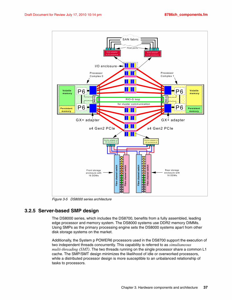
Draft Document for Review July 17, 2010 10:14 pm 8786ch_components.fm
Figure 3-5 DS8000 series architecture
3.2.5 Server-based SMP designThe DS8000 series, which includes the DS8700, benefits from a fully assembled, leading edge processor and memory system. The DS8000 systems use DDR2 memory DIMMs. Using SMPs as the primary processing engine sets the DS8000 systems apart from other disk storage systems on the market.
Additionally, the System p POWER6 processors used in the DS8700 support the execution of two independent threads concurrently. This capability is referred to as simultaneous multi-threading (SMT). The two threads running on the single processor share a common L1 cache. The SMP/SMT design minimizes the likelihood of idle or overworked processors, while a distributed processor design is more susceptible to an unbalanced relationship of tasks to processors.
ProcessorComplex 0
Processor Com plex 1
RIO
-G
RIO-G loop
SAN fabric
Host adapterin I/O enclosure
Host adapterin I/O enclosure
Host ports
Fib
re c
han
nel
sw
itch
Front storageenclosure with
16 DDMs
Rear storageenclosure with
16 DDMs
Fib
re c
han
nel
sw
itch
Fib
re c
han
nel
sw
itch
Fib
re c
han
nel
sw
itch
Device adapter inDevice adapter in I/O enclosure A I/O enclosure B
Volatilem emory
Persistentm emory
P6
P6
RIO
-G
Volatilem em ory
Persistentmem ory
P6
P6 for cluster comm unication
x4 Gen2 PCIe x4 Gen2 PCIe
I/O enclosure
GX+ adapter GX+ adapter
Chapter 3. Hardware components and architecture 37
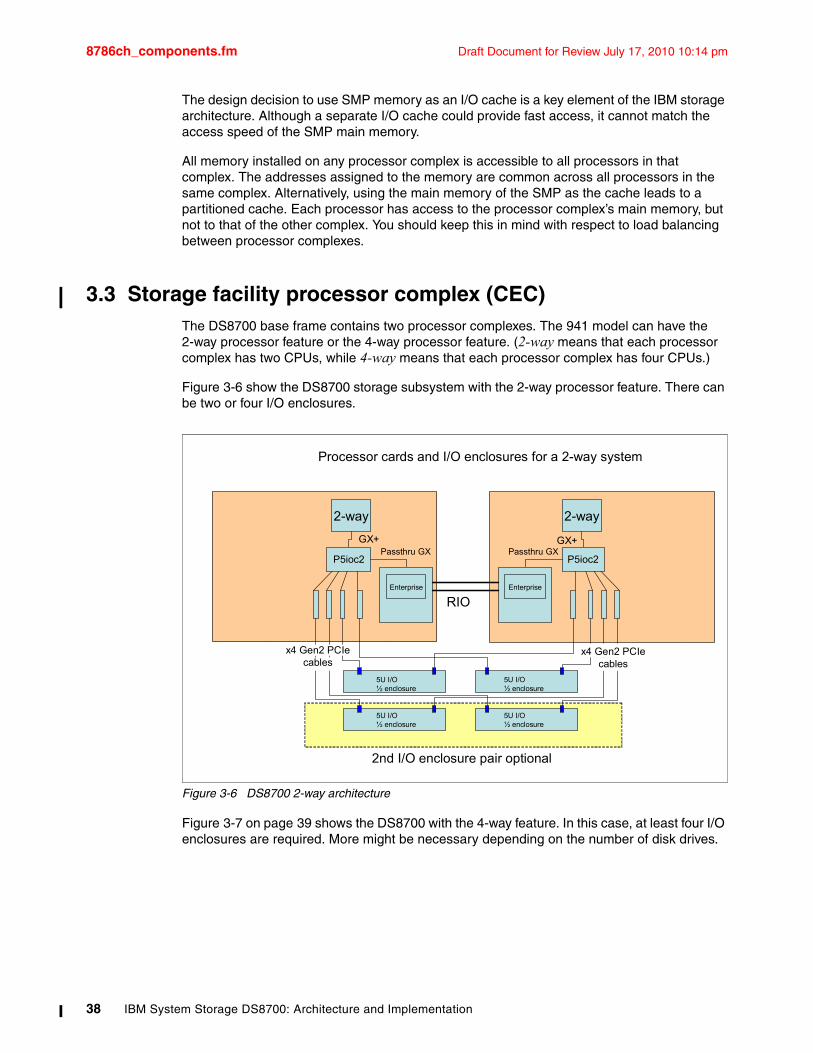
8786ch_components.fm Draft Document for Review July 17, 2010 10:14 pm
The design decision to use SMP memory as an I/O cache is a key element of the IBM storage architecture. Although a separate I/O cache could provide fast access, it cannot match the access speed of the SMP main memory.
All memory installed on any processor complex is accessible to all processors in that complex. The addresses assigned to the memory are common across all processors in the same complex. Alternatively, using the main memory of the SMP as the cache leads to a partitioned cache. Each processor has access to the processor complex’s main memory, but not to that of the other complex. You should keep this in mind with respect to load balancing between processor complexes.
3.3 Storage facility processor complex (CEC)The DS8700 base frame contains two processor complexes. The 941 model can have the 2-way processor feature or the 4-way processor feature. (2-way means that each processor complex has two CPUs, while 4-way means that each processor complex has four CPUs.)
Figure 3-6 show the DS8700 storage subsystem with the 2-way processor feature. There can be two or four I/O enclosures.
Figure 3-6 DS8700 2-way architecture
Figure 3-7 on page 39 shows the DS8700 with the 4-way feature. In this case, at least four I/O enclosures are required. More might be necessary depending on the number of disk drives.
2-way
GX+
P5ioc2Passthru GX
Enterprise
2-way
P5ioc2Passthru GX
Enterprise
RIO
GX+
5U I/O ½ enclosure
5U I/O ½ enclosure
5U I/O ½ enclosure
5U I/O ½ enclosure
x4 Gen2 PCIe cables
Processor cards and I/O enclosures for a 2-way system
2nd I/O enclosure pair optional
x4 Gen2 PCIe cables
38 IBM System Storage DS8700: Architecture and Implementation
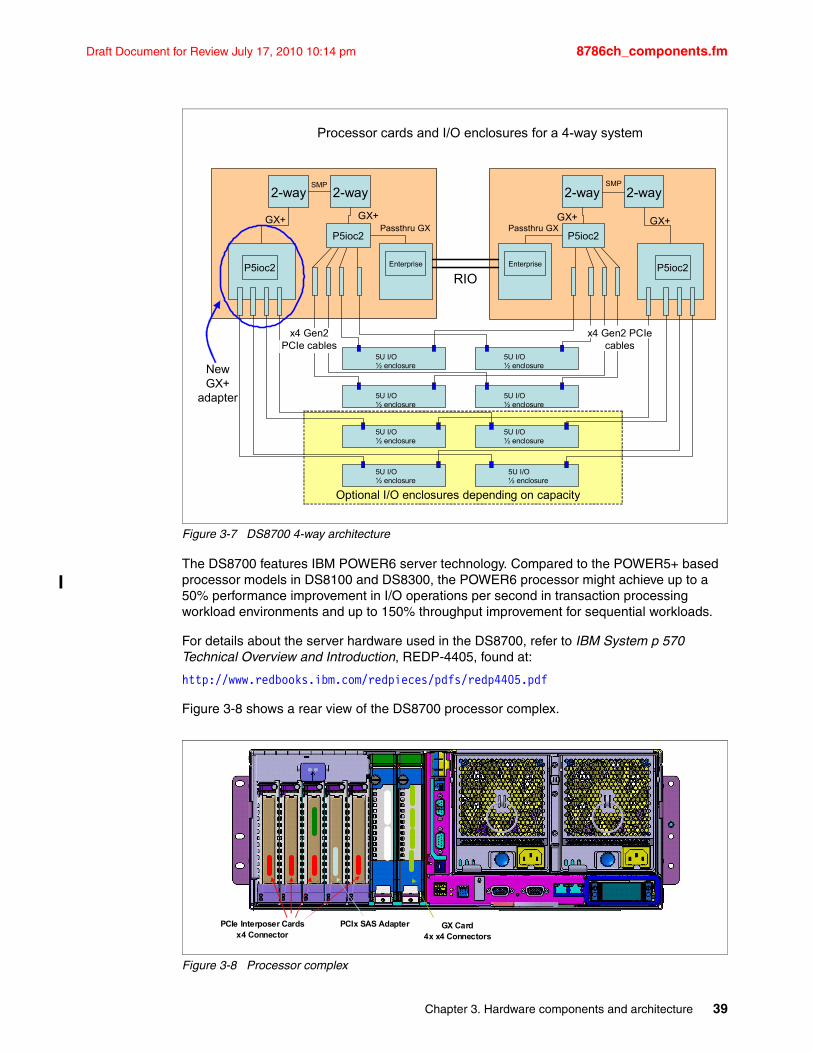
Draft Document for Review July 17, 2010 10:14 pm 8786ch_components.fm
Figure 3-7 DS8700 4-way architecture
The DS8700 features IBM POWER6 server technology. Compared to the POWER5+ based processor models in DS8100 and DS8300, the POWER6 processor might achieve up to a 50% performance improvement in I/O operations per second in transaction processing workload environments and up to 150% throughput improvement for sequential workloads.
For details about the server hardware used in the DS8700, refer to IBM System p 570 Technical Overview and Introduction, REDP-4405, found at:
http://www.redbooks.ibm.com/redpieces/pdfs/redp4405.pdf
Figure 3-8 shows a rear view of the DS8700 processor complex.
Figure 3-8 Processor complex
2-way 2-way
P5ioc2
GX+GX+
SMP
P5ioc2Passthru GX
Enterprise
2-way2-way
P5ioc2
SMP
P5ioc2Passthru GX
Enterprise
RIO
GX+GX+
5U I/O ½ enclosure
5U I/O ½ enclosure
5U I/O ½ enclosure
5U I/O ½ enclosure
5U I/O ½ enclosure
5U I/O ½ enclosure
5U I/O ½ enclosure
5U I/O ½ enclosure
New GX+
adapter
Processor cards and I/O enclosures for a 4-way system
Optional I/O enclosures depending on capacity
x4 Gen2 PCIe cables
x4 Gen2 PCIe cables
PCIe Interposer Cardsx4 Connector
GX Card4x x4 Connectors
PCIx SAS Adapter
Chapter 3. Hardware components and architecture 39
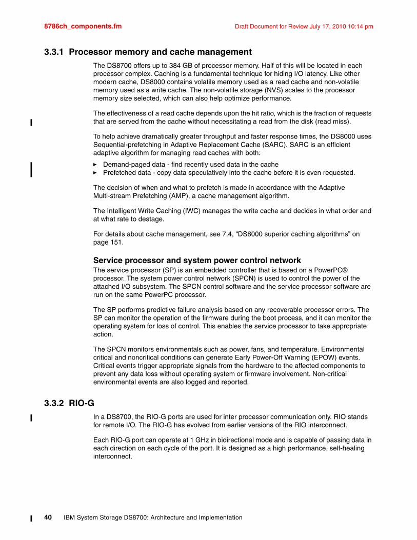
8786ch_components.fm Draft Document for Review July 17, 2010 10:14 pm
3.3.1 Processor memory and cache managementThe DS8700 offers up to 384 GB of processor memory. Half of this will be located in each processor complex. Caching is a fundamental technique for hiding I/O latency. Like other modern cache, DS8000 contains volatile memory used as a read cache and non-volatile memory used as a write cache. The non-volatile storage (NVS) scales to the processor memory size selected, which can also help optimize performance.
The effectiveness of a read cache depends upon the hit ratio, which is the fraction of requests that are served from the cache without necessitating a read from the disk (read miss).
To help achieve dramatically greater throughput and faster response times, the DS8000 uses Sequential-prefetching in Adaptive Replacement Cache (SARC). SARC is an efficient adaptive algorithm for managing read caches with both:
� Demand-paged data - find recently used data in the cache � Prefetched data - copy data speculatively into the cache before it is even requested.
The decision of when and what to prefetch is made in accordance with the Adaptive Multi-stream Prefetching (AMP), a cache management algorithm.
The Intelligent Write Caching (IWC) manages the write cache and decides in what order and at what rate to destage.
For details about cache management, see 7.4, “DS8000 superior caching algorithms” on page 151.
Service processor and system power control networkThe service processor (SP) is an embedded controller that is based on a PowerPC® processor. The system power control network (SPCN) is used to control the power of the attached I/O subsystem. The SPCN control software and the service processor software are run on the same PowerPC processor.
The SP performs predictive failure analysis based on any recoverable processor errors. The SP can monitor the operation of the firmware during the boot process, and it can monitor the operating system for loss of control. This enables the service processor to take appropriate action.
The SPCN monitors environmentals such as power, fans, and temperature. Environmental critical and noncritical conditions can generate Early Power-Off Warning (EPOW) events. Critical events trigger appropriate signals from the hardware to the affected components to prevent any data loss without operating system or firmware involvement. Non-critical environmental events are also logged and reported.
3.3.2 RIO-GIn a DS8700, the RIO-G ports are used for inter processor communication only. RIO stands for remote I/O. The RIO-G has evolved from earlier versions of the RIO interconnect.
Each RIO-G port can operate at 1 GHz in bidirectional mode and is capable of passing data in each direction on each cycle of the port. It is designed as a high performance, self-healing interconnect.
40 IBM System Storage DS8700: Architecture and Implementation
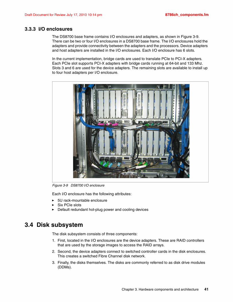
Draft Document for Review July 17, 2010 10:14 pm 8786ch_components.fm
3.3.3 I/O enclosuresThe DS8700 base frame contains I/O enclosures and adapters, as shown in Figure 3-9. There can be two or four I/O enclosures in a DS8700 base frame. The I/O enclosures hold the adapters and provide connectivity between the adapters and the processors. Device adapters and host adapters are installed in the I/O enclosures. Each I/O enclosure has 6 slots.
In the current implementation, bridge cards are used to translate PCIe to PCI-X adapters. Each PCIe slot supports PCI-X adapters with bridge cards running at 64-bit and 133 Mhz. Slots 3 and 6 are used for the device adapters. The remaining slots are available to install up to four host adapters per I/O enclosure.
Figure 3-9 DS8700 I/O enclosure
Each I/O enclosure has the following attributes:
� 5U rack-mountable enclosure � Six PCIe slots� Default redundant hot-plug power and cooling devices
3.4 Disk subsystemThe disk subsystem consists of three components:
1. First, located in the I/O enclosures are the device adapters. These are RAID controllers that are used by the storage images to access the RAID arrays.
2. Second, the device adapters connect to switched controller cards in the disk enclosures. This creates a switched Fibre Channel disk network.
3. Finally, the disks themselves. The disks are commonly referred to as disk drive modules (DDMs).
Chapter 3. Hardware components and architecture 41
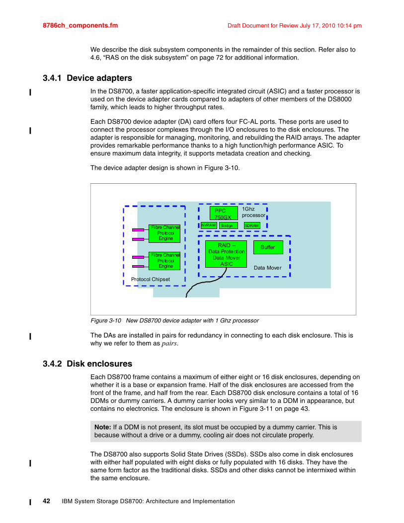
8786ch_components.fm Draft Document for Review July 17, 2010 10:14 pm
We describe the disk subsystem components in the remainder of this section. Refer also to 4.6, “RAS on the disk subsystem” on page 72 for additional information.
3.4.1 Device adaptersIn the DS8700, a faster application-specific integrated circuit (ASIC) and a faster processor is used on the device adapter cards compared to adapters of other members of the DS8000 family, which leads to higher throughput rates.
Each DS8700 device adapter (DA) card offers four FC-AL ports. These ports are used to connect the processor complexes through the I/O enclosures to the disk enclosures. The adapter is responsible for managing, monitoring, and rebuilding the RAID arrays. The adapter provides remarkable performance thanks to a high function/high performance ASIC. To ensure maximum data integrity, it supports metadata creation and checking.
The device adapter design is shown in Figure 3-10.
Figure 3-10 New DS8700 device adapter with 1 Ghz processor
The DAs are installed in pairs for redundancy in connecting to each disk enclosure. This is why we refer to them as pairs.
3.4.2 Disk enclosuresEach DS8700 frame contains a maximum of either eight or 16 disk enclosures, depending on whether it is a base or expansion frame. Half of the disk enclosures are accessed from the front of the frame, and half from the rear. Each DS8700 disk enclosure contains a total of 16 DDMs or dummy carriers. A dummy carrier looks very similar to a DDM in appearance, but contains no electronics. The enclosure is shown in Figure 3-11 on page 43.
The DS8700 also supports Solid State Drives (SSDs). SSDs also come in disk enclosures with either half populated with eight disks or fully populated with 16 disks. They have the same form factor as the traditional disks. SSDs and other disks cannot be intermixed within the same enclosure.
PPC750GX
1Ghzprocessor
NVRAM Bridge SDRAMFibre ChannelProtocolEngine
Fibre ChannelProtocolEngine
BufferRAID –Data Protection
Data MoverASIC
Data Mover
Protocol Chipset
Note: If a DDM is not present, its slot must be occupied by a dummy carrier. This is because without a drive or a dummy, cooling air does not circulate properly.
42 IBM System Storage DS8700: Architecture and Implementation
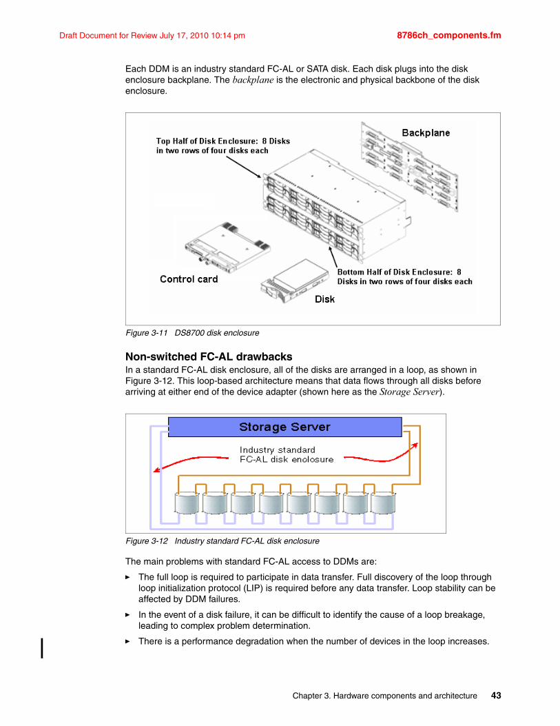
Draft Document for Review July 17, 2010 10:14 pm 8786ch_components.fm
Each DDM is an industry standard FC-AL or SATA disk. Each disk plugs into the disk enclosure backplane. The backplane is the electronic and physical backbone of the disk enclosure.
Figure 3-11 DS8700 disk enclosure
Non-switched FC-AL drawbacksIn a standard FC-AL disk enclosure, all of the disks are arranged in a loop, as shown in Figure 3-12. This loop-based architecture means that data flows through all disks before arriving at either end of the device adapter (shown here as the Storage Server).
Figure 3-12 Industry standard FC-AL disk enclosure
The main problems with standard FC-AL access to DDMs are:
� The full loop is required to participate in data transfer. Full discovery of the loop through loop initialization protocol (LIP) is required before any data transfer. Loop stability can be affected by DDM failures.
� In the event of a disk failure, it can be difficult to identify the cause of a loop breakage, leading to complex problem determination.
� There is a performance degradation when the number of devices in the loop increases.
Chapter 3. Hardware components and architecture 43
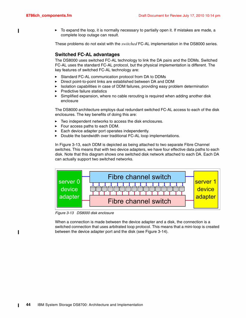
8786ch_components.fm Draft Document for Review July 17, 2010 10:14 pm
� To expand the loop, it is normally necessary to partially open it. If mistakes are made, a complete loop outage can result.
These problems do not exist with the switched FC-AL implementation in the DS8000 series.
Switched FC-AL advantagesThe DS8000 uses switched FC-AL technology to link the DA pairs and the DDMs. Switched FC-AL uses the standard FC-AL protocol, but the physical implementation is different. The key features of switched FC-AL technology are:
� Standard FC-AL communication protocol from DA to DDMs� Direct point-to-point links are established between DA and DDM� Isolation capabilities in case of DDM failures, providing easy problem determination� Predictive failure statistics� Simplified expansion, where no cable rerouting is required when adding another disk
enclosure
The DS8000 architecture employs dual redundant switched FC-AL access to each of the disk enclosures. The key benefits of doing this are:
� Two independent networks to access the disk enclosures.� Four access paths to each DDM.� Each device adapter port operates independently.� Double the bandwidth over traditional FC-AL loop implementations.
In Figure 3-13, each DDM is depicted as being attached to two separate Fibre Channel switches. This means that with two device adapters, we have four effective data paths to each disk. Note that this diagram shows one switched disk network attached to each DA. Each DA can actually support two switched networks.
Figure 3-13 DS8000 disk enclosure
When a connection is made between the device adapter and a disk, the connection is a switched connection that uses arbitrated loop protocol. This means that a mini-loop is created between the device adapter port and the disk (see Figure 3-14).
server 0deviceadapter
server 1deviceadapter
Fibre channel switch
Fibre channel switch
44 IBM System Storage DS8700: Architecture and Implementation
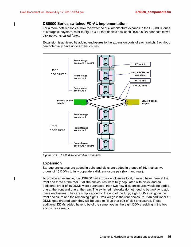
Draft Document for Review July 17, 2010 10:14 pm 8786ch_components.fm
DS8000 Series switched FC-AL implementationFor a more detailed look at how the switched disk architecture expands in the DS8000 Series of storage subsystem, refer to Figure 3-14 that depicts how each DS8000 DA connects to two disk networks called loops.
Expansion is achieved by adding enclosures to the expansion ports of each switch. Each loop can potentially have up to six enclosures.
Figure 3-14 DS8000 switched disk expansion
ExpansionStorage enclosures are added in pairs and disks are added in groups of 16. It takes two orders of 16 DDMs to fully populate a disk enclosure pair (front and rear).
To provide an example, if a DS8700 had six disk enclosures total, it would have three at the front and three at the rear. If all the enclosures were fully populated with disks, and an additional order of 16 DDMs were purchased, then two new disk enclosures would be added, one at the front and one at the rear. The switched networks do not need to be broken to add these enclosures. They are simply added to the end of the loop; eight DDMs will go in the front enclosure and the remaining eight DDMs will go in the rear enclosure. If an additional 16 DDMs gets ordered later, they will be used to fill up that pair of disk enclosures. These additional DDMs added have to be of the same type as the eight DDMs residing in the two enclosures already.
0
15
0
15
0
15
Server 0 deviceadapter
0
15
0
15
0
15Rear storage enclosure N max=6
Rear storage enclosure 2
Server 1 deviceadapter
FC switch
8 or 16 DDMs per enclosure
FC-AL link
4 FC-AL Ports
Rearenclosures
Front enclosures
Rear storage enclosure 1
Front storage enclosure 1
Front storage enclosure 2
Front storage enclosure N max=6
Chapter 3. Hardware components and architecture 45
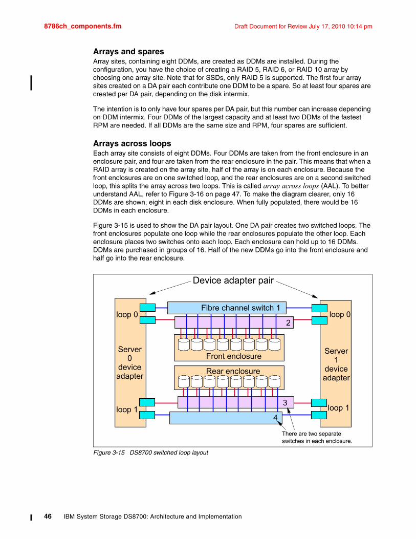
8786ch_components.fm Draft Document for Review July 17, 2010 10:14 pm
Arrays and sparesArray sites, containing eight DDMs, are created as DDMs are installed. During the configuration, you have the choice of creating a RAID 5, RAID 6, or RAID 10 array by choosing one array site. Note that for SSDs, only RAID 5 is supported. The first four array sites created on a DA pair each contribute one DDM to be a spare. So at least four spares are created per DA pair, depending on the disk intermix.
The intention is to only have four spares per DA pair, but this number can increase depending on DDM intermix. Four DDMs of the largest capacity and at least two DDMs of the fastest RPM are needed. If all DDMs are the same size and RPM, four spares are sufficient.
Arrays across loopsEach array site consists of eight DDMs. Four DDMs are taken from the front enclosure in an enclosure pair, and four are taken from the rear enclosure in the pair. This means that when a RAID array is created on the array site, half of the array is on each enclosure. Because the front enclosures are on one switched loop, and the rear enclosures are on a second switched loop, this splits the array across two loops. This is called array across loops (AAL). To better understand AAL, refer to Figure 3-16 on page 47. To make the diagram clearer, only 16 DDMs are shown, eight in each disk enclosure. When fully populated, there would be 16 DDMs in each enclosure.
Figure 3-15 is used to show the DA pair layout. One DA pair creates two switched loops. The front enclosures populate one loop while the rear enclosures populate the other loop. Each enclosure places two switches onto each loop. Each enclosure can hold up to 16 DDMs. DDMs are purchased in groups of 16. Half of the new DDMs go into the front enclosure and half go into the rear enclosure.
Figure 3-15 DS8700 switched loop layout
Front enclosure
Rear enclosure
Device adapter pair
Server 0
device adapter
loop 0
loop 1
Server 1
device adapter
loop 0
loop 13
Fibre channel switch 1
4
There are two separate switches in each enclosure.
2
46 IBM System Storage DS8700: Architecture and Implementation
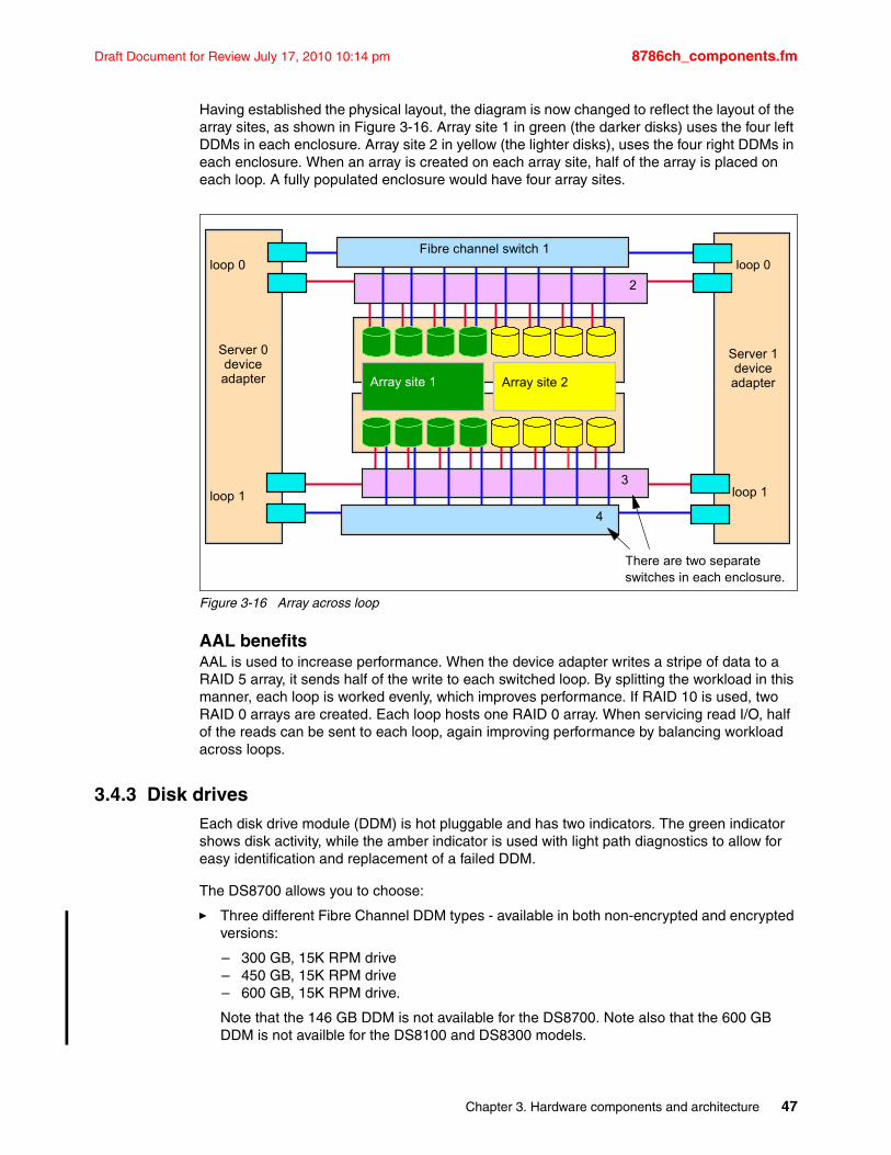
Draft Document for Review July 17, 2010 10:14 pm 8786ch_components.fm
Having established the physical layout, the diagram is now changed to reflect the layout of the array sites, as shown in Figure 3-16. Array site 1 in green (the darker disks) uses the four left DDMs in each enclosure. Array site 2 in yellow (the lighter disks), uses the four right DDMs in each enclosure. When an array is created on each array site, half of the array is placed on each loop. A fully populated enclosure would have four array sites.
Figure 3-16 Array across loop
AAL benefitsAAL is used to increase performance. When the device adapter writes a stripe of data to a RAID 5 array, it sends half of the write to each switched loop. By splitting the workload in this manner, each loop is worked evenly, which improves performance. If RAID 10 is used, two RAID 0 arrays are created. Each loop hosts one RAID 0 array. When servicing read I/O, half of the reads can be sent to each loop, again improving performance by balancing workload across loops.
3.4.3 Disk drives Each disk drive module (DDM) is hot pluggable and has two indicators. The green indicator shows disk activity, while the amber indicator is used with light path diagnostics to allow for easy identification and replacement of a failed DDM.
The DS8700 allows you to choose:
� Three different Fibre Channel DDM types - available in both non-encrypted and encrypted versions:
– 300 GB, 15K RPM drive– 450 GB, 15K RPM drive– 600 GB, 15K RPM drive.
Note that the 146 GB DDM is not available for the DS8700. Note also that the 600 GB DDM is not availble for the DS8100 and DS8300 models.
Server 0 device adapter
loop 0
loop 1
Server 1 device adapter
loop 0
loop 13
Fibre channel switch 1
4
There are two separate switches in each enclosure.
2
Array site 1 Array site 2
Chapter 3. Hardware components and architecture 47
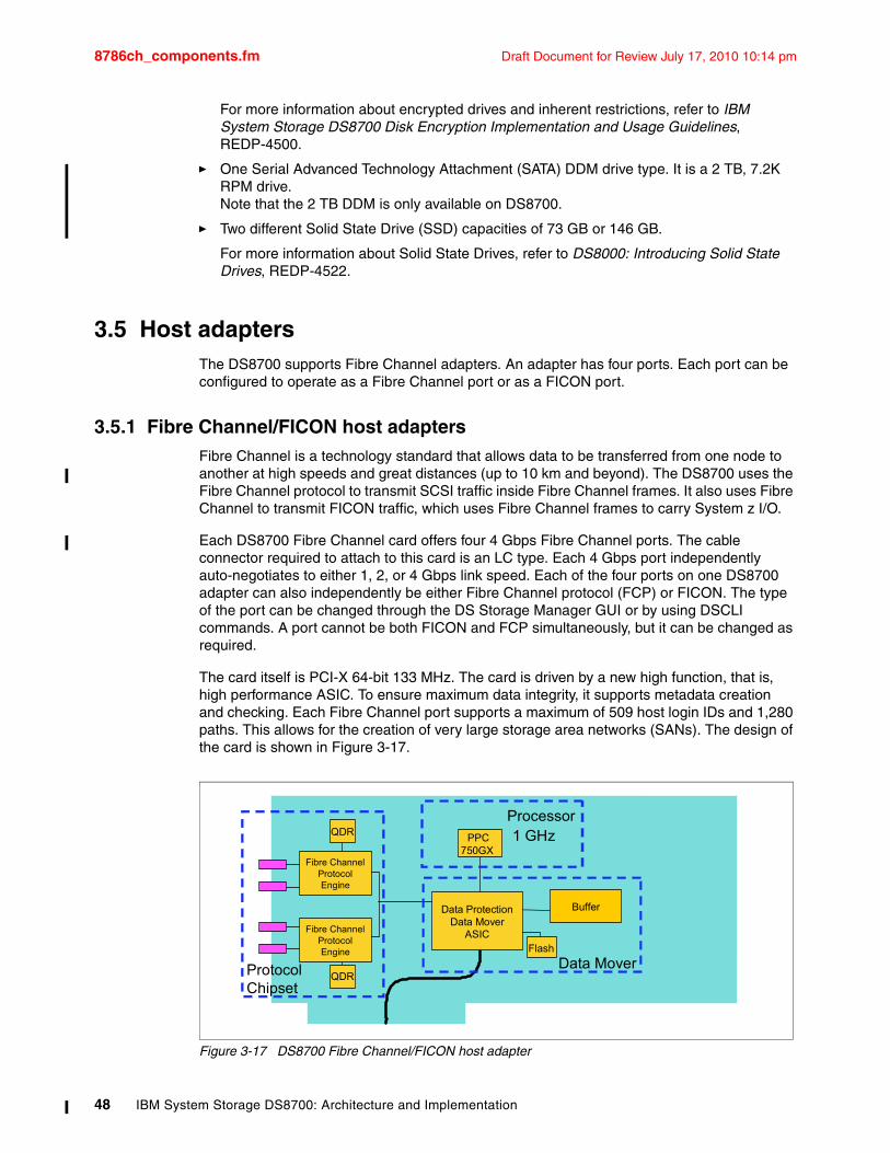
8786ch_components.fm Draft Document for Review July 17, 2010 10:14 pm
For more information about encrypted drives and inherent restrictions, refer to IBM System Storage DS8700 Disk Encryption Implementation and Usage Guidelines, REDP-4500.
� One Serial Advanced Technology Attachment (SATA) DDM drive type. It is a 2 TB, 7.2K RPM drive.Note that the 2 TB DDM is only available on DS8700.
� Two different Solid State Drive (SSD) capacities of 73 GB or 146 GB.
For more information about Solid State Drives, refer to DS8000: Introducing Solid State Drives, REDP-4522.
3.5 Host adaptersThe DS8700 supports Fibre Channel adapters. An adapter has four ports. Each port can be configured to operate as a Fibre Channel port or as a FICON port.
3.5.1 Fibre Channel/FICON host adaptersFibre Channel is a technology standard that allows data to be transferred from one node to another at high speeds and great distances (up to 10 km and beyond). The DS8700 uses the Fibre Channel protocol to transmit SCSI traffic inside Fibre Channel frames. It also uses Fibre Channel to transmit FICON traffic, which uses Fibre Channel frames to carry System z I/O.
Each DS8700 Fibre Channel card offers four 4 Gbps Fibre Channel ports. The cable connector required to attach to this card is an LC type. Each 4 Gbps port independently auto-negotiates to either 1, 2, or 4 Gbps link speed. Each of the four ports on one DS8700 adapter can also independently be either Fibre Channel protocol (FCP) or FICON. The type of the port can be changed through the DS Storage Manager GUI or by using DSCLI commands. A port cannot be both FICON and FCP simultaneously, but it can be changed as required.
The card itself is PCI-X 64-bit 133 MHz. The card is driven by a new high function, that is, high performance ASIC. To ensure maximum data integrity, it supports metadata creation and checking. Each Fibre Channel port supports a maximum of 509 host login IDs and 1,280 paths. This allows for the creation of very large storage area networks (SANs). The design of the card is shown in Figure 3-17.
Figure 3-17 DS8700 Fibre Channel/FICON host adapter
QDR
QDRPPC
750GX
Flash
BufferData ProtectionData Mover
ASIC
ProtocolChipset
Processor
Data Mover
1 GHz
Fibre Channel Protocol Engine
Fibre Channel Protocol Engine
48 IBM System Storage DS8700: Architecture and Implementation
Draft Document for Review July 17, 2010 10:14 pm 8786ch_components.fm
Fibre Channel supported serversThe current list of servers supported by Fibre Channel attachment can be found at:
http://www.ibm.com/systems/support/storage/config/ssic/index.jsp
These documents should be consulted regularly, because they have the most up-to-date information about server attachment support.
Fibre Channel distances There are two types of host adapter cards you can select:
� Longwave� Shortwave
With longwave, you can connect nodes at distances of up to 10 km (non-repeated). With shortwave, you are limited to a distance of 300 to 500 meters (non-repeated). All ports on each card must be either longwave or shortwave. There can be no inter mix of types within a card.
3.6 Power and coolingThe DS8700 series power and cooling system is highly redundant. The components are described in this section. Refer also to 4.7, “RAS on the power subsystem” on page 79.
Rack Power Control cards (RPC)The DS8700 has a pair of redundant RPC cards that are used to control certain aspects of power sequencing throughout the DS8700. These cards are attached to the Service Processor (SP) card in each processor, which allows them to communicate both with the Storage Hardware Management Console (HMC) and the storage facility. The RPCs also communicate with each primary power supply and indirectly with each rack’s fan sense cards and the disk enclosures in each frame.
Primary power suppliesThe DS8000 primary power supply (PPS) is a wide range PPS that converts input AC voltage into DC voltage. The line cord needs to be ordered specifically for the operating voltage to meet special requirements. The line cord connector requirements vary widely throughout the world; for example, the line cord might not come with a suitable connector for your nation’s preferred outlet. This connector might need to be replaced by an electrician once the machine is delivered.
There are two redundant PPSs in each frame of the DS8700. Each PPS is capable of powering the frame by itself. The PPS creates 208V output power for the processor complex and I/O enclosure power supplies. It also creates 5V and 12V DC power for the disk enclosures. There can also be an optional booster module that will allow the PPSs to temporarily run the disk enclosures off of a battery, if the extended power line disturbance feature has been purchased (see Chapter 4, “Reliability, Availability, and Serviceability (RAS) of IBM System Storage DS8700” on page 55 for a complete explanation of why this feature might be necessary for your installation).
Each PPS has internal fans to supply cooling for that power supply.
Chapter 3. Hardware components and architecture 49
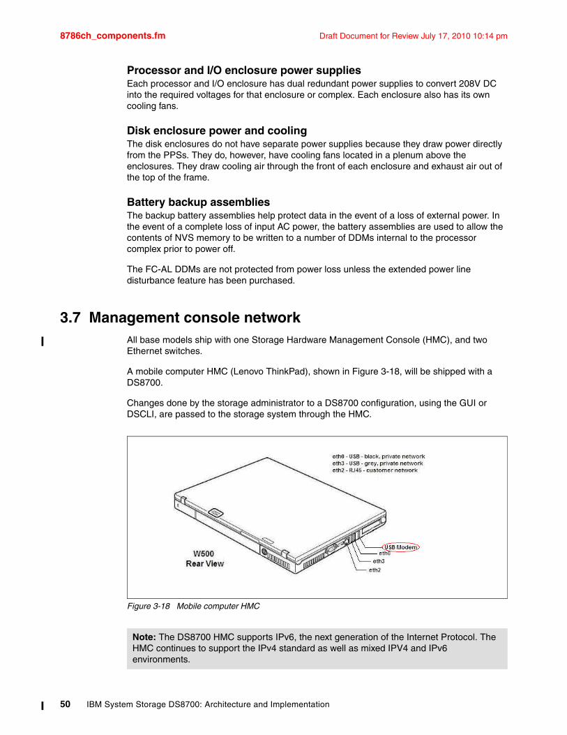
8786ch_components.fm Draft Document for Review July 17, 2010 10:14 pm
Processor and I/O enclosure power suppliesEach processor and I/O enclosure has dual redundant power supplies to convert 208V DC into the required voltages for that enclosure or complex. Each enclosure also has its own cooling fans.
Disk enclosure power and coolingThe disk enclosures do not have separate power supplies because they draw power directly from the PPSs. They do, however, have cooling fans located in a plenum above the enclosures. They draw cooling air through the front of each enclosure and exhaust air out of the top of the frame.
Battery backup assembliesThe backup battery assemblies help protect data in the event of a loss of external power. In the event of a complete loss of input AC power, the battery assemblies are used to allow the contents of NVS memory to be written to a number of DDMs internal to the processor complex prior to power off.
The FC-AL DDMs are not protected from power loss unless the extended power line disturbance feature has been purchased.
3.7 Management console networkAll base models ship with one Storage Hardware Management Console (HMC), and two Ethernet switches.
A mobile computer HMC (Lenovo ThinkPad), shown in Figure 3-18, will be shipped with a DS8700.
Changes done by the storage administrator to a DS8700 configuration, using the GUI or DSCLI, are passed to the storage system through the HMC.
Figure 3-18 Mobile computer HMC
Note: The DS8700 HMC supports IPv6, the next generation of the Internet Protocol. The HMC continues to support the IPv4 standard as well as mixed IPV4 and IPv6 environments.
50 IBM System Storage DS8700: Architecture and Implementation
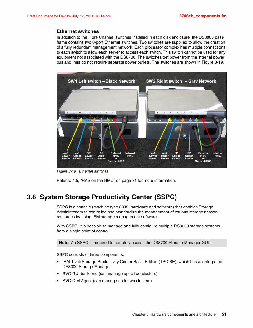
Draft Document for Review July 17, 2010 10:14 pm 8786ch_components.fm
Ethernet switchesIn addition to the Fibre Channel switches installed in each disk enclosure, the DS8000 base frame contains two 8-port Ethernet switches. Two switches are supplied to allow the creation of a fully redundant management network. Each processor complex has multiple connections to each switch to allow each server to access each switch. This switch cannot be used for any equipment not associated with the DS8700. The switches get power from the internal power bus and thus do not require separate power outlets. The switches are shown in Figure 3-19.
Figure 3-19 Ethernet switches
Refer to 4.5, “RAS on the HMC” on page 71 for more information.
3.8 System Storage Productivity Center (SSPC)SSPC is a console (machine type 2805, hardware and software) that enables Storage Administrators to centralize and standardize the management of various storage network resources by using IBM storage management software.
With SSPC, it is possible to manage and fully configure multiple DS8000 storage systems from a single point of control.
SSPC consists of three components:
� IBM Tivoli Storage Productivity Center Basic Edition (TPC BE), which has an integrated DS8000 Storage Manager
� SVC GUI back end (can manage up to two clusters)
� SVC CIM Agent (can manage up to two clusters)
InternalHMC
External HMC
orSecond 8700
SPUpperServer
SPLower Server
InternalHMC
External HMC
orSecond 8700
SPUpperServer
SPLower Server
SW1 Left switch – Black Network SW2 Right switch – Gray Network
en0UpperServer
en0Lower Server
en0UpperServer
en0Lower Server
Note: An SSPC is required to remotely access the DS8700 Storage Manager GUI.
Chapter 3. Hardware components and architecture 51
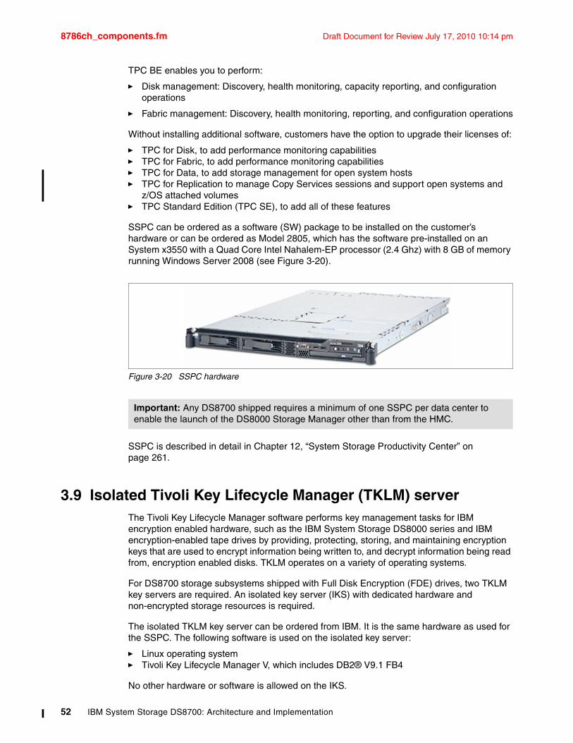
8786ch_components.fm Draft Document for Review July 17, 2010 10:14 pm
TPC BE enables you to perform:
� Disk management: Discovery, health monitoring, capacity reporting, and configuration operations
� Fabric management: Discovery, health monitoring, reporting, and configuration operations
Without installing additional software, customers have the option to upgrade their licenses of:
� TPC for Disk, to add performance monitoring capabilities� TPC for Fabric, to add performance monitoring capabilities� TPC for Data, to add storage management for open system hosts� TPC for Replication to manage Copy Services sessions and support open systems and
z/OS attached volumes� TPC Standard Edition (TPC SE), to add all of these features
SSPC can be ordered as a software (SW) package to be installed on the customer’s hardware or can be ordered as Model 2805, which has the software pre-installed on an System x3550 with a Quad Core Intel Nahalem-EP processor (2.4 Ghz) with 8 GB of memory running Windows Server 2008 (see Figure 3-20).
Figure 3-20 SSPC hardware
SSPC is described in detail in Chapter 12, “System Storage Productivity Center” on page 261.
3.9 Isolated Tivoli Key Lifecycle Manager (TKLM) serverThe Tivoli Key Lifecycle Manager software performs key management tasks for IBM encryption enabled hardware, such as the IBM System Storage DS8000 series and IBM encryption-enabled tape drives by providing, protecting, storing, and maintaining encryption keys that are used to encrypt information being written to, and decrypt information being read from, encryption enabled disks. TKLM operates on a variety of operating systems.
For DS8700 storage subsystems shipped with Full Disk Encryption (FDE) drives, two TKLM key servers are required. An isolated key server (IKS) with dedicated hardware and non-encrypted storage resources is required.
The isolated TKLM key server can be ordered from IBM. It is the same hardware as used for the SSPC. The following software is used on the isolated key server:
� Linux operating system� Tivoli Key Lifecycle Manager V, which includes DB2® V9.1 FB4
No other hardware or software is allowed on the IKS.
Important: Any DS8700 shipped requires a minimum of one SSPC per data center to enable the launch of the DS8000 Storage Manager other than from the HMC.
52 IBM System Storage DS8700: Architecture and Implementation

Draft Document for Review July 17, 2010 10:14 pm 8786ch_components.fm
Refer to 4.8, “RAS and full disk encryption” on page 81 for more information.
For more information, refer to IBM System Storage DS8700 Disk Encryption Implementation and Usage Guidelines, REDP-4500.
Chapter 3. Hardware components and architecture 53

8786ch_components.fm Draft Document for Review July 17, 2010 10:14 pm
54 IBM System Storage DS8700: Architecture and Implementation
Draft Document for Review July 17, 2010 10:14 pm 8786ch_RAS.fm
Chapter 4. Reliability, Availability, and Serviceability (RAS) of IBM System Storage DS8700
This chapter describes the reliability, availability, and serviceability (RAS) characteristics of the IBM System Storage DS8700. The following topics are covered in this chapter:
� Names and terms for DS8700
� RAS features of the DS8700 Central Electronic Complex (CEC)
� CEC failover and failback
� Data flow in the DS8700
� RAS on the HMC
� RAS on the disk subsystem
� RAS on the power subsystem
� RAS and full disk encryption
� Other features
4
© Copyright IBM Corp. 2010. All rights reserved. 55
8786ch_RAS.fm Draft Document for Review July 17, 2010 10:14 pm
4.1 Names and terms for DS8700It is important to understand the naming conventions used to describe DS8700 components and constructs in order to fully appreciate the discussion of RAS concepts. Although most terms have ben introduced in previous chapters of this book, they are repeated and summarized here, as the rest of this chapter will use these terms frequently.
Storage unit This term describes a single DS8700 (base frame plus optional expansion frames). If your organization has one DS8700, then you have a single storage complex that contains a single storage unit.
Base frame or primary frameThe DS8700 is available as a single model type (941), which includes a complete storage unit contained in a single primary frame, also called a base frame. To increase the storage capacity, up to 4 expansion frames may be added to the primary frame. A primary frame contains the following components:
� Power and cooling components (N+1 power supplies, batteries, and fans)� Power control cards (RPC, SPCN, and Fan sense)� Two POWER6 CECs� Two or four I/O Enclosures for Host Adapters and Device Adapters� 2 Gigabit Ethernet switches for internal network� Storage Hardware Management Console� Up to four pairs (eight total) Storage Enclosures for storage disks
– Each Storage Enclosure has up to 16 disk drive modules (DDM).– The primary frame can have a maximum of 128 disk drive modules.
Expansion frameExpansion frames can be added one at a time to increase the overall capacity of the storage unit. All expansion frames contain the power and cooling components needed to run the frame. The first expansion frame contains storage disks as well as I/O Enclosures for the Fibre Channel Loops. The second, third, and fourth expansion frames contain storage disks only. Because the Fibre Channel Loops are switched, the addition of an expansion frame is a concurrent operation for the DS8700. Each expansion frame can have:
� Up to eight pairs (16 total) Storage Enclosures for storage disks– Each Storage Enclosure has up to 16 disk drive modules (DDM).– An expansion frame can have a maximum of 256 disk drive modules (the fourth
expansion frame is limited to 128 drives).
Storage complexThis term describes a group of DS8700s managed by a single management console. A storage complex can, and usually does, consist of just a single DS8700 storage unit (primary frame plus optional expansion frames).
Central Electronic Complex / Processor complex / Storage ServerIn the DS8700, a Central Electronic Complex (CEC) is System p server built on the POWER6 architecture. The CECs run the AIX V6.1 operating system and storage-specific microcode. The DS8700 contains two CECs as a redundant pair so that if either fails, the remaining CEC can continue to run the storage unit. Each CEC can have up to 192 GB of memory and one or two POWER6 processor cards. In other models of the DS8000 family, a CEC was also referred to as a processor complex or a storage server. The CECs are identified as CEC0 and
56 IBM System Storage DS8700: Architecture and Implementation
Draft Document for Review July 17, 2010 10:14 pm 8786ch_RAS.fm
CEC1. Some chapters and illustrations in this publication refer to Server 0 and Server 1; these are the same as CEC 0 and CEC 1 for the DS8700.
Storage HMCThe Storage Hardware Management Console (HMC) is the master console for the DS8700 unit. With connections to the CECs, the customer network, the SSPC, and other management systems, the HMC becomes the focal point for most operations on the DS8700. All storage configuration and service actions are run through the HMC. Although many other IBM products also use an HMC, the Storage HMC is unique to the DS8000 family. Throughout this chapter, it will be referred to as the HMC, but keep in mind we are referring to the Storage HMC that is cabled to the internal network of the DS8700.
System Storage Productivity CenterThe DS8700 utilizes the IBM SSPC, a management system that integrates the power of the IBM Tivoli Storage Productivity Center (TPC) and the DS Storage Manager user interfaces (residing at the HMC) into a single view. The SSPC (machine type 2805-MC4) is an integrated hardware and software solution for centralized management of IBM storage products with IBM storage management software. SSPC is described in detail in Chapter 12, “System Storage Productivity Center” on page 261.
Storage facility images and logical partitionsA logical partition (LPAR) is a virtual server within a physical processor complex. A storage facility image (SFI) is two logical partitions acting together as a virtual storage server. Earlier DS8000 models supported more than one SFI, meaning that the two physical CECs could be divided into four logical servers, each having control of some of the physical resources of the DS8000. The DS8700 does not divide the CECs into logical partitions. There is only one SFI, which owns 100% of the physical resources. So for the DS8700, the term storage facility image can be considered synonymous with storage unit.
4.2 RAS features of DS8700 CECReliability, availability, and serviceability (RAS) are important concepts in the design of the IBM System Storage DS8700. Hardware features, software features, design considerations, and operational guidelines all contribute to make the DS8700 extremely reliable. At the heart of the DS8700 is a pair of POWER6 based System p servers known as CECs. These two servers share the load of receiving and moving data between the attached hosts and the disk arrays, but they also are redundant so that if either CEC fails, the remaining CEC can continue to run the DS8700 without any host interruption. This section looks at the RAS features of the CECs, including the hardware, the operating system, and the interconnect.
4.2.1 Hypervisor (PHYP)The POWER6 Hypervisor (PHYP) is a component of system firmware that will always be installed and activated, regardless of the system configuration. It operates as a hidden partition, with no processor resources assigned to it.
Important: The DS8700 does not divide the CECs into logical partitions. There is only one SFI, which owns 100% of the physical resources. Information regarding multi-SFI or LPARs does not apply to the IBM System Storage DS8700.
Chapter 4. Reliability, Availability, and Serviceability (RAS) of IBM System Storage DS8700 57
8786ch_RAS.fm Draft Document for Review July 17, 2010 10:14 pm
The Hypervisor provides the following capabilities:
� Reserved memory partitions allow the setting aside of a certain portion of memory to use as cache and a certain portion to use as NVS.
� Preserved memory support allows the contents of the NVS and cache memory areas to be protected in the event of a server reboot.
� I/O enclosure initialization control, so that when one server is being initialized, it does not initialize an I/O adapter that is in use by another server.
� Automatic reboot of a frozen partition or Hypervisor.
The AIX operating system uses PHYP services to manage the translation control entry (TCE) tables. The operating system communicates the desired I/O bus address to logical mapping, and the Hypervisor translates that into the I/O bus address to physical mapping within the specific TCE table. The Hypervisor needs a dedicated memory region for the TCE tables to translate the I/O address to the partition memory address, and then the Hypervisor can perform direct memory access (DMA) transfers to the PCI adapters.
4.2.2 POWER6 processorIBM POWER6 systems have a number of new features that enable systems to dynamically adjust when issues arise that threaten availability. Most notably, POWER6 systems introduce the POWER6 Processor Instruction Retry suite of tools, which includes Processor Instruction Retry, Alternate Processor Recovery, Partition Availability Prioritization, and Single Processor Checkstop. Taken together, in many failure scenarios these features allow a POWER6 processor-based system to recover with no impact from the failing core.
The POWER6 processor implements the 64-bit IBM Power Architecture® technology and capitalizes on all the enhancements brought by the POWER5™ processor. Each POWER6 chip incorporates two dual-threaded Simultaneous Multithreading processor cores, a private 4 MB level 2 cache (L2) for each processor, a 36 MB L3 cache controller shared by the two processors, integrated memory controller, and data interconnect switch. It is designed to provide an extensive set of RAS features that include improved fault isolation, recovery from errors without stopping the processor complex, avoidance of recurring failures, and predictive failure analysis.
POWER6 RAS featuresThe following sections describe the RAS leadership features of IBM POWER6 systems in more detail.
POWER6 processor instruction retrySoft failures in the processor core are transient errors. When an error is encountered in the core, the POWER6 processor will first automatically retry the instruction. If the source of the error was truly transient, the instruction will succeed and the system will continue as before. On predecessor IBM systems, this error would have caused a checkstop.
POWER6 alternate processor retryHard failures are more difficult, being true logical errors that will be replicated each time the instruction is repeated. Retrying the instruction will not help in this situation because the instruction will continue to fail. Systems with POWER6 processors introduce the ability to extract the failing instruction from the faulty core and retry it elsewhere in the system, after which the failing core is dynamically deconfigured and called out for replacement. The entire process is transparent to the partition owning the failing instruction. Systems with POWER6 processors are designed to avoid what would have been a full system outage.
58 IBM System Storage DS8700: Architecture and Implementation
Draft Document for Review July 17, 2010 10:14 pm 8786ch_RAS.fm
POWER6 cache availabilityIn the event that an uncorrectable error occurs in L2 or L3 cache, the system will be able to dynamically remove the offending line of cache without requiring a reboot. In addition, POWER6 utilizes an L1/L2 cache design and a write-through cache policy on all levels, helping to ensure that data is written to main memory as soon as possible.
POWER6 single processor checkstoppingAnother major advancement in POWER6 processors is single processor checkstopping. A processor checkstop would result in a system checkstop. A new feature in System 550 is the ability to contain most processor checkstops to the partition that was using the processor at the time. This significantly reduces the probability of any one processor affecting total system availability.
POWER6 fault avoidancePOWER6 systems are built to keep errors from ever happening. This quality-based design includes such features as reduced power consumption and cooler operating temperatures for increased reliability, enabled by the use of copper chip circuitry, silicon on insulator (SOI), and dynamic clock-gating. It also uses mainframe-inspired components and technologies.
POWER6 First Failure Data CaptureIf a problem should occur, the ability to diagnose it correctly is a fundamental requirement upon which improved availability is based. The POWER6 incorporates advanced capability in startup diagnostics and in runtime First Failure Data Capture (FFDC) based on strategic error checkers built into the chips. Any errors that are detected by the pervasive error checkers are captured into Fault Isolation Registers (FIRs), which can be interrogated by the service processor (SP). The SP has the capability to access system components using special-purpose service processor ports or by access to the error registers.
The FIRs are important because they enable an error to be uniquely identified, thus enabling the appropriate action to be taken. Appropriate actions might include such things as a bus retry, error checking and correction (ECC), or system firmware recovery routines. Recovery routines could include dynamic deallocation of potentially failing components.
Errors are logged into the system nonvolatile random access memory (NVRAM) and the SP event history log, along with a notification of the event to AIX for capture in the operating system error log. Diagnostic Error Log Analysis (diagela) routines analyze the error log entries and invoke a suitable action, such as issuing a warning message. If the error can be recovered, or after suitable maintenance, the service processor resets the FIRs so that they can accurately record any future errors.
N+1 redundancyHigh-opportunity components, or those that most affect system availability, are protected with redundancy and the ability to be repaired concurrently. The use of redundant parts allows the system to remain operational. Among them are:
� Redundant spare memory bits in cache, directories, and main memory� Redundant and hot-swap cooling� Redundant and hot-swap power supplies
Chapter 4. Reliability, Availability, and Serviceability (RAS) of IBM System Storage DS8700 59
8786ch_RAS.fm Draft Document for Review July 17, 2010 10:14 pm
Self-healingFor a system to be self-healing, it must be able to recover from a failing component by first detecting and isolating the failed component. It should then be able to take it offline, fix or isolate it, and then reintroduce the fixed or replaced component into service without any application disruption. Examples include:
� Bit steering to redundant memory in the event of a failed memory module to keep the server operational
� Bit scattering, thus allowing for error correction and continued operation in the presence of a complete chip failure (Chipkill recovery)
� Single-bit error correction using Error Checking and Correcting (ECC) without reaching error thresholds for main, L2, and L3 cache memory
� L3 cache line deletes extended from 2 to 10 for additional self-healing
� ECC extended to inter-chip connections on fabric and processor bus
� Memory scrubbing to help prevent soft-error memory faults
� Dynamic processor deallocation
Memory reliability, fault tolerance, and integrityPOWER6 uses Error Checking and Correcting (ECC) circuitry for system memory to correct single-bit memory failures and to detect double-bit memory failures. Detection of double-bit memory failures helps maintain data integrity. Furthermore, the memory chips are organized such that the failure of any specific memory module only affects a single bit within a four-bit ECC word (bit-scattering), thus allowing for error correction and continued operation in the presence of a complete chip failure (Chipkill recovery).
The memory DIMMs also utilize memory scrubbing and thresholding to determine when memory modules within each bank of memory should be used to replace ones that have exceeded their threshold of error count (dynamic bit-steering). Memory scrubbing is the process of reading the contents of the memory during idle time and checking and correcting any single-bit errors that have accumulated by passing the data through the ECC logic. This function is a hardware function on the memory controller chip and does not influence normal system memory performance.
Fault maskingIf corrections and retries succeed and do not exceed threshold limits, the system remains operational with full resources and no client or IBM service representative intervention is required.
Mutual surveillanceThe SP can monitor the operation of the firmware during the boot process, and it can monitor the operating system for loss of control. This enables the service processor to take appropriate action when it detects that the firmware or the operating system has lost control. Mutual surveillance also enables the operating system to monitor for service processor activity and can request a service processor repair action if necessary.
4.2.3 AIX operating systemEach CEC runs the IBM AIX Version 6.1 operating system. This is the latest generation of IBM’s well-proven, scalable, and open standards-based UNIX®-like operating system. This version of AIX includes support for Failure Recovery Routines (FRR).
60 IBM System Storage DS8700: Architecture and Implementation
Draft Document for Review July 17, 2010 10:14 pm 8786ch_RAS.fm
With AIX V6.1, the kernel has been enhanced with the ability to recover from unexpected errors. Kernel components and extensions can provide failure recovery routines to gather serviceability data, diagnose, repair, and recover from errors. In previous AIX versions, kernel errors always resulted in an unexpected system halt.
Refer to IBM AIX Version 6.1 Differences Guide, SG24-7559 for more information on how AIX V6.1 adds to the RAS features of AIX 5L™ V5.3.
You can also reference the IBM web site for a more thorough review of the features of the IBM AIX operating system at:
http://www.ibm.com/systems/power/software/aix/index.html
4.2.4 CEC dual hard drive rebuildIf a simultaneous failure of the dual hard drives in a CEC should occur, then they would need to be replaced and then have the AIX OS and DS8700 microcode reloaded. The DS8700 introduces a significant improvement in RAS for this process, known as a rebuild. Any fault that causes the CEC to be unable to load the operating system from its internal hard drives would lead to this service action.
For a rebuild on previous DS8000 models, the IBM service representative would have to load multiple CDs/DVDs directly onto the CEC being serviced. For the DS8700, there are no optical drives on the CECs; only the HMC has a DVD drive. For a CEC dual hard drive rebuild, the service representative acquires the needed code bundles on the HMC, which then runs as a Network Installation Management on Linux (NIMoL) server. The HMC provides the OS and microcode to the CEC over the DS8700 internal network, which is much faster than reading/verifying from an optical disc.
All of the tasks and status updates for a CEC dual hard drive rebuild are done from the HMC, which is also aware of the overall service action that necessitated the rebuild. If the rebuild fails, the HMC manages the errors, including error data, and allows the service representative to address the problem and restart the rebuild. When the rebuild completes, the server is automatically brought up for the first time (IML). Once the IML is successful, the service representative can resume operations on the CEC.
Overall, the rebuild process on a DS8700 is more robust and straightforward, reducing the time needed to perform this critical service action.
4.2.5 RIO-G interconnectThe RIO-G interconnect is a high speed loop between the two CECs. Each RIO-G port can operate at 1 GHz in bidirectional mode and is capable of passing data in each direction on each cycle of the port. In previous generations of the DS8000, the I/O Enclosures were on the RIO-G loops between the two CECs. The RIO-G bus carried the CEC-to-DDM data (host I/O) as well as all CEC-to-CEC communications.
Chapter 4. Reliability, Availability, and Serviceability (RAS) of IBM System Storage DS8700 61
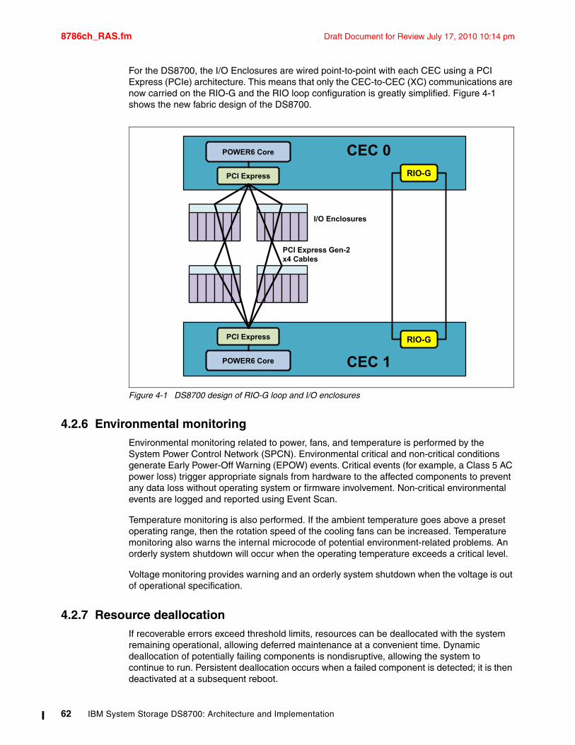
8786ch_RAS.fm Draft Document for Review July 17, 2010 10:14 pm
For the DS8700, the I/O Enclosures are wired point-to-point with each CEC using a PCI Express (PCIe) architecture. This means that only the CEC-to-CEC (XC) communications are now carried on the RIO-G and the RIO loop configuration is greatly simplified. Figure 4-1 shows the new fabric design of the DS8700.
Figure 4-1 DS8700 design of RIO-G loop and I/O enclosures
4.2.6 Environmental monitoringEnvironmental monitoring related to power, fans, and temperature is performed by the System Power Control Network (SPCN). Environmental critical and non-critical conditions generate Early Power-Off Warning (EPOW) events. Critical events (for example, a Class 5 AC power loss) trigger appropriate signals from hardware to the affected components to prevent any data loss without operating system or firmware involvement. Non-critical environmental events are logged and reported using Event Scan.
Temperature monitoring is also performed. If the ambient temperature goes above a preset operating range, then the rotation speed of the cooling fans can be increased. Temperature monitoring also warns the internal microcode of potential environment-related problems. An orderly system shutdown will occur when the operating temperature exceeds a critical level.
Voltage monitoring provides warning and an orderly system shutdown when the voltage is out of operational specification.
4.2.7 Resource deallocationIf recoverable errors exceed threshold limits, resources can be deallocated with the system remaining operational, allowing deferred maintenance at a convenient time. Dynamic deallocation of potentially failing components is nondisruptive, allowing the system to continue to run. Persistent deallocation occurs when a failed component is detected; it is then deactivated at a subsequent reboot.
CEC 0
CEC 1
RIO-G
RIO-G
I/O Enclosures
POWER6 Core
PCI Express
POWER6 Core
PCI Express
PCI Express Gen-2 x4 Cables
62 IBM System Storage DS8700: Architecture and Implementation
Draft Document for Review July 17, 2010 10:14 pm 8786ch_RAS.fm
Dynamic deallocation functions include the following components:
� Processor� L3 cache lines� Partial L2 cache deallocation� PCI-X bus and slots
Persistent deallocation functions include the following components:
� Processor� Memory� Deconfigure or bypass failing I/O adapters� L2 cache
Following a hardware error that has been flagged by the service processor, the subsequent reboot of the server invokes extended diagnostics. If a processor or cache has been marked for deconfiguration by persistent processor deallocation, the boot process will attempt to proceed to completion with the faulty device automatically deconfigured. Failing I/O adapters will be deconfigured or bypassed during the boot process.
4.3 CEC failover and failbackTo understand the process of CEC failover and failback, we have to review the logical construction of the DS8700. For more complete explanations, you may wish to refer to Chapter 5, “Virtualization concepts” on page 85.
Creating logical volumes on the DS8700 works through the following constructs:
� Storage DDMs are installed into predefined array sites.
� These array sites are used to form arrays, structured as RAID 5, RAID 6, or RAID 10 (restrictions apply for Solid State Drives and SATA drives).
� These RAID arrays then become members of a rank.
� Each rank then becomes a member of an extent pool. Each extent pool has an affinity to either server 0 or server 1. Each extent pool is either open systems fixed block (FB) or System z count key data (CKD).
� Within each extent pool, we create logical volumes. For open systems, these are called LUNs. For System z, these are called volumes. LUN stands for logical unit number, which is used for SCSI addressing. Each logical volume belongs to a logical subsystem (LSS).
For open systems, the LSS membership is really only significant for Copy Services. But for System z, the LSS is the logical control unit (LCU), which equates to a 3990 (a System z disk controller which the DS8700 emulates). It is important to remember that LSSs that have an even identifying number have an affinity with CEC 0, while LSSs that have an odd identifying number have an affinity with CEC 1. When a host operating system issues a write to a logical volume, the DS8700 host adapter directs that write to the CEC that owns the LSS of which that logical volume is a member.
4.3.1 Dual operationalOne of the basic premises of RAS in respect to processing host data is that the DS8700 will always try to maintain two copies of the data while it is moving through the storage system. The CECs have two areas of their primary memory used for holding host data: cache memory and non-volatile storage (NVS). NVS is an area of the system RAM that is persistent across a server reboot.
Chapter 4. Reliability, Availability, and Serviceability (RAS) of IBM System Storage DS8700 63
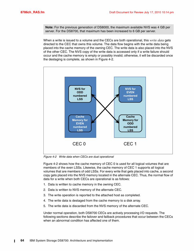
8786ch_RAS.fm Draft Document for Review July 17, 2010 10:14 pm
When a write is issued to a volume and the CECs are both operational, this write data gets directed to the CEC that owns this volume. The data flow begins with the write data being placed into the cache memory of the owning CEC. The write data is also placed into the NVS of the other CEC. The NVS copy of the write data is accessed only if a write failure should occur and the cache memory is empty or possibly invalid; otherwise, it will be discarded once the destaging is complete, as shown in Figure 4-2.
Figure 4-2 Write data when CECs are dual operational
Figure 4-2 shows how the cache memory of CEC 0 is used for all logical volumes that are members of the even LSSs. Likewise, the cache memory of CEC 1 supports all logical volumes that are members of odd LSSs. For every write that gets placed into cache, a second copy gets placed into the NVS memory located in the alternate CEC. Thus, the normal flow of data for a write when both CECs are operational is as follows:
1. Data is written to cache memory in the owning CEC.
2. Data is written to NVS memory of the alternate CEC.
3. The write operation is reported to the attached host as completed.
4. The write data is destaged from the cache memory to a disk array.
5. The write data is discarded from the NVS memory of the alternate CEC.
Under normal operation, both DS8700 CECs are actively processing I/O requests. The following sections describe the failover and failback procedures that occur between the CECs when an abnormal condition has affected one of them.
Note: For the previous generation of DS8000, the maximum available NVS was 4 GB per server. For the DS8700, that maximum has been increased to 6 GB per server.
CEC 0 CEC 1
Cache Memory for
EVEN numbered
LSS
Cache Memory for
ODD numbered
LSS
NVS for ODD
numbered LSS
NVS for EVEN
numbered LSS
64 IBM System Storage DS8700: Architecture and Implementation
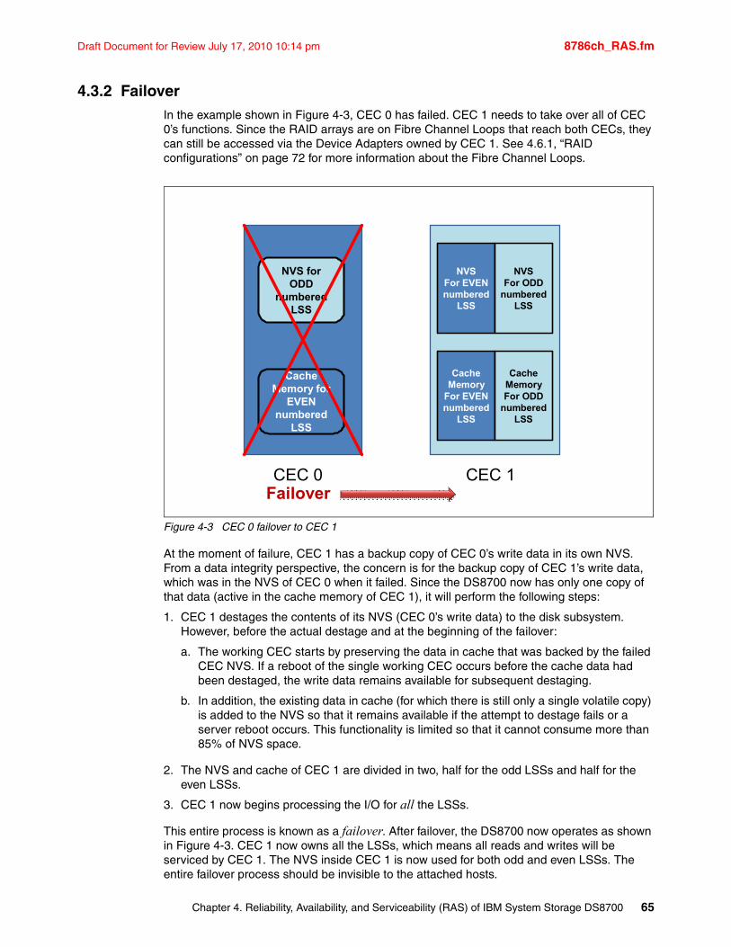
Draft Document for Review July 17, 2010 10:14 pm 8786ch_RAS.fm
4.3.2 FailoverIn the example shown in Figure 4-3, CEC 0 has failed. CEC 1 needs to take over all of CEC 0’s functions. Since the RAID arrays are on Fibre Channel Loops that reach both CECs, they can still be accessed via the Device Adapters owned by CEC 1. See 4.6.1, “RAID configurations” on page 72 for more information about the Fibre Channel Loops.
Figure 4-3 CEC 0 failover to CEC 1
At the moment of failure, CEC 1 has a backup copy of CEC 0’s write data in its own NVS. From a data integrity perspective, the concern is for the backup copy of CEC 1’s write data, which was in the NVS of CEC 0 when it failed. Since the DS8700 now has only one copy of that data (active in the cache memory of CEC 1), it will perform the following steps:
1. CEC 1 destages the contents of its NVS (CEC 0’s write data) to the disk subsystem. However, before the actual destage and at the beginning of the failover:
a. The working CEC starts by preserving the data in cache that was backed by the failed CEC NVS. If a reboot of the single working CEC occurs before the cache data had been destaged, the write data remains available for subsequent destaging.
b. In addition, the existing data in cache (for which there is still only a single volatile copy) is added to the NVS so that it remains available if the attempt to destage fails or a server reboot occurs. This functionality is limited so that it cannot consume more than 85% of NVS space.
2. The NVS and cache of CEC 1 are divided in two, half for the odd LSSs and half for the even LSSs.
3. CEC 1 now begins processing the I/O for all the LSSs.
This entire process is known as a failover. After failover, the DS8700 now operates as shown in Figure 4-3. CEC 1 now owns all the LSSs, which means all reads and writes will be serviced by CEC 1. The NVS inside CEC 1 is now used for both odd and even LSSs. The entire failover process should be invisible to the attached hosts.
CEC 0 CEC 1
Cache Memory for
EVEN numbered
LSS
NVS for ODD
numbered LSS
Failover
NVSFor EVENnumbered
LSS
NVSFor ODD
numberedLSS
CacheMemory
For EVENnumbered
LSS
CacheMemoryFor ODD
numberedLSS
Chapter 4. Reliability, Availability, and Serviceability (RAS) of IBM System Storage DS8700 65
8786ch_RAS.fm Draft Document for Review July 17, 2010 10:14 pm
The DS8700 can continue to operate in this state indefinitely. There has not been any loss of functionality, but there has been a loss of redundancy. Any critical failure in the working CEC would render the DS8700 unable to serve I/O for the arrays, so IBM support should begin work right away to determine the scope of the failure and to build an action plan to restore the failed CEC to an operational state.
4.3.3 FailbackThe failback process always begins automatically as soon as the DS8700 microcode determines that the failed CEC has been resumed to an operational state. If the failure was relatively minor and recoverable by the operating system or DS8700 microcode, then the resume action will be initiated by the software. If there was a service action with hardware components replaced, then the IBM service representative or remote support will resume the failed CEC.
For this example where CEC 0 has failed, we should now assume that CEC 0 has been repaired and has been resumed. The failback begins with CEC 1 starting to use the NVS in CEC 0 again, and the ownership of the even LSSs being transferred back to CEC 0. Normal I/O processing with both CECs operational then resumes. Just like the failover process, the failback process is invisible to the attached hosts.
In general, recovery actions (failover/failback) on the DS8700 do not impact I/O operation latency by more than 15 seconds. With certain limitations on configurations and advanced functions, this impact to latency is often limited to just 8 seconds. On logical volumes that are not configured with RAID 10 storage, there are some RAID related recoveries that cause latency impacts in excess of 15 seconds. If you have real-time response requirements in this area, contact IBM to determine the latest information about how to manage your storage to meet your requirements.
4.3.4 NVS and power outagesDuring normal operation, the DS8700 preserves write data by storing a duplicate in the NVS of the alternate CEC. To ensure that this write data is not lost due to a power event, the DS8700 contains battery backup units (BBUs). The single purpose of the BBUs is to preserve the NVS area of CEC memory in the event of a complete loss of input power to the DS8700. The design is to not move the data from NVS to the disk arrays. Instead, each CEC has dual internal SCSI disks, which are available to store the contents of NVS.
If both power supplies in the primary frame should stop receiving input power, the CECs would be informed that they are running on batteries and immediately begin a shutdown procedure. It is during this shutdown that the entire contents of NVS memory are written to the CEC hard drives so that the data will be available for destaging once the CECs are operational again. If power is lost to a single primary power supply (PPS), the ability of the other power supply to keep all batteries charged is not impacted, so the CECs would remain online.
If all the batteries were to fail (which is extremely unlikely because the batteries are in an N+1 redundant configuration), the DS8700 would lose this NVS protection and consequently would take all CECs offline because reliability and availability of host data are compromised.
The following sections show the steps followed in the event of complete power interruption.
Important: Unless the power line disturbance feature (PLD) has been purchased, the BBUs are not used to keep the storage disks in operation. They keep the CECs in operation long enough to dump NVS contents to internal hard disks.
66 IBM System Storage DS8700: Architecture and Implementation
Draft Document for Review July 17, 2010 10:14 pm 8786ch_RAS.fm
Power lossWhen an on-battery condition shutdown begins, the following events occur:
1. All host adapter I/O is blocked.
2. Each CEC begins copying its NVS data to internal disk (not the storage DDMs). For each CEC, two copies are made of the NVS data.
3. When the copy process is complete, each CEC shuts down.
4. When shutdown in each CEC is complete (or a timer expires), the DS8700 is powered down.
Power restoredWhen power is restored to the DS8700, the following events occur:
1. The CECs power on and perform power on self tests and PHYP functions.
2. Each CEC then begins boot up (IML).
3. At a certain stage in the boot process, the CEC detects NVS data on its internal SCSI disks and begins to destage it to the storage DDMs.
4. When the battery units reach a certain level of charge, the CECs come online and begin to process host I/O.
Battery chargingIn many cases, sufficient charging will occur during the power on self test, operating system boot, and microcode boot. However, if a complete discharge of the batteries has occurred, which can happen if multiple power outages occur in a short period of time, then recharging might take up to two hours.
4.4 Data flow in DS8700One of the significant hardware changes for the DS8700 is the way in which host I/O is brought into the storage unit. The DS8700 has a new design for I/O Enclosures, which house the Device Adapter and host adapter cards. The connectivity between the CECs and the I/O Enclosures has been improved as well. These changes use the many strengths of the PCI Express architecture.
Refer to 3.2.2, “Peripheral Component Interconnect Express (PCIe)” on page 33.
You can also find out more about PCI Express at the following site:
http://www.redbooks.ibm.com/Redbooks.nsf/RedbookAbstracts/tips0456.html?Open
4.4.1 New I/O enclosuresThe DS8700 I/O enclosure, also called a bay, is a new design compared to previous models of the DS8000 family. The older DS8000 bay consisted of multiple parts that required removal of the bay and disassembly for service. In the DS8700, the switch card can be replaced without removing the I/O cards, reducing time and effort in servicing the enclosure. As shown in Figure 4-1 on page 62, each CEC is connected to all four bays via PCI Express (PCIe) cables. This makes each bay an extension of each server.
Note: The CECs will not come online (process host I/O) until the batteries are sufficiently charged to handle at least one outage.
Chapter 4. Reliability, Availability, and Serviceability (RAS) of IBM System Storage DS8700 67
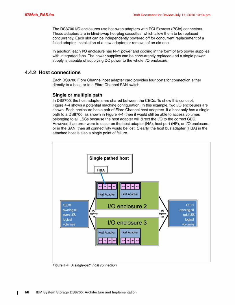
8786ch_RAS.fm Draft Document for Review July 17, 2010 10:14 pm
The DS8700 I/O enclosures use hot-swap adapters with PCI Express (PCIe) connectors. These adapters are in blind-swap hot-plug cassettes, which allow them to be replaced concurrently. Each slot can be independently powered off for concurrent replacement of a failed adapter, installation of a new adapter, or removal of an old one.
In addition, each I/O enclosure has N+1 power and cooling in the form of two power supplies with integrated fans. The power supplies can be concurrently replaced and a single power supply is capable of supplying DC power to the whole I/O enclosure.
4.4.2 Host connectionsEach DS8700 Fibre Channel host adapter card provides four ports for connection either directly to a host, or to a Fibre Channel SAN switch.
Single or multiple pathIn DS8700, the host adapters are shared between the CECs. To show this concept, Figure 4-4 shows a potential machine configuration. In this example, two I/O enclosures are shown. Each enclosure has a pair of Fibre Channel host adapters. If a host only has a single path to a DS8700, as shown in Figure 4-4, then it would still be able to access volumes belonging to all LSSs because the host adapter will direct the I/O to the correct CEC. However, if an error were to occur on the host adapter (HA), host port (HP), or I/O enclosure, or in the SAN, then all connectivity would be lost. Clearly, the host bus adapter (HBA) in the attached host is also a single point of failure.
Figure 4-4 A single-path host connection
HBA
Single pathed host
CEC 0 owning all even LSSlogicalvolumes
CEC 1owning all
odd LSSlogical
volumes
I/O enclosure 2 PCI
Expressx4
I/O enclosure 3
HP HP HP HP
Host Adapter
HP HP HP HP
HP HP HP HP HP HP HP HP
PCI Express
x4
Host Adapter
Host AdapterHost Adapter
68 IBM System Storage DS8700: Architecture and Implementation
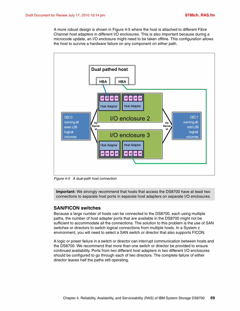
Draft Document for Review July 17, 2010 10:14 pm 8786ch_RAS.fm
A more robust design is shown in Figure 4-5 where the host is attached to different Fibre Channel host adapters in different I/O enclosures. This is also important because during a microcode update, an I/O enclosure might need to be taken offline. This configuration allows the host to survive a hardware failure on any component on either path.
Figure 4-5 A dual-path host connection
SAN/FICON switches Because a large number of hosts can be connected to the DS8700, each using multiple paths, the number of host adapter ports that are available in the DS8700 might not be sufficient to accommodate all the connections. The solution to this problem is the use of SAN switches or directors to switch logical connections from multiple hosts. In a System z environment, you will need to select a SAN switch or director that also supports FICON.
A logic or power failure in a switch or director can interrupt communication between hosts and the DS8700. We recommend that more than one switch or director be provided to ensure continued availability. Ports from two different host adapters in two different I/O enclosures should be configured to go through each of two directors. The complete failure of either director leaves half the paths still operating.
Important: We strongly recommend that hosts that access the DS8700 have at least two connections to separate host ports in separate host adapters on separate I/O enclosures.
HBA
Dual pathed host
CEC 0 owning all even LSSlogicalvolumes
CEC 1owning all
odd LSSlogical
volumes
I/O enclosure 2 PCI
Expressx4
I/O enclosure 3
HP HP HP HP HP HP HP HP
HP HP HP HP HP HP HP HP
HBA
PCI Express
x4
Host AdapterHost Adapter
Host AdapterHost Adapter
Chapter 4. Reliability, Availability, and Serviceability (RAS) of IBM System Storage DS8700 69
8786ch_RAS.fm Draft Document for Review July 17, 2010 10:14 pm
Multipathing softwareEach attached host operating system requires a mechanism to allow it to manage multiple paths to the same device, and to preferably load balance these requests. Also, when a failure occurs on one redundant path, then the attached host must have a mechanism to allow it to detect that one path is gone and route all I/O requests for those logical devices to an alternative path. Finally, it should be able to detect when the path has been restored so that the I/O can again be load-balanced. The mechanism that will be used varies by attached host operating system and environment, as detailed in the next two sections.
Open systems and SDDIn the majority of open systems environments, we strongly recommend the use of the Subsystem Device Driver (SDD) to manage both path failover and preferred path determination. SDD is a software product that IBM supplies free of charge with the DS8700.
SDD provides availability through automatic I/O path failover. If a failure occurs in the data path between the host and the DS8700, SDD automatically switches the I/O to another path. SDD will also automatically set the failed path back online after a repair is made. SDD also improves performance by sharing I/O operations to a common disk over multiple active paths to distribute and balance the I/O workload.
SDD is not available for every supported operating system. Refer to the IBM System Storage DS8000 Host Systems Attachment Guide, SC26-7917, and the interoperability Web site for guidance about which multipathing software might be required. Refer to the IBM System Storage Interoperability Center (SSIC), found at:
http://www.ibm.com/systems/support/storage/config/ssic/index.jsp
For more information about the SDD, refer to 15.1.4, “Multipathing support: Subsystem Device Driver (SDD)” on page 400.
System zIn the System z environment, the normal practice is to provide multiple paths from each host to a disk subsystem. Typically, four paths are installed. The channels in each host that can access each logical control unit (LCU) in the DS8700 are defined in the hardware configuration definition (HCD) or I/O configuration data set (IOCDS) for that host. Dynamic Path Selection (DPS) allows the channel subsystem to select any available (non-busy) path to initiate an operation to the disk subsystem. Dynamic Path Reconnect (DPR) allows the DS8700 to select any available path to a host to reconnect and resume a disconnected operation, for example, to transfer data after disconnection due to a cache miss.
These functions are part of the System z architecture and are managed by the channel subsystem on the host and the DS8700.
A physical FICON path is established when the DS8700 port sees light on the fiber (for example, a cable is plugged in to a DS8700 host adapter, a processor or the DS8700 is powered on, or a path is configured online by z/OS). At this time, logical paths are established through the port between the host and some or all of the LCUs in the DS8700, controlled by the HCD definition for that host. This happens for each physical path between a System z CPU and the DS8700. There may be multiple system images in a CPU. Logical paths are established for each system image. The DS8700 then knows which paths can be used to communicate between each LCU and each host.
70 IBM System Storage DS8700: Architecture and Implementation
Draft Document for Review July 17, 2010 10:14 pm 8786ch_RAS.fm
Control Unit Initiated ReconfigurationControl Unit Initiated Reconfiguration (CUIR) prevents loss of access to volumes in System z environments due to wrong path handling. This function automates channel path management in System z environments, in support of selected DS8700 service actions.
CUIR is available for the DS8700 when operated in the z/OS and z/VM® environments. CUIR provides automatic channel path vary on and vary off actions to minimize manual operator intervention during selected DS8700 service actions.
CUIR also allows the DS8700 to request that all attached system images set all paths required for a particular service action to the offline state. System images with the appropriate level of software support respond to such requests by varying off the affected paths, and either notifying the DS8700 subsystem that the paths are offline, or that it cannot take the paths offline. CUIR reduces manual operator intervention and the possibility of human error during maintenance actions, at the same time reducing the time required for the maintenance. This is particularly useful in environments where there are many z/OS or z/VM systems attached to a DS8700.
4.4.3 Metadata checksWhen application data enters the DS8700, special codes or metadata, also known as redundancy checks, are appended to that data. This metadata remains associated with the application data as it is transferred throughout the DS8700. The metadata is checked by various internal components to validate the integrity of the data as it moves throughout the disk system. It is also checked by the DS8700 before the data is sent to the host in response to a read I/O request. Further, the metadata also contains information used as an additional level of verification to confirm that the data returned to the host is coming from the desired location on the disk.
4.5 RAS on the HMCThe HMC is used to perform configuration, management, and maintenance activities on the DS8700. It can be ordered to be located either physically inside the base frame or external for mounting in a client-supplied rack. The DS8700 HMC is able to work with IPv4, IPv6, or a combination of both IP standards. For further information, refer to 8.3, “Network connectivity planning” on page 192.
If the HMC is not operational, then it is not possible to perform maintenance, power the DS8700 up or down, perform modifications to the logical configuration, or perform Copy Services tasks, such as the establishment of FlashCopies using DSCLI or DS GUI. We recommend that you order two management consoles to act as a redundant pair. Alternatively, if Tivoli Storage Productivity Center for Replication (TPC-R) is used, Copy Services tasks can be managed by that tool if the HMC is unavailable.
Important: The HMC described here is the Storage HMC, not to be confused with the SSPC console, which is also required with any new DS8700. SSPC is described in 3.8, “System Storage Productivity Center (SSPC)” on page 51.
Note: The above alternative is only available if you have purchased and configured the TPC-R management solution.
Chapter 4. Reliability, Availability, and Serviceability (RAS) of IBM System Storage DS8700 71
8786ch_RAS.fm Draft Document for Review July 17, 2010 10:14 pm
4.5.1 HardwareThe DS8700 ships with a mobile computer HMC (Lenovo ThinkPad Model W500). A second HMC, highly recommended, can be ordered for redundancy. The second HMC is external to the DS8700 rack(s). For more information about the HMC and network connections, refer to 9.1.1, “Storage HMC hardware” on page 206.
4.5.2 Microcode updatesThe DS8700 contains many discrete redundant components. Most of these components have firmware that can be updated. This includes the PPS, FCIC cards, device adapters, and host adapters. Both DS8700 CECs also have an operating system (AIX) and Licensed Machine Code (LMC) that can be updated. As IBM continues to develop and improve the DS8700, new releases of firmware and licensed machine code become available to offer improvements in both function and reliability.
For a detailed discussion about microcode updates, refer to Chapter 18, “Licensed machine code” on page 537.
Concurrent code updatesThe architecture of the DS8700 allows for concurrent code updates. This is achieved by using the redundant design of the DS8700. In general, redundancy is lost for a short period as each component in a redundant pair is updated.
4.5.3 Call Home and Remote SupportCall Home is the capability of the HMC to contact IBM support services to report a problem. This is referred to as Call Home for service. The HMC will also provide machine-reported product data (MRPD) to IBM by way of the Call Home facility.
IBM Service personnel located outside of the client facility log in to the HMC to provide remote service and support. Remote support as well as the Call Home option are described in detail in Chapter 20, “Remote support” on page 557.
4.6 RAS on the disk subsystemThe reason for the DS8700’s existence is to safely store and retrieve large amounts of data. Redundant Array of Independent Disks (RAID) is an industry-wide implementation of methods to store data on multiple physical disks in order to enhance the availability of that data. There are many variants of RAID in use today. The DS8700 supports RAID 5, RAID 6, and RAID 10. It does not support the non-RAID configuration of disks better known as JBOD (just a bunch of disks).
4.6.1 RAID configurationsThe following RAID configurations are possible for the DS8700:
� 6+P RAID 5 configuration: The array consists of six data drives and one parity drive. The remaining drive on the array site is used as a spare.
� 7+P RAID 5 configuration: The array consists of seven data drives and one parity drive.
Note: RAID 5 implementations are not compatible with the use of SATA disk drives. Solid state drives (SSD) support only RAID 5.
72 IBM System Storage DS8700: Architecture and Implementation
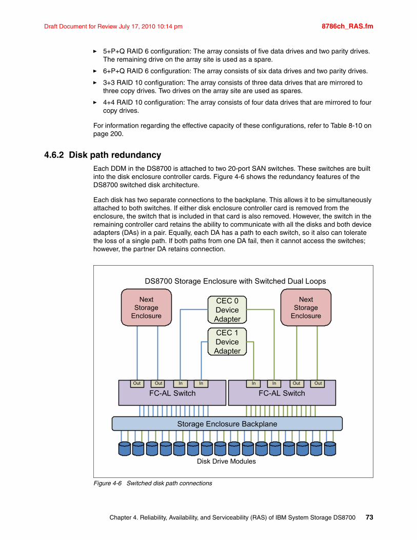
Draft Document for Review July 17, 2010 10:14 pm 8786ch_RAS.fm
� 5+P+Q RAID 6 configuration: The array consists of five data drives and two parity drives. The remaining drive on the array site is used as a spare.
� 6+P+Q RAID 6 configuration: The array consists of six data drives and two parity drives.
� 3+3 RAID 10 configuration: The array consists of three data drives that are mirrored to three copy drives. Two drives on the array site are used as spares.
� 4+4 RAID 10 configuration: The array consists of four data drives that are mirrored to four copy drives.
For information regarding the effective capacity of these configurations, refer to Table 8-10 on page 200.
4.6.2 Disk path redundancyEach DDM in the DS8700 is attached to two 20-port SAN switches. These switches are built into the disk enclosure controller cards. Figure 4-6 shows the redundancy features of the DS8700 switched disk architecture.
Each disk has two separate connections to the backplane. This allows it to be simultaneously attached to both switches. If either disk enclosure controller card is removed from the enclosure, the switch that is included in that card is also removed. However, the switch in the remaining controller card retains the ability to communicate with all the disks and both device adapters (DAs) in a pair. Equally, each DA has a path to each switch, so it also can tolerate the loss of a single path. If both paths from one DA fail, then it cannot access the switches; however, the partner DA retains connection.
Figure 4-6 Switched disk path connections
Storage Enclosure Backplane
FC-AL Switch FC-AL Switch
CEC 0DeviceAdapter
CEC 1DeviceAdapter
NextStorage
Enclosure
NextStorage
Enclosure
InOut In In InOut Out Out
Disk Drive Modules
DS8700 Storage Enclosure with Switched Dual Loops
Chapter 4. Reliability, Availability, and Serviceability (RAS) of IBM System Storage DS8700 73
8786ch_RAS.fm Draft Document for Review July 17, 2010 10:14 pm
Figure 4-6 on page 73 also shows the connection paths to the neighboring Storage Enclosures. Because expansion is done in this linear fashion, the addition of more enclosures is completely nondisruptive.
Refer to 3.4, “Disk subsystem” on page 41 for more information about the disk subsystem of the DS8700.
4.6.3 Predictive failure analysisThe drives used in the DS8700 incorporate Predictive Failure Analysis (PFA) and can anticipate certain forms of failures by keeping internal statistics of read and write errors. If the error rates exceed predetermined threshold values, the drive will be nominated for replacement. Because the drive has not yet failed, data can be copied directly to a spare drive. This avoids using RAID recovery to reconstruct all of the data onto the spare drive.
4.6.4 Disk scrubbingThe DS8700 will periodically read all sectors on a disk. This is designed to occur without any interference with application performance. If ECC-correctable bad bits are identified, the bits are corrected immediately by the DS8700. This reduces the possibility of multiple bad bits accumulating in a sector beyond the ability of ECC to correct them. If a sector contains data that is beyond ECC's ability to correct, then RAID is used to regenerate the data and write a new copy onto a spare sector of the disk. This scrubbing process applies to both array members and spare DDMs.
4.6.5 RAID 5 overviewThe DS8700 series supports RAID 5 arrays. RAID 5 is a method of spreading volume data plus parity data across multiple disk drives. RAID 5 provides faster performance by striping data across a defined set of DDMs. Data protection is provided by the generation of parity information for every stripe of data. If an array member fails, then its contents can be regenerated by using the parity data.
RAID 5 implementation in DS8700In a DS8700, a RAID 5 array built on one array site will contain either seven or eight disks depending on whether the array site is supplying a spare. A seven-disk array effectively uses one disk for parity, so it is referred to as a 6+P array (where the P stands for parity). The reason only seven disks are available to a 6+P array is that the eighth disk in the array site used to build the array was used as a spare. We then refer to this as a 6+P+S array site (where the S stands for spare). An 8-disk array also effectively uses 1 disk for parity, so it is referred to as a 7+P array.
Drive failure with RAID 5When a disk drive module fails in a RAID 5 array, the device adapter starts an operation to reconstruct the data that was on the failed drive onto one of the spare drives. The spare that is used will be chosen based on a smart algorithm that looks at the location of the spares and the size and location of the failed DDM. The rebuild is performed by reading the corresponding data and parity in each stripe from the remaining drives in the array, then performing an exclusive-OR operation to recreate the data, and then writing this data to the spare drive.
74 IBM System Storage DS8700: Architecture and Implementation
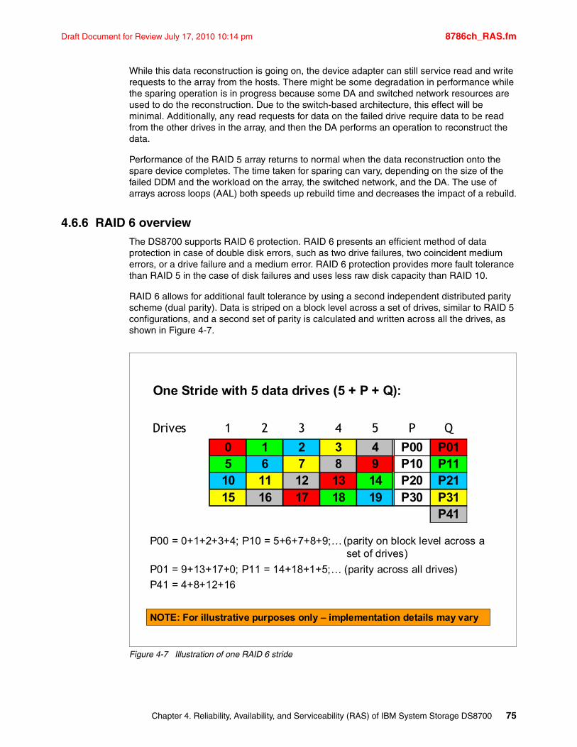
Draft Document for Review July 17, 2010 10:14 pm 8786ch_RAS.fm
While this data reconstruction is going on, the device adapter can still service read and write requests to the array from the hosts. There might be some degradation in performance while the sparing operation is in progress because some DA and switched network resources are used to do the reconstruction. Due to the switch-based architecture, this effect will be minimal. Additionally, any read requests for data on the failed drive require data to be read from the other drives in the array, and then the DA performs an operation to reconstruct the data.
Performance of the RAID 5 array returns to normal when the data reconstruction onto the spare device completes. The time taken for sparing can vary, depending on the size of the failed DDM and the workload on the array, the switched network, and the DA. The use of arrays across loops (AAL) both speeds up rebuild time and decreases the impact of a rebuild.
4.6.6 RAID 6 overviewThe DS8700 supports RAID 6 protection. RAID 6 presents an efficient method of data protection in case of double disk errors, such as two drive failures, two coincident medium errors, or a drive failure and a medium error. RAID 6 protection provides more fault tolerance than RAID 5 in the case of disk failures and uses less raw disk capacity than RAID 10.
RAID 6 allows for additional fault tolerance by using a second independent distributed parity scheme (dual parity). Data is striped on a block level across a set of drives, similar to RAID 5 configurations, and a second set of parity is calculated and written across all the drives, as shown in Figure 4-7.
Figure 4-7 Illustration of one RAID 6 stride
Drives 1 2 3 4 5 P Q
0 1 2 3 4 P00 P015 6 7 8 9 P10 P1110 11 12 13 14 P20 P2115 16 17 18 19 P30 P31
P41
One Stride with 5 data drives (5 + P + Q):
P00 = 0+1+2+3+4; P10 = 5+6+7+8+9;…(parity on block level across a set of drives)
P01 = 9+13+17+0; P11 = 14+18+1+5;… (parity across all drives)
P41 = 4+8+12+16
NOTE: For illustrative purposes only – implementation details may vary
Chapter 4. Reliability, Availability, and Serviceability (RAS) of IBM System Storage DS8700 75
8786ch_RAS.fm Draft Document for Review July 17, 2010 10:14 pm
RAID 6 is best used in combination with large capacity disk drives, such as the 1 TB and 2 TB SATA drives, because they have a longer rebuild time. Comparing RAID 6 to RAID 5 performance gives about the same results on reads. For random writes, the throughput of a RAID 6 array is around only two thirds of a RAID 5, given the additional parity handling. Workload planning is especially important before implementing RAID 6 for write intensive applications, including copy services targets and FlashCopy SE repositories. Yet, when properly sized for the I/O demand, RAID 6 is a considerable reliability enhancement.
RAID 6 implementation in the DS8700A RAID 6 array in one array site of a DS8700 can be built on either seven or eight disks:
� In a seven-disk array, two disks are always used for parity, while the eighth disk of the array site is needed as a spare. This kind of a RAID 6 array is hereafter referred to as a 5+P+Q+S array, where P and Q stand for parity and S stands for spare.
� A RAID 6 array, consisting of eight disks, will be built when all necessary spare drives are available. An eight-disk RAID 6 array also always uses two disks for parity, so it is referred to as a 6+P+Q array.
Drive failure with RAID 6When a disk drive module (DDM) fails in a RAID 6 array, the device adapter (DA) starts to reconstruct the data of the failing drive onto one of the available spare drives. A smart algorithm determines the location of the spare drive to be used, depending on the size and the location of the failed DDM. After the spare drive has replaced a failed one in a redundant array, the recalculation of the entire contents of the new drive is performed by reading the corresponding data and parity in each stripe from the remaining drives in the array and then writing this data to the spare drive.
During the rebuild of the data on the new drive, the device adapter can still handle I/O requests of the connected hosts to the affected array. Some performance degradation could occur during the reconstruction because some device adapters and switched network resources are used to do the rebuild. Due to the switch-based architecture of the DS8700, this effect will be minimal. Additionally, any read requests for data on the failed drive require data to be read from the other drives in the array, and then the DA performs an operation to reconstruct the data. Any subsequent failure during the reconstruction within the same array (second drive failure, second coincident medium errors, or a drive failure and a medium error) can be recovered without loss of data.
Performance of the RAID 6 array returns to normal when the data reconstruction on the spare device has completed. The rebuild time will vary, depending on the size of the failed DDM and the workload on the array and the DA. The completion time is comparable to a RAID 5 rebuild, but slower than rebuilding a RAID 10 array in the case of a single drive failure.
4.6.7 RAID 10 overviewRAID 10 provides high availability by combining features of RAID 0 and RAID 1. RAID 0 optimizes performance by striping volume data across multiple disk drives at a time. RAID 1 provides disk mirroring, which duplicates data between two disk drives. By combining the features of RAID 0 and RAID 1, RAID 10 provides a second optimization for fault tolerance. Data is striped across half of the disk drives in the RAID 1 array. The same data is also striped across the other half of the array, creating a mirror. Access to data is preserved if one disk in each mirrored pair remains available. RAID 10 offers faster data reads and writes than RAID 5 because it does not need to manage parity. However, with half of the DDMs in the group used for data and the other half to mirror that data, RAID 10 disk groups have less capacity than RAID 5 disk groups.
76 IBM System Storage DS8700: Architecture and Implementation
Draft Document for Review July 17, 2010 10:14 pm 8786ch_RAS.fm
RAID 10 is not as commonly used as RAID 5, mainly because more raw disk capacity is needed for every gigabyte of effective capacity. A typical area of operation for RAID 10 are workloads with a high random write ratio.
RAID 10 implementation in DS8700In the DS8700, the RAID 10 implementation is achieved using either six or eight DDMs. If spares need to be allocated on the array site, then six DDMs are used to make a three-disk RAID 0 array, which is then mirrored. If spares do not need to be allocated, then eight DDMs are used to make a four-disk RAID 0 array, which is then mirrored.
Drive failure with RAID 10When a disk drive module (DDM) fails in a RAID 10 array, the controller starts an operation to reconstruct the data from the failed drive onto one of the hot spare drives. The spare that is used will be chosen based on a smart algorithm that looks at the location of the spares and the size and location of the failed DDM. Remember a RAID 10 array is effectively a RAID 0 array that is mirrored. Thus, when a drive fails in one of the RAID 0 arrays, we can rebuild the failed drive by reading the data from the equivalent drive in the other RAID 0 array.
While this data reconstruction is going on, the DA can still service read and write requests to the array from the hosts. There might be some degradation in performance while the sparing operation is in progress, because some DA and switched network resources are used to do the reconstruction. Due to the switch-based architecture of the DS8700, this effect will be minimal. Read requests for data on the failed drive should not be affected because they can all be directed to the good RAID 1 array.
Write operations will not be affected. Performance of the RAID 10 array returns to normal when the data reconstruction onto the spare device completes. The time taken for sparing can vary, depending on the size of the failed DDM and the workload on the array and the DA. In relation to a RAID 5, RAID 10 sparing completion time is a little faster. This is because rebuilding a RAID 5 6+P configuration requires six reads plus one parity operation for each write, while a RAID 10 3+3 configuration requires one read and one write (essentially a direct copy).
Arrays across loops and RAID 10The DS8700 implements the concept of arrays across loops (AAL). With AAL, an array site is actually split into two halves. Half of the site is located on the first disk loop of a DA pair and the other half is located on the second disk loop of that DA pair. AAL is implemented primarily to maximize performance and it is used for all the RAID types in the DS8700. However, in RAID 10, we are able to take advantage of AAL to provide a higher level of redundancy. The DS8700 RAS code will deliberately ensure that one RAID 0 array is maintained on each of the two loops created by a DA pair. This means that in the extremely unlikely event of a complete loop outage, the DS8700 would not lose access to the RAID 10 array. This is because while one RAID 0 array is offline, the other remains available to service disk I/O. Figure 3-15 on page 46 shows a diagram of this strategy.
4.6.8 Spare creationWhen the arrays are created on a DS8700, the microcode determines which array sites will contain spares. The first array sites in each DA pair that are assigned to arrays will contribute one or two spares (depending on the RAID option), until the DA pair has access to at least four spares, with two spares being placed on each loop.
Chapter 4. Reliability, Availability, and Serviceability (RAS) of IBM System Storage DS8700 77
8786ch_RAS.fm Draft Document for Review July 17, 2010 10:14 pm
A minimum of one spare is created for each array site assigned to an array until the following conditions are met:
� There are a minimum of four spares per DA pair.
� There are a minimum of four spares for the largest capacity array site on the DA pair.
� There are a minimum of two spares of capacity and RPM greater than or equal to the fastest array site of any given capacity on the DA pair.
Floating sparesThe DS8700 implements a smart floating technique for spare DDMs. A floating spare is defined as follows: When a DDM fails and the data it contained is rebuilt onto a spare, then when the disk is replaced, the replacement disk becomes the spare. The data is not migrated to another DDM, such as the DDM in the original position the failed DDM occupied.
The DS8700 microcode takes this idea one step further. It might choose to allow the hot spare to remain where it has been moved, but it can instead choose to migrate the spare to a more optimum position. This will be done to better balance the spares across the DA pairs, the loops, and the enclosures. It might be preferable that a DDM that is currently in use as an array member is converted to a spare. In this case, the data on that DDM will be migrated in the background onto an existing spare. This process does not fail the disk that is being migrated, though it does reduce the number of available spares in the DS8700 until the migration process is complete.
The DS8700 uses this smart floating technique so that the larger or higher RPM DDMs are allocated as spares, to guarantee that a spare can provide at least the same capacity and performance as the replaced drive. If we were to rebuild the contents of a 300 GB DDM onto a 450 GB DDM, then approximately half of the 450 GB DDM will be wasted, because that space is not needed. When the failed 300 GB DDM is replaced with a new 300 GB DDM, the DS8700 microcode will most likely migrate the data back onto the recently replaced 300 GB DDM. When this process completes, the 300 GB DDM will rejoin the array and the 450 GB DDM will become the spare again.
Another example would be if we fail a 300 GB 15K RPM DDM onto a 1 TB 7.2K RPM DDM. The data has now moved to a slower DDM and is wasting a lot of space. This means the array will have a mix of RPMs, which is not desirable. When the failed disk is replaced, the replacement will be the same type as the failed 15K RPM disk. Again, a smart migration of the data will be performed once suitable spares have become available.
Hot-pluggable DDMsReplacement of a failed drive does not affect the operation of the DS8700, because the drives are fully hot-pluggable. Due to the fact that each disk plugs into a switch, there is no loop break associated with the removal or replacement of a disk. In addition, there is no potentially disruptive loop initialization process.
Overconfiguration of sparesThe DDM sparing policies support the overconfiguration of spares. This possibility might be of interest to some installations, because it allows the repair of some DDM failures to be deferred until a later repair action is required.
78 IBM System Storage DS8700: Architecture and Implementation
Draft Document for Review July 17, 2010 10:14 pm 8786ch_RAS.fm
4.7 RAS on the power subsystemThe DS8700 has completely redundant power and cooling. Every power supply and cooling fan in the DS8700 operates in what is known as N+1 mode. This means that there is always at least one more power supply, cooling fan, or battery than is required for normal operation. In most cases, this simply means duplication.
4.7.1 ComponentsHere we discuss the power subsystem components.
Primary power suppliesEach frame has two primary power supplies (PPS). Each PPS produces voltages for two different areas of the machine:
� 208V is produced to be supplied to each I/O enclosure and each processor complex. This voltage is placed by each supply onto two redundant power buses.
� 12V and 5V are produced to be supplied to the disk enclosures.
If either PPS fails, the other can continue to supply all required voltage to all power buses in that frame. The PPS can be replaced concurrently.
Battery backup unitsEach frame with I/O enclosures, or every frame if the power line disturbance (PLD) feature is installed, will have battery backup units (BBUs). Each BBU can be replaced concurrently, provided no more than one BBU is unavailable at any one time. The DS8700 BBUs have a planned working life of at least four years.
Rack cooling fansEach frame has a cooling fan plenum located above the disk enclosures. The fans in this plenum draw air from the front of the DDMs and then move it out through the top of the frame. There are multiple redundant fans in each enclosure. Each fan can be replaced concurrently.
Rack power control card (RPC)The rack power control cards are part of the power management infrastructure of the DS8700. There are two RPC cards for redundancy. Each card can independently control power for the entire DS8700.
Important: It should be noted that if you install the DS8700 such that both primary power supplies are attached to the same circuit breaker or the same switchboard, then the DS8700 will not be well protected from external power failures. This is a very common cause of unplanned outages.
Attention: Do not store any objects on top of a DS8700 frame that would block the airflow through the vent.
Chapter 4. Reliability, Availability, and Serviceability (RAS) of IBM System Storage DS8700 79
8786ch_RAS.fm Draft Document for Review July 17, 2010 10:14 pm
System Power Control NetworkThe System Power Control Network (SPCN) is used to control the power of the attached I/O subsystem. The SPCN monitors environmental components such as power, fans, and temperature. Environmental critical and noncritical conditions can generate Early Power-Off Warning (EPOW) events. Critical events trigger appropriate signals from the hardware to the affected components to prevent any data loss without operating system or firmware involvement. Non-critical environmental events are also logged and reported.
4.7.2 Line power lossThe DS8700 uses an area of server memory as nonvolatile storage (NVS). This area of memory is used to hold data that has not been written to the disk subsystem. If line power were to fail, where both primary power supplies (PPS) in the primary frame were to report a loss of AC input power, then the DS8700 must take action to protect that data. Refer to 4.3, “CEC failover and failback” on page 63 for a full explanation of NVS Cache operation.
4.7.3 Line power fluctuationThe DS8700 primary frame contains battery backup units that are intended to protect modified data in the event of a complete power loss. If a power fluctuation occurs that causes a momentary interruption to power (often called a brownout), then the DS8700 will tolerate this for approximately 30 ms. If the power line disturbance feature is not present on the DS8700, then after that time, the DDMs will stop spinning and the servers will begin copying the contents of NVS to the internal SCSI disks in the processor complexes. For many clients, who use uninterruptible power supply (UPS) technology, this is not an issue. UPS-regulated power is in general very reliable, so additional redundancy in the attached devices is often completely unnecessary.
Power line disturbance (PLD)If line power is not considered reliable, then the addition of the extended power line disturbance feature should be considered. This feature adds two separate pieces of hardware to the DS8700:
� For each primary power supply in each frame of the DS8700, a booster module is added that converts 208V battery power into 12V and 5V. This supplies the storage DDMs with power directly from the batteries.
� Batteries will be added to expansion frames that did not already have them. Primary frames (1) and expansion frames with I/O enclosures (2) get batteries by default. Expansion frames that do not have I/O enclosures (3, 4, and 5) normally do not get batteries.
With the addition of this hardware, the DS8700 will be able to run for up to 50 seconds on battery power before the CECs begin to copy NVS to internal disk and then shut down. This would allow for a 50 second interruption to line power with no outage to the DS8700.
4.7.4 Power controlThe DS8700 does not possess a white power switch to turn the DS8700 storage unit off and on, as was the case with previous storage models. All power sequencing is done using the Service Processor Control Network (SPCN) and RPCs. If you want to power the DS8700 off, you must do so by using the management tools provided by the Hardware Management Console (HMC). If the HMC is not functional, then it will not be possible to control the power sequencing of the DS8700 until the HMC function is restored. This is one of the benefits that is gained by purchasing a redundant HMC.
80 IBM System Storage DS8700: Architecture and Implementation
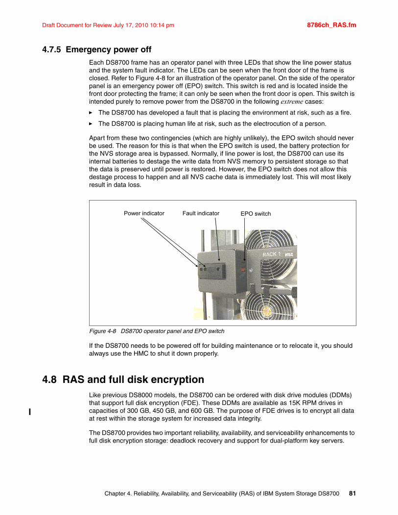
Draft Document for Review July 17, 2010 10:14 pm 8786ch_RAS.fm
4.7.5 Emergency power offEach DS8700 frame has an operator panel with three LEDs that show the line power status and the system fault indicator. The LEDs can be seen when the front door of the frame is closed. Refer to Figure 4-8 for an illustration of the operator panel. On the side of the operator panel is an emergency power off (EPO) switch. This switch is red and is located inside the front door protecting the frame; it can only be seen when the front door is open. This switch is intended purely to remove power from the DS8700 in the following extreme cases:
� The DS8700 has developed a fault that is placing the environment at risk, such as a fire.
� The DS8700 is placing human life at risk, such as the electrocution of a person.
Apart from these two contingencies (which are highly unlikely), the EPO switch should never be used. The reason for this is that when the EPO switch is used, the battery protection for the NVS storage area is bypassed. Normally, if line power is lost, the DS8700 can use its internal batteries to destage the write data from NVS memory to persistent storage so that the data is preserved until power is restored. However, the EPO switch does not allow this destage process to happen and all NVS cache data is immediately lost. This will most likely result in data loss.
Figure 4-8 DS8700 operator panel and EPO switch
If the DS8700 needs to be powered off for building maintenance or to relocate it, you should always use the HMC to shut it down properly.
4.8 RAS and full disk encryptionLike previous DS8000 models, the DS8700 can be ordered with disk drive modules (DDMs) that support full disk encryption (FDE). These DDMs are available as 15K RPM drives in capacities of 300 GB, 450 GB, and 600 GB. The purpose of FDE drives is to encrypt all data at rest within the storage system for increased data integrity.
The DS8700 provides two important reliability, availability, and serviceability enhancements to full disk encryption storage: deadlock recovery and support for dual-platform key servers.
Power indicator Fault indicator EPO switch
Chapter 4. Reliability, Availability, and Serviceability (RAS) of IBM System Storage DS8700 81
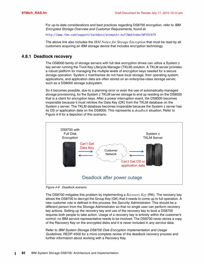
8786ch_RAS.fm Draft Document for Review July 17, 2010 10:14 pm
For up-to-date considerations and best practices regarding DS8700 encryption, refer to IBM Encrypted Storage Overview and Customer Requirements, found at:
http://www.ibm.com/support/techdocs/atsmastr.nsf/WebIndex/WP101479
The above link also includes the IBM Notice for Storage Encryption that must be read by all customers acquiring an IBM storage device that includes encryption technology.
4.8.1 Deadlock recoveryThe DS8000 family of storage servers with full disk encryption drives can utilize a System z key server running the Tivoli Key Lifecycle Manager (TKLM) solution. A TKLM server provides a robust platform for managing the multiple levels of encryption keys needed for a secure storage operation. System z mainframes do not have local storage; their operating system, applications, and application data are often stored on an enterprise-class storage server, such as a DS8000 storage subsystem.
So it becomes possible, due to a planning error or even the use of automatically-managed storage provisioning, for the System z TKLM server storage to end up residing on the DS8000 that is a client for encryption keys. After a power interruption event, the DS8000 becomes inoperable because it must retrieve the Data Key (DK) from the TKLM database on the System z server. The TKLM database becomes inoperable because the System z server has its OS or application data on the DS8000. This represents a deadlock situation. Refer to Figure 4-9 for a depiction of this scenario.
Figure 4-9 Deadlock scenario
The DS8700 mitigates this problem by implementing a Recovery Key (RK). The recovery key allows the DS8700 to decrypt the Group Key (GK) that it needs to come up to full operation. A new customer role is defined in this process: the Security Administrator. This should be a different person from the Storage Administrator so that no single user can perform recovery key actions. Setting up the recovery key and use of the recovery key to boot a DS8700 requires both people to take action. Usage of a recovery key is entirely within the customer’s control; no IBM service representative needs to be involved. The DS8700 never stores a copy of the Recovery Key on the encrypted disks and it is never included in any service data.
Refer to IBM System Storage DS8700 Disk Encryption Implementation and Usage Guidelines, REDP-4500 for a more complete review of the deadlock recovery process and further information about working with a Recovery Key.
DS8700 with Full Disk
EncryptionSystem z
TKLM Server
Storage NetworkCustomer Network
Can’t Get OS or application data
Can’t Get Data Key
Deadlock after power outage
82 IBM System Storage DS8700: Architecture and Implementation
Draft Document for Review July 17, 2010 10:14 pm 8786ch_RAS.fm
The DS8000 Licensed Machine Code (LMC) level 6.5.1.xx introduces the option to disable an encryption recovery key for a given encryption group before the encryption group is created. The state of the recovery key must be "Unconfigured" in order to disable the recovery key. If, for some reason, you do not want a recovery key, you should disable it. Recovery key that has previously been disabled can later be enabled. The actions are performed using either DSCLI or DS GUI.
Be aware that if you disable a recovery key this allows an encryption group to be configured but with no recovery alternative. Encryption deadlock recovery key is to support the ability for customer administrators to restore access to a DS8700 when the encryption key for the storage is unavailable due to an encryption deadlock scenario. If you disable the recovery key you do so at your own risk.
4.8.2 Dual platform TKLM serversThe current DS8700 full disk encryption solution requires the use of an System x SUSE Linux based key server (IKS), which operates in “clear key mode”. Customers have expressed a desire to run key servers that are hardware security module based (HSM), which operate in “secure key mode”. Key servers like the IKS, which implement a clear key design, can import and export their public and private key pair to other key servers. Servers that implement secure key design can only import and export their public key to other key servers.
To meet this request, the DS8700 allows propagation of keys across two different key server platforms. The current IKS is still supported to address the standing requirement for an isolated key server. Adding a z/OS Tivoli Key Lifecycle Manager (TKLM) Secure Key Mode server, which is common in Tape Storage environments, is concurrently supported by the DS8700.
Once the key servers are set up, they will each have two public keys. They are each capable of generating and wrapping two symmetric keys for the DS8700. The DS8700 stores both wrapped symmetric keys in the key repository. Now either key server is capable of unwrapping these keys upon a DS8700 retrieval exchange.
Refer to IBM System Storage DS8700 Disk Encryption Implementation and Usage Guidelines, REDP-4500 for more information regarding the dual-platform TKLM solution. Visit the following site for further information regarding planning and deployment of TKLM servers:
http://www.ibm.com/developerworks/wikis/display/tivolidoccentral/Tivoli+Key+Lifecycle+Manager
4.9 Other featuresThere are many more features of the DS8700 that enhance reliability, availability, and serviceability.
4.9.1 Internal networkEach DS8700 base frame contains two Gigabit Ethernet switches to allow the creation of a fully redundant management network. Each CEC in the DS8700 has a connection to each
Note: The interface for inputting a Recovery Key is through the storage HMC. This means that the Security Administrator and the Storage Administrator may need to be physically present at the DS8700 to perform the recovery.
Chapter 4. Reliability, Availability, and Serviceability (RAS) of IBM System Storage DS8700 83
8786ch_RAS.fm Draft Document for Review July 17, 2010 10:14 pm
switch. Each HMC also has a connection to each switch. This means that if a single Ethernet switch fails, then all traffic can successfully travel from either HMC to other components in the storage unit using the alternate switch.
There are also Ethernet connections for the service processor card within each CEC. If two DS8700 storage complexes are connected together, they will also use ports on the Ethernet switches. Refer to 9.1.2, “Private Ethernet networks” on page 207 for more information about the DS8700 internal network.
4.9.2 Remote supportThe DS8700 HMC has the ability to be accessed remotely by IBM service personnel for many service actions. IBM support can offload service data, change some configuration settings, and initiate repair actions over a remote connection. The customer decides which type of connection they wish to allow for remote support. Options include:
� Modem only for access to the HMC command line� VPN only for access to the HMC GUI (WebUI)� Modem and VPN� No access (secure account)
Remote support is a critical topic for customers investing in the DS8700. Refer to Chapter 20, “Remote support” on page 557 for a more thorough discussion of remote support operations. Refer to Chapter 9, “HMC planning and setup” on page 205 for more information about planning the connections needed for HMC installation.
4.9.3 Earthquake resistanceThe Earthquake Resistance Kit is an optional seismic kit for stabilizing the storage unit rack, so that the rack complies with IBM earthquake resistance standards. It helps to prevent human injury and ensures that the system will be available following the earthquake by limiting potential damage to critical system components, such as hard drives.
A storage unit rack with this optional seismic kit includes cross-braces on the front and rear of the rack which prevent the rack from twisting. Hardware at the bottom of the rack secures it to the floor. Depending on the flooring in your environment, specifically non-raised floors, installation of required floor mounting hardware might be disruptive.
This kit must be special ordered for the DS8700; contact your sales representative for further information.
Note: Connections to the customer’s network are made at the Storage HMC. No customer network connection should ever be made to the DS8700 internal Ethernet switches.
84 IBM System Storage DS8700: Architecture and Implementation
Draft Document for Review July 17, 2010 10:14 pm 8786ch_Virtualization_Concepts.fm
Chapter 5. Virtualization concepts
This chapter describes virtualization concepts as they apply to the IBM System Storage DS8000 series.
This chapter covers the following topics:
� Virtualization definition
� The abstraction layers for disk virtualization:
– Array sites– Arrays– Ranks– Extent Pools– Logical volumes– Space Efficient volumes (both Extent Space Efficient and Track Space Efficient)– Logical subsystems (LSS)– Volume access– Virtualization hierarchy summary
� Benefits of virtualization
5
© Copyright IBM Corp. 2010. All rights reserved. 85
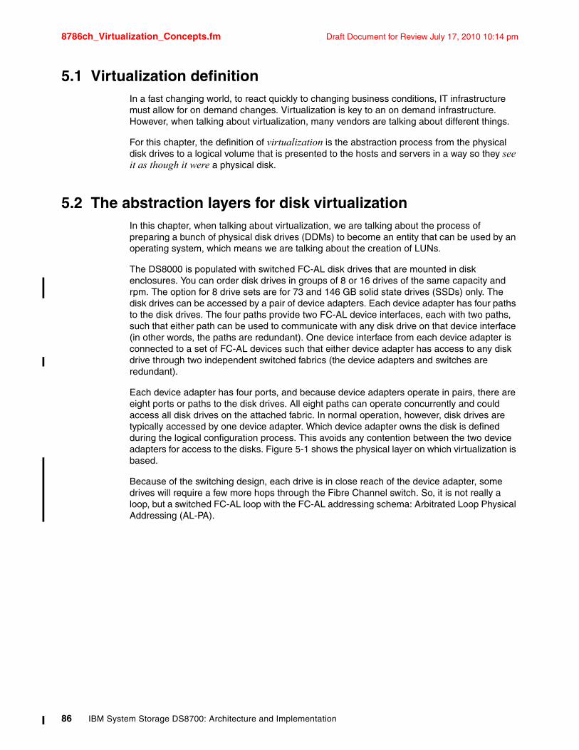
8786ch_Virtualization_Concepts.fm Draft Document for Review July 17, 2010 10:14 pm
5.1 Virtualization definitionIn a fast changing world, to react quickly to changing business conditions, IT infrastructure must allow for on demand changes. Virtualization is key to an on demand infrastructure. However, when talking about virtualization, many vendors are talking about different things.
For this chapter, the definition of virtualization is the abstraction process from the physical disk drives to a logical volume that is presented to the hosts and servers in a way so they see it as though it were a physical disk.
5.2 The abstraction layers for disk virtualizationIn this chapter, when talking about virtualization, we are talking about the process of preparing a bunch of physical disk drives (DDMs) to become an entity that can be used by an operating system, which means we are talking about the creation of LUNs.
The DS8000 is populated with switched FC-AL disk drives that are mounted in disk enclosures. You can order disk drives in groups of 8 or 16 drives of the same capacity and rpm. The option for 8 drive sets are for 73 and 146 GB solid state drives (SSDs) only. The disk drives can be accessed by a pair of device adapters. Each device adapter has four paths to the disk drives. The four paths provide two FC-AL device interfaces, each with two paths, such that either path can be used to communicate with any disk drive on that device interface (in other words, the paths are redundant). One device interface from each device adapter is connected to a set of FC-AL devices such that either device adapter has access to any disk drive through two independent switched fabrics (the device adapters and switches are redundant).
Each device adapter has four ports, and because device adapters operate in pairs, there are eight ports or paths to the disk drives. All eight paths can operate concurrently and could access all disk drives on the attached fabric. In normal operation, however, disk drives are typically accessed by one device adapter. Which device adapter owns the disk is defined during the logical configuration process. This avoids any contention between the two device adapters for access to the disks. Figure 5-1 shows the physical layer on which virtualization is based.
Because of the switching design, each drive is in close reach of the device adapter, some drives will require a few more hops through the Fibre Channel switch. So, it is not really a loop, but a switched FC-AL loop with the FC-AL addressing schema: Arbitrated Loop Physical Addressing (AL-PA).
86 IBM System Storage DS8700: Architecture and Implementation
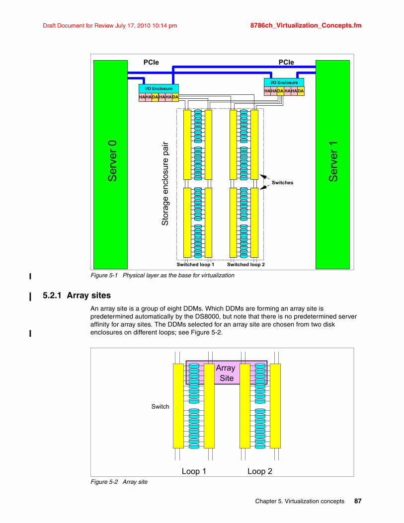
Draft Document for Review July 17, 2010 10:14 pm 8786ch_Virtualization_Concepts.fm
Figure 5-1 Physical layer as the base for virtualization
5.2.1 Array sitesAn array site is a group of eight DDMs. Which DDMs are forming an array site is predetermined automatically by the DS8000, but note that there is no predetermined server affinity for array sites. The DDMs selected for an array site are chosen from two disk enclosures on different loops; see Figure 5-2.
Figure 5-2 Array site
Ser
ver
0
Ser
ver
1
I/O Enclosure
DAHAHA HAHA DA
Sto
rage
enc
losu
re p
air
Switched loop 1
Switches
Switched loop 2
I/O Enclosure
DAHAHA HAHA DA
PCIe PCIe
Array Site
Switch
Loop 1 Loop 2
Chapter 5. Virtualization concepts 87
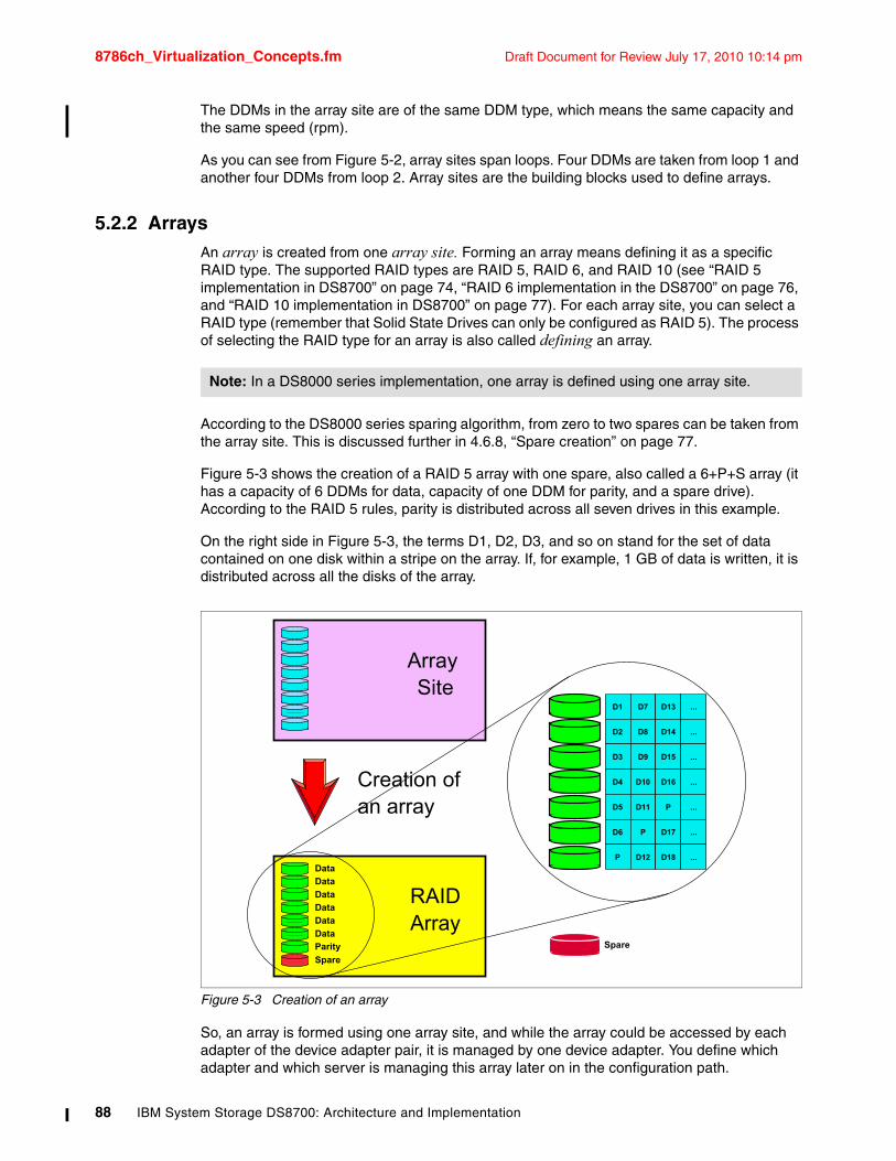
8786ch_Virtualization_Concepts.fm Draft Document for Review July 17, 2010 10:14 pm
The DDMs in the array site are of the same DDM type, which means the same capacity and the same speed (rpm).
As you can see from Figure 5-2, array sites span loops. Four DDMs are taken from loop 1 and another four DDMs from loop 2. Array sites are the building blocks used to define arrays.
5.2.2 ArraysAn array is created from one array site. Forming an array means defining it as a specific RAID type. The supported RAID types are RAID 5, RAID 6, and RAID 10 (see “RAID 5 implementation in DS8700” on page 74, “RAID 6 implementation in the DS8700” on page 76, and “RAID 10 implementation in DS8700” on page 77). For each array site, you can select a RAID type (remember that Solid State Drives can only be configured as RAID 5). The process of selecting the RAID type for an array is also called defining an array.
According to the DS8000 series sparing algorithm, from zero to two spares can be taken from the array site. This is discussed further in 4.6.8, “Spare creation” on page 77.
Figure 5-3 shows the creation of a RAID 5 array with one spare, also called a 6+P+S array (it has a capacity of 6 DDMs for data, capacity of one DDM for parity, and a spare drive). According to the RAID 5 rules, parity is distributed across all seven drives in this example.
On the right side in Figure 5-3, the terms D1, D2, D3, and so on stand for the set of data contained on one disk within a stripe on the array. If, for example, 1 GB of data is written, it is distributed across all the disks of the array.
Figure 5-3 Creation of an array
So, an array is formed using one array site, and while the array could be accessed by each adapter of the device adapter pair, it is managed by one device adapter. You define which adapter and which server is managing this array later on in the configuration path.
Note: In a DS8000 series implementation, one array is defined using one array site.
Array Site
RAIDArray
Spare
Data
Data
Data
Data
Data
Data
Parity
Creation ofan array
D1 D7 D13 ...
D2 D8 D14 ...
D3 D9 D15 ...
D4 D10 D16 ...
D5 D11 P ...
D6 P D17 ...
P D12 D18 ...
Spare
88 IBM System Storage DS8700: Architecture and Implementation
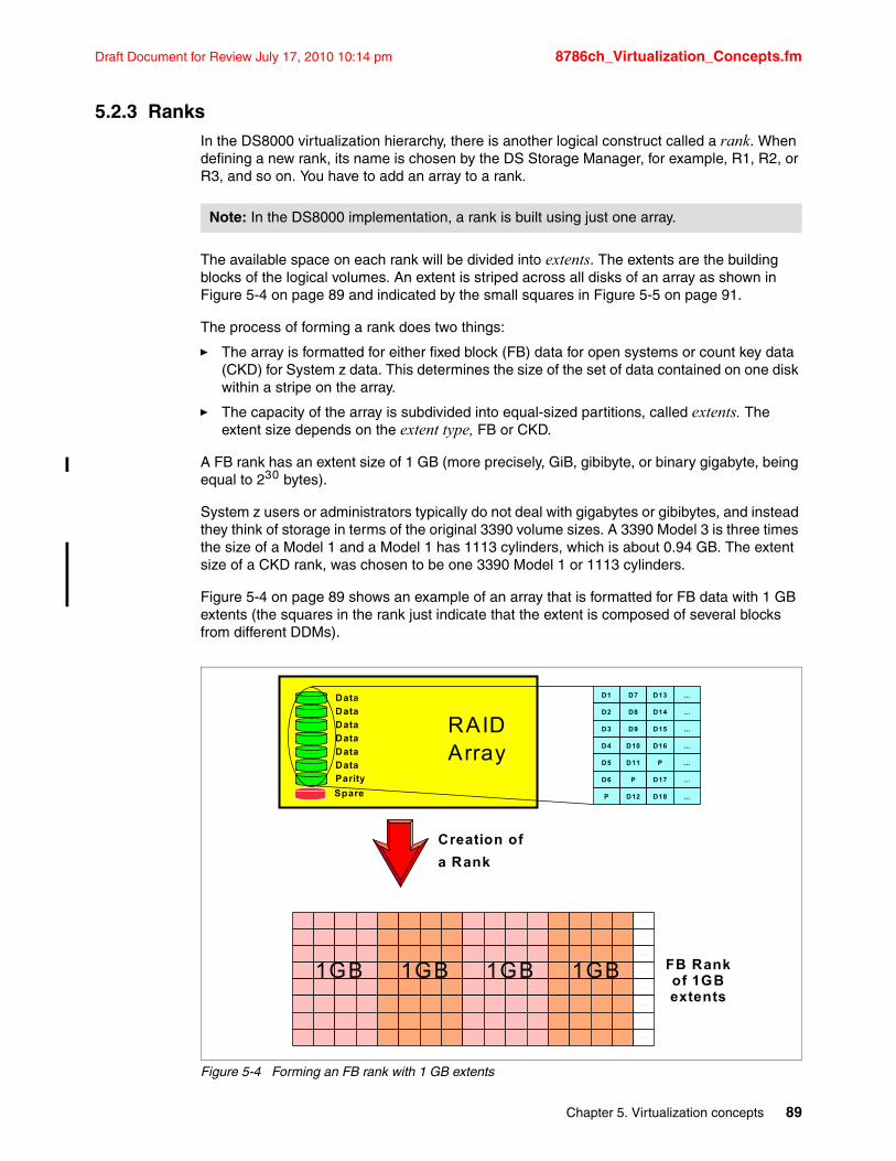
Draft Document for Review July 17, 2010 10:14 pm 8786ch_Virtualization_Concepts.fm
5.2.3 RanksIn the DS8000 virtualization hierarchy, there is another logical construct called a rank. When defining a new rank, its name is chosen by the DS Storage Manager, for example, R1, R2, or R3, and so on. You have to add an array to a rank.
The available space on each rank will be divided into extents. The extents are the building blocks of the logical volumes. An extent is striped across all disks of an array as shown in Figure 5-4 on page 89 and indicated by the small squares in Figure 5-5 on page 91.
The process of forming a rank does two things:
� The array is formatted for either fixed block (FB) data for open systems or count key data (CKD) for System z data. This determines the size of the set of data contained on one disk within a stripe on the array.
� The capacity of the array is subdivided into equal-sized partitions, called extents. The extent size depends on the extent type, FB or CKD.
A FB rank has an extent size of 1 GB (more precisely, GiB, gibibyte, or binary gigabyte, being equal to 230 bytes).
System z users or administrators typically do not deal with gigabytes or gibibytes, and instead they think of storage in terms of the original 3390 volume sizes. A 3390 Model 3 is three times the size of a Model 1 and a Model 1 has 1113 cylinders, which is about 0.94 GB. The extent size of a CKD rank, was chosen to be one 3390 Model 1 or 1113 cylinders.
Figure 5-4 on page 89 shows an example of an array that is formatted for FB data with 1 GB extents (the squares in the rank just indicate that the extent is composed of several blocks from different DDMs).
Figure 5-4 Forming an FB rank with 1 GB extents
Note: In the DS8000 implementation, a rank is built using just one array.
FB Rankof 1GBextents
Creation of
a Rank
D1 D7 D13 ...
D2 D8 D14 ...
D3 D9 D15 ...
D4 D10 D16 ...
D5 D11 P ...
D6 P D17 ...
P D12 D18 ...
RAIDArray
Spare
Data
Data
Data
Data
Data
Data
Parity
. . . .
. . . .
. . . .
. . . .
. . . .
. . . .
. . . .
. . . .
1GB 1GB 1GB 1GB
Chapter 5. Virtualization concepts 89
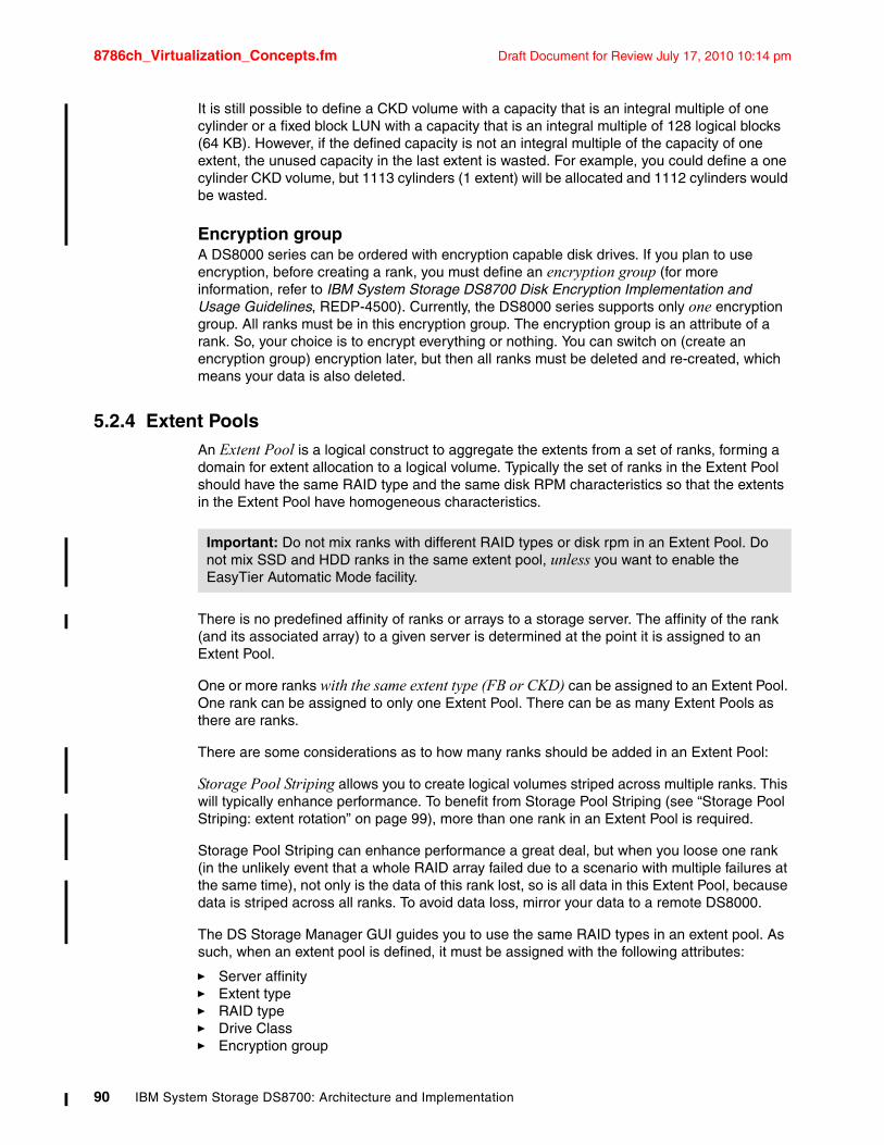
8786ch_Virtualization_Concepts.fm Draft Document for Review July 17, 2010 10:14 pm
It is still possible to define a CKD volume with a capacity that is an integral multiple of one cylinder or a fixed block LUN with a capacity that is an integral multiple of 128 logical blocks (64 KB). However, if the defined capacity is not an integral multiple of the capacity of one extent, the unused capacity in the last extent is wasted. For example, you could define a one cylinder CKD volume, but 1113 cylinders (1 extent) will be allocated and 1112 cylinders would be wasted.
Encryption groupA DS8000 series can be ordered with encryption capable disk drives. If you plan to use encryption, before creating a rank, you must define an encryption group (for more information, refer to IBM System Storage DS8700 Disk Encryption Implementation and Usage Guidelines, REDP-4500). Currently, the DS8000 series supports only one encryption group. All ranks must be in this encryption group. The encryption group is an attribute of a rank. So, your choice is to encrypt everything or nothing. You can switch on (create an encryption group) encryption later, but then all ranks must be deleted and re-created, which means your data is also deleted.
5.2.4 Extent PoolsAn Extent Pool is a logical construct to aggregate the extents from a set of ranks, forming a domain for extent allocation to a logical volume. Typically the set of ranks in the Extent Pool should have the same RAID type and the same disk RPM characteristics so that the extents in the Extent Pool have homogeneous characteristics.
There is no predefined affinity of ranks or arrays to a storage server. The affinity of the rank (and its associated array) to a given server is determined at the point it is assigned to an Extent Pool.
One or more ranks with the same extent type (FB or CKD) can be assigned to an Extent Pool. One rank can be assigned to only one Extent Pool. There can be as many Extent Pools as there are ranks.
There are some considerations as to how many ranks should be added in an Extent Pool:
Storage Pool Striping allows you to create logical volumes striped across multiple ranks. This will typically enhance performance. To benefit from Storage Pool Striping (see “Storage Pool Striping: extent rotation” on page 99), more than one rank in an Extent Pool is required.
Storage Pool Striping can enhance performance a great deal, but when you loose one rank (in the unlikely event that a whole RAID array failed due to a scenario with multiple failures at the same time), not only is the data of this rank lost, so is all data in this Extent Pool, because data is striped across all ranks. To avoid data loss, mirror your data to a remote DS8000.
The DS Storage Manager GUI guides you to use the same RAID types in an extent pool. As such, when an extent pool is defined, it must be assigned with the following attributes:
� Server affinity� Extent type� RAID type� Drive Class� Encryption group
Important: Do not mix ranks with different RAID types or disk rpm in an Extent Pool. Do not mix SSD and HDD ranks in the same extent pool, unless you want to enable the EasyTier Automatic Mode facility.
90 IBM System Storage DS8700: Architecture and Implementation
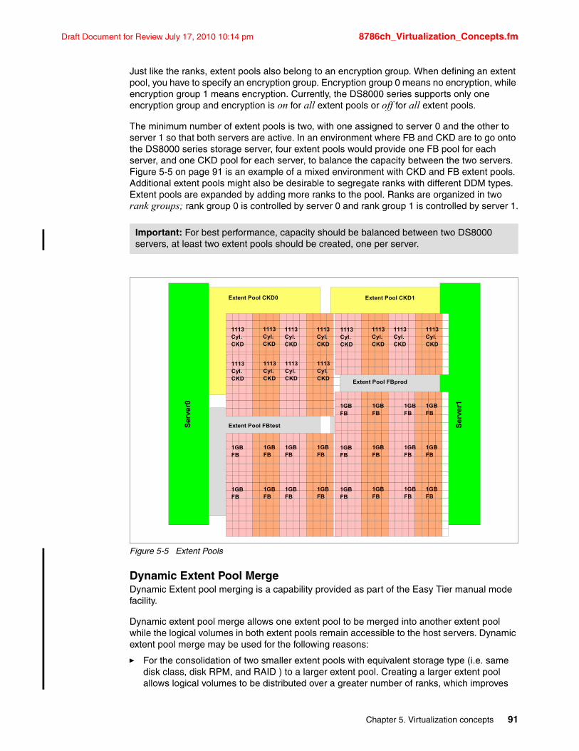
Draft Document for Review July 17, 2010 10:14 pm 8786ch_Virtualization_Concepts.fm
Just like the ranks, extent pools also belong to an encryption group. When defining an extent pool, you have to specify an encryption group. Encryption group 0 means no encryption, while encryption group 1 means encryption. Currently, the DS8000 series supports only one encryption group and encryption is on for all extent pools or off for all extent pools.
The minimum number of extent pools is two, with one assigned to server 0 and the other to server 1 so that both servers are active. In an environment where FB and CKD are to go onto the DS8000 series storage server, four extent pools would provide one FB pool for each server, and one CKD pool for each server, to balance the capacity between the two servers. Figure 5-5 on page 91 is an example of a mixed environment with CKD and FB extent pools. Additional extent pools might also be desirable to segregate ranks with different DDM types. Extent pools are expanded by adding more ranks to the pool. Ranks are organized in two rank groups; rank group 0 is controlled by server 0 and rank group 1 is controlled by server 1.
Figure 5-5 Extent Pools
Dynamic Extent Pool MergeDynamic Extent pool merging is a capability provided as part of the Easy Tier manual mode facility.
Dynamic extent pool merge allows one extent pool to be merged into another extent pool while the logical volumes in both extent pools remain accessible to the host servers. Dynamic extent pool merge may be used for the following reasons:
� For the consolidation of two smaller extent pools with equivalent storage type (i.e. same disk class, disk RPM, and RAID ) to a larger extent pool. Creating a larger extent pool allows logical volumes to be distributed over a greater number of ranks, which improves
Important: For best performance, capacity should be balanced between two DS8000 servers, at least two extent pools should be created, one per server.
1GBFB
1GBFB
1GBFB
1GBFB
Ser
ver0
1113Cyl.CKD
1113Cyl.CKD
1113Cyl.CKD
1113Cyl.CKD
Ser
ver1
1113Cyl.CKD
1113Cyl.CKD
1113Cyl.CKD
1113Cyl.CKD
1GBFB
1GBFB
1GBFB
1GBFB
1113Cyl.CKD
1113Cyl.CKD
1113Cyl.CKD
1113Cyl.CKD
1GBFB
1GBFB
1GBFB
1GBFB
1GBFB
1GBFB
1GBFB
1GBFB
1GBFB
1GBFB
1GBFB
1GBFB
Extent Pool CKD0 Extent Pool CKD1
Extent Pool FBtest
Extent Pool FBprod
Chapter 5. Virtualization concepts 91
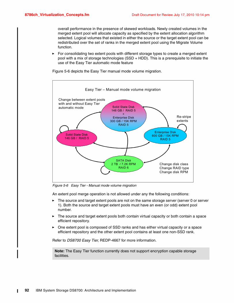
8786ch_Virtualization_Concepts.fm Draft Document for Review July 17, 2010 10:14 pm
overall performance in the presence of skewed workloads. Newly created volumes in the merged extent pool will allocate capacity as specified by the extent allocation algorithm selected. Logical volumes that existed in either the source or the target extent pool can be redistributed over the set of ranks in the merged extent pool using the Migrate Volume function.
� For consolidating two extent pools with different storage types to create a merged extent pool with a mix of storage technologies (SSD + HDD). This is a prerequisite to initiate the use of the Easy Tier automatic mode feature
Figure 5-6 depicts the Easy Tier manual mode volume migration.
Figure 5-6 Easy Tier - Manual mode volume migration
An extent pool merge operation is not allowed under any the following conditions:
� The source and target extent pools are not on the same storage server (server 0 or server 1). Both the source and target extent pools must have an even (or odd) extent pool number.
� The source and target extent pools both contain virtual capacity or both contain a space efficient repository.
� One extent pool is composed of SSD ranks and has either virtual capacity or a space efficient repository and the other extent pool contains at least one non-SSD rank.
Refer to DS8700 Easy Tier, REDP-4667 for more information.
Note: The Easy Tier function currently does not support encryption capable storage facilities.
Easy Tier – Manual mode volume migration
Solid State Disk146 GB / RAID 5
Solid State Disk146 GB / RAID 5
+Enterprise Disk
300 GB / 15K RPMRAID 5
SATA Disk2 TB / 7.2K RPM
RAID 6
Enterprise Disk600 GB / 15K RPM
RAID 5
Change disk classChange RAID typeChange disk RPM
Re-stripe extents
Change between extent poolswith and without Easy Tier automatic mode
92 IBM System Storage DS8700: Architecture and Implementation
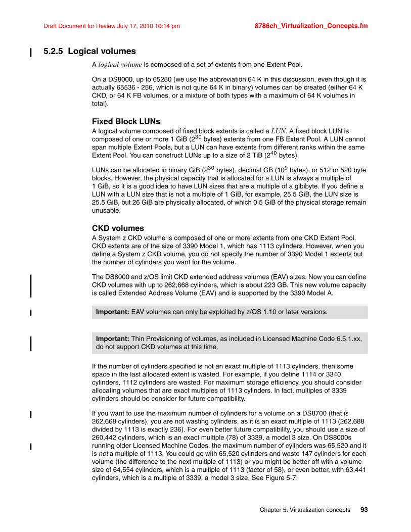
Draft Document for Review July 17, 2010 10:14 pm 8786ch_Virtualization_Concepts.fm
5.2.5 Logical volumesA logical volume is composed of a set of extents from one Extent Pool.
On a DS8000, up to 65280 (we use the abbreviation 64 K in this discussion, even though it is actually 65536 - 256, which is not quite 64 K in binary) volumes can be created (either 64 K CKD, or 64 K FB volumes, or a mixture of both types with a maximum of 64 K volumes in total).
Fixed Block LUNsA logical volume composed of fixed block extents is called a LUN. A fixed block LUN is composed of one or more 1 GiB (230 bytes) extents from one FB Extent Pool. A LUN cannot span multiple Extent Pools, but a LUN can have extents from different ranks within the same Extent Pool. You can construct LUNs up to a size of 2 TiB (240 bytes).
LUNs can be allocated in binary GiB (230 bytes), decimal GB (109 bytes), or 512 or 520 byte blocks. However, the physical capacity that is allocated for a LUN is always a multiple of 1 GiB, so it is a good idea to have LUN sizes that are a multiple of a gibibyte. If you define a LUN with a LUN size that is not a multiple of 1 GiB, for example, 25.5 GiB, the LUN size is 25.5 GiB, but 26 GiB are physically allocated, of which 0.5 GiB of the physical storage remain unusable.
CKD volumesA System z CKD volume is composed of one or more extents from one CKD Extent Pool. CKD extents are of the size of 3390 Model 1, which has 1113 cylinders. However, when you define a System z CKD volume, you do not specify the number of 3390 Model 1 extents but the number of cylinders you want for the volume.
The DS8000 and z/OS limit CKD extended address volumes (EAV) sizes. Now you can define CKD volumes with up to 262,668 cylinders, which is about 223 GB. This new volume capacity is called Extended Address Volume (EAV) and is supported by the 3390 Model A.
If the number of cylinders specified is not an exact multiple of 1113 cylinders, then some space in the last allocated extent is wasted. For example, if you define 1114 or 3340 cylinders, 1112 cylinders are wasted. For maximum storage efficiency, you should consider allocating volumes that are exact multiples of 1113 cylinders. In fact, multiples of 3339 cylinders should be consider for future compatibility.
If you want to use the maximum number of cylinders for a volume on a DS8700 (that is 262,668 cylinders), you are not wasting cylinders, as it is an exact multiple of 1113 (262,688 divided by 1113 is exactly 236). For even better future compatibility, you should use a size of 260,442 cylinders, which is an exact multiple (78) of 3339, a model 3 size. On DS8000s running older Licensed Machine Codes, the maximum number of cylinders was 65,520 and it is not a multiple of 1113. You could go with 65,520 cylinders and waste 147 cylinders for each volume (the difference to the next multiple of 1113) or you might be better off with a volume size of 64,554 cylinders, which is a multiple of 1113 (factor of 58), or even better, with 63,441 cylinders, which is a multiple of 3339, a model 3 size. See Figure 5-7.
Important: EAV volumes can only be exploited by z/OS 1.10 or later versions.
Important: Thin Provisioning of volumes, as included in Licensed Machine Code 6.5.1.xx, do not support CKD volumes at this time.
Chapter 5. Virtualization concepts 93
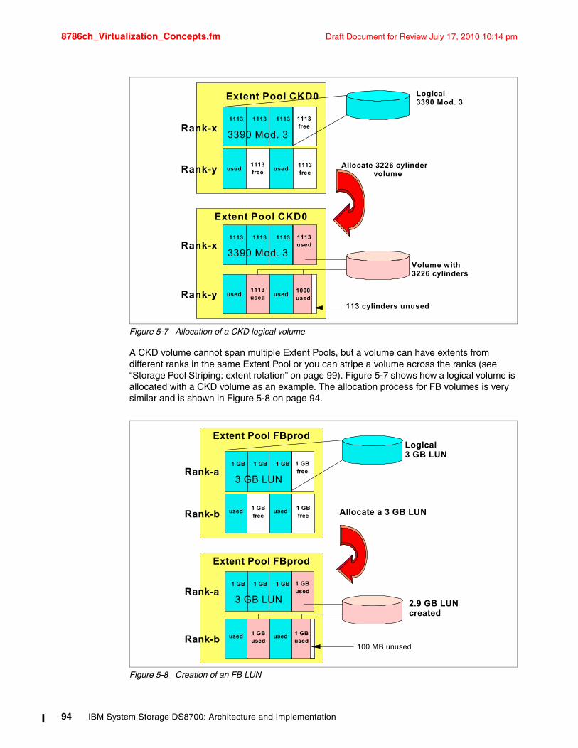
8786ch_Virtualization_Concepts.fm Draft Document for Review July 17, 2010 10:14 pm
Figure 5-7 Allocation of a CKD logical volume
A CKD volume cannot span multiple Extent Pools, but a volume can have extents from different ranks in the same Extent Pool or you can stripe a volume across the ranks (see “Storage Pool Striping: extent rotation” on page 99). Figure 5-7 shows how a logical volume is allocated with a CKD volume as an example. The allocation process for FB volumes is very similar and is shown in Figure 5-8 on page 94.
Figure 5-8 Creation of an FB LUN
1113 1113 1113 1113free
Extent Pool CKD0
Rank-x
Rank-y
3390 Mod. 3
1113free
1113free
used used Allocate 3226 cylinder volume
1113 1113 1113 1113used
Extent Pool CKD0
Rank-x
Rank-y
3390 Mod. 3
1000used
1113used
used used
Logical 3390 Mod. 3
113 cylinders unused
Volume with3226 cylinders
1 GB 1 GB 1 GB 1 GBfree
Extent Pool FBprod
Rank-a
Rank-b
3 GB LUN
1 GBfree
1 GBfree
used used Allocate a 3 GB LUN
1 GB 1 GB 1 GB 1 GBused
Extent Pool FBprod
Rank-a
Rank-b
3 GB LUN
1 GBused
1 GBused
used used
Logical 3 GB LUN
2.9 GB LUNcreated
100 MB unused
94 IBM System Storage DS8700: Architecture and Implementation
Draft Document for Review July 17, 2010 10:14 pm 8786ch_Virtualization_Concepts.fm
System i LUNsSystem i LUNs are also composed of fixed block 1 GiB extents. There are, however, some special aspects with System i LUNs. LUNs created on a DS8000 are always RAID protected. LUNs are based on RAID 5, RAID 6, or RAID 10 arrays. However, you might want to deceive i5/OS® and tell it that the LUN is not RAID protected. This causes the i5/OS to do its own mirroring. System i LUNs can have the attribute unprotected, in which case, the DS8000 will lie to a System i host and tell it that the LUN is not RAID protected.
The i5/OS only supports certain fixed volume sizes, for example, model sizes of 8.5 GB, 17.5 GB, and 35.1 GB. These sizes are not multiples of 1 GB, and hence, depending on the model chosen, some space is wasted. System i LUNs expose a 520 Byte block to the host. The operating system uses 8 of these Bytes so the usable space is still 512 Bytes like other SCSI LUNs. The capacities quoted for the System i LUNs are in terms of the 512 Byte block capacity and are expressed in GB (109). These capacities should be converted to GiB (230) when considering effective utilization of extents that are 1 GiB (230). For more information about this topic, see Chapter 17, “IBM System i considerations” on page 505.
5.2.6 Space Efficient volumesWhen a standard FB LUN or CKD volume is created on the physical drive, it will occupy as many extents as necessary for the defined capacity.
For the DS8700 with Licensed Machine Code 6.5.1.xx, there are now two types of Space Efficient volumes that can be defined: Extent Space Efficient Volumes and Track Space Efficient Volumes. The two concepts are described in detail in DS8000 Thin Provisioning, REDP-4554.
A Space Efficient volume does not occupy physical capacity when it is created. Space gets allocated when data is actually written to the volume. The amount of space that gets physically allocated is a function of the amount of data written to or changes performed on the volume. The sum of capacities of all defined Space Efficient volumes can be larger than the physical capacity available.This function is also called over-provisioning or thin provisioning.
Space Efficient volumes can be created when the DS8000 has the IBM Thin Provisioning or IBM FlashCopy SE feature enabled (licensing is required).
The general idea behind Space Efficient volumes is to use or allocate physical storage when it is only potentially or temporarily needed.
Repository for Track Space Efficient volumesThe definition of Track Space Efficient (TSE) volumes begins at the Extent Pool level. TSE volumes are defined from virtual space in that the size of the TSE volume does not initially use physical storage. However, any data written to a TSE volume must have enough physical storage to contain this write activity. This physical storage is provided by the repository.
The repository is an object within an Extent Pool. In some sense it is similar to a volume within the Extent Pool. The repository has a physical size and a logical size. The physical size of the repository is the amount of space that is allocated in the Extent Pool. It is the physical
Important: Thin Provisioning of volumes, as included in Licensed Machine Code 6.5.1.xx, is not supported for System i volumes at this time.
Note: The TSE repository cannot be created on SATA Drives.
Chapter 5. Virtualization concepts 95
8786ch_Virtualization_Concepts.fm Draft Document for Review July 17, 2010 10:14 pm
space that is available for all Space Efficient volumes in total in this Extent Pool. The repository is striped across all ranks within the Extent Pool. There can only be one repository per Extent Pool.
The logical size of the repository is limited by the available virtual capacity for Space Efficient volumes. As an example, there could be a repository of 100 GB reserved physical storage and you defined a virtual capacity of 200 GB. In this case, you could define 10 TSE-LUNs with 20 GB each. So the logical capacity can be larger than the physical capacity. Of course, you cannot fill all the volumes with data because the total physical capacity is limited by the repository size, that is, to 100 GB in this example.
Space for a Space Efficient volume is allocated when a write occurs, more precisely, when a destage from the cache occurs and there is not enough free space left on the currently allocated extent or track. The allocation unit is either an extent (ESE, 1 GB for FB) or a track (TSE, 64 KB for open systems LUNs or 57 KB for CKD volumes).
Because space is allocated in extents or tracks, the system needs to maintain tables indicating their mapping to the logical volumes, so there is some impact involved with Space Efficient volumes. The smaller the allocation unit, the larger the tables and the impact.
Important: The size of the repository and virtual space is part of the Extent Pool definition. Each Extent Pool may have a TSE volume repository, but this physical space cannot be shared between Extent Pools.
Virtual space in an Extent Pool is used for both TSE and ESE volumes, while the repository is only used for TSE volumes for FlashCopy SE. ESE volumes use available extents in the Extent Pool in a similar fashion as standard, fully provisioned volumes, but extents are only allocated as needed to write data to the ESE volume.
Note: In the current implementation of Track Space Efficient volumes, it is not possible to expand the physical size of the repository. Therefore, careful planning for the size of the repository is required before it is used. If a repository needs to be expanded, all Track Space Efficient volumes within this Extent Pool must be deleted, and then the repository must be deleted and re-created with the required size.
Summary: Virtual space is created as part of the Extent Pool definition. This virtual space is mapped onto ESE volumes in the Extent Pool (physical space) and TSE volumes in the repository (physical space) as needed. Virtual space would equal the total space of the required ESE volumes and the TSE volumes for FlashCopy SE. No actual storage is allocated until write activity occurs to the ESE or TSE volumes.
96 IBM System Storage DS8700: Architecture and Implementation
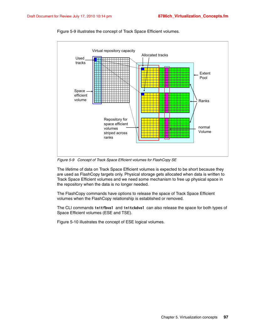
Draft Document for Review July 17, 2010 10:14 pm 8786ch_Virtualization_Concepts.fm
Figure 5-9 illustrates the concept of Track Space Efficient volumes.
Figure 5-9 Concept of Track Space Efficient volumes for FlashCopy SE
The lifetime of data on Track Space Efficient volumes is expected to be short because they are used as FlashCopy targets only. Physical storage gets allocated when data is written to Track Space Efficient volumes and we need some mechanism to free up physical space in the repository when the data is no longer needed.
The FlashCopy commands have options to release the space of Track Space Efficient volumes when the FlashCopy relationship is established or removed.
The CLI commands initfbvol and initckdvol can also release the space for both types of Space Efficient volumes (ESE and TSE).
Figure 5-10 illustrates the concept of ESE logical volumes.
ExtentPool
Ranks
Repository forspace efficientvolumesstriped acrossranks
normalVolume
Virtual repository capacity
Usedtracks
Allocated tracks
Spaceefficientvolume
Chapter 5. Virtualization concepts 97
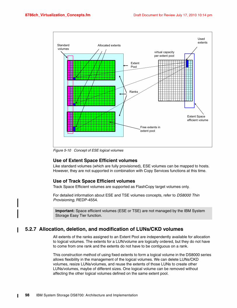
8786ch_Virtualization_Concepts.fm Draft Document for Review July 17, 2010 10:14 pm
Figure 5-10 Concept of ESE logical volumes
Use of Extent Space Efficient volumesLike standard volumes (which are fully provisioned), ESE volumes can be mapped to hosts. However, they are not supported in combination with Copy Services functions at this time.
Use of Track Space Efficient volumesTrack Space Efficient volumes are supported as FlashCopy target volumes only.
For detailed information about ESE and TSE volumes concepts, refer to DS8000 Thin Provisioning, REDP-4554.
5.2.7 Allocation, deletion, and modification of LUNs/CKD volumesAll extents of the ranks assigned to an Extent Pool are independently available for allocation to logical volumes. The extents for a LUN/volume are logically ordered, but they do not have to come from one rank and the extents do not have to be contiguous on a rank.
This construction method of using fixed extents to form a logical volume in the DS8000 series allows flexibility in the management of the logical volumes. We can delete LUNs/CKD volumes, resize LUNs/volumes, and reuse the extents of those LUNs to create other LUNs/volumes, maybe of different sizes. One logical volume can be removed without affecting the other logical volumes defined on the same extent pool.
Important: Space efficient volumes (ESE or TSE) are not managed by the IBM System Storage Easy Tier function.
Allocated extents
Extent Pool
Ranks
Standardvolumes
Used extents
Extent Spaceefficient volume
Free extents inextent pool
virtual capacityper extent pool
98 IBM System Storage DS8700: Architecture and Implementation
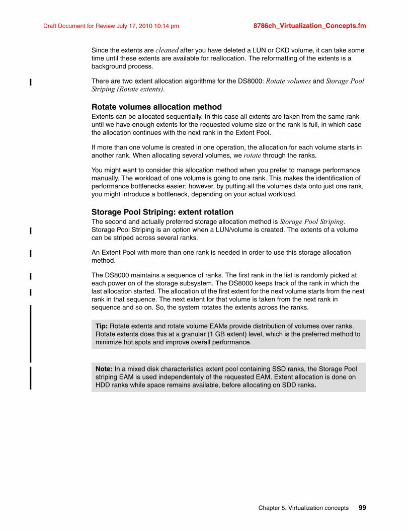
Draft Document for Review July 17, 2010 10:14 pm 8786ch_Virtualization_Concepts.fm
Since the extents are cleaned after you have deleted a LUN or CKD volume, it can take some time until these extents are available for reallocation. The reformatting of the extents is a background process.
There are two extent allocation algorithms for the DS8000: Rotate volumes and Storage Pool Striping (Rotate extents).
Rotate volumes allocation methodExtents can be allocated sequentially. In this case all extents are taken from the same rank until we have enough extents for the requested volume size or the rank is full, in which case the allocation continues with the next rank in the Extent Pool.
If more than one volume is created in one operation, the allocation for each volume starts in another rank. When allocating several volumes, we rotate through the ranks.
You might want to consider this allocation method when you prefer to manage performance manually. The workload of one volume is going to one rank. This makes the identification of performance bottlenecks easier; however, by putting all the volumes data onto just one rank, you might introduce a bottleneck, depending on your actual workload.
Storage Pool Striping: extent rotationThe second and actually preferred storage allocation method is Storage Pool Striping. Storage Pool Striping is an option when a LUN/volume is created. The extents of a volume can be striped across several ranks.
An Extent Pool with more than one rank is needed in order to use this storage allocation method.
The DS8000 maintains a sequence of ranks. The first rank in the list is randomly picked at each power on of the storage subsystem. The DS8000 keeps track of the rank in which the last allocation started. The allocation of the first extent for the next volume starts from the next rank in that sequence. The next extent for that volume is taken from the next rank in sequence and so on. So, the system rotates the extents across the ranks.
Tip: Rotate extents and rotate volume EAMs provide distribution of volumes over ranks. Rotate extents does this at a granular (1 GB extent) level, which is the preferred method to minimize hot spots and improve overall performance.
Note: In a mixed disk characteristics extent pool containing SSD ranks, the Storage Pool striping EAM is used independentely of the requested EAM. Extent allocation is done on HDD ranks while space remains available, before allocating on SDD ranks.
Chapter 5. Virtualization concepts 99
8786ch_Virtualization_Concepts.fm Draft Document for Review July 17, 2010 10:14 pm
Figure 5-11 shows an example of how volumes get allocated within the Extent Pool.
Figure 5-11 Extent allocation methods
When you create striped volumes and non-striped volumes in an Extent Pool, a rank could be filled before the others. A full rank is skipped when you create new striped volumes.
Figure 5-12 on page 101 shows both standard volumes and Extent Space Efficient volumes in an Extent Pool, both using the rotate volumes allocation method (red standard volume 8-12 and pink ESE volume 17-19, 26-27) and Storage Pool Striping extent allocation methods (all other Std and ESE volumes).
Tip: If you have to add capacity to an Extent Pool because it is nearly full, it is better to add several ranks at once, not just one. This allows new volumes to be striped across the newly added ranks.
With the Easy Tier manual mode facility, the user can request an extent pool merge followed by a volume relocation with striping to perform the same function.
Note: The rotate volume EAM is not allowed if one extent pool is comprised of SSD disks and has space efficient repository or virtual capacity configured.
ExtentPool
Ranks
6
1
2
4
5
3
7
8…….12
13
16
15
Where to start with the firstvolume is determined at power on (say, R2)Striped volume with twoExtents created
Next striped volume (five extents in this example)starts at next rank (R3) from which the previous volume was started
Non-striped volume createdStarts at next rank (R1), going in a round-robin
Striped volume createdStarts at next rank (R2)(extents 12 to 15)
Extent
6
8 9 10
11
13
14
13
R1
R2
R3
12
15
100 IBM System Storage DS8700: Architecture and Implementation
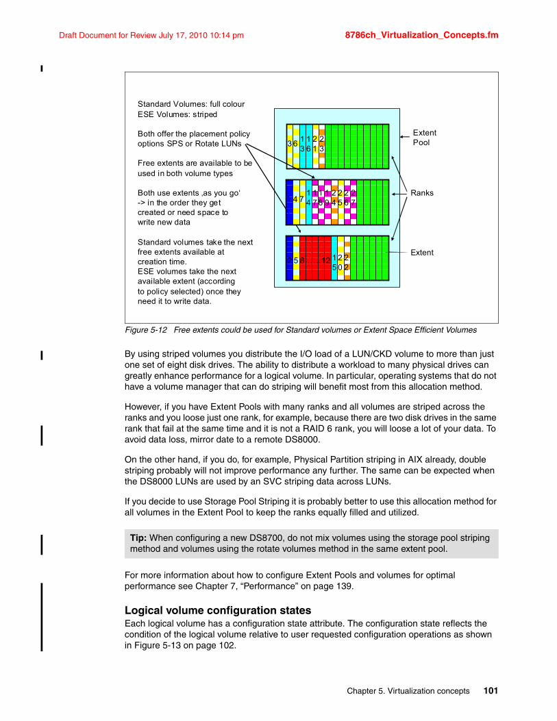
Draft Document for Review July 17, 2010 10:14 pm 8786ch_Virtualization_Concepts.fm
Figure 5-12 Free extents could be used for Standard volumes or Extent Space Efficient Volumes
By using striped volumes you distribute the I/O load of a LUN/CKD volume to more than just one set of eight disk drives. The ability to distribute a workload to many physical drives can greatly enhance performance for a logical volume. In particular, operating systems that do not have a volume manager that can do striping will benefit most from this allocation method.
However, if you have Extent Pools with many ranks and all volumes are striped across the ranks and you loose just one rank, for example, because there are two disk drives in the same rank that fail at the same time and it is not a RAID 6 rank, you will loose a lot of your data. To avoid data loss, mirror date to a remote DS8000.
On the other hand, if you do, for example, Physical Partition striping in AIX already, double striping probably will not improve performance any further. The same can be expected when the DS8000 LUNs are used by an SVC striping data across LUNs.
If you decide to use Storage Pool Striping it is probably better to use this allocation method for all volumes in the Extent Pool to keep the ranks equally filled and utilized.
For more information about how to configure Extent Pools and volumes for optimal performance see Chapter 7, “Performance” on page 139.
Logical volume configuration statesEach logical volume has a configuration state attribute. The configuration state reflects the condition of the logical volume relative to user requested configuration operations as shown in Figure 5-13 on page 102.
Tip: When configuring a new DS8700, do not mix volumes using the storage pool striping method and volumes using the rotate volumes method in the same extent pool.
ExtentPool
Ranks
Standard Volumes: full colourESE Volumes: striped
Both offer the placement policyoptions SPS or Rotate LUNs
Free extents are available to beused in both volume types
Both use extents ‚as you go‘-> in the order they get created or need space towrite new data
Standard volumes take the nextfree extents available atcreation time.ESE volumes take the next available extent (according to policy selected) once they need it to write data.
Extent2 5 8……12 2
022
15
74127
14
17
18
19
24
25
26
323
13
616
21
Chapter 5. Virtualization concepts 101
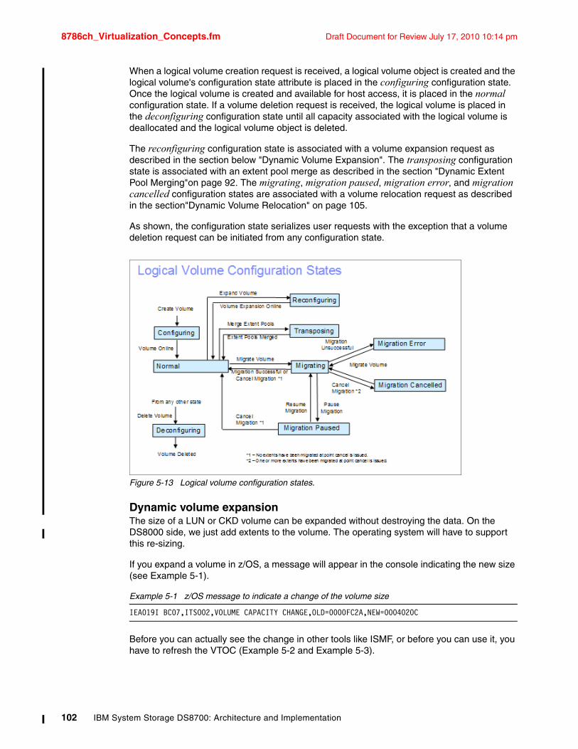
8786ch_Virtualization_Concepts.fm Draft Document for Review July 17, 2010 10:14 pm
When a logical volume creation request is received, a logical volume object is created and the logical volume's configuration state attribute is placed in the configuring configuration state. Once the logical volume is created and available for host access, it is placed in the normal configuration state. If a volume deletion request is received, the logical volume is placed in the deconfiguring configuration state until all capacity associated with the logical volume is deallocated and the logical volume object is deleted.
The reconfiguring configuration state is associated with a volume expansion request as described in the section below "Dynamic Volume Expansion". The transposing configuration state is associated with an extent pool merge as described in the section "Dynamic Extent Pool Merging"on page 92. The migrating, migration paused, migration error, and migration cancelled configuration states are associated with a volume relocation request as described in the section"Dynamic Volume Relocation" on page 105.
As shown, the configuration state serializes user requests with the exception that a volume deletion request can be initiated from any configuration state.
Figure 5-13 Logical volume configuration states.
Dynamic volume expansionThe size of a LUN or CKD volume can be expanded without destroying the data. On the DS8000 side, we just add extents to the volume. The operating system will have to support this re-sizing.
If you expand a volume in z/OS, a message will appear in the console indicating the new size (see Example 5-1).
Example 5-1 z/OS message to indicate a change of the volume size
IEA019I BC07,ITSO02,VOLUME CAPACITY CHANGE,OLD=0000FC2A,NEW=0004020C
Before you can actually see the change in other tools like ISMF, or before you can use it, you have to refresh the VTOC (Example 5-2 and Example 5-3).
102 IBM System Storage DS8700: Architecture and Implementation
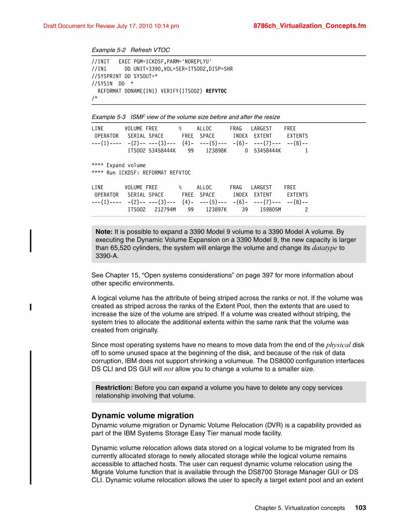
Draft Document for Review July 17, 2010 10:14 pm 8786ch_Virtualization_Concepts.fm
Example 5-2 Refresh VTOC
//INIT EXEC PGM=ICKDSF,PARM='NOREPLYU' //IN1 DD UNIT=3390,VOL=SER=ITSO02,DISP=SHR//SYSPRINT DD SYSOUT=* //SYSIN DD * REFORMAT DDNAME(IN1) VERIFY(ITSO02) REFVTOC /*
Example 5-3 ISMF view of the volume size before and after the resize
LINE VOLUME FREE % ALLOC FRAG LARGEST FREE OPERATOR SERIAL SPACE FREE SPACE INDEX EXTENT EXTENTS ---(1)---- -(2)-- ---(3)--- (4)- ---(5)--- -(6)- ---(7)--- --(8)-- ITSO02 53458444K 99 123898K 0 53458444K 1
**** Expand volume**** Run ICKDSF: REFORMAT REFVTOC
LINE VOLUME FREE % ALLOC FRAG LARGEST FREE OPERATOR SERIAL SPACE FREE SPACE INDEX EXTENT EXTENTS ---(1)---- -(2)-- ---(3)--- (4)- ---(5)--- -(6)- ---(7)--- --(8)-- ITSO02 212794M 99 123897K 39 159805M 2
See Chapter 15, “Open systems considerations” on page 397 for more information about other specific environments.
A logical volume has the attribute of being striped across the ranks or not. If the volume was created as striped across the ranks of the Extent Pool, then the extents that are used to increase the size of the volume are striped. If a volume was created without striping, the system tries to allocate the additional extents within the same rank that the volume was created from originally.
Since most operating systems have no means to move data from the end of the physical disk off to some unused space at the beginning of the disk, and because of the risk of data corruption, IBM does not support shrinking a volumeue. The DS8000 configuration interfaces DS CLI and DS GUI will not allow you to change a volume to a smaller size.
Dynamic volume migrationDynamic volume migration or Dynamic Volume Relocation (DVR) is a capability provided as part of the IBM Systems Storage Easy Tier manual mode facility.
Dynamic volume relocation allows data stored on a logical volume to be migrated from its currently allocated storage to newly allocated storage while the logical volume remains accessible to attached hosts. The user can request dynamic volume relocation using the Migrate Volume function that is available through the DS8700 Storage Manager GUI or DS CLI. Dynamic volume relocation allows the user to specify a target extent pool and an extent
Note: It is possible to expand a 3390 Model 9 volume to a 3390 Model A volume. By executing the Dynamic Volume Expansion on a 3390 Model 9, the new capacity is larger than 65,520 cylinders, the system will enlarge the volume and change its datatype to 3390-A.
Restriction: Before you can expand a volume you have to delete any copy services relationship involving that volume.
Chapter 5. Virtualization concepts 103
8786ch_Virtualization_Concepts.fm Draft Document for Review July 17, 2010 10:14 pm
allocation method (EAM). The target extent pool may be the same or a different extent pool than the extent pool where the volume is currently located.
Dynamic volume migration provides:
� The ability to change the extent pool that a logical volume is provisioned in providing a mechanism to change the underlying storage characteristics of the logical volume to include the disk class (solid state disk, enterprise disk, SATA disk), disk rpm, and RAID array type. Volume migration may also be used to migrate a logical volume into or out of an extent pool.
� The ability to specify the extent allocation method for a volume migration allowing the extent allocation method to be changed between the available extent allocation method any time after volume creation. Volume migration specifying the rotate extents EAM can also be used to re-distribute a logical volume's extent allocations across the currently existing ranks in the extent pool if additional ranks are added to an extent pool.
Each logical volume has a configuration state as described in the section above "Logical Volume Configuration States" on page 103. To initiate a volume migration, the logical volume must initially be in the normal configuration state. The volume migration will follow each of the states discussed.
There are additional functions that are associated with volume migration that allow the user to pause, resume, or cancel a volume migration. Any and all logical volumes can be requested to be migrated at any given time as long as there is sufficient capacity available to support the pre-allocation of the migrating logical volumes in their specified target extent pool.
For additional information on this topic, refer to the IBM Redbooks publication. DS8700 Easy Tier, REDP-4667.
5.2.8 Logical subsystems (LSS)A logical subsystem (LSS) is another logical construct. It groups logical volumes and LUNs, in groups of up to 256 logical volumes.
On the DS8000 series, there is no fixed binding between any rank and any logical subsystem. The capacity of one or more ranks can be aggregated into an extent pool and logical volumes configured in that extent pool are not bound to any specific rank. Different logical volumes on the same logical subsystem can be configured in different extent pools. As such, the available capacity of the storage facility can be flexibly allocated across the set of defined logical subsystems and logical volumes. You can now define up to 255 LSSs for the DS8000 series.
For each LUN or CKD volume, you can now choose an LSS. You can have up to 256 volumes in one LSS. There is, however, one restriction. We already have seen that volumes are formed from a bunch of extents from an extent pool. Extent pools, however, belong to one server (CEC), server 0 or server 1, respectively. LSSs also have an affinity to the servers. All even-numbered LSSs (X’00’, X’02’, X’04’, up to X’FE’) belong to server 0 and all odd-numbered LSSs (X’01’, X’03’, X’05’, up to X’FD’) belong to server 1. LSS X’FF’ is reserved.
System z users are familiar with a logical control unit (LCU). System z operating systems configure LCUs to create device addresses. There is a one to one relationship between an LCU and a CKD LSS (LSS X'ab' maps to LCU X'ab'). Logical volumes have a logical volume number X'abcd' where X'ab' identifies the LSS and X'cd' is one of the 256 logical volumes on the LSS. This logical volume number is assigned to a logical volume when a logical volume is created and determines the LSS that it is associated with. The 256 possible logical volumes associated with an LSS are mapped to the 256 possible device addresses on an LCU (logical
104 IBM System Storage DS8700: Architecture and Implementation
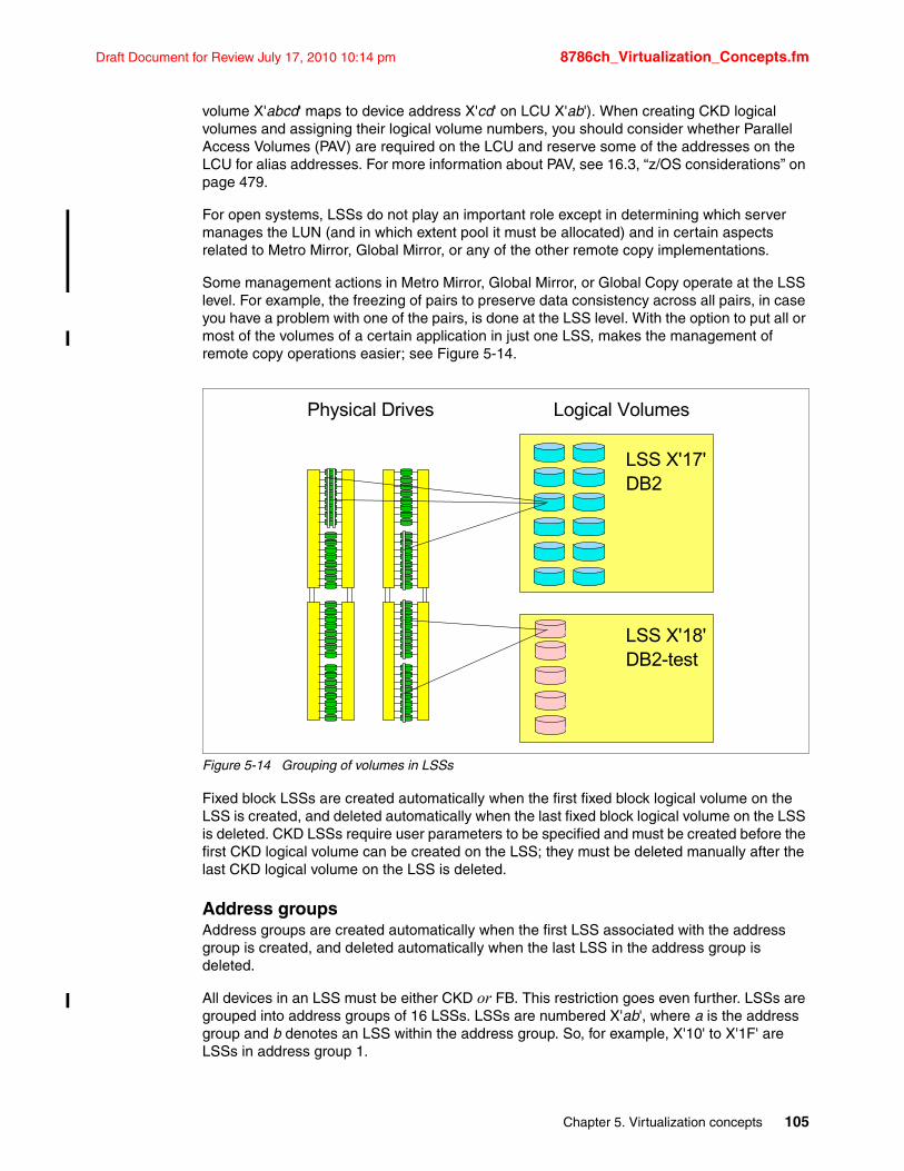
Draft Document for Review July 17, 2010 10:14 pm 8786ch_Virtualization_Concepts.fm
volume X'abcd' maps to device address X'cd' on LCU X'ab'). When creating CKD logical volumes and assigning their logical volume numbers, you should consider whether Parallel Access Volumes (PAV) are required on the LCU and reserve some of the addresses on the LCU for alias addresses. For more information about PAV, see 16.3, “z/OS considerations” on page 479.
For open systems, LSSs do not play an important role except in determining which server manages the LUN (and in which extent pool it must be allocated) and in certain aspects related to Metro Mirror, Global Mirror, or any of the other remote copy implementations.
Some management actions in Metro Mirror, Global Mirror, or Global Copy operate at the LSS level. For example, the freezing of pairs to preserve data consistency across all pairs, in case you have a problem with one of the pairs, is done at the LSS level. With the option to put all or most of the volumes of a certain application in just one LSS, makes the management of remote copy operations easier; see Figure 5-14.
Figure 5-14 Grouping of volumes in LSSs
Fixed block LSSs are created automatically when the first fixed block logical volume on the LSS is created, and deleted automatically when the last fixed block logical volume on the LSS is deleted. CKD LSSs require user parameters to be specified and must be created before the first CKD logical volume can be created on the LSS; they must be deleted manually after the last CKD logical volume on the LSS is deleted.
Address groupsAddress groups are created automatically when the first LSS associated with the address group is created, and deleted automatically when the last LSS in the address group is deleted.
All devices in an LSS must be either CKD or FB. This restriction goes even further. LSSs are grouped into address groups of 16 LSSs. LSSs are numbered X'ab', where a is the address group and b denotes an LSS within the address group. So, for example, X'10' to X'1F' are LSSs in address group 1.
LSS X'17'DB2
LSS X'18'DB2-test
Physical Drives Logical Volumes
Chapter 5. Virtualization concepts 105
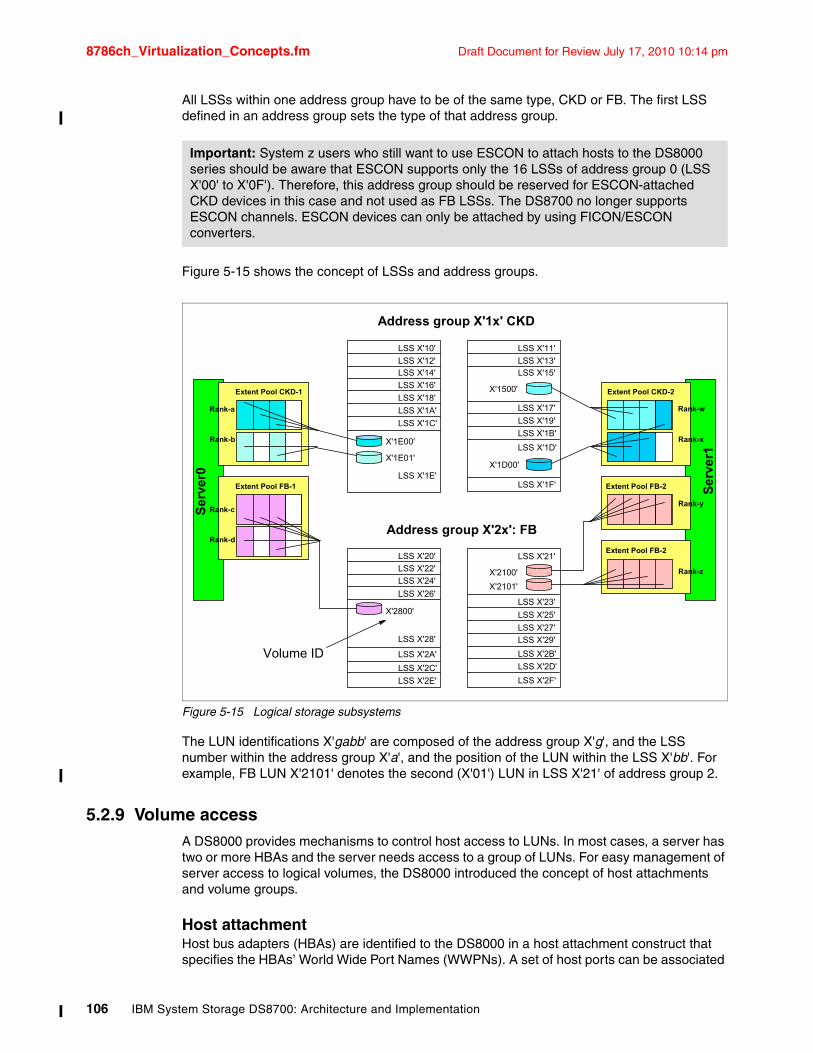
8786ch_Virtualization_Concepts.fm Draft Document for Review July 17, 2010 10:14 pm
All LSSs within one address group have to be of the same type, CKD or FB. The first LSS defined in an address group sets the type of that address group.
Figure 5-15 shows the concept of LSSs and address groups.
Figure 5-15 Logical storage subsystems
The LUN identifications X'gabb' are composed of the address group X'g', and the LSS number within the address group X'a', and the position of the LUN within the LSS X'bb'. For example, FB LUN X'2101' denotes the second (X'01') LUN in LSS X'21' of address group 2.
5.2.9 Volume accessA DS8000 provides mechanisms to control host access to LUNs. In most cases, a server has two or more HBAs and the server needs access to a group of LUNs. For easy management of server access to logical volumes, the DS8000 introduced the concept of host attachments and volume groups.
Host attachmentHost bus adapters (HBAs) are identified to the DS8000 in a host attachment construct that specifies the HBAs’ World Wide Port Names (WWPNs). A set of host ports can be associated
Important: System z users who still want to use ESCON to attach hosts to the DS8000 series should be aware that ESCON supports only the 16 LSSs of address group 0 (LSS X'00' to X'0F'). Therefore, this address group should be reserved for ESCON-attached CKD devices in this case and not used as FB LSSs. The DS8700 no longer supports ESCON channels. ESCON devices can only be attached by using FICON/ESCON converters.
Address group X'2x': FB
Address group X'1x' CKD
Extent Pool FB-2
LSS X'10'
LSS X'12'LSS X'14'
LSS X'16'
LSS X'18'
LSS X'1A'
LSS X'1C'
LSS X'1E'
LSS X'20'
LSS X'22'
LSS X'24'
LSS X'26'
LSS X'28'
LSS X'2A'
LSS X'2C'
LSS X'2E'
LSS X'11'
LSS X'13'LSS X'15'
LSS X'17'
LSS X'19'
LSS X'1B'
LSS X'1D'
LSS X'21'
LSS X'1F'
LSS X'23'
LSS X'25'
LSS X'27'
LSS X'29'
LSS X'2B'
Ser
ver0
Extent Pool CKD-1
Rank-a
Rank-b
Extent Pool FB-1
Rank-c
Rank-d
LSS X'2D'
Ser
ver1
Extent Pool CKD-2
Rank-w
Rank-x
Extent Pool FB-2
Rank-y
Rank-z
X'1E00'
X'1E01'
X'2800'
X'1500'
X'1D00'
X'2100'
Volume ID
X'2101'
LSS X'2F'
106 IBM System Storage DS8700: Architecture and Implementation
Draft Document for Review July 17, 2010 10:14 pm 8786ch_Virtualization_Concepts.fm
through a port group attribute that allows a set of HBAs to be managed collectively. This port group is referred to as a host attachment within the GUI.
Each host attachment can be associated with a volume group to define which LUNs that HBA is allowed to access. Multiple host attachments can share the same volume group. The host attachment can also specify a port mask that controls which DS8700 I/O ports the HBA is allowed to log in to. Whichever ports the HBA logs in on, it sees the same volume group that is defined in the host attachment associated with this HBA.
The maximum number of host attachments on a DS8700 is 8192.
Volume groupA volume group is a named construct that defines a set of logical volumes. When used in conjunction with CKD hosts, there is a default volume group that contains all CKD volumes and any CKD host that logs in to a FICON I/O port has access to the volumes in this volume group. CKD logical volumes are automatically added to this volume group when they are created and automatically removed from this volume group when they are deleted.
When used in conjunction with open systems hosts, a host attachment object that identifies the HBA is linked to a specific volume group. You must define the volume group by indicating which fixed block logical volumes are to be placed in the volume group. Logical volumes can be added to or removed from any volume group dynamically.
There are two types of volume groups used with open systems hosts and the type determines how the logical volume number is converted to a host addressable LUN_ID on the Fibre Channel SCSI interface. A map volume group type is used in conjunction with FC SCSI host types that poll for LUNs by walking the address range on the SCSI interface. This type of volume group can map any FB logical volume numbers to 256 LUN_IDs that have zeroes in the last six Bytes and the first two Bytes in the range of X'0000' to X'00FF'.
A mask volume group type is used in conjunction with FC SCSI host types that use the Report LUNs command to determine the LUN_IDs that are accessible. This type of volume group can allow any and all FB logical volume numbers to be accessed by the host where the mask is a bitmap that specifies which LUNs are accessible. For this volume group type, the logical volume number X'abcd' is mapped to LUN_ID X'40ab40cd00000000'. The volume group type also controls whether 512 Byte block LUNs or 520 Byte block LUNs can be configured in the volume group.
When associating a host attachment with a volume group, the host attachment contains attributes that define the logical block size and the Address Discovery Method (LUN Polling or Report LUNs) that are used by the host HBA. These attributes must be consistent with the volume group type of the volume group that is assigned to the host attachment so that HBAs that share a volume group have a consistent interpretation of the volume group definition and have access to a consistent set of logical volume types. The GUI typically sets these values appropriately for the HBA based on your specification of a host type. You must consider what volume group type to create when setting up a volume group for a particular HBA.
FB logical volumes can be defined in one or more volume groups. This allows a LUN to be shared by host HBAs configured to different volume groups. An FB logical volume is automatically removed from all volume groups when it is deleted.
The maximum number of volume groups is 8320 for the DS8700.
Figure 5-16 shows the relationships between host attachments and volume groups. Host AIXprod1 has two HBAs, which are grouped together in one host attachment and both are granted access to volume group DB2-1. Most of the volumes in volume group DB2-1 are also
Chapter 5. Virtualization concepts 107
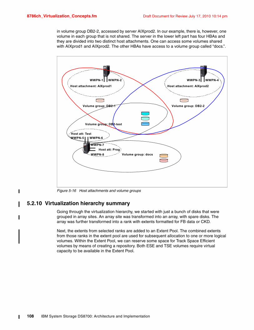
8786ch_Virtualization_Concepts.fm Draft Document for Review July 17, 2010 10:14 pm
in volume group DB2-2, accessed by server AIXprod2. In our example, there is, however, one volume in each group that is not shared. The server in the lower left part has four HBAs and they are divided into two distinct host attachments. One can access some volumes shared with AIXprod1 and AIXprod2. The other HBAs have access to a volume group called “docs.”.
Figure 5-16 Host attachments and volume groups
5.2.10 Virtualization hierarchy summaryGoing through the virtualization hierarchy, we started with just a bunch of disks that were grouped in array sites. An array site was transformed into an array, with spare disks. The array was further transformed into a rank with extents formatted for FB data or CKD.
Next, the extents from selected ranks are added to an Extent Pool. The combined extents from those ranks in the extent pool are used for subsequent allocation to one or more logical volumes. Within the Extent Pool, we can reserve some space for Track Space Efficient volumes by means of creating a repository. Both ESE and TSE volumes require virtual capacity to be available in the Extent Pool.
WWPN-1 WWPN-2
Host attachment: AIXprod1
Volume group: DB2-1
WWPN-3 WWPN-4
Host attachment: AIXprod2
Volume group: docs
WWPN-5 WWPN-6
WWPN-7
WWPN-8
Host att: Test
Host att: Prog
Volume group: DB2-2
Volume group: DB2-test
108 IBM System Storage DS8700: Architecture and Implementation
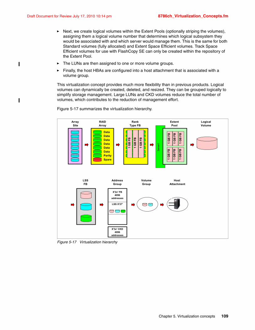
Draft Document for Review July 17, 2010 10:14 pm 8786ch_Virtualization_Concepts.fm
� Next, we create logical volumes within the Extent Pools (optionally striping the volumes), assigning them a logical volume number that determines which logical subsystem they would be associated with and which server would manage them. This is the same for both Standard volumes (fully allocated) and Extent Space Efficient volumes. Track Space Efficient volumes for use with FlashCopy SE can only be created within the repository of the Extent Pool.
� The LUNs are then assigned to one or more volume groups.
� Finally, the host HBAs are configured into a host attachment that is associated with a volume group.
This virtualization concept provides much more flexibility than in previous products. Logical volumes can dynamically be created, deleted, and resized. They can be grouped logically to simplify storage management. Large LUNs and CKD volumes reduce the total number of volumes, which contributes to the reduction of management effort.
Figure 5-17 summarizes the virtualization hierarchy.
Figure 5-17 Virtualization hierarchy
Ser
ver0
Array Site
RAIDArray
Spare
Data
Data
Data
Data
Data
Data
Parity
RankType FB
1 G
B F
B
1 G
B F
B
1 G
B F
B
1 G
B F
B
1 G
B F
B
1 G
B F
B
1 G
B F
B
1 G
B F
B
1 G
B F
B
ExtentPool
LogicalVolume
LSSFB
AddressGroup
X'2x' FB4096
addresses
LSS X'27'
X'3x' CKD4096
addresses
VolumeGroup
Host Attachment
Chapter 5. Virtualization concepts 109
8786ch_Virtualization_Concepts.fm Draft Document for Review July 17, 2010 10:14 pm
5.3 Benefits of virtualizationThe DS8000 physical and logical architecture defines new standards for enterprise storage virtualization. The main benefits of the virtualization layers are:
� Flexible LSS definition allows maximization and optimization of the number of devices per LSS.
� No strict relationship between RAID ranks and LSSs.
� No connection of LSS performance to underlying storage.
� Number of LSSs can be defined based upon device number requirements:
– With larger devices, significantly fewer LSSs might be used.
– Volumes for a particular application can be kept in a single LSS.
– Smaller LSSs can be defined if required (for applications requiring less storage).
– Test systems can have their own LSSs with fewer volumes than production systems.
� Increased number of logical volumes:
– Up to 65280 (CKD)
– Up to 65280 (FB)
– 65280 total for CKD + FB
� Any mixture of CKD or FB addresses in 4096 address groups.
� Increased logical volume size:
– CKD: 223 GB (262,668 cylinders), architected for 219 TB
– FB: 2 TB, architected for 1 PB
� Flexible logical volume configuration:
– Multiple RAID types (RAID 5, RAID 6, and RAID 10)
– Storage types (CKD and FB) aggregated into Extent Pools
– Volumes allocated from extents of Extent Pool
– Storage pool striping
– Dynamically add and remove volumes
– Logical Volume Configuration States
– Dynamic volume expansion
– Extent Space Efficient volumes for Thin Provisioning
– Track Space Efficient volumes for FlashCopy SE
– Extended Address Volumes (CKD)
– Dynamic extent pool merging for Easy Tier
– Dynamic volume relocaiton for Easy Tier
� Virtualization reduces storage management requirements.
110 IBM System Storage DS8700: Architecture and Implementation
Draft Document for Review July 17, 2010 10:14 pm 8786ch_CopyServices.fm
Chapter 6. DS8700 Copy Services Overview
This chapter discusses the Copy Services functions available with the IBM System Storage DS8700 series models, which include Remote Mirror and Copy functions, as well as the Point-in-Time Copy function like FlashCopy, FlashCopy SE, and Remote Pair FlashCopy.
These functions make the DS8700 series a key component for disaster recovery solutions, data migration activities, as well as for data duplication and backup solutions.
This chapter covers the following topics:
� Copy Services� FlashCopy and IBM FlashCopy SE� Remote Pair FlashCopy (Preserve Mirror)� Remote Mirror and Copy:
– Metro Mirror– Global Copy– Global Mirror– Metro/Global Mirror– z/OS Global Mirror– z/OS Metro/Global Mirror
� Interfaces for Copy Services� Interoperability
The information discussed in this chapter is covered to a greater extent and in more detail in the following IBM Redbooks publications:
� IBM System Storage DS8000: Copy Services in Open Environments, SG24-6788
� DS8000 Copy Services for IBM System z, SG24-6787
� IBM System Storage DS8000 Series: IBM FlashCopy SE, REDP-4368
� IBM System Storage DS8000: Remote Pair FlashCopy (Preserve Mirror), REDP-4504
6
© Copyright IBM Corp. 2010. All rights reserved. 111
8786ch_CopyServices.fm Draft Document for Review July 17, 2010 10:14 pm
6.1 Copy ServicesCopy Services is a collection of functions that provide disaster recovery, data migration, and data duplication functions. With the Copy Services functions, for example, you can create backup data with little or no disruption to your application, and you can back up your application data to the remote site for the disaster recovery.
The Copy Services functions run on the DS8700 storage unit and support open systems and System z environments. These functions are supported also on other DS8000 family models, as well as on the DS6000™ series, and on the previous generation of storage systems, the IBM TotalStorage® Enterprise Storage Server® (ESS) models.
DS8700 Copy Services functionsCopy Services in the DS8700 includes the following optional licensed functions:
� IBM System Storage FlashCopy and IBM FlashCopy SE, which are point-in-time copy functions
� Remote mirror and copy functions, which include:
– IBM System Storage Metro Mirror, previously known as synchronous PPRC
– IBM System Storage Global Copy, previously known as PPRC eXtended Distance
– IBM System Storage Global Mirror, previously known as asynchronous PPRC
– IBM System Storage Metro/Global Mirror, a three-site solution to meet the most rigorous business resiliency needs
– For migration purpose and on a RPQ base you may consider IBM System Storage Metro/Global Copy. Understand that this combination of Metro Mirror and Global Copy is not suited for disaster recovery solutions but solely for migration purpose.
� Additionally for the System z users, the following are available:
– z/OS Global Mirror, previously known as eXtended Remote Copy (XRC)
– z/OS Metro/Global Mirror, a three-site solution that combines z/OS Global Mirror and Metro Mirror
Many design characteristics of the DS8700 and its data copy and mirror capabilities and features contribute to the protection of your data, 24 hours a day and seven days a week.
We discuss these Copy Services functions in the following sections.
Copy Services management interfacesYou control and manage the DS8700 Copy Services functions by means of the following interfaces:
� DS Storage Manager, which is a graphical user interface (DS GUI) running under SSPC and with the DS8700 Hardware Management Console (HMC).
� DS Command-Line Interface (DS CLI), which provides various commands that are executed on the HMC.
� Tivoli Storage Productivity Center for Replication (TPC-R). The TPC-R server connects to the DS8700.
� DS Open Application Programming Interface (DS Open API).
112 IBM System Storage DS8700: Architecture and Implementation
Draft Document for Review July 17, 2010 10:14 pm 8786ch_CopyServices.fm
System z users can also use the following interfaces:
� TSO commands� ICKDSF utility commands� ANTRQST application programming interface (API)� DFSMSdss utility
We explain these interfaces in 6.4, “Interfaces for Copy Services” on page 133.
6.2 FlashCopy and IBM FlashCopy SEFlashCopy and FlashCopy SE are designed to provide point-in-time copy capability for logical volumes with minimal interruption to applications, and make it possible to access both the source and target copies immediately.
In this section, we discuss FlashCopy and FlashCopy SE basic characteristics and options. For a more detailed and extensive discussion about these topics, refer to the following IBM Redbooks and IBM Redpapers™ publications:
� IBM System Storage DS8000: Copy Services in Open Environments, SG24-6788� DS8000 Copy Services for IBM System z, SG24-6787� IBM System Storage DS8000 Series: IBM FlashCopy SE, REDP-4368 � IBM System Storage DS8000: Remote Pair FlashCopy (Preserve Mirror), REDP-4504.
6.2.1 Basic conceptsFlashCopy creates a point-in-time copy of the data. When a FlashCopy operation is invoked, it takes only a few seconds to complete the process of establishing a FlashCopy source and target volume pair, and create the necessary control bitmaps. Thereafter, you have access to a point-in-time copy of the source volume as though all the data had been copied. As soon as the pair has been established, you can read and write to both the source and target volumes.
Two variations of FlashCopy are available.
� Standard FlashCopy uses a normal volume as target volume. This target volume has to have the same size, or larger, as the source volume and that space is allocated in the storage subsystem.
� FlashCopy Space Efficient (SE) uses Space Efficient volumes (see 5.2.6, “Space Efficient volumes” on page 95) as FlashCopy target volumes. A Space Efficient target volume has a virtual size that is equal to or greater than the source volume size. However, space is not allocated for this volume when the volume is created and the FlashCopy initiated. Only when updates are made to the source volume will any original tracks of the source volume (that will be modified) are copied to the Space Efficient target volume. Space in the repository is allocated for just these tracks or for any write to the target itself.
Note: Both FlashCopy and FlashCopy SE can coexist on a DS8700.
Chapter 6. DS8700 Copy Services Overview 113
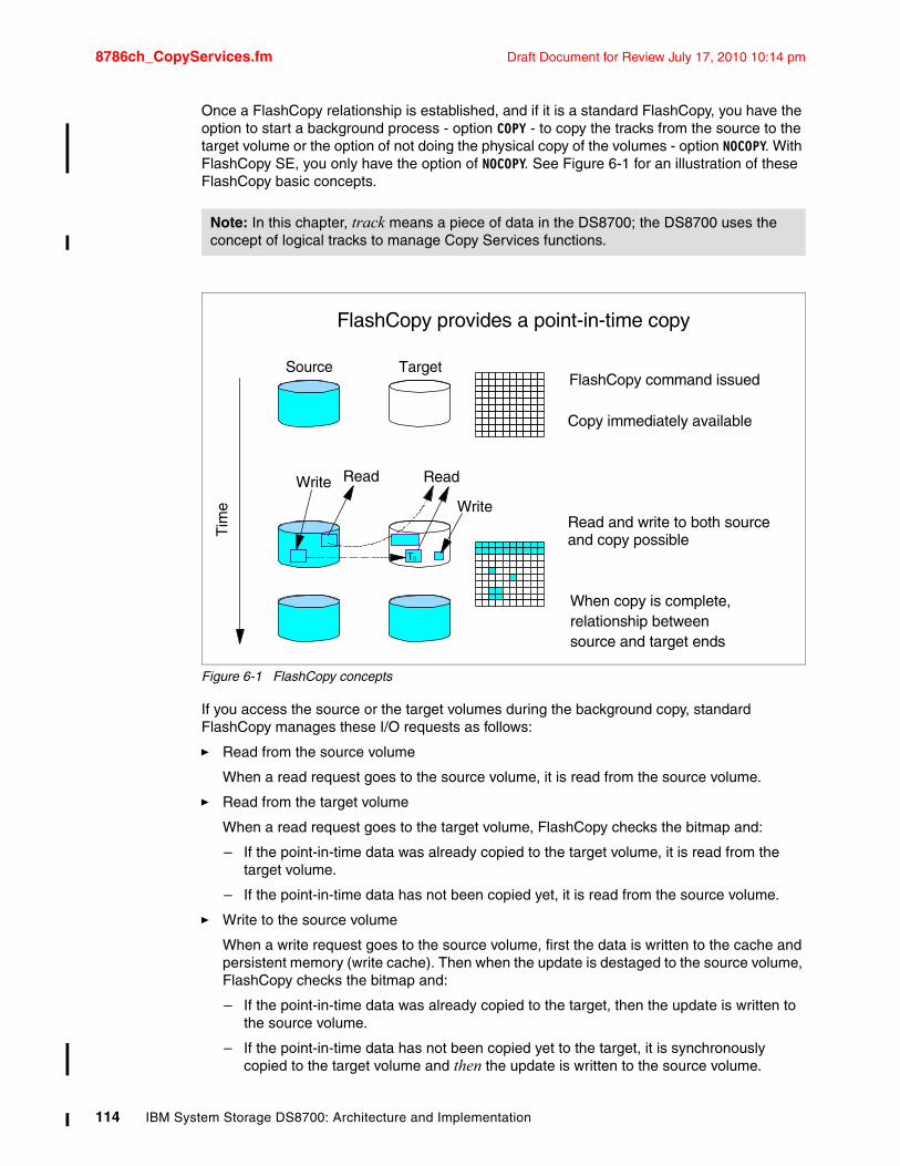
8786ch_CopyServices.fm Draft Document for Review July 17, 2010 10:14 pm
Once a FlashCopy relationship is established, and if it is a standard FlashCopy, you have the option to start a background process - option COPY - to copy the tracks from the source to the target volume or the option of not doing the physical copy of the volumes - option NOCOPY. With FlashCopy SE, you only have the option of NOCOPY. See Figure 6-1 for an illustration of these FlashCopy basic concepts.
Figure 6-1 FlashCopy concepts
If you access the source or the target volumes during the background copy, standard FlashCopy manages these I/O requests as follows:
� Read from the source volume
When a read request goes to the source volume, it is read from the source volume.
� Read from the target volume
When a read request goes to the target volume, FlashCopy checks the bitmap and:
– If the point-in-time data was already copied to the target volume, it is read from the target volume.
– If the point-in-time data has not been copied yet, it is read from the source volume.
� Write to the source volume
When a write request goes to the source volume, first the data is written to the cache and persistent memory (write cache). Then when the update is destaged to the source volume, FlashCopy checks the bitmap and:
– If the point-in-time data was already copied to the target, then the update is written to the source volume.
– If the point-in-time data has not been copied yet to the target, it is synchronously copied to the target volume and then the update is written to the source volume.
Note: In this chapter, track means a piece of data in the DS8700; the DS8700 uses the concept of logical tracks to manage Copy Services functions.
FlashCopy provides a point-in-time copy
FlashCopy command issued
Tim
e
Copy immediately available
Read and write to both source and copy possible
Write Read
When copy is complete,relationship betweensource and target ends
Source Target
Read
Write
T0
114 IBM System Storage DS8700: Architecture and Implementation
Draft Document for Review July 17, 2010 10:14 pm 8786ch_CopyServices.fm
� Write to the target volume
Whenever data is written to the target volume while the FlashCopy relationship exists, the storage subsystem makes sure that the bitmap is updated. This way, the point-in-time data from the source volume never overwrites updates that were done directly to the target.
The background copy can have a slight impact on your application because the physical copy needs some storage resources, but the impact is minimal because the host I/O occurs prior to the background copy. Also, you can issue standard FlashCopy with no background copy, option NOCOPY.
No background copy optionIf you invoke standard FlashCopy with the option NOCOPY or FlashCopy SE, the FlashCopy relationship is established without initiating a background copy. Therefore, you can minimize the impact of the background copy. When the DS8700 receives an update to a source track in a FlashCopy relationship, a copy of the point-in-time data is copied to the target volume so that it is available when the data from the target volume is accessed. This option is useful when you do not need to issue FlashCopy in the opposite direction. It is useful though to create the previous level at the source volume before the last FlashCopy action.
6.2.2 Benefits and use The point-in-time copy created by FlashCopy is typically used where you need a copy of the production data produced with little or no application downtime, depending on the application. The point-in-time copy created by FlashCopy can be used for online backup, testing new applications, or for creating a database for data mining purposes. The copy looks exactly like the original source volume and is an instantly available, binary copy.
IBM FlashCopy SE is designed for temporary copies. Since the target is smaller than the source, a background copy would not make much sense and is not permitted with IBM FlashCopy SE. FlashCopy SE is optimized for use cases where about 5% of the source volume is updated during the life of the relationship. If more than 20% of the source is expected to change, then standard FlashCopy would likely be a better choice. Durations for typical use cases are expected to generally be less than eight hours unless the source data has little write activity. FlashCopy SE could also be used for copies that will be kept long term if it is known that the FlashCopy relationship will experience few updates to the source and target volumes.
Standard FlashCopy will generally have superior performance over FlashCopy SE. If performance on the source or target volumes is important, standard FlashCopy is strongly recommended.
Some scenarios where IBM FlashCopy SE is a good choice are:
� To create a temporary copy with IBM FlashCopy SE and then back it up to tape.
� Temporary point-in-time copies for application development or DR testing.
� Online backup for different points in time, for example, to protect your data against virus infection.
� Checkpoints, but only if the source volumes will undergo moderate updates.
� FlashCopy target volumes volume in a Global Mirror (GM) environment. If the repository space becomes completely full, writes to the GM target volume will be inhibited and the GM session will be suspended. Global Mirror is explained in 6.3.3, “Global Mirror” on page 126.
Chapter 6. DS8700 Copy Services Overview 115
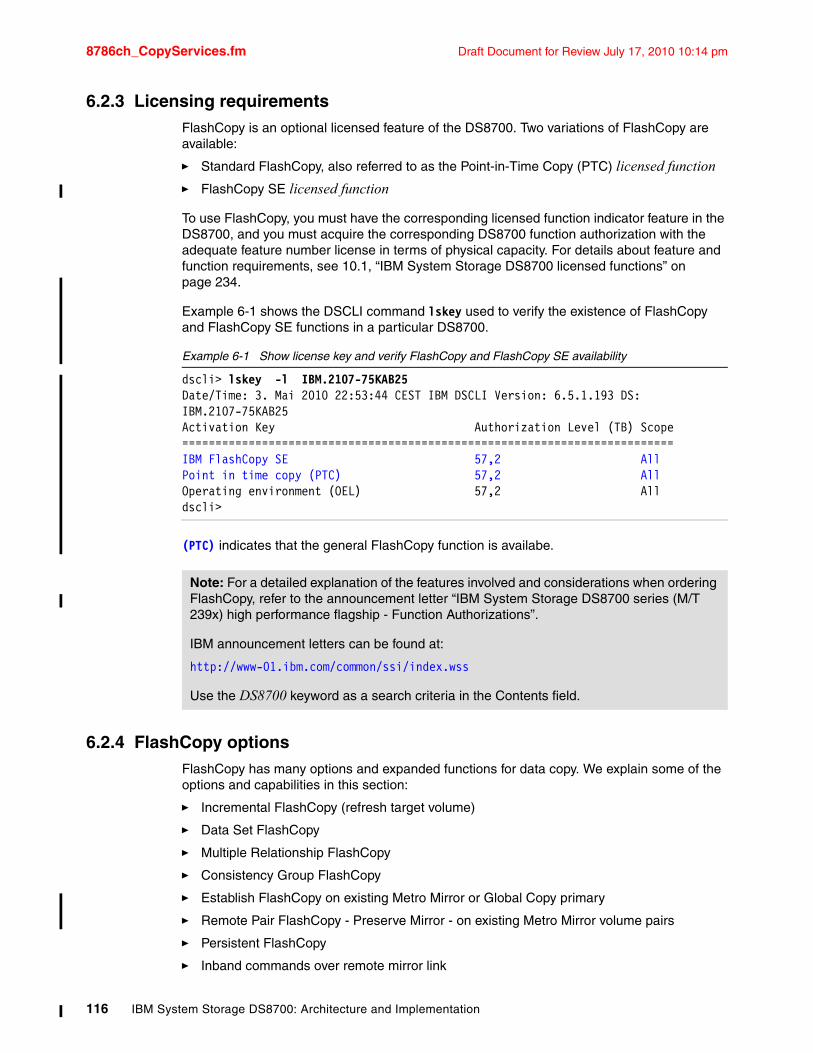
8786ch_CopyServices.fm Draft Document for Review July 17, 2010 10:14 pm
6.2.3 Licensing requirementsFlashCopy is an optional licensed feature of the DS8700. Two variations of FlashCopy are available:
� Standard FlashCopy, also referred to as the Point-in-Time Copy (PTC) licensed function
� FlashCopy SE licensed function
To use FlashCopy, you must have the corresponding licensed function indicator feature in the DS8700, and you must acquire the corresponding DS8700 function authorization with the adequate feature number license in terms of physical capacity. For details about feature and function requirements, see 10.1, “IBM System Storage DS8700 licensed functions” on page 234.
Example 6-1 shows the DSCLI command lskey used to verify the existence of FlashCopy and FlashCopy SE functions in a particular DS8700.
Example 6-1 Show license key and verify FlashCopy and FlashCopy SE availability
dscli> lskey -l IBM.2107-75KAB25Date/Time: 3. Mai 2010 22:53:44 CEST IBM DSCLI Version: 6.5.1.193 DS: IBM.2107-75KAB25Activation Key Authorization Level (TB) Scope==========================================================================IBM FlashCopy SE 57,2 AllPoint in time copy (PTC) 57,2 AllOperating environment (OEL) 57,2 Alldscli>
(PTC) indicates that the general FlashCopy function is availabe.
6.2.4 FlashCopy optionsFlashCopy has many options and expanded functions for data copy. We explain some of the options and capabilities in this section:
� Incremental FlashCopy (refresh target volume)
� Data Set FlashCopy
� Multiple Relationship FlashCopy
� Consistency Group FlashCopy
� Establish FlashCopy on existing Metro Mirror or Global Copy primary
� Remote Pair FlashCopy - Preserve Mirror - on existing Metro Mirror volume pairs
� Persistent FlashCopy
� Inband commands over remote mirror link
Note: For a detailed explanation of the features involved and considerations when ordering FlashCopy, refer to the announcement letter “IBM System Storage DS8700 series (M/T 239x) high performance flagship - Function Authorizations”.
IBM announcement letters can be found at:
http://www-01.ibm.com/common/ssi/index.wss
Use the DS8700 keyword as a search criteria in the Contents field.
116 IBM System Storage DS8700: Architecture and Implementation
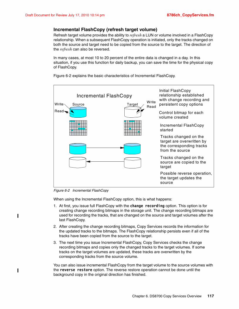
Draft Document for Review July 17, 2010 10:14 pm 8786ch_CopyServices.fm
Incremental FlashCopy (refresh target volume)Refresh target volume provides the ability to refresh a LUN or volume involved in a FlashCopy relationship. When a subsequent FlashCopy operation is initiated, only the tracks changed on both the source and target need to be copied from the source to the target. The direction of the refresh can also be reversed.
In many cases, at most 10 to 20 percent of the entire data is changed in a day. In this situation, if you use this function for daily backup, you can save the time for the physical copy of FlashCopy.
Figure 6-2 explains the basic characteristics of Incremental FlashCopy.
Figure 6-2 Incremental FlashCopy
When using the Incremental FlashCopy option, this is what happens:
1. At first, you issue full FlashCopy with the change recording option. This option is for creating change recording bitmaps in the storage unit. The change recording bitmaps are used for recording the tracks, that are changed on the source and target volumes after the last FlashCopy.
2. After creating the change recording bitmaps, Copy Services records the information for the updated tracks to the bitmaps. The FlashCopy relationship persists even if all of the tracks have been copied from the source to the target.
3. The next time you issue Incremental FlashCopy, Copy Services checks the change recording bitmaps and copies only the changed tracks to the target volumes. If some tracks on the target volumes are updated, these tracks are overwritten by the corresponding tracks from the source volume.
You can also issue incremental FlashCopy from the target volume to the source volumes with the reverse restore option. The reverse restore operation cannot be done until the background copy in the original direction has finished.
Source TargetWriteRead
Write
Read
Incremental FlashCopyInitial FlashCopy relationship established with change recording and persistent copy options
Control bitmap for each volume created
Tracks changed on the target are overwritten by the corresponding tracks from the source
Possible reverse operation, the target updates the source
Incremental FlashCopy started
Tracks changed on the source are copied to the target
Chapter 6. DS8700 Copy Services Overview 117
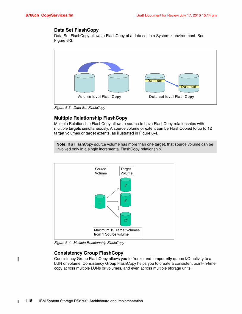
8786ch_CopyServices.fm Draft Document for Review July 17, 2010 10:14 pm
Data Set FlashCopyData Set FlashCopy allows a FlashCopy of a data set in a System z environment. See Figure 6-3.
Figure 6-3 Data Set FlashCopy
Multiple Relationship FlashCopyMultiple Relationship FlashCopy allows a source to have FlashCopy relationships with multiple targets simultaneously. A source volume or extent can be FlashCopied to up to 12 target volumes or target extents, as illustrated in Figure 6-4.
Figure 6-4 Multiple Relationship FlashCopy
Consistency Group FlashCopyConsistency Group FlashCopy allows you to freeze and temporarily queue I/O activity to a LUN or volume. Consistency Group FlashCopy helps you to create a consistent point-in-time copy across multiple LUNs or volumes, and even across multiple storage units.
Note: If a FlashCopy source volume has more than one target, that source volume can be involved only in a single incremental FlashCopy relationship.
Data set
Data set
Volume level FlashCopy Data set level FlashCopy
SourceVolume
TargetVolume
1
1’
2’
12’
Maximum 12 Target volumes from 1 Source volume
118 IBM System Storage DS8700: Architecture and Implementation
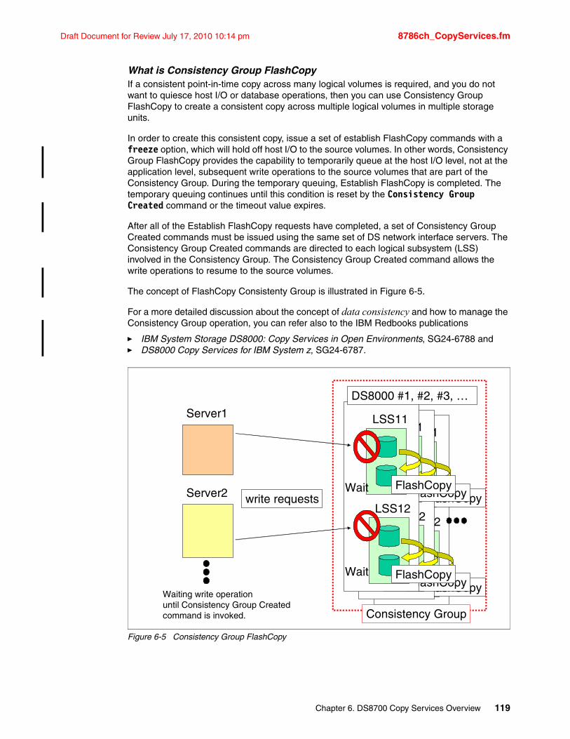
Draft Document for Review July 17, 2010 10:14 pm 8786ch_CopyServices.fm
What is Consistency Group FlashCopyIf a consistent point-in-time copy across many logical volumes is required, and you do not want to quiesce host I/O or database operations, then you can use Consistency Group FlashCopy to create a consistent copy across multiple logical volumes in multiple storage units.
In order to create this consistent copy, issue a set of establish FlashCopy commands with a freeze option, which will hold off host I/O to the source volumes. In other words, Consistency Group FlashCopy provides the capability to temporarily queue at the host I/O level, not at the application level, subsequent write operations to the source volumes that are part of the Consistency Group. During the temporary queuing, Establish FlashCopy is completed. The temporary queuing continues until this condition is reset by the Consistency Group Created command or the timeout value expires.
After all of the Establish FlashCopy requests have completed, a set of Consistency Group Created commands must be issued using the same set of DS network interface servers. The Consistency Group Created commands are directed to each logical subsystem (LSS) involved in the Consistency Group. The Consistency Group Created command allows the write operations to resume to the source volumes.
The concept of FlashCopy Consistenty Group is illustrated in Figure 6-5.
For a more detailed discussion about the concept of data consistency and how to manage the Consistency Group operation, you can refer also to the IBM Redbooks publications
� IBM System Storage DS8000: Copy Services in Open Environments, SG24-6788 and� DS8000 Copy Services for IBM System z, SG24-6787.
Figure 6-5 Consistency Group FlashCopy
Server1
Server2 write requests
LSS11
LSS12
Wait
Wait
FlashCopy
FlashCopy
LSS11
LSS12
Wait
Wait
FlashCopy
FlashCopy
LSS11
LSS12
Wait
Wait
FlashCopy
FlashCopy
Consistency Group
Waiting write operationuntil Consistency Group Created command is invoked.
DS8000 #1, #2, #3, …
Chapter 6. DS8700 Copy Services Overview 119
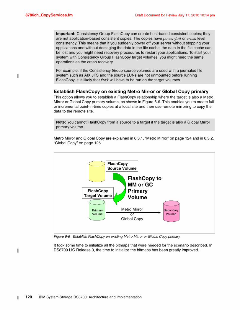
8786ch_CopyServices.fm Draft Document for Review July 17, 2010 10:14 pm
Establish FlashCopy on existing Metro Mirror or Global Copy primaryThis option allows you to establish a FlashCopy relationship where the target is also a Metro Mirror or Global Copy primary volume, as shown in Figure 6-6. This enables you to create full or incremental point-in-time copies at a local site and then use remote mirroring to copy the data to the remote site.
Metro Mirror and Global Copy are explained in 6.3.1, “Metro Mirror” on page 124 and in 6.3.2, “Global Copy” on page 125.
Figure 6-6 Establish FlashCopy on existing Metro Mirror or Global Copy primary
It took some time to initialize all the bitmaps that were needed for the scenario described. In DS8700 LIC Release 3, the time to initialize the bitmaps has been greatly improved.
Important: Consistency Group FlashCopy can create host-based consistent copies; they are not application-based consistent copies. The copies have power-fail or crash level consistency. This means that if you suddenly power off your server without stopping your applications and without destaging the data in the file cache, the data in the file cache can be lost and you might need recovery procedures to restart your applications. To start your system with Consistency Group FlashCopy target volumes, you might need the same operations as the crash recovery.
For example, if the Consistency Group source volumes are used with a journaled file system such as AIX JFS and the source LUNs are not unmounted before running FlashCopy, it is likely that fsck will have to be run on the target volumes.
Note: You cannot FlashCopy from a source to a target if the target is also a Global Mirror primary volume.
PrimaryVolume
SecondaryVolume
Metro Mirroror
Global Copy
FlashCopy to MM or GCPrimary Volume
FlashCopySource Volume
FlashCopyTarget Volume
120 IBM System Storage DS8700: Architecture and Implementation
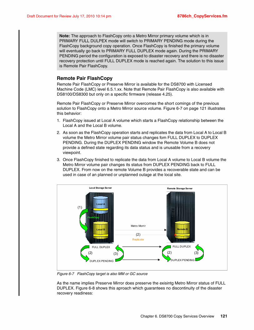
Draft Document for Review July 17, 2010 10:14 pm 8786ch_CopyServices.fm
Remote Pair FlashCopyRemote Pair FlashCopy or Preserve Mirror is available for the DS8700 with Licensed Machine Code (LMC) level 6.5.1.xx. Note that Remote Pair FlashCopy is also available with DS8100/DS8300 but only on a specific firmware (release 4.25).
Remote Pair FlashCopy or Preserve Mirror overcomes the short comings of the previous solution to FlashCopy onto a Metro Mirror source volume. Figure 6-7 on page 121 illustrates this behavior:
1. FlashCopy issued at Local A volume which starts a FlashCopy relationship between the Local A and the Local B volume.
2. As soon as the FlashCopy operation starts and replicates the data from Local A to Local B volume the Metro Mirror volume pair status changes fom FULL DUPLEX to DUPLEX PENDING. During the DUPLEX PENDING window the Remote Volume B does not provide a defined state regarding its data status and is unusable from a recovery viewpoint.
3. Once FlashCopy finished to replicate the data from Local A volume to Local B volume the Metro Mirror volume pair changes its status from DUPLEX PENDING back to FULL DUPLEX. From now on the remote Volume B provides a recoverable state and can be used in case of an planned or unplanned outage at the local site.
Figure 6-7 FlashCopy target is also MM or GC source
As the name implies Preserve Mirror does preserve the exisintg Metro Mirror status of FULL DUPLEX. Figure 6-8 shows this aproach which guarantees no discontinuity of the disaster recovery readiness:
Note: The approach to FlashCopy onto a Metro Mirror primary volume which is in PRIMARY FULL DULPEX mode will switch to PRIMARY PENDING mode during the FlashCopy background copy operation. Once FlashCopy is finished the primary volume will eventually go back to PRIMARY FULL DUPLEX mode again. During the PRIMARY PENDING period the configuration is exposed to disaster recovery and there is no disaster recovery protection until FULL DUPLEX mode is reached again. The solution to this issue is Remote Pair FlashCopy.
Local A
Local B Remote B
Local Storage Server Remote Storage Server
FlashCopy
Metro Morri r
FULL DUPLEX
DUPLEX PENDING
FULL DUPLEX
DUPLEX PENDING
Replicate
(1)
(2) (2) (3)(3)
(2)
Chapter 6. DS8700 Copy Services Overview 121
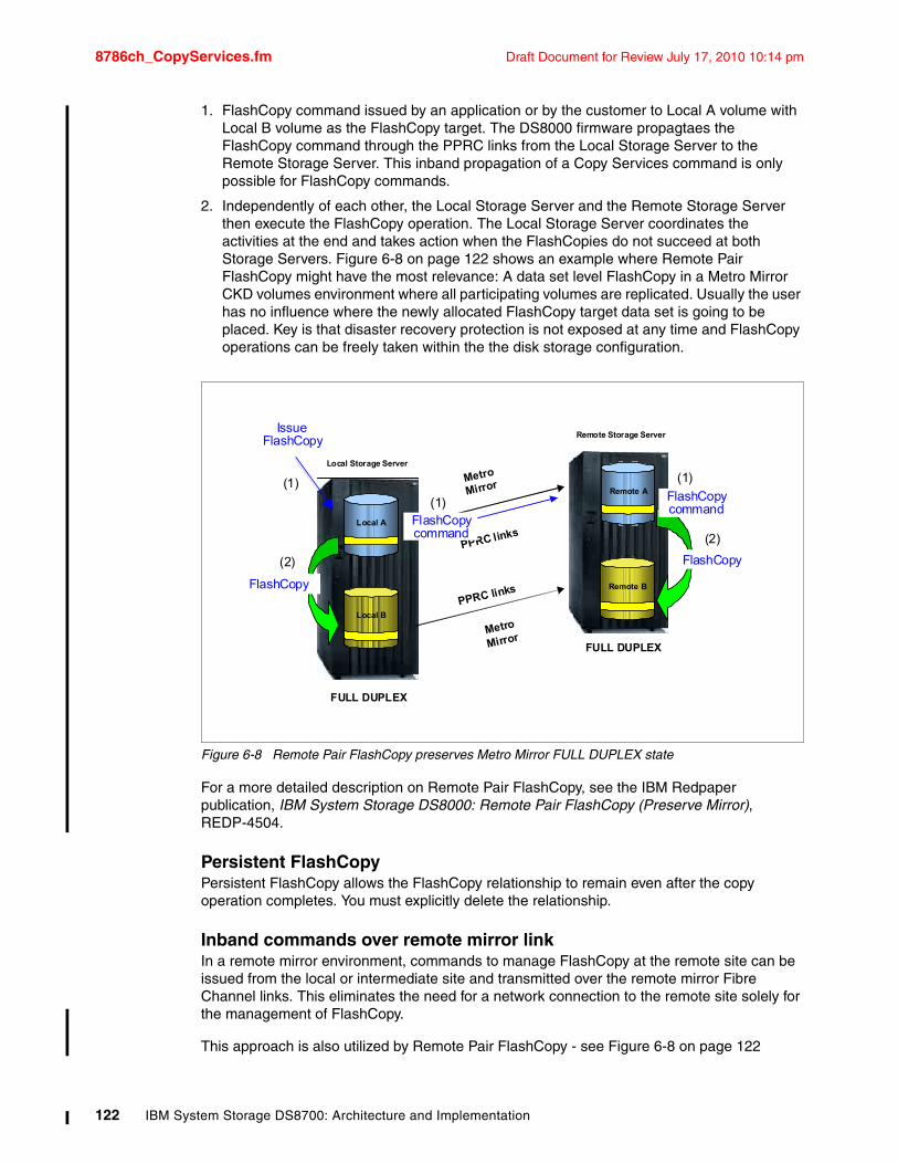
8786ch_CopyServices.fm Draft Document for Review July 17, 2010 10:14 pm
1. FlashCopy command issued by an application or by the customer to Local A volume with Local B volume as the FlashCopy target. The DS8000 firmware propagtaes the FlashCopy command through the PPRC links from the Local Storage Server to the Remote Storage Server. This inband propagation of a Copy Services command is only possible for FlashCopy commands.
2. Independently of each other, the Local Storage Server and the Remote Storage Server then execute the FlashCopy operation. The Local Storage Server coordinates the activities at the end and takes action when the FlashCopies do not succeed at both Storage Servers. Figure 6-8 on page 122 shows an example where Remote Pair FlashCopy might have the most relevance: A data set level FlashCopy in a Metro Mirror CKD volumes environment where all participating volumes are replicated. Usually the user has no influence where the newly allocated FlashCopy target data set is going to be placed. Key is that disaster recovery protection is not exposed at any time and FlashCopy operations can be freely taken within the the disk storage configuration.
Figure 6-8 Remote Pair FlashCopy preserves Metro Mirror FULL DUPLEX state
For a more detailed description on Remote Pair FlashCopy, see the IBM Redpaper publication, IBM System Storage DS8000: Remote Pair FlashCopy (Preserve Mirror), REDP-4504.
Persistent FlashCopyPersistent FlashCopy allows the FlashCopy relationship to remain even after the copy operation completes. You must explicitly delete the relationship.
Inband commands over remote mirror linkIn a remote mirror environment, commands to manage FlashCopy at the remote site can be issued from the local or intermediate site and transmitted over the remote mirror Fibre Channel links. This eliminates the need for a network connection to the remote site solely for the management of FlashCopy.
This approach is also utilized by Remote Pair FlashCopy - see Figure 6-8 on page 122
| © 2010 IBM Corporation
Local Storage Server
Remote Storage Server
Local A
Local B
Remote A
Remote B
Metro
Mirror
FULL DUPLEX
FULL DUPLEX
Metro
Mirror
(1) (1)
(2)
(2)
FlashCopy
FlashCopy
PPRC links
PPRC links
FlashCopycommand
(1)
Issue
FlashCopycommand
FlashCopy
122 IBM System Storage DS8700: Architecture and Implementation
Draft Document for Review July 17, 2010 10:14 pm 8786ch_CopyServices.fm
6.2.5 IBM FlashCopy SE optionsMost options available for standard FlashCopy (see 6.2.4, “FlashCopy options” on page 116) are also available for FlashCopy SE. Only the options that differ are discussed in this section.
Incremental FlashCopyBecause Incremental FlashCopy implies an initial full volume copy and a full volume copy is not possible in an IBM FlashCopy SE relationship, Incremental FlashCopy is not possible with IBM FlashCopy SE.
Data Set FlashCopyFlashCopy SE relationships are limited to full volume relationships. As a result, data set level FlashCopy is not supported within FlashCopy SE.
Multiple Relationship FlashCopy SEStandard FlashCopy supports up to 12 relationships and one of these relationships can be incremental. There is always some impact when doing a FlashCopy or any kind of copy within a storage subsystem. A FlashCopy onto a Space Efficient volume has more impact because additional tables have to be maintained. All IBM FlashCopy SE relations are nocopy relations; incremental FlashCopy is not possible. Therefore, the practical number of IBM FlashCopy SE relationships from one source volume will be lower than 12. You should test in your own environment how many concurrent IBM FlashCopy SE relationships are acceptable from a performance standpoint.
Consistency Group FlashCopyWith IBM FlashCopy SE, consistency groups can be formed in the same way as with standard FlashCopy - see “Consistency Group FlashCopy” on page 118. Within a consistency group, there can be a mix of standard FlashCopy and IBM FlashCopy SE relationships.
6.3 Remote Mirror and CopyThe Remote Mirror and Copy functions of the DS8700 are a set of flexible data mirroring solutions that allow replication between volumes on two or more disk storage systems. These functions are used to implement remote data backup and disaster recovery solutions.
The Remote Mirror and Copy functions are optional licensed functions of the DS8700 that include:
� Metro Mirror� Global Copy� Global Mirror� Metro/Global Mirror
In addition, System z users can use the DS8700 for:
� z/OS Global Mirror� z/OS Metro/Global Mirror
Note: This function is available by using the DS CLI, TSO, and ICKDSF commands, but not by using the DS Storage Manager GUI.
Chapter 6. DS8700 Copy Services Overview 123
8786ch_CopyServices.fm Draft Document for Review July 17, 2010 10:14 pm
In the following sections, we discuss these Remote Mirror and Copy functions.
For a more detailed and extensive discussion about these topics, refer to the IBM Redbooks publications
� IBM System Storage DS8000: Copy Services in Open Environments, SG24-6788 and� DS8000 Copy Services for IBM System z, SG24-6787.
Licensing requirementsTo use any of these Remote Mirror and Copy optional licensed functions, you must have the corresponding licensed function indicator feature in the DS8700, and you must acquire the corresponding DS8700 function authorization with the adequate feature number license in terms of physical capacity. For details about feature and function requirements, see 10.1, “IBM System Storage DS8700 licensed functions” on page 234.
Also, consider that some of the remote mirror solutions, such as Global Mirror, Metro/Global Mirror, or z/OS Metro/Global Mirror, integrate more than one licensed function. In this case, you need to have all of the required licensed functions.
6.3.1 Metro MirrorMetro Mirror, previously known as Synchronous Peer-to-Peer Remote Copy (PPRC), provides real-time mirroring of logical volumes between two DS8700s or any other combination of DS8100, DS8300, DS6800, and ESS800 that can be located up to 300 km from each other. It is a synchronous copy solution where write operations are completed on both copies - local and remote site - before they are considered complete.
Figure 6-9 illustrates the basic operational characteristics of Metro Mirror.
Note: For a detailed explanation of the features involved and considerations when ordering Copy Services licensed functions, refer to the announcement letter “IBM System Storage DS8700 series (M/T 239x) high performance flagship - Function Authorizations”.
IBM announcement letters can be found at:
http://www-01.ibm.com/common/ssi/index.wss
Use the DS8700 keyword as a search criteria in the Contents field.
124 IBM System Storage DS8700: Architecture and Implementation
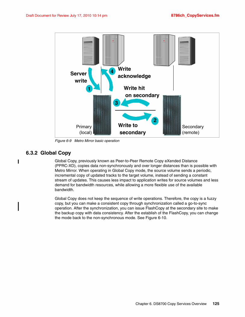
Draft Document for Review July 17, 2010 10:14 pm 8786ch_CopyServices.fm
Figure 6-9 Metro Mirror basic operation
6.3.2 Global CopyGlobal Copy, previously known as Peer-to-Peer Remote Copy eXended Distance (PPRC-XD), copies data non-synchronously and over longer distances than is possible with Metro Mirror. When operating in Global Copy mode, the source volume sends a periodic, incremental copy of updated tracks to the target volume, instead of sending a constant stream of updates. This causes less impact to application writes for source volumes and less demand for bandwidth resources, while allowing a more flexible use of the available bandwidth.
Global Copy does not keep the sequence of write operations. Therefore, the copy is a fuzzy copy, but you can make a consistent copy through synchronization called a go-to-sync operation. After the synchronization, you can issue FlashCopy at the secondary site to make the backup copy with data consistency. After the establish of the FlashCopy, you can change the mode back to the non-synchronous mode. See Figure 6-10.
2
3
1
4Server write
Write to secondary
Writeacknowledge
Write hit on secondary
Secondary(remote)
Primary(local)
Chapter 6. DS8700 Copy Services Overview 125
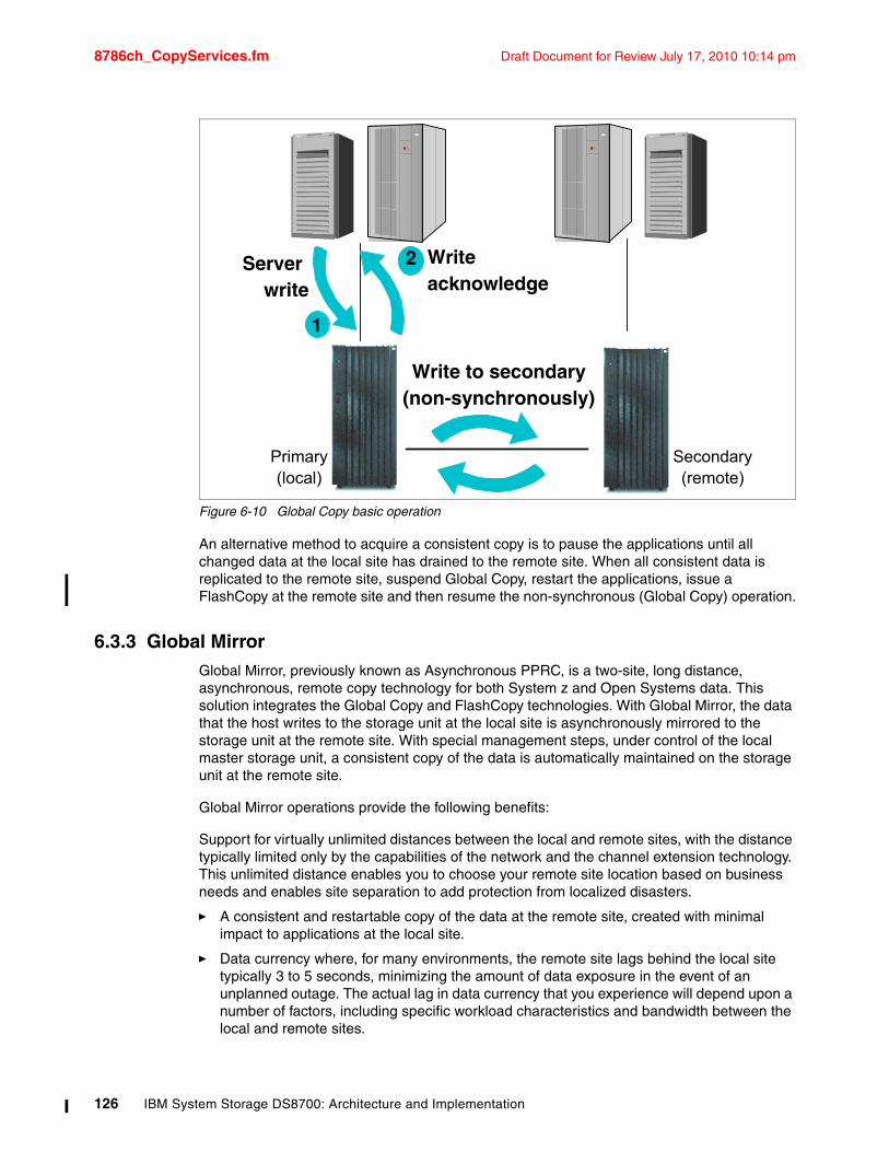
8786ch_CopyServices.fm Draft Document for Review July 17, 2010 10:14 pm
Figure 6-10 Global Copy basic operation
An alternative method to acquire a consistent copy is to pause the applications until all changed data at the local site has drained to the remote site. When all consistent data is replicated to the remote site, suspend Global Copy, restart the applications, issue a FlashCopy at the remote site and then resume the non-synchronous (Global Copy) operation.
6.3.3 Global MirrorGlobal Mirror, previously known as Asynchronous PPRC, is a two-site, long distance, asynchronous, remote copy technology for both System z and Open Systems data. This solution integrates the Global Copy and FlashCopy technologies. With Global Mirror, the data that the host writes to the storage unit at the local site is asynchronously mirrored to the storage unit at the remote site. With special management steps, under control of the local master storage unit, a consistent copy of the data is automatically maintained on the storage unit at the remote site.
Global Mirror operations provide the following benefits:
Support for virtually unlimited distances between the local and remote sites, with the distance typically limited only by the capabilities of the network and the channel extension technology. This unlimited distance enables you to choose your remote site location based on business needs and enables site separation to add protection from localized disasters.
� A consistent and restartable copy of the data at the remote site, created with minimal impact to applications at the local site.
� Data currency where, for many environments, the remote site lags behind the local site typically 3 to 5 seconds, minimizing the amount of data exposure in the event of an unplanned outage. The actual lag in data currency that you experience will depend upon a number of factors, including specific workload characteristics and bandwidth between the local and remote sites.
2
1
Server write
Write to secondary(non-synchronously)
Writeacknowledge
Primary(local)
Secondary(remote)
126 IBM System Storage DS8700: Architecture and Implementation
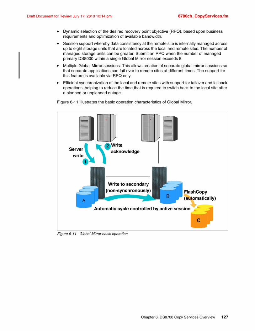
Draft Document for Review July 17, 2010 10:14 pm 8786ch_CopyServices.fm
� Dynamic selection of the desired recovery point objective (RPO), based upon business requirements and optimization of available bandwidth.
� Session support whereby data consistency at the remote site is internally managed across up to eight storage units that are located across the local and remote sites. The number of managed storage units can be greater. Submit an RPQ when the number of managed primary DS8000 within a single Global Mirror session exceeds 8.
� Multiple Global Mirror sessions: This allows creation of separate global mirror sessions so that separate applications can fail-over to remote sites at different times. The support for this feature is available via RPQ only.
� Efficient synchronization of the local and remote sites with support for failover and failback operations, helping to reduce the time that is required to switch back to the local site after a planned or unplanned outage.
Figure 6-11 illustrates the basic operation characteristics of Global Mirror.
Figure 6-11 Global Mirror basic operation
2
1
Server write
Write to secondary(non-synchronously)
Writeacknowledge
AB
C
FlashCopy(automatically)
Automatic cycle controlled by active session
Chapter 6. DS8700 Copy Services Overview 127
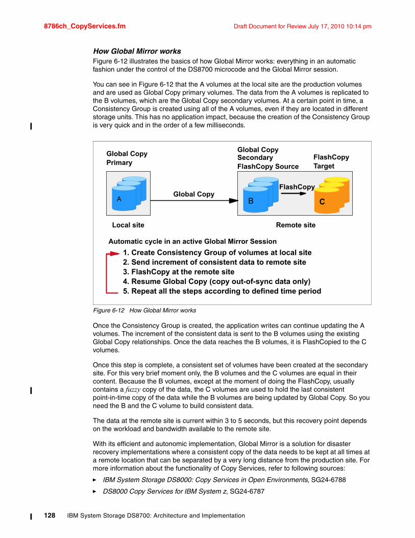
8786ch_CopyServices.fm Draft Document for Review July 17, 2010 10:14 pm
How Global Mirror worksFigure 6-12 illustrates the basics of how Global Mirror works: everything in an automatic fashion under the control of the DS8700 microcode and the Global Mirror session.
You can see in Figure 6-12 that the A volumes at the local site are the production volumes and are used as Global Copy primary volumes. The data from the A volumes is replicated to the B volumes, which are the Global Copy secondary volumes. At a certain point in time, a Consistency Group is created using all of the A volumes, even if they are located in different storage units. This has no application impact, because the creation of the Consistency Group is very quick and in the order of a few milliseconds.
Figure 6-12 How Global Mirror works
Once the Consistency Group is created, the application writes can continue updating the A volumes. The increment of the consistent data is sent to the B volumes using the existing Global Copy relationships. Once the data reaches the B volumes, it is FlashCopied to the C volumes.
Once this step is complete, a consistent set of volumes have been created at the secondary site. For this very brief moment only, the B volumes and the C volumes are equal in their content. Because the B volumes, except at the moment of doing the FlashCopy, usually contains a fuzzy copy of the data, the C volumes are used to hold the last consistent point-in-time copy of the data while the B volumes are being updated by Global Copy. So you need the B and the C volume to build consistent data.
The data at the remote site is current within 3 to 5 seconds, but this recovery point depends on the workload and bandwidth available to the remote site.
With its efficient and autonomic implementation, Global Mirror is a solution for disaster recovery implementations where a consistent copy of the data needs to be kept at all times at a remote location that can be separated by a very long distance from the production site. For more information about the functionality of Copy Services, refer to following sources:
� IBM System Storage DS8000: Copy Services in Open Environments, SG24-6788
� DS8000 Copy Services for IBM System z, SG24-6787
1. Create Consistency Group of volumes at local site2. Send increment of consistent data to remote site 3. FlashCopy at the remote site4. Resume Global Copy (copy out-of-sync data only)5. Repeat all the steps according to defined time period
Global Copy
Local site Remote site
Global CopyPrimary
Global Copy SecondaryFlashCopy Source
CBA
FlashCopyTarget
FlashCopy
Automatic cycle in an active Global Mirror Session
128 IBM System Storage DS8700: Architecture and Implementation
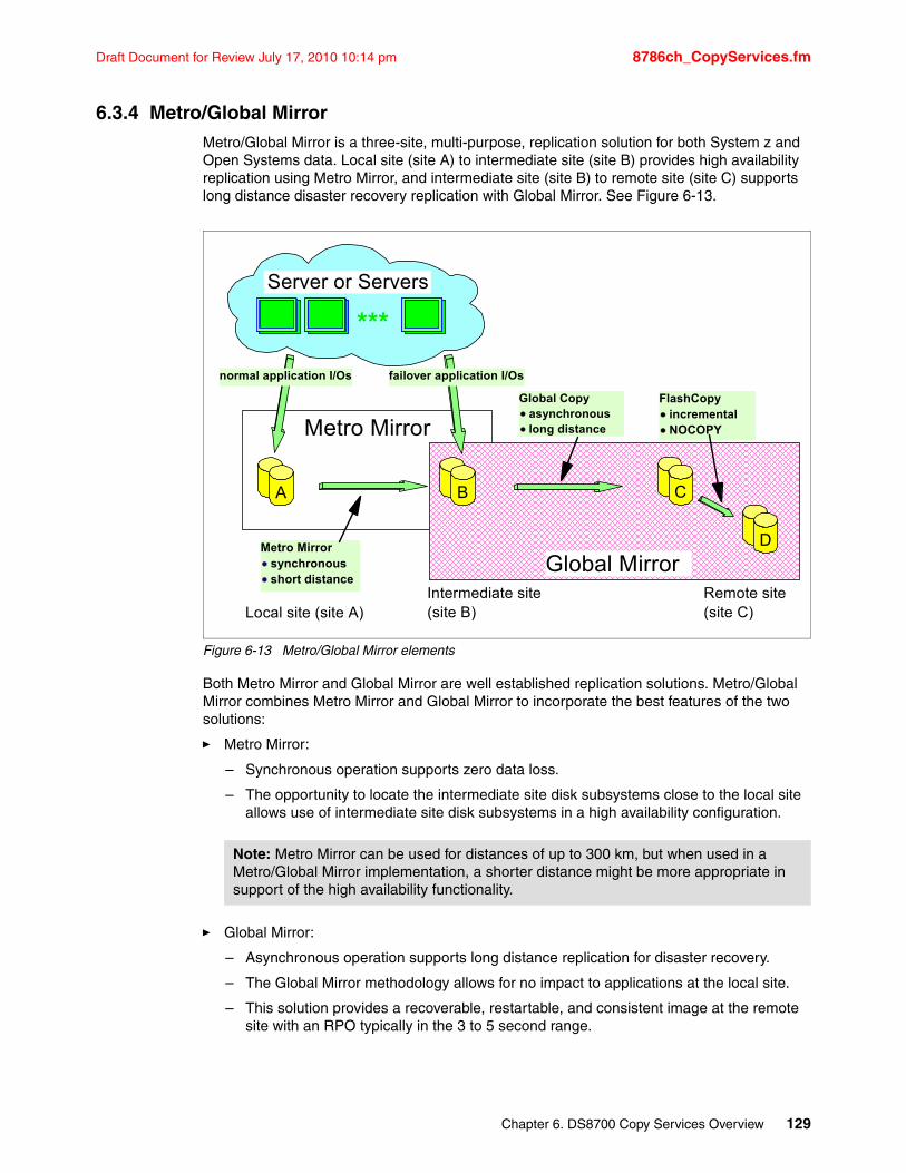
Draft Document for Review July 17, 2010 10:14 pm 8786ch_CopyServices.fm
6.3.4 Metro/Global MirrorMetro/Global Mirror is a three-site, multi-purpose, replication solution for both System z and Open Systems data. Local site (site A) to intermediate site (site B) provides high availability replication using Metro Mirror, and intermediate site (site B) to remote site (site C) supports long distance disaster recovery replication with Global Mirror. See Figure 6-13.
Figure 6-13 Metro/Global Mirror elements
Both Metro Mirror and Global Mirror are well established replication solutions. Metro/Global Mirror combines Metro Mirror and Global Mirror to incorporate the best features of the two solutions:
� Metro Mirror:
– Synchronous operation supports zero data loss.
– The opportunity to locate the intermediate site disk subsystems close to the local site allows use of intermediate site disk subsystems in a high availability configuration.
� Global Mirror:
– Asynchronous operation supports long distance replication for disaster recovery.
– The Global Mirror methodology allows for no impact to applications at the local site.
– This solution provides a recoverable, restartable, and consistent image at the remote site with an RPO typically in the 3 to 5 second range.
Note: Metro Mirror can be used for distances of up to 300 km, but when used in a Metro/Global Mirror implementation, a shorter distance might be more appropriate in support of the high availability functionality.
Local site (site A)Intermediate site(site B)
Remote site(site C)
BA C
D
Metro Mirror
Global MirrorMetro Mirror
synchronousshort distance
Global Copyasynchronouslong distance
FlashCopyincrementalNOCOPY
***
Server or Servers
normal application I/Os failover application I/Os
Chapter 6. DS8700 Copy Services Overview 129
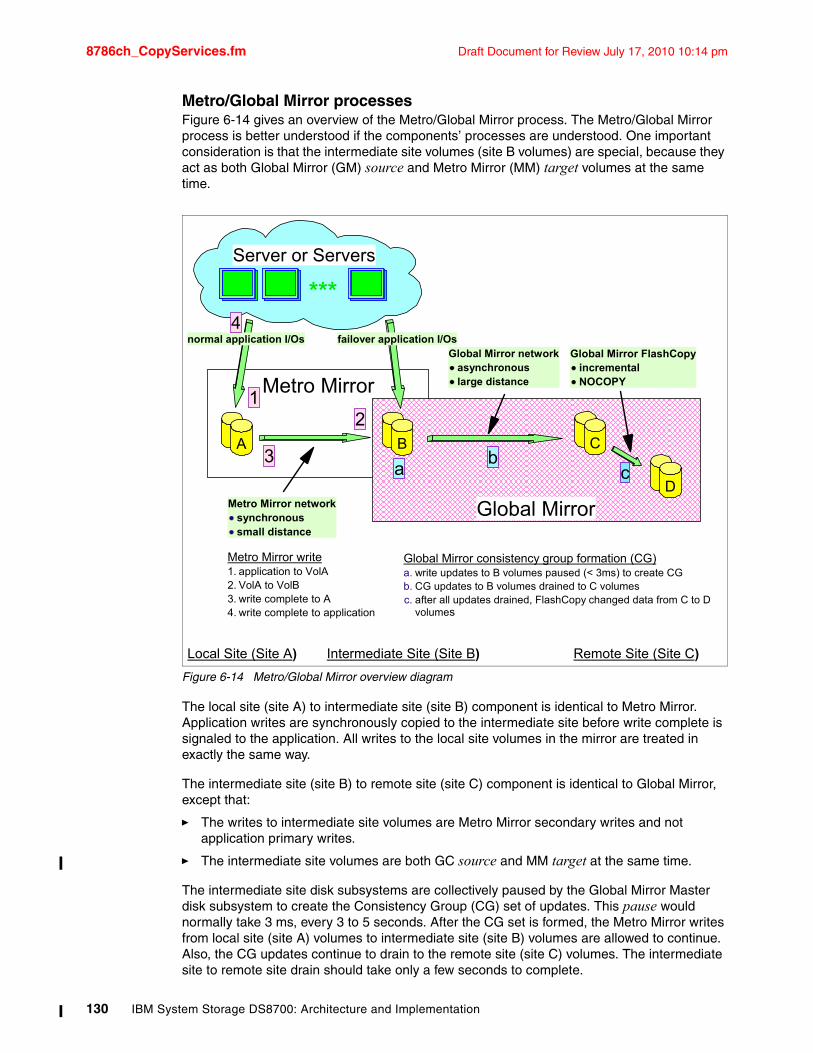
8786ch_CopyServices.fm Draft Document for Review July 17, 2010 10:14 pm
Metro/Global Mirror processesFigure 6-14 gives an overview of the Metro/Global Mirror process. The Metro/Global Mirror process is better understood if the components’ processes are understood. One important consideration is that the intermediate site volumes (site B volumes) are special, because they act as both Global Mirror (GM) source and Metro Mirror (MM) target volumes at the same time.
Figure 6-14 Metro/Global Mirror overview diagram
The local site (site A) to intermediate site (site B) component is identical to Metro Mirror. Application writes are synchronously copied to the intermediate site before write complete is signaled to the application. All writes to the local site volumes in the mirror are treated in exactly the same way.
The intermediate site (site B) to remote site (site C) component is identical to Global Mirror, except that:
� The writes to intermediate site volumes are Metro Mirror secondary writes and not application primary writes.
� The intermediate site volumes are both GC source and MM target at the same time.
The intermediate site disk subsystems are collectively paused by the Global Mirror Master disk subsystem to create the Consistency Group (CG) set of updates. This pause would normally take 3 ms, every 3 to 5 seconds. After the CG set is formed, the Metro Mirror writes from local site (site A) volumes to intermediate site (site B) volumes are allowed to continue. Also, the CG updates continue to drain to the remote site (site C) volumes. The intermediate site to remote site drain should take only a few seconds to complete.
Local Site (Site A) Intermediate Site (Site B) Remote Site (Site C)
BA C
D
Metro Mirror
Global MirrorMetro Mirror networksynchronoussmall distance
Global Mirror networkasynchronouslarge distance
Global Mirror FlashCopyincrementalNOCOPY
***
Server or Servers
normal application I/Os failover application I/Os
12
3
4
Metro Mirror write1. application to VolA2. VolA to VolB3. write complete to A4. write complete to application
ab
c
Global Mirror consistency group formation (CG)a. write updates to B volumes paused (< 3ms) to create CGb. CG updates to B volumes drained to C volumesc. after all updates drained, FlashCopy changed data from C to D
volumes
130 IBM System Storage DS8700: Architecture and Implementation
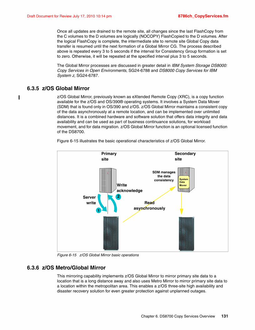
Draft Document for Review July 17, 2010 10:14 pm 8786ch_CopyServices.fm
Once all updates are drained to the remote site, all changes since the last FlashCopy from the C volumes to the D volumes are logically (NOCOPY) FlashCopied to the D volumes. After the logical FlashCopy is complete, the intermediate site to remote site Global Copy data transfer is resumed until the next formation of a Global Mirror CG. The process described above is repeated every 3 to 5 seconds if the interval for Consistency Group formation is set to zero. Otherwise, it will be repeated at the specified interval plus 3 to 5 seconds.
The Global Mirror processes are discussed in greater detail in IBM System Storage DS8000: Copy Services in Open Environments, SG24-6788 and DS8000 Copy Services for IBM System z, SG24-6787.
6.3.5 z/OS Global Mirrorz/OS Global Mirror, previously known as eXtended Remote Copy (XRC), is a copy function available for the z/OS and OS/390® operating systems. It involves a System Data Mover (SDM) that is found only in OS/390 and z/OS. z/OS Global Mirror maintains a consistent copy of the data asynchronously at a remote location, and can be implemented over unlimited distances. It is a combined hardware and software solution that offers data integrity and data availability and can be used as part of business continuance solutions, for workload movement, and for data migration. z/OS Global Mirror function is an optional licensed function of the DS8700.
Figure 6-15 illustrates the basic operational characteristics of z/OS Global Mirror.
Figure 6-15 z/OS Global Mirror basic operations
6.3.6 z/OS Metro/Global Mirror This mirroring capability implements z/OS Global Mirror to mirror primary site data to a location that is a long distance away and also uses Metro Mirror to mirror primary site data to a location within the metropolitan area. This enables a z/OS three-site high availability and disaster recovery solution for even greater protection against unplanned outages.
2
1
Server write
Writeacknowledge
Readasynchronously
Primarysite
Secondarysite
SDM manages the data
consistency System DataMover
Chapter 6. DS8700 Copy Services Overview 131
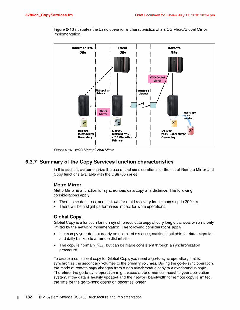
8786ch_CopyServices.fm Draft Document for Review July 17, 2010 10:14 pm
Figure 6-16 illustrates the basic operational characteristics of a z/OS Metro/Global Mirror implementation.
Figure 6-16 z/OS Metro/Global Mirror
6.3.7 Summary of the Copy Services function characteristicsIn this section, we summarize the use of and considerations for the set of Remote Mirror and Copy functions available with the DS8700 series.
Metro MirrorMetro Mirror is a function for synchronous data copy at a distance. The following considerations apply:
� There is no data loss, and it allows for rapid recovery for distances up to 300 km.� There will be a slight performance impact for write operations.
Global CopyGlobal Copy is a function for non-synchronous data copy at very long distances, which is only limited by the network implementation. The following considerations apply:
� It can copy your data at nearly an unlimited distance, making it suitable for data migration and daily backup to a remote distant site.
� The copy is normally fuzzy but can be made consistent through a synchronization procedure.
To create a consistent copy for Global Copy, you need a go-to-sync operation, that is, synchronize the secondary volumes to the primary volumes. During the go-to-sync operation, the mode of remote copy changes from a non-synchronous copy to a synchronous copy. Therefore, the go-to-sync operation might cause a performance impact to your application system. If the data is heavily updated and the network bandwidth for remote copy is limited, the time for the go-to-sync operation becomes longer.
P’P
X X’
X”
Unlimiteddistance
DS8000Metro Mirror/z/OS Global MirrorPrimary
DS8000Metro MirrorSecondary
DS8000z/OS Global MirrorSecondary
Intermediate Site
Remote Site
Local Site
Metropolitandistance
Metro Mirror
z/OS Global Mirror
FlashCopywhen required
P’P
X X’
X”
Unlimiteddistance
DS8000Metro Mirror/z/OS Global MirrorPrimary
DS8000Metro MirrorSecondary
DS8000z/OS Global MirrorSecondary
Intermediate Site
Remote Site
Local Site
Metropolitandistance
Metro Mirror
z/OS Global Mirror
FlashCopywhen required
132 IBM System Storage DS8700: Architecture and Implementation
Draft Document for Review July 17, 2010 10:14 pm 8786ch_CopyServices.fm
An alternative method to acquire a consistent copy is to pause the applications until all changed data at the local site has drained to the remote site. When all consistent data is at the remote site, suspend Global Copy, restart the applications, issue the FlashCopy, and then return to the non-synchronous (Global Copy) operation.
Global MirrorGlobal Mirror is an asynchronous copy technique; you can create a consistent copy in the secondary site with an adaptable Recovery Point Objective (RPO). RPO specifies how much data you can afford to recreate if the system needs to be recovered. The following considerations apply:
� Global Mirror can copy to nearly an unlimited distance.
� It is scalable across the storage units.
� It can realize a low RPO if there is enough link bandwidth; when the link bandwidth capability is exceeded with a heavy workload, the RPO might grow.
� Global Mirror causes only a slight impact to your application system.
z/OS Global Mirrorz/OS Global Mirror is an asynchronous copy technique controlled by z/OS host software called System Data Mover. The following considerations apply:
� It can copy to nearly unlimited distances.
� It is highly scalable.
� It has very low RPO; the RPO might grow if the bandwidth capability is exceeded, or host performance might be impacted.
� Additional host server hardware and software is required.
6.4 Interfaces for Copy ServicesThere are several interfaces for invoking and managing the Copy Services in the DS8700. We introduce them in this section.
Copy Services functions can be initiated using the following interfaces:
� DS Storage Manager Web-based Graphical User Interface (DS GUI)
� DS Command-Line Interface (DS CLI)
� Tivoli Storage Productivity Center for Replication (TPC-R)
� DS open application programming interface (DS Open API)
� System z based I/O interfaces: TSO commands, ICKDSF commands, ANTRQST macro, and DFSMSdss utility
Note: All of the Copy Services options are not always available in each management interface. Refer to the following IBM Redbooks publications for specific considerations:
� IBM System Storage DS8000: Copy Services in Open Environments, SG24-6788
� DS8000 Copy Services for IBM System z, SG24-6787
Chapter 6. DS8700 Copy Services Overview 133
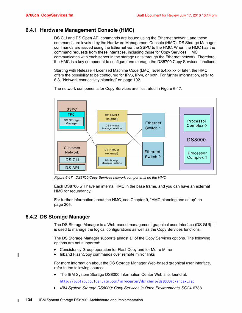
8786ch_CopyServices.fm Draft Document for Review July 17, 2010 10:14 pm
6.4.1 Hardware Management Console (HMC)DS CLI and DS Open API commands are issued using the Ethernet network, and these commands are invoked by the Hardware Management Console (HMC). DS Storage Manager commands are issued using the Ethernet via the SSPC to the HMC. When the HMC has the command requests from these interfaces, including those for Copy Services, HMC communicates with each server in the storage units through the Ethernet network. Therefore, the HMC is a key component to configure and manage the DS8700 Copy Services functions.
Starting with Release 4 Licensed Machine Code (LMC) level 5.4.xx.xx or later, the HMC offers the possibility to be configured for IPv6, IPv4, or both. For further information, refer to 8.3, “Network connectivity planning” on page 192.
The network components for Copy Services are illustrated in Figure 6-17.
Figure 6-17 DS8700 Copy Services network components on the HMC
Each DS8700 will have an internal HMC in the base frame, and you can have an external HMC for redundancy.
For further information about the HMC, see Chapter 9, “HMC planning and setup” on page 205.
6.4.2 DS Storage Manager The DS Storage Manager is a Web-based management graphical user Interface (DS GUI). It is used to manage the logical configurations as well as the Copy Services functions.
The DS Storage Manager supports almost all of the Copy Services options. The following options are not supported:
� Consistency Group operation for FlashCopy and for Metro Mirror� Inband FlashCopy commands over remote mirror links
For more information about the DS Storage Manager Web-based graphical user interface, refer to the following sources:
� The IBM System Storage DS8000 Information Center Web site, found at:
http://publib.boulder.ibm.com/infocenter/dsichelp/ds8000ic/index.jsp
� IBM System Storage DS8000: Copy Services in Open Environments, SG24-6788
SSPC
CustomerNetwork
DS8000
Processor Complex 0
DS CLI
DS API
DS HMC 1(internal)
DS HMC 2(external) Ethernet
Switch 2
EthernetSwitch 1
Processor Complex 1
DS Storage Manager
TPC
DS Storage Manager realtime
DS Storage Manager realtime
134 IBM System Storage DS8700: Architecture and Implementation
Draft Document for Review July 17, 2010 10:14 pm 8786ch_CopyServices.fm
� DS8000 Copy Services for IBM System z, SG24-6787
For additional information about the DS Storage Manager usage, see Chapter 13, “Configuration using the DS Storage Manager GUI” on page 293.
6.4.3 DS Command-Line Interface (DS CLI)The DS Command-Line Interface (DS CLI) provides a full-function command set that enables open systems hosts to invoke and manage FlashCopy and the Remote Mirror and Copy functions through batch processes and scripts. You can use the DS CLI from a supported server to control and manage Copy Services functions on Open Systems and System z volumes.
For more information about the DS CLI as well as the supported platforms, refer to the following sources:
� The IBM System Storage DS8000 Information Center Web site, found at:
http://publib.boulder.ibm.com/infocenter/dsichelp/ds8000ic/index.jsp
� The System Storage Interoperation Center (SSIC), found at:
http://www.ibm.com/systems/support/storage/config/ssic/index.jsp
� IBM System Storage DS8000: Command-Line Interface User’s Guide, GC53-1127
� IBM System Storage DS8000: Copy Services in Open Environments, SG24-6788
� DS8000 Copy Services for IBM System z, SG24-6787
For additional information about DS CLI usage, see Chapter 14, “Configuration with the Command-Line Interface” on page 357.
6.4.4 Tivoli Storage Productivity Center for Replication (TPC for Replication)IBM Tivoli Storage Productivity Center (TPC) for Replication or TPC-R provides management of DS8700 series business continuance solutions, including FlashCopy and Remote Mirror and Copy functions. IBM TPC for Replication V4 for FlashCopy, FlashCopy SE, Metro Mirror, Global Mirror, and Metro/Global Mirror support focuses on automating administration and configuration of these services, operational control like starting, suspending, and resuming, Copy Services tasks, and monitoring and managing the copy sessions. IBM TPC-R supports all flavors of Copy Services functions with the DS8000. This includes also Global Copy since TPC-R Release 4.1+.
TPC-R is designed to help administrators manage Copy Services. This applies not only to the Copy Services provided by DS8000 and DS6000 family, but also to Copy Services provided by the ESS 800 and SAN Volume Controller (SVC).
In addition to these capabilities, TPC-R also provides two-site and three-site Business Continuity manageability. This is intended to provide disaster recovery management through planned and unplanned failover and failback automation, and monitoring progress of the Copy Services so that you can verify the amount of replication that has been done as well as the amount of time required to complete the replication operation.
For more information about the TPC-R please refer to the IBM TPC Information Center Web site, found at:
http://publib.boulder.ibm.com/infocenter/tivihelp/v4r1/index.jsp
Chapter 6. DS8700 Copy Services Overview 135
8786ch_CopyServices.fm Draft Document for Review July 17, 2010 10:14 pm
6.4.5 DS Open application programming interface (DS Open API)The DS Open application programming interface (API) is a non-proprietary storage management client application that supports routine LUN management activities, such as LUN creation, mapping, and masking, and the creation or deletion of RAID 5, RAID 6, and RAID 10 volume spaces. The DS Open API also enables Copy Services functions, such as FlashCopy and Remote Mirror and Copy functions. It supports these activities through the use of the Storage Management Initiative Specification (SMIS), as defined by the Storage Networking Industry Association (SNIA).
The DS Open API helps integrate DS configuration management support into storage resource management (SRM) applications, which allows clients to benefit from existing SRM applications and infrastructures. The DS Open API also enables the automation of configuration management through client-written applications. Either way, the DS Open API presents another option for managing storage units by complementing the use of the IBM System Storage DS Storage Manager Web-based interface and the DS Command-Line Interface.
You must implement the DS Open API through the IBM System Storage Common Information Model (CIM) agent, a middleware application that provides a CIM-compliant interface. The DS Open API uses the CIM technology to manage proprietary devices, such as open system devices through storage management applications. The DS Open API allows these storage management applications to communicate with a storage unit.
For information about the DS Open API, refer to the publication IBM System Storage DS Open Application Programming Interface Reference, GC35-0516.
6.4.6 System z-based I/O interfacesIn addition to using the DS GUI, the DS CLI, or TPC for Replication, System z users also have the following additional interfaces available for Copy Services management:
� TSO commands� ICKDSF utility commands� DFSMSdss utility� ANTRQST application programming interface� Native TPF commands (for z/TPF only)
These interfaces have the advantage of not having to issue their commands to the DS8700 HMC. They can instead directly send as inband commands over a FICON channel connection between the System z and the DS8700. Sending inband commands allows for a very quick command transfer that does not depend on any additional software stacks and complex Ethernet network infrastructures.
All the available Copy Services interfaces mentioned above support the Extended Address Volumes (EAV) implemented into the DS8700.
Operating system-supported interfacesThis is a list of the supported interfaces for the various System z operating systems:
� z/OS– TSO commands– ICKDSF utility– DFSMSdss utility– ANTRQST
� z/VM and z/VSE™– ICKDSF utility
136 IBM System Storage DS8700: Architecture and Implementation
Draft Document for Review July 17, 2010 10:14 pm 8786ch_CopyServices.fm
� z/TPF– ICKDSF utility– z/TPF itself
6.5 InteroperabilityRemote mirror and copy pairs can only be established between disk subsystems of the same - or similar - type and features. For example, a DS8700 can have a remote mirror pair relationship with another DS8700, a DS8300, a DS8100, a DS6800, an ESS 800, or an ESS 750. It cannot have a remote mirror pair relationship with an RVA or an ESS F20. Note that all disk subsystems must have the appropriate features installed. If your DS8700 is mirrored to an ESS disk subsystem, the ESS must be on a PPRC Version 2 level which supports Fibre Channel links with the appropriate licensed internal code level (LIC). ESCON is not supported as PPRC link(s) on any DS8000 or DS6000.
DS8700 interoperability information can be found in the IBM System Storage Interoperation Center (SSIC) at the following web site:
http://www.ibm.com/systems/support/storage/config/ssic
6.6 z/OS Global Mirror on zIIPThe IBM z9® Integrated Information Processor (zIIP) is a special engine available on z10, z9 EC, and z9 BC servers. z/OS now provides the ability to utilize these processors in order to handle eligible workloads from the System Data Mover (SDM) in an z/OS Global Mirror (zGM) environment.
Given the appropriate hardware and software, a range of zGM workload can be offloaded to zIIP processors. This capability is available with an IBM System z9 or z10 server with one or more zIIP processors, used in conjunction with the IBM System storage DS8700, or any storage controller supporting z/OS GM.
The z/OS software must bet at V1.8 and above with APAR OA23174: Specifying zGM PARMLIB parameter zIIPEnable(YES).
Chapter 6. DS8700 Copy Services Overview 137

8786ch_CopyServices.fm Draft Document for Review July 17, 2010 10:14 pm
138 IBM System Storage DS8700: Architecture and Implementation
Draft Document for Review July 17, 2010 10:14 pm 8786ch_Perf.fm
Chapter 7. Performance
This chapter discusses the performance characteristics of the IBM System Storage DS8700 regarding physical and logical configuration. The considerations we discuss in this chapter will help you when you plan the physical and logical setup.
For a detailed discussion about performance, refer to the IBM Redbooks publication DS8000 Performance Monitoring and Tuning, SG24-7146.
This chapter covers the following topics:
� DS8700 hardware: performance characteristics
� Software performance enhancements: synergy items
� Performance and sizing considerations for open systems
� Performance and sizing considerations for System z
7
© Copyright IBM Corp. 2010. All rights reserved. 139
8786ch_Perf.fm Draft Document for Review July 17, 2010 10:14 pm
7.1 DS8700 hardware: performance characteristicsThe DS8700 features IBM POWER6 server technology and a PCIe I/O infrastructure to help support high performance. Compared to the POWER5+ processor in previous models, the POWER6 processor can enable over a 50% performance improvement in I/O operations per second in transaction processing workload environments. Additionally, sequential workloads can receive as much as 150% bandwidth improvement, which is an improvement factor of 2.5 compared to the previous models. The DS8700 offers either a dual 2-way processor complex or a dual 4-way processor complex.
The DS8700 overcomes many of the architectural limits of the predecessor disk subsystems. In this section, we go through the different architectural layers of the DS8000 and discuss the performance characteristics that differentiate the DS8000 from other disk subsystems.
7.1.1 Fibre Channel switched disk interconnection at the back endFibre Channel-connected disks are used in the DS8000 back end. This technology is commonly used to connect a group of disks in a daisy-chained fashion in a Fibre Channel Arbitrated Loop (FC-AL).
FC-AL has some shortcomings. The most obvious ones are:
� Arbitration, that is, disks compete for loop bandwidth.
� Failures within the FC-AL loop, particularly with intermittently failing components on the loops and disks.
� The increased time that it takes to complete a loop operation as the number of loop devices increase.
These shortcomings limit the effective bandwidth of an FC-AL implementation, especially for cases of highly parallel operations with concurrent reads and writes of various transfer sizes.
140 IBM System Storage DS8700: Architecture and Implementation
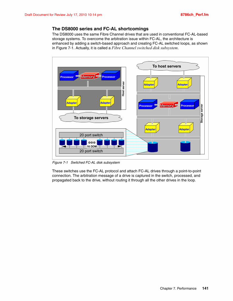
Draft Document for Review July 17, 2010 10:14 pm 8786ch_Perf.fm
The DS8000 series and FC-AL shortcomingsThe DS8000 uses the same Fibre Channel drives that are used in conventional FC-AL-based storage systems. To overcome the arbitration issue within FC-AL, the architecture is enhanced by adding a switch-based approach and creating FC-AL switched loops, as shown in Figure 7-1. Actually, it is called a Fibre Channel switched disk subsystem.
Figure 7-1 Switched FC-AL disk subsystem
These switches use the FC-AL protocol and attach FC-AL drives through a point-to-point connection. The arbitration message of a drive is captured in the switch, processed, and propagated back to the drive, without routing it through all the other drives in the loop.
Processor
AdapterAdapter
MemoryMemory Processor
AdapterAdapter
To host servers
Sto
rag
e se
rver
ooo
20 port switch
20 port switch
16 DDM
Processor
AdapterAdapter
MemoryMemory Processor
To storage serversH
ost
ser
ver
Chapter 7. Performance 141
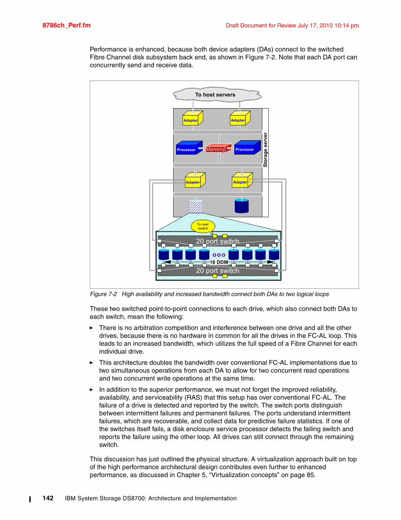
8786ch_Perf.fm Draft Document for Review July 17, 2010 10:14 pm
Performance is enhanced, because both device adapters (DAs) connect to the switched Fibre Channel disk subsystem back end, as shown in Figure 7-2. Note that each DA port can concurrently send and receive data.
Figure 7-2 High availability and increased bandwidth connect both DAs to two logical loops
These two switched point-to-point connections to each drive, which also connect both DAs to each switch, mean the following:
� There is no arbitration competition and interference between one drive and all the other drives, because there is no hardware in common for all the drives in the FC-AL loop. This leads to an increased bandwidth, which utilizes the full speed of a Fibre Channel for each individual drive.
� This architecture doubles the bandwidth over conventional FC-AL implementations due to two simultaneous operations from each DA to allow for two concurrent read operations and two concurrent write operations at the same time.
� In addition to the superior performance, we must not forget the improved reliability, availability, and serviceability (RAS) that this setup has over conventional FC-AL. The failure of a drive is detected and reported by the switch. The switch ports distinguish between intermittent failures and permanent failures. The ports understand intermittent failures, which are recoverable, and collect data for predictive failure statistics. If one of the switches itself fails, a disk enclosure service processor detects the failing switch and reports the failure using the other loop. All drives can still connect through the remaining switch.
This discussion has just outlined the physical structure. A virtualization approach built on top of the high performance architectural design contributes even further to enhanced performance, as discussed in Chapter 5, “Virtualization concepts” on page 85.
Processor
AdapterAdapter
MemoryMemory Processor
AdapterAdapter
To host servers
Sto
rag
e se
rver
ooo
20 port switch
20 port switch
16 DDM
To next switch
142 IBM System Storage DS8700: Architecture and Implementation
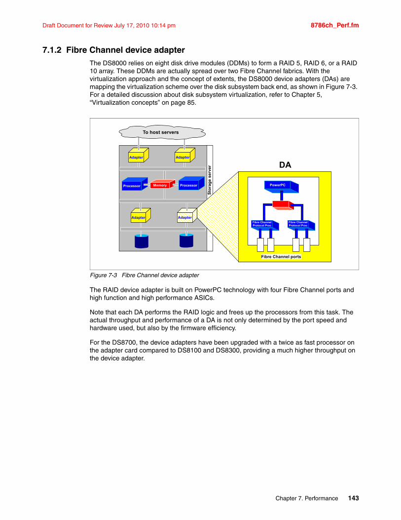
Draft Document for Review July 17, 2010 10:14 pm 8786ch_Perf.fm
7.1.2 Fibre Channel device adapterThe DS8000 relies on eight disk drive modules (DDMs) to form a RAID 5, RAID 6, or a RAID 10 array. These DDMs are actually spread over two Fibre Channel fabrics. With the virtualization approach and the concept of extents, the DS8000 device adapters (DAs) are mapping the virtualization scheme over the disk subsystem back end, as shown in Figure 7-3. For a detailed discussion about disk subsystem virtualization, refer to Chapter 5, “Virtualization concepts” on page 85.
Figure 7-3 Fibre Channel device adapter
The RAID device adapter is built on PowerPC technology with four Fibre Channel ports and high function and high performance ASICs.
Note that each DA performs the RAID logic and frees up the processors from this task. The actual throughput and performance of a DA is not only determined by the port speed and hardware used, but also by the firmware efficiency.
For the DS8700, the device adapters have been upgraded with a twice as fast processor on the adapter card compared to DS8100 and DS8300, providing a much higher throughput on the device adapter.
Processor
AdapterAdapter
AdapterAdapter
To host servers
Sto
rag
e s
erve
r
Memory PowerPC
Fibre Channel ports
Fibre Channel Protocol Proc
Fibre Channel Protocol Proc
DA
Processor
Chapter 7. Performance 143

8786ch_Perf.fm Draft Document for Review July 17, 2010 10:14 pm
7.1.3 Four-port host adapters Before looking into the heart of the DS8000 series, we briefly review the host adapters and their enhancements to address performance. Figure 7-4 shows the host adapters. These adapters are designed to hold four Fibre Channel (FC) ports, which can be configured to support either FCP or FICON.
Each port provides industry-leading throughput and I/O rates for FICON and FCP.
Figure 7-4 Host adapter with four Fibre Channel ports
With FC adapters that are configured for FICON, the DS8000 series provides the following configuration capabilities:
� Either fabric or point-to-point topologies
� A maximum of 128 host adapter ports, depending on the DS8700 processor feature
� A maximum of 509 logins per Fibre Channel port
� A maximum of 8,192 logins per storage unit
� A maximum of 1,280 logical paths on each Fibre Channel port
� Access to all control-unit images over each FICON port
� A maximum of 512 logical paths per control unit image
FICON host channels limit the number of devices per channel to 16,384. To fully access 65,280 devices on a storage unit, it is necessary to connect a minimum of four FICON host channels to the storage unit. This way, by using a switched configuration, you can expose 64 control-unit images (16,384 devices) to each host channel.
The front end with the 4 Gbps ports scales up to 128 ports for a DS8700. This results in a theoretical aggregated host I/O bandwidth of 128 times 4 Gbps.
7.1.4 IBM System p POWER6: heart of the DS8700 dual cluster designThe new DS8700 model incorporates the System p POWER6 processor technology. The DS8700 model can be equipped with the 2-way processor feature or the 4-way processor feature for highest performance requirements.
Processor
AdapterAdapter
AdapterAdapter
To host servers
Sto
rag
e s
erv
er
MemoryPowerPC
Fibre Channel Host ports
Fibre Channel Protocol Proc
HA
Fibre Channel Protocol Proc
Processor
144 IBM System Storage DS8700: Architecture and Implementation
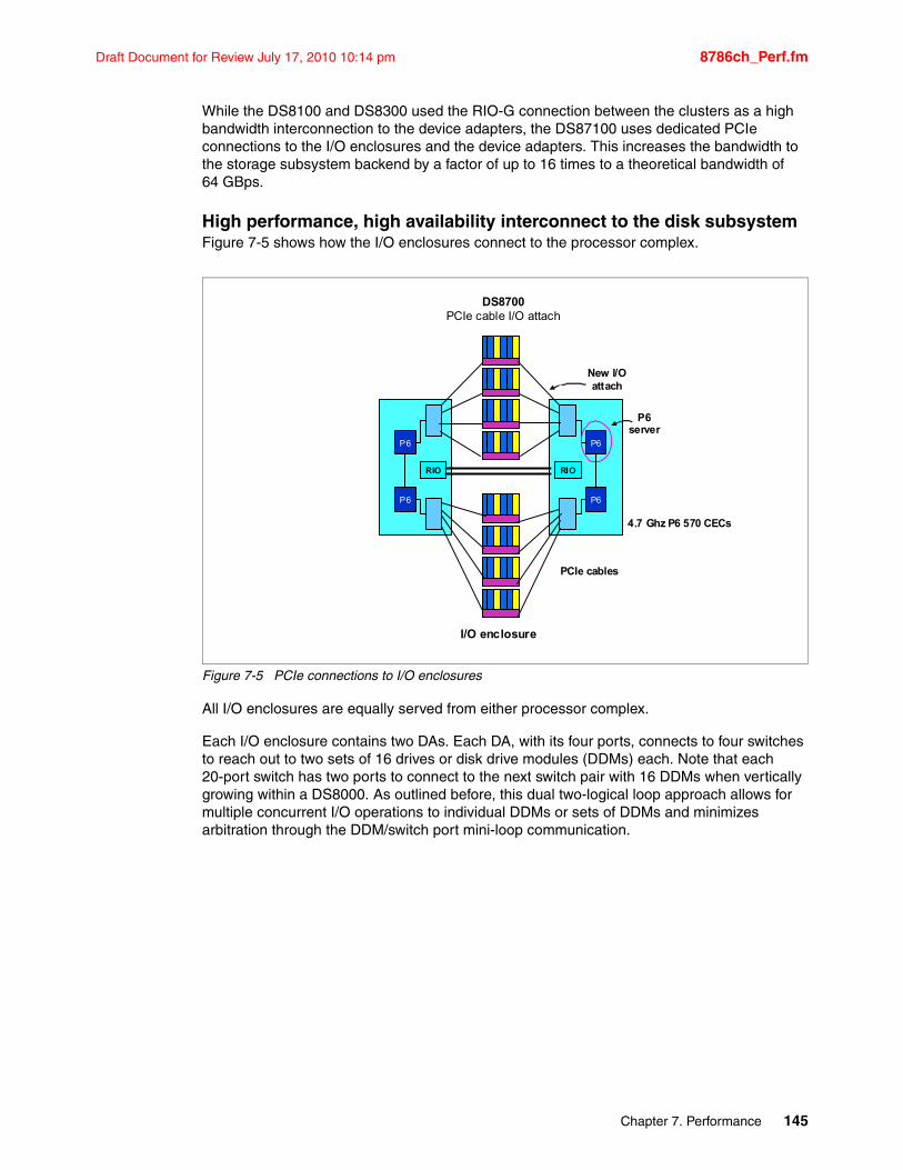
Draft Document for Review July 17, 2010 10:14 pm 8786ch_Perf.fm
While the DS8100 and DS8300 used the RIO-G connection between the clusters as a high bandwidth interconnection to the device adapters, the DS87100 uses dedicated PCIe connections to the I/O enclosures and the device adapters. This increases the bandwidth to the storage subsystem backend by a factor of up to 16 times to a theoretical bandwidth of 64 GBps.
High performance, high availability interconnect to the disk subsystemFigure 7-5 shows how the I/O enclosures connect to the processor complex.
Figure 7-5 PCIe connections to I/O enclosures
All I/O enclosures are equally served from either processor complex.
Each I/O enclosure contains two DAs. Each DA, with its four ports, connects to four switches to reach out to two sets of 16 drives or disk drive modules (DDMs) each. Note that each 20-port switch has two ports to connect to the next switch pair with 16 DDMs when vertically growing within a DS8000. As outlined before, this dual two-logical loop approach allows for multiple concurrent I/O operations to individual DDMs or sets of DDMs and minimizes arbitration through the DDM/switch port mini-loop communication.
P6
P6 P6
RIO RIO
PCIe cables
DS8700PCIe cable I/O attach
New I/O attach
P6 server
P6
4.7 Ghz P6 570 CECs
I/O enclosure
Chapter 7. Performance 145
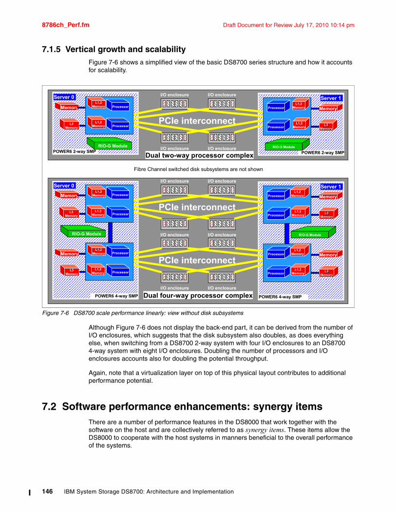
8786ch_Perf.fm Draft Document for Review July 17, 2010 10:14 pm
7.1.5 Vertical growth and scalabilityFigure 7-6 shows a simplified view of the basic DS8700 series structure and how it accounts for scalability.
Figure 7-6 DS8700 scale performance linearly: view without disk subsystems
Although Figure 7-6 does not display the back-end part, it can be derived from the number of I/O enclosures, which suggests that the disk subsystem also doubles, as does everything else, when switching from a DS8700 2-way system with four I/O enclosures to an DS8700 4-way system with eight I/O enclosures. Doubling the number of processors and I/O enclosures accounts also for doubling the potential throughput.
Again, note that a virtualization layer on top of this physical layout contributes to additional performance potential.
7.2 Software performance enhancements: synergy itemsThere are a number of performance features in the DS8000 that work together with the software on the host and are collectively referred to as synergy items. These items allow the DS8000 to cooperate with the host systems in manners beneficial to the overall performance of the systems.
PCIe interconnect
I/O enclosure
I/O enclosure
I/O enclosure
I/O enclosure
Dual two-way processor complex
Dual four-way processor complex
Fibre Channel switched disk subsystems are not shown
PCIe interconnect
I/O enclosure
I/O enclosure
I/O enclosure
I/O enclosure
PCIe interconnect
I/O enclosureI/O enclosure
POWER6 4-way SMP
RIO-G Module
Memory
L3 Memory
Processor
Processor
L1,2 Memory
L1,2 Memory
L3 Memory
Processor
Processor
L1,2 Memory
L1,2 Memory
Server 0
Memory
POWER6 4-way SMP
RIO-G Module
Memory
L3 L3 MemoryMemory
Processor
Processor
L1,2 Memory
L1,2 Memory
Memory
L3 L3 MemoryMemory
Processor
Processor
L1,2 Memory
L1,2 Memory
Server 1
POWER6 2-way SMP
Memory
L3 L3 MemoryMemory
Processor
Processor
L1,2 Memory
L1,2 Memory
Server 1
POWER6 2-way SMP
Memory
L3 Memory
Processor
Processor
L1,2 Memory
L1,2 Memory
Server 0
RIO-G Module RIO-G Module
146 IBM System Storage DS8700: Architecture and Implementation
Draft Document for Review July 17, 2010 10:14 pm 8786ch_Perf.fm
7.2.1 End to end I/O priority: synergy with System p AIX and DB2End to end I/O priority is a new addition, requested by IBM, to the SCSI T10 standard. This feature allows trusted applications to override the priority given to each I/O by the operating system. This is only applicable to raw volumes (no file system) and with the 64-bit kernel. Currently, AIX supports this feature in conjunction with DB2. The priority is delivered to storage subsystem in the FCP Transport Header.
The priority of an AIX process can be 0 (no assigned priority) or any integer value from 1 (highest priority) to 15 (lowest priority). All I/O requests associated with a given process inherit its priority value, but with end to end I/O priority, DB2 can change this value for critical data transfers. At the DS8000, the host adapter will give preferential treatment to higher priority I/O, improving performance for specific requests deemed important by the application, such as requests that might be prerequisites for others, for example, DB2 logs.
7.2.2 Cooperative caching: synergy with System p AIX and DB2Another software-related performance item is cooperative caching, a feature which provides a way for the host to send cache management hints to the storage facility. Currently, the host can indicate that the information just accessed is unlikely to be accessed again soon. This decreases the retention period of the cached data, allowing the subsystem to conserve its cache for data that is more likely to be reaccessed, improving the cache hit ratio.
With the implementation of cooperative caching, the AIX operating system allows trusted applications, such as DB2, to provide cache hints to the DS8000. This improves the performance of the subsystem by keeping more of the repeatedly accessed data within the cache. Cooperative caching is supported in System p AIX with the Multipath I/O (MPIO) Path Control Module (PCM) that is provided with the Subsystem Device Driver (SDD). It is only applicable to raw volumes (no file system) and with the 64-bit kernel.
7.2.3 Long busy wait host tolerance: synergy with System p AIXAnother new addition to the SCSI T10 standard is SCSI long busy wait, which provides a way for the target system to specify that it is busy and how long the initiator should wait before retrying an I/O.
This information, provided in the Fibre Channel Protocol (FCP) status response, prevents the initiator from retrying too soon. This in turn reduces unnecessary requests and potential I/O failures due to exceeding a set threshold for the number of retries. IBM System p AIX supports SCSI long busy wait with MPIO, and it is also supported by the DS8000.
7.2.4 HACMP-extended distance extensions: synergy with System p AIXHACMP™-Extended Distance (HACMP/XD), which is unrelated to PPRC-XD or Global Copy as it is called now, provides server/LPAR failover capability over extended distances. It can also exploit the Metro Mirror function of the DS8000 as a data replication mechanism between the primary and remote site. HACMP/XD with Metro Mirror supports distances of up to 300 km. The DS8000 requires no changes to be used in this fashion.
Chapter 7. Performance 147
8786ch_Perf.fm Draft Document for Review July 17, 2010 10:14 pm
7.3 Performance considerations for disk drivesYou can determine the number and type of ranks required based on the needed capacity and on the workload characteristics in terms of access density, read to write ratio, and hit rates.
You can approach this task from the disk side and look at some basic disk figures. Fibre Channel disks, for example, at 15K RPM provide an average seek time of approximately 3.5 ms and an average latency of 2 ms. For transferring only a small block, the transfer time can be neglected. This is an average 5.5 ms per random disk I/O operation or 180 IOPS. A combined number of eight disks (as is the case for a DS8000 array) will thus potentially sustain 1,440 IOPS when spinning at 15K RPM. Reduce the number by 12.5% when you assume a spare drive in the eight pack.
Back on the host side, consider an example with 1,000 IOPS from the host, a read-to-write ratio of 3 to 1, and 50% read cache hits. This leads to the following IOPS numbers:
� 750 read IOPS.
� 375 read I/Os must be read from disk (based on the 50% read cache hit ratio).
� 250 writes with RAID 5 results in 1,000 disk operations due to the RAID 5 write penalty (read old data and parity, write new data and parity).
� This totals to 1375 disk I/Os.
With 15K RPM DDMs doing 1000 random IOPS from the server, we actually do 1375 I/O operations on disk compared to a maximum of 1440 operations for 7+P configurations or 1260 operations for 6+P+S configurations. Thus, 1000 random I/Os from a server with a standard read-to-write ratio and a standard cache hit ratio saturate the disk drives. We made the assumption that server I/O is purely random. When there are sequential I/Os, track-to-track seek times are much lower and higher I/O rates are possible. We also assumed that reads have a hit ratio of only 50%. With higher hit ratios, higher workloads are possible. This shows the importance of intelligent caching algorithms as used in the DS8000.
For a single disk drive, various disk vendors provide the disk specifications on their Web sites. Because the access times for the Fibre Channel disks are the same, but they have different capacities, the I/O density is different. 146 GB 15K RPM disk drives can be used for access densities up 1 I/O GBps. For 300 GB drives, it is 0.5 I/O GBps. While this discussion is theoretical in approach, it provides a first estimate.
Once the speed of the disk has been decided, the capacity can be calculated based on your storage capacity needs and the effective capacity of the RAID configuration you will use. Refer to Table 8-10 on page 200 for information about calculating these needs.
Solid State Drive (SSD)From a performance point of view, the best choice for your DS8700 disks would be the new Solid State Drives (SSDs). SSDs have no moving parts (no spinning platters and no actuator arm). The performance advantages are the fast seek time and average access time. They are targeted at applications with heavy IOPS bad cache hit rates and random access workload, which necessitates fast response times. Database applications with their random and intensive IO workloads are prime candidates for deployment on SSDs.
For detailed recommendations about SSD usage and performance, refer to DS8000: Introducing Solid State Drives, REDP-4522.
Important: When sizing a storage subsystem, you should consider the capacity and the number of disk drives needed to satisfy the performance requirements.
148 IBM System Storage DS8700: Architecture and Implementation
Draft Document for Review July 17, 2010 10:14 pm 8786ch_Perf.fm
SATA disk drivesWhen analyzing disk alternatives, keep in mind that the 2 TB SATA drives are both the largest and slowest of the drives available for the DS8000 series. This, combined with the lower utilization recommendations and the potential for drive protection throttling, means that these drives are definitely not recommended for high performance or I/O intensive applications.
Differences between SATA and FC disk drivesFibre Channel disk drives provide higher performance, reliability, availability, and serviceability when compared to SATA disk drives. While Fibre Channel disk drives rotate at 15,000 RPM, SATA drives rotate only at 7,200 RPM. If an application requires high performance data throughput and almost continuous, intensive I/O operations, FC disk drives are the recommended option.
SATA disk drives are a cost-efficient storage option for lower intensity storage workloads.
Without any doubt, the technical characteristics and performance of FC disks remain superior to those of SATA disks. However, not all storage applications require these superior features.
When used for the appropriate enterprise applications, SATA disks offer a tremendous cost advantage over FC. First, SATA drives are cheaper to manufacture, and because of their larger individual capacity, they are cheaper per gigabyte (GB) than FC disks. In large capacity systems, the drives themselves account for the vast majority of the cost of the system. Using SATA disks can substantially reduce the total cost of ownership (TCO) of the storage system.
SATA is not designed for fast access to data or handling large amounts of random I/O. However, they are a good fit for many bandwidth applications, because they can provide comparable throughput for short periods of time.
RAID levelThe DS8000 series offers RAID 5, RAID 6, and RAID 10.
RAID 5Normally, RAID 5 is used because it provides very good performance for random and sequential workloads and it does not need much additional storage for redundancy (one parity drive). The DS8000 series can detect sequential workload. When a complete stripe is in cache for destage, the DS8000 series switches to a RAID 3-like algorithm. Because a complete stripe has to be destaged, the old data and parity need not be read; instead, the new parity is calculated across the stripe and data and parity are destaged to disk. This provides very good sequential performance. A random write causes a cache hit, but the I/O is not complete until a copy of the write data is put in NVS. When data is destaged to disk, a write in RAID 5 causes four disk operations, the so called write penalty.
Important: SATA drives are not the appropriate option for every storage requirement. For many enterprise applications, and certainly mission-critical and production applications, Fibre Channel disks remain the best choice.
Note: The SATA drives offer a cost-effective option for lower priority data, such as various fixed content, data archival, reference data, and near-line applications that require large amounts of storage capacity for lighter workloads. These new drives are meant to complement, not compete with, existing Fibre Channel drives, because they are not intended for use in applications that require drive utilization duty cycles greater than 20 percent.
Chapter 7. Performance 149
8786ch_Perf.fm Draft Document for Review July 17, 2010 10:14 pm
Old data must be read, as well as the old parity information. New parity is calculated in the device adapter and data and parity written to disk. Most of this activity is hidden to the server or host because the I/O is complete when data has entered cache and NVS.
RAID 6RAID 6 is an option that increases data fault tolerance. It allows additional failure, compared to RAID 5, by using a second independent distributed parity scheme (dual parity). RAID 6 provides a Read Performance similar to RAID 5, but has more write penalty than RAID 5 because it has to write a second parity stripe.
RAID 6 should be considered in situations where you would consider RAID 5, but need increased reliability. RAID 6 was designed for protection during longer rebuild times on larger capacity drives to cope with the risk of having a second drive failure within a rank while the failed drive is being rebuilt. It has the following characteristics:
Sequential Read About 99% x RAID 5 Rate
Sequential Write About 65% x RAID 5 Rate
Random 4K 70%R/30%W IOPs About 55% x RAID 5 Rate
The performance is significantly degraded with two failing disks.
RAID 10A workload that is dominated by random writes will benefit from RAID 10. Here data is striped across several disks and at the same time mirrored to another set of disks. A write causes only two disk operations compared to RAID 5’s four operations. However, you need nearly twice as many disk drives for the same capacity when compared to RAID 5. Thus, for twice the number of drives (and probably cost), we can do four times more random writes, so it is worth considering using RAID 10 for high performance random write workloads.
The decision to configure capacity as RAID 5, RAID 6, or RAID 10, as well as the amount of capacity to configure for each type, can be made at any time. RAID 5, RAID 6, and RAID 10 arrays can be intermixed within a single system and the physical capacity can be logically reconfigured at a later date (for example, RAID 6 arrays can be reconfigured into RAID 5 arrays).
Disk Magic and Capacity MagicApart from the general guidance we provide in this chapter, the best approach is to use your installation workload as input to the Disk Magic modelling tool (see Appendix A, “Tools and service offerings” on page 585). With your workload data and current configuration of disk subsystem units, Disk Magic can establish a base model. From this base model, Disk Magic can project the DS8000 units (and their configuration) that will be needed to absorb the present workload and also any future growth that you anticipate.
To estimate the number and capacity of disk drive sets needed to fulfill your storage capacity requirements, use the Capacity Magic tool. It is an easy to use tool that will also help you determine the requirements for any growth in capacity that you can foresee.
150 IBM System Storage DS8700: Architecture and Implementation
Draft Document for Review July 17, 2010 10:14 pm 8786ch_Perf.fm
7.4 DS8000 superior caching algorithmsMost, if not all, high-end disk systems have an internal cache integrated into the system design, and some amount of system cache is required for operation. Over time, cache sizes have dramatically increased, but the ratio of cache size to system disk capacity has remained nearly the same. The DS8700 can be equipped with up to 384 GB of cache.
7.4.1 Sequential Adaptive Replacement Cache (SARC)The DS8000 series uses the SARC algorithm, which was developed by IBM Storage Development in partnership with IBM Research. It is a self-tuning, self-optimizing solution for a wide range of workloads with a varying mix of sequential and random I/O streams. SARC is inspired by the Adaptive Replacement Cache (ARC) algorithm and inherits many features of it. For a detailed description about ARC, see “Outperforming LRU with an adaptive replacement cache algorithm” by N. Megiddo et al. in IEEE Computer, volume 37, number 4, pages 58–65, 2004. For a detailed description about SARC, see “SARC: Sequential Prefetching in Adaptive Replacement Cache” by Binny Gill, et al. in the Proceedings of the USENIX 2005 Annual Technical Conference, pages 293-308.
SARC basically attempts to determine four things:
� When data is copied into the cache.� Which data is copied into the cache.� Which data is evicted when the cache becomes full.� How the algorithm dynamically adapts to different workloads.
The DS8000 series cache is organized in 4 KB pages called cache pages or slots. This unit of allocation (which is smaller than the values used in other storage systems) ensures that small I/Os do not waste cache memory.
The decision to copy some amount of data into the DS8000 cache can be triggered from two policies: demand paging and prefetching.
� Demand paging means that eight disk blocks (a 4K cache page) are brought in only on a cache miss. Demand paging is always active for all volumes and ensures that I/O patterns with some locality discover at least some recently used data in the cache.
� Prefetching means that data is copied into the cache speculatively even before it is requested. To prefetch, a prediction of likely future data accesses is needed. Because effective, sophisticated prediction schemes need an extensive history of page accesses (which is not feasible in real systems), SARC uses prefetching for sequential workloads. Sequential access patterns naturally arise in video-on-demand, database scans, copy, backup, and recovery. The goal of sequential prefetching is to detect sequential access and effectively preload the cache with data so as to minimize cache misses. Today prefetching is ubiquitously applied in Web servers and clients, databases, file servers, on-disk caches, and multimedia servers.
For prefetching, the cache management uses tracks. A track is a set of 128 disk blocks (16 cache pages). To detect a sequential access pattern, counters are maintained with every track to record whether a track has been accessed together with its predecessor. Sequential prefetching becomes active only when these counters suggest a sequential access pattern. In this manner, the DS8000 monitors application read-I/O patterns and dynamically determines whether it is optimal to stage into cache:
� Just the page requested� That page requested plus the remaining data on the disk track� An entire disk track (or a set of disk tracks), which has not yet been requested
Chapter 7. Performance 151
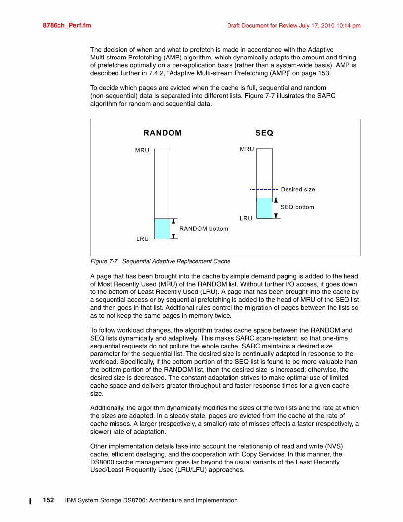
8786ch_Perf.fm Draft Document for Review July 17, 2010 10:14 pm
The decision of when and what to prefetch is made in accordance with the Adaptive Multi-stream Prefetching (AMP) algorithm, which dynamically adapts the amount and timing of prefetches optimally on a per-application basis (rather than a system-wide basis). AMP is described further in 7.4.2, “Adaptive Multi-stream Prefetching (AMP)” on page 153.
To decide which pages are evicted when the cache is full, sequential and random (non-sequential) data is separated into different lists. Figure 7-7 illustrates the SARC algorithm for random and sequential data.
Figure 7-7 Sequential Adaptive Replacement Cache
A page that has been brought into the cache by simple demand paging is added to the head of Most Recently Used (MRU) of the RANDOM list. Without further I/O access, it goes down to the bottom of Least Recently Used (LRU). A page that has been brought into the cache by a sequential access or by sequential prefetching is added to the head of MRU of the SEQ list and then goes in that list. Additional rules control the migration of pages between the lists so as to not keep the same pages in memory twice.
To follow workload changes, the algorithm trades cache space between the RANDOM and SEQ lists dynamically and adaptively. This makes SARC scan-resistant, so that one-time sequential requests do not pollute the whole cache. SARC maintains a desired size parameter for the sequential list. The desired size is continually adapted in response to the workload. Specifically, if the bottom portion of the SEQ list is found to be more valuable than the bottom portion of the RANDOM list, then the desired size is increased; otherwise, the desired size is decreased. The constant adaptation strives to make optimal use of limited cache space and delivers greater throughput and faster response times for a given cache size.
Additionally, the algorithm dynamically modifies the sizes of the two lists and the rate at which the sizes are adapted. In a steady state, pages are evicted from the cache at the rate of cache misses. A larger (respectively, a smaller) rate of misses effects a faster (respectively, a slower) rate of adaptation.
Other implementation details take into account the relationship of read and write (NVS) cache, efficient destaging, and the cooperation with Copy Services. In this manner, the DS8000 cache management goes far beyond the usual variants of the Least Recently Used/Least Frequently Used (LRU/LFU) approaches.
RANDOM
LRU
MRU
RANDOM bottom
SEQ
LRU
MRU
SEQ bottom
Desired size
152 IBM System Storage DS8700: Architecture and Implementation
Draft Document for Review July 17, 2010 10:14 pm 8786ch_Perf.fm
7.4.2 Adaptive Multi-stream Prefetching (AMP)As described previously, SARC dynamically divides the cache between the RANDOM and SEQ lists, where the SEQ list maintains pages brought into the cache by sequential access or sequential prefetching.
Starting with V5.2.400.327, Adaptive Multi-stream Prefetching (AMP) (a tool from IBM Research) manages the SEQ. AMP is an autonomic, workload-responsive, self-optimizing prefetching technology that adapts both the amount of prefetch and the timing of prefetch on a per-application basis in order to maximize the performance of the system. The AMP algorithm solves two problems that plague most other prefetching algorithms:
� Prefetch wastage occurs when prefetched data is evicted from the cache before it can be used.
� Cache pollution occurs when less useful data is prefetched instead of more useful data.
By wisely choosing the prefetching parameters, AMP provides optimal sequential read performance and maximizes the aggregate sequential read throughput of the system. The amount prefetched for each stream is dynamically adapted according to the application's needs and the space available in the SEQ list. The timing of the prefetches is also continuously adapted for each stream to avoid misses and at the same time avoid any cache pollution.
SARC and AMP play complementary roles. While SARC is carefully dividing the cache between the RANDOM and the SEQ lists so as to maximize the overall hit ratio, AMP is managing the contents of the SEQ list to maximize the throughput obtained for the sequential workloads. While SARC impacts cases that involve both random and sequential workloads, AMP helps any workload that has a sequential read component, including pure sequential read workloads.
AMP dramatically improves performance for common sequential and batch processing workloads. It also provides excellent performance synergy with DB2 by preventing table scans from being I/O bound and improves performance of index scans and DB2 utilities like Copy and Recover. Furthermore, AMP reduces the potential for array hot spots, which result from extreme sequential workload demands.
For a detailed description about AMP and the theoretical analysis for its optimal usage, see “AMP: Adaptive Multi-stream Prefetching in a Shared Cache” by Binny Gill, et al. in USENIX File and Storage Technologies (FAST), February 13-16, 2007, San Jose, CA. For a more detailed description, see “Optimal Multistream Sequential Prefetching in a Shared Cache” by Binny Gill, et al. in the ACM Journal of Transactions on Storage, October 2007.
7.4.3 Intelligent Write Caching (IWC)Recently, an additional cache algorithm, referred to as the Intelligent Write Caching (ICW), has been implemented in the DS8000 series. IWC improves performance through better write cache management and a better destaging order of writes. This new algorithm is a combination of CLOCK, a predominantly read cache algorithm, and CSCAN, an efficient write cache algorithm. Out of this combination, IBM produced a very powerful and widely applicable write cache algorithm.
Chapter 7. Performance 153
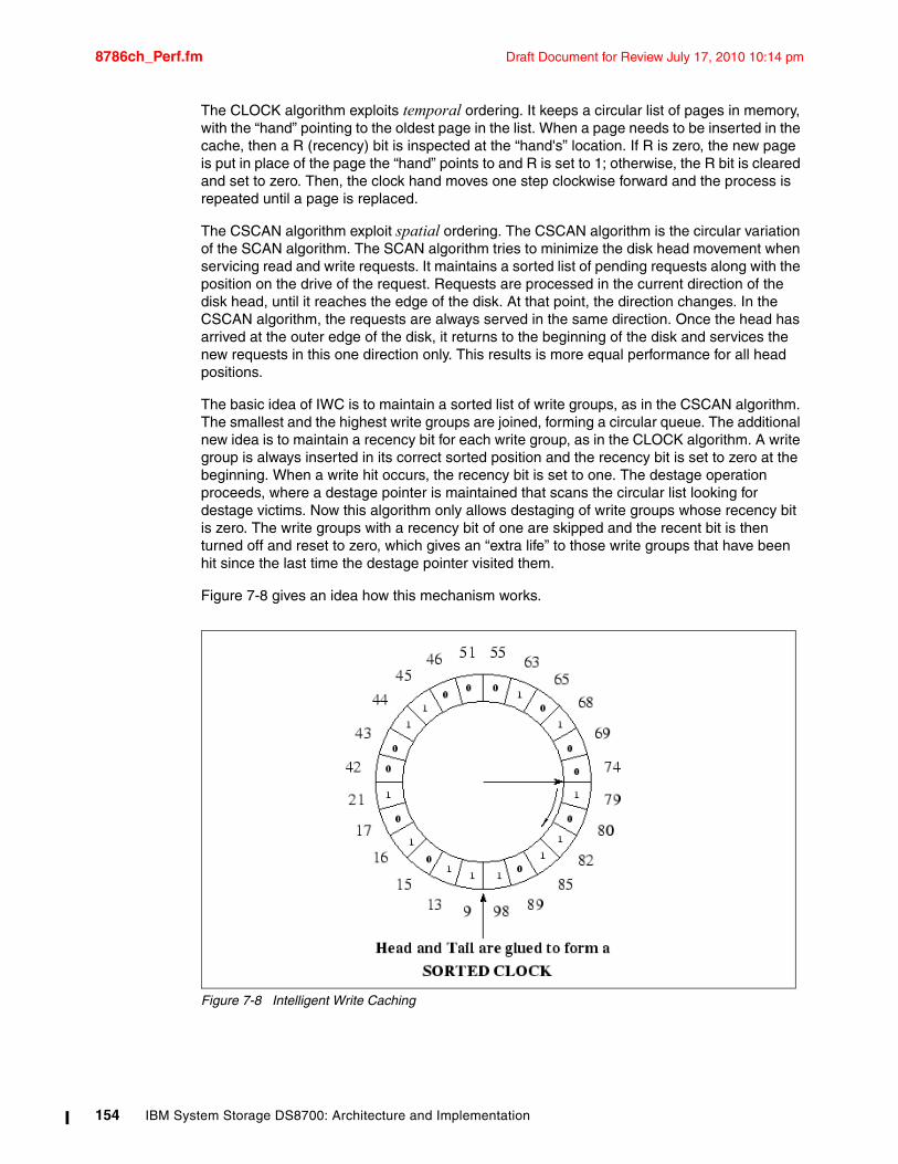
8786ch_Perf.fm Draft Document for Review July 17, 2010 10:14 pm
The CLOCK algorithm exploits temporal ordering. It keeps a circular list of pages in memory, with the “hand” pointing to the oldest page in the list. When a page needs to be inserted in the cache, then a R (recency) bit is inspected at the “hand's” location. If R is zero, the new page is put in place of the page the “hand” points to and R is set to 1; otherwise, the R bit is cleared and set to zero. Then, the clock hand moves one step clockwise forward and the process is repeated until a page is replaced.
The CSCAN algorithm exploit spatial ordering. The CSCAN algorithm is the circular variation of the SCAN algorithm. The SCAN algorithm tries to minimize the disk head movement when servicing read and write requests. It maintains a sorted list of pending requests along with the position on the drive of the request. Requests are processed in the current direction of the disk head, until it reaches the edge of the disk. At that point, the direction changes. In the CSCAN algorithm, the requests are always served in the same direction. Once the head has arrived at the outer edge of the disk, it returns to the beginning of the disk and services the new requests in this one direction only. This results is more equal performance for all head positions.
The basic idea of IWC is to maintain a sorted list of write groups, as in the CSCAN algorithm. The smallest and the highest write groups are joined, forming a circular queue. The additional new idea is to maintain a recency bit for each write group, as in the CLOCK algorithm. A write group is always inserted in its correct sorted position and the recency bit is set to zero at the beginning. When a write hit occurs, the recency bit is set to one. The destage operation proceeds, where a destage pointer is maintained that scans the circular list looking for destage victims. Now this algorithm only allows destaging of write groups whose recency bit is zero. The write groups with a recency bit of one are skipped and the recent bit is then turned off and reset to zero, which gives an “extra life” to those write groups that have been hit since the last time the destage pointer visited them.
Figure 7-8 gives an idea how this mechanism works.
Figure 7-8 Intelligent Write Caching
154 IBM System Storage DS8700: Architecture and Implementation
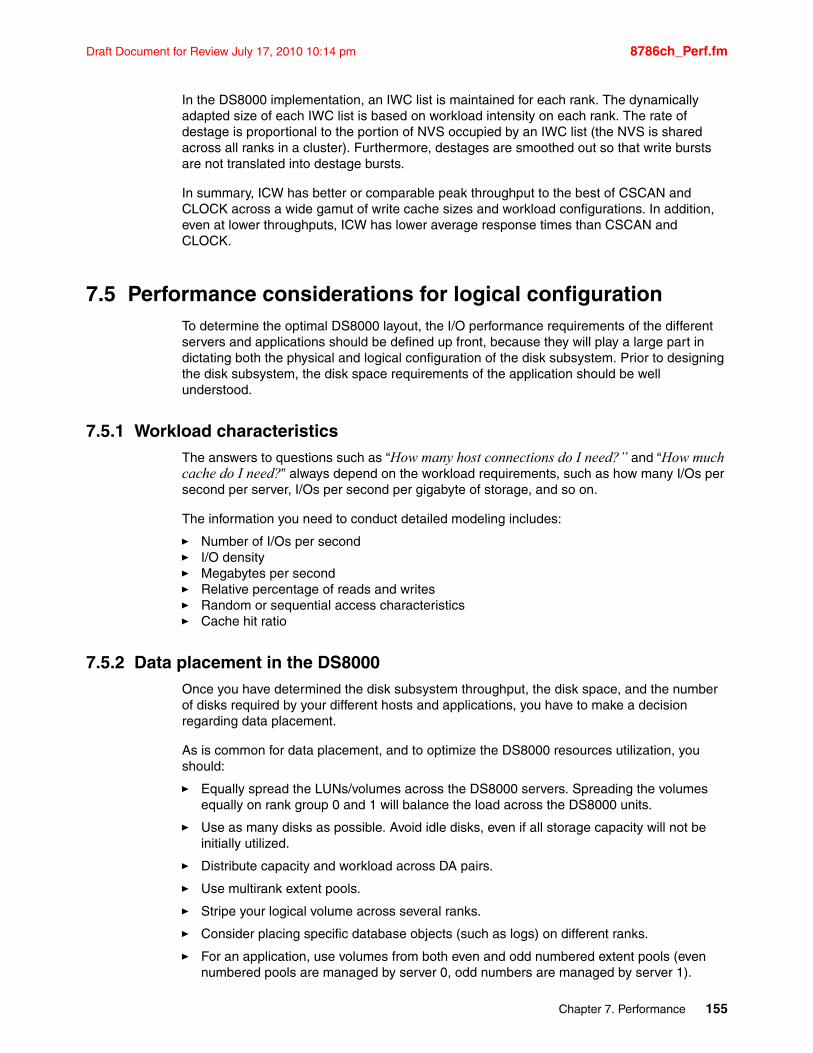
Draft Document for Review July 17, 2010 10:14 pm 8786ch_Perf.fm
In the DS8000 implementation, an IWC list is maintained for each rank. The dynamically adapted size of each IWC list is based on workload intensity on each rank. The rate of destage is proportional to the portion of NVS occupied by an IWC list (the NVS is shared across all ranks in a cluster). Furthermore, destages are smoothed out so that write bursts are not translated into destage bursts.
In summary, ICW has better or comparable peak throughput to the best of CSCAN and CLOCK across a wide gamut of write cache sizes and workload configurations. In addition, even at lower throughputs, ICW has lower average response times than CSCAN and CLOCK.
7.5 Performance considerations for logical configurationTo determine the optimal DS8000 layout, the I/O performance requirements of the different servers and applications should be defined up front, because they will play a large part in dictating both the physical and logical configuration of the disk subsystem. Prior to designing the disk subsystem, the disk space requirements of the application should be well understood.
7.5.1 Workload characteristicsThe answers to questions such as “How many host connections do I need?” and “How much cache do I need?” always depend on the workload requirements, such as how many I/Os per second per server, I/Os per second per gigabyte of storage, and so on.
The information you need to conduct detailed modeling includes:
� Number of I/Os per second� I/O density� Megabytes per second � Relative percentage of reads and writes� Random or sequential access characteristics� Cache hit ratio
7.5.2 Data placement in the DS8000Once you have determined the disk subsystem throughput, the disk space, and the number of disks required by your different hosts and applications, you have to make a decision regarding data placement.
As is common for data placement, and to optimize the DS8000 resources utilization, you should:
� Equally spread the LUNs/volumes across the DS8000 servers. Spreading the volumes equally on rank group 0 and 1 will balance the load across the DS8000 units.
� Use as many disks as possible. Avoid idle disks, even if all storage capacity will not be initially utilized.
� Distribute capacity and workload across DA pairs.
� Use multirank extent pools.
� Stripe your logical volume across several ranks.
� Consider placing specific database objects (such as logs) on different ranks.
� For an application, use volumes from both even and odd numbered extent pools (even numbered pools are managed by server 0, odd numbers are managed by server 1).
Chapter 7. Performance 155
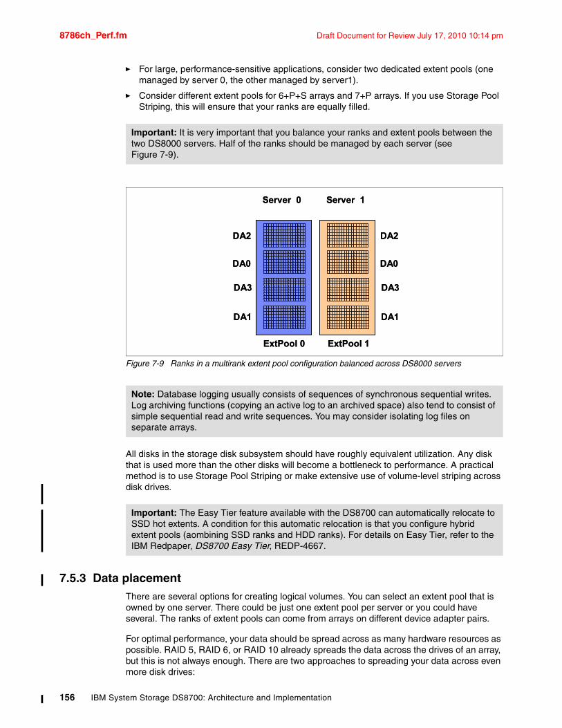
8786ch_Perf.fm Draft Document for Review July 17, 2010 10:14 pm
� For large, performance-sensitive applications, consider two dedicated extent pools (one managed by server 0, the other managed by server1).
� Consider different extent pools for 6+P+S arrays and 7+P arrays. If you use Storage Pool Striping, this will ensure that your ranks are equally filled.
Figure 7-9 Ranks in a multirank extent pool configuration balanced across DS8000 servers
All disks in the storage disk subsystem should have roughly equivalent utilization. Any disk that is used more than the other disks will become a bottleneck to performance. A practical method is to use Storage Pool Striping or make extensive use of volume-level striping across disk drives.
7.5.3 Data placementThere are several options for creating logical volumes. You can select an extent pool that is owned by one server. There could be just one extent pool per server or you could have several. The ranks of extent pools can come from arrays on different device adapter pairs.
For optimal performance, your data should be spread across as many hardware resources as possible. RAID 5, RAID 6, or RAID 10 already spreads the data across the drives of an array, but this is not always enough. There are two approaches to spreading your data across even more disk drives:
Important: It is very important that you balance your ranks and extent pools between the two DS8000 servers. Half of the ranks should be managed by each server (see Figure 7-9).
Note: Database logging usually consists of sequences of synchronous sequential writes. Log archiving functions (copying an active log to an archived space) also tend to consist of simple sequential read and write sequences. You may consider isolating log files on separate arrays.
Important: The Easy Tier feature available with the DS8700 can automatically relocate to SSD hot extents. A condition for this automatic relocation is that you configure hybrid extent pools (aombining SSD ranks and HDD ranks). For details on Easy Tier, refer to the IBM Redpaper, DS8700 Easy Tier, REDP-4667.
ExtPool 0 ExtPool 1
DA2 DA2
DA0 DA0
DA3 DA3
DA1 DA1
Server 0 Server 1
ExtPool 0 ExtPool 1
DA2 DA2
DA0 DA0
DA3 DA3
DA1 DA1
Server 0 Server 1
156 IBM System Storage DS8700: Architecture and Implementation
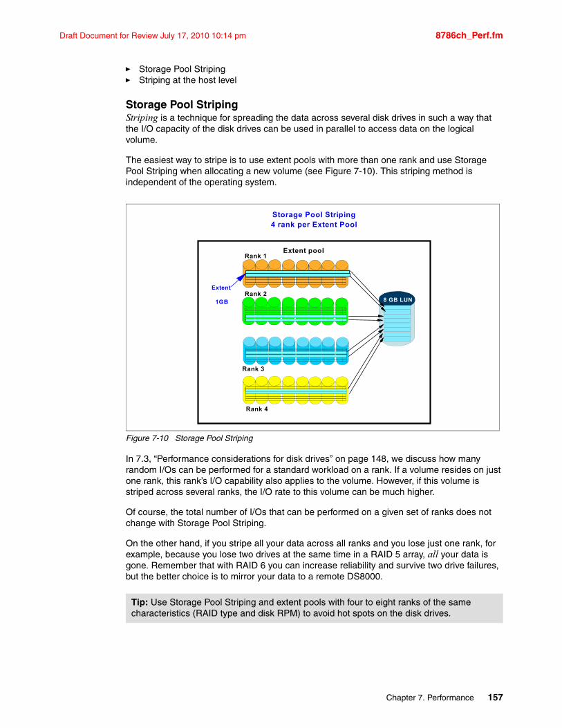
Draft Document for Review July 17, 2010 10:14 pm 8786ch_Perf.fm
� Storage Pool Striping� Striping at the host level
Storage Pool StripingStriping is a technique for spreading the data across several disk drives in such a way that the I/O capacity of the disk drives can be used in parallel to access data on the logical volume.
The easiest way to stripe is to use extent pools with more than one rank and use Storage Pool Striping when allocating a new volume (see Figure 7-10). This striping method is independent of the operating system.
Figure 7-10 Storage Pool Striping
In 7.3, “Performance considerations for disk drives” on page 148, we discuss how many random I/Os can be performed for a standard workload on a rank. If a volume resides on just one rank, this rank’s I/O capability also applies to the volume. However, if this volume is striped across several ranks, the I/O rate to this volume can be much higher.
Of course, the total number of I/Os that can be performed on a given set of ranks does not change with Storage Pool Striping.
On the other hand, if you stripe all your data across all ranks and you lose just one rank, for example, because you lose two drives at the same time in a RAID 5 array, all your data is gone. Remember that with RAID 6 you can increase reliability and survive two drive failures, but the better choice is to mirror your data to a remote DS8000.
Tip: Use Storage Pool Striping and extent pools with four to eight ranks of the same characteristics (RAID type and disk RPM) to avoid hot spots on the disk drives.
Rank 1Extent pool
Rank 3
Rank 4
Extent
1GBRank 2
Storage Pool Striping4 rank per Extent Pool
8 GB LUN
Chapter 7. Performance 157
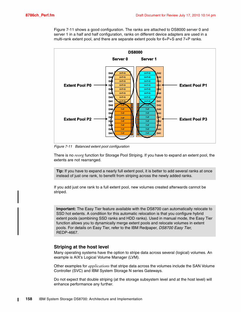
8786ch_Perf.fm Draft Document for Review July 17, 2010 10:14 pm
Figure 7-11 shows a good configuration. The ranks are attached to DS8000 server 0 and server 1 in a half and half configuration, ranks on different device adapters are used in a multi-rank extent pool, and there are separate extent pools for 6+P+S and 7+P ranks.
Figure 7-11 Balanced extent pool configuration
There is no reorg function for Storage Pool Striping. If you have to expand an extent pool, the extents are not rearranged.
If you add just one rank to a full extent pool, new volumes created afterwards cannot be striped.
Striping at the host levelMany operating systems have the option to stripe data across several (logical) volumes. An example is AIX’s Logical Volume Manager (LVM).
Other examples for applications that stripe data across the volumes include the SAN Volume Controller (SVC) and IBM System Storage N series Gateways.
Do not expect that double striping (at the storage subsystem level and at the host level) will enhance performance any further.
Tip: If you have to expand a nearly full extent pool, it is better to add several ranks at once instead of just one rank, to benefit from striping across the newly added ranks.
Important: The Easy Tier feature available with the DS8700 can automatically relocate to SSD hot extents. A condition for this automatic relocation is that you configure hybrid extent pools (aombining SSD ranks and HDD ranks). Used in manual mode, the Easy Tier function allows you to dynamically merge extent pools and relocate volumes in extent pools. For details on Easy Tier, refer to the IBM Redpaper, DS8700 Easy Tier, REDP-4667.
6+P+SDA2
DA0
DA3
DA1
DA2
DA0
DA3
DA1
DA2
DA0
DA3
DA1
DA2
DA0
DA3
DA1
6+P+S
6+P+S
6+P+S
6+P+S
6+P+S
6+P+S
6+P+S
6+P+S
6+P+S
6+P+S
6+P+S
6+P+S
6+P+S
7+P
7+P
7+P
7+P
7+P
7+P
7+P
7+P
6+P+S
7+P
7+P
7+P
7+P
7+P
7+P
7+P
7+P
6+P+S
DA2
DA0
DA3
DA1
DA2
DA0
DA3
DA1
DA2
DA0
DA3
DA1
DA2
DA0
DA3
DA1
DS8000
Server 0 Server 1
Extent Pool P0
Extent Pool P2
Extent Pool P1
Extent Pool P3
158 IBM System Storage DS8700: Architecture and Implementation
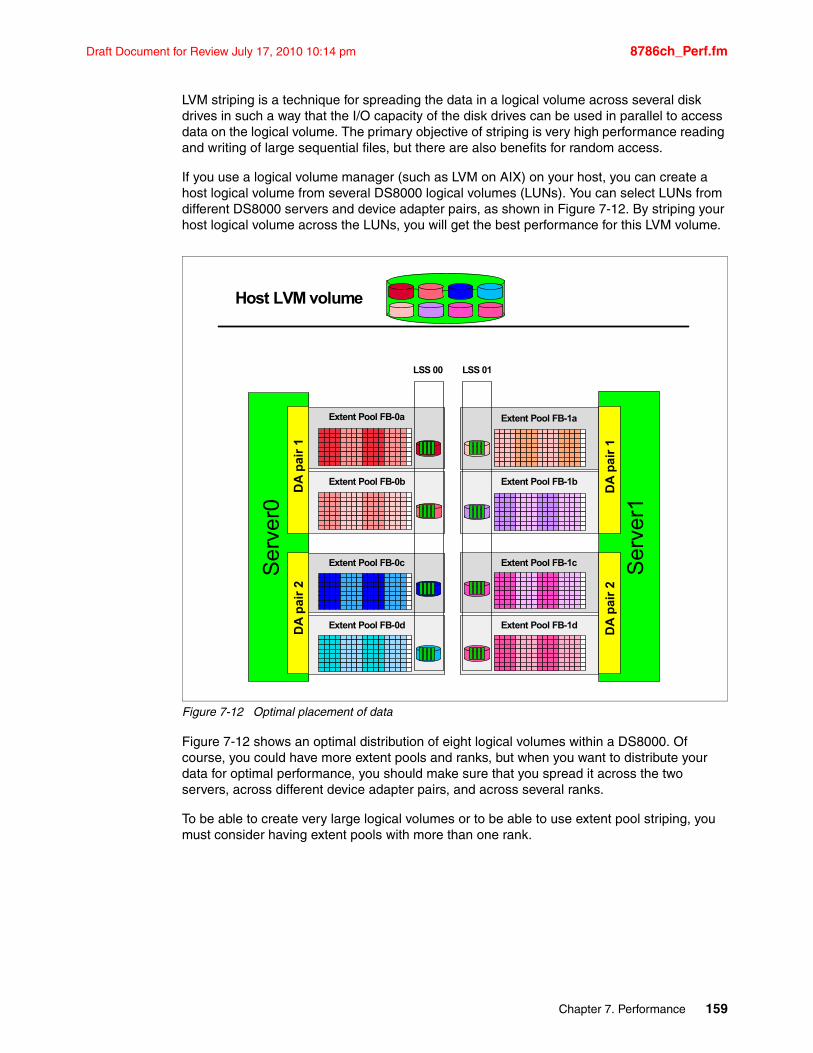
Draft Document for Review July 17, 2010 10:14 pm 8786ch_Perf.fm
LVM striping is a technique for spreading the data in a logical volume across several disk drives in such a way that the I/O capacity of the disk drives can be used in parallel to access data on the logical volume. The primary objective of striping is very high performance reading and writing of large sequential files, but there are also benefits for random access.
If you use a logical volume manager (such as LVM on AIX) on your host, you can create a host logical volume from several DS8000 logical volumes (LUNs). You can select LUNs from different DS8000 servers and device adapter pairs, as shown in Figure 7-12. By striping your host logical volume across the LUNs, you will get the best performance for this LVM volume.
Figure 7-12 Optimal placement of data
Figure 7-12 shows an optimal distribution of eight logical volumes within a DS8000. Of course, you could have more extent pools and ranks, but when you want to distribute your data for optimal performance, you should make sure that you spread it across the two servers, across different device adapter pairs, and across several ranks.
To be able to create very large logical volumes or to be able to use extent pool striping, you must consider having extent pools with more than one rank.
Ser
ver0
Ser
ver1
Extent Pool FB-0c
Extent Pool FB-1aExtent Pool FB-0a
Extent Pool FB-1c
DA
pai
r 1
DA
pai
r 1
DA
pa
ir 2
DA
pai
r 2
Host LVM volume
Extent Pool FB-1bExtent Pool FB-0b
Extent Pool FB-0d Extent Pool FB-1d
LSS 00 LSS 01
Chapter 7. Performance 159
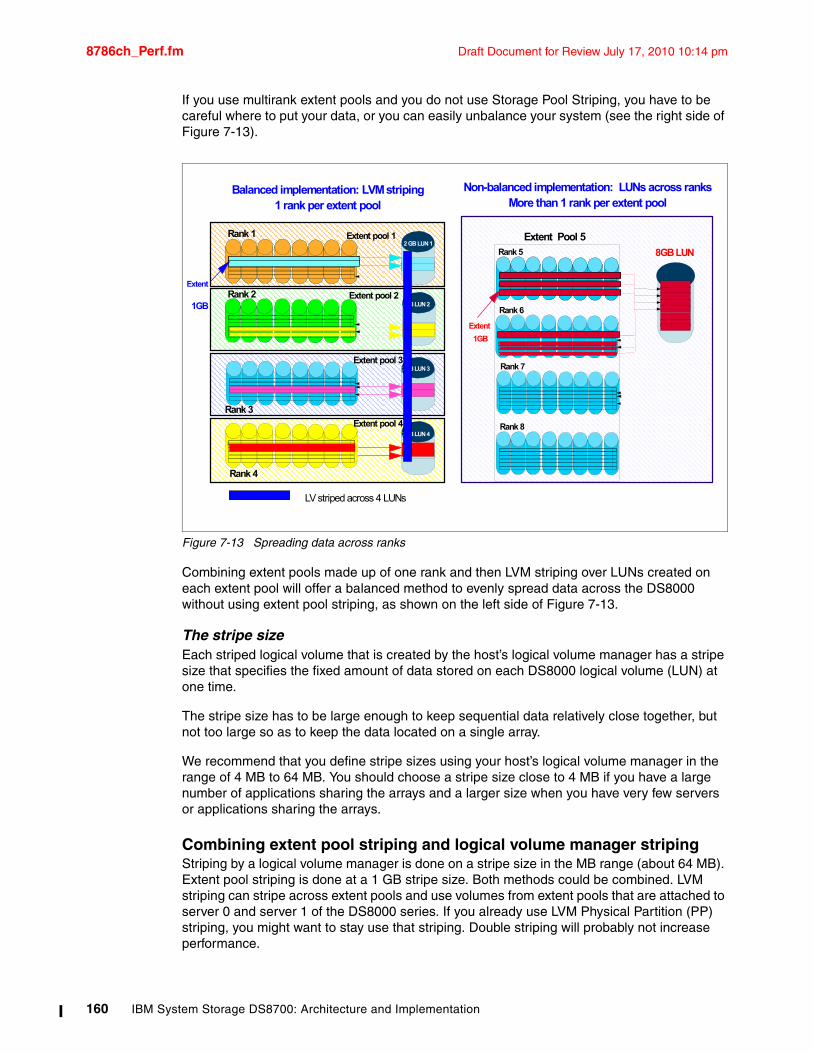
8786ch_Perf.fm Draft Document for Review July 17, 2010 10:14 pm
If you use multirank extent pools and you do not use Storage Pool Striping, you have to be careful where to put your data, or you can easily unbalance your system (see the right side of Figure 7-13).
Figure 7-13 Spreading data across ranks
Combining extent pools made up of one rank and then LVM striping over LUNs created on each extent pool will offer a balanced method to evenly spread data across the DS8000 without using extent pool striping, as shown on the left side of Figure 7-13.
The stripe sizeEach striped logical volume that is created by the host’s logical volume manager has a stripe size that specifies the fixed amount of data stored on each DS8000 logical volume (LUN) at one time.
The stripe size has to be large enough to keep sequential data relatively close together, but not too large so as to keep the data located on a single array.
We recommend that you define stripe sizes using your host’s logical volume manager in the range of 4 MB to 64 MB. You should choose a stripe size close to 4 MB if you have a large number of applications sharing the arrays and a larger size when you have very few servers or applications sharing the arrays.
Combining extent pool striping and logical volume manager stripingStriping by a logical volume manager is done on a stripe size in the MB range (about 64 MB). Extent pool striping is done at a 1 GB stripe size. Both methods could be combined. LVM striping can stripe across extent pools and use volumes from extent pools that are attached to server 0 and server 1 of the DS8000 series. If you already use LVM Physical Partition (PP) striping, you might want to stay use that striping. Double striping will probably not increase performance.
Extent PoolRank 5
Rank 6
Rank 7
Rank 8
8GB LUN
Extent
1GB
Rank 1 Extent pool 1
Rank 3
Rank 4
2 GB LUN 1
Extent
1GB
Extent Pool 5
Rank 2
Non-balanced implementation: LUNs across ranksMore than 1 rank per extent pool
2GB LUN 2
2GB LUN 3
2GB LUN 4
Extent pool 2
Extent pool 3
Extent pool 4
Balanced implementation: LVM striping1 rank per extent pool
LV striped across 4 LUNs
160 IBM System Storage DS8700: Architecture and Implementation
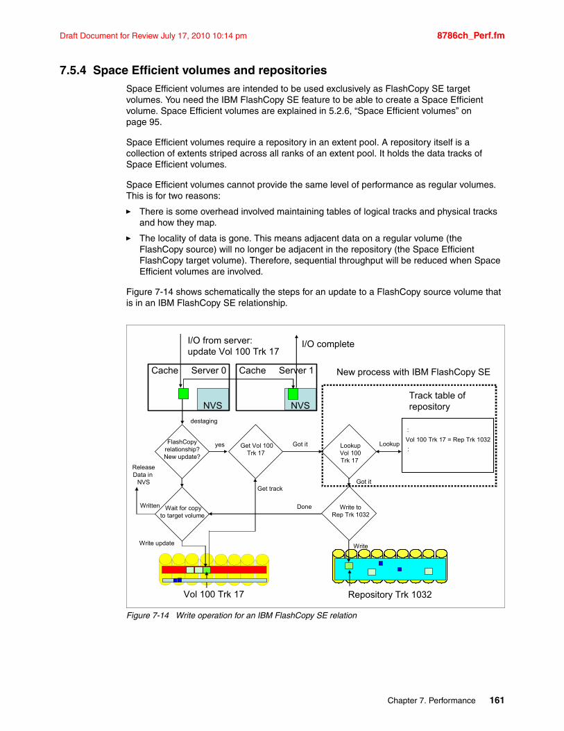
Draft Document for Review July 17, 2010 10:14 pm 8786ch_Perf.fm
7.5.4 Space Efficient volumes and repositoriesSpace Efficient volumes are intended to be used exclusively as FlashCopy SE target volumes. You need the IBM FlashCopy SE feature to be able to create a Space Efficient volume. Space Efficient volumes are explained in 5.2.6, “Space Efficient volumes” on page 95.
Space Efficient volumes require a repository in an extent pool. A repository itself is a collection of extents striped across all ranks of an extent pool. It holds the data tracks of Space Efficient volumes.
Space Efficient volumes cannot provide the same level of performance as regular volumes. This is for two reasons:
� There is some overhead involved maintaining tables of logical tracks and physical tracks and how they map.
� The locality of data is gone. This means adjacent data on a regular volume (the FlashCopy source) will no longer be adjacent in the repository (the Space Efficient FlashCopy target volume). Therefore, sequential throughput will be reduced when Space Efficient volumes are involved.
Figure 7-14 shows schematically the steps for an update to a FlashCopy source volume that is in an IBM FlashCopy SE relationship.
Figure 7-14 Write operation for an IBM FlashCopy SE relation
Cache Server 0
NVS
Cache Server 1
NVS
I/O from server:update Vol 100 Trk 17
I/O complete
FlashCopyrelationship?New update?
Wait for copyto target volume
destaging
Get Vol 100Trk 17
Vol 100 Trk 17
yes
Write toRep Trk 1032
LookupVol 100Trk 17
Got it
Track table of repository
Vol 100 Trk 17 = Rep Trk 1032
:
:
Done
Write
Repository Trk 1032
Got it
Lookup
Get track
Write update
Written
ReleaseData in
NVS
New process with IBM FlashCopy SE
Chapter 7. Performance 161
8786ch_Perf.fm Draft Document for Review July 17, 2010 10:14 pm
A FlashCopy onto a Space Efficient volume is established with the nocopy option. In normal operation (when we do not run a backup job or other activity on the Space Efficient target volume), only writes go to Space Efficient volumes. Usually a repository will hold more than just one volume and writes will come from different volumes. Thus, the workload to a repository will be purely random writes. This will stress the disk drives given that a random write triggers four disk operations on a RAID 5 array (see “RAID 5” on page 149).
If there are many source volumes that have targets in the same extent pool, all updates to these source volumes cause write activity to this one extent pool’s repository. We can consider a repository as something similar to a volume. So we have writes to many source volumes being copied to just one volume, that is, the repository.
There is less space in the repository than the total capacity (sum) of the source volumes, so you may be tempted to use less disk spindles (DDMs). By definition, fewer spindles mean less performance. You can see how careful planning is needed to achieve the required throughput and response times from the Space Efficient volumes. A good strategy is to keep the number of spindles roughly equivalent but just use smaller and faster drives (but do not use SATA drives). For example, if your source volumes are 300 GB 15K RPM disks, using 146 GB 15K RPM disks on the repository may provide both space efficiency and excellent repository performance.
Another possibility is to consider RAID 10 (see “RAID 10” on page 150) for the repository, although that goes somewhat against space efficiency (you may be better off using standard FlashCopy with RAID 5 than SE with RAID 10). However, there may be cases where trading off some of the space efficiency gains for a performance boost justifies RAID 10. If RAID 10 is used at the source, you should consider it for the repository (note that the repository will always use striping when in a multirank extent pool).
Storage Pool Striping has good synergy with the repository (volume) function. With Storage Pool Striping, the repository space is striped across multiple RAID arrays in an extent pool and this helps balance the volume skew that may appear on the sources. It is generally best to use four RAID arrays in the multirank extent pool intended to hold the repository, and no more than eight.
On a heavily loaded system, the disks in the back end, particularly where the repository resides, might be overloaded. In this case, data will stay for a longer time than usual in NVS. You might consider increasing your cache or NVS when introducing IBM FlashCopy SE.
Finally, try to use at least the same number of disk spindles on the repository as the source volumes. Avoid severe “fan in” configurations, such as 32 ranks of source disk being mapped to an 8 rank repository. This type of configuration will likely have performance problems unless the update rate to the source is very modest.
Also, although it is possible to share the repository with production volumes on the same extent pool, use caution when doing this action, as contention between the two could impact performance.
Consideration: Having a repository on SATA drives is not supported.
162 IBM System Storage DS8700: Architecture and Implementation
Draft Document for Review July 17, 2010 10:14 pm 8786ch_Perf.fm
To summarize: We can expect a very high random write workload for the repository. To prevent the repository from becoming overloaded, you can do the following:
� Have the repository in an extent pool with several ranks (a repository is always striped). Use at least four ranks but not more than eight.
� Use fast 15K RPM and small capacity disk drives for the repository ranks.
� Avoid placing repository and high performance standard volumes in the same extent pool.
7.6 Performance and sizing considerations for open systemsHere we discuss some topics particularly relevant to open systems.
7.6.1 Determining the number of paths to a LUNWhen configuring an IBM System Storage DS8000 for an open systems host, a decision must be made regarding the number of paths to a particular LUN, because the multipathing software allows (and manages) multiple paths to a LUN. There are two opposing factors to consider when deciding on the number of paths to a LUN:
� Increasing the number of paths increases availability of the data, protecting against outages.
� Increasing the number of paths increases the amount of CPU used because the multipathing software must choose among all available paths each time an I/O is issued.
A good compromise is between two and four paths per LUN.
7.6.2 Dynamic I/O load-balancing: Subsystem Device Driver (SDD)The Subsystem Device Driver is a IBM provided pseudo-device driver that is designed to support the multipath configuration environments in the DS8000. It resides in a host system with the native disk device driver.
The dynamic I/O load-balancing option (default) of SDD is recommended to ensure better performance because:
� SDD automatically adjusts data routing for optimum performance. Multipath load balancing of data flow prevents a single path from becoming overloaded, causing input/output congestion that occurs when many I/O operations are directed to common devices along the same input/output path.
� The path to use for an I/O operation is chosen by estimating the load on each adapter to which each path is attached. The load is a function of the number of I/O operations currently in process. If multiple paths have the same load, a path is chosen at random from those paths.
For more information about the SDD, see 15.1.4, “Multipathing support: Subsystem Device Driver (SDD)” on page 400.
Chapter 7. Performance 163
8786ch_Perf.fm Draft Document for Review July 17, 2010 10:14 pm
7.6.3 Automatic port queuesWhen there is I/O between a server and a DS8700 Fibre Channel port, both the server host adapter and the DS8700 host bus adapter support queuing I/Os. How long this queue can be is called the queue depth. Since several servers can and usually do communicate with few DS8700 posts, the queue depth of a storage host bus adapter should be larger than the one on the server side. This is also true for the DS8700, which supports 2048 FC commands queued on a port. However, sometimes the port queue in the DS8700 HBA can be flooded.
When the number of commands sent to the DS8000 port has exceeded the maximum number of commands that the port can queue, the port has to discard these additional commands.
This operation is a normal error recovery operation in the Fibre Channel protocol to prevent more damage. The normal recovery is a 30 second timeout for the server, after that time the command is resent. The server has a command retry count before it will fail the command. Command Timeout entries will be seen in the server logs.
Automatic Port Queues is a mechanism the DS8700 uses to self-adjust the queue based on the workload. This allows higher port queue oversubscription while maintaining a fair share for the servers and the accessed LUNs.
The port that the queue is filling up goes into SCSI Queue Fill mode, where it accepts no additional commands to slow down the I/Os.
By avoiding error recovery and the 30 second blocking SCSI Queue Full recovery interval, the overall performance is better with Automatic Port Queues.
New performance statistics are available via the DSCLI to show, for example, how often the queue was 75% full or how often the port was completely blocked.
7.6.4 Determining where to attach the hostWhen determining where to attach multiple paths from a single host system to I/O ports on a host adapter to the storage facility image, the following considerations apply:
� Choose the attached I/O ports on different host adapters.� Spread the attached I/O ports evenly between the four I/O enclosure groups.
164 IBM System Storage DS8700: Architecture and Implementation
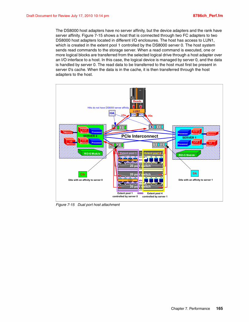
Draft Document for Review July 17, 2010 10:14 pm 8786ch_Perf.fm
The DS8000 host adapters have no server affinity, but the device adapters and the rank have server affinity. Figure 7-15 shows a host that is connected through two FC adapters to two DS8000 host adapters located in different I/O enclosures. The host has access to LUN1, which is created in the extent pool 1 controlled by the DS8000 server 0. The host system sends read commands to the storage server. When a read command is executed, one or more logical blocks are transferred from the selected logical drive through a host adapter over an I/O interface to a host. In this case, the logical device is managed by server 0, and the data is handled by server 0. The read data to be transferred to the host must first be present in server 0's cache. When the data is in the cache, it is then transferred through the host adapters to the host.
Figure 7-15 Dual port host attachment
ProcessorMemory
Processor
L1,2 Memory
L3 Memory
L1,2 Memory
RIO-G Module
SERVER 0Processor Memory
Processor
L1,2 Memory
L3 Memory
L1,2 Memory
RIO-G Module
SERVER 1
DA
PCIe Interconnect
ooo
20 port switch
20 port switch
16 DDM
ooo
20 port switch
20 port switch16 DDM
DA
IBM
DAs with an affinity to server 0
FC1HA
HAs do not have DS8000 server affinity
Extent pool 1
LUN1
LUN1
LUN1
Extent pool 1controlled by server 0
oo oo Extent pool 4controlled by server 1
FC0 I/OsI/Os
DAs with an affinity to server 1
Extent pool 4
ReadsReads
Chapter 7. Performance 165
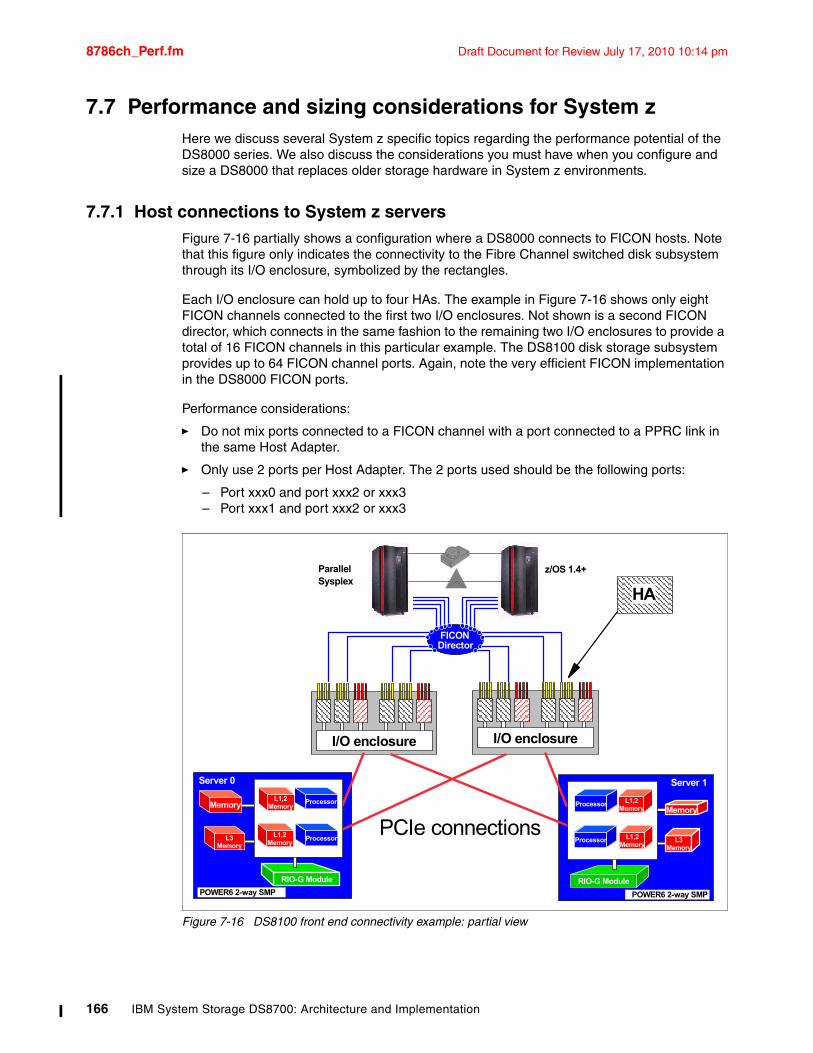
8786ch_Perf.fm Draft Document for Review July 17, 2010 10:14 pm
7.7 Performance and sizing considerations for System zHere we discuss several System z specific topics regarding the performance potential of the DS8000 series. We also discuss the considerations you must have when you configure and size a DS8000 that replaces older storage hardware in System z environments.
7.7.1 Host connections to System z serversFigure 7-16 partially shows a configuration where a DS8000 connects to FICON hosts. Note that this figure only indicates the connectivity to the Fibre Channel switched disk subsystem through its I/O enclosure, symbolized by the rectangles.
Each I/O enclosure can hold up to four HAs. The example in Figure 7-16 shows only eight FICON channels connected to the first two I/O enclosures. Not shown is a second FICON director, which connects in the same fashion to the remaining two I/O enclosures to provide a total of 16 FICON channels in this particular example. The DS8100 disk storage subsystem provides up to 64 FICON channel ports. Again, note the very efficient FICON implementation in the DS8000 FICON ports.
Performance considerations:
� Do not mix ports connected to a FICON channel with a port connected to a PPRC link in the same Host Adapter.
� Only use 2 ports per Host Adapter. The 2 ports used should be the following ports:
– Port xxx0 and port xxx2 or xxx3– Port xxx1 and port xxx2 or xxx3
Figure 7-16 DS8100 front end connectivity example: partial view
I/O enclosureI/O enclosure
z/OS 1.4+
HA
FICONDirector
ParallelSysplex
RIO-G Module
POWER6 2-way SMP
Memory
L3 Memory
POWER6 2-way SMP
Memory
L3 Memory
RIO-G Module
Server 1Server 0
PCIe connections
Processor
Processor
L1,2 Memory
L1,2 Memory
Processor
Processor
L1,2 Memory
L1,2 Memory
166 IBM System Storage DS8700: Architecture and Implementation
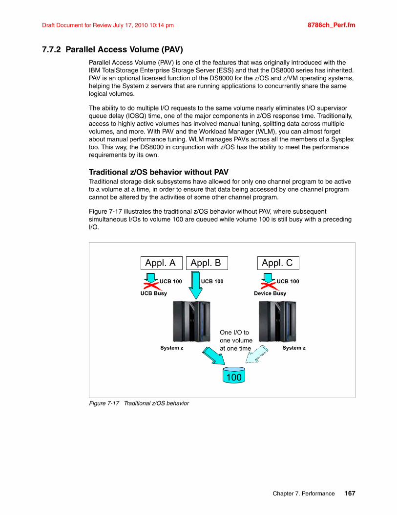
Draft Document for Review July 17, 2010 10:14 pm 8786ch_Perf.fm
7.7.2 Parallel Access Volume (PAV)Parallel Access Volume (PAV) is one of the features that was originally introduced with the IBM TotalStorage Enterprise Storage Server (ESS) and that the DS8000 series has inherited. PAV is an optional licensed function of the DS8000 for the z/OS and z/VM operating systems, helping the System z servers that are running applications to concurrently share the same logical volumes.
The ability to do multiple I/O requests to the same volume nearly eliminates I/O supervisor queue delay (IOSQ) time, one of the major components in z/OS response time. Traditionally, access to highly active volumes has involved manual tuning, splitting data across multiple volumes, and more. With PAV and the Workload Manager (WLM), you can almost forget about manual performance tuning. WLM manages PAVs across all the members of a Sysplex too. This way, the DS8000 in conjunction with z/OS has the ability to meet the performance requirements by its own.
Traditional z/OS behavior without PAVTraditional storage disk subsystems have allowed for only one channel program to be active to a volume at a time, in order to ensure that data being accessed by one channel program cannot be altered by the activities of some other channel program.
Figure 7-17 illustrates the traditional z/OS behavior without PAV, where subsequent simultaneous I/Os to volume 100 are queued while volume 100 is still busy with a preceding I/O.
Figure 7-17 Traditional z/OS behavior
Appl. A Appl. B
100
UCB 100UCB 100
UCB Busy
Appl. C
UCB 100
Device Busy
One I/O toone volumeat one time System zSystem z
Chapter 7. Performance 167
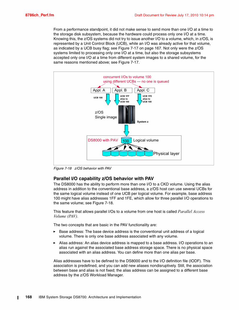
8786ch_Perf.fm Draft Document for Review July 17, 2010 10:14 pm
From a performance standpoint, it did not make sense to send more than one I/O at a time to the storage disk subsystem, because the hardware could process only one I/O at a time. Knowing this, the z/OS systems did not try to issue another I/O to a volume, which, in z/OS, is represented by a Unit Control Block (UCB), while an I/O was already active for that volume, as indicated by a UCB busy flag; see Figure 7-17 on page 167. Not only were the z/OS systems limited to processing only one I/O at a time, but also the storage subsystems accepted only one I/O at a time from different system images to a shared volume, for the same reasons mentioned above; see Figure 7-17.
Figure 7-18 z/OS behavior with PAV
Parallel I/O capability z/OS behavior with PAVThe DS8000 has the ability to perform more than one I/O to a CKD volume. Using the alias address in addition to the conventional base address, a z/OS host can use several UCBs for the same logical volume instead of one UCB per logical volume. For example, base address 100 might have alias addresses 1FF and 1FE, which allow for three parallel I/O operations to the same volume; see Figure 7-18.
This feature that allows parallel I/Os to a volume from one host is called Parallel Access Volume (PAV).
The two concepts that are basic in the PAV functionality are:
� Base address: The base device address is the conventional unit address of a logical volume. There is only one base address associated with any volume.
� Alias address: An alias device address is mapped to a base address. I/O operations to an alias run against the associated base address storage space. There is no physical space associated with an alias address. You can define more than one alias per base.
Alias addresses have to be defined to the DS8000 and to the I/O definition file (IODF). This association is predefined, and you can add new aliases nondisruptively. Still, the association between base and alias is not fixed; the alias address can be assigned to a different base address by the z/OS Workload Manager.
Physical layer
Appl. A Appl. C
UCB 100UCB 1FEalias toUCB 100
100
z/OS Single image
Appl. B
UCB 1FFalias toUCB 100
Logical volumeDS8000 with PAV
System z
concurrent I/Os to volume 100using different UCBs --- no one is queued
168 IBM System Storage DS8700: Architecture and Implementation
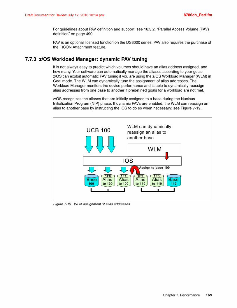
Draft Document for Review July 17, 2010 10:14 pm 8786ch_Perf.fm
For guidelines about PAV definition and support, see 16.3.2, “Parallel Access Volume (PAV) definition” on page 490.
PAV is an optional licensed function on the DS8000 series. PAV also requires the purchase of the FICON Attachment feature.
7.7.3 z/OS Workload Manager: dynamic PAV tuningIt is not always easy to predict which volumes should have an alias address assigned, and how many. Your software can automatically manage the aliases according to your goals. z/OS can exploit automatic PAV tuning if you are using the z/OS Workload Manager (WLM) in Goal mode. The WLM can dynamically tune the assignment of alias addresses. The Workload Manager monitors the device performance and is able to dynamically reassign alias addresses from one base to another if predefined goals for a workload are not met.
z/OS recognizes the aliases that are initially assigned to a base during the Nucleus Initialization Program (NIP) phase. If dynamic PAVs are enabled, the WLM can reassign an alias to another base by instructing the IOS to do so when necessary; see Figure 7-19.
Figure 7-19 WLM assignment of alias addresses
Base Alias Alias
IOS
UCB 100
Alias Base100 110to 100 to 100 to 110
Aliasto 110
WLM
WLM can dynamicallyreassign an alias toanother base
Assign to base 100
1F0 1F1 1F2 1F3
Chapter 7. Performance 169
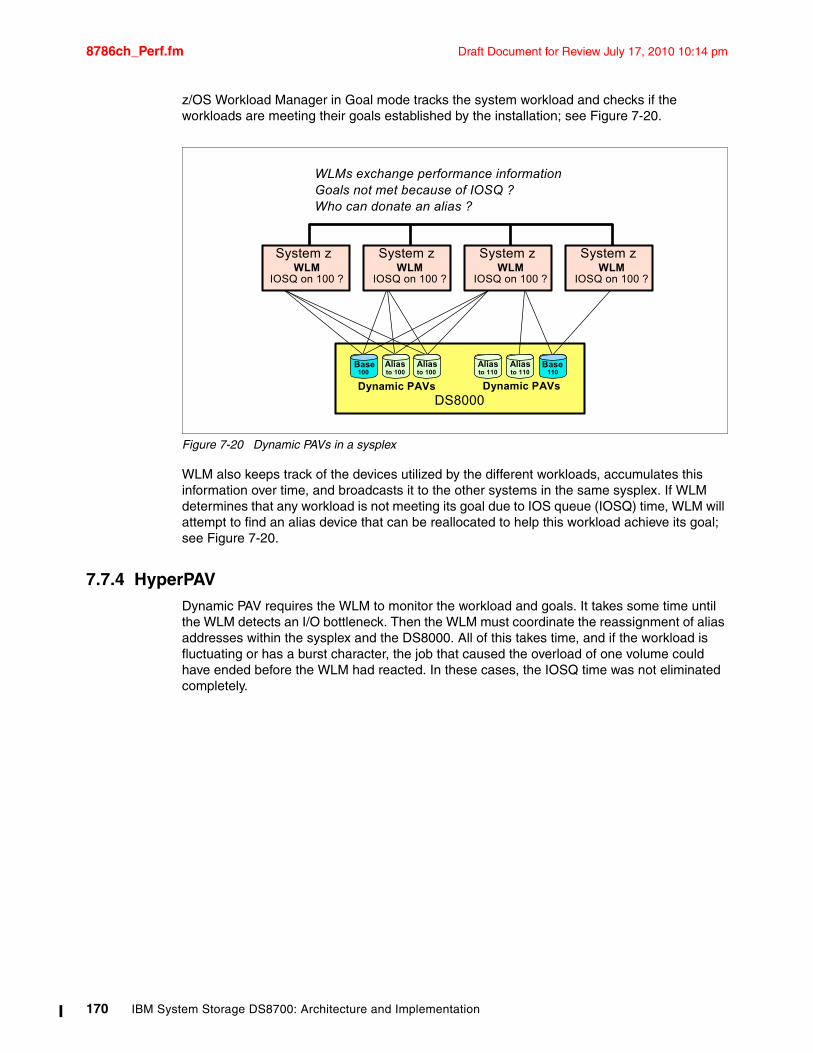
8786ch_Perf.fm Draft Document for Review July 17, 2010 10:14 pm
z/OS Workload Manager in Goal mode tracks the system workload and checks if the workloads are meeting their goals established by the installation; see Figure 7-20.
Figure 7-20 Dynamic PAVs in a sysplex
WLM also keeps track of the devices utilized by the different workloads, accumulates this information over time, and broadcasts it to the other systems in the same sysplex. If WLM determines that any workload is not meeting its goal due to IOS queue (IOSQ) time, WLM will attempt to find an alias device that can be reallocated to help this workload achieve its goal; see Figure 7-20.
7.7.4 HyperPAVDynamic PAV requires the WLM to monitor the workload and goals. It takes some time until the WLM detects an I/O bottleneck. Then the WLM must coordinate the reassignment of alias addresses within the sysplex and the DS8000. All of this takes time, and if the workload is fluctuating or has a burst character, the job that caused the overload of one volume could have ended before the WLM had reacted. In these cases, the IOSQ time was not eliminated completely.
WLMs exchange performance informationGoals not met because of IOSQ ?Who can donate an alias ?
DS8000Dynamic PAVs Dynamic PAVs
Base Alias Alias100 to 100 to 100
Alias Base110to 110
Aliasto 110
WLMIOSQ on 100 ?
System zWLM
IOSQ on 100 ?
System zWLM
IOSQ on 100 ?
System zWLM
IOSQ on 100 ?
System z
170 IBM System Storage DS8700: Architecture and Implementation
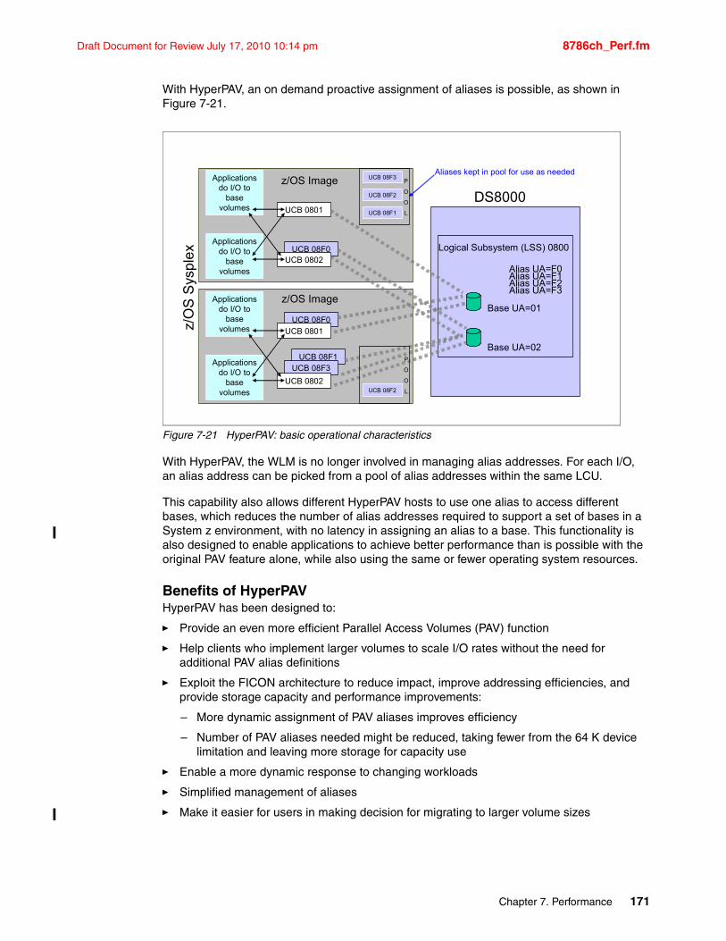
Draft Document for Review July 17, 2010 10:14 pm 8786ch_Perf.fm
With HyperPAV, an on demand proactive assignment of aliases is possible, as shown in Figure 7-21.
Figure 7-21 HyperPAV: basic operational characteristics
With HyperPAV, the WLM is no longer involved in managing alias addresses. For each I/O, an alias address can be picked from a pool of alias addresses within the same LCU.
This capability also allows different HyperPAV hosts to use one alias to access different bases, which reduces the number of alias addresses required to support a set of bases in a System z environment, with no latency in assigning an alias to a base. This functionality is also designed to enable applications to achieve better performance than is possible with the original PAV feature alone, while also using the same or fewer operating system resources.
Benefits of HyperPAVHyperPAV has been designed to:
� Provide an even more efficient Parallel Access Volumes (PAV) function
� Help clients who implement larger volumes to scale I/O rates without the need for additional PAV alias definitions
� Exploit the FICON architecture to reduce impact, improve addressing efficiencies, and provide storage capacity and performance improvements:
– More dynamic assignment of PAV aliases improves efficiency
– Number of PAV aliases needed might be reduced, taking fewer from the 64 K device limitation and leaving more storage for capacity use
� Enable a more dynamic response to changing workloads
� Simplified management of aliases
� Make it easier for users in making decision for migrating to larger volume sizes
UCB 08F1
z/O
S S
ysp
lex
DS8000
Logical Subsystem (LSS) 0800
Base UA=01
Alias UA=F0Alias UA=F1
Base UA=02
Alias UA=F2Alias UA=F3
UCB 08F3
UCB 0802
UCB 08F0UCB 0801
Applications do I/O to
base volumes
Applications do I/O to
base volumes
UCB 08F3
UCB 08F0UCB 0802
UCB 08F1
UCB 08F2
UCB 0801
Applications do I/O to
base volumes
Applications do I/O to
base volumes
UCB 08F2
P
O
O
L
P
O
O
L
z/OS Image
z/OS Image
Aliases kept in pool for use as needed
Chapter 7. Performance 171
8786ch_Perf.fm Draft Document for Review July 17, 2010 10:14 pm
Optional licensed functionHyperPAV is an optional licensed function of the DS8000 series. It is required in addition to the normal PAV license, which is capacity dependent. The HyperPAV license is independent of the capacity.
HyperPAV alias consideration on EAVHyperPAV provides a far more agile alias management algorithm, as aliases are dynamically bound to a base for the duration of the I/O for the z/OS image that issued the I/O. When an I/O completes, the alias is returned to the pool in the LCU. It then becomes available to subsequent I/Os.
Our rule of thumb is that the number of aliases required can be approximated by the peak of the following multiplication: I/O rate multiplied by the average response time. For example, if the peak of the above calculation happened when the I/O rate is 2000 I/O per second and the average response time is 4 msec (which is 0.004 sec) then the result of above calculaton will be:
2000 IO/sec x 0.004 sec/IO = 8
This means that the average number of I/O operations executing at one time for that LCU during the peak period is eight. Therefore, eight aliases should be able to handle the peak I/O rate for that LCU. However, since this calculation is based on the average during the RMF period, it is recommended that the result is multiplied by two, to accomodate higher peaks within that RMF interval. So in this case, the recommended number of aliases would be:
2 x 8 = 16
Depending on the kind of workload, there is a huge reduction in PAV-alias UCBs with HyperPAV. The combination of HyperPAV and EAV allows you to significantly reduce the constraint on the 64 K device address limit and in turn increase the amount of addressable storage available on z/OS. In conjunction with Multiple Subchannel Sets (MSS) on z9 and z10, you have even more flexibility in device configuration. Keep in mind that the EAV volumes will be supported only on z/OS v1.10 and later. Refer to 16.3.1, “z/OS program enhancements (SPEs)” on page 479 for more details about EAV specifications and considerations.
HyperPAV implementation and system requirementsFor support and implementation guidance, refer to 16.3.3, “HyperPAV z/OS support and implementation” on page 492 and 16.4.3, “PAV and HyperPAV z/VM support” on page 496.
RMF reporting on PAVRMF reports the number of exposures for each device in its Monitor/DASD Activity report and in its Monitor II and Monitor III Device reports. If the device is is a HyperPAV base device, the number is followed by an 'H', for example, 5.4H. This value is the average number of HyperPAV volumes (base and alias) in that interval. RMF reports all I/O activity against the base address, not by the individual base and associated aliases. The performance information for the base includes all base and alias I/O activity.
HyperPAV would help minimize the Input/Output Supervisor Queue (IOSQ) Time. If you still see IOSQ Time, then there are 2 possible reasons:
Note: For more details about MSS, refer to Multiple Subchannel Sets: An Implementation View, REDP-4387, found at:
http://www.redbooks.ibm.com/abstracts/redp4387.html?Open
172 IBM System Storage DS8700: Architecture and Implementation
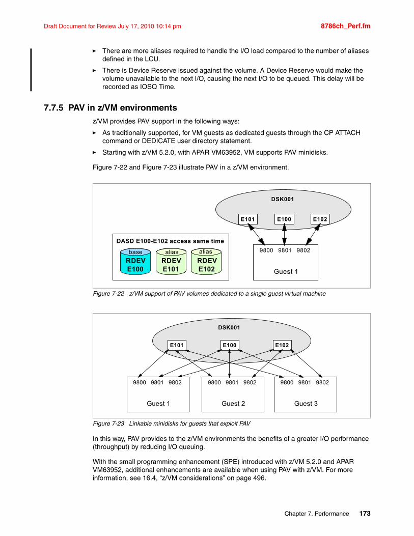
Draft Document for Review July 17, 2010 10:14 pm 8786ch_Perf.fm
� There are more aliases required to handle the I/O load compared to the number of aliases defined in the LCU.
� There is Device Reserve issued against the volume. A Device Reserve would make the volume unavailable to the next I/O, causing the next I/O to be queued. This delay will be recorded as IOSQ Time.
7.7.5 PAV in z/VM environmentsz/VM provides PAV support in the following ways:
� As traditionally supported, for VM guests as dedicated guests through the CP ATTACH command or DEDICATE user directory statement.
� Starting with z/VM 5.2.0, with APAR VM63952, VM supports PAV minidisks.
Figure 7-22 and Figure 7-23 illustrate PAV in a z/VM environment.
Figure 7-22 z/VM support of PAV volumes dedicated to a single guest virtual machine
Figure 7-23 Linkable minidisks for guests that exploit PAV
In this way, PAV provides to the z/VM environments the benefits of a greater I/O performance (throughput) by reducing I/O queuing.
With the small programming enhancement (SPE) introduced with z/VM 5.2.0 and APAR VM63952, additional enhancements are available when using PAV with z/VM. For more information, see 16.4, “z/VM considerations” on page 496.
RDEVE101
RDEVE102
RDEVE100
aliasbase alias
DASD E100-E102 access same time
DSK001
E100 E102E101
9800 9801 9802
Guest 1
DSK001
E100 E102E101
9800 9801 9802
Guest 2
9800 9801 9802
Guest 3
9800 9801 9802
Guest 1
Chapter 7. Performance 173
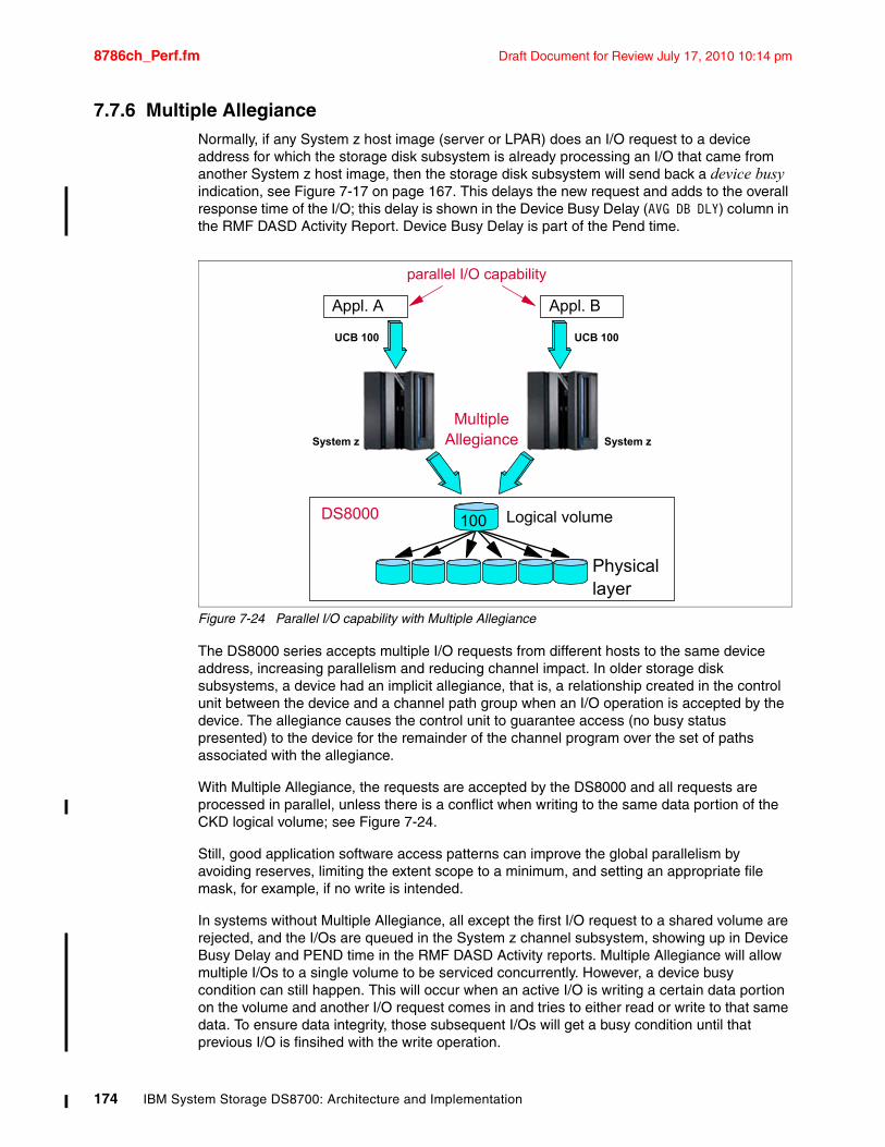
8786ch_Perf.fm Draft Document for Review July 17, 2010 10:14 pm
7.7.6 Multiple AllegianceNormally, if any System z host image (server or LPAR) does an I/O request to a device address for which the storage disk subsystem is already processing an I/O that came from another System z host image, then the storage disk subsystem will send back a device busy indication, see Figure 7-17 on page 167. This delays the new request and adds to the overall response time of the I/O; this delay is shown in the Device Busy Delay (AVG DB DLY) column in the RMF DASD Activity Report. Device Busy Delay is part of the Pend time.
Figure 7-24 Parallel I/O capability with Multiple Allegiance
The DS8000 series accepts multiple I/O requests from different hosts to the same device address, increasing parallelism and reducing channel impact. In older storage disk subsystems, a device had an implicit allegiance, that is, a relationship created in the control unit between the device and a channel path group when an I/O operation is accepted by the device. The allegiance causes the control unit to guarantee access (no busy status presented) to the device for the remainder of the channel program over the set of paths associated with the allegiance.
With Multiple Allegiance, the requests are accepted by the DS8000 and all requests are processed in parallel, unless there is a conflict when writing to the same data portion of the CKD logical volume; see Figure 7-24.
Still, good application software access patterns can improve the global parallelism by avoiding reserves, limiting the extent scope to a minimum, and setting an appropriate file mask, for example, if no write is intended.
In systems without Multiple Allegiance, all except the first I/O request to a shared volume are rejected, and the I/Os are queued in the System z channel subsystem, showing up in Device Busy Delay and PEND time in the RMF DASD Activity reports. Multiple Allegiance will allow multiple I/Os to a single volume to be serviced concurrently. However, a device busy condition can still happen. This will occur when an active I/O is writing a certain data portion on the volume and another I/O request comes in and tries to either read or write to that same data. To ensure data integrity, those subsequent I/Os will get a busy condition until that previous I/O is finsihed with the write operation.
Physicallayer
Appl. A Appl. B
UCB 100
100
MultipleAllegiance
DS8000
System z
parallel I/O capability
UCB 100
System z
Logical volume
174 IBM System Storage DS8700: Architecture and Implementation
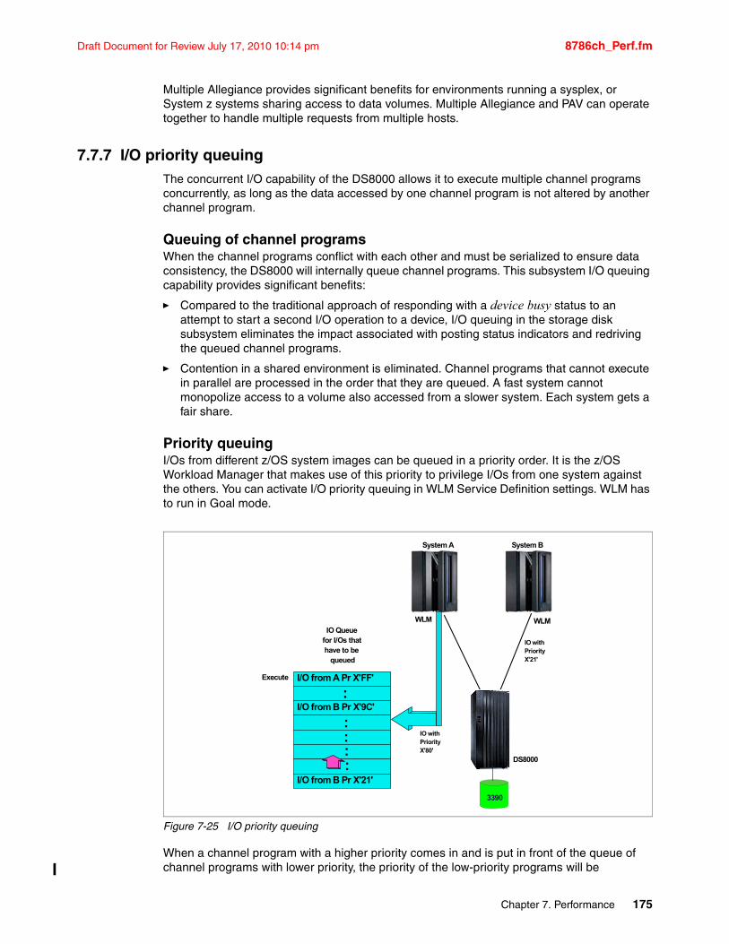
Draft Document for Review July 17, 2010 10:14 pm 8786ch_Perf.fm
Multiple Allegiance provides significant benefits for environments running a sysplex, or System z systems sharing access to data volumes. Multiple Allegiance and PAV can operate together to handle multiple requests from multiple hosts.
7.7.7 I/O priority queuingThe concurrent I/O capability of the DS8000 allows it to execute multiple channel programs concurrently, as long as the data accessed by one channel program is not altered by another channel program.
Queuing of channel programsWhen the channel programs conflict with each other and must be serialized to ensure data consistency, the DS8000 will internally queue channel programs. This subsystem I/O queuing capability provides significant benefits:
� Compared to the traditional approach of responding with a device busy status to an attempt to start a second I/O operation to a device, I/O queuing in the storage disk subsystem eliminates the impact associated with posting status indicators and redriving the queued channel programs.
� Contention in a shared environment is eliminated. Channel programs that cannot execute in parallel are processed in the order that they are queued. A fast system cannot monopolize access to a volume also accessed from a slower system. Each system gets a fair share.
Priority queuingI/Os from different z/OS system images can be queued in a priority order. It is the z/OS Workload Manager that makes use of this priority to privilege I/Os from one system against the others. You can activate I/O priority queuing in WLM Service Definition settings. WLM has to run in Goal mode.
Figure 7-25 I/O priority queuing
When a channel program with a higher priority comes in and is put in front of the queue of channel programs with lower priority, the priority of the low-priority programs will be
I/O from A Pr X'FF'
I/O from B Pr X'9C'
I/O from B Pr X'21'
:
:
::
3390
Execute
System B
DS8000
WLM
IO withPriorityX'80'
WLM
IO withPriorityX'21'
IO Queuefor I/Os that have to be queued
:
System A
Chapter 7. Performance 175
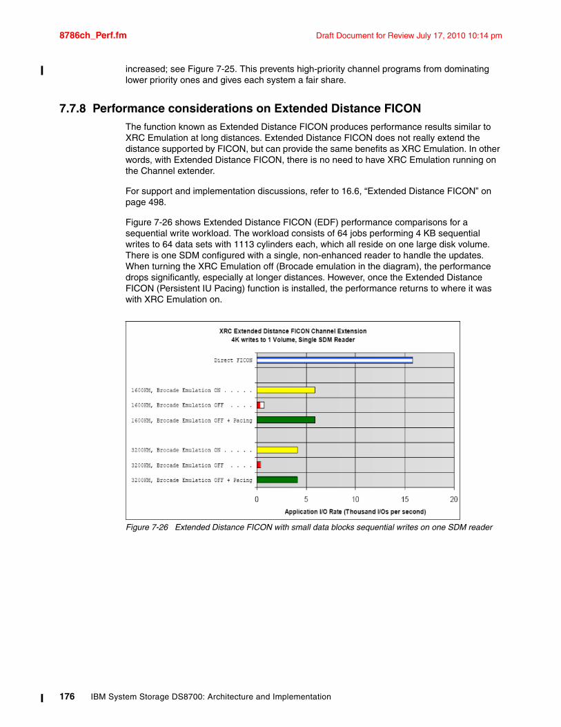
8786ch_Perf.fm Draft Document for Review July 17, 2010 10:14 pm
increased; see Figure 7-25. This prevents high-priority channel programs from dominating lower priority ones and gives each system a fair share.
7.7.8 Performance considerations on Extended Distance FICONThe function known as Extended Distance FICON produces performance results similar to XRC Emulation at long distances. Extended Distance FICON does not really extend the distance supported by FICON, but can provide the same benefits as XRC Emulation. In other words, with Extended Distance FICON, there is no need to have XRC Emulation running on the Channel extender.
For support and implementation discussions, refer to 16.6, “Extended Distance FICON” on page 498.
Figure 7-26 shows Extended Distance FICON (EDF) performance comparisons for a sequential write workload. The workload consists of 64 jobs performing 4 KB sequential writes to 64 data sets with 1113 cylinders each, which all reside on one large disk volume. There is one SDM configured with a single, non-enhanced reader to handle the updates. When turning the XRC Emulation off (Brocade emulation in the diagram), the performance drops significantly, especially at longer distances. However, once the Extended Distance FICON (Persistent IU Pacing) function is installed, the performance returns to where it was with XRC Emulation on.
Figure 7-26 Extended Distance FICON with small data blocks sequential writes on one SDM reader
176 IBM System Storage DS8700: Architecture and Implementation
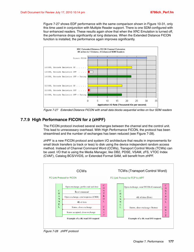
Draft Document for Review July 17, 2010 10:14 pm 8786ch_Perf.fm
Figure 7-27 shows EDF performance with the same comparison shown in Figure 10-31, only this time used in conjunction with Multiple Reader support. There is one SDM configured with four enhanced readers. These results again show that when the XRC Emulation is turned off, the performance drops significantly at long distances. When the Extended Distance FICON function is installed, the performance again improves significantly.
Figure 7-27 Extended Distance FICON with small data blocks sequential writes on four SDM readers
7.7.9 High Performance FICON for z (zHPF)The FICON protocol involved several exchanges between the channel and the control unit. This lead to unnecessary overhead. With High Performance FICON, the protocol has been streamlined and the number of exchanges has been reduced (see Figure 7-28).
zHPF is a new FICON protocol and system I/O architecture that results in improvements for small block transfers (a track or less) to disk using the device independent random access method. Instead of Channel Command Word (CCWs), Transport Control Words (TCWs) can be used. I/O that is using the Media Manager, like DB2, PDSE, VSAM, zFS, VTOC Index (CVAF), Catalog BCS/VVDS, or Extended Format SAM, will benefit from zHPF.
Figure 7-28 zHPF protocol
CCWs TCWs (Transport Control Word)
Chapter 7. Performance 177
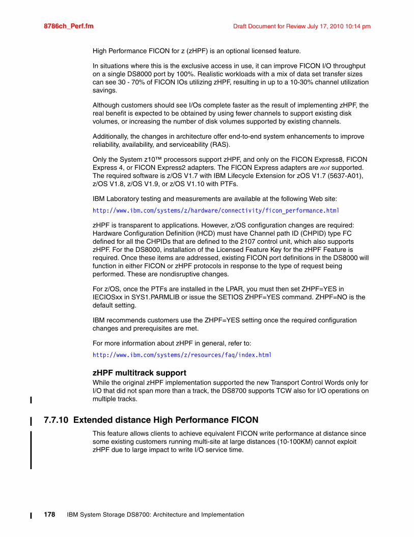
8786ch_Perf.fm Draft Document for Review July 17, 2010 10:14 pm
High Performance FICON for z (zHPF) is an optional licensed feature.
In situations where this is the exclusive access in use, it can improve FICON I/O throughput on a single DS8000 port by 100%. Realistic workloads with a mix of data set transfer sizes can see 30 - 70% of FICON IOs utilizing zHPF, resulting in up to a 10-30% channel utilization savings.
Although customers should see I/Os complete faster as the result of implementing zHPF, the real benefit is expected to be obtained by using fewer channels to support existing disk volumes, or increasing the number of disk volumes supported by existing channels.
Additionally, the changes in architecture offer end-to-end system enhancements to improve reliability, availability, and serviceability (RAS).
Only the System z10™ processors support zHPF, and only on the FICON Express8, FICON Express 4, or FICON Express2 adapters. The FICON Express adapters are not supported. The required software is z/OS V1.7 with IBM Lifecycle Extension for zOS V1.7 (5637-A01), z/OS V1.8, z/OS V1.9, or z/OS V1.10 with PTFs.
IBM Laboratory testing and measurements are available at the following Web site:
http://www.ibm.com/systems/z/hardware/connectivity/ficon_performance.html
zHPF is transparent to applications. However, z/OS configuration changes are required: Hardware Configuration Definition (HCD) must have Channel path ID (CHPID) type FC defined for all the CHPIDs that are defined to the 2107 control unit, which also supports zHPF. For the DS8000, installation of the Licensed Feature Key for the zHPF Feature is required. Once these items are addressed, existing FICON port definitions in the DS8000 will function in either FICON or zHPF protocols in response to the type of request being performed. These are nondisruptive changes.
For z/OS, once the PTFs are installed in the LPAR, you must then set ZHPF=YES in IECIOSxx in SYS1.PARMLIB or issue the SETIOS ZHPF=YES command. ZHPF=NO is the default setting.
IBM recommends customers use the ZHPF=YES setting once the required configuration changes and prerequisites are met.
For more information about zHPF in general, refer to:
http://www.ibm.com/systems/z/resources/faq/index.html
zHPF multitrack supportWhile the original zHPF implementation supported the new Transport Control Words only for I/O that did not span more than a track, the DS8700 supports TCW also for I/O operations on multiple tracks.
7.7.10 Extended distance High Performance FICONThis feature allows clients to achieve equivalent FICON write performance at distance since some existing customers running multi-site at large distances (10-100KM) cannot exploit zHPF due to large impact to write I/O service time.
178 IBM System Storage DS8700: Architecture and Implementation
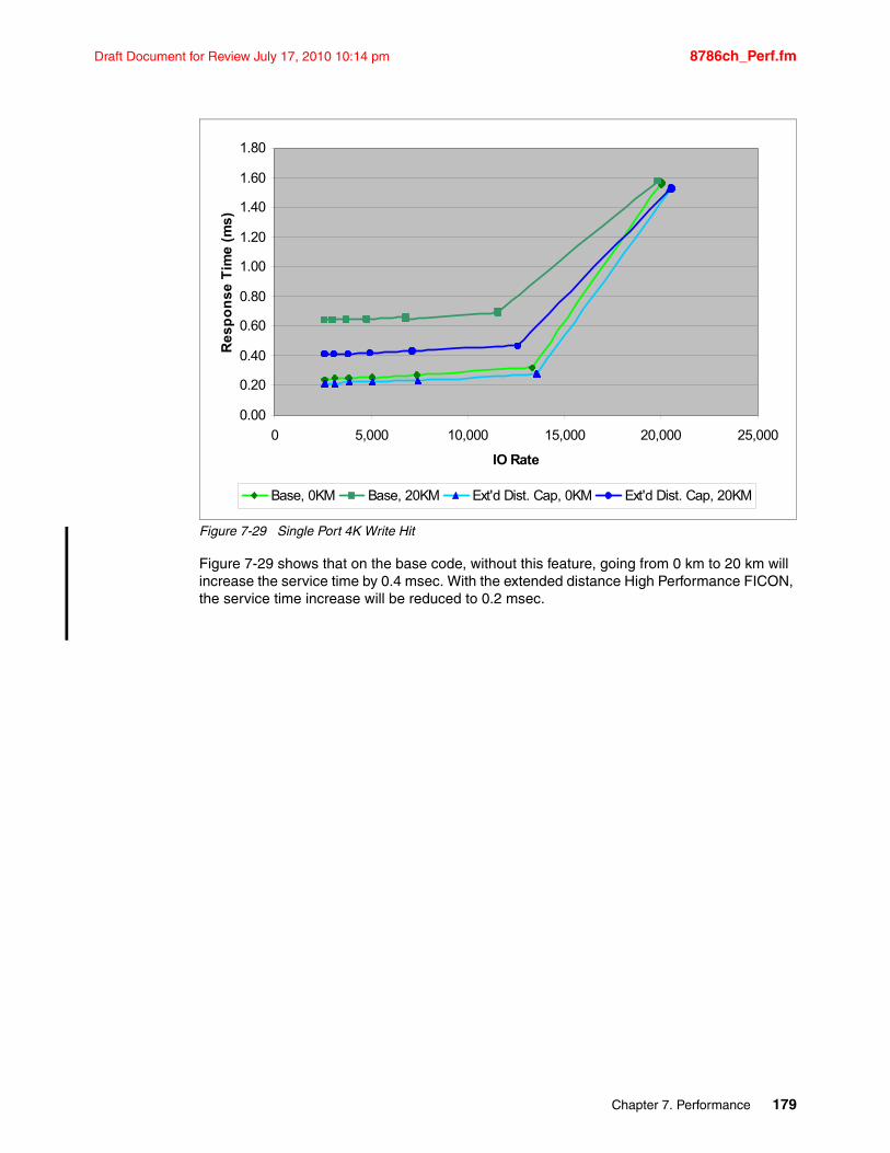
Draft Document for Review July 17, 2010 10:14 pm 8786ch_Perf.fm
Figure 7-29 Single Port 4K Write Hit
Figure 7-29 shows that on the base code, without this feature, going from 0 km to 20 km will increase the service time by 0.4 msec. With the extended distance High Performance FICON, the service time increase will be reduced to 0.2 msec.
0.00
0.20
0.40
0.60
0.80
1.00
1.20
1.40
1.60
1.80
0 5,000 10,000 15,000 20,000 25,000
IO Rate
Re
sp
on
se
Tim
e (
ms
)
Base, 0KM Base, 20KM Ext'd Dist. Cap, 0KM Ext'd Dist. Cap, 20KM
Chapter 7. Performance 179

8786ch_Perf.fm Draft Document for Review July 17, 2010 10:14 pm
180 IBM System Storage DS8700: Architecture and Implementation
Draft Document for Review July 17, 2010 10:14 pm 8786p_Planning.fm
Part 2 Planning and installation
In this part, we discuss matters related to the installation planning process for the IBM System Storage DS8000 series. We cover the following subjects:
� Physical planning and installation
� HMC planning and setup
� Performance
� DS8700 features and license keys
Part 2
© Copyright IBM Corp. 2010. All rights reserved. 181

8786p_Planning.fm Draft Document for Review July 17, 2010 10:14 pm
182 IBM System Storage DS8700: Architecture and Implementation
Draft Document for Review July 17, 2010 10:14 pm 8786ch_Physical Planning.fm
Chapter 8. Physical planning and installation
This chapter discusses the various steps involved in the planning and installation of the IBM System Storage DS8700, including a reference listing of the information required for the setup and where to find detailed technical reference material. The topics covered include:
� Considerations prior to installation
� Planning for the physical installation
� Network connectivity planning
� Secondary HMC, SSPC, TKLM, LDAP, and B2B VPN planning
� Remote mirror and copy connectivity
� Disk capacity considerations
� Planning for growth
The publication IBM System Storage DS8000 Introduction and Planning Guide, GC35-0515 should be reviewed and contains additional information and details that you will need during the configuration and installation process.
8
© Copyright IBM Corp. 2010. All rights reserved. 183
8786ch_Physical Planning.fm Draft Document for Review July 17, 2010 10:14 pm
8.1 Considerations prior to installationStart by developing and following a project plan to address the many topics needed for a successful implementation. In general, the following items should be considered for your installation planning checklist:
� Plan for growth to minimize disruption to operations. Expansion frames can only be placed to the right (from the front) of the DS8700.
� Location suitability, floor loading, access constraints, elevators, doorways, and so on.
� Power requirements: Redundancy and use of Uninterrupted Power Supply (UPS).
� Environmental requirements: Adequate cooling capacity.
� A place and connection for the secondary HMC.
� A plan for encryption integration if FDE drives are considered for the configuration.
� A place and connection for the TKLM server.
� Integration of LDAP to allow a single user ID / password management.
� Business to Business VPN for the DS8700 to allow fast data off-load and service connections.
� A plan detailing the desired logical configuration of the storage.
� Consider TPC monitoring for your environment.
� Oversee the available services from IBM to check for microcode compatibility and configuration checks.
� Available Copy Services and backup technologies.
� Staff education and availability to implement the storage plan. Alternatively, IBM or IBM Business Partner services.
Client responsibilities for the installationThe DS8700 series is specified as an IBM or IBM Business Partner installation and setup system. Still, the following activities are some of the required planning and installation activities for which the client is responsible at a high level:
� Physical configuration planning is a client responsibility. Your disk Marketing Specialist can help you plan and select the DS8700 series physical configuration and features. Introductory information, including required and optional features, can be found in this book as well as in the publication IBM System Storage DS8000 Introduction and Planning Guide, GC35-0515.
� Installation planning is a client responsibility. Information about planning the installation of your DS8700 series, including equipment, site, and power requirements, can be found in this book as well as in the publication IBM System Storage DS8000 Introduction and Planning Guide, GC35-0515.
� Integration of LDAP and Business to Business VPN connectivity are customer responsibilities. IBM can provide services to set up and integrate these components. Guidelines about how to set up these components can be found in this book.
� Integration of TPC and SNMP into the customer environment for monitoring of performance and configuration is a customer responsibility. IBM can provide services to set up and integrate these components. Guidelines about how to set up these components can be found in this book.
184 IBM System Storage DS8700: Architecture and Implementation
Draft Document for Review July 17, 2010 10:14 pm 8786ch_Physical Planning.fm
� Configuration and integration of TKLM servers and DS8700 Encryption for extended data security is a customer responsibility. IBM provides services to set up and integrate these components. Guidelines on how to set up these components can be found in this book.
� Logical configuration planning and application is a client responsibility. Logical configuration refers to the creation of RAID ranks, volumes, and LUNs, and the assignment of the configured capacity to servers. Application of the initial logical configuration and all subsequent modifications to the logical configuration are client responsibilities. The logical configuration can be created, applied, and modified using the DS Storage Manager, DS CLI, or DS Open API.
IBM Global Services will also apply or modify your logical configuration (these are fee-based services).
In this chapter, you will find information that will assist you with the planning and installation activities.
8.1.1 Who should be involvedWe suggest having a project manager to coordinate the many tasks necessary for a successful installation. Installation will require close cooperation with the user community, the IT support staff, and the technical resources responsible for floor space, power, and cooling.
A Storage Administrator should also coordinate requirements from the user applications and systems in order to build a storage plan for the installation. This will be needed to configure the storage after the initial hardware installation is complete.
The following people should be briefed and engaged in the planning process for the physical installation:
� Systems and Storage Administrators� Installation Planning Engineer� Building Engineer for floor loading and air conditioning and Location Electrical Engineer� Security Engineers for B2B VPN, LDAP, TKLM, and encryption� Administrator and Operator for monitoring and handling considerations� IBM or Business Partner Installation Engineer
8.1.2 What information is requiredA validation list to assist in the installation process should include:
� Drawings detailing the positioning as specified and agreed upon with a building engineer, ensuring the weight is within limits for the route to the final installation position.
� Approval to use elevators if the weight and size are acceptable.
� Connectivity information, servers, and SAN, and mandatory LAN connections.
� Agreement on the security structure of the installed DS8700 with all security engineers.
� Ensure that you have a detailed storage plan agreed upon, with the client available to understand how the storage is to be configured. Ensure that the configuration specialist has all the information to configure all the arrays and set up the environment as required.
� License keys for the Operating Environment License (OEL), which are mandatory, and any optional license keys.
The IBM System Storage DS8000 Introduction and Planning Guide, GC35-0515 contains additional information about physical planning. You can download it from:
http://www-03.ibm.com/systems/storage/disk/ds8000/index.html
Chapter 8. Physical planning and installation 185
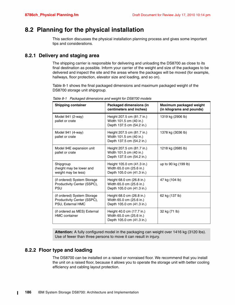
8786ch_Physical Planning.fm Draft Document for Review July 17, 2010 10:14 pm
8.2 Planning for the physical installationThis section discusses the physical installation planning process and gives some important tips and considerations.
8.2.1 Delivery and staging areaThe shipping carrier is responsible for delivering and unloading the DS8700 as close to its final destination as possible. Inform your carrier of the weight and size of the packages to be delivered and inspect the site and the areas where the packages will be moved (for example, hallways, floor protection, elevator size and loading, and so on).
Table 8-1 shows the final packaged dimensions and maximum packaged weight of the DS8700 storage unit shipgroup.
Table 8-1 Packaged dimensions and weight for DS8700 models
8.2.2 Floor type and loadingThe DS8700 can be installed on a raised or nonraised floor. We recommend that you install the unit on a raised floor, because it allows you to operate the storage unit with better cooling efficiency and cabling layout protection.
Shipping container Packaged dimensions (in centimeters and inches)
Maximum packaged weight (in kilograms and pounds)
Model 941 (2-way)pallet or crate
Height 207.5 cm (81.7 in.)Width 101.5 cm (40 in.)Depth 137.5 cm (54.2 in.)
1319 kg (2906 lb)
Model 941 (4-way)pallet or crate
Height 207.5 cm (81.7 in.)Width 101.5 cm (40 in.)Depth 137.5 cm (54.2 in.)
1378 kg (3036 lb)
Model 94E expansion unitpallet or crate
Height 207.5 cm (81.7 in.)Width 101.5 cm (40 in.)Depth 137.5 cm (54.2 in.)
1218 kg (2685 lb)
Shipgroup(height may be lower and weight may be less)
Height 105.0 cm (41.3 in.)Width 65.0 cm (25.6 in.)Depth 105.0 cm (41.3 in.)
up to 90 kg (199 lb)
(if ordered) System Storage Productivity Center (SSPC), PSU
Height 68.0 cm (26.8 in.)Width 65.0 cm (25.6 in.)Depth 105.0 cm (41.3 in.)
47 kg (104 lb)
(if ordered) System Storage Productivity Center (SSPC), PSU, External HMC
Height 68.0 cm (26.8 in.)Width 65.0 cm (25.6 in.)Depth 105.0 cm (41.3 in.)
62 kg (137 lb)
(if ordered as MES) External HMC container
Height 40.0 cm (17.7 in.)Width 65.0 cm (25.6 in.)Depth 105.0 cm (41.3 in.)
32 kg (71 lb)
Attention: A fully configured model in the packaging can weight over 1416 kg (3120 lbs). Use of fewer than three persons to move it can result in injury.
186 IBM System Storage DS8700: Architecture and Implementation
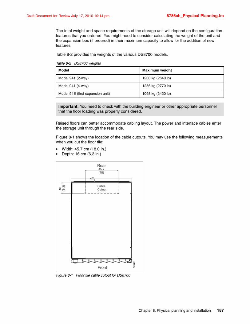
Draft Document for Review July 17, 2010 10:14 pm 8786ch_Physical Planning.fm
The total weight and space requirements of the storage unit will depend on the configuration features that you ordered. You might need to consider calculating the weight of the unit and the expansion box (if ordered) in their maximum capacity to allow for the addition of new features.
Table 8-2 provides the weights of the various DS8700 models.
Table 8-2 DS8700 weights
Raised floors can better accommodate cabling layout. The power and interface cables enter the storage unit through the rear side.
Figure 8-1 shows the location of the cable cutouts. You may use the following measurements when you cut the floor tile:
� Width: 45.7 cm (18.0 in.)� Depth: 16 cm (6.3 in.)
Figure 8-1 Floor tile cable cutout for DS8700
Model Maximum weight
Model 941 (2-way) 1200 kg (2640 lb)
Model 941 (4-way) 1256 kg (2770 lb)
Model 94E (first expansion unit) 1098 kg (2420 lb)
Important: You need to check with the building engineer or other appropriate personnel that the floor loading was properly considered.
Chapter 8. Physical planning and installation 187
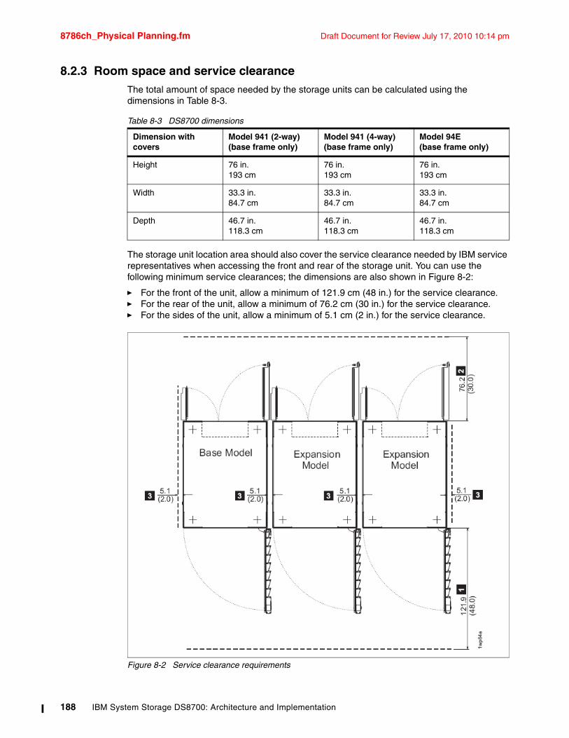
8786ch_Physical Planning.fm Draft Document for Review July 17, 2010 10:14 pm
8.2.3 Room space and service clearanceThe total amount of space needed by the storage units can be calculated using the dimensions in Table 8-3.
Table 8-3 DS8700 dimensions
The storage unit location area should also cover the service clearance needed by IBM service representatives when accessing the front and rear of the storage unit. You can use the following minimum service clearances; the dimensions are also shown in Figure 8-2:
� For the front of the unit, allow a minimum of 121.9 cm (48 in.) for the service clearance.� For the rear of the unit, allow a minimum of 76.2 cm (30 in.) for the service clearance.� For the sides of the unit, allow a minimum of 5.1 cm (2 in.) for the service clearance.
Figure 8-2 Service clearance requirements
Dimension with covers
Model 941 (2-way)(base frame only)
Model 941 (4-way)(base frame only)
Model 94E(base frame only)
Height 76 in.193 cm
76 in.193 cm
76 in.193 cm
Width 33.3 in.84.7 cm
33.3 in.84.7 cm
33.3 in.84.7 cm
Depth 46.7 in.118.3 cm
46.7 in.118.3 cm
46.7 in.118.3 cm
188 IBM System Storage DS8700: Architecture and Implementation
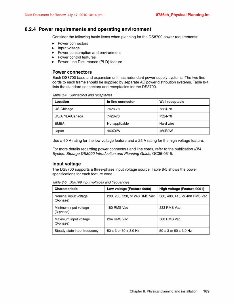
Draft Document for Review July 17, 2010 10:14 pm 8786ch_Physical Planning.fm
8.2.4 Power requirements and operating environmentConsider the following basic items when planning for the DS8700 power requirements:
� Power connectors� Input voltage� Power consumption and environment� Power control features� Power Line Disturbance (PLD) feature
Power connectorsEach DS8700 base and expansion unit has redundant power supply systems. The two line cords to each frame should be supplied by separate AC power distribution systems. Table 8-4 lists the standard connectors and receptacles for the DS8700.
Table 8-4 Connectors and receptacles
Use a 60 A rating for the low voltage feature and a 25 A rating for the high voltage feature.
For more details regarding power connectors and line cords, refer to the publication IBM System Storage DS8000 Introduction and Planning Guide, GC35-0515.
Input voltageThe DS8700 supports a three-phase input voltage source. Table 8-5 shows the power specifications for each feature code.
Table 8-5 DS8700 input voltages and frequencies
Location In-line connector Wall receptacle
US-Chicago 7428-78 7324-78
US/AP/LA/Canada 7428-78 7324-78
EMEA Not applicable Hard wire
Japan 460C9W 460R9W
Characteristic Low voltage (Feature 9090) High voltage (Feature 9091)
Nominal input voltage (3-phase)
200, 208, 220, or 240 RMS Vac 380, 400, 415, or 480 RMS Vac
Minimum input voltage (3-phase)
180 RMS Vac 333 RMS Vac
Maximum input voltage (3-phase)
264 RMS Vac 508 RMS Vac
Steady-state input frequency 50 ± 3 or 60 ± 3.0 Hz 50 ± 3 or 60 ± 3.0 Hz
Chapter 8. Physical planning and installation 189
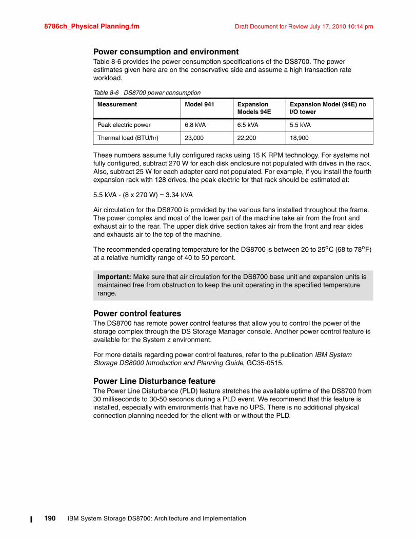
8786ch_Physical Planning.fm Draft Document for Review July 17, 2010 10:14 pm
Power consumption and environmentTable 8-6 provides the power consumption specifications of the DS8700. The power estimates given here are on the conservative side and assume a high transaction rate workload.
Table 8-6 DS8700 power consumption
These numbers assume fully configured racks using 15 K RPM technology. For systems not fully configured, subtract 270 W for each disk enclosure not populated with drives in the rack. Also, subtract 25 W for each adapter card not populated. For example, if you install the fourth expansion rack with 128 drives, the peak electric for that rack should be estimated at:
5.5 kVA - (8 x 270 W) = 3.34 kVA
Air circulation for the DS8700 is provided by the various fans installed throughout the frame. The power complex and most of the lower part of the machine take air from the front and exhaust air to the rear. The upper disk drive section takes air from the front and rear sides and exhausts air to the top of the machine.
The recommended operating temperature for the DS8700 is between 20 to 25oC (68 to 78oF) at a relative humidity range of 40 to 50 percent.
Power control featuresThe DS8700 has remote power control features that allow you to control the power of the storage complex through the DS Storage Manager console. Another power control feature is available for the System z environment.
For more details regarding power control features, refer to the publication IBM System Storage DS8000 Introduction and Planning Guide, GC35-0515.
Power Line Disturbance featureThe Power Line Disturbance (PLD) feature stretches the available uptime of the DS8700 from 30 milliseconds to 30-50 seconds during a PLD event. We recommend that this feature is installed, especially with environments that have no UPS. There is no additional physical connection planning needed for the client with or without the PLD.
Measurement Model 941 Expansion Models 94E
Expansion Model (94E) no I/O tower
Peak electric power 6.8 kVA 6.5 kVA 5.5 kVA
Thermal load (BTU/hr) 23,000 22,200 18,900
Important: Make sure that air circulation for the DS8700 base unit and expansion units is maintained free from obstruction to keep the unit operating in the specified temperature range.
190 IBM System Storage DS8700: Architecture and Implementation
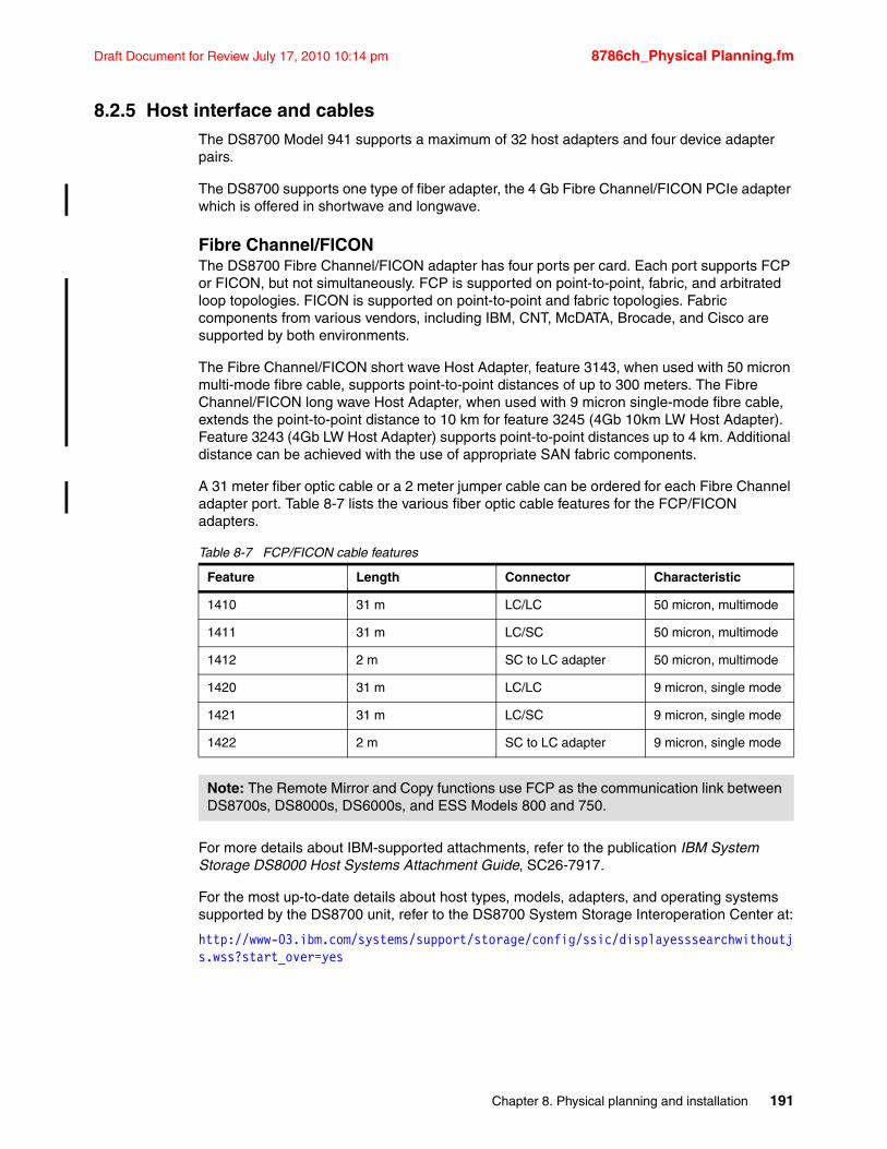
Draft Document for Review July 17, 2010 10:14 pm 8786ch_Physical Planning.fm
8.2.5 Host interface and cablesThe DS8700 Model 941 supports a maximum of 32 host adapters and four device adapter pairs.
The DS8700 supports one type of fiber adapter, the 4 Gb Fibre Channel/FICON PCIe adapter which is offered in shortwave and longwave.
Fibre Channel/FICONThe DS8700 Fibre Channel/FICON adapter has four ports per card. Each port supports FCP or FICON, but not simultaneously. FCP is supported on point-to-point, fabric, and arbitrated loop topologies. FICON is supported on point-to-point and fabric topologies. Fabric components from various vendors, including IBM, CNT, McDATA, Brocade, and Cisco are supported by both environments.
The Fibre Channel/FICON short wave Host Adapter, feature 3143, when used with 50 micron multi-mode fibre cable, supports point-to-point distances of up to 300 meters. The Fibre Channel/FICON long wave Host Adapter, when used with 9 micron single-mode fibre cable, extends the point-to-point distance to 10 km for feature 3245 (4Gb 10km LW Host Adapter). Feature 3243 (4Gb LW Host Adapter) supports point-to-point distances up to 4 km. Additional distance can be achieved with the use of appropriate SAN fabric components.
A 31 meter fiber optic cable or a 2 meter jumper cable can be ordered for each Fibre Channel adapter port. Table 8-7 lists the various fiber optic cable features for the FCP/FICON adapters.
Table 8-7 FCP/FICON cable features
For more details about IBM-supported attachments, refer to the publication IBM System Storage DS8000 Host Systems Attachment Guide, SC26-7917.
For the most up-to-date details about host types, models, adapters, and operating systems supported by the DS8700 unit, refer to the DS8700 System Storage Interoperation Center at:
http://www-03.ibm.com/systems/support/storage/config/ssic/displayesssearchwithoutjs.wss?start_over=yes
Feature Length Connector Characteristic
1410 31 m LC/LC 50 micron, multimode
1411 31 m LC/SC 50 micron, multimode
1412 2 m SC to LC adapter 50 micron, multimode
1420 31 m LC/LC 9 micron, single mode
1421 31 m LC/SC 9 micron, single mode
1422 2 m SC to LC adapter 9 micron, single mode
Note: The Remote Mirror and Copy functions use FCP as the communication link between DS8700s, DS8000s, DS6000s, and ESS Models 800 and 750.
Chapter 8. Physical planning and installation 191
8786ch_Physical Planning.fm Draft Document for Review July 17, 2010 10:14 pm
8.3 Network connectivity planningImplementing the DS8700 requires that you consider the physical network connectivity of the storage adapters and the Hardware Management Console (HMC) within your local area network.
Check your local environment for the following DS8700 unit connections:
� Hardware Management Console and network access� System Storage Productivity Center and network access� DSCLI console� DSCIMCLI console � Remote support connection� Remote power control� Storage area network connection� TKLM connection� LDAP connection
For more details about physical network connectivity, refer to the publications IBM System Storage DS8000 User´s Guide, SC26-7915 and IBM System Storage DS8000 Introduction and Planning Guide, GC35-0515.
8.3.1 Hardware Management Console and network accessHardware Management Consoles (HMCs) are the focal point for configuration, Copy Services management, and maintenance for a DS8700 unit.
The internal HMC included with every primary rack is mounted in a pull-out tray for convenience and security. The HMC consists of a mobile workstation (Lenovo Thinkpad W500) with adapters for modem and 10/100/1000Mb Ethernet. Ethernet cables connect the HMC to the storage unit.
A second, redundant external HMC is orderable and highly recommended for environments that use TKLM encryption management as well as Advanced Copy Services functions. The second HMC is external to the DS8700 rack(s) and consists of a similar mobile workstation as the primary HMC.
The management console can be connected to your network for remote management of your system by using the DS Storage Manager Web-based graphical user interface (GUI), the DS Command-Line Interface (CLI), or using storage management software through the DS Open API. In order to use the CLI to manage your storage unit, you need to connect the management console to your LAN because the CLI interface is not available on the HMC. The DS8700 can be managed from the HMC, or remotely using SSPC. Connecting the System Storage Productivity Center (SSPC) to your LAN allows you to access the DS Storage Manager GUI from any location that has network access.
Tip: To ensure that the IBM service representative can quickly and easily access an external HMC, place the external HMC rack within 15.2 m (50 ft) of the storage units that are connected to it.
192 IBM System Storage DS8700: Architecture and Implementation
Draft Document for Review July 17, 2010 10:14 pm 8786ch_Physical Planning.fm
In order to connect the management consoles (internal, and external if present) to your network, you need to provide the following settings to your IBM service representative so that he can configure the management consoles for attachment to your LAN:
� Management console network IDs, host names, and domain name� Domain Name Server (DNS) settings (if you plan to use DNS to resolve network names)� Routing information
For additional information regarding the HMC planning, refer to Chapter 9, “HMC planning and setup” on page 205.
8.3.2 System Storage Productivity Center and network accessSSPC is a solution consisting of hardware and software elements.
SSPC hardwareThe SSPC (IBM model 2805-MC4) server contains the following hardware components:
� x86 server 1U rack installed
� One Intel Xeon® quad-core processor, with a speed of 2.4 GHz, a cache of 8 MB, and power consumption of 80 W
� 8 GB of RAM (eight 1-inch dual in-line memory modules of double-data-rate three memory, with a data rate of 1333 MHz)
� Two 146 GB hard disk drives, each with a speed of 15 K
� One Broadcom 6708 Ethernet card
� One CD/DVD bay with read and write-read capability
Optional components are:
� KVM Unit� Secondary power supply
SSPC softwareThe IBM System Storage Productivity Center includes the following pre-installed (separately purchased) software, running under a licensed Microsoft® Windows Server 2008 32-bit Enterprise Edition (included):
� IBM Tivoli Storage Productivity Center V4.1.1 licensed as TPC Basic Edition. A TPC upgrade requires that you purchase and add additional TPC licenses.
� IBM System Storage SAN Volume Controller Console V5.1.0 (CIM Agent and GUI).
� DS CIM Agent Command-Line Interface (DSCIMCLI) V5.4.3.
� IBM Tivoli Storage Productivity Center for Replication (TPC-R) V4.1.1. To run TPC-R on SSPC, you must purchase and add TPC-R licenses.
� IBM DB2 Enterprise Server Edition 9.5 with Fix Pack 3.
� IPv6 installed on Windows Server 2008.
Optionally, the following components can be installed on the SSPC:
� Software components contained in SSPC V1.3 but not on previous SSPC versions (TPC-R, DSCIMCLI, DS3000, DS40000, or DS5000 Storage Manager).
� DS8700 Command-Line Interface (DSCLI).
� Antivirus software.
Chapter 8. Physical planning and installation 193
8786ch_Physical Planning.fm Draft Document for Review July 17, 2010 10:14 pm
Customers have the option to purchase and install the individual software components to create their own SSPC server.
For details, refer to Chapter 12, “System Storage Productivity Center” on page 261, and the IBM Redbooks publication IBM System Storage Productivity Center Deployment Guide, SG24-7560.
Network connectivityIn order to connect the System Storage Productivity Center (SSPC) to your network, you need to provide the following settings to your IBM service representative:
� SSPC network IDs, host names, and domain name� Domain Name Server (DNS) settings (if you plan to use DNS to resolve network names)
Routing informationThere are several networks ports that need to be opened between the SSPC console and the DS8700 and LDAP server if the SSPC is installed behind a firewall.
8.3.3 DSCLI consoleThe DSCLI provides a command-line interface for managing and configuring the DS8700 storage unit. The DSCLI can be installed on and used from a LAN-connected system, such as the storage administrator’s mobile computer. You might consider installing the DSCLI on a separate workstation connected to the storage unit’s LAN.
For details about the hardware and software requirements for the DSCLI, refer to the IBM System Storage DS8000: Command-Line Interface User´s Guide, SC26-7916.
8.3.4 DSCIMCLI The DSCIMCLI has to be used to configure the CIM agent running on the HMC. The DS8700 can be managed either by the CIM agent that is bundled with the HMC or with a separately installed CIM agent. The DSCIMCLI utility, which configures the CIM agent, is available from the DS CIM agent Web site as part of the DS CIM agent installation bundle, and also as a separate installation bundle.
For details about the configuration of the DSCIMCLI, refer to the IBM DS Open Application Programming Interface Reference, GC35-0516.
8.3.5 Remote support connectionRemote support connection is available from the HMC using a modem (dial-up) and the Virtual Private Network (VPN) over the Internet through the customer LAN.
You can take advantage of the DS8700 remote support feature for outbound calls (Call Home function) or inbound calls (remote service access by an IBM technical support representative). You need to provide an analog telephone line for the HMC modem.
194 IBM System Storage DS8700: Architecture and Implementation
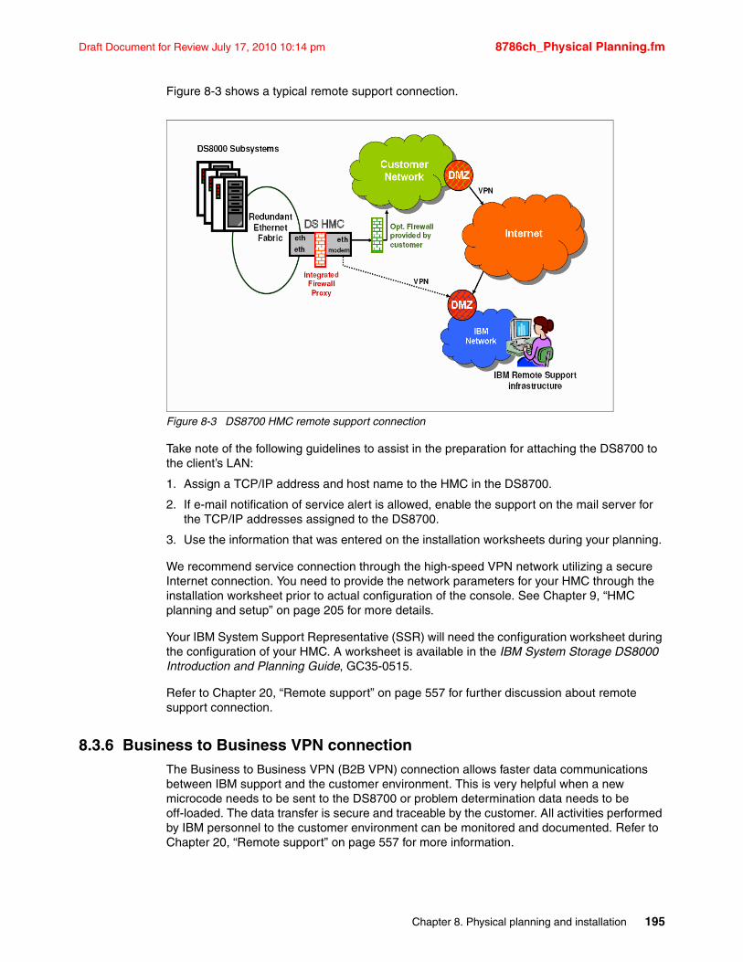
Draft Document for Review July 17, 2010 10:14 pm 8786ch_Physical Planning.fm
Figure 8-3 shows a typical remote support connection.
Figure 8-3 DS8700 HMC remote support connection
Take note of the following guidelines to assist in the preparation for attaching the DS8700 to the client’s LAN:
1. Assign a TCP/IP address and host name to the HMC in the DS8700.
2. If e-mail notification of service alert is allowed, enable the support on the mail server for the TCP/IP addresses assigned to the DS8700.
3. Use the information that was entered on the installation worksheets during your planning.
We recommend service connection through the high-speed VPN network utilizing a secure Internet connection. You need to provide the network parameters for your HMC through the installation worksheet prior to actual configuration of the console. See Chapter 9, “HMC planning and setup” on page 205 for more details.
Your IBM System Support Representative (SSR) will need the configuration worksheet during the configuration of your HMC. A worksheet is available in the IBM System Storage DS8000 Introduction and Planning Guide, GC35-0515.
Refer to Chapter 20, “Remote support” on page 557 for further discussion about remote support connection.
8.3.6 Business to Business VPN connectionThe Business to Business VPN (B2B VPN) connection allows faster data communications between IBM support and the customer environment. This is very helpful when a new microcode needs to be sent to the DS8700 or problem determination data needs to be off-loaded. The data transfer is secure and traceable by the customer. All activities performed by IBM personnel to the customer environment can be monitored and documented. Refer to Chapter 20, “Remote support” on page 557 for more information.
Chapter 8. Physical planning and installation 195
8786ch_Physical Planning.fm Draft Document for Review July 17, 2010 10:14 pm
8.3.7 Remote power controlThe System z remote power control setting allows you to power on and off the storage unit from a System z interface. If you plan to use the System z power control feature, be sure that you order the System z power control feature. This feature comes with four power control cables.
In a System z environment, the host must have the Power Sequence Controller (PSC) feature installed to have the ability to turn on and off specific control units, such as the DS8700. The control unit is controlled by the host through the power control cable. The power control cable comes with a standard length of 31 meters, so be sure to consider the physical distance between the host and DS8700.
8.3.8 Storage area network connectionThe DS8700 can be attached to a SAN environment through its Fibre Channel ports. SANs provide the capability to interconnect open systems hosts, S/390 and System z hosts, and other storage systems.
A SAN allows your single Fibre Channel host port to have physical access to multiple Fibre Channel ports on the storage unit. You might need to establish zones to limit the access (and provide access security) of host ports to your storage ports. Take note that shared access to a storage unit Fibre Channel port might come from hosts that support a combination of bus adapter types and operating systems.
8.3.9 Tivoli Key Lifecycle Manager (TKLM) server for encryptionIf the DS8700 is configured with FDE drives and enabled for encryption, an isolated TKLM server is also required.
The isolated TKLM server consists of the following hardware and software:
� IBM System x3650 with L5420 processor
– Quad-core Intel Xeon processor L5420 (2.5 GHz, 12 MB L2, 1.0 GHz FSB, 50 W)
– 6 GB memory
– 146 GB SAS RAID 1 storage
– SUSE Linux v10
– Dual Gigabit Ethernet ports (standard)
– Power supply
� Tivoli Key Lifecycle Manager V1 (includes DB2 9.1 FB4)
Note: No other hardware or software is allowed on this server. An isolated server must only use internal disk for all files necessary to boot and have the TKLM key server become operational.
196 IBM System Storage DS8700: Architecture and Implementation
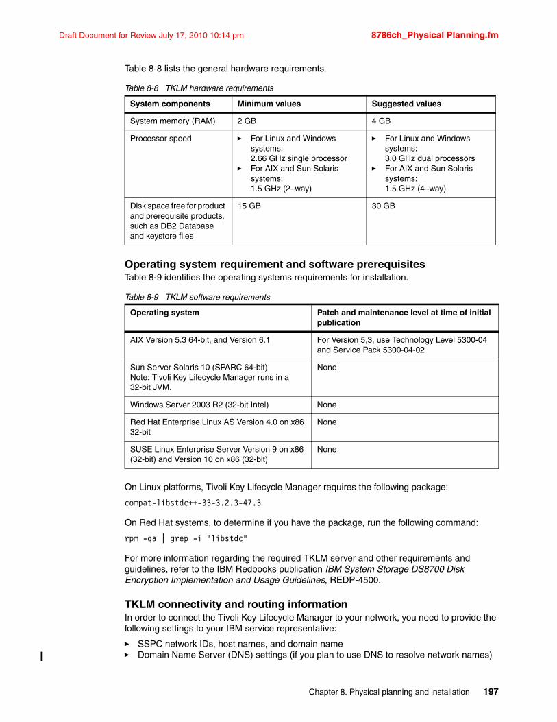
Draft Document for Review July 17, 2010 10:14 pm 8786ch_Physical Planning.fm
Table 8-8 lists the general hardware requirements.
Table 8-8 TKLM hardware requirements
Operating system requirement and software prerequisitesTable 8-9 identifies the operating systems requirements for installation.
Table 8-9 TKLM software requirements
On Linux platforms, Tivoli Key Lifecycle Manager requires the following package:
compat-libstdc++-33-3.2.3-47.3
On Red Hat systems, to determine if you have the package, run the following command:
rpm -qa | grep -i "libstdc"
For more information regarding the required TKLM server and other requirements and guidelines, refer to the IBM Redbooks publication IBM System Storage DS8700 Disk Encryption Implementation and Usage Guidelines, REDP-4500.
TKLM connectivity and routing informationIn order to connect the Tivoli Key Lifecycle Manager to your network, you need to provide the following settings to your IBM service representative:
� SSPC network IDs, host names, and domain name� Domain Name Server (DNS) settings (if you plan to use DNS to resolve network names)
System components Minimum values Suggested values
System memory (RAM) 2 GB 4 GB
Processor speed � For Linux and Windows systems: 2.66 GHz single processor
� For AIX and Sun Solaris systems: 1.5 GHz (2–way)
� For Linux and Windows systems: 3.0 GHz dual processors
� For AIX and Sun Solaris systems: 1.5 GHz (4–way)
Disk space free for product and prerequisite products, such as DB2 Database and keystore files
15 GB 30 GB
Operating system Patch and maintenance level at time of initial publication
AIX Version 5.3 64-bit, and Version 6.1 For Version 5,3, use Technology Level 5300-04 and Service Pack 5300-04-02
Sun Server Solaris 10 (SPARC 64-bit)Note: Tivoli Key Lifecycle Manager runs in a 32-bit JVM.
None
Windows Server 2003 R2 (32-bit Intel) None
Red Hat Enterprise Linux AS Version 4.0 on x86 32-bit
None
SUSE Linux Enterprise Server Version 9 on x86 (32-bit) and Version 10 on x86 (32-bit)
None
Chapter 8. Physical planning and installation 197
8786ch_Physical Planning.fm Draft Document for Review July 17, 2010 10:14 pm
There are two network ports that need to be opened on a firewall in order to allow DS8700 connection and have an administration management interface to the TKLM server. These ports are defined by the TKLM administrator.
8.3.10 Lightweight Directory Access Protocol (LDAP) server for single sign-onAn LDAP Server can be used to provide directory services to the DS8700 via the SSPC TIP (Tivoli Integrated Portal). This can enable a single sign-on interface to all DS8700s in the customer environment.
Typically, there is normally one LDAP server installed in the customer environment to provide directory services. For details, refer to IBM System Storage DS8000: LDAP Authentication, REDP-4505.
LDAP connectivity and routing informationIn order to connect the Lightweight Directory Access Protocol (LDAP) server to the System Storage Productivity Center (SSPC), you need to provide the following settings to your IBM service representative:
� LDAP network IDs, and host names domain name and port
� User ID and password of the LDAP server
If the LDAP server is isolated from the SSPC by a firewall, the LDAP port need to be opened in that firewall. There may also be a firewall between the SSPC and the DS8700 that needs to be opened in order to allow LDAP traffic between them.
8.4 Remote mirror and copy connectivityThe DS8700 uses the high speed Fibre Channel protocol (FCP) for Remote Mirror and Copy connectivity.
Make sure that you have a sufficient number of FCP paths assigned for your remote mirroring between your source and target sites to address performance and redundancy issues. When you plan to use both Metro Mirror and Global Copy modes between a pair of storage units, we recommend that you use separate logical and physical paths for the Metro Mirror and another set of logical and physical paths for the Global Copy.
Plan the distance between the primary and secondary storage units to properly acquire the necessary length of fiber optic cables that you need or if your Copy Services solution requires separate hardware, such as channel extenders or dense wavelength division multiplexing (DWDM).
For detailed information, refer to the IBM Redbooks publications IBM System Storage DS8000: Copy Services in Open Environments, SG24-6788 and DS8000 Copy Services for IBM System z, SG24-6787.
198 IBM System Storage DS8700: Architecture and Implementation
Draft Document for Review July 17, 2010 10:14 pm 8786ch_Physical Planning.fm
8.5 Disk capacity considerationsThe effective capacity of the DS8700 is determined by several factors:
� The spares’ configuration
� The size of the installed disk drives
� The selected RAID configuration: RAID 5, RAID 6, or RAID 10, in two sparing combinations
� The storage type: Fixed Block (FB) or Count Key Data (CKD)
8.5.1 Disk sparingThe DS8700 assigns spare disks automatically. The first four array sites (a set of eight disk drives) on a Device Adapter (DA) pair will normally each contribute one spare to the DA pair. A minimum of one spare is created for each array site defined until the following conditions are met:
� A minimum of four spares per DA pair
� A minimum of four spares of the largest capacity array site on the DA pair
� A minimum of two spares of capacity and RPM greater than or equal to the fastest array site of any given capacity on the DA pair
The DDM sparing policies support the overconfiguration of spares. This possibility might be useful for some installations, because it allows the repair of some DDM failures to be deferred until a later repair action is required.
Refer to IBM System Storage DS8000 Introduction and Planning Guide, GC35-0515 and 4.6.8, “Spare creation” on page 77 for more details about the DS8700 sparing concepts.
8.5.2 Disk capacityThe DS8700 operates in either a RAID 5, RAID 6, or RAID 10 configuration. The following RAID configurations are possible:
� 6+P RAID 5 configuration: The array consists of six data drives and one parity drive. The remaining drive on the array site is used as a spare.
� 7+P RAID 5 configuration: The array consists of seven data drives and one parity drive.
� 5+P+Q RAID 6 configuration: The array consists of five data drives and two parity drives. The remaining drive on the array site is used as a spare.
� 6+P+Q RAID 6 configuration: The array consists of six data drives and two parity drives.
� 3+3 RAID 10 configuration: The array consists of three data drives that are mirrored to three copy drives. Two drives on the array site are used as spares.
� 4+4 RAID 10 configuration: The array consists of four data drives that are mirrored to four copy drives.
Chapter 8. Physical planning and installation 199
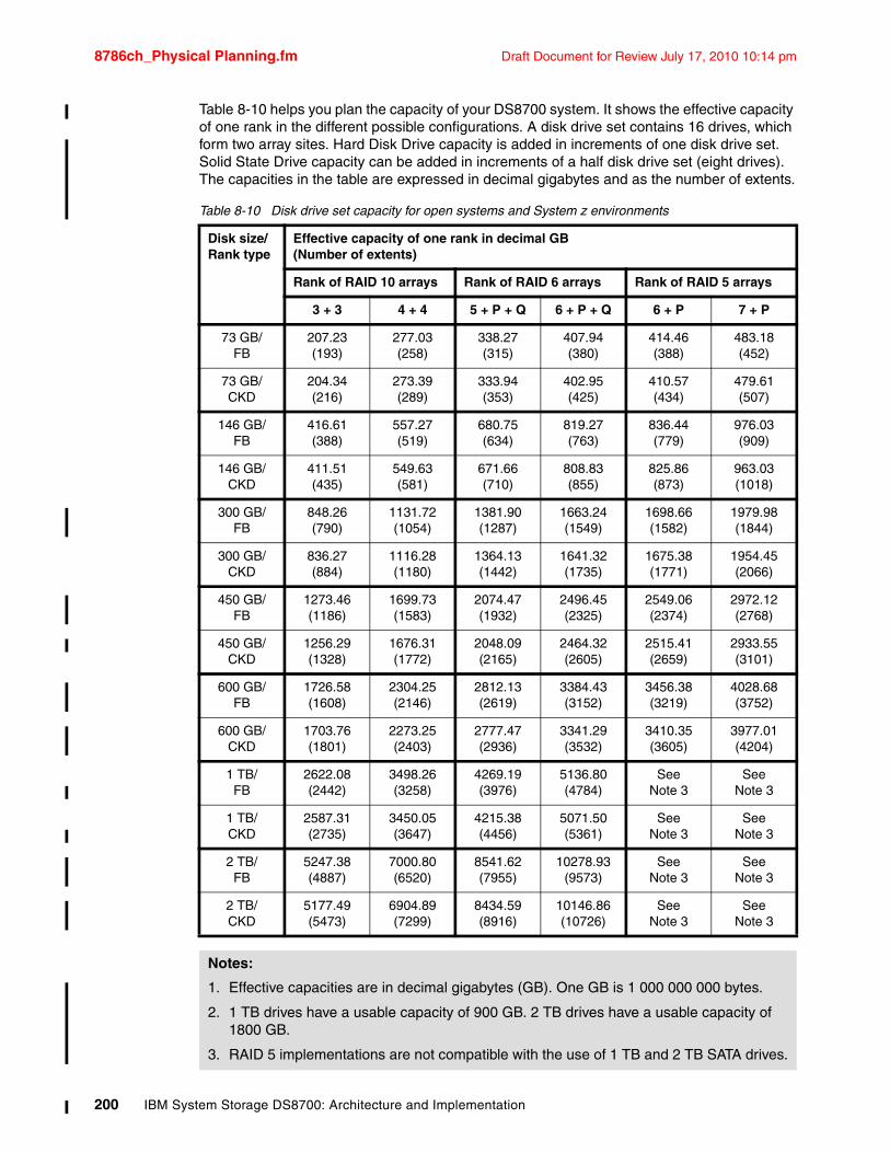
8786ch_Physical Planning.fm Draft Document for Review July 17, 2010 10:14 pm
Table 8-10 helps you plan the capacity of your DS8700 system. It shows the effective capacity of one rank in the different possible configurations. A disk drive set contains 16 drives, which form two array sites. Hard Disk Drive capacity is added in increments of one disk drive set. Solid State Drive capacity can be added in increments of a half disk drive set (eight drives). The capacities in the table are expressed in decimal gigabytes and as the number of extents.
Table 8-10 Disk drive set capacity for open systems and System z environments
Disk size/ Rank type
Effective capacity of one rank in decimal GB (Number of extents)
Rank of RAID 10 arrays Rank of RAID 6 arrays Rank of RAID 5 arrays
3 + 3 4 + 4 5 + P + Q 6 + P + Q 6 + P 7 + P
73 GB/ FB
207.23(193)
277.03(258)
338.27(315)
407.94(380)
414.46(388)
483.18(452)
73 GB/ CKD
204.34(216)
273.39(289)
333.94(353)
402.95(425)
410.57(434)
479.61(507)
146 GB/FB
416.61(388)
557.27(519)
680.75(634)
819.27(763)
836.44(779)
976.03(909)
146 GB/ CKD
411.51(435)
549.63(581)
671.66(710)
808.83(855)
825.86(873)
963.03(1018)
300 GB/FB
848.26(790)
1131.72(1054)
1381.90(1287)
1663.24(1549)
1698.66(1582)
1979.98(1844)
300 GB/ CKD
836.27(884)
1116.28(1180)
1364.13(1442)
1641.32(1735)
1675.38(1771)
1954.45(2066)
450 GB/FB
1273.46(1186)
1699.73(1583)
2074.47(1932)
2496.45(2325)
2549.06(2374)
2972.12(2768)
450 GB/ CKD
1256.29(1328)
1676.31(1772)
2048.09(2165)
2464.32(2605)
2515.41(2659)
2933.55(3101)
600 GB/FB
1726.58(1608)
2304.25(2146)
2812.13(2619)
3384.43(3152)
3456.38(3219)
4028.68(3752)
600 GB/ CKD
1703.76(1801)
2273.25(2403)
2777.47(2936)
3341.29(3532)
3410.35(3605)
3977.01(4204)
1 TB/ FB
2622.08(2442)
3498.26(3258)
4269.19(3976)
5136.80(4784)
See Note 3
See Note 3
1 TB/ CKD
2587.31(2735)
3450.05(3647)
4215.38(4456)
5071.50(5361)
See Note 3
SeeNote 3
2 TB/FB
5247.38 (4887)
7000.80 (6520)
8541.62 (7955)
10278.93 (9573)
SeeNote 3
SeeNote 3
2 TB/CKD
5177.49 (5473)
6904.89 (7299)
8434.59 (8916)
10146.86 (10726)
SeeNote 3
SeeNote 3
Notes:
1. Effective capacities are in decimal gigabytes (GB). One GB is 1 000 000 000 bytes.
2. 1 TB drives have a usable capacity of 900 GB. 2 TB drives have a usable capacity of 1800 GB.
3. RAID 5 implementations are not compatible with the use of 1 TB and 2 TB SATA drives.
200 IBM System Storage DS8700: Architecture and Implementation
Draft Document for Review July 17, 2010 10:14 pm 8786ch_Physical Planning.fm
An updated version of Capacity Magic (see “Capacity Magic” on page 586) will aid you in determining the raw and net storage capacities as well as the numbers regarding the required extents for each available type of RAID.
8.5.3 Solid State Drive (SSD) considerationsSSSD drives follow special rules for their physical installation. We summarize them below. An RPQ is needed to change these rules.
� SSD drives can be now be ordered in 8 drive install groups (half disk drive set). This provides additional capacity and price/performance options to address specific application and business requirements. Like for HDD drives, it is of course still possible to order 16 drive install groups (a disk drive set) for SSDs as well.
Note also taht an 8 drive install increment means that the SSD rank added is assigned to only one DS8700 server (CEC).
� SSD disks are installed in their preferred locations, these being the first disk enclosure pair on each Device Adapter (DA) pair. This is done so as to spread SSD disks over as many DA pairs as possible for improved performance. The preferred locations are split among eight locations in the first three frames, two in the first, four in the second, two in the third. See Figure 8-4.
� An eight drive SSD half drive set is always upgraded to a full 16 drive set when SSD capacity is added. A system can contain at most one SSD half drive set.
� A SSD feature (drive set or half drive set) is first installed in the first enclosure of a preferred enclosure pair. A second SSD feature can be installed in the same DA pair only after the system contains at least eight SSD features, that is, after each of the eight DA pairs contains at least one SSD disk drive set. This means that you can have more than 16 SSD disks in a DA pair only if the system has three or more frames. The second SSD feature in the DA pair must be a full drive set.
� A DA pair can contain at most two SSD drive sets (32 drives). With the maximum of eight DA pairs, a DS8700 system can contain up to16 SSD drive sets (256 disks, 32 arrays).
� Limiting the number of SSD drives to 16 per DA pair is preferred. The reason is to maintain adequate performance without saturating the DA. The SSDs supported in the DS8700 are so fast that the DA can become the performance bottleneck on some random workloads.
� SSD disks are available in 73 GB and 146 GB capacities. All disks on a disk enclosure pair must be of the same capacity. Feature conversions are available to exchange existing disk drive sets when purchasing new disk drive sets with higher capacity.
� SSDs can be intermixed with HDDs within the same DA pair, but not on the same disk enclosure pair.
� The DS8300 was limited to a total of 512 drives if it had both SSD and HDD drives installed, limiting the system to three frames. The DS8700 does not have this limitation.
� RPQ 8S1027 is no longer required to order SSD drives on a new DS8700 (plant order). An RPQ process is still required to order SSD feature(s) on an existing DS8700 (field upgrade). The RPQ is needed to ensure that SSDs can be placed in proper locations.
� RAID 6 and RAID 10 implementations are not supported for SSD arrays, only RAID 5. SSD drives follow normal sparing rules. The array configuration is either 6+P+S or 7+P.
Figure 8-4 shows a sample DS8700 configuration with SSD drives installed in all the eight preferred locations. The figure shows the standard locations of SSD and HDD disk drive sets.
Chapter 8. Physical planning and installation 201
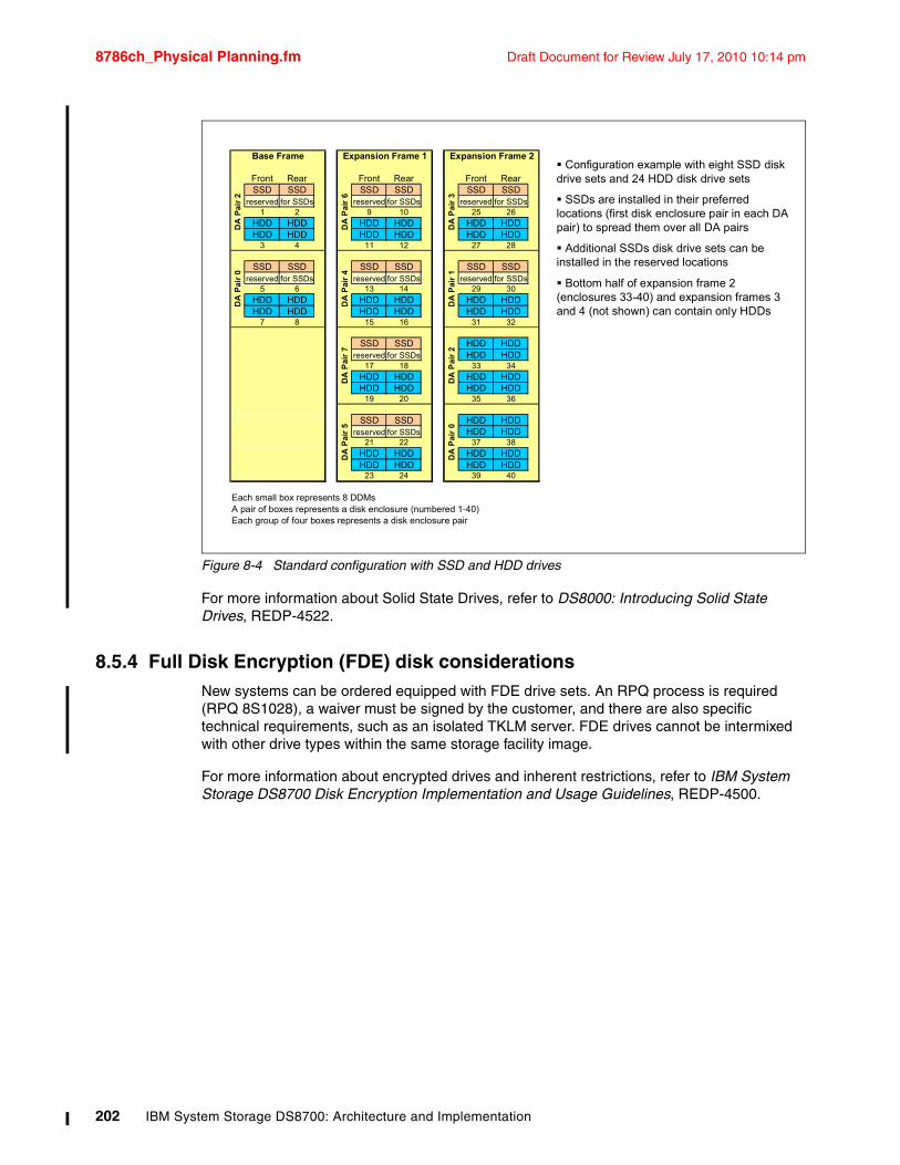
8786ch_Physical Planning.fm Draft Document for Review July 17, 2010 10:14 pm
Figure 8-4 Standard configuration with SSD and HDD drives
For more information about Solid State Drives, refer to DS8000: Introducing Solid State Drives, REDP-4522.
8.5.4 Full Disk Encryption (FDE) disk considerationsNew systems can be ordered equipped with FDE drive sets. An RPQ process is required (RPQ 8S1028), a waiver must be signed by the customer, and there are also specific technical requirements, such as an isolated TKLM server. FDE drives cannot be intermixed with other drive types within the same storage facility image.
For more information about encrypted drives and inherent restrictions, refer to IBM System Storage DS8700 Disk Encryption Implementation and Usage Guidelines, REDP-4500.
Configuration example with eight SSD disk drive sets and 24 HDD disk drive sets
SSDs are installed in their preferred locations (first disk enclosure pair in each DA pair) to spread them over all DA pairs
Additional SSDs disk drive sets can be installed in the reserved locations
Bottom half of expansion frame 2 (enclosures 33-40) and expansion frames 3 and 4 (not shown) can contain only HDDs
Front Rear Front Rear Front RearSSD SSD SSD SSD SSD SSD
reserved for SSDs reserved for SSDs reserved for SSDs1 2 9 10 25 26
HDD HDD HDD HDD HDD HDDHDD HDD HDD HDD HDD HDD
3 4 11 12 27 28
SSD SSD SSD SSD SSD SSDreserved for SSDs reserved for SSDs reserved for SSDs
5 6 13 14 29 30HDD HDD HDD HDD HDD HDDHDD HDD HDD HDD HDD HDD
7 8 15 16 31 32
SSD SSD HDD HDDreserved for SSDs HDD HDD
17 18 33 34HDD HDD HDD HDDHDD HDD HDD HDD
19 20 35 36
SSD SSD HDD HDDreserved for SSDs HDD HDD
21 22 37 38HDD HDD HDD HDDHDD HDD HDD HDD
23 24 39 40
Each small box represents 8 DDMsA pair of boxes represents a disk enclosure (numbered 1-40)Each group of four boxes represents a disk enclosure pair
DA
Pa
ir 0
Expansion Frame 1
DA
Pa
ir 6
DA
Pa
ir 4
DA
Pa
ir 7
Expansion Frame 2
DA
Pa
ir 3
DA
Pa
ir 1
DA
Pa
ir 2
DA
Pa
ir 2
DA
Pa
ir 0
Base Frame
DA
Pa
ir 5
202 IBM System Storage DS8700: Architecture and Implementation
Draft Document for Review July 17, 2010 10:14 pm 8786ch_Physical Planning.fm
8.6 Planning for growthThe DS8700 storage unit is a highly scalable storage solution. Features, such as total storage capacity, cache size, and host adapters, can be easily increased by physically adding the necessary hardware or by changing the needed licensed keys for Advanced Copy Services features (as ordered).
Planning for future growth normally suggests an increase in physical requirements, in your installation area (including floor loading), electrical power, and environmental cooling.
A key feature that you can order for your dynamic storage requirement is the Standby Capacity on Demand (CoD). This offering is designed to provide you with the ability to tap into additional storage and is particularly attractive if you have rapid or unpredictable growth, or if you simply want the knowledge that the extra storage will be there when you need it. Standby CoD allows you to access the extra storage capacity when you need it through a nondisruptive activity. For more information about Capacity on Demand, see 21.2, “Using Capacity on Demand (CoD)” on page 579.
Chapter 8. Physical planning and installation 203

8786ch_Physical Planning.fm Draft Document for Review July 17, 2010 10:14 pm
204 IBM System Storage DS8700: Architecture and Implementation
Draft Document for Review July 17, 2010 10:14 pm 8786ch_DS_HMC_Plan.fm
Chapter 9. HMC planning and setup
This chapter discusses the planning activities needed for the setup of the required DS Hardware Management Console (HMC). This chapter covers the following topics:
� Hardware Management Console (HMC) overview
� HMC software
� HMC activities
� HMC and IPv6
� HMC user management
� External HMC
9
© Copyright IBM Corp. 2010. All rights reserved. 205
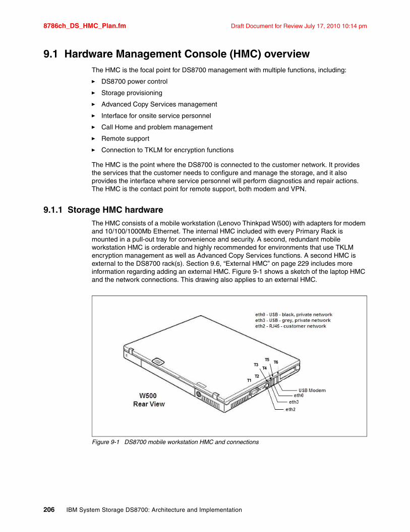
8786ch_DS_HMC_Plan.fm Draft Document for Review July 17, 2010 10:14 pm
9.1 Hardware Management Console (HMC) overviewThe HMC is the focal point for DS8700 management with multiple functions, including:
� DS8700 power control
� Storage provisioning
� Advanced Copy Services management
� Interface for onsite service personnel
� Call Home and problem management
� Remote support
� Connection to TKLM for encryption functions
The HMC is the point where the DS8700 is connected to the customer network. It provides the services that the customer needs to configure and manage the storage, and it also provides the interface where service personnel will perform diagnostics and repair actions. The HMC is the contact point for remote support, both modem and VPN.
9.1.1 Storage HMC hardwareThe HMC consists of a mobile workstation (Lenovo Thinkpad W500) with adapters for modem and 10/100/1000Mb Ethernet. The internal HMC included with every Primary Rack is mounted in a pull-out tray for convenience and security. A second, redundant mobile workstation HMC is orderable and highly recommended for environments that use TKLM encryption management as well as Advanced Copy Services functions. A second HMC is external to the DS8700 rack(s). Section 9.6, “External HMC” on page 229 includes more information regarding adding an external HMC. Figure 9-1 shows a sketch of the laptop HMC and the network connections. This drawing also applies to an external HMC.
Figure 9-1 DS8700 mobile workstation HMC and connections
T3T4
T5T6
T2T1
206 IBM System Storage DS8700: Architecture and Implementation
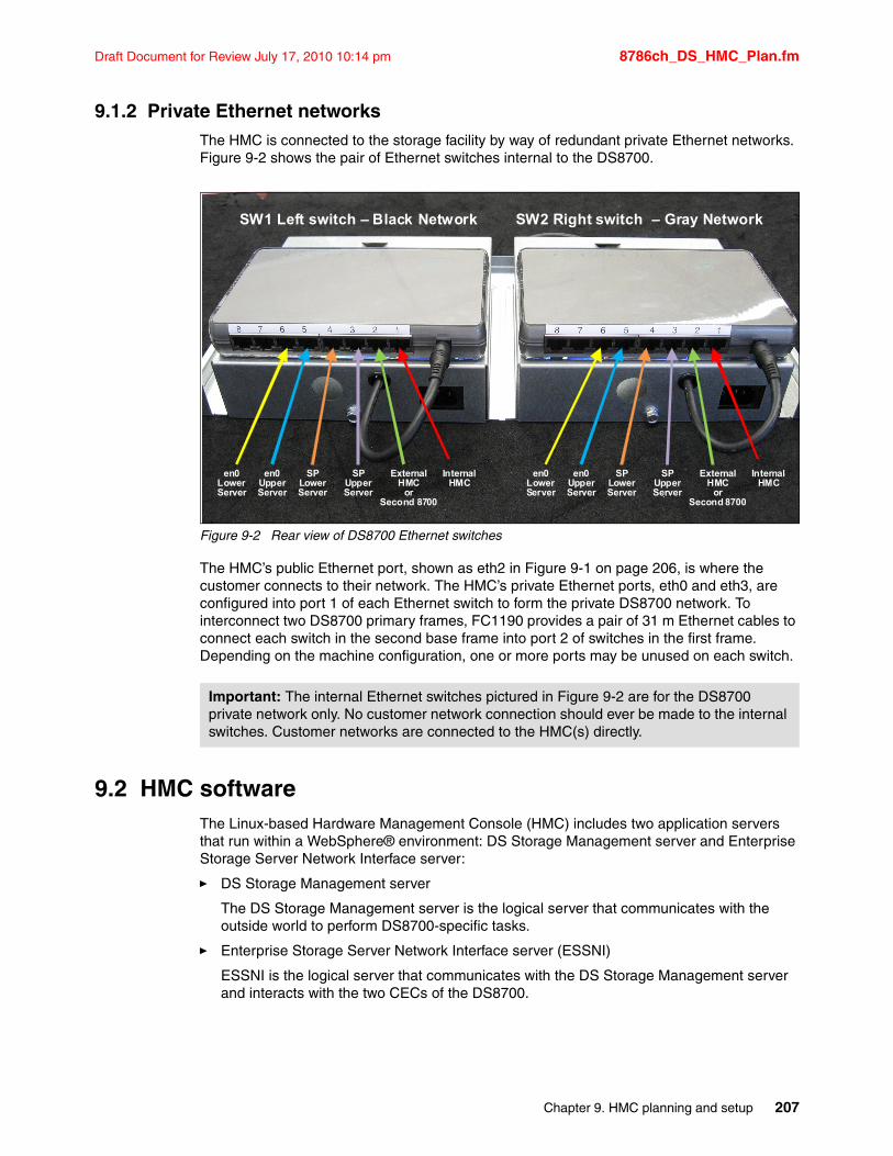
Draft Document for Review July 17, 2010 10:14 pm 8786ch_DS_HMC_Plan.fm
9.1.2 Private Ethernet networksThe HMC is connected to the storage facility by way of redundant private Ethernet networks. Figure 9-2 shows the pair of Ethernet switches internal to the DS8700.
Figure 9-2 Rear view of DS8700 Ethernet switches
The HMC’s public Ethernet port, shown as eth2 in Figure 9-1 on page 206, is where the customer connects to their network. The HMC’s private Ethernet ports, eth0 and eth3, are configured into port 1 of each Ethernet switch to form the private DS8700 network. To interconnect two DS8700 primary frames, FC1190 provides a pair of 31 m Ethernet cables to connect each switch in the second base frame into port 2 of switches in the first frame. Depending on the machine configuration, one or more ports may be unused on each switch.
9.2 HMC softwareThe Linux-based Hardware Management Console (HMC) includes two application servers that run within a WebSphere® environment: DS Storage Management server and Enterprise Storage Server Network Interface server:
� DS Storage Management server
The DS Storage Management server is the logical server that communicates with the outside world to perform DS8700-specific tasks.
� Enterprise Storage Server Network Interface server (ESSNI)
ESSNI is the logical server that communicates with the DS Storage Management server and interacts with the two CECs of the DS8700.
Important: The internal Ethernet switches pictured in Figure 9-2 are for the DS8700 private network only. No customer network connection should ever be made to the internal switches. Customer networks are connected to the HMC(s) directly.
InternalHMC
External HMC
orSecond 8700
SPUpperServer
SPLower Server
InternalHMC
External HMC
orSecond 8700
SPUpperServer
SPLower Server
SW1 Left switch – Black Network SW2 Right switch – Gray Network
en0UpperServer
en0Lower Server
en0UpperServer
en0Lower Server
Chapter 9. HMC planning and setup 207
8786ch_DS_HMC_Plan.fm Draft Document for Review July 17, 2010 10:14 pm
The DS8700 HMC provides several management interfaces. These include:
� DS Storage Manager graphical user interface (GUI)
� DS Command-Line Interface (DS CLI)
� DS Open Application Programming Interface (DS Open API)
� Web-based user interface (WebUI), specifically for use by support personnel
The GUI and the CLI are comprehensive, easy-to-use interfaces for a storage administrator to perform DS8700 management tasks to provision the storage arrays, manage application users, and change some HMC options. The two can be used interchangeably, depending on the particular task.
The DS Open API provides an interface for external storage management programs, such as Tivoli Productivity Center (TPC), to communicate with the DS8700. It channels traffic through the IBM System Storage Common Information Model (CIM) agent, a middleware application that provides a CIM-compliant interface.
Older DS8000 family products used a service interface called WebSM. The DS8700 uses a newer, faster interface called WebUI that can be used remotely over a VPN by support personnel to check the health status or to perform service tasks.
9.2.1 DS Storage Manager GUIDS Storage Manager can be accessed via the TPC Element Manager of the SSPC from any network-connected workstation with a supported browser. It can also be accessed directly from the DS8700 management console by using the browser on the HMC. Login procedures are explained in the following sections.
SSPC login to DS Storage Manager GUIThe DS Storage Manager graphical user interface (GUI) can be launched via the TPC Element Manager of the SSPC from any supported network-connected workstation.
To access the DS Storage Manager GUI through the SSPC, open a new browser window or tab and type the following address:
http://<SSPC ipaddress>:9550/ITSRM/app/welcome.html
A more thorough description of setting up and logging into SSPC can be found in 12.2.1, “Configuring SSPC for DS8700 remote GUI access” on page 265.
Console login to DS Storage Manager GUIThe following procedure can be used to log in to the management console and access the DS Storage Manager GUI using the browser that is preinstalled on the HMC:
1. Open and turn on the management console. The Hardware Management Console login window displays.
2. Move the mouse pointer to an empty area of the desktop background. Right-click with the mouse to open a Fluxbox, as shown in Figure 9-3 on page 209. Select Net HMC Browser.
208 IBM System Storage DS8700: Architecture and Implementation
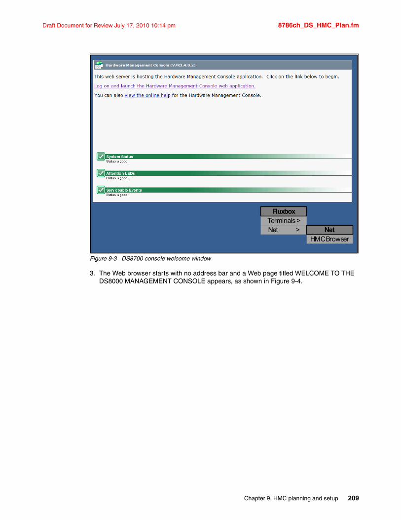
Draft Document for Review July 17, 2010 10:14 pm 8786ch_DS_HMC_Plan.fm
Figure 9-3 DS8700 console welcome window
3. The Web browser starts with no address bar and a Web page titled WELCOME TO THE DS8000 MANAGEMENT CONSOLE appears, as shown in Figure 9-4.
HMC Browser
Terminals >Net >
Fluxbox
Net
Chapter 9. HMC planning and setup 209
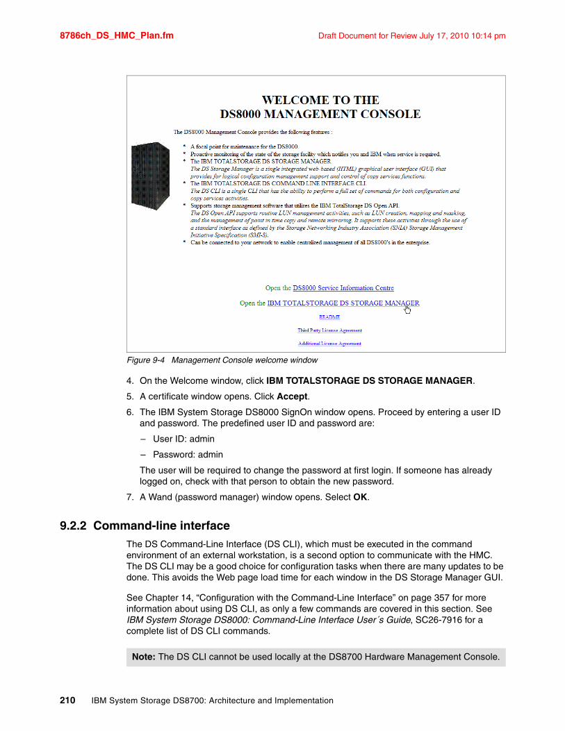
8786ch_DS_HMC_Plan.fm Draft Document for Review July 17, 2010 10:14 pm
Figure 9-4 Management Console welcome window
4. On the Welcome window, click IBM TOTALSTORAGE DS STORAGE MANAGER.
5. A certificate window opens. Click Accept.
6. The IBM System Storage DS8000 SignOn window opens. Proceed by entering a user ID and password. The predefined user ID and password are:
– User ID: admin
– Password: admin
The user will be required to change the password at first login. If someone has already logged on, check with that person to obtain the new password.
7. A Wand (password manager) window opens. Select OK.
9.2.2 Command-line interfaceThe DS Command-Line Interface (DS CLI), which must be executed in the command environment of an external workstation, is a second option to communicate with the HMC. The DS CLI may be a good choice for configuration tasks when there are many updates to be done. This avoids the Web page load time for each window in the DS Storage Manager GUI.
See Chapter 14, “Configuration with the Command-Line Interface” on page 357 for more information about using DS CLI, as only a few commands are covered in this section. See IBM System Storage DS8000: Command-Line Interface User´s Guide, SC26-7916 for a complete list of DS CLI commands.
Note: The DS CLI cannot be used locally at the DS8700 Hardware Management Console.
210 IBM System Storage DS8700: Architecture and Implementation
Draft Document for Review July 17, 2010 10:14 pm 8786ch_DS_HMC_Plan.fm
Once the DS CLI has been installed on a workstation, it can be used by just typing dscli in a command prompt window. The DS CLI provides three command modes:
� Interactive command mode
� Script command mode
� Single-shot command mode
Interactive modeTo enter the interactive mode of the DS CLI, just type dscli in a command prompt window and follow the prompts to log in, as shown in Example 9-1. Once logged on, DS CLI commands can be entered one at a time.
Example 9-1 DS CLI interactive mode
C:\Program Files\IBM\dscli>dscliEnter the primary management console IP address: 10.0.0.1Enter the secondary management console IP address: 10.0.0.1Enter your username: StevenJEnter your password:Date/Time: October 12, 2009 9:47:13 AM MST IBM DSCLI Version: 5.4.30.253 DS:IBM.2107-7502241dscli> lssiDate/Time: October 12, 2009 9:47:23 AM MST IBM DSCLI Version: 5.4.30.253 DS: -Name ID Storage Unit Model WWNN State ESSNet============================================================================- IBM.2107-7502241 IBM.2107-7502240 941 5005076303FFC076 Online Enableddscli> exit
The information required to connect to a DS8700 by DS CLI can be predefined as a profile. Example 9-2 shows editing the lines for “hmc1” and “devid” in a profile file using HMC IP Address 9.155.62.102 and for the SFI of serial number 7520280. For the DS8700, there is only one SFI, so it will be the DS8700 serial number with a ‘1’ at the end instead of a ‘0’. The file dscli.profile is the default profile used if a profile is not specified on the command line.
Example 9-2 Modifying dscli.profile
# hmc1 and hmc2 are equivalent to -hmc1 and -hmc2 command options.hmc1:9.155.62.102# Default target Storage Image IDdevid:IBM.2107-7520281
To prepare a custom DS CLI profile, the file dscli.profile can be copied and then modified, as shown above in Example 9-2. On a Windows workstation, save the file in the directory C:\Program Files\IBM\dscli with the name lab8700.profile. The -cfg flag is used at the dscli prompt to call this profile. Example 9-3 shows how to connect DS CLI to the DS8700 HMC using this custom profile.
Example 9-3 DS CLI command to use a saved profile
C:\Program Files\IBM\dscli>dscli -cfg lab8700.profileDate/Time: October 12, 2009 2:47:26 PM CEST IBM DSCLI Version: 5.4.30.253 DS:IBM.2107-75ABTV1
Tip: Commands in the DS CLI are not case sensitive. lssi is the same as Lssi. However, user names for logging in to the DS8700 are case sensitive.
Chapter 9. HMC planning and setup 211
8786ch_DS_HMC_Plan.fm Draft Document for Review July 17, 2010 10:14 pm
dscli>
Script modeIf you know already exactly what commands you want to issue on the DS8700, multiple DS CLI commands can be integrated into a script that can be executed by launching dscli with the -script parameter. To call a script with DS CLI commands, use the following syntax in a command prompt window of a Windows workstation:
dscli -script <script_filename> -hmc1 <ip-address> -user <userid> -passwd <password>
In Example 9-4, the script file lssi.cli contains just one CLI command, that is, the lssi command.
Example 9-4 CLI script mode
C:\Program Files\IBM\dscli>dscli -script c:\DS8700\lssi.cli -hmc1 10.0.0.1 -user StevenJ -passwd temp4nowDate/Time: October 12, 2009 9:33:25 AM MST IBM DSCLI Version: 5.4.30.253IBM.2107-75ABTV1Name ID Storage Unit Model WWNN State ESSNet============================================================================- IBM.2107-75ABTV1 IBM.2107-75ABTV0 941 5005076303FFC663 Online Enabled
Single-shot modeA single-shot is a single command that is executed upon successful login to the DS8700 HMC. Example 9-5 shows how to run a single-shot command from a workstation prompt.
Example 9-5 CLI single-shot mode
C:\Program Files\IBM\dscli>dscli -cfg 75abtv1.profile lssiDate/Time: October 12, 2009 3:31:02 PM MST IBM DSCLI Version: 5.4.30.253 DS: -Name ID Storage Unit Model WWNN State ESSNet==================================================================================- IBM.2107-75ABTV1 IBM.2107-75ABTV0 941 5005076303FFC663 Online EnabledC:\ProgramFiles\ibm\dscli>
9.2.3 DS Open Application Programming InterfaceCalling DS Open Application Programming Interfaces (DS Open APIs) from within a program is a third option to implement communication with the HMC. Both DS CLI and DS Open API communicate directly with the ESSNI server software running on the HMC.
The Common Information Model (CIM) Agent for the DS8700 is Storage Management Initiative Specification (SMI-S) 1.1 compliant. This agent is used by storage management applications, such as Tivoli Productivity Center (TPC), Tivoli Storage Manager, and VSS/VDS. Also, in order to comply to more open standards, the agent can be accessed by software from third-party vendors, including VERITAS/Symantec, HP/AppIQ, EMC, and many other applications at the SNIA Interoperability Lab. For more information, visit the following address:
http://www.snia.org/forums/smi/tech_programs/lab_program/
Note: A script contains commands to run against a DS8700. A profile contains instructions on which HMC to connect to and what settings to use.
212 IBM System Storage DS8700: Architecture and Implementation
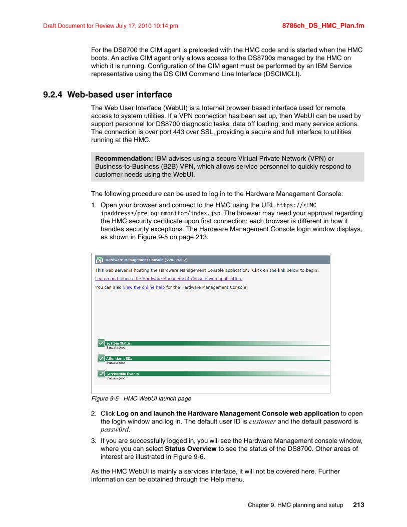
Draft Document for Review July 17, 2010 10:14 pm 8786ch_DS_HMC_Plan.fm
For the DS8700 the CIM agent is preloaded with the HMC code and is started when the HMC boots. An active CIM agent only allows access to the DS8700s managed by the HMC on which it is running. Configuration of the CIM agent must be performed by an IBM Service representative using the DS CIM Command Line Interface (DSCIMCLI).
9.2.4 Web-based user interfaceThe Web User Interface (WebUI) is a Internet browser based interface used for remote access to system utilities. If a VPN connection has been set up, then WebUI can be used by support personnel for DS8700 diagnostic tasks, data off loading, and many service actions. The connection is over port 443 over SSL, providing a secure and full interface to utilities running at the HMC.
The following procedure can be used to log in to the Hardware Management Console:
1. Open your browser and connect to the HMC using the URL https://<HMC ipaddress>/preloginmonitor/index.jsp. The browser may need your approval regarding the HMC security certificate upon first connection; each browser is different in how it handles security exceptions. The Hardware Management Console login window displays, as shown in Figure 9-5 on page 213.
Figure 9-5 HMC WebUI launch page
2. Click Log on and launch the Hardware Management Console web application to open the login window and log in. The default user ID is customer and the default password is passw0rd.
3. If you are successfully logged in, you will see the Hardware Management console window, where you can select Status Overview to see the status of the DS8700. Other areas of interest are illustrated in Figure 9-6.
As the HMC WebUI is mainly a services interface, it will not be covered here. Further information can be obtained through the Help menu.
Recommendation: IBM advises using a secure Virtual Private Network (VPN) or Business-to-Business (B2B) VPN, which allows service personnel to quickly respond to customer needs using the WebUI.
Chapter 9. HMC planning and setup 213
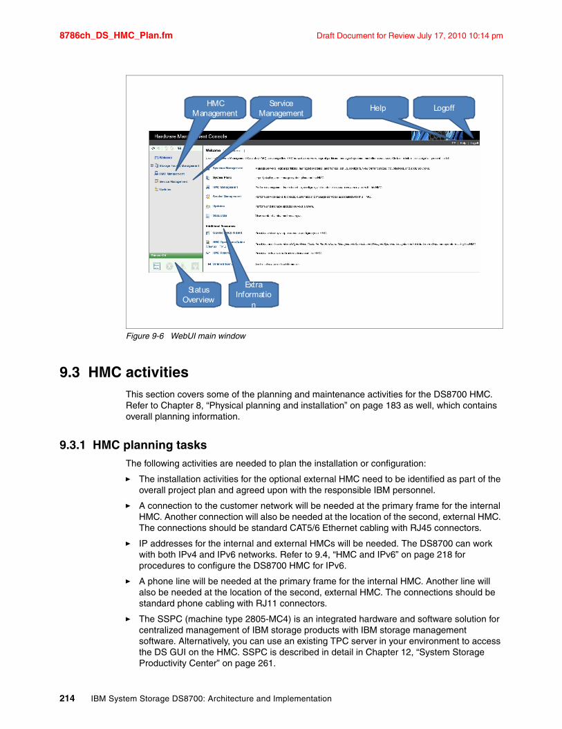
8786ch_DS_HMC_Plan.fm Draft Document for Review July 17, 2010 10:14 pm
Figure 9-6 WebUI main window
9.3 HMC activitiesThis section covers some of the planning and maintenance activities for the DS8700 HMC. Refer to Chapter 8, “Physical planning and installation” on page 183 as well, which contains overall planning information.
9.3.1 HMC planning tasksThe following activities are needed to plan the installation or configuration:
� The installation activities for the optional external HMC need to be identified as part of the overall project plan and agreed upon with the responsible IBM personnel.
� A connection to the customer network will be needed at the primary frame for the internal HMC. Another connection will also be needed at the location of the second, external HMC. The connections should be standard CAT5/6 Ethernet cabling with RJ45 connectors.
� IP addresses for the internal and external HMCs will be needed. The DS8700 can work with both IPv4 and IPv6 networks. Refer to 9.4, “HMC and IPv6” on page 218 for procedures to configure the DS8700 HMC for IPv6.
� A phone line will be needed at the primary frame for the internal HMC. Another line will also be needed at the location of the second, external HMC. The connections should be standard phone cabling with RJ11 connectors.
� The SSPC (machine type 2805-MC4) is an integrated hardware and software solution for centralized management of IBM storage products with IBM storage management software. Alternatively, you can use an existing TPC server in your environment to access the DS GUI on the HMC. SSPC is described in detail in Chapter 12, “System Storage Productivity Center” on page 261.
HMCManagement
ExtraInformatio
n
StatusOverview
ServiceManagement
Help Logoff
214 IBM System Storage DS8700: Architecture and Implementation
Draft Document for Review July 17, 2010 10:14 pm 8786ch_DS_HMC_Plan.fm
� The Web browser to be used on any administration workstation should be a supported one, as mentioned in DS8000 Introduction and Planning Guide, GC35-0515 or in the Information Center for the DS8700, which can be found at teh following address:
http://publib.boulder.ibm.com/infocenter/dsichelp/ds8000ic/index.jsp
A decision should be made as to which Web browser should be used. The Web browser is the only software that is needed on workstations that will do configuration tasks online using the DS Storage Manager GUI (through the SSPC).
� The IP addresses of SNMP recipients need to be identified if the customer wants the DS8700 HMC to send SNMP traps to a network station.
� E-mail accounts need to be identified if the customer wants the DS8700 HMC to send e-mail messages for problem conditions.
� The IP addresses of NTP servers need to be identified if the customer wants the DS8700 HMC to utilize Network Time Protocol for time synchronization.
� When ordering a DS8700, the license and some optional features need activation as part of the customization of the DS8700. Refer to Chapter 10, “DS8700 features and license keys” on page 233 for details.
Note: Applying increased feature activation codes is a concurrent action, but a license reduction or deactivation is a disruptive action.
Chapter 9. HMC planning and setup 215
8786ch_DS_HMC_Plan.fm Draft Document for Review July 17, 2010 10:14 pm
9.3.2 Planning for microcode upgradesThe following activities need to be considered in regard to the microcode upgrades on the DS8700:
� Microcode changes
IBM might release changes to the DS8700 series Licensed Machine Code. IBM plans to make most DS8700 series Licensed Machine Code changes available for download by the HMC from the IBM System Storage technical support Web site. Note that not all Licensed Machine Code changes might be available through the support Web site.
� Microcode install
An IBM service representative can install the changes that IBM does not make available for you to download. If the machine does not function as warranted and your problem can be resolved through your application of downloadable Licensed Machine Code, you are responsible for downloading and installing these designated Licensed Machine Code changes as IBM specifies. Check whether the new microcode requires new levels of DS Storage Manager, DS CLI and DS Open API and plan on upgrading them on the relevant workstations if necessary.
� Host prerequisites
When planning for initial installation or for microcode updates, make sure that all prerequisites for the hosts are identified correctly. Sometimes a new level is required for the SDD as well. The Interoperability Matrix should be the primary source to identify supported operating systems, HBAs, and hardware of hosts. View this online at:
http://www-03.ibm.com/systems/storage/product/interop.html
To prepare for the download of drivers, refer to the HBA Support Matrix referenced in the Interoperability Matrix and make sure that drivers are downloaded from the IBM Internet site. This is to make sure that drivers are used with the settings corresponding to the DS8700, not some other IBM storage subsystem.
DS8700 interoperability information can also be found at the IBM System Storage Interoperability Center (SSIC) at the following Web site:
http://www.ibm.com/systems/support/storage/config/ssic
� Maintenance windows
Even though the microcode update of the DS8700 is a nondisruptive action, any prerequisites identified for the hosts (for example, patches, new maintenance levels, or new drivers) could make it necessary to schedule a maintenance window. The host environments can then be upgraded to the level needed in parallel to the microcode update of the DS8700 taking place.
For more information about microcode upgrades, see Chapter 18, “Licensed machine code” on page 537.
Important: The Interoperability Center reflects information regarding the latest supported code levels. This does not necessarily mean that former levels of HBA firmware or drivers are no longer supported. If in doubt about any supported levels, contact your IBM representative.
216 IBM System Storage DS8700: Architecture and Implementation
Draft Document for Review July 17, 2010 10:14 pm 8786ch_DS_HMC_Plan.fm
9.3.3 Time synchronizationFor proper error analysis, it is important to have the date and time information synchronized as much as possible on all components in the DS8700 environment. This includes the DS8700 HMC(s), the SSPC, and the DS Storage Manager and DS CLI workstations.
With the DS8700, the HMC has the ability to utilize the Network Time Protocol (NTP) service. Customers can specify NTP servers on their internal network to provide the time to the HMC. It is a customer responsibility to ensure that the NTP servers are working, stable, and accurate. An IBM service representative will enable the HMC to use NTP servers. Ideally, this should be done at the time of initial DS8700 installation.
9.3.4 Monitoring with the HMCA customer can receive notifications from the HMC through SNMP traps and e-mail messages. Notifications contain information about your storage complex, such as open serviceable events. You can choose one or both notification methods:
� Simple Network Management Protocol (SNMP) traps
For monitoring purposes, the DS8700 uses SNMP traps. An SNMP trap can be sent to a server in the client’s environment, perhaps with System Management Software, which handles the trap based on the MIB delivered with the DS8700 software. A MIB containing all traps can be used for integration purposes into System Management Software. The supported traps are described in more detail in the documentation that comes with the microcode on the CDs provided by the IBM service representative. The IP address to which the traps should be sent needs to be configured during initial installation of the DS8700. For more information about the DS8700 and SNMP, see Chapter 19, “Monitoring with Simple Network Management Protocol (SNMP)” on page 543.
When you choose to enable e-mail notifications, e-mail messages are sent to all the addresses that are defined on the HMC whenever the storage complex encounters a serviceable event or must alert you to other information.
During the planning process, a list of who needs to be notified needs should be created.
SIM notification is only applicable for System z servers. It allows you to receive a notification on the system console in case of a serviceable event. SNMP and e-mail are the only notification options for the DS8700.
9.3.5 Call Home and remote supportThe HMC uses both outbound (Call Home) and inbound (remote service) support.
Call Home is the capability of the HMC to contact IBM support to report a serviceable event. Remote Services is the capability of IBM service representatives to connect to the HMC to perform service tasks remotely. If allowed to do so by the setup of the client’s environment, an IBM service support representative could connect to the HMC to perform detailed problem analysis. The IBM service support representative can view error logs and problem logs, and initiate trace or dump retrievals.
Note: Because of the many components and operating systems within the DS8700, time and date setting is a maintenance activity that can only be done by the IBM service representative.
Chapter 9. HMC planning and setup 217
8786ch_DS_HMC_Plan.fm Draft Document for Review July 17, 2010 10:14 pm
Remote support can be configured for dial-up connection through a modem or high-speed virtual private network (VPN) Internet connection. Setup of the remote support environment is done by the IBM service representative during initial installation. For more complete information, see Chapter 20, “Remote support” on page 557.
9.4 HMC and IPv6The DS8700 Hardware Management Console (HMC) can be configured for an IPv6 customer network. Note that IPv4 is still also supported.
IPv6 overviewInternet Protocol version 6 (IPv6) is the designated successor of IPv4, the current version of the Internet Protocol, for general use on the Internet.
The IPv6 standard was adopted to overcome the shortcomings of IPv4 in terms of the number of unique addresses it can provide. The primary change from IPv4 to IPv6 is the length of network addresses. IPv6 addresses are 128 bits long, while IPv4 addresses are 32 bits.
An IPv6 address can have two formats:
� Normal: Pure IPv6 format
An IPv6 (Normal) address has the following format: y : y : y : y : y : y : y : y where y is called a segment and can be any hexadecimal value between 0 and FFFF. The segments are separated by colons, not with periods as they are in IPV4.
An IPv6 normal address must have eight segments; however, a short form notation can be used for segments that are zero, or those that have leading zeros.
Examples of valid IPv6 (Normal) addresses:
– FF01: db8: 3333 : 4444 : 5555 : 6666 : 7777 : 8888
– FF01: db8: : (Implies that the last six segments are zero.)
– : : 1234 : 5678 (Implies that the first six segments are zero.)
– FF01 : db8: : 1234 : 5678 (Implies that the middle four segments are zero.)
� Dual: IPv6 plus IPv4 formats
An IPv6 (Dual) address combines an IPv6 and an IPv4 address and has the following format: y : y : y : y : y : y : x . x . x . x. The IPv6 portion of the address (indicated with Ys) is always at the beginning, followed by the IPv4 portion (indicated with Xs).
The IPv6 portion of the address must have six segments, but there is a short form notation for segments that are zero, as in the normal IPv6 address.
In the IPv4 portion of the address, x is called an octet and must be a decimal value between 0 and 255. The octets are separated by periods. The IPv4 portion of the address must contain three periods and four octets.
Examples of valid IPv6 (Dual) addresses:
– FF01 : db8: 3333 : 4444 : 5555 : 6666 : 1 . 2 . 3 . 4
– : : 11 . 22 . 33 . 44 (Implies all six IPv6 segments are zero.)
– FF01 : db8: : 123 . 123 . 123 . 123 (Implies that the last four IPv6 segments are zero.)
– : : 1234 : 5678 : 91 . 123 . 4 . 56 (Implies that the first four IPv6 segments are zero.)
– : : 1234 : 5678 : 1 . 2 . 3 . 4 (Implies that the first four IPv6 segments are zero.)
218 IBM System Storage DS8700: Architecture and Implementation
Draft Document for Review July 17, 2010 10:14 pm 8786ch_DS_HMC_Plan.fm
– FF01 : db8: : 1234 : 5678 : 5 . 6 . 7 . 8 (Implies that the middle two IPv6 segments are zero.)
Subnet masks (IPv4) and prefix lengths (IPv6)All IP addresses are divided into portions. One part identifies the network (the network number) and the other part identifies the specific machine or host within the network (the host number). Subnet masks (IPv4) and prefixes (IPv6) identify the range of IP addresses that make up a subnet, or group of IP addresses on the same network. For example, a subnet can be used to identify all the machines in a building, department, geographic location, or on the same local area network (LAN).
� In IPv4, the subnet mask 255.255.255.0 is 24 bits and consists of four 8-bit octets. The address 10.10.10.0 subnet mask 255.255.255.0 means that the subnet is a range of IP addresses from 10.10.10.0 - 10.10.10.255.
� The prefix-length in IPv6 is the equivalent of the subnet mask in IPv4. However, rather than being expressed in 4 octets like it is in IPv4, it is expressed as an integer between 1-128. For example, FF01:db8:abcd:0012::0/64 specifies a subnet with a range of IP addresses from FF01:db8:abcd:0012:0000:0000:0000:0000 - FF01:db8:abcd:0012:ffff:ffff:ffff:ffff. The emphasized portion is called the network portion of the IP address, or the prefix. The non-emphasized portion is called the host portion of the IP address, since it identifies an individual host in the network.
Configuring the HMC in an IPv6 environmentUsually, the configuration will be done by the IBM service representative during the DS8700 initial installation. See 8.3.2, “System Storage Productivity Center and network access” on page 193 for a thorough discussion about the formatting of IPv6 addresses and subnet masks. In the remainder of this section, we illustrate the steps required to configure the DS8700 HMC eth2 port for IPv6:
1. Launch and log in to WebUI; refer to 9.2.4, “Web-based user interface” on page 213 for the procedure.
Chapter 9. HMC planning and setup 219
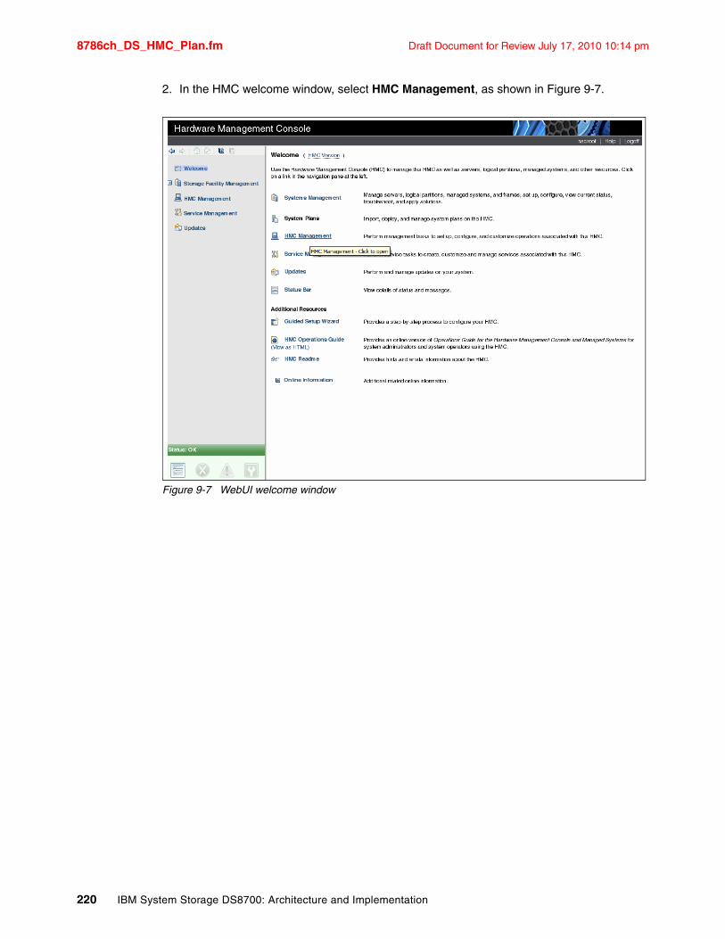
8786ch_DS_HMC_Plan.fm Draft Document for Review July 17, 2010 10:14 pm
2. In the HMC welcome window, select HMC Management, as shown in Figure 9-7.
Figure 9-7 WebUI welcome window
220 IBM System Storage DS8700: Architecture and Implementation
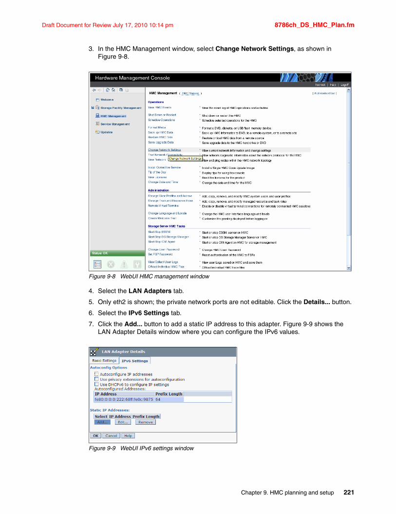
Draft Document for Review July 17, 2010 10:14 pm 8786ch_DS_HMC_Plan.fm
3. In the HMC Management window, select Change Network Settings, as shown in Figure 9-8.
Figure 9-8 WebUI HMC management window
4. Select the LAN Adapters tab.
5. Only eth2 is shown; the private network ports are not editable. Click the Details... button.
6. Select the IPv6 Settings tab.
7. Click the Add... button to add a static IP address to this adapter. Figure 9-9 shows the LAN Adapter Details window where you can configure the IPv6 values.
Figure 9-9 WebUI IPv6 settings window
Chapter 9. HMC planning and setup 221
8786ch_DS_HMC_Plan.fm Draft Document for Review July 17, 2010 10:14 pm
9.5 HMC user managementUser management can be done using the DS CLI or the DS GUI. An administrator user ID is preconfigured during the installation of the DS8700, using the following defaults:
User ID admin
Password admin
The password of the admin user ID will need to be changed before it can be used. The GUI will force you to change the password when you first log in. The DS CLI will allow you to log in but will not allow you to issue any other commands until you have changed the password. As an example, to change the admin user’s password to passw0rd, use the following DS CLI command:
chuser-pw passw0rd admin
Once you have issued that command, you can then issue other commands.
User rolesDuring the planning phase of the project, a worksheet or a script file was established with a list of all people who need access to the DS GUI or DS CLI. Note that a user can be assigned to more than one group. At least one person should be assigned to each of the following roles (user_id):
� The Administrator (admin) has access to all HMC service methods and all storage image resources, except for encryption functionality. This user authorizes the actions of the Security Administrator during the encryption deadlock prevention and resolution process.
� The Security Administrator (secadmin) has access to all encryption functions. secadmin requires an Administrator user to confirm the actions taken during the encryption deadlock prevention and resolution process.
� The Physical operator (op_storage) has access to physical configuration service methods and resources, such as managing storage complex, storage image, Rank, array, and extent pool objects.
� The Logical operator (op_volume) has access to all service methods and resources that relate to logical volumes, hosts, host ports, logical subsystems, and Volume Groups, excluding security methods.
� The Monitor group has access to all read-only, nonsecurity HMC service methods, such as list and show commands.
� The Service group has access to all HMC service methods and resources, such as performing code loads and retrieving problem logs, plus the privileges of the Monitor group, excluding security methods.
� The Copy Services operator has access to all Copy Services methods and resources, plus the privileges of the Monitor group, excluding security methods.
� No access prevents access to any service method or storage image resources. This group is used by an administrator to temporarily deactivate a user ID. By default, this user group is assigned to any user account in the security repository that is not associated with any other user group.
Note: The DS8700 supports the capability to use a Single Point of Authentication function for the GUI and CLI through a centralized LDAP server. This capability requires a TPC Version 4.1 server. For detailed information about LDAP based authentication, refer to IBM System Storage DS8000: LDAP Authentication, REDP-4505.
222 IBM System Storage DS8700: Architecture and Implementation
Draft Document for Review July 17, 2010 10:14 pm 8786ch_DS_HMC_Plan.fm
Password policiesWhenever a user is added, a password is entered by the administrator. During the first login, this password must be changed. Password settings include the time period in days after which passwords expire and a number that identifies how many failed logins are allowed. The user ID is deactivated if an invalid password is entered more times than the limit. Only a user with administrator rights can then reset the user ID with a new initial password.
If access is denied for the administrator due to the number of invalid login attempts, a procedure can be obtained from your IBM representative to reset the administrator’s password. The password for each user account is forced to adhere to the following rules:
� The length of the password must be between 6 and 16 characters.
� It must begin and end with a letter.
� It must have at least five letters.
� It must contain at least one number.
� It cannot be identical to the user ID.
� It cannot be a previous password.
9.5.1 User management using the DS CLIThe exact syntax for any DS CLI command can be found in the IBM System Storage DS8000: Command-Line Interface User´s Guide, SC26-7916. You can also use the DS CLI help command to get further assistance.
The commands to manage user IDs using the DS CLI are:
� mkuser
This command creates a user account that can be used with both DS CLI and the DS GUI. In Example 9-6, we create a user called RolandW, who is in the op_storage group. His temporary password is tempw0rd. He will have to use the chpass command when he logs in for the first time.
Example 9-6 Using the mkuser command to create a new user
dscli> mkuser -pw tempw0rd -group op_storage RolandWDate/Time: October 12, 2009 9:47:13 AM MST IBM DSCLI Version: 5.4.30.253CMUC00133I mkuser: User RolandW successfully created.
Best practice: Do not set the values of chpass to 0, as this indicates that passwords never expire and unlimited login attempts are allowed.
Note: User names and passwords are case sensitive. If you create a user name called Anthony, you cannot log in using the user name anthony.
Chapter 9. HMC planning and setup 223
8786ch_DS_HMC_Plan.fm Draft Document for Review July 17, 2010 10:14 pm
� rmuser
This command removes an existing user ID. In Example 9-7, we remove a user called JaneSmith.
Example 9-7 Removing a user
dscli> rmuser JaneSmithDate/Time: October 12, 2009 9:47:13 AM MST IBM DSCLI Version: 5.4.30.253CMUC00135W rmuser: Are you sure you want to delete user JaneSmith? [y/n]:yCMUC00136I rmuser: User JaneSmith successfully deleted.
� chuser
This command changes the password or group (or both) of an existing user ID. It is also used to unlock a user ID that has been locked by exceeding the allowable login retry count. The administrator could also use this command to lock a user ID. In Example 9-8, we unlock the user, change the password, and change the group membership for a user called JensW. He must use the chpass command when he logs in the next time.
Example 9-8 Changing a user with chuser
dscli> chuser -unlock -pw passw0rd -group monitor JensWDate/Time: October 12, 2009 9:47:13 AM MST IBM DSCLI Version: 5.4.30.253CMUC00134I chuser: User JensW successfully modified.
� lsuser
With this command, a list of all user IDs can be generated. In Example 9-9, we can see three users and the admin account.
Example 9-9 Using the lsuser command to list users
dscli> lsuserDate/Time: October 12, 2009 9:47:13 AM MST IBM DSCLI Version: 5.4.30.253Name Group State==========================StevenJ op_storage activeadmin admin activeJensW op_volume activeRolandW monitor active
� showuser
The account details of a user ID can be displayed with this command. In Example 9-10, we list the details of the user Robert.
Example 9-10 Using the showuser command to list user information
dscli> showuser RobertDate/Time: October 12, 2009 9:47:13 AM MST IBM DSCLI Version: 5.4.30.253Name RobertGroup op_volumeState activeFailedLogin 0
224 IBM System Storage DS8700: Architecture and Implementation
Draft Document for Review July 17, 2010 10:14 pm 8786ch_DS_HMC_Plan.fm
� managepwfile
This command creates or adds to an encrypted password file that will be placed onto the local machine. This file can be referred to in a DS CLI profile. This allows you to run scripts without specifying a DS CLI user password in clear text. If manually starting DS CLI, you can also refer to a password file with the -pwfile parameter. By default, the file is located in the following locations:
Windows C:\Documents and Settings\<User>\DSCLI\security.dat
Non-Windows $HOME/dscli/security.dat
In Example 9-11, we manage our password file by adding the user ID SJoseph. The password is now saved in an encrypted file called security.dat.
Example 9-11 Using the managepwfile command
dscli> managepwfile -action add -name SJoseph -pw passw0rdDate/Time: October 12, 2009 9:47:13 AM MST IBM DSCLI Version: 5.4.30.253CMUC00206I managepwfile: Record 10.0.0.1/SJoseph successfully added to password file C:\Documents and Settings\StevenJ\DSCLI\security.dat.
� chpass
This command lets you change two password policies: password expiration (days) and failed logins allowed. In Example 9-12, we change the expiration to 365 days and five failed login attempts.
Example 9-12 Changing rules using the chpass command
dscli> chpass -expire 365 -fail 5Date/Time: October 12, 2009 9:47:13 AM MST IBM DSCLI Version: 5.4.30.253CMUC00195I chpass: Security properties successfully set.
� showpass
This command lists the properties for passwords (Password Expiration days and Failed Logins Allowed). In Example 9-13, we can see that passwords have been set to expire in 90 days and that four login attempts are allowed before a user ID is locked.
Example 9-13 Using the showpass command
dscli> showpassDate/Time: October 12, 2009 9:47:13 AM MST IBM DSCLI Version: 5.4.30.253Password Expiration 90 daysFailed Logins Allowed 4
9.5.2 User management using the DS GUITo work with user administration, sign on to the DS GUI. See 12.2.1, “Configuring SSPC for DS8700 remote GUI access” on page 265 for procedures about using the SSPC to launch the DS Storage Manager GUI. From the categories in the left sidebar, select User Administration under the section Monitor System, as shown in Figure 9-10 on page 226.
Chapter 9. HMC planning and setup 225
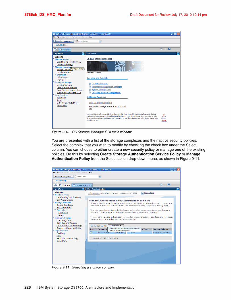
8786ch_DS_HMC_Plan.fm Draft Document for Review July 17, 2010 10:14 pm
Figure 9-10 DS Storage Manager GUI main window
You are presented with a list of the storage complexes and their active security policies. Select the complex that you wish to modify by checking the check box under the Select column. You can choose to either create a new security policy or manage one of the existing policies. Do this by selecting Create Storage Authentication Service Policy or Manage Authentication Policy from the Select action drop-down menu, as shown in Figure 9-11.
Figure 9-11 Selecting a storage complex
226 IBM System Storage DS8700: Architecture and Implementation
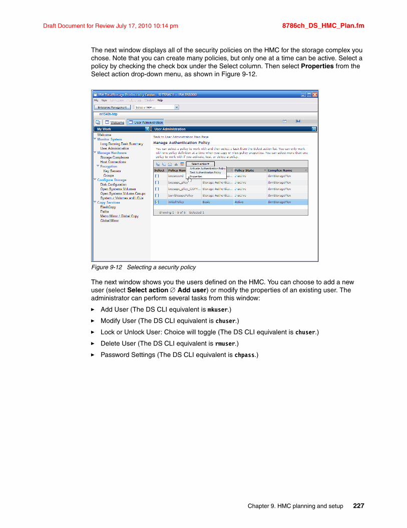
Draft Document for Review July 17, 2010 10:14 pm 8786ch_DS_HMC_Plan.fm
The next window displays all of the security policies on the HMC for the storage complex you chose. Note that you can create many policies, but only one at a time can be active. Select a policy by checking the check box under the Select column. Then select Properties from the Select action drop-down menu, as shown in Figure 9-12.
Figure 9-12 Selecting a security policy
The next window shows you the users defined on the HMC. You can choose to add a new user (select Select action Add user) or modify the properties of an existing user. The administrator can perform several tasks from this window:
� Add User (The DS CLI equivalent is mkuser.)
� Modify User (The DS CLI equivalent is chuser.)
� Lock or Unlock User: Choice will toggle (The DS CLI equivalent is chuser.)
� Delete User (The DS CLI equivalent is rmuser.)
� Password Settings (The DS CLI equivalent is chpass.)
Chapter 9. HMC planning and setup 227
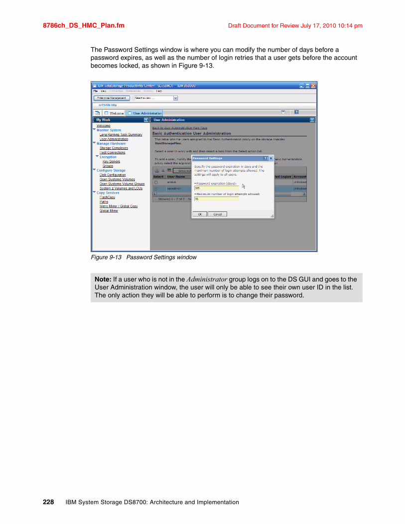
8786ch_DS_HMC_Plan.fm Draft Document for Review July 17, 2010 10:14 pm
The Password Settings window is where you can modify the number of days before a password expires, as well as the number of login retries that a user gets before the account becomes locked, as shown in Figure 9-13.
Figure 9-13 Password Settings window
Note: If a user who is not in the Administrator group logs on to the DS GUI and goes to the User Administration window, the user will only be able to see their own user ID in the list. The only action they will be able to perform is to change their password.
228 IBM System Storage DS8700: Architecture and Implementation
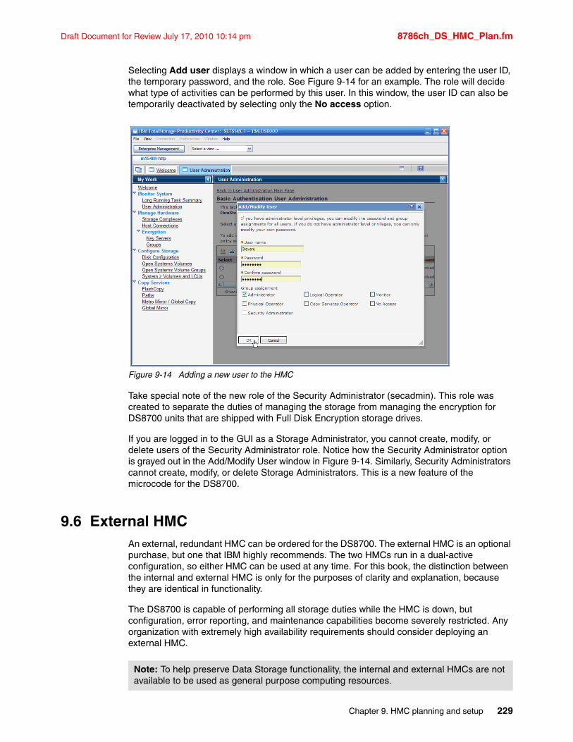
Draft Document for Review July 17, 2010 10:14 pm 8786ch_DS_HMC_Plan.fm
Selecting Add user displays a window in which a user can be added by entering the user ID, the temporary password, and the role. See Figure 9-14 for an example. The role will decide what type of activities can be performed by this user. In this window, the user ID can also be temporarily deactivated by selecting only the No access option.
Figure 9-14 Adding a new user to the HMC
Take special note of the new role of the Security Administrator (secadmin). This role was created to separate the duties of managing the storage from managing the encryption for DS8700 units that are shipped with Full Disk Encryption storage drives.
If you are logged in to the GUI as a Storage Administrator, you cannot create, modify, or delete users of the Security Administrator role. Notice how the Security Administrator option is grayed out in the Add/Modify User window in Figure 9-14. Similarly, Security Administrators cannot create, modify, or delete Storage Administrators. This is a new feature of the microcode for the DS8700.
9.6 External HMCAn external, redundant HMC can be ordered for the DS8700. The external HMC is an optional purchase, but one that IBM highly recommends. The two HMCs run in a dual-active configuration, so either HMC can be used at any time. For this book, the distinction between the internal and external HMC is only for the purposes of clarity and explanation, because they are identical in functionality.
The DS8700 is capable of performing all storage duties while the HMC is down, but configuration, error reporting, and maintenance capabilities become severely restricted. Any organization with extremely high availability requirements should consider deploying an external HMC.
Note: To help preserve Data Storage functionality, the internal and external HMCs are not available to be used as general purpose computing resources.
Chapter 9. HMC planning and setup 229
8786ch_DS_HMC_Plan.fm Draft Document for Review July 17, 2010 10:14 pm
9.6.1 External HMC benefitsHaving an external HMC provides a number of advantages. Among these are:
� Enhanced maintenance capability
Because the HMC is the only interface available for service personnel, an external HMC will provide maintenance operational capabilities if the internal HMC fails.
� Greater availability for power management
Using the HMC is the only way to safely power on or off the DS8700. An external HMC is necessary to shut down the DS8700 in the event of a failure with the internal HMC.
� Greater availability for remote support over modem
A second HMC with a phone line on the modem provides IBM a way to perform remote support should an error occur that prevents access to the first HMC. If network offload (FTP) is not allowed, one HMC can be used to offload data over the modem line while the other HMC is used for troubleshooting. See Chapter 20, “Remote support” on page 557 for more information regarding HMC modems.
� Greater availability of encryption deadlock recovery
If the DS8700 is configured for full disk encryption and an encryption deadlock scenario should happen, the HMC is the only way to input a Recovery Key to allow the DS8700 to become operational. See 4.8.1, “Deadlock recovery” on page 82 for more information regarding encryption deadlock.
� Greater availability for Advanced Copy Services
Since all Copy Services functions are driven by the HMC, any environment using Advanced Copy Services should have dual HMCs for operations continuance.
� Greater availability for configuration operations
All configuration commands must go through the HMC. This is true regardless of whether access is via the SSPC, DS CLI, the DS Storage Manager, or DS Open API with another management program. An external HMC will allow these operations to continue in the event of a failure with the internal HMC.
When a configuration or Copy Services command is issued, the DS CLI or DS Storage Manager will send the command to the first HMC. If the first HMC is not available, it will automatically send the command to the second HMC instead. Typically, you do not have to reissue the command.
Any changes made using one HMC are instantly reflected in the other HMC. There is no caching of host data done within the HMC, so there are no cache coherency issues.
9.6.2 Configuring DS CLI to use a second HMCThe second HMC can either be specified on the command line or in the profile file used by the DS CLI. To specify the second HMC in a command, use the -hmc2 parameter, as shown in Example 9-14.
Example 9-14 Using the -hmc2 parameter
C:\Program Files\IBM\dscli>dscli -hmc1 hmcalpha.ibm.com -hmc2 hmcbravo.ibm.comEnter your username: stevenjEnter your password:Date/Time: October 12, 2009 9:47:13 AM MST IBM DSCLI Version: 5.4.30.253 DS:IBM.2107-7503461
230 IBM System Storage DS8700: Architecture and Implementation
Draft Document for Review July 17, 2010 10:14 pm 8786ch_DS_HMC_Plan.fm
Alternatively, you can modify the following lines in the dscli.profile (or any profile) file:
# Management Console/Node IP Address(es)# hmc1 and hmc2 are equivalent to -hmc1 and -hmc2 command options.hmc1:hmcalpha.ibm.comhmc2:hmcbravo.ibm.com
After you make these changes and save the profile, the DS CLI will be able to automatically communicate through HMC2 in the event that HMC1 becomes unreachable. This change will allow you to perform both configuration and Copy Services commands with full redundancy.
Chapter 9. HMC planning and setup 231

8786ch_DS_HMC_Plan.fm Draft Document for Review July 17, 2010 10:14 pm
232 IBM System Storage DS8700: Architecture and Implementation
Draft Document for Review July 17, 2010 10:14 pm 8786ch_Activate_License.fm
Chapter 10. DS8700 features and license keys
This chapter discusses the activation of licensed functions, as well as the following topics:
� IBM System Storage DS8700 licensed functions
� Activation of licensed functions
� Licensed scope considerations
10
© Copyright IBM Corp. 2010. All rights reserved. 233
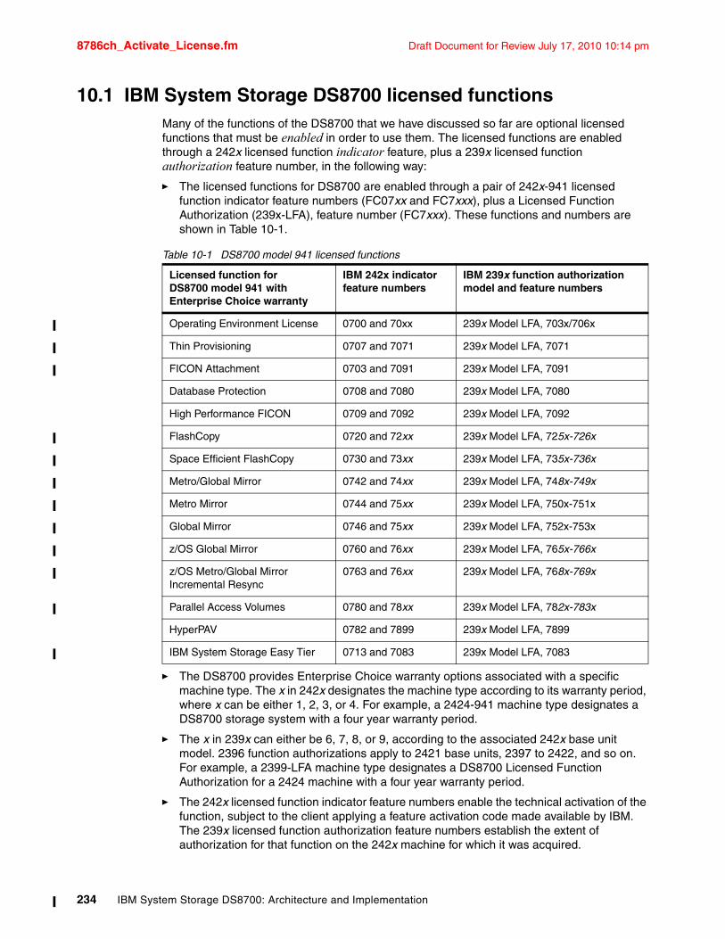
8786ch_Activate_License.fm Draft Document for Review July 17, 2010 10:14 pm
10.1 IBM System Storage DS8700 licensed functionsMany of the functions of the DS8700 that we have discussed so far are optional licensed functions that must be enabled in order to use them. The licensed functions are enabled through a 242x licensed function indicator feature, plus a 239x licensed function authorization feature number, in the following way:
� The licensed functions for DS8700 are enabled through a pair of 242x-941 licensed function indicator feature numbers (FC07xx and FC7xxx), plus a Licensed Function Authorization (239x-LFA), feature number (FC7xxx). These functions and numbers are shown in Table 10-1.
Table 10-1 DS8700 model 941 licensed functions
� The DS8700 provides Enterprise Choice warranty options associated with a specific machine type. The x in 242x designates the machine type according to its warranty period, where x can be either 1, 2, 3, or 4. For example, a 2424-941 machine type designates a DS8700 storage system with a four year warranty period.
� The x in 239x can either be 6, 7, 8, or 9, according to the associated 242x base unit model. 2396 function authorizations apply to 2421 base units, 2397 to 2422, and so on. For example, a 2399-LFA machine type designates a DS8700 Licensed Function Authorization for a 2424 machine with a four year warranty period.
� The 242x licensed function indicator feature numbers enable the technical activation of the function, subject to the client applying a feature activation code made available by IBM. The 239x licensed function authorization feature numbers establish the extent of authorization for that function on the 242x machine for which it was acquired.
Licensed function forDS8700 model 941 with Enterprise Choice warranty
IBM 242x indicator feature numbers
IBM 239x function authorization model and feature numbers
Operating Environment License 0700 and 70xx 239x Model LFA, 703x/706x
Thin Provisioning 0707 and 7071 239x Model LFA, 7071
FICON Attachment 0703 and 7091 239x Model LFA, 7091
Database Protection 0708 and 7080 239x Model LFA, 7080
High Performance FICON 0709 and 7092 239x Model LFA, 7092
FlashCopy 0720 and 72xx 239x Model LFA, 725x-726x
Space Efficient FlashCopy 0730 and 73xx 239x Model LFA, 735x-736x
Metro/Global Mirror 0742 and 74xx 239x Model LFA, 748x-749x
Metro Mirror 0744 and 75xx 239x Model LFA, 750x-751x
Global Mirror 0746 and 75xx 239x Model LFA, 752x-753x
z/OS Global Mirror 0760 and 76xx 239x Model LFA, 765x-766x
z/OS Metro/Global Mirror Incremental Resync
0763 and 76xx 239x Model LFA, 768x-769x
Parallel Access Volumes 0780 and 78xx 239x Model LFA, 782x-783x
HyperPAV 0782 and 7899 239x Model LFA, 7899
IBM System Storage Easy Tier 0713 and 7083 239x Model LFA, 7083
234 IBM System Storage DS8700: Architecture and Implementation
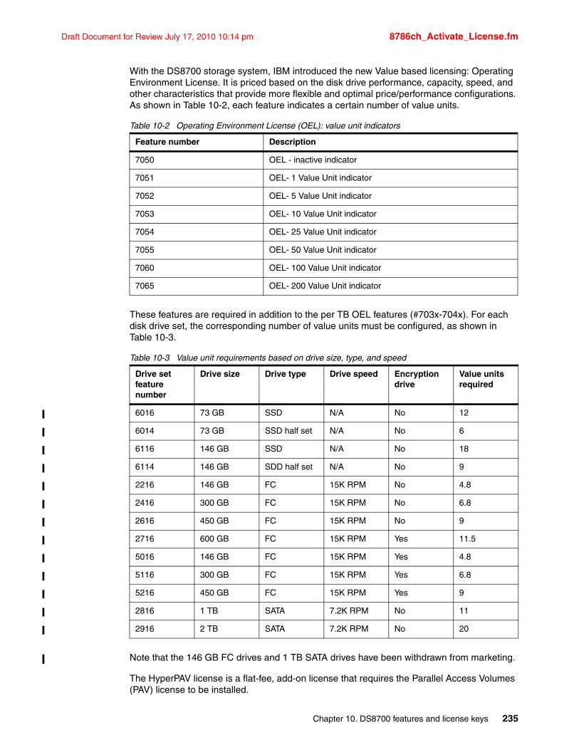
Draft Document for Review July 17, 2010 10:14 pm 8786ch_Activate_License.fm
With the DS8700 storage system, IBM introduced the new Value based licensing: Operating Environment License. It is priced based on the disk drive performance, capacity, speed, and other characteristics that provide more flexible and optimal price/performance configurations. As shown in Table 10-2, each feature indicates a certain number of value units.
Table 10-2 Operating Environment License (OEL): value unit indicators
These features are required in addition to the per TB OEL features (#703x-704x). For each disk drive set, the corresponding number of value units must be configured, as shown in Table 10-3.
Table 10-3 Value unit requirements based on drive size, type, and speed
Note that the 146 GB FC drives and 1 TB SATA drives have been withdrawn from marketing.
The HyperPAV license is a flat-fee, add-on license that requires the Parallel Access Volumes (PAV) license to be installed.
Feature number Description
7050 OEL - inactive indicator
7051 OEL- 1 Value Unit indicator
7052 OEL- 5 Value Unit indicator
7053 OEL- 10 Value Unit indicator
7054 OEL- 25 Value Unit indicator
7055 OEL- 50 Value Unit indicator
7060 OEL- 100 Value Unit indicator
7065 OEL- 200 Value Unit indicator
Drive set feature number
Drive size Drive type Drive speed Encryption drive
Value units required
6016 73 GB SSD N/A No 12
6014 73 GB SSD half set N/A No 6
6116 146 GB SSD N/A No 18
6114 146 GB SDD half set N/A No 9
2216 146 GB FC 15K RPM No 4.8
2416 300 GB FC 15K RPM No 6.8
2616 450 GB FC 15K RPM No 9
2716 600 GB FC 15K RPM Yes 11.5
5016 146 GB FC 15K RPM Yes 4.8
5116 300 GB FC 15K RPM Yes 6.8
5216 450 GB FC 15K RPM Yes 9
2816 1 TB SATA 7.2K RPM No 11
2916 2 TB SATA 7.2K RPM No 20
Chapter 10. DS8700 features and license keys 235
8786ch_Activate_License.fm Draft Document for Review July 17, 2010 10:14 pm
The license for Space Efficient FlashCopy does not require the ordinary FlashCopy (PTC) license. As with the ordinary FlashCopy, the FlashCopy SE is licensed in tiers by gross amount of TB installed. FlashCopy (PTC) and FlashCopy SE can be complementary licenses.
Metro Mirror (MM license) and Global Mirror (GM) can be complementary features as well.
IBM Systems Storage Easy Tier is a licensed function that is available with Release 5.1 at no-charge (R5.1 only available on DS8700). This feature has license options available for: FC, CKD and ALL.
10.2 Activation of licensed functionsActivating the license keys of the DS8700 can be done after the IBM service representative has completed the storage complex installation. Based on your 239x licensed function order, you need to obtain the necessary keys from the IBM Disk Storage Feature Activation (DSFA) Web site at the following address:
http://www.ibm.com/storage/dsfa
You can activate all license keys at the same time (for example, on initial activation of the storage unit) or they can be activated individually (for example, additional ordered keys).
Before connecting to the IBM DSFA Web site to obtain your feature activation codes, ensure that you have the following items:
� The IBM License Function Authorization documents. If you are activating codes for a new storage unit, these documents are included in the shipment of the storage unit. If you are activating codes for an existing storage unit, IBM will send the documents to you in an envelope.
� A USB memory device can be used for downloading your activation codes if you cannot access the DS Storage Manager from the system that you are using to access the DSFA Web site. Instead of downloading the activation codes in softcopy format, you can also print the activation codes and manually enter them using the DS Storage Manager GUI. However, this is slow and error prone, because the activation keys are 32-character long strings.
Note: For a detailed explanation of the features involved and the considerations you must have when ordering DS8700 licensed functions, refer to these announcement letters:
� IBM System Storage DS8700 Series (IBM 242x)
� IBM System Storage DS8700 series (M/T 239x) high performance flagship - Function Authorizations.
IBM announcement letters can be found at the following address:
http://www-01.ibm.com/common/ssi/index.wss
Use the DS8700 keyword as a search criteria in the Contents field.
Important: There is a special procedure to obtain the license key for the Full Disk Encryption feature. It cannot be obtained from the DSFA Web site. Refer to IBM System Storage DS8700: Disk Encryption Implementation and Usage Guidelines, REDP-4500 for more information.
236 IBM System Storage DS8700: Architecture and Implementation
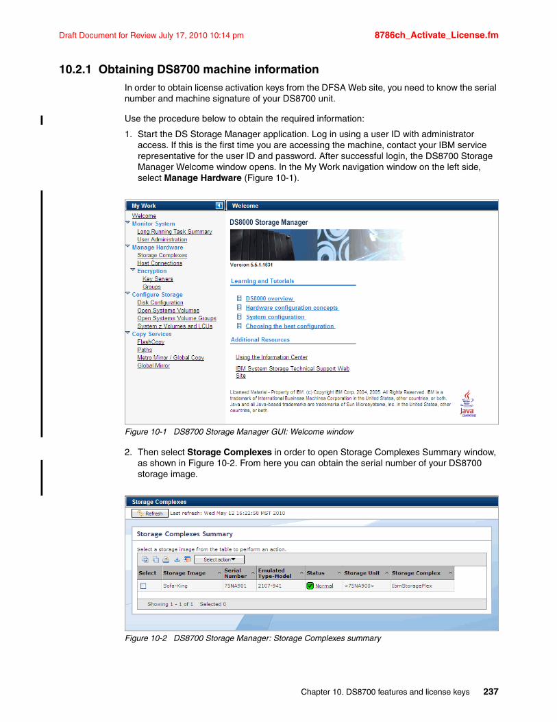
Draft Document for Review July 17, 2010 10:14 pm 8786ch_Activate_License.fm
10.2.1 Obtaining DS8700 machine informationIn order to obtain license activation keys from the DFSA Web site, you need to know the serial number and machine signature of your DS8700 unit.
Use the procedure below to obtain the required information:
1. Start the DS Storage Manager application. Log in using a user ID with administrator access. If this is the first time you are accessing the machine, contact your IBM service representative for the user ID and password. After successful login, the DS8700 Storage Manager Welcome window opens. In the My Work navigation window on the left side, select Manage Hardware (Figure 10-1).
Figure 10-1 DS8700 Storage Manager GUI: Welcome window
2. Then select Storage Complexes in order to open Storage Complexes Summary window, as shown in Figure 10-2. From here you can obtain the serial number of your DS8700 storage image.
Figure 10-2 DS8700 Storage Manager: Storage Complexes summary
Chapter 10. DS8700 features and license keys 237
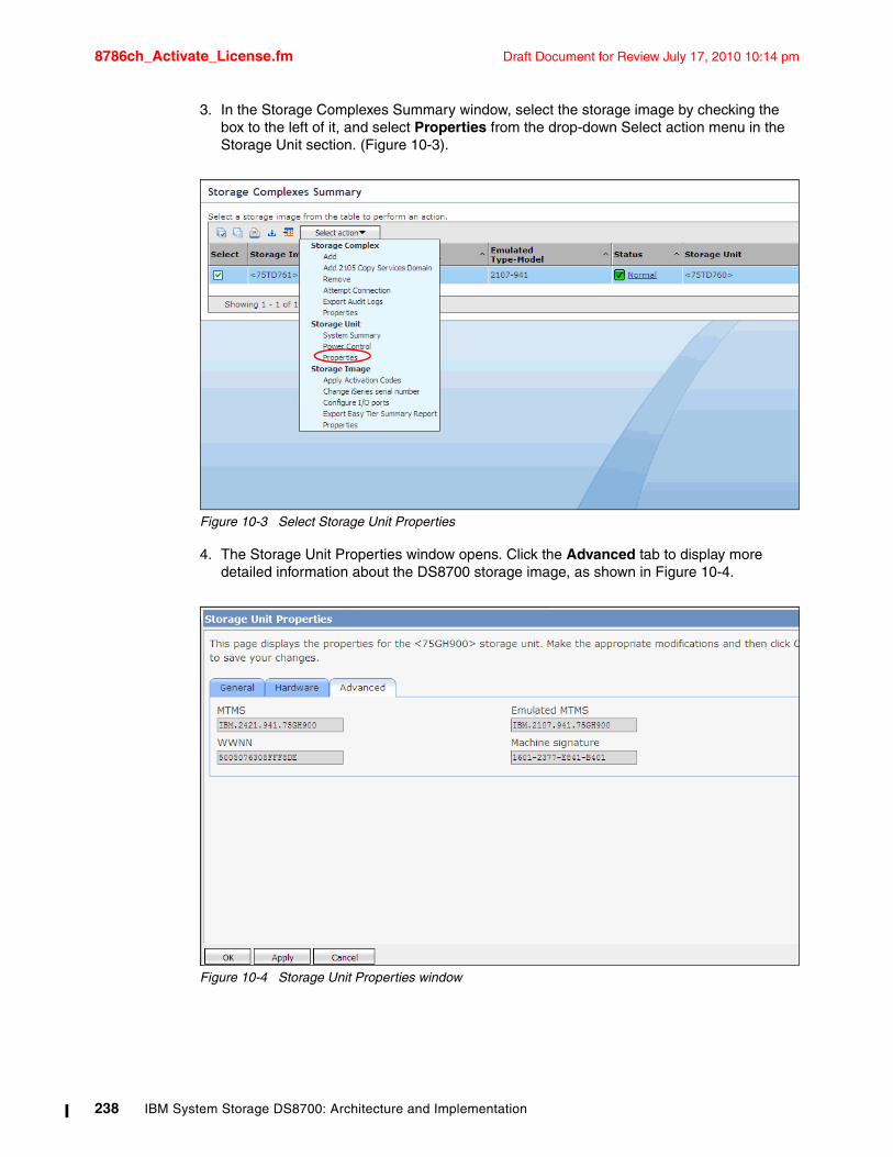
8786ch_Activate_License.fm Draft Document for Review July 17, 2010 10:14 pm
3. In the Storage Complexes Summary window, select the storage image by checking the box to the left of it, and select Properties from the drop-down Select action menu in the Storage Unit section. (Figure 10-3).
Figure 10-3 Select Storage Unit Properties
4. The Storage Unit Properties window opens. Click the Advanced tab to display more detailed information about the DS8700 storage image, as shown in Figure 10-4.
Figure 10-4 Storage Unit Properties window
238 IBM System Storage DS8700: Architecture and Implementation
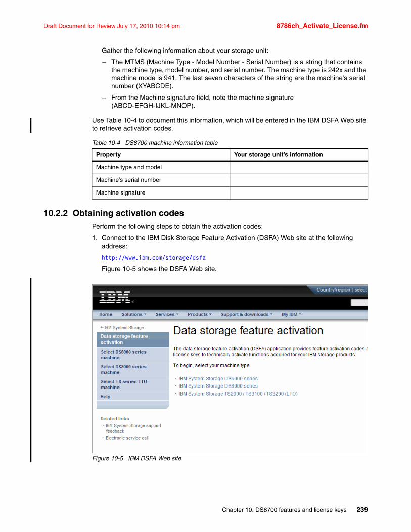
Draft Document for Review July 17, 2010 10:14 pm 8786ch_Activate_License.fm
Gather the following information about your storage unit:
– The MTMS (Machine Type - Model Number - Serial Number) is a string that contains the machine type, model number, and serial number. The machine type is 242x and the machine mode is 941. The last seven characters of the string are the machine's serial number (XYABCDE).
– From the Machine signature field, note the machine signature (ABCD-EFGH-IJKL-MNOP).
Use Table 10-4 to document this information, which will be entered in the IBM DSFA Web site to retrieve activation codes.
Table 10-4 DS8700 machine information table
10.2.2 Obtaining activation codesPerform the following steps to obtain the activation codes:
1. Connect to the IBM Disk Storage Feature Activation (DSFA) Web site at the following address:
http://www.ibm.com/storage/dsfa
Figure 10-5 shows the DSFA Web site.
Figure 10-5 IBM DSFA Web site
Property Your storage unit’s information
Machine type and model
Machine’s serial number
Machine signature
Chapter 10. DS8700 features and license keys 239
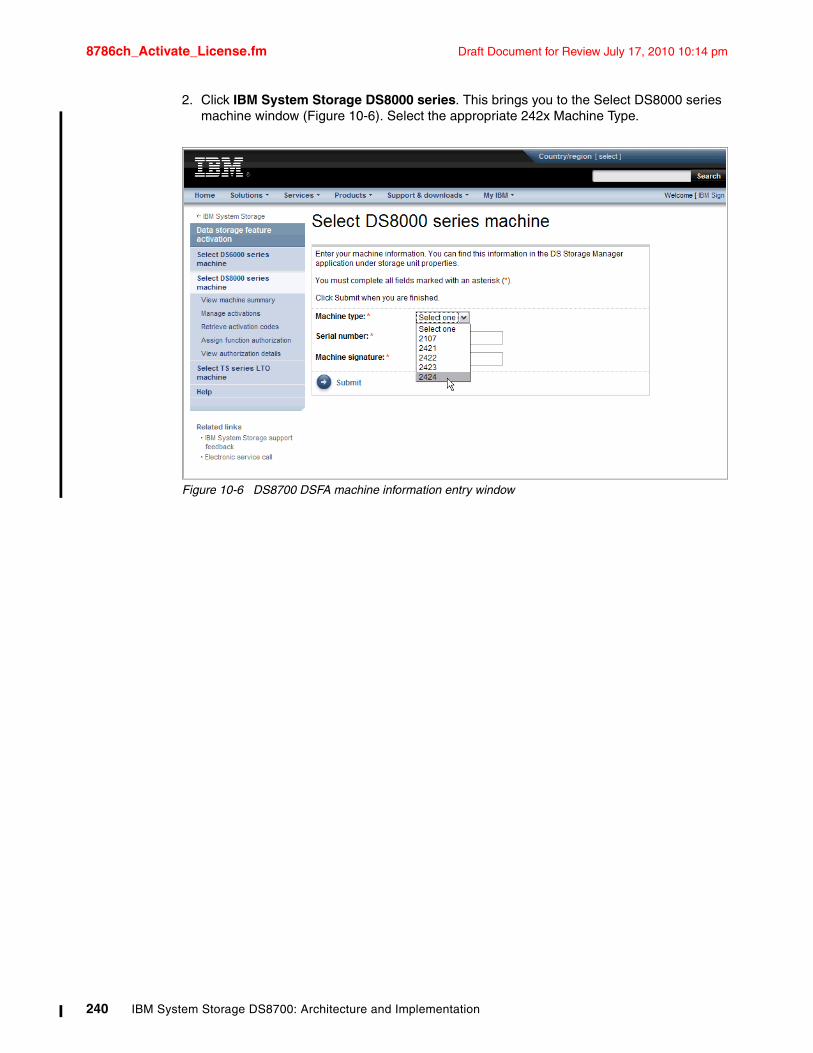
8786ch_Activate_License.fm Draft Document for Review July 17, 2010 10:14 pm
2. Click IBM System Storage DS8000 series. This brings you to the Select DS8000 series machine window (Figure 10-6). Select the appropriate 242x Machine Type.
Figure 10-6 DS8700 DSFA machine information entry window
240 IBM System Storage DS8700: Architecture and Implementation
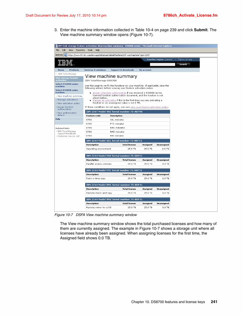
Draft Document for Review July 17, 2010 10:14 pm 8786ch_Activate_License.fm
3. Enter the machine information collected in Table 10-4 on page 239 and click Submit. The View machine summary window opens (Figure 10-7).
Figure 10-7 DSFA View machine summary window
The View machine summary window shows the total purchased licenses and how many of them are currently assigned. The example in Figure 10-7 shows a storage unit where all licenses have already been assigned. When assigning licenses for the first time, the Assigned field shows 0.0 TB.
Chapter 10. DS8700 features and license keys 241
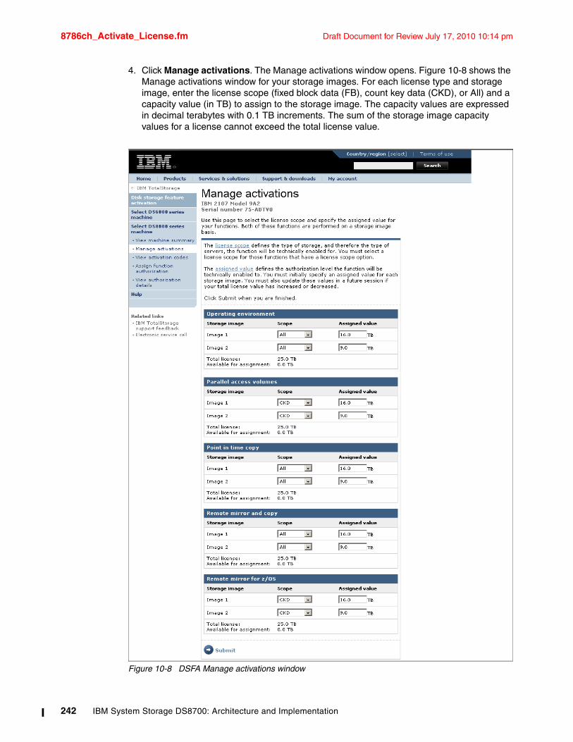
8786ch_Activate_License.fm Draft Document for Review July 17, 2010 10:14 pm
4. Click Manage activations. The Manage activations window opens. Figure 10-8 shows the Manage activations window for your storage images. For each license type and storage image, enter the license scope (fixed block data (FB), count key data (CKD), or All) and a capacity value (in TB) to assign to the storage image. The capacity values are expressed in decimal terabytes with 0.1 TB increments. The sum of the storage image capacity values for a license cannot exceed the total license value.
Figure 10-8 DSFA Manage activations window
242 IBM System Storage DS8700: Architecture and Implementation
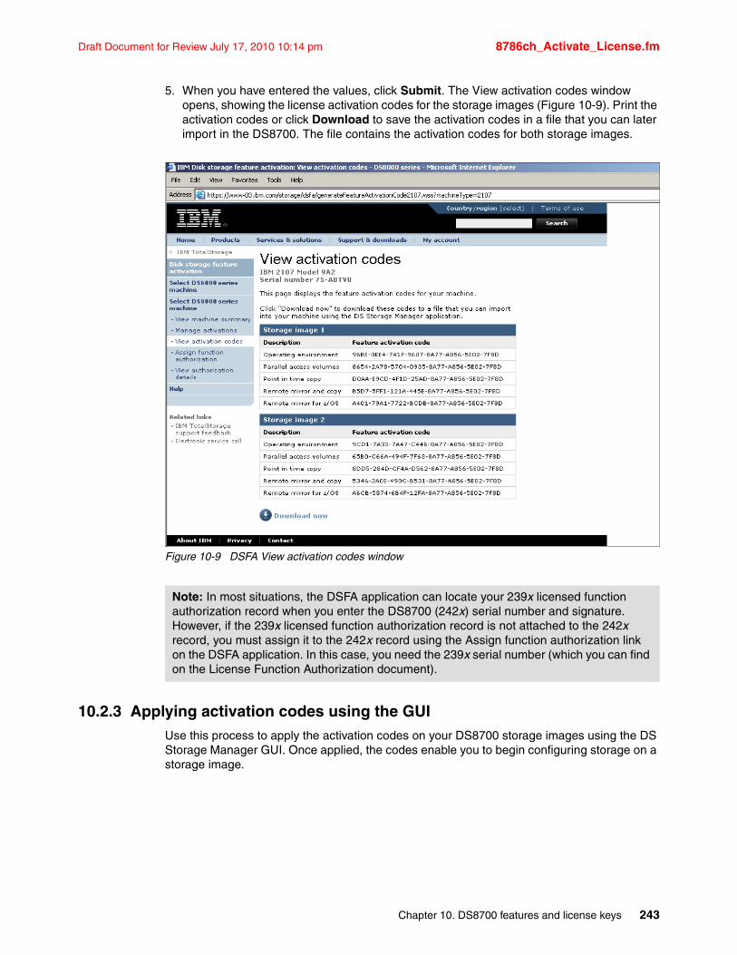
Draft Document for Review July 17, 2010 10:14 pm 8786ch_Activate_License.fm
5. When you have entered the values, click Submit. The View activation codes window opens, showing the license activation codes for the storage images (Figure 10-9). Print the activation codes or click Download to save the activation codes in a file that you can later import in the DS8700. The file contains the activation codes for both storage images.
Figure 10-9 DSFA View activation codes window
10.2.3 Applying activation codes using the GUIUse this process to apply the activation codes on your DS8700 storage images using the DS Storage Manager GUI. Once applied, the codes enable you to begin configuring storage on a storage image.
Note: In most situations, the DSFA application can locate your 239x licensed function authorization record when you enter the DS8700 (242x) serial number and signature. However, if the 239x licensed function authorization record is not attached to the 242x record, you must assign it to the 242x record using the Assign function authorization link on the DSFA application. In this case, you need the 239x serial number (which you can find on the License Function Authorization document).
Chapter 10. DS8700 features and license keys 243
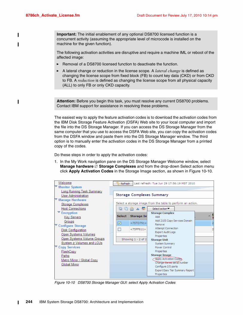
8786ch_Activate_License.fm Draft Document for Review July 17, 2010 10:14 pm
The easiest way to apply the feature activation codes is to download the activation codes from the IBM Disk Storage Feature Activation (DSFA) Web site to your local computer and import the file into the DS Storage Manager. If you can access the DS Storage Manager from the same computer that you use to access the DSFA Web site, you can copy the activation codes from the DSFA window and paste them into the DS Storage Manager window. The third option is to manually enter the activation codes in the DS Storage Manager from a printed copy of the codes.
Do these steps in order to apply the activation codes:
1. In the My Work navigation pane on the DS Storage Manager Welcome window, select Manage hardware Storage Complexes and from the drop-down Select action menu click Apply Activation Codes in the Storage Image section, as shown in Figure 10-10.
Figure 10-10 DS8700 Storage Manager GUI: select Apply Activation Codes
Important: The initial enablement of any optional DS8700 licensed function is a concurrent activity (assuming the appropriate level of microcode is installed on the machine for the given function).
The following activation activities are disruptive and require a machine IML or reboot of the affected image:
� Removal of a DS8700 licensed function to deactivate the function.
� A lateral change or reduction in the license scope. A lateral change is defined as changing the license scope from fixed block (FB) to count key data (CKD) or from CKD to FB. A reduction is defined as changing the license scope from all physical capacity (ALL) to only FB or only CKD capacity.
Attention: Before you begin this task, you must resolve any current DS8700 problems. Contact IBM support for assistance in resolving these problems.
244 IBM System Storage DS8700: Architecture and Implementation
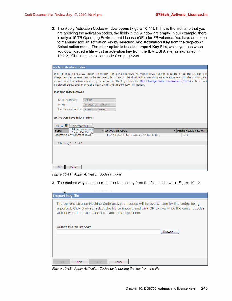
Draft Document for Review July 17, 2010 10:14 pm 8786ch_Activate_License.fm
2. The Apply Activation Codes window opens (Figure 10-11). If this is the first time that you are applying the activation codes, the fields in the window are empty. In our example, there is only a 19 TB Operating Environment License (OEL) for FB volumes. You have an option to manually add an activation key by selecting Add Activation Key from the drop-down Select action menu. The other option is to select Import Key File, which you use when you downloaded a file with the activation key from the IBM DSFA site, as explained in 10.2.2, “Obtaining activation codes” on page 239.
Figure 10-11 Apply Activation Codes window
3. The easiest way is to import the activation key from the file, as shown in Figure 10-12.
Figure 10-12 Apply Activation Codes by importing the key from the file
Chapter 10. DS8700 features and license keys 245
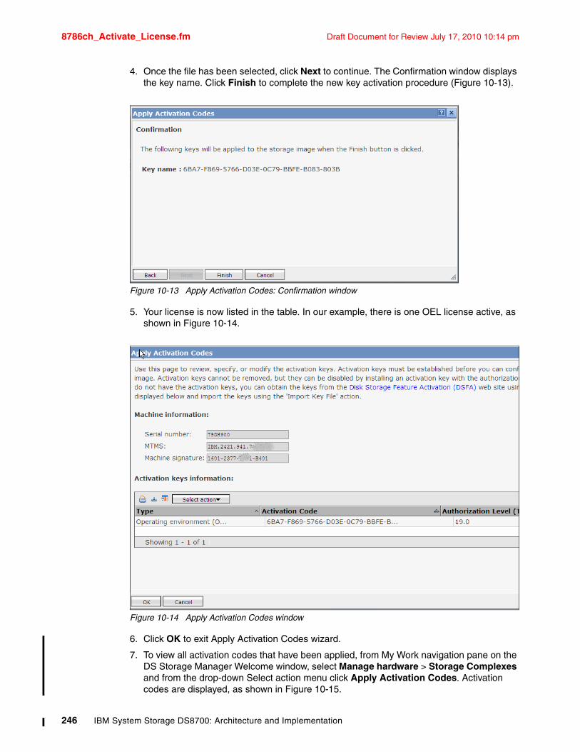
8786ch_Activate_License.fm Draft Document for Review July 17, 2010 10:14 pm
4. Once the file has been selected, click Next to continue. The Confirmation window displays the key name. Click Finish to complete the new key activation procedure (Figure 10-13).
Figure 10-13 Apply Activation Codes: Confirmation window
5. Your license is now listed in the table. In our example, there is one OEL license active, as shown in Figure 10-14.
Figure 10-14 Apply Activation Codes window
6. Click OK to exit Apply Activation Codes wizard.
7. To view all activation codes that have been applied, from My Work navigation pane on the DS Storage Manager Welcome window, select Manage hardware > Storage Complexes and from the drop-down Select action menu click Apply Activation Codes. Activation codes are displayed, as shown in Figure 10-15.
246 IBM System Storage DS8700: Architecture and Implementation
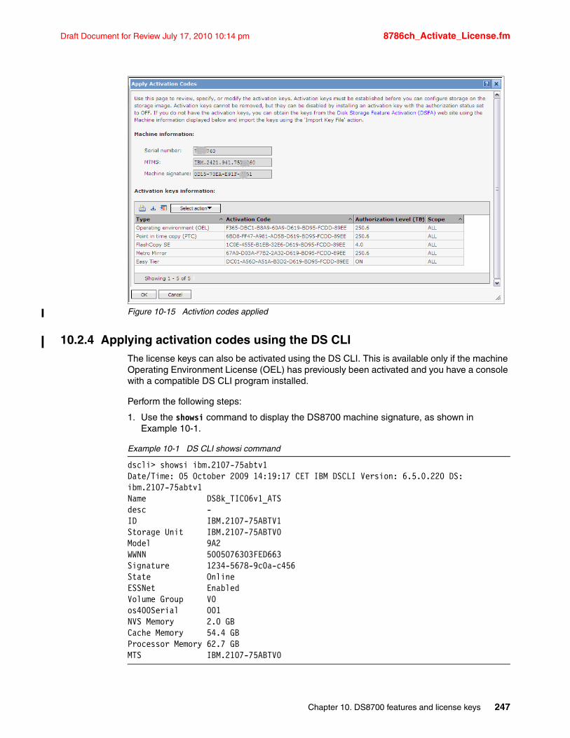
Draft Document for Review July 17, 2010 10:14 pm 8786ch_Activate_License.fm
Figure 10-15 Activtion codes applied
10.2.4 Applying activation codes using the DS CLIThe license keys can also be activated using the DS CLI. This is available only if the machine Operating Environment License (OEL) has previously been activated and you have a console with a compatible DS CLI program installed.
Perform the following steps:
1. Use the showsi command to display the DS8700 machine signature, as shown in Example 10-1.
Example 10-1 DS CLI showsi command
dscli> showsi ibm.2107-75abtv1Date/Time: 05 October 2009 14:19:17 CET IBM DSCLI Version: 6.5.0.220 DS: ibm.2107-75abtv1Name DS8k_TIC06v1_ATSdesc -ID IBM.2107-75ABTV1Storage Unit IBM.2107-75ABTV0Model 9A2WWNN 5005076303FED663Signature 1234-5678-9c0a-c456State OnlineESSNet EnabledVolume Group V0os400Serial 001NVS Memory 2.0 GBCache Memory 54.4 GBProcessor Memory 62.7 GBMTS IBM.2107-75ABTV0
Chapter 10. DS8700 features and license keys 247
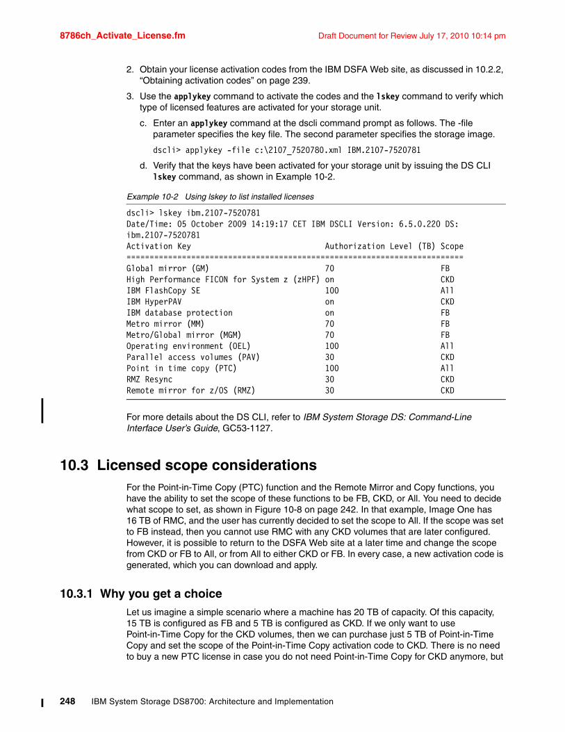
8786ch_Activate_License.fm Draft Document for Review July 17, 2010 10:14 pm
2. Obtain your license activation codes from the IBM DSFA Web site, as discussed in 10.2.2, “Obtaining activation codes” on page 239.
3. Use the applykey command to activate the codes and the lskey command to verify which type of licensed features are activated for your storage unit.
c. Enter an applykey command at the dscli command prompt as follows. The -file parameter specifies the key file. The second parameter specifies the storage image.
dscli> applykey -file c:\2107_7520780.xml IBM.2107-7520781
d. Verify that the keys have been activated for your storage unit by issuing the DS CLI lskey command, as shown in Example 10-2.
Example 10-2 Using lskey to list installed licenses
dscli> lskey ibm.2107-7520781Date/Time: 05 October 2009 14:19:17 CET IBM DSCLI Version: 6.5.0.220 DS: ibm.2107-7520781Activation Key Authorization Level (TB) Scope=========================================================================Global mirror (GM) 70 FBHigh Performance FICON for System z (zHPF) on CKDIBM FlashCopy SE 100 AllIBM HyperPAV on CKDIBM database protection on FBMetro mirror (MM) 70 FBMetro/Global mirror (MGM) 70 FBOperating environment (OEL) 100 AllParallel access volumes (PAV) 30 CKDPoint in time copy (PTC) 100 AllRMZ Resync 30 CKDRemote mirror for z/OS (RMZ) 30 CKD
For more details about the DS CLI, refer to IBM System Storage DS: Command-Line Interface User’s Guide, GC53-1127.
10.3 Licensed scope considerationsFor the Point-in-Time Copy (PTC) function and the Remote Mirror and Copy functions, you have the ability to set the scope of these functions to be FB, CKD, or All. You need to decide what scope to set, as shown in Figure 10-8 on page 242. In that example, Image One has 16 TB of RMC, and the user has currently decided to set the scope to All. If the scope was set to FB instead, then you cannot use RMC with any CKD volumes that are later configured. However, it is possible to return to the DSFA Web site at a later time and change the scope from CKD or FB to All, or from All to either CKD or FB. In every case, a new activation code is generated, which you can download and apply.
10.3.1 Why you get a choiceLet us imagine a simple scenario where a machine has 20 TB of capacity. Of this capacity, 15 TB is configured as FB and 5 TB is configured as CKD. If we only want to use Point-in-Time Copy for the CKD volumes, then we can purchase just 5 TB of Point-in-Time Copy and set the scope of the Point-in-Time Copy activation code to CKD. There is no need to buy a new PTC license in case you do not need Point-in-Time Copy for CKD anymore, but
248 IBM System Storage DS8700: Architecture and Implementation
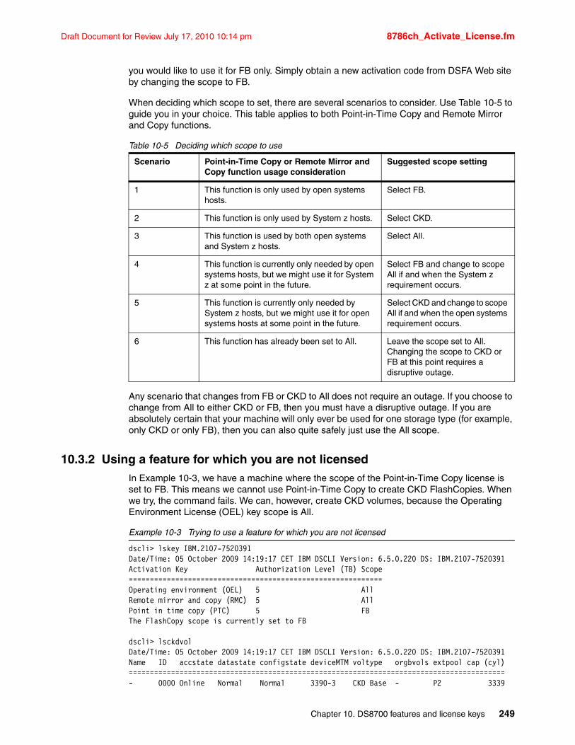
Draft Document for Review July 17, 2010 10:14 pm 8786ch_Activate_License.fm
you would like to use it for FB only. Simply obtain a new activation code from DSFA Web site by changing the scope to FB.
When deciding which scope to set, there are several scenarios to consider. Use Table 10-5 to guide you in your choice. This table applies to both Point-in-Time Copy and Remote Mirror and Copy functions.
Table 10-5 Deciding which scope to use
Any scenario that changes from FB or CKD to All does not require an outage. If you choose to change from All to either CKD or FB, then you must have a disruptive outage. If you are absolutely certain that your machine will only ever be used for one storage type (for example, only CKD or only FB), then you can also quite safely just use the All scope.
10.3.2 Using a feature for which you are not licensedIn Example 10-3, we have a machine where the scope of the Point-in-Time Copy license is set to FB. This means we cannot use Point-in-Time Copy to create CKD FlashCopies. When we try, the command fails. We can, however, create CKD volumes, because the Operating Environment License (OEL) key scope is All.
Example 10-3 Trying to use a feature for which you are not licensed
dscli> lskey IBM.2107-7520391Date/Time: 05 October 2009 14:19:17 CET IBM DSCLI Version: 6.5.0.220 DS: IBM.2107-7520391Activation Key Authorization Level (TB) Scope============================================================Operating environment (OEL) 5 AllRemote mirror and copy (RMC) 5 AllPoint in time copy (PTC) 5 FB The FlashCopy scope is currently set to FB
dscli> lsckdvolDate/Time: 05 October 2009 14:19:17 CET IBM DSCLI Version: 6.5.0.220 DS: IBM.2107-7520391Name ID accstate datastate configstate deviceMTM voltype orgbvols extpool cap (cyl)=========================================================================================- 0000 Online Normal Normal 3390-3 CKD Base - P2 3339
Scenario Point-in-Time Copy or Remote Mirror and Copy function usage consideration
Suggested scope setting
1 This function is only used by open systems hosts.
Select FB.
2 This function is only used by System z hosts. Select CKD.
3 This function is used by both open systems and System z hosts.
Select All.
4 This function is currently only needed by open systems hosts, but we might use it for System z at some point in the future.
Select FB and change to scope All if and when the System z requirement occurs.
5 This function is currently only needed by System z hosts, but we might use it for open systems hosts at some point in the future.
Select CKD and change to scope All if and when the open systems requirement occurs.
6 This function has already been set to All. Leave the scope set to All. Changing the scope to CKD or FB at this point requires a disruptive outage.
Chapter 10. DS8700 features and license keys 249
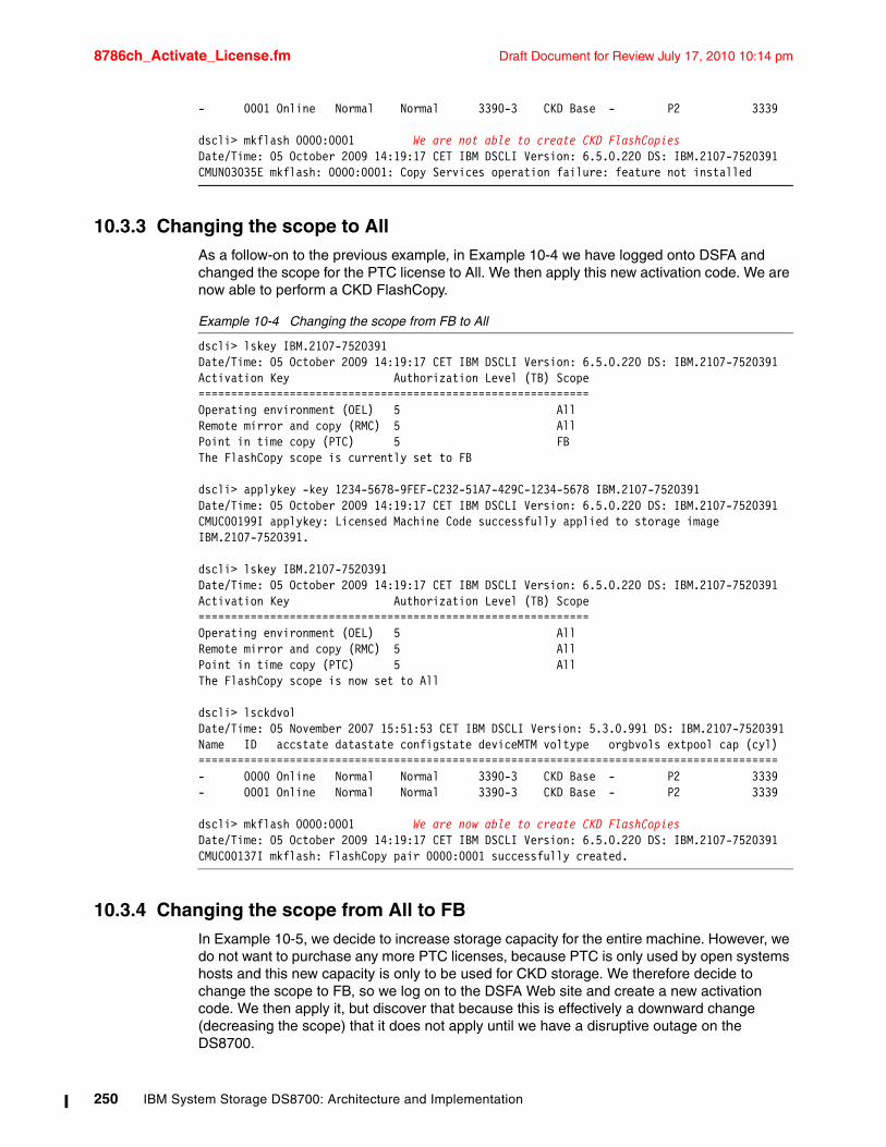
8786ch_Activate_License.fm Draft Document for Review July 17, 2010 10:14 pm
- 0001 Online Normal Normal 3390-3 CKD Base - P2 3339
dscli> mkflash 0000:0001 We are not able to create CKD FlashCopiesDate/Time: 05 October 2009 14:19:17 CET IBM DSCLI Version: 6.5.0.220 DS: IBM.2107-7520391CMUN03035E mkflash: 0000:0001: Copy Services operation failure: feature not installed
10.3.3 Changing the scope to AllAs a follow-on to the previous example, in Example 10-4 we have logged onto DSFA and changed the scope for the PTC license to All. We then apply this new activation code. We are now able to perform a CKD FlashCopy.
Example 10-4 Changing the scope from FB to All
dscli> lskey IBM.2107-7520391Date/Time: 05 October 2009 14:19:17 CET IBM DSCLI Version: 6.5.0.220 DS: IBM.2107-7520391Activation Key Authorization Level (TB) Scope============================================================Operating environment (OEL) 5 AllRemote mirror and copy (RMC) 5 AllPoint in time copy (PTC) 5 FB The FlashCopy scope is currently set to FB
dscli> applykey -key 1234-5678-9FEF-C232-51A7-429C-1234-5678 IBM.2107-7520391Date/Time: 05 October 2009 14:19:17 CET IBM DSCLI Version: 6.5.0.220 DS: IBM.2107-7520391CMUC00199I applykey: Licensed Machine Code successfully applied to storage image IBM.2107-7520391.
dscli> lskey IBM.2107-7520391Date/Time: 05 October 2009 14:19:17 CET IBM DSCLI Version: 6.5.0.220 DS: IBM.2107-7520391Activation Key Authorization Level (TB) Scope============================================================Operating environment (OEL) 5 AllRemote mirror and copy (RMC) 5 AllPoint in time copy (PTC) 5 AllThe FlashCopy scope is now set to All
dscli> lsckdvolDate/Time: 05 November 2007 15:51:53 CET IBM DSCLI Version: 5.3.0.991 DS: IBM.2107-7520391Name ID accstate datastate configstate deviceMTM voltype orgbvols extpool cap (cyl)=========================================================================================- 0000 Online Normal Normal 3390-3 CKD Base - P2 3339- 0001 Online Normal Normal 3390-3 CKD Base - P2 3339
dscli> mkflash 0000:0001 We are now able to create CKD FlashCopiesDate/Time: 05 October 2009 14:19:17 CET IBM DSCLI Version: 6.5.0.220 DS: IBM.2107-7520391CMUC00137I mkflash: FlashCopy pair 0000:0001 successfully created.
10.3.4 Changing the scope from All to FBIn Example 10-5, we decide to increase storage capacity for the entire machine. However, we do not want to purchase any more PTC licenses, because PTC is only used by open systems hosts and this new capacity is only to be used for CKD storage. We therefore decide to change the scope to FB, so we log on to the DSFA Web site and create a new activation code. We then apply it, but discover that because this is effectively a downward change (decreasing the scope) that it does not apply until we have a disruptive outage on the DS8700.
250 IBM System Storage DS8700: Architecture and Implementation
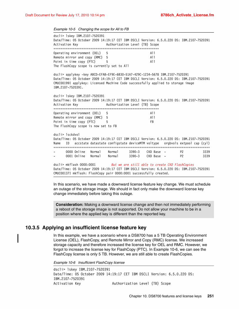
Draft Document for Review July 17, 2010 10:14 pm 8786ch_Activate_License.fm
Example 10-5 Changing the scope for All to FB
dscli> lskey IBM.2107-7520391Date/Time: 05 October 2009 14:19:17 CET IBM DSCLI Version: 6.5.0.220 DS: IBM.2107-7520391Activation Key Authorization Level (TB) Scope============================================================Operating environment (OEL) 5 AllRemote mirror and copy (RMC) 5 AllPoint in time copy (PTC) 5 AllThe FlashCopy scope is currently set to All
dscli> applykey -key ABCD-EFAB-EF9E-6B30-51A7-429C-1234-5678 IBM.2107-7520391Date/Time: 05 October 2009 14:19:17 CET IBM DSCLI Version: 6.5.0.220 DS: IBM.2107-7520391CMUC00199I applykey: Licensed Machine Code successfully applied to storage image IBM.2107-7520391.
dscli> lskey IBM.2107-7520391Date/Time: 05 October 2009 14:19:17 CET IBM DSCLI Version: 6.5.0.220 DS: IBM.2107-7520391Activation Key Authorization Level (TB) Scope============================================================Operating environment (OEL) 5 AllRemote mirror and copy (RMC) 5 AllPoint in time copy (PTC) 5 FB The FlashCopy scope is now set to FB
dscli> lsckdvolDate/Time: 05 October 2009 14:19:17 CET IBM DSCLI Version: 6.5.0.220 DS: IBM.2107-7520391Name ID accstate datastate configstate deviceMTM voltype orgbvols extpool cap (cyl)=========================================================================================- 0000 Online Normal Normal 3390-3 CKD Base - P2 3339- 0001 Online Normal Normal 3390-3 CKD Base - P2 3339
dscli> mkflash 0000:0001 But we are still able to create CKD FlashCopiesDate/Time: 05 October 2009 14:19:17 CET IBM DSCLI Version: 6.5.0.220 DS: IBM.2107-7520391CMUC00137I mkflash: FlashCopy pair 0000:0001 successfully created.
In this scenario, we have made a downward license feature key change. We must schedule an outage of the storage image. We should in fact only make the downward license key change immediately before taking this outage.
10.3.5 Applying an insufficient license feature keyIn this example, we have a scenario where a DS8700 has a 5 TB Operating Environment License (OEL), FlashCopy, and Remote Mirror and Copy (RMC) license. We increased storage capacity and therefore increased the license key for OEL and RMC. However, we forgot to increase the license key for FlashCopy (PTC). In Example 10-6, we can see the FlashCopy license is only 5 TB. However, we are still able to create FlashCopies.
Example 10-6 Insufficient FlashCopy license
dscli> lskey IBM.2107-7520391Date/Time: 05 October 2009 14:19:17 CET IBM DSCLI Version: 6.5.0.220 DS: IBM.2107-7520391Activation Key Authorization Level (TB) Scope
Consideration: Making a downward license change and then not immediately performing a reboot of the storage image is not supported. Do not allow your machine to be in a position where the applied key is different than the reported key.
Chapter 10. DS8700 features and license keys 251
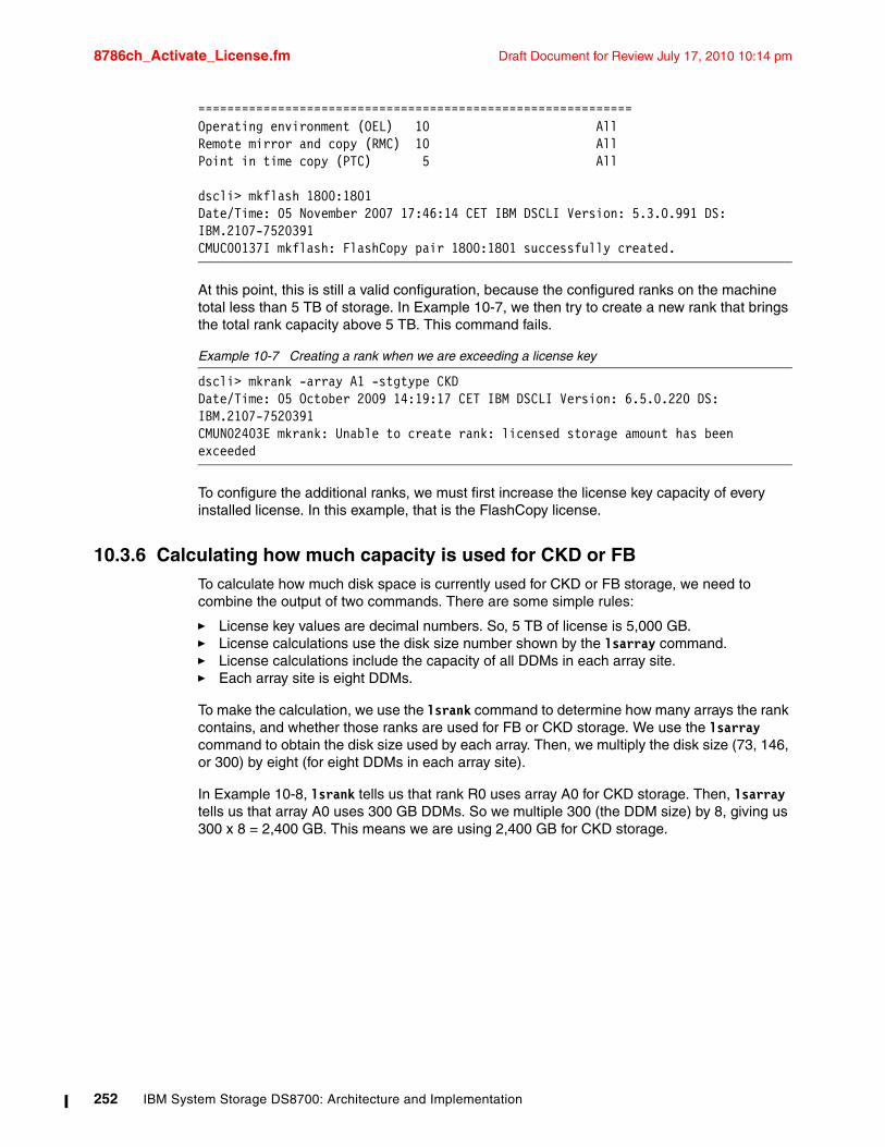
8786ch_Activate_License.fm Draft Document for Review July 17, 2010 10:14 pm
============================================================Operating environment (OEL) 10 AllRemote mirror and copy (RMC) 10 AllPoint in time copy (PTC) 5 All
dscli> mkflash 1800:1801Date/Time: 05 November 2007 17:46:14 CET IBM DSCLI Version: 5.3.0.991 DS: IBM.2107-7520391CMUC00137I mkflash: FlashCopy pair 1800:1801 successfully created.
At this point, this is still a valid configuration, because the configured ranks on the machine total less than 5 TB of storage. In Example 10-7, we then try to create a new rank that brings the total rank capacity above 5 TB. This command fails.
Example 10-7 Creating a rank when we are exceeding a license key
dscli> mkrank -array A1 -stgtype CKDDate/Time: 05 October 2009 14:19:17 CET IBM DSCLI Version: 6.5.0.220 DS: IBM.2107-7520391CMUN02403E mkrank: Unable to create rank: licensed storage amount has been exceeded
To configure the additional ranks, we must first increase the license key capacity of every installed license. In this example, that is the FlashCopy license.
10.3.6 Calculating how much capacity is used for CKD or FBTo calculate how much disk space is currently used for CKD or FB storage, we need to combine the output of two commands. There are some simple rules:
� License key values are decimal numbers. So, 5 TB of license is 5,000 GB.� License calculations use the disk size number shown by the lsarray command.� License calculations include the capacity of all DDMs in each array site.� Each array site is eight DDMs.
To make the calculation, we use the lsrank command to determine how many arrays the rank contains, and whether those ranks are used for FB or CKD storage. We use the lsarray command to obtain the disk size used by each array. Then, we multiply the disk size (73, 146, or 300) by eight (for eight DDMs in each array site).
In Example 10-8, lsrank tells us that rank R0 uses array A0 for CKD storage. Then, lsarray tells us that array A0 uses 300 GB DDMs. So we multiple 300 (the DDM size) by 8, giving us 300 x 8 = 2,400 GB. This means we are using 2,400 GB for CKD storage.
252 IBM System Storage DS8700: Architecture and Implementation
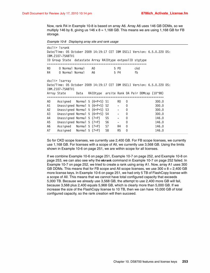
Draft Document for Review July 17, 2010 10:14 pm 8786ch_Activate_License.fm
Now, rank R4 in Example 10-8 is based on array A6. Array A6 uses 146 GB DDMs, so we multiply 146 by 8, giving us 146 x 8 = 1,168 GB. This means we are using 1,168 GB for FB storage.
Example 10-8 Displaying array site and rank usage
dscli> lsrankDate/Time: 05 October 2009 14:19:17 CET IBM DSCLI Version: 6.5.0.220 DS: IBM.2107-75ABTV1ID Group State datastate Array RAIDtype extpoolID stgtype==========================================================R0 0 Normal Normal A0 5 P0 ckdR4 0 Normal Normal A6 5 P4 fb
dscli> lsarrayDate/Time: 05 October 2009 14:19:17 CET IBM DSCLI Version: 6.5.0.220 DS: IBM.2107-75ABTV1Array State Data RAIDtype arsite Rank DA Pair DDMcap (10^9B)====================================================================A0 Assigned Normal 5 (6+P+S) S1 R0 0 300.0A1 Unassigned Normal 5 (6+P+S) S2 - 0 300.0A2 Unassigned Normal 5 (6+P+S) S3 - 0 300.0A3 Unassigned Normal 5 (6+P+S) S4 - 0 300.0A4 Unassigned Normal 5 (7+P) S5 - 0 146.0A5 Unassigned Normal 5 (7+P) S6 - 0 146.0A6 Assigned Normal 5 (7+P) S7 R4 0 146.0A7 Assigned Normal 5 (7+P) S8 R5 0 146.0
So for CKD scope licenses, we currently use 2,400 GB. For FB scope licenses, we currently use 1,168 GB. For licenses with a scope of All, we currently use 3,568 GB. Using the limits shown in Example 10-6 on page 251, we are within scope for all licenses.
If we combine Example 10-6 on page 251, Example 10-7 on page 252, and Example 10-8 on page 253, we can also see why the mkrank command in Example 10-7 on page 252 failed. In Example 10-7 on page 252, we tried to create a rank using array A1. Now, array A1 uses 300 GB DDMs. This means that for FB scope and All scope licenses, we use 300 x 8 = 2,400 GB more license keys. In Example 10-6 on page 251, we had only 5 TB of FlashCopy license with a scope of All. This means that we cannot have total configured capacity that exceeds 5,000 TB. Because we already use 3,568 GB, the attempt to use 2,400 more GB will fail, because 3,568 plus 2,400 equals 5,968 GB, which is clearly more than 5,000 GB. If we increase the size of the FlashCopy license to 10 TB, then we can have 10,000 GB of total configured capacity, so the rank creation will then succeed.
Chapter 10. DS8700 features and license keys 253

8786ch_Activate_License.fm Draft Document for Review July 17, 2010 10:14 pm
254 IBM System Storage DS8700: Architecture and Implementation
Draft Document for Review July 17, 2010 10:14 pm 8786p_Config.fm
Part 3 Storage configuration
In this part, we discuss the configuration tasks required on your IBM System Storage DS8000 storage subsystem. We cover the following topics:
� System Storage Productivity Center (SSPC) � Configuration using the DS Storage Manager GUI � Configuration with the Command-Line Interface
Part 3
© Copyright IBM Corp. 2010. All rights reserved. 255

8786p_Config.fm Draft Document for Review July 17, 2010 10:14 pm
256 IBM System Storage DS8700: Architecture and Implementation
Draft Document for Review July 17, 2010 10:14 pm 8786ch_Configflow.fm
Chapter 11. Configuration flow
This chapter gives a brief overview of the tasks required to configure the storage in a IBM System Storage DS8700 storage subsystem.
11
© Copyright IBM Corp. 2010. All rights reserved. 257
8786ch_Configflow.fm Draft Document for Review July 17, 2010 10:14 pm
11.1 Configuration worksheetsDuring the installation of the DS8700, your IBM service representative customizes the setup of your storage complex based on information that you provide in a set of customization worksheets. Each time that you install a new storage unit or management console, you must complete the customization worksheets before the IBM service representatives can perform the installation.
The customization worksheets are very important and need to be completed before the installation. It is important that this information is entered into the machine so that preventive maintenance and high availability of the machine are maintained. You can find the customization worksheets in IBM System Storage DS8000 Introduction and Planning Guide, GC35-0515.
The customization worksheets allow you to specify the initial setup for the following items:
� Company information: This information allows IBM service representatives to contact you as quickly as possible when they need to access your storage complex.
� Management console network settings: Allows you to specify the IP address and LAN settings for your management console (MC).
� Remote support (includes Call Home and remote service settings): Allows you to specify whether you want outbound (Call Home) or inbound (remote services) remote support.
� Notifications (include SNMP trap and e-mail notification settings): Allows you to specify the types of notifications that you want and that others might want to receive.
� Power control: Allows you to select and control the various power modes for the storage complex.
� Control Switch settings: Allows you to specify certain DS8700 settings that affect host connectivity. You need to enter these choices on the control switch settings worksheet so that the service representative can set them during the installation of the DS8700.
11.2 Configuration flowThe following list shows the tasks that need to be done when configuring storage in the DS8700. The order of the tasks does not have to be exactly as shown here, and some of the individual tasks can be done in a different order:
1. Install license keys: Activate the license keys for the storage unit.
2. Create arrays: Configure the installed disk drives as either RAID 5, RAID 6, or RAID 10 arrays.
3. Create ranks: Assign each array to either a fixed block (FB) rank or a count key data (CKD) rank.
Important: IBM service representatives cannot install a storage unit or management console until you provide them with the completed customization worksheets.
Important: The configuration flow changes when you use the Full Disk Encryption Feature for the DS8700. For details, refer to IBM System Storage DS8700: Architecture and ImplementationIBM System Storage DS8700 Disk Encryption Implementation and Usage Guidelines, REDP-4500.
258 IBM System Storage DS8700: Architecture and Implementation
Draft Document for Review July 17, 2010 10:14 pm 8786ch_Configflow.fm
4. Create extent pools: Define extent pools, associate each one with either Server 0 or Server 1, and assign at least one rank to each extent pool. If you want to take advantage of Storage Pool Striping, you must assign multiple ranks to an extent pool. Note that with current versions of the DS GUI, you can start directly with the creation of extent pools (arrays and ranks will be automatically and implicitly defined).
5. Create a repository for Space Efficient volumes.
6. Configure I/O ports: Define the type of the Fibre Channel/FICON ports. The port type can be either Switched Fabric, Arbitrated Loop, or FICON.
7. Create host connections for open systems: Define open systems hosts and their Fibre Channel (FC) host bus adapter (HBA) worldwide port names.
8. Create volume groups for open systems: Create volume groups where FB volumes will be assigned and select the host attachments for the volume groups.
9. Create open systems volumes: Create striped open systems FB volumes and assign them to one or more volume groups.
10.Create System z logical control units (LCUs): Define their type and other attributes, such as subsystem identifiers (SSIDs).
11.Create striped System z volumes: Create System z CKD base volumes and Parallel Access Volume (PAV) aliases for them.
The actual configuration can be done using either the DS Storage Manager GUI or DS Command-Line Interface, or a mixture of both. A novice user might prefer to use the GUI, while a more experienced user might use the CLI, particularly for some of the more repetitive tasks, such as creating large numbers of volumes.
For a more detailed discussion about how to perform the specific tasks, refer to:
� Chapter 10, “DS8700 features and license keys” on page 233� Chapter 13, “Configuration using the DS Storage Manager GUI” on page 293� Chapter 14, “Configuration with the Command-Line Interface” on page 357
General guidelines when configuring storageRemember the following general guidelines when configuring storage on the DS8700:
� To get a well-balanced load distribution, we recommend using at least two extent pools, each assigned to one DS8700 internal server (extent pool 0 and extent pool 1). If CKD and FB volumes are required, at least four extent pools should be used.
� Address groups (16 LCUs/logical subsystems (LSSs)) are all for CKD or all for FB.
� Volumes of one LCU/LSS can be allocated on multiple extent pools.
� An extent pool cannot contain all three RAID 5, RAID 6, and RAID 10 ranks. Each extent pool pair should have the same characteristics in terms of RAID type, RPM, and DDM size.
� Ranks in one extent pool should belong to different Device Adapters.
� Assign multiple ranks to extent pools to take advantage of Storage Pool Striping.
� Create hybrid pools (SSD +HDD) to take adnatage of Easy Tier automaic mode.
� CKD:
– 3380 and 3390 type volumes can be intermixed in an LCU and an extent pool.
Chapter 11. Configuration flow 259
8786ch_Configflow.fm Draft Document for Review July 17, 2010 10:14 pm
� FB:
– Create a volume group for each server unless LUN sharing is required.
– Place all ports for a single server in one volume group.
– If LUN sharing is required, there are two options:
• Use separate volumes for servers and place LUNs in multiple volume groups.• Place servers (clusters) and volumes to be shared in a single volume group.
� I/O ports:
– Distribute host connections of each type (FICON and FCP) evenly across the I/O enclosure.
– Typically, access any is used for I/O ports with access to ports controlled by SAN zoning.
260 IBM System Storage DS8700: Architecture and Implementation
Draft Document for Review July 17, 2010 10:14 pm 8786ch_ConfigSSPC.fm
Chapter 12. System Storage Productivity Center
This chapter discusses how to set up and manage the System Storage Productivity Center (SSPC) to work with the IBM System Storage DS8700 series.
The chapter covers the following topics:
� System Storage Productivity Center overview� System Storage Productivity Center components� System Storage Productivity Center setup and configuration� Working with a DS8700 system and Tivoli Storage Productivity Center Basic Edition
12
© Copyright IBM Corp. 2010. All rights reserved. 261
8786ch_ConfigSSPC.fm Draft Document for Review July 17, 2010 10:14 pm
12.1 System Storage Productivity Center (SSPC) overviewThe SSPC (machine type 2805-MC4) is an integrated hardware and software solution for centralized management of IBM storage products with IBM storage management software. It is designed to reduce the number of management servers. Through the integration of software and hardware on a single platform, the customer can start to consolidate the storage management infrastructure and manage the storage network, hosts, and physical disks in context rather than by device.
IBM System Storage Productivity Center simplifies storage management by:
� Centralizing the management of storage network resources with IBM storage management software.
� Providing greater synergy between storage management software and IBM storage devices.
� Reducing the number of servers that are required to manage the storage infrastructure. The goal is to have one SSPC per data center.
� Providing a simple migration path from basic device management to using storage management applications that provide higher-level functions.
Taking full advantage of the available and optional functions usable with SSPC can result in:
� Fewer resources required to manage the growing storage infrastructure� Reduced configuration errors� Decreased troubleshooting time and improved accuracy
12.1.1 SSPC componentsSSPC is a solution consisting of hardware and software elements.
SSPC hardwareThe SSPC (IBM model 2805-MC4) server contains the following hardware components:
� x86 server 1U rack installed
� One Intel Xeon quad-core processor, with a speed of 2.4 GHz, a cache of 8 MB, and power consumption of 80 W
� 8 GB of RAM (eight 1-in. dual in-line memory modules of double-data-rate three memory, with a data rate of 1333 MHz)
� Two 146 GB hard disk drives, each with a speed of 15 K
� One Broadcom 6708 Ethernet card
� One CD/DVD bay with read and write-read capability
Optional components are:
� KVM Unit� Secondary power supply
SSPC softwareThe IBM System Storage Productivity Center includes the following preinstalled (separately purchased) software, running under a licensed Microsoft Windows Server 2008 32-bit Enterprise Edition (included):
� IBM Tivoli Storage Productivity Center V4.1.1 licensed as TPC Basic Edition. A TPC upgrade requires that you purchase and add additional TPC licenses.
262 IBM System Storage DS8700: Architecture and Implementation
Draft Document for Review July 17, 2010 10:14 pm 8786ch_ConfigSSPC.fm
� IBM System Storage SAN Volume Controller Console V5.1.0 (CIM Agent and GUI).
� DS CIM Agent Command-Line Interface (DSCIMCLI) V5.4.3.
� IBM Tivoli Storage Productivity Center for Replication (TPC-R) V4.1.1. To run TPC-R on SSPC, you must purchase and add TPC-R licenses.
� IBM DB2 Enterprise Server Edition 9.5 with Fix Pack 3.
� IPv6 installed on Windows Server 2008.
Optionally, the following components can be installed on the SSPC:
� Software components contained in SSPC V1.3 but not on previous SSPC versions (TPC-R, DSCIMCLI, DS3000, DS40000, or DS5000 Storage Manager).
� DS8700 Command-Line Interface (DSCLI).
� Antivirus software.
Customers have the option to purchase and install the individual software components to create their own SSPC server.
12.1.2 SSPC capabilitiesSSPC, as shipped to the customer, offers the following capabilities:
� Pre-installed and tested console: IBM has designed and tested SSPC to support interoperability between server, software, and supported storage devices.
� IBM System Storage SAN Volume Controller Console and CIM agent.
� IBM Tivoli Storage Productivity Center Basic Edition is the core software that drives SSPC and brings together the ability to manage the SAN, storage devices, and host resources from a single control point by providing the following features:
– Remote access to the IBM System Storage DS8700 Storage Manager GUI. The DS8700 Storage Manager GUI itself resides and is usable on the DS8700 HMC.
– Ability to discover, monitor, alert, report, and provision storage, including:
• Automated discovery of supported storage systems in the environment. • Asset and capacity reporting from storage devices in the SAN.• Monitor status change of the storage devices.• Alert for storage device status change.• Report and display findings. • Basic end-to-end storage provisioning.
– Advanced topology viewer showing a graphical and detailed view of the overall SAN, including device relationships and visual notifications.
– A status dashboard.
Chapter 12. System Storage Productivity Center 263
8786ch_ConfigSSPC.fm Draft Document for Review July 17, 2010 10:14 pm
12.1.3 SSPC upgrade optionsYou can upgrade some of the software included with the standard SSPC.
Tivoli Storage Productivity Center Standard Edition (TPC-SE)Tivoli Storage Productivity Center Basic Edition can be easily upgraded with one or all of the advanced capabilities found in IBM Tivoli Storage Productivity Center Standard Edition. IBM Tivoli Storage Productivity Center Standard Edition (TPC-SE) includes IBM Tivoli Storage Productivity Center for Disk, IBM Tivoli Storage Productivity Center for Data, and IBM Tivoli Storage Productivity Center for Fabric. In addition to the capabilities provided by TPC Basic Edition, the Standard Edition can monitor performance and connectivity from the host file system to the physical disk, including in-depth performance monitoring and analysis of SAN fabric performance. This provides you with a main storage management application to monitor, plan, configure, report, and do problem determination on a heterogeneous storage infrastructure.
TPC-SE offers the following capabilities:
� Device configuration and management of SAN-attached devices from a single console. It also allows users to gather and analyze historical and real-time performance metrics.
� Management of file systems and databases, thus enabling enterprise-wide reports, monitoring and alerts, policy-based action, and file system capacity automation in heterogeneous environments.
� Management, monitoring, and control of SAN fabric to help automate device discovery, topology rendering, error detection fault isolation, SAN error predictor, zone control, real-time monitoring and alerts, and event management for heterogeneous enterprise SAN environments. In addition, it allows collection of performance statistics from IBM Tivoli Storage, Brocade, Cisco, and McDATA fabric switches and directors that implement the SNIA SMI-S specification.
Tivoli Storage Productivity Center for Replication (TPC-R)Optionally on SSPC V1.1, Tivoli Storage Productivity Center for Replication (TPC-R) can be installed. SSPC V1.2 and above come with TPC-R preinstalled. To use the preinstalled TPC-R, licences need to be applied first to TPC-R on the SSPC. IBM Tivoli Storage Productivity Center for Replication provides management of IBM copy services capabilities (see IBM System Storage DS8000: Copy Services in Open Environments, SG24-6788 for more details).
IBM Tivoli Storage Productivity Center for Replication is designed to:
� Simplify and improve the configuration and management of replication on your network storage devices by performing advanced copy operations in a single action.
� Manage advanced storage replication services, such as Metro Mirror, Global Mirror, Metro/Global Mirror, FlashCopy, and FlashCopy SE. TPC-R can also monitor copy services.
� Enable multiple pairing options for source and target volumes.
� Define session pairs using target and source volume groups, confirm path definitions, and create consistency sets for replication operations.
264 IBM System Storage DS8700: Architecture and Implementation
Draft Document for Review July 17, 2010 10:14 pm 8786ch_ConfigSSPC.fm
� IBM Tivoli Storage Productivity Center for Replication Three Site BC is an addition to the Tivoli Storage Productivity Center for Replication V4.1 family. Three Site BC provides:
– Support for three-site IBM DS8000 family Metro Global Mirror configurations.
– Disaster recovery configurations that can be set up to indicate copy service type (FlashCopy, Metro Mirror, Global Mirror) and the number of separate copies and sites to be set.
12.2 SSPC setup and configurationThis section summmarizes the tasks and sequence of steps required to set up and configure the DS8700 system and the SSPC used to manage DS8700 system.
For detailed information, and additional considerations, refer to the TPC / SSPC Information Center at the following address:
http://publib.boulder.ibm.com/infocenter/tivihelp/v4r1/index.jsp
12.2.1 Configuring SSPC for DS8700 remote GUI accessThe steps to configure the SSPC can be found in System Storage Productivity Center User’s Guide, SC27-2336, which is shipped with the SSPC. The document is also available at the following address:
http://publib.boulder.ibm.com/infocenter/tivihelp/v4r1/index.jsp
After IBM Support physically installs the 2805-MC4 and tests IP connectivity with the DS8700, SSPC is ready for configuration by either the customer or IBM Services.
Once the initial configuration of SSPC is done, the SSPC user is able to configure the remote GUI access to all DS8700 systems in the TPC Element Manager, as described in “Configuring TPC to access the DS8700 GUI” on page 267.
Accessing the TPC on SSPC The following methods can be used to access the TPC on SSPC console:
� Access the complete SSPC:
– Launch TPC directly at the SSPC Terminal.
– Launch TPC by Remote Desktop to the SSPC.
� Install the TPC V4.1 GUI by using the TPC installation procedure. The GUI will then connect to the TPC running on the SSPC.
� Launch the TPC GUI front end as a Java Webstart session.
– In a browser, enter http://<SSPC ipaddress>:9550/ITSRM/app/welcome.html.
– Download the correct Java version if it is not installed yet.
– Select TPC GUI and open it with the Java Webstart executable.
For the initial setup, a Java Webstart session will be opened and the TSRMGUI.jar file will be offloaded to the workstation on which the browser was started. Once the user agrees to unrestricted access to the workstation for the TPC-GUI, the system will ask if a shortcut should be created.
Chapter 12. System Storage Productivity Center 265
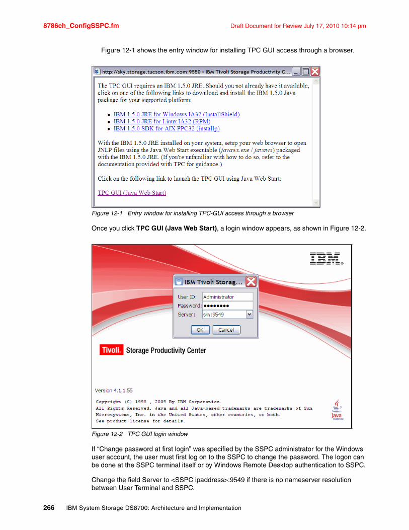
8786ch_ConfigSSPC.fm Draft Document for Review July 17, 2010 10:14 pm
Figure 12-1 shows the entry window for installing TPC GUI access through a browser.
Figure 12-1 Entry window for installing TPC-GUI access through a browser
Once you click TPC GUI (Java Web Start), a login window appears, as shown in Figure 12-2.
Figure 12-2 TPC GUI login window
If “Change password at first login” was specified by the SSPC administrator for the Windows user account, the user must first log on to the SSPC to change the password. The logon can be done at the SSPC terminal itself or by Windows Remote Desktop authentication to SSPC.
Change the field Server to <SSPC ipaddress>:9549 if there is no nameserver resolution between User Terminal and SSPC.
266 IBM System Storage DS8700: Architecture and Implementation
Draft Document for Review July 17, 2010 10:14 pm 8786ch_ConfigSSPC.fm
Configuring TPC to access the DS8700 GUIThe TPC Element Manager is a single point of access to the GUI for all the DS8700 systems in your environment. Using the TPC Element Manager for DS8700 remote GUI access allows you to:
� View a list of Elements (DS8700 GUIs within your environment).
� Access all DS8700 GUIs by launching an Element with a single action.
� Add and remove DS8700 Elements. The DS8700 GUI front end can be accessed by http or https.
� Save the user and password to access the DS8700 GUI. This option to access the DS8700 GUI without reentering the password allows you to configure SSPC as a single password logon to all DS8700s in the customer environment.
With DS8700 LIC Release 5, remote access to the DS8700 GUI is bundled with SSPC.
To access the DS8700 GUI in TPC, complete the following steps:
1. Launch Internet Explorer.
2. Select Tools and then Internet options on the Internet Explorer toolbar.
3. Click the Security tab.
4. Click the Trusted sites icon and then the Sites button.
5. Type the URL with HTTP or HTTPS, whichever you intend to use in the Add Element Manager window. For example, type https://<hmc_ip_address>, where <hmc_ip_address> is the HMC IP address that will be entered into the Add this Web site to the zone field.
6. Click Add.
7. Click Close.
8. Click OK.
9. Close Internet Explorer.
10.Launch TPC. You can double-click the Productivity Center icon on the desktop or select Start Programs IBM Tivoli Storage Productivity Center Productivity Center.
Tip: Set the SSPC IP address in the TPC-GUI entry window. At the workstation where you launched the browser to TPC GUI, go to:
� C:\Documents and Settings\<UserID>\ApplicationData\IBM\Java\Deployment\javaws\cache\http\<SSPC_IP_address>\P9550\DMITSRM\DMapp.
� Open the file AMtpcgui.jnlp and change the setting from <argument>SSPC_Name:9549</argument> to <argument><SSPC ipaddress>:9549</argument>.
Chapter 12. System Storage Productivity Center 267
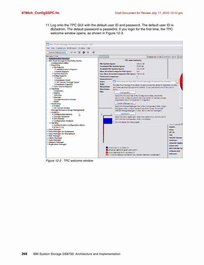
8786ch_ConfigSSPC.fm Draft Document for Review July 17, 2010 10:14 pm
11.Log onto the TPC GUI with the default user ID and password. The default user ID is db2admin. The default password is passw0rd. If you login for the first time, the TPC welcome window opens, as shown in Figure 12-3.
Figure 12-3 TPC welcome window
268 IBM System Storage DS8700: Architecture and Implementation
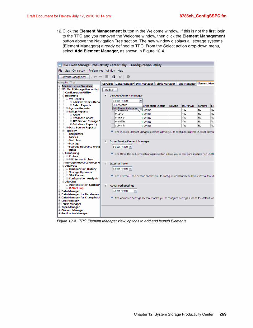
Draft Document for Review July 17, 2010 10:14 pm 8786ch_ConfigSSPC.fm
12.Click the Element Management button in the Welcome window. If this is not the first login to the TPC and you removed the Welcome window, then click the Element Management button above the Navigation Tree section. The new window displays all storage systems (Element Managers) already defined to TPC. From the Select action drop-down menu, select Add Element Manager, as shown in Figure 12-4.
Figure 12-4 TPC Element Manager view: options to add and launch Elements
Chapter 12. System Storage Productivity Center 269
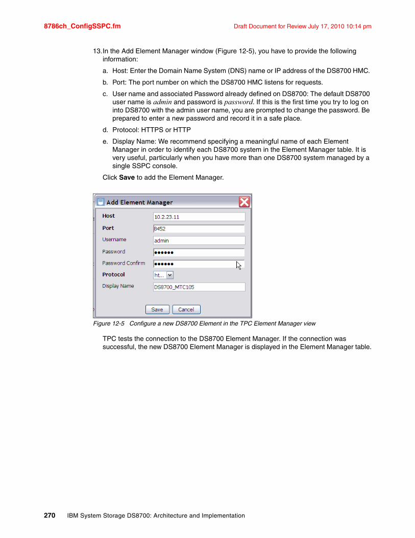
8786ch_ConfigSSPC.fm Draft Document for Review July 17, 2010 10:14 pm
13.In the Add Element Manager window (Figure 12-5), you have to provide the following information:
a. Host: Enter the Domain Name System (DNS) name or IP address of the DS8700 HMC.
b. Port: The port number on which the DS8700 HMC listens for requests.
c. User name and associated Password already defined on DS8700: The default DS8700 user name is admin and password is password. If this is the first time you try to log on into DS8700 with the admin user name, you are prompted to change the password. Be prepared to enter a new password and record it in a safe place.
d. Protocol: HTTPS or HTTP
e. Display Name: We recommend specifying a meaningful name of each Element Manager in order to identify each DS8700 system in the Element Manager table. It is very useful, particularly when you have more than one DS8700 system managed by a single SSPC console.
Click Save to add the Element Manager.
Figure 12-5 Configure a new DS8700 Element in the TPC Element Manager view
TPC tests the connection to the DS8700 Element Manager. If the connection was successful, the new DS8700 Element Manager is displayed in the Element Manager table.
270 IBM System Storage DS8700: Architecture and Implementation
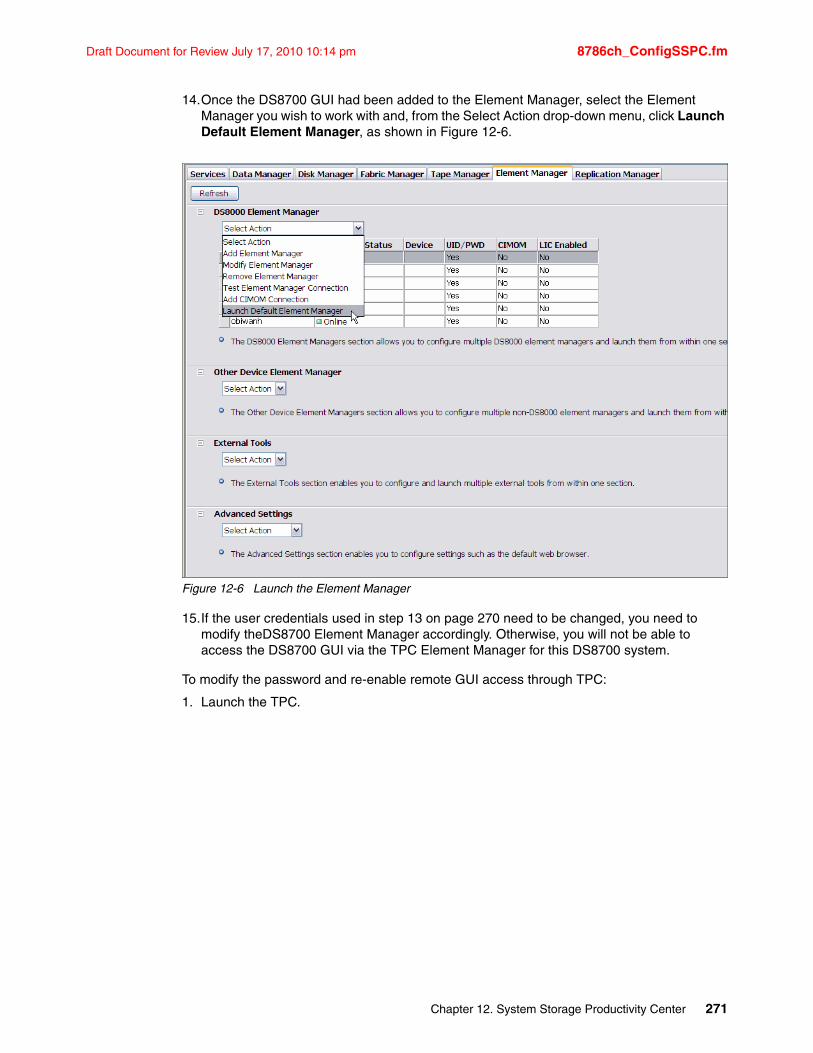
Draft Document for Review July 17, 2010 10:14 pm 8786ch_ConfigSSPC.fm
14.Once the DS8700 GUI had been added to the Element Manager, select the Element Manager you wish to work with and, from the Select Action drop-down menu, click Launch Default Element Manager, as shown in Figure 12-6.
Figure 12-6 Launch the Element Manager
15.If the user credentials used in step 13 on page 270 need to be changed, you need to modify theDS8700 Element Manager accordingly. Otherwise, you will not be able to access the DS8700 GUI via the TPC Element Manager for this DS8700 system.
To modify the password and re-enable remote GUI access through TPC:
1. Launch the TPC.
Chapter 12. System Storage Productivity Center 271
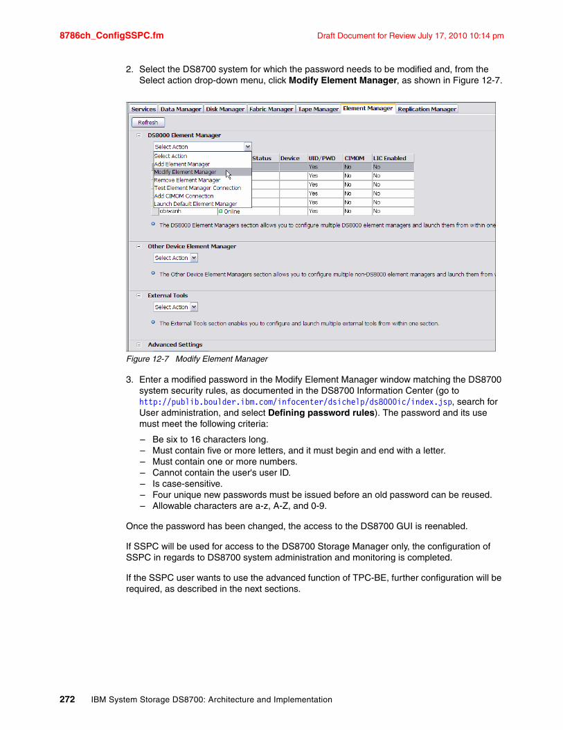
8786ch_ConfigSSPC.fm Draft Document for Review July 17, 2010 10:14 pm
2. Select the DS8700 system for which the password needs to be modified and, from the Select action drop-down menu, click Modify Element Manager, as shown in Figure 12-7.
Figure 12-7 Modify Element Manager
3. Enter a modified password in the Modify Element Manager window matching the DS8700 system security rules, as documented in the DS8700 Information Center (go to http://publib.boulder.ibm.com/infocenter/dsichelp/ds8000ic/index.jsp, search for User administration, and select Defining password rules). The password and its use must meet the following criteria:
– Be six to 16 characters long.– Must contain five or more letters, and it must begin and end with a letter.– Must contain one or more numbers.– Cannot contain the user's user ID.– Is case-sensitive.– Four unique new passwords must be issued before an old password can be reused.– Allowable characters are a-z, A-Z, and 0-9.
Once the password has been changed, the access to the DS8700 GUI is reenabled.
If SSPC will be used for access to the DS8700 Storage Manager only, the configuration of SSPC in regards to DS8700 system administration and monitoring is completed.
If the SSPC user wants to use the advanced function of TPC-BE, further configuration will be required, as described in the next sections.
272 IBM System Storage DS8700: Architecture and Implementation
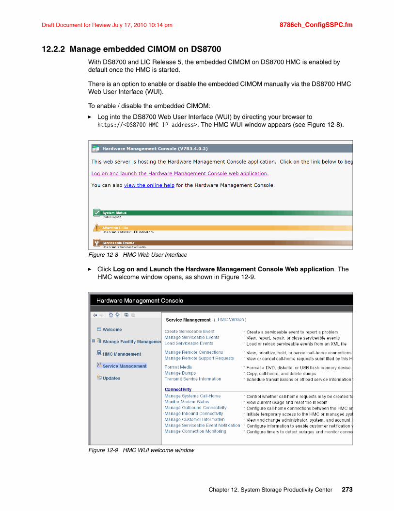
Draft Document for Review July 17, 2010 10:14 pm 8786ch_ConfigSSPC.fm
12.2.2 Manage embedded CIMOM on DS8700With DS8700 and LIC Release 5, the embedded CIMOM on DS8700 HMC is enabled by default once the HMC is started.
There is an option to enable or disable the embedded CIMOM manually via the DS8700 HMC Web User Interface (WUI).
To enable / disable the embedded CIMOM:
� Log into the DS8700 Web User Interface (WUI) by directing your browser to https://<DS8700 HMC IP address>. The HMC WUI window appears (see Figure 12-8).
Figure 12-8 HMC Web User Interface
� Click Log on and Launch the Hardware Management Console Web application. The HMC welcome window opens, as shown in Figure 12-9.
Figure 12-9 HMC WUI welcome window
Chapter 12. System Storage Productivity Center 273
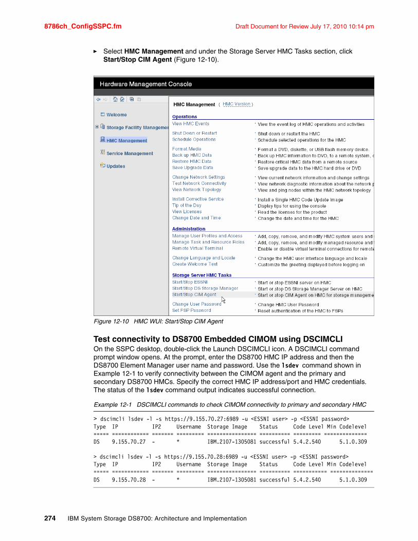
8786ch_ConfigSSPC.fm Draft Document for Review July 17, 2010 10:14 pm
� Select HMC Managementand under the Storage Server HMC Tasks section, click Start/Stop CIM Agent (Figure 12-10).
Figure 12-10 HMC WUI: Start/Stop CIM Agent
Test connectivity to DS8700 Embedded CIMOM using DSCIMCLIOn the SSPC desktop, double-click the Launch DSCIMCLI icon. A DSCIMCLI command prompt window opens. At the prompt, enter the DS8700 HMC IP address and then the DS8700 Element Manager user name and password. Use the lsdev command shown in Example 12-1 to verify connectivity between the CIMOM agent and the primary and secondary DS8700 HMCs. Specify the correct HMC IP address/port and HMC credentials. The status of the lsdev command output indicates successful connection.
Example 12-1 DSCIMCLI commands to check CIMOM connectivity to primary and secondary HMC
> dscimcli lsdev -l -s https://9.155.70.27:6989 -u <ESSNI user> -p <ESSNI password>Type IP IP2 Username Storage Image Status Code Level Min Codelevel===== ============ ======= ========= ================ ========== ========= ==============DS 9.155.70.27 - * IBM.2107-1305081 successful 5.4.2.540 5.1.0.309
> dscimcli lsdev -l -s https://9.155.70.28:6989 -u <ESSNI user> -p <ESSNI password>Type IP IP2 Username Storage Image Status Code Level Min Codelevel===== ============ ======= ========= ================ ========== =========== ==============DS 9.155.70.28 - * IBM.2107-1305081 successful 5.4.2.540 5.1.0.309
274 IBM System Storage DS8700: Architecture and Implementation
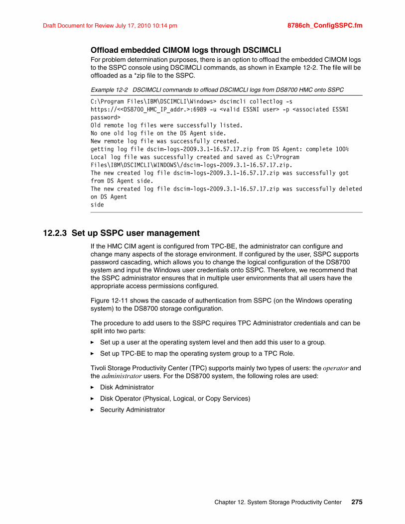
Draft Document for Review July 17, 2010 10:14 pm 8786ch_ConfigSSPC.fm
Offload embedded CIMOM logs through DSCIMCLIFor problem determination purposes, there is an option to offload the embedded CIMOM logs to the SSPC console using DSCIMCLI commands, as shown in Example 12-2. The file will be offloaded as a *zip file to the SSPC.
Example 12-2 DSCIMCLI commands to offload DSCIMCLI logs from DS8700 HMC onto SSPC
C:\Program Files\IBM\DSCIMCLI\Windows> dscimcli collectlog -s https://<<DS8700_HMC_IP_addr.>:6989 -u <valid ESSNI user> -p <associated ESSNI password>Old remote log files were successfully listed.No one old log file on the DS Agent side.New remote log file was successfully created.getting log file dscim-logs-2009.3.1-16.57.17.zip from DS Agent: complete 100%Local log file was successfully created and saved as C:\Program Files\IBM\DSCIMCLI\WINDOWS\/dscim-logs-2009.3.1-16.57.17.zip.The new created log file dscim-logs-2009.3.1-16.57.17.zip was successfully got from DS Agent side.The new created log file dscim-logs-2009.3.1-16.57.17.zip was successfully deletedon DS Agent side
12.2.3 Set up SSPC user managementIf the HMC CIM agent is configured from TPC-BE, the administrator can configure and change many aspects of the storage environment. If configured by the user, SSPC supports password cascading, which allows you to change the logical configuration of the DS8700 system and input the Windows user credentials onto SSPC. Therefore, we recommend that the SSPC administrator ensures that in multiple user environments that all users have the appropriate access permissions configured.
Figure 12-11 shows the cascade of authentication from SSPC (on the Windows operating system) to the DS8700 storage configuration.
The procedure to add users to the SSPC requires TPC Administrator credentials and can be split into two parts:
� Set up a user at the operating system level and then add this user to a group.
� Set up TPC-BE to map the operating system group to a TPC Role.
Tivoli Storage Productivity Center (TPC) supports mainly two types of users: the operator and the administrator users. For the DS8700 system, the following roles are used:
� Disk Administrator
� Disk Operator (Physical, Logical, or Copy Services)
� Security Administrator
Chapter 12. System Storage Productivity Center 275
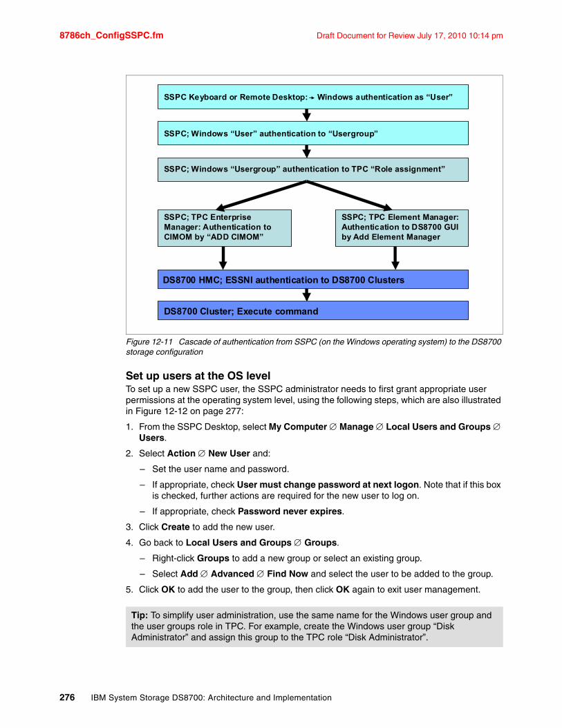
8786ch_ConfigSSPC.fm Draft Document for Review July 17, 2010 10:14 pm
Figure 12-11 Cascade of authentication from SSPC (on the Windows operating system) to the DS8700 storage configuration
Set up users at the OS levelTo set up a new SSPC user, the SSPC administrator needs to first grant appropriate user permissions at the operating system level, using the following steps, which are also illustrated in Figure 12-12 on page 277:
1. From the SSPC Desktop, select My Computer Manage Local Users and Groups Users.
2. Select Action New User and:
– Set the user name and password.
– If appropriate, check User must change password at next logon. Note that if this box is checked, further actions are required for the new user to log on.
– If appropriate, check Password never expires.
3. Click Create to add the new user.
4. Go back to Local Users and Groups Groups.
– Right-click Groups to add a new group or select an existing group.
– Select Add Advanced Find Now and select the user to be added to the group.
5. Click OK to add the user to the group, then click OK again to exit user management.
Tip: To simplify user administration, use the same name for the Windows user group and the user groups role in TPC. For example, create the Windows user group “Disk Administrator” and assign this group to the TPC role “Disk Administrator”.
SSPC Keyboard or Remote Desktop: Windows authentication as “User”
SSPC; Windows “User” authentication to “Usergroup”
SSPC; Windows “Usergroup” authentication to TPC “Role assignment”
SSPC; TPC Enterprise Manager: Authentication to CIMOM by “ADD CIMOM”
SSPC; TPC Element Manager: Authentication to DS8700 GUI by Add Element Manager
DS8700 HMC; ESSNI authentication to DS8700 Clusters
DS8700 Cluster; Execute command
276 IBM System Storage DS8700: Architecture and Implementation
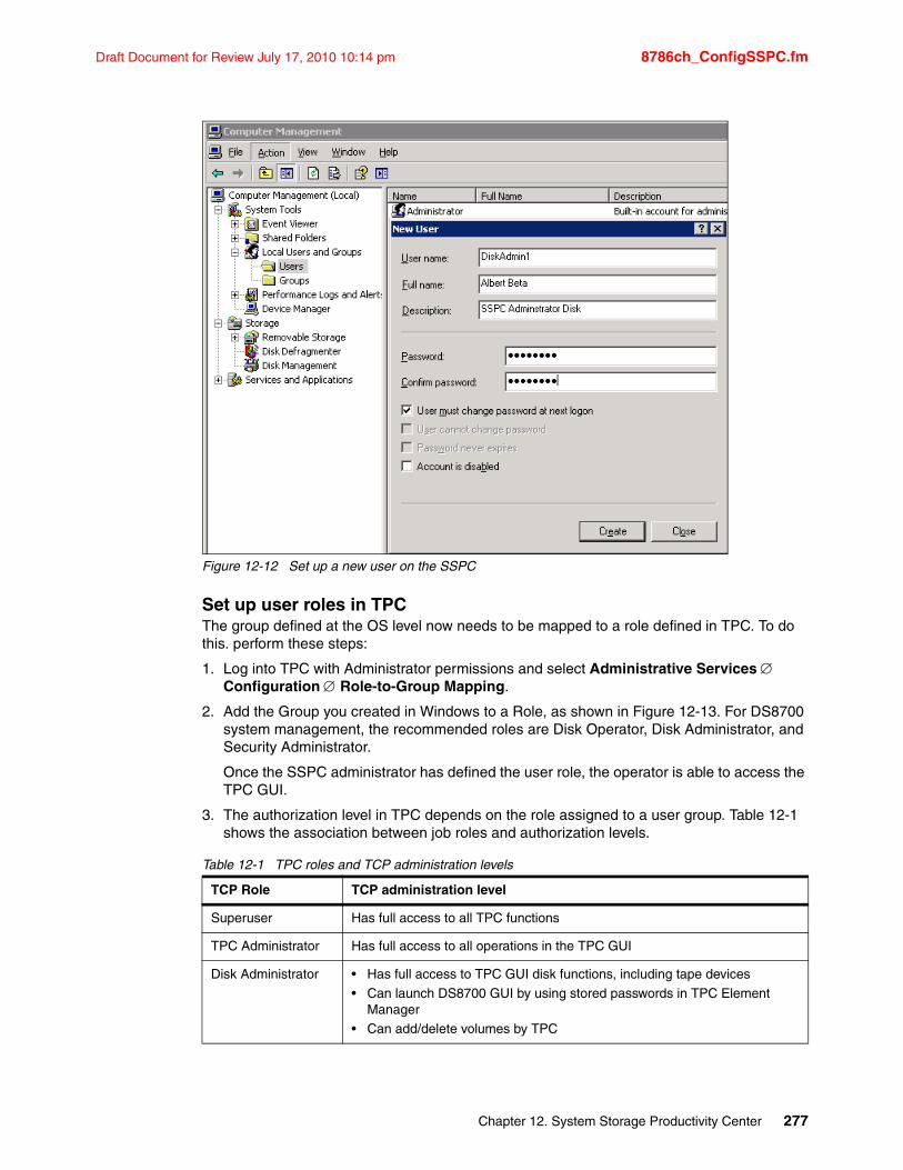
Draft Document for Review July 17, 2010 10:14 pm 8786ch_ConfigSSPC.fm
Figure 12-12 Set up a new user on the SSPC
Set up user roles in TPCThe group defined at the OS level now needs to be mapped to a role defined in TPC. To do this. perform these steps:
1. Log into TPC with Administrator permissions and select Administrative Services Configuration Role-to-Group Mapping.
2. Add the Group you created in Windows to a Role, as shown in Figure 12-13. For DS8700 system management, the recommended roles are Disk Operator, Disk Administrator, and Security Administrator.
Once the SSPC administrator has defined the user role, the operator is able to access the TPC GUI.
3. The authorization level in TPC depends on the role assigned to a user group. Table 12-1 shows the association between job roles and authorization levels.
Table 12-1 TPC roles and TCP administration levels
TCP Role TCP administration level
Superuser Has full access to all TPC functions
TPC Administrator Has full access to all operations in the TPC GUI
Disk Administrator • Has full access to TPC GUI disk functions, including tape devices• Can launch DS8700 GUI by using stored passwords in TPC Element
Manager• Can add/delete volumes by TPC
Chapter 12. System Storage Productivity Center 277
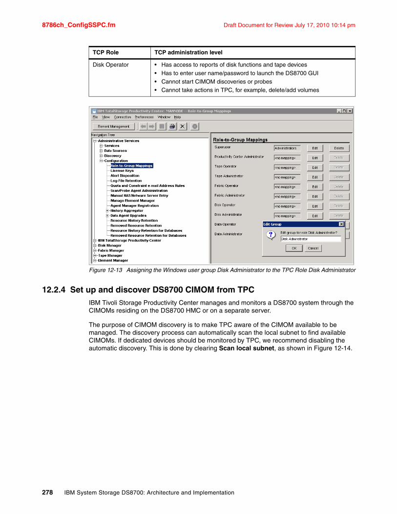
8786ch_ConfigSSPC.fm Draft Document for Review July 17, 2010 10:14 pm
Figure 12-13 Assigning the Windows user group Disk Administrator to the TPC Role Disk Administrator
12.2.4 Set up and discover DS8700 CIMOM from TPCIBM Tivoli Storage Productivity Center manages and monitors a DS8700 system through the CIMOMs residing on the DS8700 HMC or on a separate server.
The purpose of CIMOM discovery is to make TPC aware of the CIMOM available to be managed. The discovery process can automatically scan the local subnet to find available CIMOMs. If dedicated devices should be monitored by TPC, we recommend disabling the automatic discovery. This is done by clearing Scan local subnet, as shown in Figure 12-14.
Disk Operator • Has access to reports of disk functions and tape devices• Has to enter user name/password to launch the DS8700 GUI• Cannot start CIMOM discoveries or probes• Cannot take actions in TPC, for example, delete/add volumes
TCP Role TCP administration level
278 IBM System Storage DS8700: Architecture and Implementation
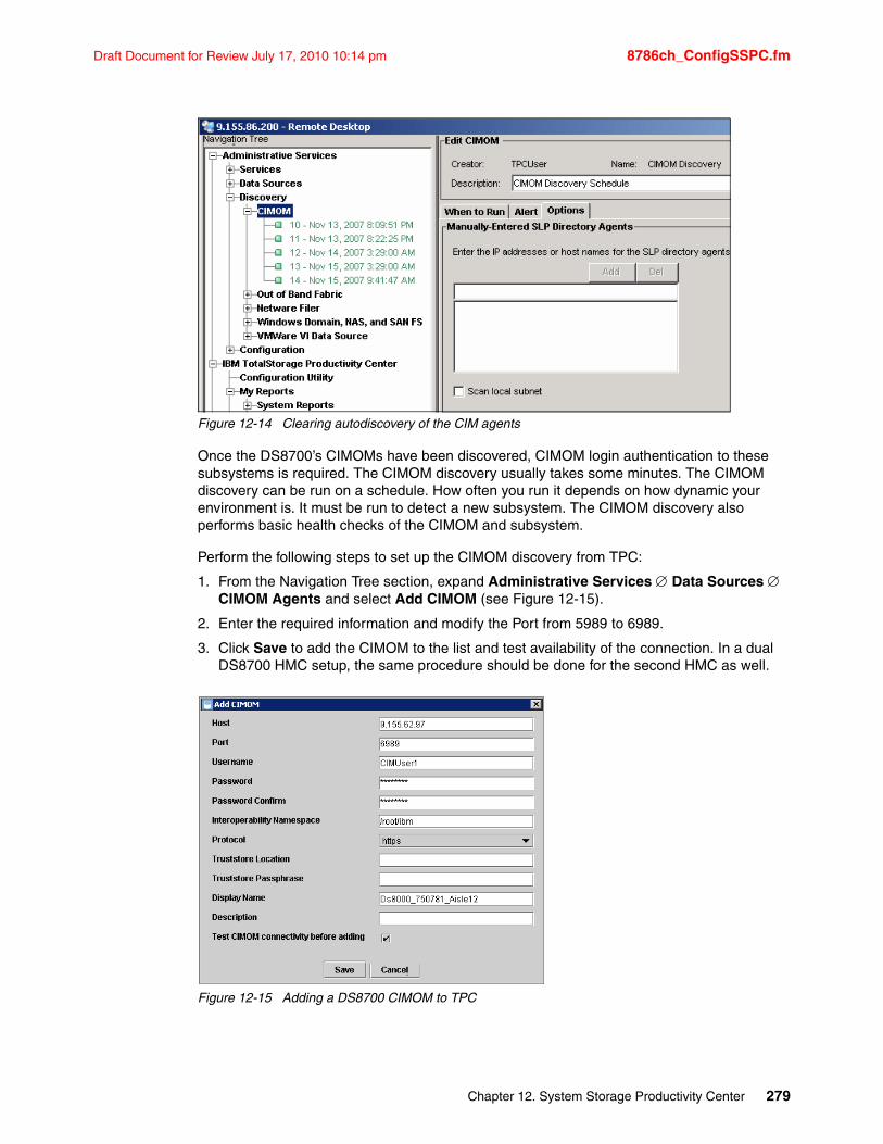
Draft Document for Review July 17, 2010 10:14 pm 8786ch_ConfigSSPC.fm
Figure 12-14 Clearing autodiscovery of the CIM agents
Once the DS8700’s CIMOMs have been discovered, CIMOM login authentication to these subsystems is required. The CIMOM discovery usually takes some minutes. The CIMOM discovery can be run on a schedule. How often you run it depends on how dynamic your environment is. It must be run to detect a new subsystem. The CIMOM discovery also performs basic health checks of the CIMOM and subsystem.
Perform the following steps to set up the CIMOM discovery from TPC:
1. From the Navigation Tree section, expand Administrative Services Data Sources CIMOM Agents and select Add CIMOM (see Figure 12-15).
2. Enter the required information and modify the Port from 5989 to 6989.
3. Click Save to add the CIMOM to the list and test availability of the connection. In a dual DS8700 HMC setup, the same procedure should be done for the second HMC as well.
Figure 12-15 Adding a DS8700 CIMOM to TPC
Chapter 12. System Storage Productivity Center 279
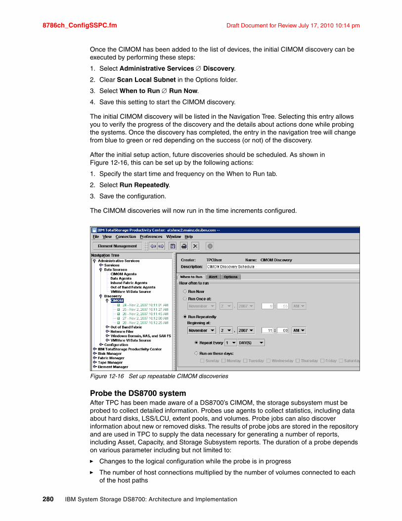
8786ch_ConfigSSPC.fm Draft Document for Review July 17, 2010 10:14 pm
Once the CIMOM has been added to the list of devices, the initial CIMOM discovery can be executed by performing these steps:
1. Select Administrative Services Discovery.
2. Clear Scan Local Subnet in the Options folder.
3. Select When to Run Run Now.
4. Save this setting to start the CIMOM discovery.
The initial CIMOM discovery will be listed in the Navigation Tree. Selecting this entry allows you to verify the progress of the discovery and the details about actions done while probing the systems. Once the discovery has completed, the entry in the navigation tree will change from blue to green or red depending on the success (or not) of the discovery.
After the initial setup action, future discoveries should be scheduled. As shown in Figure 12-16, this can be set up by the following actions:
1. Specify the start time and frequency on the When to Run tab.
2. Select Run Repeatedly.
3. Save the configuration.
The CIMOM discoveries will now run in the time increments configured.
Figure 12-16 Set up repeatable CIMOM discoveries
Probe the DS8700 systemAfter TPC has been made aware of a DS8700’s CIMOM, the storage subsystem must be probed to collect detailed information. Probes use agents to collect statistics, including data about hard disks, LSS/LCU, extent pools, and volumes. Probe jobs can also discover information about new or removed disks. The results of probe jobs are stored in the repository and are used in TPC to supply the data necessary for generating a number of reports, including Asset, Capacity, and Storage Subsystem reports. The duration of a probe depends on various parameter including but not limited to:
� Changes to the logical configuration while the probe is in progress
� The number of host connections multiplied by the number of volumes connected to each of the host paths
280 IBM System Storage DS8700: Architecture and Implementation
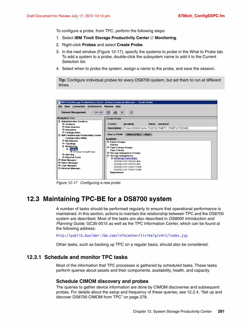
Draft Document for Review July 17, 2010 10:14 pm 8786ch_ConfigSSPC.fm
To configure a probe, from TPC, perform the following steps:
1. Select IBM Tivoli Storage Productivity Center Monitoring.
2. Right-click Probes and select Create Probe.
3. In the next window (Figure 12-17), specify the systems to probe in the What to Probe tab. To add a system to a probe, double-click the subsystem name to add it to the Current Selection list.
4. Select when to probe the system, assign a name to the probe, and save the session.
Figure 12-17 Configuring a new probe
12.3 Maintaining TPC-BE for a DS8700 systemA number of tasks should be performed regularly to ensure that operational performance is maintained. In this section, actions to maintain the relationship between TPC and the DS8700 system are described. Most of the tasks are also described in DS8000 Introduction and Planning Guide, GC35-0515 as well as the TPC Information Center, which can be found at the following address:
http://publib.boulder.ibm.com/infocenter/tivihelp/v4r1/index.jsp
Other tasks, such as backing up TPC on a regular basis, should also be considered.
12.3.1 Schedule and monitor TPC tasksMost of the information that TPC processes is gathered by scheduled tasks. These tasks perform queries about assets and their components, availability, health, and capacity.
Schedule CIMOM discovery and probesThe queries to gather device information are done by CIMOM discoveries and subsequent probes. For details about the setup and frequency of these queries, see 12.2.4, “Set up and discover DS8700 CIMOM from TPC” on page 278.
Tip: Configure individual probes for every DS8700 system, but set them to run at different times.
Chapter 12. System Storage Productivity Center 281
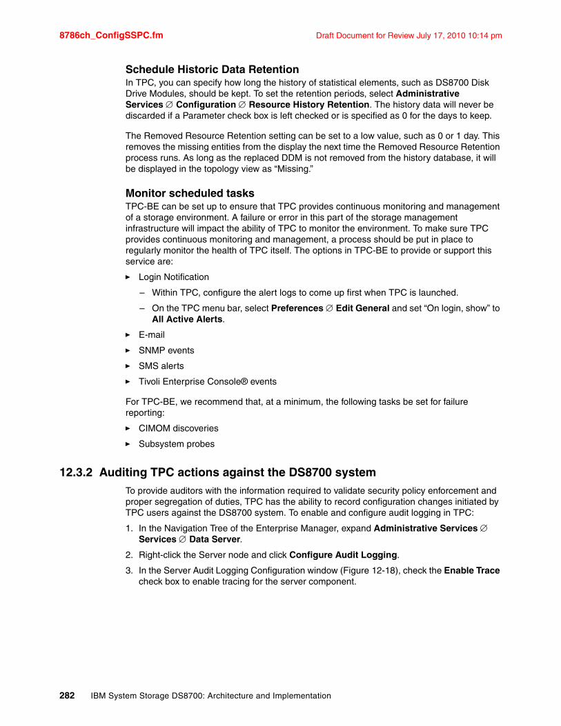
8786ch_ConfigSSPC.fm Draft Document for Review July 17, 2010 10:14 pm
Schedule Historic Data RetentionIn TPC, you can specify how long the history of statistical elements, such as DS8700 Disk Drive Modules, should be kept. To set the retention periods, select Administrative Services Configuration Resource History Retention. The history data will never be discarded if a Parameter check box is left checked or is specified as 0 for the days to keep.
The Removed Resource Retention setting can be set to a low value, such as 0 or 1 day. This removes the missing entities from the display the next time the Removed Resource Retention process runs. As long as the replaced DDM is not removed from the history database, it will be displayed in the topology view as “Missing.”
Monitor scheduled tasksTPC-BE can be set up to ensure that TPC provides continuous monitoring and management of a storage environment. A failure or error in this part of the storage management infrastructure will impact the ability of TPC to monitor the environment. To make sure TPC provides continuous monitoring and management, a process should be put in place to regularly monitor the health of TPC itself. The options in TPC-BE to provide or support this service are:
� Login Notification
– Within TPC, configure the alert logs to come up first when TPC is launched.
– On the TPC menu bar, select Preferences Edit General and set “On login, show” to All Active Alerts.
� SNMP events
� SMS alerts
� Tivoli Enterprise Console® events
For TPC-BE, we recommend that, at a minimum, the following tasks be set for failure reporting:
� CIMOM discoveries
� Subsystem probes
12.3.2 Auditing TPC actions against the DS8700 systemTo provide auditors with the information required to validate security policy enforcement and proper segregation of duties, TPC has the ability to record configuration changes initiated by TPC users against the DS8700 system. To enable and configure audit logging in TPC:
1. In the Navigation Tree of the Enterprise Manager, expand Administrative Services Services Data Server.
2. Right-click the Server node and click Configure Audit Logging.
3. In the Server Audit Logging Configuration window (Figure 12-18), check the Enable Trace check box to enable tracing for the server component.
282 IBM System Storage DS8700: Architecture and Implementation
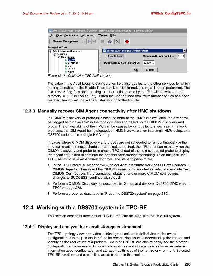
Draft Document for Review July 17, 2010 10:14 pm 8786ch_ConfigSSPC.fm
Figure 12-18 Configuring TPC Audit Logging
The value in the Audit Logging Configuration field also applies to the other services for which tracing is enabled. If the Enable Trace check box is cleared, tracing will not be performed. The Audittrace.log files documenting the user actions done by the GUI will be written to the directory <TPC_HOME>/data/log/. When the user-defined maximum number of files has been reached, tracing will roll over and start writing to the first file.
12.3.3 Manually recover CIM Agent connectivity after HMC shutdownIf a CIMOM discovery or probe fails because none of the HMCs are available, the device will be flagged as “unavailable” in the topology view and “failed” in the CIMOM discovery and probe. The unavailability of the HMC can be caused by various factors, such as IP network problems, the CIM Agent being stopped, an HMC hardware error in a single HMC setup, or a DS8700 codeload in a single HMC setup.
In cases where CIMOM discovery and probes are not scheduled to run continuously or the time frame until the next scheduled run is not as desired, the TPC user can manually run the CIMOM discovery and probe to re-enable TPC ahead of the next scheduled probe to display the health status and to continue the optional performance monitoring. To do this task, the TPC user must have an Administrator role. The steps to perform are:
1. In the TPC Enterprise Manager view, select Administrative Services Data Sources CIMOM Agents. Then select the CIMOM connections reported as failed and execute Test CIMOM Connection. If the connection status of one or more CIMOM connections changes to SUCCESS, continue with step 2.
2. Perform a CIMOM Discovery, as described in “Set up and discover DS8700 CIMOM from TPC” on page 278.
3. Perform a probe, as described in “Probe the DS8700 system” on page 280.
12.4 Working with a DS8700 system in TPC-BEThis section describes functions of TPC-BE that can be used with the DS8700 system.
12.4.1 Display and analyze the overall storage environment
The TPC topology viewer provides a linked graphical and detailed view of the overall configuration. It is the primary interface for recognizing issues, understanding the impact, and identifying the root cause of a problem. Users of TPC-BE are able to easily see the storage configuration and can easily drill down into switches and storage devices for more detailed information about configuration and storage healthiness of their entire environment. Selected TPC-BE functions and capabilities are described in this section.
Chapter 12. System Storage Productivity Center 283
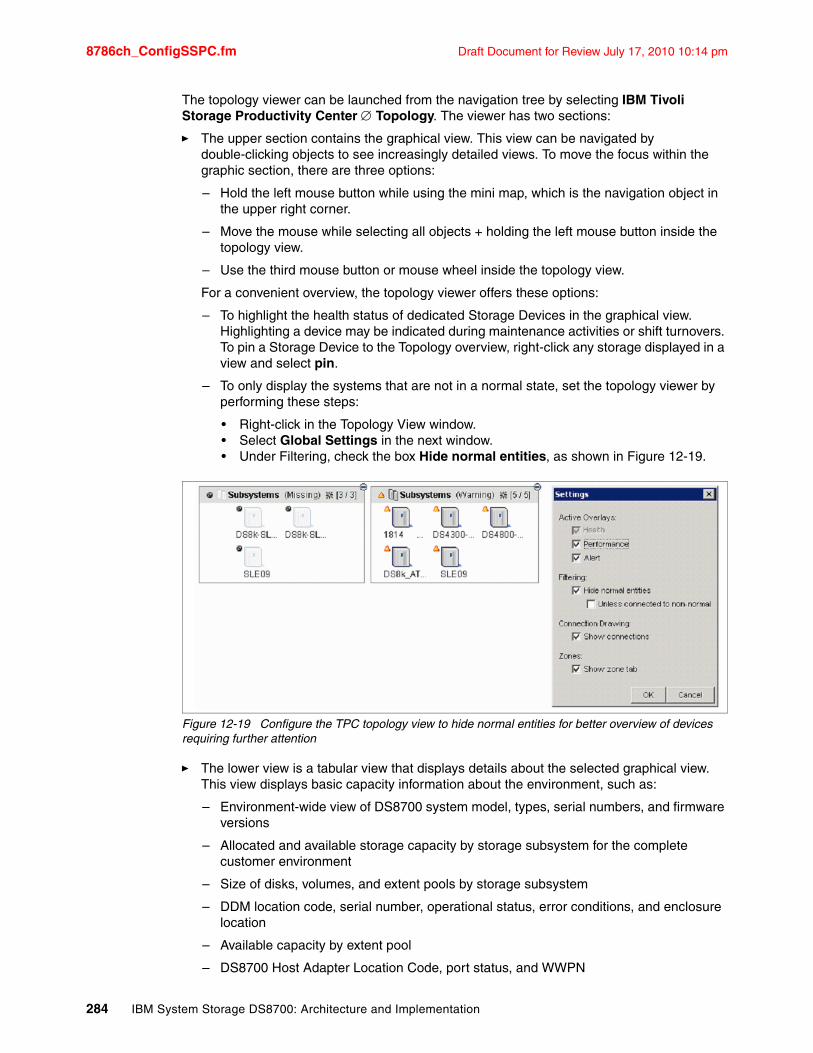
8786ch_ConfigSSPC.fm Draft Document for Review July 17, 2010 10:14 pm
The topology viewer can be launched from the navigation tree by selecting IBM Tivoli Storage Productivity Center Topology. The viewer has two sections:
� The upper section contains the graphical view. This view can be navigated by double-clicking objects to see increasingly detailed views. To move the focus within the graphic section, there are three options:
– Hold the left mouse button while using the mini map, which is the navigation object in the upper right corner.
– Move the mouse while selecting all objects + holding the left mouse button inside the topology view.
– Use the third mouse button or mouse wheel inside the topology view.
For a convenient overview, the topology viewer offers these options:
– To highlight the health status of dedicated Storage Devices in the graphical view. Highlighting a device may be indicated during maintenance activities or shift turnovers. To pin a Storage Device to the Topology overview, right-click any storage displayed in a view and select pin.
– To only display the systems that are not in a normal state, set the topology viewer by performing these steps:
• Right-click in the Topology View window.• Select Global Settings in the next window. • Under Filtering, check the box Hide normal entities, as shown in Figure 12-19.
Figure 12-19 Configure the TPC topology view to hide normal entities for better overview of devices requiring further attention
� The lower view is a tabular view that displays details about the selected graphical view. This view displays basic capacity information about the environment, such as:
– Environment-wide view of DS8700 system model, types, serial numbers, and firmware versions
– Allocated and available storage capacity by storage subsystem for the complete customer environment
– Size of disks, volumes, and extent pools by storage subsystem
– DDM location code, serial number, operational status, error conditions, and enclosure location
– Available capacity by extent pool
– DS8700 Host Adapter Location Code, port status, and WWPN
284 IBM System Storage DS8700: Architecture and Implementation
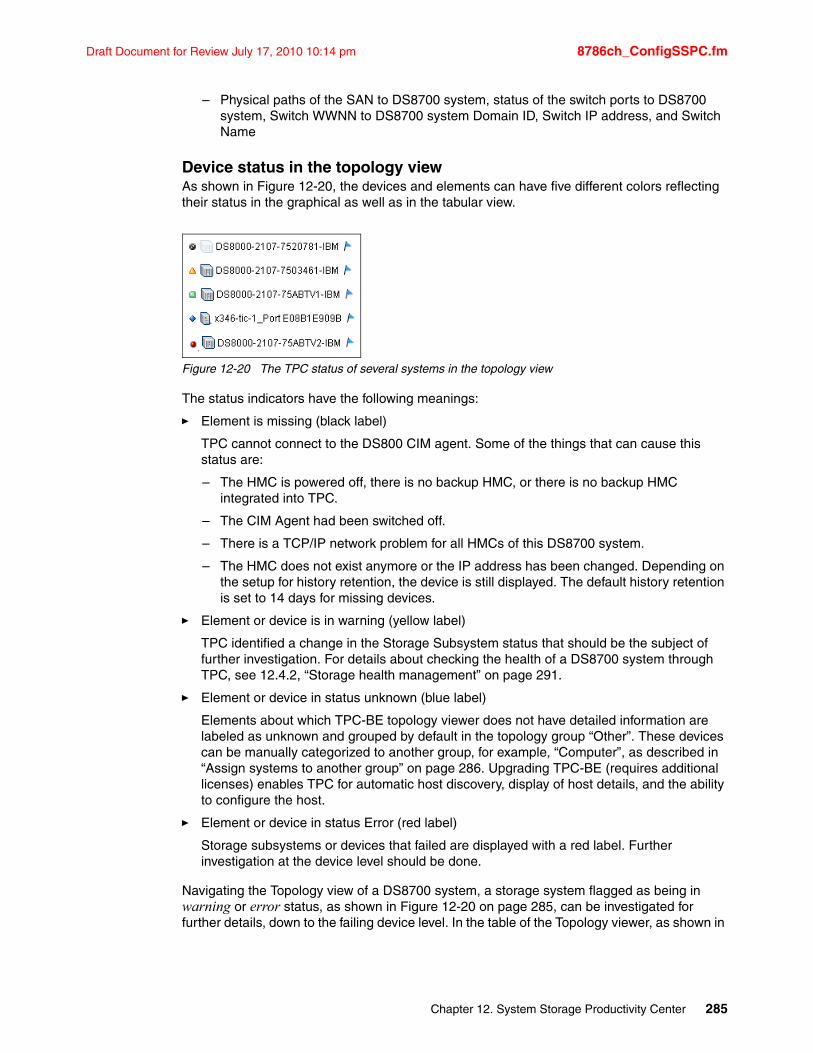
Draft Document for Review July 17, 2010 10:14 pm 8786ch_ConfigSSPC.fm
– Physical paths of the SAN to DS8700 system, status of the switch ports to DS8700 system, Switch WWNN to DS8700 system Domain ID, Switch IP address, and Switch Name
Device status in the topology viewAs shown in Figure 12-20, the devices and elements can have five different colors reflecting their status in the graphical as well as in the tabular view.
Figure 12-20 The TPC status of several systems in the topology view
The status indicators have the following meanings:
� Element is missing (black label)
TPC cannot connect to the DS800 CIM agent. Some of the things that can cause this status are:
– The HMC is powered off, there is no backup HMC, or there is no backup HMC integrated into TPC.
– The CIM Agent had been switched off.
– There is a TCP/IP network problem for all HMCs of this DS8700 system.
– The HMC does not exist anymore or the IP address has been changed. Depending on the setup for history retention, the device is still displayed. The default history retention is set to 14 days for missing devices.
� Element or device is in warning (yellow label)
TPC identified a change in the Storage Subsystem status that should be the subject of further investigation. For details about checking the health of a DS8700 system through TPC, see 12.4.2, “Storage health management” on page 291.
� Element or device in status unknown (blue label)
Elements about which TPC-BE topology viewer does not have detailed information are labeled as unknown and grouped by default in the topology group “Other”. These devices can be manually categorized to another group, for example, “Computer”, as described in “Assign systems to another group” on page 286. Upgrading TPC-BE (requires additional licenses) enables TPC for automatic host discovery, display of host details, and the ability to configure the host.
� Element or device in status Error (red label)
Storage subsystems or devices that failed are displayed with a red label. Further investigation at the device level should be done.
Navigating the Topology view of a DS8700 system, a storage system flagged as being in warning or error status, as shown in Figure 12-20 on page 285, can be investigated for further details, down to the failing device level. In the table of the Topology viewer, as shown in
Chapter 12. System Storage Productivity Center 285
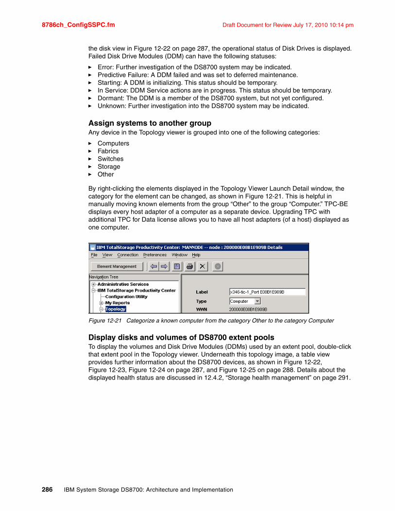
8786ch_ConfigSSPC.fm Draft Document for Review July 17, 2010 10:14 pm
the disk view in Figure 12-22 on page 287, the operational status of Disk Drives is displayed. Failed Disk Drive Modules (DDM) can have the following statuses:
� Error: Further investigation of the DS8700 system may be indicated.� Predictive Failure: A DDM failed and was set to deferred maintenance.� Starting: A DDM is initializing. This status should be temporary.� In Service: DDM Service actions are in progress. This status should be temporary.� Dormant: The DDM is a member of the DS8700 system, but not yet configured.� Unknown: Further investigation into the DS8700 system may be indicated.
Assign systems to another groupAny device in the Topology viewer is grouped into one of the following categories:
� Computers� Fabrics� Switches� Storage� Other
By right-clicking the elements displayed in the Topology Viewer Launch Detail window, the category for the element can be changed, as shown in Figure 12-21. This is helpful in manually moving known elements from the group “Other” to the group “Computer.” TPC-BE displays every host adapter of a computer as a separate device. Upgrading TPC with additional TPC for Data license allows you to have all host adapters (of a host) displayed as one computer.
Figure 12-21 Categorize a known computer from the category Other to the category Computer
Display disks and volumes of DS8700 extent poolsTo display the volumes and Disk Drive Modules (DDMs) used by an extent pool, double-click that extent pool in the Topology viewer. Underneath this topology image, a table view provides further information about the DS8700 devices, as shown in Figure 12-22, Figure 12-23, Figure 12-24 on page 287, and Figure 12-25 on page 288. Details about the displayed health status are discussed in 12.4.2, “Storage health management” on page 291.
286 IBM System Storage DS8700: Architecture and Implementation
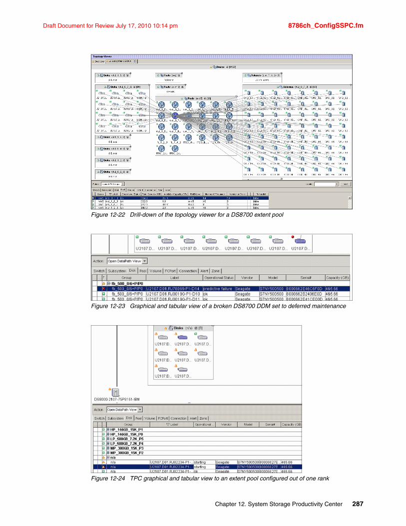
Draft Document for Review July 17, 2010 10:14 pm 8786ch_ConfigSSPC.fm
Figure 12-22 Drill-down of the topology viewer for a DS8700 extent pool
Figure 12-23 Graphical and tabular view of a broken DS8700 DDM set to deferred maintenance
Figure 12-24 TPC graphical and tabular view to an extent pool configured out of one rank
Chapter 12. System Storage Productivity Center 287
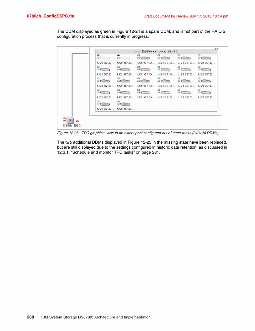
8786ch_ConfigSSPC.fm Draft Document for Review July 17, 2010 10:14 pm
The DDM displayed as green in Figure 12-24 is a spare DDM, and is not part of the RAID 5 configuration process that is currently in progress.
Figure 12-25 TPC graphical view to an extent pool configured out of three ranks (3x8=24 DDMs)
The two additional DDMs displayed in Figure 12-25 in the missing state have been replaced, but are still displayed due to the settings configured in historic data retention, as discussed in 12.3.1, “Schedule and monitor TPC tasks” on page 281.
288 IBM System Storage DS8700: Architecture and Implementation
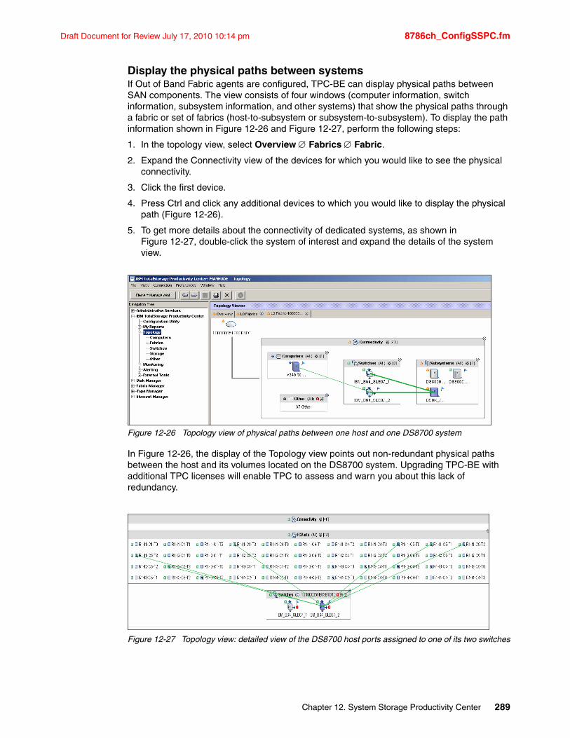
Draft Document for Review July 17, 2010 10:14 pm 8786ch_ConfigSSPC.fm
Display the physical paths between systemsIf Out of Band Fabric agents are configured, TPC-BE can display physical paths between SAN components. The view consists of four windows (computer information, switch information, subsystem information, and other systems) that show the physical paths through a fabric or set of fabrics (host-to-subsystem or subsystem-to-subsystem). To display the path information shown in Figure 12-26 and Figure 12-27, perform the following steps:
1. In the topology view, select Overview Fabrics Fabric.
2. Expand the Connectivity view of the devices for which you would like to see the physical connectivity.
3. Click the first device.
4. Press Ctrl and click any additional devices to which you would like to display the physical path (Figure 12-26).
5. To get more details about the connectivity of dedicated systems, as shown in Figure 12-27, double-click the system of interest and expand the details of the system view.
Figure 12-26 Topology view of physical paths between one host and one DS8700 system
In Figure 12-26, the display of the Topology view points out non-redundant physical paths between the host and its volumes located on the DS8700 system. Upgrading TPC-BE with additional TPC licenses will enable TPC to assess and warn you about this lack of redundancy.
Figure 12-27 Topology view: detailed view of the DS8700 host ports assigned to one of its two switches
Chapter 12. System Storage Productivity Center 289
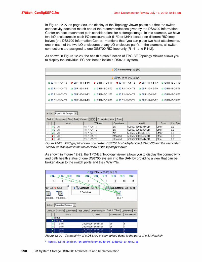
8786ch_ConfigSSPC.fm Draft Document for Review July 17, 2010 10:14 pm
In Figure 12-27 on page 289, the display of the Topology viewer points out that the switch connectivity does not match one of the recommendations given by the DS8700 Information Center on host attachment path considerations for a storage image. In this example, we have two I/O enclosures in each I/O enclosure pair (I1/I2 or I3/I4) located on different RIO loop halves (the DS8700 Information Center1 mentions that “you can place two host attachments, one in each of the two I/O enclosures of any I/O enclosure pair”). In the example, all switch connections are assigned to one DS8700 RIO loop only (R1-I1 and R1-I2).
As shown in Figure 12-28, the health status function of TPC-BE Topology Viewer allows you to display the individual FC port health inside a DS8700 system.
Figure 12-28 TPC graphical view of a broken DS8700 host adapter Card R1-I1-C5 and the associated WWNN as displayed in the tabular view of the topology viewer
As shown in Figure 12-29, the TPC-BE Topology viewer allows you to display the connectivity and path health status of one DS8700 system into the SAN by providing a view that can be broken down to the switch ports and their WWPNs.
Figure 12-29 Connectivity of a DS8700 system drilled down to the ports of a SAN switch
1 http://publib.boulder.ibm.com/infocenter/dsichelp/ds8000ic/index.jsp
290 IBM System Storage DS8700: Architecture and Implementation
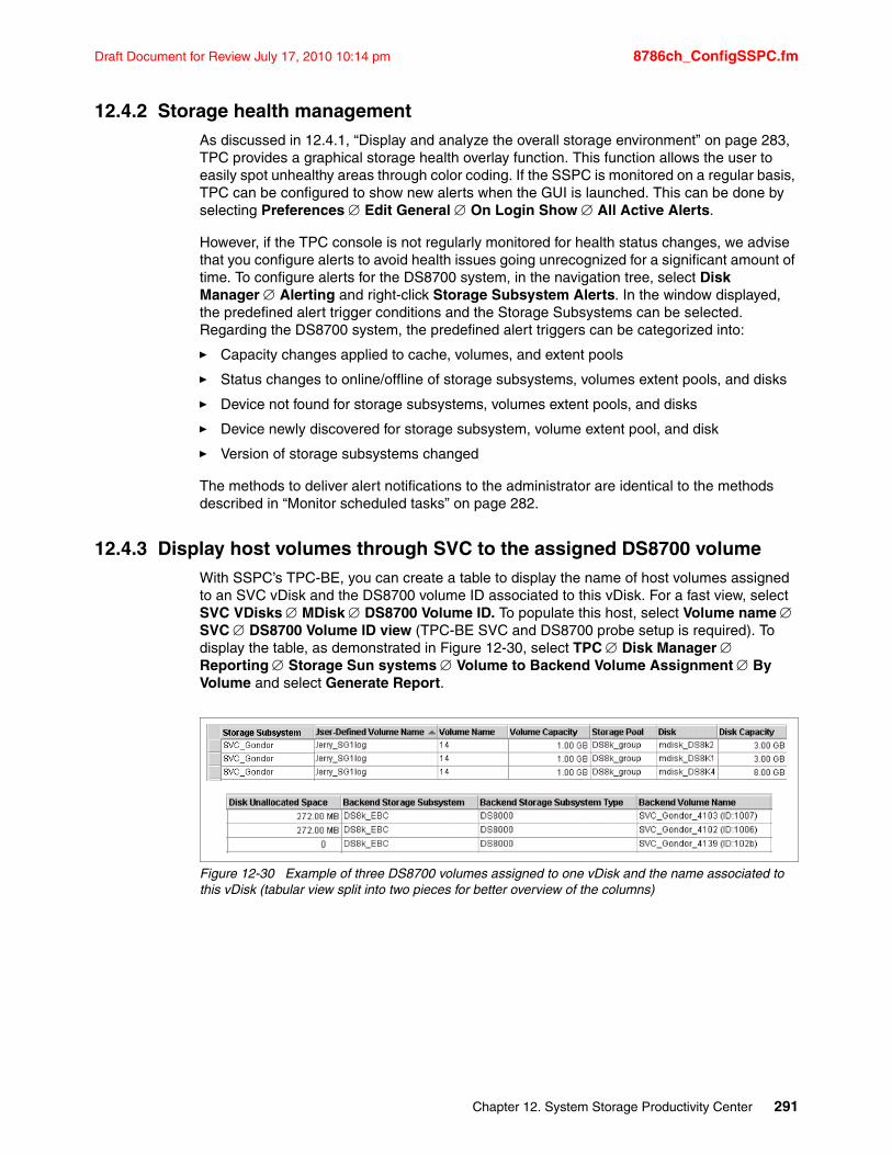
Draft Document for Review July 17, 2010 10:14 pm 8786ch_ConfigSSPC.fm
12.4.2 Storage health management As discussed in 12.4.1, “Display and analyze the overall storage environment” on page 283, TPC provides a graphical storage health overlay function. This function allows the user to easily spot unhealthy areas through color coding. If the SSPC is monitored on a regular basis, TPC can be configured to show new alerts when the GUI is launched. This can be done by selecting Preferences Edit General On Login Show All Active Alerts.
However, if the TPC console is not regularly monitored for health status changes, we advise that you configure alerts to avoid health issues going unrecognized for a significant amount of time. To configure alerts for the DS8700 system, in the navigation tree, select Disk Manager Alerting and right-click Storage Subsystem Alerts. In the window displayed, the predefined alert trigger conditions and the Storage Subsystems can be selected. Regarding the DS8700 system, the predefined alert triggers can be categorized into:
� Capacity changes applied to cache, volumes, and extent pools
� Status changes to online/offline of storage subsystems, volumes extent pools, and disks
� Device not found for storage subsystems, volumes extent pools, and disks
� Device newly discovered for storage subsystem, volume extent pool, and disk
� Version of storage subsystems changed
The methods to deliver alert notifications to the administrator are identical to the methods described in “Monitor scheduled tasks” on page 282.
12.4.3 Display host volumes through SVC to the assigned DS8700 volumeWith SSPC’s TPC-BE, you can create a table to display the name of host volumes assigned to an SVC vDisk and the DS8700 volume ID associated to this vDisk. For a fast view, select SVC VDisks MDisk DS8700 Volume ID. To populate this host, select Volume name SVC DS8700 Volume ID view (TPC-BE SVC and DS8700 probe setup is required). To display the table, as demonstrated in Figure 12-30, select TPC Disk Manager Reporting Storage Sun systems Volume to Backend Volume Assignment By Volume and select Generate Report.
Figure 12-30 Example of three DS8700 volumes assigned to one vDisk and the name associated to this vDisk (tabular view split into two pieces for better overview of the columns)
Chapter 12. System Storage Productivity Center 291

8786ch_ConfigSSPC.fm Draft Document for Review July 17, 2010 10:14 pm
292 IBM System Storage DS8700: Architecture and Implementation
Draft Document for Review July 17, 2010 10:14 pm 8786ch_ConfigGUI.fm
Chapter 13. Configuration using the DS Storage Manager GUI
The DS Storage Manager provides a graphical user interface (GUI) to configure the IBM System Storage DS8700 series and manage DS8700 Copy Services. The DS Storage Manager GUI (DS GUI) is invoked from SSPC. In this chapter, we explain the possible ways to access the DS GUI, and how to use it to configure the storage on the DS8700.
This chapter includes the following sections:
� DS Storage Manager GUI overview
� Logical configuration process
� Examples of configuring DS8700 storage
� Examples of exploring DS8700 storage status and hardware
For information about Copy Services configuration in the DS8000 family using the DS GUI, refer to the following IBM Redbooks publications:
� IBM System Storage DS8000: Copy Services in Open Environments, SG24-6788� DS8000 Copy Services for IBM System z, SG24-6787
For information about DS GUI changes related to disk encryption, refer to IBM System Storage DS8700: Disk Encryption Implementation and Usage Guidelines, REDP-4500.
For information about DS GUI changes related to LDAP authentication, refer to IBM System Storage DS8000: LDAP Authentication, REDP-4505.
For information about GUI changes related to the Easy Tier function, including dynamic volume relocation (DVR) and extent pool merge, refer to the IBM System Storage DS8700: Easy TIer, REDP-4667.
13
Note: Some of the screen captures in this chapter might not reflect the latest version of the DS GUI code.
© Copyright IBM Corp. 2010. All rights reserved. 293
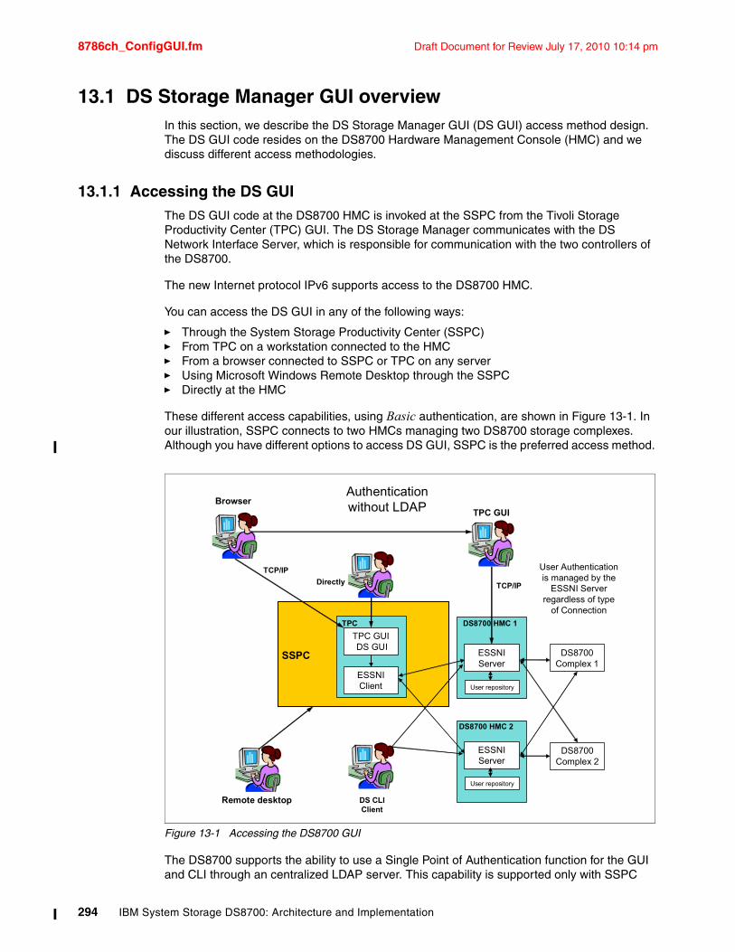
8786ch_ConfigGUI.fm Draft Document for Review July 17, 2010 10:14 pm
13.1 DS Storage Manager GUI overviewIn this section, we describe the DS Storage Manager GUI (DS GUI) access method design. The DS GUI code resides on the DS8700 Hardware Management Console (HMC) and we discuss different access methodologies.
13.1.1 Accessing the DS GUIThe DS GUI code at the DS8700 HMC is invoked at the SSPC from the Tivoli Storage Productivity Center (TPC) GUI. The DS Storage Manager communicates with the DS Network Interface Server, which is responsible for communication with the two controllers of the DS8700.
The new Internet protocol IPv6 supports access to the DS8700 HMC.
You can access the DS GUI in any of the following ways:
� Through the System Storage Productivity Center (SSPC)� From TPC on a workstation connected to the HMC� From a browser connected to SSPC or TPC on any server� Using Microsoft Windows Remote Desktop through the SSPC� Directly at the HMC
These different access capabilities, using Basic authentication, are shown in Figure 13-1. In our illustration, SSPC connects to two HMCs managing two DS8700 storage complexes. Although you have different options to access DS GUI, SSPC is the preferred access method.
Figure 13-1 Accessing the DS8700 GUI
The DS8700 supports the ability to use a Single Point of Authentication function for the GUI and CLI through an centralized LDAP server. This capability is supported only with SSPC
TPC GUIDS GUI
TPC
ESSNIServer
DS8700 HMC 1
DS8700Complex 1
SSPC
ESSNIServer
DS8700 HMC 2
DS8700Complex 2
Directly
TPC GUI
TCP/IP
TCP/IP
Browser
Remote desktop
ESSNI Client
DS CLIClient
Authentication without LDAP
User Authentication is managed by the
ESSNI Server regardless of type
of Connection
User repository
User repository
294 IBM System Storage DS8700: Architecture and Implementation
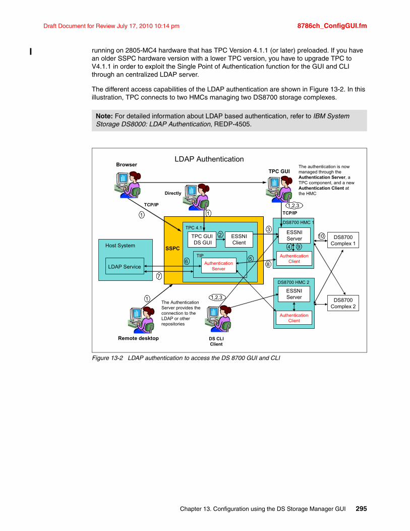
Draft Document for Review July 17, 2010 10:14 pm 8786ch_ConfigGUI.fm
running on 2805-MC4 hardware that has TPC Version 4.1.1 (or later) preloaded. If you have an older SSPC hardware version with a lower TPC version, you have to upgrade TPC to V4.1.1 in order to exploit the Single Point of Authentication function for the GUI and CLI through an centralized LDAP server.
The different access capabilities of the LDAP authentication are shown in Figure 13-2. In this illustration, TPC connects to two HMCs managing two DS8700 storage complexes.
Figure 13-2 LDAP authentication to access the DS 8700 GUI and CLI
Note: For detailed information about LDAP based authentication, refer to IBM System Storage DS8000: LDAP Authentication, REDP-4505.
TPC GUIDS GUI
TPC 4.1ESSNIServer
DS8700 HMC 1
DS8700Complex 1
SSPC
ESSNIServer
DS8700 HMC 2
DS8700Complex 2
Directly
TPC GUI
TCP/IP
TCP/IP
Browser
Remote desktop
AuthenticationServer
DS CLIClient
Authentication Client
Authentication Client
TIP
LDAP Service
Host System
LDAP Authentication
The Authentication Server provides the connection to the LDAP or other repositories
The authentication is now managed through the Authentication Server, a TPC component, and a new Authentication Client at the HMC
ESSNI Client
1
23
4
56
7
8
9
10
1
1,2,3
1 1,2,3
Chapter 13. Configuration using the DS Storage Manager GUI 295
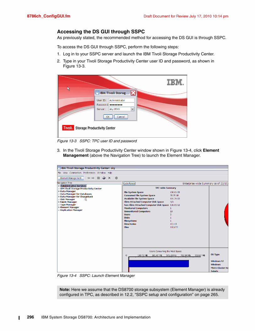
8786ch_ConfigGUI.fm Draft Document for Review July 17, 2010 10:14 pm
Accessing the DS GUI through SSPCAs previously stated, the recommended method for accessing the DS GUI is through SSPC.
To access the DS GUI through SSPC, perform the following steps:
1. Log in to your SSPC server and launch the IBM Tivoli Storage Productivity Center.
2. Type in your Tivoli Storage Productivity Center user ID and password, as shown in Figure 13-3.
Figure 13-3 SSPC: TPC user ID and password
3. In the Tivoli Storage Productivity Center window shown in Figure 13-4, click Element Management (above the Navigation Tree) to launch the Element Manager.
Figure 13-4 SSPC: Launch Element Manager
Note: Here we assume that the DS8700 storage subsystem (Element Manager) is already configured in TPC, as described in 12.2, “SSPC setup and configuration” on page 265.
296 IBM System Storage DS8700: Architecture and Implementation
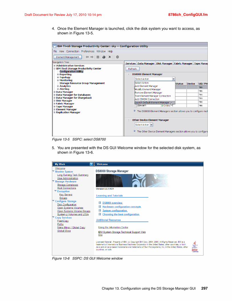
Draft Document for Review July 17, 2010 10:14 pm 8786ch_ConfigGUI.fm
4. Once the Element Manager is launched, click the disk system you want to access, as shown in Figure 13-5.
Figure 13-5 SSPC: select DS8700
5. You are presented with the DS GUI Welcome window for the selected disk system, as shown in Figure 13-6.
Figure 13-6 SSPC: DS GUI Welcome window
Chapter 13. Configuration using the DS Storage Manager GUI 297
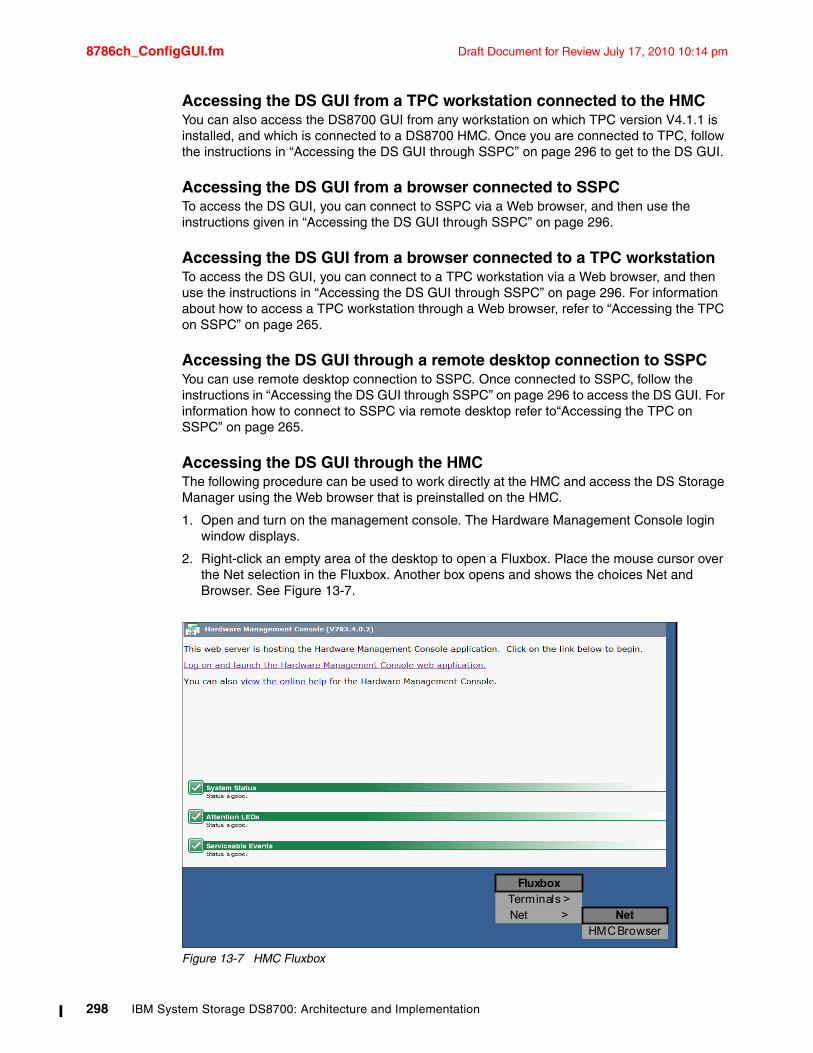
8786ch_ConfigGUI.fm Draft Document for Review July 17, 2010 10:14 pm
Accessing the DS GUI from a TPC workstation connected to the HMCYou can also access the DS8700 GUI from any workstation on which TPC version V4.1.1 is installed, and which is connected to a DS8700 HMC. Once you are connected to TPC, follow the instructions in “Accessing the DS GUI through SSPC” on page 296 to get to the DS GUI.
Accessing the DS GUI from a browser connected to SSPCTo access the DS GUI, you can connect to SSPC via a Web browser, and then use the instructions given in “Accessing the DS GUI through SSPC” on page 296.
Accessing the DS GUI from a browser connected to a TPC workstationTo access the DS GUI, you can connect to a TPC workstation via a Web browser, and then use the instructions in “Accessing the DS GUI through SSPC” on page 296. For information about how to access a TPC workstation through a Web browser, refer to “Accessing the TPC on SSPC” on page 265.
Accessing the DS GUI through a remote desktop connection to SSPCYou can use remote desktop connection to SSPC. Once connected to SSPC, follow the instructions in “Accessing the DS GUI through SSPC” on page 296 to access the DS GUI. For information how to connect to SSPC via remote desktop refer to“Accessing the TPC on SSPC” on page 265.
Accessing the DS GUI through the HMCThe following procedure can be used to work directly at the HMC and access the DS Storage Manager using the Web browser that is preinstalled on the HMC.
1. Open and turn on the management console. The Hardware Management Console login window displays.
2. Right-click an empty area of the desktop to open a Fluxbox. Place the mouse cursor over the Net selection in the Fluxbox. Another box opens and shows the choices Net and Browser. See Figure 13-7.
Figure 13-7 HMC Fluxbox
HMC Browser
Terminals >Net >
Fluxbox
Net
298 IBM System Storage DS8700: Architecture and Implementation
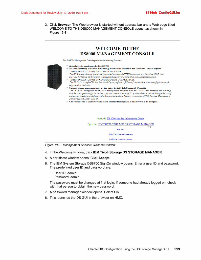
Draft Document for Review July 17, 2010 10:14 pm 8786ch_ConfigGUI.fm
3. Click Browser. The Web browser is started without address bar and a Web page titled WELCOME TO THE DS8000 MANAGEMENT CONSOLE opens, as shown in Figure 13-8.
Figure 13-8 Management Console Welcome window
4. In the Welcome window, click IBM Tivoli Storage DS STORAGE MANAGER.
5. A certificate window opens. Click Accept.
6. The IBM System Storage DS8700 SignOn window opens. Enter a user ID and password. The predefined user ID and password are:
– User ID: admin– Password: admin
The password must be changed at first login. If someone had already logged on, check with that person to obtain the new password.
7. A password manager window opens. Select OK.
8. This launches the DS GUI in the browser on HMC.
Chapter 13. Configuration using the DS Storage Manager GUI 299
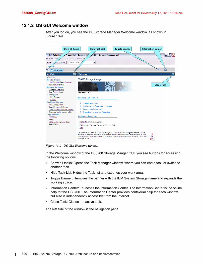
8786ch_ConfigGUI.fm Draft Document for Review July 17, 2010 10:14 pm
13.1.2 DS GUI Welcome windowAfter you log on, you see the DS Storage Manager Welcome window, as shown in Figure 13-9.
Figure 13-9 DS GUI Welcome window
In the Welcome window of the DS8700 Storage Manger GUI, you see buttons for accessing the following options:
� Show all tasks: Opens the Task Manager window, where you can end a task or switch to another task.
� Hide Task List: Hides the Task list and expands your work area.
� Toggle Banner: Removes the banner with the IBM System Storage name and expands the working space.
� Information Center: Launches the Information Center. The Information Center is the online help for the DS8700. The Information Center provides contextual help for each window, but also is independently accessible from the Internet.
� Close Task: Closes the active task.
The left side of the window is the navigation pane.
Toggle Banner Information CenterShow all Tasks Hide Task List
Close Task
300 IBM System Storage DS8700: Architecture and Implementation
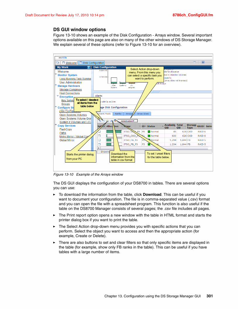
Draft Document for Review July 17, 2010 10:14 pm 8786ch_ConfigGUI.fm
DS GUI window optionsFigure 13-10 shows an example of the Disk Configuration - Arrays window. Several important options available on this page are also on many of the other windows of DS Storage Manager. We explain several of these options (refer to Figure 13-10 for an overview).
Figure 13-10 Example of the Arrays window
The DS GUI displays the configuration of your DS8700 in tables. There are several options you can use:
� To download the information from the table, click Download. This can be useful if you want to document your configuration. The file is in comma-separated value (.csv) format and you can open the file with a spreadsheet program. This function is also useful if the table on the DS8700 Manager consists of several pages; the .csv file includes all pages.
� The Print report option opens a new window with the table in HTML format and starts the printer dialog box if you want to print the table.
� The Select Action drop-down menu provides you with specific actions that you can perform. Select the object you want to access and then the appropriate action (for example, Create or Delete).
� There are also buttons to set and clear filters so that only specific items are displayed in the table (for example, show only FB ranks in the table). This can be useful if you have tables with a large number of items.
Starts the printer dialog
from your PC
Select Action drop-down menu. From this menu you
can select a specific task you want to perform.
.To set / unset filters for the table below.
To select / deselect all items from the
table below
To select / deselect all items from the
table below
To select / deselect all items from the
Download the information from the table in csv format
Chapter 13. Configuration using the DS Storage Manager GUI 301
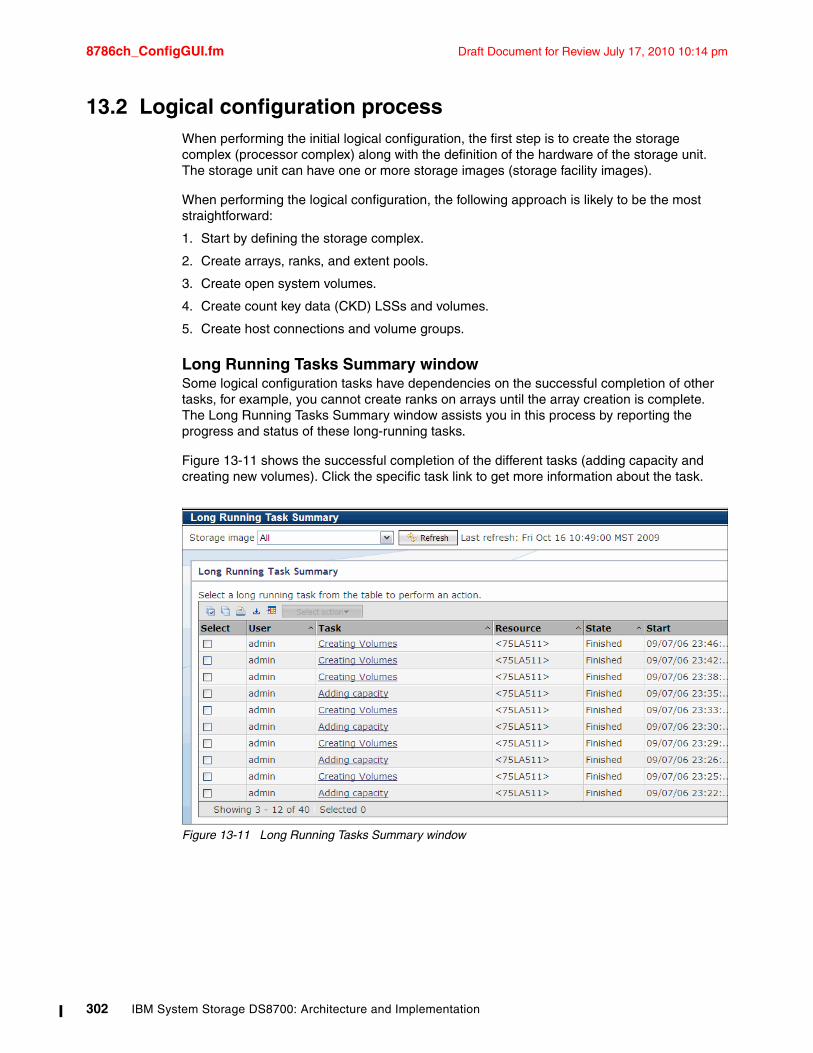
8786ch_ConfigGUI.fm Draft Document for Review July 17, 2010 10:14 pm
13.2 Logical configuration processWhen performing the initial logical configuration, the first step is to create the storage complex (processor complex) along with the definition of the hardware of the storage unit. The storage unit can have one or more storage images (storage facility images).
When performing the logical configuration, the following approach is likely to be the most straightforward:
1. Start by defining the storage complex.
2. Create arrays, ranks, and extent pools.
3. Create open system volumes.
4. Create count key data (CKD) LSSs and volumes.
5. Create host connections and volume groups.
Long Running Tasks Summary windowSome logical configuration tasks have dependencies on the successful completion of other tasks, for example, you cannot create ranks on arrays until the array creation is complete. The Long Running Tasks Summary window assists you in this process by reporting the progress and status of these long-running tasks.
Figure 13-11 shows the successful completion of the different tasks (adding capacity and creating new volumes). Click the specific task link to get more information about the task.
Figure 13-11 Long Running Tasks Summary window
302 IBM System Storage DS8700: Architecture and Implementation
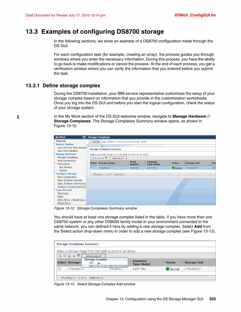
Draft Document for Review July 17, 2010 10:14 pm 8786ch_ConfigGUI.fm
13.3 Examples of configuring DS8700 storageIn the following sections, we show an example of a DS8700 configuration made through the DS GUI.
For each configuration task (for example, creating an array), the process guides you through windows where you enter the necessary information. During this process, you have the ability to go back to make modifications or cancel the process. At the end of each process, you get a verification window where you can verify the information that you entered before you submit the task.
13.3.1 Define storage complexDuring the DS8700 installation, your IBM service representative customizes the setup of your storage complex based on information that you provide in the customization worksheets. Once you log into the DS GUI and before you start the logical configuration, check the status of your storage system.
In the My Work section of the DS GUI welcome window, navigate to Manage Hardware Storage Complexes. The Storage Complexes Summary window opens, as shown in Figure 13-12.
Figure 13-12 Storage Complexes Summary window
You should have at least one storage complex listed in the table. If you have more than one DS8700 system or any other DS8000 family model in your environment connected to the same network, you can defined it here by adding a new storage complex. Select Add from the Select action drop-down menu in order to add a new storage complex (see Figure 13-13).
Figure 13-13 Select Storage Complex Add window
Chapter 13. Configuration using the DS Storage Manager GUI 303
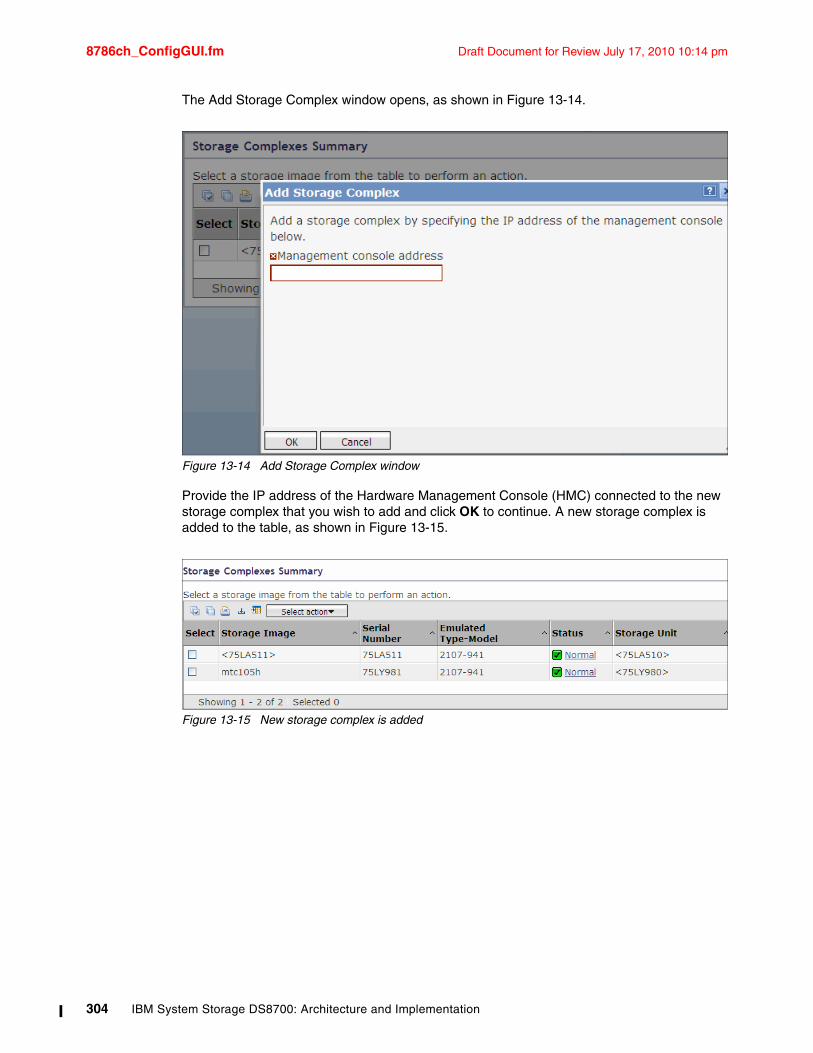
8786ch_ConfigGUI.fm Draft Document for Review July 17, 2010 10:14 pm
The Add Storage Complex window opens, as shown in Figure 13-14.
Figure 13-14 Add Storage Complex window
Provide the IP address of the Hardware Management Console (HMC) connected to the new storage complex that you wish to add and click OK to continue. A new storage complex is added to the table, as shown in Figure 13-15.
Figure 13-15 New storage complex is added
304 IBM System Storage DS8700: Architecture and Implementation
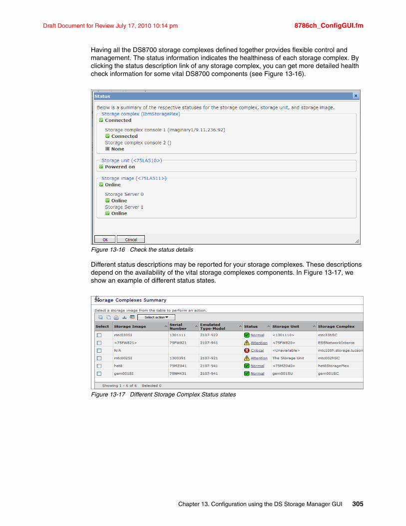
Draft Document for Review July 17, 2010 10:14 pm 8786ch_ConfigGUI.fm
Having all the DS8700 storage complexes defined together provides flexible control and management. The status information indicates the healthiness of each storage complex. By clicking the status description link of any storage complex, you can get more detailed health check information for some vital DS8700 components (see Figure 13-16).
Figure 13-16 Check the status details
Different status descriptions may be reported for your storage complexes. These descriptions depend on the availability of the vital storage complexes components. In Figure 13-17, we show an example of different status states.
Figure 13-17 Different Storage Complex Status states
Chapter 13. Configuration using the DS Storage Manager GUI 305
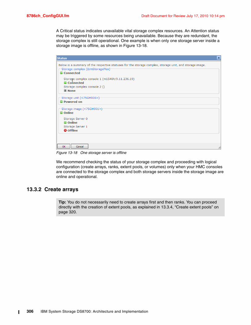
8786ch_ConfigGUI.fm Draft Document for Review July 17, 2010 10:14 pm
A Critical status indicates unavailable vital storage complex resources. An Attention status may be triggered by some resources being unavailable. Because they are redundant, the storage complex is still operational. One example is when only one storage server inside a storage image is offline, as shown in Figure 13-18.
Figure 13-18 One storage server is offline
We recommend checking the status of your storage complex and proceeding with logical configuration (create arrays, ranks, extent pools, or volumes) only when your HMC consoles are connected to the storage complex and both storage servers inside the storage image are online and operational.
13.3.2 Create arrays
Tip: You do not necessarily need to create arrays first and then ranks. You can proceed directly with the creation of extent pools, as explained in 13.3.4, “Create extent pools” on page 320.
306 IBM System Storage DS8700: Architecture and Implementation
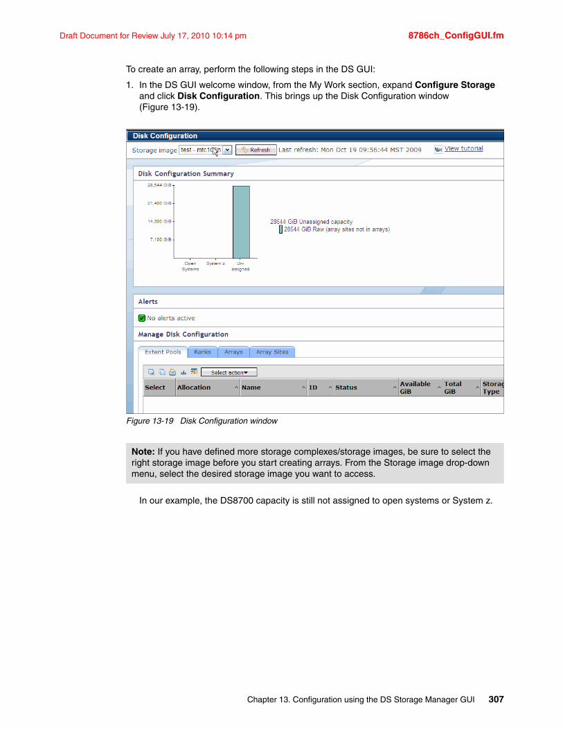
Draft Document for Review July 17, 2010 10:14 pm 8786ch_ConfigGUI.fm
To create an array, perform the following steps in the DS GUI:
1. In the DS GUI welcome window, from the My Work section, expand Configure Storage and click Disk Configuration. This brings up the Disk Configuration window (Figure 13-19).
Figure 13-19 Disk Configuration window
In our example, the DS8700 capacity is still not assigned to open systems or System z.
Note: If you have defined more storage complexes/storage images, be sure to select the right storage image before you start creating arrays. From the Storage image drop-down menu, select the desired storage image you want to access.
Chapter 13. Configuration using the DS Storage Manager GUI 307
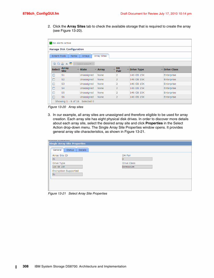
8786ch_ConfigGUI.fm Draft Document for Review July 17, 2010 10:14 pm
2. Click the Array Sites tab to check the available storage that is required to create the array (see Figure 13-20).
Figure 13-20 Array sites
3. In our example, all array sites are unassigned and therefore eligible to be used for array creation. Each array site has eight physical disk drives. In order to discover more details about each array site, select the desired array site and click Properties in the Select Action drop-down menu. The Single Array Site Properties window opens. It provides general array site characteristics, as shown in Figure 13-21.
Figure 13-21 Select Array Site Properties
308 IBM System Storage DS8700: Architecture and Implementation
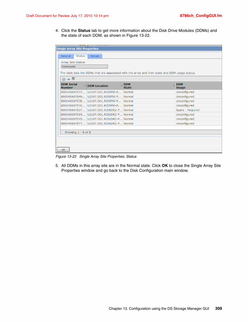
Draft Document for Review July 17, 2010 10:14 pm 8786ch_ConfigGUI.fm
4. Click the Status tab to get more information about the Disk Drive Modules (DDMs) and the state of each DDM, as shown in Figure 13-22.
Figure 13-22 Single Array Site Properties: Status
5. All DDMs in this array site are in the Normal state. Click OK to close the Single Array Site Properties window and go back to the Disk Configuration main window.
Chapter 13. Configuration using the DS Storage Manager GUI 309
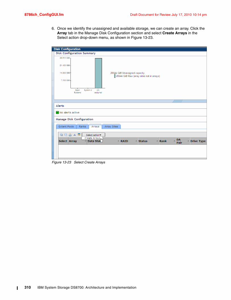
8786ch_ConfigGUI.fm Draft Document for Review July 17, 2010 10:14 pm
6. Once we identify the unassigned and available storage, we can create an array. Click the Array tab in the Manage Disk Configuration section and select Create Arrays in the Select action drop-down menu, as shown in Figure 13-23.
Figure 13-23 Select Create Arrays
310 IBM System Storage DS8700: Architecture and Implementation
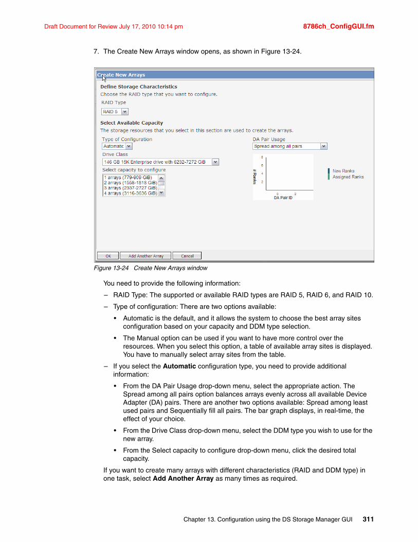
Draft Document for Review July 17, 2010 10:14 pm 8786ch_ConfigGUI.fm
7. The Create New Arrays window opens, as shown in Figure 13-24.
Figure 13-24 Create New Arrays window
You need to provide the following information:
– RAID Type: The supported or available RAID types are RAID 5, RAID 6, and RAID 10.
– Type of configuration: There are two options available:
• Automatic is the default, and it allows the system to choose the best array sites configuration based on your capacity and DDM type selection.
• The Manual option can be used if you want to have more control over the resources. When you select this option, a table of available array sites is displayed. You have to manually select array sites from the table.
– If you select the Automatic configuration type, you need to provide additional information:
• From the DA Pair Usage drop-down menu, select the appropriate action. The Spread among all pairs option balances arrays evenly across all available Device Adapter (DA) pairs. There are another two options available: Spread among least used pairs and Sequentially fill all pairs. The bar graph displays, in real-time, the effect of your choice.
• From the Drive Class drop-down menu, select the DDM type you wish to use for the new array.
• From the Select capacity to configure drop-down menu, click the desired total capacity.
If you want to create many arrays with different characteristics (RAID and DDM type) in one task, select Add Another Array as many times as required.
Chapter 13. Configuration using the DS Storage Manager GUI 311
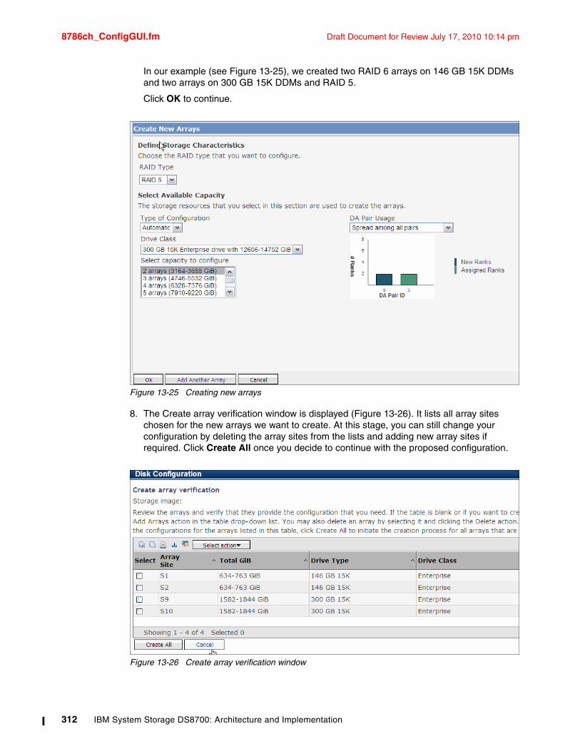
8786ch_ConfigGUI.fm Draft Document for Review July 17, 2010 10:14 pm
In our example (see Figure 13-25), we created two RAID 6 arrays on 146 GB 15K DDMs and two arrays on 300 GB 15K DDMs and RAID 5.
Click OK to continue.
Figure 13-25 Creating new arrays
8. The Create array verification window is displayed (Figure 13-26). It lists all array sites chosen for the new arrays we want to create. At this stage, you can still change your configuration by deleting the array sites from the lists and adding new array sites if required. Click Create All once you decide to continue with the proposed configuration.
Figure 13-26 Create array verification window
312 IBM System Storage DS8700: Architecture and Implementation
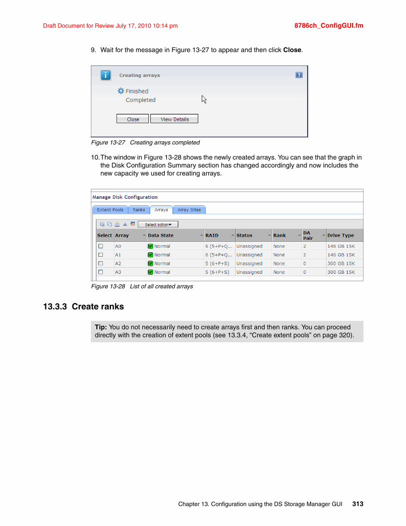
Draft Document for Review July 17, 2010 10:14 pm 8786ch_ConfigGUI.fm
9. Wait for the message in Figure 13-27 to appear and then click Close.
Figure 13-27 Creating arrays completed
10.The window in Figure 13-28 shows the newly created arrays. You can see that the graph in the Disk Configuration Summary section has changed accordingly and now includes the new capacity we used for creating arrays.
Figure 13-28 List of all created arrays
13.3.3 Create ranks
Tip: You do not necessarily need to create arrays first and then ranks. You can proceed directly with the creation of extent pools (see 13.3.4, “Create extent pools” on page 320).
Chapter 13. Configuration using the DS Storage Manager GUI 313
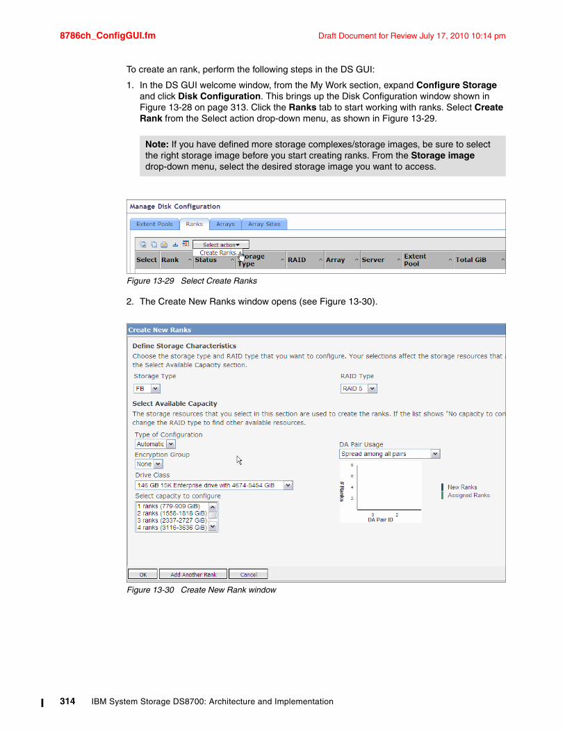
8786ch_ConfigGUI.fm Draft Document for Review July 17, 2010 10:14 pm
To create an rank, perform the following steps in the DS GUI:
1. In the DS GUI welcome window, from the My Work section, expand Configure Storage and click Disk Configuration. This brings up the Disk Configuration window shown in Figure 13-28 on page 313. Click the Ranks tab to start working with ranks. Select Create Rank from the Select action drop-down menu, as shown in Figure 13-29.
Figure 13-29 Select Create Ranks
2. The Create New Ranks window opens (see Figure 13-30).
Figure 13-30 Create New Rank window
Note: If you have defined more storage complexes/storage images, be sure to select the right storage image before you start creating ranks. From the Storage image drop-down menu, select the desired storage image you want to access.
314 IBM System Storage DS8700: Architecture and Implementation
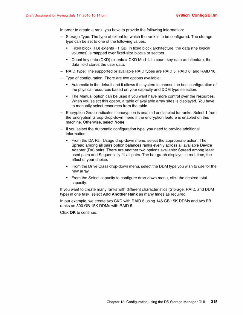
Draft Document for Review July 17, 2010 10:14 pm 8786ch_ConfigGUI.fm
In order to create a rank, you have to provide the following information:
– Storage Type: The type of extent for which the rank is to be configured. The storage type can be set to one of the following values:
• Fixed block (FB) extents =1 GB. In fixed block architecture, the data (the logical volumes) is mapped over fixed-size blocks or sectors.
• Count key data (CKD) extents = CKD Mod 1. In count-key-data architecture, the data field stores the user data.
– RAID Type: The supported or available RAID types are RAID 5, RAID 6, and RAID 10.
– Type of configuration: There are two options available:
• Automatic is the default and it allows the system to choose the best configuration of the physical resources based on your capacity and DDM type selection.
• The Manual option can be used if you want have more control over the resources. When you select this option, a table of available array sites is displayed. You have to manually select resources from the table.
– Encryption Group indicates if encryption is enabled or disabled for ranks. Select 1 from the Encryption Group drop-down menu if the encryption feature is enabled on this machine. Otherwise, select None.
– If you select the Automatic configuration type, you need to provide additional information:
• From the DA Pair Usage drop-down menu, select the appropriate action. The Spread among all pairs option balances ranks evenly across all available Device Adapter (DA) pairs. There are another two options available: Spread among least used pairs and Sequentially fill all pairs. The bar graph displays, in real-time, the effect of your choice.
• From the Drive Class drop-down menu, select the DDM type you wish to use for the new array.
• From the Select capacity to configure drop-down menu, click the desired total capacity.
If you want to create many ranks with different characteristics (Storage, RAID, and DDM type) in one task, select Add Another Rank as many times as required.
In our example, we create two CKD with RAID 6 using 146 GB 15K DDMs and two FB ranks on 300 GB 15K DDMs with RAID 5.
Click OK to continue.
Chapter 13. Configuration using the DS Storage Manager GUI 315
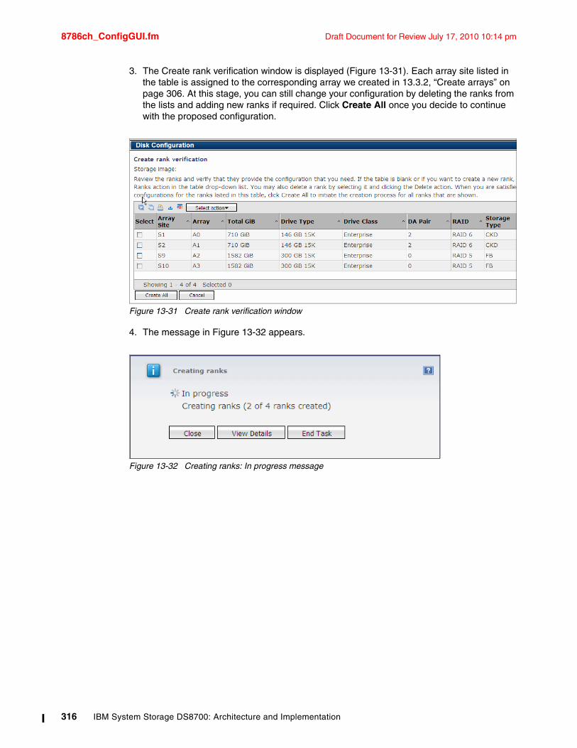
8786ch_ConfigGUI.fm Draft Document for Review July 17, 2010 10:14 pm
3. The Create rank verification window is displayed (Figure 13-31). Each array site listed in the table is assigned to the corresponding array we created in 13.3.2, “Create arrays” on page 306. At this stage, you can still change your configuration by deleting the ranks from the lists and adding new ranks if required. Click Create All once you decide to continue with the proposed configuration.
Figure 13-31 Create rank verification window
4. The message in Figure 13-32 appears.
Figure 13-32 Creating ranks: In progress message
316 IBM System Storage DS8700: Architecture and Implementation
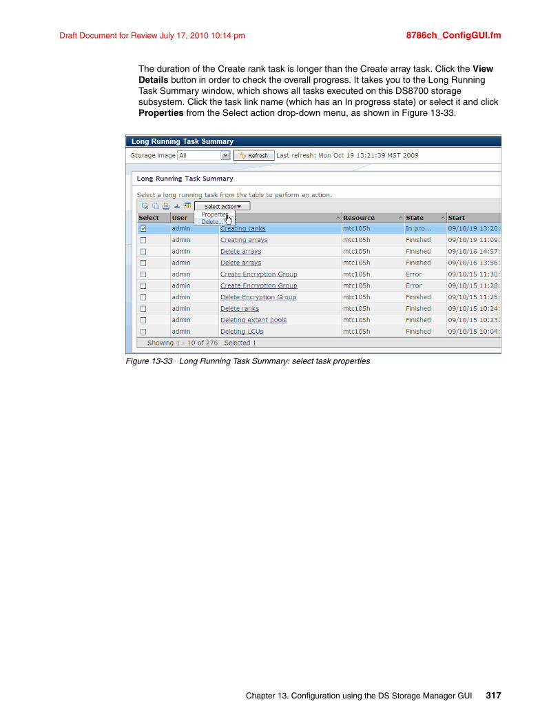
Draft Document for Review July 17, 2010 10:14 pm 8786ch_ConfigGUI.fm
The duration of the Create rank task is longer than the Create array task. Click the View Details button in order to check the overall progress. It takes you to the Long Running Task Summary window, which shows all tasks executed on this DS8700 storage subsystem. Click the task link name (which has an In progress state) or select it and click Properties from the Select action drop-down menu, as shown in Figure 13-33.
Figure 13-33 Long Running Task Summary: select task properties
Chapter 13. Configuration using the DS Storage Manager GUI 317
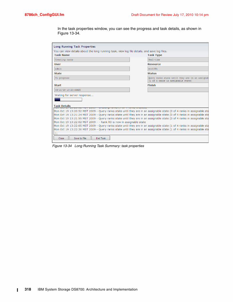
8786ch_ConfigGUI.fm Draft Document for Review July 17, 2010 10:14 pm
In the task properties window, you can see the progress and task details, as shown in Figure 13-34.
Figure 13-34 Long Running Task Summary: task properties
318 IBM System Storage DS8700: Architecture and Implementation
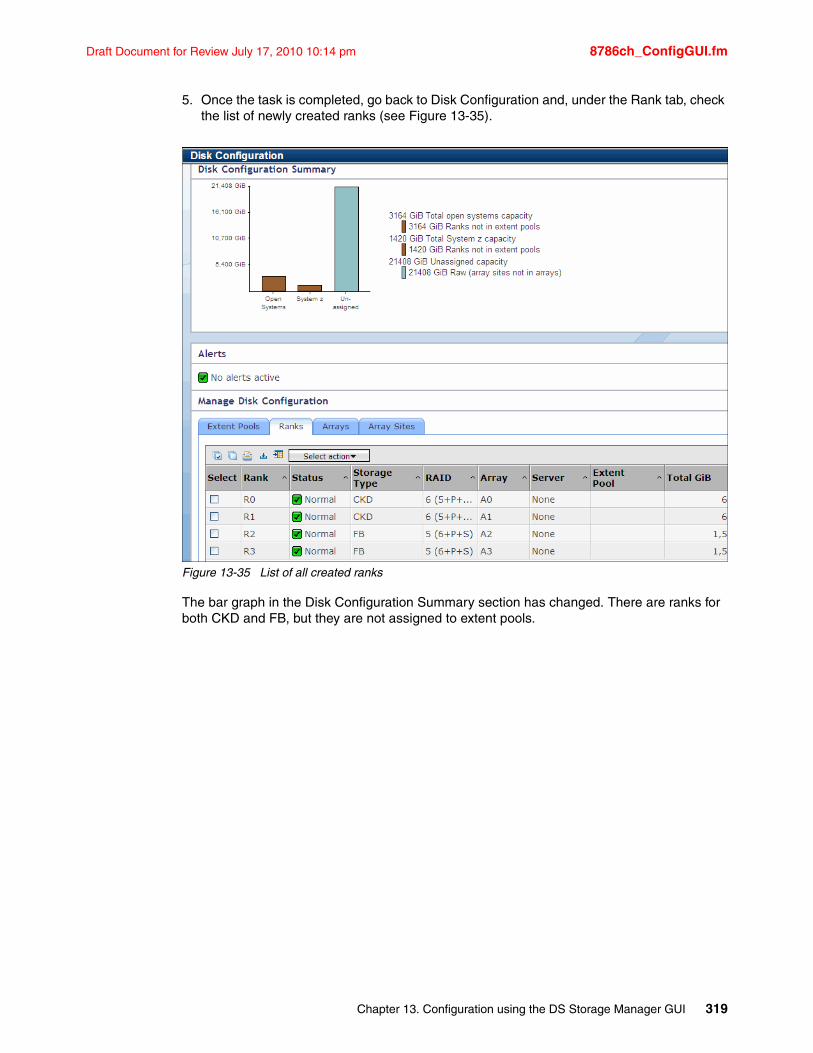
Draft Document for Review July 17, 2010 10:14 pm 8786ch_ConfigGUI.fm
5. Once the task is completed, go back to Disk Configuration and, under the Rank tab, check the list of newly created ranks (see Figure 13-35).
Figure 13-35 List of all created ranks
The bar graph in the Disk Configuration Summary section has changed. There are ranks for both CKD and FB, but they are not assigned to extent pools.
Chapter 13. Configuration using the DS Storage Manager GUI 319
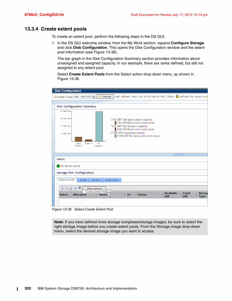
8786ch_ConfigGUI.fm Draft Document for Review July 17, 2010 10:14 pm
13.3.4 Create extent poolsTo create an extent pool, perform the following steps in the DS GUI:
1. In the DS GUI welcome window, from the My Work section, expand Configure Storage and click Disk Configuration. This opens the Disk Configuration window and the extent pool information (see Figure 13-36).
The bar graph in the Disk Configuration Summary section provides information about unassigned and assigned capacity. In our example, there are ranks defined, but still not assigned to any extent pool.
Select Create Extent Pools from the Select action drop-down menu, as shown in Figure 13-36.
Figure 13-36 Select Create Extent Pool
Note: If you have defined more storage complexes/storage images, be sure to select the right storage image before you create extent pools. From the Storage image drop-down menu, select the desired storage image you want to access.
320 IBM System Storage DS8700: Architecture and Implementation
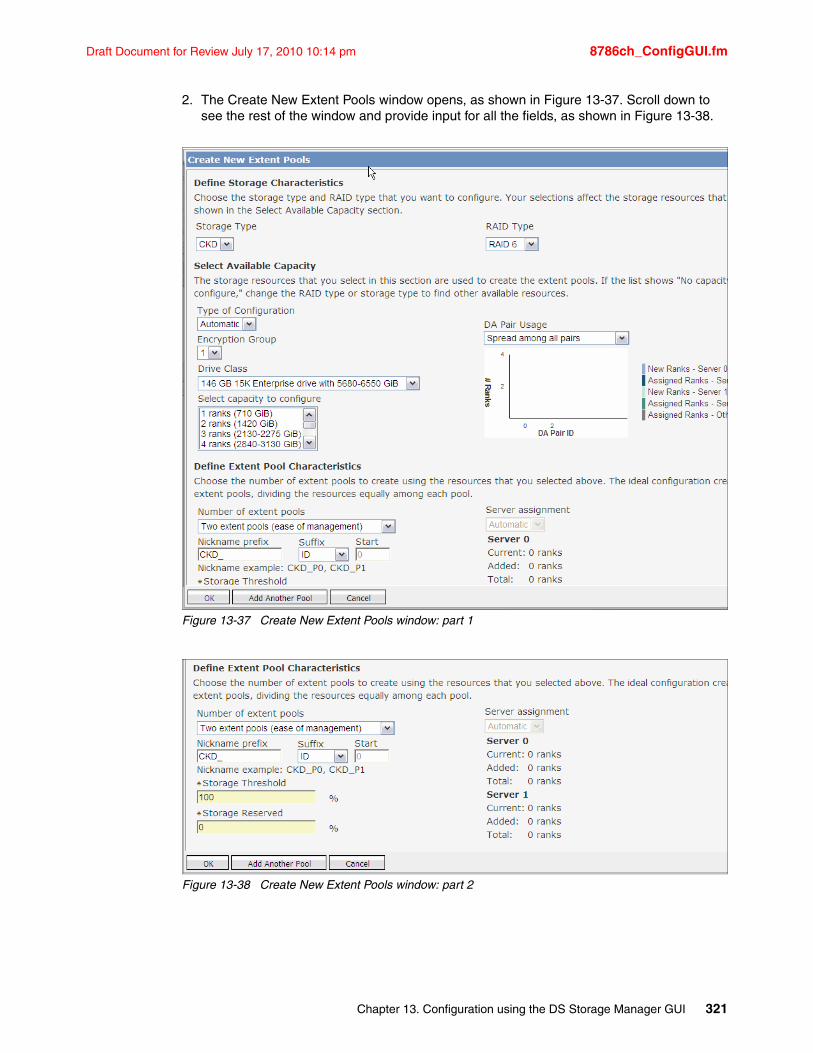
Draft Document for Review July 17, 2010 10:14 pm 8786ch_ConfigGUI.fm
2. The Create New Extent Pools window opens, as shown in Figure 13-37. Scroll down to see the rest of the window and provide input for all the fields, as shown in Figure 13-38.
Figure 13-37 Create New Extent Pools window: part 1
Figure 13-38 Create New Extent Pools window: part 2
Chapter 13. Configuration using the DS Storage Manager GUI 321
8786ch_ConfigGUI.fm Draft Document for Review July 17, 2010 10:14 pm
In order to create an extent pool, you have to provide the following information:
– Storage Type: The type of extent for which the rank is to be configured. The storage type can be set to one of the following values:
• Fixed block (FB) extents = 1 GB. In the fixed block architecture, the data (the logical volumes) is mapped over fixed-size blocks or sectors.
• Count key data (CKD) extents = CKD Mod 1. In the count-key-data architecture, the data field stores the user data.
– RAID Type: The supported or available RAID types are RAID 5, RAID 6, and RAID 10.
– Type of configuration: There are two options available:
• Automatic is the default and it allows the system to choose the best configuration of physical resources based on your capacity and DDM type selection.
• The Manual option can be used if you want have more control over the resources. When you select this option, a table of available array sites is displayed. You have to manually select resources from the table.
– Encryption Group indicates if encryption is enabled or disabled for ranks. Select 1 from the Encryption Group drop-down menu if the encryption feature is enabled on this machine. Otherwise, select None.
– If you select the Automatic configuration type, you need to provide additional information:
• From the DA Pair Usage drop-down menu, select the appropriate action. The Spread among all pairs option balances ranks evenly across all available Device Adapter (DA) pairs. For example, no more than half of the ranks attached to a DA pair is assigned to each server, so that each server's DA within the DA pair has the same number of ranks. There are another two options available: Spread among least used pairs and Sequentially fill all pairs. The bar graph displays, in real-time, the effect of your choice.
• From Drive Class drop-down menu, select the DDM type you wish to use for the new array.
• From the Select capacity to configure drop-down menu, click the desired total capacity.
– Number of extent pools: Choose the number of extent pools using previously selected ranks. The ideal configuration creates two extent pools per storage type, dividing all ranks equally among each pool. There are three available options:
• Two extent pools (ease of management)
• Single extent pool
• Extent pool for each rank (physical isolation)
– Nickname Prefix and Suffix: Provides an unique name for each extent pool. This setup is very useful if you have many extent pools, each assigned to different hosts and platforms.
– Server assignment: The Automatic option allows the system to determine the best server for each extent pool. It is the only choice when you select the Two Extent Pool option as the number of extent pools.
– Storage Threshold: Specify the maximum percentage of the storage threshold to generate an alert. This allows you to make adjustments before a storage full condition occurs.
322 IBM System Storage DS8700: Architecture and Implementation
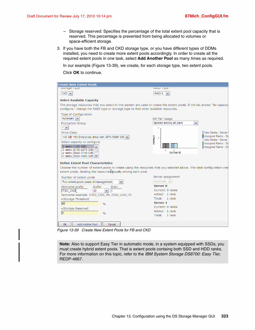
Draft Document for Review July 17, 2010 10:14 pm 8786ch_ConfigGUI.fm
– Storage reserved: Specifies the percentage of the total extent pool capacity that is reserved. This percentage is prevented from being allocated to volumes or space-efficient storage.
3. If you have both the FB and CKD storage type, or you have different types of DDMs installed, you need to create more extent pools accordingly. In order to create all the required extent pools in one task, select Add Another Pool as many times as required.
In our example (Figure 13-39), we create, for each storage type, two extent pools.
Click OK to continue.
Figure 13-39 Create New Extent Pools for FB and CKD
Note: Also to support Easy Tier in automatic mode, in a system equipped with SSDs, you must create hybrid extent pools. That is extent pools containg both SSD and HDD ranks. For more information on this topic, refer to the IBM System Storage DS8700: Easy TIer, REDP-4667.
Chapter 13. Configuration using the DS Storage Manager GUI 323
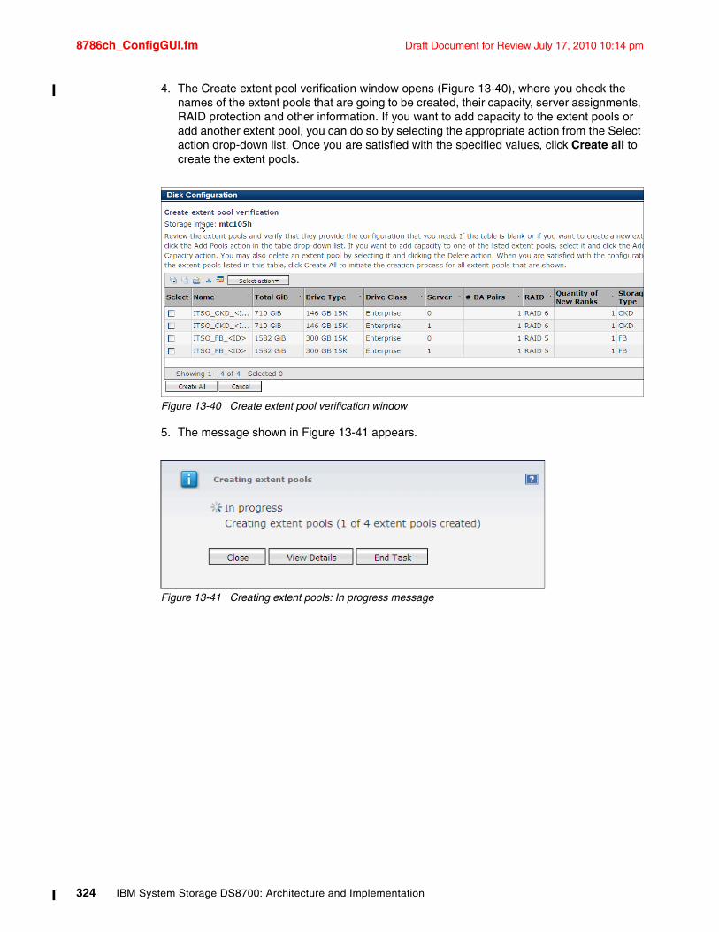
8786ch_ConfigGUI.fm Draft Document for Review July 17, 2010 10:14 pm
4. The Create extent pool verification window opens (Figure 13-40), where you check the names of the extent pools that are going to be created, their capacity, server assignments, RAID protection and other information. If you want to add capacity to the extent pools or add another extent pool, you can do so by selecting the appropriate action from the Select action drop-down list. Once you are satisfied with the specified values, click Create all to create the extent pools.
Figure 13-40 Create extent pool verification window
5. The message shown in Figure 13-41 appears.
Figure 13-41 Creating extent pools: In progress message
324 IBM System Storage DS8700: Architecture and Implementation
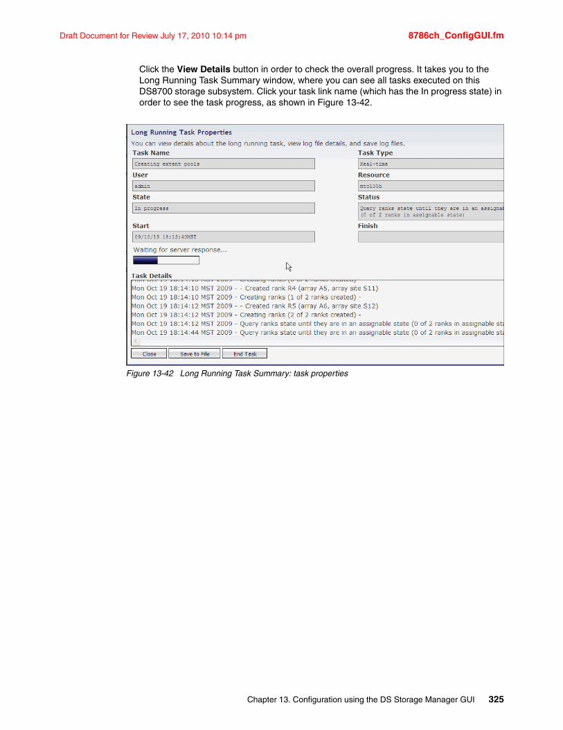
Draft Document for Review July 17, 2010 10:14 pm 8786ch_ConfigGUI.fm
Click the View Details button in order to check the overall progress. It takes you to the Long Running Task Summary window, where you can see all tasks executed on this DS8700 storage subsystem. Click your task link name (which has the In progress state) in order to see the task progress, as shown in Figure 13-42.
Figure 13-42 Long Running Task Summary: task properties
Chapter 13. Configuration using the DS Storage Manager GUI 325
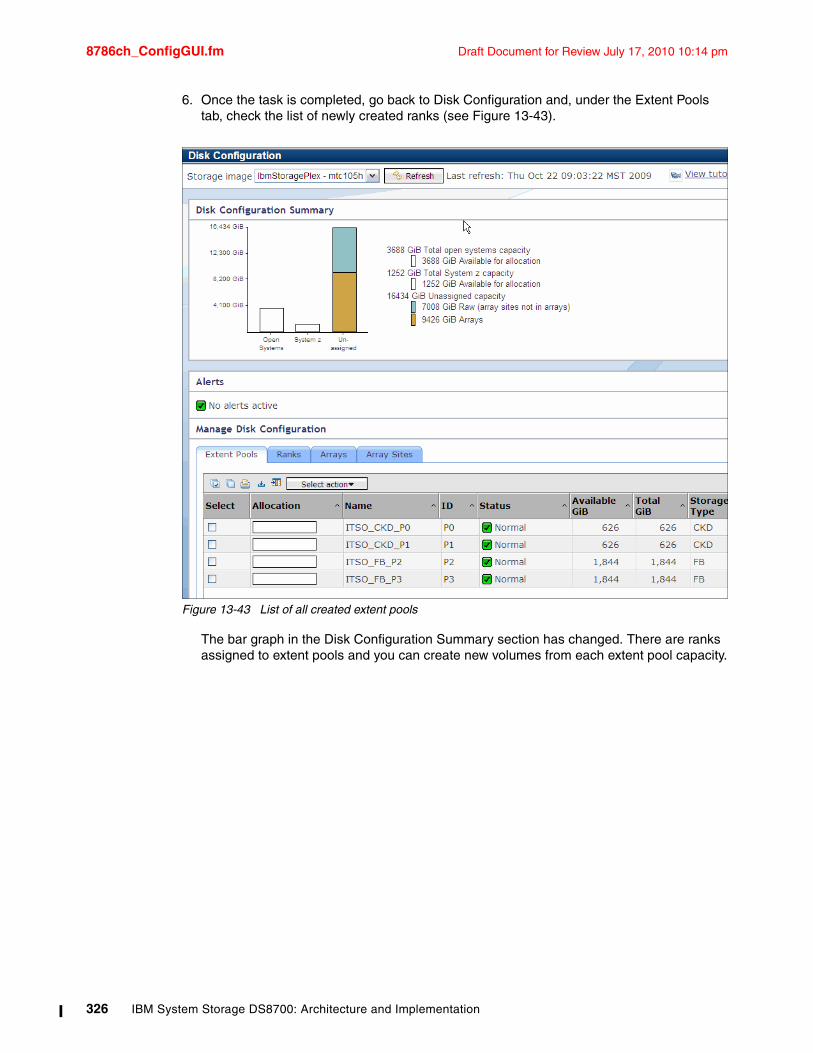
8786ch_ConfigGUI.fm Draft Document for Review July 17, 2010 10:14 pm
6. Once the task is completed, go back to Disk Configuration and, under the Extent Pools tab, check the list of newly created ranks (see Figure 13-43).
Figure 13-43 List of all created extent pools
The bar graph in the Disk Configuration Summary section has changed. There are ranks assigned to extent pools and you can create new volumes from each extent pool capacity.
326 IBM System Storage DS8700: Architecture and Implementation
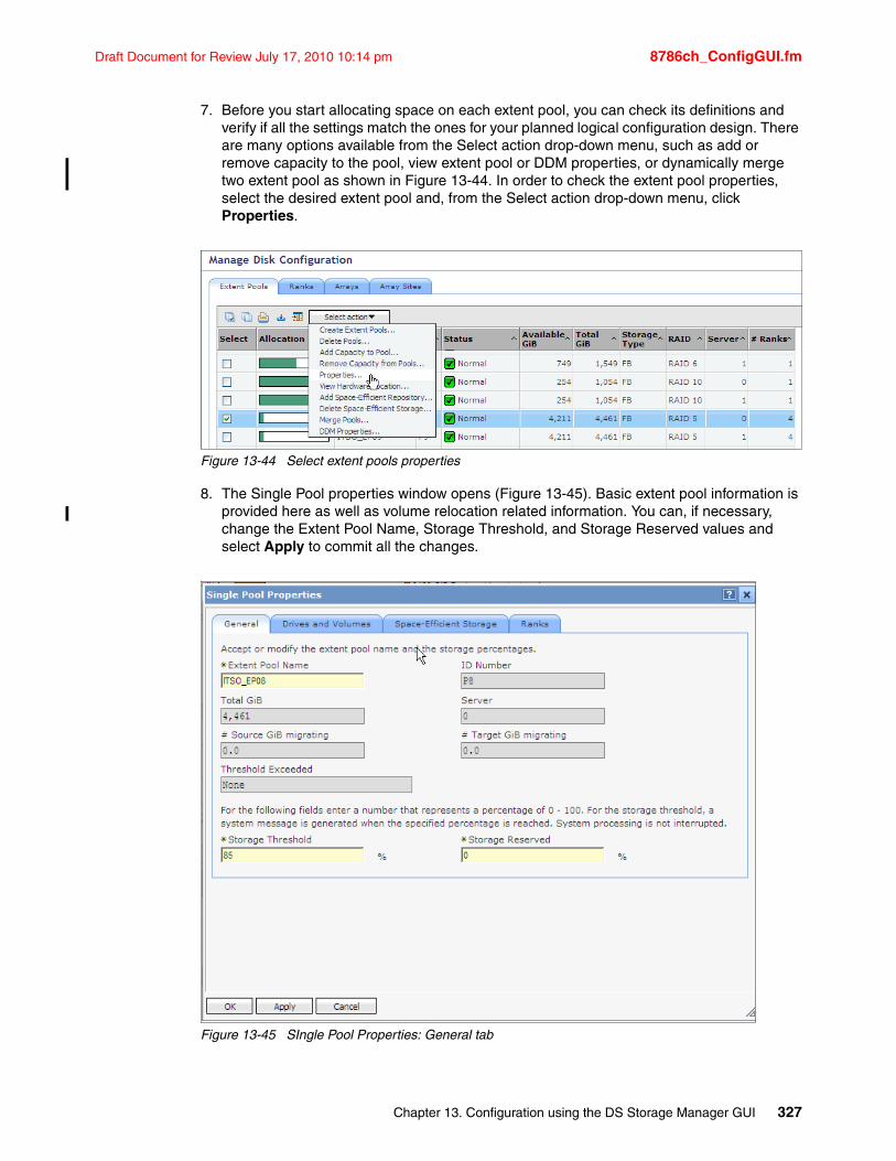
Draft Document for Review July 17, 2010 10:14 pm 8786ch_ConfigGUI.fm
7. Before you start allocating space on each extent pool, you can check its definitions and verify if all the settings match the ones for your planned logical configuration design. There are many options available from the Select action drop-down menu, such as add or remove capacity to the pool, view extent pool or DDM properties, or dynamically merge two extent pool as shown in Figure 13-44. In order to check the extent pool properties, select the desired extent pool and, from the Select action drop-down menu, click Properties.
Figure 13-44 Select extent pools properties
8. The Single Pool properties window opens (Figure 13-45). Basic extent pool information is provided here as well as volume relocation related information. You can, if necessary, change the Extent Pool Name, Storage Threshold, and Storage Reserved values and select Apply to commit all the changes.
Figure 13-45 SIngle Pool Properties: General tab
Chapter 13. Configuration using the DS Storage Manager GUI 327
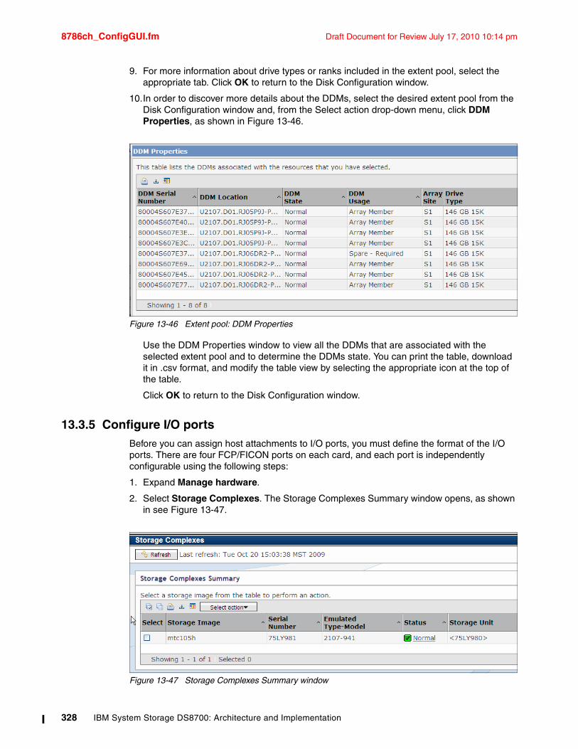
8786ch_ConfigGUI.fm Draft Document for Review July 17, 2010 10:14 pm
9. For more information about drive types or ranks included in the extent pool, select the appropriate tab. Click OK to return to the Disk Configuration window.
10.In order to discover more details about the DDMs, select the desired extent pool from the Disk Configuration window and, from the Select action drop-down menu, click DDM Properties, as shown in Figure 13-46.
Figure 13-46 Extent pool: DDM Properties
Use the DDM Properties window to view all the DDMs that are associated with the selected extent pool and to determine the DDMs state. You can print the table, download it in .csv format, and modify the table view by selecting the appropriate icon at the top of the table.
Click OK to return to the Disk Configuration window.
13.3.5 Configure I/O ports Before you can assign host attachments to I/O ports, you must define the format of the I/O ports. There are four FCP/FICON ports on each card, and each port is independently configurable using the following steps:
1. Expand Manage hardware.
2. Select Storage Complexes. The Storage Complexes Summary window opens, as shown in see Figure 13-47.
Figure 13-47 Storage Complexes Summary window
328 IBM System Storage DS8700: Architecture and Implementation
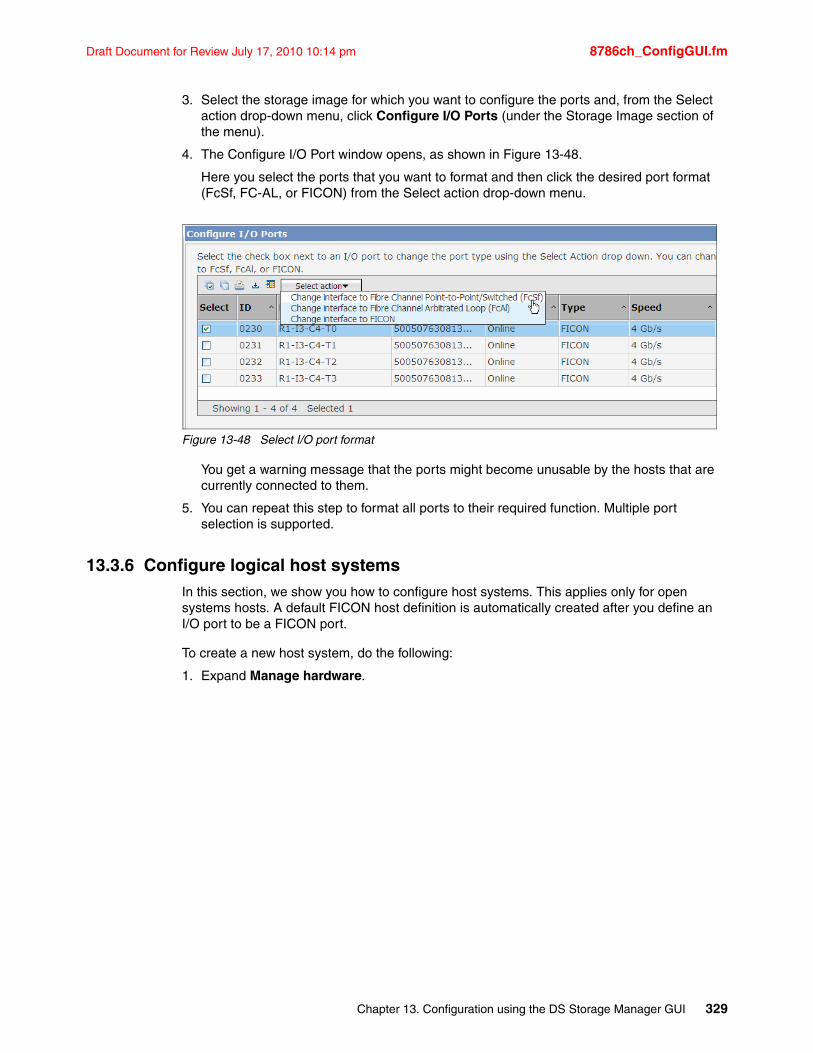
Draft Document for Review July 17, 2010 10:14 pm 8786ch_ConfigGUI.fm
3. Select the storage image for which you want to configure the ports and, from the Select action drop-down menu, click Configure I/O Ports (under the Storage Image section of the menu).
4. The Configure I/O Port window opens, as shown in Figure 13-48.
Here you select the ports that you want to format and then click the desired port format (FcSf, FC-AL, or FICON) from the Select action drop-down menu.
Figure 13-48 Select I/O port format
You get a warning message that the ports might become unusable by the hosts that are currently connected to them.
5. You can repeat this step to format all ports to their required function. Multiple port selection is supported.
13.3.6 Configure logical host systemsIn this section, we show you how to configure host systems. This applies only for open systems hosts. A default FICON host definition is automatically created after you define an I/O port to be a FICON port.
To create a new host system, do the following:
1. Expand Manage hardware.
Chapter 13. Configuration using the DS Storage Manager GUI 329
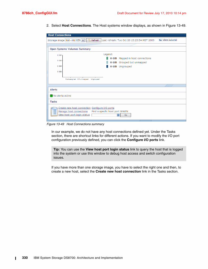
8786ch_ConfigGUI.fm Draft Document for Review July 17, 2010 10:14 pm
2. Select Host Connections. The Host systems window displays, as shown in Figure 13-49.
Figure 13-49 Host Connections summary
In our example, we do not have any host connections defined yet. Under the Tasks section, there are shortcut links for different actions. If you want to modify the I/O port configuration previously defined, you can click the Configure I/O ports link.
If you have more than one storage image, you have to select the right one and then, to create a new host, select the Create new host connection link in the Tasks section.
Tip: You can use the View host port login status link to query the host that is logged into the system or use this window to debug host access and switch configuration issues.
330 IBM System Storage DS8700: Architecture and Implementation
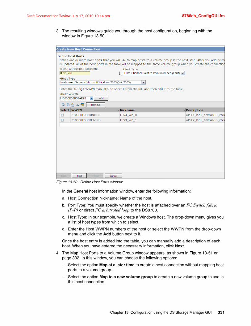
Draft Document for Review July 17, 2010 10:14 pm 8786ch_ConfigGUI.fm
3. The resulting windows guide you through the host configuration, beginning with the window in Figure 13-50.
Figure 13-50 Define Host Ports window
In the General host information window, enter the following information:
a. Host Connection Nickname: Name of the host.
b. Port Type: You must specify whether the host is attached over an FC Switch fabric (P-P) or direct FC arbitrated loop to the DS8700.
c. Host Type: In our example, we create a Windows host. The drop-down menu gives you a list of host types from which to select.
d. Enter the Host WWPN numbers of the host or select the WWPN from the drop-down menu and click the Add button next to it.
Once the host entry is added into the table, you can manually add a description of each host. When you have entered the necessary information, click Next.
4. The Map Host Ports to a Volume Group window appears, as shown in Figure 13-51 on page 332. In this window, you can choose the following options:
– Select the option Map at a later time to create a host connection without mapping host ports to a volume group.
– Select the option Map to a new volume group to create a new volume group to use in this host connection.
Chapter 13. Configuration using the DS Storage Manager GUI 331
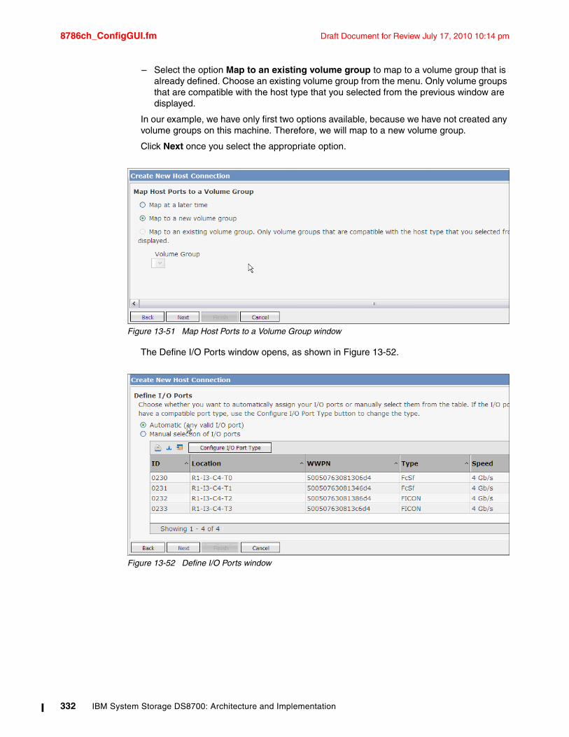
8786ch_ConfigGUI.fm Draft Document for Review July 17, 2010 10:14 pm
– Select the option Map to an existing volume group to map to a volume group that is already defined. Choose an existing volume group from the menu. Only volume groups that are compatible with the host type that you selected from the previous window are displayed.
In our example, we have only first two options available, because we have not created any volume groups on this machine. Therefore, we will map to a new volume group.
Click Next once you select the appropriate option.
Figure 13-51 Map Host Ports to a Volume Group window
The Define I/O Ports window opens, as shown in Figure 13-52.
Figure 13-52 Define I/O Ports window
332 IBM System Storage DS8700: Architecture and Implementation
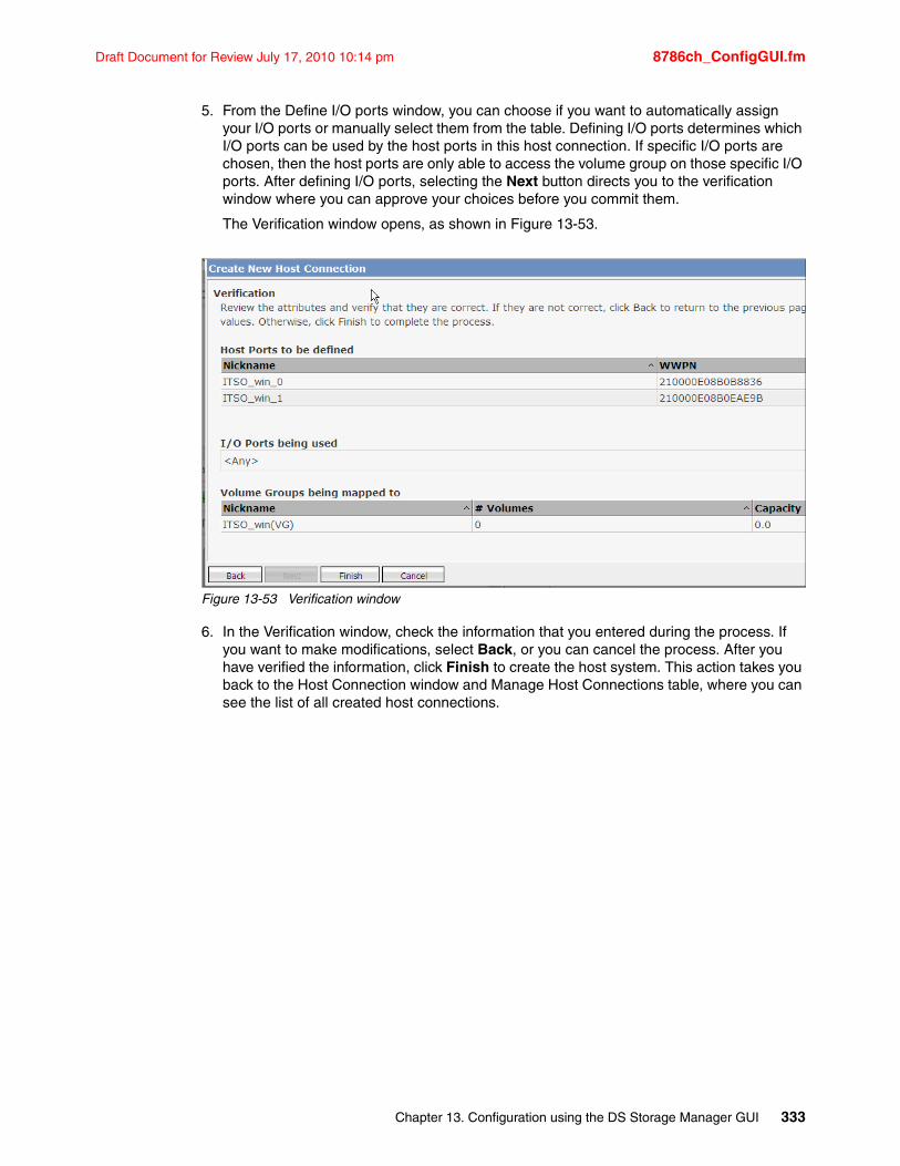
Draft Document for Review July 17, 2010 10:14 pm 8786ch_ConfigGUI.fm
5. From the Define I/O ports window, you can choose if you want to automatically assign your I/O ports or manually select them from the table. Defining I/O ports determines which I/O ports can be used by the host ports in this host connection. If specific I/O ports are chosen, then the host ports are only able to access the volume group on those specific I/O ports. After defining I/O ports, selecting the Next button directs you to the verification window where you can approve your choices before you commit them.
The Verification window opens, as shown in Figure 13-53.
Figure 13-53 Verification window
6. In the Verification window, check the information that you entered during the process. If you want to make modifications, select Back, or you can cancel the process. After you have verified the information, click Finish to create the host system. This action takes you back to the Host Connection window and Manage Host Connections table, where you can see the list of all created host connections.
Chapter 13. Configuration using the DS Storage Manager GUI 333
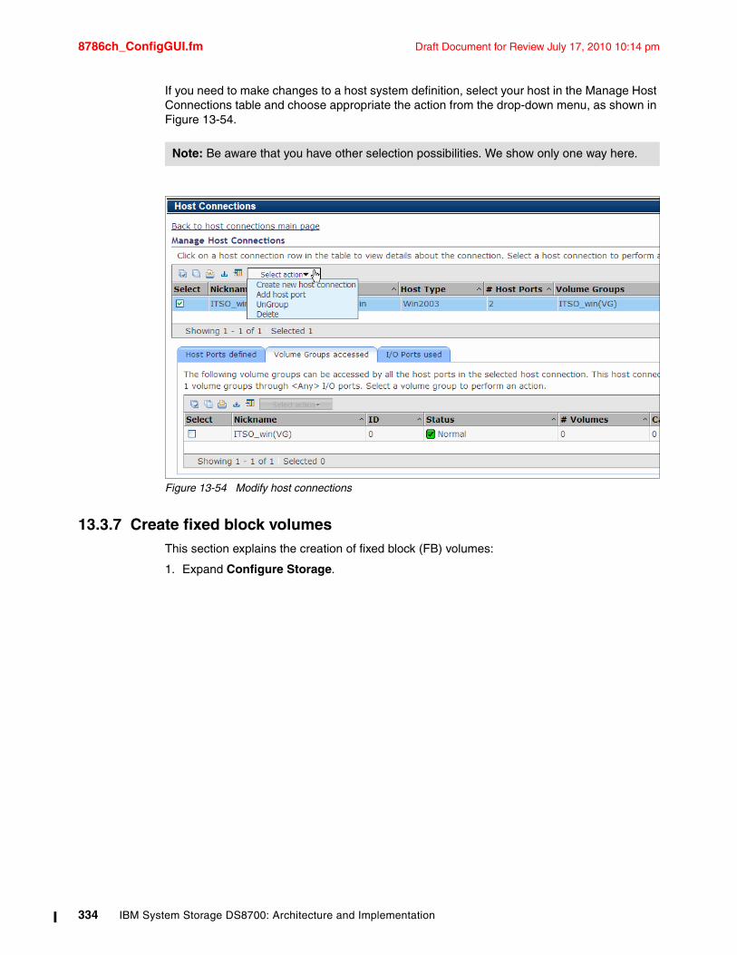
8786ch_ConfigGUI.fm Draft Document for Review July 17, 2010 10:14 pm
If you need to make changes to a host system definition, select your host in the Manage Host Connections table and choose appropriate the action from the drop-down menu, as shown in Figure 13-54.
Figure 13-54 Modify host connections
13.3.7 Create fixed block volumesThis section explains the creation of fixed block (FB) volumes:
1. Expand Configure Storage.
Note: Be aware that you have other selection possibilities. We show only one way here.
334 IBM System Storage DS8700: Architecture and Implementation
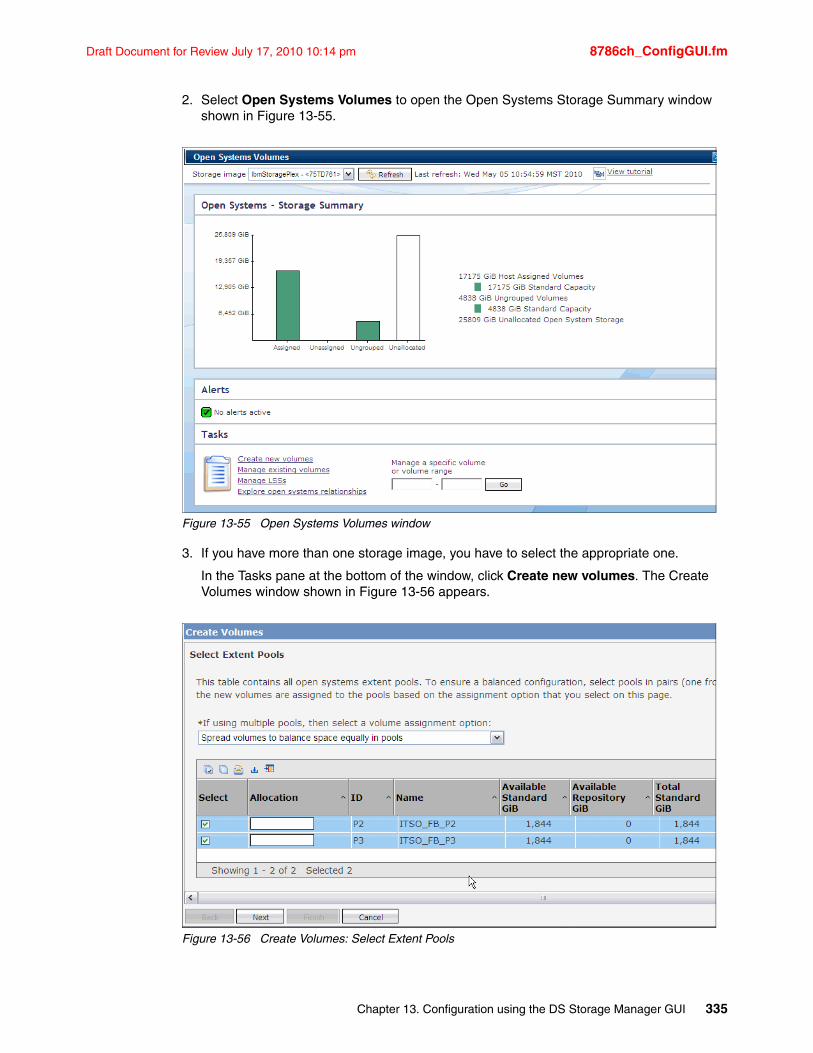
Draft Document for Review July 17, 2010 10:14 pm 8786ch_ConfigGUI.fm
2. Select Open Systems Volumes to open the Open Systems Storage Summary window shown in Figure 13-55.
Figure 13-55 Open Systems Volumes window
3. If you have more than one storage image, you have to select the appropriate one.
In the Tasks pane at the bottom of the window, click Create new volumes. The Create Volumes window shown in Figure 13-56 appears.
Figure 13-56 Create Volumes: Select Extent Pools
Chapter 13. Configuration using the DS Storage Manager GUI 335
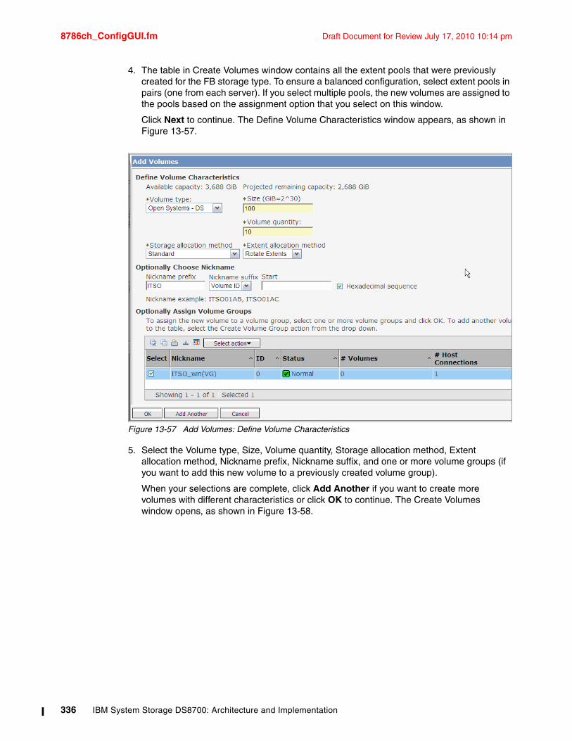
8786ch_ConfigGUI.fm Draft Document for Review July 17, 2010 10:14 pm
4. The table in Create Volumes window contains all the extent pools that were previously created for the FB storage type. To ensure a balanced configuration, select extent pools in pairs (one from each server). If you select multiple pools, the new volumes are assigned to the pools based on the assignment option that you select on this window.
Click Next to continue. The Define Volume Characteristics window appears, as shown in Figure 13-57.
Figure 13-57 Add Volumes: Define Volume Characteristics
5. Select the Volume type, Size, Volume quantity, Storage allocation method, Extent allocation method, Nickname prefix, Nickname suffix, and one or more volume groups (if you want to add this new volume to a previously created volume group).
When your selections are complete, click Add Another if you want to create more volumes with different characteristics or click OK to continue. The Create Volumes window opens, as shown in Figure 13-58.
336 IBM System Storage DS8700: Architecture and Implementation
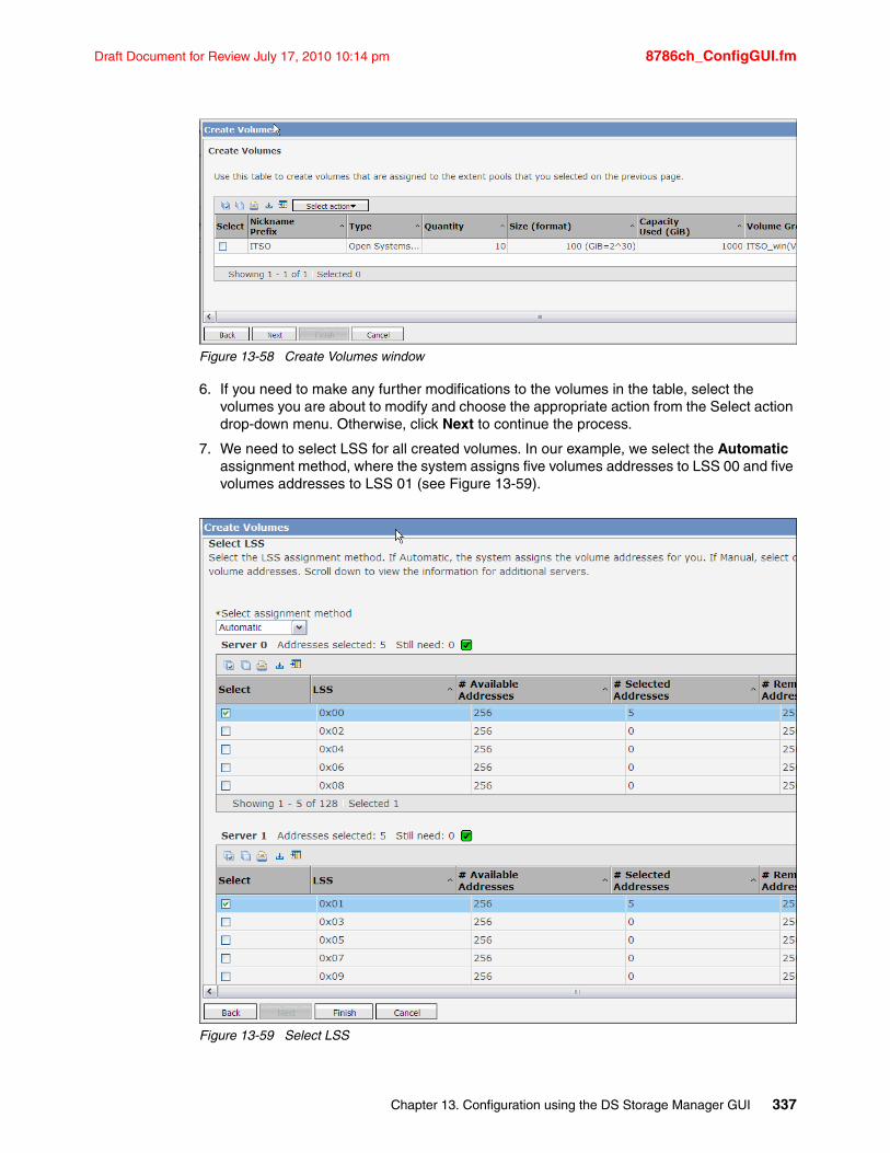
Draft Document for Review July 17, 2010 10:14 pm 8786ch_ConfigGUI.fm
Figure 13-58 Create Volumes window
6. If you need to make any further modifications to the volumes in the table, select the volumes you are about to modify and choose the appropriate action from the Select action drop-down menu. Otherwise, click Next to continue the process.
7. We need to select LSS for all created volumes. In our example, we select the Automatic assignment method, where the system assigns five volumes addresses to LSS 00 and five volumes addresses to LSS 01 (see Figure 13-59).
Figure 13-59 Select LSS
Chapter 13. Configuration using the DS Storage Manager GUI 337
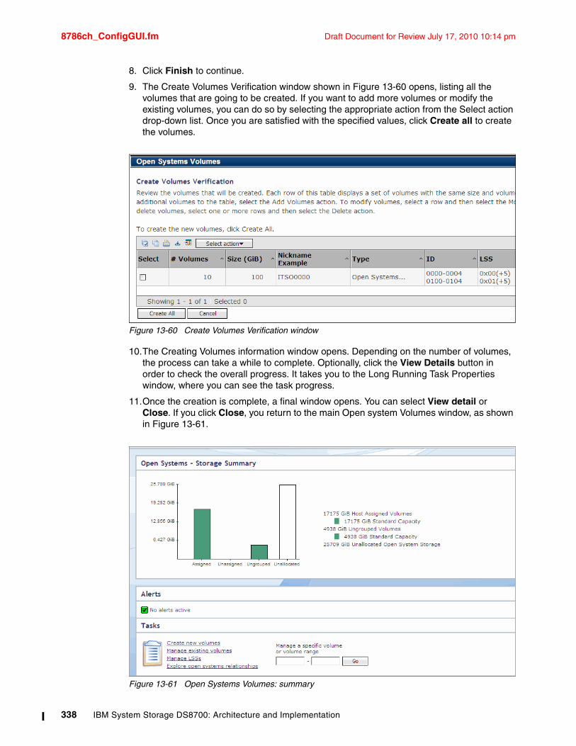
8786ch_ConfigGUI.fm Draft Document for Review July 17, 2010 10:14 pm
8. Click Finish to continue.
9. The Create Volumes Verification window shown in Figure 13-60 opens, listing all the volumes that are going to be created. If you want to add more volumes or modify the existing volumes, you can do so by selecting the appropriate action from the Select action drop-down list. Once you are satisfied with the specified values, click Create all to create the volumes.
Figure 13-60 Create Volumes Verification window
10.The Creating Volumes information window opens. Depending on the number of volumes, the process can take a while to complete. Optionally, click the View Details button in order to check the overall progress. It takes you to the Long Running Task Properties window, where you can see the task progress.
11.Once the creation is complete, a final window opens. You can select View detail or Close. If you click Close, you return to the main Open system Volumes window, as shown in Figure 13-61.
Figure 13-61 Open Systems Volumes: summary
338 IBM System Storage DS8700: Architecture and Implementation
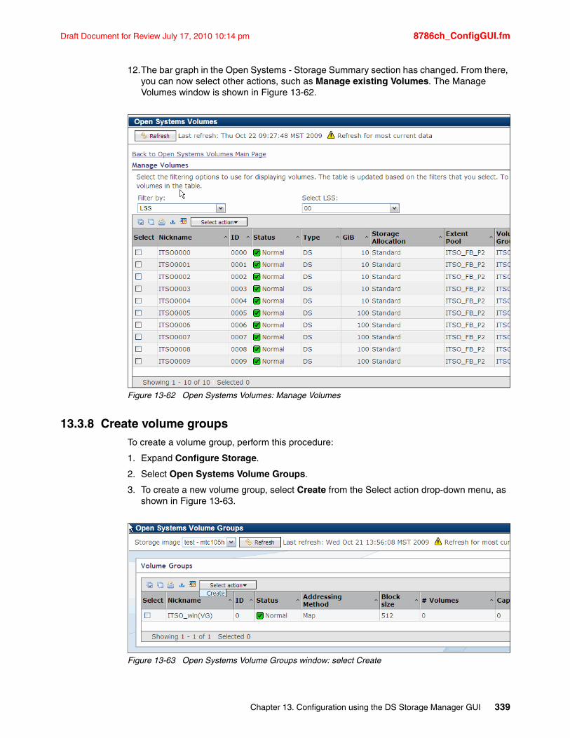
Draft Document for Review July 17, 2010 10:14 pm 8786ch_ConfigGUI.fm
12.The bar graph in the Open Systems - Storage Summary section has changed. From there, you can now select other actions, such as Manage existing Volumes. The Manage Volumes window is shown in Figure 13-62.
Figure 13-62 Open Systems Volumes: Manage Volumes
13.3.8 Create volume groupsTo create a volume group, perform this procedure:
1. Expand Configure Storage.
2. Select Open Systems Volume Groups.
3. To create a new volume group, select Create from the Select action drop-down menu, as shown in Figure 13-63.
Figure 13-63 Open Systems Volume Groups window: select Create
Chapter 13. Configuration using the DS Storage Manager GUI 339
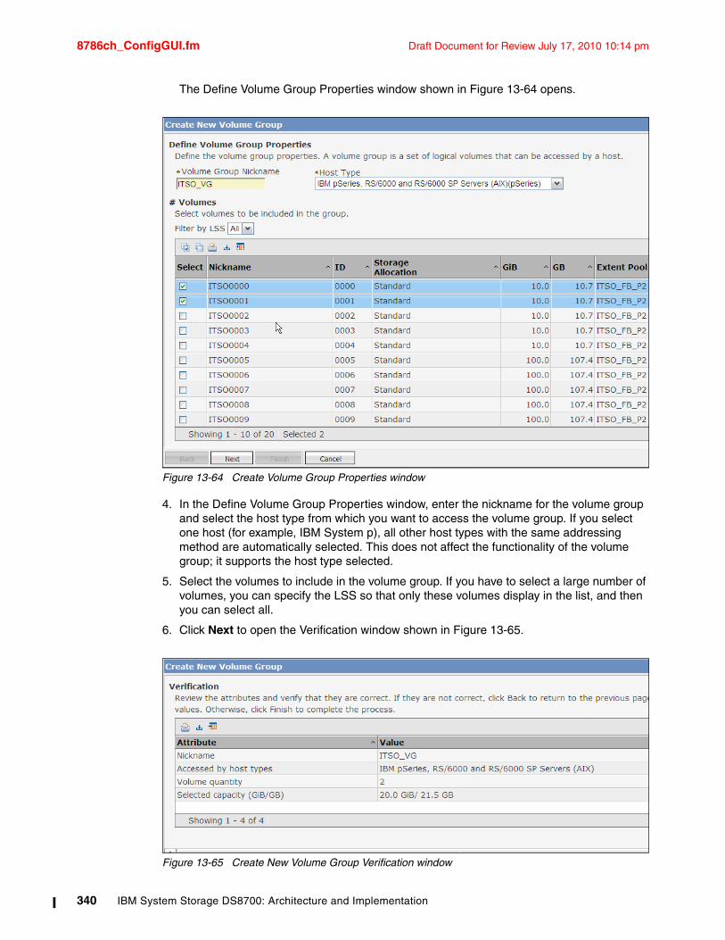
8786ch_ConfigGUI.fm Draft Document for Review July 17, 2010 10:14 pm
The Define Volume Group Properties window shown in Figure 13-64 opens.
Figure 13-64 Create Volume Group Properties window
4. In the Define Volume Group Properties window, enter the nickname for the volume group and select the host type from which you want to access the volume group. If you select one host (for example, IBM System p), all other host types with the same addressing method are automatically selected. This does not affect the functionality of the volume group; it supports the host type selected.
5. Select the volumes to include in the volume group. If you have to select a large number of volumes, you can specify the LSS so that only these volumes display in the list, and then you can select all.
6. Click Next to open the Verification window shown in Figure 13-65.
Figure 13-65 Create New Volume Group Verification window
340 IBM System Storage DS8700: Architecture and Implementation
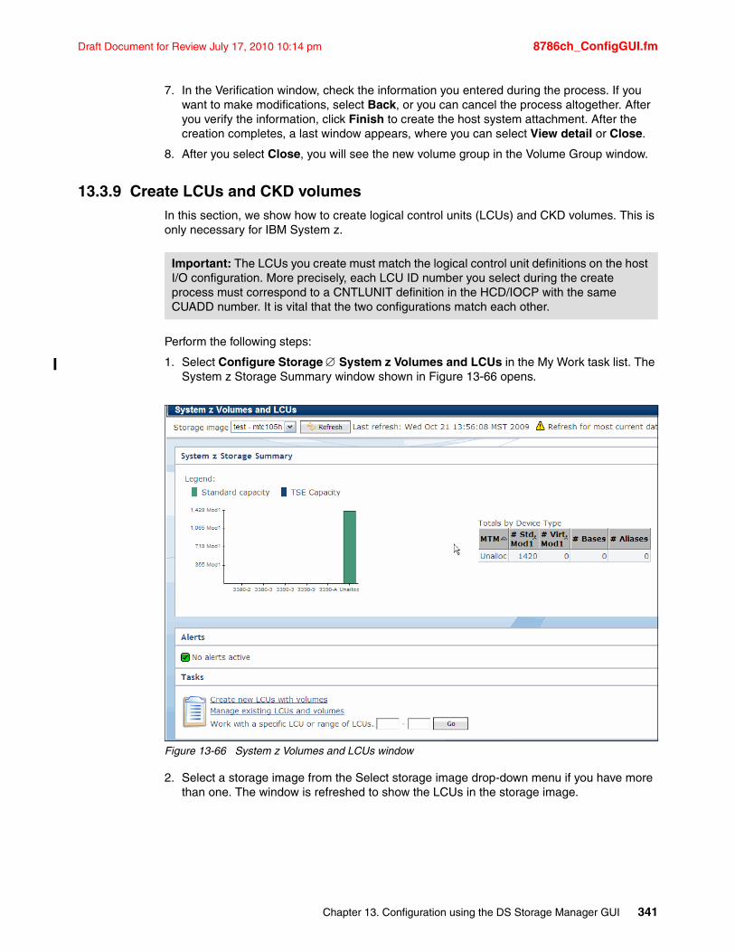
Draft Document for Review July 17, 2010 10:14 pm 8786ch_ConfigGUI.fm
7. In the Verification window, check the information you entered during the process. If you want to make modifications, select Back, or you can cancel the process altogether. After you verify the information, click Finish to create the host system attachment. After the creation completes, a last window appears, where you can select View detail or Close.
8. After you select Close, you will see the new volume group in the Volume Group window.
13.3.9 Create LCUs and CKD volumesIn this section, we show how to create logical control units (LCUs) and CKD volumes. This is only necessary for IBM System z.
Perform the following steps:
1. Select Configure Storage System z Volumes and LCUs in the My Work task list. The System z Storage Summary window shown in Figure 13-66 opens.
Figure 13-66 System z Volumes and LCUs window
2. Select a storage image from the Select storage image drop-down menu if you have more than one. The window is refreshed to show the LCUs in the storage image.
Important: The LCUs you create must match the logical control unit definitions on the host I/O configuration. More precisely, each LCU ID number you select during the create process must correspond to a CNTLUNIT definition in the HCD/IOCP with the same CUADD number. It is vital that the two configurations match each other.
Chapter 13. Configuration using the DS Storage Manager GUI 341
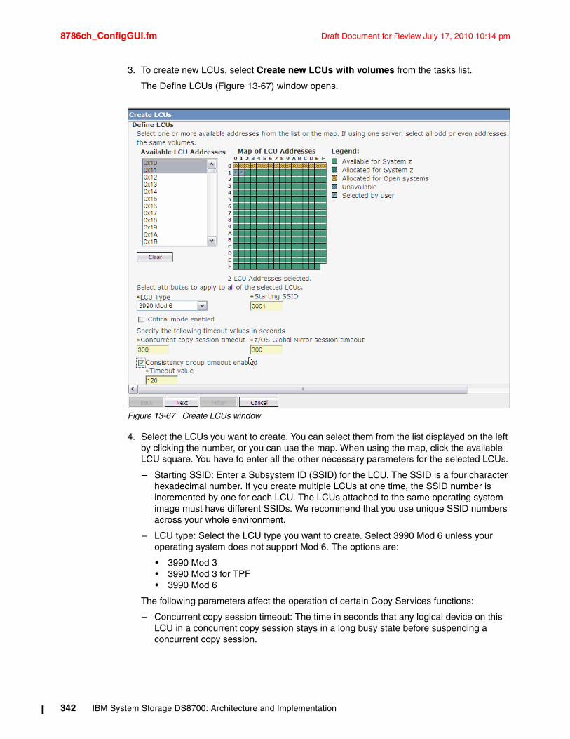
8786ch_ConfigGUI.fm Draft Document for Review July 17, 2010 10:14 pm
3. To create new LCUs, select Create new LCUs with volumes from the tasks list.
The Define LCUs (Figure 13-67) window opens.
Figure 13-67 Create LCUs window
4. Select the LCUs you want to create. You can select them from the list displayed on the left by clicking the number, or you can use the map. When using the map, click the available LCU square. You have to enter all the other necessary parameters for the selected LCUs.
– Starting SSID: Enter a Subsystem ID (SSID) for the LCU. The SSID is a four character hexadecimal number. If you create multiple LCUs at one time, the SSID number is incremented by one for each LCU. The LCUs attached to the same operating system image must have different SSIDs. We recommend that you use unique SSID numbers across your whole environment.
– LCU type: Select the LCU type you want to create. Select 3990 Mod 6 unless your operating system does not support Mod 6. The options are:
• 3990 Mod 3• 3990 Mod 3 for TPF• 3990 Mod 6
The following parameters affect the operation of certain Copy Services functions:
– Concurrent copy session timeout: The time in seconds that any logical device on this LCU in a concurrent copy session stays in a long busy state before suspending a concurrent copy session.
342 IBM System Storage DS8700: Architecture and Implementation
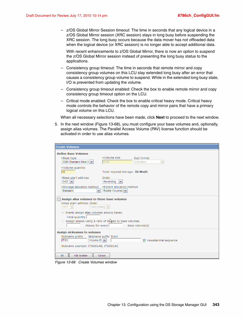
Draft Document for Review July 17, 2010 10:14 pm 8786ch_ConfigGUI.fm
– z/OS Global Mirror Session timeout: The time in seconds that any logical device in a z/OS Global Mirror session (XRC session) stays in long busy before suspending the XRC session. The long busy occurs because the data mover has not offloaded data when the logical device (or XRC session) is no longer able to accept additional data.
With recent enhancements to z/OS Global Mirror, there is now an option to suspend the z/OS Global Mirror session instead of presenting the long busy status to the applications.
– Consistency group timeout: The time in seconds that remote mirror and copy consistency group volumes on this LCU stay extended long busy after an error that causes a consistency group volume to suspend. While in the extended long busy state, I/O is prevented from updating the volume.
– Consistency group timeout enabled: Check the box to enable remote mirror and copy consistency group timeout option on the LCU.
– Critical mode enabled: Check the box to enable critical heavy mode. Critical heavy mode controls the behavior of the remote copy and mirror pairs that have a primary logical volume on this LCU.
When all necessary selections have been made, click Next to proceed to the next window.
5. In the next window (Figure 13-68), you must configure your base volumes and, optionally, assign alias volumes. The Parallel Access Volume (PAV) license function should be activated in order to use alias volumes.
Figure 13-68 Create Volumes window
Chapter 13. Configuration using the DS Storage Manager GUI 343
8786ch_ConfigGUI.fm Draft Document for Review July 17, 2010 10:14 pm
Define the base volume characteristics in the first third of this window with the following information:
– Base type:
• 3380 Mod 2
• 3380 Mod 3
• 3390 Custom
• 3390 Standard Mod 3
• 3390 Standard Mod 9
• 3390 Mod A (used for Extended Address Volumes - EAV)
– Volume size: This field must be changed if you use the volume type 3390 Custom or 3390 Mode A.
– Size format: This format only has to be changed if you want to enter a special number of cylinders. This can also only be used by 3390 Custom or 3390 Mode A volume types.
– Volume quantity: Here you must enter the number of volumes you want to create.
– Base start address: The starting address of volumes you are about to create. Specify a decimal number in the range of 0 - 255. This defaults to the value specified in the Address Allocation Policy definition.
– Order: Select the address allocation order for the base volumes. The volume addresses are allocated sequentially, starting from the base start address in the selected order. If an address is already allocated, the next free address is used.
– Storage allocation method: This field only appear on boxes that have the FlashCopy SE function activated. The options are:
• Standard: Allocate standard volumes.
• Track Space Efficient (TSE): Allocate Space Efficient volumes to be used as FlashCopy SE target volumes.
– Extent allocation method: Defines how volume extents are allocated on the ranks in the extent pool. This field is not applicable for TSE volumes. The options are:
• Rotate volumes: All extents of a volume are allocated on the rank that contains most free extents. If the volume does not fit on any one rank, it can span multiple ranks in the extent pool.
• Rotate extents: The extents of a volume are allocated on all ranks in the extent pool in a round-robin fashion. This function is called Storage Pool Striping. This allocation method can improve performance because the volume is allocated on multiple ranks. It also helps to avoid hotspots by spreading the workload more evenly on the ranks. This is the preferred allocation method.
Select Assign the alias volume to these base volumes if you us PAV or Hyper PAV and provide the following information:
– Alias start address: Enter the first alias address as a decimal number between 0 - 255.
– Order: Select the address allocation order for the alias volumes. The volume addresses are allocated sequentially starting from the alias start address in the selected order.
– Evenly assign alias volumes among bases: When you select this option, you have to enter the number of alias you want to assign to each base volume.
344 IBM System Storage DS8700: Architecture and Implementation
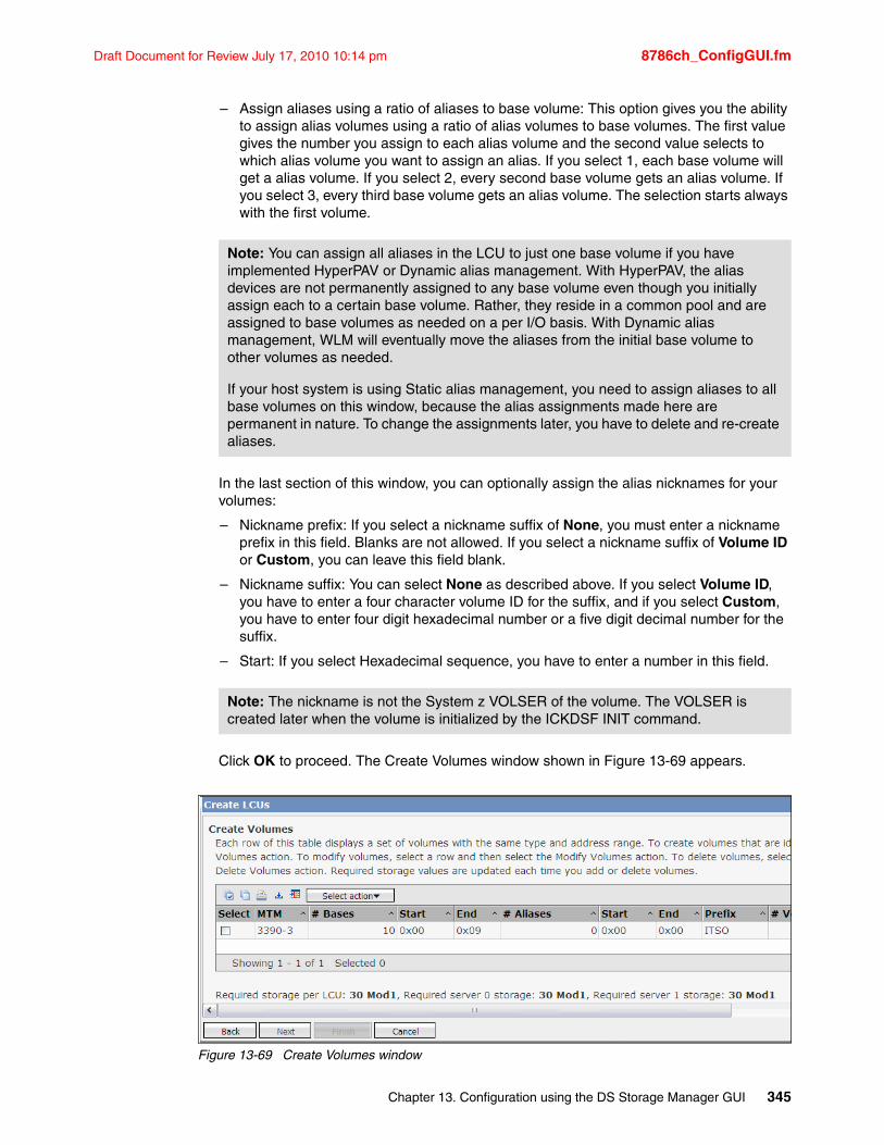
Draft Document for Review July 17, 2010 10:14 pm 8786ch_ConfigGUI.fm
– Assign aliases using a ratio of aliases to base volume: This option gives you the ability to assign alias volumes using a ratio of alias volumes to base volumes. The first value gives the number you assign to each alias volume and the second value selects to which alias volume you want to assign an alias. If you select 1, each base volume will get a alias volume. If you select 2, every second base volume gets an alias volume. If you select 3, every third base volume gets an alias volume. The selection starts always with the first volume.
In the last section of this window, you can optionally assign the alias nicknames for your volumes:
– Nickname prefix: If you select a nickname suffix of None, you must enter a nickname prefix in this field. Blanks are not allowed. If you select a nickname suffix of Volume ID or Custom, you can leave this field blank.
– Nickname suffix: You can select None as described above. If you select Volume ID, you have to enter a four character volume ID for the suffix, and if you select Custom, you have to enter four digit hexadecimal number or a five digit decimal number for the suffix.
– Start: If you select Hexadecimal sequence, you have to enter a number in this field.
Click OK to proceed. The Create Volumes window shown in Figure 13-69 appears.
Figure 13-69 Create Volumes window
Note: You can assign all aliases in the LCU to just one base volume if you have implemented HyperPAV or Dynamic alias management. With HyperPAV, the alias devices are not permanently assigned to any base volume even though you initially assign each to a certain base volume. Rather, they reside in a common pool and are assigned to base volumes as needed on a per I/O basis. With Dynamic alias management, WLM will eventually move the aliases from the initial base volume to other volumes as needed.
If your host system is using Static alias management, you need to assign aliases to all base volumes on this window, because the alias assignments made here are permanent in nature. To change the assignments later, you have to delete and re-create aliases.
Note: The nickname is not the System z VOLSER of the volume. The VOLSER is created later when the volume is initialized by the ICKDSF INIT command.
Chapter 13. Configuration using the DS Storage Manager GUI 345
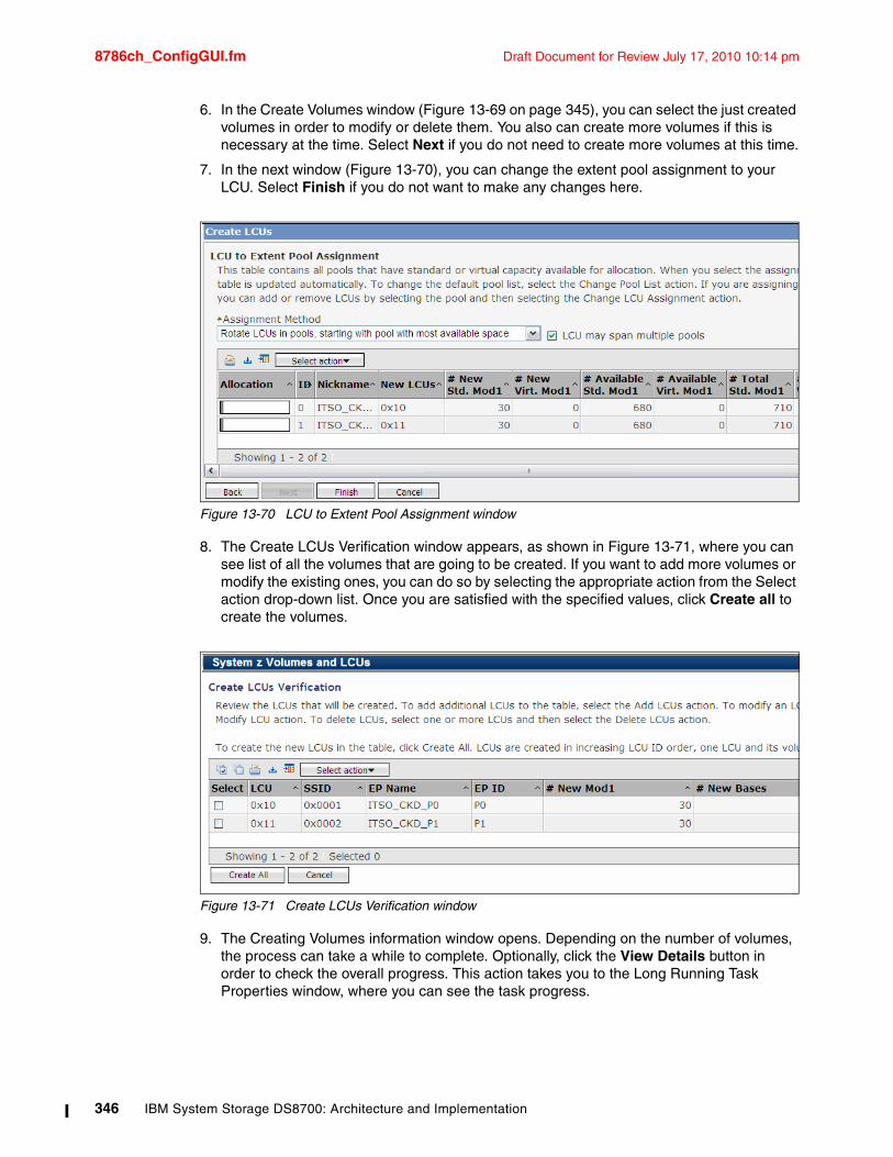
8786ch_ConfigGUI.fm Draft Document for Review July 17, 2010 10:14 pm
6. In the Create Volumes window (Figure 13-69 on page 345), you can select the just created volumes in order to modify or delete them. You also can create more volumes if this is necessary at the time. Select Next if you do not need to create more volumes at this time.
7. In the next window (Figure 13-70), you can change the extent pool assignment to your LCU. Select Finish if you do not want to make any changes here.
Figure 13-70 LCU to Extent Pool Assignment window
8. The Create LCUs Verification window appears, as shown in Figure 13-71, where you can see list of all the volumes that are going to be created. If you want to add more volumes or modify the existing ones, you can do so by selecting the appropriate action from the Select action drop-down list. Once you are satisfied with the specified values, click Create all to create the volumes.
Figure 13-71 Create LCUs Verification window
9. The Creating Volumes information window opens. Depending on the number of volumes, the process can take a while to complete. Optionally, click the View Details button in order to check the overall progress. This action takes you to the Long Running Task Properties window, where you can see the task progress.
346 IBM System Storage DS8700: Architecture and Implementation
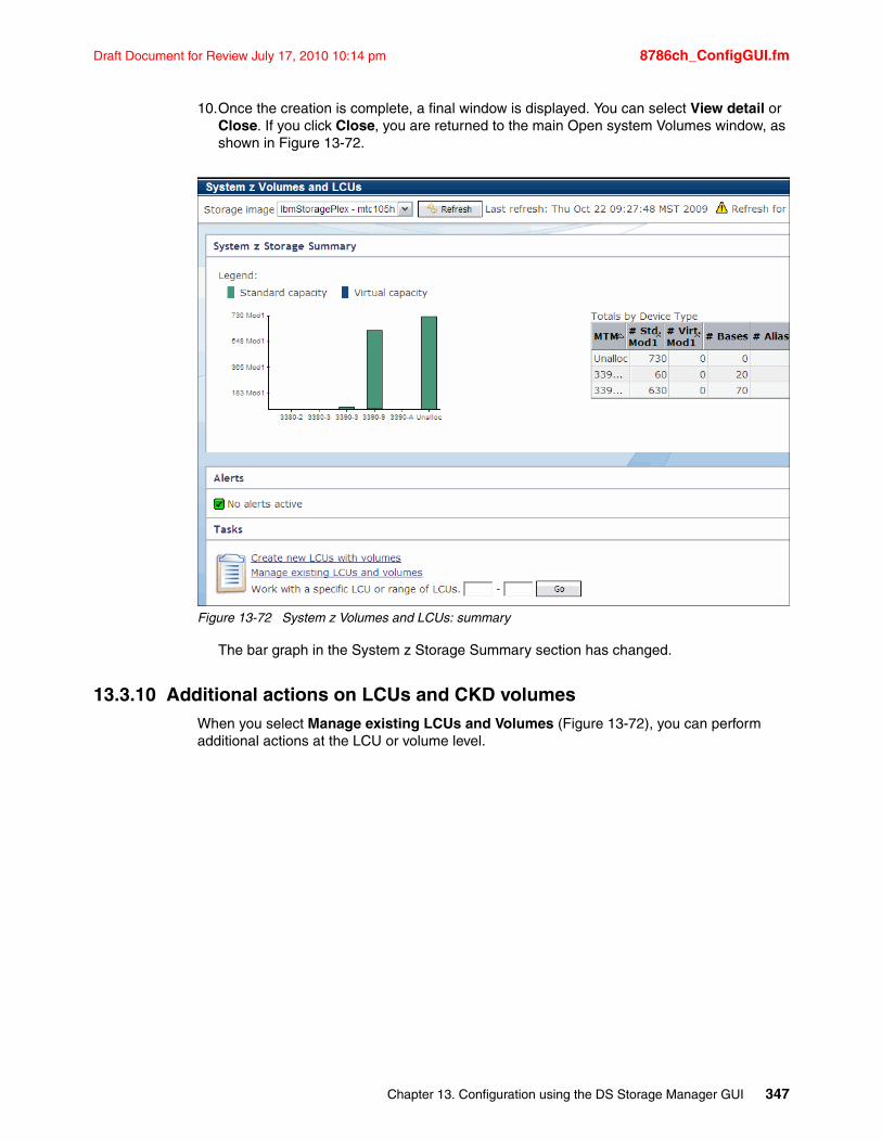
Draft Document for Review July 17, 2010 10:14 pm 8786ch_ConfigGUI.fm
10.Once the creation is complete, a final window is displayed. You can select View detail or Close. If you click Close, you are returned to the main Open system Volumes window, as shown in Figure 13-72.
Figure 13-72 System z Volumes and LCUs: summary
The bar graph in the System z Storage Summary section has changed.
13.3.10 Additional actions on LCUs and CKD volumesWhen you select Manage existing LCUs and Volumes (Figure 13-72), you can perform additional actions at the LCU or volume level.
Chapter 13. Configuration using the DS Storage Manager GUI 347
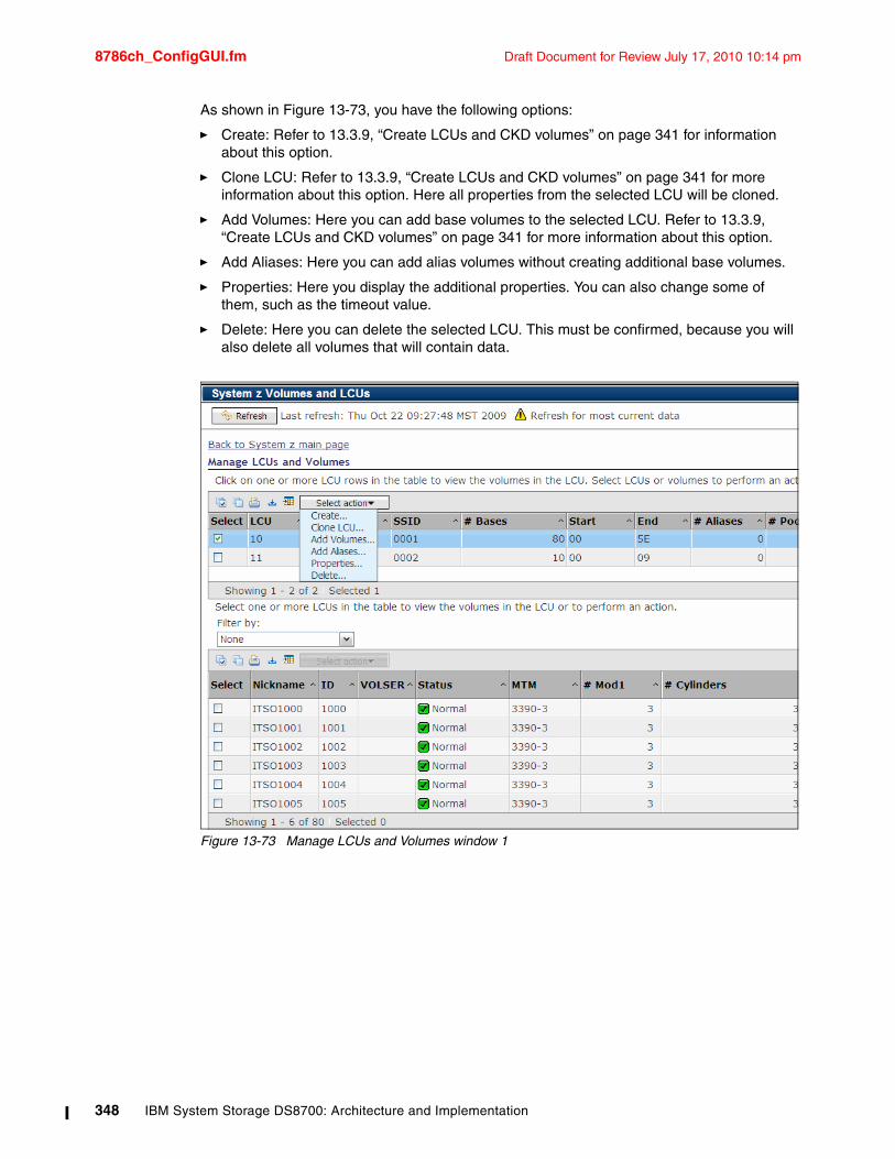
8786ch_ConfigGUI.fm Draft Document for Review July 17, 2010 10:14 pm
As shown in Figure 13-73, you have the following options:
� Create: Refer to 13.3.9, “Create LCUs and CKD volumes” on page 341 for information about this option.
� Clone LCU: Refer to 13.3.9, “Create LCUs and CKD volumes” on page 341 for more information about this option. Here all properties from the selected LCU will be cloned.
� Add Volumes: Here you can add base volumes to the selected LCU. Refer to 13.3.9, “Create LCUs and CKD volumes” on page 341 for more information about this option.
� Add Aliases: Here you can add alias volumes without creating additional base volumes.
� Properties: Here you display the additional properties. You can also change some of them, such as the timeout value.
� Delete: Here you can delete the selected LCU. This must be confirmed, because you will also delete all volumes that will contain data.
Figure 13-73 Manage LCUs and Volumes window 1
348 IBM System Storage DS8700: Architecture and Implementation
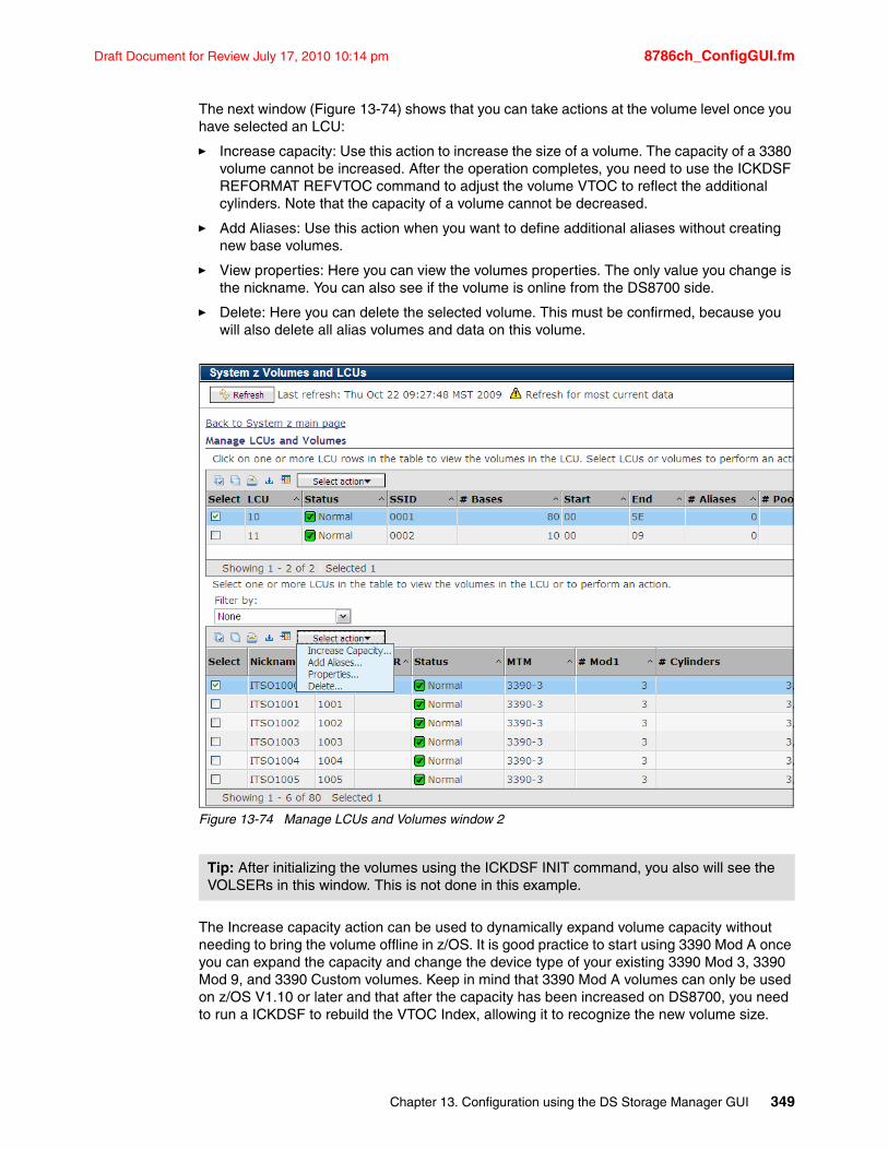
Draft Document for Review July 17, 2010 10:14 pm 8786ch_ConfigGUI.fm
The next window (Figure 13-74) shows that you can take actions at the volume level once you have selected an LCU:
� Increase capacity: Use this action to increase the size of a volume. The capacity of a 3380 volume cannot be increased. After the operation completes, you need to use the ICKDSF REFORMAT REFVTOC command to adjust the volume VTOC to reflect the additional cylinders. Note that the capacity of a volume cannot be decreased.
� Add Aliases: Use this action when you want to define additional aliases without creating new base volumes.
� View properties: Here you can view the volumes properties. The only value you change is the nickname. You can also see if the volume is online from the DS8700 side.
� Delete: Here you can delete the selected volume. This must be confirmed, because you will also delete all alias volumes and data on this volume.
Figure 13-74 Manage LCUs and Volumes window 2
The Increase capacity action can be used to dynamically expand volume capacity without needing to bring the volume offline in z/OS. It is good practice to start using 3390 Mod A once you can expand the capacity and change the device type of your existing 3390 Mod 3, 3390 Mod 9, and 3390 Custom volumes. Keep in mind that 3390 Mod A volumes can only be used on z/OS V1.10 or later and that after the capacity has been increased on DS8700, you need to run a ICKDSF to rebuild the VTOC Index, allowing it to recognize the new volume size.
Tip: After initializing the volumes using the ICKDSF INIT command, you also will see the VOLSERs in this window. This is not done in this example.
Chapter 13. Configuration using the DS Storage Manager GUI 349
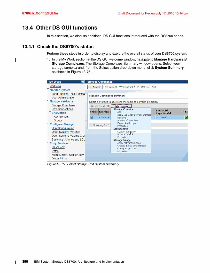
8786ch_ConfigGUI.fm Draft Document for Review July 17, 2010 10:14 pm
13.4 Other DS GUl functionsIn this section, we discuss additional DS GUI functions introduced with the DS8700 series.
13.4.1 Check the DS8700’s statusPerform these steps in order to display and explore the overall status of your DS8700 system:
1. In the My Work section in the DS GUI welcome window, navigate to Manage Hardware Storage Complexes. The Storage Complexes Summary window opens. Select your storage complex and, from the Select action drop-down menu, click System Summary, as shown in Figure 13-75.
Figure 13-75 Select Storage Unit System Summary
350 IBM System Storage DS8700: Architecture and Implementation
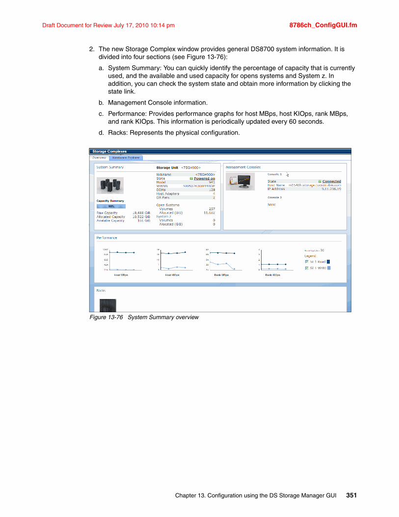
Draft Document for Review July 17, 2010 10:14 pm 8786ch_ConfigGUI.fm
2. The new Storage Complex window provides general DS8700 system information. It is divided into four sections (see Figure 13-76):
a. System Summary: You can quickly identify the percentage of capacity that is currently used, and the available and used capacity for opens systems and System z. In addition, you can check the system state and obtain more information by clicking the state link.
b. Management Console information.
c. Performance: Provides performance graphs for host MBps, host KIOps, rank MBps, and rank KIOps. This information is periodically updated every 60 seconds.
d. Racks: Represents the physical configuration.
Figure 13-76 System Summary overview
Chapter 13. Configuration using the DS Storage Manager GUI 351
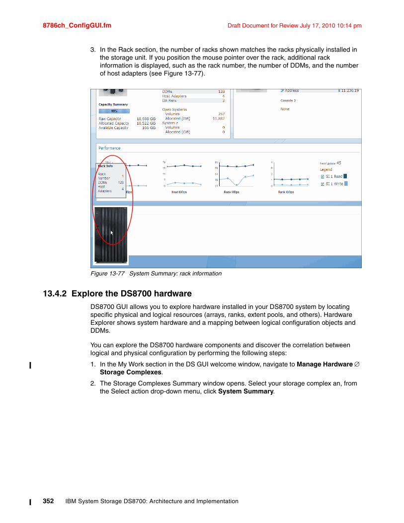
8786ch_ConfigGUI.fm Draft Document for Review July 17, 2010 10:14 pm
3. In the Rack section, the number of racks shown matches the racks physically installed in the storage unit. If you position the mouse pointer over the rack, additional rack information is displayed, such as the rack number, the number of DDMs, and the number of host adapters (see Figure 13-77).
Figure 13-77 System Summary: rack information
13.4.2 Explore the DS8700 hardwareDS8700 GUI allows you to explore hardware installed in your DS8700 system by locating specific physical and logical resources (arrays, ranks, extent pools, and others). Hardware Explorer shows system hardware and a mapping between logical configuration objects and DDMs.
You can explore the DS8700 hardware components and discover the correlation between logical and physical configuration by performing the following steps:
1. In the My Work section in the DS GUI welcome window, navigate to Manage Hardware Storage Complexes.
2. The Storage Complexes Summary window opens. Select your storage complex an, from the Select action drop-down menu, click System Summary.
352 IBM System Storage DS8700: Architecture and Implementation
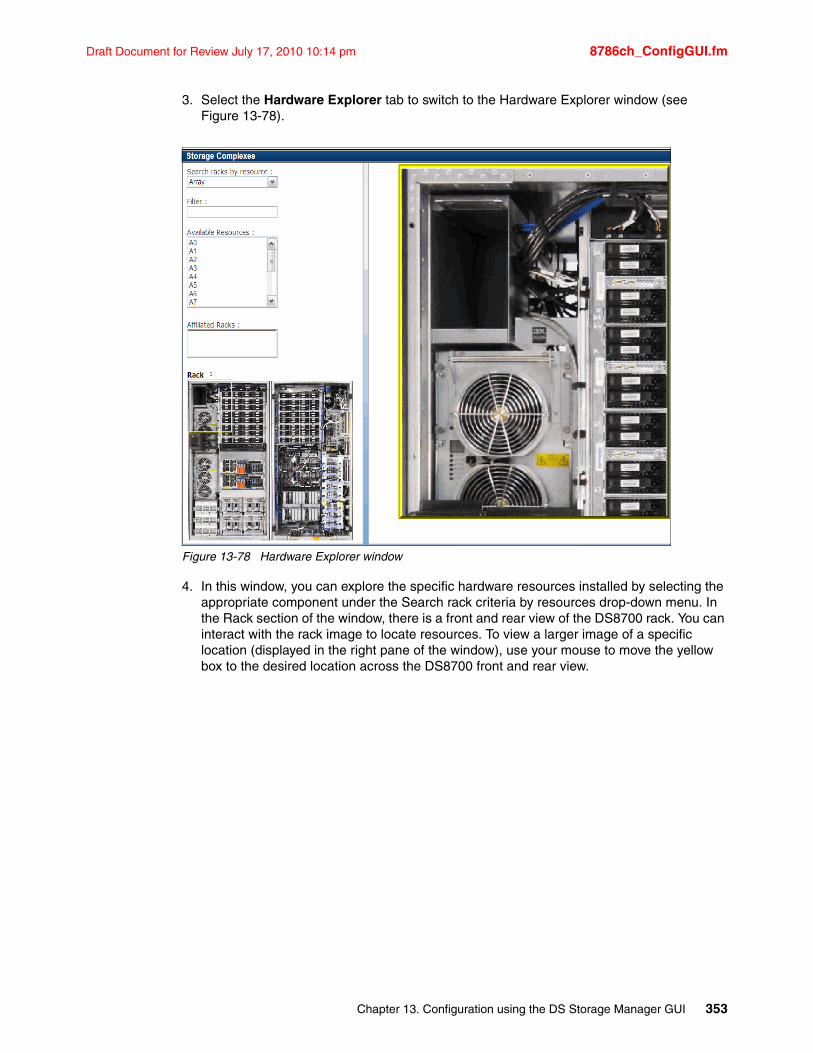
Draft Document for Review July 17, 2010 10:14 pm 8786ch_ConfigGUI.fm
3. Select the Hardware Explorer tab to switch to the Hardware Explorer window (see Figure 13-78).
Figure 13-78 Hardware Explorer window
4. In this window, you can explore the specific hardware resources installed by selecting the appropriate component under the Search rack criteria by resources drop-down menu. In the Rack section of the window, there is a front and rear view of the DS8700 rack. You can interact with the rack image to locate resources. To view a larger image of a specific location (displayed in the right pane of the window), use your mouse to move the yellow box to the desired location across the DS8700 front and rear view.
Chapter 13. Configuration using the DS Storage Manager GUI 353
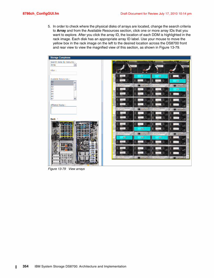
8786ch_ConfigGUI.fm Draft Document for Review July 17, 2010 10:14 pm
5. In order to check where the physical disks of arrays are located, change the search criteria to Array and from the Available Resources section, click one or more array IDs that you want to explore. After you click the array ID, the location of each DDM is highlighted in the rack image. Each disk has an appropriate array ID label. Use your mouse to move the yellow box in the rack image on the left to the desired location across the DS8700 front and rear view to view the magnified view of this section, as shown in Figure 13-79.
Figure 13-79 View arrays
354 IBM System Storage DS8700: Architecture and Implementation
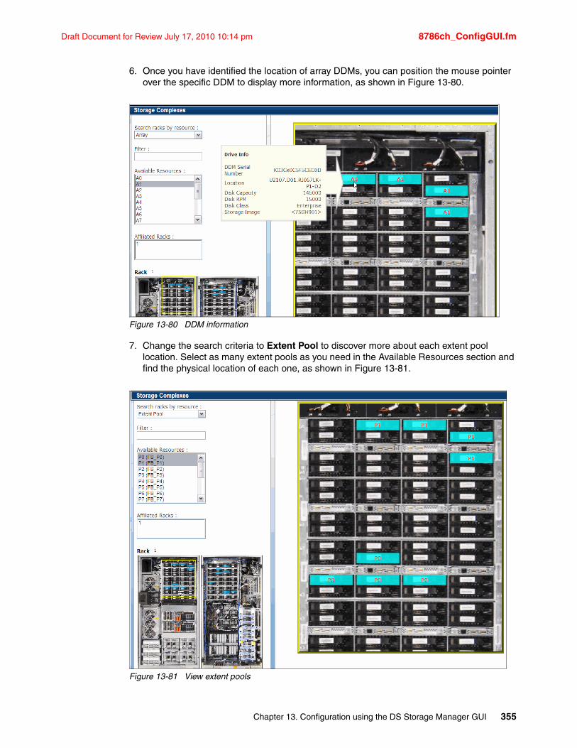
Draft Document for Review July 17, 2010 10:14 pm 8786ch_ConfigGUI.fm
6. Once you have identified the location of array DDMs, you can position the mouse pointer over the specific DDM to display more information, as shown in Figure 13-80.
Figure 13-80 DDM information
7. Change the search criteria to Extent Pool to discover more about each extent pool location. Select as many extent pools as you need in the Available Resources section and find the physical location of each one, as shown in Figure 13-81.
Figure 13-81 View extent pools
Chapter 13. Configuration using the DS Storage Manager GUI 355
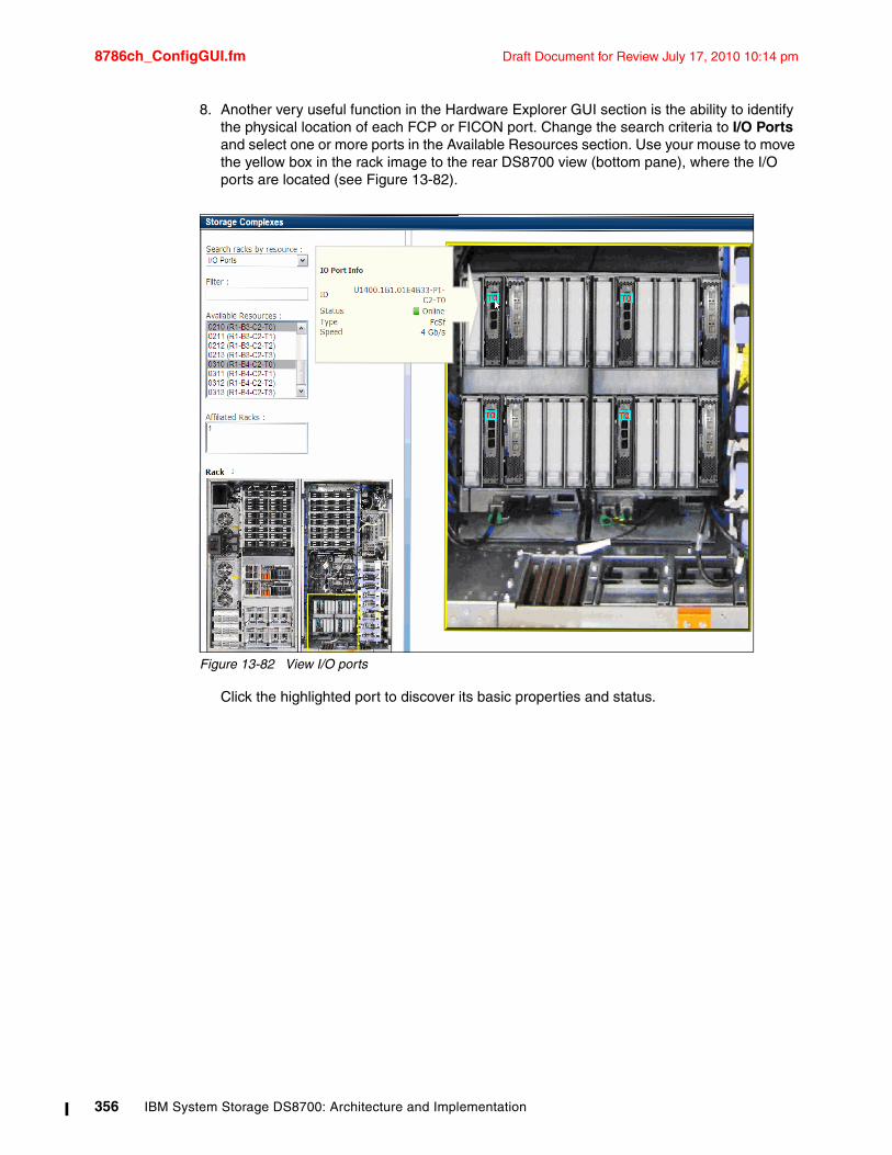
8786ch_ConfigGUI.fm Draft Document for Review July 17, 2010 10:14 pm
8. Another very useful function in the Hardware Explorer GUI section is the ability to identify the physical location of each FCP or FICON port. Change the search criteria to I/O Ports and select one or more ports in the Available Resources section. Use your mouse to move the yellow box in the rack image to the rear DS8700 view (bottom pane), where the I/O ports are located (see Figure 13-82).
Figure 13-82 View I/O ports
Click the highlighted port to discover its basic properties and status.
356 IBM System Storage DS8700: Architecture and Implementation
Draft Document for Review July 17, 2010 10:14 pm 8786ch_DSCLI.fm
Chapter 14. Configuration with the Command-Line Interface
In this chapter, we explain how to configure the storage on the IBM System Storage DS8700 storage subsystem using the DS Command-Line Interface (DS CLI). We include the following sections:
� DS Command-Line Interface overview� Configuring the I/O ports� Configuring the DS8000 storage for FB volumes� Configuring DS8000 Storage for Count Key Data Volumes
In this chapter, we discuss the use of the DS CLI for storage configuration of the DS8000, not for Copy Services configuration, encryption handling, or LDAP usage.
For Copy Services configuration in the DS8000 using the DS CLI, refer to the following books:
� IBM System Storage DS: Command-Line Interface User's Guide, GC53-1127
� IBM System Storage DS8000: Copy Services in Open Environments, SG24-6788
� DS8000 Copy Services for IBM System z, SG24-6787
� IBM System Storage DS8000 Series: IBM FlashCopy SE, REDP-4368
� IBM System Storage DS8000: Remote Pair FlashCopy (Preserve Mirror), REDP-4504
For DS CLI commands related to disk encryption, refer to IBM System Storage DS8700 Disk Encryption Implementation and Usage Guidelines, REDP-4500.
For DS CLI commands related to LDAP authentication, refer to the IBM System Storage DS8000: LDAP Authentication, REDP-4505.
For information about DS CLI changes related to the Easy Tier function, including dynamic volume relocation (DVR) and extent pool merge, refer to the IBM System Storage DS8700: Easy TIer, REDP-4667.
14
© Copyright IBM Corp. 2010. All rights reserved. 357
8786ch_DSCLI.fm Draft Document for Review July 17, 2010 10:14 pm
14.1 DS Command-Line Interface overviewThe command-line interface provides a full-function command set that allows you to check your Storage Unit configuration and perform specific application functions when necessary. For detailed information about DS CLI use and setup, refer to IBM System Storage DS: Command-Line Interface User's Guide, GC53-1127.
The following list highlights a few of the functions that you can perform with the DS CLI:
� Create user IDs that can be used with the GUI and the DS CLI.� Manage user ID passwords.� Install activation keys for licensed features.� Manage storage complexes and units.� Configure and manage Storage Facility Images.� Create and delete RAID arrays, ranks, and extent pools.� Create and delete logical volumes.� Manage host access to volumes.� Check the current Copy Services configuration that is used by the Storage Unit.� Create, modify, or delete Copy Services configuration settings.� Integrate LDAP policy usage and configuration.� Implement encryption functionality.
14.1.1 Supported operating systems for the DS CLIThe DS Command-Line Interface can be installed on these operating systems:
� AIX 5L V5.1, V5.2, V5.3, and V6.1
� HP-UX 11i, 11iV2, and 11iV3
� HP Tru64 5.1and 5.1A
� Red Hat Linux: Advanced Server (AS) 3.0, and Enterprise Server (ES) RHEL 2.1, 3, 4, and 5
� SUSE Linux SLES 8, SLES 9, SLES10, SUSE 8, and SUSE 9
� Novell NetWare 6.5
� IBM System i i5/OS 5.3
� Sun Solaris 7, 8, and 9
� HP OpenVMS 7.3-1 (or newer)
� VMware ESX V3.0.1 Console
� Windows 2000, Windows Datacenter, Windows 2003, Windows Vista, Windows Server 2008, and Windows XP (all 32-bit)
Note: The DSCLI version must correspond to the LMC level installed on your system.
Note: The DS CLI cannot be installed on a Windows 64-bit operating system.
Important: For the most recent information about currently supported operating systems, refer to the IBM System Storage DS8000 Information Center Web site at:
http://publib.boulder.ibm.com/infocenter/ds8000ic/index.jsp
358 IBM System Storage DS8700: Architecture and Implementation
Draft Document for Review July 17, 2010 10:14 pm 8786ch_DSCLI.fm
The DS CLI is supplied and installed via a CD that ships with the machine. The installation does not require a reboot of the open systems host. The DS CLI requires Java 1.4.1 or later. Java 1.4.2 is the preferred JRE on Windows, AIX, and Linux, and is supplied on the CD. Many hosts may already have a suitable level of Java installed. The installation program checks for this requirement during the installation process and does not install the DS CLI if you do not have the correct version of Java.
The installation process can be performed through a shell, such as the bash or korn shell, or the Windows command prompt, or through a GUI interface. If performed via a shell, it can be performed silently using a profile file. The installation process also installs software that allows the DS CLI to be completely uninstalled should it no longer be required.
14.1.2 User accountsDS CLI communicates with the DS8000 system through the HMC console. Either the primary or secondary HMC console may be used. DS CLI access is authenticated using HMC user accounts. Same user IDs can used for both DS CLI and DS GUI access. See 9.5, “HMC user management” on page 222 for more details on user accounts.
14.1.3 DS CLI profileIn order to access a DS8000 system with the DS CLI, you need to provide certain information on the dscli command. At the minimum, the IP address or host name of the DS8000 HMC, a username and a password are required. You can also provide information such as the output format for list commands, the number of rows per page in the command-line output, and whether a banner is included with the command-line output.
In order to avoid specifying all this information each time you use DS CLI, you can create one or more profiles to contain your preferred settings. When you launch DS CLI, all you need to do is to specify a profile name on the dscli command. You can override profile values by specifying a different parameter value on the dscli command.
When you install the command-line interface software, a default profile is installed in the profile directory with the software. The file name is dscli.profile, for example, c:\Program Files\IBM\DSCLI\profile\dscli.profile for the Windows platform and opt/ibm/dscli/profile/dscli.profile for UNIX and Linux platforms.
You have several options for using profile files:
� You can modify the system default profile dscli.profile.
� You can make a personal default profile by making a copy of the system default profile as <user_home>/dscli/profile/dscli.profile. The home directory <user_home> is designated as follows:
– Windows system: C:\Documents and Settings\<user_name>
– UNIX/Linux system: /home/<user_name>
� You can create specific profiles for different Storage Units and operations. Save the profile in the user profile directory. For example:
– c:\Program Files\IBM\DSCLI\profile\operation_name1
– c:\Program Files\IBM\DSCLI\profile\operation_name2
Chapter 14. Configuration with the Command-Line Interface 359
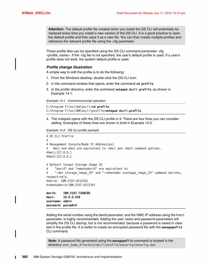
8786ch_DSCLI.fm Draft Document for Review July 17, 2010 10:14 pm
These profile files can be specified using the DS CLI command parameter -cfg <profile_name>. If the -cfg file is not specified, the user’s default profile is used. If a user’s profile does not exist, the system default profile is used.
Profile change illustrationA simple way to edit the profile is to do the following:
1. From the Windows desktop, double-click the DS CLI icon.
2. In the command window that opens, enter the command cd profile.
3. In the profile directory, enter the command notepad dscli.profile, as shown in Example 14-1.
Example 14-1 Command prompt operation
C:\Program Files\ibm\dscli>cd profileC:\Program Files\IBM\dscli\profile>notepad dscli.profile
4. The notepad opens with the DS CLI profile in it. There are four lines you can consider adding. Examples of these lines are shown in bold in Example 14-2.
Example 14-2 DS CLI profile example
# DS CLI Profile## Management Console/Node IP Address(es)# hmc1 and hmc2 are equivalent to -hmc1 and -hmc2 command options.#hmc1:127.0.0.1#hmc2:127.0.0.1
# Default target Storage Image ID# "devid" and "remotedevid" are equivalent to # "-dev storage_image_ID" and "-remotedev storeage_image_ID" command options, respectively. #devid: IBM.2107-AZ12341#remotedevid:IBM.2107-AZ12341
devid: IBM.2107-75ABCDEhmc1: 10.0.0.250username: adminpassword: passw0rd
Adding the serial number using the devid parameter, and the HMC IP address using the hmc1 parameter, is highly recommended. Adding the user name and password parameters will simplify the DS CLI startup, but is not recommended, because a password is saved in clear text in the profile file. It is better to create an encrypted password file with the managepwfile CLI command.
Attention: The default profile file created when you install the DS CLI will potentially be replaced every time you install a new version of the DS CLI. It is a good practice to open the default profile and then save it as a new file. You can then create multiple profiles and reference the relevant profile file using the -cfg parameter.
Note: A password file generated using the managepwfile command is located in the directory user_home_directory/dscli/profile/security/security.dat.
360 IBM System Storage DS8700: Architecture and Implementation
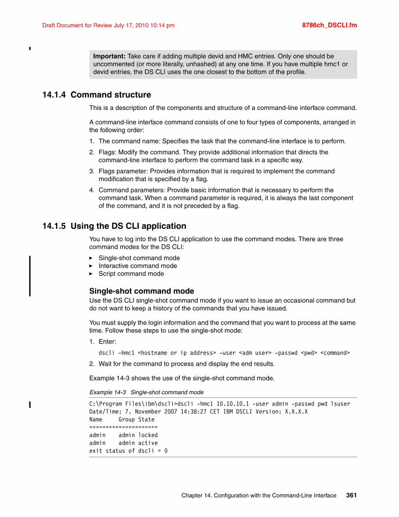
Draft Document for Review July 17, 2010 10:14 pm 8786ch_DSCLI.fm
14.1.4 Command structureThis is a description of the components and structure of a command-line interface command.
A command-line interface command consists of one to four types of components, arranged in the following order:
1. The command name: Specifies the task that the command-line interface is to perform.
2. Flags: Modify the command. They provide additional information that directs the command-line interface to perform the command task in a specific way.
3. Flags parameter: Provides information that is required to implement the command modification that is specified by a flag.
4. Command parameters: Provide basic information that is necessary to perform the command task. When a command parameter is required, it is always the last component of the command, and it is not preceded by a flag.
14.1.5 Using the DS CLI applicationYou have to log into the DS CLI application to use the command modes. There are three command modes for the DS CLI:
� Single-shot command mode� Interactive command mode� Script command mode
Single-shot command modeUse the DS CLI single-shot command mode if you want to issue an occasional command but do not want to keep a history of the commands that you have issued.
You must supply the login information and the command that you want to process at the same time. Follow these steps to use the single-shot mode:
1. Enter:
dscli -hmc1 <hostname or ip address> -user <adm user> -passwd <pwd> <command>
2. Wait for the command to process and display the end results.
Example 14-3 shows the use of the single-shot command mode.
Example 14-3 Single-shot command mode
C:\Program Files\ibm\dscli>dscli -hmc1 10.10.10.1 -user admin -passwd pwd lsuserDate/Time: 7. November 2007 14:38:27 CET IBM DSCLI Version: X.X.X.XName Group State=====================admin admin lockedadmin admin activeexit status of dscli = 0
Important: Take care if adding multiple devid and HMC entries. Only one should be uncommented (or more literally, unhashed) at any one time. If you have multiple hmc1 or devid entries, the DS CLI uses the one closest to the bottom of the profile.
Chapter 14. Configuration with the Command-Line Interface 361
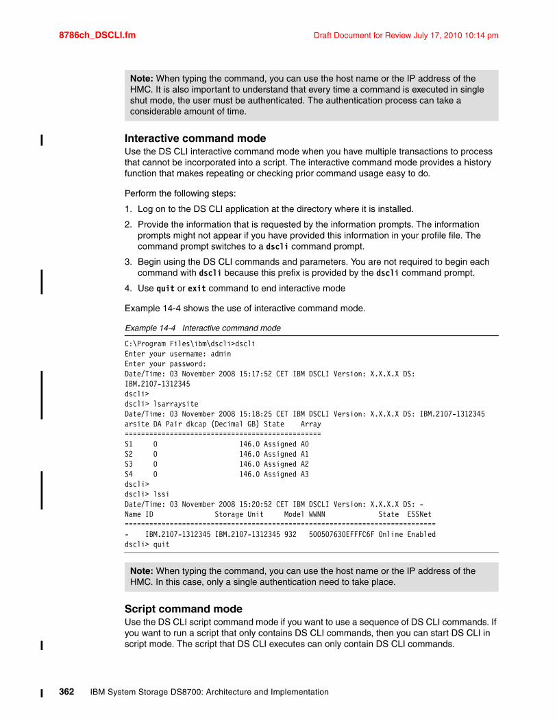
8786ch_DSCLI.fm Draft Document for Review July 17, 2010 10:14 pm
Interactive command modeUse the DS CLI interactive command mode when you have multiple transactions to process that cannot be incorporated into a script. The interactive command mode provides a history function that makes repeating or checking prior command usage easy to do.
Perform the following steps:
1. Log on to the DS CLI application at the directory where it is installed.
2. Provide the information that is requested by the information prompts. The information prompts might not appear if you have provided this information in your profile file. The command prompt switches to a dscli command prompt.
3. Begin using the DS CLI commands and parameters. You are not required to begin each command with dscli because this prefix is provided by the dscli command prompt.
4. Use quit or exit command to end interactive mode
Example 14-4 shows the use of interactive command mode.
Example 14-4 Interactive command mode
C:\Program Files\ibm\dscli>dscliEnter your username: adminEnter your password:Date/Time: 03 November 2008 15:17:52 CET IBM DSCLI Version: X.X.X.X DS:IBM.2107-1312345dscli> dscli> lsarraysiteDate/Time: 03 November 2008 15:18:25 CET IBM DSCLI Version: X.X.X.X DS: IBM.2107-1312345arsite DA Pair dkcap (Decimal GB) State Array================================================S1 0 146.0 Assigned A0S2 0 146.0 Assigned A1S3 0 146.0 Assigned A2S4 0 146.0 Assigned A3dscli> dscli> lssiDate/Time: 03 November 2008 15:20:52 CET IBM DSCLI Version: X.X.X.X DS: -Name ID Storage Unit Model WWNN State ESSNet============================================================================- IBM.2107-1312345 IBM.2107-1312345 932 500507630EFFFC6F Online Enableddscli> quit
Script command modeUse the DS CLI script command mode if you want to use a sequence of DS CLI commands. If you want to run a script that only contains DS CLI commands, then you can start DS CLI in script mode. The script that DS CLI executes can only contain DS CLI commands.
Note: When typing the command, you can use the host name or the IP address of the HMC. It is also important to understand that every time a command is executed in single shut mode, the user must be authenticated. The authentication process can take a considerable amount of time.
Note: When typing the command, you can use the host name or the IP address of the HMC. In this case, only a single authentication need to take place.
362 IBM System Storage DS8700: Architecture and Implementation
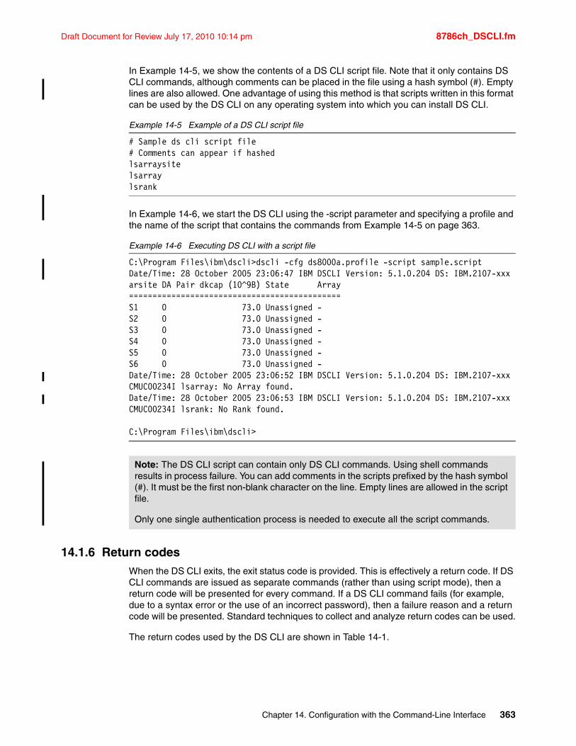
Draft Document for Review July 17, 2010 10:14 pm 8786ch_DSCLI.fm
In Example 14-5, we show the contents of a DS CLI script file. Note that it only contains DS CLI commands, although comments can be placed in the file using a hash symbol (#). Empty lines are also allowed. One advantage of using this method is that scripts written in this format can be used by the DS CLI on any operating system into which you can install DS CLI.
Example 14-5 Example of a DS CLI script file
# Sample ds cli script file# Comments can appear if hashedlsarraysitelsarraylsrank
In Example 14-6, we start the DS CLI using the -script parameter and specifying a profile and the name of the script that contains the commands from Example 14-5 on page 363.
Example 14-6 Executing DS CLI with a script file
C:\Program Files\ibm\dscli>dscli -cfg ds8000a.profile -script sample.scriptDate/Time: 28 October 2005 23:06:47 IBM DSCLI Version: 5.1.0.204 DS: IBM.2107-xxxarsite DA Pair dkcap (10^9B) State Array=============================================S1 0 73.0 Unassigned -S2 0 73.0 Unassigned -S3 0 73.0 Unassigned -S4 0 73.0 Unassigned -S5 0 73.0 Unassigned -S6 0 73.0 Unassigned -Date/Time: 28 October 2005 23:06:52 IBM DSCLI Version: 5.1.0.204 DS: IBM.2107-xxxCMUC00234I lsarray: No Array found.Date/Time: 28 October 2005 23:06:53 IBM DSCLI Version: 5.1.0.204 DS: IBM.2107-xxxCMUC00234I lsrank: No Rank found.
C:\Program Files\ibm\dscli>
14.1.6 Return codesWhen the DS CLI exits, the exit status code is provided. This is effectively a return code. If DS CLI commands are issued as separate commands (rather than using script mode), then a return code will be presented for every command. If a DS CLI command fails (for example, due to a syntax error or the use of an incorrect password), then a failure reason and a return code will be presented. Standard techniques to collect and analyze return codes can be used.
The return codes used by the DS CLI are shown in Table 14-1.
Note: The DS CLI script can contain only DS CLI commands. Using shell commands results in process failure. You can add comments in the scripts prefixed by the hash symbol (#). It must be the first non-blank character on the line. Empty lines are allowed in the script file.
Only one single authentication process is needed to execute all the script commands.
Chapter 14. Configuration with the Command-Line Interface 363
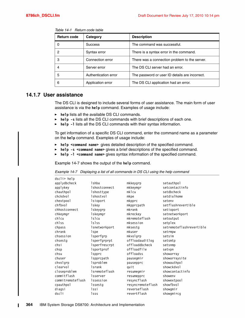
8786ch_DSCLI.fm Draft Document for Review July 17, 2010 10:14 pm
Table 14-1 Return code table
14.1.7 User assistance The DS CLI is designed to include several forms of user assistance. The main form of user assistance is via the help command. Examples of usage include:
� help lists all the available DS CLI commands.� help -s lists all the DS CLI commands with brief descriptions of each one. � help -l lists all the DS CLI commands with their syntax information.
To get information of a specific DS CLI command, enter the command name as a parameter on the help command. Examples of usage include:
� help <command name> gives detailed description of the specified command.� help -s <command name> gives a brief descriptions of the specified command. � help -l <command name> gives syntax information of the specified command.
Example 14-7 shows the output of the help command.
Example 14-7 Displaying a list of all commands in DS CLI using the help command
dscli> helpapplydbcheck lshba mkkeygrp setauthpolapplykey lshostconnect mkkeymgr setcontactinfochauthpol lshosttype mklcu setdbcheckchckdvol lshostvol mkpe setdialhomechextpool lsioport mkpprc setenvchfbvol lskey mkpprcpath setflashrevertiblechhostconnect lskeygrp mkrank setioportchkeymgr lskeymgr mkreckey setnetworkportchlcu lslcu mkremoteflash setoutputchlss lslss mksession setplexchpass lsnetworkport mksestg setremoteflashrevertiblechrank lspe mkuser setrmpwchsession lsperfgrp mkvolgrp setsimchsestg lsperfgrprpt offloadauditlog setsmtpchsi lsperfrescrpt offloaddbcheck setsnmpchsp lsportprof offloadfile setvpnchsu lspprc offloadss showarraychuser lspprcpath pausegmir showarraysitechvolgrp lsproblem pausepprc showauthpolclearvol lsrank quit showckdvolcloseproblem lsremoteflash resumegmir showcontactinfocommitflash lsserver resumepprc showenvcommitremoteflash lssession resyncflash showextpoolcpauthpol lssestg resyncremoteflash showfbvoldiagsi lssi reverseflash showgmirdscli lsss revertflash showgmircg
Return code Category Description
0 Success The command was successful.
2 Syntax error There is a syntax error in the command.
3 Connection error There was a connection problem to the server.
4 Server error The DS CLI server had an error.
5 Authentication error The password or user ID details are incorrect.
6 Application error The DS CLI application had an error.
364 IBM System Storage DS8700: Architecture and Implementation
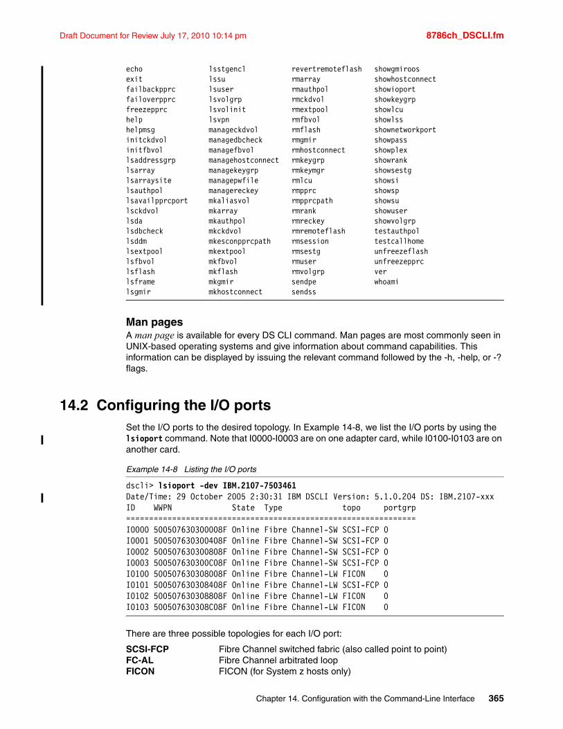
Draft Document for Review July 17, 2010 10:14 pm 8786ch_DSCLI.fm
echo lsstgencl revertremoteflash showgmiroosexit lssu rmarray showhostconnectfailbackpprc lsuser rmauthpol showioportfailoverpprc lsvolgrp rmckdvol showkeygrpfreezepprc lsvolinit rmextpool showlcuhelp lsvpn rmfbvol showlsshelpmsg manageckdvol rmflash shownetworkportinitckdvol managedbcheck rmgmir showpassinitfbvol managefbvol rmhostconnect showplexlsaddressgrp managehostconnect rmkeygrp showranklsarray managekeygrp rmkeymgr showsestglsarraysite managepwfile rmlcu showsilsauthpol managereckey rmpprc showsplsavailpprcport mkaliasvol rmpprcpath showsulsckdvol mkarray rmrank showuserlsda mkauthpol rmreckey showvolgrplsdbcheck mkckdvol rmremoteflash testauthpollsddm mkesconpprcpath rmsession testcallhomelsextpool mkextpool rmsestg unfreezeflashlsfbvol mkfbvol rmuser unfreezepprclsflash mkflash rmvolgrp verlsframe mkgmir sendpe whoamilsgmir mkhostconnect sendss
Man pages A man page is available for every DS CLI command. Man pages are most commonly seen in UNIX-based operating systems and give information about command capabilities. This information can be displayed by issuing the relevant command followed by the -h, -help, or -? flags.
14.2 Configuring the I/O portsSet the I/O ports to the desired topology. In Example 14-8, we list the I/O ports by using the lsioport command. Note that I0000-I0003 are on one adapter card, while I0100-I0103 are on another card.
Example 14-8 Listing the I/O ports
dscli> lsioport -dev IBM.2107-7503461Date/Time: 29 October 2005 2:30:31 IBM DSCLI Version: 5.1.0.204 DS: IBM.2107-xxxID WWPN State Type topo portgrp===============================================================I0000 500507630300008F Online Fibre Channel-SW SCSI-FCP 0I0001 500507630300408F Online Fibre Channel-SW SCSI-FCP 0I0002 500507630300808F Online Fibre Channel-SW SCSI-FCP 0I0003 500507630300C08F Online Fibre Channel-SW SCSI-FCP 0I0100 500507630308008F Online Fibre Channel-LW FICON 0I0101 500507630308408F Online Fibre Channel-LW SCSI-FCP 0I0102 500507630308808F Online Fibre Channel-LW FICON 0I0103 500507630308C08F Online Fibre Channel-LW FICON 0
There are three possible topologies for each I/O port:
SCSI-FCP Fibre Channel switched fabric (also called point to point)FC-AL Fibre Channel arbitrated loopFICON FICON (for System z hosts only)
Chapter 14. Configuration with the Command-Line Interface 365
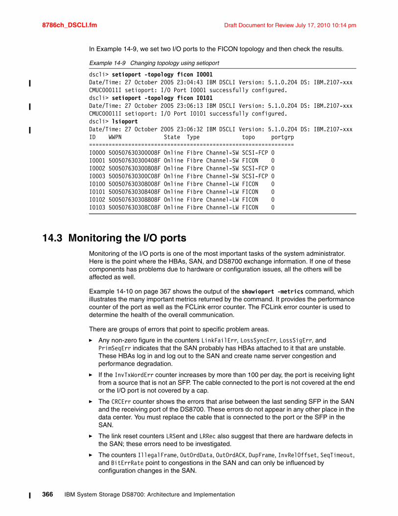
8786ch_DSCLI.fm Draft Document for Review July 17, 2010 10:14 pm
In Example 14-9, we set two I/O ports to the FICON topology and then check the results.
Example 14-9 Changing topology using setioport
dscli> setioport -topology ficon I0001Date/Time: 27 October 2005 23:04:43 IBM DSCLI Version: 5.1.0.204 DS: IBM.2107-xxxCMUC00011I setioport: I/O Port I0001 successfully configured.dscli> setioport -topology ficon I0101Date/Time: 27 October 2005 23:06:13 IBM DSCLI Version: 5.1.0.204 DS: IBM.2107-xxxCMUC00011I setioport: I/O Port I0101 successfully configured.dscli> lsioportDate/Time: 27 October 2005 23:06:32 IBM DSCLI Version: 5.1.0.204 DS: IBM.2107-xxxID WWPN State Type topo portgrp===============================================================I0000 500507630300008F Online Fibre Channel-SW SCSI-FCP 0I0001 500507630300408F Online Fibre Channel-SW FICON 0I0002 500507630300808F Online Fibre Channel-SW SCSI-FCP 0I0003 500507630300C08F Online Fibre Channel-SW SCSI-FCP 0I0100 500507630308008F Online Fibre Channel-LW FICON 0I0101 500507630308408F Online Fibre Channel-LW FICON 0I0102 500507630308808F Online Fibre Channel-LW FICON 0I0103 500507630308C08F Online Fibre Channel-LW FICON 0
14.3 Monitoring the I/O portsMonitoring of the I/O ports is one of the most important tasks of the system administrator. Here is the point where the HBAs, SAN, and DS8700 exchange information. If one of these components has problems due to hardware or configuration issues, all the others will be affected as well.
Example 14-10 on page 367 shows the output of the showioport -metrics command, which illustrates the many important metrics returned by the command. It provides the performance counter of the port as well as the FCLink error counter. The FCLink error counter is used to determine the health of the overall communication.
There are groups of errors that point to specific problem areas.
� Any non-zero figure in the counters LinkFailErr, LossSyncErr, LossSigErr, and PrimSeqErr indicates that the SAN probably has HBAs attached to it that are unstable. These HBAs log in and log out to the SAN and create name server congestion and performance degradation.
� If the InvTxWordErr counter increases by more than 100 per day, the port is receiving light from a source that is not an SFP. The cable connected to the port is not covered at the end or the I/O port is not covered by a cap.
� The CRCErr counter shows the errors that arise between the last sending SFP in the SAN and the receiving port of the DS8700. These errors do not appear in any other place in the data center. You must replace the cable that is connected to the port or the SFP in the SAN.
� The link reset counters LRSent and LRRec also suggest that there are hardware defects in the SAN; these errors need to be investigated.
� The counters IllegalFrame, OutOrdData, OutOrdACK, DupFrame, InvRelOffset, SeqTimeout, and BitErrRate point to congestions in the SAN and can only be influenced by configuration changes in the SAN.
366 IBM System Storage DS8700: Architecture and Implementation
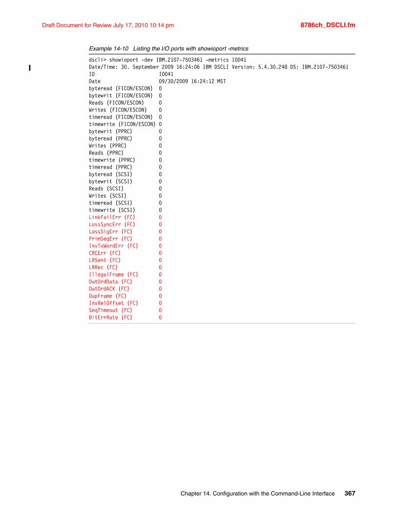
Draft Document for Review July 17, 2010 10:14 pm 8786ch_DSCLI.fm
Example 14-10 Listing the I/O ports with showioport -metrics
dscli> showioport -dev IBM.2107-7503461 -metrics I0041Date/Time: 30. September 2009 16:24:06 IBM DSCLI Version: 5.4.30.248 DS: IBM.2107-7503461ID I0041Date 09/30/2009 16:24:12 MSTbyteread (FICON/ESCON) 0bytewrit (FICON/ESCON) 0Reads (FICON/ESCON) 0Writes (FICON/ESCON) 0timeread (FICON/ESCON) 0timewrite (FICON/ESCON) 0bytewrit (PPRC) 0byteread (PPRC) 0Writes (PPRC) 0Reads (PPRC) 0timewrite (PPRC) 0timeread (PPRC) 0byteread (SCSI) 0bytewrit (SCSI) 0Reads (SCSI) 0Writes (SCSI) 0timeread (SCSI) 0timewrite (SCSI) 0LinkFailErr (FC) 0LossSyncErr (FC) 0LossSigErr (FC) 0PrimSeqErr (FC) 0InvTxWordErr (FC) 0CRCErr (FC) 0LRSent (FC) 0LRRec (FC) 0IllegalFrame (FC) 0OutOrdData (FC) 0OutOrdACK (FC) 0DupFrame (FC) 0InvRelOffset (FC) 0SeqTimeout (FC) 0BitErrRate (FC) 0
Chapter 14. Configuration with the Command-Line Interface 367
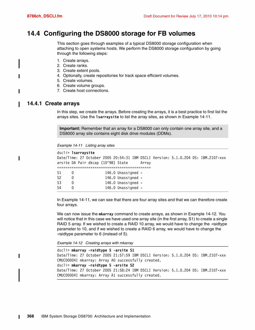
8786ch_DSCLI.fm Draft Document for Review July 17, 2010 10:14 pm
14.4 Configuring the DS8000 storage for FB volumesThis section goes through examples of a typical DS8000 storage configuration when attaching to open systems hosts. We perform the DS8000 storage configuration by going through the following steps:
1. Create arrays.2. Create ranks.3. Create extent pools.4. Optionally, create repositories for track space efficient volumes.5. Create volumes.6. Create volume groups.7. Create host connections.
14.4.1 Create arraysIn this step, we create the arrays. Before creating the arrays, it is a best practice to first list the arrays sites. Use the lsarraysite to list the array sites, as shown in Example 14-11.
Example 14-11 Listing array sites
dscli> lsarraysiteDate/Time: 27 October 2005 20:54:31 IBM DSCLI Version: 5.1.0.204 DS: IBM.2107-xxxarsite DA Pair dkcap (10^9B) State Array=============================================S1 0 146.0 Unassigned -S2 0 146.0 Unassigned -S3 0 146.0 Unassigned -S4 0 146.0 Unassigned -
In Example 14-11, we can see that there are four array sites and that we can therefore create four arrays.
We can now issue the mkarray command to create arrays, as shown in Example 14-12. You will notice that in this case we have used one array site (in the first array, S1) to create a single RAID 5 array. If we wished to create a RAID 10 array, we would have to change the -raidtype parameter to 10, and if we wished to create a RAID 6 array, we would have to change the -raidtype parameter to 6 (instead of 5).
Example 14-12 Creating arrays with mkarray
dscli> mkarray -raidtype 5 -arsite S1Date/Time: 27 October 2005 21:57:59 IBM DSCLI Version: 5.1.0.204 DS: IBM.2107-xxxCMUC00004I mkarray: Array A0 successfully created.dscli> mkarray -raidtype 5 -arsite S2Date/Time: 27 October 2005 21:58:24 IBM DSCLI Version: 5.1.0.204 DS: IBM.2107-xxxCMUC00004I mkarray: Array A1 successfully created.
Important: Remember that an array for a DS8000 can only contain one array site, and a DS8000 array site contains eight disk drive modules (DDMs).
368 IBM System Storage DS8700: Architecture and Implementation
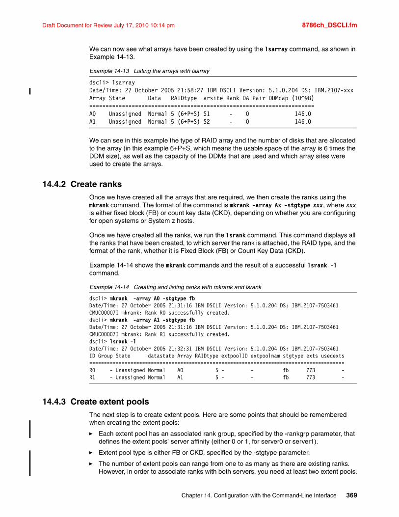
Draft Document for Review July 17, 2010 10:14 pm 8786ch_DSCLI.fm
We can now see what arrays have been created by using the lsarray command, as shown in Example 14-13.
Example 14-13 Listing the arrays with lsarray
dscli> lsarrayDate/Time: 27 October 2005 21:58:27 IBM DSCLI Version: 5.1.0.204 DS: IBM.2107-xxxArray State Data RAIDtype arsite Rank DA Pair DDMcap (10^9B)=====================================================================A0 Unassigned Normal 5 (6+P+S) S1 - 0 146.0A1 Unassigned Normal 5 (6+P+S) S2 - 0 146.0
We can see in this example the type of RAID array and the number of disks that are allocated to the array (in this example 6+P+S, which means the usable space of the array is 6 times the DDM size), as well as the capacity of the DDMs that are used and which array sites were used to create the arrays.
14.4.2 Create ranksOnce we have created all the arrays that are required, we then create the ranks using the mkrank command. The format of the command is mkrank -array Ax -stgtype xxx, where xxx is either fixed block (FB) or count key data (CKD), depending on whether you are configuring for open systems or System z hosts.
Once we have created all the ranks, we run the lsrank command. This command displays all the ranks that have been created, to which server the rank is attached, the RAID type, and the format of the rank, whether it is Fixed Block (FB) or Count Key Data (CKD).
Example 14-14 shows the mkrank commands and the result of a successful lsrank -l command.
Example 14-14 Creating and listing ranks with mkrank and lsrank
dscli> mkrank -array A0 -stgtype fbDate/Time: 27 October 2005 21:31:16 IBM DSCLI Version: 5.1.0.204 DS: IBM.2107-7503461CMUC00007I mkrank: Rank R0 successfully created.dscli> mkrank -array A1 -stgtype fbDate/Time: 27 October 2005 21:31:16 IBM DSCLI Version: 5.1.0.204 DS: IBM.2107-7503461CMUC00007I mkrank: Rank R1 successfully created.dscli> lsrank -lDate/Time: 27 October 2005 21:32:31 IBM DSCLI Version: 5.1.0.204 DS: IBM.2107-7503461ID Group State datastate Array RAIDtype extpoolID extpoolnam stgtype exts usedexts=======================================================================================R0 - Unassigned Normal A0 5 - - fb 773 -R1 - Unassigned Normal A1 5 - - fb 773 -
14.4.3 Create extent poolsThe next step is to create extent pools. Here are some points that should be remembered when creating the extent pools:
� Each extent pool has an associated rank group, specified by the -rankgrp parameter, that defines the extent pools’ server affinity (either 0 or 1, for server0 or server1).
� Extent pool type is either FB or CKD, specified by the -stgtype parameter.
� The number of extent pools can range from one to as many as there are existing ranks. However, in order to associate ranks with both servers, you need at least two extent pools.
Chapter 14. Configuration with the Command-Line Interface 369
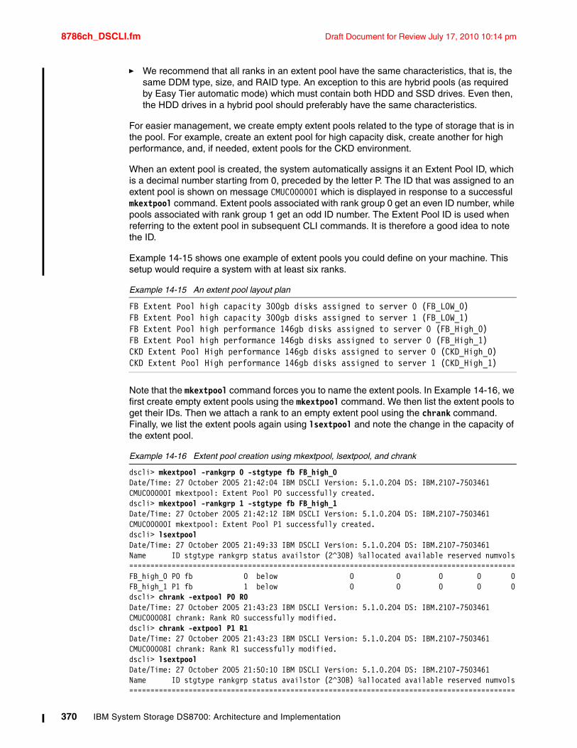
8786ch_DSCLI.fm Draft Document for Review July 17, 2010 10:14 pm
� We recommend that all ranks in an extent pool have the same characteristics, that is, the same DDM type, size, and RAID type. An exception to this are hybrid pools (as required by Easy Tier automatic mode) which must contain both HDD and SSD drives. Even then, the HDD drives in a hybrid pool should preferably have the same characteristics.
For easier management, we create empty extent pools related to the type of storage that is in the pool. For example, create an extent pool for high capacity disk, create another for high performance, and, if needed, extent pools for the CKD environment.
When an extent pool is created, the system automatically assigns it an Extent Pool ID, which is a decimal number starting from 0, preceded by the letter P. The ID that was assigned to an extent pool is shown on message CMUC00000I which is displayed in response to a successful mkextpool command. Extent pools associated with rank group 0 get an even ID number, while pools associated with rank group 1 get an odd ID number. The Extent Pool ID is used when referring to the extent pool in subsequent CLI commands. It is therefore a good idea to note the ID.
Example 14-15 shows one example of extent pools you could define on your machine. This setup would require a system with at least six ranks.
Example 14-15 An extent pool layout plan
FB Extent Pool high capacity 300gb disks assigned to server 0 (FB_LOW_0)FB Extent Pool high capacity 300gb disks assigned to server 1 (FB_LOW_1)FB Extent Pool high performance 146gb disks assigned to server 0 (FB_High_0)FB Extent Pool high performance 146gb disks assigned to server 0 (FB_High_1)CKD Extent Pool High performance 146gb disks assigned to server 0 (CKD_High_0)CKD Extent Pool High performance 146gb disks assigned to server 1 (CKD_High_1)
Note that the mkextpool command forces you to name the extent pools. In Example 14-16, we first create empty extent pools using the mkextpool command. We then list the extent pools to get their IDs. Then we attach a rank to an empty extent pool using the chrank command. Finally, we list the extent pools again using lsextpool and note the change in the capacity of the extent pool.
Example 14-16 Extent pool creation using mkextpool, lsextpool, and chrank
dscli> mkextpool -rankgrp 0 -stgtype fb FB_high_0Date/Time: 27 October 2005 21:42:04 IBM DSCLI Version: 5.1.0.204 DS: IBM.2107-7503461CMUC00000I mkextpool: Extent Pool P0 successfully created.dscli> mkextpool -rankgrp 1 -stgtype fb FB_high_1Date/Time: 27 October 2005 21:42:12 IBM DSCLI Version: 5.1.0.204 DS: IBM.2107-7503461CMUC00000I mkextpool: Extent Pool P1 successfully created.dscli> lsextpoolDate/Time: 27 October 2005 21:49:33 IBM DSCLI Version: 5.1.0.204 DS: IBM.2107-7503461Name ID stgtype rankgrp status availstor (2^30B) %allocated available reserved numvols===========================================================================================FB_high_0 P0 fb 0 below 0 0 0 0 0FB_high_1 P1 fb 1 below 0 0 0 0 0dscli> chrank -extpool P0 R0Date/Time: 27 October 2005 21:43:23 IBM DSCLI Version: 5.1.0.204 DS: IBM.2107-7503461CMUC00008I chrank: Rank R0 successfully modified.dscli> chrank -extpool P1 R1Date/Time: 27 October 2005 21:43:23 IBM DSCLI Version: 5.1.0.204 DS: IBM.2107-7503461CMUC00008I chrank: Rank R1 successfully modified.dscli> lsextpoolDate/Time: 27 October 2005 21:50:10 IBM DSCLI Version: 5.1.0.204 DS: IBM.2107-7503461Name ID stgtype rankgrp status availstor (2^30B) %allocated available reserved numvols===========================================================================================
370 IBM System Storage DS8700: Architecture and Implementation
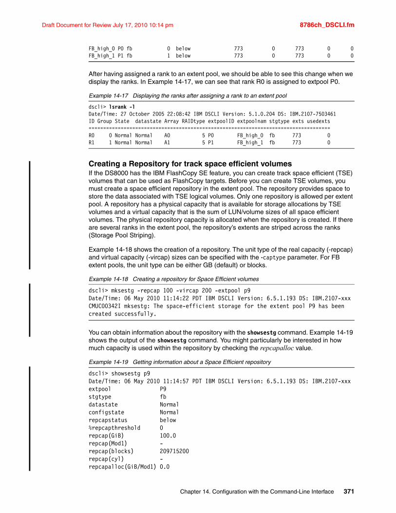
Draft Document for Review July 17, 2010 10:14 pm 8786ch_DSCLI.fm
FB_high_0 P0 fb 0 below 773 0 773 0 0FB_high_1 P1 fb 1 below 773 0 773 0 0
After having assigned a rank to an extent pool, we should be able to see this change when we display the ranks. In Example 14-17, we can see that rank R0 is assigned to extpool P0.
Example 14-17 Displaying the ranks after assigning a rank to an extent pool
dscli> lsrank -lDate/Time: 27 October 2005 22:08:42 IBM DSCLI Version: 5.1.0.204 DS: IBM.2107-7503461ID Group State datastate Array RAIDtype extpoolID extpoolnam stgtype exts usedexts===================================================================================R0 0 Normal Normal A0 5 P0 FB_high_0 fb 773 0R1 1 Normal Normal A1 5 P1 FB_high_1 fb 773 0
Creating a Repository for track space efficient volumesIf the DS8000 has the IBM FlashCopy SE feature, you can create track space efficient (TSE) volumes that can be used as FlashCopy targets. Before you can create TSE volumes, you must create a space efficient repository in the extent pool. The repository provides space to store the data associated with TSE logical volumes. Only one repository is allowed per extent pool. A repository has a physical capacity that is available for storage allocations by TSE volumes and a virtual capacity that is the sum of LUN/volume sizes of all space efficient volumes. The physical repository capacity is allocated when the repository is created. If there are several ranks in the extent pool, the repository’s extents are striped across the ranks (Storage Pool Striping).
Example 14-18 shows the creation of a repository. The unit type of the real capacity (-repcap) and virtual capacity (-vircap) sizes can be specified with the -captype parameter. For FB extent pools, the unit type can be either GB (default) or blocks.
Example 14-18 Creating a repository for Space Efficient volumes
dscli> mksestg -repcap 100 -vircap 200 -extpool p9Date/Time: 06 May 2010 11:14:22 PDT IBM DSCLI Version: 6.5.1.193 DS: IBM.2107-xxxCMUC00342I mksestg: The space-efficient storage for the extent pool P9 has been created successfully.
You can obtain information about the repository with the showsestg command. Example 14-19 shows the output of the showsestg command. You might particularly be interested in how much capacity is used within the repository by checking the repcapalloc value.
Example 14-19 Getting information about a Space Efficient repository
dscli> showsestg p9Date/Time: 06 May 2010 11:14:57 PDT IBM DSCLI Version: 6.5.1.193 DS: IBM.2107-xxxextpool P9stgtype fbdatastate Normalconfigstate Normalrepcapstatus below%repcapthreshold 0repcap(GiB) 100.0repcap(Mod1) -repcap(blocks) 209715200repcap(cyl) -repcapalloc(GiB/Mod1) 0.0
Chapter 14. Configuration with the Command-Line Interface 371
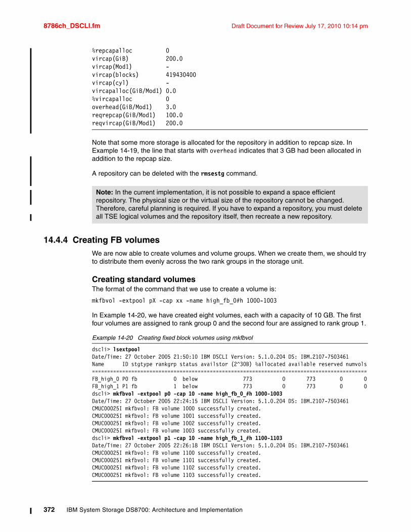
8786ch_DSCLI.fm Draft Document for Review July 17, 2010 10:14 pm
%repcapalloc 0vircap(GiB) 200.0vircap(Mod1) -vircap(blocks) 419430400vircap(cyl) -vircapalloc(GiB/Mod1) 0.0%vircapalloc 0overhead(GiB/Mod1) 3.0reqrepcap(GiB/Mod1) 100.0reqvircap(GiB/Mod1) 200.0
Note that some more storage is allocated for the repository in addition to repcap size. In Example 14-19, the line that starts with overhead indicates that 3 GB had been allocated in addition to the repcap size.
A repository can be deleted with the rmsestg command.
14.4.4 Creating FB volumesWe are now able to create volumes and volume groups. When we create them, we should try to distribute them evenly across the two rank groups in the storage unit.
Creating standard volumesThe format of the command that we use to create a volume is:
mkfbvol -extpool pX -cap xx -name high_fb_0#h 1000-1003
In Example 14-20, we have created eight volumes, each with a capacity of 10 GB. The first four volumes are assigned to rank group 0 and the second four are assigned to rank group 1.
Example 14-20 Creating fixed block volumes using mkfbvol
dscli> lsextpoolDate/Time: 27 October 2005 21:50:10 IBM DSCLI Version: 5.1.0.204 DS: IBM.2107-7503461Name ID stgtype rankgrp status availstor (2^30B) %allocated available reserved numvols===========================================================================================FB_high_0 P0 fb 0 below 773 0 773 0 0FB_high_1 P1 fb 1 below 773 0 773 0 0dscli> mkfbvol -extpool p0 -cap 10 -name high_fb_0_#h 1000-1003Date/Time: 27 October 2005 22:24:15 IBM DSCLI Version: 5.1.0.204 DS: IBM.2107-7503461CMUC00025I mkfbvol: FB volume 1000 successfully created.CMUC00025I mkfbvol: FB volume 1001 successfully created.CMUC00025I mkfbvol: FB volume 1002 successfully created.CMUC00025I mkfbvol: FB volume 1003 successfully created.dscli> mkfbvol -extpool p1 -cap 10 -name high_fb_1_#h 1100-1103Date/Time: 27 October 2005 22:26:18 IBM DSCLI Version: 5.1.0.204 DS: IBM.2107-7503461CMUC00025I mkfbvol: FB volume 1100 successfully created.CMUC00025I mkfbvol: FB volume 1101 successfully created.CMUC00025I mkfbvol: FB volume 1102 successfully created.CMUC00025I mkfbvol: FB volume 1103 successfully created.
Note: In the current implementation, it is not possible to expand a space efficient repository. The physical size or the virtual size of the repository cannot be changed. Therefore, careful planning is required. If you have to expand a repository, you must delete all TSE logical volumes and the repository itself, then recreate a new repository.
372 IBM System Storage DS8700: Architecture and Implementation
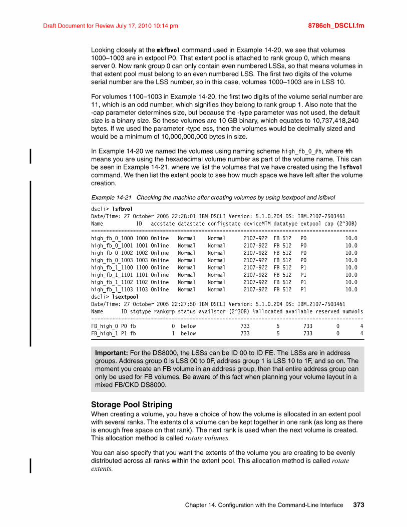
Draft Document for Review July 17, 2010 10:14 pm 8786ch_DSCLI.fm
Looking closely at the mkfbvol command used in Example 14-20, we see that volumes 1000–1003 are in extpool P0. That extent pool is attached to rank group 0, which means server 0. Now rank group 0 can only contain even numbered LSSs, so that means volumes in that extent pool must belong to an even numbered LSS. The first two digits of the volume serial number are the LSS number, so in this case, volumes 1000–1003 are in LSS 10.
For volumes 1100–1003 in Example 14-20, the first two digits of the volume serial number are 11, which is an odd number, which signifies they belong to rank group 1. Also note that the -cap parameter determines size, but because the -type parameter was not used, the default size is a binary size. So these volumes are 10 GB binary, which equates to 10,737,418,240 bytes. If we used the parameter -type ess, then the volumes would be decimally sized and would be a minimum of 10,000,000,000 bytes in size.
In Example 14-20 we named the volumes using naming scheme high_fb_0_#h, where #h means you are using the hexadecimal volume number as part of the volume name. This can be seen in Example 14-21, where we list the volumes that we have created using the lsfbvol command. We then list the extent pools to see how much space we have left after the volume creation.
Example 14-21 Checking the machine after creating volumes by using lsextpool and lsfbvol
dscli> lsfbvolDate/Time: 27 October 2005 22:28:01 IBM DSCLI Version: 5.1.0.204 DS: IBM.2107-7503461Name ID accstate datastate configstate deviceMTM datatype extpool cap (2^30B)=========================================================================================high_fb_0_1000 1000 Online Normal Normal 2107-922 FB 512 P0 10.0 high_fb_0_1001 1001 Online Normal Normal 2107-922 FB 512 P0 10.0 high_fb_0_1002 1002 Online Normal Normal 2107-922 FB 512 P0 10.0 high_fb_0_1003 1003 Online Normal Normal 2107-922 FB 512 P0 10.0 high_fb_1_1100 1100 Online Normal Normal 2107-922 FB 512 P1 10.0 high_fb_1_1101 1101 Online Normal Normal 2107-922 FB 512 P1 10.0 high_fb_1_1102 1102 Online Normal Normal 2107-922 FB 512 P1 10.0 high_fb_1_1103 1103 Online Normal Normal 2107-922 FB 512 P1 10.0 dscli> lsextpoolDate/Time: 27 October 2005 22:27:50 IBM DSCLI Version: 5.1.0.204 DS: IBM.2107-7503461Name ID stgtype rankgrp status availstor (2^30B) %allocated available reserved numvols===========================================================================================FB_high_0 P0 fb 0 below 733 5 733 0 4FB_high_1 P1 fb 1 below 733 5 733 0 4
Storage Pool StripingWhen creating a volume, you have a choice of how the volume is allocated in an extent pool with several ranks. The extents of a volume can be kept together in one rank (as long as there is enough free space on that rank). The next rank is used when the next volume is created. This allocation method is called rotate volumes.
You can also specify that you want the extents of the volume you are creating to be evenly distributed across all ranks within the extent pool. This allocation method is called rotate extents.
Important: For the DS8000, the LSSs can be ID 00 to ID FE. The LSSs are in address groups. Address group 0 is LSS 00 to 0F, address group 1 is LSS 10 to 1F, and so on. The moment you create an FB volume in an address group, then that entire address group can only be used for FB volumes. Be aware of this fact when planning your volume layout in a mixed FB/CKD DS8000.
Chapter 14. Configuration with the Command-Line Interface 373
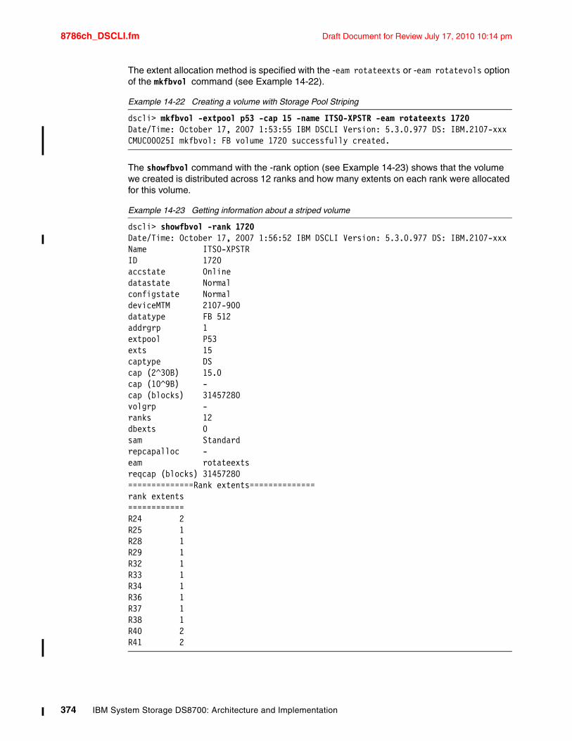
8786ch_DSCLI.fm Draft Document for Review July 17, 2010 10:14 pm
The extent allocation method is specified with the -eam rotateexts or -eam rotatevols option of the mkfbvol command (see Example 14-22).
Example 14-22 Creating a volume with Storage Pool Striping
dscli> mkfbvol -extpool p53 -cap 15 -name ITSO-XPSTR -eam rotateexts 1720Date/Time: October 17, 2007 1:53:55 IBM DSCLI Version: 5.3.0.977 DS: IBM.2107-xxxCMUC00025I mkfbvol: FB volume 1720 successfully created.
The showfbvol command with the -rank option (see Example 14-23) shows that the volume we created is distributed across 12 ranks and how many extents on each rank were allocated for this volume.
Example 14-23 Getting information about a striped volume
dscli> showfbvol -rank 1720Date/Time: October 17, 2007 1:56:52 IBM DSCLI Version: 5.3.0.977 DS: IBM.2107-xxxName ITSO-XPSTRID 1720accstate Onlinedatastate Normalconfigstate NormaldeviceMTM 2107-900datatype FB 512addrgrp 1extpool P53exts 15captype DScap (2^30B) 15.0cap (10^9B) -cap (blocks) 31457280volgrp -ranks 12dbexts 0sam Standardrepcapalloc -eam rotateextsreqcap (blocks) 31457280==============Rank extents==============rank extents============R24 2R25 1R28 1R29 1R32 1R33 1R34 1R36 1R37 1R38 1R40 2R41 2
374 IBM System Storage DS8700: Architecture and Implementation
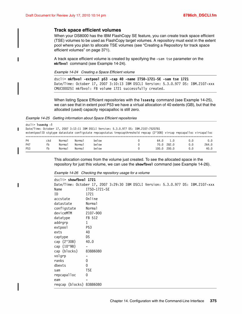
Draft Document for Review July 17, 2010 10:14 pm 8786ch_DSCLI.fm
Track space efficient volumesWhen your DS8000 has the IBM FlashCopy SE feature, you can create track space efficient (TSE) volumes to be used as FlashCopy target volumes. A repository must exist in the extent pool where you plan to allocate TSE volumes (see “Creating a Repository for track space efficient volumes” on page 371).
A track space efficient volume is created by specifying the -sam tse parameter on the mkfbvol command (see Example 14-24).
Example 14-24 Creating a Space Efficient volume
dscli> mkfbvol -extpool p53 -cap 40 -name ITSO-1721-SE -sam tse 1721Date/Time: October 17, 2007 3:10:13 IBM DSCLI Version: 5.3.0.977 DS: IBM.2107-xxxCMUC00025I mkfbvol: FB volume 1721 successfully created.
When listing Space Efficient repositories with the lssestg command (see Example 14-25), we can see that in extent pool P53 we have a virtual allocation of 40 extents (GB), but that the allocated (used) capacity repcapalloc is still zero.
Example 14-25 Getting information about Space Efficient repositories
dscli> lssestg -lDate/Time: October 17, 2007 3:12:11 IBM DSCLI Version: 5.3.0.977 DS: IBM.2107-7520781extentpoolID stgtype datastate configstate repcapstatus %repcapthreshold repcap (2^30B) vircap repcapalloc vircapalloc======================================================================================================================P4 ckd Normal Normal below 0 64.0 1.0 0.0 0.0P47 fb Normal Normal below 0 70.0 282.0 0.0 264.0P53 fb Normal Normal below 0 100.0 200.0 0.0 40.0
This allocation comes from the volume just created. To see the allocated space in the repository for just this volume, we can use the showfbvol command (see Example 14-26).
Example 14-26 Checking the repository usage for a volume
dscli> showfbvol 1721Date/Time: October 17, 2007 3:29:30 IBM DSCLI Version: 5.3.0.977 DS: IBM.2107-xxxName ITSO-1721-SEID 1721accstate Onlinedatastate Normalconfigstate NormaldeviceMTM 2107-900datatype FB 512addrgrp 1extpool P53exts 40captype DScap (2^30B) 40.0cap (10^9B) -cap (blocks) 83886080volgrp -ranks 0dbexts 0sam TSErepcapalloc 0eam -reqcap (blocks) 83886080
Chapter 14. Configuration with the Command-Line Interface 375
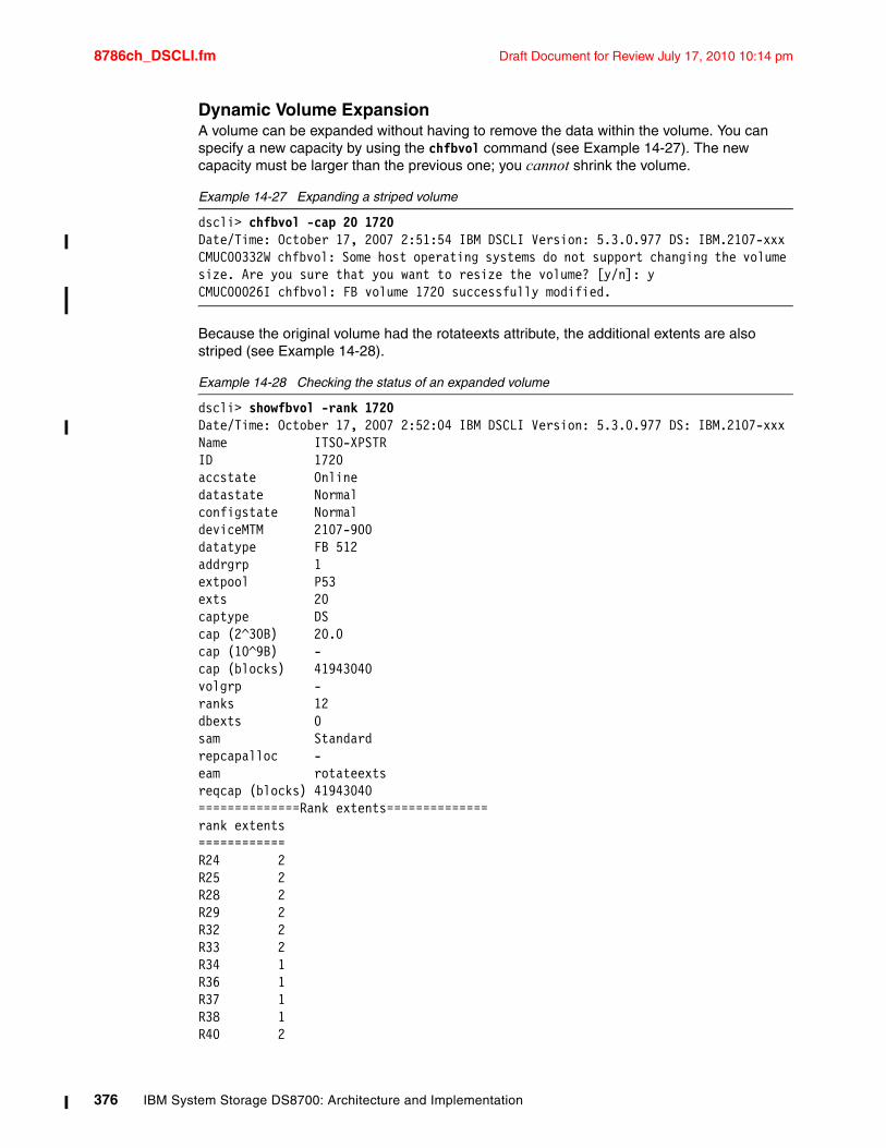
8786ch_DSCLI.fm Draft Document for Review July 17, 2010 10:14 pm
Dynamic Volume ExpansionA volume can be expanded without having to remove the data within the volume. You can specify a new capacity by using the chfbvol command (see Example 14-27). The new capacity must be larger than the previous one; you cannot shrink the volume.
Example 14-27 Expanding a striped volume
dscli> chfbvol -cap 20 1720Date/Time: October 17, 2007 2:51:54 IBM DSCLI Version: 5.3.0.977 DS: IBM.2107-xxxCMUC00332W chfbvol: Some host operating systems do not support changing the volume size. Are you sure that you want to resize the volume? [y/n]: yCMUC00026I chfbvol: FB volume 1720 successfully modified.
Because the original volume had the rotateexts attribute, the additional extents are also striped (see Example 14-28).
Example 14-28 Checking the status of an expanded volume
dscli> showfbvol -rank 1720Date/Time: October 17, 2007 2:52:04 IBM DSCLI Version: 5.3.0.977 DS: IBM.2107-xxxName ITSO-XPSTRID 1720accstate Onlinedatastate Normalconfigstate NormaldeviceMTM 2107-900datatype FB 512addrgrp 1extpool P53exts 20captype DScap (2^30B) 20.0cap (10^9B) -cap (blocks) 41943040volgrp -ranks 12dbexts 0sam Standardrepcapalloc -eam rotateextsreqcap (blocks) 41943040==============Rank extents==============rank extents============R24 2R25 2R28 2R29 2R32 2R33 2R34 1R36 1R37 1R38 1R40 2
376 IBM System Storage DS8700: Architecture and Implementation
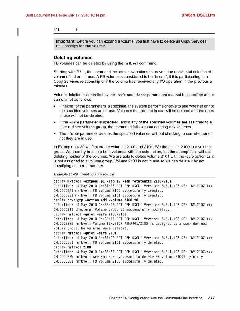
Draft Document for Review July 17, 2010 10:14 pm 8786ch_DSCLI.fm
R41 2
Deleting volumesFB volumes can be deleted by using the rmfbvol command.
Starting with R5.1, the command includes new options to prevent the accidental deletion of volumes that are in use. A FB volume is considered to be “in use”, if it is participating in a Copy Services relationship or if the volume has received any I/O operation in the previous 5 minutes.
Volume deletion is controlled by the -safe and -force parameters (cannot be specified at the same time) as follows:
� If neither of the parameters is specified, the system performs checks to see whether or not the specified volumes are in use. Volumes that are not in use will be deleted and the ones in use will not be deleted.
� If the -safe parameter is specified, and if any of the specified volumes are assigned to a user-defined volume group, the command fails without deleting any volumes.
� The -force parameter deletes the specified volumes without checking to see whether or not they are in use.
In Example 14-29 we first create volumes 2100 and 2101. We the assign 2100 to a volume group. We then try to delete both volumes with the safe option, but the attempt fails without deleting neither of the volumes. We are able to delete volume 2101 with the -safe option as it is not assigned to a volume group. Volume 2100 is not in use so we can delete it by not specifying neither parameter.
Example 14-29 Deleting a FB volume
dscli> mkfbvol -extpool p1 -cap 12 -eam rotateexts 2100-2101Date/Time: 14 May 2010 14:31:23 PDT IBM DSCLI Version: 6.5.1.193 DS: IBM.2107-xxxCMUC00025I mkfbvol: FB volume 2100 successfully created.CMUC00025I mkfbvol: FB volume 2101 successfully created.dscli> chvolgrp -action add -volume 2100 v0Date/Time: 14 May 2010 14:33:46 PDT IBM DSCLI Version: 6.5.1.193 DS: IBM.2107-xxxCMUC00031I chvolgrp: Volume group V0 successfully modified.dscli> rmfbvol -quiet -safe 2100-2101Date/Time: 14 May 2010 14:34:15 PDT IBM DSCLI Version: 6.5.1.193 DS: IBM.2107-xxxCMUC00253E rmfbvol: Volume IBM.2107-75NA901/2100 is assigned to a user-defined volume group. No volumes were deleted.dscli> rmfbvol -quiet -safe 2101Date/Time: 14 May 2010 14:35:09 PDT IBM DSCLI Version: 6.5.1.193 DS: IBM.2107-xxxCMUC00028I rmfbvol: FB volume 2101 successfully deleted.dscli> rmfbvol 2100Date/Time: 14 May 2010 14:35:32 PDT IBM DSCLI Version: 6.5.1.193 DS: IBM.2107-xxxCMUC00027W rmfbvol: Are you sure you want to delete FB volume 2100? [y/n]: yCMUC00028I rmfbvol: FB volume 2100 successfully deleted.
Important: Before you can expand a volume, you first have to delete all Copy Services relationships for that volume.
Chapter 14. Configuration with the Command-Line Interface 377
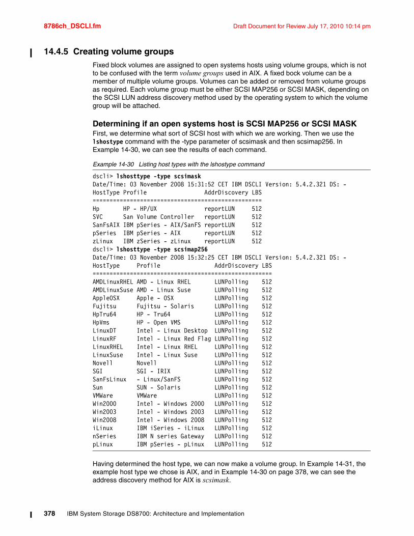
8786ch_DSCLI.fm Draft Document for Review July 17, 2010 10:14 pm
14.4.5 Creating volume groupsFixed block volumes are assigned to open systems hosts using volume groups, which is not to be confused with the term volume groups used in AIX. A fixed bock volume can be a member of multiple volume groups. Volumes can be added or removed from volume groups as required. Each volume group must be either SCSI MAP256 or SCSI MASK, depending on the SCSI LUN address discovery method used by the operating system to which the volume group will be attached.
Determining if an open systems host is SCSI MAP256 or SCSI MASKFirst, we determine what sort of SCSI host with which we are working. Then we use the lshostype command with the -type parameter of scsimask and then scsimap256. In Example 14-30, we can see the results of each command.
Example 14-30 Listing host types with the lshostype command
dscli> lshosttype -type scsimaskDate/Time: 03 November 2008 15:31:52 CET IBM DSCLI Version: 5.4.2.321 DS: -HostType Profile AddrDiscovery LBS==================================================Hp HP - HP/UX reportLUN 512SVC San Volume Controller reportLUN 512SanFsAIX IBM pSeries - AIX/SanFS reportLUN 512pSeries IBM pSeries - AIX reportLUN 512zLinux IBM zSeries - zLinux reportLUN 512dscli> lshosttype -type scsimap256Date/Time: 03 November 2008 15:32:25 CET IBM DSCLI Version: 5.4.2.321 DS: -HostType Profile AddrDiscovery LBS=====================================================AMDLinuxRHEL AMD - Linux RHEL LUNPolling 512AMDLinuxSuse AMD - Linux Suse LUNPolling 512AppleOSX Apple - OSX LUNPolling 512Fujitsu Fujitsu - Solaris LUNPolling 512HpTru64 HP - Tru64 LUNPolling 512HpVms HP - Open VMS LUNPolling 512LinuxDT Intel - Linux Desktop LUNPolling 512LinuxRF Intel - Linux Red Flag LUNPolling 512LinuxRHEL Intel - Linux RHEL LUNPolling 512LinuxSuse Intel - Linux Suse LUNPolling 512Novell Novell LUNPolling 512SGI SGI - IRIX LUNPolling 512SanFsLinux - Linux/SanFS LUNPolling 512Sun SUN - Solaris LUNPolling 512VMWare VMWare LUNPolling 512Win2000 Intel - Windows 2000 LUNPolling 512Win2003 Intel - Windows 2003 LUNPolling 512Win2008 Intel - Windows 2008 LUNPolling 512iLinux IBM iSeries - iLinux LUNPolling 512nSeries IBM N series Gateway LUNPolling 512pLinux IBM pSeries - pLinux LUNPolling 512
Having determined the host type, we can now make a volume group. In Example 14-31, the example host type we chose is AIX, and in Example 14-30 on page 378, we can see the address discovery method for AIX is scsimask.
378 IBM System Storage DS8700: Architecture and Implementation
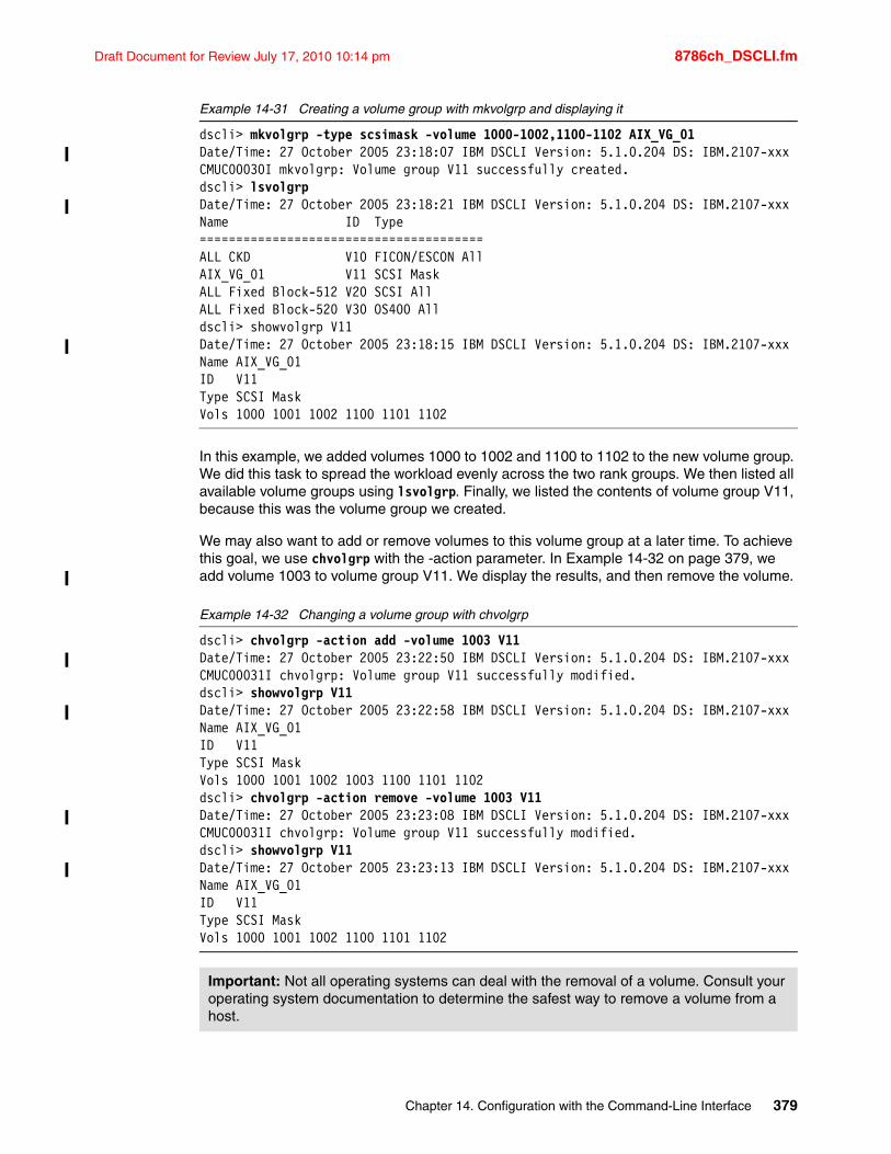
Draft Document for Review July 17, 2010 10:14 pm 8786ch_DSCLI.fm
Example 14-31 Creating a volume group with mkvolgrp and displaying it
dscli> mkvolgrp -type scsimask -volume 1000-1002,1100-1102 AIX_VG_01Date/Time: 27 October 2005 23:18:07 IBM DSCLI Version: 5.1.0.204 DS: IBM.2107-xxxCMUC00030I mkvolgrp: Volume group V11 successfully created.dscli> lsvolgrpDate/Time: 27 October 2005 23:18:21 IBM DSCLI Version: 5.1.0.204 DS: IBM.2107-xxxName ID Type=======================================ALL CKD V10 FICON/ESCON AllAIX_VG_01 V11 SCSI MaskALL Fixed Block-512 V20 SCSI AllALL Fixed Block-520 V30 OS400 Alldscli> showvolgrp V11Date/Time: 27 October 2005 23:18:15 IBM DSCLI Version: 5.1.0.204 DS: IBM.2107-xxxName AIX_VG_01ID V11Type SCSI MaskVols 1000 1001 1002 1100 1101 1102
In this example, we added volumes 1000 to 1002 and 1100 to 1102 to the new volume group. We did this task to spread the workload evenly across the two rank groups. We then listed all available volume groups using lsvolgrp. Finally, we listed the contents of volume group V11, because this was the volume group we created.
We may also want to add or remove volumes to this volume group at a later time. To achieve this goal, we use chvolgrp with the -action parameter. In Example 14-32 on page 379, we add volume 1003 to volume group V11. We display the results, and then remove the volume.
Example 14-32 Changing a volume group with chvolgrp
dscli> chvolgrp -action add -volume 1003 V11Date/Time: 27 October 2005 23:22:50 IBM DSCLI Version: 5.1.0.204 DS: IBM.2107-xxxCMUC00031I chvolgrp: Volume group V11 successfully modified.dscli> showvolgrp V11Date/Time: 27 October 2005 23:22:58 IBM DSCLI Version: 5.1.0.204 DS: IBM.2107-xxxName AIX_VG_01ID V11Type SCSI MaskVols 1000 1001 1002 1003 1100 1101 1102dscli> chvolgrp -action remove -volume 1003 V11Date/Time: 27 October 2005 23:23:08 IBM DSCLI Version: 5.1.0.204 DS: IBM.2107-xxxCMUC00031I chvolgrp: Volume group V11 successfully modified.dscli> showvolgrp V11Date/Time: 27 October 2005 23:23:13 IBM DSCLI Version: 5.1.0.204 DS: IBM.2107-xxxName AIX_VG_01ID V11Type SCSI MaskVols 1000 1001 1002 1100 1101 1102
Important: Not all operating systems can deal with the removal of a volume. Consult your operating system documentation to determine the safest way to remove a volume from a host.
Chapter 14. Configuration with the Command-Line Interface 379
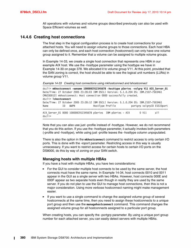
8786ch_DSCLI.fm Draft Document for Review July 17, 2010 10:14 pm
All operations with volumes and volume groups described previously can also be used with Space Efficient volumes as well.
14.4.6 Creating host connectionsThe final step in the logical configuration process is to create host connections for your attached hosts. You will need to assign volume groups to those connections. Each host HBA can only be defined once, and each host connection (hostconnect) can only have one volume group assigned to it. Remember that a volume can be assigned to multiple volume groups.
In Example 14-33, we create a single host connection that represents one HBA in our example AIX host. We use the -hosttype parameter using the hosttype we have in Example 14-30 on page 378. We allocated it to volume group V11. At this point, provided that the SAN zoning is correct, the host should be able to see the logical unit numbers (LUNs) in volume group V11.
Example 14-33 Creating host connections using mkhostconnect and lshostconnect
dscli> mkhostconnect -wwname 100000C912345678 -hosttype pSeries -volgrp V11 AIX_Server_01Date/Time: 27 October 2005 23:28:03 IBM DSCLI Version: 5.1.0.204 DS: IBM.2107-7503461CMUC00012I mkhostconnect: Host connection 0000 successfully created.dscli> lshostconnectDate/Time: 27 October 2005 23:28:12 IBM DSCLI Version: 5.1.0.204 DS: IBM.2107-7503461Name ID WWPN HostType Profile portgrp volgrpID ESSIOport=========================================================================================AIX_Server_01 0000 100000C912345678 pSeries IBM pSeries - AIX 0 V11 alldscli>
Note that you can also use just -profile instead of -hosttype. However, we do not recommend that you do this action. If you use the -hosttype parameter, it actually invokes both parameters (-profile and -hosttype), while using just -profile leaves the -hosttype column unpopulated.
There is also the option in the mkhostconnect command to restrict access to only certain I/O ports. This is done with the -ioport parameter. Restricting access in this way is usually unnecessary. If you want to restrict access for certain hosts to certain I/O ports on the DS8000, do this by way of zoning on your SAN switch.
Managing hosts with multiple HBAsIf you have a host with multiple HBAs, you have two considerations:
� For the GUI to consider multiple host connects to be used by the same server, the host connects must have the same name. In Example 14-34, host connects 0010 and 0011 appear in the GUI as a single server with two HBAs. However, host connects 000E and 000F appear as two separate hosts even though in reality they are used by the same server. If you do not plan to use the GUI to manage host connections, then this is not a major consideration. Using more verbose hostconnect naming might make management easier.
� If you want to use a single command to change the assigned volume group of several hostconnects at the same time, then you need to assign these hostconnects to a unique port group and then use the managehostconnect command. This command changes the assigned volume group for all hostconnects assigned to a particular port group.
When creating hosts, you can specify the -portgrp parameter. By using a unique port group number for each attached server, you can easily detect servers with multiple HBAs.
380 IBM System Storage DS8700: Architecture and Implementation
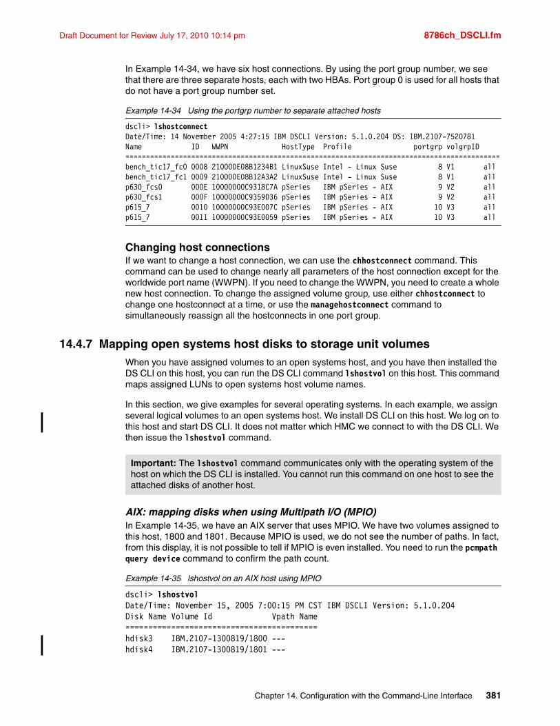
Draft Document for Review July 17, 2010 10:14 pm 8786ch_DSCLI.fm
In Example 14-34, we have six host connections. By using the port group number, we see that there are three separate hosts, each with two HBAs. Port group 0 is used for all hosts that do not have a port group number set.
Example 14-34 Using the portgrp number to separate attached hosts
dscli> lshostconnectDate/Time: 14 November 2005 4:27:15 IBM DSCLI Version: 5.1.0.204 DS: IBM.2107-7520781Name ID WWPN HostType Profile portgrp volgrpID ===========================================================================================bench_tic17_fc0 0008 210000E08B1234B1 LinuxSuse Intel - Linux Suse 8 V1 allbench_tic17_fc1 0009 210000E08B12A3A2 LinuxSuse Intel - Linux Suse 8 V1 allp630_fcs0 000E 10000000C9318C7A pSeries IBM pSeries - AIX 9 V2 allp630_fcs1 000F 10000000C9359D36 pSeries IBM pSeries - AIX 9 V2 allp615_7 0010 10000000C93E007C pSeries IBM pSeries - AIX 10 V3 allp615_7 0011 10000000C93E0059 pSeries IBM pSeries - AIX 10 V3 all
Changing host connectionsIf we want to change a host connection, we can use the chhostconnect command. This command can be used to change nearly all parameters of the host connection except for the worldwide port name (WWPN). If you need to change the WWPN, you need to create a whole new host connection. To change the assigned volume group, use either chhostconnect to change one hostconnect at a time, or use the managehostconnect command to simultaneously reassign all the hostconnects in one port group.
14.4.7 Mapping open systems host disks to storage unit volumesWhen you have assigned volumes to an open systems host, and you have then installed the DS CLI on this host, you can run the DS CLI command lshostvol on this host. This command maps assigned LUNs to open systems host volume names.
In this section, we give examples for several operating systems. In each example, we assign several logical volumes to an open systems host. We install DS CLI on this host. We log on to this host and start DS CLI. It does not matter which HMC we connect to with the DS CLI. We then issue the lshostvol command.
AIX: mapping disks when using Multipath I/O (MPIO) In Example 14-35, we have an AIX server that uses MPIO. We have two volumes assigned to this host, 1800 and 1801. Because MPIO is used, we do not see the number of paths. In fact, from this display, it is not possible to tell if MPIO is even installed. You need to run the pcmpath query device command to confirm the path count.
Example 14-35 lshostvol on an AIX host using MPIO
dscli> lshostvolDate/Time: November 15, 2005 7:00:15 PM CST IBM DSCLI Version: 5.1.0.204Disk Name Volume Id Vpath Name==========================================hdisk3 IBM.2107-1300819/1800 ---hdisk4 IBM.2107-1300819/1801 ---
Important: The lshostvol command communicates only with the operating system of the host on which the DS CLI is installed. You cannot run this command on one host to see the attached disks of another host.
Chapter 14. Configuration with the Command-Line Interface 381
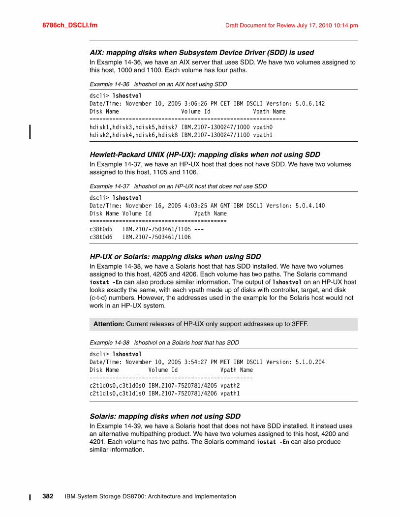
8786ch_DSCLI.fm Draft Document for Review July 17, 2010 10:14 pm
AIX: mapping disks when Subsystem Device Driver (SDD) is usedIn Example 14-36, we have an AIX server that uses SDD. We have two volumes assigned to this host, 1000 and 1100. Each volume has four paths.
Example 14-36 lshostvol on an AIX host using SDD
dscli> lshostvolDate/Time: November 10, 2005 3:06:26 PM CET IBM DSCLI Version: 5.0.6.142Disk Name Volume Id Vpath Name============================================================hdisk1,hdisk3,hdisk5,hdisk7 IBM.2107-1300247/1000 vpath0hdisk2,hdisk4,hdisk6,hdisk8 IBM.2107-1300247/1100 vpath1
Hewlett-Packard UNIX (HP-UX): mapping disks when not using SDD In Example 14-37, we have an HP-UX host that does not have SDD. We have two volumes assigned to this host, 1105 and 1106.
Example 14-37 lshostvol on an HP-UX host that does not use SDD
dscli> lshostvolDate/Time: November 16, 2005 4:03:25 AM GMT IBM DSCLI Version: 5.0.4.140Disk Name Volume Id Vpath Name==========================================c38t0d5 IBM.2107-7503461/1105 ---c38t0d6 IBM.2107-7503461/1106
HP-UX or Solaris: mapping disks when using SDDIn Example 14-38, we have a Solaris host that has SDD installed. We have two volumes assigned to this host, 4205 and 4206. Each volume has two paths. The Solaris command iostat -En can also produce similar information. The output of lshostvol on an HP-UX host looks exactly the same, with each vpath made up of disks with controller, target, and disk (c-t-d) numbers. However, the addresses used in the example for the Solaris host would not work in an HP-UX system.
Example 14-38 lshostvol on a Solaris host that has SDD
dscli> lshostvolDate/Time: November 10, 2005 3:54:27 PM MET IBM DSCLI Version: 5.1.0.204Disk Name Volume Id Vpath Name==================================================c2t1d0s0,c3t1d0s0 IBM.2107-7520781/4205 vpath2c2t1d1s0,c3t1d1s0 IBM.2107-7520781/4206 vpath1
Solaris: mapping disks when not using SDD In Example 14-39, we have a Solaris host that does not have SDD installed. It instead uses an alternative multipathing product. We have two volumes assigned to this host, 4200 and 4201. Each volume has two paths. The Solaris command iostat -En can also produce similar information.
Attention: Current releases of HP-UX only support addresses up to 3FFF.
382 IBM System Storage DS8700: Architecture and Implementation
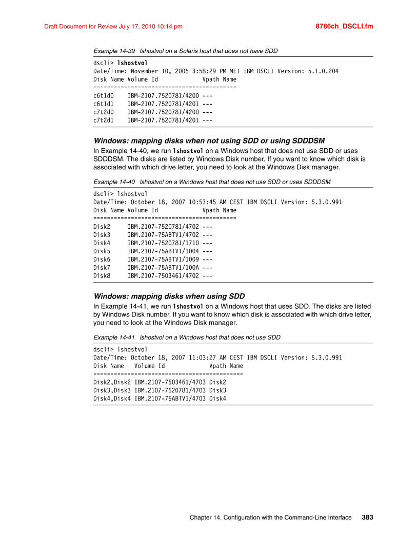
Draft Document for Review July 17, 2010 10:14 pm 8786ch_DSCLI.fm
Example 14-39 lshostvol on a Solaris host that does not have SDD
dscli> lshostvolDate/Time: November 10, 2005 3:58:29 PM MET IBM DSCLI Version: 5.1.0.204Disk Name Volume Id Vpath Name==========================================c6t1d0 IBM-2107.7520781/4200 ---c6t1d1 IBM-2107.7520781/4201 ---c7t2d0 IBM-2107.7520781/4200 ---c7t2d1 IBM-2107.7520781/4201 ---
Windows: mapping disks when not using SDD or using SDDDSMIn Example 14-40, we run lshostvol on a Windows host that does not use SDD or uses SDDDSM. The disks are listed by Windows Disk number. If you want to know which disk is associated with which drive letter, you need to look at the Windows Disk manager.
Example 14-40 lshostvol on a Windows host that does not use SDD or uses SDDDSM
dscli> lshostvolDate/Time: October 18, 2007 10:53:45 AM CEST IBM DSCLI Version: 5.3.0.991Disk Name Volume Id Vpath Name==========================================Disk2 IBM.2107-7520781/4702 ---Disk3 IBM.2107-75ABTV1/4702 ---Disk4 IBM.2107-7520781/1710 ---Disk5 IBM.2107-75ABTV1/1004 ---Disk6 IBM.2107-75ABTV1/1009 ---Disk7 IBM.2107-75ABTV1/100A ---Disk8 IBM.2107-7503461/4702 ---
Windows: mapping disks when using SDDIn Example 14-41, we run lshostvol on a Windows host that uses SDD. The disks are listed by Windows Disk number. If you want to know which disk is associated with which drive letter, you need to look at the Windows Disk manager.
Example 14-41 lshostvol on a Windows host that does not use SDD
dscli> lshostvolDate/Time: October 18, 2007 11:03:27 AM CEST IBM DSCLI Version: 5.3.0.991Disk Name Volume Id Vpath Name============================================Disk2,Disk2 IBM.2107-7503461/4703 Disk2Disk3,Disk3 IBM.2107-7520781/4703 Disk3Disk4,Disk4 IBM.2107-75ABTV1/4703 Disk4
Chapter 14. Configuration with the Command-Line Interface 383
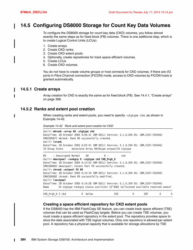
8786ch_DSCLI.fm Draft Document for Review July 17, 2010 10:14 pm
14.5 Configuring DS8000 Storage for Count Key Data VolumesTo configure the DS8000 storage for count key data (CKD) volumes, you follow almost exactly the same steps as for fixed block (FB) volumes. There is one additional step, which is to create Logical Control Units (LCUs):
1. Create arrays.2. Create CKD ranks.3. Create CKD extent pools.4. Optionally, create repositories for track space efficient volumes.5. Create LCUs.6. Create CKD volumes.
You do not have to create volume groups or host connects for CKD volumes. If there are I/O ports in Fibre Channel connection (FICON) mode, access to CKD volumes by FICON hosts is granted automatically.
14.5.1 Create arraysArray creation for CKD is exactly the same as for fixed block (FB). See 14.4.1, “Create arrays” on page 368.
14.5.2 Ranks and extent pool creationWhen creating ranks and extent pools, you need to specify -stgtype ckd, as shown in Example 14-42.
Example 14-42 Rank and extent pool creation for CKD
dscli> mkrank -array A0 -stgtype ckdDate/Time: 28 October 2005 0:05:31 IBM DSCLI Version: 5.1.0.204 DS: IBM.2107-7503461CMUC00007I mkrank: Rank R0 successfully created.dscli> lsrankDate/Time: 28 October 2005 0:07:51 IBM DSCLI Version: 5.1.0.204 DS: IBM.2107-7503461ID Group State datastate Array RAIDtype extpoolID stgtype==============================================================R0 - Unassigned Normal A0 6 - ckddscli> mkextpool -rankgrp 0 -stgtype ckd CKD_High_0Date/Time: 28 October 2005 0:13:53 IBM DSCLI Version: 5.1.0.204 DS: IBM.2107-7503461CMUC00000I mkextpool: Extent Pool P0 successfully created.dscli> chrank -extpool P2 R0Date/Time: 28 October 2005 0:14:19 IBM DSCLI Version: 5.1.0.204 DS: IBM.2107-7503461CMUC00008I chrank: Rank R0 successfully modified.dscli> lsextpoolDate/Time: 28 October 2005 0:14:28 IBM DSCLI Version: 5.1.0.204 DS: IBM.2107-7503461Name ID stgtype rankgrp status availstor (2^30B) %allocated available reserved numvol ===========================================================================================CKD_High_0 2 ckd 0 below 252 0 287 0 0
Creating a space efficient repository for CKD extent poolsIf the DS8000 has the IBM FlashCopy SE feature, you can create track space efficient (TSE) volumes that can be used as FlashCopy targets. Before you can create TSE volumes, you must create a space efficient repository in the extent pool. The repository provides space to store the data associated with TSE logical volumes. Only one repository is allowed per extent pool. A repository has a physical capacity that is available for storage allocations by TSE
384 IBM System Storage DS8700: Architecture and Implementation
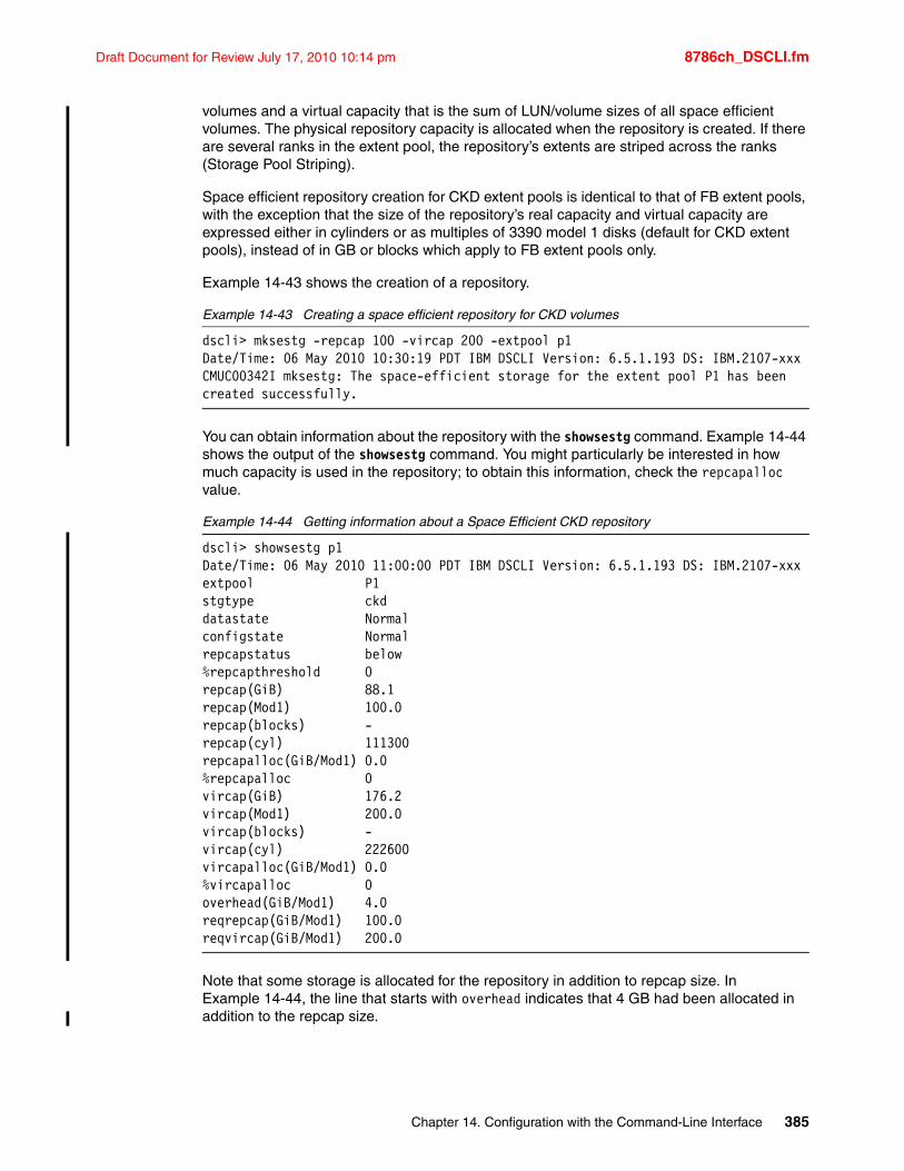
Draft Document for Review July 17, 2010 10:14 pm 8786ch_DSCLI.fm
volumes and a virtual capacity that is the sum of LUN/volume sizes of all space efficient volumes. The physical repository capacity is allocated when the repository is created. If there are several ranks in the extent pool, the repository’s extents are striped across the ranks (Storage Pool Striping).
Space efficient repository creation for CKD extent pools is identical to that of FB extent pools, with the exception that the size of the repository’s real capacity and virtual capacity are expressed either in cylinders or as multiples of 3390 model 1 disks (default for CKD extent pools), instead of in GB or blocks which apply to FB extent pools only.
Example 14-43 shows the creation of a repository.
Example 14-43 Creating a space efficient repository for CKD volumes
dscli> mksestg -repcap 100 -vircap 200 -extpool p1Date/Time: 06 May 2010 10:30:19 PDT IBM DSCLI Version: 6.5.1.193 DS: IBM.2107-xxxCMUC00342I mksestg: The space-efficient storage for the extent pool P1 has been created successfully.
You can obtain information about the repository with the showsestg command. Example 14-44 shows the output of the showsestg command. You might particularly be interested in how much capacity is used in the repository; to obtain this information, check the repcapalloc value.
Example 14-44 Getting information about a Space Efficient CKD repository
dscli> showsestg p1Date/Time: 06 May 2010 11:00:00 PDT IBM DSCLI Version: 6.5.1.193 DS: IBM.2107-xxxextpool P1stgtype ckddatastate Normalconfigstate Normalrepcapstatus below%repcapthreshold 0repcap(GiB) 88.1repcap(Mod1) 100.0repcap(blocks) -repcap(cyl) 111300repcapalloc(GiB/Mod1) 0.0%repcapalloc 0vircap(GiB) 176.2vircap(Mod1) 200.0vircap(blocks) -vircap(cyl) 222600vircapalloc(GiB/Mod1) 0.0%vircapalloc 0overhead(GiB/Mod1) 4.0reqrepcap(GiB/Mod1) 100.0reqvircap(GiB/Mod1) 200.0
Note that some storage is allocated for the repository in addition to repcap size. In Example 14-44, the line that starts with overhead indicates that 4 GB had been allocated in addition to the repcap size.
Chapter 14. Configuration with the Command-Line Interface 385
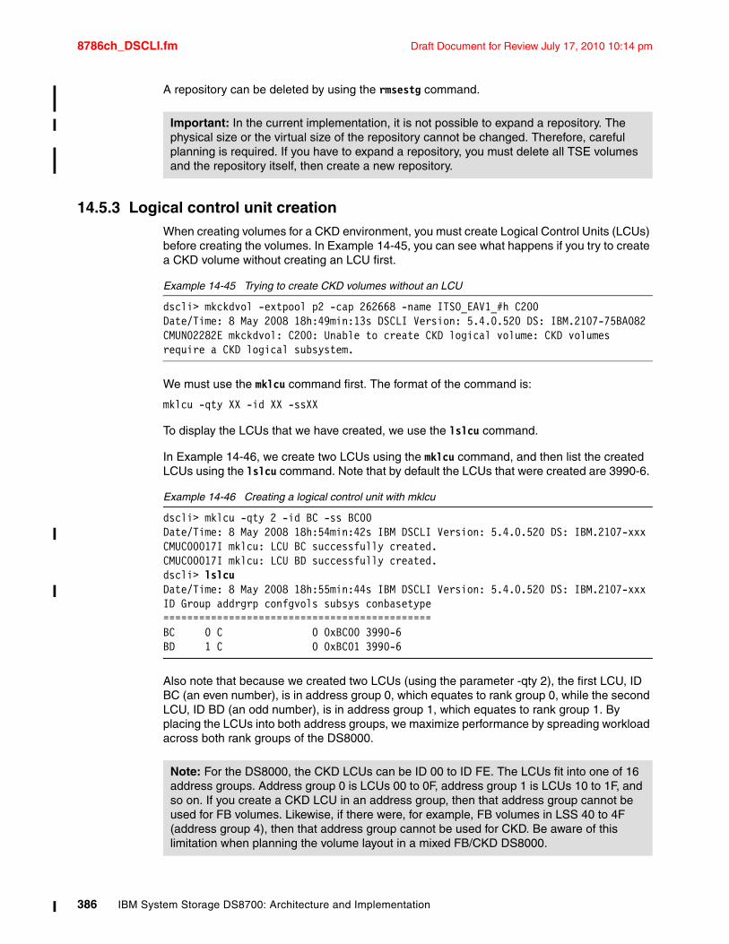
8786ch_DSCLI.fm Draft Document for Review July 17, 2010 10:14 pm
A repository can be deleted by using the rmsestg command.
14.5.3 Logical control unit creationWhen creating volumes for a CKD environment, you must create Logical Control Units (LCUs) before creating the volumes. In Example 14-45, you can see what happens if you try to create a CKD volume without creating an LCU first.
Example 14-45 Trying to create CKD volumes without an LCU
dscli> mkckdvol -extpool p2 -cap 262668 -name ITSO_EAV1_#h C200Date/Time: 8 May 2008 18h:49min:13s DSCLI Version: 5.4.0.520 DS: IBM.2107-75BA082CMUN02282E mkckdvol: C200: Unable to create CKD logical volume: CKD volumes require a CKD logical subsystem.
We must use the mklcu command first. The format of the command is:
mklcu -qty XX -id XX -ssXX
To display the LCUs that we have created, we use the lslcu command.
In Example 14-46, we create two LCUs using the mklcu command, and then list the created LCUs using the lslcu command. Note that by default the LCUs that were created are 3990-6.
Example 14-46 Creating a logical control unit with mklcu
dscli> mklcu -qty 2 -id BC -ss BC00Date/Time: 8 May 2008 18h:54min:42s IBM DSCLI Version: 5.4.0.520 DS: IBM.2107-xxxCMUC00017I mklcu: LCU BC successfully created.CMUC00017I mklcu: LCU BD successfully created.dscli> lslcuDate/Time: 8 May 2008 18h:55min:44s IBM DSCLI Version: 5.4.0.520 DS: IBM.2107-xxxID Group addrgrp confgvols subsys conbasetype=============================================BC 0 C 0 0xBC00 3990-6BD 1 C 0 0xBC01 3990-6
Also note that because we created two LCUs (using the parameter -qty 2), the first LCU, ID BC (an even number), is in address group 0, which equates to rank group 0, while the second LCU, ID BD (an odd number), is in address group 1, which equates to rank group 1. By placing the LCUs into both address groups, we maximize performance by spreading workload across both rank groups of the DS8000.
Important: In the current implementation, it is not possible to expand a repository. The physical size or the virtual size of the repository cannot be changed. Therefore, careful planning is required. If you have to expand a repository, you must delete all TSE volumes and the repository itself, then create a new repository.
Note: For the DS8000, the CKD LCUs can be ID 00 to ID FE. The LCUs fit into one of 16 address groups. Address group 0 is LCUs 00 to 0F, address group 1 is LCUs 10 to 1F, and so on. If you create a CKD LCU in an address group, then that address group cannot be used for FB volumes. Likewise, if there were, for example, FB volumes in LSS 40 to 4F (address group 4), then that address group cannot be used for CKD. Be aware of this limitation when planning the volume layout in a mixed FB/CKD DS8000.
386 IBM System Storage DS8700: Architecture and Implementation

Draft Document for Review July 17, 2010 10:14 pm 8786ch_DSCLI.fm
14.5.4 Create CKD volumesHaving created an LCU, we can now create CKD volumes by using the mkckdvol command. The format of the mkckdvol command is:
mkckdvol -extpool P2 -cap 262668 -datatype 3390-A -eam rotatevols -name ITSO_EAV1_#h BC06
The major difference to note here is that the capacity is expressed in either cylinders or as CKD extents (1,113 cylinders). In order to not waste space, use volume capacities which are a multiple of 1,113 cylinders. Another new point is the support of DS8000 Licensed Machine Code 5.4.xx.xx for Extended Address Volumes (EAV). This expanded the maximum size of a CKD volume to 262,668 cylinders and created a new device type, 3390 Model A. This new volume can only be used by z/OS systems running V1.10 or later versions.
In Example 14-47, we create a single 3390-A volume using 262,668 cylinders.
Example 14-47 Creating CKD volumes using mkckdvol
dscli> mkckdvol -extpool P2 -cap 262668 -datatype 3390-A -eam rotatevols -name ITSO_EAV1_#h BC06Date/Time: 8 May 2008 13h38min13s IBM DSCLI Version: 5.4.0.520 DS: IBM.2107-75BA082CMUC00021I mkckdvol: CKD Volume BC06 successfully created.dscli> lsckdvolDate/Time: 8 May 2008 13h38min34s IBM DSCLI Version: 5.4.0.520 DS: IBM.2107-75BA082Name ID accstate datastate configstate deviceMTM voltype orgbvols extpool cap (cyl)================================================================================================ITSO_BC00 BC00 Online Normal Normal 3390-9 CKD Base - P2 10017ITSO_BC01 BC01 Online Normal Normal 3390-9 CKD Base - P2 10017ITSO_BC02 BC02 Online Normal Normal 3390-9 CKD Base - P2 10017ITSO_BC03 BC03 Online Normal Normal 3390-9 CKD Base - P2 10017ITSO_BC04 BC04 Online Normal Normal 3390-9 CKD Base - P2 10017ITSO_BC05 BC05 Online Normal Normal 3390-9 CKD Base - P2 10017ITSO_EAV1_BC06 BC06 Online Normal Normal 3390-A CKD Base - P2 262668ITSO_BD00 BD00 Online Normal Normal 3390-9 CKD Base - P3 10017ITSO_BD01 BD01 Online Normal Normal 3390-9 CKD Base - P3 10017ITSO_BD02 BD02 Online Normal Normal 3390-9 CKD Base - P3 10017ITSO_BD03 BD03 Online Normal Normal 3390-9 CKD Base - P3 10017ITSO_BD04 BD04 Online Normal Normal 3390-9 CKD Base - P3 10017ITSO_BD05 BD05 Online Normal Normal 3390-9 CKD Base - P3 10017
Remember, we can only create CKD volumes in LCUs that we have already created.
You also need to be aware that volumes in even numbered LCUs must be created from an extent pool that belongs to rank group 0, while volumes in odd numbered LCUs must be created from an extent pool in rank group 1.
Storage pool stripingWhen creating a volume, you have a choice about how the volume is allocated in an extent pool with several ranks. The extents of a volume can be kept together in one rank (as long as there is enough free space on that rank). The next rank is used when the next volume is created. This allocation method is called rotate volumes.
You can also specify that you want the extents of the volume to be evenly distributed across all ranks within the extent pool. This allocation method is called rotate extents.
Note: For 3390-A volumes, size can be specified from 1 to 65,520 in increments of 1 and from 65,667 (next multiple of 1113) to 262,668 in increments of 1113.
Chapter 14. Configuration with the Command-Line Interface 387
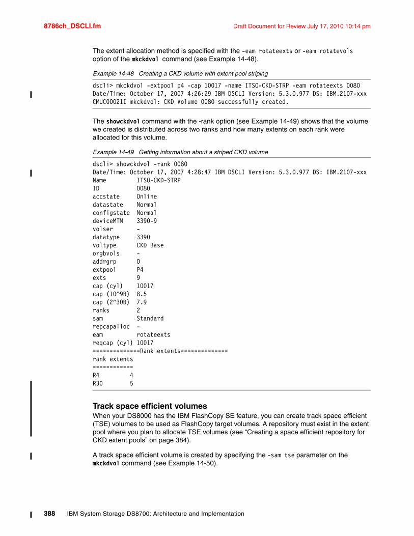
8786ch_DSCLI.fm Draft Document for Review July 17, 2010 10:14 pm
The extent allocation method is specified with the -eam rotateexts or -eam rotatevols option of the mkckdvol command (see Example 14-48).
Example 14-48 Creating a CKD volume with extent pool striping
dscli> mkckdvol -extpool p4 -cap 10017 -name ITSO-CKD-STRP -eam rotateexts 0080Date/Time: October 17, 2007 4:26:29 IBM DSCLI Version: 5.3.0.977 DS: IBM.2107-xxxCMUC00021I mkckdvol: CKD Volume 0080 successfully created.
The showckdvol command with the -rank option (see Example 14-49) shows that the volume we created is distributed across two ranks and how many extents on each rank were allocated for this volume.
Example 14-49 Getting information about a striped CKD volume
dscli> showckdvol -rank 0080Date/Time: October 17, 2007 4:28:47 IBM DSCLI Version: 5.3.0.977 DS: IBM.2107-xxxName ITSO-CKD-STRPID 0080accstate Onlinedatastate Normalconfigstate NormaldeviceMTM 3390-9volser -datatype 3390voltype CKD Baseorgbvols -addrgrp 0extpool P4exts 9cap (cyl) 10017cap (10^9B) 8.5cap (2^30B) 7.9ranks 2sam Standardrepcapalloc -eam rotateextsreqcap (cyl) 10017==============Rank extents==============rank extents============R4 4R30 5
Track space efficient volumesWhen your DS8000 has the IBM FlashCopy SE feature, you can create track space efficient (TSE) volumes to be used as FlashCopy target volumes. A repository must exist in the extent pool where you plan to allocate TSE volumes (see “Creating a space efficient repository for CKD extent pools” on page 384).
A track space efficient volume is created by specifying the -sam tse parameter on the mkckdvol command (see Example 14-50).
388 IBM System Storage DS8700: Architecture and Implementation
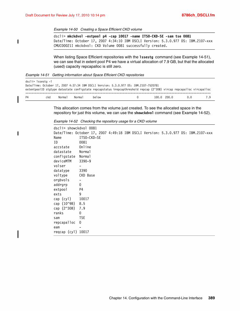
Draft Document for Review July 17, 2010 10:14 pm 8786ch_DSCLI.fm
Example 14-50 Creating a Space Efficient CKD volume
dscli> mkckdvol -extpool p4 -cap 10017 -name ITSO-CKD-SE -sam tse 0081Date/Time: October 17, 2007 4:34:10 IBM DSCLI Version: 5.3.0.977 DS: IBM.2107-xxxCMUC00021I mkckdvol: CKD Volume 0081 successfully created.
When listing Space Efficient repositories with the lssestg command (see Example 14-51), we can see that in extent pool P4 we have a virtual allocation of 7.9 GB, but that the allocated (used) capacity repcapalloc is still zero.
Example 14-51 Getting information about Space Efficient CKD repositories
dscli> lssestg -lDate/Time: October 17, 2007 4:37:34 IBM DSCLI Version: 5.3.0.977 DS: IBM.2107-7520781extentpoolID stgtype datastate configstate repcapstatus %repcapthreshold repcap (2^30B) vircap repcapalloc vircapalloc======================================================================================================================P4 ckd Normal Normal below 0 100.0 200.0 0.0 7.9
This allocation comes from the volume just created. To see the allocated space in the repository for just this volume, we can use the showckdvol command (see Example 14-52).
Example 14-52 Checking the repository usage for a CKD volume
dscli> showckdvol 0081Date/Time: October 17, 2007 4:49:18 IBM DSCLI Version: 5.3.0.977 DS: IBM.2107-xxxName ITSO-CKD-SEID 0081accstate Onlinedatastate Normalconfigstate NormaldeviceMTM 3390-9volser -datatype 3390voltype CKD Baseorgbvols -addrgrp 0extpool P4exts 9cap (cyl) 10017cap (10^9B) 8.5cap (2^30B) 7.9ranks 0sam TSErepcapalloc 0eam -reqcap (cyl) 10017
Chapter 14. Configuration with the Command-Line Interface 389
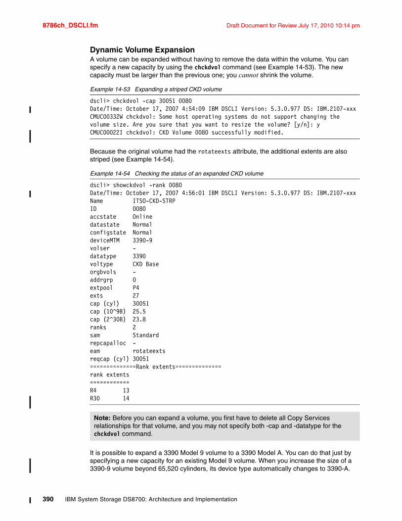
8786ch_DSCLI.fm Draft Document for Review July 17, 2010 10:14 pm
Dynamic Volume ExpansionA volume can be expanded without having to remove the data within the volume. You can specify a new capacity by using the chckdvol command (see Example 14-53). The new capacity must be larger than the previous one; you cannot shrink the volume.
Example 14-53 Expanding a striped CKD volume
dscli> chckdvol -cap 30051 0080Date/Time: October 17, 2007 4:54:09 IBM DSCLI Version: 5.3.0.977 DS: IBM.2107-xxxCMUC00332W chckdvol: Some host operating systems do not support changing the volume size. Are you sure that you want to resize the volume? [y/n]: yCMUC00022I chckdvol: CKD Volume 0080 successfully modified.
Because the original volume had the rotateexts attribute, the additional extents are also striped (see Example 14-54).
Example 14-54 Checking the status of an expanded CKD volume
dscli> showckdvol -rank 0080Date/Time: October 17, 2007 4:56:01 IBM DSCLI Version: 5.3.0.977 DS: IBM.2107-xxxName ITSO-CKD-STRPID 0080accstate Onlinedatastate Normalconfigstate NormaldeviceMTM 3390-9volser -datatype 3390voltype CKD Baseorgbvols -addrgrp 0extpool P4exts 27cap (cyl) 30051cap (10^9B) 25.5cap (2^30B) 23.8ranks 2sam Standardrepcapalloc -eam rotateextsreqcap (cyl) 30051==============Rank extents==============rank extents============R4 13R30 14
It is possible to expand a 3390 Model 9 volume to a 3390 Model A. You can do that just by specifying a new capacity for an existing Model 9 volume. When you increase the size of a 3390-9 volume beyond 65,520 cylinders, its device type automatically changes to 3390-A.
Note: Before you can expand a volume, you first have to delete all Copy Services relationships for that volume, and you may not specify both -cap and -datatype for the chckdvol command.
390 IBM System Storage DS8700: Architecture and Implementation
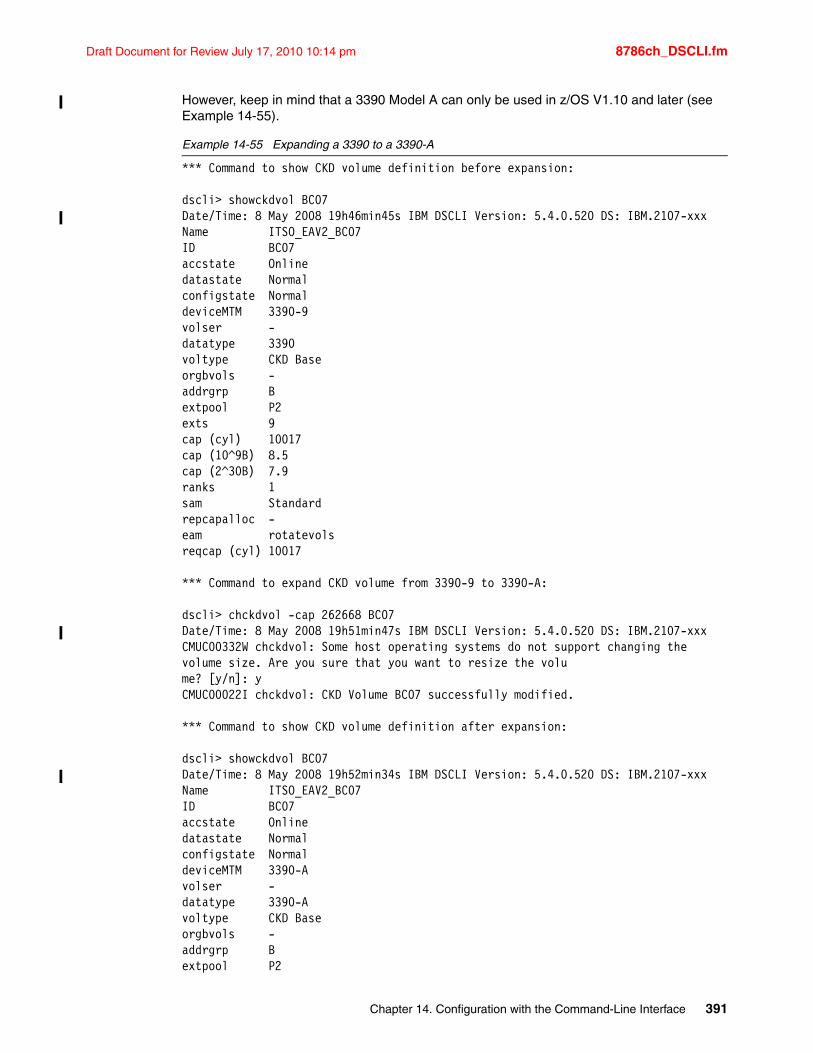
Draft Document for Review July 17, 2010 10:14 pm 8786ch_DSCLI.fm
However, keep in mind that a 3390 Model A can only be used in z/OS V1.10 and later (see Example 14-55).
Example 14-55 Expanding a 3390 to a 3390-A
*** Command to show CKD volume definition before expansion:
dscli> showckdvol BC07Date/Time: 8 May 2008 19h46min45s IBM DSCLI Version: 5.4.0.520 DS: IBM.2107-xxxName ITSO_EAV2_BC07ID BC07accstate Onlinedatastate Normalconfigstate NormaldeviceMTM 3390-9volser -datatype 3390voltype CKD Baseorgbvols -addrgrp Bextpool P2exts 9cap (cyl) 10017cap (10^9B) 8.5cap (2^30B) 7.9ranks 1sam Standardrepcapalloc -eam rotatevolsreqcap (cyl) 10017
*** Command to expand CKD volume from 3390-9 to 3390-A:
dscli> chckdvol -cap 262668 BC07Date/Time: 8 May 2008 19h51min47s IBM DSCLI Version: 5.4.0.520 DS: IBM.2107-xxxCMUC00332W chckdvol: Some host operating systems do not support changing the volume size. Are you sure that you want to resize the volume? [y/n]: yCMUC00022I chckdvol: CKD Volume BC07 successfully modified.
*** Command to show CKD volume definition after expansion:
dscli> showckdvol BC07Date/Time: 8 May 2008 19h52min34s IBM DSCLI Version: 5.4.0.520 DS: IBM.2107-xxxName ITSO_EAV2_BC07ID BC07accstate Onlinedatastate Normalconfigstate NormaldeviceMTM 3390-Avolser -datatype 3390-Avoltype CKD Baseorgbvols -addrgrp Bextpool P2
Chapter 14. Configuration with the Command-Line Interface 391
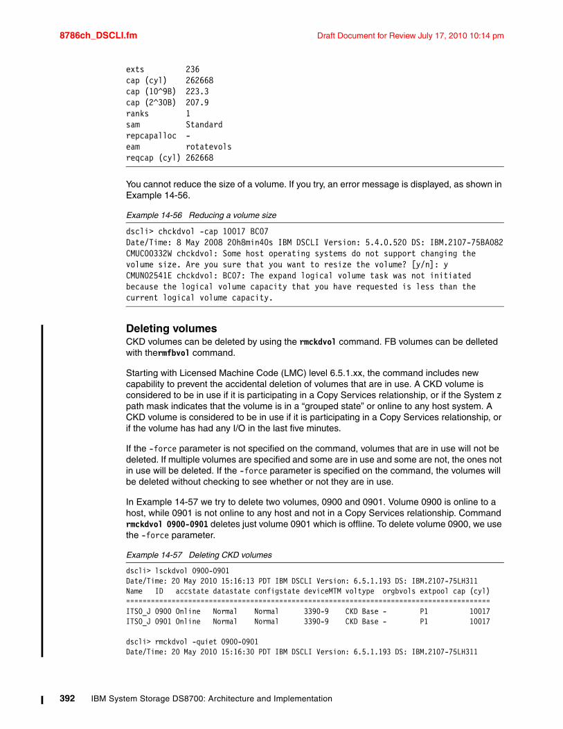
8786ch_DSCLI.fm Draft Document for Review July 17, 2010 10:14 pm
exts 236cap (cyl) 262668cap (10^9B) 223.3cap (2^30B) 207.9ranks 1sam Standardrepcapalloc -eam rotatevolsreqcap (cyl) 262668
You cannot reduce the size of a volume. If you try, an error message is displayed, as shown in Example 14-56.
Example 14-56 Reducing a volume size
dscli> chckdvol -cap 10017 BC07Date/Time: 8 May 2008 20h8min40s IBM DSCLI Version: 5.4.0.520 DS: IBM.2107-75BA082CMUC00332W chckdvol: Some host operating systems do not support changing the volume size. Are you sure that you want to resize the volume? [y/n]: yCMUN02541E chckdvol: BC07: The expand logical volume task was not initiated because the logical volume capacity that you have requested is less than the current logical volume capacity.
Deleting volumesCKD volumes can be deleted by using the rmckdvol command. FB volumes can be delleted with thermfbvol command.
Starting with Licensed Machine Code (LMC) level 6.5.1.xx, the command includes new capability to prevent the accidental deletion of volumes that are in use. A CKD volume is considered to be in use if it is participating in a Copy Services relationship, or if the System z path mask indicates that the volume is in a “grouped state” or online to any host system. A CKD volume is considered to be in use if it is participating in a Copy Services relationship, or if the volume has had any I/O in the last five minutes.
If the -force parameter is not specified on the command, volumes that are in use will not be deleted. If multiple volumes are specified and some are in use and some are not, the ones not in use will be deleted. If the -force parameter is specified on the command, the volumes will be deleted without checking to see whether or not they are in use.
In Example 14-57 we try to delete two volumes, 0900 and 0901. Volume 0900 is online to a host, while 0901 is not online to any host and not in a Copy Services relationship. Command rmckdvol 0900-0901 deletes just volume 0901 which is offline. To delete volume 0900, we use the -force parameter.
Example 14-57 Deleting CKD volumes
dscli> lsckdvol 0900-0901Date/Time: 20 May 2010 15:16:13 PDT IBM DSCLI Version: 6.5.1.193 DS: IBM.2107-75LH311Name ID accstate datastate configstate deviceMTM voltype orgbvols extpool cap (cyl)========================================================================================ITSO_J 0900 Online Normal Normal 3390-9 CKD Base - P1 10017ITSO_J 0901 Online Normal Normal 3390-9 CKD Base - P1 10017
dscli> rmckdvol -quiet 0900-0901Date/Time: 20 May 2010 15:16:30 PDT IBM DSCLI Version: 6.5.1.193 DS: IBM.2107-75LH311
392 IBM System Storage DS8700: Architecture and Implementation
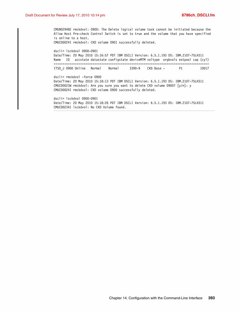
Draft Document for Review July 17, 2010 10:14 pm 8786ch_DSCLI.fm
CMUN02948E rmckdvol: 0900: The Delete logical volume task cannot be initiated because the Allow Host Pre-check Control Switch is set to true and the volume that you have specified is online to a host.CMUC00024I rmckdvol: CKD volume 0901 successfully deleted.
dscli> lsckdvol 0900-0901Date/Time: 20 May 2010 15:16:57 PDT IBM DSCLI Version: 6.5.1.193 DS: IBM.2107-75LH311Name ID accstate datastate configstate deviceMTM voltype orgbvols extpool cap (cyl)========================================================================================ITSO_J 0900 Online Normal Normal 3390-9 CKD Base - P1 10017
dscli> rmckdvol -force 0900Date/Time: 20 May 2010 15:18:13 PDT IBM DSCLI Version: 6.5.1.193 DS: IBM.2107-75LH311CMUC00023W rmckdvol: Are you sure you want to delete CKD volume 0900? [y/n]: yCMUC00024I rmckdvol: CKD volume 0900 successfully deleted.
dscli> lsckdvol 0900-0901Date/Time: 20 May 2010 15:18:26 PDT IBM DSCLI Version: 6.5.1.193 DS: IBM.2107-75LH311CMUC00234I lsckdvol: No CKD Volume found.
Chapter 14. Configuration with the Command-Line Interface 393

8786ch_DSCLI.fm Draft Document for Review July 17, 2010 10:14 pm
394 IBM System Storage DS8700: Architecture and Implementation
Draft Document for Review July 17, 2010 10:14 pm 8786p_Host consideration.fm
Part 4 Host considerations
In this part, we discuss the specific host considerations that you might need for implementing the IBM System Storage DS8000 series with your chosen platform. We cover the following host platforms:
� Open systems considerations
� IBM System z considerations
� IBM System i considerations
Part 4
Note: This part was taken from the IBM Redbooks publication IBM System Storage DS8000: Architecture and Implementation, SG24-6786, and has not been updated specifically for the DS8700.
© Copyright IBM Corp. 2010. All rights reserved. 395

8786p_Host consideration.fm Draft Document for Review July 17, 2010 10:14 pm
396 IBM System Storage DS8700: Architecture and Implementation
Draft Document for Review July 17, 2010 10:14 pm 8786ch_hostconsid_open.fm
Chapter 15. Open systems considerations
This chapter discusses the specifics for attaching IBM System Storage DS8000 series systems to host systems running the following operating system platforms:
� Windows
� AIX
� Linux
� OpenVMS
� Sun Solaris
� Hewlett-Packard UNIX (HP-UX)
Also, several general considerations are discussed at the beginning of this chapter.
15
Note: The information presented here was taken from the IBM Redbooks publication IBM System Storage DS8000: Architecture and Implementation, SG24-6786, and has not been updated specifically for the DS8700.
© Copyright IBM Corp. 2010. All rights reserved. 397
8786ch_hostconsid_open.fm Draft Document for Review July 17, 2010 10:14 pm
15.1 General considerationsIn this section, we cover several topics that are not specific to a single operating system. This includes available documentation, links to additional information, and considerations common to all platforms.
15.1.1 Getting up-to-date informationThis section provides a list of online resources where you can find detailed and up-to-date information about supported configurations, recommended settings, device driver versions, and so on. Due to the high innovation rate in the IT industry, the support information is updated frequently. Therefore, we advise that you visit these resources regularly and check for updates.
IBM System Storage Interoperability Center (SSIC)For information about supported Fibre Channel HBAs and the recommended or required firmware and device driver levels for all IBM storage systems, you can visit the IBM System Storage Interoperation Center (SSIC) at the following address:
http://www-03.ibm.com/systems/support/storage/config/ssic/displayesssearchwithoutjs.wss?start_over=yes
For each query, select a storage system, a server model, an operating system, and an HBA type. Each query shows a list of all supported HBAs together with the required firmware and device driver levels for your combination. Furthermore, a list of supported SAN switches and directors is displayed.
DS8000 Host Systems Attachment GuideThe IBM System Storage DS8000 Host Systems Attachment Guide, SC26-7917 guides you in detail through all the required steps to attach an open systems host to your DS8000 storage system. It is available at the following Web site (click Documentation on that site):
http://www-304.ibm.com/jct01004c/systems/support/supportsite.wss/supportresources?taskind=3&brandind=5000028&familyind=5329633
General link to installation documentation Sometimes links change. Good starting points to find documentation and troubleshooting information are available at the following address:
http://www.ibm.com/support/us/en/
HBA vendor resourcesAll of the Fibre Channel HBA vendors have Web sites that provide information about their products, facts, and features, as well as support information. These sites are useful when you need details that cannot be supplied by IBM resources, for example, when troubleshooting an HBA driver. Be aware that IBM cannot be held responsible for the content of these sites.
QLogic CorporationThe Qlogic Web site can be found at the following address:
http://www.qlogic.com
398 IBM System Storage DS8700: Architecture and Implementation
Draft Document for Review July 17, 2010 10:14 pm 8786ch_hostconsid_open.fm
QLogic maintains a page that lists all the HBAs, drivers, and firmware versions that are supported for attachment to IBM storage systems, which can be found at the following address:
http://support.qlogic.com/support/oem_ibm.asp
Emulex CorporationThe Emulex home page is at the following address:
http://www.emulex.com
They also have a page with content specific to IBM storage systems at the following address:
http://www.emulex.com/products/host-bus-adapters/ibm-branded.html
JNI/AMCCAMCC took over JNI, but still markets Fibre Channel (FC) HBAs under the JNI brand name. JNI HBAs are supported for DS8000 attachment to SUN systems. The home page is at the following address:
http://www.appliedmicro.com/
Their IBM storage specific support page is at the following address:
http://www.appliedmicro.com/drivers/IBM.html
AttoAtto supplies HBAs, which IBM supports for Apple Macintosh attachment to the DS8000. Their home page is at the following address:
http://www.attotech.com
They have no IBM storage specific page. Their support page is at the following address:
http://www.attotech.com/solutions/ibm.html
You must register in order to download drivers and utilities for their HBAs.
Platform and operating system vendor pagesThe platform and operating system vendors also provide much support information for their clients. Refer to this information for general guidance about connecting their systems to SAN-attached storage. However, be aware that in some cases you cannot find information to help you with third-party vendors. You should always check with IBM about interoperability and support from IBM in regard to these products. It is beyond the scope of this book to list all the vendors’ Web sites.
15.1.2 Boot supportFor most of the supported platforms and operating systems, you can use the DS8000 as a boot device. The DS8000 Interoperability Matrix provides detailed information about boot support.
The IBM System Storage DS8000 Host Systems Attachment Guide, SC26-7917 helps you with the procedures necessary to set up your host in order to boot from the DS8000.
The IBM System Storage Multipath Subsystem Device Driver User’s Guide, SC30-4131 also helps you identify the optimal configuration and lists the steps required to boot from multipathing devices.
Chapter 15. Open systems considerations 399
8786ch_hostconsid_open.fm Draft Document for Review July 17, 2010 10:14 pm
15.1.3 Additional supported configurations (RPQ)There is a process for cases where the configuration that you want is not represented in the support matrix. This process is called Request for Price Quotation (RPQ). Clients should contact their IBM storage sales specialist or IBM Business Partner for submission of an RPQ. Initiating the process does not guarantee that the configuration that you want will be supported. This depends on the technical feasibility and the required test effort. A configuration that equals or is similar to one of the already approved configurations is more likely to become approved than a completely different configuration.
15.1.4 Multipathing support: Subsystem Device Driver (SDD)To ensure maximum availability, most clients choose to connect their open systems hosts through more than one Fibre Channel path to their storage systems. With an intelligent SAN layout, this protects you from failures of FC HBAs, SAN components, and host ports in the storage subsystem.
Most operating systems, however, cannot deal natively with multiple paths to a single disk. This puts the data’s integrity at risk, because multiple write requests can be issued to the same data and nothing takes care of the correct order of writes.
To utilize the redundancy and increased I/O bandwidth that you get with multiple paths, you need an additional layer in the operating system’s disk subsystem to recombine the multiple disks seen by the HBAs into one logical disk. This layer manages path failover in case a path becomes unusable and balances I/O requests across the available paths.
Subsystem Device Driver (SDD)For most operating systems that are supported for DS8000 attachment, IBM makes available the IBM Subsystem Device Driver (SDD) free of cost to provide the following functionality:
� Enhanced data availability through automatic path failover and failback� Increased performance through dynamic I/O load balancing across multiple paths� The ability for concurrent download of licensed internal code� User configurable path selection policies for the host system
IBM Multipath Subsystem Device Driver (SDD) provides load balancing and enhanced data availability capability in configurations with more than one I/O path between the host server and the DS8000. SDD performs dynamic load balancing across all available preferred paths to ensure full utilization of the SAN and HBA resources.
SDD can be downloaded from the following address:
http://www.ibm.com/servers/storage/support/software/sdd/downloading.html
When you click the Subsystem Device Driver downloads link, a list of all the operating systems for which SDD is available appears. Selecting an operating system leads you to the download packages, the user’s guide, and additional support information.
The user’s guide, the IBM System Storage Multipath Subsystem Device Driver User’s Guide, SC30-4131, contains all the information that is needed to install, configure, and use SDD for all supported operating systems.
Note: SDD and RDAC, the multipathing solution for the IBM System Storage DS4000® series, can coexist on most operating systems, as long as they manage separate HBA pairs. Refer to the DS4000 series documentation for detailed information.
400 IBM System Storage DS8700: Architecture and Implementation
Draft Document for Review July 17, 2010 10:14 pm 8786ch_hostconsid_open.fm
Other multipathing solutionsSome operating systems come with native multipathing software, for example:
� SUN StorEdge Traffic Manager for SUN Solaris
� HP PVLinks for HP-UX
� IBM AIX native multipathing I/O support (MPIO)
� IBM i5/OS V5R3 multipath support
In addition, there are third-party multipathing solutions, such as Veritas DMP, which is part of Veritas Volume Manager.
Most of these solutions are also supported for DS8000 attachment, although the scope can vary. There might be limitations for certain host bus adapters or operating system versions. Always consult the DS8000 Interoperability Matrix for the latest information.
15.2 WindowsDS8000 supports Fibre Channel attachment to Microsoft Windows 2000 Server, Windows Server 2003, and Windows Server 2008 servers. For details regarding operating system versions and HBA types, see the System Storage Interoperation Center (SSIC), available at the following address:
http://www.ibm.com/systems/support/storage/config/ssic/displayesssearchwithoutjs.wss
This support includes cluster service, and acts as a boot device. Booting is supported currently with host adapters QLA23xx (32-bit or 64-bit) and LP9xxx (32-bit only). For a detailed discussion about SAN booting (advantages, disadvantages, potential difficulties, and troubleshooting), we highly recommend the Microsoft document Boot from SAN in Windows Server 2003 and Windows 2000 Server, found at the following address:
http://www.microsoft.com/windowsserversystem/wss2003/techinfo/plandeploy/BootfromSANinWindows.mspx
15.2.1 HBA and operating system settingsDepending on the host bus adapter type, several HBA and driver settings might be required. Refer to the IBM System Storage DS8000 Host Systems Attachment Guide, SC26-7917 for the complete description of these settings. Although the volumes can be accessed with other settings, the values recommended there have been tested for robustness.
Chapter 15. Open systems considerations 401
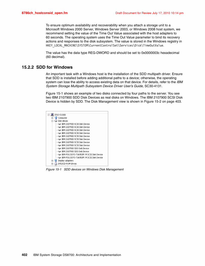
8786ch_hostconsid_open.fm Draft Document for Review July 17, 2010 10:14 pm
To ensure optimum availability and recoverability when you attach a storage unit to a Microsoft Windows 2000 Server, Windows Server 2003, or Windows 2008 host system, we recommend setting the value of the Time Out Value associated with the host adapters to 60 seconds. The operating system uses the Time Out Value parameter to bind its recovery actions and responses to the disk subsystem. The value is stored in the Windows registry in HKEY_LOCAL_MACHINE\SYSTEM\CurrentControlSet\Services\Disk\TimeOutValue.
The value has the data type REG-DWORD and should be set to 0x0000003c hexadecimal (60 decimal).
15.2.2 SDD for WindowsAn important task with a Windows host is the installation of the SDD multipath driver. Ensure that SDD is installed before adding additional paths to a device; otherwise, the operating system can lose the ability to access existing data on that device. For details, refer to the IBM System Storage Multipath Subsystem Device Driver User’s Guide, SC30-4131.
Figure 15-1 shows an example of two disks connected by four paths to the server. You see two IBM 2107900 SDD Disk Devices as real disks on Windows. The IBM 2107900 SCSI Disk Device is hidden by SDD. The Disk Management view is shown in Figure 15-2 on page 403.
Figure 15-1 SDD devices on Windows Disk Management
402 IBM System Storage DS8700: Architecture and Implementation
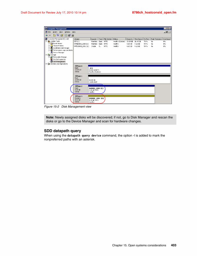
Draft Document for Review July 17, 2010 10:14 pm 8786ch_hostconsid_open.fm
Figure 15-2 Disk Management view
SDD datapath queryWhen using the datapath query device command, the option -l is added to mark the nonpreferred paths with an asterisk.
Note: Newly assigned disks will be discovered; if not, go to Disk Manager and rescan the disks or go to the Device Manager and scan for hardware changes.
Chapter 15. Open systems considerations 403
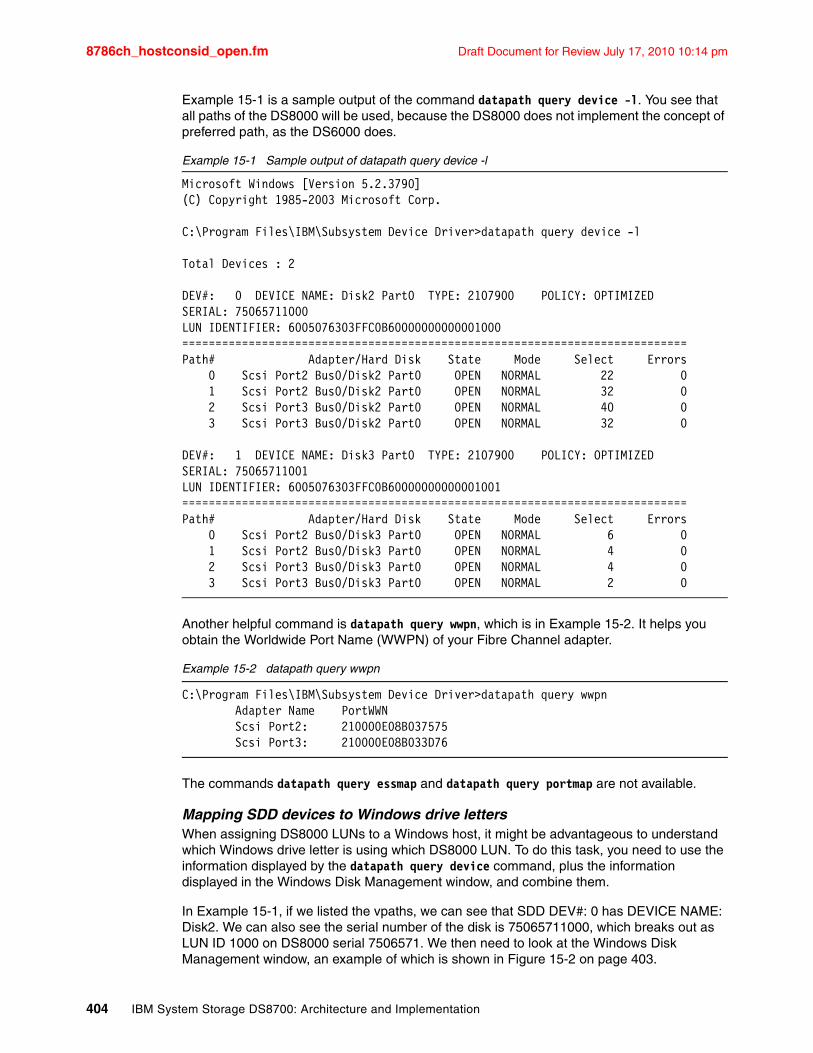
8786ch_hostconsid_open.fm Draft Document for Review July 17, 2010 10:14 pm
Example 15-1 is a sample output of the command datapath query device -l. You see that all paths of the DS8000 will be used, because the DS8000 does not implement the concept of preferred path, as the DS6000 does.
Example 15-1 Sample output of datapath query device -l
Microsoft Windows [Version 5.2.3790](C) Copyright 1985-2003 Microsoft Corp.
C:\Program Files\IBM\Subsystem Device Driver>datapath query device -l
Total Devices : 2
DEV#: 0 DEVICE NAME: Disk2 Part0 TYPE: 2107900 POLICY: OPTIMIZEDSERIAL: 75065711000LUN IDENTIFIER: 6005076303FFC0B60000000000001000============================================================================Path# Adapter/Hard Disk State Mode Select Errors 0 Scsi Port2 Bus0/Disk2 Part0 OPEN NORMAL 22 0 1 Scsi Port2 Bus0/Disk2 Part0 OPEN NORMAL 32 0 2 Scsi Port3 Bus0/Disk2 Part0 OPEN NORMAL 40 0 3 Scsi Port3 Bus0/Disk2 Part0 OPEN NORMAL 32 0
DEV#: 1 DEVICE NAME: Disk3 Part0 TYPE: 2107900 POLICY: OPTIMIZEDSERIAL: 75065711001LUN IDENTIFIER: 6005076303FFC0B60000000000001001============================================================================Path# Adapter/Hard Disk State Mode Select Errors 0 Scsi Port2 Bus0/Disk3 Part0 OPEN NORMAL 6 0 1 Scsi Port2 Bus0/Disk3 Part0 OPEN NORMAL 4 0 2 Scsi Port3 Bus0/Disk3 Part0 OPEN NORMAL 4 0 3 Scsi Port3 Bus0/Disk3 Part0 OPEN NORMAL 2 0
Another helpful command is datapath query wwpn, which is in Example 15-2. It helps you obtain the Worldwide Port Name (WWPN) of your Fibre Channel adapter.
Example 15-2 datapath query wwpn
C:\Program Files\IBM\Subsystem Device Driver>datapath query wwpn Adapter Name PortWWN Scsi Port2: 210000E08B037575 Scsi Port3: 210000E08B033D76
The commands datapath query essmap and datapath query portmap are not available.
Mapping SDD devices to Windows drive lettersWhen assigning DS8000 LUNs to a Windows host, it might be advantageous to understand which Windows drive letter is using which DS8000 LUN. To do this task, you need to use the information displayed by the datapath query device command, plus the information displayed in the Windows Disk Management window, and combine them.
In Example 15-1, if we listed the vpaths, we can see that SDD DEV#: 0 has DEVICE NAME: Disk2. We can also see the serial number of the disk is 75065711000, which breaks out as LUN ID 1000 on DS8000 serial 7506571. We then need to look at the Windows Disk Management window, an example of which is shown in Figure 15-2 on page 403.
404 IBM System Storage DS8700: Architecture and Implementation
Draft Document for Review July 17, 2010 10:14 pm 8786ch_hostconsid_open.fm
In this example, we can see that Disk 2 is Windows drive letter E; this entry is circled in blue in Figure 15-2 on page 403. SDD DEV#: 1 corresponds to the red circle around Windows drive letter G.
Now that we have mapped the LUN ID to a Windows drive letter, if drive letter E was no longer required on this Windows server, we can safely unassign LUN ID 1000 on the DS8000 with serial number 7506571, knowing that we have removed the correct drive.
Support for Windows 2000 Server and Windows Server 2003 clustering SDD 1.6.0.0 (or later) is required to support load balancing in Windows clustering. When running Windows clustering, clustering failover might not occur when the last path is being removed from the shared resources. For additional information, refer to Microsoft article Q294173 at the following address:
http://support.microsoft.com/default.aspx?scid=kb;en-us;Q294173
Windows does not support dynamic disks in the Microsoft Cluster Server (MSCS) environment.
Windows 2000 Server/Windows Server 2003 clustering environments There are subtle differences in the way that SDD handles path reclamation in a Windows clustering environment compared to a non-clustering environment. When the Windows server loses a path in a non-clustering environment, the path condition changes from open to dead and the adapter condition changes from active to degraded. The adapter and path condition will not change until the path is made operational again. When the Windows server loses a path in a clustering environment, the path condition changes from open to dead and the adapter condition changes from active to degraded. However, after a period of time, the path condition changes back to open and the adapter condition changes back to normal, even if the path has not been made operational again.
The datapath set adapter # offline command operates differently in a clustering environment as compared to a non-clustering environment. In a clustering environment, the datapath set adapter offline command does not change the condition of the path if the path is active or being reserved. If you issue the command, the following message displays:
to preserve access some paths left online
15.2.3 Windows 2003 and MPIOMicrosoft Multi Path Input Output (MPIO) solutions are designed to work in conjunction with device-specific modules (DSMs) written by vendors, but the MPIO driver package does not, by itself, form a complete solution. This joint solution allows the storage vendors to design device-specific solutions that are tightly integrated with the Windows operating system.
Note: The adapter goes to the DEGRAD state when there are active paths left on the adapter. It goes to FAILED state when there are no active paths.
MPIO drivers: MPIO is not shipped with the Windows operating system; storage vendors must pack the MPIO drivers with their own DSM. IBM Subsystem Device Driver Device Specific Module (SDDDSM) is the IBM multipath IO solution based on Microsoft MPIO technology. It is a device-specific module specifically designed to support IBM storage devices on Windows 2003 servers.
Chapter 15. Open systems considerations 405
8786ch_hostconsid_open.fm Draft Document for Review July 17, 2010 10:14 pm
The intention of MPIO is to better integrate a multipath storage solution with the operating system, and allows the use of multipathing in the SAN infrastructure during the boot process for SAN boot hosts.
15.2.4 SDD Device Specific Module for Windows 2003 and 2008The Subsystem Device Driver Device Specific Module (SDDDSM) installation is a package for DS8000 devices on the Windows Server 2003 and Windows Server 2008.
Together with MPIO, it is designed to support the multipath configuration environments in the IBM System Storage DS8000. It resides in a host system with the native disk device driver and provides the following functions:
� Enhanced data availability
� Dynamic I/O load-balancing across multiple paths
� Automatic path failover protection
� Concurrent download of licensed internal code
� Path selection policies for the host system
Also be aware of the following limitations:
� SDDDSM does not support Windows 2000
� SDD is not supported on Windows 2008
� For an HBA driver, SDDDSM requires the storport version of the HBA miniport driver
SDDDSM can be downloaded from the following address:
http://www-1.ibm.com/support/docview.wss?rs=540&context=ST52G7&dc=D430&uid=ssg1S4000350&lo=en_US&cs=utf-8&lang=en
SDDDSM for DS8000Ensure that SDDDSM is installed before adding additional paths to a device; otherwise, the operating system can lose the ability to access existing data on that device. For details, refer to the IBM System Storage Multipath Subsystem Device Driver User’s Guide, SC30-4131.
In Figure 15-3 on page 407, you see an example of three disks connected by two paths to the server. You see three IBM 2107900 Multi-Path Disk Devices as real disks on Windows. The IBM 2107900 SCSI Disk Device is hidden by SDDDSM. The Disk Manager view with the initialized disks is shown in Figure 15-4 on page 407.
406 IBM System Storage DS8700: Architecture and Implementation
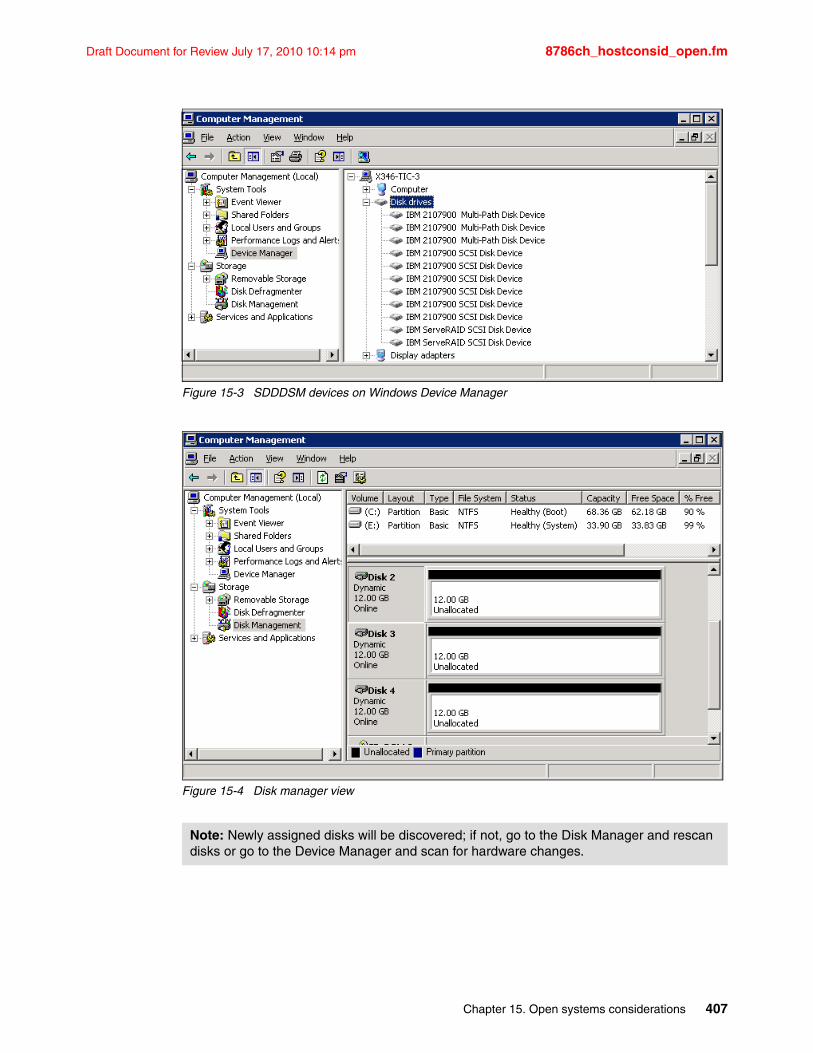
Draft Document for Review July 17, 2010 10:14 pm 8786ch_hostconsid_open.fm
Figure 15-3 SDDDSM devices on Windows Device Manager
Figure 15-4 Disk manager view
Note: Newly assigned disks will be discovered; if not, go to the Disk Manager and rescan disks or go to the Device Manager and scan for hardware changes.
Chapter 15. Open systems considerations 407
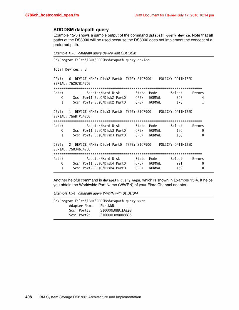
8786ch_hostconsid_open.fm Draft Document for Review July 17, 2010 10:14 pm
SDDDSM datapath queryExample 15-3 shows a sample output of the command datapath query device. Note that all paths of the DS8000 will be used because the DS8000 does not implement the concept of a preferred path.
Example 15-3 datapath query device with SDDDSM
C:\Program Files\IBM\SDDDSM>datapath query device
Total Devices : 3
DEV#: 0 DEVICE NAME: Disk2 Part0 TYPE: 2107900 POLICY: OPTIMIZEDSERIAL: 75207814703============================================================================Path# Adapter/Hard Disk State Mode Select Errors 0 Scsi Port1 Bus0/Disk2 Part0 OPEN NORMAL 203 4 1 Scsi Port2 Bus0/Disk2 Part0 OPEN NORMAL 173 1
DEV#: 1 DEVICE NAME: Disk3 Part0 TYPE: 2107900 POLICY: OPTIMIZEDSERIAL: 75ABTV14703============================================================================Path# Adapter/Hard Disk State Mode Select Errors 0 Scsi Port1 Bus0/Disk3 Part0 OPEN NORMAL 180 0 1 Scsi Port2 Bus0/Disk3 Part0 OPEN NORMAL 158 0
DEV#: 2 DEVICE NAME: Disk4 Part0 TYPE: 2107900 POLICY: OPTIMIZEDSERIAL: 75034614703============================================================================Path# Adapter/Hard Disk State Mode Select Errors 0 Scsi Port1 Bus0/Disk4 Part0 OPEN NORMAL 221 0 1 Scsi Port2 Bus0/Disk4 Part0 OPEN NORMAL 159 0
Another helpful command is datapath query wwpn, which is shown in Example 15-4. It helps you obtain the Worldwide Port Name (WWPN) of your Fibre Channel adapter.
Example 15-4 datapath query WWPN with SDDDSM
C:\Program Files\IBM\SDDDSM>datapath query wwpn Adapter Name PortWWN Scsi Port1: 210000E08B1EAE9B Scsi Port2: 210000E08B0B8836
408 IBM System Storage DS8700: Architecture and Implementation
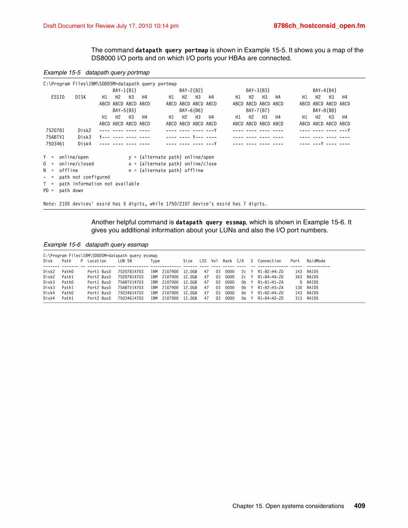
Draft Document for Review July 17, 2010 10:14 pm 8786ch_hostconsid_open.fm
The command datapath query portmap is shown in Example 15-5. It shows you a map of the DS8000 I/O ports and on which I/O ports your HBAs are connected.
Example 15-5 datapath query portmap
C:\Program Files\IBM\SDDDSM>datapath query portmap BAY-1(B1) BAY-2(B2) BAY-3(B3) BAY-4(B4) ESSID DISK H1 H2 H3 H4 H1 H2 H3 H4 H1 H2 H3 H4 H1 H2 H3 H4 ABCD ABCD ABCD ABCD ABCD ABCD ABCD ABCD ABCD ABCD ABCD ABCD ABCD ABCD ABCD ABCD BAY-5(B5) BAY-6(B6) BAY-7(B7) BAY-8(B8) H1 H2 H3 H4 H1 H2 H3 H4 H1 H2 H3 H4 H1 H2 H3 H4 ABCD ABCD ABCD ABCD ABCD ABCD ABCD ABCD ABCD ABCD ABCD ABCD ABCD ABCD ABCD ABCD 7520781 Disk2 ---- ---- ---- ---- ---- ---- ---- ---Y ---- ---- ---- ---- ---- ---- ---- ---Y 75ABTV1 Disk3 Y--- ---- ---- ---- ---- ---- Y--- ---- ---- ---- ---- ---- ---- ---- ---- ---- 7503461 Disk4 ---- ---- ---- ---- ---- ---- ---- ---Y ---- ---- ---- ---- ---- ---Y ---- ----
Y = online/open y = (alternate path) online/openO = online/closed o = (alternate path) online/closeN = offline n = (alternate path) offline- = path not configured? = path information not availablePD = path down
Note: 2105 devices' essid has 5 digits, while 1750/2107 device's essid has 7 digits.
Another helpful command is datapath query essmap, which is shown in Example 15-6. It gives you additional information about your LUNs and also the I/O port numbers.
Example 15-6 datapath query essmap
C:\Program Files\IBM\SDDDSM>datapath query essmapDisk Path P Location LUN SN Type Size LSS Vol Rank C/A S Connection Port RaidMode------- ------- -- ------------ ------------- ------------- ------ ---- ---- ----- ---- -- ------------- ----- ----------Disk2 Path0 Port1 Bus0 75207814703 IBM 2107900 12.0GB 47 03 0000 2c Y R1-B2-H4-ZD 143 RAID5Disk2 Path1 Port2 Bus0 75207814703 IBM 2107900 12.0GB 47 03 0000 2c Y R1-B4-H4-ZD 343 RAID5Disk3 Path0 Port1 Bus0 75ABTV14703 IBM 2107900 12.0GB 47 03 0000 0b Y R1-B1-H1-ZA 0 RAID5Disk3 Path1 Port2 Bus0 75ABTV14703 IBM 2107900 12.0GB 47 03 0000 0b Y R1-B2-H3-ZA 130 RAID5Disk4 Path0 Port1 Bus0 75034614703 IBM 2107900 12.0GB 47 03 0000 0e Y R1-B2-H4-ZD 143 RAID5Disk4 Path1 Port2 Bus0 75034614703 IBM 2107900 12.0GB 47 03 0000 0e Y R1-B4-H2-ZD 313 RAID5
Chapter 15. Open systems considerations 409
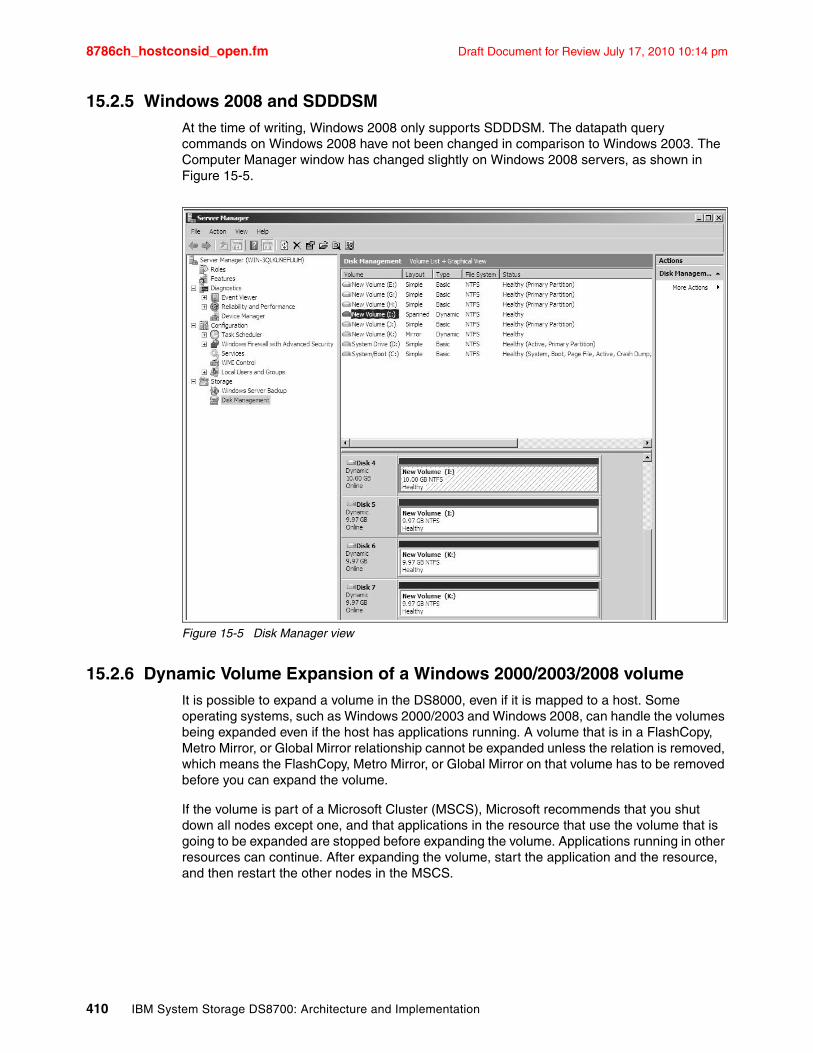
8786ch_hostconsid_open.fm Draft Document for Review July 17, 2010 10:14 pm
15.2.5 Windows 2008 and SDDDSMAt the time of writing, Windows 2008 only supports SDDDSM. The datapath query commands on Windows 2008 have not been changed in comparison to Windows 2003. The Computer Manager window has changed slightly on Windows 2008 servers, as shown in Figure 15-5.
Figure 15-5 Disk Manager view
15.2.6 Dynamic Volume Expansion of a Windows 2000/2003/2008 volumeIt is possible to expand a volume in the DS8000, even if it is mapped to a host. Some operating systems, such as Windows 2000/2003 and Windows 2008, can handle the volumes being expanded even if the host has applications running. A volume that is in a FlashCopy, Metro Mirror, or Global Mirror relationship cannot be expanded unless the relation is removed, which means the FlashCopy, Metro Mirror, or Global Mirror on that volume has to be removed before you can expand the volume.
If the volume is part of a Microsoft Cluster (MSCS), Microsoft recommends that you shut down all nodes except one, and that applications in the resource that use the volume that is going to be expanded are stopped before expanding the volume. Applications running in other resources can continue. After expanding the volume, start the application and the resource, and then restart the other nodes in the MSCS.
410 IBM System Storage DS8700: Architecture and Implementation
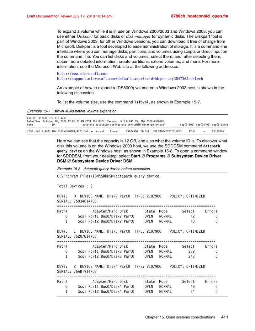
Draft Document for Review July 17, 2010 10:14 pm 8786ch_hostconsid_open.fm
To expand a volume while it is in use on Windows 2000/2003 and Windows 2008, you can use either Diskpart for basic disks or disk manager for dynamic disks. The Diskpart tool is part of Windows 2003; for other Windows versions, you can download it free of charge from Microsoft. Diskpart is a tool developed to ease administration of storage. It is a command-line interface where you can manage disks, partitions, and volumes using scripts or direct input on the command line. You can list disks and volumes, select them, and, after selecting them, obtain more detailed information, create partitions, extend volumes, and more. For more information, see the Microsoft Web site at the following addresses:
http://www.microsoft.comhttp://support.microsoft.com/default.aspx?scid=kb;en-us;304736&sd=tech
An example of how to expand a (DS8000) volume on a Windows 2003 host is shown in the following discussion.
To list the volume size, use the command lsfbvol, as shown in Example 15-7.
Example 15-7 lsfbvol -fullid before volume expansion
dscli> lsfbvol -fullid 4703Date/Time: October 18, 2007 12:02:07 PM CEST IBM DSCLI Version: 5.3.0.991 DS: IBM.2107-7520781Name ID accstate datastate configstate deviceMTM datatype extpool cap(2^30B) cap(10^9B) cap(blocks)==========================================================================================================================================ITSO_x346_3_4703 IBM.2107-7520781/4703 Online Normal Normal 2107-900 FB 512 IBM.2107-7520781/P53 12.0 - 25165824
Here we can see that the capacity is 12 GB, and also what the volume ID is. To discover what disk this volume is on the Windows 2003 host, we use the SDDDSM command datapath query device on the Windows host, as shown in Example 15-8. To open a command window for SDDDSM, from your desktop, select Start Programs Subsystem Device Driver DSM Subsystem Device Driver DSM.
Example 15-8 datapath query device before expansion
C:\Program Files\IBM\SDDDSM>datapath query device
Total Devices : 3
DEV#: 0 DEVICE NAME: Disk2 Part0 TYPE: 2107900 POLICY: OPTIMIZEDSERIAL: 75034614703============================================================================Path# Adapter/Hard Disk State Mode Select Errors 0 Scsi Port1 Bus0/Disk2 Part0 OPEN NORMAL 42 0 1 Scsi Port2 Bus0/Disk2 Part0 OPEN NORMAL 40 0
DEV#: 1 DEVICE NAME: Disk3 Part0 TYPE: 2107900 POLICY: OPTIMIZEDSERIAL: 75207814703============================================================================Path# Adapter/Hard Disk State Mode Select Errors 0 Scsi Port1 Bus0/Disk3 Part0 OPEN NORMAL 259 0 1 Scsi Port2 Bus0/Disk3 Part0 OPEN NORMAL 243 0
DEV#: 2 DEVICE NAME: Disk4 Part0 TYPE: 2107900 POLICY: OPTIMIZEDSERIAL: 75ABTV14703============================================================================Path# Adapter/Hard Disk State Mode Select Errors 0 Scsi Port1 Bus0/Disk4 Part0 OPEN NORMAL 48 0 1 Scsi Port2 Bus0/Disk4 Part0 OPEN NORMAL 34 0
Chapter 15. Open systems considerations 411
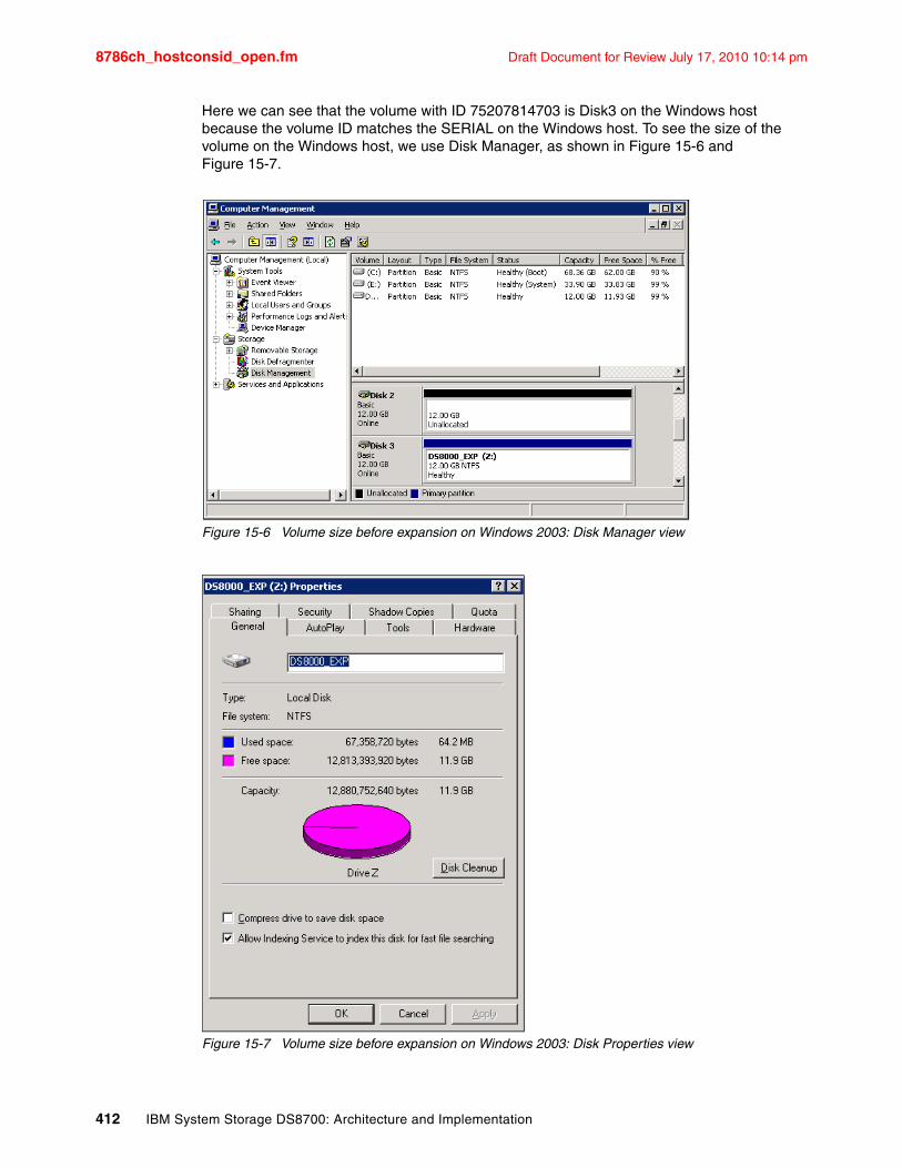
8786ch_hostconsid_open.fm Draft Document for Review July 17, 2010 10:14 pm
Here we can see that the volume with ID 75207814703 is Disk3 on the Windows host because the volume ID matches the SERIAL on the Windows host. To see the size of the volume on the Windows host, we use Disk Manager, as shown in Figure 15-6 and Figure 15-7.
Figure 15-6 Volume size before expansion on Windows 2003: Disk Manager view
Figure 15-7 Volume size before expansion on Windows 2003: Disk Properties view
412 IBM System Storage DS8700: Architecture and Implementation
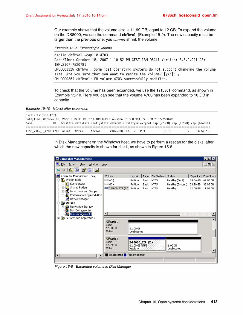
Draft Document for Review July 17, 2010 10:14 pm 8786ch_hostconsid_open.fm
Our example shows that the volume size is 11.99 GB, equal to 12 GB. To expand the volume on the DS8000, we use the command chfbvol (Example 15-9). The new capacity must be larger than the previous one; you cannot shrink the volume.
Example 15-9 Expanding a volume
dscli> chfbvol -cap 18 4703Date/Time: October 18, 2007 1:10:52 PM CEST IBM DSCLI Version: 5.3.0.991 DS: IBM.2107-7520781CMUC00332W chfbvol: Some host operating systems do not support changing the volume size. Are you sure that you want to resize the volume? [y/n]: yCMUC00026I chfbvol: FB volume 4703 successfully modified.
To check that the volume has been expanded, we use the lsfbvol command, as shown in Example 15-10. Here you can see that the volume 4703 has been expanded to 18 GB in capacity.
Example 15-10 lsfbvol after expansion
dscli> lsfbvol 4703Date/Time: October 18, 2007 1:18:38 PM CEST IBM DSCLI Version: 5.3.0.991 DS: IBM.2107-7520781Name ID accstate datastate configstate deviceMTM datatype extpool cap (2^30B) cap (10^9B) cap (blocks)====================================================================================================================ITSO_x346_3_4703 4703 Online Normal Normal 2107-900 FB 512 P53 18.0 - 37748736
In Disk Management on the Windows host, we have to perform a rescan for the disks, after which the new capacity is shown for disk1, as shown in Figure 15-8.
Figure 15-8 Expanded volume in Disk Manager
Chapter 15. Open systems considerations 413
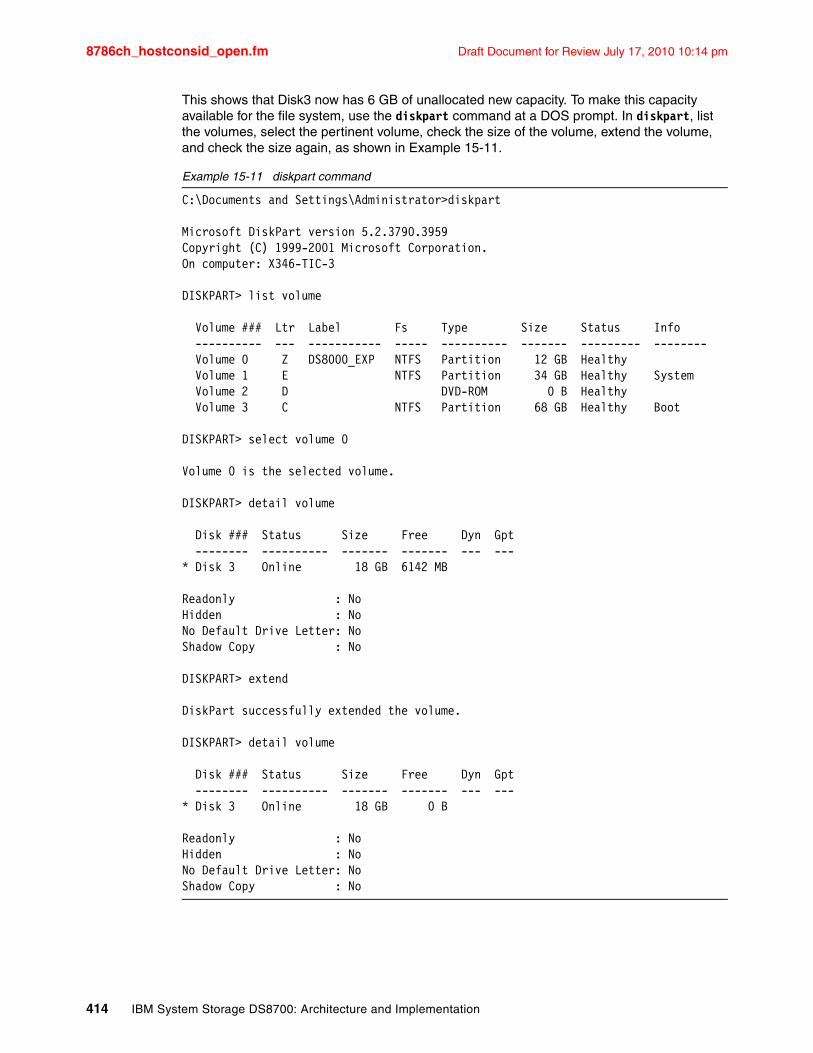
8786ch_hostconsid_open.fm Draft Document for Review July 17, 2010 10:14 pm
This shows that Disk3 now has 6 GB of unallocated new capacity. To make this capacity available for the file system, use the diskpart command at a DOS prompt. In diskpart, list the volumes, select the pertinent volume, check the size of the volume, extend the volume, and check the size again, as shown in Example 15-11.
Example 15-11 diskpart command
C:\Documents and Settings\Administrator>diskpart
Microsoft DiskPart version 5.2.3790.3959Copyright (C) 1999-2001 Microsoft Corporation.On computer: X346-TIC-3
DISKPART> list volume
Volume ### Ltr Label Fs Type Size Status Info ---------- --- ----------- ----- ---------- ------- --------- -------- Volume 0 Z DS8000_EXP NTFS Partition 12 GB Healthy Volume 1 E NTFS Partition 34 GB Healthy System Volume 2 D DVD-ROM 0 B Healthy Volume 3 C NTFS Partition 68 GB Healthy Boot
DISKPART> select volume 0
Volume 0 is the selected volume.
DISKPART> detail volume
Disk ### Status Size Free Dyn Gpt -------- ---------- ------- ------- --- ---* Disk 3 Online 18 GB 6142 MB
Readonly : NoHidden : NoNo Default Drive Letter: NoShadow Copy : No
DISKPART> extend
DiskPart successfully extended the volume.
DISKPART> detail volume
Disk ### Status Size Free Dyn Gpt -------- ---------- ------- ------- --- ---* Disk 3 Online 18 GB 0 B
Readonly : NoHidden : NoNo Default Drive Letter: NoShadow Copy : No
414 IBM System Storage DS8700: Architecture and Implementation
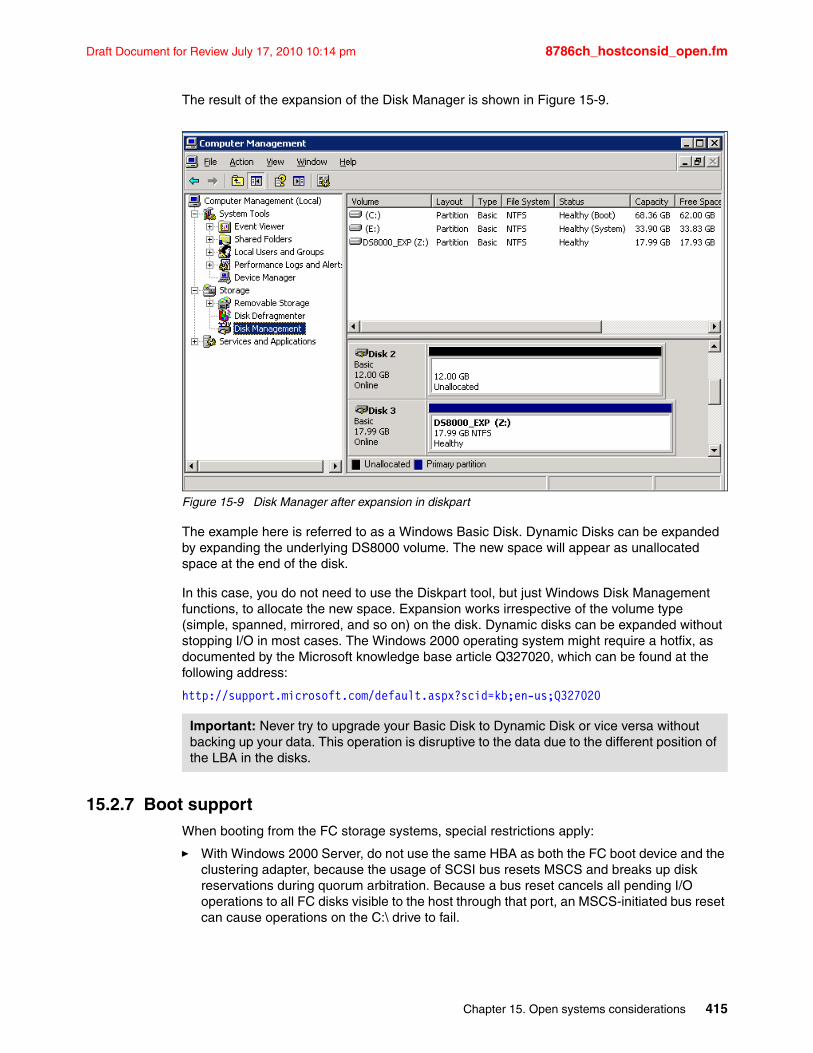
Draft Document for Review July 17, 2010 10:14 pm 8786ch_hostconsid_open.fm
The result of the expansion of the Disk Manager is shown in Figure 15-9.
Figure 15-9 Disk Manager after expansion in diskpart
The example here is referred to as a Windows Basic Disk. Dynamic Disks can be expanded by expanding the underlying DS8000 volume. The new space will appear as unallocated space at the end of the disk.
In this case, you do not need to use the Diskpart tool, but just Windows Disk Management functions, to allocate the new space. Expansion works irrespective of the volume type (simple, spanned, mirrored, and so on) on the disk. Dynamic disks can be expanded without stopping I/O in most cases. The Windows 2000 operating system might require a hotfix, as documented by the Microsoft knowledge base article Q327020, which can be found at the following address:
http://support.microsoft.com/default.aspx?scid=kb;en-us;Q327020
15.2.7 Boot supportWhen booting from the FC storage systems, special restrictions apply:
� With Windows 2000 Server, do not use the same HBA as both the FC boot device and the clustering adapter, because the usage of SCSI bus resets MSCS and breaks up disk reservations during quorum arbitration. Because a bus reset cancels all pending I/O operations to all FC disks visible to the host through that port, an MSCS-initiated bus reset can cause operations on the C:\ drive to fail.
Important: Never try to upgrade your Basic Disk to Dynamic Disk or vice versa without backing up your data. This operation is disruptive to the data due to the different position of the LBA in the disks.
Chapter 15. Open systems considerations 415
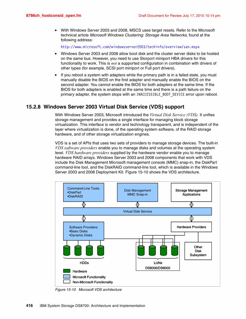
8786ch_hostconsid_open.fm Draft Document for Review July 17, 2010 10:14 pm
� With Windows Server 2003 and 2008, MSCS uses target resets. Refer to the Microsoft technical article Microsoft Windows Clustering: Storage Area Networks, found at the following address:
http://www.microsoft.com/windowsserver2003/techinfo/overview/san.mspx
� Windows Server 2003 and 2008 allow boot disk and the cluster server disks to be hosted on the same bus. However, you need to use Storport miniport HBA drivers for this functionality to work. This is not a supported configuration in combination with drivers of other types (for example, SCSI port miniport or Full port drivers).
� If you reboot a system with adapters while the primary path is in a failed state, you must manually disable the BIOS on the first adapter and manually enable the BIOS on the second adapter. You cannot enable the BIOS for both adapters at the same time. If the BIOS for both adapters is enabled at the same time and there is a path failure on the primary adapter, the system stops with an INACCESSIBLE_BOOT_DEVICE error upon reboot.
15.2.8 Windows Server 2003 Virtual Disk Service (VDS) supportWith Windows Server 2003, Microsoft introduced the Virtual Disk Service (VDS). It unifies storage management and provides a single interface for managing block storage virtualization. This interface is vendor and technology transparent, and is independent of the layer where virtualization is done, of the operating system software, of the RAID storage hardware, and of other storage virtualization engines.
VDS is a set of APIs that uses two sets of providers to manage storage devices. The built-in VDS software providers enable you to manage disks and volumes at the operating system level. VDS hardware providers supplied by the hardware vendor enable you to manage hardware RAID arrays. Windows Server 2003 and 2008 components that work with VDS include the Disk Management Microsoft management console (MMC) snap-in, the DiskPart command-line tool, and the DiskRAID command-line tool, which is available in the Windows Server 2003 and 2008 Deployment Kit. Figure 15-10 shows the VDS architecture.
Figure 15-10 Microsoft VDS architecture
Software Providers:•Basic Disks•Dynamic Disks
Disk ManagementMMC Snap-in
Hardware Providers
Virtual Disk Service
Command-Line Tools:•DiskPart•DiskRAID
Storage ManagementApplications
LUNs
OtherDisk
Subsystem
DS8000/DS6000
HDDs
Non-Microsoft Functionality
Hardware
Microsoft Functionality
Software Providers:•Basic Disks•Dynamic Disks
Disk ManagementMMC Snap-in
Hardware Providers
Virtual Disk Service
Command-Line Tools:•DiskPart•DiskRAID
Storage ManagementApplications
LUNs
OtherDisk
Subsystem
DS8000/DS6000
HDDs
Non-Microsoft Functionality
Hardware
Microsoft Functionality
416 IBM System Storage DS8700: Architecture and Implementation
Draft Document for Review July 17, 2010 10:14 pm 8786ch_hostconsid_open.fm
For a detailed description of VDS, refer to the Microsoft Windows Server 2003 Virtual Disk Service Technical Reference, found at the following address:
http://www.microsoft.com/Resources/Documentation/windowsserv/2003/all/techref/en-us/W2K3TR_vds_intro.asp
For detailed description of VDS, refer to the Microsoft Windows Server 2008 Virtual Disk Service Technical Reference, found at the following address:
http://technet.microsoft.com/en-us/windowsserver/2008/default.aspx
The DS8000 can act as a VDS hardware provider. The implementation is based on the DS Common Information Model (CIM) agent, a middleware application that provides a CIM-compliant interface. The Microsoft Virtual Disk Service uses the CIM technology to list information and manage LUNs. See the IBM System Storage DS Open Application Programming Interface Reference, GC35-0516 for information about how to install and configure VDS support.
The following sections present examples of VDS integration with advanced functions of the DS8000 storage subsystems that became possible with the implementation of the DS CIM agent.
Volume Shadow Copy ServiceThe Volume Shadow Copy Service provides a mechanism for creating consistent point-in-time copies of data, known as shadow copies. It integrates IBM System Storage FlashCopy to produce consistent shadow copies, while also coordinating with business applications, file system services, backup applications, and fast recovery solutions.
For more information, refer to the following address:
http://technet2.microsoft.com/WindowsServer/en/library/2b0d2457-b7d8-42c3-b6c9-59c145b7765f1033.mspx?mfr=true
Chapter 15. Open systems considerations 417
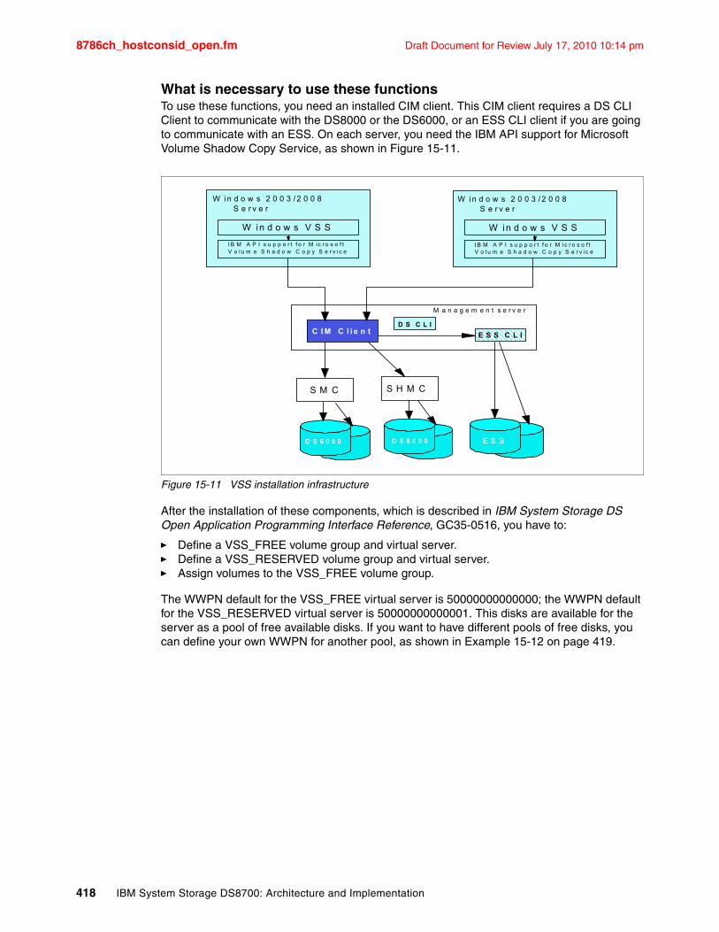
8786ch_hostconsid_open.fm Draft Document for Review July 17, 2010 10:14 pm
What is necessary to use these functionsTo use these functions, you need an installed CIM client. This CIM client requires a DS CLI Client to communicate with the DS8000 or the DS6000, or an ESS CLI client if you are going to communicate with an ESS. On each server, you need the IBM API support for Microsoft Volume Shadow Copy Service, as shown in Figure 15-11.
Figure 15-11 VSS installation infrastructure
After the installation of these components, which is described in IBM System Storage DS Open Application Programming Interface Reference, GC35-0516, you have to:
� Define a VSS_FREE volume group and virtual server.� Define a VSS_RESERVED volume group and virtual server.� Assign volumes to the VSS_FREE volume group.
The WWPN default for the VSS_FREE virtual server is 50000000000000; the WWPN default for the VSS_RESERVED virtual server is 50000000000001. This disks are available for the server as a pool of free available disks. If you want to have different pools of free disks, you can define your own WWPN for another pool, as shown in Example 15-12 on page 419.
D S 6 0 0 0 D S 8 0 0 0 E S S
M a n a g e m e n t s e r v e r
C I M C l i e n tD S C L I
E S S C L I
W in d o w s 2 0 0 3 / 2 0 0 8S e r v e r
W in d o w s V S S
I B M A P I s u p p o r t f o r M ic r o s o f t V o lu m e S h a d o w C o p y S e r v ic e
W in d o w s 2 0 0 3 / 2 0 0 8S e r v e r
W in d o w s V S S
I B M A P I s u p p o r t f o r M ic r o s o f t V o l u m e S h a d o w C o p y S e r v i c e
S M C S H M C
418 IBM System Storage DS8700: Architecture and Implementation
Draft Document for Review July 17, 2010 10:14 pm 8786ch_hostconsid_open.fm
Example 15-12 ESS Provider Configuration Tool Commands Help
C:\Program Files\IBM\ESS Hardware Provider for VSS>ibmvssconfig.exe /?
ESS Provider Configuration Tool Commands----------------------------------------ibmvssconfig.exe <command> <command arguments>
Commands:/h | /help | -? | /?showcfglistvols <all|free|vss|unassigned>add <volumeID list> (separated by spaces)rem <volumeID list> (separated by spaces)
Configuration:set targetESS <5-digit ESS Id>set user <CIMOM user name>set password <CIMOM password>set trace [0-7]set trustpassword <trustpassword>set truststore <truststore location>set usingSSL <YES | NO>set vssFreeInitiator <WWPN>set vssReservedInitiator <WWPN>set FlashCopyVer <1 | 2>set cimomPort <PORTNUM>set cimomHost <Hostname>set namespace <Namespace>
With the ibmvssconfig.exe listvols command, you can also verify what volumes are available for VSS in the VSS_FREE pool, as shown in Example 15-13.
Example 15-13 VSS list volumes at free pool
C:\Program Files\IBM\ESS Hardware Provider for VSS>ibmvssconfig.exe listvols freeListing Volumes...
LSS Volume Size Assigned to---------------------------------------------------10 003AAGXA 5.3687091E9 Bytes500000000000000011 103AAGXA 2.14748365E10 Bytes5000000000000000
Chapter 15. Open systems considerations 419
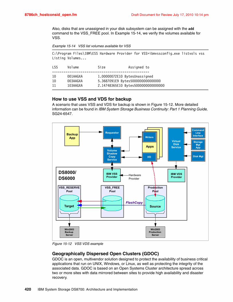
8786ch_hostconsid_open.fm Draft Document for Review July 17, 2010 10:14 pm
Also, disks that are unassigned in your disk subsystem can be assigned with the add command to the VSS_FREE pool. In Example 15-14, we verify the volumes available for VSS.
Example 15-14 VSS list volumes available for VSS
C:\Program Files\IBM\ESS Hardware Provider for VSS>ibmvssconfig.exe listvols vssListing Volumes...
LSS Volume Size Assigned to---------------------------------------------------10 001AAGXA 1.00000072E10 BytesUnassigned10 003AAGXA 5.3687091E9 Bytes500000000000000011 103AAGXA 2.14748365E10 Bytes5000000000000000
How to use VSS and VDS for backupA scenario that uses VSS and VDS for backup is shown in Figure 15-12. More detailed information can be found in IBM System Storage Business Continuity: Part 1 Planning Guide, SG24-6547.
Figure 15-12 VSS VDS example
Geographically Dispersed Open Clusters (GDOC)GDOC is an open, multivendor solution designed to protect the availability of business critical applications that run on UNIX, Windows, or Linux, as well as protecting the integrity of the associated data. GDOC is based on an Open Systems Cluster architecture spread across two or more sites with data mirrored between sites to provide high availability and disaster recovery.
VSS_FREEPool
Target
ProductionPool
DS8000/DS6000
FlashCopy
Requestor
VolumeShadow
CopyService
Win2003Production
Server
IBM VSS Provider
HardwareProvider
Source
Win2003Backup Server
VSS_RESERVEPool
BackupApp
Apps
Writers
I/O
IBM VDS Provider
CommandLine
Interface
StorageMgtApp
Disk Mgt
VirtualDisk
Service
420 IBM System Storage DS8700: Architecture and Implementation
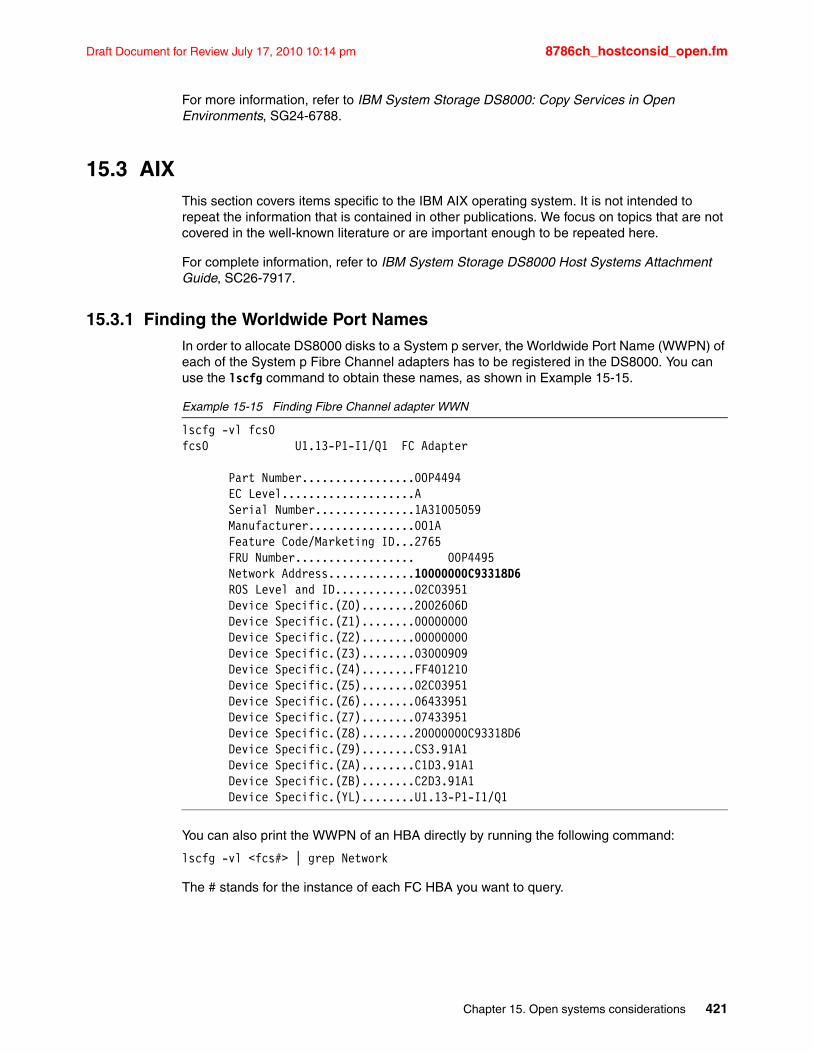
Draft Document for Review July 17, 2010 10:14 pm 8786ch_hostconsid_open.fm
For more information, refer to IBM System Storage DS8000: Copy Services in Open Environments, SG24-6788.
15.3 AIXThis section covers items specific to the IBM AIX operating system. It is not intended to repeat the information that is contained in other publications. We focus on topics that are not covered in the well-known literature or are important enough to be repeated here.
For complete information, refer to IBM System Storage DS8000 Host Systems Attachment Guide, SC26-7917.
15.3.1 Finding the Worldwide Port NamesIn order to allocate DS8000 disks to a System p server, the Worldwide Port Name (WWPN) of each of the System p Fibre Channel adapters has to be registered in the DS8000. You can use the lscfg command to obtain these names, as shown in Example 15-15.
Example 15-15 Finding Fibre Channel adapter WWN
lscfg -vl fcs0fcs0 U1.13-P1-I1/Q1 FC Adapter
Part Number.................00P4494 EC Level....................A Serial Number...............1A31005059 Manufacturer................001A Feature Code/Marketing ID...2765 FRU Number.................. 00P4495 Network Address.............10000000C93318D6 ROS Level and ID............02C03951 Device Specific.(Z0)........2002606D Device Specific.(Z1)........00000000 Device Specific.(Z2)........00000000 Device Specific.(Z3)........03000909 Device Specific.(Z4)........FF401210 Device Specific.(Z5)........02C03951 Device Specific.(Z6)........06433951 Device Specific.(Z7)........07433951 Device Specific.(Z8)........20000000C93318D6 Device Specific.(Z9)........CS3.91A1 Device Specific.(ZA)........C1D3.91A1 Device Specific.(ZB)........C2D3.91A1 Device Specific.(YL)........U1.13-P1-I1/Q1
You can also print the WWPN of an HBA directly by running the following command:
lscfg -vl <fcs#> | grep Network
The # stands for the instance of each FC HBA you want to query.
Chapter 15. Open systems considerations 421
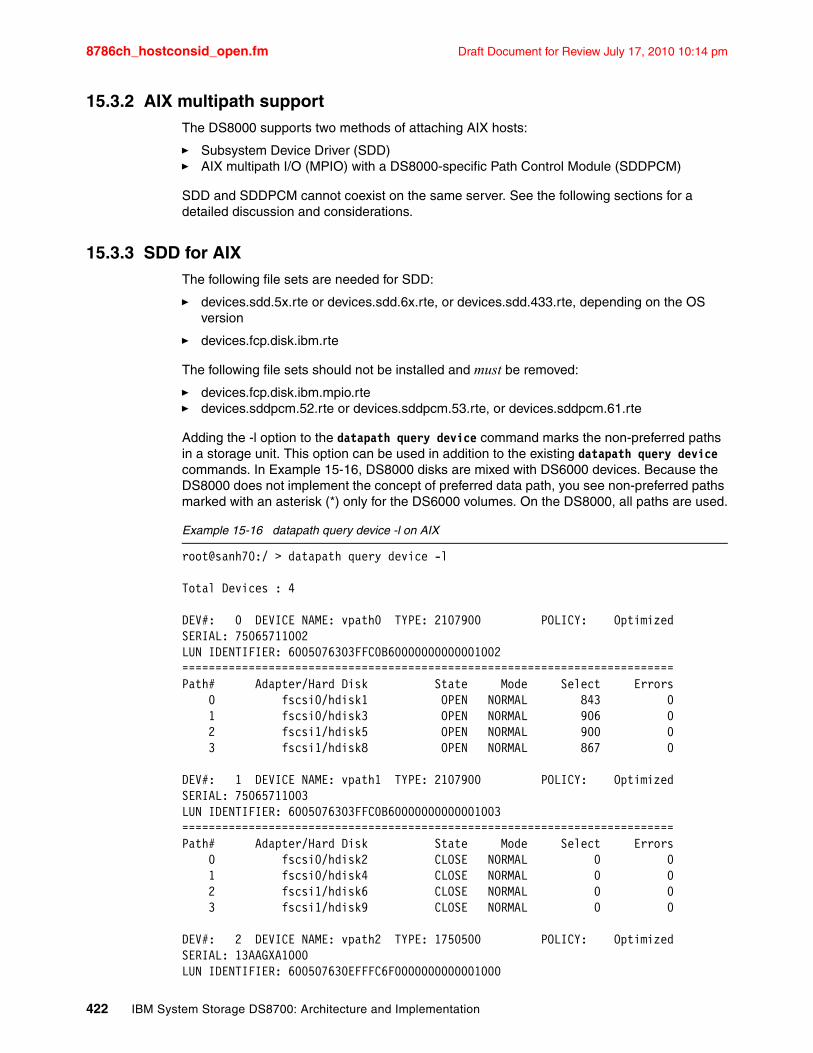
8786ch_hostconsid_open.fm Draft Document for Review July 17, 2010 10:14 pm
15.3.2 AIX multipath supportThe DS8000 supports two methods of attaching AIX hosts:
� Subsystem Device Driver (SDD)� AIX multipath I/O (MPIO) with a DS8000-specific Path Control Module (SDDPCM)
SDD and SDDPCM cannot coexist on the same server. See the following sections for a detailed discussion and considerations.
15.3.3 SDD for AIXThe following file sets are needed for SDD:
� devices.sdd.5x.rte or devices.sdd.6x.rte, or devices.sdd.433.rte, depending on the OS version
� devices.fcp.disk.ibm.rte
The following file sets should not be installed and must be removed:
� devices.fcp.disk.ibm.mpio.rte� devices.sddpcm.52.rte or devices.sddpcm.53.rte, or devices.sddpcm.61.rte
Adding the -l option to the datapath query device command marks the non-preferred paths in a storage unit. This option can be used in addition to the existing datapath query device commands. In Example 15-16, DS8000 disks are mixed with DS6000 devices. Because the DS8000 does not implement the concept of preferred data path, you see non-preferred paths marked with an asterisk (*) only for the DS6000 volumes. On the DS8000, all paths are used.
Example 15-16 datapath query device -l on AIX
root@sanh70:/ > datapath query device -l
Total Devices : 4
DEV#: 0 DEVICE NAME: vpath0 TYPE: 2107900 POLICY: OptimizedSERIAL: 75065711002LUN IDENTIFIER: 6005076303FFC0B60000000000001002==========================================================================Path# Adapter/Hard Disk State Mode Select Errors 0 fscsi0/hdisk1 OPEN NORMAL 843 0 1 fscsi0/hdisk3 OPEN NORMAL 906 0 2 fscsi1/hdisk5 OPEN NORMAL 900 0 3 fscsi1/hdisk8 OPEN NORMAL 867 0
DEV#: 1 DEVICE NAME: vpath1 TYPE: 2107900 POLICY: OptimizedSERIAL: 75065711003LUN IDENTIFIER: 6005076303FFC0B60000000000001003==========================================================================Path# Adapter/Hard Disk State Mode Select Errors 0 fscsi0/hdisk2 CLOSE NORMAL 0 0 1 fscsi0/hdisk4 CLOSE NORMAL 0 0 2 fscsi1/hdisk6 CLOSE NORMAL 0 0 3 fscsi1/hdisk9 CLOSE NORMAL 0 0
DEV#: 2 DEVICE NAME: vpath2 TYPE: 1750500 POLICY: OptimizedSERIAL: 13AAGXA1000LUN IDENTIFIER: 600507630EFFFC6F0000000000001000
422 IBM System Storage DS8700: Architecture and Implementation
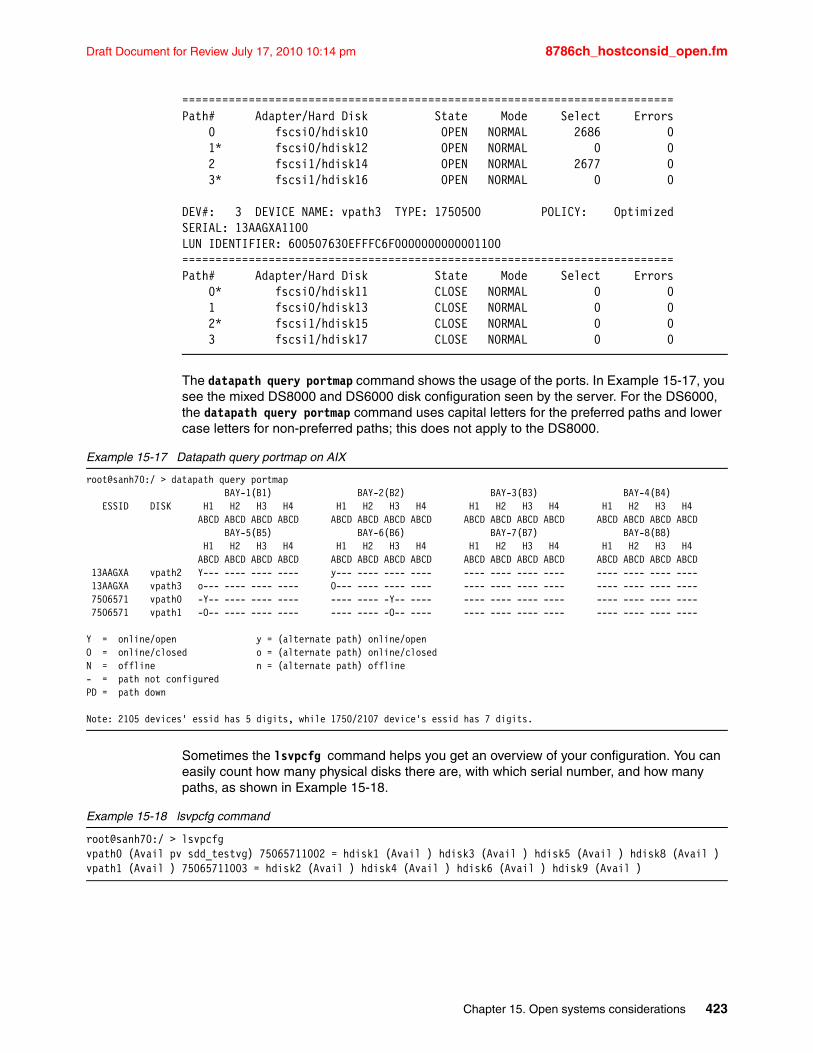
Draft Document for Review July 17, 2010 10:14 pm 8786ch_hostconsid_open.fm
==========================================================================Path# Adapter/Hard Disk State Mode Select Errors 0 fscsi0/hdisk10 OPEN NORMAL 2686 0 1* fscsi0/hdisk12 OPEN NORMAL 0 0 2 fscsi1/hdisk14 OPEN NORMAL 2677 0 3* fscsi1/hdisk16 OPEN NORMAL 0 0
DEV#: 3 DEVICE NAME: vpath3 TYPE: 1750500 POLICY: OptimizedSERIAL: 13AAGXA1100LUN IDENTIFIER: 600507630EFFFC6F0000000000001100==========================================================================Path# Adapter/Hard Disk State Mode Select Errors 0* fscsi0/hdisk11 CLOSE NORMAL 0 0 1 fscsi0/hdisk13 CLOSE NORMAL 0 0 2* fscsi1/hdisk15 CLOSE NORMAL 0 0 3 fscsi1/hdisk17 CLOSE NORMAL 0 0
The datapath query portmap command shows the usage of the ports. In Example 15-17, you see the mixed DS8000 and DS6000 disk configuration seen by the server. For the DS6000, the datapath query portmap command uses capital letters for the preferred paths and lower case letters for non-preferred paths; this does not apply to the DS8000.
Example 15-17 Datapath query portmap on AIX
root@sanh70:/ > datapath query portmap BAY-1(B1) BAY-2(B2) BAY-3(B3) BAY-4(B4) ESSID DISK H1 H2 H3 H4 H1 H2 H3 H4 H1 H2 H3 H4 H1 H2 H3 H4 ABCD ABCD ABCD ABCD ABCD ABCD ABCD ABCD ABCD ABCD ABCD ABCD ABCD ABCD ABCD ABCD BAY-5(B5) BAY-6(B6) BAY-7(B7) BAY-8(B8) H1 H2 H3 H4 H1 H2 H3 H4 H1 H2 H3 H4 H1 H2 H3 H4 ABCD ABCD ABCD ABCD ABCD ABCD ABCD ABCD ABCD ABCD ABCD ABCD ABCD ABCD ABCD ABCD 13AAGXA vpath2 Y--- ---- ---- ---- y--- ---- ---- ---- ---- ---- ---- ---- ---- ---- ---- ---- 13AAGXA vpath3 o--- ---- ---- ---- O--- ---- ---- ---- ---- ---- ---- ---- ---- ---- ---- ---- 7506571 vpath0 -Y-- ---- ---- ---- ---- ---- -Y-- ---- ---- ---- ---- ---- ---- ---- ---- ---- 7506571 vpath1 -O-- ---- ---- ---- ---- ---- -O-- ---- ---- ---- ---- ---- ---- ---- ---- ----
Y = online/open y = (alternate path) online/openO = online/closed o = (alternate path) online/closedN = offline n = (alternate path) offline- = path not configuredPD = path down
Note: 2105 devices' essid has 5 digits, while 1750/2107 device's essid has 7 digits.
Sometimes the lsvpcfg command helps you get an overview of your configuration. You can easily count how many physical disks there are, with which serial number, and how many paths, as shown in Example 15-18.
Example 15-18 lsvpcfg command
root@sanh70:/ > lsvpcfgvpath0 (Avail pv sdd_testvg) 75065711002 = hdisk1 (Avail ) hdisk3 (Avail ) hdisk5 (Avail ) hdisk8 (Avail )vpath1 (Avail ) 75065711003 = hdisk2 (Avail ) hdisk4 (Avail ) hdisk6 (Avail ) hdisk9 (Avail )
Chapter 15. Open systems considerations 423
8786ch_hostconsid_open.fm Draft Document for Review July 17, 2010 10:14 pm
There are also some other valuable features in SDD for AIX:
� Enhanced SDD configuration methods and migration
SDD has a feature in the configuration method to read the pvid from the physical disks and convert the pvid from hdisks to vpaths during the SDD vpath configuration. With this feature, you can skip the process of converting the pvid from hdisks to vpaths after configuring SDD devices. Furthermore, SDD migration can skip the pvid conversion process. This tremendously reduces the SDD migration time, especially with a large number of SDD devices and LVM configuration environment.
� Mixed volume groups with non-SDD devices in hd2vp, vp2hd, and dpovgfix
Mixed volume group is supported by three SDD LVM conversion scripts: hd2vp, vp2hd, and dpovgfix. These three SDD LVM conversion script files allow pvid conversion even if the volume group consists of SDD-supported devices and non-SDD-supported devices. Non-SDD-supported devices allowed are IBM RDAC, EMC Powerpath, NEC MPO, and Hitachi Dynamic Link Manager devices.
� Migration option for large device configuration
SDD offers an environment variable, SKIP_SDD_MIGRATION, for you to customize the SDD migration or upgrade to maximize performance. The SKIP_SDD_MIGRATION environment variable is an option available to permit the bypass of the SDD automated migration process backup, restoration, and recovery of LVM configurations and SDD device configurations. This variable can help decrease the SDD upgrade time if you choose to reboot the system after upgrading SDD.
For details about these features, see the IBM System Storage Multipath Subsystem Device Driver User’s Guide, SC30-4131.
15.3.4 AIX Multipath I/O (MPIO)AIX MPIO is an enhancement to the base OS environment that provides native support for multipath Fibre Channel storage attachment. MPIO automatically discovers, configures, and makes available every storage device path. The storage device paths are managed to provide high availability and load balancing of storage I/O. MPIO is part of the base kernel and is available for AIX 5L V5.2 and V5.3.
The base functionality of MPIO is limited. It provides an interface for vendor-specific Path Control Modules (PCMs) that allow for implementation of advanced algorithms.
IBM provides a PCM for DS8000 that enhances MPIO with all the features of the original SDD. It is called SDDPCM and is available from the SDD download site.
For basic information about MPIO, see the online guide AIX 5L System Management Concepts: Operating System and Devices from the AIX documentation Web site at the following address:
http://publib16.boulder.ibm.com/pseries/en_US/aixbman/admnconc/hotplug_mgmt.htm#mpioconcepts
The management of MPIO devices is described in the online guide System Management Guide: Operating System and Devices for AIX 5L from the AIX documentation Web site at the following address:
http://publib16.boulder.ibm.com/pseries/en_US/aixbman/baseadmn/manage_mpio.htm
424 IBM System Storage DS8700: Architecture and Implementation
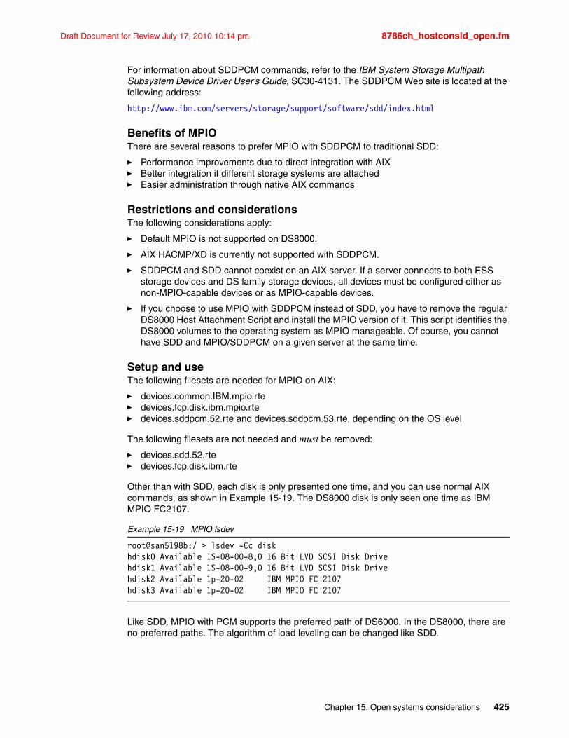
Draft Document for Review July 17, 2010 10:14 pm 8786ch_hostconsid_open.fm
For information about SDDPCM commands, refer to the IBM System Storage Multipath Subsystem Device Driver User’s Guide, SC30-4131. The SDDPCM Web site is located at the following address:
http://www.ibm.com/servers/storage/support/software/sdd/index.html
Benefits of MPIOThere are several reasons to prefer MPIO with SDDPCM to traditional SDD:
� Performance improvements due to direct integration with AIX� Better integration if different storage systems are attached� Easier administration through native AIX commands
Restrictions and considerationsThe following considerations apply:
� Default MPIO is not supported on DS8000.
� AIX HACMP/XD is currently not supported with SDDPCM.
� SDDPCM and SDD cannot coexist on an AIX server. If a server connects to both ESS storage devices and DS family storage devices, all devices must be configured either as non-MPIO-capable devices or as MPIO-capable devices.
� If you choose to use MPIO with SDDPCM instead of SDD, you have to remove the regular DS8000 Host Attachment Script and install the MPIO version of it. This script identifies the DS8000 volumes to the operating system as MPIO manageable. Of course, you cannot have SDD and MPIO/SDDPCM on a given server at the same time.
Setup and useThe following filesets are needed for MPIO on AIX:
� devices.common.IBM.mpio.rte� devices.fcp.disk.ibm.mpio.rte� devices.sddpcm.52.rte and devices.sddpcm.53.rte, depending on the OS level
The following filesets are not needed and must be removed:
� devices.sdd.52.rte� devices.fcp.disk.ibm.rte
Other than with SDD, each disk is only presented one time, and you can use normal AIX commands, as shown in Example 15-19. The DS8000 disk is only seen one time as IBM MPIO FC2107.
Example 15-19 MPIO lsdev
root@san5198b:/ > lsdev -Cc diskhdisk0 Available 1S-08-00-8,0 16 Bit LVD SCSI Disk Drivehdisk1 Available 1S-08-00-9,0 16 Bit LVD SCSI Disk Drivehdisk2 Available 1p-20-02 IBM MPIO FC 2107hdisk3 Available 1p-20-02 IBM MPIO FC 2107
Like SDD, MPIO with PCM supports the preferred path of DS6000. In the DS8000, there are no preferred paths. The algorithm of load leveling can be changed like SDD.
Chapter 15. Open systems considerations 425
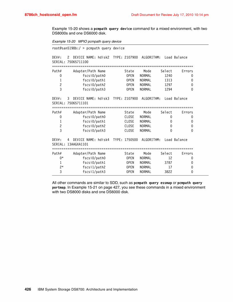
8786ch_hostconsid_open.fm Draft Document for Review July 17, 2010 10:14 pm
Example 15-20 shows a pcmpath query device command for a mixed environment, with two DS8000s and one DS6000 disk.
Example 15-20 MPIO pcmpath query device
root@san5198b:/ > pcmpath query device
DEV#: 2 DEVICE NAME: hdisk2 TYPE: 2107900 ALGORITHM: Load BalanceSERIAL: 75065711100==========================================================================Path# Adapter/Path Name State Mode Select Errors 0 fscsi0/path0 OPEN NORMAL 1240 0 1 fscsi0/path1 OPEN NORMAL 1313 0 2 fscsi0/path2 OPEN NORMAL 1297 0 3 fscsi0/path3 OPEN NORMAL 1294 0
DEV#: 3 DEVICE NAME: hdisk3 TYPE: 2107900 ALGORITHM: Load BalanceSERIAL: 75065711101==========================================================================Path# Adapter/Path Name State Mode Select Errors 0 fscsi0/path0 CLOSE NORMAL 0 0 1 fscsi0/path1 CLOSE NORMAL 0 0 2 fscsi0/path2 CLOSE NORMAL 0 0 3 fscsi0/path3 CLOSE NORMAL 0 0
DEV#: 4 DEVICE NAME: hdisk4 TYPE: 1750500 ALGORITHM: Load BalanceSERIAL: 13AAGXA1101==========================================================================Path# Adapter/Path Name State Mode Select Errors 0* fscsi0/path0 OPEN NORMAL 12 0 1 fscsi0/path1 OPEN NORMAL 3787 0 2* fscsi1/path2 OPEN NORMAL 17 0 3 fscsi1/path3 OPEN NORMAL 3822 0
All other commands are similar to SDD, such as pcmpath query essmap or pcmpath query portmap. In Example 15-21 on page 427, you see these commands in a mixed environment with two DS8000 disks and one DS6000 disk.
426 IBM System Storage DS8700: Architecture and Implementation
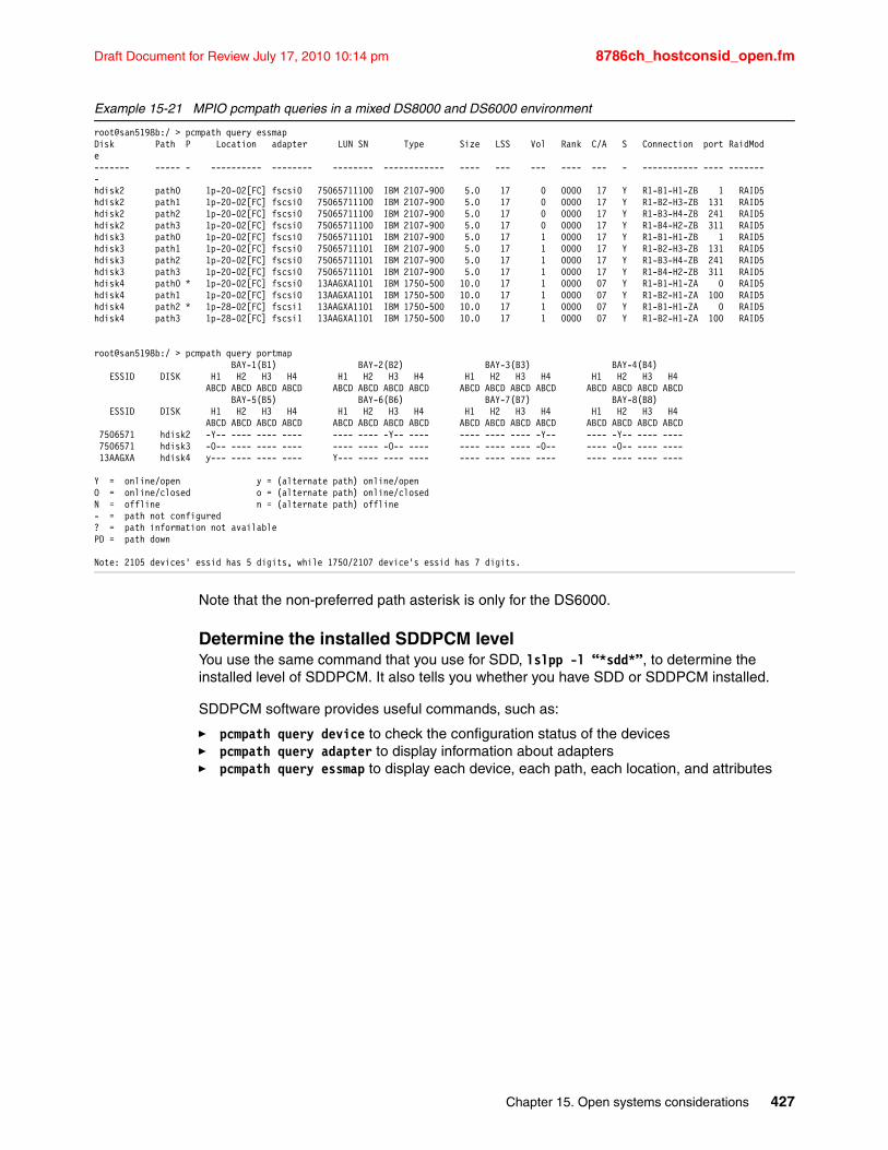
Draft Document for Review July 17, 2010 10:14 pm 8786ch_hostconsid_open.fm
Example 15-21 MPIO pcmpath queries in a mixed DS8000 and DS6000 environment
root@san5198b:/ > pcmpath query essmapDisk Path P Location adapter LUN SN Type Size LSS Vol Rank C/A S Connection port RaidMode------- ----- - ---------- -------- -------- ------------ ---- --- --- ---- --- - ----------- ---- --------hdisk2 path0 1p-20-02[FC] fscsi0 75065711100 IBM 2107-900 5.0 17 0 0000 17 Y R1-B1-H1-ZB 1 RAID5hdisk2 path1 1p-20-02[FC] fscsi0 75065711100 IBM 2107-900 5.0 17 0 0000 17 Y R1-B2-H3-ZB 131 RAID5hdisk2 path2 1p-20-02[FC] fscsi0 75065711100 IBM 2107-900 5.0 17 0 0000 17 Y R1-B3-H4-ZB 241 RAID5hdisk2 path3 1p-20-02[FC] fscsi0 75065711100 IBM 2107-900 5.0 17 0 0000 17 Y R1-B4-H2-ZB 311 RAID5hdisk3 path0 1p-20-02[FC] fscsi0 75065711101 IBM 2107-900 5.0 17 1 0000 17 Y R1-B1-H1-ZB 1 RAID5hdisk3 path1 1p-20-02[FC] fscsi0 75065711101 IBM 2107-900 5.0 17 1 0000 17 Y R1-B2-H3-ZB 131 RAID5hdisk3 path2 1p-20-02[FC] fscsi0 75065711101 IBM 2107-900 5.0 17 1 0000 17 Y R1-B3-H4-ZB 241 RAID5hdisk3 path3 1p-20-02[FC] fscsi0 75065711101 IBM 2107-900 5.0 17 1 0000 17 Y R1-B4-H2-ZB 311 RAID5hdisk4 path0 * 1p-20-02[FC] fscsi0 13AAGXA1101 IBM 1750-500 10.0 17 1 0000 07 Y R1-B1-H1-ZA 0 RAID5hdisk4 path1 1p-20-02[FC] fscsi0 13AAGXA1101 IBM 1750-500 10.0 17 1 0000 07 Y R1-B2-H1-ZA 100 RAID5hdisk4 path2 * 1p-28-02[FC] fscsi1 13AAGXA1101 IBM 1750-500 10.0 17 1 0000 07 Y R1-B1-H1-ZA 0 RAID5hdisk4 path3 1p-28-02[FC] fscsi1 13AAGXA1101 IBM 1750-500 10.0 17 1 0000 07 Y R1-B2-H1-ZA 100 RAID5
root@san5198b:/ > pcmpath query portmap BAY-1(B1) BAY-2(B2) BAY-3(B3) BAY-4(B4) ESSID DISK H1 H2 H3 H4 H1 H2 H3 H4 H1 H2 H3 H4 H1 H2 H3 H4 ABCD ABCD ABCD ABCD ABCD ABCD ABCD ABCD ABCD ABCD ABCD ABCD ABCD ABCD ABCD ABCD BAY-5(B5) BAY-6(B6) BAY-7(B7) BAY-8(B8) ESSID DISK H1 H2 H3 H4 H1 H2 H3 H4 H1 H2 H3 H4 H1 H2 H3 H4 ABCD ABCD ABCD ABCD ABCD ABCD ABCD ABCD ABCD ABCD ABCD ABCD ABCD ABCD ABCD ABCD 7506571 hdisk2 -Y-- ---- ---- ---- ---- ---- -Y-- ---- ---- ---- ---- -Y-- ---- -Y-- ---- ---- 7506571 hdisk3 -O-- ---- ---- ---- ---- ---- -O-- ---- ---- ---- ---- -O-- ---- -O-- ---- ---- 13AAGXA hdisk4 y--- ---- ---- ---- Y--- ---- ---- ---- ---- ---- ---- ---- ---- ---- ---- ----
Y = online/open y = (alternate path) online/openO = online/closed o = (alternate path) online/closedN = offline n = (alternate path) offline- = path not configured? = path information not availablePD = path down
Note: 2105 devices' essid has 5 digits, while 1750/2107 device's essid has 7 digits.
Note that the non-preferred path asterisk is only for the DS6000.
Determine the installed SDDPCM levelYou use the same command that you use for SDD, lslpp -l “*sdd*”, to determine the installed level of SDDPCM. It also tells you whether you have SDD or SDDPCM installed.
SDDPCM software provides useful commands, such as:
� pcmpath query device to check the configuration status of the devices� pcmpath query adapter to display information about adapters� pcmpath query essmap to display each device, each path, each location, and attributes
Chapter 15. Open systems considerations 427
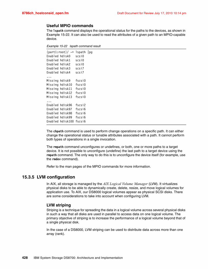
8786ch_hostconsid_open.fm Draft Document for Review July 17, 2010 10:14 pm
Useful MPIO commandsThe lspath command displays the operational status for the paths to the devices, as shown in Example 15-22. It can also be used to read the attributes of a given path to an MPIO-capable device.
Example 15-22 lspath command result
{part1:root}/ -> lspath |pgEnabled hdisk0 scsi0Enabled hdisk1 scsi0Enabled hdisk2 scsi0Enabled hdisk3 scsi7Enabled hdisk4 scsi7...Missing hdisk9 fscsi0Missing hdisk10 fscsi0Missing hdisk11 fscsi0Missing hdisk12 fscsi0Missing hdisk13 fscsi0...Enabled hdisk96 fscsi2Enabled hdisk97 fscsi6Enabled hdisk98 fscsi6Enabled hdisk99 fscsi6Enabled hdisk100 fscsi6
The chpath command is used to perform change operations on a specific path. It can either change the operational status or tunable attributes associated with a path. It cannot perform both types of operations in a single invocation.
The rmpath command unconfigures or undefines, or both, one or more paths to a target device. It is not possible to unconfigure (undefine) the last path to a target device using the rmpath command. The only way to do this is to unconfigure the device itself (for example, use the rmdev command).
Refer to the man pages of the MPIO commands for more information.
15.3.5 LVM configurationIn AIX, all storage is managed by the AIX Logical Volume Manager (LVM). It virtualizes physical disks to be able to dynamically create, delete, resize, and move logical volumes for application use. To AIX, our DS8000 logical volumes appear as physical SCSI disks. There are some considerations to take into account when configuring LVM.
LVM stripingStriping is a technique for spreading the data in a logical volume across several physical disks in such a way that all disks are used in parallel to access data on one logical volume. The primary objective of striping is to increase the performance of a logical volume beyond that of a single physical disk.
In the case of a DS8000, LVM striping can be used to distribute data across more than one array (rank).
428 IBM System Storage DS8700: Architecture and Implementation
Draft Document for Review July 17, 2010 10:14 pm 8786ch_hostconsid_open.fm
Inter-physical volume allocation policyThis is one of the simplest and most recommended methods to spread the workload accesses across physical resources. Most Logical Volume Managers offer inter-disk allocation policies for Logical Volumes. Other terms are “physical partition spreading” or “poor man’s striping”.
With AIX LVM, one or more Volume Groups can be created using the physical disks (which are Logical Volumes on the DS8000). LVM organizes Volume Group space in so-called physical partitions (PP). We recommend physical partition allocation for the Logical Volumes in round-robin order. The first free extent is allocated from the first available physical volume. The next free extent is allocated from the next available physical volume and so on. If the physical volumes have the same size, optimal I/O load distribution among the available physical volumes will be achieved.
LVM mirroringLVM has the capability to mirror logical volumes across several physical disks. This improves availability, because in case a disk fails, there is another disk with the same data. When creating mirrored copies of logical volumes, make sure that the copies are indeed distributed across separate disks.
With the introduction of SAN technology, LVM mirroring can even provide protection against a site failure. Using longwave Fibre Channel connections, a mirror can be stretched up to a 10 km distance.
Impact of DS8000 Storage Pool StripingStarting with DS8000 Licensed Machine Code 5.3.xx.xx, it is possible to stripe the extents of a DS8000 Logical Volume across multiple RAID arrays. DS8000 Storage Pool Striping will improve throughput for some workloads. It is performed on a 1 GB granularity, so it will generally benefit random workloads more than sequential ones.
If you are already using a host-based striping method (for example, LVM Striping or DB2 database container striping), there is no need to use Storage Pool Striping. However, it is possible. You should then combine the wide stripes on DS8000 with small granularity stripes on the host. The recommended size for these is usually between 8 and 64 MB. If large stripes on both DS8000 and attached host interfere with each other, I/O performance may be affected.
Refer to Chapter 7, “Performance” on page 139 for a more detailed discussion of methods to optimize performance.
15.3.6 AIX access methods for I/OAIX provides several modes to access data in a file system. It can be important for performance to choose the right access method.
Synchronous I/OSynchronous I/O occurs while you wait. An application’s processing cannot continue until the I/O operation is complete. This is a very secure and traditional way to handle data. It ensures consistency at all times, but can be a major performance inhibitor. It also does not allow the operating system to take full advantage of functions of modern storage devices, such as queuing, command reordering, and so on.
Chapter 15. Open systems considerations 429
8786ch_hostconsid_open.fm Draft Document for Review July 17, 2010 10:14 pm
Asynchronous I/OAsynchronous I/O operations run in the background and do not block user applications. This improves performance, because I/O and application processing run simultaneously. Many applications, such as databases and file servers, take advantage of the ability to overlap processing and I/O. They have to take measures to ensure data consistency, though. You can configure, remove, and change asynchronous I/O for each device by using the chdev command or SMIT.
Direct I/OAn alternative I/O technique called Direct I/O bypasses the Virtual Memory Manager (VMM) altogether and transfers data directly from the user’s buffer to the disk and from the disk to the user’s buffer. The concept behind this is similar to raw I/O in the sense that they both bypass caching at the file system level. This reduces the CPU’s processing impact and makes more memory available to the database instance, which can make more efficient use of it for its own purposes.
Direct I/O is provided as a file system option in JFS2. It can be used either by mounting the corresponding file system with the mount –o dio command, or by opening a file with the O_DIRECT flag specified in the open() system call. When a file system is mounted with the –o dio option, all files in the file system use Direct I/O by default.
Direct I/O benefits applications that have their own caching algorithms by eliminating the impact of copying data twice, first between the disk and the OS buffer cache, and then from the buffer cache to the application’s memory.
For applications that benefit from the operating system cache, do not use Direct I/O, because all I/O operations are synchronous. Direct I/O also bypasses the JFS2 read-ahead. Read-ahead can provide a significant performance boost for sequentially accessed files.
Concurrent I/OIn 2003, IBM introduced a new file system feature called Concurrent I/O (CIO) for JFS2. It includes all the advantages of Direct I/O and also relieves the serialization of write accesses. It improves performance for many environments, particularly commercial relational databases. In many cases, the database performance achieved using Concurrent I/O with JFS2 is comparable to that obtained by using raw logical volumes.
A method for enabling the concurrent I/O mode is to use the mount -o cio command when mounting a file system.
15.3.7 Dynamic Volume ExpansionStarting with IBM DS8000 Licensed Machine Code 5.3.xx.xx, it is possible to expand a logical volume in size without taking the volume offline. Additional actions are required on the attached host to make use of the extra space. This section describes the required AIX Logical Volume Manager (LVM) tasks.
Tip: If the number of asynchronous I/O (AIO) requests is high, then we recommend that you increase maxservers to approximately the number of simultaneous I/Os that there might be. In most cases, it is better to leave the minservers parameter at the default value, because the AIO kernel extension will generate additional servers if needed. By looking at the CPU utilization of the AIO servers, if the utilization is even across all of them, that means that they are all being used; you might want to try increasing their number in this case. Running pstat -a allows you to see the AIO servers by name, and running ps -k shows them to you as the name kproc.
430 IBM System Storage DS8700: Architecture and Implementation
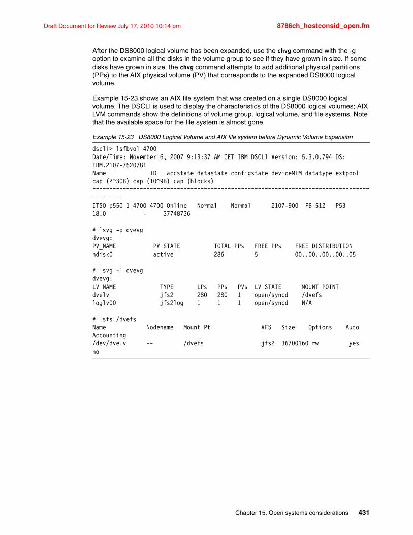
Draft Document for Review July 17, 2010 10:14 pm 8786ch_hostconsid_open.fm
After the DS8000 logical volume has been expanded, use the chvg command with the -g option to examine all the disks in the volume group to see if they have grown in size. If some disks have grown in size, the chvg command attempts to add additional physical partitions (PPs) to the AIX physical volume (PV) that corresponds to the expanded DS8000 logical volume.
Example 15-23 shows an AIX file system that was created on a single DS8000 logical volume. The DSCLI is used to display the characteristics of the DS8000 logical volumes; AIX LVM commands show the definitions of volume group, logical volume, and file systems. Note that the available space for the file system is almost gone.
Example 15-23 DS8000 Logical Volume and AIX file system before Dynamic Volume Expansion
dscli> lsfbvol 4700Date/Time: November 6, 2007 9:13:37 AM CET IBM DSCLI Version: 5.3.0.794 DS: IBM.2107-7520781Name ID accstate datastate configstate deviceMTM datatype extpool cap (2^30B) cap (10^9B) cap (blocks)==========================================================================================ITSO_p550_1_4700 4700 Online Normal Normal 2107-900 FB 512 P53 18.0 - 37748736
# lsvg -p dvevgdvevg:PV_NAME PV STATE TOTAL PPs FREE PPs FREE DISTRIBUTIONhdisk0 active 286 5 00..00..00..00..05
# lsvg -l dvevgdvevg:LV NAME TYPE LPs PPs PVs LV STATE MOUNT POINTdvelv jfs2 280 280 1 open/syncd /dvefsloglv00 jfs2log 1 1 1 open/syncd N/A
# lsfs /dvefsName Nodename Mount Pt VFS Size Options Auto Accounting/dev/dvelv -- /dvefs jfs2 36700160 rw yes no
Chapter 15. Open systems considerations 431
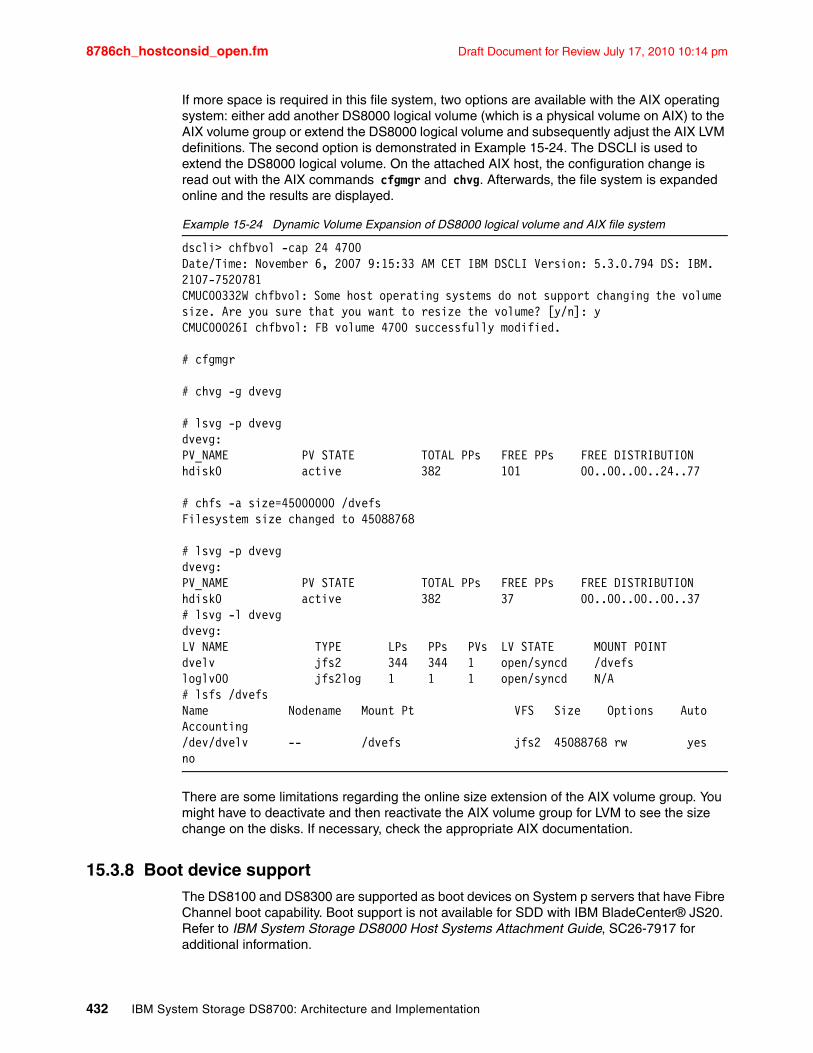
8786ch_hostconsid_open.fm Draft Document for Review July 17, 2010 10:14 pm
If more space is required in this file system, two options are available with the AIX operating system: either add another DS8000 logical volume (which is a physical volume on AIX) to the AIX volume group or extend the DS8000 logical volume and subsequently adjust the AIX LVM definitions. The second option is demonstrated in Example 15-24. The DSCLI is used to extend the DS8000 logical volume. On the attached AIX host, the configuration change is read out with the AIX commands cfgmgr and chvg. Afterwards, the file system is expanded online and the results are displayed.
Example 15-24 Dynamic Volume Expansion of DS8000 logical volume and AIX file system
dscli> chfbvol -cap 24 4700Date/Time: November 6, 2007 9:15:33 AM CET IBM DSCLI Version: 5.3.0.794 DS: IBM.2107-7520781CMUC00332W chfbvol: Some host operating systems do not support changing the volume size. Are you sure that you want to resize the volume? [y/n]: yCMUC00026I chfbvol: FB volume 4700 successfully modified.
# cfgmgr
# chvg -g dvevg
# lsvg -p dvevgdvevg:PV_NAME PV STATE TOTAL PPs FREE PPs FREE DISTRIBUTIONhdisk0 active 382 101 00..00..00..24..77
# chfs -a size=45000000 /dvefsFilesystem size changed to 45088768
# lsvg -p dvevgdvevg:PV_NAME PV STATE TOTAL PPs FREE PPs FREE DISTRIBUTIONhdisk0 active 382 37 00..00..00..00..37# lsvg -l dvevgdvevg:LV NAME TYPE LPs PPs PVs LV STATE MOUNT POINTdvelv jfs2 344 344 1 open/syncd /dvefsloglv00 jfs2log 1 1 1 open/syncd N/A# lsfs /dvefsName Nodename Mount Pt VFS Size Options Auto Accounting/dev/dvelv -- /dvefs jfs2 45088768 rw yes no
There are some limitations regarding the online size extension of the AIX volume group. You might have to deactivate and then reactivate the AIX volume group for LVM to see the size change on the disks. If necessary, check the appropriate AIX documentation.
15.3.8 Boot device supportThe DS8100 and DS8300 are supported as boot devices on System p servers that have Fibre Channel boot capability. Boot support is not available for SDD with IBM BladeCenter® JS20. Refer to IBM System Storage DS8000 Host Systems Attachment Guide, SC26-7917 for additional information.
432 IBM System Storage DS8700: Architecture and Implementation
Draft Document for Review July 17, 2010 10:14 pm 8786ch_hostconsid_open.fm
15.4 LinuxLinux is an open source, UNIX-like kernel, originally created by Linus Torvalds. The term Linux is often used to mean the whole operating system of GNU/Linux. The Linux kernel, along with the tools and software needed to run an operating system, are maintained by a loosely organized community of thousands of (mostly) volunteer programmers.
There are several organizations (distributors) that bundle the Linux kernel, tools, and applications to form a distribution, a package that can be downloaded or purchased and installed on a computer. Some of these distributions are commercial; others are not.
15.4.1 Support issues that distinguish Linux from other operating systemsLinux is different from the other proprietary operating systems in many ways:
� There is no one person or organization that can be held responsible or called for support.
� Depending on the target group, the distributions differ largely in the kind of support that is available.
� Linux is available for almost all computer architectures.
� Linux is rapidly changing.
All these factors make it difficult to promise and provide generic support for Linux. As a consequence, IBM has decided on a support strategy that limits the uncertainty and the amount of testing.
IBM only supports these Linux distributions that are targeted at enterprise clients:
� Red Hat Enterprise Linux� SUSE Linux Enterprise Server� Asianux (Red Flag Linux)
These distributions have release cycles of about one year, are maintained for five years, and require you to sign a support contract with the distributor. They also have a schedule for regular updates. These factors mitigate the issues listed previously. The limited number of supported distributions also allows IBM to work closely with the vendors to ensure interoperability and support. Details about the supported Linux distributions can be found in the System Storage Interoperation Center (SSIC) at the following address:
http://www.ibm.com/systems/support/storage/config/ssic/displayesssearchwithoutjs.wss?start_over=yes
There are exceptions to this strategy when the market demand justifies the test and support effort.
15.4.2 Reference materialThere is a wealth of information available that helps you set up your Linux server to attach it to a DS8000 storage subsystem.
The DS8000 Host Systems Attachment GuideThe IBM System Storage DS8000 Host Systems Attachment Guide, SC26-7917 provides instructions to prepare an Intel IA-32-based machine for DS8000 attachment, including:
� How to install and configure the FC HBA� Peculiarities of the Linux SCSI subsystem� How to prepare a system that boots from the DS8000
Chapter 15. Open systems considerations 433
8786ch_hostconsid_open.fm Draft Document for Review July 17, 2010 10:14 pm
This guide is not detailed with respect to the configuration and installation of the FC HBA drivers.
Implementing Linux with IBM disk storageThe IBM Redbooks publication Implementing Linux with IBM Disk Storage, SG24-6261 covers several hardware platforms and storage systems. It is not yet updated with information about the DS8000. The details provided for the attachment to the IBM Enterprise Storage Server (ESS 2105) are mostly valid for the DS8000 as well. Read it for information regarding storage attachment:
� Through FCP to an IBM System z system running Linux� To an IBM System p running Linux� To an IBM BladeCenter running Linux
You can download this book from the following address:
http://publib-b.boulder.ibm.com/abstracts/sg246261.html
Linux with System z and ESS: EssentialsThe IBM Redbooks publication Linux with zSeries and ESS: Essentials, SG24-7025 provides detailed information about Linux on System z and the ESS. It also describes in detail how the Fibre Channel (FCP) attachment of a storage system to Linux on System z works. It does not, however, describe the actual implementation. You can download this book from the following address:
http://www.redbooks.ibm.com/redbooks/pdfs/sg247025.pdf
Getting Started with zSeries Fibre Channel ProtocolThe IBM Redpapers publication Getting Started with zSeries Fibre Channel Protocol, REDP-0205 is an older publication (last updated in 2003) that provides an overview of Fibre Channel (FC) topologies and terminology, and instructions to attach open systems (Fixed Block) storage devices using FCP to an IBM System z running Linux. It can be found at the following address:
http://www.redbooks.ibm.com/redpapers/pdfs/redp0205.pdf
Other sources of informationNumerous hints and tips, especially for Linux on System z, are available on the IBM Redbooks Technotes page at the following address:
http://www.redbooks.ibm.com/redbooks.nsf/tips/
IBM System z dedicates its own Web page to storage attachment using FCP at the following address:
http://www-03.ibm.com/systems/z/connectivity/products/
The IBM System z Connectivity Handbook, SG24-5444 discusses the connectivity options available for use within and beyond the data center for IBM System z9 and zSeries® servers. There is an extra section for FC attachment. You can download this book at the following address:
http://www.redbooks.ibm.com/redbooks.nsf/RedbookAbstracts/sg245444.html?Open
The white paper ESS Attachment to United Linux 1 (IA-32) is available at the following address:
http://www.ibm.com/support/docview.wss?uid=tss1td101235
434 IBM System Storage DS8700: Architecture and Implementation
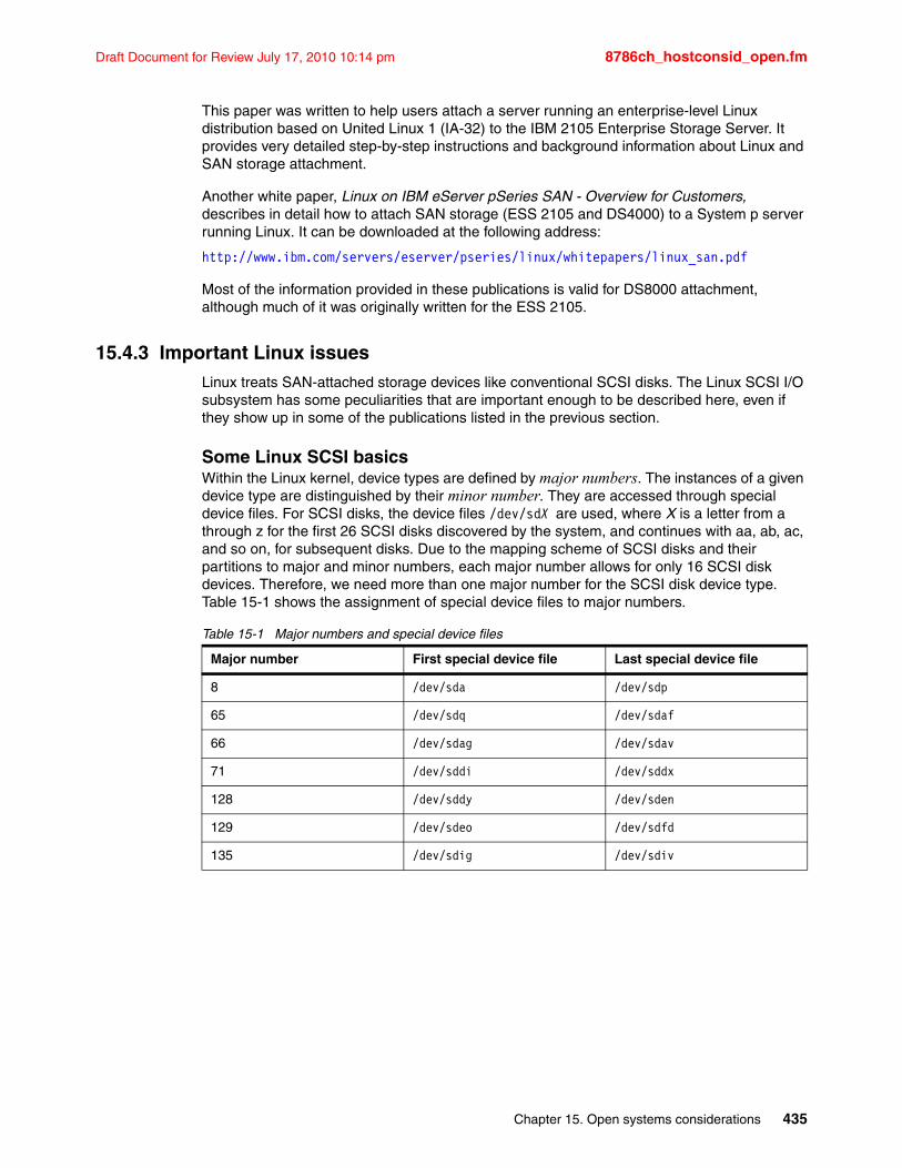
Draft Document for Review July 17, 2010 10:14 pm 8786ch_hostconsid_open.fm
This paper was written to help users attach a server running an enterprise-level Linux distribution based on United Linux 1 (IA-32) to the IBM 2105 Enterprise Storage Server. It provides very detailed step-by-step instructions and background information about Linux and SAN storage attachment.
Another white paper, Linux on IBM eServer pSeries SAN - Overview for Customers, describes in detail how to attach SAN storage (ESS 2105 and DS4000) to a System p server running Linux. It can be downloaded at the following address:
http://www.ibm.com/servers/eserver/pseries/linux/whitepapers/linux_san.pdf
Most of the information provided in these publications is valid for DS8000 attachment, although much of it was originally written for the ESS 2105.
15.4.3 Important Linux issuesLinux treats SAN-attached storage devices like conventional SCSI disks. The Linux SCSI I/O subsystem has some peculiarities that are important enough to be described here, even if they show up in some of the publications listed in the previous section.
Some Linux SCSI basicsWithin the Linux kernel, device types are defined by major numbers. The instances of a given device type are distinguished by their minor number. They are accessed through special device files. For SCSI disks, the device files /dev/sdX are used, where X is a letter from a through z for the first 26 SCSI disks discovered by the system, and continues with aa, ab, ac, and so on, for subsequent disks. Due to the mapping scheme of SCSI disks and their partitions to major and minor numbers, each major number allows for only 16 SCSI disk devices. Therefore, we need more than one major number for the SCSI disk device type. Table 15-1 shows the assignment of special device files to major numbers.
Table 15-1 Major numbers and special device files
Major number First special device file Last special device file
8 /dev/sda /dev/sdp
65 /dev/sdq /dev/sdaf
66 /dev/sdag /dev/sdav
71 /dev/sddi /dev/sddx
128 /dev/sddy /dev/sden
129 /dev/sdeo /dev/sdfd
135 /dev/sdig /dev/sdiv
Chapter 15. Open systems considerations 435
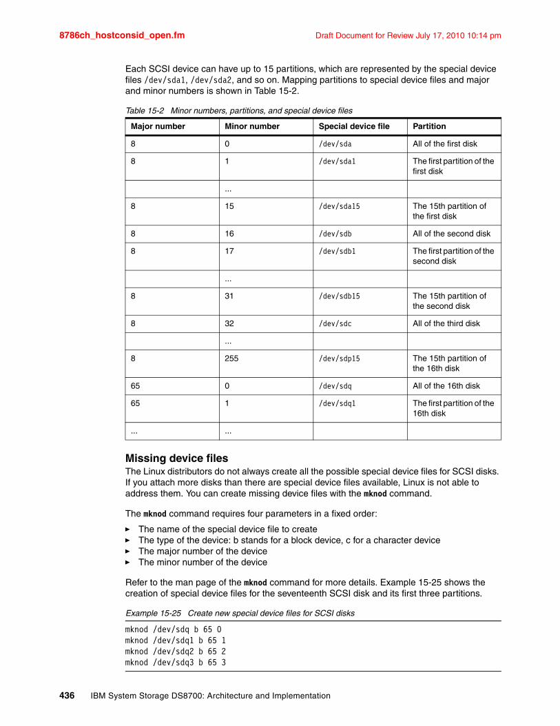
8786ch_hostconsid_open.fm Draft Document for Review July 17, 2010 10:14 pm
Each SCSI device can have up to 15 partitions, which are represented by the special device files /dev/sda1, /dev/sda2, and so on. Mapping partitions to special device files and major and minor numbers is shown in Table 15-2.
Table 15-2 Minor numbers, partitions, and special device files
Missing device filesThe Linux distributors do not always create all the possible special device files for SCSI disks. If you attach more disks than there are special device files available, Linux is not able to address them. You can create missing device files with the mknod command.
The mknod command requires four parameters in a fixed order:
� The name of the special device file to create� The type of the device: b stands for a block device, c for a character device� The major number of the device� The minor number of the device
Refer to the man page of the mknod command for more details. Example 15-25 shows the creation of special device files for the seventeenth SCSI disk and its first three partitions.
Example 15-25 Create new special device files for SCSI disks
mknod /dev/sdq b 65 0mknod /dev/sdq1 b 65 1mknod /dev/sdq2 b 65 2mknod /dev/sdq3 b 65 3
Major number Minor number Special device file Partition
8 0 /dev/sda All of the first disk
8 1 /dev/sda1 The first partition of the first disk
...
8 15 /dev/sda15 The 15th partition of the first disk
8 16 /dev/sdb All of the second disk
8 17 /dev/sdb1 The first partition of the second disk
...
8 31 /dev/sdb15 The 15th partition of the second disk
8 32 /dev/sdc All of the third disk
...
8 255 /dev/sdp15 The 15th partition of the 16th disk
65 0 /dev/sdq All of the 16th disk
65 1 /dev/sdq1 The first partition of the 16th disk
... ...
436 IBM System Storage DS8700: Architecture and Implementation
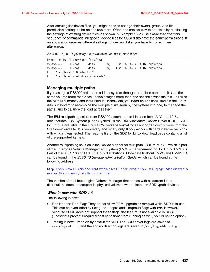
Draft Document for Review July 17, 2010 10:14 pm 8786ch_hostconsid_open.fm
After creating the device files, you might need to change their owner, group, and file permission settings to be able to use them. Often, the easiest way to do this is by duplicating the settings of existing device files, as shown in Example 15-26. Be aware that after this sequence of commands, all special device files for SCSI disks have the same permissions. If an application requires different settings for certain disks, you have to correct them afterwards.
Example 15-26 Duplicating the permissions of special device files
knox:~ # ls -l /dev/sda /dev/sda1rw-rw---- 1 root disk 8, 0 2003-03-14 14:07 /dev/sdarw-rw---- 1 root disk 8, 1 2003-03-14 14:07 /dev/sda1knox:~ # chmod 660 /dev/sd*knox:~ # chown root:disk /dev/sda*
Managing multiple pathsIf you assign a DS8000 volume to a Linux system through more than one path, it sees the same volume more than once. It also assigns more than one special device file to it. To utilize the path redundancy and increased I/O bandwidth, you need an additional layer in the Linux disk subsystem to recombine the multiple disks seen by the system into one, to manage the paths, and to balance the load across them.
The IBM multipathing solution for DS8000 attachment to Linux on Intel IA-32 and IA-64 architectures, IBM System p, and System i is the IBM Subsystem Device Driver (SDD). SDD for Linux is available in the Linux RPM package format for all supported distributions from the SDD download site. It is proprietary and binary only. It only works with certain kernel versions with which it was tested. The readme file on the SDD for Linux download page contains a list of the supported kernels.
Another multipathing solution is the Device Mapper for multipath I/O (DM-MPIO), which is part of the Enterprise Volume Management System (EVMS) management tool for Linux. EVMS is Part of the SLES 10 and RHEL 5 Linux distributions. More details about EVMS and DM-MPIO can be found in the SLES 10 Storage Administration Guide, which can be found at the following address:
http://www.novell.com/documentation/sles10/stor_evms/index.html?page=/documentation/sles10/stor_evms/data/bookinfo.html
The version of the Linux Logical Volume Manager that comes with all current Linux distributions does not support its physical volumes when placed on SDD vpath devices.
What is new with SDD 1.6The following is new:
� Red Hat and Red Flag: They do not allow RPM upgrade or removal while SDD is in use. This can be overridden by using the --nopre and --nopreun flags with rpm. However, because SUSE does not support these flags, the feature is not available in SUSE (--noscripts prevents required post conditions from running as well, so it is not an option).
� Tracing is now turned on by default for SDD. The SDD driver logs are saved to /var/log/sdd.log and the sddsrv daemon logs are saved to /var/log/sddsrv.log.
Chapter 15. Open systems considerations 437
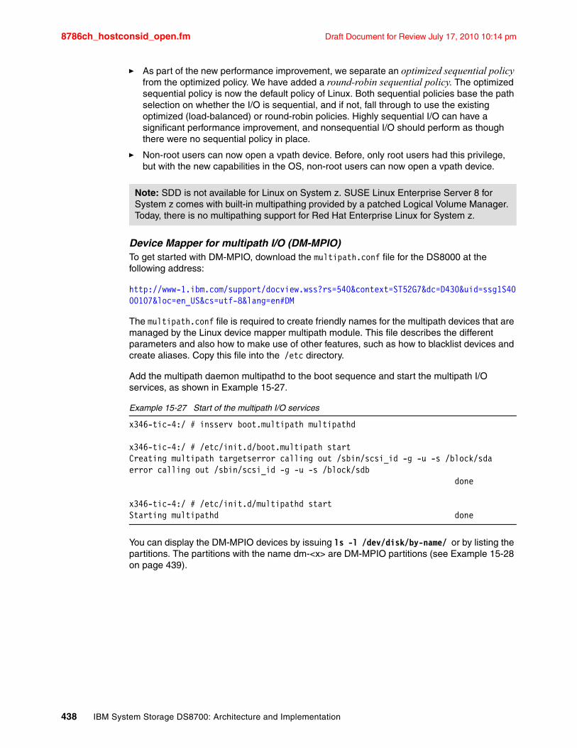
8786ch_hostconsid_open.fm Draft Document for Review July 17, 2010 10:14 pm
� As part of the new performance improvement, we separate an optimized sequential policy from the optimized policy. We have added a round-robin sequential policy. The optimized sequential policy is now the default policy of Linux. Both sequential policies base the path selection on whether the I/O is sequential, and if not, fall through to use the existing optimized (load-balanced) or round-robin policies. Highly sequential I/O can have a significant performance improvement, and nonsequential I/O should perform as though there were no sequential policy in place.
� Non-root users can now open a vpath device. Before, only root users had this privilege, but with the new capabilities in the OS, non-root users can now open a vpath device.
Device Mapper for multipath I/O (DM-MPIO)To get started with DM-MPIO, download the multipath.conf file for the DS8000 at the following address:
http://www-1.ibm.com/support/docview.wss?rs=540&context=ST52G7&dc=D430&uid=ssg1S4000107&loc=en_US&cs=utf-8&lang=en#DM
The multipath.conf file is required to create friendly names for the multipath devices that are managed by the Linux device mapper multipath module. This file describes the different parameters and also how to make use of other features, such as how to blacklist devices and create aliases. Copy this file into the /etc directory.
Add the multipath daemon multipathd to the boot sequence and start the multipath I/O services, as shown in Example 15-27.
Example 15-27 Start of the multipath I/O services
x346-tic-4:/ # insserv boot.multipath multipathd
x346-tic-4:/ # /etc/init.d/boot.multipath startCreating multipath targetserror calling out /sbin/scsi_id -g -u -s /block/sdaerror calling out /sbin/scsi_id -g -u -s /block/sdb done
x346-tic-4:/ # /etc/init.d/multipathd startStarting multipathd done
You can display the DM-MPIO devices by issuing ls -l /dev/disk/by-name/ or by listing the partitions. The partitions with the name dm-<x> are DM-MPIO partitions (see Example 15-28 on page 439).
Note: SDD is not available for Linux on System z. SUSE Linux Enterprise Server 8 for System z comes with built-in multipathing provided by a patched Logical Volume Manager. Today, there is no multipathing support for Red Hat Enterprise Linux for System z.
438 IBM System Storage DS8700: Architecture and Implementation
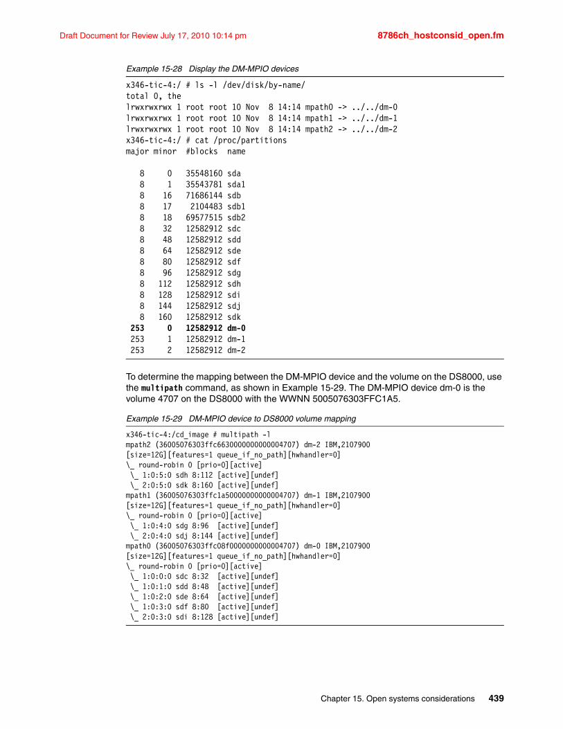
Draft Document for Review July 17, 2010 10:14 pm 8786ch_hostconsid_open.fm
Example 15-28 Display the DM-MPIO devices
x346-tic-4:/ # ls -l /dev/disk/by-name/total 0, thelrwxrwxrwx 1 root root 10 Nov 8 14:14 mpath0 -> ../../dm-0lrwxrwxrwx 1 root root 10 Nov 8 14:14 mpath1 -> ../../dm-1lrwxrwxrwx 1 root root 10 Nov 8 14:14 mpath2 -> ../../dm-2x346-tic-4:/ # cat /proc/partitionsmajor minor #blocks name
8 0 35548160 sda 8 1 35543781 sda1 8 16 71686144 sdb 8 17 2104483 sdb1 8 18 69577515 sdb2 8 32 12582912 sdc 8 48 12582912 sdd 8 64 12582912 sde 8 80 12582912 sdf 8 96 12582912 sdg 8 112 12582912 sdh 8 128 12582912 sdi 8 144 12582912 sdj 8 160 12582912 sdk 253 0 12582912 dm-0 253 1 12582912 dm-1 253 2 12582912 dm-2
To determine the mapping between the DM-MPIO device and the volume on the DS8000, use the multipath command, as shown in Example 15-29. The DM-MPIO device dm-0 is the volume 4707 on the DS8000 with the WWNN 5005076303FFC1A5.
Example 15-29 DM-MPIO device to DS8000 volume mapping
x346-tic-4:/cd_image # multipath -lmpath2 (36005076303ffc6630000000000004707) dm-2 IBM,2107900[size=12G][features=1 queue_if_no_path][hwhandler=0]\_ round-robin 0 [prio=0][active] \_ 1:0:5:0 sdh 8:112 [active][undef] \_ 2:0:5:0 sdk 8:160 [active][undef]mpath1 (36005076303ffc1a50000000000004707) dm-1 IBM,2107900[size=12G][features=1 queue_if_no_path][hwhandler=0]\_ round-robin 0 [prio=0][active] \_ 1:0:4:0 sdg 8:96 [active][undef] \_ 2:0:4:0 sdj 8:144 [active][undef]mpath0 (36005076303ffc08f0000000000004707) dm-0 IBM,2107900[size=12G][features=1 queue_if_no_path][hwhandler=0]\_ round-robin 0 [prio=0][active] \_ 1:0:0:0 sdc 8:32 [active][undef] \_ 1:0:1:0 sdd 8:48 [active][undef] \_ 1:0:2:0 sde 8:64 [active][undef] \_ 1:0:3:0 sdf 8:80 [active][undef] \_ 2:0:3:0 sdi 8:128 [active][undef]
Chapter 15. Open systems considerations 439
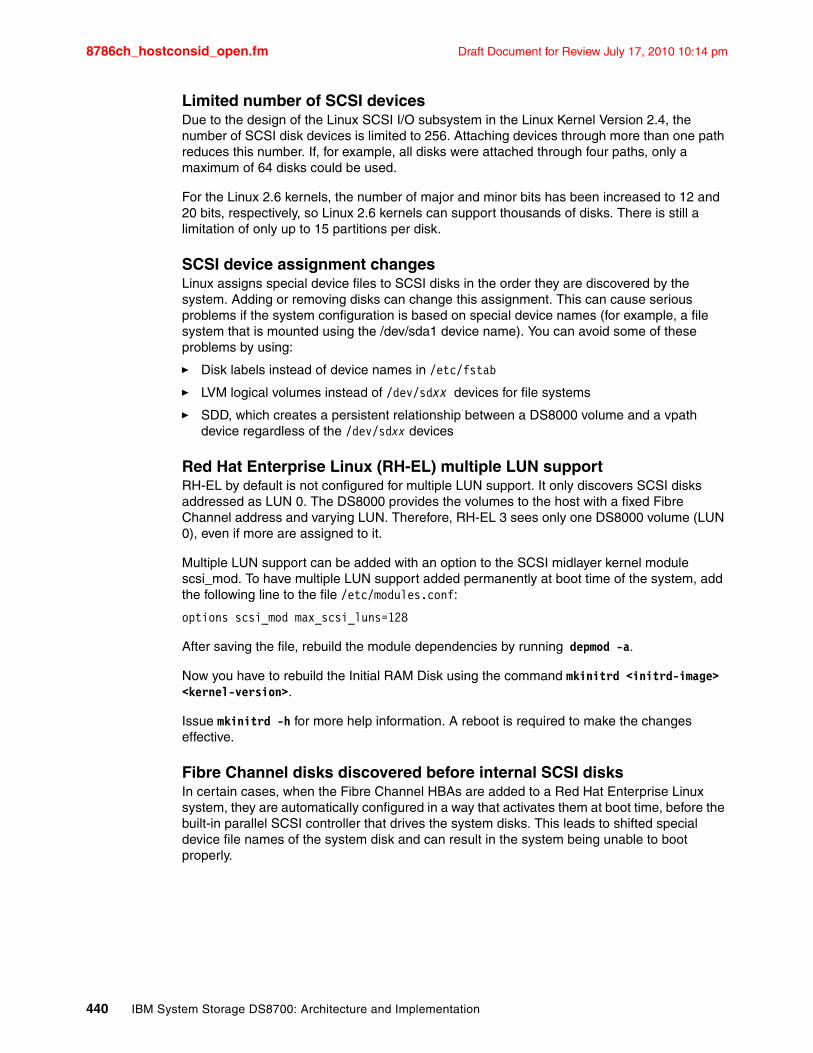
8786ch_hostconsid_open.fm Draft Document for Review July 17, 2010 10:14 pm
Limited number of SCSI devicesDue to the design of the Linux SCSI I/O subsystem in the Linux Kernel Version 2.4, the number of SCSI disk devices is limited to 256. Attaching devices through more than one path reduces this number. If, for example, all disks were attached through four paths, only a maximum of 64 disks could be used.
For the Linux 2.6 kernels, the number of major and minor bits has been increased to 12 and 20 bits, respectively, so Linux 2.6 kernels can support thousands of disks. There is still a limitation of only up to 15 partitions per disk.
SCSI device assignment changesLinux assigns special device files to SCSI disks in the order they are discovered by the system. Adding or removing disks can change this assignment. This can cause serious problems if the system configuration is based on special device names (for example, a file system that is mounted using the /dev/sda1 device name). You can avoid some of these problems by using:
� Disk labels instead of device names in /etc/fstab
� LVM logical volumes instead of /dev/sdxx devices for file systems
� SDD, which creates a persistent relationship between a DS8000 volume and a vpath device regardless of the /dev/sdxx devices
Red Hat Enterprise Linux (RH-EL) multiple LUN supportRH-EL by default is not configured for multiple LUN support. It only discovers SCSI disks addressed as LUN 0. The DS8000 provides the volumes to the host with a fixed Fibre Channel address and varying LUN. Therefore, RH-EL 3 sees only one DS8000 volume (LUN 0), even if more are assigned to it.
Multiple LUN support can be added with an option to the SCSI midlayer kernel module scsi_mod. To have multiple LUN support added permanently at boot time of the system, add the following line to the file /etc/modules.conf:
options scsi_mod max_scsi_luns=128
After saving the file, rebuild the module dependencies by running depmod -a.
Now you have to rebuild the Initial RAM Disk using the command mkinitrd <initrd-image> <kernel-version>.
Issue mkinitrd -h for more help information. A reboot is required to make the changes effective.
Fibre Channel disks discovered before internal SCSI disksIn certain cases, when the Fibre Channel HBAs are added to a Red Hat Enterprise Linux system, they are automatically configured in a way that activates them at boot time, before the built-in parallel SCSI controller that drives the system disks. This leads to shifted special device file names of the system disk and can result in the system being unable to boot properly.
440 IBM System Storage DS8700: Architecture and Implementation
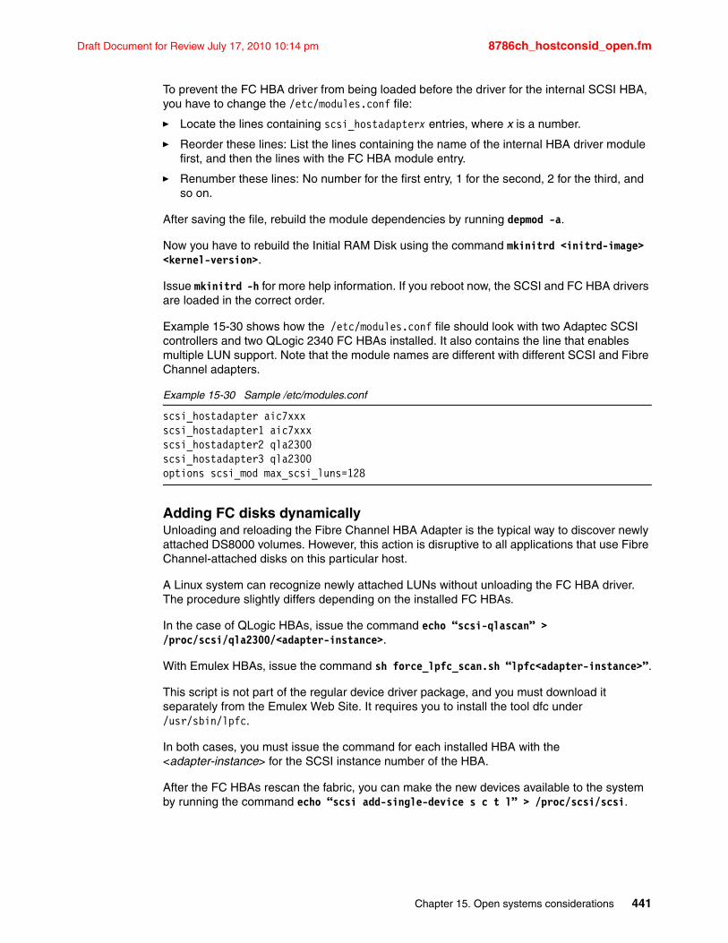
Draft Document for Review July 17, 2010 10:14 pm 8786ch_hostconsid_open.fm
To prevent the FC HBA driver from being loaded before the driver for the internal SCSI HBA, you have to change the /etc/modules.conf file:
� Locate the lines containing scsi_hostadapterx entries, where x is a number.
� Reorder these lines: List the lines containing the name of the internal HBA driver module first, and then the lines with the FC HBA module entry.
� Renumber these lines: No number for the first entry, 1 for the second, 2 for the third, and so on.
After saving the file, rebuild the module dependencies by running depmod -a.
Now you have to rebuild the Initial RAM Disk using the command mkinitrd <initrd-image> <kernel-version>.
Issue mkinitrd -h for more help information. If you reboot now, the SCSI and FC HBA drivers are loaded in the correct order.
Example 15-30 shows how the /etc/modules.conf file should look with two Adaptec SCSI controllers and two QLogic 2340 FC HBAs installed. It also contains the line that enables multiple LUN support. Note that the module names are different with different SCSI and Fibre Channel adapters.
Example 15-30 Sample /etc/modules.conf
scsi_hostadapter aic7xxxscsi_hostadapter1 aic7xxxscsi_hostadapter2 qla2300scsi_hostadapter3 qla2300options scsi_mod max_scsi_luns=128
Adding FC disks dynamicallyUnloading and reloading the Fibre Channel HBA Adapter is the typical way to discover newly attached DS8000 volumes. However, this action is disruptive to all applications that use Fibre Channel-attached disks on this particular host.
A Linux system can recognize newly attached LUNs without unloading the FC HBA driver. The procedure slightly differs depending on the installed FC HBAs.
In the case of QLogic HBAs, issue the command echo “scsi-qlascan” > /proc/scsi/qla2300/<adapter-instance>.
With Emulex HBAs, issue the command sh force_lpfc_scan.sh “lpfc<adapter-instance>”.
This script is not part of the regular device driver package, and you must download it separately from the Emulex Web Site. It requires you to install the tool dfc under /usr/sbin/lpfc.
In both cases, you must issue the command for each installed HBA with the <adapter-instance> for the SCSI instance number of the HBA.
After the FC HBAs rescan the fabric, you can make the new devices available to the system by running the command echo “scsi add-single-device s c t l” > /proc/scsi/scsi.
Chapter 15. Open systems considerations 441
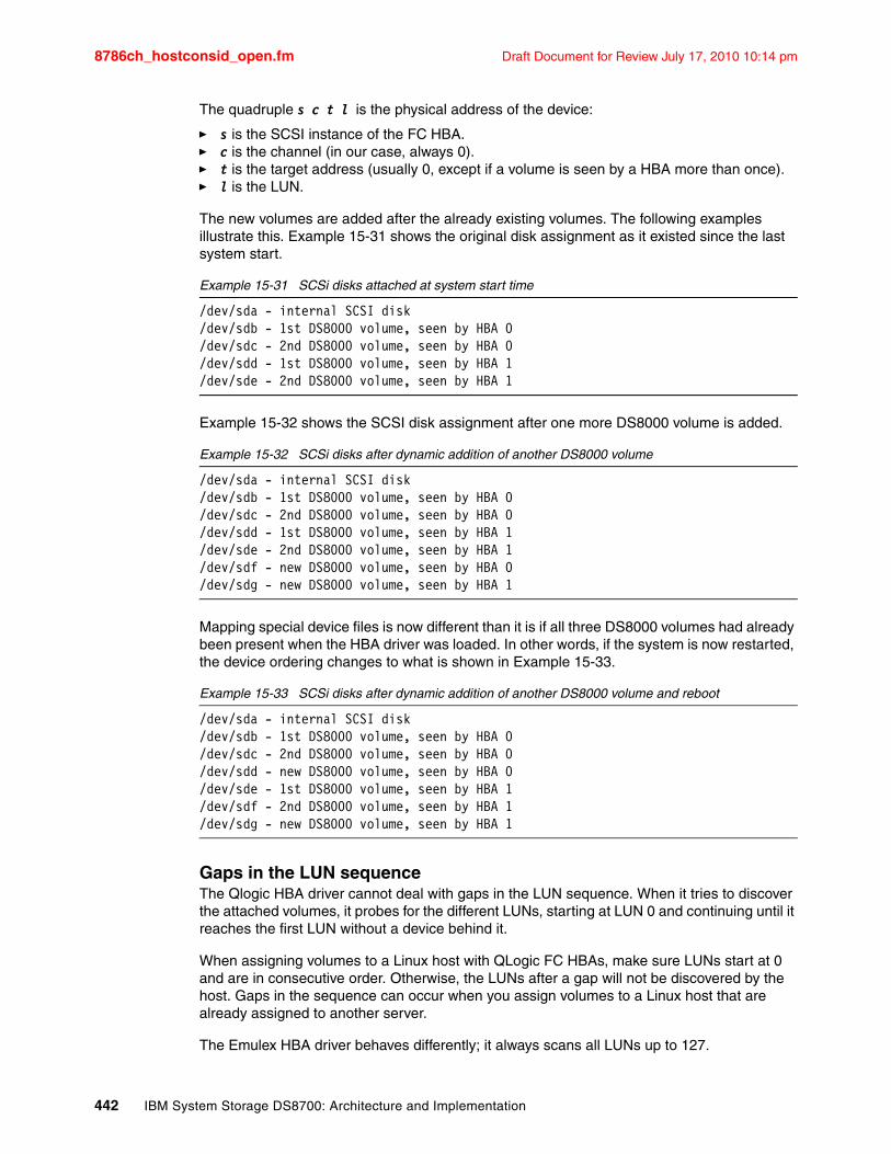
8786ch_hostconsid_open.fm Draft Document for Review July 17, 2010 10:14 pm
The quadruple s c t l is the physical address of the device:
� s is the SCSI instance of the FC HBA.� c is the channel (in our case, always 0).� t is the target address (usually 0, except if a volume is seen by a HBA more than once).� l is the LUN.
The new volumes are added after the already existing volumes. The following examples illustrate this. Example 15-31 shows the original disk assignment as it existed since the last system start.
Example 15-31 SCSi disks attached at system start time
/dev/sda - internal SCSI disk/dev/sdb - 1st DS8000 volume, seen by HBA 0/dev/sdc - 2nd DS8000 volume, seen by HBA 0/dev/sdd - 1st DS8000 volume, seen by HBA 1/dev/sde - 2nd DS8000 volume, seen by HBA 1
Example 15-32 shows the SCSI disk assignment after one more DS8000 volume is added.
Example 15-32 SCSi disks after dynamic addition of another DS8000 volume
/dev/sda - internal SCSI disk/dev/sdb - 1st DS8000 volume, seen by HBA 0/dev/sdc - 2nd DS8000 volume, seen by HBA 0/dev/sdd - 1st DS8000 volume, seen by HBA 1/dev/sde - 2nd DS8000 volume, seen by HBA 1/dev/sdf - new DS8000 volume, seen by HBA 0/dev/sdg - new DS8000 volume, seen by HBA 1
Mapping special device files is now different than it is if all three DS8000 volumes had already been present when the HBA driver was loaded. In other words, if the system is now restarted, the device ordering changes to what is shown in Example 15-33.
Example 15-33 SCSi disks after dynamic addition of another DS8000 volume and reboot
/dev/sda - internal SCSI disk/dev/sdb - 1st DS8000 volume, seen by HBA 0/dev/sdc - 2nd DS8000 volume, seen by HBA 0/dev/sdd - new DS8000 volume, seen by HBA 0/dev/sde - 1st DS8000 volume, seen by HBA 1/dev/sdf - 2nd DS8000 volume, seen by HBA 1/dev/sdg - new DS8000 volume, seen by HBA 1
Gaps in the LUN sequenceThe Qlogic HBA driver cannot deal with gaps in the LUN sequence. When it tries to discover the attached volumes, it probes for the different LUNs, starting at LUN 0 and continuing until it reaches the first LUN without a device behind it.
When assigning volumes to a Linux host with QLogic FC HBAs, make sure LUNs start at 0 and are in consecutive order. Otherwise, the LUNs after a gap will not be discovered by the host. Gaps in the sequence can occur when you assign volumes to a Linux host that are already assigned to another server.
The Emulex HBA driver behaves differently; it always scans all LUNs up to 127.
442 IBM System Storage DS8700: Architecture and Implementation
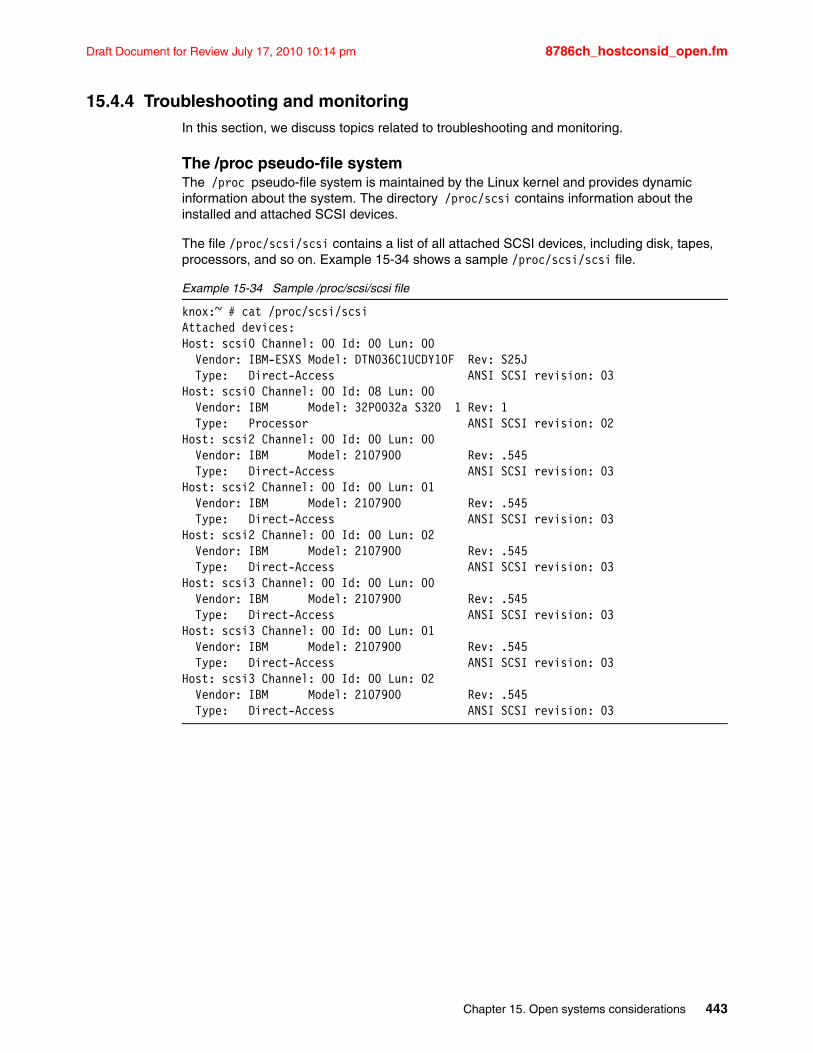
Draft Document for Review July 17, 2010 10:14 pm 8786ch_hostconsid_open.fm
15.4.4 Troubleshooting and monitoringIn this section, we discuss topics related to troubleshooting and monitoring.
The /proc pseudo-file systemThe /proc pseudo-file system is maintained by the Linux kernel and provides dynamic information about the system. The directory /proc/scsi contains information about the installed and attached SCSI devices.
The file /proc/scsi/scsi contains a list of all attached SCSI devices, including disk, tapes, processors, and so on. Example 15-34 shows a sample /proc/scsi/scsi file.
Example 15-34 Sample /proc/scsi/scsi file
knox:~ # cat /proc/scsi/scsiAttached devices:Host: scsi0 Channel: 00 Id: 00 Lun: 00 Vendor: IBM-ESXS Model: DTN036C1UCDY10F Rev: S25J Type: Direct-Access ANSI SCSI revision: 03Host: scsi0 Channel: 00 Id: 08 Lun: 00 Vendor: IBM Model: 32P0032a S320 1 Rev: 1 Type: Processor ANSI SCSI revision: 02Host: scsi2 Channel: 00 Id: 00 Lun: 00 Vendor: IBM Model: 2107900 Rev: .545 Type: Direct-Access ANSI SCSI revision: 03Host: scsi2 Channel: 00 Id: 00 Lun: 01 Vendor: IBM Model: 2107900 Rev: .545 Type: Direct-Access ANSI SCSI revision: 03Host: scsi2 Channel: 00 Id: 00 Lun: 02 Vendor: IBM Model: 2107900 Rev: .545 Type: Direct-Access ANSI SCSI revision: 03Host: scsi3 Channel: 00 Id: 00 Lun: 00 Vendor: IBM Model: 2107900 Rev: .545 Type: Direct-Access ANSI SCSI revision: 03Host: scsi3 Channel: 00 Id: 00 Lun: 01 Vendor: IBM Model: 2107900 Rev: .545 Type: Direct-Access ANSI SCSI revision: 03Host: scsi3 Channel: 00 Id: 00 Lun: 02 Vendor: IBM Model: 2107900 Rev: .545 Type: Direct-Access ANSI SCSI revision: 03
Chapter 15. Open systems considerations 443
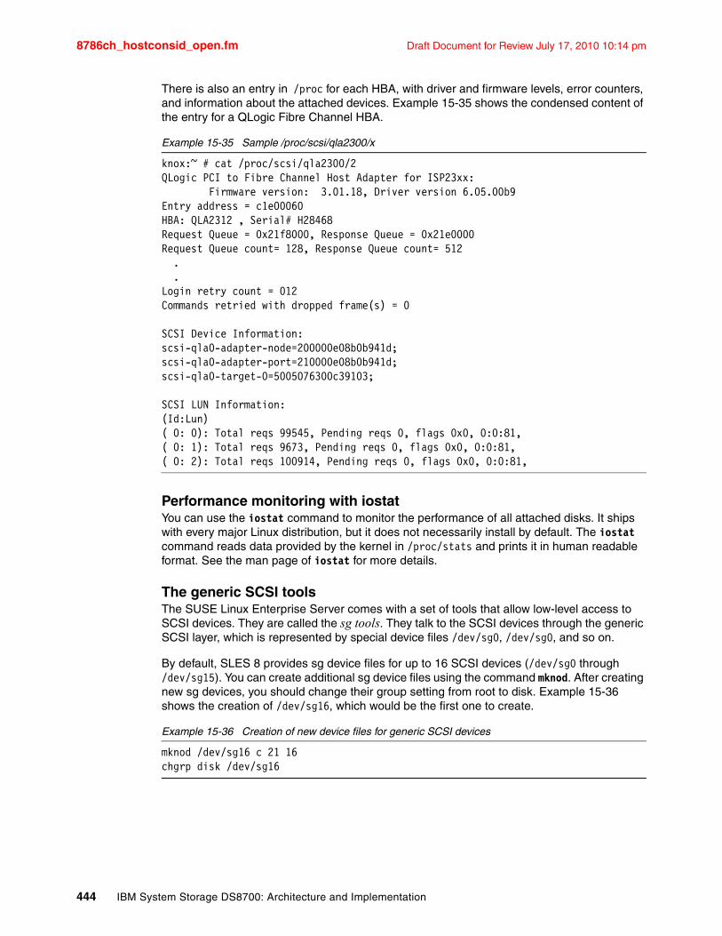
8786ch_hostconsid_open.fm Draft Document for Review July 17, 2010 10:14 pm
There is also an entry in /proc for each HBA, with driver and firmware levels, error counters, and information about the attached devices. Example 15-35 shows the condensed content of the entry for a QLogic Fibre Channel HBA.
Example 15-35 Sample /proc/scsi/qla2300/x
knox:~ # cat /proc/scsi/qla2300/2QLogic PCI to Fibre Channel Host Adapter for ISP23xx: Firmware version: 3.01.18, Driver version 6.05.00b9Entry address = c1e00060HBA: QLA2312 , Serial# H28468Request Queue = 0x21f8000, Response Queue = 0x21e0000Request Queue count= 128, Response Queue count= 512 . .Login retry count = 012Commands retried with dropped frame(s) = 0
SCSI Device Information:scsi-qla0-adapter-node=200000e08b0b941d;scsi-qla0-adapter-port=210000e08b0b941d;scsi-qla0-target-0=5005076300c39103;
SCSI LUN Information:(Id:Lun)( 0: 0): Total reqs 99545, Pending reqs 0, flags 0x0, 0:0:81,( 0: 1): Total reqs 9673, Pending reqs 0, flags 0x0, 0:0:81,( 0: 2): Total reqs 100914, Pending reqs 0, flags 0x0, 0:0:81,
Performance monitoring with iostatYou can use the iostat command to monitor the performance of all attached disks. It ships with every major Linux distribution, but it does not necessarily install by default. The iostat command reads data provided by the kernel in /proc/stats and prints it in human readable format. See the man page of iostat for more details.
The generic SCSI toolsThe SUSE Linux Enterprise Server comes with a set of tools that allow low-level access to SCSI devices. They are called the sg tools. They talk to the SCSI devices through the generic SCSI layer, which is represented by special device files /dev/sg0, /dev/sg0, and so on.
By default, SLES 8 provides sg device files for up to 16 SCSI devices (/dev/sg0 through /dev/sg15). You can create additional sg device files using the command mknod. After creating new sg devices, you should change their group setting from root to disk. Example 15-36 shows the creation of /dev/sg16, which would be the first one to create.
Example 15-36 Creation of new device files for generic SCSI devices
mknod /dev/sg16 c 21 16chgrp disk /dev/sg16
444 IBM System Storage DS8700: Architecture and Implementation
Draft Document for Review July 17, 2010 10:14 pm 8786ch_hostconsid_open.fm
Useful sg tools are:
� sg_inq /dev/sgx prints SCSI Inquiry data, such as the volume serial number.
� sg_scan prints the /dev/sg scsihost, channel, target, LUN mapping.
� sg_map prints the /dev/sd /dev/sg mapping.
� sg_readcap prints the block size and capacity (in blocks) of the device.
� sginfo prints SCSI inquiry and mode page data; it also allows you to manipulate the mode pages.
15.5 OpenVMSDS8000 supports FC attachment of OpenVMS Alpha systems with operating system Version 7.3 or later. For details regarding operating system versions and HBA types, see the System Storage Interoperation Center (SSIC), available at the following address:
http://www.ibm.com/systems/support/storage/config/ssic/displayesssearchwithoutjs.wss?start_over=yes
The support includes clustering and multiple paths (exploiting the OpenVMS built-in multipathing). Boot support is available through Request for Price Quotations (RPQ).
15.5.1 FC port configuration
In early DS8000 microcode, the OpenVMS FC driver had some limitations in handling FC error recovery. The operating system can react to some situations with MountVerify conditions, which are unrecoverable. Affected processes might hang and eventually stop.
Instead of writing a special OpenVMS driver, the decision was made to rectify this situation in the DS8000 host adapter microcode. As a result, it became a general rule not to share DS8000 FC ports between OpenVMS and non-OpenVMS hosts.
You must dedicate storage ports for only the OpenVMS host type. Multiple OpenVMS systems can access the same port. Appropriate zoning must be enforced from the beginning. The wrong access to storage ports used by OpenVMS hosts can clear the OpenVMS-specific settings for these ports. This might remain undetected for a long time, until a failure happens, and by then, I/Os might be lost. It is worth mentioning that OpenVMS is the only platform with this type of restriction (usually, different open systems platforms can share the same DS8000 FC adapters).
Note: The restrictions listed in this section apply only if your DS8000 licensed machine code is earlier than Version 5.0.4. After this version, the restrictions are removed. You can display the versions of the DS CLI, the DS Storage Manager, and the licensed machine code by using the DS CLI command ver -l.
Important: The DS8000 FC ports used by OpenVMS hosts must not be accessed by any other operating system, not even accidentally. The OpenVMS hosts have to be defined for access to these ports only, and you must ensure that no foreign HBA (without definition as an OpenVMS host) is seen by these ports. Conversely, an OpenVMS host must have access only to the DS8000 ports configured for OpenVMS compatibility.
Chapter 15. Open systems considerations 445
8786ch_hostconsid_open.fm Draft Document for Review July 17, 2010 10:14 pm
15.5.2 Volume configurationOpenVMS Fibre Channel devices have device names according to the following schema:
$1$DGA<n>
Where:
� The first portion of the device name ($1$) is the allocation class (a decimal number in the range 1-255). FC devices always have the allocation class 1.
� The following two letters encode the drivers, where the first letter denotes the device class (D = disks, M = magnetic tapes) and the second letter the device type (K = SCSI, G = Fibre Channel). So, all Fibre Channel disk names contain the code DG.
� The third letter denotes the adapter channel (from range A to Z). Fibre Channel devices always have the channel identifier A.
� The number <n> is the User-Defined ID (UDID), a number from the range 0-32767, which is provided by the storage system in response to an OpenVMS-special SCSI inquiry command (from the range of command codes reserved by the SCSI standard for vendors’ private use).
OpenVMS does not identify a Fibre Channel disk by its path or SCSI target/LUN, as other operating systems do. It relies on the Unit Device Identifier (UDID). Although OpenVMS uses the WWID to control all FC paths to a disk, a Fibre Channel disk that does not provide this additional UDID cannot be recognized by the operating system. You need the FC HBA WWID to configure the host connection.
In the DS8000, the volume nickname acts as the UDID for OpenVMS hosts. If the character string of the volume nickname evaluates to an integer in the range 0-32767, then this integer is replied as the answer when an OpenVMS host asks for the UDID.
The DS CLI command chfbvol -name 21 1001 assigns the OpenVMS UDID 21 to the DS8000 volume 1001 (LSS 10, volume 01). Thus, the DS8000 volume 1001 appears as an OpenVMS device with the name $1$DGA21 or $1$GGA21. If executed on an OpenVMS host, the DS CLI command lshostvol shows the DS8000 volumes of this host with their corresponding OpenVMS device names.
The DS management utilities do not enforce UDID rules. They accept incorrect values that are not valid for OpenVMS. It is possible to assign the same UDID value to multiple DS8000 volumes. However, because the UDID is in fact the device ID seen by the operating system, you must fulfill several consistency rules. These rules are described in detail in the OpenVMS operating system documentation; see HP Guidelines for OpenVMS Cluster Configurations at the following address:
http://h71000.www7.hp.com/doc/82FINAL/6318/6318PRO.HTML
The rules are:
� Every FC volume must have a UDID that is unique throughout the OpenVMS cluster that accesses the volume. You can use the same UDID in a different cluster or for a different stand-alone host.
� If the volume is planned for MSCP serving, then the UDID range is limited to 0-9999 (by operating system restrictions in the MSCP code).
446 IBM System Storage DS8700: Architecture and Implementation
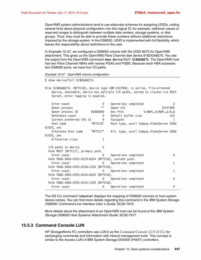
Draft Document for Review July 17, 2010 10:14 pm 8786ch_hostconsid_open.fm
OpenVMS system administrators tend to use elaborate schemes for assigning UDIDs, coding several hints about physical configuration into this logical ID, for example, odd/even values or reserved ranges to distinguish between multiple data centers, storage systems, or disk groups. Thus, they must be able to provide these numbers without additional restrictions imposed by the storage system. In the DS8000, UDID is implemented with full flexibility, which leaves the responsibility about restrictions to the user.
In Example 15-37, we configured a DS8000 volume with the UDID 8275 for OpenVMS attachment. This gives us the OpenVMS Fibre Channel disk device $1$DGA8275. You see the output from the OpenVMS command show device/full $1$DGA8275. The OpenVMS host has two Fibre Channel HBAs with names PGA0 and PGB0. Because each HBA accesses two DS8000 ports, we have four I/O paths.
Example 15-37 OpenVMS volume configuration
$ show device/full $1$DGA8275:
Disk $1$DGA8275: (NFTE18), device type IBM 2107900, is online, file-oriented device, shareable, device has multiple I/O paths, served to cluster via MSCP Server, error logging is enabled.
Error count 0 Operations completed 2 Owner process "" Owner UIC [SYSTEM] Owner process ID 00000000 Dev Prot S:RWPL,O:RWPL,G:R,W Reference count 0 Default buffer size 512 Current preferred CPU Id 9 Fastpath 1 Host name "NFTE18" Host type, avail Compaq AlphaServer GS60 6/525, yes Alternate host name "NFTE17" Alt. type, avail Compaq AlphaServer GS60 6/525, yes Allocation class 1
I/O paths to device 5 Path MSCP (NFTE17), primary path. Error count 0 Operations completed 0 Path PGA0.5005-0763-0319-8324 (NFTE18), current path. Error count 0 Operations completed 1 Path PGA0.5005-0763-031B-C324 (NFTE18). Error count 0 Operations completed 1 Path PGB0.5005-0763-0310-8324 (NFTE18). Error count 0 Operations completed 0 Path PGB0.5005-0763-0314-C324 (NFTE18). Error count 0 Operations completed 0
The DS CLI command lshostvol displays the mapping of DS8000 volumes to host system device names. You can find more details regarding this command in the IBM System Storage DS8000: Command-Line Interface User´s Guide, SC26-7916.
More details about the attachment of an OpenVMS host can be found at the IBM System Storage DS8000 Host Systems Attachment Guide, SC26-7917.
15.5.3 Command Console LUNHP StorageWorks FC controllers use LUN 0 as the Command Console LUN (CCL) for exchanging commands and information with inband management tools. This concept is similar to the Access LUN of IBM System Storage DS4000 (FAStT) controllers.
Chapter 15. Open systems considerations 447
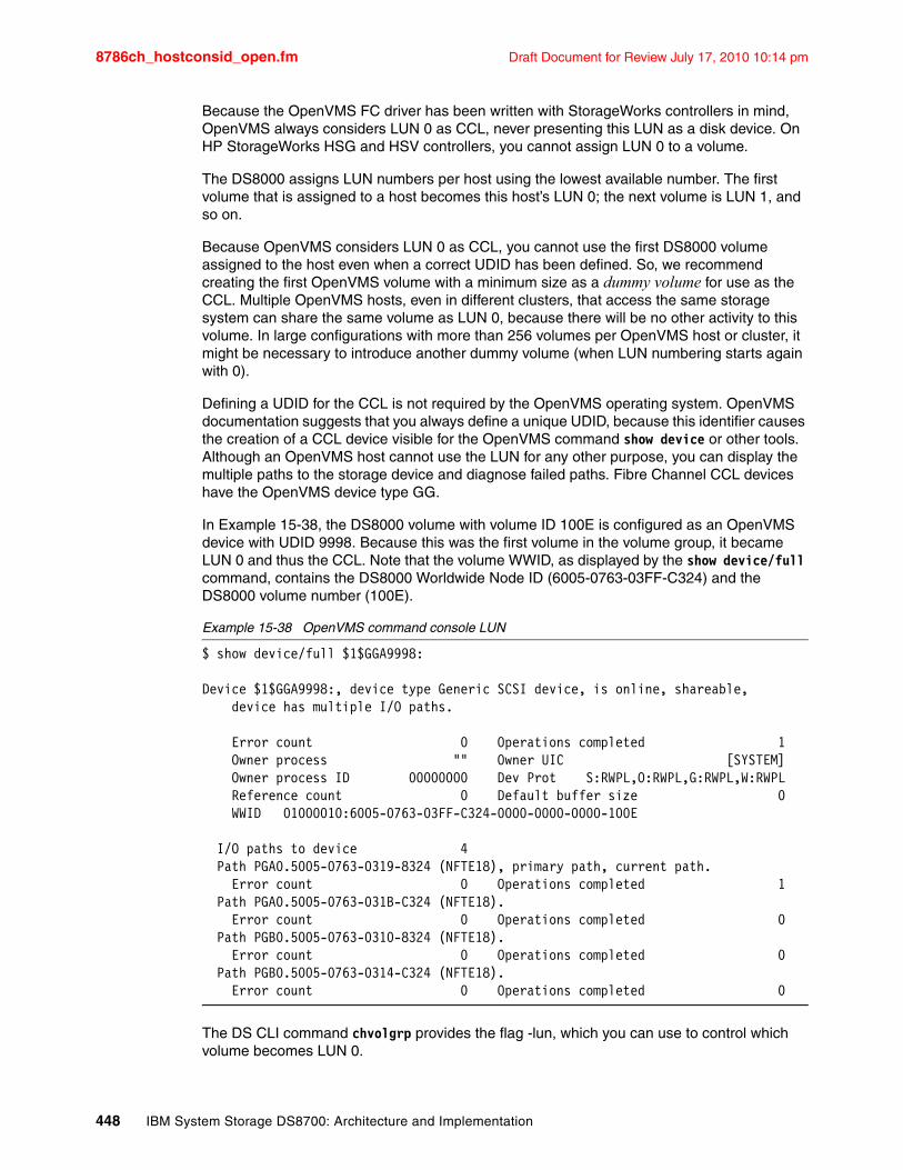
8786ch_hostconsid_open.fm Draft Document for Review July 17, 2010 10:14 pm
Because the OpenVMS FC driver has been written with StorageWorks controllers in mind, OpenVMS always considers LUN 0 as CCL, never presenting this LUN as a disk device. On HP StorageWorks HSG and HSV controllers, you cannot assign LUN 0 to a volume.
The DS8000 assigns LUN numbers per host using the lowest available number. The first volume that is assigned to a host becomes this host’s LUN 0; the next volume is LUN 1, and so on.
Because OpenVMS considers LUN 0 as CCL, you cannot use the first DS8000 volume assigned to the host even when a correct UDID has been defined. So, we recommend creating the first OpenVMS volume with a minimum size as a dummy volume for use as the CCL. Multiple OpenVMS hosts, even in different clusters, that access the same storage system can share the same volume as LUN 0, because there will be no other activity to this volume. In large configurations with more than 256 volumes per OpenVMS host or cluster, it might be necessary to introduce another dummy volume (when LUN numbering starts again with 0).
Defining a UDID for the CCL is not required by the OpenVMS operating system. OpenVMS documentation suggests that you always define a unique UDID, because this identifier causes the creation of a CCL device visible for the OpenVMS command show device or other tools. Although an OpenVMS host cannot use the LUN for any other purpose, you can display the multiple paths to the storage device and diagnose failed paths. Fibre Channel CCL devices have the OpenVMS device type GG.
In Example 15-38, the DS8000 volume with volume ID 100E is configured as an OpenVMS device with UDID 9998. Because this was the first volume in the volume group, it became LUN 0 and thus the CCL. Note that the volume WWID, as displayed by the show device/full command, contains the DS8000 Worldwide Node ID (6005-0763-03FF-C324) and the DS8000 volume number (100E).
Example 15-38 OpenVMS command console LUN
$ show device/full $1$GGA9998:
Device $1$GGA9998:, device type Generic SCSI device, is online, shareable, device has multiple I/O paths.
Error count 0 Operations completed 1 Owner process "" Owner UIC [SYSTEM] Owner process ID 00000000 Dev Prot S:RWPL,O:RWPL,G:RWPL,W:RWPL Reference count 0 Default buffer size 0 WWID 01000010:6005-0763-03FF-C324-0000-0000-0000-100E
I/O paths to device 4 Path PGA0.5005-0763-0319-8324 (NFTE18), primary path, current path. Error count 0 Operations completed 1 Path PGA0.5005-0763-031B-C324 (NFTE18). Error count 0 Operations completed 0 Path PGB0.5005-0763-0310-8324 (NFTE18). Error count 0 Operations completed 0 Path PGB0.5005-0763-0314-C324 (NFTE18). Error count 0 Operations completed 0
The DS CLI command chvolgrp provides the flag -lun, which you can use to control which volume becomes LUN 0.
448 IBM System Storage DS8700: Architecture and Implementation
Draft Document for Review July 17, 2010 10:14 pm 8786ch_hostconsid_open.fm
15.5.4 OpenVMS volume shadowingOpenVMS disks can be combined in host-based mirror sets called OpenVMS shadow sets. This functionality is often used to build disaster-tolerant OpenVMS clusters.
The OpenVMS shadow driver has been designed for disks according to DEC’s Digital Storage Architecture (DSA). This architecture includes requirements that are handled by today’s SCSI/FC devices with other approaches. Two of these requirements are the forced error indicator and the atomic revector operation for bad-block replacement.
When a DSA controller detects an unrecoverable media error, a spare block is revectored to this logical block number, and the contents of the block are marked with a forced error. This causes subsequent read operations to fail, which is the signal to the shadow driver to execute a repair operation using data from another copy.
However, there is no forced error indicator in the SCSI architecture, and the revector operation is nonatomic. As a substitute, the OpenVMS shadow driver exploits the SCSI commands READ LONG (READL) and WRITE LONG (WRITEL), optionally supported by some SCSI devices. These I/O functions allow data blocks to be read and written together with their disk device error correction code (ECC). If the SCSI device supports READL/WRITEL, OpenVMS shadowing emulates the DSA forced error with an intentionally incorrect ECC. For details, see the article, “Design of VMS Volume Shadowing Phase II - Host-based Shadowing”, by Scott H. Davis in the Digital Technical Journal, Vol. 3 No. 3, Summer 1991, archived at:
http://research.compaq.com/wrl/DECarchives/DTJ/DTJ301/DTJ301SC.TXT
The DS8000 provides volumes as SCSI-3 devices and thus does not implement a forced error indicator. It also does not support the READL and WRITEL command set for data integrity reasons.
Usually, the OpenVMS SCSI Port Driver recognizes if a device supports READL/WRITEL, and the driver sets the no forced error (NOFE) bit in the Unit Control Block. You can verify this setting with the SDA utility: After starting the utility with the analyze/system command, enter the show device command at the SDA prompt. Then, the NOFE flag should be shown in the device’s characteristics.
The OpenVMS command for mounting shadow sets provides a qualifier, /override=no_forced_error, to support non-DSA devices. To avoid possible problems (performance loss, unexpected error counts, or even removal of members from the shadow set), we recommend that you apply this qualifier.
15.6 VMwareThe DS8000 currently supports the VMware high-end virtualization solution Virtual Infrastructure 3 and the included VMware ESX Server starting with Version 2.5.
A great deal of useful information is available in IBM System Storage DS8000 Host Systems Attachment Guide, SC26-7917. This section is not intended to duplicate that publication, but rather provide more information about optimizing your VMware environment as well as a step-by-step guide to setting up ESX Server with the DS8000.
Chapter 15. Open systems considerations 449
8786ch_hostconsid_open.fm Draft Document for Review July 17, 2010 10:14 pm
Other VMware products, such as VMware Server and Workstation, are not intended for the data center class environments where the DS8000 is typically used. The supported guest operating systems are Windows 2000 Server, Windows Server 2003, SUSE Linux SLES 8, 9 and 10, and Red Hat Enterprise Linux 2.1, 3.0, and 4.0. The VMotion feature is supported starting with Version 2.5.1.
This information is likely to change, so check the System Storage Interoperation Center for complete, up-to-date information at the following address:
http://www.ibm.com/systems/support/storage/config/ssic/displayesssearchwithoutjs.wss?start_over=yes
15.6.1 VMware ESX Server 3With Virtual Infrastructure 3, VMware focuses on the whole data center and no longer on single ESX hosts. Therefore, VMware has implemented a set of technologies that helps to better utilize the resources of all ESX hosts together. The central feature is the new VMware ESX Server Version 3. For a complete list of the new features in VMware ESX Server V3, visit the VMware Web site, found at the following address:
http://www.vmware.com/
Here, we focus only on the storage-related features.
One significant enhancement is the support of iSCSI and NFS storage. Also, the capabilities to handle FC-based storage have been improved. Special attention has been paid to the usability of direct SAN access (also known as raw LUN access) from the virtual machines. The so-called “Raw Device Mappings” (RDMs) can improve the virtual machine performance and reduce processing impact, and may be required in certain scenarios.
ESX Server V3 also provides enhanced support for booting directly from the SAN. This feature is now fully supported with the DS8000.
VMware Infrastructure V3 also offers Storage VMotion, which enables the migration of virtual machines from one data store to another with zero downtime.
One of the new features of ESX Server V3 is the new version of VMware’s virtual machine file system (VMFS). In addition to performance and reliability improvements, VMFS Version 3 now also supports the creation of subdirectories. In contrast to Version 2, now all files making up a virtual machine (virtual disks, virtual BIOS, and configuration files) are stored in VMFS V3 partitions. This makes it easier to move or back up virtual machines, because all files can be stored in one single location.
While ESX Server V3 can read VMFS-2 volumes, ESX Server V2.x cannot access VMFS-3 volumes at all. Procedures to upgrade from Version 2 are available in the service documents provided by VMware.
450 IBM System Storage DS8700: Architecture and Implementation
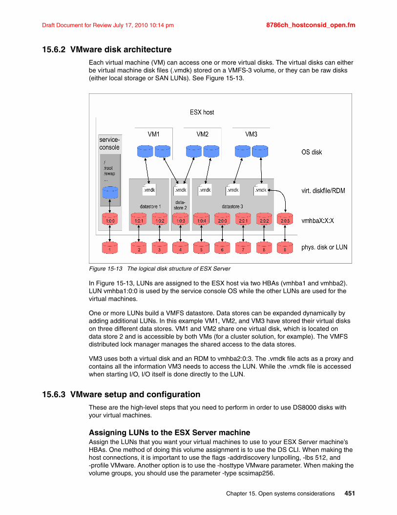
Draft Document for Review July 17, 2010 10:14 pm 8786ch_hostconsid_open.fm
15.6.2 VMware disk architectureEach virtual machine (VM) can access one or more virtual disks. The virtual disks can either be virtual machine disk files (.vmdk) stored on a VMFS-3 volume, or they can be raw disks (either local storage or SAN LUNs). See Figure 15-13.
Figure 15-13 The logical disk structure of ESX Server
In Figure 15-13, LUNs are assigned to the ESX host via two HBAs (vmhba1 and vmhba2). LUN vmhba1:0:0 is used by the service console OS while the other LUNs are used for the virtual machines.
One or more LUNs build a VMFS datastore. Data stores can be expanded dynamically by adding additional LUNs. In this example VM1, VM2, and VM3 have stored their virtual disks on three different data stores. VM1 and VM2 share one virtual disk, which is located on data store 2 and is accessible by both VMs (for a cluster solution, for example). The VMFS distributed lock manager manages the shared access to the data stores.
VM3 uses both a virtual disk and an RDM to vmhba2:0:3. The .vmdk file acts as a proxy and contains all the information VM3 needs to access the LUN. While the .vmdk file is accessed when starting I/O, I/O itself is done directly to the LUN.
15.6.3 VMware setup and configurationThese are the high-level steps that you need to perform in order to use DS8000 disks with your virtual machines.
Assigning LUNs to the ESX Server machineAssign the LUNs that you want your virtual machines to use to your ESX Server machine’s HBAs. One method of doing this volume assignment is to use the DS CLI. When making the host connections, it is important to use the flags -addrdiscovery lunpolling, -lbs 512, and -profile VMware. Another option is to use the -hosttype VMware parameter. When making the volume groups, you should use the parameter -type scsimap256.
Chapter 15. Open systems considerations 451
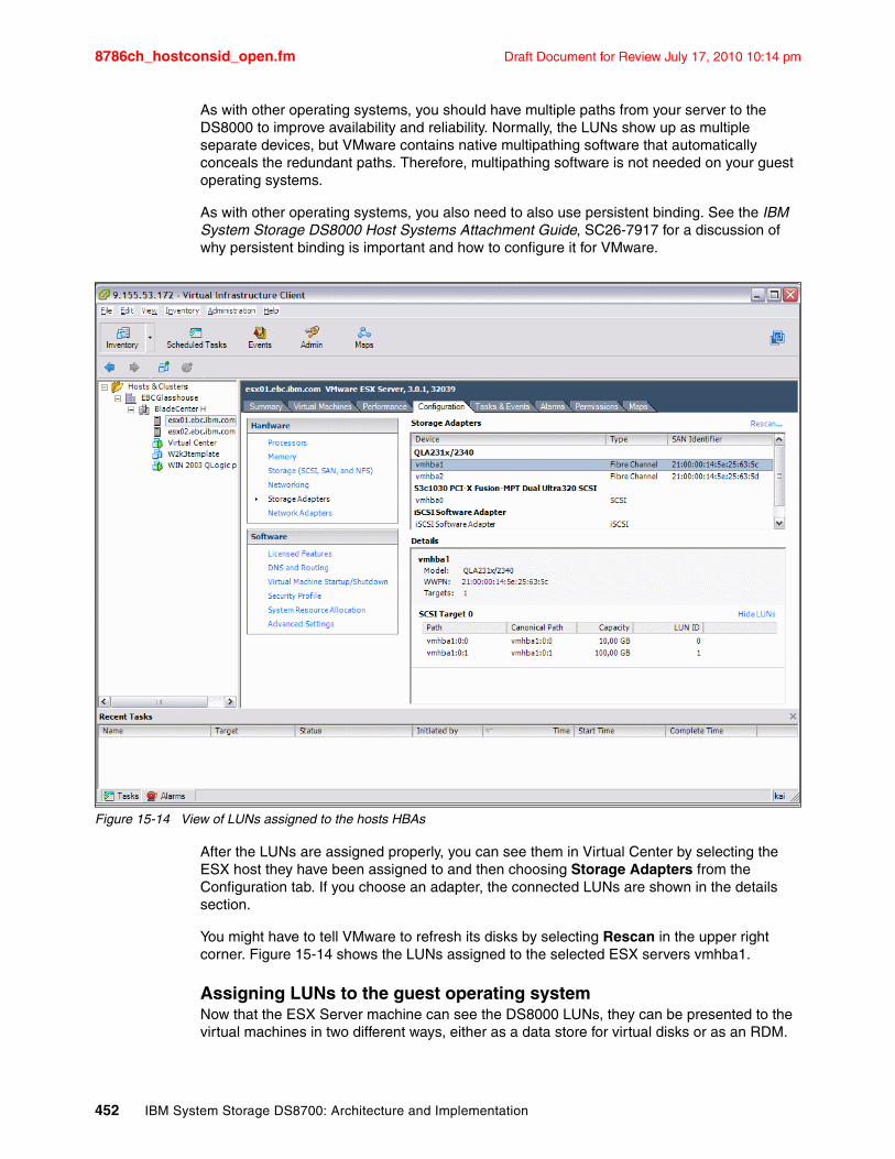
8786ch_hostconsid_open.fm Draft Document for Review July 17, 2010 10:14 pm
As with other operating systems, you should have multiple paths from your server to the DS8000 to improve availability and reliability. Normally, the LUNs show up as multiple separate devices, but VMware contains native multipathing software that automatically conceals the redundant paths. Therefore, multipathing software is not needed on your guest operating systems.
As with other operating systems, you also need to also use persistent binding. See the IBM System Storage DS8000 Host Systems Attachment Guide, SC26-7917 for a discussion of why persistent binding is important and how to configure it for VMware.
Figure 15-14 View of LUNs assigned to the hosts HBAs
After the LUNs are assigned properly, you can see them in Virtual Center by selecting the ESX host they have been assigned to and then choosing Storage Adapters from the Configuration tab. If you choose an adapter, the connected LUNs are shown in the details section.
You might have to tell VMware to refresh its disks by selecting Rescan in the upper right corner. Figure 15-14 shows the LUNs assigned to the selected ESX servers vmhba1.
Assigning LUNs to the guest operating systemNow that the ESX Server machine can see the DS8000 LUNs, they can be presented to the virtual machines in two different ways, either as a data store for virtual disks or as an RDM.
452 IBM System Storage DS8700: Architecture and Implementation
Draft Document for Review July 17, 2010 10:14 pm 8786ch_hostconsid_open.fm
� Option 1: Using virtual disks
To store virtual disk files on this LUN, it must be formatted with the VMFS. In the Configuration tab, select Storage (SCSI, SAN and NFS). On the right, you will be presented with a list of all configured data stores on this ESX host. To add a new one, click Add Storage in the upper right corner, then perform the following steps:
a. Choose the storage type (choose LUN/disk for FC SAN storage).
b. Select the LUN you want to use from the list.
c. Look over the current disk layout.
d. Enter a data store name.
e. Select the maximum file size (depends on the block size) and enter the desired capacity of your new data store.
f. On the Ready to complete page, click Finish to create the data store.
Perform a rescan to update the view.
To create a new virtual disk on this data store, select the virtual machine you want to add it to and click Edit Settings. In the lower left corner of the window, click Add, then perform the following steps:
a. Choose device type Hard disk.
b. Select Create a new disk.
c. Enter the size and select the data store where you want to store this virtual disk.
d. Select the virtual SCSI node and the mode of the disk.
e. On the Summary tab, click Finish to provide this new virtual disk for the VM.
� Option 2: Using raw device mapping (RDM)
To use a physical LUN inside a virtual machine, you need to create a raw device mapping.
The LUN you want must already be known by the ESX host. If the LUN is not yet visible to the ESX host, check if it is assigned correctly and perform a rescan.
To create an RDM, select the virtual machine you want to add it to and click Edit Settings. On the lower left corner of the window, click Add, and then perform the following steps:
a. Choose device type Hard disk.
b. Select Raw Device Mappings.
c. From the Select a disk window, select Mapped SAN LUN.
d. Choose a raw LUN from the list.
e. Select a data store onto which the raw LUN will be mapped (the proxy file will be stored here).
f. Chose the compatibility mode (explained in “Compatibility modes” on page 454).
g. Select the virtual SCSI node.
Note: At least one VMFS datastore is required to store the virtual machines configuration files and the proxy files for RDMs. This is normally done automatically during the initial installation of ESX Server.
Note: With Virtual Infrastructure V3, it is now possible to add new disks to virtual machines while they are running. However, the guest OS must support this setup.
Chapter 15. Open systems considerations 453
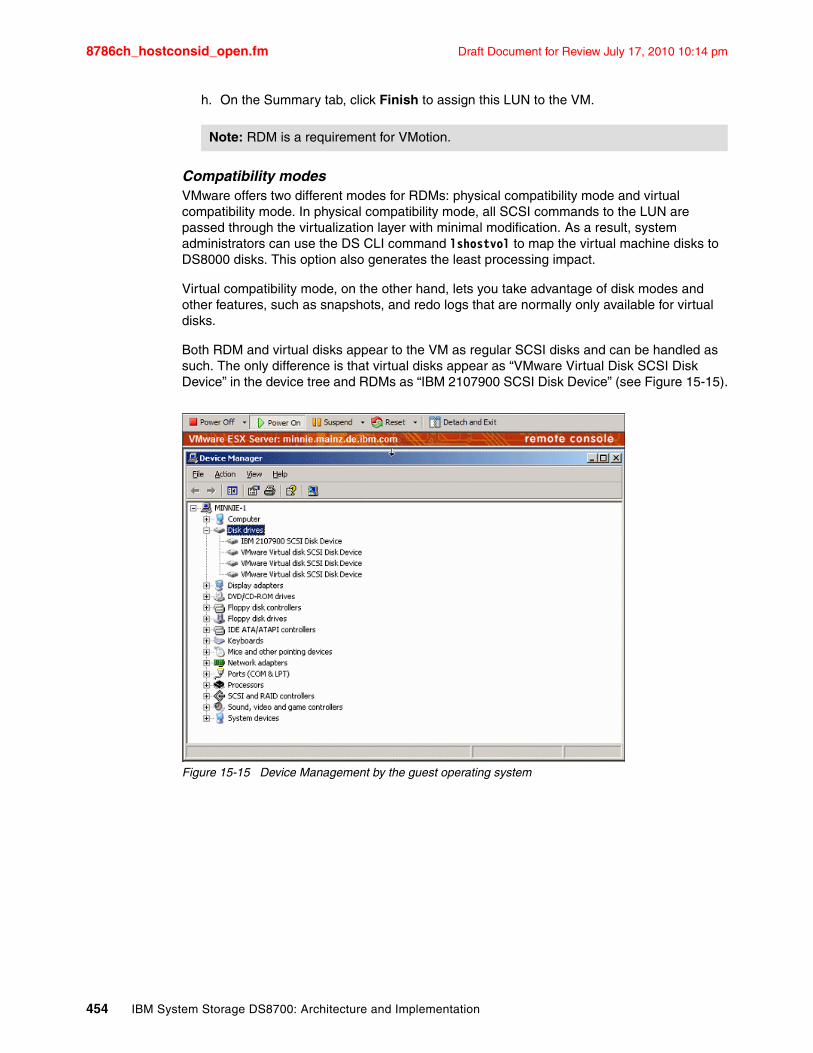
8786ch_hostconsid_open.fm Draft Document for Review July 17, 2010 10:14 pm
h. On the Summary tab, click Finish to assign this LUN to the VM.
Compatibility modesVMware offers two different modes for RDMs: physical compatibility mode and virtual compatibility mode. In physical compatibility mode, all SCSI commands to the LUN are passed through the virtualization layer with minimal modification. As a result, system administrators can use the DS CLI command lshostvol to map the virtual machine disks to DS8000 disks. This option also generates the least processing impact.
Virtual compatibility mode, on the other hand, lets you take advantage of disk modes and other features, such as snapshots, and redo logs that are normally only available for virtual disks.
Both RDM and virtual disks appear to the VM as regular SCSI disks and can be handled as such. The only difference is that virtual disks appear as “VMware Virtual Disk SCSI Disk Device” in the device tree and RDMs as “IBM 2107900 SCSI Disk Device” (see Figure 15-15).
Figure 15-15 Device Management by the guest operating system
Note: RDM is a requirement for VMotion.
454 IBM System Storage DS8700: Architecture and Implementation
Draft Document for Review July 17, 2010 10:14 pm 8786ch_hostconsid_open.fm
15.7 Sun SolarisAs with the previous models, the IBM System Storage DS8000 series continues to provide extensive support for Sun operating systems. Currently, the DS8000 supports Solaris 8, 9, and 10 on a variety of platforms. It also supports VERITAS Cluster Server and Sun Cluster. The Interoperability Matrix and the System Storage Interoperation Center (SSIC) provide complete information about supported configurations, including information about supported host bus adapters, SAN switches, and multipathing technologies. These two tools can be found at the following addresses, respectively:
http://www.ibm.com/servers/storage/disk/ds8000/interop.htmlhttp://www.ibm.com/systems/support/storage/config/ssic/
A great deal of useful information is available in the IBM System Storage DS8000 Host Systems Attachment Guide, SC26-7917. This section is not intended to duplicate that publication, but instead, this section provides more information about optimizing your Sun Solaris environment as well as a step-by-step guide to using Solaris with the DS8000.
15.7.1 Locating the WWPNs of your HBAsBefore you can assign LUNs to your server, you need to locate the WWPNs of the server’s HBAs. One popular method for locating the WWPNs is to scan the /var/adm/messages file. Often, the WWPN only shows up in the file after a reboot. Also, the string to search for depends on the type of HBA that you have. Specific details are available in the IBM System Storage DS8000 Host Systems Attachment Guide, SC26-7917.
In many cases, you can also use the prtconf command to list the WWPNs, as shown in Example 15-39.
Example 15-39 Listing the WWPNs
# prtconf -vp | grep port-wwn port-wwn: 21000003.ba43fdc1 port-wwn: 210000e0.8b099408 port-wwn: 210000e0.8b0995f3 port-wwn: 210000e0.8b096cf6 port-wwn: 210000e0.8b098f08
15.7.2 Solaris attachment to DS8000Solaris uses the LUN polling method in order to discover DS8000 LUNs. For this reason, each Solaris host is limited to 256 LUNs per HBA and volume group from the DS8000. You can assign LUNs using any of the supported DS8000 user interfaces, including the DS Command-Line Interface (DS CLI), the DS Storage Manager GUI(DS GUI), and the DS Open Application Programming Interface (DS Open API). When using the DS CLI, you should make the host connections using the flags -addrdiscovery lunpolling, -lbs 512, and -profile “SUN - Solaris”. Another option is to use the -hosttype Sun parameter. When making the volume groups, you should use the parameter -type scsimap256.
For native HBA drivers, which are using the sd stack and therefore using the /kernel/drv/sd.conf file, you should use persistent binding. If you do not use persistent binding, it is possible that Solaris will assign a different SCSI device identifier (SCSI ID) than the SCSI ID it used previously. This can happen if a new device is added to the SAN, for example. In this case, you have to reconfigure your applications or your operating system.
Chapter 15. Open systems considerations 455
8786ch_hostconsid_open.fm Draft Document for Review July 17, 2010 10:14 pm
The methods of enabling persistent binding differ depending on your host bus adapter. The IBM System Storage DS8000 Host Systems Attachment Guide, SC26-7917 contains the recommended HBA settings for each supported type.
15.7.3 Multipathing in SolarisAs with other operating systems, you should use multiple paths between the DS8000 and your Solaris server. Multiple paths help to maximize the reliability and performance of your operating environment. The DS8000 supports three multipathing technologies on Solaris:
� IBM provides the System Storage Multipath Subsystem Device Driver (SDD) as part of the DS8000 at no extra charge.
� Sun Solaris has a native multipathing software called the StorEdge Traffic Manager Software (STMS). STMS is commonly known as MPxIO (multiplexed I/O) in the industry, and the remainder of this section refers to this technology as MPxIO.
� IBM supports VERITAS Volume Manager (VxVM) Dynamic Multipathing (DMP), a part of the VERITAS Storage Foundation suite.
The multipathing technology that you should use depends predominantly on your operating environment and, of course, your business requirements. There are a few limitations depending on your operating system version, your host bus adapters, and whether you use clustering. Details are available in the IBM System Storage DS8000 Host Systems Attachment Guide, SC26-7917.
One difference between the multipathing technologies is in whether they suppress the redundant paths to the storage. MPxIO and DMP both suppress all paths to the storage except for one, and the device appears to the application as a single-path device. However, SDD allows the original paths to be seen, but creates its own virtual device (called a vpath) for applications to use.
If you assign LUNs to your server before you install multipathing software, you can see each LUN show up as two or more devices, depending on how many paths you have. In Example 15-40, the iostat -nE command shows that the volume 75207814206 appears twice: once as c2t1d1 on the first HBA and once as c3t1d1 on the second HBA.
Example 15-40 Device listing without multipath software
# iostat -nEc2t1d1 Soft Errors: 0 Hard Errors: 0 Transport Errors: 0Vendor: IBM Product: 2107900 Revision: .212 Serial No: 75207814206Size: 10.74GB <10737418240 Bytes>Media Error: 0 Device Not Ready: 0 No Device: 0 Recoverable: 0Illegal Request: 0 Predictive Failure Analysis: 0c2t1d0 Soft Errors: 0 Hard Errors: 0 Transport Errors: 0Vendor: IBM Product: 2107900 Revision: .212 Serial No: 75207814205Size: 10.74GB <10737418240 Bytes>Media Error: 0 Device Not Ready: 0 No Device: 0 Recoverable: 0Illegal Request: 0 Predictive Failure Analysis: 0c3t1d1 Soft Errors: 0 Hard Errors: 0 Transport Errors: 0Vendor: IBM Product: 2107900 Revision: .212 Serial No: 75207814206Size: 10.74GB <10737418240 Bytes>Media Error: 0 Device Not Ready: 0 No Device: 0 Recoverable: 0Illegal Request: 0 Predictive Failure Analysis: 0c3t1d0 Soft Errors: 0 Hard Errors: 0 Transport Errors: 0Vendor: IBM Product: 2107900 Revision: .212 Serial No: 75207814205Size: 10.74GB <10737418240 Bytes>Media Error: 0 Device Not Ready: 0 No Device: 0 Recoverable: 0Illegal Request: 0 Predictive Failure Analysis: 0
456 IBM System Storage DS8700: Architecture and Implementation
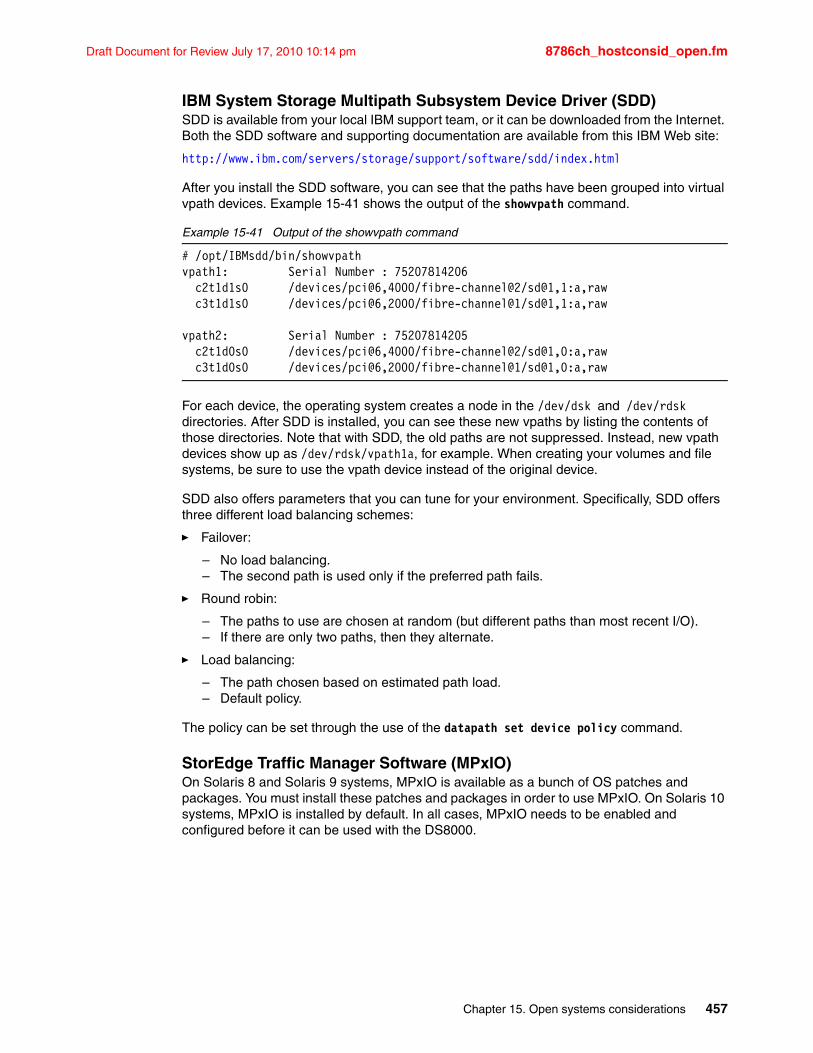
Draft Document for Review July 17, 2010 10:14 pm 8786ch_hostconsid_open.fm
IBM System Storage Multipath Subsystem Device Driver (SDD)SDD is available from your local IBM support team, or it can be downloaded from the Internet. Both the SDD software and supporting documentation are available from this IBM Web site:
http://www.ibm.com/servers/storage/support/software/sdd/index.html
After you install the SDD software, you can see that the paths have been grouped into virtual vpath devices. Example 15-41 shows the output of the showvpath command.
Example 15-41 Output of the showvpath command
# /opt/IBMsdd/bin/showvpathvpath1: Serial Number : 75207814206 c2t1d1s0 /devices/pci@6,4000/fibre-channel@2/sd@1,1:a,raw c3t1d1s0 /devices/pci@6,2000/fibre-channel@1/sd@1,1:a,raw
vpath2: Serial Number : 75207814205 c2t1d0s0 /devices/pci@6,4000/fibre-channel@2/sd@1,0:a,raw c3t1d0s0 /devices/pci@6,2000/fibre-channel@1/sd@1,0:a,raw
For each device, the operating system creates a node in the /dev/dsk and /dev/rdsk directories. After SDD is installed, you can see these new vpaths by listing the contents of those directories. Note that with SDD, the old paths are not suppressed. Instead, new vpath devices show up as /dev/rdsk/vpath1a, for example. When creating your volumes and file systems, be sure to use the vpath device instead of the original device.
SDD also offers parameters that you can tune for your environment. Specifically, SDD offers three different load balancing schemes:
� Failover:
– No load balancing.– The second path is used only if the preferred path fails.
� Round robin:
– The paths to use are chosen at random (but different paths than most recent I/O).– If there are only two paths, then they alternate.
� Load balancing:
– The path chosen based on estimated path load.– Default policy.
The policy can be set through the use of the datapath set device policy command.
StorEdge Traffic Manager Software (MPxIO)On Solaris 8 and Solaris 9 systems, MPxIO is available as a bunch of OS patches and packages. You must install these patches and packages in order to use MPxIO. On Solaris 10 systems, MPxIO is installed by default. In all cases, MPxIO needs to be enabled and configured before it can be used with the DS8000.
Chapter 15. Open systems considerations 457
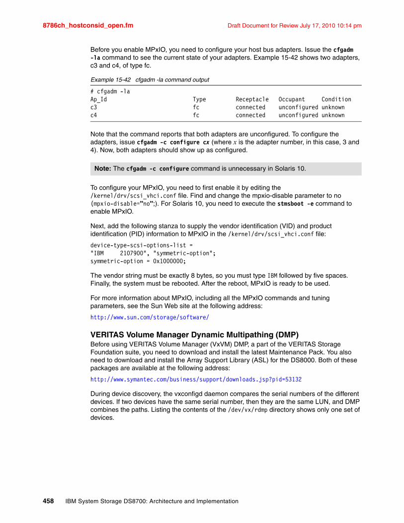
8786ch_hostconsid_open.fm Draft Document for Review July 17, 2010 10:14 pm
Before you enable MPxIO, you need to configure your host bus adapters. Issue the cfgadm -la command to see the current state of your adapters. Example 15-42 shows two adapters, c3 and c4, of type fc.
Example 15-42 cfgadm -la command output
# cfgadm -laAp_Id Type Receptacle Occupant Conditionc3 fc connected unconfigured unknownc4 fc connected unconfigured unknown
Note that the command reports that both adapters are unconfigured. To configure the adapters, issue cfgadm -c configure cx (where x is the adapter number, in this case, 3 and 4). Now, both adapters should show up as configured.
To configure your MPxIO, you need to first enable it by editing the /kernel/drv/scsi_vhci.conf file. Find and change the mpxio-disable parameter to no (mpxio-disable=”no”;). For Solaris 10, you need to execute the stmsboot -e command to enable MPxIO.
Next, add the following stanza to supply the vendor identification (VID) and product identification (PID) information to MPxIO in the /kernel/drv/scsi_vhci.conf file:
device-type-scsi-options-list ="IBM 2107900", "symmetric-option";symmetric-option = 0x1000000;
The vendor string must be exactly 8 bytes, so you must type IBM followed by five spaces. Finally, the system must be rebooted. After the reboot, MPxIO is ready to be used.
For more information about MPxIO, including all the MPxIO commands and tuning parameters, see the Sun Web site at the following address:
http://www.sun.com/storage/software/
VERITAS Volume Manager Dynamic Multipathing (DMP)Before using VERITAS Volume Manager (VxVM) DMP, a part of the VERITAS Storage Foundation suite, you need to download and install the latest Maintenance Pack. You also need to download and install the Array Support Library (ASL) for the DS8000. Both of these packages are available at the following address:
http://www.symantec.com/business/support/downloads.jsp?pid=53132
During device discovery, the vxconfigd daemon compares the serial numbers of the different devices. If two devices have the same serial number, then they are the same LUN, and DMP combines the paths. Listing the contents of the /dev/vx/rdmp directory shows only one set of devices.
Note: The cfgadm -c configure command is unnecessary in Solaris 10.
458 IBM System Storage DS8700: Architecture and Implementation
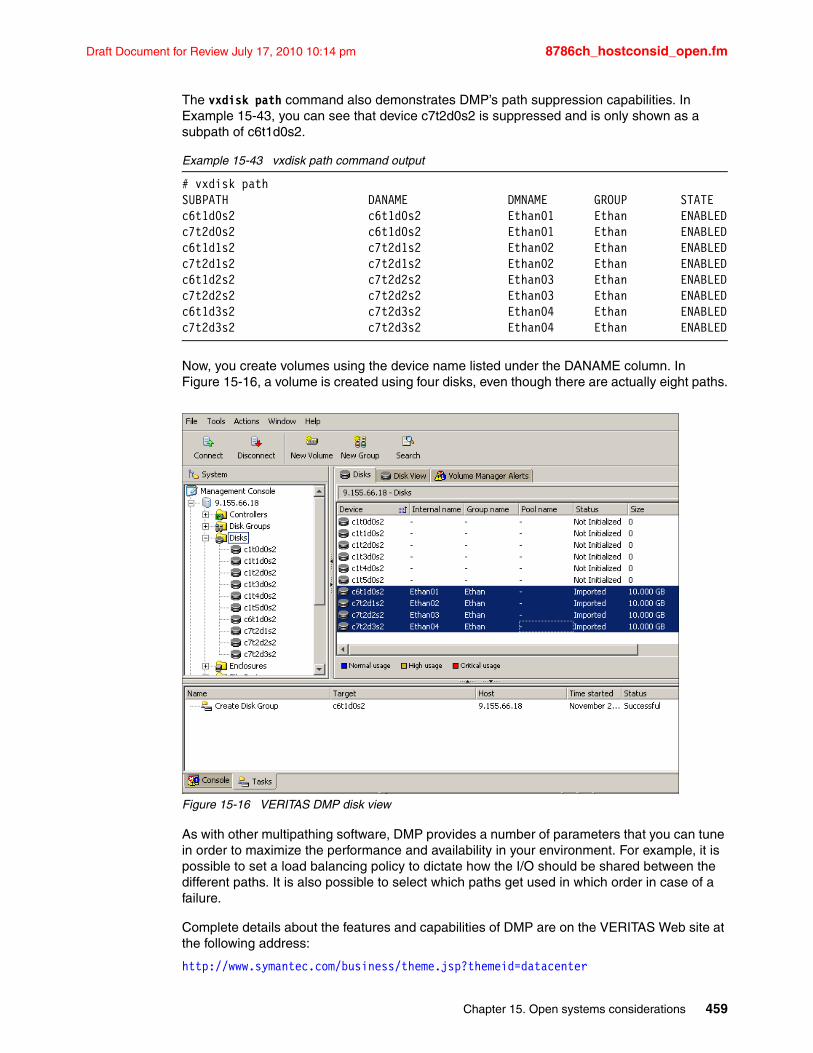
Draft Document for Review July 17, 2010 10:14 pm 8786ch_hostconsid_open.fm
The vxdisk path command also demonstrates DMP’s path suppression capabilities. In Example 15-43, you can see that device c7t2d0s2 is suppressed and is only shown as a subpath of c6t1d0s2.
Example 15-43 vxdisk path command output
# vxdisk pathSUBPATH DANAME DMNAME GROUP STATEc6t1d0s2 c6t1d0s2 Ethan01 Ethan ENABLEDc7t2d0s2 c6t1d0s2 Ethan01 Ethan ENABLEDc6t1d1s2 c7t2d1s2 Ethan02 Ethan ENABLEDc7t2d1s2 c7t2d1s2 Ethan02 Ethan ENABLEDc6t1d2s2 c7t2d2s2 Ethan03 Ethan ENABLEDc7t2d2s2 c7t2d2s2 Ethan03 Ethan ENABLEDc6t1d3s2 c7t2d3s2 Ethan04 Ethan ENABLEDc7t2d3s2 c7t2d3s2 Ethan04 Ethan ENABLED
Now, you create volumes using the device name listed under the DANAME column. In Figure 15-16, a volume is created using four disks, even though there are actually eight paths.
Figure 15-16 VERITAS DMP disk view
As with other multipathing software, DMP provides a number of parameters that you can tune in order to maximize the performance and availability in your environment. For example, it is possible to set a load balancing policy to dictate how the I/O should be shared between the different paths. It is also possible to select which paths get used in which order in case of a failure.
Complete details about the features and capabilities of DMP are on the VERITAS Web site at the following address:
http://www.symantec.com/business/theme.jsp?themeid=datacenter
Chapter 15. Open systems considerations 459

8786ch_hostconsid_open.fm Draft Document for Review July 17, 2010 10:14 pm
15.7.4 Dynamic Volume Expansion with VxVM and DMPStarting with Licensed Machine Code 5.3.xx.xx, it is possible to expand a volume in the DS8000 even if it is mapped to a host. However, a volume that is in a FlashCopy, Metro Mirror, or Global Mirror relationship cannot be expanded unless the relationship is removed, which means the FlashCopy, Metro Mirror, or Global Mirror on that volume has to be removed before it is possible to expand the volume.
An example of how to expand a volume on a Solaris host with VERITAS Volume Manager (VxVM), where the volume is a DS8000 volume, is shown in the following section.
To display the volume size, use the command lsfbvol, as shown in Example 15-44.
Example 15-44 lsfbvol -fullid before volume expansion
dscli> lsfbvol -fullid 4704Date/Time: November 7, 2007 4:18:33 PM CET IBM DSCLI Version: 5.3.0.991 DS: IBM.2107-7520781Name ID accstate datastate configstate deviceMTM datatype extpool cap(2^30B) cap(10^9B) cap(blocks)==========================================================================================================================================ITSO_v880_4704 IBM.2107-7520781/4704 Online Normal Normal 2107-900 FB 512 IBM.2107-7520781/P53 12.0 - 25165824
Here we can see that the capacity is 12 GB, and also that the volume ID is 4704. To determine what is the corresponding disk on the Solaris host, you have to install the DS CLI on this host and execute the lshostvol command. The output is shown in Example 15-45.
Example 15-45 lshostvol output
bash-3.00# /opt/ibm/dscli/bin/lshostvol.shDevice Name Volume ID----------- -------------------------------- c2t50050763030CC1A5d0 IBM.2107-7520781/4704 c2t50050763030CC08Fd0 IBM.2107-7503461/4704 c2t5005076303000663d0 IBM.2107-75ABTV1/4704 c3t50050763030B0663d0 IBM.2107-75ABTV1/4704 c3t500507630319C08Fd0 IBM.2107-7503461/4704 c3t50050763031CC1A5d0 IBM.2107-7520781/4704
Here we can see that the volume with ID 75207814704 is c2t50050763030CC1A5d0 or c3t50050763031CC1A5d0 on the Solaris host. To see the size of the volume on the Solaris host, we use the luxadm command, as shown in Example 15-46.
Example 15-46 luxadm output before volume expansion
bash-3.00# luxadm display /dev/rdsk/c2t50050763030CC1A5d0s2DEVICE PROPERTIES for disk: /dev/rdsk/c2t50050763030CC1A5d0s2 Status(Port A): O.K. Vendor: IBM Product ID: 2107900 WWN(Node): 5005076303ffc1a5 WWN(Port A): 50050763030cc1a5 Revision: .991 Serial Num: 75207814704 Unformatted capacity: 12288.000 MBytes Write Cache: Enabled Read Cache: Enabled Minimum prefetch: 0x0 Maximum prefetch: 0x16 Device Type: Disk device
460 IBM System Storage DS8700: Architecture and Implementation
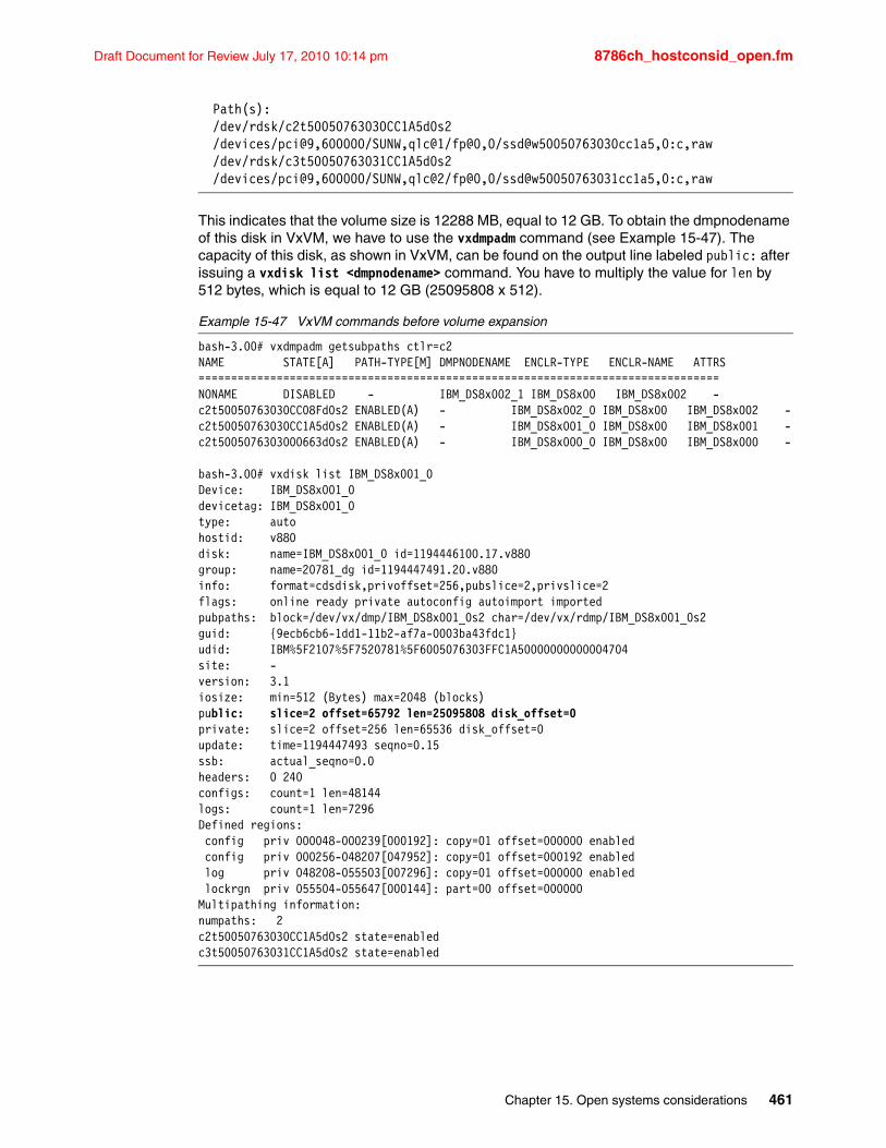
Draft Document for Review July 17, 2010 10:14 pm 8786ch_hostconsid_open.fm
Path(s): /dev/rdsk/c2t50050763030CC1A5d0s2 /devices/pci@9,600000/SUNW,qlc@1/fp@0,0/ssd@w50050763030cc1a5,0:c,raw /dev/rdsk/c3t50050763031CC1A5d0s2 /devices/pci@9,600000/SUNW,qlc@2/fp@0,0/ssd@w50050763031cc1a5,0:c,raw
This indicates that the volume size is 12288 MB, equal to 12 GB. To obtain the dmpnodename of this disk in VxVM, we have to use the vxdmpadm command (see Example 15-47). The capacity of this disk, as shown in VxVM, can be found on the output line labeled public: after issuing a vxdisk list <dmpnodename> command. You have to multiply the value for len by 512 bytes, which is equal to 12 GB (25095808 x 512).
Example 15-47 VxVM commands before volume expansion
bash-3.00# vxdmpadm getsubpaths ctlr=c2NAME STATE[A] PATH-TYPE[M] DMPNODENAME ENCLR-TYPE ENCLR-NAME ATTRS================================================================================NONAME DISABLED - IBM_DS8x002_1 IBM_DS8x00 IBM_DS8x002 -c2t50050763030CC08Fd0s2 ENABLED(A) - IBM_DS8x002_0 IBM_DS8x00 IBM_DS8x002 -c2t50050763030CC1A5d0s2 ENABLED(A) - IBM_DS8x001_0 IBM_DS8x00 IBM_DS8x001 -c2t5005076303000663d0s2 ENABLED(A) - IBM_DS8x000_0 IBM_DS8x00 IBM_DS8x000 -
bash-3.00# vxdisk list IBM_DS8x001_0Device: IBM_DS8x001_0devicetag: IBM_DS8x001_0type: autohostid: v880disk: name=IBM_DS8x001_0 id=1194446100.17.v880group: name=20781_dg id=1194447491.20.v880info: format=cdsdisk,privoffset=256,pubslice=2,privslice=2flags: online ready private autoconfig autoimport importedpubpaths: block=/dev/vx/dmp/IBM_DS8x001_0s2 char=/dev/vx/rdmp/IBM_DS8x001_0s2guid: {9ecb6cb6-1dd1-11b2-af7a-0003ba43fdc1}udid: IBM%5F2107%5F7520781%5F6005076303FFC1A50000000000004704site: -version: 3.1iosize: min=512 (Bytes) max=2048 (blocks)public: slice=2 offset=65792 len=25095808 disk_offset=0private: slice=2 offset=256 len=65536 disk_offset=0update: time=1194447493 seqno=0.15ssb: actual_seqno=0.0headers: 0 240configs: count=1 len=48144logs: count=1 len=7296Defined regions: config priv 000048-000239[000192]: copy=01 offset=000000 enabled config priv 000256-048207[047952]: copy=01 offset=000192 enabled log priv 048208-055503[007296]: copy=01 offset=000000 enabled lockrgn priv 055504-055647[000144]: part=00 offset=000000Multipathing information:numpaths: 2c2t50050763030CC1A5d0s2 state=enabledc3t50050763031CC1A5d0s2 state=enabled
Chapter 15. Open systems considerations 461
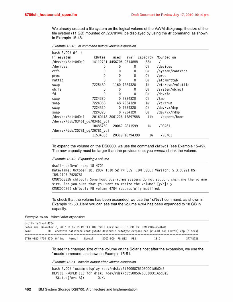
8786ch_hostconsid_open.fm Draft Document for Review July 17, 2010 10:14 pm
We already created a file system on the logical volume of the VxVM diskgroup; the size of the file system (11 GB) mounted on /20781will be displayed by using the df command, as shown in Example 15-48.
Example 15-48 df command before volume expansion
bash-3.00# df -kFilesystem kBytes used avail capacity Mounted on/dev/dsk/c1t0d0s0 14112721 4456706 9514888 32% //devices 0 0 0 0% /devicesctfs 0 0 0 0% /system/contractproc 0 0 0 0% /procmnttab 0 0 0 0% /etc/mnttabswap 7225480 1160 7224320 1% /etc/svc/volatileobjfs 0 0 0 0% /system/objectfd 0 0 0 0% /dev/fdswap 7224320 0 7224320 0% /tmpswap 7224368 48 7224320 1% /var/runswap 7224320 0 7224320 0% /dev/vx/dmpswap 7224320 0 7224320 0% /dev/vx/rdmp/dev/dsk/c1t0d0s7 20160418 2061226 17897588 11% /export/home/dev/vx/dsk/03461_dg/03461_vol 10485760 20062 9811599 1% /03461/dev/vx/dsk/20781_dg/20781_vol 11534336 20319 10794398 1% /20781
To expand the volume on the DS8000, we use the command chfbvol (see Example 15-49). The new capacity must be larger than the previous one; you cannot shrink the volume.
Example 15-49 Expanding a volume
dscli> chfbvol -cap 18 4704Date/Time: October 18, 2007 1:10:52 PM CEST IBM DSCLI Version: 5.3.0.991 DS: IBM.2107-7520781CMUC00332W chfbvol: Some host operating systems do not support changing the volume size. Are you sure that you want to resize the volume? [y/n]: yCMUC00026I chfbvol: FB volume 4704 successfully modified.
To check that the volume has been expanded, we use the lsfbvol command, as shown in Example 15-50. Here you can see that the volume 4704 has been expanded to 18 GB in capacity.
Example 15-50 lsfbvol after expansion
dscli> lsfbvol 4704Date/Time: November 7, 2007 11:05:15 PM CET IBM DSCLI Version: 5.3.0.991 DS: IBM.2107-7520781Name ID accstate datastate configstate deviceMTM datatype extpool cap (2^30B) cap (10^9B) cap (blocks)==================================================================================================================ITSO_v880_4704 4704 Online Normal Normal 2107-900 FB 512 P53 18.0 - 37748736
To see the changed size of the volume on the Solaris host after the expansion, we use the luxadm command, as shown in Example 15-51.
Example 15-51 luxadm output after volume expansion
bash-3.00# luxadm display /dev/rdsk/c2t50050763030CC1A5d0s2DEVICE PROPERTIES for disk: /dev/rdsk/c2t50050763030CC1A5d0s2 Status(Port A): O.K.
462 IBM System Storage DS8700: Architecture and Implementation
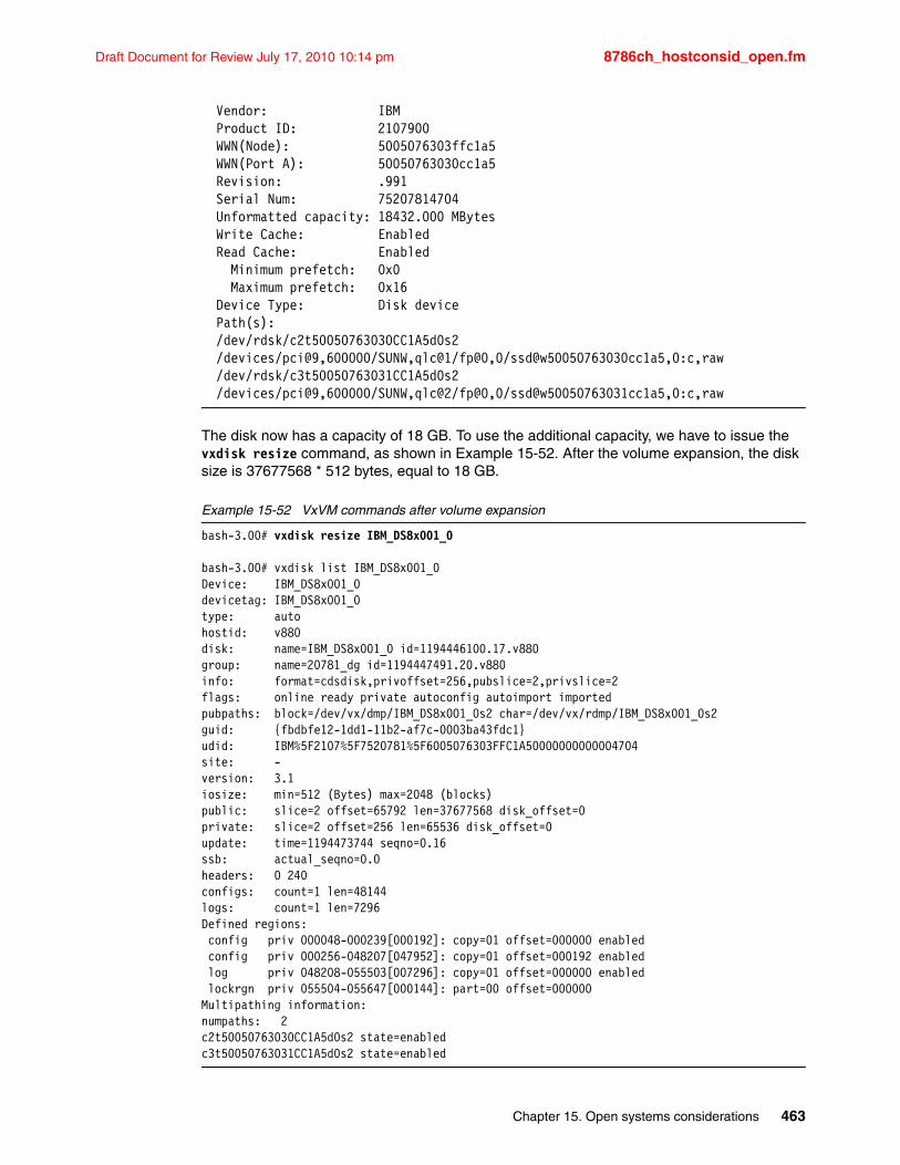
Draft Document for Review July 17, 2010 10:14 pm 8786ch_hostconsid_open.fm
Vendor: IBM Product ID: 2107900 WWN(Node): 5005076303ffc1a5 WWN(Port A): 50050763030cc1a5 Revision: .991 Serial Num: 75207814704 Unformatted capacity: 18432.000 MBytes Write Cache: Enabled Read Cache: Enabled Minimum prefetch: 0x0 Maximum prefetch: 0x16 Device Type: Disk device Path(s): /dev/rdsk/c2t50050763030CC1A5d0s2 /devices/pci@9,600000/SUNW,qlc@1/fp@0,0/ssd@w50050763030cc1a5,0:c,raw /dev/rdsk/c3t50050763031CC1A5d0s2 /devices/pci@9,600000/SUNW,qlc@2/fp@0,0/ssd@w50050763031cc1a5,0:c,raw
The disk now has a capacity of 18 GB. To use the additional capacity, we have to issue the vxdisk resize command, as shown in Example 15-52. After the volume expansion, the disk size is 37677568 * 512 bytes, equal to 18 GB.
Example 15-52 VxVM commands after volume expansion
bash-3.00# vxdisk resize IBM_DS8x001_0
bash-3.00# vxdisk list IBM_DS8x001_0Device: IBM_DS8x001_0devicetag: IBM_DS8x001_0type: autohostid: v880disk: name=IBM_DS8x001_0 id=1194446100.17.v880group: name=20781_dg id=1194447491.20.v880info: format=cdsdisk,privoffset=256,pubslice=2,privslice=2flags: online ready private autoconfig autoimport importedpubpaths: block=/dev/vx/dmp/IBM_DS8x001_0s2 char=/dev/vx/rdmp/IBM_DS8x001_0s2guid: {fbdbfe12-1dd1-11b2-af7c-0003ba43fdc1}udid: IBM%5F2107%5F7520781%5F6005076303FFC1A50000000000004704site: -version: 3.1iosize: min=512 (Bytes) max=2048 (blocks)public: slice=2 offset=65792 len=37677568 disk_offset=0private: slice=2 offset=256 len=65536 disk_offset=0update: time=1194473744 seqno=0.16ssb: actual_seqno=0.0headers: 0 240configs: count=1 len=48144logs: count=1 len=7296Defined regions: config priv 000048-000239[000192]: copy=01 offset=000000 enabled config priv 000256-048207[047952]: copy=01 offset=000192 enabled log priv 048208-055503[007296]: copy=01 offset=000000 enabled lockrgn priv 055504-055647[000144]: part=00 offset=000000Multipathing information:numpaths: 2c2t50050763030CC1A5d0s2 state=enabledc3t50050763031CC1A5d0s2 state=enabled
Chapter 15. Open systems considerations 463
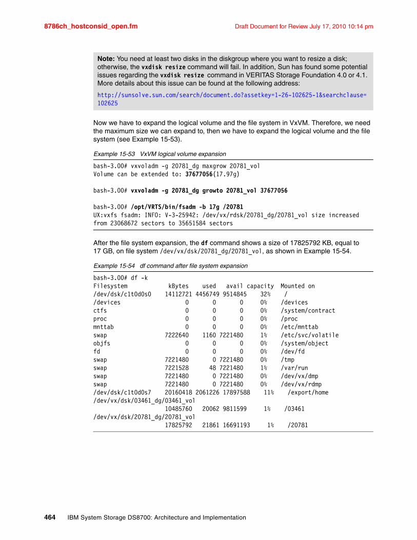
8786ch_hostconsid_open.fm Draft Document for Review July 17, 2010 10:14 pm
Now we have to expand the logical volume and the file system in VxVM. Therefore, we need the maximum size we can expand to, then we have to expand the logical volume and the file system (see Example 15-53).
Example 15-53 VxVM logical volume expansion
bash-3.00# vxvoladm -g 20781_dg maxgrow 20781_volVolume can be extended to: 37677056(17.97g)
bash-3.00# vxvoladm -g 20781_dg growto 20781_vol 37677056
bash-3.00# /opt/VRTS/bin/fsadm -b 17g /20781UX:vxfs fsadm: INFO: V-3-25942: /dev/vx/rdsk/20781_dg/20781_vol size increased from 23068672 sectors to 35651584 sectors
After the file system expansion, the df command shows a size of 17825792 KB, equal to 17 GB, on file system /dev/vx/dsk/20781_dg/20781_vol, as shown in Example 15-54.
Example 15-54 df command after file system expansion
bash-3.00# df -kFilesystem kBytes used avail capacity Mounted on/dev/dsk/c1t0d0s0 14112721 4456749 9514845 32% //devices 0 0 0 0% /devicesctfs 0 0 0 0% /system/contractproc 0 0 0 0% /procmnttab 0 0 0 0% /etc/mnttabswap 7222640 1160 7221480 1% /etc/svc/volatileobjfs 0 0 0 0% /system/objectfd 0 0 0 0% /dev/fdswap 7221480 0 7221480 0% /tmpswap 7221528 48 7221480 1% /var/runswap 7221480 0 7221480 0% /dev/vx/dmpswap 7221480 0 7221480 0% /dev/vx/rdmp/dev/dsk/c1t0d0s7 20160418 2061226 17897588 11% /export/home/dev/vx/dsk/03461_dg/03461_vol 10485760 20062 9811599 1% /03461/dev/vx/dsk/20781_dg/20781_vol 17825792 21861 16691193 1% /20781
Note: You need at least two disks in the diskgroup where you want to resize a disk; otherwise, the vxdisk resize command will fail. In addition, Sun has found some potential issues regarding the vxdisk resize command in VERITAS Storage Foundation 4.0 or 4.1. More details about this issue can be found at the following address:
http://sunsolve.sun.com/search/document.do?assetkey=1-26-102625-1&searchclause=102625
464 IBM System Storage DS8700: Architecture and Implementation
Draft Document for Review July 17, 2010 10:14 pm 8786ch_hostconsid_open.fm
15.8 Hewlett-Packard UNIX (HP-UX)The DS8000 attachment is supported with HP-UX 11i or later. For providing a fault tolerant connection to the DS8000, several multipathing solutions are supported:
� IBM Multipath Subsystem Device Driver (SDD)
� HP-UX PVLINKS
� HP-UX Native Multipathing with HP-UX 11iv3
IBM SDD and HP’s Native Multipathing offer load balancing over the available I/O paths and I/O path failover in case of a connection failure. PVLINKS is a failover solution, but does not offer automatic load balancing.
This section is intended to be a basic step-by-step configuration to attach an HP host to the point where the host is capable of running I/O to the DS8000 device. It is not intended to repeat the information that is contained in other publications.
15.8.1 Available documentationFor the latest available supported HP-UX configuration and required software patches, refer to the IBM System Storage Interoperation Center (SSIC) at the following address:
http://www.ibm.com/systems/support/storage/config/ssic
To prepare the host to attach the DS8000, refer to the DS8000 Information Center at the following address:
http://publib.boulder.ibm.com/infocenter/dsichelp/ds8000ic/index.jsp
In this Information Center, select Configuring Attaching Hosts Hewlett-Packard Server (HP-UX) host attachment.
For SDD installation, refer to IBM System Storage Multipath Subsystem Device Driver User’s Guide, SC30-4131. The User’s Guide is available at the download page for each individual SDD Operating System Version at the following address:
http://www.ibm.com/support/dlsearch.wss?rs=540&tc=ST52G7&dc=D430
15.8.2 DS8000-specific software There are two DS8000 software components available:
� IBM System Storage Multipath Subsystem Device Driver (SDD) � IBM System Storage DS8000 Command-Line Interface (DS CLI)
SDD is a multipathing software product with policy-based load balancing on all available paths to the DS8000. Install the DS CLI on the host for automation purposes of Copy Services, storage management, and storage allocation.
To get the latest version of SDD and the DS CLI to install on your host, you can either use the version that is delivered with the DS8000 Microcode bundle or you can download the latest available SDD version at the following address:
http://www.ibm.com/support/dlsearch.wss?rs=540&tc=ST52G7&dc=D430
You can download the latest available ISO-image for the DS CLI CD at the following address:
ftp://ftp.software.ibm.com/storage/ds8000/updates/DS8K_Customer_Download_Files/CLI/
Chapter 15. Open systems considerations 465
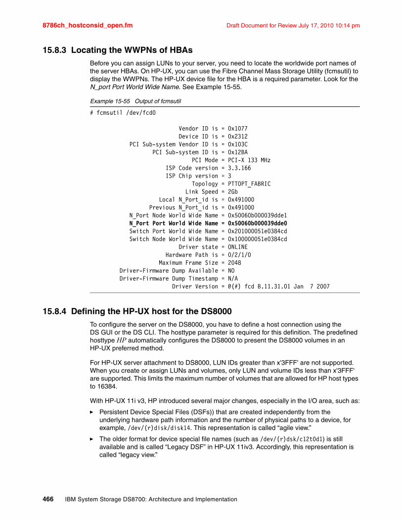
8786ch_hostconsid_open.fm Draft Document for Review July 17, 2010 10:14 pm
15.8.3 Locating the WWPNs of HBAsBefore you can assign LUNs to your server, you need to locate the worldwide port names of the server HBAs. On HP-UX, you can use the Fibre Channel Mass Storage Utility (fcmsutil) to display the WWPNs. The HP-UX device file for the HBA is a required parameter. Look for the N_port Port World Wide Name. See Example 15-55.
Example 15-55 Output of fcmsutil
# fcmsutil /dev/fcd0
Vendor ID is = 0x1077 Device ID is = 0x2312 PCI Sub-system Vendor ID is = 0x103C PCI Sub-system ID is = 0x12BA PCI Mode = PCI-X 133 MHz ISP Code version = 3.3.166 ISP Chip version = 3 Topology = PTTOPT_FABRIC Link Speed = 2Gb Local N_Port_id is = 0x491000 Previous N_Port_id is = 0x491000 N_Port Node World Wide Name = 0x50060b000039dde1 N_Port Port World Wide Name = 0x50060b000039dde0 Switch Port World Wide Name = 0x201000051e0384cd Switch Node World Wide Name = 0x100000051e0384cd Driver state = ONLINE Hardware Path is = 0/2/1/0 Maximum Frame Size = 2048 Driver-Firmware Dump Available = NO Driver-Firmware Dump Timestamp = N/A Driver Version = @(#) fcd B.11.31.01 Jan 7 2007
15.8.4 Defining the HP-UX host for the DS8000To configure the server on the DS8000, you have to define a host connection using the DS GUI or the DS CLI. The hosttype parameter is required for this definition. The predefined hosttype HP automatically configures the DS8000 to present the DS8000 volumes in an HP-UX preferred method.
For HP-UX server attachment to DS8000, LUN IDs greater than x'3FFF' are not supported. When you create or assign LUNs and volumes, only LUN and volume IDs less than x'3FFF' are supported. This limits the maximum number of volumes that are allowed for HP host types to 16384.
With HP-UX 11i v3, HP introduced several major changes, especially in the I/O area, such as:
� Persistent Device Special Files (DSFs)) that are created independently from the underlying hardware path information and the number of physical paths to a device, for example, /dev/(r)disk/disk14. This representation is called “agile view.”
� The older format for device special file names (such as /dev/(r)dsk/c12t0d1) is still available and is called “Legacy DSF” in HP-UX 11iv3. Accordingly, this representation is called “legacy view.”
466 IBM System Storage DS8700: Architecture and Implementation
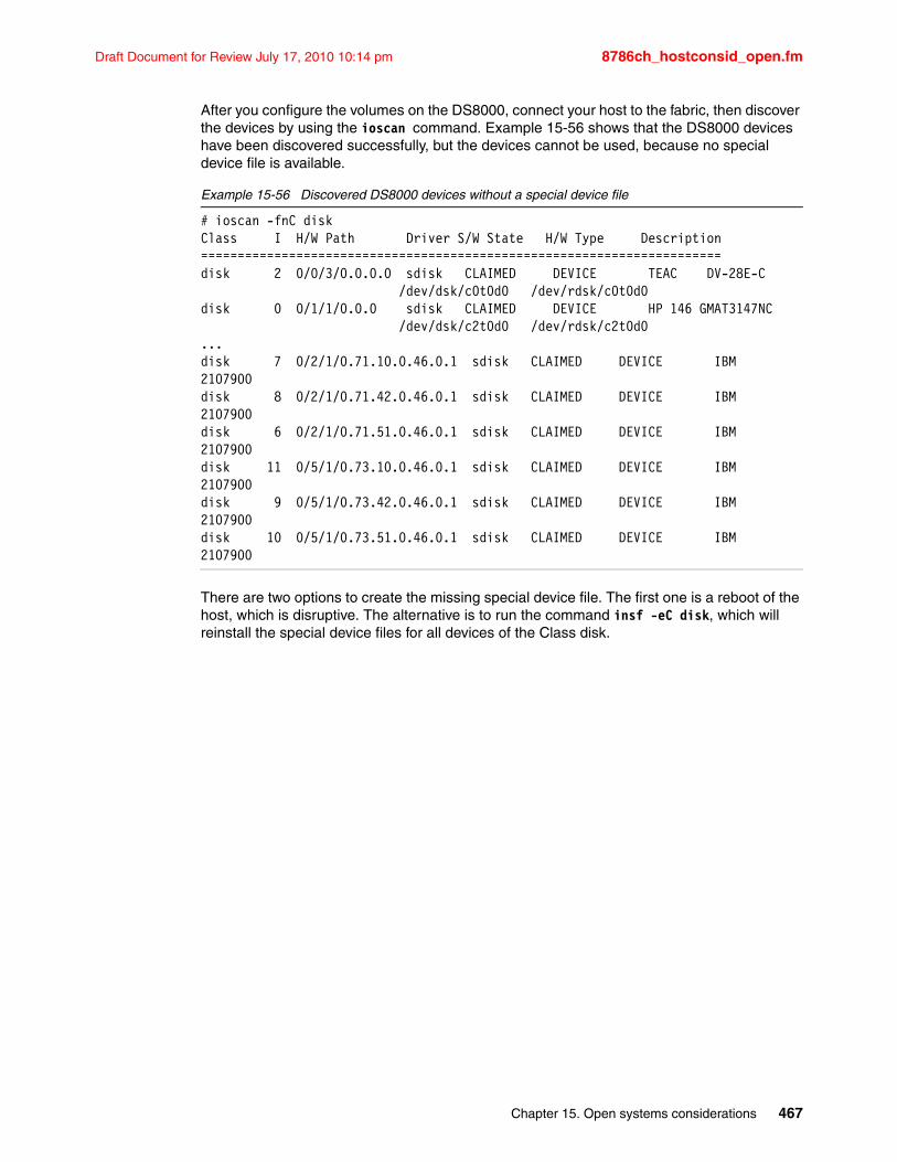
Draft Document for Review July 17, 2010 10:14 pm 8786ch_hostconsid_open.fm
After you configure the volumes on the DS8000, connect your host to the fabric, then discover the devices by using the ioscan command. Example 15-56 shows that the DS8000 devices have been discovered successfully, but the devices cannot be used, because no special device file is available.
Example 15-56 Discovered DS8000 devices without a special device file
# ioscan -fnC diskClass I H/W Path Driver S/W State H/W Type Description=======================================================================disk 2 0/0/3/0.0.0.0 sdisk CLAIMED DEVICE TEAC DV-28E-C /dev/dsk/c0t0d0 /dev/rdsk/c0t0d0disk 0 0/1/1/0.0.0 sdisk CLAIMED DEVICE HP 146 GMAT3147NC /dev/dsk/c2t0d0 /dev/rdsk/c2t0d0...disk 7 0/2/1/0.71.10.0.46.0.1 sdisk CLAIMED DEVICE IBM 2107900disk 8 0/2/1/0.71.42.0.46.0.1 sdisk CLAIMED DEVICE IBM 2107900disk 6 0/2/1/0.71.51.0.46.0.1 sdisk CLAIMED DEVICE IBM 2107900disk 11 0/5/1/0.73.10.0.46.0.1 sdisk CLAIMED DEVICE IBM 2107900disk 9 0/5/1/0.73.42.0.46.0.1 sdisk CLAIMED DEVICE IBM 2107900disk 10 0/5/1/0.73.51.0.46.0.1 sdisk CLAIMED DEVICE IBM 2107900
There are two options to create the missing special device file. The first one is a reboot of the host, which is disruptive. The alternative is to run the command insf -eC disk, which will reinstall the special device files for all devices of the Class disk.
Chapter 15. Open systems considerations 467
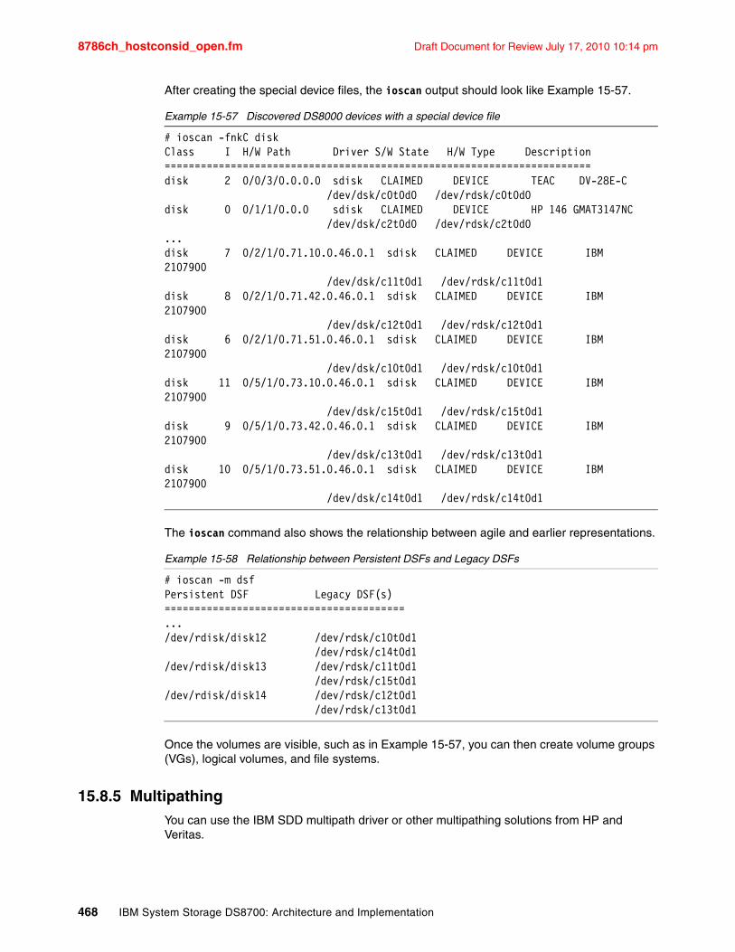
8786ch_hostconsid_open.fm Draft Document for Review July 17, 2010 10:14 pm
After creating the special device files, the ioscan output should look like Example 15-57.
Example 15-57 Discovered DS8000 devices with a special device file
# ioscan -fnkC diskClass I H/W Path Driver S/W State H/W Type Description=======================================================================disk 2 0/0/3/0.0.0.0 sdisk CLAIMED DEVICE TEAC DV-28E-C /dev/dsk/c0t0d0 /dev/rdsk/c0t0d0disk 0 0/1/1/0.0.0 sdisk CLAIMED DEVICE HP 146 GMAT3147NC /dev/dsk/c2t0d0 /dev/rdsk/c2t0d0...disk 7 0/2/1/0.71.10.0.46.0.1 sdisk CLAIMED DEVICE IBM 2107900 /dev/dsk/c11t0d1 /dev/rdsk/c11t0d1disk 8 0/2/1/0.71.42.0.46.0.1 sdisk CLAIMED DEVICE IBM 2107900 /dev/dsk/c12t0d1 /dev/rdsk/c12t0d1disk 6 0/2/1/0.71.51.0.46.0.1 sdisk CLAIMED DEVICE IBM 2107900 /dev/dsk/c10t0d1 /dev/rdsk/c10t0d1disk 11 0/5/1/0.73.10.0.46.0.1 sdisk CLAIMED DEVICE IBM 2107900 /dev/dsk/c15t0d1 /dev/rdsk/c15t0d1disk 9 0/5/1/0.73.42.0.46.0.1 sdisk CLAIMED DEVICE IBM 2107900 /dev/dsk/c13t0d1 /dev/rdsk/c13t0d1disk 10 0/5/1/0.73.51.0.46.0.1 sdisk CLAIMED DEVICE IBM 2107900 /dev/dsk/c14t0d1 /dev/rdsk/c14t0d1
The ioscan command also shows the relationship between agile and earlier representations.
Example 15-58 Relationship between Persistent DSFs and Legacy DSFs
# ioscan -m dsfPersistent DSF Legacy DSF(s)========================================.../dev/rdisk/disk12 /dev/rdsk/c10t0d1 /dev/rdsk/c14t0d1/dev/rdisk/disk13 /dev/rdsk/c11t0d1 /dev/rdsk/c15t0d1/dev/rdisk/disk14 /dev/rdsk/c12t0d1 /dev/rdsk/c13t0d1
Once the volumes are visible, such as in Example 15-57, you can then create volume groups (VGs), logical volumes, and file systems.
15.8.5 MultipathingYou can use the IBM SDD multipath driver or other multipathing solutions from HP and Veritas.
468 IBM System Storage DS8700: Architecture and Implementation
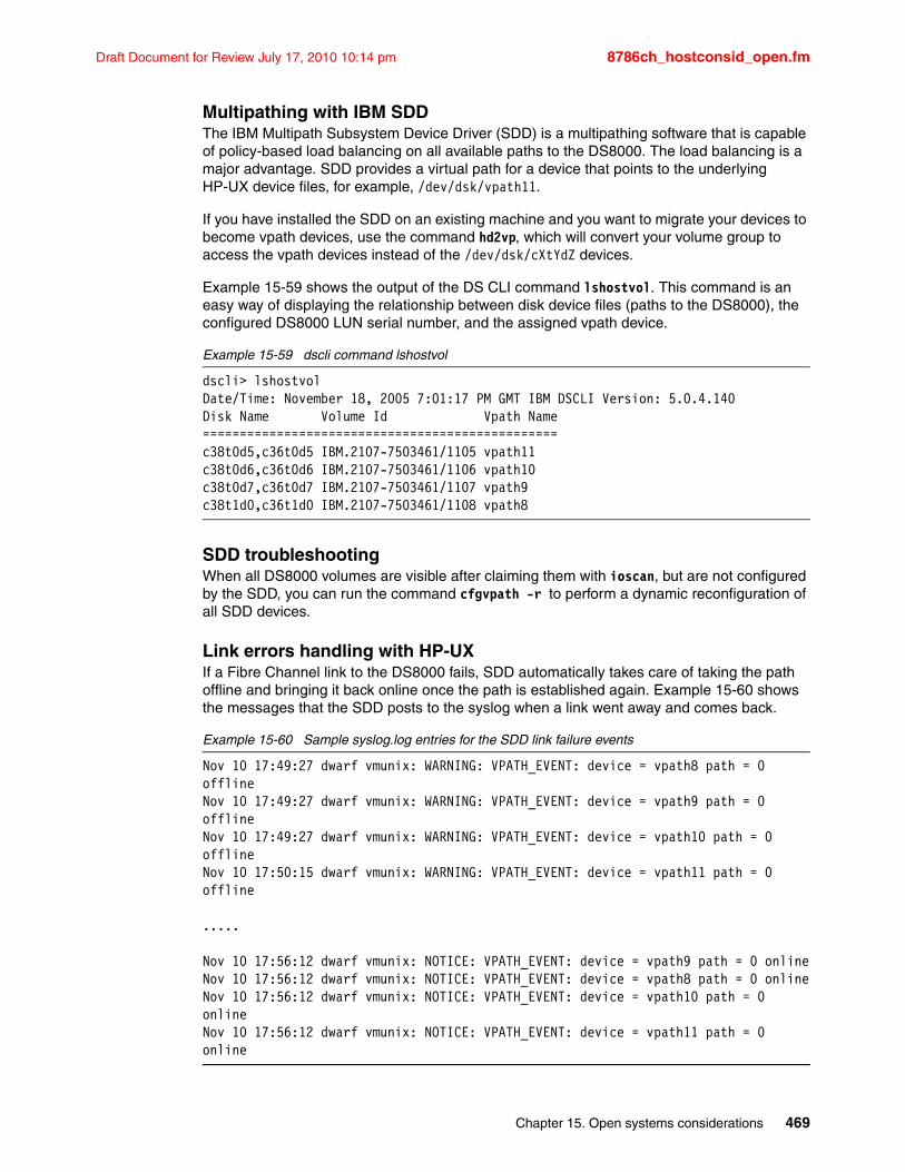
Draft Document for Review July 17, 2010 10:14 pm 8786ch_hostconsid_open.fm
Multipathing with IBM SDDThe IBM Multipath Subsystem Device Driver (SDD) is a multipathing software that is capable of policy-based load balancing on all available paths to the DS8000. The load balancing is a major advantage. SDD provides a virtual path for a device that points to the underlying HP-UX device files, for example, /dev/dsk/vpath11.
If you have installed the SDD on an existing machine and you want to migrate your devices to become vpath devices, use the command hd2vp, which will convert your volume group to access the vpath devices instead of the /dev/dsk/cXtYdZ devices.
Example 15-59 shows the output of the DS CLI command lshostvol. This command is an easy way of displaying the relationship between disk device files (paths to the DS8000), the configured DS8000 LUN serial number, and the assigned vpath device.
Example 15-59 dscli command lshostvol
dscli> lshostvolDate/Time: November 18, 2005 7:01:17 PM GMT IBM DSCLI Version: 5.0.4.140 Disk Name Volume Id Vpath Name================================================c38t0d5,c36t0d5 IBM.2107-7503461/1105 vpath11c38t0d6,c36t0d6 IBM.2107-7503461/1106 vpath10c38t0d7,c36t0d7 IBM.2107-7503461/1107 vpath9c38t1d0,c36t1d0 IBM.2107-7503461/1108 vpath8
SDD troubleshootingWhen all DS8000 volumes are visible after claiming them with ioscan, but are not configured by the SDD, you can run the command cfgvpath -r to perform a dynamic reconfiguration of all SDD devices.
Link errors handling with HP-UXIf a Fibre Channel link to the DS8000 fails, SDD automatically takes care of taking the path offline and bringing it back online once the path is established again. Example 15-60 shows the messages that the SDD posts to the syslog when a link went away and comes back.
Example 15-60 Sample syslog.log entries for the SDD link failure events
Nov 10 17:49:27 dwarf vmunix: WARNING: VPATH_EVENT: device = vpath8 path = 0 offlineNov 10 17:49:27 dwarf vmunix: WARNING: VPATH_EVENT: device = vpath9 path = 0 offlineNov 10 17:49:27 dwarf vmunix: WARNING: VPATH_EVENT: device = vpath10 path = 0 offlineNov 10 17:50:15 dwarf vmunix: WARNING: VPATH_EVENT: device = vpath11 path = 0 offline
.....
Nov 10 17:56:12 dwarf vmunix: NOTICE: VPATH_EVENT: device = vpath9 path = 0 onlineNov 10 17:56:12 dwarf vmunix: NOTICE: VPATH_EVENT: device = vpath8 path = 0 onlineNov 10 17:56:12 dwarf vmunix: NOTICE: VPATH_EVENT: device = vpath10 path = 0 onlineNov 10 17:56:12 dwarf vmunix: NOTICE: VPATH_EVENT: device = vpath11 path = 0 online
Chapter 15. Open systems considerations 469
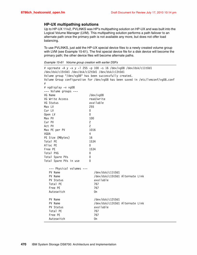
8786ch_hostconsid_open.fm Draft Document for Review July 17, 2010 10:14 pm
HP-UX multipathing solutionsUp to HP-UX 11iv2, PVLINKS was HP’s multipathing solution on HP-UX and was built into the Logical Volume Manager (LVM). This multipathing solution performs a path failover to an alternate path once the primary path is not available any more, but does not offer load balancing.
To use PVLINKS, just add the HP-UX special device files to a newly created volume group with LVM (see Example 15-61). The first special device file for a disk device will become the primary path; the other device files will become alternate paths.
Example 15-61 Volume group creation with earlier DSFs
# vgcreate -A y -x y -l 255 -p 100 -s 16 /dev/vg08 /dev/dsk/c11t0d1 /dev/dsk/c15t0d1 /dev/dsk/c12t0d1 /dev/dsk/c13t0d1Volume group "/dev/vg08" has been successfully created.Volume Group configuration for /dev/vg08 has been saved in /etc/lvmconf/vg08.conf## vgdisplay -v vg08--- Volume groups ---VG Name /dev/vg08VG Write Access read/writeVG Status availableMax LV 255Cur LV 0Open LV 0Max PV 100Cur PV 2Act PV 2Max PE per PV 1016VGDA 4PE Size (MBytes) 16Total PE 1534Alloc PE 0Free PE 1534Total PVG 0Total Spare PVs 0Total Spare PVs in use 0
--- Physical volumes --- PV Name /dev/dsk/c11t0d1 PV Name /dev/dsk/c15t0d1 Alternate Link PV Status available Total PE 767 Free PE 767 Autoswitch On
PV Name /dev/dsk/c12t0d1 PV Name /dev/dsk/c13t0d1 Alternate Link PV Status available Total PE 767 Free PE 767 Autoswitch On
470 IBM System Storage DS8700: Architecture and Implementation
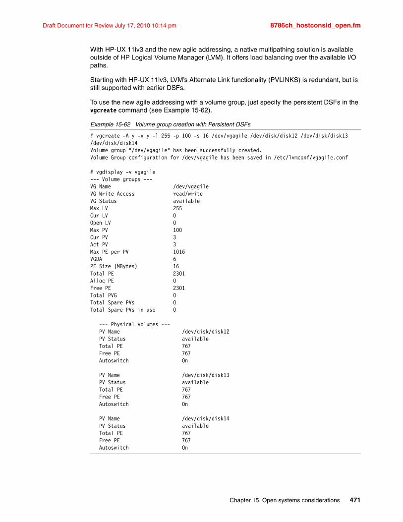
Draft Document for Review July 17, 2010 10:14 pm 8786ch_hostconsid_open.fm
With HP-UX 11iv3 and the new agile addressing, a native multipathing solution is available outside of HP Logical Volume Manager (LVM). It offers load balancing over the available I/O paths.
Starting with HP-UX 11iv3, LVM’s Alternate Link functionality (PVLINKS) is redundant, but is still supported with earlier DSFs.
To use the new agile addressing with a volume group, just specify the persistent DSFs in the vgcreate command (see Example 15-62).
Example 15-62 Volume group creation with Persistent DSFs
# vgcreate -A y -x y -l 255 -p 100 -s 16 /dev/vgagile /dev/disk/disk12 /dev/disk/disk13 /dev/disk/disk14Volume group "/dev/vgagile" has been successfully created.Volume Group configuration for /dev/vgagile has been saved in /etc/lvmconf/vgagile.conf
# vgdisplay -v vgagile--- Volume groups ---VG Name /dev/vgagileVG Write Access read/writeVG Status availableMax LV 255Cur LV 0Open LV 0Max PV 100Cur PV 3Act PV 3Max PE per PV 1016VGDA 6PE Size (MBytes) 16Total PE 2301Alloc PE 0Free PE 2301Total PVG 0Total Spare PVs 0Total Spare PVs in use 0
--- Physical volumes --- PV Name /dev/disk/disk12 PV Status available Total PE 767 Free PE 767 Autoswitch On
PV Name /dev/disk/disk13 PV Status available Total PE 767 Free PE 767 Autoswitch On
PV Name /dev/disk/disk14 PV Status available Total PE 767 Free PE 767 Autoswitch On
Chapter 15. Open systems considerations 471
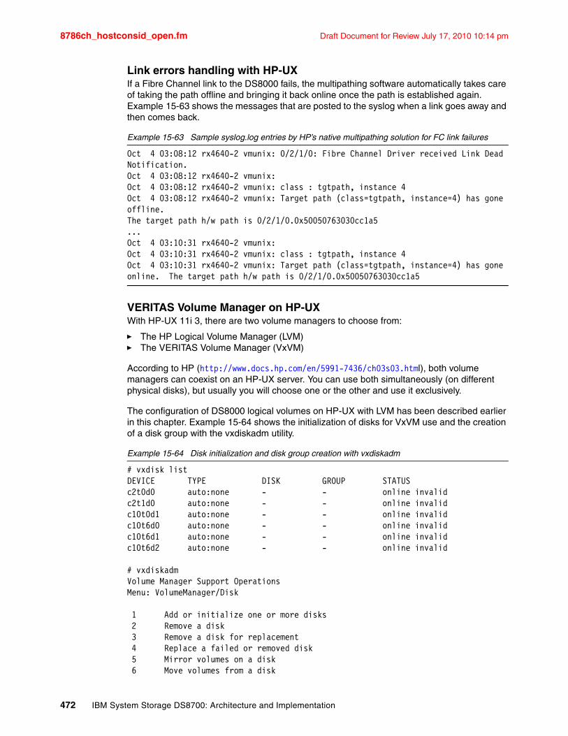
8786ch_hostconsid_open.fm Draft Document for Review July 17, 2010 10:14 pm
Link errors handling with HP-UXIf a Fibre Channel link to the DS8000 fails, the multipathing software automatically takes care of taking the path offline and bringing it back online once the path is established again. Example 15-63 shows the messages that are posted to the syslog when a link goes away and then comes back.
Example 15-63 Sample syslog.log entries by HP’s native multipathing solution for FC link failures
Oct 4 03:08:12 rx4640-2 vmunix: 0/2/1/0: Fibre Channel Driver received Link Dead Notification.Oct 4 03:08:12 rx4640-2 vmunix:Oct 4 03:08:12 rx4640-2 vmunix: class : tgtpath, instance 4Oct 4 03:08:12 rx4640-2 vmunix: Target path (class=tgtpath, instance=4) has gone offline.The target path h/w path is 0/2/1/0.0x50050763030cc1a5...Oct 4 03:10:31 rx4640-2 vmunix:Oct 4 03:10:31 rx4640-2 vmunix: class : tgtpath, instance 4Oct 4 03:10:31 rx4640-2 vmunix: Target path (class=tgtpath, instance=4) has gone online. The target path h/w path is 0/2/1/0.0x50050763030cc1a5
VERITAS Volume Manager on HP-UXWith HP-UX 11i 3, there are two volume managers to choose from:
� The HP Logical Volume Manager (LVM)� The VERITAS Volume Manager (VxVM)
According to HP (http://www.docs.hp.com/en/5991-7436/ch03s03.html), both volume managers can coexist on an HP-UX server. You can use both simultaneously (on different physical disks), but usually you will choose one or the other and use it exclusively.
The configuration of DS8000 logical volumes on HP-UX with LVM has been described earlier in this chapter. Example 15-64 shows the initialization of disks for VxVM use and the creation of a disk group with the vxdiskadm utility.
Example 15-64 Disk initialization and disk group creation with vxdiskadm
# vxdisk listDEVICE TYPE DISK GROUP STATUSc2t0d0 auto:none - - online invalidc2t1d0 auto:none - - online invalidc10t0d1 auto:none - - online invalidc10t6d0 auto:none - - online invalidc10t6d1 auto:none - - online invalidc10t6d2 auto:none - - online invalid
# vxdiskadmVolume Manager Support OperationsMenu: VolumeManager/Disk
1 Add or initialize one or more disks 2 Remove a disk 3 Remove a disk for replacement 4 Replace a failed or removed disk 5 Mirror volumes on a disk 6 Move volumes from a disk
472 IBM System Storage DS8700: Architecture and Implementation
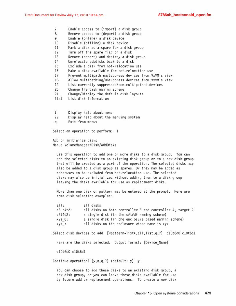
Draft Document for Review July 17, 2010 10:14 pm 8786ch_hostconsid_open.fm
7 Enable access to (import) a disk group 8 Remove access to (deport) a disk group 9 Enable (online) a disk device 10 Disable (offline) a disk device 11 Mark a disk as a spare for a disk group 12 Turn off the spare flag on a disk 13 Remove (deport) and destroy a disk group 14 Unrelocate subdisks back to a disk 15 Exclude a disk from hot-relocation use 16 Make a disk available for hot-relocation use 17 Prevent multipathing/Suppress devices from VxVM's view 18 Allow multipathing/Unsuppress devices from VxVM's view 19 List currently suppressed/non-multipathed devices 20 Change the disk naming scheme 21 Change/Display the default disk layouts list List disk information
? Display help about menu ?? Display help about the menuing system q Exit from menus
Select an operation to perform: 1
Add or initialize disksMenu: VolumeManager/Disk/AddDisks
Use this operation to add one or more disks to a disk group. You can add the selected disks to an existing disk group or to a new disk group that will be created as a part of the operation. The selected disks may also be added to a disk group as spares. Or they may be added as nohotuses to be excluded from hot-relocation use. The selected disks may also be initialized without adding them to a disk group leaving the disks available for use as replacement disks.
More than one disk or pattern may be entered at the prompt. Here are some disk selection examples:
all: all disks c3 c4t2: all disks on both controller 3 and controller 4, target 2 c3t4d2: a single disk (in the c#t#d# naming scheme) xyz_0: a single disk (in the enclosure based naming scheme) xyz_: all disks on the enclosure whose name is xyz
Select disk devices to add: [<pattern-list>,all,list,q,?] c10t6d0 c10t6d1
Here are the disks selected. Output format: [Device_Name]
c10t6d0 c10t6d1
Continue operation? [y,n,q,?] (default: y) y
You can choose to add these disks to an existing disk group, a new disk group, or you can leave these disks available for use by future add or replacement operations. To create a new disk
Chapter 15. Open systems considerations 473
8786ch_hostconsid_open.fm Draft Document for Review July 17, 2010 10:14 pm
group, select a disk group name that does not yet exist. To leave the disks available for future use, specify a disk group name of "none".
Which disk group [<group>,none,list,q,?] (default: none) dg01
There is no active disk group named dg01.
Create a new group named dg01? [y,n,q,?] (default: y)
Create the disk group as a CDS disk group? [y,n,q,?] (default: y) n
Use default disk names for these disks? [y,n,q,?] (default: y)
Add disks as spare disks for dg01? [y,n,q,?] (default: n) n
Exclude disks from hot-relocation use? [y,n,q,?] (default: n)
A new disk group will be created named dg01 and the selected disks will be added to the disk group with default disk names.
c10t6d0 c10t6d1
Continue with operation? [y,n,q,?] (default: y)
Do you want to use the default layout for all disks being initialized?[y,n,q,?] (default: y) n
Do you want to use the same layout for all disks being initialized?[y,n,q,?] (default: y)
Enter the desired format [cdsdisk,hpdisk,q,?] (default: cdsdisk) hpdisk
Enter the desired format [cdsdisk,hpdisk,q,?] (default: cdsdisk) hpdisk
Enter desired private region length[<privlen>,q,?] (default: 1024)
Initializing device c10t6d0.
Initializing device c10t6d1.
VxVM NOTICE V-5-2-120Creating a new disk group named dg01 containing the disk device c10t6d0 with the name dg0101.
VxVM NOTICE V-5-2-88Adding disk device c10t6d1 to disk group dg01 with disk name dg0102.
Add or initialize other disks? [y,n,q,?] (default: n) n
# vxdisk listDEVICE TYPE DISK GROUP STATUSc2t0d0 auto:none - - online invalid
474 IBM System Storage DS8700: Architecture and Implementation
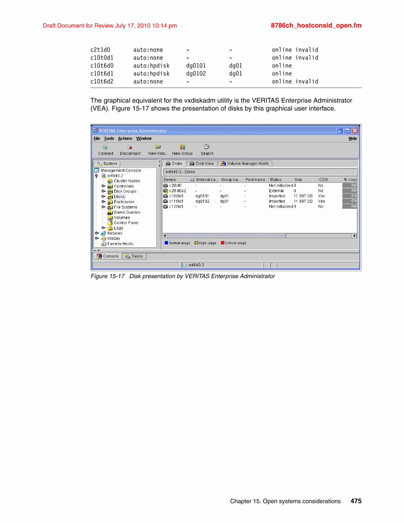
Draft Document for Review July 17, 2010 10:14 pm 8786ch_hostconsid_open.fm
c2t1d0 auto:none - - online invalidc10t0d1 auto:none - - online invalidc10t6d0 auto:hpdisk dg0101 dg01 onlinec10t6d1 auto:hpdisk dg0102 dg01 onlinec10t6d2 auto:none - - online invalid
The graphical equivalent for the vxdiskadm utility is the VERITAS Enterprise Administrator (VEA). Figure 15-17 shows the presentation of disks by this graphical user interface.
Figure 15-17 Disk presentation by VERITAS Enterprise Administrator
Chapter 15. Open systems considerations 475

8786ch_hostconsid_open.fm Draft Document for Review July 17, 2010 10:14 pm
476 IBM System Storage DS8700: Architecture and Implementation
Draft Document for Review July 17, 2010 10:14 pm 8786ch_Hostconsid_zOS.fm
Chapter 16. IBM System z considerations
This chapter discusses the specifics of attaching the IBM System Storage DS8700 series system to System z hosts. This chapter covers the following topics:
� Connectivity considerations
� Operating systems prerequisites and enhancements
� z/OS considerations
� z/VM considerations
� VSE/ESA and z/VSE considerations
� Extended Distance FICON
� High Performance FICON for z (zHPF) with multitrack support
� z/OS Basic HyperSwap
16
© Copyright IBM Corp. 2010. All rights reserved. 477
8786ch_Hostconsid_zOS.fm Draft Document for Review July 17, 2010 10:14 pm
16.1 Connectivity considerationsThe DS8700 storage unit connects to System z hosts using FICON channels, with the addition of Fibre Channel Protocol (FCP) connectivity for Linux for System z hosts.
FICONYou need to check for dependencies on the host hardware driver level and the supported feature codes. Your IBM service representative can help you determine your current hardware driver level on your mainframe processor complex. Examples of limited host server feature support are FICON Express2 LX (FC3319), and FICON Express2 SX (FC3320), which are available only for the z890 and z990 host server models. For the z9 and z10 servers, FICON Express4 LX (FC3321 at 10 km and FC3324 at 4 km) and FICON Express4 SX (FC3322) are available. In addition, z10 supports the new FICON Express8 LX (FC3325 at 10 km) and FICON Express8 SX (FC3326).
LINUX FCP connectivityYou can use either direct or switched attachment to attach a storage unit to a System z host system that runs SLES 8 or 9 or Red Hat Enterprise Linux 3.0 with current maintenance updates for FICON.
FCP attachment to Linux on System z systems can only be done through a switched-fabric configuration. You cannot attach the host through a direct configuration.
16.2 Operating systems prerequisites and enhancementsThe minimum software levels required to support the DS8700 are:
� z/OS V1.4+� z/VM V4.4 or z/VM V5.1� VSE/ESA V2.7 or z/VSE V3.1� TPF V4.1 with PTF� SLES 8 or 9 for System z� Red Hat Enterprise Linux 3.0
Some functions of the DS8700 require later software levels than the minimum levels listed here. Refer to the IBM System Storage Interoperability Center (SSIC) at the following address:
http://www-03.ibm.com/systems/support/storage/config/ssic/displayesssearchwithoutjs.wss
Important: In addition to SSIC, always review the Preventive Service Planning (PSP) bucket of the 2107 for software updates.
478 IBM System Storage DS8700: Architecture and Implementation
Draft Document for Review July 17, 2010 10:14 pm 8786ch_Hostconsid_zOS.fm
The PSP information can be found at the Resource Link™ Web site at the following address:
http://www-1.ibm.com/servers/resourcelink/svc03100.nsf?OpenDatabase
You need to register for an IBM Registration ID (IBM ID) before you can sign in to the Web site.
Look under the Planning section, then go to Tools to download the relevant PSP package.
16.3 z/OS considerationsIn this section, we discuss the program enhancements that z/OS has implemented to support the characteristics of the DS8700. We also give guidelines for the definition of Parallel Access Volumes (PAVs).
16.3.1 z/OS program enhancements (SPEs)The list of relevant Data Facility Storage Management Subsystem (DFSMS) small program enhancements (SPEs) that have been introduced in z/OS for support of all DS8000 models, including DS8700, are the following:
� Scalability support� Large volume support (LVS)� Extended Address Volumes (EAV)� Read availability mask support� Initial Program Load (IPL) enhancements� DS8700 device definition� Read control unit and device recognition for DS8700� Performance statistics� Resource Measurement Facility (RMF)� System Management Facilities (SMF)� Migration considerations
Many of these program enhancements are initially available as APARs and PTFs for the current releases of z/OS, and are later integrated into the following releases of z/OS. For this reason, we recommend that you review the DS8700 PSP bucket for your current release of z/OS.
Scalability supportThe IOS recovery was designed to support a small number of devices per control unit, and a unit check was presented on all devices at failover. This does not scale well with a DS8700, which has the capability to scale up to 65,280 devices. Under these circumstances, you can have CPU or spin lock contention, or exhausted storage below the 16 M line at device failover, or both.
Starting with z/OS V1.4 and higher for DS8700 software support, the IOS recovery has been improved by consolidating unit checks at an LSS level instead of each disconnected device. This consolidation shortens the recovery time as a result of I/O errors. This enhancement is particularly important, because the DS8700 can have up to 65,280 devices in a storage facility.
Chapter 16. IBM System z considerations 479
8786ch_Hostconsid_zOS.fm Draft Document for Review July 17, 2010 10:14 pm
BenefitsWith enhanced scalability support, the following benefits are possible:
� Common storage area (CSA) usage (above and below the 16 M line) is reduced.
� The I/O supervisor (IOS) large block pool for error recovery processing and attention and the state change interrupt processing are located above the 16 M line, thus reducing the storage demand below the 16 M line.
� Unit control blocks (UCB) are pinned during event notification facility (ENF) signalling during channel path recovery.
� These scalability enhancements provide additional performance improvements by:
– Bypassing dynamic pathing validation in channel recovery for reduced recovery I/Os.
– Reducing elapsed time by reducing the wait time in channel path recovery.
Large volume support (LVS)As today’s storage facilities tend to expand to even larger capacities, we are approaching the UCB’s 64 K limitation at a very fast rate. Thus, we must plan for even larger volume sizes.
Support has been enhanced to expand volumes to 65,520 cylinders, using existing 16-bit cylinder addressing. This is often referred to as 64 K cylinder volumes. Components and products, such as DADSM/CVAF, DFSMSdss, ICKDSF, and DFSORT, that previously shipped with 32,760 cylinders, now also support 65,520 cylinders. Checkpoint restart processing now supports a checkpoint data set that resides partially or wholly above the 32,760 cylinder boundary.
With LVS volumes, the VTOC has the potential to grow very large. Callers such as DFSMSdss have to read the entire VTOC to find the last allocated DSCB; in cases where the VTOC is very large, you can experience performance degradation. An interface is implemented to return the highly allocated DSCB on volumes initialized with an INDEX VTOC. DFSMSdss uses this interface to limit VTOC searches and to improve performance. The VTOC has to be within the first 64 K-1 tracks, while the INDEX can be anywhere on the volume.
480 IBM System Storage DS8700: Architecture and Implementation
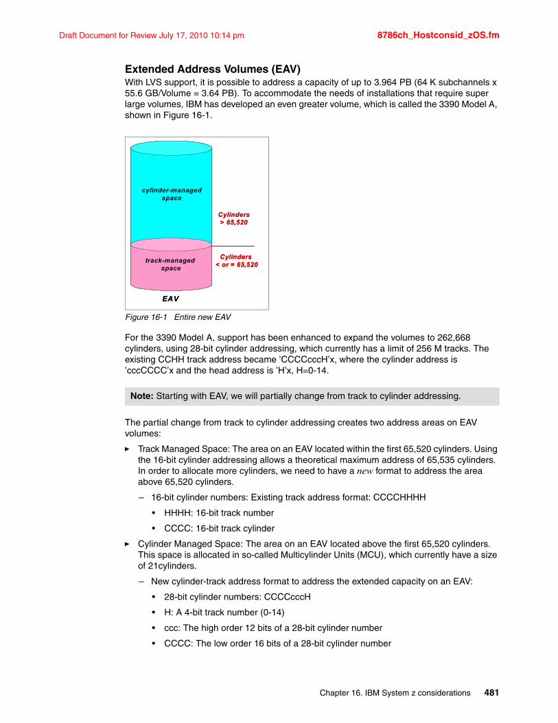
Draft Document for Review July 17, 2010 10:14 pm 8786ch_Hostconsid_zOS.fm
Extended Address Volumes (EAV)With LVS support, it is possible to address a capacity of up to 3.964 PB (64 K subchannels x 55.6 GB/Volume = 3.64 PB). To accommodate the needs of installations that require super large volumes, IBM has developed an even greater volume, which is called the 3390 Model A, shown in Figure 16-1.
Figure 16-1 Entire new EAV
For the 3390 Model A, support has been enhanced to expand the volumes to 262,668 cylinders, using 28-bit cylinder addressing, which currently has a limit of 256 M tracks. The existing CCHH track address became ’CCCCcccH’x, where the cylinder address is ’cccCCCC’x and the head address is ’H’x, H=0-14.
The partial change from track to cylinder addressing creates two address areas on EAV volumes:
� Track Managed Space: The area on an EAV located within the first 65,520 cylinders. Using the 16-bit cylinder addressing allows a theoretical maximum address of 65,535 cylinders. In order to allocate more cylinders, we need to have a new format to address the area above 65,520 cylinders.
– 16-bit cylinder numbers: Existing track address format: CCCCHHHH
• HHHH: 16-bit track number
• CCCC: 16-bit track cylinder
� Cylinder Managed Space: The area on an EAV located above the first 65,520 cylinders. This space is allocated in so-called Multicylinder Units (MCU), which currently have a size of 21cylinders.
– New cylinder-track address format to address the extended capacity on an EAV:
• 28-bit cylinder numbers: CCCCcccH
• H: A 4-bit track number (0-14)
• ccc: The high order 12 bits of a 28-bit cylinder number
• CCCC: The low order 16 bits of a 28-bit cylinder number
Note: Starting with EAV, we will partially change from track to cylinder addressing.
EAV
cylinder-managedspace
track-managed space
Cylinders> 65,520
Cylinders < or = 65,520
EAV
cylinder-managedspace
track-managed space
Cylinders> 65,520
Cylinders < or = 65,520
Chapter 16. IBM System z considerations 481
8786ch_Hostconsid_zOS.fm Draft Document for Review July 17, 2010 10:14 pm
Components and products, such as DADSM/CVAF, DFSMSdss, ICKDSF, and DFSORT, will also now support 262,668 cylinders.
� DS8700 and z/OS limit CKD EAV volume size:
- 3390 Model A: 1 - 262,668 cylinders (about 223 GB addressable Storage)
- 3390 Model A: Up to 236 x 3390 Model 1 (Four times the size we have with LVS)
� Configuration Granularity
- 1 Cylinder boundary sizes: 1 to 56,520 cylinders
- 1113 Cylinders boundary sizes: 56,763 (51 x 1113) to 262,668 (236 x 1113) cylinders
The size of an existing Mod 3/9/A volume can be increased to its maximum supported size using Dynamic Volume Expansion (DVE). That can be done with the DS CLI command as Example 16-1 shows.
Example 16-1 Dynamically expand CKD volume
dscli> chckdvol -cap 262268 -captype cyl 9ab0
Date/Time: 10. Mai 2010 07:52:55 CEST IBM DSCLI Version: 6.5.1.193 DS: IBM.2107-75KAB25CMUC00022I chckdvol: CKD Volume 9AB0 successfully modified.
Keep in mind that Dynamic Volume Expansion can be done while the volume remains online to the host system. But usually a VTOC refresh through ICKDSF is suggested to reflect the newly added free space. When the concerned volume is in a Copy Services relationship then this Copy Services relationship must be terminated until both volumes, source and target volumes are changed to their new capacity. After that the Copy Service pair has to be newly established.
The VTOC allocation method for an EAV volume has been changed compared to the VTOC used for LVS volumes. The size of an EAV VTOC index has been increased four times with now 8,192 blocks instead of 2,048 blocks before. Because there is no space left inside the format 1 DSCB, new DSCB formats, format 8 and format 9, have been created to protect existing programs from seeing unexpected track addresses. These DSCBs are called extended attribute DSCBs. Format 8 and 9 DSCBs are new for EAV. The existing format 4 DSCB has been changed also to point to the new format 8 DSCB.
How to identify an EAVWhen a volume has more than 65,520 cylinders, the format 4 DSCB (modified) is updated to x’FFFE’, which has a size of 65,534 cylinders. This will identify the volume as being an EAV. An easy way to identify an EAV is to list the VTOC Summary in TSO/ISPF option 3.4. Example 17-1 shows the VTOC summary of a 3390 Model 9 volume.
Example 16-2 TSO/ISPF 3.4 screen for a non-EAV volume: VTOC Summary
Menu RefList RefMode Utilities Help +-------------------------- VTOC Summary Information --------------------------+| Volume . : SBOXA7 || Command ===> || || Unit . . : 3390 |
Note: When formatting a volume with ICKDSF where the VTOC index size has been omitted, the volume will take the default size of 15 tracks.
482 IBM System Storage DS8700: Architecture and Implementation
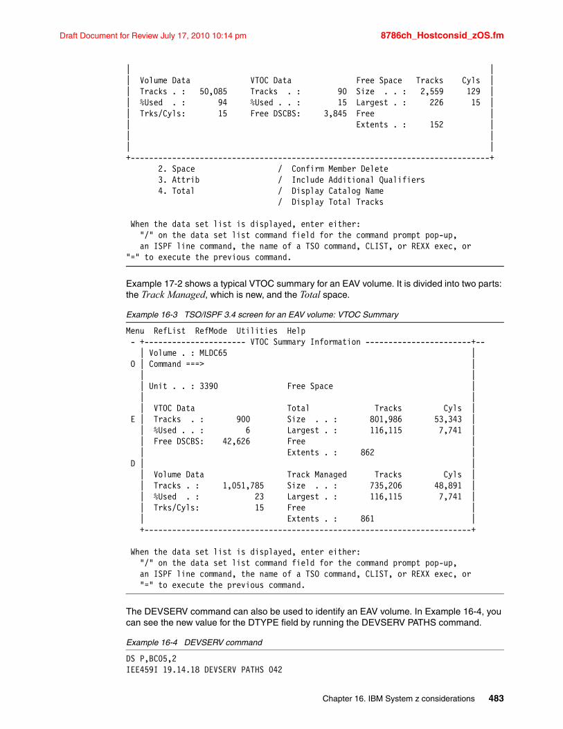
Draft Document for Review July 17, 2010 10:14 pm 8786ch_Hostconsid_zOS.fm
| || Volume Data VTOC Data Free Space Tracks Cyls || Tracks . : 50,085 Tracks . : 90 Size . . : 2,559 129 || %Used . : 94 %Used . . : 15 Largest . : 226 15 || Trks/Cyls: 15 Free DSCBS: 3,845 Free || Extents . : 152 || || |+------------------------------------------------------------------------------+ 2. Space / Confirm Member Delete 3. Attrib / Include Additional Qualifiers 4. Total / Display Catalog Name / Display Total Tracks When the data set list is displayed, enter either: "/" on the data set list command field for the command prompt pop-up, an ISPF line command, the name of a TSO command, CLIST, or REXX exec, or "=" to execute the previous command.
Example 17-2 shows a typical VTOC summary for an EAV volume. It is divided into two parts: the Track Managed, which is new, and the Total space.
Example 16-3 TSO/ISPF 3.4 screen for an EAV volume: VTOC Summary
Menu RefList RefMode Utilities Help - +---------------------- VTOC Summary Information -----------------------+-- | Volume . : MLDC65 | O | Command ===> | | | | Unit . . : 3390 Free Space | | | | VTOC Data Total Tracks Cyls | E | Tracks . : 900 Size . . : 801,986 53,343 | | %Used . . : 6 Largest . : 116,115 7,741 | | Free DSCBS: 42,626 Free | | Extents . : 862 | D | | | Volume Data Track Managed Tracks Cyls | | Tracks . : 1,051,785 Size . . : 735,206 48,891 | | %Used . : 23 Largest . : 116,115 7,741 | | Trks/Cyls: 15 Free | | Extents . : 861 | +-----------------------------------------------------------------------+ When the data set list is displayed, enter either: "/" on the data set list command field for the command prompt pop-up, an ISPF line command, the name of a TSO command, CLIST, or REXX exec, or "=" to execute the previous command.
The DEVSERV command can also be used to identify an EAV volume. In Example 16-4, you can see the new value for the DTYPE field by running the DEVSERV PATHS command.
Example 16-4 DEVSERV command
DS P,BC05,2 IEE459I 19.14.18 DEVSERV PATHS 042
Chapter 16. IBM System z considerations 483
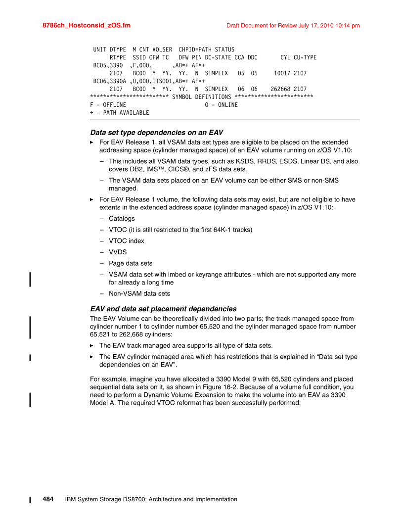
8786ch_Hostconsid_zOS.fm Draft Document for Review July 17, 2010 10:14 pm
UNIT DTYPE M CNT VOLSER CHPID=PATH STATUS RTYPE SSID CFW TC DFW PIN DC-STATE CCA DDC CYL CU-TYPE BC05,3390 ,F,000, ,AB=+ AF=+ 2107 BC00 Y YY. YY. N SIMPLEX 05 05 10017 2107 BC06,3390A ,O,000,ITSO01,AB=+ AF=+ 2107 BC00 Y YY. YY. N SIMPLEX 06 06 262668 2107 ************************ SYMBOL DEFINITIONS ************************ F = OFFLINE O = ONLINE + = PATH AVAILABLE
Data set type dependencies on an EAV � For EAV Release 1, all VSAM data set types are eligible to be placed on the extended
addressing space (cylinder managed space) of an EAV volume running on z/OS V1.10:
– This includes all VSAM data types, such as KSDS, RRDS, ESDS, Linear DS, and also covers DB2, IMS™, CICS®, and zFS data sets.
– The VSAM data sets placed on an EAV volume can be either SMS or non-SMS managed.
� For EAV Release 1 volume, the following data sets may exist, but are not eligible to have extents in the extended address space (cylinder managed space) in z/OS V1.10:
– Catalogs
– VTOC (it is still restricted to the first 64K-1 tracks)
– VTOC index
– VVDS
– Page data sets
– VSAM data set with imbed or keyrange attributes - which are not supported any more for already a long time
– Non-VSAM data sets
EAV and data set placement dependenciesThe EAV Volume can be theoretically divided into two parts; the track managed space from cylinder number 1 to cylinder number 65,520 and the cylinder managed space from number 65,521 to 262,668 cylinders:
� The EAV track managed area supports all type of data sets.
� The EAV cylinder managed area which has restrictions that is explained in “Data set type dependencies on an EAV”.
For example, imagine you have allocated a 3390 Model 9 with 65,520 cylinders and placed sequential data sets on it, as shown in Figure 16-2. Because of a volume full condition, you need to perform a Dynamic Volume Expansion to make the volume into an EAV as 3390 Model A. The required VTOC reformat has been successfully performed.
484 IBM System Storage DS8700: Architecture and Implementation
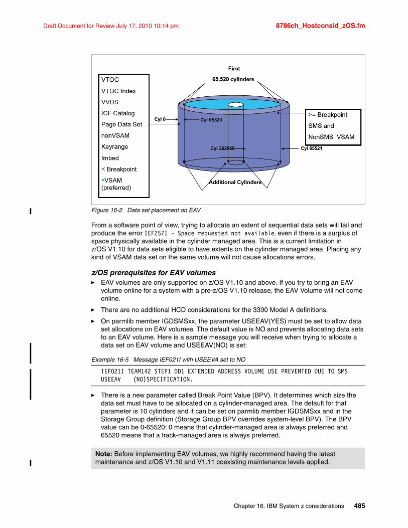
Draft Document for Review July 17, 2010 10:14 pm 8786ch_Hostconsid_zOS.fm
Figure 16-2 Data set placement on EAV
From a software point of view, trying to allocate an extent of sequential data sets will fail and produce the error IEF257I - Space requested not available, even if there is a surplus of space physically available in the cylinder managed area. This is a current limitation in z/OS V1.10 for data sets eligible to have extents on the cylinder managed area. Placing any kind of VSAM data set on the same volume will not cause allocations errors.
z/OS prerequisites for EAV volumes� EAV volumes are only supported on z/OS V1.10 and above. If you try to bring an EAV
volume online for a system with a pre-z/OS V1.10 release, the EAV Volume will not come online.
� There are no additional HCD considerations for the 3390 Model A definitions.
� On parmlib member IGDSMSxx, the parameter USEEAV(YES) must be set to allow data set allocations on EAV volumes. The default value is NO and prevents allocating data sets to an EAV volume. Here is a sample message you will receive when trying to allocate a data set on EAV volume and USEEAV(NO) is set:
Example 16-5 Message IEF021I with USEEVA set to NO
IEF021I TEAM142 STEP1 DD1 EXTENDED ADDRESS VOLUME USE PREVENTED DUE TO SMS USEEAV (NO)SPECIFICATION.
� There is a new parameter called Break Point Value (BPV). It determines which size the data set must have to be allocated on a cylinder-managed area. The default for that parameter is 10 cylinders and it can be set on parmlib member IGDSMSxx and in the Storage Group definition (Storage Group BPV overrides system-level BPV). The BPV value can be 0-65520: 0 means that cylinder-managed area is always preferred and 65520 means that a track-managed area is always preferred.
Note: Before implementing EAV volumes, we highly recommend having the latest maintenance and z/OS V1.10 and V1.11 coexisting maintenance levels applied.
Chapter 16. IBM System z considerations 485
8786ch_Hostconsid_zOS.fm Draft Document for Review July 17, 2010 10:14 pm
Data set allocation: space considerationsConsider the following items:
� When allocating a data set extent on an EAV volume, the space requested is rounded up to the next Multicylinder Unit (MCU) if the entire extent is allocated in cylinder-managed space. Individual extents always start and end on an MCU boundary.
� A given extent is contained in a single managed space, which means an extent cannot straddle where the cylinder-managed area begins.
� Exact space will be obtained if allocated on a track-managed area, exactly how it was before EAV implementation.
� If the requested space is not available from the preferred managed space (as determined by BPV), the system may allocate the space from both cylinder-managed and track-managed spaces.
� Because VSAM striped data sets require that all the stripes be the same size, the system will attempt to honor exact requested space using a combination of cylinder-managed and track-managed spaces.
VSAM Control Area (CA) considerationsConsider the following items:
� VSAM data sets created in z/OS V1.10 (EAV and non-EAV) may have different CA sizes from what would have been received in prior releases. The reason for this is that a CA must be compatible with Multicylinder Units (MCU) for a cylinder-managed area.
� VSAM data sets allocated with compatible CAs on a non-EAV are eligible to be extended to additional volumes that support cylinder-managed space. Note that VSAM data sets physically copied from a non-EAV to an EAV may have an incompatible CA and thus would not be EAS eligible. This means extents for additional space would not use cylinder-managed space.
EAV Migration considerationsConsider the following items:
� Assistance:
Migration assitance will be provided through use of the Application Migration Assistance Tracker. For more details about Assistance Tracker, see APAR II13752, which can be found at the following address:
http://www.ibm.com/support/docview.wss?uid=isg1II13752
� Recommended actions:
– Review your programs and take a look at the calls for the macros OBTAIN, REALLOC, CVAFDIR, CVAFSEQ, CVAFDSM, and CVAFFILT. Those macros were changed and you need to update your program to reflect those changes.
– Look for programs that calculate volume or data set size by any means, including reading a VTOC or VTOC index directly with a BSAM or EXCP DCB. This task is important because now we have new values returning for the volume size.
– Review your programs and look for EXCP and STARTIO macros for DASD channel programs and other programs that examine DASD channel programs or track addresses. Now that we have new addressing mode, programs must be updated.
Note: This is a migration to z/OS V1.10 consideration.
486 IBM System Storage DS8700: Architecture and Implementation
Draft Document for Review July 17, 2010 10:14 pm 8786ch_Hostconsid_zOS.fm
– Look for programs that examine any of the many operator messages that contain a DASD track, block address, data set, or volume size. The messages now show new values.
� Migrating data:
– Define new EAVs by creating them on the DS8700 or expanding existing volumes using Dynamic Volume Expansion.
– Add new EAV volumes to storage groups and storage pools, and update ACS routines.
– Copy data at the volume level: TDMF®, DFSMSdss, PPRC, DFSMS, Copy Services Global Mirror, Metro Mirror, Global Copy, and FlashCopy.
– Copy data at the data set level: SMS attrition, LDMF, DFSMSdss, and DFSMShsm.
– Good volume candidates for EAV include DB2, zFS, CICS VSAM, RLS, and IMS VSAM. Poor EAV candidates are DFSMShsm ML1, Backup or ML2 - although Small Data Set Packaging (SDSP) is eligible for cylinder managed. Also considered as poor EAV candidates are work Volumes, TSO/GDG/Batch/Load Libraries, and System Volumes.
– DFSMSdss and DFSMShsm considerations when migrating to EAV are described in DFSMS V1.10 and EAV Technical Guide, SG24-7617.
Chapter 16. IBM System z considerations 487
8786ch_Hostconsid_zOS.fm Draft Document for Review July 17, 2010 10:14 pm
Read availability mask support Dynamic CHPID Management (DCM) allows you to define a pool of channels that is managed by the system. The channels are added and deleted from control units based on workload importance and availability needs. DCM attempts to avoid single points of failure when adding or deleting a managed channel by not selecting an interface on the control unit on the same I/O card.
Control unit single point of failure information was specified in a table and had to be updated for each new control unit. Instead, with the present enhancement, we can use the Read Availability Mask command, PSF/RSD, to retrieve the information from the control unit. By doing this task, there is no need to maintain a table for this information.
Initial Program Load (IPL) enhancementsDuring the IPL sequence, the channel subsystem selects a channel path to read from the SYSRES device. Certain types of I/O errors on a channel path cause the IPL to fail even though there are alternate channel paths that might work. For example, consider a situation where there is a bad switch link on the first path but good links on the other paths. In this case, you cannot IPL, because the same faulty path is always chosen.
The channel subsystem and z/OS were enhanced to retry I/O over an alternate channel path. This circumvents IPL failures that were caused by the selection of the same faulty path to read from the SYSRES device.
DS8700 device definitionTo exploit the increase in the number of LSSs that can be added in the DS8700 (255 LSSs), the unit must be defined as 2107 in the HCD/IOCP. The host supports 255 logical control units when the DS8700 is defined as UNIT=2107. You must install the appropriate software to support this setup. If you do not have the required software support installed, you can define the DS8700 as UNIT=2105; in this case, only the 16 logical control units (LCUs) of Address Group 0 can be used.
Starting with z9-109 processors, you can define an additional subchannel set with ID 1 (SS 1) on top of the existing subchannel set (SS 0) in a channel subsystem. With this additional subchannel set, you can configure more than 2 x 63 K devices for a channel subsystem. With z/OS V1.7+ you can define Parallel Access Volume (PAV) alias devices, device types 3380A and 3390A, of the DS8700 (2107) DASD control units to SS 1. Device numbers can be duplicated across channel subsystems and subchannel sets.
Read control unit and device recognition for DS8700The host system informs the attached DS8700 of its capabilities, so that it supports native DS8700 control unit and devices. The DS8700 then only returns information that is supported by the attached host system using the self-description data, such as read data characteristics (RDC), sense ID, and read configuration data (RCD).
488 IBM System Storage DS8700: Architecture and Implementation
Draft Document for Review July 17, 2010 10:14 pm 8786ch_Hostconsid_zOS.fm
The following commands display device type 2107 in their output:
� DEVSERV QDASD and PATHS command responses � IDCAMS LISTDATA COUNTS, DSTATUS, STATUS, and IDCAMS SETCACHE
Performance statisticsTwo sets of performance statistics that are reported by the DS8700 were introduced. Because a logical volume is no longer allocated on a single RAID rank or single device adapter pair, the performance data is now provided with a set of rank performance statistics and extent pool statistics. The RAID RANK reports are no longer reported by RMF and IDCAMS LISTDATA batch reports. RMF and IDCAMS LISTDATA are enhanced to report the logical volume statistics that are provided on the DS8700.
These reports consist of back-end counters that capture the activity between the cache and the ranks in the DS8700 for each individual logical volume. These rank and extent pool statistics are disk system-wide instead of volume-wide only.
Resource Measurement Facility (RMF)RMF supports DS8700 from z/OS V1.4 and above with APAR number OA06476 and PTFs UA90079 and UA90080. RMF has been enhanced to provide Monitor I and III support for the DS8700 storage system. The Disk Systems Postprocessor report contains two DS8700 sections: Extent Pool Statistics and Rank Statistics. These statistics are generated from SMF record 74 subtype 8:
� The Extent Pool Statistics section provides capacity and performance information about allocated disk space. For each extent pool, it shows the real capacity and the number of real extents.
� The Rank Statistics section provides measurements about read and write operations in each rank of an extent pool. It also shows the number of arrays and the array width of all ranks. These values show the current configuration. The wider the rank, the more performance capability it has. By changing these values in your configuration, you can influence the throughput of your work.
Also, response and transfer statistics are available with the Postprocessor Cache Activity report generated from SMF record 74 subtype 5. These statistics are provided at the subsystem level in the Cache Subsystem Activity report and at the volume level in the Cache Device Activity report. In detail, RMF provides the average response time and byte transfer rate per read and write requests. These statistics are shown for the I/O activity called host adapter activity and transfer activity from hard disk to cache and conversely called disk activity.
Reports have been designed for reporting FICON channel utilization. RMF also provides support for Remote Mirror and Copy link utilization statistics. This support was delivered by APAR OA04877; PTFs have been available since z/OS V1R4.
Note: RMF cache reporting and the results of a LISTDATA STATUS command report a cache size that is half the actual size, because the information returned represents only the cluster to which the logical control unit is attached. Each LSS on the cluster reflects the cache and nonvolatile storage (NVS) size of that cluster. z/OS users will find that only the SETCACHE CFW ON | OFF command is supported while other SETCACHE command options (for example, DEVICE, SUBSYSTEM, DFW, NVS) are not accepted. Note also that the cache and NVS size reported by the LISTDATA command is somewhat less than the installed processor memory size. The DS8700 licensed internal code uses part of the processor memory and this is not reported by LISTDATA.
Chapter 16. IBM System z considerations 489
8786ch_Hostconsid_zOS.fm Draft Document for Review July 17, 2010 10:14 pm
System Management Facilities (SMF)SMF is a component of MVS/ESA SP that collects input/output (I/O) statistics, provided at the data set and storage class levels. It helps you monitor the performance of the direct access storage subsystem.
SMF collects disconnect time statistics that are summarized and reported at the data set level.
To support Solid State Drives, SMF is enhanced to separate DISC time for READ operations from WRITE operations. Here we discuss two subtypes:
� SMF 42 Subtype 6
This records DASD data set level I/O statistics. I/O response and service time components are recorded in multiples of 128 microseconds for the Data Set I/O Statistics section:
– S42DSRDD (Average disconnect time for reads)
– S42DSRDT (Total number of read operations)
� SMF 74 Subtype 5
The DS8700 provides the ability to obtain cache statistics for every volume in the storage subsystem. These measurements include the count of the number of operations from DASD cache to the back-end storage, the number of random operations, the number of sequential reads and sequential writes, the time to execute those operations, and the number of bytes transferred. These statistics are placed in the SMF 74 subtype 5 record.
For more information, refer to the publication MVS System Management Facilities (SMF), SA22-7630.
With firmware level 5.1+ for the DS87000 and a Windows based software tool the DS8700 identifies automatically extents which benefit when residing on Solid State Drives (SSD). For more information about Solid State Drives and this autonomic approach of the DS8700 to dynamically place hot extents onto SSD, refer to IBM System Storage DS8700 Easy Tier, Concept and Usage, REDP-4667.
Migration considerationsThe DS8700 is supported as an IBM 2105 for z/OS systems without the DFSMS and z/OS small program enhancements (SPEs) installed. This allows clients to roll the SPE to each system in a Sysplex without having to take a Sysplex-wide outage. You must take an IPL to activate the DFSMS and z/OS portions of this support.
Coexistence considerationsIBM provides support for the DS8700 running in 2105 mode on systems that do not have this SPE installed. The support consists of the recognition of the DS8700 real control unit type and device codes when it runs in 2105 emulation on these down-level systems.
Input/Output definition files (IODF) created by HCD can be shared on systems that do not have this SPE installed. Additionally, you should be able to use existing IODF files that define IBM 2105 control unit records for a 2107 subsystem as long as 16 or fewer logical subsystems are configured in the DS8700.
16.3.2 Parallel Access Volume (PAV) definitionFor EAV volumes, the static PAV should not be considered for future planning. For performance reasons, you should use HyperPAV instead, and you will be able to increase the amount of real device addresses within an LCU.
490 IBM System Storage DS8700: Architecture and Implementation
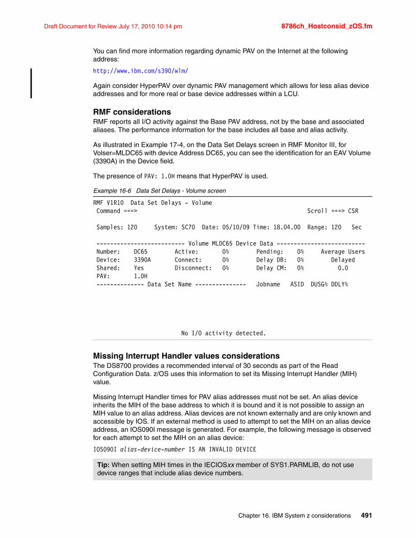
Draft Document for Review July 17, 2010 10:14 pm 8786ch_Hostconsid_zOS.fm
You can find more information regarding dynamic PAV on the Internet at the following address:
http://www.ibm.com/s390/wlm/
Again consider HyperPAV over dynamic PAV management which allows for less alias device addresses and for more real or base device addresses within a LCU.
RMF considerationsRMF reports all I/O activity against the Base PAV address, not by the base and associated aliases. The performance information for the base includes all base and alias activity.
As illustrated in Example 17-4, on the Data Set Delays screen in RMF Monitor III, for Volser=MLDC65 with device Address DC65, you can see the identification for an EAV Volume (3390A) in the Device field.
The presence of PAV: 1.0H means that HyperPAV is used.
Example 16-6 Data Set Delays - Volume screen
RMF V1R10 Data Set Delays - Volume Command ===> Scroll ===> CSR Samples: 120 System: SC70 Date: 05/10/09 Time: 18.04.00 Range: 120 Sec -------------------------- Volume MLDC65 Device Data -------------------------- Number: DC65 Active: 0% Pending: 0% Average Users Device: 3390A Connect: 0% Delay DB: 0% Delayed Shared: Yes Disconnect: 0% Delay CM: 0% 0.0 PAV: 1.0H -------------- Data Set Name --------------- Jobname ASID DUSG% DDLY%
No I/O activity detected.
Missing Interrupt Handler values considerationsThe DS8700 provides a recommended interval of 30 seconds as part of the Read Configuration Data. z/OS uses this information to set its Missing Interrupt Handler (MIH) value.
Missing Interrupt Handler times for PAV alias addresses must not be set. An alias device inherits the MIH of the base address to which it is bound and it is not possible to assign an MIH value to an alias address. Alias devices are not known externally and are only known and accessible by IOS. If an external method is used to attempt to set the MIH on an alias device address, an IOS090I message is generated. For example, the following message is observed for each attempt to set the MIH on an alias device:
IOS090I alias-device-number IS AN INVALID DEVICE
Tip: When setting MIH times in the IECIOSxx member of SYS1.PARMLIB, do not use device ranges that include alias device numbers.
Chapter 16. IBM System z considerations 491
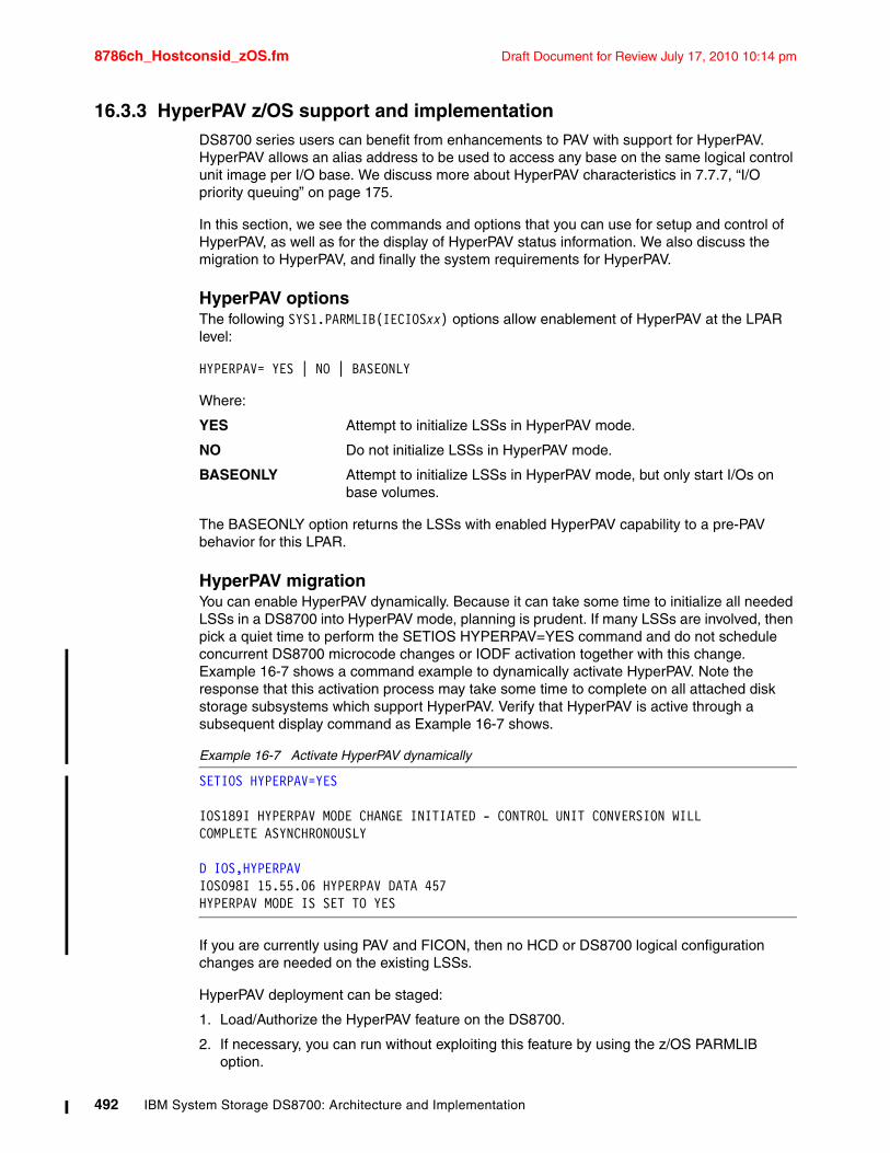
8786ch_Hostconsid_zOS.fm Draft Document for Review July 17, 2010 10:14 pm
16.3.3 HyperPAV z/OS support and implementationDS8700 series users can benefit from enhancements to PAV with support for HyperPAV. HyperPAV allows an alias address to be used to access any base on the same logical control unit image per I/O base. We discuss more about HyperPAV characteristics in 7.7.7, “I/O priority queuing” on page 175.
In this section, we see the commands and options that you can use for setup and control of HyperPAV, as well as for the display of HyperPAV status information. We also discuss the migration to HyperPAV, and finally the system requirements for HyperPAV.
HyperPAV optionsThe following SYS1.PARMLIB(IECIOSxx) options allow enablement of HyperPAV at the LPAR level:
HYPERPAV= YES | NO | BASEONLY
Where:
YES Attempt to initialize LSSs in HyperPAV mode.
NO Do not initialize LSSs in HyperPAV mode.
BASEONLY Attempt to initialize LSSs in HyperPAV mode, but only start I/Os on base volumes.
The BASEONLY option returns the LSSs with enabled HyperPAV capability to a pre-PAV behavior for this LPAR.
HyperPAV migrationYou can enable HyperPAV dynamically. Because it can take some time to initialize all needed LSSs in a DS8700 into HyperPAV mode, planning is prudent. If many LSSs are involved, then pick a quiet time to perform the SETIOS HYPERPAV=YES command and do not schedule concurrent DS8700 microcode changes or IODF activation together with this change. Example 16-7 shows a command example to dynamically activate HyperPAV. Note the response that this activation process may take some time to complete on all attached disk storage subsystems which support HyperPAV. Verify that HyperPAV is active through a subsequent display command as Example 16-7 shows.
Example 16-7 Activate HyperPAV dynamically
SETIOS HYPERPAV=YES
IOS189I HYPERPAV MODE CHANGE INITIATED - CONTROL UNIT CONVERSION WILL COMPLETE ASYNCHRONOUSLY
D IOS,HYPERPAV IOS098I 15.55.06 HYPERPAV DATA 457 HYPERPAV MODE IS SET TO YES
If you are currently using PAV and FICON, then no HCD or DS8700 logical configuration changes are needed on the existing LSSs.
HyperPAV deployment can be staged:
1. Load/Authorize the HyperPAV feature on the DS8700.
2. If necessary, you can run without exploiting this feature by using the z/OS PARMLIB option.
492 IBM System Storage DS8700: Architecture and Implementation
Draft Document for Review July 17, 2010 10:14 pm 8786ch_Hostconsid_zOS.fm
3. Enable the HyperPAV feature on z/OS images in which you want to utilize HyperPAV using the PARMLIB option or the SETIOS command.
4. Eventually, enable the HyperPAV feature on all z/OS images in the Sysplex and authorize the licensed function on all attached DS8700s.
5. Optionally, reduce the number of aliases defined.
Full coexistence with traditional PAVs like static PAV or dynamic PAV, as well as sharing with z/OS images without HyperPAV enabled, allows migration to HyperPAV to be a flexible procedure.
Chapter 16. IBM System z considerations 493
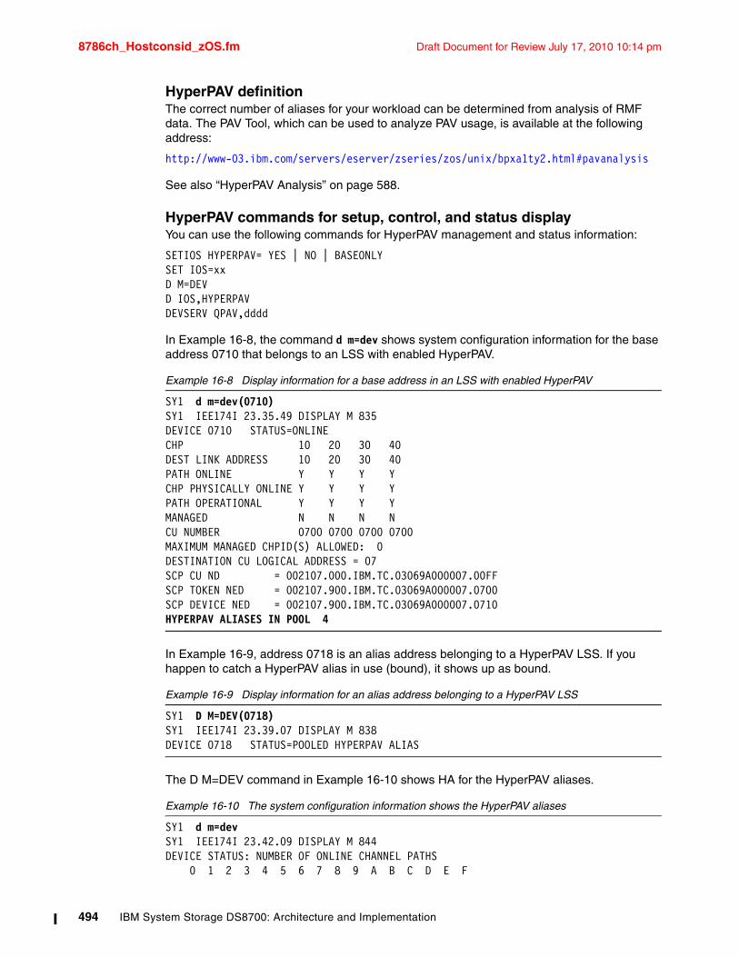
8786ch_Hostconsid_zOS.fm Draft Document for Review July 17, 2010 10:14 pm
HyperPAV definitionThe correct number of aliases for your workload can be determined from analysis of RMF data. The PAV Tool, which can be used to analyze PAV usage, is available at the following address:
http://www-03.ibm.com/servers/eserver/zseries/zos/unix/bpxa1ty2.html#pavanalysis
See also “HyperPAV Analysis” on page 588.
HyperPAV commands for setup, control, and status displayYou can use the following commands for HyperPAV management and status information:
SETIOS HYPERPAV= YES | NO | BASEONLYSET IOS=xxD M=DEVD IOS,HYPERPAVDEVSERV QPAV,dddd
In Example 16-8, the command d m=dev shows system configuration information for the base address 0710 that belongs to an LSS with enabled HyperPAV.
Example 16-8 Display information for a base address in an LSS with enabled HyperPAV
SY1 d m=dev(0710) SY1 IEE174I 23.35.49 DISPLAY M 835 DEVICE 0710 STATUS=ONLINE CHP 10 20 30 40 DEST LINK ADDRESS 10 20 30 40 PATH ONLINE Y Y Y Y CHP PHYSICALLY ONLINE Y Y Y Y PATH OPERATIONAL Y Y Y Y MANAGED N N N N CU NUMBER 0700 0700 0700 0700 MAXIMUM MANAGED CHPID(S) ALLOWED: 0 DESTINATION CU LOGICAL ADDRESS = 07 SCP CU ND = 002107.000.IBM.TC.03069A000007.00FF SCP TOKEN NED = 002107.900.IBM.TC.03069A000007.0700 SCP DEVICE NED = 002107.900.IBM.TC.03069A000007.0710 HYPERPAV ALIASES IN POOL 4
In Example 16-9, address 0718 is an alias address belonging to a HyperPAV LSS. If you happen to catch a HyperPAV alias in use (bound), it shows up as bound.
Example 16-9 Display information for an alias address belonging to a HyperPAV LSS
SY1 D M=DEV(0718) SY1 IEE174I 23.39.07 DISPLAY M 838 DEVICE 0718 STATUS=POOLED HYPERPAV ALIAS
The D M=DEV command in Example 16-10 shows HA for the HyperPAV aliases.
Example 16-10 The system configuration information shows the HyperPAV aliases
SY1 d m=dev SY1 IEE174I 23.42.09 DISPLAY M 844 DEVICE STATUS: NUMBER OF ONLINE CHANNEL PATHS 0 1 2 3 4 5 6 7 8 9 A B C D E F
494 IBM System Storage DS8700: Architecture and Implementation
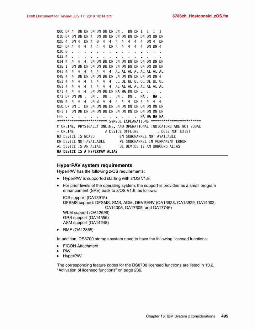
Draft Document for Review July 17, 2010 10:14 pm 8786ch_Hostconsid_zOS.fm
000 DN 4 DN DN DN DN DN DN DN . DN DN 1 1 1 1 018 DN DN DN DN 4 DN DN DN DN DN DN DN DN DN DN DN 02E 4 DN 4 DN 4 8 4 4 4 4 4 4 4 DN 4 DN 02F DN 4 4 4 4 4 4 DN 4 4 4 4 4 DN DN 4 030 8 . . . . . . . . . . . . . . . 033 4 . . . . . . . . . . . . . . . 034 4 4 4 4 DN DN DN DN DN DN DN DN DN DN DN DN 03E 1 DN DN DN DN DN DN DN DN DN DN DN DN DN DN DN 041 4 4 4 4 4 4 4 4 AL AL AL AL AL AL AL AL 048 4 4 DN DN DN DN DN DN DN DN DN DN DN DN DN 4 051 4 4 4 4 4 4 4 4 UL UL UL UL UL UL UL UL 061 4 4 4 4 4 4 4 4 AL AL AL AL AL AL AL AL 071 4 4 4 4 DN DN DN DN HA HA DN DN . . . . 073 DN DN DN . DN . DN . DN . DN . HA . HA . 098 4 4 4 4 DN 8 4 4 4 4 4 DN 4 4 4 4 0E0 DN DN 1 DN DN DN DN DN DN DN DN DN DN DN DN DN 0F1 1 DN DN DN DN DN DN DN DN DN DN DN DN DN DN DN FFF . . . . . . . . . . . . HA HA HA HA ************************ SYMBOL EXPLANATIONS ************************@ ONLINE, PHYSICALLY ONLINE, AND OPERATIONAL INDICATORS ARE NOT EQUAL+ ONLINE # DEVICE OFFLINE . DOES NOT EXIST BX DEVICE IS BOXED SN SUBCHANNEL NOT AVAILABLE DN DEVICE NOT AVAILABLE PE SUBCHANNEL IN PERMANENT ERROR AL DEVICE IS AN ALIAS UL DEVICE IS AN UNBOUND ALIAS HA DEVICE IS A HYPERPAV ALIAS
HyperPAV system requirementsHyperPAV has the following z/OS requirements:
� HyperPAV is supported starting with z/OS V1.8.
� For prior levels of the operating system, the support is provided as a small program enhancement (SPE) back to z/OS V1.6, as follows:
IOS support (OA13915)DFSMS support: DFSMS, SMS, AOM, DEVSERV (OA13928, OA13929, OA14002,
OA14005, OA17605, and OA17746)WLM support (OA12699)GRS support (OA14556)ASM support (OA14248)
� RMF (OA12865)
In addition, DS8700 storage system need to have the following licensed functions:
� FICON Attachment� PAV� HyperPAV
The corresponding feature codes for the DS8700 licensed functions are listed in 10.2, “Activation of licensed functions” on page 236.
Chapter 16. IBM System z considerations 495
8786ch_Hostconsid_zOS.fm Draft Document for Review July 17, 2010 10:14 pm
16.4 z/VM considerationsIn this section, we discuss specific considerations that are relevant when attaching a DS8700 series to a z/VM environment.
16.4.1 Connectivityz/VM provides the following connectivity:
� z/VM supports FICON attachment as 3990 Model 3 or 6 controller
� Native controller modes 2105 and 2107 are supported on z/VM V5.2.0 with APAR VM63952:
– This brings support up to equal to z/OS.
– z/VM simulates controller mode support by each guest.
� z/VM supports FCP attachment for Linux systems running as a guest.
� z/VM itself supports FCP-attached SCSI disks starting with z/VM V5.1.0.
16.4.2 Supported DASD types and LUNsz/VM supports the following extended count key data (ECKD™) DASD types:
� 3390 Models 2, 3, and 9, including the 32,760 and 65,520 cylinder custom volumes.
� 3390 Model 2 and 3 in 3380 track compatibility mode.
� 3390 Model A volumes are not supported at this time. When running z/OS as a VM guest, EAV volumes can be used if they are directly attached to the z/OS guest.
z/VM also provides the following support when using Fibre Channel Protocol (FCP) attachment:
� FCP-attached SCSI LUNs as emulated 9336 Model 20 DASD� 1 TB SCSI LUNs
16.4.3 PAV and HyperPAV z/VM supportz/VM provides PAV support. In this section, we provide basic support information, which is useful when you have to implement PAV in a z/VM environment.
You can find additional z/VM technical information for PAV support on the z/VM Technical Web site at the following address:
http://www.vm.ibm.com/storman/pav/
For further discussion of PAV, see 7.7.5, “PAV in z/VM environments” on page 173.
z/VM guest support for dedicated PAVsz/VM allows a guest z/OS to use PAV and dynamic PAV tuning as dedicated volumes. The following considerations apply:
� Alias and base addresses must be attached to the z/OS guest. You need a separate ATTACH for each alias address. You should attach the base address and its aliases address to the same guest.
� A base address cannot be attached to SYSTEM if one of its alias address(es) is attached to that guest. This means that you cannot use PAVs for Full Pack minidisks. The QUERY
496 IBM System Storage DS8700: Architecture and Implementation
Draft Document for Review July 17, 2010 10:14 pm 8786ch_Hostconsid_zOS.fm
PAV command is available for authorized (class B) users to query base and alias addresses: QUERY PAV rdev and QUERY PAV ALL.
� To verify that PAV aliases are bound to the correct bases, use the command QUERY CHPID xx combined with QUERY PAV rdev-rdev, where xx is the CHPID whose device addresses should be displayed, showing the addresses and any aliases, and rdev is the real device address.
PAV minidisk support with small program enhancement (SPE)Starting with z/VM V5.2.0 with APAR VM63952, z/VM supports PAV minidisks. With this small program enhancement (SPE), z/VM provides:
� Support of PAV minidisks.
� Workload balancing for guests that do not exploit PAV, like CMS.
� A real I/O dispatcher queues minidisk I/O across system-attached alias volumes.
� Linkable minidisks for guests that do exploit PAV (for example, z/OS and Linux).
� The PAVALIAS parameter of the DASDOPT and MINIOPT user directory statements or the CP DEFINE ALIAS command, which creates alias minidisks - fullpack and non-fullpack - for exploiting guests.
� Dynamic alias to base reassociation is supported for guests that exploit PAV for dedicated volumes and for minidisks under restricted conditions.
HyperPAV supportz/VM supports HyperPAV for dedicated DASD and minidisks starting with z/VM Version 5.3.0.
16.4.4 Missing-interrupt handler (MIH) z/VM sets its MIH value as a factor of 1.25 of what the hardware reports. This way, with the DS8700 setting the MIH value to 30 seconds, z/VM is set to a MIH value of approximately 37.5 seconds. This allows the guest to receive the MIH 30 seconds before z/VM does.
16.5 VSE/ESA and z/VSE considerationsThe following considerations apply regarding VSE/ESA and z/VSE support:
� An APAR is required for VSE 2.7 to exploit large volume support, but support for EAV is still not provided.
� VSE has a default MIH timer value to 180 seconds. You can change this setting to the suggested DS8700 value of 30 seconds by using the SIR MIH command, which is documented in Hints and Tips for VSE/ESA 2.7, which you can download from the VSE/ESA Web site at the following address:
http://www.ibm.com/servers/eserver/zseries/zvse/documentation/
Chapter 16. IBM System z considerations 497
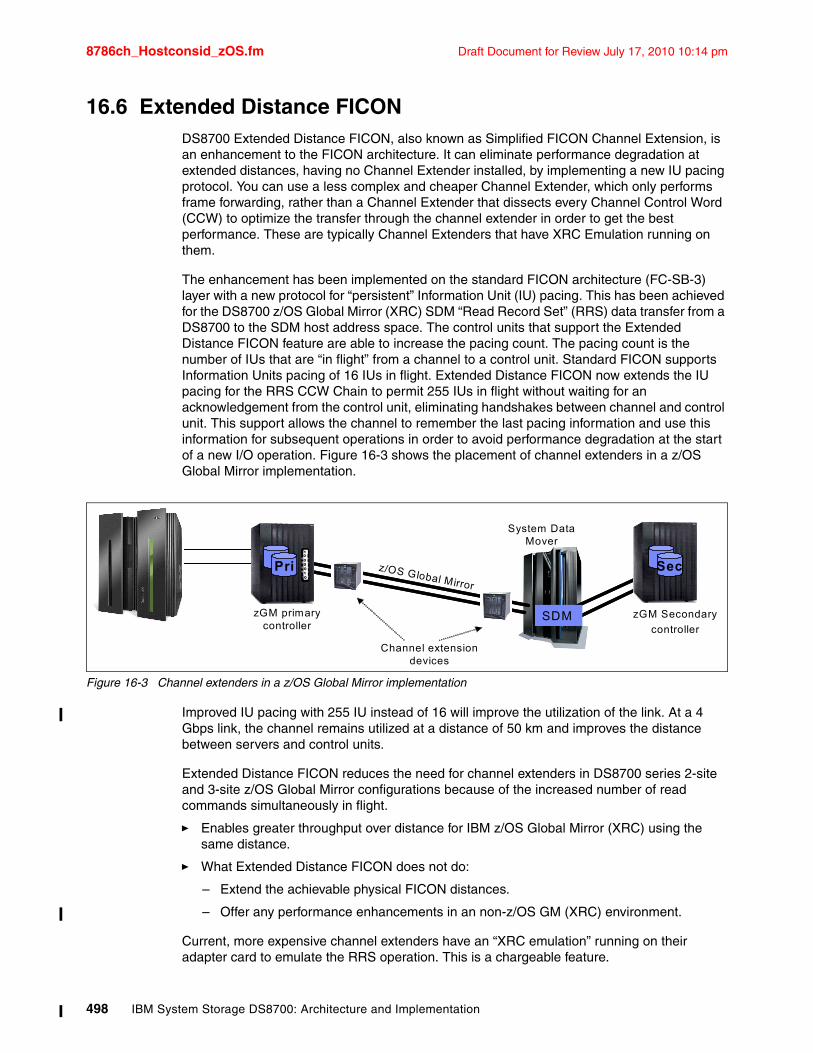
8786ch_Hostconsid_zOS.fm Draft Document for Review July 17, 2010 10:14 pm
16.6 Extended Distance FICONDS8700 Extended Distance FICON, also known as Simplified FICON Channel Extension, is an enhancement to the FICON architecture. It can eliminate performance degradation at extended distances, having no Channel Extender installed, by implementing a new IU pacing protocol. You can use a less complex and cheaper Channel Extender, which only performs frame forwarding, rather than a Channel Extender that dissects every Channel Control Word (CCW) to optimize the transfer through the channel extender in order to get the best performance. These are typically Channel Extenders that have XRC Emulation running on them.
The enhancement has been implemented on the standard FICON architecture (FC-SB-3) layer with a new protocol for “persistent” Information Unit (IU) pacing. This has been achieved for the DS8700 z/OS Global Mirror (XRC) SDM “Read Record Set” (RRS) data transfer from a DS8700 to the SDM host address space. The control units that support the Extended Distance FICON feature are able to increase the pacing count. The pacing count is the number of IUs that are “in flight” from a channel to a control unit. Standard FICON supports Information Units pacing of 16 IUs in flight. Extended Distance FICON now extends the IU pacing for the RRS CCW Chain to permit 255 IUs in flight without waiting for an acknowledgement from the control unit, eliminating handshakes between channel and control unit. This support allows the channel to remember the last pacing information and use this information for subsequent operations in order to avoid performance degradation at the start of a new I/O operation. Figure 16-3 shows the placement of channel extenders in a z/OS Global Mirror implementation.
Figure 16-3 Channel extenders in a z/OS Global Mirror implementation
Improved IU pacing with 255 IU instead of 16 will improve the utilization of the link. At a 4 Gbps link, the channel remains utilized at a distance of 50 km and improves the distance between servers and control units.
Extended Distance FICON reduces the need for channel extenders in DS8700 series 2-site and 3-site z/OS Global Mirror configurations because of the increased number of read commands simultaneously in flight.
� Enables greater throughput over distance for IBM z/OS Global Mirror (XRC) using the same distance.
� What Extended Distance FICON does not do:
– Extend the achievable physical FICON distances.
– Offer any performance enhancements in an non-z/OS GM (XRC) environment.
Current, more expensive channel extenders have an “XRC emulation” running on their adapter card to emulate the RRS operation. This is a chargeable feature.
z/OS Global Mirror
PriPri
SDM
SecSec1000010
1000010
zGM primary controller
System DataMover
zGM Secondary
controller
Channel extensiondevices
498 IBM System Storage DS8700: Architecture and Implementation
Draft Document for Review July 17, 2010 10:14 pm 8786ch_Hostconsid_zOS.fm
For example, Brocade provides functions to:
� Detect a SDM channel program and disconnect it.� Send a message to the primary site.� Reconstruct and execute the program at the primary site.� Send the data to the remote site in a large packet over the large distance.� Reconnect and complete the chain with the data mover.
Extended Distance FICON eliminates the need for these kind of spoofing functions.
Vendors supplying Channel Extenders� Brocade (former CNT) USDx� Brocade (former CNT) Edge Server (FC-IP)� Brocade 7500 (FC-IP)� Ciena (Sonet)� Nortel and ADVA� CISCO
16.6.1 Extended Distance FICON: installation considerationsIf you want to take advantage of Extended Distance FICON, remember the following considerations:
� Extended Distance FICON is, at this time, only supported on system z10 Channels. FICON Express8,FICON Express4, and FICON Express2 are supported.
� z/OS V1.7 or above is required.
� APAR OA24218 must be installed for the DFSMS SDM LPAR. The SDM APAR implements a MaxTracksRead(246) limit and 246 RRS CCW limit. This influences the SDM Multi-reader function in a positive way.
� SDM Parmlib must be updated to MaxTracksRead = 246. This is the maximum number of RRSs that is currently supported in a single channel program. Due to compatibility reasons, the permitted range of MaxTracksRead is 1 - 255, but it will be treated as a value of 246.
� The fabric requires sufficient buffer credits to support the link data rate at extended distance.
Enabling and running Extended Distance FICONWhen the prerequisites listed above are met, the channel and Control Unit (CU) indicates support of persistent IU pacing when establishing logical paths. Channel and CU provide automatic concurrent enablement on all existing logical paths.
When either side has installed the support for Extended Distance FICON:
� CU detects the DSO command with a suborder indicating that this is a RRS chain.
� CU sets persistent pacing credit for the logical path based on the number of RRS commands in the chain.
� Persistent Pacing Credit is recorded for this logical path and sends the channel the first command response.
� The channel sends now a number of CCWs up to the pacing credit (246), which is set to the path on subsequent I/O execution.
Note: With the current EDF implementation, you are restricted to using either persistent IU pacing or XRC emulation.
Chapter 16. IBM System z considerations 499
8786ch_Hostconsid_zOS.fm Draft Document for Review July 17, 2010 10:14 pm
Write thresholds during EDFWith Extended Distance FICON:
� CU can handle many read commands because they do not take up data buffer space on the adapter.
� Write commands still need to be paced at the default FICON value of 16 IUs.
� CU detects a threshold of larger write chains and will reset pacing for the logical path back to the default when the large writes result in high write buffer congestion.
� Once RRS chains are detected in the absence of buffer congestion, pacing credit will be increased again.
Disabling and enabling the EDF at the DS8700Persistent IU Pacing is enabled in the DS8700 code by default. In case of any severe problems, the EDF function can be disabled/enabled in each DS8700 CEC.
SummaryThe Extended Distance FICON channel support produces performance results similar to XRC Emulation mode at long distances. It should be used to enable a wider range of choices in channel extension technology, when using z/OS Global Mirroring, because emulation in the extender may not be required. This reduces the total cost of ownership, as well as providing comparable performance when mirroring application updates over long distances.
16.7 High Performance FICON for z with multitrack supportTo increase system performance and improve System z FICON channel efficiency, the DS8700 provides support for High Performance FICON for System z (zHPF) with multitrack. zHPF with multitrack operations is an optional licensed feature on DS8700 storage systems.
With the introduction of zHPF, the FICON architecture has been streamlined by removing significant impact from the storage subsystem and the microprocessor within the FICON channel. A command block is created to chain commands into significantly fewer sequences. The effort required to convert individual commands into FICON format is removed as multiple System z I/O commands are packaged together and passed directly over the fiber optic link.
zHPF provides an enhanced FICON protocol and system I/O architecture that results in improvements for small block transfers (a track or less) to disk using the device independent random access method.
In situations where this is the exclusive access in use, it can improve FICON I/O throughput on a single DS8700 port by 100%. Realistic workloads with a mix of data set transfer sizes can see 30 - 70% of FICON I/Os utilizing zHPF, resulting in up to a 10-30% channel utilization savings.
Although customers should see I/Os complete faster as the result of implementing zHPF, the real benefit is expected to be obtained by using fewer channels to support existing disk volumes, or increasing the number of disk volumes supported by existing channels.
Additionally, the changes in architectures offer end-to-end system enhancements to improve reliability, availability, and serviceability (RAS).
Note: Disabling the EDF function in the DS8700 microcode can only be done by an IBM System Support Representative.
500 IBM System Storage DS8700: Architecture and Implementation
Draft Document for Review July 17, 2010 10:14 pm 8786ch_Hostconsid_zOS.fm
zHPF uses the support of multitrack operations to allow reading or writing more than a track worth of data by a single transport mode operation. DB2, VSAM, zFS, HFS, PDSE, striped extended format data sets, and other applications that use large data transfers with Media Manager are expected to benefit from zHPF multitrack function.
In addition, zHPF complements the Extended Address Volumes for System z (EAV) strategy for growth by increasing the I/O rate capability as the volume sizes expand vertically.
In laboratory measurements, multitrack operations (for example, reading 16 x 4 KB/IO) converted to the zHPF protocol on a FICON Express8 channel achieved a maximum of up to 40% more MBps than multitrack operations using the native FICON protocol.
IBM laboratory testing and measurements are available at the following address:
http://www.ibm.com/systems/z/hardware/connectivity/ficon_performance.html
zHPF with multitrack operations is available on z/OS V1.8, V1.9, V1.10, and V1.11 with the PTFs for APARs OA26084 and OA29017.
At the time of the writing of this book, zHPF and support for multitrack operations is exclusive to the System z10 servers and applies to all FICON Express8, FICON Express4, and FICON Express2 features (CHPID type FC).
The FICON Express adapters are not supported.
zHPF is transparent to applications. However, z/OS configuration changes are required: Hardware Configuration Definition (HCD) must have Channel path ID (CHPID) type FC defined for all the CHPIDs that are defined to the DS8700 control unit. For the DS8700, installation of the Licensed Feature Key for the High Performance FICON feature is required. Once these items are addressed, existing FICON port definitions in the DS8700 will function in either native FICON or zHPF protocols in response to the type of request being performed. These are nondisruptive changes.
For z/OS, once the PTFs are installed in the LPAR, you must then set ZHPF=YES in IECIOSxx in SYS1.PARMLIB or issue the SETIOS ZHPF=YES command. ZHPF=NO is the default setting.
IBM recommends customers use the ZHPF=YES setting once the required configuration changes and prerequisites are met.
For more information about zHPF in general, refer to:
http://www-03.ibm.com/support/techdocs/atsmastr.nsf/fe582a1e48331b5585256de50062ae1c/05d19b2a9bd95d4e8625754c0007d365?OpenDocument
16.8 z/OS Basic HyperSwapz/OS Basic HyperSwap is a single site z/OS only solution that extends Sysplex and Parallel Sysplex® high availability capability to data. The average capacity space per controller grows permanently and the impact is huge if there is a disk subsystem failure. Therefore, IBM created a new function called Basic HyperSwap, which is available only in a z/OS environment.
All Basic HyperSwap volumes are defined to a Tivoli Storage Productivity Center for Replication (TPC-R) HyperSwap session. TPC-R supports a new session type called Basic HyperSwap. The underlying session though is a Metro Mirror session.
Chapter 16. IBM System z considerations 501
8786ch_Hostconsid_zOS.fm Draft Document for Review July 17, 2010 10:14 pm
With TPC-R 4.1.1and above, Metro Mirror sessions with HyperSwap now support also 2-site or 3-site configurations with freeze and HyperSwap. This guarantees always consistent data at the recovery site. This is possible thanks to the freeze support that is triggered through the z/OS HyperSwap address space in case of a communication failure between application and recovery site or a failure at the recovery site. A failure at the application or primary site which is identified as a HyperSwap trigger will cause the HyperSwap to happen between primary and secondary devices of a Metro Mirror session. This swap operation is solely managed by the z/OS HyperSwap address spaces in all Sysplex images.
How it worksThe Basic HyperSwap session is only a consideration for planned swaps and is not suited for unplanned failures of the disk storage subsystem. Only consider TPC-R 4.1.1+ and Metro Mirror (MM) session with HyperSwap to support a 2-site Metro Mirror configuration.
Iz/OS monitors all activity and when a primary disk failure is detected, a data freeze occurs for all volumes within the MM/Basic HyperSwap session. During this data freeze, all application I/Os are queued and appear as extended long busy respectively SCSI full condistion. This is necessary to maintain data integrity on all volumes across the HyperSwap operation. z/OS IOS then recovers the PPRC target devices and does a Unit Control Block (UCB) swap pointing to the volumes on the secondary subsystem. When all UCBs have been swapped, the I/Os are released and the application continues to run on the recovered secondary site. This is valid for all subsystems being defined in a MM/Basic HyperSwap session. There is no impact to the applications if they tolerate the “long busy condition”.
The scope of MM/Basic HyperSwap is a Sysplex environment and the volumes must be mirrored using MM (PPRC). All hosts in a Parallel Sysplex must have connectivity to both MM primary and secondary devices through FICON channels.
The subsequent swap back through a planned HyperSwap to the former configuration, before the event happened, is fully under control of TPC-R through a MM failover / MM failback from Site 1 to Site 2.
Figure 16-4 shows the Basic HyperSwap components.
502 IBM System Storage DS8700: Architecture and Implementation
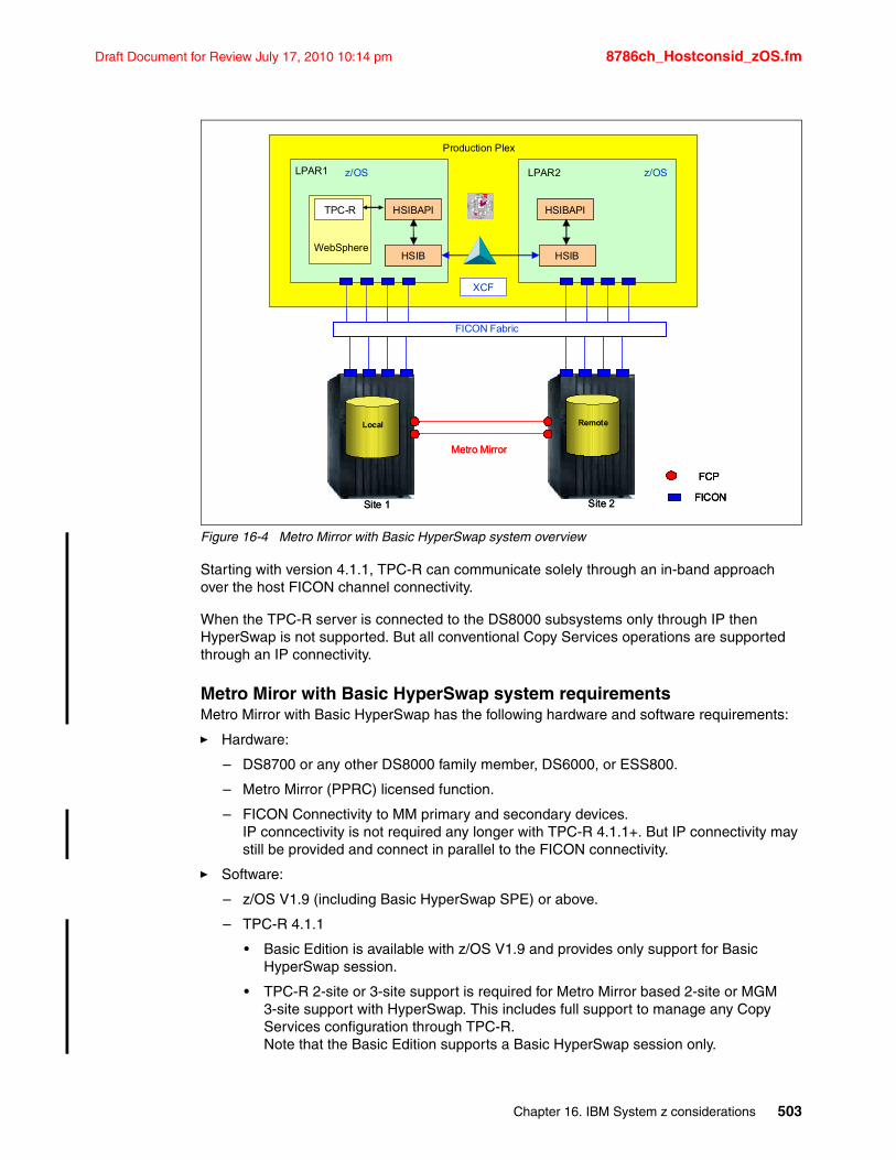
Draft Document for Review July 17, 2010 10:14 pm 8786ch_Hostconsid_zOS.fm
Figure 16-4 Metro Mirror with Basic HyperSwap system overview
Starting with version 4.1.1, TPC-R can communicate solely through an in-band approach over the host FICON channel connectivity.
When the TPC-R server is connected to the DS8000 subsystems only through IP then HyperSwap is not supported. But all conventional Copy Services operations are supported through an IP connectivity.
Metro Miror with Basic HyperSwap system requirementsMetro Mirror with Basic HyperSwap has the following hardware and software requirements:
� Hardware:
– DS8700 or any other DS8000 family member, DS6000, or ESS800.
– Metro Mirror (PPRC) licensed function.
– FICON Connectivity to MM primary and secondary devices.IP conncectivity is not required any longer with TPC-R 4.1.1+. But IP connectivity may still be provided and connect in parallel to the FICON connectivity.
� Software:
– z/OS V1.9 (including Basic HyperSwap SPE) or above.
– TPC-R 4.1.1
• Basic Edition is available with z/OS V1.9 and provides only support for Basic HyperSwap session.
• TPC-R 2-site or 3-site support is required for Metro Mirror based 2-site or MGM 3-site support with HyperSwap. This includes full support to manage any Copy Services configuration through TPC-R.Note that the Basic Edition supports a Basic HyperSwap session only.
Remote Local
HSIB
HSIBAPI
HSIB
HSIBAPI
z/OSLPAR1 LPAR2
Production Plex
XCF
WebSphere
TPC-R
z/OS
112
2
3
4
56
7
8
9
10
11
FCP
FICON
Metro Mirror
FICON Fabric
Site 1 Site 2
Remote Remote LocalLocal
HSIB
HSIBAPI
HSIB
HSIBAPI
z/OSLPAR1 LPAR2
Production Plex
XCF
WebSphere
TPC-R
z/OS
112
2
3
4
56
7
8
9
10
11
HSIBHSIB
HSIBAPIHSIBAPI
HSIBHSIB
HSIBAPIHSIBAPI
z/OSLPAR1 LPAR2
Production Plex
XCF
WebSphere
TPC-R
z/OS
112
2
3
4
56
7
8
9
10
11 112
2
3
4
112
2
3
4
56
7
8
9
10
11
56
7
8
9
10
11
FCP
FICON
FCP
FICON
Metro Mirror
FICON Fabric
Site 1 Site 2
Chapter 16. IBM System z considerations 503
8786ch_Hostconsid_zOS.fm Draft Document for Review July 17, 2010 10:14 pm
• Embedded WAS OEM and its embedded Apache Derby database are part of the TPC-R software package and are not priced.
• IBM System Service Runtime Environment (SSRE) or z/OS WebSphere Application Server V6.1. are not an option any longer since the advent of TPC-R 4.1.0+ with its embedded WAS OEM
For more information about Basic HyperSwap, refer to IBM Systems for SAP Business Intelligence: 25 Terabyte Scalability Study, REDP-4411.
Note: Basic HyperSwap provides only a high availability solution and it is not deployed as a disaster recovery solution. Since TPC-R 4.1.1+ this changed and provides with TPC-R 4.1.1+ besides high availability also disaster recovery and consistent data at the recovery site.
504 IBM System Storage DS8700: Architecture and Implementation
Draft Document for Review July 17, 2010 10:14 pm 8786ch_hostconsid_iSeries.fm
Chapter 17. IBM System i considerations
This chapter discusses the specifics for the IBM System Storage DS8700 series system attachment to System i. This chapter covers the following topics:
� Supported environment
� Logical volume sizes
� Protected versus unprotected volumes
� Adding volumes to the System i configuration
� Multipath
� Sizing guidelines
� Migration
� Boot from SAN
For further information about these topics, refer to IBM i and IBM System Storage: A Guide to Implementing External Disks on IBM i, SG24-7120.
17
© Copyright IBM Corp. 2010. All rights reserved. 505
8786ch_hostconsid_iSeries.fm Draft Document for Review July 17, 2010 10:14 pm
17.1 Supported environmentNot all hardware and software combinations for i5/OS and IBM i support the DS8700. This section describes the hardware and software prerequisites for attaching the DS8700.
17.1.1 HardwareThe DS8700 is supported on all System i models that support Fibre Channel attachment using the adapters listed below.
The following System i Fibre Channel adapters are supported on DS8700:
� FC 5749 4 Gigabit Fibre Channel Disk Controller PCI-x� FC 5760 4 Gigabit Fibre Channel Disk Controller PCI-x� FC 5774 4 Gigabit Fibre Channel Disk Controller PCI-e� FC 5735 8 Gigabit Fibre Channel Disk Controller PCI-e
FC 5760 is IOP-based adapter and can address up to 32 logical volumes. The other adapters listed above are IOP-less and can address up to 64 volumes.
IBM i V6R1, in combination with IOP-less adapters, provides SCSI command tag queuing support on DS8700 systems.
The System i Storage Web page provides information about current hardware requirements, including support for switches. You can find this page at the following address:
http://www.ibm.com/servers/eserver/iseries/storage/storage_hw.html
17.1.2 SoftwareIBM i V6.1 and V5.4 support the DS8700 system storage via native Fibre Channel attachment to POWER5 and POWER6 processor-based servers. In addition, the DS8700 is supported with IBM i V6.1 partitions via a PowerVM™ VIOS attached to POWER6 processor-based servers and blades.The System i must be running i5/OS V5R4 or IBM i V6R1.
Prior to attaching the DS8700 to System i, you should check for the latest PTFs.
17.2 Logical volume sizesIBM i is supported on DS8700 as Fixed Block (FB) storage. Unlike other Open Systems using FB architecture, IBM i only supports specific volume sizes, and these might not be an exact number of extents. In general, these relate to the volume sizes available with internal devices, although some larger sizes are now supported for external storage only. IBM i volumes are defined in decimal gigabytes (109 bytes).
506 IBM System Storage DS8700: Architecture and Implementation
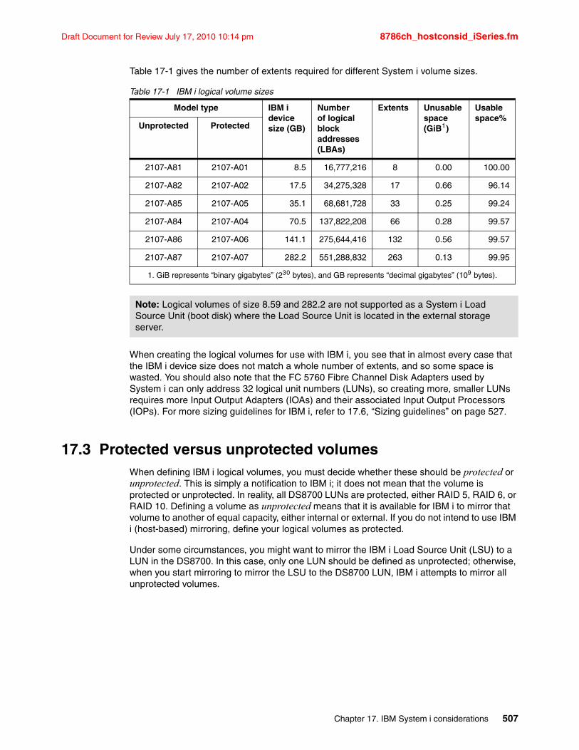
Draft Document for Review July 17, 2010 10:14 pm 8786ch_hostconsid_iSeries.fm
Table 17-1 gives the number of extents required for different System i volume sizes.
Table 17-1 IBM i logical volume sizes
When creating the logical volumes for use with IBM i, you see that in almost every case that the IBM i device size does not match a whole number of extents, and so some space is wasted. You should also note that the FC 5760 Fibre Channel Disk Adapters used by System i can only address 32 logical unit numbers (LUNs), so creating more, smaller LUNs requires more Input Output Adapters (IOAs) and their associated Input Output Processors (IOPs). For more sizing guidelines for IBM i, refer to 17.6, “Sizing guidelines” on page 527.
17.3 Protected versus unprotected volumesWhen defining IBM i logical volumes, you must decide whether these should be protected or unprotected. This is simply a notification to IBM i; it does not mean that the volume is protected or unprotected. In reality, all DS8700 LUNs are protected, either RAID 5, RAID 6, or RAID 10. Defining a volume as unprotected means that it is available for IBM i to mirror that volume to another of equal capacity, either internal or external. If you do not intend to use IBM i (host-based) mirroring, define your logical volumes as protected.
Under some circumstances, you might want to mirror the IBM i Load Source Unit (LSU) to a LUN in the DS8700. In this case, only one LUN should be defined as unprotected; otherwise, when you start mirroring to mirror the LSU to the DS8700 LUN, IBM i attempts to mirror all unprotected volumes.
Model type IBM i device size (GB)
Numberof logical block addresses (LBAs)
Extents Unusable space (GiB1)
Usable space%
Unprotected Protected
2107-A81 2107-A01 8.5 16,777,216 8 0.00 100.00
2107-A82 2107-A02 17.5 34,275,328 17 0.66 96.14
2107-A85 2107-A05 35.1 68,681,728 33 0.25 99.24
2107-A84 2107-A04 70.5 137,822,208 66 0.28 99.57
2107-A86 2107-A06 141.1 275,644,416 132 0.56 99.57
2107-A87 2107-A07 282.2 551,288,832 263 0.13 99.95
1. GiB represents “binary gigabytes” (230 bytes), and GB represents “decimal gigabytes” (109 bytes).
Note: Logical volumes of size 8.59 and 282.2 are not supported as a System i Load Source Unit (boot disk) where the Load Source Unit is located in the external storage server.
Chapter 17. IBM System i considerations 507
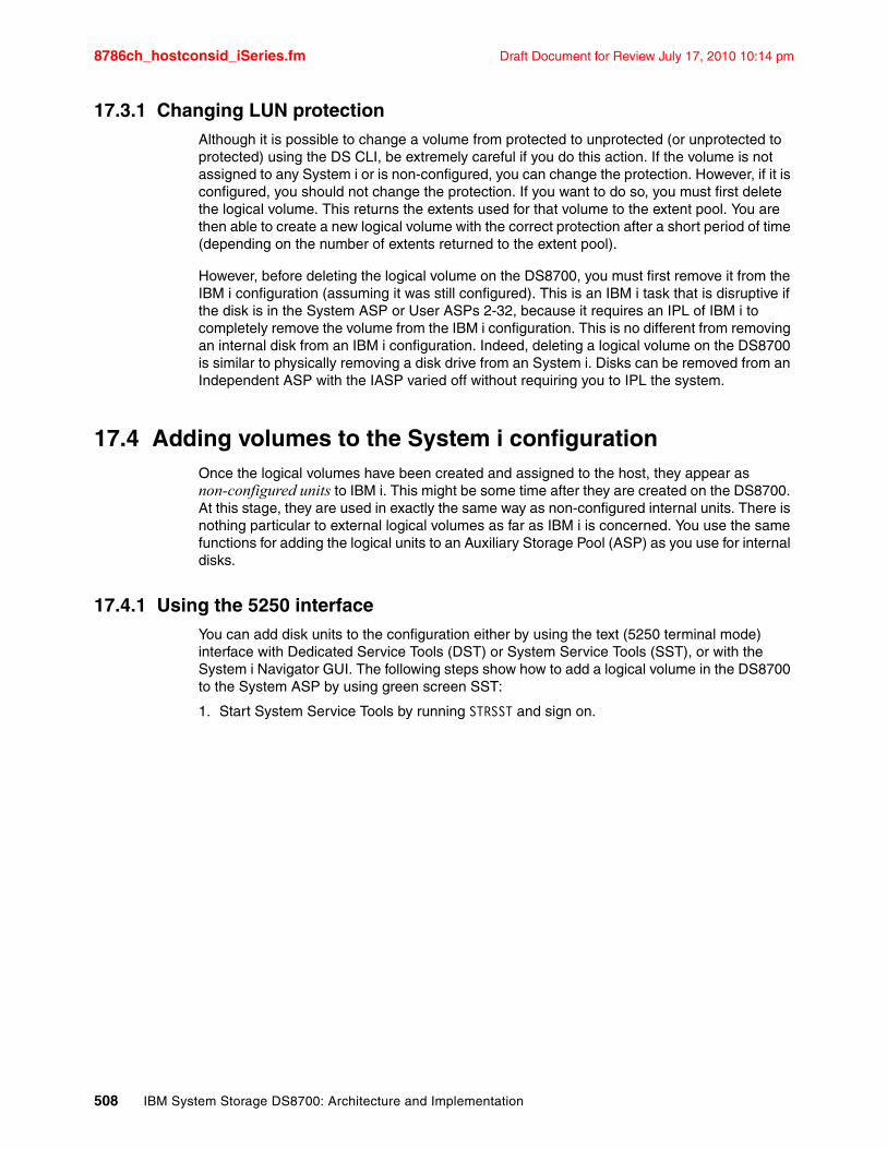
8786ch_hostconsid_iSeries.fm Draft Document for Review July 17, 2010 10:14 pm
17.3.1 Changing LUN protectionAlthough it is possible to change a volume from protected to unprotected (or unprotected to protected) using the DS CLI, be extremely careful if you do this action. If the volume is not assigned to any System i or is non-configured, you can change the protection. However, if it is configured, you should not change the protection. If you want to do so, you must first delete the logical volume. This returns the extents used for that volume to the extent pool. You are then able to create a new logical volume with the correct protection after a short period of time (depending on the number of extents returned to the extent pool).
However, before deleting the logical volume on the DS8700, you must first remove it from the IBM i configuration (assuming it was still configured). This is an IBM i task that is disruptive if the disk is in the System ASP or User ASPs 2-32, because it requires an IPL of IBM i to completely remove the volume from the IBM i configuration. This is no different from removing an internal disk from an IBM i configuration. Indeed, deleting a logical volume on the DS8700 is similar to physically removing a disk drive from an System i. Disks can be removed from an Independent ASP with the IASP varied off without requiring you to IPL the system.
17.4 Adding volumes to the System i configurationOnce the logical volumes have been created and assigned to the host, they appear as non-configured units to IBM i. This might be some time after they are created on the DS8700. At this stage, they are used in exactly the same way as non-configured internal units. There is nothing particular to external logical volumes as far as IBM i is concerned. You use the same functions for adding the logical units to an Auxiliary Storage Pool (ASP) as you use for internal disks.
17.4.1 Using the 5250 interfaceYou can add disk units to the configuration either by using the text (5250 terminal mode) interface with Dedicated Service Tools (DST) or System Service Tools (SST), or with the System i Navigator GUI. The following steps show how to add a logical volume in the DS8700 to the System ASP by using green screen SST:
1. Start System Service Tools by running STRSST and sign on.
508 IBM System Storage DS8700: Architecture and Implementation
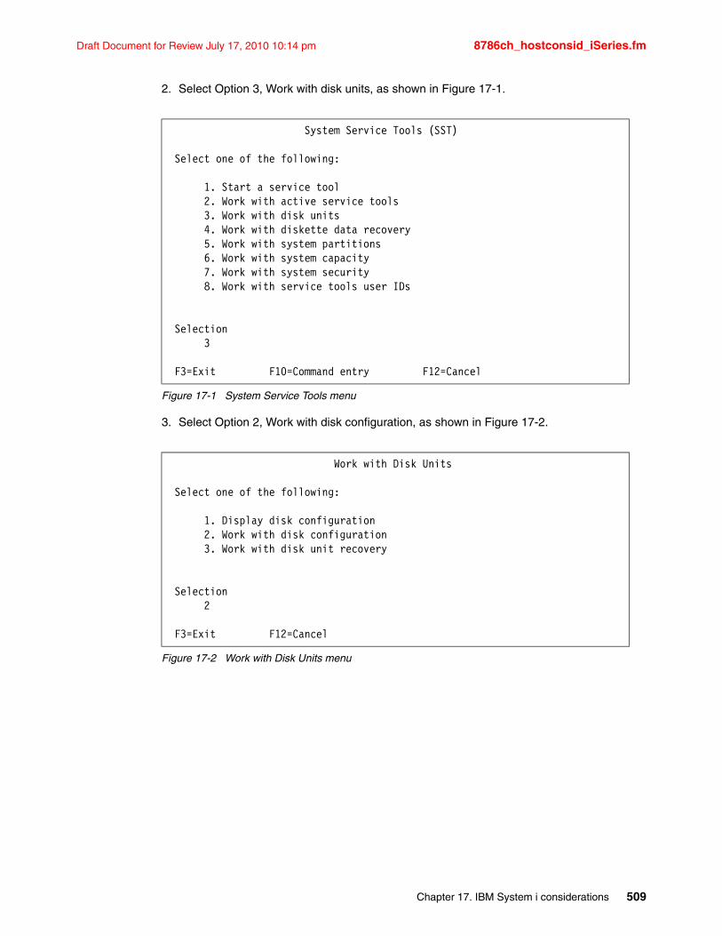
Draft Document for Review July 17, 2010 10:14 pm 8786ch_hostconsid_iSeries.fm
2. Select Option 3, Work with disk units, as shown in Figure 17-1.
Figure 17-1 System Service Tools menu
3. Select Option 2, Work with disk configuration, as shown in Figure 17-2.
Figure 17-2 Work with Disk Units menu
System Service Tools (SST) Select one of the following: 1. Start a service tool 2. Work with active service tools 3. Work with disk units 4. Work with diskette data recovery 5. Work with system partitions 6. Work with system capacity 7. Work with system security 8. Work with service tools user IDs Selection 3 F3=Exit F10=Command entry F12=Cancel
Work with Disk Units Select one of the following: 1. Display disk configuration 2. Work with disk configuration 3. Work with disk unit recovery Selection 2 F3=Exit F12=Cancel
Chapter 17. IBM System i considerations 509
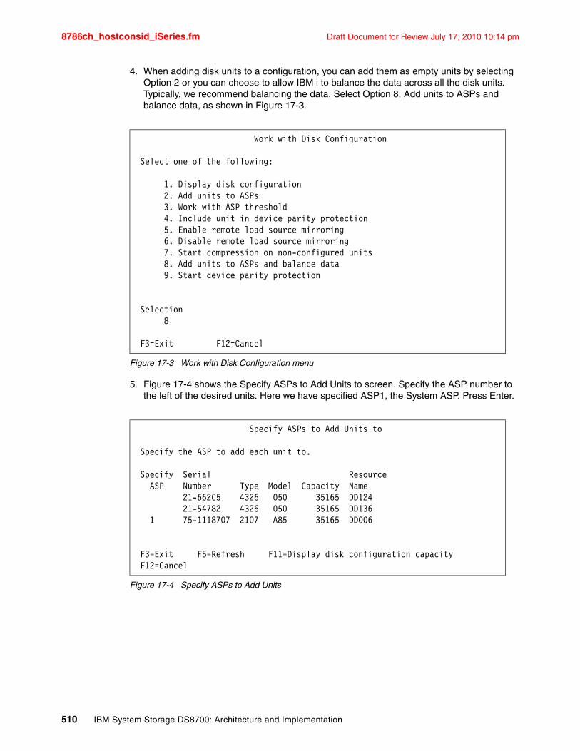
8786ch_hostconsid_iSeries.fm Draft Document for Review July 17, 2010 10:14 pm
4. When adding disk units to a configuration, you can add them as empty units by selecting Option 2 or you can choose to allow IBM i to balance the data across all the disk units. Typically, we recommend balancing the data. Select Option 8, Add units to ASPs and balance data, as shown in Figure 17-3.
Figure 17-3 Work with Disk Configuration menu
5. Figure 17-4 shows the Specify ASPs to Add Units to screen. Specify the ASP number to the left of the desired units. Here we have specified ASP1, the System ASP. Press Enter.
Figure 17-4 Specify ASPs to Add Units
Work with Disk Configuration Select one of the following: 1. Display disk configuration 2. Add units to ASPs 3. Work with ASP threshold 4. Include unit in device parity protection 5. Enable remote load source mirroring 6. Disable remote load source mirroring 7. Start compression on non-configured units 8. Add units to ASPs and balance data 9. Start device parity protection Selection 8 F3=Exit F12=Cancel
Specify ASPs to Add Units to Specify the ASP to add each unit to. Specify Serial Resource ASP Number Type Model Capacity Name 21-662C5 4326 050 35165 DD124 21-54782 4326 050 35165 DD136 1 75-1118707 2107 A85 35165 DD006 F3=Exit F5=Refresh F11=Display disk configuration capacity F12=Cancel
510 IBM System Storage DS8700: Architecture and Implementation
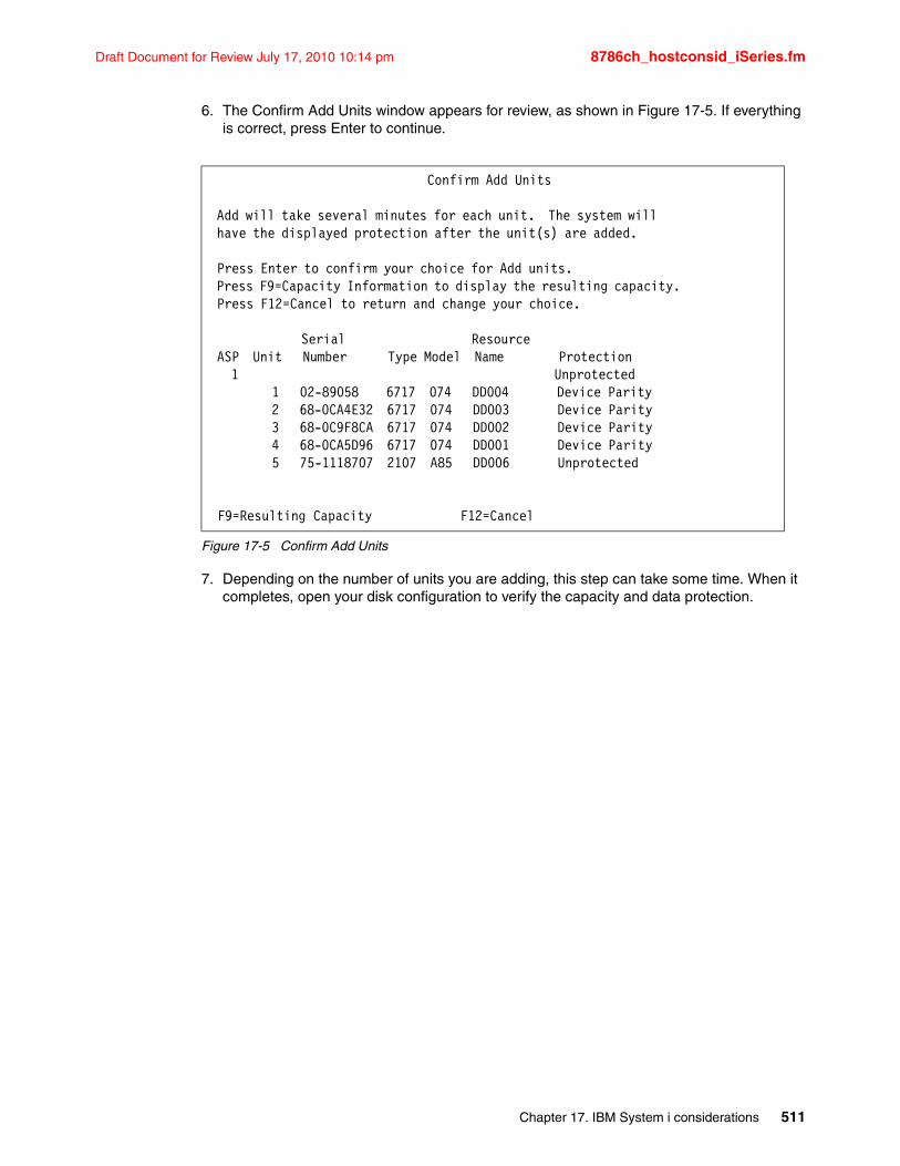
Draft Document for Review July 17, 2010 10:14 pm 8786ch_hostconsid_iSeries.fm
6. The Confirm Add Units window appears for review, as shown in Figure 17-5. If everything is correct, press Enter to continue.
Figure 17-5 Confirm Add Units
7. Depending on the number of units you are adding, this step can take some time. When it completes, open your disk configuration to verify the capacity and data protection.
Confirm Add Units Add will take several minutes for each unit. The system will have the displayed protection after the unit(s) are added. Press Enter to confirm your choice for Add units. Press F9=Capacity Information to display the resulting capacity. Press F12=Cancel to return and change your choice. Serial Resource ASP Unit Number Type Model Name Protection 1 Unprotected 1 02-89058 6717 074 DD004 Device Parity 2 68-0CA4E32 6717 074 DD003 Device Parity 3 68-0C9F8CA 6717 074 DD002 Device Parity 4 68-0CA5D96 6717 074 DD001 Device Parity 5 75-1118707 2107 A85 DD006 Unprotected F9=Resulting Capacity F12=Cancel
Chapter 17. IBM System i considerations 511
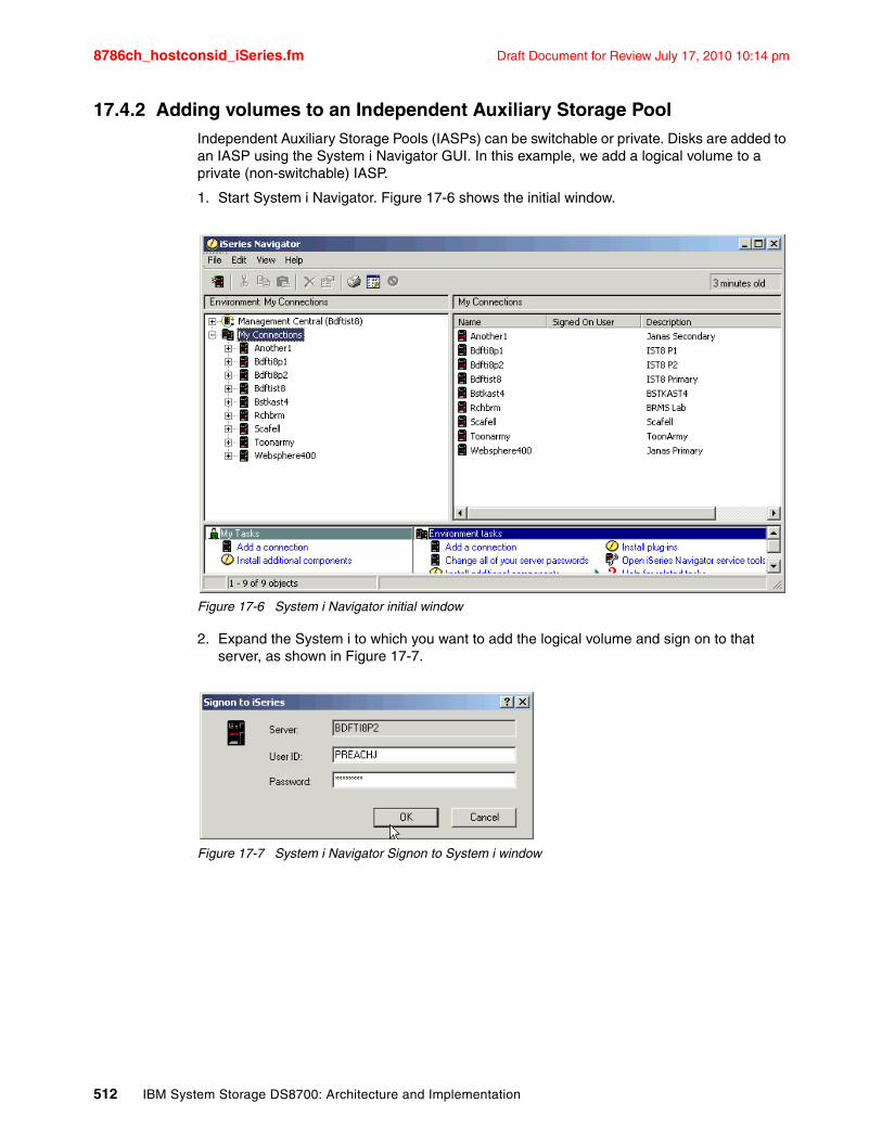
8786ch_hostconsid_iSeries.fm Draft Document for Review July 17, 2010 10:14 pm
17.4.2 Adding volumes to an Independent Auxiliary Storage PoolIndependent Auxiliary Storage Pools (IASPs) can be switchable or private. Disks are added to an IASP using the System i Navigator GUI. In this example, we add a logical volume to a private (non-switchable) IASP.
1. Start System i Navigator. Figure 17-6 shows the initial window.
Figure 17-6 System i Navigator initial window
2. Expand the System i to which you want to add the logical volume and sign on to that server, as shown in Figure 17-7.
Figure 17-7 System i Navigator Signon to System i window
512 IBM System Storage DS8700: Architecture and Implementation
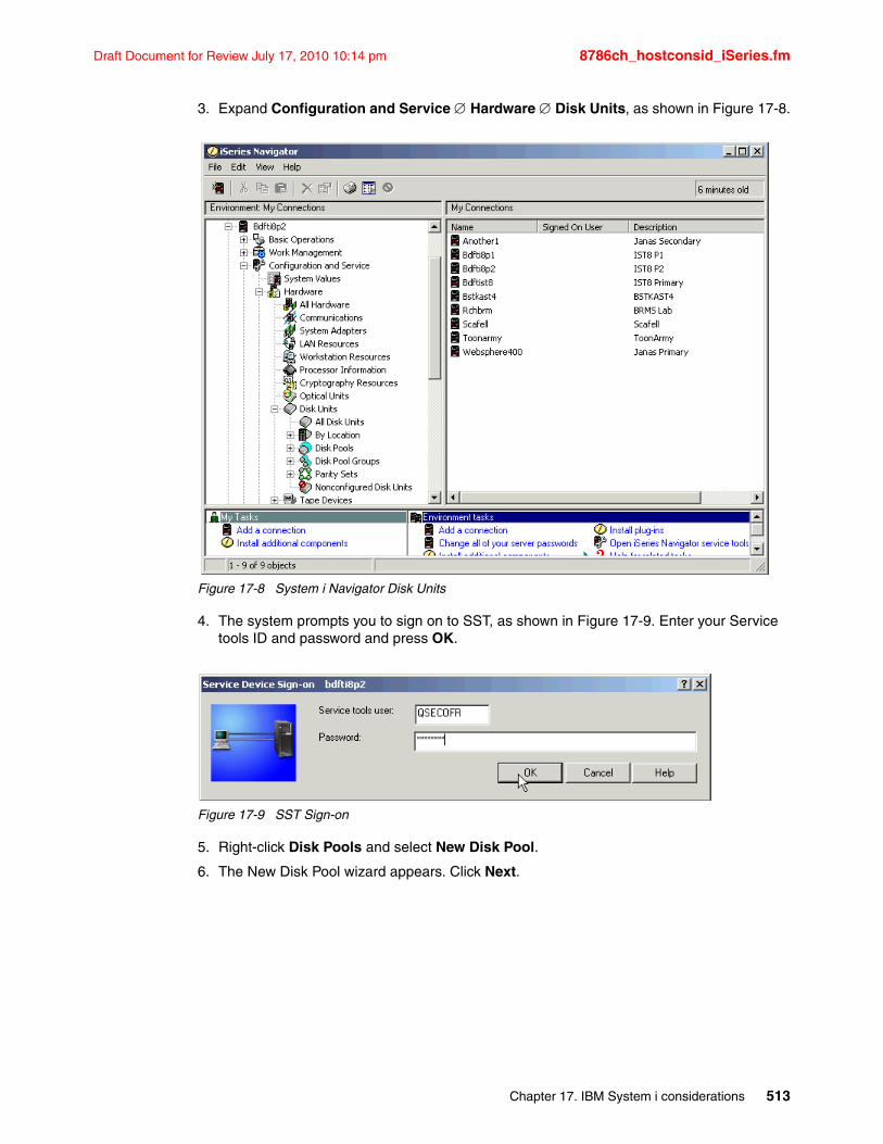
Draft Document for Review July 17, 2010 10:14 pm 8786ch_hostconsid_iSeries.fm
3. Expand Configuration and Service Hardware Disk Units, as shown in Figure 17-8.
Figure 17-8 System i Navigator Disk Units
4. The system prompts you to sign on to SST, as shown in Figure 17-9. Enter your Service tools ID and password and press OK.
Figure 17-9 SST Sign-on
5. Right-click Disk Pools and select New Disk Pool.
6. The New Disk Pool wizard appears. Click Next.
Chapter 17. IBM System i considerations 513
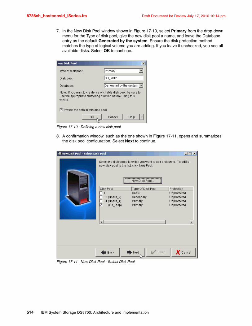
8786ch_hostconsid_iSeries.fm Draft Document for Review July 17, 2010 10:14 pm
7. In the New Disk Pool window shown in Figure 17-10, select Primary from the drop-down menu for the Type of disk pool, give the new disk pool a name, and leave the Database entry as the default Generated by the system. Ensure the disk protection method matches the type of logical volume you are adding. If you leave it unchecked, you see all available disks. Select OK to continue.
Figure 17-10 Defining a new disk pool
8. A confirmation window, such as the one shown in Figure 17-11, opens and summarizes the disk pool configuration. Select Next to continue.
Figure 17-11 New Disk Pool - Select Disk Pool
514 IBM System Storage DS8700: Architecture and Implementation
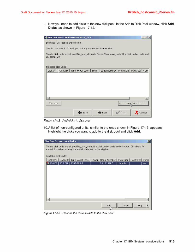
Draft Document for Review July 17, 2010 10:14 pm 8786ch_hostconsid_iSeries.fm
9. Now you need to add disks to the new disk pool. In the Add to Disk Pool window, click Add Disks, as shown in Figure 17-12.
Figure 17-12 Add disks to disk pool
10.A list of non-configured units, similar to the ones shown in Figure 17-13, appears. Highlight the disks you want to add to the disk pool and click Add.
Figure 17-13 Choose the disks to add to the disk pool
Chapter 17. IBM System i considerations 515
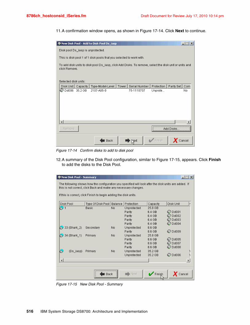
8786ch_hostconsid_iSeries.fm Draft Document for Review July 17, 2010 10:14 pm
11.A confirmation window opens, as shown in Figure 17-14. Click Next to continue.
Figure 17-14 Confirm disks to add to disk pool
12.A summary of the Disk Pool configuration, similar to Figure 17-15, appears. Click Finish to add the disks to the Disk Pool.
Figure 17-15 New Disk Pool - Summary
516 IBM System Storage DS8700: Architecture and Implementation
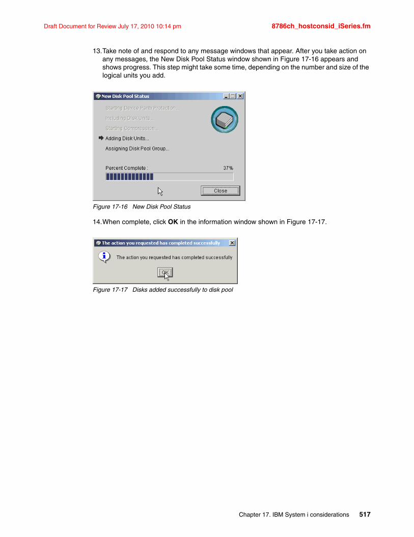
Draft Document for Review July 17, 2010 10:14 pm 8786ch_hostconsid_iSeries.fm
13.Take note of and respond to any message windows that appear. After you take action on any messages, the New Disk Pool Status window shown in Figure 17-16 appears and shows progress. This step might take some time, depending on the number and size of the logical units you add.
Figure 17-16 New Disk Pool Status
14.When complete, click OK in the information window shown in Figure 17-17.
Figure 17-17 Disks added successfully to disk pool
Chapter 17. IBM System i considerations 517
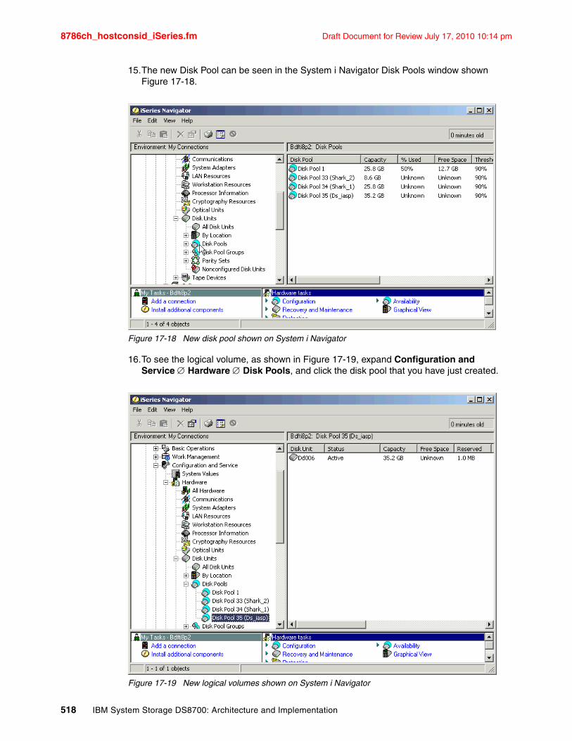
8786ch_hostconsid_iSeries.fm Draft Document for Review July 17, 2010 10:14 pm
15.The new Disk Pool can be seen in the System i Navigator Disk Pools window shown Figure 17-18.
Figure 17-18 New disk pool shown on System i Navigator
16.To see the logical volume, as shown in Figure 17-19, expand Configuration and Service Hardware Disk Pools, and click the disk pool that you have just created.
Figure 17-19 New logical volumes shown on System i Navigator
518 IBM System Storage DS8700: Architecture and Implementation
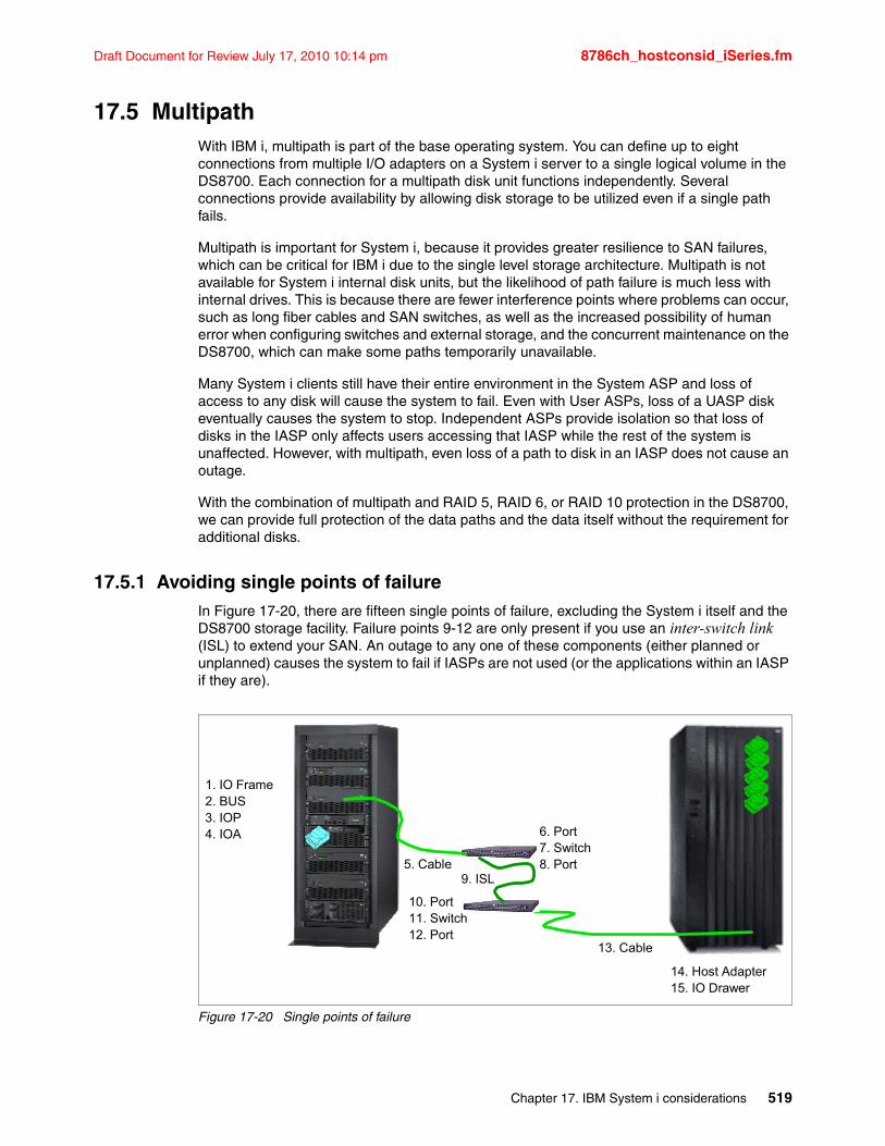
Draft Document for Review July 17, 2010 10:14 pm 8786ch_hostconsid_iSeries.fm
17.5 MultipathWith IBM i, multipath is part of the base operating system. You can define up to eight connections from multiple I/O adapters on a System i server to a single logical volume in the DS8700. Each connection for a multipath disk unit functions independently. Several connections provide availability by allowing disk storage to be utilized even if a single path fails.
Multipath is important for System i, because it provides greater resilience to SAN failures, which can be critical for IBM i due to the single level storage architecture. Multipath is not available for System i internal disk units, but the likelihood of path failure is much less with internal drives. This is because there are fewer interference points where problems can occur, such as long fiber cables and SAN switches, as well as the increased possibility of human error when configuring switches and external storage, and the concurrent maintenance on the DS8700, which can make some paths temporarily unavailable.
Many System i clients still have their entire environment in the System ASP and loss of access to any disk will cause the system to fail. Even with User ASPs, loss of a UASP disk eventually causes the system to stop. Independent ASPs provide isolation so that loss of disks in the IASP only affects users accessing that IASP while the rest of the system is unaffected. However, with multipath, even loss of a path to disk in an IASP does not cause an outage.
With the combination of multipath and RAID 5, RAID 6, or RAID 10 protection in the DS8700, we can provide full protection of the data paths and the data itself without the requirement for additional disks.
17.5.1 Avoiding single points of failureIn Figure 17-20, there are fifteen single points of failure, excluding the System i itself and the DS8700 storage facility. Failure points 9-12 are only present if you use an inter-switch link (ISL) to extend your SAN. An outage to any one of these components (either planned or unplanned) causes the system to fail if IASPs are not used (or the applications within an IASP if they are).
Figure 17-20 Single points of failure
6. Port7. Switch8. Port
1. IO Frame2. BUS3. IOP4. IOA
5. Cable9. ISL
13. Cable
10. Port11. Switch12. Port
14. Host Adapter15. IO Drawer
Chapter 17. IBM System i considerations 519

8786ch_hostconsid_iSeries.fm Draft Document for Review July 17, 2010 10:14 pm
When implementing multipath, provide as much redundancy as possible. At a minimum, multipath requires two IOAs connecting the same logical volumes. Ideally, place these on different buses and in different I/O racks in the System i. If a SAN is included, use separate switches also for each path. You should also use Host Adapters in different I/O drawer pairs in the DS8700, as shown in Figure 17-21.
Figure 17-21 Multipath removes single points of failure
Unlike other systems, which might only support two paths (dual-path), IBM i V5R3 supports up to eight paths to the same logical volumes. At a minimum, you should use two paths, although some small performance benefits might be experienced with more paths. However, because IBM i multipath spreads I/O across all available paths in a round-robin manner, there is no load balancing, only load sharing.
17.5.2 Configuring multipathThe following I/O adapters are supported on a System i attached to a DS8700 storage subsystem:
� FC 5749 4 Gigabit Fibre Channel Disk Controller PCI-x� FC 5760 4 Gigabit Fibre Channel Disk Controller PCI-x� FC 5774 4 Gigabit Fibre Channel Disk Controller PCI-e� FC 5735 8 Gigabit Fibre Channel Disk Controller PCI-e
All of these adapters can be used for multipath, and there is no requirement for all the paths to use the same type of adapter. This does not change with multipath support. When deciding how many I/O adapters to use, your first priority should be to consider the performance throughput of the IOA, because this limit might be reached before the maximum number of logical units. See 17.6, “Sizing guidelines” on page 527 for more information about sizing and performance guidelines.
In order to achieve better redundancy, we recommend configuring each logical path in a multipath configuration using different System i BUSes or different System i expansion towers, if possible.
520 IBM System Storage DS8700: Architecture and Implementation
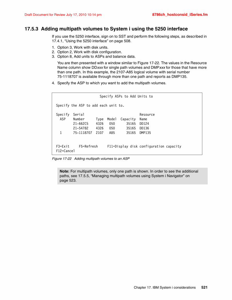
Draft Document for Review July 17, 2010 10:14 pm 8786ch_hostconsid_iSeries.fm
17.5.3 Adding multipath volumes to System i using the 5250 interfaceIf you use the 5250 interface, sign on to SST and perform the following steps, as described in 17.4.1, “Using the 5250 interface” on page 508.
1. Option 3, Work with disk units.2. Option 2, Work with disk configuration.3. Option 8, Add units to ASPs and balance data.
You are then presented with a window similar to Figure 17-22. The values in the Resource Name column show DDxxx for single path volumes and DMPxxx for those that have more than one path. In this example, the 2107-A85 logical volume with serial number 75-1118707 is available through more than one path and reports as DMP135.
4. Specify the ASP to which you want to add the multipath volumes.
Figure 17-22 Adding multipath volumes to an ASP
Specify ASPs to Add Units to Specify the ASP to add each unit to. Specify Serial Resource ASP Number Type Model Capacity Name 21-662C5 4326 050 35165 DD124 21-54782 4326 050 35165 DD136 1 75-1118707 2107 A85 35165 DMP135 F3=Exit F5=Refresh F11=Display disk configuration capacity F12=Cancel
Note: For multipath volumes, only one path is shown. In order to see the additional paths, see 17.5.5, “Managing multipath volumes using System i Navigator” on page 523.
Chapter 17. IBM System i considerations 521
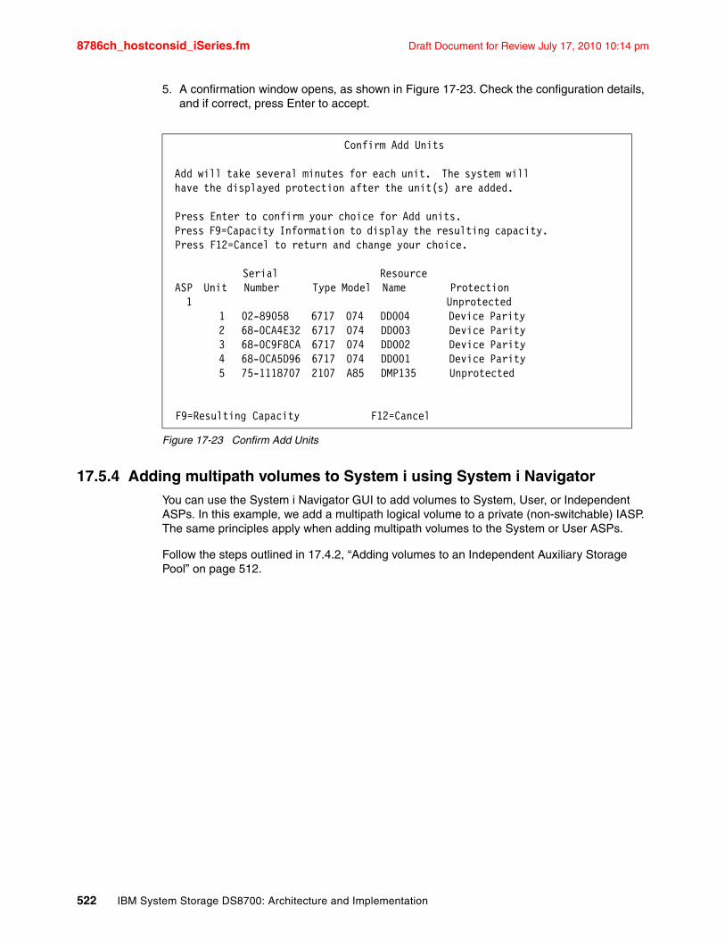
8786ch_hostconsid_iSeries.fm Draft Document for Review July 17, 2010 10:14 pm
5. A confirmation window opens, as shown in Figure 17-23. Check the configuration details, and if correct, press Enter to accept.
Figure 17-23 Confirm Add Units
17.5.4 Adding multipath volumes to System i using System i NavigatorYou can use the System i Navigator GUI to add volumes to System, User, or Independent ASPs. In this example, we add a multipath logical volume to a private (non-switchable) IASP. The same principles apply when adding multipath volumes to the System or User ASPs.
Follow the steps outlined in 17.4.2, “Adding volumes to an Independent Auxiliary Storage Pool” on page 512.
Confirm Add Units Add will take several minutes for each unit. The system will have the displayed protection after the unit(s) are added. Press Enter to confirm your choice for Add units. Press F9=Capacity Information to display the resulting capacity. Press F12=Cancel to return and change your choice. Serial Resource ASP Unit Number Type Model Name Protection 1 Unprotected 1 02-89058 6717 074 DD004 Device Parity 2 68-0CA4E32 6717 074 DD003 Device Parity 3 68-0C9F8CA 6717 074 DD002 Device Parity 4 68-0CA5D96 6717 074 DD001 Device Parity 5 75-1118707 2107 A85 DMP135 Unprotected F9=Resulting Capacity F12=Cancel
522 IBM System Storage DS8700: Architecture and Implementation
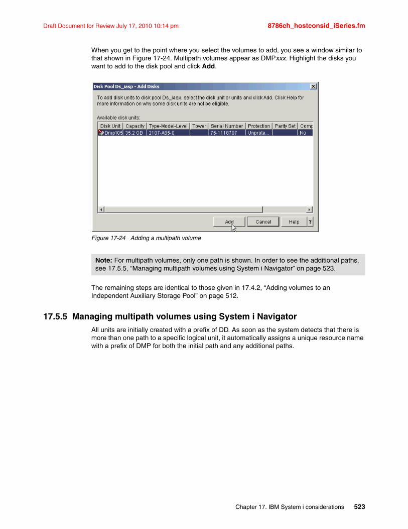
Draft Document for Review July 17, 2010 10:14 pm 8786ch_hostconsid_iSeries.fm
When you get to the point where you select the volumes to add, you see a window similar to that shown in Figure 17-24. Multipath volumes appear as DMPxxx. Highlight the disks you want to add to the disk pool and click Add.
Figure 17-24 Adding a multipath volume
The remaining steps are identical to those given in 17.4.2, “Adding volumes to an Independent Auxiliary Storage Pool” on page 512.
17.5.5 Managing multipath volumes using System i NavigatorAll units are initially created with a prefix of DD. As soon as the system detects that there is more than one path to a specific logical unit, it automatically assigns a unique resource name with a prefix of DMP for both the initial path and any additional paths.
Note: For multipath volumes, only one path is shown. In order to see the additional paths, see 17.5.5, “Managing multipath volumes using System i Navigator” on page 523.
Chapter 17. IBM System i considerations 523
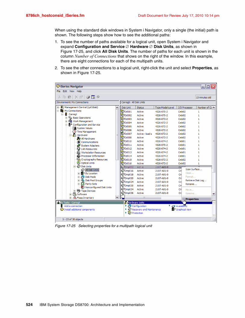
8786ch_hostconsid_iSeries.fm Draft Document for Review July 17, 2010 10:14 pm
When using the standard disk windows in System i Navigator, only a single (the initial) path is shown. The following steps show how to see the additional paths:
1. To see the number of paths available for a logical unit, open System i Navigator and expand Configuration and Service Hardware Disk Units, as shown in Figure 17-25, and click All Disk Units. The number of paths for each unit is shown in the column Number of Connections that shows on the right of the window. In this example, there are eight connections for each of the multipath units.
2. To see the other connections to a logical unit, right-click the unit and select Properties, as shown in Figure 17-25.
Figure 17-25 Selecting properties for a multipath logical unit
524 IBM System Storage DS8700: Architecture and Implementation
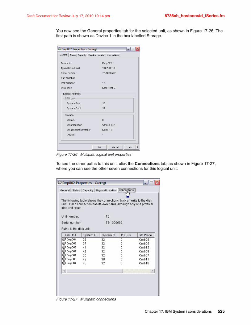
Draft Document for Review July 17, 2010 10:14 pm 8786ch_hostconsid_iSeries.fm
You now see the General properties tab for the selected unit, as shown in Figure 17-26. The first path is shown as Device 1 in the box labelled Storage.
Figure 17-26 Multipath logical unit properties
To see the other paths to this unit, click the Connections tab, as shown in Figure 17-27, where you can see the other seven connections for this logical unit.
Figure 17-27 Multipath connections
Chapter 17. IBM System i considerations 525
8786ch_hostconsid_iSeries.fm Draft Document for Review July 17, 2010 10:14 pm
17.5.6 Multipath rules for multiple System i hosts or partitionsWhen you use multipath disk units, you must consider the implications of moving IOPs and multipath connections between nodes. You must not split multipath connections between nodes, either by moving IOPs between logical partitions or by switching expansion units between systems. If two different nodes both have connections to the same LUN in the DS8700, both nodes might potentially overwrite data from the other node.
The system enforces the following rules when you use multipath disk units in a multiple system environment:
� If you move an IOP with a multipath connection to a different logical partition, you must also move all other IOPs with connections to the same disk unit to the same logical partition.
� When you make an expansion unit switchable, make sure that all multipath connections to a disk unit switch with the expansion unit.
� When you configure a switchable independent disk pool, make sure that all of the required IOPs for multipath disk units switch with the independent disk pool.
If a multipath configuration rule is violated, the system issues warnings or errors to alert you about the condition. It is important to pay attention when disk unit connections are reported missing. You want to prevent a situation where a node might overwrite data on a LUN that belongs to another node.
Disk unit connections might be missing for a variety of reasons, but especially if one of the preceding rules has been violated. If a connection for a multipath disk unit in any disk pool is found to be missing during an IPL or vary on, a message is sent to the QSYSOPR message queue.
If a connection is missing, and you confirm that the connection has been removed, you can update Hardware Service Manager (HSM) to remove that resource. Hardware Service Manager is a tool for displaying and working with system hardware from both a logical and a packaging viewpoint, an aid for debugging Input/Output (I/O) processors and devices, and for fixing failing and missing hardware. You can access Hardware Service Manager in System Service Tools (SST) and Dedicated Service Tools (DST) by selecting the option to start a service tool.
17.5.7 Changing from a single path to multipathIf you have a configuration where the logical units were only assigned to one I/O adapter, you can easily change to multipath. Simply assign the logical units in the DS8700 to another I/O adapter, and the existing DDxxx drives change to DMPxxx, and new DMPxxx resources are created for the new path.
526 IBM System Storage DS8700: Architecture and Implementation
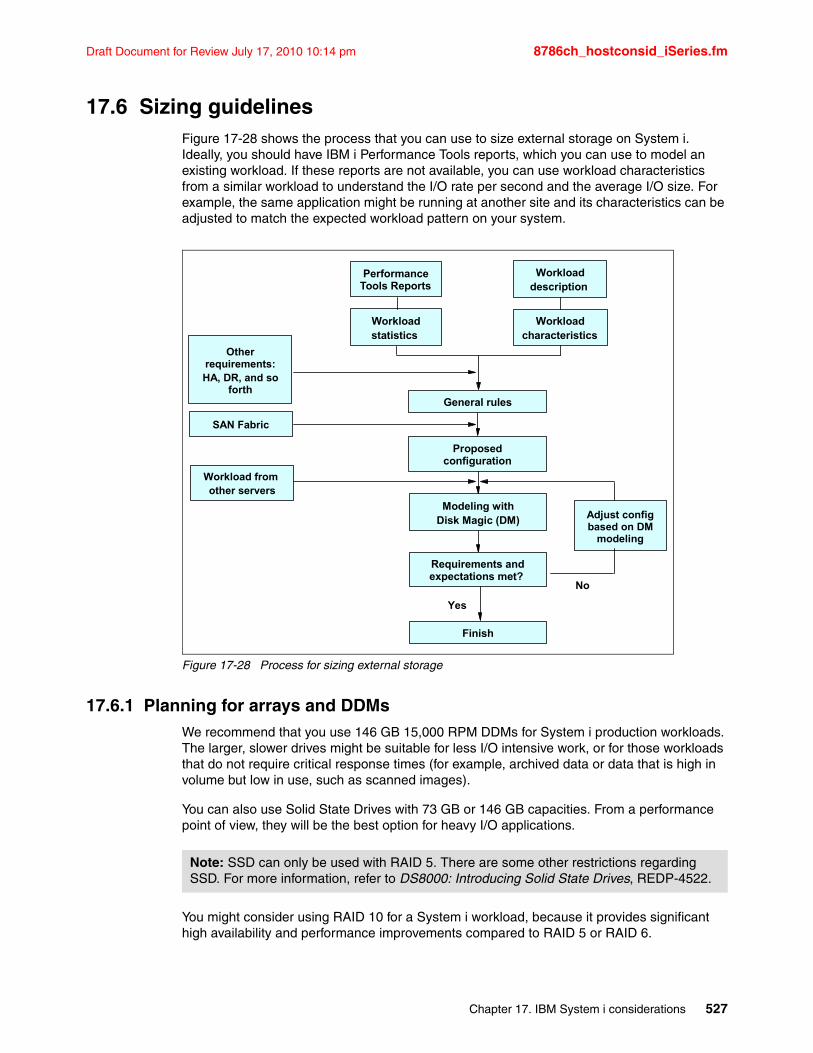
Draft Document for Review July 17, 2010 10:14 pm 8786ch_hostconsid_iSeries.fm
17.6 Sizing guidelinesFigure 17-28 shows the process that you can use to size external storage on System i. Ideally, you should have IBM i Performance Tools reports, which you can use to model an existing workload. If these reports are not available, you can use workload characteristics from a similar workload to understand the I/O rate per second and the average I/O size. For example, the same application might be running at another site and its characteristics can be adjusted to match the expected workload pattern on your system.
Figure 17-28 Process for sizing external storage
17.6.1 Planning for arrays and DDMsWe recommend that you use 146 GB 15,000 RPM DDMs for System i production workloads. The larger, slower drives might be suitable for less I/O intensive work, or for those workloads that do not require critical response times (for example, archived data or data that is high in volume but low in use, such as scanned images).
You can also use Solid State Drives with 73 GB or 146 GB capacities. From a performance point of view, they will be the best option for heavy I/O applications.
You might consider using RAID 10 for a System i workload, because it provides significant high availability and performance improvements compared to RAID 5 or RAID 6.
Modeling withDisk Magic (DM)
General rules
Proposed configuration
Requirements and expectations met?
Finish
Other requirements:HA, DR, and so
forth
SAN Fabric
Workload from other servers
Yes
Adjust config based on DM
modeling
No
Workloaddescription
Workloadcharacteristics
Performance Tools Reports
Workloadstatistics
Note: SSD can only be used with RAID 5. There are some other restrictions regarding SSD. For more information, refer to DS8000: Introducing Solid State Drives, REDP-4522.
Chapter 17. IBM System i considerations 527
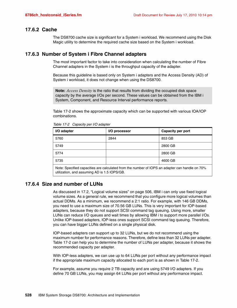
8786ch_hostconsid_iSeries.fm Draft Document for Review July 17, 2010 10:14 pm
17.6.2 CacheThe DS8700 cache size is significant for a System i workload. We recommend using the Disk Magic utility to determine the required cache size based on the System i workload.
17.6.3 Number of System i Fibre Channel adaptersThe most important factor to take into consideration when calculating the number of Fibre Channel adapters in the System i is the throughput capacity of the adapter.
Because this guideline is based only on System i adapters and the Access Density (AD) of System i workload, it does not change when using the DS8700.
Table 17-2 shows the approximate capacity which can be supported with various IOA/IOP combinations.
Table 17-2 Capacity per I/O adapter
17.6.4 Size and number of LUNsAs discussed in 17.2, “Logical volume sizes” on page 506, IBM i can only use fixed logical volume sizes. As a general rule, we recommend that you configure more logical volumes than actual DDMs. As a minimum, we recommend a 2:1 ratio. For example, with 146 GB DDMs, you need to use a maximum size of 70.56 GB LUNs. This is very important for IOP-based adapters, because they do not support SCSI command tag queuing. Using more, smaller LUNs can reduce I/O queues and wait times by allowing IBM i to support more parallel I/Os. Unlike IOP-based adapters, IOP-less ones support SCSI command tag queuing. Therefore, you can have bigger LUNs defined on a single physical disk.
IOP-based adapters can support up to 32 LUNs, but we do not recommend using the maximum number for performance reasons. Therefore, define less than 32 LUNs per adapter. Table 17-2 can help you to determine the number of LUNs per adapter, because it shows the recommended capacity per adapter.
With IOP-less adapters, we can use up to 64 LUNs per port without any performance impact if the appropriate maximum capacity allocated to each port is as shown in Table 17-2.
For example, assume you require 2 TB capacity and are using 5749 I/O adapters. If you define 70 GB LUNs, you may assign 64 LUNs per port without any performance impact.
Note: Access Density is the ratio that results from dividing the occupied disk space capacity by the average I/Os per second. These values can be obtained from the IBM i System, Component, and Resource Interval performance reports.
I/O adapter I/O processor Capacity per port
5760 2844 853 GB
5749 2800 GB
5774 2800 GB
5735 4600 GB
Note: Specified capacities are calculated from the number of IOPS an adapter can handle on 70% utilization, and assuming AD is 1.5 IOPS/GB.
528 IBM System Storage DS8700: Architecture and Implementation
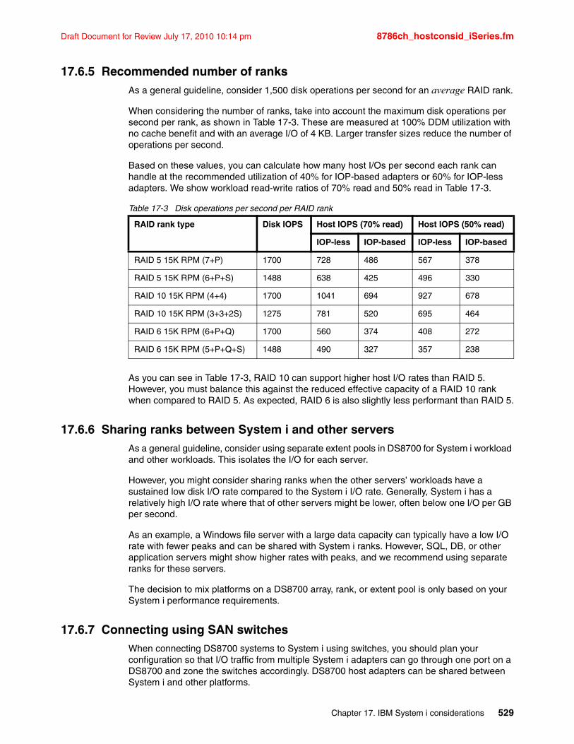
Draft Document for Review July 17, 2010 10:14 pm 8786ch_hostconsid_iSeries.fm
17.6.5 Recommended number of ranksAs a general guideline, consider 1,500 disk operations per second for an average RAID rank.
When considering the number of ranks, take into account the maximum disk operations per second per rank, as shown in Table 17-3. These are measured at 100% DDM utilization with no cache benefit and with an average I/O of 4 KB. Larger transfer sizes reduce the number of operations per second.
Based on these values, you can calculate how many host I/Os per second each rank can handle at the recommended utilization of 40% for IOP-based adapters or 60% for IOP-less adapters. We show workload read-write ratios of 70% read and 50% read in Table 17-3.
Table 17-3 Disk operations per second per RAID rank
As you can see in Table 17-3, RAID 10 can support higher host I/O rates than RAID 5. However, you must balance this against the reduced effective capacity of a RAID 10 rank when compared to RAID 5. As expected, RAID 6 is also slightly less performant than RAID 5.
17.6.6 Sharing ranks between System i and other serversAs a general guideline, consider using separate extent pools in DS8700 for System i workload and other workloads. This isolates the I/O for each server.
However, you might consider sharing ranks when the other servers’ workloads have a sustained low disk I/O rate compared to the System i I/O rate. Generally, System i has a relatively high I/O rate where that of other servers might be lower, often below one I/O per GB per second.
As an example, a Windows file server with a large data capacity can typically have a low I/O rate with fewer peaks and can be shared with System i ranks. However, SQL, DB, or other application servers might show higher rates with peaks, and we recommend using separate ranks for these servers.
The decision to mix platforms on a DS8700 array, rank, or extent pool is only based on your System i performance requirements.
17.6.7 Connecting using SAN switchesWhen connecting DS8700 systems to System i using switches, you should plan your configuration so that I/O traffic from multiple System i adapters can go through one port on a DS8700 and zone the switches accordingly. DS8700 host adapters can be shared between System i and other platforms.
RAID rank type Disk IOPS Host IOPS (70% read) Host IOPS (50% read)
IOP-less IOP-based IOP-less IOP-based
RAID 5 15K RPM (7+P) 1700 728 486 567 378
RAID 5 15K RPM (6+P+S) 1488 638 425 496 330
RAID 10 15K RPM (4+4) 1700 1041 694 927 678
RAID 10 15K RPM (3+3+2S) 1275 781 520 695 464
RAID 6 15K RPM (6+P+Q) 1700 560 374 408 272
RAID 6 15K RPM (5+P+Q+S) 1488 490 327 357 238
Chapter 17. IBM System i considerations 529
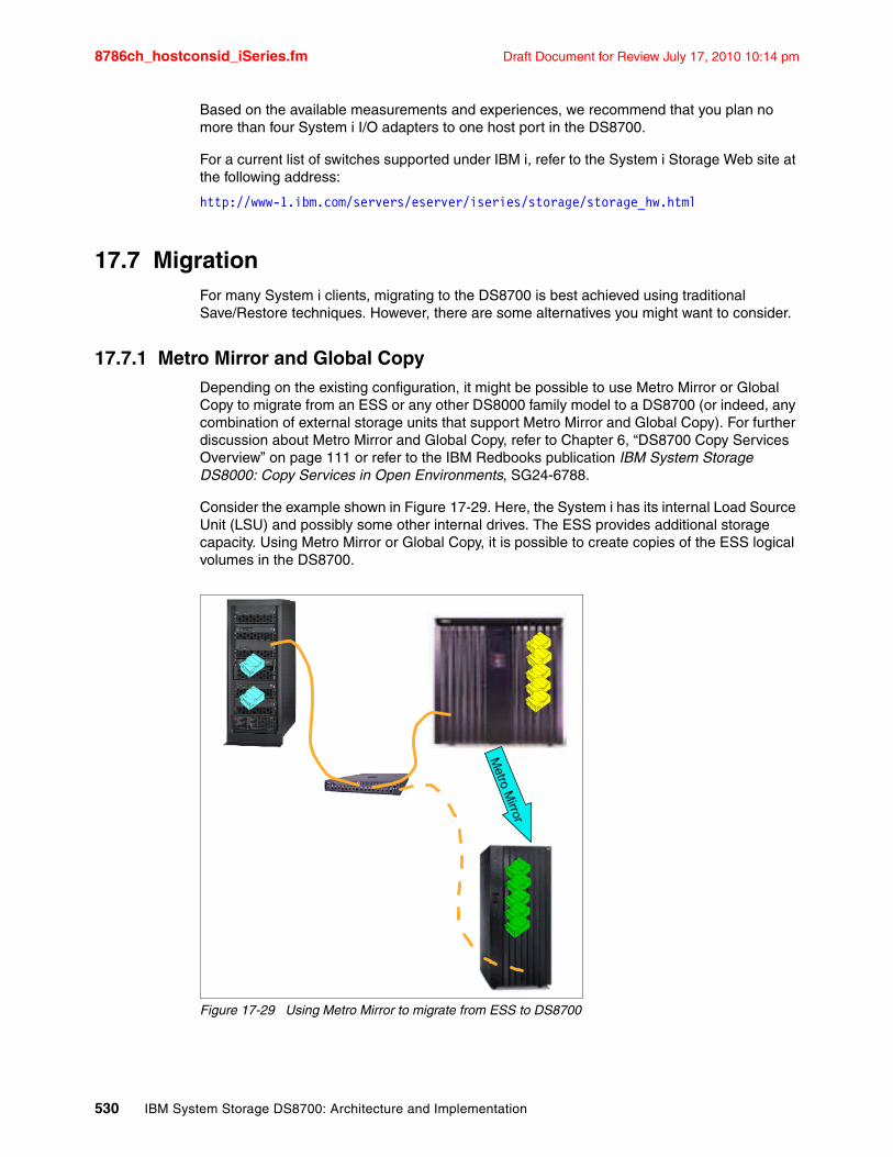
8786ch_hostconsid_iSeries.fm Draft Document for Review July 17, 2010 10:14 pm
Based on the available measurements and experiences, we recommend that you plan no more than four System i I/O adapters to one host port in the DS8700.
For a current list of switches supported under IBM i, refer to the System i Storage Web site at the following address:
http://www-1.ibm.com/servers/eserver/iseries/storage/storage_hw.html
17.7 MigrationFor many System i clients, migrating to the DS8700 is best achieved using traditional Save/Restore techniques. However, there are some alternatives you might want to consider.
17.7.1 Metro Mirror and Global CopyDepending on the existing configuration, it might be possible to use Metro Mirror or Global Copy to migrate from an ESS or any other DS8000 family model to a DS8700 (or indeed, any combination of external storage units that support Metro Mirror and Global Copy). For further discussion about Metro Mirror and Global Copy, refer to Chapter 6, “DS8700 Copy Services Overview” on page 111 or refer to the IBM Redbooks publication IBM System Storage DS8000: Copy Services in Open Environments, SG24-6788.
Consider the example shown in Figure 17-29. Here, the System i has its internal Load Source Unit (LSU) and possibly some other internal drives. The ESS provides additional storage capacity. Using Metro Mirror or Global Copy, it is possible to create copies of the ESS logical volumes in the DS8700.
Figure 17-29 Using Metro Mirror to migrate from ESS to DS8700
Metro M
irror
530 IBM System Storage DS8700: Architecture and Implementation
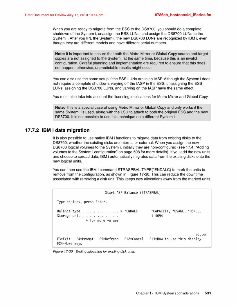
Draft Document for Review July 17, 2010 10:14 pm 8786ch_hostconsid_iSeries.fm
When you are ready to migrate from the ESS to the DS8700, you should do a complete shutdown of the System i, unassign the ESS LUNs, and assign the DS8700 LUNs to the System i. After you IPL the System i, the new DS8700 LUNs are recognized by IBM i, even though they are different models and have different serial numbers.
You can also use the same setup if the ESS LUNs are in an IASP. Although the System i does not require a complete shutdown, varying off the IASP in the ESS, unassigning the ESS LUNs, assigning the DS8700 LUNs, and varying on the IASP have the same effect.
You must also take into account the licensing implications for Metro Mirror and Global Copy.
17.7.2 IBM i data migrationIt is also possible to use native IBM i functions to migrate data from existing disks to the DS8700, whether the existing disks are internal or external. When you assign the new DS8700 logical volumes to the System i, initially they are non-configured (see 17.4, “Adding volumes to the System i configuration” on page 508 for more details). If you add the new units and choose to spread data, IBM i automatically migrates data from the existing disks onto the new logical units.
You can then use the IBM i command STRASPBAL TYPE(*ENDALC) to mark the units to remove from the configuration, as shown in Figure 17-30. This can reduce the downtime associated with removing a disk unit. This keeps new allocations away from the marked units.
Figure 17-30 Ending allocation for existing disk units
Note: It is important to ensure that both the Metro Mirror or Global Copy source and target copies are not assigned to the System i at the same time, because this is an invalid configuration. Careful planning and implementation are required to ensure that this does not happen; otherwise, unpredictable results might occur.
Note: This is a special case of using Metro Mirror or Global Copy and only works if the same System i is used, along with the LSU to attach to both the original ESS and the new DS8700. It is not possible to use this technique on a different System i.
Start ASP Balance (STRASPBAL) Type choices, press Enter. Balance type . . . . . . . . . . > *ENDALC *CAPACITY, *USAGE, *HSM... Storage unit . . . . . . . . . . 1-4094 + for more values Bottom F3=Exit F4=Prompt F5=Refresh F12=Cancel F13=How to use this display F24=More keys
Chapter 17. IBM System i considerations 531
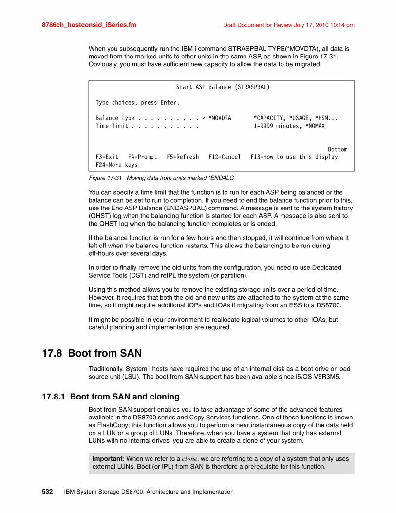
8786ch_hostconsid_iSeries.fm Draft Document for Review July 17, 2010 10:14 pm
When you subsequently run the IBM i command STRASPBAL TYPE(*MOVDTA), all data is moved from the marked units to other units in the same ASP, as shown in Figure 17-31. Obviously, you must have sufficient new capacity to allow the data to be migrated.
Figure 17-31 Moving data from units marked *ENDALC
You can specify a time limit that the function is to run for each ASP being balanced or the balance can be set to run to completion. If you need to end the balance function prior to this, use the End ASP Balance (ENDASPBAL) command. A message is sent to the system history (QHST) log when the balancing function is started for each ASP. A message is also sent to the QHST log when the balancing function completes or is ended.
If the balance function is run for a few hours and then stopped, it will continue from where it left off when the balance function restarts. This allows the balancing to be run during off-hours over several days.
In order to finally remove the old units from the configuration, you need to use Dedicated Service Tools (DST) and reIPL the system (or partition).
Using this method allows you to remove the existing storage units over a period of time. However, it requires that both the old and new units are attached to the system at the same time, so it might require additional IOPs and IOAs if migrating from an ESS to a DS8700.
It might be possible in your environment to reallocate logical volumes to other IOAs, but careful planning and implementation are required.
17.8 Boot from SANTraditionally, System i hosts have required the use of an internal disk as a boot drive or load source unit (LSU). The boot from SAN support has been available since i5/OS V5R3M5.
17.8.1 Boot from SAN and cloningBoot from SAN support enables you to take advantage of some of the advanced features available in the DS8700 series and Copy Services functions. One of these functions is known as FlashCopy; this function allows you to perform a near instantaneous copy of the data held on a LUN or a group of LUNs. Therefore, when you have a system that only has external LUNs with no internal drives, you are able to create a clone of your system.
Start ASP Balance (STRASPBAL) Type choices, press Enter. Balance type . . . . . . . . . . > *MOVDTA *CAPACITY, *USAGE, *HSM... Time limit . . . . . . . . . . . 1-9999 minutes, *NOMAX Bottom F3=Exit F4=Prompt F5=Refresh F12=Cancel F13=How to use this display F24=More keys
Important: When we refer to a clone, we are referring to a copy of a system that only uses external LUNs. Boot (or IPL) from SAN is therefore a prerequisite for this function.
532 IBM System Storage DS8700: Architecture and Implementation
Draft Document for Review July 17, 2010 10:14 pm 8786ch_hostconsid_iSeries.fm
When you use cloning:
� You need enough free capacity on your external storage unit to accommodate the clone. Additionally, you should remember that Copy Services functions are resource intensive for the external storage unit; running them during the normal business hours can impact performance.
� You should not attach a clone to your network until you have resolved any potential conflicts that the clone has with the parent system.
17.8.2 Why consider cloningBy using the cloning capability, you can create a complete copy of your entire system in minutes. You can then use this copy in any way you want, for example, you could potentially use it to minimize your backup windows, or protect yourself from a failure during an upgrade, maybe even use it as a fast way to provide yourself with a backup or test system. You can do all of these tasks using cloning with minimal impact to your production operations.
Chapter 17. IBM System i considerations 533

8786ch_hostconsid_iSeries.fm Draft Document for Review July 17, 2010 10:14 pm
534 IBM System Storage DS8700: Architecture and Implementation
Draft Document for Review July 17, 2010 10:14 pm 8786p_upgrading_and_maintaining.fm
Part 5 Maintenance and upgrades
The subjects covered in this part include:
� Licensed machine code
� Monitoring with Simple Network Management Protocol (SNMP)
� Remote support
� Capacity upgrades and CoD
Part 5
© Copyright IBM Corp. 2010. All rights reserved. 535

8786p_upgrading_and_maintaining.fm Draft Document for Review July 17, 2010 10:14 pm
536 IBM System Storage DS8700: Architecture and Implementation
Draft Document for Review July 17, 2010 10:14 pm 8786ch_Install_microcode.fm
Chapter 18. Licensed machine code
In this chapter, we discuss considerations related to the planning and installation of new licensed machine code (LMC) bundles on the IBM System Storage DS8700 series. We cover the following topics in this chapter:
� How new microcode is released
� Bundle installation
� DS8700 EFIXes
� Concurrent and non-concurrent updates
� Code updates
� Host adapter firmware updates
� Loading the code bundle
� Post-installation activities
� Summary
18
© Copyright IBM Corp. 2010. All rights reserved. 537
8786ch_Install_microcode.fm Draft Document for Review July 17, 2010 10:14 pm
18.1 How new microcode is releasedThe various components of the DS8700 system use firmware that can be updated as new releases become available. These components include device adapters, host adapters, power supplies, and Fibre Channel interface cards. In addition, the microcode and internal operating system that run on the HMCs as well as each Central Electronic Complex (CEC) can be updated. As IBM continues to develop the DS8700, new functional features will also be released through new licensed machine code (LMC) levels.
When IBM releases new microcode for the DS8700, it is released in the form of a bundle. The term bundle is used because a new code release can include updates for various DS8700 components. These updates are tested together and then the various code packages are bundled together into one unified release. In general, when referring to what code level is being used on a DS8700, the term bundle should be used. Components within the bundle will each have their own revision levels.
For a DS8000 Cross Reference table of Code Bundles, go to the following address:
http://www.ibm.com/support/docview.wss?uid=ssg1S1002949
The Cross Reference Table shows the levels of code prior to Release 6, which is installed on the DS8700. It should be updated as new bundles are released. It is important that you always match your DS CLI version to the bundle installed on your DS8700.
Starting with the release of the DS8700, the naming convention of bundles is PR.MM.AA.E, where the letters refer to:
P Product (7 = DS8700)R Release (5)MM Maintenance Level (xx)AA Service Pack (xx)E EFIX level (0 is base, and 1.n is the interim fix build above base level.)
18.2 Bundle installationIt is very likely that a new bundle will include updates for the following components:
� Linux OS for the HMC� AIX OS for the CECs� Microcode for HMC and CECs� Microcode/Firmware for Host Adapters
It is less likely that a bundle includes updates for the following components:
� Firmware for Power subsystem (PPS, RPC, and BBU)� Firmware for Storage DDMs� Firmware for Fibre Channel interface cards� Firmware for Device Adapters� Firmware for Hypervisor on CECs
The installation process involves several stages:
1. Update the HMC code. The new code version is supplied on CD or downloaded using FTP or SFTP (Secure File Transfer). This can potentially involve updates to the internal Linux version of the HMC, updates to the HMC licensed machine code, and updates to the firmware of the HMC hardware.
538 IBM System Storage DS8700: Architecture and Implementation
Draft Document for Review July 17, 2010 10:14 pm 8786ch_Install_microcode.fm
2. Load new DS8700 licensed machine code (LMC) onto the HMC and from there to the internal storage of each CEC.
3. Occasionally, new Primary Power Supply (PPS) and Rack Power Control (RPC) firmware is released. New firmware can be loaded into each RPC card and PPS directly from the HMC. Each RPC and PPS is quiesced, updated, and resumed one at a time until all of them have been updated. There are usually no service interruptions for power updates.
4. Occasionally, new firmware for the Hypervisor, service processor, system planar, and I/O enclosure planars is released. This firmware can be loaded into each device directly from the HMC. Activation of this firmware might require a shutdown and reboot of each CEC, one at a time. This would cause each CEC to fail over its logical subsystems to the alternate CEC. Certain updates do not require this step, or it might occur without processor reboots. See 4.3, “CEC failover and failback” on page 63 for more information.
5. Perform updates to the CEC operating system (currently AIX V6.1), plus updates to the internal LMC, performed one at a time. The updates cause each CEC to fail over its logical subsystems to the alternate CEC. This process also updates the firmware running in each device adapter owned by that CEC.
6. Perform updates to the host adapters. For DS8700 host adapters, the impact of these updates on each adapter is less than 2.5 seconds and should not affect connectivity. If an update were to take longer than this, the multipathing software on the host, or control-unit reconfigured initiation (CUIR), would direct I/O to a different host adapter. If a host is attached with only a single path, connectivity would be lost. See 4.4.2, “Host connections” on page 68 for more information about host attachments.
7. Occasionally, new DDM firmware is released. New firmware can be loaded concurrently or non-concurrently to the drives. The firmware update method depends on the drive type.
While the installation process described above might seem complex, it does not require a great deal of user intervention. The code installer normally just starts the distribution and activation process and then monitors its progress using the HMC.
18.3 DS8700 EFIXesFor the DS8700, customers have the option to add a small number of fixes by applying an EFIX update on top of a bundle. Applying EFIXes instead of complete bundles reduces the time required to apply the update. Depending on the code being updated, an EFIX may not require the CECs to be restarted.
The windows used to apply EFIXes are the same ones used to apply a full bundle. When this book was written, the following four components could be upgraded by an EFIX:
� Storage Facility Image (SFI) Microcode
� Device Adapter (DA) Firmware
� Host Adapter (HA) Microcode
� Storage Enclosure (SE) Firmware
EFIXes can be built from any service pack or existing EFIX. Applying an EFIX will change the last digit of the reported code bundle. A code bundle whose last digit is 0 represents a full release. A last digit of 1 or greater represents an EFIX bundle.
Important: An upgrade of the DS8700 microcode might require that you upgrade the DS CLI on workstations. Check with your IBM representative on the description and contents of the release bundle.
Chapter 18. Licensed machine code 539
8786ch_Install_microcode.fm Draft Document for Review July 17, 2010 10:14 pm
18.4 Concurrent and non-concurrent updatesThe DS8700 allows for concurrent microcode updates. This means that code updates can be installed with all attached hosts up and running with no interruption to your business applications. You also have the ability to install microcode update bundles non-concurrently, with all attached hosts shut down. However, this should not be necessary. This method is usually only employed at DS8700 installation time.
18.5 Code updatesThe microcode that runs on the HMC normally gets updated as part of a new code bundle. The HMC can hold up to six different versions of code. Each CEC can hold three different versions of code (the previous version, the active version, and the next version). Most organizations should plan for two code updates per year.
Prior to the update of the CEC operating system and microcode, a pre-verification test is run to ensure that no conditions exist that need to be corrected. The HMC code update will install the latest version of the pre-verification test. Then the newest test can be run and if problems are detected, there are one to two days before the scheduled code installation window to correct them. An example of this procedure is shown below:
Thursday Copy or download the new code bundle to the HMCs. Update the HMC(s) to the new code bundle. Run the updated pre-verification test. Resolve any issues raised by the pre-verification test.
Saturday Update the SFIs.
Note that the actual time required for the concurrent code load varies based on the bundle that you are currently running and the bundle to which you are updating. Always consult with your IBM service representative regarding proposed code load schedules.
18.6 Host adapter firmware updatesOne of the final steps in the concurrent code load process is the update of the host adapters. Normally, every code bundle contains new host adapter code. For DS8700 Fibre Channel cards, regardless of whether they are used for open systems attachment or System z (FICON) attachment, the update process is concurrent to the attached hosts. The Fibre Channel cards use a technique known as adapter fast-load. This allows them to switch to the new firmware in less than two seconds. This fast update means that single path hosts, hosts that are fiber boot, and hosts that do not have multipathing software do not need to be shut down during the update. They can keep operating during the host adapter update, because the update is so fast. This also means that no SDD path management should be necessary.
Remote Mirror and Copy path considerationsFor Remote Mirror and Copy paths that use Fibre Channel ports, there are no special considerations. The ability to perform a fast-load means that no interruption occurs to the Remote Mirror operations.
Best Practice: Many customers with multiple DS8700 systems follow the updating schedule detailed here where just the HMC is updated 1 to 2 days before the rest of the bundle is applied.
540 IBM System Storage DS8700: Architecture and Implementation
Draft Document for Review July 17, 2010 10:14 pm 8786ch_Install_microcode.fm
Control Unit-Initiated Reconfiguration (CUIR)Control Unit-Initiated Reconfiguration prevents loss of access to volumes in System z environments due to incorrect or wrong path handling. This function automates channel path management in System z environments in support of selected DS8700 service actions. Control Unit-Initiated Reconfiguration is available for the DS8700 when operated in the z/OS and z/VM environments. The CUIR function automates channel path vary on and vary off actions to minimize manual operator intervention during selected DS8700 service actions.
CUIR allows the DS8700 to request that all attached system images set all paths required for a particular service action to the offline state. System images with the appropriate level of software support respond to these requests by varying off the affected paths, and either notifying the DS8700 subsystem that the paths are offline, or that it cannot take the paths offline. CUIR reduces manual operator intervention and the possibility of human error during maintenance actions, at the same time reducing the time required for the maintenance window. This is particularly useful in environments where there are many systems attached to a DS8700.
18.7 Loading the code bundleWhen new code bundles are released, they are placed onto the Internet at the following address:
ftp://ftp.software.ibm.com/storage/DS8000/updates/
When it comes time to copy the new code bundle onto the DS8700, there are three ways to achieve this:
� Load the new code bundle onto the HMC using CDs.� Download the new code bundle directly from IBM using FTP.� Download the new code bundle directly from IBM using SFTP.
The ability to download the code bundle from IBM eliminates the need to order or burn CDs. However, access to the FTP site may require customer firewall changes. These policies are usually set at the time of the initial DS8700 installation.
If Secure File Transfer (SFTP) is chosen for downloading the new code bundle, you have to follow the guidelines for using SSL explained in 20.4.3, “Code download (inbound)” on page 567. Please reference that same section for an explanation of the SFTP protocol.
With the DS8700, it is also possible to completely disable any non-secure FTP users and executables on the HMC in order to comply with corporate security policies. Contact IBM Service to perform this extra security procedure.
18.8 Post-installation activitiesOnce a new code bundle has been installed, you may need to perform the following tasks:
1. Upgrade the DS CLI of external workstations. For the majority of new release code bundles, there is a corresponding new release of DS CLI. Make sure you upgrade to the new version of DS CLI to take advantage of any improvements IBM has made.
2. Verify the connectivity from each DS CLI workstation to the DS8700.
3. Verify the connectivity from the SSPC to the DS8700.
4. Verify the connectivity from any stand-alone TPC Element Manager to the DS8700.
Chapter 18. Licensed machine code 541
8786ch_Install_microcode.fm Draft Document for Review July 17, 2010 10:14 pm
5. Verify the connectivity from the DS8700 to all TKLM Key Servers in use.
18.9 SummaryIBM may release changes to the DS8700 series Licensed Machine Code. IBM plans to make most DS8700 series Licensed Machine Code changes available for download by the DS8700 series from the IBM System Storage technical support Web site. Note that not all Licensed Machine Code changes might be available through the support Web site. If the machine does not function as warranted and your problem can be resolved through your application of downloadable Licensed Machine Code, you are responsible for downloading and installing these designated Licensed Machine Code changes as IBM specifies. IBM has responsibility for installing changes that IBM does not make available for you to download.
The DS8700 series includes many enhancements to make the Licensed Machine Code change process simpler, quicker, and more automated. If you prefer, you can request IBM to install downloadable Licensed Machine Code changes; however, you might be charged for that service.
542 IBM System Storage DS8700: Architecture and Implementation
Draft Document for Review July 17, 2010 10:14 pm 8786ch_SNMP.fm
Chapter 19. Monitoring with Simple Network Management Protocol (SNMP)
This chapter provides information about the SNMP notifications and messages for the IBM System Storage DS8000 series. This chapter covers the following topics:
� Simple Network Management Protocol (SNMP) overview
� SNMP notifications
� numkssupported 4
19
© Copyright IBM Corp. 2010. All rights reserved. 543
8786ch_SNMP.fm Draft Document for Review July 17, 2010 10:14 pm
19.1 Simple Network Management Protocol (SNMP) overviewSNMP has become a standard for monitoring an IT environment. With SNMP, a system can be monitored, and event management, based on SNMP traps, can be automated.
SNMP is an industry-standard set of functions for monitoring and managing TCP/IP-based networks. SNMP includes a protocol, a database specification, and a set of data objects. A set of data objects forms a Management Information Base (MIB).
SNMP provides a standard MIB that includes information such as IP addresses and the number of active TCP connections. The actual MIB definitions are encoded into the agents running on a system.
MIB-2 is the Internet standard MIB that defines over 100 TCP/IP specific objects, including configuration and statistical information, such as:
� Information about interfaces� Address translation� IP, Internet-control message protocol (ICMP), TCP, and User Datagram Protocol (UDP)
SNMP can be extended through the use of the SNMP Multiplexing protocol (SMUX protocol) to include enterprise-specific MIBs that contain information related to a specific environment or application. A management agent (a SMUX peer daemon) retrieves and maintains information about the objects defined in its MIB and passes this information on to a specialized network monitor or network management station (NMS).
The SNMP protocol defines two terms, agent and manager, instead of the terms client and server, which are used in many other TCP/IP protocols.
19.1.1 SNMP agentAn SNMP agent is a daemon process that provides access to the MIB objects on IP hosts on which the agent is running. The agent can receive SNMP get or SNMP set requests from SNMP managers and can send SNMP trap requests to SNMP managers.
Agents send traps to the SNMP manager to indicate that a particular condition exists on the agent system, such as the occurrence of an error. In addition, the SNMP manager generates traps when it detects status changes or other unusual conditions while polling network objects.
19.1.2 SNMP managerAn SNMP manager can be implemented in two ways. An SNMP manager can be implemented as a simple command tool that can collect information from SNMP agents. An SNMP manager also can be composed of multiple daemon processes and database applications. This type of complex SNMP manager provides you with monitoring functions using SNMP. It typically has a graphical user interface for operators. The SNMP manager gathers information from SNMP agents and accepts trap requests sent by SNMP agents.
19.1.3 SNMP trapA trap is a message sent from an SNMP agent to an SNMP manager without a specific request from the SNMP manager.
544 IBM System Storage DS8700: Architecture and Implementation
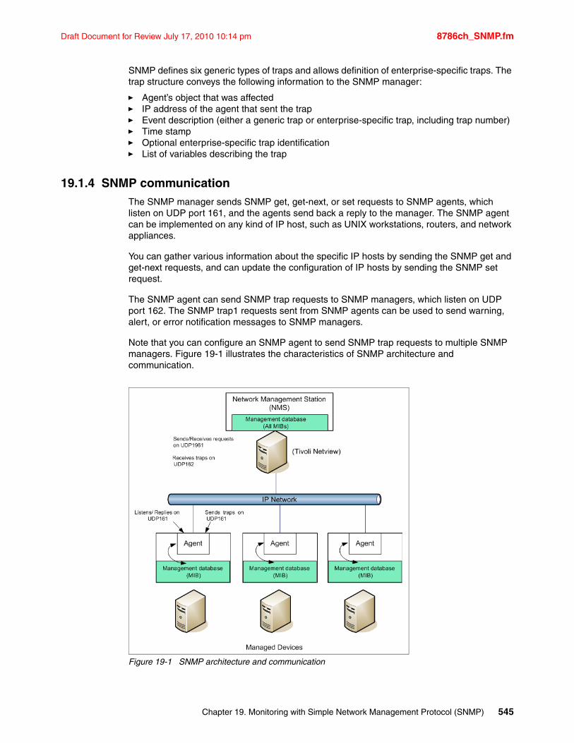
Draft Document for Review July 17, 2010 10:14 pm 8786ch_SNMP.fm
SNMP defines six generic types of traps and allows definition of enterprise-specific traps. The trap structure conveys the following information to the SNMP manager:
� Agent’s object that was affected� IP address of the agent that sent the trap� Event description (either a generic trap or enterprise-specific trap, including trap number)� Time stamp� Optional enterprise-specific trap identification� List of variables describing the trap
19.1.4 SNMP communicationThe SNMP manager sends SNMP get, get-next, or set requests to SNMP agents, which listen on UDP port 161, and the agents send back a reply to the manager. The SNMP agent can be implemented on any kind of IP host, such as UNIX workstations, routers, and network appliances.
You can gather various information about the specific IP hosts by sending the SNMP get and get-next requests, and can update the configuration of IP hosts by sending the SNMP set request.
The SNMP agent can send SNMP trap requests to SNMP managers, which listen on UDP port 162. The SNMP trap1 requests sent from SNMP agents can be used to send warning, alert, or error notification messages to SNMP managers.
Note that you can configure an SNMP agent to send SNMP trap requests to multiple SNMP managers. Figure 19-1 illustrates the characteristics of SNMP architecture and communication.
Figure 19-1 SNMP architecture and communication
Chapter 19. Monitoring with Simple Network Management Protocol (SNMP) 545
8786ch_SNMP.fm Draft Document for Review July 17, 2010 10:14 pm
19.1.5 Generic SNMP securityThe SNMP protocol uses the community name for authorization. Most SNMP implementations use the default community name public for a read-only community and private for a read-write community. In most cases, a community name is sent in a plain-text format between the SNMP agent and the manager. Some SNMP implementations have additional security features, such as the restriction of the accessible IP addresses.
Therefore, you should be careful about the SNMP security. At the very least, do not allow access to hosts that are running the SNMP agent from networks or IP hosts that do not necessarily require access.
You might want to physically secure the network to which you send SNMP packets by using a firewall, because community strings are included as plain text in SNMP packets.
19.1.6 Message Information Base (MIB)The objects, which you can get or set by sending SNMP get or set requests, are defined as a set of databases called the Message Information Base (MIB). The structure of MIB is defined as an Internet standard in RFC 1155; the MIB forms a tree structure.
Most hardware and software vendors provide you with extended MIB objects to support their own requirements. The SNMP standards allow this extension by using the private sub-tree, called enterprise specific MIB. Because each vendor has a unique MIB sub-tree under the private sub-tree, there is no conflict among vendors’ original MIB extensions.
19.1.7 SNMP trap requestAn SNMP agent can send SNMP trap requests to SNMP managers to inform them about the change of values or status on the IP host where the agent is running. There are seven predefined types of SNMP trap requests, as shown in Table 19-1.
Table 19-1 SNMP trap request types
A trap message contains pairs of an OID and a value shown in Table 19-1 to notify the cause of the trap message. You can also use type 6, the enterpriseSpecific trap type, when you have to send messages that do not fit other predefined trap types, for example, DISK I/O error and application down. You can also set an integer value field called Specific Trap on your trap message.
Trap type Value Description
coldStart 0 Restart after a crash.
warmStart 1 Planned restart.
linkDown 2 Communication link is down.
linkUp 3 Communication link is up.
authenticationFailure 4 Invalid SNMP community string was used.
egpNeighborLoss 5 EGP neighbor is down.
enterpriseSpecific 6 Vendor-specific event happened.
546 IBM System Storage DS8700: Architecture and Implementation
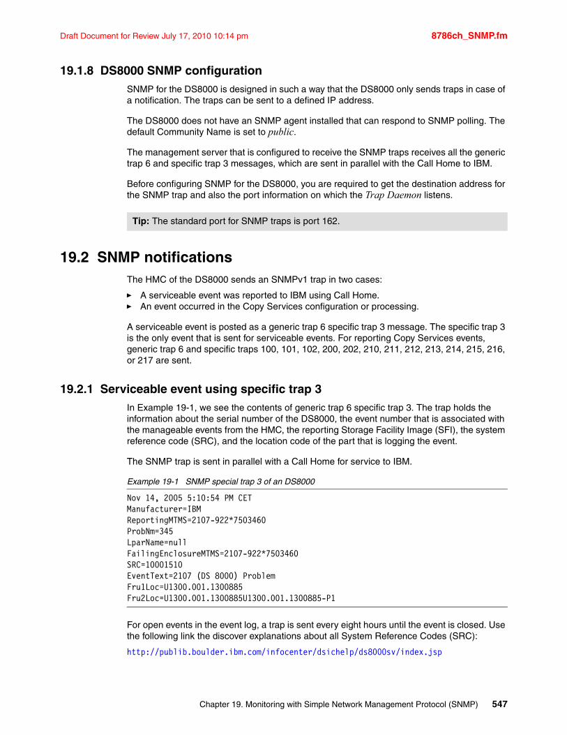
Draft Document for Review July 17, 2010 10:14 pm 8786ch_SNMP.fm
19.1.8 DS8000 SNMP configurationSNMP for the DS8000 is designed in such a way that the DS8000 only sends traps in case of a notification. The traps can be sent to a defined IP address.
The DS8000 does not have an SNMP agent installed that can respond to SNMP polling. The default Community Name is set to public.
The management server that is configured to receive the SNMP traps receives all the generic trap 6 and specific trap 3 messages, which are sent in parallel with the Call Home to IBM.
Before configuring SNMP for the DS8000, you are required to get the destination address for the SNMP trap and also the port information on which the Trap Daemon listens.
19.2 SNMP notificationsThe HMC of the DS8000 sends an SNMPv1 trap in two cases:
� A serviceable event was reported to IBM using Call Home.� An event occurred in the Copy Services configuration or processing.
A serviceable event is posted as a generic trap 6 specific trap 3 message. The specific trap 3 is the only event that is sent for serviceable events. For reporting Copy Services events, generic trap 6 and specific traps 100, 101, 102, 200, 202, 210, 211, 212, 213, 214, 215, 216, or 217 are sent.
19.2.1 Serviceable event using specific trap 3In Example 19-1, we see the contents of generic trap 6 specific trap 3. The trap holds the information about the serial number of the DS8000, the event number that is associated with the manageable events from the HMC, the reporting Storage Facility Image (SFI), the system reference code (SRC), and the location code of the part that is logging the event.
The SNMP trap is sent in parallel with a Call Home for service to IBM.
Example 19-1 SNMP special trap 3 of an DS8000
Nov 14, 2005 5:10:54 PM CETManufacturer=IBMReportingMTMS=2107-922*7503460ProbNm=345LparName=nullFailingEnclosureMTMS=2107-922*7503460SRC=10001510EventText=2107 (DS 8000) ProblemFru1Loc=U1300.001.1300885Fru2Loc=U1300.001.1300885U1300.001.1300885-P1
For open events in the event log, a trap is sent every eight hours until the event is closed. Use the following link the discover explanations about all System Reference Codes (SRC):
http://publib.boulder.ibm.com/infocenter/dsichelp/ds8000sv/index.jsp
Tip: The standard port for SNMP traps is port 162.
Chapter 19. Monitoring with Simple Network Management Protocol (SNMP) 547
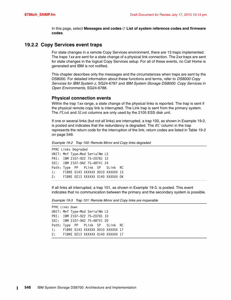
8786ch_SNMP.fm Draft Document for Review July 17, 2010 10:14 pm
In this page, select Messages and codes List of system reference codes and firmware codes.
19.2.2 Copy Services event trapsFor state changes in a remote Copy Services environment, there are 13 traps implemented. The traps 1xx are sent for a state change of a physical link connection. The 2xx traps are sent for state changes in the logical Copy Services setup. For all of these events, no Call Home is generated and IBM is not notified.
This chapter describes only the messages and the circumstances when traps are sent by the DS8000. For detailed information about these functions and terms, refer to DS8000 Copy Services for IBM System z, SG24-6787 and IBM System Storage DS8000: Copy Services in Open Environments, SG24-6788.
Physical connection eventsWithin the trap 1xx range, a state change of the physical links is reported. The trap is sent if the physical remote copy link is interrupted. The Link trap is sent from the primary system. The PLink and SLink columns are only used by the 2105 ESS disk unit.
If one or several links (but not all links) are interrupted, a trap 100, as shown in Example 19-2, is posted and indicates that the redundancy is degraded. The RC column in the trap represents the return code for the interruption of the link; return codes are listed in Table 19-2 on page 549.
Example 19-2 Trap 100: Remote Mirror and Copy links degraded
PPRC Links DegradedUNIT: Mnf Type-Mod SerialNm LSPRI: IBM 2107-922 75-20781 12SEC: IBM 2107-9A2 75-ABTV1 24Path: Type PP PLink SP SLink RC1: FIBRE 0143 XXXXXX 0010 XXXXXX 152: FIBRE 0213 XXXXXX 0140 XXXXXX OK
If all links all interrupted, a trap 101, as shown in Example 19-3, is posted. This event indicates that no communication between the primary and the secondary system is possible.
Example 19-3 Trap 101: Remote Mirror and Copy links are inoperable
PPRC Links DownUNIT: Mnf Type-Mod SerialNm LSPRI: IBM 2107-922 75-20781 10SEC: IBM 2107-9A2 75-ABTV1 20Path: Type PP PLink SP SLink RC1: FIBRE 0143 XXXXXX 0010 XXXXXX 172: FIBRE 0213 XXXXXX 0140 XXXXXX 17
548 IBM System Storage DS8700: Architecture and Implementation
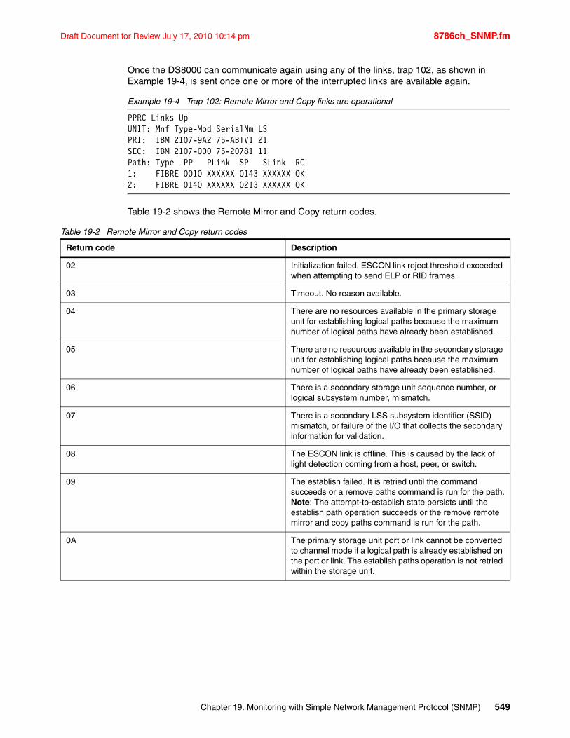
Draft Document for Review July 17, 2010 10:14 pm 8786ch_SNMP.fm
Once the DS8000 can communicate again using any of the links, trap 102, as shown in Example 19-4, is sent once one or more of the interrupted links are available again.
Example 19-4 Trap 102: Remote Mirror and Copy links are operational
PPRC Links UpUNIT: Mnf Type-Mod SerialNm LSPRI: IBM 2107-9A2 75-ABTV1 21SEC: IBM 2107-000 75-20781 11Path: Type PP PLink SP SLink RC1: FIBRE 0010 XXXXXX 0143 XXXXXX OK2: FIBRE 0140 XXXXXX 0213 XXXXXX OK
Table 19-2 shows the Remote Mirror and Copy return codes.
Table 19-2 Remote Mirror and Copy return codes
Return code Description
02 Initialization failed. ESCON link reject threshold exceeded when attempting to send ELP or RID frames.
03 Timeout. No reason available.
04 There are no resources available in the primary storage unit for establishing logical paths because the maximum number of logical paths have already been established.
05 There are no resources available in the secondary storage unit for establishing logical paths because the maximum number of logical paths have already been established.
06 There is a secondary storage unit sequence number, or logical subsystem number, mismatch.
07 There is a secondary LSS subsystem identifier (SSID) mismatch, or failure of the I/O that collects the secondary information for validation.
08 The ESCON link is offline. This is caused by the lack of light detection coming from a host, peer, or switch.
09 The establish failed. It is retried until the command succeeds or a remove paths command is run for the path.Note: The attempt-to-establish state persists until the establish path operation succeeds or the remove remote mirror and copy paths command is run for the path.
0A The primary storage unit port or link cannot be converted to channel mode if a logical path is already established on the port or link. The establish paths operation is not retried within the storage unit.
Chapter 19. Monitoring with Simple Network Management Protocol (SNMP) 549
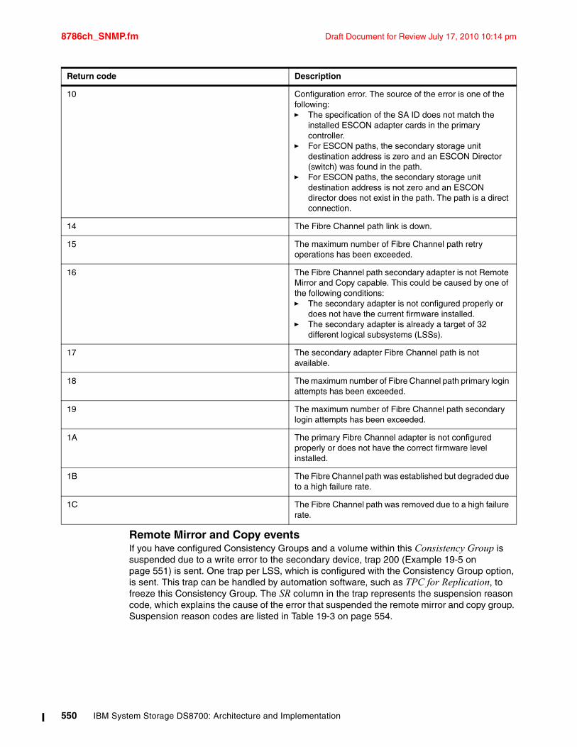
8786ch_SNMP.fm Draft Document for Review July 17, 2010 10:14 pm
Remote Mirror and Copy eventsIf you have configured Consistency Groups and a volume within this Consistency Group is suspended due to a write error to the secondary device, trap 200 (Example 19-5 on page 551) is sent. One trap per LSS, which is configured with the Consistency Group option, is sent. This trap can be handled by automation software, such as TPC for Replication, to freeze this Consistency Group. The SR column in the trap represents the suspension reason code, which explains the cause of the error that suspended the remote mirror and copy group. Suspension reason codes are listed in Table 19-3 on page 554.
10 Configuration error. The source of the error is one of the following:� The specification of the SA ID does not match the
installed ESCON adapter cards in the primary controller.
� For ESCON paths, the secondary storage unit destination address is zero and an ESCON Director (switch) was found in the path.
� For ESCON paths, the secondary storage unit destination address is not zero and an ESCON director does not exist in the path. The path is a direct connection.
14 The Fibre Channel path link is down.
15 The maximum number of Fibre Channel path retry operations has been exceeded.
16 The Fibre Channel path secondary adapter is not Remote Mirror and Copy capable. This could be caused by one of the following conditions:� The secondary adapter is not configured properly or
does not have the current firmware installed. � The secondary adapter is already a target of 32
different logical subsystems (LSSs).
17 The secondary adapter Fibre Channel path is not available.
18 The maximum number of Fibre Channel path primary login attempts has been exceeded.
19 The maximum number of Fibre Channel path secondary login attempts has been exceeded.
1A The primary Fibre Channel adapter is not configured properly or does not have the correct firmware level installed.
1B The Fibre Channel path was established but degraded due to a high failure rate.
1C The Fibre Channel path was removed due to a high failure rate.
Return code Description
550 IBM System Storage DS8700: Architecture and Implementation
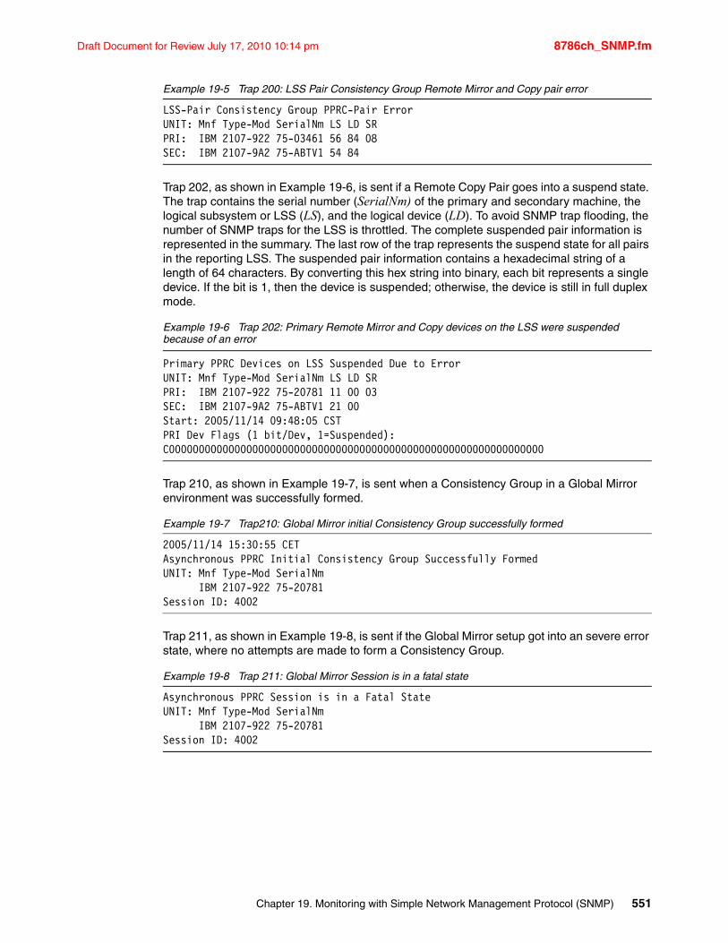
Draft Document for Review July 17, 2010 10:14 pm 8786ch_SNMP.fm
Example 19-5 Trap 200: LSS Pair Consistency Group Remote Mirror and Copy pair error
LSS-Pair Consistency Group PPRC-Pair ErrorUNIT: Mnf Type-Mod SerialNm LS LD SRPRI: IBM 2107-922 75-03461 56 84 08SEC: IBM 2107-9A2 75-ABTV1 54 84
Trap 202, as shown in Example 19-6, is sent if a Remote Copy Pair goes into a suspend state. The trap contains the serial number (SerialNm) of the primary and secondary machine, the logical subsystem or LSS (LS), and the logical device (LD). To avoid SNMP trap flooding, the number of SNMP traps for the LSS is throttled. The complete suspended pair information is represented in the summary. The last row of the trap represents the suspend state for all pairs in the reporting LSS. The suspended pair information contains a hexadecimal string of a length of 64 characters. By converting this hex string into binary, each bit represents a single device. If the bit is 1, then the device is suspended; otherwise, the device is still in full duplex mode.
Example 19-6 Trap 202: Primary Remote Mirror and Copy devices on the LSS were suspended because of an error
Primary PPRC Devices on LSS Suspended Due to ErrorUNIT: Mnf Type-Mod SerialNm LS LD SRPRI: IBM 2107-922 75-20781 11 00 03SEC: IBM 2107-9A2 75-ABTV1 21 00Start: 2005/11/14 09:48:05 CSTPRI Dev Flags (1 bit/Dev, 1=Suspended):C000000000000000000000000000000000000000000000000000000000000000
Trap 210, as shown in Example 19-7, is sent when a Consistency Group in a Global Mirror environment was successfully formed.
Example 19-7 Trap210: Global Mirror initial Consistency Group successfully formed
2005/11/14 15:30:55 CETAsynchronous PPRC Initial Consistency Group Successfully FormedUNIT: Mnf Type-Mod SerialNm
IBM 2107-922 75-20781Session ID: 4002
Trap 211, as shown in Example 19-8, is sent if the Global Mirror setup got into an severe error state, where no attempts are made to form a Consistency Group.
Example 19-8 Trap 211: Global Mirror Session is in a fatal state
Asynchronous PPRC Session is in a Fatal StateUNIT: Mnf Type-Mod SerialNm
IBM 2107-922 75-20781Session ID: 4002
Chapter 19. Monitoring with Simple Network Management Protocol (SNMP) 551
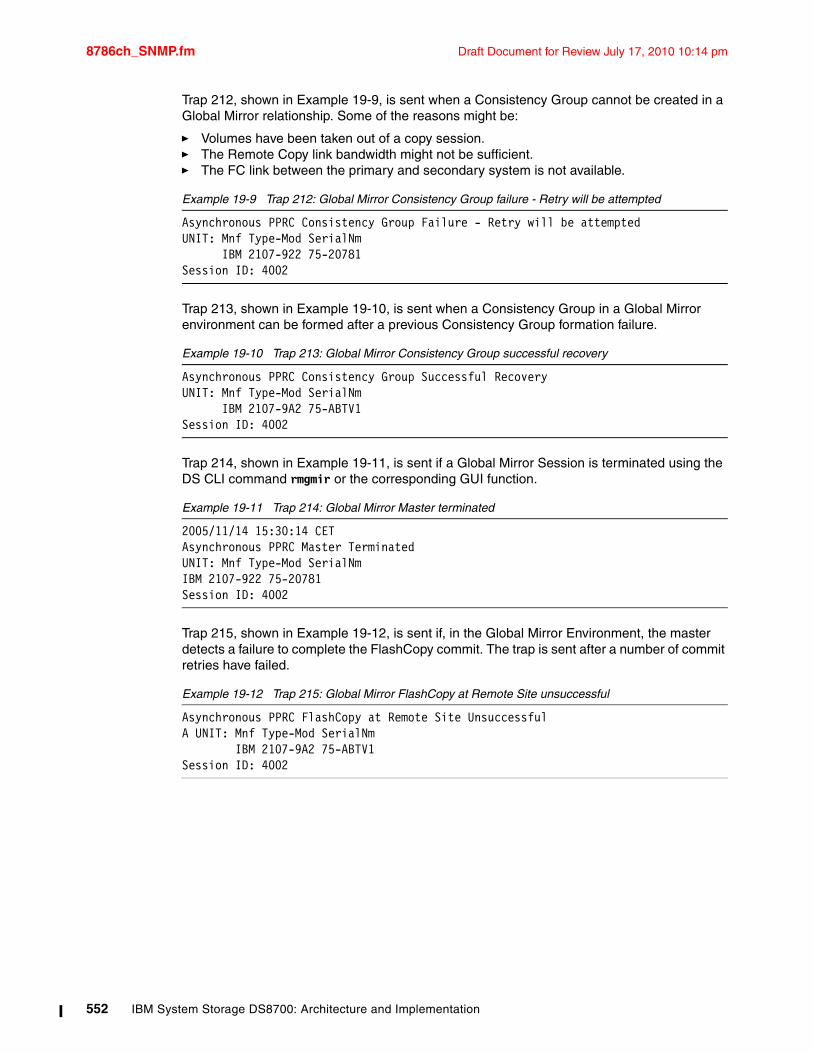
8786ch_SNMP.fm Draft Document for Review July 17, 2010 10:14 pm
Trap 212, shown in Example 19-9, is sent when a Consistency Group cannot be created in a Global Mirror relationship. Some of the reasons might be:
� Volumes have been taken out of a copy session.� The Remote Copy link bandwidth might not be sufficient.� The FC link between the primary and secondary system is not available.
Example 19-9 Trap 212: Global Mirror Consistency Group failure - Retry will be attempted
Asynchronous PPRC Consistency Group Failure - Retry will be attemptedUNIT: Mnf Type-Mod SerialNm
IBM 2107-922 75-20781Session ID: 4002
Trap 213, shown in Example 19-10, is sent when a Consistency Group in a Global Mirror environment can be formed after a previous Consistency Group formation failure.
Example 19-10 Trap 213: Global Mirror Consistency Group successful recovery
Asynchronous PPRC Consistency Group Successful RecoveryUNIT: Mnf Type-Mod SerialNm
IBM 2107-9A2 75-ABTV1Session ID: 4002
Trap 214, shown in Example 19-11, is sent if a Global Mirror Session is terminated using the DS CLI command rmgmir or the corresponding GUI function.
Example 19-11 Trap 214: Global Mirror Master terminated
2005/11/14 15:30:14 CETAsynchronous PPRC Master TerminatedUNIT: Mnf Type-Mod SerialNmIBM 2107-922 75-20781Session ID: 4002
Trap 215, shown in Example 19-12, is sent if, in the Global Mirror Environment, the master detects a failure to complete the FlashCopy commit. The trap is sent after a number of commit retries have failed.
Example 19-12 Trap 215: Global Mirror FlashCopy at Remote Site unsuccessful
Asynchronous PPRC FlashCopy at Remote Site UnsuccessfulA UNIT: Mnf Type-Mod SerialNm
IBM 2107-9A2 75-ABTV1Session ID: 4002
552 IBM System Storage DS8700: Architecture and Implementation
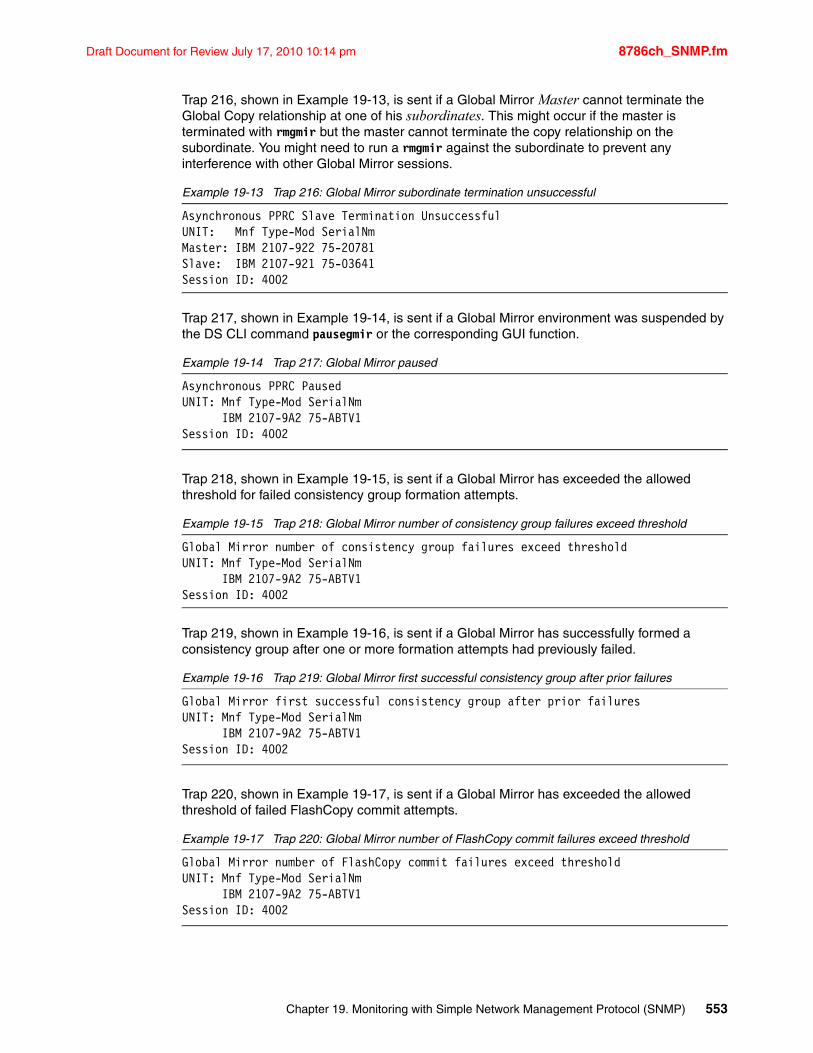
Draft Document for Review July 17, 2010 10:14 pm 8786ch_SNMP.fm
Trap 216, shown in Example 19-13, is sent if a Global Mirror Master cannot terminate the Global Copy relationship at one of his subordinates. This might occur if the master is terminated with rmgmir but the master cannot terminate the copy relationship on the subordinate. You might need to run a rmgmir against the subordinate to prevent any interference with other Global Mirror sessions.
Example 19-13 Trap 216: Global Mirror subordinate termination unsuccessful
Asynchronous PPRC Slave Termination UnsuccessfulUNIT: Mnf Type-Mod SerialNmMaster: IBM 2107-922 75-20781Slave: IBM 2107-921 75-03641Session ID: 4002
Trap 217, shown in Example 19-14, is sent if a Global Mirror environment was suspended by the DS CLI command pausegmir or the corresponding GUI function.
Example 19-14 Trap 217: Global Mirror paused
Asynchronous PPRC PausedUNIT: Mnf Type-Mod SerialNm
IBM 2107-9A2 75-ABTV1Session ID: 4002
Trap 218, shown in Example 19-15, is sent if a Global Mirror has exceeded the allowed threshold for failed consistency group formation attempts.
Example 19-15 Trap 218: Global Mirror number of consistency group failures exceed threshold
Global Mirror number of consistency group failures exceed thresholdUNIT: Mnf Type-Mod SerialNm
IBM 2107-9A2 75-ABTV1Session ID: 4002
Trap 219, shown in Example 19-16, is sent if a Global Mirror has successfully formed a consistency group after one or more formation attempts had previously failed.
Example 19-16 Trap 219: Global Mirror first successful consistency group after prior failures
Global Mirror first successful consistency group after prior failuresUNIT: Mnf Type-Mod SerialNm
IBM 2107-9A2 75-ABTV1Session ID: 4002
Trap 220, shown in Example 19-17, is sent if a Global Mirror has exceeded the allowed threshold of failed FlashCopy commit attempts.
Example 19-17 Trap 220: Global Mirror number of FlashCopy commit failures exceed threshold
Global Mirror number of FlashCopy commit failures exceed thresholdUNIT: Mnf Type-Mod SerialNm
IBM 2107-9A2 75-ABTV1Session ID: 4002
Chapter 19. Monitoring with Simple Network Management Protocol (SNMP) 553
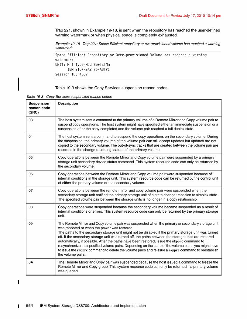
8786ch_SNMP.fm Draft Document for Review July 17, 2010 10:14 pm
Trap 221, shown in Example 19-18, is sent when the repository has reached the user-defined warning watermark or when physical space is completely exhausted.
Example 19-18 Trap 221: Space Efficient repository or overprovisioned volume has reached a warning watermark
Space Efficient Repository or Over-provisioned Volume has reached a warning watermarkUNIT: Mnf Type-Mod SerialNm
IBM 2107-9A2 75-ABTV1Session ID: 4002
Table 19-3 shows the Copy Services suspension reason codes.
Table 19-3 Copy Services suspension reason codes
Suspension reason code (SRC)
Description
03 The host system sent a command to the primary volume of a Remote Mirror and Copy volume pair to suspend copy operations. The host system might have specified either an immediate suspension or a suspension after the copy completed and the volume pair reached a full duplex state.
04 The host system sent a command to suspend the copy operations on the secondary volume. During the suspension, the primary volume of the volume pair can still accept updates but updates are not copied to the secondary volume. The out-of-sync tracks that are created between the volume pair are recorded in the change recording feature of the primary volume.
05 Copy operations between the Remote Mirror and Copy volume pair were suspended by a primary storage unit secondary device status command. This system resource code can only be returned by the secondary volume.
06 Copy operations between the Remote Mirror and Copy volume pair were suspended because of internal conditions in the storage unit. This system resource code can be returned by the control unit of either the primary volume or the secondary volume.
07 Copy operations between the remote mirror and copy volume pair were suspended when the secondary storage unit notified the primary storage unit of a state change transition to simplex state. The specified volume pair between the storage units is no longer in a copy relationship.
08 Copy operations were suspended because the secondary volume became suspended as a result of internal conditions or errors. This system resource code can only be returned by the primary storage unit.
09 The Remote Mirror and Copy volume pair was suspended when the primary or secondary storage unit was rebooted or when the power was restored.The paths to the secondary storage unit might not be disabled if the primary storage unit was turned off. If the secondary storage unit was turned off, the paths between the storage units are restored automatically, if possible. After the paths have been restored, issue the mkpprc command to resynchronize the specified volume pairs. Depending on the state of the volume pairs, you might have to issue the rmpprc command to delete the volume pairs and reissue a mkpprc command to reestablish the volume pairs.
0A The Remote Mirror and Copy pair was suspended because the host issued a command to freeze the Remote Mirror and Copy group. This system resource code can only be returned if a primary volume was queried.
554 IBM System Storage DS8700: Architecture and Implementation
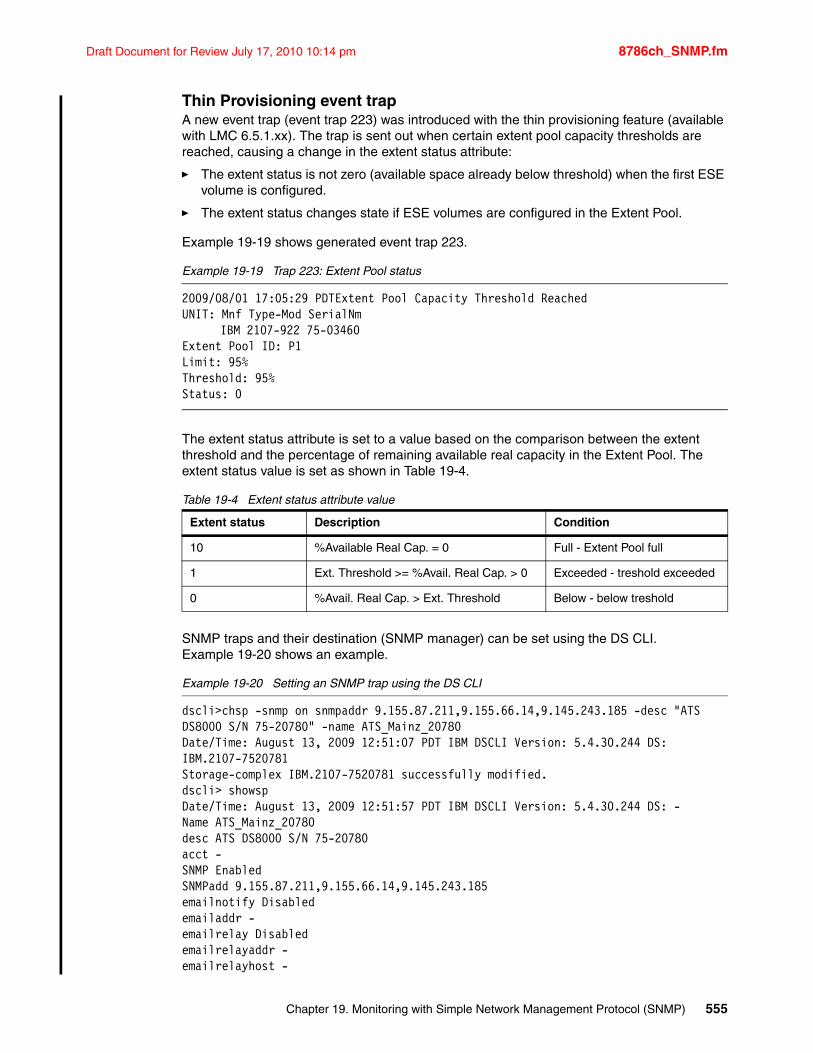
Draft Document for Review July 17, 2010 10:14 pm 8786ch_SNMP.fm
Thin Provisioning event trapA new event trap (event trap 223) was introduced with the thin provisioning feature (available with LMC 6.5.1.xx). The trap is sent out when certain extent pool capacity thresholds are reached, causing a change in the extent status attribute:
� The extent status is not zero (available space already below threshold) when the first ESE volume is configured.
� The extent status changes state if ESE volumes are configured in the Extent Pool.
Example 19-19 shows generated event trap 223.
Example 19-19 Trap 223: Extent Pool status
2009/08/01 17:05:29 PDTExtent Pool Capacity Threshold ReachedUNIT: Mnf Type-Mod SerialNm
IBM 2107-922 75-03460Extent Pool ID: P1Limit: 95%Threshold: 95%Status: 0
The extent status attribute is set to a value based on the comparison between the extent threshold and the percentage of remaining available real capacity in the Extent Pool. The extent status value is set as shown in Table 19-4.
Table 19-4 Extent status attribute value
SNMP traps and their destination (SNMP manager) can be set using the DS CLI. Example 19-20 shows an example.
Example 19-20 Setting an SNMP trap using the DS CLI
dscli>chsp -snmp on snmpaddr 9.155.87.211,9.155.66.14,9.145.243.185 -desc "ATSDS8000 S/N 75-20780" -name ATS_Mainz_20780Date/Time: August 13, 2009 12:51:07 PDT IBM DSCLI Version: 5.4.30.244 DS:IBM.2107-7520781Storage-complex IBM.2107-7520781 successfully modified.dscli> showspDate/Time: August 13, 2009 12:51:57 PDT IBM DSCLI Version: 5.4.30.244 DS: -Name ATS_Mainz_20780desc ATS DS8000 S/N 75-20780acct -SNMP EnabledSNMPadd 9.155.87.211,9.155.66.14,9.145.243.185emailnotify Disabledemailaddr -emailrelay Disabledemailrelayaddr -emailrelayhost -
Extent status Description Condition
10 %Available Real Cap. = 0 Full - Extent Pool full
1 Ext. Threshold >= %Avail. Real Cap. > 0 Exceeded - treshold exceeded
0 %Avail. Real Cap. > Ext. Threshold Below - below treshold
Chapter 19. Monitoring with Simple Network Management Protocol (SNMP) 555
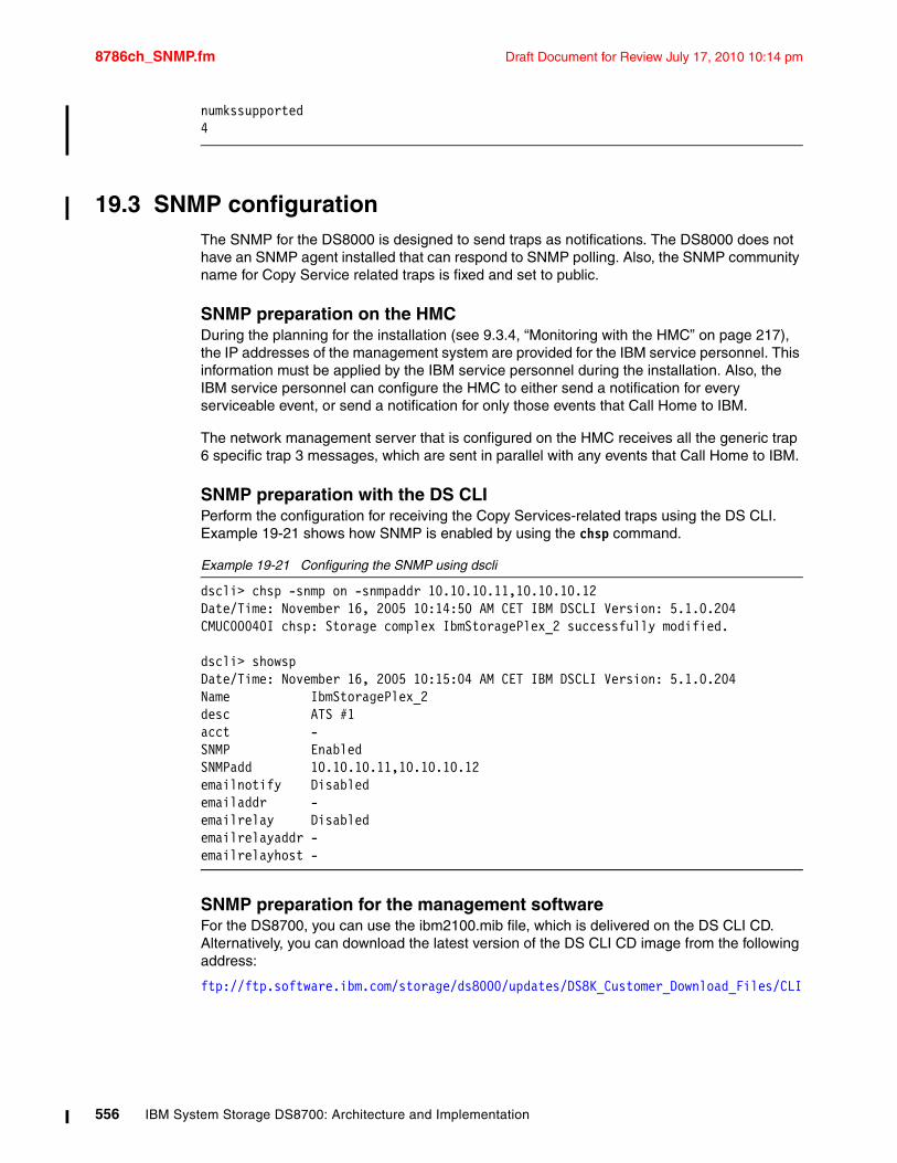
8786ch_SNMP.fm Draft Document for Review July 17, 2010 10:14 pm
numkssupported 4
19.3 SNMP configurationThe SNMP for the DS8000 is designed to send traps as notifications. The DS8000 does not have an SNMP agent installed that can respond to SNMP polling. Also, the SNMP community name for Copy Service related traps is fixed and set to public.
SNMP preparation on the HMCDuring the planning for the installation (see 9.3.4, “Monitoring with the HMC” on page 217), the IP addresses of the management system are provided for the IBM service personnel. This information must be applied by the IBM service personnel during the installation. Also, the IBM service personnel can configure the HMC to either send a notification for every serviceable event, or send a notification for only those events that Call Home to IBM.
The network management server that is configured on the HMC receives all the generic trap 6 specific trap 3 messages, which are sent in parallel with any events that Call Home to IBM.
SNMP preparation with the DS CLIPerform the configuration for receiving the Copy Services-related traps using the DS CLI. Example 19-21 shows how SNMP is enabled by using the chsp command.
Example 19-21 Configuring the SNMP using dscli
dscli> chsp -snmp on -snmpaddr 10.10.10.11,10.10.10.12Date/Time: November 16, 2005 10:14:50 AM CET IBM DSCLI Version: 5.1.0.204CMUC00040I chsp: Storage complex IbmStoragePlex_2 successfully modified.
dscli> showspDate/Time: November 16, 2005 10:15:04 AM CET IBM DSCLI Version: 5.1.0.204Name IbmStoragePlex_2desc ATS #1acct -SNMP EnabledSNMPadd 10.10.10.11,10.10.10.12emailnotify Disabledemailaddr -emailrelay Disabledemailrelayaddr -emailrelayhost -
SNMP preparation for the management softwareFor the DS8700, you can use the ibm2100.mib file, which is delivered on the DS CLI CD. Alternatively, you can download the latest version of the DS CLI CD image from the following address:
ftp://ftp.software.ibm.com/storage/ds8000/updates/DS8K_Customer_Download_Files/CLI
556 IBM System Storage DS8700: Architecture and Implementation
Draft Document for Review July 17, 2010 10:14 pm 8786ch_remote_supt.fm
Chapter 20. Remote support
In this chapter, we discuss the outbound (Call Home and Support Data offload) and inbound (code download and remote support) communications for the IBM System Storage DS8700. This chapter covers the following topics:
� Introduction to remote support
� IBM policies for remote support
� Remote connection types
� DS8700 support tasks
� Scenarios
� Audit logging
20
© Copyright IBM Corp. 2010. All rights reserved. 557
8786ch_remote_supt.fm Draft Document for Review July 17, 2010 10:14 pm
20.1 Introduction to remote supportRemote support is a complex topic that requires close scrutiny and education for all parties involved. IBM is committed to servicing the DS8700, whether it be warranty work, planned code upgrades, or management of a component failure, in a secure and professional manner. Dispatching service personnel to come to your site and perform maintenance on the system is still a part of that commitment. But as much as possible, IBM wants to minimize downtime and maximize efficiency by performing many support tasks remotely.
Of course, this plan of providing support remotely must be balanced with the customer’s expectations for security. Maintaining the highest levels of security in a data connection is a primary goal for IBM. This goal can only be achieved by careful planning with a customer and a thorough review of all the options available.
20.1.1 Suggested readingThe following publications may be of assistance in understanding IBM’s remote support offerings:
� The IBM System Storage DS8000 Introduction and Planning Guide, GC35-0515 contains additional information about physical planning. You can download it at the following address:
http://www.ibm.com/systems/storage/disk/ds8000/index.html
� A Comprehensive Guide to Virtual Private Networks, Volume I: IBM Firewall, Server and Client Solutions, SG24-5201. You can download it at the following address:
http://www.redbooks.ibm.com/abstracts/sg245201.html?Open
� The Security Planning Web site is available at the following address:
http://publib16.boulder.ibm.com/doc_link/en_US/a_doc_lib/aixbman/security/ipsec_planning.htm
� VPNs Illustrated: Tunnels, VPNs, and IPSec, by Jon C. Snader
� VPN Implementation, S1002693, can be downloaded at the following address:
http://www.ibm.com/support/docview.wss?&rs=1114&uid=ssg1S1002693
20.1.2 Organization of this chapterA list of the relevant terminology for remote support is first presented. The remainder of this chapter is organized as follows:
� Connections
We review the different types of connections that can be made from the HMC to the world outside of the DS8700.
� Tasks
We review the various support tasks that need to be run on those connections.
� Scenarios
We illustrate a scenario about how each task is performed over the different types of remote connections.
558 IBM System Storage DS8700: Architecture and Implementation
Draft Document for Review July 17, 2010 10:14 pm 8786ch_remote_supt.fm
20.1.3 Terminology and definitionsListed here are brief explanations of some of the terms to be used when discussing remote support. See “Abbreviations and acronyms” on page 595 for a full list of terms and acronyms used in this IBM Redbooks publication. Having an understanding of these terms will contribute to your discussions on remote support and security concerns. A generic definition will be presented here and then more specific information about how IBM implements the idea is given further on in this chapter.
IP networkThere are many protocols running on Local Area Networks (LANs) around the world. Most companies us the Transmission Control Protocol/Internet Protocol (TCP/IP) standard for their connectivity between workstations and servers. IP is also the networking protocol of the global Internet. Web browsing and e-mail are two of the most common applications that run on top of an IP network. IP is the protocol used by the DS8700 HMC to communicate with external systems, such as the SSPC or DS CLI workstations. There are two varieties of IP; refer to 8.3.2, “System Storage Productivity Center and network access” on page 193 for a discussion about the IPv4 and IPv6 networks.
SSHSecure Shell is a protocol that establishes a secure communications channel between two computer systems. The term SSH is also used to describe a secure ASCII terminal session between two computers. SSH can be enabled on a system when regular Telnet and FTP are disabled, making it possible to only communicate with the computer in a secure manner.
FTPFile Transfer Protocol is a method of moving binary and text files from one computer system to another over an IP connection. It is not inherently secure as it has no provisions for encryption and only simple user and password authentication. FTP is considered appropriate for data that is already public, or if the entirety of the connection is within the physical boundaries of a private network.
SFTPSSH File Transfer Protocol is unrelated to FTP. It is another file transfer method that is implemented inside a SSH connection. SFTP is generally considered to be secure enough for mission critical data and for moving sensitive data across the global Internet. FTP ports (usually ports 20/21) do not have be open through a firewall for SFTP to work.
SSLSecure Sockets Layer refers to methods of securing otherwise unsecure protocols such as HTTP (Web pages), FTP (files), or SMTP (e-Mail). Carrying HTTP over SSL is often referred to as HTTPS. An SSL connection over the global Internet is considered reasonably secure.
VPNA Virtual Private Network is a private “tunnel” through a public network. Most commonly, it refers to using specialized software and hardware to create a secure connection over the Internet. The two systems, although physically separate, behave as if they are on the same private network. A VPN allows a remote worker or an entire remote office to remain part of a company’s internal network. VPNs provide security by encrypting traffic, authenticating sessions and users, and verifying data integrity.
Chapter 20. Remote support 559
8786ch_remote_supt.fm Draft Document for Review July 17, 2010 10:14 pm
B2B VPNBusiness-to-business is a term for specialized VPN services for secure connections between IBM and its customers. This offering is also known as Client Controlled VPN and Site-to-Site VPN. This offering is in direct response to customers’ concerns about being in control of VPN sessions with their vendors. It includes the use of a hardware VPN appliance inside the customer’s network, presumably one that can interact with many vendors’ VPN clients.
IPSecInternet Protocol Security is a suite of protocols used to provide a secure transaction between two systems that use the TCP/IP network protocol. IPSec focuses on authentication and encryption, two of the main ingredients of a secure connection. Most VPNs used on the Internet use IPSec mechanisms to establish the connection.
FirewallA firewall is a device that controls whether data is allowed to travel onto a network segment. Firewalls are deployed at the boundaries of networks. They are managed by policies which declare what traffic can pass based on the sender’s address, the destination address, and the type of traffic. Firewalls are an essential part of network security and their configuration must be taken into consideration when planning remote support activities.
BandwidthBandwidth refers to the characteristics of a connection and how they relate to moving data. Bandwidth is affected by the physical connection, the logical protocols used, physical distance, and the type of data being moved. In general, higher bandwidth means faster movement of larger data sets.
20.2 IBM policies for remote supportThe following guidelines are at the core of IBM’s remote support strategies for the DS8700:
� When the DS8700 needs to transmit service data to IBM, no host data of any kind is included. Only logs and process dumps are gathered for troubleshooting. The I/O from host adapters and the contents of NVS cache memory are never transmitted.
� When a VPN session with the DS8700 is needed, the HMC will always initiate such connections and only to predefined IBM servers/ports. There is never any active process that is “listening” for incoming sessions on the HMC.
� IBM maintains multiple-level internal authorizations for any privileged access to the DS8700 components. Only approved IBM service personnel can gain access to the tools that provide the one-time security codes for HMC command-line access.
� While the HMC is based on a Linux operating system, IBM has disabled or removed all unnecessary services, processes, and IDs. This includes standard Internet services such as telnet, ftp, ‘r’ commands, and rcp programs.
560 IBM System Storage DS8700: Architecture and Implementation
Draft Document for Review July 17, 2010 10:14 pm 8786ch_remote_supt.fm
20.3 Remote connection typesThe DS8700 HMC has a connection point for the customer’s network via a standard Ethernet (10/100/1000 Mb) cable. The HMC also has a connection point for a phone line via the modem port. These two physical connections offer four possibilities for sending and receiving data between the DS8700 and IBM. The connection types are:
� Asynchronous modem connection� IP network connection� IP network connection with VPN� IP network connection with B2B VPN
In the most secure environments, both of these physical connections (Ethernet and modem) remain unplugged. The DS8700 serves up storage for its connected hosts, but has no other communication with the outside world. Of course, this means that all configuration tasks have to be done while standing at the HMC (there is no usage of the SSPC or DS CLI). This level of security, known as an air gap, also means that there is no way for the DS8700 to alert anyone that it has encountered a problem and there is no way to correct such a problem other than to be physically present at the system.
So rather than leaving the modem and Ethernet disconnected, customers will provide these connections and then apply policies on when they are to be used and what type of data they may carry. Those policies are enforced by the settings on the HMC and the configuration of customer network devices, such as routers and firewalls. The next four sections discuss the capabilities of each type of connection.
20.3.1 ModemA modem creates a low-speed asynchronous connection using a telephone line plugged into the HMC modem port. This type of connection favors transferring small amounts of data. It is relatively secure because the data is not traveling across the Internet. However, this type of connection is not terribly useful due to bandwidth limitations. Average connection speed in the US mainland is 28-36 Kbps, and can be less in other parts of the world.
DS8700 HMC modems can be configured to call IBM and send small status messages. Authorized support personnel can call the HMC and get privileged access to the command line of the operating system. Typical PEPackage transmission over a modem line could take 15 to 20 hours depending on the quality of the connection. Code downloads over a modem line are not possible.
Chapter 20. Remote support 561
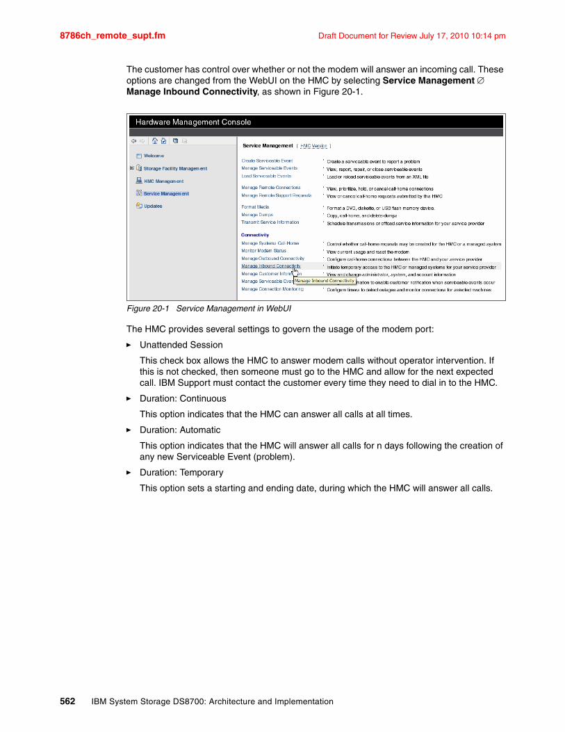
8786ch_remote_supt.fm Draft Document for Review July 17, 2010 10:14 pm
The customer has control over whether or not the modem will answer an incoming call. These options are changed from the WebUI on the HMC by selecting Service Management Manage Inbound Connectivity, as shown in Figure 20-1.
Figure 20-1 Service Management in WebUI
The HMC provides several settings to govern the usage of the modem port:
� Unattended Session
This check box allows the HMC to answer modem calls without operator intervention. If this is not checked, then someone must go to the HMC and allow for the next expected call. IBM Support must contact the customer every time they need to dial in to the HMC.
� Duration: Continuous
This option indicates that the HMC can answer all calls at all times.
� Duration: Automatic
This option indicates that the HMC will answer all calls for n days following the creation of any new Serviceable Event (problem).
� Duration: Temporary
This option sets a starting and ending date, during which the HMC will answer all calls.
562 IBM System Storage DS8700: Architecture and Implementation
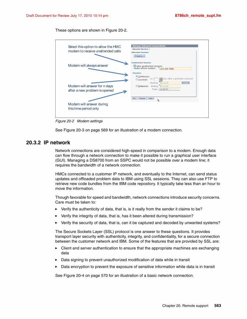
Draft Document for Review July 17, 2010 10:14 pm 8786ch_remote_supt.fm
These options are shown in Figure 20-2.
Figure 20-2 Modem settings
See Figure 20-3 on page 569 for an illustration of a modem connection.
20.3.2 IP networkNetwork connections are considered high-speed in comparison to a modem. Enough data can flow through a network connection to make it possible to run a graphical user interface (GUI). Managing a DS8700 from an SSPC would not be possible over a modem line; it requires the bandwidth of a network connection.
HMCs connected to a customer IP network, and eventually to the Internet, can send status updates and offloaded problem data to IBM using SSL sessions. They can also use FTP to retrieve new code bundles from the IBM code repository. It typically take less than an hour to move the information.
Though favorable for speed and bandwidth, network connections introduce security concerns. Care must be taken to:
� Verify the authenticity of data, that is, is it really from the sender it claims to be?
� Verify the integrity of data, that is, has it been altered during transmission?
� Verify the security of data, that is, can it be captured and decoded by unwanted systems?
The Secure Sockets Layer (SSL) protocol is one answer to these questions. It provides transport layer security with authenticity, integrity, and confidentiality, for a secure connection between the customer network and IBM. Some of the features that are provided by SSL are:
� Client and server authentication to ensure that the appropriate machines are exchanging data
� Data signing to prevent unauthorized modification of data while in transit
� Data encryption to prevent the exposure of sensitive information while data is in transit
See Figure 20-4 on page 570 for an illustration of a basic network connection.
Select this option to allow the HMCmodem to receive unattended calls
Modem will always answer
Modem will answer for n daysafter a new problem is opened
Modem will answer during this time period only
Chapter 20. Remote support 563
8786ch_remote_supt.fm Draft Document for Review July 17, 2010 10:14 pm
20.3.3 IP network with traditional VPNAdding a VPN “tunnel” to an IP network greatly increases the security of the connection between the two endpoints. Data can be verified for authenticity and integrity. Data can be encrypted so that even if it is captured enroute, it cannot be “replayed” or deciphered.
Having the safety of running within a VPN, IBM can use its service interface (WebUI) to:
� Check the status of components and services on the DS8700 in real time� Queue up diagnostic data offloads� Start, monitor, pause, and restart repair service actions
Performing the following steps result in the HMC creating a VPN tunnel back to the IBM network, which service personnel can then use. There is no VPN service that sits idle, waiting for a connection to be made by IBM. Only the HMC is allowed to initiate the VPN tunnel, and it can only be made to predefined IBM addresses. The steps to create a VPN tunnel from the DS8700 HMC to IBM are:
1. IBM support calls the HMC using the modem. After the first level of authentications, the HMC is asked to launch a VPN session.
2. The HMC hangs up the modem call and initiates a VPN connection back to a predefined address or port within IBM Support.
3. IBM Support verifies that they can see and use the VPN connection from an IBM internal IP address.
4. IBM Support launches the WebUI or other high-bandwidth tools to work on the DS8700.
See Figure 20-5 on page 571 for an illustration of a traditional VPN connection.
20.3.4 IP network with Business to Business (B2B) VPNThe B2B VPN option does not add any new functionality, IBM Support can perform all of the tasks as with the traditional HMC-based VPN. What a B2B VPN does provide is a greater measure of control over the VPN sessions by the customer. Instead of a VPN tunnel being created between the HMC and the IBM network, a tunnel is created from the customer’s VPN appliance to the IBM network. This option has also been referred to as client controlled VPN.
Customers who work with many vendors that have their own remote support systems often own and manage a VPN appliance, a server that sits on the edge of their network and creates tunnels with outside entities. This is true for many companies that have remote workers, outside sales forces, or small branch offices. Because the device is already configured to meet the customer’s security requirements, they only need to add appropriate policies for IBM support. Most commercially-available VPN servers are interoperable with the IPSec-based VPN that IBM needs to establish. Using a B2B VPN layout leverages the investment that a customer has already made in establishing secure tunnels into their network.
The VPN tunnel that gets created is valid for IBM Remote Support use only and has to be configured both on the IBM and customer sides. This design provides several advantages for the customer:
� Allows the customer to use Network Address Translation (NAT) so that the HMC is given a non-routable IP address behind the company firewall.
� Allows the customer to inspect the TCP/IP packets that are sent over this VPN.
� Allows the customer to disable the VPN on their device for ‘lockdown’ situations.
564 IBM System Storage DS8700: Architecture and Implementation
Draft Document for Review July 17, 2010 10:14 pm 8786ch_remote_supt.fm
Note that the B2B VPN only provides the tunnel that service personnel can use to actively work with the HMC from within IBM. To offload data or call home, the HMC still needs to have one of the following:
� Modem access� Non-VPN network access (SSL connection)� Traditional VPN access
See Figure 20-6 on page 572 for an illustration of a B2B VPN connection.
20.4 DS8700 support tasksThese are the tasks that require the HMC to contact the outside world. Some tasks can be done using either the modem or the network connection, and some can only be done over a network. The combination of tasks and connection types is illustrated in 20.5, “Scenarios” on page 568. The support tasks that require the DS8700 to connect to outside resources are:
� Call Home and heartbeat� Data offload� Code download� Remote support
20.4.1 Call Home and heartbeat (outbound)Here we discuss the Call Home and heartbeat capabilities.
Call HomeCall Home is the capability of the HMC to contact IBM Service to report a service event. This is referred to as Call Home for service. The HMC provides machine reported product data (MRPD) information to IBM by way of the Call Home facility. The MRPD information includes installed hardware, configurations, and features. The Call Home also includes information about the nature of a problem so that an active investigation can be launched. Call Home is a one-way communication, with data moving from the DS8700 HMC to the IBM data store.
HeartbeatThe DS8700 also uses the Call Home facility to send proactive heartbeat information to IBM. A heartbeat is a small message with some basic product information so that IBM knows the unit is operational. By sending heartbeats, both IBM and the customer ensure that the HMC is always able to initiate a full Call Home to IBM in the case of an error. If the heartbeat information does not reach IBM, a service call to the client will be made to investigate the status of the DS8700. Heartbeats represent a one-way communication, with data moving from the DS8700 HMC to the IBM data store.
The Call Home facility can be configured to:
� Use the HMC modem � Use the Internet via a SSL connection� Use the Internet via a VPN tunnel from the HMC to IBM
Call Home information and heartbeat information are stored in the IBM internal data store so the support representatives have access to the records.
Chapter 20. Remote support 565
8786ch_remote_supt.fm Draft Document for Review July 17, 2010 10:14 pm
20.4.2 Data offload (outbound)For many DS8700 problem events, such as a hardware component failure, a large amount of diagnostic data is generated. This data may include text and binary log files, firmware dumps, memory dumps, inventory lists, and timelines. These logs are grouped into collections by the component that generated them or the software service that owns them. The entire bundle is collected together in what is called a PEPackage. A DS8700 PEPackage can be quite large, often exceeding 100 MB. In some cases, more than one may be needed to properly diagnose a problem. The HMC is a focal point, gathering and storing all the data packages. So the HMC must be accessible if a service action requires the information. The data packages must be offloaded from the HMC and sent in to IBM for analysis. The offload can be done several ways
� Modem offload� Standard FTP offload� SSL offload
Modem offloadThe HMC can be configured to support automatic data offload using the internal modem and a regular phone line. Offloading a PEPackage over a modem connection is extremely slow, in many cases taking 15 to 20 hours. It also ties up the modem for this time so that IBM support cannot dial in to the HMC to perform command-line tasks. If this is the only connectivity option available, be aware that the overall process of remote support will be delayed while data is in transit.
Standard FTP offloadThe HMC can be configured to support automatic data offload using File Transfer Protocol (FTP) over a network connection. This traffic can be examined at the customer’s firewall before moving across the Internet. FTP offload allows IBM Service personnel to dial in to the HMC using the modem line while support data is being transmitted to IBM over the network.
When a direct FTP session across the Internet is not available or desirable, a customer can configure the FTP offload to use a customer-provided FTP proxy server. The customer then becomes responsible for configuring the proxy to forward the data to IBM.
The customer is required to manage their firewall(s) so that FTP traffic from the HMC (or from an FTP proxy) can pass onto the Internet.
SSL offloadFor environments that do not permit FTP traffic out to the Internet, the DS8700 also supports offload of data using SSL security. In this configuration, the HMC uses the customer-provided network connection to connect to the IBM data store, the same as in a standard FTP offload. But with SSL, all the data is encrypted so that it is rendered unusable if intercepted.
Customer firewall settings between the HMC and the Internet for SSL setup require four IP addresses open on port 443 based on geography as detailed below:
� North and South America
129.42.160.48 IBM Authentication Primary207.25.252.200 IBM Authentication Secondary129.42.160.49 IBM Data Primary207.25.252.204 IBM Data Secondary
Note: FTP offload of data is supported as an outbound service only. There is no active FTP server running on the HMC that can receive connection requests.
566 IBM System Storage DS8700: Architecture and Implementation
Draft Document for Review July 17, 2010 10:14 pm 8786ch_remote_supt.fm
� All other regions
129.42.160.48 IBM Authentication Primary207.25.252.200 IBM Authentication Secondary129.42.160.50 IBM Data Primary207.25.252.205 IBM Data Secondary
20.4.3 Code download (inbound)DS8700 microcode updates are published as bundles that can be downloaded from IBM. As explained in 18.7, “Loading the code bundle” on page 541, there are three possibilities for acquiring code on the HMC:
� Load the new code bundle using CDs.� Download the new code bundle directly from IBM using FTP.� Download the new code bundle directly from IBM using SFTP.
Loading code bundles from CDs is the only option for DS8700 installations that have no outside connectivity at all. If the HMC is connected to the customer network then IBM support will download the bundles from IBM using either FTP or SFTP.
FTPIf allowed, the support representative will open an FTP session from the HMC to the IBM code repository and download the code bundle(s) to the HMC. The customer firewall will need to be configured to allow the FTP traffic to pass.
SFTPIf FTP is not allowed, an SFTP session can be used instead. SFTP is a more secure file transfer protocol running within an SSH session, as defined in 20.1.3, “Terminology and definitions” on page 559. If this option is used, the customer firewall will need to be configured to allow the SSH traffic to pass.
Once the code bundle is acquired from IBM, the FTP or SFTP session will be closed and the code load can take place without needing to communicate outside of the DS8700.
20.4.4 Remote support (inbound and two-way)Remote support describes the most interactive level of assistance from IBM. Once a problem comes to the attention of the IBM Support Center and it is determined that the issue is more complex than a straight-forward parts replacement, the problem will likely be escalated to higher levels of responsibility within IBM Support. This could happen at the same time that a Support Representative is being dispatched to the customer site.
IBM will most likely need to trigger a data offload, perhaps more than one, and at the same time be able to interact with the DS8700 to dig deeper into the problem and develop an action plan to restore the system to normal operation. This type of interaction with the HMC is what requires the most bandwidth.
If the only available connectivity is by modem, then IBM Support will have to wait until any data offload is complete and then attempt the diagnostics and repair from a command-line environment on the HMC. This process is slower and more limited in scope than if a network connection can be used.
Chapter 20. Remote support 567
8786ch_remote_supt.fm Draft Document for Review July 17, 2010 10:14 pm
If a VPN is available, either from the HMC directly to IBM or by using VPN devices (B2B VPN option), then enough bandwidth is available for data offload and interactive troubleshooting to be done at the same time. IBM Support will be able to use graphical tools (WebUI and others) to diagnose and repair the problem.
20.5 ScenariosNow that the four connection options have been reviewed (see 20.3, “Remote connection types” on page 561) and the tasks have been reviewed (see 20.4, “DS8700 support tasks” on page 565), we can examine how each task is performed given the type of access available to the DS8700.
20.5.1 No connectionsIf both the modem or the Ethernet are not physically connected and configured, then the tasks are performed as follows:
� Call Home and heartbeat: The HMC will not send heartbeats to IBM. The HMC will not call home if a problem is detected. IBM Support will need to be notified at the time of installation to add an exception for this DS8700 in the heartbeats database, indicating that it is not expected to contact IBM.
� Data offload: If absolutely required and allowed by the customer, diagnostic data can be burned onto a DVD, carried back to an IBM facility, and uploaded to the IBM data store.
� Code download: Code must be loaded onto the HMC using CDs carried in by the Service Representative.
� Remote support: IBM cannot provide any remote support for this DS8700. All diagnostic and repair tasks must take place with an operator physically located at the console.
20.5.2 Modem onlyIf the modem is the only connectivity option, then the tasks are performed as follows:
� Call Home and heartbeat: The HMC will use the modem to call IBM and send the Call Home data and the heartbeat data. These calls are of short duration.
� Data offload: Once data offload is triggered, the HMC will use the modem to call IBM and send the data package. Depending on the package size and line quality, this call could take up to 20 hours to complete.
� Code download: Code must be loaded onto the HMC using CDs carried in by the Service Representative. There is no method of download if only a modem connection is available.
� Remote support: If the modem line is available (not being used to offload data or send Call Home data), IBM Support can dial in to the HMC and execute commands in a command-line environment. IBM Support cannot utilize a GUI or any high-bandwidth tools.
568 IBM System Storage DS8700: Architecture and Implementation
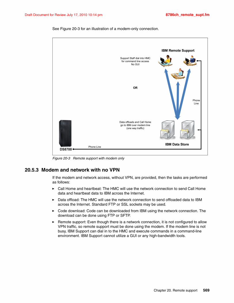
Draft Document for Review July 17, 2010 10:14 pm 8786ch_remote_supt.fm
See Figure 20-3 for an illustration of a modem-only connection.
Figure 20-3 Remote support with modem only
20.5.3 Modem and network with no VPNIf the modem and network access, without VPN, are provided, then the tasks are performed as follows:
� Call Home and heartbeat: The HMC will use the network connection to send Call Home data and heartbeat data to IBM across the Internet.
� Data offload: The HMC will use the network connection to send offloaded data to IBM across the Internet. Standard FTP or SSL sockets may be used.
� Code download: Code can be downloaded from IBM using the network connection. The download can be done using FTP or SFTP.
� Remote support: Even though there is a network connection, it is not configured to allow VPN traffic, so remote support must be done using the modem. If the modem line is not busy, IBM Support can dial in to the HMC and execute commands in a command-line environment. IBM Support cannot utilize a GUI or any high-bandwidth tools.
DS8700
IBM Remote Support
Data offloads and Call Homego to IBM over modem line
(one way traffic)
Phone Line
PhoneLine
IBM Data Store
Support Staff dial into HMCfor command line access
No GUI
OR
Chapter 20. Remote support 569
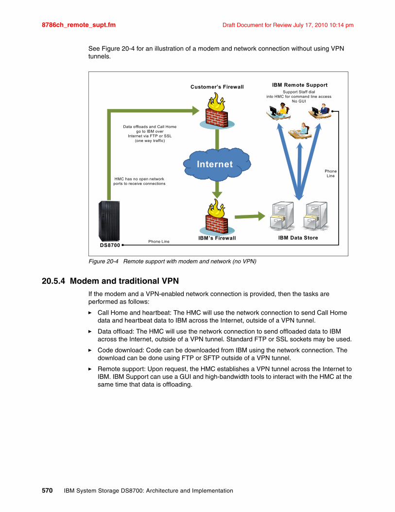
8786ch_remote_supt.fm Draft Document for Review July 17, 2010 10:14 pm
See Figure 20-4 for an illustration of a modem and network connection without using VPN tunnels.
Figure 20-4 Remote support with modem and network (no VPN)
20.5.4 Modem and traditional VPNIf the modem and a VPN-enabled network connection is provided, then the tasks are performed as follows:
� Call Home and heartbeat: The HMC will use the network connection to send Call Home data and heartbeat data to IBM across the Internet, outside of a VPN tunnel.
� Data offload: The HMC will use the network connection to send offloaded data to IBM across the Internet, outside of a VPN tunnel. Standard FTP or SSL sockets may be used.
� Code download: Code can be downloaded from IBM using the network connection. The download can be done using FTP or SFTP outside of a VPN tunnel.
� Remote support: Upon request, the HMC establishes a VPN tunnel across the Internet to IBM. IBM Support can use a GUI and high-bandwidth tools to interact with the HMC at the same time that data is offloading.
DS8700
IBM Remote SupportCustomer’s Firewall
Data offloads and Call Homego to IBM over
Internet via FTP or SSL(one way traffic)
Phone LineIBM’s Firewall
InternetPhoneLine
IBM Data Store
HMC has no open networkports to receive connections
Support Staff dialinto HMC for command line access
No GUI
570 IBM System Storage DS8700: Architecture and Implementation
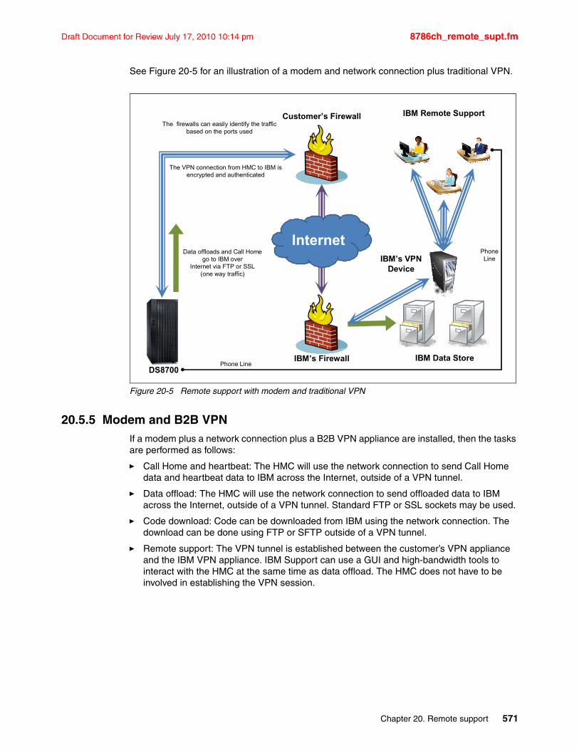
Draft Document for Review July 17, 2010 10:14 pm 8786ch_remote_supt.fm
See Figure 20-5 for an illustration of a modem and network connection plus traditional VPN.
Figure 20-5 Remote support with modem and traditional VPN
20.5.5 Modem and B2B VPNIf a modem plus a network connection plus a B2B VPN appliance are installed, then the tasks are performed as follows:
� Call Home and heartbeat: The HMC will use the network connection to send Call Home data and heartbeat data to IBM across the Internet, outside of a VPN tunnel.
� Data offload: The HMC will use the network connection to send offloaded data to IBM across the Internet, outside of a VPN tunnel. Standard FTP or SSL sockets may be used.
� Code download: Code can be downloaded from IBM using the network connection. The download can be done using FTP or SFTP outside of a VPN tunnel.
� Remote support: The VPN tunnel is established between the customer’s VPN appliance and the IBM VPN appliance. IBM Support can use a GUI and high-bandwidth tools to interact with the HMC at the same time as data offload. The HMC does not have to be involved in establishing the VPN session.
DS8700
IBM Remote Support
IBM’s VPNDevice
Customer’s Firewall
The VPN connection from HMC to IBM is encrypted and authenticated
The firewalls can easily identify the traffic based on the ports used
Phone LineIBM’s Firewall
InternetPhoneLine
IBM Data Store
Data offloads and Call Homego to IBM over
Internet via FTP or SSL(one way traffic)
Chapter 20. Remote support 571
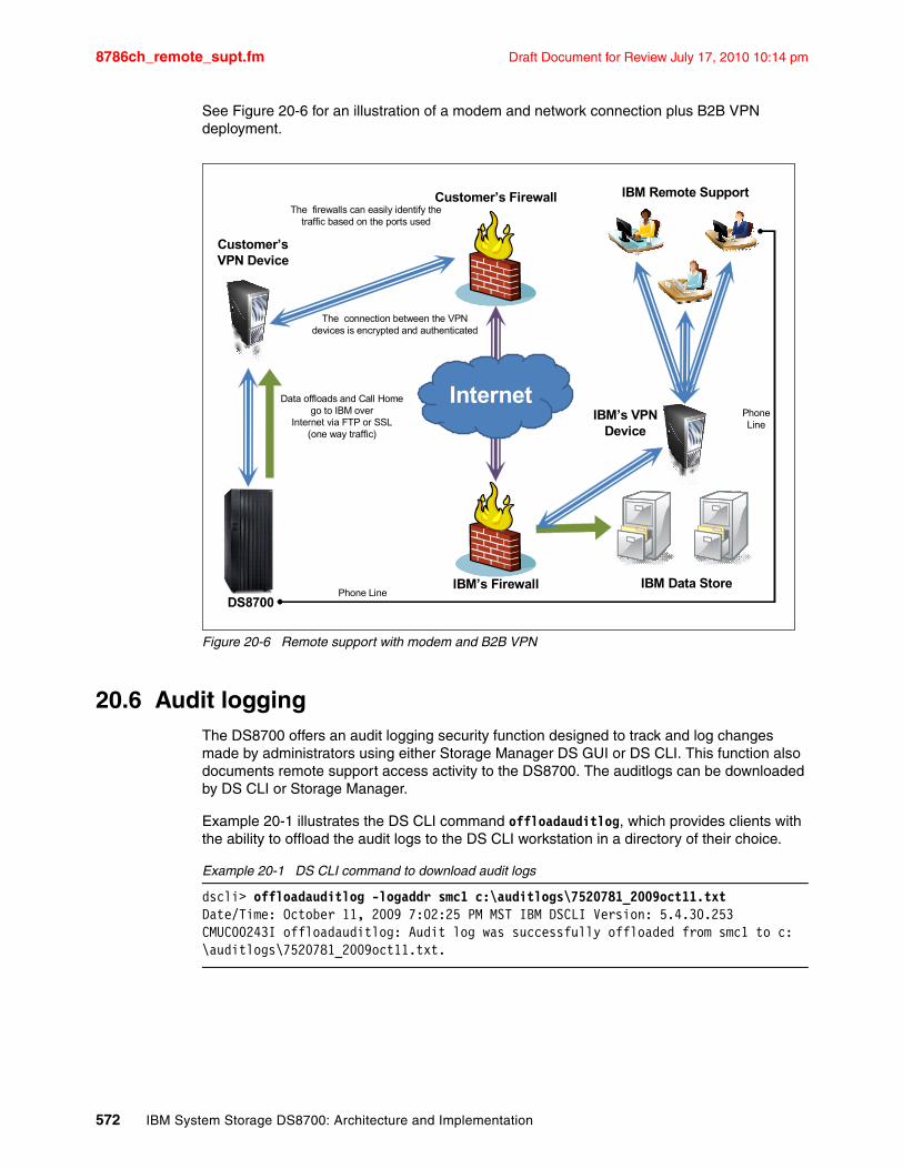
8786ch_remote_supt.fm Draft Document for Review July 17, 2010 10:14 pm
See Figure 20-6 for an illustration of a modem and network connection plus B2B VPN deployment.
Figure 20-6 Remote support with modem and B2B VPN
20.6 Audit loggingThe DS8700 offers an audit logging security function designed to track and log changes made by administrators using either Storage Manager DS GUI or DS CLI. This function also documents remote support access activity to the DS8700. The auditlogs can be downloaded by DS CLI or Storage Manager.
Example 20-1 illustrates the DS CLI command offloadauditlog, which provides clients with the ability to offload the audit logs to the DS CLI workstation in a directory of their choice.
Example 20-1 DS CLI command to download audit logs
dscli> offloadauditlog -logaddr smc1 c:\auditlogs\7520781_2009oct11.txtDate/Time: October 11, 2009 7:02:25 PM MST IBM DSCLI Version: 5.4.30.253CMUC00243I offloadauditlog: Audit log was successfully offloaded from smc1 to c:\auditlogs\7520781_2009oct11.txt.
DS8700
IBM Remote Support
IBM’s VPNDevice
Customer’s Firewall
Customer’sVPN Device
The connection between the VPN devices is encrypted and authenticated
The firewalls can easily identify thetraffic based on the ports used
Phone LineIBM’s Firewall
InternetPhoneLine
IBM Data Store
Data offloads and Call Homego to IBM over
Internet via FTP or SSL(one way traffic)
572 IBM System Storage DS8700: Architecture and Implementation
Draft Document for Review July 17, 2010 10:14 pm 8786ch_remote_supt.fm
The downloaded auditlog is a text file that provides information about when a remote access session started and ended and what remote authority level was applied. A portion of the downloaded file is shown in Example 20-2.
Example 20-2 Audit log entries related to a remote support event via modem
U,2009/10/05 18:20:49:000,,1,IBM.2107-7520780,N,8000,Phone_started,Phone_connection_startedU,2009/10/05 18:21:13:000,,1,IBM.2107-7520780,N,8036,Authority_to_root,Challenge Key = 'ZyM1NGMs'; Authority_upgrade_to_root,,,U,2009/10/05’18:26:02:000,,1,IBM.2107-7520780,N,8002,Phone_ended,Phone_connection_ended
The Challenge Key shown above is not a password on the HMC. It is a token shown to the IBM Support representative that is dialing in to the DS8700. The representative must use the Challenge Key in an IBM internal tool to generate a Response Key that is given to the HMC. The Response Key acts as a one-time authorization to the features of the HMC. The Challenge and Response Keys change every time a remote connection is made.
The Challenge-Response process must be repeated again if the representative needs to escalate privileges to access the HMC command-line environment. There is no direct user login and no root login via the modem on a DS8700 HMC.
For a detailed description about how auditing is used to record “who did what and when” in the audited system, refer to the following address:
http://www.ibm.com/support/techdocs/atsmastr.nsf/WebIndex/TD103019
Chapter 20. Remote support 573

8786ch_remote_supt.fm Draft Document for Review July 17, 2010 10:14 pm
574 IBM System Storage DS8700: Architecture and Implementation
Draft Document for Review July 17, 2010 10:14 pm 8786ch_Capacity_Upgrades_CoD.fm
Chapter 21. Capacity upgrades and CoD
This chapter discusses aspects of implementing capacity upgrades and Capacity on Demand (CoD) with the IBM System Storage DS8700. This chapter covers the following topics:
� Installing capacity upgrades
� Using Capacity on Demand (CoD)
21
© Copyright IBM Corp. 2010. All rights reserved. 575
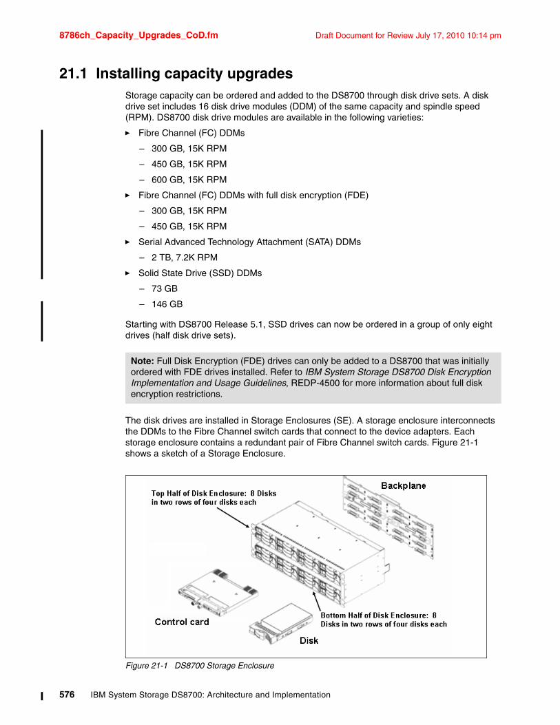
8786ch_Capacity_Upgrades_CoD.fm Draft Document for Review July 17, 2010 10:14 pm
21.1 Installing capacity upgradesStorage capacity can be ordered and added to the DS8700 through disk drive sets. A disk drive set includes 16 disk drive modules (DDM) of the same capacity and spindle speed (RPM). DS8700 disk drive modules are available in the following varieties:
� Fibre Channel (FC) DDMs
– 300 GB, 15K RPM
– 450 GB, 15K RPM
– 600 GB, 15K RPM
� Fibre Channel (FC) DDMs with full disk encryption (FDE)
– 300 GB, 15K RPM
– 450 GB, 15K RPM
� Serial Advanced Technology Attachment (SATA) DDMs
– 2 TB, 7.2K RPM
� Solid State Drive (SSD) DDMs
– 73 GB
– 146 GB
Starting with DS8700 Release 5.1, SSD drives can now be ordered in a group of only eight drives (half disk drive sets).
The disk drives are installed in Storage Enclosures (SE). A storage enclosure interconnects the DDMs to the Fibre Channel switch cards that connect to the device adapters. Each storage enclosure contains a redundant pair of Fibre Channel switch cards. Figure 21-1 shows a sketch of a Storage Enclosure.
Figure 21-1 DS8700 Storage Enclosure
Note: Full Disk Encryption (FDE) drives can only be added to a DS8700 that was initially ordered with FDE drives installed. Refer to IBM System Storage DS8700 Disk Encryption Implementation and Usage Guidelines, REDP-4500 for more information about full disk encryption restrictions.
576 IBM System Storage DS8700: Architecture and Implementation
Draft Document for Review July 17, 2010 10:14 pm 8786ch_Capacity_Upgrades_CoD.fm
The storage enclosures are always installed in pairs, one enclosure in the front of the unit and one enclosure in the rear. A storage enclosure pair can be populated with one or two disk drive sets (16 or 32 DDMs), or in case of SSDs, a half disk drive set (eight DDMs). All DDMs in a disk enclosure pair must be of the same type (capacity and speed). Most commonly, each storage enclosure is shipped full with 16 DDMs, meaning that each pair has 32 DDMs. If a disk enclosure pair is populated with only eight or 16 DDMs, disk drive filler modules called baffles are installed in the vacant DDM slots. This is to maintain the correct cooling airflow throughout the enclosure.
Each storage enclosure attaches to two device adapters (DAs). The DAs are the RAID adapter cards that connect the CECs to the DDMs. The DS8700 DA cards are always installed as a redundant pair, so they are referred to as DA pairs.
Physical installation and testing of the device adapters, storage enclosure pairs, and DDMs are performed by your IBM service representative. After the additional capacity is added successfully, the new storage appears as additional unconfigured array sites.
You might need to obtain new license keys and apply them to the storage image before you start configuring the new capacity; see Chapter 10, “DS8700 features and license keys” on page 233 for more information. You cannot create ranks using the new capacity if this causes your machine to exceed its license key limits. Please be aware that applying increased feature activation codes is a concurrent action, but a license reduction or deactivation is often a disruptive action.
21.1.1 Installation order of upgradesIndividual machine configurations vary, so it is not possible to give an exact pattern for the order in which every storage upgrade will be installed. This is because it is possible to order a machine with multiple underpopulated storage enclosures (SEs) across the device adapter (DA) pairs. This is done to allow future upgrades to be performed with the fewest physical changes. It should be noted, however, that all storage upgrades are concurrent, in that adding capacity to a DS8700 does not require any downtime.
As a general rule, when adding capacity to a DS8700, storage hardware is populated in the following order:
1. DDMs are added to underpopulated enclosures. Whenever you add 16 DDMs to a machine, eight DDMs are installed into the front storage enclosure and eight into the rear storage enclosure. If you add a complete 32 pack, then 16 are installed in the front storage enclosure and 16 are installed in the rear storage enclosure.
2. Once the first storage enclosure pair on a DA pair is fully populated with DDMs (32 DDMs total), a second storage enclosure pair can be added to that DA pair.
3. Once a DA pair has two fully populated storage enclosure pairs (64 DDMs total), another DA pair is added. The DA cards are installed into the I/O enclosures that are located at the bottom of the racks. They are not located in the storage enclosures.
Note: Special restrictions in terms of placement and intermixing apply when adding Solid State Drives. Refer to DS8700 Easy Tier, REDP-4667 for more information on SSD configuration rules.
Chapter 21. Capacity upgrades and CoD 577
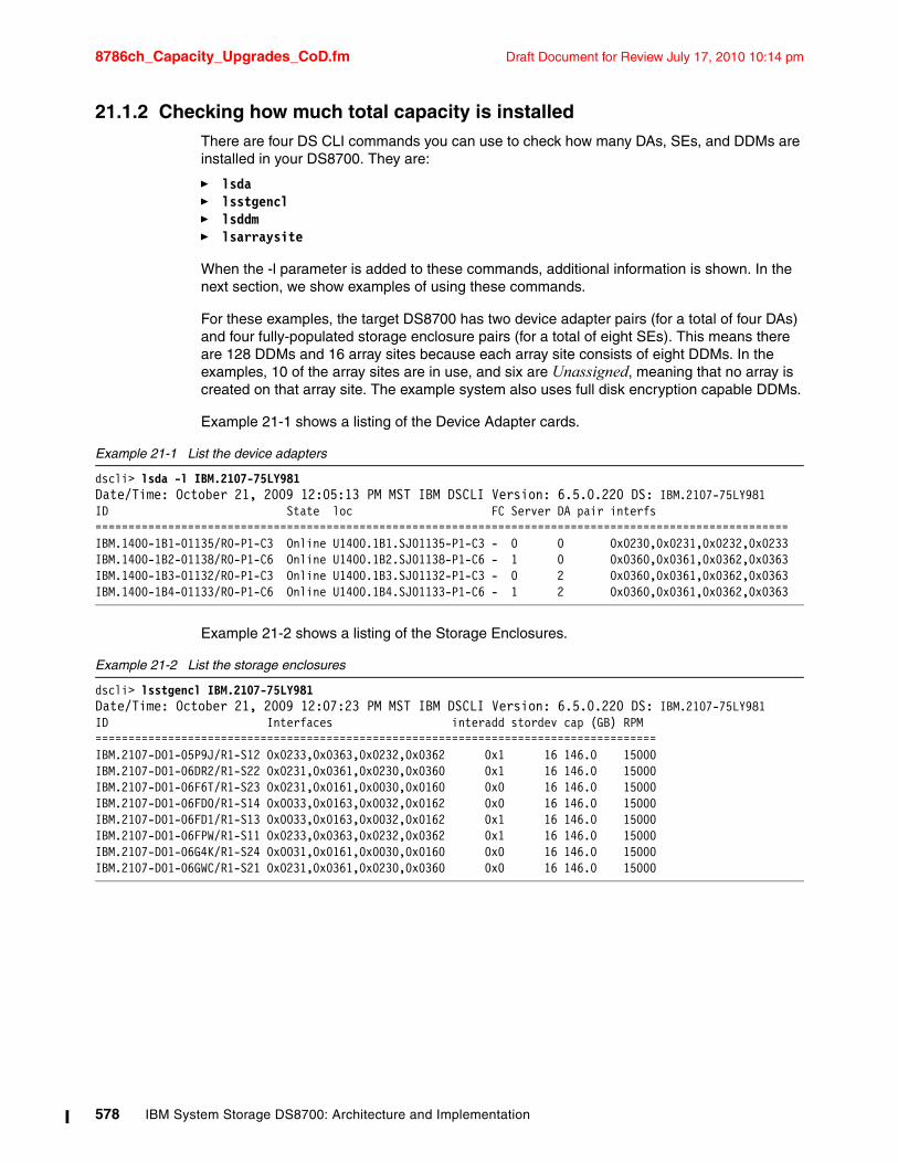
8786ch_Capacity_Upgrades_CoD.fm Draft Document for Review July 17, 2010 10:14 pm
21.1.2 Checking how much total capacity is installedThere are four DS CLI commands you can use to check how many DAs, SEs, and DDMs are installed in your DS8700. They are:
� lsda � lsstgencl � lsddm � lsarraysite
When the -l parameter is added to these commands, additional information is shown. In the next section, we show examples of using these commands.
For these examples, the target DS8700 has two device adapter pairs (for a total of four DAs) and four fully-populated storage enclosure pairs (for a total of eight SEs). This means there are 128 DDMs and 16 array sites because each array site consists of eight DDMs. In the examples, 10 of the array sites are in use, and six are Unassigned, meaning that no array is created on that array site. The example system also uses full disk encryption capable DDMs.
Example 21-1 shows a listing of the Device Adapter cards.
Example 21-1 List the device adapters
dscli> lsda -l IBM.2107-75LY981Date/Time: October 21, 2009 12:05:13 PM MST IBM DSCLI Version: 6.5.0.220 DS: IBM.2107-75LY981ID State loc FC Server DA pair interfs=========================================================================================================IBM.1400-1B1-01135/R0-P1-C3 Online U1400.1B1.SJ01135-P1-C3 - 0 0 0x0230,0x0231,0x0232,0x0233IBM.1400-1B2-01138/R0-P1-C6 Online U1400.1B2.SJ01138-P1-C6 - 1 0 0x0360,0x0361,0x0362,0x0363IBM.1400-1B3-01132/R0-P1-C3 Online U1400.1B3.SJ01132-P1-C3 - 0 2 0x0360,0x0361,0x0362,0x0363IBM.1400-1B4-01133/R0-P1-C6 Online U1400.1B4.SJ01133-P1-C6 - 1 2 0x0360,0x0361,0x0362,0x0363
Example 21-2 shows a listing of the Storage Enclosures.
Example 21-2 List the storage enclosures
dscli> lsstgencl IBM.2107-75LY981Date/Time: October 21, 2009 12:07:23 PM MST IBM DSCLI Version: 6.5.0.220 DS: IBM.2107-75LY981ID Interfaces interadd stordev cap (GB) RPM=====================================================================================IBM.2107-D01-05P9J/R1-S12 0x0233,0x0363,0x0232,0x0362 0x1 16 146.0 15000IBM.2107-D01-06DR2/R1-S22 0x0231,0x0361,0x0230,0x0360 0x1 16 146.0 15000IBM.2107-D01-06F6T/R1-S23 0x0231,0x0161,0x0030,0x0160 0x0 16 146.0 15000IBM.2107-D01-06FD0/R1-S14 0x0033,0x0163,0x0032,0x0162 0x0 16 146.0 15000IBM.2107-D01-06FD1/R1-S13 0x0033,0x0163,0x0032,0x0162 0x1 16 146.0 15000IBM.2107-D01-06FPW/R1-S11 0x0233,0x0363,0x0232,0x0362 0x1 16 146.0 15000IBM.2107-D01-06G4K/R1-S24 0x0031,0x0161,0x0030,0x0160 0x0 16 146.0 15000IBM.2107-D01-06GWC/R1-S21 0x0231,0x0361,0x0230,0x0360 0x0 16 146.0 15000
578 IBM System Storage DS8700: Architecture and Implementation
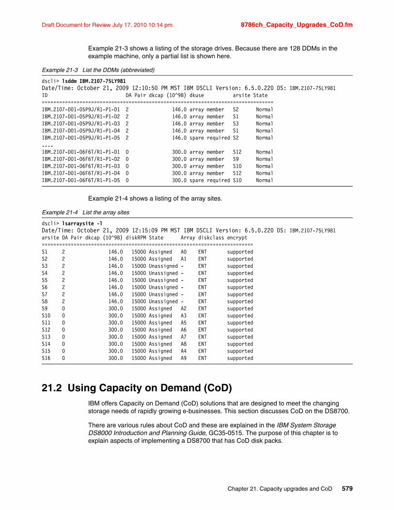
Draft Document for Review July 17, 2010 10:14 pm 8786ch_Capacity_Upgrades_CoD.fm
Example 21-3 shows a listing of the storage drives. Because there are 128 DDMs in the example machine, only a partial list is shown here.
Example 21-3 List the DDMs (abbreviated)
dscli> lsddm IBM.2107-75LY981Date/Time: October 21, 2009 12:10:50 PM MST IBM DSCLI Version: 6.5.0.220 DS: IBM.2107-75LY981ID DA Pair dkcap (10^9B) dkuse arsite State================================================================================IBM.2107-D01-05P9J/R1-P1-D1 2 146.0 array member S2 NormalIBM.2107-D01-05P9J/R1-P1-D2 2 146.0 array member S1 NormalIBM.2107-D01-05P9J/R1-P1-D3 2 146.0 array member S3 NormalIBM.2107-D01-05P9J/R1-P1-D4 2 146.0 array member S1 NormalIBM.2107-D01-05P9J/R1-P1-D5 2 146.0 spare required S2 Normal.... IBM.2107-D01-06F6T/R1-P1-D1 0 300.0 array member S12 NormalIBM.2107-D01-06F6T/R1-P1-D2 0 300.0 array member S9 NormalIBM.2107-D01-06F6T/R1-P1-D3 0 300.0 array member S10 NormalIBM.2107-D01-06F6T/R1-P1-D4 0 300.0 array member S12 NormalIBM.2107-D01-06F6T/R1-P1-D5 0 300.0 spare required S10 Normal
Example 21-4 shows a listing of the array sites.
Example 21-4 List the array sites
dscli> lsarraysite -lDate/Time: October 21, 2009 12:15:09 PM MST IBM DSCLI Version: 6.5.0.220 DS: IBM.2107-75LY981arsite DA Pair dkcap (10^9B) diskRPM State Array diskclass encrypt=========================================================================S1 2 146.0 15000 Assigned A0 ENT supportedS2 2 146.0 15000 Assigned A1 ENT supportedS3 2 146.0 15000 Unassigned - ENT supportedS4 2 146.0 15000 Unassigned - ENT supportedS5 2 146.0 15000 Unassigned - ENT supportedS6 2 146.0 15000 Unassigned - ENT supportedS7 2 146.0 15000 Unassigned - ENT supportedS8 2 146.0 15000 Unassigned - ENT supportedS9 0 300.0 15000 Assigned A2 ENT supportedS10 0 300.0 15000 Assigned A3 ENT supportedS11 0 300.0 15000 Assigned A5 ENT supportedS12 0 300.0 15000 Assigned A6 ENT supportedS13 0 300.0 15000 Assigned A7 ENT supportedS14 0 300.0 15000 Assigned A8 ENT supportedS15 0 300.0 15000 Assigned A4 ENT supportedS16 0 300.0 15000 Assigned A9 ENT supported
21.2 Using Capacity on Demand (CoD)IBM offers Capacity on Demand (CoD) solutions that are designed to meet the changing storage needs of rapidly growing e-businesses. This section discusses CoD on the DS8700.
There are various rules about CoD and these are explained in the IBM System Storage DS8000 Introduction and Planning Guide, GC35-0515. The purpose of this chapter is to explain aspects of implementing a DS8700 that has CoD disk packs.
Chapter 21. Capacity upgrades and CoD 579
8786ch_Capacity_Upgrades_CoD.fm Draft Document for Review July 17, 2010 10:14 pm
21.2.1 What is Capacity on DemandThe Standby CoD offering is designed to provide you with the ability to tap into additional storage and is particularly attractive if you have rapid or unpredictable growth, or if you simply want the knowledge that the extra storage will be there when you need it.
In many database environments, it is not unusual to have very rapid growth in the amount of disk space required for your business. This can create a problem if there is an unexpected and urgent need for disk space and no time to create a purchase order or wait for the disks to be delivered.
With this offering, up to four Standby CoD disk drive sets (64 disk drives) can be factory-installed or field-installed into your system. To activate them, you simply logically configure the disk drives for use, which is a nondisruptive activity that does not require intervention from IBM. Upon activation of any portion of a Standby CoD disk drive set, you must place an order with IBM to initiate billing for the activated set. At that time, you can also order replacement CoD disk drive sets.
This offering allows you to purchase licensed functions based upon your machine’s physical capacity, excluding unconfigured Standby CoD capacity. This can help improve your cost of ownership, because the extent of IBM authorization for licensed functions can grow at the same time you need your disk capacity to grow.
Contact your IBM representative to obtain additional information regarding Standby CoD offering terms and conditions.
21.2.2 How to tell if a DS8700 has CoDA common question is: How can you to determine if a DS8700 has CoD disks installed? There are two important indicators that you need to check for:
� Is the CoD indicator present in the Disk Storage Feature Activation (DSFA) Web site?
� What is the Operating Environment License (OEL) limit displayed by the lskey DS CLI command?
Verify CoD on the DSFA Web siteThe data storage feature activation (DSFA) Web site provides feature activation codes and license keys to technically activate functions acquired for your IBM storage products. To check for the CoD indicator on the DSFA Web site, you need to perform the following tasks:
1. Obtain the machine signature by using the DS CLI. First, connect with the DS CLI and execute showsi -fullid, as shown in Example 21-5 on page 581. The signature is a unique value that can only be accessed from the machine. You will also need to record the Machine Type displayed as well as the Machine Serial Number (ending with 0).
Note: Solid state disk drives are not available as Standby Capacity on Demand disk drives.
580 IBM System Storage DS8700: Architecture and Implementation
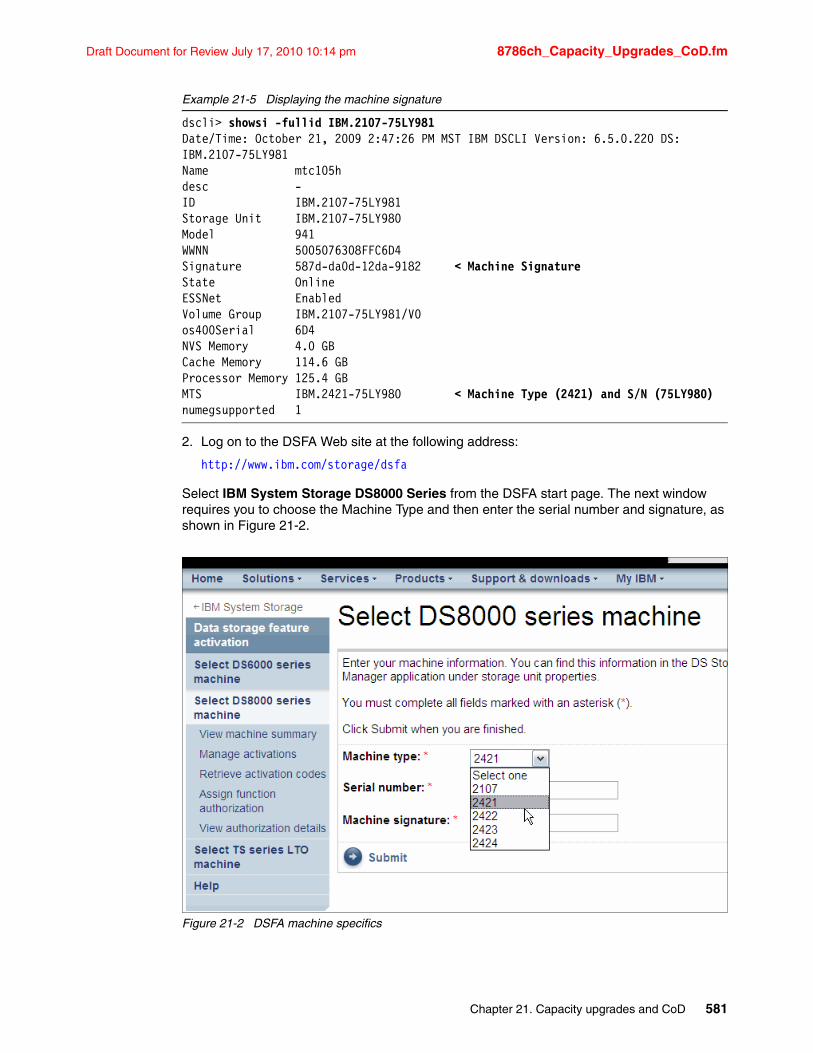
Draft Document for Review July 17, 2010 10:14 pm 8786ch_Capacity_Upgrades_CoD.fm
Example 21-5 Displaying the machine signature
dscli> showsi -fullid IBM.2107-75LY981Date/Time: October 21, 2009 2:47:26 PM MST IBM DSCLI Version: 6.5.0.220 DS: IBM.2107-75LY981Name mtc105hdesc -ID IBM.2107-75LY981Storage Unit IBM.2107-75LY980Model 941WWNN 5005076308FFC6D4Signature 587d-da0d-12da-9182 < Machine SignatureState OnlineESSNet EnabledVolume Group IBM.2107-75LY981/V0os400Serial 6D4NVS Memory 4.0 GBCache Memory 114.6 GBProcessor Memory 125.4 GBMTS IBM.2421-75LY980 < Machine Type (2421) and S/N (75LY980)numegsupported 1
2. Log on to the DSFA Web site at the following address:
http://www.ibm.com/storage/dsfa
Select IBM System Storage DS8000 Series from the DSFA start page. The next window requires you to choose the Machine Type and then enter the serial number and signature, as shown in Figure 21-2.
Figure 21-2 DSFA machine specifics
Chapter 21. Capacity upgrades and CoD 581
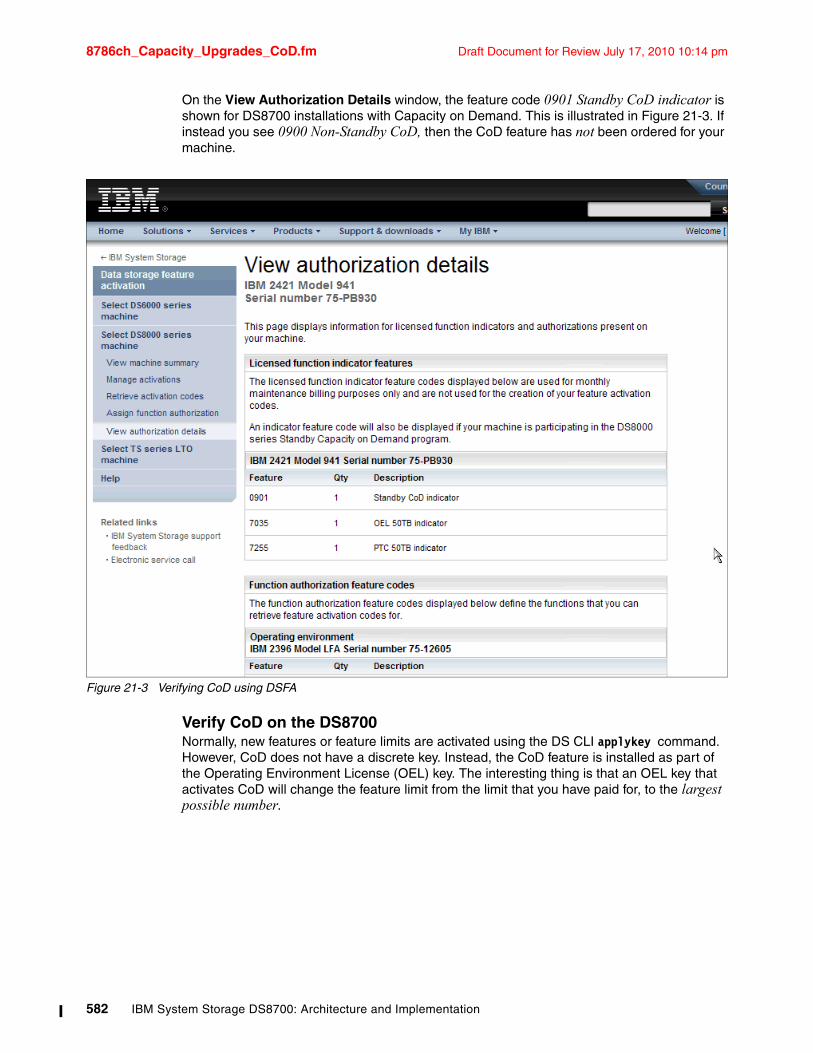
8786ch_Capacity_Upgrades_CoD.fm Draft Document for Review July 17, 2010 10:14 pm
On the View Authorization Details window, the feature code 0901 Standby CoD indicator is shown for DS8700 installations with Capacity on Demand. This is illustrated in Figure 21-3. If instead you see 0900 Non-Standby CoD, then the CoD feature has not been ordered for your machine.
Figure 21-3 Verifying CoD using DSFA
Verify CoD on the DS8700Normally, new features or feature limits are activated using the DS CLI applykey command. However, CoD does not have a discrete key. Instead, the CoD feature is installed as part of the Operating Environment License (OEL) key. The interesting thing is that an OEL key that activates CoD will change the feature limit from the limit that you have paid for, to the largest possible number.
582 IBM System Storage DS8700: Architecture and Implementation
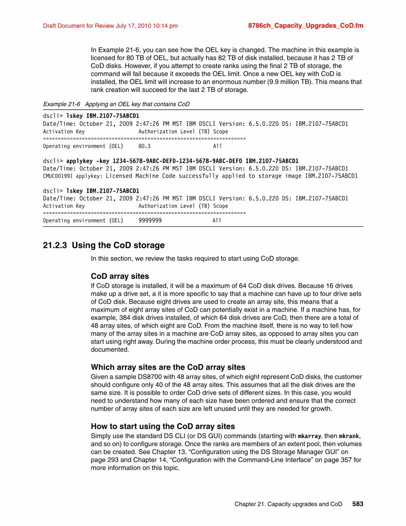
Draft Document for Review July 17, 2010 10:14 pm 8786ch_Capacity_Upgrades_CoD.fm
In Example 21-6, you can see how the OEL key is changed. The machine in this example is licensed for 80 TB of OEL, but actually has 82 TB of disk installed, because it has 2 TB of CoD disks. However, if you attempt to create ranks using the final 2 TB of storage, the command will fail because it exceeds the OEL limit. Once a new OEL key with CoD is installed, the OEL limit will increase to an enormous number (9.9 million TB). This means that rank creation will succeed for the last 2 TB of storage.
Example 21-6 Applying an OEL key that contains CoD
dscli> lskey IBM.2107-75ABCD1Date/Time: October 21, 2009 2:47:26 PM MST IBM DSCLI Version: 6.5.0.220 DS: IBM.2107-75ABCD1Activation Key Authorization Level (TB) Scope====================================================================Operating environment (OEL) 80.3 All
dscli> applykey -key 1234-5678-9ABC-DEF0-1234-5678-9ABC-DEF0 IBM.2107-75ABCD1Date/Time: October 21, 2009 2:47:26 PM MST IBM DSCLI Version: 6.5.0.220 DS: IBM.2107-75ABCD1CMUC00199I applykey: Licensed Machine Code successfully applied to storage image IBM.2107-75ABCD1
dscli> lskey IBM.2107-75ABCD1Date/Time: October 21, 2009 2:47:26 PM MST IBM DSCLI Version: 6.5.0.220 DS: IBM.2107-75ABCD1Activation Key Authorization Level (TB) Scope====================================================================Operating environment (OEL) 9999999 All
21.2.3 Using the CoD storageIn this section, we review the tasks required to start using CoD storage.
CoD array sitesIf CoD storage is installed, it will be a maximum of 64 CoD disk drives. Because 16 drives make up a drive set, a it is more specific to say that a machine can have up to four drive sets of CoD disk. Because eight drives are used to create an array site, this means that a maximum of eight array sites of CoD can potentially exist in a machine. If a machine has, for example, 384 disk drives installed, of which 64 disk drives are CoD, then there are a total of 48 array sites, of which eight are CoD. From the machine itself, there is no way to tell how many of the array sites in a machine are CoD array sites, as opposed to array sites you can start using right away. During the machine order process, this must be clearly understood and documented.
Which array sites are the CoD array sitesGiven a sample DS8700 with 48 array sites, of which eight represent CoD disks, the customer should configure only 40 of the 48 array sites. This assumes that all the disk drives are the same size. It is possible to order CoD drive sets of different sizes. In this case, you would need to understand how many of each size have been ordered and ensure that the correct number of array sites of each size are left unused until they are needed for growth.
How to start using the CoD array sitesSimply use the standard DS CLI (or DS GUI) commands (starting with mkarray, then mkrank, and so on) to configure storage. Once the ranks are members of an extent pool, then volumes can be created. See Chapter 13, “Configuration using the DS Storage Manager GUI” on page 293 and Chapter 14, “Configuration with the Command-Line Interface” on page 357 for more information on this topic.
Chapter 21. Capacity upgrades and CoD 583
8786ch_Capacity_Upgrades_CoD.fm Draft Document for Review July 17, 2010 10:14 pm
What if you accidentally configure a CoD array siteGiven the sample DS8700 with 48 array sites, of which eight represent CoD disks, if you accidentally configure 41 array sites but did not intend to start using the CoD disks yet, then use the rmarray command immediately to return that array site to an unassigned state. If volumes have been created and those volumes are in use, then you have started to use the CoD arrays and should contact IBM to inform IBM that the CoD storage is now in use.
What you do once the CoD array sites are in useOnce you have started to use the CoD array sites (and remember that IBM requires that a Standby CoD disk drive set must be activated within a twelve-month period from the date of installation; all such activation is permanent), then contact IBM so that the CoD indicator can be removed from the machine. You must place an order with IBM to initiate billing for the activated set. At that time, you can also order replacement Standby CoD disk drive sets. If new CoD disks are ordered and installed, then a new OEL key will also be issued and should be applied immediately. If no more CoD disks are desired, or the DS8700 has reached maximum capacity, then an OEL key will be issued to reflect that CoD is no longer enabled on the machine.
584 IBM System Storage DS8700: Architecture and Implementation
Draft Document for Review July 17, 2010 10:14 pm 8786ax_tools.fm
Appendix A. Tools and service offerings
This appendix gives information about the tools that are available to help you when planning, managing, migrating, and analyzing activities with your DS8700. In this appendix, we also reference the sites where you can find information about the service offerings that are available from IBM to help you in several of the activities related to the DS8700 implementation.
A
© Copyright IBM Corp. 2010. All rights reserved. 585
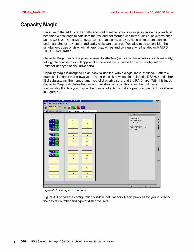
8786ax_tools.fm Draft Document for Review July 17, 2010 10:14 pm
Capacity MagicBecause of the additional flexibility and configuration options storage subsystems provide, it becomes a challenge to calculate the raw and net storage capacity of disk subsystems such as the DS8700. You have to invest considerable time, and you need an in-depth technical understanding of how spare and parity disks are assigned. You also need to consider the simultaneous use of disks with different capacities and configurations that deploy RAID 5, RAID 6, and RAID 10.
Capacity Magic can do the physical (raw) to effective (net) capacity calculations automatically, taking into consideration all applicable rules and the provided hardware configuration (number and type of disk drive sets).
Capacity Magic is designed as an easy-to-use tool with a single, main interface. It offers a graphical interface that allows you to enter the disk drive configuration of a DS8700 and other IBM subsystems, the number and type of disk drive sets, and the RAID type. With this input, Capacity Magic calculates the raw and net storage capacities; also, the tool has a functionality that lets you display the number of extents that are produced per rank, as shown in Figure A-1.
Figure A-1 Configuration window
Figure A-1 shows the configuration window that Capacity Magic provides for you to specify the desired number and type of disk drive sets.
586 IBM System Storage DS8700: Architecture and Implementation
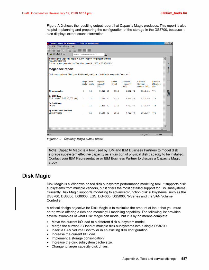
Draft Document for Review July 17, 2010 10:14 pm 8786ax_tools.fm
Figure A-2 shows the resulting output report that Capacity Magic produces. This report is also helpful in planning and preparing the configuration of the storage in the DS8700, because it also displays extent count information.
Figure A-2 Capacity Magic output report
Disk MagicDisk Magic is a Windows-based disk subsystem performance modeling tool. It supports disk subsystems from multiple vendors, but it offers the most detailed support for IBM subsystems. Currently Disk Magic supports modelling to advanced-function disk subsystems, such as the DS8700, DS8000, DS6000, ESS, DS4000, DS5000, N-Series and the SAN Volume Controller.
A critical design objective for Disk Magic is to minimize the amount of input that you must enter, while offering a rich and meaningful modeling capability. The following list provides several examples of what Disk Magic can model, but it is by no means complete:
� Move the current I/O load to a different disk subsystem model.� Merge the current I/O load of multiple disk subsystems into a single DS8700.� Insert a SAN Volume Controller in an existing disk configuration.� Increase the current I/O load.� Implement a storage consolidation.� Increase the disk subsystem cache size.� Change to larger capacity disk drives.
Note: Capacity Magic is a tool used by IBM and IBM Business Partners to model disk storage subsystem effective capacity as a function of physical disk capacity to be installed. Contact your IBM Representative or IBM Business Partner to discuss a Capacity Magic study.
Appendix A. Tools and service offerings 587
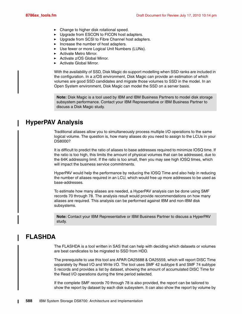
8786ax_tools.fm Draft Document for Review July 17, 2010 10:14 pm
� Change to higher disk rotational speed.� Upgrade from ESCON to FICON host adapters.� Upgrade from SCSI to Fibre Channel host adapters.� Increase the number of host adapters.� Use fewer or more Logical Unit Numbers (LUNs).� Activate Metro Mirror.� Activate z/OS Global Mirror.� Activate Global Mirror.
With the availability of SSD, Disk Magic do support modelling when SSD ranks are included in the configuration. In a z/OS environment, Disk Magic can provide an estimation of which volumes are good SSD candidates and migrate those volumes to SSD in the model. In an Open System environment, Disk Magic can model the SSD on a server basis.
HyperPAV AnalysisTraditional aliases allow you to simultaneously process multiple I/O operations to the same logical volume. The question is, how many aliases do you need to assign to the LCUs in your DS8000?
It is difficult to predict the ratio of aliases to base addresses required to minimize IOSQ time. If the ratio is too high, this limits the amount of physical volumes that can be addressed, due to the 64K addressing limit. If the ratio is too small, then you may see high IOSQ times, which will impact the business service commitments.
HyperPAV would help the performance by reducing the IOSQ Time and also help in reducing the number of aliases required in an LCU, which would free up more addresses to be used as base-addresses.
To estimate how many aliases are needed, a HyperPAV analysis can be done using SMF records 70 through 78. The analysis result would provide recommendations on how many aliases are required. This analysis can be performed against IBM and non-IBM disk subsystems.
FLASHDAThe FLASHDA is a tool written in SAS that can help with deciding which datasets or volumes are best candicates to be migrated to SSD from HDD.
The prerequisite to use this tool are APAR OA25688 & OA25559, which will report DISC Time separately by Read I/O and Write I/O. The tool uses SMF 42 subtype 6 and SMF 74 subtype 5 records and provides a list by dataset, showing the amount of accumulated DISC Time for the Read I/O operations during the time period selected.
If the complete SMF records 70 through 78 is also provided, the report can be tailored to show the report by dataset by each disk subsystem. It can also show the report by volume by
Note: Disk Magic is a tool used by IBM and IBM Business Partners to model disk storage subsystem performance. Contact your IBM Representative or IBM Business Partner to discuss a Disk Magic study.
Note: Contact your IBM Representative or IBM Business Partner to discuss a HyperPAV study.
588 IBM System Storage DS8700: Architecture and Implementation
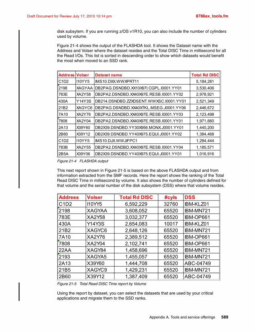
Draft Document for Review July 17, 2010 10:14 pm 8786ax_tools.fm
disk subsytem. If you are running z/OS v1R10, you can also include the number of cylinders used by volume.
Figure 21-4 shows the output of the FLASHDA tool. It shows the Dataset name with the Address and Volser where the dataset resides and the Total DISC Time in millisecond for all the Read I/Os. This list is sorted in descending order to show which datasets would benefit the most when moved to an SSD rank.
Figure 21-4 FLASHDA output
This next report shown in Figure 21-5 is based on the above FLASHDA output and from information extracted from the SMF records. Here the report shows the ranking of the Total Read DISC Time in millisecond by volume. It also shows the number of cylinders defined for that volume and the serial number of the disk subsystem (DSS) where that volume resides.
Figure 21-5 Total Read DISC Time report by Volume
Using the report by dataset, you can select the datasets that are used by your critical applications and migrate them to the SSD ranks.
Address Volser Dataset name Total Rd DISC
C1D2 I10YY5 IMS10.DXX.WWXPRT11 5,184,281
2198 XAGYAA DB2PAG.DSNDBD.XX10X97I.CGPL.I0001.YY01 3,530,406
783E XA2Y58 DB2PA2.DSNDBD.XX40X97E.RESB.I0001.YY02 2,978,921
430A Y14Y3S DB214.DSNDBD.ZZXDSENT.WWXSC.I0001.YY01 2,521,349
21B2 XAGYC6 DB2PAG.DSNDBD.XX40XTKL.MSEG.J0001.YY06 2,446,672
7A10 XA2Y76 DB2PA2.DSNDBD.XX40X97E.RESB.I0001.YY03 2,123,498
7808 XA2Y04 DB2PA2.DSNDBD.XX40X97E.RESB.I0001.YY01 1,971,660
2A13 X39Y60 DB2X39.DSNDBD.YY30X956.MONX.J0001.YY01 1,440,200
2B60 X39Y12 DB2X39.DSNDBD.YY40X975.EQUI.J0001.YY02 1,384,468
C1D2 I10YY5 IMS10.DJX.WWJIFPC1 1,284,444
783B XA2Y55 DB2PA2.DSNDBD.XX40X97E.RESB.I0001.YY04 1,185,571
2B5A X39Y06 DB2X39.DSNDBD.YY40X975.EQUI.J0001.YY01 1,016,916
Address Volser Total Rd DISC #cyls DSSC1D2 I10YY5 6,592,229 32760 IBM-KLZ012198 XAGYAA 3,608,052 65520 IBM-MN721783E XA2Y58 3,032,377 65520 IBM-OP661430A Y14Y3S 2,654,083 10017 IBM-KLZ0121B2 XAGYC6 2,648,126 65520 IBM-MN7217A10 XA2Y76 2,389,512 65520 IBM-OP6617808 XA2Y04 2,102,741 65520 IBM-OP66122AA XAGY84 1,458,696 65520 IBM-MN7212193 XAGYA5 1,455,057 65520 IBM-MN7212A13 X39Y60 1,444,708 65520 ABC-0474921B5 XAGYC9 1,429,231 65520 IBM-MN7212B60 X39Y12 1,387,409 65520 ABC-04749
Appendix A. Tools and service offerings 589
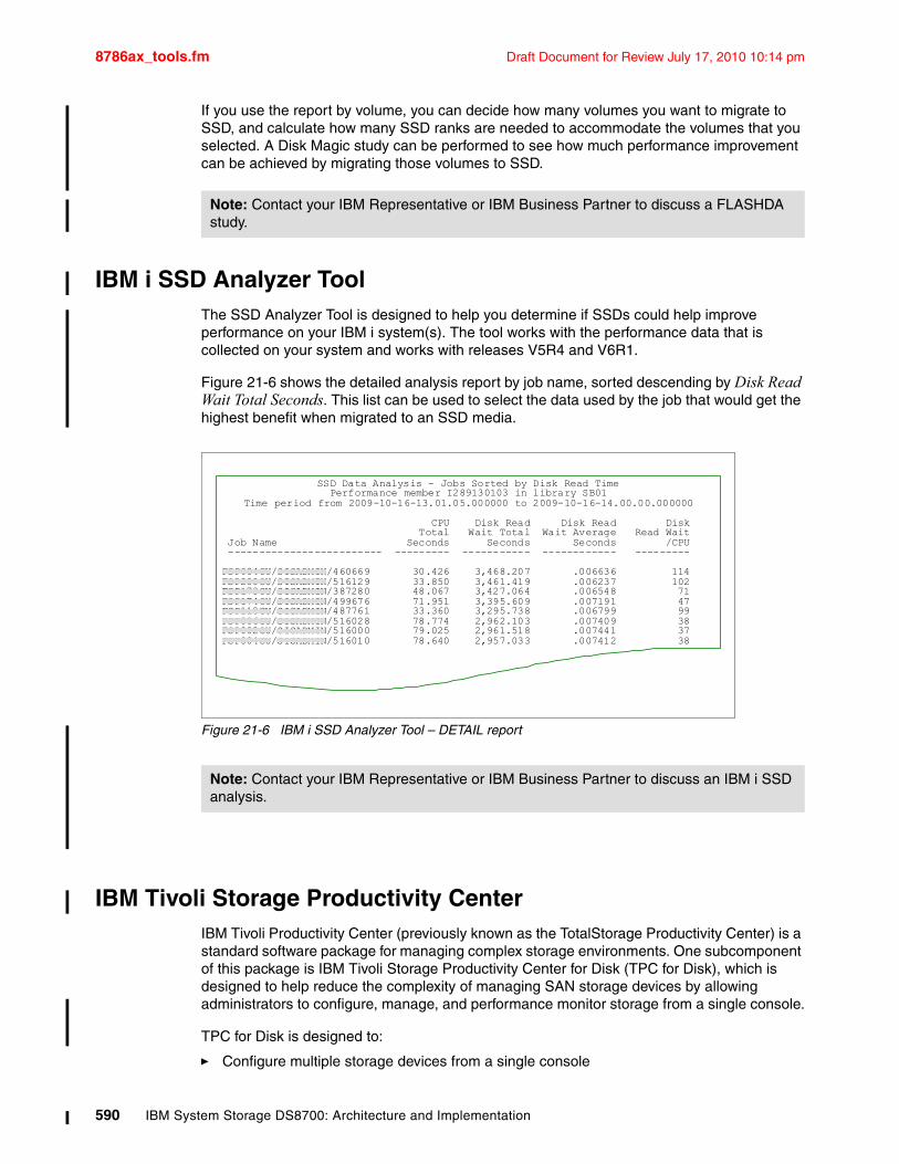
8786ax_tools.fm Draft Document for Review July 17, 2010 10:14 pm
If you use the report by volume, you can decide how many volumes you want to migrate to SSD, and calculate how many SSD ranks are needed to accommodate the volumes that you selected. A Disk Magic study can be performed to see how much performance improvement can be achieved by migrating those volumes to SSD.
IBM i SSD Analyzer ToolThe SSD Analyzer Tool is designed to help you determine if SSDs could help improve performance on your IBM i system(s). The tool works with the performance data that is collected on your system and works with releases V5R4 and V6R1.
Figure 21-6 shows the detailed analysis report by job name, sorted descending by Disk Read Wait Total Seconds. This list can be used to select the data used by the job that would get the highest benefit when migrated to an SSD media.
Figure 21-6 IBM i SSD Analyzer Tool – DETAIL report
IBM Tivoli Storage Productivity CenterIBM Tivoli Productivity Center (previously known as the TotalStorage Productivity Center) is a standard software package for managing complex storage environments. One subcomponent of this package is IBM Tivoli Storage Productivity Center for Disk (TPC for Disk), which is designed to help reduce the complexity of managing SAN storage devices by allowing administrators to configure, manage, and performance monitor storage from a single console.
TPC for Disk is designed to:
� Configure multiple storage devices from a single console
Note: Contact your IBM Representative or IBM Business Partner to discuss a FLASHDA study.
Note: Contact your IBM Representative or IBM Business Partner to discuss an IBM i SSD analysis.
SSD Data Analysis - Jobs Sorted by Disk Read TimePerformance member I289130103 in library SB01
Time period from 2009-10-16-13.01.05.000000 to 2009-10-16-14.00.00.000000
CPU Disk Read Disk Read Disk Total Wait Total Wait Average Read Wait
Job Name Seconds Seconds Seconds /CPU ------------------------- --------- ----------- ------------ ---------
FSP084CU/SISADMIN/460669 30.426 3,468.207 .006636 114FSP200CU/SISADMIN/516129 33.850 3,461.419 .006237 102FSP173CU/SISADMIN/387280 48.067 3,427.064 .006548 71FSP174CU/SISADMIN/499676 71.951 3,395.609 .007191 47FSP110CU/SISADMIN/487761 33.360 3,295.738 .006799 99FSP006CU/SISADMIN/516028 78.774 2,962.103 .007409 38FSP002CU/SISADMIN/516000 79.025 2,961.518 .007441 37FSP004CU/SISADMIN/516010 78.640 2,957.033 .007412 38
590 IBM System Storage DS8700: Architecture and Implementation
Draft Document for Review July 17, 2010 10:14 pm 8786ax_tools.fm
� Monitor and track the performance of SAN-attached Storage Management Interface Specification (SMI-S) compliant storage devices
� Enable proactive performance management by setting performance thresholds based on performance metrics and the generation of alerts
IBM Tivoli Productivity Center for Disk centralizes the management of networked storage devices that implement the SNIA SMI-S specification, which includes the IBM System Storage DS family, XIV, N series, and SAN Volume Controller (SVC). It is designed to help reduce storage management complexity and costs while improving data availability, centralizing management of storage devices through open standards (SMI-S), enhancing storage administrator productivity, increasing storage resource utilization, and offering proactive management of storage devices. IBM Tivoli Productivity Center for Disk offers the ability to discover storage devices using Service Location Protocol (SLP) and provides the ability to configure devices, in addition to gathering event and errors logs and launching device-specific applications or elements.
For more information, see Managing Disk Subsystems using IBM TotalStorage Productivity Center, SG24-7097. Also, refer to the following address:
http://www.ibm.com/servers/storage/software/center/index.html
IBM Certified Secure Data OverwriteSTG Lab Services offers IBM Certified Secure Data Overwrite service for the DS8700 and DS8000 series, and ESS models 800 and 750. This offering is meant to overcome the following issues:
� Deleted data does not mean gone forever. Usually, deleted means that the pointers to the data are invalidated and the space can be reused. Until the space is reused, the data remains on the media and what remains can be read with the right tools.
� Regulations and business prudence require that the data actually be removed when the media is no longer available.
The service executes a multipass overwrite of the data disks in the storage system:
� It operates on the entire box.
� It is three pass overwrite, which is compliant with the DoD 5220.20-M procedure for purging disks.
– Writes all sectors with zeros.
– Writes all sectors with ones.
– Writes all sectors with a pseudo-random pattern.
– Each pass reads back a random sample of sectors to verify the writes are done.
� There is a a fourth pass of zeros with InitSurf.
� IBM also purges client data from the server and HMC disks.
Certificate of completion
After the overwrite process has been completed, IBM delivers a complete report containing:
� A certificate of completion listing:
– The serial number of the systems overwritten.
– The dates and location the service was performed.
Appendix A. Tools and service offerings 591
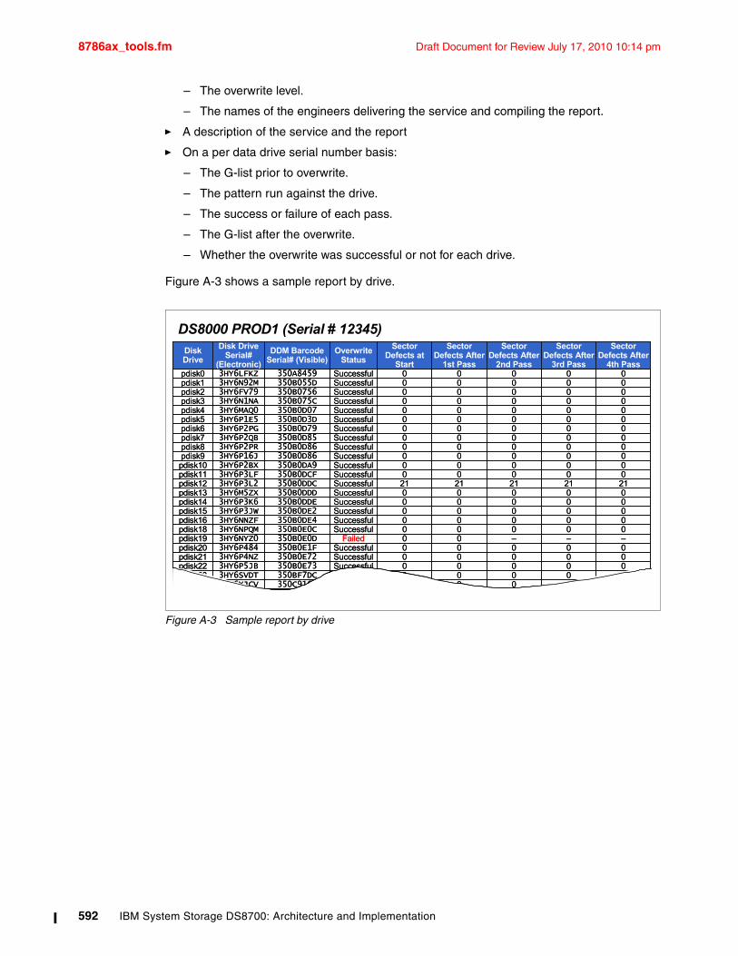
8786ax_tools.fm Draft Document for Review July 17, 2010 10:14 pm
– The overwrite level.
– The names of the engineers delivering the service and compiling the report.
� A description of the service and the report
� On a per data drive serial number basis:
– The G-list prior to overwrite.
– The pattern run against the drive.
– The success or failure of each pass.
– The G-list after the overwrite.
– Whether the overwrite was successful or not for each drive.
Figure A-3 shows a sample report by drive.
Figure A-3 Sample report by drive
00000Successful350C91E43HY6XLQ6 pdisk2500000Successful350C916F3HY6XJCV pdisk2400000Successful350BF7DC3HY6SVDT pdisk2300000Successful350B0E733HY6P5JB pdisk2200000Successful350B0E723HY6P4NZ pdisk2100000Successful350B0E1F3HY6P484 pdisk20–––00Failed350B0E0D3HY6NYZ0 pdisk1900000Successful350B0E0C3HY6NPQM pdisk1800000Successful350B0DE43HY6NNZF pdisk1600000Successful350B0DE23HY6P3JW pdisk1500000Successful350B0DDE3HY6P3K6 pdisk1400000Successful350B0DDD3HY6M5ZX pdisk132121212121Successful350B0DDC3HY6P3L2 pdisk1200000Successful350B0DCF3HY6P3LF pdisk1100000Successful350B0DA93HY6P2BX pdisk1000000Successful350B0D863HY6P16J pdisk900000Successful350B0D863HY6P2PR pdisk800000Successful350B0D853HY6P2QB pdisk700000Successful350B0D793HY6P2PG pdisk600000Successful350B0D3D3HY6P1E5 pdisk500000Successful350B0D073HY6MAQ0 pdisk400000Successful350B075C3HY6N1NA pdisk300000Successful350B07563HY6FV79 pdisk200000Successful350B055D3HY6N92M pdisk100000Successful350A84593HY6LFKZ pdisk0
Sector Defects After
4th Pass
Sector Defects After
3rd Pass
Sector Defects After
2nd Pass
Sector Defects After
1st Pass
Sector Defects at
Start
Overwrite Status
DDM Barcode Serial# (Visible)
Disk Drive Serial#
(Electronic)
Disk Drive
DS8000 PROD1 (Serial # 12345)
592 IBM System Storage DS8700: Architecture and Implementation
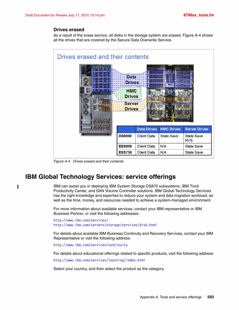
Draft Document for Review July 17, 2010 10:14 pm 8786ax_tools.fm
Drives erasedAs a result of the erase service, all disks in the storage system are erased. Figure A-4 shows all the drives that are covered by the Secure Data Overwrite Service.
Figure A-4 Drives erased and their contents
IBM Global Technology Services: service offeringsIBM can assist you in deploying IBM System Storage DS870 subsystems, IBM Tivoli Productivity Center, and SAN Volume Controller solutions. IBM Global Technology Services has the right knowledge and expertise to reduce your system and data migration workload, as well as the time, money, and resources needed to achieve a system-managed environment.
For more information about available services, contact your IBM representative or IBM Business Partner, or visit the following addresses:
http://www.ibm.com/services/http://www.ibm.com/servers/storage/services/disk.html
For details about available IBM Business Continuity and Recovery Services, contact your IBM Representative or visit the following address:
http://www.ibm.com/services/continuity
For details about educational offerings related to specific products, visit the following address:
http://www.ibm.com/services/learning/index.html
Select your country, and then select the product as the category.
Appendix A. Tools and service offerings 593
8786ax_tools.fm Draft Document for Review July 17, 2010 10:14 pm
IBM STG Lab Services: Service offeringsIn addition to the IBM Global Technology Services, the STG Lab Services and Training teams are set up to assist you with one-off, customer tailored solutions and services that will help you in your daily work with IBM Hardware and Software components. For more information about this topic, go to the following address:
http://www.ibm.com/systems/services/labservices/
594 IBM System Storage DS8700: Architecture and Implementation
Draft Document for Review July 17, 2010 10:14 pm 8786abrv.fm
ronyms
AAL Arrays Across Loops
AC Alternating Current
AL-PA Arbitrated Loop Physical Addressing
AMP Adaptive Multistream Prefetching
API Application Programming Interface
ASCII American Standard Code for Information Interchange
ASIC Application Specific Integrated Circuit
B2B Business-to-Business VPN
BBU Battery Backup Unit
CEC Central Electronics Complex
CG Consistency Group
CHPID Channel Path ID
CIM Common Information Model
CKD Count Key Data
CoD Capacity on Demand
CPU Central Processing Unit
CSDO Certified Secure Data Overwrite
CUIR Control Unit Interface Reconfiguration
DA Device Adapter
DASD Direct Access Storage Device
DC Direct Current
DDM Disk Drive Module
DFS Distributed File System
DFW DASD Fast Write
DHCP Dynamic Host Configuration Protocol
DMA Direct Memory Access
DMZ De-Militarized Zone
DNS Domain Name System
DPR Dynamic Path Reconnect
DPS Dynamic Path Selection
DSCIMCLI Data Storage Common Information Model Command-Line Interface
DSCLI Data Storage Command-Line Interface
DSFA Data Storage Feature Activation
DVE Dynamic Volume Expansion
EAV Extended Address Volume
Abbreviations and ac
© Copyright IBM Corp. 2010. All rights reserved.
EB Exabyte
ECC Error Checking and Correction
EDF Extended Distance FICON
EEH Enhanced Error Handling
EPO Emergency Power Off
EPOW Emergency Power Off Warning
ESCON Enterprise Systems Connection
ESS Enterprise Storage Server
ESSNI Enterprise Storage Server Network Interface
FATA Fibre Channel Attached Technology Adapter
FB Fixed Block
FC Flash Copy
FCAL Fibre Channel Arbitrated Loop
FCIC Fibre Channel Interface Card
FCP Fibre Channel Protocol
FCSE FlashCopy Space Efficient
FDE Full Disk Encryption
FFDC First Failure Data Capture
FICON Fiber Connection
FIR Fault Isolation Register
FRR Failure Recovery Routines
FTP File Transfer Protocol
GB Gigabyte
GC Global Copy
GM Global Mirror
GSA Global Storage Architecture
GUI Graphical User Interface
HA Host Adapter
HACMP High Availability Cluster Multi-Processing
HBA Host Bus Adapter
HCD Hardware Configuration Definition
HMC Hardware Management Console
HSM Hardware Security Module
HTTP Hypertext Transfer Protocol
HTTPS Hypertext Transfer Protocol over SSL
IBM International Business Machines Corporation
595
8786abrv.fm Draft Document for Review July 17, 2010 10:14 pm
IKE Internet Key Exchange
IKS Isolated Key Server
IOCDS Input/Output Configuration Data Set
IOPS Input Output Operations per Second
IOSQ Input/Output Supervisor Queue
IPL Initial Program Load
IPSec Internet Protocol Security
IPv4 Internet Protocol version 4
IPv6 Internet Protocol version 6
ITSO International Technical Support Organization
IWC Intelligent Write Caching
JBOD Just a Bunch of Disks
JFS Journaling File System
KB Kilobyte
Kb Kilobit
Kbps Kilobits per second
KVM Keyboard-Video-Mouse
L2TP Layer 2 Tunneling Protocol
LBA Logical Block Addressing
LCU Logical Control Unit
LDAP Lightweight Directory Access Protocol
LED Light Emitting Diode
LFU Least Frequently Used
LIC Licensed Internal Code
LIP Loop initialization Protocol
LMC Licensed Machine Code
LPAR Logical Partition
LRU Least Recently Used
LSS Logical SubSystem
LUN Logical Unit Number
LVM Logical Volume Manager
MB Megabyte
Mb Megabit
Mbps Megabits per second
MFU Most Frequently Used
MGM Metro Global Mirror
MIB Management Information Block
MM Metro Mirror
MPIO Multipath Input/Output
MRPD Machine Reported Product Data
MRU Most Recently Used
NAT Network Address Translation
NFS Network File System
NIMOL Network Installation Management on Linux
NTP Network Time Protocol
NVRAM Non-Volatile Random Access Memory
NVS Non-Volatile Storage
OEL Operating Environment License
OLTP Online Transaction Processing
PATA Parallel Attached Technology Adapter
PAV Parallel Access Volumes
PB Petabyte
PCI-X Peripheral Component Interconnect Extended
PCIe Peripheral Component Interconnect Express
PCM Path Control Module
PFA Predictive Failure Analysis
PHYP POWER® Systems Hypervisor
PLD Power Line Disturbance
PM Preserve Mirror
PMB Physical Memory Block
PPRC Peer-to-Peer Remote Copy
PPS Primary Power Supply
PSTN Public Switched Telephone Network
PTC Point-in-Time Copy
RAM Random Access Memory
RAS Reliability, Availability, Serviceability
RIO Remote Input/Output
RPC Rack Power Control
RPM Revolutions per Minute
RPO Recovery Point Objective
SAN Storage Area Network
SARC Sequential Adaptive Replacement Cache
SATA Serial Attached Technology Adapter
SCSI Small Computer System Interface
SDD Subsystem Device Driver
SDM System Data Mover
SE Storage Enclosure
SFI Storage Facility Image
596 IBM System Storage DS8700: Architecture and Implementation
Draft Document for Review July 17, 2010 10:14 pm 8786abrv.fm
SFTP SSH File Transfer Protocol
SMIS Storage Management Initiative Specification
SMP Symmetric Multiprocessor
SMS Storage Management Subsystem
SMT Simultaneous Multithreading
SMTP Simple Mail Transfer Protocol
SNIA Storage Networking Industry Association
SNMP Simple Network Monitoring Protocol
SOI Silicon on Insulator
SP Service Processor
SPCN System Power Control Network
SPE Small Programming Enhancement
SRM Storage Resource Management
SSD Solid State Drive
SSH Secure Shell
SSIC System Storage Interoperation Center
SSID Subsystem Identifier
SSL Secure Sockets Layer
SSPC System Storage Productivity Center
SVC SAN Volume Controller
TB Terabyte
TCE Translation Control Entry
TCO Total Cost of Ownership
TCP/IP Transmission Control Protocol / Internet Protocol
TKLM Tivoli Key Lifecycle Manager
TPC Tivoli Storage Productivity Center
TPC-BE Tivoli Storage Productivity Center Basic Edition
TPC-R Tivoli Storage Productivity Center for Replication
TPC-SE Tivoli Storage Productivity Center Standard Edition
UCB Unit Control Block
UDID Unit Device Identifier
UPS Uninterruptable Power Supply
VPN Virtual Private Network
VTOC Volume Table of Contents
WLM Workload Manager
WUI Web User Interface
WWPN Worldwide Port Name
XRC Extended Remote Copy
YB Yottabyte
ZB Zettabyte
zHPF High Performance FICON for z
zIIP z9 Integrated Information Processor
Abbreviations and acronyms 597

8786abrv.fm Draft Document for Review July 17, 2010 10:14 pm
598 IBM System Storage DS8700: Architecture and Implementation
Draft Document for Review July 17, 2010 10:14 pm 8786bibl.fm
Related publications
The publications listed in this section are considered particularly suitable for a more detailed discussion of the topics covered in this book.
IBM Redbooks publicationsFor information about ordering these publications, see “How to get IBM Redbooks publications” on page 600. Note that some of the documents referenced here may be available in softcopy only.
� IBM System Storage DS8700: Easy Tier, REDP-4667
� IBM System Storage DS8700 Disk Encryption Implementation and Usage Guidelines, REDP-4500
� IBM System Storage DS8000: LDAP Authentication, REDP-4505
� DS8000 Copy Services for IBM System z, SG24-6787
� DS8000: Introducing Solid State Drives, REDP-4522
� DS8000 Performance Monitoring and Tuning, SG24-7146
� IBM System Storage DS8000: Copy Services in Open Environments, SG24-6788
� IBM System Storage DS8000: Remote Pair FlashCopy (Preserve Mirror), REDP-4504
� IBM System Storage Productivity Center Deployment Guide, SG24-7560
� IBM Tivoli Storage Productivity Center V4.1 Release Guide, SG24-7725
� Migrating to IBM System Storage DS8000, SG24-7432
Other publicationsThese publications are also relevant as further information sources. Note that some of the documents referenced here may be available in softcopy only.
� Device Support Facilities: User’s Guide and Reference, GC35-0033
� IBM System Storage DS8000: Command-Line Interface User´s Guide, SC26-7916
� IBM System Storage DS8000 Host Systems Attachment Guide, SC26-7917
� IBM System Storage DS8000 Introduction and Planning Guide, GC35-0515
� IBM System Storage DS Open Application Programming Interface Reference, GC35-0516
� IBM System Storage Multipath Subsystem Device Driver User’s Guide, SC30-4131
� IBM System Storage Productivity Center Introduction and Planning Guide, SC23-8824
� Managing Disk Subsystems using IBM TotalStorage Productivity Center, SG24-7097
� Outperforming LRU with an adaptive replacement cache algorithm, by N. Megiddo, et al., in IEEE Computer, volume 37, number 4, pages 58–65, 2004
� Snader, VPNs Illustrated: Tunnels, VPNs, and IPSec, Pearson Education, 2006, ISBN 8131706702
� System Storage Productivity Center Software Installation and User’s Guide, SC23-8823
© Copyright IBM Corp. 2010. All rights reserved. 599
8786bibl.fm Draft Document for Review July 17, 2010 10:14 pm
Online resourcesThese Web sites and URLs are also relevant as further information sources:
� Documentation for the DS8000
http://publib.boulder.ibm.com/infocenter/dsichelp/ds8000ic/index.jsp
� IBM Disk Storage Feature Activation (DSFA) Web site
http://www.ibm.com/storage/dsfa
� System Storage Interoperation Center (SSIC)
http://www.ibm.com/systems/support/storage/config/ssic
How to get IBM Redbooks publicationsYou can search for, view, or download IBM Redbooks publications, Redpapers, Hints and Tips, draft publications and Additional materials, as well as order hardcopy IBM Redbooks publications or CD-ROMs, at this Web site:
ibm.com/redbooks
Help from IBMIBM Support and downloads
ibm.com/support
IBM Global Services
ibm.com/services
600 IBM System Storage DS8700: Architecture and Implementation
Draft Document for Review July 17, 2010 10:14 pm 8786IX.fm
Index
Numerics2805 522805-MC4 193, 2623390 Model A 390, 481
AAAL 77
benefits 47Accelerated Graphics Port (AGP) 33activate licenses
applying activation codes using the DS CLI 247functions 234
Adaptive Multi-stream Prefetching (AMP) 17, 36, 153address groups 105Advanced Function Licenses 215
activation 215affinity 90agile view 466AIX 421
boot support 432I/O access methods 429LVM configuration 428WWPN 421
AIX MPIO 424alias devices 345allocation 98allocation unit 96AMP 17, 36, 153applying activation codes using the DS CLI 247architecture 32array sites 87arrays 46, 88arrays across loops (AAL) 77audit logging 282Audittrace 283Audittrace.log 283authorization 234
BB2B 213base frame 30, 56Basic Disk 415Basic HyperSwap 501–502battery backup assemblies 50battery backup unit (BBU) 30–31battery pack 23BBU 30–31boot support 399Break Point Value (BPV) 485bridge 35business continuity 6, 11Business-to-Business (B2B) 213
© Copyright IBM Corp. 2010. All rights reserved.
Ccables 191cache 23, 151
pollution 153caching algorithm 151Call Home 15, 72, 217, 258, 547Capacity Magic 150, 586Capacity on Demand 25, 575CEC 8, 23, 31, 36, 56Central Electronic Complex (CEC) 8, 23, 55–56cfgmgr 432Channel Control Word (CCW) 498Channel Extender 498chfbvol 376Chipkill 60chpass 227chuser 227chvg 432CIM 208
agent 194, 213CIMOM 278, 280CIMOM discovery 281CKD volumes 93
allocation and deletion 98clear key mode 4CLOCK 154commands
structure 361community name 546components 29concurrent copy session timeout 342configuration
FC port 445flow 258volume 446
configuration state 102configuring 102configuring the DS8000 368, 384configuring using DS CLI
configuring the DS8000 368, 384consistency group 123
timeout 343Consistency Group FlashCopy 118Control Unit Initiated Reconfiguration see CUIRcooling
disk enclosure 50rack cooling fans 79
cooperative caching 147Copy Services
event traps 548interfaces 133
CSCAN 154CUIR 71Cylinder Managed Space 481
601
8786IX.fm Draft Document for Review July 17, 2010 10:14 pm
DDA 42
Fibre Channel 143DA pair 201daemon 544DASD type 496data migration
Disk Magic 587data set FlashCopy 118, 123datapath query 408, 411, 422DB2 153DDM 47, 73, 143
hot pluggable 78DDR2 37deadlock 4deconfiguring 102default profile 359demand paging 151Demand-paged data 40demand-paged data 40destage 32, 96Device Adapter (DA) 201device adapter (DA) 24, 35, 42Device Mapper for multipath I/O (DM-MPIO) 437Device Special Files 466device specific modules 405DEVSERV 483DFSA 236diagela 59Diagnostic Error Log Analysis (diagela) 59Disable Transfer Ready 19disk drive set 10–11, 201disk drives
capacity 199disk enclosure 30, 42
power and cooling 50Disk Magic 150, 587disk manager 411Disk Storage Feature Activation (DSFA) 236disk subsystem 41disk virtualization 86Diskpart 411DM-MPIO 437DoD 5220.20-M 591DPR 70DS API 112DS CIM Command-Line Interface (DSCIMCLI) 213DS CLI 112, 135, 194
applying activation codes 247command structure 361configuring second HMC 230consoledefault profile 359help 364highlights 358interactive mode 361–362operating systems 358return codes 363script command mode 362script mode 361
single-shot mode 361user accounts 359user assistance 364user management 223
DS Command-Line Interface (DS CLI) 210DS Command-Line Interface see DS CLIDS GUI 294DS HMC
external 229planning 205
DS HMC planningactivation of Advanced Function Licenses 215host prerequisites 216latest DS8000 microcode 216maintenance windows 216time synchronization 217
DS Open API 136, 212DS SM 112
user management 225DS Storage Manager 134DS Storage Manager GUI 32DS6000
business continuity 11Capacity Magic 586Dynamic LUN/volume creation and deletion 15large LUN and CKD volume support 15simplified LUN masking 16SNMP configuration 547user management using DS CLI 223
DS8000activate license functions 234activation of Advanced Function Licenses 215AIX 421AIX MPIO 424applying activation codes using the DS CLI 247architecture 32arrays 46base frame 30battery backup assemblies 50boot support 399business continuity 6Capacity Magic 586components 29configuration
flow 258configuring 368, 384considerations prior to installation 184data placement 155DDM 47disk enclosure 42Disk Magic 587disk subsystem 41distinguish Linux from other operating systems 433DS CLI consoleDS CLI highlights 358DS HMC
planning 205DS8100 Model 921 23ESCON 191existing reference materials 433
602 IBM System Storage DS8700: Architecture and Implementation
Draft Document for Review July 17, 2010 10:14 pm 8786IX.fm
expansion frame 31external DS HMC 229FC port configuration 445Fibre Channel disk drives 9Fibre Channel/FICON 191FICON 19floor type and loading 186frames 30general considerations 398HBA and operating system settings 401host adapter 9host interface and cables 191host prerequisites 216I/O priority queuing 18IBM Redbooks publications 599input voltage 189Linux 433Linux issues 435maintenance windows 216microcode 216modular expansion 30multipathing support 400multiple allegiance 18network connectivity planning 192online resources 600OpenVMS 445OpenVMS volume shadowing 449PAV 18performance 17, 139planning for growth 203power and cooling 49power connectors 189power consumption 190power control features 190Power Line Disturbance (PLD) 190power requirements 189POWER5 8, 39, 144PPS 49prerequisites and enhancements 478processor complex 38project planning 261, 293RAS 55, 57Remote Mirror and Copy connectivity 198remote power control 196remote support 194room space and service clearance 188RPC 49SAN connection 196scalability 15
benefits 27–28for performance 27
SDD 422SDD for Windows 402server-based 37service 15service processor 80setup 15SMP 37spare 46sparing considerations 199
SPCN 40, 80stripe size 160supported environment 11System z performance 18technical environment 207time synchronization 217troubleshooting and monitoring 443updated and detailed information 398volume configuration 446VSE/ESA 497Windows 401Windows Server 2003 VDS support 416z/OS considerations 479z/OS Metro/Global Mirror 13z/VM considerations 496
DS8100Model 921 23
DS8700disk drive set 10EPO 32expansion enclosure 45I/O enclosure 41processor memory 40rack operator window 32RIO-G 40service processor 40SPCNstorage capacity 10switched FC-AL 45
DSCB 482dscimcli 194DSFA 236, 239DSMs 405dual parity 150Dynamic alias 345Dynamic CHPID Management (DCM) 488dynamic data relocation 16Dynamic Disk 415Dynamic Extent Pool Merge 16Dynamic extent pool merge 91Dynamic LUN/volume creation and deletion 15Dynamic Path Reconnect (DPR) 70Dynamic volume expansion 102, 110Dynamic Volume Expansion (DVE) 376, 390, 410, 430, 482dynamic volume migration 103Dynamic Volume Relocation 16, 103Dynamic Volume Relocation (DVR) 103dynamic volume relocation (DVR) 293, 357
EEAM 100eam rotateexts 374eam rotatevols 374Early Power-Off Warning (EPOW) 40, 62Earthquake Resistance Kit 84Easy Tier 5, 14, 91, 100, 103, 158, 323EAV 93, 172ECC 60, 74Element Manager 208
Index 603
8786IX.fm Draft Document for Review July 17, 2010 10:14 pm
emergency power off (EPO) 81encryption 4Enterprise Choice 23
warranty 234Enterprise Storage Server Network Interface server (ESSNI) 207EPO 32, 81EPO switch 32, 81Error Checking and Correcting (ECC) 60ESCON 69, 191ESS 800
Capacity Magic 586ESSNI 207Ethernet
switches 51Ethernet adapter 29expansion frame 22, 24, 31, 56Extended Address Volumes 16Extended Address Volumes (EAV) 6, 93, 479, 481extended attribute DSCB 482Extended Distance 5Extended Distance FICON 176, 498Extended Remote Copy (XRC) 13, 131Extent Pool 95extent pool 162extent pool merge 100, 293, 357extent pools 90extent rotation 99Extent Space Efficien 16Extent Space Efficient Volumes 95extent type 89–90external DS HMC 229
Ffailback 66failover 65FATA 162FATA disk drives
capacity 199differences with FC 149performance 149
FC port configuration 445FC-AL
non-switched 43overcoming shortcomings 141switched 9
fcmsutil 466FCP 23FDE 6, 10, 25, 81feature conversion 201Fibre Channel
distances 49host adapters 48
Fibre Channel/FICON 191FICON 9, 19, 23, 32, 69
host adapters 48File Transfer Protocol (FTP) 566fixed block LUNs 93FlashCopy 11–12, 112, 532
benefits 115
Consistency Group 118data set 118establish on existing RMC primary 118, 120inband commands 12, 122incremental 12, 117Multiple Relationship 12, 118no background copy 115options 116persistent 122Refresh Target Volume 117
FlashCopy SE 12, 113floating spare 78floor type and loading 186Fluxbox 298frames 30
base 30expansion 31
Full Disk Encryption (FDE) 6, 9–10, 25, 202, 236, 576full disk encryption (FDE) 81functions
activate license 234
GGDS for MSCS 420general considerations 398Geographically Dispersed Sites for MSCS see GDS for MSCSGlobal Copy 11, 13, 112, 125, 132, 530Global Mirror 11, 13, 112, 126, 133
how it works 128go-to-sync 125
HHA 9, 48HACMP-Extended Distance (HACMP/XD) 147hard drive rebuild 61Hardware Management Console 195Hardware Management Console (HMC) 10, 192, 195help 365
DS CLI 364High Performance FICON 5High Performance FICON for z (zHPF) 178, 500Historic Data Retention 282hit ratio 40HMC 15, 32, 50, 57, 71, 134, 192HMC planning
technical environment 207host
interface 191prerequisite microcode 216
host adapter 9, 22four port 144
host adapter see HAhost adapters
Fibre Channel 48FICON 48
host attachment 106host considerations
AIX 421
604 IBM System Storage DS8700: Architecture and Implementation
Draft Document for Review July 17, 2010 10:14 pm 8786IX.fm
AIX MPIO 424boot support 399distinguish Linux from other operating systems 433existing reference materials 433FC port configuration 445general considerations 398HBA and operating system settings 401Linux 433Linux issues 435multipathing support 400OpenVMS 445OpenVMS volume shadowing 449prerequisites and enhancements 478SDD 422SDD for Windows 402support issues 433supported configurations (RPQ) 400System z 478troubleshooting and monitoring 443updated and detailed information 398VDS support 416volume configuration 446VSE/ESA 497Windows 401z/OS considerations 479z/VM considerations 496
hosttype 380hybrid extent pool 323HyperPAV 18, 171–172, 345, 490, 492HyperPAV license 235HyperSwap 6, 502Hypervisor 58Hypervisor (PHYP) 57
II/O enclosure 41, 50I/O latency 40I/O priority queuing 18, 175I/O tower 26i5/OS 18, 95IASP 512IBM Certified Secure Data Overwrite 16IBM FlashCopy SE 12, 95, 371, 384IBM Redbooks publications 599IBM Registration 479IBM Subsystem Device Driver (SDD) 400IBM System Storage Interoperability Center (SSIC) 137, 216, 398, 478IBM System Storage N series 158IBM Tivoli Storage Productivity Center Basic Edition (TPC BE) 51IBM TotalStorage Multipath Subsystem Device Driver see SDDIBM TotalStorage Productivity Center 10IBM TotalStorage Productivity Center for Data 264IBM TotalStorage Productivity Center for Disk 264IKS 10, 52, 83impact 96inband commands 12, 122increase capacity 349
Incremental FlashCopy 12, 117Independent Auxiliary Storage Pool 512Independent Auxiliary Storage Pools see IASPindex scan 153indicator 234Information Unit (IU) 498initckdvol 97initfbvol 97Input Output Adapter (IOA) 507Input Output Processor (IOP) 507input voltage 189install group 7, 11, 201installation
DS8000 checklist 184Intelligent Write Caching (IWC) 6, 36, 40, 153interactive mode
DS CLI 361–362inter-disk allocation 429internal fabric 9IOCDS 70IOPS 148IOS 502ioscan 467IOSQ Time 172IPv6 6, 50, 218iSeries
LUNs 95isolated key server (IKS) 10, 52IU Pacing 500IWC 6, 36, 40, 153
Llane 34large LUN and CKD volume support 15lateral change 244LCU 341LCU type 342LDAP authentication 357LDAP based authentication 222Least Recently Used (LRU) 152Legacy DSF 466licensed function
authorization 234indicator 234
Linux 433Linux issues 435logical configuration 185logical control unit (LCU) 70, 104logical size 95logical subsystem see LSSlogical volumes 93long busy state 342long busy wait 147longwave 49lsfbvol 411lshostvol 454LSS 104lsuser 224LUN polling 455LUNs 532
Index 605
8786IX.fm Draft Document for Review July 17, 2010 10:14 pm
allocation and deletion 98fixed block 93iSeries 95masking 16
LVMconfiguration 428mirroring 429striping 159, 428
Mmachine reported product data (MPRD) 565machine type 23maintenance windows 216man page 365Management Information Base (MIB) 544managepwfile 225, 360manual mode 103memory DIMM 37Metro Mirror 11, 13, 112, 124, 132, 530Metro/Global Mirror 11MIB 544, 546microcode
update 72Microsoft Cluster 410Microsoft Multi Path Input Output 405Migrate Volume 92, 103mirroring 429mkckdvol 388mkfbvol 373mkrank 253mkuser 227Model 941 22Model 94E 22modified data 32modular expansion 30Most Recently Used (MRU) 152MPIO 405MRPD 565MSCS 410Multicylinder Unit (MCU) 481, 486multipath storage solution 406multipathing support 400Multiple Allegiance 174multiple allegiance 18Multiple Global Mirror 13Multiple Reader 13, 19Multiple Relationship FlashCopy 12, 118Multiple Subchannel Sets (MSS) 172multirank 162
Nnetwork connectivity planning 192Network Time Protocol (NTP) 217NMS 544nocopy 162non-volatile storage (NVS) 35, 63NTP 217Nucleus Initialization Program (NIP) 169NVS 35, 40, 58, 63
OOEL 235offloadauditlog 572online resources 600open systems
performance 163sizing 163
OpenVMS 445OpenVMS volume shadowing 449Operating Environment License (OEL) 185, 235OS/400 data migration 531Out of Band Fabric agent 289over provisioning 95
PParallel Access Volumes (PAV) 105Parallel Access Volumes see PAVPAV 18Payment Card Industry Data Security Standard (PCI-DSS) 4PCI (Payment Card Industry) 5PCI-DSS 4PCI-e 31PCIe 9, 33, 35
slot 41PCIe adapter 191PCI-X 33Peer-to-Peer Remote Copy (PPRC) 124performance 162
data placement 155FATA disk drives 149open systems 163
determining the number of paths to a LUN 163where to attach the host 164workload characteristics 155z/OS 166
connect to System z hosts 166disk array sizing 148
Performance Accelerator feature 26Peripheral Component Interconnect Express (PCIe) 33persistent binding 452Persistent FlashCopy 122physical partition (PP) 160, 429physical paths 289physical planning 183
delivery and staging area 186floor type and loading 186host interface and cables 191input voltage 189network connectivity planning 192planning for growth 203power connectors 189power consumption 190power control features 190Power Line Disturbance (PLD) 190power requirements 189Remote Mirror and Copy connectivity 198remote power control 196remote support 194
606 IBM System Storage DS8700: Architecture and Implementation
Draft Document for Review July 17, 2010 10:14 pm 8786IX.fm
room space and service clearance 188sparing considerations 199storage area network connection 196
physical size 95planning
DS Hardware Management Console 181logical 181physical 181project 181
planning for growth 203power 50
BBU 79disk enclosure 50I/O enclosure 50PPS 79processor enclosure 50RPC 79
power and cooling 49BBU 79PPS 79rack cooling fans 79RPC 79
power connectors 189power consumption 190power control card 31power control features 190Power Line Disturbance (PLD) 190power loss 67power requirements 189Power Sequence Controller (PSC) 196power subsystem 79POWER5 8, 39, 144POWER6 4, 7PPRC-XD 125PPS 30, 79Predictive Failure Analysis (PFA) 74prefetch wastage 153prefetched data 40prefetching 151Preserve Mirror 12, 111, 116, 121Preventive Service Planning (PSP) 478primary frame 56primary power supply see PPSpriority queuing 175probe job 280processor complex 8, 38, 56processor enclosure
power 50project plan
considerations prior to installation 184physical planning 183roles 185
project planning 261, 293information required 185
PTC 116PVLINKS 470
Rrack operator window 32rack power control cards see RPC
RAID 10 162AAL 77drive failure 77implementation 77
RAID 5 162drive failure 74
RAID 6 6, 75, 101implementation 76performance 150
raidtype 368RANDOM 17random write 150ranks 89, 96RAS 55
CUIR 71fault avoidance 59First Failure Data Capture 59naming 56
read availability mask 479rebuild time 76reconfiguring 102Recovery key 5recovery key 4Recovery Point Objective see RPORedbooks Web site 600
Contact us xxreduction 244reference materials 433related publications 599
help from IBM 600how to get IBM Redbooks publications 600online resources 600
reliability, availability, serviceability see RASRemote Mirror and Copy 11Remote Mirror and Copy function see RMCRemote Mirror and Copy see RMCRemote Pair FlashCopy 7, 12, 111, 116, 121remote power control 196remote support 72, 194reorg 158repcapalloc 371report 280repository 95, 371, 384repository size 96Requests for Price Quotation see RPQreturn codes
DS CLI 363reverse restore 117RIO-G 31, 35, 40
interconnect 61RMC 13, 112, 123, 198
Global Copy 125Global Mirror 126Metro Mirror 124
rmsestg 372rmuser 227role 277room space 188rotate extents 99, 344rotate volumes 344, 373, 387
Index 607
8786IX.fm Draft Document for Review July 17, 2010 10:14 pm
rotated volume 99rotateexts 376, 390RPC 30, 49RPO 133RPQ 201, 400
SSAN 69SAN LUNs 532SAN Volume Controller (SVC) 158SARC 17, 40, 151–152scalability 15
DS8000scalability 146
script command modeDS CLI 362
script modeDS CLI 361
scripts 411scrubbing 74SDD 18, 163, 422
for Windows 402SDDDSM 405, 410Secure Data Overwrite 591secure key mode 4Security Administrator 222self-healing 60SEQ 17SEQ list 153Sequential prefetching in Adaptive Replacement Cache see SARCserver affinity 90server-based SMP 37service clearance 188service processor 40, 80session timeout 343settings
HBA and operating system 401SFI 57S-HMC 10shortwave 49showckdvol 388showfbvol 389showpass 225showsestg 371showuser 224shutdown 410silicon on insulator (SOI) 8Simplified FICON Channel Extension 498simplified LUN masking 16simultaneous multi-threading (SMT) 37single-shot mode
DS CLI 361sizing
open systems 163z/OS 166
SMIS 136SMS alert 282SMT 37SMUX 544
SNIA 136SNMP 217, 544
configuration 547, 556Copy Services event traps 548notifications 547preparation for the management software 556preparation on the DS HMC 556preparation with DS CLI 556trap 101 548trap 202 551trap 210 551trap 211 551trap 212 552trap 213 552trap 214 552trap 215 552trap 216 553trap 217 553
SNMP agent 544–545SNMP event 282SNMP manage 544SNMP trap 544, 546SNMP trap request 544SOI 8Solid State Drive 6Solid State Drive (SSD) 9, 148, 201Space Efficient 161, 368space efficient repository 100space efficient volume 110spare 78
floating 78spares 46sparing 78, 199sparing considerations 199spatial ordering 154SPCN 40, 62, 80spindle 162SSD 6SSIC 398, 445SSID 342SSL connection 15SSPC 10, 57, 214, 262
install 265SSPC user management 275Standby Capacity on Demand see Standby CoDStandby CoD 11, 25, 203storage area network connection 196storage capacity 10storage complex 56storage facility image 57Storage Hardware Management Console see HMCStorage HMC 57Storage Management Initiative Specification (SMIS) 136Storage Networking Industry Association (SNIA) 136Storage Pool Striping 90, 99, 156–158, 162, 344, 373, 429Storage Tier Advisor Tool 5storage unit 56storport 406stripe 96
608 IBM System Storage DS8700: Architecture and Implementation
Draft Document for Review July 17, 2010 10:14 pm 8786IX.fm
size 160striped volume 100Subsystem Device Driver (SDD) 400Subsystem Device Driver DSM 405switched FC-AL 9
advantages 44DS8700 implementation 45
System Data Mover (SDM) 137System i 532
adding multipath volumes using 5250 interface 521adding volumes 508adding volumes to an IASPadding volumes using System i Navigator 522avoiding single points of failure 519cache 528changing from single path to multipath 526changing LUN protection 508configuring multipath 520connecting through SAN switches 529Global Copy 530hardware 506logical volume sizes 506managing multipath volumes using System i Naviga-tor 523Metro Mirror 530migration to DS8000 530multipath 519multipath rules for multiple System i systems or parti-tions 526number of Fibre Channel adapters 528OS/400 data migration 531planning for arrays and DDMs 527protected versus unprotected volumes 507protected volume 507recommended number of ranks 529sharing ranks with other servers 529size and number of LUNs 528sizing guidelines 527software 506using 5250 interface 508
System Management Facilities (SMF) 490system power control network see SPCNSystem Storage Productivity Center (SSPC) 10, 57, 192System z
host considerations 478performance 18prerequisites and enhancements 478
TTCO 14temporal ordering 154Thin Provisioning 7thin provisioning 95Three Site BC 265time synchronization 217Tivoli Enterprise Console 282Tivoli Key Lifecycle Manager (TKLM) 10, 52Tivoli Productivity Center 590Tivoli Storage Productivity Center for Replication (TPC-R) 112
TKLM 10, 52tools
Capacity Magic 586topology 10Total Cost of Ownership (TCO) 14TotalStorage Productivity Center (TPC) 208TotalStorage Productivity Center for Fabric 264TotalStorage Productivity Center for Replication (TPC-R) 6, 71, 264TotalStorage Productivity Standard Edition (TPC-SE) 264TPC for Disk 590TPC for Replication 135TPC Information Center 281TPC topology viewer 283TPC-BE 281TPC-R 112, 135, 501track 96, 114Track Managed Space 481Track Space Efficient 16Track Space Efficient (TSE) 95, 344track space efficient (TSE) 371Track Space Efficient Volumes 95translation control entry (TCE) 58transposing 102trap 544, 546troubleshooting and monitoring 443
UUCB 502UDID 446Unit Control Block (UCB) 502Unit Device Identifier (UDID) 446user accounts
DS CLI 359user assistance
DS CLI 364user management
using DS CLI 223using DS SM 225
user management using DS SM 225user role 277
Vvalue based licensing 235value based pricing 5VDS support
Windows Server 2003 416VERITAS Volume Manager (VxVM) DMP 458virtual capacity 100Virtual Private Network (VPN) 194virtual space 95–96virtualization
abstraction layers for disk 86address groups 105array sites 87arrays 88benefits 110concepts 85
Index 609
8786IX.fm Draft Document for Review July 17, 2010 10:14 pm
definition 86extent pools 90hierarchy 108host attachment 106logical volumes 93ranks 89volume group 107
VM guest 496volume group 332volume groups 107volume manager 101volume relocation 100volumes
CKD 93VPN 15VSE/ESA 497vxdiskadm 472
Wwarranty 234Web UI 208, 213Web-based user interface (Web UI) 208window
rack operator 32Windows 401
SDD 402Windows 2003 405WLM 169workload 163Workload Manager 169write penalty 149write threshold 500WWPN 421
XXRC 13, 131XRC session 343
Zz/OS
considerations 479VSE/ESA 497
z/OS Global Mirror 11, 13, 19, 23, 112, 131, 133z/OS Global Mirror session timeout 343z/OS Metro/Global Mirror 13, 129, 131z/OS Workload Manager 170z/VM considerations 496zHPF 5, 19, 178, 500
Extended Distance 5extended distance 178multitrack 178
zIIP 137
610 IBM System Storage DS8700: Architecture and Implementation
To determine the spine w
idth of a book, you divide the paper PP
I into the number of pages in the book. A
n example is a 250 page book using P
lainfield opaque 50# smooth w
hich has a PP
I of 526. Divided
250 by 526 which equals a spine w
idth of .4752". In this case, you would use the .5” spine. N
ow select the S
pine width for the book and hide the others: S
pecial>C
on
ditio
nal
Text>Sh
ow/H
ide>S
pin
eSize(-->H
ide:)>S
et . Move the changed C
onditional text settings to all files in your book by opening the book file with the spine.fm
still open and File>Im
po
rt>Fo
rmats the
Conditional Text S
ettings (ON
LY!) to the book files.
Draft D
ocument for R
eview July 17, 2010 10:14 pm
8786spin
e.fm611
(0.1”spine)0.1”<
->0.169”
53<->
89 pages
(0.2”spine)0.17”<
->0.473”
90<->
249 pages
(1.5” spine)1.5”<
-> 1.998”
789 <->
1051 pages
(1.0” spine)0.875”<
->1.498”
460 <->
788 pages
(0.5” spine)0.475”<
->0.873”
250 <->
459 pages
IBM System
Storage DS8700: Architecture and Implem
entation
IBM System
Storage DS8700: Architecture and Im
plementation
IBM System
Storage DS8700: Architecture and Im
plementation
IBM System
Storage DS8700: Architecture and Implem
entation
(2.0” spine)2.0” <
-> 2.498”
1052 <->
1314 pages
(2.5” spine) 2.5”<
->nnn.n”
1315<->
nnnn pages
To determine the spine w
idth of a book, you divide the paper PP
I into the number of pages in the book. A
n example is a 250 page book using P
lainfield opaque 50# smooth w
hich has a PP
I of 526. Divided
250 by 526 which equals a spine w
idth of .4752". In this case, you would use the .5” spine. N
ow select the S
pine width for the book and hide the others: S
pecial>C
on
ditio
nal
Text>Sh
ow/H
ide>S
pin
eSize(-->H
ide:)>S
et . Move the changed C
onditional text settings to all files in your book by opening the book file with the spine.fm
still open and File>Im
po
rt>Fo
rmats the
Conditional Text S
ettings (ON
LY!) to the book files.
Draft D
ocument for R
eview July 17, 2010 10:14 pm
8786spin
e.fm612
IBM System
Storage DS8700: Architecture and Im
plementation
IBM System
Storage DS8700: Architecture and Im
plementation

®
SG24-8786-01 ISBN
Draft Document for Review July 17, 2010 10:15 pm
INTERNATIONAL TECHNICALSUPPORTORGANIZATION
BUILDING TECHNICAL INFORMATION BASED ON PRACTICAL EXPERIENCE
IBM Redbooks are developed by the IBM International Technical Support Organization. Experts from IBM, Customers and Partners from around the world create timely technical information based on realistic scenarios. Specific recommendations are provided to help you implement IT solutions more effectively in your environment.
For more information:ibm.com/redbooks
®
IBM System Storage DS8700: Architecture and Implementation
Dual POWER6 based controllers with up to 384 GB of cache
Automatic and Dynamic Data Relocation with Easy Tier
Enhanced availability and resiliency
This IBM Redbooks publication describes the concepts, architecture, and implementation of the IBM System Storage DS8700 storage subsystem.
This book has reference information that will help you plan for, install, and configure the DS8700 and also discusses the architecture and components.
The IBM System Storage DS8700 is the most advanced model in the IBM DS8000 series. It introduces new IBM POWER6-based controllers, with a dual 2-way or dual 4-way processor complex implementation.
Its extended connectivity, with up to 128 Fibre Channel/FICON ports for host connections, make it suitable for multiple server environments in both the Open Systems and System z environments. The DS8700 supports thin provisioning. Depending on your specific needs, the DS8700 storage subsystem can be equipped with SATA drives, FC drives, and Solid® State Drives (SSD). The DS8700 can now automatically optimize the use of SSD drives through its free of charge, Easy Tier feature. The DS8700 also supports Full Disk Encryption (FDE) feature.
Its switched Fibre Channel architecture, dual processor complex implementation, high availability design, and the advanced Point-in-Time Copy and Remote Mirror and Copy functions that it incorporates make the DS8700 storage subsystem suitable for mission-critical business functions.
Back cover


![[Architecture eBook] Precedents in Architecture](https://img.pdfslide.us/doc/110x75/55cf8526550346484b8b4fc2/architecture-ebook-precedents-in-architecture.jpg)


![Perf Comparo - DS8800, DS8700 & DS8300[1]](https://img.pdfslide.us/doc/110x75/577cc4541a28aba71198ea60/perf-comparo-ds8800-ds8700-ds83001.jpg)
