Embed Size (px)
Citation preview
DS1091L
Automotive Temperature Range Spread-Spectrum EconOscillator™
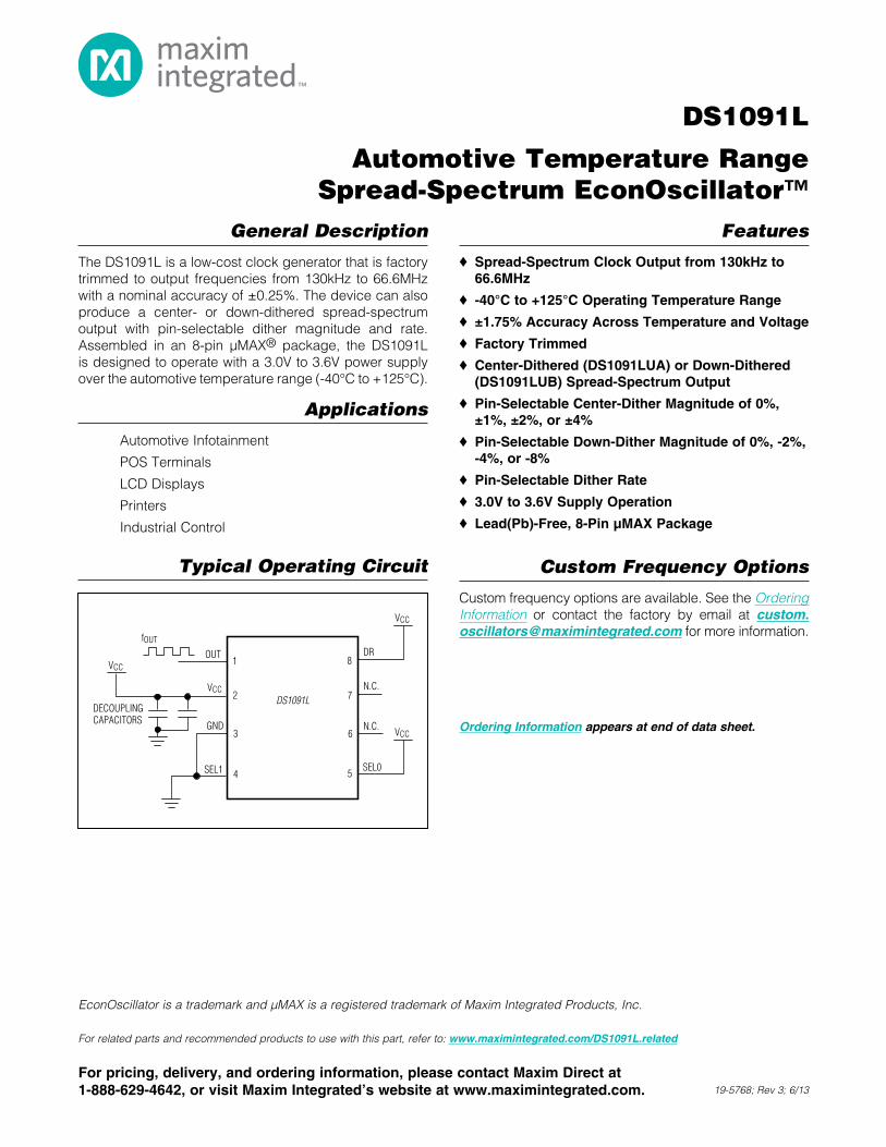
General Description
The DS1091L is a low-cost clock generator that is factory trimmed to output frequencies from 130kHz to 66.6MHz with a nominal accuracy of ±0.25%. The device can also produce a center- or down-dithered spread-spectrum output with pin-selectable dither magnitude and rate. Assembled in an 8-pin µMAX® package, the DS1091L is designed to operate with a 3.0V to 3.6V power supply over the automotive temperature range (-40°C to +125°C).
Applications
Automotive Infotainment
POS Terminals
LCD Displays
Printers
Industrial Control
Features
S Spread-Spectrum Clock Output from 130kHz to 66.6MHz
S -40°C to +125°C Operating Temperature Range
S ±1.75% Accuracy Across Temperature and Voltage
S Factory Trimmed
S Center-Dithered (DS1091LUA) or Down-Dithered (DS1091LUB) Spread-Spectrum Output
S Pin-Selectable Center-Dither Magnitude of 0%, ±1%, ±2%, or ±4%
S Pin-Selectable Down-Dither Magnitude of 0%, -2%, -4%, or -8%
S Pin-Selectable Dither Rate
S 3.0V to 3.6V Supply Operation
S Lead(Pb)-Free, 8-Pin µMAX Package
Custom Frequency Options
Custom frequency options are available. See the Ordering Information or contact the factory by email at [email protected] for more information.
19-5768; Rev 3; 6/13
Ordering Information appears at end of data sheet.
EconOscillator is a trademark and µMAX is a registered trademark of Maxim Integrated Products, Inc.
Typical Operating Circuit
For related parts and recommended products to use with this part, refer to: www.maximintegrated.com/DS1091L.related
8
3
4
2
1OUT DR
VCC
VCC
fOUT
DECOUPLINGCAPACITORS
7
6
5SEL0
VCCN.C.
N.C.
SEL1
GND
VCCDS1091L
For pricing, delivery, and ordering information, please contact Maxim Direct at 1-888-629-4642, or visit Maxim Integrated’s website at www.maximintegrated.com.
DS1091L
Automotive Temperature Range Spread-Spectrum EconOscillator™
2Maxim Integrated
Voltage Range on VCC Relative to Ground .........-0.5V to +6.0VVoltage Range on DR, SEL0, SEL1
Relativeto Ground ................................ -0.5V to (VCC + 0.5V)*Continuous Power Dissipation (TA = +70°C)
µMAX (derate 4.5mW/°C above +70°C) .....................362mW
Operating Temperature Range ........................ -40°C to +125°CStorage Temperature Range ............................ -55°C to +125°CLead Temperature (soldering, 10s) ................................+300°CSoldering Temperature (reflow) ......................................+260°C
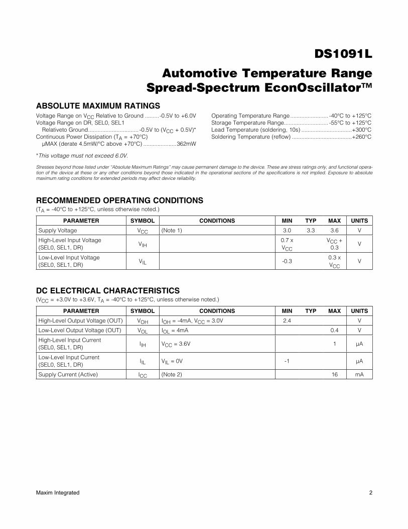
ABSOLUTE MAXIMUM RATINGS
Stresses beyond those listed under “Absolute Maximum Ratings” may cause permanent damage to the device. These are stress ratings only, and functional opera-tion of the device at these or any other conditions beyond those indicated in the operational sections of the specifications is not implied. Exposure to absolute maximum rating conditions for extended periods may affect device reliability.
RECOMMENDED OPERATING CONDITIONS(TA = -40NC to +125NC, unless otherwise noted.)
DC ELECTRICAL CHARACTERISTICS(VCC = +3.0V to +3.6V, TA = -40NC to +125NC, unless otherwise noted.)
*This voltage must not exceed 6.0V.
PARAMETER SYMBOL CONDITIONS MIN TYP MAX UNITS
Supply Voltage VCC (Note 1) 3.0 3.3 3.6 V
High-Level Input Voltage(SEL0, SEL1, DR)
VIH0.7 x VCC
VCC + 0.3
V
Low-Level Input Voltage(SEL0, SEL1, DR)
VIL -0.30.3 x VCC
V
PARAMETER SYMBOL CONDITIONS MIN TYP MAX UNITS
High-Level Output Voltage (OUT) VOH IOH = -4mA, VCC = 3.0V 2.4 V
Low-Level Output Voltage (OUT) VOL IOL = 4mA 0.4 V
High-Level Input Current(SEL0, SEL1, DR)
IIH VCC = 3.6V 1 FA
Low-Level Input Current(SEL0, SEL1, DR)
IIL VIL = 0V -1 FA
Supply Current (Active) ICC (Note 2) 16 mA
DS1091L
Automotive Temperature Range Spread-Spectrum EconOscillator™
3Maxim Integrated
Note 1: All voltages are referenced to ground. Currents entering the IC are specified positive and currents exiting the IC are negative.Note 2: Supply current measured with CL = 15pF, VCC = 3.6V, TA = +25°C, fOUT = 66.6MHz, no dither.Note 3: No dither.Note 4: Guaranteed by design.Note 5: For aging characteristics, contact factory.
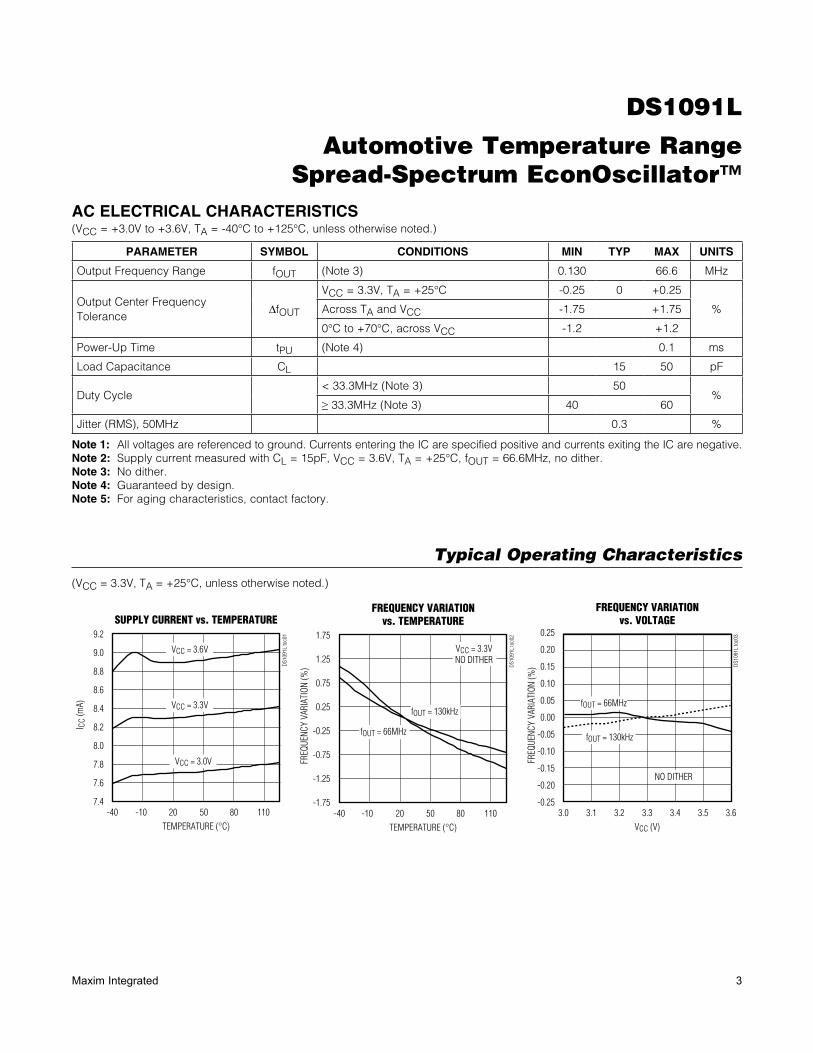
AC ELECTRICAL CHARACTERISTICS(VCC = +3.0V to +3.6V, TA = -40NC to +125NC, unless otherwise noted.)
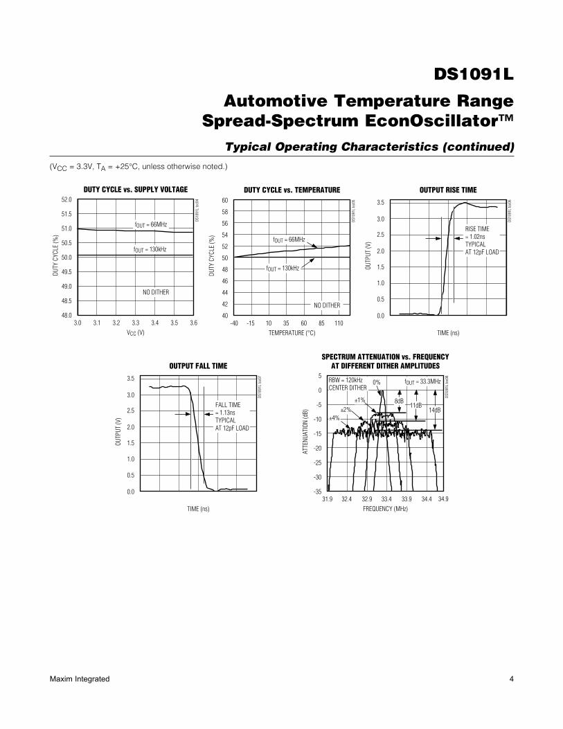
Typical Operating Characteristics
(VCC = 3.3V, TA = +25°C, unless otherwise noted.)
PARAMETER SYMBOL CONDITIONS MIN TYP MAX UNITS
Output Frequency Range fOUT (Note 3) 0.130 66.6 MHz
Output Center Frequency Tolerance
DfOUT
VCC = 3.3V, TA = +25NC -0.25 0 +0.25
%Across TA and VCC -1.75 +1.75
0NC to +70NC, across VCC -1.2 +1.2
Power-Up Time tPU (Note 4) 0.1 ms
Load Capacitance CL 15 50 pF
Duty Cycle< 33.3MHz (Note 3) 50
%R 33.3MHz (Note 3) 40 60
Jitter (RMS), 50MHz 0.3 %
7.4
7.8
7.6
8.4
8.2
8.0
9.0
8.8
8.6
9.2
-40 20-10 50 80 110
SUPPLY CURRENT vs. TEMPERATURE
DS1
091L
toc0
1
TEMPERATURE (°C)
I CC
(mA)
VCC = 3.6V
VCC = 3.3V
VCC = 3.0V
-1.75
-0.75
-1.25
0.25
-0.25
1.25
0.75
1.75
-40 20 50-10 80 110
FREQUENCY VARIATIONvs. TEMPERATURE
DS1
091L
toc0
2
TEMPERATURE (°C)
FREQ
UENC
Y VA
RIAT
ION
(%)
VCC = 3.3VNO DITHER
fOUT = 130kHz
fOUT = 66MHz
-0.25
-0.10
-0.15
-0.20
-0.05
0.00
0.05
0.10
0.15
0.20
0.25
3.0 3.23.1 3.3 3.4 3.5 3.6
FREQUENCY VARIATIONvs. VOLTAGE
DS1
091L
toc0
3
VCC (V)
FREQ
UENC
Y VA
RIAT
ION
(%)
fOUT = 66MHz
fOUT = 130kHz
NO DITHER
DS1091L
Automotive Temperature Range Spread-Spectrum EconOscillator™
4Maxim Integrated
Typical Operating Characteristics (continued)
(VCC = 3.3V, TA = +25°C, unless otherwise noted.)
48.0
48.5
49.0
49.5
50.0
50.5
51.0
51.5
52.0
3.0 3.23.1 3.3 3.4 3.5 3.6
DUTY CYCLE vs. SUPPLY VOLTAGED
S109
1L to
c04
VCC (V)
DUTY
CYC
LE (%
)
fOUT = 66MHz
fOUT = 130kHz
NO DITHER
40
46
44
42
50
48
58
56
54
52
60
-40 -15 10 35 60 85 110
DUTY CYCLE vs. TEMPERATURE
DS1
091L
toc0
5
TEMPERATURE (°C)
DUTY
CYC
LE (%
)
fOUT = 66MHz
fOUT = 130kHz
NO DITHER
0.0
0.5
1.0
1.5
2.0
2.5
3.0
3.5
OUTPUT RISE TIME
DS1
091L
toc0
6
TIME (ns)
OUTP
UT (V
)
RISE TIME= 1.02nsTYPICALAT 12pF LOAD
0.0
0.5
1.0
1.5
2.0
2.5
3.0
3.5
OUTPUT FALL TIME
DS1
091L
toc0
7
TIME (ns)
OUTP
UT (V
)
FALL TIME= 1.13nsTYPICALAT 12pF LOAD
-35
-30
-25
-20
-15
-10
-5
0
5
31.9 32.932.4 33.4 33.9 34.4 34.9
SPECTRUM ATTENUATION vs. FREQUENCYAT DIFFERENT DITHER AMPLITUDES
DS1
091L
toc0
8
FREQUENCY (MHz)
ATTE
NUAT
ION
(dB)
0%
±1%
±2%±4%
8dB11dB
14dB
fOUT = 33.3MHzRBW = 120kHzCENTER DITHER
DS1091L
Automotive Temperature Range Spread-Spectrum EconOscillator™
5Maxim Integrated
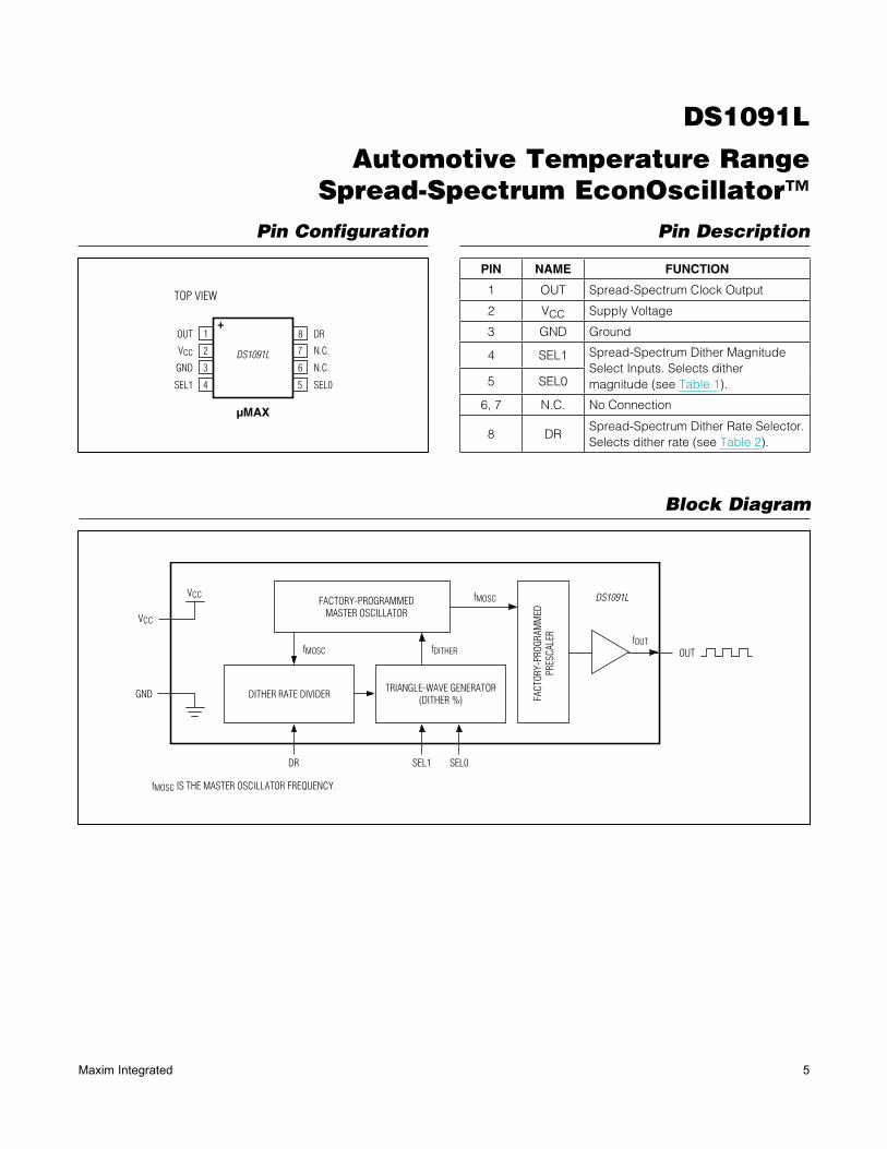
Pin Configuration Pin Description
Block Diagram
PIN NAME FUNCTION
1 OUT Spread-Spectrum Clock Output
2 VCC Supply Voltage
3 GND Ground
4 SEL1 Spread-Spectrum Dither Magnitude Select Inputs. Selects dither magnitude (see Table 1).5 SEL0
6, 7 N.C. No Connection
8 DRSpread-Spectrum Dither Rate Selector. Selects dither rate (see Table 2).
1
2
3
4
8
7
6
5
DR
N.C.
+
N.C.
SEL0SEL1
GND
VCC
OUT
µMAX
TOP VIEW
DS1091L
FACTORY-PROGRAMMEDMASTER OSCILLATOR
DITHER RATE DIVIDERTRIANGLE-WAVE GENERATOR
(DITHER %) FACT
ORY-
PROG
RAM
MED
PRES
CALE
R
SEL0SEL1DR
OUTfOUT
VCC
VCC
GND
fMOSC IS THE MASTER OSCILLATOR FREQUENCY.
fMOSC
fDITHERfMOSC
DS1091L
DS1091L
Automotive Temperature Range Spread-Spectrum EconOscillator™
6Maxim Integrated
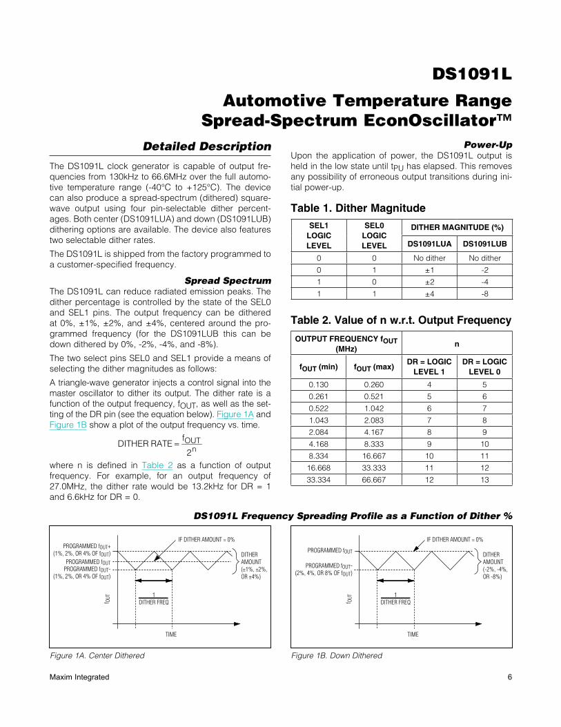
Detailed Description
The DS1091L clock generator is capable of output fre-quencies from 130kHz to 66.6MHz over the full automo-tive temperature range (-40°C to +125°C). The device can also produce a spread-spectrum (dithered) square-wave output using four pin-selectable dither percent-ages. Both center (DS1091LUA) and down (DS1091LUB) dithering options are available. The device also features two selectable dither rates.
The DS1091L is shipped from the factory programmed to a customer-specified frequency.
Spread SpectrumThe DS1091L can reduce radiated emission peaks. The dither percentage is controlled by the state of the SEL0 and SEL1 pins. The output frequency can be dithered at 0%, ±1%, ±2%, and ±4%, centered around the pro-grammed frequency (for the DS1091LUB this can be down dithered by 0%, -2%, -4%, and -8%).
The two select pins SEL0 and SEL1 provide a means of selecting the dither magnitudes as follows:
A triangle-wave generator injects a control signal into the master oscillator to dither its output. The dither rate is a function of the output frequency, fOUT, as well as the set-ting of the DR pin (see the equation below). Figure 1A and Figure 1B show a plot of the output frequency vs. time.
OUTn
fDITHER RATE
2=
where n is defined in Table 2 as a function of output frequency. For example, for an output frequency of 27.0MHz, the dither rate would be 13.2kHz for DR = 1 and 6.6kHz for DR = 0.
Power-UpUpon the application of power, the DS1091L output is held in the low state until tPU has elapsed. This removes any possibility of erroneous output transitions during ini-tial power-up.
DS1091L Frequency Spreading Profile as a Function of Dither %
Figure 1A. Center Dithered Figure 1B. Down Dithered
Table 1. Dither Magnitude
Table 2. Value of n w.r.t. Output Frequency
SEL1LOGIC LEVEL
SEL0LOGIC LEVEL
DITHER MAGNITUDE (%)
DS1091LUA DS1091LUB
0 0 No dither No dither
0 1 Q1 -2
1 0 Q2 -4
1 1 Q4 -8
OUTPUT FREQUENCY fOUT (MHz)
n
fOUT (min) fOUT (max)DR = LOGIC
LEVEL 1DR = LOGIC
LEVEL 0
0.130 0.260 4 5
0.261 0.521 5 6
0.522 1.042 6 7
1.043 2.083 7 8
2.084 4.167 8 9
4.168 8.333 9 10
8.334 16.667 10 11
16.668 33.333 11 12
33.334 66.667 12 13
TIME
1DITHER FREQ
PROGRAMMED fOUT+(1%, 2%, OR 4% OF fOUT)
PROGRAMMED fOUT-(1%, 2%, OR 4% OF fOUT)
PROGRAMMED fOUT
DITHERAMOUNT(±1%, ±2%,OR ±4%)
IF DITHER AMOUNT = 0%
f OUT
TIME
1DITHER FREQ
PROGRAMMED fOUT
PROGRAMMED fOUT-(2%, 4%, OR 8% OF fOUT)
DITHERAMOUNT(-2%, -4%,OR -8%)
IF DITHER AMOUNT = 0%
f OUT
DS1091L
Automotive Temperature Range Spread-Spectrum EconOscillator™
7Maxim Integrated
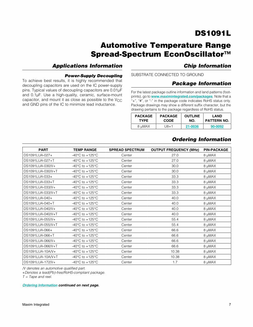
Applications Information
Power-Supply DecouplingTo achieve best results, it is highly recommended that decoupling capacitors are used on the IC power-supply pins. Typical values of decoupling capacitors are 0.01µF and 0.1µF. Use a high-quality, ceramic, surface-mount capacitor, and mount it as close as possible to the VCC and GND pins of the IC to minimize lead inductance.
Chip Information
SUBSTRATE CONNECTED TO GROUND
Package Information
For the latest package outline information and land patterns (foot-prints), go to www.maximintegrated.com/packages. Note that a “+”, “#”, or “-” in the package code indicates RoHS status only. Package drawings may show a different suffix character, but the drawing pertains to the package regardless of RoHS status.
Ordering Information
Ordering Information continued on next page.
/V denotes an automotive qualified part.+Denotes a lead(Pb)-free/RoHS-compliant package.T = Tape and reel.
PACKAGE TYPE
PACKAGE CODE
OUTLINE NO.
LAND PATTERN NO.
8 µMAX U8+1 21-0036 90-0092
PART TEMP RANGE SPREAD SPECTRUM OUTPUT FREQUENCY (MHz) PIN-PACKAGE
DS1091LUA-027+ -40NC to +125NC Center 27.0 8 FMAX
DS1091LUA-027+T -40NC to +125NC Center 27.0 8 FMAX
DS1091LUA-030/V+ -40NC to +125NC Center 30.0 8 FMAX
DS1091LUA-030/V+T -40NC to +125NC Center 30.0 8 FMAX
DS1091LUA-033+ -40NC to +125NC Center 33.3 8 FMAX
DS1091LUA-033+T -40NC to +125NC Center 33.3 8 FMAX
DS1091LUA-033/V+ -40NC to +125NC Center 33.3 8 FMAX
DS1091LUA-033/V+T -40NC to +125NC Center 33.3 8 FMAX
DS1091LUA-040+ -40NC to +125NC Center 40.0 8 FMAX
DS1091LUA-040+T -40NC to +125NC Center 40.0 8 FMAX
DS1091LUA-040/V+ -40NC to +125NC Center 40.0 8 FMAX
DS1091LUA-040/V+T -40NC to +125NC Center 40.0 8 FMAX
DS1091LUA-055/V+ -40NC to +125NC Center 55.4 8 FMAX
DS1091LUA-055/V+T -40NC to +125NC Center 55.4 8 FMAX
DS1091LUA-066+ -40NC to +125NC Center 66.6 8 FMAX
DS1091LUA-066+T -40NC to +125NC Center 66.6 8 FMAX
DS1091LUA-066/V+ -40NC to +125NC Center 66.6 8 FMAX
DS1091LUA-066/V+T -40NC to +125NC Center 66.6 8 FMAX
DS1091LUA-10A/V+ -40NC to +125NC Center 10.38 8 FMAX
DS1091LUA-10A/V+T -40NC to +125NC Center 10.38 8 FMAX
DS1091LUA-172/V+ -40NC to +125NC Center 1.7 8 FMAX
DS1091L
Automotive Temperature Range Spread-Spectrum EconOscillator™
8Maxim Integrated
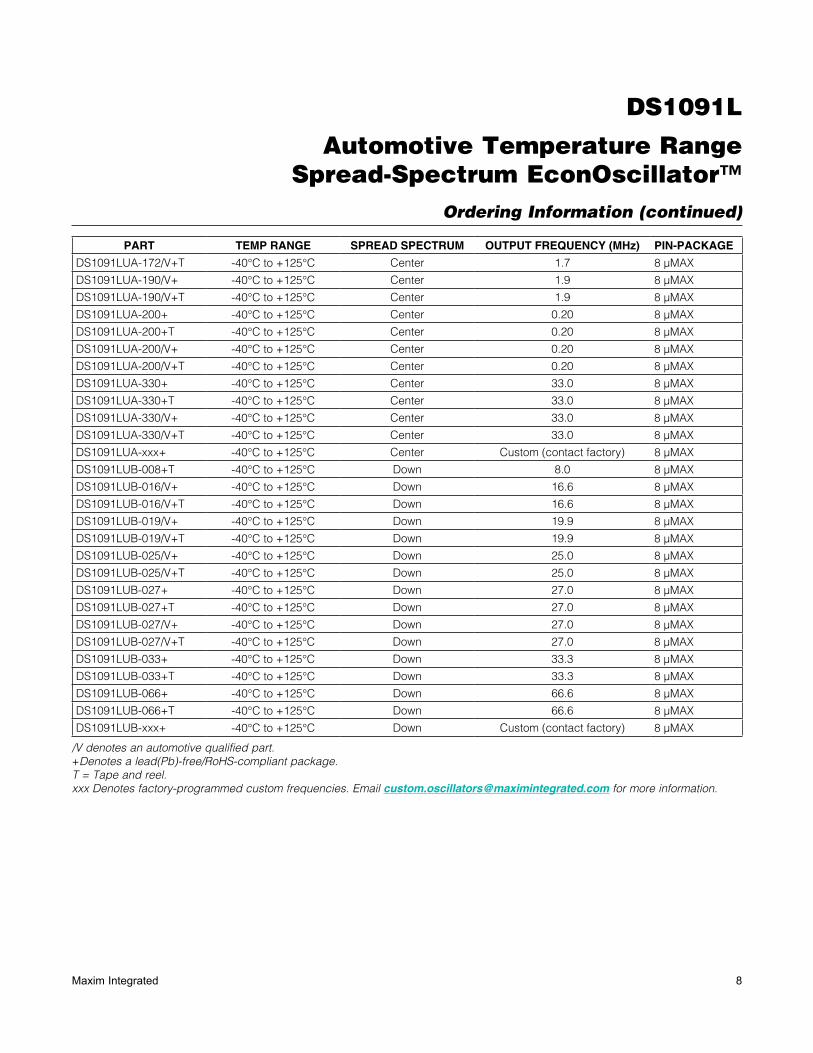
Ordering Information (continued)
/V denotes an automotive qualified part.+Denotes a lead(Pb)-free/RoHS-compliant package.T = Tape and reel.xxx Denotes factory-programmed custom frequencies. Email [email protected] for more information.
PART TEMP RANGE SPREAD SPECTRUM OUTPUT FREQUENCY (MHz) PIN-PACKAGE
DS1091LUA-172/V+T -40NC to +125NC Center 1.7 8 FMAX
DS1091LUA-190/V+ -40NC to +125NC Center 1.9 8 FMAX
DS1091LUA-190/V+T -40NC to +125NC Center 1.9 8 FMAX
DS1091LUA-200+ -40NC to +125NC Center 0.20 8 FMAX
DS1091LUA-200+T -40NC to +125NC Center 0.20 8 FMAX
DS1091LUA-200/V+ -40NC to +125NC Center 0.20 8 FMAX
DS1091LUA-200/V+T -40NC to +125NC Center 0.20 8 FMAX
DS1091LUA-330+ -40NC to +125NC Center 33.0 8 FMAX
DS1091LUA-330+T -40NC to +125NC Center 33.0 8 FMAX
DS1091LUA-330/V+ -40NC to +125NC Center 33.0 8 FMAX
DS1091LUA-330/V+T -40NC to +125NC Center 33.0 8 FMAX
DS1091LUA-xxx+ -40NC to +125NC Center Custom (contact factory) 8 FMAX
DS1091LUB-008+T -40NC to +125NC Down 8.0 8 FMAX
DS1091LUB-016/V+ -40NC to +125NC Down 16.6 8 FMAX
DS1091LUB-016/V+T -40NC to +125NC Down 16.6 8 FMAX
DS1091LUB-019/V+ -40NC to +125NC Down 19.9 8 FMAX
DS1091LUB-019/V+T -40NC to +125NC Down 19.9 8 FMAX
DS1091LUB-025/V+ -40NC to +125NC Down 25.0 8 FMAX
DS1091LUB-025/V+T -40NC to +125NC Down 25.0 8 FMAX
DS1091LUB-027+ -40NC to +125NC Down 27.0 8 FMAX
DS1091LUB-027+T -40NC to +125NC Down 27.0 8 FMAX
DS1091LUB-027/V+ -40NC to +125NC Down 27.0 8 FMAX
DS1091LUB-027/V+T -40NC to +125NC Down 27.0 8 FMAX
DS1091LUB-033+ -40NC to +125NC Down 33.3 8 FMAX
DS1091LUB-033+T -40NC to +125NC Down 33.3 8 FMAX
DS1091LUB-066+ -40NC to +125NC Down 66.6 8 FMAX
DS1091LUB-066+T -40NC to +125NC Down 66.6 8 FMAX
DS1091LUB-xxx+ -40NC to +125NC Down Custom (contact factory) 8 FMAX
DS1091L
Automotive Temperature Range Spread-Spectrum EconOscillator™
Maxim Integrated cannot assume responsibility for use of any circuitry other than circuitry entirely embodied in a Maxim Integrated product. No circuit patent licenses are implied. Maxim Integrated reserves the right to change the circuitry and specifications without notice at any time. The parametric values (min and max limits) shown in the Electrical Characteristics table are guaranteed. Other parametric values quoted in this data sheet are provided for guidance.
Maxim Integrated 160 Rio Robles, San Jose, CA 95134 USA 1-408-601-1000 9© 2013 Maxim Integrated Products, Inc. Maxim Integrated and the Maxim Integrated logo are trademarks of Maxim Integrated Products, Inc.
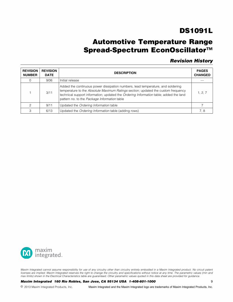
Revision History
REVISION NUMBER
REVISION DATE
DESCRIPTIONPAGES
CHANGED
0 9/06 Initial release —
1 3/11
Added the continuous power dissipation numbers, lead temperature, and soldering temperature to the Absolute Maximum Ratings section; updated the custom frequency technical support information; updated the Ordering Information table; added the land pattern no. to the Package Information table
1, 2, 7
2 9/11 Updated the Ordering Information table 7
3 6/13 Updated the Ordering Information table (adding rows) 7, 8
Mouser Electronics
Authorized Distributor
Click to View Pricing, Inventory, Delivery & Lifecycle Information: Maxim Integrated:
DS1091LUA-027+ DS1091LUA-027+T DS1091LUA-033+ DS1091LUA-033+T DS1091LUA-066+ DS1091LUA-
066+T DS1091LUB-027+ DS1091LUB-027+T DS1091LUB-033+ DS1091LUB-033+T DS1091LUB-066+
DS1091LUB-066+T DS1091LUA-033/V+ DS1091LUA-10A/V+ DS1091LUA-10A/V+T DS1091LUA-040/V+T
DS1091LUA-040+T DS1091LUA-200/V+ DS1091LUA-200/V+T DS1091LUA-200+ DS1091LUA-200+T DS1091LUA-
330/V+ DS1091LUA-330/V+T DS1091LUA-330+ DS1091LUA-330+T DS1091LUB-016/V+ DS1091LUB-016/V+T
DS1091LUB-019/V+ DS1091LUB-019/V+T DS1091LUB-025/V+ DS1091LUB-025/V+T DS1091LUB-027/V+
DS1091LUB-027/V+T DS1091LUA-030/V+ DS1091LUA-030/V+T DS1091LU-66+ DS1091LUA-033/V+T
DS1091LUB-008+T DS1091LUA-040/V+ DS1091LUA-040+ DS1091LUA-172/V+ DS1091LUA-190/V+ DS1091LUA-
055/V+T DS1091LUA-055/V+ DS1091LUA-190/V+T DS1091LUA-172/V+T