Embed Size (px)
Citation preview
DS-E Series(1~6KVA) User Manual

【NOTE】 Please carefully read the user’s manual before operation for the sake of understanding correct operation of the instrument. Please keep the manual handy for future reference.
The input and output of the instrument is with danger high voltages which may endanger the safety of life. Please strictly follow the operating description is not allowed to remove the cover of the instrument.
WARNING
1. Please connect protective earth before power supply cables. 2. The input & output voltage of the UPS is dangerous which will endanger the safety. 3. Dangerous voltages are present inside the unit. Please do not open the cover of the UPS. 4. Please turn off the mains input switch and the battery switch for any urgency. 5. There are many kinds of power sources in the equipment, the line bank or the socket may still
have dangerous voltage even if the main power is disconnected. 6. Please remove the cable between the battery & UPS before repairing. It’s necessary to wait
for another 5 minutes for discharging, because of the dangerous voltages. 7. The wires should be fastened to the terminals. It is prohibited to short the anode and cathode
of battery. It’s prohibited to touch any two of wire connectors or bare end of connecting wires. Otherwise, it may lead to damage of battery or personal injury.
8. Please keep the battery away from the fire and all the equipment that may cause spark to prevent the danger and damage.
9. Please do not open or shatter the battery, the overflow electrolyte is with causticity that may be harmful to life.
10. Please contact the professional personnel of the local dealer or the special maintenance station for any trouble-shooting. Random disposal of the trouble is not allowed.
11. This is an A-grade product with electromagnetic compatibility. 12. This equipment must be installed and serviced by qualified personnel. 13. Before you replace the battery of different brand and different type, make sure the charging
voltage is matching with UPS charging voltage due to the different required charging voltage of different battery, If any doubt, please consult with the manufacturer. Any changes of the system configuration, structure and composition will influence the performance of UPS, please consult with the manufacturer in prior before doing any changes.
14. Before usage, confirm that the temperature of the instrument has dropped into the normal run range. It is recommended still placement for 24 hours in the normal temperature range before startup.

Contents 1. Overview.......................................................................................................................................... 1
1.1 Profile........................................................................................................................................ 1
1.2 Model Meaning Explanation...................................................................................................... 1
1.3 Performance Index.................................................................................................................... 2
1.4 Primary Functions and Characteristics...................................................................................... 3
1.5 Precautions ............................................................................................................................... 4 2 .Structure and Basic Principles ......................................................................................................... 6
2.1 General Structure...................................................................................................................... 6
2.1.1 DS1000E Series Front Panel, Rear Panel Structure ........................................................6
2.1.2 DS2000E Series Front Panel, Rear Panel Structure ........................................................7
2.1.3 DS3000E Series Front Panel, Rear Panel Structure ........................................................7
2.1.4 DS6000E Series Display Interface, Front Panel, Rear Panel Structure............................8
2.2 Basic Principles........................................................................................................................11 3 .Equipment Installation ................................................................................................................... 12
3.1 Site and Environment Requirements....................................................................................... 12
3.1.1 Site Requirements ..........................................................................................................12
3.1.2 Environment Requirements ............................................................................................12
3.2 Procedures of Dismantling Cases........................................................................................... 13
3.3 Installation of UPS................................................................................................................... 13
3.4 Selection of Cable................................................................................................................... 14
3.4.1 Selection of Input Air Switch ...........................................................................................14
3.4.2 Selection of Input and Output Power Cord Diameter ......................................................15
3.5 Cable Connection.................................................................................................................... 15
3.5.1 DS1000E Series .............................................................................................................15
3.5.2 DS2000E Series .............................................................................................................16
3.5.3 DS3000E Series .............................................................................................................17
3.5.4 DS6000E Series .............................................................................................................17
3.5.5 Inspection of Electric Connection ...................................................................................18 4 . Equipment Use and Maintenance................................................................................................. 20
4.1 Preparations before First Start-up ........................................................................................... 20
4.2 UPS Start-up Sequence...........................................................................................................20
4.3 Daily Start-up and Shutdown ...................................................................................................21
4.4 Battery Daily Maintenance.......................................................................................................21
4.5 Battery Changing .....................................................................................................................22
4.6 Maintenance Guide..................................................................................................................22
4.6.1 Safety Precaution ...........................................................................................................23
4.6.2 Preventive and Regular Maintenance ............................................................................23
4.6.3 FAQ ................................................................................................................................24
4.7 Troubleshooting .......................................................................................................................26
4.7.1 Overview ........................................................................................................................26
4.7.2 Troubleshooting..............................................................................................................26 5 . Packing, Transportation and Storage.............................................................................................28
5.1 Packing....................................................................................................................................28
5.2 Transportation..........................................................................................................................28
5.3 Storage ....................................................................................................................................28
1
1. Overview
1.1 Profile
DS-E series UPS are total high frequency, pure online and intellectualized UPS.
They are also ideal power guarantee for file server, enterprise server, central
server, microcomputer, concentrator, telecommunication system, data center,
medical facilities and those requiring high quality power protections. They can
be widely used in many key business areas such as post & telecom, finance,
network, securities and railway, etc.
DS-E series UPS are single-phase alternating current input and output. Each
series has two products including standard time delay model and long time
delay model.
1.2 Model Meaning Explanation The model DS1000/2000/3000E(L) meaning of UPS products. in which
nominal output capacity item"1000" means the output capacity is 1kVA, while
"3000" means the output capacity is 3kVA, etc. Models ended with a character
"L" represent long time delay model, while those ended without "L" represent
standard time delay model.
DS-E Series(1~6KVA)User’s Manual
2
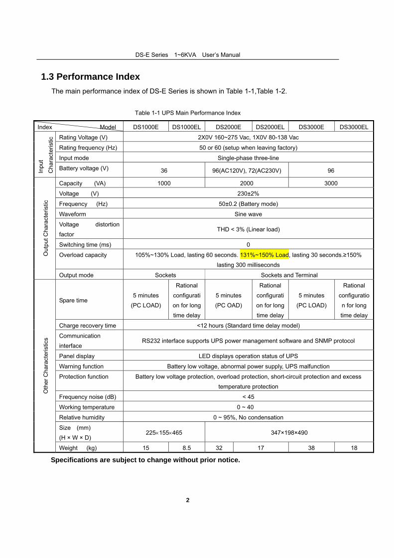
1.3 Performance Index The main performance index of DS-E Series is shown in Table 1-1,Table 1-2.
Table 1-1 UPS Main Performance Index
Index Model DS1000E DS1000EL DS2000E DS2000EL DS3000E DS3000EL
Rating Voltage (V) 2X0V 160~275 Vac, 1X0V 80-138 Vac
Rating frequency (Hz) 50 or 60 (setup when leaving factory)
Input mode Single-phase three-line
Inpu
t
Cha
ract
eris
tic
Battery voltage (V) 36 96(AC120V), 72(AC230V) 96
Capacity (VA) 1000 2000 3000
Voltage (V) 230±2%
Frequency (Hz) 50±0.2 (Battery mode)
Waveform Sine wave
Voltage distortion
factor THD < 3% (Linear load)
Switching time (ms) 0
Overload capacity 105%~130% Load, lasting 60 seconds. 131%~150% Load, lasting 30 seconds.≥150%
lasting 300 milliseconds
Out
put C
hara
cter
istic
Output mode Sockets Sockets and Terminal
Spare time 5 minutes
(PC LOAD)
Rational
configurati
on for long
time delay
5 minutes
(PC OAD)
Rational
configurati
on for long
time delay
5 minutes
(PC LOAD)
Rational
configuratio
n for long
time delay
Charge recovery time <12 hours (Standard time delay model)
Communication
interface RS232 interface supports UPS power management software and SNMP protocol
Panel display LED displays operation status of UPS
Warning function Battery low voltage, abnormal power supply, UPS malfunction
Protection function Battery low voltage protection, overload protection, short-circuit protection and excess
temperature protection
Frequency noise (dB) < 45
Working temperature 0 ~ 40℃
Relative humidity 0 ~ 95%, No condensation
Size (mm)
(H × W × D) 225×155×465 347×198×490
Oth
er C
hara
cter
istic
s
Weight (kg) 15 8.5 32 17 38 18
◆ Specifications are subject to change without prior notice.
DS-E Series(1~6KVA)User’s Manual
3
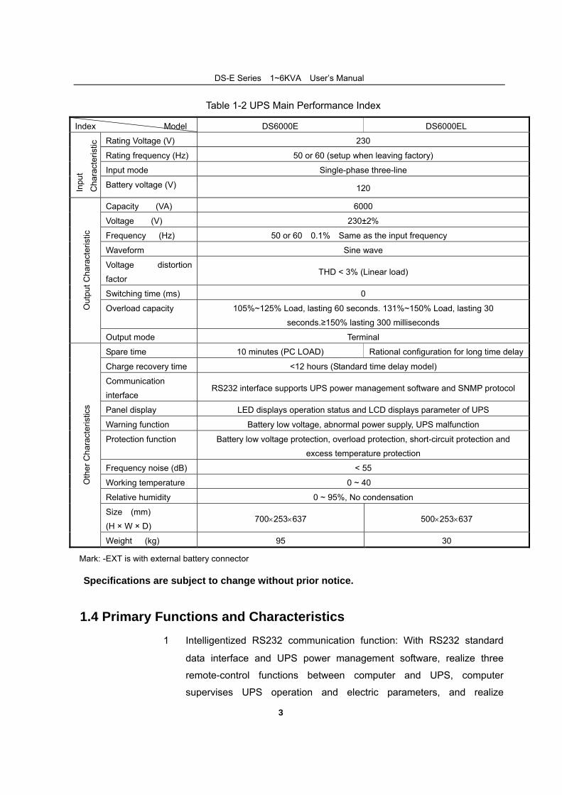
Table 1-2 UPS Main Performance Index
Index Model DS6000E DS6000EL
Rating Voltage (V) 230
Rating frequency (Hz) 50 or 60 (setup when leaving factory)
Input mode Single-phase three-line
Inpu
t
Cha
ract
eris
tic
Battery voltage (V) 120
Capacity (VA) 6000
Voltage (V) 230±2%
Frequency (Hz) 50 or 60±0.1%(Same as the input frequency)
Waveform Sine wave
Voltage distortion
factor THD < 3% (Linear load)
Switching time (ms) 0
Overload capacity 105%~125% Load, lasting 60 seconds. 131%~150% Load, lasting 30
seconds.≥150% lasting 300 milliseconds
Out
put C
hara
cter
istic
Output mode Terminal
Spare time 10 minutes (PC LOAD) Rational configuration for long time delay
Charge recovery time <12 hours (Standard time delay model)
Communication
interface RS232 interface supports UPS power management software and SNMP protocol
Panel display LED displays operation status and LCD displays parameter of UPS
Warning function Battery low voltage, abnormal power supply, UPS malfunction
Protection function Battery low voltage protection, overload protection, short-circuit protection and
excess temperature protection
Frequency noise (dB) < 55
Working temperature 0 ~ 40℃
Relative humidity 0 ~ 95%, No condensation
Size (mm)
(H × W × D) 700×253×637 500×253×637
Oth
er C
hara
cter
istic
s
Weight (kg) 95 30
Mark: -EXT is with external battery connector
◆Specifications are subject to change without prior notice.
1.4 Primary Functions and Characteristics 1. Intelligentized RS232 communication function: With RS232 standard
data interface and UPS power management software, realize three
remote-control functions between computer and UPS, computer
supervises UPS operation and electric parameters, and realize
DS-E Series(1~6KVA)User’s Manual
4
long-distance power on/off function, as well as supporting SNMP
network adaptor (outlaid, connecting UPS through RS232 interface),
which enables UPS to directly become network fresh blood.
2. High input power factor: Adopt advanced active PFC technique, which
alleviates load on electric network and represents green power supply of
new generation.
3. High performance-price ratio: Adopts multiple power transfer and high
frequency PWM technique, high efficiency, small size and light weight as
well as improving operational reliability and reducing manufacturing cost,
which lowers the cost of the system design for customers.
4. Perfect protection function: Possess such functions as output
overvoltage protection, battery under voltage protection, input
overvoltage protection and triple overflowing protection, etc and
overcome previous defects such as high frequency UPS' poor
adaptability and weak resistance to shock for electric network.
5. Low commercial power input voltage: Adopt independent quick detection
technique, even at the lower limit 120V of commercial power, the battery
remains off discharge, thus all energy output are taken from electric
network, ensuring the battery in the state with 100% energy storage,
while at the same time decreasing the battery discharge times and
prolonging its life.
1.5 Precautions
Abide by the following general safety precaution during operation or
maintenance.
1. Please don't remove the cover. This system can only be maintained or
repaired by professional maintenance personnel.
2. Protective ground terminals should be connected to earth end for sure.
3. High creepage danger! Connect to the ground before connecting UPS.
4. Install this UPS indoors with both temperature and humidity under
control and without dust.
DS-E Series(1~6KVA)User’s Manual
5
5. The electric power of this UPS has multiple sources. Before maintaining,
cut the alternating current, exterior battery or interior battery's air switch
to isolate the input energy.
6. Even if the AC power supply has been cut off, the danger from battery's
high voltage inside the UPS still exists.
7. If battery circuit has not been isolated from AC input, dangerous voltage
may possibly exists between battery terminal and ground terminal.
8. High voltage endangering personal safety exists in the storage battery
of this UPS. Please pay attention to insulation during installation and
use.
9. Improper handling of acidic battery leads to leakage risk of chemistry
dangerous substance and corrosive liquid.
10. Dripping condensation should be happen if machine was operated under
low-temperature environment. So please install and use machine when
machine was full-dry, or there will has dangerous of electric shock.
Warning: Input and output voltage of this equipment is dangerous high
voltage, which can endanger personal life or safety. Please read
carefully this Manual during installation, operation and before use. Pay
attention to various caution nameplates and caution statements.
Professional maintenance personnel without proper authorization are
not allowed to remove off the case cover of this equipment.
6
2 .Structure and Basic Principles
2.1 General Structure
2.1.1 DS1000E Series Front Panel, Rear Panel Structure
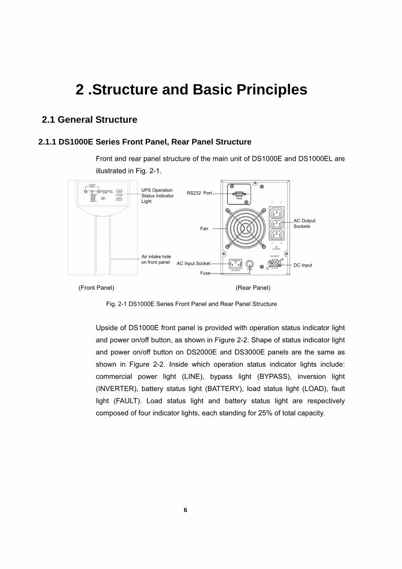
Front and rear panel structure of the main unit of DS1000E and DS1000EL are
illustrated in Fig. 2-1.
AC Input Socket DC Input
AC OutputSockets
Fuse
RS232 Port
Fan
FUSEAC INPUT
DC INPUT
AC OUTPUT
RS232
UPS Operation Status Indicator Light
Air intake hole on front panel
(Front Panel) (Rear Panel)
Fig. 2-1 DS1000E Series Front Panel and Rear Panel Structure
Upside of DS1000E front panel is provided with operation status indicator light
and power on/off button, as shown in Figure 2-2. Shape of status indicator light
and power on/off button on DS2000E and DS3000E panels are the same as
shown in Figure 2-2. Inside which operation status indicator lights include:
commercial power light (LINE), bypass light (BYPASS), inversion light
(INVERTER), battery status light (BATTERY), load status light (LOAD), fault
light (FAULT). Load status light and battery status light are respectively
composed of four indicator lights, each standing for 25% of total capacity.
DS-E Series(1~6KVA)User’s Manual
7
BYPASS
INVLINE LOAD 100%100%
BAT
ON
POWER
OFFFAULT
Fig. 2-2 DS1000E Panel Indicator
2.1.2 DS2000E Series Front Panel, Rear Panel Structure
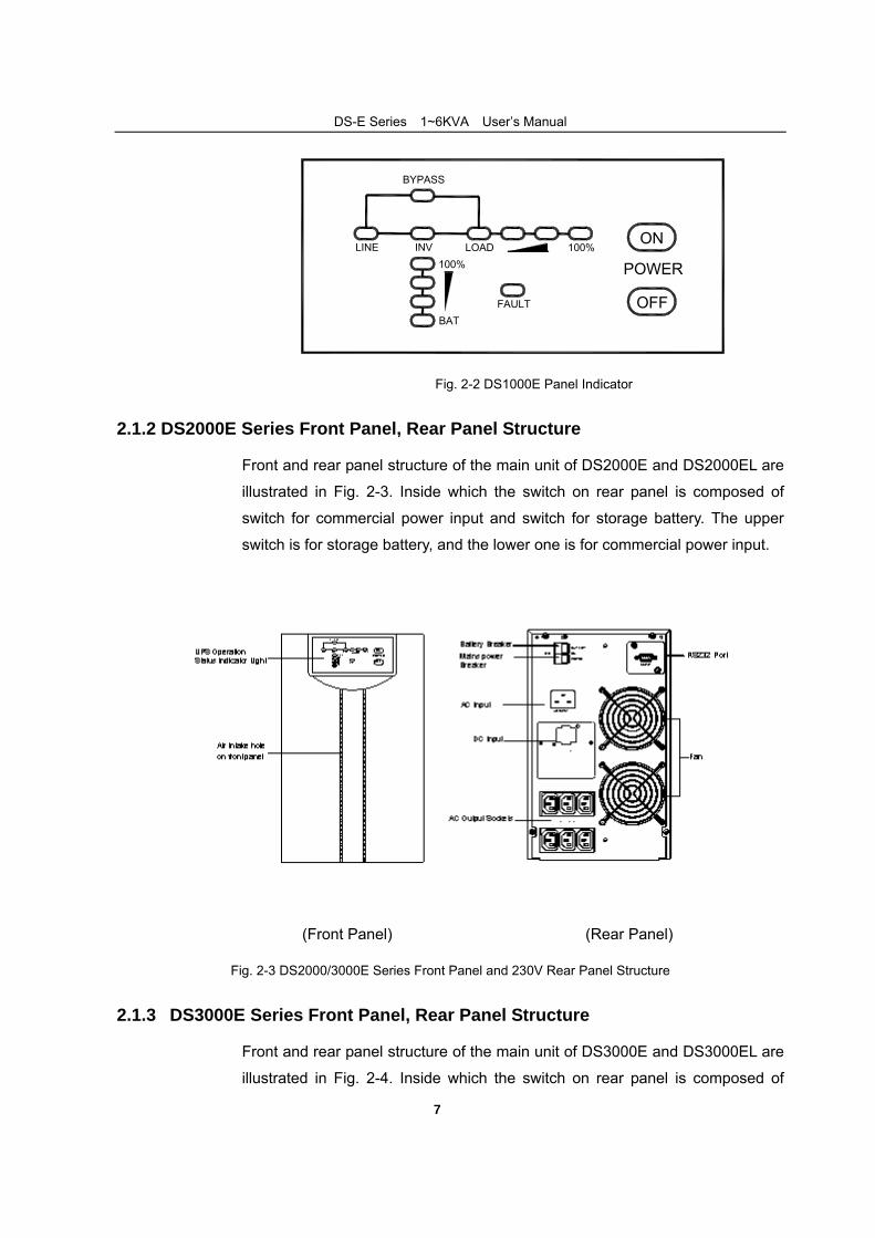
Front and rear panel structure of the main unit of DS2000E and DS2000EL are
illustrated in Fig. 2-3. Inside which the switch on rear panel is composed of
switch for commercial power input and switch for storage battery. The upper
switch is for storage battery, and the lower one is for commercial power input.
(Front Panel) (Rear Panel)
Fig. 2-3 DS2000/3000E Series Front Panel and 230V Rear Panel Structure
2.1.3 DS3000E Series Front Panel, Rear Panel Structure
Front and rear panel structure of the main unit of DS3000E and DS3000EL are
illustrated in Fig. 2-4. Inside which the switch on rear panel is composed of
DS-E Series(1~6KVA)User’s Manual
8
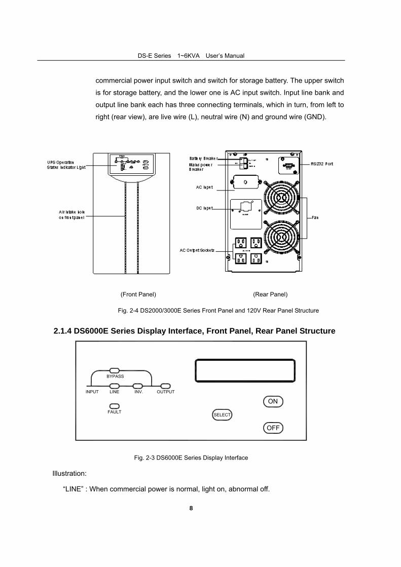
commercial power input switch and switch for storage battery. The upper switch
is for storage battery, and the lower one is AC input switch. Input line bank and
output line bank each has three connecting terminals, which in turn, from left to
right (rear view), are live wire (L), neutral wire (N) and ground wire (GND).
(Front Panel) (Rear Panel)
Fig. 2-4 DS2000/3000E Series Front Panel and 120V Rear Panel Structure
2.1.4 DS6000E Series Display Interface, Front Panel, Rear Panel Structure
INV.LINE
BYPASS
OUTPUT
SELECT
ON
OFF
FAULT
INPUT
① ② ③
④
⑤
⑥
⑦⑧
⑨
Fig. 2-3 DS6000E Series Display Interface
Illustration:
① “LINE” : When commercial power is normal, light on, abnormal off.
DS-E Series(1~6KVA)User’s Manual
9
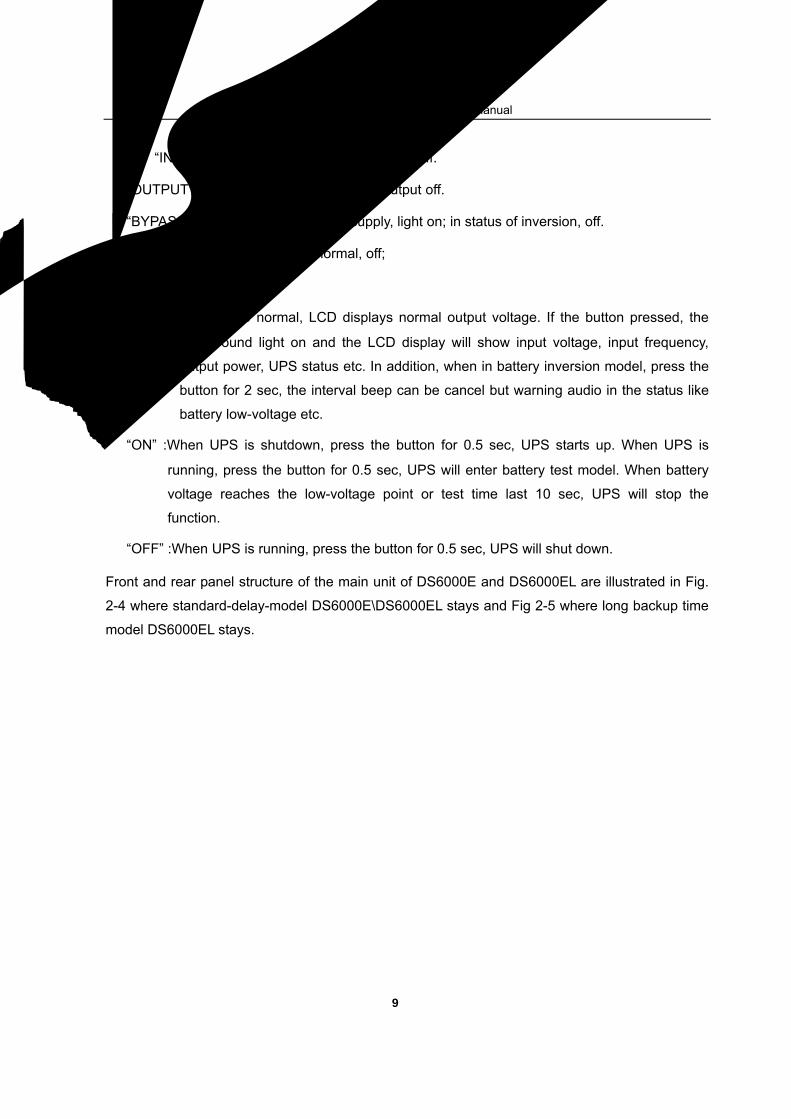
② “INV.” : Inverter normal, light on, abnormal off.
③ “OUTPUT” : UPS has output, light on; no output off.
④ “BYPASS” :UPS in status of bypass supply, light on; in status of inversion, off.
⑤ “FAULT” :UPS fault, light on; normal, off;
⑥ LCD Display
⑦ Select”: When UPS normal, LCD displays normal output voltage. If the button pressed, the
background light on and the LCD display will show input voltage, input frequency,
output power, UPS status etc. In addition, when in battery inversion model, press the
button for 2 sec, the interval beep can be cancel but warning audio in the status like
battery low-voltage etc.
⑧ “ON” :When UPS is shutdown, press the button for 0.5 sec, UPS starts up. When UPS is
running, press the button for 0.5 sec, UPS will enter battery test model. When battery
voltage reaches the low-voltage point or test time last 10 sec, UPS will stop the
function.
⑨ “OFF” :When UPS is running, press the button for 0.5 sec, UPS will shut down.
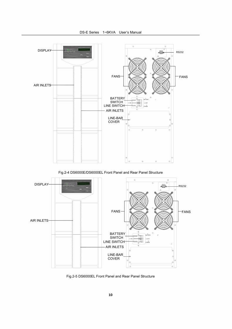
Front and rear panel structure of the main unit of DS6000E and DS6000EL are illustrated in Fig.
2-4 where standard-delay-model DS6000E\DS6000EL stays and Fig 2-5 where long backup time
model DS6000EL stays.
DS-E Series(1~6KVA)User’s Manual
10
开/ON 关/OFF
POWER市电
BATTERY电池
RS232INPUT
FAULT
OFF
ON
SELECT
OUTPUT
BYPASS
LINE INV.DISPLAY
AIR INLETS
AIR INLETS
FANS
BATTERYSWITCH
LINE SWITCH
FANS
RS232
LINE-BAR COVER
Fig.2-4 DS6000E/DS6000EL Front Panel and Rear Panel Structure
INPUT
FAULT
OFF
ON
SELECT
OUTPUT
BYPASS
LINE INV.
开/ON 关/OFF
POWER市电
BATTERY电池
RS232DISPLAY
AIR INLETS
AIR INLETS
FANS
BATTERYSWITCH
LINE SWITCH
FANS
RS232
LINE-BAR COVER
Fig.2-5 DS6000EL Front Panel and Rear Panel Structure
DS-E Series(1~6KVA)User’s Manual
11
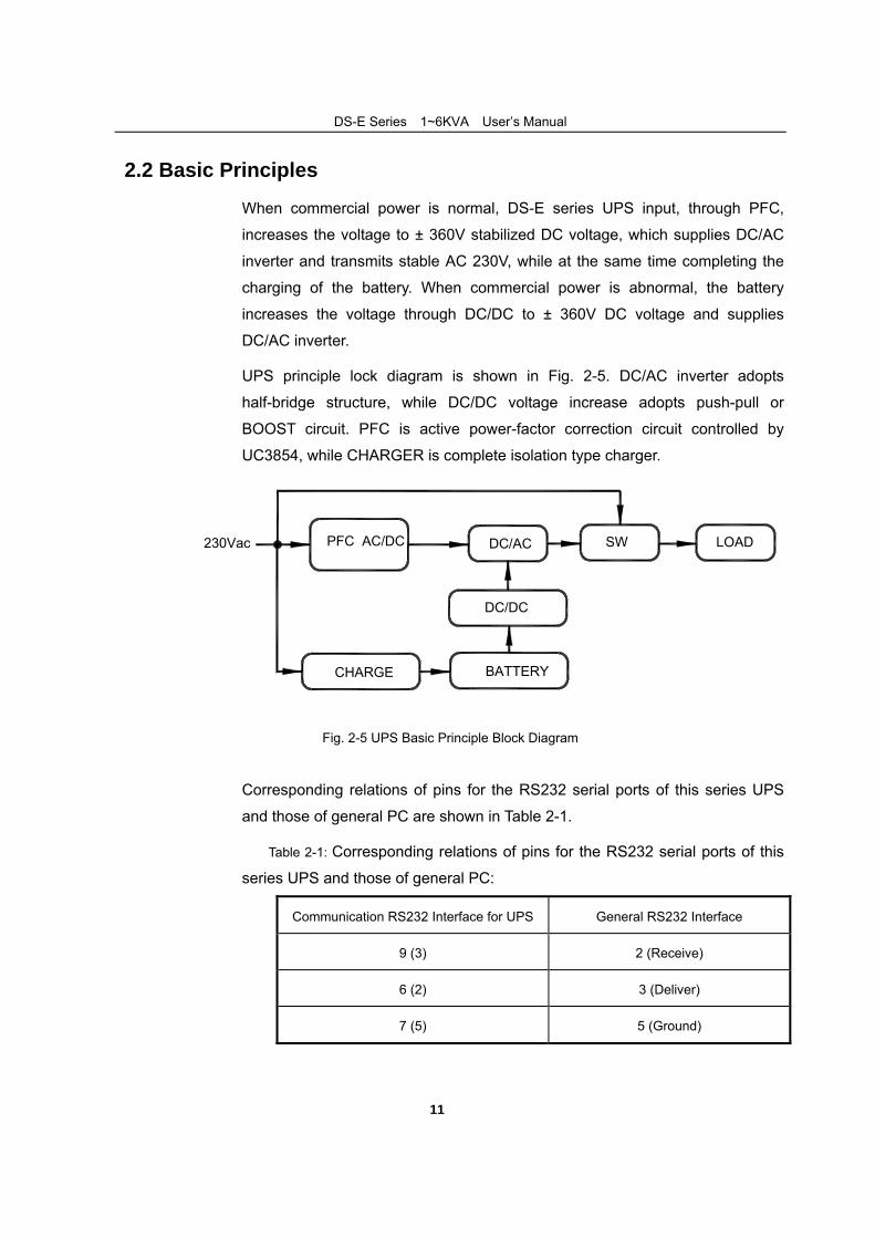
2.2 Basic Principles
When commercial power is normal, DS-E series UPS input, through PFC,
increases the voltage to ± 360V stabilized DC voltage, which supplies DC/AC
inverter and transmits stable AC 230V, while at the same time completing the
charging of the battery. When commercial power is abnormal, the battery
increases the voltage through DC/DC to ± 360V DC voltage and supplies
DC/AC inverter.
UPS principle lock diagram is shown in Fig. 2-5. DC/AC inverter adopts
half-bridge structure, while DC/DC voltage increase adopts push-pull or
BOOST circuit. PFC is active power-factor correction circuit controlled by
UC3854, while CHARGER is complete isolation type charger.
CHARGE
PFC AC/DC SW
BATTERY
DC/DC
DC/AC LOAD230Vac
Fig. 2-5 UPS Basic Principle Block Diagram
Corresponding relations of pins for the RS232 serial ports of this series UPS
and those of general PC are shown in Table 2-1.
Table 2-1: Corresponding relations of pins for the RS232 serial ports of this
series UPS and those of general PC:
Communication RS232 Interface for UPS General RS232 Interface
9 (3) 2 (Receive)
6 (2) 3 (Deliver)
7 (5) 5 (Ground)
12
3 .Equipment Installation
3.1 Site and Environment Requirements
Before UPS installation, the site and environment of equipment room should
meet the essential conditions for safe and normal operation of equipment as
defined in this section. If the customer’s site conditions are not accord with the
minimum requirement of safe equipment operation, the customer should make
corresponding changes to the site conditions, and install the equipment only
after meeting the conditions of safe and normal equipment operation.
3.1.1 Site Requirements
The site conditions should accord with the essential conditions of safe and
normal equipment operation as stated in this section.
1.The equipment room must be equipped with applicable and effective fire
apparatus;
2.The commercial power, which supplies power for UPS, should be equipped
with dedicated air switch or utility socket;
3.Strictly prohibit to storing dangerous things, such as inflammable things,
explosive things in the equipment room;
4.Before equipment installation, the ground wire should be prepared. The
voltage of neutral wire and ground wire of commercial power cannot
exceed 5V;
5.The civil engineering construction of the equipment room should be
completed totally, and the floor should be sclerotic. The site must be tidy
and dry without dust.
3.1.2 Environment Requirements Ambient temperature: 0℃~+40 ;℃
Relative humidity: 0%RH~95%RH, no condensation;
Cooling mode: air-cooling;
Verticality: no shock with orthogonal rake not exceeding 5º.
DS-E Series(1~6KVA)User’s Manual
13
3.2 Procedures of Dismantling Cases
When installing the equipment, the packing should be removed after carrying
the equipment to the installation site. The packing of UPS equipment and
fittings (battery, etc.) should be wooden case and carton. Check the UPS
equipment and fittings against the shipping list.
If the equipment or fittings are damaged during transportation or the equipment
and fittings are not accord with the ordering contract, make site record in time
and immediately contact the local office or distributors.
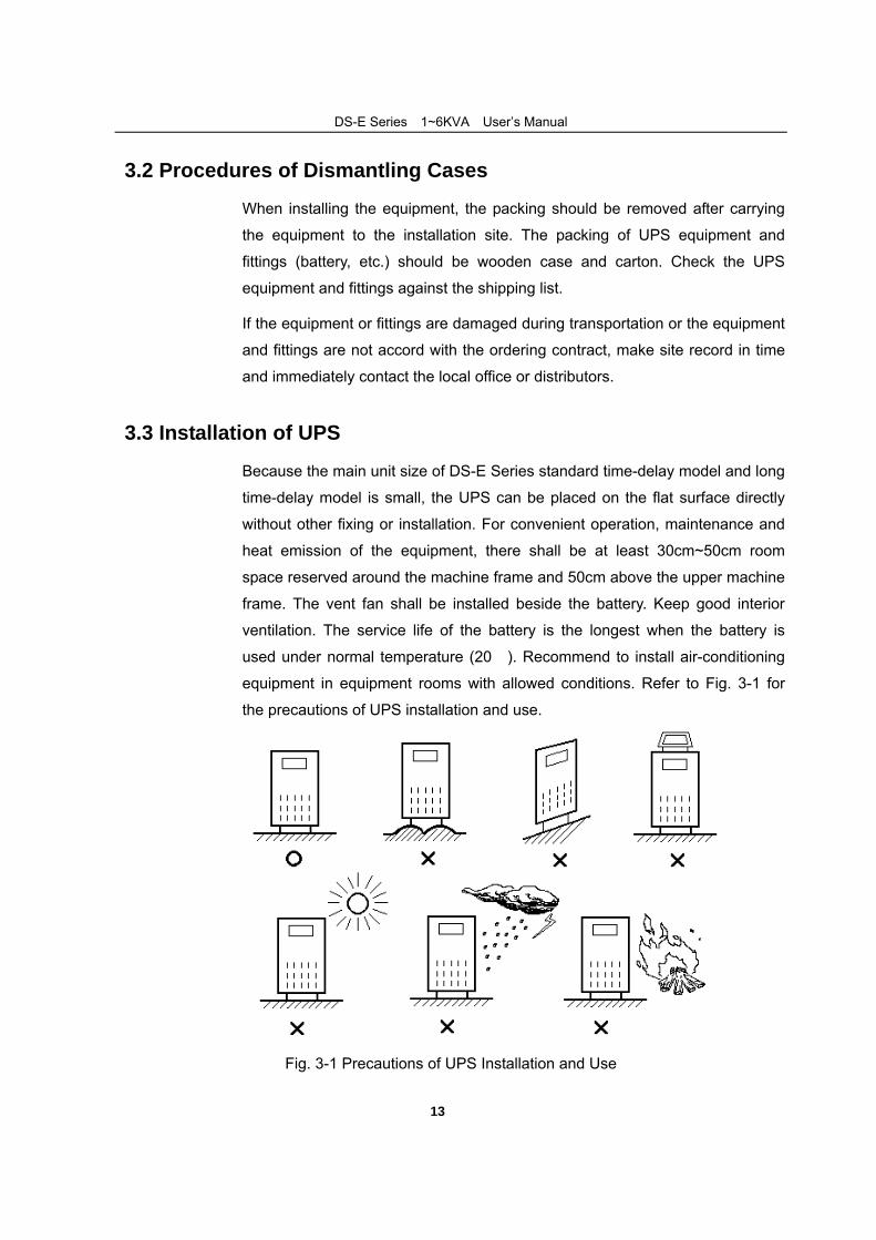
3.3 Installation of UPS
Because the main unit size of DS-E Series standard time-delay model and long
time-delay model is small, the UPS can be placed on the flat surface directly
without other fixing or installation. For convenient operation, maintenance and
heat emission of the equipment, there shall be at least 30cm~50cm room
space reserved around the machine frame and 50cm above the upper machine
frame. The vent fan shall be installed beside the battery. Keep good interior
ventilation. The service life of the battery is the longest when the battery is
used under normal temperature (20℃). Recommend to install air-conditioning
equipment in equipment rooms with allowed conditions. Refer to Fig. 3-1 for
the precautions of UPS installation and use.
Fig. 3-1 Precautions of UPS Installation and Use
DS-E Series(1~6KVA)User’s Manual
14
1.Place UPS on flat floor (avoid oblique and ragged floor).
2.Keep good ventilation, the distance of the back and side to the wall should
be above 30cm~50cm, to facilitate heat emission.
3.Avoid placing it in the location with sunniness, rain and dampness.
4.Never place it in the location with corrosive air.
5.Do not place articles on or around the UPS, to prevent the vent hole from being blocked. No person is allowed to sit on it.
3.4 Selection of Cable
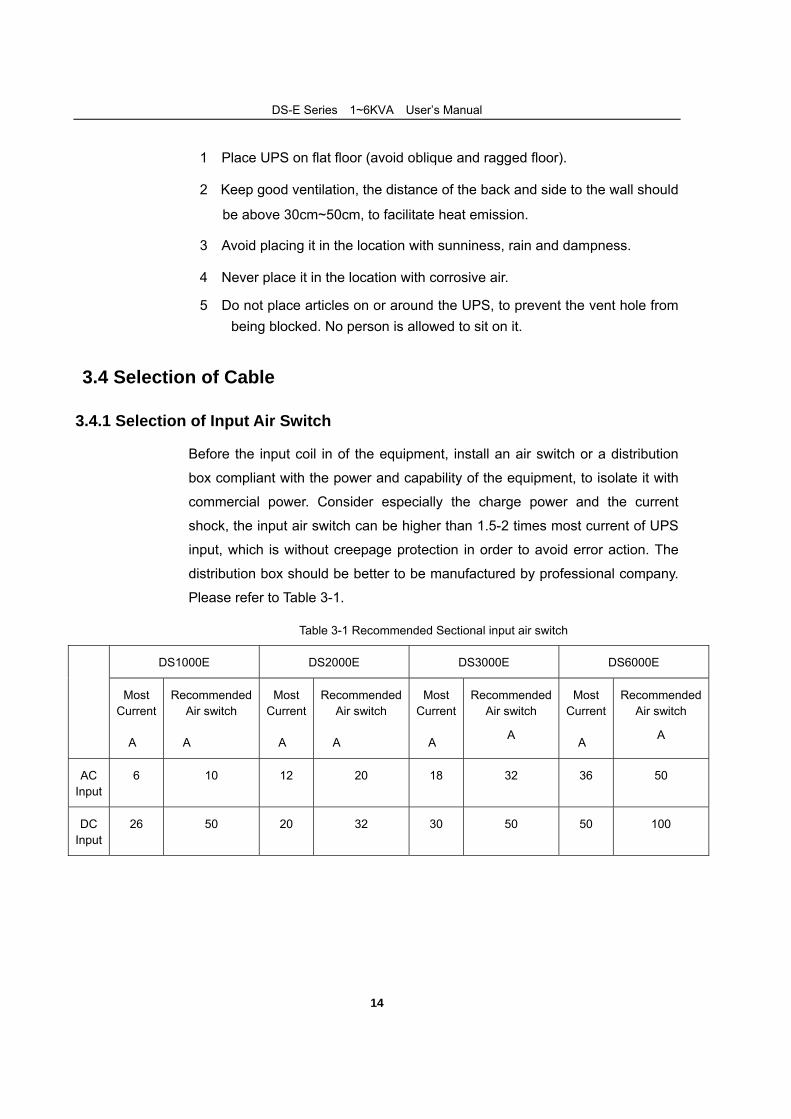
3.4.1 Selection of Input Air Switch
Before the input coil in of the equipment, install an air switch or a distribution
box compliant with the power and capability of the equipment, to isolate it with
commercial power. Consider especially the charge power and the current
shock, the input air switch can be higher than 1.5-2 times most current of UPS
input, which is without creepage protection in order to avoid error action. The
distribution box should be better to be manufactured by professional company.
Please refer to Table 3-1.
Table 3-1 Recommended Sectional input air switch
DS1000E DS2000E DS3000E DS6000E
Most Current
(A)
Recommended Air switch
(A)
Most Current
(A)
Recommended Air switch
(A)
Most Current
(A)
Recommended Air switch
(A)
Most Current
(A)
Recommended Air switch
(A)
AC Input
6 10 12 20 18 32 36 50
DC Input
26 50 20 32 30 50 50 100
DS-E Series(1~6KVA)User’s Manual
15
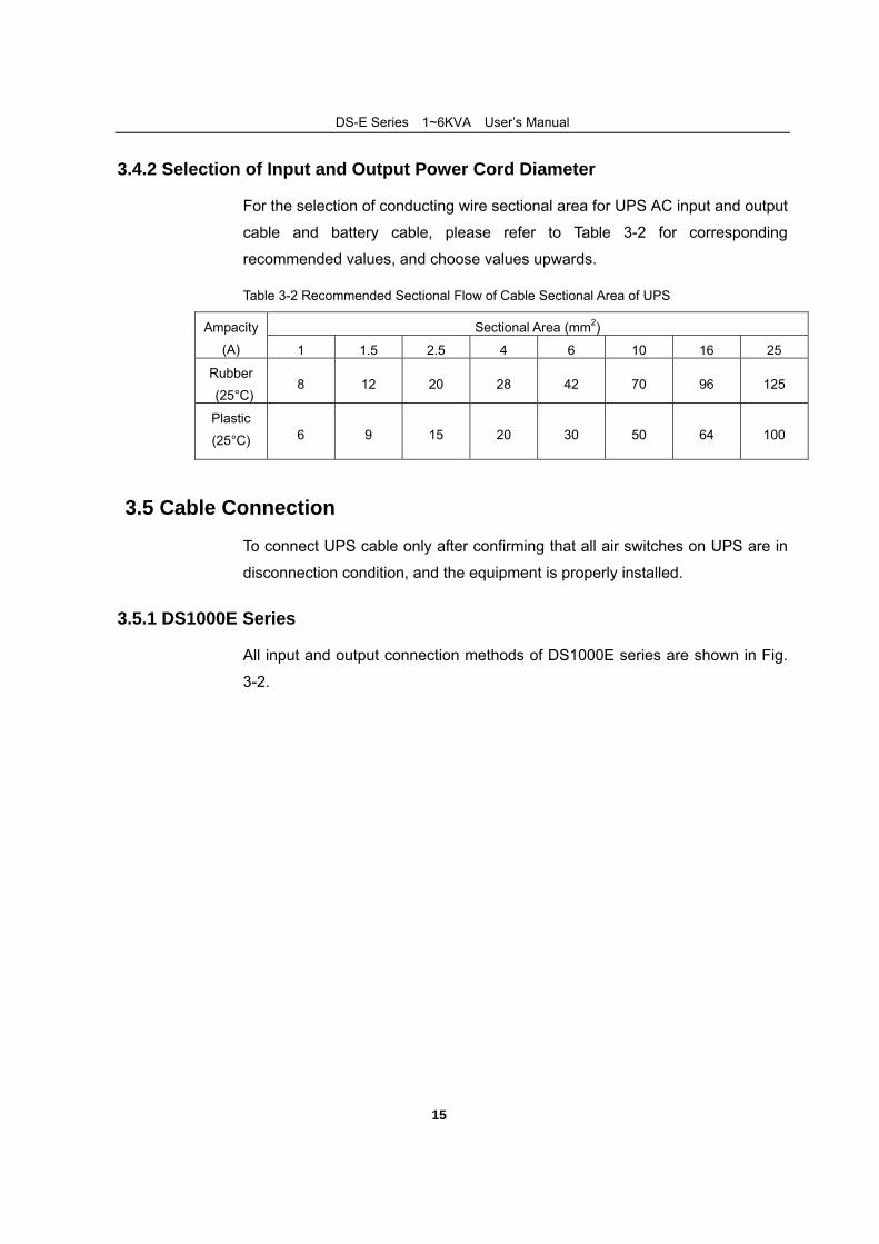
3.4.2 Selection of Input and Output Power Cord Diameter
For the selection of conducting wire sectional area for UPS AC input and output
cable and battery cable, please refer to Table 3-2 for corresponding
recommended values, and choose values upwards.
Table 3-2 Recommended Sectional Flow of Cable Sectional Area of UPS
Sectional Area (mm2) Ampacity
(A) 1 1.5 2.5 4 6 10 16 25
Rubber
(25°C) 8 12 20 28 42 70 96 125
Plastic
(25°C) 6 9 15 20 30 50 64 100
3.5 Cable Connection
To connect UPS cable only after confirming that all air switches on UPS are in
disconnection condition, and the equipment is properly installed.
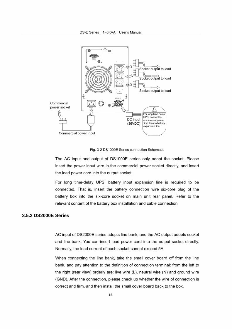
3.5.1 DS1000E Series
All input and output connection methods of DS1000E series are shown in Fig.
3-2.
DS-E Series(1~6KVA)User’s Manual
16
Socket output to load
Commercial power input
DC input(36VDC)
For long time-delay UPS, connect to commercial powerfirst, then to battery expansion line.
!
Socket output to load
Socket output to load
Commercial power socket AC INPUT
FUSE
RS232
AC OUTPUT
DC INPUT
Fig. 3-2 DS1000E Series connection Schematic
The AC input and output of DS1000E series only adopt the socket. Please
insert the power input wire in the commercial power socket directly, and insert
the load power cord into the output socket.
For long time-delay UPS, battery input expansion line is required to be
connected. That is, insert the battery connection wire six-core plug of the
battery box into the six-core socket on main unit rear panel. Refer to the
relevant content of the battery box installation and cable connection.
3.5.2 DS2000E Series
AC input of DS2000E series adopts line bank, and the AC output adopts socket
and line bank. You can insert load power cord into the output socket directly.
Normally, the load current of each socket cannot exceed 5A.
When connecting the line bank, take the small cover board off from the line
bank, and pay attention to the definition of connection terminal: from the left to
the right (rear view) orderly are: live wire (L), neutral wire (N) and ground wire
(GND). After the connection, please check up whether the wire of connection is
correct and firm, and then install the small cover board back to the box.
DS-E Series(1~6KVA)User’s Manual
17
For long time-delay UPS, battery input expansion line is required to be
connected. Refer to the relevant content of the battery box installation and
cable connection.
3.5.3 DS3000E Series
AC input of DS3000E series adopts line bank, and the AC output adopts socket
and line bank. You can insert load power cord into the output socket directly.
Normally, the load current of each socket cannot exceed 5A.
When connecting the line bank, take the small cover board off from the line
bank, and pay attention to the definition of connection terminal: from the left to
the right (rear view) orderly are: live wire (L), neutral wire (N) and ground wire
(GND). After the connection, please check up whether the wire of connection is
correct and firm, and then install the small cover board back to the box.
For long time-delay UPS, battery input expansion line is required to be
connected. Refer to the relevant content of the battery box installation and
cable connection.
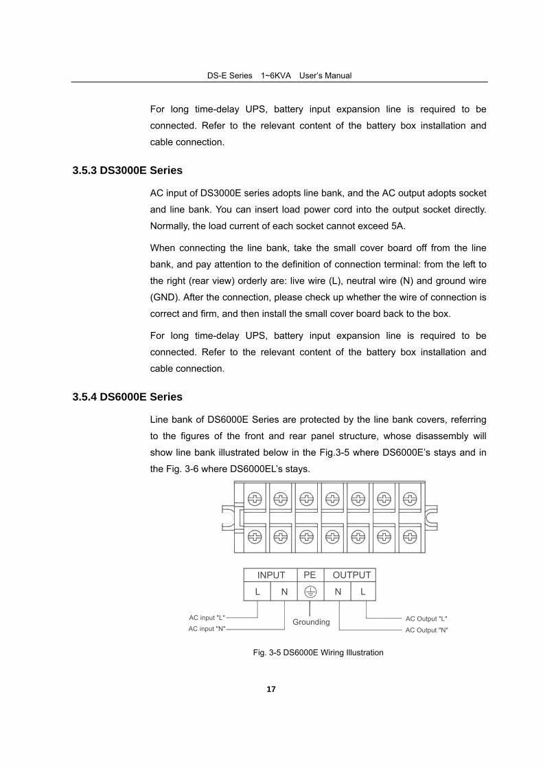
3.5.4 DS6000E Series
Line bank of DS6000E Series are protected by the line bank covers, referring
to the figures of the front and rear panel structure, whose disassembly will
show line bank illustrated below in the Fig.3-5 where DS6000E’s stays and in
the Fig. 3-6 where DS6000EL’s stays.
Grounding
NL LN
PEINPUT OUTPUT
AC Output "L"
AC Output "N"
AC input "L"AC input "N"
Fig. 3-5 DS6000E Wiring Illustration
DS-E Series(1~6KVA)User’s Manual
18
120VDCBattery -Battery +
NL LN -+PEINPUT OUTPUT BATTERY
Grouding
AC Output "L"
AC Output "N"
AC input "L"AC input "N"
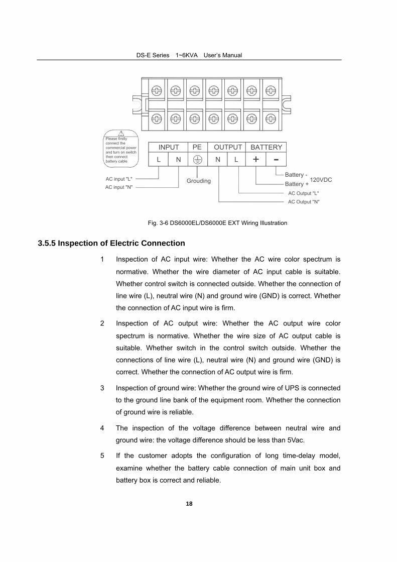
Fig. 3-6 DS6000EL/DS6000E EXT Wiring Illustration
3.5.5 Inspection of Electric Connection
1. Inspection of AC input wire: Whether the AC wire color spectrum is
normative. Whether the wire diameter of AC input cable is suitable.
Whether control switch is connected outside. Whether the connection of
line wire (L), neutral wire (N) and ground wire (GND) is correct. Whether
the connection of AC input wire is firm.
2. Inspection of AC output wire: Whether the AC output wire color
spectrum is normative. Whether the wire size of AC output cable is
suitable. Whether switch in the control switch outside. Whether the
connections of line wire (L), neutral wire (N) and ground wire (GND) is
correct. Whether the connection of AC output wire is firm.
3. Inspection of ground wire: Whether the ground wire of UPS is connected
to the ground line bank of the equipment room. Whether the connection
of ground wire is reliable.
4. The inspection of the voltage difference between neutral wire and
ground wire: the voltage difference should be less than 5Vac.
5. If the customer adopts the configuration of long time-delay model,
examine whether the battery cable connection of main unit box and
battery box is correct and reliable.
DS-E Series(1~6KVA)User’s Manual
19
6. If the UPS is installed with remote monitoring equipment, examine
whether the connection of relevant RS232 serial port is correct.
7. Examine whether the wiring is in order, whether the cable binding
accord with the technical criterion.
8. Examine whether the installation and wiring are in favor of the future
system modification, expansion and maintenance.
20
4 . Equipment Use and Maintenance
4.1 Preparations before First Start-up
To ensure normal operation of UPS, please confirm the following before use:
1. Correct installation of input and output;
2. If the air switch at the back of UPS is placed at “OFF”;
3. If the power end is connected to rated input power supply;
4. Confirm that UPS output does not short circuit, and the load capacity
does not exceed UPS capacity;
5. Confirm if computer or other instrument is turned off;
6. Confirm if battery voltage is normal;
7. It is not recommended to connect reactive load to the UPS output.
Loads are normally powered by electric network directly.
4.2 UPS Start-up Sequence
After confirming all the above, please start the machine by following means:
1. For DS2000E, DS3000E,DS6000E series, turn the air switch at the back
to “ON” position.
(Step 2 of direct operation of DS1000E series)
2. Press the "ON" button on the UPS panel to start UPS, the "INV"
indicator light will light up. After retardation time, the "BYPASS" light
goes out and the UPS is changed inversion power supply. By this time,
the start-up is completed and the equipment starts operation. Wait for
about 20 seconds after normal no-load operation to turn on the
computer or other instrument. Start the load in the sequence of
high-power to low power, first start the high-power equipment then in
turns start equipment with lower power.
3. Start computer or other equipment.
DS-E Series(1~6KVA)User’s Manual
21
4.3 Daily Start-up and Shutdown
During daily operation, operate as per the following for start-up or shut down:
1. Press the "ON" button on the UPS panel to start UPS, after 10 seconds,
turn on the computer or other instrument.
2. Before shutdown, turn off the computer and other instrument first and
perform no-load operation of UPS for 10 minutes. After the heat in the
equipment has been discharged, press the "OFF" button on the panel.
3. Normally, only when the UPS has been started and is working stably, can
the loading equipment power switch be turned on. First turn on high-power
equipment, then the equipment with lower power. Some equipment has
large start current (such as monitors of some brands). When starting such
equipment, overload protection (such as bypass operation) may occur. In
this case, it's recommended to start this type of equipment before other
equipment.
4.4 Battery Daily Maintenance 1. If the equipment has not been used for a long period, it should be charged
for more than ten hours.
2. Before operating the equipment, please charge it for ten hours after
start-up. The equipment can still be used during charging. If power
failure occurs at the same time, this discharge time may be under standard
value.
3. Normally, battery will be charged and discharged every four to six months.
First, discharge until shutdown then charge. The charging time for
standard device should be no less than ten hours each time.
4. At high temperature region, the battery should be charged and discharged
once every two months. The charging time for standard device should be
no less than ten hours each time.
5. Batteries of different capacity, type, and produced by different
manufacturers should not be mixed when using.
6. When cleaning battery case, only use wiping cloth and clear water, do not
DS-E Series(1~6KVA)User’s Manual
22
use oil substance or organic solvent such as gasoline and thinner, etc.
7. Battery and battery unit should be kept away from ignition source as well
as all electrical equipment that may easily cause spark, to avoid causing
unnecessary loss.
8. During the use of battery unit equipped for UPS, regularly check if the
charger is in good condition to prevent the battery from being overcharged
or undercharged for a long time, and to avoid excessive discharge of
battery. After discharging, immediately (no later than 24 hours) perform
complete charging, only after then will the re-discharged be allowed. Never
re-discharge if the battery is not completely charged, otherwise it will
cause decrease in battery capacity or even damage to battery.
9. When not using UPS, please turn off the "OFF" switch on the panel to
avoid causing long-time battery discharge after commercial power failure.
If the UPS has not been used for a long time, regularly perform charging
and discharging of battery to avoid battery damage due to self-discharging.
4.5 Battery Changing
When changing storage battery, pay attention to the following:
1.Do not throw battery into fire to avoid explosion.
2.Do not open or disassemble battery as the electrolyte is harmful to skin and
eyes.
3.Properly recycle the battery according to relevant instructions thereon.
4.Replace the used battery with new ones that are of same type and grade.
5.Replace the entire battery unit, do not mix the old ones with the new ones.
6.Dangerous voltage may exist between battery terminal and the ground. Test
before touching.
4.6 Maintenance Guide
Proper maintenance includes preventive maintenance and remedial
maintenance, which is crucial to optimum operation of UPS and can ensure
relatively long service life of the equipment. Preventive maintenance includes
DS-E Series(1~6KVA)User’s Manual
23
some procedures that are frequently performed. These procedures are used to
prevent system failure as well as to obtain best operating efficiency. Remedial
maintenance includes searching for system malfunction to facilitate effective
repair.
4.6.1 Safety Precaution
In order to securely and successfully conduct system maintenance, relevant
safety precautions must be observed and necessary tools and testing
equipment must be used, with the participation of qualified maintenance
personnel. Pay attention to the following safety operation rules:
1. Bear in mind that there is dangerous voltage in UPS even if the UPS
system is not in operation.
2. Make sure that the UPS operation and maintenance personnel are
familiar with this equipment and the content of this Manual.
3. When operate UPS, do not wear gold or silver jewelry such as ring or
watch, etc.
4. Do not take the safety operation procedure for granted. If there is any
doubt, consult personnel who are familiar with the equipment.
5. Be cautious that there is dangerous voltage in UPS. Before
maintenance and adjustment, use voltmeter to check and ensure that
the power is turned off and the equipment is under safe condition.
4.6.2 Preventive and Regular Maintenance
The following shows the preventive maintenance procedures which will
improve UPS system operation efficiency and reliability.
1. Keep the environment clean to avoid dust and chemical contamination
to the UPS.
2. Cable connection
Semiannually check the input and output cable connecting terminals
once. Carefully measure and check them to ensure good contact.
3. Check the working status of the vent fan on a regular basis to prevent
clogging of the air outlet. Repair it if there is any damage.
DS-E Series(1~6KVA)User’s Manual
24
4. Perform periodic inspection on battery voltage and UPS working status.
4.6.3 FAQ
If the UPS fails to work properly after starting, please don't jump to the
conclusion of UPS failure. Please refer to the following and try to solve the
problem.
Problem 1
Power supply is normal; UPS is able to output AC 230V after start, yet in the
status of battery inversion with buzzer giving intermittent buzzing.
Possible cause: Unstable AC power input as a result of poor contact of the
junction points, sockets or other connection parts of the electric network feeder
circuit connected to the UPS.
Problem 2
After UPS is installed, and after the electric brake or UPS "ON" button is
switched on, the fuse will be burnt out or tripping occurs.
Cause: wrong connection of three UPS input wires, for example, zero line or fire wire is connected to UPS earth wire (case); Or wrong connection of three
UPS output wires.
Problem 3
After UPS is started, it outputs AC 230V, yet it's working under bypass status
("BYPASS" keeping lighted).
Possible cause: too-heavy load sustained by the device which exceeds rated
power of the UPS. In such cases, relieve the load to the UPS, or use a UPS of
higher rated power capacity. If it is a temporary bypass status caused by
start-up impact of the load, and returns to proper status automatically, that's
normal operation.
Problem 4
Display and output of the UPS are normal after start. However, the output stops
as soon as load is connected to it.
DS-E Series(1~6KVA)User’s Manual
25
Cause:
(1)UPS severe overload or output circuit short circuit. Reduce the load to an
adequate amount, or check the cause for short circuit. In many cases, it is
caused by output adapter short circuit or input short-circuit fault owing to
equipment damage.
(2)Failure to follow the load start-up sequence which shall begin with
heavy-duty equipment to low-duty ones. Restart UPS and wait till UPS
runs stably; first start heavy-duty equipment and then devices of lower
duties.
Problem 5
UPS works properly after start-up, and automatically shuts off after a certain
period of time.
Cause: battery unit is not charged in time and is working under battery supply
status (not powered or not connected to power grid), thus resulting in battery
under voltage protection of the UPS.
Warning: in the case of UPS battery under voltage protection, please
immediately turn off all switches, and restart the UPS and charge the battery to
full capacity when power supply recovers. Long-period under voltage of the
battery will shorten the service life of the battery.
Problem 6
After working for a certain period, with normal input display, the buzzer gives
intermittent buzzing and displays battery under voltage simultaneously. Cause:
too-low power grid voltage makes the UPS work under battery feed status.
When the battery runs low and under voltage occurs, it enters into protection
status.
Problem 7
UPS is started and working. When power supply breaks down, UPS fails to
output power.
Cause: the battery unit is not connected to main unit or is severely damaged.
DS-E Series(1~6KVA)User’s Manual
26
4.7 Troubleshooting
4.7.1 Overview
In the case of device failure, first of all, find out any obvious damage and try to
determine what causes the failure: device problem or external environment
(such as temperature, humidity and load). Always check these external factors
before coming to the conclusion of UPS system damage.
4.7.2 Troubleshooting
Only some simple troubleshooting suggestions are provided here. If the
diagnosis result is not certain or the information given here is not sufficient for
problem-solving, please turn to your local office or distributor for repair.
1.Buzzer gives long buzzing, trouble light is on, UPS is powered through
bypass, and inverter fails.
Possible causes:(1) Output overload or short circuit results in UPS automatic
shutdown protection.
(2) Driving or power tube malfunction.
(3) Master control board failure.
(4) UPS Over-temperature protection
2.UPS works properly when power supply is O.K., but it fails to function
during power failure.
Possible causes: (1) Battery failure.
(2) Battery charger malfunction: failing to charge battery
when power supply is O.K.
(3) Poor contact between battery connecting wires or
connecting terminals.
3.Intermittent buzzing of the buzzer when UPS input is normal.
Possible causes: Abnormal input voltage that exceeds the UPS' allowable
input voltage range of power supply.
4.UPS works well when computer is in operation. After power failure, UPS
works properly and the computer breaks down.

DS-E Series(1~6KVA)User’s Manual
27
Possible cause: Poor earth connection as a result of much too high floating
voltage of the zero line and earth wire.
5.All of panel indicator lamps are off.
Possible cause: Poor connection or malfunction of display control panel.
28
5 . Packing, Transportation and Storage
5.1 Packing
UPS main unit is packed in packing-paper carton. The interior volume of the carton ( L × W × H) is: 615mm×310mm×450mm(DS2000E,DS3000E)and
570mm×270mm×310mm( DS1000E) . Pay attention to laying direction
requirements for each part when packing. The side faces of the carton are
printed with such direction marks as keep dry, handle with care, this end up,
pile number limit, as well as equipment model and other relevant information.
5.2 Transportation
Handle the goods with care; avoid violent impact. During transportation, place
the cartons in strict accordance with the laying direction indicated on the
packing carton to avoid damage to the devices.
5.3 Storage
The system equipment shall be stored in dry warehouse. Do not expose it to
isolation or rain. Place it in the way as shown on the packing boxes. Store it where the ambient temperature is between - 25℃~+55℃ (except for battery).
It is recommended to store the standard device and battery at places with temperature between 0~40℃ and relative humidity between 20%~80%. No
harmful gas, inflammable/detonable goods or corrosive chemicals shall be kept
in the warehouse which shall also be free from strong mechanical vibration,
impact and intense magnetic field affect. If not otherwise specified, the storage
period of the equipment under the required conditions of this clause is 6
months. During long-term storage, charge the storage battery every 3 months.