Embed Size (px)
Citation preview

DS-6400HDI-T Series Decoder
USER MANUAL
Version 1.0.0
User Manual of DS-6400HDI-T Decoder
1
Hikvision Network Digital Video Recorder User’s Manual
This manual, as well as the software described in it, is furnished under license and may be used or copied only in
accordance with the terms of such license. The content of this manual is furnished for informational use only, is
subject to change without notice, and should not be construed as a commitment by Hikvision Digital Technology
Co., Ltd. (Hikvision). Hikvision assumes no responsibility or liability for any errors or inaccuracies that may
appear in the book.
Except as permitted by such license, no part of this publication may be reproduced, stored in a retrieval system,
or transmitted, in any form or by any means, electronic, mechanical, recording, or otherwise, without the prior
written permission of Hikvision.
HIKVISION MAKES NO WARRANTIES, EXPRESS OR IMPLIED, INCLUDING WITHOUT LIMITATION
THE IMPLIED WARRANTIES OF MERCHANTABILITY AND FITNESS FOR A PARTICULAR PURPOSE,
REGARDING THE HIKVISION SOFTWARE. HIKVISION DOES NOT WARRANT, GUARANTEE, OR
MAKE ANY REPRESENTATIONS REGARDING THE USE OR THE RESULTS OF THE USE OF THE
HIKVISION SOFTWARE IN TERMS OF ITS CORRECTNESS, ACCURACY, RELIABILITY,
CURRENTNESS, OR OTHERWISE. THE ENTIRE RISK AS TO THE RESULTS AND PERFORMANCE OF
THE HIKVISION SOFTWARE IS ASSUMED BY YOU. THE EXCLUSION OF IMPLIED WARRANTIES IS
NOT PERMITTED BY SOME STATES. THE ABOVE EXCLUSION MAY NOT APPLY TO YOU.
IN NO EVENT WILL HIKVISION, ITS DIRECTORS, OFFICERS, EMPLOYEES, OR AGENTS BE LIABLE
TO YOU FOR ANY CONSEQUENTIAL, INCIDENTAL, OR INDIRECT DAMAGES (INCLUDING
DAMAGES FOR LOSS OF BUSINESS PROFITS, BUSINESS INTERRUPTION, LOSS OF BUSINESS
INFORMATION, AND THE LIKE) ARISING OUT OF THE USE OR INABILITY TO USE THE HIKVISION
SOFTWARE EVEN IF HIKVISION HAS BEEN ADVISED OF THE POSSIBILITY OF SUCH DAMAGES.
BECAUSE SOME STATES DO NOT ALLOW THE EXCLUSION OR LIMITATION OF LIABILITY FOR
CONSEQUENTIAL OR INCIDENTAL DAMAGES, THE ABOVE LIMITATIONS MAY NOT APPLY TO
YOU.
User Manual of DS-6400HDI-T Decoder
2
Regulatory Information
FCC Information
FCC compliance: This equipment has been tested and found to comply with the limits for a digital device,
pursuant to part 15 of the FCC Rules. These limits are designed to provide reasonable protection against harmful
interference when the equipment is operated in a commercial environment. This equipment generates, uses, and
can radiate radio frequency energy and, if not installed and used in accordance with the instruction manual, may
cause harmful interference to radio communications. Operation of this equipment in a residential area is likely to
cause harmful interference in which case the user will be required to correct the interference at his own expense.
FCC Conditions
This device complies with part 15 of the FCC Rules. Operation is subject to the following two conditions:
1. This device may not cause harmful interference.
2. This device must accept any interference received, including interference that may cause undesired operation.
EU Conformity Statement
This product and - if applicable - the supplied accessories too are marked with "CE" and
comply therefore with the applicable harmonized European standards listed under the Low
Voltage Directive 2006/95/EC, the EMC Directive 2004/108/EC.
2002/96/EC (WEEE directive): Products marked with this symbol cannot be disposed of as
unsorted municipal waste in the European Union. For proper recycling, return this product to
your local supplier upon the purchase of equivalent new equipment, or dispose of it at
designated collection points. For more information see: www.recyclethis.info.
2006/66/EC (battery directive): This product contains a battery that cannot be disposed of as
unsorted municipal waste in the European Union. See the product documentation for specific
battery information. The battery is marked with this symbol, which may include lettering to
indicate cadmium (Cd), lead (Pb), or mercury (Hg). For proper recycling, return the battery to
your supplier or to a designated collection point. For more information see: www.recyclethis.info.
Description on Laser Specification
The optical disc drive such as DVD Super Multi (Double Layer) Drive 22X that is used in this computer is
equipped with laser. The classification label with the following sentence is affixed to the surface of the drive.
CLASS 1 LASER
PRODUCT TO IEC60825-1
LASER KLASSE 1
The drive with the above label is certified by the manufacturer that the drive complies with the requirement for
laser product on the date of manufacturing pursuant to article 21 of Code of Federal Regulations by the United
States of America, Department of Health & Human Services, Food and Drug Administration.
In other countries, the drive is certified to comply with the requirement pursuant to IEC 60825-1 and EN 60825-1
on class 1 laser product.
This computer is equipped with the optical disc drive in the following list according to the model.
User Manual of DS-6400HDI-T Decoder
3
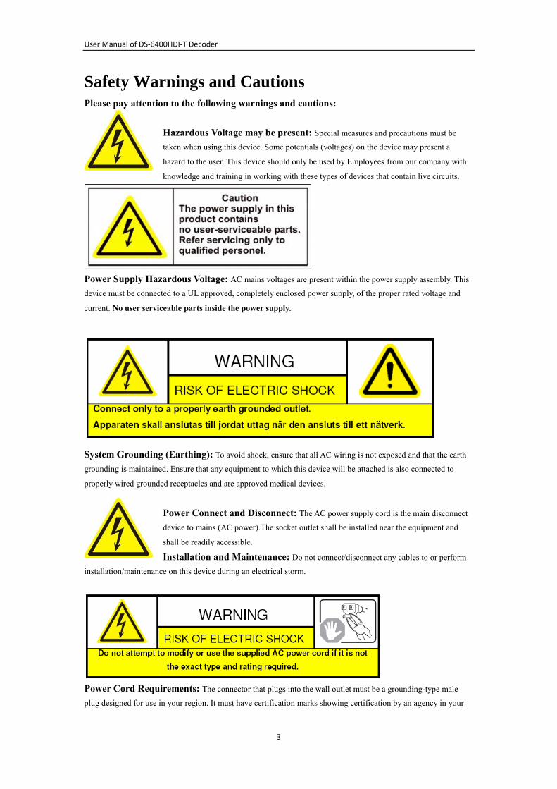
Safety Warnings and Cautions
Please pay attention to the following warnings and cautions:
Hazardous Voltage may be present: Special measures and precautions must be
taken when using this device. Some potentials (voltages) on the device may present a
hazard to the user. This device should only be used by Employees from our company with
knowledge and training in working with these types of devices that contain live circuits.
Power Supply Hazardous Voltage: AC mains voltages are present within the power supply assembly. This
device must be connected to a UL approved, completely enclosed power supply, of the proper rated voltage and
current. No user serviceable parts inside the power supply.
System Grounding (Earthing): To avoid shock, ensure that all AC wiring is not exposed and that the earth
grounding is maintained. Ensure that any equipment to which this device will be attached is also connected to
properly wired grounded receptacles and are approved medical devices.
Power Connect and Disconnect: The AC power supply cord is the main disconnect
device to mains (AC power).The socket outlet shall be installed near the equipment and
shall be readily accessible.
Installation and Maintenance: Do not connect/disconnect any cables to or perform
installation/maintenance on this device during an electrical storm.
Power Cord Requirements: The connector that plugs into the wall outlet must be a grounding-type male
plug designed for use in your region. It must have certification marks showing certification by an agency in your
User Manual of DS-6400HDI-T Decoder
4
region. The connector that plugs into the AC receptacle on the power supply must be an IEC 320, sheet C13,
female connector. See the following website for more information http://kropla.com/electric2.htm.
Lithium Battery: This device contains a Lithium Battery. There is a risk of explosion
if the battery is replaced by an incorrect type. Dispose of used batteries according to the
vendor’s instructions and in accordance with local environmental regulations.
Perchlorate Material: Special handling may apply. See
www.dtsc.ca.gov/hazardouswaste/perchlorate. This notice is required by California Code
of Regulations, Title 22, Division 4.5, Chapter 33: Best Management Practices for Perchlorate Materials. This
device includes a battery which contains perchlorate material.
Taiwan battery recycling:
Please recycle batteries.
Thermal and Mechanical Injury: Some components such as heat sinks, power
regulators, and processors may be hot; care should be taken to avoid contact with these
components.
Electro Magnetic Interference: This equipment has not been tested for
compliance with emissions limits of FCC and similar international regulations. This device is not, and may not be,
offered for sale or lease, or sold, or leased until authorization from the United States FCC or its equivalent in other
countries has been obtained. Use of this equipment in a residential location is prohibited. This equipment
generates, uses and can radiate radio frequency energy which may result in harmful interference to radio
communications. If this equipment does cause harmful interference to radio or television reception, which can be
determined by turning the equipment on and off, the user is required to take measures to eliminate the interference
or discontinue the use of this equipment.
Lead Content:
Please recycle this device in a responsible manner. Refer to local environmental
regulations for proper recycling; do not dispose of device in unsorted municipal
waste.
User Manual of DS-6400HDI-T Decoder
5
Preventive and Cautionary Tips
Before connecting and operating your DVS, please be advised of the following tips:
• Ensure unit is installed in a well-ventilated, dust-free environment.
• Keep all liquids away from the DVS.
• Please check the power supply to avoid the damage caused by voltage mismatch.
• Please make sure the DVS work in the allowed range of temperature and humidity.
• Please keep the device horizontal and avoid the installation under severe vibration environment.
• The dust board will cause a short circuit after damping; Please remove dust regularly for the board, connector,
chassis fan and other parts of the device with brush.
• Improper use or replacement of the battery may result in hazard of explosion. Replace with the same or
equivalent type only. Dispose of used batteries according to the instructions provided by the battery
manufacturer.
User Manual of DS-6400HDI-T Decoder
6
CHAPTER 1 Introduction ........................................................................................................ 8
1.1 Description ...................................................................................................................... 9
1.2 Features ........................................................................................................................... 9
CHAPTER 2 Panel and Connections ..................................................................................... 11
2.1 Front Panel .................................................................................................................... 12
2.2 Rear Panel ...................................................................................................................... 12
CHAPTER 3 Initial Network Parameters Configuration ........................................................ 13
3.1 Connecting the decoder by Hyper Terminal Tools........................................................ 14
3.2 Network Configuration by Hyper Terminal .................................................................. 16
CHAPTER 4 Decoder Configuration and Operation by Web Browser .................................. 18
4.1 Decoding Operation ....................................................................................................... 19
4.1.1 Dynamic Decode .................................................................................................... 22
4.1.2 Cycle Decoding ...................................................................................................... 23
4.1.3 Remote Playback .................................................................................................... 25
4.1.4 Global Switch for the Decoding Channels ............................................................. 26
4.1.5 Image Scaling ......................................................................................................... 26
4.1.6 Picture Overlay ....................................................................................................... 27
4.1.7 Checking the Connection Status ............................................................................. 28
4.1.8 Checking the Decode Channel Status ..................................................................... 28
4.1.9 Checking the Display Channel Status .................................................................... 29
4.1.10 Transparent Channel ............................................................................................. 29
4.2 Parameter Configuration for Decoder ........................................................................... 30
4.2.1 Checking Device Information ................................................................................ 30
4.2.2 Time Settings .......................................................................................................... 30
4.2.3 Basic Network Settings .......................................................................................... 31
4.2.4 DDNS Settings ....................................................................................................... 31
4.2.5 Alarm Input / Output Settings ................................................................................ 32
4.2.6 Arming Time .......................................................................................................... 33
4.2.7 Account Management ............................................................................................. 33
4.2.8 Rebooting, Upgrading and Restoring the Default Settings for the Decoder ......... 34
User Manual of DS-6400HDI-T Decoder
7
CHAPTER 5 Decoder Configuration and Operation by Client Software ............................... 36
5.1 Adding, Modifying and Deleting the Decoder .............................................................. 37
5.1.1 Adding the Decoder to the Client Software ............................................................ 37
5.1.2 Deleting and Modifying the Decoder to the Client Software ................................. 39
5.2 TV Wall Layout Settings ............................................................................................... 40
5.3 Setting the Decoding Channel for the Decoder ............................................................. 42
5.4 Remote Setting for Decoders ......................................................................................... 44
CHAPTER 6 Appendix ........................................................................................................... 45
Appendix A Specifications .................................................................................................. 46
Appendix B. FAQ ................................................................................................................ 47

User Manual of DS-6400HDI-T Decoder
8
CHAPTER 1
Introduction
User Manual of DS-6400HDI-T Decoder
9
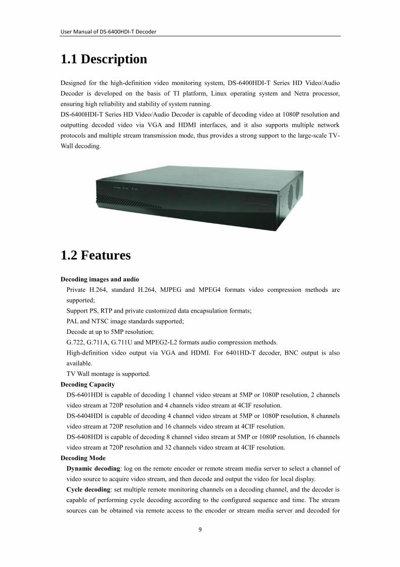
1.1 Description
Designed for the high-definition video monitoring system, DS-6400HDI-T Series HD Video/Audio
Decoder is developed on the basis of TI platform, Linux operating system and Netra processor,
ensuring high reliability and stability of system running.
DS-6400HDI-T Series HD Video/Audio Decoder is capable of decoding video at 1080P resolution and
outputting decoded video via VGA and HDMI interfaces, and it also supports multiple network
protocols and multiple stream transmission mode, thus provides a strong support to the large-scale TV-
Wall decoding.
1.2 Features
Decoding images and audio
Private H.264, standard H.264, MJPEG and MPEG4 formats video compression methods are
supported;
Support PS, RTP and private customized data encapsulation formats;
PAL and NTSC image standards supported;
Decode at up to 5MP resolution;
G.722, G.711A, G.711U and MPEG2-L2 formats audio compression methods.
High-definition video output via VGA and HDMI. For 6401HD-T decoder, BNC output is also
available.
TV Wall montage is supported.
Decoding Capacity
DS-6401HDI is capable of decoding 1 channel video stream at 5MP or 1080P resolution, 2 channels
video stream at 720P resolution and 4 channels video stream at 4CIF resolution.
DS-6404HDI is capable of decoding 4 channel video stream at 5MP or 1080P resolution, 8 channels
video stream at 720P resolution and 16 channels video stream at 4CIF resolution.
DS-6408HDI is capable of decoding 8 channel video stream at 5MP or 1080P resolution, 16 channels
video stream at 720P resolution and 32 channels video stream at 4CIF resolution.
Decoding Mode
Dynamic decoding: log on the remote encoder or remote stream media server to select a channel of
video source to acquire video stream, and then decode and output the video for local display.
Cycle decoding: set multiple remote monitoring channels on a decoding channel, and the decoder is
capable of performing cycle decoding according to the configured sequence and time. The stream
sources can be obtained via remote access to the encoder or stream media server and decoded for
User Manual of DS-6400HDI-T Decoder
10
local output. A maximum of 64 channels are allowed for cycle decoding.
Obtain stream from stream media server: The decoder can receive real-time data by access to
stream media server, and then decode the video stream and output them on the TV Wall. The private
RTSP is adopted as the control protocol, and the TCP/UDP is used for receiving the data stream.
Remote playback of record files: by remote access to the encoding devices with storage capability,
and directly obtain the record files from the encoder, and finally decode for local output.
Network
One 10/100/1000Mbps self-adaptive Ethernet interface;
Support TCP, UDP and Multicasting network protocols;
DHCP, NTP, HTTP, RTP and DDNS are supported;
Remote upgrading and maintenance can be done via web browser or client software.
User Administration
A maximum of 32 users can be created by the system, including 1 administrator and 31 users. The
user name of the administrator is admin, which cannot be modified, and the password is allowable to
be modified by the administrator only; no deletion of the administrator is allowed, and the
administrator is authorized to set the operation permissions for other users.
Transparent Channel
The decoder adopts the RS-232/RS-485 serial interface to realize transparent transmission. The data
sent remotely to the decoder via network can be transmitted by RS-232/RS-485 interface of decoder
without any operation, and the transparent channel of the decoder supports multicast transparent
transmission as well, and multiple transparent channels can be established simultaneously.
Two-way audio
The decoder is capable of realizing voice talk with the remote client.

User Manual of DS-6400HDI-T Decoder
11
CHAPTER 2
Panel and Connections
User Manual of DS-6400HDI-T Decoder
12
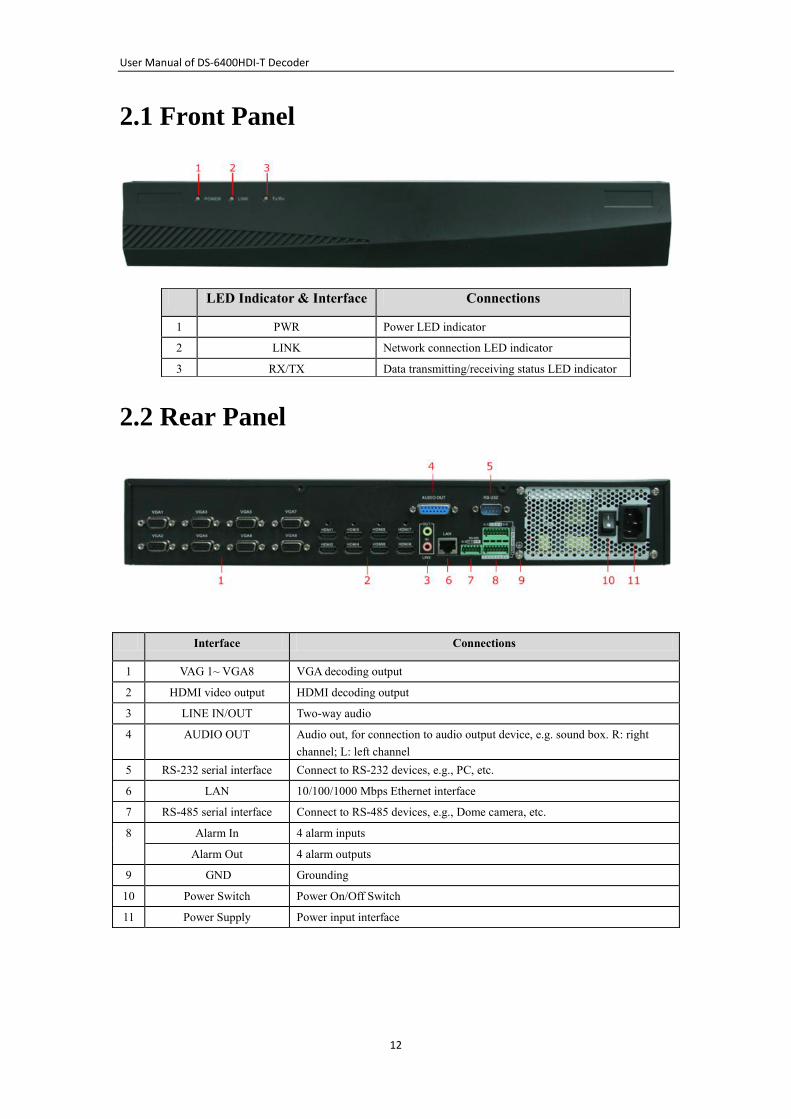
2.1 Front Panel
2.2 Rear Panel
LED Indicator & Interface Connections
1 PWR Power LED indicator
2 LINK Network connection LED indicator
3 RX/TX Data transmitting/receiving status LED indicator
Interface Connections
1 VAG 1~ VGA8 VGA decoding output
2 HDMI video output HDMI decoding output
3 LINE IN/OUT Two-way audio
4 AUDIO OUT Audio out, for connection to audio output device, e.g. sound box. R: right
channel; L: left channel
5 RS-232 serial interface Connect to RS-232 devices, e.g., PC, etc.
6 LAN 10/100/1000 Mbps Ethernet interface
7 RS-485 serial interface Connect to RS-485 devices, e.g., Dome camera, etc.
8
Alarm In 4 alarm inputs
Alarm Out 4 alarm outputs
9 GND Grounding
10 Power Switch Power On/Off Switch
11 Power Supply Power input interface
User Manual of DS-6400HDI-T Decoder
13
CHAPTER 3
Initial Network Parameters Configuration
User Manual of DS-6400HDI-T Decoder
14
Purpose:
If you don’t know the IP address of the decoder and this is not the first time you use the decoder, you
can use SADP (IP finder) software or the Serial port tools to find out the IP address of the decoder and
to configure the IP address or other network parameters of it. It is recommended to change the default
IP address for the first time to use it.
This chapter aims to tell the procedures of using the Hyper Terminal Software to find and configure the
IP address and other parameters of the device.
For the operation of the SADP software, please refer to the User Manual of the SADP software.
Note:
For the first-time user, the default user name of DS-6400HDI-T is admin, and password is 12345. And
the default IP address is 192.0.0.64.
3.1 Connecting the decoder by Hyper Terminal
Tools
Purpose:
By connecting decoder and PC with serial line via RS-232 interface, run the Hyper Terminal application, you can
get and modify the network parameters of the decoder with serial commands.
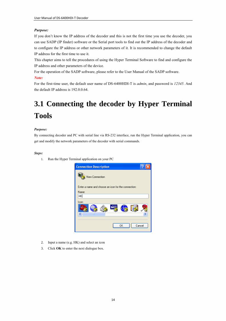
Steps:
1. Run the Hyper Terminal application on your PC
2. Input a name (e.g. HK) and select an icon
3. Click OK to enter the next dialogue box.
User Manual of DS-6400HDI-T Decoder
15
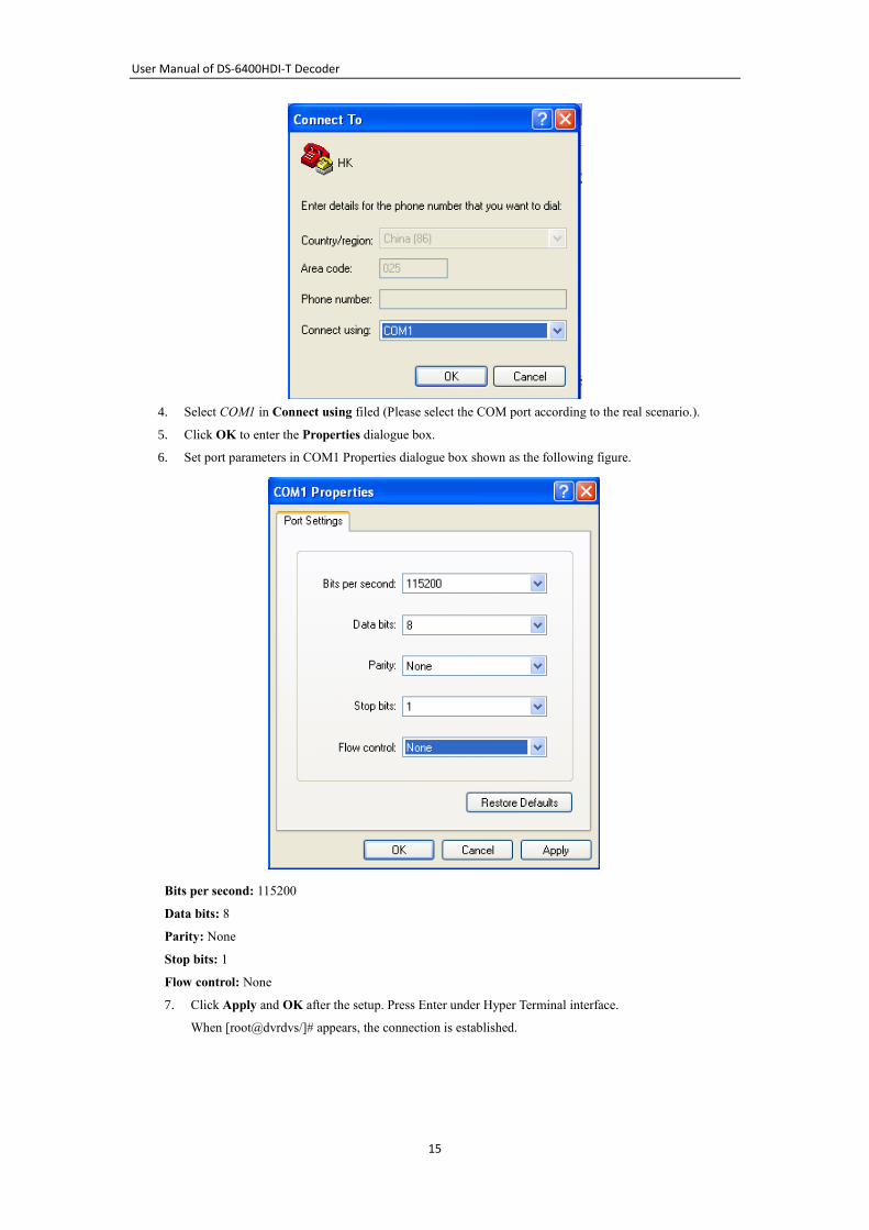
4. Select COM1 in Connect using filed (Please select the COM port according to the real scenario.).
5. Click OK to enter the Properties dialogue box.
6. Set port parameters in COM1 Properties dialogue box shown as the following figure.
Bits per second: 115200
Data bits: 8
Parity: None
Stop bits: 1
Flow control: None
7. Click Apply and OK after the setup. Press Enter under Hyper Terminal interface.
When [root@dvrdvs/]# appears, the connection is established.
User Manual of DS-6400HDI-T Decoder
16
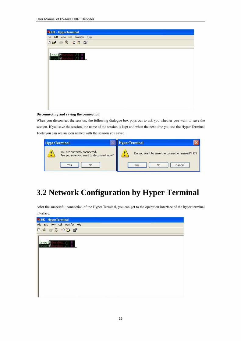
Disconnecting and saving the connection
When you disconnect the session, the following dialogue box pops out to ask you whether you want to save the
session. If you save the session, the name of the session is kept and when the next time you use the Hyper Terminal
Tools you can see an icon named with the session you saved.
3.2 Network Configuration by Hyper Terminal
After the successful connection of the Hyper Terminal, you can get to the operation interface of the hyper terminal
interface.
User Manual of DS-6400HDI-T Decoder
17
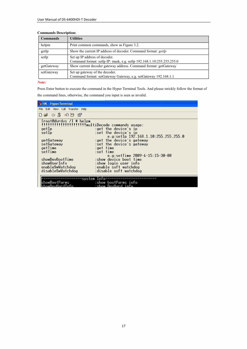
Commands Description:
Commands Utilities
helpm Print common commands, show as Figure 3.2.
getIp Show the current IP address of decoder. Command format: getIp
setIp Set up IP address of decoder.
Command format: setIp IP: mask, e.g. setIp 192.168.1.10:255.255.255.0
getGateway Show current decoder gateway address. Command format: getGateway
setGateway Set up gateway of the decoder.
Command format: setGateway Gateway, e.g. setGateway 192.168.1.1
Note:
Press Enter button to execute the command in the Hyper Terminal Tools. And please strickly follow the format of
the command lines, otherwise, the command you input is seen as invalid.
User Manual of DS-6400HDI-T Decoder
18
CHAPTER 4
Decoder Configuration and Operation by
Web Browser
User Manual of DS-6400HDI-T Decoder
19
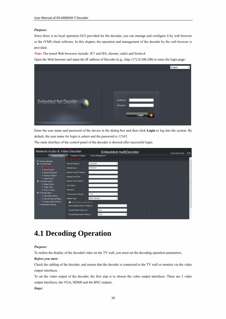
Purpose:
Since there is no local operation GUI provided for the decoder, you can manage and configure it by web browser
or the iVMS client software. In this chapter, the operation and management of the decoder by the web browser is
provided.
Note: The tested Web browsers include: IE7 and IE8, chrome, safari and firefox4.
Open the Web browser and input the IP address of Decoder (e.g., http://172.9.108.108) to enter the login page:
Enter the user name and password of the device in the dialog box and then click Login to log into the system. By
default, the user name for login is admin and the password is 12345.
The main interface of the control panel of the decoder is showed after successful login.
4.1 Decoding Operation
Purpose:
To realize the display of the decoded video on the TV wall, you must set the decoding operation parameters.
Before you start:
Check the cabling of the decoder, and ensure that the decoder is connected to the TV wall or monitor via the video
output interfaces.
To set the video output of the decoder, the first step is to choose the video output interfaces. There are 3 video
output interfaces, the VGA, HDMI and the BNC outputs.
Steps:
User Manual of DS-6400HDI-T Decoder
20
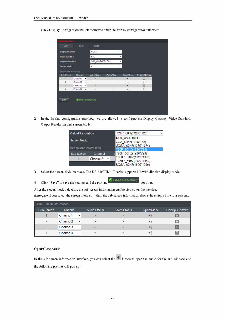
1. Click Display Configure on the left toolbar to enter the display configuration interface:
2. In the display configuration interface, you are allowed to configure the Display Channel, Video Standard,
Output Resolution and Screen Mode.
3. Select the screen-division mode. The DS-6400HDI –T series supports 1/4/9/16-division display mode.
4. Click “Save” to save the settings and the prompt pops out.
After the screen mode selection, the sub screen information can be viewed on the interface.
Example: If you select the screen mode as 4, then the sub screen information shows the status of the four screens.
Open/Close Audio
In the sub-screen information interface, you can select the button to open the audio for the sub window, and
the following prompt will pop up:
User Manual of DS-6400HDI-T Decoder
21
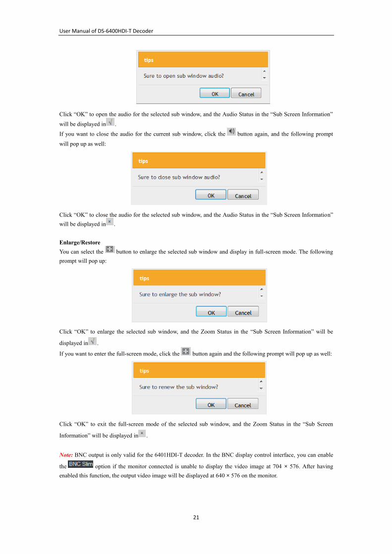
Click “OK” to open the audio for the selected sub window, and the Audio Status in the “Sub Screen Information”
will be displayed in .
If you want to close the audio for the current sub window, click the button again, and the following prompt
will pop up as well:
Click “OK” to close the audio for the selected sub window, and the Audio Status in the “Sub Screen Information”
will be displayed in .
Enlarge/Restore
You can select the button to enlarge the selected sub window and display in full-screen mode. The following
prompt will pop up:
Click “OK” to enlarge the selected sub window, and the Zoom Status in the “Sub Screen Information” will be
displayed in .
If you want to enter the full-screen mode, click the button again and the following prompt will pop up as well:
Click “OK” to exit the full-screen mode of the selected sub window, and the Zoom Status in the “Sub Screen
Information” will be displayed in .
Note: BNC output is only valid for the 6401HDI-T decoder. In the BNC display control interface, you can enable
the option if the monitor connected is unable to display the video image at 704 × 576. After having
enabled this function, the output video image will be displayed at 640 × 576 on the monitor.
User Manual of DS-6400HDI-T Decoder
22
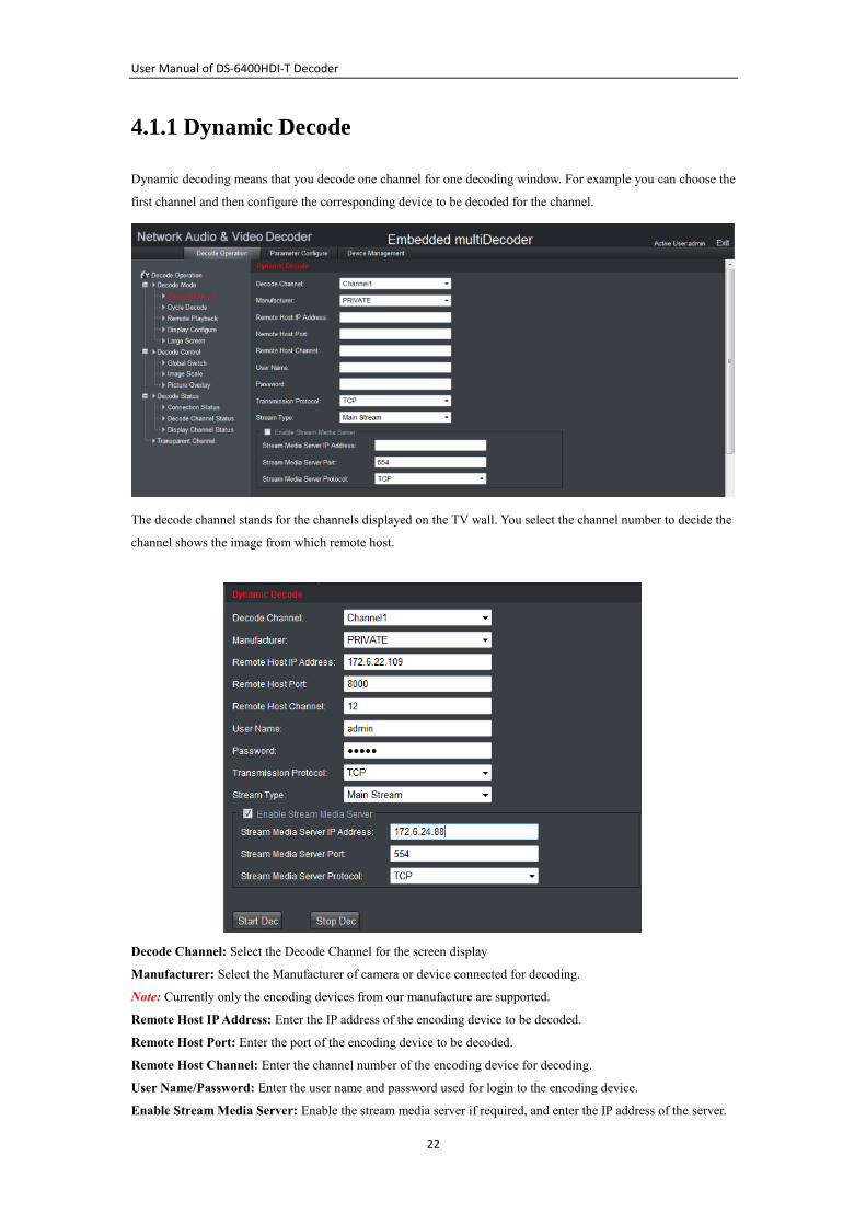
4.1.1 Dynamic Decode
Dynamic decoding means that you decode one channel for one decoding window. For example you can choose the
first channel and then configure the corresponding device to be decoded for the channel.
The decode channel stands for the channels displayed on the TV wall. You select the channel number to decide the
channel shows the image from which remote host.
Decode Channel: Select the Decode Channel for the screen display
Manufacturer: Select the Manufacturer of camera or device connected for decoding.
Note: Currently only the encoding devices from our manufacture are supported.
Remote Host IP Address: Enter the IP address of the encoding device to be decoded.
Remote Host Port: Enter the port of the encoding device to be decoded.
Remote Host Channel: Enter the channel number of the encoding device for decoding.
User Name/Password: Enter the user name and password used for login to the encoding device.
Enable Stream Media Server: Enable the stream media server if required, and enter the IP address of the server.
User Manual of DS-6400HDI-T Decoder
23
After all settings have been configured, click “Start Dec” button to start decoding, and the decoding status can be
viewed in the Connection Status or the Decode Channel Status interface. And you can see the image from the
remote encoding device is decoded and displayed on the screen.
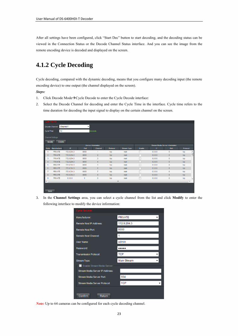
4.1.2 Cycle Decoding
Cycle decoding, compared with the dynamic decoding, means that you configure many decoding input (the remote
encoding device) to one output (the channel displayed on the screen).
Steps:
1. Click Decode ModeCycle Decode to enter the Cycle Decode interface:
2. Select the Decode Channel for decoding and enter the Cycle Time in the interface. Cycle time refers to the
time duration for decoding the input signal to display on the certain channel on the screen.
3. In the Channel Settings area, you can select a cycle channel from the list and click Modify to enter the
following interface to modify the device information:
Note: Up to 64 cameras can be configured for each cycle decoding channel.

User Manual of DS-6400HDI-T Decoder
24
Example:
If you set the Decode Channel as Channel 1 and the Cycle Time as 10 seconds and set 10 decoding devices for the
decode channel, the image from these 10 devices are displayed for 10 seconds on the screen window for the
channel in turn.
User Manual of DS-6400HDI-T Decoder
25
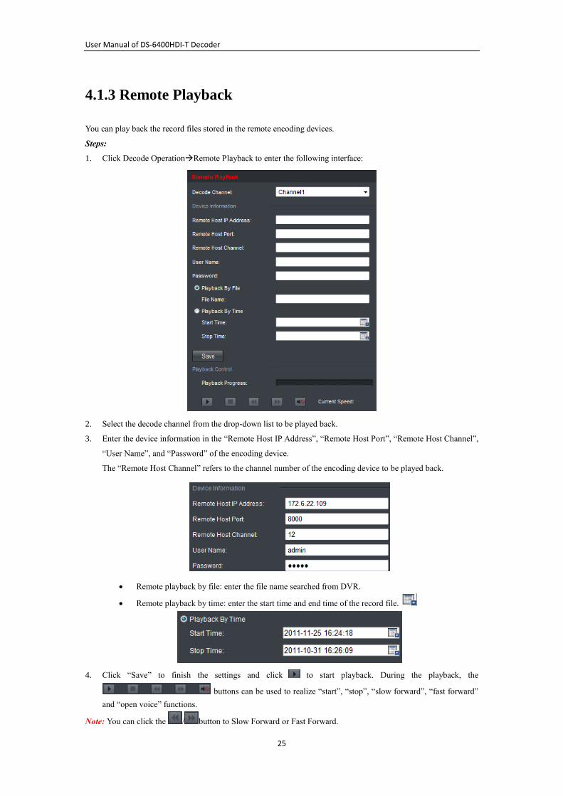
4.1.3 Remote Playback
You can play back the record files stored in the remote encoding devices.
Steps:
1. Click Decode OperationRemote Playback to enter the following interface:
2. Select the decode channel from the drop-down list to be played back.
3. Enter the device information in the “Remote Host IP Address”, “Remote Host Port”, “Remote Host Channel”,
“User Name”, and “Password” of the encoding device.
The “Remote Host Channel” refers to the channel number of the encoding device to be played back.
Remote playback by file: enter the file name searched from DVR.
Remote playback by time: enter the start time and end time of the record file.
4. Click “Save” to finish the settings and click to start playback. During the playback, the
buttons can be used to realize “start”, “stop”, “slow forward”, “fast forward”
and “open voice” functions.
Note: You can click the / button to Slow Forward or Fast Forward.
User Manual of DS-6400HDI-T Decoder
26
The speed of slow forward can be set to 1/2X, 1/4X, 1/8X and 1/16X; and the speed of fast forward can be set to
2X, 4X and 8X.
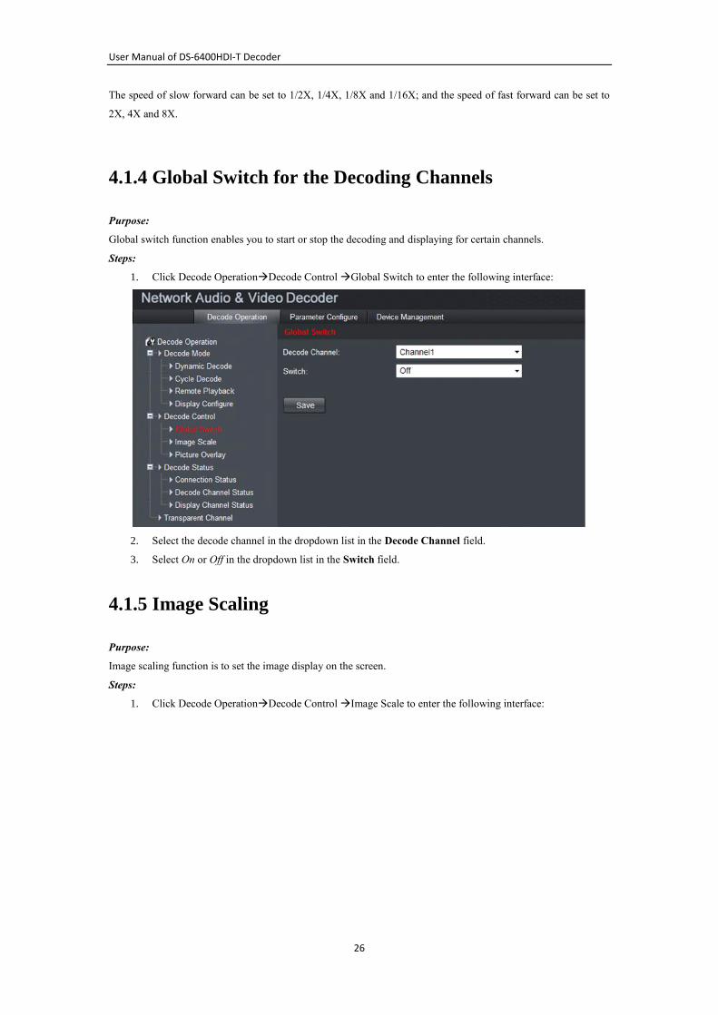
4.1.4 Global Switch for the Decoding Channels
Purpose:
Global switch function enables you to start or stop the decoding and displaying for certain channels.
Steps:
1. Click Decode OperationDecode Control Global Switch to enter the following interface:
2. Select the decode channel in the dropdown list in the Decode Channel field.
3. Select On or Off in the dropdown list in the Switch field.
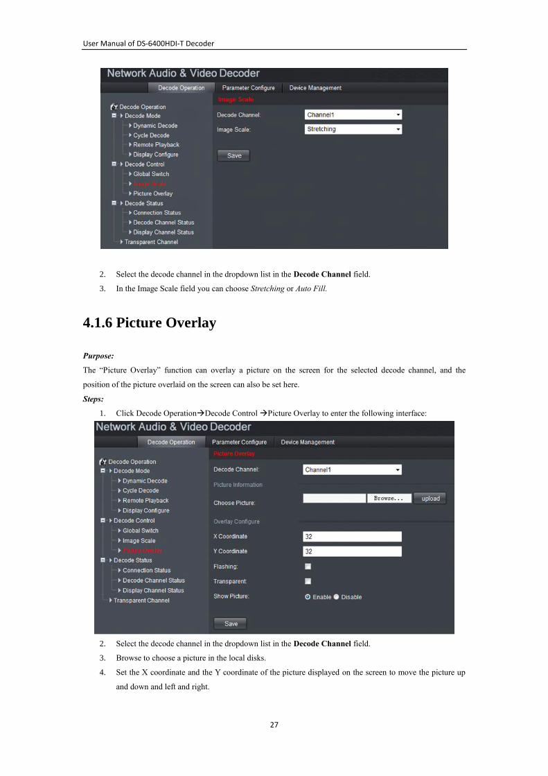
4.1.5 Image Scaling
Purpose:
Image scaling function is to set the image display on the screen.
Steps:
1. Click Decode OperationDecode Control Image Scale to enter the following interface:
User Manual of DS-6400HDI-T Decoder
27
2. Select the decode channel in the dropdown list in the Decode Channel field.
3. In the Image Scale field you can choose Stretching or Auto Fill.
4.1.6 Picture Overlay
Purpose:
The “Picture Overlay” function can overlay a picture on the screen for the selected decode channel, and the
position of the picture overlaid on the screen can also be set here.
Steps:
1. Click Decode OperationDecode Control Picture Overlay to enter the following interface:
2. Select the decode channel in the dropdown list in the Decode Channel field.
3. Browse to choose a picture in the local disks.
4. Set the X coordinate and the Y coordinate of the picture displayed on the screen to move the picture up
and down and left and right.
User Manual of DS-6400HDI-T Decoder
28
Note: The picture must be in 32-bit BMP format and its width and height must be 32X pixel, with up to 128×128
resolution and 24 bits depth.
4.1.7 Checking the Connection Status
Purpose:
Connection status shows the status of the decoding status and the network connection status of the decode channel.
Steps:
Click Decode OperationDecode Status Connection Status to view the connection status of the current decode
channel.
You can see status of the network connection is displayed on the interface.
Note: The Connection Status of device will be refreshed regularly.
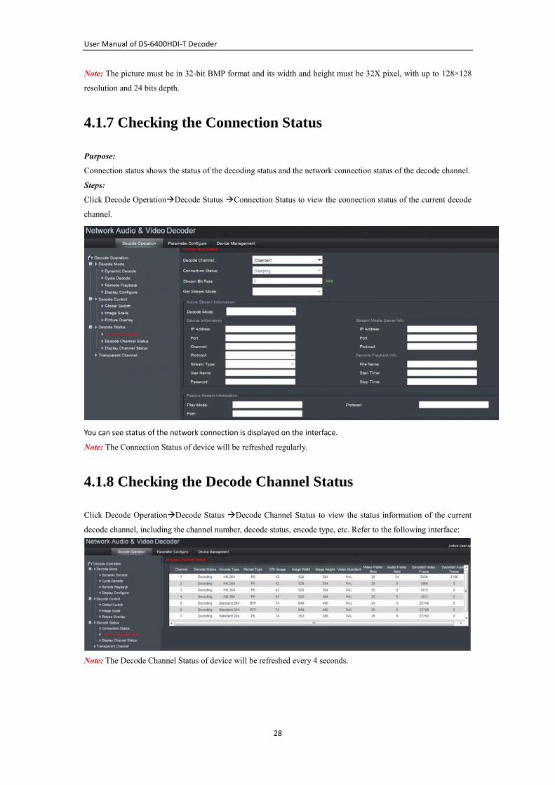
4.1.8 Checking the Decode Channel Status
Click Decode OperationDecode Status Decode Channel Status to view the status information of the current
decode channel, including the channel number, decode status, encode type, etc. Refer to the following interface:
Note: The Decode Channel Status of device will be refreshed every 4 seconds.
User Manual of DS-6400HDI-T Decoder
29
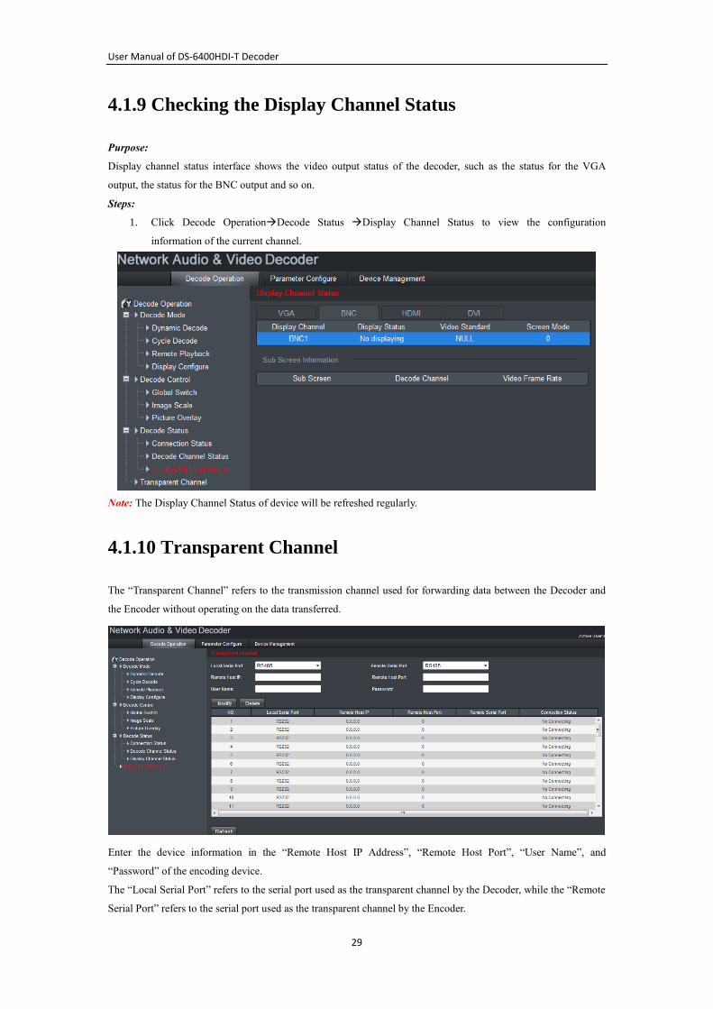
4.1.9 Checking the Display Channel Status
Purpose:
Display channel status interface shows the video output status of the decoder, such as the status for the VGA
output, the status for the BNC output and so on.
Steps:
1. Click Decode OperationDecode Status Display Channel Status to view the configuration
information of the current channel.
Note: The Display Channel Status of device will be refreshed regularly.
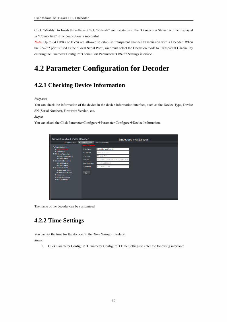
4.1.10 Transparent Channel
The “Transparent Channel” refers to the transmission channel used for forwarding data between the Decoder and
the Encoder without operating on the data transferred.
Enter the device information in the “Remote Host IP Address”, “Remote Host Port”, “User Name”, and
“Password” of the encoding device.
The “Local Serial Port” refers to the serial port used as the transparent channel by the Decoder, while the “Remote
Serial Port” refers to the serial port used as the transparent channel by the Encoder.
User Manual of DS-6400HDI-T Decoder
30
Click “Modify” to finish the settings. Click “Refresh” and the status in the “Connection Status” will be displayed
in “Connecting” if the connection is successful.
Note: Up to 64 DVRs or DVSs are allowed to establish transparent channel transmission with a Decoder. When
the RS-232 port is used as the “Local Serial Port”, user must select the Operation mode to Transparent Channel by
entering the Parameter ConfigureSerial Port ParametersRS232 Settings interface.
4.2 Parameter Configuration for Decoder
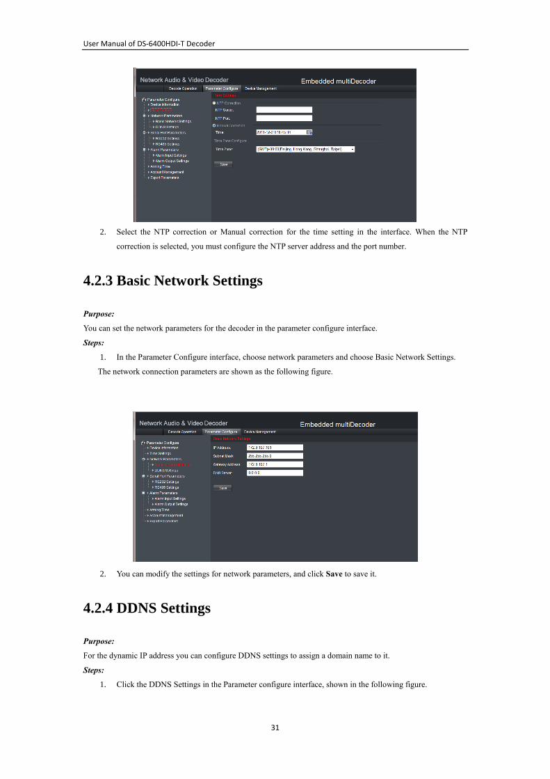
4.2.1 Checking Device Information
Purpose:
You can check the information of the device in the device information interface, such as the Device Type, Device
SN (Serial Number), Firmware Version, etc.
Steps:
You can check the Click Parameter ConfigureParameter ConfigureDevice Information.
The name of the decoder can be customized.
4.2.2 Time Settings
You can set the time for the decoder in the Time Settings interface.
Steps:
1. Click Parameter ConfigureParameter ConfigureTime Settings to enter the following interface:
User Manual of DS-6400HDI-T Decoder
31
2. Select the NTP correction or Manual correction for the time setting in the interface. When the NTP
correction is selected, you must configure the NTP server address and the port number.
4.2.3 Basic Network Settings
Purpose:
You can set the network parameters for the decoder in the parameter configure interface.
Steps:
1. In the Parameter Configure interface, choose network parameters and choose Basic Network Settings.
The network connection parameters are shown as the following figure.
2. You can modify the settings for network parameters, and click Save to save it.
4.2.4 DDNS Settings
Purpose:
For the dynamic IP address you can configure DDNS settings to assign a domain name to it.
Steps:
1. Click the DDNS Settings in the Parameter configure interface, shown in the following figure.
User Manual of DS-6400HDI-T Decoder
32
2. Check the Enable DDNS checkbox to enable the DDNS function.
3. Select DDNS Type as Private.
4. Set other parameters according to the DDNS type you selected above.
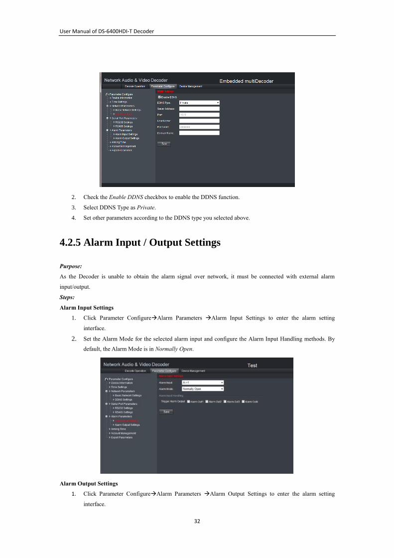
4.2.5 Alarm Input / Output Settings
Purpose:
As the Decoder is unable to obtain the alarm signal over network, it must be connected with external alarm
input/output.
Steps:
Alarm Input Settings
1. Click Parameter ConfigureAlarm Parameters Alarm Input Settings to enter the alarm setting
interface.
2. Set the Alarm Mode for the selected alarm input and configure the Alarm Input Handling methods. By
default, the Alarm Mode is in Normally Open.
Alarm Output Settings
1. Click Parameter ConfigureAlarm Parameters Alarm Output Settings to enter the alarm setting
interface.
User Manual of DS-6400HDI-T Decoder
33
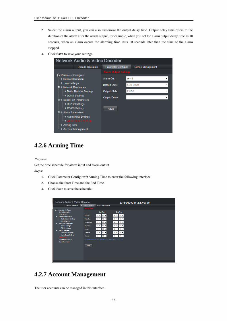
2. Select the alarm output, you can also customize the output delay time. Output delay time refers to the
duration of the alarm after the alarm output, for example, when you set the alarm output delay time as 10
seconds, when an alarm occurs the alarming time lasts 10 seconds later than the time of the alarm
stopped.
3. Click Save to save your settings.
4.2.6 Arming Time
Purpose:
Set the time schedule for alarm input and alarm output.
Steps:
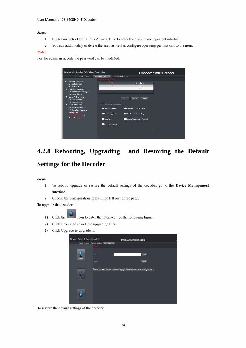
1. Click Parameter ConfigureArming Time to enter the following interface.
2. Choose the Start Time and the End Time.
3. Click Save to save the schedule.
4.2.7 Account Management
The user accounts can be managed in this interface.
User Manual of DS-6400HDI-T Decoder
34
Steps:
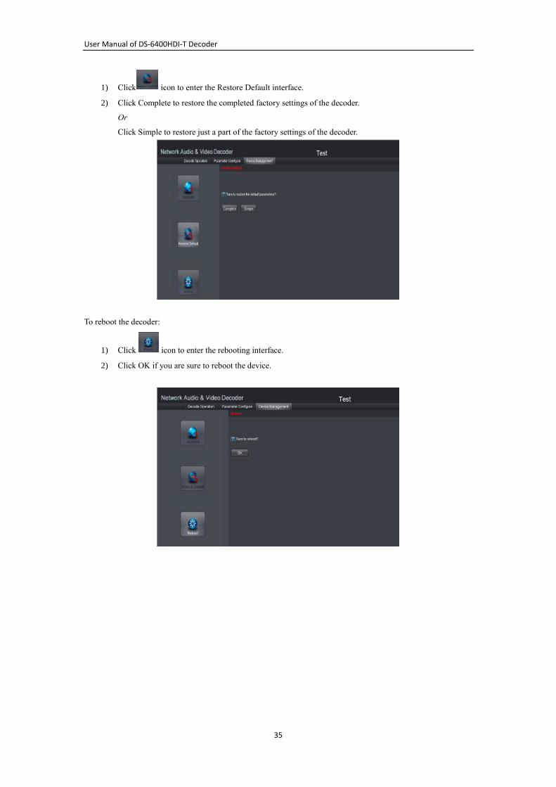
1. Click Parameter ConfigureArming Time to enter the account management interface.
2. You can add, modify or delete the user, as well as configure operating permissions to the users.
Note:
For the admin user, only the password can be modified.
4.2.8 Rebooting, Upgrading and Restoring the Default
Settings for the Decoder
Steps:
1. To reboot, upgrade or restore the default settings of the decoder, go to the Device Management
interface.
2. Choose the configuration items in the left part of the page.
To upgrade the decoder:
1) Click the icon to enter the interface, see the following figure.
2) Click Browse to search the upgrading files.
3) Click Upgrade to upgrade it.
To restore the default settings of the decoder:
User Manual of DS-6400HDI-T Decoder
35
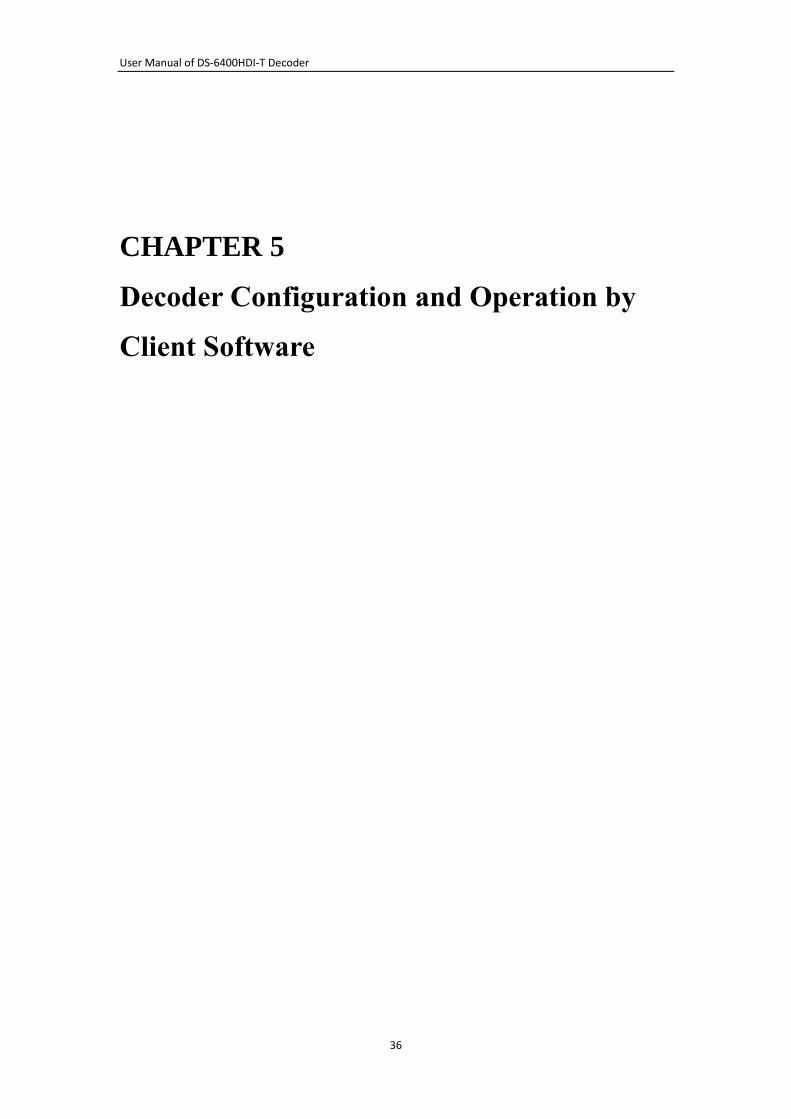
1) Click icon to enter the Restore Default interface.
2) Click Complete to restore the completed factory settings of the decoder.
Or
Click Simple to restore just a part of the factory settings of the decoder.
To reboot the decoder:
1) Click icon to enter the rebooting interface.
2) Click OK if you are sure to reboot the device.
User Manual of DS-6400HDI-T Decoder
36
CHAPTER 5
Decoder Configuration and Operation by
Client Software
User Manual of DS-6400HDI-T Decoder
37
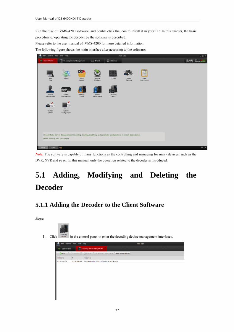
Run the disk of iVMS-4200 software, and double click the icon to install it in your PC. In this chapter, the basic
procedure of operating the decoder by the software is described.
Please refer to the user manual of iVMS-4200 for more detailed information.
The following figure shows the main interface after accessing to the software:
Note: The software is capable of many functions as the controlling and managing for many devices, such as the
DVR, NVR and so on. In this manual, only the operation related to the decoder is introduced.
5.1 Adding, Modifying and Deleting the
Decoder
5.1.1 Adding the Decoder to the Client Software
Steps:
1. Click in the control panel to enter the decoding device management interfaces.
User Manual of DS-6400HDI-T Decoder
38
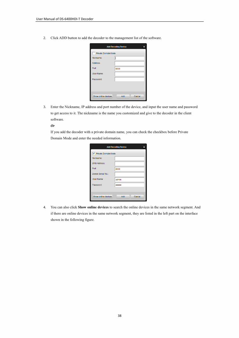
2. Click ADD button to add the decoder to the management list of the software.
3. Enter the Nickname, IP address and port number of the device, and input the user name and password
to get access to it. The nickname is the name you customized and give to the decoder in the client
software.
Or
If you add the decoder with a private domain name, you can check the checkbox before Private
Domain Mode and enter the needed information.
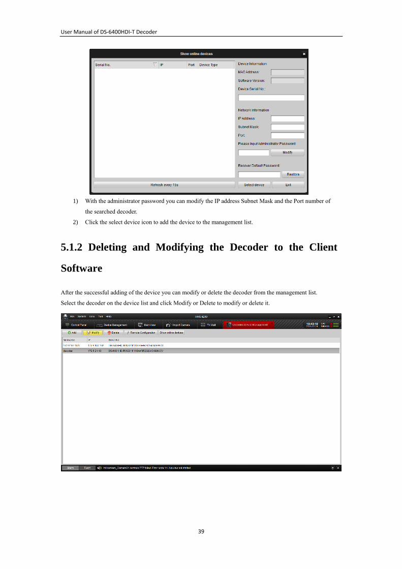
4. You can also click Show online devices to search the online devices in the same network segment. And
if there are online devices in the same network segment, they are listed in the left part on the interface
shown in the following figure.
User Manual of DS-6400HDI-T Decoder
39
1) With the administrator password you can modify the IP address Subnet Mask and the Port number of
the searched decoder.
2) Click the select device icon to add the device to the management list.
5.1.2 Deleting and Modifying the Decoder to the Client
Software
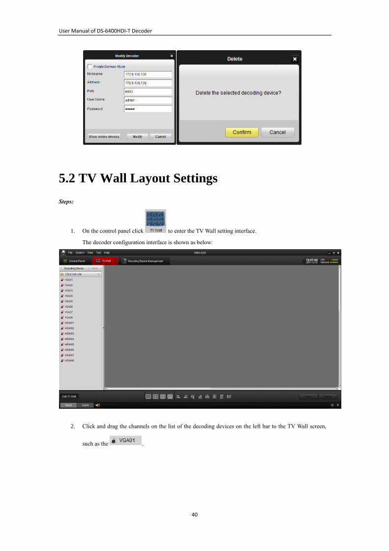
After the successful adding of the device you can modify or delete the decoder from the management list.
Select the decoder on the device list and click Modify or Delete to modify or delete it.
User Manual of DS-6400HDI-T Decoder
40
5.2 TV Wall Layout Settings
Steps:
1. On the control panel click to enter the TV Wall setting interface.
The decoder configuration interface is shown as below:
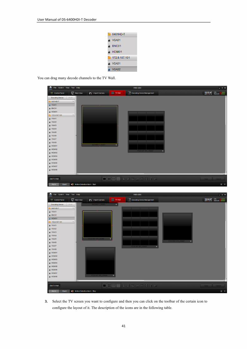
2. Click and drag the channels on the list of the decoding devices on the left bar to the TV Wall screen,
such as the .
User Manual of DS-6400HDI-T Decoder
41
You can drag many decode channels to the TV Wall.
3. Select the TV screen you want to configure and then you can click on the toolbar of the certain icon to
configure the layout of it. The description of the icons are in the following table.
User Manual of DS-6400HDI-T Decoder
42
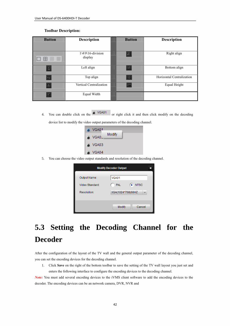
Toolbar Description:
Button Description Button Description
1\4\9\16-division
display
Right align
Left align
Bottom align
Top align
Horizontal Centralization
Vertical Centralization
Equal Height
Equal Width
4. You can double click on the or right click it and then click modify on the decoding
device list to modify the video output parameters of the decoding channel.
5. You can choose the video output standards and resolution of the decoding channel.
5.3 Setting the Decoding Channel for the
Decoder
After the configuration of the layout of the TV wall and the general output parameter of the decoding channel,
you can set the encoding devices for the decoding channel.
1. Click Save on the right of the bottom toolbar to save the setting of the TV wall layout you just set and
enters the following interface to configure the encoding devices to the decoding channel.
Note: You must add several encoding devices to the iVMS client software to add the encoding devices to the
decoder. The encoding devices can be an network camera, DVR, NVR and
User Manual of DS-6400HDI-T Decoder
43
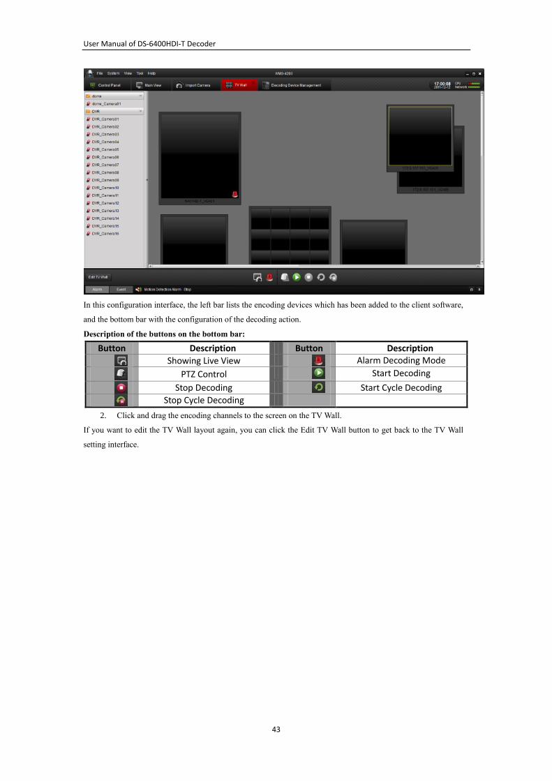
In this configuration interface, the left bar lists the encoding devices which has been added to the client software,
and the bottom bar with the configuration of the decoding action.
Description of the buttons on the bottom bar:
Button Description Button Description
Showing Live View
Alarm Decoding Mode
PTZ Control
Start Decoding
Stop Decoding
Start Cycle Decoding
Stop Cycle Decoding
2. Click and drag the encoding channels to the screen on the TV Wall.
If you want to edit the TV Wall layout again, you can click the Edit TV Wall button to get back to the TV Wall
setting interface.
User Manual of DS-6400HDI-T Decoder
44
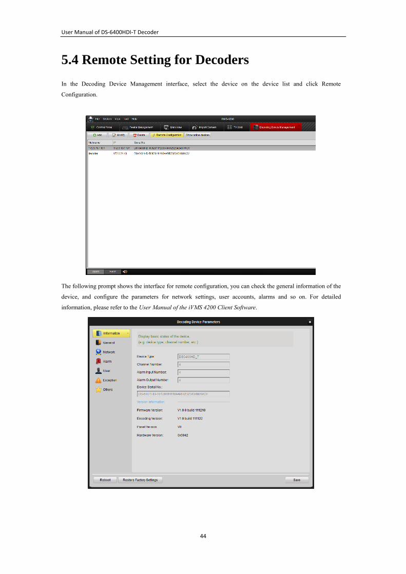
5.4 Remote Setting for Decoders
In the Decoding Device Management interface, select the device on the device list and click Remote
Configuration.
The following prompt shows the interface for remote configuration, you can check the general information of the
device, and configure the parameters for network settings, user accounts, alarms and so on. For detailed
information, please refer to the User Manual of the iVMS 4200 Client Software.

User Manual of DS-6400HDI-T Decoder
45
CHAPTER 6
Appendix
User Manual of DS-6400HDI-T Decoder
46
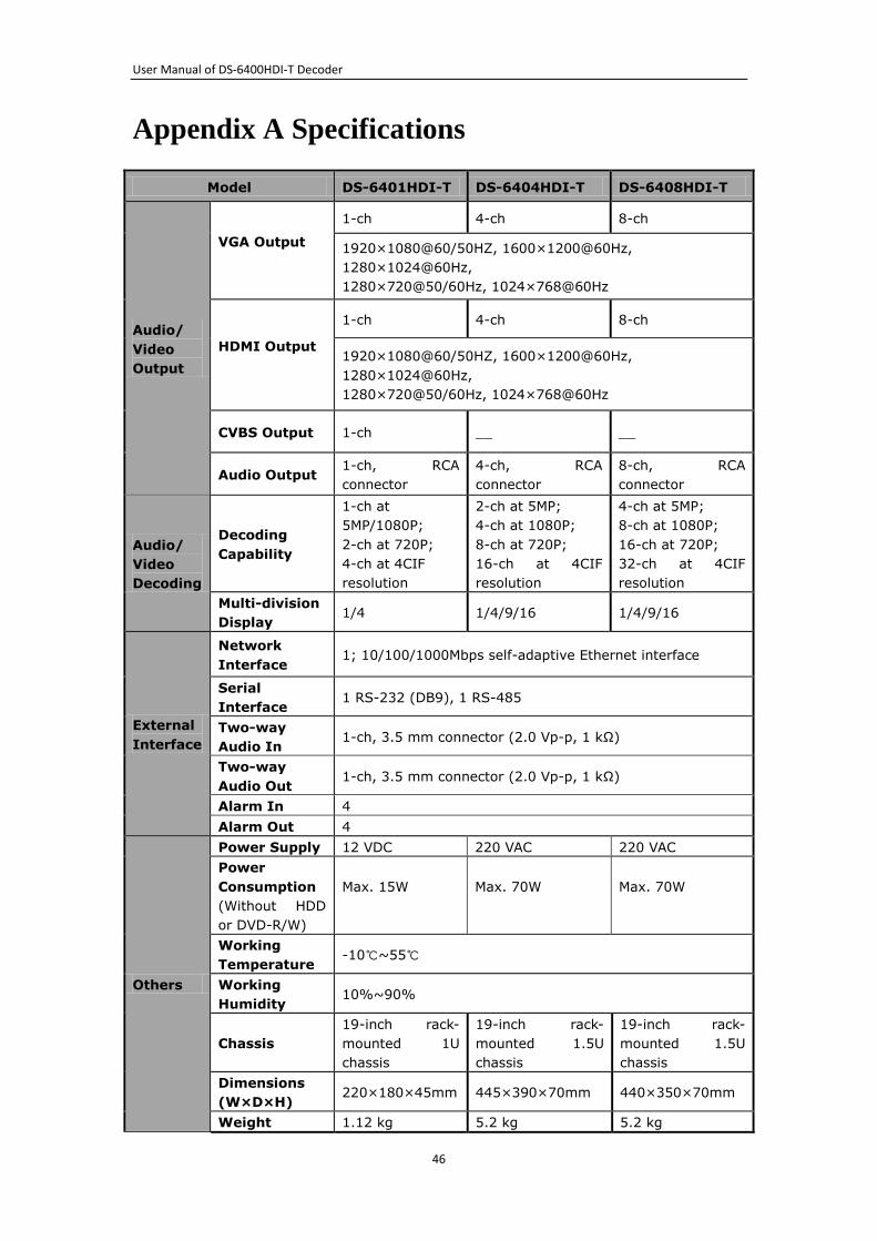
Appendix A Specifications
Model DS-6401HDI-T DS-6404HDI-T DS-6408HDI-T
Audio/
Video
Output
VGA Output
1-ch 4-ch 8-ch
1920×1080@60/50HZ, 1600×1200@60Hz,
1280×1024@60Hz,
1280×720@50/60Hz, 1024×768@60Hz
HDMI Output
1-ch 4-ch 8-ch
1920×1080@60/50HZ, 1600×1200@60Hz,
1280×1024@60Hz,
1280×720@50/60Hz, 1024×768@60Hz
CVBS Output 1-ch __ __
Audio Output 1-ch, RCA
connector
4-ch, RCA
connector
8-ch, RCA
connector
Audio/
Video
Decoding
Decoding
Capability
1-ch at
5MP/1080P;
2-ch at 720P;
4-ch at 4CIF
resolution
2-ch at 5MP;
4-ch at 1080P;
8-ch at 720P;
16-ch at 4CIF
resolution
4-ch at 5MP;
8-ch at 1080P;
16-ch at 720P;
32-ch at 4CIF
resolution
Multi-division
Display 1/4 1/4/9/16 1/4/9/16
External
Interface
Network
Interface 1; 10/100/1000Mbps self-adaptive Ethernet interface
Serial
Interface 1 RS-232 (DB9), 1 RS-485
Two-way
Audio In 1-ch, 3.5 mm connector (2.0 Vp-p, 1 kΩ)
Two-way
Audio Out 1-ch, 3.5 mm connector (2.0 Vp-p, 1 kΩ)
Alarm In 4
Alarm Out 4
Others
Power Supply 12 VDC 220 VAC 220 VAC
Power
Consumption
(Without HDD
or DVD-R/W)
Max. 15W
Max. 70W
Max. 70W
Working
Temperature -10℃~55℃
Working
Humidity 10%~90%
Chassis
19-inch rack-
mounted 1U
chassis
19-inch rack-
mounted 1.5U
chassis
19-inch rack-
mounted 1.5U
chassis
Dimensions
(W×D×H) 220×180×45mm 445×390×70mm 440×350×70mm
Weight 1.12 kg 5.2 kg 5.2 kg
User Manual of DS-6400HDI-T Decoder
47
Appendix B. FAQ
Why cannot ping the decoder?
1. Check the cable and the switch.
2. Please refer to Chapter 3 to configure the IP address of the decoder.
Why cannot connect the decoder with client software?
1. Check the decoder IP address.
2. Cable is connected.
3. User name and password of decoder are correct.
Why cannot play back the record files in DVR with decoder?
1. Check the DVR network connection.
2. Check the parameters of the playback file.
3. Check if there are files existed in the selected time duration.
Why cannot decode the stream transported by stream media server?
1. Check the network connection between decoder and stream media server.
2. Check if the stream media server port is connected with the port added on decoder.

User Manual of DS-6400HDI-T Decoder
48