Embed Size (px)
Citation preview

DS-1600KI Network Keyboard
User Manual UD00183B

1
User Manual
COPYRIGHT ©2015 Hangzhou Hikvision Digital Technology Co., Ltd.
ALL RIGHTS RESERVED.
Any and all information, including, among others, wordings, pictures, graphs are the properties of Hangzhou
Hikvision Digital Technology Co., Ltd. or its subsidiaries (hereinafter referred to be “Hikvision”). This user
manual (hereinafter referred to be “the Manual”) cannot be reproduced, changed, translated, or distributed,
partially or wholly, by any means, without the prior written permission of Hikvision. Unless otherwise stipulated,
Hikvision does not make any warranties, guarantees or representations, express or implied, regarding to the
Manual.
About this Manual
This Manual is applicable to DS-1600KI Network Keyboard.
The Manual includes instructions for using and managing the product. Pictures, charts, images and all other
information hereinafter are for description and explanation only. The information contained in the Manual is
subject to change, without notice, due to firmware updates or other reasons. Please find the latest version in the
company website (http://overseas.hikvision.com/en/).
Please use this user manual under the guidance of professionals.
Trademarks Acknowledgement
and other Hikvision’s trademarks and logos are the properties of Hikvision in various
jurisdictions. Other trademarks and logos mentioned below are the properties of their respective owners.
Legal Disclaimer
TO THE MAXIMUM EXTENT PERMITTED BY APPLICABLE LAW, THE PRODUCT DESCRIBED, WITH
ITS HARDWARE, SOFTWARE AND FIRMWARE, IS PROVIDED “AS IS”, WITH ALL FAULTS AND
ERRORS, AND HIKVISION MAKES NO WARRANTIES, EXPRESS OR IMPLIED, INCLUDING WITHOUT
LIMITATION, MERCHANTABILITY, SATISFACTORY QUALITY, FITNESS FOR A PARTICULAR
PURPOSE, AND NON-INFRINGEMENT OF THIRD PARTY. IN NO EVENT WILL HIKVISION, ITS
DIRECTORS, OFFICERS, EMPLOYEES, OR AGENTS BE LIABLE TO YOU FOR ANY SPECIAL,
CONSEQUENTIAL, INCIDENTAL, OR INDIRECT DAMAGES, INCLUDING, AMONG OTHERS,
DAMAGES FOR LOSS OF BUSINESS PROFITS, BUSINESS INTERRUPTION, OR LOSS OF DATA OR
DOCUMENTATION, IN CONNECTION WITH THE USE OF THIS PRODUCT, EVEN IF HIKVISION HAS
BEEN ADVISED OF THE POSSIBILITY OF SUCH DAMAGES.
REGARDING TO THE PRODUCT WITH INTERNET ACCESS, THE USE OF PRODUCT SHALL BE
WHOLLY AT YOUR OWN RISKS. HIKVISION SHALL NOT TAKE ANY RESPONSIBILITES FOR
ABNORMAL OPERATION, PRIVACY LEAKAGE OR OTHER DAMAGES RESULTING FROM CYBER
ATTACK, HACKER ATTACK, VIRUS INSPECTION, OR OTHER INTERNET SECURITY RISKS;
HOWEVER, HIKVISION WILL PROVIDE TIMELY TECHNICAL SUPPORT IF REQUIRED.
SURVEILLANCE LAWS VARY BY JURISDICTION. PLEASE CHECK ALL RELEVANT LAWS IN YOUR
JURISDICTION BEFORE USING THIS PRODUCT IN ORDER TO ENSURE THAT YOUR USE CONFORMS
THE APPLICABLE LAW. HIKVISION SHALL NOT BE LIABLE IN THE EVENT THAT THIS PRODUCT IS
USED WITH ILLEGITIMATE PURPOSES.
IN THE EVENT OF ANY CONFLICTS BETWEEN THIS MANUAL AND THE APPLICABLE LAW, THE
LATER PREVAILS.

2
Regulatory Information
FCC Information
FCC compliance: This equipment has been tested and found to comply with the limits for a Class A digital device,
pursuant to part 15 of the FCC Rules. These limits are designed to provide reasonable protection against harmful
interference when the equipment is operated in a commercial environment. This equipment generates, uses, and
can radiate radio frequency energy and, if not installed and used in accordance with the instruction manual, may
cause harmful interference to radio communications. Operation of this equipment in a residential area is likely to
cause harmful interference in which case the user will be required to correct the interference at his own expense.
FCC Conditions
This device complies with part 15 of the FCC Rules. Operation is subject to the following two conditions:
1. This device may not cause harmful interference.
2. This device must accept any interference received, including interference that may cause undesired operation.
EU Conformity Statement
This product and - if applicable - the supplied accessories too are marked with "CE" and comply
therefore with the applicable harmonized European standards listed under the EMC Directive
2004/108/EC, the RoHS Directive 2011/65/EU.
2012/19/EU (WEEE directive): Products marked with this symbol cannot be disposed of as unsorted
municipal waste in the European Union. For proper recycling, return this product to your local
supplier upon the purchase of equivalent new equipment, or dispose of it at designated collection
points. For more information see: www.recyclethis.info
2006/66/EC (battery directive): This product contains a battery that cannot be disposed of as unsorted
municipal waste in the European Union. See the product documentation for specific battery
information. The battery is marked with this symbol, which may include lettering to indicate
cadmium (Cd), lead (Pb), or mercury (Hg). For proper recycling, return the battery to your supplier or to a
designated collection point. For more information see: www.recyclethis.info
Industry Canada ICES-003 Compliance
This device meets the CAN ICES-3 (A)/NMB-3(A) standards requirements.

3
Safety Instruction
These instructions are intended to ensure that user can use the product correctly to avoid danger or property loss.
The precaution measure is divided into “Warnings” and “Cautions”
Warnings: Serious injury or death may occur if any of the warnings are neglected.
Cautions: Injury or equipment damage may occur if any of the cautions are neglected.
Warnings
Proper configuration of all passwords and other security settings is the responsibility of the installer
and/or end-user.
In the use of the product, you must be in strict compliance with the electrical safety regulations of the
nation and region. Please refer to technical specifications for detailed information.
Input voltage should meet both the SELV (Safety Extra Low Voltage) and the Limited Power Source
with 100~240 VAC or 12 VDC according to the IEC60950-1 standard. Please refer to technical
specifications for detailed information.
Do not connect several devices to one power adapter as adapter overload may cause over-heating or a
fire hazard.
Please make sure that the plug is firmly connected to the power socket.
If smoke, odor or noise rise from the device, turn off the power at once and unplug the power cable, and
then please contact the service center.
Warnings Follow these safeguards to
prevent serious injury or death.
Cautions Follow these precautions to
prevent potential injury or material damage.

4
Preventive and Cautionary Tips
Before connecting and operating your keyboard, please be advised of the following tips:
• Ensure unit is placed in a well-ventilated, dust-free environment.
• Keep all liquids away from the keyboard.
• Please check the power supply to avoid the damage caused by voltage mismatch.
• Please make sure the keyboard works in the allowed range of temperature and humidity.
• Please keep the device horizontal and avoid the installation under severe vibration environment.
• The dust board will cause a short circuit after damping; please use brush to dedust regularly for the board,
connector, chassis fan, etc.

5
Table of Contents
Chapter 1 Product Overview ...................................................................................................................... 7
1.1 Introduction ...................................................................................................................................... 8
1.2 Appearance ....................................................................................................................................... 8
Chapter 2 Getting Started .........................................................................................................................10
2.1 Activating the Keyboard ..................................................................................................................11
2.2 Configuring Keyboard by SADP .................................................................................................... 12
2.3 Login and Logout ........................................................................................................................... 15
Chapter 3 General Settings ........................................................................................................................17
3.1 Ethernet Settings ............................................................................................................................. 19
3.2 WLAN Settings .............................................................................................................................. 20
3.3 Language Settings ........................................................................................................................... 22
3.4 Date and Time Settings ................................................................................................................... 22
3.5 Others ............................................................................................................................................. 24
3.6 About .............................................................................................................................................. 25
Chapter 4 Keyboard Application ................................................................................................................27
4.1 Main Menu ..................................................................................................................................... 28
4.2 Device Management ....................................................................................................................... 28
4.2.1 Managing the Devices ............................................................................................................. 29
4.2.2 Managing the Cameras ............................................................................................................ 36
4.2.3 Managing the Groups .............................................................................................................. 39
4.2.4 Managing the Video Wall ........................................................................................................ 43
4.3 Live View........................................................................................................................................ 46
4.3.1 Local View ............................................................................................................................... 47
4.3.2 Video Wall ............................................................................................................................... 53
4.3.3 External View .......................................................................................................................... 59
4.4 System Configuration ..................................................................................................................... 62
4.4.1 User Management .................................................................................................................... 62
4.4.2 Storage Management ............................................................................................................... 69
4.4.3 System Maintenance ................................................................................................................ 70
Chapter 5 Accessing by iVMS Platform ......................................................................................................72
5.1 Configuring iVMS-5200 Platform .................................................................................................. 73
5.1.1 Platform Login ......................................................................................................................... 73
5.1.2 Main Menu .............................................................................................................................. 73
5.1.3 Managing the Video Wall ........................................................................................................ 74
5.1.4 Managing the Input Channel.................................................................................................... 76
5.2 Displaying Video on Monitor ......................................................................................................... 77
5.3 Logout ............................................................................................................................................. 79
Chapter 6 Accessing by Matrix Access Gateway .........................................................................................81
6.1 Matrix Access Gateway Login ........................................................................................................ 82
6.2 Configuring the Video Wall ............................................................................................................ 82
6.3 Logout ............................................................................................................................................. 84
Chapter 7 Appendix ..................................................................................................................................85

6
7.1 Specifications .................................................................................................................................. 86
7.2 Summary of Changes ...................................................................................................................... 86

7
Chapter 1 Product Overview

8
1.1 Introduction
DS-1600KI is the new generation of fully touch-enabled and detachable network keyboard independently
developed by Hikvision. In addition to displaying images, the 10.1" capacitive touchscreen supports DVI and
HDMI video outputs. It runs on Android 4.4 and has the brand new UI design. It is compatible with all series of
front-end and back-end devices of Hikvision and control center platform such as iVMS. It supports recording,
picture capturing and two-way audio, as well as the video wall control and scene switch of iVMS and decoding
devices. The four-axis joystick can be used to the PTZ control of speed dome and quick location of the target. The
joystick panel is detachable for the convenience of operation. This keyboard can be widely used in various video
surveillance fields.
1.2 Appearance
12
3
Figure 1.1 Appearance of DS-1600KI Keyboard
The DS-1600KI keyboard consists of a touchscreen and a joystick panel. The joystick panel is detachable and can
be separated from the keyboard. Refer to Table 1.1 for the description of the keyboard appearance.
Table 1. 1 Description of Keyboard Appearance
Number Name Description
1 Touchscreen 10.1" capacitive touchscreen for display, configuration and operation of the
keyboard.
2 Joystick Used for PTZ control.
3 Capture Button Used for picture capture.
Refer to Table 1.2 for the description of the joystick operations.
Table 1. 2 Description of Joystick Operations
Graphic Operation Function
Up PTZ control mode: Move the PTZ up.
Down PTZ control mode: Move the PTZ down.

9
Left PTZ control mode: Move the PTZ left.
Right PTZ control mode: Move the PTZ right.
Rotate anticlockwise Zoom out (ZOOM-)
Rotate clockwise Zoom in (ZOOM+)
There are eight interfaces and one button on the rear panel of DS-1600KI keyboard.
1 2 3 4 5 6 7 8 9
POWER12 VDCLANLIN E
INAUDIO
OUTDVI
Figure 1.2 Rear Panel of DS-1600KI
Refer to Table 1.3 for the description of the rear interface of the keyboard.
Table 1. 3 Description of Rear Panel
Number Name Description
1 USB Interface One for connecting to the USB device. One for connecting to the joystick.
2
3 DVI DVI video output connector.
4 HDMI HDMI video output connector.
5 LINE IN 3.5 mm connector for audio input.
6 AUDIO OUT 3.5 mm connector for audio output.
7 LAN Network
Interface 1 10M/100M/1000M adaptive Ethernet interface.
8 Power Input 12 VDC power input.
9 Power Switch
Press to turn on or turn off the touchscreen.
Hold down to enable the keyboard into the sleeping mode. Hold down in the
sleeping mode to wake it up.

10
Chapter 2 Getting Started

11
The network keyboard is in inactive status when it leaves factory. You should activate it before performing other
operations. Then you can log in to and log out of the keyboard.
2.1 Activating the Keyboard
For the first-time access, you need to activate the keyboard by setting an admin password. No operation is allowed
before activation. You can activate by the local keyboard or SADP. Refer to Chapter 2.2 Configuring Keyboard by
SADP for details.
Steps:
1. Enter the password in the Set Password text field. You can only use any two or more than two combinations
of upper case letters, lower case letters, numbers, and special characters. The password level hint will appear.
Figure 2.1 Activation Interface
STRONG PASSWORD RECOMMENDED–We highly recommend you create a strong password
of your own choosing (Using a minimum of 8 characters, including at least three of the following
categories: upper case letters, lower case letters, numbers, and special characters.) in order to increase the
security of your product. And we recommend you reset your password regularly, especially in the high
security system, resetting the password monthly or weekly can better protect your product.
There are 4 levels of the password. The strength level of the password will be displayed when you enter the
password.
Level 0 (Risky password): The length of the password is less than 8-character long. Or the password is the
same with the user name or the sequence of the password is the inverted sequence of the user name. Or the
password only contains one kind of characters.
Figure 2.2 Risky Password
Level 1 (Weak password): It includes two kinds of characters including numbers and lower case letters, or
numbers and upper case letters. A minimum of 8 characters are used.
Figure 2.3 Weak Password
Level 2 (Medium password): It includes two kinds of characters. The combination cannot be numbers and

12
lower case letters, or numbers and upper case letters. A minimum of 8 characters are used.
Figure 2.4 Medium Password
Level 3 (Strong password): It includes three kinds of characters or above. A minimum of 8 characters are
used.
Figure 2.5 Strong Password
2. Confirm the password in the Confirm text field.
3. Click Activate button to activate the keyboard.
2.2 Configuring Keyboard by SADP
You can also configure the keyboard by SADP. SADP can search the DS-1600KI keyboard and display the device
information.
Activating the Keyboard
Purpose:
For the new keyboard or the keyboard after complete restoration, the security status is inactive. You need to
activate the keyboard before the other operations.
Figure 2.6 SADP Interface
Steps:
1. Select the checkbox before the ID of the DS-1600KI keyboard and the Activate the Device panel appears on
the right.

13
Figure 2.7 Activating the Device
2. Enter the new password in the New Password text field and confirm the password in the Confirm Password
text field.
Figure 2.8 Entering and Confirming the Password
The strength level of the password shows when you enter the password.
STRONG PASSWORD RECOMMENDED–We highly recommend you create a strong password
of your own choosing (Using a minimum of 8 characters, including at least three of the following
categories: upper case letters, lower case letters, numbers, and special characters.) in order to increase the
security of your product. And we recommend you reset your password regularly, especially in the high
security system, resetting the password monthly or weekly can better protect your product.
3. Click Activate button to activate the keyboard. After the activation, the security status of the keyboard will
become Active.
Modifying Network Parameters
Purpose:
You can modify the network parameters of the keyboard by SADP.
Steps:
1. Select the checkbox before the ID of the DS-1600KI keyboard.
2. The Modify Network Parameters panel appears on the right. Enter the IP Address, Port, Subnet Mask and
Gateway in the corresponding text field. Or select the checkbox of Enable DHCP to get the network
parameters automatically.

14
Figure 2.9 Modifying Network Parameters
3. Enter the Admin Password you have configured.
4. Click Modify button to complete the modification.
You can modify the port randomly within the range from 2000 to 65535.
You don’t need to modify the parameters of IPv6 Address, IPv6 Gateway, IPv6 Prefix Length and HTTP
Port.
Resetting the Keyboard Password
Purpose:
You can reset the keyboard password by SADP.
Steps:
1. Select the checkbox before the ID of the DS-1600KI keyboard.
2. Click to enter the Reset Password interface.
Figure 2.10 Resetting the Password
15
3. Click Export button to download the key request file. Set the file path in the pop-up window. Click Select
Folder to save the device key request file on your PC.
The exported key request file is XML file which is named as Device Serial No.-System Time.
4. Send the key request file to our technical engineers and the engineer will send you a key file back.
5. Select Import File radio button as the resetting mode.
6. Click to select the key file (XML file) returned by the technical engineer and click Open.
7. Enter the new password in text fields of New Password and Confirm Password. The system will judge
password strength automatically, and we highly recommend you to use a strong password to ensure your data
security.
STRONG PASSWORD RECOMMENDED–We highly recommend you create a strong password
of your own choosing (Using a minimum of 8 characters, including at least three of the following
categories: upper case letters, lower case letters, numbers, and special characters.) in order to increase the
security of your product. And we recommend you reset your password regularly, especially in the high
security system, resetting the password monthly or weekly can better protect your product.
8. Click Confirm to reset the password.
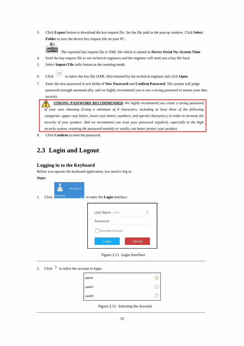
2.3 Login and Logout
Logging in to the Keyboard
Before you operate the keyboard application, you need to log in.
Steps:
1. Click to enter the Login interface.
Figure 2.11 Login Interface
2. Click to select the account to login.
Figure 2.12 Selecting the Account

16
3. Select the user account name by clicking .
4. Enter the password of the account.
5. (Optional) You can click the checkbox to select Remember Password to save the password.
6. Click Login.
If the admin enters wrong password for 7 times, the password would be locked. If the operator enters wrong
password for 5 times, the password would be locked. The times of entering wrong password by two users in 3
minutes will be overlapped. The password will be unlocked automatically in 30 minutes after being locked.
Logging out of the Keyboard
After login, you can log out of the keyboard.
Steps:
Click on the upper-right corner. The window box pops up as follows.
Figure 2.13 Logout Interface
Click Confirm to log out.
(Optional) Click to cancel the logout.

17
Chapter 3 General Settings
18
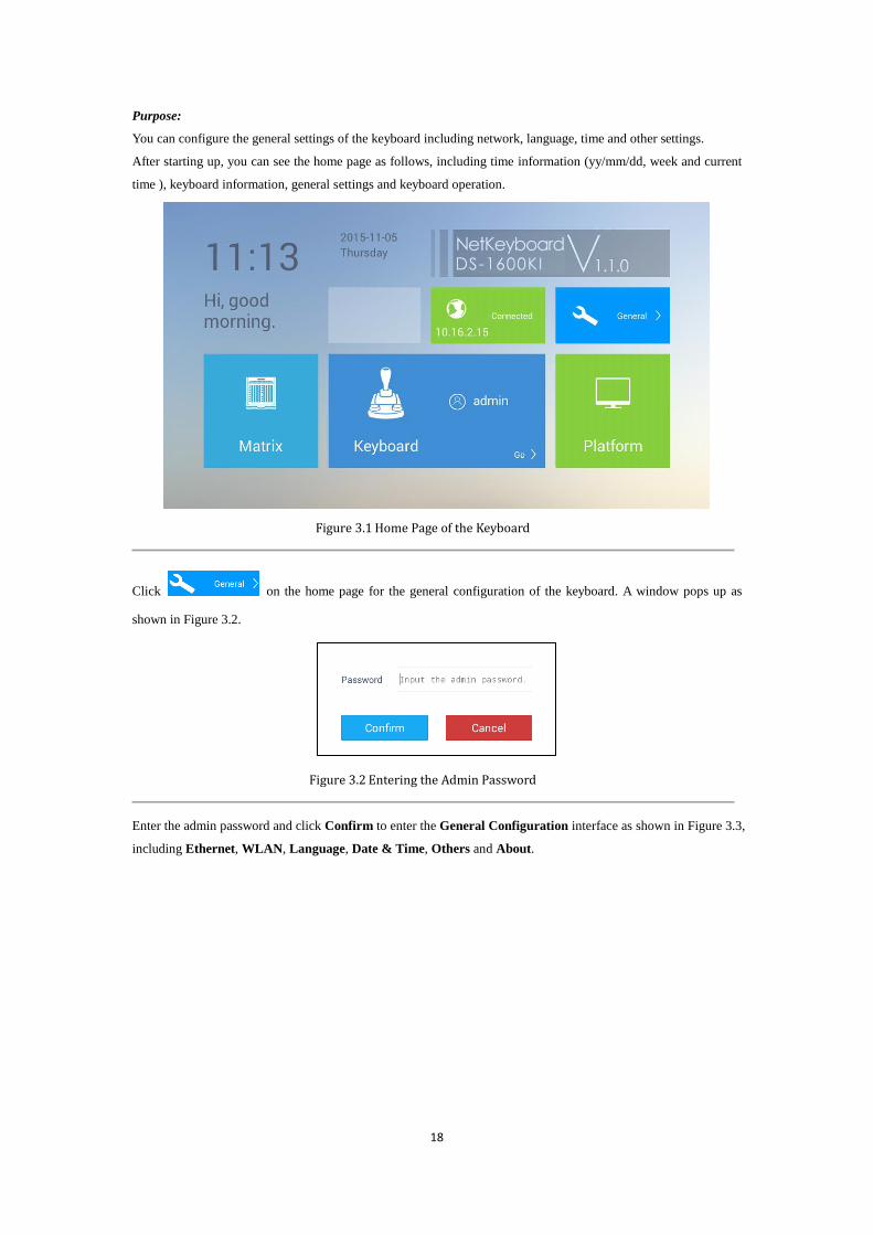
Purpose:
You can configure the general settings of the keyboard including network, language, time and other settings.
After starting up, you can see the home page as follows, including time information (yy/mm/dd, week and current
time ), keyboard information, general settings and keyboard operation.
Figure 3.1 Home Page of the Keyboard
Click on the home page for the general configuration of the keyboard. A window pops up as
shown in Figure 3.2.
Figure 3.2 Entering the Admin Password
Enter the admin password and click Confirm to enter the General Configuration interface as shown in Figure 3.3,
including Ethernet, WLAN, Language, Date & Time, Others and About.

19
Figure 3.3 General Settings Interface
Refer to Table 3.1 for the description of the General Settings interface.
Table 3.1 Description of General Settings Interface
Menu Descriptions
Ethernet Support two network configuration modes: Static IP and DHCP.
WLAN Connect to available WLAN
Language Chinese / English
Date & Time Set Date & Time and select Time Zone
Others
Adjust the Brightness of the screen, choose interval of the Sleep time,
enable/disable the Alarm Sound and choose the Resolution of External
Monitor.
About Show the detailed information of the DS-1600KI
3.1 Ethernet Settings
Purpose:
You can configure Ethernet settings to connect to the network.
Steps:
1. Click the Ethernet button on the right of the General interface to enter the Ethernet Configuration
interface.
2. Switch the Ethernet enable button to to enable Ethernet configuration.
Task 1: Configure Static IP
Steps:
1) Click the Static IP enable button to to enable Static IP configuration.
2) Click the Edit button to enter the IP address configuration interface shown in Figure 3.4.
3) You can set the IP address parameters and click on the upper-left corner to save the modification.

20
Figure 3.4 Setting the Static IP Parameters
Task 2: Configure DHCP
Steps:
1) Click the DHCP enable button to to enable DHCP configuration.
2) Click the Details button to enter the Details interface shown in Figure 3.5 to gain the practical IP
parameters.
Figure 3.5 Details of DHCP
You can not enable Static IP and DHCP at the same time.
3.2 WLAN Settings
Purpose:
You can configure WLAN parameters to connect to the network.
Steps:
1. Click the WLAN button on the right of the General interface to enter the WLAN Configuration interface.
2. Switch the WLAN enable button to to enable automatic acquisition of WLAN information.
You can obtain Wi-Fi information nearby or enter Wi-Fi information manually to add network.
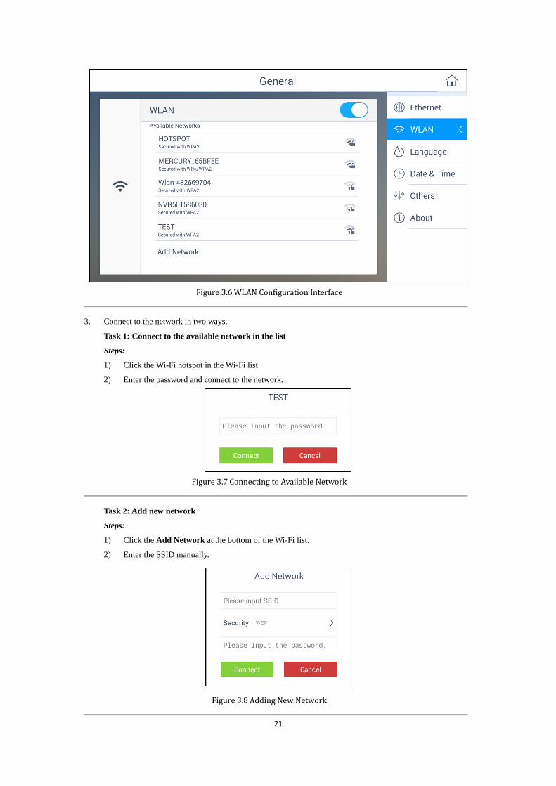
21
Figure 3.6 WLAN Configuration Interface
3. Connect to the network in two ways.
Task 1: Connect to the available network in the list
Steps:
1) Click the Wi-Fi hotspot in the Wi-Fi list
2) Enter the password and connect to the network.
Figure 3.7 Connecting to Available Network
Task 2: Add new network
Steps:
1) Click the Add Network at the bottom of the Wi-Fi list.
2) Enter the SSID manually.
Figure 3.8 Adding New Network

22
3) Select the security type as shown in Figure 3.9.
Figure 3.9 Selecting the Security Type
4) Enter the password to connect to the network.
If you open both the Ethernet and WLAN, the WLAN takes effect by default.
3.3 Language Settings
Purpose:
You can choose language for the device in this section.
Steps:
1. Click the Language button on the right of the General interface to enter the Language Configuration
interface.
2. Click the radio button to to select the Chinese or English language.
Figure 3.10 Language Configuration Interface
3.4 Date and Time Settings
Purpose:
You can set date and time and select time zone by configuring the parameters.

23
Configure Date & Time:
Steps:
1. Click the Date & Time button on the right of the General interface to enter the configuration interface.
Figure 3.11 Date and Time Configuration Interface
2. Set the date and time in two ways.
Task 1: Automatic mode
Steps:
Enable the automatic mode by switching to , or else the manual mode is enabled.
Task 2: Manual mode
Steps:
1) Click to set the current date as shown in Figure 3.12.
2) Click to set the current time as shown in Figure 3.12.
Figure 3.12 Date and Time Configuration
Select Time Zone:
Steps:
Click to select time zone in your location. The pop-up interface is shown in Figure 3.13.

24
Figure 3.13 Selecting Time Zone
3.5 Others
Purpose:
You can adjust the brightness of the screen, choose interval of the sleep time, enable/disable the alarm sound and
choose the resolution of the external monitor.
Steps:
1. Click the Others button on the right of the General interface to enter the configuration interface.
Figure 3.14 Others Configuration Interface
2. Configure the other parameters.
Task 1: Configure brightness
Steps:
Click to lighten the screen and click to darken the screen. You can choose in the range of 5% to
100%.
Task 2: Configure sleeping interval

25
Steps:
Click for interval selecting and five modes of interval are selectable. The pop-up
window is shown in Figure 3.15.
Figure 3.15 Selecting Sleeping Interval
Task 3: Configure alarm sound
Steps:
Turn the alarm sound as ON via setting as and turn it as OFF via setting as .
Support alarm in network disconnected, IP conflicted, USB error and FTP error conditions.
Task 4: Configure the resolution of external monitor
Steps:
Click to select the resolution of external monitor. The pop-up window is shown in Figure 3.16.
Figure 3.16 Selecting the Resolution of External Monitor
3.6 About
Purpose:
You can obtain the detailed information of DS-1600KI network keyboard including Version information and Serial
No..
Steps:
Click the About button on the right of the General interface to enter the About interface. You can see the detailed
information of the network keyboard.

26
Figure 3.17 About Interface

27
Chapter 4 Keyboard Application

28
4.1 Main Menu
Click to enter the keyboard operation interface. You can click on the upper-right corner to enter
the main menu shown in Figure 4.1.
Figure 4.1 Main Menu
Refer to Table 4.1 for the description of the main menu.
Table 4.1 Description of Main Menu
Menu Description
Live View Live view by Local/Video Wall/External, PTZ control, recording, picture capturing,
two-way audio, etc.
Device Display device list, manage the device/camera/group/video wall, view device information,
etc.
Configuration User management, Storage management and System maintenance.
Home Return to the home page.
4.2 Device Management
Purpose:
You can manage the devices in the Device Management section, including managing the device, camera, group
and video wall.
Click on the main menu to enter the Device Management interface.
The Device Management contains four sections: managing devices, camera, group and video wall. Refer to Table

29
4.2 for the description of device management.
Table 4.2 Description of Device Management
Menu Description
Device Add/view/delete/modify/refresh devices
Camera View and modify the details of the channels.
Group Add/delete/modify the groups which contains several channels.
Video Wall Edit the video wall name, row and column; Configure the output of the channels on video wall.
4.2.1 Managing the Devices
Purpose:
For the admin, you can add/delete/modify/refresh devices on the Device Management interface. And some other
basic operations are supported, including viewing the device details, and clearing all the added devices. For the
operators, you can only refresh/view the details of the devices authorized by the admin on the Device
Management interface.
Select Device on the right side to enter the Device Management interface.
Figure 4.2 Device Management Interface of the Admin

30
Figure 4.3 Device Management Interface of the Operator
Adding a Device by the Admin
Purpose:
As the admin, you need to add a device firstly that all operations such as live view and device management are
accessible. Two ways are available for adding the devices: manual adding and auto-adding. As an operator, you
cannot add devices. All the devices authorized by the admin are shown on the Device Management interface.
Up to 2000 devices can be added by the admin.
Task1: Manual Adding
Steps:
1. Click Add Device to manually add a device. A window pops up as shown in Figure 4.4.
Figure 4.4 Manual Adding Device
Name: Edit a name for the device as desired.

31
Special characters are not allowed to enter. The longest length is 32 characters long. If the name is
left empty, the current name of the device is remained.
Type: The type of the added device. It is not editable when you add a device. The type of the device will be
shown after you add it successfully.
Address: The IP address of the added device.
Port: The port of the added device.
User Name: Enter the user name of the added device.
Password: Enter the password of the added device.
2. Click to confirm and finish the adding of device.
3. (Optional) You can click to cancel adding.
If the entered parameters are wrong, an exception window will pop up to remind you.
Task2: Auto-adding
Steps:
1. Click and hold down the Add Device icon for one second. The Auto Search window pops up as shown in
Figure 4.5. All the online devices under the same broadcast domain with the keyboard will be displayed in the
Auto Search window.
Figure 4.5 Auto Search Result
2. Click to select the added device. The device already added will be marked with .
3. Click to confirm the settings. And a pop-up box will show up to enter the user name and password of the
added device.
Figure 4.6 Auto Adding Device

32
4. Enter the user name and password of the added device.
5. Click Confirm.
6. (Optional) You can click Cancel to cancel the auto-adding.
When you add devices in batch, the user names and passwords of all the devices will be matched
one by one. Only when matched successfully can the device be added.
Editing the Device by the Admin
Purpose:
In the Device Management interface, for the admin, you can view the details of, refresh and delete the added
devices. You can also clear all the added devices.
Click the added device in the Device Management interface. A pop-up box is shown in Figure 4.7.
Figure 4.7 Editing the Device by the Admin
Viewing and Modifying the Device
Steps:
1. Click Details to view the detailed information of the added devices including IP address, port, etc. The details
of the added devices is shown in Figure 4.8.
Figure 4.8 Viewing Device Information
2. Click to modify the details of the added devices. Only Name, User Name and Password are editable.

33
Figure 4.9 Editing the Device
3. Click to confirm the modification.
4. (Optional) You can click to cancel the modification.
Refreshing the Device
You can click Refresh to refresh the status of the added devices.
Deleting the Device
Steps:
1. Click Delete to delete the selected device. A hint box will pop up as shown in Figure.4.10 .
Figure 4.10 Hint Box of Deleting the Device
2. Click Delete to confirm the deletion.
3. (Optional) You can click to cancel the deletion.
Clearing the Devices
Steps:
1. Click Clear to delete all the devices. A hint box will pop up as shown in Figure 4.11.
Figure 4.11 Hint Box of Deleting all the Devices
2. Click Delete to confirm the deletion.

34
3. (Optional) You can click to cancel the deletion.
Controlling the Front Panel of Added DVR/NVR by the Admin
Purpose:
The keyboard can control the front panel of the added DVR/NVR.
Steps:
1. Click the added DVR/NVR in the Device Management interface. A pop-up box is shown in Figure 4.12.
Figure 4.12 Editing the Added DVR/NVR
2. Select Control to enter the Remote Panel.
Figure 4.13 DVR/NVR Remote Panel
3. Click the buttons on the control panel to control the front panel of the added DVR/NVR.
4. Click to exit from the DVR/NVR Control Panel.
You can also view the details of, refresh, delete and clear the added DVR/NVR. Refer to Editing the
Device by the Admin for reference.

35
Editing the Device by the Operator
Purpose:
In the Device Management interface, for the operator, you can only view the details of the added device and
refresh it.
Click the added device in the Device Management interface. A pop-up box is shown in Figure 4.14.
Figure 4.14 Editing the Device
Viewing the Device
Steps:
Click Details to view the detailed information of the added devices including IP address, port, etc. The details of
the added devices are shown in Figure 4.15.
Figure 4.15 Viewing Device Information
For the operator, you cannot modify the detailed information of the devices.
Refreshing the Device
You can click Refresh to refresh the status of the added devices.
Controlling the Front Panel of Added DVR/NVR by the Operator
Purpose:
The keyboard can control the front panel of the added DVR/NVR.
Steps:
1. Click the added DVR/NVR in the Device Management interface. A box pops up as shown in Figure 4.16.

36
Figure 4.16 Editing the Added DVR/NVR by the Operator
2. Select Control to enter the DVR/NVR Control Panel.
Figure 4.17 DVR/NVR Control Panel
3. Click the buttons on the control panel to control the front panel of the added DVR/NVR.
4. Click to exit from the DVR/NVR Control Panel.
You can also view the details of, and refresh the added DVR/NVR. Refer to Editing the Device by the
Operator for reference.
4.2.2 Managing the Cameras
Purpose:
You can view and edit the channel details on the Camera Management interface.
Select Camera on the right side to enter the Camera Management interface.

37
Figure 4.18 Camera Management Interface
The number on the upper-right corner of each camera, e.g., , is the serial number of the corresponding camera.
Viewing the Camera
Steps:
1. Click the camera tab to view the details. A window of channel details is shown in Figure 4.19.
Figure 4.19 Viewing the Camera for the Admin

38
Figure 4.20 Viewing the Camera for the Operator
2. You can view the information of the camera including name, channel ID, protocol, stream, device, address
and channel No.
Name: The name of the camera as desired.
Channel ID: The serial number of the camera according to the added sequence.
Protocol: The transfer protocol of the camera.
Stream: The stream type of the camera.
Device: The name of the channel.
Address: The IP address and port of the corresponding device.
Channel No.: The No. of the added camera.
Editing the Camera by the Admin
Only the admin has the permission to edit the channel.
Steps:
1. Click to modify the details of the cameras. Only Name, Channel ID, Protocol and Stream are editable.
Figure 4.21 Editing the Camera

39
When editing Name and Channel ID, you can click to delete the original information.
The range of the Channel ID is from 1 to 999999, and the ID cannot be repeated.
2. Click to select the protocol.
Figure 4.22 Selecting the Protocol
3. Click to select the stream.
Figure 4.23 Selecting the Stream Type
4. Click to confirm the modification.
5. (Optional) You can click to cancel the modification.
4.2.3 Managing the Groups
For the admin and operators, the group management steps are the same. This section takes the operations
of the admin as an example.
Purpose:
You can add the relevant cameras into the same group to make them easy to manage. E.g., you can add all the
cameras of the underground garage into one group.
You can add/delete/modify groups in the Group Management interface. And some other basic operations are
supported, including viewing the group details, and clearing all the groups.
Select Group on the right side to enter the Group Management interface.

40
Figure 4.24 Group Management Interface
Creating a New Group
Purpose:
You can create a new group and add some cameras in it.
Steps:
1. Click New Group to manually create a group. A pop-up window is shown in Figure 4.25.
Figure 4.25 Creating a New Group
Name: Edit a name for the group as desired. Special characters are not allowed to enter in the Name text
field. The longest length of the name is 32 characters long.
Group No.: Edit the group number as desired. The range is from 1 to 16, and the No. cannot be repeated.
You can add up to 64 cameras in each group and you can add up to 16 groups.
Dwell Time: Edit the cycle dwell time for each channel as desired. The range is from 10s to 10000s. The
default dwell time is 30s.
41
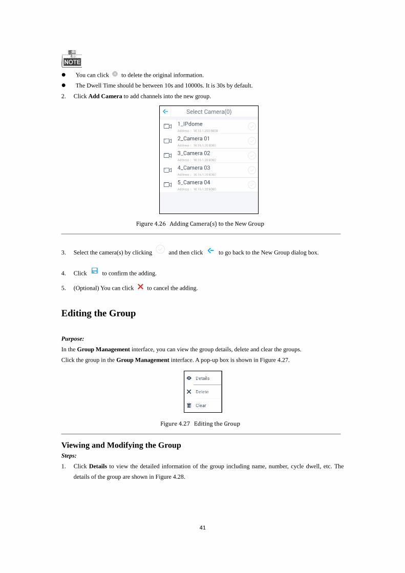
You can click to delete the original information.
The Dwell Time should be between 10s and 10000s. It is 30s by default.
2. Click Add Camera to add channels into the new group.
Figure 4.26 Adding Camera(s) to the New Group
3. Select the camera(s) by clicking and then click to go back to the New Group dialog box.
4. Click to confirm the adding.
5. (Optional) You can click to cancel the adding.
Editing the Group
Purpose:
In the Group Management interface, you can view the group details, delete and clear the groups.
Click the group in the Group Management interface. A pop-up box is shown in Figure 4.27.
Figure 4.27 Editing the Group
Viewing and Modifying the Group
Steps:
1. Click Details to view the detailed information of the group including name, number, cycle dwell, etc. The
details of the group are shown in Figure 4.28.

42
Figure 4.28 Viewing the Group
1. Click to modify the details of the selected group. Only Name, Dwell Time and Channels are editable.
Figure 4.29 Modifying the Group
2. If you want to delete an added camera, click .
3. Click Add Camera to add camera(s) to the group.
4. Click to confirm the modification.
5. (Optional) You can click to cancel the modification.
Deleting the Group
Steps:
1. Click Delete to delete the selected group. A hint box will pop up as follows.
Figure 4.30 Hint Box of Deleting the Group
2. Click Delete to confirm the deletion.

43
3. (Optional) You can click to cancel the deletion.
Clearing the Groups
Steps:
1. Click Clear to delete all the groups. A hint box will pop up as follows.
Figure 4.31 Hint Box of Deleting all the Groups
2. Click Delete to confirm the deletion.
3. (Optional) You can click to cancel the deletion.
4.2.4 Managing the Video Wall
Purpose:
You can configure the video wall on the Video Wall Management interface, including editing the video wall,
selecting the output channel and deleting the configured window.
Select Video Wall on the right side to enter the Video Wall Management interface.
Figure 4.32 Video Wall Management Interface
Editing the Video Wall
Purpose:

44
You can edit the details of the video wall, including the name, row and column.
Steps:
1. Click on the upper-right corner. A window pops up as shown in Figure 4.33.
Figure 4.33 Editing the Video Wall
Name: Edit a name for the video wall as desired.
Row: The row of the video wall.
Column: The column of the video wall.
You can click to delete the original information.
The row and column should be between 1 and 8.
The details will be displayed on the upper-left corner.
2. Click to confirm and save the settings.
3. (Optional) You can click to cancel editing.
Configuring the Output Channel
Purpose:
For the normal decoding devices, you can select the output channel for each video wall window. For some other
video wall devices, you can get the output channels automatically.
Steps:
1. Click the window on the video wall. A pop-up window is shown in Figure 4.34.

45
Figure 4.34 Selecting the Output Channel
2. Click on the upper-left corner to view all the channels of the decoder.
3. Click one of the channels to set it as the output channel of the selected window.
4. (Optional) You can click to cancel the configuration.
Deleting the Configured Window
As the admin, hold down the configured window for one second. Click on the upper-right corner of the
selected window to delete it.
Figure 4.35 Deleting the Configured Window
The DS-1600KI keyboard can automatically obtain the configured video wall of the DS-6400HDI-S,
DS-6400HDI-T, DS-6500HDI-T, DS-6901UDI, DS-B20, DS-C10S, DS-C10N, etc.. It supports the output
configuration of DS-6300DI, DS-6300DI-T, DS-6401HDI, DS-6500DI, DS-6500DI-T, etc.. It also supports

46
opening/closing the window, moving the window and switching the images and groups. The multi-screen display
configured on the iVMS-5200 client software cannot be deleted by holding down the window and clicking .
4.3 Live View
For the admin and operators, the live view steps are the same. This section takes the operations of the
admin as an example.
Purpose:
After the device is successfully added, you can view the live video of the added network cameras and video
encoders in the Live View interface. And some other basic operations are supported, including picture capturing,
manual recording, PTZ control, etc.
The PTZ control should be supported by the added device.
Steps:
1. Click on the main menu to enter the Live View interface. The screen will be displayed in
1-division mode by default. The keyboard supports three modes of live view: Local, Video Wall and
External.
Figure 4.36 Live View Interface
2. Click on the upper-right corner in the Live View interface to select the live view mode.
47
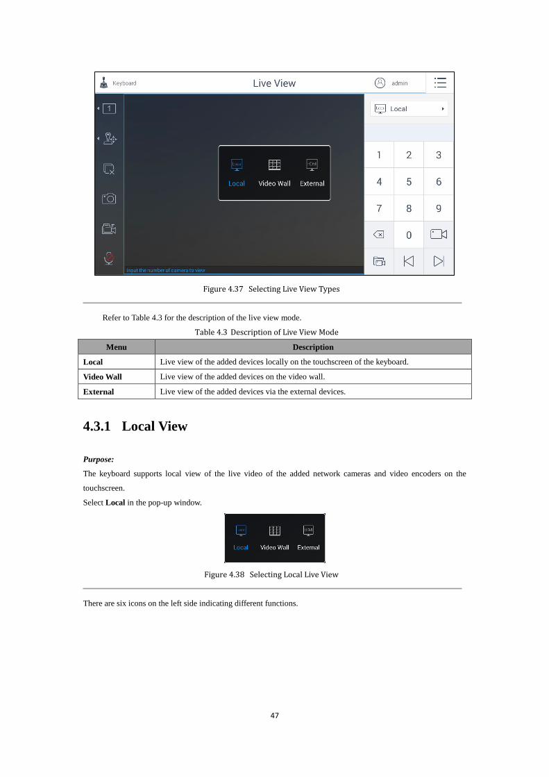
Figure 4.37 Selecting Live View Types
Refer to Table 4.3 for the description of the live view mode.
Table 4.3 Description of Live View Mode
Menu Description
Local Live view of the added devices locally on the touchscreen of the keyboard.
Video Wall Live view of the added devices on the video wall.
External Live view of the added devices via the external devices.
4.3.1 Local View
Purpose:
The keyboard supports local view of the live video of the added network cameras and video encoders on the
touchscreen.
Select Local in the pop-up window.
Figure 4.38 Selecting Local Live View
There are six icons on the left side indicating different functions.

48
Figure 4.39 Local Live View Interface
Refer to Table 4.4 for the description of the live view icons.
Table 4.4 Description of Live View Icons
Icon Description
Select the window division. The screen will be displayed in 1-division
mode by default.
The window division modes vary with the connected devices.
PTZ control panel.
Stop all the live view.
Capture picture of the selected live view window, and save the picture to the
USB disk or upload it to the FTP server. You can also press the button at the
top of the joystick to capture the picture.
/
Record the video of the selected live view window, and save the video to
the USB disk or upload it to the FTP server.
/
Enable/Disable two-way audio. You can get not only the live video but also
the real-time audio.
There is a numeric panel on the right with numbers 0 to 9 and five other icons for you to enter the serial number of
the device.
Figure 4.40 Live View Numeric Panel
49
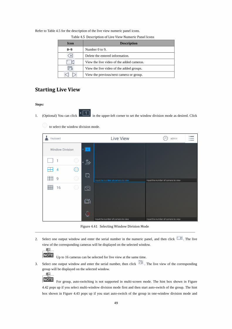
Refer to Table 4.5 for the description of the live view numeric panel icons.
Table 4.5 Description of Live View Numeric Panel Icons
Icon Description
0~9 Number 0 to 9.
Delete the entered information.
View the live video of the added cameras.
View the live video of the added groups.
View the previous/next camera or group.
Starting Live View
Steps:
1. (Optional) You can click in the upper-left corner to set the window division mode as desired. Click
to select the window division mode.
Figure 4.41 Selecting Window Division Mode
2. Select one output window and enter the serial number in the numeric panel, and then click . The live
view of the corresponding cameras will be displayed on the selected window.
Up to 16 cameras can be selected for live view at the same time.
3. Select one output window and enter the serial number, then click . The live view of the corresponding
group will be displayed on the selected window.
For group, auto-switching is not supported in multi-screen mode. The hint box shown in Figure
4.42 pops up if you select multi-window division mode first and then start auto-switch of the group. The hint
box shown in Figure 4.43 pops up if you start auto-switch of the group in one-window division mode and

50
then select multi-window division mode.
Figure 4.42 Hint box of Starting Auto-Switch of the Group (1)
Figure 4.43 Hint box of Starting Auto-Switch of the Group (2)
4. Enter 0 in the numeric panel and click . You can stop the live view of the corresponding camera.
5. (Optional) You can click to delete the entered information if you entered incorrectly.
6. (Optional) You can click or to preview the previous or next camera or group.
7. (Optional) You can double-click the selected window to realize full-screen live view. Or double-click in the
full-screen mode to restore to the normal live view mode.
8. (Optional) You can click to stop the local live view.
PTZ Control
In the live view mode, select a playing window and click to activate PTZ control panel, and the
changes to .
Figure 4.44 PTZ Control Panel
51
The PTZ control should be supported by the added device.
You can turn the joystick to realize the pan left/right and tilt up/down movements. You can also rotate the joystick
anticlockwise/clockwise to zoom out/in in the live view. Refer to Table 4.6 for the description of PTZ control panel
icons.
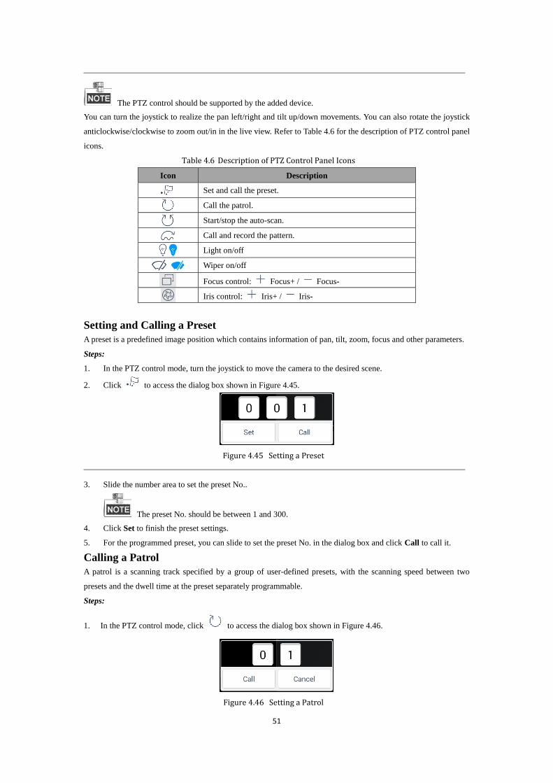
Table 4.6 Description of PTZ Control Panel Icons
Icon Description
Set and call the preset.
Call the patrol.
Start/stop the auto-scan.
Call and record the pattern.
Light on/off
Wiper on/off
Focus control: Focus+ / Focus-
Iris control: Iris+ / Iris-
Setting and Calling a Preset
A preset is a predefined image position which contains information of pan, tilt, zoom, focus and other parameters.
Steps:
1. In the PTZ control mode, turn the joystick to move the camera to the desired scene.
2. Click to access the dialog box shown in Figure 4.45.
Figure 4.45 Setting a Preset
3. Slide the number area to set the preset No..
The preset No. should be between 1 and 300.
4. Click Set to finish the preset settings.
5. For the programmed preset, you can slide to set the preset No. in the dialog box and click Call to call it.
Calling a Patrol
A patrol is a scanning track specified by a group of user-defined presets, with the scanning speed between two
presets and the dwell time at the preset separately programmable.
Steps:
1. In the PTZ control mode, click to access the dialog box shown in Figure 4.46.
Figure 4.46 Setting a Patrol

52
2. Slide to select a patrol No. in the dialog box and click Call to call it.
The patrol No. should be between 1 and 32.
3. Click Cancel to close the patrol dialog box.
Recording and Calling a Pattern
Patterns can be set to record the movement of the PTZ.
Steps:
1. In the PTZ control mode, click to access the dialog box shown in Figure 4.47.
Figure 4.47 Setting a Pattern
2. Slide to select a pattern No. in the dialog box.
Up to 4 patterns can be configured.
3. Click Record to start recording of this pattern path. The dialog box is shown in Figure 4.48.
Figure 4.48 Calling the Pattern
4. Use the joystick and other buttons to control the PTZ movement.
5. Click Stop to stop and save the pattern recording.
6. Click Call to call the pattern.
After completion of PTZ control, click to hide the PTZ control panel.
Capturing the Picture
Steps:
1. Select one output window and enter the serial number in the numeric panel, and then click . The live
video of the corresponding cameras will be displayed on the selected window.
2. Click to capture the picture of the selected live view window, and save the picture to the USB disk or
upload it to the FTP server. You can also press the button at the top of the joystick to capture the picture.
You must connect a USB disk to the keyboard, or ensure the network connection of the PC (running FTP
server) and the keyboard is valid and correct. Run the FTP server on the PC and copy the firmware into the
corresponding directory of your PC.

53
Recording
Steps:
1. Select one output window and enter the serial number in the numeric panel, and then click . The live
video of the corresponding cameras will be displayed on the selected window.
2. Click to record the video of the selected window, and then the icon will change to . The hint of
“Start recording” will appear.
3. Click to stop recording and the hint of “Stop recording” will appear.
You must connect a USB disk to the keyboard, or ensure the network connection of the PC (running FTP
server) and the keyboard is valid and correct. Run the FTP server on the PC and copy the firmware into the
corresponding directory of your PC.
Two-Way Audio
Steps:
1. Select one output window and enter the serial number in the numeric panel, and then click . The live
video of the corresponding cameras will be displayed on the selected window.
2. Click to start two-way audio and the hint of “Start two-way audio” will appear.
3. Click to stop two-way audio and the hint of “Stop two-way audio” will appear.
In local live view mode, turn on to enable two-way audio between the keyboard and the IP camera,
network speed dome, DVR or NVR.
4.3.2 Video Wall
Purpose:
The keyboard supports preview on the video wall of the live video of the added devices on the touchscreen.
Select Video Wall in the pop-up window of live view mode.
Figure 4.49 Selecting Video Wall Live View
There are seven icons on the left side indicating different functions.

54
Figure 4.50 Live View Interface of Video Wall
You can edit the name of the video wall as well as the row and column in Video Wall Management
interface. Refer to Chapter 4.2.4 Managing the Video Wall for details. Refer to Table 4.7 for the description of
video wall icons.
Table 4.7 Description of Video Wall Icons
Icon Description
Select the window division mode.
The window division modes vary with the connected devices.
PTZ control panel.
Call the scene of the video wall.
Get the present status of the video wall.
Capture picture of the selected live view window, and save the picture to the
USB disk or upload it to the FTP server. You can also press the button at the
top of the joystick to capture the picture.
/
Record the video of the selected live view window, and save the video to the
USB disk or upload it to the FTP server.
Enable/Disable two-way audio. You can get not only the live video but also the
real-time audio.
There is a numeric panel on the right with numbers 0 to 9 and five other icons for you to enter the serial number of
the device.
55
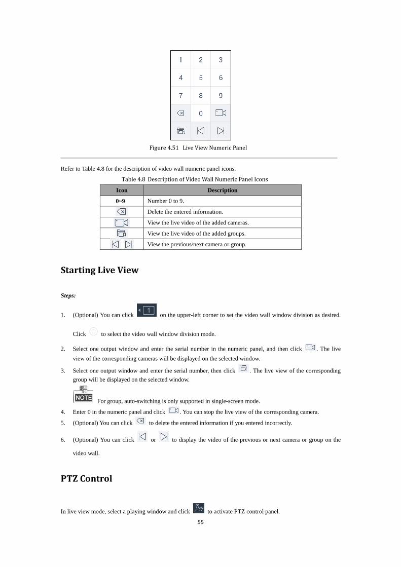
Figure 4.51 Live View Numeric Panel
Refer to Table 4.8 for the description of video wall numeric panel icons.
Table 4.8 Description of Video Wall Numeric Panel Icons
Icon Description
0~9 Number 0 to 9.
Delete the entered information.
View the live video of the added cameras.
View the live video of the added groups.
View the previous/next camera or group.
Starting Live View
Steps:
1. (Optional) You can click on the upper-left corner to set the video wall window division as desired.
Click to select the video wall window division mode.
2. Select one output window and enter the serial number in the numeric panel, and then click . The live
view of the corresponding cameras will be displayed on the selected window.
3. Select one output window and enter the serial number, then click . The live view of the corresponding
group will be displayed on the selected window.
For group, auto-switching is only supported in single-screen mode.
4. Enter 0 in the numeric panel and click . You can stop the live view of the corresponding camera.
5. (Optional) You can click to delete the entered information if you entered incorrectly.
6. (Optional) You can click or to display the video of the previous or next camera or group on the
video wall.
PTZ Control
In live view mode, select a playing window and click to activate PTZ control panel.
56
The PTZ control should be supported by the added device.
You can turn the joystick to realize the pan left/right and tilt up/down movements. You can also rotate the joystick
anticlockwise/clockwise to zoom out/in in the live view. Refer to Chapter 4.3.1 Local View for details.
Switching the Scene
Steps:
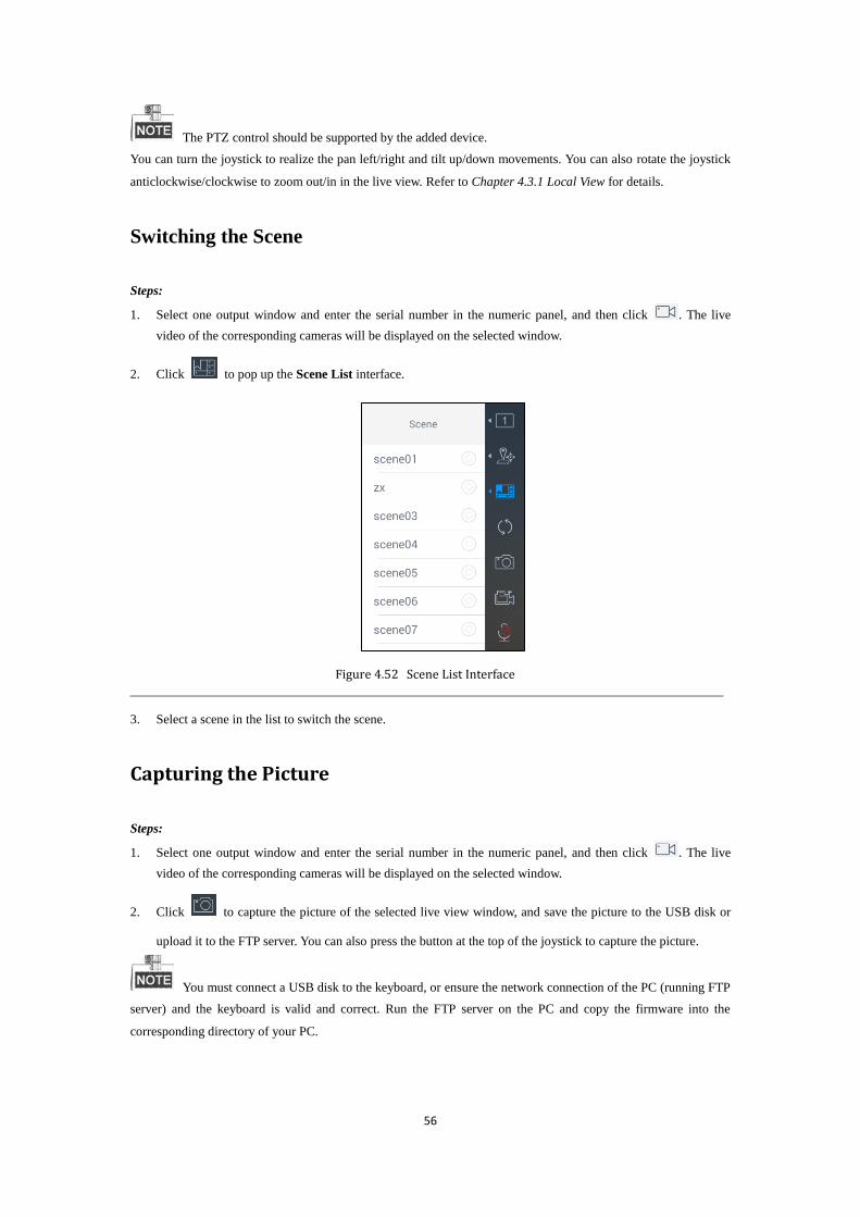
1. Select one output window and enter the serial number in the numeric panel, and then click . The live
video of the corresponding cameras will be displayed on the selected window.
2. Click to pop up the Scene List interface.
Figure 4.52 Scene List Interface
3. Select a scene in the list to switch the scene.
Capturing the Picture
Steps:
1. Select one output window and enter the serial number in the numeric panel, and then click . The live
video of the corresponding cameras will be displayed on the selected window.
2. Click to capture the picture of the selected live view window, and save the picture to the USB disk or
upload it to the FTP server. You can also press the button at the top of the joystick to capture the picture.
You must connect a USB disk to the keyboard, or ensure the network connection of the PC (running FTP
server) and the keyboard is valid and correct. Run the FTP server on the PC and copy the firmware into the
corresponding directory of your PC.

57
Recording
Steps:
1. Select one output window and enter the serial number in the numeric panel, and then click . The live
video of the corresponding cameras will be displayed on the selected window.
2. Click to record the video of the selected window, and then the icon will change to . The hint of
“Start recording” will appear.
3. Click to stop recording and the hint of “Stop recording” will appear.
You must connect a USB disk to the keyboard, or ensure the network connection of the PC (running FTP
server) and the keyboard is valid and correct. Run the FTP server on the PC and copy the firmware into the
corresponding directory of your PC.
Two-Way Audio
Steps:
1. Select one output window and enter the serial number in the numeric panel, and then click . The live
video of the corresponding cameras will be displayed on the selected window.
2. Click to start two-way audio and the hint of “Start two-way audio” will appear.
3. Click to stop two-way audio and the hint of “Stop two-way audio” will appear.
In video wall live view mode, turn on to enable two-way audio between the keyboard and the
corresponding front-end devices if the output channel is DS-B20, or between the keyboard and the decoder if the
output channel is a decoder (including DS-6400HDI-S).
Floating and Matching the Window
Purpose:
For the devices supporting window floating (i.e., DS-B20), you can move the playing window within the video
wall as desired, close the window and adjust the window to match it with the boarders.
The function must be supported by the connected decoding device before using it.
Steps:
1. Drag a screen which links to a decoding output to open a window.
2. You can move the playing window within the video wall as desired and adjust its size.

58
Figure 4.53 Floating the Window
3. During moving the window, the dotted borders will display. You can double-click the window to adjust it to
match it to the borders.
Figure 4.54 Matching the Window
Closing the Window
Steps:
1. Hold down the window to access the button on the window by which you can close the window.
2. Hold down the window again to hide the button.

59
Figure 4.55 Closing the Window
4.3.3 External View
Purpose:
The keyboard supports external preview of the live video of the added devices, e.g., external display via HDMI or
DVI interface. The local keyboard will not display the video.
Select External in the pop-up window of live view mode.
Figure 4.56 Selecting External Live View
Figure 4.57 External Live View Interface

60
Refer to Table 4.9 for the description of the external live view icons.
Table 4.9 Description of External Live View Icons
Icon Description
Select the window division mode. The screen will be displayed in
1-division mode by default.
The window division modes vary with the connected devices.
PTZ control panel.
Stop all the live view.
Capture picture of the selected live view window, and upload the picture to
the USB disk or to the FTP server. You can also press the button at the top
of the joystick to capture the picture.
/
Record the video of the selected live view window, and save the video to
the USB disk or upload it to the FTP server.
Enable/Disable two-way audio. You can get not only the live video but also
the real-time audio.
There is a numeric panel on the right with numbers 0 to 9 and five other icons for you to enter the number of the
device.
Figure 4.58 Live View Numeric Panel
Refer to Table 4.10 for the description of the external live view numeric panel icons.
Table 4.10 Description of External Live View Numeric Panel Icons
Icon Description
0~9 Number 0 to 9.
Delete the entered information.
Preview the live video of the added cameras.
Preview the live video of the added groups.
Preview the previous/next camera or group.
Starting Live View
Steps:
1. (Optional) You can click on the upper-left corner to set the window division as desired. Click

61
to select the window division mode.
2. Select one output window and enter the serial number in the numeric panel, and then click . The live
view of the corresponding cameras will be displayed on the selected window.
3. Select one output window and enter the serial number, then click . The live view of the corresponding
group will be displayed on the selected window.
For group, auto-switching is only supported in single-screen mode.
4. Enter 0 in the numeric panel and click . You can stop the live view of the corresponding camera.
5. (Optional) You can click to delete the entered information if you entered incorrectly.
6. (Optional) You can click or to display the video of the previous or next camera or group on the
external display.
7. (Optional) You can click to stop the external live view.
PTZ Control
In live view mode, select a playing window and click to activate PTZ control panel.
The PTZ control should be supported by the added device.
You can turn the joystick to realize the pan left/right and tilt up/down movements. You can also rotate the joystick
anticlockwise/clockwise to zoom out/in in the live view. Refer to Chapter 4.3.1 Local View for details.
Capturing the Picture
Steps:
1. Select one output window and enter the serial number in the numeric panel, and then click . The live
video of the corresponding cameras will be displayed on the selected window.
2. Click to capture the picture of the selected live view window, and save the picture to the USB disk or
upload it to the FTP server. You can also press the button at the top of the joystick to capture the picture.
You must connect a USB disk to the keyboard, or ensure the network connection of the PC (running FTP
server) and the keyboard is valid and correct. Run the FTP server on the PC and copy the firmware into the
corresponding directory of your PC.
Recording
Steps:
1. Select one output window and enter the serial number in the numeric panel, and then click . The live
video of the corresponding cameras will be displayed on the selected window.

62
2. Click to record the video of the selected window, and then the icon will change to . The hint of
“Start recording” will appear.
3. Click to stop recording and the hint of “Stop recording” will appear.
You must connect a USB disk to the keyboard, or ensure the network connection of the PC (running FTP
server) and the keyboard is valid and correct. Run the FTP server on the PC and copy the firmware into the
corresponding directory of your PC.
Two-Way Audio
Steps:
1. Select one output window and enter the serial number in the numeric panel, and then click . The live
video of the corresponding cameras will be displayed on the selected window.
2. Click to start two-way audio and the hint of “Start two-way audio” will appear.
3. Click to stop two-way audio and the hint of “Stop two-way audio” will appear.
In external live view modes, turn on to enable two-way audio between the keyboard and the IP
camera, network speed dome, DVR or NVR.
4.4 System Configuration
Purpose:
As the admin, you can configure the keyboard system including user management, storage management and
system maintenance. As an operator, you can only configure the keyboard system including user management and
storage management.
Click on the main menu to enter the System Configuration interface.
The System Configuration contains three sections for the admin: user management, storage management and
system maintenance. Refer to Table 4.11 for the description of system configuration for the admin.
Table 4.11 Description of System Configuration for the Admin
Menu Description
User Add/view/delete user accounts.
Storage Configure the FTP server for picture and record uploading.
Maintenance System upgrade, import/export configuration file, restore the defaults of local configurations.
4.4.1 User Management
Purpose:
Multiple user accounts can be added to the system. And some other basic operations are supported for the admin,

63
including viewing/deleting user accounts, adding devices to the users and changing the password. For the operator,
you can only view the account and change the password.
The keyboard supports adding 1 admin and 15 operators at most. The admin has the highest authority
and can operate the devices. The operators can only operate the devices linked by the admin.
Select User on the right side to enter the User Management interface.
Figure 4.59 User Management Interface for the Admin
Figure 4.60 User Management Interface for the Operator

64
Adding a New User by the Admin
Only the admin can add new users.
Steps:
1. Click New User in the User Management interface for the admin to open the New User dialog box.
Figure 4.61 Adding a New User
2. Enter the user name, password and confirm password as desired.
STRONG PASSWORD RECOMMENDED–We highly recommend you create a strong password
of your own choosing (Using a minimum of 8 characters, including at least three of the following
categories: upper case letters, lower case letters, numbers, and special characters.) in order to increase the
security of your product. And we recommend you reset your password regularly, especially in the high
security system, resetting the password monthly or weekly can better protect your product.
The strength level of the password will be displayed when you set the password. Refer to Chapter 2.1
Activation for details of the strength level.
The keyboard supports adding 15 operators at most. The password cannot be risky password, otherwise
it cannot be configured.
3. Click Add Device to add device(s) to the new user.

65
Figure 4.62 Adding Device(s) to the New User
Only the devices which have already been added to the admin account will be displayed in the
device list.
4. Select the device(s) by clicking and then click to go back to the New User dialog box.
5. If you want to delete a certain device, click .
6. Click to confirm the creation.
7. (Optional) You can click to cancel the adding.
If you have added a new user account and the keyboard has been logged out of, when you log in to the
keyboard again, you can select the account to login. Refer to Chapter 2.2 Login and Logout for details.
Managing the Accounts
Purpose:
For the admin, after adding users successfully, the user account is added to the user list on the User Management
interface. You can edit or delete the information of the user accounts. For the operator, you can only change the
password.
Editing the Admin Account
Steps:
1. Click admin account on the User Management interface for the admin. The Set Password dialog box pops
up as shown in Figure 4.63.
Figure 4.63 Editing the Admin Account
2. You can change the old password by entering the Old Password, New Password and confirming the password.
3. Click to confirm the editing.
4. (Optional) You can click to cancel the editing.
Editing the Normal User Accounts by the Admin
Steps:
1. Click the normal user account on the User Management interface for admin. A box pop up as shown in

66
Figure 4.64.
Figure 4.64 Editing the Normal User Account
2. Click Details to edit the detailed information of the user account including password and related devices. The
details of the user account are shown in Figure 4.65.
Figure 4.65 Viewing the User Detailed Information
3. Click to set the password
Figure 4.66 Setting the Password
4. Enter the New Password and confirm the password.
5. Click Submit to confirm the edit.
6. (Optional) You can click to go back to the User Details dialog box.
7. Click Add Device to add device(s) to the selected user.

67
Figure 4.67 Adding Device(s) to the User
Only the devices which have already been added to the admin account will be displayed in the
device list.
8. Select the device(s) by clicking and then click to go back to the User Details dialog box.
9. If you want to delete a certain device, click .
10. Click to confirm the editing.
11. (Optional) You can click to cancel the editing.
Deleting the User Accounts by the Admin
Steps:
1. Click Delete to delete the selected user. A hint box pops up as follows.
Figure 4.68 Hint Box of Deleting the User
2. Click Delete to confirm the deletion.
3. (Optional) You can click to cancel the deletion.
Clearing the User Accounts by the Admin
Steps:
1. Click Clear to delete all the users. A hint box will pop up as follows.
Figure 4.69 Hint Box of Deleting all the Users
68
2. Click Delete to confirm the deletion.
3. (Optional) You can click to cancel the deletion.
Editing the User Accounts by the Operator
Steps:
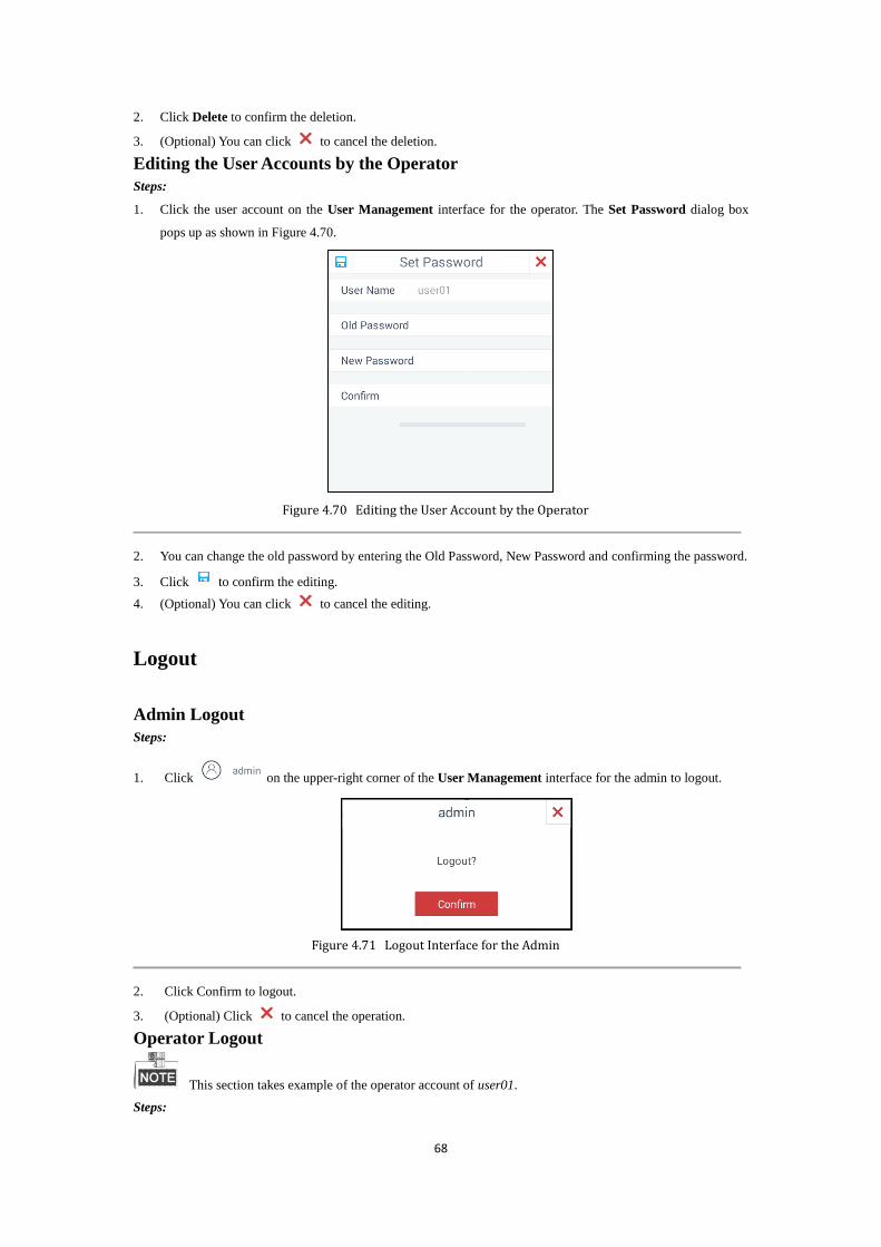
1. Click the user account on the User Management interface for the operator. The Set Password dialog box
pops up as shown in Figure 4.70.
Figure 4.70 Editing the User Account by the Operator
2. You can change the old password by entering the Old Password, New Password and confirming the password.
3. Click to confirm the editing.
4. (Optional) You can click to cancel the editing.
Logout
Admin Logout
Steps:
1. Click on the upper-right corner of the User Management interface for the admin to logout.
Figure 4.71 Logout Interface for the Admin
2. Click Confirm to logout.
3. (Optional) Click to cancel the operation.
Operator Logout
This section takes example of the operator account of user01.
Steps:

69
1. Click on the upper-right corner of the User Management interface for the operator to
logout.
Figure 4.72 Logout Interface for the Operator
2. Click Confirm to logout.
3. (Optional) Click to cancel the operation.
4.4.2 Storage Management
Purpose:
You can configure the FTP server parameters in Storage Management interface. In Live View mode, you can
upload captured pictures and records to the FTP server. Otherwise you can save them to the USB disk.
Before you start:
Ensure the network connection of the PC (running FTP server) and the device is valid and correct. Run the FTP
server on the PC and copy the firmware into the corresponding directory of your PC.
Configuring FTP server
Steps:
1. Select Storage on the right side to enter the Storage Management interface.
Figure 4.73 Storage Management Interface for the Admin

70
Figure 4.74 Storage Management Interface for the Operator
2. Switch on the upper-right corner to .
3. Enter the Address, Folder, User Name and Password of the FTP server.
Figure 4.75 Configuring FTP Server
You can create a new folder in the root directory of the user.
4. Click Apply.
4.4.3 System Maintenance
This section is only applicable to the admin.
Purpose:
You can upgrade the system, import and export the configuration files, and restore the defaults of local
configurations.
Select Maintenance on the right side to enter the Maintenance interface.

71
Figure 4.76 System Maintenance Interface
Upgrade: When there is a new version available in the USB disk, you can click Browse to select the upgrade
patch to update the system.
Import: You can import the configuration file from the USB disk.
Export: You can export the configuration file to the USB disk.
Simple Restore: You can restore the defaults of local configurations expect the network parameters and the
admin password.
Complete Restore: You can restore the defaults of all the local configurations except the network
parameters and the device will become inactive status.

72
Chapter 5 Accessing by iVMS Platform

73
DS-1600KI Network Keyboard can be accessed by iVMS-5200.
You should make proper configuration on the iVMS platform before connecting the keyboard to the
iVMS server. Refer to the user manual of corresponding iVMS platform for instructions.
5.1 Configuring iVMS-5200 Platform
5.1.1 Platform Login
Click on the home page to enter the Platform Login interface.
Figure 5.1 Platform Login
Steps:
1. Enter the IP address, Port, User Name and Password of the accessed platform.
2. (Optional) Select the checkbox of Remember Password if you want to save the password.
3. Click Login.
5.1.2 Main Menu
After login, you can click on the upper-right corner to activate the main menu as follows.

74
Figure 5.2 Main Menu of Platform Configuration
Refer to Table 5.1 for the description of the main menu.
Table 5.1 Description of Main Menu
Menu Description
Video Wall Display the live video of the input channel on the output monitor of the video wall.
Resource Display the resource list.
Logout Log out of the platform module.
5.1.3 Managing the Video Wall
After logging in to the platform, you should select the video wall first. Click on the main menu to enter
the Resource List interface. The resource list contains the resources configured in iVMS 5200platform.

75
Figure 5.3 Resource List of Video Wall
The number on the upper-right corner of each item stands for the serial number of the video wall. Click a video
wall to enter the Scene List interface.
Figure 5.4 Scene List
Steps:
1. Call the scene by clicking .
2. Click to exit from the Scene List interface and return to the Resource List interface.
After calling the scene of the video wall, appears on the right-bottom corner of the selected video
wall item, indicating that the video wall is in use.
3. Log in to the iVMS platform, and click Logical View->Camera to enter the following interface.
Figure 5.5 Camera List
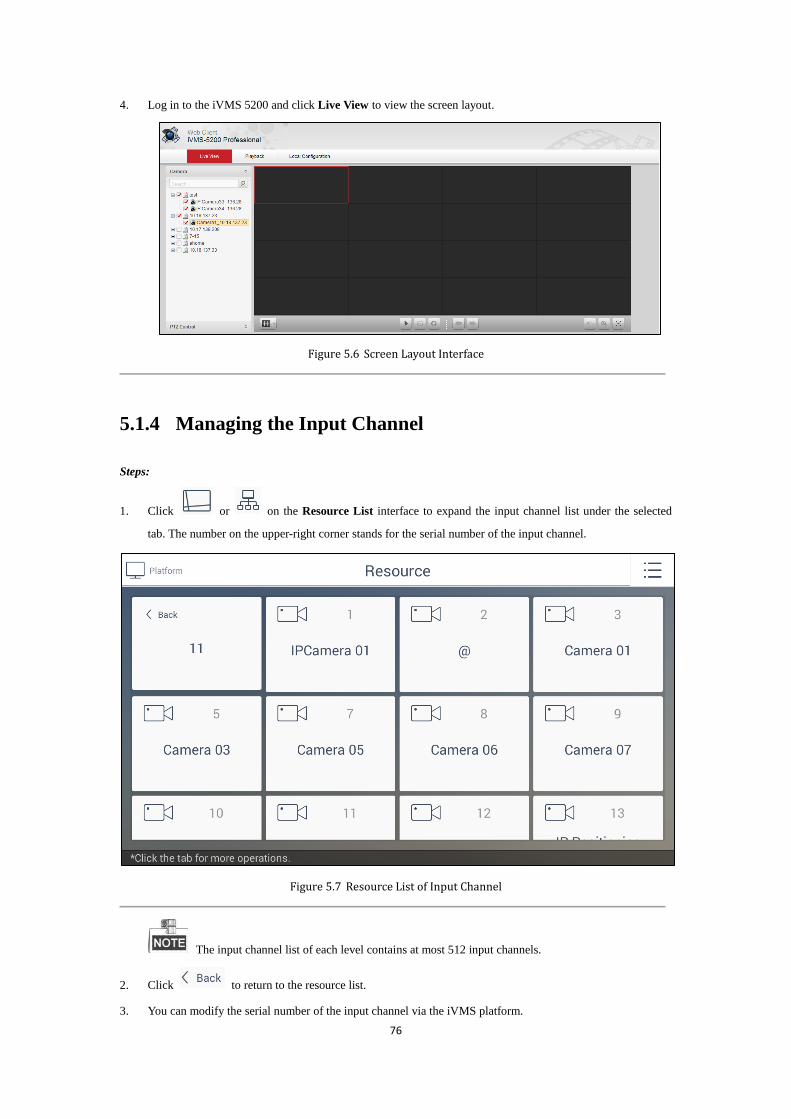
76
4. Log in to the iVMS 5200 and click Live View to view the screen layout.
Figure 5.6 Screen Layout Interface
5.1.4 Managing the Input Channel
Steps:
1. Click or on the Resource List interface to expand the input channel list under the selected
tab. The number on the upper-right corner stands for the serial number of the input channel.
Figure 5.7 Resource List of Input Channel
The input channel list of each level contains at most 512 input channels.
2. Click to return to the resource list.
3. You can modify the serial number of the input channel via the iVMS platform.

77
Click Logical View->Camera to enter the following interface to view the list of connected input channels:
Figure 5.8 Camera List
Select an input channel from the list and click it to enter the Editing interface to modify the index No. in the
Keyboard No. field.
Figure 5.9 Editing Camera Interface
If you do not configure the serial number, you can not operate on the keyboard. The configuration
method varies with different platforms.
5.2 Displaying Video on Monitor
You have two ways to display video on the monitor of the video wall.
Task 1:
Steps:
1. On the interface of the Resource List of Input Channel as shown in Figure 5.7, select a camera and click
the camera tab. If you do not select the video wall first, a dialog will pop up to hint you that “Invalid camera
number. Please select the video wall first.” If you have configured the video wall as shown in 5.3.1
Managing the Video Wall, the Monitor Selection interface pops up.
Figure 5.10 Monitor Selection Interface

78
2. Enter the monitor number in the text field to display the video of the selected camera on the selected monitor
directly.
Task 2:
Click on the main menu to enter the Video Wall interface.
Figure 5.11 Video Wall Interface
stands for the video wall you have configured in the resource list of video wall. Refer to
Chapter 5.1.3 Managing the Video Wall for details.
There is a numeric panel on the right with numbers 0 to 9 and five other icons for you to enter the serial number of
the device.
Figure 5.12 Video Wall Numeric Panel
Refer to Table 5.2 for the description of video wall numeric panel icons.
Table 5.2 Description of Video Wall Numeric Panel Icons
Icon Description
0~9 Number 0 to 9.
Delete the entered information.

79
Preview the live video of the input channel.
Preview the live video of the input channel on the selected
output monitor of the video wall.
Preview the previous/next input channel.
You can follow the steps as follows to view the video of an input channel on the selected monitor.
Steps:
1. Enter the serial number of the output monitor in the numeric panel, and click .
2. Enter the serial number of the input channel in the numeric panel, and click . Then the information of
the output monitor and the input channel appears on the Video Wall interface.
Figure 5.13 Displaying Video on the Selected Monitor
3. (Optional) You can click to delete the entered information if you entered incorrectly.
4. (Optional) You can click or to preview the live video of the previous or next input channel on the
selected output monitor.
5. You can realize the PTZ control of the camera via the joystick. You can turn the joystick to realize the pan
left/right and tilt up/down movements. You can also rotate the joystick anticlockwise/clockwise to zoom
out/in in the live view.
You need to drag the output monitor to the input channel layer on the video wall via the iVMS platform
first. Then the operation of displaying video on the video wall via the keyboard can succeed.
5.3 Logout
Steps:

80
1. Click on the main menu and a window box pops up as follows.
Figure 5.14 Logout Interface
2. Click Confirm to log out of the Platform module.
3. (Optional) You can click to cancel the logout.

81
Chapter 6 Accessing by Matrix Access
Gateway

82
Purpose:
You can get access to the matrix access gateway, realize unified management of the monitors, switch the live video
on the video wall and set PTZ control on the Matrix module.
The PTZ control should be supported by the added device.
6.1 Matrix Access Gateway Login
Click on the home page to enter the Matrix Access Gateway Login interface.
Figure 6.1 Matrix Access Gateway Login Interface
Steps:
1. Enter the IP address, Port, User Name and Password of the matrix.
2. (Optional) Select the checkbox of Remember Password if you want to save the password.
3. Click Login.
6.2 Configuring the Video Wall
After login, you can enter the Video Wall interface.
There is a numeric panel on the right with numbers 0 to 9 and five other icons for you to enter the number of the
device.
Figure 6.2 Video Wall Numeric Panel

83
Refer to Table 5.3 for the description of video wall numeric panel icons.
Table 5.3 Description of Video Wall Numeric Panel Icons
Icon Description
0~9 Number 0 to 9.
Delete the entered information.
Preview the live video of the input channel.
Preview the live video of the input channel on the selected
output monitor of the video wall.
Preview the previous/next input channel.
You can follow the steps as follows to view the video of an input channel on the selected monitor.
Steps:
1. Enter the serial number of the output monitor in the numeric panel, and click . Then you can get the
window division mode of the selected monitor.
2. Select a sub-window. Enter the serial number of the input channel in the numeric panel, and click . Then
the information of the output window and the input channel appears on the Video Wall interface.
Figure 6.3 Displaying Video on the Selected Window of the Monitor
3. (Optional) You can click to delete the entered information if you entered incorrectly.
4. (Optional) You can click or to preview the live video of the previous or next input channel on the
selected output window.
5. You can realize the PTZ control of the camera via the joystick. You can turn the joystick to realize the pan
left/right and tilt up/down movements. You can also rotate the joystick anticlockwise/clockwise to zoom
out/in in the live view.
For the specific configuration of the matrix access gateway, you can refer to the related user manual.

84
6.3 Logout
Steps:
1. Click on the upper-right corner of the Video Wall interface and a window box pops up as
follows.
Figure 6.4 Logout Interface
2. Click Confirm to log out of the Matrix module.
3. (Optional) You can click to cancel the logout.

85
Chapter 7 Appendix

86
7.1 Specifications
7.2 Summary of Changes
Version 1.1.0
Added:
1. Accessible by iVMS platform and matrix access gateway.
2. Configurable by SADP;
3. Double-click to realize full-screen live view and then double-click to restore to the normal live view mode;
4. Control the front panel of the added DVR/NVR in device management;
5. Optimize the PTZ control via the joystick and support 3D PTZ control;
6. Up to 4 patterns can be configured;
7. Connectable to multiple models of decoders and multi-screen controllers;
Model DS-1600KI
Operating System Android 4.4
TFT LCD Screen 10.1" TFT LCD touchscreen
Resolution: 1024 × 600
Joystick 4-axis joystick
Local Decoding Local decoding 2-ch at up to 1080p resolution , and up to 16-division window display
Two-way Audio
Input
1-ch, 3.5 mm connector
(2.0Vp-p, >10kΩ)
Audio Output 1-ch, 3.5 mm connector (2.0 Vp-p, 600 Ω)
Network Interface 1 10M/100M/1000M self-adaptive Ethernet interface
WiFi Supported
USB Interface USB 2.0 × 2
Video Interface 1 HDMI, 1 DVI
Power Supply 12 VDC/POE
Consumption ≤ 15W
Working
Temperature -10°C to +55°C (14ºF to 131ºF)
Working Humidity 10% to 90%
Dimensions
(W × D × H) 404 × 180 × 163 mm (15.9 × 7.1 × 6.4 inch)
Weight 1.7 Kg

87