Embed Size (px)
Citation preview

drylin® E – electrical drive technology
Lubricant free linear modules Clean operation, resistant to dirt Toothed belts, rack drives, trapezoidal / high helix threads
Large range of accessories Cost-effective Configure online
1137
3D-CAD files, prices and delivery time www.igus.co.uk/drylinELifetime calculation, configuration and more www.igus.co.uk/drylinE
Available from stock Detailed information about delivery time online
drylin® E | Advantages drylin® E | Product overviewLinear axes with motor
11391138
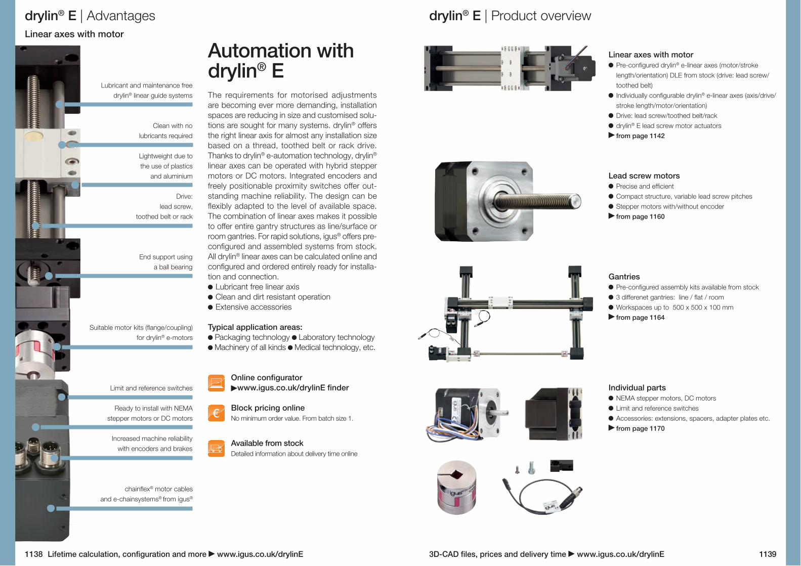
Automation with drylin® EThe requirements for motorised adjustments are becoming ever more demanding, installation spaces are reducing in size and customised solu-tions are sought for many systems. drylin® offers the right linear axis for almost any installation size based on a thread, toothed belt or rack drive. Thanks to drylin® e-automation technology, drylin® linear axes can be operated with hybrid stepper motors or DC motors. Integrated encoders and freely positionable proximity switches offer out-standing machine reliability. The design can be flexibly adapted to the level of available space. The combination of linear axes makes it possible to offer entire gantry structures as line/surface or room gantries. For rapid solutions, igus® offers pre-configured and assembled systems from stock. All drylin® linear axes can be calculated online and configured and ordered entirely ready for installa-tion and connection.
Lubricant free linear axis Clean and dirt resistant operation Extensive accessories
Typical application areas: Packaging technology Laboratory technology Machinery of all kinds Medical technology, etc.
Online configuratorwww.igus.co.uk/drylinE finder
Block pricing onlineNo minimum order value. From batch size 1.
Lubricant and maintenance free drylin® linear guide systems
Clean with no lubricants required
Lightweight due to the use of plastics
and aluminium
Drive: lead screw,
toothed belt or rack
End support using a ball bearing
Suitable motor kits (flange/coupling) for drylin® e-motors
Limit and reference switches
Ready to install with NEMA stepper motors or DC motors
Increased machine reliability with encoders and brakes
chainflex® motor cables and e-chainsystems® from igus®
Linear axes with motor Pre-configured drylin® e-linear axes (motor/stroke length/orientation) DLE from stock (drive: lead screw/toothed belt)
Individually configurable drylin® e-linear axes (axis/drive/stroke length/motor/orientation)
Drive: lead screw/toothed belt/rack drylin® E lead screw motor actuators from page 1142
Lead screw motors Precise and efficient Compact structure, variable lead screw pitches Stepper motors with/without encoder from page 1160
Gantries Pre-configured assembly kits available from stock 3 differenet gantries: line / flat / room Workspaces up to 500 x 500 x 100 mm from page 1164
Individual parts NEMA stepper motors, DC motors Limit and reference switches Accessories: extensions, spacers, adapter plates etc. from page 1170
3D-CAD files, prices and delivery time www.igus.co.uk/drylinELifetime calculation, configuration and more www.igus.co.uk/drylinE
drylin® E | Application examples
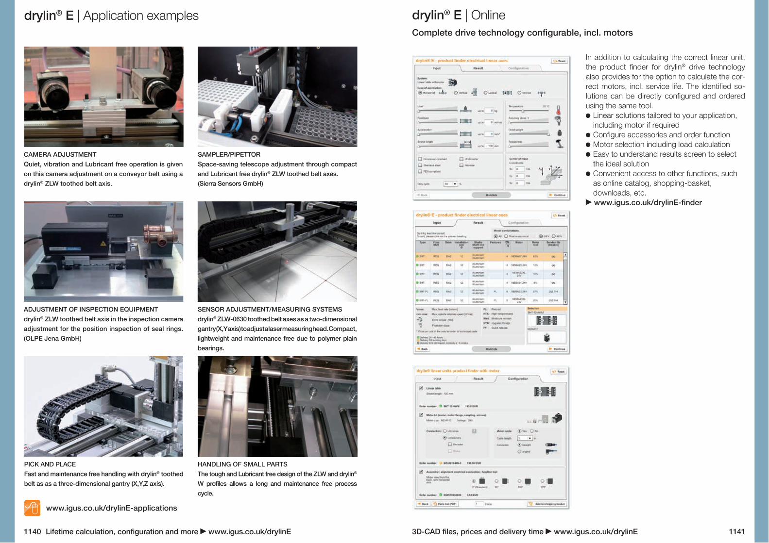
CAMERA ADJUSTMENTQuiet, vibration and Lubricant free operation is given on this camera adjustment on a conveyor belt using a drylin® ZLW toothed belt axis.
SAMPLER/PIPETTORSpace-saving telescope adjustment through compact and Lubricant free drylin® ZLW toothed belt axes.(Sierra Sensors GmbH)
ADJUSTMENT OF INSPECTION EQUIPMENTdrylin® ZLW toothed belt axis in the inspection camera adjustment for the position inspection of seal rings. (OLPE Jena GmbH)
SENSOR ADJUSTMENT/MEASURING SYSTEMSdrylin® ZLW-0630 toothed belt axes as a two-dimensional gantry (X,Y axis) to adjust a laser measuring head. Compact, lightweight and maintenance free due to polymer plain bearings.
PICK AND PLACEFast and maintenance free handling with drylin® toothed belt as as a three-dimensional gantry (X,Y,Z axis).
HANDLING OF SMALL PARTSThe tough and Lubricant free design of the ZLW and drylin® W profiles allows a long and maintenance free process cycle.
www.igus.co.uk/drylinE-applications
drylin® E | OnlineComplete drive technology configurable, incl. motors
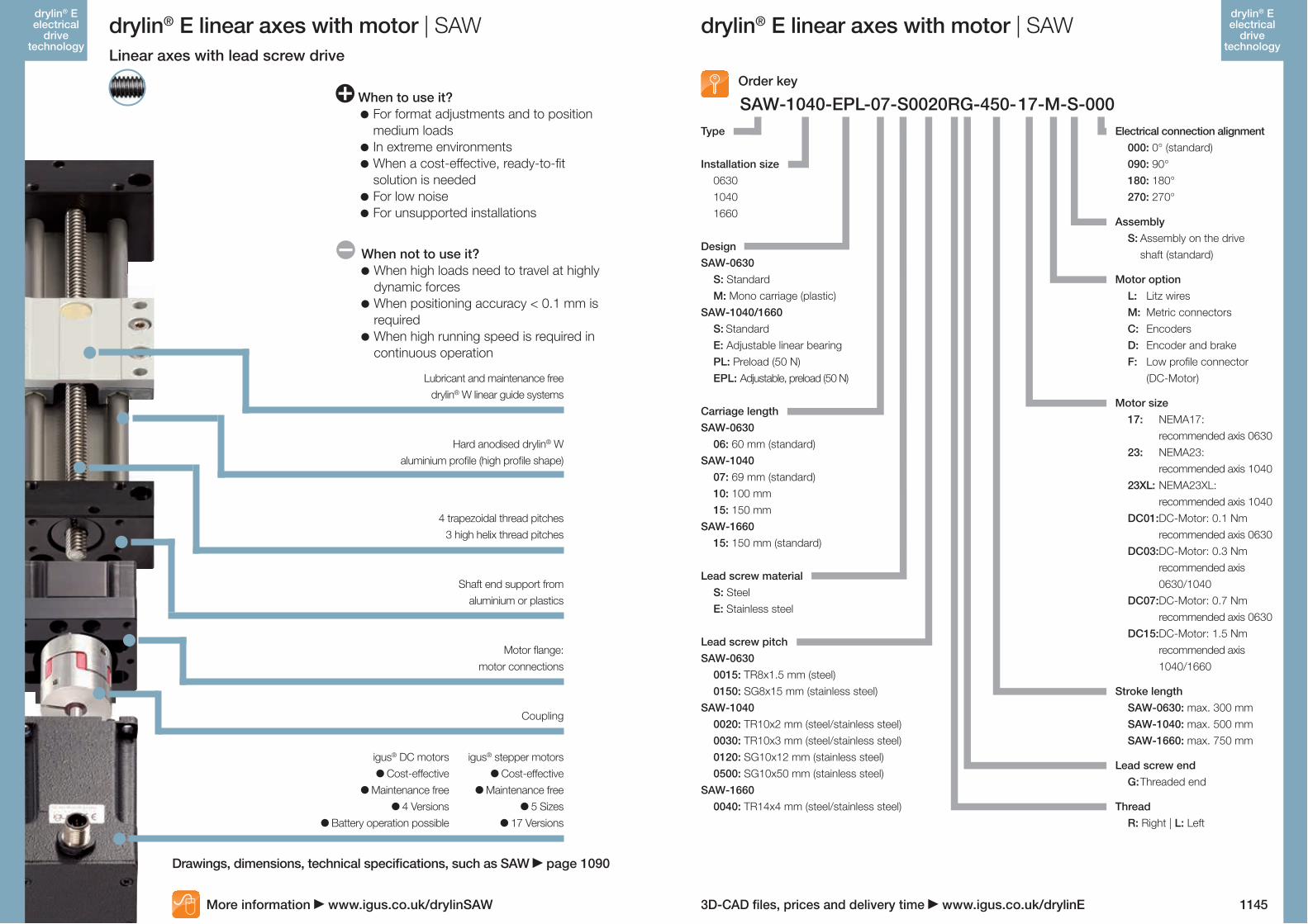
In addition to calculating the correct linear unit, the product finder for drylin® drive technology also provides for the option to calculate the cor- rect motors, incl. service life. The identified so- lutions can be directly configured and ordered using the same tool.
Linear solutions tailored to your application, including motor if required
Configure accessories and order function Motor selection including load calculation Easy to understand results screen to select the ideal solution
Convenient access to other functions, such as online catalog, shopping-basket, downloads, etc. www.igus.co.uk/drylinE-finder
11411140

3D-CAD files, prices and delivery time www.igus.co.uk/drylinELifetime calculation, configuration and more www.igus.co.uk/drylinE
DLE-SA-0001
DLE-SA-0002
DLE-SA-0003
DLE-SA-0004
DLE-SA-0005
DLE-SA-0006
Part No. Size Carriage length Stroke Motor Max. stat. load
DLE-SA-0001
DLE-SA-0002
DLE-SA-0003
DLE-SA-0004
DLE-SA-0005
DLE-SA-0006
Linear axes with motor from stock - deliverable within 24 hours
drylin® E linear axes with motor | DLE
1142 1143
drylin® E electrical
drive technology
drylin® E electrical
drive technology
drylin® E linear axes with motor | DLE
axial [N] radial [N]
ZLW-0630 Basic 60 300 NEMA17 Litz wires 35 140ZLW-1040 Basic 100 500 NEMA23 Litz wires 100 400
ZLW-1080 Standard 100 1,000 NEMA23XL Litz wires 150 600
SAW-0630 Tr08x1.5 60 250 NEMA17 Litz wires 100 400
SAW-1040 Tr10x2 69 500 NEMA23 Litz wires 500 2,000
SAW-1080 Tr12x3 100 500 NEMA23XL Litz wires 750 2,000
Deliverable within 24 hours:drylin® linear axes with motorigus® now delivers ready to install, pre-configured linear modules (drive: lead screw or toothed belt) from stock within 24 hours. You simply choose between 3 sizes, 3 stroke lengths and 3 stepper motors ... and the system is delivered 24 hours after you place your order.
Drive: lead screw or toothed belt Absolutely lubricant free NEMA stepper motors with Litz wires Pre-assembled and tested Based on drylin® linear axes ZLW and SAW
Technical data
Dimensionally interchangeable withdrylin® linear axes
SAW page 1090 ZLW page 1130
Technical data SAW page 1090 ZLW page 1130
Further information about the motors page 1174
3D-CAD files, prices and delivery time www.igus.co.uk/drylinE
SAW-1040-EPL-07-S0020RG-450-17-M-S-000 When to use it? For format adjustments and to position
medium loads In extreme environments When a cost-effective, ready-to-fit
solution is needed For low noise For unsupported installations
When not to use it? When high loads need to travel at highly
dynamic forces When positioning accuracy < 0.1 mm is
required When high running speed is required in
continuous operation
4 trapezoidal thread pitches 3 high helix thread pitches
Shaft end support from aluminium or plastics
Motor flange: motor connections
Coupling
Hard anodised drylin® W aluminium profile (high profile shape)
igus® DC motors Cost-effective
Maintenance free 4 Versions
Battery operation possible
igus® stepper motors Cost-effective
Maintenance free 5 Sizes
17 Versions
Lubricant and maintenance free drylin® W linear guide systems
Drawings, dimensions, technical specifications, such as SAW page 1090
More information www.igus.co.uk/drylinSAW
drylin® E linear axes with motor | SAW
DesignSAW-0630 S: Standard M: Mono carriage (plastic)SAW-1040/1660 S: Standard E: Adjustable linear bearing PL: Preload (50 N) EPL: Adjustable, preload (50 N)
Thread R: Right | L: Left
Lead screw pitchSAW-0630 0015: TR8x1.5 mm (steel) 0150: SG8x15 mm (stainless steel)SAW-1040 0020: TR10x2 mm (steel/stainless steel) 0030: TR10x3 mm (steel/stainless steel) 0120: SG10x12 mm (stainless steel) 0500: SG10x50 mm (stainless steel)SAW-1660 0040: TR14x4 mm (steel/stainless steel)
Order key
Electrical connection alignment 000: 0° (standard) 090: 90° 180: 180° 270: 270°
Assembly S: Assembly on the drive
shaft (standard)
Motor option L: Litz wires M: Metric connectors C: Encoders D: Encoder and brake F: Low profile connector
(DC-Motor)
Motor size 17: NEMA17:
recommended axis 0630 23: NEMA23:
recommended axis 1040 23XL: NEMA23XL:
recommended axis 1040 DC01: DC-Motor: 0.1 Nm
recommended axis 0630 DC03: DC-Motor: 0.3 Nm
recommended axis 0630/1040
DC07: DC-Motor: 0.7 Nm recommended axis 0630
DC15: DC-Motor: 1.5 Nm recommended axis 1040/1660
Stroke length SAW-0630: max. 300 mm SAW-1040: max. 500 mm SAW-1660: max. 750 mm
Lead screw end G: Threaded end
Lead screw material S: Steel E: Stainless steel
Carriage lengthSAW-0630 06: 60 mm (standard)SAW-1040 07: 69 mm (standard) 10: 100 mm 15: 150 mmSAW-1660 15: 150 mm (standard)
Type
Installation size 0630 1040 1660
drylin® E linear axes with motor | SAWLinear axes with lead screw drive
1145
drylin® E electrical
drive technology
drylin® E electrical
drive technology

3D-CAD files, prices and delivery time www.igus.co.uk/drylinE
Type
Installation size 0630 1040
DesignSAWC-0630 S: Standard M: Mono carriage (plastic)SAWC-1040 S: Standard E: Adjustable linear bearing PL: Preload (50 N) EPL: Adjustable, preload(50 N)
Carriage lengthSAWC-0630 06: 60 mm (standard)SAWC-1040 07: 69 mm (standard) 10: 100 mm 15: 150 mm
Lead screw material S: Steel E: Stainless steel
Lead screw pitchSAWC-0630 0015: TR8x1.5 mm (stainless steel) 0150: SG8x15 mm (stainless steel)SAWC-1040 0020: TR10x2 mm (stainless steel) 0120: SG10x12 mm (stainless steel) 0500: SG10x50 mm (stainless steel)
SAWC-1040-EPL-07-S0020RG-300-17-L-S-090Electrical connection alignment 000: 0° (standard) 090: 90° 180: 180° 270: 270°
Assembly S: Assembly on the drive
shaft (standard)
Motor option L: Litz wires
Motor size 17: NEMA17: recommended axis 0630 23: NEMA23: recommended axis 1040
Stroke length SAWC-0630: max. 300 mm SAWC-1040: max. 500 mm
Lead screw end G: Threaded end
Thread R: Right handed
drylin® E linear axes with motor | SAWC
Order key
When not to use it? When high loads need to travel at highly
dynamic forces When positioning accuracy < 0.1 mm is
required When high running speed is required in
continuous operation
When to use it? For format adjustments and to position
medium loads When a compact solution with optimised
useful full-length ratio is required For special requirement on the running
behaviour When a cost-effective, ready-to-fit
solution is needed For low noise For unsupported installations
drylin® E linear axes with motor | SAWCLinear axes with lead screw drive
Lubricant and maintenance free drylin® W linear guide systems
2 trapezoidal thread pitches 3 high helix thread pitches
Hard anodised drylin® W aluminium profile (high profile shape)
igus® stepper motors Cost-effective
Maintenance free 2 Sizes
Shaft end support made from aluminium
1147
drylin® E electrical
drive technology
More information www.igus.co.uk/drylinSAWC
drylin® E electrical
drive technology

3D-CAD files, prices and delivery time www.igus.co.uk/drylinE
SLW-1040-EPL-07-S 0020 R G-750-17-L-S-000
drylin® E linear axes with motor | SLWLinear axes with lead screw drive
When to use it? For format adjustments and to position
medium loads In extreme environments When a cost-effective, ready-to-fit
solution is needed For low noise When installation space is limited
Lubricant and maintenance free drylin® W linear profile guides
4 trapezoidal thread pitches 3 high helix thread pitches
Shaft end support from aluminium or plastics
Motor flange: motor connections
Coupling
Hard anodised drylin® W aluminium profile (plain profile shape)
igus® DC motors Cost-effective
Maintenance free 4 Versions
Battery operation possible
When not to use it? When high loads need to travel at highly
dynamic forces When positioning accuracy < 0.1 mm is
required When high running speed is required in
continuous operation
igus® stepper motors Cost-effective
Maintenance free 5 Sizes
17 Versions
Drawings, dimensions, technical specifications, such as SLW page 1084
More information www.igus.co.uk/drylinSLW
drylin® E linear axes with motor | SLW
DesignSLW-0630 BB: Ball bearingSLW-1040/1080/1660/2080 S: Standard E: Adjustable linear bearing PL: Preload (50 N) EPL: Adjustable, preoload (50 N) BB: Ball bearing BBE: Ball bearing, adjustable
linear bearing BBPL: Ball bearing, preload (50 N) BBEPL: Ball bearing, adjustable linear
bearing, preload (50 N)
Thread R: Right L: Left
Lead screw pitchSLW-0630 0015: TR8x1.5 mm (steel) 0150: SG8x15 mm (stainless steel)SLW-1040/1080 0020: TR10x2 mm (steel/stainless steel) 0030: TR10x3 mm (steel/stainless steel) 0120: SG10x12 mm (stainless steel) 0500: SG10x50 mm (stainless steel)SLW-1660 0040: TR14x4 mm (steel/stainless steel)SLW-2080 0040: TR18x4 mm (steel/stainless steel)
Order key
Electrical connection alignment 000: 0° (standard) 090: 90° 180: 180° 270: 270°
Assembly S: Assembly on the drive
shaft (standard)
Motor option L: Litz wires M: Metric connectors C: Encoder D: Encoder and brake F: Low profile connector
(DC Motor)
Motor size/Recommended axis 17: NEMA17 / 0630 23: NEMA23 / 1040, 1080 23XL: NEMA23XL / 1040,
1080, 1660 34: NEMA 34 / 2080 DC01: DC-Motor: 0.1 Nm /
0630 DC03: DC-Motor: 0.3 Nm /
0630, 1040 DC07: DC-Motor: 0.7 Nm /
1040 DC15: DC-Motor: 1.5 Nm /
1040, 1660
Stroke length SLW-0630: max. 300 mm SLW-1040/1080: max.
750 mm (BB: max.500 mm) SLW-1660: max 750 mm SLW-2080: max 1000 mm
(BB: 900 mm)
Lead screw end G: Threaded end Z: End 12h9 (with SLW-2080)
Lead screw material S: Steel E: Stainless steel
Carriage lengthSLW-0630 06: 60 mm (standard)SLW-1040 07: 69 mm (standard) 10: 100 mm 15: 150 mmSLW-1080/1660/2080 15: 150 mm (standard)
Type
Installation size 0630 1040/1080 1660 2080
1149
drylin® E electrical
drive technology
drylin® E electrical
drive technology

3D-CAD files, prices and delivery time www.igus.co.uk/drylinE
SHT-12-BBZB-AWM-S0020RG-750-17-L-S-000
drylin® E linear axes with motor | SHTLinear axes with lead screw drive
When to use it? For format adjustments and to position
medium loads In extreme environments When a cost-effective, ready-to-fit
solution is needed For low noise When installation space is limited
4 trapezoidal thread pitches 3 high helix thread pitches
Carriages and shaft end supports from anodised aluminium
Lubricant and maintenance free with drylin® liners and lead screw nuts
Motor flange: motor connections
Coupling
3 shaft materials
igus® DC motors Cost-effective
Maintenance free 4 Versions
Battery operation possible
When not to use it? When high loads need to travel at highly
dynamic forces When positioning accuracy < 0.1 mm is
required When high running speed is required in
continuous operation
igus® stepper motors Cost-effective
Maintenance free 5 Sizes
17 Versions
Drawings, dimensions, technical specifications, such as SHT page 1068
More information www.igus.co.uk/drylinSHT
Design S: Standard PL: Preload (50 N) BB: Ball bearing BBPL: Ball bearing, preload (50 N) BBZB: Ball bearing, zero backlash
(only SHT-12 with SG10x12)
Thread R: Right | L: Left
Lead screw pitchSHT-12 0020: T10x2 mm (steel/stainless steel) 0030: TR10x3 mm (steel/stainless steel) 0120: SG10x12 mm (stainless steel) 0500: SG10x50 mm (stainless steel)SHT-20 0040: TR18x4 mm (steel/stainless steel)SHT-30 0050: TR24x5 mm (steel/stainless steel)
Lead screw end G: Threaded end (with SHT-12) Z: End 12h9 (with SHT-20) Z: End 14h9 (with SHT-30)
Wellenmaterial AWM: Hard-anodised aluminium SWM: Cf53 (1.1213) EWM: Stainless steel X105 (1.4125)
Type
Installation size 12 20 30
Lead screw material S: Steel E: Stainless steel
drylin® E linear axes with motor | SHT
Order key
Electrical connection alignment 000: 0° (standard) 090: 90° 180: 180° 270: 270°
Assembly S: Assembly on the drive
shaft (standard)
Motor option L: Litz wires M: Metric connectors C: Encoder D: Encoder and brake F: Low profile connector
(DC Motor)
Motor size 17: NEMA17:
recommended axis 12 23: NEMA23:
recommended axis 12/20
23XL: NEMA23XL: recommended axis 20
34: NEMA34: recommended axis 20/30
DC01: DC-Motor: 0,1 Nm recommended axis 12
DC03: DC-Motor: 0,3 Nm recommended axis 12
DC07: DC-Motor: 0,7 Nm recommended axis 12
DC15: DC-Motor: 1,5 Nm recommended axis 12
Stroke length SHT-12: max. 750 mm
(BB max. 500 mm) SHT-20: max. 1000 mm
(BB max. 900 mm) SHT-30: max 1250 mm
(BB max. 1,000 mm)
1151
drylin® E electrical
drive technology
drylin® E electrical
drive technology

3D-CAD files, prices and delivery time www.igus.co.uk/drylinE
SHTC-08-ZB-A-E127RG-100-17-L-000
Linear axes with lead screw drive
Carriages and shaft end supports made from anodised aluminium
4 trapezoidal thread pitches 3 high helix thread pitches
Lubricant and maintenance free with drylin® liners and lead screw nuts
Motor flange and coupling: motor connections
3 shaft materials
igus® DC motors Cost-effective
Maintenance free 4 Versions
Battery operation possible
igus® stepper motors Cost-effective
Maintenance free 5 Sizes
17 Versions
drylin® E linear axes with motor | SHTC drylin® E linear axes with motor | SHTC
Drawings, dimensions, technical specifications, such as SHTC page 1070
More information www.igus.co.uk/drylinSHTC
Design ZB: Zero backlash
Shaft material AWM: Hard-anodised aluminium EWM: Stainless steel X105 (1.4125)
Type
Installation size
Order key
Electrical connection alignment 000: 0° (standard) 090: 90° 180: 180° 270: 270°
Motor size 17: NEMA17
Stroke length SHTC-08: max. 750 mm
drylin® E electrical
drive technology
drylin® E electrical
drive technology
1152 1153
Motor option L: Stranded wire with motor
flange C: Encoder with motor flange G: Lead screw motor with
stranded wire H: Lead screw motor with
encoder
Lead screw design E020RG: Stainless steel, trapezoidal thread,
pitch: 2 mm E025RZ: Stainless steel dryspin®,
pitch: 2.54 mm E127RZ: Stainless steel high helix thread,
pitch: 12.7 mm E254RZ: Stainless steel dryspin®,
pitch: 25.4 mm
drylin® E electrical
drive technology
drylin® E electrical
drive technology

3D-CAD files, prices and delivery time www.igus.co.uk/drylinE
ZLW-1040-02-B-60-L-750-17-M-S-000
Motor size 17: NEMA17: recommended axis 0630 23: NEMA23: recommended axis 1040 23XL: NEMA23XL: recommended axis 1040 34: NEMA34: recom. axis 1040/1660 DC01: DC-Motor 0.1 Nm:
recommended axis 0630 DC03: DC-Motor: 0.3 Nm:
recommended axis 0630 DC07: DC-Motor: 0.7 Nm
recommended axis 1040 DC15: DC-Motor: 1.5 Nm
recommended axis 1040
Electrical connection alignment 000: 0° (standard) 090: 90° 180: 180° 270: 270°
Assembly*Drive shaft on one side S: Motor assembly on defined drive
shaft (L or R) Drive shaft on both sides (L/R) L: Motor assembly on drive shaft left R: Motor assembly on drive shaft right
Motor option L: Litz wires M: metrischer Stecker C: Encoder D: Encoder and brake F: Low profile connector (DC-Motor)
Version 02: With deep groove ball brgs.
Installation size 0630 1040 1660
Type ZLW
Stroke length ZLW-0630: max. 1,000 mm ZLW-1040: max. 2,000 mm ZLW-1660: max. 3,000 mm
Drive pins L: Left-hand drive shaft R: Right-hand drive shaft L/R: Drive both sides
Carriage length 60: 60 mm (only ZLW 0630) 100: 100 mm 150: 150 mm 200: 200 mm 250: 250 mm
Design S: Type series – standard B: Type series – basic
S: Motor assembly on defined drive shaft (L or R)
L: Motor assembly on drive shaft left R: Motor assembly on drive shaft right
* Assembly example, drive shaft on one side (connection alignment 0°):
* Assembly example, drive shaft on both sides (connection alignment 0°):
drylin® E linear axes with motor | ZLW drylin® E linear axes with motor | ZLW
Order key
Pulley supports with deep groove bearings
Lubricant and maintenance free drylin® W linear profile guides
Hard anodised drylin® W aluminium profile
(high profile shape)
Various Carriage lengths
Polyurethane or neoprene toothed belts
Linear axes with toothed belt
When to use it? Fast positioning of small loads Quiet operation Slim design Continuous operation
When not to use it? When high loads must be motion
controlled at high dynamic speeds When positioning accuracy < 0.1 mm is
required
igus® DC motors Cost-effective
Maintenance free 4 Versions
Battery operation possible
Motor flange: motor connections
Spider Coupling
igus® stepper motors Cost-effective
Maintenance free 5 Sizes
17 Versions
More information www.igus.co.uk/drylinZLW
Drawings, dimensions, technical specifications, such as ZLW page 1130
drylin® E electrical
drive technology
drylin® E electrical
drive technology
1154 1155
drylin® E electrical
drive technology
drylin® E electrical
drive technology

3D-CAD files, prices and delivery time www.igus.co.uk/drylinE
SLN-27-14-0050-100-11-L-S-000
GRW-0630-A-80-150-17-L-S-000Motor pin alignment 000: 0° (standard) 090: 90° 180: 180° 270: 270°
Assembly
Installation size
Type
Stroke length max. 250 mm
Carriage03: Basic04: Standard, adjustable05: Standard, preload
Lead screw pitch0008: M5x0.8 (stainless steel)0050: Sg5x5 (stainless steel)0025: DST6.35x2.54 (stainless steel)0127: SG6.35x12.7 (stainless steel)0254: DST6.35x25.4 (stainless steel)
Lubrication free linear guide using polymer plain bearings
Lubricant and maintenance free drylin® N low profile linear guides
Motor flange: motor connections
1 trapezoidal thread pitch, 1 high helix thread pitch
igus® stepper motors Cost-effective
Maintenance free 1 Size
2 Versions
Order key:
drylin® E linear axes with motor | SLNMiniature linear axis with lead screw drive
drylin® E linear axes with motor | GRWCantilever axis with rack drive
Motor size 17: NEMA17
Order key:
Motor pin alignment 000: 0° (standard) 090: 90° 180: 180° 270: 270°
Assembly S: Assembly with one drive shaft
(standard)
Installation size 0630
Design A: Standard
Type
Stroke length max. 150 mm
Carriage length 80: 80 mm Motor option
L: Litz wires M: Metric connectors C: Encoder D: Encoder and brake
Base body made from corrosion resistant tough plastic
Aluminium base body
Assembly option for limit reference switch already integrated
Lubricant and maintenance free drylin® W low profile linear guide
igus® stepper motors Cost-effective
Maintenance free 1 Baugröße
4 Versions
More information www.igus.co.uk/drylinGRW
More information www.igus.co.uk/drylinSLN
Drawings, dimensions, technical specifications, such as SLN page 1101
drylin® E electrical
drive technology
drylin® E electrical
drive technology
1156 1157
Options HR: Hand wheel D1-F: DC-Motor, 0.025 Nm, 375 rpm E1-F: DC-Motor, 0.06 Nm, 137 rpm J1-F: DC-Motor, 0.19 Nm, 36 rpm 11-L: NEMA11, Litz wires 11-C: NEMA11, Encoder/Litz wires 11-G: NEMA11 lead screw motor, stranded wires 11-H: NEMA11 lead screw motor,
encoder/stranded wire
Shaft end support01: Plain bearing02: Ball bearing
drylin® E electrical
drive technology
drylin® E electrical
drive technology
3D-CAD files, prices and delivery time www.igus.co.uk/drylinE
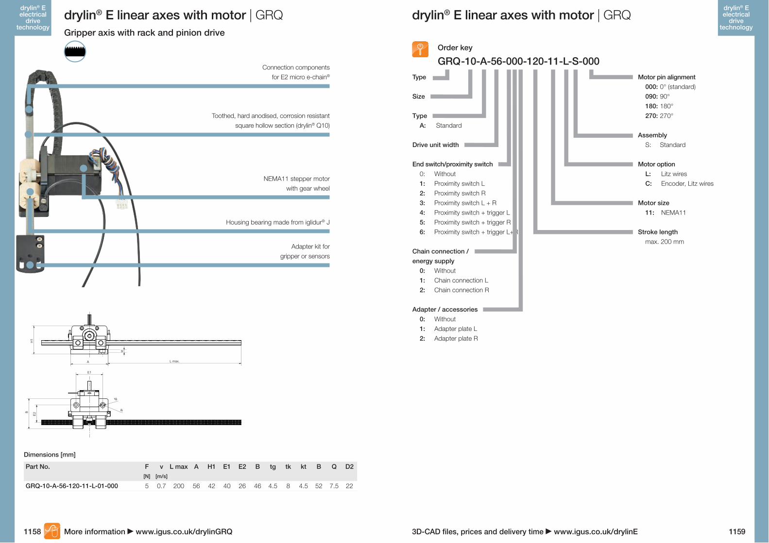
GRQ-10-A-56-120-11-L-01-000
GRQ -10-A-56-000-120-11-L-S-000Motor pin alignment 000: 0° (standard) 090: 90° 180: 180° 270: 270°
Assembly S: Standard
Motor option L: Litz wires C: Encoder, Litz wires
Motor size 11: NEMA11
Stroke length max. 200 mm
drylin® E linear axes with motor | GRQ
Order key
Dimensions [mm]
Part No. F v L max A H1 E1 E2 B tg tk kt B Q D2[N] [m/s]
5 0.7 200 56 42 40 26 46 4.5 8 4.5 52 7.5 22
More information www.igus.co.uk/drylinGRQ
Connection components for E2 micro e-chain®
Toothed, hard anodised, corrosion resistant square hollow section (drylin® Q10)
Housing bearing made from iglidur® J
Adapter kit for gripper or sensors
NEMA11 stepper motor with gear wheel
drylin® E linear axes with motor | GRQGripper axis with rack and pinion drive
1159
drylin® E electrical
drive technology
Type
Size
Type A: Standard
Drive unit width
End switch/proximity switch 0: Without 1: Proximity switch L 2: Proximity switch R 3: Proximity switch L + R 4: Proximity switch + trigger L 5: Proximity switch + trigger R 6: Proximity switch + trigger L+R
Chain connection / energy supply 0: Without 1: Chain connection L 2: Chain connection R
Adapter / accessories 0: Without 1: Adapter plate L 2: Adapter plate R
E1
H1
A
tg
tk
L max.
B
E2
kt
E1
H1
A
tg
tk
L max.
B
E2
kt
1158
drylin® E electrical
drive technology

3D-CAD files, prices and delivery time www.igus.co.uk/drylinELifetime calculation, configuration and more www.igus.co.uk/drylinE
Available from stock Detailed information about delivery time online
max. 50 °Cmin. 0 °C
1160 1161
drylin® E electrical
drive technology
drylin® E electrical
drive technology
drylin® E lead screw motors | Advantages
Lubricant free drylin® threaded nut, cylindrical or with flange
NEMA stepper motors with holding torques from 0.1 to 2.0 Nm
Direct centring via H7/h7 motor/lead screw adjustment
Durable dryspin® high helix thread or self-locking
trapezoidal thread
High machine reliability with encoder
Efficient, precise and compact – drylin® lead screw motorsdrylin® E with the lead screw motor range is the optimum solution for systems that need a stepper motor with a directly integrated lead screw. The stand-alone versions have a compact design and are available with NEMA stepper motors with and without an encoder. The lead screw is precisely centred and, in combination with the dryspin®
high helix thread technology, the system has a long service life.
3 stepper motor sizes Lubricant free drylin® lead screw technology Can be delivered ready for connection
Typical application areas: Medical technology Tool building Laboratory technology
Block pricing onlineNo minimum order value. From batch size 1.
3 stepper motor sizes
drylin® E lead screw motors | Product overview
Lead screw motor NEMA 11/17/23 stepper motos Holding torque 0.1 - 2.0 Nm The lead screw can be attached on either side from page 1162
Lead screw motor with encoder NEMA 11/17/23-stepper motor Increased machine reliability Can be used with 7 lead screw pitches from 0.8 - 50 mm from page 1162
drylin® lead screws for stepper motor Efficient dryspin® high helix lead screw, ready to install with precision machined ends
Self-locking trapezoidal thread lead screw, ready to install with precision machined ends
Available for delivery individually or fully assembled from page 1163
Matching dryspin® high helix lead screw nut Available in several geometric designs and pitches from page 991
Matching drylin® trapezoidal lead screw nut Lubrication free, self locking and available in several plastic materials from page 1010
drylin® E lead screw motors installed in drylin® SAWC with motor from page 1146 drylin® SHTC with motor from page 1152 drylin® SLN with motor from page 1156
Lead screw can be attached on either side

3D-CAD files, prices and delivery time www.igus.co.uk/drylinELifetime calculation, configuration and more www.igus.co.uk/drylinE
Part No. Motor size
MOT-ST-27-L-A-A NEMA11MOT-ST-42-L-A-A NEMA17
MOT-ST-56-L-A-A NEMA23
MOT-ST-27-L-C-A NEMA11
MOT-ST-42-L-C-A NEMA17
MOT-ST-56-L-C-A NEMA23
Part No. Motor size
DST-LS-MOT-6.35X2.54-R-XXX-ES NEMA11DST-LS-MOT-6.35X25.4-R-XXX-ES NEMA11
DST-LS-MOT-10X12-R-XXX-ES NEMA17/23
DST-LS-MOT-10X25-R-XXX-ES NEMA17/23
DST-LS-MOT-10X50-R-XXX-ES NEMA17/23
DST-LS-MOT-14X25-R-1000-ES NEMA17/23
Part No. Motor size
PTGSG-MOT-M5X0.8-R-XXX-ES NEMA11PTGSG-MOT-08X1.5-R-XXX-ES NEMA17/23
PTGSG-MOT-10X2-R-XXX-ES NEMA17/23
PTGSG-MOT-12X3-R-XXX-ES NEMA17/23
PTGSG-MOT-12X6P3-R-XXX-ES NEMA17/23
PTGSG-MOT-05X5-R-XXX-ES NEMA11
PTGSG-MOT-06.35X12.7-R-XXX-ES NEMA11
PTGSG-MOT-08X15-R-XXX-ES NEMA17/23
PTGSG-MOT-10X12-R-XXX-ES NEMA17/23
PTGSG-MOT-10X50-R-XXX-ES NEMA17/23
PTGSG-MOT-12X25-R-XXX-ES NEMA17/23
Detailed technical data online www.igus.co.uk/drylinE
1162 1163
drylin® E electrical
drive technology
drylin® E electrical
drive technology
drylin® E lead screw motors | Product range drylin® E lead screw motors | Product range
3 stepper motor sizes with stranded wire and holding torque 0.1 - 2 Nm
7 lead screw types with pitches from 0.8 - 50 mm Maximum precision by centring the lead screw with a H7/h7 motor/lead screw fit
Matching lead screw nuts in the drylin® product range When using a stepper motor without an encoder the lead screw can be attached on either side
Space saving, versatile
Available for delivery ready for connection with drylin®
linear axes SAWC, SLN and SLT
Distance over hubs Holding torque Shaft load Encoder
[mm] [mm] axial [N]
28 0.1 50 no42 0.5 100 no
56 2.0 500 no
28 0.1 50 yes
42 0.5 100 yes
56 2.0 500 yes
Technical data – stepper motor with stranded wire
Material: stainless steel Lead screw needs to be secured with an adhesive Ready to fit
Distance over hubs
Thread type Lead screw -Ø
Lead max.
[mm] [mm] [mm] axial [N] Length
28 DST 6.35 2.54 30028 DST 6.35 25.4 300
42 / 56 DST 10 12 500
42 / 56 DST 10 25 500
42 / 56 DST 10 50 500
42 / 56 DST 14 25 500
Technical– high helix threads with dryspin® technology
Distance over hubs
Thread type Lead screw -Ø
Lead max.
[mm] [mm] [mm] axial [N] Length
28 M5 5 0.8 25042 / 56 TR 8 1.5 300
42 / 56 TR 10 2 500
42 / 56 TR 12 3 500
42 / 56 TR 12 6P3 500
28 SG 5 5 250
28 SG 6.35 12.7 300
42 / 56 SG 8 15 300
42 / 56 SG 10 12 500
42 / 56 SG 10 50 500
42 / 56 SG 12 25 500
Technical data – high helix threads without dryspin® technology
XXX: Lead screw length
If desired by the factory, please order using the following assembly number: Assembly front: MONT004F000 (flange side)Assembly back: MONT004B000 (assembly not possible with a motor with an encoder)
Lead screw needs to be secured with an adhesive (Loctite 648)!
Curing time: after 6 hours approx. 50% after 24 hours 100%
Ø
Usable thread length = total length - 20 mm
Total length: XXX
Stand-alone solution for customer requirements – with or without encoder Lead screw with precision machined ends

3D-CAD files, prices and delivery time www.igus.co.uk/drylinELifetime calculation, configuration and more www.igus.co.uk/drylinE
Lubricant free drylin® W profile rails
Available from stock Detailed information about delivery time online
max. 50 °Cmin. 0 °C
1164 1165
drylin® E electrical
drive technology
drylin® E electrical
drive technology
drylin® E multi-axis gantries | Advantages drylin® E multi-axis gantries | Product overview
Pre-assembled from stock – drylin® multi-axis gantriesGantries combine several linear axes in order to implement a multidimensional movement. igus® offers 3 gantry systems as pre-assembled sys-tems for various applications and workspaces. Available for delivery within 24 hours, all of the gantry solutions are based on lubricant free drylin® linear axes with stepper motors.
Drive: toothed belt or rack Gantry systems from stock Defined stroke length Rapid assembly
Typical application areas: Pick and place Measurement and testing automation Assembly handling
Labelling technology
Block pricing onlineNo minimum order value. From batch size 1.
3 gantry typesWorkspaces up to 500 x 500 x 100 mm
drylin® drive units with defined
stroke lengths
Drive: lead screw, toothed belt or rack
Accessories included
Ready to install with NEMA stepper motors
Machine reliability with encoder
Line gantry Using drylin® linear axes ZLW-1080 and GRW-0630
NEMA 17/23 stepper motors, assembled and tested Increased machine reliability with encoder from page 1166
Flat gantry Using drylin® linear axis ZLW-0630 NEMA17 stepper motors, assembled and tested Increased machine reliability with encoder fom page 1167
Room gantry Using drylin® linear axes ZLW-1040, ZLW-1080 and GRW-0630
NEMA17/23 stepper motors, assembled and tested Increased machine reliability with encoder from page 1168

3D-CAD files, prices and delivery time www.igus.co.uk/drylinELifetime calculation, configuration and more www.igus.co.uk/drylinE
DLE-FG-0001 / DLE-FG-0002DLE-LG-0001
Technical dataWorkspace: 500 x 100 mmMax. speed: 0.5 m/sMax. acceleration: 3.0 m/s2
Repeatability: 0.3 mmLoad capacity: 10 N
Part No.
Technical data www.igus.co.uk/gantry
Technical data www.igus.co.uk/gantry
Part No.
1166 1167
drylin® E electrical
drive technology
drylin® E electrical
drive technology
drylin® E multi-axis gantries | Product range drylin® E multi-axis gantries | Product rangeLine gantry
Type: line gantry X-axis: drylin® GRW-0630 rack drive with NEMA17 stepper motor with encoder
Y-axis: drylin® ZLW-1080 toothed belt axis with NEMA23 stepper motor with encoder
228
Hubverlust durch Endschalter: 3mm
13
4054
15
209,
5
120 400
90
100
Flat gantry
Type: flat gantryDLE-FG-0001
X-axis: drylin® ZLW-0630 toothed belt axis with NEMA17 stepper motor with encoder
Y-axis: drylin® ZLW-0630 toothed belt axis with NEMA17 stepper motor with encoder
DLE-FG-0002 X-axis: drylin® ZLW-0630 toothed belt axis with NEMA17 stepper motor with stranded wire
Y-axis: drylin® ZLW-0630 toothed belt axis with NEMA17 stepper motor with stranded wire
Technical dataWorkspace: 300 x 300 mmMax. speed: 1.5 m/sMax. acceleration: 10 m/s2
Repeatability: 0.3 mmLoad capacity: 50 N
100
91100
4554
Hubverlust durch Endschalter: 20mm
508
400
420
515
Stroke reduction by using a limit switch: 20 mm
Stroke reduction by using a limit switch: 3 mm

3D-CAD files, prices and delivery time www.igus.co.uk/drylinELifetime calculation, configuration and more www.igus.co.uk/drylinE
DLE-RG-0001
AK-0011 ZLW-0630AK-0012 ZLW-1040
drylin® E | AccessoriesSpacer
The spacer is an aluminium standoff that brings the selected drylin® linear unit to a height that matches your NEMA motor. An attachment feature for proximity switches is already integrated. Retro-fitting is also possible.
Using the new adapter kits, multi-axis gantries can be built simply and quickly. The assembly preparation forenergy chains is already in place.
Simple and fast multi-axes gantry setup For lead screw and toothed belt axes Energy chain assembly preparation Anodised aluminium Space and weight reducing
Typical application areas:Handling systems, filling and retrieval equipment, feed equipment, feeders, pick and place, interlinkage systems, gantries, "intelligent" conveyor belts and trans- portation systems
Part No. Matching linear modules Description 2 assembly plates for XXY gantry setup, length: 100 mm incl. 12 screws
More information www.igus.co.uk/drylinE
STY-104001 SLW-1040STY-108002 SLW-1080STY-166006 SLW-1660STY-20805 SLW-2080STY-121001 SHT-12STY-201801 SHT-20
AK-0001 SLW-1040AK-0002 SLW-1080AK-0003 SLW-1660AK-0004 SLW-2080AK-0006 SHT-12AK-0007 SHT-20
Part No. Matching linear modules Height [mm] Description
1 spacer with integrated proximity switch tab.Material: aluminium anodised
Part No. Matching linear modules Description
2 spacers each, with integrated proximity switch tab including screws. Material: aluminium anodised
Part No.
Technical data www.igus.co.uk/gantry
Adapter kit for simple gantry setup
1168 1169
drylin® E electrical
drive technology
drylin® E electrical
drive technology
drylin® E multi-axis gantries | Product rangeRoom gantry
Type: room gantry X-axis: drylin® ZLW-1040 toothed belt axis with NEMA23 stepper motor with encoder
Y-axis: drylin® ZLW-1080 toothed belt axis with NEMA23 stepper motor with encoder
Z-axis: drylin® GRW cantilever axis with rack drive and NEMA17 stepper motor with encoder
Technical dataWorkspace: 500 x 500 x 100 mmMax. speed: 0.2 m/sMax. acceleration: 1.5 m/s2
Repeatability: 0.8 mmLoad capacity: 10 N
217
Hubverlust durchEndschalter: 20mm
599
747
126
673
21.021.024.520.017.522.0
Stroke reduction by using a limit switch: 20 mm

3D-CAD files, prices and delivery time www.igus.co.uk/drylinELifetime calculation, configuration and more www.igus.co.uk/drylinE
MAT9043737 TPE CF9-CF.INIMAT9043738 TPE CF9-CF.INIMAT9043740 TPE CF9-CF.INIMAT9043742 TPE CF9-CF.INIMAT9043743 TPE CF9-CF.INIMAT9043745 TPE CF9-CF.INI
MAT90432594-3 PVC CF240MAT90432594-5 PVC CF240MAT90432594-10 PVC CF240MAT90436430-3 PVC CF240MAT90436430-5 PVC CF240MAT90436430-10 PVC CF240
MAT90439520-3 PUR CF78.ULMAT90439520-5 PUR CF78.ULMAT90439520-10 PUR CF78.UL
MAT90439519-3 PVC CF211MAT90439519-5 PVC CF211MAT90439519-10 PVC CF211
MAT9043716 TPE CF9-CF.INIMAT9043717 TPE CF9-CF.INIMAT9043719 TPE CF9-CF.INIMAT9043724 TPE CF9-CF.INIMAT9043725 TPE CF9-CF.INIMAT9043727 TPE CF9-CF.INI
SAW-0630 IK-0001 IK-0002SAW-1040 IK-0001 IK-0002SAW-1660 IK-0003 IK-0004SLW-BB-0630 - -SLW-BB-1040 IK-0006 IK-0017SLW-BB-1080 IK-0007 IK-0018SLW-BB-1660 IK-0008 IK-0019SLW-BB-2080 IK-0009 IK-0020SHT-BB-12 IK-0011 IK-0022SHT-BB-20 IK-0012 IK-0023SHT-BB-30 - -SLW-1040-AL IK-0006 IK-0017SLW-1080 IK-0007 IK-0018SLW-1660 IK-0008 IK-0019SLW-2080 IK-0009 IK-0020SHT-12 IK-0011 IK-0022SHT-20 IK-0012 IK-0023SHT-30 - -ZLW-0630-B IK-0001 IK-0002ZLW-0630-S IK-0001 IK-0002ZLW-1040-B IK-0001 IK-0002ZLW-1040-S IK-0001 IK-0002ZAW-1040-B IK-0001 IK-0002ZAW-1040-S IK-0001 IK-0002ZLW-1660-S IK-0003 IK-0004
drylin® E | Stepper motor cablesConnecting cables
Part No. Jacket Type Cable length Connectors[m]
Power cable3.0 straight 5.0 straight 10.0 straight 3.0 angled 5.0 angled 10.0 angled
Encoder (harnessed) 3.0 straight 5.0 straight 10.0 straight 3.0 angled 5.0 angled 10.0 angled
Part No. Jacket Type Cable length Connectors[m]
Power cable3.0 straight 5.0 straight 10.0 straight
Encoder (harnessed) 3.0 straight 5.0 straight 10.0 straight
Part No. Jacket Type Cable length Connectors[m]
Brake cable3.0 straight 5.0 straight 10.0 straight 3.0 angled 5.0 angled 10.0 angled
Flange size 42 (NEMA17), 56 (NEMA23), 60 (NEMA23XL)
Flange size 42 (NEMA17), 56 (NEMA23), 60 (NEMA23XL)
Flange size 86 (NEMA34)
The ideal compliment to the drylin® E product range; chainflex® connecting cables
Suitable for energy chains Shielded and oil resistant Straight and angled connectors
drylin® E | Limit reference switchProximity switches: Limit and reference switches
Technical data Steckerbelegung
The compact and easy assembly of the proximity switches represent a logical extension of the kit approach for the drylin® E range. The plastic housing makes the proximity switches, which can be used as limit, position or reference switches, particularly light and tough.
20-30 mm of extra stroke length is needed for each limit reference switch
Matching cables are added by including the following attachments:
A proximity switch kit for SAW & ZLW includes a proximi- ty switch, a bracket and mounting screws
Cable length = 3m, 5m, 10mConnector description BG = straight socketAssignment numberProximity switch kit
IK-0010-BG-3
Achse Part No. Part No.Proximity switch kit Proximity switch kit
N.C./normally closed N.O./normally open
Proximity switches UnitOperating voltage [VDC] 10...30Max. trigger curren. [mA] 100Ambient temperature [°C] -25 ... +70Trigger distance [SN] 2.5Protection class IP67Connector M8
Initiator M8 3-pin Proximity switch cablePIN Signal PIN Colour1 + 1 Brown3 - 3 Blue4 Load 4 Black
3
4
1 1
4
3
A proximity switch kit for SLW & SHT includes a proximity switch, two spacers and mounting screws.
1170 1171
drylin® E electrical
drive technology
drylin® E electrical
drive technology

3D-CAD files, prices and delivery time www.igus.co.uk/drylinELifetime calculation, configuration and more www.igus.co.uk/drylinE
MF-0630-NEMA17-S ZLW-0630MF-0630-NEMA23-S ZLW-0630MF-1040-NEMA17-S ZLW-1040MF-1040-NEMA23-S ZLW-1040MF-1040-NEMA34-L ZLW-1040MF-1660-NEMA34-S ZLW-1660MF-2260-NEMA23-S ZAW-1040MF-0630-DC0310 ZLW-0630MF-1040-DC0310 ZLW-1040
MF-1123-NEMA17 SAW/SLW-BB-0630MF-2040-NEMA17 SAW/SLW-1040-AL, SHT-12MF-2040-NEMA23-S SAW/SLW-1040-AL, SHT-12/20MF-3648-NEMA23 SHT-20, SHT-BB-20
MF-3648-NEMA34SLW-1660/2080,
SLW-BB-1660/2080MF-3648-NEMA34-XL SHT-30, SHT-BB-30MF-1123-DC0310 SAW/SLW-BB-0630MF-2040-DC0310 SAW/SLW-1040-AL, SHT12
ZLW-0630-B NEMA17 COU-AR-K-050-000-25-26-B-AAABNEMA23 COU-AR-K-063-000-25-26-B-AAAB
COU-AR-K-060-000-25-26-B-AAABZLW-0630-S NEMA17 COU-AR-K-050-080-25-26-B-AAAA
NEMA23 COU-AR-K-063-080-25-26-B-AAAACOU-AR-K-060-080-25-26-B-AAAA
ZLW-1040-B / ZAW NEMA17 COU-AR-K-050-000-25-26-B-AAABNEMA23 COU-AR-K-063-000-25-26-B-AAABNEMA23XL COU-AR-K-080-000-25-26-B-AAAB
COU-AR-K-060-000-25-26-B-AAABZLW-1040-S / ZAW NEMA23 COU-AR-K-063-100-32-32-B-AAAA
NEMA23XL COU-AR-K-080-100-32-32-B-AAAANEMA34 COU-AR-K-140-100-32-32-B-AAAA
COU-AR-K-060-100-32-32-B-AAAAZLW-1660-S NEMA 34 COU-AR-K-140-140-32-32-B-AAAA
SAW-0630 / SLW-BB-0630 NEMA17 COU-AR-K-050-080-25-26-B-AAAACOU-AR-K-060-080-25-26-B-AAAA
SAW-1040 / SLW-(BB)-1040 NEMA17 COU-AR-K-050-100-32-32-B-AAAANEMA23 COU-AR-K-063-100-32-32-B-AAAANEMA23XL COU-AR-K-080-100-32-32-B-AAAA
COU-AR-K-060-100-32-32-B-AAAASLW-(BB)-1660 NEMA23 COU-AR-K-063-140-32-32-B-AAAA
NEMA23XL COU-AR-K-080-140-32-32-B-AAAASLW-(BB)-2080 NEMA23 COU-AR-K-063-120-32-32-B-AAAA
NEMA23XL COU-AR-K-080-120-32-32-B-AAAANEMA34 COU-AR-K-140-120-32-32-B-AAAA
SHT-(BB)-12 NEMA17 COU-AR-K-050-100-32-32-B-AAAANEMA23 COU-AR-K-063-100-32-32-B-AAAANEMA23XL COU-AR-K-080-100-32-32-B-AAAA
COU-AR-K-060-100-32-32-B-AAAASHT-(BB)-20 NEMA23 COU-AR-K-063-120-32-32-B-AAAA
NEMA23XL COU-AR-K-080-120-32-32-B-AAAANEMA34 COU-AR-K-140-120-32-32-B-AAAA
SHT-(BB)-30 NEMA34 COU-AR-K-140-140-32-32-B-AAAA
Motor flange for toothed belt axes
Motor flange for lead screw drives
drylin® E | Motor flanges
2 base plate lengths for each NEMA motor flange, others on request
Matches the igus® coupling page 1173
The motor flange, sometimes called motor enclosure, encloses and protects the coupling and provides the matching mounting dimensions for your NEMA motor.
Matches the igus® coupling page 1173
Part No. Matching linear modules Base plate Motor flangeAG LG LK AM HM LM f12 99.5 35.5 10 53 42 712 99.5 35.5 10 59 56 1417 119 35 10 63 44 -17 119 35 10 70.7 56.4 717 138 54 10 85 85 20.510 166 52 10 86 86 -10 108 35 10 70.7 56.4 -12 99.5 35.5 10 53 42 717 119 35 10 63 44 -
Part No. Matching linear modules LG AM HM LM b f ha45 - 43 43 43 - 21.547 12 56 56 56 - 21.548 13 56 56 56 - 2856 13 56 56 56 - 28
65 10 86 86 46 20 43
76 10 86 86 56 15 4345 - 43 43 43 - 21.547 12 43 43 43 - 21.5
HM
LM
ha
LG
AM
bf
drylin® E | CouplingsCouplings
The coupling connects the drive shaft of the axis to the motor. An elastic polymer insert in the center of the coupling transfers the motor torque. This damping element compensates for radial and axial clea- rance.
20 Versions from stock Vibration dampening and easy fitting
Coupling material: aluminium. TPU elastomeric centre. Shore hardness: 98 Sh A. Temperature range -30 °C to +100 °C.
L
ØD
Ødi1
Ødi2
Techn. data - couplingToothed belt axis Motor type Coupling D di1 di2 L Weight
[mm] [mm] [mm] [kg]25.00 5.00 �6.00 26.00 0.0225.00 6.35 �6.00 26.00 0.02
DC-Motor31 25.00 6.00 �6.00 26.00 0.0225.00 5.00 8.00 26.00 0.0225.00 6.35 8.00 26.00 0.02
DC-Motor31 25.00 6.00 8.00 26.00 0.0225.00 5.00 �6.00 26.00 0.0225.00 6.35 �6.00 26.00 0.0225.00 8.00 �6.00 26.00 0.02
DC-Motor31 25.00 6.00 �6.00 26.00 0.0232.00 6.35 10.00 32.00 0.0532.00 8.00 10.00 32.00 0.0532.00 14.00 10.00 32.00 0.05
DC-Motor31 32.00 6.00 10.00 32.00 0.0532.00 14.00 14.00 32.00 0.05
Lead screw axis Motor type Coupling D di1 di2 L Weight[mm] [mm] [mm] [kg]
25.00 5.00 8.00 26.00 0.02DC-Motor31 25.00 6.00 8.00 26.00 0.02
32.00 5.00 10.00 32.00 0.0532.00 6.35 10.00 32.00 0.0532.00 8.00 10.00 32.00 0.05
DC-Motor31 32.00 6.00 10.00 32.00 0.0532.00 6.35 14.00 32.00 0.0532.00 8.00 14.00 32.00 0.0532.00 6.35 12.00 32.00 0.0532.00 8.00 12.00 32.00 0.0532.00 14.00 12.00 32.00 0.0532.00 5.00 10.00 32.00 0.0532.00 6.35 10.00 32.00 0.0532.00 8.00 10.00 32.00 0.05
DC-Motor31 32.00 6.00 10.00 32.00 0.0532.00 6.35 12.00 32.00 0.0532.00 8.00 12.00 32.00 0.0532.00 14.00 12.00 32.00 0.0532.00 14.00 14.00 32.00 0.05
Dimensions [mm]
Dimensions [mm]
1172 1173
drylin® E electrical
drive technology
drylin® E electrical
drive technology
Motortype NEMA

3D-CAD files, prices and delivery time www.igus.co.uk/drylinELifetime calculation, configuration and more www.igus.co.uk/drylinE
drylin® E | NEMA stepper motorsVarious stepper motor options
Motor with litz cablesLitz motors are the least expensive and the most common stepper motors. The connecting wires for this type directly exit from the housing. They are preferably installed in ma- chines and equipment that have an additional housing or are used in clean environments.
Motor with connector and encoderThe encoder sends signals from the motor to the motor control. The encoder verifies that the required linear moti- on has occurred precisely as required.Encoder = increased machine reliability.
Motor with connector, encoder and brakeThe brake can hold the payload in position when the mo- tor is not under power. This is used as a safety feature du- ring power failures – recommended for vertically mounted systems.
Motor with connectorThe connector interface provides a high IP65 protection level (IP: International Protection). The higher the IP rating, the better the motor is protected from the ingress of dirt and water.
drylin® E stepper motors | Technical data
Technical data
Technical data
Distance over hubs 28 42 56 60 86Motor NEMA11 NEMA17 NEMA23 NEMA23XL NEMA34Maximum voltage [VDC] 60 60 60 60 60Nominal voltage [VDC] 24-48 24-48 24-48 24-48 24-48Nominal current [A] 1.0 1.8 4.2 4.2 6.4Holding torque [Nm] 0.13 0.5 2.0 3.5 5.9Ratchet torque [Nm] 0.004 0.022 0.068 0.075 0.210Step angle ° 1.8 1.8 1.8 1.8 1.8Resistance/phase [Ω] 2.30 ±10% 1.75 ±10% 0.5 ±10% 0.65 ±10% 0.33 ±10%Inductivity/phase [mH] 1.40 ±20% 3.30 ±20% 1.90 ±20% 3.20 ±20% 3.00 ±20%Mass moment of inertia - rotor [kgcm2] 0.02 0.08 0.48 0.84 2.70Shaft load, axial [N] 7 7 15 15 65Shaft load, radial [N] 20 20 52 63 200
Distance over hubs 28 (NEMA11) 42 (NEMA17) 56 (NEMA23) 60 (NEMA23XL) 86 (NEMA34)BrakeOperating voltage [VDC] - 24 ±10% 24 ±10% 24 ±10% 24 ±10%Output rating [W] - 8 10 10 11Holding torque [Nm] - 0.4 1.0 1.0 2.0Mass moment of inertia [kgcm2] - 0.01 0.02 0.02 0.07
Operating dataAmbient temperature [°C] -10 to +50Max. allowable temp. increase [°C] 80Insulation class BAir humidity (non condensing) [%] 85IP rating – motor housing IP65 (shaft seal IO52, litz wire motor IP40)CE conformity EVM Directive
Distance over hubs 28 (NEMA11) 42 (NEMA17) 56 (NEMA23) 60 (NEMA23XL) 86 (NEMA34)WeightProduct weight [kg] 0.25 0.32 1.12 1.56 3.20With Encoder [kg] 0.27 0.34 1.14 1.58 3.30With Encoder and brake [kg] - 0.58 1.36 1.82 3.60
EncoderOperating voltage [VDC] 5Signals/rotation [1/min] 500Zero signal/index yesLine driver RS422 Protocol
Signal shape(Clock-wise motor rotation)
[CW]A/
B
B/
N
N/
A
Installation sizes of NEMA stepper motors
NEMA17: Small, but lots of powerThis little motor has impressive torque and high RPMs.Reliable operation at fast travel with low loads
The holding moment, Mo, is 0.5 Nm The connection size is 42 x 42 mm
NEMA11: Tiny but with plenty of powerThis motor has very compact dimensions. Even so, heavy loads can be moved with the suitable lead screw pitch. This motor is typically used on small test and analysis equipment and miniature adjustments.
The holding moment, Mo, is 0.13 Nm The connection size is 28 x 28 mm
NEMA23: The best known stepper motor sizeVersatile choice due to the high torque and rotational speed.This motor is the best choice for most applications with medium loads.
The holding moment, Mo, is 2.0 Nm The connection size is 56 x 56 mm
NEMA23XL: The power motor in the medium installation sizeA development extension of the typical NEMA23 with nearly twice the torque. The assembly dimensions are identical to the NEMA23, allowing many applications
The holding moment, Mo, is 3.5 Nm The connection size is 60 x 60 mm
NEMA34: The power pack in the large installation sizeApplications with higher loads are implemented using the largest installation size. Heavy-duty format adjustments or parallel dual axis setups are among its primary duties
The holding moment, Mo, is 5,9 Nm The connection size is 86 x 86 mm
1174 1175
drylin® E electrical
drive technology
drylin® E electrical
drive technology

3D-CAD files, prices and delivery time www.igus.co.uk/drylinELifetime calculation, configuration and more www.igus.co.uk/drylinE
MOT-AN-S-060-001-028-…
MOT-AN-S-060-020-056-... MOT-AN-S-060-035-060-…
MOT-AN-S-060-059-086-…
MOT-AN-S-060-005-042-…
MOT-AN-S-060-020-056-M-A-AAAA
-------
drylin® E stepper motors | Characteristic curvesCharacteristic curves
0.14
0.12
0.10
0.08
M[N
m]
0.06
0.04
0.02
0.00n[1/min]10 100 1,000 10,000
0.5
10 100 1,000 10,000n[1/min]
0.8
1.0
1.3
1.5
1.8
0.3
0.0
10 100
3.5
3.0
2.5
2.0
1.5
1.0
0.5
0.01,000 10,000n[1/min]
10
1.0
2.0
3.0
M[N
m]
4.0
5.0
6.0
0.0
100 1,000 10,000n[1/min]
10
0.6
0.5
0.4
0.3
0.2
0.1
0.0
100 1,000 10,000n[1/min]
M
Flange size 28 (NEMA11)
Flange size 56 (NEMA23) Flange size 60 (NEMA23XL)
Flange size 86 (NEMA34)
Flange size 42 (NEMA17)
drylin® E stepper motors | Order key
Order key
More information www.igus.co.uk/drylinE
24 VDC 48 VDC
The characteristic progressions are determined in quarter step mode
Specification AAAA: Standard AAAC: Encoders AAAD: Encoder & brakeOptions A: Without C: Incremental encoder D: Incremental encoder & brakeMotor connection M: Metric connector L: Litz wiresDistance over hubs 028: 28 mm (NEMA11) 042: 42 mm (NEMA17) 056: 56 mm (NEMA23) 060: 60 mm (NEMA23XL) 086: 86 mm (NEMA34)Holding torque 001: 0.1 Nm 005: 0.5 Nm 020: 2.0 Nm 035: 3.5 Nm 059: 5.9 NmMaximum voltage 060: 60 V/DCMotor type S: Stepper motorType AN: DesignProduct type MOT: Motor
1176 1177
drylin® E electrical
drive technology
drylin® E electrical
drive technology

3D-CAD files, prices and delivery time www.igus.co.uk/drylinELifetime calculation, configuration and more www.igus.co.uk/drylinE
Torque max. Continuous torque Motor current
MOT-AE-B-024-001-037-F-A-AAAA
MOT-AE-B-024-003-037-F-A-AAAA
MOT-AE-B-024-007-037-F-A-AAAA
MOT-AE-B-024-015-037-F-A-AAAA
MOT-AE-B-024-001-037-F-A-AAAA
MOT-AE-B-024-001-037-F-A-AAAA
MOT-AE-B-024-007-037-F-A-AAAA
MOT-AE-B-024-007-037-F-A-AAAA
MOT-AE-B-024-015-037-F-A-AAAA
MOT-AE-B-024-015-037-F-A-AAAA
MOT-AE-B-024-003-037-F-A-AAAA
MOT-AE-B-024-003-037-F-A-AAAA
-------
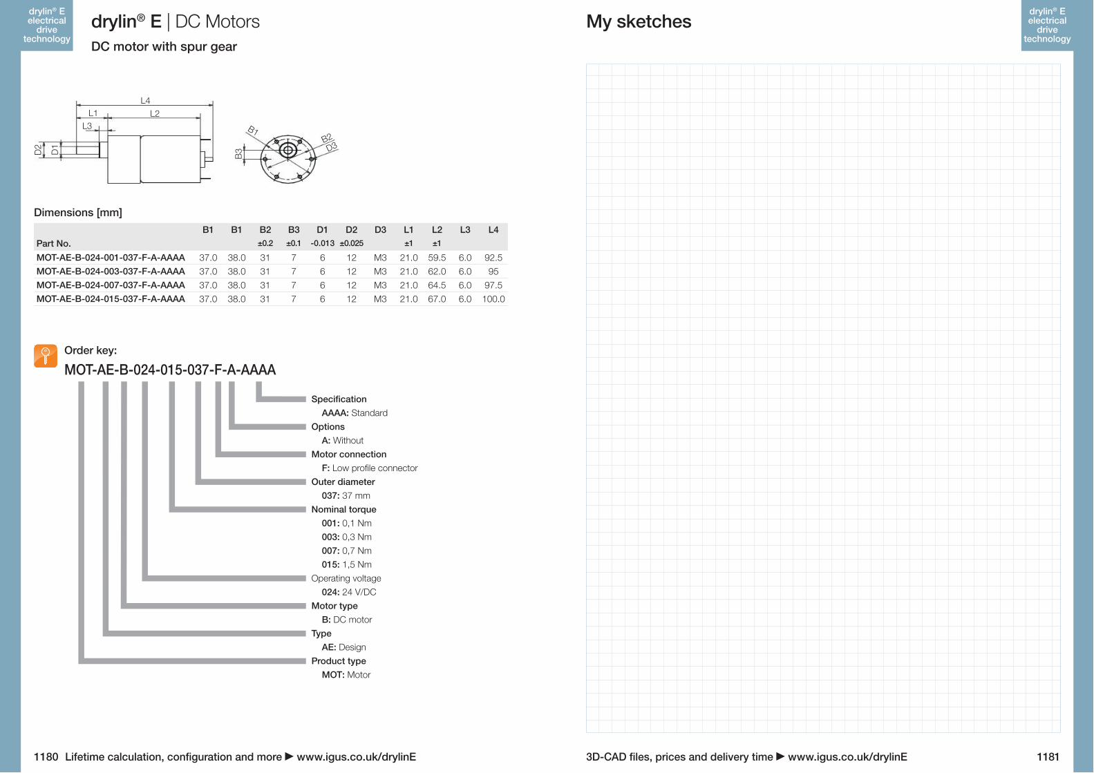
drylin® E | DC MotorsDC motor with spur gear
his small DC motor can be powered directly from a power source, such as a battery. It reverses direction by chan-ging the polarity. Typical applications are sensor/camera travel and light-duty format adjustments with drylin® lead screw or toothed belt axes.
Torque Mn from 0.1 Nm to 1.5 Nm Up to 440 RPM Can be operated at 12 & 24 VDC
MotorMaximum voltage [VDC] 24 24 24 24Nominal voltage [VDC] 24 24 24 24Nominal current [A] 0.5 0.5 0.5 0.5Nominal torque [Nm] 0.1 0.3 0.7 1.5Startup torque [Nm] 0.3 0.5 1.0 1.8Idling speed [1/min] 440 146 58 22Rated speed [1/min] 350 112 47 17Shaft load, axial [N] 6.8 6.8 6.8 6.8Shaft load, radial [N] 9.8 9.8 9.8 9.8Reduction gearing [N] 10 30 75 200
Operating dataAmbient temperature [°C] -10 to +60Max. allowable temperature increase [°C] 60Humidity (non-condensing) [%] 85IP protection class - motor housing IP30Operating mode S2 (Short term operation)
WeightProduct weight [kg] 0.207 0.213 0.221 0.270
Motor connector assigments Low profile connector Length 7 mm, Width 4 mm, Thickness 0.45 mm
Technical data
drylin® E DC motors | Characteristic curvesCharacteristic curves 24 VDC
1.0
1.5
1.00.5
0.5
0.0 0.0
M[N
m]
I [A
]
n[rpm]
1.0
1.5
1.00.5
0.5
0.0 0.0
M[N
m]
I [A
]
n[rpm]
4.0
1.5
1.02.0
0.5
0.0 0.0
M[N
m]
I [A
]
n[rpm]
4.0
1.5
1.02.0
0.5
0.0 0.0
M[N
m]
I [A
]
n[rpm]
6.0 1.5
1.0
3.0
0.5
0.0 0.0
M[N
m]
I [A
]
n[rpm]
6.0 1.5
1.0
3.0
0.5
0.0 0.0
M[N
m]
I [A
]
n[rpm]
2.0
1.5
1.01.0
0.5
0.0 0.0
M[N
m]
I [A
]
n[rpm]
2.0
1.5
1.01.0
0.5
0.0 0.0
M[N
m]
I [A
]
n[rpm]
Characteristic curves 12 VDC
1178 1179
drylin® E electrical
drive technology
drylin® E electrical
drive technology
3D-CAD files, prices and delivery time www.igus.co.uk/drylinELifetime calculation, configuration and more www.igus.co.uk/drylinE
MOT-AE-B-024-001-037-F-A-AAAAMOT-AE-B-024-003-037-F-A-AAAAMOT-AE-B-024-007-037-F-A-AAAAMOT-AE-B-024-015-037-F-A-AAAA
MOT-AE-B-024-015-037-F-A-AAAAOrder key:
DC motor with spur gear
drylin® E | DC Motors
B1 B1 B2 B3 D1 D2 D3 L1 L2 L3 L4Part No. ±0.2 ±0.1 -0.013 ±0.025 ±1 ±1
37.0 38.0 31 7 6 12 M3 21.0 59.5 6.0 92.537.0 38.0 31 7 6 12 M3 21.0 62.0 6.0 9537.0 38.0 31 7 6 12 M3 21.0 64.5 6.0 97.537.0 38.0 31 7 6 12 M3 21.0 67.0 6.0 100.0
Dimensions [mm]
L4L2L1
L3
D1
D2
B3
B1B2D3
My sketches
Specification AAAA: StandardOptions A: WithoutMotor connection F: Low profile connectorOuter diameter 037: 37 mmNominal torque 001: 0,1 Nm 003: 0,3 Nm 007: 0,7 Nm 015: 1,5 NmOperating voltage 024: 24 V/DCMotor type B: DC motorType AE: DesignProduct type MOT: Motor
1180 1181
drylin® E electrical
drive technology
drylin® E electrical
drive technology